JP6870723B2 - OCT motion contrast data analysis device, OCT motion contrast data analysis program. - Google Patents
OCT motion contrast data analysis device, OCT motion contrast data analysis program. Download PDFInfo
- Publication number
- JP6870723B2 JP6870723B2 JP2019219981A JP2019219981A JP6870723B2 JP 6870723 B2 JP6870723 B2 JP 6870723B2 JP 2019219981 A JP2019219981 A JP 2019219981A JP 2019219981 A JP2019219981 A JP 2019219981A JP 6870723 B2 JP6870723 B2 JP 6870723B2
- Authority
- JP
- Japan
- Prior art keywords
- analysis
- motion contrast
- data
- oct
- contrast data
- Prior art date
- Legal status (The legal status is an assumption and is not a legal conclusion. Google has not performed a legal analysis and makes no representation as to the accuracy of the status listed.)
- Active
Links
- 238000007405 data analysis Methods 0.000 title claims description 19
- 238000004458 analytical method Methods 0.000 claims description 308
- 238000012014 optical coherence tomography Methods 0.000 claims description 119
- 210000004204 blood vessel Anatomy 0.000 claims description 101
- 238000005259 measurement Methods 0.000 claims description 57
- 238000000034 method Methods 0.000 claims description 44
- 230000003287 optical effect Effects 0.000 claims description 33
- 230000008569 process Effects 0.000 claims description 31
- 230000004323 axial length Effects 0.000 claims description 4
- 238000003325 tomography Methods 0.000 claims description 3
- 230000008859 change Effects 0.000 description 21
- 238000000605 extraction Methods 0.000 description 19
- 230000002792 vascular Effects 0.000 description 10
- 206010025421 Macule Diseases 0.000 description 7
- 238000003384 imaging method Methods 0.000 description 5
- 238000001514 detection method Methods 0.000 description 3
- 238000010586 diagram Methods 0.000 description 3
- 239000000284 extract Substances 0.000 description 3
- 210000002445 nipple Anatomy 0.000 description 3
- 210000003733 optic disk Anatomy 0.000 description 3
- 230000003595 spectral effect Effects 0.000 description 3
- 230000002159 abnormal effect Effects 0.000 description 2
- 210000000873 fovea centralis Anatomy 0.000 description 2
- 230000006872 improvement Effects 0.000 description 2
- 230000002093 peripheral effect Effects 0.000 description 2
- 230000004044 response Effects 0.000 description 2
- 230000002207 retinal effect Effects 0.000 description 2
- 241000270295 Serpentes Species 0.000 description 1
- 230000017531 blood circulation Effects 0.000 description 1
- 238000004364 calculation method Methods 0.000 description 1
- 239000000835 fiber Substances 0.000 description 1
- 230000006870 function Effects 0.000 description 1
- 238000010191 image analysis Methods 0.000 description 1
- 210000001365 lymphatic vessel Anatomy 0.000 description 1
- 238000013507 mapping Methods 0.000 description 1
- 230000000877 morphologic effect Effects 0.000 description 1
- 210000001328 optic nerve Anatomy 0.000 description 1
- 238000003672 processing method Methods 0.000 description 1
- 238000012950 reanalysis Methods 0.000 description 1
- 230000011218 segmentation Effects 0.000 description 1
- 230000002194 synthesizing effect Effects 0.000 description 1
- 230000001052 transient effect Effects 0.000 description 1
- 210000005166 vasculature Anatomy 0.000 description 1
Images


Description
本開示は、光干渉断層計(OCT:Optical Coherence Tomography)によって取得されたモーションコントラストデータを解析するための装置に関する。 The present disclosure relates to an apparatus for analyzing motion contrast data acquired by an optical coherence tomography (OCT).
近年では、OCT技術を利用して、被検体のモーションコントラストデータを得る技術が注目されている(非特許文献1参照)。 In recent years, a technique for obtaining motion contrast data of a subject by using OCT technique has attracted attention (see Non-Patent Document 1).
しかしながら、モーションコントラストデータの画像化については、種々の改良がおこなわれているが、解析関係については、種々の面で改善の余地があり得る。 However, although various improvements have been made to the imaging of motion contrast data, there may be room for improvement in various aspects regarding the analysis relationship.
例えば、モーションコントラストデータを用いた解析と、OCTデータを用いた解析(例えば、眼底の層厚解析)とが独立しており、手間であった。また、各解析結果の対比が難しかった。複数のモーションコントラストデータの解析する場合も手間であった。 For example, the analysis using the motion contrast data and the analysis using the OCT data (for example, the layer thickness analysis of the fundus) are independent, which is troublesome. Moreover, it was difficult to compare the results of each analysis. It was also troublesome to analyze multiple motion contrast data.
本開示は、従来技術の問題点の少なくとも一つを鑑み、モーションコントラストデータの解析を好適に行うことができるOCTモーションコントラストデータ解析装置、OCTモーションコントラストデータ解析プログラムを提供することを技術課題とする。 The technical subject of the present disclosure is to provide an OCT motion contrast data analysis device and an OCT motion contrast data analysis program capable of suitably analyzing motion contrast data in view of at least one of the problems of the prior art. ..
上記課題を解決するために、本開示は以下のような構成を備えることを特徴とする。 In order to solve the above problems, the present disclosure is characterized by having the following configurations.
(1) 光干渉断層計によって取得された被検眼のOCTモーションコントラストデータを解析するためのOCTモーションコントラストデータ解析装置であって、
複数のセクションに分割された第1の解析領域を、前記OCTモーションコントラストデータとは異なる画像データである被検眼眼底のOCTデータに設定して、予め設定された複数のセクションでの被検眼眼底の層厚に関する基本統計量を取得する取得手段と、
複数のセクションに分割された第2の解析領域を被検眼眼底の前記OCTモーションコントラストデータに設定して、前記モーションコントラストデータの解析処理を行う解析処理手段と、を有し、
前記第2の解析領域の各セクションの配置位置及び範囲は、前記第1の解析領域での各セクションの配置位置及び範囲と同一であることを特徴とする
(2) 光干渉断層計によって取得された被検眼のOCTモーションコントラストデータを解析するためのOCTモーションコントラストデータ解析装置において実行されるOCTモーションコントラストデータ解析プログラムであって、前記OCTモーションコントラストデータ解析装置のプロセッサによって実行されることで、
複数のセクションに分割された第1の解析領域を、前記OCTモーションコントラストデータとは異なる画像データである被検眼眼底のOCTデータに設定して、予め設定された複数のセクションでの被検眼眼底の層厚に関する基本統計量を取得するステップと、
複数のセクションに分割された第2の解析領域を被検眼眼底の前記OCTモーションコントラストデータに設定して、前記モーションコントラストデータの解析処理を行うステップと、を有し、
前記第2の解析領域の各セクションの配置位置及び範囲は、前記第1の解析領域での各セクションの配置位置及び範囲と同一であることを特徴とする。
(1) An OCT motion contrast data analysis device for analyzing OCT motion contrast data of the eye to be inspected acquired by an optical coherence tomography.
The first analysis region divided into a plurality of sections is set to the OCT data of the fundus of the eye to be inspected, which is image data different from the OCT motion contrast data, and the fundus of the eye to be inspected in the plurality of preset sections is set. An acquisition method for acquiring basic statistics on layer thickness,
It has an analysis processing means for setting a second analysis region divided into a plurality of sections to the OCT motion contrast data of the fundus of the eye to be inspected and performing analysis processing of the motion contrast data.
The arrangement position and range of each section in the second analysis area are the same as the arrangement position and range of each section in the first analysis area. (2) Acquired by an optical interference tomography. It is an OCT motion contrast data analysis program executed in the OCT motion contrast data analysis device for analyzing the OCT motion contrast data of the eye to be inspected , and is executed by the processor of the OCT motion contrast data analysis device.
The first analysis region divided into a plurality of sections is set to the OCT data of the fundus of the eye to be inspected, which is image data different from the OCT motion contrast data, and the fundus of the eye to be inspected in the plurality of preset sections is set. Steps to get basic statistics on layer thickness,
It has a step of setting a second analysis region divided into a plurality of sections to the OCT motion contrast data of the fundus of the eye to be inspected and performing analysis processing of the motion contrast data.
The arrangement position and range of each section in the second analysis region are the same as the arrangement position and range of each section in the first analysis region.
以下、本実施形態について簡単に説明する。本実施形態のOCTモーションコントラストデータ解析装置は、例えば、光干渉断層計によって取得された被検体のモーションコントラストデータを解析する。OCTモーションコントラストデータ解析装置は、例えば、解析処理部(例えば、制御部70)を備える。解析処理部は、例えば、第2の画像データ上に設定された解析チャートに基づいて、モーションコントラストデータに対する解析処理を行う。ここで、第2の画像データは、例えば、モーションコントラストデータとは異なる画像データである。これによって、本解析装置は、モーションコントラストの解析をスムーズに行うことができる。 Hereinafter, the present embodiment will be briefly described. The OCT motion contrast data analysis device of the present embodiment analyzes, for example, the motion contrast data of the subject acquired by the optical interference tomography. The OCT motion contrast data analysis device includes, for example, an analysis processing unit (for example, a control unit 70). The analysis processing unit performs analysis processing on the motion contrast data based on, for example, an analysis chart set on the second image data. Here, the second image data is, for example, image data different from the motion contrast data. As a result, the present analysis device can smoothly analyze the motion contrast.
例えば、解析処理部は、解析チャートの位置情報に基づいてモーションコントラストデータに対する解析領域を設定してもよい。そして、解析処理部は、設定された解析領域に関してモーションコントラストに対する解析処理を行うようにしてもよい。このような解析処理は、例えば、解析領域における血管領域の抽出処理に適用されてもよい。 For example, the analysis processing unit may set an analysis area for the motion contrast data based on the position information of the analysis chart. Then, the analysis processing unit may perform analysis processing on the motion contrast with respect to the set analysis area. Such an analysis process may be applied to, for example, an extraction process of a blood vessel region in the analysis region.
また、解析処理部は、解析チャートの位置情報に基づいてモーションコントラストデータに対する解析処理を行う際の基準位置を設定し、設定された基準位置を基準としてモーションコントラストに対する解析処理を行うようにしてもよい。この場合、設定された基準位置を基準として解析領域が設定されてもよい。解析処理部は、設定された解析領域に関してモーションコントラストに対する解析処理を行うようにしてもよい。このような処理は、例えば、解析領域における血管領域の抽出処理に適用されてもよい。また、設定された基準位置を基準としてモーションコントラストデータに対する解析処理が実行されてもよい。このような処理は、例えば、無血管領域の抽出処理を行う際の基準位置の設定に適用されてもよい。 Further, the analysis processing unit may set a reference position for performing analysis processing on the motion contrast data based on the position information of the analysis chart, and perform analysis processing on the motion contrast based on the set reference position. Good. In this case, the analysis area may be set with reference to the set reference position. The analysis processing unit may perform analysis processing on the motion contrast with respect to the set analysis area. Such a process may be applied to, for example, an extraction process of a blood vessel region in an analysis region. Further, the analysis process for the motion contrast data may be executed with the set reference position as a reference. Such a process may be applied, for example, to the setting of a reference position when performing the extraction process of the avascular region.
また、解析チャートの範囲に基づいて、モーションコントラストデータでの解析領域が設定されてもよい。 Further, an analysis area for motion contrast data may be set based on the range of the analysis chart.
なお、モーションコントラストデータは、例えば、二次元モーションコントラストデータ、エンフェイスモーションコントラストデータ、3次元モーションコントラストデータであってもよい。 The motion contrast data may be, for example, two-dimensional motion contrast data, face-to-face motion contrast data, or three-dimensional motion contrast data.
なお、解析チャートは、設定されたセクションでの計測結果の基本統計量を示す解析チャートであってもよく、例えば、モーションコントラストデータの基礎となるOCTデータに対する解析結果に基づく計測結果の基本統計量であってもよい。 The analysis chart may be an analysis chart showing the basic statistics of the measurement results in the set section. For example, the basic statistics of the measurement results based on the analysis results for the OCT data which is the basis of the motion contrast data. It may be.
第2の画像データは、モーションコントラストデータと、被検体上の取得部位に関して少なくとも重複してもよい。例えば、第2の画像データは、被検体上の取得範囲に関して、モーションコントラストデータと同一であってもよい。第2の画像データは、例えば、被検体上の取得範囲に関して、モーションコントラストデータの取得範囲を含んでもよい。 The second image data may at least overlap with the motion contrast data with respect to the acquisition site on the subject. For example, the second image data may be the same as the motion contrast data with respect to the acquisition range on the subject. The second image data may include, for example, the acquisition range of motion contrast data with respect to the acquisition range on the subject.
なお、解析処理部は、例えば、解析チャートの変更に連動して、変更された解析チャートに基づく解析処理を行ってもよい。これによって、解析チャートの設定変更に応じたモーションコントラストの解析に対する変更をスムーズに行うことができる。 The analysis processing unit may perform analysis processing based on the changed analysis chart in conjunction with the change of the analysis chart, for example. As a result, it is possible to smoothly change the motion contrast analysis according to the setting change of the analysis chart.
例えば、解析処理部は、解析チャートの表示位置の変更に連動して、モーションコントラストデータに対する解析領域の位置を変更してもよい。例えば、解析処理部は、解析チャートの範囲の変更に連動して、モーションコントラストデータに対する解析領域の範囲を変更してもよい。 For example, the analysis processing unit may change the position of the analysis area with respect to the motion contrast data in conjunction with the change of the display position of the analysis chart. For example, the analysis processing unit may change the range of the analysis area for the motion contrast data in conjunction with the change of the range of the analysis chart.
また、例えば、解析処理部は、解析チャートの表示位置の変更に連動して、モーションコントラストデータに対する解析処理の基準位置を変更してもよい。 Further, for example, the analysis processing unit may change the reference position of the analysis processing for the motion contrast data in conjunction with the change of the display position of the analysis chart.
なお、解析処理部は、例えば、解析チャートの中心位置に基づいて、モーションコントラストデータに対する解析処理の中心位置又は基準位置を設定してもよい。 The analysis processing unit may set the center position or the reference position of the analysis processing for the motion contrast data, for example, based on the center position of the analysis chart.
なお、解析処理部は、例えば、解析処理による解析結果に基づいて被検体の計測処理を行ってもよい。 The analysis processing unit may perform measurement processing of the subject based on the analysis result of the analysis processing, for example.
なお、解析処理部は、解析チャートに基づいて脈管解析領域を設定してもよい。そして、解析処理部は、設定された脈管解析領域において脈管抽出処理を行ってもよい。 The analysis processing unit may set the vessel analysis region based on the analysis chart. Then, the analysis processing unit may perform the vascular extraction processing in the set vascular analysis region.
なお、解析処理部は、抽出された脈管に関する計測を行ってもよい。脈管に関する計測としては、脈管の面積・体積、脈管の密度、脈管の量、脈管総量、脈管蛇行度、脈管の規則性、脈管の対称性等であってもよい。 The analysis processing unit may perform measurement on the extracted vasculature. The measurement related to the vessel may be the area / volume of the vessel, the density of the vessel, the amount of the vessel, the total amount of the vessel, the degree of meandering of the vessel, the regularity of the vessel, the symmetry of the vessel, or the like. ..
解析処理部は、例えば、モーションコントラストデータにおける無脈管抽出処理の基準位置を解析チャートの位置に基づいて設定してもよい。そして解析処理部は、設定された基準位置を基準として無脈管抽出処理を行ってもよい。 For example, the analysis processing unit may set the reference position of the pulseless tube extraction process in the motion contrast data based on the position of the analysis chart. Then, the analysis processing unit may perform the pulseless tube extraction process with reference to the set reference position.
なお、本装置は、例えば、第1の指示受付部(例えば、制御部70)をさらに備えてもよい。第1の指示受付部は、例えば、第2の画像データ上での解析チャートの位置を設定するための検者からの指示を受け付ける。この場合、解析処理部は、第1の指示受付部によって設定された解析チャートの位置情報に基づいて、モーションコントラストデータに対する解析処理を行ってもよい。 The device may further include, for example, a first instruction receiving unit (for example, a control unit 70). The first instruction receiving unit receives, for example, an instruction from the examiner for setting the position of the analysis chart on the second image data. In this case, the analysis processing unit may perform analysis processing on the motion contrast data based on the position information of the analysis chart set by the first instruction receiving unit.
なお、第2の画像データは、例えば、被検体の正面画像、被検体に関する解析マップ等の少なくともいずれかであってもよい。 The second image data may be, for example, at least one of a front image of the subject, an analysis map relating to the subject, and the like.
なお、本装置は、例えば、第2の指示受付部(例えば、制御部70)をさらに備えてもよい。第2の指示受付部は、例えば、モーションコントラストデータ上での解析領域の位置又は解析処理の基準位置を設定するための検者からの指示を受け付ける。この場合、解析処理部は、例えば、第2の指示受付部によって設定された解析領域の位置情報又は基準位置の位置情報に基づいて、モーションコントラストデータに対する解析処理を行ってもよい。 The device may further include, for example, a second instruction receiving unit (for example, a control unit 70). The second instruction receiving unit receives, for example, an instruction from the examiner for setting the position of the analysis region on the motion contrast data or the reference position of the analysis process. In this case, the analysis processing unit may perform analysis processing on the motion contrast data based on, for example, the position information of the analysis region or the position information of the reference position set by the second instruction receiving unit.
なお、解析処理部は、第2の指示受付手段によって設定された解析領域の位置情報又は基準位置の位置情報に基づいて、解析チャートの位置を設定できてもよい。 The analysis processing unit may be able to set the position of the analysis chart based on the position information of the analysis area or the position information of the reference position set by the second instruction receiving means.
なお、第2の画像データは、モーションコントラストデータの基礎となるOCTデータと関連付けられていてもよい。 The second image data may be associated with the OCT data that is the basis of the motion contrast data.
なお、解析処理部は、解析処理として閾値処理による血管領域の抽出を行う場合、閾値を求めるために設定されるモーションコントラストデータ上の領域を、解析チャートの位置情報に基づいて設定してもよい。 When the analysis processing unit extracts the blood vessel region by the threshold value processing as the analysis process, the analysis processing unit may set the region on the motion contrast data set to obtain the threshold value based on the position information of the analysis chart. ..
なお、本装置は、第3の指示受付部を備えてもよい。第3の指示受付部は、例えば、モーションコントラストデータで解析領域を選択するための検者からの指示を受け付ける。この場合、解析処理部は、第3の指示受付部によって選択された解析領域に基づいて、第2の画像データ上での解析領域を設定してもよい。 The device may include a third instruction receiving unit. The third instruction receiving unit receives, for example, an instruction from the examiner for selecting an analysis area in the motion contrast data. In this case, the analysis processing unit may set the analysis area on the second image data based on the analysis area selected by the third instruction receiving unit.
なお、被検体は、被検眼眼底であってもよい。この場合、解析処理部は、例えば、モーションコントラストデータの被検体上での取得領域に応じて、解析処理を行うために設定される解析領域の位置、範囲、形状の少なくともいずれかをそれぞれ設定可能であってもよい。もちろん、解析領域の位置、範囲、形状等は、それぞれ予め設定可能であってもよいし、各データに対する解析結果に応じて範囲が変更されてもよい。 The subject may be the fundus of the eye to be inspected. In this case, for example, the analysis processing unit can set at least one of the position, range, and shape of the analysis area set for performing the analysis processing according to the acquisition area of the motion contrast data on the subject. It may be. Of course, the position, range, shape, etc. of the analysis area may be set in advance, or the range may be changed according to the analysis result for each data.
なお、取得領域は、被検体の表面方向(例えば、被検眼眼底の黄斑、乳頭など)であってもよいし、被検体の深さ方向(例えば、被検眼眼底の血管層毎など)であってもよい。 The acquisition region may be the surface direction of the subject (for example, the macula of the fundus of the eye to be inspected, the papilla, etc.) or the depth direction of the subject (for example, each blood vessel layer of the fundus of the eye to be inspected). You may.
なお、取得領域が異なる複数のモーションコントラストデータが生成された場合、各データ毎に解析領域の範囲をそれぞれ設定可能であってもよい。複数のモーションコントラストデータとしては、例えば、各血管層に分離された複数の正面モーションコントラストデータであってもよく、正面モーションコントラストデータ毎に異なる解析領域を設定可能であってもよい。 When a plurality of motion contrast data having different acquisition areas are generated, the range of the analysis area may be set for each data. The plurality of motion contrast data may be, for example, a plurality of frontal motion contrast data separated into each blood vessel layer, or a different analysis area may be set for each frontal motion contrast data.
なお、解析マップとしては、例えば、被検体に関する計測結果の二次元分布を示すマップであってもよい。この場合、例えば、例えば、計測値に応じて色分けされたカラーマップであってもよい。 The analysis map may be, for example, a map showing a two-dimensional distribution of measurement results for a subject. In this case, for example, a color map that is color-coded according to the measured value may be used.
なお、例えば、解析チャート504は、予め設定されたセクションでの被検体の計測結果の基本統計量を求めるための解析チャートであってもよく、セクション内での基本統計量が計測されてもよい。
In addition, for example, the
<実施例>
以下、本実施例のOCTモーションコントラストデータ解析装置について図面を用いて説明する。図1に示すOCTモーションコントラストデータ解析装置(以下、OCT解析装置)1は、OCTデバイス10によって取得されたモーションコントラストデータを解析処理する。
<Example>
Hereinafter, the OCT motion contrast data analysis apparatus of this embodiment will be described with reference to the drawings. The OCT motion contrast data analysis device (hereinafter, OCT analysis device) 1 shown in FIG. 1 analyzes the motion contrast data acquired by the
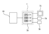
OCT解析装置1は、例えば、制御部70を備える。制御部70は、例えば、一般的なCPU(Central Processing Unit)71、フラッシュROM72、RAM73、等で実現される。フラッシュROM72には、例えば、モーションコントラストデータを処理するための解析処理プログラム、OCTデバイス10の動作を制御してモーションコントラストデータを得るためのプログラム、初期値等が記憶される。RAM73は、例えば、各種情報を一時的に記憶する。
The
制御部70には、図1に示すように、例えば、記憶部(例えば、不揮発性メモリ)74、操作部76、および表示部75等が電気的に接続されている。記憶部74は、例えば、電源の供給が遮断されても記憶内容を保持できる非一過性の記憶媒体である。例えば、ハードディスクドライブ、フラッシュROM、着脱可能なUSBメモリ等を記憶部74として使用することができる。
As shown in FIG. 1, the
操作部76には、検者による各種操作指示が入力される。操作部76は、入力された操作指示に応じた信号をCPU71に出力する。操作部76には、例えば、マウス、ジョイスティック、キーボード、タッチパネル等の少なくともいずれかのユーザーインターフェイスを用いればよい。
Various operation instructions by the inspector are input to the
表示部75は、装置1の本体に搭載されたディスプレイであってもよいし、本体に接続されたディスプレイであってもよい。例えば、パーソナルコンピュータ(以下、「PC」という)のディスプレイを用いてもよい。表示部75は、例えば、OCTデバイス10によって取得されたOCTデータ、モーションコントラストデータ等を表示する。
The
なお、本実施例のOCT解析装置1は、例えば、OCTデバイス10が接続されている。なお、OCT解析装置1は、例えば、OCTデバイス10と同一の筐体に収納された一体的な構成であってもよいし、別々の構成であってもよい。制御部70は、接続されたOCTデバイス10からモーションコントラストデータを取得してもよい。制御部70は、記憶媒体を介してOCTデバイス10によって取得されたモーションコントラストデータを取得してもよい。
The
<OCTデバイス>
以下、図2に基づいてOCTデバイス10の概略を説明する。例えば、OCTデバイス10は、被検眼Eに測定光を照射し、その反射光と測定光とによって取得されたOCT信号を取得する。OCTデバイス10は、例えば、OCT光学系100を主に備える。
<OCT device>
Hereinafter, the outline of the
<OCT光学系>
OCT光学系100は、被検眼Eに測定光を照射し、その反射光と参照光との干渉信号を検出する。OCT光学系100は、例えば、測定光源102と、カップラー(光分割器)104と、測定光学系106と、参照光学系110と、検出器120等を主に備える。なお、OCT光学系の詳しい構成については、例えば、特開2015−131107号を参考にされたい。
<OCT optical system>
The OCT
OCT光学系100は、いわゆる光断層干渉計(OCT:Optical coherence tomography)の光学系である。OCT光学系100は、測定光源102から出射された光をカップラー104によって測定光(試料光)と参照光に分割する。分割された測定光は測定光学系106へ、参照光は参照光学系110へそれぞれ導光される。測定光は測定光学系106を介して被検眼Eの眼底Efに導かれる。その後、被検眼Eによって反射された測定光と,参照光との合成による干渉光を検出器120に受光させる。
The OCT
測定光学系106は、例えば、走査部(例えば、光スキャナ)108を備える。走査部108は、例えば、眼底上でXY方向(横断方向)に測定光を走査させるために設けられてもよい。例えば、CPU71は、設定された走査位置情報に基づいて走査部108の動作を制御し、検出器120によって検出された受光信号に基づいてOCT信号を取得する。参照光学系110は、眼底Efでの測定光の反射によって取得される反射光と合成される参照光を生成する。参照光学系110は、マイケルソンタイプであってもよいし、マッハツェンダタイプであっても良い。
The measurement
検出器120は、測定光と参照光との干渉状態を検出する。フーリエドメインOCTの場合では、干渉光のスペクトル強度が検出器120によって検出され、スペクトル強度データに対するフーリエ変換によって所定範囲における深さプロファイル(Aスキャン信号)が取得される。
The
なお、OCTデバイス10として、例えば、Spectral-domain OCT(SD−OCT)、Swept-source OCT(SS−OCT)、Time-domain OCT(TD−OCT)等が用いられてもよい。
As the
<正面撮影光学系>
正面撮影光学系200は、例えば、被検眼Eの眼底Efを正面方向(例えば、測定光の光軸方向)から撮影し、眼底Efの正面画像を得る。正面撮影光学系200は、例えば、走査型レーザ検眼鏡(SLO)の装置構成であってもよいし(例えば、特開2015−66242号公報参照)、いわゆる眼底カメラタイプの構成であってもよい(特開2011−10944参照)。なお、正面撮影光学系200としては、OCT光学系100が兼用してもよく、検出器120からの検出信号に基づいて正面画像が取得されてもよい。
<Front photography optical system>
The frontal imaging
<固視標投影部>
固視標投影部300は、眼Eの視線方向を誘導するための光学系を有する。投影部300は、眼Eに呈示する固視標を有し、眼Eを誘導できる。例えば、固視標投影部300は、可視光を発する可視光源を有し、固視標の呈示位置を二次元的に変更させる。これによって、視線方向が変更され、結果的にOCTデータの取得部位が変更される。
<Fixed target projection unit>
The fixation
<モーションコントラストデータの取得>
本実施例のOCT解析装置1は、例えば、OCTデバイス10によって検出されたOCTデータを処理してモーションコントラストデータを取得してもよい。CPU71は、走査部108の駆動を制御し、眼底Ef上の領域A1において測定光を走査させる。なお、図3(a)において、z軸の方向は、測定光の光軸の方向とする。x軸の方向は、z軸に垂直であって被検者の左右方向とする。y軸の方向は、z軸に垂直であって被検者の上下方向とする。
<Acquisition of motion contrast data>
The
例えば、CPU71は、領域A1において走査ラインSL1,SL2,・・・,SLnに沿ってx方向に測定光を走査させる。なお、測定光の光軸方向に交差する方向(例えば、x方向)に測定光を走査させることを「Bスキャン」と呼ぶ。そして、1回のBスキャンによって得られた二次元OCTデータを1フレームの二次元OCTデータとして説明する。CPU71は、例えば、xy方向に2次元的に測定光を走査させ、各走査位置においてz方向のAスキャン信号を得てもよい。
For example, the
CPU71は、OCTデータに基づいてモーションコントラストデータを取得してもよい。モーションコントラストは、例えば、被検眼の血流、網膜組織の変化などを捉えた情報であってもよい。モーションコントラストデータを取得する場合、CPU71は、被検眼の同一位置に関して時間的に異なる少なくとも2つのOCTデータを取得する。例えば、各走査ラインにおいて、CPU71は、時間の異なる複数回のBスキャンを行い、時間の異なる複数のOCTデータをそれぞれ取得する。
The
例えば、図3(b)は、走査ラインSL1,SL2,・・・,SLnにおいて時間の異なる複数回のBスキャンを行った場合に取得されたOCT信号を示している。例えば、図3(b)は、走査ラインSL1を時間T11,T12,・・・,T1Nで走査し、走査ラインSL2を時間T21,T22,・・・,T2Nで走査し、走査ラインSLnを時間Tn1,Tn2,・・・,TnNで走査した場合を示している。例えば、CPU71は、各走査ラインにおいて、時間の異なる複数のOCTデータを取得し、そのOCTデータを記憶部74に記憶させる。
For example, FIG. 3B shows an OCT signal acquired when a plurality of B scans having different times are performed on the scanning lines SL1, SL2, ..., SLn. For example, FIG. 3B scans the scanning line SL1 at time T11, T12, ..., T1N, scans scanning line SL2 at time T21, T22, ..., T2N, and scans scanning line SLn for time. The case where scanning is performed with Tn1, Tn2, ..., TnN is shown. For example, the
CPU71は、上記のように、同一位置に関して時間的に異なる複数のOCTデータを取得すると、OCTデータを処理してモーションコントラストデータを取得する。モーションコントラストを取得するためのOCTデータの演算方法としては、例えば、複素OCTデータの強度差を算出する方法、複素OCTデータの位相差を算出する方法、複素OCTデータのベクトル差分を算出する方法、複素OCT信号の位相差及びベクトル差分を掛け合わせる方法、信号の相関を用いる方法(コリレーションマッピング)などが挙げられる。なお、演算手法の一つとして、例えば、特開2015−131107号公報を参照されたい。
As described above, when the
CPU71は、異なる走査ラインでのモーションコントラストデータを並べることによって、被検眼Eの3次元モーションコントラストデータを取得してもよい。なお、前述のように、モーションコントラストデータとしては、位相差に限らず、強度差、ベクトル差分等が取得されてもよい。
The
<モーションコントラストデータの解析処理>
上記のように取得されたモーションコントラストデータの解析処理の一例を、以下に説明する。
<Analysis processing of motion contrast data>
An example of the analysis processing of the motion contrast data acquired as described above will be described below.
CPU71は、モーションコントラストデータに対する解析領域を設定し、設定された解析領域に関して解析処理を行うことによって少なくとも一つの解析結果を取得してもよい。この場合、CPU71は、モーションコントラストデータとは異なる画像データである第2の画像データ上の解析チャートの位置情報を基準として、モーションコントラストデータでの解析領域を設定してもよい。
The
以下、解析結果の一例として、モーションコントラストデータに対する解析処理によって被検眼の血管領域を抽出する場合について説明する。この場合、モーションコントラストデータに対する解析領域として血管解析領域が設定され、少なくとも血管解析領域において血管領域を抽出するための解析処理を行われる。 Hereinafter, as an example of the analysis result, a case where the blood vessel region of the eye to be inspected is extracted by the analysis processing for the motion contrast data will be described. In this case, a blood vessel analysis region is set as an analysis region for the motion contrast data, and analysis processing for extracting the blood vessel region is performed at least in the blood vessel analysis region.
図4は、血管領域を抽出する際の解析画面の一例を示す図である。CPU71は、例えば、解析画面において、MC表示領域400、第2の画像表示領域500を表示部75の表示画面に表示するようにしてもよい。この場合、MC表示領域400、第2の画像表示領域500が同時に表示されてもよいし、別タイミングで表示されてもよい。
FIG. 4 is a diagram showing an example of an analysis screen when extracting a blood vessel region. For example, the
MC表示領域400は、モーションコントラストデータ(以下、MCデータ)402を表示するための領域であり、例えば、MCデータ402として、図4に示すように、正面MCデータ(エンフェイスMCデータともいう)が表示されてもよい。正面MCデータは、例えば、深さ方向の少なくとも一部の領域に関して3次元MCデータを取り出す(例えば、特願2015−121574号公報参照)ことによって取得されてもよい。例えば、MCデータにおける深さ方向での積算値又は最大値によって正面MCデータが生成されてもよい。もちろん、MCデータ402として、一次元MCデータ、二次元MCデータ、3次元MCデータが表示されてもよい。
The
CPU71は、MCデータ402上での血管解析領域を示す表示(例えば、グラフィック404)を、MCデータ402上に表示するようにしてもよい。血管解析領域を示す表示としては、図4のグラフィック404のように血管解析領域の外縁を示す枠表示であってもよいし、血管解析領域と非血管解析領域とが色分けされた表示であってもよい。
The
第2の画像表示領域500には、MCデータ402とは異なる画像データである第2の画像データ502を表示するための領域であり、例えば、正面画像、解析マップの少なくともいずれかが表示されてもよい。第2の画像データ502は、取得部位に関して、MCデータ402と少なくとも一部が重複する画像データが用いられる。例えば、MCデータ402が黄斑部位を中心とするデータの場合、黄斑に関する第2の画像データが表示され、MCデータ402が乳頭部位を中心とするデータの場合、乳頭に関する第2の画像データが表示されてもよい。
The second
解析マップとしては、例えば、眼底に関する計測結果の二次元分布を示すマップであってもよい。この場合、例えば、例えば、計測値に応じて色分けされたカラーマップであってもよい。解析マップとしては、例えば、層厚を示す厚みマップ、被検眼の層厚と正常眼データベースに記憶された正常眼の層厚との比較結果を示す比較マップ、被検眼の層厚と正常眼データベースに記憶された正常眼の層厚とのずれを標準偏差にて示すデビエーションマップ、各検査日との厚みの差分を示す検査日比較厚み差分マップ、であってもよい。なお、層厚を求める場合、例えば、OCTデータに対する画像処理(例えば、セグメンテーション処理)によってOCTデータが層毎に分割処理され、層境界の間隔に基づいて各層の厚みが計測される。もちろん、層厚に限定されず、解析マップとしては、層厚に限定されず、例えば、眼底の曲率分布を示すマップであってよい。 The analysis map may be, for example, a map showing a two-dimensional distribution of measurement results relating to the fundus. In this case, for example, a color map that is color-coded according to the measured value may be used. The analysis map includes, for example, a thickness map showing the layer thickness, a comparison map showing the comparison result between the layer thickness of the eye to be examined and the layer thickness of the normal eye stored in the normal eye database, and the layer thickness of the eye to be examined and the normal eye database. It may be a deviation map showing the deviation from the layer thickness of the normal eye stored in the standard deviation, or an examination date comparison thickness difference map showing the difference in thickness from each examination date. When determining the layer thickness, for example, the OCT data is divided into layers by image processing (for example, segmentation processing) on the OCT data, and the thickness of each layer is measured based on the interval between the layer boundaries. Of course, it is not limited to the layer thickness, and the analysis map is not limited to the layer thickness, and may be, for example, a map showing the curvature distribution of the fundus.
正面画像は、例えば、正面撮影光学系200によって撮影された正面画像であってもよいし、OCT3次元データから生成される正面OCTデータ(エンフェイスOCTデータともいう)であってもよい。3次元OCTデータの場合、3次元モーションコントラストデータの基礎となる3次元OCTデータであってもよい。解析マップは、例えば、被検眼上の解析結果(例えば、眼底層の厚み、曲率など)を二次元的に表現するカラーマップであってもよい。図4では、第2の画像データ502として、正面画像に解析マップが重畳された画像が表示されている。
The front image may be, for example, a front image taken by the front photographing
<解析チャート>
CPU71は、解析チャート504を、第2の画像データ502上に重畳して表示してもよい。この場合、第2の画像データ502は、3次元OCTデータに対する解析結果に基づく計測結果(例えば、解析マップの計測データ)と予め関連付けられてもよく(レジストレーション)、解析チャート504が設定された領域に対応する計測結果が出力される。この場合、第2の画像データ502が3次元OCTデータと関連付けされ、解析チャートが設定された領域に関して解析処理が実行されてもよく、解析結果に基づいて計測結果が出力されてもよい。この場合、3次元OCTデータは、MCデータの基礎となる3次元OCTデータであることが好ましい。なぜなら、MCデータと第2の画像データとの位置的な対応付け(レジストレーション)が容易かつ正確であるからである。
<Analysis chart>
The
例えば、解析チャート504は、予め設定されたセクションでの計測結果の基本統計量を計測するための解析チャートであってもよく、セクション内での基本統計量が計測されてもよい。解析チャート504を形成するセクションは、一つの領域であってもよいし、複数のセクションであってもよい。複数のセクションの場合、分割されたセクション毎に基本統計量が計測されてもよい。基本統計量としては、代表値(平均値、中央値、最頻値、最大値、最小値、など)、散布度(分散、標準偏差、変動係数)などであってもよい。
For example, the
例えば、解析チャート504は、眼底の層厚の二次元的な分布につき、領域毎の平均を求めるチャートであってもよい。また、解析チャート504には、所定領域での層厚を数値にて表示する数値表示領域が付されてもよい。数値表示の代わりに、セクション単位での、計測結果に応じた色分けが行われてもよい。層厚データは、各層の合計であってもよいし、ある層(例えば、視神経線維層)での厚みであってもよい。
For example, the
解析チャート504は任意に選択可能であり、厚みマップが黄斑マップの場合、解析チャート504として、例えば、検者は、GCHART、S/Iチャート、ETDRSから選択可能である。なお、厚みマップが乳頭マップの場合、解析チャートとして、例えば、全体チャート、上下チャート(2分割)、TSNITチャート(4分割)、ClockHourチャート(12分割)から選択可能である。
The
CPU71は、操作部76からの操作信号を受け付け、第2の画像データ502上での解析チャート504の表示位置を変更してもよい。これによって、第2の画像データ502上での解析チャート504による解析領域が変更される。CPU71は、解析チャート504の表示位置の変更に連動して、変更後の解析領域における解析結果を求めてもよい。なお、解析チャートの一部が、第2の画像データ502をはみ出してもよい。
The
例えば、検者は、操作部76を用いて解析チャート504を移動させることによって、解析チャートの中心504cを、眼底の基準部位(例えば、中心窩中心(図4中のM参照)、視神経乳頭中心、異常部位)に設定してもよい。これによって、例えば、眼底の基準部位を中心として、解析チャート504による計測結果が得られる。例えば、基準部位を中心とするチャート内全体の平均層厚、基準部位の層厚、基準部位を中心とする所定エリア内での平均層厚(例えば、1、2、3mm)等が計測されてもよい。これによって、眼底上の基準部位を中心とする計測結果が得られるので、臨床的にも有用である。
For example, the examiner moves the
<解析チャートと血管解析領域の連動>
例えば、CPU71は、解析チャート504の位置情報を用いて、MCデータ上での血管領域の抽出を行うようにしてもよい。より詳細には、CPU71は、解析チャート504の移動に連動して、MCデータ上での血管解析領域の位置を移動させるようにしてもよい。この場合、CPU71は、血管解析領域を示す表示(例えば、グラフィック404)を、MCデータ402上で移動させてもよい。つまり、解析チャート504による解析領域の移動に連動して、血管解析領域の位置が変化する。
<Linkage between analysis chart and blood vessel analysis area>
For example, the
血管解析領域の移動の結果、MCデータ上での血管解析領域が変更される。そこで、CPU71は、血管解析領域の変更に連動して、変更後の血管解析領域における解析結果を求めてもよい(血管解析の手法については後述する)。
As a result of the movement of the blood vessel analysis area, the blood vessel analysis area on the MC data is changed. Therefore, the
解析チャートと血管解析領域を連動させる場合、CPU71は、第2の画像データ502での解析チャート504の中心504cと、MCデータ402での血管解析領域の中心404cとが、解析上の同一位置に配置されるように、血管解析領域を移動させてもよい。つまり、CPU71は、MCデータ402において、第2の画像データ502における解析チャート504の中心位置に対応する位置に解析領域の中心を設定してもよい。この場合、第2の画像データ502とMCデータ402との間で位置的に関連付け(レジストレーション)されていることが好ましい。
When linking the analysis chart and the blood vessel analysis region, the
ここで、例えば、検者が、解析チャート504の中心504cを、眼底の基準部位(例えば、中心窩中心、視神経乳頭中心、異常部位)に設定した場合、血管解析領域の中心が、眼底の基準部位に自動的に設定される。これによって、MCデータ402上で改めて解析領域を変更しなくとも、解析の基準位置を、解析チャート504による解析とMCデータ402に対する解析との間で一致させることができる。
Here, for example, when the examiner sets the
<血管解析領域の設定>
血管解析領域は、検者が任意に設定できてもよい。例えば、CPU71は、操作部76からの操作信号を受け付け、MCデータ上での血管解析領域の位置を変更してもよい。この場合、血管解析領域を示す表示の位置を変更してもよい。CPU71は、血管解析領域の変更に応じて、変更後の血管解析領域における解析結果を求めてよい。この場合、CPU71は、血管解析領域の移動に連動して、第2の画像データ502上での解析チャート504の位置を移動させるようにしてもよい。この結果、解析チャート504の位置調整の手間を省くことができる。
<Setting of blood vessel analysis area>
The blood vessel analysis area may be arbitrarily set by the examiner. For example, the
なお、複数のモーションコントラストデータの解析を行う場合、第1のモーションコントラストデータにおける血管解析領域の位置の変更に連動して、第2のモーションコントラストデータにおける血管解析領域の位置の設定に用いてもよい。例えば、眼底の深さ方向に関して異なる複数のモーションコントラストデータの解析において適用可能である。また、CPU71は、第1のモーションコントラストデータ上で設定された第1のデータ領域を利用して、第2のモーションコントラストデータの中で第1のデータ領域に位置的に対応する第2のデータ領域でのアーチファクトを除去してもよい(例えば、第2のデータ領域の各画素の輝度において第1のデータ領域の各輝度の輝度を差し引く)。
When analyzing a plurality of motion contrast data, it may be used to set the position of the blood vessel analysis region in the second motion contrast data in conjunction with the change in the position of the blood vessel analysis region in the first motion contrast data. Good. For example, it can be applied in the analysis of a plurality of motion contrast data different in the depth direction of the fundus. Further, the
血管解析領域の範囲(サイズ)が検者によって設定できてもよい。血管解析領域の範囲は、眼底上でのMCデータ402の取得領域に応じて設定可能であってもよい。取得領域としては、眼底の表面方向に関して異なる取得領域に応じて設定可能であってもよい。例えば、黄斑部位、乳頭部位に関して、範囲がそれぞれ設定されてもよい。
The range (size) of the blood vessel analysis area may be set by the examiner. The range of the blood vessel analysis region may be set according to the acquisition region of
取得領域に応じた設定としては、眼底の深さ方向に関して異なる取得領域に応じて設定可能であってもよい。例えば、異なる血管層に関して、範囲がそれぞれ設定されてもよい。もちろん、血管層に限定されず、異なる網膜層(又は脈絡膜層)に関して、範囲がそれぞれ設定されてもよい。これによって、眼底上での取得領域に応じた血管解析が可能となる。正面MCデータが血管層毎に複数生成される場合、各血管層の正面MCデータでそれぞれ血管解析領域の範囲が予め設定可能であってもよい。これによって、各血管層に応じた血管解析が可能となる。 As the setting according to the acquisition area, it may be possible to set according to different acquisition areas in the depth direction of the fundus. For example, ranges may be set for different vascular layers. Of course, the range is not limited to the vascular layer, and the range may be set for different retinal layers (or choroidal layers). This enables blood vessel analysis according to the acquisition region on the fundus. When a plurality of frontal MC data are generated for each blood vessel layer, the range of the blood vessel analysis region may be preset in the frontal MC data of each blood vessel layer. This enables blood vessel analysis according to each blood vessel layer.
図5は設定画面の例であり、黄斑マップは、黄斑を中心とするモーションコントラストデータ、乳頭マップは、乳頭を中心とするモーションコントラストデータを示しており、マップ単位で、範囲(例えば、直径)が設定される。なお、範囲を設定する場合、例えば、CPU71は、操作部76からの操作信号を受け付けることによってグラフィック404の範囲(サイズ)を変更してもよい。また、血管解析領域の範囲は、解析チャート504と同じ範囲であってもよい。また、解析チャート504の範囲に基づいて、血管解析領域の範囲が設定されてもよい。
FIG. 5 is an example of a setting screen, in which the macula map shows motion contrast data centered on the macula and the papilla map shows motion contrast data centered on the papilla, and the range (for example, diameter) is shown in map units. Is set. When setting the range, for example, the
なお、上記説明においては、血管解析領域の変更パラメータとして、血管解析領域の位置、範囲(サイズ)を設定可能としたが、これに限定されない。例えば、血管解析領域の形状を設定可能であってもよい(例えば、円、楕円、矩形等)。この場合、眼底上でのMCデータ402の取得領域に応じて、血管解析領域の形状が設定可能であってもよい。
In the above description, the position and range (size) of the blood vessel analysis region can be set as the change parameters of the blood vessel analysis region, but the present invention is not limited to this. For example, the shape of the blood vessel analysis region may be set (eg, circle, ellipse, rectangle, etc.). In this case, the shape of the blood vessel analysis region may be set according to the acquisition region of the
血管解析領域は、複数のセクションに分割された領域であってもよく、各セクションにおいて血管解析が実行されてもよい。各セクションの配置位置又は範囲(サイズ)のいずれかが異なる複数の血管解析領域が選択可能であってもよい。 The blood vessel analysis region may be a region divided into a plurality of sections, and blood vessel analysis may be performed in each section. A plurality of blood vessel analysis regions having different arrangement positions or ranges (sizes) of each section may be selectable.
この場合、眼底上でのMCデータ402の取得領域に応じて、血管解析領域の分割パターンが設定可能であってもよい。例えば、Superficial Capillary Plexusは、全体チャート(セクション一つ)、Intermediate Capillary PlexusはS/Iチャート(上下2分割セクション)であってもよい。この場合、血管解析領域の各セクションの配置位置及び範囲は、解析チャート504の各セクションの配置位置及び範囲と同一となるように設定されてもよい。これによって、解析チャート504の各セクションの解析結果と、血管解析領域での各セクションの解析結果とを対応付けて評価できる。よって、眼底の血管解析結果と、眼底の形態解析結果(例えば、層厚)との関連性を、セクション単位で確認できる。
In this case, the division pattern of the blood vessel analysis region may be set according to the acquisition region of the
<血管抽出処理、血管計測>
CPU71は、前述のように設定された血管解析領域にてMCデータ402を解析することによって、設定された血管解析領域での計測結果を表示部75上に表示してもよい。このようにすれば、解析チャートでの計測とMCデータ402に対する計測とをスムーズに行うことができる。なお、解析結果は、例えば、MC表示領域400上に数値406として表示されてもよい。
<Blood vessel extraction processing, blood vessel measurement>
The
例えば、CPU71は、MCデータ上の血管解析領域として設定された領域に関して画像処理による解析を行うことによって、血管領域と非血管領域との判別処理を行う。判別処理によって、血管領域が抽出される。この場合、判別処理によって、非血管領域が抽出されてもよい。
For example, the
判別処理としては、例えば、閾値処理であってもよく、閾値を満たす画素を血管領域とし、閾値を満たさない画素を非血管領域として判別してもよい。閾値自体は、検者によって任意に設定できてもよいし、固定値として予め決定されていてもよい。また、閾値は、MCデータ402に対する画像解析処理を経て設定されてもよい。
The discrimination process may be, for example, a threshold value process, and pixels that satisfy the threshold value may be defined as a blood vessel region, and pixels that do not satisfy the threshold value may be discriminated as a non-blood vessel region. The threshold value itself may be arbitrarily set by the examiner, or may be predetermined as a fixed value. Further, the threshold value may be set after performing an image analysis process on the
例えば、CPU71は、判別処理の結果に基づいて血管領域に関する計測を行うようにしてもよい。CPU71は、判別処理によって抽出された血管領域に基づいて、血管領域を計測してもよい。計測結果としては、例えば、血管密度、血管面積であってもよい。血管領域の密度としては、例えば、血管解析領域全体における血管領域の比率を求めることによって、単位面積当たりの血管の面積(血管量)が求められる。計測結果としては、これに限定されず、例えば、血管総量、血管蛇行度、血管の規則性等であってもよい。なお、血管解析領域が、複数のセクションに分割された場合、CPU71は、各セクション間での計測結果の比率、差分を求めてもよい。これによって、例えば、血管の対称性等を求めることができる。
For example, the
なお、血管計測に関し、眼軸長に応じてOCTの走査範囲が異なる場合があるので、CPU71は、被検眼の眼軸長値に応じて計測結果を補正してもよい。なお、CPU71は、判別処理の結果に基づいて、血管領域と非血管領域とを判別して表示してもよく、例えば、血管領域を色づけして表示してもよい。
Regarding blood vessel measurement, since the scanning range of OCT may differ depending on the axial length of the eye, the
例えば、CPU71は、血管解析領域の変更に応じて再解析を行い、血管抽出処理の結果を更新してもよい。この場合、CPU71は、血管抽出処理の結果を更新すると共に、更新された血管抽出の結果に基づいて、血管領域に関する計測結果を更新してもよい。
For example, the
例えば、CPU71は、解析チャート504の変更に連動した血管解析領域の変更に応じて、血管領域に関する計測結果を更新してもよい。これによって、検者が、解析チャート504の中心504cを、眼底の基準部位(例えば、中心窩中心、視神経乳頭中心)に設定した場合、眼底の基準部位を中心とする血管計測をスムーズに行うことができる。
For example, the
なお、血管領域と非血管領域との判別処理を自動的に行う場合、CPU71は、MCデータ402の輝度値から二値化処理(例えば、判別分析法)を適用することによって、血管・非血管領域を定めてもよい。解析チャート504が複数のセクションを有する場合、チャートの各セクションに対応する領域単位で閾値が設定されてもよいし、チャート全体に対応する領域全体で閾値が設定されてもよい。また、血管解析領域が複数のセクションに分割されている場合、各セクションに対応する領域単位で閾値が設定されてもよいし、血管解析領域全体で閾値が設定されてもよい。
この場合、CPU71は、解析チャート504の中心504cに対応する中心座標から所定領域(例えば、2.0mm)のみを二値化パラメータ(閾値)を算出する際の対象領域とし、算出されたパラメータを用いて、対象領域よりも周辺の領域に対する二値化処理を行うようにしてもよい
MCデータ402の周辺部は、不要な成分が含まれている場合が多い。例えば、眼軸長が長い眼等の場合、眼の湾曲が大きいので、画角が広い範囲で撮影した場合、基礎となるOCTデータ自体が欠ける。また、データの端部(例えば、撮影の終わりの方)で眼が動いて、基礎となるOCTデータが欠ける場合がある。そこで、解析チャート504の位置を利用することによって判別処理を精度よく実施できる。
When automatically discriminating between the blood vessel region and the non-blood vessel region, the
In this case, the
<解析チャートを用いた中心窩無血管領域(FAZ)の検出>
次に、MCデータ402に対する解析処理によって被検眼のFAZを抽出する場合について説明する。この場合、MCデータに対して、無血管解析領域を抽出するための解析処理を行われる。
<Detection of foveal avascular region (FAZ) using analysis chart>
Next, a case where the FAZ of the eye to be inspected is extracted by the analysis process for the
図6は、FAZを抽出する際の解析画面の一例を示す図である。なお、図4と同じ番号を付したものについては、特段の説明がない限り、同一の機能・構成を有するものとする。 FIG. 6 is a diagram showing an example of an analysis screen when extracting FAZ. Those with the same number as in FIG. 4 shall have the same function and configuration unless otherwise specified.
例えば、CPU71は、解析チャート504の中心504cの位置情報を用いて、MCデータ上での中心窩無血管領域(以下、FAZ)の抽出処理を行うようにしてもよい。より詳細には、画像処理によってFAZを抽出する場合、CPU71は、シード点S(領域検出の開始)を基準として周辺の画素値を解析することによって、FAZに対応する領域を抽出してもよい。
For example, the
FAZは、無血管領域であって輝度値が低いので、例えば、FAZの中心部に設定されたシード点Sを基準として中心部周辺での輝度と連結性を判定することによって、FAZが抽出される。なお、抽出処理の手法としては、例えば、グラフ理論ベースでの抽出処理の他、領域拡張法による抽出、Snake、Level Setのような動的輪郭モデルによる抽出がある。また、Kimらによる”Noninvasive Imaging of the Foveal Avascular Zone with High-Speed,Phase-Variance Optical Coherence Tomography” 2012年1月に記載された手法が用いられてもよい。 Since FAZ is an avascular region and has a low brightness value, for example, FAZ is extracted by determining the brightness and connectivity around the center with reference to the seed point S set in the center of FAZ. To. The extraction processing method includes, for example, extraction processing based on graph theory, extraction by the region expansion method, and extraction by a dynamic contour model such as Snake and Level Set. In addition, the method described in "Noninvasive Imaging of the Foveal Avascular Zone with High-Speed, Phase-Variance Optical Coherence Tomography" by Kim et al., January 2012 may be used.
ここで、CPU71は、第2の画像データ502での解析チャート504の中心504cと、MCデータ402上での解析処理の基準位置(例えば、シード点S)とが、解析上の同一位置に配置されるように、無血管抽出処理の基準位置を設定してもよい。ここで、CPU71は、解析チャート504の中心504cの位置と、MCデータ402上での無血管抽出処理の基準位置(例えば、シード点S)を一致させる。つまり、CPU71は、MCデータ402において、第2の画像データ502における解析チャート504の中心位置に対応する位置に、解析処理の基準位置を設定してもよい。この場合、第2の画像データ502とMCデータ402との間で位置的に関連付け(レジストレーション)されていることが好ましい。
Here, in the
例えば、解析チャート504の中心504cが中心窩中心に設定された場合、解析処理の基準位置(例えば、シード点Sの位置)が中心窩中心に設定されるので、FAZをスムーズに検出することができる。仮に、解析処理の基準位置から外れた場合、血管領域を中心に画像処理が行われる可能性があり、FAZの抽出精度が低下する可能性がある。
For example, when the
もちろん、CPU71は、操作部76からの操作信号を受け付け、解析処理での基準位置を設定してもよく、設定された基準位置を基準としてFAZを画像処理によって検出してもよい。この場合、CPU71は、FAZ抽出時の解析処理の基準位置と、解析チャート504の中心504cとが、解析上の同一位置に配置されるように、解析チャート504の表示位置を変更してもよい。
Of course, the
なお、上記解析は、血管に限定されず、脈管解析領域として脈管解析(例えば、リンパ管)に適用可能である。 The above analysis is not limited to blood vessels, and can be applied to vascular analysis (for example, lymphatic vessels) as a vascular analysis region.
なお、上記説明においては、解析領域に限定して解析処理を行ったが、これに限定されず、CPU71は、設定された解析領域に関する解析処理を行うと共に、他の領域についても解析処理を行ってもよい。
In the above description, the analysis process is limited to the analysis area, but the analysis process is not limited to this, and the
なお、上記説明においては、正面MCデータを例として説明したが、MCデータであれば、本実施形態の適用は可能である。例えば、3次元OCTデータ上での解析チャートの位置情報に基づいて、3次元MCデータの解析領域が設定されてもよい。もちろん、MCデータとしては、例えば、一次元MCデータ、二次元MCデータであってもよい。 In the above description, the front MC data has been described as an example, but if it is MC data, the present embodiment can be applied. For example, the analysis area of the 3D MC data may be set based on the position information of the analysis chart on the 3D OCT data. Of course, the MC data may be, for example, one-dimensional MC data or two-dimensional MC data.
なお、上記説明においては、MCデータが表示部75に表示された上で、MCデータに対する血管の計測結果が出力されたが、これに限定されず、MCデータを表示せず、第2の画像データ502と共に、CPU71に行われた計測結果のみが表示されるようにしてもよい。これにより、画面上の表示を簡略化できる。
In the above description, the MC data is displayed on the
なお、上記説明においては、第2の画像データとして、被検体の正面画像、被検体に関する解析マップを用いたが、例えば、解析処理を行うモーションコントラストデータとは異なる第2のモーションコントラストデータであってもよい。これによって、複数のモーションコントラストデータの解析をスムーズに行うことができる。 In the above description, the front image of the subject and the analysis map for the subject are used as the second image data, but for example, the second motion contrast data is different from the motion contrast data for which the analysis process is performed. You may. As a result, it is possible to smoothly analyze a plurality of motion contrast data.
また、眼底の表面方向に関して異なる複数の正面MCデータの合成によって、広範囲のMCデータが生成された場合、CPU71は、一つの正面MCデータよりも広い領域を解析領域して設定するようにしてもよい。これにより、広範囲における解析が可能となる。また、CPU71は、前述のように生成された広範囲のMCデータを形成する正面MCデータ毎の解析領域を設定するようにしてもよい。この場合、各正面MCデータにおいて複数の解析領域が設定されてもよい。
Further, when a wide range of MC data is generated by synthesizing a plurality of front MC data different with respect to the surface direction of the fundus, the
なお、上記説明においては、被検眼の眼底を例として説明したが、これに限定されず、被検眼の前眼部においても適用可能である。さらに、被検眼に限らず、OCTによって取得された他のモーションコントラストデータ(例えば、眼以外の他の組織におけるモーションコントラストデータ)に対しても適用可能である。 In the above description, the fundus of the eye to be inspected has been described as an example, but the present invention is not limited to this, and the application is also applicable to the anterior segment of the eye to be inspected. Furthermore, it is applicable not only to the eye to be inspected but also to other motion contrast data acquired by OCT (for example, motion contrast data in tissues other than the eye).
1 OCTモーションコントラストデータ解析装置
10 OCTデバイス
70 制御部
75 表示部
400 MC表示領域
402 MCデータ
500 第2の画像表示領域
502 第2の画像データ
504 解析チャート
1 OCT motion contrast
Claims (7)
複数のセクションに分割された第1の解析領域を、前記OCTモーションコントラストデータとは異なる画像データである被検眼眼底のOCTデータに設定して、予め設定された複数のセクションでの被検眼眼底の層厚に関する基本統計量を取得する取得手段と、
複数のセクションに分割された第2の解析領域を被検眼眼底の前記OCTモーションコントラストデータに設定して、前記モーションコントラストデータの解析処理を行う解析処理手段と、を有し、
前記第2の解析領域の各セクションの配置位置及び範囲は、前記第1の解析領域での各セクションの配置位置及び範囲と同一であることを特徴とするOCTモーションコントラストデータ解析装置。 It is an OCT motion contrast data analysis device for analyzing OCT motion contrast data of the eye to be inspected acquired by an optical coherence tomography.
The first analysis region divided into a plurality of sections is set to the OCT data of the fundus of the eye to be inspected, which is image data different from the OCT motion contrast data, and the fundus of the eye to be inspected in the plurality of preset sections is set. An acquisition method for acquiring basic statistics on layer thickness,
It has an analysis processing means for setting a second analysis region divided into a plurality of sections to the OCT motion contrast data of the fundus of the eye to be inspected and performing analysis processing of the motion contrast data.
An OCT motion contrast data analysis apparatus, characterized in that the arrangement position and range of each section in the second analysis area are the same as the arrangement position and range of each section in the first analysis area.
複数のセクションに分割された第1の解析領域を、前記OCTモーションコントラストデータとは異なる画像データである被検眼眼底のOCTデータに設定して、予め設定された複数のセクションでの被検眼眼底の層厚に関する基本統計量を取得するステップと、
複数のセクションに分割された第2の解析領域を被検眼眼底の前記OCTモーションコントラストデータに設定して、前記モーションコントラストデータの解析処理を行うステップと、を有し、
前記第2の解析領域の各セクションの配置位置及び範囲は、前記第1の解析領域での各セクションの配置位置及び範囲と同一であることを特徴とするOCTモーションコントラストデータ解析プログラム。 It is an OCT motion contrast data analysis program executed in the OCT motion contrast data analysis device for analyzing the OCT motion contrast data of the eye to be inspected acquired by the optical interference tomography, and is performed by the processor of the OCT motion contrast data analysis device. By being executed
The first analysis region divided into a plurality of sections is set to the OCT data of the fundus of the eye to be inspected, which is image data different from the OCT motion contrast data, and the fundus of the eye to be inspected in the plurality of preset sections is set. Steps to get basic statistics on layer thickness,
It has a step of setting a second analysis region divided into a plurality of sections to the OCT motion contrast data of the fundus of the eye to be inspected and performing analysis processing of the motion contrast data.
An OCT motion contrast data analysis program characterized in that the arrangement position and range of each section in the second analysis area are the same as the arrangement position and range of each section in the first analysis area.
Priority Applications (1)
| Application Number | Priority Date | Filing Date | Title |
|---|---|---|---|
| JP2019219981A JP6870723B2 (en) | 2019-12-04 | 2019-12-04 | OCT motion contrast data analysis device, OCT motion contrast data analysis program. |
Applications Claiming Priority (1)
| Application Number | Priority Date | Filing Date | Title |
|---|---|---|---|
| JP2019219981A JP6870723B2 (en) | 2019-12-04 | 2019-12-04 | OCT motion contrast data analysis device, OCT motion contrast data analysis program. |
Related Parent Applications (1)
| Application Number | Title | Priority Date | Filing Date |
|---|---|---|---|
| JP2015175194A Division JP6627342B2 (en) | 2015-09-04 | 2015-09-04 | OCT motion contrast data analysis device, OCT motion contrast data analysis program. |
Publications (2)
| Publication Number | Publication Date |
|---|---|
| JP2020044362A JP2020044362A (en) | 2020-03-26 |
| JP6870723B2 true JP6870723B2 (en) | 2021-05-12 |
Family
ID=69899136
Family Applications (1)
| Application Number | Title | Priority Date | Filing Date |
|---|---|---|---|
| JP2019219981A Active JP6870723B2 (en) | 2019-12-04 | 2019-12-04 | OCT motion contrast data analysis device, OCT motion contrast data analysis program. |
Country Status (1)
| Country | Link |
|---|---|
| JP (1) | JP6870723B2 (en) |
Families Citing this family (1)
| Publication number | Priority date | Publication date | Assignee | Title |
|---|---|---|---|---|
| JP7305608B2 (en) * | 2020-12-11 | 2023-07-10 | キヤノン株式会社 | Ophthalmic analysis device, ophthalmic analysis program |
Family Cites Families (3)
| Publication number | Priority date | Publication date | Assignee | Title |
|---|---|---|---|---|
| US9357916B2 (en) * | 2012-05-10 | 2016-06-07 | Carl Zeiss Meditec, Inc. | Analysis and visualization of OCT angiography data |
| US20140073917A1 (en) * | 2012-09-10 | 2014-03-13 | Oregon Health & Science University | Quantification of local circulation with oct angiography |
| US20140276025A1 (en) * | 2013-03-14 | 2014-09-18 | Carl Zeiss Meditec, Inc. | Multimodal integration of ocular data acquisition and analysis |
-
2019
- 2019-12-04 JP JP2019219981A patent/JP6870723B2/en active Active
Also Published As
| Publication number | Publication date |
|---|---|
| JP2020044362A (en) | 2020-03-26 |
Similar Documents
| Publication | Publication Date | Title |
|---|---|---|
| JP6627342B2 (en) | OCT motion contrast data analysis device, OCT motion contrast data analysis program. | |
| JP6922152B2 (en) | Ophthalmology analyzer, ophthalmology analysis program | |
| US10660515B2 (en) | Image display method of providing diagnosis information using three-dimensional tomographic data | |
| US10674909B2 (en) | Ophthalmic analysis apparatus and ophthalmic analysis method | |
| US10022047B2 (en) | Ophthalmic apparatus | |
| JP6922151B2 (en) | Ophthalmology analyzer, ophthalmology analysis program | |
| US10492682B2 (en) | Ophthalmic analysis device and ophthalmic analysis program | |
| US20180350076A1 (en) | Optical coherence tomography (oct) data processing method, storage medium storing program for executing the oct data processing method, and processing device | |
| JP6828295B2 (en) | Optical coherence tomography equipment and optical coherence tomography control program | |
| JP6870723B2 (en) | OCT motion contrast data analysis device, OCT motion contrast data analysis program. | |
| JP7005382B2 (en) | Information processing equipment, information processing methods and programs | |
| JP7106304B2 (en) | Image processing device, image processing method and program | |
| JP2019103762A (en) | Oct data analysis device, and oct data analysis program | |
| JP2018191761A (en) | Information processing device, information processing method, and program | |
| JP2019150554A (en) | Image processing system and method for controlling the same | |
| JP7297952B2 (en) | Information processing device, information processing method and program | |
| JP2019208845A (en) | Image processing device, image processing method, and program | |
| JP7228648B2 (en) | Ophthalmic information processing device and ophthalmic photographing device | |
| JP7297133B2 (en) | Ophthalmic information processing device and ophthalmic photographing device | |
| JP7191166B2 (en) | Ophthalmic photographing device and ophthalmic information processing device | |
| JP7111874B2 (en) | ophthalmic imaging equipment | |
| JP2019024617A (en) | Ophthalmologic information processing device and ophthalmologic imaging device | |
| JP2019103763A (en) | Oct data analysis device, and oct data analysis program |
Legal Events
| Date | Code | Title | Description |
|---|---|---|---|
| A621 | Written request for application examination |
Free format text: JAPANESE INTERMEDIATE CODE: A621 Effective date: 20191205 |
|
| A977 | Report on retrieval |
Free format text: JAPANESE INTERMEDIATE CODE: A971007 Effective date: 20201030 |
|
| A131 | Notification of reasons for refusal |
Free format text: JAPANESE INTERMEDIATE CODE: A131 Effective date: 20201117 |
|
| A521 | Request for written amendment filed |
Free format text: JAPANESE INTERMEDIATE CODE: A523 Effective date: 20210118 |
|
| TRDD | Decision of grant or rejection written | ||
| A01 | Written decision to grant a patent or to grant a registration (utility model) |
Free format text: JAPANESE INTERMEDIATE CODE: A01 Effective date: 20210316 |
|
| A61 | First payment of annual fees (during grant procedure) |
Free format text: JAPANESE INTERMEDIATE CODE: A61 Effective date: 20210329 |
|
| R150 | Certificate of patent or registration of utility model |
Ref document number: 6870723 Country of ref document: JP Free format text: JAPANESE INTERMEDIATE CODE: R150 |
|
| R250 | Receipt of annual fees |
Free format text: JAPANESE INTERMEDIATE CODE: R250 |