JP6870068B2 - Clothes processing equipment - Google Patents
Clothes processing equipment Download PDFInfo
- Publication number
- JP6870068B2 JP6870068B2 JP2019505421A JP2019505421A JP6870068B2 JP 6870068 B2 JP6870068 B2 JP 6870068B2 JP 2019505421 A JP2019505421 A JP 2019505421A JP 2019505421 A JP2019505421 A JP 2019505421A JP 6870068 B2 JP6870068 B2 JP 6870068B2
- Authority
- JP
- Japan
- Prior art keywords
- drum
- hook
- peripheral surface
- outer peripheral
- ball balancer
- Prior art date
- Legal status (The legal status is an assumption and is not a legal conclusion. Google has not performed a legal analysis and makes no representation as to the accuracy of the status listed.)
- Active
Links
- 230000002093 peripheral effect Effects 0.000 claims description 90
- 230000008878 coupling Effects 0.000 description 31
- 238000010168 coupling process Methods 0.000 description 31
- 238000005859 coupling reaction Methods 0.000 description 31
- 239000003599 detergent Substances 0.000 description 10
- 238000000034 method Methods 0.000 description 8
- 238000005406 washing Methods 0.000 description 8
- 238000011068 loading method Methods 0.000 description 5
- 238000010586 diagram Methods 0.000 description 4
- XLYOFNOQVPJJNP-UHFFFAOYSA-N water Substances O XLYOFNOQVPJJNP-UHFFFAOYSA-N 0.000 description 4
- 241000239290 Araneae Species 0.000 description 3
- 230000009471 action Effects 0.000 description 3
- 238000001035 drying Methods 0.000 description 3
- 239000007788 liquid Substances 0.000 description 3
- 239000000126 substance Substances 0.000 description 3
- 238000009826 distribution Methods 0.000 description 2
- 238000003780 insertion Methods 0.000 description 2
- 230000037431 insertion Effects 0.000 description 2
- 239000002184 metal Substances 0.000 description 2
- 239000007769 metal material Substances 0.000 description 2
- 238000005452 bending Methods 0.000 description 1
- 230000008901 benefit Effects 0.000 description 1
- 238000011109 contamination Methods 0.000 description 1
- 230000007423 decrease Effects 0.000 description 1
- 230000000694 effects Effects 0.000 description 1
- 239000012530 fluid Substances 0.000 description 1
- 238000004519 manufacturing process Methods 0.000 description 1
- 238000003825 pressing Methods 0.000 description 1
- 230000008569 process Effects 0.000 description 1
- 238000000926 separation method Methods 0.000 description 1
- 238000003860 storage Methods 0.000 description 1
Images


Classifications
-
- D—TEXTILES; PAPER
- D06—TREATMENT OF TEXTILES OR THE LIKE; LAUNDERING; FLEXIBLE MATERIALS NOT OTHERWISE PROVIDED FOR
- D06F—LAUNDERING, DRYING, IRONING, PRESSING OR FOLDING TEXTILE ARTICLES
- D06F37/00—Details specific to washing machines covered by groups D06F21/00 - D06F25/00
- D06F37/20—Mountings, e.g. resilient mountings, for the rotary receptacle, motor, tub or casing; Preventing or damping vibrations
- D06F37/22—Mountings, e.g. resilient mountings, for the rotary receptacle, motor, tub or casing; Preventing or damping vibrations in machines with a receptacle rotating or oscillating about a horizontal axis
- D06F37/225—Damping vibrations by displacing, supplying or ejecting a material, e.g. liquid, into or from counterbalancing pockets
-
- D—TEXTILES; PAPER
- D06—TREATMENT OF TEXTILES OR THE LIKE; LAUNDERING; FLEXIBLE MATERIALS NOT OTHERWISE PROVIDED FOR
- D06F—LAUNDERING, DRYING, IRONING, PRESSING OR FOLDING TEXTILE ARTICLES
- D06F37/00—Details specific to washing machines covered by groups D06F21/00 - D06F25/00
- D06F37/02—Rotary receptacles, e.g. drums
- D06F37/04—Rotary receptacles, e.g. drums adapted for rotation or oscillation about a horizontal or inclined axis
- D06F37/06—Ribs, lifters, or rubbing means forming part of the receptacle
-
- D—TEXTILES; PAPER
- D06—TREATMENT OF TEXTILES OR THE LIKE; LAUNDERING; FLEXIBLE MATERIALS NOT OTHERWISE PROVIDED FOR
- D06F—LAUNDERING, DRYING, IRONING, PRESSING OR FOLDING TEXTILE ARTICLES
- D06F37/00—Details specific to washing machines covered by groups D06F21/00 - D06F25/00
- D06F37/42—Safety arrangements, e.g. for stopping rotation of the receptacle upon opening of the casing door
-
- D—TEXTILES; PAPER
- D06—TREATMENT OF TEXTILES OR THE LIKE; LAUNDERING; FLEXIBLE MATERIALS NOT OTHERWISE PROVIDED FOR
- D06F—LAUNDERING, DRYING, IRONING, PRESSING OR FOLDING TEXTILE ARTICLES
- D06F39/00—Details of washing machines not specific to a single type of machines covered by groups D06F9/00 - D06F27/00
- D06F39/04—Heating arrangements
-
- D—TEXTILES; PAPER
- D06—TREATMENT OF TEXTILES OR THE LIKE; LAUNDERING; FLEXIBLE MATERIALS NOT OTHERWISE PROVIDED FOR
- D06F—LAUNDERING, DRYING, IRONING, PRESSING OR FOLDING TEXTILE ARTICLES
- D06F39/00—Details of washing machines not specific to a single type of machines covered by groups D06F9/00 - D06F27/00
- D06F39/08—Liquid supply or discharge arrangements
- D06F39/083—Liquid discharge or recirculation arrangements
- D06F39/085—Arrangements or adaptations of pumps
-
- D—TEXTILES; PAPER
- D06—TREATMENT OF TEXTILES OR THE LIKE; LAUNDERING; FLEXIBLE MATERIALS NOT OTHERWISE PROVIDED FOR
- D06F—LAUNDERING, DRYING, IRONING, PRESSING OR FOLDING TEXTILE ARTICLES
- D06F39/00—Details of washing machines not specific to a single type of machines covered by groups D06F9/00 - D06F27/00
- D06F39/10—Filtering arrangements
-
- D—TEXTILES; PAPER
- D06—TREATMENT OF TEXTILES OR THE LIKE; LAUNDERING; FLEXIBLE MATERIALS NOT OTHERWISE PROVIDED FOR
- D06F—LAUNDERING, DRYING, IRONING, PRESSING OR FOLDING TEXTILE ARTICLES
- D06F39/00—Details of washing machines not specific to a single type of machines covered by groups D06F9/00 - D06F27/00
- D06F39/12—Casings; Tubs
- D06F39/125—Supporting arrangements for the casing, e.g. rollers or legs
-
- D—TEXTILES; PAPER
- D06—TREATMENT OF TEXTILES OR THE LIKE; LAUNDERING; FLEXIBLE MATERIALS NOT OTHERWISE PROVIDED FOR
- D06F—LAUNDERING, DRYING, IRONING, PRESSING OR FOLDING TEXTILE ARTICLES
- D06F37/00—Details specific to washing machines covered by groups D06F21/00 - D06F25/00
- D06F37/02—Rotary receptacles, e.g. drums
- D06F37/04—Rotary receptacles, e.g. drums adapted for rotation or oscillation about a horizontal or inclined axis
-
- D—TEXTILES; PAPER
- D06—TREATMENT OF TEXTILES OR THE LIKE; LAUNDERING; FLEXIBLE MATERIALS NOT OTHERWISE PROVIDED FOR
- D06F—LAUNDERING, DRYING, IRONING, PRESSING OR FOLDING TEXTILE ARTICLES
- D06F37/00—Details specific to washing machines covered by groups D06F21/00 - D06F25/00
- D06F37/02—Rotary receptacles, e.g. drums
- D06F37/12—Rotary receptacles, e.g. drums adapted for rotation or oscillation about a vertical axis
-
- D—TEXTILES; PAPER
- D06—TREATMENT OF TEXTILES OR THE LIKE; LAUNDERING; FLEXIBLE MATERIALS NOT OTHERWISE PROVIDED FOR
- D06F—LAUNDERING, DRYING, IRONING, PRESSING OR FOLDING TEXTILE ARTICLES
- D06F37/00—Details specific to washing machines covered by groups D06F21/00 - D06F25/00
- D06F37/20—Mountings, e.g. resilient mountings, for the rotary receptacle, motor, tub or casing; Preventing or damping vibrations
- D06F37/22—Mountings, e.g. resilient mountings, for the rotary receptacle, motor, tub or casing; Preventing or damping vibrations in machines with a receptacle rotating or oscillating about a horizontal axis
-
- Y—GENERAL TAGGING OF NEW TECHNOLOGICAL DEVELOPMENTS; GENERAL TAGGING OF CROSS-SECTIONAL TECHNOLOGIES SPANNING OVER SEVERAL SECTIONS OF THE IPC; TECHNICAL SUBJECTS COVERED BY FORMER USPC CROSS-REFERENCE ART COLLECTIONS [XRACs] AND DIGESTS
- Y02—TECHNOLOGIES OR APPLICATIONS FOR MITIGATION OR ADAPTATION AGAINST CLIMATE CHANGE
- Y02B—CLIMATE CHANGE MITIGATION TECHNOLOGIES RELATED TO BUILDINGS, e.g. HOUSING, HOUSE APPLIANCES OR RELATED END-USER APPLICATIONS
- Y02B40/00—Technologies aiming at improving the efficiency of home appliances, e.g. induction cooking or efficient technologies for refrigerators, freezers or dish washers
Description
本発明は、ボールバランサとドラムとがフック結合により結合される衣類処理装置に関する。 The present invention relates to a garment processing device in which a ball balancer and a drum are connected by a hook connection.
衣類処理装置は、ドラムの内部に衣服、寝具など(以下、洗濯物という。)を投入して洗濯物に付着した汚染を除去する装置である。衣類処理装置は、洗濯、すすぎ、脱水、乾燥などの過程を行うことができる。衣類処理装置は、ドラムに洗濯物を投入する方式によってトップローディング(top loading)方式とフロントローディング(front loading)方式に分けられる。フロントローディング方式の洗濯機を一般にドラム式洗濯機という。 The clothes processing device is a device that removes contamination adhering to the laundry by putting clothes, bedding, etc. (hereinafter referred to as laundry) inside the drum. The garment processing device can perform processes such as washing, rinsing, dehydrating, and drying. The garment processing device is divided into a top loading method and a front loading method according to the method of loading the laundry into the drum. A front-loading type washing machine is generally called a drum type washing machine.
衣類処理装置は、外観を形成するキャビネットと、キャビネットの内部に収容されるタブと、タブの内部に回転可能に装着されて洗濯物が投入されるドラムと、ドラムの内周面に配置されて洗濯物の上昇及び落下により洗濯物の洗浄を助けるリフターと、洗剤をドラムの内部に供給する洗剤供給装置とを含むものが一般的である。 The garment processing equipment is arranged on the cabinet that forms the appearance, the tab that is housed inside the cabinet, the drum that is rotatably mounted inside the tab and into which the laundry is loaded, and the inner peripheral surface of the drum. It generally includes a lifter that assists in washing the laundry by raising and dropping the laundry, and a detergent supply device that supplies the detergent to the inside of the drum.
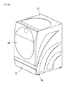
図1はフロントローディング方式の衣類処理装置の外観を示し、図2は図1の衣類処理装置の内部を示す。 FIG. 1 shows the appearance of the front-loading type garment processing device, and FIG. 2 shows the inside of the garment processing device of FIG.
衣類処理装置は、外観を形成する衣類処理装置のキャビネット11と、キャビネット11の内部に回転可能に装着されて洗濯物が投入されるドラム110と、ドラム110の内部に設けられるリフター21と、キャビネット11の前面に設けられるドア12とを含む。キャビネット11の下部には、洗剤を投入するための洗剤投入口を遮蔽する洗剤投入口蓋体13が配置される。また、衣類処理装置は、ドラム110の内部に位置する洗濯物の乾燥のために空気を循環させなければならないので、ダクトや熱交換器などを含む。さらに、衣類処理装置の下部には、キャビネット11の底面を形成するベースが配置される。ベース110は、ドラム110、タブ15、排水ポンプ18、フィルタ部17、洗剤供給部などを支持する役割を果たす。
The clothes processing device includes a
ドラムに洗濯物が収容されて駆動モータによりドラムが回転することによって洗濯工程が行われる。ドラムに洗濯物が収容された状態でドラムの回転軸を中心とする洗濯物の質量分布が許容範囲内にある場合は動的平衡状態(dynamic equilibrium, dynamic balance)が維持されるが、ドラムの内部に収容された洗濯物の位置によっては動的平衡状態が維持されていない状態で回転することがある。 The washing process is performed by accommodating the laundry in the drum and rotating the drum by the drive motor. When the mass distribution of the laundry around the rotation axis of the drum is within the permissible range while the laundry is contained in the drum, the dynamic equilibrium (dynamic balance) is maintained, but the drum Depending on the position of the laundry housed inside, it may rotate in a state where the dynamic equilibrium state is not maintained.
ドラムの回転軸を中心とする質量分布が均一でない状態でドラムが回転する場合、動的平衡状態が崩れているので、ドラムの回転により大きな振動及び騒音が発生してタブやキャビネットに伝達されるという問題が生じることがある。 When the drum rotates in a state where the mass distribution centered on the rotation axis of the drum is not uniform, the dynamic equilibrium state is broken, and the rotation of the drum causes large vibration and noise to be transmitted to the tabs and cabinets. May occur.
動的非平衡状態でドラムの回転により発生する騒音及び振動を低減するために、ドラムの前部及び後部にバランサをそれぞれ配置する。バランサの内部には所定の重量を有する物質が含まれてもよく、また、前記物質は円周方向に移動可能な経路を有するようにしてもよい。ドラム内部の荷重が一方に偏った場合、前記物質は荷重が偏った所の反対側に偏って分布することになり、よって、ドラムの偏心回転を防止することができる。このために、ドラムの前部及び後部にバランサをそれぞれ設ける。 Balancers are placed at the front and rear of the drum to reduce noise and vibration generated by the rotation of the drum in a dynamic non-equilibrium state. The inside of the balancer may contain a substance having a predetermined weight, and the substance may have a path that can move in the circumferential direction. When the load inside the drum is biased to one side, the substance is distributed unevenly to the opposite side of the place where the load is biased, so that the eccentric rotation of the drum can be prevented. For this purpose, balancers are provided at the front and rear of the drum, respectively.
バランサはドラムとの締結により固定しなければならないが、従来は、ドラムの前部及び後部にバランサを固定するために、ドラムの外周面に所定の間隔でネジ結合のための孔をパンチングなどの方法で形成し、その後バランサの外周面に形成されたネジ結合部でのネジ結合により固定する方法を用いていた。 The balancer must be fixed by fastening to the drum, but conventionally, in order to fix the balancer to the front and rear of the drum, holes for screw connection are punched on the outer peripheral surface of the drum at predetermined intervals. A method was used in which the drum was formed by a method and then fixed by screw coupling at a screw coupling portion formed on the outer peripheral surface of the balancer.
このために、生産ラインの作業者は、ドラムの外周面に孔を形成し、ネジ結合部の数に対応する数のネジを締結して固定していた。しかし、当該方法は、別途のネジを用いてネジ結合により固定する時間がかかるので、作業に要する時間が増加し、生産性が低下するという問題があった。 For this purpose, the workers on the production line formed holes on the outer peripheral surface of the drum and fastened and fixed the number of screws corresponding to the number of screw joints. However, this method has a problem that it takes a long time to fix by screw connection using a separate screw, so that the time required for the work increases and the productivity decreases.
よって、フック結合によりネジ結合と同じ結合力を提供しながらも作業者の簡単な作業だけでドラムとバランサを結合することのできる構造が求められている。 Therefore, there is a demand for a structure that can connect the drum and the balancer only by a simple operation by the operator while providing the same coupling force as the screw coupling by the hook coupling.
本発明は、ボールバランサとドラムとを簡単な方法で固定することができ、ネジ結合と同じ結合力を提供することができる装置を提案することを目的とする。 An object of the present invention is to propose a device capable of fixing a ball balancer and a drum by a simple method and providing the same coupling force as a screw coupling.
本発明は、ドラムとボールバランサとを固定することによりドラムの回転によるボールバランサの前後方向への動きを防止することを目的とする。 An object of the present invention is to prevent the ball balancer from moving in the front-rear direction due to the rotation of the drum by fixing the drum and the ball balancer.
本発明は、ドラムの切断された面をボールバランサに押し込んで嵌める方式でドラムとボールバランサを固定することにより作業者の利便性を図ることを目的とする。 An object of the present invention is to improve the convenience of an operator by fixing the drum and the ball balancer by pushing the cut surface of the drum into the ball balancer and fitting the drum.
本発明は、ネジ結合ではなくフック結合を用いてドラムとボールバランサとを固定することにより迅速な結合を可能にすることを目的とする。 An object of the present invention is to enable a quick connection by fixing the drum and the ball balancer by using a hook connection instead of a screw connection.
本発明の上記課題を解決するために、本発明の一実施形態による衣類処理装置は、外周面が切開されて外力により内部に向かって曲がるように形成されるフック部を備えるドラムと、外周面から突設されて前記フック部を収容するフック収容部を備えるボールバランサとを含み、前記フック部は、曲がって前記フック収容部に密着し、前記ドラムの回転による前記ドラムの前後方向への前記ボールバランサの動きを制限する。 In order to solve the above-mentioned problems of the present invention, the garment processing apparatus according to the embodiment of the present invention includes a drum having a hook portion whose outer peripheral surface is incised and formed so as to bend inward by an external force, and an outer peripheral surface. The hook portion includes a ball balancer provided with a hook accommodating portion that is projected from the head and accommodates the hook portion, and the hook portion bends and comes into close contact with the hook accommodating portion, and the rotation of the drum causes the drum to move in the front-rear direction. Limit the movement of the ball balancer.
本発明の一態様によれば、前記ドラムは、ネジの挿入のために外周面を貫通するように形成される貫通孔を備え、前記フック部及び前記貫通孔は、前記ドラムの周部に沿って所定の間隔で交互に形成配置される。 According to one aspect of the present invention, the drum comprises a through hole formed to penetrate the outer peripheral surface for screw insertion, and the hook portion and the through hole are along the peripheral portion of the drum. It is formed and arranged alternately at predetermined intervals.
本発明の他の態様によれば、前記フック部は、前記ドラムの外周面が四角形状に切開されて形成され、いずれか1つのエッジ部を中心として前記ドラムの回転軸と交差する方向に曲がるようになっている。 According to another aspect of the present invention, the hook portion is formed by incising the outer peripheral surface of the drum in a quadrangular shape, and bends in a direction intersecting the rotation axis of the drum with any one edge portion as the center. It has become like.
本発明の一態様によれば、前記フック部は、前記フック収容部に収容されて前記ボールバランサに密着するように、所定の長さを有する。 According to one aspect of the present invention, the hook portion has a predetermined length so as to be accommodated in the hook accommodating portion and in close contact with the ball balancer.
本発明の一態様によれば、前記フック部は、前記ドラムの外周面に所定の間隔で形成されるようになっており、前記各フック部は、異なる方向に曲がって前記フック収容部に収容されるように、交互に形成配置される。 According to one aspect of the present invention, the hook portions are formed on the outer peripheral surface of the drum at predetermined intervals, and the hook portions are bent in different directions and accommodated in the hook accommodating portion. They are alternately formed and arranged so that they are formed.
本発明の一態様によれば、前記ボールバランサは、ネジ結合のために外周面に沿って前記貫通孔に対応する位置にネジ結合部が形成される。 According to one aspect of the present invention, in the ball balancer, a screw joint portion is formed at a position corresponding to the through hole along the outer peripheral surface for screw connection.
本発明の一態様によれば、前記フック収容部は、外力の作用で曲がる前記フック部が嵌められて支持されるように、内側がテーパ状に形成される。 According to one aspect of the present invention, the hook accommodating portion is formed in a tapered shape on the inside so that the hook portion that bends by the action of an external force is fitted and supported.
本発明の一態様によれば、前記フック収容部は、前記フック部の離脱を防止するように、前記ボールバランサの外周面から突設され、前記ドラムの回転軸と平行な方向に延びる第1部材と、前記ボールバランサの外周面から突設され、前記第1部材に対向するように所定距離離隔して配置される第2部材と、前記第1部材及び前記第2部材に連結され、前記ボールバランサの外周面から前記第1部材及び前記第2部材の延長方向と交差する方向に突設され、前記フック部を支持する第3部材とを含む。 According to one aspect of the present invention, the hook accommodating portion is projected from the outer peripheral surface of the ball balancer so as to prevent the hook portion from coming off, and extends in a direction parallel to the rotation axis of the drum. The member, the second member projecting from the outer peripheral surface of the ball balancer and arranged at a predetermined distance so as to face the first member, and the first member and the second member are connected to each other. A third member that projects from the outer peripheral surface of the ball balancer in a direction intersecting the extension direction of the first member and the second member and supports the hook portion is included.
ここで、前記第3部材は、溝が延びて形成される係止部を中心部内側に備え、曲がった前記フック部の離脱を防止する。 Here, the third member is provided with a locking portion formed by extending the groove inside the central portion, and prevents the bent hook portion from coming off.
上記のように構成される本発明によれば、ドラムとボールバランサとの固定を、ドラムの外周面に形成されるフック部をフック収容部に単に押圧して固定する方法により行うことができる。 According to the present invention configured as described above, the drum and the ball balancer can be fixed by simply pressing the hook portion formed on the outer peripheral surface of the drum against the hook accommodating portion.
また、ドラムのフック部がバランサのフック収容部に固定されるので、ネジ結合と同じ結合力を有する。 Further, since the hook portion of the drum is fixed to the hook accommodating portion of the balancer, it has the same coupling force as the screw coupling.
さらに、ドラムの複数のフック部が異なる方向に配置されてボールバランサのフック収容部に嵌められるので、ドラムが回転しても、ボールバランサがドラムの前後方向に移動することを防止することができる。 Further, since the plurality of hook portions of the drum are arranged in different directions and fitted into the hook accommodating portions of the ball balancer, it is possible to prevent the ball balancer from moving in the front-rear direction of the drum even if the drum rotates. ..
さらに、ドラムのフック部をボールバランサのフック収容部に押し込んで固定するので、作業者はドラムとボールバランサとを迅速に固定することができ、ネジ結合のみを用いる場合よりも作業を迅速に行うことができ、生産性を向上させることができる。 Furthermore, since the hook portion of the drum is pushed into the hook accommodating portion of the ball balancer to fix it, the operator can quickly fix the drum and the ball balancer, and the work is performed faster than when only the screw connection is used. Can improve productivity.
以下、図面を参照して、本発明による衣類処理装置についてより詳細に説明する。 Hereinafter, the garment processing apparatus according to the present invention will be described in more detail with reference to the drawings.
本明細書においては、異なる実施形態であっても同一又は類似の構成には同一又は類似の符号を付し、その説明は省略する。本明細書で用いられる単数の表現は特に断らない限り複数の表現を含む。 In the present specification, the same or similar configurations are designated by the same or similar reference numerals even in different embodiments, and the description thereof will be omitted. The singular representation used herein includes multiple representations unless otherwise noted.
図1は衣類処理装置の外観を示す図であり、図2は衣類処理装置の内部を示す図である。 FIG. 1 is a diagram showing the appearance of the garment processing apparatus, and FIG. 2 is a diagram showing the inside of the garment processing apparatus.
衣類処理装置100は、外観を形成するキャビネット11と、キャビネット11の内部に回転可能に装着されて洗濯物が投入されるドラム110と、ドラム110の内部に設けられるリフター21と、キャビネット11の前面に設けられるドア12とを含む。また、キャビネット11の下部には、洗剤を投入するための洗剤投入口を遮蔽する洗剤投入口蓋体13が配置される。さらに、衣類処理装置100は、ドラム110の内部に位置する洗濯物の乾燥のために空気を循環させなければならないので、ダクト(図示せず)、熱交換器(図示せず)などを含む。
The garment processing device 100 includes a
衣類処理装置100の下部には、液体洗剤又は液体柔軟剤を収容し、キャビネット11の外部に引き出し可能な貯蔵容器16、ドラム110を支持して振動を抑制する複数の弾性部材22及び/又はダンパー23、ドラム110を回転させる駆動モータ(図示せず)が備えられてもよい。また、キャビネット11の前面には、洗濯する洗濯物を出し入れできるようにドア12が備えられてもよい。ドア12は、ドラム110の前面を開閉できるように構成されてもよい。ドア12は、円盤状に形成されてもよい。ドラム110の下部には、電源供給により水を加熱できるように電気ヒータが備えられてもよい。
In the lower part of the garment processing device 100, a
ドラム110の下側には、ドラム110の内部の水を排水する排水ポンプ18が備えられてもよい。ドラム110の下側には、ドラム110の水を引き出してドラム110の上部領域に流入させる循環ポンプ19が備えられてもよい。排水ポンプ18の一側には、ドラム110から引き出された水の異物を捕集するフィルタ部17が備えられてもよい。
A
衣類処理装置100の下部には、ベース110が配置される。ベース110の上部には、フィルタ部17、排水ポンプ18、循環ポンプ19、ドラム110を支持する弾性部材22などが配置され、衣類処理装置100の底面を形成する。
A
ベース110には、衣類処理装置100を地面から所定高さ離隔させる機能を有する複数のレッグ14が配置される。レッグ14は、衣類処理装置100を支持する役割を果たす。
A plurality of
図3はタブ15内で洗濯物を収容して回転するドラム110を示す斜視図であり、図4は図3のドラム110を分解した分解図である。
FIG. 3 is a perspective view showing a
ドラム110は、前方部材111(又はドラムフロント)、円筒部材112(又はドラムセンタ)、後方部材113(又はドラムリア)が結合されて形成される。ドラム110は、内部に洗濯物を収容し、タブ内で駆動モータにより回転して洗濯工程を行う。
The
ドラム110は、前方部材111、円筒部材112及び後方部材113が結合されて外観を形成する。
The
円筒部材112の前部にはフロントボールバランサ120aが配置され、円筒部材112の後部にはリアボールバランサ120bが配置される。後方部材113の背面には、スパイダ116が配置される。
A front ball balancer 120a is arranged at the front portion of the
各部材の役割について説明すると、ボールバランサ120は、ドラム110の回転による振動を抑制するための部材であり、内部にボール(ball)や液体(流体)が備えられる。スパイダ116は、ドラム110に回転力を供給する役割を果たす部材である。リフター21は、ドラム110の内部の洗濯物を持ち上げてから落下させ、その落差により洗濯性能を向上させる役割を果たす。
Explaining the role of each member, the
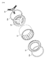
図5はドラム110及びドラム110の前部及び後部に配置されるボールバランサ120を示す断面図である。
FIG. 5 is a cross-sectional view showing the
図5に示すように、ドラム110は、円筒状に形成される円筒部材112と、円筒部材112の前部に配置される前方部材111と、円筒部材112の後部に配置される後方部材113とを含む。
As shown in FIG. 5, the
前方部材111は、円筒部材112の前部で前方部材111の周面が円筒部材112の前方周面の一部と重なってカーリングされるように形成され、円筒部材112に結合固定される。前方部材111には、洗濯物の出し入れのための開口が形成される。
The
前方部材111の外側には前方に突出する段差部が形成され、その段差部にフロントバランサが取り付けられることになる。図5に示すように、フロントボールバランサ120aは、四角形状の断面を有するリング状に形成され、前方部材111の周面に沿って配置される。
A step portion protruding forward is formed on the outside of the
フロントボールバランサ120aの外周面に沿ってフック収容部121及びネジ結合部122が所定の間隔で交互に形成されるので、前方部材111と円筒部材112の重なる部分が、切開されて形成されるフック部114によってフック結合され、ドラム110の外周面に形成される貫通孔115によってネジ結合されることにより、フロントボールバランサ120aとドラム110が固定される。その詳細については後述する。
Since the
また、後方部材113は、前方部材111と同様に、円筒部材112の後部で後方部材113の周面が円筒部材112の後方周面とカーリングされるように形成され、円筒部材112に固定される。後方部材113は、円筒部材112の後部を覆う役割を果たすものであり、円筒部材112の後部に配置される。後方部材113の背面には、回転軸に結合されるスパイダ116が結合され、回転軸を介して駆動モータによる回転力がドラム110に伝達される。
Further, the
後方部材113の外側には後方に突出する段差部が形成され、その段差部にリアバランサを取り付けることができる。リアボールバランサ120bは、フロントボールバランサ120aと同様に、四角形状の断面を有するリング状に形成され、後方部材113の周面に沿って配置される。
A step portion protruding rearward is formed on the outside of the
前述したように、リアボールバランサ120bの外周面に沿ってフック収容部121及びネジ結合部122が所定の間隔で交互に形成されるので、後方部材113と円筒部材112の重なる部分が、切開されて形成されるフック部114によってフック結合され、ドラム110の外周面に形成される貫通孔115によってネジ結合されることにより、リアボールバランサ120bとドラム110が固定される。
As described above, since the
図6はドラム110を前方から見た正面図である。
FIG. 6 is a front view of the
同図において、符号A〜Fはドラム110とボールバランサ120の結合位置を示すものであり、円形のドラム110において60°間隔で配置されている。ただし、これは一例にすぎず、ドラム110とボールバランサ120の結合力を高めるために結合部分をより多く形成してもよい。
In the figure, reference numerals A to F indicate the coupling positions of the
本発明による衣類処理装置100において、ドラム110とボールバランサ120の結合は、ネジ結合及びフック結合が交互に行われることを特徴とする。例えば、A及びDにはネジ結合が行われ、B、C、E、Fにはフック結合が行われるようにしてもよい。フック結合の方がネジ結合より作業者の作業が容易であるという利点があるので、A〜F部分には少なくとも1つのフック結合が行われることが好ましい。
In the garment processing apparatus 100 according to the present invention, the
本発明においては、A〜Fをネジ結合又は/及びフック結合にする構成で様々な実施形態を実現することができる。ただし、ドラム110の回転により発生する遠心力又は振動により予期しない応力が生じることがあるので、各フック結合は、ドラム110の中心を基準として対称となる部分で行われ、各ネジ結合も、ドラム110の中心を基準として対称となる部分で行われることが好ましい。
In the present invention, various embodiments can be realized by a configuration in which A to F are screw-coupled and / and hook-coupled. However, since unexpected stress may occur due to centrifugal force or vibration generated by the rotation of the
ドラム110とボールバランサ120のフック結合においては、ドラム110の外周面の一側が切開され、切開されたドラム110の外周面がドラム110の内部に向かって曲がるように形成されることにより、フック部114を形成するようにしてもよい。フック部114がボールバランサ120の外周面に形成されるフック収容部121に収容されることにより、ドラム110とボールバランサ120が固定される。
In the hook connection between the
ドラム110とボールバランサ120のネジ結合においては、ドラム110の外周面にネジが貫通するように貫通孔115が形成され、ボールバランサ120の外周面に形成されるネジ結合部122にネジが締結されることにより、ドラム110とボールバランサ120が固定される。
In the screw connection between the
図7はボールバランサ120のフック収容部121を示す斜視図である。
FIG. 7 is a perspective view showing the
ボールバランサ120の外周面には、外周面から突設されるフック収容部121が外周面に沿って形成される。フック収容部121は、ボールバランサ120の外周面に少なくとも1つ形成される。ここで、ボールバランサ120とは、フロントボールバランサ120a又はリアボールバランサ120bを意味する。
On the outer peripheral surface of the
フック収容部121は、ドラム110の外周面が切開されてドラム110の内部に曲がったフック部114を収容する。フック部114がフック収容部121に収容されることにより、ドラム110とボールバランサ120が固定される。フック部114がフック収容部121に支持されることにより、ドラム110とボールバランサ120が密着し、ドラム110の回転によるボールバランサ120の前後方向への動きを制限することができる。また、フック収容部121は、外力の作用で曲がったフック部114が嵌められて支持されるように、内側がテーパ状に形成されてもよい。
The
フック収容部121は、第1部材121a、第2部材121b、第3部材121c及び係止部121dを含む。
The
第1部材121aと第2部材121bとは、所定距離離隔して形成される。
The
第1部材121a及び第2部材121bは、ボールバランサ120の外周面から突設されるものであり、ドラム110の回転軸と平行な方向に延びるようにしてもよい。
The
第1部材121aと第2部材121bとの離隔距離は、ドラム110の外周面の切開される幅に応じて決定される。第1部材121a及び第2部材121bは、第1部材121aと第2部材121bとを連結する第3部材121cに接触する部分までボールバランサ120の外周面から突出する高さが高くなるように、折り曲げられた形状に形成されてもよい。
The separation distance between the
第3部材121cは、第1部材121aと第2部材121bとを連結するものであり、ボールバランサ120の外周面から突出した形状を有する。第3部材121cは、ボールバランサ120の外周面から第1部材121a及び第2部材121bの延長方向と交差する方向に突設されてもよい。
The
第3部材121cには、ドラム110の外周面が切開されて形成されるフック部114が係止固定されるように、係止部121dが備えられる。係止部121dは、第3部材121cの中心部に一方向に延びる溝の形状に形成される。
The
係止部121dにフック部114が収容されるので、曲がったフック部114の離脱を防止することができ、ドラム110の回転によるボールバランサ120の前後方向への動きを防止することができる。
Since the
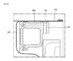
図8a及び図8bはドラムの前部でフック部114がフック収容部121に収容された状態を示す図である。
8a and 8b are views showing a state in which the
図8a及び図8bは円筒部材112及び前方部材111により形成されるドラム110とフロントボールバランサ120aの結合を示す。
8a and 8b show the coupling between the
フック部114は、ドラム110の外周面が所定の形状に切開され、外力によりドラム110の内部に向かって曲がるように形成される。ドラム110は、金属材質からなり、図8aのようにドラム110の外周面が切開されると、切開された面が金属自体の性質により内部に向かって曲がるので、フック部114としての機能を果たすことができる。ここで、ドラム110の外周面とは、前方部材111及び/又は円筒部材112の外周面を意味する。
The
図8aに示すように、フック部114は、前方部材111と円筒部材112の重なる部分が切開されて形成されてもよく、また、フック部114は、前方部材111の外周面又は円筒部材112の外周面からなるようにしてもよい。図8a及び図8bにおいては、円筒部材112の外周面が切開されてフック部114が形成された場合を例に挙げている。
As shown in FIG. 8a, the
図8a及び図8bから分かるように、フック部114は、作業者による外力が作用すると、曲がってフック収容部121の係止部121dに収容されることにより、ドラム110の前面又は背面方向へのボールバランサ120の動きを制限する。よって、フック部114は、所定の長さを有するようにしなければならず、具体的には、フック部114は、フック収容部121の係止部121dまで収容される長さを有するように切開されることが好ましい。
As can be seen from FIGS. 8a and 8b, the
図8bはドラム110の外周面が切開されてフック部114が形成され、外力の作用でフック部114が曲がってフック収容部121に収容された状態を示す。フック部114は、図8aのフック部114とは異なる方向に曲がるように形成されてフック収容部121に収容される。すなわち、図8bにおいては、図8aのドラム110の外周面とは異なる位置が切開され、図8aのフック部114とは異なる位置にフック部114が存在する。図8bのフック部114は、ボールバランサ120を中心として図8aのフック部114に対向する位置に形成されてもよい。
FIG. 8b shows a state in which the outer peripheral surface of the
また、フック部114は、ドラム110の外周面でドラム110の周面に沿って所定の間隔で形成されてもよく、かつ、各フック部114は、異なる方向に曲がるように交互に形成配置されてフック収容部121の係止部121dに支持されてもよい。この場合、同じ方向に曲がるフック部114を構成した場合に比べて、ドラム110とボールバランサ120を効果的に固定することができる。
Further, the
図9a及び図9bはドラムの後部でフック部114がフック収容部121に収容された状態を示す図である。
9a and 9b are views showing a state in which the
図9a及び図9bにおいては、ドラムの後部でフック部114がフック収容部121に収容されるが、この場合、図8a及び図8bに示したものが、円筒部材112及び後方部材113により形成されるドラム110とリアボールバランサ120bの結合に同様に適用される。
In FIGS. 9a and 9b, the
図9a及び図9bに示すように、フック部114は、ドラム110の外周面が所定の形状に切開され、外力が作用すると内部に向かって曲がる。
As shown in FIGS. 9a and 9b, the outer peripheral surface of the
ドラム110は、金属材質からなり、図9aのようにドラム110の外周面が切開されると、金属自体の性質により内部に向かって曲がるので、フック部114としての機能を果たすことができる。ここで、ドラム110の外周面とは、後方部材113及び円筒部材112の外面を意味する。
The
図9aに示すように、フック部114は、後方部材113と円筒部材112の重なる部分が切開されて形成されてもよく、また、フック部114は、後方部材113の外周面又は円筒部材112の外周面からなるようにしてもよい。図9a及び図9bにおいては、円筒部材112の外周面が切開されてフック部114が形成された場合を例に挙げている。
As shown in FIG. 9a, the
図9a及び図9bから分かるように、フック部114は、作業者による外力が作用すると、曲がってフック収容部121の係止部121dに収容されることにより、ドラム110の前面又は背面方向へのボールバランサ120の動きを制限する。よって、フック部114は、所定の長さを有するようにしなければならず、具体的には、フック部114は、フック収容部121の係止部121dまで収容される長さを有するように切開されることが好ましい。
As can be seen from FIGS. 9a and 9b, the
図9bにおいては、図9aと同様に、ドラム110の外周面が切開されてフック部114が形成され、外力が作用するとフック部114が曲がってフック収容部121に収容される。フック部114は、図9aのフック部114とは異なる方向に曲がるように形成されてフック収容部121に収容される。
In FIG. 9b, similarly to FIG. 9a, the outer peripheral surface of the
すなわち、図9bにおいては、図9aのドラム110の外周面とは異なる位置が切開され、図9aのフック部114とは異なる位置にフック部114が存在する。つまり、図9bのフック部114は、ボールバランサ120を中心として図9aのフック部114に対向する位置に形成されてもよい。
That is, in FIG. 9b, a position different from the outer peripheral surface of the
また、フック部114は、ドラム110の外周面でドラム110の周面に沿って所定の間隔で形成されてもよく、かつ、各フック部114は、異なる方向に曲がるように交互に形成配置されてフック収容部121の係止部121dに支持されてもよい。この場合、同じ方向に曲がるフック部114を構成した場合に比べて、ドラム110とボールバランサ120を効果的に固定することができる。
Further, the
図10は四角形状に切開されたフック部114がフック収容部121に収容された状態を示す図である。
FIG. 10 is a diagram showing a state in which the
図8a〜図9bのように、フック部114は、外力によりドラム110の内部に向かって曲がることによりフック収容部121に収容される。
As shown in FIGS. 8a to 9b, the
フック部114は、ドラム110の外周面に四角形状に切開されて形成されてもよい。ここで、各角部は曲線状に形成されてもよい。フック部114の幅の長さは、フック収容部121の幅の長さに対応するように決定されることが好ましい。よって、フック部114の幅の長さは、フック収容部121の第3部材121cの長さに応じて決定され、第3部材121cの両端に配置される第1部材121a及び第2部材121bによりフック部114の離脱が防止される。
The
四角形状になるように1つのエッジ部を除いて切開されているフック部114は、切開されていないエッジ部を中心としてドラム110の回転軸と交差する方向に曲がる。曲がったフック部114がフック収容部121の係止部121dに支持されることにより、ドラム110とボールバランサ120とが固定される。
The
図11はボールバランサ120に形成されたネジ結合部122を示す図である。
FIG. 11 is a diagram showing a
ネジ結合部122は、ボールバランサ120の外周面に沿って所定の間隔で形成されてもよい。ボールバランサ120の外周面には、フック収容部121又はネジ結合部122が所定の間隔で交互に配置される。ボールバランサ120の外周面には、ドラム110の外周面が切開されて形成されるフック部114を収容するためのフック収容部121、及びネジを締結するためのネジ結合部122が外周面に沿って所定の間隔で形成されてもよい。
The
ネジ結合部122は、ネジの挿入のためにドラム110の外周面を貫通するように形成される貫通孔115に対応して配置される。ネジ結合部122は、ネジ結合孔122aを含む。
The
ネジ結合孔122aは、ネジを挿入して固定することができるように、通常、円形に形成される。ネジ結合孔122aには、ボールバランサ120の外周面から突設されるリブ122bが連結される。リブ122bは、ネジ結合孔122aの両側に連結され、ドラム110に覆われるように形成されるのでドラム110の内周面に接触する。リブ122bは、ドラム110の内周面を支持する役割を果たす。リブ122bは、一方向に延設されてもよく、互いに交差する他方向に延設されてもよい。よって、内側に空間部(図示せず)が形成される。
The
図12はフロントボールバランサ120aとドラム110の前方部材111がネジ結合により結合された状態を示し、図13はリアボールバランサ120bとドラム110の後方部材113がネジ結合により結合された状態を示す。
FIG. 12 shows a state in which the front ball balancer 120a and the
フロントボールバランサ120aは、ドラム110の前方部材111が突出して形成される空間部に配置され、リアボールバランサ120bは、ドラム110の後方部材113が突出して形成される空間部に配置される。
The front ball balancer 120a is arranged in a space formed by projecting the
ドラム110の外周面に形成される貫通孔115は、周面に沿って互いに離隔するように複数形成されてもよく、フロントボールバランサ120a及びリアボールバランサ120bの外周面に形成されるネジ結合部122は、周面に沿って互いに離隔するように複数形成されてもよい。
A plurality of through
ここで、フロントボールバランサ120a及びリアボールバランサ120bの外周面に形成されるネジ結合部122とドラム110の外周面に形成される貫通孔115とは重なるように配置され、ネジ結合孔122aにネジが締結されることによりドラム110とボールバランサ120とが固定されて結合される。よって、洗濯工程でのドラム110の回転によるボールバランサ120の前後方向への移動を防止することができる。
Here, the
ただし、ネジ結合によりドラム110とボールバランサ120とを固定することは、ドラム110の外周面にフック部114を形成してボールバランサ120のフック収容部121に収容されるようにすることに比べて、作業に要する時間が長い。よって、ネジ結合及びフック結合を適切に配置している本発明においては、ネジ結合によりドラム110とボールバランサ120とを固定する方法に比べて、同じ結合力を有しながらも作業時間を短縮させることができるという効果が得られる。
However, fixing the
以上説明した衣類処理装置は、上記実施形態の構成や方法に限定されるものではなく、各実施形態の全部又は一部を選択的に組み合わせて構成することで様々に変形することができる。 The garment processing apparatus described above is not limited to the configuration and method of the above-described embodiment, and can be variously modified by selectively combining all or a part of each embodiment.
本発明は、衣類処理装置分野において用いられる。 The present invention is used in the field of garment processing equipment.
Claims (9)
外周面から突設されて前記フック部を収容するフック収容部を備えるボールバランサと、を含み、
前記フック部は、曲がって前記フック収容部に密着し、前記ボールバランサの動きを制限し、
前記フック部は、前記ドラムの外周面に沿って複数形成され、
前記各フック部は、前記フック収容部に嵌められて支持され、
前記複数のフック部のうち、一部は、前記ドラムの前面方向に延びるように内側に曲がり、他の一部は、前記ドラムの背面方向に延びるように内側に曲がり、
前記フック収容部は、前記フック部を係止固定するように中心部から突設される複数の係止部を含み、
前記複数の係止部のうち、一部は、前記ドラムの背面方向に突出し、他の一部は、前記ドラムの前面方向に突出することを特徴とする、衣類処理装置。 A drum with a hook that is formed so that the outer peripheral surface is incised and bends inward.
Including a ball balancer provided with a hook accommodating portion projecting from the outer peripheral surface and accommodating the hook portion.
The hook portion bends and comes into close contact with the hook accommodating portion to limit the movement of the ball balancer.
A plurality of the hook portions are formed along the outer peripheral surface of the drum.
Wherein each hook portion is supported fitted before Symbol hook accommodating portion,
Of the plurality of hook portions, a part is bent inward so as to extend toward the front surface of the drum, and the other part is bent inward so as to extend toward the back surface of the drum.
The hook accommodating portion includes a plurality of locking portions projecting from a central portion so as to lock and fix the hook portion.
A garment processing device, characterized in that a part of the plurality of locking portions projects toward the back surface of the drum and the other portion projects toward the front surface of the drum.
前記フック部及び前記貫通孔は、前記ドラムの周部に沿って交互に形成配置されることを特徴とする、請求項1に記載の衣類処理装置。 The drum is provided with a through hole formed so as to penetrate the outer peripheral surface at a position separated from the hook portion and into which a screw can be inserted.
The garment processing apparatus according to claim 1, wherein the hook portion and the through hole are alternately formed and arranged along the peripheral portion of the drum.
前記ボールバランサの外周面から突設され、前記ドラムの回転軸と平行な方向に延びる第1部材と、
前記ボールバランサの外周面から突設され、前記第1部材に対向するように所定距離離隔して配置される第2部材と、
前記第1部材及び前記第2部材に連結され、前記ボールバランサの外周面から前記第1部材及び前記第2部材の延長方向と交差する方向に突設される第3部材とを含むことを特徴とする、請求項1に記載の衣類処理装置。 The hook accommodating portion
A first member projecting from the outer peripheral surface of the ball balancer and extending in a direction parallel to the rotation axis of the drum.
A second member projecting from the outer peripheral surface of the ball balancer and arranged at a predetermined distance so as to face the first member.
It is characterized by including a third member connected to the first member and the second member and projecting from the outer peripheral surface of the ball balancer in a direction intersecting the extension direction of the first member and the second member. The garment processing apparatus according to claim 1.
Applications Claiming Priority (3)
| Application Number | Priority Date | Filing Date | Title |
|---|---|---|---|
| KR1020160099576A KR102517225B1 (en) | 2016-08-04 | 2016-08-04 | Cloth treating appratus |
| KR10-2016-0099576 | 2016-08-04 | ||
| PCT/KR2017/005277 WO2018026091A1 (en) | 2016-08-04 | 2017-05-22 | Garment processing device |
Publications (2)
| Publication Number | Publication Date |
|---|---|
| JP2019523096A JP2019523096A (en) | 2019-08-22 |
| JP6870068B2 true JP6870068B2 (en) | 2021-05-12 |
Family
ID=59416607
Family Applications (1)
| Application Number | Title | Priority Date | Filing Date |
|---|---|---|---|
| JP2019505421A Active JP6870068B2 (en) | 2016-08-04 | 2017-05-22 | Clothes processing equipment |
Country Status (7)
| Country | Link |
|---|---|
| US (1) | US10988884B2 (en) |
| EP (1) | EP3279388B1 (en) |
| JP (1) | JP6870068B2 (en) |
| KR (1) | KR102517225B1 (en) |
| CN (1) | CN107687067B (en) |
| AU (1) | AU2017306233B2 (en) |
| WO (1) | WO2018026091A1 (en) |
Families Citing this family (4)
| Publication number | Priority date | Publication date | Assignee | Title |
|---|---|---|---|---|
| US11629448B2 (en) * | 2017-03-13 | 2023-04-18 | Midea Group Co., Ltd. | Laundry washing machine with adjustable wash capacity |
| EP3702513B1 (en) * | 2019-02-26 | 2023-04-05 | Electrolux Appliances Aktiebolag | Laundry washing machine |
| EP3702511B1 (en) | 2019-02-26 | 2022-11-09 | Electrolux Appliances Aktiebolag | Laundry washing machine |
| JP2021013692A (en) * | 2019-07-16 | 2021-02-12 | シャープ株式会社 | Washing machine |
Family Cites Families (15)
| Publication number | Priority date | Publication date | Assignee | Title |
|---|---|---|---|---|
| FR2302184A1 (en) | 1975-02-26 | 1976-09-24 | Solvay | PROCE |
| KR0137672Y1 (en) * | 1996-01-31 | 1999-05-15 | 전주범 | A set up structure of balance ring for a washing machine |
| KR19990011168U (en) * | 1997-08-30 | 1999-03-25 | 전주범 | Balancer installation structure of washing machine |
| JP3646046B2 (en) * | 2000-05-17 | 2005-05-11 | 株式会社東芝 | Washing machine dewatering tank |
| CN2536625Y (en) | 2001-12-22 | 2003-02-19 | 海尔集团公司 | Internal tub of washing machine |
| CN2698829Y (en) | 2004-04-05 | 2005-05-11 | 方益民 | Dewatering drum of washing machine |
| KR101371033B1 (en) | 2007-07-25 | 2014-03-10 | 엘지전자 주식회사 | Portable terminal |
| KR101486350B1 (en) | 2008-05-16 | 2015-01-26 | 엘지전자 주식회사 | Cloth Treating Apparutus |
| FR2931170B1 (en) * | 2008-05-16 | 2012-11-02 | Lg Electronics Inc | LAUNDRY MACHINE WITH DRUM AND COUNTERWEIGHT. |
| KR101629672B1 (en) * | 2009-06-29 | 2016-06-14 | 삼성전자 주식회사 | Washing machine and method for manufacturing the same |
| KR101330732B1 (en) * | 2009-10-23 | 2013-11-20 | 삼성전자주식회사 | Washing machine and balancer thereof |
| KR101823618B1 (en) | 2011-10-06 | 2018-02-01 | 삼성전자주식회사 | Washing machine having balancer |
| KR102318153B1 (en) * | 2013-06-27 | 2021-10-28 | 삼성전자주식회사 | Balancer and washing machine having the same |
| DE102013221293A1 (en) * | 2013-10-21 | 2015-04-23 | BSH Bosch und Siemens Hausgeräte GmbH | Method for attaching an imbalance compensation device to a laundry drum, arrangement and household appliance |
| KR101417782B1 (en) | 2013-12-11 | 2014-07-14 | 삼성전자주식회사 | Drum type washing machine |
-
2016
- 2016-08-04 KR KR1020160099576A patent/KR102517225B1/en active IP Right Grant
-
2017
- 2017-05-22 JP JP2019505421A patent/JP6870068B2/en active Active
- 2017-05-22 WO PCT/KR2017/005277 patent/WO2018026091A1/en active Application Filing
- 2017-05-22 AU AU2017306233A patent/AU2017306233B2/en active Active
- 2017-07-26 US US15/660,545 patent/US10988884B2/en active Active
- 2017-07-27 EP EP17183551.5A patent/EP3279388B1/en active Active
- 2017-08-04 CN CN201710660372.0A patent/CN107687067B/en active Active
Also Published As
| Publication number | Publication date |
|---|---|
| EP3279388B1 (en) | 2020-09-02 |
| CN107687067A (en) | 2018-02-13 |
| KR102517225B1 (en) | 2023-04-03 |
| AU2017306233A1 (en) | 2019-03-21 |
| JP2019523096A (en) | 2019-08-22 |
| AU2017306233B2 (en) | 2020-07-09 |
| WO2018026091A1 (en) | 2018-02-08 |
| CN107687067B (en) | 2021-03-02 |
| US20180038034A1 (en) | 2018-02-08 |
| KR20180015941A (en) | 2018-02-14 |
| EP3279388A1 (en) | 2018-02-07 |
| US10988884B2 (en) | 2021-04-27 |
Similar Documents
| Publication | Publication Date | Title |
|---|---|---|
| JP6870068B2 (en) | Clothes processing equipment | |
| JP7084893B2 (en) | Lifter for garment processing equipment | |
| CA2748828C (en) | Laundry machine with reduced drum vibration | |
| US20080148785A1 (en) | Washing Machine | |
| EP3587649B1 (en) | Assembly of washing machines for managing laundry | |
| EP3401433A1 (en) | Clothes treating apparatus | |
| US11479899B2 (en) | Washing machine | |
| US10738408B2 (en) | Clothes treating apparatus | |
| CN107385763B (en) | Washing machine | |
| KR102281193B1 (en) | Lifter for laundary treating apparatus | |
| JP7018623B2 (en) | washing machine | |
| KR102283888B1 (en) | Lifter for laundary treating apparatus | |
| KR102281195B1 (en) | Lifter for laundary treating apparatus | |
| KR102598162B1 (en) | Washing machine | |
| JP7225227B2 (en) | washing machine | |
| US20120186307A1 (en) | Fabric treating machine | |
| KR20160073139A (en) | Top load type washing machine |
Legal Events
| Date | Code | Title | Description |
|---|---|---|---|
| A521 | Request for written amendment filed |
Free format text: JAPANESE INTERMEDIATE CODE: A523 Effective date: 20190219 |
|
| A621 | Written request for application examination |
Free format text: JAPANESE INTERMEDIATE CODE: A621 Effective date: 20190219 |
|
| A977 | Report on retrieval |
Free format text: JAPANESE INTERMEDIATE CODE: A971007 Effective date: 20200214 |
|
| A131 | Notification of reasons for refusal |
Free format text: JAPANESE INTERMEDIATE CODE: A131 Effective date: 20200225 |
|
| A521 | Request for written amendment filed |
Free format text: JAPANESE INTERMEDIATE CODE: A523 Effective date: 20200525 |
|
| A02 | Decision of refusal |
Free format text: JAPANESE INTERMEDIATE CODE: A02 Effective date: 20201006 |
|
| A521 | Request for written amendment filed |
Free format text: JAPANESE INTERMEDIATE CODE: A523 Effective date: 20210203 |
|
| C60 | Trial request (containing other claim documents, opposition documents) |
Free format text: JAPANESE INTERMEDIATE CODE: C60 Effective date: 20210203 |
|
| A911 | Transfer to examiner for re-examination before appeal (zenchi) |
Free format text: JAPANESE INTERMEDIATE CODE: A911 Effective date: 20210216 |
|
| C21 | Notice of transfer of a case for reconsideration by examiners before appeal proceedings |
Free format text: JAPANESE INTERMEDIATE CODE: C21 Effective date: 20210302 |
|
| TRDD | Decision of grant or rejection written | ||
| A01 | Written decision to grant a patent or to grant a registration (utility model) |
Free format text: JAPANESE INTERMEDIATE CODE: A01 Effective date: 20210316 |
|
| A61 | First payment of annual fees (during grant procedure) |
Free format text: JAPANESE INTERMEDIATE CODE: A61 Effective date: 20210414 |
|
| R150 | Certificate of patent or registration of utility model |
Ref document number: 6870068 Country of ref document: JP Free format text: JAPANESE INTERMEDIATE CODE: R150 |
|
| R250 | Receipt of annual fees |
Free format text: JAPANESE INTERMEDIATE CODE: R250 |