JP6869793B2 - Ophthalmic devices, their control methods, and programs - Google Patents

Ophthalmic devices, their control methods, and programs Download PDF

Info

Publication number
JP6869793B2
JP6869793B2 JP2017086353A JP2017086353A JP6869793B2 JP 6869793 B2 JP6869793 B2 JP 6869793B2 JP 2017086353 A JP2017086353 A JP 2017086353A JP 2017086353 A JP2017086353 A JP 2017086353A JP 6869793 B2 JP6869793 B2 JP 6869793B2
Authority
JP
Japan
Prior art keywords
fixation
eye
light
inspected
magnification
Prior art date
Legal status (The legal status is an assumption and is not a legal conclusion. Google has not performed a legal analysis and makes no representation as to the accuracy of the status listed.)
Active
Application number
JP2017086353A
Other languages
Japanese (ja)
Other versions
JP2018183350A (en
JP2018183350A5 (en
Inventor
井上 宏之
宏之 井上
稲生 耕久
耕久 稲生
Current Assignee (The listed assignees may be inaccurate. Google has not performed a legal analysis and makes no representation or warranty as to the accuracy of the list.)
Canon Inc
Original Assignee
Canon Inc
Priority date (The priority date is an assumption and is not a legal conclusion. Google has not performed a legal analysis and makes no representation as to the accuracy of the date listed.)
Filing date
Publication date
Application filed by Canon Inc filed Critical Canon Inc
Priority to JP2017086353A priority Critical patent/JP6869793B2/en
Publication of JP2018183350A publication Critical patent/JP2018183350A/en
Publication of JP2018183350A5 publication Critical patent/JP2018183350A5/ja
Application granted granted Critical
Publication of JP6869793B2 publication Critical patent/JP6869793B2/en
Active legal-status Critical Current
Anticipated expiration legal-status Critical

Links

Images

Description

本発明は、被検眼と対向する位置に配置される対物レンズとして倍率の異なる複数の対物レンズを交換可能に構成された眼科装置及びその制御方法、並びに、当該制御方法をコンピュータに実行させるためのプログラムに関するものである。 The present invention is an ophthalmic apparatus configured so that a plurality of objective lenses having different magnifications can be exchanged as objective lenses arranged at positions facing the eye to be inspected, a control method thereof, and a computer for executing the control method. It's about the program.

現在、眼を観察や撮影等するための眼科装置としては、例えば、前眼部撮影装置、眼底カメラ、共焦点レーザー走査検眼鏡(Scanning Laser Ophthalmoscope:SLO)装置、多波長光波干渉を利用した光干渉断層撮影(Optical Coherence Tomography:OCT)装置等がある。中でも、OCT装置は、被写体の断層画像を高解像度に得ることができるため、眼科装置として網膜の専門外来では必要不可欠な装置になりつつあり、また、眼科用だけでなく内視鏡等にも利用されている。 Currently, ophthalmic devices for observing and photographing the eye include, for example, anterior ocular segment imaging device, fundus camera, confocal laser scanning ophthalmoscope (SLO) device, and light using multi-wavelength optical wave interference. There are optical coherence tomography (OCT) devices and the like. Above all, the OCT device is becoming an indispensable device in the specialized outpatient department of the retina as an ophthalmic device because it can obtain a tomographic image of the subject with high resolution, and it is also used not only for ophthalmology but also for endoscopes and the like. It's being used.

眼科装置としてOCT装置を使用する場合、例えば眼の疾患により、眼底の周辺部まで含むように広範囲を撮影することや眼底の特定の部位を高解像で撮影すること、即ち光学倍率を変更して撮影することが求められている。この点に関して、例えば、特許文献1には、被検眼と対物レンズとの間に変倍用の光学部材を着脱することにより、光学倍率を変更する眼科装置が開示されている。 When an OCT device is used as an ophthalmologic device, for example, due to an eye disease, a wide range may be photographed so as to include the peripheral part of the fundus, or a specific part of the fundus may be imaged with high resolution, that is, the optical magnification may be changed. It is required to take a picture. In this regard, for example, Patent Document 1 discloses an ophthalmic apparatus that changes the optical magnification by attaching and detaching an optical member for variable magnification between the eye to be inspected and the objective lens.

特開2011−147612号公報Japanese Unexamined Patent Publication No. 2011-147612

しかしながら、特許文献1に記載の眼科装置では、変倍用の光学部材を測定光学系に追加するため、被検眼を固視させるための固視標も変倍されてしまう。このため、被検眼を変倍して検査を行う際に、変倍の前後で被検眼の固視を安定させることが困難であるという問題があった。 However, in the ophthalmic apparatus described in Patent Document 1, since an optical member for scaling is added to the measurement optical system, the fixation target for fixing the eye to be inspected is also scaled. For this reason, there is a problem that it is difficult to stabilize the fixation of the eye to be inspected before and after the magnification is changed when the eye to be inspected is magnified for the examination.

本発明は、このような問題点に鑑みてなされたものであり、被検眼を変倍して検査を行う際に、変倍の前後で被検眼の固視を安定させることが可能な仕組みを提供することを目的とする。 The present invention has been made in view of such problems, and provides a mechanism capable of stabilizing the fixation of the eye to be inspected before and after the magnification is changed when the eye to be inspected is magnified for examination. The purpose is to provide.

本発明の眼科装置の一つは、被検眼と対向する位置に配置される対物レンズを介して、前記被検眼を固視させるための固視標を前記被検眼に投影する投影手段であって、前記固視標に係る固視光を発光する発光手段と、前記被検眼に対して前記固視光を走査する走査手段と、を含み構成される投影手段と、前記対物レンズの倍率が変更された場合に、前記走査手段による前記被検眼に対する前記固視光の走査間隔であって、当該倍率の変更に基づく前記固視光の走査間隔の変化が小さくなるように、前記固視光の走査間隔に係る前記投影手段調整を行う調整手段と、を有する。
本発明の眼科装置の一つは、被検眼と対向する位置に配置される対物レンズを介して、前記被検眼を固視させるための固視標を前記被検眼に投影する投影手段であって、前記固視標に係る固視光を発光する発光手段と、前記被検眼に対して前記固視光を走査する走査手段と、を含み構成される投影手段と、前記被検眼を撮影するための光学系における撮影に関する画角の変更に対応する倍率の変更に応じて、前記走査手段による前記被検眼に対する前記固視光の走査間隔であって、当該倍率の変更に基づく前記固視光の走査間隔の変化が小さくなるように、前記固視光の走査間隔に係る前記投影手段の調整を行う調整手段と、を有する。
また、本発明は、上述した眼科装置の制御方法、及び、当該制御方法をコンピュータに実行させるプログラムを含む。
One of the ophthalmic devices of the present invention is a projection means for projecting a fixation target for fixing an eye to be examined onto the eye to be inspected via an objective lens arranged at a position facing the eye to be inspected. A projection means including a light emitting means for emitting the fixation light according to the fixation target and a scanning means for scanning the fixation light with respect to the eye to be inspected, and a magnification of the objective lens are changed. When this is done, the scanning interval of the fixation light with respect to the eye to be inspected by the scanning means is such that the change in the scanning interval of the fixation light due to the change in the magnification is small. It has an adjusting means for adjusting the projection means related to the scanning interval.
One of the ophthalmic devices of the present invention is a projection means for projecting a fixation target for fixing an eye to be examined onto the eye to be inspected via an objective lens arranged at a position facing the eye to be inspected. A projection means including a light emitting means for emitting the fixation light according to the fixation target, a scanning means for scanning the fixation light with respect to the eye to be inspected, and a projection means for photographing the eye to be inspected. The scanning interval of the fixation light with respect to the eye to be inspected by the scanning means according to the change of the magnification corresponding to the change of the image angle related to the photographing in the optical system of the above, and the scanning interval of the fixation light based on the change of the magnification. It has an adjusting means for adjusting the projection means related to the scanning interval of the optometry light so that the change in the scanning interval becomes small.
The present invention also includes the above-mentioned control method for an ophthalmic apparatus and a program for causing a computer to execute the control method.

本発明によれば、被検眼を変倍して検査を行う際に、変倍の前後で被検眼の固視を安定させることができる。 According to the present invention, when the test eye is magnified and the test is performed, the fixation of the eye to be inspected can be stabilized before and after the scaling.

本発明の第1の実施形態に係る眼科装置の全体構成の一例を示す図である。It is a figure which shows an example of the whole structure of the ophthalmic apparatus which concerns on 1st Embodiment of this invention. 本発明の第1の実施形態を示し、図1に示す検査部及びベース部の内部構成の一例を示す図である。It is a figure which shows the 1st Embodiment of this invention, and shows an example of the internal structure of the inspection part and the base part shown in FIG. 本発明の第1の実施形態を示し、図1に示す制御・処理部の内部構成の一例を示す図である。It is a figure which shows the 1st Embodiment of this invention, and shows an example of the internal structure of the control / processing part shown in FIG. 本発明の第1の実施形態に係る眼科装置において、被検眼と対向する位置に低倍率(焦点距離が短く広画角)の対物レンズが配置された場合の光路に係るSLO光学系及び固視標光学系の位置を示す図である。In the ophthalmic apparatus according to the first embodiment of the present invention, the SLO optical system and fixation related to the optical path when a low magnification (short focal length and wide angle of view) objective lens is arranged at a position facing the eye to be inspected. It is a figure which shows the position of the target optical system. 本発明の第1の実施形態に係る眼科装置において、被検眼と対向する位置に高倍率(焦点距離が長く狭画角)の対物レンズが配置された場合の光路に係るSLO光学系及び固視標光学系の位置を示す図である。In the ophthalmic apparatus according to the first embodiment of the present invention, the SLO optical system and fixation related to the optical path when an objective lens having a high magnification (long focal length and narrow angle of view) is arranged at a position facing the eye to be inspected. It is a figure which shows the position of the target optical system. 本発明の第1の実施形態に係る眼科装置の制御方法における処理手順の一例を示すフローチャートである。It is a flowchart which shows an example of the processing procedure in the control method of the ophthalmic apparatus which concerns on 1st Embodiment of this invention. 本発明の第1の実施形態を示し、被検眼と対向する位置に異なる倍率の対物レンズが配置された場合の固視標の一例を示す図である。It is a figure which shows the 1st Embodiment of this invention, and shows an example of the fixation target when the objective lens of a different magnification is arranged at the position facing the eye to be examined. 本発明の第1の実施形態を示し、被検眼と対向する位置に異なる倍率の対物レンズが配置された場合の固視標の一例を示す図である。It is a figure which shows the 1st Embodiment of this invention, and shows an example of the fixation target when the objective lens of a different magnification is arranged at the position facing the eye to be examined. 本発明の第2の実施形態を示し、図1に示す検査部及びベース部の内部構成の一例を示す図である。It is a figure which shows the 2nd Embodiment of this invention and shows an example of the internal structure of the inspection part and the base part shown in FIG. 本発明の第2の実施形態を示し、図9に示す固視標アパーチャの概略構成の一例を示す図である。It is a figure which shows the 2nd Embodiment of this invention and shows an example of the schematic structure of the fixation target aperture shown in FIG. 本発明の第3の実施形態を示し、図9に示す検査部の光路に係る固視標光学系の一例を示す図である。It is a figure which shows the 3rd Embodiment of this invention, and shows an example of the fixation target optical system which concerns on the optical path of the inspection part shown in FIG. 本発明の第4の実施形態を示し、図11に示す固視灯の発光パターンの一例を示す図である。It is a figure which shows the 4th Embodiment of this invention, and shows an example of the light emission pattern of the fixation lamp shown in FIG.

以下に、図面を参照しながら、本発明を実施するための形態(実施形態)について説明する。 Hereinafter, embodiments (embodiments) for carrying out the present invention will be described with reference to the drawings.

(第1の実施形態)
まず、本発明の第1の実施形態について説明する。
(First Embodiment)
First, the first embodiment of the present invention will be described.

<眼科装置10の全体構成>
図1は、本発明の第1の実施形態に係る眼科装置10の全体構成の一例を示す図である。眼科装置10は、図1に示すように、検査部100、制御・処理部200、入力部300、表示部400、ステージ部500、ベース部600、及び、顔受け部700を有して構成されている。
<Overall configuration of ophthalmic apparatus 10>
FIG. 1 is a diagram showing an example of the overall configuration of the ophthalmic apparatus 10 according to the first embodiment of the present invention. As shown in FIG. 1, the ophthalmic apparatus 10 includes an inspection unit 100, a control / processing unit 200, an input unit 300, a display unit 400, a stage unit 500, a base unit 600, and a face receiving unit 700. ing.

検査部100は、制御・処理部200の制御に基づいて、光を被検眼(より詳細に、本実施形態では被検眼の眼底)に照射し、被検眼から反射・散乱してくる戻り光を検出して、各種の画像信号を取得する。 The inspection unit 100 irradiates the eye to be inspected (more specifically, the fundus of the eye to be inspected in this embodiment) with light based on the control of the control / processing unit 200, and emits the return light reflected / scattered from the eye to be inspected. Detect and acquire various image signals.

制御・処理部200は、眼科装置10の動作を統括的に制御するとともに、各種の処理を行う。例えば、制御・処理部200は、検査部100や表示部400、ステージ部500、ベース部600の制御を行うとともに、検査部100で得られた各種の画像信号に対して所定の画像処理等を行う。 The control / processing unit 200 comprehensively controls the operation of the ophthalmic apparatus 10 and performs various processes. For example, the control / processing unit 200 controls the inspection unit 100, the display unit 400, the stage unit 500, and the base unit 600, and performs predetermined image processing or the like on various image signals obtained by the inspection unit 100. Do.

入力部300は、制御・処理部200に対して各種の情報を入力する。この入力部300は、例えば、検者が操作を行うキーボードやマウス等から構成されている。 The input unit 300 inputs various information to the control / processing unit 200. The input unit 300 is composed of, for example, a keyboard, a mouse, or the like operated by the examiner.

表示部400は、制御・処理部200の制御に基づいて、各種の画像や各種の情報等を表示する処理を行う。 The display unit 400 performs processing for displaying various images, various information, and the like based on the control of the control / processing unit 200.

ステージ部500は、制御・処理部200の制御に基づき不図示のモータを介して、検査部100を図1のX方向、Y方向、Z方向に移動させる。 The stage unit 500 moves the inspection unit 100 in the X, Y, and Z directions of FIG. 1 via a motor (not shown) under the control of the control / processing unit 200.

ベース部600は、ステージ部500を介して検査部100を支持するとともに、顔受け部700を支持するものである。また、このベース部600は、図2に示す分光器610を内蔵している。 The base portion 600 supports the inspection portion 100 and the face receiving portion 700 via the stage portion 500. Further, the base portion 600 has a built-in spectroscope 610 shown in FIG.

顔受け部700は、被検者の顔を受けて被検者の顎と額を固定することにより、被検者の眼の固定を促すものである。 The face receiving portion 700 receives the face of the subject and fixes the chin and forehead of the subject to promote the fixation of the eyes of the subject.

≪検査部100及びベース部600の内部構成≫
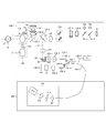
図2は、本発明の第1の実施形態を示し、図1に示す検査部100及びベース部600の内部構成の一例を示す図である。ここで、図2では、第1の実施形態における検査部100を「検査部100−1」として記載している。
<< Internal configuration of inspection unit 100 and base unit 600 >>
FIG. 2 is a diagram showing a first embodiment of the present invention and showing an example of the internal configuration of the inspection unit 100 and the base unit 600 shown in FIG. Here, in FIG. 2, the inspection unit 100 in the first embodiment is described as “inspection unit 100-1”.

まず、図2に示す検査部100−1の内部構成について説明する。 First, the internal configuration of the inspection unit 100-1 shown in FIG. 2 will be described.

図2に示す検査部100−1では、被検眼Eに対向して対物レンズ111が設置され、その光軸上に第1のダイクロイックミラー132−1及び第2のダイクロイックミラー132−2が配置されている。この第1のダイクロイックミラー132−1及び第2のダイクロイックミラー132−2によって、光が、OCT光学系の光路L1、被検眼Eの観察と2次元画像の取得とを兼ねるSLO光学系及び固視標光学系の光路L2、及び、前眼観察光学系の光路L3とに波長帯域ごとに分岐される。 In the inspection unit 100-1 shown in FIG. 2, the objective lens 111 is installed facing the eye E to be inspected, and the first dichroic mirror 132-1 and the second dichroic mirror 132-2 are arranged on the optical axis thereof. ing. By the first dichroic mirror 132-1 and the second dichroic mirror 132-2, the light is the SLO optical system and fixation that combine the observation of the optical path L1 and the eye E to be examined and the acquisition of the two-dimensional image of the OCT optical system. It is branched into the optical path L2 of the target optical system and the optical path L3 of the anterior eye observation optical system for each wavelength band.

ここで、対物レンズ111は、レンズを保持する鏡筒110によって保持されている。鏡筒110には、例えば突起部からなる着脱検知用の目印112が設けられている。対物レンズ検知部131は、例えば近接センサ等によって、鏡筒110の有無を検知する。また、対物レンズ121は、変倍時に使用するレンズであり、具体的に本実施形態においては、対物レンズ111(第1の対物レンズ)よりも高倍率の対物レンズ(第2の対物レンズ)である。この対物レンズ121も、鏡筒120によって保持されており、この鏡筒120には、鏡筒110とは異なる位置に着脱検知用の目印122が設けられている。そして、対物レンズ検知部131は、これらの着脱検知用の目印112及び122を検知することによって、被検眼Eに対向する位置に配置された対物レンズとしてどの倍率の対物レンズが装着されたかを検知することができる。この図2に示すように、本実施形態に係る眼科装置10は、被検眼Eと対向する位置に配置される対物レンズとして倍率の異なる複数の対物レンズ111及び121を交換可能に構成されている。 Here, the objective lens 111 is held by a lens barrel 110 that holds the lens. The lens barrel 110 is provided with, for example, a mark 112 for detecting attachment / detachment, which is formed of a protrusion. The objective lens detection unit 131 detects the presence or absence of the lens barrel 110 by, for example, a proximity sensor or the like. Further, the objective lens 121 is a lens used at the time of variable magnification. Specifically, in the present embodiment, the objective lens 121 is an objective lens (second objective lens) having a higher magnification than the objective lens 111 (first objective lens). is there. The objective lens 121 is also held by the lens barrel 120, and the lens barrel 120 is provided with a mark 122 for detecting attachment / detachment at a position different from that of the lens barrel 110. Then, the objective lens detection unit 131 detects which magnification of the objective lens is attached as the objective lens arranged at the position facing the eye E to be inspected by detecting the marks 112 and 122 for detecting the attachment / detachment. can do. As shown in FIG. 2, the ophthalmic apparatus 10 according to the present embodiment is configured so that a plurality of objective lenses 111 and 121 having different magnifications can be exchanged as objective lenses arranged at positions facing the eye E to be inspected. ..

具体的に、SLO光学系及び固視標光学系の光路L2は、例えば、被検眼Eの眼底Efを観察するために眼底正面画像(SLO画像)を撮像するためのSLO光学系、及び、眼底Efに対して固視標を提示する固視標光学系の光路である。また、OCT光学系の光路L1は、例えば、被検眼Eの眼底Efにおける断層画像(OCT画像)を撮像するためのOCT光学系130の光路である。また、前眼観察光学系の光路L3は、被検眼Eの前眼部を観察するために前眼部画像を撮像するための前眼観察光学系の光路である。 Specifically, the optical paths L2 of the SLO optical system and the fixation target optical system are, for example, an SLO optical system for capturing a fundus frontal image (SLO image) for observing the fundus Ef of the eye E to be inspected, and a fundus. It is an optical path of the fixation target optical system that presents the fixation target to Ef. Further, the optical path L1 of the OCT optical system is, for example, the optical path of the OCT optical system 130 for capturing a tomographic image (OCT image) in the fundus Ef of the eye E to be inspected. Further, the optical path L3 of the anterior eye observation optical system is an optical path of the anterior eye observation optical system for capturing an image of the anterior segment for observing the anterior segment of the eye E to be inspected.

まず、SLO光学系及び固視標光学系の光路L2について説明する。 First, the optical path L2 of the SLO optical system and the fixation target optical system will be described.

光路L2には、リレーレンズ141、SLO走査手段142、レンズ135−4及び135−5、ミラー132−5、第3のダイクロイックミラー132−4、フォトダイオード153、SLO光源152、固視灯(固視標用光源)151が配置されている。 The optical path L2 includes a relay lens 141, an SLO scanning means 142, lenses 135-4 and 135-5, a mirror 132-5, a third dichroic mirror 132-4, a photodiode 153, an SLO light source 152, and a fixation lamp (solid). The optotype light source) 151 is arranged.

ミラー132−5は、穴あきミラーや中空のミラーが蒸着されたプリズムであり、SLO光源152による照明光と、被検眼Eからの戻り光とを分離する。第3のダイクロイックミラー132−4は、光路L2に対して、SLO光源152による照明光と固視灯151による固視光とを波長帯域ごとに分離して出力する。 The mirror 132-5 is a prism on which a perforated mirror or a hollow mirror is vapor-deposited, and separates the illumination light from the SLO light source 152 and the return light from the eye E to be inspected. The third dichroic mirror 132-4 outputs the illumination light by the SLO light source 152 and the fixation light by the fixation lamp 151 separately for each wavelength band to the optical path L2.

SLO走査手段142は、SLO光源152による照明光と固視灯151による固視光とを被検眼Eの眼底Ef上で走査するものである。このSLO走査手段142は、図2のX方向に走査するXスキャナと、図2のY方向に走査するYスキャナを有して構成されている。本実施形態では、Xスキャナは、例えばSLO走査手段142における主走査方向の走査を担うスキャナであり、高速走査を行う必要があるため、例えばポリゴンミラーで構成されている。また、Yスキャナは、例えばSLO走査手段142における副走査方向の走査を担うスキャナであり、例えばガルバノミラーによって構成されている。 The SLO scanning means 142 scans the illumination light from the SLO light source 152 and the fixation light from the fixation lamp 151 on the fundus Ef of the eye E to be inspected. The SLO scanning means 142 includes an X scanner that scans in the X direction of FIG. 2 and a Y scanner that scans in the Y direction of FIG. In the present embodiment, the X scanner is, for example, a scanner responsible for scanning in the main scanning direction in the SLO scanning means 142, and is required to perform high-speed scanning. Therefore, the X scanner is composed of, for example, a polygon mirror. Further, the Y scanner is, for example, a scanner responsible for scanning in the sub-scanning direction in the SLO scanning means 142, and is configured by, for example, a galvano mirror.

SLOフォーカスレンズ135−4は、SLO光源152による照明光及び固視灯151による固視光の焦点合わせのため、例えば不図示のモータによって駆動される。固視灯151は、可視光である固視光を被検眼Eに照射することにより、被検眼Eの眼底Efに当該固視光に基づく固視標を提示して、被検眼の固視を促すためのものである。SLO光源152は、例えば780nm付近の波長の光を発生する。 The SLO focus lens 135-4 is driven by, for example, a motor (not shown) for focusing the illumination light by the SLO light source 152 and the fixation light by the fixation lamp 151. The fixation lamp 151 irradiates the eye E to be examined with visible light, thereby presenting an fixation target based on the fixation light to the fundus Ef of the eye E to obtain the fixation of the eye to be inspected. It is for encouraging. The SLO light source 152 generates light having a wavelength in the vicinity of, for example, 780 nm.

SLO光源152から発せられた照明光は、第3のダイクロイックミラー132−4で反射され、ミラー132−5を通過した後、レンズ135−5、SLOフォーカスレンズ135−4を通り、SLO走査手段142によって、被検眼Eの眼底Ef上で走査される。そして、被検眼Eの眼底Efからの戻り光は、照明光と同じ経路を辿った後、ミラー132−5によって反射され、フォトダイオード153へと導かれる。フォトダイオード153は、被検眼Eの眼底Efからの戻り光を検出して、SLO画像信号を取得する。 The illumination light emitted from the SLO light source 152 is reflected by the third dichroic mirror 132-4, passes through the mirror 132-5, passes through the lens 135-5 and the SLO focus lens 135-4, and passes through the SLO scanning means 142. Is scanned on the fundus Ef of the eye E to be inspected. Then, the return light from the fundus Ef of the eye E to be inspected follows the same path as the illumination light, is reflected by the mirror 132-5, and is guided to the photodiode 153. The photodiode 153 detects the return light from the fundus Ef of the eye E to be inspected and acquires the SLO image signal.

また、固視灯151から発せられた固視光は、第3のダイクロイックミラー132−4、ミラー132−5を透過した後、レンズ135−5、SLOフォーカスレンズ135−4を通り、SLO走査手段142によって、被検眼Eの眼底Ef上で走査される。このとき、SLO走査手段142の動きに合わせて固視灯151を点滅させることによって、被検眼Eの眼底Ef上の任意の位置に任意の形状の固視標を形成することが可能になり、被検者の固視を促すことができる。 Further, the optometry light emitted from the optometry lamp 151 passes through the third dichroic mirror 132-4 and the mirror 132-5, and then passes through the lens 135-5 and the SLO focus lens 135-4, and is passed through the SLO scanning means. The 142 scans on the fundus Ef of the eye E to be inspected. At this time, by blinking the fixation lamp 151 in accordance with the movement of the SLO scanning means 142, it becomes possible to form an fixation target of an arbitrary shape at an arbitrary position on the fundus Ef of the eye E to be inspected. It is possible to encourage the subject to fix his eyes.

続いて、OCT光学系の光路L1について説明する。 Subsequently, the optical path L1 of the OCT optical system will be described.

OCT光学系の光路L1は、被検眼Eを光干渉断層撮影するための光学系であるOCT光学系130の光路である。より具体的には、被検眼の断層画像(OCT画像)を形成するための干渉信号を得るための光路である。 The optical path L1 of the OCT optical system is the optical path of the OCT optical system 130, which is an optical system for taking an optical coherence tomography of the eye E to be inspected. More specifically, it is an optical path for obtaining an interference signal for forming a tomographic image (OCT image) of the eye to be inspected.

OCT光学系の光路L1には、まず、リレーレンズ133、OCT走査手段134、シャッター136、OCTフォーカスレンズ135−1、レンズ135−2が配置されている。OCT走査手段134は、OCT光源101からの光(測定光)を被検眼Eの眼底Er上で走査するためのXYスキャナを具備して構成されている。OCT走査手段134は、図2に示す例では1枚のミラーとして図示してあるが、X方向及びY方向の走査を行うものである。シャッター136は、不図示の駆動機構によって光路L1に挿入や退避が可能となっている。OCTフォーカスレンズ135−1は、光カプラー103に接続されている光ファイバー102−2のファイバー端105−1から出射されるOCT光源101からの光(測定光)を、被検眼Eの眼底Efに対して焦点合わせするためのフォーカス調整部材である。このOCTフォーカスレンズ135−1は、制御・処理部200の制御に基づく不図示のモータによって駆動される。 First, a relay lens 133, an OCT scanning means 134, a shutter 136, an OCT focus lens 135-1, and a lens 135-2 are arranged in the optical path L1 of the OCT optical system. The OCT scanning means 134 is configured to include an XY scanner for scanning the light (measurement light) from the OCT light source 101 on the fundus Er of the eye E to be inspected. Although the OCT scanning means 134 is shown as a single mirror in the example shown in FIG. 2, it scans in the X direction and the Y direction. The shutter 136 can be inserted and retracted into the optical path L1 by a drive mechanism (not shown). The OCT focus lens 135-1 directs the light (measurement light) from the OCT light source 101 emitted from the fiber end 105-1 of the optical fiber 102-2 connected to the optical coupler 103 to the fundus Ef of the eye E to be inspected. It is a focus adjusting member for focusing. The OCT focus lens 135-1 is driven by a motor (not shown) based on the control of the control / processing unit 200.

このOCTフォーカスレンズ135−1による焦点合わせによって、被検眼Eの眼底Efからの戻り光は、同時に、光ファイバー102−2のファイバー端105−1にスポット状に結像されて入射されることとなる。さらに、OCT光学系の光路L1には、光カプラー103、OCT光源101、光ファイバー102−1〜102−4、レンズ135−3、分散補償用ガラス137、及び、参照ミラー132−3が配置されている。光ファイバー102−1〜102−4は、例えば、光カプラー103に接続され一体化しているシングルモードの光ファイバーである。また、光ファイバー102−4には、ベース部600の内部構成された分光器610が接続されている。以上の構成によって、マイケルソン干渉系が構成されている。 By focusing with the OCT focus lens 135-1, the return light from the fundus Ef of the eye E to be inspected is simultaneously imaged and incident on the fiber end 105-1 of the optical fiber 102-2 in a spot shape. .. Further, an optical coupler 103, an OCT light source 101, an optical fiber 102-1 to 102-4, a lens 135-3, a dispersion compensation glass 137, and a reference mirror 132-3 are arranged in the optical path L1 of the OCT optical system. There is. The optical fibers 102-1 to 102-4 are, for example, single-mode optical fibers connected to and integrated with the optical coupler 103. Further, the spectroscope 610 internally configured in the base portion 600 is connected to the optical fiber 102-4. The Michelson interference system is configured by the above configuration.

OCT光源101は、例えば、代表的な低コヒーレント光源であるSLD(Super Luminescent Diode)で構成されている。OCT光源101の光の中心波長は855nm程度であり、波長バンド幅は約100nm程度である。ここで、バンド幅は、得られる断層画像の光軸方向の分解能に影響するため、重要なパラメータである。また、ここでは、OCT光源101としてSLDを適用した例を説明したが、低コヒーレント光が出射できる光源であればよく、例えばASE(Amplified Spontaneous Emission)等を用いることもできる。また、OCT光源101の光の中心波長は被検眼Eを測定することに鑑みると近赤外光が適する。また、OCT光源101の光の中心波長は、得られる断層画像の横方向の分解能に影響するため、なるべく短波長であることが望ましい。この双方の理由から、実施形態においては、OCT光源101の光の中心波長を855nm程度とした。また、本実施形態では、マイケルソン干渉系を適用する例について説明したが、例えばマッハツェンダー干渉系を用いてもよい。例えば、測定光と参照光との光量差に応じて、光量差が大きい場合にはマッハツェンダー干渉系を用い、光量差が比較的小さい場合にはマイケルソン干渉計を用いることが望ましい。 The OCT light source 101 is composed of, for example, an SLD (Super Luminate Diode) which is a typical low coherent light source. The central wavelength of the light of the OCT light source 101 is about 855 nm, and the wavelength bandwidth is about 100 nm. Here, the bandwidth is an important parameter because it affects the resolution of the obtained tomographic image in the optical axis direction. Further, although an example in which SLD is applied as the OCT light source 101 has been described here, any light source capable of emitting low coherent light may be used, and for example, ASE (Amplified Spontaneous Emission) or the like can be used. Further, as the central wavelength of the light of the OCT light source 101, near infrared light is suitable in view of measuring the eye E to be inspected. Further, since the central wavelength of the light of the OCT light source 101 affects the lateral resolution of the obtained tomographic image, it is desirable that the wavelength is as short as possible. For both of these reasons, in the embodiment, the central wavelength of the light of the OCT light source 101 is set to about 855 nm. Further, in the present embodiment, an example of applying the Michelson interference system has been described, but for example, a Mach-Zehnder interference system may be used. For example, it is desirable to use a Mach-Zehnder interference system when the light amount difference is large, and to use a Michelson interferometer when the light amount difference is relatively small, depending on the light amount difference between the measurement light and the reference light.

光カプラー103は、光ファイバー102−1を介してOCT光源101から出射された光を測定光と参照光とに分岐する分岐部材である。光カプラー103で分岐された測定光は、光ファイバー102−2及び対物レンズを介して、観察対象である被検眼Eの眼底Efに向けて出射される。眼底Erに照射された測定光は、眼底Erにおいて反射・散乱し、同じ光路を通じて光カプラー103に達する。一方、参照光は、光ファイバー102−3を経由して、レンズ135−3、分散補償用ガラス137を通り、参照ミラー132−3に向けて出射される。参照ミラー132−3に照射された参照光は、参照ミラー132−3で反射して同じ光路を通じて光カプラー103に達する。 The optical coupler 103 is a branching member that branches the light emitted from the OCT light source 101 via the optical fiber 102-1 into the measurement light and the reference light. The measurement light branched by the optical coupler 103 is emitted toward the fundus Ef of the eye E to be observed via the optical fiber 102-2 and the objective lens. The measurement light applied to the fundus Er is reflected and scattered in the fundus Er and reaches the optical coupler 103 through the same optical path. On the other hand, the reference light passes through the optical fiber 102-3, passes through the lens 135-3 and the dispersion compensation glass 137, and is emitted toward the reference mirror 132-3. The reference light emitted to the reference mirror 132-3 is reflected by the reference mirror 132-3 and reaches the optical coupler 103 through the same optical path.

このようにして、光カプラー103に達した測定光と参照光とは、光カプラー103において合波されて干渉光となる。ここで、測定光の光路長と参照光の光路長とが、ほぼ同一となったときに干渉を生じる。参照ミラー132−3は、制御・処理部200の制御に基づく不図示のモータ及び駆動機構によって光軸方向に調整可能に保持されており、被検眼Eによって変わる測定光の光路長に参照光の光路長を合わせることが可能となっている。即ち、参照ミラー132−3は、参照光の光路長を調整する参照光調整部材を構成する。 In this way, the measurement light and the reference light that have reached the optical coupler 103 are combined in the optical coupler 103 to become interference light. Here, interference occurs when the optical path length of the measurement light and the optical path length of the reference light are substantially the same. The reference mirror 132-3 is held so as to be adjustable in the optical axis direction by a motor and a drive mechanism (not shown) based on the control of the control / processing unit 200, and the reference light has an optical path length of the measurement light that changes depending on the eye E to be inspected. It is possible to match the optical path length. That is, the reference mirror 132-3 constitutes a reference light adjusting member that adjusts the optical path length of the reference light.

また、光ファイバー102−2には測定光側の偏光調整部104−1が設けられ、光ファイバー102−3には参照光側の偏光調整部104−2が設けられている。これらの偏光調整部104−1及び104−2は、光ファイバーをループ状に引き回した部分を幾つか持ち、このループ状の部分を光ファイバーの長手方向を中心として回動させることで光ファイバーに捩じりを加えて、対応する測定光と参照光の偏光状態を各々調整して合わせることが可能となっている。 Further, the optical fiber 102-2 is provided with a polarization adjusting unit 104-1 on the measurement light side, and the optical fiber 102-3 is provided with a polarization adjusting unit 104-2 on the reference light side. These polarization adjusting units 104-1 and 104-2 have several portions in which the optical fiber is routed in a loop shape, and the loop-shaped portions are rotated around the longitudinal direction of the optical fiber to twist the optical fiber. In addition, it is possible to adjust and match the polarization states of the corresponding measurement light and the reference light.

続いて、前眼観察光学系の光路L3について説明する。 Subsequently, the optical path L3 of the anterior eye observation optical system will be described.

前眼観察光学系の光路L3には、レンズ135−6、スプリットプリズム161、レンズ135−7、赤外光を検知する前眼部観察用のCCD162が配置されている。CCD162は、不図示の前眼観察用照射光源の光の波長、具体的には970nm付近に感度を持つものである。スプリットプリズム161は、被検眼Eの瞳孔と共役な位置に配置されており、被検眼Eに対する検査部100−1のZ方向(前後方向)の距離を、前眼部のスプリット像として検出するためのものである。 A lens 135-6, a split prism 161 and a lens 135-7, and a CCD 162 for observing the anterior segment of the eye for detecting infrared light are arranged in the optical path L3 of the anterior segment observation optical system. The CCD 162 has a sensitivity in the wavelength of light of an irradiation light source for frontal eye observation (not shown), specifically in the vicinity of 970 nm. The split prism 161 is arranged at a position conjugate with the pupil of the eye E to be inspected, and is for detecting the distance of the inspection unit 100-1 to the eye E to be inspected in the Z direction (anterior-posterior direction) as a split image of the anterior eye portion. belongs to.

次いで、図2に示すベース部600の内部構成について説明する。 Next, the internal configuration of the base portion 600 shown in FIG. 2 will be described.

ベース部600の内部には、分光器610が設けられている。この分光器610は、レンズ611、回折格子612、レンズ613、及び、ラインセンサ614を有して構成されている。 A spectroscope 610 is provided inside the base portion 600. The spectroscope 610 includes a lens 611, a diffraction grating 612, a lens 613, and a line sensor 614.

光カプラー103で生成された干渉光は、光ファイバー102−4を介して分光器610に導かれる。具体的に、光ファイバー102−4から出射された干渉光は、レンズ611を介して平行光となった後、回折格子612で分光され、レンズ613によってラインセンサ614に結像される。ラインセンサ614は、この干渉光を検出して、OCT画像信号を取得する。 The interference light generated by the optical coupler 103 is guided to the spectroscope 610 via the optical fiber 102-4. Specifically, the interference light emitted from the optical fiber 102-4 becomes parallel light through the lens 611, is separated by the diffraction grating 612, and is imaged on the line sensor 614 by the lens 613. The line sensor 614 detects this interference light and acquires an OCT image signal.

なお、本実施形態においては、OCT光学系130は、被検眼Eの眼底Efの断層画像を撮影するための構成例を示すが、本発明においてはこれに限定されるものではなく、例えば角膜等の被検眼Eの前眼部の断層画像を撮影するための構成であってもよい。上述したように、OCT光学系130において、OCT光源101からの光は、光カプラー103によって測定光と参照光とに分けられる。そして、測定光は、光ファイバー102−2及び対物レンズを介して、観察対象である被検眼Eの眼底Efに向けて出射される。そして、眼底Efからの測定光の戻り光は、光カプラー103において参照ミラー132−3で反射された参照光と合波され、干渉光として分光器610に導かれる。なお、ここで述べる戻り光とは、観察対象である被検眼Eの眼底Efに対する光の照射方向における界面に関する情報等が含まれる反射光や散乱光のことである。そして、戻り光と参照光との干渉光を分光器610で検出し、解析することによって眼底Efの断層画像を得ることができる。この際、被検眼Eの狙った領域を撮影するためには、被検眼Eの2次元画像の取得と、被検眼Eの眼球運動の抑制が重要である。そのため、眼科装置10では、OCT光学系とSLO光学系と固視標光学系とを1つの対物レンズで実現し、装置の簡素化を図っている。また、眼科装置10では、被検眼Eの疾患の観点から、被検眼Eの眼底Efの周辺部まで含む広範囲を撮影すること、及び、眼底Efの特定の部位を高解像で撮影することを実現すべく、被検眼Eと対向する位置に配置される1つの対物レンズとして倍率の異なる複数の対物レンズを交換可能に構成されている。 In the present embodiment, the OCT optical system 130 shows a configuration example for capturing a tomographic image of the fundus Ef of the eye E to be inspected, but the present invention is not limited to this, for example, the cornea and the like. It may be configured to take a tomographic image of the anterior segment of the eye E to be inspected. As described above, in the OCT optical system 130, the light from the OCT light source 101 is divided into measurement light and reference light by the optical coupler 103. Then, the measurement light is emitted toward the fundus Ef of the eye E to be observed through the optical fiber 102-2 and the objective lens. Then, the return light of the measurement light from the fundus Ef is combined with the reference light reflected by the reference mirror 132-3 in the optical coupler 103, and is guided to the spectroscope 610 as interference light. The return light described here is reflected light or scattered light that includes information about the interface in the irradiation direction of light with respect to the fundus Ef of the eye E to be observed. Then, a tomographic image of the fundus Ef can be obtained by detecting and analyzing the interference light between the return light and the reference light with the spectroscope 610. At this time, in order to photograph the target area of the eye E to be inspected, it is important to acquire a two-dimensional image of the eye E to be inspected and to suppress the eye movement of the eye E to be inspected. Therefore, in the ophthalmic apparatus 10, the OCT optical system, the SLO optical system, and the fixation target optical system are realized by one objective lens, and the apparatus is simplified. Further, in the ophthalmic apparatus 10, from the viewpoint of the disease of the eye E, a wide range including the peripheral portion of the fundus Ef of the eye E is photographed, and a specific part of the fundus Ef is photographed with high resolution. In order to realize this, a plurality of objective lenses having different magnifications are interchangeably configured as one objective lens arranged at a position facing the eye E to be inspected.

≪制御・処理部200の内部構成≫
図3は、本発明の第1の実施形態を示し、図1に示す制御・処理部200の内部構成の一例を示す図である。なお、図3において、図1及び図2に示す構成と同様の構成については同じ符号を付している。
<< Internal configuration of control / processing unit 200 >>
FIG. 3 is a diagram showing a first embodiment of the present invention and showing an example of the internal configuration of the control / processing unit 200 shown in FIG. In FIG. 3, the same reference numerals are given to the configurations similar to those shown in FIGS. 1 and 2.

制御・処理部200は、図3に示すように、中央演算装置(CPU)210、固定ディスク装置(HDD)220、主記憶装置(メモリ)230、ユーザーインターフェース240、OCTスキャナ制御部250、OCTスキャナ(X)ドライバ251、OCTスキャナ(Y)ドライバ252、SLOスキャナ制御部260、SLOスキャナ(X)ドライバ261、SLOスキャナ(Y)ドライバ262、モータドライバ270、及び、固視標制御部280を有して構成されている。 As shown in FIG. 3, the control / processing unit 200 includes a central computing device (CPU) 210, a fixed disk device (HDD) 220, a main storage device (memory) 230, a user interface 240, an OCT scanner control unit 250, and an OCT scanner. It has (X) driver 251 and OCT scanner (Y) driver 252, SLO scanner control unit 260, SLO scanner (X) driver 261, SLO scanner (Y) driver 262, motor driver 270, and fixation target control unit 280. It is composed of.

CPU210は、表示部400、HDD220、メモリ230、ユーザーインターフェース240と接続されている。さらに、CPU210は、OCTスキャナ制御部250、SLOスキャナ制御部260、モータドライバ270、固視標制御部280、フォトダイオード153、ラインセンサ614と接続されている。 The CPU 210 is connected to the display unit 400, the HDD 220, the memory 230, and the user interface 240. Further, the CPU 210 is connected to the OCT scanner control unit 250, the SLO scanner control unit 260, the motor driver 270, the fixation target control unit 280, the photodiode 153, and the line sensor 614.

CPU210は、OCT走査手段134の走査波形を生成するOCTスキャナ制御部250を制御する。そして、OCTスキャナ制御部250は、CPU210の制御に基づいて、OCTスキャナ(X)ドライバ251及びOCTスキャナ(Y)ドライバ252を制御することにより、OCT走査手段134の駆動を制御する。 The CPU 210 controls the OCT scanner control unit 250 that generates the scanning waveform of the OCT scanning means 134. Then, the OCT scanner control unit 250 controls the drive of the OCT scanning means 134 by controlling the OCT scanner (X) driver 251 and the OCT scanner (Y) driver 252 based on the control of the CPU 210.

また、CPU210は、SLO走査手段142の走査波形を生成するSLOスキャナ制御部260を制御する。そして、SLOスキャナ制御部260は、CPU210の制御に基づいて、SLOスキャナ(X)ドライバ261及びSLOスキャナ(Y)ドライバ262を制御することにより、SLO走査手段142の駆動を制御する。具体的に、SLOスキャナ制御部260は、SLOスキャナ(X)ドライバ261及びSLOスキャナ(Y)ドライバ262を介してSLO走査手段142の駆動を制御することにより、被検眼Eの眼底Efを照明光で2次元的に走査する。これにより、フォトダイオード153では、眼底Efの2次元画像であるSLO画像の信号を取得することができる。 Further, the CPU 210 controls the SLO scanner control unit 260 that generates the scanning waveform of the SLO scanning means 142. Then, the SLO scanner control unit 260 controls the drive of the SLO scanning means 142 by controlling the SLO scanner (X) driver 261 and the SLO scanner (Y) driver 262 based on the control of the CPU 210. Specifically, the SLO scanner control unit 260 controls the drive of the SLO scanning means 142 via the SLO scanner (X) driver 261 and the SLO scanner (Y) driver 262 to illuminate the fundus Ef of the eye E to be inspected. Scan two-dimensionally with. As a result, the photodiode 153 can acquire the signal of the SLO image, which is a two-dimensional image of the fundus Ef.

さらに、CPU210は、モータドライバ270を介して、OCTフォーカスレンズ135−1、SLOフォーカスレンズ135−4、参照ミラー132−3を駆動する不図示のモータの駆動を制御する。 Further, the CPU 210 controls the drive of a motor (not shown) that drives the OCT focus lens 135-1, the SLO focus lens 135-4, and the reference mirror 132-3 via the motor driver 270.

さらに、CPU210は、固視灯151の発光制御を行う固視標制御部280を制御する。そして、固視標制御部280は、CPU210の制御に基づいて、固視灯151の発光制御を行う。具体的に、本実施形態においては、プレビュー時のSLO画像取得に必要な初期撮像領域及び走査線間隔の情報を、予めメモリ230に記憶させておく。そして、固視標制御部280は、SLO画像の初期撮像領域または部分領域のフレームレート及び走査線間隔に基づき、SLO走査手段142が眼底Er上の所望の位置を光で走査するタイミングに合わせて固視灯151を発光(点灯)させ、眼底Er上の任意の位置に任意の固視標を形成する。 Further, the CPU 210 controls the fixation target control unit 280 that controls the light emission of the fixation lamp 151. Then, the fixation target control unit 280 controls the light emission of the fixation lamp 151 based on the control of the CPU 210. Specifically, in the present embodiment, the information of the initial imaging area and the scanning line spacing necessary for acquiring the SLO image at the time of preview is stored in the memory 230 in advance. Then, the fixation target control unit 280 adjusts to the timing at which the SLO scanning means 142 scans a desired position on the fundus Er with light based on the frame rate and the scanning line spacing of the initial imaging region or partial region of the SLO image. The fixation lamp 151 is made to emit light (lights up) to form an arbitrary fixation target at an arbitrary position on the fundus Er.

さらに、CPU210は、SLO画像信号を取得するフォトダイオード153を制御して、フォトダイオード153からSLO画像信号を取得するとともに、当該SLO画像信号の画像処理等を行う。 Further, the CPU 210 controls the photodiode 153 that acquires the SLO image signal, acquires the SLO image signal from the photodiode 153, and performs image processing of the SLO image signal and the like.

また、CPU210は、OCT画像信号を取得するラインセンサ614を制御して、ラインセンサ614からOCT画像信号を取得するとともに、当該OCT画像信号の画像処理等を行う。具体的に、本実施形態においては、CPU210は、ラインセンサ614から得られるOCT画像信号をフーリエ変換し、得られる信号を輝度或いは濃度情報に変換することによって被検眼Eの深さ方向(Z方向)の断層画像を生成する。このようなスキャン方式をAスキャンと呼び、得られる断層画像をAスキャン画像と呼ぶ。このAスキャンを被検眼Eの所定の横断方向にOCT走査手段134を用いて行うことにより、複数のAスキャン画像を取得することができる。例えば、X方向にOCT走査手段134を走査すればXZ面における断層画像が得られ、Y方向にOCT走査手段134を走査すればYZ面における断層画像が得られる。このように被検眼Eを所定の横断方向に走査する方式をBスキャンと呼び、得られる断層画像をBスキャン画像と呼ぶ。 Further, the CPU 210 controls the line sensor 614 to acquire the OCT image signal, acquires the OCT image signal from the line sensor 614, and performs image processing of the OCT image signal and the like. Specifically, in the present embodiment, the CPU 210 Fourier transforms the OCT image signal obtained from the line sensor 614 and converts the obtained signal into luminance or density information in the depth direction (Z direction) of the eye E to be inspected. ) Generate a tomographic image. Such a scanning method is called an A scan, and the obtained tomographic image is called an A scan image. By performing this A scan in a predetermined transverse direction of the eye E to be inspected by using the OCT scanning means 134, a plurality of A scan images can be acquired. For example, scanning the OCT scanning means 134 in the X direction gives a tomographic image on the XZ plane, and scanning the OCT scanning means 134 in the Y direction gives a tomographic image on the YZ plane. The method of scanning the eye E to be examined in a predetermined transverse direction in this way is called a B scan, and the obtained tomographic image is called a B scan image.

メモリ230は、例えばCPU210が処理を実行するためのプログラムや各種の情報等を予め記憶するとともに、CPU210の処理によって得られた各種の情報等を記憶する。例えば、メモリ230は、被検眼Eと対向する位置に配置され得る異なる倍率の対物レンズ111及び121と、各種のパラメータとの対応関係を示すテーブル情報を記憶している。さらに、メモリ230は、被検眼Eに係る被検者情報等も記憶している。 The memory 230 stores, for example, a program for the CPU 210 to execute a process, various information, and the like in advance, and also stores various information and the like obtained by the process of the CPU 210. For example, the memory 230 stores table information showing the correspondence between the objective lenses 111 and 121 having different magnifications that can be arranged at positions facing the eye E to be inspected and various parameters. Further, the memory 230 also stores the subject information and the like related to the eye E to be examined.

次いで、眼科装置10による断層画像の撮影方法について説明する。
眼科装置10は、OCT走査手段134を制御することで、被検眼Eの眼底Efの所定部位の断層画像を撮影することができる。
Next, a method of photographing a tomographic image by the ophthalmic apparatus 10 will be described.
By controlling the OCT scanning means 134, the ophthalmic apparatus 10 can take a tomographic image of a predetermined portion of the fundus Ef of the eye E to be inspected.

まず、CPU210は、OCT走査手段134を制御して測定光をX方向に走査し、眼底EfにおけるX方向の撮影範囲から所定の走査数に係るOCT画像信号をラインセンサ614で取得する。そして、CPU210は、X方向のある位置で得られるラインセンサ614のOCT画像信号の輝度分布を高速フーリエ変換(Fast Fourier Transform:FFT)し、FFTで得られた線状の輝度分布を表示部400に示すために濃度或いはカラー情報に変換する。本実施形態では、これがAスキャン画像に相当し、この複数のAスキャン画像を並べた2次元画像がBスキャン画像に相当する。そして、CPU210は、1つのBスキャン画像を構築するための複数のAスキャン画像を取得した後、Y方向の走査位置を移動させて再びX方向の走査を行うことにより、複数のBスキャン画像を取得する。そして、CPU210は、複数のBスキャン画像或いは複数のBスキャン画像から構築した3次元画像を表示部400に表示することにより、検者による被検眼Eの診断に用いることができる。ここでは、X方向に走査を行うことによりBスキャン画像を取得する例について説明をしたが、本実施形態においてはこれに限定されるものではなく、Y方向に走査を行うことによりBスキャン画像を取得するようにしてもよい。また、X方向及びY方向の双方の走査によって任意の走査パターンを形成し、Bスキャン画像を取得するようにしてもよい。 First, the CPU 210 controls the OCT scanning means 134 to scan the measurement light in the X direction, and acquires an OCT image signal related to a predetermined number of scans from the imaging range in the X direction on the fundus Ef with the line sensor 614. Then, the CPU 210 performs a fast Fourier transform (FFT) on the luminance distribution of the OCT image signal of the line sensor 614 obtained at a certain position in the X direction, and displays the linear luminance distribution obtained by the FFT on the display unit 400. Convert to density or color information to show. In the present embodiment, this corresponds to an A-scan image, and a two-dimensional image in which the plurality of A-scan images are arranged corresponds to a B-scan image. Then, the CPU 210 acquires a plurality of A-scan images for constructing one B-scan image, then moves the scanning position in the Y direction and scans in the X-direction again to obtain the plurality of B-scan images. get. Then, the CPU 210 can be used for the diagnosis of the eye E to be inspected by the examiner by displaying the plurality of B-scan images or the three-dimensional image constructed from the plurality of B-scan images on the display unit 400. Here, an example of acquiring a B-scan image by scanning in the X direction has been described, but the present embodiment is not limited to this, and the B-scan image is obtained by scanning in the Y direction. You may try to get it. Further, an arbitrary scanning pattern may be formed by scanning in both the X direction and the Y direction, and a B scan image may be acquired.

<固視標の変更制御>
次に、対物レンズの倍率変更に伴う固視標の変更制御について説明を行う。
<Control of change of fixation target>
Next, the control of changing the fixation target when the magnification of the objective lens is changed will be described.

図4は、本発明の第1の実施形態に係る眼科装置10において、被検眼Eと対向する位置に低倍率(焦点距離が短く広画角)の対物レンズ111が配置された場合の光路L2に係るSLO光学系及び固視標光学系の位置を示す図である。また、図5は、本発明の第1の実施形態に係る眼科装置10において、被検眼Eと対向する位置に対物レンズ111よりも高倍率(焦点距離が長く狭画角)の対物レンズ121が配置された場合の光路L2に係るSLO光学系及び固視標光学系の位置を示す図である。この図4及び図5において、図2に示す構成と同様の構成については同じ符号を付している。また、図4と図5では、SLOフォーカスレンズ135−4が異なる位置に配置されている。 FIG. 4 shows an optical path L2 when an objective lens 111 having a low magnification (a short focal length and a wide angle of view) is arranged at a position facing the eye E to be inspected in the ophthalmic apparatus 10 according to the first embodiment of the present invention. It is a figure which shows the position of the SLO optical system and the optometry objective optical system which concerns on. Further, FIG. 5 shows an objective lens 121 having a higher magnification (longer focal length and narrower angle of view) than the objective lens 111 at a position facing the eye E to be inspected in the ophthalmic apparatus 10 according to the first embodiment of the present invention. It is a figure which shows the position of the SLO optical system and the fixation target optical system which concerns on an optical path L2 when it is arranged. In FIGS. 4 and 5, the same reference numerals are given to the configurations similar to those shown in FIG. Further, in FIGS. 4 and 5, the SLO focus lenses 135-4 are arranged at different positions.

図4において、ワーキングディスタンスWD1は、低倍率の対物レンズ111の焦点距離に対応して決まる被検眼Eと対物レンズ111との距離である。同様に、図5において、ワーキングディスタンスWD2は、高倍率の対物レンズ121の焦点距離に対応して決まる被検眼Eと対物レンズ121との距離である。 In FIG. 4, the working distance WD1 is the distance between the eye to be inspected E and the objective lens 111, which is determined according to the focal length of the low-magnification objective lens 111. Similarly, in FIG. 5, the working distance WD2 is the distance between the eye E to be inspected and the objective lens 121, which is determined according to the focal length of the high-magnification objective lens 121.

本実施形態においては、図2(図4及び図5も同様)に示す光路L2に係るSLO光学系及び固視標光学系が、被検眼Eと対向する位置に配置された対物レンズを介して被検眼Eを固視させるための固視標を被検眼Eに投影する投影手段を構成する。即ち、本実施形態における投影手段は、固視標に係る固視光を発光する発光手段である固視灯151と、被検眼Eに対して固視灯151からの固視光を走査して、被検眼Eに固視標を投影させる走査手段であるSLO走査手段142を含み構成されている。 In the present embodiment, the SLO optical system and the fixation target optical system related to the optical path L2 shown in FIG. 2 (the same applies to FIGS. 4 and 5) are interposed via an objective lens arranged at a position facing the eye E to be inspected. It constitutes a projection means for projecting a fixation target for fixing the eye E to be examined onto the eye E to be inspected. That is, the projection means in the present embodiment scans the fixation light 151, which is a light emitting means for emitting the fixation light related to the fixation target, and the fixation light from the fixation lamp 151 with respect to the eye E to be inspected. The SLO scanning means 142, which is a scanning means for projecting the fixation target onto the eye E to be inspected, is included.

そして、本実施形態においては、CPU210は、対物レンズ検知部131から取得した対物レンズの倍率が変更された場合(例えば、図4に示す低倍率の対物レンズ111から図5に示す高倍率の対物レンズ121に変更された場合、或いは、図5に示す高倍率の対物レンズ121から図4に示す低倍率の対物レンズ111に変更された場合)に、当該倍率の変更に基づく固視標の大きさの変化が小さくなるように、上述した投影手段を調整する。この際、例えば、CPU210は、当該倍率が変更される前の固視標の大きさと当該倍率が変更された後の固視標の大きさとが同じになるように、上述した投影手段を調整することがより好適である。 Then, in the present embodiment, the CPU 210 has a case where the magnification of the objective lens acquired from the objective lens detection unit 131 is changed (for example, the low-magnification objective lens 111 shown in FIG. 4 to the high-magnification objective shown in FIG. 5). When the lens 121 is changed, or when the high-magnification objective lens 121 shown in FIG. 5 is changed to the low-magnification objective lens 111 shown in FIG. 4), the size of the fixation target based on the change in the magnification is used. The above-mentioned projection means is adjusted so that the change in the force is small. At this time, for example, the CPU 210 adjusts the projection means described above so that the size of the fixation target before the magnification is changed and the size of the fixation target after the magnification is changed are the same. Is more preferable.

また、本実施形態においては、CPU210は、対物レンズ検知部131から取得した対物レンズの倍率が変更された場合(例えば、図4に示す低倍率の対物レンズ111から図5に示す高倍率の対物レンズ121に変更された場合、或いは、図5に示す高倍率の対物レンズ121から図4に示す低倍率の対物レンズ111に変更された場合)に、当該倍率の変更に基づく固視標の明るさの変化が小さくなるように、上述した投影手段を調整する。この際、例えば、CPU210は、当該倍率が変更される前の固視標の明るさと当該倍率が変更された後の固視標の明るさとが同じになるように、上述した投影手段を調整することがより好適である。この固視標の明るさに係る調整を行うCPU210は、調整手段を構成する。 Further, in the present embodiment, the CPU 210 has a case where the magnification of the objective lens acquired from the objective lens detection unit 131 is changed (for example, the low magnification objective lens 111 shown in FIG. 4 to the high magnification objective shown in FIG. 5). When the lens 121 is changed, or when the high-magnification objective lens 121 shown in FIG. 5 is changed to the low-magnification objective lens 111 shown in FIG. 4), the brightness of the fixation target based on the change in the magnification is used. The above-mentioned projection means is adjusted so that the change in the force is small. At this time, for example, the CPU 210 adjusts the projection means described above so that the brightness of the fixation target before the magnification is changed and the brightness of the fixation target after the magnification is changed are the same. Is more preferable. The CPU 210 that adjusts the brightness of the fixation target constitutes an adjustment means.

さらに、本実施形態においては、被検眼Eと対向する位置に配置され得る異なる倍率の対物レンズ111及び121と、眼科装置10の制御方法に係る各種のパラメータとの対応関係を示すテーブル情報が、予めメモリ230に記憶されているものとする。 Further, in the present embodiment, the table information showing the correspondence between the objective lenses 111 and 121 having different magnifications that can be arranged at positions facing the eye E to be inspected and various parameters related to the control method of the ophthalmic apparatus 10 is provided. It is assumed that it is stored in the memory 230 in advance.

例えば、メモリ230には、被検眼Eと対向する位置に配置され得る異なる倍率の対物レンズ111及び121と、SLOフォーカスレンズ135−4の基準位置及びその移動範囲との対応関係を示すテーブル情報が、予め記憶されているものとする。ここで、SLOフォーカスレンズ135−4の基準位置とは、例えば、対物レンズ検知部131から取得した対物レンズの倍率が変更された場合に、当該変更後にSLOフォーカスレンズ135−4を移動させる位置である。また、SLOフォーカスレンズ135−4の移動範囲とは、例えば、SLOフォーカスレンズ135−4の基準位置を含むSLOフォーカスレンズ135−4の移動可能範囲(可動域)である。 For example, the memory 230 contains table information indicating the correspondence between the objective lenses 111 and 121 having different magnifications that can be arranged at positions facing the eye E to be inspected, the reference position of the SLO focus lens 135-4, and the moving range thereof. , It is assumed that it is stored in advance. Here, the reference position of the SLO focus lens 135-4 is, for example, a position where the SLO focus lens 135-4 is moved after the change when the magnification of the objective lens acquired from the objective lens detection unit 131 is changed. is there. The range of motion of the SLO focus lens 135-4 is, for example, the range of motion (range of motion) of the SLO focus lens 135-4 including the reference position of the SLO focus lens 135-4.

また、例えば、メモリ230には、被検眼Eと対向する位置に配置され得る異なる倍率の対物レンズ111及び121と、OCTフォーカスレンズ135−1の基準位置及びその移動範囲並びに参照ミラー132−3の基準位置及びその移動範囲との対応関係を示すテーブル情報が、予め記憶されているものとする。ここで、OCTフォーカスレンズ135−1の基準位置とは、例えば、対物レンズ検知部131から取得した対物レンズの倍率が変更された場合に、当該変更後にOCTフォーカスレンズ135−1を移動させる位置である。また、OCTフォーカスレンズ135−1の移動範囲とは、例えば、OCTフォーカスレンズ135−1の基準位置を含むOCTフォーカスレンズ135−1の移動可能範囲(可動域)である。また、参照ミラー132−3の基準位置とは、例えば、対物レンズ検知部131から取得した対物レンズの倍率が変更された場合に、当該変更後に参照ミラー132−3を移動させる位置である。また、参照ミラー132−3の移動範囲とは、例えば、参照ミラー132−3の基準位置を含む参照ミラー132−3の移動可能範囲(可動域)である。 Further, for example, in the memory 230, objective lenses 111 and 121 having different magnifications that can be arranged at positions facing the eye E to be inspected, a reference position of the OCT focus lens 135-1 and its moving range, and a reference mirror 132-3. It is assumed that the table information indicating the correspondence relationship between the reference position and the movement range thereof is stored in advance. Here, the reference position of the OCT focus lens 135-1 is, for example, a position where the OCT focus lens 135-1 is moved after the change when the magnification of the objective lens acquired from the objective lens detection unit 131 is changed. is there. The range of motion of the OCT focus lens 135-1 is, for example, the range of motion (range of motion) of the OCT focus lens 135-1 including the reference position of the OCT focus lens 135-1. The reference position of the reference mirror 132-3 is, for example, a position where the reference mirror 132-3 is moved after the change in the magnification of the objective lens acquired from the objective lens detection unit 131. The moving range of the reference mirror 132-3 is, for example, a movable range (range of motion) of the reference mirror 132-3 including the reference position of the reference mirror 132-3.

<眼科装置10の制御方法の処理手順>
図6は、本発明の第1の実施形態に係る眼科装置10の制御方法における処理手順の一例を示すフローチャートである。なお、図6の説明においては、説明を簡単にするために、被検眼Eと対向する位置に配置され得る対物レンズとして、低倍率(広画角)の対物レンズ111と高倍率(狭画角)の対物レンズ121との2つがあるものとする。また、図6のフローチャートを開始するのに際して、メモリ230には、上述した対物レンズ111及び121とSLOフォーカスレンズ135−4の基準位置及びその移動範囲との対応関係を示すテーブル情報が予め記憶されているものとする。さらに、図6のフローチャートを開始するのに際して、メモリ230には、上述した対物レンズ111及び121とOCTフォーカスレンズ135−1の基準位置及びその移動範囲並びに参照ミラー132−3の基準位置及びその移動範囲との対応関係を示すテーブル情報が予め記憶されているものとする。さらに、図6のフローチャートを開始するのに際して、メモリ230には、対物レンズ111及び121とワーキングディスタンスWD1及びWD2との対応関係を示すテーブル情報が予め記憶されているものとする。
<Processing procedure of the control method of the ophthalmic apparatus 10>
FIG. 6 is a flowchart showing an example of a processing procedure in the control method of the ophthalmic apparatus 10 according to the first embodiment of the present invention. In the description of FIG. 6, for the sake of simplicity, the objective lens 111 having a low magnification (wide angle of view) and the objective lens having a high magnification (narrow angle of view) can be arranged at a position facing the eye E to be inspected. ), And the objective lens 121. Further, when starting the flowchart of FIG. 6, the memory 230 stores in advance table information showing the correspondence relationship between the above-mentioned objective lenses 111 and 121 and the reference positions of the SLO focus lenses 135-4 and their moving ranges. It is assumed that Further, when starting the flowchart of FIG. 6, in the memory 230, the reference positions and movement ranges of the objective lenses 111 and 121 and the OCT focus lens 135-1 described above, and the reference positions and movements of the reference mirror 132-3 are stored in the memory 230. It is assumed that the table information indicating the correspondence with the range is stored in advance. Further, at the time of starting the flowchart of FIG. 6, it is assumed that the memory 230 stores in advance table information showing the correspondence between the objective lenses 111 and 121 and the working distances WD1 and WD2.

まず、対物レンズの交換がなされると、ステップS1において、対物レンズ検知部131は、交換がなされた対物レンズを検知する処理を行う。ここで、本実施形態においては、対物レンズ検知部131は、対物レンズを内蔵する鏡筒の異なる位置に設けられている着脱検知用の目印112及び122を検知することにより、それぞれ、対物レンズ111及び121を検知する。なお、対物レンズの交換は、対物レンズを内蔵する鏡筒を眼科装置10の対物レンズ取り付け部(不図示)に取り付けることにより行われる。この際、対物レンズ取り付け部(不図示)の取り付け機構としては、例えば、バヨネット式など公知のマウント機構を用いることができる。 First, when the objective lens is replaced, in step S1, the objective lens detection unit 131 performs a process of detecting the replaced objective lens. Here, in the present embodiment, the objective lens detection unit 131 detects the attachment / detachment detection marks 112 and 122 provided at different positions of the lens barrel containing the objective lens, thereby detecting the objective lens 111, respectively. And 121 are detected. The replacement of the objective lens is performed by attaching the lens barrel containing the objective lens to the objective lens mounting portion (not shown) of the ophthalmic apparatus 10. At this time, a known mounting mechanism such as a bayonet type can be used as the mounting mechanism of the objective lens mounting portion (not shown).

続いて、ステップS2において、CPU210は、対物レンズ検知部131から対物レンズの倍率を含む対物レンズ情報を取得する。そして、CPU210は、メモリ230から、当該対物レンズ情報に対応する各種のパラメータを取得する。ここで取得する各種のパラメータとしては、例えば、当該対物レンズ情報に対応した、ワーキングディスタンス(WD1またはWD2)、SLOフォーカスレンズ135−4の基準位置及びその移動範囲、OCTフォーカスレンズ135−1の基準位置及びその移動範囲、並びに、参照ミラー132−3の基準位置及びその移動範囲を含む情報である。このステップS2の処理を行うCPU210は、取得手段を構成する。 Subsequently, in step S2, the CPU 210 acquires objective lens information including the magnification of the objective lens from the objective lens detection unit 131. Then, the CPU 210 acquires various parameters corresponding to the objective lens information from the memory 230. The various parameters acquired here include, for example, the working distance (WD1 or WD2) corresponding to the objective lens information, the reference position of the SLO focus lens 135-4 and its moving range, and the reference of the OCT focus lens 135-1. Information including the position and its moving range, and the reference position of the reference mirror 132-3 and its moving range. The CPU 210 that performs the process of step S2 constitutes an acquisition means.

続いて、ステップS3において、CPU210は、ステップS2で取得した対物レンズ情報に基づいて、ステップS1における対物レンズの交換が、低倍率(広画角)の対物レンズ111から高倍率(狭画角)の対物レンズ121への交換であるか否かを判断する。 Subsequently, in step S3, the CPU 210 changes the objective lens in step S1 from the low magnification (wide angle of view) objective lens 111 to the high magnification (narrow angle of view) based on the objective lens information acquired in step S2. It is determined whether or not the lens is replaced with the objective lens 121.

ステップS3の判断の結果、ステップS1における対物レンズの交換が、低倍率(広画角)の対物レンズ111から高倍率(狭画角)の対物レンズ121への交換である場合には(S3/YES)、ステップS4に進む。
ステップS4に進むと、CPU210は、ステップS2で取得したワーキングディスタンスの情報に基づいて、自動でワーキングディスタンスを調整する制御を行う。
As a result of the determination in step S3, when the replacement of the objective lens in step S1 is from the low magnification (wide angle of view) objective lens 111 to the high magnification (narrow angle of view) objective lens 121 (S3 / YES), the process proceeds to step S4.
Proceeding to step S4, the CPU 210 controls to automatically adjust the working distance based on the working distance information acquired in step S2.

一方、ステップS3の判断の結果、ステップS1における対物レンズの交換が、低倍率(広画角)の対物レンズ111から高倍率(狭画角)の対物レンズ121への交換でない場合には(S3/NO)、ステップS5に進む。即ち、高倍率(狭画角)の対物レンズ121から低倍率(広画角)の対物レンズ111へ交換がされた場合には、ステップS5に進む。
ステップS5に進むと、CPU210は、自動でワーキングディスタンスを調整することはせずに、検者の操作に基づく手動でのワーキングディスタンスの調整制御を行う。これは、高倍率(狭画角)の対物レンズ121から低倍率(広画角)の対物レンズ111へ交換がされ、ワーキングディスタンスが長い方から短い方へ変更された場合には、検査部100が被検者に向かう方向に動作するためである。即ち、この場合、検者による手動操作にすることで、検者が確実に被検者を確認しながら検査部100を移動させることができる。
On the other hand, as a result of the determination in step S3, when the replacement of the objective lens in step S1 is not the replacement of the low magnification (wide angle of view) objective lens 111 with the high magnification (narrow angle of view) objective lens 121 (S3). / NO), the process proceeds to step S5. That is, when the high-magnification (narrow angle of view) objective lens 121 is replaced with the low-magnification (wide angle of view) objective lens 111, the process proceeds to step S5.
Proceeding to step S5, the CPU 210 does not automatically adjust the working distance, but manually adjusts the working distance based on the operation of the examiner. When the high-magnification (narrow angle of view) objective lens 121 is replaced with the low-magnification (wide angle of view) objective lens 111 and the working distance is changed from the long one to the short one, the inspection unit 100 This is because it moves in the direction toward the subject. That is, in this case, the inspector can move the inspection unit 100 while surely confirming the inspector by performing the manual operation by the inspector.

ステップS4の処理が終了した場合、或いは、ステップS5の処理が終了した場合には、ステップS6に進む。 When the process of step S4 is completed, or when the process of step S5 is completed, the process proceeds to step S6.

ステップS6に進むと、CPU210は、ステップS2においてメモリ230から取得した、ステップS1で交換された対物レンズに対応するSLOフォーカスレンズ135−4に係る各種のパラメータに従って、SLOフォーカスレンズ135−4の基準位置(例えば、0Dの位置)及びその移動範囲を設定する。この際、図4に示す低倍率(広画角)の対物レンズ111から図5に示す高倍率(狭画角)の対物レンズ121へ交換された場合には、SLOフォーカスレンズ135−4の移動可能範囲及び基準位置は光路L2において被検眼Eに近づく方向に設定される。 Proceeding to step S6, the CPU 210 refers to the SLO focus lens 135-4 according to various parameters related to the SLO focus lens 135-4 corresponding to the objective lens exchanged in step S1 acquired from the memory 230 in step S2. The position (for example, the position of 0D) and its movement range are set. At this time, when the low magnification (wide angle of view) objective lens 111 shown in FIG. 4 is replaced with the high magnification (narrow angle of view) objective lens 121 shown in FIG. 5, the SLO focus lens 135-4 is moved. The possible range and the reference position are set in the optical path L2 in the direction approaching the eye to be inspected E.

続いて、ステップS7において、CPU210は、SLOフォーカスレンズ135−4をステップS6で設定した位置(例えば基準位置)に移動する制御を行う。 Subsequently, in step S7, the CPU 210 controls the movement of the SLO focus lens 135-4 to the position (for example, the reference position) set in step S6.

続いて、ステップS8において、CPU210は、対物レンズ検知部131から取得した対物レンズの倍率の変更に基づく固視標の大きさの変化が小さくなるように、固視標制御部280及びSLOスキャナ制御部260等を介して、投影手段である光路L2に係るSLO光学系及び固視標光学系を調整する。この際、例えば、CPU210は、当該倍率が変更される前の固視標の大きさと当該倍率が変更された後の固視標の大きさとが同じになるように、上述した投影手段を調整することがより好適である。この固視標の大きさに係る調整を行うCPU210は、調整手段を構成する。 Subsequently, in step S8, the CPU 210 controls the fixation target control unit 280 and the SLO scanner so that the change in the size of the fixation target based on the change in the magnification of the objective lens acquired from the objective lens detection unit 131 becomes small. The SLO optical system and the fixation target optical system related to the optical path L2, which is a projection means, are adjusted via the unit 260 and the like. At this time, for example, the CPU 210 adjusts the projection means described above so that the size of the fixation target before the magnification is changed and the size of the fixation target after the magnification is changed are the same. Is more preferable. The CPU 210 that adjusts the size of the fixation target constitutes an adjustment means.

続いて、ステップS9において、CPU210は、対物レンズ検知部131から取得した対物レンズの倍率の変更に基づく固視標の明るさの変化が小さくなるように、固視標制御部280及びSLOスキャナ制御部260等を介して、投影手段である光路L2に係るSLO光学系及び固視標光学系を調整する。この際、例えば、CPU210は、当該倍率が変更される前の固視標の明るさと当該倍率が変更された後の固視標の明るさとが同じになるように、上述した投影手段を調整することがより好適である。この固視標の明るさに係る調整を行うCPU210は、調整手段を構成する。 Subsequently, in step S9, the CPU 210 controls the fixation target control unit 280 and the SLO scanner so that the change in the brightness of the fixation target based on the change in the magnification of the objective lens acquired from the objective lens detection unit 131 becomes small. The SLO optical system and the fixation target optical system related to the optical path L2, which is a projection means, are adjusted via the unit 260 and the like. At this time, for example, the CPU 210 adjusts the projection means described above so that the brightness of the fixation target before the magnification is changed and the brightness of the fixation target after the magnification is changed are the same. Is more preferable. The CPU 210 that adjusts the brightness of the fixation target constitutes an adjustment means.

続いて、ステップS10において、CPU210は、ステップS2においてメモリ230から取得した、ステップS1で交換された対物レンズに対応するOCTフォーカスレンズ135−1及び参照ミラー132−3に係る各種のパラメータに従って、OCTフォーカスレンズ135−1の基準位置及びその移動範囲並びに参照ミラー132−3の基準位置及びその移動範囲を設定する。この際、図4に示す低倍率(広画角)の対物レンズ111から図5に示す高倍率(狭画角)の対物レンズ121へ交換された場合には、これらの移動可能範囲及び基準位置は、ワーキングディスタンスがWD1からWD2に変化(WD2−WD1)するのに応じて光路L1において被検眼Eから離れる方向に設定される。その後、CPU210は、OCTフォーカスレンズ135−1及び参照ミラー132−3を本ステップで設定した位置(例えば基準位置)に移動する制御を行う。 Subsequently, in step S10, the CPU 210 performs OCT according to various parameters related to the OCT focus lens 135-1 and the reference mirror 132-3 corresponding to the objective lens exchanged in step S1 acquired from the memory 230 in step S2. The reference position of the focus lens 135-1 and its moving range, and the reference position of the reference mirror 132-3 and its moving range are set. At this time, when the low magnification (wide angle of view) objective lens 111 shown in FIG. 4 is replaced with the high magnification (narrow angle of view) objective lens 121 shown in FIG. 5, these movable ranges and reference positions are used. Is set in the direction away from the eye E to be inspected in the optical path L1 according to the change in the working distance from WD1 to WD2 (WD2-WD1). After that, the CPU 210 controls to move the OCT focus lens 135-1 and the reference mirror 132-3 to the position (for example, the reference position) set in this step.

続いて、ステップS11において、CPU210は、OCT光源101から光を出射する制御を行って、ラインセンサ614からOCT画像信号を取得し、被検眼Eの眼底Efにおける断層画像(OCT画像)を生成して取得する処理を行う。 Subsequently, in step S11, the CPU 210 controls to emit light from the OCT light source 101, acquires an OCT image signal from the line sensor 614, and generates a tomographic image (OCT image) at the fundus Ef of the eye E to be inspected. And perform the acquisition process.

ステップS11の処理が終了すると、図6のフローチャートの処理を終了する。 When the process of step S11 is completed, the process of the flowchart of FIG. 6 is completed.

≪本実施形態における図6のS8及びS9の具体的処理例≫
次に、第1の実施形態における図6のステップS8及びS9の具体的処理例について説明する。
<< Specific processing examples of S8 and S9 in FIG. 6 in this embodiment >>
Next, specific processing examples of steps S8 and S9 of FIG. 6 in the first embodiment will be described.

図7は、本発明の第1の実施形態を示し、被検眼Eと対向する位置に異なる倍率の対物レンズが配置された場合の固視標の一例を示す図である。具体的に、図7(a)は、被検眼Eと対向する位置に高倍率(狭画角)の対物レンズ121が配置された場合の、被検眼Eの眼底Erにおける狭画角領域710と固視標711を示している。 FIG. 7 shows a first embodiment of the present invention, and is a diagram showing an example of a fixation target when objective lenses having different magnifications are arranged at positions facing the eye E to be inspected. Specifically, FIG. 7A shows a narrow angle of view region 710 in the fundus Er of the eye to be inspected E when the objective lens 121 having a high magnification (narrow angle of view) is arranged at a position facing the eye to be inspected E. It shows the optometry marker 711.

図7(b)は、比較例を示し、被検眼Eと対向する位置に低倍率(広画角)の対物レンズ111が配置された場合であって本実施形態における固視標の大きさ調整を行わない場合の、被検眼Eの眼底Erにおける広画角領域720と固視標721を示している。この図7(b)には、図7(a)の狭画角領域710に相当する領域を点線で示している。低倍率(広画角)の対物レンズ111に変更された場合に、変更前の高倍率(狭画角)の対物レンズ121の場合と同様の固視標投影制御を行うと、図7(b)に示すように、図7(a)に示す場合と比較して被検者にとっては固視標721が大きくなってしまう。 FIG. 7B shows a comparative example in which the objective lens 111 having a low magnification (wide angle of view) is arranged at a position facing the eye E to be inspected, and the size of the fixation target in the present embodiment is adjusted. The wide angle of view region 720 and the fixation target 721 in the fundus Er of the eye E to be inspected are shown. In FIG. 7B, a region corresponding to the narrow angle of view region 710 in FIG. 7A is shown by a dotted line. When the objective lens 111 with a low magnification (wide angle of view) is changed, the fixation target projection control similar to that of the objective lens 121 with a high magnification (narrow angle of view) before the change is performed. ), The fixation target 721 becomes larger for the subject than in the case shown in FIG. 7A.

そこで、本実施形態では、図6のステップS8において、CPU210は、対物レンズの倍率の変更に基づく固視標の大きさの変化が小さくなるように(例えば、変更の前後で固視標の大きさが同一になるように)、投影手段である光路L2に係るSLO光学系及び固視標光学系を調整する。図7(c)は、本実施形態を示し、被検眼Eと対向する位置に低倍率(広画角)の対物レンズ111が配置された場合であって本実施形態における固視標の大きさ調整を行った場合の、被検眼Eの眼底Erにおける広画角領域720と固視標722を示している。この図7(c)において、図7(b)と同様の構成については同じ符号を付している。 Therefore, in the present embodiment, in step S8 of FIG. 6, the CPU 210 reduces the change in the size of the fixation target due to the change in the magnification of the objective lens (for example, the size of the fixation target before and after the change). The SLO optical system and the fixation target optical system related to the optical path L2, which is the projection means, are adjusted so that they are the same. FIG. 7C shows the present embodiment, in which the objective lens 111 having a low magnification (wide angle of view) is arranged at a position facing the eye E to be inspected, and the size of the fixation target in the present embodiment. The wide angle-of-view region 720 and the fixation target 722 in the fundus Er of the eye E to be inspected when the adjustment is performed are shown. In FIG. 7 (c), the same reference numerals are given to the same configurations as those in FIG. 7 (b).

具体的に、本実施形態では、CPU210は、固視灯151による固視光の発光タイミングを変更することにより、上述した固視標の大きさに係る調整を行う。より詳細に、CPU210は、対物レンズの倍率が高倍率(狭画角)から低倍率(広画角)に変更された場合に、固視灯151による固視光の発光タイミングとして、SLO走査手段142による走査の速度を一定としたときに固視光の発光時間を短くする変更を行うことにより、図7(c)に示す固視標の大きさに係る調整を行う。 Specifically, in the present embodiment, the CPU 210 adjusts the size of the fixation target described above by changing the emission timing of the fixation light by the fixation lamp 151. More specifically, the CPU 210 sets the SLO scanning means as the emission timing of the fixation light by the fixation lamp 151 when the magnification of the objective lens is changed from a high magnification (narrow angle of view) to a low magnification (wide angle of view). The size of the fixation target shown in FIG. 7C is adjusted by making a change to shorten the emission time of the fixation light when the scanning speed by 142 is constant.

図8は、本発明の第1の実施形態を示し、被検眼Eと対向する位置に異なる倍率の対物レンズが配置された場合の固視標の一例を示す図である。具体的に、図8(a)は、被検眼Eと対向する位置に高倍率(狭画角)の対物レンズ121が配置された場合の、被検眼Eの眼底Erにおける固視標を示している。また、図8(b)は、被検眼Eと対向する位置に低倍率(広画角)の対物レンズ111が配置された場合の、被検眼Eの眼底Erにおける固視標を示している。この図8において、横方向がSLO走査手段142による主走査方向を示し、縦方向がSLO走査手段142による副走査方向を示している。 FIG. 8 shows a first embodiment of the present invention, and is a diagram showing an example of a fixation target when objective lenses having different magnifications are arranged at positions facing the eye E to be inspected. Specifically, FIG. 8A shows a fixation target in the fundus Er of the eye E to be inspected when the objective lens 121 having a high magnification (narrow angle of view) is arranged at a position facing the eye E to be inspected. There is. Further, FIG. 8B shows a fixation target in the fundus Er of the eye to be inspected E when the objective lens 111 having a low magnification (wide angle of view) is arranged at a position facing the eye to be inspected E. In FIG. 8, the horizontal direction indicates the main scanning direction by the SLO scanning means 142, and the vertical direction indicates the sub-scanning direction by the SLO scanning means 142.

この図8(b)に示すように、対物レンズの倍率が高倍率(狭画角)から低倍率(広画角)に変更されると、図8(a)に示す場合と比較して被検者に提示される固視標の走査線間隔が広くなる。即ち、図8(b)に示すように、対物レンズの倍率が高倍率(狭画角)から低倍率(広画角)に変更されると、図8(a)に示す場合と比較して固視標を描画する副走査線(図8では、副走査線同士の間隔をiで示している)の数が減少する。このため、対物レンズの倍率が高倍率(狭画角)から低倍率(広画角)に変更されると、被検眼Eに投影される固視標の明るさが暗くなってしまう。 As shown in FIG. 8 (b), when the magnification of the objective lens is changed from a high magnification (narrow angle of view) to a low magnification (wide angle of view), it is covered as compared with the case shown in FIG. 8 (a). The scanning line spacing of the fixation target presented to the examiner becomes wider. That is, as shown in FIG. 8 (b), when the magnification of the objective lens is changed from a high magnification (narrow angle of view) to a low magnification (wide angle of view), as compared with the case shown in FIG. 8 (a). The number of sub-scanning lines for drawing the fixation target (in FIG. 8, the distance between the sub-scanning lines is indicated by i) is reduced. Therefore, when the magnification of the objective lens is changed from a high magnification (narrow angle of view) to a low magnification (wide angle of view), the brightness of the fixation target projected on the eye E to be inspected becomes dark.

そこで、本実施形態では、図6のステップS9において、CPU210は、対物レンズの倍率の変更に基づく固視標の明るさの変化が小さくなるように(例えば、変更の前後で固視標の明るさが同一になるように)、投影手段である光路L2に係るSLO光学系及び固視標光学系を調整する。 Therefore, in the present embodiment, in step S9 of FIG. 6, the CPU 210 reduces the change in the brightness of the fixation target due to the change in the magnification of the objective lens (for example, the brightness of the fixation target before and after the change). The SLO optical system and the fixation target optical system related to the optical path L2, which is the projection means, are adjusted so that they are the same.

例えば、CPU210は、固視灯151による固視光の発光強度(発光光量)を変更することにより、上述した固視標の明るさに係る調整を行う。この場合、より詳細に、CPU210は、対物レンズの倍率が高倍率(狭画角)から低倍率(広画角)に変更された場合に、固視灯151による固視光の発光強度を大きくする変更を行うことにより、上述した固視標の明るさに係る調整を行う。また、逆に、CPU210は、対物レンズの倍率が低倍率(広画角)から高倍率(狭画角)に変更された場合、固視灯151による固視光の発光強度(発光光量)を小さくする変更を行うことにより、上述した固視標の明るさに係る調整を行う。 For example, the CPU 210 adjusts the brightness of the fixation target described above by changing the emission intensity (emission light amount) of the fixation light by the fixation lamp 151. In this case, in more detail, the CPU 210 increases the emission intensity of the fixation light by the fixation lamp 151 when the magnification of the objective lens is changed from a high magnification (narrow angle of view) to a low magnification (wide angle of view). By making the above-mentioned changes, the brightness of the fixation target described above is adjusted. On the contrary, when the magnification of the objective lens is changed from a low magnification (wide angle of view) to a high magnification (narrow angle of view), the CPU 210 determines the emission intensity (emission light amount) of the fixation light by the fixation lamp 151. By making a change to make it smaller, the above-mentioned adjustment regarding the brightness of the fixation target is performed.

なお、本実施形態においては、上述した固視光の発光強度の変更によって固視標の明るさを調整する態様に限定されるものではなく、以下に示す他の態様も適用可能である。例えば、CPU210は、対物レンズの倍率の変更前後で、SLO走査手段142による被検眼Eの眼底Efに対する固視光の走査間隔(例えば、図8に示す間隔i)が略同一となるように制御することにより、上述した固視標の明るさに係る調整を行う態様である。 In this embodiment, the embodiment is not limited to the mode in which the brightness of the fixation target is adjusted by changing the emission intensity of the fixation light described above, and other aspects shown below can also be applied. For example, the CPU 210 controls so that the scanning interval of the fixation light (for example, the interval i shown in FIG. 8) with respect to the fundus Ef of the eye E to be inspected by the SLO scanning means 142 becomes substantially the same before and after the change in the magnification of the objective lens. By doing so, it is an aspect of adjusting the brightness of the above-mentioned fixation target.

なお、図6に示す例では、固視標の大きさに係る調整(S8)と、固視標の明るさに係る調整(S9)との両方の調整を行う態様を示したが、本発明においてはこの態様に限定されるものではない。例えば、固視標の大きさに係る調整(S8)、及び、固視標の明るさに係る調整(S9)のいずれか一方の調整のみを行う態様も、本発明に適用可能である。この際、図6に示す例のように、固視標の大きさに係る調整(S8)と、固視標の明るさに係る調整(S9)との両方の調整を行えば、いずれか一方の調整のみを行う場合よりも、変倍の前後で被検眼Eの固視をより安定させることができるという効果を奏する。 In the example shown in FIG. 6, both the adjustment related to the size of the fixation target (S8) and the adjustment related to the brightness of the fixation target (S9) are performed. Is not limited to this aspect. For example, an aspect in which only one of the adjustment related to the size of the fixation target (S8) and the adjustment related to the brightness of the fixation target (S9) is performed is also applicable to the present invention. At this time, as in the example shown in FIG. 6, if both the adjustment related to the size of the fixation target (S8) and the adjustment related to the brightness of the fixation target (S9) are performed, either one is adjusted. It is possible to stabilize the fixation of the eye E to be inspected before and after the magnification change as compared with the case where only the adjustment of is performed.

また、上述した例では、変倍の前後で固視標の大きさ及び明るさが同一になるように調整する態様を示したが、本発明においてはこの態様に限定されるものではない。例えば、変倍の前後で固視標の大きさ及び明るさの変化が小さくなるように調整する態様も、本発明に適用可能である。 Further, in the above-described example, an embodiment in which the size and brightness of the fixation target are adjusted to be the same before and after scaling is shown, but the present invention is not limited to this embodiment. For example, an aspect of adjusting so that the change in the size and brightness of the fixation target becomes small before and after scaling is also applicable to the present invention.

第1の実施形態では、CPU210は、対物レンズの倍率が変更された場合に、当該倍率の変更に基づく固視標の大きさ及び/又は明るさの変化が小さくなるように投影手段である光路L2に係るSLO光学系及び固視標光学系を調整するようにしている。
かかる構成によれば、被検眼Eを変倍して検査を行う際に、変倍の前後で被検眼Eの固視を安定させることができる。
In the first embodiment, the CPU 210 is an optical path that is a projection means so that when the magnification of the objective lens is changed, the change in the size and / or brightness of the fixation target based on the change in the magnification is small. The SLO optical system and the fixation target optical system related to L2 are adjusted.
According to such a configuration, when the examination is performed by scaling the eye E to be inspected, it is possible to stabilize the fixation of the eye E to be inspected before and after the scaling.

(第2の実施形態)
次に、本発明の第2の実施形態について説明する。なお、以下の第2の実施形態における説明では、上述した第1の実施形態と同様の内容についてはその説明を省略し、上述した第1の実施形態の内容と異なる部分について説明を行う。
(Second Embodiment)
Next, a second embodiment of the present invention will be described. In the following description of the second embodiment, the description of the same contents as those of the above-mentioned first embodiment will be omitted, and the parts different from the contents of the above-mentioned first embodiment will be described.

第2の実施形態に係る眼科装置10の全体構成は、図1に示す第1の実施形態に係る眼科装置10の全体構成と同様である。 The overall configuration of the ophthalmic apparatus 10 according to the second embodiment is the same as the overall configuration of the ophthalmic apparatus 10 according to the first embodiment shown in FIG.

図9は、本発明の第2の実施形態を示し、図1に示す検査部100及びベース部600の内部構成の一例を示す図である。ここで、図9では、第2の実施形態における検査部100を「検査部100−2」として記載している。この図9において、図2に示す構成と同様の構成については同じ符号を付しており、その詳細な説明は省略する。具体的に、第2の実施形態では、光路L2の構成が第1の実施形態と異なっている。 FIG. 9 is a diagram showing a second embodiment of the present invention and showing an example of the internal configuration of the inspection unit 100 and the base unit 600 shown in FIG. Here, in FIG. 9, the inspection unit 100 in the second embodiment is described as “inspection unit 100-2”. In FIG. 9, the same reference numerals are given to the configurations similar to those shown in FIG. 2, and detailed description thereof will be omitted. Specifically, in the second embodiment, the configuration of the optical path L2 is different from that in the first embodiment.

図9において、光路L2−1は、SLO光学系の光路であって、図2に示す光路L2に係るSLO光学系及び固視標光学系に対して固視灯151を除き且つダイクロイックミラー170を追加した光学系の光路である。 In FIG. 9, the optical path L2-1 is an optical path of the SLO optical system, and the dichroic mirror 170 is removed from the SLO optical system and the fixation target optical system related to the optical path L2 shown in FIG. 2 except for the fixation lamp 151. This is the optical path of the added optical system.

そして、図9では、SLO光学系の光路L2−1とは独立して、固視標光学系の光路L2−2が設けられている。この固視標光学系の光路L2−2には、図9に示すように、ダイクロイックミラー170、レンズ171及び172、レンズユニット180、固視標ユニット190が設けられている。そして、本実施形態においては、図9に示す光路L2−2に係る固視標光学系が、被検眼Eと対向する位置に配置された対物レンズを介して被検眼Eを固視させるための固視標を被検眼Eに投影する投影手段を構成する。 Then, in FIG. 9, an optical path L2-2 of the fixation target optical system is provided independently of the optical path L2-1 of the SLO optical system. As shown in FIG. 9, the optical path L2-2 of the fixation target optical system is provided with a dichroic mirror 170, lenses 171 and 172, a lens unit 180, and a fixation target unit 190. Then, in the present embodiment, the fixation target optical system according to the optical path L2-2 shown in FIG. 9 is for fixing the subject E through an objective lens arranged at a position facing the subject E. It constitutes a projection means for projecting the fixation target onto the eye E to be inspected.

ダイクロイックミラー170は、リレーレンズ141とSLO走査手段142との間に設けられ、SLO光源152からの光と固視標ユニット190からの固視光とを波長帯域ごとに分岐する。この際、例えば、ダイクロイックミラー170の透過光路は、被検眼Eの2次元画像を取得するSLO光学系の光路L2−1であり、ダイクロイックミラー170の反射光路は、固視標光学系の光路L2−2である。 The dichroic mirror 170 is provided between the relay lens 141 and the SLO scanning means 142, and divides the light from the SLO light source 152 and the fixation light from the fixation target unit 190 for each wavelength band. At this time, for example, the transmitted optical path of the dichroic mirror 170 is the optical path L2-1 of the SLO optical system that acquires a two-dimensional image of the eye E to be inspected, and the reflected optical path of the dichroic mirror 170 is the optical path L2 of the fixation target optical system. -2.

固視標ユニット190は、固視標アパーチャ191、アパーチャ切替手段192、及び、固視灯193を有して構成されている。また、この固視標ユニット190は、CPU210で制御可能に構成された固視標ユニット駆動手段173に接続されている。 The fixation target unit 190 includes a fixation target aperture 191 and an aperture switching means 192, and a fixation lamp 193. Further, the fixation target unit 190 is connected to the fixation target unit driving means 173 configured to be controllable by the CPU 210.

固視灯193は、例えば、可視光を発生させるLED等を含む2次元投影光学系である。アパーチャ切替手段192は、例えばステッピングモータであり、光路L2−2中に挿入するアパーチャを切り替える。 The fixation lamp 193 is, for example, a two-dimensional projection optical system including an LED or the like that generates visible light. The aperture switching means 192 is, for example, a stepping motor, and switches the aperture to be inserted in the optical path L2-2.

固視標ユニット駆動手段173は、例えばステッピングモータで形成されている。この固視標ユニット駆動手段173は、固視標アパーチャ191及び固視灯193を含む固視標ユニット190を光路L2−2に対して直交する面内で2次元方向に移動させるものであり、被検者に提示する固視標の位置を移動する際に制御される。 The fixation target unit driving means 173 is formed of, for example, a stepping motor. The fixation target unit driving means 173 moves the fixation target unit 190 including the fixation target aperture 191 and the fixation lamp 193 in a two-dimensional direction in a plane orthogonal to the optical path L2-2. It is controlled when moving the position of the fixation target presented to the subject.

フォーカスレンズ171は、固視灯193による固視光の焦点合わせのため、例えば不図示のモータによって駆動される。レンズユニット180は、本実施形態では、光路L2−2中には挿入されない。 The focus lens 171 is driven by, for example, a motor (not shown) for focusing the fixation light by the fixation lamp 193. In this embodiment, the lens unit 180 is not inserted in the optical path L2-2.

固視灯193から発せられた固視光は、固視標アパーチャ191、レンズ172、フォーカスレンズ171を通り、ダイクロイックミラー170で反射されて、被検眼Eへ向かう光路に合流する。図9に示す検査部100−2のその他の構成は、図2に示す第1の実施形態における検査部100−1の構成と同様であるため、その説明は省略する。 The fixation light emitted from the fixation lamp 193 passes through the fixation target aperture 191, the lens 172, and the focus lens 171, is reflected by the dichroic mirror 170, and joins the optical path toward the eye E to be inspected. Since the other configurations of the inspection unit 100-2 shown in FIG. 9 are the same as the configurations of the inspection unit 100-1 in the first embodiment shown in FIG. 2, the description thereof will be omitted.

図10は、本発明の第2の実施形態を示し、図9に示す固視標アパーチャ191の概略構成の一例を示す図である。この図10に示す固視標アパーチャ191は、固視灯193側から見た図である。 FIG. 10 shows a second embodiment of the present invention, and is a diagram showing an example of a schematic configuration of the fixation target aperture 191 shown in FIG. The fixation target aperture 191 shown in FIG. 10 is a view seen from the fixation lamp 193 side.

固視標アパーチャ191は、図9に示すように固視灯193と対物レンズとの間に設けられ、図10に示すように固視灯193からの固視光を通過させ且つ大きさの異なる複数の開口部1001及び1002が形成された絞り手段である。 The fixation target aperture 191 is provided between the fixation lamp 193 and the objective lens as shown in FIG. 9, and allows the fixation light from the fixation lamp 193 to pass through and has a different size as shown in FIG. It is a drawing means in which a plurality of openings 1001 and 1002 are formed.

具体的に、固視標アパーチャ191の開口部1001は、被検眼Eと対向する位置に高倍率(狭画角)の対物レンズ121が配置された場合に光路L2−2中に挿入されるアパーチャである。また、固視標アパーチャ191の開口部1002は、被検眼Eと対向する位置に低倍率(広画角)の対物レンズ111が配置された場合に光路L2−2中に挿入されるアパーチャである。 Specifically, the opening 1001 of the fixation target aperture 191 is an aperture that is inserted into the optical path L2-2 when the high-magnification (narrow angle of view) objective lens 121 is arranged at a position facing the eye E to be inspected. Is. Further, the opening 1002 of the fixation target aperture 191 is an aperture that is inserted into the optical path L2-2 when the low-magnification (wide angle of view) objective lens 111 is arranged at a position facing the eye E to be inspected. ..

対物レンズの変更によって倍率が変更される場合、被検者の眼底Erに投影される固視標の大きさは変化する。具体的に、高倍率(狭画角)用の開口部1001に係るアパーチャが光路L2−2中に挿入されている状態で、低倍率(広画角)の対物レンズ111に変更された場合、図7を用いて説明したように、被検眼Eに投影される固視標の大きさが大きくなる。そこで、本実施形態では、この場合、低倍率(広画角)の開口部1002に係るアパーチャに切り替えることにより、被検眼Eに倍率の変更によらない大きさの固視標を提示する。 When the magnification is changed by changing the objective lens, the size of the fixation target projected on the fundus Er of the subject changes. Specifically, when the aperture related to the opening 1001 for high magnification (narrow angle of view) is inserted in the optical path L2-2 and the objective lens 111 is changed to a low magnification (wide angle of view) objective lens 111. As described with reference to FIG. 7, the size of the fixation target projected on the eye E to be inspected becomes large. Therefore, in this embodiment, in this case, by switching to the aperture related to the opening 1002 having a low magnification (wide angle of view), the eye E to be inspected is presented with an fixation target having a size that does not depend on the change in the magnification.

具体的な本実施形態の処理としては、CPU210は、対物レンズの倍率が変更された場合に、固視標アパーチャ191の開口部を変更することにより、図6のステップS8における固視標の大きさに係る調整を行う。より詳細に、CPU210は、対物レンズの倍率が高倍率から低倍率に変更された場合、当該倍率の変更に基づく固視標の大きさの変化が小さくなるように(例えば、変更の前後で固視標の大きさが同一になるように)、大きさの小さい開口部1002に変更する。 As a specific process of the present embodiment, the CPU 210 changes the opening of the fixation target aperture 191 when the magnification of the objective lens is changed, so that the size of the fixation target in step S8 of FIG. 6 is changed. Make adjustments related to this. More specifically, when the magnification of the objective lens is changed from a high magnification to a low magnification, the CPU 210 reduces the change in the size of the fixation target based on the change in the magnification (for example, before and after the change). Change to a smaller opening 1002 (so that the objectives have the same size).

ただし、この開口部1002に係るアパーチャを用いる場合には、開口部1001に係るアパーチャを用いる場合と比較して、固視光の遮光面積が増えるため、被検眼Eに投影される固視標の明るさが暗くなってしまう。そこで、本実施形態では、CPU210は、対物レンズの倍率が高倍率(狭画角)から低倍率(広画角)に変更された場合、固視灯193による固視光の発光強度(発光光量)を大きくする変更を行うことにより、上述した固視標の明るさに係る調整を行う。また、逆に、CPU210は、対物レンズの倍率が低倍率(広画角)から高倍率(狭画角)に変更された場合、固視灯193による固視光の発光強度(発光光量)を小さくする変更を行うことにより、上述した固視標の明るさに係る調整を行う。 However, when the aperture related to the opening 1002 is used, the light-shielding area of the fixation light increases as compared with the case where the aperture related to the opening 1001 is used, so that the fixation target projected on the eye E to be inspected is used. The brightness becomes dark. Therefore, in the present embodiment, when the magnification of the objective lens is changed from a high magnification (narrow angle of view) to a low magnification (wide angle of view), the CPU 210 emits light emission intensity (emission light amount) of the fixation light by the fixation lamp 193. ) Is increased to adjust the brightness of the fixation target described above. On the contrary, when the magnification of the objective lens is changed from a low magnification (wide angle of view) to a high magnification (narrow angle of view), the CPU 210 determines the emission intensity (emission light amount) of the fixation light by the fixation lamp 193. By making a change to make it smaller, the above-mentioned adjustment regarding the brightness of the fixation target is performed.

なお、図10では、高倍率(狭画角)用と低倍率(広画角)用の2つの開口部1001及び1002に係る円形アパーチャを設ける例を示したが、本実施形態においてはこの態様に限定されるものではない。例えば、他の変倍用の複数のアパーチャや様々な形状のアパーチャを複数設ける態様も、本実施形態に適用可能である。 In addition, in FIG. 10, an example of providing circular apertures relating to two openings 1001 and 1002 for high magnification (narrow angle of view) and low magnification (wide angle of view) is shown, but in this embodiment, this aspect is shown. It is not limited to. For example, a mode in which a plurality of other apertures for scaling and a plurality of apertures having various shapes are provided is also applicable to the present embodiment.

また、上述した例では、固視標の大きさに係る調整と、固視標の明るさに係る調整との両方の調整を行う態様を示したが、本発明においてはこの態様に限定されるものではない。例えば、固視標の大きさに係る調整、及び、固視標の明るさに係る調整のいずれか一方の調整のみを行う態様も、本発明に適用可能である。この際、固視標の大きさに係る調整と、固視標の明るさに係る調整との両方の調整を行えば、いずれか一方の調整のみを行う場合よりも、変倍の前後で被検眼Eの固視をより安定させることができるという効果を奏する。 Further, in the above-described example, the mode of adjusting both the adjustment related to the size of the fixation target and the adjustment related to the brightness of the fixation target is shown, but the present invention is limited to this mode. It's not a thing. For example, an aspect in which only one of the adjustment related to the size of the fixation target and the adjustment related to the brightness of the fixation target is adjusted is also applicable to the present invention. At this time, if both the adjustment related to the size of the optometry and the adjustment related to the brightness of the optometry are performed, the image is covered before and after the scaling as compared with the case where only one of the adjustments is made. It has the effect of making the fixation of the optometry E more stable.

また、上述した例では、変倍の前後で固視標の大きさ及び明るさが同一になるように調整する態様を示したが、本発明においてはこの態様に限定されるものではない。例えば、変倍の前後で固視標の大きさ及び明るさの変化が小さくなるように調整する態様も、本発明に適用可能である。 Further, in the above-described example, an embodiment in which the size and brightness of the fixation target are adjusted to be the same before and after scaling is shown, but the present invention is not limited to this embodiment. For example, an aspect of adjusting so that the change in the size and brightness of the fixation target becomes small before and after scaling is also applicable to the present invention.

第2の実施形態では、CPU210は、対物レンズの倍率が変更された場合に、当該倍率の変更に基づく固視標の大きさ及び/又は明るさの変化が小さくなるように投影手段である図9の光路L2−2に係る固視標光学系を調整するようにしている。
かかる構成によれば、被検眼Eを変倍して検査を行う際に、変倍の前後で被検眼Eの固視を安定させることができる。
In the second embodiment, the CPU 210 is a projection means so that when the magnification of the objective lens is changed, the change in the size and / or brightness of the fixation target based on the change in the magnification is small. The fixation target optical system related to the optical path L2-2 of No. 9 is adjusted.
According to such a configuration, when the examination is performed by scaling the eye E to be inspected, it is possible to stabilize the fixation of the eye E to be inspected before and after the scaling.

(第3の実施形態)
次に、本発明の第3の実施形態について説明する。なお、以下の第3の実施形態における説明では、上述した第1及び第2の実施形態と同様の内容についてはその説明を省略し、上述した第1及び第2の実施形態の内容と異なる部分について説明を行う。
(Third Embodiment)
Next, a third embodiment of the present invention will be described. In the following description of the third embodiment, the description of the same contents as those of the first and second embodiments described above will be omitted, and the parts different from the contents of the first and second embodiments described above will be omitted. Will be explained.

第3の実施形態に係る眼科装置10の全体構成は、図1に示す第1の実施形態に係る眼科装置10の全体構成と同様である。また、第3の実施形態における検査部100の内部構成は、図9に示す第2の実施形態における検査部100−2の内部構成と基本的には同じであるが、光路L2−2に係る固視標光学系の一部の構成が異なっている。 The overall configuration of the ophthalmic apparatus 10 according to the third embodiment is the same as the overall configuration of the ophthalmic apparatus 10 according to the first embodiment shown in FIG. Further, the internal configuration of the inspection unit 100 in the third embodiment is basically the same as the internal configuration of the inspection unit 100-2 in the second embodiment shown in FIG. 9, but relates to the optical path L2-2. Some configurations of the fixation target optical system are different.

図11は、本発明の第3の実施形態を示し、図9に示す検査部100−2の光路L2−2に係る固視標光学系の一例を示す図である。この図11において、図9に示す構成と同様の構成については同じ符号を付しており、その詳細な説明は省略する。 FIG. 11 shows a third embodiment of the present invention, and is a diagram showing an example of an fixation target optical system related to an optical path L2-2 of the inspection unit 100-2 shown in FIG. In FIG. 11, the same reference numerals are given to the configurations similar to those shown in FIG. 9, and detailed description thereof will be omitted.

第3の実施形態における光路L2−2に係る固視標光学系は、図11に示すように、ダイクロイックミラー170、レンズ171及び172、レンズユニット180、固視灯194が設けられている。 As shown in FIG. 11, the fixation target optical system according to the optical path L2-2 in the third embodiment is provided with a dichroic mirror 170, lenses 171 and 172, a lens unit 180, and a fixation lamp 194.

固視灯194は、ディスプレイパネル等の2次元発光手段であり、例えば可視光を発生させる液晶パネルや有機ELパネル等から形成されている。固視灯194から発せられた固視光は、レンズ172、フォーカスレンズ171を通り、ダイクロイックミラー170で反射されて、被検眼Eへ向かう光路に合流する。 The fixation lamp 194 is a two-dimensional light emitting means such as a display panel, and is formed of, for example, a liquid crystal panel or an organic EL panel that generates visible light. The fixation light emitted from the fixation lamp 194 passes through the lens 172 and the focus lens 171, is reflected by the dichroic mirror 170, and joins the optical path toward the eye E to be inspected.

レンズユニット180は、固視灯194と対物レンズとの間に設けられ、被検眼Eに投影される固視標の倍率を変更する変倍手段であり、具体的に本実施形態では、被検眼Eに投影される固視標の倍率を大きくする機能を有している。このレンズユニット180は、レンズ181及びレンズ182を有して構成されている。このレンズユニット180は、対物レンズの倍率が変更された場合に、当該倍率の変更による作用を打ち消す機能を有するものである。具体的に、本実施形態では、被検眼Eと対向する位置に低倍率(広画角)の対物レンズ111が配置された場合には、レンズユニット180が光路L2−2に挿入されない状態で、固視標が被検眼Eに最適に投影されるように設定されている。また、被検眼Eと対向する位置に高倍率(狭画角)の対物レンズ121が配置された場合には、レンズユニット180が光路L2−2に挿入された状態で、固視標が被検眼Eに最適に投影されるように(固視標を拡大するように)設定されている。このレンズユニット180の光路L2−2に対する挿入/退避は、CPU210で制御可能な不図示のレンズユニット駆動手段(例えばステッピングモータ)によってなされる。 The lens unit 180 is a magnification-changing means provided between the fixation lamp 194 and the objective lens to change the magnification of the fixation target projected on the eye E to be inspected. Specifically, in the present embodiment, the eye to be inspected. It has a function of increasing the magnification of the fixation target projected on E. The lens unit 180 includes a lens 181 and a lens 182. The lens unit 180 has a function of canceling the effect of the change in the magnification when the magnification of the objective lens is changed. Specifically, in the present embodiment, when the low magnification (wide angle of view) objective lens 111 is arranged at a position facing the eye E to be inspected, the lens unit 180 is not inserted into the optical path L2-2. The fixation target is set so as to be optimally projected on the eye E to be inspected. Further, when the objective lens 121 having a high magnification (narrow angle of view) is arranged at a position facing the eye E to be inspected, the fixation target is the eye to be inspected with the lens unit 180 inserted in the optical path L2-2. It is set to be optimally projected on E (to magnify the fixation target). The insertion / evacuation of the lens unit 180 into the optical path L2-2 is performed by a lens unit driving means (for example, a stepping motor) which is controllable by the CPU 210 and is not shown.

第3の実施形態における検査部100のその他の構成は、図9に示す第2の実施形態における検査部100−2の構成と同様であるため、その説明は省略する。 Since the other configurations of the inspection unit 100 in the third embodiment are the same as the configurations of the inspection unit 100-2 in the second embodiment shown in FIG. 9, the description thereof will be omitted.

具体的な本実施形態の処理としては、CPU210は、対物レンズの倍率が変更された場合に、変倍手段であるレンズユニット180を光路L2−2に対して挿入/退避させることにより、図6のステップS8における固視標の大きさに係る調整を行う。より詳細に、CPU210は、対物レンズの倍率が高倍率(狭画角)から低倍率(広画角)に変更された場合、図7を用いて説明した観点から、被検眼Eに投影される固視標を縮小するべく、レンズユニット180を光路L2−2から退避させる制御を行う。また、CPU210は、対物レンズの倍率が低倍率(広画角)から高倍率(狭画角)に変更された場合、図7を用いて説明した観点から、被検眼Eに投影される固視標を拡大するべく、レンズユニット180を光路L2−2に挿入する制御を行う。 As a specific process of the present embodiment, the CPU 210 inserts / retracts the lens unit 180, which is a scaling means, with respect to the optical path L2-2 when the magnification of the objective lens is changed. The size of the fixation target in step S8 of the above is adjusted. More specifically, when the magnification of the objective lens is changed from a high magnification (narrow angle of view) to a low magnification (wide angle of view), the CPU 210 is projected onto the eye E to be inspected from the viewpoint described with reference to FIG. In order to reduce the fixation target, the lens unit 180 is controlled to be retracted from the optical path L2-2. Further, when the magnification of the objective lens is changed from a low magnification (wide angle of view) to a high magnification (narrow angle of view), the CPU 210 fixes the image projected onto the eye E to be inspected from the viewpoint described with reference to FIG. Control is performed to insert the lens unit 180 into the optical path L2-2 in order to enlarge the target.

第3の実施形態では、CPU210は、対物レンズの倍率が変更された場合に、当該倍率の変更に基づく固視標の大きさの変化が小さくなるように投影手段である図11の光路L2−2に係る固視標光学系を調整するようにしている。
かかる構成によれば、被検眼Eを変倍して検査を行う際に、変倍の前後で被検眼Eの固視を安定させることができる。さらに、第3の実施形態では、対物レンズの倍率の変更による作用を打ち消すべくレンズユニット180を光路L2−2に対して挿入/退避させるため、対物レンズの倍率の変更前後で固視標の明るさ変わらないと考えることができる。その結果、第3の実施形態では、固視光の明るさに係る固視灯194の発光強度(発光光量)の調整を行う必要が無く、処理の軽減を図ることもできる。
In the third embodiment, the CPU 210 is the optical path L2-of FIG. 11, which is a projection means so that when the magnification of the objective lens is changed, the change in the size of the fixation target based on the change in the magnification is small. The fixation target optical system according to No. 2 is adjusted.
According to such a configuration, when the examination is performed by scaling the eye E to be inspected, it is possible to stabilize the fixation of the eye E to be inspected before and after the scaling. Further, in the third embodiment, since the lens unit 180 is inserted / retracted with respect to the optical path L2-2 in order to cancel the action of changing the magnification of the objective lens, the brightness of the fixation target before and after the change of the magnification of the objective lens It can be considered that it does not change. As a result, in the third embodiment, it is not necessary to adjust the emission intensity (emission light amount) of the fixation lamp 194, which is related to the brightness of the fixation light, and the processing can be reduced.

なお、第3の実施形態においても、上述した第1及び第2の実施形態と同様に、変倍の前後で固視標の大きさが同一になるように調整する態様を想定しているが、本発明においてはこの態様に限定されるものではない。例えば、変倍の前後で固視標の大きさの変化が小さくなるように調整する態様も、本発明に適用可能である。 In the third embodiment as well, as in the first and second embodiments described above, it is assumed that the size of the fixation target is adjusted to be the same before and after the scaling. , The present invention is not limited to this aspect. For example, an aspect of adjusting so that the change in the size of the fixation target becomes small before and after scaling is also applicable to the present invention.

また、図11(図9も同様)に示す例では、変倍手段として1つのレンズユニット180を設ける態様を示したが、本発明においてはこの態様に限定されるものではない。例えば、変倍に係る倍率が複数あり、これらの倍率に応じた対物レンズが複数ある場合、各々の倍率に対応した複数のレンズユニットを用意し、変倍に係る倍率によってこれらのレンズユニットを切替えるようにしてもよい。また、レンズユニット180の内部のレンズ間距離や、レンズユニット180自体の光軸位置を移動させることによって、変倍をキャンセルする機能を持たせるようにしてもよい。 Further, in the example shown in FIG. 11 (also in FIG. 9), a mode in which one lens unit 180 is provided as the scaling means is shown, but the present invention is not limited to this mode. For example, when there are a plurality of magnifications related to magnification and there are a plurality of objective lenses corresponding to these magnifications, a plurality of lens units corresponding to each magnification are prepared, and these lens units are switched according to the magnification related to the magnification. You may do so. Further, the variable magnification may be canceled by moving the distance between the lenses inside the lens unit 180 or the position of the optical axis of the lens unit 180 itself.

(第4の実施形態)
次に、本発明の第4の実施形態について説明する。なお、以下の第4の実施形態における説明では、上述した第1〜第3の実施形態と同様の内容についてはその説明を省略し、上述した第1〜第3の実施形態の内容と異なる部分について説明を行う。
(Fourth Embodiment)
Next, a fourth embodiment of the present invention will be described. In the following description of the fourth embodiment, the description of the same contents as those of the above-mentioned first to third embodiments is omitted, and the parts different from the contents of the above-mentioned first to third embodiments are omitted. Will be explained.

第4の実施形態に係る眼科装置10の全体構成は、図1に示す第1の実施形態に係る眼科装置10の全体構成と同様である。また、第4の実施形態における検査部100の内部構成は、図9に示す第2の実施形態における検査部100−2の内部構成と基本的には同じであるが、光路L2−2に係る固視標光学系の一部の構成が異なっている。具体的に、第4の実施形態における光路L2−2に係る固視標光学系の構成は、図11に示す第3の実施形態における光路L2−2に係る固視標光学系の構成と同様である。 The overall configuration of the ophthalmic apparatus 10 according to the fourth embodiment is the same as the overall configuration of the ophthalmic apparatus 10 according to the first embodiment shown in FIG. Further, the internal configuration of the inspection unit 100 in the fourth embodiment is basically the same as the internal configuration of the inspection unit 100-2 in the second embodiment shown in FIG. 9, but relates to the optical path L2-2. Some configurations of the fixation target optical system are different. Specifically, the configuration of the fixation target optical system according to the optical path L2-2 in the fourth embodiment is the same as the configuration of the fixation target optical system according to the optical path L2-2 in the third embodiment shown in FIG. Is.

図12は、本発明の第4の実施形態を示し、図11に示す固視灯194の発光パターンの一例を示す図である。具体的に、図12(a)は、被検眼Eと対向する位置に高倍率(狭画角)の対物レンズ121が配置された場合の固視灯194の発光パターン1201の一例を示している。また、図12(b)は、被検眼Eと対向する位置に低倍率(広画角)の対物レンズ111が配置された場合の固視灯194の発光パターン1202の一例を示している。 FIG. 12 shows a fourth embodiment of the present invention, and is a diagram showing an example of a light emitting pattern of the fixation lamp 194 shown in FIG. Specifically, FIG. 12A shows an example of the light emission pattern 1201 of the fixation lamp 194 when the objective lens 121 having a high magnification (narrow angle of view) is arranged at a position facing the eye E to be inspected. .. Further, FIG. 12B shows an example of the light emission pattern 1202 of the fixation lamp 194 when the low magnification (wide angle of view) objective lens 111 is arranged at a position facing the eye E to be inspected.

上述したように、対物レンズの変更によって倍率が変更される場合、被検者の眼底Erに投影される固視標の大きさは変化する。具体的には、高倍率(狭画角)用の発光パターン1201で発光していた状態で、低倍率(広画角)の対物レンズ111に変更された場合、図7を用いて説明したように、被検眼Eに投影される固視標の大きさが大きくなる。そこで、本実施形態では、この場合、固視灯194の発光パターンを、発光パターン1201よりも発光領域が小さい低倍率(広画角)用の発光パターン1202に変更することにより、被検眼Eに倍率の変更によらない大きさの固視標を提示する。 As described above, when the magnification is changed by changing the objective lens, the size of the fixation target projected on the fundus Er of the subject changes. Specifically, when the objective lens 111 is changed to a low magnification (wide angle of view) objective lens 111 while emitting light with the light emission pattern 1201 for high magnification (narrow angle of view), as described with reference to FIG. In addition, the size of the fixation target projected on the eye E to be inspected becomes large. Therefore, in this embodiment, in this case, the light emitting pattern of the fixation lamp 194 is changed to the light emitting pattern 1202 for low magnification (wide angle of view), which has a smaller light emitting region than the light emitting pattern 1201, so that the eye E is examined. A fixed angle of view of a size that does not depend on the change in magnification is presented.

具体的な本実施形態の処理としては、CPU210は、対物レンズの倍率が変更された場合に、固視灯194の発光パターンを変えて発光領域を変更することにより、図6のステップS8における固視標の大きさに係る調整を行う。より詳細に、CPU210は、対物レンズの倍率が高倍率から低倍率に変更された場合、当該倍率の変更に基づく固視標の大きさの変化が小さくなるように(例えば、変更の前後で固視標の大きさが同一になるように)、発光領域が小さくなる発光パターン1202に変更する。 As a specific process of the present embodiment, when the magnification of the objective lens is changed, the CPU 210 changes the light emitting pattern of the fixation lamp 194 to change the light emitting region, so that the solidification in step S8 of FIG. 6 is performed. Make adjustments related to the size of the optotype. More specifically, when the magnification of the objective lens is changed from a high magnification to a low magnification, the CPU 210 reduces the change in the size of the fixation target based on the change in the magnification (for example, before and after the change). The light emitting pattern 1202 is changed so that the light emitting region becomes smaller (so that the size of the optotype is the same).

ただし、この発光パターン1202を用いる場合には、発光パターン1201を用いる場合と比較して、発光面積が減るため、被検眼Eに投影される固視標の明るさが暗くなってしまう。そこで、本実施形態では、CPU210は、対物レンズの倍率が高倍率(狭画角)から低倍率(広画角)に変更された場合、固視灯194による固視光の発光強度(発光光量)を大きくする変更を行うことにより、図6のステップS9における固視標の明るさに係る調整を行う。また、逆に、CPU210は、対物レンズの倍率が低倍率(広画角)から高倍率(狭画角)に変更された場合、固視灯194による固視光の発光強度(発光光量)を小さくする変更を行うことにより、図6のステップS8における固視標の明るさに係る調整を行う。 However, when the light emitting pattern 1202 is used, the light emitting area is reduced as compared with the case where the light emitting pattern 1201 is used, so that the brightness of the fixation target projected on the eye E to be inspected becomes dark. Therefore, in the present embodiment, when the magnification of the objective lens is changed from a high magnification (narrow angle of view) to a low magnification (wide angle of view), the CPU 210 emits light emission intensity (emission light amount) of the fixation light by the fixation lamp 194. ) Is increased to adjust the brightness of the fixation target in step S9 of FIG. On the contrary, when the magnification of the objective lens is changed from a low magnification (wide angle of view) to a high magnification (narrow angle of view), the CPU 210 determines the emission intensity (emission light amount) of the fixation light by the fixation lamp 194. By making a change to make it smaller, the brightness of the fixation target in step S8 of FIG. 6 is adjusted.

なお、図12では、高倍率(狭画角)用と低倍率(広画角)用の2つの発光パターン1201及び1202を用意する例を示したが、本実施形態においてはこの態様に限定されるものではない。例えば、他の変倍用の複数の発光パターンや様々な形状の発光パターンを複数用意する態様も、本実施形態に適用可能である。 Note that FIG. 12 shows an example in which two light emission patterns 1201 and 1202 for high magnification (narrow angle of view) and low magnification (wide angle of view) are prepared, but the present embodiment is limited to this mode. It's not something. For example, a mode in which a plurality of other light emitting patterns for variable magnification or a plurality of light emitting patterns having various shapes are prepared is also applicable to the present embodiment.

また、上述した例では、固視標の大きさに係る調整と、固視標の明るさに係る調整との両方の調整を行う態様を示したが、本発明においてはこの態様に限定されるものではない。例えば、固視標の大きさに係る調整、及び、固視標の明るさに係る調整のいずれか一方の調整のみを行う態様も、本発明に適用可能である。この際、固視標の大きさに係る調整と、固視標の明るさに係る調整との両方の調整を行えば、いずれか一方の調整のみを行う場合よりも、変倍の前後で被検眼Eの固視をより安定させることができるという効果を奏する。 Further, in the above-described example, the mode of adjusting both the adjustment related to the size of the fixation target and the adjustment related to the brightness of the fixation target is shown, but the present invention is limited to this mode. It's not a thing. For example, an aspect in which only one of the adjustment related to the size of the fixation target and the adjustment related to the brightness of the fixation target is adjusted is also applicable to the present invention. At this time, if both the adjustment related to the size of the optometry and the adjustment related to the brightness of the optometry are performed, the image is covered before and after the scaling as compared with the case where only one of the adjustments is made. It has the effect of making the fixation of the optometry E more stable.

また、上述した例では、変倍の前後で固視標の大きさ及び明るさが同一になるように調整する態様を示したが、本発明においてはこの態様に限定されるものではない。例えば、変倍の前後で固視標の大きさ及び明るさの変化が小さくなるように調整する態様も、本発明に適用可能である。 Further, in the above-described example, an embodiment in which the size and brightness of the fixation target are adjusted to be the same before and after scaling is shown, but the present invention is not limited to this embodiment. For example, an aspect of adjusting so that the change in the size and brightness of the fixation target becomes small before and after scaling is also applicable to the present invention.

第4の実施形態では、CPU210は、対物レンズの倍率が変更された場合に、当該倍率の変更に基づく固視標の大きさ及び/又は明るさの変化が小さくなるように投影手段である図11の光路L2−2に係る固視標光学系を調整するようにしている。
かかる構成によれば、被検眼Eを変倍して検査を行う際に、変倍の前後で被検眼Eの固視を安定させることができる。
In the fourth embodiment, the CPU 210 is a projection means so that when the magnification of the objective lens is changed, the change in the size and / or brightness of the fixation target based on the change in the magnification is small. The fixation target optical system related to the optical path L2-2 of No. 11 is adjusted.
According to such a configuration, when the examination is performed by scaling the eye E to be inspected, it is possible to stabilize the fixation of the eye E to be inspected before and after the scaling.

(その他の実施形態)
本発明は、上述の実施形態の1以上の機能を実現するプログラムを、ネットワーク又は記憶媒体を介してシステム又は装置に供給し、そのシステム又は装置のコンピュータにおける1つ以上のプロセッサーがプログラムを読出し実行する処理でも実現可能である。また、1以上の機能を実現する回路(例えば、ASIC)によっても実現可能である。
このプログラム及び当該プログラムを記憶したコンピュータ読み取り可能な記憶媒体は、本発明に含まれる。
(Other embodiments)
The present invention supplies a program that realizes one or more functions of the above-described embodiment to a system or device via a network or storage medium, and one or more processors in the computer of the system or device reads and executes the program. It is also possible to realize the processing. It can also be realized by a circuit (for example, ASIC) that realizes one or more functions.
This program and a computer-readable storage medium that stores the program are included in the present invention.

なお、上述した本発明の実施形態は、いずれも本発明を実施するにあたっての具体化の例を示したものに過ぎず、これらによって本発明の技術的範囲が限定的に解釈されてはならないものである。即ち、本発明はその技術思想、または、その主要な特徴から逸脱することなく、様々な形で実施することができる。 It should be noted that the above-described embodiments of the present invention merely show examples of embodiment in carrying out the present invention, and the technical scope of the present invention should not be construed in a limited manner by these. Is. That is, the present invention can be implemented in various forms without departing from the technical idea or its main features.

10:眼科装置、100:検査部、200:制御・処理部、300:入力部、400:表示部、500:ステージ部、600:ベース部、700:顔受け部 10: Ophthalmic apparatus, 100: Examination unit, 200: Control / processing unit, 300: Input unit, 400: Display unit, 500: Stage unit, 600: Base unit, 700: Face receiving unit

Claims (18)

被検眼と対向する位置に配置される対物レンズを介して、前記被検眼を固視させるための固視標を前記被検眼に投影する投影手段であって、前記固視標に係る固視光を発光する発光手段と、前記被検眼に対して前記固視光を走査する走査手段と、を含み構成される投影手段と、
前記対物レンズの倍率が変更された場合に、前記走査手段による前記被検眼に対する前記固視光の走査間隔であって、当該倍率の変更に基づく前記固視光の走査間隔の変化が小さくなるように、前記固視光の走査間隔に係る前記投影手段調整を行う調整手段と、
を有することを特徴とする眼科装置。
It is a projection means for projecting a fixation target for fixing the eye to be inspected onto the eye to be inspected through an objective lens arranged at a position facing the eye to be inspected, and the fixation light according to the fixation target. A projection means including a light emitting means for emitting light and a scanning means for scanning the fixation light with respect to the eye to be inspected.
When the magnification of the objective lens is changed, the scanning interval of the fixation light with respect to the eye to be inspected by the scanning means is such that the change in the scanning interval of the fixation light based on the change in the magnification becomes small. to an adjustment means for adjusting the said projection means according to the scanning interval of the fixation light,
An ophthalmic device characterized by having.
被検眼と対向する位置に配置される対物レンズを介して、前記被検眼を固視させるための固視標を前記被検眼に投影する投影手段であって、前記固視標に係る固視光を発光する発光手段と、前記被検眼に対して前記固視光を走査する走査手段と、を含み構成される投影手段と、It is a projection means for projecting a fixation target for fixing the eye to be inspected onto the eye to be inspected through an objective lens arranged at a position facing the eye to be inspected, and the fixation light according to the fixation target. A projection means including a light emitting means for emitting light and a scanning means for scanning the fixation light with respect to the eye to be inspected.
前記被検眼を撮影するための光学系における撮影に関する画角の変更に対応する倍率の変更に応じて、前記走査手段による前記被検眼に対する前記固視光の走査間隔であって、当該倍率の変更に基づく前記固視光の走査間隔の変化が小さくなるように、前記固視光の走査間隔に係る前記投影手段の調整を行う調整手段と、The scanning interval of the fixation light with respect to the eye to be inspected by the scanning means in response to the change in the magnification corresponding to the change in the angle of view in the optical system for photographing the eye to be inspected. The adjusting means for adjusting the projection means related to the scanning interval of the fixation light so that the change in the scanning interval of the fixation light based on the above is small.
を有することを特徴とする眼科装置。An ophthalmic device characterized by having.
前記調整手段は、前記倍率が変更された場合に、当該倍率の変更に基づく前記固視標の大きさの変化が小さくなるように、前記固視標の大きさに係る前記投影手段の調整を更に行うことを特徴とする請求項1または2に記載の眼科装置。The adjusting means adjusts the projection means related to the size of the fixation target so that the change in the size of the fixation target due to the change in the magnification becomes small when the magnification is changed. The ophthalmic apparatus according to claim 1 or 2, further comprising. 前記調整手段は、前記倍率が変更される前の前記固視標の大きさと前記倍率が変更された後の前記固視標の大きさとが同じになるように、前記固視標の大きさに係る前記投影手段の調整を行うことを特徴とする請求項に記載の眼科装置。 The adjusting means adjusts the size of the fixation target so that the size of the fixation target before the magnification is changed and the size of the fixation target after the magnification is changed are the same. The ophthalmic apparatus according to claim 3 , wherein the projection means is adjusted. 前記調整手段は、前記固視光の発光タイミングを変更することにより、前記固視標の大きさに係る前記投影手段の調整を行うことを特徴とする請求項またはに記載の眼科装置。 The ophthalmic apparatus according to claim 3 or 4 , wherein the adjusting means adjusts the projection means according to the size of the fixation target by changing the emission timing of the fixation light. 前記調整手段は、前記倍率が高倍率から低倍率に変更された場合に、前記固視光の発光タイミングとして、前記走査の速度を一定としたときに前記固視光の発光時間を短くする変更を行うことにより、前記固視標の大きさに係る前記投影手段の調整を行うことを特徴とする請求項に記載の眼科装置。 The adjusting means, if the previous Kibai rate is changed from a high magnification to a low magnification, as a light emitting timing of the fixation light, short emission time of the fixation light when a constant speed of the scanning The ophthalmic apparatus according to claim 5 , wherein the projection means related to the size of the fixation target is adjusted by making such a change. 前記調整手段は、前記倍率が変更された場合に、当該倍率の変更に基づく前記固視標の明るさの変化が小さくなるように、前記固視標の明るさに係る前記投影手段の調整を更に行うことを特徴とする請求項1乃至のいずれか1項に記載の眼科装置。 The adjusting means, if the previous Kibai rate is changed, so that the change in the brightness of the fixation target based on the change of the magnification is reduced, the projection means according to the brightness of the fixation target The ophthalmic apparatus according to any one of claims 1 to 6 , wherein the adjustment is further performed. 前記調整手段は、前記倍率が変更される前の前記固視標の明るさと前記倍率が変更された後の前記固視標の明るさとが同じになるように、前記固視標の明るさに係る前記投影手段の調整を行うことを特徴とする請求項に記載の眼科装置。 The adjusting means adjusts the brightness of the fixation target so that the brightness of the fixation target before the magnification is changed and the brightness of the fixation target after the magnification is changed are the same. The ophthalmic apparatus according to claim 7 , wherein the projection means is adjusted. 前記調整手段は、前記固視光の発光強度を変更することにより、前記固視標の明るさに係る前記投影手段の調整を行うことを特徴とする請求項またはに記載の眼科装置。 The ophthalmic apparatus according to claim 7 or 8 , wherein the adjusting means adjusts the projection means related to the brightness of the fixation target by changing the emission intensity of the fixation light. 前記調整手段は、前記倍率が高倍率から低倍率に変更された場合に、前記固視光の発光強度を大きくする変更を行うことにより、前記固視標の明るさに係る前記投影手段の調整を行うことを特徴とする請求項に記載の眼科装置。 The adjusting means, if the previous Kibai rate is changed from a high magnification to a low magnification, by making changes to increase the emission intensity of the fixation light, the projection means according to the brightness of the fixation target The ophthalmic apparatus according to claim 9 , wherein the adjustment is performed. 前記調整手段は、前記倍率の変更前後で、前記固視光の走査間隔が略同一となるように制御することにより、前記固視光の走査間隔に係る前記投影手段の調整を行うことを特徴とする請求項1乃至10のいずれか1項に記載の眼科装置。 It said adjusting means, before and after the change before Kibai rate, by scanning interval of the fixation light is controlled to be substantially the same, performing the adjustment of the projection means in accordance with the scanning interval of the fixation light The ophthalmic apparatus according to any one of claims 1 to 10. 前記調整手段は、前記倍率が高倍率から低倍率に変更された場合には、前記固視光の走査間隔が狭くなるように、前記固視光の走査間隔に係る前記投影手段の調整を行うことを特徴とする請求項1乃至11のいずれか1項に記載の眼科装置。 The adjusting means, if the previous Kibai rate is changed from a high magnification to a low magnification, the as scanning interval fixation light is narrowed, the adjustment of the projection unit in accordance with the scanning interval of the fixation light The ophthalmic apparatus according to any one of claims 1 to 11 , wherein the ophthalmic apparatus according to any one of claims 1 to 11. 前記走査間隔は、前記走査手段による副走査方向の走査間隔であることを特徴とする請求項1乃至12のいずれか1項に記載の眼科装置。 The ophthalmic apparatus according to any one of claims 1 to 12 , wherein the scanning interval is a scanning interval in the sub-scanning direction by the scanning means. 記発光手段とは異なるSLO光源から発せられた照明光を前記走査手段によって前記被検眼において走査するSLO光学系と、
前記照明光を前記走査手段によって前記被検眼において走査するタイミングに応じて、前記発光手段の発光制御を行う固視標制御手段と、
を更に有し、
前記投影手段および前記SLO光学系は、前記走査手段を含む一部の光学部材が共用されていることを特徴とする請求項1乃至13のいずれか1項に記載の眼科装置。
And the SLO optical system for scanning in the subject's eye by the scanning means the illumination light emitted from different SLO light source from the previous SL-emitting means,
A fixation target control means that controls the light emission of the light emitting means according to the timing at which the illumination light is scanned by the scanning means in the eye to be inspected.
With more
The ophthalmic apparatus according to any one of claims 1 to 13 , wherein the projection means and the SLO optical system share a part of optical members including the scanning means.
前記眼科装置は、
前記被検眼と対向する位置に配置される前記対物レンズとして倍率の異なる複数の対物レンズを交換可能に構成され、
前記被検眼と対向する位置に配置された前記対物レンズの倍率を取得する取得手段を更に有することを特徴とする請求項1乃至14のいずれか1項に記載の眼科装置。
The ophthalmic apparatus
A plurality of objective lenses having different magnifications are interchangeably configured as the objective lens arranged at a position facing the eye to be inspected.
The ophthalmic apparatus according to any one of claims 1 to 14 , further comprising an acquisition means for acquiring the magnification of the objective lens arranged at a position facing the eye to be inspected.
被検眼と対向する位置に配置される対物レンズを介して、前記被検眼を固視させるための固視標を前記被検眼に投影する投影手段であって、前記固視標に係る固視光を発光する発光手段と、前記被検眼に対して前記固視光を走査する走査手段と、を含み構成される投影手段を有する眼科装置の制御方法であって、
前記対物レンズの倍率が変更された場合に、前記走査手段による前記被検眼に対する前記固視光の走査間隔であって、当該倍率の変更に基づく前記固視光の走査間隔の変化が小さくなるように、前記固視光の走査間隔に係る前記投影手段調整を行う調整ステップ
を有することを特徴とする眼科装置の制御方法。
It is a projection means for projecting a fixation target for fixing the eye to be inspected onto the eye to be inspected through an objective lens arranged at a position facing the eye to be inspected, and is a fixation light related to the fixation target. A method for controlling an ophthalmic apparatus having a projection means including a light emitting means for emitting light and a scanning means for scanning the fixation light with respect to the eye to be inspected.
When the magnification of the objective lens is changed, the scanning interval of the fixation light with respect to the eye to be inspected by the scanning means is such that the change in the scanning interval of the fixation light based on the change in the magnification becomes small. a control method for an ophthalmologic apparatus characterized by having an adjustment step of adjusting the said projection means according to the scanning interval of the fixation light.
被検眼と対向する位置に配置される対物レンズを介して、前記被検眼を固視させるための固視標を前記被検眼に投影する投影手段であって、前記固視標に係る固視光を発光する発光手段と、前記被検眼に対して前記固視光を走査する走査手段と、を含み構成される投影手段を有する眼科装置の制御方法であって、It is a projection means for projecting a fixation target for fixing the eye to be inspected onto the eye to be inspected through an objective lens arranged at a position facing the eye to be inspected, and the fixation light according to the fixation target. A method for controlling an ophthalmic apparatus having a projection means including a light emitting means for emitting light and a scanning means for scanning the fixation light with respect to the eye to be inspected.
前記被検眼を撮影するための光学系における撮影に関する画角の変更に対応する倍率の変更に応じて、前記走査手段による前記被検眼に対する前記固視光の走査間隔であって、当該倍率の変更に基づく前記固視光の走査間隔の変化が小さくなるように、前記固視光の走査間隔に係る前記投影手段の調整を行う調整ステップThe scanning interval of the fixation light with respect to the eye to be inspected by the scanning means in response to the change in the magnification corresponding to the change in the angle of view in the optical system for photographing the eye to be inspected. An adjustment step of adjusting the projection means related to the scanning interval of the fixation light so that the change in the scanning interval of the fixation light based on the above is small.
を有することを特徴とする眼科装置の制御方法。A method for controlling an ophthalmic apparatus, which comprises.
請求項16または17に記載の眼科装置の制御方法をコンピュータに実行させるプログラム。 A program that causes a computer to execute the control method of the ophthalmic apparatus according to claim 16 or 17.
JP2017086353A 2017-04-25 2017-04-25 Ophthalmic devices, their control methods, and programs Active JP6869793B2 (en)

Priority Applications (1)

Application Number Priority Date Filing Date Title
JP2017086353A JP6869793B2 (en) 2017-04-25 2017-04-25 Ophthalmic devices, their control methods, and programs

Applications Claiming Priority (1)

Application Number Priority Date Filing Date Title
JP2017086353A JP6869793B2 (en) 2017-04-25 2017-04-25 Ophthalmic devices, their control methods, and programs

Publications (3)

Publication Number Publication Date
JP2018183350A JP2018183350A (en) 2018-11-22
JP2018183350A5 JP2018183350A5 (en) 2020-07-16
JP6869793B2 true JP6869793B2 (en) 2021-05-12

Family

ID=64356340

Family Applications (1)

Application Number Title Priority Date Filing Date
JP2017086353A Active JP6869793B2 (en) 2017-04-25 2017-04-25 Ophthalmic devices, their control methods, and programs

Country Status (1)

Country Link
JP (1) JP6869793B2 (en)

Family Cites Families (3)

* Cited by examiner, † Cited by third party
Publication number Priority date Publication date Assignee Title
JP6180147B2 (en) * 2013-03-27 2017-08-16 キヤノン株式会社 Ophthalmic apparatus, control method thereof, and program
JP2017070635A (en) * 2015-10-09 2017-04-13 キヤノン株式会社 Ophthalmologic apparatus and control method of ophthalmologic apparatus
JP6775302B2 (en) * 2016-02-24 2020-10-28 株式会社トプコン Ophthalmologic imaging equipment

Also Published As

Publication number Publication date
JP2018183350A (en) 2018-11-22

Similar Documents

Publication Publication Date Title
JP5483873B2 (en) Optical tomographic imaging apparatus and optical tomographic imaging method
JP6566541B2 (en) Ophthalmic equipment
JP6498398B2 (en) Ophthalmic equipment
JP2015160103A (en) Optometrist imaging device and optical unit attachable to the same
JP6619202B2 (en) Ophthalmic imaging equipment
JP6776076B2 (en) OCT device
JP6388440B2 (en) Ophthalmic equipment
US10321819B2 (en) Ophthalmic imaging apparatus
EP3257433B1 (en) Ophthalmic imaging device and generation method of ophthalmic synthetic image
JP2021102097A (en) Ophthalmologic apparatus
JP6452977B2 (en) Ophthalmic imaging apparatus and control method thereof
JP6921599B2 (en) Ophthalmic devices, their control methods, and programs
JP6713297B2 (en) Ophthalmic equipment
JP6619203B2 (en) Ophthalmic imaging equipment
JP6739183B2 (en) Ophthalmic equipment
JP6869793B2 (en) Ophthalmic devices, their control methods, and programs
JP6431399B2 (en) Ophthalmic imaging equipment
JP6616659B2 (en) Ophthalmic imaging equipment
JP6912554B2 (en) Ophthalmic equipment
JP2019025186A (en) Ophthalmologic apparatus and data collection method
JP6761519B2 (en) Ophthalmologic imaging equipment
JP6557388B2 (en) Ophthalmic imaging equipment
JP6959158B2 (en) Ophthalmic equipment
JP6844949B2 (en) Ophthalmic equipment
JP2016101298A (en) Ophthalmological photographing apparatus

Legal Events

Date Code Title Description
A521 Written amendment

Free format text: JAPANESE INTERMEDIATE CODE: A523

Effective date: 20200331

A621 Written request for application examination

Free format text: JAPANESE INTERMEDIATE CODE: A621

Effective date: 20200331

A521 Written amendment

Free format text: JAPANESE INTERMEDIATE CODE: A523

Effective date: 20200520

TRDD Decision of grant or rejection written
A01 Written decision to grant a patent or to grant a registration (utility model)

Free format text: JAPANESE INTERMEDIATE CODE: A01

Effective date: 20210316

A61 First payment of annual fees (during grant procedure)

Free format text: JAPANESE INTERMEDIATE CODE: A61

Effective date: 20210414

R151 Written notification of patent or utility model registration

Ref document number: 6869793

Country of ref document: JP

Free format text: JAPANESE INTERMEDIATE CODE: R151