JP6869080B2 - Robot control device and control program - Google Patents
Robot control device and control program Download PDFInfo
- Publication number
- JP6869080B2 JP6869080B2 JP2017072439A JP2017072439A JP6869080B2 JP 6869080 B2 JP6869080 B2 JP 6869080B2 JP 2017072439 A JP2017072439 A JP 2017072439A JP 2017072439 A JP2017072439 A JP 2017072439A JP 6869080 B2 JP6869080 B2 JP 6869080B2
- Authority
- JP
- Japan
- Prior art keywords
- posture
- information
- identification information
- waypoint
- change
- Prior art date
- Legal status (The legal status is an assumption and is not a legal conclusion. Google has not performed a legal analysis and makes no representation as to the accuracy of the status listed.)
- Active
Links
- 230000036544 posture Effects 0.000 claims description 169
- 230000008859 change Effects 0.000 claims description 111
- 230000007246 mechanism Effects 0.000 claims description 23
- 238000000034 method Methods 0.000 claims description 18
- 230000008569 process Effects 0.000 claims description 13
- 230000003028 elevating effect Effects 0.000 claims description 8
- 238000012546 transfer Methods 0.000 description 87
- 238000010586 diagram Methods 0.000 description 11
- 238000012545 processing Methods 0.000 description 10
- 230000032258 transport Effects 0.000 description 8
- 238000013461 design Methods 0.000 description 7
- 239000013598 vector Substances 0.000 description 4
- 238000007689 inspection Methods 0.000 description 3
- 230000004048 modification Effects 0.000 description 3
- 238000012986 modification Methods 0.000 description 3
- 239000011521 glass Substances 0.000 description 1
- 239000004065 semiconductor Substances 0.000 description 1
- 239000000758 substrate Substances 0.000 description 1
- 235000012431 wafers Nutrition 0.000 description 1
Images


Landscapes
- Manipulator (AREA)
- Container, Conveyance, Adherence, Positioning, Of Wafer (AREA)
Description
本発明は、ワークを搬送するスカラ型の搬送ロボットを制御するロボット制御装置、及び制御プログラムに関する。 The present invention relates to a robot control device for controlling a scalar-type transfer robot that conveys a work, and a control program.
半導体ウェハ、ガラス基板等のワークを、クリーンルーム等の限定された環境内でワークの収容体からアライナ、処理チャンバ等が設けられたステーション間で搬送するスカラ(SCARA:Selective Compliance Assembly Robot Arm )型搬送ロボットが実用化されている。特許文献1には、一端部がベースに回転可能に支持されたアーム機構を有するスカラ型搬送ロボットが開示されている。
SCARA (Selective Compliance Assembly Robot Arm) type transport that transports workpieces such as semiconductor wafers and glass substrates from work accommodating bodies to stations provided with aligners, processing chambers, etc. in a limited environment such as a clean room. Robots have been put into practical use.
水平多関節のアーム機構を有するスカラ型搬送ロボットは、そのアームが届く範囲に載置された複数のステーション間でワークを搬出及び搬入する。各ステーションのスカラ型搬送ロボットに対する配置は、該ロボットが使用されるFA(Factory Automation)システムによって異なる。したがってスカラ型搬送ロボットを制御するロボット制御装置は、システム毎に、各ステーションに対して搬送ロボットがアームを直線的に抜入できる姿勢(リトラクトポジション)の教示を受ける。ロボット制御装置は、教示された各ステーションに対するリトラクトポジションのアームの角度等の情報を記憶し、記憶した情報を使用してアームを制御する。 A SCARA type transfer robot having a horizontal articulated arm mechanism carries in and out a work piece between a plurality of stations mounted within the reach of the arm. The arrangement of each station with respect to the scalar type transfer robot differs depending on the FA (Factory Automation) system in which the robot is used. Therefore, the robot control device that controls the scalar type transfer robot is taught the posture (retract position) in which the transfer robot can linearly insert and remove the arm for each station for each system. The robot control device stores information such as the angle of the arm at the retract position with respect to each of the taught stations, and controls the arm using the stored information.
スカラ型搬送ロボットが使用されるシステムの設計によって、複数のステーション間の距離、位置関係は異なり、限られた空間内でスカラ型搬送ロボットが使用されるケースがある。このようなケースでは、搬出元の1つのステーションのリトラクトポジションから、搬入先のステーションのリトラクトポジションまで、アームを各々単に回転させた場合に他のステーション又は周辺の障害物とアームとが干渉する可能性がある。このような干渉を回避するように、各システムに特化されたアーム制御が行なわれている。 Depending on the design of the system in which the scalar type transfer robot is used, the distance and positional relationship between a plurality of stations differ, and there are cases where the scalar type transfer robot is used in a limited space. In such a case, if the arms are simply rotated from the retract position of one station of the carry-out source to the retract position of the station of the carry-in destination, the arm may interfere with other stations or obstacles in the vicinity. There is sex. Arm control specialized for each system is performed so as to avoid such interference.
しかしながら上述したように、スカラ型搬送ロボットが使用されるシステムの設計によって、複数のステーションの配置は異なるから、このような多様なシステム毎にリトラクトポジションの教示及び干渉回避用のアーム制御をすることは煩雑である。この煩雑さによって、スカラ型搬送ロボットを制御するためのプログラムに誤りを発生させる可能性がある。 However, as described above, since the arrangement of a plurality of stations differs depending on the design of the system in which the scalar type transfer robot is used, the retract position is taught and the arm control for interference avoidance is performed for each of such various systems. Is complicated. Due to this complexity, there is a possibility that an error may occur in the program for controlling the scalar type transfer robot.
本発明は斯かる事情に鑑みてなされたものであり、多様なシステム設計に対応可能なロボット制御装置及び制御プログラムを提供することを目的とする。 The present invention has been made in view of such circumstances, and an object of the present invention is to provide a robot control device and a control program capable of supporting various system designs.
本開示に係るロボット制御装置は、複数のアーム及びハンドが連結部で連結されている水平多関節のアーム機構を備えるロボットの姿勢を変更させるロボット制御装置であって、予め規定された複数の姿勢夫々の識別情報に対応付けて、前記規定された複数の姿勢夫々での各連結部におけるアームの回転角度を記憶しておく記憶部と、前記複数の姿勢間で経由すべき姿勢を示す経由点の情報を、変更前及び変更後の姿勢を示す識別情報に対応付けて記憶した経由点テーブルと、前記複数のアーム間の各連結部に対し、該連結部における回転角度を各出力するプロセッサとを備え、前記プロセッサは、変更前及び変更後の姿勢を示す識別情報に基づき、経由点の情報を前記経由点テーブルから読み出し、読み出した経由点の情報が示す姿勢の識別情報に対応付けられている回転角度を前記各連結部に対し出力した後、変更後の姿勢の識別情報に対応付けられている回転角度を前記各連結部に対し出力する。 The robot control device according to the present disclosure is a robot control device that changes the posture of a robot having a horizontally articulated arm mechanism in which a plurality of arms and hands are connected by a connecting portion, and is a plurality of predetermined postures. A storage unit that stores the rotation angle of the arm at each connecting portion in each of the plurality of defined postures in association with each identification information, and a transit point indicating the posture to be passed between the plurality of postures. A waypoint table that stores the information in association with identification information indicating the posture before and after the change, and a processor that outputs the rotation angle at each connecting portion between the plurality of arms. The processor reads the information of the waypoints from the waypoint table based on the identification information indicating the postures before and after the change, and associates the information of the waypoints with the posture identification information indicated by the read waypoint information. After the current rotation angle is output to each of the connecting portions, the rotation angle associated with the changed posture identification information is output to each of the connecting portions.
本開示に係る制御プログラムは、複数のアーム及びハンドが連結部で連結されている水平多関節のアーム機構を備えるロボットと接続されるプロセッサに、前記ロボットの姿勢を変更させる処理を実行させる制御プログラムであって、前記プロセッサに、変更前及び変更後の姿勢を示す識別情報を取得し、予め規定された複数の姿勢夫々の識別情報に対応付けて記憶してある前記複数の姿勢夫々での各連結部におけるアームの回転角度を記憶してある記憶部から、取得した識別情報に対応する回転角度を読み出し、複数の姿勢間で経由すべき姿勢を示す経由点の情報を、変更前及び変更後の姿勢を示す識別情報に対応付けて記憶してある経由点テーブルを読み出し、読み出した経由点テーブルから、取得した変更前及び変更後の姿勢を示す識別情報に基づき経由点の情報を抽出し、抽出した経由点の情報が示す姿勢の識別情報に対応付けられている回転角度を前記複数のアーム及びハンドの間の各連結部に対し出力した後、変更後の姿勢の識別情報に対応付けられている回転角度を前記各連結部に対し出力する処理を実行させる。 The control program according to the present disclosure is a control program for causing a processor connected to a robot having a horizontally articulated arm mechanism in which a plurality of arms and hands are connected by a connecting portion to execute a process of changing the posture of the robot. The identification information indicating the posture before and after the change is acquired by the processor, and each of the plurality of postures is stored in association with the identification information of each of the plurality of predetermined postures. The rotation angle corresponding to the acquired identification information is read out from the storage unit that stores the rotation angle of the arm in the connecting unit, and the information of the waypoint indicating the posture to be passed between the plurality of postures is before and after the change. The waypoint table stored in association with the identification information indicating the posture of is read, and the waypoint information is extracted from the read waypoint table based on the acquired identification information indicating the posture before and after the change. After the rotation angle associated with the posture identification information indicated by the extracted waypoint information is output to each connecting portion between the plurality of arms and hands, it is associated with the changed posture identification information. A process of outputting the rotation angle to each of the connecting portions is executed.
これにより本開示に係るロボット制御装置では、経由点テーブルから読み出される経由点の情報に基づき姿勢の変更前後に経由すべき姿勢へとロボットの姿勢を制御する。経由点テーブルを記憶していることにより、テーブルの内容を各システムに特化させる一方で、制御処理手順は識別情報の取得、経由点の情報の読み出し、読み出した経由点の情報に対応する姿勢への変更指示と、汎用化させることができる。 As a result, the robot control device according to the present disclosure controls the posture of the robot to the posture to be passed before and after the change of the posture based on the information of the waypoints read from the waypoint table. By storing the waypoint table, the contents of the table are specialized for each system, while the control processing procedure is the attitude of acquiring identification information, reading the waypoint information, and responding to the read waypoint information. It can be generalized with a change instruction to.
本開示に係るロボット制御装置では、前記ハンドの高さを変更する昇降機構を更に備え、前記記憶部には、前記規定された複数の姿勢夫々での前記ハンドの高さが更に記憶してあり、前記経由点テーブルには、前記複数の姿勢間で経由すべき姿勢を前記ハンドの高さを示す情報別に示す経由点の情報が記憶してあり、前記プロセッサは、読み出した経由点の情報が示す姿勢の識別情報に対応付けられている回転角度を前記各連結部に対し出力すると共に前記経由点の情報に対応する高さを前記昇降機構へ出力した後に、変更後の姿勢の識別情報に対応付けられている回転角度を前記各連結部に対し出力すると共に前記変更後の姿勢の識別情報に対応付けられているハンドの高さを前記昇降機構へ出力する。 The robot control device according to the present disclosure further includes an elevating mechanism for changing the height of the hand, and the storage unit further stores the height of the hand in each of the plurality of defined postures. In the waypoint table, information on the waypoints indicating the postures to be passed between the plurality of postures for each information indicating the height of the hand is stored, and the processor stores the information on the waypoints read out. After the rotation angle associated with the indicated posture identification information is output to each of the connecting portions and the height corresponding to the waypoint information is output to the elevating mechanism, the changed posture identification information is used. The associated rotation angle is output to each of the connecting portions, and the height of the hand associated with the changed posture identification information is output to the elevating mechanism.
これにより本開示に係るロボット制御装置では、アームの角度のみならずハンドの高さについても併せて、経由すべき姿勢へとロボットの姿勢を制御する。 As a result, in the robot control device according to the present disclosure, the posture of the robot is controlled to the posture to be passed through not only the angle of the arm but also the height of the hand.
本開示に係るロボット制御装置では、前記ロボットを移動させる移動機構を更に備え、
前記記憶部には、前記規定された複数の姿勢と前記ロボットの位置とが共に記憶してあり、前記経由点テーブルには、前記複数の姿勢間で経由すべき姿勢を前記ロボットの位置を示す情報別に示す経由点の情報が記憶してあり、前記プロセッサは、読み出した経由点の情報が示す姿勢の識別情報に対応付けられている回転角度を前記各連結部に対し出力すると共に前記経由点の情報に対応付けられている位置を前記移動機構へ出力した後に、変更後の姿勢の識別情報に対応付けられている回転角度を前記各連結部に対し出力すると共に前記変更後の姿勢の識別情報に対応付けられている位置を前記移動機構へ出力する。
The robot control device according to the present disclosure further includes a moving mechanism for moving the robot.
The storage unit stores both the specified plurality of postures and the positions of the robot, and the waypoint table indicates the positions of the robot as the postures to be passed between the plurality of postures. Information on the waypoints indicated for each information is stored, and the processor outputs the rotation angle associated with the posture identification information indicated by the read waypoint information to each of the connecting portions, and also outputs the waypoints. After outputting the position associated with the information of the above to the moving mechanism, the rotation angle associated with the changed posture identification information is output to each of the connecting portions and the changed posture is identified. The position associated with the information is output to the moving mechanism.
これにより本開示に係るロボット制御装置では、アームの角度のみならずロボット自体の位置についても併せて、経由すべき姿勢へとロボットの姿勢を制御する。 As a result, the robot control device according to the present disclosure controls the posture of the robot to the posture to be passed through, not only the angle of the arm but also the position of the robot itself.
本開示に係るロボット制御装置では、前記経由点テーブルは、変更前及び変更後の姿勢を示す識別情報に対応付けて経由点が無いことを示す情報を記憶してある。 In the robot control device according to the present disclosure, the waypoint table stores information indicating that there is no waypoint in association with the identification information indicating the posture before and after the change.
これにより本開示に係るロボット制御装置では、経由点テーブルには経由点が無いことも含まれている。姿勢の変更前後での経由点の有無によらずに各姿勢に対応する識別情報に対応付けて経由点の情報が記憶されているから、プロセッサはいずれの場合も経由点テーブルを読み出すという処理手順を汎用的に実行する。プロセッサは、識別情報に対応付けて経由点が存在しない場合にはこの経由点への姿勢の変更処理をスキップすればよく、経由点の有無に左右されない処理の実行が可能になる。 As a result, in the robot control device according to the present disclosure, it is included that there is no waypoint in the waypoint table. Since the waypoint information is stored in association with the identification information corresponding to each posture regardless of the presence or absence of the waypoints before and after the posture change, the processor reads the waypoint table in any case. Is executed for general purposes. When the waypoint does not exist in association with the identification information, the processor may skip the process of changing the posture to the waypoint, and can execute the process regardless of the presence or absence of the waypoint.
本開示に係るロボット制御装置では、前記経由点テーブルは、変更前及び変更後の姿勢を示す識別情報に対応付けて複数の経由点の情報を記憶しておき、前記プロセッサは、前記複数の経由点の情報を順に読み出す。 In the robot control device according to the present disclosure, the waypoint table stores information on a plurality of waypoints in association with identification information indicating postures before and after the change, and the processor stores the information on the plurality of waypoints. Read the point information in order.
これにより本開示に係るロボット制御装置では、経由点テーブルの変更前及び変更後の姿勢夫々には、複数の経由点の情報が記憶されている。複数の経由点を順に読み出すことにより、経由点テーブルに記憶する経由点の情報の順序によって、プロセッサが実行する処理手順即ち制御プログラムを直接的に変更することなしに、プロセッサが実行する処理を各システムに特化した内容に適応させることが可能になる。 As a result, in the robot control device according to the present disclosure, information on a plurality of waypoints is stored in each of the postures before and after the change of the waypoint table. By reading out a plurality of waypoints in order, the processing procedure executed by the processor, that is, the processing executed by the processor without directly changing the control program, is performed according to the order of the waypoint information stored in the waypoint table. It becomes possible to adapt to the contents specialized for the system.
本開示のロボット制御装置による場合、ロボットの動作対象のシステムの設計が変更されたとしても、経由点テーブルの内容と、複数の姿勢の規定とを適切に変更することで、プログラムの書き換えなしに変更後のシステムに適応させることができる。したがって、同一のリソースで多様なシステム設計に対応させることが可能である。 In the case of the robot control device of the present disclosure, even if the design of the system to which the robot operates is changed, the contents of the waypoint table and the provisions of a plurality of postures can be appropriately changed without rewriting the program. It can be adapted to the modified system. Therefore, it is possible to support various system designs with the same resource.
本発明をその実施の形態を示す図面に基づいて具体的に説明する。 The present invention will be specifically described with reference to the drawings showing the embodiments thereof.
(実施の形態1)
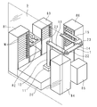
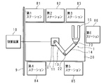
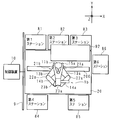
図1は、実施の形態1における搬送システムの概要を示す説明図であり、図2は搬送システムの模式上面図である。搬送システムは、複数のステーション81〜86と、搬送ロボット1と、制御装置10と、ベース20とを含み、矩形板状のワークWを搬送する。ワークWの形状は勿論例示であり、円板状等であってもよい。
(Embodiment 1)
FIG. 1 is an explanatory view showing an outline of the transport system according to the first embodiment, and FIG. 2 is a schematic top view of the transport system. The transfer system includes a plurality of
複数のステーション81〜86は、矩形箱状のベース20の周囲を取り囲むように配置されている。複数のステーション81〜86の内の第1ステーション81、第3ステーション83、第4ステーション84、第5ステーション85、及び第6ステーション86は夫々、ワークWを夫々収容する棚板を有する収容体である。第2ステーション82は、ワークWの検査装置であり、ワークWが載置される検査台を有している。第1ステーション81、第2ステーション82及び第3ステーション83は、ベース20の一長辺に沿って順に、各々収容棚又は検査台をベース20側に向けるようにして並設されている。第4ステーション84及び第5ステーション85は、ベース20の他長辺に沿って各々収容棚をベース20側に向けるようにして並設されている。第6ステーション86は、ベース20の一短辺の略中央に対応するように、収容棚をベース20に向けるようにして配置されている。ベース20の前記一短辺とは反対側の短辺に沿うようにして壁9が設けられている。壁9は、長さがベース20の短辺よりも長く、両長辺に沿って配置されているステーション81〜85をも覆うようにしてある。なお壁9は透明であっても不透明であってもよいが、図1では説明を容易にするために透明な壁として示されている。
The plurality of
搬送ロボット1は、スカラ型ロボットである。搬送ロボット1はベース20の所定箇所に設置される基部11を備える。基部11には、その中央部に設けられた孔に鉛直方向に貫通するように嵌合されている円筒状の第1軸12が設けられている。第1軸12は、基部11に対して昇降可能に支持されている。第1軸12の一端には、扁平な長細板状の第1アーム13の一端が、その扁平面が水平方向に沿うように、第1連結部(ショルダ)21により連結されている。第1連結部21は、鉛直方向の回転軸を有し、第1アーム13の他端が、第1軸12の中心軸と同軸で第1アーム13の長さを半径とした円の円周状の軌道で動くことができる。第1アーム13の他端には、第1アーム13と同形状の第2アーム14の一端が、同様にその扁平面が水平方向に沿うように、第2連結部(エルボ)22により連結されている。第2連結部22も鉛直方向の回転軸を有し、第2アーム14の他端は、第2連結部22即ち第1アーム13の他端を中心軸にして、第2アーム14の長さを半径とする円の円周状の軌道で動くことができる。第2アーム14の他端には、略U字板状のハンド15の幅方向の中央を支持する基部が、該ハンド15の扁平面が水平面に沿うように第3連結部(リスト)23により連結されている。第3連結部23も鉛直方向の回転軸を有し、ハンド15は該第3連結部23を中心軸に水平面上を回転する。
The
搬送ロボット1の第1連結部21、第2連結部22、及び第3連結部23には、夫々サーボモータ(第1〜第3モータ21M〜23M)が取り付けられている。搬送ロボット1は制御装置10と接続されており、制御装置10からの制御信号に基づくサーボモータの動作により、第1連結部21〜第3連結部23における回転角度が制御される。第1連結部21では第1アーム13の基部11に対する回転角度が制御され、第2連結部22では第1アーム13と第2アーム14との間の回転角度が制御され、第3連結部23では第2アーム14とハンド15との回転角度が制御される。第1連結部21〜第3連結部23夫々における回転角度が制御されることで搬送ロボット1の姿勢が変更される。また搬送ロボット1の第1軸12には昇降モータ(第4モータ24M)が取り付けられており、該昇降モータへの制御により、第1軸12(ハンド15)の基部11に対する高さが制御される。
Servo motors (first to
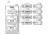
図3は、実施の形態1における制御装置10の構成を示すブロック図である。制御装置10は例えばPLC(Programmable Logic Controller )を用い、CPU(Central Processing Unit )等のプロセッサ101と、フラッシュメモリ等である書き換え可能な不揮発性のメモリ102とを含む制御部100を備える。
FIG. 3 is a block diagram showing the configuration of the
制御部100は、第1駆動回路111を介して第1連結部21に設けられたサーボモータである第1モータ21Mに接続されている。同様に制御部100は、第2駆動回路112を介して第2連結部22に設けられたサーボモータである第2モータ22Mに接続されており、第3駆動回路113を介して第3連結部23に設けられたサーボモータである第3モータ23Mに接続されている。また制御部100は、第4駆動回路114を介して第1軸12を昇降させる第4モータ24Mに接続されている。
The
第1〜第4駆動回路111〜114は、図示しない電源回路から電源の供給を受けて第1〜第4モータ21M〜24Mへ電力を供給すると共に、制御部100からの制御信号に基づいて第1〜第3モータ21M〜23Mのオン及びオフ、並びに回転角度を制御する。また、第1モータ21M〜第3モータ23Mには夫々、回転角度を検出するエンコーダが設けられており、プロセッサ101は、エンコーダが出力する回転角度を示す各信号を入力して、第1モータ21M〜第3モータ23Mにおける回転角度を検知することが可能である。また第1軸12の昇降モータである第4モータ24Mにもエンコーダが設けられており、プロセッサ101は、該エンコーダが出力する信号を入力して移動距離を換算し、第1軸12の高さを検知することが可能である(いずれも図示せず)。
The first to
制御部10のメモリ102には、制御プログラム10Pが記憶されている。プロセッサ101は、制御プログラム10Pを実行することにより、第1〜第4モータ21M〜24Mに対する制御信号を出力する。メモリ102には、経由点テーブル10Tが記憶されている。制御部10は、制御プログラム10Pを実行する際に、経由点テーブル10Tを参照してこれに従い制御を行なう。経由点テーブル10Tについては後述する。
The
図4は、実施の形態1における搬送ロボット1のリトラクトポジションの一例を示す説明図である。図4は図2の模式上面図に対応し、搬送ロボット1の異なる姿勢を示している。図4中の符号PAは、第1ステーション81に対するリトラクトポジションを示し、符号PBは、第3ステーション83に対するリトラクトポジションを示している。各リトラクトポジションPA,PBについては夫々、その姿勢となるための第1連結部21〜第3連結部23における回転角度、及びハンド15の高さ方向の位置を規定する教示点がメモリ102に記憶されている。教示点は例えば、第1連結部21〜第3連結部23夫々における回転角度と、ハンド15の任意のデカルト座標系における座標とを示す。ロボット制御装置10では、第1ステーション81及び第3ステーション83のみならず全ステーション81〜86に対応するリトラクトポジションの教示点をメモリ102に記憶しておく。ロボット制御装置10のプロセッサ101は、各リトラクトポジションの教示点に基づいてハンド15の移動、即ち搬送ロボット1の姿勢を変更させる。
FIG. 4 is an explanatory diagram showing an example of the retract position of the
例えば図4中の搬送ロボット1をリトラクトポジションPAからリトラクトポジションPBへ変更させるケースでの制御について説明する。ロボット制御装置10は、このケースにおいてリトラクトポジションPAからリトラクトポジションPBへ搬送ロボット1の第1連結部21〜第3連結部23を適切に回転させることが必要になる。まず単純に第1連結部21のみをリトラクトポジションPAに対応する角度から、リトラクトポジションPBに対応する角度となるように搬送ロボット1の姿勢を変更させる場合、ハンド15の先端、及び第2連結部22は図4中の破線で示すような軌道を描く。この場合、図4で明らかなようにハンド15の先端が第1ステーション81若しくは壁9と干渉するか、第2連結部22が第4ステーション84と干渉する。したがってこのような干渉を回避するために従来、プロセッサ101がリトラクトポジションPAの教示点からリトラクトポジションPBの教示点へハンド15を直線的に移動させる移動方向に対応するベクトルを演算により求めるか、又は図示しない教示装置から教示するようにしている。プロセッサ101は、演算により又は教示装置から得られたベクトルに対応する第1連結部21〜第3連結部23の回転角度を夫々算出して記憶する。以後、リトラクトポジションPAからリトラクトポジションPBへ搬送ロボット1の姿勢を変更させる場合には、プロセッサ101は記憶した情報を読み出して各第1モータ21M〜第3モータ23Mへ向けて、各々を適切に回転させる制御信号を出力する。図4の例であれば、第1連結部21を反時計回りに120°(−120°)回転させると共に、同時に第2連結部22を時計回りに180°回転させ、更に第3連結部23を反時計回りに60°回転させるといったように制御される。
For example, the control in the case where the
また高さについては、ワークWを収容する棚板を有する収容体であるステーション81,83〜86について、夫々棚板を収容部として各識別する情報に対応付けて収容部の高さを記憶してある。したがってプロセッサ101は、ワークWの搬入先又は搬出先のステーション81,83〜86及び収容部を識別する情報の指示を受けた場合、まず、搬入先又は搬出先のステーション81,83〜86に応じたリトラクトポジションに搬送ロボット1の姿勢を変更させる。そしてプロセッサ101は、ハンド1の高さが収容部を識別する情報に対応付けて記憶してある高さに対応するように、第1軸12を昇降させるべく第4モータ24Mへ向けて制御信号を出力する。
Regarding the height, for
実施の形態1における搬送システムでは基本的に、ロボット制御装置10が上述の教示点及びベクトルに基づいて搬送ロボット1を制御するが、これに加えて、ロボット制御装置10は、経由点を示す経由点テーブル10Tを参照しながら搬送ロボット1を制御する。経由点としては例えば、搬送ロボット1のホームポジションを用いる。ホームポジションは、第1連結部21〜第3連結部23がいずれも退避(所定の初期位置の姿勢へ変動)した姿勢である。図5は、実施の形態1における搬送ロボット1のホームポジションの一例を示す説明図である。図5Aは、第1アーム13、第2アーム14及びハンド15が直線状に折り畳まれた姿勢のホームポジションを示し、図5Bは、第1アーム13、第2アーム14及びハンド15が正三角形の各辺に対応する姿勢となったホームポジションを示している。ホームポジションについても、例えば図5Aの姿勢では第1連結部21は角度ゼロ、第2連結部22は角度180°、第3連結部23は角度−180°等として設定されており、メモリ102に記憶されている。
In the transfer system according to the first embodiment, the
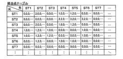
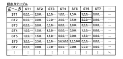
図6は、経由点テーブル10Tの内容例を示す説明図である。図6に示す経由点テーブル10Tでは、各行の項目が搬送ロボット1の変動前のリトラクトポジションに対応するステーションを示しており、各列の項目が変動後のリトラクトポジションに対応するステーションを示している。各項目には、ステーションを各々識別する情報が示されている。図6の例では、第1ステーション81の識別情報は「ST1」、第2ステーション82の識別情報は「ST2」、第3ステーション83の識別情報は「ST3」、第4ステーション84の識別情報は「ST4」である。同様に第5ステーション85の識別情報は「ST5」であり、第6ステーション86の識別情報は「ST6」である。経由点テーブル10T自体は、システム設計によらないので、図6に示すように第7ステーションに対応する「ST7」等の欄を含んでよい。変動前のリトラクトポジションの行と変動後のリトラクトポジションの列が交差した欄に、姿勢を変更させる場合に経由すべき経由点の情報が示されている。経由点の情報は、搬送ロボット1の特定の姿勢に対応する識別情報であり、例えば以下のような姿勢と対応する。なお「ホームポジション」は、図5A又は図5Bのいずれであってもよいし、他の姿勢であってもよい。
「0」:経由点なし
「1」:ホームポジション(任意の高さ)
「2」:ホームポジション(変更後の高さ)
「3」:ホームポジション(変更前の高さ)
「2」と「3」はいずれもホームポジションに対応するが、「2」は、ハンド15の高さを、搬送ロボット1が変更後の姿勢にてワークWを搬入又は搬出するための高さと同一に変更しておくことに対応する。「3」は、ハンド15の高さを、搬送ロボット1が変更前の姿勢でワークWを搬入又は搬出した時点での高さのままとすることに対応する。なお経由点の情報は、上述のように4つに限らず更に他の特定の姿勢に対応する情報を含む5つ以上の数を含んでもよい。
FIG. 6 is an explanatory diagram showing an example of the contents of the waypoint table 10T. In the waypoint table 10T shown in FIG. 6, the item in each row shows the station corresponding to the retract position before the change of the
"0": No waypoint "1": Home position (arbitrary height)
"2": Home position (height after change)
"3": Home position (height before change)
Both "2" and "3" correspond to the home position, but "2" is the height of the
図6の説明図において例えば、第1ステーション81に対するリトラクトポジション(図4の符号PA)から第3ステーション83のリトラクトポジション(図4の符号PB)へ搬送ロボット1の姿勢を変更させる場合には、対応する欄には「0,0,0,…」が示されている。なお経由点の情報が複数個存在するのは、各欄に対して確保されるメモリ102の容量に対応する。「0,0,0,…」の経由点の情報はつまり、第1ステーション81に対するリトラクトポジション(図4の符号PA)から第3ステーション83のリトラクトポジション(図4の符号PB)へは経由点なしで姿勢を変更するように制御されることを示す。この場合は上述したように、ハンド15を直線的に移動させるベクトルに基づいて直接的に姿勢の変更が行なわれる。同様にして図6の説明図では、第1ステーション81に対するリトラクトポジションから第5ステーション85のリトラクトポジションへ搬送ロボット1の姿勢を変更させる場合、対応する欄には「1,2,0,…」が示されている。つまりこの場合、第1ステーション81に対するリトラクトポジションから第5ステーション85のリトラクトポジションへ姿勢を変更させる場合には一旦、搬送ロボット1の姿勢はハンド15を任意の高さとするホームポジションを経由する。そして搬送ロボット1の姿勢はその後、第5ステーション85にて搬入又は搬出するワークWの高さとハンド15の高さが同一となるホームポジションを経由した後に、第5ステーション85に対するリトラクトポジションへ変更される。
In the explanatory diagram of FIG. 6, for example, when changing the posture of the
図7は、経由点テーブル10Tを用いた搬送ロボット1の姿勢変更処理手順の一例を示すフローチャートである。制御部100のプロセッサ101は、制御プログラム10Pに基づき、1つのステーションに対するリトラクトポジションから他の1つのステーションに対するリトラクトポジションへの姿勢の変更が指示された場合、以下の処理を実行する。
FIG. 7 is a flowchart showing an example of the posture change processing procedure of the
プロセッサ101は、変更前のリトラクトポジションに対応するステーションの識別情報を取得する(ステップS1)。プロセッサ101は同時的に、変更後のリトラクトポジションに対応するステーションの識別情報を取得する(ステップS2)。プロセッサ101は、取得した識別情報に基づき、経由点テーブル10Tを参照し(ステップS3)、ステップS1及びS2で取得した識別情報にて夫々特定される行及び列が交差する欄の経由点の情報を1つずつ、先頭から順に読み出す(ステップS4)。プロセッサ101は、読み出した経由点の情報が「0(ゼロ)」を示しているか否か判断する(ステップS5)。「0」を示していないと判断された場合(S5:NO)、プロセッサ101は、読み出した経由点の情報に対応する姿勢とするべく制御信号を第1駆動回路111〜第4駆動回路114へ出力し(ステップS6)、処理をステップS5へ戻す。ステップS6においてプロセッサ101は、記憶してある第1連結部21〜第3連結部23の回転角度、第1軸12の高さを示す制御信号を出力する。
The
ステップS5にて「0」を示していると判断された場合(S5:YES)、プロセッサ101はステップS2で取得した識別情報に対応するリトラクトポジションへ搬送ロボット1の姿勢を変更させるべく制御信号を第1駆動回路111〜第4駆動回路114へ出力し(ステップS7)、処理を終了する。ステップS7では、プロセッサ101は記憶してある第1連結部21〜第3連結部23の回転角度、第1軸12の高さを示す制御信号を出力する。
When it is determined in step S5 that "0" is indicated (S5: YES), the
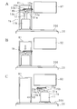
図8は、搬送ロボット1の姿勢の変更例を示す概要図である。図8Aは変更前の姿勢、図8Bは経由点における姿勢、図8Cは変更後の姿勢を示している。なお図8Aは、図1における第1ステーション81に対するリトラクトポジションを示し、図8Bは、ホームポジション(図5Aに対応)を示し、図8Cは、図1における第5ステーション85に対するリトラクトポジションを示している。
FIG. 8 is a schematic view showing an example of changing the posture of the
プロセッサ101は、図7のフローチャートに示した処理に従ってまず、「ST1」及び「ST5」を夫々、変更前及び変更後のリトラクトポジションに対応するステーションの識別情報として取得する(S1,S2)。このとき搬送ロボット1の姿勢は、図8Aに示す通りである。次にプロセッサ101は、経由点テーブル10Tを参照し(S3)、「ST1」に対応する行と「ST5」に対応する列とが交差する欄の経由点の情報「1,2,0,…」を読み出す(S4)。プロセッサ101は、経由点の先頭が「1」であって「0」を示していないと判断するから(S5:NO)、ホームポジション「1」に対応する姿勢とするべく制御信号を第1駆動回路111〜第4駆動回路114へ出力する(S6)。これにより搬送ロボット1の姿勢は、図8Bに示す状態となる。ホームポジション「1」では高さは任意である。したがって高さについては第1軸12を中間位置とするなどしてもよい。プロセッサ101は、次の経由点の情報が「2」であって「0」を示していないと判断するから(S5:NO)、ホームポジション「2」に対応する姿勢とするべく制御信号を第1駆動回路111〜第4駆動回路114へ出力する(S6)。ホームポジション「2」は、高さが変更後の高さ、即ち第5ステーション85における搬入又は搬出するワークWの高さとなるようにすることを示すから、プロセッサ101は第4駆動回路114へ高さを変更すべく制御信号を出力する。プロセッサ101は、次の経由点の情報が「0」を示していると判断するから(S5:YES)、変更後即ち第5ステーション85に対するリトラクトポジションの姿勢とすべく制御信号を第1駆動回路111〜第3駆動回路113へ出力し(S7)、姿勢の変更を終了する。これにより搬送ロボット1の姿勢は図8Cに示す状態となる。
The
なおステップS4で読み出した経由点の情報が「3,2,0,…」であった場合、プロセッサ101は、ハンド15を姿勢の変更前の高さに維持しながら第1アーム13、第2アーム14及びハンドの姿勢をホームポジションへ変更する。そしてその後プロセッサ101は、ハンド15を姿勢の変更後、即ち第5ステーション85における搬入又は搬出するワークWの高さとなるように制御する。プロセッサ101は、第1アーム13、第2アーム14及びハンド15の姿勢を第5ステーション85に対するリトラクトポジションへと変更させるように制御する。
When the information of the waypoints read in step S4 is "3,2,0, ...", the
図7のフローチャートに示した処理は、姿勢の変更前及び変更後のリトラクトポジションの組み合わせがどのようなものであっても、同一のプログラムソースに基づき実行が可能である。また、経由点テーブル10Tの内容によらず、同一のプログラムソースを汎用的に適用することが可能である。つまり、システムの設計が変更されたとしても、教示点及び教示情報と、経由点テーブル10Tの内容と、経由点に含まれるホームポジションの教示点とをそのシステムに合わせて変更すれば、プログラムの書き換えは不要になる。これまでロボット制御装置10におけるプログラムは、各システムに適応させた固有のものとするケースがあった。しかしながら本実施の形態1におけるロボット制御装置10では、制御プログラム10Pを具体的なシステム構成に特化させた内容とすることなしに、汎用のプログラムソースを用いて様々なシステムに適応させることが可能である。
The process shown in the flowchart of FIG. 7 can be executed based on the same program source regardless of the combination of the retract positions before and after the posture change. Further, the same program source can be applied universally regardless of the contents of the waypoint table 10T. That is, even if the design of the system is changed, if the teaching points and teaching information, the contents of the waypoint table 10T, and the teaching points of the home position included in the waypoints are changed according to the system, the program can be changed. No need to rewrite. Until now, there have been cases where the program in the
(実施の形態2)
図9は、実施の形態2における搬送システムの模式上面図である。実施の形態2の搬送システムは、複数のステーション81〜86と、搬送ロボット1bと、制御装置10と、ベース20とスライダー200とを含み、矩形板状のワークWを搬送する。ワークWの形状は勿論例示であり、円板状等であってもよい。なお実施の形態2の搬送システムの内、実施の形態1の搬送システムと共通する構成については、同一の符号を付して詳細な説明を省略する。特に実施の形態2では、搬送ロボット1bの構成が実施の形態1と異なり、更に障害物92が加えられているが、ロボット制御装置10の構成は経由テーブル10Tの内容以外は実施の形態1と共通であり、制御プログラム10Pは同一である。
(Embodiment 2)
FIG. 9 is a schematic top view of the transport system according to the second embodiment. The transfer system of the second embodiment includes a plurality of
実施の形態2における搬送システムでは、複数のステーション81〜86及び壁9の他に、第2ステーション82、第3ステーション83及びベース20の一部に亘る範囲の障害物92が、搬送ロボット1bの上方に設置されている。
In the transfer system according to the second embodiment, in addition to the plurality of
なお実施の形態2における搬送システムの搬送ロボット1bは、ベース20の長手方向(図9におけるX軸方向)に沿って設けられたスライダー200上に設置された基部11bと、該基部11bに設けられた第1軸12(図11参照)と、第1軸12の一端に設けられた円板上にアーム機構を1対連結して構成されている。基部11bは、スライダー200に沿って動くことが可能である。実施の形態2において第1軸12は、基部11bに対して旋回可能に構成されており、第1軸12を旋回させる第5モータ(図示せず)が設けられている。
The
対をなす一方のアーム機構は、第1アーム13a、第2アーム14a、及びハンド15aを含み、他方のアーム機構も第1アーム13b、第2アーム14b、及びハンド15bを含む。ハンド15a及びハンド15bは、ハンド15aが上方で上下に重なるようにして異なる高さで設けられている。第1アーム13a,13b、第2アーム14a,14bは相互に対称的に設けられている。1対のアーム機構は、その対称軸(第1軸12と第1アーム13a及び第1アーム13b夫々とを連結する第1連結部21a及び第1連結部21b間の中央を通る直線)に沿ってのみハンド15a及びハンド15bを夫々直線的に動かすように制御される。高さ方向(図9中のZ軸方向)については、第1軸12が昇降することによりハンド15a及びハンド15bの高さを調整することができる。
One pair of arm mechanisms includes a
図9に示したような搬送ロボット1bでは、各ステーション81〜86に対するリトラクトポジションは、基部11bのX軸方向における位置(座標X)と、第1軸12の昇降位置即ちハンド15a,15bの高さ(座標Z)と、第1軸12の旋回角度(角度θ)とで教示される。各リトラクトポジションは、ハンド15a及びハンド15b夫々の位置(対称軸上の座標Y)を含んでもよい。ホームポジションは、座標Yをゼロとする姿勢即ち、第1連結部21a,21b〜第3連結部23a,23bを全て退避させた状態を示し、スライダー200上の位置(座標X)は任意とする。
In the
図9に示したような搬送システムに対しても、実施の形態1にて説明した制御プログラム10P及び経由点テーブル10Tを用いて同様の制御が可能である。図10は、実施の形態2における経由点テーブル10Tの一例を示す説明図である。図10に示す経由点テーブル10Tは、実施の形態1の図6に示した内容例と対応しているが、実施の形態2における経由点テーブル10Tの経由点の情報には、第1軸12の旋回角度θで分別された各ホームポジションの情報が対応する。例えば以下のような姿勢と対応する。
「0」:経由点なし
「1」:ホームポジション(任意の高さ、変更前の旋回角度)
「2」:ホームポジション(変更後の高さ、変更前の旋回角度)
「3」:ホームポジション(変更前の高さ、変更前の旋回角度)
「4」:ホームポジション(任意の高さ、変更後の旋回角度)
「5」:ホームポジション(変更後の高さ、変更後の旋回角度)
「6」:ホームポジション(変更前の高さ、変更後の旋回角度)
つまり、「1」〜「3」は高さが異なるものの旋回角度が変更前と同一である一方で、「4」〜「6」は旋回角度が変更後と同一であるとする。
Similar control can be performed on the transfer system as shown in FIG. 9 by using the
"0": No waypoint "1": Home position (arbitrary height, turning angle before change)
"2": Home position (height after change, turning angle before change)
"3": Home position (height before change, turning angle before change)
"4": Home position (arbitrary height, turning angle after change)
"5": Home position (height after change, turning angle after change)
"6": Home position (height before change, turning angle after change)
That is, it is assumed that "1" to "3" have different heights but the turning angle is the same as before the change, while "4" to "6" have the same turning angle as after the change.
図10に示す経由テーブル10Tでは、第1ステーション81に対するリトラクトポジションから第6ステーション86のリトラクトポジションへ搬送ロボット1の姿勢を変更させることに対応する欄(太字)には「0,0,0,…」ではなく「2,0,0,…」が示されている。つまり、第1ステーション81に対するリトラクトポジションから第6ステーション86のリトラクトポジションへ姿勢を変更させる場合には一旦、旋回角度はそのままで搬送ロボット1の姿勢を第6ステーション86へのリトラクトポジションに対する高さとする。
In the transit table 10T shown in FIG. 10, the column (bold) corresponding to changing the posture of the
図11は、搬送ロボット1bの姿勢の変更例を示す概要図である。図11A〜図11Cは、第1ステーション81に対するリトラクトポジションから第6ステーション86に対するリトラクトポジションへの搬送ロボット1bの姿勢の変化を示している。姿勢の変化は第4及び第5ステーション84,85から第1〜第3ステーション81〜83を見る視点にて示す。図11Aは変更前の姿勢、図11Bは経由点における姿勢、図11Cは変更後の姿勢を示している。つまり図11Aは、第1ステーション81に対するリトラクトポジションを示し、図11Bは、図10の経由テーブル10Tに対応する経由点を示し、図11Cは、第6ステーション86に対するリトラクトポジションを示している。
FIG. 11 is a schematic view showing an example of changing the posture of the
プロセッサ101は、図7のフローチャートに示した処理に従ってまず、「ST1」及び「ST6」を夫々、変更前及び変更後のリトラクトポジションに対応するステーションの識別情報として取得する(S1,S2)。このとき搬送ロボット1bの姿勢は、図11Aに示す通りである。次にプロセッサ101は、図10に示した経由点テーブル10Tを参照し(S3)、「ST1」に対応する行と「ST6」に対応する列とが交差する欄の経由点の情報「2,0,0,…」を読み出す(S4)。プロセッサ101は、経由点の先頭が「2」であって「0」を示していないと判断するから(S5:NO)、ホームポジション「2」に対応する姿勢とするべく制御信号を出力する(S6)。これにより搬送ロボット1の姿勢は、図11Bに示す状態となる。ホームポジション「2」では、旋回角度は変更前のまま、高さを変更後とする。プロセッサ101は、次の経由点の情報が「0」を示していると判断するから(S5:YES)、変更後即ち第6ステーション86に対するリトラクトポジションの姿勢とすべく制御信号を出力し(S7)、姿勢の変更を終了する。これにより搬送ロボット1の姿勢は図11Cに示す状態となる。
The
図12は、実施の形態2における経由点テーブル10Tの他の一例を示す説明図である。図12に示す経由点テーブル10Tは、図10に示した内容例と対応しているが、図12では、第1ステーション81に対するリトラクトポジションから第6ステーション86のリトラクトポジションへ搬送ロボット1の姿勢を変更させることに対応する欄(太字)には「5,0,0,…」が示されている。つまり、第1ステーション81に対するリトラクトポジションから第6ステーション86のリトラクトポジションへ姿勢を変更させる場合には一旦、旋回角度を変更後の角度として搬送ロボット1の姿勢を第6ステーション86へのリトラクトポジションに対する高さとする。
FIG. 12 is an explanatory diagram showing another example of the waypoint table 10T according to the second embodiment. The waypoint table 10T shown in FIG. 12 corresponds to the content example shown in FIG. 10, but in FIG. 12, the posture of the
図13は、搬送ロボット1bの姿勢の他の変更例を示す概要図である。図13A〜図13Cは、図11A〜図11C同様に姿勢の変化を示しており、相違点は図13Bにて、図12の経由テーブル10Tに対応する経由点を示していることである。
FIG. 13 is a schematic view showing another example of changing the posture of the
図12に示した経由テーブル10Tを参照する場合、図10の経由テーブル10Tを参照する場合と比較して、プロセッサ101は、搬送ロボット1bの姿勢をホームポジション「5」に対応する姿勢とするべく制御信号を出力する(S6)。これにより搬送ロボット1の姿勢は、図13Bに示す状態となる。ホームポジション「5」では、旋回角度も高さも変更後と同一とする。このように経由テーブル10Tの内容を変更するのみで、ロボット制御装置10におけるプロセッサ101が実行する制御プログラム10Pをそのまま利用しつつ、異なる動きを実現できる。したがって各システムに合わせてプログラムを特化させるよりも、汎用的な処理手順を実行させるプログラムとして煩雑さを低減することができるからプログラム管理も容易になり、制御のミスも低減される。
When referring to the transit table 10T shown in FIG. 12, the
実施の形態1及び2で示したように、搬送ロボット1と搬送ロボット1bとで異なる機構を有しているが、ロボット制御装置10における制御プログラム10Pに基づく処理は同一とすることが可能である。教示点、経由点及びそれに応じた経由点テーブル10Tの内容をシステム毎に特化した内容に適応させることで、多様なシステムにおけるスカラ型搬送ロボットのロボット制御に適用させることが可能である。
As shown in the first and second embodiments, the
(変形例1)
実施の形態2における図10〜図11に示した姿勢の変更例では、第1ステーション81のリトラクトポジションから第6ステーション86のリトラクトポジションへの姿勢の変更時に経由する経由点の情報を「2,0,0,…」(図10)としたが、「2,5,0,…」としてもよい。つまり、経由点が「2,0,0,…」である場合は、「2」のホームポジションの情報が、「変更前の旋回角度のままで変更後の高さとする」ことに対応するから、図11Bから図11Cへの姿勢の変化で示されているように、プロセッサ101は搬送ロボット1bを旋回させると共にスライダー200を動作させて位置を変更する。これに対し、経由点の情報を「2,5,0,…」とした場合は、「5」のホームポジションの情報は「変更後の旋回角度で変更後の高さとする」ことに対応するから、プロセッサ101はまず経由点「2」に基づき高さを変更させ、経由点「5」に基づき旋回角度を旋回させた後に、スライダー200を動作させて位置を変更する。
(Modification example 1)
In the posture change example shown in FIGS. 10 to 11 in the second embodiment, the information of the waypoints to be passed when the posture is changed from the retract position of the
(変形例2)
実施の形態2においては、経由点の情報としてスライダー200上の位置情報(座標X)を含むようにしてもよい。例えばホームポジションの情報として以下のような情報を加える。
「7」:ホームポジション(変更前のスライダー位置)
「8」:ホームポジション(変更後のスライダー位置)
(Modification 2)
In the second embodiment, the position information (coordinates X) on the
"7": Home position (slider position before change)
"8": Home position (slider position after change)
このようなホームポジションの情報を用いる場合には、例えば図11に示す姿勢の変化のために必要な経由点の情報は「2,8,0,…」である。つまり、第1ステーション81に対するリトラクトポジションから第6ステーション86のリトラクトポジションへ姿勢を変更させる場合にはまず第1段階として、旋回角度はそのままで搬送ロボット1の姿勢を第6ステーション86へのリトラクトポジションに対する高さとする(図11B)。そして第2段階として、プロセッサ101は、旋回角度は図11Bの姿勢と同じままでスライダー200を動作させ、搬送ロボット1bの位置を第6ステーション86に対するリトラクトポジションの位置へ移動させる。その後プロセッサ101は、第6ステーション86に対するリトラクトポジションの姿勢とすべく制御信号を出力し、搬送ロボット1bが旋回して図11Cの姿勢(変更後のホームポジション)とする。なおこの場合は、図11Cの位置で搬送ロボット1bが支障なく旋回できることが条件となる。これにより、スライダー200上の位置を示す位置情報を用いない場合と比較して、制御プログラム10Pの内容を変更することなしに、搬送ロボット1bの姿勢及び位置の変化の過程を細かく設定することができる。
When such home position information is used, for example, the information on the waypoints required for the change in posture shown in FIG. 11 is "2,8,0, ...". That is, when changing the posture from the retract position with respect to the
ホームポジションの情報を更に、以下に示すような搬送ロボット1bの姿勢(高さ及び旋回角度)の情報と、スライダー200上の位置情報(X軸上位置)とを組み合わせた情報としてもよい。
「0」:経由点なし
「11」:ホームポジション(任意の高さ、変更前の旋回角度、変更前のX軸上位置)
「12」:ホームポジション(任意の高さ、変更前の旋回角度、変更後のX軸上位置)
「21」:ホームポジション(変更後の高さ、変更前の旋回角度、変更前のX軸上位置)
「22」:ホームポジション(変更後の高さ、変更前の旋回角度、変更後のX軸上位置)
「31」:ホームポジション(変更前の高さ、変更前の旋回角度、変更前のX軸上位置)
「32」:ホームポジション(変更前の高さ、変更前の旋回角度、変更後のX軸上位置)
「41」:ホームポジション(任意の高さ、変更後の旋回角度、変更前のX軸上位置)
「42」:ホームポジション(任意の高さ、変更後の旋回角度、変更後のX軸上位置)
「51」:ホームポジション(変更後の高さ、変更後の旋回角度、変更前のX軸上位置)
「52」:ホームポジション(変更後の高さ、変更後の旋回角度、変更後のX軸上位置)
「61」:ホームポジション(変更前の高さ、変更後の旋回角度、変更前のX軸上位置)
「62」:ホームポジション(変更前の高さ、変更後の旋回角度、変更後のX軸上位置)
The home position information may be further combined with the posture (height and turning angle) information of the
"0": No waypoint "11": Home position (arbitrary height, turning angle before change, position on X-axis before change)
"12": Home position (arbitrary height, turning angle before change, position on X-axis after change)
"21": Home position (height after change, turning angle before change, position on X-axis before change)
"22": Home position (height after change, turning angle before change, position on X-axis after change)
"31": Home position (height before change, turning angle before change, position on X-axis before change)
"32": Home position (height before change, turning angle before change, position on X-axis after change)
"41": Home position (arbitrary height, turning angle after change, position on X-axis before change)
"42": Home position (arbitrary height, turning angle after change, position on X-axis after change)
"51": Home position (height after change, turning angle after change, position on X-axis before change)
"52": Home position (height after change, turning angle after change, position on X-axis after change)
"61": Home position (height before change, turning angle after change, position on X-axis before change)
"62": Home position (height before change, turning angle after change, position on X-axis after change)
上記のようなホームポジションの情報例では、第1ステーション81に対するリトラクトポジションから第6ステーション86のリトラクトポジションへ姿勢を変更する際に参照する経由点の情報を「21,22,0,…」とした場合には、上述の「7」、「8」を用いて「2,8,0,…」したときの制御とプロセッサ101の制御は同一となる。このように経由点の情報を、高さに加えて第1軸12の旋回角度θで分別するのみならず、スライダー200上の位置で分別したホームポジションの情報に対応させることで、搬送ロボット1bの姿勢及び位置の変化の過程を細かく設定することができる。
In the home position information example as described above, the information of the waypoints to be referred to when changing the posture from the retract position for the
なおスライダー200の位置情報は、図12及び13に示した姿勢の変更例についても用いることが可能である。また位置情報は実施の形態2で示したような1軸のスライダー200の位置情報には限定されない。例えば2軸のスライダーを用い、X軸及びY軸夫々での位置を使用して経由点の情報として用いることができる。移動手段はスライダーには限定されない。
The position information of the
なお、上述のように開示された本実施の形態はすべての点で例示であって、制限的なものではないと考えられるべきである。本発明の範囲は、上記した意味ではなく、特許請求の範囲によって示され、特許請求の範囲と均等の意味および範囲内でのすべての変更が含まれることが意図される。 It should be noted that the present embodiment disclosed as described above is an example in all respects and should be considered not to be restrictive. The scope of the present invention is indicated by the scope of claims, not the above-mentioned meaning, and is intended to include all modifications within the meaning and scope equivalent to the scope of claims.
1 搬送ロボット
12 第1軸
13 第1アーム
14 第2アーム
15 ハンド
21 第1連結部
22 第2連結部
23 第3連結部
21M 第1モータ
22M 第2モータ
23M 第3モータ
24M 第4モータ
10 ロボット制御装置
100 制御部
101 プロセッサ
102 メモリ
10P 制御プログラム
10T 経由点テーブル
1
Claims (6)
予め規定された複数の姿勢夫々の識別情報に対応付けて、前記規定された複数の姿勢夫々での各連結部におけるアームの回転角度を記憶しておく記憶部と、
前記複数の姿勢間で経由すべき1又は複数の姿勢を示す経由点の情報を、変更前及び変更後の姿勢を示す識別情報の組に対応付けて記憶した経由点テーブルと、
前記複数のアーム間の各連結部に対し、該連結部における回転角度を各出力するプロセッサと
を備え、
前記経由点の情報は、前記ロボットの異なる特定の姿勢夫々に対応する符号の列であって、前記符号の内の特定の符号は経由点が無いことに対応し、他の符号で経由すべき特定の姿勢を示し、
前記プロセッサは、
変更前及び変更後の姿勢を示す識別情報に基づき、前記変更前の識別情報及び前記変更後の識別情報の組に対応付けられた経由点の情報を前記経由点テーブルから読み出し、
読み出した経由点の情報が示す符号の姿勢の識別情報に対応付けられている回転角度を前記各連結部に対し、前記経由点の情報が示す姿勢の数だけ出力した後、変更後の姿勢の識別情報に対応付けられている回転角度を前記各連結部に対し出力する
ことを特徴とするロボット制御装置。 A robot control device that changes the posture of a robot having a horizontal articulated arm mechanism in which a plurality of arms and hands are connected by a connecting portion.
A storage unit that stores the rotation angle of the arm at each connecting portion in each of the plurality of predetermined postures in association with the identification information of each of the plurality of predetermined postures.
A waypoint table in which information on waypoints indicating one or more postures to be passed between the plurality of postures is stored in association with a set of identification information indicating the postures before and after the change.
Each connecting portion between the plurality of arms is provided with a processor that outputs the rotation angle at the connecting portion.
The information of the waypoint is a sequence of codes corresponding to different specific postures of the robot, and the specific code in the code corresponds to the absence of a way point and should be passed by another code. Show a specific posture,
The processor
Based on the identification information indicating the posture before and after the change, the information of the waypoints associated with the set of the identification information before the change and the identification information after the change is read from the waypoint table.
The rotation angle associated with the posture identification information of the code indicated by the read transit point information is output to each of the connecting portions by the number of postures indicated by the transit point information , and then the changed posture. A robot control device characterized in that the rotation angle associated with the identification information is output to each of the connecting portions.
請求項1に記載のロボット制御装置。The robot control device according to claim 1.
前記記憶部には、前記規定された複数の姿勢夫々での前記ハンドの高さが更に記憶してあり、
前記経由点テーブルには、前記複数の姿勢間で経由すべき姿勢を前記ハンドの高さを示す情報別に示す経由点の情報が記憶してあり、
前記プロセッサは、読み出した経由点の情報が示す姿勢の識別情報に対応付けられている回転角度を前記各連結部に対し出力すると共に前記経由点の情報に対応する高さを前記昇降機構へ出力した後に、変更後の姿勢の識別情報に対応付けられている回転角度を前記各連結部に対し出力すると共に前記変更後の姿勢の識別情報に対応付けられているハンドの高さを前記昇降機構へ出力する
ことを特徴とする請求項1又は2に記載のロボット制御装置。 Further equipped with an elevating mechanism for changing the height of the hand,
The storage unit further stores the height of the hand in each of the plurality of defined postures.
In the waypoint table, information on the waypoints indicating the postures to be passed between the plurality of postures for each information indicating the height of the hand is stored.
The processor outputs the rotation angle associated with the posture identification information indicated by the read waypoint information to each of the connecting portions, and outputs the height corresponding to the waypoint information to the elevating mechanism. After that, the rotation angle associated with the changed posture identification information is output to each of the connecting portions, and the height of the hand associated with the changed posture identification information is calculated by the elevating mechanism. The robot control device according to claim 1 or 2 , wherein the robot control device is characterized by outputting to.
請求項3に記載のロボット制御装置。The robot control device according to claim 3.
前記記憶部には、前記規定された複数の姿勢と前記ロボットの位置とが共に記憶してあり、
前記経由点テーブルには、前記複数の姿勢間で経由すべき姿勢を前記ロボットの位置を示す情報別に示す経由点の情報が記憶してあり、
前記プロセッサは、読み出した経由点の情報が示す姿勢の識別情報に対応付けられている回転角度を前記各連結部に対し出力すると共に前記経由点の情報に対応付けられている位置を前記移動機構へ出力した後に、変更後の姿勢の識別情報に対応付けられている回転角度を前記各連結部に対し出力すると共に前記変更後の姿勢の識別情報に対応付けられている位置を前記移動機構へ出力する
ことを特徴とする請求項1から請求項4のいずれか1つに記載のロボット制御装置。 Further equipped with a moving mechanism for moving the robot,
The storage unit stores both the specified plurality of postures and the position of the robot.
In the waypoint table, information on the waypoints indicating the postures to be passed between the plurality of postures for each information indicating the position of the robot is stored.
The processor outputs the rotation angle associated with the posture identification information indicated by the read waypoint information to each of the connecting portions, and the moving mechanism determines the position associated with the waypoint information. After outputting to, the rotation angle associated with the changed posture identification information is output to each connecting portion, and the position associated with the changed posture identification information is output to the moving mechanism. The robot control device according to any one of claims 1 to 4, wherein the robot control device is characterized by outputting.
前記プロセッサに、
変更前及び変更後の姿勢を示す識別情報を取得し、
予め規定された複数の姿勢夫々の識別情報に対応付けて記憶してある前記複数の姿勢夫々での各連結部におけるアームの回転角度を記憶してある記憶部から、取得した識別情報に対応する回転角度を読み出し、
複数の姿勢間で経由すべき1又は複数の姿勢を示し、前記ロボットの異なる特定の姿勢夫々に対応する符号の列であって、前記符号の内の特定の符号は経由点が無いことに対応し、他の符号で経由すべき特定の姿勢を示す経由点の情報を、変更前及び変更後の姿勢を示す識別情報の組に対応付けて記憶してある経由点テーブルを読み出し、
読み出した経由点テーブルから、取得した変更前及び変更後の姿勢を示す識別情報に基づき、前記変更前の識別情報及び前記変更後の識別情報の組に対応付けられた経由点の情報を抽出し、
抽出した経由点の情報が示す符号の姿勢の識別情報に対応付けられている回転角度を前記複数のアーム及びハンドの間の各連結部に対し、前記経由点の情報が示す姿勢の数だけ出力した後、変更後の姿勢の識別情報に対応付けられている回転角度を前記各連結部に対し出力する
処理を実行させることを特徴とする制御プログラム。 A control program for causing a processor connected to a robot having a horizontal articulated arm mechanism in which a plurality of arms and hands are connected by a connecting portion to execute a process of changing the posture of the robot.
To the processor
Acquire identification information indicating the posture before and after the change,
Corresponds to the identification information acquired from the storage unit that stores the rotation angle of the arm at each connecting portion in each of the plurality of postures, which is stored in association with the identification information of each of the plurality of postures defined in advance. Read the rotation angle,
One or more orientation to be over between a plurality of position indicates the a string of the code corresponding to the s different specific orientation husband the robot, a specific code of said code in absence of waypoints Correspondingly, the waypoint table indicating the specific attitude to be passed by another code is read out in association with the set of the identification information indicating the attitude before and after the change.
From the read waypoint table, based on the acquired identification information indicating the posture before and after the change, the information of the waypoints associated with the set of the identification information before the change and the identification information after the change is extracted. ,
The rotation angle associated with the posture identification information of the code indicated by the extracted waypoint information is output to each connecting portion between the plurality of arms and hands by the number of postures indicated by the waypoint information. A control program characterized by executing a process of outputting the rotation angle associated with the changed posture identification information to each of the connecting portions.
Priority Applications (1)
| Application Number | Priority Date | Filing Date | Title |
|---|---|---|---|
| JP2017072439A JP6869080B2 (en) | 2017-03-31 | 2017-03-31 | Robot control device and control program |
Applications Claiming Priority (1)
| Application Number | Priority Date | Filing Date | Title |
|---|---|---|---|
| JP2017072439A JP6869080B2 (en) | 2017-03-31 | 2017-03-31 | Robot control device and control program |
Publications (2)
| Publication Number | Publication Date |
|---|---|
| JP2018171691A JP2018171691A (en) | 2018-11-08 |
| JP6869080B2 true JP6869080B2 (en) | 2021-05-12 |
Family
ID=64106494
Family Applications (1)
| Application Number | Title | Priority Date | Filing Date |
|---|---|---|---|
| JP2017072439A Active JP6869080B2 (en) | 2017-03-31 | 2017-03-31 | Robot control device and control program |
Country Status (1)
| Country | Link |
|---|---|
| JP (1) | JP6869080B2 (en) |
Families Citing this family (1)
| Publication number | Priority date | Publication date | Assignee | Title |
|---|---|---|---|---|
| CN113226662B (en) * | 2018-12-28 | 2024-07-09 | 川崎重工业株式会社 | Robot control device, robot system, and robot control method |
Family Cites Families (7)
| Publication number | Priority date | Publication date | Assignee | Title |
|---|---|---|---|---|
| JP4589853B2 (en) * | 2005-09-22 | 2010-12-01 | 東京エレクトロン株式会社 | Substrate transport system and substrate transport method |
| JP4974859B2 (en) * | 2007-11-20 | 2012-07-11 | 株式会社ダイヘン | Robot controller |
| JP5239845B2 (en) * | 2008-12-26 | 2013-07-17 | 株式会社安川電機 | Substrate transfer robot, substrate transfer apparatus, and semiconductor manufacturing apparatus |
| JP5504641B2 (en) * | 2009-02-13 | 2014-05-28 | 株式会社安川電機 | Substrate transport robot, substrate transport apparatus including the same, and semiconductor manufacturing apparatus |
| JP6217089B2 (en) * | 2013-02-21 | 2017-10-25 | セイコーエプソン株式会社 | Robot control system, robot, robot control method and program |
| JP2016040067A (en) * | 2014-08-13 | 2016-03-24 | キヤノン株式会社 | Robot device, method for controlling robot, program and recording medium |
| JP6511806B2 (en) * | 2014-12-25 | 2019-05-15 | シンフォニアテクノロジー株式会社 | Articulated robot and control method of articulated robot |
-
2017
- 2017-03-31 JP JP2017072439A patent/JP6869080B2/en active Active
Also Published As
| Publication number | Publication date |
|---|---|
| JP2018171691A (en) | 2018-11-08 |
Similar Documents
| Publication | Publication Date | Title |
|---|---|---|
| JP6914811B2 (en) | Horizontal articulated robot and its origin return method | |
| JP6173677B2 (en) | Home position return method for industrial robots | |
| US10836042B2 (en) | Robot system | |
| JP5620445B2 (en) | Article takeout device for determining holding position and posture of robot based on selection condition | |
| JP6722677B2 (en) | Substrate transfer device | |
| EP2547490B1 (en) | Calibration of a base coordinate system for an industrial robot | |
| TW201641232A (en) | Robot system | |
| KR20160022779A (en) | Robot system, robot teaching method and robot teaching apparatus therefor | |
| US10875726B2 (en) | Work transfer system and control method thereof | |
| JP6630727B2 (en) | Horizontal articulated robot | |
| US10020216B1 (en) | Robot diagnosing method | |
| JP6892018B2 (en) | Robot device | |
| JPWO2012169374A1 (en) | Work processing system | |
| JP2020536761A5 (en) | ||
| JP2019048349A (en) | Robot system, robot control device, and manufacturing method of workpiece | |
| JP6869080B2 (en) | Robot control device and control program | |
| JP2018073942A (en) | Substrate gripping hand and substrate transfer device including the same | |
| KR20130093021A (en) | Carrier device | |
| JP7269071B2 (en) | Conveyor robot | |
| CN109997086A (en) | The measurement of the kinematic axis of robot | |
| JP6281554B2 (en) | Teaching jig, robot, teaching system and teaching method | |
| JP2019084627A (en) | Method for returning horizontal multi-joint robot to original position | |
| JP3638775B2 (en) | Redundant robot position determination method for redundant robot | |
| JP7149815B2 (en) | Robot system and its operation method | |
| US10403539B2 (en) | Robot diagnosing method |
Legal Events
| Date | Code | Title | Description |
|---|---|---|---|
| A621 | Written request for application examination |
Free format text: JAPANESE INTERMEDIATE CODE: A621 Effective date: 20191105 |
|
| A977 | Report on retrieval |
Free format text: JAPANESE INTERMEDIATE CODE: A971007 Effective date: 20200930 |
|
| A131 | Notification of reasons for refusal |
Free format text: JAPANESE INTERMEDIATE CODE: A131 Effective date: 20201110 |
|
| A521 | Request for written amendment filed |
Free format text: JAPANESE INTERMEDIATE CODE: A523 Effective date: 20210107 |
|
| TRDD | Decision of grant or rejection written | ||
| A01 | Written decision to grant a patent or to grant a registration (utility model) |
Free format text: JAPANESE INTERMEDIATE CODE: A01 Effective date: 20210330 |
|
| A61 | First payment of annual fees (during grant procedure) |
Free format text: JAPANESE INTERMEDIATE CODE: A61 Effective date: 20210413 |
|
| R150 | Certificate of patent or registration of utility model |
Ref document number: 6869080 Country of ref document: JP Free format text: JAPANESE INTERMEDIATE CODE: R150 |
|
| R250 | Receipt of annual fees |
Free format text: JAPANESE INTERMEDIATE CODE: R250 |