JP6868622B2 - A suitcase preferably of a rigid model with a replaceable outer case - Google Patents
A suitcase preferably of a rigid model with a replaceable outer case Download PDFInfo
- Publication number
- JP6868622B2 JP6868622B2 JP2018527966A JP2018527966A JP6868622B2 JP 6868622 B2 JP6868622 B2 JP 6868622B2 JP 2018527966 A JP2018527966 A JP 2018527966A JP 2018527966 A JP2018527966 A JP 2018527966A JP 6868622 B2 JP6868622 B2 JP 6868622B2
- Authority
- JP
- Japan
- Prior art keywords
- suitcase
- frame
- shell
- shells
- shows
- Prior art date
- Legal status (The legal status is an assumption and is not a legal conclusion. Google has not performed a legal analysis and makes no representation as to the accuracy of the status listed.)
- Active
Links
- 239000000463 material Substances 0.000 claims description 16
- 229920000049 Carbon (fiber) Polymers 0.000 claims description 3
- 239000004917 carbon fiber Substances 0.000 claims description 3
- VNWKTOKETHGBQD-UHFFFAOYSA-N methane Chemical compound C VNWKTOKETHGBQD-UHFFFAOYSA-N 0.000 claims description 3
- 239000004033 plastic Substances 0.000 claims description 3
- 229920003023 plastic Polymers 0.000 claims description 3
- 239000004743 Polypropylene Substances 0.000 claims description 2
- 229920000122 acrylonitrile butadiene styrene Polymers 0.000 claims description 2
- 239000004676 acrylonitrile butadiene styrene Substances 0.000 claims description 2
- 229920001971 elastomer Polymers 0.000 claims description 2
- 229920000515 polycarbonate Polymers 0.000 claims description 2
- 239000004417 polycarbonate Substances 0.000 claims description 2
- -1 polypropylene Polymers 0.000 claims description 2
- 229920001155 polypropylene Polymers 0.000 claims description 2
- 229920000915 polyvinyl chloride Polymers 0.000 claims description 2
- 239000004800 polyvinyl chloride Substances 0.000 claims description 2
- 239000005060 rubber Substances 0.000 claims description 2
- 239000003086 colorant Substances 0.000 description 3
- 230000008878 coupling Effects 0.000 description 3
- 238000010168 coupling process Methods 0.000 description 3
- 238000005859 coupling reaction Methods 0.000 description 3
- 238000005516 engineering process Methods 0.000 description 3
- 238000003780 insertion Methods 0.000 description 3
- 230000037431 insertion Effects 0.000 description 3
- 238000000034 method Methods 0.000 description 3
- 239000002759 woven fabric Substances 0.000 description 3
- 239000004744 fabric Substances 0.000 description 2
- 239000004753 textile Substances 0.000 description 2
- 238000010521 absorption reaction Methods 0.000 description 1
- 238000005452 bending Methods 0.000 description 1
- 230000033228 biological regulation Effects 0.000 description 1
- 238000005034 decoration Methods 0.000 description 1
- 230000014759 maintenance of location Effects 0.000 description 1
- 239000012778 molding material Substances 0.000 description 1
- 230000035939 shock Effects 0.000 description 1
- 235000019640 taste Nutrition 0.000 description 1
Images


Classifications
-
- A—HUMAN NECESSITIES
- A45—HAND OR TRAVELLING ARTICLES
- A45C—PURSES; LUGGAGE; HAND CARRIED BAGS
- A45C13/00—Details; Accessories
- A45C13/002—Protective covers
-
- A—HUMAN NECESSITIES
- A45—HAND OR TRAVELLING ARTICLES
- A45C—PURSES; LUGGAGE; HAND CARRIED BAGS
- A45C13/00—Details; Accessories
- A45C13/005—Hinges
-
- A—HUMAN NECESSITIES
- A45—HAND OR TRAVELLING ARTICLES
- A45C—PURSES; LUGGAGE; HAND CARRIED BAGS
- A45C13/00—Details; Accessories
- A45C13/04—Frames
-
- A—HUMAN NECESSITIES
- A45—HAND OR TRAVELLING ARTICLES
- A45C—PURSES; LUGGAGE; HAND CARRIED BAGS
- A45C13/00—Details; Accessories
- A45C13/08—Decorative devices for handbags or purses
-
- A—HUMAN NECESSITIES
- A45—HAND OR TRAVELLING ARTICLES
- A45C—PURSES; LUGGAGE; HAND CARRIED BAGS
- A45C13/00—Details; Accessories
- A45C13/10—Arrangement of fasteners
-
- A—HUMAN NECESSITIES
- A45—HAND OR TRAVELLING ARTICLES
- A45C—PURSES; LUGGAGE; HAND CARRIED BAGS
- A45C13/00—Details; Accessories
- A45C13/26—Special adaptations of handles
-
- A—HUMAN NECESSITIES
- A45—HAND OR TRAVELLING ARTICLES
- A45C—PURSES; LUGGAGE; HAND CARRIED BAGS
- A45C5/00—Rigid or semi-rigid luggage
- A45C5/02—Materials therefor
-
- A—HUMAN NECESSITIES
- A45—HAND OR TRAVELLING ARTICLES
- A45C—PURSES; LUGGAGE; HAND CARRIED BAGS
- A45C5/00—Rigid or semi-rigid luggage
- A45C5/03—Suitcases
-
- A—HUMAN NECESSITIES
- A45—HAND OR TRAVELLING ARTICLES
- A45C—PURSES; LUGGAGE; HAND CARRIED BAGS
- A45C5/00—Rigid or semi-rigid luggage
- A45C5/14—Rigid or semi-rigid luggage with built-in rolling means
-
- A—HUMAN NECESSITIES
- A45—HAND OR TRAVELLING ARTICLES
- A45F—TRAVELLING OR CAMP EQUIPMENT: SACKS OR PACKS CARRIED ON THE BODY
- A45F3/00—Travelling or camp articles; Sacks or packs carried on the body
- A45F3/04—Sacks or packs carried on the body by means of two straps passing over the two shoulders
-
- A—HUMAN NECESSITIES
- A45—HAND OR TRAVELLING ARTICLES
- A45F—TRAVELLING OR CAMP EQUIPMENT: SACKS OR PACKS CARRIED ON THE BODY
- A45F3/00—Travelling or camp articles; Sacks or packs carried on the body
- A45F3/10—Pack-frames carried on the body
-
- A—HUMAN NECESSITIES
- A45—HAND OR TRAVELLING ARTICLES
- A45C—PURSES; LUGGAGE; HAND CARRIED BAGS
- A45C5/00—Rigid or semi-rigid luggage
- A45C5/03—Suitcases
- A45C2005/032—Suitcases semi-rigid, i.e. resistant against deformation and resilient, e.g. with a resilient frame
-
- A—HUMAN NECESSITIES
- A45—HAND OR TRAVELLING ARTICLES
- A45C—PURSES; LUGGAGE; HAND CARRIED BAGS
- A45C5/00—Rigid or semi-rigid luggage
- A45C5/03—Suitcases
- A45C2005/037—Suitcases with a hard shell, i.e. rigid shell as volume creating element
Landscapes
- Chemical & Material Sciences (AREA)
- Engineering & Computer Science (AREA)
- Materials Engineering (AREA)
- Purses, Travelling Bags, Baskets, Or Suitcases (AREA)
Description
本発明は、任意の形態または大きさの旅行用スーツケースまたはバックパックなどの容器の技術分野に一般に関する。 The present invention relates generally to the art of containers such as travel suitcases or backpacks of any form or size.
特に、本発明は、より長持ちし、必要に応じて色及び/または装飾を修正できるように構成されている容器に関する。 In particular, the present invention relates to containers that are configured to last longer and to be modified in color and / or decoration as needed.
旅行用スーツケースが古くから知られており、大きさは様々である。 Travel suitcases have been known for a long time and come in a variety of sizes.
いわゆるトロリースーツケースには、簡単に運べるようにキャスターが備わっており、大きさが制限されている。それらの大きさは様々であって、通常、空港の規制に従っている。そのようなスーツケースには、手荷物として機内持ち込みができるように小さいものもあれば、より大きいものもある。 So-called trolley suitcases are equipped with casters for easy carrying and are limited in size. They vary in size and usually follow airport regulations. Some such suitcases are small enough to be carried on board as baggage, while others are larger.
スーツケースは、硬質のものと非硬質のものとに分けられる。硬質のスーツケースは、本のように開いて再び閉じることが可能で、プラスチック、炭素繊維、または同様な材料で作ることができる硬質の材料で構成されている外部のシェルによって構成されている。 Suitcases are divided into hard and non-hard ones. A rigid suitcase is made up of an external shell made of a rigid material that can be opened and closed like a book and can be made of plastic, carbon fiber, or similar material.
硬質のスーツケースの利点は、ケース内の中身を、それに衝撃や重量が作用した場合により良く保護することができることであり、それは、スーツケースが、たとえ他のスーツケースの重さによって押されたときでも、基本的にその元の形態を維持するからである。 The advantage of a rigid suitcase is that it can better protect the contents inside the case when impact or weight acts on it, which means that the suitcase is pushed by the weight of other suitcases. This is because it basically maintains its original form even at times.
そのようなスーツケースは商業的により普及していることが多いのが常である。 Such suitcases are often more commercially popular.
他の型式のスーツケースは、通常の織物で作られていてもよいが、上方から重量が作用した場合に変形することが多い。 Other types of suitcases may be made of ordinary fabric, but often deform when weight is applied from above.
硬質のスーツケースに関する技術的な問題は、強力な衝撃や重さを受けると、織物のスーツケースよりももろいことが証明されていることである。旅行中、たとえば、航空機の胴体内にスーツケースが押し込まれるときに、スーツケースは、ほとんど注意を払われずに詰め込まれたり投げられたりすることが多いことは明らかである。その結果、到着時に、損傷していたり、ひっかき傷がついていたり、壊れていたりすることさえあるスーツケースを受け取ることになる。 The technical problem with rigid suitcases is that they have proven to be more brittle than woven suitcases under heavy impact and weight. It is clear that suitcases are often stuffed or thrown with little attention during travel, for example, when the suitcase is pushed into the fuselage of an aircraft. As a result, upon arrival, you will receive a suitcase that may be damaged, scratched, or even broken.
この種類の問題に対して、様々な解決策が提案されている。 Various solutions have been proposed for this type of problem.
解決策が特許文献1に記載されており、外部の織物の張り生地が設けられている。 The solution is described in Patent Document 1, and an external woven upholstery fabric is provided.
この種類の解決策は、ひっかき傷から保護する機能を果たすことは証明されているものの、許容可能な保護を保証できないので、衝撃の場合には効果が低くなる。 Although this type of solution has proven to serve as scratch protection, it is less effective in the event of an impact because it cannot guarantee acceptable protection.
実際に、織物は、衝撃、自から切れること、衝突に対するどのような種類の保護も保証不能で、ひっかき傷に対する保護だけを保証する。 In fact, textiles cannot guarantee any kind of protection against impact, self-cutting, collisions, only scratch protection.
そのため、本発明の目的は、技術的な不便を解決する、物体、衣類、アクセサリ、書籍などの一般的な物体を運搬するための容器を提供することである。 Therefore, an object of the present invention is to provide a container for carrying general objects such as objects, clothing, accessories, books, etc., which solves the technical inconvenience.
特に、衝撃及びひっかき傷に効果的に耐えるようになり、好みや必要に応じて交換可能でもある、一般に物体の運搬のための容器を提供することが本発明の目的である。 In particular, it is an object of the present invention to provide a container for carrying objects in general, which is capable of effectively withstanding impacts and scratches and is also replaceable as desired or needed.
これらの、そして他の目的は、したがって、枠11、102と、枠に接続されており、内側の収容容積を少なくとも部分的に区分し、硬質または半硬質の材料から作られている、少なくとも1個のシェル2、10、101と、を有する、物体、衣類、アクセサリ、本を搬送する本容器1によって得られる。
These and other purposes are therefore connected to
本発明によれば、シェルは、交換可能な態様で枠に接続されている。 According to the present invention, the shell is connected to the frame in an interchangeable manner.
したがって、硬質の容器は、胴体全体を構成する硬質または半硬質の材料で作られている1個または2個以上のシェルで構成されている。 Therefore, a rigid container is composed of one or more shells made of a rigid or semi-rigid material that constitutes the entire fuselage.
本発明によれば、そのような胴体(1個または2個以上)を構成しているシェルを、そのような種類の枠と明らかに互換性のある新しいシェルを接続できるように枠から取り外すことができる。 According to the present invention, the shells that make up such a fuselage (one or more) are removed from the frame so that a new shell that is clearly compatible with such a type of frame can be connected. Can be done.
このように、すべての前述の技術的な不便さが容易に解決される。 In this way, all the aforementioned technical inconveniences are easily resolved.
特に、たとえば、容器が衝撃を受けてシェルが壊れた場合、素早くシェルを交換して、スーツケースなどの容器を、新品の状態に戻すことができる。 In particular, for example, if the container is impacted and the shell breaks, the shell can be quickly replaced to return the container, such as a suitcase, to a new state.
さらに、このようにして、必要に応じて、実用的にそして素早く、多数の異なる容器を購入する必要なくデザインを変更することができる。 Moreover, in this way, the design can be changed , practically and quickly, as needed, without the need to purchase a large number of different containers.
たとえば、スーツケースの場合、スーツケースだけを買うだけでなく、色、材料、デザインも異なる互換性のあるシェル一式も買うことができる。個人の好みに従って、スーツケースの全体の態様を修正することによって、シェルを再三再四変化させることができる。 For example, in the case of suitcases, you can not only buy suitcases, but also a complete set of compatible shells in different colors, materials and designs. The shell can be changed over and over again by modifying the overall aspect of the suitcase according to personal preference.
例えば、色が異なるまたはデザインが異なる2個のシェルをスーツケースに取り付け、そのときの好みや希望に従って、スーツケースを色で創造的にすることができる。 For example, two shells of different colors or different designs can be attached to the suitcase and the suitcase can be creative with color according to the tastes and wishes of the time.
さらに、本発明による本容器の特徴と利点は、添付の図面を参照したいくつかの実施形態に従った説明によってより明らかになるが、それに限定されない。 Moreover, the features and advantages of the container according to the invention will be more apparent, but not limited to, by description according to some embodiments with reference to the accompanying drawings.
図1は、本発明の硬質のスーツケースの軸測投影図を示している。 FIG. 1 shows an axonometric projection of the rigid suitcase of the present invention.
それ自体が背景技術において非常によく知られており、それによってスーツケースを容易に牽引できる引き出し可能/格納可能なハンドルを有することができる。 It is very well known in the background art itself and can have a retractable / retractable handle that allows the suitcase to be easily towed.
さらに、ハンドルによってユーザが容易に牽引できるような態様で、スーツケースに車輪3を容易に設けることができる。 Further, the wheel 3 can be easily provided on the suitcase in such a manner that the user can easily pull it by the handle.
車輪3はそれ自体、背景技術において非常によく知られており、本発明の特定の目的ではないことは明らかである。 It is clear that the wheel 3 itself is very well known in the background art and is not a particular object of the present invention.
本発明の説明をさらに進めると、全体(一般的に2個のシェル)がスーツケースの胴体を構成し、スーツケース自体の収容容量を定めている外部シェルを交換可能な方法で取り付けることができる枠がスーツケースには設けられている。 Further on the description of the present invention, an external shell, which constitutes the body of the suitcase as a whole (generally two shells) and defines the capacity of the suitcase itself, can be attached in a replaceable manner. A frame is provided on the suitcase.
例えば、図1は、移動可能で新しいシェル10に交換可能なシェル2を概ね示している。これは、反対側のシェルにも当てはまることは明らかである。
For example, FIG. 1 generally shows a
図2は、スーツケースの側面図を示しており、枠11の構造をよりよく示しており、左と右のシェル2は、交換可能な態様で接続されている。
FIG. 2 shows a side view of the suitcase, better showing the structure of the
両方のシェルは、必要に応じて、取り外して、異なる色または材料及び異なる形状の他の互換性のあるシェルと交換することができる。 Both shells can be removed and replaced with other compatible shells of different colors or materials and different shapes, if desired.
背景技術によれば、枠は、車輪、ハンドルを固定し、2個の半分に開くことが可能なスーツケース自体を閉じるための全体の支持のために必要であって、この場合の移動可能な、または実際にどのような交換可能な締結においても、胴体の固定を支持するために必要なことは明らかである。 According to background technology, the frame is needed for the entire support to close the suitcase itself, which secures the wheels, handles and can be opened in two halves, in this case movable , Or in fact any replaceable fastening, it is clear that it is necessary to support the fixation of the fuselage.
このように、例えば、シェル2(一方だけ、または両方)が損傷した場合、それを交換して、スーツケースを実質的に新品にして、機能するようにすることができる。 Thus, for example, if the shell 2 (one or both) is damaged, it can be replaced to make the suitcase substantially new and functional.
また、色/材料、または形態すら異なるシェルを選択することによってスーツケースのデザインを容易に変更して、スーツケースを常に新品にすることができる。 You can also easily change the design of your suitcase by choosing a shell that is different in color / material, or even form, so that your suitcase is always new.
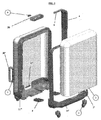
図3の分解図描画は、そのような解決策を構造的に詳細に示している。 The exploded view drawing of FIG. 3 shows such a solution in structural detail.
参照番号30及び30’は、ユーザがスーツケースを2個の異なる方法で持ち上げることができるようにするために、スーツケースの2個の側部に固定されている2つの共通のハンドルを示している。
ハンドルは、例えば、図3の部品7にように回転するように取り付けられている固定胴体に対して回転可能である。 The handle is rotatable with respect to a fixed fuselage that is attached to rotate, for example, as shown in component 7 of FIG.
そのようなハンドルは、背景技術においてそれ自体が周知であって、さらに検討はしない。 Such handles are well known in the background art and will not be considered further.
図3を常に参照して本発明の構造の説明をさらに進めると、シェル2が枠から取り外されていることが明確に示されている。そのようなシェルは、反対側のシェルと同様に、枠から取り外して、再度取り付けたり、他の同等なシェルに交換したりできるように枠に接続されている。
Further discussion of the structure of the present invention with constant reference to FIG. 3 clearly shows that the
そのため、本発明によれば、従来のスーツケースの枠に接続される2個の従来のシェルが、ここでは、完全に取り外して同等のシェルに交換可能になっている。 Therefore, according to the present invention, the two conventional shells connected to the frame of the conventional suitcase can now be completely removed and replaced with equivalent shells.
枠は、旅行鞄の外側の形態に沿っていることが明らかで、ほぼ背景技術のようにシェルが取り付けられる正方形の枠組み11で構成されているが、シェルとの移動可能な結合ができるようにしている特徴を有している。
The frame clearly follows the outer shape of the travel bag and consists of a
特に、枠は、互いに結合する2個の好ましくは対称の部分11’、11”に分割される。枠の各部分は、シェルが固定されるような枠組み11’、11”を構成している。本発明の枠組みは、シェルの縁を上から下に摺動させる側部ガイドを構成している。
In particular, the frame, the two preferably joined together
図6から図11の行程は、そのような解決策を構造的に、そして機能的に非常によく示している。 The steps of FIGS. 6-11 show such a solution very well structurally and functionally.
特に、図6に示しているように、シェルは、柔軟な材料の(たとえば、シェルと同じ材料でもよいが、柔軟でスプリングバックを有するようになる厚さを備えている)付属部分、例えば、フラップ2’をその基部に有している。 In particular, as shown in FIG. 6, the shell is an accessory of a flexible material (eg, it may be the same material as the shell, but has a thickness that makes it flexible and has a springback), eg, It has a flap 2'at its base.
枠11によって構成されているガイドに対してシェルが挿入され摺動する一方で、付属部分は、枠と一体のピボット2”を乗り越え、付属部分に設けられている受け入れ孔に挿入可能になる。
While the shell is inserted and slides with respect to the guide configured by the
図7及び図8は、挿入段階を軸測投影図に示している。 7 and 8 show the insertion stage in an axonometric projection.
図9及び図10の断面は、そのような挿入段階を示しており、フラップに設けられている孔がピボットを内側に挿入するように、フラップはピボットを乗り越えている(図10を参照)。 The cross sections of FIGS. 9 and 10 show such an insertion step, with the flap riding over the pivot so that the holes provided in the flap insert the pivot inward (see FIG. 10).
取り外しのために、ユーザは、ピボットを孔から外してシェルの取り外しに進むように、曲げることによって、フラップを手動で操作することができる。 For removal, the user can manually operate the flap by bending it so that the pivot is removed from the hole and the shell is removed.
そのような解決策は、両方のシェルに対して枠の2個の半分上で使用される。 Such a solution is used on two halves of the frame for both shells.
シェルの他のロックシステムを使用してもよいことは明らかである。 It is clear that other locking systems in the shell may be used.
たとえば、付属部分を機械的な干渉によって座部内でロックしてもよい。 For example, the attachment may be locked within the seat by mechanical interference.
付属部分/ピボットの解決策は、ユーザがフラップを意図的に操作する場合にだけ取り外されるシェルの完璧な保持を保証することが明らかである。そのため、偶然に外れる危険性はなく、そのような解決策は容易に実現できるようになる。 It is clear that the accessory / pivot solution guarantees perfect retention of the shell being removed only if the user intentionally manipulates the flap. Therefore, there is no risk of accidental disengagement, and such a solution can be easily realized.
図3にもよく示されているように、部品6は、枠11’、11’の2個の対称な半分を回転可能に互いに接続しているヒンジを示している。 As is also well shown in FIG. 3, component 6 shows a hinge in which two symmetrical halves of frames 11'and 11' are rotatably connected to each other.
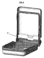
このように、図4にも示しているように、旅行鞄の2個の半分が本のように開かれ、それから再び閉じることができるように、一方を他方に対して開くことができるようになる。 Thus, as shown in FIG. 4, two halves of the travel bag can be opened like a book and then one can be opened to the other so that it can be closed again. Become.
背景技術とは反対に、ヒンジは、スーツケースの側部ではなくその基部、車輪が配置されているちょうどその位置に存在し、開き方は図4に示されているようであり、開いている位置で車輪の対の一方が他方に向かっている。 Contrary to background technology, the hinge is not at the side of the suitcase, but at its base, exactly where the wheels are located, and the opening is as shown in FIG. 4 and is open. At the position one of the pair of wheels is facing the other.
そのため、そのような開き方は、一般的な解決策の代替である。 Therefore, such an opening is an alternative to the general solution.
横に並んでいる少なくとも2個のヒンジ6が設けられるのが好ましい。 It is preferable that at least two hinges 6 arranged side by side are provided.
本発明の構造の説明をさらに進め、図3も参照すると、部品9は、引き出し可能/格納可能なアーム4(つまり伸縮自在アーム)に接続されている牽引ハンドルを示している。 Further describing the structure of the present invention and also with reference to FIG. 3, component 9 shows a tow handle connected to a retractable / retractable arm 4 (ie, telescopic arm).
たとえば図1に示しているアームのような、引き出し可能/格納可能なアームは、背景技術のように使用可能であるが、背景技術とは反対のアーム4は、側部に配置され、枠11の側部に沿って得られている座部に沿って移動する。
A retractable / retractable arm, such as the arm shown in FIG. 1, can be used like the background technique, while the arm 4, which is the opposite of the background technique, is located on the side and
図12は、引き出されており、枠の外周によって得られるある種の軌道に対して摺動して移動する構成のアームを示している。 FIG. 12 shows an arm that is pulled out and slides and moves with respect to a certain trajectory obtained by the outer circumference of the frame.
枠の2個の半分11’、11’は、それらの周囲に沿った摺動ダクトを構成しており、図5に示しているように、ハンドル9は、完全に格納されたときには、胴体と実質的な同じ高さに移動して枠のそのような2個の半分によって区画されている領域内にあって、見えない。このように、ハンドル9とハンドルが接続されているアーム自体が、何の支障もなく枠自体の内側に事実上隠れるので、邪魔を際だって減らすことができる。 The two halves of the frame, 11'and 11', constitute sliding ducts along their perimeter, and as shown in FIG. 5, the handle 9 is with the fuselage when fully retracted. Within the area separated by such two halves of the frame, moving to substantially the same height, invisible. In this way, the arm itself to which the handle 9 and the handle are connected is substantially hidden inside the frame itself without any trouble, so that the obstruction can be remarkably reduced.
図16は、伸縮自在のアームの枠の一方の半分に対する格納と、その結果としての引き出し位置と格納位置との間の摺動をよく示している。図16Aは、参照番号40を付して摺動軌道を示している。
FIG. 16 well illustrates the storage of the telescopic arm with respect to one half of the frame and the resulting sliding between the drawer and storage positions. FIG. 16A shows the sliding track with
背景技術による周知のロックを、アームの引き出しストロークを制限するのに使用することができるのは明らかである。 It is clear that well-known locks from background techniques can be used to limit the pull-out stroke of the arm.
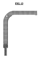
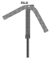
図13から図15の行程に示しているように、ハンドル9は、使用者の都合のよい位置で必要に応じて回転できるように一点でヒンジ接続することが可能である。ハンドル9は、L形状であることが有利である。 As shown in the steps of FIGS. 13 to 15, the handle 9 can be hinged at one point so that it can rotate at a convenient position for the user as needed. It is advantageous that the handle 9 has an L shape.
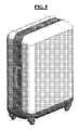
図17は、本発明によって、旅行鞄上で外部シェルが様々なモデルに交換されている説明のための例である。 FIG. 17 is an example for illustration in which the external shell is replaced by various models on the travel bag according to the present invention.
この例の場合、従来の型の引き出し可能なハンドルを備えているスーツケースを明確化のためだけに、そして非限定的に示している。 In the case of this example, a suitcase with a conventional type pullable handle is shown for clarity only and in a non-limiting manner.
前述の説明は、各容器に対して当てはまり、実際に同じ解決策はバックパックにも有効である。 The above explanation applies to each container, and in fact the same solution works for backpacks as well.
より詳細には、図18は、本発明のバックパックの分解図描画を示している。 More specifically, FIG. 18 shows an exploded view drawing of the backpack of the present invention.
そのようなバックパックは、スーツケースのように、バックパックの輪郭の形状に沿った同様な環状要素の形態の枠102を有している。
Such a backpack, like a suitcase, has a
そのような環状の要素は、スーツケースの解決策のように、バックパックの硬質または半硬質のシェルを取り外し可能に保持しロックするのに必要である。 Such an annular element is needed to detachably hold and lock the hard or semi-hard shell of the backpack, as in the suitcase solution.
この目的のために、図18は、参照番号101を付して、全長にわたってシェルの境界が環状の枠に接触するまで、自体を環状の枠の内部に挿入するシェルを示している。スーツケースの解決策とは反対に、この場合、シェルを枠に対して摺動させるのではなく、枠に固定されている移動ピボット105がシェルの受け入れ孔106の内部に挿入可能になるようにシェルを押すことによって挿入は発生する。
For this purpose, FIG. 18, with reference number 101, shows a shell that inserts itself inside the annular frame until the boundary of the shell touches the annular frame over its entire length. Contrary to the suitcase solution, in this case, instead of sliding the shell against the frame, the moving
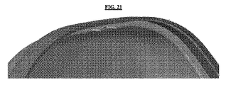
そのような解決策は、図19から図21の拡大図により詳細に説明されている。 Such a solution is described in detail by the enlarged views of FIGS. 19 to 21.
図19は、枠を構成している環状要素にシェルを結合しなければならない時のピボット105を示している。図20は、発生した結合を示している。ピボットは、3角形つまり矢の形態に形作られており、ピボットが完全に挿入されながら一度反発して反対側に移動して自体をロックするまで、シェルが移動してピボットが孔の内部に挿入されている時に、その横断方向の直動を可能にする傾斜した側部を有している。実際に、そのようなピボットを、右側いっぱいに直動している図19の位置に保持するばねが備わっている。傾斜している側部のおかげで、孔106の内側へ徐々に挿入されながら、ピボットは左に直動し、孔をいったん横切ると、ばね(または一般的な他の弾性要素)の作動のおかげで図19の位置に戻り、自体をしっかりとロックする。
FIG. 19 shows a
ユーザは、シェルを取り外すために手動で、したがって、ばね(または一般的な弾性要素)の力にうち勝って、ピボットを左に移動させなければならない。 The user must manually move the pivot to the left to remove the shell, thus overcoming the force of the spring (or common elastic element).
図21は、2個の対称なピボット及び2個の受け入れ孔を備えている解決策を示している。 FIG. 21 shows a solution with two symmetrical pivots and two receiving holes.
要求があれば、そのような解決策は、スーツケース、好ましくは小さいサイズのスーツケースにも適合可能である。 If required, such a solution is also applicable to suitcases, preferably small size suitcases.
スーツケースおよびバックパックの両方、または他の一般的な容器の構成において、シェルまたは半分のシェルは、プラスチック、炭素繊維、PVC、ポリプロピレン、ABS、ポリカーボネート、および同様な材料などの硬質の材料で作られており、形作られることが好ましい。 In both suitcases and backpacks, or other common container configurations, the shell or half shell is made of hard materials such as plastic, carbon fiber, PVC, polypropylene, ABS, polycarbonate, and similar materials. It was and is preferably shaped.
さらに、シェルのそのようなサイズは、全体の収容容積のほぼ対称な半分を一般に区分する(たとえば、スーツケースの2個のシェルまたはバックパックのシェルのように)。 In addition, such size of the shell generally divides a nearly symmetrical half of the total capacity (for example, two shells in a suitcase or a shell in a backpack).
さらに、そのようなシェルは、例えばゴムなどの半硬質の材料でも実現されるかもしれない。その結果、高い柔軟性と衝撃吸収性の両方を有することになろう。 Moreover, such shells may also be realized with a material of semi-rigid, such as rubber. As a result, it will have both high flexibility and shock absorption.
その代わりに、織物は除外されるが、それは衝撃から保護できないからである。 Instead, textiles are excluded because they cannot be protected from impact.
本発明において、硬質または半硬質の材料は、スーツケースを覆うことになり、そのため旅行鞄の半分(または旅行鞄全体)の形状を維持する半分のスーツケース(または旅行鞄全体)の形状及びスーツケースに取り付けらない覆いの形状が得られるように、たとえば、金型における成形材料を有している。 In the present invention, a hard or semi-rigid material will cover the suitcase, thus maintaining the shape of half the suitcase (or the entire travel bag) and the shape and suit of the half suitcase (or the entire travel bag). For example, the molding material in the mold is provided so that a cover shape that does not attach to the case can be obtained.
その意味で、織物は、硬質または半硬質の材料とは考えられない。 In that sense, woven fabrics are not considered to be hard or semi-rigid materials.
しかし、旅行鞄の構成をさらに変えるために、前述の硬質または半硬質の材料の、しかし、デニムの織物などの織物で外部が覆われているシェルを設けることができる。そのような解決策は、すべての前述の構成に有効である。 However, in order to further change the composition of the travel bag, it is possible to provide a shell of the above-mentioned hard or semi-hard material, but the outside is covered with a woven fabric such as a denim woven fabric. Such a solution works for all the aforementioned configurations.
半分のシェルに結合可能な態様で配置されているスーツケース販売及び、必要に応じて交換するために、そのようなスーツケース用の1個または2個以上の取り換え可能な半分のシェルの別個の販売を決定することができるのは明らかである。 Suitcases that are arranged in a manner that can be combined into half shells and separate one or more replaceable half shells for such suitcases for replacement as needed It is clear that the sale can be decided.
前述の記述全体は、物体、衣類、アクセサリ、本を搬送するための任意の個人用容器に有効である。 The entire description above is valid for any personal container for transporting objects, clothing, accessories and books.
そのため、その意味で、本発明は、単なるスーツケース(トロリースーツケースを含むあらゆる種類のスーツケースを意味する)だけではなく、バッグ、バックパック、ポーチ、および個人が使用し、ユーザが運搬する容器にも限定されていない。 Therefore, in that sense, the present invention is not just a suitcase (meaning all types of suitcases, including trolley suitcases), but bags, backpacks, pouches, and containers used by individuals and carried by users. Not limited to.
Claims (10)
枠(11)に接続されており、内側の収容容積を少なくとも部分的に区分し、硬質または半硬質の材料から作られている、左と右のシェル(2)と、
を有し、
左と右の前記シェル(2)のそれぞれが前記枠(11)から取り外したり、前記枠(11)に再度取り付けたり、他の同等なシェルに交換したりできるように、2つの前記シェル(2)を前記枠(11)に交換可能な態様で接続するために、締結接続手段を有しており、前記枠(11)は、2個の部分に分割され、2個の前記部分は、ほぼ長方形であり、2つの側面、上面及び底面を有し、互いに結合し、2つの前記側面は前記部分の外側に縁ガイドを構成し、前記縁ガイドは、前記シェル(2)の縁を前記部分の前記上面から前記底面に摺動させることを特徴とする、
スーツケース(1)。 Ring frame (11) and
The left and right shells ( 2 ), which are connected to the frame (11) and at least partially divide the inner containment volume and are made of hard or semi-hard material,
Have,
Two of the shells (2) so that each of the left and right shells (2) can be removed from the frame (11), reattached to the frame (11), or replaced with another equivalent shell. ) Is interchangeably connected to the frame (11), the frame (11) is divided into two parts, and the two parts are approximately the same. It is rectangular and has two sides, a top surface and a bottom surface, coupled to each other, the two said sides forming an edge guide on the outside of the portion, the edge guide having the edge of the shell (2) as the portion. It is characterized in that it slides from the upper surface to the bottom surface.
Suitcase (1).
Applications Claiming Priority (3)
| Application Number | Priority Date | Filing Date | Title |
|---|---|---|---|
| ITUB2015A009427A ITUB20159427A1 (en) | 2015-12-15 | 2015-12-15 | A suitcase, preferably rigid, with an interchangeable protective outer shell. |
| IT102015000083280 | 2015-12-15 | ||
| PCT/IB2016/055435 WO2017103695A1 (en) | 2015-12-15 | 2016-09-13 | A suitcase, preferably of the rigid type, with an interchangeable external case |
Publications (3)
| Publication Number | Publication Date |
|---|---|
| JP2018537189A JP2018537189A (en) | 2018-12-20 |
| JP2018537189A5 JP2018537189A5 (en) | 2020-09-03 |
| JP6868622B2 true JP6868622B2 (en) | 2021-05-12 |
Family
ID=55588460
Family Applications (1)
| Application Number | Title | Priority Date | Filing Date |
|---|---|---|---|
| JP2018527966A Active JP6868622B2 (en) | 2015-12-15 | 2016-09-13 | A suitcase preferably of a rigid model with a replaceable outer case |
Country Status (7)
| Country | Link |
|---|---|
| US (1) | US11432628B2 (en) |
| EP (1) | EP3389430B1 (en) |
| JP (1) | JP6868622B2 (en) |
| KR (1) | KR20180093909A (en) |
| CN (1) | CN108366655B (en) |
| IT (1) | ITUB20159427A1 (en) |
| WO (1) | WO2017103695A1 (en) |
Families Citing this family (2)
| Publication number | Priority date | Publication date | Assignee | Title |
|---|---|---|---|---|
| US10993517B2 (en) * | 2017-11-27 | 2021-05-04 | High Hope Zhongding Corporation | Suitcase with a detachable portion |
| US11413738B1 (en) * | 2021-02-03 | 2022-08-16 | Ming Shin Tools Co., Ltd. | Toolbox |
Family Cites Families (26)
| Publication number | Priority date | Publication date | Assignee | Title |
|---|---|---|---|---|
| US4344646A (en) * | 1980-05-27 | 1982-08-17 | Woodstream Corporation | Detachable latch |
| EP0079395B1 (en) * | 1981-11-12 | 1986-06-18 | ZINTZMEYER & LUX AG | Case with variable volume |
| US4852520A (en) * | 1987-11-16 | 1989-08-01 | Alco Industries, Inc. | Portable pet carrier |
| FR2645416A1 (en) * | 1989-04-10 | 1990-10-12 | Pinault Robert | Modular case for transporting everyday articles outside one's home |
| US5048649A (en) | 1990-03-02 | 1991-09-17 | American Tourister, Inc. | Luggage with pull handle |
| DE4221215A1 (en) * | 1992-06-27 | 1994-01-05 | Karl Adolf Weidt | Suitcase with top seat near handle - has flat moulded part near carrying handle, and hook for attaching bags. |
| US5529156A (en) * | 1994-03-11 | 1996-06-25 | Yang; Fu-Hsiung | Frame work for soft-sided luggage |
| KR970704369A (en) * | 1994-07-19 | 1997-09-06 | 저스틴 원카 | Variable capacity suitcases (SUITCASE WITH VARIABLE CAPACITY) |
| US5685451A (en) * | 1996-01-17 | 1997-11-11 | Delta Consolidated Industries | Carrying case with inserted nameplate |
| DE29702619U1 (en) * | 1997-02-14 | 1998-06-10 | MP Michael Pfeiffer Design & Marketing GmbH, 85649 Brunnthal | Case with changeable capacity |
| JP3464393B2 (en) * | 1998-09-24 | 2003-11-10 | 明治合成株式会社 | bag |
| US20020014382A1 (en) * | 2000-08-01 | 2002-02-07 | Chaw Khong Technology Co., Ltd. | Combination carrying handle and retractable handle |
| JP2003189918A (en) * | 2001-12-27 | 2003-07-08 | Matsuzaki:Kk | Bag |
| CN2634883Y (en) * | 2003-08-04 | 2004-08-25 | 高志伟 | Suitcase |
| US7240778B2 (en) * | 2004-08-06 | 2007-07-10 | Umagination Labs, L.P. | Personalizing luggage |
| CN2909606Y (en) * | 2006-03-11 | 2007-06-06 | 富士康(昆山)电脑接插件有限公司 | Fixing device for electric connector |
| ITBO20060287A1 (en) * | 2006-04-14 | 2007-10-15 | Gt Line Srl | PROFESSIONAL CASE WITH SIMPLIFIED MOUNTING. |
| EP1867246B1 (en) * | 2006-06-16 | 2014-11-19 | Valigeria Roncato S.p.A. | Lightweight structured suitcase |
| JP3125023U (en) * | 2006-06-23 | 2006-09-07 | 衣川産業株式会社 | Motorcycle bag |
| US20110155526A1 (en) * | 2009-12-30 | 2011-06-30 | Chao Ming Cheng | Suitcase having protective shield |
| WO2011093984A1 (en) * | 2010-01-29 | 2011-08-04 | Heys (USA), Inc. | Hard -sided expandable suitcase |
| US20150114776A1 (en) * | 2012-05-10 | 2015-04-30 | Travelpro International, Inc. | Soft sided luggage frame |
| TWM462020U (en) * | 2013-02-08 | 2013-09-21 | Tang ting ting | Luggage structure with protective cover |
| WO2015127779A1 (en) * | 2014-02-27 | 2015-09-03 | 陈国平 | Detachable combined draw-bar box |
| CA2915616A1 (en) * | 2014-12-19 | 2016-06-19 | Minmor Industiries, Llc | Decorative sleeve for candles and lights with interlocking connectors |
| TWM541768U (en) * | 2017-01-25 | 2017-05-21 | 吳禎權 | Trunk |
-
2015
- 2015-12-15 IT ITUB2015A009427A patent/ITUB20159427A1/en unknown
-
2016
- 2016-09-13 CN CN201680074698.9A patent/CN108366655B/en active Active
- 2016-09-13 EP EP16825551.1A patent/EP3389430B1/en active Active
- 2016-09-13 KR KR1020187015831A patent/KR20180093909A/en not_active Application Discontinuation
- 2016-09-13 US US16/063,231 patent/US11432628B2/en active Active
- 2016-09-13 JP JP2018527966A patent/JP6868622B2/en active Active
- 2016-09-13 WO PCT/IB2016/055435 patent/WO2017103695A1/en active Application Filing
Also Published As
| Publication number | Publication date |
|---|---|
| EP3389430B1 (en) | 2021-02-24 |
| WO2017103695A9 (en) | 2017-09-08 |
| US11432628B2 (en) | 2022-09-06 |
| US20200268118A1 (en) | 2020-08-27 |
| CN108366655A (en) | 2018-08-03 |
| WO2017103695A1 (en) | 2017-06-22 |
| CN108366655B (en) | 2020-12-08 |
| ITUB20159427A1 (en) | 2017-06-15 |
| EP3389430A1 (en) | 2018-10-24 |
| KR20180093909A (en) | 2018-08-22 |
| JP2018537189A (en) | 2018-12-20 |
Similar Documents
| Publication | Publication Date | Title |
|---|---|---|
| EP2685863B1 (en) | Hard-sided luggage bag with front lid | |
| CA2821860C (en) | Improved articles of luggage | |
| US11571051B2 (en) | Expandable luggage assemblies | |
| CN110786608A (en) | Luggage system | |
| JP2021532842A (en) | Luggage supplies divided along the front and rear main surfaces | |
| US10413045B2 (en) | Hard shell backpack | |
| US20200352292A1 (en) | Luggage with Pocket | |
| US20050056511A1 (en) | Case having shell members formed from molded plastic shell parts and a fabric covering | |
| CA2803708C (en) | Foldable travel bags and methods to manufacture foldable travel bags | |
| JP6868622B2 (en) | A suitcase preferably of a rigid model with a replaceable outer case | |
| CN210076794U (en) | Modular luggage article | |
| US20170020254A1 (en) | Decorative Luggage | |
| JP2018537189A5 (en) | ||
| US6499575B1 (en) | Wheeled luggage | |
| US20230276915A1 (en) | Expandable Luggage Assemblies | |
| JP3181838U (en) | Suitcase base and suitcase using the same | |
| US9999283B2 (en) | Collapsible luggage and a method for its use | |
| CN210043370U (en) | Luggage article | |
| KR101869079B1 (en) | Luggage with an auxiliary compartment | |
| BE1023052B1 (en) | BIKE CHAIR FOR CHILDREN | |
| KR20200007188A (en) | Bag | |
| TWM516349U (en) | Frame structure for luggage | |
| BE1023052A1 (en) | BIKE CHAIR FOR CHILDREN | |
| KR20120005638U (en) | Portable multipurpose Bag |
Legal Events
| Date | Code | Title | Description |
|---|---|---|---|
| A521 | Request for written amendment filed |
Free format text: JAPANESE INTERMEDIATE CODE: A523 Effective date: 20180725 |
|
| A621 | Written request for application examination |
Free format text: JAPANESE INTERMEDIATE CODE: A621 Effective date: 20190912 |
|
| A521 | Request for written amendment filed |
Free format text: JAPANESE INTERMEDIATE CODE: A523 Effective date: 20191223 |
|
| A521 | Request for written amendment filed |
Free format text: JAPANESE INTERMEDIATE CODE: A523 Effective date: 20200722 |
|
| A977 | Report on retrieval |
Free format text: JAPANESE INTERMEDIATE CODE: A971007 Effective date: 20200807 |
|
| A131 | Notification of reasons for refusal |
Free format text: JAPANESE INTERMEDIATE CODE: A131 Effective date: 20200818 |
|
| A521 | Request for written amendment filed |
Free format text: JAPANESE INTERMEDIATE CODE: A523 Effective date: 20201021 |
|
| TRDD | Decision of grant or rejection written | ||
| A01 | Written decision to grant a patent or to grant a registration (utility model) |
Free format text: JAPANESE INTERMEDIATE CODE: A01 Effective date: 20210330 |
|
| A61 | First payment of annual fees (during grant procedure) |
Free format text: JAPANESE INTERMEDIATE CODE: A61 Effective date: 20210412 |
|
| R150 | Certificate of patent or registration of utility model |
Ref document number: 6868622 Country of ref document: JP Free format text: JAPANESE INTERMEDIATE CODE: R150 |
|
| R250 | Receipt of annual fees |
Free format text: JAPANESE INTERMEDIATE CODE: R250 |