JP6868515B2 - Structure management device, structure management method, and structure management program - Google Patents
Structure management device, structure management method, and structure management program Download PDFInfo
- Publication number
- JP6868515B2 JP6868515B2 JP2017174953A JP2017174953A JP6868515B2 JP 6868515 B2 JP6868515 B2 JP 6868515B2 JP 2017174953 A JP2017174953 A JP 2017174953A JP 2017174953 A JP2017174953 A JP 2017174953A JP 6868515 B2 JP6868515 B2 JP 6868515B2
- Authority
- JP
- Japan
- Prior art keywords
- model
- photograph
- unit
- deformed
- deformation
- Prior art date
- Legal status (The legal status is an assumption and is not a legal conclusion. Google has not performed a legal analysis and makes no representation as to the accuracy of the status listed.)
- Active
Links
- 238000007726 management method Methods 0.000 title claims description 119
- 238000000034 method Methods 0.000 claims description 146
- 238000005259 measurement Methods 0.000 claims description 74
- 238000007689 inspection Methods 0.000 claims description 65
- 238000012545 processing Methods 0.000 claims description 44
- 238000012423 maintenance Methods 0.000 claims description 8
- 238000010276 construction Methods 0.000 description 37
- 230000008569 process Effects 0.000 description 36
- 238000010586 diagram Methods 0.000 description 33
- 238000005516 engineering process Methods 0.000 description 26
- 230000000750 progressive effect Effects 0.000 description 25
- 238000011161 development Methods 0.000 description 20
- 230000018109 developmental process Effects 0.000 description 20
- 230000008439 repair process Effects 0.000 description 18
- 230000008859 change Effects 0.000 description 14
- 230000006870 function Effects 0.000 description 13
- 238000003860 storage Methods 0.000 description 7
- 238000004364 calculation method Methods 0.000 description 6
- 230000002250 progressing effect Effects 0.000 description 6
- 238000000691 measurement method Methods 0.000 description 5
- 230000009466 transformation Effects 0.000 description 5
- 230000032683 aging Effects 0.000 description 4
- 238000010187 selection method Methods 0.000 description 4
- 230000008901 benefit Effects 0.000 description 3
- 238000013070 change management Methods 0.000 description 3
- 238000012937 correction Methods 0.000 description 3
- 230000000694 effects Effects 0.000 description 3
- 238000000605 extraction Methods 0.000 description 3
- 238000003384 imaging method Methods 0.000 description 2
- 230000007246 mechanism Effects 0.000 description 2
- NJPPVKZQTLUDBO-UHFFFAOYSA-N novaluron Chemical compound C1=C(Cl)C(OC(F)(F)C(OC(F)(F)F)F)=CC=C1NC(=O)NC(=O)C1=C(F)C=CC=C1F NJPPVKZQTLUDBO-UHFFFAOYSA-N 0.000 description 2
- 241000226585 Antennaria plantaginifolia Species 0.000 description 1
- 229910000831 Steel Inorganic materials 0.000 description 1
- 238000004220 aggregation Methods 0.000 description 1
- 230000002776 aggregation Effects 0.000 description 1
- 238000013459 approach Methods 0.000 description 1
- 230000005540 biological transmission Effects 0.000 description 1
- 238000012790 confirmation Methods 0.000 description 1
- 238000007796 conventional method Methods 0.000 description 1
- 230000006866 deterioration Effects 0.000 description 1
- 238000007667 floating Methods 0.000 description 1
- 238000010191 image analysis Methods 0.000 description 1
- 230000008676 import Effects 0.000 description 1
- 230000000873 masking effect Effects 0.000 description 1
- 238000005457 optimization Methods 0.000 description 1
- 230000002093 peripheral effect Effects 0.000 description 1
- 238000013439 planning Methods 0.000 description 1
- 238000003825 pressing Methods 0.000 description 1
- 230000003449 preventive effect Effects 0.000 description 1
- 238000003672 processing method Methods 0.000 description 1
- 230000002787 reinforcement Effects 0.000 description 1
- 230000003014 reinforcing effect Effects 0.000 description 1
- 239000010959 steel Substances 0.000 description 1
- 230000001360 synchronised effect Effects 0.000 description 1
- 238000012546 transfer Methods 0.000 description 1
Images


Landscapes
- Bridges Or Land Bridges (AREA)
- Processing Or Creating Images (AREA)
Description
本発明は、橋梁などの構造物を管理するための構造物管理装置、構造物管理方法、及び構造物管理プログラムに関し、特に、橋梁などの構造物における進行性変状を効果的に把握する技術に関する。 The present invention relates to a structure management device for managing a structure such as a bridge, a structure management method, and a structure management program, and in particular, a technique for effectively grasping progressive deformation in a structure such as a bridge. Regarding.
橋梁などの構造物は、検査−計画−工事といった一連の流れで管理すべきであり、こういった総合的マネジメント手法としてアセットマネジメントがある。アセットマネジメントでは、検査や工事の履歴を適切かつ時系列に管理することが重要であり、その管理を容易にするため、基本管理図と呼ばれる構造物管理用図面を用いるのが一般的である。 Structures such as bridges should be managed in a series of steps such as inspection-planning-construction, and there is asset management as such a comprehensive management method. In asset management, it is important to manage the history of inspections and constructions appropriately and in chronological order, and in order to facilitate the management, it is common to use a drawing for structure management called a basic control chart.
基本管理図を作成するには、橋梁構造物を測定する必要がある。その測定方法としては、TS(トータルステーション)による方法と、地上レーザーによる方法と、ステレオカメラによる方法の3通りの方法が知られている。また、基本管理図の管理方法としては、2次元的な管理方法や、撮影写真による管理方法がある。2次元的な管理方法は、橋梁構造物を2次元図面で管理する方法であり、紙ベースやCADなどで管理する場合によく用いられる。一方、撮影写真による管理方法とは、橋梁構造物の測定時や点検時などに橋梁構造物をデジタルカメラなどで撮影し、その撮影写真を管理しておくというものである。この管理方法は、橋梁構造物のありのままの変状を記録・管理したい場合に適している。撮影写真は膨大な枚数になるため、電子化してリスト形式やカタログ形式によりコンピュータ上で管理するのが一般的である。 To create a basic control chart, it is necessary to measure the bridge structure. Three methods are known as the measurement method: a method using a TS (total station), a method using a ground laser, and a method using a stereo camera. Further, as a management method of the basic control chart, there are a two-dimensional management method and a management method using photographed photographs. The two-dimensional management method is a method of managing a bridge structure with a two-dimensional drawing, and is often used when managing with a paper base or CAD. On the other hand, the management method using photographed photographs is to photograph the bridge structure with a digital camera or the like at the time of measurement or inspection of the bridge structure, and manage the photographed photograph. This management method is suitable when it is desired to record and manage the natural deformation of the bridge structure. Since the number of photographed photographs is enormous, it is common to digitize them and manage them on a computer in a list format or a catalog format.
しかしながら、このような従来技術によると、橋梁構造物の測定が煩雑となり、また基本管理図の作成コストが掛かるという課題がある。すなわち、TSや地上レーザーなどの高価な測定装置を用いれば、高精度に橋梁構造物を測定することができるが、基本管理図は、通常維持管理の検査業務のベースマップに使用するものであり、必要以上に高精度である必要はない。また、基本管理図を作成するための必要要件は、現地での測定作業が少なく、室内作業において容易に基本管理図を作成できることである。さらに、現地での測定作業を少なくするという意味では、ステレオカメラを用いた方法は有効であるが、橋梁構造物を一から作成することは室内作業工数が掛かるため実現的でない。 However, according to such a conventional technique, there is a problem that the measurement of the bridge structure becomes complicated and the cost of creating the basic control chart is high. That is, bridge structures can be measured with high accuracy by using expensive measuring devices such as TS and ground laser, but the basic control chart is usually used as a base map for maintenance inspection work. , It doesn't have to be more accurate than necessary. In addition, the necessary requirement for creating a basic control chart is that there is little on-site measurement work and it is possible to easily create a basic control chart in indoor work. Further, although the method using a stereo camera is effective in terms of reducing the on-site measurement work, it is not feasible to create the bridge structure from scratch because it requires man-hours for indoor work.
そこで、本出願人は、上記課題を解決するため、時系列管理に適した構造物管理用図面を容易に作成することのできる構造物管理用図面作成装置を提案している(特許文献1参照)。特許文献1に開示される構造物管理用図面作成装置によれば、撮影写真や変状・補修図形を時系列管理することができるため、時系列管理に適した構造物管理用図面を容易に作成することが可能となる。
Therefore, in order to solve the above problems, the applicant has proposed a structure management drawing creation device capable of easily creating a structure management drawing suitable for time series management (see Patent Document 1). ). According to the structure management drawing creation device disclosed in
ところで、検査作業においては、予防保全の観点から、ひび割れなどの変状がどのように進行しているか適切に記録し、時系列に履歴管理することが重要である。検査作業は、煩雑で且つ時間を要する作業であるため、簡単な操作で効率的に行えるようにすることが要望されている。具体的には、継続的検査における要望として、2回目以降の検査作業の効率化を図りたい(誰もが簡単に行えるデータ更新方法を実現したい)という要望がある。また、劣化の進行性を把握するために正確に記録したい(時系列で整合性の取れた記録方法を実現したい)という要望もある。 By the way, in the inspection work, from the viewpoint of preventive maintenance, it is important to appropriately record how the deformation such as cracks is progressing and manage the history in chronological order. Since the inspection work is a complicated and time-consuming work, it is required to be able to perform it efficiently with a simple operation. Specifically, as a request for continuous inspection, there is a request to improve the efficiency of the second and subsequent inspection work (to realize a data update method that anyone can easily perform). There is also a demand for accurate recording (to realize a time-series and consistent recording method) in order to grasp the progress of deterioration.
本発明は、上記課題を解決するためになされたものであり、構造物における進行性変状を効果的に把握することのできる構造物管理装置、構造物管理方法、及び構造物管理プログラムを提供することを目的とする。 The present invention has been made to solve the above problems, and provides a structure management device, a structure management method, and a structure management program capable of effectively grasping progressive deformation in a structure. The purpose is to do.
本発明の一態様に係る構造物管理装置は、構造物を管理するための構造物管理装置であって、前記構造物の構造パラメータ及び前記構造物の撮影写真を登録する登録部と、前記構造物の3Dモデルを前記構造パラメータを用いて作成する3Dモデル作成部と、前記3Dモデル作成部により作成された3Dモデルと前記登録部により登録された前回の撮影写真とが対応付けられている状態で、前記登録部により今回の撮影写真が登録された場合、前回の撮影写真と今回の撮影写真との対応点を特徴量マッチング手法により取得する対応点取得部と、前記対応点取得部により取得された対応点を選別する対応点選別部と、前記対応点選別部により選別された対応点に基づいて今回の撮影写真を前記3Dモデルと対応付けて3D空間に配置する3D空間配置部とを備えたことを要旨とする。 The structure management device according to one aspect of the present invention is a structure management device for managing a structure, and includes a registration unit for registering structural parameters of the structure and a photograph of the structure, and the structure. A state in which a 3D model creation unit that creates a 3D model of an object using the structural parameters, a 3D model created by the 3D model creation unit, and a previously photographed photograph registered by the registration unit are associated with each other. Then, when the photograph taken this time is registered by the registration unit, the corresponding point acquisition unit that acquires the corresponding points between the previously photographed photograph and the photograph taken this time by the feature amount matching method and the corresponding point acquisition unit acquire the corresponding points. A correspondence point selection unit that selects the corresponding points, and a 3D space arrangement unit that arranges the photograph taken this time in the 3D space in association with the 3D model based on the correspondence points selected by the correspondence point selection unit. The gist is that we have prepared.
本発明の一態様に係る構造物管理方法は、構造物を管理するための構造物管理方法であって、前記構造物の構造パラメータ及び前記構造物の撮影写真を登録する登録ステップと、前記構造物の3Dモデルを前記構造パラメータを用いて作成する3Dモデル作成ステップと、前記3Dモデル作成ステップで作成された3Dモデルと前記登録ステップで登録された前回の撮影写真とが対応付けられている状態で、前記登録ステップで今回の撮影写真が登録された場合、前回の撮影写真と今回の撮影写真との対応点を特徴量マッチング手法により取得する対応点取得ステップと、前記対応点取得ステップで取得された対応点を選別する対応点選別ステップと、前記対応点選別ステップで選別された対応点に基づいて今回の撮影写真を前記3Dモデルと対応付けて3D空間に配置する3D空間配置ステップとを含むことを要旨とする。 The structure management method according to one aspect of the present invention is a structure management method for managing a structure, which includes a registration step for registering a structural parameter of the structure and a photograph of the structure, and the structure. A state in which a 3D model creation step of creating a 3D model of an object using the structural parameters, a 3D model created in the 3D model creation step, and a previously photographed photograph registered in the registration step are associated with each other. Then, when the photograph taken this time is registered in the registration step, the corresponding point acquisition step of acquiring the corresponding point between the photograph taken last time and the photograph taken this time by the feature amount matching method and the corresponding point acquisition step are acquired. A corresponding point selection step for selecting the corresponding points selected, and a 3D space arrangement step for arranging the photograph taken this time in the 3D space in association with the 3D model based on the corresponding points selected in the corresponding point selection step. The gist is to include it.
本発明の一態様に係る構造物管理プログラムは、前記構造物管理装置としてコンピュータを機能させることを要旨とする。 The gist of the structure management program according to one aspect of the present invention is to make a computer function as the structure management device.
本発明によれば、構造物における進行性変状を効果的に把握することのできる構造物管理装置、構造物管理方法、及び構造物管理プログラムを提供することが可能である。 According to the present invention, it is possible to provide a structure management device, a structure management method, and a structure management program capable of effectively grasping progressive deformation in a structure.
以下、本発明の実施の形態について図面を参照して詳細に説明する。なお、図面の記載において、同一または類似の部分には同一または類似の符号を付している。ただし、図面は模式的なものであり、厚みと平面寸法との関係、各層の厚みの比率などは現実のものとは異なることに留意すべきである。したがって、具体的な厚みや寸法は以下の説明を参酌して判断すべきものである。また、図面相互間においても互いの寸法の関係や比率が異なる部分が含まれていることは勿論である。 Hereinafter, embodiments of the present invention will be described in detail with reference to the drawings. In the description of the drawings, the same or similar parts are designated by the same or similar reference numerals. However, it should be noted that the drawings are schematic, and the relationship between the thickness and the plane dimension, the ratio of the thickness of each layer, etc. are different from the actual ones. Therefore, the specific thickness and dimensions should be determined in consideration of the following explanation. In addition, it goes without saying that the drawings include parts having different dimensional relationships and ratios from each other.
≪基本技術≫
本発明は、特許文献1に開示される技術(以下、「基本技術」という。)の改良発明である。そのため、まずは基本技術の内容について説明する。
≪Basic technology≫
The present invention is an improved invention of the technique disclosed in Patent Document 1 (hereinafter, referred to as "basic technique"). Therefore, the contents of the basic technology will be explained first.
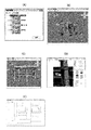
図1は、基本技術における構造物管理用図面作成装置10の構成図である。この構造物管理用図面作成装置10は、橋梁などの構造物の管理用図面(以下、「基本管理図」という場合がある。)を作成する装置であって、図1に示すように、登録部11と、基本管理図作成部12と、出力部13と、記憶部14と、3D(dimension)モデル作成部15と、3D空間配置部16と、3Dモデル再構成部17と、変状測定部18とを備えている。
FIG. 1 is a configuration diagram of a
登録部11は、構造物の構造パラメータや構造物の撮影写真などの各種情報を登録する。構造物の撮影写真としては、ステレオ撮影装置20により撮影されたステレオ撮影写真(右,左)を用いることができる。記憶部14は、各種情報を記憶するためのメモリである。3Dモデル作成部15は、構造物の3Dモデルを構造パラメータなどを用いて作成する。3D空間配置部16は、撮影写真を3D空間(X,Y,Z)に配置する。3Dモデル再構成部17は、3Dモデルの部材寸法を撮影写真を用いて更新し、更新後の部材寸法を用いて3Dモデルを再構成する。基本管理図作成部12は、再構成された3Dモデルを用いて管理用図面を作成する。出力部13は、作成された管理用図面を出力する。変状測定部18は、撮影写真上の変状箇所の位置及び数量を測定する。以下、機能別に詳しく説明する。
The
(基本管理図作成方法)
既に説明した通り、従来技術によると、橋梁構造物の測定が煩雑となり、また基本管理図の作成コストが掛かるという課題がある。そこで、基本技術では、時系列管理に適した基本管理図を容易に作成できるようにするため、以下の手法を採用している。
(How to create a basic control chart)
As described above, according to the prior art, there is a problem that the measurement of the bridge structure becomes complicated and the cost of creating the basic control chart is high. Therefore, in the basic technology, the following method is adopted so that a basic control chart suitable for time series management can be easily created.
図2は、基本技術におけるステレオ撮影装置20の概観図である。このステレオ撮影装置20は、図2に示すように、一脚21の一方端にステレオ架台22を備え、そのステレオ架台22には、2台のデジタルカメラ23が所定の間隔で取り付けられている。2台のデジタルカメラ23には、リモートシャッターケーブル24が接続されており、2台同時シャッターリリースが可能となっている。
FIG. 2 is an overview view of the
図3は、基本技術における基本管理図作成方法を示す図である。まず、橋梁構造別の橋梁3Dモデルのうち所望の橋梁3Dモデルを選択する。例えば、「ラーメン高架橋」「コンクリート単T桁(ゲルバー桁)」「コンクリート単版桁(スラブ桁)」「PC構造(I形桁、T形桁)」などの橋梁構造別の橋梁3Dモデルのうち「ラーメン高架橋」を選択すると、図3(A)に示すように、ラーメン高架橋の構造パラメータを入力するための画面が表示される。次いで、ラーメン高架橋の構造パラメータを入力すると、図3(B)に示すように、ラーメン高架橋の初期橋梁3Dモデルが表示される。初期橋梁3Dモデルが表示されると、ステレオ撮影写真を用いて部材寸法を測定する。この測定方法の詳細については後述するが、図3(C)に示すように、撮影写真上で測定したい箇所のみを指示すればよいようになっている。部材寸法を測定すると、図3(D)に示すように、測定した部材寸法に再構成された橋梁3Dモデルが完成する。この状態で出力を指示すると、図3(E)に示すように、完成した橋梁3Dモデルを用いて基本管理図(例えば展開図)が作成され、作成された基本管理図が出力される。 FIG. 3 is a diagram showing a method of creating a basic control chart in the basic technology. First, a desired bridge 3D model is selected from the bridge 3D models for each bridge structure. For example, among bridge 3D models by bridge structure such as "Rahmen high bridge", "Concrete single T girder (Gerber girder)", "Concrete single plate girder (Slab girder)", "PC structure (I type girder, T type girder)" When "Rahmen girder bridge" is selected, a screen for inputting structural parameters of the rigid frame girder bridge is displayed as shown in FIG. 3 (A). Next, when the structural parameters of the rigid frame viaduct are input, the initial bridge 3D model of the rigid frame viaduct is displayed as shown in FIG. 3 (B). When the initial bridge 3D model is displayed, the member dimensions are measured using stereo photographs. The details of this measurement method will be described later, but as shown in FIG. 3C, it is only necessary to indicate the portion to be measured on the photographed photograph. When the member dimensions are measured, as shown in FIG. 3D, a bridge 3D model reconstructed to the measured member dimensions is completed. When the output is instructed in this state, a basic control chart (for example, a developed view) is created using the completed bridge 3D model as shown in FIG. 3 (E), and the created basic control chart is output.
図4は、基本技術における部材寸法測定方法を示す図である。まず、図4(A)に示すように、測定したい部位(縦ばり)を選択すると、対応する撮影写真(対応する左右2つの画像)が表示される。ここで、図4(B)に示すように、左画像上で寸法測定箇所を2点指示すると、図4(C)に示すように、この2点に対応する右画像上の位置が自動的に探索される。その結果、〔数1〕〜〔数3〕により2点のXYZ座標が計算され、これらXYZ座標に基づいて寸法値(6805mm)が算出される。ここで、〔数1〕は、ステレオカメラ(モデル)の関係式であり、〔数2〕は、ステレオモデルのモデル座標(X,Y,Z)Mの計算式であり、〔数3〕は、ステレオモデルの実座標(X,Y,Z)Gの計算式である(図5参照)。なお、図5(B)では、測定対象に直交座標系を設定し、左カメラ位置にXYZ座標の原点を設定している。 FIG. 4 is a diagram showing a member size measuring method in the basic technique. First, as shown in FIG. 4A, when the part (vertical beam) to be measured is selected, the corresponding photographed photograph (corresponding two left and right images) is displayed. Here, as shown in FIG. 4 (B), when two dimensional measurement points are specified on the left image, the positions on the right image corresponding to these two points are automatically set as shown in FIG. 4 (C). To be searched for. As a result, the XYZ coordinates of the two points are calculated by [Equation 1] to [Equation 3], and the dimensional value (6805 mm) is calculated based on these XYZ coordinates. Here, [Equation 1] is a relational expression of a stereo camera (model), [Equation 2] is a calculation expression of model coordinates (X, Y, Z) M of a stereo model, and [Equation 3] is a calculation expression. , Real coordinates of the stereo model (X, Y, Z) G calculation formula (see FIG. 5). In FIG. 5B, an orthogonal coordinate system is set for the measurement target, and the origin of the XYZ coordinates is set at the left camera position.

図6は、基本技術における寸法測定条件の判定機能の説明図である。測定精度を確保するためには、ステレオ撮影装置20の仕様に合わせて次の条件を満足しなければならない。
(1)撮影距離25m以内(推奨20m以内)で撮影する。焦点距離24mm(35mm版カメラ換算)では撮影画角が広いため、対象接近しての撮影が可能である。
(2)測定対象に正対して撮影する。 ただし、やむを得ず斜めから撮影する場合、±30度以内(推奨±15度以内)とする。
FIG. 6 is an explanatory diagram of a determination function of dimensional measurement conditions in the basic technique. In order to ensure the measurement accuracy, the following conditions must be satisfied according to the specifications of the
(1) Shoot within a shooting distance of 25 m (recommended within 20 m). With a focal length of 24 mm (35 mm camera equivalent), the shooting angle of view is wide, so it is possible to shoot close to the target.
(2) Take a picture facing the measurement target. However, if it is unavoidable to shoot from an angle, the temperature should be within ± 30 degrees (recommended within ± 15 degrees).
そこで、部材寸法測定時に〔数4〕及び〔数5〕の計算を行う。〔数4〕は、距離Lの計算式である。〔数4〕中の|ベクトルOS|及び|ベクトルOE|は、それぞれ、撮影位置Oから測点S及びEまでの距離である。〔数5〕は、角度θの計算式である。ベクトルMOとベクトルMSの内積により角度θを計算し、撮影角|θ−90|を求める。 Therefore, [Equation 4] and [Equation 5] are calculated at the time of measuring the member dimensions. [Equation 4] is a formula for calculating the distance L. The | vector OS | and | vector OE | in [Equation 4] are the distances from the shooting position O to the stations S and E, respectively. [Equation 5] is a calculation formula for the angle θ. The angle θ is calculated from the inner product of the vector MO and the vector MS, and the shooting angle | θ-90 | is obtained.
![]()
![]()
ここで、距離Lが25m以内(推奨20m以内)であるかどうかを判定するとともに、撮影角|θ−90|が30度以内(推奨15度以内)であるかどうかを判定する。この寸法測定条件を満たさない場合は、測定精度が所定制限を超える場合があることのメッセージを表示し、他の撮影写真を用いて測定することを促す等の処置を行う。 Here, it is determined whether or not the distance L is within 25 m (recommended within 20 m), and whether or not the shooting angle | θ-90 | is within 30 degrees (recommended within 15 degrees). If this dimensional measurement condition is not satisfied, a message indicating that the measurement accuracy may exceed a predetermined limit is displayed, and measures such as prompting the measurement using another photograph are taken.
図7は、基本技術におけるステレオ撮影装置20の測定精度判定機能とキャリブレーション機能の説明図である。すなわち、構造物管理用図面作成装置10は、測定精度を確実に確保するために、ステレオ撮影装置20を用いた測定が所定の測定精度を満たすかどうかを判定する精度判定機能と、所定の測定精度を満たさない場合のキャリブレーション機能を備えている。
FIG. 7 is an explanatory diagram of a measurement accuracy determination function and a calibration function of the
例えば、図7(A)に示すように、現場で看板の寸法をメジャーで測定したところ、縦×横=91cm×60cmであったとする。この場合、図7(B)に示すように、実測値をmm単位で入力すると、入力された実測値が所定の測定精度を満たすかどうか判定され、その判定結果が表示される。ここでは、所定の測定精度を満たす場合を想定しているため、判定結果として「○」が表示されている。一方、所定の測定精度を満たさない場合は、図7(C)に示すように、実測値の誤差が最小になるようにステレオ撮影装置20の撮影パラメータを調整する。なお、判定基準は特に限定されるものではないが、ここでは、誤差10mm以内、あるいは誤差率1%以内である場合を「○」としている。
For example, as shown in FIG. 7A, when the size of the signboard is measured at the site with a measure, it is assumed that the length x width = 91 cm x 60 cm. In this case, as shown in FIG. 7B, when the measured value is input in mm units, it is determined whether or not the input measured value satisfies a predetermined measurement accuracy, and the determination result is displayed. Here, since it is assumed that the predetermined measurement accuracy is satisfied, “◯” is displayed as the determination result. On the other hand, when the predetermined measurement accuracy is not satisfied, as shown in FIG. 7C, the photographing parameters of the
以上のように、基本技術によれば、撮影写真を用いて橋梁3Dモデルを再構成し、再構成した橋梁3Dモデルを用いて基本管理図を作成するという手法を採用しているため、時系列管理に適した基本管理図を容易に作成することが可能となる。 As described above, according to the basic technology, since the method of reconstructing the bridge 3D model using the photographed photograph and creating the basic control chart using the reconstructed bridge 3D model is adopted, the time series is adopted. It is possible to easily create a basic control chart suitable for management.
(撮影写真管理方法)
従来技術によると、撮影写真の管理が煩雑で、橋梁構造物との位置関係が把握できないという課題がある。すなわち、橋梁構造物の測定や点検においては、撮影写真がどの部位をどの位置から撮影したものであるかを知っておくことは重要である。しかしながら、撮影した橋梁部位と撮影位置を対応付けて管理することは非常に面倒な作業であり、それぞれの撮影写真の位置関係を把握することはさらに困難である。そこで、基本技術では、橋梁構造物の位置関係を視覚的に把握できるようにするため、以下の手法を採用している。
(Photograph management method)
According to the prior art, there is a problem that the management of photographed photographs is complicated and the positional relationship with the bridge structure cannot be grasped. In other words, in the measurement and inspection of bridge structures, it is important to know which part of the photograph was taken from which position. However, it is a very troublesome task to manage the photographed bridge portion and the photographed position in association with each other, and it is more difficult to grasp the positional relationship of each photographed photograph. Therefore, in the basic technology, the following method is adopted so that the positional relationship of the bridge structure can be visually grasped.
図8は、基本技術における撮影写真管理方法を示す図である。まず、構造物管理用図面作成装置10には、橋梁構造物毎に撮影された撮影写真が登録されている。この状態で、図8(A)に示すように、登録された撮影写真を対象橋梁の径間や柱間などの区間分割した箇所にドラッグ&ドロップすると、ドロップされた3D空間上の位置に撮影写真が配置される。この時点では概略的な配置であるが、橋梁3Dモデルと撮影写真を対応付けることで、図8(B)に示すように、撮影写真の正確な配置が可能となり、また撮影写真から測定可能部位の対応付けが可能となる。
FIG. 8 is a diagram showing a photograph management method in the basic technique. First, in the structure management
以上のように、基本技術によれば、3D空間上で撮影写真が管理されるため、橋梁構造物の位置関係を視覚的に把握することが可能となる。また、3D空間上の自由な位置に撮影写真を配置することができるため、例えば、橋梁構造物を下から上向きに撮影した写真を管理することも可能である。さらに、ステレオとして撮影写真を管理することができるため、その撮影写真を用いて距離・角度・面積などを測定することが可能となる。加えて、橋梁構造物別に撮影写真を検索することができるため、橋梁構造物別の撮影写真を時系列で管理することが可能となる。 As described above, according to the basic technology, since the photograph taken is managed in the 3D space, it is possible to visually grasp the positional relationship of the bridge structure. Further, since the photographed photograph can be arranged at a free position in the 3D space, for example, it is possible to manage the photographed photograph of the bridge structure from the bottom to the top. Further, since the photographed photograph can be managed as a stereo, it is possible to measure the distance, the angle, the area, etc. using the photographed photograph. In addition, since it is possible to search for photographs taken by bridge structure, it is possible to manage photographs taken by bridge structure in chronological order.
(経年変化管理方法)
従来技術によると、補修履歴など橋梁構造物の経年変化を2次元図面で管理するため、実物の橋梁構造物をイメージしにくく、変状箇所の経年変化を把握しにくいという課題がある。そこで、基本技術では、変状箇所の経年変化を容易に把握できるようにするため、以下の手法を採用している。
(Aging management method)
According to the prior art, since the secular change of the bridge structure such as the repair history is managed by the two-dimensional drawing, there is a problem that it is difficult to imagine the actual bridge structure and it is difficult to grasp the secular change of the deformed part. Therefore, in the basic technology, the following method is adopted so that the secular change of the deformed part can be easily grasped.
図9は、基本技術における経年変化管理方法を示す図である。前記した3D空間上での撮影写真管理方法は、橋梁維持点検業務に活用することも可能である。すなわち、対象橋梁を撮影した複数枚の撮影写真を時系列かつ橋梁構造部位別に管理することにより、変状箇所の経年変化管理を実現することができる。具体的には、図9(A)中の点線で描いた矩形に示すように、橋梁構造物全体の橋梁3Dモデルにおいて経年変化を見たい箇所の構造物部位を選択する。これにより、図9(B)に示すように、選択された構造物部位について経年変化ビューアが表示されるようになっている。この経年変化ビューアを表示する際、撮影写真の撮影年月日や点検時のメモなどを記載・編集するための画面を表示するとともに、対象撮影写真をサムネイル表示することも可能である。 FIG. 9 is a diagram showing a secular change management method in the basic technique. The above-mentioned photograph management method in 3D space can also be utilized for bridge maintenance and inspection work. That is, by managing a plurality of photographs taken of the target bridge in chronological order and for each bridge structural part, it is possible to realize the secular change management of the deformed part. Specifically, as shown by the rectangle drawn by the dotted line in FIG. 9 (A), the structure part of the part where the secular change is to be seen is selected in the bridge 3D model of the entire bridge structure. As a result, as shown in FIG. 9B, the aging viewer is displayed for the selected structural part. When displaying this aging viewer, it is possible to display a screen for describing / editing the shooting date of the shot photo and a memo at the time of inspection, and also to display the target shot photo as a thumbnail.
以上のように、基本技術によれば、橋梁3Dモデルを用いて3D空間上で経年変化を管理することができるため、3D構造物をイメージしやすく、変状箇所の経年変化を容易に把握することが可能となる。 As described above, according to the basic technology, it is possible to manage the secular change in the 3D space using the bridge 3D model, so that it is easy to imagine the 3D structure and easily grasp the secular change of the deformed part. It becomes possible.
(変状測定方法)
従来技術によると、変状箇所の位置及び数量を正確かつ安全に測定することが容易でないという課題がある。すなわち、実際の橋梁構造物に生じている変状箇所の位置及び数量を測定するには、高所作業車などにより対象箇所に接近し、スケールにより測定することとなるが、このような測定方法は、準備作業の作業負担や作業者の安全性の点で課題がある。また、ズームカメラによる点検作業を行うことも可能であるが、この場合、変状箇所の位置及び数量の測定に正確性を欠く。さらに、その結果を基本管理図に記載する場合、記載自体が模式図的なものになってしまう。そこで、基本技術では、変状箇所の位置及び数量を正確かつ安全に測定できるようにするため、以下の手法を採用している。
(Deformity measurement method)
According to the prior art, there is a problem that it is not easy to accurately and safely measure the position and quantity of the deformed portion. That is, in order to measure the position and quantity of the deformed part occurring in the actual bridge structure, it is necessary to approach the target part with an aerial work platform or the like and measure with a scale. Has problems in terms of the workload of preparatory work and the safety of workers. It is also possible to perform inspection work with a zoom camera, but in this case, the measurement of the position and quantity of the deformed part lacks accuracy. Further, when the result is described in the basic control chart, the description itself becomes a schematic diagram. Therefore, in the basic technology, the following method is adopted so that the position and quantity of the deformed part can be measured accurately and safely.
図10は、基本技術における変状箇所の位置算出方法を示す図である。すなわち、図10中に1〜4の点で示すように、橋梁3Dモデルと撮影写真を対応付ける。これにより、撮影写真のレンズ歪みなどを考慮した橋梁3Dモデルに基づいて正確に変状箇所の位置を算出することが可能となる。以下、レンズ歪みなどを除去している場合としていない場合の違いについて詳しく説明する。
FIG. 10 is a diagram showing a method of calculating the position of a deformed portion in the basic technique. That is, as shown by
図11は、レンズ歪みなどを除去している場合の表示結果を示す図である。すなわち、レンズ歪みなどを除去している場合は、図11(A)に示すように、正確に撮影位置を算出した後の撮影写真が配置される。そこで、配置された撮影写真(例えば、丸印で囲った撮影写真)をダブルクリックすると、図11(B)に示すように、この撮影写真が橋梁3Dモデルと重ね合わせて表示される。この図を見ても明らかなように、樽上のレンズ歪みが除去されているため、橋梁3Dモデルと撮影写真がピッタリと合っている。 FIG. 11 is a diagram showing a display result when lens distortion and the like are removed. That is, when lens distortion and the like are removed, as shown in FIG. 11A, a photograph taken after the shooting position is accurately calculated is arranged. Then, when the arranged photographed photograph (for example, the photographed photograph surrounded by a circle) is double-clicked, this photographed photograph is displayed superimposed on the bridge 3D model as shown in FIG. 11B. As is clear from this figure, the lens distortion on the barrel has been removed, so the bridge 3D model and the photograph taken are exactly the same.
図12は、レンズ歪みなどを除去していない場合の表示結果を示す図である。ここでも、図11(B)と同様、撮影写真が橋梁3Dモデルと重ね合わせて表示された状態を示している。ただし、樽上のレンズ歪みが除去されていないため、図12を見ても明らかなように、周辺部で橋梁3Dモデルと撮影写真のズレが大きくなっている。 FIG. 12 is a diagram showing a display result when lens distortion and the like are not removed. Here, as in FIG. 11B, the photographed photograph is shown in a state of being superimposed on the bridge 3D model. However, since the lens distortion on the barrel is not removed, as is clear from FIG. 12, the gap between the bridge 3D model and the photograph taken is large in the peripheral portion.
図13は、デジタルカメラの内部機構に起因する歪み(誤差)要因の説明図である。すなわち、民生用に市販されているデジタルカメラは、写真測量用に製作されたものではない。そこで、基本技術では、民生用に市販されているデジタルカメラを測定用に利用するため、公称値の焦点距離補正量(Δf)、レンズ中心位置ズレ(xp0,yp0)、レンズ歪み量(ラジアル方向(樽型)レンズ歪み係数k1,k2)を正確に検定し、算出するようにしている。この作業は、写真測量ではカメラキャリブレーション(カメラ検定)と呼ばれている。そのため、焦点距離補正量(Δf)、レンズ中心位置ズレ(xp0,yp0)、ラジアル方向レンズ歪み係数(k1,k2)をカメラキャリブレーションデータと呼ぶ。他に、タンジェンシャル方向(糸巻型)レンズ歪み係数(p1,p2)を加える場合もある。タンジェンシャル方向のレンズ歪み係数も含めた場合の歪み補正量(Δx,Δy)の計算式を以下に示す。r2=x’2+y’2,(x ,y )は写真座標である。 FIG. 13 is an explanatory diagram of distortion (error) factors caused by the internal mechanism of the digital camera. That is, the digital cameras on the market for consumer use are not manufactured for photogrammetry. Therefore, in the basic technology, since a commercially available digital camera for consumer use is used for measurement, the nominal focal length correction amount (Δf), the lens center position deviation (xp 0 , yp 0 ), and the lens distortion amount ( The radial direction (barrel type) lens distortion coefficient k1, k2) is accurately tested and calculated. This work is called camera calibration in photogrammetry. Therefore, the focal length correction amount (Δf), the lens center position deviation (xp 0 , yp 0 ), and the radial direction lens distortion coefficient (k1, k2) are referred to as camera calibration data. In addition, the tangier direction (pincushion type) lens distortion coefficient (p1, p2) may be added. The formula for calculating the amount of distortion correction (Δx, Δy) including the lens distortion coefficient in the tangier direction is shown below. r 2 = x '2 + y ' 2, is the (x, y) photo coordinate.
Δx = (x/f)Δf + xp0 − x(k1r2+k2r4)−(p1(r2+2x2)+p2xy)
Δy = (y/f)Δf + yp0 − y(k1r2+k2r4)−( p1(r2+2y2)+p2xy)
図14は、基本技術における検査、補修管理(変状測定)方法を示す図である。すなわち、基本技術では、3D空間上に配置された撮影写真を用いた変状測定方法を採用している。具体的には、図14(A)に示すように、橋梁セットより作成済みの橋梁3Dモデルを選択し、この橋梁3Dモデルと単写真との間で特徴点を対応付ける。これにより、撮影位置が自動取得され、単写真が3D空間上に自動配置される。次いで、図14(B)中の矩形に示すように、3D空間上に配置された単写真上の変状をなぞる。これにより、なぞられた変状箇所の位置及び数量(長さや面積など)が測定され、変状を示す図形が橋梁3Dモデル上に作図されるとともに基本管理図上に出力される。測定された変状箇所の位置及び数量は、展開図以外の図面(変状展開図など)に反映させることも可能である。
Δx = (x / f) Δf + x p0 − x (k 1 r 2 + k 2 r 4 ) − (p 1 (r 2 + 2 x 2 ) + p 2 xy)
Δy = (y / f) Δf + y p0 − y (k 1 r 2 + k 2 r 4 ) − (p 1 (r 2 + 2y 2 ) + p 2 xy)
FIG. 14 is a diagram showing an inspection and repair management (deformation measurement) method in the basic technique. That is, in the basic technique, a deformation measurement method using a photograph taken in a 3D space is adopted. Specifically, as shown in FIG. 14A, a bridge 3D model created from the bridge set is selected, and feature points are associated between the bridge 3D model and a single photograph. As a result, the shooting position is automatically acquired, and the single photograph is automatically arranged in the 3D space. Next, as shown by the rectangle in FIG. 14 (B), the deformation on the single photograph arranged in the 3D space is traced. As a result, the position and quantity (length, area, etc.) of the traced deformed part are measured, and a figure showing the deformed part is drawn on the bridge 3D model and output on the basic control chart. It is also possible to reflect the measured position and quantity of the deformed portion in a drawing other than the developed view (such as a deformed developed view).
図15は、変状箇所の位置及び数量を正確に測定する原理を示す図である。すなわち、基本技術によれば、橋梁3Dモデルと撮影写真の位置関係が正確に求まっている。そのため、撮影写真上の変状箇所が橋梁3Dモデルを構成する部材のどの面に対応しているかを判断することができる。例えば、図15に示すように、撮影写真L上の点A、B、C、Dは、対応する部材面L´上の点A´、B´、C´、D´にそれぞれ対応している。これにより、図14を用いて説明したように、単写真上で変状箇所を入力すると、その変状箇所の位置及び数量を正確に測定することが可能となる。 FIG. 15 is a diagram showing a principle of accurately measuring the position and quantity of the deformed portion. That is, according to the basic technology, the positional relationship between the bridge 3D model and the photograph taken is accurately obtained. Therefore, it is possible to determine which surface of the member constituting the bridge 3D model the deformed portion on the photographed photograph corresponds to. For example, as shown in FIG. 15, the points A, B, C, and D on the photograph L correspond to the points A', B', C', and D'on the corresponding member surfaces L', respectively. .. As a result, as described with reference to FIG. 14, when a deformed portion is input on a single photograph, the position and quantity of the deformed portion can be accurately measured.
以上のように、基本技術によれば、撮影写真のレンズ歪みなどを考慮した橋梁3Dモデルと撮影写真を対応付けることができるため、変状箇所の位置及び数量を正確かつ安全に測定することが可能となる。 As described above, according to the basic technology, it is possible to associate the bridge 3D model in consideration of the lens distortion of the photographed photograph with the photographed photograph, so that the position and quantity of the deformed part can be measured accurately and safely. It becomes.
(構造物管理用図面作成装置10の動作)
図16は、基本技術における構造物管理用図面作成装置10の動作を示すフローチャートである。以下、図16を用いて構造物管理用図面を作成する動作について説明する。
(Operation of drawing
FIG. 16 is a flowchart showing the operation of the structure management
まず、対象橋梁情報を予約登録する(ステップS1)。具体的には、橋梁名、橋梁形式、路線名、橋梁コード、セット番号、起点終点方駅名、キロ程、橋梁種別、撮影作業予定者、撮影予定日、対象橋梁構造別の構造パラメータを入力し、「予約登録」を指示する。これにより、対象橋梁の各種情報が記憶部14上のプロジェクトDBに予約登録される。
First, the target bridge information is reserved and registered (step S1). Specifically, enter the bridge name, bridge type, route name, bridge code, set number, start / end station name, km, bridge type, planned shooting person, scheduled shooting date, and structural parameters for each target bridge structure. , Instruct "reservation registration". As a result, various information of the target bridge is reserved and registered in the project DB on the
次いで、ステレオ撮影装置20により対象橋梁を撮影する(ステップS2)。 Next, the target bridge is photographed by the stereo photographing apparatus 20 (step S2).
次いで、対象橋梁情報を本登録する(ステップS3)。具体的には、現地撮影の結果を踏まえ、予約登録されている橋梁情報を修正し、「本登録」を指示する。これにより、対象橋梁の各種情報がプロジェクトDBに本登録され、本登録された橋梁種別及びその構造パラメータを用いて初期の橋梁3Dモデルが作成される(ステップS4)。 Next, the target bridge information is officially registered (step S3). Specifically, based on the results of on-site photography, the bridge information registered for reservation is corrected and "main registration" is instructed. As a result, various information of the target bridge is registered in the project DB, and an initial bridge 3D model is created using the registered bridge type and its structural parameters (step S4).
次いで、ステレオ撮影写真を登録する(ステップS5)。具体的には、ステレオ撮影装置20をPCに接続し、デジタルカメラ内の記録メディアからPCに撮影写真を取り込む。左右カメラ内の記録メディアには、予め左カメラ及び右カメラの名称が付けられている。そのため、撮影写真を取り込むと、撮影時刻が同期してペアリングされ、自動的に左写真と右写真がリストアップされる。撮影時刻や左右写真の内容を確認して「登録」を指示すると、ステレオ撮影写真が登録される。
Next, the stereo photograph is registered (step S5). Specifically, the
次いで、部材情報を付与する(ステップS6)。具体的には、ステレオ撮影写真を部材情報及び大まかな位置情報と対応付ける。このステップS5により、部材の寸法測定操作や撮影写真の3D空間配置操作をスムーズに行うことができる。 Next, member information is added (step S6). Specifically, the stereo photograph is associated with the member information and the rough position information. By this step S5, the dimensional measurement operation of the member and the 3D space arrangement operation of the photographed photograph can be smoothly performed.
次いで、部材寸法を測定する(ステップS7)。具体的には、測定したい部材を選択後、その部材のステレオ撮影写真を呼び出し、写真上で部材両端をマウスカーソルで指示する。これにより、指示された2点の位置が自動的に探索されて部材寸法が測定される。 Next, the member dimensions are measured (step S7). Specifically, after selecting the member to be measured, the stereo photograph of the member is called, and both ends of the member are indicated by the mouse cursor on the photograph. As a result, the positions of the two designated points are automatically searched and the member dimensions are measured.
次いで、ステレオ撮影装置20を用いた測定が所定の測定精度を満たすかどうかを判定する(ステップS8)。ここで、所定の測定精度を満たさない場合はステレオ撮影装置20のキャリブレーションを行う(ステップS8→S9)。一方、所定の測定精度を満たす場合は部材寸法が更新され、更新後の部材寸法を用いて橋梁3Dモデルが再構成される(ステップS8→S10)。
Next, it is determined whether or not the measurement using the
次いで、基本管理図を作成して出力する(ステップS11→S12)。具体的には、完成した橋梁3Dモデルを用いて基本管理図(例えば展開図)を作成し、作成した基本管理図をディスプレイやプリンタなどに出力する。出力形式は、jpg形式やdxf形式など様々あり、特に限定されるものではない。 Next, a basic control chart is created and output (steps S11 → S12). Specifically, a basic control chart (for example, a development chart) is created using the completed bridge 3D model, and the created basic control chart is output to a display, a printer, or the like. There are various output formats such as jpg format and dxf format, and the output format is not particularly limited.
図17は、基本技術における構造物管理用図面作成装置10の動作を示すフローチャートである。以下、図17を用いて変状箇所を入力する動作について説明する。
FIG. 17 is a flowchart showing the operation of the structure management
まず、ステレオ撮影装置20により変状箇所を撮影する(ステップS21)。この撮影に使用するカメラはズーム機能付きのカメラであればよく、単カメラを使用してもよい。 First, the deformed portion is photographed by the stereo photographing apparatus 20 (step S21). The camera used for this shooting may be a camera with a zoom function, and a single camera may be used.
次いで、対象橋梁情報をオープンする(ステップS22)。具体的には、変状箇所の入力対象橋梁のプロジェクトをプロジェクトDBからオープンする。 Next, the target bridge information is opened (step S22). Specifically, the project of the bridge to be input of the deformed part is opened from the project DB.
次いで、撮影写真を登録し、使用カメラを選択する(ステップS23)。具体的には、撮影写真をPCに取り込み、撮影写真を登録する。また、使用したカメラの情報を設定する。 Next, the photographed photograph is registered and the camera to be used is selected (step S23). Specifically, the photographed photograph is taken into the PC and the photographed photograph is registered. Also, set the information of the camera used.
次いで、部材情報を付与する(ステップS24)。具体的には、ステレオ撮影写真を部材情報及び大まかな位置情報と対応付ける。このステップS24により、部材の寸法測定操作や撮影写真の3D空間配置操作をスムーズに行うことができる。なお、このステップS24を省略して次のステップS25を実行することも可能である。 Next, member information is added (step S24). Specifically, the stereo photograph is associated with the member information and the rough position information. By this step S24, the dimensional measurement operation of the member and the 3D space arrangement operation of the photographed photograph can be smoothly performed. It is also possible to omit this step S24 and execute the next step S25.
次いで、橋梁3Dモデルを撮影写真と対応付ける(ステップS25)。具体的には、橋梁3Dモデルと写真画像のそれぞれで最低4点以上の同一点を指示し、橋梁3Dモデルと写真画像の関係式を算出する。対応付けが完了すると、撮影位置と撮影方向が正確に求められ、この情報を用いて3D空間上に撮影写真を正確に配置する。配置された撮影写真は正確に橋梁3Dモデルと重なるため、撮影写真上で入力した変状箇所が橋梁3Dモデルの実座標系に投影され、変状箇所の位置及び数量を正確に測定することが可能となる。 Next, the bridge 3D model is associated with the photographed photograph (step S25). Specifically, at least four or more identical points are indicated for each of the bridge 3D model and the photographic image, and the relational expression between the bridge 3D model and the photographic image is calculated. When the association is completed, the shooting position and the shooting direction are accurately obtained, and this information is used to accurately arrange the shot photograph in the 3D space. Since the placed photographed photograph exactly overlaps with the bridge 3D model, the deformed part input on the photographed photograph is projected on the actual coordinate system of the bridge 3D model, and the position and quantity of the deformed part can be accurately measured. It will be possible.
次いで、変状箇所を入力する(ステップS26)。具体的には、写真画像上で入力した変状箇所のデータを画像座標系から橋梁3Dモデル上の実座標系に変換し、対象部材上の位置及び数量を算出する。また、変状箇所を入力する際、ひび割れ、剥離、鉄筋浮きなどの属性情報や判定区分などを入力座標値データと合わせて登録する。 Next, the deformed portion is input (step S26). Specifically, the data of the deformed portion input on the photographic image is converted from the image coordinate system to the real coordinate system on the bridge 3D model, and the position and quantity on the target member are calculated. In addition, when inputting a deformed part, attribute information such as cracks, peeling, and floating of reinforcing bars and judgment classification are registered together with input coordinate value data.
最後に、変状箇所を基本管理図と合成して出力する(ステップS27)。具体的には、測定した変状箇所を別レイヤーとして基本管理図(例えば展開図)上に合成出力する。 Finally, the deformed portion is combined with the basic control chart and output (step S27). Specifically, the measured deformed part is combined and output on a basic control chart (for example, a developed view) as a separate layer.
(特徴的な処理)
以上説明したように、基本技術の構造物管理用図面作成装置10によれば、従来にない新規な処理を実行することができる。その中でも特徴的な処理を以下に改めて列挙する。
(Characteristic processing)
As described above, according to the structure management
(1)橋梁3Dモデル再構成処理
初期橋梁3Dモデルの部材寸法を撮影写真を用いて更新し、更新後の部材寸法を用いて橋梁3Dモデルを再構成する。その際、更新の対象部材が隣接している他部材との関係を考慮し、橋梁3Dモデルの全部材の位置・寸法値をリアルタイムに更新し、橋梁3Dモデルを変形して再構成する。例えば、図18(A)(B)(C)は、再構成前の橋梁3Dモデルを示し、図18(D)(E)(F)は再構成後の橋梁3Dモデルを示している。ここで、図18(A)の矢印に示す2つの部材を更新すると、これら部材に隣接している各種部材が自動的に変形される。具体的には、図18(B)(E)に示すように、床版部の形状は長方形から矩形形状へ変形され、図18(C)(F)に示すように、柱形状も長方形から矩形形状へ変形されることになる。
(1) Bridge 3D model reconstruction process The member dimensions of the initial bridge 3D model are updated using photographed photographs, and the bridge 3D model is reconstructed using the updated member dimensions. At that time, the positions and dimensional values of all the members of the bridge 3D model are updated in real time in consideration of the relationship between the members to be updated and other adjacent members, and the bridge 3D model is deformed and reconstructed. For example, FIGS. 18 (A), (B), and (C) show a bridge 3D model before reconstruction, and FIGS. 18 (D), (E), and (F) show a bridge 3D model after reconstruction. Here, when the two members shown by the arrows in FIG. 18A are updated, various members adjacent to these members are automatically deformed. Specifically, as shown in FIGS. 18 (B) and 18 (E), the shape of the floor slab is deformed from a rectangle to a rectangular shape, and as shown in FIGS. 18 (C) and 18 (F), the pillar shape is also changed from a rectangle. It will be transformed into a rectangular shape.
図19及び図20は、橋梁3Dモデル再構成処理に必要な各種データの説明図である。以下、これらの図を用いて、橋梁3Dモデル再構成処理をさらに詳しく説明する。 19 and 20 are explanatory views of various data required for the bridge 3D model reconstruction process. Hereinafter, the bridge 3D model reconstruction process will be described in more detail with reference to these figures.
基本管理図作成DB30は、記憶部14に記憶されるデータベースであり、図19に示すように、プロジェクト情報テーブル31と、ステレオカメラ情報テーブル32と、カメラ情報テーブル33とを含んでいる。プロジェクト情報テーブル31は、図20(A)に示すように、「ID」「プロジェクト名」「予定入力者」等のプロジェクト情報を格納するためのテーブルである。ステレオカメラ情報テーブル32は、図20(B)に示すように、「ID」「カメラペア名」「撮影方式」等のステレオカメラ情報を格納するためのテーブルである。カメラ情報テーブル33は、図20(C)に示すように、「ID」「カメラ名」「シリアル番号」等のカメラ情報を格納するためのテーブルである。プロジェクト情報テーブル31中のカメラペアIDは、ステレオカメラ情報テーブル32中のカメラペア名に対応付けされており、また、ステレオカメラ情報テーブル32中の左カメラID及び右カメラIDは、カメラ情報テーブル33中のカメラ名に対応付けされている。
The basic control
図19に示すように、プロジェクト情報ファイル35にプロジェクトデータ34が設定されると、そのプロジェクトデータ34はプロジェクト情報テーブル31にも格納される(更新時も同様)。プロジェクトデータ34に設定された橋梁構造及び構造パラメータは、 橋梁3Dモデル情報ファイル36に記述される。3Dモデルデータフォルダ37は、橋梁3Dモデル情報ファイル36に記述されている橋梁3Dモデルを構成する各部材の3Dモデルデータ用のフォルダである。部材寸法が測定されると、3Dモデルデータフォルダ37内の部材寸法値が更新される。展開図用内部ファイル38は、橋梁3Dモデル情報に基づいて展開図出力用に作成される内部ファイルである。この内部ファイル38に基づいてjpg形式やdxf形式などの展開図ファイル39が出力される。ステレオ写真情報ファイル40には、ステレオ写真情報(例えば、ステレオペア毎にペアの画像ファイル名、3D空間に配置した時の対応点情報、撮影位置情報など)が記述される。実写真画像は、左写真画像データフォルダ「L」41と右写真画像データフォルダ「R」フォルダ42に格納される。ステレオ測定時の測定データは、一時的に記憶メモリ上に格納されるが、ファイルへは出力されない。
As shown in FIG. 19, when the
図21及び図22は、橋梁(ラーメン高架橋)の3Dモデルの説明図である。 21 and 22 are explanatory views of a 3D model of a bridge (Rahmen viaduct).
橋梁3Dモデルは、図21(A)(B)に示すように、柱・縦ばり・横ばり・床版などの各部材の3Dモデルから構成される。これら部材の3Dモデルデータが「柱i−j.x」「縦i−j.x」「横i−j.x」「床i−j.x」等である。これら部材をステレオ撮影写真からの寸法測定値に基づいて更新し、全体の橋梁3Dモデルを再構築する。図22に示すように、i(=1,…,m)とj(=1,…,n)で柱位置を定義し、柱i−j、梁(縦i−j、横i−j、中縦/中横i−j)の部位名称を決める。mは、線路方向(起点から終点への方向)の柱の数であり、nは、線路直交方向(左から右への方向)の柱の数である。 As shown in FIGS. 21 (A) and 21 (B), the bridge 3D model is composed of 3D models of each member such as columns, vertical beams, horizontal beams, and floor slabs. The 3D model data of these members are "pillar i-j.x", "vertical i-j.x", "horizontal i-j.x", "floor i-j.x", and the like. These members are updated based on dimensional measurements from stereo photographs to reconstruct the entire bridge 3D model. As shown in FIG. 22, the column position is defined by i (= 1, ..., M) and j (= 1, ..., n), and the column ij, the beam (vertical ij, horizontal ij, Determine the part name of middle vertical / middle horizontal ij). m is the number of pillars in the line direction (direction from the start point to the end point), and n is the number of pillars in the line orthogonal direction (direction from left to right).
図23は、橋梁3Dモデル再構成処理を示すフローチャートである。 FIG. 23 is a flowchart showing the bridge 3D model reconstruction process.
まず、初期の橋梁3Dモデルが作成され(ステップS31)、部材寸法が測定されると(ステップS32)、対象部材の寸法が変更され(ステップS33)、対象部材に接続される橋梁3Dモデル情報が読み込まれる(ステップS34)。対象部材に接続(隣接)されているかどうかは、橋梁3Dモデル情報ファイル36の内容に基づいて判定することができる。
First, when the initial bridge 3D model is created (step S31) and the member dimensions are measured (step S32), the dimensions of the target member are changed (step S33), and the bridge 3D model information connected to the target member is obtained. It is read (step S34). Whether or not it is connected (adjacent) to the target member can be determined based on the contents of the bridge 3D
次いで、橋梁3Dモデル情報に基づいて柱3Dモデルデータへの影響が判定される(ステップS35)。柱3Dモデルデータとは、橋梁を構成する柱の3Dモデルデータである。 Next, the influence on the column 3D model data is determined based on the bridge 3D model information (step S35). The column 3D model data is the 3D model data of the columns constituting the bridge.
ここで、柱3Dモデルデータへの影響がないと判定された場合は、対象部材の3Dモデルデータが更新される(ステップS36)。柱3Dモデルデータへの影響がない場合とは、(1)高欄の高さを変更する場合、(2)床版張り出し部の長さを変更する場合、(3)中層縦(横)ばりの高さ・幅を変更する場合など、その部材自体の寸法変更が他の部材へ影響を与えない場合をいう。 Here, if it is determined that there is no influence on the column 3D model data, the 3D model data of the target member is updated (step S36). When there is no effect on the pillar 3D model data, (1) when changing the height of the balustrade, (2) when changing the length of the floor slab overhang, (3) when the middle layer vertical (horizontal) beam This refers to the case where the dimensional change of the member itself does not affect other members, such as when changing the height and width.
一方、柱3Dモデルデータへの影響があると判定された場合は、対象部材に接続される柱3Dモデルデータが抽出され(ステップS37)、抽出された柱3Dモデルデータが対象部材の寸法変更に基づいて更新される(ステップS38)。「柱3Dモデルデータの更新」とは、柱の位置XYと寸法を更新することを意味する。さらに、このように更新された柱3Dモデルに接続される部材の3Dモデルデータが抽出され、(ステップS39)、抽出された部材の3Dモデルデータが同様に更新される(ステップS40)。 On the other hand, when it is determined that there is an influence on the column 3D model data, the column 3D model data connected to the target member is extracted (step S37), and the extracted column 3D model data is used to change the dimensions of the target member. It is updated based on (step S38). "Update of column 3D model data" means updating the position XY and dimensions of the column. Further, the 3D model data of the member connected to the column 3D model updated in this way is extracted (step S39), and the 3D model data of the extracted member is similarly updated (step S40).
全ての接続部材の3Dモデルデータの更新が完了すると(ステップS41)、再構成された橋梁3Dモデルが作成される(ステップS42)。以上の処理は、全ての部材寸法が測定される度に繰り返される(ステップS43→S32)。 When the update of the 3D model data of all the connecting members is completed (step S41), the reconstructed bridge 3D model is created (step S42). The above process is repeated every time all member dimensions are measured (steps S43 → S32).
図24は、橋梁3Dモデル再構成処理を示すフローチャートであり、図25、図26、及び図27は、橋梁の柱・はり・床版の骨格部材の平面図である。以下、これらの図を用いて、柱3Dモデルデータの更新(図23、ステップS38)、及び部材3Dモデルデータの更新(図23、ステップS40)をさらに詳しく説明する。 FIG. 24 is a flowchart showing a bridge 3D model reconstruction process, and FIGS. 25, 26, and 27 are plan views of skeleton members of bridge columns, beams, and decks. Hereinafter, using these figures, updating the column 3D model data (FIG. 23, step S38) and updating the member 3D model data (FIG. 23, step S40) will be described in more detail.
まず、横ばり長さがL0からL1に変更されると(ステップS51)、この寸法変更を全ての横ばりに適用するかどうかが判定される(ステップS52)。ここで、図25(A)に示すように、寸法変更を全ての横ばりに適用する場合は、基準(固定)柱として柱i−1を選択し(ステップS53)、基準柱i−1の中心位置を決定するために基準柱i−1をΔLだけ移動させた後(ステップS54)、縦ばりiをΔLだけ移動させる(ステップS55)。ΔLは“L1−L0”である。さらに、横ばりiの寸法をL0からL1に変更すると(ステップS56)、図25(B)に示すように、全ての横ばりの寸法が更新されることになる。 First, when the leveling length is changed from L0 to L1 (step S51), it is determined whether or not this dimensional change is applied to all the leveling (step S52). Here, as shown in FIG. 25 (A), when the dimensional change is applied to all horizontal columns, the column i-1 is selected as the reference (fixed) column (step S53), and the reference column i-1 is selected. After moving the reference pillar i-1 by ΔL to determine the center position (step S54), the vertical beam i is moved by ΔL (step S55). ΔL is “L1-L0”. Further, when the dimensions of the sideways i are changed from L0 to L1 (step S56), all the dimensions of the sideways are updated as shown in FIG. 25 (B).
一方、図26(A)に示すように、寸法変更を1つの横ばりに適用する場合は、基準柱として柱1−1を選択する(ステップS57)。そして、図26(B)に示すように、柱1−2の中心位置を決定するために柱1−2をΔLだけ移動させた後(ステップS58)、lbやl1などの直線式を計算し(ステップS59)、柱i−2の位置を決定する。この柱i−2の位置を決定する方法としては、移動後の柱1−2位置と、この柱1−2位置から最も離れた位置にある柱4−2位置とを通る直線lbを求め、この直線lbと直線l2及びl3との交点をそれぞれ柱2−2位置及び柱3−2位置とするのが好ましい。このようにすれば、個々の柱i−2の位置を精度よく且つ高速に決定することができる。 On the other hand, as shown in FIG. 26 (A), when the dimensional change is applied to one horizontal column, the column 1-1 is selected as the reference column (step S57). Then, as shown in FIG. 26 (B), after the posts 1-2 is moved by ΔL in order to determine the center position of the pillars 1-2 (step S58), the linear equation, such as l b and l 1 Calculation (step S59) is performed to determine the position of the pillar i-2. As a method for determining the position of the column i-2, determined and pillars 1-2 position after the movement, a straight line l b passing through the column 4-2 position farthest from the column 1-2 positions , preferably in the respective columns 2-2 positions and posts 3-2 position an intersection of the straight line l b and the straight line l 2 and l 3. In this way, the positions of the individual pillars i-2 can be determined accurately and at high speed.
次いで、図26(C)に示すように、直線lbと直線l1のなす角θを算出し(ステップS60)、変形後の柱寸法W´を算出した後、柱・縦ばり・横ばりの形状を変更する(ステップS61→S62)。具体的には、図26(D)に示すように、柱の寸法より直線lbの平行線である補助直線lb +及びlb −を求めて縦ばり形状を変更する。そして、横ばりの寸法より直線l1の平行線である補助直線l1 +及びl1 −を求め、直線lb +とl1 −との交点、直線lb +とl1 +との交点を計算し、横ばり形状を変更する。柱の変形角度は、直線lbとl1とのなす角θに基づいて算出でき、柱の変形角度を算出できれば、変形前の正方形や長方形の寸法Wより変形後の寸法W´を算出できる。全ての柱・横ばり・縦ばりの形状が変更されると(ステップS63)、擬似アフィン変換式を算出し(ステップS64)、図26(E)に示すように、擬似アフィン変換式を用いて床版部の形状を変更する(ステップS65)。 Then, as shown in FIG. 26 (C), calculates the straight line l b and the angle between the straight line l 1 theta (step S60), after calculating the column dimensions W'after deformation, the post-vertical beams and horizontal beams The shape of is changed (step S61 → S62). Specifically, as shown in FIG. 26 (D), a parallel line of a straight line l b than the dimension of the pillars auxiliary linear l b + and l b - to change the vertical burr shape seeking. Then, from the dimension of the cross beam is a parallel line of a straight line l 1 auxiliary linear l 1 + and l 1 - a determined, straight l b + a l 1 - the intersection of the intersection of the straight line l b + a l 1 + And change the horizontal shape. The deformation angle of the column can be calculated based on the angle θ formed by the straight lines l b and l 1, and if the deformation angle of the column can be calculated, the dimension W'after deformation can be calculated from the dimension W of the square or rectangle before deformation. .. When the shapes of all columns, horizontal beams, and vertical beams are changed (step S63), a pseudo-affine transformation formula is calculated (step S64), and as shown in FIG. 26 (E), the pseudo-affine transformation formula is used. The shape of the floor slab is changed (step S65).
さらに、縦ばりの寸法が短くなるように変更する場合について説明する。この場合は、図27(A)に示すように、○印の柱を基点とし、現在の縦ばり方向に沿って長さを調整する。具体的には、図27(B)に示すように、対の柱を固定し、移動した柱位置との間で直線l1を求める。そして、この直線l1の平行補助直線l1 +及びl1 −を求め、直線lb +、直線lb −、直線la +、直線la −との交点を計算すると、図27(C)に示すように、柱・縦ばり・横ばりの形状を変更することができる。 Further, a case of changing the vertical beam so as to be shorter will be described. In this case, as shown in FIG. 27 (A), the length is adjusted along the current vertical beam direction with the pillar marked with a circle as the base point. Specifically, as shown in FIG. 27 (B), to secure the pair of pillars, it obtains a straight line l 1 between the moved column position. Then, the parallel auxiliary straight lines l 1 + and l 1 of the straight line l 1 - seeking, linear l b +, linear l b -, linear l a +, linear l a - Calculating the intersection of the FIG. 27 (C ), The shapes of columns, vertical beams, and horizontal beams can be changed.
(2)展開図作成処理
完成した橋梁3Dモデルから基本管理図である展開図を作成する。その際、橋梁3Dモデルを構成する個々の3Dモデルについて全ての面を展開するのではなく、図28や図29に示すように、他の部材と接している面(外部から見えない面)は展開しない。すなわち、個々の部材の位置や隣接関係を考慮し、展開図に含めるべき面を判断するようになっている。このようにすれば、橋梁を管理するうえで不要な面が展開図に含まれないため、管理が容易になるというメリットがある。なお、図30に示すように、展開図には、その展開図に含まれる部材に対応する撮影写真を埋め込むことも可能である。
(2) Development map creation process A development map, which is a basic control chart, is created from the completed bridge 3D model. At that time, instead of developing all the surfaces of the individual 3D models constituting the bridge 3D model, as shown in FIGS. 28 and 29, the surfaces in contact with other members (surfaces that cannot be seen from the outside) are Do not expand. That is, the surface to be included in the development drawing is determined in consideration of the position and the adjacent relationship of each member. In this way, there is an advantage that the management becomes easy because the development view does not include the surfaces unnecessary for managing the bridge. As shown in FIG. 30, it is also possible to embed a photograph taken corresponding to the member included in the developed view in the developed view.
図31は、展開図作成処理を示すフローチャートである。 FIG. 31 is a flowchart showing a development drawing creation process.
まず、橋梁3Dモデルが作成され(ステップS71)、対象部材に接続される橋梁3Dモデル情報が読み込まれると(ステップS72)、この橋梁3Dモデル情報に基づいて展開図として出力する面が判定される(ステップS73)。ここでは、面の全領域が他部材と隣接しない面であり(ステップS74)、かつ、外部から見える面である場合(ステップS75)は、展開図として出力すべき面であると判定することとしている。「面の全領域が他部材と隣接しない」とは、面の一部でも他部材と隣接しない領域があることを意味する。 First, when the bridge 3D model is created (step S71) and the bridge 3D model information connected to the target member is read (step S72), the surface to be output as a development view is determined based on the bridge 3D model information. (Step S73). Here, when the entire area of the surface is a surface that is not adjacent to other members (step S74) and is a surface that can be seen from the outside (step S75), it is determined that the surface should be output as a developed view. There is. "The entire area of the surface is not adjacent to other members" means that even a part of the surface has an area that is not adjacent to other members.
このように展開図として出力すべき面を判定すると、その面を展開図出力メモリへ登録し(ステップS76)、同部材のグループ化を行った後(ステップS77)、指定位置に配置出力する(ステップS78)。全ての部材について展開図出力が完了すると(ステップS79)、展開図内部ファイルを出力し(ステップS80)、jpg形式やdxf形式などで展開図を出力する(ステップS81)。 When the surface to be output as the developed view is determined in this way, the surface is registered in the developed view output memory (step S76), the members are grouped (step S77), and then the surface is arranged and output at the designated position (step S77). Step S78). When the development drawing output is completed for all the members (step S79), the development drawing internal file is output (step S80), and the development drawing is output in jpg format, dxf format, or the like (step S81).
(3)変状測定処理
作成した橋梁3Dモデルを撮影写真と対応付けることにより、撮影写真上で変状箇所(コンクリートのひび割れ、剥離、鉄筋露出など)を入力すると、その変状箇所の位置及び数量が画像座標系から橋梁3Dモデルの実座標系に変換され、変状の長さや面積が正確に測定される。これにより、図32に示すように、変状箇所を撮影した撮影写真1上で変状箇所を入力すると、その変状箇所は展開図1にも正確に反映される。その後の点検業務で同じ部材について新しい変状箇所を撮影した場合は、この撮影写真2上で新しい変状箇所を入力する。これにより、これまでの変状結果を示す展開図2がインポートされ、その展開図2に新しい変状箇所が反映される(展開図3参照)。
(3) Deformity measurement processing By associating the created bridge 3D model with the photographed photograph, if the deformed part (crack, peeling, exposed reinforcement, etc. of concrete) is input on the photographed photograph, the position and quantity of the deformed part Is converted from the image coordinate system to the real coordinate system of the bridge 3D model, and the length and area of the deformation are measured accurately. As a result, as shown in FIG. 32, when the deformed portion is input on the
図33は、変状測定処理に必要な各種データの説明図である。図19と異なる点は、変状測定情報ファイル43と、変状測定用内部ファイル44と、変状図ファイル45とが追加された点である。変状測定情報ファイル43は、変状箇所の測定情報を格納するファイルである。変状測定用内部ファイル44は、変状箇所の測定情報に基づいて変状図出力用に作成される内部ファイルである。この内部ファイル44に基づいてjpg形式やdxf形式などの変状図ファイル45やcsv形式の変状数量表45が出力される。
FIG. 33 is an explanatory diagram of various data required for the deformation measurement process. The difference from FIG. 19 is that the deformation
図34は、変状測定処理を示すフローチャートであり、図35、図36、及び図37は、変状測定処理の説明図である。以下、これらの図を用いて、変状測定処理をさらに詳しく説明する。 FIG. 34 is a flowchart showing the deformation measurement process, and FIGS. 35, 36, and 37 are explanatory views of the deformation measurement process. Hereinafter, the deformation measurement process will be described in more detail with reference to these figures.
まず、レンズ歪みが除去された写真画像を作成し(ステップS91)、橋梁3Dモデルと写真画像の対応点を取得する(ステップS92)。次いで、撮影位置(Xo,Yo,Zo)と撮影方向角(Ω,Φ,Κ)を算出し(ステップS93)、写真画像上の変状(長さ・面積)を測定する(ステップS94)。さらに、図35に示すように、撮影位置(視点)からの視線ベクトルVsを計算して橋梁3Dモデルと交差する3Dモデル面を抽出し(ステップS95→S96)、抽出した3Dモデル面の数を判定する(ステップS97)。 First, a photographic image from which lens distortion has been removed is created (step S91), and a corresponding point between the bridge 3D model and the photographic image is acquired (step S92). Next, the shooting position (Xo, Yo, Zoo) and the shooting direction angle (Ω, Φ, Κ) are calculated (step S93), and the deformation (length / area) on the photographic image is measured (step S94). Further, as shown in FIG. 35, the line-of-sight vector Vs from the shooting position (viewpoint) is calculated to extract the 3D model plane that intersects the bridge 3D model (step S95 → S96), and the number of the extracted 3D model planes is calculated. Determine (step S97).
ここで、3Dモデル面を抽出しなかった場合は、「対象3D面が存在しません。別の写真を使用下さい。」等のメッセージを表示する(ステップS98)。また、1個の3Dモデル面を抽出した場合は、図36に示すように、視線ベクトルと対象3Dモデル面の交点座標XYZを計算する(ステップS99)。また、2個以上の3Dモデル面を抽出した場合は、図37に示すように、面法線ベクトルVNと視線ベクトル距離SLを計算し(ステップS100)、最適面を選定する(ステップS101)。最適面とは、抽出した2個以上の3Dモデル面のうちの最適な面であり、例えば、(1)VSとVNのなす角θが180度に最も近い面や、(2)SLが最も近い面を選定する(ステップS102)。このようにすれば、(1)VSとVNのなす角θが180度に近い面ほど作業者に正対しており、また、(2)SLが最も近い面は作業者から見て最も手前にあるため、最適面を選定することができる。 Here, if the 3D model surface is not extracted, a message such as "The target 3D surface does not exist. Please use another photo." Is displayed (step S98). When one 3D model plane is extracted, the intersection coordinates XYZ of the line-of-sight vector and the target 3D model plane are calculated as shown in FIG. 36 (step S99). When two or more 3D model planes are extracted, as shown in FIG. 37, the plane normal vector VN and the line-of-sight vector distance SL are calculated (step S100), and the optimum plane is selected (step S101). ). The optimal surface, an optimal surface of the extracted two more 3D model surface, for example, (1) the angle of the V S and V N theta is or surface closest to 180 degrees, (2) S The surface closest to L is selected (step S102). Thus, (1) about the near surface angle θ is 180 degrees of V S and V N to the operator are directly opposite, and (2) nearest the surface S L is looked from the worker Since it is in the foreground, the optimum surface can be selected.
次いで、算出されたXYZ座標を面XY座標に変換し(ステップS103)、変状測定結果の属性情報を登録する(ステップS104)。そして、全ての箇所について変状測定が完了すると、変状測定データを出力する(ステップS105→S106)。過去の変状測定結果がある場合は、その過去の変状測定データを読み込み、展開図に重ね合わせて出力する(ステップS107→S108→S109)。 Next, the calculated XYZ coordinates are converted into surface XY coordinates (step S103), and the attribute information of the deformation measurement result is registered (step S104). Then, when the deformation measurement is completed for all the locations, the deformation measurement data is output (steps S105 → S106). If there is a past deformation measurement result, the past deformation measurement data is read, superimposed on the developed view, and output (step S107 → S108 → S109).
(4)時系列管理
基本技術の構造物管理用図面作成装置10によれば、撮影写真や、変状・補修箇所の位置(どの部材、どの位置にあるか)、形状(図形)、数量(長さや面積)を時系列管理することができる。撮影写真の時系列管理は、主に、登録部11、3D空間配置部16、ステレオ写真情報ファイル40によって実現される。すなわち、登録部11は、撮影写真(単写真)の属性情報をステレオ写真情報ファイル40に記述し、3D空間配置部16は、撮影写真を3D空間に配置する際、ステレオ写真情報ファイル40を参照して撮影写真の属性情報を利用する。また、変状・補修箇所の位置、形状、数量の時系列管理は、主に、変状測定部18、基本管理図作成部12、変状測定情報ファイル43によって実現される。すなわち、変状測定部18は、変状・補修図形の属性情報を変状測定情報ファイル43に記述し、基本管理図作成部12は、基本管理図を作成する際、変状測定情報ファイル43を参照して変状・補修図形の属性情報を利用する。以下、このような時系列管理を図面に従って詳しく説明する。
(4) Time-series management According to the structure management
図38は、撮影写真と変状・補修図形の時系列管理法の説明図である。まず、工事(撮影)歴や検査(撮影)歴は、図38(A)に示すように、ステレオ写真の登録画面において設定することができる。例えば、ある橋梁に対して次のような4回の撮影が行われたとする。 FIG. 38 is an explanatory diagram of a time series management method of a photograph and a deformed / repaired figure. First, the construction (photographing) history and the inspection (photographing) history can be set on the stereo photo registration screen as shown in FIG. 38 (A). For example, suppose that a bridge is photographed four times as follows.
(1)2007/12/10の基図作成撮影
(2)2009/01/10の通常全般検査撮影
(3)2009/12/14の○○工事-00-00
(4)2010/11/26の通常全般検査撮影
これら全ての撮影写真は、対象橋梁のプロジェクトに登録される。次いで、撮影写真の属性を設定する。ここでは、図38(A)に示すように、撮影写真が「基図作成」「検査情報」「工事情報」のいずれに該当するかラジオボタンで選択するようになっている。「基図作成」を選択すると、図38(B)に示すように、「撮影日時」「撮像種別」「撮影名称」等を設定することができる。「検査情報」を選択すると、図38(C)に示すように、「検査日時」「検査種別」「検査名称」等を設定することができる。「工事情報」を選択すると、図38(D)に示すように、「工事日時」「工事種別」「工事名称」等を設定することができる。検査名称は、検査日時と検査種別を用いて自動的に設定され、工事名称は、工事日時と工事種別を用いて自動的に設定されるようになっている。もちろん、このように設定された検査名称や工事名称は、手動で修正することが可能である。次いで、図38(E)に示すように、検査または工事歴の撮影写真を登録し、管理する。変状・補修図形の検査または工事歴は、入力済みの撮影写真の工事歴を継承することができる。なお、以下では主に工事歴を例示して説明するが、検査歴についても同様である。
(1) 2007/12/10 base drawing creation photography (2) 2009/01/10 normal general inspection photography (3) 2009/12/14 ○○ construction-00-00
(4) Normal general inspection photography on November 26, 2010 All these photographs will be registered in the project of the target bridge. Next, the attributes of the photographed photograph are set. Here, as shown in FIG. 38 (A), the radio button is used to select which of "basic drawing creation", "inspection information", and "construction information" the photographed photograph corresponds to. When "Create base map" is selected, "shooting date and time", "imaging type", "shooting name" and the like can be set as shown in FIG. 38 (B). When "inspection information" is selected, "inspection date and time", "inspection type", "inspection name" and the like can be set as shown in FIG. 38 (C). When "construction information" is selected, "construction date and time", "construction type", "construction name" and the like can be set as shown in FIG. 38 (D). The inspection name is automatically set using the inspection date and time and the inspection type, and the construction name is automatically set using the construction date and time and the construction type. Of course, the inspection name and construction name set in this way can be manually corrected. Next, as shown in FIG. 38 (E), photographed photographs of inspection or construction history are registered and managed. The inspection or construction history of deformed / repaired figures can inherit the construction history of the entered photograph. In the following, the construction history will be mainly illustrated and explained, but the same applies to the inspection history.
図39は、撮影写真と変状・補修図形の時系列管理法の説明図である。まず、図39(A)に示すように、時系列管理画面において表示条件(表示セット)を選択する。ここでは、表示条件として「全ての撮影」が選択されている。その他の表示条件としては、「2007/12/10基図作成」「2009/01/10通常全般検査」「2009/12/14の○○工事-00-00」「2010/11/26の通常全般検査撮影」「最新の工事」などがある。表示条件を選択することにより、チェックボックスのOn/Offを効率よく設定することができる。この時系列管理画面において所望の工事歴を選択すると、図39(C)(D)(E)に示すように、その対象の撮影写真や変状・補修箇所、展開図が表示される。 FIG. 39 is an explanatory diagram of a time series management method of a photograph and a deformed / repaired figure. First, as shown in FIG. 39 (A), a display condition (display set) is selected on the time series management screen. Here, "all shooting" is selected as the display condition. Other display conditions include "2007/12/10 base drawing creation", "2009/01/10 normal general inspection", "2009/12/14 XX construction-00-00", and "2010/11/26 normal". There are "general inspection photography" and "latest construction". By selecting the display conditions, the On / Off of the check box can be set efficiently. When a desired construction history is selected on this time-series management screen, as shown in FIGS. 39 (C), (D), and (E), a photograph of the target, a deformed / repaired portion, and a developed view are displayed.
図40は、撮影写真の時系列管理の具体例1を示す図である。まず、工事歴を選択すると、図40(A)に示すように、その対象の撮影写真が写真リスト画面に表示される。また、図40(B)に示すように、その対象の撮影写真が3D空間上に配置され、3D空間画面に表示される。この状態で、図40(B)中に丸印で示す撮影写真をダブルクリックすると、図40(C)に示すように、その撮影写真の情報(例えば「2009/01/10通常全般検査」)がステータスバー上に表示される。ここで、所望の部材を選択した状態で矢印キー「←」「→」「↑」「↓」を押下すると、その部材の撮影写真が順次表示される。撮影写真の表示順序(移動方法)は特に限定されるものではない。例えば、「←」「→」キーを押下した場合は同じ工事内で移動し、「↑」キーを押下した場合は過去に移動し、「↓」キーを押下した場合は異なる工事へ移動するようになっている。 FIG. 40 is a diagram showing a specific example 1 of time series management of photographed photographs. First, when the construction history is selected, as shown in FIG. 40 (A), the photographed photograph of the object is displayed on the photograph list screen. Further, as shown in FIG. 40 (B), the photograph of the object is arranged in the 3D space and displayed on the 3D space screen. In this state, when the photograph taken by the circle in FIG. 40 (B) is double-clicked, the information of the photograph is shown in FIG. 40 (C) (for example, "2009/01/10 normal general inspection"). Is displayed on the status bar. Here, when the arrow keys "←", "→", "↑", and "↓" are pressed with the desired member selected, the photographed photographs of the member are sequentially displayed. The display order (movement method) of the photographed photographs is not particularly limited. For example, if you press the "←" and "→" keys, you will move within the same construction, if you press the "↑" key, you will move to the past, and if you press the "↓" key, you will move to a different construction. It has become.
図41は、撮影写真の時系列管理の具体例2を示す図である。この具体例は、図9に示されるソフトウェアの実画面に相当するものである。図中、左上の画面で所望の部材を選択すると、矢印(イ)に示すように、その部材を撮影したサムネイル写真の一覧が表示される。この状態で所望のサムネイル写真をダブルクリックすると、矢印(ロ)に示すように、その撮影写真の管理画面が表示される。また、図中、左下の画面で変状図形を選択した場合も、矢印(ハ)に示すように、その変状図形に関連付けされている撮影写真の管理画面が表示されるようになっている。 FIG. 41 is a diagram showing a specific example 2 of time series management of photographed photographs. This specific example corresponds to the actual screen of the software shown in FIG. When a desired member is selected on the upper left screen of the figure, a list of thumbnail photographs of the member is displayed as shown by the arrow (a). When a desired thumbnail photo is double-clicked in this state, the management screen of the photographed photo is displayed as shown by the arrow (b). Also, when a deformed figure is selected on the lower left screen in the figure, the management screen of the photograph taken associated with the deformed figure is displayed as shown by the arrow (c). ..
図42は、変状・補修箇所の時系列管理の具体例1を示す図である。まず、工事歴を選択すると、図42(A)に示すように、その工事の際に入力された変状・補修箇所の図形が3D空間画面に表示される。この状態で3D空間画面上の撮影写真(図示せず)を選択すると、図42(B)に示すように、その撮影写真の情報がポップアップで表示される。そこで、変状・補修箇所を選択すると、その変状・補修箇所についてコメントや判定区分が表示される。ここでは、スペースキーを押下することで写真と変状とを切り替えることができる。 FIG. 42 is a diagram showing a specific example 1 of time-series management of a deformed / repaired portion. First, when the construction history is selected, as shown in FIG. 42 (A), the graphic of the deformed / repaired portion input at the time of the construction is displayed on the 3D space screen. When a photograph (not shown) on the 3D space screen is selected in this state, the information of the photograph is displayed in a pop-up as shown in FIG. 42 (B). Therefore, when a deformed / repaired part is selected, comments and judgment categories are displayed for the deformed / repaired part. Here, you can switch between the photo and the transformation by pressing the space key.
図43は、変状・補修箇所の時系列管理の具体例2を示す図である。図43(A)に示すように、変状・補修箇所の入力写真画像画面でも工事歴を選択し、その対象の変状・補修箇所を表示する。これにより、過去の変状・補修箇所が現在どのような状況に変化したかを容易に把握することができる。また、図43(B)に示すように、展開図の表示画面上でも同様に工事歴毎に変状・補修箇所を表示する。これにより、変状・補修箇所がどのように分布し、進行しているか時系列に把握することができ、補修計画立案に役立てることが可能となる。 FIG. 43 is a diagram showing a specific example 2 of time-series management of deformed / repaired parts. As shown in FIG. 43 (A), the construction history is also selected on the input photographic image screen of the deformed / repaired portion, and the deformed / repaired portion of the target is displayed. As a result, it is possible to easily grasp what kind of situation the past deformation / repaired part has changed to the present. Further, as shown in FIG. 43 (B), the deformed / repaired portion is similarly displayed for each construction history on the display screen of the developed view. As a result, it is possible to grasp in chronological order how the deformed / repaired parts are distributed and progressing, which can be useful for repair planning.
図44は、変状・補修箇所の時系列管理の具体例3を示す図である。図44(A)に示すように、変状・補修箇所の集計出力においても工事歴を選択し、その対象の変状・補修箇所を表示する。これにより、工事歴毎に部材毎の変状量や補修量を集計することができる。また、図44(B)に示すように、異なる時期の集計結果により変状面積と補修面積の変化を把握することが可能となる。 FIG. 44 is a diagram showing a specific example 3 of time-series management of deformed / repaired parts. As shown in FIG. 44 (A), the construction history is also selected in the aggregate output of the deformed / repaired parts, and the deformed / repaired parts of the target are displayed. As a result, the amount of deformation and the amount of repair for each member can be totaled for each construction history. Further, as shown in FIG. 44 (B), it is possible to grasp the change in the deformed area and the repaired area from the aggregated results at different times.
なお、ここでは、主に変状・補修箇所の図形の時系列管理及び集計について説明したが、基本技術はこれに限定されるものではない。すなわち、変状・補修箇所の図形の時系列管理及び集計を行う対象は、より具体的に説明すると、変状・補修箇所の位置(どの部材、どの位置にあるか)、形状(図形)、数量(長さや面積)である。 In addition, although the time-series management and tabulation of the figures of the deformed / repaired parts have been mainly described here, the basic technology is not limited to this. That is, more specifically, the target for time-series management and aggregation of the deformed / repaired figure is the position (which member, which position) of the deformed / repaired part, the shape (figure), and the shape (figure). Quantity (length and area).
以上のように、基本技術における構造物管理用図面作成装置10によれば、撮影写真や変状・補修図形を時系列管理することができる。すなわち、撮影写真を工事歴毎に3D空間上で管理することができる。また、写真リスト画面や一覧リスト画面でも撮影写真を工事歴毎に管理することができる。入力した変状・補修図形についても同様、3D空間画面上、展開図画面上、入力写真画面上で工事歴毎に管理することができる。また、撮影写真を入力する際に、入力済みの変状・補修図形を重ねて表示することができる。さらに、変状・補修図形の集計出力において工事歴を指定することで、その時の変状・補修箇所を集計することができる。
As described above, according to the structure management
なお、前記の説明では特に言及しなかったが、展開図作成処理や変状測定処理は、必ずしも再構築処理が行われていることを前提とする処理ではない。すなわち、再構築処理後の3Dモデルではなく初期の3Dモデルを用いても、前記と同様の手法で展開図作成処理や変状測定処理を行うことができる場合がある。 Although not specifically mentioned in the above description, the development drawing creation process and the deformation measurement process are not necessarily processes on the premise that the reconstruction process has been performed. That is, even if the initial 3D model is used instead of the 3D model after the reconstruction process, the development drawing creation process and the deformation measurement process may be performed by the same method as described above.
すなわち、変状測定処理では、3Dモデルと撮影写真を正確に対応付けることで、正確な測定を可能としている。言い換えると、初期の3Dモデルは、実際の橋梁構造の寸法値と違う未完成3Dモデルであり、正確性に欠ける。しかし、多くの橋梁は標準形であり、標準形の橋梁については、初期の3Dモデルを用いても問題なく展開図作成処理や変状測定処理を行うことができる。 That is, in the deformation measurement process, accurate measurement is possible by accurately associating the 3D model with the photograph taken. In other words, the early 3D model is an unfinished 3D model that differs from the actual dimensions of the bridge structure and lacks accuracy. However, many bridges are of standard type, and for standard type bridges, development drawing processing and deformation measurement processing can be performed without any problem even if an early 3D model is used.
≪本発明の実施の形態≫
次に、本発明について、基本技術と異なる点を中心に説明する。本発明は、基本技術の改良発明であり、写真同士の対応付けにより進行性変状を効果的に把握する技術である。もちろん、本発明は、基本技術の内容の全てを備えている。
<< Embodiment of the present invention >>
Next, the present invention will be described focusing on the differences from the basic technique. The present invention is an improved invention of the basic technique, and is a technique for effectively grasping progressive deformation by associating photographs with each other. Of course, the present invention includes all the contents of the basic technique.
(従来の写真同士の対応付け適用分野)
写真同士の対応付けとは、2枚以上の写真間で同じ位置の点(対応点)を見つけ出すことである。
(Conventional photo-to-photo correspondence application field)
Correspondence between photographs is to find a point (corresponding point) at the same position between two or more photographs.
図45は、従来の写真同士の対応付け適用分野の説明図である(出典:コンピュータビジョン最先端ガイド2)。具体的には、図45(A)は、対応点探索による画像のマッチング(モザイク画像作成)の一例を示している。図45(B)は、特徴点追跡(人物追跡)の一例を示している。図45(C)は、特定画像による物体認識(道路標識認識)の一例を示している。これらの図に示すように、写真同士の対応付け手法である特徴量マッチングについては、これまで多くの適用事例が紹介されている。 FIG. 45 is an explanatory diagram of a conventional field of application of correspondence between photographs (Source: Computer Vision State-of-the-art Guide 2). Specifically, FIG. 45A shows an example of image matching (mosaic image creation) by searching for corresponding points. FIG. 45B shows an example of feature point tracking (person tracking). FIG. 45C shows an example of object recognition (road sign recognition) using a specific image. As shown in these figures, many application examples have been introduced so far for feature matching, which is a method of associating photographs with each other.
しかし、これらはコンピュータビジョンの画像解析での適用事例であり、橋梁構造物などのインフラの維持管理分野での適応事例ではない。特に、変状の進行性を把握するためには、撮影した写真と橋梁構造物の3Dモデルとを正確に対応付ける必要がある。そこで、本発明では、3D空間上に配置した撮影写真を用い、写真同士の対応付けを行うことで、撮影写真と3Dモデルとの正確な対応付けにより進行性変状を効果的に把握する手法を採用している。 However, these are application cases of computer vision in image analysis, not application cases in the field of maintenance and management of infrastructure such as bridge structures. In particular, in order to grasp the progress of deformation, it is necessary to accurately associate the photograph taken with the 3D model of the bridge structure. Therefore, in the present invention, a method of effectively grasping the progressive deformation by accurately associating the photographed photograph with the 3D model by using the photographed photograph arranged in the 3D space and associating the photographs with each other. Is adopted.
(本発明の概要)
図46は、本発明の概要の説明図である。ここでは、構造物管理用図面作成装置10を用いて写真同士を対応付け、進行性変状の把握と記録を行う様子を示している。構造物管理用図面作成装置10は、室内に設置されたコンピュータでもよいが、現場検査作業で用いるタブレット端末でもよい。説明の都合上、画面を一部拡大したり着目箇所を枠で囲ったりしているが、もちろん、これらの画面は単なる一例である。
(Outline of the present invention)
FIG. 46 is an explanatory diagram of an outline of the present invention. Here, the structure management
まず、図46(A)では、前回検査の状態の3Dモデル60を画面に表示し、枠F1内に示される変状50に着目している。変状50は、3Dモデル60上に配置されたひび割れ等の変状図形である。
First, in FIG. 46 (A), the
次いで、図46(B)では、前回検査において撮影された写真(以下、「前回写真」という。)70を画面左側に表示し、今回検査において撮影された写真(以下、「今回写真」という。)80を画面右側に表示している。前回写真70は、既に3Dモデル60と対応付けられているものとする。この状態で前回写真70と今回写真80とを対応付けることにより、今回写真80を正確に3D空間に配置することができる。
Next, in FIG. 46 (B), the
次いで、図46(C)では、前回検査において入力した変状50を今回写真80と重畳表示し(枠F2参照)、その変状50の箇所を拡大して表示している(枠F3参照)。このとき、今回検査の変状が進行している場合は、その進行性箇所を変状50に追加的に入力する(枠F4参照)。この追加的入力は自動でもよいし、手動でもよい。例えば、作業者は、今回写真80上の変状が進行していることを確認すると、その進行性箇所をなぞるようにして変状50の図形を編集するようにしてもよい。
Next, in FIG. 46 (C), the
最後に、図46(D)では、今回検査の状態の3Dモデル60を画面に表示している。この画面では、図46(C)の編集結果が反映されている。すなわち、枠F5内に示される変状50のうち一番左の変状50については、下方向にひび割れが進行している。
Finally, in FIG. 46 (D), the
以上のように、本発明によれば、異なる時期の写真同士を対応付けることにより、2回目以降の検査作業の効率化を図ることができる。また、変状の進行性を正確に記録できることはいうまでもなく、検査−計画−工事といった一連の流れで橋梁の保守管理を行うサイクルの中で、変状の補修工事の記録を適切に反映し、時系列に履歴管理する場合にも活用できる。そのため、3Dモデル60を情報共有・管理の基図として,橋梁の検査記録の品質と効率を高め,維持管理の全体最適化を推進できる。
As described above, according to the present invention, it is possible to improve the efficiency of the second and subsequent inspection work by associating the photographs at different times with each other. In addition, it goes without saying that the progress of deformation can be accurately recorded, and the record of repair work for deformation is appropriately reflected in the cycle of bridge maintenance management in a series of inspection-planning-construction. However, it can also be used when managing history in chronological order. Therefore, using the
(今回写真と3Dモデルとの正確な関係性決定)
図47及び図48は、今回写真80と3Dモデル60との正確な関係性決定の説明図である。正確な関係性決定とは、3Dモデル60に対して、どの位置から、どの方向に向いて撮影したかを正確に決定すること(写真測量における単写真標定)である。
(Determining the exact relationship between the photo and the 3D model this time)
47 and 48 are explanatory views for determining the exact relationship between
まず、図47(A)に示すように、前回写真70上のXYと3Dモデル60上のXYZとが対応付けられているものとする。これにより、図47(B)に示すように、前回写真70と3Dモデル60とを重畳表示した場合、前回写真70と3Dモデル60とを正確に一致させることができる。
First, as shown in FIG. 47 (A), it is assumed that the XY on the
このとき、図48(A)に示すように、前回写真70と3Dモデル60の各面が対応し、透過した状態となっている。例えば、前回写真70上の点71のXYは、3Dモデル60上のXYZと対応している。そこで、図48(B)に示すように、前回写真70と今回写真80を表示した状態で「対応付け実行」を指示すると、自動的に、前回写真70と今回写真80との対応点が特徴量マッチング手法により取得され、その対応点の中から関係性決定に使用する点として4点〜8点が選別される。これにより、今回写真80上の点81のXYと3Dモデル60上のXYZとの正確な関係性が決定される。
At this time, as shown in FIG. 48 (A), the faces of the
以上のように、本発明では、既に3Dモデル60と対応付けられている前回写真70を仲介にして、今回写真80上の点81のXYと3Dモデル60上のXYZとの正確な関係性を決定するようにしている。これにより、今回写真80と3Dモデル60とを重畳表示した場合でも、今回写真80と3Dモデル60とを正確に一致させることができる。
As described above, in the present invention, the exact relationship between the XY of the
(対応点の選別方法)
次に、本発明における対応点の選別方法について詳細に説明する。本発明では、以下に説明する3つの選別方法を適宜組み合わせ、対応点を選別するようにしている。以下の説明では、特徴量マッチング手法により取得された段階の対応点を「取得点」といい、その取得点の中から選別された対応点を「選別点」という場合がある。
(Method of selecting corresponding points)
Next, the method of selecting the corresponding points in the present invention will be described in detail. In the present invention, the corresponding points are selected by appropriately combining the three selection methods described below. In the following description, the corresponding points at the stage acquired by the feature amount matching method may be referred to as "acquisition points", and the corresponding points selected from the acquired points may be referred to as "selection points".
なお、特徴量マッチング手法とは、写真内のエッジやコーナー点などの特徴量をもとに二つの写真同士で同じ位置である対応点(ここでは取得点)を見つけ出す手法のことである。特徴量マッチング手法を使った場合は、手動により同一点を見つける方法に比べ、画像処理によるこの手法の方が誰もが簡単に行うという利点があり、さらに、取得点から選別点を抽出する処理が適用しやすい利点がある。 The feature amount matching method is a method of finding a corresponding point (acquired point in this case) at the same position between two photographs based on a feature amount such as an edge or a corner point in a photograph. When using the feature matching method, there is an advantage that anyone can easily perform this method by image processing compared to the method of manually finding the same point, and further, the process of extracting the selection points from the acquired points. Has the advantage of being easy to apply.
(1)3Dモデル60の活用による選別方法
今回写真80と3Dモデル60との正確な関係性を決定するために、3Dモデル部分以外に存在する取得点は不要である。そこで、本発明では、前回写真70と3Dモデル60とを内部処理で重畳表示させ、マスク処理により3Dモデル部分以外に存在する取得点を除外するようにしている。
(1) Sorting method by utilizing the
図49は、3Dモデル60の活用による選別方法の説明図である。従来技術によれば、図49(A)に示すように、3Dモデル60を活用しないため、3Dモデル60と関係ない箇所(鉄塔、家など)でも対応点が取得される。一方、本発明によれば、図49(B)に示すように、3Dモデル部分のマスク60Mを用いてマスク処理を行う。すなわち、3Dモデル60を活用するため、3Dモデル60と関係ない箇所で取得された対応点が除外される(枠F11,F12参照)。これにより、3Dモデル60との関係で有効な取得点のみが容易に選別され、今回写真80と3Dモデル60とを正確に対応付けることが可能になる。また、対応点を取得した後にマスク処理を行うことにより、いったんは3Dモデル60と関係ない箇所でも対応点が取得されるため、3Dモデル60の輪郭部分で対応点を取得できるという効果もある。
FIG. 49 is an explanatory diagram of a sorting method by utilizing the
(2)既存配置済の撮影写真の活用による選別方法
3D空間に配置済みの撮影写真で選別済み(3Dモデルと撮影写真との間で同じ位置が正確に選定されている)の対応点(以下、選別済みの対応点)は、3Dモデル60上で重要な点である。そこで、マスク処理により選別した対応点のうち、選別済みの対応点位置に近いものを優先して選別するようにしてもよい。
(2) Sorting method by utilizing existing photographed photographs Sorted by photographed photographs already arranged in 3D space (the same position is accurately selected between the 3D model and photographed photographs) , Selected corresponding points) is an important point on the
図50(A)の左側の写真は、3D空間に配置済の前回写真70であり、図50(A)の右側の写真は、これから3D空間に配置する今回写真80である。ここでは、選別済みの対応点2(大きな○印)、対応点4(大きな○印)の近く(例えば、100ピクセル以内)に取得点があるため、その取得点(小さな○印)を選別している。これにより、3Dモデル60上で重要な点を優先して選別することができるため、3Dモデルと撮影写真との間で同じ位置が正確に選定できていると判断できるため、より正確に今回写真80と3Dモデル60とを対応付けることが可能になる。
The photo on the left side of FIG. 50 (A) is the
(3)均等配置及び取得範囲を考慮した選別方法
多数の対応点が取得された場合、選別点の偏りを排除することが重要である。そこで、マスク処理により選別した対応点のうち、取得点を囲む矩形82の四隅に近いものを優先して選別するようにしてもよい。
(3) Sorting method considering even placement and acquisition range When a large number of corresponding points are acquired, it is important to eliminate the bias of the sorting points. Therefore, among the corresponding points selected by the mask processing, those close to the four corners of the
図50(B)は、これから3D空間に配置する今回写真80を示している。ここでは、取得点を囲む矩形82の四隅の近く(例えば、100ピクセル以内)に取得点があるため、その取得点を優先して選別している。これにより、選別点の偏りを排除することができるだけでなく、取得点を囲む矩形82の最大範囲から取得点を選別することができるため、より正確に今回写真80と3Dモデル60とを対応付けることが可能になる。
FIG. 50B shows
以上のように、本発明では、特徴量マッチング手法により取得された対応点を選別し、今回写真80と3Dモデル60とを正確に対応付けることが可能である。なお、上記した3つの選別方法の実行順序は、“(1)3Dモデル60の活用による選別方法”が最初であればよく、“(2)既存配置済の撮影写真の活用による選別方法”と“(3)均等配置及び取得範囲を考慮した選別方法”の実行順序は特に限定されるものではない。
As described above, in the present invention, it is possible to select the corresponding points acquired by the feature amount matching method and accurately associate the
(構造物管理用図面作成装置)
図51は、本発明における構造物管理用図面作成装置10の構成図である。この構造物管理用図面作成装置10は、構造物を管理するための構造物管理装置であって、図51に示すように、登録部11と、基本管理図作成部12と、出力部13と、記憶部14と、3Dモデル作成部15と、3D空間配置部16と、3Dモデル再構成部17と、変状測定部18に加え、画像処理パラメータ登録部101と、時系列リンク管理部102と、対応点取得部103と、対応点選別部104とを備えている。
(Drawing device for structure management)
FIG. 51 is a configuration diagram of the structure management
画像処理パラメータ登録部101は、画像処理で使用する各種パラメータを登録する処理部である。具体的には、対応点取得部103の画像処理で使用する処理方法や処理結果の判定閾値を登録するようになっている。
The image processing
時系列リンク管理部102は、変状図形や撮影写真を時系列にリンクさせて管理する処理部である。具体的には、変状図形を入力した写真(画像)の撮影時期と時系列(検査工事歴)とを結び付けて管理するようになっている。
The time-series
対応点取得部103は、写真同士の対応点(例えば、前回写真70と今回写真80との対応点)を特徴量マッチング手法により取得する処理部である。特徴量マッチング手法は、特徴点抽出による候補点(KeyPointとも呼ばれる。)の抽出と候補点から、その点の特徴量を類似度判定に用いるマッチング手法である。
The correspondence
対応点選別部104は、対応点取得部103により取得された対応点の中から、3D空間配置部16で使用する対応点を選別する処理部である。選別方法としては、(1)3Dモデル60の活用による選別方法、(2)既存配置済の撮影写真の活用による選別方法、(3)均等配置及び取得範囲を考慮した選別方法などを採用することができる。
The correspondence
(各種データ)
図52は、進行性変状を効果的に把握するために必要な各種データの説明図である。図33と異なる点は、検査工事情報ファイル111と、変状補修情報ファイル112と、写真対応付け処理内部ファイル113とが追加された点である。
(Various data)
FIG. 52 is an explanatory diagram of various data necessary for effectively grasping the progressive deformation. The difference from FIG. 33 is that the inspection work information file 111, the deformation repair information file 112, and the photo association processing
検査工事情報ファイル111は、検査や工事毎の情報を登録し、時系列管理を行うためのファイルである。検査や工事毎の情報としては、検査工事ID、検査・工事区分、検査工事の名称、検査工事日、作業者、検査対象区分(内面、外面の区分)などがある。 The inspection work information file 111 is a file for registering information for each inspection and work and performing time series management. Information for each inspection or construction includes inspection construction ID, inspection / construction classification, inspection construction name, inspection construction date, worker, inspection target classification (inner surface / outer surface classification), and the like.
変状補修情報ファイル112は、入力変状図形の図形情報や属性情報を登録し、さらにその撮影写真ID、検査工事IDを登録したファイルである。図形情報としては、図形区分(連続線分、矩形)、図形データ(写真上と3Dモデル60上の座標値)などがある。属性情報としては、変状ID、変状種別、変状サイズ、判定区分、概要、記事などがある。変状IDをキーに、検査工事ID、撮影写真IDが関連付けられている。修繕工事により変状が補修されるため、補修済みの情報も変状補修情報ファイル112で管理している。
The deformation repair information file 112 is a file in which the graphic information and attribute information of the input deformed figure are registered, and the photographed photograph ID and the inspection work ID are registered. The graphic information includes a graphic division (continuous line segment, rectangle), graphic data (coordinate values on a photograph and on a 3D model 60), and the like. The attribute information includes a deformation ID, a deformation type, a deformation size, a judgment classification, an outline, an article, and the like. The inspection work ID and the photographed photograph ID are associated with the deformation ID as a key. Since the deformation is repaired by the repair work, the repaired information is also managed in the deformation
写真対応付け処理内部ファイル113は、特徴量マッチング処理で使用するパラメータやマッチング結果を一時的に内部で管理するためのファイルである。
The photo association processing
なお、図52には、図33にない3Dモデルデータファイル37A、左写真画像ファイル41A、右写真画像ファイル42Aを追加しているが、これらは補足的に追加したものである。すなわち、3Dモデルデータファイル37Aは、3Dモデルデータフォルダ37に格納される3Dモデルデータである。左写真画像ファイル41Aは、左写真画像データフォルダ「L」41に格納される実写真画像である。右写真画像ファイル42Aは、右写真画像データフォルダ「R」42に格納される実写真画像である。
Note that, in FIG. 52, a 3D model data file 37A, a left
(進行性変状把握動作)
図53及び図54は、本発明における構造物管理用図面作成装置(タブレット端末)10を用いて進行性変状を把握する動作を示すフローチャートである。図53及び図54の全てのステップで、橋梁3Dモデル情報ファイル36、変状補修情報ファイル112、ステレオ写真情報ファイル40、検査工事情報ファイル111の4つのデータを使用する。
(Progressive deformation grasping operation)
53 and 54 are flowcharts showing an operation of grasping a progressive deformation by using the structure management drawing creation device (tablet terminal) 10 in the present invention. In all the steps of FIGS. 53 and 54, four data of the bridge 3D
まず、変状リストを表示する(ステップS111)。具体的には、現場でタブレット端末を操作し、変状補修情報ファイル112から変状IDをキーにして現状の変状データをリスト表示する。 First, the transformation list is displayed (step S111). Specifically, the tablet terminal is operated at the site, and the current deformation data is displayed in a list from the deformation repair information file 112 using the deformation ID as a key.
次いで、変状図形・撮影写真を表示する(ステップS112)。具体的には、変状の進行性を判断するために、変状リストから変状データを選択し、3Dモデル60上の前回検査の変状図形の位置とその変状に該当する撮影写真(前回写真70)を表示する。
Next, the deformed figure / photograph is displayed (step S112). Specifically, in order to judge the progress of the deformation, the deformation data is selected from the deformation list, the position of the deformation figure of the previous inspection on the
次いで、現在の変状状況を判断する(ステップS113)。このとき、変状に進行性がない場合は、ステップS128に進む。一方、変状に進行性がある場合は、進行性変状の更新入力を行うためにデジタルカメラ等で写真撮影を行い(ステップS114)、その撮影写真(今回写真80)をWi−Fi等でタブレット端末に転送し、当該プロジェクトにインポートして登録する(ステップS115)。
Next, the current state of deformation is determined (step S113). At this time, if the deformation is not progressive, the process proceeds to step S128. On the other hand, if the deformation is progressive, a photograph is taken with a digital camera or the like (step S114) in order to input the update of the progressive deformation, and the photographed photograph (
次いで、前回写真70と今回写真80の2写真を表示する(ステップS116)。前回写真70は、前回検査において撮影された写真(既存変状を入力した時の写真)である。今回写真80は、今回検査において撮影された写真(現在の写真)である。前回検査は、今回検査の1回前の検査であってもよいし、2回以上前の検査であってもよい。
Next, two photographs, the
次いで、写真同士の対応付けを行う(ステップS117)。具体的には、特徴量マッチング処理を行い、前回写真70と今回写真80との対応点を取得する。このマッチング結果は、一時的に写真対応付け処理内部ファイル113に記録される。
Next, the photographs are associated with each other (step S117). Specifically, the feature amount matching process is performed, and the corresponding points between the
次いで、対応付け判定閾値による点抽出を行う(ステップS118)。具体的には、ステップS117で取得した対応点のうち、閾値による判定を行い、類似度の高い対応点を抽出する。この点抽出結果も、一時的に写真対応付け処理内部ファイル113に記録される。
Next, point extraction is performed based on the association determination threshold value (step S118). Specifically, among the corresponding points acquired in step S117, the determination based on the threshold value is performed, and the corresponding points having a high degree of similarity are extracted. This point extraction result is also temporarily recorded in the photo association processing
次いで、対応点を選別する(ステップS119)。具体的には、ステップS118で抽出した対応点のうち、(1)3Dモデル60の活用による選別方法、(2)既存配置済の撮影写真の活用による選別方法、(3)均等配置及び取得範囲を考慮した選別方法などにより対応点を選別する。このステップS119の詳細については後述する。
Next, the corresponding points are selected (step S119). Specifically, among the corresponding points extracted in step S118, (1) a selection method by utilizing the
次いで、選別対応点の3D座標値を算出する(ステップS120)。具体的には、ステップS119で選別した画像上対応点に対応する3Dモデル60上の3D座標値を算出する。
Next, the 3D coordinate value of the sorting corresponding point is calculated (step S120). Specifically, the 3D coordinate values on the
次いで、選別対応点による写真配置を行う(ステップS121)。具体的には、ステップS120で算出した3D座標値(画像上、3Dモデル60上)を用いて単写真標定を行い、3D空間に今回写真80を配置する。単写真標定とは、撮影写真の撮影位置と撮影方向を算出することである。
Next, the photographs are arranged according to the sorting correspondence points (step S121). Specifically, the single-photograph is set using the 3D coordinate values (on the image and on the 3D model 60) calculated in step S120, and the
次いで、進行性変状の確認表示を行う(ステップS122)。具体的には、ステップS121の写真配置によって、正確に3Dモデル60と今回写真80との関係性が決定されたため、今回写真80上に前回検査の変状を重畳表示し、進行性変状の状況を確認する。
Next, a confirmation display of the progressive deformation is performed (step S122). Specifically, since the relationship between the
次いで、進行の状態に従って変状の形状を更新し(ステップS123)、図形分割が必要かどうかを判断する(ステップS124)。図形分割とは、進行性変状とそうでない変状とを区別するために、グループ化されている変状から進行性変状を分割する処理である。 Next, the deformed shape is updated according to the progress state (step S123), and it is determined whether or not the graphic division is necessary (step S124). The graphic division is a process of dividing a progressive deformation from a grouped deformation in order to distinguish between a progressive deformation and a non-progressive deformation.
このとき、図形分割が必要である場合は、図形分割を行い(ステップS125)、属性情報の更新が必要かどうかを判断する(ステップS126)。また、属性情報の更新が必要である場合は、属性情報(例えば、進行性変状の判定種別)を更新する(ステップS127)。図形の長さや面積は図形形状を更新すると同時に自動的に更新されるようになっている。 At this time, if the figure division is necessary, the figure division is performed (step S125), and it is determined whether or not the attribute information needs to be updated (step S126). If it is necessary to update the attribute information, the attribute information (for example, the determination type of progressive deformation) is updated (step S127). The length and area of the figure are automatically updated at the same time as the figure shape is updated.
以上の処理を全ての変状について繰り返す(ステップS128→S129でNO→S112→・・・)。全ての変状について作業が終了すると(ステップS128→S129でYES)、更新入力した変状内容を変状リストに反映する(ステップS130)。 The above process is repeated for all the deformations (NO → S112 → ... in step S128 → S129). When the work for all the deformations is completed (YES in step S128 → S129), the updated input deformation contents are reflected in the deformation list (step S130).
(対応点選別動作)
以下、ステップS119の対応点選別について更に詳しく説明する。なお、以下の説明では、選別基準を満たす場合を「採用」といい、満たさない場合を「不採用」という。
(Corresponding point selection operation)
Hereinafter, the corresponding point selection in step S119 will be described in more detail. In the following description, the case where the selection criteria are satisfied is referred to as "adoption", and the case where the selection criteria are not satisfied is referred to as "non-adoption".
図55は、対応点を選別する動作を示すフローチャートである。図55の全てのステップでも、橋梁3Dモデル情報ファイル36、変状補修情報ファイル112、ステレオ写真情報ファイル40、検査工事情報ファイル111の4つのデータを使用する。
FIG. 55 is a flowchart showing an operation of selecting corresponding points. In all the steps of FIG. 55, four data of the bridge 3D
まず、3Dモデル60のマスク60Mを作成する(ステップS131)。具体的には、前回写真70に合致するように3Dモデル60を回転・移動させ、3Dモデル部分のマスク60Mを作成する。
First, the
次いで、マスク60Mによる不採用対応点を除去する(ステップS132)。具体的には、マスク60M以外の箇所に対応点がある場合、その対応点は不採用として除外する。
Next, the non-adoption corresponding points due to the
次いで、四隅の近傍点を採用する(ステップS133)。具体的には、ステップS132で採用された対応点(マスク60Mの箇所にある点)を囲む矩形82の四隅の近傍に対応点がある場合は、この対応点を採用する。
Next, the neighborhood points at the four corners are adopted (step S133). Specifically, when there are corresponding points in the vicinity of the four corners of the
次いで、選別済みの対応点の近傍点を採用する(ステップS134)。具体的には、前回写真70で選別済みの対応点の近傍に対応点がある場合は、この対応点を採用する。
Next, a point near the selected corresponding point is adopted (step S134). Specifically, when there is a corresponding point in the vicinity of the corresponding point selected in the
これにより、採用点の数が4点以上8点以下に達した場合は対応点選別処理を終了する(ステップS135→終了)。一方、採用点が4点以上8点以下に達しない場合は次の対応点について同様の処理を繰り返す(ステップS135,S138,S137,S136→S133→・・・)。全ての採用点について同様の処理を繰り返しても採用点が4点未満である場合は手動で対応点を追加する(ステップS135→S139)。 As a result, when the number of adopted points reaches 4 points or more and 8 points or less, the corresponding point selection process ends (step S135 → end). On the other hand, if the number of adopted points does not reach 4 points or more and 8 points or less, the same processing is repeated for the next corresponding points (steps S135, S138, S137, S136 → S133 → ...). If the number of adopted points is less than 4 even after repeating the same process for all the adopted points, the corresponding points are manually added (steps S135 → S139).
なお、ステップS133とS134の順番は逆でもよい。 The order of steps S133 and S134 may be reversed.
以上説明したように、本発明における構造物管理用図面作成装置10は、構造物を管理するための構造物管理装置であって、構造物の構造パラメータ及び構造物の撮影写真を登録する登録部11と、構造物の3Dモデル60を構造パラメータを用いて作成する3Dモデル作成部15と、3Dモデル作成部15により作成された3Dモデル60と登録部11により登録された前回写真70とが対応付けられている状態で、登録部11により今回写真80が登録された場合、前回写真70と今回写真80との対応点を特徴量マッチング手法により取得する対応点取得部103と、対応点取得部103により取得された対応点を選別する対応点選別部104と、対応点選別部104により選別された対応点に基づいて今回写真80を3Dモデル60と対応付けて3D空間に配置する3D空間配置部16とを備える。これにより、写真同士の対応付けにより進行性変状を効果的に把握することが可能となる。
As described above, the structure management
また、対応点選別部104は、前回写真70と3Dモデル60とを重畳させ、マスク処理により3Dモデル部分以外に存在する対応点を除外してもよい。これにより、3Dモデル60との関係で有効な取得点のみが容易に選別され、今回写真80と3Dモデル60とを正確に対応付けることが可能になる。また、いったんは3Dモデル60と関係ない箇所でも対応点が取得されるため、3Dモデル60の輪郭部分で対応点を取得できるという効果もある。
Further, the corresponding
また、対応点選別部104は、マスク処理により選別した対応点のうち、3D空間に配置済みの撮影写真で選別済みの対応点位置に近いものを優先して選別してもよい。これにより、3Dモデル60上で重要な点を優先して選別することができるため、より正確に今回写真80と3Dモデル60とを対応付けることが可能になる。
Further, the corresponding
また、対応点選別部104は、マスク処理により選別した対応点のうち、その対応点を囲む矩形82の四隅に近いものを優先して選別してもよい。これにより、選別点の偏りを排除することができるだけでなく、取得点を囲む矩形82の最大範囲から取得点を選別することができるため、より正確に今回写真80と3Dモデル60とを対応付けることが可能になる。
Further, the corresponding
また、撮影写真上に変状図形を入力する変状測定部18と、変状図形を入力した撮影写真を時系列に関連付けて管理する時系列リンク管理部102とを備え、3D空間配置部16は、前回写真70上に変状図形が入力されている場合、その変状図形を今回写真80に重畳させてもよい。これにより、重畳された変状図形と今回写真80とを比較することで、容易に進行性変状を把握することが可能になる。
Further, a 3D
また、変状測定部18は、今回写真80上の変状の進行状態に従って、今回写真80に重畳された変状図形を編集してもよい。これにより、進行性変状が最新の状態に編集されるため、正確な経年変化を管理することが可能になる。
Further, the
なお、上記の説明では、本発明を構造物管理用図面作成装置10に適用した場合を例示して説明したが、図面を作成する機能などは必ずしも必要でない。すなわち、本発明は、構造物を管理するための装置全般に適用することが可能である。
In the above description, the case where the present invention is applied to the structure management
また、上記の説明では、橋梁の管理する場合を例示して説明したが、本発明はこれに限定されるものではない。すなわち、橋梁以外の構造物を管理する場合も同様に本発明を適用することが可能である。 Further, in the above description, the case of managing a bridge has been illustrated and described, but the present invention is not limited thereto. That is, the present invention can be similarly applied when managing structures other than bridges.
また、本発明は、構造物管理用図面作成装置10として実現することができるだけでなく、構造物管理用図面作成装置10が備える特徴的な処理部をステップとする構造物管理方法として実現したり、構造物管理用図面作成装置10としてコンピュータを機能させる構造物管理プログラムとして実現したりすることもできる。このようなプログラムは、CD−ROM等の記録媒体やインターネット等の伝送媒体を介して配信することができるのはいうまでもない。
Further, the present invention can be realized not only as a structure management
≪その他の実施の形態≫
上記のように、いくつかの実施の形態を記載したが、開示の一部をなす論述および図面は例示的なものであり、各実施の形態を限定するものであると理解すべきではない。この開示から当業者には様々な代替実施の形態、実施例および運用技術が明らかとなろう。
<< Other embodiments >>
As mentioned above, some embodiments have been described, but the statements and drawings that form part of the disclosure are exemplary and should not be understood as limiting each embodiment. This disclosure will reveal to those skilled in the art various alternative embodiments, examples and operational techniques.
このように、各実施の形態は、ここでは記載していない様々な態様を含む。 As such, each embodiment includes various aspects not described herein.
10…構造物管理用図面作成装置(構造物管理装置)
11…登録部
12…基本管理図作成部
13…出力部
14…記憶部
15…3Dモデル作成部
16…3D空間配置部
17…3Dモデル再構成部
18…変状測定部
20…ステレオ撮影装置
101…画像処理パラメータ登録部
102…時系列リンク管理部
103…対応点取得部
104…対応点選別部
10 ... Drawing creation device for structure management (structure management device)
11 ...
Claims (10)
前記構造物の構造パラメータ及び前記構造物の撮影写真を登録する登録部と、
前記構造物の3Dモデルを前記構造パラメータを用いて作成する3Dモデル作成部と、
前記3Dモデル作成部により作成された3Dモデルと前記登録部により登録された前回の撮影写真とが対応付けられている状態で、前記登録部により今回の撮影写真が登録された場合、前回の撮影写真と今回の撮影写真との対応点を特徴量マッチング手法により取得する対応点取得部と、
前記対応点取得部により取得された対応点を選別する対応点選別部と、
前記対応点選別部により選別された対応点に基づいて今回の撮影写真を前記3Dモデルと対応付けて3D空間に配置する3D空間配置部と
を備え、
前記対応点選別部は、前回の撮影写真と前記3Dモデルとを重畳させ、マスク処理により前記3Dモデル部分以外に存在する対応点を除外する
ことを特徴とする構造物管理装置。 A structure management device for inspection and maintenance of structures.
A registration unit for registering structural parameters of the structure and photographed photographs of the structure,
A 3D model creation unit that creates a 3D model of the structure using the structural parameters,
When the current photograph is registered by the registration unit while the 3D model created by the 3D model creation unit is associated with the previously photographed photograph registered by the registration unit, the previous photography is performed. Correspondence point acquisition unit that acquires the correspondence point between the photograph and the photograph taken this time by the feature amount matching method,
A correspondence point selection unit that selects the correspondence points acquired by the correspondence point acquisition unit, and a correspondence point selection unit.
A 3D space arranging unit for arranging the photograph taken this time in 3D space in association with the 3D model based on the corresponding points selected by the corresponding point selection unit is provided .
The structure management device is characterized in that the corresponding point selection unit superimposes the previously photographed photograph and the 3D model, and excludes the corresponding points existing other than the 3D model portion by mask processing.
前記変状図形を入力した撮影写真および前記変状図形を時系列に関連付けて管理する時系列リンク管理部と
を備え、
前記3D空間配置部は、前回の撮影写真上に前記変状図形が入力されている場合、その変状図形を今回の撮影写真に重畳させることを特徴とする請求項1から3のいずれか1項に記載の構造物管理装置。 Deformation measurement unit that inputs deformed figures on the photograph taken, and
It is provided with a photograph taken by inputting the deformed figure and a time-series link management unit that manages the deformed figure in association with time series.
Any one of claims 1 to 3 , wherein the 3D space arrangement unit superimposes the deformed figure on the photograph taken this time when the deformed figure is input on the photograph taken last time. The structure management device described in the section.
さらに備え、
前記3Dモデルと、前記撮影写真と、前記基本管理図とは、それぞれに含まれる箇所の位置関係が対応付けられている
ことを特徴とする請求項1記載の構造物管理装置。 A basic control chart creation unit that creates a 2D basic control chart using the 3D model of the structure generated by the 3D model creation unit.
Further prepare
The structure management device according to claim 1, wherein the 3D model, the photographed photograph, and the basic control chart are associated with each other in a positional relationship of portions included in the 3D model.
前記変状測定部により、前記撮影写真上に前記変状図形が入力されている場合、前記変状図形を前記基本管理図上に出力させる基本管理図作成部を、さらに備え、
前記3Dモデルと、前記撮影写真と、前記基本管理図とは、それぞれに含まれる前記変状図形の位置関係が対応付けられている
ことを特徴とする請求項4記載の構造物管理装置。 A 2D basic control chart is created using the 3D model of the structure generated by the 3D model creation unit.
When the deformed figure is input on the photographed photograph by the deformed measuring unit , a basic control chart creating unit for outputting the deformed figure on the basic control chart is further provided.
The structure management device according to claim 4 , wherein the 3D model, the photographed photograph, and the basic control chart are associated with the positional relationship of the deformed figure included in each.
前記3Dモデル作成部により生成された前記構造物の3Dモデルを用いて2Dの基本管理図を作成し、前記変状測定部により、前回の撮影写真上または3Dモデル上に前記変状図形が入力されている場合、前記変状図形を前記基本管理図上に出力させる基本管理図作成部を、さらに備え、
前記3Dモデルと、前記撮影写真と、前記基本管理図とは、それぞれに含まれる前記変状図形の位置関係が対応付けられている
ことを特徴とする請求項4記載の構造物管理装置。 The deformation measuring unit inputs a deformed figure on the photographed photograph or the 3D model, and then inputs the deformed figure.
A 2D basic control chart is created using the 3D model of the structure generated by the 3D model creation unit, and the deformation figure is input by the deformation measurement unit on the previous photograph or the 3D model. If so, a basic control chart creation unit for outputting the deformed figure on the basic control chart is further provided.
The structure management device according to claim 4 , wherein the 3D model, the photographed photograph, and the basic control chart are associated with the positional relationship of the deformed figure included in each.
前記構造物の構造パラメータ及び前記構造物の撮影写真を登録する登録ステップと、
前記構造物の3Dモデルを前記構造パラメータを用いて作成する3Dモデル作成ステップと、
前記3Dモデル作成ステップで作成された3Dモデルと前記登録ステップで登録された前回の撮影写真とが対応付けられている状態で、前記登録ステップで今回の撮影写真が登録された場合、前回の撮影写真と今回の撮影写真との対応点を特徴量マッチング手法により取得する対応点取得ステップと、
前記対応点取得ステップで取得された対応点を選別する対応点選別ステップと、
前記対応点選別ステップで選別された対応点に基づいて今回の撮影写真を前記3Dモデルと対応付けて3D空間に配置する3D空間配置ステップと
を含み、
前記対応点選別ステップは、前回の撮影写真と前記3Dモデルとを重畳させ、マスク処理により前記3Dモデル部分以外に存在する対応点を除外する
ことを特徴とする構造物管理方法。 It is a structure management method for inspection and maintenance of structures.
A registration step for registering the structural parameters of the structure and a photograph of the structure, and
A 3D model creation step for creating a 3D model of the structure using the structural parameters, and
When the 3D model created in the 3D model creation step and the previously photographed photograph registered in the registration step are associated with each other and the current photographed photograph is registered in the registration step, the previous photographed photograph is taken. Correspondence point acquisition step to acquire the correspondence point between the photograph and the photograph taken this time by the feature amount matching method,
A correspondence point selection step for selecting the correspondence points acquired in the correspondence point acquisition step, and a correspondence point selection step.
Including a 3D space arrangement step in which the photograph taken this time is arranged in the 3D space in association with the 3D model based on the corresponding points selected in the corresponding point selection step .
The structure management method is characterized in that the corresponding point selection step superimposes the previously photographed photograph and the 3D model, and excludes the corresponding points existing other than the 3D model portion by mask processing.
Priority Applications (1)
| Application Number | Priority Date | Filing Date | Title |
|---|---|---|---|
| JP2017174953A JP6868515B2 (en) | 2017-09-12 | 2017-09-12 | Structure management device, structure management method, and structure management program |
Applications Claiming Priority (1)
| Application Number | Priority Date | Filing Date | Title |
|---|---|---|---|
| JP2017174953A JP6868515B2 (en) | 2017-09-12 | 2017-09-12 | Structure management device, structure management method, and structure management program |
Publications (3)
| Publication Number | Publication Date |
|---|---|
| JP2019049951A JP2019049951A (en) | 2019-03-28 |
| JP2019049951A5 JP2019049951A5 (en) | 2020-08-20 |
| JP6868515B2 true JP6868515B2 (en) | 2021-05-12 |
Family
ID=65905697
Family Applications (1)
| Application Number | Title | Priority Date | Filing Date |
|---|---|---|---|
| JP2017174953A Active JP6868515B2 (en) | 2017-09-12 | 2017-09-12 | Structure management device, structure management method, and structure management program |
Country Status (1)
| Country | Link |
|---|---|
| JP (1) | JP6868515B2 (en) |
Families Citing this family (9)
| Publication number | Priority date | Publication date | Assignee | Title |
|---|---|---|---|---|
| JP7053019B2 (en) * | 2018-04-25 | 2022-04-12 | 有限会社リライト | Structure inspection system and inspection method |
| WO2020227343A1 (en) * | 2019-05-07 | 2020-11-12 | The Joan and Irwin Jacobs Technion-Cornell Institute | Systems and methods for detection of anomalies in civil infrastructure using context aware semantic computer vision techniques |
| JP7413383B2 (en) | 2019-07-18 | 2024-01-15 | 富士フイルム株式会社 | Information display device, method and program |
| CN114175020A (en) | 2019-07-19 | 2022-03-11 | 富士胶片株式会社 | Image display device, method, and program |
| JP7407194B2 (en) * | 2019-07-22 | 2023-12-28 | 富士フイルム株式会社 | Information display device, information display method, and information display program |
| WO2021187157A1 (en) * | 2020-03-16 | 2021-09-23 | 富士フイルム株式会社 | Image processing device, image processing method, and image processing program |
| JP7564865B2 (en) | 2020-04-01 | 2024-10-09 | 富士フイルム株式会社 | Three-dimensional display device, three-dimensional display method, and program |
| JP6795866B1 (en) * | 2020-06-05 | 2020-12-02 | 株式会社繕 | Construction support cloud system and program |
| JP7003352B1 (en) | 2021-04-12 | 2022-01-20 | 株式会社三井E&Sマシナリー | Structure inspection data management system |
Family Cites Families (2)
| Publication number | Priority date | Publication date | Assignee | Title |
|---|---|---|---|---|
| JP4790090B2 (en) * | 2010-02-19 | 2011-10-12 | 西日本旅客鉄道株式会社 | Drawing management apparatus for structure management and processing program therefor |
| US9251582B2 (en) * | 2012-12-31 | 2016-02-02 | General Electric Company | Methods and systems for enhanced automated visual inspection of a physical asset |
-
2017
- 2017-09-12 JP JP2017174953A patent/JP6868515B2/en active Active
Also Published As
| Publication number | Publication date |
|---|---|
| JP2019049951A (en) | 2019-03-28 |
Similar Documents
| Publication | Publication Date | Title |
|---|---|---|
| JP6868515B2 (en) | Structure management device, structure management method, and structure management program | |
| JP4790090B2 (en) | Drawing management apparatus for structure management and processing program therefor | |
| US11164304B2 (en) | Methods for automatically generating a common measurement across multiple assembly units | |
| US11288412B2 (en) | Computation of point clouds and joint display of point clouds and building information models with project schedules for monitoring construction progress, productivity, and risk for delays | |
| Zhang et al. | Automated progress control using laser scanning technology | |
| Kim et al. | A framework for dimensional and surface quality assessment of precast concrete elements using BIM and 3D laser scanning | |
| Fassi et al. | Surveying and modelling the main spire of Milan Cathedral using multiple data sources | |
| Murphy et al. | Developing historic building information modelling guidelines and procedures for architectural heritage in Ireland | |
| Ma et al. | Review on automated quality inspection of precast concrete components | |
| JP6235327B2 (en) | Construction information management system and construction information management method | |
| JP6325834B2 (en) | Maintenance support system and maintenance support method | |
| Puri et al. | Toward automated dimensional quality control of precast concrete elements using design BIM | |
| JP2005140550A (en) | Three dimensional model preparation method | |
| JP7242370B2 (en) | Underground object management system | |
| JP2015075389A (en) | Photographic measurement plotting method and photographic measurement plotting device | |
| JP4444440B2 (en) | Stereo image measuring device | |
| JP2017199259A (en) | Material recognition device and material recognition method | |
| JP2006275984A (en) | Method of measuring displacement of high-voltage tower | |
| KR100549511B1 (en) | Method for producing picture drawing of gis using digital photogrammetry and laser scanning | |
| Dezen-Kempter et al. | An integrated laser and image surveying approach in support of model-based information technology for inventory of campus historic buildings | |
| Kontrimovicius et al. | Photogrammetry-based approach for collecting and processing information about an existing building | |
| JP7202337B2 (en) | Information acquisition device and program | |
| CN117537735B (en) | Measurement method and device | |
| KR102625537B1 (en) | Platform for safety diagnosis through 3d model and method thereof | |
| JP2023114892A (en) | Maintenance management work support system |
Legal Events
| Date | Code | Title | Description |
|---|---|---|---|
| A621 | Written request for application examination |
Free format text: JAPANESE INTERMEDIATE CODE: A621 Effective date: 20190920 |
|
| A521 | Request for written amendment filed |
Free format text: JAPANESE INTERMEDIATE CODE: A523 Effective date: 20200624 |
|
| A977 | Report on retrieval |
Free format text: JAPANESE INTERMEDIATE CODE: A971007 Effective date: 20201029 |
|
| A131 | Notification of reasons for refusal |
Free format text: JAPANESE INTERMEDIATE CODE: A131 Effective date: 20201104 |
|
| A521 | Request for written amendment filed |
Free format text: JAPANESE INTERMEDIATE CODE: A523 Effective date: 20201223 |
|
| TRDD | Decision of grant or rejection written | ||
| A01 | Written decision to grant a patent or to grant a registration (utility model) |
Free format text: JAPANESE INTERMEDIATE CODE: A01 Effective date: 20210316 |
|
| A61 | First payment of annual fees (during grant procedure) |
Free format text: JAPANESE INTERMEDIATE CODE: A61 Effective date: 20210412 |
|
| R150 | Certificate of patent or registration of utility model |
Ref document number: 6868515 Country of ref document: JP Free format text: JAPANESE INTERMEDIATE CODE: R150 |
|
| R250 | Receipt of annual fees |
Free format text: JAPANESE INTERMEDIATE CODE: R250 |