JP6865472B2 - Gripping device and splitting device, and transplanting device and transplanting system using them - Google Patents

Gripping device and splitting device, and transplanting device and transplanting system using them Download PDF

Info

Publication number
JP6865472B2
JP6865472B2 JP2018190774A JP2018190774A JP6865472B2 JP 6865472 B2 JP6865472 B2 JP 6865472B2 JP 2018190774 A JP2018190774 A JP 2018190774A JP 2018190774 A JP2018190774 A JP 2018190774A JP 6865472 B2 JP6865472 B2 JP 6865472B2
Authority
JP
Japan
Prior art keywords
gripping
nursery
piece
tip
members
Prior art date
Legal status (The legal status is an assumption and is not a legal conclusion. Google has not performed a legal analysis and makes no representation as to the accuracy of the status listed.)
Active
Application number
JP2018190774A
Other languages
Japanese (ja)
Other versions
JP2020059077A (en
Inventor
一道 大橋
一道 大橋
広樹 鈴木
広樹 鈴木
Current Assignee (The listed assignees may be inaccurate. Google has not performed a legal analysis and makes no representation or warranty as to the accuracy of the list.)
OHASHI ENGINEERING CO., LTD.
Original Assignee
OHASHI ENGINEERING CO., LTD.
Priority date (The priority date is an assumption and is not a legal conclusion. Google has not performed a legal analysis and makes no representation as to the accuracy of the date listed.)
Filing date
Publication date
Application filed by OHASHI ENGINEERING CO., LTD. filed Critical OHASHI ENGINEERING CO., LTD.
Priority to JP2018190774A priority Critical patent/JP6865472B2/en
Priority to CN201980065480.0A priority patent/CN112804871B/en
Priority to PCT/JP2019/039927 priority patent/WO2020075786A1/en
Publication of JP2020059077A publication Critical patent/JP2020059077A/en
Application granted granted Critical
Publication of JP6865472B2 publication Critical patent/JP6865472B2/en
Active legal-status Critical Current
Anticipated expiration legal-status Critical

Links

Images

Classifications

    • AHUMAN NECESSITIES
    • A01AGRICULTURE; FORESTRY; ANIMAL HUSBANDRY; HUNTING; TRAPPING; FISHING
    • A01GHORTICULTURE; CULTIVATION OF VEGETABLES, FLOWERS, RICE, FRUIT, VINES, HOPS OR SEAWEED; FORESTRY; WATERING
    • A01G9/00Cultivation in receptacles, forcing-frames or greenhouses; Edging for beds, lawn or the like
    • A01G9/08Devices for filling-up flower-pots or pots for seedlings; Devices for setting plants or seeds in pots
    • BPERFORMING OPERATIONS; TRANSPORTING
    • B25HAND TOOLS; PORTABLE POWER-DRIVEN TOOLS; MANIPULATORS
    • B25JMANIPULATORS; CHAMBERS PROVIDED WITH MANIPULATION DEVICES
    • B25J15/00Gripping heads and other end effectors

Landscapes

  • Engineering & Computer Science (AREA)
  • Robotics (AREA)
  • Mechanical Engineering (AREA)
  • Life Sciences & Earth Sciences (AREA)
  • Environmental Sciences (AREA)
  • Cultivation Receptacles Or Flower-Pots, Or Pots For Seedlings (AREA)
  • Hydroponics (AREA)
  • Manipulator (AREA)
  • Transplanting Machines (AREA)

Description

本発明は、苗を移植する移植装置に適用される把持装置及び分割装置、並びにこれらを用いた移植装置及び移植システムに関する。 The present invention relates to a gripping device and a dividing device applied to a transplanting device for transplanting seedlings, and a transplanting device and a transplanting system using these.

近年、屋内等のコントロールされた環境下に植物を育成する植物工場が発展を遂げており、安全で安定的な食料の供給、環境の保全が期待されている。植物工場において利用される各種装置も更なる発展、改良が期待されている。特許文献1は苗床把持ユニット、特許文献2は移植ハンドを開示している。 In recent years, plant factories that grow plants in a controlled environment such as indoors have been developed, and safe and stable food supply and environmental conservation are expected. Further development and improvement are expected for various devices used in plant factories. Patent Document 1 discloses a nursery holding unit, and Patent Document 2 discloses a transplanting hand.

特開2016−007686号公報Japanese Unexamined Patent Publication No. 2016-007686 特開2018−068234号公報Japanese Unexamined Patent Publication No. 2018-068234

従来から提供されている各種装置は、一般的に構造及び動作が複雑であり、装置の製造コスト及び植物の育成コストの上昇等を招くとともに、その動作が植物の苗に悪影響を及ぼす懸念がある。 The various devices conventionally provided are generally complicated in structure and operation, which may lead to an increase in the manufacturing cost of the device and the plant growing cost, and the operation may adversely affect the plant seedlings. ..

本発明は、簡易な構成でありながら効率的に苗を育成するのに寄与し得る技術に関する。 The present invention relates to a technique that can contribute to efficiently growing seedlings in spite of having a simple structure.

本発明の把持装置は、苗が植え付けられた苗床片を把持する把持装置であって、第1の方向に沿って相対的に移動可能に設けられた少なくとも一組の把持部材と、前記一組の把持部材の先端に設けられ、前記苗床片の少なくとも二つの対向した側面を挟んで把持可能な少なくとも一組の先端部と、を備え、前記一組の把持部材の相対的な移動に伴い、前記一組の先端部は当該先端部の全長に渡って、互いの距離が等しい状態を維持したまま互いに接近及び離間可能である。 The gripping device of the present invention is a gripping device for gripping a nursery piece in which seedlings are planted, and includes at least one set of gripping members provided so as to be relatively movable along a first direction, and the above-mentioned one set. With at least one set of tip portions provided at the tip of the gripping member and capable of gripping at least two opposite side surfaces of the nursery piece, with the relative movement of the set of gripping members, The set of tips can approach and separate from each other over the entire length of the tips while maintaining equal distances from each other.

本発明の把持装置は、苗が植え付けられた苗床片を把持する把持装置であって、互いに接近及び離間可能な少なくとも一組の把持部材と、前記一組の把持部材の先端において設けられ、前記一組の把持部材の接近時に前記苗床片の底面の一部のみを挟んで把持する少なくとも一組の先端部と、を備える。 The gripping device of the present invention is a gripping device for gripping a nursery piece in which seedlings are planted, and is provided at least one set of gripping members that can approach and separate from each other and the tip of the set of gripping members. It includes at least one set of tip portions that sandwich and grip only a part of the bottom surface of the nursery piece when a set of gripping members approach each other.

本発明の移植装置は、栽培用パネルの下方に設けられ、前記一組の把持部材が前記栽培用パネルに設けられた穴を通過して当該栽培用パネルの上方まで上昇可能な上述の把持装置と、前記栽培用パネルの上方にて、前記苗床片を保持する保持部材と、を備える。 The transplanting device of the present invention is provided below the cultivation panel, and the above-mentioned gripping device capable of ascending the set of gripping members to the upper part of the cultivation panel through a hole provided in the cultivation panel. And a holding member for holding the nursery piece above the cultivation panel.

本発明の移植システムは、上述の移植装置と、分割前の複数の苗床片を含む苗床シートを前記移植装置に搬送する搬送装置と、を備える。 The transplanting system of the present invention includes the above-mentioned transplanting device and a transporting device for transporting a nursery sheet containing a plurality of nursery pieces before division to the transplanting device.

本発明の分割装置は、複数の苗床片を含む苗床シートを複数の苗床片に分割する分割装置であって、前記苗床シートを押さえつける押圧装置と、前記苗床シートについて、分割すべき複数の苗床片に対応するように複数個所で保持する複数の保持部材を有する保持装置と、を備え、前記複数の保持部材は、分割すべき複数の苗床片が並べられた方向に対して相対的に移動可能である。 The dividing device of the present invention is a dividing device for dividing a nursery sheet containing a plurality of nursery pieces into a plurality of nursery pieces, a pressing device for pressing the nursery sheet and a plurality of nursery pieces to be divided for the nursery sheet. A holding device having a plurality of holding members for holding at a plurality of places so as to correspond to the above, and the plurality of holding members can be moved relative to the direction in which the plurality of nursery pieces to be divided are arranged. Is.

本発明の移植装置は、上述の分割装置と、栽培用パネルの下方に設けられ、一組の把持部材が前記栽培用パネルに設けられた穴を通過して当該栽培用パネルの上方まで上昇し、前記保持部材によって保持された苗床片を把持する把持装置と、を備える。 The transplant device of the present invention is provided below the above-mentioned partitioning device and the cultivation panel, and a set of gripping members rises above the cultivation panel through a hole provided in the cultivation panel. , A gripping device for gripping a nursery piece held by the holding member.

本発明の移植装置は、上述の移植装置と、前記苗床シートを前記移植装置に搬送する搬送装置と、を備える。 The transplanting device of the present invention includes the above-mentioned transplanting device and a transporting device for transporting the nursery sheet to the transplanting device.

本発明によれば、簡易な構成により苗床シートを分割して苗床片を生成することが可能であり、各種のコストを抑えつつ苗の品質の低下を抑えることが可能となる。 According to the present invention, it is possible to divide a nursery sheet to generate a nursery piece with a simple structure, and it is possible to suppress deterioration of seedling quality while suppressing various costs.

本発明に係る移植システムの一実施形態の斜視図。The perspective view of one Embodiment of the transplantation system which concerns on this invention. 図1の移植システムにおける移植装置を示し、(a)斜視図、(b)正面図。The transplant device in the transplant system of FIG. 1 is shown, (a) a perspective view, and (b) a front view. 移植システムにおける搬送装置に組み込まれた押出装置の部分の拡大斜視図。Enlarged perspective view of a portion of an extruder built into a transfer device in a transplant system. 搬送装置における切断装置の部分の拡大斜視図。An enlarged perspective view of a portion of the cutting device in the transport device. 切断装置による苗床シートの切断工程を示す拡大側面図であり、(a)第1工程、(b)第2工程、(c)第3工程。It is an enlarged side view which shows the cutting process of a nursery sheet by a cutting apparatus, (a) 1st process, (b) 2nd process, (c) 3rd process. 移植装置における押出装置の部分の拡大斜視図。An enlarged perspective view of a portion of the extruder in the transplant device. 移植装置における押圧装置の押圧動作を示す拡大斜視図であり、(a)第1工程、(b)第2工程。It is an enlarged perspective view which shows the pressing operation of the pressing device in a transplanting apparatus, (a) 1st step, (b) 2nd step. 移植装置における保持装置の分割動作を示す拡大斜視図であり、(a)第1工程、(b)第2工程。It is an enlarged perspective view which shows the division operation of the holding device in a transplant device, (a) 1st step, (b) 2nd step. 保持装置の保持部材の拡大斜視図であり、(a)上方から見た拡大斜視図、(b)下方から見た拡大斜視図。It is an enlarged perspective view of the holding member of a holding device, (a) an enlarged perspective view seen from above, and (b) an enlarged perspective view seen from below. 保持部材の押圧動作を示す拡大側面図であり、(a)第1工程、(b)第2工程。It is an enlarged side view which shows the pressing operation of a holding member, (a) 1st process, (b) 2nd process. 移植装置における第1の実施形態の把持装置の斜視図。The perspective view of the gripping apparatus of 1st Embodiment in a transplant apparatus. 第1の実施形態の把持装置における把持部材の部分の拡大斜視図。The enlarged perspective view of the part of the gripping member in the gripping device of 1st Embodiment. 図12の把持部材の把持動作を示す拡大側面図であり、(a)第1工程、(b)第2工程。12 is an enlarged side view showing a gripping operation of the gripping member of FIG. 12, in which (a) a first step and (b) a second step. 図12の把持部材の把持動作を示す拡大側面図であり、(a)第3工程、(b)第4工程、(c)(a)、(b)において上方から見た上面図。It is an enlarged side view which shows the gripping operation of the gripping member of FIG. 12, and is the top view seen from above in (a) 3rd step, (b) 4th step, (c) (a), (b). 図12の把持部材の把持動作を示す拡大側面図であり、(a)第5工程、(b)第6工程。12 is an enlarged side view showing a gripping operation of the gripping member of FIG. 12, in which (a) a fifth step and (b) a sixth step. 第2の実施形態の把持装置の斜視図。FIG. 3 is a perspective view of the gripping device of the second embodiment. 第2の実施形態の把持装置において、二つの把持ピンが接近した状態における正面図。In the gripping device of the second embodiment, the front view in a state where two gripping pins are close to each other. 第2の実施形態の把持装置において、二つの把持ピンが離間した状態における正面図。In the gripping device of the second embodiment, the front view in a state where two gripping pins are separated from each other. 図16の把持部材の把持動作を示す拡大側面図であり、(a)第1工程、(b)第2工程、(c)第1及び第2工程における上面図。FIG. 16 is an enlarged side view showing a gripping operation of the gripping member of FIG. 16, and is a top view of (a) a first step, (b) a second step, and (c) a first and a second step. 図16の把持部材の把持動作を示す拡大側面図であり、(a)第3工程、(b)第4工程、(c)第3及び第4工程における上面図。FIG. 16 is an enlarged side view showing a gripping operation of the gripping member of FIG. 16, and is a top view in (a) a third step, (b) a fourth step, and (c) a third and a fourth step. 図16の把持部材の把持動作を示す拡大側面図であり、(a)第5工程、(b)第6工程、(c)第5及び第6工程における上面図。It is an enlarged side view which shows the gripping operation of the gripping member of FIG. 16, and is the top view in (a) 5th step, (b) 6th step, (c) 5th and 6th steps. 図16の把持部材の把持動作を示す拡大側面図であり、(a)第7工程、(b)第8工程、(c)第7及び第8工程における上面図。It is an enlarged side view which shows the gripping operation of the gripping member of FIG. 16, and is the top view in (a) 7th step, (b) 8th step, (c) 7th and 8th steps.

以下、図面を用いて、本発明に係る把持装置及び分割装置、並びにこれらを用いた移植装置及び移植システムの具体的な実施の形態について詳述する。 Hereinafter, specific embodiments of the gripping device and the dividing device according to the present invention, and the transplanting device and the transplanting system using these will be described in detail with reference to the drawings.

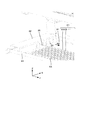
図1は、本発明に係る移植システムの一実施形態の斜視図を示している。移植システム1は、移植装置3と搬送装置(ローダー)5を備えている。図2は、図1の移植システム1における移植装置3を示し、(a)は斜視図、(b)は正面図を示している。 FIG. 1 shows a perspective view of an embodiment of a transplant system according to the present invention. The transplantation system 1 includes a transplantation device 3 and a transfer device (loader) 5. 2A and 2B show a transplanting device 3 in the transplanting system 1 of FIG. 1, where FIG. 2A is a perspective view and FIG. 2B is a front view.

移植システム1は、環境がコントロールされた植物工場などの設備において植物を育成するため、苗床シートに埋め込まれた複数の植物の苗を栽培用パネルに移植するためのシステムである。図1に示す苗床シートC1は外部から持ち込まれて、例えば人手等によって搬送装置5に載置され、搬送装置5及び移植装置3において所定の加工を施されて最終的に個別の苗が埋め込まれた苗床片C3(図3等参照)に分割され、苗床片C3が栽培用パネルDの穴に配置される。移植システム1の各種部材はステンレス等の金属よって構成されるが、その材料は特に限定されない。また各種部材の構造、形状、位置関係なども特に限定されるものではない。 The transplantation system 1 is a system for transplanting seedlings of a plurality of plants embedded in a nursery sheet to a cultivation panel in order to grow plants in a facility such as a plant factory where the environment is controlled. The nursery sheet C1 shown in FIG. 1 is brought in from the outside, placed on the transport device 5 by hand, for example, subjected to predetermined processing in the transport device 5 and the transplant device 3, and finally individual seedlings are embedded. It is divided into a nursery piece C3 (see FIG. 3 and the like), and the nursery piece C3 is arranged in a hole of a cultivation panel D. Various members of the transplantation system 1 are made of a metal such as stainless steel, but the material thereof is not particularly limited. Further, the structure, shape, positional relationship, etc. of various members are not particularly limited.

苗床シートC1は、例えばポリウレタンフォーム等により構成されたものが用いられるが、特にその種類は限定されない。本例の苗床シートC1では、予め個別の苗床片C3に分割しやすいように切れ込み線が入れられ、上面における中心位置における+のマークの所にも切り込みが入れられて苗が埋め込まれている(苗の図示は省略)。もちろん苗床シートC1、苗床片C3の大きさ及び形状、切り込み線の態様等は特に限定されるものではない。 As the nursery sheet C1, for example, one made of polyurethane foam or the like is used, but the type thereof is not particularly limited. In the nursery sheet C1 of this example, a notch line is made in advance so that it can be easily divided into individual nursery pieces C3, and a notch is also made at the + mark at the center position on the upper surface to embed the seedlings ( Seedlings are not shown). Of course, the size and shape of the nursery sheet C1 and the nursery piece C3, the mode of the cut line, and the like are not particularly limited.

栽培用パネルDも例えばポリウレタンフォーム等により構成されたものが用いられるが、特にその種類は限定されない。栽培用パネルDには複数の円形の穴H(図13等参照)が設けられており、穴Hに苗床片C3が配置される。苗床片C3が配置可能であれば、穴Hの形状や数などは特に限定されない。 As the cultivation panel D, for example, one made of polyurethane foam or the like is used, but the type thereof is not particularly limited. The cultivation panel D is provided with a plurality of circular holes H (see FIG. 13 and the like), and the nursery piece C3 is arranged in the holes H. As long as the nursery piece C3 can be arranged, the shape and number of holes H are not particularly limited.

搬送装置5は、架台11、架台11上に配置された平面状の基台12、基台12上で動作する押出装置13、切断装置14を備えている。搬送装置5は、原製品である苗床シートC1を中間段階の中型の苗床シートC1Aに分割するとともに移植装置3まで搬送する役割を果たす。 The transport device 5 includes a gantry 11, a flat base 12 arranged on the gantry 11, an extrusion device 13 operating on the base 12, and a cutting device 14. The transport device 5 plays a role of dividing the seedbed sheet C1 which is the original product into the medium-sized nursery sheet C1A in the intermediate stage and transporting it to the transplant device 3.

移植装置3は、架台20、架台20上に配置された平面状の基台21、基台21上で動作する押出装置22(図2(a)、図3参照)、押圧装置30及び保持装置40を含む分割装置70(図1参照)、把持装置50(図2(b)参照)を備えている。移植装置3は、搬送装置5から搬送された中型の苗床シートC1Aを最終的に一つの苗に対応した苗床片C3に分割し、苗床片C3を栽培用パネルDの穴に配置する。 The transplanting device 3 includes a pedestal 20, a flat base 21 arranged on the pedestal 20, an extrusion device 22 (see FIGS. 2A and 3) operating on the base 21, a pressing device 30, and a holding device. It includes a dividing device 70 (see FIG. 1) including a 40 and a gripping device 50 (see FIG. 2 (b)). The transplanting device 3 finally divides the medium-sized nursery sheet C1A transported from the transporting device 5 into a nursery piece C3 corresponding to one seedling, and arranges the nursery piece C3 in the hole of the cultivation panel D.

図3は、搬送装置5における押出装置13の部分の拡大斜視図を示す。押出装置13は長尺状の押出部材15と基台12の上に固定された押出レール16を含む。作業者等が苗床シートC1を基台12の上に配置した後、押出部材15が図示せぬ押出機構の作用により、押出レール16に沿って矢印P1の方向に進み、苗床シートC1を押して切断装置14まで搬送する。 FIG. 3 shows an enlarged perspective view of a portion of the extrusion device 13 in the transfer device 5. The extrusion device 13 includes an elongated extrusion member 15 and an extrusion rail 16 fixed on a base 12. After the worker or the like arranges the nursery sheet C1 on the base 12, the extrusion member 15 advances in the direction of the arrow P1 along the extrusion rail 16 by the action of an extrusion mechanism (not shown), and pushes the nursery sheet C1 for cutting. Transport to device 14.

図4は、搬送装置5における切断装置14の部分の拡大斜視図を示す。切断装置14は、その先端に切断刃17を備えており、大型の苗床シートC1を中型の苗床シートC1Aに分割する。本例では図6に示す様に、切断装置14は苗床シートC1を6列ごとに分割することにより中型の苗床シートC1Aを生成する。 FIG. 4 shows an enlarged perspective view of a portion of the cutting device 14 in the transport device 5. The cutting device 14 is provided with a cutting blade 17 at its tip, and divides a large nursery sheet C1 into a medium-sized nursery sheet C1A. In this example, as shown in FIG. 6, the cutting device 14 generates a medium-sized nursery sheet C1A by dividing the nursery sheet C1 into 6 rows.

図5は、切断装置14による苗床シートC1の切断工程を示す拡大側面図であり、(a)は第1工程、(b)は第2工程、(c)は第3工程の拡大側面図をそれぞれ示している。切断装置14は苗床シートC1の上方位置であって、苗床シートC1の所定の切り込みに対応する位置に停止し(図5(a)参照)、下降して切断刃17が苗床シートC1に接触し(図5(b)参照)、さらに下降して切断刃17が苗床シートC1の底面まで到達して(図5(c)参照)、苗床シートC1を中型の苗床シートC1Aに分割する。さらに切断装置14は、中型の苗床シートC1Aを図の右側へ押し出し、移植装置3へ搬送する。 5A and 5B are enlarged side views showing a cutting step of the nursery sheet C1 by the cutting device 14, where FIG. 5A is an enlarged side view of the first step, FIG. 5B is a second step, and FIG. 5C is an enlarged side view of the third step. Each is shown. The cutting device 14 is located above the nursery sheet C1 and stops at a position corresponding to a predetermined cut in the nursery sheet C1 (see FIG. 5A), then descends and the cutting blade 17 comes into contact with the nursery sheet C1. (See FIG. 5 (b)), the cutting blade 17 further descends to reach the bottom surface of the nursery sheet C1 (see FIG. 5 (c)), and the nursery sheet C1 is divided into a medium-sized nursery sheet C1A. Further, the cutting device 14 pushes out the medium-sized nursery sheet C1A to the right side of the drawing and conveys it to the transplanting device 3.

図6は、移植装置3における押出装置22の部分の拡大斜視図を示す。押出装置22は、基台21の上に固定された押出ガイド24、25に沿って矢印P2の方向に進み、中型の苗床シートC1Aを押す。押出装置22には複数の調整溝23が設けられており、押出ガイド25の位置をずらして係合する調整溝23を変更することで、押出ガイド24、25の幅を変更し、ガイドする中型の苗床シートC1Aの幅、すなわち苗床片C3の数を変更することができる。本例では、中型の苗床シートC1Aの幅方向一列における苗床片C3の数は6個であるが、その数は調整可能である。 FIG. 6 shows an enlarged perspective view of a portion of the extrusion device 22 in the transplant device 3. The extrusion device 22 advances in the direction of arrow P2 along the extrusion guides 24 and 25 fixed on the base 21, and pushes the medium-sized nursery sheet C1A. The extrusion device 22 is provided with a plurality of adjusting grooves 23. By shifting the position of the extrusion guide 25 and changing the engaging adjustment groove 23, the widths of the extrusion guides 24 and 25 are changed and the guide is medium-sized. The width of the nursery sheet C1A, that is, the number of nursery pieces C3 can be changed. In this example, the number of nursery pieces C3 in a row in the width direction of the medium-sized nursery sheet C1A is 6, but the number can be adjusted.

次に、分割装置70(図1参照)が備える押圧装置30及び保持装置40について説明する。分割装置70は、複数の苗床片C3を含む中型の苗床シートC1Aを複数の苗床片C3に分割する役割を果たす。図7は、押圧装置30の押圧動作を示す拡大斜視図であり、(a)第1工程、(b)第2工程を示す。押圧装置30は、中型の苗床シートC1Aを押さえつける役割を果たすが、本実施形態では部分的に切断する役割も果たすものある。 Next, the pressing device 30 and the holding device 40 included in the dividing device 70 (see FIG. 1) will be described. The dividing device 70 serves to divide the medium-sized nursery sheet C1A containing the plurality of nursery pieces C3 into the plurality of nursery pieces C3. FIG. 7 is an enlarged perspective view showing a pressing operation of the pressing device 30, and shows (a) a first step and (b) a second step. The pressing device 30 plays a role of pressing the medium-sized nursery sheet C1A, but in the present embodiment, it also plays a role of partially cutting.

押圧装置30は、中型の苗床シートC1Aの表面から所定の深さまで侵入する押え部材31を有している。図7(b)の破線で囲まれたV部分に示す様に、押え部材31には、中型の苗床シートC1Aの表面に沿って、長手方向に複数の侵入刃部31aと複数の空間部31bが交互に並べられて配置されている。 The pressing device 30 has a pressing member 31 that penetrates from the surface of the medium-sized nursery sheet C1A to a predetermined depth. As shown in the V portion surrounded by the broken line in FIG. 7B, the holding member 31 has a plurality of intrusion blade portions 31a and a plurality of space portions 31b in the longitudinal direction along the surface of the medium-sized nursery sheet C1A. Are arranged alternately.

図7(a)に示す様に、図6に示す押出装置22によって搬送された中型の苗床シートC1Aは所定位置に停止し、押圧装置30が中型の苗床シートC1Aの上方位置であって、中型の苗床シートC1Aの所定の切り込みに対応する位置に停止する。そして図7(b)に示す様に押え部材31が下降すると、侵入刃部31aが中型の苗床シートC1Aに進入する。侵入刃部31aは先の尖った切先部31cを三つ有しており、中型の苗床シートC1Aの表面から内部に進入しやすい。押え部材31により、6個の苗床片C3が切り込みL(図7(b)参照)を介して一列に繋がった線状の苗床シートC2が生成され、これは後述する保持装置40による保持対象となる。 As shown in FIG. 7A, the medium-sized nursery sheet C1A conveyed by the extrusion device 22 shown in FIG. 6 stops at a predetermined position, and the pressing device 30 is above the medium-sized nursery sheet C1A. Stop at a position corresponding to a predetermined cut in the nursery sheet C1A. Then, as shown in FIG. 7B, when the pressing member 31 descends, the intruding blade portion 31a enters the medium-sized nursery sheet C1A. The intrusion blade portion 31a has three pointed tip portions 31c, and easily enters the inside from the surface of the medium-sized nursery sheet C1A. The presser member 31 generates a linear nursery sheet C2 in which six nursery pieces C3 are connected in a row via a notch L (see FIG. 7B), which is to be held by the holding device 40 described later. Become.

押え部材31における長手方向において、侵入刃部31aは切り込みLを介して隣接した苗床片C3を跨ぎつつ各苗床片C3の中央位置である苗の位置Tを避けた位置に進入する。すなわち侵入刃部31aは、苗床片C3の両端部に侵入し、中央には侵入しない。一方、空間部31bは、各苗床片C3の中央位置である苗の位置Tには対応する様に位置するため、押え部材31が直接苗に接触し難くなっており、苗を痛める可能性を抑えることができる。 In the longitudinal direction of the pressing member 31, the invading blade portion 31a enters a position avoiding the position T of the seedling, which is the central position of each nursery piece C3, while straddling the adjacent nursery piece C3 via the notch L. That is, the invading blade portion 31a invades both ends of the nursery piece C3 and does not invade the center. On the other hand, since the space portion 31b is located so as to correspond to the position T of the seedling, which is the central position of each nursery piece C3, it is difficult for the pressing member 31 to come into direct contact with the seedling, which may damage the seedling. It can be suppressed.

図8は、保持装置40の分割動作を示す拡大斜視図であり、(a)第1工程、(b)第2工程を示す。保持装置40は、移植装置3の所定位置に配置された支持柱41と、支持柱41に固定された梁42と、梁42の下面に形成されたレール43と、レール43上をスライド可能なスライド部材44(図8(b)参照)と、スライド部材44に連結された連結アーム46と、連結アーム46に接続された複数の保持部材45とを備えている。 FIG. 8 is an enlarged perspective view showing the division operation of the holding device 40, and shows (a) a first step and (b) a second step. The holding device 40 can slide on the support column 41 arranged at a predetermined position of the transplant device 3, the beam 42 fixed to the support column 41, the rail 43 formed on the lower surface of the beam 42, and the rail 43. It includes a slide member 44 (see FIG. 8B), a connecting arm 46 connected to the slide member 44, and a plurality of holding members 45 connected to the connecting arm 46.

保持部材45は、図7(b)における線状の苗床シートC2について、図8(a)において破線で示す様に分割すべき複数の苗床片C3に対応して複数個所で保持するように設けられている。図8(a)の状態から、図示せぬ駆動機構により図8(b)に示したスライド部材44(図8(a)では見えない)が矢印P3の方向に移動すると、スライド部材44に連結した連結アーム46が伸びて、図8(b)の状態となる。レール43、スライド部材44、連結アーム46の作用により、複数の保持部材45は、分割すべき複数の苗床片C3が並べられた方向に対して相対的に移動可能となっている。 The holding member 45 is provided so as to hold the linear nursery sheet C2 in FIG. 7B at a plurality of locations corresponding to the plurality of nursery bed pieces C3 to be divided as shown by the broken line in FIG. 8A. Has been done. When the slide member 44 (not visible in FIG. 8 (a)) shown in FIG. 8 (b) moves in the direction of arrow P3 from the state of FIG. 8 (a) by a drive mechanism (not shown), it is connected to the slide member 44. The connecting arm 46 is extended to be in the state shown in FIG. 8 (b). Due to the action of the rail 43, the slide member 44, and the connecting arm 46, the plurality of holding members 45 are relatively movable with respect to the direction in which the plurality of nursery pieces C3 to be divided are arranged.

図9は、保持部材45の拡大斜視図であり、(a)上方から見た拡大斜視図、(b)下方から見た拡大斜視図を示す。保持部材45は、連結アーム46に固定され支持される部分である支持部47と、先端に設けられた爪部49と、爪部49を駆動する爪駆動部48とを備えている。 9A and 9B are enlarged perspective views of the holding member 45, showing (a) an enlarged perspective view seen from above, and (b) an enlarged perspective view seen from below. The holding member 45 includes a support portion 47 which is a portion fixed and supported by the connecting arm 46, a claw portion 49 provided at the tip thereof, and a claw drive portion 48 for driving the claw portion 49.

図10は、保持部材45の線状の苗床シートC2(及び苗床片C3)に対する押圧動作を示す拡大側面図であり、(a)第1工程、(b)第2工程を示す。保持部材45における爪部49は相対的に移動可能な第1の爪49a及び第2の爪49bを有している。図10(a)において破線で示す様に、第1の爪49aが線状の苗床シートC2(苗床片C3)の上面を押え、第2の爪49bが線状の苗床シートC2(苗床片C3)の側面を押える。上側に配置された第1の爪49aは、矢印P4に沿って下向きに移動可能であり、下側に配置された第2の爪49bは、矢印P5に沿って上向きに移動可能である。よって、第1の爪49a及び第2の爪49bがこれらの矢印の向きに移動すると、図10(b)に示す様に、第1の爪49a及び第2の爪49bが相対的に接近し、線状の苗床シートC2(苗床片C3)の一部、特に上面の端部を挟むことが可能である。 FIG. 10 is an enlarged side view showing a pressing operation of the holding member 45 against the linear nursery sheet C2 (and the nursery piece C3), and shows (a) a first step and (b) a second step. The claw portion 49 of the holding member 45 has a first claw 49a and a second claw 49b that are relatively movable. As shown by the broken line in FIG. 10A, the first claw 49a presses the upper surface of the linear nursery sheet C2 (nursery piece C3), and the second claw 49b is the linear nursery sheet C2 (nursery piece C3). ) Hold down the side. The first claw 49a arranged on the upper side can move downward along the arrow P4, and the second claw 49b arranged on the lower side can move upward along the arrow P5. Therefore, when the first claw 49a and the second claw 49b move in the directions of these arrows, the first claw 49a and the second claw 49b come relatively close to each other as shown in FIG. 10 (b). , A part of the linear nursery sheet C2 (nursery piece C3), particularly the end of the upper surface can be sandwiched.

分割装置70が線状の苗床シートC2を苗床片C3に分割する方法は以下の手順である。図7(b)に示す様に、押圧装置30が線状の苗床シートC2(中型の苗床シートC1A)を押圧した状態で、図8(a)に示す様に保持装置40が線状の苗床シートC2に接近し、図10(a)に示す状態となる。この状態では、第1の爪49aは苗床片C3の上面には接触していない。 The method in which the dividing device 70 divides the linear nursery sheet C2 into the nursery piece C3 is as follows. As shown in FIG. 7B, with the pressing device 30 pressing the linear nursery sheet C2 (medium-sized nursery sheet C1A), the holding device 40 presses the linear nursery sheet C1A as shown in FIG. 8A. It approaches the sheet C2 and is in the state shown in FIG. 10 (a). In this state, the first claw 49a is not in contact with the upper surface of the nursery piece C3.

図8(a)及び図10(a)の状態から、第1の爪49aが矢印P4に沿って下向きに移動し、第2の爪49bが矢印P5に沿って上向きに移動する。この結果、図10(b)に示す様に、第1の爪49a及び第2の爪49bによって、線状の苗床シートC2の上面の端部を挟み、線状の苗床シートC2を保持する。 From the states of FIGS. 8A and 10A, the first claw 49a moves downward along the arrow P4, and the second claw 49b moves upward along the arrow P5. As a result, as shown in FIG. 10B, the linear nursery sheet C2 is held by sandwiching the upper end of the linear nursery sheet C2 between the first claw 49a and the second claw 49b.

図10(b)に示す状態のまま保持装置40が、図8(a)において座標軸で示すY方向に移動(後退)し、線状の苗床シートC2を図7(b)の状態における押圧装置30から切り離す。その後、スライド部材44の移動、連結アーム46の伸びに伴い、保持部材45がP3方向に移動して線状の苗床シートC2が分割され、図10(b)において破線で示す様に6個の苗床片C3が生成され、各苗床片C3が保持部材45に保持された状態となる。 The holding device 40 moves (backs) in the Y direction indicated by the coordinate axes in FIG. 8A while keeping the state shown in FIG. 10B, and presses the linear nursery sheet C2 in the state shown in FIG. 7B. Separate from 30. After that, as the slide member 44 moves and the connecting arm 46 extends, the holding member 45 moves in the P3 direction to divide the linear nursery sheet C2, and as shown by the broken line in FIG. 10B, six pieces are formed. The nursery piece C3 is generated, and each nursery piece C3 is held by the holding member 45.

尚、図9に示す様に、第1の爪49aが水平方向に二股に分かれて互いに寸法の等しい第1の爪片49a1と第2の爪片49a2を含み、第1の爪片49a1と第2の爪片49a2の間に空間S1が形成される。保持動作の際、第1の爪49aは線状の苗床シートC2(苗床片C3)の上面に接触するが、苗が存在する苗床片C3の中央位置(図7(b)参照)に対しては、空間S1が対応するように配置される。よって、第1の爪片49a1と第2の爪片49a2が直接的に苗に接触し難くなっており、苗を痛める可能性を抑えることができる。 As shown in FIG. 9, the first claw 49a is bifurcated in the horizontal direction and includes the first claw piece 49a1 and the second claw piece 49a2 having the same dimensions as each other, and the first claw piece 49a1 and the first claw piece 49a1. Space S1 is formed between the claw pieces 49a2 of 2. During the holding operation, the first claw 49a contacts the upper surface of the linear nursery sheet C2 (nursery piece C3), but with respect to the central position of the nursery piece C3 where the seedlings are present (see FIG. 7B). Are arranged so that the spaces S1 correspond to each other. Therefore, it is difficult for the first nail piece 49a1 and the second nail piece 49a2 to come into direct contact with the seedlings, and the possibility of damaging the seedlings can be suppressed.

また、第2の爪49bは、先端において第1の爪49aに接近するように湾曲した湾曲先端部49b1を有する。このような形状により、第1の爪49a及び第2の爪49bは、より確実に線状の苗床シートC2(及び苗床片C3)を保持することが可能となる。 Further, the second claw 49b has a curved tip portion 49b1 that is curved so as to approach the first claw 49a at the tip. With such a shape, the first claw 49a and the second claw 49b can more reliably hold the linear nursery sheet C2 (and the nursery piece C3).

実施形態の分割装置70においては、保持部材45の爪部49によって線状の苗床シートC2を苗に悪影響が及ぶのを抑制した状態で保持しつつ、スライド部材44の移動により線状の苗床シートC2を複数の苗床片C3に分割することができ、作業の効率を上げることができる。 In the dividing device 70 of the embodiment, the linear nursery sheet C2 is held in a state of being suppressed from adversely affecting the seedlings by the claw portion 49 of the holding member 45, and the linear nursery sheet is moved by the movement of the slide member 44. C2 can be divided into a plurality of nursery pieces C3, and work efficiency can be improved.

図11は、移植装置における第1の実施形態の把持装置50の斜視図であり、図12は、本実施形態の把持装置50における把持部材の部分の拡大斜視図である。把持装置50は、苗が植え付けられた苗床片C3を把持して、栽培用パネルDに配置する装置であり、図2(b)に示す様に、架台20に載置された栽培用パネルDよりも下方に配置される。把持装置50は架台20に固定される支持板51と、支持板51に固定されるとともに上下方向に伸縮可能な伸縮機構52と、伸縮機構52の上に固定された支持台53と、支持台53の上に配置された把持部材駆動機構54及び一組の把持部材55と、を備えている。 FIG. 11 is a perspective view of the gripping device 50 of the first embodiment in the transplanting device, and FIG. 12 is an enlarged perspective view of a portion of the gripping member in the gripping device 50 of the present embodiment. The gripping device 50 is a device that grips the nursery piece C3 in which the seedlings are planted and arranges it on the cultivation panel D. As shown in FIG. 2B, the cultivation panel D placed on the gantry 20 Placed below. The gripping device 50 includes a support plate 51 fixed to the gantry 20, an expansion / contraction mechanism 52 fixed to the support plate 51 and expandable in the vertical direction, a support base 53 fixed on the expansion / contraction mechanism 52, and a support base. It includes a gripping member drive mechanism 54 arranged on the 53 and a set of gripping members 55.

伸縮機構52が伸縮することにより、支持台53、把持部材駆動機構54及び把持部材55が上下方向に移動可能である。特に後述するように把持部材55は、上昇時に栽培用パネルDに設けられた穴H(図13〜図15参照)を通過することが可能な構成となっている。 As the expansion / contraction mechanism 52 expands / contracts, the support base 53, the gripping member driving mechanism 54, and the gripping member 55 can move in the vertical direction. In particular, as will be described later, the gripping member 55 has a configuration capable of passing through holes H (see FIGS. 13 to 15) provided in the cultivation panel D when ascending.

把持部材駆動機構54は、対向した一組の把持部材55を座標軸のY軸方向に沿って互いに接近及び離間可能とするように駆動する。図12においては、便宜上手前の把持部材55のみが互いに接近した状態を示しているが、現実の工程においては、全ての把持部材55の組が同時に接近又は離間する。 The gripping member driving mechanism 54 drives a set of facing gripping members 55 so as to be able to approach and separate from each other along the Y-axis direction of the coordinate axes. In FIG. 12, for convenience, only the front gripping members 55 are shown to be close to each other, but in an actual process, all the gripping member 55 sets are approaching or separating from each other at the same time.

さらに把持部材55は、その先端において設けられた先端部56を備えている。後述するように互いに対向した一組の先端部56は一組の把持部材55の接近時に、苗床片C3の底面の一部のみを挟んで把持することができる。本実施形態の先端部56は、一方の把持部材55の本体55aから他方の把持部材55に向かう方向に屈曲した形状を呈する把持爪57より構成される。把持爪57は、本体55aから斜め上方に延びるように屈曲している。 Further, the gripping member 55 includes a tip portion 56 provided at the tip thereof. As will be described later, a set of tip portions 56 facing each other can grip only a part of the bottom surface of the nursery piece C3 when the set of gripping members 55 approach each other. The tip portion 56 of the present embodiment is composed of a gripping claw 57 having a shape bent in a direction from the main body 55a of one gripping member 55 toward the other gripping member 55. The gripping claw 57 is bent so as to extend diagonally upward from the main body 55a.

図13〜図15は、把持装置50が苗床片C3を把持し栽培用パネルDに配置する方法を示している。以下この方法の手順を説明する。図13は、図12の把持部材の把持動作を示す拡大側面図であり、(a)第1工程、(b)第2工程を示す。図13(a)の第1工程では、一組の把持部材55は未だ栽培用パネルDの下方に位置し、苗床片C3は栽培用パネルDの上方にて保持部材45の爪部49にて保持されている(図10(b)と同じ状態)。この状態から伸縮機構52が伸びて把持部材55は矢印Z1の方向に上昇し、栽培用パネルDの穴Hを通過して、図13(b)に示す第2工程の状態となり、先端部56(把持爪57)は、苗床片C3の底面から苗床片C3の内部に侵入する。そして、把持部材駆動機構54が、一組の把持部材55の各々を矢印Y1、Y2の方向に駆動し、一組の把持部材55は接近する。 13 to 15 show a method in which the gripping device 50 grips the nursery piece C3 and arranges it on the cultivation panel D. The procedure of this method will be described below. 13 is an enlarged side view showing the gripping operation of the gripping member of FIG. 12, and shows (a) a first step and (b) a second step. In the first step of FIG. 13A, the set of gripping members 55 is still located below the cultivation panel D, and the nursery piece C3 is above the cultivation panel D at the claws 49 of the holding member 45. It is held (the same state as in FIG. 10B). From this state, the expansion / contraction mechanism 52 extends, the gripping member 55 rises in the direction of the arrow Z1, passes through the hole H of the cultivation panel D, and is in the state of the second step shown in FIG. (Gripping claw 57) invades the inside of the nursery piece C3 from the bottom surface of the nursery piece C3. Then, the gripping member driving mechanism 54 drives each of the pair of gripping members 55 in the directions of arrows Y1 and Y2, and the set of gripping members 55 approach each other.

図14は、図12の把持部材の把持動作を示す拡大側面図であり、(a)第3工程、(b)第4工程を示す。図13(b)に示したように、一組の把持部材55は接近し、図14(a)の第3工程に示すように、一組の先端部56(把持爪57)が接触した状態となる。苗床片C3は保持部材45によって保持されつつも、その底面が一組の把持爪57によって挟まれ、把持された状態となる。先端部56(把持爪57)による把持によって、苗床片C3は径方向に若干縮み、小さくなっている。この状態から伸縮機構52が縮んで把持部材55は矢印Z2の方向に下降し、苗床片C3が栽培用パネルDの穴Hと上下方向(Z方向)においてほぼ同じ位置となるところで、把持部材55は一旦停止し、図14(b)に示す第4工程の状態となる。そして、把持部材駆動機構54が、一組の把持部材55の各々を矢印Y3、Y4の方向に駆動し、一組の把持部材55は離間する。 14 is an enlarged side view showing the gripping operation of the gripping member of FIG. 12, and shows (a) a third step and (b) a fourth step. As shown in FIG. 13 (b), a set of gripping members 55 are close to each other, and as shown in the third step of FIG. 14 (a), a set of tip portions 56 (grasping claws 57) are in contact with each other. It becomes. While the nursery piece C3 is held by the holding member 45, its bottom surface is sandwiched by a set of gripping claws 57 and is in a gripped state. By gripping with the tip portion 56 (grasping claw 57), the nursery piece C3 is slightly shrunk in the radial direction and becomes smaller. From this state, the expansion / contraction mechanism 52 contracts, the gripping member 55 descends in the direction of arrow Z2, and the nursery piece C3 is at substantially the same position as the hole H of the cultivation panel D in the vertical direction (Z direction). Is temporarily stopped, and is in the state of the fourth step shown in FIG. 14 (b). Then, the gripping member drive mechanism 54 drives each of the set of gripping members 55 in the directions of arrows Y3 and Y4, and the set of gripping members 55 are separated from each other.

図14(c)は、図14(a)、(b)の状態において情報から見た上面図を示している。把持爪57は、水平方向に並べられ、互いに寸法の等しい第1の把持爪片57aと第2の把持爪片57bを含み、かつ第1の把持爪片57aと第2の把持爪片57bの間に斜線ハッチングを施した空間S2が形成される。第1の把持爪片57aと第2の把持爪片57bは縦、横、高さなどの寸法が等しく同じ形状であり、空間S2は苗が位置する苗床片C3の中央位置を含むことになる。よって、把持爪57が直接苗に接触し難くなっており、苗を痛める可能性を抑えることができる。 FIG. 14 (c) shows a top view of the information in the states of FIGS. 14 (a) and 14 (b). The gripping claws 57 include a first gripping claw piece 57a and a second gripping claw piece 57b that are arranged horizontally and have the same dimensions as each other, and the first gripping claw piece 57a and the second gripping claw piece 57b. A space S2 with diagonal hatching is formed between them. The first gripping claw piece 57a and the second gripping claw piece 57b have the same dimensions such as length, width, and height, and the space S2 includes the central position of the nursery piece C3 where the seedlings are located. .. Therefore, it is difficult for the gripping claw 57 to come into direct contact with the seedlings, and the possibility of damaging the seedlings can be suppressed.

図15は、図12の把持部材の把持動作を示す拡大側面図であり、(a)第5工程、(b)第6工程を示す。図14(b)に示したように、一組の把持部材55は離間し、図15(a)の第5工程に示すように、一組の先端部56(把持爪57)が離間した状態となる。さらに把持部材55はZ2方向に下降し、先端部56(把持爪57)による苗床片C3の把持を解放し、図15(b)の第6工程に示す様に図13(a)と同様の元の位置に戻り、一連の工程が終了する。苗床片C3は拡がる弾性力を有しているため、先端部56(把持爪57)による把持の開放に伴い、穴Hの壁に沿うまで広がり、円形となって穴Hの中に固定される。栽培用パネルDの総ての穴Hに苗床片C3が配置された後、栽培用パネルDは人手等により移植システム1から取り外され、次の工程に持ち込まれる。 FIG. 15 is an enlarged side view showing the gripping operation of the gripping member of FIG. 12, and shows (a) a fifth step and (b) a sixth step. As shown in FIG. 14 (b), a set of gripping members 55 are separated from each other, and as shown in the fifth step of FIG. 15 (a), a set of tip portions 56 (grip claws 57) are separated from each other. It becomes. Further, the gripping member 55 descends in the Z2 direction to release the gripping of the nursery piece C3 by the tip portion 56 (grasping claw 57), and is the same as in FIG. 13 (a) as shown in the sixth step of FIG. 15 (b). It returns to its original position and the series of steps is completed. Since the nursery piece C3 has an elastic force that expands, it expands along the wall of the hole H as the tip 56 (grip claw 57) opens the grip, and is fixed in the hole H in a circular shape. .. After the nursery piece C3 is placed in all the holes H of the cultivation panel D, the cultivation panel D is manually removed from the transplantation system 1 and brought to the next step.

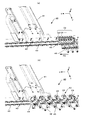
図16は、第2の実施形態の把持装置60の斜視図である。把持装置60は、苗が植え付けられた苗床片C3を把持して、栽培用パネルDに配置する装置であり、図2(b)に示す把持装置50の別実施形態であって、架台20に載置された栽培用パネルDよりも下方に配置される。把持装置50は架台20に固定される支持板61と、支持板61に固定されるとともに上下方向に伸縮可能な伸縮機構62と、伸縮機構62の上に固定された支持台63と、支持台63の上に配置された把持部材駆動機構64及び一組の把持部材65と、を備えている。 FIG. 16 is a perspective view of the gripping device 60 of the second embodiment. The gripping device 60 is a device that grips the nursery bed piece C3 in which the seedlings are planted and arranges it on the cultivation panel D, which is another embodiment of the gripping device 50 shown in FIG. 2 (b) and is mounted on the gantry 20. It is arranged below the placed cultivation panel D. The gripping device 50 includes a support plate 61 fixed to the gantry 20, an expansion / contraction mechanism 62 fixed to the support plate 61 and expandable in the vertical direction, a support base 63 fixed on the expansion / contraction mechanism 62, and a support base. It includes a gripping member drive mechanism 64 arranged on the 63 and a set of gripping members 65.

伸縮機構62が伸縮することにより、支持台63、把持部材駆動機構64及び把持部材65が上下方向に移動可能である。特に後述するように把持部材65は、上昇時に栽培用パネルDに設けられた穴H(図19〜図22参照)を通過することが可能な構成となっている。把持部材駆動機構64は、二組の対向した板材より構成され、それぞれの板材に対向した一組の把持部材65が取り付けられている。把持部材駆動機構64を構成する2枚の板材が座標軸のX軸方向に沿って相対的に移動することにより、一組の把持部材65が第1の方向である座標軸のX軸方向に沿って互いに接近及び離間可能するように駆動する。 By expanding and contracting the expansion / contraction mechanism 62, the support base 63, the gripping member driving mechanism 64, and the gripping member 65 can move in the vertical direction. In particular, as will be described later, the gripping member 65 has a configuration capable of passing through holes H (see FIGS. 19 to 22) provided in the cultivation panel D when ascending. The gripping member drive mechanism 64 is composed of two sets of facing plate members, and one set of gripping members 65 facing each plate member is attached to the gripping member driving mechanism 64. The two plate members constituting the gripping member drive mechanism 64 move relatively along the X-axis direction of the coordinate axes, so that a set of gripping members 65 moves along the X-axis direction of the coordinate axes, which is the first direction. Drive so that they can approach and separate from each other.

一組の把持部材65は、第1の方向であるX軸方向に沿って相対的に移動可能に設けられている。さらに把持部材65は、その先端に設けられ、苗床片C3の少なくとも二つの対向した側面を挟んで把持可能な少なくとも一組の先端部66を備えている。一組の把持部材65の相対的な移動に伴い、一組の先端部66は当該先端部の全長に渡って、互いの距離が等しい状態を維持したまま互いに接近及び離間可能である。この点については後述する。 A set of gripping members 65 are provided so as to be relatively movable along the X-axis direction, which is the first direction. Further, the gripping member 65 is provided at the tip thereof and includes at least one set of tip portions 66 that can be gripped by sandwiching at least two opposite side surfaces of the nursery piece C3. With the relative movement of the set of gripping members 65, the set of tip 66 can approach and separate from each other while maintaining the same distance from each other over the entire length of the tip. This point will be described later.

先端部66は、把持部材65の本体65aに対して屈曲した部分である屈曲部68の上に設けられ、本実施形態において先端部66は、屈曲部68の上に設けられた直線状の把持ピン67より構成される。図17は、把持装置60において、二つの把持ピン67が接近した状態における正面図であり、図18は、二つの把持ピン67が離間した状態における正面図である。把持部材駆動機構64の作用により、このような二つの把持ピン67の接近及び離間の状態が実現される。 The tip portion 66 is provided on the bent portion 68 which is a portion of the gripping member 65 bent with respect to the main body 65a, and in the present embodiment, the tip portion 66 is a linear grip provided on the bent portion 68. It is composed of pins 67. FIG. 17 is a front view of the gripping device 60 when the two gripping pins 67 are close to each other, and FIG. 18 is a front view of the gripping device 60 when the two gripping pins 67 are separated from each other. By the action of the gripping member drive mechanism 64, such a state of approaching and separating the two gripping pins 67 is realized.

一組の把持部材65、特にその本体65aは、第1の方向であるX軸方向に交差する、特に本実施形態では垂直に交差する第2の方向であるY軸方向において互いに一定の距離をおいて離間して配置されている。ここで屈曲部68の詳細を、図19(c)等を参照して述べる。屈曲部68は、把持部材65の本体65aから第1の方向(X軸方向)に延びる第1片68aおよび当該第1片68aから第2の方向(Y軸方向)に延びる第2片68bを含んでいる。第1片68aと第2片68bは、水平面(XY平面)において互いに垂直に交わっており、図19(c)に示す様に当該水平面内において屈曲部18は略L字形状を呈する。 A set of gripping members 65, in particular the body 65a thereof, intersect each other in the X-axis direction, which is the first direction, and in particular, in the Y-axis direction, which is the second direction that intersects vertically in the present embodiment. They are placed apart from each other. Here, the details of the bent portion 68 will be described with reference to FIG. 19 (c) and the like. The bent portion 68 includes a first piece 68a extending from the main body 65a of the gripping member 65 in the first direction (X-axis direction) and a second piece 68b extending from the first piece 68a in the second direction (Y-axis direction). Includes. The first piece 68a and the second piece 68b intersect each other perpendicularly in the horizontal plane (XY plane), and as shown in FIG. 19C, the bent portion 18 has a substantially L-shape in the horizontal plane.

第2片68bの開放された先端(第1片68aと接続する側とは逆側の先端)である開放先端において、先端部66(把持ピン67)が第2片68bに対して垂直に起立する様に設けられている。このため、一組の先端部66(把持ピン67)は、各々の把持部材65から第2の方向(Y軸方向)において等しい位置の集合体であるM−M線上で互いに接近及び離間可能である。 At the open tip of the second piece 68b (the tip opposite to the side connected to the first piece 68a), the tip 66 (grasping pin 67) stands upright with respect to the second piece 68b. It is provided to do so. Therefore, a set of tip portions 66 (grip pins 67) can approach and separate from each other on the MM line, which is an aggregate at equal positions in the second direction (Y-axis direction) from each grip member 65. is there.

図19〜図22は、把持装置60が苗床片C3を把持し栽培用パネルDに配置する方法を示している。以下この方法の手順を説明する。図19は、図16の把持部材65の把持動作を示す拡大側面図であり、(a)第1工程、(b)第2工程、(c)第1及び第2工程における上面図を示す。図19(a)の第1工程では、一組の把持部材65は未だ栽培用パネルDの下方に位置し、苗床片C3は栽培用パネルDの上方にて保持部材45の爪部49にて保持されている(図10(b)と同じ状態)。但し本実施形態では保持部材45が図13、図14の場合と異なり、保持部材45は紙面の奥側へ向かう状態で苗床片C3を保持しているため、保持部材45は図示されていない。この状態から伸縮機構62が伸びて把持部材65は矢印Z1の方向に上昇し、栽培用パネルDの穴Hを通過して、図19(b)に示す第2工程の状態となり、先端部66(把持ピン67)の先端が苗床片C3の底面にほぼ接触した状態になる。また一組の先端部66(把持ピン67)は、互いに最接近した状態となっており、図19(c)に示す様に、各々略L字形状を呈する一組の屈曲部18が、互いに係合した状態になっている。一組の先端部66(把持ピン67)が短い距離をもって位置しているため、栽培用パネルDの穴Hを通過することができる。 19 to 22 show a method in which the gripping device 60 grips the nursery piece C3 and arranges it on the cultivation panel D. The procedure of this method will be described below. FIG. 19 is an enlarged side view showing the gripping operation of the gripping member 65 of FIG. 16, and shows top views in (a) first step, (b) second step, and (c) first and second steps. In the first step of FIG. 19A, the set of gripping members 65 is still located below the cultivation panel D, and the nursery piece C3 is above the cultivation panel D at the claws 49 of the holding member 45. It is held (the same state as in FIG. 10B). However, in the present embodiment, unlike the cases of FIGS. 13 and 14, the holding member 45 holds the nursery piece C3 in a state of facing the back side of the paper surface, so that the holding member 45 is not shown. From this state, the expansion / contraction mechanism 62 extends, the gripping member 65 rises in the direction of the arrow Z1, passes through the hole H of the cultivation panel D, and is in the state of the second step shown in FIG. The tip of (grasping pin 67) is in a state of being substantially in contact with the bottom surface of the nursery piece C3. Further, a set of tip portions 66 (grip pins 67) are in a state of being closest to each other, and as shown in FIG. 19 (c), a set of bent portions 18 each having a substantially L-shape are attached to each other. It is in an engaged state. Since a set of tip portions 66 (grasping pins 67) are located at a short distance, they can pass through the hole H of the cultivation panel D.

尚、図19における一組の把持部材65の各々について、左側の第1の把持部材65Aと、右側の第2の把持部材65Bとして区別する。第1の把持部材の第1片68aと第2の把持部材65Bの第1片68aは、それぞれの本体65aから第1の方向(X軸方向)において互いに逆方向に延び、さらに第2片68bが水平面(XY平面)内で第1片68aから垂直な方向、すなわち第2の方向(Y軸方向)に延びている。そして第2片68bの開放先端部に先端部66(把持ピン67)が設けられている。すなわち、第1の把持部材65A(の本体65a)が左側に位置し、第2の把持部材65B(の本体65a)が右側に位置するが、第1の把持部材65Aの先端部66(把持ピン67)は右側に位置し、第2の把持部材65Bの先端部66(把持ピン67)は左側に位置することになる。 Each of the set of gripping members 65 in FIG. 19 is distinguished as a first gripping member 65A on the left side and a second gripping member 65B on the right side. The first piece 68a of the first gripping member and the first piece 68a of the second gripping member 65B extend from their respective main bodies 65a in the first direction (X-axis direction) in opposite directions, and further extend in opposite directions to each other, and further, the second piece 68b. Extends in the horizontal plane (XY plane) from the first piece 68a in the vertical direction, that is, in the second direction (Y-axis direction). A tip 66 (grasping pin 67) is provided at the open tip of the second piece 68b. That is, the first grip member 65A (main body 65a) is located on the left side and the second grip member 65B (main body 65a) is located on the right side, but the tip portion 66 (grip pin) of the first grip member 65A is located. 67) is located on the right side, and the tip end portion 66 (grip pin 67) of the second gripping member 65B is located on the left side.

図20は、図16の把持部材65の把持動作を示す拡大側面図であり、(a)第3工程、(b)第4工程、(c)第3及び第4工程における上面図を示す。先端部66(把持ピン67)及び屈曲部68が穴Hを通過した図19(b)の状態から、把持部材駆動機構64が、一組の把持部材65の各々を矢印X1、X2の方向に駆動する。すると、図20(a)に示したように、一組の把持部材65は、第1の方向(X軸方向)における位置が入れ替わる、すなわち左右の把持部材65が入れ替わることになる。すなわち、第1の把持部材65A(の本体65a)が右側に位置し、第2の把持部材65B(の本体65a)が左側に位置するが、第1の把持部材65Aの先端部66(把持ピン67)も右側に位置し、第2の把持部材65Bの先端部66(把持ピン67)も左側に位置することになる。そして、一組の先端部66(把持ピン67)は最も離間した状態となる。さらに伸縮機構62が伸びて把持部材65が矢印Z1の方向に上昇すると、図20(b)に示す第4工程の状態となり、先端部66(把持ピン67)が苗床片C3の側面に接近した状態になる。 FIG. 20 is an enlarged side view showing the gripping operation of the gripping member 65 of FIG. 16, and shows top views in (a) third step, (b) fourth step, and (c) third and fourth steps. From the state of FIG. 19B in which the tip portion 66 (grip pin 67) and the bent portion 68 have passed through the hole H, the grip member drive mechanism 64 moves each of the set of grip members 65 in the directions of arrows X1 and X2. Drive. Then, as shown in FIG. 20A, the positions of the set of gripping members 65 in the first direction (X-axis direction) are exchanged, that is, the left and right gripping members 65 are exchanged. That is, the first grip member 65A (main body 65a) is located on the right side and the second grip member 65B (main body 65a) is located on the left side, but the tip portion 66 (grip pin) of the first grip member 65A is located. 67) is also located on the right side, and the tip end portion 66 (grip pin 67) of the second gripping member 65B is also located on the left side. Then, the set of tip portions 66 (grip pins 67) are in the most separated state. When the telescopic mechanism 62 further extends and the gripping member 65 rises in the direction of arrow Z1, the state of the fourth step shown in FIG. 20B is reached, and the tip portion 66 (grasping pin 67) approaches the side surface of the nursery piece C3. Become in a state.

図21は、図16の把持部材65の把持動作を示す拡大側面図であり、(a)第5工程、(b)第6工程、(c)第5及び第6工程における上面図を示す。図20(b)の状態から、把持部材駆動機構64が、一組の把持部材65の各々を矢印X3、X4の方向に駆動する。すると、図21(a)に示したように、一組の把持部材65は、再び第1の方向(X軸方向)における位置が入れ替わる。そして、一組の先端部66(把持ピン67)は最接近した状態、すなわち、図19における状態に戻る。 21 is an enlarged side view showing the gripping operation of the gripping member 65 of FIG. 16, and shows top views in (a) fifth step, (b) sixth step, and (c) fifth and sixth steps. From the state of FIG. 20B, the gripping member driving mechanism 64 drives each of the set of gripping members 65 in the directions of arrows X3 and X4. Then, as shown in FIG. 21A, the positions of the set of gripping members 65 are again exchanged in the first direction (X-axis direction). Then, the set of tip portions 66 (grasping pins 67) returns to the closest state, that is, the state shown in FIG.

ただしこの状態では、図19と異なり一組の先端部66(把持ピン67)の間には苗床片C3が存在している。よって、一組の把持部材65の相対的な移動に伴い、一組の先端部66(把持ピン67)は、苗床片C3の内部に侵入する過程で、苗床片C3の側面を部分的に押圧する。この移動において、一組の先端部66(把持ピン67)は当該先端部66の全長に渡って、互いの距離が等しい状態を維持したまま互いに接近可能である。すなわち、図20(a)、(b)の状態では先端部66(把持ピン67)の上下方向の全長に渡って互いの距離Rが保たれており、この距離Rが一組の先端部66(把持ピン67)の接近に伴い、先端部66(把持ピン67)の全長に渡って一定割合で減少し、図21(a)、(b)に示す距離Rになる(R>R)。このように距離Rが減少することは、先端部66(把持ピン67)が、苗床片C3に対して傾いた姿勢で把持しないことを意味しており、先端部66(把持ピン67)は安定的に苗床片C3を把持することができる。 However, in this state, unlike FIG. 19, a nursery piece C3 exists between a set of tip portions 66 (grip pins 67). Therefore, with the relative movement of the set of gripping members 65, the set of tip 66 (grasping pin 67) partially presses the side surface of the nursery piece C3 in the process of invading the inside of the nursery piece C3. To do. In this movement, a set of tip portions 66 (grip pins 67) can approach each other over the entire length of the tip portions 66 while maintaining the same distance from each other. That is, FIG. 20 (a), the vertical over the entire length is kept the distance R 1 of each other, this distance R is a pair of the distal end portion of the (b) tip 66 in the state of (gripping pin 67) As the 66 (grip pin 67) approaches, the distance decreases at a constant rate over the entire length of the tip 66 (grip pin 67) to reach the distance R 2 shown in FIGS. 21 (a) and 21 (b) (R 1 >. R 2 ). The decrease in the distance R in this way means that the tip portion 66 (grasping pin 67) does not grip in an inclined posture with respect to the nursery piece C3, and the tip portion 66 (grasping pin 67) is stable. The nursery piece C3 can be gripped.

そして最終的には、図21(c)に示した様に斜線ハッチングを施した略三角形状の溝部Gを形成した状態で、一組の先端部66(把持ピン67)は最接近した状態を保ちつつ苗床片C3を把持する。この状態から伸縮機構62が縮んで把持部材65は矢印Z2の方向に下降し、苗床片C3が栽培用パネルDの穴Hと上下方向(Z方向)においてほぼ同じ位置となるところで、把持部材65は一旦停止し、図21(b)に示す第6工程の状態となる。 Finally, as shown in FIG. 21 (c), a set of tip portions 66 (grip pins 67) are in the closest contact state in a state where a substantially triangular groove portion G having diagonal hatching is formed. Hold the nursery piece C3 while holding it. From this state, the expansion / contraction mechanism 62 contracts, the grip member 65 descends in the direction of arrow Z2, and the nursery piece C3 is at substantially the same position as the hole H of the cultivation panel D in the vertical direction (Z direction). Is temporarily stopped, and is in the state of the sixth step shown in FIG. 21 (b).

尚、苗床片C3の側面の高さdと、先端部66(把持ピン67)が苗床片C3の側面に接触して把持する領域の長さdは、好ましくはd≧d/2、さらに好ましくはd≧2d/3の関係を満たす状態となっている。長さdが高さdに対して所定割合以上の大きさを持つことにより、苗床片C3をより確実に把持することができる。 The height d 1 of the side surface of the nursery piece C3 and the length d 2 of the region where the tip portion 66 (grip pin 67) contacts and grips the side surface of the nursery piece C3 are preferably d 2 ≧ d 1 /. 2, more preferably in a state satisfying a relationship d 22d 1/3. When the length d 2 has a size equal to or larger than a predetermined ratio with respect to the height d 1 , the nursery piece C3 can be gripped more reliably.

また、先端部66(把持ピン67)が苗床片C3の側面の中央を把持することにより、図21(c)に示した二つの溝部Gが対向した状態で苗床片C3に形成され、苗床片C3が全体に略円形となり、栽培用パネルDの穴Hの形状に適合する。このため、苗床片C3を穴Hに配置する際に、苗床片C3が穴Hに干渉しにくく、配置が円滑なものとなる。また、二つの先端部66(把持ピン67)は所定の距離をおいているため、中央に配置された苗を痛めるのを抑制する。 Further, by gripping the center of the side surface of the nursery piece C3 by the tip portion 66 (grasping pin 67), the nursery bed piece C3 is formed with the two groove portions G shown in FIG. 21 (c) facing each other. C3 has a substantially circular shape as a whole, and fits the shape of the hole H of the cultivation panel D. Therefore, when the nursery piece C3 is arranged in the hole H, the nursery piece C3 is less likely to interfere with the hole H, and the arrangement becomes smooth. Further, since the two tip portions 66 (grasping pins 67) are separated from each other at a predetermined distance, it is possible to prevent the seedlings arranged in the center from being damaged.

図22は、図16の把持部材65の把持動作を示す拡大側面図であり、(a)第7工程、(b)第8工程、(c)第7及び第8工程における上面図を示す。図21(b)の状態から、把持部材駆動機構64が、一組の把持部材65の各々を矢印X1、X2の方向に駆動する。すると、図22(a)の第7工程に示したように、一組の把持部材65は、再び第1の方向(X軸方向)における位置が入れ替わる、すなわち左右の把持部材65が入れ替わることになる。そして、一組の先端部66(把持ピン67)は図20に類似するが、図20の状態ほどは離れていない距離Rをもって離れた状態となる(R>R>R)。一組の先端部66(把持ピン67)は、穴Hの壁に接近した状態となっており、苗床片C3の把持を解放する。苗床片C3は拡がる弾性力を有しているため、図21(c)に示す様に穴Hの壁に沿うまで広がり、円形となって穴Hの中に固定される。 22 is an enlarged side view showing the gripping operation of the gripping member 65 of FIG. 16, and shows top views in (a) 7th step, (b) 8th step, and (c) 7th and 8th steps. From the state of FIG. 21B, the gripping member driving mechanism 64 drives each of the set of gripping members 65 in the directions of arrows X1 and X2. Then, as shown in the seventh step of FIG. 22A, the positions of the set of gripping members 65 in the first direction (X-axis direction) are exchanged again, that is, the left and right gripping members 65 are exchanged. Become. Then, a set of tip portions 66 (grip pins 67) are similar to those in FIG. 20, but are separated by a distance R 3 which is not as far as the state shown in FIG. 20 (R 1 > R 3 > R 2 ). A set of tip portions 66 (grip pins 67) are in a state of being close to the wall of the hole H, and release the grip of the nursery piece C3. Since the nursery piece C3 has an elastic force that expands, it expands along the wall of the hole H as shown in FIG. 21 (c), forms a circle, and is fixed in the hole H.

この移動において、一組の先端部66(把持ピン67)は当該先端部66の全長に渡って、互いの距離が等しい状態を維持したまま互いに離間可能である。すなわち、図21(a)、(b)の状態では先端部66(把持ピン67)の上下方向の全長に渡って互いの距離Rが保たれており、この距離Rが一組の先端部66(把持ピン67)の離間に伴い、先端部66(把持ピン67)の全長に渡って一定割合で増加し、図22(a)に示す距離Rになる(R>R)。このように距離Rが増加することで、先端部66(把持ピン67)は安定的に苗床片C3を解放することができる。 In this movement, a set of tip portions 66 (grip pins 67) can be separated from each other over the entire length of the tip portions 66 while maintaining the same distance from each other. That is, FIG. 21 (a), the vertical over the entire length is kept to each other a distance R 2, the distance R is a pair of the distal end portion of the (b) tip 66 in the state (gripping pin 67) As the 66 (grip pin 67) is separated, the distance increases at a constant rate over the entire length of the tip 66 (grip pin 67) to reach the distance R 3 shown in FIG. 22 (a) (R 3 > R 2 ). By increasing the distance R in this way, the tip portion 66 (grip pin 67) can stably release the nursery piece C3.

図22(a)の状態から伸縮機構62がさらに縮んで把持部材65は矢印Z2の方向に下降し、図22(b)に示す第8工程の状態となって、把持部材65は元の位置に戻る。苗床片C3は拡がる弾性力を有しているため、図21(c)に示す様に穴Hの壁に沿うまで広がり、穴Hの中に固定される。 The expansion / contraction mechanism 62 further contracts from the state shown in FIG. 22A, the gripping member 65 descends in the direction of arrow Z2, and the state of the eighth step shown in FIG. 22B is reached, and the gripping member 65 is in the original position. Return to. Since the nursery piece C3 has an elastic force to expand, it expands along the wall of the hole H as shown in FIG. 21 (c) and is fixed in the hole H.

以上より、本実施形態の把持装置60は、苗が植え付けられた苗床片C3を把持する把持装置60であって、第1の方向に沿って相対的に移動可能に設けられた少なくとも一組の把持部材65と、一組の把持部材65の先端に設けられ、苗床片C3の少なくとも二つの対向した側面を挟んで把持可能な少なくとも一組の先端部66と、を備え、一組の把持部材65の相対的な移動に伴い、一組の先端部66は当該先端部66の全長に渡って、互いの距離が等しい状態を維持したまま互いに接近及び離間可能である。 From the above, the gripping device 60 of the present embodiment is a gripping device 60 that grips the nursery bed piece C3 in which the seedlings are planted, and is at least one set of gripping devices 60 provided so as to be relatively movable along the first direction. A set of gripping members including a gripping member 65 and at least one set of tip portions 66 provided at the tips of the set of gripping members 65 and capable of gripping at least two opposite side surfaces of the nursery piece C3. With the relative movement of 65, a set of tip 66s can approach and separate from each other over the entire length of the tip 66 while maintaining equal distances from each other.

これにより、把持装置の把持部材が、苗床片C3に対して傾いた姿勢で把持せず、苗床片C3を安定的に把持するとともに、安定的に苗床片C3の把持を解放することができ、苗に悪影響が及ぶのを抑制することができる。 As a result, the gripping member of the gripping device does not grip the nursery bed piece C3 in an inclined posture, and can stably grip the nursery bed piece C3 and stably release the gripping of the nursery bed piece C3. It is possible to suppress the adverse effect on the seedlings.

以上より、本実施形態の把持装置60において、先端部66は、把持部材65の本体65aに対して屈曲した部分である屈曲部68の上に設けられ、一組の把持部材65は、第1の方向に交差する第2の方向において互いに一定の距離をおいて離間して配置され、屈曲部68は本体から第1の方向に延びる第1片68aおよび当該第1片68aから第2の方向に延びる第2片68bを含み、第2片68bの開放された先端である開放先端において、先端部66が第2片68bに対して垂直に起立する様に設けられ、一組の先端部66が各々の把持部材65から第2の方向において等しい位置の集合体である線M−M上で互いに接近及び離間可能である。これにより、一組の把持部材65をコンパクトに配置することが可能となる。 From the above, in the gripping device 60 of the present embodiment, the tip portion 66 is provided on the bent portion 68 which is a portion bent with respect to the main body 65a of the gripping member 65, and the set of gripping members 65 is the first. The bent portions 68 are arranged at a certain distance from each other in the second direction intersecting the directions of the main body, and the bent portion 68 extends from the main body in the first direction and the first piece 68a and the first piece 68a to the second direction. At the open tip, which is the open tip of the second piece 68b, including the second piece 68b extending to, the tip 66 is provided so as to stand upright with respect to the second piece 68b, and a set of tip 66s. Can approach and separate from each other on the line MM, which is an assembly at equal positions in the second direction from each gripping member 65. This makes it possible to compactly arrange a set of gripping members 65.

以上より、本実施形態の把持装置60において、一組の把持部材65が第1の把持部材65Aと第2の把持部材65Bを含み、第1の把持部材65Aの第1片68aと第2の把持部材65Bの第1片68aは第1の方向において互いに逆方向に延び、一組の先端部66の接近時および離間時において、第1の方向における第1の把持部材65Aと第2の把持部材65Bの位置が入れ替わる。これにより、一組の把持部材65をコンパクトに配置することが可能となる。 From the above, in the gripping device 60 of the present embodiment, the set of gripping members 65 includes the first gripping member 65A and the second gripping member 65B, and the first piece 68a and the second piece 68a of the first gripping member 65A. The first piece 68a of the gripping member 65B extends in opposite directions in the first direction, and the first gripping member 65A and the second gripping member 65A and the second gripping member 65A in the first direction when the tip portion 66 of the set approaches and separates from each other. The positions of the members 65B are exchanged. This makes it possible to compactly arrange a set of gripping members 65.

以上より、本実施形態の把持装置60において、先端部66は、把持部材65の本体に対して屈曲した部分である屈曲部68の上に設けられた直線状の把持ピン67より構成される。これにより、苗床片C3を安定的に把持することが可能となる。 From the above, in the gripping device 60 of the present embodiment, the tip portion 66 is composed of a linear gripping pin 67 provided on the bent portion 68 which is a portion bent with respect to the main body of the gripping member 65. This makes it possible to stably grip the nursery piece C3.

以上より、本実施形態の把持装置60において、苗床片C3の側面の高さdと、先端部66が苗床片C3の側面に接触する領域の長さdが、d≧d/2の関係を満たす。これにより、苗床片C3をより確実に把持することができる。 From the above, in the gripping device 60 of the present embodiment, the height d 1 of the side surface of the nursery piece C3 and the length d 2 of the region where the tip 66 contacts the side surface of the nursery piece C3 are d 2 ≧ d 1 /. Satisfy the relationship of 2. As a result, the nursery piece C3 can be gripped more reliably.

以上より、本実施形態の移植装置3は、栽培用パネルDの下方に設けられ、一組の把持部材65が栽培用パネルDに設けられた穴を通過して当該栽培用パネルDの上方まで上昇可能な本実施形態の把持装置60と、栽培用パネルDの上方にて、苗床片C3を保持する保持部材45と、を備える。これにより、簡易な構成でコストも抑えつつ、苗に対する影響も抑制し効率的に移植作業を行い得る移植装置を実現することができる。 From the above, the transplant device 3 of the present embodiment is provided below the cultivation panel D, and a set of gripping members 65 passes through the holes provided in the cultivation panel D and reaches above the cultivation panel D. The gripping device 60 of the present embodiment that can be raised and a holding member 45 that holds the nursery bed piece C3 above the cultivation panel D are provided. As a result, it is possible to realize a transplanting apparatus capable of efficiently performing transplanting work while suppressing the influence on seedlings while suppressing the cost with a simple configuration.

以上より、本実施形態の移植システム1は、本実施形態の移植装置3と、分割前の複数の苗床片C3を含む苗床シートC1を移植装置に搬送する搬送装置と、を備える。これにより、簡易な構成でコストも抑えつつ、苗に対する影響も抑制し効率的に移植作業を行い得る移植システムを実現することができる。 Based on the above, the transplantation system 1 of the present embodiment includes the transplantation device 3 of the present embodiment and a transfer device for transporting the nursery bed sheet C1 including the plurality of nursery bed pieces C3 before division to the transplantation device. As a result, it is possible to realize a transplanting system capable of efficiently performing the transplanting work while suppressing the influence on the seedlings while suppressing the cost with a simple configuration.

以上より、本実施形態の把持装置50は、苗が植え付けられた苗床片C3を把持する把持装置50であって、互いに接近及び離間可能な少なくとも一組の把持部材55と、一組の把持部材55の先端において設けられ、一組の把持部材55の接近時に苗床片の底面の一部のみを挟んで把持する少なくとも一組の先端部56と、を備える。 Based on the above, the gripping device 50 of the present embodiment is a gripping device 50 that grips the nursery bed piece C3 in which seedlings are planted, and includes at least one set of gripping members 55 that can approach and separate from each other and a set of gripping members. It is provided at the tip of the 55, and includes at least a set of tip 56s that sandwich and grip only a part of the bottom surface of the nursery piece when the set of gripping members 55 approach.

これにより、把持装置の把持部材が、苗に悪影響が及ぶのを抑制しつつ、安定的に苗床片を把持することができる。 As a result, the gripping member of the gripping device can stably grip the nursery piece while suppressing the adverse effect on the seedlings.

以上より、本実施形態の把持装置50において、先端部56は一方の把持部材55の本体55aから他方の把持部材55に向かう方向に屈曲した把持爪57より構成される。これにより、より確実に苗床片を把持することができる。 From the above, in the gripping device 50 of the present embodiment, the tip portion 56 is composed of a gripping claw 57 bent in a direction from the main body 55a of one gripping member 55 toward the other gripping member 55. As a result, the nursery piece can be gripped more reliably.

以上より、本実施形態の把持装置50において、把持爪57は、本体55aから斜め上方に延びるように屈曲している。これにより、より確実に苗床片を把持することができる。 From the above, in the gripping device 50 of the present embodiment, the gripping claw 57 is bent so as to extend diagonally upward from the main body 55a. As a result, the nursery piece can be gripped more reliably.

以上より、本実施形態の把持装置50において、把持爪57は、水平方向に並べられ、互いに寸法の等しい第1の把持爪片57aと第2の把持爪片57bを含み、第1の把持爪片57aと第2の把持爪片57bの間に空間S2が形成される。これにより、苗に悪影響が及ぶのを抑制することができる。 From the above, in the gripping device 50 of the present embodiment, the gripping claws 57 include a first gripping claw piece 57a and a second gripping claw piece 57b that are arranged in the horizontal direction and have the same dimensions as each other, and the first gripping claw. A space S2 is formed between the piece 57a and the second gripping claw piece 57b. As a result, it is possible to prevent the seedlings from being adversely affected.

以上より、本実施形態の移植装置3は、栽培用パネルDの下方に設けられ、一組の把持部材65が栽培用パネルDに設けられた穴を通過して当該栽培用パネルDの上方まで上昇可能な本実施形態の把持装置60と、栽培用パネルDの上方にて、苗床片C3を保持する保持部材45と、を備える。これにより、簡易な構成でコストも抑えつつ、苗に対する影響も抑制し効率的に移植作業を行い得る移植装置を実現することができる。 From the above, the transplant device 3 of the present embodiment is provided below the cultivation panel D, and a set of gripping members 65 passes through the holes provided in the cultivation panel D and reaches above the cultivation panel D. The gripping device 60 of the present embodiment that can be raised and a holding member 45 that holds the nursery bed piece C3 above the cultivation panel D are provided. As a result, it is possible to realize a transplanting apparatus capable of efficiently performing transplanting work while suppressing the influence on seedlings while suppressing the cost with a simple configuration.

以上より、本実施形態の移植システム1は、本実施形態の移植装置3と、分割前の複数の苗床片C3を含む苗床シートC1を移植装置に搬送する搬送装置5と、を備える。これにより、簡易な構成でコストも抑えつつ、苗に対する影響も抑制し効率的に移植作業を行い得る移植システムを実現することができる。 Based on the above, the transplantation system 1 of the present embodiment includes the transplantation device 3 of the present embodiment and a transfer device 5 for transporting the nursery bed sheet C1 including the plurality of nursery bed pieces C3 before division to the transplantation device. As a result, it is possible to realize a transplanting system capable of efficiently performing the transplanting work while suppressing the influence on the seedlings while suppressing the cost with a simple configuration.

以上より、本実施形態の分割装置70は、複数の苗床片C3を含む苗床シートC2を複数の苗床片C3に分割する分割装置70であって、苗床シートC2を押さえつける押圧装置30と、苗床シートC2について、分割すべき複数の苗床片C3に対応するように複数個所で保持する複数の保持部材45を有する保持装置40と、を備え、複数の保持部材45は、分割すべき複数の苗床片C3が並べられた方向に対して相対的に移動可能である。 Based on the above, the dividing device 70 of the present embodiment is a dividing device 70 that divides the nursery sheet C2 including the plurality of nursery pieces C3 into the plurality of nursery pieces C3, and is a pressing device 30 for pressing the nursery sheet C2 and a nursery sheet. Regarding C2, a holding device 40 having a plurality of holding members 45 for holding a plurality of nursery pieces C3 to be divided is provided, and the plurality of holding members 45 are a plurality of nursery pieces to be divided. C3 is movable relative to the direction in which it is arranged.

これにより、苗に悪影響が及ぶのを抑制しつつ、苗床片を保持しながら苗床シートを複数の苗床片に分割することができ、作業の効率を上げることができる。 As a result, the nursery sheet can be divided into a plurality of nursery pieces while holding the nursery pieces while suppressing adverse effects on the seedlings, and the work efficiency can be improved.

以上より、本実施形態の分割装置70において、保持部材45は相対的に移動可能な第1の爪49a及び第2の爪49bを有し、第1の爪49aが苗床片C3の上面を押え、第2の爪49bが苗床片C3の側面を押え、第1の爪49a及び第2の爪49bが相対的に接近し、苗床片C3の一部を挟む。これにより、苗に悪影響が及ぶのを抑制しつつ、確実に苗床片を把持することができる。 From the above, in the dividing device 70 of the present embodiment, the holding member 45 has a relatively movable first claw 49a and a second claw 49b, and the first claw 49a presses the upper surface of the nursery piece C3. , The second claw 49b presses the side surface of the nursery piece C3, and the first claw 49a and the second claw 49b are relatively close to each other to sandwich a part of the nursery piece C3. As a result, the nursery piece can be reliably gripped while suppressing the adverse effect on the seedlings.

以上より、本実施形態の分割装置70において、第1の爪49aが水平方向に二股に分かれて互いに寸法の等しい第1の爪片49a1と第2の爪片49a2を含み、第1の爪片49a1と第2の爪片49a2の間に空間S1が形成される。これにより、苗に悪影響が及ぶのを抑制することができる。 From the above, in the dividing device 70 of the present embodiment, the first claw 49a is bifurcated in the horizontal direction and includes the first claw piece 49a1 and the second claw piece 49a2 having the same dimensions as each other, and the first claw piece A space S1 is formed between 49a1 and the second nail piece 49a2. As a result, it is possible to prevent the seedlings from being adversely affected.

以上より、本実施形態の分割装置70において、第2の爪49bは、先端において第1の爪49aに接近するように湾曲した湾曲先端部49b1を有する。これにより、より確実に苗床片を把持することができる。 From the above, in the partitioning device 70 of the present embodiment, the second claw 49b has a curved tip portion 49b1 that is curved so as to approach the first claw 49a at the tip. As a result, the nursery piece can be gripped more reliably.

以上より、本実施形態の分割装置70において、押圧装置30は、苗床シートC2の表面から所定の深さまで侵入する押え部材31を有し、当該押え部材31は、苗床シートC2の表面に沿って、複数の侵入刃部31aと複数の空間部31bが交互に並べられて配置されている。これにより、これにより、苗に悪影響が及ぶのを抑制することができる。 From the above, in the dividing device 70 of the present embodiment, the pressing device 30 has a pressing member 31 that penetrates from the surface of the nursery sheet C2 to a predetermined depth, and the pressing member 31 is along the surface of the nursery sheet C2. , A plurality of intrusion blade portions 31a and a plurality of space portions 31b are arranged alternately side by side. As a result, it is possible to prevent the seedlings from being adversely affected.

以上より、本実施形態の移植装置3は、分割装置70と、栽培用パネルDの下方に設けられ、一組の把持部材55(65)が栽培用パネルDに設けられた穴Hを通過して当該栽培用パネルDの上方まで上昇し、保持部材45によって保持された苗床片C3を把持する把持装置50(60)と、を備える。これにより、簡易な構成でコストも抑えつつ、苗に対する影響も抑制し効率的に移植作業を行い得る移植装置を実現することができる。 From the above, the transplanting device 3 of the present embodiment is provided below the dividing device 70 and the cultivation panel D, and a set of gripping members 55 (65) passes through the hole H provided in the cultivation panel D. It is provided with a gripping device 50 (60) that rises above the cultivation panel D and grips the nursery bed piece C3 held by the holding member 45. As a result, it is possible to realize a transplanting apparatus capable of efficiently performing transplanting work while suppressing the influence on seedlings while suppressing the cost with a simple configuration.

以上より、本実施形態の移植システム1は、移植装置3と、苗床シートC1を移植装置3に搬送する搬送装置5と、を備える。これにより、簡易な構成でコストも抑えつつ、苗に対する影響も抑制し効率的に移植作業を行い得る移植システムを実現することができる。 Based on the above, the transplanting system 1 of the present embodiment includes a transplanting device 3 and a transporting device 5 for transporting the nursery sheet C1 to the transplanting device 3. As a result, it is possible to realize a transplanting system capable of efficiently performing the transplanting work while suppressing the influence on the seedlings while suppressing the cost with a simple configuration.

尚、本発明は、上述した実施形態に限定されるものではなく、適宜、変形、改良、等が可能である。その他、上述した実施形態における各構成要素の材質、形状、寸法、数値、形態、数、配置箇所、等は本発明を達成できるものであれば任意であり、限定されない。 The present invention is not limited to the above-described embodiment, and can be appropriately modified, improved, and the like. In addition, the material, shape, size, numerical value, form, number, arrangement location, etc. of each component in the above-described embodiment are arbitrary and are not limited as long as the present invention can be achieved.

1 移植システム
3 移植装置
5 搬送装置(ローダー)
13 押出装置
14 切断装置
22 押出装置
30 押圧装置
31 押え部材
40 保持装置
45 保持部材
49 爪部
49a 第1の爪
49b 第2の爪
50 把持装置
55 把持部材
56 先端部
57 把持爪
60 把持装置
65 把持部材
66 先端部
67 把持ピン
68 屈曲部
C1 苗床シート
C1A 中型の苗床シート
C2 線状の苗床シート
C3 苗床片
D 栽培用パネル
1 Porting system 3 Porting device 5 Transport device (loader)
13 Extruding device 14 Cutting device 22 Extruding device 30 Pressing device 31 Pressing member 40 Holding device 45 Holding member 49 Claw 49a First claw 49b Second claw 50 Gripping device 55 Gripping member 56 Tip portion 57 Gripping claw 60 Gripping device 65 Gripping member 66 Tip part 67 Gripping pin 68 Bending part C1 Nursery bed sheet C1A Medium-sized nursery bed sheet C2 Linear nursery bed sheet C3 Nursery bed piece D Cultivation panel

Claims (6)

苗が植え付けられた苗床片を把持する把持装置であって、
第1の方向に沿って相対的に移動可能に設けられた少なくとも一組の把持部材と、
前記一組の把持部材の先端に設けられ、前記苗床片の少なくとも二つの対向した側面を挟んで把持可能な少なくとも一組の先端部と、を備え、
前記一組の把持部材の相対的な移動に伴い、前記一組の先端部は当該先端部の全長に渡って、互いの距離が等しい状態を維持したまま互いに接近及び離間可能であ
前記先端部は、前記把持部材の本体に対して屈曲した部分である屈曲部の上に設けられ、
前記一組の把持部材は、前記第1の方向に交差する第2の方向において互いに一定の距離をおいて離間して配置され、
前記屈曲部は前記本体から前記第1の方向に延びる第1片および当該第1片から前記第2の方向に延びる第2片を含み、
前記第2片の開放された先端である開放先端において、前記先端部が前記第2片に対して垂直に起立する様に設けられ、
前記一組の先端部が各々の把持部材から前記第2の方向において等しい位置の集合体である線上で互いに接近及び離間可能である
把持装置。
A gripping device that grips a nursery piece in which seedlings are planted.
With at least a set of gripping members provided so as to be relatively movable along the first direction,
A set of tip portions provided at the tip ends of the set of gripping members and capable of gripping at least two opposite side surfaces of the nursery piece.
With the relative movement of the pair of gripping members, said pair of tip over the entire length of the tip, Ri each other toward and away from possible der while maintaining the state metric of each other are equal,
The tip portion is provided on the bent portion which is a bent portion with respect to the main body of the grip member.
The set of gripping members are arranged apart from each other at a certain distance in a second direction intersecting the first direction.
The bent portion includes a first piece extending from the main body in the first direction and a second piece extending from the first piece in the second direction.
At the open tip, which is the open tip of the second piece, the tip is provided so as to stand perpendicular to the second piece.
The pair of tips can approach and separate from each gripping member on a line that is an assembly of equal positions in the second direction .
Gripping device.
苗が植え付けられた苗床片を把持する把持装置であって、
第1の方向に沿って相対的に移動可能に設けられた少なくとも一組の把持部材と、
前記一組の把持部材の先端に設けられ、前記苗床片の少なくとも二つの対向した側面を挟んで把持可能な少なくとも一組の先端部と、を備え、
前記一組の把持部材の相対的な移動に伴い、前記一組の先端部は当該先端部の全長に渡って、互いの距離が等しい状態を維持したまま互いに接近及び離間可能であり、
前記一組の把持部材が第1の把持部材と第2の把持部材を含み、
前記第1の把持部材の第1片と前記第2の把持部材の第1片は前記第1の方向において互いに逆方向に延び、
前記一組の先端部の接近時および離間時において、前記第1の方向における前記第1の把持部材と前記第2の把持部材の位置が入れ替わる
把持装置。
A gripping device that grips a nursery piece in which seedlings are planted.
With at least a set of gripping members provided so as to be relatively movable along the first direction,
A set of tip portions provided at the tip ends of the set of gripping members and capable of gripping at least two opposite side surfaces of the nursery piece.
With the relative movement of the set of gripping members, the tip of the set can approach and separate from each other while maintaining the same distance from each other over the entire length of the tip.
The set of gripping members includes a first gripping member and a second gripping member.
The first piece of the first gripping member and the first piece of the second gripping member extend in opposite directions in the first direction.
The positions of the first gripping member and the second gripping member in the first direction are switched when the pair of tips are approached and separated .
Gripping device.
請求項1又は2に記載の把持装置であって、
前記先端部は、前記把持部材の本体に対して屈曲した部分である屈曲部の上に設けられた直線状の把持ピンより構成される、
把持装置。
The gripping device according to claim 1 or 2.
The tip portion is composed of a linear gripping pin provided on the bent portion which is a portion bent with respect to the main body of the gripping member.
Gripping device.
請求項1からのいずれか1項に記載の把持装置であって、
前記苗床片の側面の高さd1と、前記先端部が前記苗床片の側面に接触する領域の長さd2が、d2≧d1/2の関係を満たす、
把持装置。
The gripping device according to any one of claims 1 to 3.
The height d1 of the side surface of the nursery piece and the length d2 of the region where the tip portion contacts the side surface of the nursery piece satisfies the relationship of d2 ≧ d1 / 2.
Gripping device.
栽培用パネルの下方に設けられ、前記一組の把持部材が前記栽培用パネルに設けられた穴を通過して当該栽培用パネルの上方まで上昇可能な請求項1からのいずれか1項に記載の把持装置と、
前記栽培用パネルの上方にて、前記苗床片を保持する保持部材と、
を備える移植装置。
The item according to any one of claims 1 to 4 , which is provided below the cultivation panel and allows the set of gripping members to pass through the holes provided in the cultivation panel and rise to the upper part of the cultivation panel. The gripping device described and
Above the cultivation panel, a holding member for holding the nursery piece and
A transplant device equipped with.
請求項に記載の移植装置と、
分割前の複数の苗床片を含む苗床シートを前記移植装置に搬送する搬送装置と、を備える移植システム。
The transplant device according to claim 5 and
A transplantation system including a transport device for transporting a nursery sheet containing a plurality of nursery pieces before division to the transplant device.
JP2018190774A 2018-10-09 2018-10-09 Gripping device and splitting device, and transplanting device and transplanting system using them Active JP6865472B2 (en)

Priority Applications (3)

Application Number Priority Date Filing Date Title
JP2018190774A JP6865472B2 (en) 2018-10-09 2018-10-09 Gripping device and splitting device, and transplanting device and transplanting system using them
CN201980065480.0A CN112804871B (en) 2018-10-09 2019-10-09 Holding device, dividing device, and transplanting device and transplanting system using the holding device and dividing device
PCT/JP2019/039927 WO2020075786A1 (en) 2018-10-09 2019-10-09 Gripping device and dividing device, and transplant device and transplant system using same

Applications Claiming Priority (1)

Application Number Priority Date Filing Date Title
JP2018190774A JP6865472B2 (en) 2018-10-09 2018-10-09 Gripping device and splitting device, and transplanting device and transplanting system using them

Publications (2)

Publication Number Publication Date
JP2020059077A JP2020059077A (en) 2020-04-16
JP6865472B2 true JP6865472B2 (en) 2021-04-28

Family

ID=70164616

Family Applications (1)

Application Number Title Priority Date Filing Date
JP2018190774A Active JP6865472B2 (en) 2018-10-09 2018-10-09 Gripping device and splitting device, and transplanting device and transplanting system using them

Country Status (3)

Country Link
JP (1) JP6865472B2 (en)
CN (1) CN112804871B (en)
WO (1) WO2020075786A1 (en)

Family Cites Families (11)

* Cited by examiner, † Cited by third party
Publication number Priority date Publication date Assignee Title
GB2387757B (en) * 2002-04-27 2005-05-11 Ultracell Ltd Automated planter
JP2004242652A (en) * 2003-02-12 2004-09-02 Saito Mikio Transplanting device for hydroponic seedling
CN101194554B (en) * 2006-12-05 2013-01-23 井关农机株式会社 Seedling implantation paw of transplanter
CN105392359A (en) * 2013-07-10 2016-03-09 株式会社椿本链条 Plant transplanting device
JP6122811B2 (en) * 2014-06-26 2017-04-26 株式会社椿本チエイン Nursery bed holding unit
JP6429752B2 (en) * 2015-09-03 2018-11-28 株式会社椿本チエイン Plant transplanting equipment
JP2017085988A (en) * 2015-11-11 2017-05-25 株式会社椿本チエイン Seedling transplanting device, seedbed piece gripping mechanism and gripping member
JP6777097B2 (en) * 2015-12-24 2020-10-28 株式会社椿本チエイン Transplanting device and transplanting method
JP6421158B2 (en) * 2016-10-27 2018-11-07 株式会社椿本チエイン Transplantation hand unit
JP6493358B2 (en) * 2016-10-31 2019-04-03 株式会社椿本チエイン Transplanting hand
JP6411431B2 (en) * 2016-10-31 2018-10-24 株式会社椿本チエイン Transplanting hand

Also Published As

Publication number Publication date
JP2020059077A (en) 2020-04-16
CN112804871A (en) 2021-05-14
WO2020075786A1 (en) 2020-04-16
CN112804871B (en) 2023-05-30

Similar Documents

Publication Publication Date Title
JP7020521B2 (en) Transplanting device and transplanting method
US11267135B2 (en) Pick-up and placement tools for items having hook portion and pusher
US20200245471A1 (en) Lead component mounting machine and lead component mounting method
CN105935835B (en) Sheet processing system and method for processing sheet material
JP6877588B2 (en) Bending machine for metal sheets
CN103416915B (en) Automatic shoelace threading machine and threading method thereof
EP3262201B1 (en) Method for producing motifs on leather and related leather punching machine
JP6429752B2 (en) Plant transplanting equipment
DE102015102818B4 (en) Robot hand with workpiece positioning function, robot system and method for positioning and gripping a workpiece
JP6865472B2 (en) Gripping device and splitting device, and transplanting device and transplanting system using them
EP1245356B1 (en) Multiaxis punch device
JP2018068180A (en) Separating device
JP7103131B2 (en) Transplanting device and transplanting method
JP7405396B2 (en) transplant device
CN113458745B (en) Sleeving device
JP2020058263A (en) Automatic transplanter and transplant method
JP2004180539A (en) Device for producing grafted seedling
JP2021101633A (en) Seedling bed holding member and transplantation apparatus
JP2002000075A (en) Device for producing grafted seedling and method for producing the same

Legal Events

Date Code Title Description
A621 Written request for application examination

Free format text: JAPANESE INTERMEDIATE CODE: A621

Effective date: 20201113

A871 Explanation of circumstances concerning accelerated examination

Free format text: JAPANESE INTERMEDIATE CODE: A871

Effective date: 20201113

A975 Report on accelerated examination

Free format text: JAPANESE INTERMEDIATE CODE: A971005

Effective date: 20201130

A131 Notification of reasons for refusal

Free format text: JAPANESE INTERMEDIATE CODE: A131

Effective date: 20201222

A521 Request for written amendment filed

Free format text: JAPANESE INTERMEDIATE CODE: A523

Effective date: 20210120

TRDD Decision of grant or rejection written
A01 Written decision to grant a patent or to grant a registration (utility model)

Free format text: JAPANESE INTERMEDIATE CODE: A01

Effective date: 20210323

A61 First payment of annual fees (during grant procedure)

Free format text: JAPANESE INTERMEDIATE CODE: A61

Effective date: 20210330

R150 Certificate of patent or registration of utility model

Ref document number: 6865472

Country of ref document: JP

Free format text: JAPANESE INTERMEDIATE CODE: R150