JP6865306B2 - Composition for forming niobium-containing film and vapor deposition of niobium-containing film - Google Patents
Composition for forming niobium-containing film and vapor deposition of niobium-containing film Download PDFInfo
- Publication number
- JP6865306B2 JP6865306B2 JP2019570456A JP2019570456A JP6865306B2 JP 6865306 B2 JP6865306 B2 JP 6865306B2 JP 2019570456 A JP2019570456 A JP 2019570456A JP 2019570456 A JP2019570456 A JP 2019570456A JP 6865306 B2 JP6865306 B2 JP 6865306B2
- Authority
- JP
- Japan
- Prior art keywords
- pyr
- niobium
- ipr
- containing film
- ntbu
- Prior art date
- Legal status (The legal status is an assumption and is not a legal conclusion. Google has not performed a legal analysis and makes no representation as to the accuracy of the status listed.)
- Active
Links
- 239000010955 niobium Substances 0.000 title claims description 412
- 229910052758 niobium Inorganic materials 0.000 title claims description 183
- GUCVJGMIXFAOAE-UHFFFAOYSA-N niobium atom Chemical compound [Nb] GUCVJGMIXFAOAE-UHFFFAOYSA-N 0.000 title claims description 177
- 239000000203 mixture Substances 0.000 title claims description 174
- 238000007740 vapor deposition Methods 0.000 title description 2
- 239000002243 precursor Substances 0.000 claims description 124
- 229910052739 hydrogen Inorganic materials 0.000 claims description 56
- 239000000376 reactant Substances 0.000 claims description 52
- 238000000034 method Methods 0.000 claims description 47
- 238000000231 atomic layer deposition Methods 0.000 claims description 44
- 125000000740 n-pentyl group Chemical group [H]C([H])([H])C([H])([H])C([H])([H])C([H])([H])C([H])([H])* 0.000 claims description 36
- 239000000758 substrate Substances 0.000 claims description 33
- 238000000151 deposition Methods 0.000 claims description 26
- 229910052757 nitrogen Inorganic materials 0.000 claims description 20
- 125000000217 alkyl group Chemical group 0.000 claims description 16
- 229910052760 oxygen Inorganic materials 0.000 claims description 13
- 239000001301 oxygen Substances 0.000 claims description 4
- 239000007795 chemical reaction product Substances 0.000 claims description 2
- 125000001449 isopropyl group Chemical group [H]C([H])([H])C([H])(*)C([H])([H])[H] 0.000 description 84
- 239000010408 film Substances 0.000 description 64
- 239000012535 impurity Substances 0.000 description 55
- 239000010410 layer Substances 0.000 description 45
- 125000000999 tert-butyl group Chemical group [H]C([H])([H])C(*)(C([H])([H])[H])C([H])([H])[H] 0.000 description 42
- 239000012528 membrane Substances 0.000 description 37
- 210000002381 plasma Anatomy 0.000 description 29
- 230000008569 process Effects 0.000 description 29
- UOCJDOLVGGIYIQ-PBFPGSCMSA-N cefatrizine Chemical group S([C@@H]1[C@@H](C(N1C=1C(O)=O)=O)NC(=O)[C@H](N)C=2C=CC(O)=CC=2)CC=1CSC=1C=NNN=1 UOCJDOLVGGIYIQ-PBFPGSCMSA-N 0.000 description 24
- 239000007787 solid Substances 0.000 description 22
- OFBQJSOFQDEBGM-UHFFFAOYSA-N Pentane Chemical compound CCCCC OFBQJSOFQDEBGM-UHFFFAOYSA-N 0.000 description 20
- 230000008021 deposition Effects 0.000 description 20
- -1 tert-amyl group Chemical group 0.000 description 20
- IJGRMHOSHXDMSA-UHFFFAOYSA-N Atomic nitrogen Chemical compound N#N IJGRMHOSHXDMSA-UHFFFAOYSA-N 0.000 description 18
- 239000007789 gas Substances 0.000 description 17
- WYURNTSHIVDZCO-UHFFFAOYSA-N tetrahydrofuran Substances C1CCOC1 WYURNTSHIVDZCO-UHFFFAOYSA-N 0.000 description 17
- 239000000463 material Substances 0.000 description 16
- 229910052751 metal Inorganic materials 0.000 description 15
- 239000002184 metal Substances 0.000 description 15
- 239000007788 liquid Substances 0.000 description 13
- 235000012431 wafers Nutrition 0.000 description 13
- MZRVEZGGRBJDDB-UHFFFAOYSA-N N-Butyllithium Chemical compound [Li]CCCC MZRVEZGGRBJDDB-UHFFFAOYSA-N 0.000 description 12
- 239000000243 solution Substances 0.000 description 11
- 238000006243 chemical reaction Methods 0.000 description 10
- 150000001875 compounds Chemical class 0.000 description 10
- 238000002411 thermogravimetry Methods 0.000 description 10
- UHOVQNZJYSORNB-UHFFFAOYSA-N Benzene Chemical compound C1=CC=CC=C1 UHOVQNZJYSORNB-UHFFFAOYSA-N 0.000 description 9
- PXHVJJICTQNCMI-UHFFFAOYSA-N Nickel Chemical compound [Ni] PXHVJJICTQNCMI-UHFFFAOYSA-N 0.000 description 9
- YXFVVABEGXRONW-UHFFFAOYSA-N Toluene Chemical compound CC1=CC=CC=C1 YXFVVABEGXRONW-UHFFFAOYSA-N 0.000 description 9
- 238000000137 annealing Methods 0.000 description 9
- CFJRGWXELQQLSA-UHFFFAOYSA-N azanylidyneniobium Chemical compound [Nb]#N CFJRGWXELQQLSA-UHFFFAOYSA-N 0.000 description 9
- 239000000460 chlorine Substances 0.000 description 9
- 239000004065 semiconductor Substances 0.000 description 9
- 239000011734 sodium Chemical class 0.000 description 9
- RTZKZFJDLAIYFH-UHFFFAOYSA-N Diethyl ether Chemical compound CCOCC RTZKZFJDLAIYFH-UHFFFAOYSA-N 0.000 description 8
- 239000007983 Tris buffer Substances 0.000 description 8
- 239000012159 carrier gas Substances 0.000 description 8
- 238000005229 chemical vapour deposition Methods 0.000 description 8
- 230000006870 function Effects 0.000 description 8
- 238000012545 processing Methods 0.000 description 8
- 238000007789 sealing Methods 0.000 description 8
- 239000002904 solvent Substances 0.000 description 8
- 238000005481 NMR spectroscopy Methods 0.000 description 7
- 239000012298 atmosphere Substances 0.000 description 7
- 230000008018 melting Effects 0.000 description 7
- 238000002844 melting Methods 0.000 description 7
- 239000000047 product Substances 0.000 description 7
- 238000010926 purge Methods 0.000 description 7
- 239000010936 titanium Substances 0.000 description 7
- XKRFYHLGVUSROY-UHFFFAOYSA-N Argon Chemical compound [Ar] XKRFYHLGVUSROY-UHFFFAOYSA-N 0.000 description 6
- IMNFDUFMRHMDMM-UHFFFAOYSA-N N-Heptane Chemical compound CCCCCCC IMNFDUFMRHMDMM-UHFFFAOYSA-N 0.000 description 6
- 229910052782 aluminium Inorganic materials 0.000 description 6
- UHOVQNZJYSORNB-MZWXYZOWSA-N benzene-d6 Chemical compound [2H]C1=C([2H])C([2H])=C([2H])C([2H])=C1[2H] UHOVQNZJYSORNB-MZWXYZOWSA-N 0.000 description 6
- 239000010949 copper Substances 0.000 description 6
- 238000000354 decomposition reaction Methods 0.000 description 6
- 238000000113 differential scanning calorimetry Methods 0.000 description 6
- 229910052732 germanium Inorganic materials 0.000 description 6
- 238000010438 heat treatment Methods 0.000 description 6
- 239000011261 inert gas Substances 0.000 description 6
- 239000003446 ligand Substances 0.000 description 6
- 229910052744 lithium Inorganic materials 0.000 description 6
- VLKZOEOYAKHREP-UHFFFAOYSA-N n-Hexane Chemical compound CCCCCC VLKZOEOYAKHREP-UHFFFAOYSA-N 0.000 description 6
- 239000012071 phase Substances 0.000 description 6
- 229910052710 silicon Inorganic materials 0.000 description 6
- 229910052708 sodium Inorganic materials 0.000 description 6
- 238000001228 spectrum Methods 0.000 description 6
- 230000004580 weight loss Effects 0.000 description 6
- DGAQECJNVWCQMB-PUAWFVPOSA-M Ilexoside XXIX Chemical class C[C@@H]1CC[C@@]2(CC[C@@]3(C(=CC[C@H]4[C@]3(CC[C@@H]5[C@@]4(CC[C@@H](C5(C)C)OS(=O)(=O)[O-])C)C)[C@@H]2[C@]1(C)O)C)C(=O)O[C@H]6[C@@H]([C@H]([C@@H]([C@H](O6)CO)O)O)O.[Na+] DGAQECJNVWCQMB-PUAWFVPOSA-M 0.000 description 5
- WHXSMMKQMYFTQS-UHFFFAOYSA-N Lithium Chemical class [Li] WHXSMMKQMYFTQS-UHFFFAOYSA-N 0.000 description 5
- 230000015572 biosynthetic process Effects 0.000 description 5
- 239000011575 calcium Substances 0.000 description 5
- 239000003990 capacitor Substances 0.000 description 5
- 229910052799 carbon Inorganic materials 0.000 description 5
- 239000011651 chromium Substances 0.000 description 5
- 238000005137 deposition process Methods 0.000 description 5
- 239000011777 magnesium Substances 0.000 description 5
- 239000011572 manganese Substances 0.000 description 5
- 238000004519 manufacturing process Methods 0.000 description 5
- 229910052700 potassium Inorganic materials 0.000 description 5
- VYPSYNLAJGMNEJ-UHFFFAOYSA-N silicon dioxide Inorganic materials O=[Si]=O VYPSYNLAJGMNEJ-UHFFFAOYSA-N 0.000 description 5
- 238000003756 stirring Methods 0.000 description 5
- 238000000859 sublimation Methods 0.000 description 5
- 230000008022 sublimation Effects 0.000 description 5
- 238000003786 synthesis reaction Methods 0.000 description 5
- GYHNNYVSQQEPJS-UHFFFAOYSA-N Gallium Chemical compound [Ga] GYHNNYVSQQEPJS-UHFFFAOYSA-N 0.000 description 4
- JUJWROOIHBZHMG-UHFFFAOYSA-N Pyridine Chemical compound C1=CC=NC=C1 JUJWROOIHBZHMG-UHFFFAOYSA-N 0.000 description 4
- XUIMIQQOPSSXEZ-UHFFFAOYSA-N Silicon Chemical compound [Si] XUIMIQQOPSSXEZ-UHFFFAOYSA-N 0.000 description 4
- 238000000441 X-ray spectroscopy Methods 0.000 description 4
- XAGFODPZIPBFFR-UHFFFAOYSA-N aluminium Chemical compound [Al] XAGFODPZIPBFFR-UHFFFAOYSA-N 0.000 description 4
- 229910052786 argon Inorganic materials 0.000 description 4
- 229910052801 chlorine Inorganic materials 0.000 description 4
- 238000004821 distillation Methods 0.000 description 4
- 239000012530 fluid Substances 0.000 description 4
- 229910052733 gallium Inorganic materials 0.000 description 4
- GNPVGFCGXDBREM-UHFFFAOYSA-N germanium atom Chemical compound [Ge] GNPVGFCGXDBREM-UHFFFAOYSA-N 0.000 description 4
- 229910021480 group 4 element Inorganic materials 0.000 description 4
- 229910052734 helium Inorganic materials 0.000 description 4
- 229910052747 lanthanoid Inorganic materials 0.000 description 4
- 150000002602 lanthanoids Chemical class 0.000 description 4
- 125000004123 n-propyl group Chemical group [H]C([H])([H])C([H])([H])C([H])([H])* 0.000 description 4
- URLJKFSTXLNXLG-UHFFFAOYSA-N niobium(5+);oxygen(2-) Chemical compound [O-2].[O-2].[O-2].[O-2].[O-2].[Nb+5].[Nb+5] URLJKFSTXLNXLG-UHFFFAOYSA-N 0.000 description 4
- 150000004767 nitrides Chemical class 0.000 description 4
- 239000011591 potassium Substances 0.000 description 4
- 239000010703 silicon Substances 0.000 description 4
- QTBSBXVTEAMEQO-UHFFFAOYSA-N Acetic acid Chemical compound CC(O)=O QTBSBXVTEAMEQO-UHFFFAOYSA-N 0.000 description 3
- OKTJSMMVPCPJKN-UHFFFAOYSA-N Carbon Chemical compound [C] OKTJSMMVPCPJKN-UHFFFAOYSA-N 0.000 description 3
- ZAMOUSCENKQFHK-UHFFFAOYSA-N Chlorine atom Chemical compound [Cl] ZAMOUSCENKQFHK-UHFFFAOYSA-N 0.000 description 3
- RYGMFSIKBFXOCR-UHFFFAOYSA-N Copper Chemical compound [Cu] RYGMFSIKBFXOCR-UHFFFAOYSA-N 0.000 description 3
- XDTMQSROBMDMFD-UHFFFAOYSA-N Cyclohexane Chemical compound C1CCCCC1 XDTMQSROBMDMFD-UHFFFAOYSA-N 0.000 description 3
- XEEYBQQBJWHFJM-UHFFFAOYSA-N Iron Chemical compound [Fe] XEEYBQQBJWHFJM-UHFFFAOYSA-N 0.000 description 3
- ATJFFYVFTNAWJD-UHFFFAOYSA-N Tin Chemical compound [Sn] ATJFFYVFTNAWJD-UHFFFAOYSA-N 0.000 description 3
- RTAQQCXQSZGOHL-UHFFFAOYSA-N Titanium Chemical compound [Ti] RTAQQCXQSZGOHL-UHFFFAOYSA-N 0.000 description 3
- 150000003973 alkyl amines Chemical class 0.000 description 3
- 238000001505 atmospheric-pressure chemical vapour deposition Methods 0.000 description 3
- 230000004888 barrier function Effects 0.000 description 3
- 230000005587 bubbling Effects 0.000 description 3
- 125000000484 butyl group Chemical group [H]C([*])([H])C([H])([H])C([H])([H])C([H])([H])[H] 0.000 description 3
- 229910052802 copper Inorganic materials 0.000 description 3
- 229910021478 group 5 element Inorganic materials 0.000 description 3
- 229910052735 hafnium Inorganic materials 0.000 description 3
- VBJZVLUMGGDVMO-UHFFFAOYSA-N hafnium atom Chemical compound [Hf] VBJZVLUMGGDVMO-UHFFFAOYSA-N 0.000 description 3
- 239000001307 helium Substances 0.000 description 3
- SWQJXJOGLNCZEY-UHFFFAOYSA-N helium atom Chemical compound [He] SWQJXJOGLNCZEY-UHFFFAOYSA-N 0.000 description 3
- 238000004050 hot filament vapor deposition Methods 0.000 description 3
- 238000007654 immersion Methods 0.000 description 3
- 238000011065 in-situ storage Methods 0.000 description 3
- 150000002736 metal compounds Chemical class 0.000 description 3
- 229910044991 metal oxide Inorganic materials 0.000 description 3
- 150000004706 metal oxides Chemical class 0.000 description 3
- 229910052759 nickel Inorganic materials 0.000 description 3
- 229910000484 niobium oxide Inorganic materials 0.000 description 3
- 125000004433 nitrogen atom Chemical group N* 0.000 description 3
- 239000003921 oil Substances 0.000 description 3
- 238000009832 plasma treatment Methods 0.000 description 3
- 238000000623 plasma-assisted chemical vapour deposition Methods 0.000 description 3
- BASFCYQUMIYNBI-UHFFFAOYSA-N platinum Chemical compound [Pt] BASFCYQUMIYNBI-UHFFFAOYSA-N 0.000 description 3
- 125000001436 propyl group Chemical group [H]C([*])([H])C([H])([H])C([H])([H])[H] 0.000 description 3
- 125000003226 pyrazolyl group Chemical group 0.000 description 3
- 150000003254 radicals Chemical class 0.000 description 3
- 239000010409 thin film Substances 0.000 description 3
- 229910052719 titanium Inorganic materials 0.000 description 3
- 238000011282 treatment Methods 0.000 description 3
- 230000008016 vaporization Effects 0.000 description 3
- ZSLUVFAKFWKJRC-IGMARMGPSA-N 232Th Chemical compound [232Th] ZSLUVFAKFWKJRC-IGMARMGPSA-N 0.000 description 2
- 208000035404 Autolysis Diseases 0.000 description 2
- OYPRJOBELJOOCE-UHFFFAOYSA-N Calcium Chemical compound [Ca] OYPRJOBELJOOCE-UHFFFAOYSA-N 0.000 description 2
- 206010057248 Cell death Diseases 0.000 description 2
- VYZAMTAEIAYCRO-UHFFFAOYSA-N Chromium Chemical compound [Cr] VYZAMTAEIAYCRO-UHFFFAOYSA-N 0.000 description 2
- QPLDLSVMHZLSFG-UHFFFAOYSA-N Copper oxide Chemical compound [Cu]=O QPLDLSVMHZLSFG-UHFFFAOYSA-N 0.000 description 2
- YNQLUTRBYVCPMQ-UHFFFAOYSA-N Ethylbenzene Chemical compound CCC1=CC=CC=C1 YNQLUTRBYVCPMQ-UHFFFAOYSA-N 0.000 description 2
- FYYHWMGAXLPEAU-UHFFFAOYSA-N Magnesium Chemical compound [Mg] FYYHWMGAXLPEAU-UHFFFAOYSA-N 0.000 description 2
- PWHULOQIROXLJO-UHFFFAOYSA-N Manganese Chemical compound [Mn] PWHULOQIROXLJO-UHFFFAOYSA-N 0.000 description 2
- 229910020055 NbON Inorganic materials 0.000 description 2
- KDLHZDBZIXYQEI-UHFFFAOYSA-N Palladium Chemical compound [Pd] KDLHZDBZIXYQEI-UHFFFAOYSA-N 0.000 description 2
- ZLMJMSJWJFRBEC-UHFFFAOYSA-N Potassium Chemical compound [K] ZLMJMSJWJFRBEC-UHFFFAOYSA-N 0.000 description 2
- WTKZEGDFNFYCGP-UHFFFAOYSA-N Pyrazole Chemical compound C=1C=NNC=1 WTKZEGDFNFYCGP-UHFFFAOYSA-N 0.000 description 2
- 229910052581 Si3N4 Inorganic materials 0.000 description 2
- 229910006404 SnO 2 Inorganic materials 0.000 description 2
- 229910052776 Thorium Inorganic materials 0.000 description 2
- 229910052783 alkali metal Inorganic materials 0.000 description 2
- 229910052785 arsenic Inorganic materials 0.000 description 2
- RQNWIZPPADIBDY-UHFFFAOYSA-N arsenic atom Chemical compound [As] RQNWIZPPADIBDY-UHFFFAOYSA-N 0.000 description 2
- QVGXLLKOCUKJST-UHFFFAOYSA-N atomic oxygen Chemical compound [O] QVGXLLKOCUKJST-UHFFFAOYSA-N 0.000 description 2
- JKOSHCYVZPCHSJ-UHFFFAOYSA-N benzene;toluene Chemical compound C1=CC=CC=C1.C1=CC=CC=C1.CC1=CC=CC=C1 JKOSHCYVZPCHSJ-UHFFFAOYSA-N 0.000 description 2
- 229910052797 bismuth Inorganic materials 0.000 description 2
- JCXGWMGPZLAOME-UHFFFAOYSA-N bismuth atom Chemical compound [Bi] JCXGWMGPZLAOME-UHFFFAOYSA-N 0.000 description 2
- 229910052793 cadmium Inorganic materials 0.000 description 2
- BDOSMKKIYDKNTQ-UHFFFAOYSA-N cadmium atom Chemical compound [Cd] BDOSMKKIYDKNTQ-UHFFFAOYSA-N 0.000 description 2
- 229910052791 calcium Inorganic materials 0.000 description 2
- 229910002091 carbon monoxide Inorganic materials 0.000 description 2
- 229910052804 chromium Inorganic materials 0.000 description 2
- 229910017052 cobalt Inorganic materials 0.000 description 2
- 239000010941 cobalt Substances 0.000 description 2
- GUTLYIVDDKVIGB-UHFFFAOYSA-N cobalt atom Chemical compound [Co] GUTLYIVDDKVIGB-UHFFFAOYSA-N 0.000 description 2
- 125000006165 cyclic alkyl group Chemical group 0.000 description 2
- RUSXXJKVMARGOF-UHFFFAOYSA-N cyclohexane;heptane Chemical compound C1CCCCC1.CCCCCCC RUSXXJKVMARGOF-UHFFFAOYSA-N 0.000 description 2
- NNBZCPXTIHJBJL-UHFFFAOYSA-N decalin Chemical compound C1CCCC2CCCCC21 NNBZCPXTIHJBJL-UHFFFAOYSA-N 0.000 description 2
- DIOQZVSQGTUSAI-UHFFFAOYSA-N decane Chemical compound CCCCCCCCCC DIOQZVSQGTUSAI-UHFFFAOYSA-N 0.000 description 2
- 239000010432 diamond Substances 0.000 description 2
- 229910003460 diamond Inorganic materials 0.000 description 2
- XBDQKXXYIPTUBI-UHFFFAOYSA-N dimethylselenoniopropionate Natural products CCC(O)=O XBDQKXXYIPTUBI-UHFFFAOYSA-N 0.000 description 2
- 238000010494 dissociation reaction Methods 0.000 description 2
- 230000005593 dissociations Effects 0.000 description 2
- SNRUBQQJIBEYMU-UHFFFAOYSA-N dodecane Chemical compound CCCCCCCCCCCC SNRUBQQJIBEYMU-UHFFFAOYSA-N 0.000 description 2
- 150000002170 ethers Chemical class 0.000 description 2
- 125000001495 ethyl group Chemical group [H]C([H])([H])C([H])([H])* 0.000 description 2
- 239000011521 glass Substances 0.000 description 2
- 239000001257 hydrogen Substances 0.000 description 2
- 125000004435 hydrogen atom Chemical group [H]* 0.000 description 2
- AMWRITDGCCNYAT-UHFFFAOYSA-L hydroxy(oxo)manganese;manganese Chemical compound [Mn].O[Mn]=O.O[Mn]=O AMWRITDGCCNYAT-UHFFFAOYSA-L 0.000 description 2
- 229910052738 indium Inorganic materials 0.000 description 2
- APFVFJFRJDLVQX-UHFFFAOYSA-N indium atom Chemical compound [In] APFVFJFRJDLVQX-UHFFFAOYSA-N 0.000 description 2
- 125000000959 isobutyl group Chemical group [H]C([H])([H])C([H])(C([H])([H])[H])C([H])([H])* 0.000 description 2
- 239000007791 liquid phase Substances 0.000 description 2
- 238000004518 low pressure chemical vapour deposition Methods 0.000 description 2
- 229910052749 magnesium Inorganic materials 0.000 description 2
- 229910052748 manganese Inorganic materials 0.000 description 2
- 150000002739 metals Chemical class 0.000 description 2
- BDAGIHXWWSANSR-UHFFFAOYSA-N methanoic acid Natural products OC=O BDAGIHXWWSANSR-UHFFFAOYSA-N 0.000 description 2
- 125000002496 methyl group Chemical group [H]C([H])([H])* 0.000 description 2
- 238000004377 microelectronic Methods 0.000 description 2
- 238000002156 mixing Methods 0.000 description 2
- 229910052697 platinum Inorganic materials 0.000 description 2
- 150000003141 primary amines Chemical class 0.000 description 2
- 150000003217 pyrazoles Chemical class 0.000 description 2
- UMJSCPRVCHMLSP-UHFFFAOYSA-N pyridine Natural products COC1=CC=CN=C1 UMJSCPRVCHMLSP-UHFFFAOYSA-N 0.000 description 2
- 150000003222 pyridines Chemical class 0.000 description 2
- 238000001953 recrystallisation Methods 0.000 description 2
- 238000001878 scanning electron micrograph Methods 0.000 description 2
- 150000003335 secondary amines Chemical class 0.000 description 2
- 238000004062 sedimentation Methods 0.000 description 2
- VSZWPYCFIRKVQL-UHFFFAOYSA-N selanylidenegallium;selenium Chemical compound [Se].[Se]=[Ga].[Se]=[Ga] VSZWPYCFIRKVQL-UHFFFAOYSA-N 0.000 description 2
- 230000028043 self proteolysis Effects 0.000 description 2
- HQVNEWCFYHHQES-UHFFFAOYSA-N silicon nitride Chemical compound N12[Si]34N5[Si]62N3[Si]51N64 HQVNEWCFYHHQES-UHFFFAOYSA-N 0.000 description 2
- 229910052814 silicon oxide Inorganic materials 0.000 description 2
- 239000010935 stainless steel Substances 0.000 description 2
- 229910001220 stainless steel Inorganic materials 0.000 description 2
- 229910052712 strontium Inorganic materials 0.000 description 2
- CIOAGBVUUVVLOB-UHFFFAOYSA-N strontium atom Chemical compound [Sr] CIOAGBVUUVVLOB-UHFFFAOYSA-N 0.000 description 2
- JBQYATWDVHIOAR-UHFFFAOYSA-N tellanylidenegermanium Chemical compound [Te]=[Ge] JBQYATWDVHIOAR-UHFFFAOYSA-N 0.000 description 2
- 150000003512 tertiary amines Chemical class 0.000 description 2
- 238000000427 thin-film deposition Methods 0.000 description 2
- XOLBLPGZBRYERU-UHFFFAOYSA-N tin dioxide Chemical compound O=[Sn]=O XOLBLPGZBRYERU-UHFFFAOYSA-N 0.000 description 2
- OGIDPMRJRNCKJF-UHFFFAOYSA-N titanium oxide Inorganic materials [Ti]=O OGIDPMRJRNCKJF-UHFFFAOYSA-N 0.000 description 2
- VOSJXMPCFODQAR-UHFFFAOYSA-N trisilylamine group Chemical group [SiH3]N([SiH3])[SiH3] VOSJXMPCFODQAR-UHFFFAOYSA-N 0.000 description 2
- WFKWXMTUELFFGS-UHFFFAOYSA-N tungsten Chemical compound [W] WFKWXMTUELFFGS-UHFFFAOYSA-N 0.000 description 2
- 229910052721 tungsten Inorganic materials 0.000 description 2
- 239000010937 tungsten Substances 0.000 description 2
- JFALSRSLKYAFGM-UHFFFAOYSA-N uranium(0) Chemical compound [U] JFALSRSLKYAFGM-UHFFFAOYSA-N 0.000 description 2
- 238000009834 vaporization Methods 0.000 description 2
- 239000011701 zinc Substances 0.000 description 2
- KOPFEFZSAMLEHK-UHFFFAOYSA-N 1h-pyrazole-5-carboxylic acid Chemical group OC(=O)C=1C=CNN=1 KOPFEFZSAMLEHK-UHFFFAOYSA-N 0.000 description 1
- OSWFIVFLDKOXQC-UHFFFAOYSA-N 4-(3-methoxyphenyl)aniline Chemical compound COC1=CC=CC(C=2C=CC(N)=CC=2)=C1 OSWFIVFLDKOXQC-UHFFFAOYSA-N 0.000 description 1
- 229910052684 Cerium Inorganic materials 0.000 description 1
- 239000005751 Copper oxide Substances 0.000 description 1
- 229910052692 Dysprosium Inorganic materials 0.000 description 1
- 229910052691 Erbium Inorganic materials 0.000 description 1
- 229910001218 Gallium arsenide Inorganic materials 0.000 description 1
- CTQNGGLPUBDAKN-UHFFFAOYSA-N O-Xylene Chemical compound CC1=CC=CC=C1C CTQNGGLPUBDAKN-UHFFFAOYSA-N 0.000 description 1
- 229920000144 PEDOT:PSS Polymers 0.000 description 1
- 229920001609 Poly(3,4-ethylenedioxythiophene) Polymers 0.000 description 1
- 229910052777 Praseodymium Inorganic materials 0.000 description 1
- 229910019899 RuO Inorganic materials 0.000 description 1
- GWEVSGVZZGPLCZ-UHFFFAOYSA-N Titan oxide Chemical compound O=[Ti]=O GWEVSGVZZGPLCZ-UHFFFAOYSA-N 0.000 description 1
- NRTOMJZYCJJWKI-UHFFFAOYSA-N Titanium nitride Chemical compound [Ti]#N NRTOMJZYCJJWKI-UHFFFAOYSA-N 0.000 description 1
- 238000003848 UV Light-Curing Methods 0.000 description 1
- 229910021542 Vanadium(IV) oxide Inorganic materials 0.000 description 1
- QCWXUUIWCKQGHC-UHFFFAOYSA-N Zirconium Chemical compound [Zr] QCWXUUIWCKQGHC-UHFFFAOYSA-N 0.000 description 1
- 235000011054 acetic acid Nutrition 0.000 description 1
- 230000003213 activating effect Effects 0.000 description 1
- 239000000853 adhesive Substances 0.000 description 1
- 230000001070 adhesive effect Effects 0.000 description 1
- 239000003463 adsorbent Substances 0.000 description 1
- 239000000443 aerosol Substances 0.000 description 1
- 150000001340 alkali metals Chemical class 0.000 description 1
- 150000001447 alkali salts Chemical class 0.000 description 1
- 229910045601 alloy Inorganic materials 0.000 description 1
- 239000000956 alloy Substances 0.000 description 1
- PNEYBMLMFCGWSK-UHFFFAOYSA-N aluminium oxide Inorganic materials [O-2].[O-2].[O-2].[Al+3].[Al+3] PNEYBMLMFCGWSK-UHFFFAOYSA-N 0.000 description 1
- 125000004429 atom Chemical group 0.000 description 1
- 230000009286 beneficial effect Effects 0.000 description 1
- 229910052794 bromium Inorganic materials 0.000 description 1
- 150000001721 carbon Chemical group 0.000 description 1
- 125000004432 carbon atom Chemical group C* 0.000 description 1
- 150000001735 carboxylic acids Chemical class 0.000 description 1
- 150000001768 cations Chemical class 0.000 description 1
- ZMIGMASIKSOYAM-UHFFFAOYSA-N cerium Chemical compound [Ce][Ce][Ce][Ce][Ce][Ce][Ce][Ce][Ce][Ce][Ce][Ce][Ce][Ce][Ce][Ce][Ce][Ce][Ce][Ce][Ce][Ce][Ce][Ce][Ce][Ce][Ce][Ce][Ce][Ce][Ce][Ce][Ce][Ce][Ce][Ce][Ce][Ce] ZMIGMASIKSOYAM-UHFFFAOYSA-N 0.000 description 1
- 230000008859 change Effects 0.000 description 1
- 239000003638 chemical reducing agent Substances 0.000 description 1
- 239000003795 chemical substances by application Substances 0.000 description 1
- 238000011109 contamination Methods 0.000 description 1
- 229910000431 copper oxide Inorganic materials 0.000 description 1
- RKTYLMNFRDHKIL-UHFFFAOYSA-N copper;5,10,15,20-tetraphenylporphyrin-22,24-diide Chemical compound [Cu+2].C1=CC(C(=C2C=CC([N-]2)=C(C=2C=CC=CC=2)C=2C=CC(N=2)=C(C=2C=CC=CC=2)C2=CC=C3[N-]2)C=2C=CC=CC=2)=NC1=C3C1=CC=CC=C1 RKTYLMNFRDHKIL-UHFFFAOYSA-N 0.000 description 1
- 125000000113 cyclohexyl group Chemical group [H]C1([H])C([H])([H])C([H])([H])C([H])(*)C([H])([H])C1([H])[H] 0.000 description 1
- 125000001511 cyclopentyl group Chemical group [H]C1([H])C([H])([H])C([H])([H])C([H])(*)C1([H])[H] 0.000 description 1
- 125000001559 cyclopropyl group Chemical group [H]C1([H])C([H])([H])C1([H])* 0.000 description 1
- 238000013461 design Methods 0.000 description 1
- 238000001514 detection method Methods 0.000 description 1
- CEJLBZWIKQJOAT-UHFFFAOYSA-N dichloroisocyanuric acid Chemical compound ClN1C(=O)NC(=O)N(Cl)C1=O CEJLBZWIKQJOAT-UHFFFAOYSA-N 0.000 description 1
- 238000009792 diffusion process Methods 0.000 description 1
- NQKXFODBPINZFK-UHFFFAOYSA-N dioxotantalum Chemical compound O=[Ta]=O NQKXFODBPINZFK-UHFFFAOYSA-N 0.000 description 1
- 239000002019 doping agent Substances 0.000 description 1
- KBQHZAAAGSGFKK-UHFFFAOYSA-N dysprosium atom Chemical compound [Dy] KBQHZAAAGSGFKK-UHFFFAOYSA-N 0.000 description 1
- 238000001227 electron beam curing Methods 0.000 description 1
- 238000005516 engineering process Methods 0.000 description 1
- UYAHIZSMUZPPFV-UHFFFAOYSA-N erbium Chemical compound [Er] UYAHIZSMUZPPFV-UHFFFAOYSA-N 0.000 description 1
- 238000000605 extraction Methods 0.000 description 1
- 238000011049 filling Methods 0.000 description 1
- 235000019253 formic acid Nutrition 0.000 description 1
- 125000000524 functional group Chemical group 0.000 description 1
- 238000004817 gas chromatography Methods 0.000 description 1
- 239000003292 glue Substances 0.000 description 1
- PCHJSUWPFVWCPO-UHFFFAOYSA-N gold Chemical compound [Au] PCHJSUWPFVWCPO-UHFFFAOYSA-N 0.000 description 1
- 229910052737 gold Inorganic materials 0.000 description 1
- 239000010931 gold Substances 0.000 description 1
- 229910052736 halogen Inorganic materials 0.000 description 1
- 150000002367 halogens Chemical class 0.000 description 1
- 238000002513 implantation Methods 0.000 description 1
- 229910003437 indium oxide Inorganic materials 0.000 description 1
- PJXISJQVUVHSOJ-UHFFFAOYSA-N indium(iii) oxide Chemical compound [O-2].[O-2].[O-2].[In+3].[In+3] PJXISJQVUVHSOJ-UHFFFAOYSA-N 0.000 description 1
- 238000009616 inductively coupled plasma Methods 0.000 description 1
- 230000000977 initiatory effect Effects 0.000 description 1
- 229910052740 iodine Inorganic materials 0.000 description 1
- 229910052741 iridium Inorganic materials 0.000 description 1
- 238000002955 isolation Methods 0.000 description 1
- 229910052746 lanthanum Inorganic materials 0.000 description 1
- FZLIPJUXYLNCLC-UHFFFAOYSA-N lanthanum atom Chemical compound [La] FZLIPJUXYLNCLC-UHFFFAOYSA-N 0.000 description 1
- 238000004811 liquid chromatography Methods 0.000 description 1
- WPBNNNQJVZRUHP-UHFFFAOYSA-L manganese(2+);methyl n-[[2-(methoxycarbonylcarbamothioylamino)phenyl]carbamothioyl]carbamate;n-[2-(sulfidocarbothioylamino)ethyl]carbamodithioate Chemical compound [Mn+2].[S-]C(=S)NCCNC([S-])=S.COC(=O)NC(=S)NC1=CC=CC=C1NC(=S)NC(=O)OC WPBNNNQJVZRUHP-UHFFFAOYSA-L 0.000 description 1
- 238000004949 mass spectrometry Methods 0.000 description 1
- 230000015654 memory Effects 0.000 description 1
- AUHZEENZYGFFBQ-UHFFFAOYSA-N mesitylene Substances CC1=CC(C)=CC(C)=C1 AUHZEENZYGFFBQ-UHFFFAOYSA-N 0.000 description 1
- 125000001827 mesitylenyl group Chemical group [H]C1=C(C(*)=C(C([H])=C1C([H])([H])[H])C([H])([H])[H])C([H])([H])[H] 0.000 description 1
- 229910001092 metal group alloy Inorganic materials 0.000 description 1
- 238000012986 modification Methods 0.000 description 1
- 230000004048 modification Effects 0.000 description 1
- 239000002808 molecular sieve Substances 0.000 description 1
- 230000007935 neutral effect Effects 0.000 description 1
- 229910000510 noble metal Inorganic materials 0.000 description 1
- 239000012454 non-polar solvent Substances 0.000 description 1
- 230000001590 oxidative effect Effects 0.000 description 1
- RVTZCBVAJQQJTK-UHFFFAOYSA-N oxygen(2-);zirconium(4+) Chemical compound [O-2].[O-2].[Zr+4] RVTZCBVAJQQJTK-UHFFFAOYSA-N 0.000 description 1
- 229910052763 palladium Inorganic materials 0.000 description 1
- 125000001147 pentyl group Chemical group C(CCCC)* 0.000 description 1
- 230000000737 periodic effect Effects 0.000 description 1
- 229920003023 plastic Polymers 0.000 description 1
- 239000002798 polar solvent Substances 0.000 description 1
- 229920001467 poly(styrenesulfonates) Polymers 0.000 description 1
- UJWXRGDMZGEREV-UHFFFAOYSA-N potassium;1h-pyrazole Chemical class [K].C=1C=NNC=1 UJWXRGDMZGEREV-UHFFFAOYSA-N 0.000 description 1
- PUDIUYLPXJFUGB-UHFFFAOYSA-N praseodymium atom Chemical compound [Pr] PUDIUYLPXJFUGB-UHFFFAOYSA-N 0.000 description 1
- 235000019260 propionic acid Nutrition 0.000 description 1
- 238000000746 purification Methods 0.000 description 1
- ASRAWSBMDXVNLX-UHFFFAOYSA-N pyrazolynate Chemical compound C=1C=C(Cl)C=C(Cl)C=1C(=O)C=1C(C)=NN(C)C=1OS(=O)(=O)C1=CC=C(C)C=C1 ASRAWSBMDXVNLX-UHFFFAOYSA-N 0.000 description 1
- 239000010453 quartz Substances 0.000 description 1
- IUVKMZGDUIUOCP-BTNSXGMBSA-N quinbolone Chemical compound O([C@H]1CC[C@H]2[C@H]3[C@@H]([C@]4(C=CC(=O)C=C4CC3)C)CC[C@@]21C)C1=CCCC1 IUVKMZGDUIUOCP-BTNSXGMBSA-N 0.000 description 1
- 239000012495 reaction gas Substances 0.000 description 1
- 229910052703 rhodium Inorganic materials 0.000 description 1
- 239000010948 rhodium Substances 0.000 description 1
- MHOVAHRLVXNVSD-UHFFFAOYSA-N rhodium atom Chemical compound [Rh] MHOVAHRLVXNVSD-UHFFFAOYSA-N 0.000 description 1
- 229910052707 ruthenium Inorganic materials 0.000 description 1
- 238000004626 scanning electron microscopy Methods 0.000 description 1
- 125000002914 sec-butyl group Chemical group [H]C([H])([H])C([H])([H])C([H])(*)C([H])([H])[H] 0.000 description 1
- 239000000377 silicon dioxide Substances 0.000 description 1
- URGAHOPLAPQHLN-UHFFFAOYSA-N sodium aluminosilicate Chemical compound [Na+].[Al+3].[O-][Si]([O-])=O.[O-][Si]([O-])=O URGAHOPLAPQHLN-UHFFFAOYSA-N 0.000 description 1
- 239000011343 solid material Substances 0.000 description 1
- 239000007790 solid phase Substances 0.000 description 1
- 239000002887 superconductor Substances 0.000 description 1
- 230000002194 synthesizing effect Effects 0.000 description 1
- GUVRBAGPIYLISA-UHFFFAOYSA-N tantalum atom Chemical compound [Ta] GUVRBAGPIYLISA-UHFFFAOYSA-N 0.000 description 1
- MZLGASXMSKOWSE-UHFFFAOYSA-N tantalum nitride Chemical compound [Ta]#N MZLGASXMSKOWSE-UHFFFAOYSA-N 0.000 description 1
- 125000001973 tert-pentyl group Chemical group [H]C([H])([H])C([H])([H])C(*)(C([H])([H])[H])C([H])([H])[H] 0.000 description 1
- 238000002230 thermal chemical vapour deposition Methods 0.000 description 1
- 238000005979 thermal decomposition reaction Methods 0.000 description 1
- 238000012546 transfer Methods 0.000 description 1
- 229910052723 transition metal Inorganic materials 0.000 description 1
- 150000003624 transition metals Chemical class 0.000 description 1
- 230000007723 transport mechanism Effects 0.000 description 1
- 125000000026 trimethylsilyl group Chemical group [H]C([H])([H])[Si]([*])(C([H])([H])[H])C([H])([H])[H] 0.000 description 1
- 229910052720 vanadium Inorganic materials 0.000 description 1
- GPPXJZIENCGNKB-UHFFFAOYSA-N vanadium Chemical compound [V]#[V] GPPXJZIENCGNKB-UHFFFAOYSA-N 0.000 description 1
- GRUMUEUJTSXQOI-UHFFFAOYSA-N vanadium dioxide Chemical compound O=[V]=O GRUMUEUJTSXQOI-UHFFFAOYSA-N 0.000 description 1
- 238000005019 vapor deposition process Methods 0.000 description 1
- PXXNTAGJWPJAGM-UHFFFAOYSA-N vertaline Natural products C1C2C=3C=C(OC)C(OC)=CC=3OC(C=C3)=CC=C3CCC(=O)OC1CC1N2CCCC1 PXXNTAGJWPJAGM-UHFFFAOYSA-N 0.000 description 1
- 239000008096 xylene Substances 0.000 description 1
- 229910052726 zirconium Inorganic materials 0.000 description 1
- 229910001928 zirconium oxide Inorganic materials 0.000 description 1
Images


Classifications
-
- C—CHEMISTRY; METALLURGY
- C23—COATING METALLIC MATERIAL; COATING MATERIAL WITH METALLIC MATERIAL; CHEMICAL SURFACE TREATMENT; DIFFUSION TREATMENT OF METALLIC MATERIAL; COATING BY VACUUM EVAPORATION, BY SPUTTERING, BY ION IMPLANTATION OR BY CHEMICAL VAPOUR DEPOSITION, IN GENERAL; INHIBITING CORROSION OF METALLIC MATERIAL OR INCRUSTATION IN GENERAL
- C23C—COATING METALLIC MATERIAL; COATING MATERIAL WITH METALLIC MATERIAL; SURFACE TREATMENT OF METALLIC MATERIAL BY DIFFUSION INTO THE SURFACE, BY CHEMICAL CONVERSION OR SUBSTITUTION; COATING BY VACUUM EVAPORATION, BY SPUTTERING, BY ION IMPLANTATION OR BY CHEMICAL VAPOUR DEPOSITION, IN GENERAL
- C23C16/00—Chemical coating by decomposition of gaseous compounds, without leaving reaction products of surface material in the coating, i.e. chemical vapour deposition [CVD] processes
- C23C16/44—Chemical coating by decomposition of gaseous compounds, without leaving reaction products of surface material in the coating, i.e. chemical vapour deposition [CVD] processes characterised by the method of coating
- C23C16/455—Chemical coating by decomposition of gaseous compounds, without leaving reaction products of surface material in the coating, i.e. chemical vapour deposition [CVD] processes characterised by the method of coating characterised by the method used for introducing gases into reaction chamber or for modifying gas flows in reaction chamber
- C23C16/45523—Pulsed gas flow or change of composition over time
- C23C16/45525—Atomic layer deposition [ALD]
- C23C16/45553—Atomic layer deposition [ALD] characterized by the use of precursors specially adapted for ALD
-
- C—CHEMISTRY; METALLURGY
- C01—INORGANIC CHEMISTRY
- C01B—NON-METALLIC ELEMENTS; COMPOUNDS THEREOF; METALLOIDS OR COMPOUNDS THEREOF NOT COVERED BY SUBCLASS C01C
- C01B21/00—Nitrogen; Compounds thereof
- C01B21/06—Binary compounds of nitrogen with metals, with silicon, or with boron, or with carbon, i.e. nitrides; Compounds of nitrogen with more than one metal, silicon or boron
- C01B21/0615—Binary compounds of nitrogen with metals, with silicon, or with boron, or with carbon, i.e. nitrides; Compounds of nitrogen with more than one metal, silicon or boron with transition metals other than titanium, zirconium or hafnium
- C01B21/0617—Binary compounds of nitrogen with metals, with silicon, or with boron, or with carbon, i.e. nitrides; Compounds of nitrogen with more than one metal, silicon or boron with transition metals other than titanium, zirconium or hafnium with vanadium, niobium or tantalum
-
- C—CHEMISTRY; METALLURGY
- C07—ORGANIC CHEMISTRY
- C07F—ACYCLIC, CARBOCYCLIC OR HETEROCYCLIC COMPOUNDS CONTAINING ELEMENTS OTHER THAN CARBON, HYDROGEN, HALOGEN, OXYGEN, NITROGEN, SULFUR, SELENIUM OR TELLURIUM
- C07F9/00—Compounds containing elements of Groups 5 or 15 of the Periodic Table
-
- C—CHEMISTRY; METALLURGY
- C09—DYES; PAINTS; POLISHES; NATURAL RESINS; ADHESIVES; COMPOSITIONS NOT OTHERWISE PROVIDED FOR; APPLICATIONS OF MATERIALS NOT OTHERWISE PROVIDED FOR
- C09D—COATING COMPOSITIONS, e.g. PAINTS, VARNISHES OR LACQUERS; FILLING PASTES; CHEMICAL PAINT OR INK REMOVERS; INKS; CORRECTING FLUIDS; WOODSTAINS; PASTES OR SOLIDS FOR COLOURING OR PRINTING; USE OF MATERIALS THEREFOR
- C09D1/00—Coating compositions, e.g. paints, varnishes or lacquers, based on inorganic substances
-
- C—CHEMISTRY; METALLURGY
- C09—DYES; PAINTS; POLISHES; NATURAL RESINS; ADHESIVES; COMPOSITIONS NOT OTHERWISE PROVIDED FOR; APPLICATIONS OF MATERIALS NOT OTHERWISE PROVIDED FOR
- C09D—COATING COMPOSITIONS, e.g. PAINTS, VARNISHES OR LACQUERS; FILLING PASTES; CHEMICAL PAINT OR INK REMOVERS; INKS; CORRECTING FLUIDS; WOODSTAINS; PASTES OR SOLIDS FOR COLOURING OR PRINTING; USE OF MATERIALS THEREFOR
- C09D5/00—Coating compositions, e.g. paints, varnishes or lacquers, characterised by their physical nature or the effects produced; Filling pastes
-
- C—CHEMISTRY; METALLURGY
- C23—COATING METALLIC MATERIAL; COATING MATERIAL WITH METALLIC MATERIAL; CHEMICAL SURFACE TREATMENT; DIFFUSION TREATMENT OF METALLIC MATERIAL; COATING BY VACUUM EVAPORATION, BY SPUTTERING, BY ION IMPLANTATION OR BY CHEMICAL VAPOUR DEPOSITION, IN GENERAL; INHIBITING CORROSION OF METALLIC MATERIAL OR INCRUSTATION IN GENERAL
- C23C—COATING METALLIC MATERIAL; COATING MATERIAL WITH METALLIC MATERIAL; SURFACE TREATMENT OF METALLIC MATERIAL BY DIFFUSION INTO THE SURFACE, BY CHEMICAL CONVERSION OR SUBSTITUTION; COATING BY VACUUM EVAPORATION, BY SPUTTERING, BY ION IMPLANTATION OR BY CHEMICAL VAPOUR DEPOSITION, IN GENERAL
- C23C16/00—Chemical coating by decomposition of gaseous compounds, without leaving reaction products of surface material in the coating, i.e. chemical vapour deposition [CVD] processes
- C23C16/06—Chemical coating by decomposition of gaseous compounds, without leaving reaction products of surface material in the coating, i.e. chemical vapour deposition [CVD] processes characterised by the deposition of metallic material
- C23C16/18—Chemical coating by decomposition of gaseous compounds, without leaving reaction products of surface material in the coating, i.e. chemical vapour deposition [CVD] processes characterised by the deposition of metallic material from metallo-organic compounds
-
- C—CHEMISTRY; METALLURGY
- C23—COATING METALLIC MATERIAL; COATING MATERIAL WITH METALLIC MATERIAL; CHEMICAL SURFACE TREATMENT; DIFFUSION TREATMENT OF METALLIC MATERIAL; COATING BY VACUUM EVAPORATION, BY SPUTTERING, BY ION IMPLANTATION OR BY CHEMICAL VAPOUR DEPOSITION, IN GENERAL; INHIBITING CORROSION OF METALLIC MATERIAL OR INCRUSTATION IN GENERAL
- C23C—COATING METALLIC MATERIAL; COATING MATERIAL WITH METALLIC MATERIAL; SURFACE TREATMENT OF METALLIC MATERIAL BY DIFFUSION INTO THE SURFACE, BY CHEMICAL CONVERSION OR SUBSTITUTION; COATING BY VACUUM EVAPORATION, BY SPUTTERING, BY ION IMPLANTATION OR BY CHEMICAL VAPOUR DEPOSITION, IN GENERAL
- C23C16/00—Chemical coating by decomposition of gaseous compounds, without leaving reaction products of surface material in the coating, i.e. chemical vapour deposition [CVD] processes
- C23C16/22—Chemical coating by decomposition of gaseous compounds, without leaving reaction products of surface material in the coating, i.e. chemical vapour deposition [CVD] processes characterised by the deposition of inorganic material, other than metallic material
- C23C16/30—Deposition of compounds, mixtures or solid solutions, e.g. borides, carbides, nitrides
- C23C16/34—Nitrides
-
- C—CHEMISTRY; METALLURGY
- C23—COATING METALLIC MATERIAL; COATING MATERIAL WITH METALLIC MATERIAL; CHEMICAL SURFACE TREATMENT; DIFFUSION TREATMENT OF METALLIC MATERIAL; COATING BY VACUUM EVAPORATION, BY SPUTTERING, BY ION IMPLANTATION OR BY CHEMICAL VAPOUR DEPOSITION, IN GENERAL; INHIBITING CORROSION OF METALLIC MATERIAL OR INCRUSTATION IN GENERAL
- C23C—COATING METALLIC MATERIAL; COATING MATERIAL WITH METALLIC MATERIAL; SURFACE TREATMENT OF METALLIC MATERIAL BY DIFFUSION INTO THE SURFACE, BY CHEMICAL CONVERSION OR SUBSTITUTION; COATING BY VACUUM EVAPORATION, BY SPUTTERING, BY ION IMPLANTATION OR BY CHEMICAL VAPOUR DEPOSITION, IN GENERAL
- C23C16/00—Chemical coating by decomposition of gaseous compounds, without leaving reaction products of surface material in the coating, i.e. chemical vapour deposition [CVD] processes
- C23C16/22—Chemical coating by decomposition of gaseous compounds, without leaving reaction products of surface material in the coating, i.e. chemical vapour deposition [CVD] processes characterised by the deposition of inorganic material, other than metallic material
- C23C16/30—Deposition of compounds, mixtures or solid solutions, e.g. borides, carbides, nitrides
- C23C16/40—Oxides
- C23C16/405—Oxides of refractory metals or yttrium
-
- C—CHEMISTRY; METALLURGY
- C01—INORGANIC CHEMISTRY
- C01P—INDEXING SCHEME RELATING TO STRUCTURAL AND PHYSICAL ASPECTS OF SOLID INORGANIC COMPOUNDS
- C01P2006/00—Physical properties of inorganic compounds
- C01P2006/40—Electric properties
Landscapes
- Chemical & Material Sciences (AREA)
- Organic Chemistry (AREA)
- Materials Engineering (AREA)
- Engineering & Computer Science (AREA)
- Inorganic Chemistry (AREA)
- Mechanical Engineering (AREA)
- Chemical Kinetics & Catalysis (AREA)
- Metallurgy (AREA)
- General Chemical & Material Sciences (AREA)
- Life Sciences & Earth Sciences (AREA)
- Wood Science & Technology (AREA)
- Crystallography & Structural Chemistry (AREA)
- Chemical Vapour Deposition (AREA)
- Formation Of Insulating Films (AREA)
Description
関連出願の相互参照
本出願は、その全体があらゆる目的で参照により本明細書に援用される、2017年6月28日に出願された米国特許出願公開第15/636,354号明細書に対する優先権を主張するものである。
Cross-references to related applications This application takes precedence over US Patent Application Publication No. 15 / 636,354, filed June 28, 2017, which is hereby incorporated by reference in its entirety for all purposes. It claims the right.
ニオブ含有膜形成用組成物、それを合成する方法及びニオブ含有膜形成用組成物を使用する蒸着プロセスを介して1つ以上の基板上にニオブ含有膜を形成する方法が開示される。 A composition for forming a niobium-containing film, a method for synthesizing the composition, and a method for forming a niobium-containing film on one or more substrates via a thin-film deposition process using the composition for forming a niobium-containing film are disclosed.
従来、酸化ジルコニウム(ZrO2)の薄膜がキャパシタ構造物における絶縁層のための高k材料として使用されてきた。最近、2つのZrO2誘電体層間に挟まれた酸化ニオブ(Nb2O5)薄膜が漏れ電流を著しく減らし、ZrO2の立方/正方相を安定化させるのに役立つことが分かった。結果として得られるZrO2/Nb2O5/ZrO2スタックは、ダイナミックランダムアクセスメモリ(DRAM)の現在の金属−絶縁体−金属(MIM)キャパシタにおいてより高いk値を提供する。(Alumina,J.Vac.Sci.Technol A 4(6),1986及びMicroelectronic Engineering 86(2009)1789−1795)。 Conventionally, a thin film of zirconium oxide (ZrO 2 ) has been used as a high-k material for an insulating layer in a capacitor structure. Recently, it has been found that a niobium oxide (Nb 2 O 5 ) thin film sandwiched between two ZrO 2 dielectric layers significantly reduces leakage current and helps stabilize the cubic / tetragonal phase of ZrO 2. The resulting ZrO 2 / Nb 2 O 5 / ZrO 2 stack provides a higher k value in current metal-insulator-metal (MIM) capacitors in dynamic random access memory (DRAM). (Alumina, J. Vac. Sci. Technol A 4 (6), 1986 and Microelectronic Engineering 86 (2009) 1789-1795).
窒化ニオブ(NbNx、ここで、xは、約1である)などの金属窒化物膜は、それらが超電導体になる極めて低いT(4K)での光検出器などの幾つかの特定分野用途向けに使用されてきた。Romestain et al.,New Journal of Physics,Vol.6,2004。過去10年にわたり、TiN、TaN、WN又はNbNなどの金属窒化物がマイクロ電子デバイスにおける拡散障壁及び接着剤/膠層として一層使用されている[Applied Surface Science 120(1997)199−212]。NbCl5が例えばNbNxの原子層エピタキシャル成長のためのニオブ源として検討されてきたが、このプロセスは、還元剤としてZnを必要とした[Applied Surface Science 82/83(1994)468−474]。NbNx膜は、NbCl5及びNH3を使用する原子層堆積によっても堆積された[Thin Solid Films 491(2005)235−241]。塩素含有量は、強い温度依存性を示した。500℃で堆積した膜は、ほとんど塩素を含まなかったが、堆積温度が250℃ほどに低い場合、塩素含有量は、8原子%であった。同書。500℃の塩素を含まない堆積温度は、幾つかの半導体デバイスの製造にとって高すぎ得る。NbCl5の高い融点も、この前駆体を蒸着プロセスで使用することを困難にする。 Metal nitride films such as niobium nitride (NbN x , where x is about 1) have some specific field applications such as photodetectors at very low T (4K) where they become superconductors. Has been used for. Romestein et al. , New Journal of Physics, Vol. 6,2004. Over the last decade, metal nitrides such as TiN, TaN, WN or NbN have been further used as diffusion barriers and adhesive / glue layers in microelectronic devices [Applied Surface Science 120 (1997) 199-212]. NbCl 5 has been investigated as a niobium source for, for example , atomic layer epitaxial growth of NbN x , but this process required Zn as a reducing agent [Applied Surface Science 82/83 (1994) 468-474]. NbN x membranes were also deposited by atomic layer deposition using NbCl 5 and NH 3 [Thin Solid Films 491 (2005) 235-241]. Chlorine content showed strong temperature dependence. The membrane deposited at 500 ° C. contained almost no chlorine, but when the deposition temperature was as low as 250 ° C., the chlorine content was 8 atomic%. The same book. A chlorine-free deposition temperature of 500 ° C. can be too high for the manufacture of some semiconductor devices. The high melting point of NbCl 5 also makes it difficult to use this precursor in the vapor deposition process.
Gustらは、ピラゾラト配位子を有するニオブ及びタンタルイミド錯体の合成、構造及び性質並びにCVDによる窒化タンタル膜の成長のためのそれらの潜在的使用を開示している。Polyhedron 20(2001)805−813。しかし、当業者は、すべてのCVD前駆体がALDプロセスに適切であり得るわけではないことを認めるであろう。例えば、https://www.scribd.com/document/310950017/ALD−an−Enabler−for−Nanoscience−及び−Nanotechnology−Gordon−Harvard−Revied−Amide−CompoundsでGordon et al.を参照されたい。 Gust et al. Disclose the synthesis, structure and properties of niobium and tantalumimide complexes with pyrazolate ligands and their potential use for the growth of tantalum nitride membranes by CVD. Polyhedron 20 (2001) 805-813. However, those skilled in the art will recognize that not all CVD precursors may be suitable for the ALD process. For example, https: // www. scribd. com / document / 3109950017 / ALD-an-Energy-for-Nanoscience- and -Nanotechnology-Gordon-Harvard-Reviewed-Amide-Compounds. Please refer to.
絶縁性であろうと導電性であろうと、Nb含有膜の原子層堆積に適切である、液体又は低融点(50℃未満)で高度に熱安定性のある新規のニオブ含有前駆体分子が依然として必要とされている。 There is still a need for new niobium-containing precursor molecules that are liquid or have a low melting point (less than 50 ° C) and are highly thermally stable, suitable for atomic layer deposition of Nb-containing membranes, whether insulating or conductive. It is said that.
表記及び用語
特定の略語、記号及び用語が以下の説明及び特許請求の範囲の全体にわたって使用され、そのようなものとして以下が挙げられる。
Notations and Terms Specific abbreviations, symbols and terms are used throughout the scope of the following description and claims, such as:
本明細書において使用される場合、不定冠詞「1つの(a)」又は「1つの(an)」は、1つ以上を意味する。 As used herein, the indefinite article "one (a)" or "one (an)" means one or more.
本明細書において使用される場合、「およそ」又は「約」という用語は、記載の値の±10%を意味する。 As used herein, the term "approximately" or "approx." Means ± 10% of the stated value.
本明細書において列挙される任意の及びすべての範囲は、「両端値を含む」という用語が使用されているかどうかに関わらず、それらの終点を含む(すなわちx=1〜4又は1〜4のx範囲は、x=1、x=4及びx=その間の任意の数を含む)。 Any and all ranges listed herein include their endpoints, whether or not the term "including both ends" is used (ie, x = 1-4 or 1-4). The x range includes x = 1, x = 4 and x = any number in between).
元素の周期表からの元素の標準的な略語が本明細書において使用される。元素は、これらの略語によって表され得るものと理解されたい(例えば、Nbは、ニオブを意味し、Nは、窒素を意味し、Cは、炭素を意味するなど)。 Standard abbreviations for elements from the Periodic Table of Elements are used herein. It should be understood that the element can be represented by these abbreviations (eg, Nb means niobium, N means nitrogen, C means carbon, etc.).
本明細書において使用される場合、R基の記載に関連して使用される場合の「独立して」という用語は、対象のR基が、同じ又は異なる下付き文字又は上付き文字を有する別のR基に対して独立して選択されるだけでなく、その同じR基のあらゆる追加の種類に対しても独立して選択されることを示すものと理解されたい。例えば、式MR1 x(NR2R3)(4−x)(ここで、xは、2又は3である)中、2つ又は3つのR1基は、互いに又はR2若しくはR3と同じ場合があるが、同じである必要はない。 As used herein, the term "independently" as used in connection with the description of an R group means that the R group of interest has the same or different subscripts or superscripts. It should be understood to indicate that it is not only selected independently for the R group of, but also independently for any additional type of that same R group. For example, (wherein, x is 2 or 3) wherein MR 1 x (NR 2 R 3 ) (4-x) in two or three R 1 groups, or with R 2 or R 3 together It may be the same, but it does not have to be the same.
本明細書において使用される場合、「アルキル基」という用語は、炭素原子及び水素原子のみを含有する飽和官能基を意味する。更に、「アルキル基」という用語は、直鎖、分岐又は環状のアルキル基を意味する。直鎖アルキル基の例としては、メチル基、エチル基、プロピル基、ブチル基などが挙げられるが、これらに限定されるものではない。分岐アルキル基の例としては、t−ブチルが挙げられるが、これに限定されるものではない。環状アルキル基の例としては、シクロプロピル基、シクロペンチル基、シクロヘキシル基などが挙げられるが、これらに限定されるものではない。 As used herein, the term "alkyl group" means a saturated functional group containing only carbon and hydrogen atoms. Further, the term "alkyl group" means a linear, branched or cyclic alkyl group. Examples of the linear alkyl group include, but are not limited to, a methyl group, an ethyl group, a propyl group, a butyl group and the like. Examples of branched alkyl groups include, but are not limited to, t-butyl. Examples of the cyclic alkyl group include, but are not limited to, a cyclopropyl group, a cyclopentyl group, a cyclohexyl group and the like.
本明細書において使用される場合、「Me」という略語は、メチル基を意味し;「Et」という略語は、エチル基を意味し;「Pr」という略語は、プロピルを意味し;「nPr」という略語は、「ノルマル」又は直鎖プロピル基を意味し;「iPr」という略語は、イソプロピル基を意味し;「Bu」という略語は、ブチル基を意味し;「nBu」という略語は、「ノルマル」又は直鎖ブチル基を意味し;「tBu」という略語は、1,1−ジメチルエチルとしても知られるtert−ブチル基を意味し;「sBu」という略語は、1−メチルプロピルとしても知られるsec−ブチル基を意味し;「iBu」という略語は、2−メチルプロピルとしても知られるイソブチル基を意味し;「アミル」という用語は、アミル基又はペンチル基を意味し;「tアミル」という用語は、1,1−ジメチルプロピルとしても知られるtert−アミル基を意味する。 As used herein, the abbreviation "Me" means a methyl group; the abbreviation "Et" means an ethyl group; the abbreviation "Pr" means propyl; "nPr". The abbreviation "normal" or linear propyl group; the abbreviation "iPr" means isopropyl group; the abbreviation "Bu" means butyl group; the abbreviation "nBu" means "nBu". Means "normal" or a linear butyl group; the abbreviation "tBu" means a tert-butyl group also known as 1,1-dimethylethyl; the abbreviation "sBu" is also known as 1-methylpropyl. The abbreviation "iBu" means an isobutyl group, also known as 2-methylpropyl; the term "amyl" means an amyl or pentyl group; "t amyl". The term means the tert-amyl group, also known as 1,1-dimethylpropyl.
本明細書において使用される場合、「TMS」という略語は、トリメチルシリル(Me3Si−)を意味し;「DMS」という略語は、ジメチルシリル(Me2HSi−)を意味し;「MMS」という略語は、モノメチルシリル(MeH2Si−)を意味し;「py」という略語は、ピリジンを意味し;R1,R2,R3−Pyrという略語は、次の構造:
As used herein, the abbreviation "TMS" means trimethylsilyl (Me 3 Si-); the abbreviation "DMS" means dimethylsilyl (Me 2 HSi-); abbreviations means

を有するピラゾリル配位子を意味する。 Means a pyrazolyl ligand having.
酸化ニオブ又は窒化ニオブなど、堆積される膜又は層は、それらの適切な化学量論(例えば、NbO,Nb2O5)に言及することなく本明細書及び特許請求の範囲の全体にわたって列挙され得ることに留意されたい。これらの層は、典型的には0原子%〜15原子%で水素も含有し得る。しかし、定期的に測定されるわけではないため、与えられる任意の膜の組成は、特に明記されない限り、それらのH含有量を無視する。
Such as niobium oxide or niobium nitride, deposited by the film or layer, suitable stoichiometry (e.g., NbO,
式: formula:
(式中、それぞれのR、R1、R2及びR3は、独立して、H、アルキル基又はR’3Siであり、それぞれのR’は、独立して、H又はアルキル基である)
を有する前駆体を含むニオブ含有膜形成用組成物が開示される。開示されるニオブ含有膜形成用組成物は、以下の態様の1つ以上を含み得る:
・それぞれのR、R1、R2及びR3は、独立して、H、Me、Et、nPr、iPr、tBu、sBu、iBu、nBu、tアミル、SiMe3、SiMe2H又はSiH2Meから選択される;
・それぞれのRは、iPr、tBu又はtアミルである;
・それぞれのR2は、H又はMeである;
・R、R1、R2及びR3は、それぞれtBu、H、H及びHである;
・R、R1、R2及びR3は、それぞれtBu、Me、H及びHである;
・R、R1、R2及びR3は、それぞれtBu、Me、H及びMeである;
・R、R1、R2及びR3は、それぞれtBu、Me、Me及びMeである;
・R、R1、R2及びR3は、それぞれtBu、Et、H及びEtである;
・R、R1、R2及びR3は、それぞれtBu、nPr、H及びnPrである;
・R、R1、R2及びR3は、それぞれtBu、iPr、H及びiPrである;
・R、R1、R2及びR3は、それぞれtBu、tBu、H及びtBuである;
・R、R1、R2及びR3は、それぞれtBu、tアミル、H及びtアミルである;
・R、R1、R2及びR3は、それぞれtBu、iPr、H及びtBuである;
・R、R1、R2及びR3は、それぞれtBu、iPr、H及びMeである;
・R、R1、R2及びR3は、それぞれtBu、iPr、H及びEtである;
・R、R1、R2及びR3は、それぞれtBu、SiMe3、H及びSiMe3である;
・R、R1、R2及びR3は、それぞれtBu、SiHMe2、H及びSiHMe2である;
・R、R1、R2及びR3は、それぞれtBu、SiH2Me、H及びSiH2Meである;
・R、R1、R2及びR3は、それぞれtアミル、H、H及びHである;
・R、R1、R2及びR3は、それぞれtアミル、Me、H及びHである;
・R、R1、R2及びR3は、それぞれtアミル、Me、H及びMeである;
・R、R1、R2及びR3は、それぞれtアミル、Me、Me及びMeである;
・R、R1、R2及びR3は、それぞれtアミル、Et、H及びEtである;
・R、R1、R2及びR3は、それぞれtアミル、nPr、H及びnPrである;
・R、R1、R2及びR3は、それぞれtアミル、iPr、H及びiPrである;
・R、R1、R2及びR3は、それぞれtアミル、tBu、H及びtBuである;
・R、R1、R2及びR3は、それぞれtアミル、tアミル、H及びtアミルである;
・R、R1、R2及びR3は、それぞれtアミル、iPr、H及びtBuである;
・R、R1、R2及びR3は、それぞれtアミル、iPr、H及びMeである;
・R、R1、R2及びR3は、それぞれtアミル、iPr、H及びEtである;
・R、R1、R2及びR3は、それぞれtアミル、SiMe3、H及びSiMe 3 である;
・R、R1、R2及びR3は、それぞれtアミル、SiHMe2、H及びSiHMe2である;
・R、R1、R2及びR3は、それぞれtアミル、SiH2Me、H及びSiH2Meである;
・R、R1、R2及びR3は、それぞれiPr、H、H及びHである;
・R、R1、R2及びR3は、それぞれiPr、Me、H及びHである;
・R、R1、R2及びR3は、それぞれiPr、Me、H及びMeである;
・R、R1、R2及びR3は、それぞれiPr、Me、Me及びMeである;
・R、R1、R2及びR3は、それぞれiPr、Et、H及びEtである;
・R、R1、R2及びR3は、それぞれiPr、nPr、H及びnPrである;
・R、R1、R2及びR3は、それぞれiPr、iPr、H及びiPrである;
・R、R1、R2及びR3は、それぞれiPr、tBu、H及びtBuである;
・R、R1、R2及びR3は、それぞれiPr、tアミル、H及びtアミルである;
・R、R1、R2及びR3は、それぞれiPr、iPr、H及びtBuである;
・R、R1、R2及びR3は、それぞれiPr、iPr、H及びMeである;
・R、R1、R2及びR3は、それぞれiPr、iPr、H及びEtである;
・R、R1、R2及びR3は、それぞれiPr、SiMe3、H及びSiMe 3 である;
・R、R1、R2及びR3は、それぞれiPr、SiHMe2、H及びSiHMe2である;
・R、R1、R2及びR3は、それぞれiPr、SiH2Me、H及びSiH2Meである;
・前駆体は、式Nb(=NiPr)(H,H,H−Pyr)3を有する;
・前駆体は、式Nb(=NiPr)(Me,H,H−Pyr)3を有する;
・前駆体は、式Nb(=NiPr)(Me,H,Me−Pyr)3を有する;
・前駆体は、式Nb(=NiPr)(Me,Me,Me−Pyr)3を有する;
・前駆体は、式Nb(=NiPr)(Et,H,Et−Pyr)3を有する;
・前駆体は、式Nb(=NiPr)(nPr,H,nPr−Pyr)3を有する;
・前駆体は、式Nb(=NiPr)(iPr,H,iPr−Pyr)3を有する;
・前駆体は、式Nb(=NiPr)(tBu,H,tBu−Pyr)3を有する;
・前駆体は、式Nb(=NiPr)(iBu,H,iBu−Pyr)3を有する;
・前駆体は、式Nb(=NiPr)(nBu,H,nBu−Pyr)3を有する;
・前駆体は、式Nb(=NiPr)(sBu,H,sBu−Pyr)3を有する;
・前駆体は、式Nb(=NiPr)(tアミル,H,tアミル−Pyr)3を有する;
・前駆体は、式Nb(=NiPr)(iPr,H,tBu−Pyr)3を有する;
・前駆体は、式Nb(=NiPr)(iPr,H,Me−Pyr)3を有する;
・前駆体は、式Nb(=NiPr)(iPr,H,Et−Pyr)3を有する;
・前駆体は、式Nb(=NiPr)(TMS,H,TMS−Pyr)3を有する;
・前駆体は、式Nb(=NiPr)(DMS,H,DMS−Pyr)3を有する;
・前駆体は、式Nb(=NiPr)(MMS,H,MMS−Pyr)3を有する;
・前駆体は、式Nb(=NtBu)(H,H,H−Pyr)3を有する;
・前駆体は、式Nb(=NtBu)(Me,H,H−Pyr)3を有する;
・前駆体は、式Nb(=NtBu)(Me,H,Me−Pyr)3を有する;
・前駆体は、式Nb(=NtBu)(Me,Me,Me−Pyr)3を有する;
・前駆体は、式Nb(=NtBu)(Et,H,Et−Pyr)3を有する;
・前駆体は、式Nb(=NtBu)(nPr,H,nPr−Pyr)3を有する;
・前駆体は、式Nb(=NtBu)(iPr,H,iPr−Pyr)3を有する;
・前駆体は、式Nb(=NtBu)(tBu,H,tBu−Pyr)3を有する;
・前駆体は、式Nb(=NtBu)(sBu,H,sBu−Pyr)3を有する;
・前駆体は、式Nb(=NtBu)(nBu,H,nBu−Pyr)3を有する;
・前駆体は、式Nb(=NtBu)(iBu,H,iBu−Pyr)3を有する;
・前駆体は、式Nb(=NtBu)(tアミル,H,tアミル−Pyr)3を有する;
・前駆体は、式Nb(=NtBu)(iPr,H,tBu−Pyr)3,を有する;
・前駆体は、式Nb(=NtBu)(iPr,H,Me−Pyr)3を有する;
・前駆体は、式Nb(=NtBu)(iPr,H,Et−Pyr)3を有する;
・前駆体は、式Nb(=NtBu)(TMS,H,TMS−Pyr)3を有する;
・前駆体は、式Nb(=NtBu)(DMS,H,DMS−Pyr)3を有する;
・前駆体は、式Nb(=NtBu)(MMS,H,MMS−Pyr)3を有する;
・前駆体は、式Nb(=Ntアミル)(H,H,H−Pyr)3を有する;
・前駆体は、式Nb(=Ntアミル)(Me,H,H−Pyr)3を有する;
・前駆体は、式Nb(=Ntアミル)(Me,H,Me−Pyr)3を有する;
・前駆体は、式Nb(=Ntアミル)(Me,Me,Me−Pyr)3を有する;
・前駆体は、式Nb(=Ntアミル)(Et,H,Et−Pyr)3を有する;
・前駆体は、式Nb(=Ntアミル)(nPr,H,nPr−Pyr)3を有する;
・前駆体は、式Nb(=Ntアミル)(iPr,H,iPr−Pyr)3を有する;
・前駆体は、式Nb(=Ntアミル)(tBu,H,tBu−Pyr)3を有する;
・前駆体は、式Nb(=Ntアミル)(sBu,H,sBu−Pyr)3を有する;
・前駆体は、式Nb(=Ntアミル)(nBu,H,nBu−Pyr)3を有する;
・前駆体は、式Nb(=Ntアミル)(iBu,H,iBu−Pyr)3を有する;
・前駆体は、式Nb(=Ntアミル)(tアミル,H,tアミル−Pyr)3を有する;
・前駆体は、式Nb(=Ntアミル)(iPr,H,tBu−Pyr)3を有する;
・前駆体は、式Nb(=Ntアミル)(iPr,H,Me−Pyr)3を有する;
・前駆体は、式Nb(=Ntアミル)(iPr,H,Et−Pyr)3を有する;
・前駆体は、式Nb(=Ntアミル)(TMS,H,TMS−Pyr)3を有する;
・前駆体は、式Nb(=Ntアミル)(DMS,H,DMS−Pyr)3を有する;
・前駆体は、式Nb(=Ntアミル)(MMS,H,MMS−Pyr)3を有する;
・ニオブ含有膜形成用組成物は、約95.0%w/w〜約100.0%w/wの前駆体を含む;
・ニオブ含有膜形成用組成物は、約0.0%w/w〜約5.0%w/wの不純物を含む;
・ニオブ含有膜形成用組成物は、約0.0%w/w〜約2.0%w/wの不純物を含む;
・ニオブ含有膜形成用組成物は、約0.0%w/w〜約1.0%w/wの不純物を含む;
・不純物は、ピラゾール類;ピリジン類;アルキルアミン;アルキルイミン;THF;エーテル;ペンタン;シクロヘキサン;ヘプタン;ベンゼン;トルエン;塩素化金属化合物;リチウム、ナトリウム又はカリウムピラゾールを含む;
・ニオブ含有膜形成用組成物は、約0.0%w/w〜約2.0%w/wのピラゾール類不純物を含む;
・ニオブ含有膜形成用組成物は、約0.0%w/w〜約2.0%w/wのピリジン類不純物を含む;
・ニオブ含有膜形成用組成物は、約0.0%w/w〜約2.0%w/wのアルキルアミン不純物を含む;
・ニオブ含有膜形成用組成物は、約0.0%w/w〜約2.0%w/wのアルキルイミン不純物を含む;
・ニオブ含有膜形成用組成物は、約0.0%w/w〜約2.0%w/wのTHF不純物を含む;
・ニオブ含有膜形成用組成物は、約0.0%w/w〜約2.0%w/wのエーテル不純物を含む;
・ニオブ含有膜形成用組成物は、約0.0%w/w〜約2.0%w/wのペンタン不純物を含む;
・ニオブ含有膜形成用組成物は、約0.0%w/w〜約2.0%w/wのシクロヘキサン不純物を含む;
・ニオブ含有膜形成用組成物は、約0.0%w/w〜約2.0%w/wのヘプタン不純物を含む;
・ニオブ含有膜形成用組成物は、約0.0%w/w〜約2.0%w/wのベンゼン不純物を含む;
・ニオブ含有膜形成用組成物は、約0.0%w/w〜約2.0%w/wのトルエン不純物を含む;
・ニオブ含有膜形成用組成物は、約0.0%w/w〜約2.0%w/wの塩素化金属化合物不純物を含む;
・ニオブ含有膜形成用組成物は、約0.0%w/w〜約2.0%w/wのリチウム、ナトリウム又はカリウムピラゾリル不純物を含む;
・ニオブ含有膜形成用組成物は、約0ppbw〜約1ppmwの金属不純物を含む;
・ニオブ含有膜形成用組成物は、約0ppbw〜約500ppbwの金属不純物を含む;
・金属不純物は、アルミニウム(Al)、ヒ素(As)、バリウム(Ba)、ベリリウム(Be)、ビスマス(Bi)、カドミウム(Cd)、カルシウム(Ca)、クロム(Cr)、コバルト(Co)、銅(Cu)、ガリウム(Ga)、ゲルマニウム(Ge)、ハフニウム(Hf)、ジルコニウム(Zr)、インジウム(In)、鉄(Fe)、鉛(Pb)、リチウム(Li)、マグネシウム(Mg)、マンガン(Mn)、タングステン(W)、ニッケル(Ni)、カリウム(K)、ナトリウム(Na)、ストロンチウム(Sr)、トリウム(Th)、スズ(Sn)、チタン(Ti)、ウラン(U)及び亜鉛(Zn)を含む;
・ニオブ含有膜形成用組成物は、約0ppbw〜約500ppbwのAl不純物を含む;
・ニオブ含有膜形成用組成物は、約0ppbw〜約500ppbwのAs不純物を含む;
・ニオブ含有膜形成用組成物は、約0ppbw〜約500ppbwのBa不純物を含む;
・ニオブ含有膜形成用組成物は、約0ppbw〜約500ppbwのBe不純物を含む;
・ニオブ含有膜形成用組成物は、約0ppbw〜約500ppbwのBi不純物を含む;
・ニオブ含有膜形成用組成物は、約0ppbw〜約500ppbwのCd不純物を含む;
・ニオブ含有膜形成用組成物は、約0ppbw〜約500ppbwのCa不純物を含む;
・ニオブ含有膜形成用組成物は、約0ppbw〜約500ppbwのCr不純物を含む;
・ニオブ含有膜形成用組成物は、約0ppbw〜約500ppbwのCo不純物を含む;
・ニオブ含有膜形成用組成物は、約0ppbw〜約500ppbwのCu不純物を含む;
・ニオブ含有膜形成用組成物は、約0ppbw〜約500ppbwのGa不純物を含む;
・ニオブ含有膜形成用組成物は、約0ppbw〜約500ppbwのGe不純物を含む;
・ニオブ含有膜形成用組成物は、約0ppbw〜約500ppbwのHf不純物を含む;
・ニオブ含有膜形成用組成物は、約0ppbw〜約500ppbwのZr不純物を含む;
・ニオブ含有膜形成用組成物は、約0ppbw〜約500ppbwのIn不純物を含む;
・ニオブ含有膜形成用組成物は、約0ppbw〜約500ppbwのFe不純物を含む;
・ニオブ含有膜形成用組成物は、約0ppbw〜約500ppbwのPb不純物を含む;
・ニオブ含有膜形成用組成物は、約0ppbw〜約500ppbwのLi不純物を含む;
・ニオブ含有膜形成用組成物は、約0ppbw〜約500ppbwのMg不純物を含む;
・ニオブ含有膜形成用組成物は、約0ppbw〜約500ppbwのMn不純物を含む;
・ニオブ含有膜形成用組成物は、約0ppbw〜約500ppbwのW不純物を含む;
・ニオブ含有膜形成用組成物は、約0ppbw〜約500ppbwのNi不純物を含む;
・ニオブ含有膜形成用組成物は、約0ppbw〜約500ppbwのK不純物を含む;
・ニオブ含有膜形成用組成物は、約0ppbw〜約500ppbwのNa不純物を含む;
・ニオブ含有膜形成用組成物は、約0ppbw〜約500ppbwのSr不純物を含む;
・ニオブ含有膜形成用組成物は、約0ppbw〜約500ppbwのTh不純物を含む;
・ニオブ含有膜形成用組成物は、約0ppbw〜約500ppbwのSn不純物を含む;
・ニオブ含有膜形成用組成物は、約0ppbw〜約500ppbwのTi不純物を含む;
・ニオブ含有膜形成用組成物は、約0ppbw〜約500ppbwのU不純物を含む;及び
・ニオブ含有膜形成用組成物は、約0ppbw〜約500ppbwのZn不純物を含む。
(Wherein, each R,
A composition for forming a niobium-containing film containing a precursor having the above is disclosed. The disclosed niobium-containing film-forming compositions may include one or more of the following embodiments:
-Each R, R 1 , R 2 and R 3 are independently H, Me, Et, nPr, iPr, tBu, sBu, iBu, nBu, t Amil, SiMe 3 , SiMe 2 H or SiH 2 Me. Selected from;
-Each R is iPr, tBu or t-Amil;
-Each R 2 is H or Me;
R, R 1 , R 2 and R 3 are tBu, H, H and H, respectively;
R, R 1 , R 2 and R 3 are tBu, Me, H and H, respectively;
R, R 1 , R 2 and R 3 are tBu, Me, H and Me, respectively;
R, R 1 , R 2 and R 3 are tBu, Me, Me and Me, respectively;
R, R 1 , R 2 and R 3 are tBu, Et, H and Et, respectively;
R, R 1 , R 2 and R 3 are tBu, nPr, H and nPr, respectively;
R, R 1 , R 2 and R 3 are tBu, iPr, H and iPr, respectively;
R, R 1 , R 2 and R 3 are tBu, tBu, H and tBu, respectively;
R, R 1 , R 2 and R 3 are tBu, t-amyl, H and t-amyl, respectively;
R, R 1 , R 2 and R 3 are tBu, iPr, H and tBu, respectively;
R, R 1 , R 2 and R 3 are tBu, iPr, H and Me, respectively;
R, R 1 , R 2 and R 3 are tBu, iPr, H and Et, respectively;
R, R 1 , R 2 and R 3 are tBu, SiMe 3 , H and SiMe 3 , respectively;
R, R 1 , R 2 and R 3 are tBu, SiHMe 2 , H and SiHMe 2 , respectively;
R, R 1 , R 2 and R 3 are tBu, SiH 2 Me, H and SiH 2 Me, respectively;
R, R 1 , R 2 and R 3 are t-amyl, H, H and H, respectively;
R, R 1 , R 2 and R 3 are t-amyl, Me, H and H, respectively;
R, R 1 , R 2 and R 3 are t-amyl, Me, H and Me, respectively;
R, R 1 , R 2 and R 3 are t-amyl, Me, Me and Me, respectively;
R, R 1 , R 2 and R 3 are t amyl, Et, H and Et, respectively;
R, R 1 , R 2 and R 3 are t-amyl, nPr, H and nPr, respectively;
R, R 1 , R 2 and R 3 are t-amyl, iPr, H and iPr, respectively;
R, R 1 , R 2 and R 3 are t-amyl, tBu, H and tBu, respectively;
R, R 1 , R 2 and R 3 are t-amyl, t-amyl, H and t-amyl, respectively;
R, R 1 , R 2 and R 3 are t-amyl, iPr, H and tBu, respectively;
R, R 1 , R 2 and R 3 are t-amyl, iPr, H and Me, respectively;
R, R 1 , R 2 and R 3 are t-amyl, iPr, H and Et, respectively;
R, R 1 , R 2 and R 3 are t-amyl, SiMe 3 , H and SiMe 3 , respectively;
R, R 1 , R 2 and R 3 are t-amyl, SiHMe 2 , H and SiHMe 2 , respectively;
R, R 1 , R 2 and R 3 are t-amyl, SiH 2 Me, H and SiH 2 Me, respectively;
R, R 1 , R 2 and R 3 are iPr, H, H and H, respectively;
R, R 1 , R 2 and R 3 are iPr, Me, H and H, respectively;
R, R 1 , R 2 and R 3 are iPr, Me, H and Me, respectively;
R, R 1 , R 2 and R 3 are iPr, Me, Me and Me, respectively;
R, R 1 , R 2 and R 3 are iPr, Et, H and Et, respectively;
R, R 1 , R 2 and R 3 are iPr, nPr, H and nPr, respectively;
R, R 1 , R 2 and R 3 are iPr, iPr, H and iPr, respectively;
R, R 1 , R 2 and R 3 are iPr, tBu, H and tBu, respectively;
R, R 1 , R 2 and R 3 are iPr, t-amyl, H and t-amyl, respectively;
R, R 1 , R 2 and R 3 are iPr, iPr, H and tBu, respectively;
R, R 1 , R 2 and R 3 are iPr, iPr, H and Me, respectively;
R, R 1 , R 2 and R 3 are iPr, iPr, H and Et, respectively;
R, R 1 , R 2 and R 3 are iPr, SiMe 3 , H and SiMe 3 , respectively;
R, R 1 , R 2 and R 3 are iPr, SiHMe 2 , H and SiHMe 2 , respectively;
R, R 1 , R 2 and R 3 are iPr, SiH 2 Me, H and SiH 2 Me, respectively;
The precursor has the formula Nb (= NiPr) (H, H, H-Pyr) 3 ;
The precursor has the formula Nb (= NiPr) (Me, H, H-Pyr) 3 ;
The precursor has the formula Nb (= NiPr) (Me, H, Me-Pyr) 3 ;
The precursor has the formula Nb (= NiPr) (Me, Me, Me-Pyr) 3 ;
The precursor has the formula Nb (= NiPr) (Et, H, Et-Pyr) 3 ;
The precursor has the formula Nb (= NiPr) (nPr, H, nPr-Pyr) 3 ;
The precursor has the formula Nb (= NiPr) (iPr, H, iPr-Pyr) 3 ;
The precursor has the formula Nb (= NiPr) (tBu, H, tBu-Pyr) 3 ;
The precursor has the formula Nb (= NiPr) (iBu, H, iBu-Pyr) 3 ;
The precursor has the formula Nb (= NiPr) (nBu, H, nBu-Pyr) 3 ;
The precursor has the formula Nb (= NiPr) (sBu, H, sBu-Pyr) 3 ;
The precursor has the formula Nb (= NiPr) (t-amyl, H, t-amyl-Pyr) 3 .
The precursor has the formula Nb (= NiPr) (iPr, H, tBu-Pyr) 3 ;
The precursor has the formula Nb (= NiPr) (iPr, H, Me-Pyr) 3 ;
The precursor has the formula Nb (= NiPr) (iPr, H, Et-Pyr) 3 ;
The precursor has the formula Nb (= NiPr) (TMS, H, TMS-Pyr) 3 ;
The precursor has the formula Nb (= NiPr) (DMS, H, DMS-Pyr) 3 ;
The precursor has the formula Nb (= NiPr) (MMS, H, MMS-Pyr) 3 ;
The precursor has the formula Nb (= NtBu) (H, H, H-Pyr) 3 ;
The precursor has the formula Nb (= NtBu) (Me, H, H-Pyr) 3 ;
The precursor has the formula Nb (= NtBu) (Me, H, Me-Pyr) 3 ;
The precursor has the formula Nb (= NtBu) (Me, Me, Me-Pyr) 3 ;
The precursor has the formula Nb (= NtBu) (Et, H, Et-Pyr) 3 ;
The precursor has the formula Nb (= NtBu) (nPr, H, nPr-Pyr) 3 ;
The precursor has the formula Nb (= NtBu) (iPr, H, iPr-Pyr) 3 ;
The precursor has the formula Nb (= NtBu) (tBu, H, tBu-Pyr) 3 ;
The precursor has the formula Nb (= NtBu) (sBu, H, sBu-Pyr) 3 ;
The precursor has the formula Nb (= NtBu) (nBu, H, nBu-Pyr) 3 ;
The precursor has the formula Nb (= NtBu) (iBu, H, iBu-Pyr) 3 ;
The precursor has the formula Nb (= NtBu) (t-amyl, H, t-amyl-Pyr) 3 .
The precursor has the formula Nb (= NtBu) (iPr, H, tBu-Pyr) 3 ,;
The precursor has the formula Nb (= NtBu) (iPr, H, Me-Pyr) 3 ;
The precursor has the formula Nb (= NtBu) (iPr, H, Et-Pyr) 3 ;
The precursor has the formula Nb (= NtBu) (TMS, H, TMS-Pyr) 3 ;
The precursor has the formula Nb (= NtBu) (DMS, H, DMS-Pyr) 3 ;
The precursor has the formula Nb (= NtBu) (MMS, H, MMS-Pyr) 3 ;
The precursor has the formula Nb (= Nt amyl) (H, H, H-Pyr) 3 ;
The precursor has the formula Nb (= Nt amyl) (Me, H, H-Pyr) 3 ;
The precursor has the formula Nb (= Nt amyl) (Me, H, Me-Pyr) 3 ;
The precursor has the formula Nb (= Nt amyl) (Me, Me, Me-Pyr) 3 ;
The precursor has the formula Nb (= Nt amyl) (Et, H, Et-Pyr) 3 ;
The precursor has the formula Nb (= Nt amyl) (nPr, H, nPr-Pyr) 3 ;
The precursor has the formula Nb (= Nt amyl) (iPr, H, iPr-Pyr) 3 ;
The precursor has the formula Nb (= Nt amyl) (tBu, H, tBu-Pyr) 3 ;
The precursor has the formula Nb (= Nt amyl) (sBu, H, sBu-Pyr) 3 ;
The precursor has the formula Nb (= Nt amyl) (nBu, H, nBu-Pyr) 3 ;
The precursor has the formula Nb (= Nt amyl) (iBu, H, iBu-Pyr) 3 ;
The precursor has the formula Nb (= Nt amyl) (t amyl, H, t amyl-Pyr) 3 ;
The precursor has the formula Nb (= Nt amyl) (iPr, H, tBu-Pyr) 3 ;
The precursor has the formula Nb (= Nt amyl) (iPr, H, Me-Pyr) 3 ;
The precursor has the formula Nb (= Nt amyl) (iPr, H, Et-Pyr) 3 ;
The precursor has the formula Nb (= Nt amyl) (TMS, H, TMS-Pyr) 3 ;
The precursor has the formula Nb (= Nt amyl) (DMS, H, DMS-Pyr) 3 ;
The precursor has the formula Nb (= Nt amyl) (MMS, H, MMS-Pyr) 3 ;
The niobium-containing film-forming composition comprises a precursor of about 95.0% w / w to about 100.0% w / w;
The niobium-containing film-forming composition contains impurities of about 0.0% w / w to about 5.0% w / w;
The niobium-containing film-forming composition contains impurities of about 0.0% w / w to about 2.0% w / w;
The niobium-containing film-forming composition contains impurities of about 0.0% w / w to about 1.0% w / w;
• Imperazoles include pyrazoles; pyridines; alkylamines; alkylimines; THF; ethers; pentane; cyclohexane; heptane; benzene; toluene; chlorinated metal compounds; lithium, sodium or potassium pyrazole;
The niobium-containing film-forming composition contains about 0.0% w / w to about 2.0% w / w of pyrazole impurities;
The niobium-containing film-forming composition contains about 0.0% w / w to about 2.0% w / w of pyridine impurities;
The niobium-containing film-forming composition contains about 0.0% w / w to about 2.0% w / w of alkylamine impurities;
The niobium-containing film-forming composition contains about 0.0% w / w to about 2.0% w / w of alkylimine impurities;
The niobium-containing film-forming composition contains about 0.0% w / w to about 2.0% w / w of THF impurities;
The niobium-containing film-forming composition contains about 0.0% w / w to about 2.0% w / w of ether impurities;
The niobium-containing film-forming composition contains about 0.0% w / w to about 2.0% w / w of pentane impurities;
The niobium-containing film-forming composition contains about 0.0% w / w to about 2.0% w / w of cyclohexane impurities;
The niobium-containing film-forming composition contains about 0.0% w / w to about 2.0% w / w of heptane impurities;
The niobium-containing film-forming composition contains about 0.0% w / w to about 2.0% w / w of benzene impurities;
The niobium-containing film-forming composition contains about 0.0% w / w to about 2.0% w / w of toluene impurities;
The niobium-containing film-forming composition contains about 0.0% w / w to about 2.0% w / w of chlorinated metal compound impurities;
The niobium-containing film-forming composition contains from about 0.0% w / w to about 2.0% w / w lithium, sodium or potassium pyrazolyl impurities;
The niobium-containing film-forming composition contains about 0 ppbw to about 1 ppmw of metal impurities;
The niobium-containing film-forming composition contains about 0 ppbw to about 500 ppbb of metal impurities;
-Metal impurities include aluminum (Al), arsenic (As), gallium (Ba), berylium (Be), bismuth (Bi), cadmium (Cd), calcium (Ca), chromium (Cr), cobalt (Co), Copper (Cu), gallium (Ga), germanium (Ge), hafnium (Hf), zirconium (Zr), indium (In), iron (Fe), lead (Pb), lithium (Li), magnesium (Mg), Manganese (Mn), Tungsten (W), Nickel (Ni), Potassium (K), Sodium (Na), Strontium (Sr), Thorium (Th), Tin (Sn), Titanium (Ti), Uran (U) and Contains zinc (Zn);
The niobium-containing film-forming composition contains about 0 ppbb to about 500 ppbb of Al impurities;
The niobium-containing film-forming composition contains about 0 ppbb to about 500 ppbb of As impurities;
The niobium-containing film-forming composition contains Ba impurities of about 0 ppbw to about 500 ppbb;
The niobium-containing film-forming composition contains Be impurities of about 0 ppbw to about 500 ppbb;
The niobium-containing film-forming composition contains Bi impurities of about 0 ppbw to about 500 ppbb;
The niobium-containing film-forming composition contains about 0 ppbw to about 500 ppbb of Cd impurities;
The niobium-containing film-forming composition contains Ca impurities ranging from about 0 ppbw to about 500 ppbb;
The niobium-containing film-forming composition contains Cr impurities of about 0 ppbw to about 500 ppbb;
The niobium-containing film-forming composition contains about 0 ppbw to about 500 ppbb of Co impurities;
The niobium-containing film-forming composition contains Cu impurities of about 0 ppbw to about 500 ppbb;
The niobium-containing film-forming composition contains about 0 ppbw to about 500 ppbb of Ga impurities;
The niobium-containing film-forming composition contains Ge impurities from about 0 ppbw to about 500 ppbb;
The niobium-containing film-forming composition contains about 0 ppbw to about 500 ppbb of Hf impurities;
The niobium-containing film-forming composition contains about 0 ppbw to about 500 ppbb of Zr impurities;
The niobium-containing film-forming composition contains about 0 ppbb to about 500 ppbb of In impurities;
The niobium-containing film-forming composition contains Fe impurities of about 0 ppbw to about 500 ppbb;
The niobium-containing film-forming composition contains about 0 ppbb to about 500 ppbb of Pb impurities;
The niobium-containing film-forming composition contains about 0 ppbw to about 500 ppbb of Li impurities;
The composition for forming a niobium-containing film contains Mg impurities of about 0 ppbw to about 500 ppbb;
The composition for forming a niobium-containing film contains Mn impurities of about 0 ppbw to about 500 ppbb;
The niobium-containing film-forming composition contains about 0 ppbw to about 500 ppbb of W impurities;
The niobium-containing film-forming composition contains about 0 ppbw to about 500 ppbb of Ni impurities;
The niobium-containing film-forming composition contains about 0 ppbw to about 500 ppbb of K impurities;
The niobium-containing film-forming composition contains about 0 ppbb to about 500 ppbb of Na impurities;
The niobium-containing film-forming composition contains about 0 ppbw to about 500 ppbb of Sr impurities;
The niobium-containing film-forming composition contains Th impurities of about 0 ppbw to about 500 ppbb;
The niobium-containing film-forming composition contains Sn impurities of about 0 ppbw to about 500 ppbb;
The niobium-containing film-forming composition contains about 0 ppbw to about 500 ppbb of Ti impurities;
The niobium-containing film-forming composition contains about 0 ppbw to about 500 ppbb U impurities; and the niobium-containing film-forming composition contains about 0 ppbb to about 500 ppbw Zn impurities.
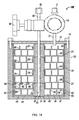
入口導管及び出口導管を有し、上記に開示されるニオブ含有膜形成用組成物のいずれかを収容するするキャニスターを含むニオブ含有膜形成用組成物送出装置も開示される。開示される送出装置は、以下の態様の1つ以上を含み得る:
・入口導管の末端は、ニオブ含有膜形成用組成物の表面より上に位置し、及び出口導管の末端は、ニオブ含有膜形成用組成物の表面より上に位置する;
・入口導管の末端は、ニオブ含有膜形成用組成物の表面より上に位置し、及び出口導管の末端は、ニオブ含有膜形成用組成物の表面より下に位置する;
・入口導管の末端は、ニオブ含有膜形成用組成物の表面より下に位置し、及び出口導管の末端は、ニオブ含有膜形成用組成物の表面より上に位置する。
Also disclosed is a niobium-containing membrane-forming composition delivery device comprising an inlet and outlet conduit and containing a canister containing any of the niobium-containing membrane-forming compositions disclosed above. The disclosed delivery device may include one or more of the following aspects:
The end of the inlet conduit is located above the surface of the niobium-containing film-forming composition, and the end of the outlet conduit is located above the surface of the niobium-containing film-forming composition;
The end of the inlet conduit is located above the surface of the niobium-containing film-forming composition, and the end of the outlet conduit is located below the surface of the niobium-containing film-forming composition;
The end of the inlet conduit is located below the surface of the niobium-containing film-forming composition, and the end of the outlet conduit is located above the surface of the niobium-containing film-forming composition.
基板上へのニオブ含有膜の堆積プロセスも開示される。上記に開示されるニオブ含有膜形成用組成物は、反応器であって、その中に配置された基板を有する反応器中に導入される。前駆体の少なくとも一部が基板上に堆積されてニオブ含有層を形成する。開示されるプロセスは、以下の態様の1つ以上を更に含み得る:
・反応物を反応器中に導入する;
・反応物は、プラズマ処理される;
・反応物は、プラズマ処理されない;
・反応物は、遠隔プラズマ処理される;
・反応物は、H2、H2CO、N2H4、NH3、水素ラジカル、第一級アミン、第二級アミン、第三級アミン、トリシリルアミン及びそれらの混合物からなる群から選択される;
・反応物は、H2である;
・反応物は、NH3である;
・反応物は、O2、O3、H2O、H2O2、NO、N2O、NO2、それらの酸素ラジカル及びそれらの混合物からなる群から選択される;
・反応物は、H2Oである;
・反応物は、プラズマ処理されたO2である;
・反応物は、O3である;
・ニオブ含有前駆体及び反応物は、チャンバー中に逐次導入される;
・ニオブ含有前駆体の導入及び反応物の導入は、反応物とNb含有前駆体との気相混合を回避するために時間的又は空間的に分離される;
・別の前駆体を反応器中に導入する;
・第2前駆体は、IV族元素、別のV族元素、Si、Ge、Al又は任意のランタニドから選択される元素Mを含む;
・ニオブ含有膜及び第2前駆体は、積層体を形成する;
・ニオブ含有膜及び第2前駆体は、NbO/MO積層体を形成する;
・反応器は、原子層堆積のために構成される;
・反応器は、プラズマ支援原子層堆積のために構成される;
・反応器は、空間原子層堆積のために構成される;
・ニオブ含有膜は、NbnOmであり、ここで、n及びmのそれぞれは、1〜6(両端値を含む)の範囲である整数である;
・ニオブ含有膜は、NbO2又はNb2O5である;
・ニオブ含有膜は、NboNpであり、ここで、o及びpのそれぞれは、1〜6(両端値を含む)の範囲である整数である;
・ニオブ含有膜は、NbNである;
・ニオブ含有膜は、NboNpOqであり、ここで、o、p及びqのそれぞれは、1〜6(両端値を含む)の範囲である整数である;
・ニオブ含有膜は、NbONである;
・ニオブ含有膜は、NbMOであり、ここで、Mは、IV族元素、別のV族元素、Si、Ge、Al又は任意のランタニドである。
The process of depositing a niobium-containing film on a substrate is also disclosed. The niobium-containing membrane-forming composition disclosed above is introduced into a reactor having a substrate arranged therein. At least a portion of the precursor is deposited on the substrate to form a niobium-containing layer. The disclosed process may further include one or more of the following embodiments:
-Introduce the reactants into the reactor;
-The reactants are plasma treated;
-The reactants are not plasma treated;
-Reactant is treated with remote plasma;
-Reactants are selected from the group consisting of H 2 , H 2 CO, N 2 H 4 , NH 3 , hydrogen radicals, primary amines, secondary amines, tertiary amines, trisilylamines and mixtures thereof. Be done;
-The reactant is H 2 ;
-The reactant is NH 3 ;
The reactants are selected from the group consisting of O 2 , O 3 , H 2 O, H 2 O 2, NO, N 2 O, NO 2 , their oxygen radicals and mixtures thereof;
-The reactant is H 2 O;
The reactant is plasma treated O 2 ;
Reaction product is a O 3;
-Niobium-containing precursors and reactants are introduced sequentially into the chamber;
The introduction of niobium-containing precursors and the introduction of reactants are separated temporally or spatially to avoid gas-phase mixing of the reactants with the Nb-containing precursors;
-Introduce another precursor into the reactor;
The second precursor comprises a Group IV element, another Group V element, an element M selected from Si, Ge, Al or any lanthanide;
-The niobium-containing film and the second precursor form a laminate;
The niobium-containing film and the second precursor form an NbO / MO laminate;
-Reactor is constructed for atomic layer deposition;
-Reactor is constructed for plasma-assisted atomic layer deposition;
-Reactor is constructed for spatial layer deposition;
The niobium-containing film is Nb n O m , where n and m are integers in the range 1-6 (including both ends);
The niobium-containing membrane is NbO 2 or Nb 2 O 5 ;
The niobium-containing film is Nb o N p , where each of o and p is an integer in the range 1-6 (including both ends);
-The niobium-containing film is NbN;
The niobium-containing film is Nb o N p O q , where each of o, p and q is an integer in the range 1-6 (including both ends);
-The niobium-containing film is NbON;
The niobium-containing film is NbMO, where M is a Group IV element, another Group V element, Si, Ge, Al or any lanthanide.
本発明の性質及び目的の更なる理解のため、添付の図面とともに以下の詳細な説明を参照すべきである。 For a better understanding of the nature and purpose of the invention, the following detailed description should be referred to along with the accompanying drawings.
式: formula:
(式中、それぞれのR、R1、R2及びR3は、独立して、H、アルキル基又はR’3Siであり、それぞれのR’は、独立して、H又はアルキル基である)
を有する前駆体を含むニオブ含有膜形成用組成物が開示される。式に例示されるように、窒素原子は、ニオブ原子に結合し、4配位Nb(V)中心をもたらし得る。結果として得られるジオメトリーは、それぞれの3,5−ジアルキルピラゾリル部分中の窒素−窒素結合の中心が一座配位子と見なされる4面体であり得る。ピラゾリル配位子中の炭素原子は、sp2混成であり、Nbは、η5結合ピラゾラト環によって配位されていると考えることができるモノアニオン性配位子にわたって非局在化電荷をもたらし得る。この実施形態では、式は、
(Wherein, each R,
A composition for forming a niobium-containing film containing a precursor having the above is disclosed. As illustrated in the formula, the nitrogen atom can bond to the niobium atom to result in a tetracoordinated Nb (V) center. The resulting geometry can be a tetrahedron in which the center of the nitrogen-nitrogen bond in each 3,5-dialkylpyrazolyl moiety is considered a bidentate ligand. The carbon atom in the pyrazolyl ligand is sp 2 hybrid and Nb can result in a delocalized charge across a monoanionic ligand that can be considered coordinated by the η5-bonded pyrazolat ring. In this embodiment, the formula
であろう。 Will.
代わりに、ピラゾリル配位子中の炭素原子は、sp3混成又はsp2混成とsp3混成とのある組み合わせのいずれかであり、窒素原子の1つ上に負電荷をもたらし、且つ窒素原子の他のものの上に中性電荷をもたらし得る。この実施形態では、式は、 Alternatively, the carbon atoms of the pyrazolyl in the ligand is either some combination of sp3 hybridized or sp2 hybridized and sp 3 hybridized, bring a negative charge on one of the nitrogen atom, and the other nitrogen atom It can bring a neutral charge on top of things. In this embodiment, the formula
であろう。 Will.
便宜上、非局在結合は、下式に描かれる。しかし、それぞれの式は、代わりに、NとNbとの間の単結合を示すこの式で表され得る。 For convenience, the delocalized bond is drawn by the following equation. However, each equation can instead be represented by this equation showing a single bond between N and Nb.
R=iPrである場合、ニオブ含有膜形成用前駆体は、式Nb(=NiPr)(R1,R2,R3−Pyr)3: When R = iPr, the precursor for forming a niobium-containing film is of the formula Nb (= NiPr) (R 1 , R 2 , R 3- Pyr) 3 :
(式中、それぞれのR1、R2及びR3は、独立して、H、アルキル基又はSiR’3であり、それぞれのR’は、独立して、H又はアルキル基である)
を有し得る。好ましくは、それぞれのR1、R2及びR3は、独立して、H、Me、Et、nPr、iPr、tBu、sBu、iBu、nBu、tアミル、SiMe3、SiMe2H又はSiH2Meである。
(Wherein each of R 1, R 2 and R 3, independently, H, 'is 3, each R' alkyl or SiR are independently H or an alkyl group)
Can have. Preferably, each of R 1, R 2 and R 3, independently, H, Me, Et, nPr , iPr, tBu, sBu, iBu, nBu, t -amyl, SiMe 3, SiMe 2 H or SiH 2 Me Is.
代表的な前駆体としては、Nb(=NiPr)(H,H,H−Pyr)3、Nb(=NiPr)(Me,H,H−Pyr)3、Nb(=NiPr)(Me,H,Me−Pyr)3、Nb(=NiPr)(Me,Me,Me−Pyr)3、Nb(=NiPr)(Et,H,Et−Pyr)3、Nb(=NiPr)(nPr,H,nPr−Pyr)3、Nb(=NiPr)(iPr,H,iPr−Pyr)3、Nb(=NiPr)(tBu,H,tBu−Pyr)3、Nb(=NiPr)(iBu,H,iBu−Pyr)3、Nb(=NiPr)(nBu,H,nBu−Pyr)3、Nb(=NiPr)(sBu,H,sBu−Pyr)3、Nb(=NiPr)(tアミル,H,tアミル−Pyr)3、Nb(=NiPr)(iPr,H,tBu−Pyr)3、Nb(=NiPr)(iPr,H,Me−Pyr)3、Nb(=NiPr)(iPr,H,Et−Pyr)3、Nb(=NiPr)(TMS,H,TMS−Pyr)3、Nb(=NiPr)(DMS,H,DMS−Pyr)3又はNb(=NiPr)(MMS,H,MMS−Pyr)3が挙げられる。 Typical precursors include Nb (= NiPr) (H, H, H-Pyr) 3 , Nb (= NiPr) (Me, H, H-Pyr) 3 , Nb (= NiPr) (Me, H, Me-Pyr) 3 , Nb (= NiPr) (Me, Me, Me-Pyr) 3 , Nb (= NiPr) (Et, H, Et-Pyr) 3 , Nb (= NiPr) (nPr, H, nPr- Pyr) 3 , Nb (= NiPr) (iPr, H, iPr-Pyr) 3 , Nb (= NiPr) (tBu, H, tBu-Pyr) 3 , Nb (= NiPr) (iBu, H, iBu-Pyr) 3 , Nb (= NiPr) (nBu, H, nBu-Pyr) 3 , Nb (= NiPr) (sBu, H, sBu-Pyr) 3 , Nb (= NiPr) (t-Amil, H, t-Amil-Pyr) 3 , Nb (= NiPr) (iPr, H, tBu-Pyr) 3 , Nb (= NiPr) (iPr, H, Me-Pyr) 3 , Nb (= NiPr) (iPr, H, Et-Pyr) 3 , Examples thereof include Nb (= NiPr) (TMS, H, TMS-Pyr) 3 , Nb (= NiPr) (DMS, H, DMS-Pyr) 3 or Nb (= NiPr) (MMS, H, MMS-Pyr) 3. ..
R=tBuである場合、ニオブ含有膜形成用前駆体は、式Nb(=NtBu)(R1,R2,R3−Pyr)3: When R = tBu, the precursor for forming a niobium-containing film is of the formula Nb (= NtBu) (R 1 , R 2 , R 3- Pyr) 3 :
(式中、それぞれのR1、R2及びR3は、独立して、H、アルキル基又はSiR’3であり、それぞれのR’は、独立して、H又はアルキル基である)
を有し得る。好ましくは、それぞれのR1、R2及びR3は、独立して、H、Me、Et、nPr、iPr、tBu、sBu、iBu、nBu、tアミル、SiMe3、SiMe2H又はSiH2Meである。
(Wherein each of R 1, R 2 and R 3, independently, H, 'is 3, each R' alkyl or SiR are independently H or an alkyl group)
Can have. Preferably, each of R 1, R 2 and R 3, independently, H, Me, Et, nPr , iPr, tBu, sBu, iBu, nBu, t -amyl, SiMe 3, SiMe 2 H or SiH 2 Me Is.
代表的な前駆体としては、Nb(=NtBu)(H,H,H−Pyr)3、Nb(=NtBu)(Me,H,H−Pyr)3、Nb(=NtBu)(Me,H,Me−Pyr)3、Nb(=NtBu)(Me,Me,Me−Pyr)3、Nb(=NtBu)(Et,H,Et−Pyr)3、Nb(=NtBu)(nPr,H,nPr−Pyr)3、Nb(=NtBu)(iPr,H,iPr−Pyr)3、Nb(=NtBu)(tBu,H,tBu−Pyr)3、Nb(=NtBu)(sBu,H,sBu−Pyr)3、Nb(=NtBu)(nBu,H,nBu−Pyr)3、Nb(=NtBu)(iBu,H,iBu−Pyr)3、Nb(=NtBu)(tアミル,H,tアミル−Pyr)3、Nb(=NtBu)(iPr,H,tBu−Pyr)3、Nb(=NtBu)(iPr,H,Me−Pyr)3、Nb(=NtBu)(iPr,H,Et−Pyr)3、Nb(=NtBu)(TMS,H,TMS−Pyr)3、Nb(=NtBu)(DMS,H,DMS−Pyr)3又はNb(=NtBu)(MMS,H,MMS−Pyr)3が挙げられる。 Typical precursors include Nb (= NtBu) (H, H, H-Pyr) 3 , Nb (= NtBu) (Me, H, H-Pyr) 3 , Nb (= NtBu) (Me, H, Me-Pyr) 3 , Nb (= NtBu) (Me, Me, Me-Pyr) 3 , Nb (= NtBu) (Et, H, Et-Pyr) 3 , Nb (= NtBu) (nPr, H, nPr- Pyr) 3 , Nb (= NtBu) (iPr, H, iPr-Pyr) 3 , Nb (= NtBu) (tBu, H, tBu-Pyr) 3 , Nb (= NtBu) (sBu, H, sBu-Pyr) 3 , Nb (= NtBu) (nBu, H, nBu-Pyr) 3 , Nb (= NtBu) (iBu, H, iBu-Pyr) 3 , Nb (= NtBu) (t Amil, H, t Amil-Pyr) 3 , Nb (= NtBu) (iPr, H, tBu-Pyr) 3 , Nb (= NtBu) (iPr, H, Me-Pyr) 3 , Nb (= NtBu) (iPr, H, Et-Pyr) 3 , Examples thereof include Nb (= NtBu) (TMS, H, TMS-Pyr) 3 , Nb (= NtBu) (DMS, H, DMS-Pyr) 3 or Nb (= NtBu) (MMS, H, MMS-Pyr) 3. ..
R=tアミルである場合、ニオブ含有膜形成用前駆体は、式Nb(=Ntアミル)(R1,R2,R3−Pyr)3: When R = t-amyl, the precursor for forming a niobium-containing film is the formula Nb (= Nt-amyl) (R 1 , R 2 , R 3- Pyr) 3 :
(式中、それぞれのR1、R2及びR3は、独立して、H、アルキル基又はSiR’3であり、それぞれのR’は、独立して、H又はアルキル基である)
を有し得る。好ましくは、それぞれのR1、R2及びR3は、独立して、H、Me、Et、nPr、iPr、tBu、sBu、iBu、nBu、tアミル、SiMe3、SiMe2H又はSiH2Meである。
(Wherein each of R 1, R 2 and R 3, independently, H, 'is 3, each R' alkyl or SiR are independently H or an alkyl group)
Can have. Preferably, each of R 1, R 2 and R 3, independently, H, Me, Et, nPr , iPr, tBu, sBu, iBu, nBu, t -amyl, SiMe 3, SiMe 2 H or SiH 2 Me Is.
代表的な前駆体としては、Nb(=Ntアミル)(H,H,H−Pyr)3、Nb(=Ntアミル)(Me,H,H−Pyr)3、Nb(=Ntアミル)(Me,H,Me−Pyr)3、Nb(=Ntアミル)(Me,Me,Me−Pyr)3、Nb(=Ntアミル)(Et,H,Et−Pyr)3、Nb(=Ntアミル)(nPr,H,nPr−Pyr)3、Nb(=Ntアミル)(iPr,H,iPr−Pyr)3、Nb(=Ntアミル)(tBu,H,tBu−Pyr)3、Nb(=Ntアミル)(sBu,H,sBu−Pyr)3、Nb(=Ntアミル)(nBu,H,nBu−Pyr)3、Nb(=Ntアミル)(iBu,H,iBu−Pyr)3、Nb(=Ntアミル)(tアミル,H,tアミル−Pyr)3、Nb(=Ntアミル)(iPr,H,tBu−Pyr)3、Nb(=Ntアミル)(iPr,H,Me−Pyr)3、Nb(=Ntアミル)(iPr,H,Et−Pyr)3、Nb(=Ntアミル)(TMS,H,TMS−Pyr)3、Nb(=Ntアミル)(DMS,H,DMS−Pyr)3又はNb(=Ntアミル)(MMS,H,MMS−Pyr)3が挙げられる。 Typical precursors are Nb (= Nt amyl) (H, H, H-Pyr) 3 , Nb (= Nt amyl) (Me, H, H-Pyr) 3 , Nb (= Nt amyl) (Me). , H, Me-Pyr) 3 , Nb (= Nt Amil) (Me, Me, Me-Pyr) 3 , Nb (= Nt Amil) (Et, H, Et-Pyr) 3 , Nb (= Nt Amil) ( nPr, H, nPr-Pyr) 3 , Nb (= Nt Amil) (iPr, H, iPr-Pyr) 3 , Nb (= Nt Amil) (tBu, H, tBu-Pyr) 3 , Nb (= Nt Amil) (SBu, H, sBu-Pyr) 3 , Nb (= Nt Amil) (nBu, H, nBu-Pyr) 3 , Nb (= Nt Amil) (iBu, H, iBu-Pyr) 3 , Nb (= Nt Amil) ) (T Amil, H, t Amil-Pyr) 3 , Nb (= Nt Amil) (iPr, H, tBu-Pyr) 3 , Nb (= Nt Amil) (iPr, H, Me-Pyr) 3 , Nb ( = Nt Amil) (iPr, H, Et-Pyr) 3 , Nb (= Nt Amil) (TMS, H, TMS-Pyr) 3 , Nb (= Nt Amil) (DMS, H, DMS-Pyr) 3 or Nb (= Nt Amil) (MMS, H, MMS-Pyr) 3 can be mentioned.
これらの前駆体は、Nb(=NR)X3(py)2を3当量のZ(R1,R2,R3−Pyr)と反応させることによって合成され得、ここで、Xは、F、Cl、Br及びIからなる群から選択されるハロゲンであり;Zは、Li、Na及びKからなる群から選択されるアルカリ金属であり;R、R1、R2及びR3は、上記に定義されている。Nb(=NR)X3(py)2は、Chemische Berichte,Vol 127,Issue 7,1994,1201−12に記載されているように調製され得る。Z(R1,R2,R3−Pyr)は、n−ブチルリチウム(nBuLi)などのアルキルアルカリ金属と、対応するR1,R2,R3−ピラゾールとの反応によって調製され得る。反応物の添加は、温度が−50℃未満である低温で行われ得る。反応は、THF又はジエチルエーテルなどの極性溶媒中で行われ得る。前駆体は、ペンタン、ヘキサン、シクロヘキサン、ヘプタン、ベンゼン及びトルエンなどの非極性溶媒での抽出によってアルカリ塩から分離され得る。結果として得られるニオブ含有膜形成用組成物は、減圧昇華、減圧蒸留又は限定なしにTHF、ジエチルエーテル、ペンタン、ヘキサン、シクロヘキサン、ヘプタン、ベンゼン、トルエン若しくはそれらの混合物からなる群から選択される適切な溶媒中での再結晶によって精製され得る。 These precursors can be synthesized by reacting Nb (= NR) X 3 (py) 2 with 3 equivalents of Z (R 1 , R 2 , R 3- Pyr), where X is F. , Cl, Br and I are halogens selected from the group; Z is an alkali metal selected from the group consisting of Li, Na and K; R, R 1 , R 2 and R 3 are described above. Is defined in. Nb (= NR) X 3 (py) 2 can be prepared as described in Chemische Berichte, Vol 127, Issue 7, 1994, 1201-12. Z (R 1 , R 2 , R 3- Pyr) can be prepared by the reaction of an alkyl alkali metal such as n-butyllithium (nBuLi) with the corresponding R 1 , R 2 , R 3-pyrazole. Addition of the reactants can be carried out at low temperatures, where the temperature is less than −50 ° C. The reaction can be carried out in a polar solvent such as THF or diethyl ether. The precursor can be separated from the alkali salt by extraction with a non-polar solvent such as pentane, hexane, cyclohexane, heptane, benzene and toluene. The resulting niobium-containing film-forming composition is suitable selected from the group consisting of THF, diethyl ether, pentane, hexane, cyclohexane, heptane, benzene, toluene or mixtures thereof, with reduced pressure sublimation, reduced pressure distillation or without limitation. It can be purified by recrystallization in a solvent.
開示されるニオブ含有膜形成用組成物の純度は、95%w/w超(すなわち95.0%w/w〜100.0%w/w)、好ましくは98%w/w超(すなわち98.0%w/w〜100.0%w/w)、より好ましくは99%w/w超(すなわち99.0%w/w〜100.0%w/w)である。当業者は、この純度がH NMR又は質量分析法付きのガス又は液体クロマトグラフィーによって測定され得ることを認めるであろう。開示されるニオブ含有膜形成用組成物は、次の不純物:ピラゾール類;ピリジン類;アルキルアミン;アルキルイミン;THF;エーテル;ペンタン;シクロヘキサン;ヘプタン;ベンゼン;トルエン;塩素化金属化合物;又はリチウム、ナトリウム若しくはカリウムピラゾリルのいずれかを含有し得る。これらの不純物の全量は、5%w/w未満(すなわち0.0%w/w〜5.0%w/w)、好ましくは2%w/w未満(すなわち0.0%w/w〜2.0%w/w)、より好ましくは1%w/w未満(すなわち0.0%w/w〜1.0%w/w)である。組成物は、再結晶、昇華、蒸留及び/又は4Aモレキュラーシーブなどの適切な吸着材にガス又は液体を通すことによって精製され得る。 The disclosed niobium-containing film-forming compositions have a purity greater than 95% w / w (ie, 95.0% w / w to 100.0% w / w), preferably greater than 98% w / w (ie, 98). It is 0.0% w / w to 100.0% w / w), more preferably more than 99% w / w (that is, 99.0% w / w to 100.0% w / w). Those skilled in the art will recognize that this purity can be measured by NMR or gas or liquid chromatography with mass spectrometry. The disclosed niobium-containing film-forming compositions include the following impurities: pyrazoles; pyridines; alkylamines; alkylimines; THF; ethers; pentane; cyclohexane; heptane; benzene; toluene; chlorinated metal compounds; or lithium, It may contain either sodium or potassium pyrazolyl. The total amount of these impurities is less than 5% w / w (ie 0.0% w / w to 5.0% w / w), preferably less than 2% w / w (ie 0.0% w / w ~. 2.0% w / w), more preferably less than 1% w / w (ie 0.0% w / w to 1.0% w / w). The composition can be purified by passing a gas or liquid through a suitable adsorbent such as recrystallization, sublimation, distillation and / or 4A molecular sieve.
開示されるニオブ含有膜形成用組成物の精製はまた、0ppbw〜1ppmw、好ましくは0〜500ppbw(十億重量当たりの部)レベルでの金属不純物をもたらし得る。これらの金属不純物としては、アルミニウム(Al)、ヒ素(As)、バリウム(Ba)、ベリリウム(Be)、ビスマス(Bi)、カドミウム(Cd)、カルシウム(Ca)、クロム(Cr)、コバルト(Co)、銅(Cu)、ガリウム(Ga)、ゲルマニウム(Ge)、ハフニウム(Hf)、ジルコニウム(Zr)、インジウム(In)、鉄(Fe)、鉛(Pb)、リチウム(Li)、マグネシウム(Mg)、マンガン(Mn)、タングステン(W)、ニッケル(Ni)、カリウム(K)、ナトリウム(Na)、ストロンチウム(Sr)、トリウム(Th)、スズ(Sn)、チタン(Ti)、ウラン(U)及び亜鉛(Zn)が挙げられるが、これらに限定されるものではない。 Purification of the disclosed niobium-containing film-forming compositions can also result in metal impurities at the 0 ppbb to 1 ppmw, preferably 0 to 500 ppbw (per billion weight) levels. Examples of these metal impurities include aluminum (Al), arsenic (As), gallium (Ba), berylium (Be), bismuth (Bi), cadmium (Cd), calcium (Ca), chromium (Cr), and cobalt (Co). ), Copper (Cu), gallium (Ga), germanium (Ge), hafnium (Hf), zirconium (Zr), indium (In), iron (Fe), lead (Pb), lithium (Li), magnesium (Mg) ), Manganese (Mn), Tungsten (W), Nickel (Ni), Potassium (K), Sodium (Na), Strontium (Sr), Thorium (Th), Tin (Sn), Titanium (Ti), Uran (U) ) And zinc (Zn), but are not limited thereto.
蒸着プロセスを用いて基板上にニオブ含有層を形成する方法も開示される。本出願人らは、開示されるニオブ含有膜形成用組成物が原子層堆積に適していると考えており、それを以下の堆積実施例において実証する。より具体的には、開示されるニオブ含有膜形成用組成物は、表面飽和、1サイクル当たりの自己限定的成長及び約2:1〜約200:1、好ましくは約20:1〜約100:1の範囲のアスペクト比に関する完全ステップカバレージが可能である。更に、開示されるニオブ含有膜形成用組成物は、ALDを可能にするための良好な熱安定性を示す高い分解温度を有する。高い分解温度は、より高い純度を有する膜をもたらすより高い温度でのALDを可能にする。 Also disclosed is a method of forming a niobium-containing layer on a substrate using a thin film deposition process. Applicants believe that the disclosed niobium-containing film-forming compositions are suitable for atomic layer deposition and will demonstrate this in the following deposition examples. More specifically, the disclosed niobium-containing film-forming compositions have surface saturation and self-limiting growth per cycle and about 2: 1 to about 200: 1, preferably about 20: 1 to about 100 :. Complete step coverage for aspect ratios in the range of 1 is possible. In addition, the disclosed niobium-containing film-forming compositions have a high decomposition temperature that exhibits good thermal stability to enable ALD. The high decomposition temperature allows ALD at higher temperatures, resulting in a film with higher purity.
この方法は、半導体、光起電力、LCD−TFT又はフラットパネル型のデバイスの製造において有用であり得る。当業者に周知のあらゆる堆積方法を用いるニオブ含有薄膜の堆積に、開示されるニオブ含有膜形成用組成物を用いることができる。適切な気相成長方法の例としては、化学気相成長(CVD)又は原子層堆積(ALD)が挙げられる。代表的なCVD方法としては、熱CVD、プラズマ支援CVD(PECVD)、パルスCVD(PCVD)、低圧CVD(LPCVD)、準大気圧CVD(SACVD)又は大気圧CVD(APCVD)、ホットワイヤーCVD(HWCVD、cat−CVDとしても知られ、ホットワイヤーが堆積プロセスのエネルギー源として機能する)、ラジカル組み込みCVD及びそれらの組合せが挙げられる。代表的なALD方法としては、熱式ALD,プラズマ支援ALD(PEALD)、空間隔離ALD、ホットワイヤーALD(HWALD)、ラジカル組み込みALD及びそれらの組み合わせが挙げられる。超臨界流体堆積も使用され得る。堆積方法は、好ましくは、適切なテップカバレージ及び膜厚制御を提供するためにALD、PE−ALD又は空間ALDである。 This method can be useful in the manufacture of semiconductors, photovoltaics, LCD-TFTs or flat panel type devices. The disclosed niobium-containing film-forming composition can be used for deposition of niobium-containing thin films using any deposition method well known to those skilled in the art. Examples of suitable vapor deposition methods include chemical vapor deposition (CVD) or atomic layer deposition (ALD). Typical CVD methods include thermal CVD, plasma assisted CVD (PECVD), pulse CVD (PCVD), low pressure CVD (LPCVD), quasi-atmospheric pressure CVD (SACVD) or atmospheric pressure CVD (APCVD), and hot wire CVD (HWCVD). , Also known as cat-CVD, where hot wire functions as an energy source for the deposition process), radical-embedded CVD and combinations thereof. Typical ALD methods include thermal ALD, plasma-assisted ALD (PEALD), space isolation ALD, hot wire ALD (HWALD), radical-incorporated ALD, and combinations thereof. Supercritical fluid deposition can also be used. The deposition method is preferably ALD, PE-ALD or spatial ALD to provide appropriate tep coverage and film thickness control.
開示されるニオブ含有膜形成用組成物は、ニート形態又はエチルベンゼン、キシレン、メシチレン、デカリン、デカン、ドデカンなどの適切な溶媒とのブレンド物のいずれかで供給され得る。開示される前駆体は、溶媒中に様々な濃度で存在し得る。 The disclosed niobium-containing film-forming compositions can be supplied in either neat form or in blends with suitable solvents such as ethylbenzene, xylene, mesitylene, decalin, decane, dodecane. The disclosed precursors can be present in the solvent at various concentrations.
ニートの又は混合されたニオブ含有膜形成用組成物は、配管及び/又は流量計などの従来手段によって蒸気形態で反応器中に導入される。従来の気化ステップ、例えば直接気化、蒸留若しくはバブリングにより、又はXuらのPCT公開国際公開第2009/087609号パンフレットに開示されるものなどの昇華器を用いることにより、ニートの又は混合された組成物を気化させることによって蒸気形態を得ることができる。反応器中に導入する前に気化させる場合、ニートの又は混合された組成物を液体状態で蒸発器に供給することができる。代わりに、組成物を収容する容器中にキャリアガスを流すことにより、又はキャリアガスを組成物中にバブリングすることにより、ニートの又は混合された組成物を気化させることができる。キャリアガスとしては、Ar、He、N2及びそれらの混合物を挙げることができるが、これらに限定されるものではない。キャリアガスのバブリングにより、ニートの又は混合された組成物溶液中に存在するあらゆる溶存酸素を除去することもできる。キャリアガスと組成物とは、次に蒸気として反応器中に導入される。 The neat or mixed niobium-containing membrane-forming composition is introduced into the reactor in vapor form by conventional means such as piping and / or flow meters. Neat or mixed compositions by conventional vaporization steps, such as by direct vaporization, distillation or bubbling, or by using sublimators such as those disclosed in Xu et al., PCT Publication International Publication No. 2009/08769 Pamphlet. The vapor form can be obtained by vaporizing. If vaporized prior to introduction into the reactor, the neat or mixed composition can be fed to the evaporator in a liquid state. Alternatively, the neat or mixed composition can be vaporized by flowing the carrier gas into the container containing the composition or by bubbling the carrier gas into the composition. Examples of the carrier gas include, but are not limited to, Ar, He, N 2 and a mixture thereof. Bubbling of the carrier gas can also remove any dissolved oxygen present in the neat or mixed composition solution. The carrier gas and composition are then introduced into the reactor as vapor.
必要に応じて、組成物がその液相にあることができ、十分な蒸気圧を有することができる温度まで、開示される組成物を収容する容器を加熱することができる。容器は、例えば、約0℃〜約180℃の範囲内の温度に維持することができる。当業者は、気化させる前駆体の量を制御するために周知の方法で容器の温度を調節できることを認識する。 If desired, the composition can be in its liquid phase and the container containing the disclosed composition can be heated to a temperature at which it can have sufficient vapor pressure. The container can be maintained at a temperature in the range of, for example, about 0 ° C to about 180 ° C. Those skilled in the art will recognize that the temperature of the vessel can be adjusted in a well-known manner to control the amount of precursor to be vaporized.
ニオブ含有膜形成用組成物は、開示されるニオブ含有膜形成用組成物送出装置によって半導体処理ツールまで送出することができる。図16及び17は、開示される送出装置1の2つの実施形態を示す。
The niobium-containing film-forming composition can be delivered to the semiconductor processing tool by the disclosed niobium-containing film-forming composition delivery device. 16 and 17 show two embodiments of the disclosed
図16は、ニオブ含有膜形成用組成物送出装置1の一実施形態の側面図である。図16では、開示されるニオブ含有膜形成用組成物11は、少なくとも2つの導管、入口導管3及び出口導管4を有する容器2内に収容される。前駆体分野の当業者であれば、高温及び高圧でも気体の形態のニオブ含有膜形成用組成物11の漏れが防止されるように容器2、入口導管3及び出口導管4が製造されることを認識するであろう。
FIG. 16 is a side view of an embodiment of the niobium-containing film forming
適切なバルブとしては、ばね荷重バルブ又はダイヤフラムが取り付けられたバルブが挙げられる。バルブは、制限流オリフィス(RFO)を更に含むことができる。送出装置1は、ガスマニホールドに接続され、エンクロージャー中にあるべきである。ガスマニホールドにより、あらゆる残留量の材料が反応しないように、送出装置1が交換されるときに空気に曝露し得る配管の安全な排気及びパージが可能となるであろう。
Suitable valves include spring-loaded valves or valves fitted with diaphragms. The valve can further include a limiting flow orifice (RFO). The
送出装置1は、漏れが生じないようにする必要があり、閉じたときにわずかな量の材料も漏れないようにすることができるバルブを取り付ける必要がある。送出装置1は、バルブ6及び7により、前述の開示のガスキャビネットなどの半導体処理ツールの別の構成要素に流体接続される。好ましくは、容器2、入口導管3、バルブ6、出口導管4及びバルブ7は、典型的には316L EPステンレス鋼でできている。
The
図16では、入口導管3の末端8は、ニオブ含有膜形成用組成物11の表面より上に位置する一方、出口導管4の末端9は、ニオブ含有膜形成用組成物11の表面より下に位置する。この実施形態では、ニオブ含有膜形成用組成物11は、好ましくは、液体形態である。限定するものではないが、窒素、アルゴン、ヘリウム及びそれらの混合物などの不活性ガスを入口導管3内に導入することができる。不活性ガスによって容器2が加圧され、それにより、液体のニオブ含有膜形成用組成物11は、出口導管4から半導体処理ツールの構成要素(図示せず)まで押し出される。半導体処理ツールとしては、修復されるウエハが配置され、気相での処理が行われるチャンバーに蒸気を送出するために、ヘリウム、アルゴン、窒素又はそれらの混合物などのキャリアガスを使用して又は使用せずに、液体のニオブ含有膜形成用組成物11を蒸気に変換する蒸発器を挙げることができる。代わりに、液体のニオブ含有膜形成用組成物11は、ジェット又はエアロゾルとしてウエハ表面に直接送出することができる。
In FIG. 16 , the
図17は、ニオブ含有膜形成用組成物送出装置1の第2の実施形態の側面図である。図17では、入口導管3の末端8は、ニオブ含有膜形成用組成物11の表面より下に位置する一方、出口導管4の末端9は、ニオブ含有膜形成用組成物11の表面より上に位置する。図17は、任意選択の加熱要素14も含み、これによってニオブ含有膜形成用組成物11の温度を上昇させることができる。ニオブ含有膜形成用組成物11は、固体又は液体の形態であり得る。限定するものではないが、窒素、アルゴン、ヘリウム及びそれらの混合物などの不活性ガスが入口導管3内に導入される。不活性ガスは、ニオブ含有膜形成用組
成物11中を流れ、不活性ガスと気化したニオブ含有膜形成用組成物11との混合物を出口導管4に運び、半導体処理ツールの構成要素まで運ぶ。
FIG. 17 is a side view of a second embodiment of the niobium-containing film forming
図16及び17の両方は、バルブ6及び7を含む。当業者は、それぞれ導管3及び4を通して流れることができるように、バルブ6及び7を開放位置又は閉鎖位置に配置できることを認識するであろう。別の代替形態では、入口導管3及び出口導管4は、本明細書における本開示から逸脱することなく、ニオブ含有膜形成用組成物11の表面より上に両方とも配置し得る。更に、入口導管3は、充填口であり得る。
Both FIGS. 16 and 17 include
別の代替形態では、ニオブ含有膜形成用組成物11が蒸気形態にある場合又は十分な蒸気圧が固相/液相の上方に存在する場合、図16若しくは17における送出装置1又は存在する任意の固体若しくは液体の表面より上で終わる単一導管を有するより単純な送出装置が使用され得る。この場合、ニオブ含有膜形成用組成物11は、それぞれ図16におけるバルブ6又は図17におけるバルブ7を開けることによって簡単に導管3又は4を通して蒸気形態で送出される。例えば、任意選択の加熱要素14を用いることにより、ニオブ含有膜形成用組成物11を蒸気形態で送出するのに十分な蒸気圧を得るために適切な温度に送出装置1を維持することができる。
In another alternative form, if the niobium-containing film-forming
ニオブ含有膜形成用組成物が固体である場合、昇華器を用いてそれらの蒸気を反応器に送出することができる。図18は、適切な昇華器100の一実施形態を示す。昇華器100は、容器33を含む。容器33は、円筒形容器であり得るか、又はこれとは別に制限なくあらゆる形状であり得る。容器33は、ステンレス鋼、ニッケル及びその合金、石英、ガラス並びに他の化学的に適合する材料などの材料で構成され、制限はない。ある場合には、容器33は、別の金属又は金属合金で構成され、制限はない。ある場合には、容器33は、約8センチメートル〜約55センチメートルの内径を有し、且つ代わりに約8センチメートル〜約30センチメートルの内径を有する。当業者によって理解されるように、別の構成は、別の寸法を有することができる。
If the niobium-containing membrane-forming composition is solid, a sublimator can be used to deliver their vapors to the reactor. FIG. 18 shows one embodiment of a
容器33は、封止可能な上部15、封止部材18及びガスケット20を含む。封止可能な上部15は、外部環境から容器33を封止するように構成される。封止可能な上部15は、容器33に到達できるように構成される。更に、封止可能な上部15は、容器33中への導管の通路のために構成される。代わりに、封止可能な上部15は、容器33中に流体が流れるように構成される。封止可能な上部15は、容器33との流体接触を維持するための浸漬管92を含む導管を収容し、それが貫通するように構成される。制御バルブ90及び取付具95を有する浸漬管92は、キャリアガスが容器33中に流れるように構成される。ある場合には、浸漬管92は、容器33の中心軸の下方に延在する。更に、封止可能な上部15は、出口管12を含む導管を収容し、それが貫通するように構成される。キャリアガスとニオブ含有膜形成用組成物の蒸気とは、出口管12を通って容器33から取り出される。出口管12は、制御バルブ10及び取付具5を含む。ある場合には、出口管12は、昇華器100から膜堆積チャンバーまで送るためにガス送出マニホールドと流体連結される。
The container 33 includes a sealable
容器33及び封止可能な上部15は、少なくとも2つの封止部材18により、代わりに少なくとも約4つの封止部材により封止される。ある場合には、封止可能な上部15は、少なくとも約8つの封止部材18によって容器33に封止される。当業者によって理解されるように、封止部材18は、封止可能な上部15を容器33に取り外し可能に連結し、ガスケット20とともに耐ガス性シールを形成する。封止部材18は、容器33を封止するための当業者に周知のあらゆる適切な手段を含むことができる。ある場合には、封止部材18は、つまみねじを含む。
The container 33 and the sealable top 15 are sealed by at least two sealing members 18 and instead by at least about four sealing members. In some cases, the sealable top 15 is sealed in the container 33 by at least about eight sealing members 18. As will be appreciated by those skilled in the art, the sealing member 18 detachably connects the sealable top 15 to the container 33 to form a gas resistant seal with the
図18に示されるように、容器33は、内部に配置される少なくとも1つのディスクを更に含む。ディスクは、固体材料のための棚又は水平支持体を含む。ある実施形態では、
ディスク30が容器33の内径又は円周よりも小さい外径又は円周を含み、開口部31を形成するように、内側ディスク30は、容器33内に環状に配置される。ディスク86が容器33の内径と同じ、ほぼ同じ又はほぼ重なる外径又は円周を含むように、容器内の周囲に外側ディスク86が配置される。外側ディスク86により、ディスクの中央に配置される開口部87が形成される。複数のディスクが容器33内に配置される。これらのディスクは、交互に積み重ねられ、内側ディスク30、34、36、44は、容器内で交互に外側ディスク62、78、82、86と垂直方向に積み重ねられる。実施形態では、内側ディスク30、34、36、44は、外側に向かって環状に延在し、外側ディスク62、78、82、86は、容器33の中央に向かって環状に延在する。図18の実施形態に示されるように、内側ディスク30、34、36、44は、外側ディスク62、78、82、86と物理的に接触しない。
As shown in FIG. 18 , container 33 further comprises at least one disc placed internally. Discs include shelves or horizontal supports for solid materials. In one embodiment
The
組み立てられた昇華器100は、配列され且つ連結された支持脚50、内部通路51、同心の壁40、41、42及び同心のスロット47、48、49を含む内側ディスク30、34、36、44を含む。内側ディスク30、34、36、44は、垂直に積み重ねられ、浸漬管92の周囲に環状の方向にある。更に、昇華器は、外側ディスク62、78、82、86を含む。図18に示されるように、容器33からディスク62、78、82、86に熱が伝達するために良好な接触となるように、外側ディスク62、78、82、86は、容器33中に隙間なく嵌合すべきである。好ましくは、外側ディスク62、78、82、86は、容器33の内壁に結合されるか又は物理的に接触する。
The assembled
図示されるように、外側ディスク62、78、82、86と、内側ディスク30、34、36、44とは、容器33の内側に積み重ねられる。容器33中で組み立てて昇華器100が形成されると、内側ディスク30、34、36、44は、組み立てられた外側ディスク62、78、82、86間で外側ガス通路31、35、37、45を形成する。更に、外側ディスク62、78、82、86は、内側ディスク30、34、36、44の支持脚と内側ガス通路56、79、83、87を形成する。内側ディスク30、34、36、44の壁40、41、42は、固体前駆体を保持するための溝付きスロットを形成する。外側ディスク62、78、82、86は、固体前駆体を保持するための壁68、69、70を含む。組立中、内側ディスク30、34、36、44の環状スロット47、48、49及び外側ディスク62、78、82、86の環状スロット64、65、66中に固体前駆体が入れられる。
As shown, the outer discs 62, 78, 82, 86 and the
図18は、任意の固体のニオブ含有膜形成用組成物の蒸気を反応器に送出することができる昇華器の一実施形態を開示しているが、当業者であれば、本明細書の教示から逸脱しない別の昇華器設計も適切であり得ることを認識するであろう。更に、当業者であれば、本明細書の教示から逸脱せずに、開示されるニオブ含有膜形成用組成物11は、Jurcikらの国際公開第2006/059187号パンフレットに開示されるアンプルなどの別の送出装置を用いて半導体処理ツールに送出できることを認識するであろう。
FIG. 18 discloses an embodiment of a sublimator capable of delivering the vapor of any solid niobium-containing film-forming composition to the reactor, but those skilled in the art will appreciate the teachings herein. You will recognize that another sublimator design that does not deviate from is also appropriate. Further, those skilled in the art will not deviate from the teachings herein, and the disclosed niobium-containing film-forming
反応器は、限定するものではないが、化合物を反応させ、層を形成させるのに適切な条件下において、平行板型反応器、コールドウォール型反応器、ホットウォール型反応器、枚葉式反応器、多葉式反応器又は他のタイプの堆積システムなどの装置内で堆積方法が行われるあらゆるエンクロージャー又はチャンバーであり得る。当業者は、これらの反応器のいずれかがALD又はCVD堆積プロセスのいずれかのために使用され得ることを認めるであろう。 Reactors are, but are not limited to, parallel plate reactors, coldwall reactors, hotwall reactors, single-wafer reactors under conditions suitable for reacting compounds to form layers. It can be any enclosure or chamber in which the deposition method takes place within a device such as a vessel, multi-leaf reactor or other type of deposition system. Those skilled in the art will recognize that any of these reactors can be used for either ALD or CVD deposition processes.
反応器には、膜がその上に堆積される1つ以上の基板が収容される。基板は、プロセスが行われる材料として一般に定義される。基板は、半導体、光起電力、フラットパネル又はLCD−TFTのデバイスの製造に使用されるあらゆる適切な基板であり得る。適切な基板の例としては、シリコン、シリカ、ガラスなどのウエハ又はGaAsウエハが挙げられる。ウエハは、前の製造ステップでその上に堆積された異なる材料の1つ以上の層を有し得る。例えば、ウエハは、シリコン層(結晶性、非晶質、多孔質など)、酸化ケイ素層、窒化ケイ素層、酸窒化ケイ素層、炭素ドープ酸化ケイ素(SiCOH)層、金属若しくは金属窒化物層(Ti、Ru、Taなど)又はそれらの組み合わせを含み得る。更に、ウエハは、銅層又は貴金属層(例えば、白金、パラジウム、ロジウム若しくは金)を含み得る。ウエハは、マンガン、酸化マンガンなどの障壁層を含み得る。ポリ(3,4−エチレンジオキシチオフェン)ポリ(スチレンスルホネート)[PEDOT:PSS]などのプラスチック層も使用され得る。層は、平面である場合もパターン化される場合もある。開示される方法により、ウエハの上に直接又はウエハの上面上の1つ若しくは2つ以上の層(パターン化された複数の層が基板を形成する場合)の上に直接、ニオブ含有層を堆積することができる。更に、当業者であれば、本明細書において使用される「膜」又は「層」という用語は、表面上に配置されるか又は広げられるある厚さのある材料を意味し、この表面は、トレンチ又は線であり得ることを認識するであろう。本明細書及び請求項の全体にわたって、ウエハ及びその上の任意の関連する層が基板と呼ばれる。例えば、酸化ニオブ膜は、ZrO2層、HfO2層又はMoO2層などの金属酸化物層上に堆積され得る。引き続く処理において、別の金属酸化物層を酸化ニオブ層の上に堆積して積層体を形成し得る。ZrO2/Nb2O5/ZrO2積層体誘電性スタックは、DRAM高kスタックに典型的なものである。窒化ニオブ層又は窒化チタン層などの導電性金属窒化物層は、それぞれ下部及び上部電極を形成するために最後の金属酸化物層の前又は最後の層の上に堆積され得る。結果として得られるNbN/ZrO2/Nb2O5/ZrO2/NbNスタックは、DRAMキャパシタ中に使用され得る。RuO、Ru、Pt、Ir、WN、WNCなどの他の導電性膜も、単独で又はNbN若しくはTaN層に加えて下部又は上部電極として使用され得る。 The reactor contains one or more substrates on which the membrane is deposited. Substrates are generally defined as the material from which the process takes place. The substrate can be any suitable substrate used in the manufacture of semiconductors, photovoltaics, flat panels or LCD-TFT devices. Examples of suitable substrates include wafers such as silicon, silica, glass or GaAs wafers. The wafer may have one or more layers of different materials deposited on it in the previous manufacturing step. For example, wafers are silicon layers (crystalline, amorphous, porous, etc.), silicon oxide layers, silicon nitride layers, silicon nitride layers, carbon-doped silicon oxide (SiCOH) layers, metal or metal nitride layers (Ti). , Ru, Ta, etc.) or a combination thereof. Further, the wafer may include a copper layer or a noble metal layer (eg platinum, palladium, rhodium or gold). The wafer may include a barrier layer such as manganese, manganese oxide and the like. Plastic layers such as poly (3,4-ethylenedioxythiophene) poly (styrene sulfonate) [PEDOT: PSS] may also be used. The layers may be flat or patterned. The niobium-containing layer is deposited directly on the wafer or directly on one or more layers (if multiple patterned layers form the substrate) by the disclosed method. can do. Further, to those skilled in the art, the term "membrane" or "layer" as used herein means a material of some thickness that is placed or spread on a surface, which surface is defined as. You will recognize that it can be a trench or line. Throughout this specification and claims, the wafer and any related layers on it are referred to as substrates. For example, the niobium oxide film can be deposited on a metal oxide layer such as a ZrO 2 layer, an HfO 2 layer or a MoO 2 layer. In subsequent treatments, another metal oxide layer may be deposited on top of the niobium oxide layer to form a laminate. The ZrO 2 / Nb 2 O 5 / ZrO 2 laminate dielectric stack is typical of DRAM high k stacks. Conductive metal nitride layers, such as the niobium nitride layer or the titanium nitride layer, can be deposited before or on the last layer of the last metal oxide layer to form the lower and upper electrodes, respectively. The resulting NbN / ZrO 2 / Nb 2 O 5 / ZrO 2 / NbN stack can be used in DRAM capacitors. Other conductive films such as RuO, Ru, Pt, Ir, WN, WNC can also be used alone or in addition to the NbN or TaN layers as lower or upper electrodes.
反応器内の温度及び圧力は、原子層堆積に適切な条件に維持される。換言すると、気化した組成物をチャンバー中に導入した後、チャンバー内の条件は、前駆体の一部が基板上に堆積してニオブ含有層を形成するような条件である。例えば、反応器内の圧力は、堆積パラメーターに準拠して必要に応じて約1Pa〜約105Pa、より好ましくは約25Pa〜約103Paに維持することができる。同様に、反応器内の温度は、約100℃〜約500℃、好ましくは約150℃〜約400℃に維持することができる。当業者であれば、「前駆体の少なくとも一部が堆積する」とは、前駆体の一部又はすべてが基板と反応するか又は基板に付着することを意味することを認識するであろう。 The temperature and pressure in the reactor are maintained at conditions suitable for atomic layer deposition. In other words, after introducing the vaporized composition into the chamber, the conditions in the chamber are such that a part of the precursor is deposited on the substrate to form a niobium-containing layer. For example, the pressure in the reactor, about 1Pa~ about 10 5 Pa as necessary to conform to the deposition parameters, and more preferably maintained at about 25Pa~ about 10 3 Pa. Similarly, the temperature in the reactor can be maintained at about 100 ° C. to about 500 ° C., preferably about 150 ° C. to about 400 ° C. Those skilled in the art will recognize that "at least a portion of the precursor is deposited" means that some or all of the precursor reacts with or adheres to the substrate.
反応器の温度は、基板ホルダーの温度の制御又は反応器壁の温度の制御のいずれかによって制御することができる。基板の加熱に使用される装置は、当技術分野において周知である。反応器壁は、十分な成長速度において、所望の物理的状態及び組成を有する所望の膜を得るのに十分な温度に加熱される。反応器壁を加熱できる非限定的で代表的な温度範囲としては、約100℃〜約500℃を挙げることができる。プラズマ堆積プロセスが使用される場合、堆積温度は、約150℃〜約400℃の範囲であり得る。代わりに、熱プロセスが行われる場合、堆積温度は、約200℃〜約500℃の範囲であり得る。 The temperature of the reactor can be controlled either by controlling the temperature of the substrate holder or by controlling the temperature of the reactor wall. The devices used to heat the substrate are well known in the art. The reactor wall is heated at a sufficient growth rate to a temperature sufficient to obtain the desired membrane with the desired physical condition and composition. A non-limiting and typical temperature range in which the reactor wall can be heated may be about 100 ° C. to about 500 ° C. If a plasma deposition process is used, the deposition temperature can range from about 150 ° C to about 400 ° C. Alternatively, if a thermal process is carried out, the deposition temperature can range from about 200 ° C to about 500 ° C.
開示されるニオブ含有膜形成用組成物に加えて、反応物を反応器中に導入することができる。標的が導電性膜である場合、反応物は、H2、H2CO、N2H4、NH3、第一級アミン、第二級アミン、第三級アミン、トリシリルアミン、それらのラジカル及びそれらの混合物であり得る。好ましくは、反応物は、H2又はNH3である。 In addition to the disclosed niobium-containing membrane-forming compositions, reactants can be introduced into the reactor. When the target is a conductive film, the reactants are H 2 , H 2 CO, N 2 H 4 , NH 3 , primary amines, secondary amines, tertiary amines, trisilylamines, their radicals. And a mixture thereof. Preferably, the reactant is H 2 or NH 3 .
代わりに、標的が誘電性膜である場合、反応物は、O2、O3、H2O、H2O2、NO、N2O、NO2、O・若しくはOH・などの酸素含有ラジカル、カルボン酸、ギ酸、酢酸、プロピオン酸及びそれらの混合物の1つなどの酸化性ガスであり得る。好ましくは、酸化性ガスは、O3、H2O2又はH2Oからなる群から選択される。 Instead, if the target is a dielectric film, the reactants are oxygen-containing radicals such as O 2 , O 3 , H 2 O, H 2 O 2 , NO, N 2 O, NO 2 , O · or OH ·. , Carboxylic acid, formic acid, acetic acid, propionic acid and one of their mixtures and the like. Preferably, the oxidizing gas is selected from the group consisting of O 3 , H 2 O 2 or H 2 O.
反応物は、反応物をそのラジカル形態に分解するために、プラズムで処理され得る。プラズマで処理される場合、N2も窒素源ガスとして利用され得る。例えば、プラズマは、約50W〜約500W、好ましくは約100W〜約400Wの出力で発生させることができる。プラズマは、反応器自体の内部で発生させるか、又は反応器自体の内部に存在することができる。代わりに、一般に反応器から離れた位置において、例えば遠隔配置されたプラズマシステム中にプラズマが存在する。当業者であれば、このようなプラズマ処理に適切な方法及び装置を認識するであろう。 The reactants can be treated with a plasm to decompose the reactants into their radical form. When treated with plasma, N 2 can also be used as a nitrogen source gas. For example, the plasma can be generated at an output of about 50 W to about 500 W, preferably about 100 W to about 400 W. The plasma can be generated inside the reactor itself or can be present inside the reactor itself. Instead, the plasma is generally present at a location far from the reactor, eg, in a remotely located plasma system. Those skilled in the art will recognize suitable methods and equipment for such plasma processing.
例えば、反応チャンバー中でプラズマが発生する直接プラズマ反応器中に反応物を導入して、反応チャンバー中でプラズマ処理された反応物を生成することができる。代表的な直接プラズマ反応器としては、Trion Technologiesによって製造されるTitan(商標)PECVD Systemが挙げられる。反応物は、プラズマ処理前に反応チャンバー中に導入し維持することができる。代わりに、反応物の導入と同時にプラズマ処理を行うことができる。その場プラズマは、典型的には、シャワーヘッドと基板ホルダーとの間で発生する13.56MHzのRF誘導結合プラズマである。基板又はシャワーヘッドは、陽イオン衝突が起こるかどうかにより、電力印加電極であり得る。その場プラズマ発生器中の典型的な印加電力は、約30W〜約1000Wである。好ましくは、開示される方法において約30W〜約600Wの電力が使用される。より好ましくは、電力は、約100W〜約500Wの範囲である。その場プラズマを用いた反応物の解離は、同じ電力入力の遠隔プラズマ源を用いて実現される場合よりも典型的には少なく、したがって遠隔プラズマプラズマほど反応物の解離が効率的ではなく、プラズマによって容易に損傷する基板上のニオブ含有膜の堆積に有益であり得る。 For example, a reactant can be introduced directly into a plasma reactor where plasma is generated in the reaction chamber to produce a plasma-treated reactant in the reaction chamber. A typical direct plasma reactor is the Titan ™ PECVD System manufactured by Trion Technologies. The reactants can be introduced and maintained in the reaction chamber prior to plasma treatment. Alternatively, the plasma treatment can be performed at the same time as the introduction of the reactants. The in-situ plasma is typically 13.56 MHz inductively coupled plasma generated between the shower head and the substrate holder. The substrate or shower head can be a power application electrode, depending on whether cation collisions occur. A typical applied power in an in-situ plasma generator is from about 30 W to about 1000 W. Preferably, about 30 W to about 600 W of power is used in the disclosed method. More preferably, the power is in the range of about 100W to about 500W. Dissociation of reactants using in-situ plasma is typically less than that achieved using remote plasma sources with the same power input, and therefore less efficient dissociation of reactants than remote plasma plasmas. Can be beneficial for the deposition of niobium-containing membranes on substrates that are easily damaged by.
代わりに、プラズマ処理した反応物は、反応チャンバーの外部で生成することができる。MKS InstrumentsのASTRONi(登録商標)反応ガス発生器を用いて、反応チャンバー中に送る前に反応物を処理することができる。2.45GHz、7kWのプラズマ出力及び約0.5Torr〜約10Torrの範囲の圧力で運転すると、反応物O2は、分解して2つのO・ラジカルになることができる。好ましくは、遠隔プラズマは、約1kW〜約10kW、より好ましくは約2.5kW〜約7.5kWの出力で発生させることができる。 Alternatively, the plasma-treated reactant can be produced outside the reaction chamber. The MKS Instruments ASTRONi® reaction gas generator can be used to process the reactants prior to delivery into the reaction chamber. When operated at 2.45 GHz, 7 kW plasma output and pressures in the range of about 0.5 Torr to about 10 Torr, the reactant O 2 can be decomposed into two O - radicals. Preferably, the remote plasma can be generated at an output of about 1 kW to about 10 kW, more preferably about 2.5 kW to about 7.5 kW.
チャンバー内の原子層堆積条件は、基板表面上に吸着された又は化学吸着された開示されるNb組成物を反応させ、基板上にニオブ含有膜を形成させる。幾つかの実施形態では、本出願人らは、反応物のプラズマ処理により、開示される組成物との反応に必要なエネルギーを有する反応物を得ることができると考えている。 Atomic layer deposition conditions in the chamber react the disclosed Nb composition adsorbed or chemisorbed on the substrate surface to form a niobium-containing film on the substrate. In some embodiments, Applicants believe that plasma treatment of the reactants can result in the reactants having the energy required to react with the disclosed compositions.
堆積が望まれる膜の種類により、追加の前駆体化合物を反応器中に導入することができる。前駆体を用いることで、追加の元素をニオブ含有膜に加えることができる。追加の元素としては、ランタニド類(イッテリビウム、エルビウム、ジスプロシウム、ガドリウム、プラセオジム、セリウム、ランタン、イットリウム)、IV族元素(ジルコニウム、チタン、ハフニウム)、主族元素(ゲルマニウム、ケイ素、アルミニウム)、追加のV族元素(タンタル、バナジウム)又はこれらの混合物が挙げられ得る。追加の前駆体化合物が利用される場合、基板上に堆積された得られる膜は、追加の元素と組み合わせてニオブ金属を含有する。追加の前駆体及びNb前駆体が2つ以上のALDスーパーサイクルシーケンスにおいて使用される場合、ナノ積層体膜が得られる。 Depending on the type of membrane desired to deposit, additional precursor compounds can be introduced into the reactor. Precursors can be used to add additional elements to the niobium-containing membrane. Additional elements include lanthanides (itteribium, erbium, dysprosium, gadium, praseodymium, cerium, lanthanum, ittrium), group IV elements (zirconium, titanium, hafnium), main group elements (germanium, silicon, aluminum), additional elements. Group V elements (tantal, vanadium) or mixtures thereof may be mentioned. If additional precursor compounds are utilized, the resulting membrane deposited on the substrate will contain niobium metal in combination with additional elements. When additional precursors and Nb precursors are used in more than one ALD supercycle sequence, nanolaminate membranes are obtained.
ニオブ含有膜形成用組成物及び反応物は、逐次反応器中に導入され得る(原子層堆積)。反応器は、Nb含有膜形成用組成物、任意の追加の前駆体及び反応物のそれぞれの導入間に不活性ガスでパージされ得る。別の例は、Nb組成物と非活性化反応物とがチャンバー温度及び圧力条件で実質的に反応しないという条件で、反応物をプラズマで逐次活性化しながら、反応物を連続的に導入すること及びニオブ含有膜形成用組成物をパルスで導入することである(CW PEALD)。 Niobium-containing membrane-forming compositions and reactants can be introduced into the reactor sequentially (atomic layer deposition). The reactor can be purged with an inert gas during each introduction of the Nb-containing membrane-forming composition, any additional precursor and reactant. Another example is the continuous introduction of reactants while sequentially activating the reactants with plasma, provided that the Nb composition and the deactivated reactants do not substantially react under chamber temperature and pressure conditions. And the composition for forming a niobium-containing film is introduced by pulse (CW PEALD).
組成物のそれぞれのパルスは、約0.01秒〜約120秒、代わりに約1秒〜約60秒、代わりに約5秒〜約30秒の範囲の時間にわたって続くことができる。反応物もパルスで反応器中に送ることができる。このような実施形態では、それぞれのパルスは、約0.01秒〜約120秒、代わりに約1秒〜約30秒、代わりに約2秒〜約20秒の範囲の期間にわたって続くことができる。別の代替形態では、気化した組成物及び反応物は、数枚のウエハを保持するサセプターがその下で回転するシャワーヘッドの異なるセクターから(組成物と反応物との混合なしに)同時に噴霧され得る(空間ALD)。 Each pulse of the composition can last for a time ranging from about 0.01 seconds to about 120 seconds, instead from about 1 second to about 60 seconds, and instead from about 5 seconds to about 30 seconds. The reactants can also be pulsed into the reactor. In such an embodiment, each pulse can last for a period ranging from about 0.01 seconds to about 120 seconds, instead from about 1 second to about 30 seconds, and instead from about 2 seconds to about 20 seconds. .. In another alternative form, the vaporized composition and reactants are simultaneously sprayed (without mixing the composition and reactants) from different sectors of the showerhead, under which a susceptor holding several wafers rotates. Get (spatial ALD).
特定のプロセスパラメーターに応じて、堆積は、種々の長さの時間にわたって行われ得る。一般に、堆積は、必要な性質を有する膜を生成するために所望の又は必要な長さで続けられ得る。典型的な膜厚は、具体的な堆積プロセスに応じて、数オングストローム〜数百ミクロン、典型的には2nm〜100nmで変動し得る。堆積プロセスは、所望の膜を得るために必要な回数でも行われ得る。 Depending on the particular process parameters, the deposition can take place over time of varying lengths. In general, deposition can be continued for the desired or required length to produce a film with the required properties. Typical film thickness can vary from a few angstroms to a few hundred microns, typically from 2 nm to 100 nm, depending on the specific deposition process. The deposition process can be performed as many times as necessary to obtain the desired membrane.
1つの非限定的で代表的なALD型プロセスにおいて、気相の開示されるニオブ含有膜形成用組成物が反応器中に導入され、反応器において、それは、適切な基板と接触する。過剰の組成物は、次に、反応器をパージすること及び/又は排気することによって反応器から除去され得る。反応物(例えば、NH3)が反応器中に導入され、反応器において、それは、吸収された組成物と自己限定的に反応する。いかなる過剰の反応物も、反応器をパージすること及び/又は排気することによって反応器から除去される。所望の膜が窒化ニオブである場合、この2ステッププロセスは、所望の膜厚を提供し得るか、又は必要な厚さを有する膜が得られるまで繰り返され得る。 In one non-limiting and representative ALD-type process, the niobium-containing membrane-forming composition with disclosed gas phase is introduced into the reactor, in which it contacts the appropriate substrate. The excess composition can then be removed from the reactor by purging and / or evacuating the reactor. The reactant (eg, NH 3 ) is introduced into the reactor, where it reacts in a self-limiting manner with the absorbed composition. Any excess reactant is removed from the reactor by purging and / or evacuating the reactor. If the desired film is niobium nitride, this two-step process can be repeated until a film with the desired film thickness can be provided or a film with the required thickness is obtained.
代わりに、所望の膜がニオブ含有遷移金属と第2の元素とを含む場合、前述の2ステッププロセス後、追加の前駆体化合物の蒸気を反応器中に導入することができる。追加の前駆体化合物は、堆積されるニオブ含有膜の性質に基づいて選択される。反応器中への導入後、追加の前駆体化合物は、基板と接触する。いかなる過剰の前駆体化合物も反応器のパージ及び/又は排気によって反応器から除去される。再び、反応物を反応器中に導入して前駆体化合物と反応させることができる。過剰の反応物は、反応器のパージ及び/又は排気によって反応器から除去される。所望の膜厚が実現されれば、プロセスを終了することができる。しかし、より厚い膜が望まれる場合、この4ステッププロセス全体を繰り返すことができる。ニオブ含有膜形成用組成物、追加の前駆体化合物及び反応物の供給を交替で行うことにより、所望の組成及び厚さの膜を堆積することができる。 Alternatively, if the desired membrane contains a niobium-containing transition metal and a second element, a vapor of additional precursor compound can be introduced into the reactor after the two-step process described above. Additional precursor compounds are selected based on the nature of the niobium-containing membrane to be deposited. After introduction into the reactor, the additional precursor compound contacts the substrate. Any excess precursor compound is removed from the reactor by purging and / or exhausting the reactor. Again, the reactants can be introduced into the reactor and reacted with the precursor compound. Excess reactants are removed from the reactor by purging and / or exhausting the reactor. Once the desired film thickness is achieved, the process can be terminated. However, if a thicker film is desired, the entire 4-step process can be repeated. By alternating the supply of niobium-containing film-forming compositions, additional precursor compounds and reactants, films of the desired composition and thickness can be deposited.
この代表的なALDプロセスにおける反応物がプラズマで処理される場合、代表的なALDプロセスは、代表的なPEALDプロセスになる。反応物は、チャンバーに導入される前又は後にプラズマで処理することができる。 When the reactants in this typical ALD process are treated with plasma, the typical ALD process becomes a typical PEALD process. The reactants can be treated with plasma before or after being introduced into the chamber.
第2の非限定的で代表的なALDプロセスにおいて、気相の開示されるニオブ含有膜形成用組成物の1つ、例えばニオブ(tブチルイミド)トリス(3,5−ジイソプロピルピラゾリル)(Nb(=NtBu)(iPr,H,iPr−Pyr)3)が反応器中に導入され、反応器において、それは、Si基板と接触する。過剰の組成物は、次に、反応器をパージすること及び/又は排気することによって反応器から除去され得る。反応物(例えば、NH3)が反応器中に導入され、反応器において、それは、吸収された組成物と自己限定的に反応して窒化ニオブ膜を形成する。いかなる過剰のNH3ガスも、反応器をパージすること及び/又は排気することによって反応器から除去される。窒化ニオブ膜が所望の厚さ、典型的には約10オングストロームを得るまで、これらの2つのステップが繰り返され得る。ZrO2が次にNbN膜上に堆積され得る。例えば、ZrCp(NMe2)3がZr前駆体としてとして役立ち得る。Nb(=NtBu)(iPr,H,iPr−Pyr)3及びNH3を使用する上記の第2の非限定的で代表的なALDプロセスは、次に、ZrO2層上で繰り返され得る。結果として得られるNbN/ZrO2/NbNスタックは、DRAMキャパシタ中に使用され得る。 In the second non-limiting and representative ALD process, one of the niobium-containing membrane-forming compositions whose gas phase is disclosed, such as niobium (t butylimide) tris (3,5-diisopropylpyrazolyl) (Nb (=). NtBu) (iPr, H, iPr-Pyr) 3 ) is introduced into the reactor, where it contacts the Si substrate. The excess composition can then be removed from the reactor by purging and / or evacuating the reactor. A reactant (eg, NH 3 ) is introduced into the reactor, where it reacts self-limitingly with the absorbed composition to form a niobium nitride membrane. Any excess of the NH 3 gas is also removed from the reactor by it and / or exhaust purge the reactor. These two steps can be repeated until the niobium nitride film has the desired thickness, typically about 10 angstroms. ZrO 2 can then be deposited on the NbN membrane. For example, ZrCp (NMe 2 ) 3 can serve as a Zr precursor. The second non-limiting and representative ALD process described above using Nb (= NtBu) (iPr, H, iPr-Pyr) 3 and NH 3 can then be repeated on the ZrO 2 layer. The resulting NbN / ZrO 2 / NbN stack can be used in DRAM capacitors.
別の代表的なALDプロセスにおいて、別の前駆体(例えば、O含有反応物/Nb前駆体/O含有反応物)は、NbMO膜又はNbO/MOナノ積層体(Mは、IV族元素、別のV族原子、ケイ素、ゲルマニウム、アルミニウム又は任意のランタニドから選択される)を堆積するために1つ又は幾つかのALDスーパーサイクル間で逐次導入され得る。選択されるM前駆体は、好ましくは、選択されるNb含有膜形成用組成物によって示される同じ温度ウィンドウでALD成長を受ける。 In another typical ALD process, another precursor (eg, O-containing reactant / Nb precursor / O-containing reactant) is an NbMO membrane or NbO / MO nanolaminate (M is a Group IV element, separate). Can be introduced sequentially between one or several ALD supercycles to deposit (selected from Group V atoms, silicon, germanium, aluminum or any lanthanide). The selected M precursor preferably undergoes ALD growth in the same temperature window indicated by the selected Nb-containing film-forming composition.
前述のプロセスの結果として得られるニオブ含有膜は、Nb、NbkSil、NbnOm、NboNp又はNboNpOq(式中、k、l、m、n、o、p及びqは、それぞれ独立して、1〜6の範囲であり得る)を含み得る。代表的な膜は、NbO2、Nb2O5、NbN及びNbONを含む。当業者は、適切なニオブ含有膜形成用組成物、反応物の公平な選択により、所望の膜組成が得られ得ることを認めるであろう。NbN膜は、DRAM中のキャパシタ電極、3Dフラッシュメモリデバイス中のゲート金属、相変化メモリ中の加熱素子又は論理デバイス中のエレクトロマイグレーション障壁層、ゲート金属及び接触層に適切なステップカバレージを提供し得る。 The niobium-containing membranes obtained as a result of the above process are Nb, Nb k Si l , Nb n O m , Nb o N p or Nb o N p O q (in the formula, k, l, m, n, o, p and q can each independently be in the range 1-6). Representative membranes include NbO 2 , Nb 2 O 5 , NbN and NbON. Those skilled in the art will recognize that the desired film composition can be obtained by fair selection of appropriate niobium-containing film-forming compositions and reactants. NbN films may provide suitable step coverage for capacitor electrodes in DRAMs, gate metals in 3D flash memory devices, electromigration barrier layers in heating elements or logic devices in phase change memories, gate metals and contact layers. ..
所望の膜厚を得た後、膜は、熱アニール、炉内アニール、高速熱アニール、UV若しくはeビーム硬化及び/又はプラズマガス曝露などの更なる処理を行うことができる。当業者であれば、これらの更なる処理ステップを行うために用いられるシステム及び方法を認識するであろう。例えば、NbN膜は、不活性雰囲気、N含有雰囲気又はそれらの組合せの下で、約200℃〜約1000℃の範囲の温度に0.1秒〜約7200秒の範囲の時間にわたって曝露することができる。最も好ましくは、不活性雰囲気下又はN含有雰囲気下において、温度は、400℃で3600秒である。結果として得られる膜は、より少ない不純物を含むことができ、したがって密度を改善して漏れ電流を改善することができる。アニールステップは、堆積が行われる反応チャンバーと同じ反応チャンバー中で行うことができる。代わりに、基板を反応チャンバーから取り出すことができ、アニール/フラッシュアニールプロセスは、別の装置中で行われる。上記のいずれかの後処理方法、特に熱アニールは、NbN膜の炭素及び窒素による汚染の軽減に有効であることが分かっている。これにより、したがって膜の抵抗率が改善される傾向にある。 After obtaining the desired film thickness, the film can be subjected to further treatments such as thermal annealing, in-fire annealing, fast thermal annealing, UV or e-beam curing and / or plasma gas exposure. One of ordinary skill in the art will be aware of the systems and methods used to perform these further processing steps. For example, NbN membranes can be exposed to temperatures in the range of about 200 ° C. to about 1000 ° C. for times ranging from 0.1 seconds to about 7200 seconds under an inert atmosphere, an N-containing atmosphere or a combination thereof. it can. Most preferably, in an inert atmosphere or an N-containing atmosphere, the temperature is 400 ° C. for 3600 seconds. The resulting film can contain less impurities, thus improving density and improving leakage current. The annealing step can be performed in the same reaction chamber as the reaction chamber in which the deposition takes place. Alternatively, the substrate can be removed from the reaction chamber and the annealing / flash annealing process is performed in a separate instrument. Any of the above post-treatment methods, especially thermal annealing, has been found to be effective in reducing carbon and nitrogen contamination of NbN films. This tends to therefore improve the resistivity of the film.
アニーリング後、開示されるプロセスのいずれかによって堆積されたNbN膜は、約50μohm.cm〜約1,000μohm.cmの室温でのバルク抵抗率を有し得る。室温は、季節に応じて約20℃〜約28℃である。バルク抵抗率は、体積抵抗率としても知られる。当業者は、バルク抵抗率が典型的には約50nm厚さであるNbN膜に関して室温で測定されることを認めるであろう。バルク抵抗率は、典型的には、電子輸送メカニズムの変化のためにより薄い膜について増加する。バルク抵抗率は、より高い温度でも増加する。 After annealing, the NbN membrane deposited by any of the disclosed processes was about 50 μohm. cm to about 1,000 μohm. It may have a bulk resistivity of cm at room temperature. Room temperature is about 20 ° C to about 28 ° C depending on the season. Bulk resistivity is also known as volume resistivity. Those skilled in the art will appreciate that bulk resistivity is measured at room temperature for NbN films that are typically about 50 nm thick. Bulk resistivity typically increases for thinner membranes due to changes in electron transport mechanisms. Bulk resistivity also increases at higher temperatures.
別の代替形態では、開示される組成物は、ドーピング剤又は着床剤として使用され得る。開示される組成物の一部は、酸化インジウム(In2O3)膜、二酸化タンタル(TaO2)膜、二酸化バナジウム(VO2)膜、酸化チタン膜、酸化銅膜又は二酸化スズ(SnO2)膜など、ドープされる膜の最上部上に堆積され得る。ニオブは、その後、アニーリングステップ中に膜中に拡散してニオブ−ドープ膜{(Nb)In2O3、(Nb)VO2、(Nb)TiO、(Nb)CuO、(Nb)SnO2}を形成する。例えば、そのドーピング方法が全体として参照により本明細書に援用される、Lavoieらに対する
米国特許出願公開第2008/0241575号明細書を参照されたい。
In another alternative form, the disclosed composition can be used as a doping agent or implantation agent. Some of the disclosed compositions are indium oxide (In 2 O 3 ) film, tantalum dioxide (TaO 2 ) film , vanadium dioxide (VO 2 ) film, titanium oxide film, copper oxide film or tin dioxide (SnO 2 ). It can be deposited on top of the doped membrane, such as a membrane. Niobium is then diffused into the membrane during the annealing step to diffuse the niobium-doped membrane {(Nb) In 2 O 3 , (Nb) VO 2 , (Nb) TiO, (Nb) CuO, (Nb) SnO 2 }. To form. See, for example, US Patent Application Publication No. 2008/0241575 to Lavoie et al., The doping method of which is incorporated herein by reference in its entirety.
以下の非限定的な実施例は、本発明の実施形態を更に例示するために提供される。しかし、これらの実施例は、すべてを含むことを意図するものではなく、本明細書において記載される本発明の範囲を限定することを意図するものではない。 The following non-limiting examples are provided to further illustrate embodiments of the present invention. However, these examples are not intended to be all-encompassing and are not intended to limit the scope of the invention described herein.
実施例1:ニオブ(tブチルイミド)トリス(3,5−ジメチルピラゾリル)の合成
−78℃における40mLのTHF中の1H−3,5−ジメチルピラゾール(2g、0.00214mol)の溶液にnBuLi(14mL、1.6M)を滴加した。室温で一夜撹拌した後、混合物を−78℃における500mLのTHF中のNb(=NtBu)Cl3(py)2(3g、7.00mmol)の溶液に添加した。混合物を室温で終夜撹拌した。溶媒を次に減圧下で除去し、生成物をペンタンで抽出して黄色固体を得た。この物質を次に25mTorrにおいて130℃までの昇華によって精製して、0.64g(20%)の純黄色固体を得た。NMR 1Hスペクトルを図1に提供する。NMR 1H(δ,ppm,C6D6):6.04(s,3H),2.31(s,18H),0.96(s,9H).
Example 1: Synthesis of niobium (t butylimide) tris (3,5-dimethylpyrazolyl) nBuLi (14 mL) in a solution of 1H-3,5-dimethylpyrazole (2 g, 0.00214 mol) in 40 mL THF at −78 ° C. , 1.6 M) was added dropwise. After stirring overnight at room temperature, the mixture was added to a solution of Nb (= NtBu) Cl 3 (py) 2 (3 g, 7.00 mmol) in 500 mL THF at −78 ° C. The mixture was stirred at room temperature overnight. The solvent was then removed under reduced pressure and the product was extracted with pentane to give a yellow solid. The material was then purified by sublimation to 130 ° C. at 25 mTorr to give 0.64 g (20%) of a pure yellow solid. The NMR 1 H spectrum provided in FIG. NMR 1 H (δ, ppm, C6D6): 6.04 (s, 3H), 2.31 (s, 18H), 0.96 (s, 9H).
200mL/分で窒素(クローズカップ中に15%)を流す雰囲気中において10℃/分の昇温速度で測定したオープンカップのTGA分析中、固体は、5.6%の残留質量を残した。これらの結果を図2に示し、それは、昇温時の重量減少の百分率を図示するTGAグラフである。図3に示すように、融点は、示差走査熱量測定法(DSC)を用いて約95℃であると測定された。図3は、分解が始まる温度が、ALDを可能にするための良好な熱安定性(ウエハ表面上での自己分解なし)を示す338℃であることも開示している。 During TGA analysis of the open cup measured at a heating rate of 10 ° C./min in an atmosphere of flowing nitrogen (15% in a closed cup) at 200 mL / min, the solid left a residual mass of 5.6%. These results are shown in FIG. 2, which is a TGA graph illustrating the percentage of weight loss upon temperature rise. As shown in FIG. 3, the melting point was measured to be about 95 ° C. using differential scanning calorimetry (DSC). FIG. 3 also discloses that the temperature at which decomposition begins is 338 ° C, which exhibits good thermal stability (no autolysis on the wafer surface) to allow ALD.
実施例2:ニオブ(tアミルイミド)トリス(3,5−ジメチルピラゾリル)の合成
−78℃における40mLのTHF中の1H−3,5−ジメチルピラゾール(2g、20.81mol)の溶液にnBuLi(14mL、1.6M)を滴加した。室温で6時間撹拌した後、混合物を−78℃における30mLのTHF中のNb(=Ntアミル)Cl3(py)2(3g、6.78mmol)の溶液に添加した。混合物を室温で終夜撹拌した。溶媒を次に減圧下で除去し、生成物をペンタンで抽出して黄色固体を得た。この物質を次に25mTorrにおいて130℃までの昇華によって精製して、0.64g(20%)の純黄色固体を得た。NMR 1Hスペクトルを図4に提供する。NMR 1H(δ,ppm,C6D6):6.05(s,3H),2.32(s,18H),1.18(q,2H),0.93(s,6H),0.77(t,3H).
Example 2: Synthesis of niobium (t-amylimide) tris (3,5-dimethylpyrazolyl) nBuLi (14 mL) in a solution of 1H-3,5-dimethylpyrazole (2 g, 20.81 mol) in 40 mL THF at −78 ° C. , 1.6 M) was added dropwise. After stirring at room temperature for 6 hours, the mixture was added to a solution of Nb (= Nt amyl) Cl 3 (py) 2 (3 g, 6.78 mmol) in 30 mL THF at −78 ° C. The mixture was stirred at room temperature overnight. The solvent was then removed under reduced pressure and the product was extracted with pentane to give a yellow solid. The material was then purified by sublimation to 130 ° C. at 25 mTorr to give 0.64 g (20%) of a pure yellow solid. The NMR 1 H spectrum provided in FIG. NMR 1 H (δ, ppm, C6D6): 6.05 (s, 3H), 2.32 (s, 18H), 1.18 (q, 2H), 0.93 (s, 6H), 0.77 (T, 3H).
200mL/分で窒素(クローズカップ中に15%)を流す雰囲気中において10℃/分の昇温速度で測定したオープンカップのTGA分析中、固体は、4.1%の残留質量を残した。これらの結果を図5に示し、それは、昇温時の重量減少の百分率を図示するTGAグラフである。融点は、DSCを用いて、tアミル基の使用が融点を低下させるのに役立たなかったことを例示する約96℃であると測定された。 During TGA analysis of the open cup measured at a heating rate of 10 ° C./min in an atmosphere of flowing nitrogen (15% in a closed cup) at 200 mL / min, the solid left a residual mass of 4.1%. These results are shown in FIG. 5, which is a TGA graph illustrating the percentage of weight loss upon temperature rise. The melting point was measured using DSC to be about 96 ° C., exemplifying that the use of t-amyl groups did not help lower the melting point.
実施例3:ニオブ(tブチルイミド)トリス(3−メチルピラゾリル)の合成
室温における50mLのTHF中の1H−3−メチルピラゾール(1.8g、21.92mmol)の溶液にカリウム(0.94g、24.04mmol)の新たにカットした片を添加した。室温で6時間撹拌した後、混合物を−78℃における40mLのTHF中のNb(=NtBu)Cl3(py)2(3g、7.00mmol)の溶液に添加した。混合物を室温で終夜撹拌した。溶媒を次に減圧下で除去し、生成物をペンタンで抽出して黄色固体を得た。この物質を次に20mTorrにおいて170℃までの昇華にかけたが、色が黒色に変化し、物質は収集されなかった。
Example 3: Synthesis of niobium (t butylimide) tris (3-methylpyrazolyl) Potassium (0.94 g, 24) in a solution of 1H-3-methylpyrazole (1.8 g, 21.92 mmol) in 50 mL THF at room temperature .04 mmol) of freshly cut pieces were added. After stirring at room temperature for 6 hours, the mixture was added to a solution of Nb (= NtBu) Cl 3 (py) 2 (3 g, 7.00 mmol) in 40 mL THF at −78 ° C. The mixture was stirred at room temperature overnight. The solvent was then removed under reduced pressure and the product was extracted with pentane to give a yellow solid. The material was then sublimated to 170 ° C. at 20 mTorr, but the color turned black and no material was collected.
代わりに、−78℃における50mLのTHF中の1H−3−メチルピラゾール(1.8g、21.92mmol)の溶液にnBuLi(14mL、1.6M)を滴加した。室温で6時間撹拌した後、混合物を−78℃における40mLのTHF中のNb(=NtBu)Cl3(py)2(3g、7.00mmol)の溶液に添加した。混合物を室温で終夜撹拌した。溶媒を次に減圧下で除去し、生成物をペンタンで抽出してオレンジ色固体を得た。この物質を次に50mTorrにおいて150℃までの昇華にかけたが、色が暗褐色に変化し、物質は収集されなかった。 Instead, nBuLi (14 mL, 1.6 M) was added dropwise to a solution of 1H-3-methylpyrazole (1.8 g, 21.92 mmol) in 50 mL THF at −78 ° C. After stirring at room temperature for 6 hours, the mixture was added to a solution of Nb (= NtBu) Cl 3 (py) 2 (3 g, 7.00 mmol) in 40 mL THF at −78 ° C. The mixture was stirred at room temperature overnight. The solvent was then removed under reduced pressure and the product was extracted with pentane to give an orange solid. The material was then sublimated to 150 ° C. at 50 mTorr, but the color changed to dark brown and no material was collected.
実施例4:ニオブ(tブチルイミド)トリス(3,5−ジイソプロピルピラゾリル)の合成
−78℃における800mLのTHF中の1H−3,5−ジイソプロピルピラゾール(73g、0.48mol)の溶液にnBuLi(195mL、2.5M)を滴加した。室温で一夜撹拌した後、混合物を−78℃における500mLのTHF中のNb(=NtBu)Cl3(py)2(66g、0.154mol)の溶液に添加した。混合物を室温で終夜撹拌した。溶媒を次に減圧下で除去し、生成物をペンタンで抽出して黄色オイルを得た。この物質を次に20mTorrにおいて220℃まで蒸留によって精製して、72g(76%)の純黄色オイルを得た。NMR 1Hスペクトルを図6に提供する。NMR 1H(δ,ppm,C6D6):6.17(s,3H),3.12(m,6H),1.27(d,36H),1.07(s,9H).
Example 4: Synthesis of niobium (tbutylimide) tris (3,5-diisopropylpyrazolyl) nBuLi (195 mL) in a solution of 1H-3,5-diisopropylpyrazole (73 g, 0.48 mol) in 800 mL THF at −78 ° C. , 2.5 M) was added dropwise. After stirring at room temperature overnight, the mixture of THF 500mL at -78 ℃ Nb (= NtBu) Cl 3 (py) 2 (66g, 0.15 4m ol) was added to a solution of. The mixture was stirred at room temperature overnight. The solvent was then removed under reduced pressure and the product was extracted with pentane to give a yellow oil. The material was then purified by distillation at 20 mTorr to 220 ° C. to give 72 g (76%) of pure yellow oil. The NMR 1 H spectrum provided in FIG. NMR 1 H (δ, ppm, C6D6): 6.17 (s, 3H), 3.12 (m, 6H), 1.27 (d, 36H), 1.07 (s, 9H).
200mL/分で窒素(クローズカップ中に15%)を流す雰囲気中において10℃/分の昇温速度で測定したオープンカップのTGA分析中、オイルは、1.7%の残留質量を残した。これらの結果を図7に示し、それは、昇温時の重量減少の百分率を図示するTGAグラフである。図8に示すように、分解温度は、DSCを用いて、ALDを可能にするための良好な熱安定性(ウエハ表面上での自己分解なし)を示す約430℃で始まることが測定される。 During TGA analysis of the open cup measured at a heating rate of 10 ° C./min in an atmosphere of flowing nitrogen (15% in a closed cup) at 200 mL / min, the oil left a residual mass of 1.7%. These results are shown in FIG. 7, which is a TGA graph illustrating the percentage of weight loss upon temperature rise. As shown in FIG. 8, the decomposition temperature is measured using DSC to start at about 430 ° C., which exhibits good thermal stability (no autolysis on the wafer surface) to allow ALD. ..
この前駆体の液体状態は、意外である。Gustらは、Nb(=NtBu)(tBu,H,tBu−Pyr)3が白色固体であることを報告している(Polyhedron 20(2001)805−813、806−807において)。実施例1は、類似のMe生成物(すなわちNb(=NtBu)(Me,H,Me−Pyr)3)も固体であることを実証している。当業者は、iPr置換基がそのMe又はtBu類似体のそれらと異なる性質の生成物をもたらすと予期しなかったであろう。この前駆体の予期されない液体状態は、この前駆体の蒸気送出を、固体状態のGustら及び実施例1の類似前駆体よりも容易にし得る。より特に、液体状態は、固体状態の前駆体のものと比べてより一貫性のある、再現性のある蒸気濃度を提供し得る。更に、DSC分析は、この化合物を高温(300℃超)でのALDに非常に適したものにする、熱分解の意外にも高い開始(430℃)を示す。 The liquid state of this precursor is surprising. Gust et al. Report that Nb (= NtBu) (tBu, H, tBu-Pyr) 3 is a white solid (in Polyhedron 20 (2001) 805-813, 806-807). Example 1 demonstrates that similar Me products (ie, Nb (= NtBu) (Me, H, Me-Pyr) 3 ) are also solids. Those skilled in the art would not have expected that iPr substituents would result in products of different properties from those of their Me or tBu analogs. The unexpected liquid state of this precursor may facilitate vapor delivery of this precursor than the solid state of Gust et al. And similar precursors of Example 1. More particularly, the liquid state can provide a more consistent and reproducible vapor concentration compared to that of the solid state precursor. In addition, DSC analysis shows a surprisingly high initiation of thermal decomposition (430 ° C.), which makes this compound very suitable for ALD at high temperatures (> 300 ° C.).
堆積実施例1
Nb(=NtBu)(iPr,H,iPr−Pyr)3及びNH3を使用するALD堆積をSi基板上で行った。Nb(=NtBu)(iPr,H,iPr−Pyr)3のキャニスターを140℃に維持した。チャンバー圧を0.5torrに設定した。プロセス温度を約300℃〜約475℃の範囲の温度に設定した。これらの結果を図9に示し、それは、Nb(=NtBu)(iPr,H,iPr−Pyr)3を使用するチャンバー温度の関数としてのNbN膜成長速度を示すグラフである。ALD堆積は、非一様性が低い約350℃〜約400℃の範囲の温度で起こった。図10は、前駆体源導入時間が増加するときに375℃におけるNbN膜成長速度が約0.34A/Cyで安定したままであることを示す。図11は、Nb(=NtBu)(NEt2)3及びNb(=NtBu)(iPr,H,iPr−Pyr)3を使用するチャンバー温度の関数としてのNbN膜成長速度を示すグラフである。図11に示すように、Nb(=NtBu)(iPr,H,iPr−Pyr)3からのNbN膜は、Nb(=NtBu)(NEt2)3からのものよりも約200℃高い温度で堆積する。
Sedimentation Example 1
ALD deposition using Nb (= NtBu) (iPr, H, iPr-Pyr) 3 and NH 3 was performed on a Si substrate. The canister of Nb (= NtBu) (iPr, H, iPr-Pyr) 3 was maintained at 140 ° C. The chamber pressure was set to 0.5 torr. The process temperature was set to a temperature in the range of about 300 ° C to about 475 ° C. These results are shown in FIG. 9, which is a graph showing the NbN membrane growth rate as a function of chamber temperature using Nb (= NtBu) (iPr, H, iPr-Pyr) 3. ALD deposition occurred at temperatures ranging from about 350 ° C to about 400 ° C with low non-uniformity. FIG. 10 shows that the NbN membrane growth rate at 375 ° C. remains stable at about 0.34 A / Cy as the precursor source introduction time increases. FIG. 11 is a graph showing the NbN membrane growth rate as a function of chamber temperature using Nb (= NtBu) (NET 2 ) 3 and Nb (= NtBu) (iPr, H, iPr-Pyr) 3. As shown in FIG. 11, the NbN membrane from Nb (= NtBu) (iPr, H, iPr-Pyr) 3 deposits at a temperature about 200 ° C. higher than that from Nb (= NtBu) (NEt 2 ) 3. To do.
堆積実施例2
Nb(=NtBu)(iPr,H,iPr−Pyr)3及びO3を使用するALD堆積をSi基板上で行った。Nb(=NtBu)(iPr,H,iPr−Pyr)3のキャニスター温度を115℃に維持し、プロセス圧を0.5torrに設定した。ALDプロセス温度を、非一様性が低い約250℃〜約400℃の範囲の温度に設定した。図12は、Nb(=NtBu)(iPr,H,iPr−Pyr)3を使用するチャンバー温度の関数としてのNb2O5膜成長速度(菱形)及び%非一様性(円形)を示すグラフである。ALDウィンドウが350℃まで観察された。図13及び14のXPSグラフに示すように、300℃及び325℃で得られた膜は、それぞれ分析器の検出限界未満であるC又はN不純物を含有した。
Sedimentation Example 2
Nb (= NtBu) (iPr, H, iPr-Pyr) the ALD deposition using 3 and O 3 was performed on the Si substrate. The canister temperature of Nb (= NtBu) (iPr, H, iPr-Pyr) 3 was maintained at 115 ° C. and the process pressure was set to 0.5 torr. The ALD process temperature was set to a temperature in the range of about 250 ° C to about 400 ° C with low non-uniformity. FIG. 12 is a graph showing the Nb 2 O 5 membrane growth rate (diamond) and% non-uniformity (circle) as a function of chamber temperature using Nb (= NtBu) (iPr, H, iPr-Pyr) 3. Is. The ALD window was observed up to 350 ° C. As shown in the XPS graphs of FIGS. 13 and 14, the membranes obtained at 300 ° C. and 325 ° C. contained C or N impurities, which were below the detection limit of the analyzer, respectively.
Nb(=NtBu)(iPr,H,iPr−Pyr)3及びO3を使用する追加のALD堆積を、1:15のアスペクト比を有するSi基板上で行った。Nb(=NtBu)(iPr,H,iPr−Pyr)3のキャニスター温度を115℃に維持し、プロセス圧を1torrに設定した。ALDプロセス温度を約325℃に設定した。100%ステップカバレージが得られた。より具体的には、図15a〜15cに示すように、Nb2O3の67nm層は、1:15構造の最上部及び底部の両方において走査電子顕微鏡法を用いて測定された。これらの結果に基づき、本出願人らは、Ruなど、良好な化学吸着がその上で起こるあらゆる表面上において、Nb(=NtBu)(iPr,H,iPr−Pyr)3前駆体がNbNのよく制御された厚さの層を提供するであろうことを0.4A/サイクル成長速度が実証していると考える。より特に、本出願人らは、開示されるNb(=NtBu)(iPr,H,iPr−Pyr)3前駆体が、定温放置時間の実質的な変化なしに本実施例のSi表面上と等しいか又はより良好な有効性でRu表面上に化学吸着するであろうと予期する。結果として、開示されるNb(=NtBu)(iPr,H,iPr−Pyr)3前駆体は、1:40、1:50又は更に1:60のアスペクト比を有するDRAM構造物におけるRu基板上への堆積に非常に好適であり得る。 Nb (= NtBu) (iPr, H, iPr-Pyr) additional ALD deposition using 3 and O 3, 1: was performed on a Si substrate having a 15 aspect ratio. The canister temperature of Nb (= NtBu) (iPr, H, iPr-Pyr) 3 was maintained at 115 ° C. and the process pressure was set to 1 torr. The ALD process temperature was set to about 325 ° C. 100% step coverage was obtained. More specifically, as shown in FIGS. 15a-15c, the 67 nm layer of Nb 2 O 3 was measured using scanning electron microscopy at both the top and bottom of the 1:15 structure. Based on these results, Applicants often find that the Nb (= NtBu) (iPr, H, iPr-Pyr) 3 precursor is NbN on any surface on which good chemisorption occurs, such as Ru. It is believed that 0.4 A / cycle growth rate demonstrates that it will provide a layer of controlled thickness. More particularly, Applicants have disclosed that the disclosed Nb (= NtBu) (iPr, H, iPr-Pyr) 3 precursors are equal to the Si surface of this example without substantial changes in constant temperature standing time. Or expect to chemisorb on the Ru surface with better efficacy. As a result, the disclosed Nb (= NtBu) (iPr, H, iPr-Pyr) 3 precursors are on the Ru substrate in a DRAM structure having an aspect ratio of 1:40, 1:50 or even 1:60. Can be very suitable for deposition.
本発明の性質を説明するために本明細書に記載され例示された詳細、材料、ステップ及び部品の配置の多くの更なる変更形態は、添付の請求項に示される本発明の原理及び範囲から逸脱せずに当業者によってなされ得ることを理解されたい。したがって、本発明は、前述の実施例及び/又は添付の図面中の特定の実施形態に限定されることを意図するものでない。 Many further modifications of the arrangement of details, materials, steps and parts illustrated and exemplified herein to illustrate the nature of the invention are from the principles and scope of the invention set forth in the appended claims. It should be understood that it can be done by one of ordinary skill in the art without deviation. Therefore, the present invention is not intended to be limited to the particular embodiments described above and / or the accompanying drawings.
Claims (15)
(式中、それぞれのR、R1、R2及びR3は、独立して、H、アルキル基又はR’3Siであり、それぞれのR’は、独立して、H又はアルキル基である。ただし、前記式からNb(=NtBu)(tBu,H,tBu−Pyr) 3 は除く。)
を有するニオブ含有膜形成用前駆体を含むニオブ含有膜形成用組成物。 formula
(Wherein, each R, R 1, R 2 and R 3 are independently H, 'a 3 Si, each R' an alkyl group or R is independently is H or an alkyl group However, Nb (= NtBu) (tBu, H, tBu-Pyr) 3 is excluded from the above equation.)
A composition for forming a niobium-containing film containing a precursor for forming a niobium-containing film having a niobium-containing film.
,iBu−Pyr)3、Nb(=NiPr)(tアミル,H,tアミル−Pyr)3、Nb(=NiPr)(iPr,H,tBu−Pyr)3、Nb(=NiPr)(iPr,H,Me−Pyr)3、Nb(=NiPr)(iPr,H,Et−Pyr)3、Nb(=NiPr)(TMS,H,TMS−Pyr)3、Nb(=NiPr)(DMS,H,DMS−Pyr)3及びNb(=NiPr)(MMS,H,MMS−Pyr)3からなる群から選択される、請求項2に記載のニオブ含有膜形成用組成物。 The precursors for forming a niobium-containing film are Nb (= NiPr) (H, H, H-Pyr) 3 , Nb (= NiPr) (Me, H, H-Pyr) 3 , Nb (= NiPr) (Me, H, Me-Pyr) 3 , Nb (= NiPr) (Me, Me, Me-Pyr) 3 , Nb (= NiPr) (Et, H, Et-Pyr) 3 , Nb (= NiPr) (nPr, H, nPr-Pyr) 3 , Nb (= NiPr) (iPr, H, iPr-Pyr) 3 , Nb (= NiPr) (tBu, H, tBu-Pyr) 3 , Nb (= NiPr) (nBu, H, nBu- Pyr) 3 , Nb (= NiPr) (sBu, H, sBu-Pyr) 3 , Nb (= NiPr) (iBu, H
, IBu-Pyr) 3 , Nb (= NiPr) (t Amil, H, t Amil-Pyr) 3 , Nb (= NiPr) (iPr, H, tBu-Pyr) 3 , Nb (= NiPr) (iPr, H , Me-Pyr) 3 , Nb (= NiPr) (iPr, H, Et-Pyr) 3 , Nb (= NiPr) (TMS, H, TMS-Pyr) 3 , Nb (= NiPr) (DMS, H, DMS) The niobium-containing film-forming composition according to claim 2, which is selected from the group consisting of −Pyr) 3 and Nb (= NiPr) (MMS, H, MMS-Pyr) 3.
H,TMS−Pyr)3、Nb(=NtBu)(DMS,H,DMS−Pyr)3及びNb(=NtBu)(MMS,H,MMS−Pyr)3からなる群から選択される、請求項5に記載のニオブ含有膜形成用組成物。 The precursors for forming a niobium-containing film include Nb (= NtBu) (H, H, H-Pyr) 3 , Nb (= NtBu) (Me, H, H-Pyr) 3 , Nb (= NtBu) (Me, H, Me-Pyr) 3 , Nb (= NtBu) (Me, Me, Me-Pyr) 3 , Nb (= NtBu) (Et, H, Et-Pyr) 3 , Nb (= NtBu) (nPr, H, nPr-Pyr) 3, Nb ( = NtBu) (iPr, H, iPr-Pyr) 3, N b (= NtBu) (nBu, H, nBu-Pyr) 3, Nb (= NtBu) (sBu, H, sBu -Pyr) 3 , Nb (= NtBu) (iBu, H, iBu-Pyr) 3 , Nb (= NtBu) (t Amil, H, t Amil-Pyr) 3 , Nb (= NtBu) (iPr, H, tBu) −Pyr) 3 , Nb (= NtBu) (iPr, H, Me-Pyr) 3 , Nb (= NtBu) (iPr, H, Et-Pyr) 3 , Nb (= NtBu) (TMS,
Claim 5 selected from the group consisting of H, TMS-Pyr) 3 , Nb (= NtBu) (DMS, H, DMS-Pyr) 3 and Nb (= NtBu) (MMS, H, MMS-Pyr) 3. The composition for forming a niobium-containing film according to the above.
前記ニオブ含有膜形成用前駆体の少なくとも一部を前記基板上に堆積するステップと
を含む原子層堆積方法。 A method for depositing an atomic layer for forming a niobium-containing film, wherein the vapor of the composition for forming a niobium-containing film according to any one of claims 1 to 10 is used in a reactor, and a substrate is contained therein. Steps to introduce into the reactor and
A method of atomic layer deposition including a step of depositing at least a part of the precursor for forming a niobium-containing film on the substrate.
Applications Claiming Priority (3)
| Application Number | Priority Date | Filing Date | Title |
|---|---|---|---|
| US15/636,354 US10174423B2 (en) | 2017-06-28 | 2017-06-28 | Niobium-containing film forming compositions and vapor deposition of Niobium-containing films |
| US15/636,354 | 2017-06-28 | ||
| PCT/US2018/036015 WO2019005433A1 (en) | 2017-06-28 | 2018-06-05 | Niobium-containing film forming compositions and vapor deposition of niobium-containing films |
Publications (2)
| Publication Number | Publication Date |
|---|---|
| JP2020524905A JP2020524905A (en) | 2020-08-20 |
| JP6865306B2 true JP6865306B2 (en) | 2021-04-28 |
Family
ID=60040008
Family Applications (1)
| Application Number | Title | Priority Date | Filing Date |
|---|---|---|---|
| JP2019570456A Active JP6865306B2 (en) | 2017-06-28 | 2018-06-05 | Composition for forming niobium-containing film and vapor deposition of niobium-containing film |
Country Status (5)
| Country | Link |
|---|---|
| US (1) | US10174423B2 (en) |
| JP (1) | JP6865306B2 (en) |
| KR (1) | KR102371411B1 (en) |
| CN (1) | CN110785513B (en) |
| WO (1) | WO2019005433A1 (en) |
Families Citing this family (10)
| Publication number | Priority date | Publication date | Assignee | Title |
|---|---|---|---|---|
| US10023462B2 (en) * | 2015-11-30 | 2018-07-17 | L'Air Liquide, Société Anonyme pour l'Etude et l'Exploitation des Procédés Georges Claude | Niobium-Nitride film forming compositions and vapor deposition of Niobium-Nitride films |
| KR20200114865A (en) | 2019-03-29 | 2020-10-07 | 삼성전자주식회사 | Semiconductor device comprising capacitor and fabrication method of the same |
| US20210189145A1 (en) * | 2019-12-19 | 2021-06-24 | L'Air Liquide, Société Anonyme pour I'Etude et I'Exploitation des Procédés Georges Claude | Group v element-containing film forming compositions and vapor deposition of group v element-containing film |
| KR20210158678A (en) * | 2020-06-24 | 2021-12-31 | 솔브레인 주식회사 | Method for forming thin film |
| KR102530814B1 (en) * | 2020-06-30 | 2023-05-10 | 주식회사 이지티엠 | Group 5 metal compound for thin film deposition and method of forming group 5 metal containing thin film using the same |
| JP7363688B2 (en) * | 2020-07-08 | 2023-10-18 | 東ソー株式会社 | Titanium complex, method for producing the same, and method for producing a titanium-containing thin film |
| WO2022019712A1 (en) * | 2020-07-24 | 2022-01-27 | 주식회사 유피케미칼 | Niobium precursor compound, film-forming precursor composition comprising same, and method for forming niobium-containing film |
| US20220119939A1 (en) * | 2020-10-16 | 2022-04-21 | L'Air Liquide, Société Anonyme pour l'Etude et l'Exploitation des Procédés Georges Claude | Method of improving step coverage using an inhibitor molecule for high aspect ratio structures |
| KR102631512B1 (en) * | 2021-07-28 | 2024-01-31 | 한국화학연구원 | Novel Organometallic Compounds for deposition of thin film |
| US20230323530A1 (en) * | 2022-04-12 | 2023-10-12 | L'Air Liquide, Société Anonyme pour l'Etude et l'Exploitatation des Procédés Georges Claude | Niobium, vanadium, tantalum film forming compositions and deposition of group v (five) containing films using the same |
Family Cites Families (12)
| Publication number | Priority date | Publication date | Assignee | Title |
|---|---|---|---|---|
| US6133161A (en) * | 1998-08-27 | 2000-10-17 | Micron Technology, Inc. | Methods of forming a film on a substrate using complexes having tris(pyrazolyl) methanate ligands |
| US7482037B2 (en) * | 2004-08-20 | 2009-01-27 | Micron Technology, Inc. | Methods for forming niobium and/or vanadium containing layers using atomic layer deposition |
| US8153831B2 (en) * | 2006-09-28 | 2012-04-10 | Praxair Technology, Inc. | Organometallic compounds, processes for the preparation thereof and methods of use thereof |
| KR101279925B1 (en) * | 2006-11-02 | 2013-07-08 | 어드밴스드 테크놀러지 머티리얼즈, 인코포레이티드 | Antimony and germanium complexes useful for cvd/ald of metal thin films |
| US20080241575A1 (en) | 2007-03-28 | 2008-10-02 | Lavoie Adrein R | Selective aluminum doping of copper interconnects and structures formed thereby |
| US8636845B2 (en) * | 2008-06-25 | 2014-01-28 | L'Air Liquide, Société Anonyme pour l'Etude et l'Exploitation des Procédés Georges Claude | Metal heterocyclic compounds for deposition of thin films |
| ATE535534T1 (en) | 2008-10-07 | 2011-12-15 | Air Liquide | ORGANIC METAL NIOBIUM AND VANADIUM PRECURSORS FOR THIN FILM DEPOSITION |
| EP2573094A1 (en) | 2011-09-22 | 2013-03-27 | L'Air Liquide Société Anonyme pour l'Etude et l'Exploitation des Procédés Georges Claude | Novel niobium-organic compounds and their use for thin films deposition |
| JP6465699B2 (en) * | 2015-03-06 | 2019-02-06 | 株式会社Adeka | Diazadienyl compound, raw material for thin film formation, method for producing thin film, and diazadiene compound |
| US9691770B2 (en) * | 2015-04-16 | 2017-06-27 | L'Air Liquide, Société Anonyme pour l'Etude et l'Exploitation des Procédés Georges Claude | Vanadium-containing film forming compositions and vapor deposition of vanadium-containing films |
| US20160307904A1 (en) * | 2015-04-16 | 2016-10-20 | L'Air Liquide, Société Anonyme pour l'Etude et l'Exploitation des Procédés Georges Claude | Niobium-containing film forming compositions and vapor deposition of niobium-containing films |
| KR102442621B1 (en) | 2015-11-30 | 2022-09-13 | 삼성전자주식회사 | Methods of forming thin film and integrated circuit device using niobium compound |
-
2017
- 2017-06-28 US US15/636,354 patent/US10174423B2/en active Active
-
2018
- 2018-06-05 WO PCT/US2018/036015 patent/WO2019005433A1/en active Application Filing
- 2018-06-05 CN CN201880040099.4A patent/CN110785513B/en active Active
- 2018-06-05 KR KR1020207001323A patent/KR102371411B1/en active IP Right Grant
- 2018-06-05 JP JP2019570456A patent/JP6865306B2/en active Active
Also Published As
| Publication number | Publication date |
|---|---|
| US20170298511A1 (en) | 2017-10-19 |
| KR20200008048A (en) | 2020-01-22 |
| US10174423B2 (en) | 2019-01-08 |
| CN110785513A (en) | 2020-02-11 |
| CN110785513B (en) | 2021-10-08 |
| WO2019005433A1 (en) | 2019-01-03 |
| JP2020524905A (en) | 2020-08-20 |
| KR102371411B1 (en) | 2022-03-04 |
Similar Documents
| Publication | Publication Date | Title |
|---|---|---|
| JP6865306B2 (en) | Composition for forming niobium-containing film and vapor deposition of niobium-containing film | |
| JP7022752B2 (en) | Zirconium, Hafnium, Titanium Precursors and Group 4 Containing Films Using It | |
| JP6934521B2 (en) | Sedimentation of zirconium, hafnium, titanium precursors and Group 4 containing films using them | |
| US10584039B2 (en) | Titanium-containing film forming compositions for vapor deposition of titanium-containing films | |
| US11168099B2 (en) | Titanium-containing film forming compositions for vapor deposition of titanium-containing films | |
| US20200149165A1 (en) | Zirconium, hafnium, titanium precursors and deposition of group 4 containing films using the same | |
| JP6934524B2 (en) | Deposition of zirconium, hafnium, titanium precursors and Group 4 containing films using them | |
| US9790591B2 (en) | Titanium-containing film forming compositions for vapor deposition of titanium-containing films | |
| JP6941670B2 (en) | Composition for forming a Group 4 transition metal-containing film for vapor phase growth of a Group 4 transition metal-containing film | |
| WO2022146668A1 (en) | Group iv element containing precursors and deposition of group iv element containing films | |
| KR20220116524A (en) | Vapor Deposition of Group V Element-Containing Film Forming Composition and Group V Element-Containing Film |
Legal Events
| Date | Code | Title | Description |
|---|---|---|---|
| A621 | Written request for application examination |
Free format text: JAPANESE INTERMEDIATE CODE: A621 Effective date: 20191219 |
|
| RD03 | Notification of appointment of power of attorney |
Free format text: JAPANESE INTERMEDIATE CODE: A7423 Effective date: 20200108 |
|
| RD04 | Notification of resignation of power of attorney |
Free format text: JAPANESE INTERMEDIATE CODE: A7424 Effective date: 20200109 |
|
| A521 | Request for written amendment filed |
Free format text: JAPANESE INTERMEDIATE CODE: A523 Effective date: 20200609 |
|
| A977 | Report on retrieval |
Free format text: JAPANESE INTERMEDIATE CODE: A971007 Effective date: 20201217 |
|
| A131 | Notification of reasons for refusal |
Free format text: JAPANESE INTERMEDIATE CODE: A131 Effective date: 20201222 |
|
| A521 | Request for written amendment filed |
Free format text: JAPANESE INTERMEDIATE CODE: A523 Effective date: 20210312 |
|
| TRDD | Decision of grant or rejection written | ||
| A01 | Written decision to grant a patent or to grant a registration (utility model) |
Free format text: JAPANESE INTERMEDIATE CODE: A01 Effective date: 20210323 |
|
| A61 | First payment of annual fees (during grant procedure) |
Free format text: JAPANESE INTERMEDIATE CODE: A61 Effective date: 20210405 |
|
| R150 | Certificate of patent or registration of utility model |
Ref document number: 6865306 Country of ref document: JP Free format text: JAPANESE INTERMEDIATE CODE: R150 |
|
| R250 | Receipt of annual fees |
Free format text: JAPANESE INTERMEDIATE CODE: R250 |