JP6863166B2 - Variable control device for combustion cylinder ratio - Google Patents
Variable control device for combustion cylinder ratio Download PDFInfo
- Publication number
- JP6863166B2 JP6863166B2 JP2017153145A JP2017153145A JP6863166B2 JP 6863166 B2 JP6863166 B2 JP 6863166B2 JP 2017153145 A JP2017153145 A JP 2017153145A JP 2017153145 A JP2017153145 A JP 2017153145A JP 6863166 B2 JP6863166 B2 JP 6863166B2
- Authority
- JP
- Japan
- Prior art keywords
- cylinder
- deactivation
- cylinders
- ratio
- combustion
- Prior art date
- Legal status (The legal status is an assumption and is not a legal conclusion. Google has not performed a legal analysis and makes no representation as to the accuracy of the status listed.)
- Active
Links
Images


Classifications
-
- F—MECHANICAL ENGINEERING; LIGHTING; HEATING; WEAPONS; BLASTING
- F02—COMBUSTION ENGINES; HOT-GAS OR COMBUSTION-PRODUCT ENGINE PLANTS
- F02D—CONTROLLING COMBUSTION ENGINES
- F02D41/00—Electrical control of supply of combustible mixture or its constituents
- F02D41/008—Controlling each cylinder individually
- F02D41/0087—Selective cylinder activation, i.e. partial cylinder operation
-
- F—MECHANICAL ENGINEERING; LIGHTING; HEATING; WEAPONS; BLASTING
- F02—COMBUSTION ENGINES; HOT-GAS OR COMBUSTION-PRODUCT ENGINE PLANTS
- F02D—CONTROLLING COMBUSTION ENGINES
- F02D17/00—Controlling engines by cutting out individual cylinders; Rendering engines inoperative or idling
- F02D17/02—Cutting-out
-
- F—MECHANICAL ENGINEERING; LIGHTING; HEATING; WEAPONS; BLASTING
- F02—COMBUSTION ENGINES; HOT-GAS OR COMBUSTION-PRODUCT ENGINE PLANTS
- F02D—CONTROLLING COMBUSTION ENGINES
- F02D2200/00—Input parameters for engine control
- F02D2200/02—Input parameters for engine control the parameters being related to the engine
- F02D2200/10—Parameters related to the engine output, e.g. engine torque or engine speed
- F02D2200/101—Engine speed
-
- F—MECHANICAL ENGINEERING; LIGHTING; HEATING; WEAPONS; BLASTING
- F02—COMBUSTION ENGINES; HOT-GAS OR COMBUSTION-PRODUCT ENGINE PLANTS
- F02D—CONTROLLING COMBUSTION ENGINES
- F02D2200/00—Input parameters for engine control
- F02D2200/02—Input parameters for engine control the parameters being related to the engine
- F02D2200/10—Parameters related to the engine output, e.g. engine torque or engine speed
- F02D2200/1012—Engine speed gradient
-
- F—MECHANICAL ENGINEERING; LIGHTING; HEATING; WEAPONS; BLASTING
- F02—COMBUSTION ENGINES; HOT-GAS OR COMBUSTION-PRODUCT ENGINE PLANTS
- F02D—CONTROLLING COMBUSTION ENGINES
- F02D2250/00—Engine control related to specific problems or objectives
- F02D2250/12—Timing of calculation, i.e. specific timing aspects when calculation or updating of engine parameter is performed
-
- F—MECHANICAL ENGINEERING; LIGHTING; HEATING; WEAPONS; BLASTING
- F02—COMBUSTION ENGINES; HOT-GAS OR COMBUSTION-PRODUCT ENGINE PLANTS
- F02D—CONTROLLING COMBUSTION ENGINES
- F02D2250/00—Engine control related to specific problems or objectives
- F02D2250/18—Control of the engine output torque
- F02D2250/21—Control of the engine output torque during a transition between engine operation modes or states
-
- F—MECHANICAL ENGINEERING; LIGHTING; HEATING; WEAPONS; BLASTING
- F02—COMBUSTION ENGINES; HOT-GAS OR COMBUSTION-PRODUCT ENGINE PLANTS
- F02D—CONTROLLING COMBUSTION ENGINES
- F02D41/00—Electrical control of supply of combustible mixture or its constituents
- F02D41/02—Circuit arrangements for generating control signals
- F02D41/04—Introducing corrections for particular operating conditions
- F02D41/12—Introducing corrections for particular operating conditions for deceleration
- F02D41/123—Introducing corrections for particular operating conditions for deceleration the fuel injection being cut-off
Description
本発明は、間欠的に気筒休止を行う間欠休止運転中にエンジンの燃焼気筒比率の可変制御を行う燃焼気筒比率の可変制御装置に関する。 The present invention relates to a variable control device for a combustion cylinder ratio that performs variable control of the combustion cylinder ratio of an engine during intermittent deactivation operation in which cylinders are deactivated intermittently.
従来、上記のような燃焼気筒比率の可変制御装置として、特許文献1に記載のものが知られている。同文献の可変制御装置では、燃焼を休止する気筒を固定せずに動的に変更していくことで、多様な燃焼気筒比率を実現している。
Conventionally, as the variable control device for the combustion cylinder ratio as described above, the one described in
上記文献には、所定の燃焼気筒比率を実現する気筒休止のパターンの一例として、5気筒を続けて燃焼を行った後に1気筒の燃焼を休止し、その後、1気筒で燃焼を行った後に1気筒の燃焼を休止するパターンで気筒休止を行うことで、燃焼気筒比率を75%(=6/8)とすることが記載されている。この気筒休止のパターンには、気筒休止間隔が5気筒分の区間と同間隔が1気筒分の区間とが存在している。 In the above document, as an example of a cylinder suspension pattern that realizes a predetermined combustion cylinder ratio, combustion of one cylinder is paused after continuously burning five cylinders, and then combustion is performed by one cylinder, and then 1 It is described that the combustion cylinder ratio is set to 75% (= 6/8) by performing cylinder suspension in a pattern of suspending combustion of cylinders. In this cylinder deactivation pattern, there are a section in which the cylinder deactivation interval is for 5 cylinders and a section in which the same interval is for 1 cylinder.
エンジン回転数は、気筒休止に応じて一旦落ち込むが、その後のエンジン回転数の上昇量は、気筒休止間隔が長い区間では大きくなり、同間隔が短い区間では小さくなる。そのため、気筒休止間隔が長い区間と短い区間とが混在すると、エンジンの回転変動が大きくなる。こうしたエンジンの回転変動を抑えるには、気筒毎の個別のトルク管理が必要となる。すなわち、気筒休止間隔が短い区間では燃焼を行う各気筒のトルク発生量を、同間隔が長い区間よりも大きくして、次の気筒休止までのエンジン回転数の上昇量を揃える必要がある。 The engine speed drops once in response to cylinder deactivation, but the amount of increase in engine speed thereafter increases in the section where the cylinder deactivation interval is long, and decreases in the section where the same interval is short. Therefore, if a section having a long cylinder deactivation interval and a section having a short cylinder deactivation interval coexist, the engine rotation fluctuation becomes large. In order to suppress such engine rotation fluctuations, individual torque management for each cylinder is required. That is, it is necessary to increase the torque generation amount of each cylinder that burns in the section where the cylinder deactivation interval is short as compared to the section where the same interval is long, and to make the amount of increase in the engine speed until the next cylinder deactivation uniform.
さらに、燃焼気筒比率の可変制御を行う場合には、同比率の変更に応じて気筒休止のパターンが変化する。そのため、回転変動を抑えるための気筒毎の個別のトルク管理は複雑なものとなる。 Further, when the combustion cylinder ratio is variably controlled, the cylinder deactivation pattern changes according to the change of the ratio. Therefore, individual torque management for each cylinder to suppress rotational fluctuation becomes complicated.
本発明は、こうした実情に鑑みてなされたものであり、その解決しようとする課題は、燃焼気筒比率の可変制御を行う際の気筒休止間隔の変更に伴うエンジンの回転変動を好適に抑制することのできる燃焼気筒比率の可変制御装置を提供することにある。 The present invention has been made in view of these circumstances, and the problem to be solved is to suitably suppress engine rotation fluctuations due to a change in cylinder deactivation interval when variable control of the combustion cylinder ratio is performed. It is an object of the present invention to provide a variable control device of a combustion cylinder ratio capable of producing
上記課題を解決する燃焼気筒比率の可変制御装置は、気筒休止を間欠的に行う間欠休止運転中にエンジンの燃焼気筒比率の可変制御を行う。また、同可変制御装置は、一定の間隔での気筒休止の繰り返しにより実現可能な燃焼気筒比率を目標燃焼気筒比率として設定する目標燃焼気筒比率設定部を備えている。こうして設定された目標燃焼気筒比率は、同比率の値が変更された場合、気筒休止の間隔を変更することで、変更前の目標燃焼気筒比率から変更後の目標燃焼気筒比率へと燃焼気筒比率を変更可能な値となる。 The variable control device for the combustion cylinder ratio that solves the above problems performs variable control of the combustion cylinder ratio of the engine during intermittent deactivation operation in which cylinder deactivation is performed intermittently. Further, the variable control device includes a target combustion cylinder ratio setting unit that sets a combustion cylinder ratio that can be realized by repeating cylinder deactivation at regular intervals as a target combustion cylinder ratio. When the value of the same ratio is changed, the target combustion cylinder ratio set in this way is changed from the target combustion cylinder ratio before the change to the target combustion cylinder ratio after the change by changing the cylinder pause interval. Is a value that can be changed.
ここで、現在の燃焼気筒比率を実現する気筒休止の間隔を現在休止間隔とし、同現在休止間隔で気筒休止を行ってからその次に気筒休止を行うまでの気筒休止の間隔を次回休止間隔とする。また、目標燃焼気筒比率を実現する気筒休止の間隔を目標休止間隔とする。上記可変制御装置は、下記のように次回休止間隔を決定する気筒休止パターン決定部を備えている。すなわち、気筒休止パターン決定部は、現在休止間隔と目標休止間隔との差がX気筒以下の場合には、目標休止間隔を次回休止間隔とし、同差がX気筒を超える場合には、現在休止間隔よりも目標休止間隔にX気筒分近い間隔を次回休止間隔とする。なお、上記「X」は、自然数を値として取り、且つエンジンの運転状態に応じて値が変化する可変値となっている。 Here, the cylinder deactivation interval that realizes the current combustion cylinder ratio is set as the current deactivation interval, and the cylinder deactivation interval from the cylinder deactivation to the next cylinder deactivation at the same current deactivation interval is defined as the next deactivation interval. To do. Further, the cylinder deactivation interval that realizes the target combustion cylinder ratio is set as the target deactivation interval. The variable control device includes a cylinder deactivation pattern determination unit that determines the next deactivation interval as described below. That is, the cylinder deactivation pattern determination unit sets the target deactivation interval as the next deactivation interval when the difference between the current deactivation interval and the target deactivation interval is X cylinders or less, and when the difference exceeds the X cylinders, the current deactivation interval is currently deactivated. The interval that is closer to the target deactivation interval than the interval by X cylinders is set as the next deactivation interval. The above-mentioned "X" is a variable value that takes a natural number as a value and changes the value according to the operating state of the engine.
こうして次回休止間隔を設定すれば、現在休止間隔が目標休止間隔と一致した状態となれば、目標燃焼気筒比率が変更されるまで、気筒休止の間隔が一定に保たれる。すなわち、燃焼気筒比率を一定としている間は、気筒休止間隔が一定に保たれる。 By setting the next deactivation interval in this way, if the current deactivation interval matches the target deactivation interval, the cylinder deactivation interval is kept constant until the target combustion cylinder ratio is changed. That is, while the combustion cylinder ratio is constant, the cylinder deactivation interval is kept constant.
また、上記のように気筒休止間隔を設定すれば、1回当たりの気筒休止間隔の変更をX気筒分以下として、燃焼気筒比率の変更が行われる。すなわち、X気筒を超える気筒休止間隔の変更を必要とする目標燃焼気筒比率の変更がなされた場合に、複数回に分けて気筒休止間隔を段階的に変更することで、気筒休止間隔の変更に伴うエンジンの回転変動を抑制するようにしている。 Further, if the cylinder deactivation interval is set as described above, the combustion cylinder ratio is changed by setting the change of the cylinder deactivation interval per time to be X cylinders or less. That is, when the target combustion cylinder ratio that requires the change of the cylinder deactivation interval exceeding the X cylinder is changed, the cylinder deactivation interval can be changed by gradually changing the cylinder deactivation interval in a plurality of times. The engine rotation fluctuations that accompany it are suppressed.
ここで、気筒休止間隔の変更によるエンジンの回転変動を抑制することだけを考えれば、上記Xの値を、すなわち1回当たりの気筒休止間隔の変更量を小さくすればよい。ただし、そうした場合、気筒休止間隔が大きく変更される大幅な燃焼気筒比率の変更に要する時間が長くなり、燃焼気筒比率の可変制御の応答性が悪化する。一方、エンジンの運転状況によっては、一度に気筒休止間隔をある程度大きく変更しても、それにより生じるエンジンの回転変動が許容できる範囲内に留まることがある。そのため、1回当たり気筒休止間隔の最大変更量をエンジンの運転状況に応じて変化させつつ、上記燃焼気筒比率の変更を行えば、応答性の悪化を抑えつつ、エンジンの回転変動を抑制できる。したがって、上記燃焼気筒比率の可変制御装置によれば、燃焼気筒比率の可変制御を行う際の気筒休止間隔の変更に伴うエンジンの回転変動を好適に抑制することができる。 Here, considering only the suppression of engine rotation fluctuation due to the change in the cylinder deactivation interval, the value of X, that is, the amount of change in the cylinder deactivation interval per cylinder may be reduced. However, in such a case, the time required for a large change in the combustion cylinder ratio, which greatly changes the cylinder deactivation interval, becomes long, and the responsiveness of the variable control of the combustion cylinder ratio deteriorates. On the other hand, depending on the operating condition of the engine, even if the cylinder deactivation interval is changed to some extent at one time, the rotation fluctuation of the engine caused by the change may remain within an acceptable range. Therefore, if the maximum change amount of the cylinder deactivation interval is changed according to the operating condition of the engine and the combustion cylinder ratio is changed, the deterioration of the responsiveness can be suppressed and the rotation fluctuation of the engine can be suppressed. Therefore, according to the variable control device for the combustion cylinder ratio, it is possible to suitably suppress the rotation fluctuation of the engine due to the change in the cylinder deactivation interval when the variable control of the combustion cylinder ratio is performed.
エンジン回転数が低いときには、燃焼サイクルが長くなり、気筒休止間隔の変更に伴うエンジン回転数の変化も時間をかけて緩やかに生じるようになる。そのため、気筒休止間隔の変更により発生するエンジンの回転変動は、エンジン回転数が低いほど緩やかとなる。すなわち、エンジン回転数が低いほど、許容可能な気筒休止間隔の変更量が大きくなる。よって、上記気筒休止パターン決定部の次回休止間隔の設定は、エンジン回転数が低いときには、同エンジン回転数が高いときよりも上記Xが大きい値となるように、すなわち1回当たりの気筒休止間隔の最大変更量が大きくなるように行うようにするとよい。 When the engine speed is low, the combustion cycle becomes long, and the change in engine speed due to the change in the cylinder deactivation interval also gradually occurs over time. Therefore, the engine rotation fluctuation caused by the change of the cylinder deactivation interval becomes gentler as the engine speed decreases. That is, the lower the engine speed, the larger the allowable change amount of the cylinder deactivation interval. Therefore, the next pause interval of the cylinder deactivation pattern determination unit is set so that when the engine speed is low, X becomes a larger value than when the engine speed is high, that is, the cylinder deactivation interval per cylinder. It is advisable to make the maximum change amount of.
また、気筒休止間隔の変更により生じるエンジンの平均トルク(単位時間あたりの発生トルク)の変化率は、変更前の気筒休止間隔が大きいほど小さくなる。そのため、現在休止間隔が大きいほど、許容可能な気筒休止間隔の変更量が大きくなる。よって、上記気筒休止パターン決定部による次回休止間隔の設定は、現在休止間隔が大きいときには、同現在休止間隔が小さいときよりも、上記Xが大きい値となるように、すなわち1回当たりの気筒休止間隔の最大変更量が大きくなるように行うようにするとよい。 Further, the rate of change of the average torque (torque generated per unit time) of the engine caused by the change of the cylinder deactivation interval becomes smaller as the cylinder deactivation interval before the change is larger. Therefore, the larger the current deactivation interval, the greater the amount of change in the permissible cylinder deactivation interval. Therefore, the next deactivation interval is set by the cylinder deactivation pattern determination unit so that when the current deactivation interval is large, X becomes a larger value than when the current deactivation interval is small, that is, one cylinder deactivation. It is advisable to make the maximum change amount of the interval large.
さらに、加速時や減速時などのエンジン回転数の変化が大きいときには、すなわち、エンジン回転数の急変中には、気筒休止間隔の変更に伴う回転変動がドライバリティの悪化に繋がり難い。そのため、エンジン回転数の変化が大きいときほど、許容可能な気筒休止間隔の変更量が大きくなる。よって、上記燃焼気筒比率の可変制御装置における気筒休止パターン決定部による次回休止間隔の設定は、エンジン回転数の変化が大きいときには、同変化が小さいときより、上記Xが大きい値となるように、すなわち1回当たりの気筒休止間隔の最大変更量が大きくなるように行うようにするとよい。 Further, when the change in the engine speed is large during acceleration or deceleration, that is, during a sudden change in the engine speed, the rotation fluctuation due to the change in the cylinder deactivation interval is unlikely to lead to deterioration of drivability. Therefore, the larger the change in the engine speed, the larger the allowable change amount of the cylinder deactivation interval. Therefore, in the variable control device for the combustion cylinder ratio, the cylinder deactivation pattern determination unit sets the next deactivation interval so that when the change in engine speed is large, X becomes a larger value than when the change is small. That is, it is preferable to make the maximum change amount of the cylinder deactivation interval per one time large.
1気筒の燃焼により発生するトルクが一定であるとすると、間欠休止運転中にエンジンが単位時間当たりに発生するトルク(以下、エンジンの平均トルクと記載する)は、燃焼気筒比率に比例する。よって、気筒休止間隔を変更したときのエンジンの平均トルクの変化率は、その変更前後の燃焼気筒比率の変化率に比例することになる。そのため、上記Xの値が、現在休止間隔から次回休止間隔に気筒休止の間隔を変更したときの燃焼気筒比率の変化率が既定の制限値未満となる値となっていれば、気筒休止間隔の変更に伴うエンジンの平均トルクの変化率も制限値未満に制限されることになる。 Assuming that the torque generated by the combustion of one cylinder is constant, the torque generated per unit time by the engine during intermittent pause operation (hereinafter referred to as the average torque of the engine) is proportional to the combustion cylinder ratio. Therefore, the rate of change in the average torque of the engine when the cylinder deactivation interval is changed is proportional to the rate of change in the combustion cylinder ratio before and after the change. Therefore, if the value of X is a value at which the rate of change of the combustion cylinder ratio when the cylinder deactivation interval is changed from the current deactivation interval to the next deactivation interval is less than the default limit value, the cylinder deactivation interval The rate of change in the average torque of the engine due to the change will also be limited to less than the limit value.
気筒休止間隔の変更量に最小の量が定められており、その最小量の気筒休止間隔の変更によっても、燃焼気筒比率の変化率が上記制限値以上となってしまうことがあるが、その場合には、その最小の量だけ気筒休止間隔を変更するようにするとよい。すなわち、上記燃焼気筒比率の可変制御装置における気筒休止パターン決定部による次回休止間隔の設定は、上記Xの値が、現在休止間隔から次回休止間隔に気筒休止の間隔を変更したときの燃焼気筒比率の変化率が既定の制限値未満となる値、及び気筒休止の間隔の最小の変更量のうちの大きい方の値となるように行うようにするとよい。 A minimum amount is set for the amount of change in the cylinder deactivation interval, and even if the minimum amount of change in the cylinder deactivation interval is changed, the rate of change in the combustion cylinder ratio may exceed the above limit value. It is advisable to change the cylinder deactivation interval by the minimum amount. That is, the setting of the next deactivation interval by the cylinder deactivation pattern determination unit in the variable control device for the combustion cylinder ratio is the combustion cylinder ratio when the value of X changes the cylinder deactivation interval from the current deactivation interval to the next deactivation interval. It is preferable to set the rate of change to be less than the predetermined limit value and the larger value of the minimum change amount of the cylinder deactivation interval.
上述のように、エンジン回転数が低いときや同エンジン回転数の変化が大きいときには、許容可能な気筒休止間隔の変更量が大きくなる。そのため、上記次回燃焼気筒比率の設定は、エンジン回転数が低いときには同エンジン回転数が高いときよりも上記制限値が大きくなるように行うようにしたり、エンジン回転数の変化が大きいときには同変化が小さいときよりも上記制限値が大きくなるように行うようにしたりすることが望ましい。 As described above, when the engine speed is low or the change in the engine speed is large, the allowable change amount of the cylinder deactivation interval becomes large. Therefore, the setting of the next combustion cylinder ratio is set so that the above limit value becomes larger when the engine speed is low than when the engine speed is high, or the same change occurs when the engine speed changes significantly. It is desirable to make the above limit value larger than when it is small.
エンジンの全気筒を休止する燃料カットからの復帰後の間欠休止運転に際しては、燃焼気筒比率を如何なる比率としても、燃焼再開によるエンジンの回転変動が発生してしまう。そのため、上記気筒休止パターン決定部は、エンジンの全気筒を休止する燃料カットからの復帰時には、燃料カットにおける最後の気筒休止から同燃料カットからの復帰後における最初の気筒休止までの気筒休止の間隔を目標休止間隔とするとよい。こうした場合、燃料カットの復帰後の間欠休止運転を、燃焼気筒比率を目標燃焼気筒比率とした状態で開始できる。 In the intermittent pause operation after returning from the fuel cut that suspends all the cylinders of the engine, the rotation fluctuation of the engine occurs due to the restart of combustion regardless of the ratio of the combustion cylinders. Therefore, the cylinder deactivation pattern determination unit determines the cylinder deactivation interval from the last cylinder deactivation in the fuel cut to the first cylinder deactivation after the return from the fuel cut when returning from the fuel cut in which all cylinders of the engine are deactivated. Should be the target deactivation interval. In such a case, the intermittent pause operation after the recovery of the fuel cut can be started with the combustion cylinder ratio as the target combustion cylinder ratio.
すべての気筒で燃焼を行う全気筒燃焼運転と間欠休止運転との切替えに際しても、平均トルクの変化によるエンジンの回転変動が発生する。このときの回転変動は、全気筒燃焼運転からの切替え後、或いは全気筒燃焼運転への切替え前の間欠休止運転における燃焼気筒比率が1に近いほど小さくなる。すなわち、上記全気筒燃焼運転からの切替え後の最初の気筒休止を行う際の気筒休止間隔、或いは全気筒燃焼運転への切替え前における最後の気筒休止を行う際の気筒休止間隔を大きくするほど、上記切替え時のエンジンの回転変動を抑制できる。一方、エンジン回転数が低いときには、気筒休止間隔の変更に伴うエンジン回転数の変化が時間をかけて緩やかに生じるため、上記切替え時のエンジンの回転変動がドライバビリティの悪化に繋がり難くなる。そのため、上記気筒休止パターン決定部は、すべての気筒で燃焼を行う全気筒燃焼運転から間欠休止運転への切替え後における最初の気筒休止を行う際の気筒休止間隔、及び間欠休止運転から全気筒燃焼運転への切替え前における最後の気筒休止を行う際の気筒休止間隔を、エンジン回転数が低いときには、同エンジン回転数が高いときよりも小さくすることが望ましい。 Even when switching between all-cylinder combustion operation in which combustion is performed in all cylinders and intermittent pause operation, engine rotation fluctuations occur due to changes in average torque. The rotational fluctuation at this time becomes smaller as the combustion cylinder ratio in the intermittent pause operation after switching from the all-cylinder combustion operation or before switching to the all-cylinder combustion operation becomes closer to 1. That is, the larger the cylinder deactivation interval when performing the first cylinder deactivation after switching from the all-cylinder combustion operation, or the cylinder deactivation interval when performing the last cylinder deactivation before switching to the all-cylinder combustion operation, the more. It is possible to suppress fluctuations in engine rotation during the above switching. On the other hand, when the engine speed is low, the engine speed changes slowly over time due to the change in the cylinder pause interval, so that the engine speed fluctuation at the time of switching is less likely to lead to deterioration of drivability. Therefore, the cylinder deactivation pattern determination unit determines the cylinder deactivation interval when performing the first cylinder deactivation after switching from the all-cylinder combustion operation in which combustion is performed in all cylinders to the intermittent deactivation operation, and the cylinder deactivation operation to all cylinder combustion. It is desirable that the cylinder deactivation interval when the last cylinder deactivation is performed before switching to operation is smaller when the engine deactivation speed is lower than when the engine deactivation speed is high.
また、エンジン回転数の変化が大きいときにも、上記のような全気筒燃焼運転、間欠休止運転の切替えに際してのエンジンの回転変動がドライバビリティの悪化に繋がり難くなる。そのため、上記気筒休止パターン決定部は、すべての気筒で燃焼を行う全気筒燃焼運転から間欠休止運転への切替え後における最初の気筒休止を行う際の気筒休止間隔、及び間欠休止運転から全気筒燃焼運転への切替え前における最後の気筒休止を行う際の気筒休止間隔を、エンジン回転数の変化が大きいときには、同変化が小さいときよりも小さくすることが望ましい。 Further, even when the change in the engine speed is large, the fluctuation in the engine speed at the time of switching between the all-cylinder combustion operation and the intermittent pause operation as described above is unlikely to lead to deterioration of drivability. Therefore, the cylinder deactivation pattern determination unit determines the cylinder deactivation interval when performing the first cylinder deactivation after switching from the all-cylinder combustion operation in which combustion is performed in all cylinders to the intermittent deactivation operation, and the cylinder deactivation operation to all cylinder combustion. It is desirable that the cylinder deactivation interval when the last cylinder deactivation is performed before switching to operation is smaller when the change in engine speed is large than when the change is small.
(第1実施形態)
以下、燃焼気筒比率の可変制御装置の第1実施形態を、図1〜図7を参照して詳細に説明する。
(First Embodiment)
Hereinafter, the first embodiment of the variable control device for the combustion cylinder ratio will be described in detail with reference to FIGS. 1 to 7.
図1に、本実施形態の可変制御装置が適用されるエンジン10の構成を示す。同図に示すように、エンジン10は、直列に配列された4つの気筒#1〜#4を備えている。同エンジン10での各気筒#1〜#4の点火順序は、気筒#1、気筒#3、気筒#4、気筒#2の順となっている。エンジン10の吸気通路11には、その内部を流れる吸気の流量(吸入空気量GA)を検出するエアフローメータ12と、吸入空気量GAを調整するための流量制御弁であるスロットルバルブ13とが設けられている。さらに、エンジン10には、燃料を噴射するインジェクタ14と、火花放電により燃料を着火する点火プラグ15とが気筒毎にそれぞれ設けられている。
FIG. 1 shows the configuration of the
本実施形態の可変制御装置は、エンジン10の運転制御を行うマイクロコントローラである電子制御ユニット16を備える。電子制御ユニット16には、上述のエアフローメータ12を始め、エンジン10のクランク角を検出するクランク角センサ17、スロットルバルブ13の開度(スロットル開度TA)を検出するスロットル開度センサ18、アクセルペダルの踏込み量を検出するアクセルペダルセンサ19などの各種センサの検出信号が入力されている。そして、電子制御ユニット16は、これらセンサの検出信号に基づき、スロットルバルブ13の開度制御、インジェクタ14の燃料噴射制御、点火プラグ15の点火時期制御などを実施することで、エンジン10の運転制御を行っている。
The variable control device of the present embodiment includes an
なお、電子制御ユニット16は、クランク角センサ17が検出したクランク角の変化速度からエンジン回転数NEを求めている。また、電子制御ユニット16は、アクセルペダルセンサ19が検出したアクセルペダルの踏込み量とエンジン回転数NEとから、エンジン10の要求トルクを求めている。
The
電子制御ユニット16は、エンジン10の運転制御の一環として、燃焼気筒比率の可変制御を行っている。燃焼気筒比率は、燃焼を行う気筒(燃焼気筒)の数と燃焼を休止する気筒(休止気筒)の数との合計に対する燃焼気筒数の比率である。なお、燃焼行程を迎える気筒のすべてで燃焼を行う全気筒燃焼運転では、燃焼気筒比率は、100%(=1)となる。また、一部の気筒で燃焼を休止する間欠休止運転では、燃焼気筒比率は、100%未満の値となる。
The
なお、全気筒燃焼運転では、すべての気筒#1〜#4において1燃焼サイクル毎に、インジェクタ14の燃料噴射、及び点火プラグ15の放電を繰り返し行うようにしている。これに対して、間欠休止運転では、該当気筒が燃焼休止の対象となっていない間は、同気筒でのインジェクタ14の燃料噴射、及び点火プラグ15の火花放電を1燃焼サイクル毎に繰り返し行う。そして、該当気筒が燃焼休止の対象となったときに、同気筒でのインジェクタ14の燃料噴射、及び点火プラグ15の火花放電を1燃焼サイクルの間停止するようにしている。
In the all-cylinder combustion operation, the fuel injection of the
図2に、燃焼気筒比率の可変制御に係る電子制御ユニット16の制御構造を示す。同図に示すように、電子制御ユニット16は、上記制御構造として、目標燃焼気筒比率設定部20、気筒休止パターン決定部21、及び空気量調整部22を備える。
FIG. 2 shows a control structure of the
目標燃焼気筒比率設定部20は、エンジン10の運転状態に応じて、可変制御における燃焼気筒比率の目標値である目標燃焼気筒比率γtを演算し、気筒休止パターン決定部21は、その演算した目標燃焼気筒比率γtに基づきエンジン10の気筒休止パターンを決定する。これに対して、空気量調整部22は、気筒休止パターンの切替えに、すなわち燃焼気筒比率の変更に応じたエンジン負荷率KLの調整を行っている。エンジン負荷率KLは、最大シリンダ流入空気量に対するシリンダ流入空気量の比率を表している。なお、シリンダ流入空気量は、1気筒の1サイクル当たりの吸気量であり、スロットルバルブ13の開度を最大開度としたときのシリンダ流入空気量が最大シリンダ流入空気量である。
The target combustion cylinder
(目標燃焼気筒比率の演算)
ここで、目標燃焼気筒比率設定部20による目標燃焼気筒比率γtの演算について説明する。目標燃焼気筒比率設定部20は、規定の制御周期毎に、エンジン回転数と全気筒燃焼時要求負荷率KLAとに基づき目標燃焼気筒比率γtの演算を行っている。全気筒燃焼時要求負荷率KLAは、エンジン10が全気筒燃焼運転を行っているとした場合に、要求トルク分のトルクの発生に必要なエンジン負荷率KLを表し、その値はエンジン回転数NEと要求トルクとに基づき演算されている。
(Calculation of target combustion cylinder ratio)
Here, the calculation of the target combustion cylinder ratio γt by the target combustion cylinder
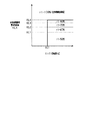
図3に、本実施形態における目標燃焼気筒比率γtの設定態様を示す。本実施形態では、目標燃焼気筒比率γtは、50%、67%、75%、80%、100%のいずれかの値に設定される。 FIG. 3 shows a setting mode of the target combustion cylinder ratio γt in the present embodiment. In the present embodiment, the target combustion cylinder ratio γt is set to any value of 50%, 67%, 75%, 80%, and 100%.
同図に示すように、エンジン回転数NEが既定値NE1以下の領域では、全気筒燃焼時要求負荷率KLAに拘わらず、目標燃焼気筒比率γtの値は100%に設定される。これに対して、エンジン回転数NEが既定値NE1を超える領域では、全気筒燃焼時要求負荷率KLAに応じて、目標燃焼気筒比率γtの値を50%〜100%の範囲で可変設定している。具体的には、エンジン回転数NEが既定値NE1を超える領域での目標燃焼気筒比率γtは、全気筒燃焼時要求負荷率KLAが既定値KL1未満のときには50%に、既定値KL1以上、且つ既定値KL2(>KL1)未満のときには67%に、それぞれ設定される。さらに、全気筒燃焼時要求負荷率が、既定値KL2以上、且つ既定値KL3(>KL2)未満のときには75%に、既定値KL3以上、且つ既定値KL4(>KL3)未満のときには80%に、既定値KL4以上のときには100%に、それぞれ設定される。 As shown in the figure, in the region where the engine speed NE is equal to or less than the default value NE1, the value of the target combustion cylinder ratio γt is set to 100% regardless of the required load factor KLA at the time of combustion of all cylinders. On the other hand, in the region where the engine speed NE exceeds the default value NE1, the value of the target combustion cylinder ratio γt is variably set in the range of 50% to 100% according to the required load factor KLA at the time of combustion of all cylinders. There is. Specifically, the target combustion cylinder ratio γt in the region where the engine speed NE exceeds the default value NE1 is 50% when the required load factor KLA at the time of combustion of all cylinders is less than the default value KL1, the default value KL1 or more, and When it is less than the default value KL2 (> KL1), it is set to 67%. Further, when the required load factor during combustion of all cylinders is KL2 or more and less than the default value KL3 (> KL2), it is 75%, and when it is KL3 or more and less than the default value KL4 (> KL3), it is 80%. , When the default value is KL4 or more, it is set to 100%.
(気筒休止パターンの決定)
続いて、気筒休止パターン決定部21による気筒休止パターンの決定について説明する。本実施形態における燃焼気筒比率の可変制御では、0%、50%、67%、75%、80%、83%、86%、88%、100%の9通りの燃焼気筒比率が使用される。表1には、それら9通りの燃焼気筒比率のそれぞれにおける、気筒の燃焼、休止の順序が示されている。ちなみに、燃料カット時やアイドルストップ時など、一時的に全ての気筒で燃焼を休止する全気筒休止の場合が、燃焼気筒比率が0%の場合となる。
(Determining cylinder deactivation pattern)
Subsequently, determination of the cylinder deactivation pattern by the cylinder deactivation pattern determination unit 21 will be described. In the variable control of the combustion cylinder ratio in the present embodiment, nine types of combustion cylinder ratios of 0%, 50%, 67%, 75%, 80%, 83%, 86%, 88% and 100% are used. Table 1 shows the order of combustion and deactivation of the cylinders in each of the nine combustion cylinder ratios. By the way, in the case of all cylinder deactivation in which combustion is temporarily deactivated in all cylinders such as when fuel is cut or idle stop, the combustion cylinder ratio is 0%.

上記のように間欠休止運転中の燃焼気筒比率は、50%、67%、75%、80%、83%、86%、88%のいずれかに設定されることになるが、これらの間では気筒の休止間隔を1気筒ずつ変更することで燃焼気筒比率の変更が可能である。すなわち、本実施形態では、間欠休止運転中の燃焼気筒比率の変更に際して、気筒休止間隔の最小の変更量は1気筒となっている。 As described above, the combustion cylinder ratio during intermittent pause operation is set to any of 50%, 67%, 75%, 80%, 83%, 86%, and 88%. The combustion cylinder ratio can be changed by changing the cylinder pause interval one cylinder at a time. That is, in the present embodiment, when the combustion cylinder ratio is changed during the intermittent deactivation operation, the minimum change amount of the cylinder deactivation interval is one cylinder.
本実施形態では、上記気筒休止パターンのそれぞれに、各パターンの気筒休止間隔を値とする識別番号(ID)を付している。さらに、本実施形態では、燃焼気筒比率が0%(全気筒休止)及び100%(全気筒燃焼)の場合については、次の扱いとしている。すなわち、気筒休止のみが繰り返される燃焼気筒比率が0%(全気筒休止)の場合については、1回の気筒休止からなるパターンを便宜上の気筒休止パターンとし、その識別番号を「0」としている。また、燃焼のみが繰り返される燃焼気筒比率が100%の場合については、1回の燃焼からなるパターンを便宜上の気筒休止パターンとし、その識別番号を「8」としている。 In the present embodiment, each of the cylinder deactivation patterns is assigned an identification number (ID) whose value is the cylinder deactivation interval of each pattern. Further, in the present embodiment, the cases where the combustion cylinder ratio is 0% (all cylinders deactivated) and 100% (all cylinders combustion) are treated as follows. That is, when the ratio of combustion cylinders in which only cylinder deactivation is repeated is 0% (all cylinder deactivation), a pattern consisting of one cylinder deactivation is used as a convenient cylinder deactivation pattern, and its identification number is set to "0". Further, when the ratio of combustion cylinders in which only combustion is repeated is 100%, a pattern consisting of one combustion is set as a cylinder deactivation pattern for convenience, and the identification number is set to "8".
気筒休止パターン決定部21は、エンジン10の運転中、既定の制御周期毎に、実施中の気筒休止パターンの次に実施する気筒休止パターンの燃焼気筒比率(以下、次回燃焼気筒比率γnと記載する)を決定する。この決定に際して、気筒休止パターン決定部21は、実施中の気筒休止パターンの燃焼気筒比率(以下、現在燃焼気筒比率γcと記載する)、目標燃焼気筒比率γt、及びエンジン回転数NEを読み込む。そして、気筒休止パターン決定部21は、予め電子制御ユニット16に記憶された演算マップを参照して、次回燃焼気筒比率γnを演算する。
The cylinder deactivation pattern determination unit 21 describes the combustion cylinder ratio of the cylinder deactivation pattern to be executed next to the cylinder deactivation pattern being executed (hereinafter, the next combustion cylinder ratio γn) for each predetermined control cycle during the operation of the engine 10. ) Is determined. At the time of this determination, the cylinder deactivation pattern determination unit 21 reads the combustion cylinder ratio of the cylinder deactivation pattern being implemented (hereinafter, referred to as the current combustion cylinder ratio γc), the target combustion cylinder ratio γt, and the engine speed NE. Then, the cylinder deactivation pattern determination unit 21 calculates the next combustion cylinder ratio γn with reference to the calculation map stored in the
なお、電子制御ユニット16は、気筒休止パターンを変更する際には、変更前の気筒休止パターンを最後まで行ってから、変更後の気筒休止パターンを最初から開始するようにしている。すなわち、現在燃焼気筒比率γcに対応した気筒休止パターンを最後まで行った後、次回燃焼気筒比率γnに対応した気筒休止パターンを最初から開始するようにしている。
When changing the cylinder deactivation pattern, the
図4に、次回燃焼気筒比率γnを演算するための次回燃焼気筒比率演算処理ルーチンの処理手順を示す。気筒休止パターン決定部21は、エンジン10の運転中、既定の演算周期毎に本ルーチンの処理を実施する。
FIG. 4 shows a processing procedure of the next combustion cylinder ratio calculation processing routine for calculating the next combustion cylinder ratio γn. The cylinder deactivation pattern determination unit 21 executes the processing of this routine at a predetermined calculation cycle during the operation of the
本ルーチンの処理が開始されると、まずステップS100において、現在燃焼気筒比率γc、目標燃焼気筒比率γt、エンジン回転数NE、及び同エンジン回転数NEの変化量ΔNEが読み込まれる。変化量ΔNEは、既定時間におけるエンジン回転数NEの変化量を表している。 When the processing of this routine is started, first, in step S100, the current combustion cylinder ratio γc, the target combustion cylinder ratio γt, the engine speed NE, and the amount of change ΔNE of the engine speed NE are read. The amount of change ΔNE represents the amount of change in the engine speed NE in a predetermined time.
続いて、ステップS110において、現在燃焼気筒比率γcが0%であるか否かが、すなわち燃料カットの実施中であるか否かが判定される。ここで、現在燃焼気筒比率γcが0%であれば(S110:YES)、ステップS120に処理が進められる。そして、そのステップS120において、次回燃焼気筒比率γnの値として目標燃焼気筒比率γtの値が設定された後、今回の本ルーチンの処理が終了される。 Subsequently, in step S110, it is determined whether or not the combustion cylinder ratio γc is currently 0%, that is, whether or not the fuel cut is being carried out. Here, if the combustion cylinder ratio γc is currently 0% (S110: YES), the process proceeds to step S120. Then, in step S120, after the value of the target combustion cylinder ratio γt is set as the value of the next combustion cylinder ratio γn, the processing of this routine is completed.
これに対して、現在燃焼気筒比率γcが0%でない場合には、ステップS130に処理が進められ、そのステップS130において、エンジン回転数NEが既定値α未満であること、同エンジン回転数NEの変化量ΔNEが既定値εを超えていること、の少なくとも一方が満たされているか否かが判定される。そして、同ステップS130において肯定判定(YES)された場合にはステップS140に処理が進められ、否定判定(NO)された場合にはステップS150に処理が進められる。 On the other hand, when the combustion cylinder ratio γc is not 0% at present, the process proceeds to step S130, and in step S130, the engine speed NE is less than the default value α, and the engine speed NE It is determined whether or not at least one of the change amount ΔNE exceeding the default value ε is satisfied. Then, if an affirmative determination (YES) is made in step S130, the process proceeds to step S140, and if a negative determination (NO) is made, the process proceeds to step S150.
ステップS140に処理が進められると、そのステップS140において、低回転数用の演算マップM1を用いて次回燃焼気筒比率γnが演算された後、今回の本ルーチンの処理が終了される。なお、本実施形態では、次回燃焼気筒比率γnの演算に用いるマップとして、上記低回転数用の演算マップM1に加え、中回転数用の演算マップM2と高回転数用の演算マップM3との3つの演算マップが、電子制御ユニット16に予め記憶されている。これらの演算マップM1〜M3の具体的な内容、及びそれらを用いた次回燃焼気筒比率γnの演算の詳細については後述する。
When the process proceeds to step S140, the process of this routine is completed after the next combustion cylinder ratio γn is calculated using the calculation map M1 for the low rotation speed in step S140. In the present embodiment, as the map used for the calculation of the next combustion cylinder ratio γn, in addition to the calculation map M1 for the low rotation speed, the calculation map M2 for the medium rotation speed and the calculation map M3 for the high rotation speed are used. The three calculation maps are stored in advance in the
一方、ステップS150に処理が進められると、そのステップS150において、エンジン回転数NEが既定値β(>α)未満であるか否かが判定される。エンジン回転数NEが既定値β未満の場合(S150:YES)、ステップS160に処理が進められ、そのステップS160において、中回転数用の演算マップM2を用いて次回燃焼気筒比率γnが演算された後、今回の本ルーチンの処理が終了される。これに対して、エンジン回転数NEが既定値β以上の場合(S150:NO)、ステップS170に処理が進められ、そのステップS170において、高回転数用の演算マップM3を用いて次回燃焼気筒比率γnが演算された後、今回の本ルーチンの処理が終了される。 On the other hand, when the process proceeds to step S150, it is determined in step S150 whether or not the engine speed NE is less than the default value β (> α). When the engine speed NE is less than the default value β (S150: YES), the process proceeds to step S160, and in that step S160, the next combustion cylinder ratio γn is calculated using the calculation map M2 for the medium speed. After that, the processing of this routine is completed. On the other hand, when the engine speed NE is equal to or higher than the default value β (S150: NO), the process proceeds to step S170, and in that step S170, the next combustion cylinder ratio is used by using the calculation map M3 for high speed. After γn is calculated, the processing of this routine is completed.
続いて、こうした次回燃焼気筒比率演算処理ルーチンにおいて使用する3つの演算マップM1〜M3、及びそれらを用いた次回燃焼気筒比率γnの演算態様の詳細を説明する。上述のように、低回転数用の演算マップM1は、燃料カットの実施中でなく、エンジン回転数NEが既定値α未満、又はその変化量ΔNEが既定値εを超える場合の次回燃焼気筒比率γnの演算に使用される。これに対して、中回転数用の演算マップM2は、燃料カットの実施中でなく、エンジン回転数NEが既定値α以上、且つ既定値β未満の場合の次回燃焼気筒比率γnの演算に、高回転数用の演算マップM3は、燃料カットの実施中でなく、エンジン回転数NEが既定値β以上の場合の次回燃焼気筒比率γnの演算に、それぞれ使用される。 Subsequently, the three calculation maps M1 to M3 used in such a next combustion cylinder ratio calculation processing routine, and the details of the calculation mode of the next combustion cylinder ratio γn using them will be described. As described above, in the calculation map M1 for low rotation speed, the next combustion cylinder ratio when the engine rotation speed NE is less than the default value α or the change amount ΔNE exceeds the default value ε when the fuel cut is not being executed. It is used for the calculation of γn. On the other hand, the calculation map M2 for the medium rotation speed is used for the calculation of the next combustion cylinder ratio γn when the engine rotation speed NE is equal to or more than the default value α and less than the default value β when the fuel cut is not being executed. The calculation map M3 for high rotation speed is used for the calculation of the next combustion cylinder ratio γn when the engine rotation speed NE is equal to or higher than the default value β when the fuel cut is not being executed.
これらの演算マップM1〜M3は、現在燃焼気筒比率γcに対して、次回燃焼気筒比率γnとして設定可能な燃焼気筒比率の範囲を表すものとなっている。気筒休止パターン決定部21は、上記ステップS140、S160、S170の処理において、該当する演算マップM1〜M3を参照して、現在燃焼気筒比率γcから次回燃焼気筒比率γnとして設定可能な燃焼気筒比率を取得する。そして、気筒休止パターン決定部21は、設定可能な燃焼気筒比率のうちで、目標燃焼気筒比率γtに最も近い比率を次回燃焼気筒比率γnの値として演算する。 These calculation maps M1 to M3 represent a range of combustion cylinder ratios that can be set as the next combustion cylinder ratio γn with respect to the current combustion cylinder ratio γc. In the processing of steps S140, S160, and S170, the cylinder deactivation pattern determination unit 21 refers to the corresponding calculation maps M1 to M3 to set the combustion cylinder ratio that can be set as the next combustion cylinder ratio γn from the current combustion cylinder ratio γc. get. Then, the cylinder deactivation pattern determination unit 21 calculates the ratio closest to the target combustion cylinder ratio γt among the settable combustion cylinder ratios as the value of the next combustion cylinder ratio γn.
一方、エンジン回転数NEが低いときには、燃焼サイクルが長くなり、燃焼気筒比率を変更したときの平均トルクの変化に応じたエンジン回転数NEの変化も時間をかけて緩やかに生じるようになる。そのため、エンジン回転数NEが低いときには、燃焼気筒比率の変更によるエンジン10の回転変動がドライバビリティの悪化に繋がり難くなる。
On the other hand, when the engine speed NE is low, the combustion cycle becomes long, and the engine speed NE changes slowly over time according to the change in the average torque when the combustion cylinder ratio is changed. Therefore, when the engine speed NE is low, the rotation fluctuation of the
以上を踏まえて本実施形態では、上述の演算マップM1〜M3を下記のように設定している。表3〜5は、各演算マップM1〜M3における現在燃焼気筒比率γcと次回燃焼気筒比率γnとして設定可能な燃焼気筒比率との関係を示している。 Based on the above, in the present embodiment, the above-mentioned calculation maps M1 to M3 are set as follows. Tables 3 to 5 show the relationship between the current combustion cylinder ratio γc and the combustion cylinder ratio that can be set as the next combustion cylinder ratio γn in the calculation maps M1 to M3.
なお、現在燃焼気筒比率γcの値によっては、上記変化率Δγが上記制限値MX未満となる燃焼気筒比率が、現在燃焼気筒比率γcと同じ比率しか存在しない場合がある(例えばγc=50%の場合)。演算マップM1、M2では、こうした場合にも、燃焼気筒比率を変更可能とするため、いずれの現在燃焼気筒比率γcにおいても、対応する気筒休止パターンの識別番号の値の差が1以内の燃焼気筒比率は、次回燃焼気筒比率γnとして設定可能とされている。 Depending on the value of the current combustion cylinder ratio γc, the combustion cylinder ratio in which the change rate Δγ is less than the limit value MX may exist only at the same ratio as the current combustion cylinder ratio γc (for example, γc = 50%). If). In the calculation maps M1 and M2, since the combustion cylinder ratio can be changed even in such a case, the difference between the values of the identification numbers of the corresponding cylinder deactivation patterns is within 1 in any of the current combustion cylinder ratios γc. The ratio can be set as the next combustion cylinder ratio γn.
こうした低回転数用、中回転数用の演算マップM1、M2では、全気筒燃焼運転時又は間欠休止運転時に設定可能な上記8通りの燃焼気筒比率のうち、次の要件(A)、(B)の少なくとも一つを満たす燃焼気筒比率が次回燃焼気筒比率γnとして設定可能とされている。 In the calculation maps M1 and M2 for low rotation speed and medium rotation speed, the following requirements (A) and (B) among the above eight types of combustion cylinder ratios that can be set during all-cylinder combustion operation or intermittent pause operation are as follows. ) Is set as the next combustion cylinder ratio γn.
(A)現在燃焼気筒比率γcに対して燃焼気筒比率の変化率Δγが既定の制限値MX未満となる燃焼気筒比率であること。
(B)現在燃焼気筒比率γcに対して、対応する気筒休止パターンの識別番号の差が1以内の燃焼気筒比率であること。
(A) The combustion cylinder ratio at which the rate of change Δγ of the combustion cylinder ratio with respect to the current combustion cylinder ratio γc is less than the predetermined limit value MX.
(B) The difference between the current combustion cylinder ratio γc and the identification number of the corresponding cylinder deactivation pattern is within 1 for the combustion cylinder ratio.
ここで、気筒休止間隔の変更により燃焼気筒比率を変更する間欠休止運転中に限れば、上記要件(B)を満たす燃焼気筒比率は、現在燃焼気筒比率γcに対して1気筒以内の気筒休止間隔の変更で実現可能な比率となる。一方、上述のように間欠休止運転中の燃焼気筒比率の変更に際して、気筒休止間隔の最小の変更量は1気筒分となっている。よって、上記要件(B)を満たす燃焼気筒比率は、現在燃焼気筒比率γcに対する気筒休止間間隔の差が、同気筒休止間隔の最小変更量以内となる比率となっている。 Here, as long as it is limited to the intermittent deactivation operation in which the combustion cylinder ratio is changed by changing the cylinder deactivation interval, the combustion cylinder ratio satisfying the above requirement (B) is the cylinder deactivation interval of one cylinder or less with respect to the current combustion cylinder ratio γc. It becomes a feasible ratio by changing. On the other hand, when the combustion cylinder ratio is changed during the intermittent deactivation operation as described above, the minimum change amount of the cylinder deactivation interval is one cylinder. Therefore, the combustion cylinder ratio satisfying the above requirement (B) is such that the difference between the cylinder deactivation intervals with respect to the current combustion cylinder ratio γc is within the minimum change amount of the cylinder deactivation intervals.
一方、表5に示すように高回転数用の演算マップM3では、現在燃焼気筒比率γcに対して、対応する気筒休止パターンの識別番号の値の差が1以内の比率だけが次回燃焼気筒比率γnとして設定可能な燃焼気筒比率とされている。なお、こうした高回転数用の演算マップM3も、制限値MXを0%とした場合の上記要件(A)、(B)の少なくともの一方を満たす燃焼気筒比率が次回燃焼気筒比率γnとして設定可能とされた演算マップということができる。 On the other hand, as shown in Table 5, in the calculation map M3 for high rotation speed, only the ratio in which the difference between the values of the identification numbers of the corresponding cylinder deactivation patterns is within 1 with respect to the current combustion cylinder ratio γc is the next combustion cylinder ratio. It is a combustion cylinder ratio that can be set as γn. In the calculation map M3 for such a high rotation speed, the combustion cylinder ratio satisfying at least one of the above requirements (A) and (B) when the limit value MX is set to 0% can be set as the next combustion cylinder ratio γn. It can be said that it is a calculation map.
(エンジン負荷率の調整)
続いて、空気量調整部22が行う要求負荷率KLTの調整について説明する。空気量調整部22は、全気筒燃焼時要求負荷率KLA、燃焼気筒比率γに対して、式(2)の関係を満たすように、要求負荷率KLTの演算を行っている。
(Adjustment of engine load factor)
Subsequently, the adjustment of the required load factor KLT performed by the air
そして、空気量調整部22は、スロットルバルブ13を通過する吸気の挙動の物理モデルであるスロットルモデルを用いて、エンジン負荷率KLを要求負荷率KLTとするために必要なスロットル開度TAの目標値である目標スロットル開度TATを算出する。
Then, the air
電子制御ユニット16は、スロットル開度TAが同目標スロットル開度TATと同じ値となるようにスロットルバルブ13を制御する。これにより、燃焼気筒比率の変更に伴う平均トルクの変化を抑えるように、エンジン負荷率KLの調整が行われている。
The
なお、空気量調整部22は、実施中の気筒休止パターンにおける最後の燃焼気筒の吸気行程が終了したときに、要求負荷率KLTの演算に使用する燃焼気筒比率γの値を、現在燃焼気筒比率γcから次回燃焼気筒比率γnに切替えている。そして、この時点から、現在燃焼気筒比率γcに応じた要求負荷率KLTから次回燃焼気筒比率γnに応じた要求負荷率KLTへとエンジン負荷率KLを変更するためのスロットル開度TAの変更を開始するようにしている。
The air
ここで、現在燃焼気筒比率γcから次回燃焼気筒比率γnへの燃焼気筒比率の変更に際して必要なエンジン負荷率KLの調整量(以下、要求調整量ΔKLと記載する)は、燃焼気筒比率の変化率Δγが大きいほど大きくなる。こうした要求調整量ΔKL分のエンジン負荷率KLの調整が、切替え後の気筒休止パターンにおける最初の燃焼気筒の吸気行程が開始するまでに完了すれば、燃焼気筒比率の変更前後の平均トルクが同じとなる。よって、上記エンジン負荷率KLの調整は、切替え前の気筒休止パターンにおける最後の燃焼気筒の吸気行程が終了した時点から、切替え後の気筒休止パターンにおける最初の燃焼気筒の吸気行程が開始する時点までの期間(以下、負荷率調整期間と記載する)に完了することが望ましい。 Here, the adjustment amount of the engine load factor KL (hereinafter referred to as the required adjustment amount ΔKL) required when changing the combustion cylinder ratio from the current combustion cylinder ratio γc to the next combustion cylinder ratio γn is the rate of change of the combustion cylinder ratio. The larger Δγ, the larger. If the adjustment of the engine load factor KL for the required adjustment amount ΔKL is completed by the time the intake stroke of the first combustion cylinder in the cylinder deactivation pattern after switching is completed, the average torque before and after the change of the combustion cylinder ratio is the same. Become. Therefore, the adjustment of the engine load factor KL is performed from the time when the intake stroke of the last combustion cylinder in the cylinder deactivation pattern before switching ends to the time when the intake stroke of the first combustion cylinder in the cylinder deactivation pattern after switching starts. It is desirable to complete the period (hereinafter referred to as the load factor adjustment period).
なお、スロットルバルブ13の動作やスロットルバルブ13から気筒#1〜#4までの吸気の搬送の遅れのため、一定の時間内に行えるエンジン負荷率KLの変更の量には限界がある。これに対して、上記負荷率調整期間は、エンジン回転数NEが低いほど長い時間となる。
Due to the operation of the
したがって、要求負荷率調整量ΔKL分のエンジン負荷率KLの調整を上記負荷率調整期間に完了可能となる燃焼気筒比率の変化率Δγは、エンジン回転数NEが低いほど大きくなる。これを反映して、上記演算マップM1〜M3では、次回燃焼気筒比率γnとして設定可能な燃焼気筒比率の変化率Δγの制限値MXが、高回転用の演算マップM3、中回転用の演算マップM2、低回転用の演算マップM1の順に大きい値となるように設定されている。 Therefore, the rate of change Δγ of the combustion cylinder ratio that enables the adjustment of the engine load factor KL for the required load factor adjustment amount ΔKL to be completed during the load factor adjustment period increases as the engine speed NE decreases. Reflecting this, in the above calculation maps M1 to M3, the limit value MX of the change rate Δγ of the combustion cylinder ratio that can be set as the next combustion cylinder ratio γn is the calculation map M3 for high rotation and the calculation map for medium rotation. The values are set to be larger in the order of M2 and the calculation map M1 for low rotation.
(第1実施形態の作用効果)
上記のように構成された本実施形態の燃焼気筒比率の可変制御装置では、目標燃焼気筒比率設定部20により、エンジン10の運転状況(エンジン回転数NE、エンジン負荷率KL)に応じて目標燃焼気筒比率γtが設定される。目標燃焼気筒比率設定部20が間欠休止運転時に設定する目標燃焼気筒比率γtの値は、一定の間隔での気筒休止の繰り返しにより実現可能な燃焼気筒比率となっている。
(Action and effect of the first embodiment)
In the variable control device for the combustion cylinder ratio of the present embodiment configured as described above, the target combustion cylinder
また、本実施形態では、気筒休止パターン決定部21により、目標燃焼気筒比率γtに応じて、次回燃焼気筒比率γnが決定される。次回燃焼気筒比率γnは、現在実施中の気筒休止パターンの次に実施する気筒休止パターンの燃焼気筒比率を表す。気筒休止パターン決定部21が間欠休止運転中に設定する次回燃焼気筒比率γnの値はいずれも、一定の間隔での気筒休止を繰り返すことで、すなわちN個の気筒を続けて燃焼させた後に1個の気筒の燃焼を休止するパターンで気筒休止を繰り返すことで実現可能な燃焼気筒比率となっている。 Further, in the present embodiment, the cylinder deactivation pattern determination unit 21 determines the next combustion cylinder ratio γn according to the target combustion cylinder ratio γt. The next combustion cylinder ratio γn represents the combustion cylinder ratio of the cylinder deactivation pattern to be executed next to the cylinder deactivation pattern currently being implemented. The value of the next combustion cylinder ratio γn set by the cylinder deactivation pattern determination unit 21 during the intermittent deactivation operation is 1 by repeating cylinder deactivation at regular intervals, that is, after continuously burning N cylinders. It is a combustion cylinder ratio that can be realized by repeating cylinder deactivation in a pattern that deactivates the combustion of individual cylinders.
電子制御ユニット16は、実施中の気筒休止パターンの完了後に、次回燃焼気筒比率γnに対応する気筒休止パターンを開始するようにエンジン10の運転制御を行う。そのため、エンジン10では、N個の気筒を続けて燃焼させた後に1個の気筒を休止するパターンの気筒休止を連続して行うことで間欠休止運転が行われる。こうした間欠休止運転中の燃焼気筒比率の変更は、気筒休止間隔の変更を通じて行われる。
The
こうした本実施形態では、次回燃焼気筒比率γnにより、現在燃焼気筒比率γcを実現する間隔で気筒休止を行ってからその次に気筒休止を行うまでの気筒休止の間隔が一義に定まる。以下の説明では、現在燃焼気筒比率γcを実現する気筒の休止間隔を現在休止間隔Ncと記載し、現在休止間隔Ncで気筒休止を行ってからその次に気筒休止を行うまでの気筒休止の間隔を次回休止間隔Nnと記載する。また、目標燃焼気筒比率γtを実現する気筒休止の間隔を、目標休止間隔Ntと記載する。 In such an embodiment, the next combustion cylinder ratio γn uniquely determines the cylinder deactivation interval from the cylinder deactivation to the next cylinder deactivation at the interval at which the current combustion cylinder ratio γc is realized. In the following description, the deactivation interval of the cylinder that realizes the current combustion cylinder ratio γc is described as the current deactivation interval Nc, and the cylinder deactivation interval from the cylinder deactivation at the current deactivation interval Nc to the next cylinder deactivation. Is described as the next pause interval Nn. Further, the cylinder deactivation interval for achieving the target combustion cylinder ratio γt is described as the target deactivation interval Nt.
上述の次回燃焼気筒比率γnの演算マップM1〜M3は、現在燃焼気筒比率γcに対して、次回燃焼気筒比率γnとして設定可能な燃焼気筒比率の範囲を定めるものとなっている。すなわち、演算マップM1〜M3は、現在休止間隔Ncに対して、次回休止間隔Nnとして設定可能な気筒休止間隔の範囲を定めるものとなっている。 The above-mentioned calculation maps M1 to M3 of the next combustion cylinder ratio γn define the range of the combustion cylinder ratio that can be set as the next combustion cylinder ratio γn with respect to the current combustion cylinder ratio γc. That is, the calculation maps M1 to M3 define the range of the cylinder deactivation interval that can be set as the next deactivation interval Nn with respect to the current deactivation interval Nc.
ここで、次回休止間隔Nnとして設定可能な気筒休止間隔の範囲が、現在休止間隔Ncに対して目標休止間隔Nt側にX気筒以内の範囲であるとする。このときのXの値が0であると、燃焼気筒比率を変更は一切できないことになる。そのため、Xの値は1以上の整数、すなわち自然数となる。一方、次回燃焼気筒比率γnの決定では、エンジン回転数NE及びその単位時間当たりの変化量により、使用する演算マップM1〜M3が切替えられている。そして、現在燃焼気筒比率γcを引数として演算マップM1〜M3を参照することで、次回休止間隔Nnとして設定可能な気筒休止間隔の範囲が求められている。よって、上記Xは、値として自然数を取り、且つ現在燃焼気筒比率γc(現在休止間隔Nc)やエンジン回転数NEといったエンジン10の運転状況に応じて変化する可変値となる。
Here, it is assumed that the range of the cylinder deactivation interval that can be set as the next deactivation interval Nn is within the X cylinder on the target deactivation interval Nt side with respect to the current deactivation interval Nc. If the value of X at this time is 0, the combustion cylinder ratio cannot be changed at all. Therefore, the value of X is an integer of 1 or more, that is, a natural number. On the other hand, in the determination of the next combustion cylinder ratio γn, the calculation maps M1 to M3 to be used are switched according to the engine speed NE and the amount of change per unit time. Then, by referring to the calculation maps M1 to M3 with the combustion cylinder ratio γc as an argument, the range of the cylinder deactivation interval that can be set as the next deactivation interval Nn is obtained. Therefore, X takes a natural number as a value, and is a variable value that changes according to the operating conditions of the
そして、気筒休止パターン決定部21は、設定可能な燃焼気筒比率の範囲内に目標燃焼気筒比率γtが存在すれば、目標燃焼気筒比率γtを次回燃焼気筒比率γnとし、同範囲内に目標燃焼気筒比率γtが存在しなければ、その範囲内で目標燃焼気筒比率γtに最も近い比率を次回燃焼気筒比率γnとしている。一方、次回休止間隔Nnとして設定可能な気筒休止間隔の範囲が現在休止間隔NcからX気筒以内の範囲であるとすると、現在休止間隔Ncと目標休止間隔Ntとの差ΔNがX気筒以下であれば、上記設定可能な燃焼気筒比率の範囲内に目標燃焼気筒比率γtが存在することになる。よって、気筒休止パターン決定部21は、現在休止間隔Ncと目標休止間隔Ntとの差ΔNがX気筒以下の場合には、目標休止間隔Ntを次回休止間隔Nnとし、同差ΔNがX気筒を超える場合には、現在休止間隔Ncよりも目標休止間隔NtにX気筒分近い間隔を次回休止間隔Nnとしていることになる。 Then, if the target combustion cylinder ratio γt exists within the range of the settable combustion cylinder ratio, the cylinder pause pattern determination unit 21 sets the target combustion cylinder ratio γt as the next combustion cylinder ratio γn and sets the target combustion cylinder within the same range. If the ratio γt does not exist, the ratio closest to the target combustion cylinder ratio γt within that range is set as the next combustion cylinder ratio γn. On the other hand, assuming that the range of the cylinder deactivation interval that can be set as the next deactivation interval Nn is within the range of the current deactivation interval Nc and X cylinders, the difference ΔN between the current deactivation interval Nc and the target deactivation interval Nt is X cylinders or less. For example, the target combustion cylinder ratio γt exists within the range of the above-mentioned settable combustion cylinder ratio. Therefore, when the difference ΔN between the current deactivation interval Nc and the target deactivation interval Nt is X cylinders or less, the cylinder deactivation pattern determination unit 21 sets the target deactivation interval Nt as the next deactivation interval Nn, and the same difference ΔN sets the X cylinder. If it exceeds the current pause interval Nc, the interval closer to the target pause interval Nt by X cylinders is set as the next pause interval Nn.
なお、次回燃焼気筒比率γnの決定に際して気筒休止パターン決定部21は、エンジン回転数NEが既定値α未満の場合、又はエンジン回転数NEの変化量ΔNEが既定値εよりも大きい場合には低回転数用の演算マップM1を使用する。また、エンジン回転数NEの変化量ΔNEが既定値ε以下の場合にあってエンジン回転数NEがα以上の場合には中回転数用、高回転数用の演算マップM2、M3を使用する。そして、低回転数用の演算マップM1では、中回転数用の演算マップM2よりも次回燃焼気筒比率γnとして設定可能な燃焼気筒比率の範囲が広くなっており、更にその演算マップM2では高回転数用の演算マップM3よりも同範囲が広くなっている。よって、次回休止間隔Nnとして設定可能な気筒休止間隔の範囲を現在休止間隔NcからX気筒以内の範囲としたときのXの値は、エンジン回転数NEが低いときやその変化が大きいときには、エンジン回転数NEが高いときやその変化が小さいときよりも大きい値となっている。 When determining the next combustion cylinder ratio γn, the cylinder suspension pattern determination unit 21 is low when the engine speed NE is less than the default value α or when the change amount ΔNE of the engine speed NE is larger than the default value ε. The calculation map M1 for the number of rotations is used. Further, when the change amount ΔNE of the engine speed NE is equal to or less than the default value ε and the engine speed NE is α or more, the calculation maps M2 and M3 for the medium speed and the high speed are used. The calculation map M1 for low rotation speed has a wider range of combustion cylinder ratios that can be set as the next combustion cylinder ratio γn than the calculation map M2 for medium rotation speeds, and the calculation map M2 has a wider range of high rotation speeds. The same range is wider than the calculation map M3 for numbers. Therefore, when the range of the cylinder deactivation interval that can be set as the next deactivation interval Nn is set to the range within the X cylinder from the current deactivation interval Nc, the value of X is the engine when the engine speed NE is low or the change is large. The value is larger than when the rotation speed NE is high or when the change is small.
また、低回転数用の演算マップM1、及び中回転数用の演算マップM2は、現在燃焼気筒比率γcが大きくなるほど、次回燃焼気筒比率γnとして設定可能な燃焼気筒比率の範囲が広くなるように設定されている。すなわち、本実施形態では、低回転数域及び中回転数域においては、次回休止間隔Nnとして設定可能な気筒休止間隔の範囲を現在休止間隔NcからX気筒以内の範囲としたときのXの値は、現在休止間隔Ncが大きいときには、同現在休止間隔Ncが小さいときよりも大きい値となる。 Further, in the calculation map M1 for low rotation speed and the calculation map M2 for medium rotation speed, the range of the combustion cylinder ratio that can be set as the next combustion cylinder ratio γn becomes wider as the current combustion cylinder ratio γc becomes larger. It is set. That is, in the present embodiment, in the low rotation speed range and the medium rotation speed range, the value of X when the range of the cylinder deactivation interval that can be set as the next deactivation interval Nn is set to the range within the X cylinder from the current deactivation interval Nc. Is a value larger when the current pause interval Nc is large than when the current pause interval Nc is small.
ちなみに、上述のように上記各演算マップM1〜M3では、上記要件(A)、(B)の少なくとも一方を満たす比率が、次回燃焼気筒比率γnとして設定可能な燃焼気筒比率とされている。すなわち、要件(A)現在燃焼気筒比率γcに対して燃焼気筒比率の変化率Δγが既定の制限値MX未満となる燃焼気筒比率であること、及び要件(B)現在燃焼気筒比率γcに対して、対応する気筒休止パターンの識別番号の差が1以内の燃焼気筒比率であること、の少なくとも一方を満たす比率である。 Incidentally, as described above, in each of the above calculation maps M1 to M3, the ratio satisfying at least one of the above requirements (A) and (B) is set as the combustion cylinder ratio that can be set as the next combustion cylinder ratio γn. That is, the requirement (A) is the combustion cylinder ratio in which the rate of change Δγ of the combustion cylinder ratio is less than the predetermined limit value MX with respect to the current combustion cylinder ratio γc, and the requirement (B) with respect to the current combustion cylinder ratio γc. , The ratio satisfies at least one of the combustion cylinder ratios in which the difference in the identification numbers of the corresponding cylinder deactivation patterns is within 1.
上述のように要件(B)を満たす燃焼気筒比率は、間欠休止運転中に限れば、現在燃焼気筒比率γcに対して、最小量(1気筒)分の気筒休止間隔の変更で実現可能な燃焼気筒比率となっている。すなわち、上記要件(B)を満たす燃焼気筒比率は、次回休止間隔Nnとして設定可能な気筒休止間隔の範囲を現在休止間隔NcからX気筒以内の範囲としたときのXの値が、気筒休止間隔の最小の変更量となる比率である。 As described above, the combustion cylinder ratio that satisfies the requirement (B) is the combustion that can be realized by changing the cylinder deactivation interval for the minimum amount (1 cylinder) with respect to the current combustion cylinder ratio γc, as long as it is in intermittent deactivation operation. It is a cylinder ratio. That is, for the combustion cylinder ratio satisfying the above requirement (B), the value of X when the range of the cylinder deactivation interval that can be set as the next deactivation interval Nn is within the range from the current deactivation interval Nc to X cylinders is the cylinder deactivation interval. This is the ratio that is the minimum change amount of.
一方、上記要件(A)を満たす燃焼気筒比率は、現在休止間隔Ncから次回休止間隔Nnに気筒休止の間隔を変更したときの燃焼気筒比率の変化率Δγが制限値MX未満となる燃焼気筒比率である。よって、上記要件(A)、(B)の少なくとも一方を満たす燃焼気筒比率の範囲は、上記Xの値が、現在休止間隔Ncから次回休止間隔Nnに気筒休止の間隔を変更したときの燃焼気筒比率の変化率Δγが制限値MX未満となる値、及び気筒休止の間隔の最小の変更量のうちの大きい方の値となる燃焼気筒比率の範囲となる。 On the other hand, the combustion cylinder ratio satisfying the above requirement (A) is the combustion cylinder ratio in which the rate of change Δγ of the combustion cylinder ratio when the cylinder deactivation interval is changed from the current deactivation interval Nc to the next deactivation interval Nn is less than the limit value MX. Is. Therefore, the range of the combustion cylinder ratio that satisfies at least one of the above requirements (A) and (B) is the combustion cylinder when the value of the above X changes the cylinder deactivation interval from the current deactivation interval Nc to the next deactivation interval Nn. It is within the range of the combustion cylinder ratio, which is the larger value of the value at which the rate of change Δγ of the ratio is less than the limit value MX and the minimum change amount of the cylinder deactivation interval.
そして、低回転数用の演算マップM1は上記制限値MXを25%として、中回転数用の演算マップM2は上記制限値MXを15%として、高回転数用の演算マップM3は上記制限値MXを0%として、それぞれ構成されている。すなわち、気筒休止パターン決定部21は、エンジン回転数NEが低いときには、同エンジン回転数が高いときよりも上記制限値MXが大きい値となるものとして、次回燃焼気筒比率γnを、すなわち次回休止間隔Nnを決定する。また、気筒休止パターン決定部21は、エンジン回転数NEの変化が大きいときには、同エンジン回転数の変化が小さいときよりも同制限値MXが大きい値となるものとして次回休止間隔Nnを決定する。 The calculation map M1 for low rotation speed has the limit value MX of 25%, the calculation map M2 for medium rotation speed has the limit value MX of 15%, and the calculation map M3 for high rotation speed has the limit value of 15%. Each is configured with MX as 0%. That is, the cylinder deactivation pattern determination unit 21 sets the next combustion cylinder ratio γn, that is, the next deactivation interval, assuming that the limit value MX is larger when the engine speed NE is low than when the engine speed is high. Determine Nn. Further, the cylinder deactivation pattern determination unit 21 determines the next deactivation interval Nn assuming that the limit value MX is larger when the change in the engine speed NE is large than when the change in the engine speed is small.
ところで、現在燃焼気筒比率γcが100%の場合に、すなわち全気筒燃焼運転の場合に次回燃焼気筒比率γnとして設定可能な燃焼気筒比率の範囲は、低回転数用の演算マップM1では80%〜100%の範囲となっている。一方、本実施形態では、図3に示すように、間欠休止運転中に目標燃焼気筒比率γtとして設定される比率は80%以下となっている。そのため、全気筒燃焼運転から間欠休止運転への切替えに際して、次回燃焼気筒比率γnの決定に低回転数用の演算マップM1を使用する状況では、燃焼気筒比率を80%とした状態で間欠休止運転が開始される。これに対して中回転数用の演算マップM2では同範囲は86%〜100%の範囲となっており、更に高回転数用の演算マップM3では同範囲は88%〜100%の範囲となっている。よって、中回転数用の演算マップM2を使用する状況では燃焼気筒比率を86%とした状態で、高回転数用の演算マップM3を使用する状況では燃焼気筒比率を88%とした状態で、それぞれ間欠休止運転が開始される。 By the way, when the current combustion cylinder ratio γc is 100%, that is, in the case of all-cylinder combustion operation, the range of the combustion cylinder ratio that can be set as the next combustion cylinder ratio γn is 80% to 80% in the calculation map M1 for low rotation speed. It is in the range of 100%. On the other hand, in the present embodiment, as shown in FIG. 3, the ratio set as the target combustion cylinder ratio γt during the intermittent pause operation is 80% or less. Therefore, when switching from all-cylinder combustion operation to intermittent pause operation, in a situation where the calculation map M1 for low rotation speed is used to determine the next combustion cylinder ratio γn, intermittent pause operation is performed with the combustion cylinder ratio set to 80%. Is started. On the other hand, in the calculation map M2 for medium rotation speed, the same range is in the range of 86% to 100%, and in the calculation map M3 for high rotation speed, the same range is in the range of 88% to 100%. ing. Therefore, in the situation where the calculation map M2 for the medium rotation speed is used, the combustion cylinder ratio is set to 86%, and in the situation where the calculation map M3 for the high rotation speed is used, the combustion cylinder ratio is set to 88%. Intermittent pause operation is started for each.
上述のように、80%、86%、88%の燃焼気筒比率は、それぞれ気筒休止の間隔を4気筒、6気筒、7気筒として気筒休止を繰り返すことで実現される。よって、全気筒燃焼運転から間欠休止運転への切替え後における最初の気筒休止を行う際の気筒休止間隔は、低回転数用の演算マップM1を使用する状況では4気筒、中回転数用の演算マップM2を使用する状況では6気筒、高回転数用の演算マップM3を使用する状況では7気筒となる。 As described above, the combustion cylinder ratios of 80%, 86%, and 88% are realized by repeating cylinder deactivation with the cylinder deactivation intervals of 4 cylinders, 6 cylinders, and 7 cylinders, respectively. Therefore, the cylinder pause interval when performing the first cylinder pause after switching from the all-cylinder combustion operation to the intermittent pause operation is the calculation for 4 cylinders and the middle speed in the situation where the calculation map M1 for the low rotation speed is used. In the situation where the map M2 is used, it is 6 cylinders, and in the situation where the calculation map M3 for high rotation speed is used, it is 7 cylinders.
一方、低回転数用の演算マップM1では、現在燃焼気筒比率が83%以上の場合に100%の燃焼気筒比率を次回燃焼気筒比率γnとして設定可能となっている。これに対して、中回転数用、高回転数用の演算マップM2、M3では、現在燃焼気筒比率が88%以上の場合に100%の燃焼気筒比率を次回燃焼気筒比率γnとして設定可能となっている。そのため、低回転数用の演算マップM1を使用する状況では、燃焼気筒比率が83%の状態、すなわち、気筒休止間隔を5気筒として間欠休止運転を行っている状態から直ちに全気筒燃焼運転に切替え可能となる。これに対して、中回転数用、高回転数用の演算マップM2、M3を使用する状況では、燃焼気筒比率が88%の状態、すなわち、気筒休止間隔を7気筒として間欠休止運転を行う状態としてからしか、全気筒燃焼運転に切替えられないことになる。 On the other hand, in the calculation map M1 for low rotation speed, when the current combustion cylinder ratio is 83% or more, the combustion cylinder ratio of 100% can be set as the next combustion cylinder ratio γn. On the other hand, in the calculation maps M2 and M3 for medium rotation speed and high rotation speed, when the current combustion cylinder ratio is 88% or more, 100% combustion cylinder ratio can be set as the next combustion cylinder ratio γn. ing. Therefore, in the situation where the calculation map M1 for low rotation speed is used, the state where the combustion cylinder ratio is 83%, that is, the state where the cylinder deactivation interval is set to 5 cylinders and the intermittent deactivation operation is performed is immediately switched to the all cylinder combustion operation. It will be possible. On the other hand, in the situation where the calculation maps M2 and M3 for the medium rotation speed and the high rotation speed are used, the combustion cylinder ratio is 88%, that is, the cylinder deactivation interval is set to 7 cylinders and the intermittent deactivation operation is performed. Only then can it be switched to all-cylinder combustion operation.
ここで、全気筒燃焼運転から間欠休止運転への切替え後における最初の気筒休止を行う際の気筒休止間隔を間欠休止運転の開始休止間隔とする。また、間欠休止運転から全気筒燃焼運転への切替え前における最後の気筒休止を行う際の気筒休止間隔を間欠休止運転の終了休止間隔とする。上記のように本実施形態では、エンジン回転数NEが低いときには同エンジン回転数NEが高いときよりも、間欠休止運転の開始休止間隔、及び終了休止間隔が小さくされている。また、エンジン回転数NEの変化量ΔNEが大きいときには、同変化量ΔNEが小さいときよりも、間欠休止運転の開始休止間隔、及び終了休止間隔が小さくされている。 Here, the cylinder deactivation interval at the time of performing the first cylinder deactivation after switching from the all-cylinder combustion operation to the intermittent deactivation operation is defined as the start deactivation interval of the intermittent deactivation operation. Further, the cylinder deactivation interval at the time of performing the last cylinder deactivation before switching from the intermittent deactivation operation to the all-cylinder combustion operation is defined as the end deactivation interval of the intermittent deactivation operation. As described above, in the present embodiment, when the engine speed NE is low, the start pause interval and the end pause interval of the intermittent pause operation are smaller than when the engine speed NE is high. Further, when the change amount ΔNE of the engine speed NE is large, the start pause interval and the end pause interval of the intermittent pause operation are smaller than when the change amount ΔNE is small.
続いて、こうした本実施形態の燃焼気筒比率の可変制御に係る制御動作の具体例を説明する。ここでは、低回転数域、中回転数域、高回転数域のそれぞれにおいて、燃焼気筒比率を100%から50%に変更する場合の、すなわち全気筒燃焼運転中に目標燃焼気筒比率γtが50%に設定された場合の本実施形態の制御動作を説明する。なお、ここでの低回転数域は、次回燃焼気筒比率γnの演算に低回転数用の演算マップM1を使用するエンジン10の運転領域を示している。また、中回転数域は同演算に中回転数用の演算マップM2を使用するエンジン10の運転領域を、高回転数域は同演算に高回転数用の演算マップM3を使用するエンジン10の運転領域を、それぞれ示している。
Subsequently, a specific example of the control operation related to the variable control of the combustion cylinder ratio of the present embodiment will be described. Here, when the combustion cylinder ratio is changed from 100% to 50% in each of the low rotation speed region, the medium rotation speed region, and the high rotation speed region, that is, the target combustion cylinder ratio γt is 50 during all cylinder combustion operation. The control operation of this embodiment when it is set to% will be described. The low rotation speed region here indicates an operating region of the
表3に示すように、低回転数用の演算マップM1において現在燃焼気筒比率γcが100%の場合に次回燃焼気筒比率γnとして設定可能な燃焼気筒比率は、80%、83%、86%、88%、100%となっている。この中で目標燃焼気筒比率γtの50%に最も近い比率は80%である。また、同演算マップM1において現在燃焼気筒比率γcが80%の場合の次回燃焼気筒比率γnとして設定可能な燃焼気筒比率は67%、75%、80%、83%、86%、88%となっており、この中で50%に最も近い比率は67%である。更に、同演算マップM1において現在燃焼気筒比率γcが67%の場合の次回燃焼気筒比率γnとして設定可能な燃焼気筒比率は50%、67%、75%、80%であり、目標燃焼気筒比率γtである50%がその中に含まれる。よって、低回転数域では、100%、80%、67%、50%の順に、3段階の変更を経て、100%から50%への燃焼気筒比率の変更が行われることになる。 As shown in Table 3, when the current combustion cylinder ratio γc is 100% in the calculation map M1 for low rotation speed, the combustion cylinder ratios that can be set as the next combustion cylinder ratio γn are 80%, 83%, 86%, and so on. It is 88% and 100%. Among them, the ratio closest to 50% of the target combustion cylinder ratio γt is 80%. Further, in the calculation map M1, when the current combustion cylinder ratio γc is 80%, the combustion cylinder ratios that can be set as the next combustion cylinder ratio γn are 67%, 75%, 80%, 83%, 86%, and 88%. Of these, 67% is the closest to 50%. Further, in the calculation map M1, the combustion cylinder ratios that can be set as the next combustion cylinder ratio γn when the current combustion cylinder ratio γc is 67% are 50%, 67%, 75%, and 80%, and the target combustion cylinder ratio γt. 50% is included in it. Therefore, in the low rotation speed range, the combustion cylinder ratio is changed from 100% to 50% through a three-step change in the order of 100%, 80%, 67%, and 50%.
同様に、表4に示す中回転数用の演算マップM2に従えば、中回転数域では、100%、86%、75%、67%、50%の順に、4段階の変更を経て、100%から50%への燃焼気筒比率の変更が行われることになる。また、表5に示す高回転数用の演算マップM3に従えば、高回転数域では、100%、88%、86%、83%、80%、75%、67%、50%の順に、7段階の変更を経て、100%から50%への燃焼気筒比率の変更が行われることになる。 Similarly, according to the calculation map M2 for the medium rotation speed shown in Table 4, in the medium rotation speed range, 100%, 86%, 75%, 67%, and 50% are changed in the order of 100%. The combustion cylinder ratio will be changed from% to 50%. Further, according to the calculation map M3 for high rotation speed shown in Table 5, in the high rotation speed range, the order is 100%, 88%, 86%, 83%, 80%, 75%, 67%, 50%. After 7 steps of change, the combustion cylinder ratio will be changed from 100% to 50%.
図5〜7に、低回転数域、中回転数域、高回転数域のそれぞれにおいて100%から50%に燃焼気筒比率を変更する際の点火信号、気筒休止パターン、エンジン負荷率KL、及び要求負荷率KLTの推移を示す。 Figures 5 to 7 show the ignition signal, cylinder deactivation pattern, engine load factor KL, and engine load factor KL when changing the combustion cylinder ratio from 100% to 50% in each of the low speed range, medium speed range, and high speed range. The transition of the required load factor KLT is shown.
これらの図に示す点火信号は実際には、各気筒#1〜#4の点火プラグ15に個別に出力される点火信号の合成波形を示している。各気筒の点火プラグ15の点火信号は、(図示しない)点火コイルの一次コイルの通電開始時期から通電停止時期までオンとされ、点火プラグ15は、一次コイルへの通電停止と共に火花放電を発生して、点火を行うように構成されている。気筒休止を行うときには、該当気筒の点火プラグ15の点火信号のオン出力が1燃焼サイクル分スキップされるため、同信号の合成波形のオン周期が前後よりも長くなる。ここでは、気筒休止の時期や気筒休止間隔を表すために、こうした点火信号の合成波形を示している。
The ignition signals shown in these figures actually show a composite waveform of the ignition signals individually output to the spark plugs 15 of the
図5に示すように、低回数域では、気筒休止パターンはまず、100%の燃焼気筒比率に対応する識別番号が8のパターンから80%の燃焼気筒比率に対応する識別番号が4のパターンに切替えられる。すなわち、このときの全気筒燃焼運転から間欠休止運転への切替え後における最初の気筒休止を行う際の気筒休止間隔nは、4気筒分となる。その後、67%の燃焼気筒比率に対応する識別番号が2のパターンを経て、目標燃焼気筒比率γtである50%の燃焼気筒比率に対応する識別番号が1のパターンへと気筒休止パターンが切替えられる。そしてこれに伴い、4気筒、2気筒、1気筒の順に気筒休止間隔が変更される。 As shown in FIG. 5, in the low frequency range, the cylinder deactivation pattern first changes from a pattern having an identification number of 8 corresponding to a 100% combustion cylinder ratio to a pattern having an identification number of 4 corresponding to an 80% combustion cylinder ratio. Can be switched. That is, the cylinder deactivation interval n when performing the first cylinder deactivation after switching from the all-cylinder combustion operation to the intermittent deactivation operation at this time is for four cylinders. After that, the cylinder deactivation pattern is switched to a pattern in which the identification number corresponding to the combustion cylinder ratio of 67% is 2 and the identification number corresponding to the combustion cylinder ratio of 50%, which is the target combustion cylinder ratio γt, is 1. .. Along with this, the cylinder deactivation interval is changed in the order of 4-cylinder, 2-cylinder, and 1-cylinder.
図6に示すように、中回転数域では、気筒休止パターンはまず、100%の燃焼気筒比率に対応する識別番号が8のパターンから86%の燃焼気筒比率に対応する識別番号が6のパターンに切替えられる。すなわち、このときの全気筒燃焼運転から間欠休止運転への切替え後における最初の気筒休止を行う際の気筒休止間隔nは、6気筒分となる。その後、75%の燃焼気筒比率に対応する識別番号が3のパターン、67%の燃焼気筒比率に対応する識別番号が2のパターンを経て、目標燃焼気筒比率γtである50%の燃焼気筒比率に対応する識別番号が1のパターンへと気筒休止パターンが切替えられる。これにより、6気筒、3気筒、2気筒、1気筒の順に気筒休止間隔が変更される。 As shown in FIG. 6, in the medium rotation speed range, the cylinder deactivation pattern first has a pattern with an identification number of 8 corresponding to a 100% combustion cylinder ratio to a pattern with an identification number of 6 corresponding to an 86% combustion cylinder ratio. Can be switched to. That is, the cylinder deactivation interval n when performing the first cylinder deactivation after switching from the all-cylinder combustion operation to the intermittent deactivation operation at this time is 6 cylinders. After that, the identification number corresponding to the 75% combustion cylinder ratio is 3 patterns, and the identification number corresponding to the 67% combustion cylinder ratio is 2 patterns, and the target combustion cylinder ratio γt is 50% combustion cylinder ratio. The cylinder deactivation pattern is switched to the pattern in which the corresponding identification number is 1. As a result, the cylinder deactivation interval is changed in the order of 6 cylinders, 3 cylinders, 2 cylinders, and 1 cylinder.
図7に示すように、高回転数域では、気筒休止パターンはまず、100%の燃焼気筒比率に対応する識別番号が8のパターンから88%の燃焼気筒比率に対応する識別番号が7のパターンに切替えられる。すなわち、このときの全気筒燃焼運転から間欠休止運転への切替え後における最初の気筒休止を行う際の気筒休止間隔nは、7気筒分となる。その後、識別番号が1ずつ小さいパターンに切替えていくことで、目標燃焼気筒比率γtである50%の燃焼気筒比率に対応する識別番号が1のパターンへと気筒休止パターンが切替えられる。これにより、7気筒、6気筒、5気筒、4気筒、3気筒、2気筒、1気筒の順に気筒休止間隔が変更される。 As shown in FIG. 7, in the high rotation speed range, the cylinder deactivation pattern first has a pattern with an identification number of 8 corresponding to a 100% combustion cylinder ratio to a pattern with an identification number of 7 corresponding to a combustion cylinder ratio of 88%. Can be switched to. That is, the cylinder deactivation interval n when performing the first cylinder deactivation after switching from the all-cylinder combustion operation to the intermittent deactivation operation at this time is 7 cylinders. After that, by switching to a pattern in which the identification number is smaller by 1, the cylinder deactivation pattern is switched to the pattern in which the identification number corresponds to the combustion cylinder ratio of 50%, which is the target combustion cylinder ratio γt. As a result, the cylinder deactivation interval is changed in the order of 7 cylinders, 6 cylinders, 5 cylinders, 4 cylinders, 3 cylinders, 2 cylinders, and 1 cylinder.
以上のように、中、高回転数域の場合に比して、低回転数域の場合には、100%から50%に燃焼気筒比率を変更する際の気筒休止パターンの切替え回数が少ない分、同パターンの切替え毎の要求負荷率KLTの変化量が、すなわちエンジン負荷率KLの要求調整量ΔKLが大きくなる。ただし、低回転数域の場合には、中、高回転数域の場合よりも、負荷率調整期間が長い時間となるため、要求調整量ΔKLが大きくても、負荷率調整期間にエンジン負荷率KLの調整を完了することが可能である。 As described above, in the case of the low rotation speed range, the number of times the cylinder deactivation pattern is switched when changing the combustion cylinder ratio from 100% to 50% is smaller than in the case of the middle and high rotation speed range. , The amount of change in the required load factor KLT for each switching of the same pattern, that is, the required adjustment amount ΔKL of the engine load factor KL becomes large. However, in the low rpm range, the load factor adjustment period is longer than in the medium and high rpm range, so even if the required adjustment amount ΔKL is large, the engine load factor will be in the load factor adjustment period. It is possible to complete the adjustment of the KL.
一方、高回転数域の場合には、負荷率調整期間は短い時間となるが、100%から50%に燃焼気筒比率を変更する際の気筒休止パターンの切替え回数が多い分、同パターンの切替え毎の要求調整量ΔKLが小さくなる。そのため、負荷率調整期間が短い時間であっても、同期間にエンジン負荷率KLの調整を完了できるようになる。 On the other hand, in the high rpm range, the load factor adjustment period is short, but the same pattern is switched because the cylinder deactivation pattern is frequently switched when changing the combustion cylinder ratio from 100% to 50%. The required adjustment amount ΔKL for each becomes smaller. Therefore, even if the load factor adjustment period is short, the adjustment of the engine load factor KL can be completed in the same period.
また、低回転数域では、燃焼サイクルが長くなるため、気筒休止パターンの切替え回数を多くすると、目標燃焼気筒比率γtへの燃焼気筒比率の変更に非常に長い時間を要してしまう。これに対して、高回転数域では、燃焼サイクルが短くなるため、気筒休止パターンの切替え回数を多くしても、比較的短い時間で目標燃焼気筒比率γtへの燃焼気筒比率の変更を完了することができる。 Further, since the combustion cycle becomes long in the low rotation speed range, if the number of times of switching the cylinder deactivation pattern is increased, it takes a very long time to change the combustion cylinder ratio to the target combustion cylinder ratio γt. On the other hand, in the high rpm range, the combustion cycle is shortened, so even if the number of cylinder deactivation patterns is increased, the change of the combustion cylinder ratio to the target combustion cylinder ratio γt is completed in a relatively short time. be able to.
このように本実施形態では、大幅な目標燃焼気筒比率γtの変更がなされた場合、複数回に分けて気筒休止間隔を段階的に変更していくことで、変更前の目標燃焼気筒比率γtから変更後の目標燃焼気筒比率γtへと燃焼気筒比率を変更している。そして、エンジン回転数NEが低いときや、同エンジン回転数NEの変化が大きいときには、変更後の目標燃焼気筒比率γtに至るまでの気筒休止間隔の変更の回数を少なくするようにしている。そして、これにより、燃焼気筒比率の可変制御を行う際の気筒休止間隔の変更に伴うエンジンの回転変動を、同可変制御の応答性の悪化を抑えつつ、好適に抑制している。 As described above, in the present embodiment, when the target combustion cylinder ratio γt is significantly changed, the cylinder deactivation interval is gradually changed in a plurality of times to change the target combustion cylinder ratio γt before the change. The combustion cylinder ratio is changed to the changed target combustion cylinder ratio γt. When the engine speed NE is low or the change in the engine speed NE is large, the number of times the cylinder deactivation interval is changed until the target combustion cylinder ratio γt after the change is reached is reduced. As a result, the rotation fluctuation of the engine due to the change of the cylinder deactivation interval when the variable control of the combustion cylinder ratio is performed is suitably suppressed while suppressing the deterioration of the responsiveness of the variable control.
なお、エンジン10では、車両惰性走行時に全気筒を休止する燃料カットを実施する。こうした燃料カットからの復帰(燃焼再開)は、エンジン回転数NEが既定の復帰回転数以下に低下したときや、アクセルペダルが踏み込まれたとき等に行われる。こうした燃料カットからの復帰に際しては、燃焼再開後の速やかなエンジン出力の回復が求められる。そこで、気筒休止パターン決定部21は、エンジン10の全気筒を休止する燃料カットからの復帰時には、目標燃焼気筒比率γtがどの様な値であっても、同目標燃焼気筒比率γtの値をそのまた次回燃焼気筒比率γnの値に設定している。すなわち、燃料カットの復帰時には、燃料カットにおける最後の気筒休止から同燃料カットからの復帰後における最初の気筒休止までの気筒休止の間隔を目標休止間隔Ntとすることで、燃料カット復帰後の速やかなエンジン出力の回復を可能としている。
In the
(第2実施形態)
次に、燃焼気筒比率の可変制御装置の第2実施形態を説明する。なお本実施形態にあって、第1実施形態と共通する構成については、同一の符号を付してその詳細な説明は省略する。
(Second Embodiment)
Next, a second embodiment of the variable control device for the combustion cylinder ratio will be described. In the present embodiment, the same reference numerals are given to the configurations common to those in the first embodiment, and detailed description thereof will be omitted.
本実施形態の可変制御装置は、第1バンク、第2バンクの2つのバンクに分かれて6つの気筒が配列されたV型6気筒のエンジンに適用される。以下の説明では、第1バンクに設けられた3つの気筒をそれぞれ気筒#1、気筒#3、気筒#5と記載し、第2バンクに設けられた3つの気筒をそれぞれ気筒#2、気筒#4、気筒#6と記載する。このとき、エンジン10での気筒#1〜#6の点火順序は、気筒#1、気筒#2、気筒#3、気筒#4、気筒#5、気筒#6の順となっている。
The variable control device of the present embodiment is applied to a V-type 6-cylinder engine in which 6 cylinders are arranged by being divided into two banks, a first bank and a second bank. In the following description, the three cylinders provided in the first bank are described as
なお、上記のようなV型のエンジンでは、間欠休止運転中に燃焼を休止する気筒が、2つのバンクのうちの一方に集中してしまうと、両バンクの排気性状に偏りが生じ、エミッションコントロールが困難となる虞がある。そこで、本実施形態では、間欠休止運転中の燃焼休止を2気筒ずつ連続して行って、第1バンク、第2バンクでそれぞれ1気筒ずつ燃焼を休止することで、バンク間の排気性状の偏りを抑制している。 In a V-type engine as described above, if the cylinders that suspend combustion during intermittent pause operation are concentrated in one of the two banks, the exhaust properties of both banks will be biased, resulting in emission control. May be difficult. Therefore, in the present embodiment, the combustion is suspended for two cylinders in succession during the intermittent pause operation, and the combustion is suspended for one cylinder each in the first bank and the second bank, so that the exhaust property is biased between the banks. Is suppressed.
本実施形態における燃焼気筒比率の可変制御では、0%、50%、60%、67%、71%、75%、80%、83%、86%、88%、100%の11通りの燃焼気筒比率が使用される。表6には、それら11通りの燃焼気筒比率のそれぞれにおける、気筒の燃焼、休止の順序が示されている。表6の燃焼気筒比率のうち、エンジン10の間欠休止運転中に使用される比率は、50%、60%、67%、71%、75%、80%、83%、86%、及び88%の9通りとなる。これらの燃焼気筒比率では、燃焼行程を迎える気筒の順にN個(Nは任意の自然数)の気筒を続けて燃焼させた後に2個の気筒の燃焼を休止するパターンで気筒休止が繰り返される。
In the variable control of the combustion cylinder ratio in the present embodiment, 11 types of combustion cylinders of 0%, 50%, 60%, 67%, 71%, 75%, 80%, 83%, 86%, 88% and 100% are used. The ratio is used. Table 6 shows the order of combustion and deactivation of the cylinders in each of the 11 combustion cylinder ratios. Of the combustion cylinder ratios in Table 6, the ratios used during intermittent pause operation of the
本実施形態の場合にも、図2に示した第1実施形態のものと同様に、目標燃焼気筒比率設定部20、気筒休止パターン決定部21、及び空気量調整部22を備えた電子制御ユニット16により、燃焼気筒比率の可変制御が行われる。本実施形態においても、目標燃焼気筒比率設定部20による目標燃焼気筒比率γtの演算、空気量調整部22による燃焼気筒比率に応じたエンジン負荷率KLの調整は、第1実施形態の場合と同様に行われる。また、気筒休止パターン決定部21による次回燃焼気筒比率γnの決定も、その決定に使用する演算マップM1〜M3の内容が異なる以外は、第1実施形態の場合と同様に行われる。
Also in the case of this embodiment, as in the case of the first embodiment shown in FIG. 2, an electronic control unit including a target combustion cylinder
本実施形態の可変制御装置において気筒休止パターン決定部21が次回燃焼気筒比率γnの決定に使用する低回転数用、中回転数用、高回転数用の演算マップM1〜M3における現在燃焼気筒比率γcと次回燃焼気筒比率γnとして設定可能な燃焼気筒比率との関係は、表7〜表9に示す通りとなっている。 In the variable control device of the present embodiment, the current combustion cylinder ratio in the calculation maps M1 to M3 for low rotation speed, medium rotation speed, and high rotation speed used by the cylinder deactivation pattern determination unit 21 for determining the next combustion cylinder ratio γn. The relationship between γc and the combustion cylinder ratio that can be set as the next combustion cylinder ratio γn is as shown in Tables 7 to 9.
これに加え、低回転数用の演算マップM1では、変更前後の燃焼気筒比率の変化率Δγが25%未満となる燃焼気筒比率が、中回転数用の演算マップM2では、変更前後の燃焼気筒比率の変化率Δγが15%未満となる燃焼気筒比率が、次回燃焼気筒比率γnとして設定可能な比率とされている。 In addition to this, in the calculation map M1 for low rotation speed, the combustion cylinder ratio in which the rate of change Δγ of the combustion cylinder ratio before and after the change is less than 25%, and in the calculation map M2 for medium rotation speed, the combustion cylinder before and after the change. The combustion cylinder ratio at which the rate of change Δγ of the ratio is less than 15% is a ratio that can be set as the next combustion cylinder ratio γn.
こうした本実施形態においても、大幅な目標燃焼気筒比率γtの変更がなされた場合、複数回に分けて気筒休止間隔を段階的に変更していくことで、変更前の目標燃焼気筒比率γtから変更後の目標燃焼気筒比率γtへと燃焼気筒比率を変更している。そして、エンジン回転数NEが低いときや、同エンジン回転数NEの変化が大きいときには、変更後の目標燃焼気筒比率γtに至るまでの気筒休止間隔の変更の回数を少なくするようにしている。そして、これにより、燃焼気筒比率の可変制御を行う際の気筒休止間隔の変更に伴うエンジンの回転変動を、同可変制御の応答性の悪化を抑えつつ、好適に抑制している。 Also in this embodiment, when the target combustion cylinder ratio γt is significantly changed, the target combustion cylinder ratio γt before the change is changed by gradually changing the cylinder deactivation interval in a plurality of times. The combustion cylinder ratio is changed to the later target combustion cylinder ratio γt. When the engine speed NE is low or the change in the engine speed NE is large, the number of times the cylinder deactivation interval is changed until the target combustion cylinder ratio γt after the change is reached is reduced. As a result, the rotation fluctuation of the engine due to the change of the cylinder deactivation interval when the variable control of the combustion cylinder ratio is performed is suitably suppressed while suppressing the deterioration of the responsiveness of the variable control.
以上説明した各実施形態は、次のように変更して実施することもできる。
・上記実施形態では、空気量調整部22により、燃焼気筒比率の変更に応じてエンジン10の要求負荷率KLTを調整するようにしていたが、こうした調整を行わないようにしてもよい。そうした場合にも、燃焼気筒比率を変更するときの気筒休止間隔の変更量をX気筒以内に限定するとともに、そのXの値をエンジン10の運転状況に応じて値が変化する可変値としていれば、燃焼気筒比率の可変制御を行う際の気筒休止間隔の変更に伴うエンジンの回転変動を抑制できる。
Each of the above-described embodiments can be modified and implemented as follows.
-In the above embodiment, the air
・上記実施形態では、燃料カットからの復帰時には、最初から燃焼気筒比率を目標燃焼気筒比率γtとして燃焼を再開するようにしていた。すなわち、燃料カットの実施中は、目標燃焼気筒比率γtの値をそのまま次回燃焼気筒比率γnの値として設定し、燃料カットからの復帰により目標燃焼気筒比率γtが0%以外の値に変更されたときには、その変更された目標燃焼気筒比率γtの値が次回燃焼気筒比率γnの値として設定されるようにしていた。こうした例外措置を行わず、燃料カットからの復帰時にも通常通りに演算マップM1〜M3を用いて次回燃焼気筒比率γnを演算するようにしてもよい。こうした場合、燃料カットからの復帰時には、まず燃焼気筒比率を50%とした状態で燃焼が再開され、その後、目標燃焼気筒比率γtに近づくように燃焼気筒比率が段階的に変更される、といった態様で燃焼気筒比率の可変制御が行われることになる。 -In the above embodiment, when returning from the fuel cut, combustion is restarted with the combustion cylinder ratio as the target combustion cylinder ratio γt from the beginning. That is, during the fuel cut, the value of the target combustion cylinder ratio γt was set as it is as the value of the next combustion cylinder ratio γn, and the target combustion cylinder ratio γt was changed to a value other than 0% by returning from the fuel cut. Occasionally, the changed value of the target combustion cylinder ratio γt was set as the value of the next combustion cylinder ratio γn. The next combustion cylinder ratio γn may be calculated using the calculation maps M1 to M3 as usual even when returning from the fuel cut without taking such an exception measure. In such a case, when returning from the fuel cut, combustion is first restarted with the combustion cylinder ratio set to 50%, and then the combustion cylinder ratio is gradually changed so as to approach the target combustion cylinder ratio γt. Will be used to variably control the combustion cylinder ratio.
・上記実施形態では、エンジン回転数NE及びその変化量ΔNEに応じて、3つの演算マップM1〜M3の中から次回燃焼気筒比率γnの演算に用いる演算マップを切替えていた。こうした演算マップの数やその切替えの条件等は適宜に変更してもよい。 -In the above embodiment, the calculation map used for the calculation of the next combustion cylinder ratio γn is switched from the three calculation maps M1 to M3 according to the engine speed NE and the change amount ΔNE thereof. The number of such calculation maps and the conditions for switching them may be changed as appropriate.
・上記実施形態では、エンジン回転数NE及びその変化量ΔNEに応じて、次回燃焼気筒比率γnの演算に用いる演算マップを切替えていたが、こうした演算マップの切替えを、エンジン回転数NE及びその変化量ΔNEのうちのいずれか一方のみに基づき行うようにしてもよい。 -In the above embodiment, the calculation map used for the calculation of the next combustion cylinder ratio γn is switched according to the engine speed NE and its change amount ΔNE, but such switching of the calculation map is performed by changing the engine speed NE and its change. It may be performed based on only one of the quantities ΔNE.
・上記実施形態では、次回燃焼気筒比率γnとして設定可能な燃焼気筒比率の範囲を、予め記憶しておいた演算マップを用いて求めていたが、次回燃焼気筒比率γnの演算の都度、同範囲を計算するようにしてもよい。 -In the above embodiment, the range of the combustion cylinder ratio that can be set as the next combustion cylinder ratio γn is obtained by using the calculation map stored in advance, but the same range is obtained each time the calculation of the next combustion cylinder ratio γn is performed. May be calculated.
・上記実施形態では、現在燃焼気筒比率γc、エンジン回転数NE及びその変化量ΔNEに応じて値が変化する可変値Xについて、次回休止間隔Nnが、現在休止間隔Ncに対してX気筒以内の気筒休止間隔となるように、次回燃焼気筒比率γnを決定していた。すなわち、現在燃焼気筒比率γc、エンジン回転数NE及びその変化量ΔNEの3つのパラメータを、上記可変値Xの値を決定するエンジン10の運転状況を示すパラメータとしていた。車速や車両の加速度など、エンジン10の運転状況を示すそれ以外のパラメータを、可変値Xの値を決定するパラメータに加えるようにしてもよい。いずれにせよ、そうした可変値Xが次のような値となっていれば、燃焼気筒比率の可変制御を行う際の気筒休止間隔の変更に伴うエンジンの回転変動を好適に抑制できるようになる。すなわち、気筒休止間隔を変更したときのエンジン10の回転変動が大きくなり易い状況にあるときには、同回転変動が大きくなり難い状況にあるときよりも可変値Xが小さい値となる、或いはエンジン10の回転変動がドライバビリティの悪化に繋がり易い状況にあるときには、繋がり難い状況にあるときよりも可変値Xが小さい値となる。
-In the above embodiment, for the variable value X whose value changes according to the current combustion cylinder ratio γc, the engine speed NE and the change amount ΔNE, the next pause interval Nn is within X cylinders with respect to the current pause interval Nc. The next combustion cylinder ratio γn was determined so as to be the cylinder deactivation interval. That is, the three parameters of the current combustion cylinder ratio γc, the engine speed NE, and the amount of change ΔNE thereof are used as parameters indicating the operating status of the
・上記各実施形態では、燃料噴射及び点火の停止により、気筒での燃焼を休止するようにしていた。吸/排気バルブの開弁動作を停止するバルブロック機構が気筒毎に設けられたエンジンに適用する場合には、同バルブロック機構による吸/排気バルブの開弁動作の停止を通じて、気筒での燃焼を休止するように上記各実施形態における燃焼気筒比率の可変制御装置を構成することが可能である。 -In each of the above embodiments, combustion in the cylinder is stopped by stopping fuel injection and ignition. When a valve block mechanism for stopping the valve opening operation of the intake / exhaust valve is applied to an engine provided for each cylinder, combustion in the cylinder is performed by stopping the valve opening operation of the intake / exhaust valve by the valve block mechanism. It is possible to configure the variable control device for the combustion cylinder ratio in each of the above embodiments so as to suspend.
10…エンジン、11…吸気通路、12…エアフローメータ、13…スロットルバルブ、14…インジェクタ、15…点火プラグ、16…電子制御ユニット(燃焼気筒比率の可変制御装置)、17…クランク角センサ、18…スロットルセンサ、19…アクセルペダルセンサ、20…目標燃焼気筒比率設定部、21…気筒休止パターン決定部、22…空気量調整部。
10 ... engine, 11 ... intake passage, 12 ... air flow meter, 13 ... throttle valve, 14 ... injector, 15 ... spark plug, 16 ... electronic control unit (variable control device for combustion cylinder ratio), 17 ... crank angle sensor, 18 ... Throttle sensor, 19 ... Accelerator pedal sensor, 20 ... Target combustion cylinder ratio setting unit, 21 ... Cylinder deactivation pattern determination unit, 22 ... Air volume adjustment unit.
Claims (9)
一定数の気筒を続けて燃焼させた後に気筒休止することの繰り返しにより実現可能な燃焼気筒比率を目標燃焼気筒比率として設定する目標燃焼気筒比率設定部と、
現在の燃焼気筒比率を実現する気筒休止間の気筒数を現在休止間隔とし、同現在休止間隔で気筒休止を行ってからその次に気筒休止を行うまでの気筒休止間の気筒数を次回休止間隔とし、前記目標燃焼気筒比率を実現する気筒休止間の気筒数を目標休止間隔としたとき、
前記現在休止間隔と前記目標休止間隔との差がX気筒以下の場合には、前記目標休止間隔を前記次回休止間隔とし、前記現在休止間隔と前記目標休止間隔との差がX気筒を超える場合には、前記現在休止間隔よりも前記目標休止間隔にX気筒分近い間隔を前記次回休止間隔とする気筒休止パターン決定部と、
を備えており、且つ前記Xの値が、値として自然数を取り、エンジン回転数が低いときには、同エンジン回転数が高いときよりも前記Xが大きい値となる
燃焼気筒比率の可変制御装置。 In the combustion cylinder ratio variable control device that performs variable control of the combustion cylinder ratio of the engine during intermittent deactivation operation in which cylinder deactivation is performed intermittently
A target combustion cylinder ratio setting unit that sets a combustion cylinder ratio that can be realized by repeating cylinder deactivation after continuously burning a certain number of cylinders as a target combustion cylinder ratio,
The number of cylinders between the current burn cylinder ratios realized for cylinders hibernation as the current pause interval, the next time the number of cylinders between cylinders hibernation from performing cylinder deactivation at the same current pause interval until the cylinder deactivation to the next and pause interval, when the number of cylinders between cylinders hibernation for realizing the target combustion cylinder ratio with the goal pause interval,
When the difference between the current pause interval and the target pause interval is X cylinders or less, the target pause interval is set as the next pause interval, and the difference between the current pause interval and the target pause interval exceeds the X cylinder. The cylinder deactivation pattern determination unit has an interval closer to the target deactivation interval by X cylinders than the current deactivation interval as the next deactivation interval.
A variable control device for a combustion cylinder ratio, wherein the value of X takes a natural number as a value, and when the engine speed is low, the value of X becomes larger than when the engine speed is high.
一定数の気筒を続けて燃焼させた後に気筒休止することの繰り返しにより実現可能な燃焼気筒比率を目標燃焼気筒比率として設定する目標燃焼気筒比率設定部と、
現在の燃焼気筒比率を実現する気筒休止間の気筒数を現在休止間隔とし、同現在休止間隔で気筒休止を行ってからその次に気筒休止を行うまでの気筒休止間の気筒数を次回休止間隔とし、前記目標燃焼気筒比率を実現する気筒休止間の気筒数を目標休止間隔としたとき、
前記現在休止間隔と前記目標休止間隔との差がX気筒以下の場合には、前記目標休止間隔を前記次回休止間隔とし、前記現在休止間隔と前記目標休止間隔との差がX気筒を超える場合には、前記現在休止間隔よりも前記目標休止間隔にX気筒分近い間隔を前記次回休止間隔とする気筒休止パターン決定部と、
を備えており、且つ前記Xの値が、値として自然数を取り、前記現在休止間隔が大きいときには、同現在休止間隔が小さいときよりも前記Xが大きい値となる
燃焼気筒比率の可変制御装置。 In the combustion cylinder ratio variable control device that performs variable control of the combustion cylinder ratio of the engine during intermittent deactivation operation in which cylinder deactivation is performed intermittently
A target combustion cylinder ratio setting unit that sets a combustion cylinder ratio that can be realized by repeating cylinder deactivation after continuously burning a certain number of cylinders as a target combustion cylinder ratio,
The number of cylinders between the current burn cylinder ratios realized for cylinders hibernation as the current pause interval, the next time the number of cylinders between cylinders hibernation from performing cylinder deactivation at the same current pause interval until the cylinder deactivation to the next and pause interval, when the number of cylinders between cylinders hibernation for realizing the target combustion cylinder ratio with the goal pause interval,
When the difference between the current pause interval and the target pause interval is X cylinders or less, the target pause interval is set as the next pause interval, and the difference between the current pause interval and the target pause interval exceeds the X cylinder. The cylinder deactivation pattern determination unit has an interval closer to the target deactivation interval by X cylinders than the current deactivation interval as the next deactivation interval.
And the value of X takes a natural number as a value, and when the current pause interval is large, the value of X is larger than when the current pause interval is small.
Variable control device for combustion cylinder ratio.
一定数の気筒を続けて燃焼させた後に気筒休止することの繰り返しにより実現可能な燃焼気筒比率を目標燃焼気筒比率として設定する目標燃焼気筒比率設定部と、
現在の燃焼気筒比率を実現する気筒休止間の気筒数を現在休止間隔とし、同現在休止間隔で気筒休止を行ってからその次に気筒休止を行うまでの気筒休止間の気筒数を次回休止間隔とし、前記目標燃焼気筒比率を実現する気筒休止間の気筒数を目標休止間隔としたとき、
前記現在休止間隔と前記目標休止間隔との差がX気筒以下の場合には、前記目標休止間隔を前記次回休止間隔とし、前記現在休止間隔と前記目標休止間隔との差がX気筒を超える場合には、前記現在休止間隔よりも前記目標休止間隔にX気筒分近い間隔を前記次回休止間隔とする気筒休止パターン決定部と、
を備えており、且つ前記Xの値が、値として自然数を取り、エンジン回転数の変化が大きいときには、同エンジン回転数の変化が小さいときよりも前記Xが大きい値となる
燃焼気筒比率の可変制御装置。 In the combustion cylinder ratio variable control device that performs variable control of the combustion cylinder ratio of the engine during intermittent deactivation operation in which cylinder deactivation is performed intermittently
A target combustion cylinder ratio setting unit that sets a combustion cylinder ratio that can be realized by repeating cylinder deactivation after continuously burning a certain number of cylinders as a target combustion cylinder ratio,
The number of cylinders between the current burn cylinder ratios realized for cylinders hibernation as the current pause interval, the next time the number of cylinders between cylinders hibernation from performing cylinder deactivation at the same current pause interval until the cylinder deactivation to the next and pause interval, when the number of cylinders between cylinders hibernation for realizing the target combustion cylinder ratio with the goal pause interval,
When the difference between the current pause interval and the target pause interval is X cylinders or less, the target pause interval is set as the next pause interval, and the difference between the current pause interval and the target pause interval exceeds the X cylinder. The cylinder deactivation pattern determination unit has an interval closer to the target deactivation interval by X cylinders than the current deactivation interval as the next deactivation interval.
And the value of X takes a natural number as a value, and when the change in engine speed is large, the value of X is larger than when the change in engine speed is small.
Variable control device for combustion cylinder ratio.
一定数の気筒を続けて燃焼させた後に気筒休止することの繰り返しにより実現可能な燃焼気筒比率を目標燃焼気筒比率として設定する目標燃焼気筒比率設定部と、
現在の燃焼気筒比率を実現する気筒休止間の気筒数を現在休止間隔とし、同現在休止間隔で気筒休止を行ってからその次に気筒休止を行うまでの気筒休止間の気筒数を次回休止間隔とし、前記目標燃焼気筒比率を実現する気筒休止間の気筒数を目標休止間隔としたとき、
前記現在休止間隔と前記目標休止間隔との差がX気筒以下の場合には、前記目標休止間隔を前記次回休止間隔とし、前記現在休止間隔と前記目標休止間隔との差がX気筒を超える場合には、前記現在休止間隔よりも前記目標休止間隔にX気筒分近い間隔を前記次回休止間隔とする気筒休止パターン決定部と、
を備えており、且つ前記Xの値が、値として自然数を取り、前記Xの値が、前記現在休止間隔から前記次回休止間隔に気筒休止間の気筒数を変更したときの燃焼気筒比率の変化率が既定の制限値未満となる値、及び前記気筒休止間の気筒数の最小の変更量のうちの大きい方の値となっている
燃焼気筒比率の可変制御装置。 In the combustion cylinder ratio variable control device that performs variable control of the combustion cylinder ratio of the engine during intermittent deactivation operation in which cylinder deactivation is performed intermittently
A target combustion cylinder ratio setting unit that sets a combustion cylinder ratio that can be realized by repeating cylinder deactivation after continuously burning a certain number of cylinders as a target combustion cylinder ratio,
The number of cylinders between the current burn cylinder ratios realized for cylinders hibernation as the current pause interval, the next time the number of cylinders between cylinders hibernation from performing cylinder deactivation at the same current pause interval until the cylinder deactivation to the next and pause interval, when the number of cylinders between cylinders hibernation for realizing the target combustion cylinder ratio with the goal pause interval,
When the difference between the current pause interval and the target pause interval is X cylinders or less, the target pause interval is set as the next pause interval, and the difference between the current pause interval and the target pause interval exceeds the X cylinder. The cylinder deactivation pattern determination unit has an interval closer to the target deactivation interval by X cylinders than the current deactivation interval as the next deactivation interval.
Includes a and the value of the X is, takes a natural number as the value, the value of the X is, from the current pause interval of the combustion cylinder ratio of changing the number of cylinders between cylinders hibernate in the next pause interval the rate of change has become a larger value of the predefined limit values less than value serving, and the minimum amount of change number of cylinders between the cylinders hibernation
Variable control device for combustion cylinder ratio.
請求項4に記載の燃焼気筒比率の可変制御装置。 The variable control device for a combustion cylinder ratio according to claim 4 , wherein when the engine speed is low, the limit value is larger than when the engine speed is high.
請求項4又は5に記載の燃焼気筒比率の可変制御装置。 The variable control device for a combustion cylinder ratio according to claim 4 or 5 , wherein when the change in engine speed is large, the limit value is larger than when the change in engine speed is small.
請求項1〜6のいずれか1項に記載の燃焼気筒比率の可変制御装置。 The cylinder deactivation pattern determining unit, when returning from the fuel cut to pause all cylinders of the engine, the cylinders hibernation from the last cylinder deactivation in the fuel cut until the first cylinder deactivation after return from the fuel cut The variable control device for the combustion cylinder ratio according to any one of claims 1 to 6 , wherein the number of cylinders is the target deactivation interval.
請求項1〜7のいずれか1項に記載の燃焼気筒比率の可変制御装置。 The cylinder deactivation pattern determination unit is based on the number of cylinders during cylinder deactivation when performing the first cylinder deactivation after switching from the all-cylinder combustion operation in which combustion is performed in all cylinders to the intermittent deactivation operation, and from the intermittent deactivation operation. wherein the number of cylinders between cylinder deactivation when performing the last cylinder deactivation before switching to the all-cylinder combustion operation, when a low engine speed, according to claim 1-7 in which the engine speed is smaller than when a high The variable control device for the combustion cylinder ratio according to any one of the items.
請求項1〜8のいずれか1項に記載の燃焼気筒比率の可変制御装置。 The cylinder deactivation pattern determination unit is based on the number of cylinders during cylinder deactivation when performing the first cylinder deactivation after switching from the all-cylinder combustion operation in which combustion is performed in all cylinders to the intermittent deactivation operation, and the intermittent deactivation operation. wherein the number of cylinders between cylinder deactivation when performing the last cylinder deactivation before switching to the all-cylinder combustion operation, when the change in engine speed is large, according to claim 1-8 to be smaller than when the change is small The variable control device for the combustion cylinder ratio according to any one of the items.
Priority Applications (4)
| Application Number | Priority Date | Filing Date | Title |
|---|---|---|---|
| JP2017153145A JP6863166B2 (en) | 2017-08-08 | 2017-08-08 | Variable control device for combustion cylinder ratio |
| US16/013,126 US11384702B2 (en) | 2017-08-08 | 2018-06-20 | Variable combustion cylinder ratio control device and method |
| CN201810835148.5A CN109386389A (en) | 2017-08-08 | 2018-07-26 | The changeable controller and method of combustion cylinders ratio |
| EP18187501.4A EP3441596B1 (en) | 2017-08-08 | 2018-08-06 | Variable combustion cylinder ratio control device and method |
Applications Claiming Priority (1)
| Application Number | Priority Date | Filing Date | Title |
|---|---|---|---|
| JP2017153145A JP6863166B2 (en) | 2017-08-08 | 2017-08-08 | Variable control device for combustion cylinder ratio |
Publications (2)
| Publication Number | Publication Date |
|---|---|
| JP2019031937A JP2019031937A (en) | 2019-02-28 |
| JP6863166B2 true JP6863166B2 (en) | 2021-04-21 |
Family
ID=63165270
Family Applications (1)
| Application Number | Title | Priority Date | Filing Date |
|---|---|---|---|
| JP2017153145A Active JP6863166B2 (en) | 2017-08-08 | 2017-08-08 | Variable control device for combustion cylinder ratio |
Country Status (4)
| Country | Link |
|---|---|
| US (1) | US11384702B2 (en) |
| EP (1) | EP3441596B1 (en) |
| JP (1) | JP6863166B2 (en) |
| CN (1) | CN109386389A (en) |
Families Citing this family (4)
| Publication number | Priority date | Publication date | Assignee | Title |
|---|---|---|---|---|
| US10393085B2 (en) * | 2016-10-20 | 2019-08-27 | Tula Technology, Inc. | Managing firing phase transitions |
| JP6881105B2 (en) * | 2016-12-16 | 2021-06-02 | トヨタ自動車株式会社 | Variable control method of combustion cylinder ratio |
| JP6812897B2 (en) * | 2017-04-28 | 2021-01-13 | トヨタ自動車株式会社 | Intermittent combustion operation method of engine and engine control device |
| US10883431B2 (en) * | 2018-09-21 | 2021-01-05 | GM Global Technology Operations LLC | Managing torque delivery during dynamic fuel management transitions |
Family Cites Families (64)
| Publication number | Priority date | Publication date | Assignee | Title |
|---|---|---|---|---|
| US5327856A (en) * | 1992-12-22 | 1994-07-12 | General Motors Corporation | Method and apparatus for electrically driving engine valves |
| US5555871A (en) * | 1995-05-08 | 1996-09-17 | Ford Motor Company | Method and apparatus for protecting an engine from overheating |
| JP2005009364A (en) * | 2003-06-17 | 2005-01-13 | Honda Motor Co Ltd | Cylinder deactivation control device for multi-cylinders internal combustion engine |
| JP2005256664A (en) * | 2004-03-10 | 2005-09-22 | Toyota Motor Corp | Output-control device of internal combustion engine |
| US7072758B2 (en) * | 2004-03-19 | 2006-07-04 | Ford Global Technologies, Llc | Method of torque control for an engine with valves that may be deactivated |
| US7028650B2 (en) * | 2004-03-19 | 2006-04-18 | Ford Global Technologies, Llc | Electromechanical valve operating conditions by control method |
| US7194993B2 (en) * | 2004-03-19 | 2007-03-27 | Ford Global Technologies, Llc | Starting an engine with valves that may be deactivated |
| US7555896B2 (en) * | 2004-03-19 | 2009-07-07 | Ford Global Technologies, Llc | Cylinder deactivation for an internal combustion engine |
| US7032581B2 (en) * | 2004-03-19 | 2006-04-25 | Ford Global Technologies, Llc | Engine air-fuel control for an engine with valves that may be deactivated |
| US7128687B2 (en) * | 2004-03-19 | 2006-10-31 | Ford Global Technologies, Llc | Electromechanically actuated valve control for an internal combustion engine |
| US7031821B2 (en) * | 2004-03-19 | 2006-04-18 | Ford Global Technologies, Llc | Electromagnetic valve control in an internal combustion engine with an asymmetric exhaust system design |
| US7066121B2 (en) * | 2004-03-19 | 2006-06-27 | Ford Global Technologies, Llc | Cylinder and valve mode control for an engine with valves that may be deactivated |
| US6938598B1 (en) * | 2004-03-19 | 2005-09-06 | Ford Global Technologies, Llc | Starting an engine with electromechanical valves |
| US7107947B2 (en) * | 2004-03-19 | 2006-09-19 | Ford Global Technologies, Llc | Multi-stroke cylinder operation in an internal combustion engine |
| US7032545B2 (en) * | 2004-03-19 | 2006-04-25 | Ford Global Technologies, Llc | Multi-stroke cylinder operation in an internal combustion engine |
| US7055483B2 (en) * | 2004-03-19 | 2006-06-06 | Ford Global Technologies, Llc | Quick starting engine with electromechanical valves |
| US8402942B2 (en) * | 2008-07-11 | 2013-03-26 | Tula Technology, Inc. | System and methods for improving efficiency in internal combustion engines |
| US8616181B2 (en) * | 2008-07-11 | 2013-12-31 | Tula Technology, Inc. | Internal combustion engine control for improved fuel efficiency |
| US8336521B2 (en) * | 2008-07-11 | 2012-12-25 | Tula Technology, Inc. | Internal combustion engine control for improved fuel efficiency |
| EP2565410A1 (en) * | 2010-04-26 | 2013-03-06 | Toyota Jidosha Kabushiki Kaisha | Internal combustion engine |
| US8972150B2 (en) * | 2010-06-01 | 2015-03-03 | GM Global Technology Operations LLC | Selective cylinder disablement control systems and methods |
| GB2484528A (en) * | 2010-10-15 | 2012-04-18 | Gm Global Tech Operations Inc | Engine control apparatus and a method for transitioning between cylinder operation of a multiple cylinder internal combustion engine |
| JP2012197747A (en) * | 2011-03-22 | 2012-10-18 | Toyota Motor Corp | Onboard internal combustion engine control device |
| CN103635675B (en) * | 2011-06-21 | 2016-03-02 | 本田技研工业株式会社 | Accelerator pedal reaction force control device |
| WO2016048714A1 (en) * | 2014-09-22 | 2016-03-31 | Tula Technology, Inc. | Skip fire transition control |
| US9745905B2 (en) * | 2011-10-17 | 2017-08-29 | Tula Technology, Inc. | Skip fire transition control |
| CN103890351B (en) * | 2011-10-17 | 2017-03-29 | 图拉技术公司 | Skip the igniting fraction management in igniter motor control |
| US10167799B2 (en) * | 2012-07-31 | 2019-01-01 | Tula Technology, Inc. | Deceleration cylinder cut-off in a hybrid vehicle |
| US9790867B2 (en) * | 2012-07-31 | 2017-10-17 | Tula Technology, Inc. | Deceleration cylinder cut-off |
| DE112013003999T5 (en) * | 2012-08-10 | 2015-05-07 | Tula Technology, Inc. | Ignition fraction management in ignition omission engine control |
| US9458778B2 (en) * | 2012-08-24 | 2016-10-04 | GM Global Technology Operations LLC | Cylinder activation and deactivation control systems and methods |
| US9222427B2 (en) * | 2012-09-10 | 2015-12-29 | GM Global Technology Operations LLC | Intake port pressure prediction for cylinder activation and deactivation control systems |
| US10227939B2 (en) * | 2012-08-24 | 2019-03-12 | GM Global Technology Operations LLC | Cylinder deactivation pattern matching |
| US9458780B2 (en) * | 2012-09-10 | 2016-10-04 | GM Global Technology Operations LLC | Systems and methods for controlling cylinder deactivation periods and patterns |
| US9249747B2 (en) * | 2012-09-10 | 2016-02-02 | GM Global Technology Operations LLC | Air mass determination for cylinder activation and deactivation control systems |
| US9416743B2 (en) * | 2012-10-03 | 2016-08-16 | GM Global Technology Operations LLC | Cylinder activation/deactivation sequence control systems and methods |
| US9376973B2 (en) * | 2012-09-10 | 2016-06-28 | GM Global Technology Operations LLC | Volumetric efficiency determination systems and methods |
| CA2798599C (en) * | 2012-12-14 | 2013-11-12 | Westport Power Inc. | Skip-fire fuel injection system and method |
| US9200575B2 (en) * | 2013-03-15 | 2015-12-01 | Tula Technology, Inc. | Managing engine firing patterns and pattern transitions during skip fire engine operation |
| US9399963B2 (en) * | 2013-03-15 | 2016-07-26 | Tula Technology, Inc. | Misfire detection system |
| US10190481B2 (en) * | 2013-10-02 | 2019-01-29 | GM Global Technology Operations LLC | Minimum power consumption for cool down diagnostic based on cylinder deactivation |
| US9399964B2 (en) * | 2014-11-10 | 2016-07-26 | Tula Technology, Inc. | Multi-level skip fire |
| US9441550B2 (en) * | 2014-06-10 | 2016-09-13 | GM Global Technology Operations LLC | Cylinder firing fraction determination and control systems and methods |
| US9556811B2 (en) * | 2014-06-20 | 2017-01-31 | GM Global Technology Operations LLC | Firing pattern management for improved transient vibration in variable cylinder deactivation mode |
| US9587567B2 (en) * | 2014-06-30 | 2017-03-07 | Cummins Inc. | Selective cylinder deactivation apparatus and method for high power diesel engines |
| US9441551B2 (en) * | 2014-07-29 | 2016-09-13 | Ford Global Technologies, Llc | Method for a variable displacement engine |
| US9657637B2 (en) * | 2014-10-13 | 2017-05-23 | Ford Global Technologies, Llc | Method for controlling transitions in a variable displacement engine |
| US9835082B2 (en) * | 2014-10-16 | 2017-12-05 | Ford Global Technologies, Llc | Method and system for improving turbocharger efficiency |
| US9506411B2 (en) * | 2014-10-17 | 2016-11-29 | Ford Global Technologies, Llc | If method and system for engine knock control |
| US9976500B2 (en) * | 2014-10-20 | 2018-05-22 | Ford Global Technologies, Llc | Method and system for selective cylinder deactivation |
| US9988997B2 (en) * | 2014-10-22 | 2018-06-05 | Ford Global Technologies, Llc | Method and system for engine temperature control |
| US10323588B2 (en) * | 2014-10-22 | 2019-06-18 | Ford Global Technologies, Llc | Method and system for particulate matter control |
| US9599047B2 (en) * | 2014-11-20 | 2017-03-21 | GM Global Technology Operations LLC | Combination cylinder state and transmission gear control systems and methods |
| US20160252033A1 (en) * | 2016-05-09 | 2016-09-01 | Caterpillar Inc. | Cylinder cutout strategy for operation of engine |
| US10330035B2 (en) * | 2016-06-02 | 2019-06-25 | Ford Global Technologies, Llc | Method and system for determining air-fuel imbalance |
| US10711715B2 (en) * | 2016-06-09 | 2020-07-14 | Ford Global Technologies, Llc | System and method for improving cylinder deactivation |
| US11149661B2 (en) * | 2016-12-16 | 2021-10-19 | Toyota Jidosha Kabushiki Kaisha | Variable combustion cylinder ratio control method and variable combustion cylinder ratio control device |
| JP6881105B2 (en) | 2016-12-16 | 2021-06-02 | トヨタ自動車株式会社 | Variable control method of combustion cylinder ratio |
| US10077726B2 (en) * | 2016-12-21 | 2018-09-18 | Ford Global Technologies, Llc | System and method to activate and deactivate engine cylinders |
| US10214219B2 (en) * | 2017-01-10 | 2019-02-26 | Ford Global Technologies, Llc | Methods and systems for powertrain NVH control in a vehicle |
| US10100761B2 (en) * | 2017-02-17 | 2018-10-16 | Ford Global Technologies, Llc | Method and system for selective cylinder deactivation |
| US10113496B2 (en) * | 2017-02-23 | 2018-10-30 | Continental Automotive Systems, Inc. | Connected energy management and autonomous driving strategy for engine cylinder deactivation |
| US10221787B2 (en) * | 2017-06-16 | 2019-03-05 | Ford Global Technologies, Llc | Method and system for a variable displacement engine |
| US10690070B2 (en) * | 2018-01-11 | 2020-06-23 | Ford Global Technologies, Llc | Method and system for controlling engine fueling |
-
2017
- 2017-08-08 JP JP2017153145A patent/JP6863166B2/en active Active
-
2018
- 2018-06-20 US US16/013,126 patent/US11384702B2/en active Active
- 2018-07-26 CN CN201810835148.5A patent/CN109386389A/en active Pending
- 2018-08-06 EP EP18187501.4A patent/EP3441596B1/en active Active
Also Published As
| Publication number | Publication date |
|---|---|
| EP3441596B1 (en) | 2020-09-23 |
| EP3441596A1 (en) | 2019-02-13 |
| CN109386389A (en) | 2019-02-26 |
| JP2019031937A (en) | 2019-02-28 |
| US11384702B2 (en) | 2022-07-12 |
| US20190048814A1 (en) | 2019-02-14 |
Similar Documents
| Publication | Publication Date | Title |
|---|---|---|
| JP6863166B2 (en) | Variable control device for combustion cylinder ratio | |
| US9482202B2 (en) | Torque compensation for detonation | |
| US7571707B2 (en) | Engine mode transition utilizing dynamic torque control | |
| JP6812897B2 (en) | Intermittent combustion operation method of engine and engine control device | |
| JP7435674B2 (en) | Combustion cylinder ratio variable control device | |
| US20130047956A1 (en) | Control system and method for preventing stochastic pre-ignition in an engine | |
| JP6881209B2 (en) | Internal combustion engine control device | |
| JP2012127228A (en) | Idol control device for engine | |
| CN110573716B (en) | Deceleration cylinder cutoff in hybrid vehicle | |
| JP7119403B2 (en) | engine controller | |
| JP6888508B2 (en) | Internal combustion engine control device | |
| JP7010040B2 (en) | Engine control unit | |
| US20160084192A1 (en) | System and method for adjusting fuel injection parameters during transient events to reduce particulate emissions | |
| JP2007278224A (en) | Control device of internal combustion engine | |
| JP3740897B2 (en) | Control device for internal combustion engine | |
| JP2019085946A (en) | Control device of internal combustion engine | |
| US11028748B2 (en) | Controller and control method for internal combustion engine | |
| JP6737156B2 (en) | Control device for internal combustion engine | |
| JP2015086780A (en) | Control device of internal combustion engine | |
| JP6191532B2 (en) | Engine control device | |
| JP2023067573A (en) | Control device for internal combustion engine | |
| JP2014159753A (en) | Control device of internal combustion engine | |
| JP2022146773A (en) | Control device of internal combustion engine | |
| JP2019173610A (en) | Engine control device | |
| JPS62186063A (en) | Ignition timing controller for engine |
Legal Events
| Date | Code | Title | Description |
|---|---|---|---|
| A621 | Written request for application examination |
Free format text: JAPANESE INTERMEDIATE CODE: A621 Effective date: 20191212 |
|
| A977 | Report on retrieval |
Free format text: JAPANESE INTERMEDIATE CODE: A971007 Effective date: 20201015 |
|
| A131 | Notification of reasons for refusal |
Free format text: JAPANESE INTERMEDIATE CODE: A131 Effective date: 20201104 |
|
| A521 | Request for written amendment filed |
Free format text: JAPANESE INTERMEDIATE CODE: A523 Effective date: 20201223 |
|
| TRDD | Decision of grant or rejection written | ||
| A01 | Written decision to grant a patent or to grant a registration (utility model) |
Free format text: JAPANESE INTERMEDIATE CODE: A01 Effective date: 20210302 |
|
| A61 | First payment of annual fees (during grant procedure) |
Free format text: JAPANESE INTERMEDIATE CODE: A61 Effective date: 20210315 |
|
| R151 | Written notification of patent or utility model registration |
Ref document number: 6863166 Country of ref document: JP Free format text: JAPANESE INTERMEDIATE CODE: R151 |