JP6862395B2 - Image forming device - Google Patents
Image forming device Download PDFInfo
- Publication number
- JP6862395B2 JP6862395B2 JP2018150556A JP2018150556A JP6862395B2 JP 6862395 B2 JP6862395 B2 JP 6862395B2 JP 2018150556 A JP2018150556 A JP 2018150556A JP 2018150556 A JP2018150556 A JP 2018150556A JP 6862395 B2 JP6862395 B2 JP 6862395B2
- Authority
- JP
- Japan
- Prior art keywords
- cleaning
- image forming
- image
- job
- sheets
- Prior art date
- Legal status (The legal status is an assumption and is not a legal conclusion. Google has not performed a legal analysis and makes no representation as to the accuracy of the status listed.)
- Active
Links
Images


Classifications
-
- G—PHYSICS
- G03—PHOTOGRAPHY; CINEMATOGRAPHY; ANALOGOUS TECHNIQUES USING WAVES OTHER THAN OPTICAL WAVES; ELECTROGRAPHY; HOLOGRAPHY
- G03G—ELECTROGRAPHY; ELECTROPHOTOGRAPHY; MAGNETOGRAPHY
- G03G21/00—Arrangements not provided for by groups G03G13/00 - G03G19/00, e.g. cleaning, elimination of residual charge
- G03G21/0005—Arrangements not provided for by groups G03G13/00 - G03G19/00, e.g. cleaning, elimination of residual charge for removing solid developer or debris from the electrographic recording medium
-
- G—PHYSICS
- G03—PHOTOGRAPHY; CINEMATOGRAPHY; ANALOGOUS TECHNIQUES USING WAVES OTHER THAN OPTICAL WAVES; ELECTROGRAPHY; HOLOGRAPHY
- G03G—ELECTROGRAPHY; ELECTROPHOTOGRAPHY; MAGNETOGRAPHY
- G03G21/00—Arrangements not provided for by groups G03G13/00 - G03G19/00, e.g. cleaning, elimination of residual charge
- G03G21/16—Mechanical means for facilitating the maintenance of the apparatus, e.g. modular arrangements
- G03G21/1661—Mechanical means for facilitating the maintenance of the apparatus, e.g. modular arrangements means for handling parts of the apparatus in the apparatus
- G03G21/1666—Mechanical means for facilitating the maintenance of the apparatus, e.g. modular arrangements means for handling parts of the apparatus in the apparatus for the exposure unit
Description
本発明は、電子写真方式を用いて記録媒体に画像を形成する電子写真複写機、レーザビームプリンタ等の画像形成装置に関する。 The present invention relates to an image forming apparatus such as an electrophotographic copying machine or a laser beam printer that forms an image on a recording medium using an electrophotographic method.
従来、電子写真方式を採用する画像形成装置には、帯電した感光体の表面にレーザ光を照射して静電潜像を形成する光走査装置が設けられている。この光走査装置は、光源やミラー等の光学系部品と、光学系部品を覆う筐体と、光源からの光を筐体外へ出射する開口部を備えている。そして、この開口部は、筐体内部にトナーや埃等の異物が侵入するのを防止するために、光を透過させる透明窓によって閉塞されている。 Conventionally, an image forming apparatus that employs an electrophotographic method is provided with an optical scanning apparatus that irradiates a surface of a charged photoconductor with a laser beam to form an electrostatic latent image. This optical scanning device includes an optical system component such as a light source and a mirror, a housing that covers the optical system component, and an opening that emits light from the light source to the outside of the housing. The opening is closed by a transparent window that allows light to pass through in order to prevent foreign matter such as toner and dust from entering the inside of the housing.
ここで、透明窓上にトナーや埃等の異物が存在する場合、開口部から出射される光が異物に遮られることで光学特性が変化し、形成される画像の品質が低下してしまう虞があった。 Here, when foreign matter such as toner or dust is present on the transparent window, the light emitted from the opening is blocked by the foreign matter, which changes the optical characteristics and may deteriorate the quality of the formed image. was there.
これに対して、特許文献1では、清掃部材を透明窓上に接触させながら移動させることで、透明窓上の異物を清掃部材によって除去する清掃処理を行う構成が開示されている。また、特許文献1では、このような清掃処理を、例えば1万枚程度の画像形成が実施される度に定期的に実行する構成が開示されている。 On the other hand, Patent Document 1 discloses a configuration in which a cleaning process is performed in which a cleaning member is moved while being in contact with the transparent window to remove foreign matter on the transparent window. Further, Patent Document 1 discloses a configuration in which such a cleaning process is periodically executed every time, for example, about 10,000 images are formed.
しかしながら、定期的に清掃処理を実行する枚数に到達した際にユーザが画像形成ジョブを実行中であると、画像形成ジョブを中断して清掃処理を行うことになってしまう。この場合、清掃処理にかかる時間だけユーザを待たせてしまい、ユーザビリティを損なう虞があった。 However, if the user is executing the image forming job when the number of sheets for which the cleaning process is to be executed periodically is reached, the image forming job is interrupted and the cleaning process is performed. In this case, the user may be kept waiting for the time required for the cleaning process, which may impair usability.
そこで、本発明は、上記の点に鑑み、定期的に清掃処理を実行する場合であってもユーザビリティを損なうことがない画像形成装置を提供することを目的とする。 Therefore, in view of the above points, it is an object of the present invention to provide an image forming apparatus that does not impair usability even when the cleaning process is periodically executed.
上記目的を達成するための本発明に係る画像形成装置の代表的な構成は、感光体と、前記感光体を走査するレーザ光を外部に通過させる透明窓を備える光走査装置と、を有し、前記レーザ光により走査されることによって前記感光体に形成される静電潜像をトナー像として現像し、前記トナー像を記録媒体に転写することによって記録媒体上に画像を形成する画像形成手段と、前記透明窓を清掃する清掃機構と、前記画像形成手段によって記録媒体へ画像が形成された画像形成枚数をカウントするカウンタと、前記カウンタによって、前記清掃機構による清掃動作が実行されてからカウントされた画像形成枚数が所定の枚数あるいは前記所定の枚数の近傍の枚数を含む所定の範囲に達したことに応じて前記透明窓を清掃するように前記清掃機構を制御する制御手段と、を備え、前記制御手段は、入力されたジョブによって指定される画像形成枚数と前記ジョブに係る画像形成枚数をカウントする前の前記カウンタのカウント値との合計値が前記所定の枚数を含む前記所定の範囲に含まれる場合、前記ジョブによる画像形成が完了した後に前記清掃機構を動作させることを特徴とする。 A typical configuration of the image forming apparatus according to the present invention for achieving the above object includes a photoconductor and an optical scanning device provided with a transparent window for passing a laser beam for scanning the photoconductor to the outside. An image forming means for developing an electrostatic latent image formed on the photoconductor by being scanned by the laser beam as a toner image and transferring the toner image to a recording medium to form an image on the recording medium. A cleaning mechanism for cleaning the transparent window, a counter for counting the number of images formed on the recording medium by the image forming means, and a counter for counting after the cleaning operation by the cleaning mechanism is executed by the counter. A control means for controlling the cleaning mechanism so as to clean the transparent window when the number of formed images reaches a predetermined range including a predetermined number or a number in the vicinity of the predetermined number is provided. In the control means, the total value of the number of images formed by the input job and the count value of the counter before counting the number of images formed related to the job is the predetermined range including the predetermined number of images. When included in, the cleaning mechanism is operated after the image formation by the job is completed.
本発明によれば、定期的に清掃処理を実行する場合であっても、ユーザビリティを損なうことがない画像形成装置を提供することができる。 According to the present invention, it is possible to provide an image forming apparatus that does not impair usability even when the cleaning process is periodically executed.
以下にて、本発明を実施するための形態について、図面を参照して説明する。尚、以下に記載されている構成部品の寸法、材質、形状、その相対配置などは、特に特定的な記載がない限りは、この発明の範囲をそれらのみに限定する趣旨のものではない。 Hereinafter, embodiments for carrying out the present invention will be described with reference to the drawings. The dimensions, materials, shapes, relative arrangements, and the like of the components described below are not intended to limit the scope of the present invention to those, unless otherwise specified.
<第1の実施形態>
図1は、本実施形態における画像形成装置1の概略断面図である。図1に示すように、本実施形態における画像形成装置1は、イエロー(Y)、マゼンタ(M)、シアン(C)及びブラック(Bk)の色毎にトナー像を形成する4基の画像形成部10Y、10M、10C、10Bkを備えるタンデム型のカラーレーザビームプリンタである。
<First Embodiment>
FIG. 1 is a schematic cross-sectional view of the image forming apparatus 1 according to the present embodiment. As shown in FIG. 1, the image forming apparatus 1 in the present embodiment forms four image forming toner images for each of the yellow (Y), magenta (M), cyan (C), and black (Bk) colors. It is a tandem type color laser beam
また、本実施形態における画像形成装置1は、装置本体の上部にリーダ部306を備える。リーダ部306は、原稿を自動的に搬送する原稿搬送装置301と、搬送された原稿の画像を読み取る原稿読取装置305と、原稿が排紙される原稿排紙トレイ302と、を備える。
Further, the image forming apparatus 1 in the present embodiment includes a
原稿搬送装置301は、原稿がセットされる原稿給紙トレイ300を備える。原稿搬送装置301は、原稿給紙トレイ300に載置された原稿をガラス303上の原稿読取位置へ1枚ずつ搬送する。ガラス303上に搬送された原稿は、原稿読取装置305の内部に設けられるCCDやCIS等の不図示のスキャナによって読み取られる。その後、原稿搬送装置301は、さらに原稿を搬送し、原稿排紙トレイ302上に原稿を排出する。
The
原稿搬送装置301は、原稿読取装置305に対して開閉可能となっており、操作者は原稿搬送装置301を開くことで、ガラス303上に原稿を載置することが可能となっている。
The
そして、スキャナは、原稿搬送装置301によってガラス303上に搬送された原稿やガラス303上に載置された原稿等に光源から光を照射し、原稿からの反射光を受光センサによって受光した光を電気信号に変換する。ここで変換した赤(r)、緑(g)、青(b)成分の電気信号を、後述するCPU601等の制御部に出力する。
Then, the scanner irradiates the document conveyed on the
また、図1に示すように、本実施形態における画像形成装置1は、操作部304を備える。操作部304はユーザやサービスマン等の作業者に対して、印刷条件の設定情報を表示するディスプレイを有する。
Further, as shown in FIG. 1, the image forming apparatus 1 in the present embodiment includes an
ディスプレイは、作業者が指などで接触することにより操作されるソフトキーを表示することができる。これにより、作業者は、片面印刷や両面印刷などの指示情報を操作パネルから入力することができる。 The display can display soft keys that are operated by the operator touching them with a finger or the like. As a result, the operator can input instruction information such as single-sided printing and double-sided printing from the operation panel.
操作部304は、画像形成動作を開始する際に押下するスタートキーや、画像形成動作を中断する際に押下するストップキーを有する。テンキーは画像形成枚数の設定などを行う際に押下するキーである。本実施形態の画像形成装置においてスタートキー、ストップキー、およびテンキーはハードキーとして操作部304に設けられているが、これらをソフトキーとしてディスプレイに表示しても良い。操作部304で入力された各種データは、CPU601を通じてRAM603に記憶される。
The
画像形成装置1は、各画像形成部10Y、10M、10C、10Bkにて作像されたトナー像が転写される中間転写ベルト20を備えている。そして、中間転写ベルト20にそれぞれの画像形成部10から重ねられたトナー像を記録媒体であるシートPに転写してシート上(記録媒体上)にカラー画像を形成するように構成されている。尚、画像形成部10Y、10M、10C、10Bkは、それぞれで用いるトナーの色が異なる以外は略同一に構成されている。以下では画像形成部10として画像形成部10Yを例に説明し、画像形成部10M、10C、10Bkについて重複する説明を省略する。ここで、本発明において、記録媒体としては、一般的な印刷に用いられる紙だけでなく、布、プラスチック、フィルム等も広く包含する。
The image forming apparatus 1 includes an
画像形成部10は、感光体100と、感光体100を一様な背景電位に帯電させる帯電ローラ12と、後述する光走査装置40によって感光体100上に形成される静電潜像を現像してトナー像を形成する現像部としての現像器13と、形成されたトナー像を中間転写ベルト20へ転写する一次転写ローラ15が設けられている。ここで、一次転写ローラ15は、中間転写ベルト20を介して感光体100との間に一次転写部を形成しており、所定の転写電圧が印加されることにより感光体100上に形成されたトナー像を中間転写ベルト20に転写する。
The image forming unit 10 develops an electrostatic latent image formed on the
中間転写ベルト20は、無端状に形成され、第1ベルト搬送ローラ21及び第2ベルト搬送ローラ22に架け回されており、矢印H方向に回転動作しながら各画像形成部10で形成されたトナー像が転写される。ここで、4基の画像形成部10Y、10M、10C、10Bkは、中間転写ベルト20の鉛直方向下側に並列的に配置されており、各色の画像情報に応じて形成したトナー像を中間転写ベルト20に転写する。画像形成部10による各色の画像形成プロセスは、中間転写ベルト20上に一次転写された上流側のトナー像に重ね合わせるタイミングで行われる。その結果、中間転写ベルト20上には、4色のトナー像が重ね合わせられるように形成される。
The
また、第1ベルト搬送ローラ21は、中間転写ベルト20を挟んで二次転写ローラ65と互いに圧接されており、中間転写ベルト20を介して二次転写ローラ65との間にシートP上にトナー像を転写する二次転写部を形成している。シートPは、二次転写部に挿通されることで、中間転写ベルト20からトナー像が転写される。尚、中間転写ベルト20の表面に残った転写残トナーは、不図示のクリーニング装置によって回収される。
Further, the first belt transfer roller 21 is in pressure contact with the secondary transfer roller 65 with the
ここで、各色の画像形成部10は、中間転写ベルト20の回転方向(矢印H方向)において、二次転写部に対して上流側からイエローのトナー像を形成する画像形成部10Y、マゼンタのトナー像を形成する画像形成部10M、シアンのトナー像を形成する画像形成部10C、ブラックのトナー像を形成する画像形成部1Bkが順に配置されている。
Here, the image forming unit 10 of each color forms a yellow toner image from the upstream side with respect to the secondary transfer unit in the rotation direction (arrow H direction) of the
また、各画像形成部10の鉛直方向下方には、各感光体100にレーザ光を走査して、形成する画像情報に応じた静電潜像を各感光体100上に形成する光走査手段としての光走査装置40が設けられている。ここで、画像形成部10及び光走査装置40は、画像形成手段の一例である。
Further, below each image forming unit 10 in the vertical direction, as an optical scanning means for scanning each photoconductor 100 with a laser beam and forming an electrostatic latent image corresponding to the image information to be formed on each
光走査装置40は、各色の画像情報に応じて変調されたレーザ光を出射する不図示の4基の半導体レーザを備えている。また、光走査装置40は、モータユニット41と、モータユニット41によって高速回転されることで、各半導体レーザから出射された各レーザ光を各感光体100の回転軸方向に沿って走査させるように偏向させる回転多面鏡43を備えている。回転多面鏡43によって偏向された各レーザ光は、光走査装置40の内部側に配置された光学部材に案内され、光走査装置40の上部に設けられた各開口部を覆う透過部材42a〜dを介して光走査装置40の内部側から外部側へと出射され、各感光体100を露光する。ここで、透過部材42a〜dは、透明窓の一例である。
The
一方、シートPは、画像形成装置1の下部に配置される給送カセット2に収容されている。そして、シートPは、ピックアップローラ24によって、給送ローラ25とリタードローラ26によって形成される分離ニップ部へと給送される。ここで、リタードローラ26は、ピックアップローラ24によってシートPが複数枚給送された場合に逆回転するように駆動が伝達されており、シートPを1枚ずつ下流へ搬送することでシートPの重送を防止している。給送ローラ25及びリタードローラ26によって1枚ずつ搬送されたシートPは、画像形成装置1の右側面に沿って略垂直に伸びる搬送路27に搬送される。
On the other hand, the sheet P is housed in the feeding cassette 2 arranged in the lower part of the image forming apparatus 1. Then, the seat P is fed by the
そして、シートPは、搬送路27を通って画像形成装置1の鉛直方向下側から上側へと搬送され、レジストレーションローラ29に搬送される。レジストレーションローラ29は、搬送されるシートPを一旦停止させ、シートの斜行を矯正する。その後、レジストレーションローラ29は、中間転写ベルト20上に形成されたトナー像が二次転写部へ搬送されるタイミングに合わせてシートPを二次転写部へ搬送する。その後、二次転写部においてトナー像が転写されたシートPは、定着器3へと搬送され、定着器3によって加熱加圧されることでシートP上にトナー像が定着される。そして、トナー像が定着されたシートPは、排出ローラ28によって画像形成装置1の外側であって画像形成装置1の本体上部に設けられる排出トレイへと排出される。
Then, the sheet P is conveyed from the lower side in the vertical direction to the upper side of the image forming apparatus 1 through the
このように、画像形成装置1の本体内部において、光走査装置40の上方に画像形成部10が設けられる構成であると、画像形成動作に伴って、光走査装置40の上部に設けられる透過部材42a〜d上にトナーや紙粉や埃等の異物が落下してくる場合がある。この場合、透過部材42a〜dを介して感光体100へ出射されるレーザ光が、異物によって遮られることになる。従って、異物によって光学特性が変化することで画像の品質が低下してしまう場合があった。
As described above, if the image forming unit 10 is provided above the
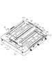
そこで、本実施形態は、光走査装置40に、透過部材42a〜dを清掃するための清掃機構51を備えている。以下では、光走査装置40と、光走査装置40に設けられる清掃機構51について、詳しく説明をする。図2は、光走査装置40の全体を示す斜視図であり、図3は、光走査装置40の上面図である。
Therefore, in the present embodiment, the
図2及び図3に示すように、光走査装置40は、上述したモータユニット41や回転多面鏡43を内部側に収容する収容部40aと、収容部40aに取り付けられ、収容部40aの上面を覆うカバー部40bとを有している。ここで、収容部40aとカバー部40bとによって光走査装置40の筐体を構成している。カバー部40bには、各色の感光体100に対応してレーザ光が通過する開口部が4つ設けられており、各開口部は、対応する感光体100の回転軸線方向に長尺な矩形状であって、それぞれが長手方向に互いに並行に延びるように形成されている。そして、各開口部は、それぞれが長尺な矩形状に形成される透過部材42a〜dによってそれぞれ閉塞されている。透過部材42a〜dは、開口部と同様に4つ設けられており、それぞれが長手方向に互いに並行に延びるように、カバー部40bに取り付けられている。尚、透過部材42a〜dの長手方向は、光走査装置40から出射されるレーザ光の走査方向と略等しくなっている。また、本実施形態では、透過部材42a〜dの長手方向は、各感光体100の回転軸線方向と略等しくなっている。
As shown in FIGS. 2 and 3, the
ここで、透過部材42a〜dは、光走査装置40の内部へトナーや埃、紙粉等の異物が侵入することを防ぐために設けられており、異物が半導体レーザやミラー、回転多面鏡43等に付着することによる画像品質の低下を防止している。透過部材42a〜dは、例えばガラス等の透明な部材で形成されており、収容部40a内の半導体レーザによって発せられるレーザ光を、感光体100へ出射可能となっている。本実施形態では、透過部材42a〜dの大きさを開口部の開口よりも大きく設定し、透過部材42a〜dが各開口部をオーバーラップして覆うように構成されている。そして、透過部材42a〜dの開口部に対してオーバーラップしている部分を接着することで、透過部材42a〜dをカバー部40bに固定している。
Here, the
このように、光走査装置40は、カバー部40b及び透過部材42a〜dによって覆われることで、トナーや紙粉、埃等の異物が光走査装置40の内部へ入り込まないような構成となっている。また、開口部よりも大きい透過部材42a〜dをカバー部40b上に接着固定することで、光走査装置40の上方から落下するトナーや紙粉、埃等の異物が、透過部材42a〜dと各開口部の隙間から光走査装置40の内部へ入り込むことを防止している。
In this way, the
そして、本実施形態では、上方から光走査装置40の上面(透過部材42a〜dの上面)へ落下する異物を清掃する清掃処理を行う清掃機構51を備えている。ここで、透過部材42a〜dの上面とは、光走査装置40に対して外側の面であり、透過部材42a〜dを通過するレーザ光が出射する側の面である。
The present embodiment includes a
清掃機構51は、光走査装置40のカバー部40b上であって、画像形成部10と対向する面側に取り付けられている。清掃機構51は、それぞれが透過部材42a〜dの上面(光走査装置40の外部側の面)を清掃するための清掃部材53a〜dと、清掃部材53a〜dを保持して透過部材42a〜d上を移動させる第1清掃ホルダ511と第2清掃ホルダ512を有している。
The
第1清掃ホルダ511及び第2清掃ホルダ512は、それぞれが隣り合う2つの透過部材42に跨って、透過部材42が延びる方向と直交する方向に延在すると共に、それぞれが清掃部材53を2つずつ有している。ここで、第1清掃ホルダ511及び第2清掃ホルダ512が有する清掃部材53は、透過部材42に対応する数だけ設けられている。
The
つまり、第1清掃ホルダ511は、透過部材42aと42bとに跨るように配置され、透過部材42aの上面を清掃する清掃部材53aと、透過部材42bの上面を清掃する清掃部材53bとを有している。また、第2清掃ホルダ512は、透過部材42cと42dとに跨るように配置され、透過部材42cの上面を清掃する清掃部材53bと、透過部材42dの上面を清掃する清掃部材53dとを有している。
That is, the
清掃部材53a〜dは、例えばシリコンゴムや、不織布等で構成され、第1清掃ホルダ511及び第2清掃ホルダ512の移動に伴って透過部材42の上面に接触して移動することで、透過部材42上の異物を除去することが可能であり、清掃部材42上を清掃可能となっている。
The
第1清掃ホルダ511は、中央部分がワイヤ54に連結されており、ワイヤ54を中心にして両端側にそれぞれ清掃部材53a,53bを保持する構成となっている。また、第2清掃ホルダ512は、中央部がワイヤ54に連結されており、ワイヤ54を中心にして両端側にそれぞれ清掃部材53c,53dを保持する構成となっている。従って、ワイヤ54は、透過部材42a,42bの間と、透過部材42c,42dの間とを通過するように張設されている。
The central portion of the
また、ワイヤ54は、カバー部40bに回転可能に保持されている4つの張設用滑車57a〜d、テンション調整用滑車58及び巻取ドラム59によって、カバー部40b上に環状に張設されている。そして、ワイヤ54は、装置の組み立て時に巻取ドラム59に所定回数巻き取られることで長さの調整がなされた状態で、張設用滑車57a〜dに張架されている。このとき、4つの張設用滑車57a〜dは、上述したように、ワイヤ54が透過部材42a,42bの間と、透過部材42c,42dの間とを通過するように配置されている。
Further, the
ワイヤ54は、張設用滑車57aと57dとの間に設けられるテンション調整用滑車58によって張力が調整されているため、各張設用滑車57、テンション調整用滑車58及び巻取ドラム59の間で弛まずに張った状態で配置されている。これにより、ワイヤ54を張設することによって、ワイヤ54を滑らかに環状走行させることができる。
Since the tension of the
本実施形態では、テンション調整用滑車58を、張設用滑車57aと57dとの間に設けた構成としたが、張設用滑車57a〜dに張架されたワイヤ57の張力を調整できる位置であれば、この位置に限らなくてもよい。
In the present embodiment, the
このように、本実施形態では、第1清掃ホルダ511に清掃部材53a,bを設け、第2清掃ホルダ512に清掃部材53c,dを設ける構成としている。これに対し、1つの清掃ホルダに1つの清掃部材を保持させる場合は、透過部材の数だけ清掃ホルダを有する必要があり、清掃ホルダを張設するワイヤの長さが長くなる。従って、本実施形態では、1つの清掃ホルダに1つの清掃部材を保持させる構成と比較して、清掃ホルダの数を低減することができると共に、ワイヤ54の長さを短くすることができ、より簡単な構成で透過部材42a〜d上面の清掃を行うことができる。
As described above, in the present embodiment, the
また、巻取ドラム59は、駆動部としての巻取モータ55の駆動によって回転可能に構成されている。
Further, the take-up drum 59 is configured to be rotatable by driving a take-up
ここで、巻取モータ55は正逆回転可能に構成されている。本実施形態では、巻取モータ55の正回転をCW方向(Clock Wise)とし、逆回転をCCW方向(Counter Clock Wise)とする。
Here, the take-up
従って、ワイヤ54は、巻取モータ55のCW方向またはCCW方向への回転によって巻取ドラム59が回転することで、巻取ドラム59に巻き取り及び引き出しされる構成になっている。このように、巻取ドラム59によって巻き取り及び引き出しされることで、ワイヤ54が各張設用滑車57に張架された状態でカバー部40b上を環状に走行可能となっている。
Therefore, the
そのため、ワイヤ54に連結されている第1清掃ホルダ511及び第2清掃ホルダ512は、ワイヤ54の走行に伴って、矢印D1,D2方向(透過部材42の長手方向)に移動可能となっている。本実施形態では、巻取モータ55がCCW方向へ回転することで第1清掃ホルダ511及び第2清掃ホルダ512が矢印D1方向へ移動する。また、巻取モータ55がCW方向へ回転することで、第1清掃ホルダ511及び第2清掃ホルダ512がD2方向へ移動する。
Therefore, the
このとき、ワイヤ54が環状に張設されているため、ワイヤ54の移動に伴って、第1清掃ホルダ511と第2清掃ホルダ512とが、透過部材42a〜dの長手方向においてそれぞれが直線的に反対方向に移動する構成となっている。
At this time, since the
ここで、巻取モータ55及び巻取ドラム59は、カバー部40bの上面に対して凹むように設けられた凹部60内に設けられている。これによって、光走査装置40の高さ方向のサイズを小さくすることが可能となっている。尚、この凹部60は、光走査装置40の内部とは連通しておらず、この凹部60からも異物が光走査装置40の内部へ入り込まないように設けられている。
Here, the take-up
また、カバー部40bには、第1清掃ホルダ511の、透過部材42a,bの長手方向(感光体100の回転軸線方向)への移動を規制する第1ストッパ56aが設けられている。また、カバー部40bには、第2清掃ホルダ512の、透過部材42c,dの長手方向(感光体100の回転軸線方向)への移動を規制する第2ストッパ56bが設けられている。ここで、第1ストッパ56a及び第2ストッパ56bは、当接部材の一例である。
Further, the
第1ストッパ56a及び第2ストッパ56bは、透過部材42a〜dの長手方向における一端側に設けられている。従って、第1清掃ホルダ511及び第2清掃ホルダ512が矢印D1方向に移動していくと、第1清掃ホルダ511が矢印D1方向における透過部材42a,bの端部に到達し、第1ストッパ56aに当接することになる。
The
これにより、第1清掃ホルダ511の矢印D1方向への移動が第1ストッパ56aによって規制されるため、ワイヤ54を走行させるために巻取ドラム59を回転させている巻取モータ55に作用する負荷が大きくなる。この負荷を後述する電流検出部を用いて検出することによって、第1清掃ホルダ511が第1ストッパ56aに到達したことが検出される。このとき、第2清掃ホルダ512は、透過部材42の長手方向において前記第1清掃ホルダ511の反対側に位置している。
As a result, the movement of the
尚、本実施形態における第1清掃ホルダ511及び第2清掃ホルダ512の移動による一連の清掃処理は、以下の通りである。
The series of cleaning processes by moving the
まず、駆動モータ55がCW方向に回転駆動されることで、ワイヤ54が矢印D2方向に走行し、第1清掃ホルダ511及び第2清掃ホルダ512が矢印D2方向へ移動する。
First, the
その後、第2清掃ホルダ512は、矢印D2方向における透過部材42c,dの端部に到達し、第2ストッパ56bに当接することになる。これにより、第2清掃ホルダ512の矢印D2方向への移動が第2ストッパ56bによって規制されるため、ワイヤ54を走行させるために巻取ドラム59を回転させている巻取モータ55に作用する負荷が大きくなる。この負荷を後述する電流検出部を用いて検出することによって、第2清掃ホルダ512が第2ストッパ56bに到達したことが検出される。
After that, the
そして、第2清掃ホルダ512が第2ストッパ56bに到達したことが検出された場合は、巻取モータ55の回転を停止させる。このとき、第1清掃ホルダ511は、透過部材42の長手方向において他端側であって、第二位置に到達している。従って、巻取モータ55の回転が停止されることで、透過部材42の長手方向において第二位置にて移動が停止される。
Then, when it is detected that the
その後、巻取モータ55をCCW方向へ回転させることで、ワイヤ54を矢印D1方向に走行させる。これによって、第1清掃ホルダ511及び第2清掃ホルダ512は、それぞれ矢印D1方向へ移動する。
After that, the take-up
その後、第1清掃ホルダ511が矢印D1方向における透過部材42a,bの端部に到達し、第1ストッパ56aに当接することになる。これにより、第1清掃ホルダ511の矢印D1方向への移動が第1ストッパ56aによって規制されるため、ワイヤ54を走行させるために巻取ドラム59を回転させている巻取モータ55に作用する負荷が大きくなる。この負荷を後述する電流検出部を用いて検出することによって、第1清掃ホルダ511が第1ストッパ56aに到達したことが検出される。
After that, the
そして、第1清掃ホルダ511が第1ストッパ56aに到達したことが検出された場合は、巻取モータ55のCCW方向への回転を停止し、所定回転だけCW方向へ回転させる。これによって矢印D2方向に所定距離だけワイヤ54を走行させてから、巻取モータ55の回転を停止させる。
When it is detected that the
このように、本実施形態では、第1清掃ホルダ511及び第2清掃ホルダ512が、透過部材42a〜d上をそれぞれ1往復することを、一連の清掃処理としている。そして、一連の清掃処理が終了した際は、矢印D2方向に所定距離だけワイヤ54を走行させることで第1清掃ホルダ511は第1ストッパ56aに当接しない位置であって、透過部材42の表面に清掃部材53が接触していない位置にて動作を停止させている。
As described above, in the present embodiment, the
つまり、第1清掃ホルダ511は、透過部材42の長手方向における透過部材42の端部と第1ストッパ56aとの間であって、透過部材42においてレーザ光が通過しない非通過領域に位置している。尚、このとき第2清掃ホルダ512は、長手方向において透過部材42の端部に当接しない位置、つまり、透過部材42においてレーザ光が通過しない非通過領域にて動作を停止させている。ここで、一連の清掃処理が終了した場合における第1清掃ホルダ511及び第2清掃ホルダ512の停止位置が、正常停止位置であり、清掃開始位置である。
That is, the
以上で説明した一連の清掃処理では、第2清掃ホルダ512が第2ストッパ56baに到達した場合に巻取モータ55の回転を停止させてからCCW方向へ回転させる構成としたが、第2ストッパ56bに到達したことに応じてCCW方向へ回転させる構成であってもよい。
In the series of cleaning processes described above, when the
尚、本実施形態では、巻取モータ55を正回転(CW方向へ回転)させることでワイヤ54を矢印D1方向へ走行させ、巻取モータ55を逆回転(CCW方向へ回転)させることでワイヤ54を矢印D2方向へ走行させる構成としたが、巻取モータ55の正回転によってワイヤ54を矢印D2方向へ走行させ、逆回転によって矢印D1方向へ走行させる構成であってもよい。
In the present embodiment, the take-up
また、カバー部40bには、第1清掃ホルダ511及び第2清掃ホルダ512の移動をガイドするためのガイド部材61a〜dが設けられている。そして、図4及び図5に示すように、第1清掃ホルダ511の両端部は、ガイド部材61a,61bとそれぞれ係合している。
Further, the
ここで、図4は、第1清掃ホルダ511近傍を示す部分斜視図である。尚、第2清掃ホルダ512についても第1清掃ホルダ511の構成と同様に、第2清掃ホルダ512の両端部は、ガイド部材61c,61dとそれぞれ係合している。図5は、第1清掃ホルダ511の清掃部材53aを保持している側の端部における部分断面図である。ここでは、第1清掃ホルダ511の構成のみを説明するが、本実施形態では、第2清掃ホルダ512にも同様の構成を用いるものとする。
Here, FIG. 4 is a partial perspective view showing the vicinity of the
図4及び図5に示すように、ガイド部材61a〜dは、カバー部40bと一体的に形成され、カバー部40bの上面から上方に突出するように設けられている。
As shown in FIGS. 4 and 5, the
ここで、ガイド部材61a〜dは、図5に示すように、カバー部40bの上面に対して上方に突出する第1突部61aaと、第1突部61aaから清掃部材53aに対して離れる方向に延びる第2突部61abを有している。
Here, as shown in FIG. 5, the
そして、第1清掃ホルダ511の一端側の端部511aが、第2突部61abの下方に潜り込むように形成されている。ここで、端部511aは、第2突部61abと当接部が円弧形状となるように構成されている。このように、端部511aを円弧形状とすることで、第1清掃ホルダ511が矢印D1方向または矢印D2方向(図3参照)へ移動する際の摺動抵抗を低減させることができる。
Then, the
尚、本実施形態では、第1清掃ホルダ511の一端側のみを詳細に説明するが、他端側も同様の構成を有しているものとする。また、第2清掃ホルダ512についても同様の形状を有しているものとする。
In this embodiment, only one end side of the
また、第1清掃ホルダ511及び第2清掃ホルダ512は、ガイド部材61a〜dに係合することで、透過部材42a〜dに対して第1清掃ホルダ511及び第2清掃ホルダ512に保持される清掃部材53a〜dが離間する方向に移動してしまうことを抑制している。このとき、第1清掃ホルダ511及び第2清掃ホルダ512とガイド部材61a〜dの係合位置は、透過部材42a〜dに清掃部材53a〜dが所定の接触圧で接触するような位置となっている。
Further, the
また、本実施形態では、ガイド部材61a〜d、第1ストッパ56a及び第2ストッパ56bをカバー部40bと一体的に樹脂で形成する構成としているが、カバー部40bと別体構成としてもよい。
Further, in the present embodiment, the
上述したように、本実施形態では、清掃処理時に第1清掃ホルダ511及び第2清掃ホルダ512をそれぞれ矢印D1方向や矢印D2方向へ移動させることで、透過部材42a〜dの上面を清掃することが可能となっている。そして、この清掃処理は、操作者から操作部304等を介して任意のタイミングで清掃処理実行の指示を受け付けた場合や、画時形成されたシートの積算枚数が所定枚数に達したことに応じて定期的に実行される。
As described above, in the present embodiment, the upper surfaces of the
ここで、定期的に清掃処理を実行する所定枚数は、初期設定として予め1万枚等に設定されている。この初期設定に対して、操作者は、例えば、操作部304を介して500枚毎の値を入力することで、清掃処理を実行する際の所定枚数を設定変更できる。
Here, the predetermined number of sheets for which the cleaning process is periodically executed is set to 10,000 sheets or the like in advance as an initial setting. For this initial setting, the operator can change the setting of a predetermined number of sheets when the cleaning process is executed, for example, by inputting a value for every 500 sheets via the
このように、定期的に清掃処理を実行する場合、画像形成ジョブの実行中に画像形成枚数が所定枚数に達すると、画像形成ジョブを一旦停止して清掃機構51を動作させて清掃処理を行う。しかしながら、画像形成ジョブを一旦停止させるため、画像形成ジョブを実行している操作者は、清掃処理が終わるまで待機しなければならず、ユーザビリティを損なっていた。
In this way, when the cleaning process is periodically executed, when the number of images formed reaches a predetermined number during the execution of the image forming job, the image forming job is temporarily stopped and the
そこで、本実施形態では、定期的に清掃処理を実行する場合であっても、操作者を待たせる時間を低減するために、清掃処理を実行するタイミングを画像形成ジョブの内容に応じて変更する構成としている。 Therefore, in the present embodiment, even when the cleaning process is periodically executed, the timing of executing the cleaning process is changed according to the content of the image forming job in order to reduce the time that the operator has to wait. It has a structure.
以下では、図6〜図8を用いて本実施形態における画像形成ジョブ実行時のシーケンスについて説明をする。図6は、本実施形態における画像形成ジョブ実行時のシーケンスを行うための制御構成を示す制御ブロック図である。また、図7は、本実施形態における画像形成ジョブ実行時のシーケンスを示すフローチャートである。 Hereinafter, the sequence at the time of executing the image formation job in the present embodiment will be described with reference to FIGS. 6 to 8. FIG. 6 is a control block diagram showing a control configuration for performing a sequence at the time of executing an image formation job in the present embodiment. Further, FIG. 7 is a flowchart showing a sequence at the time of executing the image forming job in the present embodiment.
本実施形態において、CPU601は、画像形成装置1の全体を制御し、画像形成ジョブのシーケンスにおける制御を行う。また、CPU601は、ROM602に格納されたファームウェアプログラムやファームウェアプログラムを制御するためのブートプログラムを読み出し、記憶部としてのRAM603を作業領域及びデータの一次記憶領域として使用して各種制御を実行する。
In the present embodiment, the
そして、CPU601は、光走査装置40を制御するための清掃制御部604に接続され、清掃制御部604を介して清掃機構51を制御する。清掃制御部604は、CPU601からの清掃処理の実行指示に基づいて、巻取モータ55をCW方向やCCW方向へ回転駆動させる。つまり、CPU601は、清掃制御部604を介して、清掃処理における巻取モータ55の制御を行っている。
Then, the
ここで、巻取モータ55には、前述したように巻取モータ55の駆動電流を検出し、検出結果を清掃制御部604へ出力する電流検出部605が設けられている。そして、清掃制御部604は、電流検出部605の検出結果に基づいて、巻取モータ55のCW方向やCCW方向への回転動作、もしくは巻取モータ44の停止を制御する。ここで、清掃制御部604は、上述したように、第1清掃ホルダ511が第1ストッパ56aに当接したこと又は第2清掃ホルダ512が第2ストッパ56bに当接したことを、電流検出部605の検出結果に基づいて判定している。
Here, the take-up
巻取モータ55は、一定電圧で制御されており、第1清掃ホルダ511または第2清掃ホルダ512が第1ストッパ56aまたは第2ストッパ56bに当接すると、巻取モータ55に作用する負荷が重くなることに応じて駆動電流が増加する。
The take-up
従って、清掃制御部604は、電流検出部605によって検出される巻取モータ55の駆動電流が所定の値よりも大きくなった場合に、第1清掃ホルダ511または第2清掃ホルダ512が第1ストッパ56aまたは第2ストッパ56bに当接し、透過部材42a〜dの端部から端部への1方向の移動が終了したことを検出する。つまり、清掃処理における往復動作の片道の清掃が終了したことを検出する。
Therefore, in the cleaning control unit 604, when the drive current of the take-up
ここで、所定の値とは、第1清掃ホルダ511または第2清掃ホルダ512が透過部材42上を移動している間に巻取モータ55に流れる駆動電流値よりも大きい値である。つまり、所定の値とは、第1清掃ホルダ511または第2清掃ホルダ512が第1ストッパ56aまたは第2ストッパ56bに当接する前に巻取モータ55に流れている駆動電流値よりも大きい値である。また、所定の値とは、第1清掃ホルダ511または第2清掃ホルダ512が第1ストッパ56aまたは第2ストッパ56bに当接したことを検出できる値であって、モータの故障等その他の変動によって増加する電流値の値を含まない値に設定する。
Here, the predetermined value is a value larger than the drive current value flowing through the take-up
尚、本実施形態では、第1清掃ホルダ511または第2清掃ホルダ512の第1ストッパ56aまたは第2ストッパ56bへの当接の判定を検出した電流値と所定の値との比較で行ったが他の方法で判定するものであってもよい。例えば、所定の値との比較ではなく、検出した電流値の変化量を判定することで行ってもよい。
In the present embodiment, the determination of the contact of the
また、CPU601は、操作部304等を介して操作者からの指示を受け付けるユーザインターフェース部(以下、UI部)606と接続されている。CPU601は、UI部606を介して、操作者から画像形成ジョブの実行指示や清掃処理の実行指示を受け付ける。また、CPU601は、UI部606を介して定期的な清掃処理のための画像形成枚数の設定を受け付ける。ここで、CPU601は、操作者によって清掃設定枚数を受け付けると、受け付けた設定を清掃設定枚数としてRAM603に保存する。
Further, the
そして、CPU601は、画像形成ジョブを受け付けた場合、画像形成部10によってシートに画像が形成される度に画像形成枚数情報をカウンタ607に出力し、カウンタ607のカウント値を1ずつ増加させる。ここで、CPU601は、画像形成部10において、シートが通過したときに1カウント、もしくはシートに画像形成を行ったときに1カウントさせるようにカウンタ607に画像形成枚数情報を出力する。このとき、シートに対して画像形成を行った回数をカウントする場合、例えばシート1枚に対して画像形成する毎に1カウントしてもよいし、シート1枚の表裏何れかの1ページに画像形成する毎に1カウントしてもよい。シートの1ページに対して画像形成する毎に1カウントする場合、例えば、A4サイズのシートに両面印刷を行う場合は、2ページのシートとしてカウントされる。つまり、両面印刷を行う場合は「1枚のシート」=「2ページ分のカウント(2カウント)」となる。このように、カウンタ607は、画像形成されたシートのページ数もしくは画像形成されたシートの枚数をカウントし、カウント値をCPU601に出力する。
Then, when the image forming job is accepted, the
そして、CPU601は、カウンタ607から出力されるカウント値と、RAM603に保存した清掃設定枚数とを比較し、清掃処理を実行するか否かの判定を行う。判定の結果、清掃処理を実行する場合は、清掃制御部604を介して清掃機構51を制御し、上述したような清掃処理を実行させる。ここで、清掃処理を実行した後、CPU601は、カウンタ607のカウント値を0とし、カウント値をリセットする。
Then, the
尚、本実施形態では、CPU601が全体の制御を行う構成としたが、いくつかの内蔵モジュールを用いて同様の制御を行うものであってもよい。また、清掃制御部604を介さずに、直接CPU601によって巻取モータ55等を制御する構成であってもよい。
In the present embodiment, the
次に、CPU601による清掃処理を定期的に行うための清掃設定枚数の設定シーケンスについて、図7を用いて説明する。
Next, the setting sequence of the set number of cleaning sheets for periodically performing the cleaning process by the
まず、画像形成装置1が起動すると、CPU601は、清掃設定枚数を初期設定値としてRAM603に保存する(S700)。ここで、清掃設定枚数の初期設定値は、例えば1000枚等に設定する。
First, when the image forming apparatus 1 is activated, the
そして、UI部606を介して操作者がメンテナンスモードの操作を行ったか否かを判定する(S701)。メンテナンスモードの操作がされない場合(S701No)は、清掃設定枚数を初期設定値として、清掃設定枚数の設定シーケンスを終了する。CPU601は、メンテナンスモードの操作がされた場合(S701Yes)は、操作者によって清掃設定枚数が入力されたか否かを判定する(S702)。
Then, it is determined whether or not the operator has performed the maintenance mode operation via the UI unit 606 (S701). When the maintenance mode is not operated (S701No), the cleaning set number is set as the initial setting value, and the cleaning set number setting sequence is ended. When the maintenance mode is operated (S701Yes), the
CPU601は、操作者によって清掃設定枚数が入力されない場合(S702No)、清掃設定枚数を初期設定値として、清掃設定枚数の設定シーケンスを終了する。一方、操作者によって清掃設定枚数が入力された場合(S702Yes)、CPU601は、清掃設定枚数を操作者によって設定された枚数に変更し、RAM603に保存し(S703)、清掃設定枚数の設定シーケンスを終了する。
When the cleaning set number is not input by the operator (S702No), the
次に、CPU601による本実施形態の画像形成シーケンスについて、図8を用いて説明する。図8は、本実施形態における画像形成シーケンスを示すフローチャートである。
Next, the image formation sequence of the present embodiment by the
まず、CPU601は、操作者から操作部304等を介して画像形成ジョブを受け付けた場合、指定された画像形成枚数や片面両面印刷などの印刷条件を読み出し、受け付けた画像形成ジョブに対する動作設定をRAM603に保存する(S800)。
First, when the
CPU601は、S800で保存した動作設定により画像形成枚数が設定されると、カウンタ607のカウント値を取得する(S801)。そして、CPU601は、ユーザがS800で設定した画像形成枚数とS801で読み出したカウント値の合計を算出し、合計値が清掃設定枚数の−50枚以上であって+50枚以下であるか判断する(S802)。ここで、本実施形態においては、清掃設定枚数の±50の値を近傍の値とし、清掃設定枚数−50〜清掃設定枚数+50の範囲を所定の値とする。また、清掃設定枚数−50枚の値は、第1の枚数の一例であり、清掃設定枚数+50の値は第2の枚数及び第2清掃設定枚数の一例である。また、ここでの清掃設定枚数は所定の枚数または第1清掃設定枚数の一例である。
When the number of image formations is set by the operation setting saved in S800, the
CPU601は、合計値が清掃設定枚数の−50枚以上であって+50枚以下であった場合(S802のYes)、画像形成動作を実行する(S803)。CPU601は、シートに対して画像形成動作をする度に、カウンタ607のカウント値に1を加算する(S804)。その後、CPU601は、操作者がS800で設定した画像形成ジョブのすべての画像形成が完了したか否かを判定する(S805)。そして、CPU601は、すべての画像形成が完了していない場合(S805No)は画像形成ジョブの実行を継続し、シートに画像形成する度にカウンタ607のカウント値を1ずつ加算する。また、CPU601は、すべての画像形成が完了した場合(S805Yes)、清掃制御部604に清掃実行指示を出力し、清掃機構51を制御して清掃を行う(S806)。
When the total value is −50 or more and +50 or less of the set number of cleaning sheets (Yes in S802), the
その後、CPU601は、カウンタ607のカウント値をクリアし(S807)、カウント値0としてRAM603に保存し(S808)、次の画像形成ジョブを受け付けているか否かを判定する(S809)。CPU601は、次の画像形成ジョブを受け付けている場合(S809Yes)は、S800に戻り、次の画像形成ジョブを受け付けていない場合(S809No)は、画像形成シーケンスを終了する。
After that, the
また、S800で保存した画像形成枚数とS801で取得したカウント値の合計値が清掃設定枚数の−50枚以上+50枚でなかった場合(S802のNo)、CPU601は、合計値が清掃設定枚数−50枚より少ないか否かを判定する(S810)。CPU601は、合計値が清掃設定枚数−50枚より少ない場合(S810のYes)、画像形成動作を実行し(S811)、カウンタ607のカウント値を1加算する(S812)。
Further, when the total value of the number of image formations saved in S800 and the count value acquired in S801 is not -50 or more + 50 of the set number of cleaning sheets (No of S802), the total value of the
その後、CPU601は、操作者がS800で設定した画像形成ジョブのすべての画像形成が終了したか否かを判定する(S813)。CPU601は、すべての画像形成が終了していない場合(S813No)、画像形成ジョブの実行を継続し、シートに画像を形成する度にS811にてカウンタ607のカウント値を1ずつ加算する。また、CPU601は、すべての画像形成が終了した場合(S813Yes)、この時のカウンタ607のカウント値をRAM603に保存する(S808)。そして、CPU601は、次の画像形成ジョブを受け付けている場合(S809Yes)は、S800に戻り、次の画像形成ジョブを受け付けていない場合(S809No)は、画像形成シーケンスを終了する。
After that, the
また、CPU601は、S800で保存した画像形成枚数とS801で取得したカウント値の合計値が+50枚より多かった場合(S810のNO)、画像形成動作を実行する(S814)。CPU601は、S814でシートに対して画像を形成すると、カウンタ607のカウント値を1増やす(S815)。
Further, when the total value of the number of images formed in S800 and the count value acquired in S801 is more than +50 (NO in S810), the
そして、CPU601は、S815でカウントアップしたカウンタ607のカウント値が清掃設定枚数に達したか否かを判断する(S816)。ここで、S815では、例えばカウント値が100であった場合、1枚のシートに画像形成が実行されるとカウント値は1加算され101となる。そして、S816では、CPU601は101という値を取得してRAM603に保存されている清掃設定枚数と比較し、カウント値が清掃設定枚数と等しいか否かを判定する。
Then, the
そして、S816の結果が清掃設定枚数と等しくなるまでは画像形成動作を実行し(S816のNo)、S816の結果が清掃設定枚数と等しいと判定された場合(S816のYes)、画像形成動作を中断する(S817)。 Then, the image forming operation is executed until the result of S816 becomes equal to the set number of cleaning sheets (No of S816), and when it is determined that the result of S816 is equal to the set number of cleaning sheets (Yes of S816), the image forming operation is performed. Suspend (S817).
そして、CPU601は、清掃制御部604に清掃実行指示を出力し、清掃処理を行う(S818)。その後、CPU601は、S818の清掃処理を終えると、カウンタ607のカウント値をクリアし(S819)、中断していた画像形成ジョブを再開し、画像形成動作を実行する(S820)。
Then, the
その後、CPU601は、S820で画像形成動作を実行するとカウンタ607のカウント値を1増やす(S821)。そして、CPU601は、操作者がS800で設定した画像形成ジョブのすべての画像形成が終了したか否かを判定する(S822)。CPU601は、すべての画像形成が終了していない場合(S822No)は画像形成ジョブの実行を継続し、シート1枚に対して画像形成を行うたびにカウンタ607のカウント値を1ずつ加算する。CPU601は、すべての画像形成が終了した場合(S822Yes)は、このときのカウント値をRAM603に保存する(S808)。
After that, when the image forming operation is executed in S820, the
そして、CPU601は、次の画像形成ジョブを受け付けている場合(S809Yes)は、S800に戻り、次の画像形成ジョブを受け付けていない場合(S809No)は、画像形成シーケンスを終了する。
Then, the
このように、本実施形態では、画像形成ジョブを行っている最中に、カウント値(画像形成枚数)が清掃設定枚数に到達する場合であっても、画像形成ジョブを中断させず、画像形成ジョブが終了してから清掃処理を行う。従って、画像形成ジョブの実行を指示した操作者を待たせることがなくなり、ユーザビリティの低下を防ぐことができる。 As described above, in the present embodiment, even if the count value (the number of image formations) reaches the cleaning set number during the image formation job, the image formation job is not interrupted and the image is formed. The cleaning process is performed after the job is completed. Therefore, it is not necessary to wait for the operator who has instructed to execute the image forming job, and it is possible to prevent the usability from being deteriorated.
また、本実施形態では、操作者から画像形成ジョブを受け付けた際に、ジョブ中の画像形成枚数と現在のカウント値(累積した画像形成枚数)とを合算した値が清掃設定枚数よりも±50枚の範囲であるか否かを判定し、清掃処理を行うタイミングを変更した。これにより、画像形成ジョブを終えた際に、累積の画像形成枚数が清掃設定枚数より少ない場合であっても、清掃設定枚数の近傍の枚数である場合は画像形成ジョブ完了後に清掃処理を行うことで、次の画像形成ジョブを行う際に清掃処理による画像形成ジョブの中断を防ぐことができる。また、画像形成ジョブを終えた際に、累積の画像形成枚数が清掃設定枚数より多い場合であっても、清掃設定枚数の近傍の枚数である場合は画像形成ジョブ完了後に清掃処理を行うことで、ジョブを中断させることでダウンタイムが発生することを防ぐことができる。 Further, in the present embodiment, when an image formation job is received from the operator, the total value of the number of image formations in the job and the current count value (cumulative number of image formations) is ± 50 from the set number of cleanings. It was judged whether or not it was within the range of sheets, and the timing of cleaning was changed. As a result, when the image formation job is completed, even if the cumulative number of image formations is less than the set number of cleanings, if the number is close to the set number of cleanings, the cleaning process is performed after the completion of the image formation job. Therefore, when the next image forming job is performed, the interruption of the image forming job due to the cleaning process can be prevented. Further, when the image formation job is completed, even if the cumulative number of image formations is larger than the cleaning set number, if the number is close to the cleaning set number, the cleaning process is performed after the image formation job is completed. , It is possible to prevent downtime from occurring by interrupting the job.
また、画像形成ジョブの実行中に清掃設定枚数を大幅に超えるような画像形成ジョブを受け付けた場合は、清掃処理によって画像形成ジョブを中断することにはなるが、透過部材42上に異物が存在することによる画像品質の低下を防ぐことができる。 Further, if an image forming job that greatly exceeds the set number of cleaning sheets is accepted during the execution of the image forming job, the image forming job is interrupted by the cleaning process, but foreign matter exists on the transparent member 42. It is possible to prevent deterioration of image quality due to the above.
尚、本実施形態では、清掃設定枚数の±50枚の範囲を清掃設定枚数の近傍の値として所定の範囲を設定したが、画像形成装置1を動作させた際の透過部材42の汚れ量によって、清掃設定枚数の近傍の値や所定の範囲を可変してもよい。例えば、±100枚の範囲を清掃設定枚数の近傍の値としてもよい。 In the present embodiment, a predetermined range is set with a range of ± 50 of the set number of cleaning sheets as a value in the vicinity of the set number of cleaning sheets, but depending on the amount of dirt on the transparent member 42 when the image forming apparatus 1 is operated. , The value near the set number of cleaning sheets or a predetermined range may be changed. For example, the range of ± 100 sheets may be set as a value in the vicinity of the set number of cleaning sheets.
<第2の実施形態>
次に、第2の実施形態について説明する。尚、第2の実施形態では、画像形成ジョブを受け付けた際の清掃処理実行タイミングの判定に用いる清掃設定枚数の近傍値が異なる以外は、第1の実施形態と同じ構成であるため、同構成については同符号を付して説明を省略する。
<Second embodiment>
Next, the second embodiment will be described. The second embodiment has the same configuration as the first embodiment except that the neighborhood value of the set number of cleanings used for determining the cleaning process execution timing when the image formation job is accepted is different. The same reference numerals are given to the above, and the description thereof will be omitted.
図9は、第2実施形態における画像形成シーケンスを説明するためのフローチャートである。まず、CPU601は、操作者から操作部304等を介して画像形成ジョブを受け付けた場合、指定された画像形成枚数や片面両面印刷などの印刷条件を読み出し、受け付けた画像形成ジョブに対する動作設定をRAM603に保存する(S900)。
FIG. 9 is a flowchart for explaining the image formation sequence in the second embodiment. First, when the
CPU601は、S900で保存した動作設定により画像形成枚数が設定されると、カウンタ607のカウント値を取得する(S901)。そして、CPU601は、ユーザがS900で設定した画像形成枚数とS901で読み出したカウント値の合計値を算出し、合計値が清掃設定枚数の−10%以上であって+10%以内であるか判断する(S902)。ここで、本実施形態においては、清掃設定枚数±10%の値を近傍の値とし、清掃設定枚数×90%〜清掃設定枚数×110%の範囲を所定の値を含む所定の範囲とする。つまり、CPU601は、S902において、画像形成ジョブ中の画像形成枚数と現在のカウント値との合計値が、清掃設定枚数に対する90%以上の値であって清掃設定枚数に対する110%以下の値であるか否かを判定する。より具体的には、CPU601は、清掃設定枚数が1000枚であった場合、S902において、画像形成ジョブ中の画像形成枚数と現在のカウント値との合計値が900枚以上1100枚以下であるか否かを判定する。ここで、清掃設定枚数×90%の値は第1の枚数の一例であり、清掃設定枚数×110%の値は第2の枚数、または第2清掃設定枚数の一例である。また、ここでの清掃設定枚数は所定の枚数または第1清掃枚数の一例である。
When the number of image formations is set by the operation setting saved in S900, the
CPU601は、合計値が清掃設定枚数の−10%以上であって+10%以内であった場合(S902のYes)、画像形成動作を実行する(S903)。CPU601は、シートに対して画像形成動作をすると、カウンタ607のカウント値に1を加算する(S904)。その後、CPU601は、操作者がS900で設定した画像形成ジョブのすべての画像形成が完了したか否かを判定する(S905)。そして、CPU601は、すべての画像形成が完了していない場合(S905No)は画像形成ジョブの実行を継続し、シートに画像形成する度にカウンタ607のカウント値を1ずつ加算する。また、CPU601は、すべての画像形成が完了した場合(S905Yes)、清掃制御部604に清掃実行指示を出力し、清掃機構51を制御して清掃を行う(S906)。
When the total value is -10% or more and + 10% or less of the set number of cleaning sheets (Yes in S902), the
その後、CPU601は、カウンタ607のカウント値をクリアし(S907)、カウント値0としてRAM603に保存(S908)する。そして、CPU601は、次の画像形成ジョブを受け付けているか否かを判定する(S909)。CPU601は、次の画像形成ジョブを受け付けている場合(S909Yes)は、S900に戻り、次の画像形成ジョブを受け付けていない場合(909No)は、画像形成シーケンスを終了する。
After that, the
また、S900で保存した画像形成枚数とS901で取得したカウント値の合計値が清掃設定枚数の−10%以上であって+10%以内でなかった場合(S902のNo)、CPU601は、合計値が清掃設定枚数−10%より少ないか否かを判定する(S910)。CPU601は、合計値が清掃設定枚数−10%より少ない場合(S910のYes)、画像形成動作を実行し(S911)、カウンタ607のカウント値を1加算する(S912)。
Further, when the total value of the number of image formations saved in S900 and the count value acquired in S901 is -10% or more and not within + 10% of the set number of cleaning sheets (No in S902), the total value of the
その後、CPU601は、操作者がS900で設定した画像形成ジョブのすべての画像形成が終了したか否かを判定する(S913)。CPU601は、すべての画像形成が終了していない場合(S913No)、画像形成ジョブの実行を継続し、シートに画像を形成する度にS911にてカウンタ607のカウント値を1ずつ加算する。また、CPU601は、すべての画像形成が終了した場合(S913Yes)、この時のカウンタ607のカウント値をRAM603に保存する(S908)。そして、CPU601は、次の画像形成ジョブを受け付けている場合(S909Yes)は、S900に戻り、次の画像形成ジョブを受け付けていない場合(S909No)は、画像形成シーケンスを終了する。
After that, the
また、CPU601は、S900で保存した画像形成枚数とS901で取得したカウント値の合計値が+10%より多かった場合(S910のNO)、画像形成動作を実行する(S914)。CPU601は、S914でシートに対して画像を形成すると、カウンタ607のカウント値を1増やす(S915)。
Further, when the total value of the number of images formed in S900 and the count value acquired in S901 is more than + 10% (NO in S910), the
そして、CPU601は、S915でカウントアップしたカウンタ607のカウント値が清掃設定枚数に達したか否かを判断する(S916)。
Then, the
そして、S916の結果が清掃設定枚数と等しくなるまでは画像形成動作を実行し(S916のNo)、S916の結果が清掃設定枚数と等しいと判定された場合(S916のYes)、画像形成動作を中断する(S917)。 Then, the image forming operation is executed until the result of S916 becomes equal to the set number of cleaning sheets (No of S916), and when it is determined that the result of S916 is equal to the set number of cleaning sheets (Yes of S916), the image forming operation is performed. Suspend (S917).
そして、CPU601は、清掃制御部604に清掃実行指示を出力し、清掃処理を行う(S918)。その後、CPU601は、S918の清掃処理を終えると、カウンタ607のカウント値をクリアし(S919)、中断していた画像形成ジョブを再開し、画像形成動作を実行する(S920)。
Then, the
その後、CPU601は、S920で画像形成動作を実行するとカウンタ607のカウント値を1増やす(S921)。そして、CPU601は、操作者がS900で設定した画像形成ジョブのすべての画像形成が終了したか否かを判定する(S922)。CPU601は、すべての画像形成が終了していない場合(S922No)は画像形成ジョブの実行を継続し、シート1枚に対して画像形成を行う度にカウンタ607のカウント値を1ずつ加算する。CPU601は、すべての画像形成が終了した場合(S922Yes)は、このときのカウント値をRAM603に保存する(S908)。
After that, when the image forming operation is executed in S920, the
そして、CPU601は、次の画像形成ジョブを受け付けている場合(S909Yes)は、S900に戻り、次の画像形成ジョブを受け付けていない場合(S909No)は、画像形成シーケンスを終了する。
Then, the
このように、本実施形態では、画像形成ジョブを行っている最中に、カウント値(画像形成枚数)が清掃設定枚数に到達する場合であっても、画像形成ジョブを中断させず、画像形成ジョブが終了してから清掃処理を行う。従って、画像形成ジョブの実行を指示した操作者を待たせることがなくなり、ユーザビリティの低下を防ぐことができる。 As described above, in the present embodiment, even if the count value (the number of image formations) reaches the cleaning set number during the image formation job, the image formation job is not interrupted and the image is formed. The cleaning process is performed after the job is completed. Therefore, it is not necessary to wait for the operator who has instructed to execute the image forming job, and it is possible to prevent the usability from being deteriorated.
また、本実施形態では、操作者から画像形成ジョブを受け付けた際に、ジョブ中の画像形成枚数と現在のカウント値(累積した画像形成枚数)とを合算した値が清掃設定枚数の近傍の値であるか否か(−10%以上であって+10%以内であるか)を判定し、清掃処理を行うタイミングを変更した。これにより、画像形成ジョブを終えた際に、累積の画像形成枚数が清掃設定枚数より少ない場合であっても、清掃設定枚数の近傍の枚数である場合は画像形成ジョブ完了後に清掃処理を行うことで、次の画像形成ジョブを行う際に清掃処理による画像形成ジョブの中断を防ぐことができる。また、画像形成ジョブを終えた際に、累積の画像形成枚数が清掃設定枚数より多い場合であっても、清掃設定枚数の近傍の枚数である場合は画像形成ジョブ完了後に清掃処理を行うことで、ジョブを中断させることでダウンタイムが発生することを防ぐことができる。従って、ユーザビリティの低下を抑制することができる。 Further, in the present embodiment, when an image formation job is received from the operator, the total value of the number of image formations in the job and the current count value (cumulative number of image formations) is a value in the vicinity of the set number of cleanings. (Whether it is -10% or more and + 10% or less) was determined, and the timing of performing the cleaning process was changed. As a result, when the image formation job is completed, even if the cumulative number of image formations is less than the set number of cleanings, if the number is close to the set number of cleanings, the cleaning process is performed after the completion of the image formation job. Therefore, when the next image forming job is performed, the interruption of the image forming job due to the cleaning process can be prevented. Further, when the image formation job is completed, even if the cumulative number of image formations is larger than the cleaning set number, if the number is close to the cleaning set number, the cleaning process is performed after the image formation job is completed. , It is possible to prevent downtime from occurring by interrupting the job. Therefore, the deterioration of usability can be suppressed.
また、画像形成ジョブの実行中に清掃設定枚数を大幅に超えるような画像形成ジョブを受け付けた場合は、清掃処理によって画像形成ジョブを中断することにはなるが、透過部材42上に異物が存在することによる画像品質の低下を防ぐことができる。従って、操作者は、画像品質が低下していることによる画像形成ジョブのやり直しなどをすることがなくなるため、結果としてユーザビリティの低下を抑制することができる。 Further, if an image forming job that greatly exceeds the set number of cleaning sheets is accepted during the execution of the image forming job, the image forming job is interrupted by the cleaning process, but foreign matter exists on the transparent member 42. It is possible to prevent deterioration of image quality due to the above. Therefore, the operator does not have to redo the image forming job due to the deterioration of the image quality, and as a result, the deterioration of usability can be suppressed.
また、本実施形態では、清掃設定枚数の±10%の範囲を清掃設定枚数の近傍の値とした。これにより、清掃設定枚数が操作者によって変更可能であっても、設定された清掃設定枚数に応じた近傍の値に基づいて、清掃処理の実行タイミングを変更することができる。これにより、操作者によって設定された清掃設定枚数に対して、清掃処理の実行タイミングが早すぎ又は遅すぎることを抑制することが可能となる。従って、清掃処理が行われないことによる画像品位の低下や、清掃タイミングが早まることによって頻繁に清掃処理が行われてしまうことによるユーザビリティの低下を抑制することができる。 Further, in the present embodiment, the range of ± 10% of the set number of cleaning sheets is set as a value in the vicinity of the set number of cleaning sheets. As a result, even if the set number of cleaning sheets can be changed by the operator, the execution timing of the cleaning process can be changed based on the value in the vicinity corresponding to the set number of set cleaning sheets. As a result, it is possible to prevent the execution timing of the cleaning process from being too early or too late with respect to the set number of cleanings set by the operator. Therefore, it is possible to suppress the deterioration of the image quality due to the fact that the cleaning process is not performed and the deterioration of the usability due to the frequent cleaning process being performed due to the earlier cleaning timing.
<第3の実施形態>
次に、第3の実施形態について説明する。尚、第3の実施形態では、画像形成ジョブを受け付けた際の清掃処理実行タイミングの判定に用いる清掃設定枚数の近傍値が異なる以外は、第1の実施形態と同じ構成であるため、同構成については同符号を付して説明を省略する。
<Third embodiment>
Next, a third embodiment will be described. The third embodiment has the same configuration as the first embodiment except that the neighborhood value of the set number of cleanings used for determining the cleaning process execution timing when the image formation job is accepted is different. The same reference numerals are given to the above, and the description thereof will be omitted.
図10は、第3実施形態における画像形成シーケンスを説明するためのフローチャートである。まず、CPU601は、操作者から操作部304等を介して画像形成ジョブを受け付けた場合、指定された画像形成枚数や片面両面印刷などの印刷条件を読み出し、受け付けた画像形成ジョブに対する動作設定をRAM603に保存する(S1000)。
FIG. 10 is a flowchart for explaining the image formation sequence in the third embodiment. First, when the
CPU601は、S1000で保存した動作設定により画像形成枚数が設定されると、カウンタ607のカウント値を取得する(S1001)。そして、CPU601は、ユーザがS1000で設定した画像形成枚数とS1001で読み出したカウント値の合計値を算出し、合計値が清掃設定枚数の−10%以上であるか判断する(S1002)。ここで、本実施形態においては、清掃設定枚数−10%の値を近傍の値とし、清掃設定枚数×90%〜清掃設定枚数の範囲を所定の値を含む所定の範囲とする。つまり、CPU601は、S1002において、画像形成ジョブ中の画像形成枚数と現在のカウント値との合計値が、清掃設定枚数に対する90%以上の値であるか否かを判定する。より具体的には、CPU601は、清掃設定枚数が1000枚であった場合、S1002において、画像形成ジョブ中の画像形成枚数と現在のカウント値との合計値が900枚以上であるか否かを判定する。ここで、清掃設定枚数×90%の値は第1の枚数の一例であり、清掃設定枚数×110%の値は第2の枚数の一例である。また、ここでの清掃設定枚数は所定の枚数の一例である。
When the number of image formations is set by the operation setting saved in S1000, the
CPU601は、合計値が清掃設定枚数の−10%以上であった場合(S1002のYes)、画像形成動作を実行する(S1003)。CPU601は、シートに対して画像形成動作をすると、カウンタ607のカウント値に1を加算する(S1004)。その後、CPU601は、操作者がS1000で設定した画像形成ジョブのすべての画像形成が完了したか否かを判定する(S1005)。そして、CPU601は、すべての画像形成が完了していない場合(S1005No)は画像形成ジョブの実行を継続し、シートに画像形成する度にカウンタ607のカウント値を1ずつ加算する。また、CPU601は、すべての画像形成が完了した場合(S1005Yes)、清掃制御部604に清掃実行指示を出力し、清掃機構51を制御して清掃を行う(S1006)。
When the total value is −10% or more of the set number of cleaning sheets (Yes in S1002), the
その後、CPU601は、カウンタ607のカウント値をクリアし(S1007)、カウント値0としてRAM603に保存(S1008)する。そして、CPU601は、次の画像形成ジョブを受け付けているか否かを判定する(S1009)。CPU601は、次の画像形成ジョブを受け付けている場合(S1009Yes)は、S1000に戻り、次の画像形成ジョブを受け付けていない場合(1009No)は、画像形成シーケンスを終了する。
After that, the
また、S1000で保存した画像形成枚数とS1001で取得したカウント値の合計値が清掃設定枚数の−10%以上でなかった場合(S1002のNo)、合計値が清掃設定枚数−10%より少ないため、CPU601は、画像形成動作を実行し(S1010)、カウンタ607のカウント値を1加算する(S1011)。
Further, when the total value of the number of image formations saved in S1000 and the count value acquired in S1001 is not -10% or more of the set number of cleaning sheets (No in S1002), the total value is less than -10% of the set number of cleaning sheets. ,
その後、CPU601は、操作者がS1000で設定した画像形成ジョブのすべての画像形成が終了したか否かを判定する(S1012)。CPU601は、すべての画像形成が終了していない場合(S1012No)、画像形成ジョブの実行を継続し、シートに画像を形成する度にS1011にてカウンタ607のカウント値を1ずつ加算する。また、CPU601は、すべての画像形成が終了した場合(S1012Yes)、この時のカウンタ607のカウント値をRAM603に保存する(S1008)。そして、CPU601は、次の画像形成ジョブを受け付けている場合(S1009Yes)は、S1000に戻り、次の画像形成ジョブを受け付けていない場合(S1009No)は、画像形成シーケンスを終了する。
After that, the
このように、本実施形態では、累積の画像形成枚数とユーザが設定した画像形成ジョブの枚数の合計値が清掃設定枚数×90%〜清掃設定枚数の範囲であった場合に、画像形成ジョブ完了後に清掃動作を実行する構成とした。つまり、清掃設定枚数近傍の範囲を、第2の実施形態に対して狭くした。 As described above, in the present embodiment, the image formation job is completed when the total value of the cumulative number of image formations and the number of image formation jobs set by the user is in the range of the cleaning set number × 90% to the cleaning set number. It was configured to execute the cleaning operation later. That is, the range near the set number of cleaning sheets is narrowed with respect to the second embodiment.
この構成であっても、画像形成ジョブを終えた際に、累積の画像形成枚数が清掃設定枚数より少ない場合であっても、清掃設定枚数の近傍の枚数である場合は画像形成ジョブ完了後に清掃処理を行うことで、次の画像形成ジョブを行う際に清掃処理による画像形成ジョブの中断を防ぐことができる。 Even with this configuration, when the cumulative number of image formations is less than the set number of cleanings when the image formation job is completed, if the number is close to the set number of cleanings, cleaning is performed after the completion of the image formation job. By performing the processing, it is possible to prevent the image forming job from being interrupted due to the cleaning process when the next image forming job is performed.
<第4の実施形態>
次に、第4の実施形態について説明する。尚、第4の実施形態では、画像形成ジョブを受け付けた際の清掃処理実行タイミングの判定に用いる清掃設定枚数の近傍値が異なる以外は、第1の実施形態と同じ構成であるため、同構成については同符号を付して説明を省略する。
<Fourth Embodiment>
Next, a fourth embodiment will be described. The fourth embodiment has the same configuration as the first embodiment except that the neighborhood value of the set number of cleanings used for determining the cleaning process execution timing when the image formation job is accepted is different. The same reference numerals are given to the above, and the description thereof will be omitted.
図11は、第4実施形態における画像形成シーケンスを説明するためのフローチャートである。まず、CPU601は、操作者から操作部304等を介して画像形成ジョブを受け付けた場合、指定された画像形成枚数や片面両面印刷などの印刷条件を読み出し、受け付けた画像形成ジョブに対する動作設定をRAM603に保存する(S1100)。
FIG. 11 is a flowchart for explaining the image formation sequence in the fourth embodiment. First, when the
CPU601は、S900で保存した動作設定により画像形成枚数が設定されると、カウンタ607のカウント値を取得する(S1101)。そして、CPU601は、ユーザがS1100で設定した画像形成枚数とS1101で読み出したカウント値の合計値を算出し、合計値が清掃設定枚数の+10%以内であるか判断する(S1102)。ここで、本実施形態においては、清掃設定枚数+10%の値を近傍の値とし、清掃設定枚数〜清掃設定枚数×110%の範囲を所定の値を含む所定の範囲とする。つまり、CPU601は、S1102において、画像形成ジョブ中の画像形成枚数と現在のカウント値との合計値が、清掃設定枚数に対する110%以下の値であるか否かを判定する。より具体的には、CPU601は、清掃設定枚数が1000枚であった場合、S1102において、画像形成ジョブ中の画像形成枚数と現在のカウント値との合計値が1100枚以下であるか否かを判定する。ここで、清掃設定枚数は第1清掃枚数の一例であり、清掃設定枚数×110%の値は第2清掃設定枚数の一例である。
When the number of image formations is set by the operation setting saved in S900, the
CPU601は、合計値が清掃設定枚数の+10%以内であった場合(S1102のYes)、画像形成動作を実行する(S1103)。CPU601は、シートに対して画像形成動作をすると、カウンタ607のカウント値に1を加算する(S1104)。その後、CPU601は、操作者がS1100で設定した画像形成ジョブのすべての画像形成が完了したか否かを判定する(S1105)。そして、CPU601は、すべての画像形成が完了していない場合(S1105No)は画像形成ジョブの実行を継続し、シートに画像形成する度にカウンタ607のカウント値を1ずつ加算する。また、CPU601は、すべての画像形成が完了した場合(S1105Yes)、清掃制御部604に清掃実行指示を出力し、清掃機構51を制御して清掃を行う(S1106)。
When the total value is within + 10% of the set number of cleaning sheets (Yes in S1102), the
その後、CPU601は、カウンタ607のカウント値をクリアし(S1107)、カウント値0としてRAM603に保存(S1108)する。そして、CPU601は、次の画像形成ジョブを受け付けているか否かを判定する(S1109)。CPU601は、次の画像形成ジョブを受け付けている場合(S1109Yes)は、S1100に戻り、次の画像形成ジョブを受け付けていない場合(S1109No)は、画像形成シーケンスを終了する。
After that, the
また、S1100で保存した画像形成枚数とS1101で取得したカウント値の合計値が+10%より多かった場合(S1102NO)、画像形成動作を実行する(S1110)。CPU601は、S1110でシートに対して画像を形成すると、カウンタ607のカウント値を1増やす(S1111)。
Further, when the total value of the number of image formations saved in S1100 and the count value acquired in S1101 is more than + 10% (S1102NO), the image formation operation is executed (S1110). When the
そして、CPU601は、S1111でカウントアップしたカウンタ607のカウント値が清掃設定枚数に達したか否かを判断する(S1112)。
Then, the
そして、S1112の結果が清掃設定枚数と等しくなるまでは画像形成動作を実行し(S1112のNo)、S1112の結果が清掃設定枚数と等しいと判定された場合(S1112Yes)、画像形成動作を中断する(S1113)。 Then, the image forming operation is executed until the result of S1112 becomes equal to the set number of cleaning sheets (No of S1112), and when it is determined that the result of S1112 is equal to the set number of cleaning sheets (S1112Yes), the image forming operation is interrupted. (S1113).
そして、CPU601は、清掃制御部604に清掃実行指示を出力し、清掃処理を行う(S1114)。その後、CPU601は、S918の清掃処理を終えると、カウンタ607のカウント値をクリアし(S1115)、中断していた画像形成ジョブを再開し、画像形成動作を実行する(S1116)。
Then, the
その後、CPU601は、S1116で画像形成動作を実行するとカウンタ607のカウント値を1増やす(S1117)。そして、CPU601は、操作者がS1100で設定した画像形成ジョブのすべての画像形成が終了したか否かを判定する(S1118)。CPU601は、すべての画像形成が終了していない場合(S1118No)は画像形成ジョブの実行を継続し、シート1枚に対して画像形成を行う度にカウンタ607のカウント値を1ずつ加算する。CPU601は、すべての画像形成が終了した場合(S1118Yes)は、このときのカウント値をRAM603に保存する(S1108)。
After that, when the image forming operation is executed in S1116, the
そして、CPU601は、次の画像形成ジョブを受け付けている場合(S1109Yes)は、S1100に戻り、次の画像形成ジョブを受け付けていない場合(S1109No)は、画像形成シーケンスを終了する。
Then, the
このように、本実施形態では、画像形成ジョブを終えた際に、累積の画像形成枚数が清掃設定枚数より多い場合であっても、清掃設定枚数の近傍の枚数である場合は画像形成ジョブ完了後に清掃処理を行うことで、ジョブを中断させることでダウンタイムが発生することを防ぐことができる。従って、ユーザビリティの低下を抑制することができる。 As described above, in the present embodiment, when the image formation job is completed, even if the cumulative number of image formations is larger than the cleaning set number, the image formation job is completed if the number is close to the cleaning set number. By performing the cleaning process later, it is possible to prevent downtime from occurring due to interruption of the job. Therefore, the deterioration of usability can be suppressed.
また、画像形成ジョブの実行中に清掃設定枚数を大幅に超えるような画像形成ジョブを受け付けた場合は、清掃処理によって画像形成ジョブを中断することにはなるが、透過部材42上に異物が存在することによる画像品質の低下を防ぐことができる。従って、操作者は、画像品質が低下していることによる画像形成ジョブのやり直しなどをすることがなくなるため、結果としてユーザビリティの低下を抑制することができる。 Further, if an image forming job that greatly exceeds the set number of cleaning sheets is accepted during the execution of the image forming job, the image forming job is interrupted by the cleaning process, but foreign matter exists on the transparent member 42. It is possible to prevent deterioration of image quality due to the above. Therefore, the operator does not have to redo the image forming job due to the deterioration of the image quality, and as a result, the deterioration of usability can be suppressed.
<他の実施形態>
上述した実施形態では、画像形成部10の鉛直方向下方に光走査装置40を設ける構成としたが、光走査装置40を画像形成部10の鉛直方向上方に設ける構成であってもよい。この構成の場合、透過部材42a〜dは画像形成部10に対して上方に設けられるため、画像形成部10からトナーや紙粉等が落下することはないが、飛散したトナーや紙粉が付着する虞がある。そのため、画像形成部10の鉛直方向上方に光走査装置40を設ける構成であっても、清掃機構51を設けることで透過部材42a〜dに付着したトナーや紙粉等の異物を除去することができるようになる。
<Other Embodiments>
In the above-described embodiment, the
また、上述した実施形態では、CPU601からの画像形成枚数情報に基づいてカウンタ607がカウント値を1ずつ加算していく構成としたが、画像形成枚数情報に基づいてカウンタ607がカウント値を1ずつ減算していく構成としてもよい。この場合は、設置絵された清掃設定枚数から減算する構成であってもよく、清掃設定枚数を「−1000」のように設定したり、カウンタ607によってカウントされたカウント値の絶対値に基づいて清掃設定枚数に到達したか否かを判定するものであってもよい。
Further, in the above-described embodiment, the counter 607 adds the count value by 1 based on the image formation number information from the
このような構成であっても、画像形成ジョブを行っている最中にカウント値(画像形成枚数)が清掃設定枚数に到達する場合、画像形成ジョブを中断させずに画像形成ジョブが終了してから清掃処理を行う。従って、画像形成ジョブの実行を指示した操作者を待たせることがなくなり、ユーザビリティの低下を防ぐことができる。 Even with such a configuration, if the count value (image formation number) reaches the cleaning set number during the image formation job, the image formation job ends without interrupting the image formation job. Clean up from. Therefore, it is not necessary to wait for the operator who has instructed to execute the image forming job, and it is possible to prevent the usability from being deteriorated.
また、上述した実施形態では、操作部304を介して操作者から画像形成ジョブを受け付ける構成を開示したが、通信回線を介して外部機器から画像形成ジョブを受け付ける構成にも、上述した実施形態を採用することができる。このように、画像形成装置1は、様々な方法により操作者から画像形成ジョブを受け付けることが可能となっている。これに対し、上述した実施形態を用いることで、操作部304を介して画像形成ジョブを入力する操作者に対しては、ユーザビリティの低下を抑制するといった効果が特に大きいと考えられる。これは、操作部304を介して画像形成ジョブを入力する操作者は、画像形成ジョブの完了を装置本体の前で待つ可能性が高いためである。
Further, in the above-described embodiment, the configuration for accepting the image formation job from the operator via the
同様に、画像読取装置306を用いて読み取った原稿画像を画像形成部1によってコピーする画像形成ジョブを行う操作者に対しても、装置本体の前でジョブの完了を待つ可能性が高いため、上述した実施形態を用いることによる効果が特に大きいと考えられる。この他に、画像形成装置1に近距離無線通信方式を用いた不図示のユーザ認証部等を設ける構成に対しても、上述した実施形態を用いることによる効果が特に大きいと考えられる。これは、送信したジョブに対して画像形成するために操作者がユーザ認証部にて認証動作をするため、操作者がそのまま画像形成ジョブの完了を装置の前で待つ可能性が高いためである。
Similarly, an operator who performs an image forming job of copying a document image read by the
このように、上述した実施形態では、画像形成装置1に対して画像形成ジョブを実行させる操作者に対して、光走査装置40の清掃動作に伴って操作者のジョブを中断してしまうことを抑制することができるため、ユーザビリティの低下を抑制することができる。
As described above, in the above-described embodiment, the operator who causes the image forming apparatus 1 to execute the image forming job is interrupted by the cleaning operation of the
1 画像形成装置
13 現像器
40 光走査装置
42a〜d 透過部材
53a〜d 清掃部材
54 ワイヤ
55 巻取モータ
56a 第1ストッパ
56b 第2ストッパ
57a〜d 張設用滑車
59 巻取ドラム
61a〜d ガイド部材
100 感光体
511 第1清掃ホルダ
512 第2清掃ホルダ
601 CPU
602 ROM
603 RAM
604 清掃制御部
605 電流検出部
606 ユーザインターフェース部
607 カウンタ
1 Image forming device 13
602 ROM
603 RAM
604
Claims (19)
前記透明窓を清掃する清掃動作を実行する清掃機構と、
前記画像形成手段によって記録媒体へ画像が形成された画像形成枚数をカウントするカウンタと、
前記カウンタによって、前記清掃機構による前回の清掃動作が実行されてからカウントされた累積の画像形成枚数が所定の枚数あるいは前記所定の枚数を含む所定の範囲に達したことに応じて前記透明窓を清掃するように前記清掃機構を制御する制御手段と、を備え、
前記制御手段は、入力されたジョブによって指定される画像形成枚数と前記ジョブに係る画像形成枚数をカウントする前の前記カウンタのカウント値との合計値が前記所定の枚数を含む前記所定の範囲に含まれる場合、前記ジョブによる画像形成が完了した後に前記清掃機構を動作させる
ことを特徴とする画像形成装置。 An electrostatic latent image formed on the photoconductor by having a photoconductor and an optical scanning device provided with a transparent window for passing a laser beam for scanning the photoconductor to the outside and scanning with the laser beam. To form an image on a recording medium by developing the toner image as a toner image and transferring the toner image to a recording medium.
A cleaning mechanism that executes a cleaning operation to clean the transparent window,
A counter that counts the number of images formed on the recording medium by the image forming means, and
The transparent window is opened by the counter when the cumulative number of image formations counted since the previous cleaning operation by the cleaning mechanism is executed reaches a predetermined number or a predetermined range including the predetermined number. A control means for controlling the cleaning mechanism for cleaning is provided.
In the control means, the total value of the number of images formed by the input job and the count value of the counter before counting the number of images formed related to the job is within the predetermined range including the predetermined number of images. When included, an image forming apparatus characterized in that the cleaning mechanism is operated after the image forming by the job is completed.
ことを特徴とする請求項1に記載の画像形成装置。 When the total value is larger than the predetermined range, the control means starts the image formation by the job, and then when the count value by the counter becomes equal to the predetermined number of sheets, the control means performs the image formation by the job. The image forming apparatus according to claim 1, wherein when the cleaning mechanism is interrupted and the cleaning mechanism is operated to complete the cleaning of the transparent window, the image forming by the interrupted job is restarted.
ことを特徴とする請求項1に記載の画像形成装置。 The image forming apparatus according to claim 1, wherein the control means does not operate the cleaning mechanism after the image forming by the job is completed when the total value is less than the predetermined range.
ことを特徴とする請求項1または請求項2に記載の画像形成装置。 The image forming apparatus according to claim 1 or 2, wherein the control means resets the count value of the counter when the cleaning mechanism is operated to finish cleaning the transparent window.
前記ユーザインターフェース部を介して前記操作者に設定された値を前記所定の枚数として記憶する記憶部をさらに有し、
前記制御手段は、前記合計値が前記記憶部に記憶された前記所定の枚数を含む前記所定の範囲に含まれるか否かを判定する
ことを特徴とする請求項1乃至請求項4のいずれか1項に記載の画像形成装置。 A user interface unit that accepts settings related to the image forming apparatus from the operator, and
Further, it has a storage unit that stores a value set by the operator via the user interface unit as the predetermined number of sheets.
Any of claims 1 to 4, wherein the control means determines whether or not the total value is included in the predetermined range including the predetermined number of sheets stored in the storage unit. The image forming apparatus according to item 1.
ことを特徴とする請求項1乃至請求項5のいずれか1項に記載の画像形成装置。 Any one of claims 1 to 5, wherein the predetermined range is −50 or more with respect to the predetermined number of sheets and +50 or less with respect to the predetermined number of sheets. The image forming apparatus according to the item.
ことを特徴とする請求項1乃至請求項5のいずれか1項に記載の画像形成装置。 The predetermined range is any one of claims 1 to 5, wherein the number of sheets is 90% or more with respect to the predetermined number of sheets and 110% or less with respect to the predetermined number of sheets. The image forming apparatus according to.
前記透明窓を清掃する清掃動作を実行する清掃機構と、
前記画像形成手段が画像を形成するページ数をカウントするカウンタと、
前記カウンタによって、前記清掃機構による前回の清掃動作が実行されてからカウントされた前記記録媒体への画像形成ページ数の累積ページ数が所定のページ数あるいは前記所定のページ数を含む所定の範囲に達したことに応じて前記透明窓を清掃するように前記清掃機構を制御する制御手段と、を備え、
前記制御手段は、入力されたジョブによって指定される画像形成ページ数と前記ジョブに係る画像形成ページ数をカウントする前の前記カウンタのカウント値との合計値が前記所定のページ数を含む前記所定の範囲に含まれる場合、前記ジョブによる画像形成が完了した後に前記清掃機構を動作させることを特徴とする画像形成装置。 An electrostatic latent image formed on the photoconductor by having a photoconductor and an optical scanning device provided with a transparent window for passing a laser beam for scanning the photoconductor to the outside and scanning with the laser beam. To form an image on a recording medium by developing the toner image as a toner image and transferring the toner image to a recording medium.
A cleaning mechanism that executes a cleaning operation to clean the transparent window,
A counter that counts the number of pages on which the image forming means forms an image,
By the counter, the cumulative number of image-forming pages on the recording medium counted since the previous cleaning operation by the cleaning mechanism is executed is within a predetermined range including the predetermined number of pages or the predetermined number of pages. A control means for controlling the cleaning mechanism so as to clean the transparent window according to the achievement is provided.
In the control means, the predetermined number of image-forming pages specified by the input job and the total value of the count value of the counter before counting the number of image-forming pages related to the job include the predetermined number of pages. When it is included in the range of, the image forming apparatus is characterized in that the cleaning mechanism is operated after the image forming by the job is completed.
ことを特徴とする請求項8に記載の画像形成装置。 When the total value is larger than the predetermined range, the control means starts image formation by the job, and then the count value by the counter becomes equal to the predetermined number of pages, the image formation by the job is performed. The image forming apparatus according to claim 8, wherein when the cleaning mechanism is operated and the cleaning of the transparent window is completed, the image forming by the interrupted job is restarted.
ことを特徴とする請求項8に記載の画像形成装置。 The image forming apparatus according to claim 8, wherein the control means does not operate the cleaning mechanism after the image forming by the job is completed when the total value is less than the predetermined range.
ことを特徴とする請求項8または請求項9に記載の画像形成装置。 The image forming apparatus according to claim 8 or 9, wherein the control means resets the count value of the counter when the cleaning mechanism is operated to finish cleaning the transparent window.
前記ユーザインターフェース部を介して前記操作者に設定された値を前記所定のページ数として記憶する記憶部をさらに有し、
前記制御手段は、前記合計値が前記記憶部に記憶された前記所定のページ数を含む前記所定の範囲に含まれるか否かを判定する
ことを特徴とする請求項8乃至請求項11のいずれか1項に記載の画像形成装置。 A user interface unit that accepts settings related to the image forming apparatus from the operator, and
Further having a storage unit that stores a value set for the operator via the user interface unit as the predetermined number of pages.
Any of claims 8 to 11, wherein the control means determines whether or not the total value is included in the predetermined range including the predetermined number of pages stored in the storage unit. The image forming apparatus according to claim 1.
ことを特徴とする請求項8乃至請求項12のいずれか1項に記載の画像形成装置。 Claims 8 to 12 are characterized in that the predetermined range is a value of −50 or more with respect to the predetermined number of pages and a value of +50 or less with respect to the predetermined number of pages. The image forming apparatus according to any one of the above.
ことを特徴とする請求項8乃至請求項12のいずれか1項に記載の画像形成装置。 The predetermined range is a value of 90% or more with respect to the predetermined number of pages and 110% or less with respect to the predetermined number of pages, according to claims 8 to 12. The image forming apparatus according to any one of the following items.
前記透明窓を清掃する清掃機構と、
前記清掃機構の動作を制御する制御手段であって、前記画像形成手段による累積の画像形成枚数に応じて前記清掃機構を動作させるための清掃設定枚数を設定可能な制御手段と、を備え、
前記制御手段は、入力されたジョブによって指定される画像形成枚数と前回の清掃動作が実行されてから当該ジョブが入力されるまでの累積の画像形成枚数との合計値が、
前記清掃設定枚数よりも少ない第1の枚数に満たない場合、前記ジョブに基づく画像形成が完了した後、次のジョブに基づく画像形成が開始するまでは前記清掃機構に清掃動作を実行させず、
前記第1の枚数以上かつ前記清掃設定枚数以下である場合、前記入力されたジョブに基づく画像形成が完了した後、次のジョブに基づく画像形成が開始するまでに前記清掃機構に清掃動作を実行させる
ことを特徴とする画像形成装置。 An electrostatic latent image formed on the photoconductor by having a photoconductor and an optical scanning device provided with a transparent window for passing a laser beam for scanning the photoconductor to the outside and scanning with the laser beam. To form an image on a recording medium by developing the toner image as a toner image and transferring the toner image to a recording medium.
A cleaning mechanism for cleaning the transparent window and
A control means for controlling the operation of the cleaning mechanism, the control means capable of setting a set number of cleanings for operating the cleaning mechanism according to the cumulative number of images formed by the image forming means.
In the control means, the total value of the number of image formations specified by the input job and the cumulative number of image formations from the execution of the previous cleaning operation to the input of the job is calculated.
If the number of sheets is less than the first number, which is less than the set number of cleanings, the cleaning mechanism is not allowed to perform the cleaning operation until the image formation based on the next job is started after the image formation based on the job is completed.
If the number is equal to or greater than the first number and less than or equal to the cleaning set number, the cleaning mechanism executes a cleaning operation after the image formation based on the input job is completed and before the image formation based on the next job is started. An image forming apparatus characterized in that the image is formed.
前記合計値が前記清掃設定枚数よりも多い第2の枚数を超える場合、前回の清掃動作が実行されてからの累積の画像形成枚数が前記清掃設定枚数と等しくなったことに応じて前記入力されたジョブに基づく画像形成を中断して前記清掃機構に清掃動作を実行させ、
前記合計値が前記清掃設定枚数以上かつ前記第2の枚数以下である場合、前記入力されたジョブに基づく画像形成が完了した後、次のジョブに基づく画像形成が開始するまでに前記清掃機構に清掃動作を実行させる
ことを特徴とする請求項15に記載の画像形成装置。 The control means
When the total value exceeds the second number of sheets, which is larger than the set number of cleanings, the total number of images formed since the previous cleaning operation is executed is equal to the set number of cleanings. The image formation based on the job was interrupted and the cleaning mechanism was made to perform the cleaning operation.
When the total value is equal to or more than the set number of cleaning sheets and equal to or less than the second number of sheets to be cleaned, the cleaning mechanism is contacted after the image formation based on the input job is completed and before the image formation based on the next job is started. The image forming apparatus according to claim 15, wherein a cleaning operation is performed.
前記制御手段は、前記入力手段に入力された値に基づいて前記清掃設定枚数を設定する
ことを特徴とする請求項15または請求項16に記載の画像形成装置。 Further having an input means capable of inputting the cleaning set number by the operator,
The image forming apparatus according to claim 15, wherein the control means sets the cleaning set number of sheets based on a value input to the input means.
ことを特徴とする請求項15乃至請求項17のいずれか1項に記載の画像形成装置。 The image forming apparatus according to any one of claims 15 to 17, wherein the first number of sheets is 90% or more of the set number of cleaning sheets.
ことを特徴とする請求項16に記載の画像形成装置。 The image forming apparatus according to claim 16, wherein the second number of sheets is 110% or less of the set number of cleaning sheets.
Priority Applications (3)
| Application Number | Priority Date | Filing Date | Title |
|---|---|---|---|
| JP2018150556A JP6862395B2 (en) | 2018-08-09 | 2018-08-09 | Image forming device |
| US16/530,442 US10739718B2 (en) | 2018-08-09 | 2019-08-02 | Image forming apparatus |
| JP2021058386A JP7129516B2 (en) | 2018-08-09 | 2021-03-30 | image forming device |
Applications Claiming Priority (1)
| Application Number | Priority Date | Filing Date | Title |
|---|---|---|---|
| JP2018150556A JP6862395B2 (en) | 2018-08-09 | 2018-08-09 | Image forming device |
Related Child Applications (1)
| Application Number | Title | Priority Date | Filing Date |
|---|---|---|---|
| JP2021058386A Division JP7129516B2 (en) | 2018-08-09 | 2021-03-30 | image forming device |
Publications (2)
| Publication Number | Publication Date |
|---|---|
| JP2020027131A JP2020027131A (en) | 2020-02-20 |
| JP6862395B2 true JP6862395B2 (en) | 2021-04-21 |
Family
ID=69405967
Family Applications (2)
| Application Number | Title | Priority Date | Filing Date |
|---|---|---|---|
| JP2018150556A Active JP6862395B2 (en) | 2018-08-09 | 2018-08-09 | Image forming device |
| JP2021058386A Active JP7129516B2 (en) | 2018-08-09 | 2021-03-30 | image forming device |
Family Applications After (1)
| Application Number | Title | Priority Date | Filing Date |
|---|---|---|---|
| JP2021058386A Active JP7129516B2 (en) | 2018-08-09 | 2021-03-30 | image forming device |
Country Status (2)
| Country | Link |
|---|---|
| US (1) | US10739718B2 (en) |
| JP (2) | JP6862395B2 (en) |
Families Citing this family (2)
| Publication number | Priority date | Publication date | Assignee | Title |
|---|---|---|---|---|
| JP6929824B2 (en) * | 2018-12-04 | 2021-09-01 | キヤノン株式会社 | Image forming device |
| US11249413B2 (en) * | 2019-07-10 | 2022-02-15 | Kyocera Document Solutions Inc. | Optical scanning device and image forming apparatus including the same |
Family Cites Families (7)
| Publication number | Priority date | Publication date | Assignee | Title |
|---|---|---|---|---|
| JP4374462B2 (en) * | 2004-10-25 | 2009-12-02 | 株式会社リコー | Cleaning device, image forming device |
| JP5029646B2 (en) * | 2009-04-07 | 2012-09-19 | コニカミノルタビジネステクノロジーズ株式会社 | Image forming apparatus and cleaning capability recovery processing control method |
| KR101838632B1 (en) * | 2011-12-28 | 2018-03-15 | 에스프린팅솔루션 주식회사 | Image forming apparatus |
| JP5660738B2 (en) * | 2012-10-18 | 2015-01-28 | 京セラドキュメントソリューションズ株式会社 | Image forming apparatus |
| JP6256241B2 (en) * | 2014-07-29 | 2018-01-10 | 京セラドキュメントソリューションズ株式会社 | Optical scanning device and image forming apparatus having the same |
| JP6264222B2 (en) * | 2014-07-29 | 2018-01-24 | 京セラドキュメントソリューションズ株式会社 | Optical scanning device and image forming apparatus having the same |
| JP6995521B2 (en) * | 2017-07-14 | 2022-01-14 | キヤノン株式会社 | Image forming device |
-
2018
- 2018-08-09 JP JP2018150556A patent/JP6862395B2/en active Active
-
2019
- 2019-08-02 US US16/530,442 patent/US10739718B2/en active Active
-
2021
- 2021-03-30 JP JP2021058386A patent/JP7129516B2/en active Active
Also Published As
| Publication number | Publication date |
|---|---|
| JP7129516B2 (en) | 2022-09-01 |
| US20200050138A1 (en) | 2020-02-13 |
| JP2021103331A (en) | 2021-07-15 |
| US10739718B2 (en) | 2020-08-11 |
| JP2020027131A (en) | 2020-02-20 |
Similar Documents
| Publication | Publication Date | Title |
|---|---|---|
| JP2021103331A (en) | Image forming apparatus | |
| JP7282827B2 (en) | image forming device | |
| JP7030733B2 (en) | Image forming device | |
| JP5289421B2 (en) | Image forming apparatus | |
| JP6146180B2 (en) | Recording medium setting device and image forming apparatus | |
| JP6818722B2 (en) | Image forming device | |
| JP2020016728A (en) | Image forming device | |
| JP4376196B2 (en) | Image forming apparatus | |
| JP2021140175A (en) | Image forming apparatus | |
| JP6859310B2 (en) | Image forming device | |
| US11204581B2 (en) | Image forming apparatus with optical scanning device window cleaning member and control thereof | |
| JP2020091372A (en) | Image forming apparatus | |
| WO2019171974A1 (en) | Image forming device | |
| JP6873952B2 (en) | Image forming device | |
| JP2015006933A (en) | Recording medium set device and image formation device | |
| JP2019200357A (en) | Image forming apparatus | |
| JP7254499B2 (en) | image forming device | |
| JP5920648B2 (en) | Drive device, belt meandering correction device and image forming apparatus using the same | |
| JP2023048842A (en) | Image forming apparatus including optical scanner | |
| JP2006126519A (en) | Image forming apparatus | |
| JP4019836B2 (en) | Sheet transport system | |
| JP2014038270A (en) | Belt unit and image forming apparatus | |
| JP2017095270A (en) | Document feeding device, image formation apparatus and document feeding method | |
| JP2006323325A (en) | Image forming apparatus |
Legal Events
| Date | Code | Title | Description |
|---|---|---|---|
| A621 | Written request for application examination |
Free format text: JAPANESE INTERMEDIATE CODE: A621 Effective date: 20191029 |
|
| A977 | Report on retrieval |
Free format text: JAPANESE INTERMEDIATE CODE: A971007 Effective date: 20200903 |
|
| A131 | Notification of reasons for refusal |
Free format text: JAPANESE INTERMEDIATE CODE: A131 Effective date: 20200915 |
|
| A521 | Request for written amendment filed |
Free format text: JAPANESE INTERMEDIATE CODE: A523 Effective date: 20201111 |
|
| A131 | Notification of reasons for refusal |
Free format text: JAPANESE INTERMEDIATE CODE: A131 Effective date: 20201201 |
|
| A521 | Request for written amendment filed |
Free format text: JAPANESE INTERMEDIATE CODE: A523 Effective date: 20210121 |
|
| TRDD | Decision of grant or rejection written | ||
| A01 | Written decision to grant a patent or to grant a registration (utility model) |
Free format text: JAPANESE INTERMEDIATE CODE: A01 Effective date: 20210302 |
|
| A61 | First payment of annual fees (during grant procedure) |
Free format text: JAPANESE INTERMEDIATE CODE: A61 Effective date: 20210331 |
|
| R151 | Written notification of patent or utility model registration |
Ref document number: 6862395 Country of ref document: JP Free format text: JAPANESE INTERMEDIATE CODE: R151 |