JP6861981B2 - Ceiling rebar structural materials and outer wall rebar structural materials and buildings - Google Patents
Ceiling rebar structural materials and outer wall rebar structural materials and buildings Download PDFInfo
- Publication number
- JP6861981B2 JP6861981B2 JP2016190922A JP2016190922A JP6861981B2 JP 6861981 B2 JP6861981 B2 JP 6861981B2 JP 2016190922 A JP2016190922 A JP 2016190922A JP 2016190922 A JP2016190922 A JP 2016190922A JP 6861981 B2 JP6861981 B2 JP 6861981B2
- Authority
- JP
- Japan
- Prior art keywords
- reinforcing bar
- wire mesh
- ceiling
- wall
- structural material
- Prior art date
- Legal status (The legal status is an assumption and is not a legal conclusion. Google has not performed a legal analysis and makes no representation as to the accuracy of the status listed.)
- Active
Links
- 239000000463 material Substances 0.000 title claims description 386
- 230000003014 reinforcing effect Effects 0.000 claims description 710
- 239000004567 concrete Substances 0.000 claims description 130
- 210000003205 muscle Anatomy 0.000 claims description 99
- 239000011150 reinforced concrete Substances 0.000 claims description 85
- 239000006260 foam Substances 0.000 claims description 82
- 239000011810 insulating material Substances 0.000 claims description 79
- JOYRKODLDBILNP-UHFFFAOYSA-N Ethyl urethane Chemical compound CCOC(N)=O JOYRKODLDBILNP-UHFFFAOYSA-N 0.000 claims description 76
- 238000005452 bending Methods 0.000 claims description 37
- 229910052751 metal Inorganic materials 0.000 claims description 26
- 239000002184 metal Substances 0.000 claims description 26
- 239000000853 adhesive Substances 0.000 claims description 20
- 230000001070 adhesive effect Effects 0.000 claims description 20
- 239000002131 composite material Substances 0.000 claims description 17
- 230000002787 reinforcement Effects 0.000 claims description 8
- 229920003002 synthetic resin Polymers 0.000 claims description 7
- 239000000057 synthetic resin Substances 0.000 claims description 7
- 239000002023 wood Substances 0.000 claims description 7
- XEEYBQQBJWHFJM-UHFFFAOYSA-N Iron Chemical compound [Fe] XEEYBQQBJWHFJM-UHFFFAOYSA-N 0.000 description 334
- 229910052742 iron Inorganic materials 0.000 description 167
- 238000003466 welding Methods 0.000 description 23
- 229910000831 Steel Inorganic materials 0.000 description 18
- 238000009415 formwork Methods 0.000 description 18
- 239000010959 steel Substances 0.000 description 18
- 238000010276 construction Methods 0.000 description 16
- 230000009970 fire resistant effect Effects 0.000 description 8
- 238000000034 method Methods 0.000 description 8
- 238000009413 insulation Methods 0.000 description 7
- XLYOFNOQVPJJNP-UHFFFAOYSA-N water Substances O XLYOFNOQVPJJNP-UHFFFAOYSA-N 0.000 description 7
- 239000010440 gypsum Substances 0.000 description 6
- 229910052602 gypsum Inorganic materials 0.000 description 6
- 239000004570 mortar (masonry) Substances 0.000 description 6
- 239000004033 plastic Substances 0.000 description 6
- 229920003023 plastic Polymers 0.000 description 6
- PMVSDNDAUGGCCE-TYYBGVCCSA-L Ferrous fumarate Chemical compound [Fe+2].[O-]C(=O)\C=C\C([O-])=O PMVSDNDAUGGCCE-TYYBGVCCSA-L 0.000 description 5
- 230000006866 deterioration Effects 0.000 description 5
- 230000002093 peripheral effect Effects 0.000 description 5
- 238000003780 insertion Methods 0.000 description 4
- 230000037431 insertion Effects 0.000 description 4
- 239000011490 mineral wool Substances 0.000 description 4
- 239000012779 reinforcing material Substances 0.000 description 4
- 238000010008 shearing Methods 0.000 description 4
- 229910052782 aluminium Inorganic materials 0.000 description 3
- XAGFODPZIPBFFR-UHFFFAOYSA-N aluminium Chemical compound [Al] XAGFODPZIPBFFR-UHFFFAOYSA-N 0.000 description 3
- 238000009434 installation Methods 0.000 description 3
- 239000002984 plastic foam Substances 0.000 description 3
- 239000011120 plywood Substances 0.000 description 3
- 229920005989 resin Polymers 0.000 description 3
- 239000011347 resin Substances 0.000 description 3
- 238000000926 separation method Methods 0.000 description 3
- 229910000838 Al alloy Inorganic materials 0.000 description 2
- 229910001369 Brass Inorganic materials 0.000 description 2
- 229910045601 alloy Inorganic materials 0.000 description 2
- 239000000956 alloy Substances 0.000 description 2
- 239000010951 brass Substances 0.000 description 2
- 238000005266 casting Methods 0.000 description 2
- 230000000694 effects Effects 0.000 description 2
- 239000004795 extruded polystyrene foam Substances 0.000 description 2
- 239000000155 melt Substances 0.000 description 2
- 230000000149 penetrating effect Effects 0.000 description 2
- -1 polyethylene Polymers 0.000 description 2
- 239000010935 stainless steel Substances 0.000 description 2
- 229910001220 stainless steel Inorganic materials 0.000 description 2
- 229920000877 Melamine resin Polymers 0.000 description 1
- ISWSIDIOOBJBQZ-UHFFFAOYSA-N Phenol Chemical compound OC1=CC=CC=C1 ISWSIDIOOBJBQZ-UHFFFAOYSA-N 0.000 description 1
- 239000004698 Polyethylene Substances 0.000 description 1
- 239000004743 Polypropylene Substances 0.000 description 1
- 229920006328 Styrofoam Polymers 0.000 description 1
- 230000032683 aging Effects 0.000 description 1
- 239000000919 ceramic Substances 0.000 description 1
- 238000010586 diagram Methods 0.000 description 1
- 239000004794 expanded polystyrene Substances 0.000 description 1
- 238000011900 installation process Methods 0.000 description 1
- JEIPFZHSYJVQDO-UHFFFAOYSA-N iron(III) oxide Inorganic materials O=[Fe]O[Fe]=O JEIPFZHSYJVQDO-UHFFFAOYSA-N 0.000 description 1
- JDSHMPZPIAZGSV-UHFFFAOYSA-N melamine Chemical compound NC1=NC(N)=NC(N)=N1 JDSHMPZPIAZGSV-UHFFFAOYSA-N 0.000 description 1
- 238000007747 plating Methods 0.000 description 1
- 229920000728 polyester Polymers 0.000 description 1
- 229920000573 polyethylene Polymers 0.000 description 1
- 229920001155 polypropylene Polymers 0.000 description 1
- 229920006327 polystyrene foam Polymers 0.000 description 1
- 230000003449 preventive effect Effects 0.000 description 1
- 238000009420 retrofitting Methods 0.000 description 1
- 239000007921 spray Substances 0.000 description 1
- 230000035882 stress Effects 0.000 description 1
- 239000008261 styrofoam Substances 0.000 description 1
- 239000000725 suspension Substances 0.000 description 1
Images


Description
本発明は、建造物の鉄筋コンクリート製の天井スラブ構造物を構成する天井鉄筋構造材に関し、建造物の鉄筋コンクリート製の外壁構造物を構成する外壁鉄筋構造材に関するとともに、鉄筋コンクリート製の外壁構造物と鉄筋コンクリート製の天井スラブ構造物とから形成された建造物に関する。 The present invention relates to a ceiling reinforced concrete structure constituting a reinforced concrete ceiling slab structure of a building, a reinforced concrete outer wall structure constituting a reinforced concrete outer wall structure of a building, and an outer wall structure made of reinforced concrete and a reinforced concrete. Regarding structures formed from ceiling slab structures made of.
水平の一方向に所定の間隔をあけて並設された複数の野縁と、野縁の下面に取り付けられた天井材と、野縁に交差させ、水平の他方向に所定の間隔をあけて並設された複数の野縁受けと、野縁および野縁受けを交差部で接続する野縁接続用金具と、上端側を上部構造に接続し、下端側を野縁受けに接続して配設された複数の吊りボルトと、吊りボルトの下端側および野縁受けを接続する吊りボルト接続用金具と、複数の野縁受けに載置した形で他方向に沿って延設されるとともに複数の野縁受けに接続して配設される水平材と、 水平材に一端を上部構造に他端をそれぞれ直接的あるいは間接的に接続して配設された補強ブレースと、 水平材と天井材または野縁とを接続する耐震補強用部材とを有する吊り天井構造が開示されている(特許文献1参照)。 A plurality of field edges arranged side by side at a predetermined interval in one horizontal direction, and a ceiling material attached to the lower surface of the field edge, intersecting the field edge and at a predetermined interval in the other horizontal direction. Multiple field edge receivers installed side by side, field edge connection metal fittings that connect the field edge and field edge receiver at the intersection, the upper end side is connected to the upper structure, and the lower end side is connected to the field edge receiver. Multiple hanging bolts installed, hanging bolt connection fittings for connecting the lower end side of the hanging bolts and the field edge receiver, and a plurality of hanging bolts that are mounted on the multiple field edge receivers and extended along the other direction. A horizontal member that is connected to the field edge holder, a reinforcing brace that is directly or indirectly connected to the horizontal member at one end and the other end to the upper structure, and a horizontal member and a ceiling member. Alternatively, a suspended ceiling structure having a seismic reinforcing member for connecting to a field edge is disclosed (see Patent Document 1).
また、四角柱状の角形鋼管柱の屋外側に設置された耐火性外壁と、四角柱状の角形鋼管柱の屋内側に設置された耐火材となる内壁板と、耐火性外壁と内壁板との間に設置された押出法ポリスチレンフォーム製の断熱材と、角形鋼管柱の屋外側の面とその面に直交し断熱材が配設される側の角形鋼管柱の側面の少なくとも一部とに連続して貼り付けられる加熱膨張シートとを有し、角形鋼管柱が隣接して設置される場合、加熱膨張シートが貼り付けられた角形鋼管柱の側面間に止水性と耐火性とを兼ね備えた耐火シール材を介在させた外壁構造物が開示されている(特許文献2参照)。この外壁構造物は、屋内側の形状を変えることなく、外壁の耐火性能を向上させることができる。 In addition, between the fire-resistant outer wall installed on the outdoor side of the square columnar square steel pipe column, the inner wall plate as the fire-resistant material installed on the indoor side of the square columnar square steel pipe column, and the fire-resistant outer wall and the inner wall plate. The heat insulating material made of extruded polystyrene foam installed in the steel pipe column is continuous with at least a part of the outdoor side surface of the square steel pipe column and the side surface of the square steel pipe column on the side orthogonal to the surface and where the heat insulating material is arranged. When a square steel pipe column is installed adjacent to the heat expansion sheet to which the heat expansion sheet is attached, a fireproof seal having both water resistance and fire resistance between the side surfaces of the square steel pipe column to which the heat expansion sheet is attached. An outer wall structure in which a material is interposed is disclosed (see Patent Document 2). This outer wall structure can improve the fire resistance performance of the outer wall without changing the shape of the indoor side.
前記特許文献1に開示の吊り天井構造は、補強ブレースと耐震補強用部材とを備えることで、吊り天井に大きな揺れが発生することはなく、天井の耐震性能を向上させることができる。吊りボルトを利用する吊り天井構造では、吊りボルトを利用して野縁受けや野縁を天井スラブから吊り下げ、釘によって野縁に天井仕上げ材を固定する。天井仕上げ材は、室内に露出する。地震による激しい揺れが天井に作用した場合、経年劣化した吊りボルトが破断し、または、吊りボルトと野縁受けとの連結や野縁受けと野縁との連結が外れ、天井が崩落し、あるいは、経年劣化した釘が破断し、天井仕上げボードが室内に落下して思わぬ事故につながる場合があり、天井の安全性を確保することができない。なお、吊り天井構造を有する建造物は、地震による激しい揺れによって天井が崩落する場合がある。 The suspended ceiling structure disclosed in Patent Document 1 is provided with a reinforcing brace and a seismic retrofitting member, so that the suspended ceiling does not shake significantly and the seismic performance of the ceiling can be improved. In a suspended ceiling structure that uses hanging bolts, hanging bolts are used to suspend the field edge holder and field edge from the ceiling slab, and nails are used to fix the ceiling finishing material to the field edge. The ceiling finishing material is exposed indoors. If the ceiling is shaken violently by an earthquake, the suspended bolts that have deteriorated over time will break, or the suspension bolts will be disconnected from the field edge receiver or the field edge receiver will be disconnected from the field edge, and the ceiling will collapse or the ceiling will collapse. , Aged nails may break and the ceiling finishing board may fall into the room, leading to an unexpected accident, and the safety of the ceiling cannot be ensured. In a building having a suspended ceiling structure, the ceiling may collapse due to violent shaking caused by an earthquake.
前記特許文献2に開示の外壁構造物は、四角柱状の角形鋼管柱の間に延びる耐火性外壁および内壁板とそれら板の間に配置された断熱材とから形成され、角形鋼管柱の間に鉄筋やコンクリートが存在せず、外壁構造物に鉄筋コンクリート製と同等の十分な強度を持たせることができない。この外壁構造物は、四角柱状の角形鋼管柱の間に延びる耐火性外壁および内壁板において外壁構造物に作用する各種の応力を支えなければならず、地震による激しい揺れが作用した場合、その揺れに耐えきれずに耐火性外壁および内壁板が倒壊するおそれがあり、また、津波におそわれた場合、その水圧に耐えきれず耐火性外壁および内壁板が押し流されるおそれがあり、外壁の安全性を確保することができない。さらに、耐火性外壁と内壁板との間に押出法ポリスチレンフォーム製の断熱材が介在するだけであるから、遮音性が低く、建造物の周囲の騒音を遮断することができない。
The outer wall structure disclosed in
本発明の目的は、鉄筋コンクリート製の強固な天井を作ることができ、高い強度を有する頑丈な天井を有する建造物を施工することができる天井スラブ構造物を提供することにある。また、地震による激しい揺れに耐えることができ、地震の激しい揺れによる天井の崩壊を防ぐことができるとともに、地震や経年劣化による天井仕上げ材の落下を防ぐことができる天井スラブ構造物を提供することにある。さらに、遮音性や耐火性に優れ、階下や階上の騒音を遮断することができ、火災に強い天井を有する建造物を施工することができる天井スラブ構造物を提供することにある。本発明の他の目的は、鉄筋コンクリート製の強固な外壁と天井とを有し、地震による崩壊を防ぐことができ、津波による流失を防ぐことができる建造物を提供することにある。 An object of the present invention is to provide a ceiling slab structure capable of making a strong ceiling made of reinforced concrete and constructing a structure having a strong ceiling with high strength. In addition, provide a ceiling slab structure that can withstand violent shaking caused by an earthquake, prevent the ceiling from collapsing due to violent shaking, and prevent the ceiling finishing material from falling due to an earthquake or deterioration over time. It is in. Furthermore, it is an object of the present invention to provide a ceiling slab structure which is excellent in sound insulation and fire resistance, can block noise downstairs and upstairs, and can construct a building having a ceiling resistant to fire. Another object of the present invention is to provide a structure having a strong outer wall and ceiling made of reinforced concrete, which can prevent collapse due to an earthquake and can prevent runoff due to a tsunami.
本発明の他の目的は、高い強度を有し、地震による激しい揺れや津波の水圧に耐えることができ、建造物の地震による倒壊や建造物の津波による流失を防ぐことができる外壁構造物を提供することにある。さらに、遮音性や耐火性に優れ、周囲の騒音を遮断することができ、火災に強い外壁を備えた建造物を施工することができる外壁構造物を提供することにある。 Another object of the present invention is to provide an outer wall structure having high strength, capable of withstanding violent shaking caused by an earthquake and water pressure of a tsunami, and preventing collapse of a building due to an earthquake and runoff of a building due to a tsunami. To provide. Further, it is an object of the present invention to provide an outer wall structure which is excellent in sound insulation and fire resistance, can block ambient noise, and can construct a building having a fire resistant outer wall.
前記課題を解決するための本発明の第1の前提は、建造物の鉄筋コンクリート製の天井スラブ構造物を構成する天井鉄筋構造材である。 The first premise of the present invention for solving the above problems is a ceiling reinforcing bar structural material constituting a ceiling slab structure made of reinforced concrete of a building.
前記第1の前提における本発明の天井鉄筋構造材の特徴は、天井鉄筋構造材が、前後方向へ延びる所定面積の金網と、金網の上面に設置された鉄筋トラスと、金網の下面に設置された天井仕上げボードと、所定の接着機能を有して金網と天井仕上げボードとを固着する発泡ウレタンとから形成され、鉄筋トラスが、金網の上面から上方へ離間して前後方向へ延びる上端筋と、金網と上端筋との間に位置して前後方向へ延びる一対の下端筋と、金網と上端筋との間で上下方向へ波状に曲折を繰り返しながら前後方向へ延びる一対の第1および第2ラチス筋とを有することにある。 The feature of the ceiling reinforcing bar structural material of the present invention in the first premise is that the ceiling reinforcing bar structural material is installed on a wire mesh having a predetermined area extending in the front-rear direction, a reinforcing bar truss installed on the upper surface of the wire mesh, and the lower surface of the wire mesh. It is formed of a ceiling finishing board and urethane foam that has a predetermined adhesive function and fixes the wire mesh and the ceiling finishing board, and the reinforcing bar truss is separated upward from the upper surface of the wire mesh and extends in the front-rear direction. , A pair of lower end bars that are located between the wire mesh and the upper end bar and extend in the front-back direction, and a pair of first and second bars that extend in the front-back direction while repeating wavy bends in the vertical direction between the wire mesh and the upper end bar. To have a lattice muscle.
本発明の天井鉄筋構造材の一例としては、金網の上面に所定の被り寸法でコンクリートが打設され、金網と鉄筋トラスとが金網の上面において硬化したコンクリートと一体化することで天井スラブ構造物が形成されている。 As an example of the ceiling reinforcing bar structural material of the present invention, concrete is cast on the upper surface of the wire net with a predetermined covering size, and the wire net and the reinforcing bar truss are integrated with the hardened concrete on the upper surface of the wire net to form a ceiling slab structure. Is formed.
本発明の天井鉄筋構造材の他の一例として、天井鉄筋構造材では、第1および第2ラチス筋が上端筋に当接して凸状に曲折する凸部から金網に当接して凹状に曲折する凹部に向かって幅方向外方へ末広がりになり、それらラチス筋の凸部と上端筋とが溶接固定され、それらラチス筋の中間部と下端筋とが溶接固定されているとともに、それらラチス筋の凹部と金網とが溶接固定されている。 As another example of the ceiling reinforcing bar structural material of the present invention, in the ceiling reinforcing bar structural material, the first and second lattice reinforcing bars abut on the upper end bar and bend in a convex shape, and the convex portion abuts on the wire net and bends in a concave shape. It spreads outward in the width direction toward the concave part, the convex part and the upper end muscle of the lattice muscles are welded and fixed, the middle part and the lower end muscle of the lattice muscles are welded and fixed, and the lattice muscles The recess and the wire net are welded and fixed.
本発明の天井鉄筋構造材の他の一例としては、金網が、ラス金網であり、ラス金網が、幅方向へ所定寸法離間して前後方向へ延びる複数の凸条を有し、第1および第2ラチス筋の凹部が、ラス金網の凸条に溶接固定されている。 As another example of the ceiling reinforcing bar structural material of the present invention , the wire mesh is a lath wire mesh, and the lath wire mesh has a plurality of ridges extending in the front-rear direction separated by a predetermined dimension in the width direction, and the first and first ones. 2 The recesses of the lattice streaks are welded and fixed to the ridges of the lath wire mesh.
本発明の天井鉄筋構造材の他の一例としては、第1および第2ラチス筋の凹部が、ラス金網の上面と並行するように幅方向外方へ屈曲してラス金網の凸条の2箇所に当接する屈曲部分を有し、屈曲部分が、ラス金網の凸条の2箇所に溶接固定されている。 As another example of the ceiling reinforcing bar structural material of the present invention, the recesses of the first and second lattice bars are bent outward in the width direction so as to be parallel to the upper surface of the lath wire mesh, and are provided at two positions of the protrusions of the lath wire mesh. It has a bent portion that comes into contact with the wire mesh, and the bent portion is welded and fixed to two points of the protrusion of the lath wire mesh.
本発明の天井鉄筋構造材の他の一例としては、天井仕上げボードが、木質系化粧ボード、合成樹脂系化粧ボード、無機質系化粧ボード、金属系化粧ボードのいずれかまたはそれらを組み合わせた複合化粧ボードである。 As another example of the ceiling reinforcing bar structural material of the present invention , the ceiling finishing board is a composite decorative board of any one of a wooden decorative board, a synthetic resin decorative board, an inorganic decorative board, a metal decorative board, or a combination thereof. Is.
前記課題を解決するための本発明の第2の前提は、建造物の鉄筋コンクリート製の外壁構造物を構成する外壁鉄筋構造材である。 The second premise of the present invention for solving the above problems is an outer wall reinforcing bar structural material constituting an outer wall structure made of reinforced concrete of a building.
前記第2の前提における本発明の外壁鉄筋構造材の特徴は、外壁鉄筋構造材が、上下方向へ延びる所定面積の金網と、金網の前面に設置された鉄筋トラスと、金網の後面に設置された内装ボードと、所定の接着機能を有して金網と内装ボードとを固着する発泡ウレタンとから形成され、鉄筋トラスが、金網の前面から前方へ離間して上下方向へ延びる上端筋と、金網と上端筋との間に位置して上下方向へ延びる一対の下端筋と、金網と上端筋との間に位置して前後方向へ波状に曲折を繰り返しながら上下方向へ延びる一対の第1および第2ラチス筋とを有し、鉄筋トラスの上端筋と下端筋と第1および第2ラチス筋とのうちの少なくとも1つが、建造物の基礎から上方へ延びる基礎鉄筋に連結されることにある。 The feature of the outer wall reinforcing bar structural material of the present invention in the second premise is that the outer wall reinforcing bar structural material is installed on a wire net having a predetermined area extending in the vertical direction, a reinforcing bar truss installed in front of the wire net, and a rear surface of the wire net. The rebar truss is formed of an interior board and urethane foam that has a predetermined adhesive function to fix the wire mesh and the interior board, and the reinforcing bar truss extends from the front surface of the wire mesh to the front and extends in the vertical direction, and the wire mesh. A pair of lower end bars located between the and upper end bars and extending in the vertical direction, and a pair of first and first bars located between the wire net and the upper end bars and extending in the vertical direction while repeating wavy bends in the front-back direction. It has two rebars, and at least one of the upper and lower end rebars and the first and second rebars of the rebar truss is connected to the foundation rebar extending upward from the foundation of the structure.
本発明の外壁鉄筋構造材の一例としては、金網の前面に所定の被り寸法でコンクリートが打設され、金網と鉄筋トラスとが金網の前面において硬化したコンクリートと一体化することで外壁構造物が形成されている。 As an example of the outer wall reinforcing bar structural material of the present invention, concrete is cast on the front surface of the wire mesh with a predetermined covering size, and the wire mesh and the reinforcing bar truss are integrated with the hardened concrete on the front surface of the wire mesh to form the outer wall structure. It is formed.
本発明の外壁鉄筋構造材の他の一例として、外壁鉄筋構造材では、第1および第2ラチス筋が上端筋に当接して凸状に曲折する凸部から金網に当接して凹状に曲折する凹部に向かって幅方向外方へ末広がりになり、それらラチス筋の凸部と上端筋とが溶接固定され、それらラチス筋の中間部と下端筋とが溶接固定されているとともに、それらラチス筋の凹部と金網とが溶接固定されている。 As another example of the outer wall reinforcing bar structural material of the present invention, in the outer wall reinforcing bar structural material, the first and second lattice reinforcing bars abut on the upper end bar and bend in a convex shape, and the convex portion abuts on the wire mesh and bends in a concave shape. It spreads outward in the width direction toward the concave part, the convex part and the upper end muscle of the lattice muscles are welded and fixed, the middle part and the lower end muscle of the lattice muscles are welded and fixed, and the lattice muscles The recess and the wire mesh are welded and fixed.
本発明の外壁鉄筋構造材の他の一例としては、金網が、ラス金網であり、ラス金網が、幅方向へ所定寸法離間して上下方向へ延びる複数の凸条を有し、第1および第2ラチス筋の凹部が、ラス金網の凸条に溶接固定されている。 As another example of the outer wall reinforcing bar structural material of the present invention, the wire mesh is a lath wire mesh, and the lath wire mesh has a plurality of ridges extending in the vertical direction separated by a predetermined dimension in the width direction, and the first and first ones. 2 The recesses of the lattice streaks are welded and fixed to the ridges of the lath wire mesh.
本発明の外壁鉄筋構造材の他の一例としては、第1および第2ラチス筋の凹部が、ラス金網の前面と並行するように幅方向外方へ屈曲してラス金網の凸条の2箇所に当接する屈曲部分を有し、屈曲部分が、ラス金網の凸条の2箇所に溶接固定されている。 As another example of the outer wall reinforcing bar structural material of the present invention, the recesses of the first and second lattice bars are bent outward in the width direction so as to be parallel to the front surface of the lath wire mesh, and two places of the protrusions of the lath wire mesh. It has a bent portion that comes into contact with the wire mesh, and the bent portion is welded and fixed to two points of the protrusion of the lath wire mesh.
本発明の外壁鉄筋構造材の他の一例としては、内装ボードが、木質系化粧ボード、合成樹脂系化粧ボード、無機質系化粧ボード、金属系化粧ボードのいずれかまたはそれらを組み合わせた複合化粧ボードである。 As another example of the outer wall reinforcing bar structural material of the present invention, the interior board is a composite decorative board using any one of a wooden decorative board, a synthetic resin decorative board, an inorganic decorative board, a metal decorative board, or a combination thereof. is there.
前記課題を解決するための本発明の第3の前提は、建造物の基礎に連結された鉄筋コンクリート製の外壁構造物と、外壁構造物の頂部に連結された鉄筋コンクリート製の天井スラブ構造物とから形成された建造物である。 The third premise of the present invention for solving the above problems is from a reinforced concrete outer wall structure connected to the foundation of a building and a reinforced concrete ceiling slab structure connected to the top of the outer wall structure. It is a formed structure.
前記第3の前提における本発明の建造物の特徴は、外壁構造物が、基礎から上方へ延びていて基礎の幅方向へ並ぶ複数の第1外壁鉄筋構造材と、第1外壁鉄筋構造材の内側に位置して第1外壁鉄筋構造材に対向し、基礎から上下方向へ延びていて基礎の幅方向へ並ぶ複数の第2外壁鉄筋構造材と、第1および第2外壁鉄筋構造材の間のスペースに打設されたコンクリートとから形成され、第1外壁鉄筋構造材が、上下方向へ延びる所定面積の第1金網と、第1金網の後方に位置して第1金網の対向面に設置された第1鉄筋トラスと、第1金網の前方に位置して第1金網の非対向面に設置された外断熱材と、所定の接着機能を有して第1金網と外断熱材とを固着する発泡ウレタンとを備え、第2外壁鉄筋構造材が、上下方向へ延びる所定面積の第2金網と、第2金網の前方に位置して第2金網の対向面に設置された第2鉄筋トラスと、第2金網の後方に位置して第2金網の非対向面に設置された内装ボードと、所定の接着機能を有して第2金網と内装ボードとを固着する発泡ウレタンとを備え、第1鉄筋トラスが、第1金網の対向面から後方へ離間して上下方向へ延びる上端筋と、第1金網と上端筋との間に位置して上下方向へ延びる一対の下端筋と、第1金網と上端筋との間で前後方向へ波状に曲折を繰り返しながら上下方向へ延びる一対の第1および第2ラチス筋とを有し、第2鉄筋トラスが、第2金網の対向面から前方へ離間して上下方向へ延びていて、幅方向へ隣接する第1鉄筋トラスの間に位置する上端筋と、第2金網と上端筋との間に位置して上下方向へ延びていて、幅方向へ隣接する第1鉄筋トラスの間に位置する下端筋と、幅方向へ隣接する第1鉄筋トラスの間に位置して第2金網と上端筋との間で前後方向へ波状に曲折を繰り返しながら上下方向へ延びる一対の第1および第2ラチス筋とを有し、天井スラブ構造物が、天井に敷設されて天井の幅方向へ並ぶ複数の天井鉄筋構造材と、天井鉄筋構造材の上面に所定の被り寸法で打設されたコンクリートとから形成され、天井鉄筋構造材が、前後方向へ延びる所定面積の金網と、金網の上面に設置された複数の鉄筋トラスと、金網の下面に設置された天井仕上げボードと、所定の接着機能を有して金網と天井仕上げボードとを固着する発泡ウレタンとを備え、それら鉄筋トラスが、金網の上面から上方へ離間して前後方向へ延びる上端筋と、金網と上端筋との間に位置して前後方向へ延びる一対の下端筋と、金網と上端筋との間で上下方向へ波状に曲折を繰り返しながら前後方向へ延びる一対の第1および第2ラチス筋とを有し、外壁構造物では、第1鉄筋トラスの上端筋と下端筋と第1および第2ラチス筋とのうちの少なくとも1つが基礎から上方へ延びる基礎鉄筋に連結され、第2鉄筋トラスの上端筋と下端筋と第1および第2ラチス筋とのうちの少なくとも1つが基礎から上方へ延びる基礎鉄筋に連結され、第1および第2金網と第1および第2鉄筋トラスとがスペースにおいて硬化したコンクリートと一体化し、天井スラブ構造物では、金網と鉄筋トラスとが金網の上面において硬化したコンクリートと一体化していることにある。 The feature of the structure of the present invention in the third premise is that the outer wall structures extend upward from the foundation and are lined up in the width direction of the foundation. Between a plurality of second outer wall reinforcing bar structural materials located inside, facing the first outer wall reinforcing bar structural material, extending in the vertical direction from the foundation and lining up in the width direction of the foundation, and the first and second outer wall reinforcing bar structural materials. The first outer wall reinforcing bar structural material is formed from the concrete placed in the space of, and is installed on the opposite surface of the first wire net having a predetermined area extending in the vertical direction and the first wire net located behind the first wire net. The first reinforcing bar truss made, the outer heat insulating material located in front of the first wire net and installed on the non-opposing surface of the first wire net, and the first wire net and the outer heat insulating material having a predetermined adhesive function. The second outer wall reinforcing bar structural material is provided with urethane foam to be fixed, and the second reinforcing bar having a predetermined area extending in the vertical direction and the second reinforcing bar located in front of the second wire net and installed on the opposite surface of the second wire net. It is provided with a truss, an interior board located behind the second wire net and installed on a non-opposing surface of the second wire net, and urethane foam having a predetermined adhesive function to fix the second wire net and the interior board. , The first reinforcing bar truss is located between the first wire net and the upper end bar and is located between the first wire net and the upper end bar and extends in the vertical direction. It has a pair of first and second rebars extending in the vertical direction while repeating wavy bends in the front-rear direction between the first rebar and the upper end rebar, and the second rebar truss is from the facing surface of the second rebar. It is separated forward and extends in the vertical direction, and is located between the first reinforcing bar truss adjacent in the width direction and the upper end bar, and is located between the second wire net and the upper end bar and extends in the vertical direction. A wavy bend in the front-rear direction between the second rebar and the upper end rebar located between the first rebar truss adjacent in the width direction and the lower end rebar located between the first rebar truss adjacent in the width direction. A plurality of ceiling reinforcing bar structural materials having a pair of first and second lattice reinforcing bars extending in the vertical direction while repeating, and a ceiling slab structure laid on the ceiling and arranged in the width direction of the ceiling, and a ceiling reinforcing bar structural material. The ceiling reinforcing bar structural material is formed from concrete cast on the upper surface with a predetermined covering size, and is formed on a wire net having a predetermined area extending in the front-rear direction, a plurality of reinforcing bar trusses installed on the upper surface of the wire net, and the lower surface of the wire net. It is provided with an installed ceiling finishing board and urethane foam that has a predetermined adhesive function and fixes the wire net and the ceiling finishing board, and the upper end of the reinforcing bar truss extending upward from the upper surface of the wire net in the front-rear direction. Streaks, wire mesh and top streaks It has a pair of lower end bars that are located between them and extend in the anteroposterior direction, and a pair of first and second lattice bars that extend in the anteroposterior direction while repeatedly bending in the vertical direction between the wire net and the upper end bar. In the outer wall structure, at least one of the upper and lower end bars and the first and second lattice bars of the first reinforcing bar is connected to the foundation reinforcing bar extending upward from the foundation, and the upper and lower ends of the second reinforcing bar truss are connected. At least one of the bars and the first and second rebars is connected to the foundation rebar extending upward from the foundation, and the first and second rebars and the first and second rebar trusses are integrated with the hardened concrete in the space. In the ceiling slab structure, the wire net and the reinforcing bar truss are integrated with the hardened concrete on the upper surface of the wire net.
本発明に係る天井鉄筋構造材によれば、それが前後方向へ延びる所定面積の金網と金網の上面に設置された鉄筋トラスと金網の下面に設置された天井仕上げボードと金網および天井仕上げボードを固着する発泡ウレタンとから形成され、鉄筋トラスが前後方向へ延びる上端筋および一対の下端筋と上下方向へ波状に曲折を繰り返しながら前後方向へ延びる一対の第1および第2ラチス筋とを有するから、金網と鉄筋トラスとが引っ張りに弱いコンクリートを補強する鉄筋となり、天井鉄筋構造材を使用することで鉄筋コンクリート製の強固な天井スラブ構造物を作ることができ、高い強度を有する頑丈な天井スラブ構造物を備えた建造物を施工することができる。天井鉄筋構造材は、それを利用して構築された天井スラブ構造物が高い強度を有し、天井スラブ構造物の安全性を確実に確保することができるから、地震による激しい揺れに耐えることができ、地震の激しい揺れによる天井スラブ構造物の崩壊を防ぐことができる。天井鉄筋構造材は、金網の下面に設置された天井仕上げボードを備え、所定の接着機能を有する発泡ウレタンによって金網と天井仕上げボードとが固着され、金網の上面にコンクリートが打設された場合、金網と天井仕上げボードとが硬化したコンクリートと一体になるから、天井仕上げボードを金網の下面に確実に固定することができ、地震や天井スラブ構造物の経年劣化による天井仕上げ材の落下を防ぐことができる。天井鉄筋構造材は、金網の下面に設置された天井仕上げボードを天井仕上げ材として利用することができるから、施工された天井スラブ構造物の下面に天井仕上げ材を別途設置するための天井仕上げ工事を省くことができ、天井仕上げ工事のための手間やコストを省くことができる。 According to the ceiling reinforcing bar structural material according to the present invention , a wire net having a predetermined area extending in the front-rear direction, a reinforcing bar truss installed on the upper surface of the wire net, and a ceiling finishing board, a wire net, and a ceiling finishing board installed on the lower surface of the wire net. Because the reinforcing bar truss is formed of urethane foam to be fixed, and has a pair of lower end bars and a pair of lower end bars extending in the front-rear direction and a pair of first and second lattice bars extending in the front-rear direction while repeating wavy bending in the vertical direction. , The wire net and the reinforcing bar truss become the reinforcing bars to reinforce the concrete that is vulnerable to tension, and by using the ceiling reinforcing bar structural material, it is possible to make a strong ceiling slab structure made of reinforced concrete, and a sturdy ceiling slab structure with high strength. It is possible to construct a structure equipped with objects. As for the ceiling reinforced structural material, the ceiling slab structure constructed by using it has high strength, and the safety of the ceiling slab structure can be surely ensured, so that it can withstand violent shaking due to an earthquake. It is possible to prevent the ceiling slab structure from collapsing due to the violent shaking of the earthquake. The ceiling reinforced structural material includes a ceiling finishing board installed on the lower surface of the wire net, and when the wire net and the ceiling finishing board are fixed by urethane foam having a predetermined adhesive function and concrete is cast on the upper surface of the wire net, Since the wire net and the ceiling finishing board are integrated with the hardened concrete, the ceiling finishing board can be securely fixed to the lower surface of the wire net, and the ceiling finishing material can be prevented from falling due to an earthquake or aging deterioration of the ceiling slab structure. Can be done. Since the ceiling finishing board installed on the lower surface of the wire net can be used as the ceiling finishing material for the ceiling reinforcing bar structural material, the ceiling finishing work for separately installing the ceiling finishing material on the lower surface of the constructed ceiling slab structure. Can be omitted, and the labor and cost for ceiling finishing work can be saved.
金網の上面に所定の被り寸法でコンクリートが打設され、金網と鉄筋トラスとが金網の上面において硬化したコンクリートと一体化することで天井スラブ構造物が形成されている天井鉄筋構造材は、金網と鉄筋トラスとが引っ張りに弱いコンクリートを補強する鉄筋となり、天井鉄筋構造材を使用することで鉄筋コンクリート製の強固な天井スラブ構造物を作ることができ、高い強度を有する頑丈な天井スラブ構造物を備えた建造物を施工することができる。天井鉄筋構造材は、金網の上面に所定の被り寸法で打設されたコンクリートが優れた遮音性と優れた耐火性とを有するから、建造物の下階や上階の騒音を遮断することができ、火災に強い天井スラブ構造物を有する建造物を施工することができる。 Concrete is cast on the upper surface of the wire net with a predetermined covering size, and the ceiling slab structure is formed by integrating the wire net and the reinforcing bar truss with the hardened concrete on the upper surface of the wire net. And the reinforcing bar truss become the reinforcing bars to reinforce the concrete that is vulnerable to pulling, and by using the ceiling reinforcing bar structural material, it is possible to make a strong ceiling slab structure made of reinforced concrete, and to make a sturdy ceiling slab structure with high strength. It is possible to construct the prepared building. As for the ceiling reinforcing bar structural material, concrete placed on the upper surface of the wire net with a predetermined covering size has excellent sound insulation and excellent fire resistance, so that it is possible to block the noise on the lower and upper floors of the building. It is possible to construct a building with a ceiling slab structure that is resistant to fire.
第1および第2ラチス筋が上端筋に当接して凸状に曲折する凸部から金網に当接して凹状に曲折する凹部に向かって幅方向外方へ末広がりになり、それらラチス筋の凸部と上端筋とが溶接固定され、それらラチス筋の中間部と下端筋とが溶接固定されているとともに、それらラチス筋の凹部と金網とが溶接固定されている天井鉄筋構造材は、上端筋と第1および第2ラチス筋の凸部とが溶接固定され、下端筋と第1および第2ラチス筋とが溶接固定され、第1および第2ラチス筋の凹部と金網とが溶接固定されることで、天井鉄筋構造材において金網と上端筋と下端筋と第1および第2ラチス筋とが一体になるとともに、金網と上端筋と下端筋と第1および第2ラチス筋とがコンクリートを補強する鉄筋となるから、コンクリートに曲げ引張力や曲げ圧縮力、せん断力が作用したとしても、それら力によってコンクリートが破損することはなく、天井鉄筋構造材を使用することで鉄筋コンクリート製の強固な天井スラブ構造物を作ることができ、高い強度を有する頑丈な天井スラブ構造物を備えた建造物を施工することができる。 The first and second rebars diverge outward in the width direction from the convex part that abuts on the upper end muscle and bends convexly toward the concave part that abuts on the wire net and bends concavely, and the convex part of those rebar muscles. And the upper end bar are welded and fixed, the middle part of the lattice bar and the lower end bar are welded and fixed, and the recess of the lattice bar and the wire net are welded and fixed. The convex portions of the first and second lattice bars are welded and fixed, the lower end bars and the first and second lattice bars are welded and fixed, and the concave portions of the first and second lattice bars and the wire net are welded and fixed. Then, in the ceiling reinforcing bar structural material, the wire net, the upper end bar, the lower end bar, and the first and second lattice bars are integrated, and the wire net, the upper end bar, the lower end bar, and the first and second lattice bars reinforce the concrete. Since it becomes a reinforcing bar, even if bending tensile force, bending compressive force, and welding force act on the concrete, the concrete will not be damaged by those forces, and by using the ceiling reinforcing bar structural material, a strong ceiling slab made of reinforced concrete. Structures can be made and structures with high-strength, sturdy ceiling slab structures can be constructed.
金網がラス金網であり、ラス金網が幅方向へ所定寸法離間して前後方向へ延びる複数の凸条を有し、第1および第2ラチス筋の凹部がラス金網の凸条に溶接固定されている天井鉄筋構造材は、第1および第2ラチス筋の凹部がラス金網の凸条に溶接固定されることで、それらラチス筋をラス金網に確実に固定することができ、鉄筋トラスとラス金網との固定が不用意に解除されることはないから、ラス金網を含む上端筋と下端筋と第1および第2ラチス筋とがコンクリートを補強する鉄筋となり、コンクリートに曲げ引張力や曲げ圧縮力、せん断力が作用したとしても、それら力によってコンクリートが破損することはなく、天井鉄筋構造材を使用することで鉄筋コンクリート製の強固な天井スラブ構造物を作ることができ、高い強度を有する頑丈な天井スラブ構造物を備えた建造物を施工することができる。 The wire net is a lath wire net, the lath wire net has a plurality of ridges extending in the front-rear direction separated by a predetermined dimension in the width direction, and the recesses of the first and second lattice bars are welded and fixed to the ridges of the lath wire net. In the ceiling reinforcing bar structural material, the recesses of the first and second lattice bars are welded and fixed to the ridges of the lath wire mesh, so that the lattice bars can be securely fixed to the lath wire mesh, and the reinforcing bar truss and the lath wire mesh can be securely fixed. Since the fixing with and is not inadvertently released, the upper end reinforcing bar including the lath wire net, the lower end reinforcing bar, and the first and second lattice reinforcing bars serve as reinforcing bars to reinforce the concrete, and the bending tensile force and bending compressive force are applied to the concrete. Even if shearing force acts, the concrete will not be damaged by those forces, and by using the ceiling reinforcing bar structural material, it is possible to make a strong ceiling slab structure made of reinforced concrete, and it is sturdy with high strength. Buildings with ceiling slab structures can be constructed.
第1および第2ラチス筋の凹部がラス金網の上面と並行するように幅方向外方へ屈曲してラス金網の凸条の2箇所に当接する屈曲部分を有し、屈曲部分がラス金網の凸条の2箇所に溶接固定されている天井鉄筋構造材は、第1および第2ラチス筋の凹部の屈曲部分がラス金網の凸条の2箇所に溶接固定されることで、それらラチス筋をラス金網に確実に固定することができ、鉄筋トラスとラス金網との固定が不用意に解除されることはないから、ラス金網を含む上端筋と下端筋と第1および第2ラチス筋とがコンクリートを補強する鉄筋となり、コンクリートに曲げ引張力や曲げ圧縮力、せん断力が作用したとしても、それら力によってコンクリートが破損することはなく、天井鉄筋構造材を使用することで鉄筋コンクリート製の強固な天井スラブ構造物を作ることができ、高い強度を有する頑丈な天井スラブ構造物を備えた建造物を施工することができる。 The recesses of the first and second rebars have bent portions that bend outward in the width direction so as to be parallel to the upper surface of the lath wire net and abut on the two protrusions of the lath wire net, and the bent portions are of the lath wire net. The ceiling reinforcing bar structural material that is welded and fixed to the two points of the ridges can be fixed by welding the bent parts of the recesses of the first and second lattice bars to the two places of the ridges of the lath wire net. Since it can be securely fixed to the lath wire net and the fixing between the reinforcing bar truss and the lath wire net is not inadvertently released, the upper end bar and the lower end bar including the lath wire net and the first and second lattice bars are separated. It becomes a reinforcing bar that reinforces concrete, and even if bending tensile force, bending compressive force, and shearing force act on the concrete, the concrete will not be damaged by those forces, and by using the ceiling reinforcing bar structural material, it is made of reinforced concrete. Ceiling slab structures can be made, and structures with sturdy ceiling slab structures with high strength can be constructed.
天井仕上げボードが木質系化粧ボード、合成樹脂系化粧ボード、無機質系化粧ボード、金属系化粧ボードのいずれかまたはそれらを組み合わせた複合化粧ボードである天井鉄筋構造材は、天井仕上げボードとしてそれら化粧ボードのいずれかまたはそれら化粧ボードを組み合わせた複合化粧ボードを使用することで、強固な天井スラブ構造物とともに室内側に露出する見端のよい天井仕上げ材をあわせて施工することができる。天井鉄筋構造材は、それら化粧ボードや複合化粧ボードを天井仕上げ材として利用することができるから、施工された天井スラブ構造物の下面に天井仕上げ材を別途設置するための天井仕上げ材工事を省くことができ、天井仕上げ工事のための手間やコストを省くことができる。 Ceiling reinforced structural materials, which are composite decorative boards in which the ceiling finishing board is one of wood-based decorative boards, synthetic resin-based decorative boards, inorganic decorative boards, metal-based decorative boards, or a combination thereof, are those decorative boards as ceiling finishing boards. By using one of the above or a composite decorative board in which the decorative boards are combined, it is possible to construct a strong ceiling slab structure together with a ceiling finishing material that is exposed to the indoor side and has a good appearance. Since these decorative boards and composite decorative boards can be used as ceiling finishing materials for the ceiling reinforcing bar structural material, the ceiling finishing material work for separately installing the ceiling finishing material on the lower surface of the constructed ceiling slab structure is omitted. This can save time and cost for ceiling finishing work.
本発明に係る外壁鉄筋構造材によれば、上下方向へ延びる所定面積の金網と金網の前面に設置された鉄筋トラスと金網の後面に設置された内装ボードと金網および内装ボードを固着する発泡ウレタンとから形成され、鉄筋トラスが上下方向へ延びる上端筋および一対の下端筋と前後方向へ波状に曲折を繰り返しながら上下方向へ延びる一対の第1および第2ラチス筋とを有するから、鉄板ベースと鉄筋トラスとが引っ張りに弱いコンクリートを補強する鉄筋となり、外壁鉄筋構造材を使用することで鉄筋コンクリート製の強固な外壁構造物を作ることができ、高い強度を有する頑丈な外壁構造物を備えた建造物を施工することができる。外壁鉄筋構造材は、それを利用して構築された外壁構造物が高い強度を有し、外壁構造物の安全性を確実に確保することができるから、地震による激しい揺れや津波の水圧に十分に耐えることができ、地震の激しい揺れによる外壁構造物の崩壊を防ぐことができるとともに、津波による建造物の流失を防ぐことができる。外壁鉄筋構造材は、鉄筋トラスの上端筋と下端筋と第1および第2ラチス筋とのうちの少なくとも1つが建造物の基礎から上方へ延びる基礎鉄筋に連結されるから、建造物の基礎と一体になった優れた強度の外壁構造物を作ることができ、強い衝撃に十分に耐えることが可能な外壁構造物を備えた建造物を施工することができる。外壁鉄筋構造材は、金網の後面に設置された内装ボードを内装材として利用することができるから、施工された外壁構造物の後面に内装材を別途設置するための内装工事を省くことができ、内装工事のための手間やコストを省くことができる。 According to the outer wall reinforcing bar structural material according to the present invention, a wire net having a predetermined area extending in the vertical direction, a reinforcing bar truss installed on the front surface of the wire net, and an interior board installed on the rear surface of the wire net, and urethane foam for fixing the wire net and the interior board. Since the reinforcing bar truss has a pair of upper end bars and a pair of lower end bars extending in the vertical direction and a pair of first and second lattice bars extending in the vertical direction while repeating wavy bending in the front-rear direction, the reinforcing bar truss is formed from the steel plate base. Reinforcing bar truss becomes a reinforcing bar to reinforce concrete that is vulnerable to pulling, and by using outer wall reinforcing bar structural material, it is possible to make a strong outer wall structure made of reinforced concrete, and construction with a strong outer wall structure with high strength You can construct things. As for the outer wall reinforcing bar structural material, the outer wall structure constructed by using it has high strength, and the safety of the outer wall structure can be surely ensured, so that it is sufficient for the severe shaking caused by an earthquake and the water pressure of a tsunami. It is possible to prevent the collapse of the outer wall structure due to the violent shaking of the earthquake, and it is possible to prevent the building from being washed away by the tsunami. The outer wall reinforcing bar structural material is connected to the foundation reinforcing bar extending upward from the foundation of the building, so that at least one of the upper end reinforcing bar, the lower end reinforcing bar, and the first and second lattice reinforcing bars of the reinforcing bar truss is connected to the foundation of the building. It is possible to make an integrated outer wall structure with excellent strength, and it is possible to construct a building having an outer wall structure that can sufficiently withstand a strong impact. As the outer wall reinforcing bar structural material, the interior board installed on the rear surface of the wire mesh can be used as the interior material, so that the interior work for separately installing the interior material on the rear surface of the constructed outer wall structure can be omitted. , The labor and cost for interior work can be saved.
金網の前面に所定の被り寸法でコンクリートが打設され、金網と鉄筋トラスとが金網の前面において硬化したコンクリートと一体化することで外壁構造物が形成されている外壁鉄筋構造材は、金網と鉄筋トラスとが引っ張りに弱いコンクリートを補強する鉄筋となり、外壁鉄筋構造材を使用することで鉄筋コンクリート製の強固な外壁構造物を作ることができ、高い強度を有する頑丈な外壁構造物を備えた建造物を施工することができる。外壁鉄筋構造材は、金網の前面に所定の被り寸法で打設されたコンクリートが優れた遮音性と優れた耐火性とを有するから、建造物の周囲の騒音を遮断することができ、火災に強い外壁構造物を備えた建造物を施工することができる。 Concrete is cast on the front surface of the wire net with a predetermined covering size, and the outer wall structure is formed by integrating the wire net and the reinforcing bar truss with the hardened concrete on the front surface of the wire net. Reinforcing bar truss becomes a reinforcing bar that reinforces concrete that is vulnerable to pulling, and by using outer wall reinforcing bar structural material, it is possible to make a strong outer wall structure made of reinforced concrete, and construction with a strong outer wall structure with high strength You can construct things. As for the outer wall reinforcing bar structural material, concrete placed on the front surface of the wire mesh with a predetermined covering size has excellent sound insulation and excellent fire resistance, so it is possible to block noise around the building and cause a fire. Buildings with strong exterior wall structures can be constructed.
第1および第2ラチス筋が上端筋に当接して凸状に曲折する凸部から金網に当接して凹状に曲折する凹部に向かって幅方向外方へ末広がりになり、それらラチス筋の凸部と上端筋とが溶接固定され、それらラチス筋の中間部と下端筋とが溶接固定されているとともに、それらラチス筋の凹部と金網とが溶接固定されている外壁鉄筋構造材は、上端筋と第1および第2ラチス筋の凸部とが溶接固定され、下端筋と第1および第2ラチス筋とが溶接固定され、第1および第2ラチス筋の凹部と金網とが溶接固定されることで、外壁鉄筋構造材において金網と上端筋と下端筋と第1および第2ラチス筋とが一体になるとともに、金網と上端筋と下端筋と第1および第2ラチス筋とがコンクリートを補強する鉄筋となるから、コンクリートに曲げ引張力や曲げ圧縮力、せん断力が作用したとしても、それら力によってコンクリートが破損することはなく、外壁鉄筋構造材を使用することで鉄筋コンクリート製の強固な外壁構造物を作ることができ、高い強度を有する頑丈な外壁構造物を備えた建造物を施工することができる。 The first and second rebars diverge outward in the width direction from the convex part that abuts on the upper end muscle and bends convexly toward the concave part that abuts on the wire net and bends concavely. And the upper end reinforcement are welded and fixed, the middle part and the lower end reinforcement of these lattice reinforcements are welded and fixed, and the concave part of these lattice reinforcements and the wire net are welded and fixed. The convex portions of the first and second lattice bars are welded and fixed, the lower end bars and the first and second lattice bars are welded and fixed, and the concave portions of the first and second lattice bars and the wire net are welded and fixed. Then, in the outer wall reinforcing bar structural material, the wire net, the upper end bar, the lower end bar, and the first and second lattice bars are integrated, and the wire net, the upper end bar, the lower end bar, and the first and second lattice bars reinforce the concrete. Since it becomes a reinforcing bar, even if bending tensile force, bending compressive force, and welding force act on the concrete, the concrete will not be damaged by those forces, and by using the outer wall reinforcing bar structural material, a strong outer wall structure made of reinforced concrete. It is possible to make objects and to construct structures with strong exterior wall structures with high strength.
金網がラス金網であり、ラス金網が幅方向へ所定寸法離間して上下方向へ延びる複数の凸条を有し、第1および第2ラチス筋の凹部がラス金網の凸条に溶接固定されている外壁鉄筋構造材は、第1および第2ラチス筋の凹部がラス金網の凸条に溶接固定されることで、それらラチス筋をラス金網に確実に固定することができ、鉄筋トラスとラス金網との固定が不用意に解除されることはないから、ラス金網を含む上端筋と下端筋と第1および第2ラチス筋とがコンクリートを補強する鉄筋となり、コンクリートに曲げ引張力や曲げ圧縮力、せん断力が作用したとしても、それら力によってコンクリートが破損することはなく、外壁鉄筋構造材を使用することで鉄筋コンクリート製の強固な外壁構造物を作ることができ、高い強度を有する頑丈な外壁構造物を備えた建造物を施工することができる。 The wire mesh is a lath wire mesh, the lath wire mesh has a plurality of ridges extending in the vertical direction separated by a predetermined dimension in the width direction, and the recesses of the first and second lattice bars are welded and fixed to the ridges of the lath wire net. In the outer wall reinforcing bar structural material, the recesses of the first and second lattice bars are welded and fixed to the ridges of the lath wire mesh, so that the lattice bars can be securely fixed to the lath wire mesh, and the reinforcing bar truss and the lath wire mesh can be securely fixed. Since the fixing with the concrete is not inadvertently released, the upper end reinforcing bar including the lath wire mesh, the lower end reinforcing bar, and the first and second lattice reinforcing bars serve as reinforcing bars to reinforce the concrete, and the bending tensile force and bending compressive force are applied to the concrete. Even if shearing force acts, the concrete will not be damaged by those forces, and by using the outer wall reinforcing bar structural material, a strong outer wall structure made of reinforced concrete can be made, and a sturdy outer wall with high strength. Buildings with structures can be constructed.
第1および第2ラチス筋の凹部がラス金網の前面と並行するように幅方向外方へ屈曲してラス金網の凸条の2箇所に当接する屈曲部分を有し、屈曲部分がラス金網の凸条の2箇所に溶接固定されている外壁鉄筋構造材は、第1および第2ラチス筋の凹部の屈曲部分がラス金網の凸条の2箇所に溶接固定されることで、それらラチス筋をラス金網に確実に固定することができ、鉄筋トラスとラス金網との固定が不用意に解除されることはないから、ラス金網を含む上端筋と下端筋と第1および第2ラチス筋とがコンクリートを補強する鉄筋となり、コンクリートに曲げ引張力や曲げ圧縮力、せん断力が作用したとしても、それら力によってコンクリートが破損することはなく、外壁鉄筋構造材を使用することで鉄筋コンクリート製の強固な外壁構造物を作ることができ、高い強度を有する頑丈な外壁構造物を備えた建造物を施工することができる。 The recesses of the first and second rebars bend outward in the width direction so as to be parallel to the front surface of the lath wire net, and have a bent portion that abuts on two points of the protrusions of the lath wire net, and the bent portion is of the lath wire net. The outer wall reinforcing bar structural material that is welded and fixed to the two points of the ridges can be fixed by welding the bent portions of the concave portions of the first and second lattice bars to the two points of the ridges of the lath wire net. Since it can be securely fixed to the lath wire net and the fixing between the reinforcing bar truss and the lath wire net is not inadvertently released, the upper end bar and the lower end bar including the lath wire net and the first and second lattice bars are separated. It becomes a reinforcing bar that reinforces concrete, and even if bending tensile force, bending compressive force, and shearing force act on the concrete, the concrete will not be damaged by those forces, and by using the outer wall reinforcing bar structural material, it is made of reinforced concrete. It is possible to make an outer wall structure, and it is possible to construct a structure having a sturdy outer wall structure having high strength.
内装ボードが木質系化粧ボード、合成樹脂系化粧ボード、無機質系化粧ボード、金属系化粧ボードのいずれかまたはそれらを組み合わせた複合化粧ボードである外壁鉄筋構造材は、内装ボードとしてそれら化粧ボードのいずれかまたはそれら化粧ボードを組み合わせた複合化粧ボードを使用することで、強固な外壁構造物とともに室内側に露出する見端のよい内装材をあわせて施工することができる。外壁鉄筋構造材は、それら化粧ボードや複合化粧ボードを内装材として利用することができるから、施工された外壁構造物の後面に内装材を別途設置するための内装工事を省くことができ、内装工事のための手間やコストを省くことができる。 The exterior wall reinforced structural material, which is a composite decorative board in which the interior board is one of wood-based decorative boards, synthetic resin-based decorative boards, inorganic decorative boards, metal-based decorative boards, or a combination thereof, is one of those decorative boards as an interior board. Alternatively, by using a composite decorative board that is a combination of these decorative boards, it is possible to construct a strong outer wall structure and an interior material that is exposed to the indoor side and has a good appearance. Since these decorative boards and composite decorative boards can be used as interior materials for the outer wall reinforcing bar structural material, it is possible to omit the interior work for separately installing the interior material on the rear surface of the constructed outer wall structure, and the interior The labor and cost for construction can be saved.
本発明に係る建造物によれば、天井スラブ構造物が天井に敷設された複数の天井鉄筋構造材と天井鉄筋構造材の上面に打設されたコンクリートとから形成され、天井鉄筋構造材が所定面積の金網と金網の上面に設置された鉄筋トラスと金網の下面に設置された天井仕上げボードと、金網および天井仕上げボードを固着する発泡ウレタンとを備え、天井鉄筋構造材およびコンクリートから作られた鉄筋コンクリート製の天井スラブ構造物が高い強度を有するから、天井スラブ構造物の安全性を確実に確保することができる。建造物は、外壁構造物が基礎から上方へ延びる複数の第1および第2外壁鉄筋構造材と第1および第2外壁鉄筋構造材の間のスペースに打設されたコンクリートとから形成され、第1外壁鉄筋構造材が所定面積の第1金網と第1金網の対向面に設置された第1鉄筋トラスと第1金網の非対向面に設置された外断熱材と第1金網および外断熱材を固着する発泡ウレタンとを備え、第2外壁鉄筋構造材が所定面積の第2金網と第2金網の対向面に設置された第2鉄筋トラスと第2金網の非対向面に設置された内装ボードと第2金網および内装ボードを固着する発泡ウレタンとを備え、第1および第2外壁鉄筋構造材とコンクリートとから作られた鉄筋コンクリート製の外壁構造物が高い強度を有するから、外壁構造物の安全性を確実に確保することができる。建造物は、地震による激しい揺れや津波の水圧に十分に耐えることが可能であり、地震の激しい揺れによる天井の崩落を防ぐことができるとともに、地震による崩壊を防ぐことができ、津波による流失を防ぐことができる。 According to buildings according to the present invention, is formed from the concrete ceiling slab structure is Da設on the upper surface of a plurality of ceiling rebar structural member and the ceiling rebar structure material laid on a ceiling, the ceiling rebar structure material given Reinforcing bar truss installed on the area wire mesh and the upper surface of the wire mesh, ceiling finishing board installed on the lower surface of the wire mesh, and urethane foam for fixing the wire mesh and the ceiling finishing board, made of ceiling reinforcing bar structural material and concrete. Since the ceiling slab structure made of reinforced concrete has high strength, the safety of the ceiling slab structure can be ensured. The structure is composed of a plurality of first and second outer wall rebar structures in which the outer wall structure extends upward from the foundation and concrete placed in the space between the first and second outer wall rebar structures. 1 Outer wall Reinforcing bar structural material is installed on the opposite surface of the first wire net and the first wire net in a predetermined area. The first reinforcing bar truss and the outer heat insulating material and the first wire net and the outer heat insulating material installed on the non-opposing surface of the first wire net. The interior is equipped with urethane foam to fix the concrete, and the second outer wall reinforcing bar structural material is installed on the opposite surface of the second wire net and the second wire net in a predetermined area, and is installed on the non-opposing surface of the second reinforcing bar truss and the second wire net. The outer wall structure is provided with urethane foam that fixes the board to the second wire mesh and the interior board, and the outer wall structure made of reinforced concrete made of the first and second outer wall reinforcing bar structural materials and concrete has high strength. Safety can be ensured. The building can sufficiently withstand the violent shaking caused by the earthquake and the water pressure of the tsunami, and can prevent the ceiling from collapsing due to the violent shaking of the earthquake. Can be prevented.
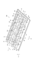
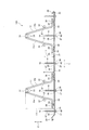
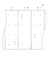
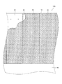
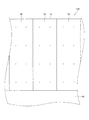
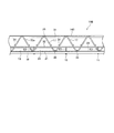
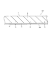
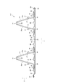
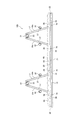
一例として示す天井鉄筋構造材14Aの斜視図である図1等の添付の図面を参照し、本発明に係る天井鉄筋構造材の詳細を説明すると、以下のとおりである。なお、図2は、天井鉄筋構造材14Aの正面図であり、図3は、天井鉄筋構造材14Aを使用して作られた一例として示す天井スラブ構造物10Aの側面図である。図4は、天井鉄筋構造材14Aを使用して作られた天井スラブ構造物10Aの下面図である。図1,2では、前後方向を矢印X、幅方向を矢印Yで示し、上下方向を矢印Zで示す。
The details of the ceiling reinforcing bar structural material according to the present invention will be described below with reference to the attached drawings such as FIG. 1 which is a perspective view of the ceiling reinforcing bar
天井鉄筋構造材14Aは、鉄筋コンクリート造の戸建て住宅(建造物)の鉄筋コンクリート製の天井スラブ構造物10Aの構築に使用される。天井スラブ構造物10Aは、天井鉄筋構造材14A(天井鉄筋構造材14B,14Cを含む)から作られた戸建て住宅(2階建て住宅や3階建て住宅)の鉄筋コンクリート製の外壁構造物12A(外壁構造物12B,12Cを含む)(外壁13)の上(頂部30)に設置(連結)され、戸建て住宅の天井11として使用される。天井スラブ構造物10Aは、複数の天井鉄筋構造材14Aと、天井鉄筋構造材14Aの上面に打設されたコンクリート15とから形成されている。なお、建造物には、戸建て住宅の他に、低層階ビルや中層階ビル、地下室、倉庫、車庫等のあらゆる建造物が含まれる。
The ceiling reinforced concrete
それら天井鉄筋構造材14Aは、前後方向へ長く、戸建て住宅の天井11に敷設されて幅方向へ並んでいる。それら天井鉄筋構造材14Aは、前後方向へ延びる所定面積の鉄板ベース16と、鉄板ベース16の上面20に設置された複数の鉄筋トラス17と、鉄板ベース16の下面21(室内側)に設置された天井仕上げボード18と、天井仕上げボード18を鉄板ベース16に固定する複数の固定ボルト19とから形成されている。
The ceiling reinforcing bar
鉄板ベース16は、フラットな上面20およびフラットな下面21を有するとともに、前後方向へ延びる両側縁部22と幅方向へ延びる両端縁部23とを有する。鉄板ベース16の両側縁部22の間には、前後方向へ延びるとともに鉄板ベース16の上面20から上方へ凸となる複数の凸条24(縦条)が形成されている。それら凸条24は、鉄板ベース16を折り曲げることから作られている。幅方向へ隣り合う鉄筋トラス17の間に延びる鉄板ベース16の第1部位25と鉄筋トラス17の後記する下端筋32の間に延びる鉄板ベース16の第2部位26と両側縁部22とには、ボルト螺着孔27が作られている。
The
鉄板ベース16の一方の側縁部22には、第1係合部28が作られ、鉄板ベース16の他方の側縁部22には、第2係合部29が作られている。第1係合部28は、鉄板ベース16の一方の側縁部22を鉄板ベース16の上面20に向かって折り曲げることから作られている。第2係合部29は、鉄板ベース16の他方の側縁部22を鉄板ベース16の下面21に向かって折り曲げることから作られている。
A first engaging
各鉄板ベース16は、一方の鉄板ベース16の第1係合部28に他方の鉄板ベース16の第2係合部29が嵌め込まれ、それら係合部28,29どうしが互いに係合することで、各鉄板ベース16が幅方向へつながっている。それら鉄板ベース16は、隣り合う鉄板ベース16どうしが連結された状態で幅方向へ並んでいる。なお、戸建て住宅の外壁13の頂部30に位置する(載置された)鉄板ベース16の両側縁部22には、第1および第2係合部28,29が作られておらず、フラット(平坦)である。鉄板ベース16の縦横寸法や厚み寸法、面積に特に制限はなく、縦横寸法や厚み寸法、面積を自由に選択することができる。
In each
それら鉄筋トラス17は、鉄板ベース16の上面20に配置され、幅方向へ所定寸法離間しつつ幅方向へ平行して並ぶとともに、前後方向へ延びている。1つの鉄板ベース16に2つの鉄筋トラス17が配置固定されているが、1つの鉄板ベース16に配置する鉄筋トラス17の数に特に制限はなく、鉄板ベース16の面積や鉄筋トラス17の大きさ等に応じて鉄板ベース16に配置する鉄筋トラス17の数を自由に選択することができる。
The reinforcing
それら鉄筋トラス17は、1本の上端筋31と2本(一対)の下端筋32と2本(一対)の第1および第2ラチス筋33a,33bとから組み立てられている。鉄筋トラス17の上端筋31や下端筋32、第1および第2ラチス筋33a,33bのうちの少なくとも1つ(好ましくは下端筋32と第1および第2ラチス筋33a,33b)には、幅方向へ延びていて上下方向へ並ぶ複数の補強筋34(横筋やフープ筋等)(図10参照)が結束線(針金)(図示せず)によって連結されている。
The reinforcing
上端筋31は、鉄を延伸した鉄棒から作られ、その周面に複数の節(リブ)を有する異形金属棒(異形鉄筋)が使用されている。上端筋31は、幅方向に隣り合う(隣接する)凸条24の間に位置し、鉄板ベース16の上面20から上方へ所定寸法離間して前後方向へ直状に延びている。各鉄筋トラス17において幅方向へ並ぶ上端筋31の前後方向の長さ寸法は略同一であり、それら上端筋31が幅方向へ所定寸法離間しつつ、幅方向へ並行して並んでいる。
The
それら下端筋32は、鉄を延伸した鉄棒から作られ、その周面に複数の節(リブ)を有する異形金属棒(異形鉄筋)が使用されている。下端筋32は、幅方向に隣り合う(隣接する)凸条24の間に位置(凸条24から内側へ所定寸法離間して位置)するとともに、それらラチス筋33a,33bの幅方向外方に位置し、上端筋31の側方であって上端筋31の幅方向両側に位置している。それら下端筋32は、鉄板ベース16の上面20から上方へ所定寸法離間して前後方向へ直状に延びている。各鉄筋トラス17において幅方向へ並ぶ下端筋32の前後方向の長さ寸法は略同一であり、それら下端筋32が幅方向へ所定寸法離間しつつ、幅方向へ並行して並んでいる。
The lower end bars 32 are made of iron rods in which iron is stretched, and deformed metal rods (deformed bars) having a plurality of nodes (ribs) on the peripheral surface thereof are used. The
第1および第2ラチス筋33a,33bは、鉄を延伸した鉄棒から作られている。それらラチス筋33a,33bは、幅方向に隣り合う(隣接する)凸条24の間に位置(凸条24から内側へ所定寸法離間して位置)するとともに、鉄板ベース16の上面20と上端筋31との間に位置し、上下方向へ波状に曲折(起伏)を繰り返しながら前後方向へ延びている。それらラチス筋33a,33bは、上端筋31の側に位置する凸部35と、鉄板ベース16の上面20の側に位置する凹部36と、凸部35および凹部36の間において前後方向へ傾斜して延びる中間部37とを有する。
The first and
第1および第2ラチス筋33a,33bの上下方向へ波状に曲折を繰り返す角度は一定であり、単位長さ(たとえば1m)当たりのラチス筋33a,33bの曲折を繰り返す回数は同一である。ラチス筋33a,33bの上下方向へ波状に曲折を繰り返す角度は自由に変えることができ、その角度を調節(単位長さ当たりのラチス筋33a,33bの曲折を繰り返す回数を調節)することで、ラチス筋33a,33bの凸部35どうしの前後方向の離間寸法を調節することができ、ラチス筋33a,33bの凹部36どうしの前後方向の離間寸法を調節することができる。
The angle at which the first and
第1および第2ラチス筋33a,33bは、上端筋31を挟んで幅方向へ対称型に配置されている。したがって、幅方向に並ぶそれらラチス筋33a,33bの凸部35どうしの位置が一致し、中間部37どうしの位置が一致しているとともに、凹部36どうしの位置が一致している。それらラチス筋33a,33bは、前後方向に隣り合う(隣接する)凸部35どうしの離間寸法が等しく、凸部35が前後方向へ等間隔で並んでいるとともに、前後方向に隣り合う(隣接する)凹部36どうしの離間寸法が等しく、凹部36が前後方向へ等間隔で並んでいる。
The first and
第1および第2ラチス筋33a,33bは、図2に示すように、鉄板ベース16に対して垂直ではなく、鉄板ベース16に対して所定角度で傾斜し、その凸部35から凹部36に向かって幅方向外方へ末広がりになっている。それらラチス筋33a,33bの傾斜角度について特に制限はなく、その傾斜角度を自由に変えることができる。それらラチス筋33a,33bの凸部35は、凸状に折り曲げられ、上方へ向かって凸となるように曲折している。それら凸部35は、上端筋31の周面に当接し、凸部35のうちの上端筋31と交差する部分(交差箇所)が上端筋31にスポット溶接によって溶着(固定)されている。
As shown in FIG. 2, the first and second lattice bars 33a and 33b are not perpendicular to the
第1および第2ラチス筋33a,33bの中間部37は、下端筋32の幅方向内方(内側)に位置し、中間部37のうちの下端筋32と交差当接する部分(交差箇所)が下端筋32にスポット溶接によって溶着(固定)されている。それらラチス筋33a,33bの凹部36は、凹状に折り曲げられ、下方へ向かって凹となるように曲折しつつ、鉄板ベース16の前面と並行するように幅方向外方へ折り曲げられている(幅方向外方へ屈曲している)。凹部36は、幅方向外方へ折り曲げられて幅方向へ延びる屈曲部分38を有する。
The
それら屈曲部分38は、幅方向外方へ向かって凸となるように弧を画き、鉄板ベース16の凸条24に位置している。屈曲部分38は、鉄板ベース16の凸条24と2箇所で交差当接し、凸条24と交差する部分(交差箇所)がスポット溶接によって凸条24に溶着(固定)されている。天井鉄筋構造材14Aでは、ラチス筋33a,33bの凹部36が幅方向外方へ折り曲げられておらず、凹部36に屈曲部分38が作られていなくてもよい。この場合、ラチス筋33a,33bの凹部36が凸条24と1箇所に交差当接し、凸条24と交差する凹部36の部分(交差箇所)がスポット溶接によって凸条24に溶着(固定)される。
The
上端筋31や下端筋32、第1および第2ラチス筋33a,33bは、それらの太さについて特に制限はなく、施工する天井11の大きさや天井11に必要な強度等に合わせて上端筋31や下端筋32、ラチス筋33a,33bの太さを自由に変えることができる。上端筋31や下端筋32、第1および第2ラチス筋33a,33bは鉄から作られているが、鉄以外の金属から作ることもできる。また、上端筋31や下端筋32、ラチス筋33a,33bが鉄から作られている場合は、それらにメッキ等の防錆処理が施されていてもよい。
The thickness of the
上端筋31とラチス筋33a,33bの凸部35とのスポット溶接や下端筋32とラチス筋33a,33bの中間部37とのスポット溶接では、図示はしていないが、電極と移動機構とを備えた自動溶接機が使用される。自動溶接機によるスポット溶接の一例は、上端筋31およびラチス筋33a,33bの凸部35を各電極で挟み込み、下端筋32およびラチス筋33a,33bの中間部37を各電極で挟み込みつつ、それら電極で上端筋31と凸部35とを押圧するとともに、それら電極で下端筋32と中間部37とを押圧し、それら電極に所定の電流を流す(所定の電圧を印可する)。
In spot welding between the
それら電極から流れた電流は、上端筋31とラチス筋33a,33bの凸部35とに流れ、上端筋31および凸部35を加熱溶融するとともに、下端筋32とラチス筋33a,33bの中間部37とに流れ、下端筋32および中間部37を加熱溶融する。次に、それら電極が上端筋31および凸部35から離間するとともに、電極が下端筋32および中間部37から離間し、上端筋31および凸部35や下端筋32および中間部37が自然に冷却され、上端筋31と凸部35とが溶着するとともに、下端筋32と中間部37とが溶着する。上端筋31と凸部35とをスポット溶接し、下端筋32と中間部37とをスポット溶接することで、鉄筋トラス17が作られる。
The current flowing from these electrodes flows to the
鉄板ベース16の凸条24とラチス筋33a,33bの凹部36の屈曲部分38との自動溶接機によるスポット溶接による溶接の一例は、凸条24および屈曲部分38を各電極で挟み込みつつ、それら電極で凸条24と屈曲部分38とを押圧し、それら電極に所定の電流を流す(所定の電圧を印可する)。それら電極から流れた電流は、凸条24と屈曲部分38とに流れ、凸条24および屈曲部分38を加熱溶融する。次に、それら電極が凸条24および屈曲部分38から離間し、凸条24および屈曲部分38が自然に冷却され、凸条24と屈曲部分38の部分(交差箇所)とが溶着する。
An example of welding by spot welding of the
天井仕上げボード18は、所定の厚み寸法を有するとともに、鉄板ベース16と略同一の面積を有し、その平面形状が前後方向へ長い矩形に成形されている。天井仕上げボード18は、戸建て住宅(建造物)の室内に露出する。天井仕上げボード18の鉄板ベース16の第1および第2部位25,26や両側縁部22に作られたボルト螺着孔27と同一の位置には、ボルト螺着孔39が作られている。
The
天井仕上げボード18には、天然木化粧合板や木目合板、プリント合板等の木質系化粧ボード、ポリエステル化粧板やメラミン化粧板、タップ樹脂化粧板、特殊樹脂化粧板等の合成樹脂系化粧ボード、石膏ボード(GB−R)や化粧石膏ボード(GB−D)、不燃積層石膏ボード(GB−NC)、化粧セラミックボード、ロックウール板等の無機質系化粧ボード、後面に所定のデザインが印刷(プリント)された表面処理鋼板やアルミ化粧ボード、ステンレス化粧ボード等の金属系化粧ボードのいずれかが使用されている。
The
また、天井仕上げボード18には、表面材に表面処理鋼板を使用し、しん材として石膏ボード、ロックウール化粧吸音板等を張り合わせた複合ボード、表面材に表面処理鋼板を使用し、しん材として硬質プラスチックフォームを接着させた複合ボード、表面材にアルミニウム合金塗装板を使用し、しん材として石膏ボード、ロックウール化粧吸音板等を張り合わせた複合ボード、表面材にアルミニウム合金塗装板を使用し、しん材として硬質プラスチックフォームを接着させた複合ボード、表面材に塗装ステンレス鋼板を使用し、しん材として石膏ボード、ロックウール化粧吸音板などを張り合わせた複合ボード、表面材に塗装ステンレス鋼板を使用し、しん材として硬質プラスチックフォームを接着させた複合ボード等の各種の複合ボードが使用されている。
Further, for the
固定ボルト19は、鉄を延伸した鉄棒から作られ、頭部40と螺子が形成された螺子部41とを有する。固定ボルト19は、その螺子部41が鉄板ベース16の第1および第2部位25,26と両側縁部22とに作られたボルト螺着孔27と天井仕上げボード18に作られたボルト螺着孔39とに螺着され、天井仕上げボード18を鉄板ベース16に固定している。なお、鉄板ベース16の下面21に接着剤(図示せず)が塗布され、天井仕上げボード18がその接着剤および固定ボルト19によって鉄板ベース16に固定されていてもよい。
The fixing
固定ボルト19の螺子部41の鉄板ベース16の上面20から上方への露出寸法L1は、鉄板ベース16の上面20から鉄筋トラス17の下端筋32までの上下寸法L2と同一である。なお、露出寸法L1は、鉄板ベース16の上面20から鉄筋トラス17の上端筋31までの上下寸法L3のうちの少なくとも鉄板ベース16の上面20から鉄筋トラス17の下端筋32までの上下寸法L2と同一であればよい。固定ボルト19の螺子部41は、鉄板ベース16の上面20から上方へ露出し、鉄板ベース16(天井鉄筋構造材14A)の上面20において硬化したコンクリート15と一体化している。
The exposed dimension L1 of the
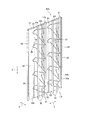
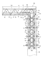
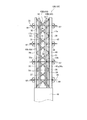
図5は、一例として示す第1外壁鉄筋構造材42Aの斜視図であり、図6は、一例として示す第2外壁鉄筋構造材43Aの斜視図である。図7は、第1および第2外壁鉄筋構造材42A,43Aを使用して作られた一例として示す外壁構造物12Aの側面図であり、図8は、第1および第2外壁鉄筋構造材42A,43Aを使用して作られた外壁構造物12Aの正面図である。図9は、第1および第2外壁鉄筋構造材42A,43Aを使用して作られた外壁構造物12Aの背面図である。図5〜図7では、前後方向を矢印X、幅方向を矢印Yで示し、上下方向を矢印Zで示す。
FIG. 5 is a perspective view of the first outer wall reinforcing bar
第1および第2外壁鉄筋構造材42A,43Aは、鉄筋コンクリート造の戸建て住宅(建造物)の鉄筋コンクリート製の外壁構造物12Aの構築に使用される。外壁構造物12Aは、戸建て住宅(2階建て住宅や3階建て住宅)の基礎46に連結され、戸建て住宅の外壁13として使用される。外壁構造物12Aは、複数の第1外壁鉄筋構造材42Aと、第1外壁鉄筋構造材42Aの内側(室内側)に位置して第1外壁鉄筋構造材42Aに対向する複数の第2外壁鉄筋構造材43Aと、複数本のセパレーター44と、第1および第2外壁鉄筋構造材42A,43Aの間のスペース45に打設されたコンクリート15とから形成されている。第1および第2外壁鉄筋構造材42A,43Aは、上下方向へ長く、鉄筋コンクリート造の戸建て住宅の基礎46に連結されている。第1および第2外壁鉄筋構造材42A,43Aは、基礎46から上方へ延びるとともに、幅方向へ並んでいる。
The first and second outer wall reinforced
それら第1外壁鉄筋構造材42Aは、上下方向へ延びる所定面積の第1鉄板ベース16aと、第1鉄板ベース16aの後方(室内側)に位置して第1鉄板ベース16aの対向面47(後面)に設置された複数の第1鉄筋トラス17aと、第1鉄板ベース16aの前方(室外側)に位置して第1鉄板ベース16aの非対向面48(前面)に設置された外断熱材49とから形成されている。それら第2外壁鉄筋構造材43Aは、上下方向へ延びる所定面積の第2鉄板ベース16bと、第2鉄板ベース16bの前方(室外側)に位置して第2鉄板ベース16bの対向面50(前面)に設置された第2鉄筋トラス17bと、第2鉄板ベース16bの後方(室内側)に位置して第2鉄板ベース16bの非対向面51(後面)に設置された内装ボード52とから形成されている。
The first outer wall reinforcing bar
第1および第2鉄板ベース16a,16bは、フラットな対向面47,50およびフラットな非対向面48,51を有するとともに、上下方向へ延びる両側縁部22と幅方向へ延びる両端縁部23とを有する。第1および第2鉄板ベース16a,16bの両側縁部22の間には、上下方向へ延びるとともに鉄板ベース16a,16bの対向面47,50から前後方向前方へ凸となる複数の凸条24が形成されている。それら凸条24は、鉄板ベース16a,16bを折り曲げることから作られている。第1鉄板ベース16aの幅方向へ隣り合う(隣接する)凸条24の間(隣り合う(隣接する)鉄筋トラス17aの間)には、鉄板ベース16aの非対向面48から前方へ延びる複数の連結片53が形成されている。
The first and second
それら連結片53は、第1鉄板ベース16aを切断して作られ、上下方向へ凸となって延びる切断線と幅方向へ直状に延びる折曲線とに囲繞された鉄板ベース16aの部位が連結片53を画成している。それら連結片53は、折曲線を中心に第1鉄板ベース16aに対して略直角に折り曲げられ、鉄板ベース16aから前方へ延びている。折り曲げられる以前の連結片53(第1鉄板ベース16aの部位)は、鉄板ベース16aにおいて上下方向へ延びている。それら連結片53は、第1鉄板ベース16aから前方へ向かうにつれて次第に先細りの鋭角に成形され、鉄板ベース16aの非対向面48から前方へ延びた状態で外断熱材49に突き刺さっている。なお、第2鉄筋構造材43aの第2鉄板ベース16bには、連結片53が形成されていない。
The connecting
第1および第2鉄板ベース16a,16bの一方の側縁部22には、第1係合部28が作られ、他方の側縁部22には、第2係合部29が作られている。第1係合部28や第2係合部29は、図1の天井鉄筋構造材14Aの鉄板ベース16に作られたそれらと同一である。各第1鉄板ベース16aは、一方の鉄板ベース16aの第1係合部28に他方の鉄板ベース16aの第2係合部29が嵌め込まれ、それら係合部28,29どうしが互いに係合することで、鉄板ベース16aが幅方向へつながっている。それら第1鉄板ベース16aは、隣り合う第1鉄板ベース16aどうしが連結された状態で幅方向へ並んでいる。各第2鉄板ベース16bは、一方の鉄板ベース16bの第1係合部28に他方の鉄板ベース16bの第2係合部29が嵌め込まれ、それら係合部28,29どうしが互いに係合することで、鉄板ベース16bが幅方向へつながっている。それら第2鉄板ベース16bは、隣り合う第2鉄板ベース16bどうしが連結された状態で幅方向へ並んでいる。
A first engaging
それら第1鉄筋トラス17aは、第1鉄板ベース16aの対向面47に配置され、幅方向へ所定寸法離間しつつ幅方向へ平行して並ぶとともに、上下方向へ延びている。なお、第1鉄筋トラス17aの数に特に制限はなく、第1鉄板ベース16aの面積や鉄筋トラス17aの大きさ等に応じて鉄板ベース16aに配置する鉄筋トラス17aの数を自由に選択することができる。第1鉄筋トラス17aは、第1鉄板ベース16aの対向面47から後方へ離間して上下方向へ延びる1本の上端筋31と、第1鉄板ベース16aと上端筋31との間に位置して上下方向へ延びる2本(一対)の下端筋32と、第1鉄板ベース17aと上端筋31との間で前後方向へ波状に曲折を繰り返しながら上下方向へ延びる2本(一対)の第1および第2ラチス筋33a,33bとから組み立てられている。
The first reinforcing
それら第2鉄筋トラス17bは、第2鉄板ベース16bの対向面50に配置され、幅方向へ所定寸法離間しつつ幅方向へ平行して並ぶとともに、上下方向へ延びている。なお、第2鉄筋トラス17bの数に特に制限はなく、第2鉄板ベース16bの面積や鉄筋トラス17bの大きさ等に応じて鉄板ベース16bに配置する鉄筋トラス17bの数を自由に選択することができる。第2鉄筋トラス17bは、第2鉄板ベース16bの対向面50から前方へ離間して上下方向へ延びる1本の上端筋31と、第2鉄板ベース16bと上端筋31との間に位置して上下方向へ延びる2本(一対)の下端筋32と、第2鉄板ベース16bと上端筋31との間で前後方向へ波状に曲折を繰り返しながら上下方向へ延びる2本(一対)の第1および第2ラチス筋33a,33bとから組み立てられている。
The second reinforcing
上端筋31や下端筋32、第1および第2ラチス筋33a,33bは、図1の天井鉄筋構造材14Aの鉄筋トラス17のそれらと同一であるから、図1と同一の符号を付すとともに、図1の説明を援用することで、上端筋31や下端筋32、第1および第2ラチス筋33a,33bの説明は省略する。上端筋31およびラチス筋33a,33bの凸部35、下端筋32およびラチス筋33a,33bの中間部37、ラチス筋33a,33bの凹部36の屈曲部分38および第1および第2鉄板ベース16a,16bの凸条24は、既述の自動溶接機によるスポット溶接によって溶着(固定)されている。
Since the upper end bars 31, the lower end bars 32, and the first and second lattice bars 33a and 33b are the same as those of the reinforcing
第1鉄筋トラス17aでは、上端筋31と下端筋32と第1および第2ラチス筋33a,33bとのうちの少なくとも1つ(好ましくは下端筋32と第1および第2ラチス筋33a,33b)が基礎46から上方へ延びる基礎鉄筋54に結束線(針金)(図示せず)によって連結されている。第2鉄筋トラス17bでは、上端筋31と下端筋32と第1および第2ラチス筋33a,33bとのうちの少なくとも1つ(好ましくは下端筋32と第1および第2ラチス筋33a,33b)が基礎46から上方へ延びる基礎鉄筋54に結束線(図示せず)によって連結されている。さらに、幅方向へ延びていて上下方向へ並ぶ複数の補強筋34(横筋やフープ筋等)が第1および第2鉄筋トラス17a,17bの上端筋31や下端筋32、第1および第2ラチス筋33a,33bのうちの少なくとも1つに結束線(図示せず)によって連結されている。
In the first reinforcing
外壁構造物12Aでは、幅方向へ隣り合う(隣接する)第1鉄筋トラス17aの間に第2鉄筋トラス17bが位置し、幅方向へ隣り合う(隣接する)第2鉄筋トラス17bの間に第1鉄筋トラス17aが位置している。第1鉄筋トラス17aの上端筋31は、第2鉄板ベース16bと第2鉄筋トラス17bの下端筋32との間であって、幅方向へ隣り合う(隣接する)第2鉄筋トラス17bの第1ラチス筋33aと第2ラチス筋33bとの間に位置している。第1鉄筋トラス17aの上端筋31と第2鉄板ベース16bとの間には、スペースが形成されている。
In the
第2鉄筋トラス17bの上端筋31は、第1鉄板ベース16aと第1鉄筋トラス17aの下端筋32との間であって、幅方向へ隣り合う(隣接する)第1鉄筋トラス17aの第1ラチス筋33aと第2ラチス筋33bとの間に位置している。第2鉄筋トラス17bの上端筋31と第1鉄板ベース16aとの間には、スペースが形成されている。第1鉄筋トラス17aの下端筋32は、第2鉄筋トラス17bの上端筋31の側に位置し、第2鉄筋トラス17bの下端筋32は、第1鉄筋トラス17aの上端筋31の側に位置している。
The
それら外断熱材49(ボード状断熱材)は、所定の厚み寸法を有するとともに、第1鉄板ベース16aと略同一の面積を有し、その平面形状が上下方向へ長い矩形に成形されている。それら外断熱材49は、それら第1外壁鉄筋構造材42Aの外側(第1鉄筋ベース16aの直前)に配置され、第1鉄板ベース16aに形成された連結片53の先端部55に突き刺さっている。外断熱材49には、押出発泡ポリスチレンフォーム(スタイロフォーム)(発泡プラスチック)が使用されている。外断熱材12Aには、押出発泡ポリエチレンフォームの他に、ポリプロピレンフォーム、フェノールフォーム、PET樹脂発泡体等(発泡プラスチック)を使用することもできる。外断熱材49の室外側に露出する前面には、モルタル55が吹き付けられている。
The external heat insulating material 49 (board-shaped heat insulating material) has a predetermined thickness dimension, has substantially the same area as the first
内装ボード52は、所定の厚み寸法を有するとともに、第2鉄板ベース17bと略同一の面積を有し、その平面形状が上下方向へ長い矩形に成形されている。内装ボード52には、図1の天井鉄筋構造材14Aの天井仕上げボード18と同一の化粧ボードや複合ボードが使用されている。内装ボード52は、第2鉄板ベース16bに固定ビス(図示せず)によって固定され、または、第2鉄板ベース16bに固定ビスと接着剤(図示せず)とによって固定され、その後面(化粧面)が室内側に露出する。なお、第2鉄板ベース16bと内装ボード52との間に桟木が配置され、桟木が鉄板ベース16bの非対向面51に固定され、内装ボード52が桟木に固定されることで、内装ボード52が桟木を介して鉄板ベース16bの非対向面51に連結されていてもよい。
The
それらセパレーター44は、第1外壁鉄筋構造材42A(外断熱材49)および第2外壁鉄筋構造材43A(内装ボード52)の所定の部位に設置され、第1外壁鉄筋構造材42Aと第2外壁鉄筋構造材43Aとの間のスペース45に位置して前後方向へ延びている。セパレーター44は、互いに対向する第1外壁鉄筋構造材42Aと第2外壁鉄筋構造材43Aとを連結し、第1および第2外壁鉄筋構造材42A,43Aを固定する。コンクリート15は、スペース45において硬化し、第1および第2鉄板ベース16a,16b、第1および第2鉄筋トラス17a,17bの上端筋31、下端筋32、第1および第2ラチス筋33a,33b、補強筋34、基礎鉄筋54と一体化している。
The
図10は、外断熱材49を設置する前の第1および第2外壁鉄筋構造材42A,43Aの側面図であり、図11は、コンクリート15を打設する前の第1および第2外壁鉄筋構造材42A,43Aの側面図である。図12は、コンクリート15を打設した後の第1および第2外壁鉄筋構造材42A,43Aの側面図であり、図13は、コンクリート15を打設する前の天井鉄筋構造材14Aの側面図である。図14は、天井鉄筋構造材14Aと第1および第2外壁鉄筋構造材42A,43Aとの連結の一例を示す図である。第1および第2外壁鉄筋構造材42A,43Aを使用して鉄筋コンクリート製の外壁構造物12A(外壁13)を構築するとともに、天井鉄筋構造材14Aを使用して鉄筋コンクリート製の天井スラブ構造物10A(天井11)を構築し、鉄筋コンクリート造の戸建て住宅(建造物)を施工する手順の一例を説明すると、以下のとおりである。
FIG. 10 is a side view of the first and second outer
天井仕上げボード18が固定された複数の天井鉄筋構造材14Aや複数の第1外壁鉄筋構造材42A、内装ボード52(桟木を介して固定される場合がある)が固定された複数の第2外壁鉄筋構造材43A、複数枚の外断熱材49が施工現場に搬送されている。外断熱材49は、第1鉄板ベース16aの大きさにあわせるため、施工現場において所定の大きさに切断される。なお、施工現場において天井仕上げボード18を鉄板ベース16に固定する固定作業を行う場合があるとともに、施工現場において内装ボード52を第2鉄板ベース16bに固定する固定作業を行う場合がある。
A plurality of ceiling reinforcing bar
鉄筋コンクリート造の戸建て住宅の基礎46を施工した後、第1および第2外壁鉄筋構造材42A,43Aの第1および第2鉄筋トラス17a,17bが上下方向へ延びるように、第1および第2外壁鉄筋構造材42A,43Aを前後方向に対向させた状態でそれら外壁鉄筋構造材42A,43Aを基礎46の上に載置する。第1外壁鉄筋構造材42Aが室外側に位置し、外断熱材49が室外側に露出し、第2外壁鉄筋構造材43Aが室内側に位置し、内装ボード52が室内側に露出する。
After constructing the
隣り合う一方の第1鉄板ベース16aの第1係合部28と他方の第1鉄板ベース16aの第2係合部29とを係合させて第1外壁鉄筋構造材42Aを幅方向へ並べ、隣り合う一方の第2鉄板ベース16bの第1係合部28と他方の第2鉄板ベース16bの第2係合部29とを係合させて第2外壁鉄筋構造材43Aを幅方向へ並べる。なお、第1鉄板ベース16aに画成された連結片53が折曲線を中心に鉄板ベース16aに対して略直角に折り曲げられて鉄板ベース16aから前方へ延びている(図10参照)。
The first engaging
第1および第2外壁鉄筋構造材42A,43Aを幅方向へ並べた後、それら外壁鉄筋構造材42A,43Aの第1および第2鉄筋トラス17a,17bの上端筋31や下端筋32、第1および第2ラチス筋33a,33bのうちの少なくとも1つ(好ましくは下端筋32と第1および第2ラチス筋33a,33b)を基礎46から上方へ延びる基礎鉄筋54に結束線を利用して連結するとともに、複数の補強筋34を第1および第2鉄筋トラス17a,17bの上端筋31や下端筋32、第1および第2ラチス筋33a,33bのうちの少なくとも1つ(好ましくは下端筋32と第1および第2ラチス筋33a,33b)に結束線を利用して連結する。
After arranging the first and second outer wall reinforcing bar
外断熱材49を第1外壁鉄筋構造材42Aの第1鉄筋ベース16aの直前(鉄筋ベース16aの非対向面48)に配置し、外断熱材49を第1鉄板ベース16aの連結片53の先端部55に突き刺すとともに、外断熱材49(後面)を第1鉄板ベース16aの非対向面48に塗布された接着剤によって固着し、外断熱材49を幅方向へ並べる。
The external
第1外壁鉄筋構造材42Aは、第1鉄板ベース16aを切断して作られた連結片53の先端部55に外断熱材49を突き刺すことで、外断熱材49が鉄板ベース16aの連結片53に支持されるから、連結片53を利用して第1外壁鉄筋構造材42Aの外側に外断熱材49を容易に配置することができるのみならず、外断熱材49を第1外壁鉄筋構造材42Aの外側に設置するための設置部材を別途用意する必要はなく、設置部材の節約を図ることができ、設置工程を少なくすることができる。
In the first outer wall reinforcing bar
外断熱材49を配置した後、セパレーター44を第1外壁鉄筋構造材42A(外断熱材49)および第2外壁鉄筋構造材43A(内装ボード52)の所定の部位に設置する。セパレーター44の第1外壁鉄筋構造材42Aの側に位置する一端部を第1鉄板ベース16aおよび外断熱材49に穿孔されたセパ挿通孔に挿通し、一端部に型枠緊結金具56(フォームタイ(登録商標))を連結する。セパレーター44のスペース45に位置する一端部には、プラスチックコーンが挿通されている。一端部に連結された型枠緊結金具56を挟んでその両側に鉄やアルミ、真鍮、合金等の金属から作られた断面形状が円形の一対の丸パイプ57(単管パイプ)を配置し、型枠緊結金具56の座金58によって丸パイプ57を座金58と外断熱材49との間に固定する。
After arranging the outer
セパレーター44の第2外壁鉄筋構造材43Aの側に位置する他端部を第2鉄板ベース16bおよび内装ボード52に穿孔されたセパ挿通孔に挿通し、他端部に型枠緊結金具56(フォームタイ)を連結する。セパレーター44のスペース45に位置する他端部には、プラスチックコーンが挿通されている。他端部に連結された型枠緊結金具56を挟んでその両側に一対の丸パイプ57(単管パイプ)を配置し、型枠緊結金具56の座金58によって丸パイプ57を座金58と内装ボード52との間に固定する。
The other end of the
それらセパレーター44によって第1外壁鉄筋構造材42Aと第2外壁鉄筋構造材43Aとを連結した後、図14に示すように、第1および第2外壁鉄筋構造材42A,43Aの頂部30にアングル材59を載置固定する。アングル材59を第1および第2外壁鉄筋構造材42A,43Aの頂部30に載置固定した後、アングル材59の水平部分61の上面に天井鉄筋構造材14Aの鉄板ベース16の側縁部22および端縁部23を載置し、ボルトおよびナット(図示せず)によって鉄板ベース16の側縁部22および端縁部23をアングル材59に固定する。または、アングル材59に鉄板ベース16の側縁部22および端縁部23を溶接固定する。
After connecting the first outer wall reinforcing bar
なお、アングル材59の水平部分61に載置される鉄板ベース16の側縁部22および端縁部23には、天井仕上げボード18は設置されておらず、鉄板ベース16が露出している。また、第1および第2外壁鉄筋構造材42A,43Aの頂部30に位置する鉄板ベース16には、コンクリート打設用の開口67が形成されている。開口67には、連結鉄筋60(L字鉄筋)が配置されている。連結鉄筋60の開口67から下方へ延びる部分は、第1および第2鉄筋トラス17a,17bの上端筋31と下端筋32と第1および第2ラチス筋33a,33bとのうちの少なくとも1つ(好ましくは下端筋32と第1および第2ラチス筋33a,33b)に結束線(図示せず)によって連結されている。連結鉄筋60の天井鉄筋構造材14Aに並行して延びる部分は、天井鉄筋構造材14Aの鉄筋トラス17の上端筋31と下端筋32と第1および第2ラチス筋33a,33bとのうちの少なくとも1つ(好ましくは下端筋32と第1および第2ラチス筋33a,33b)に結束線(図示せず)によって連結されている。
The
アングル材59に天井鉄筋構造材14Aの鉄板ベース16を固定すると、戸建て住宅の1階部分の骨組みが完成する。なお、図示はしていないが、戸建て住宅の2階部分の骨組みを作るには、1階部分の外壁構造物12Aと同一の外壁構造物12Aを1階部分の外壁構造物12Aの頂部30に連結固定するとともに、1階部分の天井鉄筋構造材14Aと同一の天井鉄筋構造材14Aを2階部分の外壁構造物12Aの頂部30に連結固定する。戸建て住宅の3階部分の骨組みを作るには、1階部分の外壁構造物12Aと同一の外壁構造物12Aを2階部分の外壁構造物12Aの頂部30に連結固定するとともに、1階部分の天井鉄筋構造材14Aと同一の天井鉄筋構造材14Aを3階部分の外壁構造物12Aの頂部30に連結固定する。
When the
次に、開口67から第1外壁鉄筋構造材42Aと第2外壁鉄筋構造材43Aとの間のスペース45にコンクリート15を打設するとともに、天井鉄筋構造材14Aの鉄板ベース16の上面20に所定の被り寸法でコンクリート15を打設する。なお、第1外壁鉄筋構造材42Aの所定の箇所には、第1鉄板ベース16aと外断熱材49と貫通するコンクリート打設開口(図示せず)が作られている。アングル材59の垂直部分62が天井鉄筋構造材14Aの型枠になり、天井鉄筋構造材14Aの周縁からのコンクリート15の漏れを防ぐことができる。コンクリート15を所定期間養生した後(コンクリート15が硬化した後)、型枠緊結金具56(座金58を含む)を取り外し、外断熱材49の前面の全域にモルタル55を吹き付けて施工が終了し、鉄筋コンクリート製の外壁構造物12A(外壁13)および鉄筋コンクリート製の天井スラブ構造物10A(天井11)が作られる。屋根を施工することで、鉄筋コンクリート造の戸建て住宅(建造物)が建造される。
Next, concrete 15 is placed in the
アングル材59の垂直部分62が天井鉄筋構造材14Aの型枠になり、外壁構造物12Aの第1外壁鉄筋構造材42A(第1鉄板ベース16a)と第2外壁鉄筋構造材43A(第2鉄板ベース16b)との間にコンクリート15を打設するスペース45が作られるから、ベニヤ板や桟木によってコンクリート15を打設する型枠を組み立てる必要はなく、型枠を組み立てるコストや時間を省くことができ、短い工期で外壁構造物12A(外壁13)や天井スラブ構造物10A(天井11)を作ることができる。
The
天井鉄筋構造材14Aの鉄板ベース16と鉄筋トラス17とが引っ張りに弱いコンクリート15を補強する鉄筋となり、天井鉄筋構造材14Aを使用することで鉄筋コンクリート製の強固な天井スラブ構造物10A(天井11)を作ることができ、高い強度を有する頑丈な天井スラブ構造物10Aを有する戸建て住宅(建造物)を施工することができる。さらに、第1および第2外壁鉄筋構造材42a,43aの第1および第2鉄板ベース16a,16bと第1および第2鉄筋トラス17a,17bとが引っ張りに弱いコンクリート15を補強する鉄筋となり、第1および第2外壁鉄筋構造材42a,43aを使用することで鉄筋コンクリート製の強固な外壁構造物12A(外壁13)を作ることができ、高い強度を有する頑丈な外壁構造物12Aを有する戸建て住宅(建造物)を施工することができる。
The reinforcing
天井鉄筋構造材14Aの鉄板ベース16の上面20から上方へ露出する固定ボルト19の螺子部41が硬化したコンクリート15と一体化し、固定ボルト19がコンクリート15に固定されるから、螺子部41がコンクリート15と一体化した固定ボルト19によって天井仕上げボード18を鉄板ベース16の下面21に確実に固定することができ、天井仕上げボード18や鉄板ベース16において固定ボルト19が緩むことや天井仕上げボード18や鉄板ベース16から固定ボルトが抜け落ちることはなく、地震や天井スラブ構造物10A(天井11)の経年劣化による天井仕上げ材18の落下を防ぐことが可能な戸建て住宅(建造物)を施工することができる。また、第1外壁鉄筋構造材42A(外断熱材49)と第2外壁鉄筋構造材43A(内装ボード52)とが複数のセパレーター44によって連結されているから、第1および第2外壁鉄筋構造材42A,43Aの間のスペース45に打設されたコンクリート15の側圧がそれら外壁鉄筋構造材42A,43Aに作用したとしても、第1外壁鉄筋構造材42Aや第2外壁鉄筋構造材43Aに変形が生ずることはなく、セパレーター44を含む第1および第2外壁鉄筋構造材42a,43aを利用することで、構造計算された設計どおりの鉄筋コンクリート製の強固な外壁構造物12A(外壁13)を有する戸建て住宅を施工することができる。
Since the
天井鉄筋構造材14Aの鉄板ベース16の上面20に所定の被り寸法で打設されたコンクリート15が優れた遮音性と優れた耐火性とを有し、第1および第2外壁鉄筋構造材42A,43Aの間のスペース45に打設されたコンクリート15が優れた遮音性と優れた耐火性とを有するから、戸建て住宅(建造物)の下階や上階の騒音を遮断することができるとともに、戸建て住宅の周囲の騒音を遮断することができ、火災に強い天井11や外壁13を有する戸建て住宅を施工することができる。さらに、第1および第2外壁鉄筋構造材42A,43Aの第1および第2鉄筋トラス17a,17bの上端筋31と下端筋32と第1および第2ラチス筋33a,33bとのうちの少なくとも1つが基礎46から上方へ延びる基礎鉄筋54に連結されているから、戸建て住宅の基礎46と一体になった優れた強度の外壁13を作ることができ、強い衝撃に十分に耐えることが可能な外壁構造物12A(外壁13)を有する戸建て住宅を施工することができる。
The concrete 15 placed on the
天井鉄筋構造材14Aの鉄板ベース16の下面21に設置された天井仕上げボード18を天井仕上げ材として利用することができるから、施工された天井11の下面に天井仕上げ材を別途設置するための天井仕上げ工事を省くことができ、天井仕上げ工事のための手間やコストを省くことができる。さらに、第2外壁鉄筋構造材43Aの第2鉄板ベース16bの非対向面51に設置された各化粧板等の内装ボード52を内装材として利用することができるから、施工された外壁13の後面に内装材を別途設置するための内装工事を省くことができ、内装工事のための手間やコストを省くことができる。
Since the
戸建て住宅(建造物)は、天井鉄筋構造材14Aから作られた鉄筋コンクリート製の天井スラブ構造物10A(天井11)が高い強度を有し、天井スラブ構造物10Aの安全性を確実に確保することができるとともに、第1および第2外壁鉄筋構造材42A,43Aから作られた鉄筋コンクリート製の外壁構造物12A(外壁13)が高い強度を有し、外壁構造物12Aの安全性を確実に確保することができる。戸建て住宅(建造物)は、地震による激しい揺れや津波の水圧に十分に耐えることが可能であり、地震の激しい揺れによる天井11の崩落を防ぐことができるとともに、地震による崩壊を防ぐことができ、津波による流失を防ぐことができる。
In a detached house (building), the
図15は、他の一例として示す天井鉄筋構造材14Bの斜視図であり、図16は、図15の天井鉄筋構造材14Bの正面図である。図17は、コンクリート15を打設する前の天井鉄筋構造材14Bの側面図であり、図18は、天井スラブ構造物10Bの側面図である。図15,16では、前後方向を矢印X、幅方向を矢印Yで示し、上下方向を矢印Zで示す。天井鉄筋構造材14Bは、鉄筋コンクリート造の戸建て住宅(建造物)の鉄筋コンクリート製の天井スラブ構造物10Bの構築に使用される。天井スラブ構造物10Bは、外壁構造物12A(外壁構造物12B,12Cを含む)から作られた戸建て住宅(2階建て住宅や3階建て住宅)の鉄筋コンクリート製の外壁13の上(頂部30)に設置(連結)され、戸建て住宅の天井11として使用される。天井スラブ構造物10Bは、複数の天井鉄筋構造材14Bと、天井鉄筋構造材14Bの上面(鉄筋ベース16の上面20)に打設されたコンクリート15とから形成されている。
FIG. 15 is a perspective view of the ceiling reinforcing bar
天井鉄筋構造材14Bは、上下方向へ延びる所定面積の鉄板ベース16と、鉄板ベース16の上面20に設置された複数の鉄筋トラス17と、鉄板ベース16の下面21(室内側)に設置された天井仕上げボード18と、天井仕上げボード18を鉄板ベース16に固定する複数の固定ボルト19とから形成されている。鉄板ベース16や鉄筋トラス17、天井仕上げボード18は、図1の天井鉄筋構造材14Aのそれらと同一であるから、図1と同一の符号を付すとともに、図1の天井鉄筋構造材14Aの説明を援用することで、鉄板ベース16や鉄筋トラス17、天井仕上げボード18の説明は省略する。
The ceiling reinforcing bar
固定ボルト19は、鉄を延伸した鉄棒から作られ、頭部40と螺子が形成された螺子部41とを有する。固定ボルト19は、その螺子部41が鉄板ベース16の第1および第2部位25,26に作られたボルト螺着孔27と天井仕上げボード18に作られたボルト螺着孔39とに螺着され、天井仕上げボード18を鉄板ベース16に固定している。なお、鉄板ベース16の下面21に接着剤(図示せず)が塗布され、天井仕上げボード18がその接着剤および固定ボルト19によって鉄板ベース16に固定されていてもよい。
The fixing
固定ボルト19の螺子部41の鉄板ベース16の上面20から上方への露出寸法L1は、鉄板ベース16の上面20から鉄筋トラス17の上端筋31と下端筋32との間までの上下寸法と同一である。なお、露出寸法L1は、鉄板ベース16の上面20から鉄筋トラス17の上端筋31までの上下寸法L3のうちの少なくとも鉄板ベース16の上面20から鉄筋トラス17の下端筋32までの上下寸法L2と同一であればよい。固定ボルト19の螺子部41は、上下方向へ延びる垂直部分63と、上下方向と交差する方向へ折曲された折曲部分64とを有する。螺子部41の垂直部分63と折曲部分64とは、鉄板ベース16の上面20から上方へ露出し、天井鉄筋構造材14Bの上面において硬化したコンクリート15と一体化している。
The exposed dimension L1 of the
第1および第2外壁鉄筋構造材42A,43Aを使用して鉄筋コンクリート製の外壁構造物12A(外壁13)を構築するとともに、天井鉄筋構造材14Bを使用して鉄筋コンクリート製の天井スラブ構造物10B(天井11)を構築し、鉄筋コンクリート造の戸建て住宅(建造物)を施工する手順は、第1および第2外壁鉄筋構造材42A,43Aおよび天井鉄筋構造材14Aを使用して鉄筋コンクリート製の外壁構造物12Aや天井スラブ構造物10Bを構築し、鉄筋コンクリート造の戸建て住宅を施工する手順と同一であるから、図10〜図14に基づく説明を援用することで、その説明は省略する。
The first and second outer wall reinforcing bar
天井鉄筋構造材14Bは、天井鉄筋構造材14Aにおいて説明した既述の効果に加え、以下の効果を有する。固定ボルト19の螺子部41の垂直部分63のみならず上下方向と交差する方向へ折曲された折曲部分64がコンクリート15と一体化するから、螺子部41がコンクリート15に確実に保持され、固定ボルト19をコンクリート15に確実に固定することができ、固定ボルト19によって天井仕上げボード18を鉄板ベース16の下面21に確実に固定することができる。さらに、螺子部41の垂直部分63および折曲部分64がコンクリート15と一体化した固定ボルト19によって天井仕上げボード18を鉄板ベース16の下面21に確実に固定することができるから、天井仕上げボード18や鉄板ベース16において固定ボルト19が緩むことや天井仕上げボード18や鉄板ベース16から固定ボルト19が抜け落ちることはなく、地震や天井スラブ構造物10B(天井11)の経年劣化による天井仕上げ材18の落下を確実に防ぐことができる。
The ceiling reinforcing bar
なお、天井鉄筋構造材14B(天井スラブ構造物10B)や第1および第2外壁鉄筋構造材42A,43A(外壁構造物12A)から作られた戸建て住宅(建造物)は、天井鉄筋構造材14Aから作られた鉄筋コンクリート製の天井スラブ構造物10B(天井11)が高い強度を有し、天井スラブ構造物10Bの安全性を確実に確保することができるとともに、第1および第2外壁鉄筋構造材42A,43Aから作られた鉄筋コンクリート製の外壁構造物12A(外壁13)が高い強度を有し、外壁構造物12Aの安全性を確実に確保することができる。戸建て住宅(建造物)は、地震による激しい揺れや津波の水圧に十分に耐えることが可能であり、地震の激しい揺れによる天井11の崩落を防ぐことができるとともに、地震による崩壊を防ぐことができ、津波による流失を防ぐことができる。
The detached house (building) made of the ceiling reinforced
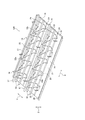
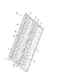
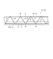
図19は、他の一例として示す天井鉄筋構造材14Cの斜視図であり、図20は、図19の天井鉄筋構造材14Cの正面図である。図19,20では、前後方向を矢印X、幅方向を矢印Yで示し、上下方向を矢印Zで示す。天井鉄筋構造材14Cは、鉄筋コンクリート造の戸建て住宅(建造物)の鉄筋コンクリート製の天井スラブ構造物10C(図24,25参照)(天井11)の構築に使用される。天井スラブ構造物10Cは、第1および第2外壁鉄筋構造材42A,43A(第1および第2外壁鉄筋構造材42B,42C,43B,43Cを含む)から作られた戸建て住宅(2階建て住宅や3階建て住宅)の鉄筋コンクリート製の外壁構造物12A(外壁構造物12B,12Cを含む)(外壁13)の上(頂部30)に設置(連結)され、戸建て住宅の天井11として使用される。
FIG. 19 is a perspective view of the ceiling reinforcing bar
天井スラブ構造物10Cは、複数の天井鉄筋構造材14Cと、天井鉄筋構造材14Cの上面(ラス金網65の上面20)に打設されたコンクリート15とから形成されている。それら天井鉄筋構造材14Cは、前後方向へ長く、戸建て住宅の天井11に敷設されて幅方向へ並んでいる。それら天井鉄筋構造材14Cは、前後方向へ延びる所定面積のラス金網65(金網)(ワイヤーメッシュ)と、ラス金網65の上面20に設置された複数の鉄筋トラス17と、ラス金網65の下面21(室内側)に設置された天井仕上げボード18と、天井仕上げボード18とラス金網65とを固定する発泡ウレタン66(硬質発泡ウレタンフォーム)とから形成されている。
The
ラス金網65は、上面20および下面21を有するとともに、前後方向へ延びる両側縁部22と幅方向へ延びる両端縁部23とを有する。ラス金網65の両側縁部22の間には、前後方向へ延びるとともにラス金網65の上面20から上方へ凸となる複数の凸条24(縦条)が形成されている。それら凸条24は、ラス金網65を折り曲げることから作られている。なお、ラス金網65の縦横寸法や厚み寸法、面積、開口面積に特に制限はなく、縦横寸法や厚み寸法、面積、開口面積を自由に選択することができる。
The
ラス金網65の一方の側縁部22には、第1係合部28が作られ、ラス金網65の他方の側縁部22には、第2係合部29が作られている。第1係合部28は、ラス金網65の一方の側縁部22をラス金網65の上面に20向かって折り曲げることから作られている。第2係合部29は、ラス金網65の他方の側縁部22をラス金網65の下面21に向かって折り曲げることから作られている。
A first engaging
各ラス金網65は、一方のラス金網65の第1係合部28に他方のラス金網65の第2係合部29が嵌め込まれ、それら係合部28,29どうしが互いに係合することで、各ラス金網65が幅方向へつながっている。それらラス金網65は、隣り合うラス金網65どうしが連結された状態で幅方向へ並んでいる。なお、戸建て住宅の外壁13の頂部30に位置する(載置された)ラス金網65の両側縁部22には、第1および第2係合部28,29が作られていない。
In each
それら鉄筋トラス17は、ラス金網65の上面20に配置され、幅方向へ所定寸法離間しつつ幅方向へ平行して並ぶとともに、前後方向へ延びている。1つのラス金網65に2つの鉄筋トラス17が配置固定されているが、1つのラス金網65に配置する鉄筋トラス17の数に特に制限はなく、ラス金網65の面積や鉄筋トラス17の大きさ等に応じてラス金網65に配置する鉄筋トラス17の数を自由に選択することができる。
The reinforcing
第1および第2ラチス筋33a,33bの凹部36の屈曲部分38は、ラス金網65の凸条24に位置し、ラス金網65の凸条24と2箇所で交差当接し、凸条24と交差する部分(交差箇所)がスポット溶接によって凸条24に溶着固定されている。なお、鉄筋トラス17の構成は、図1の天井鉄筋構造材14Aのそれと同一であるから、図1と同一の符号を付すとともに、図1の天井鉄筋構造材14Aの説明を援用することで、鉄筋トラス17の説明は省略する。
The
天井仕上げボード18は、所定の接着機能を有する発泡ウレタン66によってラス金網65に固着されている。発泡ウレタン66は、ラス金網65の上面20から充填され、ラス金網65の網目を通過して天井仕上げボード18に達している。天井仕上げボード18は、図1の天井鉄筋構造材14Aのそれと同一であるから、図1と同一の符号を付すとともに、図1の天井鉄筋構造材14Aの説明を援用することで、天井仕上げボード18の説明は省略する。コンクリート15は、ラス金網65の網目を通過して天井仕上げボード18に達している。コンクリート15は、ラス金網65の上面において硬化し、鉄筋トラス17の上端筋31、下端筋32、第1および第2ラチス筋33a,33b、天井仕上げボード18、ラス金網65と一体化している。
The
図21は、他の一例として示す天井鉄筋構造材14Dの斜視図であり、図22は、発泡ウレタン66を充填する以前の状態で示す天井鉄筋構造材14Dの斜視図である。図23は、図21の天井鉄筋構造材14Dの正面図であり、図24は、天井鉄筋構造材14Cまたは天井鉄筋構造材14Dによって作られた天井スラブ構造物10C(天井11)または天井スラブ構造物10D(天井11)の側面図である。図25は、天井鉄筋構造材14Cまたは天井鉄筋構造材14Dによって作られた天井スラブ構造物10C(天井11)または天井スラブ構造物10D(天井11)の下面図である。図21,22では、前後方向を矢印X、幅方向を矢印Yで示し、上下方向を矢印Zで示す。
FIG. 21 is a perspective view of the ceiling reinforcing bar
天井鉄筋構造材14Dは、鉄筋コンクリート造の戸建て住宅(建造物)の鉄筋コンクリート製の天井スラブ構造物10D(天井11)の構築に使用される。天井スラブ構造物10Dは、第1および第2外壁鉄筋構造材42A,43A(第1および第2外壁鉄筋構造材42B,42C,43B,43Cを含む)から作られた戸建て住宅(2階建て住宅や3階建て住宅)の鉄筋コンクリート製の外壁構造物12A(外壁構造物12B,12Cを含む)(外壁13)の上(頂部30)に設置(連結)され、戸建て住宅の天井11として使用される。
The ceiling reinforced
天井スラブ構造物10Dは、複数の天井鉄筋構造材14Dと、天井鉄筋構造材14Dの上面(金網68の上面20)に打設されたコンクリート15とから形成されている。それら天井鉄筋構造材14Cは、前後方向へ長く、戸建て住宅の天井11に敷設されて幅方向へ並んでいる。それら天井鉄筋構造材14Cは、前後方向へ延びる所定面積の金網68と、金網68の上面20に設置された複数の鉄筋トラス17と、金網68の下面21(室内側)に設置された天井仕上げボード18と、天井仕上げボード18と金網68とを固定する発泡ウレタン66(硬質発泡ウレタンフォーム)とから形成されている。
The
金網68は、上面20および下面21を有するとともに、前後方向へ延びる両側縁部22と幅方向へ延びる両端縁部23とを有し、天井仕上げボード18の略全域に延びている。金網68は、複数本の横条69と複数本の縦条70とから形成されている。横条69や縦条70は、鉄を延伸した断面円形の金属棒(鉄棒)から作られている。横条69は、金網68の両端縁部23の間において、前後方向へ略等間隔離間(所定寸法離間)して並び、天井仕上げボード18と並行して幅方向へ延びている。なお、横条69の本数に特に制限はなく、横条69の本数を自由に決定することができる。
The
縦条70は、横条69の下に配置され(位置し)、金網68の両側縁部22の間において、幅方向へ所定寸法離間して並び、天井仕上げボード18と並行して前後方向へ延びている。なお、縦条70の本数に特に制限はなく、縦条70の本数を自由に決定することができる。横条69と縦条70とは、互いに直交(交差)した状態でそれら条69,70の交差部において溶接固定されている。縦条70が横条69の上に配置された状態でそれら条69,70の交差部において溶接固定されていてもよい。
The
金網68の一方の側縁部22の横条69には、第1係合部(フック)(図示せず)が連接され、金網68の他方の側縁部22の横条69には、第2係合部(ループ)(図示せず)が連接されている。各金網68は、一方の金網68の第1係合部に他方の金網68の第2係合部が連結され、それら係合部どうしが互いに係合することで、各金網68が幅方向へつながっている。それら金網68は、隣り合う金網68どうしが連結された状態で幅方向へ並んでいる。なお、戸建て住宅の外壁13の頂部30に位置する(載置された)金網68の両側縁部22には、第1および第2係合部が連接されていない。
A first engaging portion (hook) (not shown) is connected to the
それら鉄筋トラス17は、金網68の上面20に配置され、幅方向へ所定寸法離間しつつ幅方向へ平行して並ぶとともに、前後方向へ延びている。1つの金網68に2つの鉄筋トラス17が配置固定されているが、1つの金網68に配置する鉄筋トラス17の数に特に制限はなく、金網68の面積や鉄筋トラス17の大きさ等に応じて金網68に配置する鉄筋トラス17の数を自由に選択することができる。
The reinforcing
第1および第2ラチス筋33a,33bの凹部36の屈曲部分38は、金網68の縦条70の上に位置し、縦条70と2箇所で交差当接し、縦条70と交差する部分(交差箇所)がスポット溶接によって縦条70に溶着固定されている。なお、鉄筋トラス17の構成は、図1の天井鉄筋構造材14Aのそれと同一であるから、図1と同一の符号を付すとともに、図1の天井鉄筋構造材14Aの説明を援用することで、鉄筋トラス17の説明は省略する。
The
天井仕上げボード18は、所定の接着機能を有する発泡ウレタン66によって金網68(横条69および縦条70)に固着されている。発泡ウレタン66は、金網68の上面20から充填され、金網68の横条69および縦条70を通過して天井仕上げボード18に達している。天井仕上げボード18は、図1の天井鉄筋構造材14Aのそれと同一であるから、図1と同一の符号を付すとともに、図1の天井鉄筋構造材14Aの説明を援用することで、天井仕上げボード18の説明は省略する。
The
コンクリート15は、金網68の横条69および縦条70を通過して天井仕上げボード18に達している。コンクリート15は、金網68の上面において硬化し、鉄筋トラス17の上端筋31、下端筋32、第1および第2ラチス筋33a,33b、天井仕上げボード18、金網68(横条69および縦条70)と一体化している。
The concrete 15 passes through the
発泡ウレタン66は、天井仕上げボード18の略全域を覆い、金網68の横条69および縦条70の略全域を覆うとともに、鉄筋トラスト17のうちのラチス筋33a,33bの屈曲部分38を含む凹部36の略全域を覆う。硬化した発泡ウレタン66によって天井仕上げボード18と金網68とが強固に固着される。硬化した発泡ウレタン66は、金網68の縦横条69,70とラチス筋33a,33bの屈曲部分38とを覆う厚み寸法を有し、その最上部が屈曲部分38よりも上であって下端筋32よりも下に位置している。
The
発泡ウレタン66は、その上下方向の厚み寸法が上端筋31や下端筋32、トラス筋33a,33bに対するコンクリートの被りを確保可能な寸法に調節されている。天井鉄筋構造材14Dは、発泡ウレタン66の最上部が下端筋32よりも下に位置するとともに、上下方向の厚み寸法が上端筋31や下端筋32、トラス筋33a,33bに対するコンクリートの被りを確保可能な寸法に調節されているから、天井鉄筋構造材14Dにコンクリートを打設したときに、上端筋31や下端筋32、トラス筋33a,33bに対するコンクリートの被りを確実に確保することができる。
The thickness of the
図26は、一例として示す第1外壁鉄筋構造材42Bの斜視図であり、図27は、一例として示す第2外壁鉄筋構造材43Bの斜視図である。図26,27では、前後方向を矢印X、幅方向を矢印Yで示し、上下方向を矢印Zで示す。第1および第2外壁鉄筋構造材42B,43Bは、鉄筋コンクリート造の戸建て住宅(建造物)の鉄筋コンクリート製の外壁構造物12B(外壁13)の構築に使用される。外壁構造物12Bは、戸建て住宅(2階建て住宅や3階建て住宅)の基礎46に連結され、戸建て住宅の外壁13として使用される。
FIG. 26 is a perspective view of the first outer wall reinforcing bar
外壁構造物12Bは、複数の第1外壁鉄筋構造材42Bと、第1外壁鉄筋構造材42Bの内側(室内側)に位置して第1外壁鉄筋構造材42Bに対向する複数の第2外壁鉄筋構造材43Bと、複数本のセパレーター44と、第1および第2外壁鉄筋構造材42B,43Bの間のスペース45に打設されたコンクリート15とから形成されている。第1および第2外壁鉄筋構造材42B,43Bは、上下方向へ長く、鉄筋コンクリート造の戸建て住宅の基礎46に連結されている。第1および第2外壁鉄筋構造材42B,43Bは、基礎46から上方へ延びるとともに、幅方向へ並んでいる。
The
それら第1外壁鉄筋構造材42Bは、上下方向へ延びる所定面積の第1ラス金網65aと、ラス金網65aの後方(室内側)に位置してラス金網65aの対向面47(後面)に設置された複数の第1鉄筋トラス17aと、ラス金網65aの前方(室外側)に位置してラス金網65aの非対向面48(前面)に設置された外断熱材49と、発泡ウレタン66(硬質発泡ウレタンフォーム)とから形成されている。それら第2外壁鉄筋構造材43Bは、上下方向へ延びる所定面積の第2ラス金網65bと、ラス金網65bの前方(室外側)に位置してラス金網65bの対向面50(前面)に設置された第2鉄筋トラス17bと、ラス金網65bの後方(室内側)に位置してラス金網65bの非対向面51(後面)に設置された内装ボード52と、発泡ウレタン66(硬質発泡ウレタンフォーム)とから形成されている。
The first outer wall reinforcing bar
第1および第2ラス金網65a,65bは、対向面47,50および非対向面48,51を有するとともに、上下方向へ延びる両側縁部22と幅方向へ延びる両端縁部23とを有する。第1および第2ラス金網65a,65bの両側縁部22の間には、上下方向へ延びるとともにラス金網65a,65bの対向面47,50から前後方向前方へ凸となる複数の凸条24が形成されている(図20援用)。それら凸条24は、ラス金網65a,65bを折り曲げることから作られている。
The first and second lath wire meshes 65a and 65b have facing
第1および第2ラス金網65a,65bの一方の側縁部22には、第1係合部28が作られ、他方の側縁部22には、第2係合部29が作られている。第1係合部28や第2係合部29は、図20の天井鉄筋構造材14cのラス金網65に作られたそれらと同一である。各第1ラス金網65aは、一方のラス金網65aの第1係合部28に他方のラス金網65aの第2係合部29が嵌め込まれ、それら係合部28,29どうしが互いに係合することで、第1ラス金網65aが幅方向へつながっている。それら第1ラス金網65aは、隣り合う第1ラス金網65aどうしが連結された状態で幅方向へ並んでいる。各第2ラス金網65bは、一方のラス金網65bの第1係合部28に他方のラス金網65bの第2係合部29が嵌め込まれ、それら係合部28,29どうしが互いに係合することで、第2ラス金網65bが幅方向へつながっている。それら第2ラス金網65bは、隣り合う第2ラス金網65bどうしが連結された状態で幅方向へ並んでいる。
A first engaging
それら第1鉄筋トラス17aは、第1ラス金網65aの対向面47に配置され、幅方向へ所定寸法離間しつつ幅方向へ平行して並ぶとともに、上下方向へ延びている。なお、第1鉄筋トラス17aの数に特に制限はなく、第1ラス金網65aの面積や鉄筋トラス17aの大きさ等に応じてラス金網65aに配置する鉄筋トラス17aの数を自由に選択することができる。第1鉄筋トラス17aは、第1ラス金網65aの対向面47から後方へ離間して上下方向へ延びる1本の上端筋31と、ラス金網65aと上端筋31との間に位置して上下方向へ延びる2本(一対)の下端筋32と、ラス金網65aと上端筋31との間で前後方向へ波状に曲折を繰り返しながら上下方向へ延びる2本(一対)の第1および第2ラチス筋33a,33bとから組み立てられている。
The first reinforcing
それら第2鉄筋トラス17bは、第2ラス金網65bの対向面50に配置され、幅方向へ所定寸法離間しつつ幅方向へ平行して並ぶとともに、上下方向へ延びている。なお、第2鉄筋トラス17bの数に特に制限はなく、第2ラス金網65bの面積や鉄筋トラス17bの大きさ等に応じてラス金網65bに配置する鉄筋トラス17bの数を自由に選択することができる。第2鉄筋トラス17bは、第2ラス金網65bの対向面50から前方へ離間して上下方向へ延びる1本の上端筋31と、ラス金網65bと上端筋31との間に位置して上下方向へ延びる2本(一対)の下端筋32と、ラス金網65bと上端筋31との間で前後方向へ波状に曲折を繰り返しながら上下方向へ延びる2本(一対)の第1および第2ラチス筋33a,33bとから組み立てられている。
The second reinforcing
第1および第2ラチス筋33a,33bの凹部36の屈曲部分38は、第1および第2ラス金網65a,65bの凸条24に位置し、ラス金網65a,65bの凸条24と2箇所で交差当接し、凸条24と交差する部分(交差箇所)がスポット溶接によって凸条24に溶着(固定)されている。なお、第1および第2鉄筋トラス17a,17bの構成は、図1の天井鉄筋構造材14Aの鉄筋トラス17と同一であるから、図1と同一の符号を付すとともに、図1の天井鉄筋構造材14Aの説明を援用することで、第1および第2鉄筋トラス17a,17bの説明は省略する。
The
第1鉄筋トラス17aでは、上端筋31と下端筋32と第1および第2ラチス筋33a,33bとのうちの少なくとも1つ(好ましくは下端筋32と第1および第2ラチス筋33a,33b)が基礎46から上方へ延びる基礎鉄筋54に結束線(針金)(図示せず)によって連結されている。第2鉄筋トラス17bでは、上端筋31と下端筋32と第1および第2ラチス筋33a,33bとのうちの少なくとも1つ(好ましくは下端筋32と第1および第2ラチス筋33a,33b)が基礎46から上方へ延びる基礎鉄筋54に結束線(図示せず)によって連結されている。さらに、幅方向へ延びていて上下方向へ並ぶ複数の補強筋34(横筋やフープ筋等)が第1および第2鉄筋トラス17a,17bの上端筋31や下端筋32、第1および第2ラチス筋33a,33bのうちの少なくとも1つに結束線(図示せず)によって連結されている。
In the first reinforcing
外断熱材49(ボード状断熱材)は、所定の接着機能を有する発泡ウレタン66(硬質発泡ウレタンフォーム)によって第1ラス金網65aに固着されている。発泡ウレタン66は、第1ラス金網65aの上面20から充填され、第1ラス金網65aの網目を通過して外断熱材49に達している。外断熱材49は、図1の外壁構造物12Aのそれと同一である。外断熱材49の室外側に露出する前面には、モルタル55が吹き付けられている。内装ボード52は、所定の接着機能を有する発泡ウレタン66によって第2ラス金網65bに固着されている。発泡ウレタン66は、第2ラス金網65bの上面20から充填され、第2ラス金網65bの網目を通過して内装ボード52に達している。内装ボード52は、図1の外壁構造物12Aのそれと同一である。
The external heat insulating material 49 (board-shaped heat insulating material) is fixed to the first
外壁構造物12Bでは、幅方向へ隣り合う(隣接する)第1鉄筋トラス17aの間に第2鉄筋トラス17bが位置し、幅方向へ隣り合う(隣接する)第2鉄筋トラス17bの間に第1鉄筋トラス17aが位置している。第1鉄筋トラス17aの上端筋31は、第2鉄板ベース16bと第2鉄筋トラス17bの下端筋32との間であって、幅方向へ隣り合う(隣接する)第2鉄筋トラス17bの第1ラチス筋33aと第2ラチス筋33bとの間に位置している。第1鉄筋トラス17aの上端筋31と第2鉄板ベース16bとの間には、スペース45が形成されている。
In the
第2鉄筋トラス17bの上端筋31は、第1鉄板ベース16aと第1鉄筋トラス17aの下端筋32との間であって、幅方向へ隣り合う(隣接する)第1鉄筋トラス17aの第1ラチス筋33aと第2ラチス筋33bとの間に位置している。第2鉄筋トラス17bの上端筋31と第1鉄板ベース16aとの間には、スペースが形成されている。第1鉄筋トラス17aの下端筋32は、第2鉄筋トラス17bの上端筋31の側に位置し、第2鉄筋トラス17bの下端筋32は、第1鉄筋トラス17aの上端筋31の側に位置している。
The
それらセパレーター44は、第1外壁鉄筋構造材42B(外断熱材49)および第2外壁鉄筋構造材43B(内装ボード52)の所定の部位に設置され、第1外壁鉄筋構造材42Bと第2外壁鉄筋構造材43Bとの間のスペース45に位置して前後方向へ延びている。セパレーター44は、互いに対向する第1外壁鉄筋構造材42Bと第2外壁鉄筋構造材43Bとを連結し、第1および第2外壁鉄筋構造材42B,43Bを固定する。コンクリート15は、スペース45において硬化し、第1および第2ラス金網65a,65b、外断熱材49、内装ボード52、第1および第2鉄筋トラス17a,17bの上端筋31、下端筋32、第1および第2ラチス筋33a,33b、補強筋34、基礎鉄筋54と一体化している。
The
図28は、他の一例として示す第1外壁鉄筋構造材42Cの斜視図であり、図29は、他の一例として示す第2外壁鉄筋構造材43Cの斜視図である。図30は、第1および第2外壁鉄筋構造材42B,43Bまたは第1および第2外壁鉄筋構造材42C,43Cによって作られた外壁構造物12Bまたは外壁構造物12Cの側面図である。図28,29では、発泡ウレタン66の図示を一部省略している。図28,29では、前後方向を矢印X、幅方向を矢印Yで示し、上下方向を矢印Zで示す。なお、第1および第2外壁鉄筋構造材42B,43Bまたは第1および第2外壁鉄筋構造材42C,43Cによって作られた外壁構造物12B(外壁13)または外壁構造物12C(外壁13)の正面図は、図8と同様に表れ、第1および第2外壁鉄筋構造材42B,43Bまたは第1および第2外壁鉄筋構造材42C,43Cによって作られた外壁構造物12B(外壁13)または外壁構造物12C(外壁13)の背面図は、図9と同様に表れる。図28,29では発泡ウレタン66の図示を部分的に省略しているが、実際には第1金網68aおよび第2金網68bの全域が発泡ウレタン66に被覆されている。
FIG. 28 is a perspective view of the first outer wall reinforcing bar
第1および第2外壁鉄筋構造材42C,43Cは、鉄筋コンクリート造の戸建て住宅(建造物)の鉄筋コンクリート製の外壁構造物12C(外壁13)の構築に使用される。外壁構造物12Cは、戸建て住宅(2階建て住宅や3階建て住宅)の基礎46に連結され、戸建て住宅の外壁13として使用される。外壁構造物12Cは、複数の第1外壁鉄筋構造材42Cと、第1外壁鉄筋構造材42Cの内側(室内側)に位置して第1外壁鉄筋構造材42Cに対向する複数の第2外壁鉄筋構造材43Cと、複数本のセパレーター44と、第1および第2外壁鉄筋構造材42,43の間のスペース45に打設されたコンクリート15とから形成されている。第1および第2外壁鉄筋構造材42C,43Cは、上下方向へ長く、鉄筋コンクリート造の戸建て住宅の基礎46に連結されている。第1および第2外壁鉄筋構造材42C,43Cは、基礎46から上方へ延びるとともに、幅方向へ並んでいる。
The first and second outer wall reinforced
それら第1外壁鉄筋構造材42Cは、上下方向へ延びる所定面積の第1金網68aと、金網68aの後方(室内側)に位置して金網68aの対向面47(後面)に設置された複数の第1鉄筋トラス17aと、金網68aの前方(室外側)に位置して金網68aの非対向面48(前面)に設置された外断熱材49とから形成されている。それら第2外壁鉄筋構造材43Cは、上下方向へ延びる所定面積の第2金網68bと、金網68bの前方(室外側)に位置して金網68bの対向面50(前面)に設置された第2鉄筋トラス17bと、金網68bの後方(室内側)に位置して金網68bの非対向面51(後面)に設置された内装ボード52とから形成されている。
The first outer wall reinforcing bar
第1および第2金網68a,68bは、対向面47,50および非対向面48,51を有するとともに、上下方向へ延びる両側縁部22と幅方向へ延びる両端縁部23とを有し、天井仕上げボード18の略全域に延びている。金網68a,68bは、複数本の横条69と複数本の縦条70とから形成されている。横条69や縦条70は、鉄を延伸した断面円形の金属棒(鉄棒)から作られている。横条69は、金網68の両端縁部23の間において、前後方向へ略等間隔離間(所定寸法離間)して並び、外断熱材49や内装ボード52と並行して幅方向へ延びている。なお、横条69の本数に特に制限はなく、横条69の本数を自由に決定することができる。
The first and second wire meshes 68a and 68b have facing
縦条70は、横条69の下に配置され(位置し)、金網68a,68bの両側縁部22の間において、幅方向へ所定寸法離間して並び、外断熱材49や内装ボード52と並行して前後方向へ延びている。なお、縦条70の本数に特に制限はなく、縦条70の本数を自由に決定することができる。横条69と縦条70とは、互いに直交(交差)した状態でそれら条69,70の交差部において溶接固定されている。縦条70が横条69の上に配置された状態でそれら条69,70の交差部において溶接固定されていてもよい。
The
金網68a,68bの一方の側縁部22の横条69には、第1係合部(フック)(図示せず)が連接され、金網68a,68bの他方の側縁部22の横条69には、第2係合部(ループ)(図示せず)が連接されている。各金網68aは、一方の金網68aの第1係合部に他方の金網68aの第2係合部が連結され、それら係合部どうしが互いに係合することで、各金網68aが幅方向へつながっている。それら金網68aは、隣り合う金網68aどうしが連結された状態で幅方向へ並んでいる。なお、戸建て住宅の外壁13の頂部30に位置する(載置された)金網68aの両側縁部22には、第1および第2係合部が連接されていない。
A first engaging portion (hook) (not shown) is connected to the
各金網68bは、一方の金網68aの第1係合部に他方の金網68bの第2係合部が連結され、それら係合部どうしが互いに係合することで、各金網68bが幅方向へつながっている。それら金網68bは、隣り合う金網68bどうしが連結された状態で幅方向へ並んでいる。なお、戸建て住宅の外壁13の頂部30に位置する(載置された)金網68bの両側縁部22には、第1および第2係合部が連接されていない。
In each
それら鉄筋トラス17a,17bは、金網68a,68bの対向面47,50に配置され、幅方向へ所定寸法離間しつつ幅方向へ平行して並ぶとともに、前後方向へ延びている。1つの金網68a,68bに2つの鉄筋トラス17a,17bが配置固定されているが、1つの金網68a,68bに配置する鉄筋トラス17a,17bの数に特に制限はなく、金網68a,68bの面積や鉄筋トラス17a,17bの大きさ等に応じて金網68a,68bに配置する鉄筋トラス17a,17bの数を自由に選択することができる。
The reinforcing
第1および第2ラチス筋33a,33bの凹部36の屈曲部分38は、金網68a,68bの縦条70の上に位置し、縦条70と2箇所で交差当接し、縦条70と交差する部分(交差箇所)がスポット溶接によって縦条70に溶着固定されている。なお、第1および第2鉄筋トラス17a,17bの構成は、図1の天井鉄筋構造材14Aの鉄筋トラス17と同一であるから、図1と同一の符号を付すとともに、図1の天井鉄筋構造材14Aの説明を援用することで、第1および第2鉄筋トラス17a,17bの説明は省略する。
The
第1鉄筋トラス17aでは、上端筋31と下端筋32と第1および第2ラチス筋33a,33bとのうちの少なくとも1つ(好ましくは下端筋32と第1および第2ラチス筋33a,33b)が基礎46から上方へ延びる基礎鉄筋54に結束線(針金)(図示せず)によって連結されている。第2鉄筋トラス17bでは、上端筋31と下端筋32と第1および第2ラチス筋33a,33bとのうちの少なくとも1つ(好ましくは下端筋32と第1および第2ラチス筋33a,33b)が基礎46から上方へ延びる基礎鉄筋54に結束線(図示せず)によって連結されている。さらに、幅方向へ延びていて上下方向へ並ぶ複数の補強筋34(横筋やフープ筋等)が第1および第2鉄筋トラス17a,17bの上端筋31や下端筋32、第1および第2ラチス筋33a,33bのうちの少なくとも1つに結束線(図示せず)によって連結されている。
In the first reinforcing
外断熱材49(ボード状断熱材)は、所定の接着機能を有する発泡ウレタン66(硬質発泡ウレタンフォーム)によって金網68aに固着されている。発泡ウレタン66は、金網68aの対向面47(上面)から充填され、金網68aを通過して外断熱材49に達している。外断熱材49は、図1の外壁構造物12Aのそれと同一である。外断熱材49の室外側に露出する前面には、モルタル55が吹き付けられている。内装ボード52は、所定の接着機能を有する発泡ウレタン66によって金網68bに固着されている。発泡ウレタン66は、金網68bの対向面50(上面)から充填され、金網68bを通過して内装ボード52に達している。内装ボード52は、図1の外壁構造物12Aのそれと同一である。
The external heat insulating material 49 (board-shaped heat insulating material) is fixed to the
発泡ウレタン66は、天井仕上げボード18の略全域を覆い、第1および第2金網68a,68bの横条69および縦条70の略全域を覆うとともに、鉄筋トラスト17a,17bのうちのラチス筋33a,33bの屈曲部分38を含む凹部36の略全域を覆う。硬化した発泡ウレタン66によって外断熱材49や内装ボード52と第1および第2金網68a,68bとが強固に固着される。硬化した発泡ウレタン66は、第1および第2金網68a,68bの縦横条69,70とラチス筋33a,33bの屈曲部分38とを覆う厚み寸法を有し、その最上部が屈曲部分38よりも上であって下端筋32よりも下に位置している。
The
発泡ウレタン66は、その上下方向の厚み寸法が上端筋31や下端筋32、トラス筋33a,33bに対するコンクリートの被りを確保可能な寸法に調節されている。第1および第2外壁鉄筋構造材42C,43Cは、発泡ウレタン66の最上部が下端筋32よりも下に位置するとともに、上下方向の厚み寸法が上端筋31や下端筋32、トラス筋33a,33bに対するコンクリートの被りを確保可能な寸法に調節されているから、第1および第2外壁鉄筋構造材42C,43Cにコンクリートを打設したときに、上端筋31や下端筋32、トラス筋33a,33bに対するコンクリートの被りを確実に確保することができる。
The thickness of the
図31は、コンクリート15を打設する前の第1および第2外壁鉄筋構造材42B,42C,43B,43Cの側面図であり、図32は、コンクリート15を打設した後の第1および第2外壁鉄筋構造材42B,42C,43B,43Cの側面図である。図33は、コンクリート15を打設する前の天井鉄筋構造材14Cの側面図であり、図34は、第1および第2外壁鉄筋構造材42B,42C,43B,43Cと天井鉄筋構造材14Aとの連結の一例を示す図である。第1および第2外壁鉄筋構造材42B,42C,43B,43Cを使用して鉄筋コンクリート製の外壁構造物12B(外壁13)を構築するとともに、天井鉄筋構造材14Cを使用して鉄筋コンクリート製の天井スラブ構造物10C(天井11)を構築し、鉄筋コンクリート造の戸建て住宅(建造物)を施工する手順の一例を説明すると、以下のとおりである。
FIG. 31 is a side view of the first and second outer wall reinforcing bar
天井仕上げボード18が固定された複数の天井鉄筋構造材14C、外断熱材49が固定された複数の第1外壁鉄筋構造材42B,42C、内装ボード52が固定された複数の第2外壁鉄筋構造材43B,43Cが施工現場に搬送されている。なお、天井仕上げボード18を天井鉄筋構造材14C(ラス金網65,金網68)に固定する固定作業、外断熱材49を第1外壁鉄筋構造材42B(第1ラス金網65a)や第1外壁鉄筋構造材42C(第1金網68a)に固定する固定作業、内装ボード52を第2外壁鉄筋構造材43B(第2ラス金網65b)や第2外壁鉄筋構造材43C(第2金網68b)に固定する固定作業を施工現場において行う場合がある。
A plurality of ceiling reinforcing bar
天井鉄筋構造材14Cと天井仕上げボード18との固定作業を施工現場において行う場合、ラス金網65や金網68の大きさにあわせて天井仕上げボード18を所定の大きさに切断し、その天井仕上げボード18をラス金網65や金網68の下面21に配置した後、鉄筋トラス17の側からラス金網65や金網68の上面20に発泡ウレタン66を充填する(吹き付ける)。発泡ウレタン66は、ラス金網65の全域に充填されておらず、ラス金網65の上面20において幅方向へ所定寸法離間させつつ前後方向へ延びるようにラス金網65に部分的に充填される。なお、発泡ウレタン66がラス金網65の上面20全域に充填されてもよい。
When fixing the ceiling reinforcing bar
発泡ウレタン66をラス金網65や金網68の上面20に充填すると、発泡ウレタン66がラス金網65や金網68の開口(網目)を通過して天井仕上げボード18に達し、硬化した発泡ウレタン66によってラス金網65や金網68と天井仕上げボード18とが強固に固着される。発泡ウレタン66によってラス金網65や金網68と天井仕上げボード18とが固着されるから、天井仕上げボード18をラス金網65や金網68の下面21に固定するための固定部材を別途用意する必要はなく、固定部材の節約を図ることができ、固定工程を少なくすることができる。
When the
第1外壁鉄筋構造材42B,42Cと外断熱材49の固定作業を施工現場において行う場合、第1ラス金網65aや第1金網68aの大きさにあわせて外断熱材49を所定の大きさに切断し、その外断熱材49をラス金網65aや第1金網68aの非対向面48に配置した後、第1鉄筋トラス17aの側からラス金網65aや第1金網68aの対向面47に発泡ウレタン66を充填する(吹き付ける)。発泡ウレタン66は、第1ラス金網65aの全域に充填されておらず、ラス金網65aの対向面47において幅方向へ所定寸法離間させつつ上下方向へ延びるようにラス金網65aに部分的に充填される。なお、発泡ウレタン66がラス金網65aの対向面47全域に充填されてもよい。
When fixing the first outer wall reinforcing bar
発泡ウレタン66をラス金網65aや第1金網68aの対向面47に充填すると、発泡ウレタン66がラス金網65aや第1金網68aの開口(網目)を通過して外断熱材49に達し、硬化した発泡ウレタン66によってラス金網65aや第1金網68aと外断熱材49とが強固に固着される。発泡ウレタン66によってラス金網65aや第1金網68aと外断熱材49とが固着されるから、外断熱材49をラス金網65aや第1金網68aの非対向面48に固定するための固定部材を別途用意する必要はなく、固定部材の節約を図ることができ、固定工程を少なくすることができる。
When the
第2外壁鉄筋構造材43B,43Cと内装ボード52の固定作業を施工現場において行う場合、第2ラス金網65bや第2金網68bの大きさにあわせて内装ボード52を所定の大きさに切断し、その内装ボード52をラス金網65bや第2金網68bの非対向面51に配置した後、第2鉄筋トラス17bの側からラス金網65bや第2金網68bの対向面50に発泡ウレタン66を充填する(吹き付ける)。発泡ウレタン66は、第2ラス金網65bの全域に充填されておらず、ラス金網65bの対向面50において幅方向へ所定寸法離間させつつ上下方向へ延びるようにラス金網65bに部分的に充填される。なお、発泡ウレタン66がラス金網65bの対向面50全域に充填されてもよい。
When fixing the second outer wall reinforcing bar
発泡ウレタン66をラス金網65bや第2金網68bの対向面50に充填すると、発泡ウレタン66がラス金網65bや第2金網68bの開口(網目)を通過して内装ボード52に達し、硬化した発泡ウレタン66によってラス金網65bや第2金網68bと内装ボード52とが強固に固着される。発泡ウレタン66によってラス金網65bや第2金網68bと内装ボード52とが固着されるから、内装ボード52をラス金網65bや第2金網68bの非対向面51に固定するための固定部材を別途用意する必要はなく、固定部材の節約を図ることができ、固定工程を少なくすることができる。
When the
鉄筋コンクリート造の戸建て住宅の基礎46を施工した後、第1および第2外壁鉄筋構造材42B,42C,43B,43Cの第1および第2鉄筋トラス17a,17bが上下方向へ延びるように、第1および第2外壁鉄筋構造材42B,42C,43B,43Cを前後方向に対向させた状態でそれら外壁鉄筋構造材42B,42C,43B,43Cを基礎46の上に載置する。第1外壁鉄筋構造材42B,42Cが室外側に位置し、外断熱材49が室外側に露出し、第2外壁鉄筋構造材43B,43Cが室内側に位置し、内装ボード52が室内側に露出する。
After constructing the
隣り合う一方の第1ラス金網65aや第1金網68aの第1係合部28(第1係合部)と他方の第1ラス金網65aや第1金網68aの第2係合部29(第2係合部)とを係合させて第1外壁鉄筋構造材42B,42Cを幅方向へ並べ、隣り合う一方の第2ラス金網65bや第2金網68bの第1係合部28(第1係合部)と他方の第2ラス金網65bや第2金網68bの第2係合部29(第2係合部)とを係合させて第2外壁鉄筋構造材43B,43Cを幅方向へ並べる。第1および第2外壁鉄筋構造材42B,42C,43B,43Cを幅方向へ並べた後、それら外壁鉄筋構造材42B,42C,43B,43Cの第1および第2鉄筋トラス17a,17bの上端筋31や下端筋32、第1および第2ラチス筋33a,33bのうちの少なくとも1つ(好ましくは下端筋32と第1および第2ラチス筋33a,33b)を基礎46から上方へ延びる基礎鉄筋54に結束線を利用して連結するとともに、複数の補強筋34を第1および第2鉄筋トラス17a,17bの上端筋31や下端筋32、第1および第2ラチス筋33a,33bのうちの少なくとも1つ(好ましくは下端筋32と第1および第2ラチス筋33a,33b)に結束線を利用して連結する。
The first engaging portion 28 (first engaging portion) of one adjacent first
次に、セパレーター44を第1外壁鉄筋構造材42B,42C(外断熱材49)および第2外壁鉄筋構造材43B,43C(内装ボード52)の所定の部位に設置する。セパレーター44の第1外壁鉄筋構造材42B,42Cの側に位置する一端部を第1ラス金網65aや第1金網68a、外断熱材49に穿孔されたセパ挿通孔に挿通し、一端部に型枠緊結金具56(フォームタイ)を連結する。セパレーター44のスペース45に位置する一端部には、プラスチックコーンが挿通されている。一端部に連結された型枠緊結金具56を挟んでその両側に鉄やアルミ、真鍮、合金等の金属から作られた断面形状が円形の一対の丸パイプ57(単管パイプ)を配置し、型枠緊結金具56の座金58によって丸パイプ57を座金58と外断熱材49との間に固定する。
Next, the
セパレーター44の第2外壁鉄筋構造材43B,43Cの側に位置する他端部を第2ラス金網65bや第2金網68b、内装ボード52に穿孔されたセパ挿通孔に挿通し、他端部に型枠緊結金具56(フォームタイ)を連結する。セパレーター44のスペース45に位置する他端部には、プラスチックコーンが挿通されている。他端部に連結された型枠緊結金具56を挟んでその両側に一対の丸パイプ57(単管パイプ)を配置し、型枠緊結金具56の座金58によって丸パイプ57を座金58と内装ボード52との間に固定する。
The other end of the
第1外壁鉄筋構造材42B,42Cおよび第2外壁鉄筋構造材43B,43Cでは、幅方向へ隣り合う(隣接する)第1鉄筋トラス17aの間に第2鉄筋トラス17bが位置し、幅方向へ隣り合う(隣接する)第2鉄筋トラス17bの間に第1鉄筋トラス17aが位置している。第1鉄筋トラス17aの上端筋31は、第2鉄板ベース16bと第2鉄筋トラス17bの下端筋32との間であって、幅方向へ隣り合う(隣接する)第2鉄筋トラス17bの第1ラチス筋33aと第2ラチス筋33bとの間に位置している。第1鉄筋トラス17aの上端筋31と第2鉄板ベース16bとの間には、スペース45が形成されている。
In the first outer wall reinforcing bar
第2鉄筋トラス17bの上端筋31は、第1鉄板ベース16aと第1鉄筋トラス17aの下端筋32との間であって、幅方向へ隣り合う(隣接する)第1鉄筋トラス17aの第1ラチス筋33aと第2ラチス筋33bとの間に位置している。第2鉄筋トラス17bの上端筋31と第1鉄板ベース16aとの間には、スペースが形成されている。第1鉄筋トラス17aの下端筋32は、第2鉄筋トラス17bの上端筋31の側に位置し、第2鉄筋トラス17bの下端筋32は、第1鉄筋トラス17aの上端筋31の側に位置している。
The
それらセパレーター44は、第1外壁鉄筋構造材42B,42C(外断熱材49)および第2外壁鉄筋構造材43B,43C(内装ボード52)の所定の部位に設置され、第1外壁鉄筋構造材42B,42Cと第2外壁鉄筋構造材43B,43Cとの間のスペース45に位置して前後方向へ延びている。セパレーター44は、互いに対向する第1外壁鉄筋構造材42B,42Cと第2外壁鉄筋構造材43B,43Cとを連結し、第1および第2外壁鉄筋構造材42B,42C,43B,43Cを固定する。
The
それらセパレーター44によって第1外壁鉄筋構造材42B,42Cと第2外壁鉄筋構造材43B,43Cとを連結した後、図34に示すように、第1および第2外壁鉄筋構造材42B,42C,43B,43Cの頂部30にアングル材59を載置固定する。アングル材59を第1および第2外壁鉄筋構造材42B,42C,43B,43Cの頂部30に載置固定した後、アングル材59の水平部分61の上面に天井鉄筋構造材14C,14Dのラス金網65の側縁部22および端縁部23を載置し、ボルトおよびナット(図示せず)によってラス金網65の側縁部22および端縁部23をアングル材59に固定する。または、アングル材59にラス金網65の側縁部22および端縁部23を溶接固定する。
After connecting the first outer wall reinforcing bar
なお、アングル材59の水平部分61に載置されるラス金網65や金網68の側縁部22および端縁部23には、天井仕上げボード18は設置(固着)されておらず、ラス金網65や金網68が露出している。また、第1および第2外壁鉄筋構造材42B,42C,43B,43Cの頂部30に位置する第1および第2ラス金網65a,65bや第1および第2金網68a,68bには、コンクリート打設用の開口67が形成されている。開口67には、連結鉄筋60(L字鉄筋)が配置されている。連結鉄筋60の開口67から下方へ延びる部分は、第1および第2鉄筋トラス17a,17bの上端筋31と下端筋32と第1および第2ラチス筋33a,33bとのうちの少なくとも1つ(好ましくは下端筋32と第1および第2ラチス筋33a,33b)に結束線(図示せず)によって連結されている。連結鉄筋60の天井鉄筋構造材14C,14Dに並行して延びる部分は、天井鉄筋構造材14C,14Dの鉄筋トラス17の上端筋31と下端筋32と第1および第2ラチス筋33a,33bとのうちの少なくとも1つ(好ましくは下端筋32と第1および第2ラチス筋33a,33b)に結束線(図示せず)によって連結されている。
The
アングル材59に天井鉄筋構造材14C,14Dのラス金網65を固定すると、戸建て住宅の1階部分の骨組みが完成する。なお、図示はしていないが、戸建て住宅の2階部分の骨組みを作るには、1階部分の第1および第2外壁鉄筋構造材42B,42C,43B,43Cと同一の第1および第2外壁鉄筋構造材42B,42C,43B,43Cを1階部分のそれの頂部30に連結固定するとともに、1階部分の天井鉄筋構造材14C,14Dと同一の天井鉄筋構造材14C,14Dを2階部分の第1および第2外壁鉄筋構造材42B,42C,43B,43Cの頂部30に連結固定する。戸建て住宅の3階部分の骨組みを作るには、2階部分の第1および第2外壁鉄筋構造材42B,42C,43B,43Cと同一の第1および第2外壁鉄筋構造材42B,42C,43B,43Cを2階部分のそれの頂部30に連結固定するとともに、2階部分の天井鉄筋構造材14C,14Dと同一の天井鉄筋構造材14C,14Dを3階部分の第1および第2外壁鉄筋構造材42B,42C,43B,43Cの頂部30に連結固定する。
When the
次に、開口67から第1および第2外壁鉄筋構造材42B,42C,43B,43Cの間のスペース45にコンクリート15を打設するとともに、天井鉄筋構造材14C,14Dのラス金網65や金網68の上面20に所定の被り寸法でコンクリート15を打設する。なお、第1外壁鉄筋構造材42B,42Cの所定の箇所には、第1ラス金網65aや第1金網68aと外断熱材49と貫通するコンクリート打設開口(図示せず)が作られている。アングル材59の垂直部分62が天井鉄筋構造材14C,14Dの型枠になり、天井鉄筋構造材14C,14Dの周縁からのコンクリート15の漏れを防ぐことができる。
Next, concrete 15 is placed in the
コンクリート15は、第1および第2ラス金網65a,65bや第1および第2金網68a,68bの開口(網目)を通過して外断熱材49と内装ボード52とに達し、外断熱材49と内装ボード52とに付着する。コンクリート15は、ラス金網65や金網68の開口(網目)を通過して天井仕上げボード18に達し、天井仕上げボード18に付着する。コンクリート15は、スペース45において硬化し、第1および第2金網68a,68b、外断熱材49、内装ボード52、第1および第2鉄筋トラス17a,17bの上端筋31、下端筋32、第1および第2ラチス筋33a,33b、補強筋34、基礎鉄筋54と一体化している。
The concrete 15 passes through the openings (mesh) of the first and second lath wire meshes 65a and 65b and the first and second wire meshes 68a and 68b to reach the external
コンクリート15を所定期間養生した後(コンクリート15が硬化した後)、型枠緊結金具56(座金58を含む)を取り外し、外断熱材49の前面の全域にモルタル55を吹き付けて施工が終了し、鉄筋コンクリート製の外壁13および鉄筋コンクリート製の天井11(天井スラブ)作られる。屋根を施工することで、鉄筋コンクリート造の戸建て住宅(建造物)が建造される。
After curing the concrete 15 for a predetermined period (after the concrete 15 has hardened), the formwork binding metal fittings 56 (including the seat 58) are removed, and the
アングル材59の垂直部分62が天井鉄筋構造材14C,14Dの型枠になり、第1外壁鉄筋構造材42B,42C(外断熱材49)と第2外壁鉄筋構造材43B,43C(内装ボード52)との間にコンクリート15を打設するスペース45が作られるから、ベニヤ板や桟木によってコンクリート15を打設する型枠を組み立てる必要はなく、型枠を組み立てるコストや時間を省くことができ、短い工期で外壁構造物12B(外壁13)や天井スラブ構造物10C(天井11)を作ることができる。
The
天井鉄筋構造材14C,14Dのラス金網65や金網68と鉄筋トラス17とが引っ張りに弱いコンクリート15を補強する鉄筋となり、天井鉄筋構造材14C,14Dを使用することで鉄筋コンクリート製の強固な天井スラブ構造物10C(天井11)を作ることができ、高い強度を有する頑丈な天井スラブ構造物10Cを有する戸建て住宅(建造物)を施工することができる。さらに、第1および第2外壁鉄筋構造材42B,42C,43B,43Cの第1および第2ラス金網65a,65bや第1および第2金網68a,68bと第1および第2鉄筋トラス17a,17bとが引っ張りに弱いコンクリート15を補強する鉄筋となり、第1および第2外壁鉄筋構造材42B,42C,43B,43Cを使用することで鉄筋コンクリート製の強固な外壁構造物12B(外壁13)を作ることができ、高い強度を有する頑丈な外壁構造物12Bを有する戸建て住宅(建造物)を施工することができる。
The
天井鉄筋構造材14C,14Dのラス金網65や金網68と天井仕上げボード18とが発泡ウレタン66によって固着されているとともに、ラス金網65や金網68の上面20に打設されたコンクリート15がラス金網65や金網68の開口(網目)を通過して天井仕上げボード18に達し、鉄筋トラス17とラス金網65や金網68と天井仕上げボード18とが硬化したコンクリート15と一体化するから、天井仕上げボード18をラス金網65や金網68の下面21に確実に固定することができ、地震や天井スラブ構造物10C(天井11)の経年劣化による天井仕上げ材18の落下を防ぐことが可能な戸建て住宅(建造物)を施工することができる。
The
第1外壁鉄筋構造材42B,42C(外断熱材49)と第2外壁鉄筋構造材43B,43C(内装ボード52)とが複数のセパレーター44によって連結されているから、第1および第2外壁鉄筋構造材42B,42C,43B,43Cの間のスペース45に打設されたコンクリート15の側圧がそれら外壁鉄筋構造材42B,42C,43B,43Cに作用したとしても、第1外壁鉄筋構造材42B,42Cや第2外壁鉄筋構造材43B,43Cに変形が生ずることはなく、セパレーター44を含む第1および第2外壁鉄筋構造材42B,42C,43B,43Cを利用することで、構造計算された設計どおりの鉄筋コンクリート製の強固な外壁構造物12B(外壁13)を有する戸建て住宅を施工することができる。
Since the first outer wall reinforcing bar
10A 天井スラブ構造物
10B 天井スラブ構造物
10C 天井スラブ構造物
11 天井(天井スラブ)
12A 外壁構造物
12B 外壁構造物
13 外壁
14A 天井鉄筋構造材
14B 天井鉄筋構造材
14C 天井鉄筋構造材
15 コンクリート
16 鉄筋ベース
16a 第1鉄筋ベース
16b 第2鉄筋ベース
17 鉄筋トラス
17a 第1鉄筋トラス
17b 第2鉄筋トラス
18 天井仕上げボード
19 固定ボルト
20 上面
21 下面
22 両側縁部
23 両端縁部
24 凸条(縦条)
25 第1部位
26 第2部位
27 ボルト螺着孔
28 第1係合部
29 第2係合部
30 頂部
31 上端筋
32 下端筋
33a 第1ラチス筋
33b 第2ラチス筋
34 補強筋
35 凸部
36 凹部
37 中間部
38 屈曲部分
39 ボルト螺着孔
40 頭部
41 螺子部
42A 第1外壁鉄筋構造材
42B 第1外壁鉄筋構造材
43A 第2外壁鉄筋構造材
43B 第2外壁鉄筋構造材
44 セパレーター
45 スペース
46 基礎
47 対向面
48 非対向面
49 外断熱材
50 対向面
51 非対向面
52 内装ボード
53 連結片
54 基礎鉄筋
55 モルタル
56 型枠緊結金具(フォームタイ)
57 丸パイプ
58 座金
59 アングル材
60 連結鉄筋(L字鉄筋)
61 水平部分
62 垂直部分
63 水平部分
64 折曲部分
65 ラス金網
65a 第1ラス金網
65b 第2ラス金網
66 発泡ウレタン
67 開口
68 金網
68a 第1金網
68b 第2金網
69 横条
70 縦条
10A
12A
25
57
61
Claims (13)
前記天井鉄筋構造材が、前後方向へ延びる所定面積の金網と、前記金網の上面に設置された鉄筋トラスと、前記金網の下面に設置された天井仕上げボードと、所定の接着機能を有して前記金網と前記天井仕上げボードとを固着する発泡ウレタンとから形成され、前記鉄筋トラスが、前記金網の上面から上方へ離間して前後方向へ延びる上端筋と、前記金網と前記上端筋との間に位置して前後方向へ延びる一対の下端筋と、前記金網と前記上端筋との間で上下方向へ波状に曲折を繰り返しながら前後方向へ延びる一対の第1および第2ラチス筋とを有することを特徴とする天井鉄筋構造材。 In the ceiling reinforced structural material that constitutes the ceiling slab structure made of reinforced concrete of the building
The ceiling reinforcing bar structural material has a predetermined bonding function with a wire mesh having a predetermined area extending in the front-rear direction, a reinforcing bar truss installed on the upper surface of the wire mesh, and a ceiling finishing board installed on the lower surface of the wire mesh. Between the wire mesh and the upper end bar, which is formed of urethane foam that fixes the wire mesh and the ceiling finishing board, and the reinforcing bar truss extends in the front-rear direction apart from the upper surface of the wire mesh in the front-rear direction. Having a pair of lower end bars extending in the front-rear direction and a pair of first and second lattice bars extending in the front-rear direction while repeating vertical bending in the vertical direction between the wire mesh and the upper end bar. Ceiling reinforcing bar structural material characterized by.
前記外壁鉄筋構造材が、上下方向へ延びる所定面積の金網と、前記金網の前面に設置された鉄筋トラスと、前記金網の後面に設置された内装ボードと、所定の接着機能を有して前記金網と前記内装ボードとを固着する発泡ウレタンとから形成され、前記鉄筋トラスが、前記金網の前面から前方へ離間して上下方向へ延びる上端筋と、前記金網と前記上端筋との間に位置して上下方向へ延びる一対の下端筋と、前記金網と前記上端筋との間に位置して前後方向へ波状に曲折を繰り返しながら上下方向へ延びる一対の第1および第2ラチス筋とを有し、前記鉄筋トラスの上端筋と下端筋と第1および第2ラチス筋とのうちの少なくとも1つが、前記建造物の基礎から上方へ延びる基礎鉄筋に連結されることを特徴とする外壁鉄筋構造材。 In the outer wall reinforced structural material that constitutes the outer wall structure made of reinforced concrete of the building
The outer wall reinforcing bar structural material has a predetermined bonding function with a wire mesh having a predetermined area extending in the vertical direction, a reinforcing bar truss installed on the front surface of the wire mesh, and an interior board installed on the rear surface of the wire mesh. The reinforcing bar truss is formed of urethane foam that fixes the wire mesh and the interior board, and is located between the upper end bar extending in the vertical direction apart from the front surface of the wire mesh and the upper end bar. It has a pair of lower end bars extending in the vertical direction and a pair of first and second lattice bars extending in the vertical direction while repeating wavy bending in the front-rear direction located between the wire mesh and the upper end bar. However, the outer wall reinforcing bar structure is characterized in that at least one of the upper end reinforcing bar, the lower end reinforcing bar, and the first and second lattice reinforcing bars of the reinforcing bar truss is connected to the foundation reinforcing bar extending upward from the foundation of the building. Material.
前記外壁構造物が、前記基礎から上方へ延びていて該基礎の幅方向へ並ぶ複数の第1外壁鉄筋構造材と、前記第1外壁鉄筋構造材の内側に位置して該第1外壁鉄筋構造材に対向し、前記基礎から上下方向へ延びていて該基礎の幅方向へ並ぶ複数の第2外壁鉄筋構造材と、前記第1および第2外壁鉄筋構造材の間のスペースに打設されたコンクリートとから形成され、
前記第1外壁鉄筋構造材が、上下方向へ延びる所定面積の第1金網と、前記第1金網の後方に位置して該第1金網の対向面に設置された第1鉄筋トラスと、前記第1金網の前方に位置して該第1金網の非対向面に設置された外断熱材と、所定の接着機能を有して前記第1金網と前記外断熱材とを固着する発泡ウレタンとを備え、前記第2外壁鉄筋構造材が、上下方向へ延びる所定面積の第2金網と、前記第2金網の前方に位置して該第2金網の対向面に設置された第2鉄筋トラスと、前記第2金網の後方に位置して該第2金網の非対向面に設置された内装ボードと、所定の接着機能を有して前記第2金網と前記内装ボードとを固着する発泡ウレタンとを備え、
前記第1鉄筋トラスが、前記第1金網の対向面から後方へ離間して上下方向へ延びる上端筋と、前記第1金網と前記上端筋との間に位置して上下方向へ延びる一対の下端筋と、前記第1金網と前記上端筋との間で前後方向へ波状に曲折を繰り返しながら上下方向へ延びる一対の第1および第2ラチス筋とを有し、前記第2鉄筋トラスが、前記第2金網の対向面から前方へ離間して上下方向へ延びていて、幅方向へ隣接する前記第1鉄筋トラスの間に位置する上端筋と、前記第2金網と前記上端筋との間に位置して上下方向へ延びていて、幅方向へ隣接する前記第1鉄筋トラスの間に位置する下端筋と、幅方向へ隣接する前記第1鉄筋トラスの間に位置して前記第2金網と前記上端筋との間で前後方向へ波状に曲折を繰り返しながら上下方向へ延びる一対の第1および第2ラチス筋とを有し、
前記天井スラブ構造物が、前記天井に敷設されて該天井の幅方向へ並ぶ複数の天井鉄筋構造材と、前記天井鉄筋構造材の上面に所定の被り寸法で打設されたコンクリートとから形成され、前記天井鉄筋構造材が、前後方向へ延びる所定面積の金網と、前記金網の上面に設置された複数の鉄筋トラスと、前記金網の下面に設置された天井仕上げボードと、所定の接着機能を有して前記金網と前記天井仕上げボードとを固着する発泡ウレタンとを備え、それら鉄筋トラスが、前記金網の上面から上方へ離間して前後方向へ延びる上端筋と、前記金網と前記上端筋との間に位置して前後方向へ延びる一対の下端筋と、前記金網と前記上端筋との間で上下方向へ波状に曲折を繰り返しながら前後方向へ延びる一対の第1および第2ラチス筋とを有し、
前記外壁構造物では、前記第1鉄筋トラスの上端筋と下端筋と第1および第2ラチス筋とのうちの少なくとも1つが前記基礎から上方へ延びる基礎鉄筋に連結され、前記第2鉄筋トラスの上端筋と下端筋と第1および第2ラチス筋とのうちの少なくとも1つが前記基礎から上方へ延びる基礎鉄筋に連結され、前記第1および第2金網と前記第1および第2鉄筋トラスとが前記スペースにおいて硬化したコンクリートと一体化し、前記天井スラブ構造物では、前記金網と前記鉄筋トラスとが該金網の上面において硬化したコンクリートと一体化していることを特徴とする建造物。
In a structure formed of a reinforced concrete outer wall structure connected to the foundation of a building and a reinforced concrete ceiling slab structure connected to the top of the outer wall structure.
A plurality of first outer wall reinforcing bar structural materials extending upward from the foundation and lining up in the width direction of the foundation, and the first outer wall reinforcing bar structure located inside the first outer wall reinforcing bar structure. It was placed in the space between the plurality of second outer wall reinforcing bar structural materials facing the material and extending in the vertical direction from the foundation and lining up in the width direction of the foundation, and the first and second outer wall reinforcing bar structural materials. Formed from concrete
The first wire mesh having a predetermined area extending in the vertical direction, the first wire mesh located behind the first wire mesh and installed on the facing surface of the first wire mesh, and the first wire mesh in which the first outer wall reinforcing bar structural material extends in the vertical direction. An external heat insulating material located in front of the first wire mesh and installed on a non-opposing surface of the first wire mesh, and a urethane foam having a predetermined adhesive function and fixing the first wire mesh and the outer heat insulating material. The second outer wall reinforcing bar structural material includes a second wire mesh having a predetermined area extending in the vertical direction, and a second reinforcing bar truss located in front of the second wire mesh and installed on the opposite surface of the second wire mesh. An interior board located behind the second wire mesh and installed on a non-opposing surface of the second wire mesh, and urethane foam having a predetermined adhesive function and fixing the second wire mesh and the interior board. Prepare,
A pair of lower ends of the first reinforcing bar truss located between the first wire net and the upper end bar and extending in the vertical direction, and an upper end bar extending rearwardly from the facing surface of the first wire net and extending in the vertical direction. The second reinforcing bar truss has a bar and a pair of first and second lattice bars extending in the vertical direction while repeating wavy bending in the front-rear direction between the first wire net and the upper end bar. Between the upper end bar located between the first reinforcing bar truss, which extends in the vertical direction apart from the facing surface of the second wire net and is adjacent in the width direction, and between the second wire net and the upper end bar. The lower end bar located between the first reinforcing bar truss that is located and extends in the vertical direction and is adjacent in the width direction, and the second wire net that is located between the first reinforcing bar truss that is adjacent in the width direction. It has a pair of first and second lattice muscles extending in the vertical direction while repeating wavy bending in the front-back direction with the upper end muscle.
The ceiling slab structure is formed of a plurality of ceiling reinforcing bar structural materials laid on the ceiling and arranged in the width direction of the ceiling, and concrete cast on the upper surface of the ceiling reinforcing bar structural material with a predetermined covering size. The ceiling reinforcing bar structural material has a predetermined bonding function with a wire net having a predetermined area extending in the front-rear direction, a plurality of reinforcing bar trusses installed on the upper surface of the wire net, and a ceiling finishing board installed on the lower surface of the wire net. The wire mesh and the ceiling finishing board are provided with urethane foam, and the reinforcing bar trusses are separated upward from the upper surface of the wire mesh and extend in the front-rear direction, and the wire mesh and the upper end bar. A pair of lower end rebars located between the above and extending in the anterior-posterior direction, and a pair of first and second rebars extending in the anterior-posterior direction while repeating wavy bends in the vertical direction between the wire net and the upper end rebar. Have and
In the outer wall structure, at least one of the upper end bar, the lower end bar, and the first and second lattice bars of the first rebar truss is connected to the foundation rebar extending upward from the foundation, and the second rebar truss At least one of the upper end bar, the lower end bar, and the first and second lattice bars is connected to the foundation reinforcing bar extending upward from the foundation, and the first and second wire nets and the first and second reinforcing bar trusses are connected to each other. A structure characterized in that the wire net and the reinforcing bar truss are integrated with the hardened concrete on the upper surface of the wire net in the ceiling slab structure, which is integrated with the hardened concrete in the space.
Priority Applications (1)
| Application Number | Priority Date | Filing Date | Title |
|---|---|---|---|
| PCT/JP2016/079765 WO2017061533A1 (en) | 2015-10-09 | 2016-10-06 | Ceiling reinforced structural body, outer-wall reinforced structural body and building |
Applications Claiming Priority (2)
| Application Number | Priority Date | Filing Date | Title |
|---|---|---|---|
| JP2015200909 | 2015-10-09 | ||
| JP2015200909 | 2015-10-09 |
Related Child Applications (1)
| Application Number | Title | Priority Date | Filing Date |
|---|---|---|---|
| JP2020204252A Division JP2021046784A (en) | 2015-10-09 | 2020-12-09 | Ceiling reinforcement structure material and exterior wall reinforcement structure material, and building structure |
Publications (2)
| Publication Number | Publication Date |
|---|---|
| JP2017072022A JP2017072022A (en) | 2017-04-13 |
| JP6861981B2 true JP6861981B2 (en) | 2021-04-21 |
Family
ID=58538183
Family Applications (2)
| Application Number | Title | Priority Date | Filing Date |
|---|---|---|---|
| JP2016190922A Active JP6861981B2 (en) | 2015-10-09 | 2016-09-29 | Ceiling rebar structural materials and outer wall rebar structural materials and buildings |
| JP2020204252A Pending JP2021046784A (en) | 2015-10-09 | 2020-12-09 | Ceiling reinforcement structure material and exterior wall reinforcement structure material, and building structure |
Family Applications After (1)
| Application Number | Title | Priority Date | Filing Date |
|---|---|---|---|
| JP2020204252A Pending JP2021046784A (en) | 2015-10-09 | 2020-12-09 | Ceiling reinforcement structure material and exterior wall reinforcement structure material, and building structure |
Country Status (1)
| Country | Link |
|---|---|
| JP (2) | JP6861981B2 (en) |
Families Citing this family (3)
| Publication number | Priority date | Publication date | Assignee | Title |
|---|---|---|---|---|
| JP7090871B2 (en) * | 2018-01-12 | 2022-06-27 | ケンテック株式会社 | Deck plate |
| JP7179323B2 (en) * | 2018-10-30 | 2022-11-29 | ケンテック株式会社 | wall rebar structure |
| WO2023286583A1 (en) * | 2021-07-14 | 2023-01-19 | 三菱地所株式会社 | Composite deck plate |
Family Cites Families (8)
| Publication number | Priority date | Publication date | Assignee | Title |
|---|---|---|---|---|
| JPH0622055Y2 (en) * | 1989-03-24 | 1994-06-08 | 丸井産業株式会社 | Construction joint structure |
| JPH04258436A (en) * | 1991-02-12 | 1992-09-14 | Kajima Corp | Application of heat-insulation concrete external wall |
| JPH0754428A (en) * | 1993-08-11 | 1995-02-28 | Takenaka Komuten Co Ltd | Method of constructing wall by truss reinforcing bar embedded form |
| JPH0726427U (en) * | 1993-10-25 | 1995-05-19 | 高島屋日発工業株式会社 | Ceiling makeup panel |
| JPH10205041A (en) * | 1997-01-25 | 1998-08-04 | Kanegafuchi Chem Ind Co Ltd | Component of floor, etc. |
| JP2000314198A (en) * | 1999-04-30 | 2000-11-14 | Wakken Kensetsu Kk | Sheathing board type formwork with insulation member or finish board adhered to metal lath having separator hole with apex of v-type rib made flat |
| JP5419247B2 (en) * | 2008-12-15 | 2014-02-19 | 滋 矢口 | Deck plate |
| JP5631817B2 (en) * | 2011-07-06 | 2014-11-26 | 大成建設株式会社 | Concrete frames and precast concrete members |
-
2016
- 2016-09-29 JP JP2016190922A patent/JP6861981B2/en active Active
-
2020
- 2020-12-09 JP JP2020204252A patent/JP2021046784A/en active Pending
Also Published As
| Publication number | Publication date |
|---|---|
| JP2017072022A (en) | 2017-04-13 |
| JP2021046784A (en) | 2021-03-25 |
Similar Documents
| Publication | Publication Date | Title |
|---|---|---|
| JP2021046784A (en) | Ceiling reinforcement structure material and exterior wall reinforcement structure material, and building structure | |
| JP6368787B2 (en) | Three-dimensional lightweight steel frame formed by bidirectional continuous double beams | |
| JP6931520B2 (en) | Outer wall structure | |
| US6167671B1 (en) | Prefabricated concrete wall form system | |
| SA94140688B1 (en) | building element | |
| JP2012528961A (en) | Structure | |
| CN102162278A (en) | Light steel structure building system | |
| WO2014153589A1 (en) | Panel for a building structure, a building system and a building structure having the building panel | |
| KR101939090B1 (en) | Seismic design reinforcement system for buildings and seismic reinforcement method of buildings using the same | |
| JP4100475B2 (en) | Precast balcony structure and reinforced concrete exterior heat insulation wall structure with balcony | |
| WO2017061533A1 (en) | Ceiling reinforced structural body, outer-wall reinforced structural body and building | |
| JP5828200B2 (en) | Roof structure | |
| JP7179323B2 (en) | wall rebar structure | |
| US20070186497A1 (en) | In-fill wall system | |
| KR101397886B1 (en) | Method for reinforcing seismic capability of existing moment frames buildings of reinforced concrete by section enlargement | |
| JP2017223029A (en) | Reinforcement structure for exterior wall | |
| WO2014182262A1 (en) | Beams, columns and beam-column joints structural elements innovation | |
| JP3759142B2 (en) | Assembled formwork unit | |
| JP3574721B2 (en) | ALC building structure and construction method thereof | |
| CA2548968A1 (en) | Mould resistant sandwich panel | |
| RU59097U1 (en) | WALL PANEL | |
| JP4282085B2 (en) | Exterior wall structure of reinforced concrete exterior heat insulation building and insulation support panel used | |
| KR200304648Y1 (en) | fabricated frame structure for interior and exterior partition of building | |
| US7571579B2 (en) | Structural element for the construction of buildings | |
| JP2641848B2 (en) | Wall panel for building with double wall structure |
Legal Events
| Date | Code | Title | Description |
|---|---|---|---|
| AA64 | Notification of invalidation of claim of internal priority (with term) |
Free format text: JAPANESE INTERMEDIATE CODE: A241764 Effective date: 20161025 |
|
| A521 | Request for written amendment filed |
Free format text: JAPANESE INTERMEDIATE CODE: A523 Effective date: 20161129 |
|
| A521 | Request for written amendment filed |
Free format text: JAPANESE INTERMEDIATE CODE: A523 Effective date: 20170117 |
|
| A621 | Written request for application examination |
Free format text: JAPANESE INTERMEDIATE CODE: A621 Effective date: 20190926 |
|
| A131 | Notification of reasons for refusal |
Free format text: JAPANESE INTERMEDIATE CODE: A131 Effective date: 20201020 |
|
| A521 | Request for written amendment filed |
Free format text: JAPANESE INTERMEDIATE CODE: A523 Effective date: 20201209 |
|
| TRDD | Decision of grant or rejection written | ||
| A01 | Written decision to grant a patent or to grant a registration (utility model) |
Free format text: JAPANESE INTERMEDIATE CODE: A01 Effective date: 20210224 |
|
| A61 | First payment of annual fees (during grant procedure) |
Free format text: JAPANESE INTERMEDIATE CODE: A61 Effective date: 20210324 |
|
| R150 | Certificate of patent or registration of utility model |
Ref document number: 6861981 Country of ref document: JP Free format text: JAPANESE INTERMEDIATE CODE: R150 |
|
| R250 | Receipt of annual fees |
Free format text: JAPANESE INTERMEDIATE CODE: R250 |