JP6861925B2 - Game machine - Google Patents
Game machine Download PDFInfo
- Publication number
- JP6861925B2 JP6861925B2 JP2017165050A JP2017165050A JP6861925B2 JP 6861925 B2 JP6861925 B2 JP 6861925B2 JP 2017165050 A JP2017165050 A JP 2017165050A JP 2017165050 A JP2017165050 A JP 2017165050A JP 6861925 B2 JP6861925 B2 JP 6861925B2
- Authority
- JP
- Japan
- Prior art keywords
- game
- special
- display
- state
- signal
- Prior art date
- Legal status (The legal status is an assumption and is not a legal conclusion. Google has not performed a legal analysis and makes no representation as to the accuracy of the status listed.)
- Active
Links
Images








































Landscapes
- Display Devices Of Pinball Game Machines (AREA)
- Pinball Game Machines (AREA)
Description
本発明は、所定条件の成立に基づきゲームを実行し、当該ゲームの結果が特別結果となった場合に、遊技者に有利な状態を発生する遊技機に関する。 The present invention relates to a gaming machine that executes a game based on the establishment of a predetermined condition and generates a state advantageous to the player when the result of the game becomes a special result.
遊技機の代表例としてパチンコ機が知られている。このパチンコ機では、遊技領域に設けられた始動口に遊技球が入賞すること(始動入賞)に基づいて、遊技領域に設けられた変動表示装置に表示される複数の識別情報(図柄、記号など)を変動表示する変動表示ゲームを開始し、この変動表示ゲームの進行に応じた演出を行うようにしている。この演出を行うために動作により演出を行う可動演出装置を備えたものが知られている(例えば、特許文献1参照)。 A pachinko machine is known as a typical example of a game machine. In this pachinko machine, a plurality of identification information (designs, symbols, etc.) displayed on a variable display device provided in the game area is based on the fact that the game ball wins a prize in the start port provided in the game area (starting prize). ) Is variablely displayed, and a variable display game is started, and the effect is performed according to the progress of the variable display game. In order to perform this effect, there is known one provided with a movable effect device that produces an effect by motion (see, for example, Patent Document 1).
しかしながら、可動演出装置を備えているが、遊技の興趣を十分に高めることができなかった。
本発明の目的は、可動演出装置によって遊技の興趣を高めることである。
However, although it is equipped with a movable production device , it has not been possible to sufficiently enhance the interest of the game.
An object of the present invention is to enhance the interest of the game by the movable production device.
以上の課題を解決するため、請求項1に記載の発明は、
所定条件の成立に基づきゲームを実行し、当該ゲームの結果が特別結果となった場合に、遊技者に有利な状態を発生する遊技機において、
前記ゲームに関する表示が可能な表示装置と、動作による遊技の演出が可能な可動演出装置と、演出が実行可能な演出装置と、を備え、
前記可動演出装置は、
所定の遊技情報を遊技者に対して表示することで報知可能な報知領域を有し、
前記表示装置の周縁側に位置する第1位置と、当該第1位置よりも前記表示装置の中央側であるとともに前記演出装置へ近づく第2位置との間を移動可能であり、
前記第2位置へ移動した際に当該可動演出装置の報知領域において所定の遊技情報を報知する特定演出を実行可能であり、
前記演出装置は、遊技者に対する特定の遊技情報の報知を含む演出を実行可能な報知領域を含み、
前記特定演出には、第1特定演出と第2特定演出とがあり、
前記第1特定演出は、前記可動演出装置が前記第2位置に移動した状態で、当該可動演出装置による前記所定の遊技情報の報知と前記表示装置による表示と前記演出装置による前記特定の遊技情報の報知とを関連させて実行する演出であり、
前記第2特定演出は、前記可動演出装置が前記第2位置に移動した状態で、当該可動演出装置による前記第1特定演出で報知した遊技情報とは異なる遊技情報の報知と、前記表示装置による前記第1特定演出での表示とは異なる表示と、を関連させて実行する演出であって、前記演出装置の報知領域では当該第2特定演出以外の演出においても実行可能な演出を実行することを特徴とする。
In order to solve the above problems, the invention according to
In a game machine that executes a game based on the establishment of a predetermined condition and generates a state advantageous to the player when the result of the game becomes a special result.
A display device capable of displaying the game, a movable production device capable of producing a game by movement, and a production device capable of executing the production are provided.
The movable production device is
Have a notifiable notification area by displaying to the player a predetermined game information,
It is possible to move between a first position located on the peripheral side of the display device and a second position closer to the effect device as well as being closer to the center side of the display device than the first position.
It is possible to execute a specific effect of notifying predetermined game information in the notification area of the movable effect device when moving to the second position.
The presentation device includes a notification area capable of executing the effect that contains the notification of the specific game information against the Yu technique's,
The specific effect includes a first specific effect and a second specific effect.
The first specific effect, in a state where the movable effect device is moved to the second position, the specific game information by the display and the presentation device by the display unit and notification of the predetermined gaming information by the movable effect device production der to be executed in connection with the notification of is,
The second specific effect is the notification of game information different from the game information notified by the first specific effect by the movable effect device in a state where the movable effect device is moved to the second position, and the display device. a demonstration that executes in conjunction different display and, a the display in the first specific effect, that perform executable effect also in effect other than the second specific effect in the notification area of the presentation device It is characterized by that.
本発明によれば、遊技の興趣を高めることができる。 According to the present invention, the interest of the game can be enhanced .
<第1実施形態>
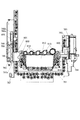
以下、本発明の好適な実施の形態を図面に基づいて説明する。図1は、本発明の一実施形態の遊技機の説明図である。
<First Embodiment>
Hereinafter, preferred embodiments of the present invention will be described with reference to the drawings. FIG. 1 is an explanatory diagram of a gaming machine according to an embodiment of the present invention.
本実施形態の遊技機10は前面枠12を備え、該前面枠12は外枠(支持枠)11に開閉回動可能に組み付けられている。遊技盤30(図2参照)は前面枠12の表側に形成された収納部(図示省略)に収納されている。また、前面枠(本体枠)12には、遊技盤30の前面を覆うカバーガラス(透明部材)14を備えたガラス枠15(透明板保持枠)が取り付けられている。
The
また、ガラス枠15の左右には内部にランプやLED等を内蔵し装飾や演出、および異常発生時の報知(例えば、払出異常が発生した場合はランプやLED等を異常報知色(例えば、赤色)で点灯(点滅)させる)のための発光をする枠装飾装置18や、音響(例えば、効果音)を発するスピーカ(上スピーカ)19aが設けられている。さらに、前面枠12の下部にもスピーカ(下スピーカ)19bが設けられている。また、異常発生時はスピーカ(上スピーカ)19a、スピーカ(下スピーカ)19bから音声で異常内容が報知されるようになっている。なお、ガラス枠15の所定部位に払出異常報知用のランプを設けるようにしても良い。
In addition, lamps, LEDs, etc. are built into the left and right sides of the
また、前面枠12の下部には、図示しない打球発射装置に遊技球を供給する上皿21(貯留皿)、遊技機10の裏面側に設けられている払出ユニットから払い出された遊技球が流出する上皿球出口22、上皿21が一杯になった状態で払い出された遊技球を貯留する下皿(受皿)23及び打球発射装置の操作部24等が設けられている。さらに、上皿21の上縁部には、遊技者からの押圧操作入力を受け付けるための演出ボタンスイッチ25aを内蔵した演出ボタン25が設けられている。また、演出ボタン25の上面(押圧面)には、遊技者からの接触操作入力を受け付けるためのタッチパネル29が設けられている。さらに、前面枠12下部右側には、前面枠12やガラス枠15を開放したり施錠したりする鍵を挿入するための鍵穴26が設けられている。
なお、本実施形態ではタッチパネル29を演出ボタン25と一体的に設けたが、タッチパネル29は、演出ボタン25と別体であってもよく、例えば、演出ボタン25の近傍にサブ表示装置を設け、そのサブ表示装置の表示面にタッチパネル29を設けてもよい。
Further, in the lower part of the
In the present embodiment, the
また、演出ボタン25右方には、遊技者が隣接する球貸機から球貸しを受ける場合に操作する球貸ボタン27、球貸機のカードユニットからプリペイドカードを排出させるために操作する排出ボタン28、プリペイドカードの残高を表示する残高表示部(図示省略)等が設けられている。この実施形態の遊技機10においては、遊技者が上記操作部24を回動操作することによって、打球発射装置が上皿21から供給される遊技球を遊技盤30前面の遊技領域32に向かって発射する。また、遊技者が演出ボタン25やタッチパネル29を操作することによって、表示装置41(図2参照)における変動表示ゲーム(飾り特図変動表示ゲーム)において、遊技者の操作を介入させた演出等を行うことができる。
Further, on the right side of the
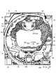
次に、図2を用いて遊技盤30の一例について説明する。図2は、本実施形態の遊技盤30の正面図である。
Next, an example of the
遊技盤30の表面には、外周壁31で囲われた略円形状の遊技領域32が形成されている。遊技領域32は、遊技盤30の四隅に各々設けられた樹脂製のサイドケース33及び外周壁31に囲繞されて構成される。また、遊技領域32の左側には、外周壁31に沿って設けられ、発射された遊技球を遊技領域32の所定位置まで誘導する誘導路31aを形成する誘導壁31bが設けられている。
On the surface of the
遊技領域32には、ほぼ中央に表示装置41を備えたセンターケース(遊技演出構成体)40が配置されている。表示装置41は、センターケース40に設けられた凹部に、センターケース40の前面より奥まった位置に取り付けられている。すなわち、センターケース40は表示装置41の表示領域の周囲を囲い、表示装置41の表示面よりも前方へ突出し周囲の遊技領域32から遊技球が飛び込みにくくするように形成されている。
In the
表示装置41(変動表示装置)は、例えば、LCD(液晶表示器)、CRT(ブラウン管)等の表示画面を有する装置で構成されている。表示画面の画像を表示可能な領域(表示領域)には、複数の識別情報(特別図柄)や特図変動表示ゲームを演出するキャラクタや演出効果を高める背景画像等の遊技に関する情報が表示される。表示装置41の表示画面においては、識別情報として割り当てられた複数の特別図柄が変動表示(可変表示)されて、特図変動表示ゲームに対応した飾り特図変動表示ゲームが行われる。また、表示画面には遊技の進行に基づく演出のための画像(例えば、大当り表示画像、ファンファーレ表示画像、エンディング表示画像等)が表示される。また、センターケース40には、動作することによって遊技の演出を行う盤演出装置44が備えられている。この盤演出装置44は、図2に示す状態から表示装置41の中央へ向けて動作可能となっている。
The display device 41 (variable display device) is composed of, for example, a device having a display screen such as an LCD (liquid crystal display) and a CRT (cathode ray tube). In the area (display area) where the image of the display screen can be displayed, information related to the game such as a plurality of identification information (special symbols), characters for directing the special figure variation display game, and background images for enhancing the effect of the effect is displayed. .. On the display screen of the
センターケース40の下方には、第1特図変動表示ゲーム(特図1変動表示ゲーム)の開始条件を与える第1始動入賞口36(始動入賞口、始動入賞領域)が設けられている。第1始動入賞口36に入賞した遊技球は、始動口1スイッチ36a(図27参照)により検出される。
Below the
また、センターケース40の左部には、センターケース40の外側の遊技領域32を流下する遊技球を受け入れ、ステージ部620へと誘導するワープ流路を形成するワープ流路形成部材614が取り付けられている。ワープ流路形成部材614は、遊技領域32の前後幅(遊技盤本体80の前面から遊技盤30の前方を覆うカバーガラス(透明部材)14の裏面までの幅)の分だけ前方へ延出するようになっている。
Further, a warp flow
ワープ流路形成部材614により形成されるワープ流路は、遊技球が一列で流下可能な内径を有する筒状の流路であり、センターケース40の左方の遊技領域32に向けて開口し、遊技領域32を流下する遊技球を受入可能となっている。この上流側端部がワープ流路の流入口をなす。さらにワープ流路は、上流側端部から流入した遊技球を右下方へ誘導した後に後方へ誘導するL字状の流路となっている。そして、下流側端部は後方に開口し、ステージ部620の左端部に遊技球を誘導するようになっている。
The warp flow path formed by the warp flow
ステージ部620は遊技球が前後左右に転動可能であり、左右両側が中央に向かって下る傾斜面となっているとともに、第1始動入賞口36の直上となる中央部が上向きに突出した略W字状に形成されている。なお、ステージ部620の中央部は上向きに突出しているが左右両端よりは低くなっている。このステージ部620には、左端からワープ流路を通った遊技球が流入し、左右方向に沿って転動するようになっている。また、ステージ部620の下方で跳ねた遊技球も流入可能である。
The
この略W字状に形成されたステージ部620において、上向きに突出した中央部の両側に位置する最も低くなった部分には、前方に下る傾斜面が形成されている。この傾斜面により、ステージ部620上で流下勢が弱まった遊技球はステージ部620の前端から下方の遊技領域32へ誘導される。
In the
また、略W字状に形成されたステージ部620において、上向きに突出した中央部の頂点となる部分には、前後方向に沿って延在し、前方へ向かって下る溝状の流下路が形成されている。この流下路は浅い溝となっており、多くの遊技球は溝に嵌らずに左右に転動する。流下路に嵌った遊技球は前方へ誘導されて第1始動入賞口36の直上に落下し、高い確率で第1始動入賞口36に流入するようになっている。
Further, in the
また、第1始動入賞口36の右側には、第2特図変動表示ゲームの開始条件を与える普通変動入賞装置37(第2始動入賞口、始動入賞領域)が設けられている。普通変動入賞装置37は、上端側が手前に倒れる方向に回動することで開放して遊技球が流入し易い状態に変換可能な可動部材37bを備えており、この可動部材37bは、常時はほぼ鉛直となって遊技球が流入できない閉じた閉状態(遊技者にとって不利な状態)を保持している。そして、普図変動表示ゲームの結果が所定の停止表示態様となった場合には、駆動装置としての普電ソレノイド37c(図27参照)によって上端側が右方に倒れるように回動して普通変動入賞装置37に遊技球が流入し易い開状態(遊技者にとって有利な状態)に変化させられるようになっている。普通変動入賞装置37に入賞した遊技球は、始動口2スイッチ37a(図27参照)により検出される。なお、普通変動入賞装置37が閉状態でも入賞できるようにし、閉状態では開状態よりは入賞しにくいものとしても良い。
Further, on the right side of the first
また、遊技領域32におけるセンターケース40の下方左側には、二つの一般入賞口35が配置され、これら一般入賞口35に入賞した遊技球は、入賞口スイッチ35a(図27参照)により検出される。この二つの一般入賞口35それぞれの左方には入賞口などに入賞しなかった遊技球を回収するアウト口30aが設けられている。また、第1始動入賞口36の下方にも入賞口などに入賞しなかった遊技球を回収するアウト口30aが設けられている。
Further, two general winning
センターケースの右側に位置する遊技領域32は、上部に一般入賞口35が設けられている。この一般入賞口35に入賞した遊技球は、遊技領域32の裏面側に設けられ、透明な材質からなる誘導流路653に流入する。この誘導流路653は、当該一般入賞口35の下方に設けられた透過流路部650の裏面側を通るように配され、途中からセンターケース40の内側を通るように配されている。さらに、この誘導流路653は、第1始動入賞口36の裏側の位置に至るように配され、遊技機10の外部へ遊技球を検出する排出流路726に連通するようになっている。
The
この一般入賞口35の下方には、透過流路部650が設けられている。透過流路部650は、遊技領域32の前後を透明な材質からなる透明部材651で構成したもので、当該透明部材651を透して遊技領域32を流下する遊技球を視認可能としている。この透過流路部650の裏面側には透明な材質からなる上述した誘導流路653が設けられており、この誘導流路653よりも後側には誘導流路653及び透過流路部650を後方から照らす発光手段が設けられている。
A transmission
このような透過流路部650では、発光手段の点灯及び消灯に係らず遊技領域32を流下する遊技球は常時視認可能となる。また、誘導流路653を流下する遊技球は、発光手段が消灯している場合には視認性が低くなり、発光手段が点灯している場合には視認性が高まり流下する遊技球を容易に視認可能となる。
In such a transmission
これにより、後述の演出制御装置300により発光手段の発光を制御することで、一般入賞口35に入賞して誘導流路653を流下する遊技球の視認性を変化させることができ、遊技の興趣を向上することができる。また、一般入賞口35に入賞して遊技を終えた遊技球を視認可能とすることで、右側の遊技領域32において流下する遊技球を多く見せることができる。後述するように誘導流路653を流下した遊技球が流入する排出流路726には、この一般入賞口35への入賞を検出するための入賞口スイッチ35a設けられており、この入賞口スイッチ35aでの検出に基づき、所定の賞球が払い出されるとともに、所定の演出が実行されるようになっている。なお、透過流路部650や誘導流路653は、流下する遊技球を視認可能な程度に透明であれば良く、装飾や色彩が施されていても良い。
As a result, by controlling the light emission of the light emitting means by the
遊技領域32におけるセンターケース40の右下部であって、透過流路部650の下方には、特図変動表示ゲームの結果によって遊技球を受け入れない状態と受け入れ易い状態とに変換可能な特別変動入賞装置(大入賞口)38が配設されている。特別変動入賞装置38は、下端を中心として回動可能な開閉部材38cを備え、この開閉部材38cは、常時は図2に示すように略垂直となった閉じた閉状態(遊技者にとって不利な状態)を保持している。そして、特図変動表示ゲームの結果が所定の停止表示態様となって特別遊技状態となった場合には、駆動装置としての大入賞口ソレノイド38b(図27参照)によって上端が右方へ向かうように回動し、遊技球が流入し易い開状態(遊技者にとって有利な状態)に変化させられて遊技球の流入が可能となり、遊技者に所定の遊技価値(賞球)を付与するようになっている。なお、大入賞口の内部(入賞領域)には、当該大入賞口に入った遊技球を検出する検出手段としての大入賞口スイッチ38a(図27参照)が配設されている。
In the lower right of the
遊技領域32におけるセンターケース40の右側であって、特別変動入賞装置38の下方には、普図変動表示ゲームの開始条件を与える普通図柄始動ゲート(普図始動ゲート)34が設けられている。普図始動ゲート34に入賞した遊技球は、ゲートスイッチ34a(図27参照)により検出される。さらに、普通図柄始動ゲート34の下方には一般入賞口35が設けられている。この一般入賞口35に入賞した遊技球は、入賞口スイッチ35a(図27参照)により検出される。
On the right side of the
また、センターケース40の左部には、特図変動表示ゲームに関する情報を表示する情報表示装置630が設けられている。この情報表示装置630は、第1特図変動表示ゲームの実行権利である第1始動記憶の数を表示する第1情報表示部、第2特図変動表示ゲームの実行権利である第2始動記憶の数を表示する第2情報表示部を備える。また、表示装置41で第1〜第3図柄により表示される飾り特図変動表示ゲームとは別個に第4図柄により第1特図変動表示ゲームに対応する飾り特図1変動表示ゲームを表示する第3情報表示部や、表示装置41で第1〜第3図柄により表示される飾り特図変動表示ゲームとは別個に第4図柄により第2特図変動表示ゲームに対応する飾り特図2変動表示ゲームを表示する第4情報表示部を備える。
Further, on the left side of the
第1情報表示部と第2情報表示部はそれぞれ二つの発光部材で構成され、第3情報表示部と第4情報表示部はそれぞれ一つの発光部材で構成されている。情報表示装置630にはこれらの六つの発光部材が配されている。また、情報表示装置630は周囲の意匠と一体となるような意匠が施されている。
The first information display unit and the second information display unit are each composed of two light emitting members, and the third information display unit and the fourth information display unit are each composed of one light emitting member. These six light emitting members are arranged in the
本実施形態の遊技機10においては、遊技球が流下する遊技領域32のうち、センターケース40の左方の領域が左側遊技領域とされ、センターケース40の右方の領域が右側遊技領域とされている。そして、遊技者が発射勢を調節して左側遊技領域へ遊技球を発射(いわゆる左打ち)することで第1始動入賞口36、一般入賞口35への入賞を狙うことができ、右側遊技領域へ遊技球を発射(いわゆる右打ち)することで普図始動ゲート34や普通変動入賞装置37、特別変動入賞装置38、第1始動入賞口36、一般入賞口35への入賞を狙うことができるようになっている。
In the
また、遊技領域32の外側(ここでは遊技盤30の右下部)には、特図変動表示ゲームをなす特図1変動表示ゲームや特図2変動表示ゲーム及び普図始動ゲート34への入賞をトリガとする普図変動表示ゲームの表示や、各種情報を表示する一括表示装置50が設けられている。
Further, on the outside of the game area 32 (here, the lower right of the game board 30), a prize is given to the special figure 1 variable display game, the special figure 2 variable display game, and the general figure start
一括表示装置50は、7セグメント型の表示器(LEDランプ)等で構成された特図1変動表示ゲーム用の特図1表示器(第1特図変動表示部)51及び特図2変動表示ゲーム用の特図2表示器(第2特図変動表示部)52と、LEDランプで構成された各種表示器を備える。各種表示器には、特図1変動表示ゲームの始動記憶数報知用の特図1保留表示器、特図2変動表示ゲームの始動記憶数報知用の特図2保留表示器が含まれている。また、大当り時のラウンド数(特別変動入賞装置の開閉回数)を表示するラウンド表示部、時短状態(普電サポート中、特定遊技状態中)であるかを報知する第1遊技状態表示部、左打ち(通常打ち)と右打ちのうち遊技者に有利な打ち方(遊技状態に対応した打ち方)を報知する第2遊技状態表示部が含まれている。また、遊技機10の電源投入時に大当りの確率状態が高確率状態となっていることを表示する第3遊技状態表示部(第3遊技状態表示器、確率状態表示部)、普図変動表示ゲーム用の普図表示器、普図変動表示ゲームの始動記憶数報知用の普図保留表示器が含まれている。
The
特図1表示器51では、第1特図変動表示ゲームの変動時間中においては、予め定められた複数の点灯パターンを予め定められた順序で表示する特図1変動中表示を繰り返し行う。そして、第1特図変動表示ゲームの変動時間が終了すると、当該第1特図変動表示ゲームの結果に応じた点灯パターン(結果態様)を停止表示する。特図1変動中表示において表示する点灯パターンの各々や結果態様として表示する点灯パターンは、第1特図変動表示ゲームを表示するための識別情報(特図、特別図柄)をなす。
In the special figure 1
特図2表示器52では、第2特図変動表示ゲームの変動時間中においては、予め定められた複数の点灯パターンを予め定められた順序で表示する特図2変動中表示を繰り返し行う。そして、第2特図変動表示ゲームの変動時間が終了すると、当該第2特図変動表示ゲームの結果に応じた点灯パターン(結果態様)を停止表示する。特図2変動中表示において表示する点灯パターンの各々や結果態様として表示する点灯パターンは、第2特図変動表示ゲームを表示するための識別情報(特図、特別図柄)をなす。
In the special figure 2
普図表示器では、普図変動表示ゲームの変動時間中においては、予め定められた複数の点灯パターンを予め定められた順序で表示する普図変動中表示を繰り返し行う。そして、普図変動表示ゲームの変動時間が終了すると、当該普図変動表示ゲームの結果に応じた点灯パターン(結果態様)を停止表示する。普図変動中表示において表示する点灯パターンの各々や結果態様として表示する点灯パターンは、普図変動表示ゲームを表示するための識別情報(普図、普通図柄)をなす。 During the fluctuation time of the normal map fluctuation display game, the normal map display repeats the normal map fluctuation display in which a plurality of predetermined lighting patterns are displayed in a predetermined order. Then, when the fluctuation time of the normal map variation display game ends, the lighting pattern (result mode) according to the result of the normal map variation display game is stopped and displayed. Each of the lighting patterns displayed in the normal map fluctuation display and the lighting pattern displayed as the result mode form identification information (normal map, normal symbol) for displaying the normal map variation display game.
特図1保留表示器は、第1特図変動表示ゲームの実行権利である第1始動記憶の数(第1保留数)を複数の発光部の消灯、点滅、点灯により表示する。特図2保留表示器は、第2特図変動表示ゲームの実行権利である第2始動記憶の数(第2保留数)を複数の発光部の消灯、点滅、点灯により表示する。普図保留表示器は、普図変動表示ゲームの実行権利である普図始動記憶の数(普図保留数)を複数の発光部の消灯、点滅、点灯により表示する。 The special figure 1 hold indicator displays the number of first start memories (first hold number), which is the execution right of the first special figure variation display game, by turning off, blinking, and turning on a plurality of light emitting units. The special figure 2 hold indicator displays the number of second start memories (second hold number), which is the execution right of the second special figure variation display game, by turning off, blinking, and turning on the plurality of light emitting units. The normal figure hold indicator displays the number of normal figure start memories (the number of normal figure hold), which is the execution right of the normal figure variation display game, by turning off, blinking, and turning on a plurality of light emitting units.
ラウンド表示部は、特別遊技状態中でない場合にはすべての発光部を消灯状態にし、特別遊技状態中には特別結果に応じて選択されたラウンド数に対応した点灯態様とする。第1遊技状態表示部(時短状態報知部)は、時短状態が発生していない通常の遊技状態の場合(変動時間短縮機能未作動時)にはランプを消灯状態にし、時短状態が発生している場合(変動時間短縮機能作動時)にはランプを点灯状態にする。第2遊技状態表示部(右打ち報知部)57は、右打ちよりも左打ちの方が遊技者にとって有利な遊技状態の場合(通常打ち時)にはランプを消灯状態にし、左打ちよりも右打ちの方が遊技者にとって有利な遊技状態の場合(右打ち時)にはランプを点灯状態にする。第3遊技状態表示部は、電源投入時に高確率状態である場合にはLEDを点灯し、高確率状態でない場合はLEDを消灯状態にする。 When the round display unit is not in the special game state, all the light emitting units are turned off, and during the special game state, the lighting mode corresponds to the number of rounds selected according to the special result. The first game status display unit (time reduction status notification unit) turns off the lamp in the normal game state (when the fluctuation time reduction function is not activated) in which the time reduction state does not occur, and the time reduction state occurs. If it is (when the fluctuation time reduction function is activated), the lamp is turned on. The second game status display unit (right-handed notification unit) 57 turns off the lamp when left-handed is more advantageous to the player than right-handed (normal hitting), and is more than left-handed. When right-handed is more advantageous for the player (when right-handed), the lamp is turned on. The third game state display unit turns on the LED when it is in a high probability state when the power is turned on, and turns off the LED when it is not in a high probability state.
次に、本発明の実施形態の遊技機10における遊技盤30の詳細について説明する。図3に示すように遊技盤30は、略矩形板状の遊技盤本体80と、センターケース40の前側部分を構成する前方構成部材600と、センターケース40の後側部分を構成するとともに遊技盤30に必要な各種部材が取り付けられた後方構成部材700と、を備える。
Next, the details of the
前方構成部材600は、遊技盤本体80に形成された前後に貫通する開口に対して前面側から嵌め込まれることで取り付けられるようになっている。この前方構成部材は円環状のベース部材610を有し、このベース部材610にワープ流路形成部材614、情報表示装置630、透過流路部650、特別変動入賞装置38などの各種の部材が取り付けられている。ベース部材610には、ねじ穴やねじ止め部、位置決めのためのボス、ボスを受け入れる凹部やリブを受け入れるスリットなどが形成され、各種部材をベース部材610における適切な位置に固定できるようになっているとともに、前方構成部材600を遊技盤本体に対する適切な位置に固定できるようになっている。
The
ベース部材610の前面には、ステージ部620、ワープ流路形成部材614が配される部分を除き、規制壁613が設けられている。この規制壁613は、遊技領域32の前後幅(遊技盤本体80の前面から遊技盤30の前方を覆うカバーガラス(透明部材)14の裏面までの幅)の分だけ前方へ延出するようになっている。これにより遊技領域32を流下する遊技球がセンターケース40内に流入することを規制し、表示装置41の視認性を確保するとともにステージ部620への遊技球の流入数を制限するようになっている。
A
遊技盤本体80の裏面側を構成する後方構成部材700は、前方に開口した凹部711を有する略矩形箱状の後方ベース部材710を有しており、この後方ベース部材710には、ねじ穴やねじ止め部、位置決めのためのボス、ボスを受け入れる凹部やリブを受け入れるスリットなどが形成され、各種部材を適切な位置に固定できるようになっている。また、後方ベース部材710の前端には、側壁712に対して垂直に外側に向かって延出する鍔状の固定部713が形成されており、後方構成部材700を遊技盤本体80の裏面の所定位置に固定できるようになっている。また、後方ベース部材710の後壁714には、前後に貫通する貫通孔715が形成されている。この貫通孔715は、後方ベース部材710の後方に取り付けられる表示装置41の表示面を視認可能とするものである。
The
後方ベース部材710の後壁714の裏面に取り付けられる表示装置41は、後方ベース部材710の後壁714に形成された貫通孔715の全体を覆うことのできる表示面を有する液晶表示装置を備えている。この表示装置41は、表示面が前側となるように取り付けられることで、後方ベース部材710に形成された貫通孔715を介して表示面の画像が遊技盤30の前方から視認可能となるようにされている。なお、表示装置41は、液晶表示装置を備えるものに限られず、例えば、EL、CRT等のディスプレイを備えるものであってもよい。また、本実施形態の遊技機では、表示装置41における長方形の表示領域の長辺が上下方向に沿うように取り付けられる。
The
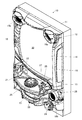
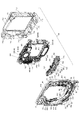
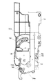
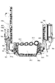
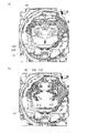
また、図4(a)に示すように表示装置41の裏面は制御装置等を取り付けるための取付部65とされており、図4(b)に示すように演出制御装置300や中継基板66が取り付けられている。なお、遊技制御装置100も表示装置41の裏面に重なるように配されているが、取り付けられているのは後方ベース部材710の下部である。
Further, as shown in FIG. 4A, the back surface of the
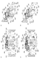
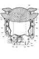
図3に戻り、後方ベース部材710の凹部711の内部には、各入賞口に入賞した遊技球の排出流路を形成する排出流路ユニット720や、複数の盤演出装置44や盤装飾装置46が設けられている。図5に示すように複数の盤演出装置44としては、動作することによって遊技の演出を行う可動演出装置である左役物ユニット740、下表示ユニット780、上役物ユニット830が設けられている。また、複数の盤装飾装置46としては、発光部661での発光による装飾を行う右上ランプユニット660と、上役物ユニット830と一体に配されて画像を表示する上表示ユニット910と、が設けられている。
Returning to FIG. 3, inside the
図3に示すように排出流路ユニット720は、遊技盤本体80の裏面下部に取り付けられるようになっている。この排出流路ユニット720に設けられる排出流路のうち、第1始動入賞口36に入賞した遊技球が流下する排出流路721には、第1始動入賞口36への入賞を検出する始動口1スイッチ36aが設けられている。また、遊技領域32の左下に設けられた二つの一般入賞口35に入賞した遊技球が流下する排出流路722には、一般入賞口35への入賞を検出する入賞口スイッチ35aが設けられている。
As shown in FIG. 3, the discharge
また、普通変動入賞装置37に入賞した遊技球が流下する排出流路723には、図示を省略するが普通変動入賞装置37に入賞した遊技球を検出する始動口2スイッチ37aが設けられる。また、遊技領域32の右下に設けられた一般入賞口35に入賞した遊技球が流下する排出流路724には、一般入賞口35への入賞を検出する入賞口スイッチ35aが設けられている。なお、特別変動入賞装置38に入賞した遊技球を検出する大入賞口スイッチ38aは、特別変動入賞装置38内に設けられており、特別変動入賞装置38に入賞した遊技球が流下する排出流路725には設けられていない。
Further, the
そして、透過流路部650の上方に設けられた一般入賞口35に入賞した遊技球が流下する誘導流路653に連通する排出流路726には、当該一般入賞口への入賞を検出する入賞口スイッチ35aが設けられている。この入賞口スイッチ35aは、当該一般入賞口35に入賞したことに伴う演出を行うための検出センサも兼ねている。また、排出流路ユニット720の上部には、装飾部材727が設けられており、上方から排出流路などの構造が見えないようにされている。
Then, in the
図2、図3、図5に示すように左役物ユニット740は、表示装置41の表示領域の左側に配されており、動作可能な左可動体760が表示領域の左側に退避して前方構成部材600の後方に隠れた隠蔽状態と、当該隠蔽状態から上端が右方へ倒れるように回動して表示領域の前側に重なって視認可能となる露出状態との間で動作可能である。
As shown in FIGS. 2, 3 and 5, the
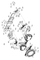
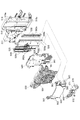
図6に示すように左役物ユニット740は、後方ベース部材710に固定されて各種部材の取り付けベースとなるベース部材741を備えている。このベース部材741の前面下部には、左可動体760を駆動するための駆動ユニットを取り付けるための駆動ユニット取付部742が設けられている。この駆動ユニット取付部742には、左可動体760を動作するための駆動源をなすモータ751と、モータ751の駆動軸に取り付けられた駆動ギア751aと、駆動ギア751aから駆動力を受けるとともに左可動体760に固定される従動ギア752と、従動ギア752にかかるモータ751の駆動力を制限する補助ギア753と、が取り付けられている。
As shown in FIG. 6, the
また、駆動ユニット取付部742には、左可動体760を回動可能に軸支する回動軸746a(図7に図示)が取り付けられる軸取付部746が設けられている。この軸取付部746には、前後方向に沿って回動軸746aが取り付けられるようになっている。この回動軸746aは、従動ギア752の中心を通り、左可動体760の軸受部762に挿通されるようになっていて、左可動体760はこの回動軸746aを中心に回動するようになっている。また、軸取付部746に隣接して、軸取付部746を中心とした円弧状に形成された前後に貫通する案内部748が設けられている。この案内部748は、従動ギア752の後方へ延出する被案内軸752aを案内するものである。
Further, the drive
ベース部材741の前面における駆動ユニット取付部742の上方には、左可動体760の動作を案内する案内部材754を取り付けるための案内部材取付部743が設けられている。この案内部材取付部753に取り付けられる案内部材754は、前後に貫通する円弧状の案内部755を備え、この案内部755に左可動体760に設けられた被案内軸763がスライド可能に挿通されるようになっている。
Above the drive
ベース部材741の前面における案内部材取付部743の上方には、左可動体760の動作を案内するとともに左可動体760を支持するための支持アーム756を取り付けるための支持アーム取付部744が設けられている。この支持アーム取付部744には、前後方向に沿って延在する回動軸745a(図9に図示)を取り付けるための軸取付部745と、軸取付部745を中心とした円弧状に形成された前後に貫通する案内部749が設けられている。
Above the guide
この支持アーム取付部744に取り付けられる支持アーム756は、第1支持アーム757と第2支持アーム758とから構成されている。第1支持アーム757は、軸取付部745に取り付けられた回動軸745aに対して回動可能に取り付けられる軸受部757aが一端部に設けられている。これにより、第1支持アーム757はベース部材741に対して回動軸745aを中心として回動可能に取り付けられる。また、第1支持アーム757の裏面側には、後方に延出する被案内軸757bが設けられている。この被案内軸757bは、ベース部材741に設けられた案内部749に沿って案内されるようになっている。また、第1支持アーム757の他端には、第2支持アーム758の一端と接続する接続軸757cが前後方向に沿って後方に延出するように設けられている。
The
第2支持アーム758の一端には、第1支持アーム757に設けられた接続軸757cと回動可能に接続する接続部758aが設けられている。また、第2支持アーム758の他端には、左可動体760に設けられた前後方向に沿って延在する接続軸765と回動可能に接続する接続部758bが設けられている。
At one end of the
また、ベース部材741の前面右側には、左可動体760が初期位置である隠蔽状態にあることを検出するための検出センサ747が設けられている。この検出センサ747は、発光部と受光部とが所定の間隔をおいて対向して配された光センサで、受光部において発光部からの光を検出することでON信号を出力するものである。左可動体760が初期位置にある場合には、左可動体760に設けられた遮光板764が検出センサ747の受光部と発光部の間に位置し、検出センサ747の出力がOFFとなるようにされている。また、左可動体760が初期位置から動作することで遮光板764が検出センサ747の受光部と発光部の間から退避して、検出センサ747の出力がONとなるようにされており、これにより左可動体760が初期位置にあることを検出可能となっている。
Further, on the front right side of the
また、ベース部材741の前面側には、駆動ユニット取付部742の前側等を覆うカバー部材776が取り付けられる。さらに、ベース部材741の右側面の下方には、装飾板777が取り付けられる。
Further, a
左可動体760は、左可動体ベース部761と、LED基板767と、枠体部770と、装飾部773と、装飾枠体部774と、レンズ部材775と、を備える。左可動体ベース部761は、前後方向に延在する筒状の軸受部762を下端部に備える。この軸受部762には、ベース部材741の軸取付部746に取り付けられた前後方向に延在する回動軸746aが挿通されるようになっている。また、左可動体ベース部761の前面側であって軸受部762の前側となる位置には、従動ギア752が取り付けられるようになっており、モータ751からの駆動力を受けて左可動体ベース部761が回動軸746aを中心として回動駆動されるようになっている。
The left
また、左可動体ベース部761の前面側であって左側部分には、案内部材754の案内部755により案内される被案内軸763が、前後方向に沿って後方に延出するように設けられている。さらに、被案内軸763が設けられた部分の上方には、検出センサ747で検出を行うための遮光板764が設けられている。また、左可動体ベース部761の前面側であって右側部分には前後方向に沿って延在する接続軸765が設けられており、この接続軸765に第2支持アーム758の接続部758bが回動可能に接続される。
Further, on the front side of the left movable
LED基板767は、前面に複数のLEDが配されており、前方へ向かって光を照射するようになっている。枠体部770は、前後方向に貫通する貫通部が形成された枠状部771を備える。LED基板767のLEDはこの枠状部771に形成された貫通部の内側に位置するようになっている。
A plurality of LEDs are arranged on the front surface of the
枠状部771の前面側には、貫通部を閉鎖するようにレンズ部材775が取り付けられる。レンズ部材775は、LEDからの光を透過して光による装飾を可能とするものである。また、枠状部771の前面側には、レンズ部材775を囲むように装飾枠体部774が取り付けられる。さらに、枠体部770の前面側であって右側部分は、装飾部773を取り付ける装飾部取付部772とされている。
A
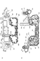
図7〜図12には、左役物ユニット740における各部材の配置と動作を示した。なお、説明のために一部の部材の表示を省略している。図7〜図9には、左可動体760が隠蔽状態にある状態を示した。
7 to 12 show the arrangement and operation of each member in the
図7は前面側から見た図であって、装飾部773、カバー部材776、装飾板777を省略している。この状態では、左可動体760が略垂直な状態となっている。また、左可動体ベース部材761の被案内軸763は案内部755の左端に位置した状態となっている。さらに、遮光板764が検出センサ747の検出部の間に位置し、検出された状態となっている。
FIG. 7 is a view seen from the front side, and the
図8は裏面側から見た図であって、装飾部773、カバー部材776、装飾板777を省略している。第1支持アーム757の被案内軸757bは、案内部749の裏面側から見た右端に位置している。また、従動ギア752に設けられた被案内軸752aは、案内部748の上端に位置している。これらの各案内部により被案内軸の回動を規制することで、左可動体760が隠蔽状態において適切な位置で停止するようになる。
FIG. 8 is a view seen from the back surface side, and the
図9は図8からベース部材741を省略した図である。第1支持アーム757と第2支持アーム758は、接続軸757cを中心として折りたたまれた状態となっている。また、補助ギア753は、上部に突出する突出部753aに、左可動体ベース部761の裏面に設けられた弾性片766が係合している。この弾性片766は弾性力のある板状の部材で、補助ギア753が裏面側から見て反時計回り方向に回動することに抵抗するように付勢するようになっている。これにより、隠蔽状態から露出状態に変換する際に従動ギア752にかかるモータ751の駆動力を制限し、従動ギア752に係る負担を軽減するとともに、露出状態から隠蔽状態に戻る際にモータ751にかかる負荷を軽減するようにしている。
FIG. 9 is a diagram in which the
図10〜図12には、左可動体760が露出状態にある状態を示した。図10は前面側から見た図であって、装飾部773、カバー部材776、装飾板777を省略している。この状態では、隠蔽状態から左可動体760が回動軸746aを中心として前面側から見て時計回り方向に回動し、右方に傾倒した状態となっている。これにより、左可動体760が遊技者から視認可能となる。また、被案内軸763は案内部755の右端に位置した状態となっている。さらに、遮光板764が検出センサ747の検出部の間から退避し、検出されない状態となっている。また、第1支持アーム757は左可動体760の動作に伴い回動軸745aを中心として前面側から見て時計回り方向に回動し、第2支持アーム758は接続軸757cを中心として前面側から見て反時計回り方向に回動して支持アーム756が伸長した状態となる。
10 to 12 show a state in which the left
図11は裏面側から見た図であって、装飾部773、カバー部材776、装飾板777を省略している。第1支持アーム757の被案内軸757bは、案内部749の裏面側から見た左端に位置している。また、従動ギア752に設けられた被案内軸752aは、案内部748の下端に位置している。これらの各案内部により被案内軸の回動を規制することで、左可動体760が露出状態において適切な位置で停止するようになる。
FIG. 11 is a view seen from the back surface side, and the
図12は図11からベース部材741を省略した図である。支持アーム756をなす第1支持アーム757と第2支持アーム758は、接続軸757cを中心として回動して伸長した状態となっている。この支持アーム756により、左可動体760の回動中心よりも先端側が支持されるとともに動作が案内され、さらに回動範囲が規制される。これにより、左可動体760を安定して動作することができる。また、補助ギア753は、弾性片766の付勢力に抗して回動した状態であり、裏面側から見て時計回り方向の付勢力を受けた状態となっている。これにより、左可動体760の自重によりモータ751にかかる負担を軽減できる。
FIG. 12 is a diagram in which the
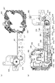
次に、下表示ユニット780について説明する。図13に示すように下表示ユニット780は、後方ベース部材710に固定されて各種部材の取り付けベースとなる下ベース部材781と、下ベース部材781に対して上下に動作可能な可動表示体800を備えている。
Next, the
下ベース部材781は、U字型に形成されており、右側部分には可動表示体800の被案内部803を上下方向に沿って案内する案内部782が設けられている。この案内部782には、上下方向に沿って延在するレール783が設けられている。また、案内部782の前側にはカバー部材784が取り付けられる。この案内部782とカバー部材784の間に可動表示体800の被案内部803を挟むことで、可動表示体800の被案内部803が、案内部782の前面、レール783及びカバー部材784により上下方向にスライド可能に保持されるようになっている。
The
下ベース部材781の左側部分には、可動表示体800を上下方向にスライド可能に保持するための第1スライドレール790を取り付けるレール取付部785が設けられている。ここに取り付けられる第1スライドレール790は、外レール790aに内レール790bが上下方向にスライド可能に嵌め込まれており、外レール790aが下ベース部材781のレール取付部785に固定され、内レール790bが可動表示体800の左側部分に設けられた上下方向に延在する接続部805の裏面に固定される。これにより、可動表示体800の左側部分が下ベース部材781により上下方向に動作可能に保持されることとなる。
A
また、下ベース部材781には、上下方向に延在するラックギアである第1ラックギア786がレール取付部785の左方に隣接して設けられている。この第1ラックギア786には従動ギア796が噛み合うようになっており、第1ラックギア786の前面側には、従動ギア796の前面左側に重なるように配されて従動ギア796が第1ラックギア786の前側に脱落することを防止するる抑え部材798が取り付けられる。
Further, the
この従動ギア796は、可動表示体800の接続部805における左側面に上下方向に延在するように設けられた第2ラックギア806とも噛み合うようになっている。可動表示体800の接続部805の前面側には、従動ギア796の前面右側に重なるように配され、従動ギア796が第2ラックギア806の前側に脱落することを防止する抑え部材797が取り付けられる。この抑え部材797の下端には、可動表示体800が初期位置にあることを検出するための遮光板797aが設けられている。
The driven
この遮光板797aは、可動表示体800が初期位置にある状態では、下ベース部材781の前面左下部に設けられた検出センサ787により検出されるようになっている。検出センサ787は、発光部と受光部とが所定の間隔をおいて対向して配された光センサで、受光部において発光部からの光を検出することでON信号を出力するものである。可動表示体800が初期位置にある場合には、遮光板797aが検出センサ787の受光部と発光部の間に位置し、検出センサ787の出力がOFFとなるようにされている。また、可動表示体800が初期位置から動作することで遮光板797aが検出センサ787の受光部と発光部の間から退避して、検出センサ787の出力がONとなるようにされており、これにより可動表示体800が初期位置にあることを検出可能となっている。
The light-shielding
モータ791は、モータ保持部材792を介して下ベース部材781の前面左下部に取り付けられる。このモータ保持部材792の裏面側には、第2スライドレール794の外レール794aが取り付けられる。第2スライドレール794は、外レール794aに内レール794bが上下方向にスライド可能に嵌め込まれており、内レール794bの裏面側には従動ギア保持部材795が取り付けられる。
The
従動ギア保持部材795の上部には、従動ギア796の回転軸796aを保持する軸受部795aが設けられている。また、図14に示すように従動ギア保持部材795の側面には、モータ791の駆動軸に取り付けられる駆動ギア793と噛み合う第3ラックギア795bが設けられている(図14参照)。これにより、モータ791の駆動に伴い従動ギア保持部材795が上下に動作して従動ギア796が上下に動作する。従動ギア796は、第1ラックギア786及び第2ラックギア806と噛み合っており、従動ギア796が上方へ移動することで第2ラックギア806が上方へ繰り出されて可動表示体800が上方へ移動する。また従動ギア796が下方へ移動することで第2ラックギア806が下方へ繰り出されて可動表示体800が下方へ移動することとなる。
A bearing
図13に戻り、可動表示体800は、下ベース部材781に対して上下方向に移動可能に取り付けられる可動ベース部801と、サブ表示装置812を備える表示ユニット810と、を備える。可動ベース部801は、表示ユニット810を取り付けるための取付部802を中央部に備え、この取付部802の右側に延出するように被案内部803が設けられている。
Returning to FIG. 13, the
被案内部803には前後に段差が形成された段差部804が設けられ、段差部804の左側面が、下ベース部材781の案内部782に設けられたレール783の右側面に当接するようになっている。また、段差部804よりも右側部分が、案内部782の前面とカバー部材784の裏面により挟まれるようになっている。これにより、被案内部803が上下方向に沿ってスライド可能に保持されることとなる。
The guided
また、取付部802の左側に延出するように接続部805が設けられている。この接続部805には、上述したように左側面に第2ラックギア806が上下方向に延在するように設けられている。また、接続部805の裏面側には第1スライドレール790の内レール790bが取り付けられ、前面側には抑え部材797が取り付けられる。
Further, a connecting
表示ユニット810は、取付部802の前面に取り付けられる本体部811を備えている。この本体部811は中央部分にサブ表示装置812を備えている。サブ表示装置812としては情報を表示可能な表示装置であれば良く、ドットマトリクス方式の表示装置や液晶表示装置などを用いることができる。
The
また、サブ表示装置812の上方には、実行中の特図変動表示ゲームについての大当りとなる可能性の高さである期待度を表示する期待度表示部813が設けられている。この期待度表示部813は5つの独立した発光部からなり、期待度が高くなるにつれて左から順に発光する発光部の数が増えるようになっている。
Further, above the
図14〜図18には、下表示ユニット780における各部材の配置と動作を示した。なお、説明のために一部の部材の表示を省略している。図14〜図16には、可動表示体800が初期位置である下端位置にある状態を示した。この状態では、可動表示体800の抑え部材797に設けられた遮光板797aが、検出センサ787の位置にあり、検出された状態となっている。なお、下端位置にある状態では、図2に示したように可動表示体800の大部分はセンターケース40の開口部分よりも下方の位置にあるが、センターケース40の奥側に配されているため、サブ表示装置812の中央よりも上側の部分は遊技者から視認可能である。
14 to 18 show the arrangement and operation of each member in the
また、図14に示すように、モータ791の駆動軸に取り付けられた駆動ギア793は、第3ラックギア795bの上端近傍に位置しており、従動ギア796は第2ラックギア806の上半部に位置している。この状態から駆動ギア793を裏面側から見た時計回り方向に回転させることで、従動ギア保持部材795が上方へ動作されて従動ギア796が上方へ移動する。従動ギア796は第1ラックギア786と噛み合っていることから裏面側から見た時計回り方向に回転し、これにより第2ラックギア806が上方へ繰り出されて可動表示体800が上昇する。
Further, as shown in FIG. 14, the
図17及び図18には、可動表示体800が最大動作位置である上端位置にある状態を示した。この状態では、可動表示体800の抑え部材797に設けられた遮光板797aは検出センサ787から離れた位置にあり、検出されない状態となっている。なお、上端位置にある場合は、サブ表示装置812の中央よりも上側の部分はセンターケース40の開口部分よりも上方の位置にあり、サブ表示装置812のセンターケース40の開口部分よりも下側にある部分についても遊技者から視認可能であるので、サブ表示装置812の全体を遊技者が視認可能な状態となる。
17 and 18 show a state in which the
次に、上役物ユニット830の構成について説明する。図19に示すように上役物ユニット830は、後方ベース部材710に固定されて各種部材の取り付けベースとなる上ベース部材831と、上ベース部材831に対して上下に動作可能な昇降役物ユニット860と、上ベース部材831の中央部に設けられた上表示ユニット取付部832に取り付けられる上表示ユニット910と、を備えている。
Next, the configuration of the
上ベース部材831の左右部分には、昇降役物ユニット860を上下動作するための駆動機構を取り付けるための左駆動機構取付部833及び右駆動機構取付部834が設けられている。左駆動機構取付部833の裏面側には、駆動源をなすモータ841が取り付けられ、当該モータ841の駆動軸841aが左駆動機構取付部833の前面側に貫通するようになっている。この駆動軸841aには、左駆動機構取付部833の前面に配された駆動ギア842が接続されている。また、左駆動機構取付部833の前面には、駆動ギア842から従動ギア843を介して回転力が伝達される回転体844が設けられている。
Left and right portions of the
回転体844の前面には、前方に突出する接続軸844aが設けられている。この接続軸844aには左リンク部材846の一端の接続部846aが回動可能に接続される。この左リンク部材846の他端には、前後方向に延在する回動軸を介して左アーム847と回動可能に接続する接続部846bが設けられている。
A connecting
また、左駆動機構取付部833の前面には、前後方向に沿って前方に延出する回転軸845が設けられている。この回転軸845には左アーム847の一端の接続部847aが回動可能に接続される。左アーム847の他端には、長穴状の貫通孔であるスライド接続部847bが設けられている。このスライド接続部847bには円筒形のスライド部材847cが長穴の延在方向に沿ってスライド可能に嵌合しており、このスライド部材847cに昇降役物ユニット860の後方に延出する左接続軸862が回動可能に接続される。
Further, on the front surface of the left drive
また、左駆動機構取付部833の前面側を覆うように左カバー部材848が取り付けられるようになっている。この左カバー部材848には、回転体844の接続軸844aや、回転軸845が前方に貫通する開口が設けられており、左リンク部材846や左アーム847は左カバー部材848の前面側に配される。また、左カバー部材848には、昇降役物ユニット860への電力の供給を行うためのケーブル848aが設けられている。
Further, the
上ベース部材831の右側部分に設けられた右駆動機構取付部834にも左駆動機構取付部833と同様の駆動機構が設けられている。右駆動機構取付部834の裏面側には、駆動源をなすモータ851が取り付けられ、当該モータ851の駆動軸851aが右駆動機構取付部834の前面側に貫通するようになっている。この駆動軸851aには、右駆動機構取付部834の前面に配された駆動ギア852が接続されている。また、右駆動機構取付部834の前面には、駆動ギア852から従動ギア853を介して回転力が伝達される回転体854が設けられている。
The right drive
回転体854の前面には、前方に突出する接続軸854aが設けられている。この接続軸854aには右リンク部材856の一端の接続部856aが回動可能に接続される。この右リンク部材856の他端には、前後方向に延在する回動軸を介して右アーム857と回動可能に接続する接続部856bが設けられている。また、回転体854の前面には、前方に突出する遮光板854b設けられている。この遮光板854bは、昇降役物ユニット860が初期位置にあることを検出可能とするためのものである。
A connecting
さらに、右駆動機構取付部834の前面には、前後方向に沿って前方に延出する回転軸855が設けられている。この回転軸855には右アーム857の一端の接続部857aが回動可能に接続される。右アーム857の他端には、長穴状の貫通孔であるスライド接続部857bが設けられている。このスライド接続部857bには円筒形のスライド部材857cが長穴の延在方向に沿ってスライド可能に嵌合しており、このスライド部材857cに昇降役物ユニット860の後方に延出する右接続軸863が回動可能に接続される。
Further, a
さらに、右アーム857におけるスライド接続部857bの下方には、昇降役物ユニット860の後方に延出する被案内軸864を案内する案内部857dが設けられている。この案内部857dには円筒形のスライド部材857eが案内部857dに沿ってスライド可能に嵌合しており、このスライド部材857eに昇降役物ユニット860の後方に延出する被案内軸864が回動可能に接続される。
Further, below the
また、右駆動機構取付部834や右リンク部材856、右アーム857の前面側を覆うように右カバー部材858が取り付けられる。この右カバー部材858の裏面側には昇降役物ユニット860が初期位置である上端位置にあることを検出するための検出センサ859が設けられている。検出センサ859は、発光部と受光部とが所定の間隔をおいて対向して配された光センサで、受光部において発光部からの光を検出することでON信号を出力するものである。昇降役物ユニット860が初期位置にある場合には、遮光板854bが検出センサ859の受光部と発光部の間に位置し、検出センサ859の出力がOFFとなるようにされている。また、昇降役物ユニット860が初期位置から動作することで遮光板854bが検出センサ859の受光部と発光部の間から退避して、検出センサ859の出力がONとなるようにされている。これにより昇降役物ユニット860が初期位置にあることを検出可能となっている。また、右カバー部材858には、昇降役物ユニット860への電力の供給や検出センサ859からの検出信号の通信を行うためのケーブル858aが設けられている。
Further, the
上ベース部材831の前面中央部であって、上表示ユニット取付部832の左側に隣接する部分には、昇降役物ユニット860の上下動作をガイドするスライドレール835を取り付けるレール取付部836が設けられている。スライドレール835は、外レール835aに内レール835bが上下方向にスライド可能に嵌め込まれたものであり、外レール835aが上ベース部材831のレール取付部836に固定され、内レール835bが昇降役物ユニット860の裏面に固定される。
A
図20、図21には、昇降役物ユニット860の上下動作に伴う各部材の配置と動作を示した。図20には昇降役物ユニット860が初期位置である上端位置にある状態を示した。図20(a)は正面から見た図、図20(b)は裏面から見た図である。
20 and 21 show the arrangement and operation of each member accompanying the vertical movement of the lifting
図20(a)に示すように昇降役物ユニット860が上端位置にある場合は、上ベース部材831の前側に重なる位置に配される。なお、中央部分には上表示ユニット910が配されるがここでは図示を省略している。この状態では、回転体844,854の接続軸844a,854aは移動範囲における最上部に位置している。これにより、回転軸845を中心として回動する左アーム847が左リンク部材846により回動範囲における最上部に引き上げられた状態となる。また、回転軸855を中心として回動する右アーム857が右リンク部材856により回動範囲の最上部に引き上げられた状態となる。
When the elevating
図20(b)に示すように、回動範囲の最上部に引き上げられた左アーム847により、昇降役物ユニット860の後方に延出する左接続軸862が移動範囲の最上部に引き上げられた状態となる。この際、スライド部材847cはスライド接続部847bにおける左アーム847の先端側の位置にある状態となる。また、回動範囲の最上部に引き上げられた右アーム857により、昇降役物ユニット860の後方に延出する右接続軸863が移動範囲の最上部に引き上げられた状態となる。この際、スライド部材857cはスライド接続部857bにおける右アーム857の先端側の位置にある状態となる。このように、左アーム847及び右アーム857により左接続軸862及び右接続軸863が移動範囲の最上部に引き上げられることで、昇降役物ユニット860が上端位置に配されることとなる。
As shown in FIG. 20B, the
図21には昇降役物ユニット860が最大動作位置である下端位置にある状態を示した。図21(a)は正面から見た図、図21(b)は裏面から見た図である。この下端位置にある状態では、回転体844,854の接続軸844a,854aが移動範囲における最下部に位置していることで、回転軸845を中心として回動する左アーム847が回動範囲における最下部に降下した状態となる。また、回転軸855を中心として回動する右アーム857が回動範囲の最下部に降下した状態となる。
FIG. 21 shows a state in which the lifting
また、図21(b)に示すように、回動範囲の最下部に降下した左アーム847により、昇降役物ユニット860の後方に延出する左接続軸862が移動範囲の最下部に降下した状態となる。この際、スライド部材847cは、スライド接続部847bにおける左アーム847の先端側から離れた位置にある状態となる。また、回動範囲の最下部に降下した右アーム857により、昇降役物ユニット860の後方に延出する右接続軸863が移動範囲の最下部に降下した状態となる。この際、スライド部材857cは、スライド接続部857bにおける右アーム857の先端側から離れた位置にある状態となる。このように、左アーム847及び右アーム857により左接続軸862及び右接続軸863を移動範囲の最下部に位置させることで、昇降役物ユニット860が下端位置に配されることとなる。
Further, as shown in FIG. 21 (b), the
図20に示した上端位置から図21に示す下端位置に移動させる際には、図20(a)に示した状態から回転体844を前面側から見て時計回り方向に回動して接続軸844aを移動範囲における最下部に移動させるとともに、図20(a)に示した状態から回転体854を前面側から見て反時計回り方向に回動して接続軸854aを移動範囲における最下部に移動させることで、図21(a)に示すように昇降役物ユニット860を下端位置に移動することができる。なお、昇降役物ユニット860の動作方向は、スライドレール835や、案内部857d及び被案内軸864により上下方向に沿うようにされている。また、図21に示した下端位置から図20に示す上端位置に移動させる際には、これとは逆の動作を行う。
When moving from the upper end position shown in FIG. 20 to the lower end position shown in FIG. 21, the
図22には、異常が発生して昇降役物ユニット860が下端位置を超えて下降した場合を示した。この場合であっても、スライド部材847cがスライド接続部847bから脱落せずに左アーム847により左接続軸862が保持される。また、スライド部材857cがスライド接続部857bから脱落せずに右アーム857により右接続軸863が保持される。さらに、スライド部材857eが案内部857dから脱落せずに右アーム857により被案内軸864が保持される。これにより、昇降役物ユニット860が落下せずに保持されることとなる。
FIG. 22 shows a case where an abnormality occurs and the lifting
また、この状態から左アーム847及び右アーム857を上昇させるように動作することで、案内部857dによって被案内軸864が案内されることにより昇降役物ユニット860が上下方向に沿って上昇する。これにより、スライドレール835の再係合を含め初期位置に復帰することが可能となっている。
Further, by operating so as to raise the
次に、昇降役物ユニット860の詳細について説明する。図23に示すように昇降役物ユニット860は、各種部材の取り付けベースとなる昇降ベース部材861を備える。昇降ベース部材861の裏面左側には、左アーム847と接続する後方へ延出する左接続軸862が設けられている。また、昇降ベース部材861の裏面右側には、右アーム857と接続する後方へ延出する右接続軸863と、案内部857dに接続する後方へ延出する被案内軸864が設けられている。
Next, the details of the lifting
昇降ベース部材861の左側部分には、可動発光部材900を動作するための駆動源をなすモータ870が設けられている。このモータ870の駆動軸は昇降ベース部材861の裏面側に位置しており、この駆動軸に駆動ギア875が取り付けられる。さらに、昇降ベース部材861の裏面側には、駆動ギア875と噛み合う従動ギア876と、従動ギア876の回転に伴い左右にスライド動作するスライドラック871が設けられている。従動ギア876には、スライドラック871と接続するための後方へ延出する接続軸876aが設けられている。また、接続軸876aが設けられた部分には、前方へ延出する板状の遮光板876bが設けられている。この遮光板876bは図示しない検出センサにより可動発光部材900が初期位置にあるか否かを検出可能とするためのものである。
A
スライドラック871の中央部には、前後に貫通する貫通孔に、第1リンクアーム872を駆動するための第1ラックギア871aと、第2リンクアーム873を駆動するための第2ラックギア871bが設けられている。また、スライドラック871の左端部には、従動ギア876の裏面に設けられた後方に延出する接続軸876aが嵌合するための、前後に貫通する上下方向に延在した長穴状の接続部871cが設けられている。さらに、第1ラックギア871a及び第2ラックギア871bが設けられた貫通孔の左右には、前後に貫通する左右方向に延在した長穴状の案内部871dが設けられている。この案内部871dには、昇降ベース部材861の裏面に設けられた案内軸861a(図24参照)が嵌合するようになっており、スライドラック871が長穴の延在方向に沿って移動可能な状態で昇降ベース部材861に保持されるようになっている。
In the central portion of the
また、昇降ベース部材861の裏面側には、後方へ延出する第1支持軸865及び第2支持軸866が設けられている。第1支持軸865は、スライドラック871の第1ラックギア871aが設けられた部分を貫通するようになっている。この第1支持軸865には第1リンクアーム872の一端に設けられた接続部872aが回動可能に接続される。接続部872aには、スライドラック871の第1ラックギア871aと噛み合うギア872bが設けられている。なお、第1リンクアーム872の他端には、可動発光部材900の接続ベース部材901に設けられた第3接続軸902に対して回動可能に接続する接続部872cが設けられている。
Further, on the back surface side of the elevating
また、第2支持軸866は、スライドラック871の第2ラックギア871bが設けられた部分を貫通するようになっている。この第2支持軸866には第2リンクアーム873の一端に設けられた接続部873aが回動可能に接続される。接続部873aには、スライドラック871の第2ラックギア871bと噛み合うギア873bが設けられている。なお、第2リンクアーム873の他端には、可動発光部材900の接続ベース部材901に設けられた第4接続軸903に対して回動可能に接続する接続部873cが設けられている。
Further, the
また、昇降ベース部材861の裏面左側には、裏面カバー部材867が取り付けられる。この裏面カバー部材867の裏面にはスライドレール835の内レール835bが上下方向に延在するように取り付けられている。
Further, a
昇降ベース部材861の前側には、左側に位置する左発光部材880と、右側に位置する右発光部材890と、動作可能な可動発光部材900と、が配される。さらに、昇降ベース部材861の前側中央部には装飾部材874が取り付けられる。
On the front side of the elevating
左発光部材880は、昇降ベース部材861の前面左側に設けられた左取付部868に取り付けられる。この左発光部材880は、左取付部868の前側に取り付けられる取付ベース881と、取付ベースの前側に配される左カバー部材882を備える。これら取付ベース881及び左カバー部材882は、モータ870から発生する熱を逃がすために複数の貫通孔が設けられている。
The left
さらに左発光部材880は、左カバー部材882の前側に配され、複数のLEDが前面に配された左LED基板883と、左LED基板883の前側に配される左レンズ部材884と、左レンズ部材884の前側に配される左装飾部材885と、を備える。左レンズ部材884及び左装飾部材885は所定の文字情報を形取った形状となっており、その形状から当該文字情報を認識でき、さらに光を透過可能な材質からなるのでLEDの発光により当該文字情報が発光表示されるようになっている。
Further, the left
右発光部材890は、昇降ベース部材861の前面右側に設けられた右取付部869に取り付けられる。この右発光部材890は、右取付部869の前側に配され、複数のLEDが前面に配された右LED基板891と、右LED基板891の前側に配される右レンズ部材892と、右レンズ部材892の前側に配される右装飾部材893と、を備える。右レンズ部材892及び右装飾部材893は所定の文字情報を形取った形状となっており、その形状から当該文字情報を認識でき、さらに光を透過可能な材質からなるのでLEDの発光により当該文字情報が発光表示されるようになっている。
The right
可動発光部材900は、第1リンクアーム872及び第2リンクアーム873と接続する接続ベース部材901を備える。この接続ベース部材901は左右に延在する溝部901aを形成するように溝形となっている。溝部901aの前後幅は、右発光部材890及び昇降ベース部材861を収容可能な幅となっており、後述するように可動発光部材900が右発光部材と重なる初期位置にある場合には、溝部901a前側を形成する部分が右発光部材890の前側に位置し、溝部901aの後側を形成する部分が昇降ベース部材861の裏面側に位置するようになっている。溝部901aの後側を形成する部分の裏面には、後方へ延出する第3接続軸902及び第4接続軸903が設けられている。第3接続軸902には第1リンクアーム872の接続部872cが回動可能に接続され、第4接続軸903には第2リンクアーム873の接続部873cが回動可能に接続される。
The movable
さらに可動発光部材900は、接続ベース部材901の前側にカバー部材904が配され、カバー部材904の前側には複数のLEDが前面に配されたLED基板905が配される。さらに、LED基板905の前側にはレンズ部材906が配され、レンズ部材906の前側には装飾部材907が配される。レンズ部材906及び装飾部材907は所定の文字情報を形取った形状となっており、その形状から当該文字情報を認識でき、さらに光を透過可能な材質からなるのでLEDの発光により当該文字情報が発光表示されるようになっている。
Further, in the movable
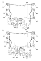
次に、可動発光部材900の動作について説明する。可動発光部材900は、図24に示すように初期位置をなす第1状態と、図25に示すように最大動作位置をなす第2状態との間で動作可能である。
Next, the operation of the movable
図24(a)には可動発光部材900が初期位置にある第1状態である場合の前面側から見た図を示した。この第1状態では、可動発光部材900が右発光部材890の前側に重なり、少なくとも右発光部材890の文字情報は視認できない状態となっている。よって、遊技者が認識可能な文字列は、左発光部材880の文字情報と可動発光部材900の文字情報から構成され、この順に並ぶ文字列となる。
FIG. 24A shows a view seen from the front side when the movable
図24(b)には可動発光部材900が第1状態である場合の裏面側から見た図を示した。スライドラック871の端部に設けられた接続部871cに嵌合する従動ギア876の接続軸876aは、裏面側から見た動作範囲における左端に位置しており、これによりスライドラック871は裏面側から見た動作範囲における左端に位置している。
FIG. 24B shows a view seen from the back surface side when the movable
この状態では、第1リンクアーム872の接続部872aは第1ラックギア871aの裏面側から見た右端に位置し、第1リンクアーム872は裏面側から見て接続部872aから左右方向に沿って左方へ向かって延在する状態に配される。また、第2リンクアーム873の接続部873aは第2ラックギア871bの裏面側から見た右端に位置し、第2リンクアーム873は裏面側から見て接続部873aから左右方向に沿って左方へ向かって延在する状態に配される。また、案内軸861aも案内部871dの裏面側から見た右端に位置している。
In this state, the connecting
図25(a)には可動発光部材900が最大動作位置にある第2状態である場合の前面側から見た図を示した。この第2状態では、可動発光部材900が右発光部材890の前側から退避し、右発光部材890の文字情報が視認可能な状態となる。また、この第2状態では、可動発光部材900が図示を省略する左発光部材880と右発光部材890と中間となる位置に下降した状態となる。よって、遊技者が認識可能な文字列は、左発光部材880の文字情報と、可動発光部材900の文字情報と、右発光部材890の文字情報から構成され、この順に並ぶ文字列となる。
FIG. 25A shows a view seen from the front side when the movable
図25(b)には可動発光部材900が第2状態である場合の裏面側から見た図を示した。図24(b)に示した第1状態から従動ギア876が裏面側から見て反時計回り方向に回動し、接続軸876aが裏面側から見た動作範囲における右端に位置した状態となる。この過程でスライドラック871は裏面側から見て右方にスライド動作し、動作範囲における右端に位置する状態となる。
FIG. 25B shows a view seen from the back surface side when the movable
図24(b)に示した第1状態からスライドラック871が右方にスライドすることで、第1ラックギア871aによって第1リンクアーム872の接続部872aが裏面側から見て反時計回りに回動し、第1リンクアーム872が裏面側から見て反時計回りに回動して図25(b)に示すように上下方向に沿った状態となる。同様に第2ラックギア871bによって第2リンクアーム873の接続部873aが裏面側から見て反時計回りに回動し、第2リンクアーム873が裏面側から見て反時計回りに回動して図25(b)に示すように上下方向に沿った状態となる。この第1リンクアーム872及び第2リンクアーム873の動作により、可動発光部材900は第1状態から上下左右の向きを維持したまま下降することとなる。なお、逆の動作を行うことで第1状態に戻すことができる。
When the
図24に示す第1状態では、左発光部材880の文字情報と可動発光部材900の文字情報が視認可能である。これらの文字情報を左から読むことにより構成される単語は、当該機種の呼称を省略した単語となっていて有意な情報となっている。そして、図25に示す第2状態では、左発光部材880の文字情報と可動発光部材900の文字情報と右発光部材890の文字情報が視認可能である。これらの文字情報を左から読むことにより構成される単語は、当該機種の呼称を省略しない単語となっていて、これも有意な情報となっている。
In the first state shown in FIG. 24, the character information of the left
すなわち、第1状態で視認可能な左発光部材880の文字情報と可動発光部材900の文字情報が第1の文字情報をなし、この第1の文字情報で構成される単語は有意な情報をなしている。また、第2状態で視認可能となる右発光部材890の文字情報が第2の文字情報をなし、第1の文字情報と第2の文字情報で構成される単語も有意な情報をなしている。そして、第1の文字情報のみで示される情報は、第1の文字情報及び第2の文字情報の組み合わせによって示される情報の略称となっている。
That is, the character information of the left
なお、ここでは、第1の文字情報を2つの文字情報としたが、これに限られるものではなく、1つとしても良いし3つ以上としても良い。また、第2の文字情報を1つの文字情報としたが、2つ以上の文字情報としても良い。また、可動発光部材900の動作は上述したものに限られるものではなく、第2の文字情報を視認可能な状態と視認不能な状態とに変換できる動作であればどのようなものでも良い。
In this case, the first character information is set to two character information, but the information is not limited to this, and may be one or three or more. Further, although the second character information is used as one character information, it may be used as two or more character information. Further, the operation of the movable
以上のことから、所定条件の成立に基づきゲームを実行し、当該ゲームの結果が特別結果となった場合に、遊技者に有利な状態を発生する遊技機において、動作による遊技の演出が可能な可動演出装置(昇降役物ユニット860)を備え、可動演出装置は、第1部材(昇降ベース部材861)と、当該第1部材に対して動作可能な第2部材(可動発光部材900)と、を備えるとともに、文字情報として、第1の文字情報と、第2の文字情報とが付されており、文字情報は、第1の文字情報のみでも有意な情報をなすとともに、第1の文字情報及び第2の文字情報の組み合わせによっても有意な情報をなすものであり、第2部材は、第2の文字情報の前方に重なって当該第2の文字情報を遊技者が視認できない第1状態と、第2の文字情報の前方から退避して当該第2の文字情報を遊技者が視認可能な第2状態と、に変換可能であり、第1状態では第1の文字情報のみが視認可能であり、第2状態では第1の文字情報及び第2の文字情報が視認可能となるように構成されていることとなる。したがって、可動演出装置の動作により異なる文字情報が示されることとなり、遊技の興趣を高めることができる。 From the above, it is possible to produce a game by movement in a game machine that executes a game based on the establishment of a predetermined condition and generates a state advantageous to the player when the result of the game becomes a special result. A movable effect device (elevating accessory unit 860) is provided, and the movable effect device includes a first member (elevation base member 861), a second member (movable light emitting member 900) that can operate with respect to the first member, and the movable effect device. The first character information and the second character information are attached as the character information, and the character information is meaningful information only by the first character information and the first character information. The combination of the second character information and the second character information also forms significant information, and the second member overlaps the front of the second character information and the second character information cannot be visually recognized by the player. , The second character information can be saved from the front of the second character information and converted into a second state in which the player can see the second character information. In the first state, only the first character information can be seen. Yes, in the second state, the first character information and the second character information are configured to be visible. Therefore, different character information is shown depending on the operation of the movable effect device, and the interest of the game can be enhanced.
また、第1部材及び第2部材は、第1状態及び第2状態の何れにおいても遊技者が視認可能な第1の文字情報が付されていることとなる。したがって、常に文字情報を認識可能となる。 Further, the first member and the second member are provided with the first character information that can be visually recognized by the player in both the first state and the second state. Therefore, the character information can always be recognized.
また、可動演出装置は、第1部材も動作可能であることとなる。したがって、より複雑な演出動作が可能となり、遊技の興趣を高めることができる。 In addition, the movable effect device can also operate the first member. Therefore, more complicated production operations can be performed, and the interest of the game can be enhanced.
また、第1の文字情報のみで示される情報は、第1の文字情報及び第2の文字情報の組み合わせによって示される情報の略称であることとなる。したがって、第2部材の動作状態にかかわらず常に同じ情報を提供可能となる。 Further, the information indicated only by the first character information is an abbreviation of the information indicated by the combination of the first character information and the second character information. Therefore, the same information can always be provided regardless of the operating state of the second member.
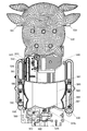
次に、上表示ユニット910について説明する。上表示ユニット910は、遊技に関する表示を実行可能な情報表示装置をなす液晶表示装置であって、図19に示したように上役物ユニット830の上ベース部材831に設けられた上表示ユニット取付部832に取り付けられることで後方ベース部材710に取り付けられるようになっている。
Next, the
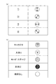
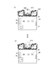
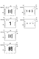
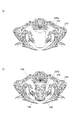
図26(a)には上表示ユニット910が表示する表示内容を示した。表示内容1〜4は、特定表示(ここでは星の絵柄)が上表示ユニット910の表示領域の中央を中心として異なる角度に位置するように表示する表示内容である。表示内容1,2,3,4の順で表示することで、特定の表示が時計回り方向に回転するように表示される。また、逆順で表示すれば特定の表示が反時計回り方向に回転するように表示される。すなわち、表示内容を所定の切替態様で切り替えることで一連のアニメーション演出を実行可能となっている。
FIG. 26A shows the display contents displayed by the
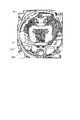
表示内容としては図26(a)に示した1〜4の表示内容に限られるものではない。例えば、図26(b)に示すような表示内容を設定することも可能である。例えば、表示内容としてキャラクタの画像を表示するものとしても良い。このキャラクタの画像は例えば大当りとなる可能性が高いことを示唆する際に使用する。また、「V」の文字を表示して大当りの発生を確定的に報知する表示内容を設けても良い。また、遊技状態や演出モード、演出ステージなどを表示する表示内容を設けても良い。このような表示内容としては、例えば遊技機のテーマに沿った画像として満月の画像を表示するものが挙げられる。
The display contents are not limited to the
また、上表示ユニット910を構成する液晶表示装置のバックライトを消灯するすることで実現される状態である全消灯を一つの表示内容としても良い。この場合は、表示領域が暗い状態となって、遊技者の顔が映り込む状態となる。なお、絵柄などの表示内容を示さずに黒色の単色表示としても良い。また、絵柄などの表示内容を示さずに特定の単色での表示のみを行う絵柄なし表示を一つの表示内容としても良い。この場合は、表示領域が特定の色(例えば白色)で発光するように見える。この際の表示色は任意に設定可能である。
Further, all the lights, which are the states realized by turning off the backlight of the liquid crystal display device constituting the
また、独立した表示内容を複数組み合わせて表示できるようにしても良い。例えば、図26(a)に示した一の表示内容と、図26(b)に示したキャラクタの画像とを合成して表示しても良い。これにより、キャラクタの表示内容と遊技状態や演出モード、演出ステージなどを表示する表示内容を合成して表示するなど、多彩な組み合わせが可能となる。なお、合成する表示内容の数や表示内容は任意に設定可能である。 In addition, a plurality of independent display contents may be combined and displayed. For example, one display content shown in FIG. 26 (a) and an image of the character shown in FIG. 26 (b) may be combined and displayed. As a result, various combinations are possible, such as combining and displaying the display contents of the character and the display contents for displaying the game state, the effect mode, the effect stage, and the like. The number of display contents to be combined and the display contents can be set arbitrarily.
また、エラー発生時は上表示ユニット910の表示をエラーに対応した表示内容としても良い。表示内容としてエラーを報知する表示内容を予め用意しておいても良いし、特定の単色のみの表示で報知を行うようにしても良い。特定の単色表示で報知を行う場合は、枠装飾装置18におけるエラー発生時の発光色と同じ表示色としても良い。また、上表示ユニット910において特定の単色表示でエラー報知を行う場合に、エラーの種類により表示色を異ならせても良い。例えば、遊技の進行が不可能となるエラー(電波・磁気エラー等)は赤色にし、遊技の進行が可能なエラー(軽微なエラー)は黄色としても良い。
Further, when an error occurs, the display of the
また、遊技の進行が可能なエラーの場合は、演出に対応した表示内容を継続するようにしても良い。また、遊技の進行が不可能となるエラーと遊技の進行が可能なエラーのいずれであっても、演出に対応した表示内容を継続したまま背景色のみエラーに対応する表示色としても良い。すなわち、演出に対応した画像とエラーに対応した画像を合成したものを表示するようにしてもよい。 Further, in the case of an error in which the game can proceed, the display content corresponding to the effect may be continued. Further, regardless of whether the error makes it impossible for the game to proceed or the error allows the game to proceed, only the background color may be used as the display color corresponding to the error while continuing the display content corresponding to the effect. That is, a composite image of the image corresponding to the effect and the image corresponding to the error may be displayed.
また、上表示ユニット910において遊技機の電源投入時に表示する初期表示内容を設定しても良い。この初期表示内容としては、例えば、演出モード等を報知する表示内容のように遊技中において最も使用される頻度の高い表示内容としても良い。また、電源投入時の初期動作として、各表示内容を順に全ての表示内容を表示するようにしても良い。
Further, the initial display content to be displayed when the power of the game machine is turned on may be set in the
また、特別結果となる確率を複数段階のうちから選択することが可能な設定変更装置を備えた場合に、当該設定変更装置により確率の変更操作が行われた場合には、上表示ユニット910の表示を、特定の表示内容とするようにしても良い。特定の表示内容としては、例えば、確率の変更操作が行われたことを示すためだけに用いられる表示を用意しても良いし、遊技の演出で使用されないような単色での表示や、複数の単色表示(例えば赤色の単色表示と黒色の単色表示)を所定時間毎に切り替えて点滅するように表示する点滅表示とするようにしても良い。また、図26に示した複数の表示内容を組み合わせることを可能とした場合は、遊技の演出で使用されない絵柄の組み合わせによる表示内容としても良い。
Further, when a setting changing device capable of selecting the probability of a special result from a plurality of stages is provided and the probability changing operation is performed by the setting changing device, the
図27は、本実施形態のパチンコ遊技機10の制御システムのブロック図である。
遊技機10は遊技制御装置100を備え、遊技制御装置100は、遊技を統括的に制御する主制御装置(主基板)であって、遊技用マイクロコンピュータ(以下、遊技用マイコンと称する)111を有するCPU部110と、入力ポートを有する入力部120と、出力ポートやドライバなどを有する出力部130と、CPU部110と入力部120と出力部130との間を接続するデータバス140などからなる。
FIG. 27 is a block diagram of the control system of the
The
上記CPU部110は、アミューズメントチップ(IC)と呼ばれる遊技用マイコン(CPU)111と、水晶振動子のような発振子を備え、CPUの動作クロックやタイマ割込み、乱数生成回路の基準となるクロックを生成する発振回路(水晶発振器)113などを有する。遊技制御装置100及び該遊技制御装置100によって駆動されるソレノイドやモータなどの電子部品には、電源装置400で生成されたDC32V,DC12V,DC5Vなど所定のレベルの直流電圧が供給されて動作可能にされる。
The
電源装置400は、24Vの交流電源から上記DC32Vの直流電圧を生成するAC−DCコンバータやDC32Vの電圧からDC12V,DC5Vなどのより低いレベルの直流電圧を生成するDC−DCコンバータなどを有する通常電源部410と、遊技用マイコン111の内部のRAMに対して停電時に電源電圧を供給するバックアップ電源部420と、停電監視回路を有し、遊技制御装置100に停電の発生、回復を知らせる停電監視信号やリセット信号などの制御信号を生成して出力する制御信号生成部430などを備える。
The
この実施形態では、電源装置400は、遊技制御装置100と別個に構成されているが、バックアップ電源部420及び制御信号生成部430は、別個の基板上あるいは遊技制御装置100と一体、すなわち、主基板上に設けるように構成してもよい。遊技盤30及び遊技制御装置100は機種変更の際に交換の対象となるので、本実施形態のように、電源装置400若しくは主基板とは別の基板にバックアップ電源部420及び制御信号生成部430を設けることにより、交換の対象から外しコストダウンを図ることができる。
In this embodiment, the
上記バックアップ電源部420は、電解コンデンサのような大容量のコンデンサ1つで構成することができる。バックアップ電源は、遊技制御装置100の遊技用マイコン111(特に内蔵RAM)に供給され、停電中あるいは電源遮断後もRAMに記憶されたデータが保持されるようになっている。すなわち、遊技制御装置100が電源遮断状態でも記憶したデータを保持可能なバックアップ記憶手段なす。そして、電源復旧時にはバックアップ記憶手段により保持されたデータに基づき制御を再開可能に構成されている。制御信号生成部430は、例えば通常電源部410で生成された32Vの電圧を監視してそれが例えば17V以下に下がると停電発生を検出して停電監視信号を変化させるとともに、所
定時間後にリセット信号を出力する。また、電源投入時や停電回復時にもその時点から所定時間経過後にリセット信号を出力する。
The backup
また、遊技制御装置100にはRAM初期化スイッチ112が設けられている。このRAM初期化スイッチ112が操作されると初期化スイッチ信号が生成され、これに基づき遊技用マイコン111内のRAM111C及び払出制御装置200内のRAMに記憶されている情報を強制的に初期化する処理が行われる。特に限定されるわけではないが初期化スイッチ信号は電源投入時に読み込まれ、停電監視信号は遊技用マイコン111が実行するメインプログラムのメインループの中で繰り返し読み込まれる。リセット信号は強制割込み信号の一種であり、制御システム全体をリセットさせる。
Further, the
遊技用マイコン111は、CPU(中央処理ユニット:マイクロプロセッサ)111A、読出し専用のROM(リードオンリメモリ)111B及び随時読出し書込み可能なRAM(ランダムアクセスメモリ)111Cを備える。
The
ROM111Bは、遊技制御のための不変の情報(プログラム、固定データ、各種乱数の判定値等)を不揮発的に記憶し、RAM111Cは、遊技制御時にCPU111Aの作業領域や各種信号や乱数値の記憶領域として利用される。ROM111B又はRAM111Cとして、EEPROMのような電気的に書換え可能な不揮発性メモリを用いてもよい。
The
また、ROM111Bは、例えば、特図変動表示ゲームの実行時間、演出内容、リーチ状態の発生の有無などを規定する変動パターン(変動態様)を決定するための変動パターンテーブルを記憶している。変動パターンテーブルとは、始動記憶として記憶されている変動パターン乱数1〜3をCPU111Aが参照して変動パターンを決定するためのテーブルである。また、変動パターンテーブルには、結果がはずれとなる場合に選択されるはずれ変動パターンテーブル、結果が大当りとなる場合に選択される大当り変動パターンテーブル等が含まれる。さらに、これらのパターンテーブルには、リーチ状態となった後の変動パターンである後半変動パターンを決定するためのテーブル(後半変動グループテーブルや後半変動パターン選択テーブル等)、リーチ状態となる前の変動パターンである前半変動パターンを決定するためのテーブル(前半変動グループテーブルや前半変動パターン選択テーブル等)が含まれている。
Further, the
ここでリーチ(リーチ状態)とは、表示状態が変化可能な表示装置を有し、該表示装置が時期を異ならせて複数の表示結果を導出表示し、該複数の表示結果が予め定められた特別結果態様となった場合に、遊技状態が遊技者にとって有利な遊技状態(特別遊技状態)となる遊技機10において、複数の表示結果の一部がまだ導出表示されていない段階で、既に導出表示されている表示結果が特別結果態様となる条件を満たしている表示状態をいう。また、別の表現をすれば、リーチ状態とは、表示装置の変動表示制御が進行して表示結果が導出表示される前段階にまで達した時点でも、特別結果態様となる表示条件からはずれていない表示態様をいう。そして、例えば、特別結果態様が揃った状態を維持しながら複数の変動表示領域による変動表示を行う状態(いわゆる全回転リーチ)もリーチ状態に含まれる。また、リーチ状態とは、表示装置の表示制御が進行して表示結果が導出表示される前段階にまで達した時点での表示状態であって、表示結果が導出表示される以前に決定されている複数の変動表示領域の表示結果の少なくとも一部が特別結果態様となる条件を満たしている場合の表示状態をいう。
Here, the reach (reach state) has a display device whose display state can be changed, and the display device derives and displays a plurality of display results at different times, and the plurality of display results are predetermined. In the
よって、例えば、特図変動表示ゲームに対応して表示装置に表示される飾り特図変動表示ゲームが、表示装置における左、中、右の変動表示領域の各々で所定時間複数の識別情報を変動表示した後、左、右、中の順で変動表示を停止して結果態様を表示するものであ
る場合、左、右の変動表示領域で、特別結果態様となる条件を満たした状態(例えば、同一の識別情報)で変動表示が停止した状態がリーチ状態となる。またこの他に、すべての変動表示領域の変動表示を一旦停止した時点で、左、中、右のうち何れか二つの変動表示領域で特別結果態様となる条件を満たした状態(例えば、同一の識別情報となった状態、ただし特別結果態様は除く)をリーチ状態とし、このリーチ状態から残りの一つの変動表示領域を変動表示するようにしても良い。
Therefore, for example, the decorative special figure variation display game displayed on the display device corresponding to the special figure variation display game changes a plurality of identification information for a predetermined time in each of the left, middle, and right variation display areas of the display device. After the display, when the variation display is stopped in the order of left, right, and middle to display the result mode, the left and right variation display areas satisfy the conditions for the special result mode (for example,). The state in which the variable display is stopped with the same identification information) is the reach state. In addition to this, when the fluctuation display of all the fluctuation display areas is temporarily stopped, the condition of the special result mode in any two of the left, middle, and right fluctuation display areas is satisfied (for example, the same). The state in which the identification information is used, except for the special result mode) may be set as the reach state, and the remaining one variable display area may be variable-displayed from this reach state.
そして、このリーチ状態には複数のリーチ演出が含まれ、特別結果態様が導出される可能性が異なる(期待値が異なる)リーチ演出として、ノーマルリーチ(Nリーチ)、スペシャル1リーチ(SP1リーチ)、スペシャル2リーチ(SP2リーチ)、スペシャル3リーチ(SP3リーチ)、プレミアリーチが設定されている。なお、期待値は、リーチなし<ノーマルリーチ<スペシャル1リーチ<スペシャル2リーチ<スペシャル3リーチ<プレミアリーチの順に高くなるようになっている。また、このリーチ状態は、少なくとも特図変動表示ゲームで特別結果態様が導出される場合(大当りとなる場合)における変動表示態様に含まれるようになっている。すなわち、特図変動表示ゲームで特別結果態様が導出されないと判定する場合(はずれとなる場合)における変動表示態様に含まれることもある。よって、リーチ状態が発生した状態は、リーチ状態が発生しない場合に比べて大当りとなる可能性の高い状態である。 The reach state includes a plurality of reach effects, and as reach effects in which the possibility of deriving a special result mode is different (expected value is different), normal reach (N reach), special 1 reach (SP1 reach), and so on. Special 2 reach (SP2 reach), special 3 reach (SP3 reach), and premier reach are set. The expected value increases in the order of no reach <normal reach <special 1 reach <special 2 reach <special 3 reach <premier reach. Further, this reach state is included in the variation display mode at least when the special result mode is derived (when it becomes a big hit) in the special figure variation display game. That is, it may be included in the variation display mode when it is determined that the special result mode is not derived in the special figure variation display game (when it is out of order). Therefore, the state in which the reach state occurs is more likely to be a big hit than the case in which the reach state does not occur.
CPU111Aは、ROM111B内の遊技制御用プログラムを実行して、払出制御装置200や演出制御装置300に対する制御信号(コマンド)を生成したりソレノイドや表示装置の駆動信号を生成して出力して遊技機10全体の制御を行う。また、図示しないが、遊技用マイコン111は、特図変動表示ゲームの当りを判定するための大当り乱数や大当りの図柄を決定するための大当り図柄乱数、特図変動表示ゲームでの変動パターン(各種リーチやリーチ無しの変動表示における変動表示ゲームの実行時間等を含む)を決定するための変動パターン乱数、普図変動表示ゲームの当りを判定するための当り乱数等を生成するための乱数生成回路と、発振回路113からの発振信号(原クロック信号)に基づいてCPU111Aに対する所定周期(例えば、4ミリ秒)のタイマ割込み信号や乱数生成回路の更新タイミングを与えるクロックを生成するクロックジェネレータを備えている。
The
また、CPU111Aは、特図変動表示ゲームに関する処理において、ROM111Bに記憶されている複数の変動パターンテーブルの中から、何れか一の変動パターンテーブルを取得する。具体的には、CPU111Aは、特図変動表示ゲームの遊技結果(当り(大当り又は小当り)あるいははずれ)や、現在の遊技状態としての特図変動表示ゲームの確率状態(通常確率状態あるいは高確率状態)、現在の遊技状態としての普通変動入賞装置37の動作状態(時短動作状態)、始動記憶数などに基づいて、複数の変動パターンテーブルの中から、何れか一の変動パターンテーブルを選択して取得する。ここで、CPU111Aは、特図変動表示ゲームを実行する場合に、ROM111Bに記憶された複数の変動パターンテーブルのうち、何れか一の変動パターンテーブルを取得する変動振り分け情報取得手段をなす。
Further, the
払出制御装置200は、CPU、ROM、RAM、入力インタフェース、出力インタフェース等を備え、遊技制御装置100からの賞球払出し指令(コマンドやデータ)に従って、払出ユニットの払出モータを駆動させ、賞球を払い出させるための制御を行う。また、払出制御装置200は、カードユニットからの貸球要求信号に基づいて払出ユニットの払出モータを駆動させ、貸球を払い出させるための制御を行う。
The
遊技用マイコン111の入力部120には、遊技機に対する電波の発射を検出する盤電波センサ62、始動入賞口36内の始動口1スイッチ36a、普通変動入賞装置37内の
始動口2スイッチ37a、普図始動ゲート34内のゲートスイッチ34a、入賞口スイッチ35a、特別変動入賞装置38の大入賞口スイッチ38aに接続され、これらのスイッチから供給されるハイレベルが11Vでロウレベルが7Vのような負論理の信号が入力され、0V−5Vの正論理の信号に変換するインタフェースチップ(近接I/F)121が設けられている。近接I/F121は、入力の範囲が7V−11Vとされることで、センサや近接スイッチのリード線が不正にショートされたり、センサやスイッチがコネクタから外されたり、リード線が切断されてフローティングになったような異常な状態を検出することができ、異常検知信号を出力するように構成されている。
The input unit 120 of the
近接I/F121の出力は、第2入力ポート123又は第3入力ポート124へ供給されデータバス140を介して遊技用マイコン111に読み込まれる。なお、近接I/F121の出力のうち、始動口1スイッチ36a、始動口2スイッチ37a、ゲートスイッチ34a、入賞口スイッチ35a及び大入賞口スイッチ38aの検出信号は第2入力ポート123へ入力される。また、近接I/F121の出力のうち、盤電波センサ62の検出信号及びセンサやスイッチの異常を検出した際に出力される異常検知信号は第3入力ポート124に入力される。また、第3入力ポート124には、遊技機10の前面枠12等に設けられた不正検出用の磁気センサ61の検出信号や、遊技機10のガラス枠15等に設けられたガラス枠開放検出スイッチ63の検出信号、遊技機10の前面枠(本体枠)12等に設けられた本体枠開放検出スイッチ64の検出信号も入力されるようになっている。なお、振動を検出する振動センサスイッチを遊技機に設け、検出信号が第3入力ポート124に入力されるようにしても良い。
The output of the proximity I /
また、近接I/F121の出力のうち、第2入力ポート123への出力は、主基板100から中継基板70を介して図示しない試射試験装置へも供給されるようになっている。さらに、近接I/F121の出力のうち始動口1スイッチ36aと始動口2スイッチ37aの検出信号は、第2入力ポート123の他、遊技用マイコン111へ入力されるように構成されている。
Further, among the outputs of the proximity I /
上記のように近接I/F121は、信号のレベル変換機能を有する。このようなレベル変換機能を可能にするため、近接I/F121には、電源装置400から通常のICの動作に必要な例えば5Vのような電圧の他に、12Vの電圧が供給されるようになっている。
As described above, the proximity I /
第2入力ポート123が保持しているデータは、遊技用マイコン111が第2入力ポート123に割り当てられているアドレスをデコードすることによってイネーブル信号CE2をアサート(有効レベルに変化)することよって、読み出すことができる。第3入力ポート124や後述の第1入力ポート122も同様である。
The data held by the
また、入力部120には、払出制御装置200からの枠電波不正信号(前面枠12に設けられた枠電波センサが電波を検出することに基づき出力される信号)、払出ビジー信号(払出制御装置200がコマンドを受付可能な状態か否かを示す信号)、払出異常ステータス信号(払出異常を示すステータス信号)、シュート球切れスイッチ信号(払出し前の遊技球の不足を示す信号)、オーバーフロースイッチ信号(下皿23に遊技球が所定量以上貯留されていること(満杯になったこと)を検出したときに出力される信号)、タッチスイッチ信号(操作部24に設けられたタッチスイッチの入力に基づく信号)を取り込んでデータバス140を介して遊技用マイコン111に供給する第1入力ポート122が設けられている。
Further, the input unit 120 receives a frame radio wave illegal signal from the payout control device 200 (a signal output based on the frame radio wave sensor provided on the
また、入力部120には、電源装置400からの停電監視信号やリセット信号などの信号を遊技用マイコン111等に入力するためのシュミットバッファ125が設けられてお
り、シュミットバッファ125はこれらの入力信号からノイズを除去する機能を有する。電源装置400からの停電監視信号や、RAM初期化スイッチ112からの初期化スイッチ信号は、一旦第1入力ポート122に入力され、データバス140を介して遊技用マイコン111に取り込まれる。つまり、前述の各種スイッチからの信号と同等の信号として扱われる。遊技用マイコン111に設けられている外部からの信号を受ける端子の数には制約があるためである。
Further, the input unit 120 is provided with a
一方、シュミットバッファ125によりノイズ除去されたリセット信号RESETは、遊技用マイコン111に設けられているリセット端子に直接入力されるとともに、出力部130の各ポートに供給される。また、リセット信号RESETは出力部130を介さずに直接中継基板70に出力することで、試射試験装置へ出力するために中継基板70のポート(図示省略)に保持される試射試験信号をオフするように構成されている。また、リセット信号RESETを中継基板70を介して試射試験装置へ出力可能に構成するようにしてもよい。なお、リセット信号RESETは入力部120の各ポート122,123,124には供給されない。リセット信号RESETが入る直前に遊技用マイコン111によって出力部130の各ポートに設定されたデータはシステムの誤動作を防止するためリセットする必要があるが、リセット信号RESETが入る直前に入力部120の各ポートから遊技用マイコン111が読み込んだデータは、遊技用マイコン111のリセットによって廃棄されるためである。
On the other hand, the reset signal RESET whose noise has been removed by the
出力部130には、遊技用マイコン111から演出制御装置300への通信経路及び遊技用マイコン111から払出制御装置200への通信経路に配されるシュミットバッファ132が設けられている。遊技制御装置100から演出制御装置300及び払出制御装置200へは、シリアル通信でデータが送信される。なお、演出制御装置300の側から遊技制御装置100へ信号を入力できないようにした片方向通信とされている。
The
さらに、出力部130には、データバス140に接続され図示しない認定機関の試射試験装置へ変動表示ゲームの特図図柄情報を知らせるデータや大当りの確率状態を示す信号などを中継基板70を介して出力するバッファ133が実装可能に構成されている。このバッファ133は遊技店に設置される実機(量産販売品)としてのパチンコ遊技機の遊技制御装置(主基板)には実装されない部品である。なお、前記近接I/F121から出力される始動口スイッチなど加工の必要のないスイッチの検出信号は、バッファ133を通さずに中継基板70を介して試射試験装置へ供給される。
Further, the
一方、磁気センサ61や盤電波センサ62のようにそのままでは試射試験装置へ供給できない検出信号は、一旦遊技用マイコン111に取り込まれて他の信号若しくは情報に加工されて、例えば遊技機が遊技制御できない状態であることを示すエラー信号としてデータバス140からバッファ133、中継基板70を介して試射試験装置へ供給される。なお、中継基板70には、上記バッファ133から出力された信号を取り込んで試射試験装置へ供給するポートや、バッファを介さないスイッチの検出信号の信号線を中継して伝達するコネクタなどが設けられている。中継基板70上のポートには、遊技用マイコン111から出力されるチップイネーブル信号CEも供給され、該信号CEにより選択制御されたポートの信号が試射試験装置へ供給されるようになっている。
On the other hand, a detection signal that cannot be supplied to the test firing test device as it is, such as the magnetic sensor 61 and the panel
また、出力部130には、データバス140に接続され特別変動入賞装置38を開成させるソレノイド(大入賞口ソレノイド)38b及び普通変動入賞装置37の可動部材37bを開成させるソレノイド(普電ソレノイド)37cの開閉データを出力するための第2出力ポート134が設けられている。また、出力部130には、一括表示装置50に表示する内容に応じてLEDのアノード端子が接続されているセグメント線のオン/オフデータを出力するための第3出力ポート135、一括表示装置50のLEDのカソード端子が
接続されているデジット線のオン/オフデータを出力するための第4出力ポート136が設けられている。
Further, the
また、出力部130には、大当り情報など遊技機10に関する情報を外部情報端子板71へ出力するための第5出力ポート137が設けられている。外部情報端子板71にはフォトリレーが備えられ、例えば遊技店に設置された外部装置(情報収集端末や遊技場内部管理装置(ホールコンピュータ)など)に接続可能であり、遊技機10に関する情報を外部装置に供給することができるようになっている。また、第5出力ポート137からはシュミットバッファ132を介して払出制御装置200に発射許可信号も出力される。
Further, the
さらに、出力部130には、第2出力ポート134から出力される大入賞口ソレノイド38bや普電ソレノイド37cの開閉データ信号を受けてソレノイド駆動信号を生成し出力する第1ドライバ(駆動回路)138a、第3出力ポート135から出力される一括表示装置50の電流供給側のセグメント線のオン/オフ駆動信号を出力する第2ドライバ138b、第4出力ポート136から出力される一括表示装置50の電流引き込み側のデジット線のオン/オフ駆動信号を出力する第3ドライバ138c、第5出力ポート137から管理装置等の外部装置へ供給する外部情報信号を外部情報端子板71へ出力する第4ドライバ138dが設けられている。
Further, the
上記第1ドライバ138aには、32Vで動作するソレノイドを駆動できるようにするため、電源電圧としてDC32Vが電源装置400から供給される。また、一括表示装置50のセグメント線を駆動する第2ドライバ138bには、DC12Vが供給される。デジット線を駆動する第3ドライバ138cは、表示データに応じたデジット線を電流で引き抜くためのものであるため、電源電圧は12V又は5Vのいずれであってもよい。
DC32V is supplied from the
12Vを出力する第2ドライバ138bによりセグメント線を介してLEDのアノード端子に電流を流し込み、接地電位を出力する第3ドライバ138cによりカソード端子よりセグメント線を介して電流を引き抜くことで、ダイナミック駆動方式で順次選択されたLEDに電源電圧が流れて点灯される。外部情報信号を外部情報端子板71へ出力する第4ドライバ138dは、外部情報信号に12Vのレベルを与えるため、DC12Vが供給される。なお、バッファ133や第2出力ポート134、第1ドライバ138a等は、遊技制御装置100の出力部130、すなわち、主基板ではなく、中継基板70側に設けるようにしてもよい。
A dynamic drive system in which a
さらに、出力部130には、外部の検査装置500へ各遊技機の識別コードやプログラムなどの情報を送信するためのフォトカプラ139が設けられている。フォトカプラ139は、遊技用マイコン111が検査装置500との間でシリアル通信によってデータの送受信を行えるように双方通信可能に構成されている。なお、かかるデータの送受信は、通常の汎用マイクロプロセッサと同様に遊技用マイコン111が有するシリアル通信端子を利用して行われるため、入力ポート122,123,124のようなポートは設けられていない。
Further, the
次に、図28を用いて、演出制御装置300の構成について説明する。
演出制御装置300は、遊技用マイコン111と同様にアミューズメントチップ(IC)からなる主制御用マイコン(CPU)311と、主制御用マイコン311からのコマンドやデータに従って表示装置41への映像表示のための画像処理を行うグラフィックプロセッサとしてのVDP(Video Display Processor)312と、各種のメロディや効果音
などをスピーカ19a,19bから再生させるため音の出力を制御する音源LSI314を備えている。
Next, the configuration of the
The
上記主制御用マイコン311には、CPUが実行するプログラムや各種データを格納したPROM(プログラマブルリードオンリメモリ)からなるプログラムROM321、作業領域を提供するRAM322、停電時に電力が供給されなくとも記憶内容を保持可能なFeRAM323、現在の日時(年月日や曜日、時刻など)を示す情報を生成する計時手段をなすRTC(リアルタイムクロック)338が接続されている。なお、主制御用マイコン311の内部にも作業領域を提供するRAMが設けられている。また、主制御用マイコン311にはWDT(ウォッチドッグ・タイマ)回路324が接続されている。主制御用マイコン311は、遊技用マイコン111からのコマンドを解析し、演出内容を決定してVDP312へ出力映像の内容を指示したり、音源LSI314への再生音の指示、装飾ランプの点灯、モータやソレノイドの駆動制御、演出時間の管理などの処理を実行する。
The
VDP312には、作業領域を提供するRAM312aや、画像を拡大、縮小処理するためのスケーラ312bが設けられている。また、VDP312にはキャラクタ画像や映像データが記憶された画像ROM325や、画像ROM325から読み出されたキャラクタなどの画像データを展開したり加工したりするのに使用される超高速なVRAM(ビデオRAM)326が接続されている。
The
特に限定されるわけではないが、主制御用マイコン311とVDP312との間は、パラレル方式でデータの送受信が行われるように構成されている。パラレル方式でデータを送受信することで、シリアルの場合よりも短時間にコマンドやデータを送信することができる。
Although not particularly limited, the
VDP312から主制御用マイコン311へは、表示装置41の映像とガラス枠15や遊技盤30に設けられている装飾ランプの点灯を同期させるための垂直同期信号VSYNC、データの送信タイミングを与える同期信号STSが入力される。なお、VDP312から主制御用マイコン311へは、VRAMへの描画の終了等処理状況を知らせるため割込み信号INT0〜n及び主制御用マイコン311からのコマンドやデータの受信待ちの状態にあることを知らせるためのウェイト信号WAITなども入力される。
From the
演出制御装置300には、LVDS(小振幅信号伝送)方式で表示装置41へ送信する映像信号を生成する信号変換回路313が設けられている。VDP312から信号変換回路313へは、映像データ、水平同期信号HSYNC及び垂直同期信号VSYNCが入力されるようになっており、VDP312で生成された映像は、信号変換回路313を介して表示装置41に表示される。
The
音源LSI314には音声データが記憶された音声ROM327が接続されている。主制御用マイコン311と音源LSI314は、アドレス/データバス340を介して接続されている。また、音源LSI314から主制御用マイコン311へは割込み信号INTが入力されるようになっている。演出制御装置に300には、ガラス枠15に設けられた上スピーカ19a及び前面枠12に設けられた下スピーカ19bを駆動するオーディオパワーアンプなどからなるアンプ回路337が設けられており、音源LSI314で生成された音声はアンプ回路337を介して上スピーカ19a及び下スピーカ19bから出力される。
An
また、演出制御装置300には、遊技制御装置100から送信されてくるコマンドを受信するインタフェースチップ(コマンドI/F)331が設けられている。このコマンドI/F331を介して、遊技制御装置100から演出制御装置300へ送信された飾り特図保留数コマンド、飾り特図コマンド、変動コマンド、停止情報コマンド等を、演出制御指令信号(演出コマンド)として受信する。遊技制御装置100の遊技用マイコン111
はDC5Vで動作し、演出制御装置300の主制御用マイコン311はDC3.3Vで動作するため、コマンドI/F331には信号のレベル変換の機能が設けられている。
Further, the
Operates at
また、演出制御装置300には、遊技盤30(センターケース40を含む)に設けられているLED(発光ダイオード)を有する盤装飾装置46やサブ情報表示装置90を駆動制御する盤装飾LED制御回路332、ガラス枠15に設けられているLED(発光ダイオード)を有する枠装飾装置(例えば枠装飾装置18等)を駆動制御する枠装飾LED制御回路333、遊技盤30(センターケース40を含む)に設けられている盤演出装置44(例えば表示装置41における演出表示と協働して演出効果を高める可動役物等)を駆動制御する盤演出可動体制御回路334が設けられている。ランプやモータ及びソレノイドなどを駆動制御するこれらの制御回路332〜334は、アドレス/データバス340を介して主制御用マイコン311と接続されている。なお、ガラス枠15にモータ(例えば演出用の装置を動作させるモータ)等の駆動源を備え、動作する可動演出部材によって、特図変動表示ゲームを含む遊技の演出を行う可動演出装置をなす枠演出装置を設け、この枠演出装置を駆動制御する枠演出可動体制御回路を備えていても良い。
Further, the
さらに、演出制御装置300には、ガラス枠15に設けられた演出ボタン25に内蔵されている演出ボタンスイッチ25a、ガラス枠15に設けられたタッチパネル29、盤演出装置44内のモータの初期位置等を検出する演出役物スイッチ47(演出モータスイッチ)のオン/オフ状態を検出して主制御用マイコン311へ検出信号を入力する機能や、演出制御装置300に設けられた音量調節スイッチ335の状態を検出して主制御用マイコン311へ検出信号を入力するスイッチ入力回路336が設けられている。
Further, the
電源装置400の通常電源部410は、上記のような構成を有する演出制御装置300やそれによって制御される電子部品に対して所望のレベルの直流電圧を供給するため、モータやソレノイドを駆動するためのDC32V、液晶パネルからなる表示装置41、モータやLEDを駆動するためのDC12V、コマンドI/F331の電源電圧となるDC5Vの他に、モータやLED、スピーカを駆動するためのDC15Vの電圧を生成するように構成されている。さらに、主制御用マイコン311として、3.3Vあるいは1.2Vのような低電圧で動作するLSIを使用する場合には、DC5Vに基づいてDC3.3VやDC1.2Vを生成するためのDC−DCコンバータが演出制御装置300に設けられる。なお、DC−DCコンバータは通常電源部410に設けるようにしてもよい。
The normal
電源装置400の制御信号生成部430により生成されたリセット信号は、主制御用マイコン311に供給され、当該デバイスをリセット状態にする。また、主制御用マイコン311から出力される形で、VDP312(VDPRESET信号)、音源LSI314、スピーカを駆動するアンプ回路337(SNDRESET信号)、ランプやモータなどを駆動制御する制御回路332〜334(IORESET信号)に供給され、これらをリセット状態にする。また、演出制御装置300には遊技機10の各所を冷却する冷却FAN45が接続され、演出制御装置300の電源が投入された状態では冷却FAN45が駆動するようにされている。
The reset signal generated by the control
本実施形態の遊技機10では、図示しない発射装置から遊技領域32に向けて遊技球(パチンコ球)が打ち出されることによって遊技が行われる。打ち出された遊技球は、遊技領域32内の各所に配置された障害釘や風車等の方向転換部材によって転動方向を変えながら遊技領域32を流下し、普図始動ゲート34、一般入賞口35、始動入賞口36、普通変動入賞装置37又は特別変動入賞装置38に入賞するか、遊技領域32の最下部に設けられたアウト口30aへ流入し遊技領域32から排出される。そして、一般入賞口35、始動入賞口36、普通変動入賞装置37又は特別変動入賞装置38に遊技球が入賞すると、入賞した入賞口の種類に応じた数の賞球が、払出制御装置200(図27参照)によっ
て制御される払出ユニットから、ガラス枠15の上皿21又は下皿23に排出される。
In the
普図始動ゲート34内には、該普図始動ゲート34を通過した遊技球を検出するための非接触型のスイッチなどからなるゲートスイッチ34a(図27参照)が設けられており、遊技領域32内に打ち込まれた遊技球が普図始動ゲート34内を通過すると、ゲートスイッチ34aにより検出される。遊技制御装置100の遊技用マイコン111のCPU111Aでは、普図始動ゲート34に備えられたゲートスイッチ34aからの遊技球の検出信号の入力に基づき、普図始動記憶数が上限数(例えば、4個)未満ならば普図始動記憶数を加算(+1)してROM111Bに普図始動記憶を1つ記憶する。この普図始動入賞の記憶数は、一括表示装置50の普図保留表示器56に表示される。また、普図始動記憶には、ゲートスイッチ34aからの遊技球の検出信号の入力に基づき抽出された普図変動表示ゲームの結果を決定するための当り判定用乱数値(当り乱数値)が記憶されるようになっている。
A
そして、普図始動記憶があり普図変動表示ゲームを開始可能な場合、すなわち、普図変動表示ゲームの実行中でなく、普図変動表示ゲームが当って普通変動入賞装置37を開状態に変換する当り状態でもない場合は、最先に記憶された普図始動記憶に記憶された当り判定用乱数値とROM111Bに記憶されている判定値と比較し、普図変動表示ゲームの当りはずれを判定し、普図変動表示ゲームを開始する処理を行う。この当り判定用乱数値が判定値と一致した場合に、当該普図変動表示ゲームが当りとなって特定の結果態様(普図特定結果)が導出されることとなる。
Then, when there is a memory of starting the normal map and the normal variable display game can be started, that is, the normal variable display game is hit and the normal
また、遊技制御装置100は普図変動表示ゲームを実行する処理として、一括表示装置50に設けられた普図表示器53に、所定の変動時間に亘り予め定められた複数の点灯パターンを予め定められた順序で繰り返し表示する普図変動中表示を行った後、結果に応じた点灯パターン(結果態様)を停止表示する普図変動表示ゲームを表示する処理を行う。なお、普図表示器53を表示装置41で構成し、普通識別情報として例えば数字、記号、キャラクタ図柄などを用い、これを所定時間変動表示させた後、停止表示させて結果を表示するように構成しても良い。
Further, the
普図変動表示ゲームの結果が当りの場合は、当りの種類に対応して普図表示器53に特別の結果態様をなす第1当り停止図柄〜第3当り停止図柄の何れかとなる点灯パターンを停止表示するとともに、普電ソレノイド37cを動作させ、普通変動入賞装置37の可動部材37bを所定時間(例えば、0.5秒間又は1.7秒間)上述のように開放する制御を行う。すなわち、遊技制御装置100が、変換部材(可動部材37b)の変換制御を行う変換制御実行手段をなす。なお、普図変動表示ゲームの結果がはずれの場合は、普図表示器53にはずれの結果態様となる点灯パターンを表示する制御を行う。
If the result of the solenoid variable display game is a hit, a lighting pattern that is one of the first hit stop symbol to the third hit stop symbol that has a special result mode is displayed on the solenoid display 53 according to the type of hit. Along with displaying the stop, the normal
また、始動入賞口36への入賞球及び普通変動入賞装置37への入賞球は、それぞれ内部に設けられた始動口1スイッチ36aと始動口2スイッチ37aによって検出される。遊技制御装置100の遊技用マイコン111のCPU111Aでは、始動入賞口36への入賞に基づき始動記憶(特図始動記憶)をなす第1始動記憶を所定の上限数(例えば、4個)を限度に記憶するとともに、普通変動入賞装置37への入賞に基づき始動記憶(特図始動記憶)をなす第2始動記憶を所定の上限数(例えば、4個)を限度に記憶する。始動入賞口36や普通変動入賞装置37への入賞に基づき、それぞれ始動記憶情報として大当り乱数値や大当り図柄乱数値、並びに各変動パターン乱数値が抽出されるようになっており、抽出された乱数値は、第1始動記憶や第2始動記憶としてRAM111Bに記憶される。そして、この始動記憶の記憶数は、一括表示装置50の特図1保留表示器54や特図2保留表示器55に表示されるとともに、センターケース40の表示装置41においても飾り特図始動記憶表示として表示される。また、サブ情報表示装置90の第1サブ表示部
91や第2サブ表示部92においても表示される。
Further, the winning ball to the
そして、遊技制御装置100のCPU111Aは、第1特図変動表示ゲーム又は第2特図変動表示ゲームが開始可能な状態となると、開始する特図変動表示ゲームに応じた最先の始動記憶に記憶された大当り判定用乱数値とROM111Bに記憶されている判定値と比較し、特図変動表示ゲームの当りはずれを判定する処理などを行う。さらに、遊技制御装置100のCPU111Aは、実行する特図変動表示ゲームの判定結果を含む制御信号(演出制御コマンド)を、演出制御装置300に出力する。
Then, when the
そして、第1特図変動表示ゲームを実行する場合は、所定の変動時間に亘り特図1表示器51(変動表示装置)で予め定められた複数の点灯パターンを予め定められた順序で繰り返し表示する特図1変動中表示を行った後、結果に応じた点灯パターン(結果態様)を停止表示する第1特図変動表示ゲームを表示する処理を行う。また、第2特図変動表示ゲームを実行する場合は、所定の変動時間に亘り特図2表示器52(変動表示装置)で予め定められた複数の点灯パターンを予め定められた順序で繰り返し表示する特図2変動中表示を行った後、結果に応じた点灯パターン(結果態様)を停止表示する第2特図変動表示ゲームを表示する処理を行う。 Then, when the first special figure fluctuation display game is executed, a plurality of predetermined lighting patterns are repeatedly displayed in a predetermined order on the special figure 1 display 51 (variation display device) over a predetermined fluctuation time. After performing the special figure 1 changing display, the process of displaying the first special figure changing display game for stopping and displaying the lighting pattern (result mode) according to the result is performed. Further, when executing the second special figure fluctuation display game, a plurality of predetermined lighting patterns are repeatedly displayed in a predetermined order on the special figure 2 display 52 (variation display device) over a predetermined fluctuation time. After performing the special figure 2 changing display, the process of displaying the second special figure changing display game for stopping and displaying the lighting pattern (result mode) according to the result is performed.
また、演出制御装置300では、遊技制御装置100からの制御信号に基づき、表示装置41(変動表示装置)で特図変動表示ゲームに対応して複数種類の識別情報(例えば、数字、記号、キャラクタ図柄等)を変動表示させる飾り特図変動表示ゲームを表示する処理を行う。また、サブ情報表示装置90のサブゲーム表示部で特図変動表示ゲームに対応して発光部の発光態様を変化させる飾り特図変動表示ゲームを表示する処理を行う。さらに、演出制御装置300では、遊技制御装置100からの制御信号に基づき、演出状態の設定や、スピーカ19a,19bからの音の出力、各種LEDの発光を制御する処理等を行う。すなわち、演出制御装置300が、遊技(変動表示ゲーム等)に関する演出を制御する演出制御手段をなす。
Further, in the
表示装置41における飾り特図変動表示ゲームは、例えば、表示装置41において前述した数字等で構成される飾り特別図柄(識別情報)を左変動表示領域(第1特別図柄)、右変動表示領域(第2特別図柄)、中変動表示領域(第3特別図柄)のそれぞれにおいて各図柄を識別困難な速さで変動表示(高速変動)する。そして、所定時間後に変動している図柄を左変動表示領域、右変動表示領域、中変動表示領域の順に順次停止させて、左変動表示領域、右変動表示領域、中変動表示領域の各々で停止表示された識別情報により構成される結果態様により特図変動表示ゲームの結果を表示することで行われる。また、表示装置41では、興趣向上のためにキャラクタの出現など多様な演出表示が行われる。
In the decorative special symbol variation display game in the
そして、遊技制御装置100のCPU111Aは、特図変動表示ゲームの結果が大当りや小当りの場合は、特図1表示器51又は特図2表示器52に特別結果態様や小当り結果態様となる点灯パターンを表示するとともに、特別遊技状態や小当り遊技状態を発生させる処理を行う。また、これに対応して表示装置41に表示される飾り特図変動表示ゲームの結果態様も特別結果態様や小当り結果態様となる。
Then, when the result of the special figure variation display game is a big hit or a small hit, the
特別遊技状態や小当り遊技状態を発生させる処理においては、遊技制御装置100のCPU111Aは、例えば、大入賞口ソレノイド38bにより特別変動入賞装置38の開閉部材38cを開放させ、大入賞口内への遊技球の流入を可能とする制御を行う。そして、大入賞口に所定個数(例えば、10個)の遊技球が入賞するか、大入賞口の開放から所定の開放可能時間が経過するかの何れかの条件が達成されるまで大入賞口を開放することを1ラウンドとし、これを所定ラウンド回数継続する(繰り返す)制御(サイクル遊技)を行う。すなわち、遊技制御装置100が、停止結果態様が特別結果態様となった場合に、大
入賞口を開閉する制御を行う大入賞口開閉制御手段をなす。また、特図変動表示ゲームの結果がはずれの場合は、特図1表示器51又は特図2表示器52にはずれの結果態様を表示する制御を行う。
In the process of generating the special gaming state or the small hit gaming state, the
また、遊技制御装置100は、特図変動表示ゲームの結果態様に基づき、特別遊技状態の終了後に、遊技状態として高確率状態を発生可能となっている。この高確率状態は、特図変動表示ゲームにて当り結果となる確率が、通常確率状態に比べて高い状態である。また、第1特図変動表示ゲーム及び第2特図変動表示ゲームのどちらの特図変動表示ゲームの結果態様に基づき高確率状態となっても、第1特図変動表示ゲーム及び第2特図変動表示ゲームの両方が高確率状態となる。
Further, the
また、遊技制御装置100は、特図変動表示ゲームの結果態様に基づき、特別遊技状態の終了後に、遊技状態として時短状態(特定遊技状態、普図高確率状態、第2動作状態)を発生可能となっている。この時短状態においては、普図変動表示ゲームの当り結果となる確率(普図確率)を通常確率(普図低確率状態)である0よりも高い高確率(普図高確率状態)とすることが可能である。これにより、普通変動入賞装置37が普図低確率状態である場合よりも、単位時間あたりの普通変動入賞装置37の開放時間が多くなるように制御するようになっている。ここで、本実施形態における普通変動入賞装置37は、通常遊技状態においては可動部材37bを開放しないように普図確率が0に設定されている。すなわち、普通変動入賞装置37の動作状態を、第1動作状態と、該第1動作状態よりも入賞が容易な第2動作状態と、の何れかの動作状態で制御するように構成されている。
Further, the
また、時短状態において、普図変動表示ゲームの実行時間(普図変動時間)は、例えば、500m秒となり、普図変動表示ゲームの結果を表示する普図停止時間は、例えば、600m秒となり、普図変動表示ゲームが当り結果となって普通変動入賞装置37が開放される場合に、第1当り停止図柄の開放時間(普電開放時間)と開放回数(例えば、500m秒×1回)、第2当り停止図柄の開放時間(普電開放時間)と開放回数(例えば、1700m秒×2回)、第3当り停止図柄の開放時間(普電開放時間)と開放回数(例えば、1700m秒×3回)、となるように設定することが可能である。
Further, in the time saving state, the execution time of the normal map fluctuation display game (normal map fluctuation time) is, for example, 500 msec, and the normal map stop time for displaying the result of the normal map fluctuation display game is, for example, 600 msec. When the normal
なお、普図変動表示ゲーム及び普通変動入賞装置37を時短動作状態とする制御を行うよう適宜普図変動表示ゲームの実行時間、普図停止時間、普電開放回数、普電開放時間を設定しても良く、例えば、時短状態においては、上述の普図変動表示ゲームの実行時間(普図変動時間)を第1変動時間よりも短い第2変動時間となるように制御することが可能である(例えば、10000m秒が1000m秒)。また、時短状態においては、普図変動表示ゲームの結果を表示する普図停止時間を第1停止時間よりも短い第2停止時間となるように制御することが可能である(例えば、1604m秒が704m秒)。また、時短状態においては、普図変動表示ゲームが当り結果となって普通変動入賞装置37が開放される場合に、開放時間(普電開放時間)を通常状態(普図低確率状態)の第1開放時間よりも長い第2開放時間となるように制御することが可能である(例えば、100m秒が1352m秒)。また、時短状態においては、普図変動表示ゲームの1回の当り結果に対して、普通変動入賞装置37の開放回数(普電開放回数)を第1開放回数(例えば、2回)よりも多い回数(例えば、4回)の第2開放回数に設定することが可能である。また、時短状態においては、普図変動表示ゲームの当り結果となる確率(普図確率)を通常動作状態である場合の通常確率(普図低確率状態、例えば、1/251)よりも高い高確率(普図高確率状態、例えば、250/251)とすることが可能である。
It should be noted that the execution time, the normal figure stop time, the normal power opening number, and the normal power opening time of the normal figure fluctuation display game are appropriately set so as to control the normal fluctuation display game and the normal
時短状態においては、普図変動時間、普図停止時間、普電開放回数、普電開放時間、普図確率の何れか一つ又は複数を変化させることで普通変動入賞装置37を開状態に状態変換する時間を通常よりも延長するようにする。また、変化させるものが異なる複数種類の
時短状態を設定することも可能である。また、当りとなった場合に第1開放態様と第2開放態様の何れかを選択するようにしても良い。この場合、第1開放態様と第2開放態様の選択確率を異ならせても良い。また、高確率状態と時短状態は、それぞれ独立して発生可能であり、両方を同時に発生することも可能であるし一方のみを発生させることも可能である。
In the time saving state, the normal
なお、特図1表示器51と特図2表示器52は、別々の表示器でも良いし同一の表示器でも良いが、各々独立して、また、同時には実行しないように各特図変動表示ゲームが表示される。また、表示装置41も、第1特図変動表示ゲームと第2特図変動表示ゲームで別々の表示装置や別々の表示領域を使用するとしても良いし、同一の表示装置や表示領域を使用するとしても良いが、各々独立して、また、同時には実行しないように飾り特図変動表示ゲームが表示される。また、遊技機10に特図1表示器51、特図2表示器52を備えずに、表示装置41のみで特図変動表示ゲームを実行するようにしても良い。また、第2特図変動表示ゲームは、第1特図変動表示ゲームよりも優先して実行されるようになっている。すなわち、第1特図変動表示ゲームと第2特図変動表示ゲームの始動記憶がある場合であって、特図変動表示ゲームの実行が可能となった場合は、第2特図変動表示ゲームが実行(優先して実行)されるようになっている。また、本実施形態の説明において、第1特図変動表示ゲームと第2特図変動表示ゲームを区別しない場合は、単に特図変動表示ゲームと称する。
The special figure 1
なお、特に限定されるわけではないが、上記始動入賞口36内の始動口1スイッチ36a、普通変動入賞装置37内の始動口2スイッチ37a、ゲートスイッチ34a、入賞口スイッチ35a、大入賞口スイッチ38aには、磁気検出用のコイルを備え該コイルに金属が近接すると磁界が変化する現象を利用して遊技球を検出する非接触型の磁気近接センサ(以下、近接スイッチと称する)が使用されている。また、遊技機10のガラス枠15等に設けられたガラス枠開放検出スイッチ63や前面枠(本体枠)12等に設けられた本体枠開放検出スイッチ64には、機械的な接点を有するマイクロスイッチを用いることができる。
Although not particularly limited, the starting
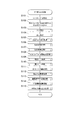
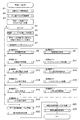
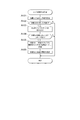
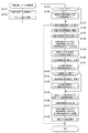
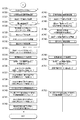
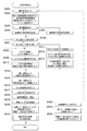
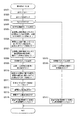
以下、このような遊技を行う遊技機の制御について説明する。まず、上記遊技制御装置100の遊技用マイクロコンピュータ(遊技用マイコン)111によって実行される制御について説明する。遊技用マイコン111による制御処理は、主に図29及び図30に示すメイン処理と、所定時間周期(例えば4m秒)で行われる図31に示すタイマ割込み処理とからなる。
Hereinafter, control of a gaming machine that performs such a game will be described. First, the control executed by the game microcomputer (game microcomputer) 111 of the
〔メイン処理〕
先ず、メイン処理について説明する。メイン処理は、電源が投入されることで開始される。このメイン処理においては、図29及び図30に示すように、まず、割込みを禁止する処理(ステップS1)を行ってから、割込みが発生したときにレジスタ等の値を退避する領域の先頭アドレスであるスタックポインタを設定するスタックポインタ設定処理(ステップS2)を行う。次に、レジスタバンク0を指定し(ステップS3)、所定のレジスタ(例えばDレジスタ)にRAM先頭アドレスの上位アドレスをセットする(ステップS4)。本実施形態の場合、RAMのアドレスの範囲は0000h〜01FFhで、上位としては00hか01hをとり、ステップS4では先頭の00hをセットする。次に、発射停止の信号を出力して発射許可信号を禁止状態に設定する(ステップS5)。発射許可信号は遊技制御装置100と払出制御装置200の少なくとも一方が発射停止の信号を出力している場合に禁止状態に設定され、遊技球の発射が禁止されるようになっている。
[Main processing]
First, the main process will be described. The main process is started when the power is turned on. In this main process, as shown in FIGS. 29 and 30, first, the process of disabling interrupts (step S1) is performed, and then the start address of the area for saving the value of the register or the like when an interrupt occurs is used. The stack pointer setting process (step S2) for setting a certain stack pointer is performed. Next, register
その後、入力ポート1(第1入力ポート122)の状態を読み込み(ステップS6)、電源投入ディレイタイマを設定する処理を行う(ステップS7)。この処理では所定の初
期値を設定することにより、主制御手段をなす遊技制御装置100からの指示に従い種々の制御を行う従制御手段(例えば、払出制御装置200や演出制御装置300)のプログラムが正常に起動するのを待つための待機時間(例えば3秒)が設定される。これにより、電源投入の際に仮に遊技制御装置100が先に立ち上がって従制御装置(例えば払出制御装置200や演出制御装置300)が立ち上がる前にコマンドを従制御装置へ送ってしまい、従制御装置がコマンドを取りこぼすのを回避することができる。すなわち、遊技制御装置100が、電源投入時において、主制御手段(遊技制御装置100)の起動を遅らせて従制御装置(払出制御装置200、演出制御装置300等)の起動を待つための所定の待機時間を設定する待機手段をなす。
After that, the state of the input port 1 (first input port 122) is read (step S6), and a process of setting the power-on delay timer is performed (step S7). In this process, by setting a predetermined initial value, a program of a slave control means (for example, a
また、電源投入ディレイタイマの計時は、RAMの正当性判定(チェックサム算出)の対象とならない記憶領域(正当性判定対象外のRAM領域又はレジスタ等)を用いて行われる。これにより、RAM領域のチェックサム等のチェックデータを算出する際に、一部のRAM領域を除外して算出する必要がないため電源投入時の制御が複雑になることを防止することができる。 Further, the power-on delay timer is timed by using a storage area (a RAM area or a register that is not subject to the validity judgment) that is not subject to the validity judgment (checksum calculation) of the RAM. As a result, when calculating check data such as a checksum of a RAM area, it is not necessary to exclude a part of the RAM area for calculation, so that it is possible to prevent the control at the time of power-on from becoming complicated.
なお、第1入力ポート122には初期化スイッチ信号が入力されるようになっており、待機時間の開始前に第1入力ポート122の状態を読み込むことで、初期化スイッチ112の操作を確実に検出できる。すなわち、待機時間の経過後に初期化スイッチ112の状態を読み込むようにすると、待機時間の経過を待ってから初期化スイッチ112を操作したり、電源投入から待機時間の経過まで初期化スイッチ112を操作し続けたりする必要がある。しかし、待機時間の開始前に状態を読み込むことで、このような煩わしい操作を行わなくても電源投入後すぐに操作を行うことで検出されるようになり、電源投入時に行った初期化の操作が受け付けられないような事態を防止できる。
An initialization switch signal is input to the
電源投入ディレイタイマを設定する処理(ステップS7)を行った後、待機時間の計時と、待機時間中における停電の発生を監視する処理(ステップS8からS12)を行う。まず、電源装置400から入力されている停電監視信号をポート及びデータバスを介して読み込んでチェックする回数(例えば2回)を設定し(ステップS8)、停電監視信号がオンであるかの判定を行う(ステップS9)。
After performing the process of setting the power-on delay timer (step S7), the process of timing the standby time and monitoring the occurrence of a power failure during the standby time (steps S8 to S12) is performed. First, the number of times (for example, twice) to read and check the power failure monitoring signal input from the
停電監視信号がオンである場合(ステップS9;Y)は、ステップS8で設定したチェック回数分停電監視信号のオン状態が継続しているかを判定する(ステップS10)。そして、チェック回数分停電監視信号のオン状態が継続していない場合(ステップS10;N)は、停電監視信号がオンであるかの判定(ステップS9)に戻る。また、チェック回数分停電監視信号のオン状態が継続している場合(ステップS10;Y)、すなわち、停電が発生していると判定した場合は、遊技機の電源が遮断されるのを待つ。このように、所定期間に亘り停電監視信号を受信し続けた場合に停電が発生したと判定することで、ノイズなどにより停電を誤検知することを防止でき、電源投入時における不具合に適切に対処することができる。 When the power failure monitoring signal is on (step S9; Y), it is determined whether the power failure monitoring signal is kept on for the number of checks set in step S8 (step S10). Then, when the power failure monitoring signal has not been turned on for the number of checks (step S10; N), the process returns to the determination of whether the power failure monitoring signal is on (step S9). Further, when the power failure monitoring signal is continuously turned on for the number of checks (step S10; Y), that is, when it is determined that a power failure has occurred, the power of the gaming machine is waited to be cut off. In this way, by determining that a power failure has occurred when the power failure monitoring signal is continuously received for a predetermined period, it is possible to prevent false detection of a power failure due to noise or the like, and appropriately deal with problems when the power is turned on. can do.
すなわち、遊技制御装置100が、所定の待機時間において停電の発生を監視する停電監視手段をなす。これにより、主制御手段をなす遊技制御装置100の起動を遅らせている期間において発生した停電に対応することが可能となり、電源投入時における不具合に適切に対処することができる。なお、待機時間の終了まではRAMへのアクセスが許可されておらず、前回の電源遮断時の記憶内容が保持されたままとなっているため、ここでの停電発生時にはバックアップの処理等は行う必要がない。このため、待機時間中に停電が発生してもRAMのバックアップを取る必要がなく、制御の負担を軽減することができる。
That is, the
一方、停電監視信号がオンでない場合(ステップS9;N)、すなわち、停電が発生していない場合には、電源投入ディレイタイマを−1更新し(ステップS11)、タイマの値が0であるかを判定する(ステップS12)。タイマの値が0でない場合(ステップS12;N)、すなわち、待機時間が終了していない場合は、停電監視信号のチェック回数を設定する処理(ステップS8)に戻る。また、タイマの値が0である場合(ステップS12;Y)、すなわち、待機時間が終了した場合は、RAMやEEPROM等の読出し書込み可能なRWM(リードライトメモリ)のアクセス許可をし(ステップS13)、全出力ポートにオフデータを出力(出力が無い状態に設定)する(ステップS14)。 On the other hand, when the power failure monitoring signal is not on (step S9; N), that is, when a power failure has not occurred, the power-on delay timer is updated by -1 (step S11), and whether the timer value is 0 or not. Is determined (step S12). If the value of the timer is not 0 (step S12; N), that is, if the standby time has not ended, the process returns to the process of setting the number of times the power failure monitoring signal is checked (step S8). When the timer value is 0 (step S12; Y), that is, when the standby time has expired, access permission is granted to the read / write RWM (read / write memory) such as RAM or EEPROM (step S13). ), Output off-data to all output ports (set to no output) (step S14).
次に、シリアルポート(遊技用マイコン111に予め搭載されているポートで、この実施形態では、演出制御装置300や払出制御装置200との通信に使用)を設定する(ステップS15)。
次いで、RWM内の停電検査領域1の値が正常な停電検査領域チェックデータ1(例えば5Ah)であるかを判定し(ステップS16)、正常であれば(ステップS16;Y)、RWM内の停電検査領域2の値が正常な停電検査領域チェックデータ2(例えばA5h)であるかを判定する(ステップS17)。そして、停電検査領域2の値が正常であれば(ステップS17;Y)、RWM内の所定領域のチェックサムを算出するチェックサム算出処理を行い(ステップS18)、算出したチェックサムと電源断時のチェックサムが一致するかを判定する(ステップS19)。チェックサムが一致する場合(ステップS19;Y)は、先に読み込んだ第1入力ポート122の状態から初期化スイッチがオンにされたかを判定し(ステップS20)、初期化スイッチがオフである場合(ステップS20;N)は、図30のステップS25へ移行して、停電から正常に復旧した場合の処理を行う。
Next, a serial port (a port previously mounted on the
Next, it is determined whether the value of the power
ステップS18及び後述のステップS45のチェックサム算出処理で算出するチェックサムは、遊技制御用のワーク領域のチェックサムと、状態表示用のワーク領域のチェックサムとを合算したものである。なお、遊技制御用のワーク領域のチェックサムと状態表示用のワーク領域のチェックサムとを別々に算出しステップS19にて一致するかを別々に判定しても良いし、何れか一方だけ(例えば遊技制御用のワーク領域のチェックサムだけ)を算出して当該一方だけをステップS19の判定に用いても良い。 The checksum calculated in the checksum calculation process of step S18 and step S45 described later is a sum of the checksum of the work area for game control and the checksum of the work area for status display. The checksum of the work area for game control and the checksum of the work area for status display may be calculated separately and it may be determined separately in step S19 whether or not they match, or only one of them (for example,). Only the checksum of the work area for game control) may be calculated and only one of them may be used for the determination in step S19.
ここで、遊技制御用のワーク領域には、遊技制御を行うために必要な情報(各種データやプログラム)が格納される。
また、状態表示用のワーク領域には、ベース値や役物比率などを表示するために必要な情報が格納される。ベース値は、遊技領域32に発射されて遊技を終えた全ての遊技球(セーフ球及びアウト球)を検出するアウトスイッチでの遊技球の検出数や入賞領域への入賞に基づく払出数から算出される値であり、ベース値を表示するために必要な情報は、例えば、アウトスイッチでの遊技球の検出数に関する情報と、入賞領域への入賞に基づく払出数に関する情報とを含む。また、役物比率は、遊技機10の電源投入から現在までに入賞口に入賞したことで得られた全賞球数(賞球の合計数)のうち、大当り状態中(すなわち、ファンファーレ及びエンディング中は除外)に大入賞口に入賞したことで得られた賞球数(役物別獲得球数)の割合(いわゆる連続役物比率)であり、役物比率を表示するために必要な情報は、例えば、全賞球数(賞球の合計数)に関する情報と、賞球数(役物別獲得球数)に関する情報とを含む。
Here, in the work area for game control, information (various data and programs) necessary for performing game control is stored.
In addition, the work area for displaying the status stores information necessary for displaying the base value, the accessory ratio, and the like. The base value is calculated from the number of game balls detected by the out switch that detects all the game balls (safe balls and out balls) that have been fired into the
また、初期化スイッチがオンである場合(ステップS20;Y)は、図30のステップS30へ移行して、遊技制御用のRAM領域の初期化の処理を行う。初期化スイッチが、外部からの操作が可能な初期化操作部をなし、遊技制御装置100が、初期化操作部が操作されたことに基づきRAMに記憶されたデータを初期化する初期化手段をなす。
また、停電検査領域の値が正常なチェックデータでないと判定された場合(ステップS16;NもしくはステップS17;N)、チェックサムが一致しないと判定された場合(
ステップS19;N)は、ステップS21へ移行して、全てのRAM領域の初期化の処理を行う。すなわち、状態表示用のRAM領域は、RAM異常が生じた場合にのみ初期化される。また、遊技制御用のRAM領域は、初期化スイッチがオンにされた場合だけでなく、RAM異常が生じた場合にも初期化される。
When the initialization switch is on (step S20; Y), the process proceeds to step S30 of FIG. 30 to initialize the RAM area for game control. The initialization switch serves as an initialization operation unit that can be operated from the outside, and the
Further, when it is determined that the value of the power failure inspection area is not normal check data (step S16; N or step S17; N), it is determined that the checksums do not match (step S16; N or step S17; N).
Step S19; N) proceeds to step S21 to perform initialization processing of all RAM areas. That is, the RAM area for displaying the status is initialized only when a RAM abnormality occurs. Further, the RAM area for game control is initialized not only when the initialization switch is turned on but also when a RAM abnormality occurs.
図30のステップS25では、初期化すべき領域に停電復旧時の初期値をセーブする(ステップS25)。ここでの初期化すべき領域とは、停電検査領域、チェックサム領域及びエラー不正監視に係る領域である。なお、払出制御装置200がコマンドを受付可能な状態か否かを示す信号である払出ビジー信号の状態を記憶するビジー信号ステータス領域もクリアされ、払出ビジー信号の状態を確定していないことを示す不定状態とされる。同様にタッチスイッチ信号の状態を記憶するタッチスイッチ信号状態監視領域もクリアされ、タッチスイッチ信号の状態を確定していないことを示す不定状態とされる。その後、RWM内の遊技状態を記憶する領域を調べて特図変動表示ゲームの確率状態が高確率状態であるか否かを判定する(ステップS26)。
In step S25 of FIG. 30, the initial value at the time of power failure recovery is saved in the area to be initialized (step S25). The areas to be initialized here are a power failure inspection area, a checksum area, and an area related to error fraud monitoring. The busy signal status area for storing the state of the payout busy signal, which is a signal indicating whether or not the
ここで、特図の高確率中でない場合(ステップS26;N)は、ステップS27,S28をスキップしてステップS29へ移行する。また、特図の高確率中である場合(ステップS26;Y)は、高確率報知フラグ領域にオン情報をセーブし(ステップS27)、遊技盤30に設けられる高確率報知LED(エラー表示器)のオン(点灯)データをセグメント領域にセーブする(ステップS28)。
そして、後述の特図ゲーム処理を合理的に実行するために用意されている処理番号に対応する停電復旧時のコマンドを演出制御基板(演出制御装置300)へ送信し(ステップS29)、ステップS33へ進む。本実施形態の場合、ステップS29では、機種指定コマンド、特図1保留数コマンド、特図2保留数コマンド、確率情報コマンド、画面指定コマンド(例えば、客待ち状態中の場合には客待ちデモコマンド、それ以外の場合には復旧画面コマンド)等の複数のコマンドを送信する。また、機種によっては、これらのコマンドに加えて、演出回数情報コマンドや高確率回数情報コマンドも送信する。
Here, if the special figure is not in the high probability (step S26; N), steps S27 and S28 are skipped and the process proceeds to step S29. Further, when the special figure is in high probability (step S26; Y), the on information is saved in the high probability notification flag area (step S27), and the high probability notification LED (error indicator) provided on the
Then, a command at the time of power failure recovery corresponding to the processing number prepared for rationally executing the special figure game processing described later is transmitted to the effect control board (effect control device 300) (step S29), and step S33. Proceed to. In the case of the present embodiment, in step S29, a model designation command, a special figure 1 hold number command, a special figure 2 hold number command, a probability information command, and a screen designation command (for example, a customer wait demo command when waiting for a customer) , Otherwise, send multiple commands such as recovery screen command). In addition to these commands, depending on the model, a production count information command and a high probability count information command are also transmitted.
画面指定コマンドは、再開された遊技の状態に応じたコマンドを送信する。制御の再開に伴い電源遮断により中断された特図変動表示ゲームを再開する場合には、画面指定コマンドとして復旧情報をなす復旧画面コマンドを送信する。さらにこの場合は、再開される特図変動表示ゲームの結果に関する情報も送信する。また、客待ち状態中に電源が遮断されて電源の復旧により客待ち状態で制御を再開する際には画面指定コマンドとして客待ちデモコマンドを送信する。また、制御の再開に伴い電源遮断により中断された特別遊技状態を再開する場合には、画面指定コマンドとして特別遊技状態再開コマンドを送信する。 The screen specification command sends a command according to the state of the restarted game. When resuming the special figure fluctuation display game that was interrupted by power interruption due to the resumption of control, a recovery screen command that provides recovery information is transmitted as a screen specification command. Further, in this case, information regarding the result of the special figure variation display game to be restarted is also transmitted. In addition, when the power is cut off during the customer waiting state and the control is resumed in the customer waiting state due to the restoration of the power supply, the customer waiting demo command is transmitted as a screen designation command. Further, when resuming the special game state interrupted by power interruption due to the resumption of control, a special game state resumption command is transmitted as a screen designation command.
また、図30のステップS30では、遊技制御用のRAM領域(ワーク領域とスタック領域)を0クリアして(ステップS30)、初期化すべき領域にRAM初期化時の初期値をセーブする(ステップS31)。そして、RAM初期化時のコマンドを演出制御基板(演出制御装置300)へ送信して(ステップS32)、ステップS33へ進む。 Further, in step S30 of FIG. 30, the RAM area (work area and stack area) for game control is cleared to 0 (step S30), and the initial value at the time of RAM initialization is saved in the area to be initialized (step S31). ). Then, the command at the time of RAM initialization is transmitted to the effect control board (effect control device 300) (step S32), and the process proceeds to step S33.
一方、ステップS16、S17、S19からステップS21へジャンプした場合には、RAMアクセス禁止領域をアクセス許可に設定し(ステップS21)、ビジー信号ステータス領域やタッチスイッチ信号状態監視領域を含む全てのRAM領域を0クリアして(ステップS22)、RAMアクセス禁止領域をアクセス禁止に設定する(ステップS23)。そして、初期化すべき領域に全RAM初期化時の初期値をセーブする(ステップS24)。ここでの初期化すべき領域とは、遊技制御用のワーク領域と状態表示用のワーク領域とのうち、0以外の値をセットしたい領域であり、例えば客待ちデモ領域及び演出モードの設定に係る領域である。
そして、RAM初期化時のコマンドを演出制御基板(演出制御装置300)へ送信して
(ステップS32)、ステップS33へ進む。本実施形態の場合、ステップS32では、機種指定コマンド、特図1保留数コマンド、特図2保留数コマンド、確率情報コマンド、RAM初期化コマンド(客待ちデモ画面を表示させるとともに、所定時間(例えば30秒間)光と音でRAM初期化の報知を行わせるためのコマンド)等の複数のコマンドを送信する。また、機種によっては、これらのコマンドに加えて、演出回数情報コマンドや高確率回数情報コマンドも送信する。
On the other hand, when jumping from steps S16, S17, S19 to step S21, the RAM access prohibited area is set to the access permission (step S21), and all the RAM areas including the busy signal status area and the touch switch signal state monitoring area are set. Is cleared to 0 (step S22), and the RAM access prohibited area is set to access prohibited (step S23). Then, the initial value at the time of initializing all RAM is saved in the area to be initialized (step S24). The area to be initialized here is an area of the work area for game control and the work area for status display for which a value other than 0 is to be set, and is related to, for example, the setting of the customer waiting demo area and the effect mode. The area.
Then, the command at the time of RAM initialization is transmitted to the effect control board (effect control device 300) (step S32), and the process proceeds to step S33. In the case of the present embodiment, in step S32, a model designation command, a special figure 1 hold number command, a special figure 2 hold number command, a probability information command, and a RAM initialization command (a customer waiting demo screen is displayed and a predetermined time (for example, for example) (30 seconds) Send multiple commands such as (command to notify RAM initialization by light and sound). In addition to these commands, depending on the model, a production count information command and a high probability count information command are also transmitted.
ステップS33では、遊技用マイコン111(クロックジェネレータ)内のタイマ割込み信号及び乱数更新トリガ信号(CTC)を発生するCTC(Counter/Timer Circuit)
回路を起動する処理を行う。なお、CTC回路は、遊技用マイコン111内のクロックジェネレータに設けられている。クロックジェネレータは、発振回路113からの発振信号(原クロック信号)を分周する分周回路と、分周された信号に基づいてCPU111Aに対して所定周期(例えば、4ミリ秒)のタイマ割込み信号及び乱数生成回路へ供給する乱数更新のトリガを与える信号CTCを発生するCTC回路とを備えている。
In step S33, the CTC (Counter / Timer Circuit) that generates the timer interrupt signal and the random number update trigger signal (CTC) in the gaming microcomputer 111 (clock generator).
Performs the process of starting the circuit. The CTC circuit is provided in the clock generator in the
上記ステップS33のCTC起動処理の後は、乱数生成回路を起動設定する処理を行う(ステップS34)。具体的には、乱数生成回路内の所定のレジスタ(CTC更新許可レジスタ)へ乱数生成回路を起動させるためのコード(指定値)の設定などがCPU111Aによって行われる。また、乱数生成回路のハードウェアで生成されるハード乱数(ここでは大当り乱数)のビット転置パターンの設定も行われる。ビット転置パターンとは、抽出した乱数のビット配置(上段のビット転置前の配置)を、予め定められた順で入れ替えて異なるビット配置(下段のビット転置後の配置)として格納する際の入れ替え方を定めるパターンである。このビット転置パターンに従い乱数のビットを入れ替えることで、乱数の規則性を崩すことができるとともに、乱数の秘匿性を高めることができる。なお、ビット転置パターンは、固定された単一のパターンであっても良いし、予め用意された複数のパターンから選択するようにしても良い。また、ユーザーが任意に設定できるようにしても良い。
After the CTC activation process in step S33, a process for activating and setting the random number generation circuit is performed (step S34). Specifically, the
その後、電源投入時の乱数生成回路内の所定のレジスタ(ソフト乱数レジスタ1〜n)の値を抽出し、対応する各種初期値乱数(本実施形態の場合、特図の当り図柄を決定する乱数(大当り図柄乱数、小当り図柄乱数)、普図の当りを決定する乱数(当り乱数)、普図の当り図柄を決定する乱数(当り図柄乱数))の初期値(スタート値)としてRWMの所定領域にセーブしてから(ステップS35)、割込みを許可する(ステップS36)。本実施形態で使用するCPU111A内の乱数生成回路においては、電源投入毎にソフト乱数レジスタの初期値が変わるように構成されているため、この値を各種初期値乱数の初期値(スタート値)とすることで、ソフトウェアで生成される乱数の規則性を崩すことができ、遊技者による不正な乱数の取得を困難にすることができる。
After that, the values of the predetermined registers (soft random number registers 1 to n) in the random number generation circuit at the time of turning on the power are extracted, and the corresponding initial value random numbers (in the case of this embodiment, the random numbers that determine the hit symbol of the special figure). (Big hit symbol random number, small hit symbol random number), random number that determines the hit of the normal figure (hit random number), random number that determines the hit symbol of the normal figure (win symbol random number)) as the initial value (start value) of RWM After saving in the area (step S35), the interrupt is permitted (step S36). In the random number generation circuit in the
続いて、各種初期値乱数の値を更新して乱数の規則性を崩すための初期値乱数更新処理(ステップS37)を行う。本実施形態において、初期値乱数更新処理では、大当り図柄初期値乱数と、小当り図柄初期値乱数と、当り初期値乱数と、当り図柄初期値乱数とを更新(例えば+1更新)する。ここで、「大当り図柄初期値乱数」は、特図変動表示ゲームの大当り停止図柄を決定する乱数の初期値となる乱数のことであり、「小当り図柄初期値乱数」は、特図変動表示ゲームの小当り停止図柄を決定する乱数の初期値となる乱数のことである。また、「当り初期値乱数」は、普図変動表示ゲームの当りを決定する乱数の初期値となる乱数のことであり、「当り図柄初期値乱数」は、普図変動表示ゲームの当り停止図柄を決定する乱数の初期値となる乱数のことである。このように、メイン処理の中で時間が許す限り初期値乱数をインクリメントし続けることによって、乱数のランダム性を高めることができるようにしている。なお、小当り図柄乱数は、小当りのない機種では当然存在しない。また、機種によっては、当り図柄初期値乱数が存在しない遊技機もある。 Subsequently, the initial value random number update process (step S37) for updating the values of various initial value random numbers and breaking the regularity of the random numbers is performed. In the present embodiment, in the initial value random number update process, the big hit symbol initial value random number, the small hit symbol initial value random number, the hit initial value random number, and the hit symbol initial value random number are updated (for example, +1 update). Here, the "big hit symbol initial value random number" is a random number that is the initial value of the random number that determines the jackpot stop symbol of the special symbol variation display game, and the "small hit symbol initial value random number" is the special symbol variation display. It is a random number that is the initial value of the random number that determines the small hit stop symbol of the game. Further, the "hit initial value random number" is a random number that is the initial value of the random number that determines the hit of the normal figure fluctuation display game, and the "hit symbol initial value random number" is the hit stop symbol of the normal figure fluctuation display game. It is a random number that is the initial value of the random number that determines. In this way, the randomness of the random numbers can be increased by continuing to increment the initial value random numbers as long as time allows in the main processing. It should be noted that the small hit symbol random number does not naturally exist in the model without the small hit. In addition, depending on the model, there is also a game machine in which the random number of the initial value of the winning symbol does not exist.
また、特に限定されるわけではないが、本実施形態においては、大当り乱数、大当り図柄乱数、小当り図柄乱数、当り乱数、当り図柄乱数は乱数生成回路において生成される乱数を使用して生成するように構成されている。ただし、大当り乱数はCPUの動作クロックと同等以上の速度のクロックを基にして更新される所謂「高速カウンタ」であり、大当り図柄乱数、小当り図柄乱数、当り乱数、当り図柄乱数はプログラムの処理単位であるタイマ割込み処理と同周期となるCTC出力(タイマ割込み処理のCTC(CTC0)とは別のCTC(CTC2))を基にして更新される「低速カウンタ」である。また、大当り図柄乱数、小当り図柄乱数、当り乱数、当り図柄乱数においては、乱数が一巡する毎に各々の初期値乱数(ソフトウェアで生成)を用いてスタート値を変更する所謂「初期値変更方式」を採用している。なお、前記各乱数は、+1、あるいは−1によるカウンタ式更新でもよいし、一巡するまで範囲内の全ての値が重複なくバラバラに出現するランダム式更新でもよい。つまり、大当り乱数はハードウェアのみで更新される乱数であり、大当り図柄乱数、小当り図柄乱数、当り乱数、当り図柄乱数はハードウェア及びソフトウェアで更新される乱数である。 Further, although not particularly limited, in the present embodiment, the big hit random number, the big hit symbol random number, the small hit symbol random number, the hit random number, and the hit symbol random number are generated by using the random numbers generated in the random number generation circuit. It is configured as follows. However, the jackpot random number is a so-called "high-speed counter" that is updated based on a clock whose speed is equal to or higher than the CPU operating clock, and the jackpot symbol random number, small hit symbol random number, hit random number, and hit symbol random number are processed by the program. It is a "low-speed counter" that is updated based on the CTC output (CTC (CTC2) different from CTC (CTC0) of timer interrupt processing) that has the same cycle as the timer interrupt processing, which is a unit. In addition, for big hit symbol random numbers, small hit symbol random numbers, hit random numbers, and hit symbol random numbers, the so-called "initial value change method" is used to change the start value using each initial value random number (generated by software) each time the random number goes around. "Is adopted. It should be noted that each of the random numbers may be a counter-type update by +1 or -1, or a random-type update in which all the values in the range appear separately without duplication until one cycle is completed. That is, the jackpot random number is a random number updated only by the hardware, and the jackpot symbol random number, the small hit symbol random number, the hit random number, and the hit symbol random number are random numbers updated by the hardware and software.
上記ステップS37の初期値乱数更新処理の後、電源装置400から入力されている停電監視信号をポート及びデータバスを介して読み込んでチェックする回数(例えば2回)を設定し(ステップS38)、停電監視信号がオンであるかの判定を行う(ステップS39)。停電監視信号がオンでない場合(ステップS39;N)は、初期値乱数更新処理(ステップS37)に戻る。すなわち、停電が発生していない場合には、初期値乱数更新処理と停電監視信号のチェック(ループ処理)を繰り返し行う。初期値乱数更新処理(ステップS37)の前に割り込みを許可する(ステップS36)ことによって、初期値乱数更新処理中にタイマ割込みが発生すると割込み処理が優先して実行されるようになり、タイマ割込みが初期値乱数更新処理によって待たされることで割込み処理が圧迫されるのを回避することができる。
After the initial value random number update process in step S37, the number of times (for example, twice) to read and check the power failure monitoring signal input from the
なお、上記ステップS37での初期値乱数更新処理は、メイン処理のほか、タイマ割込み処理の中においても初期値乱数更新処理を行う方法もあり、そのような方法を採用した場合には両方で初期値乱数更新処理が実行されるのを回避するため、メイン処理で初期値乱数更新処理を行う場合には割込みを禁止してから更新して割込みを解除する必要があるが、本実施形態のようにタイマ割込み処理の中での初期値乱数更新処理はせず、メイン処理内のみにした場合には初期値乱数更新処理の前に割込みを解除しても何ら問題はなく、それによってメイン処理が簡素化されるという利点がある。 In the initial value random number update process in step S37, in addition to the main process, there is also a method of performing the initial value random number update process in the timer interrupt process. In order to avoid executing the value random number update process, when the initial value random number update process is performed in the main process, it is necessary to disable the interrupt and then update to release the interrupt. If the initial value random number update processing is not performed in the timer interrupt processing and only in the main processing, there is no problem even if the interrupt is canceled before the initial value random number update processing, which causes the main processing. It has the advantage of being simplified.
停電監視信号がオンである場合(ステップS39;Y)は、ステップS38で設定したチェック回数分停電監視信号のオン状態が継続しているかを判定する(ステップS40)。そして、チェック回数分停電監視信号のオン状態が継続していない場合(ステップS40;N)は、停電監視信号がオンであるかの判定(ステップS39)に戻る。また、チェック回数分停電監視信号のオン状態が継続している場合(ステップS40;Y)、すなわち、停電が発生していると判定した場合は、一旦割込みを禁止する処理(ステップS41)、全出力ポートにオフデータを出力する処理(ステップS42)を行う。 When the power failure monitoring signal is on (step S39; Y), it is determined whether the power failure monitoring signal is continuously on for the number of checks set in step S38 (step S40). Then, when the power failure monitoring signal has not been turned on for the number of checks (step S40; N), the process returns to the determination of whether the power failure monitoring signal is on (step S39). Further, when the power failure monitoring signal is continuously on for the number of checks (step S40; Y), that is, when it is determined that a power failure has occurred, the process of temporarily disabling interrupts (step S41), all. The process of outputting off-data to the output port (step S42) is performed.
その後、停電検査領域1に停電検査領域チェックデータ1をセーブし(ステップS43)、停電検査領域2に停電検査領域チェックデータ2をセーブする(ステップS44)。さらに、RWMの電源遮断時のチェックサムを算出するチェックサム算出処理(ステップS45)、算出したチェックサムをセーブする処理(ステップS46)を行った後、RWMへのアクセスを禁止する処理(ステップS47)を行ってから、遊技機の電源が遮断されるのを待つ。このように、停電検査領域にチェックデータをセーブするとともに、電源遮断時のチェックサムを算出することで、電源の遮断の前にRWMに記憶されていた情報
が正しくバックアップされているか否かを電源再投入時に判断することができる。
After that, the power failure inspection
以上のことから、遊技を統括的に制御する主制御手段(遊技制御装置100)と、該主制御手段からの指示に従い種々の制御を行う従制御手段(払出制御装置200、演出制御装置300等)と、を備える遊技機において、主制御手段は、電源投入時において、当該主制御手段の起動を遅らせて従制御装置の起動を待つための所定の待機時間を設定する待機手段(遊技制御装置100)と、当該所定の待機時間において停電の発生を監視する停電監視手段(遊技制御装置100)と、を備えていることとなる。
From the above, a main control means (game control device 100) that comprehensively controls the game and a sub-control means (
また、各種装置に電力を供給する電源装置400を備え、当該電源装置400は、停電の発生を検出した際に停電監視信号を出力するように構成され、停電監視手段(遊技制御装置100)は、所定期間に亘り停電監視信号を受信し続けた場合に停電が発生したと判定するようにしていることとなる。
Further, a
また、主制御手段(遊技制御装置100)は、データを記憶可能なRAM111Cと、外部からの操作が可能な初期化操作部(初期化スイッチ)と、初期化操作部が操作されたことに基づきRAM111Cに記憶されたデータを初期化する初期化手段(遊技制御装置100)と、を備え、当該初期化手段の操作状態を待機時間の開始前に読み込むようにしていることとなる。
Further, the main control means (game control device 100) is based on the fact that the
また、主制御手段(遊技制御装置100)は、待機時間の経過後にRAM111Cへのアクセスを許可するようにしていることとなる。
Further, the main control means (game control device 100) is configured to allow access to the
〔タイマ割込み処理〕
次に、タイマ割込み処理について説明する。図31に示すように、タイマ割込み処理は、クロックジェネレータ内のCTC回路で生成される周期的なタイマ割込み信号がCPU111Aに入力されることで開始される。遊技用マイコン111においてタイマ割込みが発生すると、自動的に割込み禁止状態になって、図31のタイマ割込み処理が開始される。
[Timer interrupt processing]
Next, timer interrupt processing will be described. As shown in FIG. 31, the timer interrupt process is started by inputting a periodic timer interrupt signal generated by the CTC circuit in the clock generator to the
タイマ割込み処理が開始されると、まず、レジスタバンク1を指定する(ステップS101)。レジスタバンク1に切り替えたことで、所定のレジスタ(例えばメイン処理で使っているレジスタ)に保持されている値をRWMに移すレジスタ退避の処理を行ったのと同等になる。次に、所定のレジスタ(例えばDレジスタ)にRAM先頭アドレスの上位アドレスをセットする(ステップS102)。ステップS102では、メイン処理におけるステップS4と同じ処理を行っているが、レジスタバンクが異なる。次に、各種センサやスイッチからの入力や、信号の取込み、すなわち、各入力ポートの状態を読み込む入力処理(ステップS103)を行う。それから、各種処理でセットされた出力データに基づき、ソレノイド(大入賞口ソレノイド38b、普電ソレノイド37c)等のアクチュエータの駆動制御などを行うための出力処理(ステップS104)を行う。なお、メイン処理におけるステップS5で発射停止の信号を出力すると、この出力処理が行われることで発射許可の信号が出力され、発射許可信号を許可状態に設定可能な状態とされる。この発射許可信号は払出制御装置を経由して発射制御装置に出力される。その際、信号の加工等は行われない。また、当該発射許可信号は遊技制御装置から見た発射許可の状態を示す第1の信号であり、払出制御装置から見た発射許可の状態を示す第2の信号(発射許可信号)も払出制御装置内で生成され、発射制御装置に出力される。つまり、2つの発射許可信号が発射制御装置に出力されており、両者が共に発射許可となっている場合に、遊技球が発射可能な状態となるよう構成されている。
When the timer interrupt process is started, first, the
次に、各種処理で送信バッファにセットされたコマンドを払出制御装置200に出力する払出コマンド送信処理(ステップS105)、初期値乱数更新処理の対象となっている
大当り図柄乱数、小当り図柄乱数、当り乱数、当り図柄乱数の初期値(スタート値)を更新する乱数更新処理1(ステップS106)、特図1,特図2の変動表示ゲームにおける変動パターンを決定するための変動パターン乱数を更新する乱数更新処理2(ステップS107)を行う。その後、始動口1スイッチ36a、始動口2スイッチ37a、普図のゲートスイッチ34a、入賞口スイッチ35a、大入賞口スイッチ38aから正常な信号の入力があるか否かの監視や、エラーの監視(前面枠やガラス枠が開放されていないかなど)を行う入賞口スイッチ/状態監視処理(ステップS108)を行う。また、特図変動表示ゲームに関する処理を行う特図ゲーム処理(ステップS109)、普図変動表示ゲームに関する処理を行う普図ゲーム処理(ステップS110)を行う。
Next, the payout command transmission process (step S105) that outputs the command set in the transmission buffer in various processes to the
次に、遊技機10に設けられ、特図変動表示ゲームの表示や遊技に関する各種情報を表示するセグメントLEDを所望の内容を表示するように駆動するセグメントLED編集処理(ステップS111)、磁気センサ61からの検出信号をチェックして異常がないか判定する処理を行う磁石不正監視処理(ステップS112)、盤電波センサ62からの検出信号をチェックして異常がないか判定する処理を行う盤電波不正監視処理(ステップS113)を行う。それから、外部の各種装置に出力する信号を出力バッファにセットする外部情報編集処理(ステップS114)を行って、アウトスイッチでの遊技球の検出数や入賞領域への入賞に基づく払出数からベース値を算出する処理等を行う状態表示編集出力処理を行い(ステップS115)、タイマ割込み処理を終了する。
ここで、本実施形態では、割込み禁止状態を復元する処理(すなわち、割込みを許可する処理)や、レジスタバンクの指定を復元する処理(すなわち、レジスタバンク0を指定する処理)は、割込みリターンの際(タイマ割込み処理の終了時)に自動的に行う。なお、使用するCPUによっては、割込み禁止状態を復元する処理やレジスタバンクの指定を復元する処理の実行を命令する必要がある遊技機もある。
Next, a segment LED editing process (step S111), which is provided in the
Here, in the present embodiment, the process of restoring the interrupt disabled state (that is, the process of permitting interrupts) and the process of restoring the register bank designation (that is, the process of specifying register bank 0) are interrupt return processes. It is automatically performed at the time (at the end of timer interrupt processing). Depending on the CPU used, some gaming machines need to be instructed to execute a process of restoring the interrupt disabled state or a process of restoring the register bank designation.
〔払出コマンド送信処理〕
次に、前述のタイマ割込み処理における払出コマンド送信処理(ステップS105)の詳細について説明する。図32に示すように払出コマンド送信処理では、まず、入賞数カウンタ領域2にカウントがあるかをチェックする(ステップS181)。
[Payout command transmission process]
Next, the details of the payout command transmission process (step S105) in the timer interrupt process described above will be described. As shown in FIG. 32, in the payout command transmission process, first, it is checked whether or not there is a count in the winning number counter area 2 (step S181).
入賞数カウンタ領域は遊技制御装置100のRAM111Cに設けられ、入賞数カウンタ領域1と入賞数カウンタ領域2が設けられている。入賞数カウンタ領域1は、払出制御装置200に対して賞球の払い出しを指示するための払出コマンド(賞球指令)を送信するために用いる領域であって、払出コマンドを未だ送信していない賞球に対応する入賞のデータが記憶される。すなわち、入賞数カウンタ領域1が、賞球指令に関する情報を記憶可能な賞球指令カウンタをなす。
The winning number counter area is provided in the
入賞数カウンタ領域2は、入賞口への入賞により発生した賞球数(払出予定数)が所定数(ここでは10個)になる毎に外部装置へ出力するメイン賞球信号を送信するために用いる領域であって、メイン賞球信号の生成処理を行っていない賞球に対応する入賞のデータが記憶される。すなわち、入賞数カウンタ領域2が、メイン賞球信号に関する情報を記憶可能なメイン賞球信号カウンタをなす。なお、外部装置には、このメイン賞球信号の他に、払出制御装置200からも実際に払い出した賞球数が所定数(ここでは10個)になる毎に払出賞球信号が出力されるようになっており、この二つの信号を照合することで、不正な払い出しを監視することが可能となっている。
The prize
これらの入賞数カウンタ領域にはそれぞれ、各入賞口に対して設定された賞球数別(本実施形態の場合、3個賞球、10個賞球、14個賞球)に入賞数カウンタ領域が設けられており、入賞口への入賞に基づき対応する入賞数カウンタ領域のカウント数が1加算されるようになっている。つまり、入賞領域への一の入賞を単位として当該入賞の情報を記憶
可能とされている。なお、入賞数カウンタ領域1は入賞数カウンタ領域2よりも広い領域が割り当てられ、より多くの入賞のデータを記憶できるようにされている。これは、メイン賞球信号が送信先の状態に関係なく送信可能であるのに対し、払出コマンドが送信先である払出制御装置200の状態により送信を保留する場合もあり、より多くの未送信データが蓄積される可能性があるためである。
具体的には、本実施形態の場合、入賞数カウンタ領域1の3個賞球カウンタ領域、10個賞球カウンタ領域、及び14個賞球カウンタ領域には、それぞれ65535入賞まで記憶することができ、入賞数カウンタ領域2の3個賞球カウンタ領域、10個賞球カウンタ領域、及び14個賞球カウンタ領域には、それぞれ255入賞まで記憶することができるよう構成されている。
Each of these prize number counter areas is divided into prize ball number counter areas (3 prize balls, 10 prize balls, 14 prize balls in the case of this embodiment) set for each prize opening. Is provided, and the count number of the corresponding winning number counter area is added by 1 based on the winning in the winning opening. That is, it is possible to store the information of the winning in units of one winning in the winning area. The winning
Specifically, in the case of the present embodiment, up to 65535 prizes can be stored in each of the 3 prize ball counter area, the 10 prize ball counter area, and the 14 prize ball counter area of the prize
入賞数カウンタ領域2にカウントがあるかをチェックする処理(ステップS181)においては、賞球数別に設けられた複数の入賞数カウンタ領域のうち、チェック対象とされた入賞数カウンタ領域に「0」でないカウント数があるかを判定する。そして、カウント数がない場合(ステップS181;N)は、チェック対象となる入賞数カウンタ領域2のアドレスを更新し(ステップS182)、すべての入賞数カウンタ領域のカウント数のチェックが終了したかを判定する(ステップS183)。この判定で、すべてのチェックが終了した(ステップS183;Y)と判定すると、ステップS192に移行する。一方、すべてのチェックが終了していない(ステップS183;N)と判定すると、ステップS181へ戻って上記処理を繰り返す。本実施形態の場合、3個賞球カウンタ領域→10個賞球カウンタ領域→14個賞球カウンタ領域の順にチェック対象となる入賞数カウンタ領域2のアドレスを更新する。
In the process of checking whether or not there is a count in the winning number counter area 2 (step S181), among the plurality of winning number counter areas provided for each number of winning balls, the winning number counter area to be checked is "0". Determine if there is a count that is not. Then, when there is no count number (step S181; N), the address of the prize
また、上記ステップS181で、カウント数がある(ステップS181;Y)と判定した場合には、対象の入賞数カウンタ領域のカウント数を−1更新し(ステップS184)、対象の入賞数カウンタ領域2のアドレスに対応する払出数を取得する(ステップS185)。そして、賞球残数領域の値と取得した払出数を加算し(ステップS186)、加算結果を賞球残数領域にセーブする(ステップS187)。なお、この処理の前における賞球残数領域の値としては、メイン賞球信号の出力の基準となる所定数に満たなかった端数が記憶されている。
Further, when it is determined in step S181 that there is a count number (step S181; Y), the count number of the target winning number counter area is updated by -1 (step S184), and the target winning
その後、加算結果から10を減算して(ステップS188)、減算結果が0以上かを判定し(ステップS189)、0以上でない場合(ステップS189;N)は、ステップS192の処理に移行する。また、0以上である場合(ステップS189;Y)は、メイン賞球信号出力回数領域の値を+1更新する(ステップS190)。すなわち、賞球残数が10個になる度に、メイン賞球信号の出力回数を+1更新する。
そして、減算結果を賞球残数領域にセーブして(ステップS191)、ステップS188の処理に戻る。これにより、ホールコンピュータなどの外部の装置にメイン賞球信号が出力されるようになる。すなわち、遊技制御装置100が、所定の入賞領域への遊技球の入賞に伴い払い出しが決定された賞球数に関する情報を含むメイン賞球信号を遊技機の外部に出力する外部情報出力手段をなす。なお、メイン賞球信号を出力するようにすることで、大当り中などの遊技球の払い出しが集中する場合に、遊技球の払い出しとともに賞球信号の出力が遅延して、大当り中に発生した正確な賞球数が計数することができないといった不具合を防止することができる。
ここで、ステップS181〜S191の処理は、メイン賞球信号の出力回数を更新する(増やす)処理であり、ステップS192〜S201の処理は、払出コマンドを送信する処理である。
After that, 10 is subtracted from the addition result (step S188), it is determined whether the subtraction result is 0 or more (step S189), and if it is not 0 or more (step S189; N), the process proceeds to step S192. When it is 0 or more (step S189; Y), the value of the main prize ball signal output number region is updated by +1 (step S190). That is, every time the remaining number of prize balls reaches 10, the number of times the main prize ball signal is output is updated by +1.
Then, the subtraction result is saved in the prize ball remaining number area (step S191), and the process returns to the process of step S188. As a result, the main prize ball signal is output to an external device such as a hall computer. That is, the
Here, the processes of steps S181 to S191 are processes of updating (increasing) the number of output times of the main prize ball signal, and the processes of steps S192 to S201 are processes of transmitting a payout command.
ステップS192では、払出コマンド送信タイマが「0」でなければ−1更新し(ステップS192)、払出コマンド送信タイマが「0」になったかを判定する(ステップS1
93)。払出コマンド送信タイマが「0」でない場合(ステップS193;N)は、払出コマンド送信処理を終了する。また、払出コマンド送信タイマが「0」である場合(ステップS193;Y)は、払出ビジー信号フラグをチェックして、払出ビジー信号がビジー状態であるかを判定する(ステップS194)。
In step S192, if the payout command transmission timer is not "0", -1 is updated (step S192), and it is determined whether the payout command transmission timer has become "0" (step S1).
93). If the payout command transmission timer is not "0" (step S193; N), the payout command transmission process ends. When the payout command transmission timer is "0" (step S193; Y), the payout busy signal flag is checked to determine whether the payout busy signal is in a busy state (step S194).
払出ビジー信号は払出制御装置200が払出制御を即座に開始可能な状態か否かを示す信号であって、払出制御を即座に開始可能でない場合には払出ビジー信号がオン状態(ビジー状態)とされる。つまり、払出ビジー信号は、払出コマンド(賞球指令)を受付可能な状態であるか否かを示す信号とも言える。すなわち、払出ビジー信号が、払出制御手段(払出制御装置200)が払出制御を開始可能であるか否を示す状態信号をなす。
The payout busy signal is a signal indicating whether or not the
この払出ビジー信号がビジー状態である場合(ステップS194;Y)は、払出コマンド送信処理を終了する。すなわち、本実施形態では、タイマ割込み毎に払出コマンドを送信するのではなく、所定時間が経過し(払出コマンド送信タイマの値が0になり)、且つ、払出制御装置200側が賞球を払い出せる状態である場合に、払出コマンドを送信するよう構成されている。このように払出制御装置200が払出制御を即座に開始可能でなく、払出コマンドを送信しない場合は、払出コマンドの送信に関する以降の処理を行わないようにすることで、無駄な処理を行うことを防止し制御の負担を軽減するようにしている。
When the payout busy signal is in the busy state (step S194; Y), the payout command transmission process ends. That is, in the present embodiment, the payout command is not transmitted for each timer interrupt, but a predetermined time elapses (the value of the payout command transmission timer becomes 0), and the
払出ビジー信号がオン状態(ビジー状態)になる条件は、例えば、払出動作中、球貸し動作中、シュート球切れエラー中、オーバーフローエラー中、枠電波不正発生中、払出球検出スイッチ(払い出された球を監視するスイッチ)の異常中、払出不足エラー中、払出過剰エラー中、払出制御装置200のメモリ内に払い出すべき賞球数のカウント(未払い出しの賞球数=獲得遊技球数残)があるとき(=0でないとき)等である。 The conditions for turning on the payout busy signal (busy state) are, for example, during the payout operation, during the ball lending operation, during the shoot ball out error, during the overflow error, during the frame radio wave fraud, and the payout ball detection switch (payout). Counting the number of prize balls to be paid out in the memory of the payout control device 200 (number of unpaid prize balls = remaining number of acquired game balls) during an abnormality (switch for monitoring the balls), an error of insufficient payout, an error of overpayment ) Is present (when it is not 0), etc.
払出ビジー信号がビジー状態でない場合(ステップS194;N)は、入賞数カウンタ領域1にカウントがあるかをチェックする(ステップS195)。入賞数カウンタ領域1にカウントがあるかをチェックする処理(ステップS195)においては、賞球数別に設けられた複数の入賞数カウンタ領域のうち、チェック対象とされた入賞数カウンタ領域に「0」でないカウント数があるかを判定する。 When the payout busy signal is not in the busy state (step S194; N), it is checked whether there is a count in the winning number counter area 1 (step S195). In the process of checking whether or not there is a count in the winning number counter area 1 (step S195), among the plurality of winning number counter areas provided for each number of winning balls, the winning number counter area to be checked is "0". Determine if there is a count that is not.
そして、カウント数がない場合(ステップS195;N)は、チェック対象となる入賞数カウンタ領域1のアドレスを更新し(ステップS196)、すべての入賞数カウンタ領域のカウント数のチェックが終了したかを判定する(ステップS197)。この判定で、すべてのチェックが終了した(ステップS197;Y)と判定すると、払出コマンド送信処理を終了する。一方、すべてのチェックが終了していない(ステップS197;N)と判定すると、ステップS195へ戻って上記処理を繰り返す。本実施形態の場合、3個賞球カウンタ領域→10個賞球カウンタ領域→14個賞球カウンタ領域の順にチェック対象となる入賞数カウンタ領域1のアドレスを更新する。
Then, when there is no count number (step S195; N), the address of the prize
また、上記ステップS195で、カウント数がある(ステップS195;Y)と判定した場合には、対象の入賞数カウンタ領域のカウント数を−1更新し(ステップS198)、対象の入賞数カウンタ領域1のアドレスに対応する払出数コマンドを取得する(ステップS199)。そして、取得した払出数コマンドを払出用シリアル送信バッファに書き込み(ステップS200)、払出コマンド送信タイマ領域に初期値をセーブして(ステップS201)、払出コマンド送信処理を終了する。払出コマンド送信タイマは送信間隔を管理するためのもので、初期値として、例えば200m秒が設定される。
Further, when it is determined in step S195 that there is a count number (step S195; Y), the count number of the target winning number counter area is updated by -1 (step S198), and the target winning
これにより、入賞領域への一の入賞を単位とした払出コマンド(賞球指令)が生成され
、払出制御装置200に送信されるようになる。払出制御装置200はこの払出コマンドに基づき所定数の賞球を払い出す制御を行う。すなわち、遊技制御装置100が、払出制御手段(払出制御装置200)から出力される当該払出制御手段が払出制御を開始可能であるか否を示す状態信号が払出制御を開始可能であることを示している場合に賞球指令を払出制御手段に送信する賞球指令送信手段をなす。
As a result, a payout command (prize ball command) in units of one prize in the prize area is generated and transmitted to the
このように遊技制御装置100が、払出制御装置200から出力される状態信号に基づいて賞球指令を送信する制御を行うので、払出制御装置200が即座に払出制御を実行可能な場合にのみ賞球指令が送信されることとなる。これにより、未だ払い出しが行われていない入賞に対応するデータは遊技制御装置100側で保持されるようになるので停電発生時には遊技制御装置100でバックアップされるようになり、払出制御装置200にバックアップするための機能を備えなくとも正確な払出制御を実現できる。
Since the
従来の遊技機(例えば、特開2000−312759号公報の遊技機)では、何らかの原因により電源の遮断状態が発生した場合、払出制御装置200は自身の記憶手段にデータをバックアップし、電源遮断直前のデータによる払出制御状態を維持するようにしている。しかしながら、従来の遊技機では、バックアップするための機能が必要となるため、コストアップにつながるという問題があった。本発明によれば、払出制御装置200にバックアップするための機能を備えなくとも正確な払出制御を実現できるようにすることができる。
In a conventional game machine (for example, a game machine of JP-A-2000-321759), when a power cutoff state occurs for some reason, the
また、外部の装置に送信されるメイン賞球信号は払出ビジー信号の状態に関係なく出力されるので、遅滞なくメイン賞球信号を出力でき、ホールコンピュータなどの外部の装置では賞球の払い出しの時期を正確に把握でき、例えばベース値を正確に把握できるようになる。また、賞球指令に関する情報を記憶可能な賞球指令カウンタと、メイン賞球信号に関する情報を記憶可能なメイン賞球信号カウンタとを別々に備えるので、送信タイミングが異なる賞球指令とメイン賞球信号の情報を別々に管理でき、情報を確実に管理することができる。 In addition, since the main prize ball signal transmitted to the external device is output regardless of the state of the payout busy signal, the main prize ball signal can be output without delay, and the prize ball is paid out by an external device such as a hall computer. The time can be accurately grasped, for example, the base value can be accurately grasped. Further, since the prize ball command counter that can store the information about the prize ball command and the main prize ball signal counter that can store the information about the main prize ball signal are separately provided, the prize ball command and the main prize ball having different transmission timings are provided. The signal information can be managed separately, and the information can be managed reliably.
以上のことから、統括的に遊技制御を行うとともに、遊技領域32に設けられた入賞領域(始動入賞口36、普通変動入賞装置37、一般入賞口35、特別変動入賞装置38)への遊技球の入賞に基づいて賞球指令を送信する遊技制御手段(遊技制御装置100)と、遊技制御手段から送信される賞球指令に基づいて、遊技球の払出制御を行う払出制御手段(払出制御装置200)と、を備え、遊技制御手段は、払出制御手段から出力される当該払出制御手段が払出制御を開始可能であるか否を示す状態信号(ビジー信号)に基づいて賞球指令を払出制御手段に送信する制御を行い、停電が発生し該停電から復帰した場合には、払出制御手段から払出制御を開始可能であることを示す状態信号が出力されていたとしても、直ちに賞球指令を払出制御手段に送信せず、払出制御手段から払出制御を開始可能であることを示す状態信号が所定期間に亘って継続して出力されたことに対応して賞球指令を払出制御手段に送信するようにしていることとなる。
Based on the above, the game is controlled comprehensively, and the game ball to the winning area (starting winning
また、遊技領域32に賞球数の異なる入賞領域(始動入賞口36、普通変動入賞装置37、一般入賞口35、特別変動入賞装置38)を複数設け、遊技制御手段(遊技制御装置100)は、賞球数毎に、遊技球の払出制御を指示する賞球指令の未送信の有無を特定可能な賞球指令カウンタ(遊技制御装置100)を備え、状態信号が払出制御を開始可能であることを示し、かつ、各賞球指令カウンタに未送信の賞球指令がある場合に、賞球指令を払出制御手段(払出制御装置200)に送信するようにし、状態信号が当該払出制御手段が払出制御を開始可能であるか否かの特定を、各賞球指令カウンタに未送信の賞球指令があるか否かの特定よりも先に行うようにしていることとなる。
Further, a plurality of winning areas (
また、統括的に遊技制御を行うとともに、所定の入賞領域(始動入賞口36、普通変動入賞装置37、一般入賞口35、特別変動入賞装置38)への遊技球の入賞に基づいて賞球指令を送信する遊技制御手段(遊技制御装置100)と、遊技制御手段から送信される賞球指令に基づいて、遊技球の払出制御を行う払出制御手段(払出制御装置200)と、を備え、遊技制御手段は、払出制御手段から出力される当該払出制御手段が払出制御を開始可能であるか否を示す状態信号が払出制御を開始可能であることを示している場合に賞球指令を払出制御手段に送信する賞球指令送信手段(遊技制御装置100)と、所定の入賞領域への遊技球の入賞に伴い払い出しが決定された賞球数に関する情報を含む賞球信号(メイン賞球信号)を遊技機の外部に出力する外部情報出力手段(遊技制御装置100)と、を備え、外部情報出力手段は、払出制御手段から出力される状態信号が、払出制御手段が払出制御を開始可能であるか否かに関係なく賞球信号の出力を行うようにしたこととなる。
In addition, the game is controlled in a comprehensive manner, and a prize ball command is issued based on the winning of the game ball in a predetermined winning area (starting winning
また、賞球指令送信手段(遊技制御装置100)は、停電が発生し該停電から復帰した場合には、状態信号が払出制御を開始可能であることを示していたとしても、直ちに賞球指令を払出制御手段(払出制御装置200)に送信せず、状態信号が払出制御を開始可能であることを示している状態が所定期間に亘って継続していることに対応して賞球指令を払出制御手段に送信するようにしたこととなる。 Further, even if the prize ball command transmitting means (game control device 100) indicates that the status signal can start the payout control when a power failure occurs and recovers from the power failure, the prize ball command is immediately issued. Is not transmitted to the payout control means (payout control device 200), and the prize ball command is issued in response to the state in which the state signal indicates that the payout control can be started continues for a predetermined period. It means that it is transmitted to the payout control means.
また、遊技制御手段(遊技制御装置100)は、賞球指令に関する情報を記憶可能な賞球指令カウンタ(遊技制御装置100)と、賞球信号(メイン賞球信号)に関する情報を記憶可能な賞球信号カウンタ(遊技制御装置100)と、を備え、賞球指令送信手段(遊技制御装置100)は、所定の入賞領域(始動入賞口36、普通変動入賞装置37、一般入賞口35、特別変動入賞装置38)への一の入賞を単位として賞球指令を生成し、状態信号が払出制御を開始可能であることを示している場合に一の賞球指令を払出制御手段(払出制御装置200)に送信するように構成され、賞球指令カウンタ(遊技制御装置100)は、所定の入賞領域への一の入賞を単位として当該入賞の情報を記憶可能であり、所定の入賞領域への遊技球の入賞時に更新を行うとともに、払出制御手段への賞球指令への送信に対応させて更新を行うことで、送信していない賞球指令の数を記憶可能とし、外部情報出力手段は、所定の入賞領域への遊技球の入賞に伴い払い出しが決定された賞球数を累積し、累積値が所定数に達する毎に賞球信号を遊技機の外部に出力するように構成され、賞球信号カウンタは、所定の入賞領域への一の入賞を単位として当該入賞の情報を記憶可能であり、所定の入賞領域への遊技球の入賞時に更新を行うとともに、外部情報出力手段による賞球数の累積処理に対応させて更新を行うことで、未だ累積処理を行っていない賞球数を記憶可能であることとなる。
Further, the game control means (game control device 100) has a prize ball command counter (game control device 100) that can store information about the prize ball command and a prize that can store information about the prize ball signal (main prize ball signal). A ball signal counter (game control device 100) is provided, and the prize ball command transmitting means (game control device 100) is provided with a predetermined winning area (starting winning
また、本実施形態では、遊技制御装置100からは、遊技球の払出予定個数が10個になる毎にメイン賞球信号が出力され、払出制御装置200からは、遊技球の払出個数が10個になる毎にメイン賞球信号が出力されるよう構成されている。
具体的には、遊技制御装置100は、10個の払出予定毎(払出コマンドを送信する毎)に、メイン賞球数信号出力回数を+1更新(払出コマンド送信処理内のサブルーチン)し、更新(設定)されている出力回数分、メイン賞球信号を出力する。
予定毎に出力されるメイン賞球信号に対し、払出制御装置200からは実際に10個の払出が行われる毎に賞球信号が送信されるので、予定と結果の整合をとることができ、不正な払出に対応することができる。また、大当り期間中に入賞しても、球切れ等で払出が遅れ、大当り終了後に払い出された場合にも、入賞時に出力されるメイン賞球信号によって、ホールコン(ホールコンピュータ)が正確な情報を収集(判断)することができる。
Further, in the present embodiment, the
Specifically, the
With respect to the main prize ball signal output for each schedule, the
〔入賞口スイッチ/状態監視処理〕
図33には、タイマ割込み処理における入賞口スイッチ/状態監視処理(ステップS10
8)を示した。この入賞口スイッチ/状態監視処理では、まず、大入賞口(特別変動入賞装置38)内の一方の大入賞口スイッチ38aに対応する入賞口監視テーブル1を準備し(ステップS301)、大入賞口が開いていないにもかかわらず大入賞口に不正な入賞がないか監視するとともに正常な入賞を検出する不正&入賞監視処理(ステップS302)を実行する。
[Winning opening switch / status monitoring process]
FIG. 33 shows the winning port switch / status monitoring process in the timer interrupt process (step S10).
8) was shown. In this winning opening switch / status monitoring process, first, a winning opening monitoring table 1 corresponding to one of the winning
入賞口監視テーブルには、対象のスイッチに入力があるかを判定するデータの位置を示す監視スイッチビット、不正監視情報の下位アドレス、不正入賞数領域の下位アドレス、不正入賞エラー報知コマンド、不正入賞数上限値(不正発生判定個数)、入賞口スイッチテーブルのアドレス、報知タイマ更新情報(許可/更新)の情報が定義されている。また、入賞口監視テーブルのうちの入賞テーブルには、監視の繰り返し回数(スイッチの数)に加えて、各スイッチ毎に、監視スイッチビット、入賞数カウンタ領域1の下位アドレス、入賞数カウンタ領域2の下位アドレスの情報が定義されている。入賞口監視テーブルは、監視対象のスイッチのそれぞれに応じたものが用意されている。
In the winning opening monitoring table, a monitoring switch bit indicating the position of data for determining whether or not there is an input in the target switch, a lower address of fraudulent monitoring information, a lower address of the fraudulent winning number area, a fraudulent winning error notification command, and a fraudulent winning Information on the upper limit of the number (number of fraud occurrence judgments), the address of the winning opening switch table, and the notification timer update information (permission / update) is defined. Further, in the winning table of the winning opening monitoring table, in addition to the number of times of monitoring repetition (number of switches), the monitoring switch bit, the lower address of the winning
その後、大入賞口(特別変動入賞装置38)内の他方の大入賞口スイッチ38aに対応する入賞口監視テーブル2を準備し(ステップS303)、大入賞口が開いていないにもかかわらず大入賞口に不正な入賞がないか監視するとともに正常な入賞を検出する不正&入賞監視処理(ステップS304)を実行する。
After that, the winning opening monitoring table 2 corresponding to the other large winning
次に、普電内の入賞口スイッチ(始動口2スイッチ37a)の入賞口監視テーブルを準備し(ステップS305)、普電が開いていないにもかかわらず普電に不正な入賞がないか監視するとともに正常な入賞を検出する不正&入賞監視処理(ステップS306)を実行する。そして、常時入賞可能な入賞口スイッチ(例えば、始動口1スイッチ36aや一般入賞口35の入賞口スイッチ35a)の入賞口監視テーブルを準備し(ステップS307)、入賞数を更新する入賞数カウンタ更新処理(ステップS308)を行う。
Next, prepare a winning opening monitoring table for the winning opening switch (starting
次に、状態を監視すべき複数のスイッチ並びに信号のうちいずれのスイッチ又は信号を今回の監視の対象とするかを順番に指定するための状態スキャンカウンタを更新する(ステップS309)。本実施形態の場合、状態スキャンカウンタは0から3の範囲で更新される。その後、状態スキャンカウンタの値に応じて、監視する状態を設定するための遊技機状態監視テーブル1を準備する(ステップS310)。そして、エラーが発生しているかなどの状態を判定する遊技機状態チェック処理(ステップS311)を行う。 Next, the status scan counter for sequentially designating which of the plurality of switches for monitoring the status and which switch or signal is to be monitored this time is updated (step S309). In the case of this embodiment, the status scan counter is updated in the range of 0 to 3. After that, the game machine state monitoring table 1 for setting the state to be monitored is prepared according to the value of the state scan counter (step S310). Then, a game machine state check process (step S311) for determining a state such as whether an error has occurred is performed.
本実施形態の場合、状態スキャンカウンタの値を遊技機状態監視テーブル1に参照することで、状態スキャンカウンタの値が「0」である場合はスイッチのコネクタ抜けなどの発生により出力されるスイッチ異常1信号に基づく状態の監視が設定され、状態スキャンカウンタの値が「1」である場合は払出制御装置200からのシュート球切れスイッチ信号に基づく状態の監視が設定される。状態スキャンカウンタの値が「2」である場合はオーバーフロースイッチ信号に基づく状態の監視が設定され、状態スキャンカウンタの値が「3」である場合は払出異常ステータス信号に基づく状態の監視が設定される。
In the case of the present embodiment, the value of the status scan counter is referred to the game machine status monitoring table 1, and when the value of the status scan counter is "0", a switch abnormality is output due to a disconnection of the switch connector or the like. Status monitoring based on one signal is set, and when the value of the status scan counter is "1", status monitoring based on the shoot ball out switch signal from the
次に、状態スキャンカウンタの値に応じて、監視する状態を設定するための遊技機状態監視テーブル2を準備する(ステップS312)。そして、エラーが発生しているかなどの状態を判定する遊技機状態チェック処理(ステップS313)を行う。 Next, the game machine state monitoring table 2 for setting the state to be monitored is prepared according to the value of the state scan counter (step S312). Then, a game machine state check process (step S313) for determining a state such as whether an error has occurred is performed.
本実施形態の場合、状態スキャンカウンタの値を遊技機状態監視テーブル2に参照することで、状態スキャンカウンタの値が「0」である場合はガラス枠開放検出スイッチ63から出力される信号に基づく状態の監視が設定され、状態スキャンカウンタの値が「1」である場合は本体枠開放検出スイッチ64から出力される信号に基づく状態の監視が設定
される。また、状態スキャンカウンタの値が「2」である場合は枠電波不正信号に基づく状態の監視が設定され、状態スキャンカウンタの値が「3」である場合はタッチスイッチ信号に基づく状態の監視が設定される。
In the case of the present embodiment, the value of the state scan counter is referred to the game machine state monitoring table 2, and when the value of the state scan counter is "0", it is based on the signal output from the glass frame opening
次に、状態スキャンカウンタの値が「0」であるかを判定し(ステップS314)、エラースキャンカウンタの値が「0」でない場合(ステップS314;N)は、入賞口スイッチ/状態監視処理を終了する。この場合は、次に参照する遊技機状態監視テーブル3に状態の監視対象がない場合である。また、エラースキャンカウンタの値が「0」である場合(ステップS314;Y)は、遊技機状態監視テーブル3を準備し(ステップS315)、エラーが発生しているかなどの状態を判定する遊技機状態チェック処理(ステップS316)を行う。 Next, it is determined whether the value of the status scan counter is "0" (step S314), and if the value of the error scan counter is not "0" (step S314; N), the winning opening switch / status monitoring process is performed. finish. In this case, there is no status monitoring target in the game machine status monitoring table 3 to be referred to next. When the value of the error scan counter is "0" (step S314; Y), the game machine state monitoring table 3 is prepared (step S315), and the game machine determines the state such as whether an error has occurred. The state check process (step S316) is performed.
本実施形態の場合、状態スキャンカウンタの値を遊技機状態監視テーブル3に参照することで、状態スキャンカウンタの値が「0」である場合はスイッチのコネクタ抜けなどの発生により出力されるスイッチ異常2信号に基づく状態の監視が設定される。なお、遊技機状態監視テーブル3には状態スキャンカウンタが「1」から「3」の場合は定義されていない。 In the case of this embodiment, the value of the status scan counter is referred to the game machine status monitoring table 3, and when the value of the status scan counter is "0", a switch abnormality is output due to the occurrence of a switch connector disconnection or the like. 2 Signal-based condition monitoring is set. It should be noted that the game machine status monitoring table 3 is not defined when the status scan counter is from "1" to "3".
その後、払出制御装置200が払出制御を開始可能であるかを示す払出ビジー信号をチェックする払出ビジー信号チェック処理(ステップS317)を行って、入賞口スイッチ/状態監視処理を終了する。なお、ステップS315からS317の処理は、タイマ割込み毎に更新される状態スキャンカウンタの値が「0」の場合のみ実行されるため、4回のタイマ割込みに1回の割合で実行されることとなる。すなわち、タイマ割込みが4m秒毎に行われる場合は、16m秒毎にステップS315からS317の処理が行われることとなる。
After that, the payout busy signal check process (step S317) for checking the payout busy signal indicating whether the
〔特図ゲーム処理〕
次に、上述のタイマ割込み処理における特図ゲーム処理(ステップS109)の詳細について説明する。特図ゲーム処理では、始動口1スイッチ36a及び始動口2スイッチ37aの入力の監視と、特図変動表示ゲームに関する処理全体の制御、特図の表示の設定を行う。
[Special game processing]
Next, the details of the special figure game processing (step S109) in the above-mentioned timer interrupt processing will be described. In the special figure game process, the inputs of the
図34に示すように、特図ゲーム処理では、先ず、始動口1スイッチ36a及び始動口2スイッチ37aの入賞を監視する始動口スイッチ監視処理(ステップA1)を行う。始動口スイッチ監視処理では、始動入賞口36、第2始動入賞口をなす普通変動入賞装置37に遊技球の入賞があると、各種乱数(大当り乱数など)の抽出を行い、当該入賞に基づく特図変動表示ゲームの開始前の段階で入賞に基づく遊技結果を事前に判定する遊技結果事前判定を行う。
As shown in FIG. 34, in the special figure game process, first, a start port switch monitoring process (step A1) for monitoring the winning of the
次に、大入賞口スイッチ監視処理(ステップA2)を行う。この大入賞口スイッチ監視処理では、特別変動入賞装置38内に設けられた大入賞口スイッチ38aでの遊技球の検出を監視する処理を行う。
Next, the large winning opening switch monitoring process (step A2) is performed. In this large winning opening switch monitoring process, a process of monitoring the detection of a game ball by the large winning
次に、特図ゲーム処理タイマが「0」でなければ−1更新する(ステップA3)。なお、特図ゲーム処理タイマの最小値は「0」に設定されている。そして、特図ゲーム処理タイマの値が「0」であるかを判定する(ステップA4)。特図ゲーム処理タイマの値が「0」である場合(ステップA4;Y)、すなわちタイムアップした又はすでにタイムアップしていた場合は、特図ゲーム処理番号に対応する処理に分岐させるために参照する特図ゲームシーケンス分岐テーブルをレジスタに設定し(ステップA5)、当該テーブルを用いて特図ゲーム処理番号に対応する処理の分岐先アドレスを取得する(ステップA6)。
そして、特図ゲーム処理番号に応じてサブルーチンコールを行う(ステップA7)。
Next, if the special figure game processing timer is not "0", -1 is updated (step A3). The minimum value of the special figure game processing timer is set to "0". Then, it is determined whether or not the value of the special figure game processing timer is "0" (step A4). If the value of the special figure game processing timer is "0" (step A4; Y), that is, if the time is up or has already been up, refer to it in order to branch to the processing corresponding to the special figure game processing number. The special figure game sequence branch table to be used is set in the register (step A5), and the branch destination address of the process corresponding to the special figure game process number is acquired using the table (step A6).
Then, a subroutine call is made according to the special figure game processing number (step A7).
ステップA7にて、特図ゲーム処理番号が「0」の場合は、特図変動表示ゲームの変動開始を監視し、特図変動表示ゲームの変動開始の設定や演出の設定や、特図変動中処理を行うために必要な情報の設定等を行う特図普段処理(ステップA8)を行う。
ステップA7にて、特図ゲーム処理番号が「1」の場合は、特図の停止表示時間の設定や、特図表示中処理を行うために必要な情報の設定等を行う特図変動中処理(ステップA9)を行う。
In step A7, when the special figure game processing number is "0", the change start of the special figure change display game is monitored, the change start setting and effect setting of the special figure change display game, and the special figure change is in progress. The special figure normal process (step A8) for setting the information necessary for performing the process is performed.
In step A7, when the special figure game processing number is "1", the special figure changing process for setting the stop display time of the special figure, setting the information necessary for performing the special figure display processing, and the like. (Step A9) is performed.
ステップA7にて、特図ゲーム処理番号が「2」の場合は、特図変動表示ゲームの遊技結果が大当りであれば、大当りの種類に応じたファンファーレコマンドの設定や、各大当りの大入賞口開放パターンに応じたファンファーレ時間の設定や、ファンファーレ/インターバル中処理を行うために必要な情報の設定等を行う特図表示中処理(ステップA10)を行う。 In step A7, when the special figure game processing number is "2", if the game result of the special figure variation display game is a big hit, the fanfare command is set according to the type of big hit, and the big winning opening of each big hit. The special figure display processing (step A10) for setting the fanfare time according to the opening pattern, setting the information necessary for performing the fanfare / interval processing, and the like is performed.
ステップA7にて、特図ゲーム処理番号が「3」の場合は、大入賞口の開放時間の設定や開放回数の更新、大入賞口開放中処理を行うために必要な情報の設定等を行うファンファーレ/インターバル中処理(ステップA11)を行う。
ステップA7にて、特図ゲーム処理番号が「4」の場合は、大当りラウンドが最終ラウンドでなければインターバルコマンドを設定する一方で最終ラウンドであればエンディングコマンドを設定する処理や、大入賞口残存球処理を行うために必要な情報の設定等を行う大入賞口開放中処理(ステップA12)を行う。
In step A7, when the special figure game processing number is "3", the opening time of the large winning opening is set, the number of opening times is updated, and the information necessary for performing the processing during the opening of the large winning opening is set. Perform fanfare / interval processing (step A11).
In step A7, when the special figure game processing number is "4", the process of setting the interval command if the jackpot round is not the final round, while setting the ending command if it is the final round, or the remaining big winning opening. The large winning opening opening processing (step A12) for setting the information necessary for performing the ball processing is performed.
ステップA7にて、特図ゲーム処理番号が「5」の場合は、大当りラウンドが最終ラウンドであれば大入賞口内にある残存球が排出されるための時間を設定する処理や、大当り終了処理を行うために必要な情報の設定等を行う大入賞口残存球処理(ステップA13)を行う。
ステップA7にて、特図ゲーム処理番号が「6」の場合は、特図普段処理を行うために必要な情報の設定等を行う大当り終了処理(ステップA14)を行う。
In step A7, when the special figure game processing number is "5", if the jackpot round is the final round, the process of setting the time for the remaining balls in the jackpot to be discharged and the jackpot end process are performed. The large winning opening remaining ball processing (step A13) for setting the information necessary for the operation is performed.
In step A7, when the special figure game processing number is "6", the jackpot end process (step A14) for setting the information necessary for performing the special figure normal processing is performed.
ステップA7にて、特図ゲーム処理番号が「7」の場合は、小当りが発生した際の大入賞口の開放時間・開放パターンの設定、ファンファーレコマンドの設定、小当り中処理を行うために必要な情報の設定等を行う小当りファンファーレ中処理(ステップA15)を行う。
ステップA7にて、特図ゲーム処理番号が「8」の場合は、エンディングコマンドの設定や小当り残存球処理を行うために必要な情報の設定等を行う小当り中処理(ステップA16)を行う。
ステップA7にて、特図ゲーム処理番号が「9」の場合は、小当り中処理の際に大入賞口内に入賞した残存球が排出されるための時間を設定する処理や、小当り終了処理を行うために必要な情報の設定等を行う小当り残存球処理(ステップA17)を行う。
ステップA7にて、特図ゲーム処理番号が「10」の場合は、特図普段処理を行うために必要な情報の設定等を行う小当り終了処理(ステップA18)を行う。
In step A7, when the special figure game processing number is "7", in order to set the opening time / opening pattern of the big winning opening when a small hit occurs, set the fanfare command, and perform the small hit middle processing. The small hit fanfare process (step A15) for setting necessary information and the like is performed.
In step A7, when the special figure game processing number is "8", the small hit middle processing (step A16) for setting the ending command and the information necessary for performing the small hit remaining ball processing is performed. ..
In step A7, when the special figure game processing number is "9", the processing for setting the time for the remaining balls that have won in the large winning opening during the small hit medium processing and the small hit end processing The small hit remaining ball processing (step A17) for setting the information necessary for performing the above is performed.
In step A7, when the special figure game processing number is "10", the small hit end process (step A18) for setting the information necessary for performing the special figure normal processing is performed.
その後、特図1表示器51の変動を制御するためのテーブルを準備した後(ステップA19)、特図1表示器51による特別図柄の変動の制御に係る図柄変動制御処理(ステップA20)を行う。そして、特図2表示器52の変動を制御するためのテーブルを準備した後(ステップA21)、特図2表示器52による特別図柄の変動の制御に係る図柄変動制御処理(ステップA22)を行い、特図ゲーム処理を終了する。一方、ステップA4にて、特図ゲーム処理タイマの値が「0」でない場合(ステップA4;N)、すなわちタイムアップしていない場合は、ステップA19の処理に移行して、それ以降の処理を行う。
After that, after preparing a table for controlling the fluctuation of the special figure 1 display 51 (step A19), the symbol fluctuation control process (step A20) related to the control of the fluctuation of the special symbol by the special figure 1
なお、小当りは条件装置の作動を伴わない結果態様であり、大当りとは条件装置の作動を伴う特別結果である。条件装置とは、特図変動表示ゲームで大当りが発生(大当り図柄の停止表示)した場合に作動するもので、条件装置が作動するとは、例えば大当り状態が発生して特別電動役物としての特別変動入賞装置38を連続して作動させるための特定のフラグがセットされる(役物連続作動装置が作動される)ことを意味する。条件装置が作動しないとは、例えば小当り抽選に当選したような場合のように前述のフラグはセットされないことを意味する。なお、「条件装置」は上記のようなソフトウェア的にオンオフされるフラグのようなソフトウェア手段であっても良いし、電気的にオンオフされるスイッチのようなハードウェア手段であっても良い。また、「条件装置」は、その作動が電動役物の連続作動に必要条件とされる装置として、パチンコ遊技機の分野においては一般的に使用されている用語であり、本明細書においても同様な意味を有する用語として使用している。
The small hit is a result mode that does not involve the operation of the condition device, and the big hit is a special result that involves the operation of the condition device. The condition device operates when a big hit occurs (stop display of the big hit symbol) in the special figure fluctuation display game, and when the condition device operates, for example, a big hit state occurs and it is special as a special electric accessory. It means that a specific flag for continuously operating the variable winning
〔始動口スイッチ監視処理〕
次に、上述の特図ゲーム処理における始動口スイッチ監視処理(ステップA1)の詳細について説明する。図35に示すように、始動口スイッチ監視処理では、先ず、第1始動口(始動入賞口36)入賞監視テーブルを準備し(ステップA101)、ハード乱数取得処理(ステップA102)を行って、第1始動口への入賞があるか否かを判定する(ステップA103)。
ステップA103にて、第1始動口への入賞がないと判定した場合(ステップA103;N)には、ステップA109の処理に移行して、それ以降の処理を行う。
一方、ステップA103にて、第1始動口への入賞があると判定した場合(ステップA103;Y)には、特図時短中(普電サポート中)であるか否かを判定する(ステップA104)。
[Starting port switch monitoring process]
Next, the details of the start port switch monitoring process (step A1) in the above-mentioned special figure game process will be described. As shown in FIG. 35, in the start port switch monitoring process, first, the first start port (starting winning opening 36) winning monitoring table is prepared (step A101), and the hard random number acquisition process (step A102) is performed to perform the first step. 1 It is determined whether or not there is a prize in the starting port (step A103).
If it is determined in step A103 that there is no winning in the first starting port (step A103; N), the process proceeds to step A109, and subsequent processes are performed.
On the other hand, when it is determined in step A103 that there is a prize in the first starting port (step A103; Y), it is determined whether or not the special time is being shortened (during normal power support) (step A104). ).
ステップA104にて、特図時短中でないと判定した場合(ステップA104;N)には、ステップA107の処理に移行して、それ以降の処理を行う。
一方、ステップA104にて、特図時短中であると判定した場合(ステップA104;Y)には、右打ち指示報知コマンドを準備して(ステップA105)、当該コマンドを演出制御装置300へ送信する演出コマンド設定処理(ステップA106)を行う。すなわち、時短状態であれば、特図変動表示ゲームの確率状態にかかわらず、右打ち指示報知コマンドを準備して(ステップA105)、演出コマンド設定処理(ステップA106)を行う。本実施形態の遊技機10の場合、第1始動口(始動入賞口36)へは左打ちでないと入賞せず、普通変動入賞装置37へは右打ちでないと入賞しない。したがって、時短状態は、左打ちよりも右打ちの方が有利な遊技状態となるが、時短状態中に第1始動口に入賞があった場合(すなわち、時短状態中に左打ちされた場合)には、右打ち指示報知コマンドを演出制御装置300に送信して、右打ちするよう指示する報知(警告)を演出制御装置300によって行うよう構成されている。
次いで、第1始動口(始動入賞口36)による保留の情報を設定するテーブルを準備した後(ステップA107)、特図始動口スイッチ共通処理(ステップA108)を行う。
If it is determined in step A104 that the special figure time is not shortened (step A104; N), the process proceeds to step A107, and subsequent processes are performed.
On the other hand, when it is determined in step A104 that the special figure time is being shortened (step A104; Y), a right-handed instruction notification command is prepared (step A105), and the command is transmitted to the
Next, after preparing a table for setting the information of holding by the first starting port (starting winning opening 36) (step A107), the special figure starting port switch common process (step A108) is performed.
次に、第2始動口(普通変動入賞装置37)入賞監視テーブルを準備し(ステップA109)、ハード乱数取得処理(ステップA110)を行って、第2始動口への入賞があるか否かを判定する(ステップA111)。
ステップA111にて、第2始動口への入賞がないと判定した場合(ステップA111;N)には、始動口スイッチ監視処理を終了する。
一方、ステップA111にて、第2始動口への入賞があると判定した場合(ステップA111;Y)には、普通電動役物(普通変動入賞装置37)が作動中である、すなわち、普通変動入賞装置37が作動して遊技球の入賞が可能な開状態となっているか否かを判定
し(ステップA112)、普通電動役物が作動中である(ステップA112;Y)と判定すると、ステップA114の処理に移行して、それ以降の処理を行う。一方、ステップA112にて、普通電動役物が作動中でない(ステップA112;N)と判定すると、普電不正発生中であるかを判定する(ステップA113)。
Next, the second starting port (normal variable winning device 37) winning monitoring table is prepared (step A109), and the hard random number acquisition process (step A110) is performed to determine whether or not there is a winning in the second starting port. Determine (step A111).
If it is determined in step A111 that there is no winning in the second starting port (step A111; N), the starting port switch monitoring process is terminated.
On the other hand, when it is determined in step A111 that there is a prize for the second starting port (step A111; Y), the ordinary electric accessory (ordinary variable winning device 37) is operating, that is, the ordinary variation. When it is determined whether or not the winning
普電不正発生中であるかの判定では、普通変動入賞装置37への不正入賞数が不正発生判定個数(例えば5個)以上である場合に不正発生中であると判定する。普通変動入賞装置37は、閉状態では遊技球が入賞不可能であり、開状態でのみ遊技球が入賞可能である。よって、閉状態で遊技球が入賞した場合は何らかの異常や不正が発生した場合であり、このような閉状態で入賞した遊技球があった場合はその数を不正入賞数として計数する。そして、このように計数された不正入賞数が所定の不正発生判定個数(上限値)以上である場合に不正発生中と判定する。
In the determination of whether or not a fraudulent occurrence is occurring, it is determined that fraudulent occurrence is occurring when the number of fraudulent winnings to the ordinary variable winning
ステップA113にて、普電不正発生中でない(ステップA113;N)と判定すると、第2始動口(普通変動入賞装置37)による保留の情報を設定するテーブルを準備した後(ステップA114)、特図始動口スイッチ共通処理(ステップA115)を行って、始動口スイッチ監視処理を終了する。また、ステップA113にて、普電不正発生中である(ステップA113;Y)と判定した場合は、始動口スイッチ監視処理を終了する。すなわち、第2始動記憶をそれ以上発生させないようにする。 In step A113, if it is determined that the electric power fraud has not occurred (step A113; N), after preparing a table for setting the information on hold by the second starting port (normal variable winning device 37) (step A114), the special feature. Figure The start port switch common process (step A115) is performed to end the start port switch monitoring process. If it is determined in step A113 that an illegal electric power is being generated (step A113; Y), the start port switch monitoring process is terminated. That is, the second start memory is prevented from being generated any more.
〔ハード乱数取得処理〕
次に、上述の始動口スイッチ監視処理におけるハード乱数取得処理(ステップA102、A110)の詳細について説明する。図36に示すように、ハード乱数取得処理では、まず、第1始動口(始動入賞口36)及び第2始動口(普通変動入賞装置37)のうち、監視対象の始動口の入賞なし情報を設定して(ステップA121)、始動口1スイッチ36a及び始動口2スイッチ37aのうち、監視対象の始動口スイッチに入力があるか否かを判定する(ステップA122)。そして、監視対象の始動口スイッチに入力がない場合(ステップA122;N)は、ハード乱数取得処理を終了する。一方、監視対象の始動口スイッチに入力がある場合(ステップA122;Y)は、乱数ラッチレジスタステータスを読み込み(ステップA123)、対象の乱数ラッチレジスタにラッチデータがあるかを判定する(ステップA124)。
[Hard random number acquisition process]
Next, the details of the hard random number acquisition process (steps A102, A110) in the above-mentioned start port switch monitoring process will be described. As shown in FIG. 36, in the hard random number acquisition process, first, among the first starting port (starting winning opening 36) and the second starting opening (normal variable winning device 37), information on the starting port to be monitored without winning is obtained. It is set (step A121), and it is determined whether or not there is an input in the start port switch to be monitored among the
対象の乱数ラッチレジスタにラッチデータがない場合(ステップA124;N)、すなわち乱数が抽出されていない場合は、ハード乱数取得処理を終了する。また、対象の乱数ラッチレジスタにラッチデータがある場合(ステップA124;Y)は、監視対象のハード乱数ラッチレジスタに抽出された大当り乱数をロードし、準備する(ステップA125)。そして、第1始動口(始動入賞口36)及び第2始動口(普通変動入賞装置37)のうち、監視対象の始動口の入賞あり情報を設定して(ステップA126)、ハード乱数取得処理を終了する。 If there is no latch data in the target random number latch register (step A124; N), that is, if no random number has been extracted, the hard random number acquisition process ends. If there is latch data in the target random number latch register (step A124; Y), the jackpot random number extracted in the monitored hard random number latch register is loaded and prepared (step A125). Then, among the first starting port (starting winning opening 36) and the second starting opening (normal variable winning device 37), the winning information of the starting port to be monitored is set (step A126), and the hard random number acquisition process is performed. finish.
〔特図始動口スイッチ共通処理〕
次に、上述の始動口スイッチ監視処理における特図始動口スイッチ共通処理(ステップA108、A115)の詳細について説明する。特図始動口スイッチ共通処理は、始動口1スイッチ36aや始動口2スイッチ37aの入力があった場合に、各々の入力について共通して行われる処理である。
[Special figure start port switch common processing]
Next, the details of the special figure start port switch common process (steps A108 and A115) in the above-mentioned start port switch monitoring process will be described. The special figure start port switch common process is a process that is commonly performed for each input when the
図37に示すように、特図始動口スイッチ共通処理では、先ず、始動口1スイッチ36a及び始動口2スイッチ37aのうち、監視対象の始動口スイッチへの入賞の回数に関する情報を遊技機10の外部の管理装置に対して出力する回数である始動口信号出力回数をロードし(ステップA131)、ロードした値を+1更新して(ステップA132)、出
力回数がオーバーフローするかを判定する(ステップA133)。出力回数がオーバーフローしない場合(ステップA133;N)は、更新後の値をRWMの始動口信号出力回数領域にセーブして(ステップA134)、ステップA135の処理に移行する。一方、出力回数がオーバーフローする場合(ステップA133;Y)は、ステップA135の処理に移行する。本実施形態では、始動口信号出力回数領域に「0」から「255」までの値を記憶することができる。そして、ロードした値が「255」である場合には+1更新によって更新後の値は「0」になり、出力回数がオーバーフローすると判定するよう構成されている。
As shown in FIG. 37, in the special figure start port switch common process, first, among the
次に、始動口1スイッチ36a及び始動口2スイッチ37aのうち、監視対象の始動口スイッチに対応する更新対象の特図保留(始動記憶)数が上限値未満かを判定する(ステップA135)。更新対象の特図保留数が上限値未満でない場合(ステップA135;N)は、特図始動口スイッチ共通処理を終了する。
Next, among the
また、更新対象の特図保留数が上限値未満である場合(ステップA135;Y)は、更新対象の特図保留数(特図1保留数又は特図2保留数)を+1更新して(ステップA136)、対象の始動口入賞フラグをセーブする(ステップA137)。続けて、監視対象の始動口スイッチ及び特図保留数に対応する乱数格納領域のアドレスを算出して(ステップA138)、ハード乱数取得処理のステップA125にて準備した大当り乱数をRWMの大当り乱数格納領域にセーブする(ステップA139)。次に、監視対象の始動口スイッチの大当り図柄乱数を抽出し、準備して(ステップA140)、RWMの大当り図柄乱数格納領域にセーブする(ステップA141)。 If the number of special figure reservations to be updated is less than the upper limit (step A135; Y), the number of special figure reservations to be updated (number of special figure 1 hold or special figure 2 hold) is updated by +1 (step A135; Y). Step A136), the target start opening winning flag is saved (step A137). Subsequently, the address of the start port switch to be monitored and the random number storage area corresponding to the number of reserved special figures is calculated (step A138), and the jackpot random number prepared in step A125 of the hard random number acquisition process is stored in the RWM jackpot random number. Save to the area (step A139). Next, the jackpot symbol random number of the start port switch to be monitored is extracted, prepared (step A140), and saved in the jackpot symbol random number storage area of the RWM (step A141).
次いで、第1始動口(始動入賞口36)への入賞であるかを判定する(ステップA142)。
ステップA142にて、第1始動口への入賞でないと判定した場合(ステップA142;N)には、ステップA145の処理に移行する。
一方、ステップA142にて、第1始動口への入賞であると判定した場合(ステップA142;Y)には、小当り図柄乱数を抽出し、準備して(ステップA143)、RWMの小当り図柄乱数格納領域にセーブする(ステップA144)。
Next, it is determined whether or not the winning is in the first starting opening (starting winning opening 36) (step A142).
If it is determined in step A142 that the winning is not to the first starting port (step A142; N), the process proceeds to step A145.
On the other hand, when it is determined in step A142 that the prize is won in the first starting port (step A142; Y), the small hit symbol random number is extracted and prepared (step A143), and the small hit symbol of RWM is extracted. Save in the random number storage area (step A144).
次いで、変動パターン乱数1から3を対応するRWMの変動パターン乱数格納領域にセーブして(ステップA145)、特図保留情報判定処理(ステップA146)を行う。
次いで、監視対象の始動口スイッチ及び特図保留数に対応する飾り特図保留数コマンドを準備し(ステップA147)、演出コマンド設定処理(ステップA148)を行って、特図始動口スイッチ共通処理を終了する。
Next, the fluctuation pattern
Next, the start port switch to be monitored and the decorative special figure hold number command corresponding to the special figure hold number are prepared (step A147), the effect command setting process (step A148) is performed, and the special figure start port switch common process is performed. finish.
ここで、遊技制御装置100(RAM111C)は、始動入賞口36や普通変動入賞装置37の始動領域での遊技球の検出に基づき、所定の乱数を抽出し前記変動表示ゲームの実行権利となる始動記憶として所定数を上限に記憶する始動記憶手段をなす。また、始動記憶手段(遊技制御装置100)は、第1始動入賞口(始動入賞口36)への遊技球の入賞に基づき抽出した各種の乱数値を、所定数を上限に第1始動記憶として記憶し、第2始動入賞口(普通変動入賞装置37)への遊技球の入賞に基づき抽出した各種の乱数値を、所定数を上限に第2始動記憶として記憶する。
Here, the game control device 100 (RAM111C) extracts a predetermined random number based on the detection of the game ball in the starting area of the
〔特図保留情報判定処理〕
次に、上述の始動口スイッチ共通処理における特図保留情報判定処理(ステップA146)の詳細について説明する。特図保留情報判定処理は、対応する始動記憶に基づく特図変動表示ゲームの開始タイミングより前に当該始動記憶に対応した結果関連情報の判定を行う先読み処理である。
[Special figure reservation information judgment processing]
Next, the details of the special figure hold information determination process (step A146) in the above-mentioned start port switch common process will be described. The special figure reservation information determination process is a look-ahead process for determining result-related information corresponding to the start memory before the start timing of the special figure variation display game based on the corresponding start memory.
図38に示すように、まず、特図始動口スイッチ共通処理のステップA137にてセーブした始動口入賞フラグをチェックして、第1始動口(始動入賞口36)への入賞であるかを判定する(ステップA151)。
ステップA151にて、第1始動口への入賞でないと判定した場合(ステップA151;N)には、ステップA154の処理に移行する。
一方、ステップA151にて、第1始動口への入賞であると判定した場合(ステップA151;Y)には、特図時短中であるかを判定する(ステップA152)。
As shown in FIG. 38, first, the start port winning flag saved in step A137 of the special figure start port switch common process is checked, and it is determined whether or not the first start port (starting winning opening 36) has won a prize. (Step A151).
If it is determined in step A151 that the winning is not to the first starting port (step A151; N), the process proceeds to step A154.
On the other hand, in step A151, when it is determined that the first starting port has been won (step A151; Y), it is determined whether or not the special time is being shortened (step A152).
ステップA152にて、特図時短中であると判定した場合(ステップA152;Y)には、特図保留情報判定処理を終了する。
一方、ステップA152にて、特図時短中でないと判定した場合(ステップA152;N)には、大当り中または小当り中であるかを判定する(ステップA153)。
ステップA153にて、大当り中または小当り中であると判定した場合(ステップA153;Y)には、特図保留情報判定処理を終了する。
一方、ステップA153にて、大当り中または小当り中でないと判定した場合(ステップA153;N)には、大当り乱数値が大当り判定値と一致するか否かにより大当りであるか否かを判定する大当り判定処理(ステップA154)を行う。そして、判定結果が大当りである場合(ステップA155;Y)は、対象の始動口スイッチに対応する大当り図柄乱数チェックテーブルを設定し(ステップA156)、特図始動口スイッチ共通処理のステップA140にて準備した大当り図柄乱数に対応する停止図柄情報を取得して(ステップA157)、ステップA164の処理に移行する。
If it is determined in step A152 that the special figure holding time is being shortened (step A152; Y), the special figure reservation information determination process is terminated.
On the other hand, in step A152, when it is determined that the special figure time is not shortened (step A152; N), it is determined whether the big hit or the small hit is in progress (step A153).
If it is determined in step A153 that a big hit or a small hit is in progress (step A153; Y), the special figure reservation information determination process ends.
On the other hand, when it is determined in step A153 that the jackpot is not being hit or the small hit is not being made (step A153; N), it is determined whether or not the jackpot is a jackpot based on whether or not the jackpot random number value matches the jackpot determination value. The jackpot determination process (step A154) is performed. Then, when the determination result is a big hit (step A155; Y), the big hit symbol random number check table corresponding to the target start port switch is set (step A156), and in step A140 of the special figure start port switch common process. The stop symbol information corresponding to the prepared jackpot symbol random number is acquired (step A157), and the process proceeds to step A164.
一方、判定結果が大当りでない場合(ステップA155;N)は、第1始動口(始動入賞口36)への入賞であるかを判定する(ステップA158)。
ステップA158にて、第1始動口への入賞でないと判定した場合(ステップA158;N)には、はずれの停止図柄情報を設定して(ステップA163)、ステップA164の処理に移行する。
一方、ステップA158にて、第1始動口への入賞であると判定した場合(ステップA158;Y)には、大当り乱数値が小当り判定値と一致するか否かにより小当りであるか否かを判定する小当り判定処理(ステップA159)を行う。そして、判定結果が小当りでない場合(ステップA160;N)は、はずれの停止図柄情報を設定して(ステップA163)、ステップA164の処理に移行する。
一方、判定結果が小当りである場合(ステップA160;Y)には、小当り図柄乱数チェックテーブルを設定し(ステップA161)、特図始動口スイッチ共通処理のステップA143にて準備した小当り図柄乱数に対応する停止図柄情報を取得して(ステップA162)、ステップA164の処理に移行する。
On the other hand, when the determination result is not a big hit (step A155; N), it is determined whether or not the first starting opening (starting winning opening 36) has won a prize (step A158).
If it is determined in step A158 that the prize is not won in the first starting port (step A158; N), the stop symbol information of the loss is set (step A163), and the process proceeds to step A164.
On the other hand, when it is determined in step A158 that the winning is won to the first starting port (step A158; Y), whether or not the jackpot random number value is a small hit depending on whether or not it matches the small hit determination value. A small hit determination process (step A159) is performed to determine whether or not. Then, when the determination result is not a small hit (step A160; N), the stop symbol information of the loss is set (step A163), and the process proceeds to the process of step A164.
On the other hand, when the determination result is a small hit (step A160; Y), a small hit symbol random number check table is set (step A161), and the small hit symbol prepared in step A143 of the special figure start port switch common process is set. The stop symbol information corresponding to the random number is acquired (step A162), and the process proceeds to step A164.
そして、対象の始動口スイッチ及び停止図柄情報に対応する先読み停止図柄コマンドを準備し(ステップA164)、演出コマンド設定処理を行う(ステップA165)。次に、変動パターンを設定するためのパラメータである特図情報を設定する特図情報設定処理(ステップA166)を行い、特図変動表示ゲームの変動態様を設定する変動パターン設定処理を行う(ステップA167)。 Then, a look-ahead stop symbol command corresponding to the target start port switch and stop symbol information is prepared (step A164), and the effect command setting process is performed (step A165). Next, the special figure information setting process (step A166) for setting the special figure information which is a parameter for setting the variation pattern is performed, and the variation pattern setting process for setting the variation mode of the special figure variation display game is performed (step). A167).
その後、特図変動表示ゲームの変動態様における前半変動パターンを示す前半変動番号及び後半変動パターンを示す後半変動番号に対応する先読み変動パターンコマンドを準備して(ステップA168)、演出コマンド設定処理を行い(ステップA169)、特図保留情報判定処理を終了する。なお、ステップA166における特図情報設定処理、ステップA167における変動パターン設定処理は、特図普段処理で特図変動表示ゲームの開始時に実行される処理と同様である。 After that, a look-ahead variation pattern command corresponding to the first half variation number indicating the first half variation pattern and the second half variation number indicating the second half variation pattern in the variation mode of the special figure variation display game is prepared (step A168), and the effect command setting process is performed. (Step A169), the special figure reservation information determination process is terminated. The special figure information setting process in step A166 and the variation pattern setting process in step A167 are the same as the processes executed at the start of the special figure variation display game in the special figure normal processing.
以上の処理により、先読み対象の始動記憶に基づく特図変動表示ゲームの結果を含む先読み図柄コマンドと、当該始動記憶に基づく特図変動表示ゲームでの変動パターンの情報を含む先読み変動パターンコマンドが準備され、演出制御装置300に送信される。これにより、始動記憶に対応した結果関連情報(大当りか否かや変動パターンの種類)の判定結果(先読み結果)を、対応する始動記憶に基づく特図変動表示ゲームの開始タイミングより前に演出制御装置300に対して知らせることができ、特に表示装置41に表示される飾り特図始動記憶表示を変化させるなどして、その特図変動表示ゲームの開始タイミングより前に遊技者に結果関連情報を報知することが可能となる。
By the above processing, a look-ahead symbol command including the result of the special figure variation display game based on the start memory of the look-ahead target and a look-ahead variation pattern command including information on the variation pattern in the special figure variation display game based on the start memory are prepared. And transmitted to the
すなわち、遊技制御装置100が、始動入賞記憶手段(遊技制御装置100)に始動記憶として記憶される乱数を、当該始動記憶に基づく変動表示ゲームの実行前に判定する(例えば特別結果となるか否か等を判定)事前判定手段をなす。なお、始動記憶に対応して記憶された乱数値を事前に判定する時期は、当該始動記憶が発生した始動入賞時だけではなく、当該始動記憶に基づく変動表示ゲームが行われる前であればいつでもよい。
That is, the
〔特図普段処理〕
次に、上述の特図ゲーム処理における特図普段処理(ステップA8)の詳細について説明する。図39に示すように、特図普段処理では、先ず、特図2保留数(第2始動記憶数)が「0」であるかを判定する(ステップA301)。特図2保留数が「0」である(ステップA301;Y)と判定すると、特図1保留数(第1始動記憶数)が「0」であるかを判定する(ステップA305)。そして、特図1保留数が「0」である(ステップA305;Y)と判定すると、客待ちデモが開始済みであるかを判定し(ステップA309)、客待ちデモが開始済みでない場合(ステップA309;N)は、客待ちデモフラグ領域に客待ちデモ中フラグをセットする(ステップA310)。
[Special figure normal processing]
Next, the details of the special figure normal processing (step A8) in the above-mentioned special figure game processing will be described. As shown in FIG. 39, in the special figure normal processing, first, it is determined whether or not the special figure 2 hold number (second start storage number) is “0” (step A301). When it is determined that the special figure 2 hold number is "0" (step A301; Y), it is determined whether the special figure 1 hold number (first start storage number) is "0" (step A305). Then, when it is determined that the number of reserved special figures 1 is "0" (step A305; Y), it is determined whether the customer waiting demo has started (step A309), and when the customer waiting demo has not started (step A309). A309; N) sets the customer waiting demo flag area in the customer waiting demo flag area (step A310).
続けて、客待ちデモコマンドを準備して(ステップA311)、演出コマンド設定処理(ステップA312)を行う。次いで、処理番号として特図普段処理に係る「0」を設定して(ステップA313)、特図ゲーム処理番号領域に当該処理番号をセーブする(ステップA314)。そして、変動図柄判別フラグ領域をクリアし(ステップA315)、大入賞口不正監視期間フラグ領域に不正監視期間中フラグをセーブして(ステップA316)、特図普段処理を終了する。すなわち、特図変動表示ゲームを開始可能な状態であるが始動条件が成立しない場合に、待機情報をなす客待ちデモコマンドを演出制御装置300に送信するようにしていることとなる。
一方、ステップA309にて、客待ちデモが開始済みである場合(ステップA309;Y)は、ステップA310〜A312の処理を行わずに、ステップA313の処理へ移行する。
Subsequently, the customer waiting demo command is prepared (step A311), and the effect command setting process (step A312) is performed. Next, "0" related to the special figure normal processing is set as the processing number (step A313), and the processing number is saved in the special figure game processing number area (step A314). Then, the variable symbol discrimination flag area is cleared (step A315), the flag during the fraud monitoring period is saved in the large winning opening fraud monitoring period flag area (step A316), and the special figure normal processing is ended. That is, when the special figure variation display game can be started but the start condition is not satisfied, the customer waiting demo command that forms the standby information is transmitted to the
On the other hand, if the customer waiting demo has already started in step A309 (step A309; Y), the process proceeds to step A313 without performing the processes of steps A310 to A312.
また、ステップA301にて、特図2保留数が「0」でない場合(ステップA301;N)は、特図2保留数に対応する飾り特図保留数コマンドを準備する(ステップA302)。次いで、演出コマンド設定処理(ステップA303)を行い、特図2変動開始処理(ステップA304)を行って、特図普段処理を終了する。
また、ステップA305にて、特図1保留数が「0」でない場合(ステップA305;N)は、特図1保留数に対応する飾り特図保留数コマンドを準備する(ステップA306)。次いで、演出コマンド設定処理(ステップA307)を行い、特図1変動開始処理(ステップA308)を行って、特図普段処理を終了する。
Further, in step A301, when the special figure 2 hold number is not "0" (step A301; N), the decorative special figure hold number command corresponding to the special figure 2 hold number is prepared (step A302). Next, the effect command setting process (step A303) is performed, the special figure 2 fluctuation start process (step A304) is performed, and the special figure normal process is completed.
Further, in step A305, when the special figure 1 hold number is not "0" (step A305; N), the decorative special figure hold number command corresponding to the special figure 1 hold number is prepared (step A306). Next, the effect command setting process (step A307) is performed, the special figure 1 fluctuation start process (step A308) is performed, and the special figure normal process is completed.
このように、特図2保留数のチェックを特図1保留数のチェックよりも先に行うことで、特図2保留数が「0」でない場合には特図2変動開始処理(ステップA304)が実行されることとなる。すなわち、第2特図変動表示ゲームが第1特図変動表示ゲームに優先
して実行されることとなる。つまり、遊技制御装置100が、第2始動記憶手段(遊技制御装置100)に第2始動記憶がある場合には、当該第2始動記憶に基づく変動表示ゲームを、第1始動記憶に基づく変動表示ゲームよりも優先的に実行する優先制御手段をなす。
In this way, by checking the number of special figures 2 held before checking the number of special figures 1 held, if the number of special figures 2 held is not "0", the special figure 2 fluctuation start process (step A304). Will be executed. That is, the second special figure variation display game is executed in preference to the first special figure variation display game. That is, when the
〔特図1変動開始処理〕
次に、上述の特図普段処理における特図1変動開始処理(ステップA308)の詳細について説明する。特図1変動開始処理は、第1特図変動表示ゲームの開始時に行う処理である。図40(a)に示すように、まず、実行する特図変動表示ゲームの種別(ここでは特図1)を示す特図1変動フラグを変動図柄判別領域にセーブし(ステップA321)、第1特図変動表示ゲームが大当りであるか否かを判別するための大当りフラグ1にはずれ情報や大当り情報を設定するとともに、第1特図変動表示ゲームが小当りであるか否かを判別するための小当りフラグにはずれ情報や小当り情報を設定する大当りフラグ1設定処理(ステップA322)を行う。
[Special Figure 1 Fluctuation Start Processing]
Next, the details of the special figure 1 fluctuation start processing (step A308) in the above-mentioned special figure normal processing will be described. The special figure 1 variation start process is a process performed at the start of the first special figure variation display game. As shown in FIG. 40 (a), first, the special figure 1 fluctuation flag indicating the type of the special figure fluctuation display game to be executed (here, special figure 1) is saved in the fluctuation symbol discrimination area (step A321), and the first To set the
次に、特図1停止図柄(図柄情報)の設定に係る特図1停止図柄設定処理(ステップA323)を行った後、変動パターンを設定するためのパラメータである特図情報を設定する特図情報設定処理(ステップA324)を行い、第1特図変動表示ゲームの変動パターンの設定に関する種々の情報を参照するための情報が設定されたテーブルである特図1変動パターン設定情報テーブルを準備する(ステップA325)。その後、第1特図変動表示ゲームにおける変動態様である変動パターンを設定する変動パターン設定処理(ステップA326)を行い、第1特図変動表示ゲームの変動開始の情報を設定する変動開始情報設定処理(ステップA327)を行う。 Next, after performing the special figure 1 stop symbol setting process (step A323) related to the setting of the special figure 1 stop symbol (symbol information), the special figure for setting the special figure information which is a parameter for setting the fluctuation pattern is set. The information setting process (step A324) is performed, and the special figure 1 variation pattern setting information table, which is a table in which information for referring to various information regarding the setting of the variation pattern of the first special figure variation display game is set, is prepared. (Step A325). After that, the variation pattern setting process (step A326) for setting the variation pattern, which is the variation mode in the first special figure variation display game, is performed, and the variation start information setting process for setting the variation start information of the first special figure variation display game is performed. (Step A327) is performed.
次いで、処理番号として特図変動中処理にかかる「1」を設定し(ステップA328)、特図ゲーム処理番号領域に当該処理番号をセーブする(ステップA329)。
そして、客待ちデモフラグ領域をクリアし(ステップA330)、特図1の変動開始に関する信号(例えば、特別図柄1変動中信号をON)を試験信号出力データ領域にセーブする(ステップA331)。その後、特図1変動制御フラグ領域に変動中フラグをセーブし(ステップA332)、特図1点滅制御タイマ領域に点滅制御タイマ(特図1表示器51の点滅の周期のタイマ)の初期値(ここでは100ms)を設定する(ステップA333)。次いで、特図1変動図柄番号領域に初期値(ここでは「0」)をセーブして(ステップA334)、特図1変動開始処理を終了する。
Next, "1" related to the special figure changing process is set as the process number (step A328), and the process number is saved in the special figure game process number area (step A329).
Then, the customer waiting demo flag area is cleared (step A330), and the signal related to the start of the fluctuation of the special figure 1 (for example, the signal during the change of the
〔特図2変動開始処理〕
次に、上述の特図普段処理における特図2変動開始処理(ステップA304)の詳細について説明する。特図2変動開始処理は、第2特図変動表示ゲームの開始時に行う処理であって、図40(a)に示した特図1変動開始処理での処理と同様の処理を、第2始動記憶を対象として行うものである。
[Special figure 2 fluctuation start processing]
Next, the details of the special figure 2 fluctuation start processing (step A304) in the above-mentioned special figure normal processing will be described. The special figure 2 variation start process is a process performed at the start of the second special figure variation display game, and the same process as the process in the special figure 1 variation start process shown in FIG. 40 (a) is performed in the second start. It is intended for memory.
図40(b)に示すように、まず、実行する特図変動表示ゲームの種別(ここでは特図2)を示す特図2変動フラグを変動図柄判別領域にセーブし(ステップA341)、第2特図変動表示ゲームが大当りであるか否かを判別するための大当りフラグ2にはずれ情報や大当り情報を設定する大当りフラグ2設定処理(ステップA342)を行う。
As shown in FIG. 40 (b), first, the special figure 2 fluctuation flag indicating the type of the special figure fluctuation display game to be executed (here, special figure 2) is saved in the fluctuation symbol discrimination area (step A341), and the second The
次に、特図2停止図柄(図柄情報)の設定に係る特図2停止図柄設定処理(ステップA343)を行った後、変動パターンを設定するためのパラメータである特図情報を設定する特図情報設定処理(ステップA344)を行い、第2特図変動表示ゲームの変動パターンの設定に関する種々の情報を参照するための情報が設定されたテーブルである特図2変動パターン設定情報テーブルを準備する(ステップA345)。その後、第2特図変動表
示ゲームにおける変動態様である変動パターンを設定する変動パターン設定処理(ステップA346)を行い、第2特図変動表示ゲームの変動開始の情報を設定する変動開始情報設定処理(ステップA347)を行う。
Next, after performing the special figure 2 stop symbol setting process (step A343) related to the setting of the special figure 2 stop symbol (symbol information), the special figure for setting the special figure information which is a parameter for setting the fluctuation pattern is set. The information setting process (step A344) is performed, and the special figure 2 variation pattern setting information table, which is a table in which information for referring to various information regarding the setting of the variation pattern of the second special figure variation display game is set, is prepared. (Step A345). After that, the variation pattern setting process (step A346) for setting the variation pattern, which is the variation mode in the second special figure variation display game, is performed, and the variation start information setting process for setting the variation start information of the second special figure variation display game is performed. (Step A347) is performed.
次いで、処理番号として特図変動中処理にかかる「1」を設定し(ステップA348)、特図ゲーム処理番号領域に当該処理番号をセーブする(ステップA349)。
そして、客待ちデモフラグ領域をクリアし(ステップA350)、特図2の変動開始に関する信号(例えば、特別図柄2変動中信号をON)を試験信号出力データ領域にセーブする(ステップA351)。その後、特図2変動制御フラグ領域に変動中フラグをセーブし(ステップA352)、特図2点滅制御タイマ領域に点滅制御タイマ(特図2表示器52の点滅の周期のタイマ)の初期値(ここでは100ms)を設定する(ステップA353)。次いで、特図2変動図柄番号領域に初期値(ここでは「0」)をセーブして(ステップA354)、特図2変動開始処理を終了する。
Next, "1" related to the special figure changing process is set as the process number (step A348), and the process number is saved in the special figure game process number area (step A349).
Then, the customer waiting demo flag area is cleared (step A350), and the signal related to the start of fluctuation of special figure 2 (for example, the signal during change of
〔特図変動中処理〕
次に、上述の特図ゲーム処理における特図変動中処理(ステップA9)の詳細について説明する。図41に示すように、特図変動中処理では、まず、変動図柄判別フラグ(特図1変動フラグ又は特図2変動フラグ)に対応する図柄停止コマンドを準備し(ステップA601)、演出コマンド設定処理を行う(ステップA602)。すなわち、実行中の特図変動表示ゲームの変動時間が終了して結果を導出表示することに伴い停止情報をなす図柄停止コマンドが演出制御装置300に送信されることとなる。演出制御装置300では、この図柄停止コマンドの受信に伴い、当該特図変動表示ゲームに対応する飾り特図変動表示ゲームの変動表示を停止して結果を停止表示する。
[Processing during special figure fluctuation]
Next, the details of the special figure changing process (step A9) in the above-mentioned special figure game process will be described. As shown in FIG. 41, in the special figure change processing, first, a symbol stop command corresponding to the change symbol determination flag (special figure 1 change flag or special figure 2 change flag) is prepared (step A601), and the effect command is set. Process (step A602). That is, the symbol stop command that forms the stop information is transmitted to the
その後、停止図柄パターンに対応する表示時間を設定して(ステップA603)、設定した表示時間を特図ゲーム処理タイマ領域にセーブする(ステップA604)。本実施形態の場合、停止図柄パターンがはずれ図柄パターン、大当り図柄パターン又は小当り図柄パターンの何れであっても表示時間として600m秒を設定するが、停止図柄パターンによって表示時間を異ならせても良い。すなわち、遊技制御装置100が、変動表示ゲームの停止結果態様を表示する停止時間を設定する停止時間設定手段をなす。
After that, the display time corresponding to the stop symbol pattern is set (step A603), and the set display time is saved in the special figure game processing timer area (step A604). In the case of the present embodiment, the display time is set to 600 msec regardless of whether the stop symbol pattern is an out-of-order symbol pattern, a big hit symbol pattern, or a small hit symbol pattern, but the display time may be different depending on the stop symbol pattern. .. That is, the
次いで、処理番号として特図表示中処理に係る処理番号「2」を設定し(ステップA605)、特図ゲーム処理番号領域に当該処理番号をセーブする(ステップA606)。 Next, the process number "2" related to the process during display of the special figure is set as the process number (step A605), and the process number is saved in the special figure game process number area (step A606).
次に、特図1の変動終了に関する信号(例えば、特別図柄1変動中信号をOFF)を試験信号出力データ領域にセーブし(ステップA607)、特図2の変動終了に関する信号(例えば、特別図柄2変動中信号をOFF)を試験信号出力データ領域にセーブして(ステップA608)、外部情報端子に出力用の特図変動表示ゲームの実行回数に係る図柄確定回数信号制御タイマ領域に制御タイマ初期値(例えば256m秒)をセーブする(ステップA609)。その後、特図1表示器51における特図1変動表示ゲームの制御用の情報として、特図1表示器51での変動停止に係る停止フラグを特図1変動制御フラグ領域にセーブし(ステップA610)、特図2表示器52における特図2変動表示ゲームの制御用の情報として、特図2表示器52での変動停止に係る停止フラグを特図2変動制御フラグ領域にセーブして(ステップA611)、特図変動中処理を終了する。
Next, the signal related to the end of fluctuation of special figure 1 (for example, the signal during change of
〔特図表示中処理〕
次に、上述の特図ゲーム処理における特図表示中処理(ステップA10)の詳細について説明する。図42及び図43に示すように、特図表示中処理では、まず、特図1変動開始処理における大当りフラグ1設定処理にて設定された小当りフラグをロードして(ステップA701)、RWMの小当りフラグ領域をクリアする処理(ステップA702)を行
う。
次いで、特図1変動開始処理における大当りフラグ1設定処理にて設定された大当りフラグ1と、特図2変動開始処理における大当りフラグ2設定処理にて設定された大当りフラグ2と、をロードして(ステップA703)、RWMの大当りフラグ1領域及び大当りフラグ2領域をクリアする処理(ステップA704)を行う。そして、ロードされた大当りフラグ2が大当りかを判定して(ステップA705)、大当りである(ステップA705;Y)と判定すると、第2特図変動表示ゲームの大当り(特図2大当り)の開始に関する試験信号(例えば、条件装置作動中信号をON、役物連続作動装置作動中信号をオン、特別図柄2当り信号をON)をRWMの試験信号出力データ領域にセーブして(ステップA708)、ラウンド数上限値テーブルを設定する(ステップA709)。
[Processing during special figure display]
Next, the details of the special figure display process (step A10) in the above-mentioned special figure game process will be described. As shown in FIGS. 42 and 43, in the special figure display processing, first, the small hit flag set in the
Next, the
一方、ステップA705にて、大当りフラグ2のチェックの結果、大当りでない(ステップA705;N)と判定すると、ロードされた大当りフラグ1が大当りかを判定して(ステップA706)、大当りである(ステップA706;Y)と判定すると、第1特図変動表示ゲームの大当り(特図1大当り)の開始に関する試験信号(例えば、条件装置作動中信号をON、役物連続作動装置作動中信号をオン、特別図柄1当り信号をON)をRWMの試験信号出力データ領域にセーブし(ステップA707)、ラウンド数上限値テーブルを設定する処理(ステップA709)を行う。
On the other hand, in step A705, if it is determined that the
ラウンド数上限値テーブルを設定する処理(ステップA709)を行った後、ラウンド数上限値情報に対応するラウンド数上限値(本実施形態の場合、「16」又は「4」)を取得し、RWMのラウンド数上限値領域にセーブする(ステップA710)。続けて、ラウンド数上限値情報に対応するラウンドLEDポインタを取得し、RWMのラウンドLEDポインタ領域にセーブする(ステップA711)。 After performing the process of setting the round number upper limit value table (step A709), the round number upper limit value (“16” or “4” in the case of the present embodiment) corresponding to the round number upper limit value information is acquired, and the RWM is obtained. Save to the upper limit area of the number of rounds of (step A710). Subsequently, the round LED pointer corresponding to the round number upper limit value information is acquired and saved in the round LED pointer area of the RWM (step A711).
次に、停止図柄パターンに対応した飾り特図コマンドをRWMの飾り特図コマンド領域からロードし、準備して(ステップA712)、演出コマンド設定処理(ステップA713)を行う。その後、普図変動表示ゲーム及び特図変動表示ゲームにて当り結果となる確率を通常確率状態(低確率状態)とする情報に係る確率情報コマンドを準備して(ステップA714)、演出コマンド設定処理(ステップA715)を行う。続けて、特図1又は特図2停止図柄設定処理にて設定された図柄情報(停止図柄番号又は停止図柄パターン)に対応するファンファーレコマンドを準備して(ステップA716)、演出コマンド設定処理(ステップA717)を行う。このファンファーレコマンドが特別遊技状態の開始時に演出制御装置300に送信される特別遊技状態開始情報をなす。
Next, the decorative special figure command corresponding to the stop symbol pattern is loaded from the decorative special figure command area of the RWM, prepared (step A712), and the effect command setting process (step A713) is performed. After that, a probability information command related to the information that sets the probability of a hit result in the normal figure fluctuation display game and the special figure fluctuation display game to the normal probability state (low probability state) is prepared (step A714), and the effect command setting process is performed. (Step A715) is performed. Subsequently, a fanfare command corresponding to the symbol information (stop symbol number or stop symbol pattern) set in the special figure 1 or special figure 2 stop symbol setting process is prepared (step A716), and the effect command setting process (step). A717) is performed. This fanfare command forms the special game state start information transmitted to the
次に、大入賞口開放情報と、普図変動表示ゲーム及び特図変動表示ゲームにて当り結果となる確率の状態に対応する信号をRWMの外部情報出力データ領域にセーブする(ステップA718)。本実施形態の場合、ステップA718において、大入賞口開放情報と確率の状態に対応する信号として、大当り2信号と大当り3信号をセーブする。なお、それぞれのON/OFFは大入賞口開放情報と確率の状態とで決まる。例えば、大当り2信号は、出玉のある大当り(大入賞口開放情報が大入賞口開放情報1以外)である場合にはON、出玉のない大当り(所謂、突確大当りなど。大入賞口開放情報が大入賞口開放情報1)である場合には、時短状態中での大当り時であればON、それ以外ではOFFとなる。また、大当り3信号は、出玉のある大当りである場合にはON、出玉のない大当りである場合にはOFFとなる。
Next, the large winning opening opening information and the signal corresponding to the state of the probability of winning in the normal figure fluctuation display game and the special figure fluctuation display game are saved in the external information output data area of the RWM (step A718). In the case of the present embodiment, in step A718, two big hit signals and three big hit signals are saved as signals corresponding to the big winning opening opening information and the state of probability. In addition, each ON / OFF is determined by the big winning opening opening information and the state of the probability. For example, the
その後、大入賞口開放情報と、普図変動表示ゲーム及び特図変動表示ゲームにて当り結果となる確率の状態に対応する大当りファンファーレ時間(例えば5000m秒、4700m秒、7700m秒又は300m秒)を設定して(ステップA719)、設定した大当りファンファーレ時間を特図ゲーム処理タイマ領域にセーブする(ステップA720)。
そして、特図ゲームモードフラグをロードし、ロードしたフラグを特図ゲームモードフラグ退避領域にセーブする(ステップA721)。これにより特別結果が発生した際における特図の確率状態、時短状態の情報が記憶される。そして、後に記憶した情報に基づき特別遊技状態の終了後の演出モードが決定される。
After that, the big winning opening opening information and the big hit fanfare time (for example, 5000 msec, 4700 msec, 7700 msec, or 300 msec) corresponding to the state of the probability of winning in the normal figure fluctuation display game and the special figure fluctuation display game are displayed. It is set (step A719), and the set jackpot fanfare time is saved in the special figure game processing timer area (step A720).
Then, the special figure game mode flag is loaded, and the loaded flag is saved in the special figure game mode flag save area (step A721). As a result, information on the probability state and time saving state of the special figure when a special result occurs is stored. Then, the effect mode after the end of the special game state is determined based on the information stored later.
そして、大入賞口開放情報に対応する大入賞口(特別変動入賞装置38)の大入賞口不正入賞数領域をクリアし(ステップA722)、大入賞口開放情報に対応する大入賞口の大入賞口不正監視期間フラグ領域に不正監視期間外フラグをセーブする(ステップA723)。その後、ファンファーレ/インターバル中処理に移行するためのファンファーレ/インターバル中処理移行設定処理1(ステップA724)を行い、特図表示中処理を終了する。すなわち、遊技制御装置100が、第1特図変動表示ゲームと第2特図変動表示ゲームの何れかで結果が特別結果となることに基づき、特別変動入賞装置38を開状態に変換する特別遊技状態を発生する特別遊技状態発生手段をなす。
Then, the large winning opening illegal winning number area of the large winning opening (special variable winning device 38) corresponding to the large winning opening opening information is cleared (step A722), and the large winning opening large winning opening corresponding to the large winning opening opening information is cleared. The flag outside the fraud monitoring period is saved in the mouth fraud monitoring period flag area (step A723). After that, the fanfare / interval processing transition setting process 1 (step A724) for shifting to the fanfare / interval processing is performed, and the special figure display processing is terminated. That is, a special game in which the
一方、ステップA706にて、大当りフラグ1が大当りでない場合(ステップA706;N)は、ロードした小当りフラグが小当りかを判定する(ステップA725)。
ステップA725にて、小当りフラグが小当りであると判定した場合(ステップA725;Y)には、高確率状態で実行可能な特図変動表示ゲームの回数を管理するための高確率変動回数領域の値(高確率変動回数)を更新する高確率変動回数更新処理(ステップA726)、演出モードの設定に関する演出モード情報チェック処理(ステップA727)を行って、特図変動表示ゲームの確率状態が高確率状態であるかを判定する(ステップA728)。
On the other hand, in step A706, when the
When it is determined in step A725 that the small hit flag is a small hit (step A725; Y), a high probability fluctuation number region for managing the number of special figure variation display games that can be executed in the high probability state. The high probability fluctuation number update process (step A726) for updating the value (high probability fluctuation count) and the effect mode information check process (step A727) for setting the effect mode are performed, and the probability state of the special figure variation display game is high. It is determined whether it is a stochastic state (step A728).
ステップA728にて、特図の高確率中でないと判定した場合(ステップA728;N)には、飾り特図コマンド領域から飾り特図コマンドをロードし、準備して(ステップA729)、演出コマンド設定処理(ステップA730)を行う。次いで、小当りファンファーレコマンドを準備し(ステップA731)、演出コマンド設定処理(ステップA732)を行って、ステップA733の処理に移行する。この小当りファンファーレコマンドも特別遊技状態の開始時に演出制御装置300に送信される特別遊技状態開始情報をなす。
If it is determined in step A728 that the special figure is not in high probability (step A728; N), the decorative special figure command is loaded from the decorative special figure command area, prepared (step A729), and the effect command is set. The process (step A730) is performed. Next, a small hit fanfare command is prepared (step A731), an effect command setting process (step A732) is performed, and the process proceeds to step A733. This small hit fanfare command also forms special game state start information transmitted to the
また、ステップA728にて、特図の高確率中であると判定した場合(ステップA728;Y)には、ステップA733の処理に移行する。このように、本実施形態の遊技機10においては、特図変動表示ゲームの確率状態が高確率状態である場合には、小当りの発生で大入賞口は開くが、小当りの発生を遊技者に意識させないようにするために、表示装置41に表示される画面を変化させないようになっている。
そして、特図ゲームモードフラグをロードし、ロードしたフラグを特図ゲームモードフラグ退避領域にセーブする(ステップA733)。次いで、処理番号として小当りファンファーレ中処理にかかる「7」を設定して(ステップA734)、当該処理番号を特図ゲーム処理番号領域にセーブする(ステップA735)。
If it is determined in step A728 that the special figure is in high probability (step A728; Y), the process proceeds to step A733. As described above, in the
Then, the special figure game mode flag is loaded, and the loaded flag is saved in the special figure game mode flag save area (step A733). Next, "7" related to the processing during the small hit fanfare is set as the processing number (step A734), and the processing number is saved in the special figure game processing number area (step A735).
次いで、小当りファンファーレ時間(例えば0.3秒)を特図ゲーム処理タイマ領域にセーブし(ステップA736)、小当り遊技の開始に関する信号(例えば、大当り1信号をON(大当り+小当りで出力))を外部情報出力データ領域にセーブして(ステップA737)、小当り遊技の開始に関する信号(例えば、特別図柄1小当り信号をON)を試験信号出力データ領域にセーブする(ステップA738)。
Next, the small hit fanfare time (for example, 0.3 seconds) is saved in the special figure game processing timer area (step A736), and a signal relating to the start of the small hit game (for example, one big hit signal is turned ON (big hit + small hit output). )) Is saved in the external information output data area (step A737), and the signal relating to the start of the small hit game (for example, the
次いで、大入賞口不正入賞数領域をクリアして(ステップA739)、大入賞口不正監視期間フラグ領域に不正監視期間外フラグをセーブする(ステップA740)。
次いで、右打ち指示に関する信号(発射位置指定信号1をON)を試験信号出力データ
領域にセーブし(ステップA741)、右打ち中の表示LED(例えば、第1遊技状態表示部57)を点灯させるため、遊技状態表示番号2領域に右打ち状態中の番号をセーブして(ステップA742)、特図表示中処理を終了する。
Next, the area for the number of illegal winnings of the large winning opening is cleared (step A739), and the flag outside the illegal monitoring period is saved in the large winning opening illegal monitoring period flag area (step A740).
Next, the signal related to the right-handed strike instruction (launch
一方、ステップA725にて、小当りフラグが小当りでないと判定した場合(ステップA725;N)には、高確率状態で実行可能な特図変動表示ゲームの回数を管理するための高確率変動回数領域の値(高確率変動回数)を更新する高確率変動回数更新処理(ステップA743)、演出モードの設定に関する演出モード情報チェック処理(ステップA744)を行い、演出モード番号に対応する切替準備残り回転数を設定して(ステップA745)、演出残り回転数と切替準備残り回転数とが一致するかを判定する(ステップA746)。なお、切替準備残り回転数は、複数の演出モードのうちの全ての演出モードにおいて異なる値(回転数)であってもよいし、複数の演出モードのうちの何れかの演出モードにおいて同一の値(回転数)であってもよいし、複数の演出モードのうちの全ての演出モードにおいて同一の値(回転数)であってもよい。
ステップA746にて、演出残り回転数と切替準備残り回転数とが一致しないと判定した場合(ステップA746;N)には、処理番号として特図普段処理に係る「0」を設定し(ステップA749)、特図ゲーム処理番号領域に当該処理番号をセーブして(ステップA750)、変動図柄判別フラグ領域をクリアする(ステップA751)。そして、大入賞口不正監視期間フラグ領域に不正監視期間中フラグをセーブして(ステップA752)、特図表示中処理を終了する。
On the other hand, when it is determined in step A725 that the small hit flag is not a small hit (step A725; N), the number of high-probability fluctuations for managing the number of special figure variation display games that can be executed in the high-probability state. The high-probability fluctuation number update process (step A743) for updating the area value (high-probability fluctuation number) and the effect mode information check process (step A744) for setting the effect mode are performed, and the remaining rotation for switching preparation corresponding to the effect mode number is performed. A number is set (step A745), and it is determined whether or not the remaining rotation speed of the effect and the remaining rotation speed of the switching preparation match (step A746). The remaining rotation speed for switching preparation may be a different value (rotation speed) in all the production modes among the plurality of production modes, or the same value in any of the plurality of production modes. It may be (rotation speed), or it may be the same value (rotation speed) in all the production modes among the plurality of production modes.
If it is determined in step A746 that the remaining rotation speeds for the effect and the remaining rotation speeds for switching preparation do not match (step A746; N), "0" related to the special figure normal processing is set as the processing number (step A749). ), The processing number is saved in the special figure game processing number area (step A750), and the variable symbol discrimination flag area is cleared (step A751). Then, the flag during the fraud monitoring period is saved in the large winning opening fraud monitoring period flag area (step A752), and the special figure display processing is terminated.
一方、ステップA746にて、演出残り回転数と切替準備残り回転数とが一致すると判定した場合(ステップA746;Y)には、演出モード切替準備コマンドを準備して(ステップA747)、演出コマンド設定処理(ステップA748)を行った後に、ステップA749の処理に移行する。演出モード切替準備コマンドは、演出モードが切り替わる数回転前から先読み演出を行わないようにするためのコマンドであり、演出モード切替準備コマンドを演出制御装置300に送信することによって、モードをまたいで演出に矛盾等が生じないようにすることができる。
On the other hand, if it is determined in step A746 that the remaining rotation speeds for the effect and the remaining rotation speed for the switching preparation match (step A746; Y), the effect mode switching preparation command is prepared (step A747), and the effect command is set. After performing the process (step A748), the process proceeds to the process of step A749. The effect mode switching preparation command is a command for preventing the pre-reading effect from being performed several rotations before the effect mode is switched. By transmitting the effect mode switching preparation command to the
〔普図ゲーム処理〕
次に、上述のタイマ割込み処理における普図ゲーム処理(ステップS110)の詳細について説明する。普図ゲーム処理では、ゲートスイッチ34aの入力の監視と、普図変動表示ゲームに関する処理全体の制御、普図の表示の設定等を行う。
[Public map game processing]
Next, the details of the normal game processing (step S110) in the above-mentioned timer interrupt processing will be described. In the normal map game process, the input of the
図44に示すように、普図ゲーム処理では、まず、ゲートスイッチ34aからの入力を監視するゲートスイッチ監視処理(ステップB1)を行い、始動口2スイッチ37aからの入力を監視する普電入賞スイッチ監視処理(ステップB2)を行う。次に、普図ゲーム処理タイマが「0」でなければ−1更新する(ステップB3)。なお、普図ゲーム処理タイマの最小値は「0」に設定されている。そして、普図ゲーム処理タイマの値が「0」となったかを判定する(ステップB4)。
As shown in FIG. 44, in the Fuzu game process, first, a gate switch monitoring process (step B1) for monitoring the input from the
普図ゲーム処理タイマの値が「0」である(ステップB4;Y)、すなわちタイムアップした又はすでにタイムアップしていたと判定すると、普図ゲーム処理番号に対応する処理に分岐させるために参照する普図ゲームシーケンス分岐テーブルをレジスタに設定する処理(ステップB5)を行って、当該テーブルを用いて普図ゲーム処理番号に対応する処理の分岐先アドレスを取得する処理(ステップB6)を行う。そして、普図ゲーム処理番号に応じてサブルーチンコールを行う(ステップB7)。 When the value of the normal figure game processing timer is "0" (step B4; Y), that is, when it is determined that the time has been up or has already been timed up, it is referred to in order to branch to the processing corresponding to the normal figure game processing number. The process of setting the normal figure game sequence branch table in the register (step B5) is performed, and the process of acquiring the branch destination address of the process corresponding to the normal figure game process number (step B6) is performed using the table. Then, a subroutine call is made according to the normal figure game processing number (step B7).
ステップB7にて、普図ゲーム処理番号が「0」の場合は、普図変動表示ゲームの変動開始を監視し、普図変動表示ゲームの変動開始の設定や演出の設定や、普図変動中処理を
行うために必要な情報の設定等を行う普図普段処理(ステップB8)を行う。
また、ステップB7にて、普図ゲーム処理番号が「1」の場合は、普図表示中処理を行うために必要な情報の設定等を行う普図変動中処理(ステップB9)を行う。
In step B7, when the normal map game processing number is "0", the fluctuation start of the normal map fluctuation display game is monitored, the fluctuation start setting and effect setting of the normal map fluctuation display game, and the normal map fluctuation are in progress. Performs normal processing (step B8) for setting information necessary for processing.
Further, in step B7, when the normal map game processing number is "1", the normal map changing process (step B9) for setting the information necessary for performing the normal map display processing is performed.
また、ステップB7にて、普図ゲーム処理番号が「2」の場合は、普図変動表示ゲームの結果が当りであれば、時短状態中であるか否かに応じた普電開放時間の設定や、普図当り中処理を行うために必要な情報の設定等を行う普図表示中処理(ステップB10)を行う。
また、ステップB7にて、普図ゲーム処理番号が「3」の場合は、普図当り中処理の継続、あるいは普電残存球処理を行うために必要な情報の設定等を行う普図当り中処理(ステップB11)を行う。
Further, in step B7, when the normal map game processing number is "2", if the result of the normal map fluctuation display game is a hit, the normal power opening time is set according to whether or not the time is shortened. In addition, the normal map display process (step B10) for setting the information necessary for performing the normal map hitting process is performed.
Further, in step B7, when the normal figure game processing number is "3", the normal figure hitting process is continued, or the information necessary for performing the normal electric remaining ball processing is set. The process (step B11) is performed.
また、ステップB7にて、普図ゲーム処理番号が「4」の場合は、普図当り終了処理を行うために必要な情報の設定等を行う普電残存球処理(ステップB12)を行う。
また、ステップB7にて、普図ゲーム処理番号が「5」の場合は、普図普段処理を行うために必要な情報の設定等を行う普図当り終了処理(ステップB13)を行う。
Further, in step B7, when the normal figure game processing number is "4", the normal electric remaining ball processing (step B12) for setting the information necessary for performing the normal drawing per end processing is performed.
Further, in step B7, when the normal figure game processing number is "5", the normal figure per end process (step B13) for setting the information necessary for performing the normal figure normal processing is performed.
その後、普図表示器による普通図柄の変動を制御するための普図変動制御テーブルを準備した後(ステップB14)、普図表示器53による普通図柄の変動の制御に係る図柄変動制御処理(ステップB15)を行って、普図ゲーム処理を終了する。
一方、ステップB4にて、普図ゲーム処理タイマの値が「0」でない(ステップB4;N)、すなわちタイムアップしていないと判定すると、ステップB14の処理に移行して、それ以降の処理を行う。
After that, after preparing the normal symbol fluctuation control table for controlling the fluctuation of the normal symbol by the normal symbol display (step B14), the symbol fluctuation control process (step) related to the control of the fluctuation of the normal symbol by the normal symbol display 53. B15) is performed to end the normal map game processing.
On the other hand, if it is determined in step B4 that the value of the normal figure game processing timer is not "0" (step B4; N), that is, the time is not up, the process proceeds to step B14, and subsequent processing is performed. Do.
〔普図普段処理〕
次に、上述の普図ゲーム処理における普図普段処理(ステップB8)の詳細について説明する。図45に示すように、普図普段処理では、まず、普図保留数が「0」であるかを判定し(ステップB301)、普図保留数が「0」である場合(ステップB301;Y)は、処理番号として普図普段処理にかかる「0」を設定し(ステップB322)、普図ゲーム処理番号領域に当該処理番号をセーブする(ステップB323)。その後、普電不正監視期間フラグ領域に不正監視期間中フラグをセーブして(ステップB324)、普図普段処理を終了する。
[Usually processing]
Next, details of the normal drawing normal processing (step B8) in the above-mentioned normal drawing game processing will be described. As shown in FIG. 45, in the normal drawing normal processing, first, it is determined whether the normal figure hold number is "0" (step B301), and when the normal figure hold number is "0" (step B301; Y). ) Sets "0" for the normal processing of the normal figure as the processing number (step B322), and saves the processing number in the normal drawing game processing number area (step B323). After that, the flag during the fraud monitoring period is saved in the Fuden fraud monitoring period flag area (step B324), and the normal processing of the normal figure is terminated.
また、普図保留数が「0」でない場合(ステップB301;N)は、RWMの当り乱数格納領域(保留数1用)、当り図柄乱数格納領域(保留数1用)から乱数をロードし、ロードした領域、すなわち当り乱数格納領域(保留数1用)及び当り図柄乱数格納領域(保留数1用)を0クリアして(ステップB302)、普図変動表示ゲームにて当り結果となる確率が通常確率(すなわち、普図低確率)よりも高くされた普図高確率中であるか、すなわち時短状態中であるかを判定する(ステップB303)。 If the number of reserved figures is not "0" (step B301; N), a random number is loaded from the hit random number storage area (for 1 hold number) and the hit symbol random number storage area (for 1 hold number) of the RWM. The loaded area, that is, the hit random number storage area (for 1 hold number) and the hit symbol random number storage area (for 1 hold number) are cleared to 0 (step B302), and the probability of a hit result in the normal figure variation display game is It is determined whether the normal probability (that is, the low probability of the normal figure) is higher than the high probability of the normal figure, that is, the time saving state (step B303).
普図高確率中でない場合(ステップB303;N)は、普図低確率時の下限判定値(低確率下限判定値)を設定し(ステップB304)、普図高確率中である場合(ステップB303;Y)は、普図高確率時の下限判定値(高確率下限判定値)を設定する(ステップB305)。
その後、当り乱数の値が上限判定値以上であるかを判定し(ステップB306)、当り乱数の値が上限判定値以上でない場合(ステップB306;N)は、当り乱数の値がステップB304又はB305にて設定した下限判定値未満であるかを判定する(ステップB307)。
When the normal figure is not in the high probability (step B303; N), the lower limit judgment value (low probability lower limit judgment value) at the time of the normal figure low probability is set (step B304), and when the normal figure is in the high probability (step B303). ; Y) sets the lower limit determination value (high probability lower limit determination value) at the time of high probability in the normal figure (step B305).
After that, it is determined whether the value of the hit random number is equal to or higher than the upper limit determination value (step B306), and if the value of the hit random number is not equal to or higher than the upper limit determination value (step B306; N), the value of the hit random number is step B304 or B305. It is determined whether or not it is less than the lower limit determination value set in (step B307).
当り乱数の値が上限判定値以上である場合(ステップB306;Y)や、当り乱数の値
がステップB304又はB305にて設定した下限判定値未満である場合(ステップB307;Y)は、当りフラグ領域にはずれ情報をセーブし(ステップB308)、はずれ停止図柄番号を設定し(ステップB309)、はずれ図柄情報を普図停止図柄情報領域にセーブして(ステップB310)、停止図柄番号を普図停止図柄領域にセーブする(ステップB314)。
一方、当り乱数の値がステップB304又はB305にて設定した下限判定値未満でない場合(ステップB307;N)は、当りフラグ領域に当り情報をセーブし(ステップB311)、ステップB302にてロードした当り図柄乱数に対応する当り停止図柄番号を設定し(ステップB312)、停止図柄番号に対応する停止図柄情報を普図停止図柄情報領域にセーブして(ステップB313)、停止図柄番号を普図停止図柄領域にセーブする(ステップB314)。
When the value of the hit random number is equal to or greater than the upper limit determination value (step B306; Y), or when the value of the hit random number is less than the lower limit determination value set in step B304 or B305 (step B307; Y), the hit flag Save the outlier information in the area (step B308), set the outlier stop symbol number (step B309), save the outlier symbol information in the normal symbol stop symbol information area (step B310), and stop the stop symbol number in the normal symbol. Save in the symbol area (step B314).
On the other hand, when the value of the hit random number is not less than the lower limit determination value set in step B304 or B305 (step B307; N), the hit information is saved in the hit flag area (step B311), and the hit loaded in step B302. The hit stop symbol number corresponding to the symbol random number is set (step B312), the stop symbol information corresponding to the stop symbol number is saved in the normal symbol stop symbol information area (step B313), and the stop symbol number is set to the normal symbol stop symbol. Save to the area (step B314).
本実施形態の場合、普図低確率時における当りの確率は0/251、普図高確率時における当りの確率は250/251であり、上限判定値は「251」、低確率下限判定値は「251」、高確率下限判定値は「1」である。したがって、普図低確率時は、当り乱数の値が「0」〜「250」全ての場合ではずれとなる。また、普図高確率時は、当り乱数の値が「1」〜「250」の何れかである場合が当り、当り乱数の値が「0」である場合がはずれとなる。
また、本実施形態の場合、当り図柄は2種類ある。
In the case of the present embodiment, the hit probability at the low probability of the normal figure is 0/251, the hit probability at the high probability of the normal figure is 250/251, the upper limit judgment value is "251", and the low probability lower limit judgment value is. "251", the high probability lower limit determination value is "1". Therefore, when the probability is low in the normal figure, the value of the hit random number is deviated in all cases of "0" to "250". In addition, at the time of high probability of normal drawing, the case where the value of the hit random number is any of "1" to "250" is hit, and the case where the value of the hit random number is "0" is out of the question.
Further, in the case of this embodiment, there are two types of hit symbols.
停止図柄番号を普図停止図柄領域にセーブ(ステップB314)した後、停止図柄番号を試験信号出力データ領域にセーブする(ステップB315)。
その後、当り乱数格納領域をシフトし(ステップB316)、シフト後の空き領域を0クリアして(ステップB317)、普図保留数を−1更新する(ステップB318)。すなわち、最も古い普図保留数1に関する普図変動表示ゲームが実行されることに伴い、普図保留数1以降に保留となっている普図保留数2〜4の順位を1つずつ繰り上げる処理を行う。この処理により、普図当り乱数格納領域の普図保留数2用から普図保留数4用の値が、普図当り乱数格納領域の普図保留数1用から普図保留数3用に移動することとなる。そして、普図当り乱数格納領域の普図保留数4用の値がクリアされて、普図保留数が1デクリメントされる。
After saving the stop symbol number in the normal symbol stop symbol area (step B314), the stop symbol number is saved in the test signal output data area (step B315).
After that, the hit random number storage area is shifted (step B316), the free area after the shift is cleared to 0 (step B317), and the number of reserved normal figures is updated by -1 (step B318). That is, as the oldest normal
次いで、変動パターン乱数3を抽出して(ステップB319)、当該変動パターン乱数3に対応する変動時間を設定し、普図ゲーム処理タイマ領域にセーブする(ステップB320)。そして、普図変動中処理に移行するための普図変動中処理移行設定処理(ステップB321)を行い、普図普段処理を終了する。すなわち、遊技制御装置100が、普図始動ゲート34(流入領域)での遊技球の検出に基づいて(普図始動記憶に基づいて)変動表示ゲームとして普図変動表示ゲームを実行するゲーム実行手段をなす。
本実施形態の場合、ステップB320では、変動時間として、200/256の確率で500m秒が設定され、40/256の確率で1500m秒が設定され、16/256の確率で3000m秒が設定される。
Next, the variation pattern
In the case of the present embodiment, in step B320, the fluctuation time is set to 500 msec with a probability of 200/256, 1500 msec with a probability of 40/256, and 3000 msec with a probability of 16/256. ..
〔普図変動中処理〕
次に、上述の普図ゲーム処理における普図変動中処理(ステップB9)の詳細について説明する。図46に示すように、普図変動中処理では、まず、処理番号として普図表示中処理にかかる「2」に設定し(ステップB401)、当該処理番号を普図ゲーム処理番号領域にセーブする(ステップB402)。その後、普図表示器53における普図変動表示ゲームの結果の表示時間である普図表示時間(例えば600m秒)を普図ゲーム処理タイマ領域にセーブし(ステップB403)、普図の変動終了に関する信号(例えば、普通図柄1変動中信号をOFF)を試験信号出力データ領域にセーブし(ステップB404)、普図変動表示ゲームが停止中であることを示す停止フラグを普図変動制御フラグ領域にセ
ーブして(ステップB405)、普図変動中処理を終了する。
[Processing during fluctuation of general map]
Next, the details of the processing during the fluctuation of the normal map (step B9) in the above-mentioned normal map game processing will be described. As shown in FIG. 46, in the normal map changing process, first, the process number is set to "2" related to the normal map display process (step B401), and the process number is saved in the normal map game process number area. (Step B402). After that, the normal map display time (for example, 600 msec), which is the display time of the result of the normal map variation display game on the normal map display 53, is saved in the normal map game processing timer area (step B403), and the fluctuation of the normal map ends. The signal (for example, the
〔普図表示中処理〕
次に、上述の普図ゲーム処理における普図表示中処理(ステップB10)の詳細について説明する。図47に示すように、普図表示中処理では、まず、普図普段処理にて設定された当りフラグ(当り情報又ははずれ情報)をロードし(ステップB501)、RWMの当りフラグ領域をクリアして(ステップB502)、ロードされた当りフラグが当り情報かを判定する(ステップB503)。
[Processing during display of general map]
Next, the details of the normal map display processing (step B10) in the above-mentioned normal map game process will be described. As shown in FIG. 47, in the normal map display processing, first, the hit flag (hit information or miss information) set in the normal map normal process is loaded (step B501), and the hit flag area of the RWM is cleared. (Step B502), it is determined whether the loaded hit flag is hit information (step B503).
当りフラグが当り情報でない場合(ステップB503;N)は、処理番号として普図普段処理にかかる「0」を設定し(ステップB515)、当該処理番号を普図ゲーム処理番号領域にセーブする(ステップB516)。その後、普電不正監視期間フラグ領域に不正監視期間中フラグをセーブして(ステップB517)、普図表示中処理を終了する。 When the hit flag is not the hit information (step B503; N), "0" related to the normal processing of the normal figure is set as the processing number (step B515), and the processing number is saved in the normal drawing game processing number area (step). B516). After that, the fraudulent monitoring period flag is saved in the Fuden fraud monitoring period flag area (step B517), and the normal map display processing is terminated.
一方、当りフラグが当り情報である場合(ステップB503;Y)は、当り中処理設定テーブルを設定して(ステップB504)、普図停止図柄情報に対応する当り開始ポインタの値(例えば、「0」又は「5」)を取得し、普図当り中制御ポインタ領域にセーブする(ステップB505)。次いで、普図停止図柄情報に対応する当り終了ポインタの値(例えば、「4」又は「7」)を取得し、普図当り終了ポインタ領域にセーブする(ステップB506)。次いで、普図停止図柄情報に対応する普電開放時間(例えば、1700m秒又は2600m秒)を取得し、普図ゲーム処理タイマ領域にセーブする(ステップB507)。 On the other hand, when the hit flag is the hit information (step B503; Y), the hit processing setting table is set (step B504), and the value of the hit start pointer corresponding to the normal figure stop symbol information (for example, "0"). Or "5") and save it in the control pointer area during normal drawing (step B505). Next, the value of the hit end pointer corresponding to the normal figure stop symbol information (for example, “4” or “7”) is acquired and saved in the normal figure hit end pointer area (step B506). Next, the normal power release time (for example, 1700 msec or 2600 msec) corresponding to the normal figure stop symbol information is acquired and saved in the normal figure game processing timer area (step B507).
次いで、普図当り中処理に移行するための処理番号として「3」を設定し(ステップB508)、その処理番号を普図ゲーム処理番号領域にセーブする(ステップB509)。その後、普図変動表示ゲームの当りの開始に関する信号(例えば、普通図柄1当り中信号をON)と、普電作動開始に関する信号(例えば、普通電動役物1作動中信号をON)を試験信号出力データ領域にセーブして(ステップB510)、普電ソレノイドを駆動(オン)する信号を出力するため、普電ソレノイド出力データ領域にオンデータをセーブする(ステップB511)。
Next, "3" is set as the processing number for shifting to the normal processing per map (step B508), and the processing number is saved in the normal map game processing number area (step B509). After that, a signal related to the start of hitting the normal figure variation display game (for example, turning on the middle signal per normal symbol) and a signal related to starting the normal electric operation (for example, turning on the signal during normal
さらに、普通変動入賞装置37への入賞数を記憶する普電カウント数領域の情報をクリアして(ステップB512)、普電不正監視期間における普通変動入賞装置37への入賞数を記憶する普電不正入賞数領域の情報をクリアする(ステップB513)。そして、普通変動入賞装置37の不正監視期間外を規定するフラグ(不正監視期間外フラグ)を普電不正監視期間フラグ領域にセーブして(ステップB514)、普図表示中処理を終了する。
Further, the information in the normal
〔普図当り中処理〕
次に、上述の普図ゲーム処理における普図当り中処理(ステップB11)の詳細について説明する。図48に示すように、普図当り中処理では、まず、普図当り中制御ポインタをロードし、準備して(ステップB601)、ロードした普図当り中制御ポインタの値が上限値以上であるかを判定する(ステップB602)。
[Processing during normal drawing]
Next, the details of the normal map hitting process (step B11) in the above-mentioned normal map game process will be described. As shown in FIG. 48, in the normal drawing hitting process, first, the normal drawing hitting control pointer is loaded and prepared (step B601), and the value of the loaded normal drawing hitting control pointer is equal to or higher than the upper limit value. (Step B602).
そして、普図当り中制御ポインタの値が上限値以上でない場合(ステップB602;N)は、普図当り中制御ポインタを+1更新して(ステップB603)、普図当り中制御ポインタの値(ステップB603で+1更新する前の値)に応じた分岐処理を行う(ステップB604)。
また、普図当り中制御ポインタの値が上限値以上である場合(ステップB602;Y)は、ステップB603における普図当り中処理制御ポインタ領域を+1更新する処理を行
わずに、普図当り中制御ポインタの値に応じた分岐処理を行う(ステップB604)。
When the value of the control pointer per normal figure is not equal to or greater than the upper limit value (step B602; N), the control pointer per normal figure is updated by +1 (step B603), and the value of the control pointer per normal figure (step). Branch processing is performed according to the value before updating +1 in B603 (step B604).
When the value of the control pointer per normal figure is equal to or greater than the upper limit value (step B602; Y), the middle control pointer area per normal figure is not updated by +1 in step B603, and the control pointer area per normal figure is not updated. Branch processing is performed according to the value of the control pointer (step B604).
制御ポインタの値が「0」、「2」又は「5」であった場合は、ステップB605へ移行して、普通変動入賞装置37の閉塞を制御するため、制御ポインタに対応する普通変動入賞装置37の閉塞後のウェイト時間を普図ゲーム処理タイマ領域にセーブし(ステップB605)、普電ソレノイド37cをオフさせるため、普電ソレノイド出力データ領域にオフデータをセーブして(ステップB606)、普図当り中処理を終了する。
When the value of the control pointer is "0", "2", or "5", the process proceeds to step B605 to control the blockage of the normal
また、制御ポインタの値が「1」又は「3」であった場合は、ステップB607へ移行して、普通変動入賞装置37の開放を制御するため、制御ポインタに対応する普通変動入賞装置37の開放時間である普電開放時間を普図ゲーム処理タイマ領域にセーブし(ステップB607)、普電ソレノイド37cをオンさせるため、普電ソレノイド出力データ領域にオンデータをセーブして(ステップB608)、普図当り中処理を終了する。
If the value of the control pointer is "1" or "3", the process proceeds to step B607 to control the opening of the normal
また、制御ポインタの値が「6」であった場合は、ステップB609へ移行して、普通変動入賞装置37の開放を制御するため、制御ポインタに対応する普通変動入賞装置37の開放時間である普電開放時間を普図ゲーム処理タイマ領域にセーブし(ステップB609)、普電ソレノイド37cをオンさせるため、普電ソレノイド出力データ領域にオンデータをセーブして(ステップB610)、普図当り中処理を終了する。
If the value of the control pointer is "6", the process proceeds to step B609 to control the opening of the normal
また、制御ポインタの値が「4」又は「7」であった場合は、ステップB611へ移行して、普通変動入賞装置37の開放制御を終了して普電残存球処理を行うため、処理番号として「4」を設定する(ステップB611)。そして、この処理番号を普図ゲーム処理番号領域にセーブし(ステップB612)、普電残存球処理時間を普図ゲーム処理タイマ領域にセーブする(ステップB613)。その後、普電ソレノイド37cをオフさせるため、普電ソレノイド出力データ領域にオフデータをセーブして(ステップB614)、普図当り中処理を終了する。
If the value of the control pointer is "4" or "7", the process proceeds to step B611, the opening control of the normal
ここで、本実施形態では、例えば、ステップB605にてウェイト時間として300m秒を、ステップB607にて普電開放時間として1700m秒を、ステップB609にて普電開放時間として2600m秒を、ステップB613にて普電残存球処理時間として600m秒をセーブする。
さらに、普図停止図柄が「当り図柄1」である場合は、図47に示す普図表示中処理のステップB505において、当り開始ポインタの値として「0」が取得され、普図表示中処理のステップB506において、当り終了ポインタの値として「4」が取得され、普図表示中処理のステップB507において、普電開放時間として「1700m秒」が取得される。したがって、600m秒の表示時間の経過後、普電開放時間が「1700m秒」であるため普電が1700m秒間開放し、その後、普図当り中制御ポインタが「0」であるため300m秒のウェイト時間が設定され、次いで、普図当り中制御ポインタが「1」に更新されるため普電が1700m秒間開放し、次いで、普図当り中制御ポインタが「2」に更新されるため300m秒のウェイト時間が設定され、次いで、普図当り中制御ポインタが「3」に更新されるため普電が1700m秒間開放し、次いで、普図当り中制御ポインタが「4」に更新されるため600m秒の普電残存球処理時間が設定される。
Here, in the present embodiment, for example, in step B605, the wait time is 300 msec, in step B607, the normal power release time is 1700 msec, in step B609, the normal power release time is 2600 msec, and in step B613. It saves 600 msec as the processing time for the remaining spheres of the normal electric power.
Further, when the normal figure stop symbol is "hit
また、普図停止図柄が「当り図柄2」である場合は、図47に示す普図表示中処理のステップB505において、当り開始ポインタの値として「5」が取得され、普図表示中処理のステップB506において、当り終了ポインタの値として「7」が取得され、普図表示中処理のステップB507において、普電開放時間として「2600m秒」が取得される。したがって、600m秒の表示時間の経過後、普電開放時間が「2600m秒」であるため普電が2600m秒間開放し、その後、普図当り中制御ポインタが「5」であるた
め300m秒のウェイト時間が設定され、次いで、普図当り中制御ポインタが「6」に更新されるため普電が2600m秒間開放し、次いで、普図当り中制御ポインタが「7」に更新されるため600m秒の普電残存球処理時間が設定される。
When the normal figure stop symbol is "hit
〔外部情報編集処理〕
次に、上述のタイマ割込み処理における外部情報編集処理(ステップS114)の詳細について説明する。外部情報編集処理では、払出コマンド送信処理(ステップS105)、入賞口スイッチ/状態監視処理(ステップS108)、磁石不正監視処理(ステップS112)、盤電波不正監視処理(ステップS113)での監視結果に基づいて、情報収集端末や遊技場内部管理装置等の外部装置や試射試験装置に出力する情報を作成して出力バッファにセットする処理等を行う。
[External information editing process]
Next, the details of the external information editing process (step S114) in the above-mentioned timer interrupt process will be described. In the external information editing process, the monitoring results in the payout command transmission process (step S105), the winning opening switch / status monitoring process (step S108), the magnet fraud monitoring process (step S112), and the panel radio wave fraud monitoring process (step S113) are used. Based on this, information to be output to an external device such as an information collection terminal or a game hall internal management device or a test firing test device is created and set in an output buffer.
図49及び図50に示すように、外部情報編集処理では、まず、ガラス枠開放エラーの発生中でもなく(ステップS801;N)、本体枠開放エラーの発生中でもない場合(ステップS802;N)には、扉・枠開放信号のオフデータを外部情報出力データ領域にセーブし(ステップS803)、セキュリティ信号のオフデータを外部情報出力データ領域にセーブして(ステップS804)、ステップS807の処理に移行する。
一方、ガラス枠開放エラーの発生中である場合(ステップS801;Y)、あるいは、本体枠開放エラーの発生中である場合(ステップS802;Y)には、扉・枠開放信号のオンデータを外部情報出力データ領域にセーブし(ステップS805)、遊技機エラー状態信号のオンデータを試験信号出力データ領域にセーブして(ステップS806)、ステップS807の処理に移行する。
As shown in FIGS. 49 and 50, in the external information editing process, first, when the glass frame opening error has not occurred (step S801; N) and the main body frame opening error has not occurred (step S802; N), , The off-data of the door / frame opening signal is saved in the external information output data area (step S803), the off-data of the security signal is saved in the external information output data area (step S804), and the process proceeds to step S807. ..
On the other hand, when a glass frame opening error is occurring (step S801; Y) or when a main body frame opening error is occurring (step S802; Y), the on-data of the door / frame opening signal is externally output. The data is saved in the information output data area (step S805), the on-data of the game machine error status signal is saved in the test signal output data area (step S806), and the process proceeds to step S807.
そして、初期化スイッチの操作等によりRAMに記憶されたデータの初期化が行われた時から所定時間(例えば256m秒)を計時するセキュリティ信号制御タイマが「0」でなければ−1更新する(ステップS807)。なお、セキュリティ信号制御タイマの初期値は、メイン処理においてRAMクリアで起動したときのRAM初期値設定時に設定され、セキュリティ信号制御タイマの最小値は「0」に設定されている。そして、セキュリティ信号制御タイマの値が「0」であるかを判定する(ステップS808)。
セキュリティ信号制御タイマの値が「0」でない場合(ステップS808;N)、すなわちタイムアップしていない場合は、セキュリティ信号のオンデータを外部情報出力データ領域にセーブして(ステップS809)、ステップS810の処理に移行する。また、セキュリティ信号制御タイマの値が「0」である場合(ステップS808;Y)、すなわちタイムアップした又はすでにタイムアップしていた場合は、ステップS809の処理を行わずに、ステップS810の処理に移行する。
Then, if the security signal control timer that measures a predetermined time (for example, 256 ms) from the time when the data stored in the RAM is initialized by operating the initialization switch or the like is not "0", the security signal control timer is updated by -1 (. Step S807). The initial value of the security signal control timer is set when the RAM initial value is set when the RAM is cleared in the main process, and the minimum value of the security signal control timer is set to "0". Then, it is determined whether the value of the security signal control timer is "0" (step S808).
If the value of the security signal control timer is not "0" (step S808; N), that is, if the time is not up, the on-data of the security signal is saved in the external information output data area (step S809), and step S810. Move to the processing of. Further, when the value of the security signal control timer is "0" (step S808; Y), that is, when the time is up or the time is already up, the process of step S810 is performed without the process of step S809. Transition.
そして、磁石不正の発生中である場合(ステップS810;Y)、盤電波不正の発生中である場合(ステップS811;Y)、枠電波不正の発生中である場合(ステップS812;Y)、普電不正の発生中である場合(ステップS813;Y)、あるいは、大入賞口不正の発生中である場合(ステップS814;Y)は、セキュリティ信号のオンデータを外部情報出力データ領域にセーブし(ステップS817)、遊技機エラー状態信号のオンデータを試験信号出力データ領域にセーブして(ステップS818)、ステップS819の処理に移行する。すなわち、エラーの発生が外部情報として出力される。 Then, when the magnet fraud is occurring (step S810; Y), the panel radio wave fraud is occurring (step S811; Y), and the frame radio wave fraud is occurring (step S812; Y), it is common. When an electric fraud is occurring (step S813; Y) or a big winning opening fraud is occurring (step S814; Y), the on-data of the security signal is saved in the external information output data area (step S814; Y). Step S817), the on-data of the game machine error status signal is saved in the test signal output data area (step S818), and the process proceeds to step S819. That is, the occurrence of the error is output as external information.
一方、磁石不正の発生中でもなく(ステップS810;N)、盤電波不正の発生中でもなく(ステップS811;N)、枠電波不正の発生中でもなく(ステップS812;N)、普電不正の発生中でもなく(ステップS813;N)、大入賞口不正の発生中でもない場合(ステップS814;N)は、スイッチ異常の発生中であるかを判定する(ステップS815)。
スイッチ異常の発生中である場合(ステップS815;Y)には、遊技機エラー状態信
号のオンデータを試験信号出力データ領域にセーブして(ステップS818)、ステップS819の処理に移行する。また、スイッチ異常の発生中でない場合(ステップS815;N)には、遊技機エラー状態信号のオフデータを試験信号出力データ領域にセーブして(ステップS816)、ステップS819の処理に移行する。
On the other hand, neither magnet fraud has occurred (step S810; N), panel radio wave fraud has not occurred (step S811; N), frame radio wave fraud has not occurred (step S812; N), and general electric wave fraud has not occurred. (Step S813; N), if the large winning opening fraud is not occurring (step S814; N), it is determined whether or not a switch abnormality is occurring (step S815).
When a switch abnormality is occurring (step S815; Y), the on-data of the game machine error status signal is saved in the test signal output data area (step S818), and the process proceeds to step S819. If the switch error is not occurring (step S815; N), the off-data of the game machine error status signal is saved in the test signal output data area (step S816), and the process proceeds to step S819.
そして、払出予定の賞球数に関する情報を設定するメイン賞球信号編集処理(ステップS819)を行い、始動口の入賞信号を編集する始動口信号編集処理(ステップS820)を行う。
次に、特図変動表示ゲームの実行回数に係る情報の出力時間を制御するための図柄確定回数制御タイマが「0」でなければ−1更新する(ステップS821)。なお、図柄確定回数制御タイマの最小値は「0」に設定されている。そして、図柄確定回数制御タイマの値が「0」であるかを判定する(ステップS822)。
Then, the main prize ball signal editing process (step S819) for setting the information regarding the number of prize balls to be paid out is performed, and the starting port signal editing process (step S820) for editing the winning signal of the starting port is performed.
Next, if the symbol confirmation number control timer for controlling the output time of the information related to the execution number of the special figure variation display game is not "0", the number is updated by -1 (step S821). The minimum value of the symbol confirmation count control timer is set to "0". Then, it is determined whether or not the value of the symbol confirmation number control timer is "0" (step S822).
図柄確定回数制御タイマの値が「0」である場合(ステップS822;Y)、すなわちタイムアップした又はすでにタイムアップしていた場合は、図柄確定回数信号のオフデータを外部情報出力データ領域にセーブして(ステップS823)、外部情報編集処理を終了する。
また、図柄確定回数制御タイマの値が「0」でない場合(ステップS822;N)、すなわちタイムアップしていない場合は、図柄確定回数信号のオンデータを外部情報出力データ領域にセーブして(ステップS824)、外部情報編集処理を終了する。
When the value of the symbol confirmation count control timer is "0" (step S822; Y), that is, when the time is up or has already been up, the off data of the symbol confirmation count signal is saved in the external information output data area. Then (step S823), the external information editing process is terminated.
If the value of the symbol confirmation count control timer is not "0" (step S822; N), that is, if the time is not up, the on-data of the symbol confirmation count signal is saved in the external information output data area (step). S824), the external information editing process is terminated.
次に演出制御装置300での制御について説明する。演出制御装置300の主制御用マイコン(CPU)311では、図51に示すメイン処理と、図示しないタイマ割込み処理を行う。
Next, the control by the
〔メイン処理〕
図51に示すようにメイン処理では、はじめにプログラム開始時の処理を行う。このプログラム開始時の処理では、まず、割込みを禁止し(ステップC1)、CPUの初期設定を行う(ステップC2)。次に、VDP312の初期設定を行って(ステップC3)、割込みを許可する(ステップC4)。次いで、表示用データの生成を許可して(ステップC5)、乱数シードを設定し(ステップC6)、初期化すべき領域に電源投入時の初期値をセーブする(ステップC7)。これにより、停電発生検出済みフラグ等がクリアされる。
[Main processing]
As shown in FIG. 51, in the main process, the process at the start of the program is first performed. In the process at the start of this program, interrupts are first disabled (step C1), and the CPU is initially set (step C2). Next, the initial setting of VDP312 is performed (step C3), and interrupts are enabled (step C4). Next, the generation of display data is permitted (step C5), a random number seed is set (step C6), and the initial value at the time of power-on is saved in the area to be initialized (step C7). As a result, the power failure detection detected flag and the like are cleared.
ステップC1からC7のプログラム開始時の処理を行った後、メインループ処理としてループの処理を行う。このループ処理では、まず、WDT(watchdog timer)をクリアする(ステップC8)。次いで、演出ボタン25やタッチパネル29の操作に基づく入力信号(立ち上がりエッジ)から入力情報を作成する演出ボタン入力処理(ステップC9)を行う。演出ボタン25やタッチパネル29からの入力の読み込みはタイマ割込み処理内で行い、この演出ボタン入力処理では演出ボタン25やタッチパネル29からの入力があった時に、演出内容を変更する処理等を行う。
After performing the processing at the start of the program in steps C1 to C7, the loop processing is performed as the main loop processing. In this loop processing, first, the WDT (watchdog timer) is cleared (step C8). Next, the effect button input process (step C9) for creating input information from the input signal (rising edge) based on the operation of the
そして、LEDや液晶の輝度、音量などの変更可能範囲の設定や、遊技者によるLEDや液晶の輝度、音量の変更などの操作を受け付けるホール・遊技者設定モード処理を行う(ステップC10)。次に、飾り特図変動表示ゲームの変動態様の詳細を決定する乱数を更新する乱数更新処理(ステップC11)を行う。 Then, the hall / player setting mode processing that accepts operations such as setting the changeable range of the brightness and volume of the LED and the liquid crystal and changing the brightness and volume of the LED and the liquid crystal by the player is performed (step C10). Next, a random number update process (step C11) for updating a random number that determines the details of the variation mode of the decorative special figure variation display game is performed.
次いで、遊技制御装置100からのコマンドを解析して対応を行う受信コマンドチェック処理(ステップC12)を行い、演出の進行を制御するための設定や描画コマンドの編集を行う演出表示編集処理(ステップC13)を行って、描画コマンドの準備終了を設定する(ステップC14)。これらの処理では、描画する内容に合わせ各種データの更新を
行う等して、最終的に描画データをフレームバッファに設定するところまで行う。1/30秒(約33.3m秒)以内に描画する画面の描画データを準備できていれば問題なく画像更新できる。
Next, a reception command check process (step C12) that analyzes commands from the
そして、フレーム切替タイミングであるか否かを判定する(ステップC15)。本実施形態では、システム周期(1フレーム1/30秒)を作るため、Vブランク割込(1/60秒)が2回入るとフレーム切替タイミングであると判定する。なお、フレーム切替タイミングは適宜任意に変更可能であり、例えば、1/60秒で画像の更新(フレームの切り替え)を行ってもよいし、1/60秒よりも遅いタイミングで画像の更新(フレームの切り替え)を行ってもよい。ステップC15で、フレーム切替タイミングでないと判定した場合(ステップC15;N)には、ステップC15の処理を繰り返して行う。一方、ステップC15で、フレーム切替タイミングであると判定した場合(ステップC15;Y)には、画面描画を指示する(ステップC16)。
Then, it is determined whether or not it is the frame switching timing (step C15). In the present embodiment, since the system cycle (1
その後、スピーカ(上スピーカ19a、下スピーカ19b)からの音声の出力に関する制御を行うサウンド制御処理(ステップC17)、盤装飾装置46や枠装飾装置18、サブ情報表示装置90などのLEDの制御を行う装飾制御処理(ステップC18)、盤演出装置44のモータやソレノイドの制御を行う可動体制御処理(ステップC19)を行い、WDTをクリアする処理(ステップC8)に戻る。
After that, the sound control process (step C17) that controls the output of the sound from the speakers (
〔受信コマンドチェック処理〕
図52には、上述のメイン処理における受信コマンドチェック処理を示した。この受信コマンドチェック処理では、まず、1フレーム(1/30秒間)の間に何個のコマンドを受信したかをカウントするコマンド受信カウンタの値をコマンド受信数としてロードし(ステップC201)、コマンド受信数が0でないか否かを判定する(ステップC202)。そして、コマンド受信数が0であると判定した場合(ステップC202;N)は、受信コマンドチェック処理を終了する。また、受信コマンド数が0でないと判定した場合(ステップC202;Y)には、コマンド受信カウンタ領域の内容をコマンド受信数分減算する(ステップC203)。
[Receive command check process]
FIG. 52 shows the received command check process in the above-mentioned main process. In this received command check process, first, the value of the command reception counter that counts how many commands are received in one frame (1/30 second) is loaded as the number of command receptions (step C201), and the command is received. It is determined whether or not the number is non-zero (step C202). Then, when it is determined that the number of received commands is 0 (step C202; N), the received command check process ends. If it is determined that the number of received commands is not 0 (step C202; Y), the contents of the command reception counter area are subtracted by the number of command receptions (step C203).
次いで、受信コマンドバッファの内容をコマンド領域にコピーして(ステップC204)、コマンド読出インデックスを0〜31の範囲で+1更新し(ステップC205)、コマンド受信数分のコマンドのコピーが完了したか否かを判定する(ステップC206)。このように、本実施形態では、受信コマンドバッファ内で直接コマンドの解析を行わず、受信コマンドバッファの内容をコマンド領域(解析用のRAM領域)にコピーし、コマンド領域でコマンドの解析作業を行うよう構成されている。これにより、コマンドの解析中に遊技制御装置100からコマンドが送信されてくる場合に備えて、コマンド(データ)を移動して空きを作っておくことができる。また、コマンドの解析をメイン処理一巡単位でまとめて行うことができる。
Next, the contents of the received command buffer are copied to the command area (step C204), the command read index is updated by +1 in the range of 0 to 31 (step C205), and whether or not the command copying for the number of command receptions is completed is completed. (Step C206). As described above, in the present embodiment, the command is not analyzed directly in the received command buffer, the contents of the received command buffer are copied to the command area (RAM area for analysis), and the command is analyzed in the command area. It is configured as. As a result, the command (data) can be moved to create a space in case the command is transmitted from the
ステップC206で、コマンド受信数分のコマンドのコピーが完了していないと判定した場合(ステップC206;N)には、ステップC204の処理に戻る。また、コマンド受信数分のコマンドのコピーが完了したと判定した場合(ステップC206;Y)には、コマンド領域の内容をロードして(ステップC207)、受信コマンド解析処理(ステップC208)を行う。 If it is determined in step C206 that the copy of the command for the number of received commands has not been completed (step C206; N), the process returns to step C204. When it is determined that the copying of the commands corresponding to the number of received commands is completed (step C206; Y), the contents of the command area are loaded (step C207), and the received command analysis process (step C208) is performed.
次いで、コマンド領域のアドレスを更新し(ステップC209)、コマンド受信数分のコマンドの解析が完了したか否か判定する(ステップC210)。そして、コマンド受信数分のコマンドの解析が完了していないと判定した場合(ステップC210;N)には、ステップC207の処理に戻る。また、コマンド受信数分のコマンドの解析が完了したと
判定した場合(ステップC210;Y)には、受信コマンドチェック処理を終了する。このように、受信コマンドチェック処理では、1フレーム(1/30秒間)の間に受信したコマンドをまとめて解析する。なお、本実施形態では、コマンドを32個分まで保存できる構成としている。
Next, the address of the command area is updated (step C209), and it is determined whether or not the analysis of the commands corresponding to the number of received commands is completed (step C210). Then, when it is determined that the analysis of the commands corresponding to the number of received commands has not been completed (step C210; N), the process returns to the process of step C207. Further, when it is determined that the analysis of the commands corresponding to the number of received commands is completed (step C210; Y), the received command check process is terminated. In this way, in the received command check process, the commands received in one frame (1/30 second) are collectively analyzed. In this embodiment, up to 32 commands can be saved.
〔受信コマンド解析処理〕
図53には、上述の受信コマンドチェック処理における受信コマンド解析処理を示した。この受信コマンド解析処理では、まず、コマンド上位バイトをMODE、下位バイトをACT(ACTION)として分離し(ステップC231)、MODE及びACTは正常範囲であるか否かを判定する(ステップC232、ステップC233)。MODE及びACTは正常範囲であると判定した場合(ステップC232;Y、ステップC233;Y)には、MODEに対するACTは正しい組合せであるか否かを判定する(ステップC234)。
[Received command analysis processing]
FIG. 53 shows the received command analysis process in the above-mentioned received command check process. In this received command analysis process, first, the upper byte of the command is separated as MODE and the lower byte is ACT (ACTION) (step C231), and it is determined whether or not MODE and ACT are in the normal range (step C232, step C233). ). When it is determined that the MODE and the ACT are in the normal range (step C232; Y, step C233; Y), it is determined whether or not the ACT for the MODE is the correct combination (step C234).
また、ステップC232、ステップC233で、MODE又はACTは正常範囲でないと判定した場合(ステップC232;N、ステップC233;N)、あるいは、ステップC234でMODEに対するACTは正しい組合せでないと判定した場合(ステップC234;N)には、受信コマンド解析処理を終了する。 Further, when it is determined in step C232 and step C233 that MODE or ACT is not in the normal range (step C232; N, step C233; N), or when it is determined in step C234 that ACT for MODE is not the correct combination (step C232; N, step C233; N). At C234; N), the received command analysis process is terminated.
ステップC234で、MODEに対するACTは正しい組合せであると判定した場合(ステップC234;Y)には、MODEは変動系コマンドの範囲であるか否かを判定する(ステップC235)。変動系コマンドは、特図の変動パターンを指令するコマンドである。そして、MODEは変動系コマンドの範囲であると判定した場合(ステップC235;Y)には、変動系コマンド処理(ステップC236)を行って、受信コマンド解析処理を終了する。 If it is determined in step C234 that the ACT for MODE is the correct combination (step C234; Y), MODE determines whether or not it is within the range of the variable command (step C235). The variable command is a command that commands the variable pattern of the special figure. Then, when it is determined that the MODE is within the range of the variable command (step C235; Y), the variable command process (step C236) is performed to end the received command analysis process.
また、ステップC235で、MODEは変動系コマンドの範囲でないと判定した場合(ステップC235;N)には、MODEは大当り系コマンドの範囲であるか否かを判定する(ステップC237)。大当り系コマンドは、大当り中演出に関する動作(ファンファーレ画面やラウンド画面の表示など)を指令するコマンドや、小当り中演出に関する動作(ファンファーレ画面や終了画面の表示など)を指令するコマンドである。そして、MODEは大当り系コマンドの範囲であると判定した場合(ステップC237;Y)には、大当り系コマンド処理(ステップC238)を行って、受信コマンド解析処理を終了する。 If it is determined in step C235 that MODE is not in the range of the variable command (step C235; N), it is determined whether MODE is in the range of the jackpot command (step C237). The jackpot command is a command for commanding an operation related to a big hit medium effect (display of a fanfare screen or a round screen, etc.) or a command for an operation related to a small hit medium effect (display of a fanfare screen, an end screen, etc.). Then, when it is determined that the MODE is within the range of the jackpot command (step C237; Y), the jackpot command process (step C238) is performed to end the received command analysis process.
また、ステップC237で、MODEは大当り系コマンドの範囲でないと判定した場合(ステップC237;N)には、MODEは図柄系コマンドの範囲であるか否かを判定する(ステップC239)。図柄系コマンドは、特図の図柄に関する情報(例えば、特図の停止図柄を何にするかなど)を指令するコマンドである。そして、MODEは図柄系コマンドの範囲であると判定した場合(ステップC239;Y)には、図柄系コマンド処理(ステップC240)を行って、受信コマンド解析処理を終了する。 Further, in step C237, when it is determined that MODE is not in the range of the jackpot command (step C237; N), MODE determines whether or not it is in the range of the symbol command (step C239). The symbol system command is a command for commanding information about the symbol of the special symbol (for example, what the stop symbol of the special symbol should be). Then, when the MODE determines that the range of the symbol-based command is within the range (step C239; Y), the symbol-based command process (step C240) is performed to end the received command analysis process.
また、ステップC239で、MODEは図柄系コマンドの範囲でないと判定した場合(ステップC239;N)には、MODEは保留数コマンドやエラーコマンドなどの単発系コマンドの範囲であるか否かを判定する(ステップC241)。単発系コマンドは、図柄コマンドと変動系コマンドのように組合せで意味をなすコマンドと違い、単独で成立するコマンドである。この単発系コマンドには、客待ちデモコマンド、保留数コマンド、図柄停止コマンド、確率情報系コマンド、エラー/不正系コマンド、機種指定コマンドなどがある。そして、MODEは単発系コマンドの範囲であると判定した場合(ステップC241;Y)には、単発系コマンド処理(ステップC242)を行って、受信コマンド解析処理を終了する。 If it is determined in step C239 that MODE is not in the range of symbol commands (step C239; N), MODE determines whether it is in the range of single-shot commands such as hold count commands and error commands. (Step C241). Single-shot commands are commands that are established independently, unlike commands that make sense in combination, such as symbol commands and variable commands. This one-shot command includes a customer waiting demo command, a hold count command, a symbol stop command, a probability information command, an error / invalid command, a model specification command, and the like. Then, when it is determined that the MODE is within the range of the single-shot command (step C241; Y), the single-shot command process (step C242) is performed to end the received command analysis process.
また、ステップC241で、MODEは単発系コマンドの範囲でないと判定した場合(ステップC241;N)には、MODEは先読み図柄系コマンドの範囲であるか否かを判定する(ステップC243)。そして、MODEは先読み図柄系コマンドの範囲であると判定した場合(ステップC243;Y)には、先読み図柄系コマンド処理(ステップC244)を行って、受信コマンド解析処理を終了する。 If it is determined in step C241 that MODE is not in the range of the one-shot command (step C241; N), MODE determines whether or not it is in the range of the look-ahead symbol command (step C243). When the MODE determines that the command is within the range of the look-ahead symbol command (step C243; Y), the look-ahead symbol command process (step C244) is performed to end the received command analysis process.
また、ステップC243で、MODEは先読み図柄系コマンドの範囲でないと判定した場合(ステップC243;N)には、MODEは先読み変動系コマンドの範囲であるか否かを判定する(ステップC245)。そして、MODEは先読み変動系コマンドの範囲であると判定した場合(ステップC245;Y)には、先読み変動系コマンド処理(ステップC246)を行って、受信コマンド解析処理を終了する。また、ステップC245で、MODEは先読み変動系コマンドの範囲でないと判定した場合(ステップC245;N)には、受信コマンド解析処理を終了する。 If it is determined in step C243 that MODE is not in the range of the look-ahead symbol command (step C243; N), MODE determines whether or not it is in the range of the look-ahead variable command (step C245). When the MODE determines that the command is within the range of the look-ahead variable command (step C245; Y), the look-ahead variable command process (step C246) is performed to end the received command analysis process. If it is determined in step C245 that MODE is not within the range of the look-ahead variable command (step C245; N), the received command analysis process is terminated.
なお、先読み変動系コマンド及び先読み図柄系コマンドは、先読み演出を実行するために必要な情報を含むコマンドである。先読み演出(先読み予告、あるいは先読み予告演出ともいう)とは、特図変動表示ゲームが未実行の始動記憶(保留)に対応する特図変動表示ゲームがその後実行された時に大当りになるか否か(あるいはどんな変動パターンになるか)を、所定の信頼度で遊技者に事前報知すべく、表示装置41に表示する飾り特図始動記憶表示等を通常と異なる態様で行うことや、表示装置41に演出表示を行うなどの演出である。そして、先読み系コマンド(先読み変動系コマンド及び先読み図柄系コマンド)は、先読み演出の対象となる始動記憶に対応する変動パターンや停止図柄を事前に知らせるコマンドであり、始動入賞時に遊技制御装置100から演出制御装置300に送信される。なお、先読みでない通常の変動系コマンドや図柄系コマンドは、変動表示開始時に遊技制御装置100から演出制御装置300に送信される。
The look-ahead variable command and the look-ahead symbol command are commands that include information necessary for executing the look-ahead effect. The look-ahead effect (also called look-ahead notice or look-ahead notice effect) is whether or not the special figure change display game corresponding to the unexecuted start memory (hold) becomes a big hit when the special figure change display game is subsequently executed. In order to notify the player in advance of (or what kind of fluctuation pattern will be obtained) with a predetermined reliability, the decorative special figure start memory display or the like to be displayed on the
〔先読み図柄系コマンド処理〕
図54には、上述の受信コマンド解析処理における先読み図柄系コマンド処理(ステップC244)を示した。この先読み図柄系コマンド処理では、まず、最新の保留情報が特図1保留であるかを判定する(ステップC301)。最新の保留情報が特図1保留である場合(ステップC301;Y)、すなわち、受信した先読み図柄系コマンドが特図1保留に関するものである場合は、コマンドを特図1保留数に対応する特図1先読み図柄コマンド領域にセーブし(ステップC302)、先読み変動コマンド受信待ちフラグをセットして(ステップC304)、先読み図柄系コマンド処理を終了する。
[Look-ahead design command processing]
FIG. 54 shows a look-ahead symbol-based command process (step C244) in the above-mentioned received command analysis process. In this look-ahead symbol-based command processing, first, it is determined whether the latest hold information is the special figure 1 hold (step C301). When the latest hold information is the special figure 1 hold (step C301; Y), that is, when the received look-ahead symbol system command is related to the special figure 1 hold, the command corresponds to the special figure 1 hold number. FIG. 1 Saves in the look-ahead symbol command area (step C302), sets the look-ahead variation command reception waiting flag (step C304), and ends the look-ahead symbol command processing.
また、最新の保留情報が特図1保留でない場合(ステップC301;N)、すなわち、受信した先読み図柄系コマンドが特図2保留に関するものである場合は、コマンドを特図2保留数に対応する特図2先読み図柄コマンド領域にセーブし(ステップC303)、先読み変動コマンド受信待ちフラグをセットして(ステップC304)、先読み図柄系コマンド処理を終了する。ステップC304で先読み変動コマンド受信待ちフラグをセットするのは、先読み図柄コマンドと先読み変動コマンド(先読み変動パターンコマンド)とがセット(ペア)のためである。 Further, when the latest hold information is not the special figure 1 hold (step C301; N), that is, when the received look-ahead symbol system command is related to the special figure 2 hold, the command corresponds to the special figure 2 hold number. Special figure 2 Saves in the look-ahead symbol command area (step C303), sets the look-ahead fluctuation command reception waiting flag (step C304), and ends the look-ahead symbol command processing. The read-ahead variation command reception waiting flag is set in step C304 because the look-ahead symbol command and the look-ahead variation command (look-ahead variation pattern command) are set (paired).
〔先読み変動系コマンド処理〕
図55には、上述の受信コマンド解析処理における先読み変動系コマンド処理(ステップC246)を示した。この先読み変動系コマンド処理では、まず、先読み変動コマンド受信待ち中であるかを判定する(ステップC311)。ここでは、上述の先読み図柄系コマンド処理で設定される先読み変動コマンド受信待ちフラグがある場合に受信待ち中と判定するようになっている。先読み変動コマンド受信待ち中でない場合(ステップC311
;N)は、先読み変動系コマンド処理を終了する。一方、先読み変動コマンド受信待ち中である場合(ステップC311;Y)は、先読み変動コマンド受信待ちフラグをクリアする(ステップC312)。
[Look-ahead variable command processing]
FIG. 55 shows the look-ahead variable command process (step C246) in the above-mentioned received command analysis process. In this look-ahead variation command processing, first, it is determined whether or not the look-ahead variation command is waiting to be received (step C311). Here, when there is a look-ahead variation command reception waiting flag set in the above-mentioned look-ahead symbol system command processing, it is determined that the command is waiting for reception. When not waiting for the look-ahead fluctuation command reception (step C311)
; N) ends the look-ahead variable command processing. On the other hand, when waiting for the look-ahead variation command reception (step C311; Y), the look-ahead variation command reception wait flag is cleared (step C312).
その後、ステップC313〜C316の処理では、遊技制御装置100から受信した先読み変動コマンド(先読み変動パターンコマンド)を、演出制御装置300での処理に便利なように変換する処理を行う。まず、最新保留情報の図柄の保留数に対応する先読み変動MODE変換テーブルを設定する処理(ステップC313)を行って、今回受信した先読み変動系コマンドに対応する始動記憶の特図種別の情報と当該特図種別の現在の保留数とに応じて、MODEを変換するためのMODE変換テーブルを設定する。
After that, in the processes of steps C313 to C316, a pre-reading variation command (pre-reading variation pattern command) received from the
次いで、設定したMODE変換テーブルを参照して、先読み変動コマンドのMODEに対応するサブ内先読み変動コマンドMODEを取得する(ステップC314)。さらに、先読み変動ACT変換テーブルを設定して(ステップC315)、先読み変動コマンドのACTに対応するサブ内先読み変換コマンドACTを取得する(ステップC316)。 Next, with reference to the set MODE conversion table, the sub-internal look-ahead variation command MODE corresponding to the look-ahead variation command MODE is acquired (step C314). Further, the look-ahead variation ACT conversion table is set (step C315), and the sub-internal look-ahead conversion command ACT corresponding to the look-ahead variation command ACT is acquired (step C316).
MODEには前半変動の情報が含まれているが、このMODEに基づき設定される前半変動の内容や時間は判定時における保留数によって変化するので、事前判定時の判定と特図変動表示ゲーム開始時の判定とで判定結果が異なる場合がある。よって、判定時の保留数に影響されずに先読み予告演出の処理を容易かつ確実に行うことができるようにするために、現在の保留数に応じた変換態様でMODEを変換し、判定時の保留数によらずに共通して扱うことができるようにしている。例えば、リーチなしはずれ変動であって保留の状況によっては短い前半変動時間になる可能性があるものや、リーチなしはずれ変動であって保留の状況にかかわらず長い前半変動時間となるもののように、先読み予告演出の設定で考慮する事項で区分けしたMODEに変換しておき、先読み予告演出の処理を容易かつ確実に行うことができるようにする。 The MODE contains information on the first half fluctuation, but since the content and time of the first half fluctuation set based on this MODE change depending on the number of holds at the time of judgment, the judgment at the time of pre-judgment and the special figure fluctuation display game start. The judgment result may differ depending on the judgment of the time. Therefore, in order to enable easy and reliable processing of the look-ahead notice effect without being affected by the number of holds at the time of judgment, the MODE is converted in a conversion mode according to the current number of holds, and at the time of judgment. It is possible to handle in common regardless of the number of reservations. For example, non-reach out-of-reach fluctuations that may have a short first half fluctuation time depending on the holding situation, and non-reach out-of-reach fluctuations that have a long first half fluctuation time regardless of the holding situation. It is converted into a MODE classified by the matters to be considered in the setting of the look-ahead notice effect so that the process of the look-ahead notice effect can be easily and surely performed.
また、ACTにはリーチの有無やリーチの種類などの後半変動の情報が含まれている。このACTに基づき設定される後半変動の内容は判定時の保留数によって変化することはない。しかし、例えばノーマルリーチでも、最終停止図柄がリーチ図柄の1コマ手前で停止するはずれと、1コマ先で停止するはずれと、当りの場合とが設定されているように、同種のリーチでも様々な態様があり、このそれぞれに対応したACTが設定されているため、値の範囲が広いものとなっている。このため、同一系統のリーチに対応するACTを同一のACTに変換することで数を減らし、先読み予告演出の処理におけるチェックなどの処理負担を軽減するようにしている。 In addition, the ACT includes information on the latter half fluctuation such as the presence / absence of reach and the type of reach. The content of the latter half fluctuation set based on this ACT does not change depending on the number of holdings at the time of determination. However, even in normal reach, for example, there are various modes even in the same type of reach, as the final stop symbol is set to stop one frame before the reach symbol, to stop one frame ahead, and to hit. Since the ACT corresponding to each of these is set, the range of values is wide. Therefore, by converting the ACTs corresponding to the reach of the same system to the same ACT, the number is reduced, and the processing load such as checking in the processing of the look-ahead notice effect is reduced.
次いで、変換後のMODE、ACTは共に0以外であるかを判定する(ステップC317)。変換後のMODE、ACTは共に0以外でない場合(ステップC317;N)は、異常なコマンド値であるので先読み変動系コマンド処理を終了する。一方、変換後のMODE、ACTは共に0以外である場合(ステップC317;Y)は、変換後コマンドを最新保留情報、保留数に対応する先読み変動コマンド領域にセーブして(ステップC318)、MODEとACTの組合せ(コマンド組合せ)が正常であるかを判定する先読みコマンド整合チェック処理(ステップC319)を行う。 Next, it is determined whether the converted MODE and ACT are both other than 0 (step C317). If both MODE and ACT after conversion are not other than 0 (step C317; N), the command value is abnormal, and the look-ahead variable command processing is terminated. On the other hand, when both the converted MODE and ACT are other than 0 (step C317; Y), the converted command is saved in the latest hold information and the look-ahead variable command area corresponding to the number of holds (step C318), and the MODE is saved. A look-ahead command consistency check process (step C319) for determining whether the combination of ACT and ACT (command combination) is normal is performed.
先読みコマンド整合チェック処理(ステップC319)の結果、コマンド組合せが正常でない場合(ステップC320;N)は、先読み変動系コマンド処理を終了する。一方、コマンド組合せが正常である場合(ステップC320;Y)は、先読み予告演出の実行を抽選する先読み抽選処理(ステップC321)を行い、先読み予告演出を発生するかを判定する(ステップC322)。 If the command combination is not normal as a result of the look-ahead command consistency check process (step C319) (step C320; N), the look-ahead variable command process is terminated. On the other hand, when the command combination is normal (step C320; Y), the look-ahead lottery process (step C321) for drawing the execution of the look-ahead notice effect is performed, and it is determined whether or not the look-ahead notice effect is generated (step C322).
そして、先読み予告演出を発生しない場合(ステップC322;N)は、先読み変動系コマンド処理を終了する。一方、先読み予告演出を発生する場合(ステップC322;Y)は、当該発生する先読み予告演出(すなわち、先読み抽選処理(ステップC321)で選出された先読み予告演出)が、直ちに開始する演出であるかを判定する(ステップC323)。直ちに開始する演出とは、例えば、表示装置41に表示される飾り特図始動記憶表示の表示態様を現時点から変更する保留変化予告である。また、直ちに開始しない演出とは、特図変動表示ゲームの実行中に行う先読み予告演出であって、複数の特図変動表示ゲームに亘り連続で特定の演出やリーチ状態を発生させる演出や、変動表示中に登場するキャラクタによって予告を行う演出、飾り特図始動記憶表示の表示態様を現時点よりも後のタイミングで変更する保留変化予告などである。なお、このような直ちに開始しない演出の実行を開始するタイミングとしては、特図変動表示ゲームの実行中であればその特図変動表示ゲームが終了し、次の特図変動表示ゲームの実行が開始されるタイミングなどが該当する。
Then, when the pre-reading advance notice effect is not generated (step C322; N), the pre-reading variable command processing is terminated. On the other hand, when the pre-reading notice effect is generated (step C322; Y), is the pre-reading notice effect (that is, the pre-reading notice effect selected in the pre-reading lottery process (step C321)) immediately started? Is determined (step C323). The effect that starts immediately is, for example, a pending change notice that changes the display mode of the decorative special figure start memory display displayed on the
直ちに開始する演出でない場合(ステップC323;N)は、先読み変動系コマンド処理を終了する。この場合は、先読み予告演出を実行する特図変動表示ゲームの開始時などに予告の設定を行う。一方、直ちに開始する演出である場合(ステップC323;Y)は、選出された先読み予告演出に対応する表示を設定し(ステップC324)、先読み変動系コマンド処理を終了する。 If the effect is not to start immediately (step C323; N), the look-ahead variable command process ends. In this case, the notice is set at the start of the special figure variation display game for executing the look-ahead notice effect. On the other hand, in the case of the effect to be started immediately (step C323; Y), the display corresponding to the selected pre-reading advance notice effect is set (step C324), and the pre-reading variable command processing is ended.
〔変動系コマンド処理〕
図56には、上述の受信コマンド解析処理における変動系コマンド処理(ステップC236)を示した。この変動系コマンド処理では、まず、特図種別が未確定であるかを判定する(ステップC361)。特図種別とは、特図の種別が特図1か特図2かを示す情報であり、上述の図柄系コマンド処理のステップC251で設定される情報である。
[Variable command processing]
FIG. 56 shows a variable command process (step C236) in the above-mentioned received command analysis process. In this variable command processing, first, it is determined whether or not the special figure type is undetermined (step C361). The special figure type is information indicating whether the special figure type is special figure 1 or special figure 2, and is information set in step C251 of the above-mentioned symbol system command processing.
この特図種別が未確定である場合(ステップC361;Y)は、変動系コマンド処理を終了する。また、特図種別が未確定でない場合(ステップC361;N)、すなわち特図種別が設定されている場合は、変動コマンドと図柄コマンドの組み合わせをチェックし(ステップC362)、変動コマンドと図柄種別が不整合であるかを判定する(ステップC363)。 When this special figure type is undecided (step C361; Y), the variable command processing ends. If the special symbol type is not undetermined (step C361; N), that is, if the special symbol type is set, the combination of the variable command and the symbol command is checked (step C362), and the variable command and the symbol type are changed. It is determined whether there is an inconsistency (step C363).
変動コマンドと図柄種別が不整合である場合(ステップC363;Y)は、変動系コマンド処理を終了する。また、変動コマンドと図柄種別が不整合でない場合(ステップC363;N)は、変動コマンドから変動パターン種別を判別する(ステップC364)。図柄種別とは図柄のカテゴリを意味し、図柄種別には例えば、はずれ図柄、16R確変A大当り図柄、16R確変B大当り図柄、16R通常A大当り図柄、16R通常B大当り図柄、4R確変大当り図柄、小当り図柄などがある。変動コマンドと図柄種別が不整合である場合とは、はずれの変動コマンド(変動パターンコマンド)を受信したのに、16R確変A大当り図柄の図柄コマンドを受信していた時のような、演出を行う上で矛盾してしまう組み合わせ(変動コマンドと図柄種別の組み合わせ)であることを意味する。 If the variable command and the symbol type are inconsistent (step C363; Y), the variable command process ends. When the variation command and the symbol type are not inconsistent (step C363; N), the variation pattern type is determined from the variation command (step C364). The symbol type means a category of symbols, and the symbol types include, for example, a missed symbol, a 16R probability variation A jackpot symbol, a 16R probability variation B jackpot symbol, a 16R normal A jackpot symbol, a 16R normal B jackpot symbol, and a 4R probability variation jackpot symbol. There is a winning pattern. When the variation command and the symbol type are inconsistent, the effect is as if the deviation command (variation pattern command) was received, but the symbol command of the 16R probability variation A jackpot symbol was received. It means that the combination is inconsistent with the above (combination of variable command and symbol type).
変動コマンドから変動パターン種別を判別する処理(ステップC364)では、受信したコマンドに応じて、特図の変動表示演出の大まかな分類である変動パターン種別を判別する。そして、変動コマンドに応じた演出を行うための情報を設定する変動演出設定処理を行う(ステップC365)。 In the process of determining the variation pattern type from the variation command (step C364), the variation pattern type, which is a rough classification of the variation display effect of the special figure, is determined according to the received command. Then, the variation effect setting process for setting the information for performing the effect according to the variation command is performed (step C365).
次に、P機状態(パチンコ機の状態)として特図変動中を設定する(ステップC366)。ここで、特図変動中とは、特図の変動中(客待ちデモ中や大当り中、あるいはファンファーレ中等でないこと)を表している。さらに、先読み演出回数(先読み実行回数)が
ゼロでなければ先読み演出回数を−1更新(先読み演出回数を1だけ減らす処理)し(ステップC367)、変動系コマンド処理を終了する。
Next, the special figure changing state is set as the P machine state (pachinko machine state) (step C366). Here, the special map is changing means that the special map is changing (not during a customer waiting demonstration, a big hit, or a fanfare). Further, if the number of pre-reading effects (number of times of pre-reading execution) is not zero, the number of pre-reading effects is updated by -1 (process of reducing the number of pre-reading effects by 1) (step C367), and the variable command processing is terminated.
〔変動演出設定処理〕
図57には、上述の変動系コマンド処理における変動演出設定処理(ステップC365)を示した。この変動演出設定処理では、まず、変動パターン種別がリーチなし変動であるかを判定する(ステップC381)。変動パターン種別がリーチなし変動である場合(ステップC381;Y)は、機種コード及び特図種別とその時点の演出モードに対応する前半予告振分グループアドレステーブルを設定する(ステップC382)。なお、リーチなし変動であるので図柄種別は必ずはずれ図柄であり、ここでは図柄種別を特に参照しなくてもよい。なお演出モードは、演出制御装置300が管理する遊技モードに相当し、機種によって当然異なるが、ここでは通常モード、確変モード、時短モード及び潜伏モードなどがある。さらに、各モード内に予告演出の振り分け率や表示装置41における飾り特図変動表示ゲームの演出態様を異ならせた複数のモードを設けている。
[Variable effect setting process]
FIG. 57 shows the variation effect setting process (step C365) in the above-mentioned variation system command process. In this variation effect setting process, first, it is determined whether the variation pattern type is reachless variation (step C381). When the variation pattern type is non-reach variation (step C381; Y), the first half notice distribution group address table corresponding to the model code, the special figure type, and the production mode at that time is set (step C382). Since it is a variation without reach, the symbol type is always a missed symbol, and it is not necessary to refer to the symbol type in particular here. The effect mode corresponds to a game mode managed by the
次に、前半予告振分グループアドレステーブルを参照して、MODE、特図種別の保留数に対応する前半予告振分グループテーブルのアドレスを取得する(ステップC383)。これによりリーチなし変動の場合には、各変動中に出現する予告演出の抽選内容(具体的には各予告演出態様の出現率)を保留数に応じて変化させることが可能となる。その後、前半予告振分グループテーブルを使って前半変動中に出現する予告の抽選を行う(ステップC386)。 Next, with reference to the first half notice distribution group address table, the address of the first half notice distribution group table corresponding to the number of reservations of MODE and special figure type is acquired (step C383). As a result, in the case of non-reach variation, it is possible to change the lottery content of the advance notice effect (specifically, the appearance rate of each advance notice effect mode) that appears during each change according to the number of reservations. After that, a lottery for notices appearing during the first half fluctuation is performed using the first half notice distribution group table (step C386).
一方、変動パターン種別がリーチなし変動でない場合(ステップC381;N)は、機種コード、特図種別、演出モード及び図柄種別に対応する前半予告振分グループアドレステーブルを設定する(ステップC384)。そして、前半予告振分グループアドレステーブルを参照して、MODE、変動パターン種別に対応する前半予告振分グループテーブルのアドレスを取得し(ステップC385)、前半予告振分グループテーブルを使って前半変動中に出現する予告の抽選を行う(ステップC386)。 On the other hand, when the fluctuation pattern type is not reachless fluctuation (step C381; N), the first half notice distribution group address table corresponding to the model code, special figure type, effect mode, and symbol type is set (step C384). Then, referring to the first half notice distribution group address table, the address of the first half notice distribution group table corresponding to the MODE and the fluctuation pattern type is acquired (step C385), and the first half is changing using the first half notice distribution group table. The notice lottery that appears in is performed (step C386).
次に、後半変動の予告演出を抽選する。なお、特図変動表示ゲームの後半変動とはいわゆるリーチアクション(例えば、特図の複数列の表示領域のうち特定領域を除く表示領域が大当りとなる特別結果態様(特別な図柄の組合せ)で変動表示が停止していて、特定領域のみで変動表示している状態)の変動表示である。一方、特図変動表示ゲームの前半変動とはリーチアクション開始前までの変動表示である。 Next, a lottery will be drawn for the notice production of the latter half fluctuation. The latter half of the special figure variation display game is a so-called reach action (for example, a variation display in a special result mode (combination of special symbols) in which the display area excluding a specific area among the display areas of a plurality of columns of the special figure is a big hit). Is stopped and the variable display is displayed only in a specific area). On the other hand, the first half fluctuation of the special figure fluctuation display game is the fluctuation display before the start of the reach action.
まず、機種コード、特図種別、演出モード及び図柄種別に対応する後半予告振分グループアドレステーブルを設定する(ステップC387)。後半予告振分グループアドレステーブルは、後半予告振分グループテーブルのアドレスを選択するためのテーブルである。そして、後半予告振分グループアドレステーブルを参照してACTに対応する後半予告振分グループテーブルのアドレスを取得し(ステップC388)、後半予告振分グループテーブルを使って後半変動中(リーチ中)に出現する予告の抽選を行う(ステップC389)。 First, the latter half notice distribution group address table corresponding to the model code, the special figure type, the effect mode, and the symbol type is set (step C387). The second half notice distribution group address table is a table for selecting the address of the second half notice distribution group table. Then, the address of the second half notice distribution group table corresponding to ACT is acquired by referring to the second half notice distribution group address table (step C388), and during the second half fluctuation (during reach) using the second half notice distribution group table. A lottery for the notice of appearance is performed (step C389).
その後、MODE、ACTに対応する変動演出の内容を決定し(ステップC390)、予告抽選結果に対応する演出の内容を決定する(ステップC391)。これにより、飾り特図変動表示ゲームの変動時間や主なリーチ内容などの演出や予告、実行中記憶表示部84の表示態様などが決定されることとなる。
After that, the content of the variable effect corresponding to MODE and ACT is determined (step C390), and the content of the effect corresponding to the advance notice lottery result is determined (step C391). As a result, the effect and notice of the variation time of the decorative special figure variation display game, the main reach contents, and the display mode of the running
次いで、決定された特図変動表示ゲームの変動パターン(リーチ演出など)や予告内容も参照して停止図柄を決定する停止図柄設定処理を行う(ステップC392)。次に、変
動演出の表示設定を行い(ステップC393)、予告演出の表示設定を行う(ステップC394)。これらの処理により、上述したように設定された飾り特図変動表示ゲームでの演出や予告が実行可能となる。その後、特図種別に対応する保留減少の表示設定を行う(ステップC395)。この処理では特図変動表示ゲームを開始する際に対応する始動記憶の減少に対応して飾り特図始動記憶表示を減少させる設定を行う。
Next, the stop symbol setting process for determining the stop symbol is performed with reference to the determined variation pattern (reach effect, etc.) of the special symbol variation display game and the notice content (step C392). Next, the display setting of the variable effect is performed (step C393), and the display setting of the notice effect is performed (step C394). By these processes, it becomes possible to execute the effect and the advance notice in the decorative special figure variation display game set as described above. After that, the display setting of the hold reduction corresponding to the special figure type is performed (step C395). In this process, a setting is made to reduce the decorative special figure start memory display in response to the decrease in the start memory corresponding to the start of the special figure variation display game.
そして、BGMの番号である音番号、装飾ランプ等による演出の種類を示す番号である装飾番号を設定し(ステップC396)、特図種別に対応する飾り特図変動(識別情報の変動表示)の表示設定を行う(ステップC397)。さらに、サブ情報表示装置90において、識別情報の変動表示とは別に飾り特図変動表示ゲームを表示する第4図柄の変動表示を設定するために、特図種別に対応する第4図柄変動の表示設定を行い(ステップC398)、変動演出設定処理を終了する。
Then, the sound number which is the BGM number, the decoration number which is the number indicating the type of the effect by the decoration lamp, etc. are set (step C396), and the decoration special figure variation (variation display of the identification information) corresponding to the special figure type is set. Display settings are made (step C397). Further, in the sub
次に、遊技制御装置300により制御される遊技の演出について説明する。図58には、表示装置41における表示と、下表示ユニット780、上役物ユニット830及び上表示ユニット910による演出の一例を示した。この例では、第1始動記憶を主体として遊技が進行する通常遊技状態、すなわち、通常確率状態であり、時短状態ではない状態であって、特別遊技状態でもない状態での演出の一例を示した。
Next, the production of the game controlled by the
図58(a)に示すように、表示装置41の表示領域の中央には、飾り特図変動表示ゲームのうちの第1飾りゲームを表示する飾り特図変動表示ゲーム表示部85が設けられる。ここでは、左、中、右の3つの変動表示領域の各々で識別情報を変動表示した後に各変動表示領域で識別情報を停止表示し、3つの識別情報で構成される結果態様を表示する飾り特図変動表示ゲームを表示する。
As shown in FIG. 58 (a), a decorative special figure variable display
表示領域の中央右側には、飾り特図変動表示ゲームのうちの第2飾りゲームを表示する第2飾りゲーム表示部88が設けられている。この第2飾りゲーム表示部88に表示される第2飾りゲームは、飾り特図変動表示ゲーム表示部85に表示される第1飾りゲームと同様に、上領域、中領域、下領域の3つの領域で識別情報を変動表示した後に各領域で識別情報を停止表示し、3つの識別情報で構成される結果態様を表示する第2飾りゲームを表示する。
On the right side of the center of the display area, a second decoration
また、表示領域の中央左側には始動記憶に対応する飾り特図始動記憶表示を表示する記憶表示部83が設けられる。この記憶表示部83には、第1始動記憶を表示する第1記憶表示部83aが設けられている。第1記憶表示部83aに表示される飾り特図始動記憶表示は、第1始動記憶と一対一に対応し、記憶順に並んで表示されるものであり、ここでは4つの第1始動記憶があることを示している。下端の飾り特図始動記憶表示が最先に記憶された第1始動記憶に対応する飾り特図始動記憶表示であり、消化される毎に下へ移行するようになっている。また、それぞれの始動記憶に対応する特図1変動表示ゲームの結果や変動パターン等の先読み結果をその表示態様により示唆することが可能である。
Further, on the left side of the center of the display area, a
なお、ここでは記憶表示部83に第2始動記憶を表示する第2記憶表示部83bを表示していないが、第2始動記憶が発生した場合には第1記憶表示部83aに隣接して第2記憶表示部83bが表示される。この第2記憶表示部83bにおける表示は第1記憶表示部83aにおける表示と同様の方法により表示を行う。
Although the second
第1記憶表示部83aの下方には、現在実行中の特図変動表示ゲームに対応する始動記憶に関する情報を表示する実行中記憶表示部84が設けられる。この実行中記憶表示部84には、特図変動表示ゲームの開始時に第1記憶表示部83aの下端にある飾り特図始動記憶表示が移行し、実行される特図変動表示ゲームの結果や変動パターン等をその表示態様により示唆するようになっている。なお、第2始動記憶に基づく特図変動表示ゲームが開始される場合には、第2記憶表示部83bの下端にある飾り特図始動記憶表示が実行中記憶表示部84に移行する。
Below the first
図58(a)は、下表示ユニット780及び上役物ユニット830が初期位置にある状態を示している。この状態では、可動表示体800は、図中において破線で示すセンターケース40の開口部分の下端よりも下方の位置にあるが、センターケース40の奥側に配されているためサブ表示装置812の中央よりも上側の部分は遊技者から視認可能である。
FIG. 58A shows a state in which the
また、上役物ユニット830は、昇降役物ユニット860が動作範囲の上端である初期位置にあり、可動発光部材900も動作範囲の上端の初期位置にある。この状態では、可動発光部材900が右発光部材890の前側に位置するとともに、左発光部材880と可動発光部材900が上表示ユニット910に隣接した位置に配される。
Further, the
図58(b)には、上役物ユニット830の昇降役物ユニット860が動作範囲の下端である最大動作位置に移動した状態を示した。飾り特図変動表示ゲーム表示部85、第2飾りゲーム表示部88、記憶表示部83及び実行中記憶表示部84の表示位置は、昇降役物ユニット860が動作範囲の下端である最大動作位置に移動しても重ならない位置に表示されるようになっている。
FIG. 58B shows a state in which the lifting
図58(c)には、上役物ユニット830の昇降役物ユニット860が動作範囲の下端である最大動作位置に移動し、可動表示体800も同時に動作範囲の上端である最大動作位置に移動した状態を示した。この状態では、サブ表示装置812の全体を遊技者が視認可能な状態となる。なお、可動発光部材900は初期位置にある状態となっている。飾り特図変動表示ゲーム表示部85及び第2飾りゲーム表示部88の表示位置は、この状態において上役物ユニット830や可動表示体800と重ならない位置に表示されるようになっている。なお、記憶表示部83及び実行中記憶表示部84の表示領域は、可動表示体800と重なる位置となっているので、ここでは表示を終了しているが、可動表示体800と重ならないように縮小又は移動して表示するようにしても良い。飾り特図始動記憶表示に代えて始動記憶数を数字で表示することで始動記憶数を表示するものとしても良い。
In FIG. 58 (c), the lifting
図58(d)には、上役物ユニット830の昇降役物ユニット860が動作範囲の下端である最大動作位置に移動し、さらに可動発光部材900が動作範囲の下端である最大動作位置に移動した状態を示した。可動発光部材900が動作することで、左発光部材880、可動発光部材900及び右発光部材890が視認可能な状態となる。また図58(c)では、可動表示体800も同時に動作範囲の上端である最大動作位置に移動している。可動発光部材900の動作範囲と可動表示体800の動作範囲は重ならないように構成されており、これらを同時に動作することが可能となっている。さらに、第2飾りゲーム表示部88は、可動発光部材900と可動表示体800が最大動作位置に移動してもこれらに重ならないような位置に表示されるようになっている。
In FIG. 58 (d), the lifting
また、上表示ユニット910では、図58(a)では表示内容1の表示を行っており、図58(b)では表示内容2の表示を行っており、図58(c)では表示内容3の表示を行っており、図58(d)では表示内容4の表示を行っている。この順で表示を変化させることにより、表示が時計回り方向に回転するように見えるようになる。
Further, in the
なお、図58に示した上役物ユニット830及び下表示ユニット780の動作や、上表示ユニット910での表示内容は、それぞれ独立して制御可能であり、変動パターンや遊技の進行に応じて必要なものを動作する。また、表示装置41における表示も独立して制御可能であり、任意の表示を行うことが可能である。
The operations of the
図59には、表示装置41における表示と、左役物ユニット740及び上役物ユニット830の動作、音声の出力による演出の一例を示した。この例では、第1始動記憶を主体として遊技が進行する通常遊技状態、すなわち、通常確率状態であり、時短状態ではない状態であって、特別遊技状態でもない状態である場合を示した。また、結果が特別結果となる特図変動表示ゲームであって大当りとなることが確定的に報知される例を示した。また、上表示ユニット910の表示内容として図26(b)に示した表示内容を表示可能としている。
FIG. 59 shows an example of the display on the
図59(a)に示す状態は、飾り特図変動表示ゲーム表示部85において、各変動表示領域で変動表示を行った後に各変動表示領域で識別情報を仮停止した状態である。仮停止の状態では識別情報を揺れるように表示し、完全に停止していないことを示すようにしている。ここでは各変動表示領域で仮停止した識別情報が異なっており、リーチ状態とはなっていない。この仮停止の状態は未だ変動表示中であり、第2飾りゲーム表示部88では各領域の変動表示が継続されている。また、左役物ユニット740の左可動体760は初期位置である隠蔽状態となっており、上役物ユニット830、下表示ユニット780も初期位置にある状態となっている。さらに、上表示ユニット910では遊技状態や演出モード、演出ステージなどを表示する表示内容の表示がなされており、音声としては変動表示中のBGMが出力されている。
The state shown in FIG. 59A is a state in which the decorative special figure variation display
この状態から図59(b)に示すように左可動体760が動作して表示領域の前側に重なって視認可能となる露出状態となる。この状態では飾り特図変動表示ゲーム表示部85の左変動表示領域の表示の前側に重なり、一時的に視認できない状態となる。その後、図59(c)に示すように左可動体760が隠蔽位置に戻ると左変動表示領域では変動表示が再開される。また、変動表示が再開されることに伴い、「もう一回」の音声が出力される。このとき上表示ユニット910では、キャラクタ画像が表示されて大当りとなる可能性が高いことを示している。
From this state, as shown in FIG. 59 (b), the left
そして、図59(d)に示すように、左変動表示領域の変動表示が右変動表示領域と同じ図柄で仮停止してリーチ状態となり、中変動表示領域の変動表示が再開される。このとき、表示装置41に「リーチ」と表示されるとともに、「リーチ」の音声が出力される。さらに、図59(e)に示すように、上役物ユニット830の昇降役物ユニット860が下降し、上表示ユニット910の表示が一旦終了して全消灯となる。これに伴い、中変動表示領域での変動表示の速度が上昇するとともに識別情報が薄く表示されるようになって、リーチ演出が表示されるようになる。
Then, as shown in FIG. 59 (d), the fluctuation display in the left fluctuation display area temporarily stops at the same symbol as the right fluctuation display area to reach the reach state, and the fluctuation display in the middle fluctuation display area is restarted. At this time, "reach" is displayed on the
その後、リーチ演出の所定タイミングにおいて、上表示ユニット910において「V」の文字が表示され、大当りとなることが確定的に報知される。また、「大当りするよ」の音声が出力され、音声によっても大当りとなることが確定的に報知される。この後、飾り特図変動表示ゲーム表示部85では特別結果態様で変動表示が停止し、特別遊技状態が開始される。
After that, at a predetermined timing of the reach effect, the character "V" is displayed on the
なお、上述の演出は一例であってこの他に昇降役物ユニット860や可動発光部材900及び下表示ユニット780が動作することもある。ただし、左可動体760の動作範囲と、昇降役物ユニット860や可動発光部材900及び下表示ユニット780の動作範囲は一部が重なるため、左可動体760と同時に動作する場合には互いに動作範囲が重ならないように動作させる。
The above-mentioned effect is an example, and in addition to this, the elevating
図60には、特図変動表示ゲームの途中で飾り特図変動表示ゲームにおいて特別結果態様以外の結果態様で仮停止した後に再度変動表示を開始する再変動表示を一回以上行う、いわゆる擬似連変動表示態様が実行される場合の演出の一例を示した。 In FIG. 60, a so-called pseudo-ream is performed one or more times in the decorative special figure variation display game, in which the variation display is restarted after being temporarily stopped in a result mode other than the special result mode. An example of the effect when the variable display mode is executed is shown.
図60(a)に示すように飾り特図変動表示ゲーム表示部85の右及び左変動表示領域で同一の識別情報が仮停止してリーチ状態となっている。この状態では上表示ユニット910では表示が行われていない状態となっている。ここでは擬似連変動表示態様であるので、図60(b)に示すように中変動表示領域に擬似連であることを示す「連」の図柄が仮停止して、一旦すべての識別情報が仮停止した状態となる。なお、「連」の図柄は結果態様を構成する識別情報としては用いられることがない特定識別情報である。
As shown in FIG. 60A, the same identification information is temporarily stopped in the right and left variable display areas of the decorative special figure variable display
これに伴い、図60(b)〜(f)に示すように、上表示ユニット910において表示内容1〜4の表示が順次行われ、特定表示である星の絵柄が時計回り方向に回転する一連のアニメーションが表示される。また、表示装置41では、上表示ユニット910で表示される保持の絵柄と同じ特定表示である星の絵柄が特定識別情報の周囲を同じく時計回り方向に回転するアニメーションが表示される。このように上表示ユニット910の表示と表示装置41での表示を連動させる特定演出を行うことで、演出効果を高め、遊技の興趣を向上することができる。
Along with this, as shown in FIGS. 60 (b) to 60 (f), the
なお、図60(b)〜(f)では、上表示ユニット910での特定表示の位置と、表示装置41での特定表示の位置が対応するようになっていて、例えば、図60(b)では上表示ユニット910では特定表示のうちの一つが回転中心の上の位置にあり、表示装置41でも特定表示が回転中心の上の位置にあるようにされている。もちろん上表示ユニット910の表示と表示装置41の表示とで特定表示の位置や回転の周期が同じでなくても良い。
In FIGS. 60 (b) to 60 (f), the position of the specific display on the
所定時間の仮停止時間にわたり図60(b)〜(f)の表示が継続され、その後再度の変動表示が開始される。この再度の変動表示の際には、上表示ユニット910や表示装置41での特定表示による演出表示を行わないようにしても良いし、一方又は両方で継続して行うようにしても良い。また、2回目以降の仮停止の際や再変動の際にも同様の特定表示による演出表示を行うようにしても良いし、別の特定表示による演出表示を行うようにしても良い。上表示ユニット910では、表示内容1〜4の表示順を変えることで、反時計回り方向に特定表示が回転する表示や、ランダムに特定表示が動作するような表示を行うことができ、さらには背景色を異ならせることも可能である。
The display of FIGS. 60 (b) to 60 (f) is continued for a temporary stop time of a predetermined time, and then the variable display is started again. At the time of this re-variable display, the effect display by the specific display on the
図61には、実行中記憶表示部84における演出表示の一例を示した。実行中記憶表示部84において実行中の特図変動表示ゲームの結果や変動パターン等をその表示態様により示唆する態様の一つとして、上表示ユニット910の表示と連動した特定演出を行うことが可能である。この例では図61(a)に示すように、上表示ユニット910において表示内容1の表示を行うとともに、実行中記憶表示部84においても表示内容1と同じ表示を行う。さらに、図61(b)に示すように上表示ユニット910の表示が表示内容3に変化するのに伴い、実行中記憶表示部84においても表示内容3の表示に変化するようになっており、図61(a)の状態と図61(b)の状態が繰り返し変化するようになっている。このように、上表示ユニット910と実行中記憶表示部84の表示を連動させることで、よりわかりやすく遊技者に示唆又は報知を行うことができる。
FIG. 61 shows an example of the effect display in the execution
なお、このように上表示ユニット910と実行中記憶表示部84の表示を連動させることは、実行中の特図変動表示ゲームの結果や変動パターン等を示唆する場合にのみ行うようにしても良いし、常時行うようにしても良い。常時連動した表示を行う場合には、例えば常時は上表示ユニット910において遊技状態や演出モード、演出ステージなどを表示する表示内容を表示するとした場合に、これと同じ表示を実行中記憶表示部84で表示するようにしても良く、この表示内容で連動させた場合は実行中の特図変動表示ゲームについての示唆又は報知ではなく単なる演出表示となる。
It should be noted that linking the display of the
また、上表示ユニット910と実行中記憶表示部84の表示を一致させなくても良い。例えば、上表示ユニット910において特定表示である星の絵柄を時計回り方向に回転させるような一連のアニメーション表示を行う場合に、実行中記憶表示部84でも特定表示である星の絵柄を時計回り方向に回転させる表示を行うが、特定表示の位置は異なっていても良く(回転位相が異なっていても良く)、同じ方向に特定表示が回転していれば良い。また、上表示ユニット910での回転方向と逆方向に回転するような表示も可能である。
Further, it is not necessary to match the display of the
また、上述の特定演出では、上表示ユニット910と実行中記憶表示部84の表示を連動させるとしたが、上表示ユニット910と記憶表示部83の表示を連動させても良く、さらにこれに加えて実行中記憶表示部84の表示も連動させても良い。上表示ユニット910と記憶表示部83の表示を連動させることで、表示を連動させた飾り特図始動記憶表示に対応する始動記憶に基づく特図変動表示ゲームについての示唆又は報知であるいわゆる先読み演出を行うことが可能である。また、先読み演出ではなく、実行中の特図変動表示ゲームについての示唆又は報知として利用することも可能であり、単なる演出表示として利用することも可能である。
Further, in the above-mentioned specific effect, the display of the
また、実行中記憶表示部84を表示装置41に設けず、上述の実行中記憶表示部84に表示されるの表示を上表示ユニット910に表示させてもよい。例えば、図61(a)、(b)において実行中記憶表示部84を表示しないようにし、上表示ユニット910のみで実行中の始動記憶の情報を表示する。すなわち、始動記憶を表示する記憶表示部83と実行中記憶表示部84とを異なる表示装置に表示するようにしても良い。そうすることで表示装置41における実行中記憶表示部84分の表示領域を、記憶表示部83や特図変動表示ゲーム表示部85等の表示領域として活用することができ、記憶表示部83や特図変動表示ゲーム表示部85等の表示態様又は演出態様が視認しやすくなる。
Further, the execution
また、図61に示したような特定演出の最初の段階において図62に示すような演出表示を行うようにしても良い。まず、図62(a)に示すように上表示ユニット910で特定表示をなす星の絵柄による演出表示を開始し、さらに、表示装置41に特定表示をなす星の絵柄を表示する。この際、上表示ユニット910では、特定表示が斜め右下へ向かって2つ並ぶ表示内容となっており、これに併せて表示装置41でも2つの特定表示が順次斜め右下へ向かって移動するように表示される。また、下表示ユニット780が初期位置から上昇し、サブ表示装置812の全体を視認可能な状態となる。
Further, the effect display as shown in FIG. 62 may be performed at the first stage of the specific effect as shown in FIG. 61. First, as shown in FIG. 62 (a), the
その後、図62(b)に示すように上表示ユニット910では、特定表示が斜め左下へ向かって並ぶ表示内容となり、これに併せて表示装置41でも2つの特定表示が順次斜め左下へ向かって移動して下表示ユニット780の裏側へ向かうように表示される。特定表示が下表示ユニット780の裏側へ移動する毎にサブ表示装置812に特定表示をなす星の絵柄を表示する。
After that, as shown in FIG. 62B, in the
そして、図62(c)に示すように、表示装置41に表示された2つの特定表示が下表示ユニット780の裏側へ移動し、サブ表示装置812に2つの特定表示が表示された状態となった後、サブ表示装置812の特定表示が実行中記憶表示部84へ移動するように表示する。これにより、図62(d)に示すように上表示ユニット910と実行中記憶表示部84とに特定表示が表示される状態となる。
Then, as shown in FIG. 62 (c), the two specific displays displayed on the
このように各表示装置の間を特定表示が移動するような演出を行うことで、遊技の興趣を向上させることができる。なお、各表示装置の間の移動の順番はここに示したものに限られず任意に設定可能である。 By performing the effect of moving the specific display between the display devices in this way, it is possible to improve the interest of the game. The order of movement between the display devices is not limited to those shown here, and can be set arbitrarily.
以上のことから、所定条件の成立に基づきゲームを実行し、当該ゲームの結果が特別結果となった場合に、遊技者に有利な状態を発生する遊技機において、遊技に関する表示を実行可能な情報表示装置(上表示ユニット910)と、情報表示装置での表示を制御する制御手段(演出制御装置300)と、を備え、情報表示装置は、複数の表示内容のうちから選択された表示内容を表示可能に構成され、制御手段は、表示する表示内容を所定の切替態様で切り替えることで一連のアニメーション演出を実行可能であることとなる。したがって、遊技の興趣を向上することができる。 From the above, information that can execute a display related to a game on a game machine that executes a game based on the establishment of a predetermined condition and generates a state advantageous to the player when the result of the game becomes a special result. The information display device includes a display device (upper display unit 910) and a control means (effect control device 300) for controlling the display on the information display device, and the information display device displays display contents selected from a plurality of display contents. It is configured to be displayable, and the control means can execute a series of animation effects by switching the display contents to be displayed in a predetermined switching mode. Therefore, it is possible to improve the interest of the game.
また、ゲームに関する演出を表示可能であり、制御手段により制御される表示装置41を備え、制御手段は、表示装置41において、一連のアニメーション演出に関連した特定演出を実行可能であり、特定演出の演出態様に対応して、情報表示装置における複数の表示内容の切替態様を選択可能であることとなる。したがって、遊技の興趣を向上することができる。
Further, a
図63には、遊技球の発射方向の報知の一例を示した。ここでは右打ちを行うことを指示する場合の一例を示した。図63(a)〜(c)に示すように、表示装置41では「右打ち」の表示と右向きの矢印の表示を行う。また、サブ表示装置812では、右向きの矢印の表示を行う。上表示ユニット910では特定表示が時計回り方向に回転するような一連のアニメーション表示を行う。
FIG. 63 shows an example of notification of the launch direction of the game ball. Here, an example is shown in the case of instructing to perform right-handed strike. As shown in FIGS. 63 (a) to 63 (c), the
また、図63(d)〜(f)に示すように、遊技盤30の前面を覆うカバーガラス14の周囲を囲むように設けられた発光による装飾が可能な枠装飾装置18においても、発光する部位が時計回り方向に移動するような発光を行う。この際、上表示ユニット910において表示される特定表示の位置と、枠装飾装置18で発光する部位が対応するようになっている。
Further, as shown in FIGS. 63 (d) to 63 (f), the
図63(a)に示すように上表示ユニット910で特定表示が上下に並ぶように表示されている場合は、図63(d)に示すように枠装飾装置18において発光する部位が上下に並ぶようになっている。また、図63(b)に示すように上表示ユニット910で特定表示が左下方向に向かって並ぶように表示されている場合は、図63(e)に示すように枠装飾装置18においても発光する部位が左下方向に向かって並ぶようになっている。同様に、図63(c)に示すように上表示ユニット910で特定表示が左右に並ぶように表示されている場合は、図63(f)に示すように枠装飾装置18においても発光する部位が左右に並ぶようになっている。
When the specific display is displayed vertically in the
このように、上表示ユニット910の表示と枠装飾装置18の発光を同期させることで、より分かりやすく報知を行うことができる。なお、左打ちを報知する場合には、上表示ユニット910において特定表示が反時計回り方向に移動するように表示するとともに、枠装飾装置18において発光する部位が反時計回り方向に移動するように表示する。また、発射方向を指示する場合だけでなく、他の演出において上表示ユニット910で特定表示を表示する際に枠装飾装置18において発光する部位を同期させるようにしても良い。
In this way, by synchronizing the display of the
図64には、高確率状態における遊技の一例を示した。本実施形態の遊技機では、所定の特別遊技状態の終了後に所定回数(例えば50回)の特図変動表示ゲームを実行するまで高確率状態かつ時短状態となるようにされている。また、後述する特殊な例を除き、飾り特図変動表示ゲーム表示部85や第2飾りゲーム表示部88で使用する識別図柄としては0〜9の数字を用いるようにしている。
FIG. 64 shows an example of a game in a high probability state. In the game machine of the present embodiment, the high probability state and the time saving state are set until the special figure variation display game is executed a predetermined number of times (for example, 50 times) after the end of the predetermined special game state. Further, except for a special example described later,
図64(a)に示すように高確率状態中では、表示装置41の表示領域に高確率状態で実行可能な特図変動表示ゲームの残り回数を示す残り回数表示89がなされる。ここでは現在停止した特図変動表示ゲームを含めて高確率状態であと11回の特図変動表示ゲームを実行可能であることを示している。
As shown in FIG. 64A, in the high probability state, the remaining
その後、図64(b)に示すように新たな特図変動表示ゲームが開始されると、残り回数表示89が更新され、変動時間の終了に伴い図64(c)に示すように結果態様が表示される。高確率状態では当該高確率状態で実行可能な特図変動表示ゲームの残り回数が10回までの特図変動表示ゲームについて、図64(a)〜(c)に示すように飾り特図変動表示ゲーム表示部85において3つの変動表示領域のそれぞれで識別情報列を変動表示し、3つの識別情報で構成される結果態様を表示するようになっている。
After that, when a new special figure variation display game is started as shown in FIG. 64 (b), the remaining
そして、図64(d)に示すように新たな特図変動表示ゲームが開始されて高確率状態で実行可能な特図変動表示ゲームの残り回数が9回になると、飾り特図変動表示ゲーム表示部85における飾り特図変動表示ゲームの実行態様が変更される特定演出モード(ここではファイナルモードと称する)が開始される。表示装置41においてはこの特定演出モードが開始された旨の報知が行われる。
Then, as shown in FIG. 64 (d), when a new special figure variation display game is started and the remaining number of special figure variation display games that can be executed in a high probability state reaches 9, the decorative special figure variation display game display is performed. A specific effect mode (referred to here as a final mode) in which the execution mode of the decorative special figure variation display game in the
この特定演出モードでは、飾り特図変動表示ゲーム表示部85での飾り特図変動表示ゲームを、図64(e)に示すように1つの変動表示領域で識別情報列を変動表示し、図64(f)に示すように1つの識別情報で構成される結果態様を表示するものとする。結果がはずれである場合には、残り回数表示89に表示される回数と同じ数字の識別情報が停止するようになっている。これにより、結果態様によって特図変動表示ゲームの結果と高確率状態の残り回数を同時に報知可能となる。なお、第2ゲーム表示部88では、特定演出モードであるか否かに関わらず3つの変動表示領域のそれぞれで識別情報列を変動表示し、3つの識別情報で構成される結果態様を表示するようになっているが、飾り特図変動表示ゲーム表示部85と同様の表示態様としても良い。
In this specific effect mode, the decorative special figure variable display game on the decorative special figure variable display
図64(g)に示すように、その後に開始される新たな特図変動表示ゲームでも1つの変動表示領域で識別情報列を変動表示し、図64(h)に示すように1つの識別情報で構成される結果態様を表示する。ここでも結果がはずれであるので、残り回数表示89に表示される回数と同じ数字の識別情報が停止している。
As shown in FIG. 64 (g), the identification information string is variablely displayed in one variable display area even in the new special figure variable display game started after that, and one identification information is displayed as shown in FIG. 64 (h). The result mode composed of is displayed. Since the result is out of order here as well, the identification information having the same number as the number displayed on the remaining
遊技が進行し、図65(a)に示すように残り回数が1回の状態での特図変動表示ゲームが行われ、図65(b)に示すように結果がはずれとなり残り回数表示89に表示される回数と同じ数字の識別情報である「1」が停止し、その後、図65(c)に示すように高確率状態で実行可能な最後の特図変動表示ゲームが開始される。 As the game progresses, a special figure variation display game is played in a state where the remaining number of times is one as shown in FIG. 65 (a), and as shown in FIG. 65 (b), the result is out of order and the remaining number of times is displayed 89. The identification information "1" having the same number as the number of times displayed is stopped, and then the final special figure variation display game that can be executed in a high probability state is started as shown in FIG. 65 (c).
この特図変動表示ゲームの開始に伴い、図65(c)に示すように残り回数表示89は「ラスト」の表示となる。この特図変動表示ゲームも結果がはずれであり、この場合は図65(d)に示すように結果態様として「終」の文字が表示される。この「終」の文字は、通常では使用されない特殊識別情報であり、結果がはずれであることと高確率状態の終了を報知する機能を有する。
With the start of this special figure variation display game, the remaining
この特図変動表示ゲームの停止時間が終了すると特定演出モードが終了し、遊技状態に応じたモードに移行する。ここでは通常確率状態の演出モードである通常モードに移行する。特定演出モードから通常モードに移行して新たな特図変動表示ゲームが開始される際には、図65(e)に示すように飾り特図変動表示ゲーム表示部85において高確率状態で実行可能な最後の特図変動表示ゲームの結果態様を通常モードにおける表示である3つの識別情報で構成される表示で表示してから、図65(f)に示すように変動表示を開始する。なお、図65(e)で飾り特図変動表示ゲーム表示部85に表示する結果態様は、図65(d)において第2飾りゲーム表示部88に表示されていた結果態様である。
When the stop time of this special figure variation display game ends, the specific effect mode ends, and the mode shifts to the mode according to the game state. Here, the mode shifts to the normal mode, which is the effect mode of the normal probability state. When a new special figure variation display game is started by shifting from the specific effect mode to the normal mode, it can be executed in a high probability state on the decorative special figure variation display
図66には、特定演出モードにおけるリーチ演出の一例を示した。図66(a)に示すように1つの変動表示領域で識別情報列の変動表示が行われている状態からリーチ状態が開始されると、図66(b)に示すように本実施形態の遊技機における機種名である「ABC」の最初の文字である「A」の文字が仮停止する。この「A」の文字は通常では使用されない特殊識別情報である。なお、この文字は、上役物ユニット830の左発光部材880に表示されている文字である。
FIG. 66 shows an example of the reach effect in the specific effect mode. When the reach state is started from the state in which the variation display of the identification information string is performed in one variation display area as shown in FIG. 66 (a), the game of the present embodiment is started as shown in FIG. 66 (b). The character "A", which is the first character of the model name "ABC" in the machine, is temporarily stopped. The character "A" is special identification information that is not normally used. It should be noted that this character is a character displayed on the left
その後、図66(c)に示すように再度変動表示が開始され、図66(d)に示すように機種名の二文字目である「B」の文字が仮停止する。この「B」の文字も通常では使用されない特殊識別情報である。なお、この文字は、上役物ユニット830の可動発光部材900に表示されている文字である。さらに、図66(e)に示すように再度変動表示が開始され、結果が大当りである場合には図66(f)に示すように機種名の三文字目である「C」の文字が仮停止する。この「C」の文字も通常では使用されない特殊識別情報である。なお、この文字は、上役物ユニット830の右発光部材890に表示されている文字である。
After that, the variable display is started again as shown in FIG. 66 (c), and the second character "B" of the model name is temporarily stopped as shown in FIG. 66 (d). The letter "B" is also special identification information that is not normally used. It should be noted that this character is a character displayed on the movable
図66(f)の時点では大当りであることは認識できるものの、特別結果の種類までは認識できない状態である。この後に、図66(g)に示すように特定演出モード以外の演出モードにおいて行われる3つの識別情報で構成される表示で特別結果態様が仮停止され、図66(h)に示すように停止表示される。なお、図66(g)の状態から図66(i)に示すように特別結果態様が変更されて停止する場合もある。これにより遊技者が特別結果の種類を把握することができる。その後、特別遊技状態が開始される。なお、結果がはずれである場合には、図66(e)の状態から図66(j)に示すように残り回数表示89に表示される回数と同じ数字の識別情報が停止し、特図変動表示ゲームが終了する。この場合にも、残り回数表示89に表示される回数と同じ数字の識別情報を停止するのではなく、通常では使用されない特殊識別情報を表示して特別結果でないことを示すようにしても良い。
At the time of FIG. 66 (f), it can be recognized that it is a big hit, but the type of special result cannot be recognized. After that, as shown in FIG. 66 (g), the special result mode is temporarily stopped by the display composed of the three identification information performed in the effect mode other than the specific effect mode, and stopped as shown in FIG. 66 (h). Is displayed. In addition, as shown in FIG. 66 (i), the special result mode may be changed from the state of FIG. 66 (g) to stop. This allows the player to know the type of special result. After that, the special game state is started. If the result is incorrect, the identification information of the same number as the number of times displayed on the remaining
この特定演出モードにおけるリーチ状態では、結果がはずれである場合には「A」、「B」、「残り回数の数」の3つの特殊識別情報を示すことで、結果がはずれとなることを報知している。また、結果が特別結果である場合には、「A」、「B」、「C」の3つの特殊識別情報を示すことで結果が特別結果となることを報知し、さらに、図66(h)に示すように3つの識別情報で特別結果の種類を示すので、6つの識別情報を用いて結果を報知している。また、図66(i)のような変化を行う場合は9つの識別情報を用いて結果を報知していることとなる。 In the reach state in this specific effect mode, when the result is out of order, the result is out of order by showing three special identification information of "A", "B", and "the number of remaining times". doing. Further, when the result is a special result, it is notified that the result will be a special result by showing the three special identification information of "A", "B", and "C", and further, FIG. 66 (h). ) Shows the type of special result with three identification information, so the result is notified using six identification information. Further, when the change as shown in FIG. 66 (i) is performed, the result is notified using nine identification information.
すなわち、リーチ状態となる場合には3つ、6つ又は9つの識別情報で結果を示し、図64、図65に示したようにリーチ状態とならない場合は1つの識別情報で結果を示している。また、特定演出モードでない場合には3つの識別情報で結果を示している。このように、遊技状態や変動パターンにより結果を示す識別情報の個数を異ならせることで、従来にない多彩な演出を実行可能となる。ただし、仮停止により示される識別情報は最終的な結果を示すものではなく結果を示唆するものである。この仮停止(一時停止)により結果を示唆する情報と、最終的に停止して結果を示す情報と、が特図変動表示ゲームの結果を示唆する示唆情報をなす。 That is, when the reach state is reached, the result is shown by three, six or nine identification information, and when the reach state is not reached, the result is shown by one identification information as shown in FIGS. 64 and 65. .. Further, when the mode is not the specific effect mode, the result is shown by three identification information. In this way, by making the number of identification information indicating the result different depending on the game state and the fluctuation pattern, it is possible to execute a variety of effects that have never existed before. However, the identification information provided by the temporary stop does not indicate the final result but suggests the result. The information that suggests the result by this temporary stop (pause) and the information that finally stops and shows the result form the suggestive information that suggests the result of the special figure variation display game.
また、特定演出モードにおける特殊識別情報は結果態様を構成するものではなく、最終的には図66(h)、(i)、(j)のように特殊識別情報ではない識別情報による結果態様が表示される。このように、特殊識別情報が結果態様を構成しないものとすることで、大当りの場合には最終的に結果態様が導出されるまでは特別結果の種類が明確にならず、リーチ状態中における期待感を維持することができる。また、遊技者に付与される価値が低い特別結果が導出される場合でも期待感を維持することができる。 Further, the special identification information in the specific effect mode does not constitute the result mode, and finally, the result mode based on the identification information that is not the special identification information as shown in FIGS. 66 (h), (i), and (j). Is displayed. In this way, by assuming that the special identification information does not constitute the result mode, in the case of a big hit, the type of the special result is not clarified until the result mode is finally derived, and the expectation in the reach state. The feeling can be maintained. In addition, the expectation can be maintained even when a special result having a low value given to the player is derived.
以上のように演出モードや変動パターンにより変動表示を行う領域の数や結果態様を構成する識別情報の数を設定する処理は、演出制御装置300で行われる図57に示した変動演出設定処理において、演出モードや変動パターンを考慮して演出の実行態様を決定する際に併せて設定される。また、この変動演出設定処理における停止図柄設定処理(ステップC392)では、特定演出モードであって結果がはずれとなる場合には、高確率状態で実行可能な特図変動表示ゲームの残り回数を参照して結果態様を設定する。
As described above, the process of setting the number of regions for displaying fluctuations according to the effect mode and the variation pattern and the number of identification information constituting the result mode is performed in the
なお、結果を示すために用いる識別情報の個数を1つ、3つ、6つ又は9つとしたが、これ以外の個数であっても良い。また、特定演出モードであるか否かやリーチ状態であるか否かにより結果を示すために用いる識別情報の個数を変化させるとしたが、これ以外の条件により個数を変化させても良い。また、識別情報により結果を報知するとしたが、識別情報により結果を示唆するものとしても良い。すなわち、同一の識別情報であっても異なる結果となる場合が含まれていても良い。また、一時停止又は停止する識別情報の個数を異ならせるとしたが、一時停止する識別情報の個数のみが異なるようにしても良いし、停止する識別情報の個数のみが異なるようにしても良い。 The number of identification information used to show the result is 1, 3, 6, or 9, but it may be any other number. Further, although the number of identification information used to show the result is changed depending on whether or not it is in the specific effect mode or whether or not it is in the reach state, the number may be changed depending on other conditions. Further, although the result is notified by the identification information, the result may be suggested by the identification information. That is, the same identification information may include cases where different results are obtained. Further, although the number of identification information to be paused or stopped is different, only the number of identification information to be paused may be different, or only the number of identification information to be stopped may be different.
また、先読み結果に基づき、大当りとなる始動記憶や特定の変動パターンとなる始動記憶を予告対象として、当該始動記憶に基づく特図変動表示ゲームより前の複数の特図変動表示ゲームにわたり連続して実行する先読み予告演出において特定演出モードと同様の変動表示を行うようにしても良い。この場合、残り回数としては予告対象の特図変動表示ゲームまでに実行される特図変動表示ゲームの回数とし、予告対象の特図変動表示ゲームより前の特図変動表示ゲームでは、上述の特定演出モードのように結果態様を残り回数で表示する飾り特図変動表示ゲームを行うようにする。このようにすることで、予告対象の特図変動表示ゲームまでのカウントダウンがなされるようになり、遊技の興趣を向上することができる。 In addition, based on the pre-reading result, the start memory that becomes a big hit and the start memory that becomes a specific fluctuation pattern are subject to advance notice, and continuously over a plurality of special figure fluctuation display games prior to the special figure fluctuation display game based on the start memory. In the pre-reading advance notice effect to be executed, the same variable display as in the specific effect mode may be performed. In this case, the remaining number of times is the number of special figure fluctuation display games executed up to the special figure fluctuation display game to be announced, and in the special figure fluctuation display game prior to the special figure fluctuation display game to be announced, the above-mentioned specification is made. A decorative special figure variation display game that displays the result mode by the remaining number of times is performed as in the production mode. By doing so, the countdown to the special figure variation display game to be notified can be made, and the fun of the game can be improved.
また、先読み予告演出における予告対象の特図変動表示ゲームまでの特図変動表示ゲームにおける変動表示領域の数(例えば1つ)を、先読み予告演出の対象以外の特図変動表示ゲームで使用する変動表示領域の数(例えば3つ)よりも少なくすることで、予告対象までの特図変動表示ゲームを素早く消化できるようになる。 In addition, the number of variable display areas (for example, one) in the special figure variable display game up to the special figure variable display game to be announced in the pre-reading notice effect is used in the special figure variable display game other than the target of the pre-reading advance notice effect. By making it smaller than the number of display areas (for example, three), it becomes possible to quickly digest the special figure variation display game up to the notice target.
また、特定演出モード以外であっても結果を示唆又は報知するために用いる識別情報の数をゲームによって異ならせても良い。例えば、特図変動表示ゲームの途中で飾り特図変動表示ゲームにおいて特別結果態様以外の結果態様で仮停止した後に再度変動表示を開始する再変動表示を一回以上行う、いわゆる擬似連変動表示態様を実行可能とし、特図変動表示ゲームの結果に応じて再変動表示の回数を選択可能としても良い。 Further, the number of identification information used for suggesting or notifying the result may be different depending on the game even if the mode is other than the specific effect mode. For example, in the decorative special figure variation display game in the middle of the special figure variation display game, the re-variation display is performed once or more after temporarily stopping in a result mode other than the special result mode, that is, a so-called pseudo-continuous variation display mode. May be enabled, and the number of re-variable displays may be selectable according to the result of the special figure variable display game.
飾り特図変動表示ゲームを3つの変動表示領域を用いて実行するようにし、結果がはずれの場合は再変動表示を1回又は2回とすることで、1回の仮停止による3個の識別情報の表示又は2回の仮停止による6個の識別情報の表示と、最終停止時の3個の識別情報の表示とで、6個又は9個の識別情報で結果を報知するようにする。これに対して結果が特別結果の場合は再変動表示を2回又は3回とすることで、2回の仮停止による6個の識別情報の表示又は3回の仮停止による9個の識別情報の表示と、最終停止時の3個の識別情報の表示とで、9個又は12個の識別情報で結果を報知するようにする。 Decorative special figure variation display game is executed using three variation display areas, and if the result is out of order, the re-variation display is set to once or twice, and three identifications are made by one temporary stop. By displaying information or displaying 6 identification information by two temporary stops and displaying 3 identification information at the time of the final stop, the result is notified by 6 or 9 identification information. On the other hand, if the result is a special result, the revariation display is set to 2 or 3 times, so that 6 identification information is displayed by 2 temporary stops or 9 identification information is displayed by 3 temporary stops. And the display of the three identification information at the time of the final stop, the result is notified by nine or twelve identification information.
以上のことから、所定条件の成立に基づき識別情報を変動表示するゲームを実行し、当該ゲームの結果が特別結果となった場合に、遊技者に有利な状態を発生する遊技機において、遊技に関する情報を表示可能な表示装置41と、表示装置41での表示を制御する制御手段(演出制御装置300)と、を備え、制御手段は、ゲームの開始から当該ゲームの終了までにおける一時停止又は停止の際に表示する識別情報により構成される示唆情報によってゲームの結果を示唆可能に構成され、ゲームの終了までに表示可能な示唆情報を構成する識別情報の個数を、ゲームの結果によって異ならせることが可能であることとなる。したがって、従来にない多彩なゲームを実行可能となる。
From the above, in a game machine that executes a game in which identification information is variablely displayed based on the establishment of a predetermined condition and generates a state advantageous to the player when the result of the game becomes a special result, the game is related to the game. A
また、制御手段は、変動表示を行う領域の数をゲームによって異ならせることが可能であることとなる。したがって、従来にない多彩なゲームを実行可能となる。 In addition, the control means can make the number of areas for variable display different depending on the game. Therefore, it is possible to execute a variety of games that have never existed before.
<第2実施形態>
次に、第2実施形態の遊技機について説明する。なお、基本的には、上述の第1実施形態の遊技機と同様の構成を有しており、以下、同様の構成を有する部分については同じ符号を付している。
<Second Embodiment>
Next, the gaming machine of the second embodiment will be described. It should be noted that basically, it has the same configuration as the game machine of the first embodiment described above, and hereinafter, the same reference numerals are given to the parts having the same configuration.
図67は、本実施形態の遊技盤30の正面図である。遊技盤30の表面には、外周壁31で囲われた略円形状の遊技領域32が形成されている。遊技領域32は、遊技盤30の四隅に各々設けられた樹脂製のサイドケース33及び外周壁31に囲繞されて構成される。また、遊技領域32の左側には、外周壁31に沿って設けられ、発射された遊技球を遊技領域32の所定位置まで誘導する誘導路31aを形成する誘導壁31bが設けられている。
FIG. 67 is a front view of the
遊技領域32には、ほぼ中央に表示装置41を備えたセンターケース(遊技演出構成体)40が配置されている。表示装置41は、センターケース40に設けられた凹部に、センターケース40の前面より奥まった位置に取り付けられている。すなわち、センターケース40は表示装置41の表示領域の周囲を囲い、表示装置41の表示面よりも前方へ突出し周囲の遊技領域32から遊技球が飛び込みにくくするように形成されている。
In the
表示装置41(変動表示装置)は、例えば、LCD(液晶表示器)、CRT(ブラウン管)等の表示画面を有する装置で構成されている。表示画面の画像を表示可能な領域(表示領域)には、複数の識別情報(特別図柄)や特図変動表示ゲームを演出するキャラクタや演出効果を高める背景画像等の遊技に関する情報が表示される。表示装置41の表示画面においては、識別情報として割り当てられた複数の特別図柄が変動表示(可変表示)されて、特図変動表示ゲームに対応した飾り特図変動表示ゲームが行われる。また、表示画面には遊技の進行に基づく演出のための画像(例えば、大当り表示画像、ファンファーレ表示画像、エンディング表示画像等)が表示される。また、センターケース40には、動作することによって遊技の演出を行う盤演出装置44が備えられている。この盤演出装置44は、図67に示す状態から表示装置41の中央へ向けて動作可能となっている。
The display device 41 (variable display device) is composed of, for example, a device having a display screen such as an LCD (liquid crystal display) and a CRT (cathode ray tube). In the area (display area) where the image of the display screen can be displayed, information related to the game such as a plurality of identification information (special symbols), characters for directing the special figure variation display game, and background images for enhancing the effect of the effect is displayed. .. On the display screen of the
センターケース40の下方には、第1特図変動表示ゲーム(特図1変動表示ゲーム)の開始条件を与える第1始動入賞口36(始動入賞口、始動入賞領域)が設けられている。第1始動入賞口36に入賞した遊技球は、始動口1スイッチ36a(図27参照)により検出される。
Below the
また、センターケース40の左部には、センターケース40の外側の遊技領域32を流下する遊技球を受け入れ、ステージ部620へと誘導するワープ流路を形成するワープ流路形成部材614が取り付けられている。ワープ流路形成部材614は、遊技領域32の前後幅(遊技盤本体80の前面から遊技盤30の前方を覆うカバーガラス(透明部材)14の裏面までの幅)の分だけ前方へ延出するようになっている。
Further, a warp flow
ワープ流路形成部材614により形成されるワープ流路は、遊技球が一列で流下可能な内径を有する筒状の流路であり、センターケース40の左方の遊技領域32に向けて開口し、遊技領域32を流下する遊技球を受入可能となっている。この上流側端部がワープ流路の流入口をなす。さらにワープ流路は、上流側端部から流入した遊技球を右下方へ誘導した後に後方へ誘導するL字状の流路となっている。そして、下流側端部は後方に開口し、ステージ部620の左端部に遊技球を誘導するようになっている。
The warp flow path formed by the warp flow
ステージ部620は遊技球が前後左右に転動可能であり、左右両側が中央に向かって下る傾斜面となっているとともに、第1始動入賞口36の直上となる中央部が上向きに突出した略W字状に形成されている。なお、ステージ部620の中央部は上向きに突出しているが左右両端よりは低くなっている。このステージ部620には、左端からワープ流路を通った遊技球が流入し、左右方向に沿って転動するようになっている。また、ステージ部620の下方で跳ねた遊技球も流入可能である。
The
この略W字状に形成されたステージ部620において、上向きに突出した中央部の両側に位置する最も低くなった部分には、前方に下る傾斜面が形成されている。この傾斜面により、ステージ部620上で流下勢が弱まった遊技球はステージ部620の前端から下方の遊技領域32へ誘導される。
In the
また、略W字状に形成されたステージ部620において、上向きに突出した中央部の頂点となる部分には、前後方向に沿って延在し、前方へ向かって下る溝状の流下路が形成されている。この流下路は浅い溝となっており、多くの遊技球は溝に嵌らずに左右に転動する。流下路に嵌った遊技球は前方へ誘導されて第1始動入賞口36の直上に落下し、高い確率で第1始動入賞口36に流入するようになっている。
Further, in the
遊技領域32におけるセンターケース40の右側には、普図変動表示ゲームの開始条件を与える普通図柄始動ゲート(普図始動ゲート)34が設けられている。普図始動ゲート34に入賞した遊技球は、ゲートスイッチ34a(図27参照)により検出される。
On the right side of the
また、センターケース40の右下方には、第2特図変動表示ゲームの開始条件を与える普通変動入賞装置37(第2始動入賞口、始動入賞領域)が設けられている。普通変動入賞装置37は、上端側が左方に倒れる方向に回動することで開放して遊技球が流入し易い状態に変換可能な可動部材37bを備えており、この可動部材37bは、常時はほぼ鉛直となって遊技球が流入できない閉じた閉状態(遊技者にとって不利な状態)を保持している。そして、普図変動表示ゲームの結果が所定の停止表示態様となった場合には、駆動装置としての普電ソレノイド37c(図27参照)によって図67に示すように上端側が左方に倒れるように回動して普通変動入賞装置37に遊技球が流入し易い開状態(遊技者にとって有利な状態)に変化させられるようになっている。普通変動入賞装置37に入賞した遊技球は、始動口2スイッチ37a(図27参照)により検出される。なお、普通変動入賞装置37が閉状態でも入賞できるようにし、閉状態では開状態よりは入賞しにくいものとしても良い。
Further, in the lower right of the
また、遊技領域32におけるセンターケース40の下方左側には二つの一般入賞口35が配置され、普通変動入賞装置37の上方には一つの一般入賞口35が配置されている。これら一般入賞口35に入賞した遊技球は、入賞口スイッチ35a(図27参照)により検出される。
Further, two general winning
遊技領域32におけるセンターケース40の右下部には、特図変動表示ゲームの結果によって遊技球を受け入れない状態と受け入れ易い状態とに変換可能な特別変動入賞装置(大入賞口)38が配設されている。特別変動入賞装置38は、上方に開口した大入賞口を備え、当該大入賞口の開口を開閉可能な開閉部材を備える。開閉部材の上部は、当該開閉部材が底面をなすことで遊技球が流下可能な流路38dとなっており、遊技球が左方へ流下可能となっている。
At the lower right of the
開閉部材は、常時は大入賞口を閉鎖する閉じた閉状態(遊技者にとって不利な状態)を保持している。この閉状態では、流路38dを流下する遊技球は大入賞口の上方を通過して特別変動入賞装置38の左方へ流下する。そして、特図変動表示ゲームの結果が所定の停止表示態様となって特別遊技状態となった場合には、駆動装置としての大入賞口ソレノイド38b(図27参照)によって開閉部材が流路38dから退避し、流路38dに流入した遊技球が大入賞口に流入可能な開状態(遊技者にとって有利な状態)に変化させられる。大入賞口の内部(入賞領域)には、当該大入賞口に入った遊技球を検出する検出手段としての大入賞口スイッチ38a(図27参照)が配設されている。
The opening / closing member always holds a closed closed state (a state disadvantageous to the player) that closes the large winning opening. In this closed state, the game ball flowing down the
また、センターケース40の右下部には、特図変動表示ゲームに関する情報を表示する情報表示装置630が設けられている。この情報表示装置630は、第1特図変動表示ゲームの実行権利である第1始動記憶の数を表示する第1情報表示部、第2特図変動表示ゲームの実行権利である第2始動記憶の数を表示する第2情報表示部を備える。また、表示装置41で第1〜第3図柄により表示される飾り特図変動表示ゲームとは別個に第4図柄により第1特図変動表示ゲームに対応する飾り特図1変動表示ゲームを表示する第3情報表示部や、表示装置41で第1〜第3図柄により表示される飾り特図変動表示ゲームとは別個に第4図柄により第2特図変動表示ゲームに対応する飾り特図2変動表示ゲームを表示する第4情報表示部を備える。
Further, in the lower right portion of the
第1情報表示部と第2情報表示部はそれぞれ二つの発光部材で構成され、第3情報表示部と第4情報表示部はそれぞれ一つの発光部材で構成されている。情報表示装置630にはこれらの六つの発光部材が配されている。また、情報表示装置630は周囲の意匠と一体となるような意匠が施されている。
The first information display unit and the second information display unit are each composed of two light emitting members, and the third information display unit and the fourth information display unit are each composed of one light emitting member. These six light emitting members are arranged in the
本実施形態の遊技機10においては、遊技球が流下する遊技領域32のうち、センターケース40の左方の領域が左側遊技領域とされ、センターケース40の右方の領域が右側遊技領域とされている。そして、遊技者が発射勢を調節して左側遊技領域へ遊技球を発射(いわゆる左打ち)することで第1始動入賞口36、一般入賞口35への入賞を狙うことができ、右側遊技領域へ遊技球を発射(いわゆる右打ち)することで普図始動ゲート34や普通変動入賞装置37、特別変動入賞装置38、一般入賞口35への入賞を狙うことができるようになっている。
In the
また、遊技領域32の外側(ここでは遊技盤30の右下部)には、特図変動表示ゲームをなす特図1変動表示ゲームや特図2変動表示ゲーム及び普図始動ゲート34への入賞をトリガとする普図変動表示ゲームの表示や、各種情報を表示する一括表示装置50が設けられている。
Further, on the outside of the game area 32 (here, the lower right of the game board 30), a prize is given to the special figure 1 variable display game, the special figure 2 variable display game, and the general figure start
一括表示装置50は、7セグメント型の表示器(LEDランプ)等で構成された特図1変動表示ゲーム用の特図1表示器(第1特図変動表示部)51及び特図2変動表示ゲーム用の特図2表示器(第2特図変動表示部)52と、LEDランプで構成された各種表示器を備える。各種表示器には、特図1変動表示ゲームの始動記憶数報知用の特図1保留表示器、特図2変動表示ゲームの始動記憶数報知用の特図2保留表示器が含まれている。また、大当り時のラウンド数(特別変動入賞装置の開閉回数)を表示するラウンド表示部、時短状態(普電サポート中、特定遊技状態中)であるかを報知する第1遊技状態表示部、左打ち(通常打ち)と右打ちのうち遊技者に有利な打ち方(遊技状態に対応した打ち方)を報知する第2遊技状態表示部が含まれている。また、遊技機10の電源投入時に大当りの確率状態が高確率状態となっていることを表示する第3遊技状態表示部(第3遊技状態表示器、確率状態表示部)、普図変動表示ゲーム用の普図表示器、普図変動表示ゲームの始動記憶数報知用の普図保留表示器が含まれている。
The
特図1表示器51では、第1特図変動表示ゲームの変動時間中においては、予め定められた複数の点灯パターンを予め定められた順序で表示する特図1変動中表示を繰り返し行う。そして、第1特図変動表示ゲームの変動時間が終了すると、当該第1特図変動表示ゲームの結果に応じた点灯パターン(結果態様)を停止表示する。特図1変動中表示において表示する点灯パターンの各々や結果態様として表示する点灯パターンは、第1特図変動表示ゲームを表示するための識別情報(特図、特別図柄)をなす。
In the special figure 1
特図2表示器52では、第2特図変動表示ゲームの変動時間中においては、予め定められた複数の点灯パターンを予め定められた順序で表示する特図2変動中表示を繰り返し行う。そして、第2特図変動表示ゲームの変動時間が終了すると、当該第2特図変動表示ゲームの結果に応じた点灯パターン(結果態様)を停止表示する。特図2変動中表示において表示する点灯パターンの各々や結果態様として表示する点灯パターンは、第2特図変動表示ゲームを表示するための識別情報(特図、特別図柄)をなす。
In the special figure 2
普図表示器では、普図変動表示ゲームの変動時間中においては、予め定められた複数の点灯パターンを予め定められた順序で表示する普図変動中表示を繰り返し行う。そして、普図変動表示ゲームの変動時間が終了すると、当該普図変動表示ゲームの結果に応じた点灯パターン(結果態様)を停止表示する。普図変動中表示において表示する点灯パターンの各々や結果態様として表示する点灯パターンは、普図変動表示ゲームを表示するための識別情報(普図、普通図柄)をなす。 During the fluctuation time of the normal map fluctuation display game, the normal map display repeats the normal map fluctuation display in which a plurality of predetermined lighting patterns are displayed in a predetermined order. Then, when the fluctuation time of the normal map variation display game ends, the lighting pattern (result mode) according to the result of the normal map variation display game is stopped and displayed. Each of the lighting patterns displayed in the normal map fluctuation display and the lighting pattern displayed as the result mode form identification information (normal map, normal symbol) for displaying the normal map variation display game.
特図1保留表示器は、第1特図変動表示ゲームの実行権利である第1始動記憶の数(第1保留数)を複数の発光部の消灯、点滅、点灯により表示する。特図2保留表示器は、第2特図変動表示ゲームの実行権利である第2始動記憶の数(第2保留数)を複数の発光部の消灯、点滅、点灯により表示する。普図保留表示器は、普図変動表示ゲームの実行権利である普図始動記憶の数(普図保留数)を複数の発光部の消灯、点滅、点灯により表示する。 The special figure 1 hold indicator displays the number of first start memories (first hold number), which is the execution right of the first special figure variation display game, by turning off, blinking, and turning on a plurality of light emitting units. The special figure 2 hold indicator displays the number of second start memories (second hold number), which is the execution right of the second special figure variation display game, by turning off, blinking, and turning on the plurality of light emitting units. The normal figure hold indicator displays the number of normal figure start memories (the number of normal figure hold), which is the execution right of the normal figure variation display game, by turning off, blinking, and turning on a plurality of light emitting units.
ラウンド表示部は、特別遊技状態中でない場合にはすべての発光部を消灯状態にし、特別遊技状態中には特別結果に応じて選択されたラウンド数に対応した点灯態様とする。第1遊技状態表示部(時短状態報知部)は、時短状態が発生していない通常の遊技状態の場合(変動時間短縮機能未作動時)にはランプを消灯状態にし、時短状態が発生している場合(変動時間短縮機能作動時)にはランプを点灯状態にする。第2遊技状態表示部(右打ち報知部)57は、右打ちよりも左打ちの方が遊技者にとって有利な遊技状態の場合(通常打ち時)にはランプを消灯状態にし、左打ちよりも右打ちの方が遊技者にとって有利な遊技状態の場合(右打ち時)にはランプを点灯状態にする。第3遊技状態表示部は、電源投入時に高確率状態である場合にはLEDを点灯し、高確率状態でない場合はLEDを消灯状態にする。 When the round display unit is not in the special game state, all the light emitting units are turned off, and during the special game state, the lighting mode corresponds to the number of rounds selected according to the special result. The first game status display unit (time reduction status notification unit) turns off the lamp in the normal game state (when the fluctuation time reduction function is not activated) in which the time reduction state does not occur, and the time reduction state occurs. If it is (when the fluctuation time reduction function is activated), the lamp is turned on. The second game status display unit (right-handed notification unit) 57 turns off the lamp when left-handed is more advantageous to the player than right-handed (normal hitting), and is more than left-handed. When right-handed is more advantageous for the player (when right-handed), the lamp is turned on. The third game state display unit turns on the LED when it is in a high probability state when the power is turned on, and turns off the LED when it is not in a high probability state.
次に、本実施形態の遊技機10における遊技盤30の詳細について説明する。図68に示すように遊技盤30は、略矩形板状の遊技盤本体80と、センターケース40の前側部分を構成する前方構成部材600と、センターケース40の後側部分を構成するとともに遊技盤30に必要な各種部材が取り付けられた後方構成部材700と、を備える。
Next, the details of the
前方構成部材600は、遊技盤本体80に形成された前後に貫通する開口に対して前面側から嵌め込まれることで取り付けられるようになっている。この前方構成部材は円環状のベース部材610を有し、このベース部材610にワープ流路形成部材614や情報表示装置630などの各種の部材が取り付けられている。ベース部材610には、ねじ穴やねじ止め部、位置決めのためのボス、ボスを受け入れる凹部やリブを受け入れるスリットなどが形成され、各種部材をベース部材610における適切な位置に固定できるようになっているとともに、前方構成部材600を遊技盤本体に対する適切な位置に固定できるようになっている。
The
ベース部材610の前面には、ステージ部620、ワープ流路形成部材614が配される部分を除き、規制壁613が設けられている。この規制壁613は、遊技領域32の前後幅(遊技盤本体80の前面から遊技盤30の前方を覆うカバーガラス(透明部材)14の裏面までの幅)の分だけ前方へ延出するようになっている。これにより遊技領域32を流下する遊技球がセンターケース40内に流入することを規制し、表示装置41の視認性を確保するとともにステージ部620への遊技球の流入数を制限するようになっている。
A
遊技盤本体80の裏面側を構成する後方構成部材700は、前方に開口した凹部711を有する略矩形箱状の後方ベース部材710を有しており、この後方ベース部材710には、ねじ穴やねじ止め部、位置決めのためのボス、ボスを受け入れる凹部やリブを受け入れるスリットなどが形成され、各種部材を適切な位置に固定できるようになっている。また、後方ベース部材710の前端には、側壁712に対して垂直に外側に向かって延出する鍔状の固定部713が形成されており、後方構成部材700を遊技盤本体80の裏面の所定位置に固定できるようになっている。また、後方ベース部材710の後壁714には、前後に貫通する貫通孔715が形成されている。この貫通孔715は、後方ベース部材710の後方に取り付けられる表示装置41の表示面を視認可能とするものである。
The
後方ベース部材710の後壁714の裏面に取り付けられる表示装置41は、後方ベース部材710の後壁714に形成された貫通孔715の全体を覆うことのできる表示面を有する液晶表示装置を備えている。この表示装置41は、表示面が前側となるように取り付けられることで、後方ベース部材710に形成された貫通孔715を介して表示面の画像が遊技盤30の前方から視認可能となるようにされている。なお、表示装置41は、液晶表示装置を備えるものに限られず、例えば、EL、CRT等のディスプレイを備えるものであってもよい。
The
後方ベース部材710の凹部711の内部には、各入賞口に入賞した遊技球の排出流路を形成するとともに遊技球の検出センサを備える排出流路ユニット720や、複数の盤演出装置44や盤装飾装置46が設けられている。複数の盤演出装置44としては、動作することによって遊技の演出を行う可動演出装置である上可動装飾ユニット210及び下可動装飾ユニット510が設けられている。
Inside the
図69に示すように上可動装飾ユニット210は、表示装置41の表示領域の上側に配されており、図67に示した初期状態から図69(a)に示すように上下動作可能な第1上可動部材230と、図67に示した初期状態から図69(b)に示すように回動可能な第2上可動部材219とを備える。
As shown in FIG. 69, the upper movable
図68に戻り上可動装飾ユニット210には、後方ベース部材710に取り付けられるベース部材211を備える。ベース部材211は前面側から見てコ字状になっており、表示領域の上方に配される上ベース部212と、表示領域の前面側から見て左方に配される左ベース部213と、表示領域の前面側から見て右方に配される右ベース部214と、からなる。
Returning to FIG. 68, the upper movable
左ベース部213の右端部及び右ベース部214の左端部には、上下方向に沿って延在する案内部215が設けられている。この案内部215は、第1上可動部材230を上下方向に沿って案内するものである。また、左ベース部213及び右ベース部214には、第1上可動部材230を上下に駆動する駆動機構216がそれぞれ備えられている。各駆動機構216は駆動源としてのモータを有し、モータを駆動することでリンク部材217を動作して第1上可動部材230を上下に駆動できるようになっている。
A
リンク部材217は、左ベース部213と右ベース部214にそれぞれ回動可能に取り付けられ、互いに対向する方向へ延出するように配される。このリンク部材217は、一端部が左ベース部213に設けられた前後方向に沿って前方へ延出する回動軸又は右ベース部214に設けられた前後方向に沿って前方へ延出する回動軸により回動可能に軸支される。また、リンク部材217の他端部は、第1上可動部材230が取り付けられるユニットベース部221(図70参照)に取り付けられる取付部材239に設けられた接続部222にスライド可能に接続されている。また、ここでは図示を省略するが、リンク部材217の前面には当該リンク部材217の前側を覆うように図69(b)に示した第2上可動部材219が取り付けられるようになっている。
The
図70(a)に示すように、ユニットベース部221は左右に延在する板状の部分であり、中央部に第1上可動部材230が取り付けられている。このユニットベース部における第1上可動部材230が取り付けられた部分の左右には、リンク部材を接続する接続部222が設けられている。接続部222は、前後に貫通して左右に延在する長穴であり、この接続部222にリンク部材217の端部がスライド可能に接続され、モータの駆動に基づくリンク部材217の動作に応じてユニットベース部221が上下に動作するようになっている。また、ユニットベース部221の左右端部には、左ベース部213及び右ベース部214に設けられた案内部215によって案内される被案内部223が設けられている。
As shown in FIG. 70A, the
図71に示すように第1上可動部材230は、ユニットベース部221に取り付けられる発光ユニット240を備える。この発光ユニット240は、光による装飾を行う発光装飾部256を備えている。また、発光ユニット240の上部には、発光装飾部256に設けられた被覆部材248を駆動するための駆動機構が設けられ、この駆動機構の上部を覆うように上カバー部材255が取り付けられる。また、発光ユニット240には、発光装飾部256の外周を覆うカバー部材231が設けられている。このカバー部材231は光を透過可能な材質で構成されている。
As shown in FIG. 71, the first upper
発光ユニット240の前側には、内装飾部材232と外装飾部材233が配される。図72(a)に示すように内装飾部材232は、発光装飾部256と対向する部分に貫通孔232aが設けられ、図72(b)に示すように貫通孔232aを通して発光装飾部256が視認可能となるようにされている。また、外装飾部材233は内装飾部材232の前側に配され、貫通孔232aの周囲を囲む装飾が施されている。
An inner
図71に戻り、発光ユニット240の後方には光を前方に反射するリフレクタ235が配される。このリフレクタ235には、発光装飾部256の左右後方となる位置に貫通孔235aが設けられている。この貫通孔235aの後方には、貫通孔235aを閉鎖するように光を透過可能なレンズ部材である基板レンズ236が取り付けられ、基板レンズ236の後方には前面に複数のLEDが配されたLED基板237が配される。また、LED基板237の後方には基板カバー238が取り付けられる。
Returning to FIG. 71, a
また、貫通孔235aの前方には、光を透過可能なレンズ部材であるリフレクタレンズ234が取り付けられる。このリフレクタレンズ234は、LED基板237からの光を被覆部材248側(発光ユニット240の中央)に集める機能を有する。これにより、LEDからの光により発光装飾部256を後方側面から装飾することが可能となっている。また、リフレクタレンズ234は、発光装飾部256に設けられた発光部250のLED基板250b(図73参照)からの光を反射して発光装飾部256における発光による装飾を補助する。さらに、リフレクタレンズ234は、LED基板237やLED基板250bからの光の一部を透過して、周囲に配されたリフレクタ235や内装飾部材232に照射されるようにすることで、発光ユニット240の内部に光を散乱させて光による装飾が効率よく行われるようにする機能を有する。
Further, a
また、リフレクタ235の後方には、第1上可動部材230をユニットベース部221の前面に取り付けるための取付部材239が配されている。この取付部材239の前面側にはリフレクタ235と発光ユニット240が取り付けられるようになっている。また、取付部材239には、第1上可動部材230を上下動作するためのリンク部材217がスライド可能に接続する接続部222が設けられている。
Further, behind the
図73に示すように発光ユニット240は、駆動源をなすモータ241と、モータ241を覆うモーターカバー242を備える。モータ241の駆動軸241aは、上下方向に沿って上方に延出するように配され、この駆動軸241aには駆動ギア243が取り付けられる。この駆動ギア243は従動ギア244を介してリングギア245に駆動力を伝達できるようになっている。また、従動ギア244の下方には当該従動ギア244を軸支するための軸受部材254が配されている。
As shown in FIG. 73, the
リングギア245の内周部には、リングギアを回転可能に支持する支持部材246が嵌合されている。この支持部材246は中央に挿入される支持軸249を介して上カバー部材255に固定されるようになっている。また、リングギア245には被覆部材248が取り付けられる回転部247が取り付けられるようになっており、リングギア245の回転に伴い回転部247とこの回転部247に取り付けられた被覆部材248が上下方向に沿った軸を中心として回転するようになっている。
A
回転部247の中心には上下に貫通する貫通孔247aが形成され、この貫通孔247aを支持軸249が上下に貫通するようになっている。貫通孔247aの下方に貫通した支持軸249には発光部250が取り付けられる。発光部250は、光を透過可能なレンズ部材である装飾レンズ部材250aを備え、この装飾レンズ部材250aの裏面側には、前面に複数のLEDが配されたLED基板250bが取り付けられている。
A through
図70に示すように発光部250と被覆部材248で構成される発光装飾部256では、発光部250の周囲を被覆部材248が回転することで、図70(a)、(b)に示すように発光部250を正面から視認不能な被覆状態と、図70(c)、(d)に示すように発光部250を正面から視認可能な退避状態とに変化し、回転灯のような装飾が可能となっている。
As shown in FIGS. 70, in the light emitting
また、被覆部材248は大部分が光を透過しない材質から構成されているが、装飾図柄の縁取りに沿って光を透過可能な透過部248aが設けられている。これにより、図70(a)、(b)に示すように発光部250の前側を覆うように被覆部材248が位置している状態でも、この透過部248aを介して発光部250からの光を視認可能であり、この状態でも光による装飾が可能となっている。また、透過部248aを透過した光によりカバー部材231に透過部248aの形状の装飾模様が投影される。なお、カバー部材231を透明な部材からなるとしたが、透過する光の一部を散乱するような半透明とすることで、透過部248aを透過した光による装飾模様がより視認しやすくなり、装飾効果を高めることができる。
Further, although the covering
また、被覆部材248が初期位置にあることを検出するための検出用ギア252にリングギア245を介して駆動力が伝達されるようになっている。検出用ギア252には遮光板252aが設けられており、この遮光板252aを検出センサ253で検出することで初期位置にあることを検出できるようになっている。
Further, the driving force is transmitted to the
検出センサ253は、発光部と受光部とが所定の間隔をおいて対向して配された光センサで、受光部において発光部からの光を検出することでON信号を出力するものである。被覆部材248が初期位置にある場合には、図70(a)に示すように遮光板252aが検出センサ253の受光部と発光部の間に位置し、検出センサ253の出力がOFFとなるようにされている。また、図70(c)に示すように被覆部材248が初期位置から動作することで遮光板252aが検出センサ253の受光部と発光部の間から退避して、検出センサ253の出力がONとなるようにされており、これにより被覆部材248が初期位置にあることを検出可能となっている。
The
以上のことから、所定条件の成立に基づきゲームを実行し、当該ゲームの結果が特別結果となった場合に、遊技者に有利な状態を発生する遊技機において、動作による遊技の演出が可能な可動演出装置(上可動装飾ユニット210)を備え、可動演出装置は、発光部250と、発光部250の前方を覆う被覆状態と、発光部250の前方から退避した退避状態とに変換可能な被覆部材248と、を備え、被覆部材248は、発光部250からの光を透過可能な透過部248aを有し、被覆状態であっても当該透過部248aを介して発光部250からの光を視認可能であることとなる。したがって、常に光による装飾が可能となるので装飾性が高まり、遊技の興趣を高めることができる。
From the above, it is possible to produce a game by movement in a game machine that executes a game based on the establishment of a predetermined condition and generates a state advantageous to the player when the result of the game becomes a special result. A movable effect device (upper movable decorative unit 210) is provided, and the movable effect device has a coating that can be converted into a coating state that covers the
また、被覆部材248は、発光部250の中心を通る軸を中心として当該発光部250の周囲を回転することで、被覆状態と退避状態とに変換可能に構成されていることとなる。したがって、被覆状態では透過部248aを通った発光部250からの光による装飾が行われ、退避状態では発光部250からの直接の光による装飾が行われるようになり、趣の異なる光による装飾が可能となる。また、回転灯のような装飾を行うことも可能となり、多彩な演出が可能となって遊技の興趣を高めることができる。
Further, the covering
また、被覆部材248は、被覆状態において遊技者から視認可能となる面に装飾が施されており、当該装飾に沿って透過部248aが設けられていることとなる。したがって、被覆部材248に施された装飾を際立たせることができて装飾性が向上し、遊技の興趣を高めることができる。
Further, the covering
なお、被覆部材248は発光部250の周囲を全て覆うようにしても良い。また、この場合には透過部248aの範囲を上述した実施形態よりも広くとることが好ましい。また、周方向の位置によって透過部248aの範囲を異ならせ、回転によって視認可能となる光の量が異なるようにし、光量の変化による装飾を可能としても良い。
The covering
被覆部材248を動作する演出として、表示装置41上の所定の演出時に(所定のタイミングに)、発光部250の発光とともに図70(a)に示した初期位置から回転を開始することが考えられるが、発光部250が発光せずに被覆部材248を回転させるようにしても良い。すなわち、被覆部材248の動作による装飾と、発光部250の発光による装飾は独立して実行でき、それぞれを単独で行う態様と、両者を同時に行う態様を実行可能である。これにより多彩な装飾態様を実現でき、遊技の興趣を向上することができる。
As an effect of operating the covering
被覆部材248を回転させた状態で発光部250を発光させる場合と、発光部250を発光させた状態で被覆部材248を回転開始させる場合とでは、例えば発光開始時の見え方が異なり、異なる印象を与えることができる。特に、被覆部材248を回転させた状態で発光部250を発光させる方が、早くから遊技者が視認する発光態様の変化が始まることとなり、より装飾性の高い演出となる。
For example, the appearance at the start of light emission is different between the case where the
また、通常は表示装置41での演出表示に意識が向いているため、特別な報知を行わず、かつ、発光部250を発光させずに被覆部材248を回転させることで遊技者が気づきにくい態様の演出を実行可能となる。すなわち、タイミングよく被覆部材248を見た遊技者のみが被覆部材248の動作を知ることができるという演出とすることもできる。例えば、このような演出を特別結果となることの報知として行うことで、気づいた遊技者に優越感を持たせ、遊技の興趣を向上することができる。また、このような演出を後に発光部材250が発光することを予告するものとすることで、発光部250の発光と被覆部材248の回転とにより行われる報知(本報知)の前段階の予告(先報知)とすることができ、報知演出の興趣を向上することができる。
Further, since the consciousness is usually directed to the effect display on the
次に、下可動装飾ユニット510について説明する。下可動装飾ユニット510は、表示装置41の表示領域の下側に配されており、図67に示した初期状態から図74(a)に示す状態へ上下動作可能となっている。また、図74(a)に示すように上昇することで、図74(b)に示すように第1装飾部材550から第2装飾部材560が脱落するようになっている。なお、最大で図75に示す状態まで上昇可能となっている。
Next, the lower movable
図76に示すように下可動装飾ユニット510は、後方ベース部材710に取り付けられる駆動ベース部511と、該駆動ベース部511に対して上下動作可能な第1装飾部材550及び第2装飾部材560を備える。また、第2装飾部材560の下方には、初期位置において第2装飾部材560を支持するとともに、上方の位置から落下した第2装飾部材560を受けとめて衝撃を緩和する支持部材580が設けられている。さらに、駆動ベース部511の前面下部には、第1始動入賞口36に入賞した遊技球が流下する排出流路を形成する流路形成部材590が設けられている。この流路形成部材590には、始動口1スイッチ36aが設けられている。
As shown in FIG. 76, the lower movable
図77に示すように駆動ベース部511の裏面側には、駆動源をなすモータ512が設けられている。モータ512の駆動軸に取り付けられた駆動ギア513は、第1従動ギア514を介して第2従動ギア515に駆動力を伝達するようになっている。第2従動ギア515は、駆動ベース部511の支持部511aにより支持された前後方向に沿って延在する回転軸515aによって回転可能に軸支されている。この第2従動ギア515の裏面側には、当該第2従動ギア515の回転軸515aから偏心した位置にアーム516と接続する接続軸が設けられている。
As shown in FIG. 77, a
アーム516は、駆動ベース部511の支持部511bにより支持される前後方向に沿って延在する回転軸516aによって回転可能に軸支されている。このアーム516には、第2従動ギア515の裏面に設けられた接続軸がスライド可能に接続する長穴状の接続部516bが設けられており、第2従動ギア515が図77に示す状態から前面側から見て反時計回り方向に回動することでアーム516は回転軸516aを中心として上方へ回動するようになっている。また、アーム516には、第1装飾部材550及び第2装飾部材560を動作させるための可動部材520の裏面に設けられた接続軸522(図82参照)がスライド可能に接続する長穴状の接続部516cが設けられている。さらに、アーム516の後方には駆動ベース部511の裏面を覆う裏面カバー517が取り付けられる。
The
図78に示すように駆動ベース部511には、前後に貫通して上下方向に延在する貫通孔518が形成されている。この貫通孔518が形成された部分の前面には駆動ベース部511に対して上下方向に動作可能な可動部材520が設けられている。この可動部材520の裏面には後方へ延出する接続軸522が設けられており、この接続軸522が駆動ベース部511の貫通孔518を通って駆動ベース部511の裏面側に延出し、アーム516の接続部516cにスライド可能に接続するようになっている。これにより、アーム516の動作に伴い可動部材520が上下に動作可能となる。
As shown in FIG. 78, the
また、駆動ベース部511における貫通孔518の右側には、前後に貫通して上下方向に延在する案内部519が形成されている。この案内部519には可動部材520の裏面に延出した被案内部527(図82参照)がスライド部材519aを介して上下方向にスライド可能に保持されるようになっている。これにより、可動部521の右側部分が上下方向に沿って移動可能に駆動ベース部511によって保持されるようになっている。
Further, on the right side of the through
また、駆動ベース部511の前面における貫通孔518の左側には、上下方向に沿って延在する第1ラックギア525が取り付けられる。この第1ラックギア525には、可動部材520に設けられたギア523が噛み合うようになっている。なお、このギア523は、後述する第1装飾部材550の裏面に取り付けられる裏面部材540の裏面に設けられた第2ラックギア542(図84参照)とも噛み合うようになっている。
Further, a
また、第1ラックギア525の前面には前方へ突出する案内軸525aが形成されており、この案内軸525aが可動部材520の前面側から見た左側部分に形成された上下方向に沿って延在する長穴状の被案内部524にスライド可能に嵌合するようになっている。これにより、可動部材520の左側部分が上下方向に沿って移動可能に駆動ベース部511によって保持されるようになっている。
Further, a
また、駆動ベース部511の前面であって可動部材520の右側には、スライドレール526が取り付けられている。このスライドレール526は、前レール526aと後レール526bが上下方向にスライド可能に嵌合しており、後レール526bが駆動ベース部511の前面に取り付けられ、前レール526aが裏面部材540の裏面に取り付けられている。これにより裏面部材540が駆動ベース部511に対して上下方向に移動可能に保持されるようになっている。なお、裏面部材540は可動部材520に対しても独立して上下方向に移動可能となっている。
A
裏面部材540の下部には、第1装飾部材550が初期位置にあることを検出センサ572により検出するための遮光板541が設けられている。また、裏面部材540の前面には第1装飾部材550が取り付けられる。第1装飾部材550は、キャラクタの全身を模した形状となっている。この第1装飾部材550の左右には、第2装飾部材560を着脱可能に連結するための連結機構551が下向きに設けられている。ここでは連結機構551として磁石を用いており、磁力により第2装飾部材560を連結可能となっている。
A light-shielding
第1装飾部材550の前側には第2装飾部材560が配される。この第2装飾部材560の左右上端部には磁石が内蔵された連結機構561が上向きに設けられている。この連結機構561は、第1装飾部材550に設けられた連結機構551と対向するように配され、磁力により連結機構551と連結するようになっている。第2装飾部材560は、第1装飾部材550のキャラクタの服を模した形状をしており、連結した状態では第1装飾部材550の下半分を覆うように配される。
A second
この第2装飾部材560の左右側部には、後方へ延出する接続部562が設けられている。この接続部562は、駆動ベース部511の前面であって第1ラックギア525の左側及びスライドレール526の右側に取り付けられたスライド部材530に対して上下方向にスライド可能となるように接続部材562aにより接続される。これにより、第2装飾部材560が駆動ベース部511により上下方向にスライド可能に保持されることとなる。また、第2装飾部材560の中央下部には、支持部材580が当接する当接部563が設けられている。
On the left and right side portions of the second
駆動ベース部511の前面下部には、支持部材580を備える支持ユニット570が取り付けられている。支持ユニット570は、駆動ベース部511に取り付けるベース部材571を備え、このベース部材571の中央部に支持部材580が配されている。また、ベース部材571の左側部分には、第1装飾部材550が初期位置にあることを検出するための検出センサ572が設けられている。
A
検出センサ572は、発光部と受光部とが所定の間隔をおいて対向して配された光センサで、受光部において発光部からの光を検出することでON信号を出力するものである。第1装飾部材550が初期位置にある場合には、裏面部材540の遮光板541が検出センサ572の受光部と発光部の間に位置し、検出センサ572の出力がOFFとなるようにされている。また、第1装飾部材550が初期位置から動作することで遮光板541が検出センサ572の受光部と発光部の間から退避して、検出センサ572の出力がONとなるようにされており、これにより第1装飾部材550が初期位置にあることを検出可能となっている。
The
図79に示すように支持部材580は、上下方向に延在する軸部581aを有するとともに上端部に第2装飾部材560の当接部563と当接する支持部581bを備えた軸部材581を備える。また、支持部材580は、上下方向に貫通する貫通部が形成された筒状の本体部582を備える。この貫通部には、軸部材581の軸部581aが上下方向に動作可能に挿通されている。
As shown in FIG. 79, the
本体部582の中央部分には径が細くなった保持部582aが設けられており、この保持部582aがベース部材571により保持されるようになっている。また、軸部材581の支持部581bと本体部582との間には弾性部材583が配されている。ここでは弾性部材583として圧縮コイルばねを用いている。この弾性部材583の弾性力により、第2装飾部材560が初期位置にある場合に当該第2装飾部材560に当接して支持するとともに、第2装飾部材560が上方から落下した際に受け止めて衝撃を緩和するようになっている。
A holding
なお、弾性部材583としては圧縮コイルバネ以外のものであっても良く、板バネやゴム、スポンジ等でも良いし、磁石の反発力によって弾性力を発生させるものであっても良い。また、支持部材580の構成は上述したものに限られず、初期位置において第2装飾部材560を支持するとともに、落下する第2装飾部材560が受ける衝撃を緩和できるものであれば良い。
The
軸部581aの下端部には規制部材584が取り付けられている。この規制部材584は、軸部581aを挿通するために本体部582に形成された貫通部の径よりも大きい径を有しており、軸部581aが本体部582から抜けることを防止するものである。
A
図80に示すように支持部材580は、支持ユニット570のベース部材571の中央部に設けられた取付部573に取り付けられるようになっている。この取付部573は上方に開口した凹部となっているとともに、着脱可能な挟持部材573aを取り外すことで前側部分を開放可能となっている。支持部材580は、取付部573の底面に規制部材584が載置されるように配される。また、取付部573の内周面には本体部582の保持部582aと嵌合する突出部が設けられており、これにより本体部582が取付部573内で上下動しないように保持される。
As shown in FIG. 80, the
次に、下可動装飾ユニット510の動作について説明する。図81、図82には、下可動装飾ユニット510が初期位置にある状態を示した。この状態では、第1装飾部材550と第2装飾部材560は連結機構551,561により連結した状態となっている。また、第2装飾部材560の当接部563と支持部材580の支持部581bが当接した状態となっている。支持部材580の支持部581bの上下位置は、支持部581bに荷重がかかっていない状態での上下位置よりも下方の位置となるようにされている。
Next, the operation of the lower movable
これにより、第1装飾部材550及び第2装飾部材560がわずかに上方へ向けて付勢され、初期位置で停止中に第1装飾部材550及び第2装飾部材560等の重量によって駆動機構にかかる負担を軽減することができる。さらに、初期位置から上昇動作を開始する際にも、支持部材580による上方への付勢力によって上昇動作が補助され、駆動機構にかかる負担を軽減することができる。
As a result, the first
また、初期位置にある状態では、第1装飾部材550及び第2装飾部材560は動作可能範囲における最下部よりも上方の位置にあるようにされている。すなわち、遊技における動作範囲よりも下方へ動作可能となっていて、図81に示す状態からさらに下降することが可能である。よって、図81に示す初期位置では下側の接続部562はスライド部材530の下端部まで達していない。
Further, in the initial position, the first
これにより、第1装飾部材550及び第2装飾部材560が上昇した位置から初期位置に下降した際に、支持部材580の退縮による緩衝の効果を有効に活用できるようになる。また、遊技機の運搬などで衝撃が加わった際にも衝撃を緩和でき、下可動装飾ユニット510の破損を防止できる。特に、第1装飾部材550及び第2装飾部材560の動作可能範囲における最下部を、支持部材580の弾性部材583が最も退縮した状態で第1装飾部材550及び第2装飾部材560が存在する位置より下方の位置とすれば、支持部材580による緩衝の効果を最大限に得ることができる。
As a result, when the first
また、図82に示すように初期位置にある状態では、ギア523は第1ラックギア525の下端部に位置している。なお、ギア523は裏面部材540に設けられた第2ラックギア542の上端部に位置している。
Further, as shown in FIG. 82, the
図83、図84には、第1装飾部材550と第2装飾部材560の連結が解除される直前の状態を示した。初期位置からモータ512を動作してアーム516を上方に回動させることで、図84に示した可動部材520の接続軸522が上方へ動作されて可動部材520が上昇する。これに伴い第1ラックギア525と噛み合うギア523が裏面側から見て時計回り方向に回転し、裏面部材540の第2ラックギア542が上方へ動作して裏面部材540を上昇させることで第1装飾部材550が上昇する。第2装飾部材560は連結機構551,561を介して連結しているので、第1装飾部材550の上昇とともに上昇する。
83 and 84 show a state immediately before the connection between the first
第2装飾部材560の上側の接続部562は、スライド部材530の上端に達することで上昇が規制された状態となる。この位置からさらに可動部材520を上昇させると、第1装飾部材550は上昇するのに対して第2装飾部材560は上昇できない状態となるので、磁力により連結している連結機構551,561に連結を解除する方向の力が加わり連結が解除されることとなる。すなわち、スライド部材530及び接続部562が、連結状態で第1装飾部材550と第2装飾部材560が所定位置まで上昇した際に、連結を解除して分離状態とする連結解除機構をなす。
When the upper connecting
連結の解除によって第2装飾部材560は自重により落下し、支持部材580により受け止められる。この際、図85(a)に示すように支持部材580の弾性部材583が退縮し、弾性力により衝撃を緩和して第2装飾部材560の破損を防止することができる。その後、第2装飾部材560は弾性部材583の弾性力により図85(b)に示すように上方へ戻され支持部材580により支持された状態となる。この際の第2装飾部材560の位置は、図81に示した初期位置よりも上方の位置となる。図81に示す状態では、第2装飾部材560の荷重に加えて第1装飾部材550の荷重の一部も支持部材580にかかるため、支持部材580は図85(b)に示す状態よりも退縮した状態となっている。
When the connection is released, the second
図86、図87には第1装飾部材550と第2装飾部材560が分離し、第1装飾部材550が動作可能範囲の上限位置にある状態を示した。図86に示すように第2装飾部材560は、支持部材580により支持された状態となっている。また、図87に示すように可動部材520は動作範囲の上限位置にあって、ギア523が第1ラックギア525の上端部近傍に位置する状態となる。さらに図86に示すように当該ギア523によって第2ラックギア542が最も上方に送り出された状態となり、ギア523は裏面部材540の第2ラックギア542の下端部近傍に位置する状態となる。
86 and 87 show a state in which the first
この状態から可動部材520を下降させることで第1装飾部材550が初期位置へ戻ることとなる。第1装飾部材550が初期位置へ戻ることで、図81に示したように連結機構551,561が当接して連結状態となる。すなわち、特別な操作を行わなくても第1装飾部材550と第2装飾部材560が連結した状態にすることができる。また、上述したように、図86、図87に示す状態での第2装飾部材560の位置は、図81に示す初期位置よりも上方の位置にあるため、第1装飾部材550が初期位置へ向けて下降する過程において第2装飾部材560と接触することとなるため、確実に連結することが可能となっている。
By lowering the
なお、連結機構551,561を磁石により構成するとしたが、これ以外の方法により連結するものであっても良い。例えば係合により連結するものや面ファスナーにより連結するものであっても良い。さらに、モータやソレノイドなどの動力により動作する部材により連結するものであっても良い。また、連結の解除についても、本実施形態のように第2装飾部材560の動作を規制することにより連結を解除するものに限られず、連結機構551,561に働きかける別途の部材の作用により連結が解除されるようにしても良いし、当該別途の部材がモータやソレノイドなどの動力により動作することで連結が解除されるようにしても良い。
Although it is assumed that the connecting
また、支持部材580は、第1装飾部材550及び第2装飾部材560の重量の一部を負担する機能と、落下する第2装飾部材560にかかる衝撃を緩和する機能と、を備えるようにしたが、何れか一方の機能のみを備えるようにしても良い。例えば、落下する第2装飾部材560にかかる衝撃を緩和する機能のみ備えるものとする場合は、第2装飾部材560が初期位置にある場合に支持部材580の支持部581bが第2装飾部材560の当接部563と当接していなくても良い。この場合、第1装飾部材550と分離して第2装飾部材560が落下した際に支持部材580により受け止められた第2装飾部材560は初期位置よりも下方の位置で待機するようにし、第1装飾部材550が初期位置に戻り連結機構551,561により連結されることで初期位置に戻るようにする。
Further, the
また、本実施形態の支持部材580を、第1実施形態の遊技機にも適用可能である。例えば、下表示ユニット780の可動表示体800が初期位置にある際に当該可動表示体800の重量の一部を負担するように支持部材580を設けることで、駆動機構にかかる負担を軽減できるとともに、運搬の際の衝撃を緩和できて不具合の発生を防止することができる。
Further, the
図88、図89には支持部材の変形例を示した。図88に示すように、規制部材584を軸部材581の軸部581aの下端部を案内するとともに一定幅以上の下降を規制するような構成としても良い。この規制部材584は、軸部581aを挿入可能な上方に開口した凹部584aを備えており、支持部581bに荷重がかかっていない状態では、軸部581aの下端部が凹部584aの上端部近傍にわずかに挿入された状態となる。そして、支持部581bに荷重がかかって軸部材581が下降することで軸部581aの下端部が凹部の奥へ進入し、一定幅下降すると凹部の底面に軸部581aの下端部が当接してこれ以上の下降を防止するようになっている。
88 and 89 show deformation examples of the support member. As shown in FIG. 88, the restricting
図89には、図88に示した支持部材580を用いた例を示した。図89(a)は図85(a)に対応する状態であり、図89(b)は図85(b)に対応する状態である。規制部材584はベース部材571に固定されるようになっており、軸部581aを本体部582と規制部材584とで支持及び案内することで、軸部581aの上下方向の動作をより安定させることができる。
FIG. 89 shows an example using the
以上のことから、所定条件の成立に基づきゲームを実行し、当該ゲームの結果が特別結果となった場合に、遊技者に有利な状態を発生する遊技機において、動作による遊技の演出が可能な可動演出装置(下可動装飾ユニット510)を備え、可動演出装置は、上下方向に動作可能な動作部(第1装飾部材550、第2装飾部材560)と、動作部を動作する駆動機構(モータ512、アーム516)と、動作部が遊技において動作する動作範囲における下端部に位置する際に、当該動作部の当接部563に当接し、当該動作部を下方から支持可能な支持部材580と、を備え、支持部材580は、上下方向に伸縮可能な弾性部材583と、動作部の当接部563と当接する支持部581bと、を備え、支持部581bは、弾性部材583の弾性力に抗して下方向に所定の範囲内で動作可能であり、動作部が初期位置である場合の当接部563が位置する上下位置を、当接部563と支持部581bが離間した状態であって、弾性部材583の弾性力によって当該支持部581bが位置する上下位置よりも下側の位置としたこととなる。したがって、支持部材580が動作部を支持することで駆動機構に係る重量の一部を負担し可動演出装置における不具合の発生を防止できる。
From the above, it is possible to produce a game by motion in a game machine that executes a game based on the establishment of a predetermined condition and generates a state advantageous to the player when the result of the game becomes a special result. A movable effect device (lower movable decorative unit 510) is provided, and the movable effect device includes an operation unit (first
また、動作部は、当該動作部が初期位置である場合における当該動作部の当接部563が位置する上下位置よりも下側の位置へ動作可能であることとなる。したがって、支持部材580により効果的に動作部を支持することができ、可動演出装置における不具合の発生を防止できる。
Further, the moving unit can operate to a position lower than the vertical position where the
また、動作部は、第1動作部(第1装飾部材550)と、第2動作部(第2装飾部材560)と、を備え、第1動作部と、第2動作部は、連結機構551,561により連結されて一体となった連結状態と、連結状態で当該第1動作部と当該第2動作部が所定の上下位置まで動作した際に、連結状態を解除する連結解除機構により分離した分離状態とに変換可能であり、初期位置においては、当該第1動作部と当該第2動作部が連結状態とされるように構成され、第1動作部は、駆動機構に接続されることにより上下方向に動作されるように構成され、第2動作部は、当接部563を備え、連結状態である場合には、第1動作部の動作に伴った動作態様であり、分離状態である場合には、当該第2動作部が自重により落下し、当該第2動作部の当接部563が支持部材580の支持部581bに当接するように構成したこととなる。したがって、第1装飾部材550と第2装飾部材560が分離可能な連結機構551,561により連結及び分離が可能であることで、多彩な演出が可能となる。また、落下する第2装飾部材560を支持部材580により受け止めて衝撃を緩和でき、可動演出装置における不具合の発生を防止できる。
Further, the operating unit includes a first operating unit (first decorative member 550) and a second operating unit (second decorative member 560), and the first operating unit and the second operating unit are a connecting
なお、本発明の遊技機は、遊技機として、前記実施の形態に示されるようなパチンコ遊技機に限られるものではなく、例えば、その他のパチンコ遊技機、アレンジボール遊技機、雀球遊技機などの遊技球を使用する全ての遊技機に適用可能である。また、本発明をスロットマシンに適用することも可能である。このスロットマシンとしてはメダルを使用するスロットマシンに限られるものではなく、例えば、遊技球を使用するスロットマシンなどの全てのスロットマシンが含まれる。また、上述の各実施形態の構成は適宜組み合わせて適用することが可能である。 The gaming machine of the present invention is not limited to the pachinko gaming machine as shown in the above-described embodiment as the gaming machine, and is not limited to, for example, other pachinko gaming machines, arrange ball gaming machines, sparrow ball gaming machines, and the like. It is applicable to all gaming machines that use the gaming ball of. It is also possible to apply the present invention to slot machines. This slot machine is not limited to a slot machine that uses medals, and includes, for example, all slot machines such as a slot machine that uses a game ball. In addition, the configurations of the above-described embodiments can be applied in combination as appropriate.
また、今回開示された実施の形態はすべての点で例示であって制限的なものではないと考えられるべきである。本発明の範囲は上記した説明ではなくて特許請求の範囲によって示され、特許請求の範囲と均等の意味および範囲内でのすべての変更が含まれることが意図される。 In addition, the embodiments disclosed this time should be considered to be exemplary in all respects and not restrictive. The scope of the present invention is shown by the scope of claims rather than the above description, and it is intended to include all modifications within the meaning and scope equivalent to the scope of claims.
10 遊技機
510 下可動装飾ユニット(可動演出装置)
512 モータ(駆動機構)
516 アーム(駆動機構)
550 第1装飾部材(動作部、第1動作部)
551 連結機構
560 第2装飾部材(動作部、第2動作部)
562 連結機構
563 当接部
580 支持部材
581b 支持部
583 弾性部材
10
512 motor (drive mechanism)
516 arm (drive mechanism)
550 1st decorative member (moving part, 1st moving part)
551
562
Claims (1)
前記ゲームに関する表示が可能な表示装置と、動作による遊技の演出が可能な可動演出装置と、演出が実行可能な演出装置と、を備え、
前記可動演出装置は、
所定の遊技情報を遊技者に対して表示することで報知可能な報知領域を有し、
前記表示装置の周縁側に位置する第1位置と、当該第1位置よりも前記表示装置の中央側であるとともに前記演出装置へ近づく第2位置との間を移動可能であり、
前記第2位置へ移動した際に当該可動演出装置の報知領域において所定の遊技情報を報知する特定演出を実行可能であり、
前記演出装置は、遊技者に対する特定の遊技情報の報知を含む演出を実行可能な報知領域を含み、
前記特定演出には、第1特定演出と第2特定演出とがあり、
前記第1特定演出は、前記可動演出装置が前記第2位置に移動した状態で、当該可動演出装置による前記所定の遊技情報の報知と前記表示装置による表示と前記演出装置による前記特定の遊技情報の報知とを関連させて実行する演出であり、
前記第2特定演出は、前記可動演出装置が前記第2位置に移動した状態で、当該可動演出装置による前記第1特定演出で報知した遊技情報とは異なる遊技情報の報知と、前記表示装置による前記第1特定演出での表示とは異なる表示と、を関連させて実行する演出であって、前記演出装置の報知領域では当該第2特定演出以外の演出においても実行可能な演出を実行することを特徴とする遊技機。 In a game machine that executes a game based on the establishment of a predetermined condition and generates a state advantageous to the player when the result of the game becomes a special result.
A display device capable of displaying the game, a movable production device capable of producing a game by movement, and a production device capable of executing the production are provided.
The movable production device is
Have a notifiable notification area by displaying to the player a predetermined game information,
It is possible to move between a first position located on the peripheral side of the display device and a second position closer to the effect device as well as being closer to the center side of the display device than the first position.
It is possible to execute a specific effect of notifying predetermined game information in the notification area of the movable effect device when moving to the second position.
The presentation device includes a notification area capable of executing the effect that contains the notification of the specific game information against the Yu technique's,
The specific effect includes a first specific effect and a second specific effect.
The first specific effect, in a state where the movable effect device is moved to the second position, the specific game information by the display and the presentation device by the display unit and notification of the predetermined gaming information by the movable effect device production der to be executed in connection with the notification of is,
The second specific effect is the notification of game information different from the game information notified by the first specific effect by the movable effect device in a state where the movable effect device is moved to the second position, and the display device. a demonstration that executes in conjunction different display and, a the display in the first specific effect, that perform executable effect also in effect other than the second specific effect in the notification area of the presentation device A game machine characterized by that.
Priority Applications (1)
| Application Number | Priority Date | Filing Date | Title |
|---|---|---|---|
| JP2017165050A JP6861925B2 (en) | 2017-08-30 | 2017-08-30 | Game machine |
Applications Claiming Priority (1)
| Application Number | Priority Date | Filing Date | Title |
|---|---|---|---|
| JP2017165050A JP6861925B2 (en) | 2017-08-30 | 2017-08-30 | Game machine |
Publications (2)
| Publication Number | Publication Date |
|---|---|
| JP2019041825A JP2019041825A (en) | 2019-03-22 |
| JP6861925B2 true JP6861925B2 (en) | 2021-04-21 |
Family
ID=65813166
Family Applications (1)
| Application Number | Title | Priority Date | Filing Date |
|---|---|---|---|
| JP2017165050A Active JP6861925B2 (en) | 2017-08-30 | 2017-08-30 | Game machine |
Country Status (1)
| Country | Link |
|---|---|
| JP (1) | JP6861925B2 (en) |
Family Cites Families (3)
| Publication number | Priority date | Publication date | Assignee | Title |
|---|---|---|---|---|
| JP5083667B2 (en) * | 2008-12-15 | 2012-11-28 | 株式会社ソフイア | Game machine |
| JP6142319B2 (en) * | 2013-09-12 | 2017-06-07 | 株式会社ソフイア | Game machine |
| JP2017104262A (en) * | 2015-12-09 | 2017-06-15 | 京楽産業.株式会社 | Game machine |
-
2017
- 2017-08-30 JP JP2017165050A patent/JP6861925B2/en active Active
Also Published As
| Publication number | Publication date |
|---|---|
| JP2019041825A (en) | 2019-03-22 |
Similar Documents
| Publication | Publication Date | Title |
|---|---|---|
| JP6674936B2 (en) | Gaming machine | |
| JP7125799B2 (en) | game machine | |
| JP7188760B2 (en) | game machine | |
| JP2019037682A (en) | Game machine | |
| JP2019017880A (en) | Game machine | |
| JP2020156958A (en) | Game machine | |
| JP2019037679A (en) | Game machine | |
| JP6814919B2 (en) | Game machine | |
| JP6842702B2 (en) | Game machine | |
| JP6788280B2 (en) | Game machine | |
| JP6674937B2 (en) | Gaming machine | |
| JP6861925B2 (en) | Game machine | |
| JP7081820B2 (en) | Pachinko machine | |
| JP2019005245A (en) | Game machine | |
| JP2017185321A (en) | Game machine | |
| JP6643732B2 (en) | Gaming machine | |
| JP7078998B2 (en) | Pachinko machine | |
| JP7045072B2 (en) | Pachinko machine | |
| JP2018198905A (en) | Game machine | |
| JP2019037677A (en) | Game machine | |
| JP2019037676A (en) | Game machine | |
| JP6943437B2 (en) | Pachinko machine | |
| JP2019005251A (en) | Game machine | |
| JP2017213383A (en) | Game machine | |
| JP6943434B2 (en) | Pachinko machine |
Legal Events
| Date | Code | Title | Description |
|---|---|---|---|
| A521 | Request for written amendment filed |
Free format text: JAPANESE INTERMEDIATE CODE: A523 Effective date: 20180927 |
|
| A621 | Written request for application examination |
Free format text: JAPANESE INTERMEDIATE CODE: A621 Effective date: 20180927 |
|
| A131 | Notification of reasons for refusal |
Free format text: JAPANESE INTERMEDIATE CODE: A131 Effective date: 20190514 |
|
| A521 | Request for written amendment filed |
Free format text: JAPANESE INTERMEDIATE CODE: A523 Effective date: 20190703 |
|
| A131 | Notification of reasons for refusal |
Free format text: JAPANESE INTERMEDIATE CODE: A131 Effective date: 20191217 |
|
| A521 | Request for written amendment filed |
Free format text: JAPANESE INTERMEDIATE CODE: A523 Effective date: 20200130 |
|
| A131 | Notification of reasons for refusal |
Free format text: JAPANESE INTERMEDIATE CODE: A131 Effective date: 20200714 |
|
| A521 | Request for written amendment filed |
Free format text: JAPANESE INTERMEDIATE CODE: A523 Effective date: 20200901 |
|
| TRDD | Decision of grant or rejection written | ||
| A01 | Written decision to grant a patent or to grant a registration (utility model) |
Free format text: JAPANESE INTERMEDIATE CODE: A01 Effective date: 20210105 |
|
| A61 | First payment of annual fees (during grant procedure) |
Free format text: JAPANESE INTERMEDIATE CODE: A61 Effective date: 20210108 |
|
| R150 | Certificate of patent or registration of utility model |
Ref document number: 6861925 Country of ref document: JP Free format text: JAPANESE INTERMEDIATE CODE: R150 |
|
| R250 | Receipt of annual fees |
Free format text: JAPANESE INTERMEDIATE CODE: R250 |
|
| R250 | Receipt of annual fees |
Free format text: JAPANESE INTERMEDIATE CODE: R250 |
|
| R250 | Receipt of annual fees |
Free format text: JAPANESE INTERMEDIATE CODE: R250 |