JP6861436B2 - Temporary door for scaffolding - Google Patents
Temporary door for scaffolding Download PDFInfo
- Publication number
- JP6861436B2 JP6861436B2 JP2018095936A JP2018095936A JP6861436B2 JP 6861436 B2 JP6861436 B2 JP 6861436B2 JP 2018095936 A JP2018095936 A JP 2018095936A JP 2018095936 A JP2018095936 A JP 2018095936A JP 6861436 B2 JP6861436 B2 JP 6861436B2
- Authority
- JP
- Japan
- Prior art keywords
- pipe material
- door
- temporary door
- vertical pipe
- temporary
- Prior art date
- Legal status (The legal status is an assumption and is not a legal conclusion. Google has not performed a legal analysis and makes no representation as to the accuracy of the status listed.)
- Active
Links
Images

Landscapes
- Conveying And Assembling Of Building Elements In Situ (AREA)
- Door And Window Frames Mounted To Openings (AREA)
Description
本発明は、建設現場に仮設される足場の作業者出入り口を開閉する足場用仮設扉に関するものである。 The present invention relates to a temporary scaffolding door that opens and closes a worker entrance and exit of a scaffolding temporarily installed at a construction site.
建設現場に仮設される足場に作業者出入り口(作業者出入り口として利用される開口部)が設けられる場合がある。このような作業者出入り口には、安全対策として仮設扉が併設される。この種の仮設扉は、特許文献を示すことは出来ないが、前記作業者出入り口の片側に位置するように足場に設けられた上下方向の扉支持用支柱材(一般的には鋼管)に仮設扉を、蝶番又はこれに代わる手段を介して開閉自在に支持させることによって構成される。 A worker's doorway (opening used as a worker's doorway) may be provided on the scaffolding temporarily installed at the construction site. Temporary doors are installed at such worker entrances and exits as a safety measure. Although this type of temporary door cannot be shown in the patent document, it is temporarily installed on a vertical door support strut material (generally a steel pipe) provided on the scaffolding so as to be located on one side of the worker entrance / exit. The door is constructed by allowing it to be opened and closed and supported via a hinge or alternative means.
上記のような足場用仮設扉は、保守作業などのために取り外す場合があるため、取り外しと取付けが簡単容易に行えるものであることが望まれるが、現状、このような要望に応えられるような仮設扉は考えられていなかった。 Since the temporary door for scaffolding as described above may be removed for maintenance work, it is desired that the temporary door can be easily removed and installed, but at present, such a request can be met. Temporary doors were not considered.
本発明は、上記のような従来の問題点を解消することのできる足場用仮設扉を提案するものであって、本発明に係る足場用仮設扉は、後述する実施例との関係を理解し易くするために、当該実施例の説明において使用した参照符号を括弧付きで付して示すと、足場(2)に対する作業者出入り口(4)を開閉する仮設扉(1)には、前記作業者出入り口(4)の片側に配置されている上下方向の扉支持用支柱材(13)に当該扉支持用支柱材(13)と平行にクランプ(15a,15b)で固定される固定管材(12)、この固定管材(12)の上端部に下向きに挿入される上側垂直管材(10)、前記固定管材(12)の下端部に上向きに挿入される下側垂直管材(11)、及び前記固定管材(12)の下側で前記下側垂直管材(11)の下端部が着脱自在に外嵌固定される下側支柱部(9b)が設けられ、前記上側垂直管材(10)の下端には斜辺部(23)が設けられ、前記固定管材(12)の内側には、前記上側垂直管材(10)の下端斜辺部(23)の上端部を支持してこの仮設扉(1)を閉じ位置に保持する突起(17)が突設され、前記下側垂直管材(11)による前記下側支柱部(9b)と前記固定管材(12)との連結状態を解いた状態では、前記下側支柱部(9b)が前記固定管材(12)の真下位置から横側方に離れるように仮設扉(1)を斜めにした状態で当該仮設扉(1)を上動させることにより、前記上側垂直管材(10)を前記固定管材(12)の上端部から抜き取れるように構成されている。 The present invention proposes a temporary door for a scaffold that can solve the above-mentioned conventional problems, and the temporary door for a scaffold according to the present invention understands the relationship with the examples described later. For the sake of simplicity, the reference symbols used in the description of the embodiment are shown in parentheses. The temporary door (1) that opens and closes the worker entrance (4) to the scaffold (2) is the worker. A fixed pipe material (12) fixed to a vertical door support strut material (13) arranged on one side of the doorway (4) with clamps (15a, 15b) in parallel with the door support strut material (13). , The upper vertical pipe material (10) inserted downward into the upper end portion of the fixed pipe material (12), the lower vertical pipe material (11) inserted upward into the lower end portion of the fixed pipe material (12), and the fixed pipe material. A lower strut portion (9b) is provided on the lower side of (12) to which the lower end portion of the lower vertical pipe material (11) is detachably fitted and fixed, and an oblique side is provided at the lower end of the upper vertical pipe material (10). A portion (23) is provided, and inside the fixed pipe material (12), the upper end portion of the lower end oblique side portion (23) of the upper vertical pipe material (10) is supported and the temporary door (1) is closed. In a state where the protrusion (17) to be held is projected and the lower support column portion (9b) and the fixed tube member (12) are not connected by the lower vertical tube material (11), the lower support column portion is released. By moving the temporary door (1) upward with the temporary door (1) slanted so that (9b) is laterally separated from the position directly below the fixed pipe material (12), the upper vertical pipe material (9b) 10) is configured to be pulled out from the upper end of the fixed tube material (12).
上記本発明の構成によれば、仮設扉を開くときは、前記固定管材を回転中心軸としてこの仮設扉を開動させる。このとき、仮設扉側の前記上側垂直管材の下端斜辺部が固定管材側の前記突起に対して乗り上げることになり、仮設扉は開動しながら上昇することになる。このとき、この仮設扉側の前記上側垂直管材と前記下側垂直管材が前記固定管材に対して上昇する。開いた仮設扉は、前記上側垂直管材の下端斜辺部が固定管材側の前記突起に支持されているので、この仮設扉から手を放して当該仮設扉を降下自由な状態にすると、この仮設扉の全重量を受けて降下しようとする前記上側垂直管材の下端斜辺部と前記突起との当接により、この仮設扉を開動させたときとは反対向きの回転分力が前記上側垂直管材に作用し、開いていた仮設扉が自動的に閉動することになる、この仮設扉の閉動は、前記下端斜辺部の上端が前記突起に支持される状態で終了する。 According to the configuration of the present invention, when the temporary door is opened, the temporary door is opened by using the fixed pipe material as a rotation center axis. At this time, the lower end oblique side portion of the upper vertical pipe material on the temporary door side rides on the protrusion on the fixed pipe material side, and the temporary door rises while opening. At this time, the upper vertical pipe material and the lower vertical pipe material on the temporary door side rise with respect to the fixed pipe material. In the opened temporary door, the lower end hypotenuse of the upper vertical pipe material is supported by the protrusion on the fixed pipe material side. Therefore, when the temporary door is released from the temporary door and the temporary door is allowed to descend freely, the temporary door is opened. Due to the contact between the hypotenuse of the lower end of the upper vertical pipe material, which is about to descend by receiving the total weight of the door, and the protrusion, a rotational component force in the direction opposite to that when the temporary door is opened acts on the upper vertical pipe material. Then, the temporary door that has been opened is automatically closed. The closing of the temporary door ends in a state where the upper end of the lower end hypotenuse portion is supported by the protrusion.
上記のように本発明の構成によれば、開いた仮設扉から手を放してフリーな状態にするだけで開いた仮設扉が自動的に閉動するので、閉じ忘れによる事故などを未然に防止出来るのであるが、このような機能を備えたものでありながら、保守作業などのために仮設扉を取り外す必要が生じたときは、前記下側垂直管材による前記下側支柱部と前記固定管材との連結状態を解いた状態で、当該下側支柱部が前記固定管材の真下位置から横側方に離れるように仮設扉を斜めにし、続いて仮設扉を持ち上げ、前記上側垂直管材を前記固定管材の上端部から抜き取ることにより、仮設扉を取り外すことが出来る。逆に、取り外した仮設扉を元の位置に組み付けるときは、上記作業を逆の順序で行い、最後にて前記固定管材と仮設扉側の下側支柱部とを前記下側垂直管材を介して連結すれば良い。このように仮設扉の取り外しと取付け作業を簡単容易に行うことが出来る。 As described above, according to the configuration of the present invention, the opened temporary door is automatically closed just by releasing the hand from the opened temporary door and leaving it in a free state, so that an accident caused by forgetting to close the door can be prevented. Although it can be done, when it becomes necessary to remove the temporary door for maintenance work, etc., even though it has such a function, the lower support column portion made of the lower vertical pipe material and the fixed pipe material are used. The temporary door is slanted so that the lower strut portion is separated from the position directly below the fixed pipe material to the lateral side, and then the temporary door is lifted, and the upper vertical pipe material is used as the fixed pipe material. The temporary door can be removed by pulling it out from the upper end of the door. On the contrary, when assembling the removed temporary door to the original position, the above operations are performed in the reverse order, and finally, the fixed pipe material and the lower strut portion on the temporary door side are connected via the lower vertical pipe material. All you have to do is connect them. In this way, the temporary door can be easily removed and attached.
上記本発明を実施する場合、前記仮設扉(1)は、コの字形枠材(5)と、このコの字形枠材(5)の上側水平部材(5a)と下側水平部材(5b)とを連結する上下方向連結部材(6)を備えた構造とし、前記下側支柱部(9b)は、前記コの字形枠材(5)の下側水平部材(5b)の遊端部を上向きに折曲して構成し、前記上側垂直管材(10)は、前記コの字形枠材(5)の上側水平部材(5a)の遊端部を下向きに折曲して連設した上側支柱部(9a)に外嵌固定することが出来る。この構成によれば、仮設扉全体の構造をシンプルにして安価に実施することが出来る。 When the present invention is carried out, the temporary door (1) has a U-shaped frame material (5), and an upper horizontal member (5a) and a lower horizontal member (5b) of the U-shaped frame material (5). The structure is provided with a vertical connecting member (6) for connecting the above, and the lower strut portion (9b) faces upward at the free end portion of the lower horizontal member (5b) of the U-shaped frame member (5). The upper vertical pipe material (10) is formed by bending the free end portion of the upper horizontal member (5a) of the U-shaped frame material (5) downward and continuously provided with the upper vertical pipe material (10). It can be externally fixed to (9a). According to this configuration, the structure of the entire temporary door can be simplified and implemented at low cost.
又、前記上側垂直管材(10)の下端斜辺部(23)は、前記突起(17)によって支持される上端部から下端部まで左右対称に伸びる左右一対の斜辺部(23a,23b)を備えたものとし、前記突起(17)は、前記上側垂直管材(10)の内側に半径方向に突出する軸部(20b)に回転自在に遊嵌されたベアリング(21)によって構成することが出来る。この構成によれば、上側垂直管材の下端を斜めに切断するだけで下端斜辺部を構成することが出来、しかも仮設扉の開閉、特に開動操作が軽く円滑に行えるだけでなく、仮設扉の閉動も確実且つ円滑に行わせることが出来る。 Further, the lower end oblique side portion (23) of the upper vertical pipe material (10) is provided with a pair of left and right oblique side portions (23a, 23b) extending symmetrically from the upper end portion to the lower end portion supported by the protrusion (17). The protrusion (17) can be configured by a bearing (21) rotatably loosely fitted to a shaft portion (20b) protruding inward of the upper vertical pipe material (10) in the radial direction. According to this configuration, the hypotenuse portion of the lower end can be formed only by diagonally cutting the lower end of the upper vertical pipe material, and the temporary door can be opened and closed, especially the opening operation can be performed lightly and smoothly, and the temporary door can be closed. The movement can be performed reliably and smoothly.
更に、前記扉支持用支柱材(13)に対し前記作業者出入り口(4)を挟んで反対側に、上下方向の扉受止め用支柱材(14)を配設し、前記仮設扉(1)には、この仮設扉(1)が閉じ位置にあるときに前記扉受止め用支柱材(14)に当接するストッパー板(16)を突設しておくことが出来る。この構成によれば、仮設扉が閉じ位置を超えて反対側に開動する恐れは無くなり、安全性が高められる。 Further, a vertical door receiving support column (14) is arranged on the opposite side of the door support support column (13) with the worker entrance (4) in between, and the temporary door (1) is provided. Can be provided with a stopper plate (16) that comes into contact with the door receiving support column material (14) when the temporary door (1) is in the closed position. According to this configuration, there is no possibility that the temporary door will open to the opposite side beyond the closed position, and safety will be improved.
尚、仮設扉(1)側の前記下側支柱部(9b)と前記固定管材(12)とは、前記下側垂直管材(11)によって連結されていることになり、仮設扉(1)の取り外しに際しては、前記下側支柱部(9b)と前記固定管材(12)との連結状態を解く必要があるが、このための具体的な手段としては、前記下側垂直管材(11)の下端部を、仮設扉(1)側の前記下側支柱部(9b)の上端部に外嵌する状態でボルトナット(24)により互いに結合し、このボルトナット(24)による結合を解かれた前記下側垂直管材(11)を前記下側支柱部(9b)に外嵌する状態で下降限まで降下させることにより、前記固定管材(12)内から前記下側垂直管材(11)が下方に外れて、前記固定管材(12)に対し前記下側垂直管材(11)及び前記下側支柱部(9b)を横側方へ移動させることが出来るように構成することが出来る。この構成によれば、仮設扉を取り外したとき、下側垂直管材が前記下側支柱部に外嵌する状態で仮設扉側に保持されることになり、仮設扉から取り外された下側垂直管材に対する特別な取り扱いが不要になる。 The lower support column portion (9b) on the temporary door (1) side and the fixed pipe material (12) are connected by the lower vertical pipe material (11), and the temporary door (1) is connected. At the time of removal, it is necessary to release the connection state between the lower support column portion (9b) and the fixed pipe material (12), and as a specific means for this, the lower end of the lower vertical pipe material (11) is used. The portions were connected to each other by bolts and nuts (24) in a state of being fitted to the upper end of the lower support portion (9b) on the temporary door (1) side, and the connection by the bolts and nuts (24) was released. By lowering the lower vertical pipe material (11) to the lowering limit while the lower vertical pipe material (11) is fitted onto the lower strut portion (9b), the lower vertical pipe material (11) is disengaged downward from the inside of the fixed pipe material (12). Therefore, the lower vertical pipe material (11) and the lower support column portion (9b) can be configured to be laterally movable with respect to the fixed pipe material (12). According to this configuration, when the temporary door is removed, the lower vertical pipe material is held on the temporary door side in a state where the lower vertical pipe material is externally fitted to the lower support column portion, and the lower vertical pipe material removed from the temporary door. No special handling is required.
又、上記のように前記下側垂直管材(11)の下端部を仮設扉(1)側の前記下側支柱部(9b)の上端部に外嵌する状態でボルトナット(24)により互いに結合するが、このボルトナット(24)による結合を解かれた前記下側垂直管材(11)を前記固定管材(12)内に持ち上げて前記下側支柱部(9b)から上方に抜き取ることにより、前記下側支柱部(9b)を前記固定管材(12)の下側から横側方へ移動させることが出来るように構成することも出来る。この構成によれば、前記下側垂直管材を長くして前記固定管材内への挿入深さを深くしながら、仮設扉側の前記下側支柱部の長さを短くすることが出来る。 Further, as described above, the lower end portion of the lower vertical pipe material (11) is externally fitted to the upper end portion of the lower strut portion (9b) on the temporary door (1) side and is connected to each other by bolts and nuts (24). However, by lifting the lower vertical pipe material (11) that has been disconnected by the bolt nut (24) into the fixed pipe material (12) and pulling it upward from the lower strut portion (9b), the said It is also possible to configure the lower support column portion (9b) so that it can be moved from the lower side to the lateral side of the fixed pipe material (12). According to this configuration, the length of the lower column portion on the temporary door side can be shortened while the lower vertical pipe material is lengthened to increase the insertion depth into the fixed pipe material.
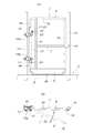
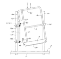
以下、全体の概略を添付図に基いて説明すると、図1A及び図1Bに示すように、仮設扉1は、建設現場に仮設される枠組み足場2の足場板3上に対する作業者出入口4を開閉するものであって、コの字形枠材5、このコの字形枠材5の上側水平部材5aと下側水平部材5bとを連結する上下方向連結部材6、この上下方向連結部材6の中間高さとコの字形枠材5の上下方向部材5cの中間高さとを連結する水平連結部材7、及び補強板材8によって構成されている。コの字形枠材5の上側水平部材5aの遊端部は下向きに直角に折曲されて、上側支柱部9aが形成され、コの字形枠材5の下側水平部材5bの遊端部は上向きに直角に折曲されて、上側支柱部9aと同心状の下側支柱部9bが形成されている。前記上下方向連結部材6は、上側支柱部8aと下側支柱部8bの内側に隣り合う位置に設けられ、前記補強板材8は、上下方向部材5cの下端近傍部、下側水平部材5b、上下方向連結部材6の下端部、及び下側支柱部8bの下端近傍部に外側から当て付けられて溶接により固着されている。尚、補強板材8を除いて全ての構成部材は、適当な太さの鋼管によって構成されている。
Hereinafter, the overall outline will be described with reference to the attached drawings. As shown in FIGS. 1A and 1B, the
仮設扉1の前記上側支柱部9aの下端には、上側垂直管材10が取り付けられ、前記下側支柱部9bの上端には、下側垂直管材11が取り付けられ、これら上下各垂直管材10,11に、固定管材12の上下両端部が外嵌している。前記作業者出入口4の左右両側には、枠組み足場2に組み込まれた、それぞれ適当な太さの鋼管から成る上下方向の扉支持用支柱材13と上下方向の扉受止め用支柱材14とが並設されている。前記固定管材12は、その上端側と下端側の2箇所が、前記扉支持用支柱材13に互いに平行に並列するように、パイプクランプ15a,15bによって取り付けられることにより、扉支持用支柱材13と扉受止め用支柱材14との間の作業者出入口4を仮設扉1が開閉出来るように構成されている。仮設扉1が図示のように作業者出入口4を閉じているとき、仮設扉1のコの字形枠材5における上下方向部材5cが扉受止め用支柱材14の内側に並列する状態にあって、当該上下方向部材5cの高さ方向のほぼ中央位置に外側に張り出すように固着されたストッパー板16が前記扉受止め用支柱材14の内側、即ち、足場板3のある側に当接し、仮設扉1が足場板3から遠ざかる外向きには開動しないように構成されている。
An upper
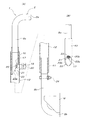
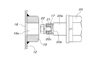
以下、要部の詳細を図2A〜図4に基いて説明すると、固定管材12の上端近傍位置には、突起17が内側に突出するように設けられている。具体的には、固定管材12には半径方向に貫通する貫通孔18が設けられると共に、この貫通孔18と同心状に固定管材12の外側面にナット19が溶接により固着され、このナット19と前記貫通孔18とによって半径方向に貫通する貫通ネジ孔19aが形成されている。この貫通ネジ孔19aに外側から螺合締結させたボルト20の螺軸部20aの先端から小径軸部20bが同心状に連設され、この小径軸部20bにニードルベアリング21が外嵌され、このニードルベアリング21の抜け止めのために、前記小径軸部20bに外端側から同心状に設けられた取付けネジ孔20cに、前記ニードルベアリング21よりも小径の小ボルト22を螺合締結している。
Hereinafter, the details of the main part will be described with reference to FIGS. 2A to 4, and the
この構成によれば、前記ニードルベアリング21が、固定管材12の内側に突出する突起17を構成していることになるが、ニードルベアリング21と小ボルト22の外径をボ貫通ネジ孔19aの内径より小さくしておけば、図4に示すように、ボルト20の先端に上記のようにニードルベアリング21と小ボルト22を先に取り付けた状態で、ボルト20を貫通ネジ孔19aに螺合締結させることが出来る。勿論、ニードルベアリング21の外径を貫通ネジ孔19aの内径より大きくする場合は、ボルト20だけを貫通ネジ孔19aに螺合締結させ、固定管材12の内側に突出しているボルト20の小径軸部20bにニードルベアリング21を固定管材12の内側から外嵌させると共に、小ボルト22を取付けネジ孔20cに固定管材12の内側から螺合締結させなければならない。
According to this configuration, the
図2A及び図2Bに示すように、仮設扉1の上側支柱部9aの下端には、前記上側垂直管材10の上端部が外嵌された状態で溶接により固着一体化されているが、上側支柱部9aと上側垂直管材10とをボルトナットにより互いに結合させても良い。而して、前記上側垂直管材10の下端には、下端斜辺部23が形成されている。この下端斜辺部23は、仮設扉1の上下方向部材5cのある側が最も高くなる向きに斜めに切断されて、上端部から下端部まで左右対称に伸びる左右一対の斜辺23a,23bを備えたものとなっている。一方、仮設扉1の下側支柱部9bは、その上端が固定管材12の下端より低いものであって、当該下側支柱部9bの上端には、固定管材12の下端から上向きに挿入された下側垂直管材11の下端部が外嵌された状態で、この両者が直径方向に貫通するボルトナット24によって着脱自在に結合されている。
As shown in FIGS. 2A and 2B, the upper end of the upper
上記の構成によれば、仮設扉1の上側垂直管材10と下側垂直管材11は、固定管材12に対して昇降自在且つ自転自在に遊嵌しているので、重力で降下しようとする仮設扉1は、上側垂直管材10の下端斜辺部23を介して、固定管材12側の突起17であるニードルベアリング21によって受け止められる。このとき、仮設扉1が固定管材12に対して足場板3のある側に開いた状態にあるときは、位置固定のニードルベアリング21が前記下端斜辺部23の斜辺23aの中間位置を受け止めることになるので、当該斜辺23aを介して上側垂直管材10(仮設扉1)には閉動方向の回転力が作用し、仮設扉1が閉動しながら降下することになる。そして位置固定のニードルベアリング21が前記下端斜辺部23の上端(左右一対の斜辺23a,23bの上端部間)に達したとき、仮設扉1の降下と閉動とが止まり、仮設扉1が作業者出入口4を閉じる閉じ位置で安定する。このとき、仮設扉1のストッパー板16が作業者出入口4脇の扉受止め用支柱材14に当接し、仮に仮設扉1に閉動方向の外力が作用していたとしても、当該仮設扉1が閉じ位置を超えて反対側に開くような危険は無い。
According to the above configuration, the upper
上記のように作業者出入口4を閉じている仮設扉1を開くときは、足場板3側からは仮設扉1を手前に引くことにより、反対側からは仮設扉1を足場板3側へ押すことになる。このときの仮設扉1の開動により、上側垂直管材10が固定管材12に対して回転することになるが、閉じるときとは反対に、上側垂直管材10の下端斜辺部23が位置固定のニードルベアリング21に対して乗り上げる方向になるので、仮設扉1は開動しながら上昇することになる。実際には、扉支持用支柱材13と固定管材12、及び扉受止め用支柱材14が同一仮想垂直面上にあるので、仮設扉1の開動限界位置は、この仮設扉1が扉支持用支柱材13に重なる角度(<180度)となるので、仮設扉1が開動限界位置まで開動したとしても、上側垂直管材10の下端斜辺部23の下端近傍位置にニードルベアリング21が位置する状態になる。即ち、仮設扉1に対する開動方向の操作力を断てば、仮設扉1に作用する重力によって仮設扉1には、上側垂直管材10の下端斜辺部23が位置固定のニードルベアリング21に対して下向きに圧接することにより閉動方向の回転力が作用しているので、仮設扉1は自動的に閉動を開始することになる。
When opening the
尚、固定管材12の位置を、扉支持用支柱材13と扉受止め用支柱材14とを結ぶ仮想垂直面より足場板3側に入った位置とするなどして、閉じ位置にある仮設扉1を180度以上開動させることが出来るように構成すれば、仮設扉1が180度以上開動したとき、上側垂直管材10の下端斜辺部23を支持している固定管材12側のニードルベアリング21が、下端斜辺部23の一方の斜辺23aの下端を反対側に乗り越えて逆勾配の斜辺32bを支持する状態になるので、仮設扉1には、下向きの重力に伴って開動方向の回転力が働き、当該仮設扉1が180度を超えた開動限界位置まで自動的に開動して安定することになる。
It should be noted that the position of the fixed
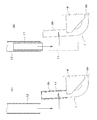
上記のように作業者出入口4を開閉することが出来る仮設扉1を、何らかの保守作業を行うために取り外す必要が生じたときは、図2Aに示す実施例では、閉じ位置にある(下降限高さにある)仮設扉1の下側垂直管材11を固定しているボルトナット24を取り外して、当該下側垂直管材11を仮設扉1の下側支柱部9bに沿って下げ降ろす。この結果、図6に示すように、固定管材12の下端より下側垂直管材11の上端が低くなれば(下側支柱部9bの上端は固定管材12の下端より低い)、次に仮設扉1の下端側を固定管材12から引き離すように傾動させて、図3Aに示すように、仮設扉1の下側支柱部9bとこれに外嵌している状態の下側垂直管材11を、固定管材12の下側から横側方へ移動させる。このときの仮設扉1の傾動は、固定管材12と当該固定管材12に遊嵌している仮設扉1側の上側垂直管材10との間の遊び代を利用して行うことが出来る。このように仮設扉1を傾動させたならば、図5に示すように、仮設扉1を持ち上げて、上側垂直管材10を固定管材12から上方へ抜き取ることにより、仮設扉1の取り外しが完了する。
When it becomes necessary to remove the
保守作業などの完了した仮設扉1を再び作業者出入口4の開閉位置にセットするときは、上記の取り外し作業とは逆の手順で取付け作業を行えば良い。即ち、仮設扉1の下側支柱部9bに下側垂直管材11が外嵌されている状態の仮設扉1を持ち上げ、図5に示すように上側垂直管材10を、斜めになっている下端斜辺部23から固定管材12の上端側に下向きに挿入し、図6に示すように仮設扉1の下側支柱部9bとこれに外嵌している下側垂直管材11を固定管材12の真下に位置させる。この状態で下側支柱部9bに対し下側垂直管材11を上昇させて、当該下側垂直管材11の上端側を固定管材12の下端から上向きに挿入し、最後に両者をボルトナット24にて締結一体化すれば、取付け作業の完了となる。
When the
若し、下側垂直管材11の長さが長い、或いは下側垂直管材11を固定管材12より下方に降下させることが出来るほどの余裕が下側支柱部9b側に無いために、下側垂直管材11を固定管材12より下方に降下させることが出来ないときは、ボルトナット24を外した下側垂直管材11を持ち上げて、図3Bに示すように固定管材12内に下側垂直管材11を収容させる。この後、先に説明した要領で仮設扉1を取り外すことが出来る。この場合は、固定管材12内に収容させた下側垂直管材11は引き抜いて保管し、外した仮設扉1の取付け時に、下側垂直管材11を固定管材12内に収容させ、仮設扉1の下側支柱部9bを固定管材12の真下に位置させた段階で、固定管材12内から下側垂直管材11を降下させてその下端部を下側支柱部9bに外嵌させると共に、ボルトナット24により下側垂直管材11の下端部と下側支柱部9bの上端部とを結合一体化すれば良い。尚、このように下側垂直管材11を固定管材12内に一時収容させた状態で仮設扉1の取り外し取付け作業を行うときは、固定管材12の下端近傍位置に、この固定管材12内に挿入された下側垂直管材11を仮止めしておくための手段、例えば固定管材12の側壁に設けられた貫通ネジ孔と、この貫通ネジ孔に螺合する固定用ボルトを設けておくことが出来る。
If the length of the lower
尚、本発明を実施する場合、固定管材12側に設ける突起17としては、ニードルベアリング21に限らないが、仮設扉1側の上側垂直管材10の下端斜辺部23との摩擦抵抗が少ない方が好ましい。又、単に円形断面の上側垂直管材10の下端を斜めに切断しただけの下端斜辺部23であれば、この下端斜辺部23を形成する左右一対の斜辺23a,23b間の上端入隅部に突起17が嵌合した状態で、当該突起17が上側垂直管材10(仮設扉1)を支持することになるが、左右一対の斜辺23a,23b間の上端入隅部に突起17が噛み込む恐れがあるときは、左右一対の斜辺23a,23b間の上端に、水平面又は突起17(ニードルベアリング21)と面接触する円弧形凹入面を形成しても良い。勿論、上側垂直管材10の下端斜辺部23は、180度又は180度以下の仮設扉1の開閉運動範囲のみをカバーする周方向領域にのみ形成することも出来る。又、上記実施例においける各種管材としては、一般的には鋼管が使用出来る。
In the case of carrying out the present invention, the
本発明の足場用仮設扉は、建設現場に仮設される足場の作業者出入り口を開閉する手段として活用出来る。 The temporary scaffolding door of the present invention can be used as a means for opening and closing the worker entrance / exit of the scaffolding temporarily installed at the construction site.
1 仮設扉
2 枠組み足場
3 足場板
4 作業者出入口
5 コの字形枠材
5a 上側水平部材
5b 下側水平部材
5c 上下方向部材
6 上下方向連結部材
7 水平連結部材
8 補強板材
9a 上側支柱部
9b 下側支柱部
10 上側垂直管材
11 下側垂直管材
12 固定管材
13 扉支持用支柱材
14 扉受止め用支柱材
15a,15b パイプクランプ
16 ストッパー板
17 突起
19a 貫通ネジ孔19a
20 ボルト
20b 小径軸部
20c 取付けネジ孔
21 ニードルベアリング
22 小ボルト
23 下端斜辺部
23a,23b 斜辺
24 ボルトナット
1
20
Claims (6)
The lower end portion of the lower vertical pipe material is connected to each other by bolts and nuts in a state of being fitted to the upper end portion of the lower support portion on the temporary door side, and the lower vertical pipe material that has been disconnected by the bolt nut is used. The claim is configured so that the lower strut portion can be moved from the lower side to the lateral side of the fixed pipe material by lifting it into the fixed pipe material and pulling it upward from the lower strut portion. The temporary door for scaffolding according to any one of 1 to 4.
Priority Applications (1)
| Application Number | Priority Date | Filing Date | Title |
|---|---|---|---|
| JP2018095936A JP6861436B2 (en) | 2018-05-18 | 2018-05-18 | Temporary door for scaffolding |
Applications Claiming Priority (1)
| Application Number | Priority Date | Filing Date | Title |
|---|---|---|---|
| JP2018095936A JP6861436B2 (en) | 2018-05-18 | 2018-05-18 | Temporary door for scaffolding |
Publications (2)
| Publication Number | Publication Date |
|---|---|
| JP2019199772A JP2019199772A (en) | 2019-11-21 |
| JP6861436B2 true JP6861436B2 (en) | 2021-04-21 |
Family
ID=68613057
Family Applications (1)
| Application Number | Title | Priority Date | Filing Date |
|---|---|---|---|
| JP2018095936A Active JP6861436B2 (en) | 2018-05-18 | 2018-05-18 | Temporary door for scaffolding |
Country Status (1)
| Country | Link |
|---|---|
| JP (1) | JP6861436B2 (en) |
Families Citing this family (2)
| Publication number | Priority date | Publication date | Assignee | Title |
|---|---|---|---|---|
| JP6975577B2 (en) * | 2017-08-07 | 2021-12-01 | 株式会社技研製作所 | Elevated structure and its construction method |
| KR200495534Y1 (en) * | 2020-08-24 | 2022-06-22 | 주식회사 잘만드네 | Scaffolding clamps for rotating structure |
Family Cites Families (7)
| Publication number | Priority date | Publication date | Assignee | Title |
|---|---|---|---|---|
| US2958090A (en) * | 1958-03-07 | 1960-11-01 | Slopa Robert Earl | Self-closing door hinge |
| JPS5550319Y2 (en) * | 1976-04-28 | 1980-11-22 | ||
| DE3310317C2 (en) * | 1983-03-22 | 1985-08-08 | Josef 7611 Steinach Maier | Walk console with a door |
| JPS6238359U (en) * | 1985-08-27 | 1987-03-06 | ||
| JPH0725151U (en) * | 1993-10-01 | 1995-05-12 | エイブル設備株式会社 | Device to prevent falling accidents at the work site |
| JP4364885B2 (en) * | 2006-06-12 | 2009-11-18 | Krh株式会社 | Temporary scaffolding connection structure |
| JP2011042947A (en) * | 2009-08-20 | 2011-03-03 | Shinwa Kk | Door for scaffold |
-
2018
- 2018-05-18 JP JP2018095936A patent/JP6861436B2/en active Active
Also Published As
| Publication number | Publication date |
|---|---|
| JP2019199772A (en) | 2019-11-21 |
Similar Documents
| Publication | Publication Date | Title |
|---|---|---|
| JP5086147B2 (en) | Gondola with curing device | |
| EP3258041B1 (en) | Door hinge assembly | |
| JP6861436B2 (en) | Temporary door for scaffolding | |
| KR102614750B1 (en) | Guide for supporting slab pannel beam of building construction | |
| KR200491973Y1 (en) | Hanger for pipe | |
| KR101873394B1 (en) | Climbing shoe of climbing system | |
| JPH09256658A (en) | Hatch safety fence | |
| JP5980387B2 (en) | Breakwater door and how to install the breakwater door | |
| JP5077014B2 (en) | Elevator rope steady rest | |
| KR102430549B1 (en) | Noise protection panel | |
| JP5821193B2 (en) | Vertical constant air volume ventilator | |
| JP2006045905A (en) | Locking device of natural ventilation window | |
| JP4876813B2 (en) | Natural ventilation window | |
| JP2972519B2 (en) | Falling object curing device | |
| JP2011042947A (en) | Door for scaffold | |
| KR100664481B1 (en) | Workbench brake device | |
| JP6749158B2 (en) | louver | |
| JP6302820B2 (en) | Method and apparatus for opening / closing door plate of elevator door for temporary scaffold | |
| JP6708880B2 (en) | Opening and closing structure | |
| KR102661862B1 (en) | Hinge device for opening and closing inclined doors | |
| KR101495869B1 (en) | Railing reinforcement structure for building | |
| JP3527159B2 (en) | Storage box for waste materials | |
| KR102331575B1 (en) | Gang form fall prevention device | |
| JP2013122140A (en) | Expansion gate | |
| JP3033217U (en) | Self-closing door device |
Legal Events
| Date | Code | Title | Description |
|---|---|---|---|
| A621 | Written request for application examination |
Free format text: JAPANESE INTERMEDIATE CODE: A621 Effective date: 20191216 |
|
| A977 | Report on retrieval |
Free format text: JAPANESE INTERMEDIATE CODE: A971007 Effective date: 20200918 |
|
| A131 | Notification of reasons for refusal |
Free format text: JAPANESE INTERMEDIATE CODE: A131 Effective date: 20201020 |
|
| A521 | Request for written amendment filed |
Free format text: JAPANESE INTERMEDIATE CODE: A523 Effective date: 20201026 |
|
| TRDD | Decision of grant or rejection written | ||
| A01 | Written decision to grant a patent or to grant a registration (utility model) |
Free format text: JAPANESE INTERMEDIATE CODE: A01 Effective date: 20210319 |
|
| A61 | First payment of annual fees (during grant procedure) |
Free format text: JAPANESE INTERMEDIATE CODE: A61 Effective date: 20210323 |
|
| R150 | Certificate of patent or registration of utility model |
Ref document number: 6861436 Country of ref document: JP Free format text: JAPANESE INTERMEDIATE CODE: R150 |
|
| R250 | Receipt of annual fees |
Free format text: JAPANESE INTERMEDIATE CODE: R250 |
|
| R250 | Receipt of annual fees |
Free format text: JAPANESE INTERMEDIATE CODE: R250 |
|
| R250 | Receipt of annual fees |
Free format text: JAPANESE INTERMEDIATE CODE: R250 |