JP6860776B2 - Virtual space controller, its control method, and program - Google Patents
Virtual space controller, its control method, and program Download PDFInfo
- Publication number
- JP6860776B2 JP6860776B2 JP2016130476A JP2016130476A JP6860776B2 JP 6860776 B2 JP6860776 B2 JP 6860776B2 JP 2016130476 A JP2016130476 A JP 2016130476A JP 2016130476 A JP2016130476 A JP 2016130476A JP 6860776 B2 JP6860776 B2 JP 6860776B2
- Authority
- JP
- Japan
- Prior art keywords
- data
- dimensional model
- information processing
- virtual space
- processing device
- Prior art date
- Legal status (The legal status is an assumption and is not a legal conclusion. Google has not performed a legal analysis and makes no representation as to the accuracy of the status listed.)
- Active
Links
Images


Landscapes
- Processing Or Creating Images (AREA)
- Controls And Circuits For Display Device (AREA)
- User Interface Of Digital Computer (AREA)
Description
本発明は、設計変更された部品データが構成する三次元モデルを仮想空間上で操作することなく、当該部品データを仮想空間上で閲覧可能な仮想空間制御装置、その制御方法、及びプログラムに関する。 The present invention relates to a virtual space control device capable of viewing the component data in the virtual space without operating the three-dimensional model composed of the redesigned component data in the virtual space, a control method thereof, and a program.
従来、組立系製造業では業務のフロントローディングが行われている。フロントローディングは、後工程で発生する可能性のある問題を初期工程で検討することにより、品質向上を目指す取り組みである。例えば、設計部門で作成中のCADデータを三次元CADソフトウェアで表示し、組立部門や品質保証部門といった下流部門が部品の干渉チェックをシミュレーションしている。 Conventionally, business front-loading has been performed in the assembly manufacturing industry. Front-loading is an effort aimed at improving quality by examining problems that may occur in the post-process in the initial process. For example, the CAD data being created by the design department is displayed by three-dimensional CAD software, and downstream departments such as the assembly department and the quality assurance department are simulating the interference check of parts.
しかしながら、設計部門から取得するCADデータは未完成である。設計部門と下流部門とが協力して製品設計を進めていくため、設計部門と下流部門との間でCADデータのやり取りが何度も行われる。つまり、下流部門は設計部門が改善したCADデータを何度も取得し、その都度シミュレーション等を行う必要がある。 However, the CAD data obtained from the design department is incomplete. Since the design department and the downstream department cooperate to proceed with product design, CAD data is exchanged between the design department and the downstream department many times. That is, the downstream department needs to acquire the improved CAD data many times by the design department and perform a simulation or the like each time.
その際に、設計部門から下流部門に対して設計変更の内容をきちんと伝えることが重要であるが、設計変更した箇所が多いと、設計変更箇所を伝え忘れてしまう可能性がある。そのため、下流部門は前回取得したCADデータから何がどのように変更されたのかを、設計変更前のCADデータと設計変更後のCADデータとを比較して、確認しなければならない。 At that time, it is important for the design department to properly convey the details of the design change to the downstream department, but if there are many design changes, there is a possibility that the design change will be forgotten. Therefore, the downstream department must confirm what has changed from the previously acquired CAD data by comparing the CAD data before the design change with the CAD data after the design change.
そこで特許文献1には、設計変更前のCADデータと設計変更後のCADデータとをそれぞれ一定形状の複数のエリアに分割し、そのエリアごとに体積を算出して設計変更前後で比較することにより、形状が変更された箇所を特定する仕組みが開示されている。
Therefore, in
特許文献1の仕組みや三次元CADソフトウェアの従来機能により、設計変更された箇所を自動的に特定する仕組みが存在するため、下流部門の作業者は容易に設計変更された箇所を確認することができる。
Since there is a mechanism for automatically identifying the design-changed part by the mechanism of
しかしながら、多数の部品から構成される組立品の場合、設計変更された箇所が組立品の内部に組み込まれていることがあるため、設計変更された箇所が判明したとしても、その箇所を三次元モデルとして確認することは手間がかかる。なぜなら、CADデータの三次元モデルを三次元CADソフトウェアで表示し、設計変更箇所だけが表示されるように設定しなければならないためである。 However, in the case of an assembly composed of a large number of parts, the redesigned part may be incorporated inside the assembly, so even if the redesigned part is found, that part is three-dimensional. It takes time to confirm as a model. This is because it is necessary to display the three-dimensional model of the CAD data with the three-dimensional CAD software and set so that only the design change part is displayed.
また、三次元モデルを含む画像を、現実空間を撮像した画像に重畳し、これを観察者のヘッドマウントディスプレイに提示する複合現実感(Mixed Reality、以下、MRという。)や拡張現実感と呼ばれている仕組みが存在する。この仕組みを用いて、組立品の三次元モデルを表示し、組立品の内部にある設計変更箇所を確認しようとしても、仮想空間に存在する三次元モデルを操作して部品ごとに分解しなければならないので、観察者にとって非常に手間である。 Further, it is called mixed reality (hereinafter referred to as MR) or extended reality in which an image including a three-dimensional model is superimposed on an image captured in real space and presented on the observer's head-mounted display. There is a mechanism that is used. Using this mechanism, even if you try to display the 3D model of the assembly and check the design changes inside the assembly, you have to operate the 3D model existing in the virtual space and disassemble each part. It is very troublesome for the observer because it does not become.
本発明の目的は、設計変更された部品データが構成する三次元モデルを仮想空間上で操作することなく、当該部品データを仮想空間上で閲覧可能な仕組みを提供することである。 An object of the present invention is to provide a mechanism that allows the component data to be browsed in the virtual space without operating the three-dimensional model composed of the redesigned component data in the virtual space.
上記の目的を達成するために本発明の仮想空間制御装置は、複数の部品データから構成される三次元モデルが配置される仮想空間を提示するための仮想空間制御装置であって、設計変更前の第一の三次元モデルと、設計変更後の第二の三次元モデルとを取得する取得手段と、前記取得手段で取得した第一の三次元モデルを構成する複数の部品データと、前記取得手段で取得した第二の三次元モデルを構成する複数の部品データとを比較し、設計変更がなされた部品データを特定する特定手段と、前記第二の三次元モデルと、前記特定手段で特定された部品データとを前記仮想空間上に配置する配置手段とを備えることを特徴とする。 In order to achieve the above object, the virtual space control device of the present invention is a virtual space control device for presenting a virtual space in which a three-dimensional model composed of a plurality of component data is arranged, and before the design change. Acquisition means for acquiring the first three-dimensional model of the above, the second three-dimensional model after the design change, a plurality of component data constituting the first three-dimensional model acquired by the acquisition means, and the acquisition. The specific means for specifying the part data for which the design has been changed by comparing the plurality of part data constituting the second three-dimensional model acquired by the means, the second three-dimensional model, and the specific means for specifying. It is characterized by including an arrangement means for arranging the obtained component data in the virtual space.
本発明によれば、設計変更された部品データが構成する三次元モデルを仮想空間上で操作することなく、当該部品データを仮想空間上で閲覧可能となる。 According to the present invention, the component data can be browsed in the virtual space without operating the three-dimensional model composed of the redesigned component data in the virtual space.
以下、図面を参照しながら、本発明の実施形態について説明する。 Hereinafter, embodiments of the present invention will be described with reference to the drawings.
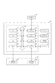
図1は、本実施形態における情報処理システムのシステム構成の一例を示す図である。図1に示す情報処理システムは、複合現実感技術(以下、MR技術という。)を用いた、ユーザに仮想空間を閲覧させるためのシステムである。情報処理システムは、情報処理装置101にHMD102が相互にデータ通信可能に接続されている。情報処理装置101とHMD102との接続は、有線接続であってもよいし、無線接続であってもよい。尚、図1のシステム上に接続される各種端末の構成は一例であり、用途や目的に応じて様々な構成例がある。
FIG. 1 is a diagram showing an example of a system configuration of an information processing system according to the present embodiment. The information processing system shown in FIG. 1 is a system for allowing a user to browse a virtual space using mixed reality technology (hereinafter referred to as MR technology). In the information processing system, the HMD 102 is connected to the
情報処理装置101(仮想空間制御装置)は、汎用的なコンピュータである。情報処理装置101は、HMD102で撮影(撮像)された現実空間の画像(以下、現実空間画像という。)と、情報処理装置101で生成された仮想空間の画像(以下、仮想空間画像という。)とを重畳する。こうして生成された画像(以下、複合現実画像という。)を、HMD102に送信する。尚、MR技術に関しては従来技術を用いるため、詳細な説明は省略する。また、情報処理装置101は、パーソナルコンピュータであってもよいし、サーバのような大型のコンピュータであってもよい。更には、携帯電話やタブレット端末といった携帯端末であってもよい。コンピュータの種類は特に問わない。
The information processing device 101 (virtual space control device) is a general-purpose computer. The
HMD102は、ヘッドマウントディスプレイである。HMD102は、ユーザの頭部に装着する装置であり、右目用と左目用のビデオカメラと、右目用と左目用のディスプレイを備えている。HMD102は、HMD102のビデオカメラで撮影された現実空間画像を情報処理装置101に送信する。そして、情報処理装置101から複合現実画像を受信し、ディスプレイに表示する。HMD102では、右目用と左目用のディスプレイを設けているので、視差によって立体感を得ることができる。尚、HMD102で撮影する現実空間画像とHMD102で表示する複合現実画像は、動画(映像)が望ましいが、所定の間隔で撮影された静止画であってもよい。また、スマートフォンのようにディスプレイとビデオカメラがハードウェアの前面と背面に設置されている装置を、ヘッドマウントディスプレイの代用としてもよい。
The HMD 102 is a head-mounted display. The HMD 102 is a device worn on the user's head and includes video cameras for the right eye and the left eye, and displays for the right eye and the left eye. The HMD 102 transmits a real space image taken by the video camera of the HMD 102 to the
本実施形態では、情報処理装置101とHMD102とを含むシステムとして説明を行うが、情報処理装置101とHMD102とが一体化したデバイス(仮想空間制御装置)であってもよい。すなわち、HMD102に情報処理装置101の各種ハードウェアを搭載し、HMD102だけで動作するようにしてもよい。
In the present embodiment, the system including the
また、情報処理装置101には赤外線カメラ104が接続されている。赤外線カメラ104は、赤外線を用いた光学式のセンサである。赤外線カメラ104は、現実空間に赤外線を照射し、現実空間の物体で反射した赤外線を撮影することにより、赤外線カメラ104が定義する座標系における、現実空間の物体の位置及び姿勢を特定する。この赤外線カメラ104を用いて、現実空間におけるHMD102(すなわちユーザ)の位置及び姿勢(向きや傾き、視線の方向等。以下、同じ。)を特定する。HMD102には、オプティカルマーカ103という赤外線を反射する物体を備えており、赤外線カメラ104はこのオプティカルマーカ103で反射した赤外線を撮影することで、HMD102の位置及び姿勢を特定できるようになっている。ユーザがどのような位置や姿勢であっても、当該ユーザが装着するHMD102のオプティカルマーカ103を撮影または検知できるように、情報処理システムでは赤外線カメラ104を複数台設置することが望ましい。また、位置及び姿勢を特定可能なHMD102は、赤外線カメラ104の撮影範囲に存在するものとして説明を行う。
Further, an
尚、本実施形態においては、現実空間におけるHMD102の位置及び姿勢を特定するために、赤外線カメラ104を用いるが、これらの現実空間における位置及び姿勢を特定できるのであれば、これに限らない。例えば、磁気センサを用いてもよいし、HMD102が撮影した画像を解析して位置及び姿勢を特定してもよい。
In the present embodiment, the
本実施形態においては、HMD102を装着したユーザは、ターゲットマーカ105を用いて各種操作を行う。ターゲットマーカ105は、二次元マーカから構成される。情報処理装置101はこの二次元マーカの傾きやHMD102との距離を画像認識により特定することにより、現実空間上のターゲットマーカ105が仮想空間上においてはどういった位置・姿勢であるのかを特定することができる。尚、二次元マーカの種類は特に問わないが、画像認識により二次元マーカの形状が取得しやすい種類である方が望ましい。
In the present embodiment, the user wearing the
図2は、情報処理装置101とHMD102の各ハードウェア構成の一例を示す図である。
FIG. 2 is a diagram showing an example of each hardware configuration of the
CPU201は、システムバス204に接続される各デバイスやコントローラを統括的に制御する。
The
また、ROM202あるいは外部メモリ211には、CPU201の制御プログラムであるBIOS(Basic Input / OutputSystem)やオペレーティングシステムが記憶されている。更には、情報処理装置101の実行する機能を実現するために必要な後述する各種プログラム等が記憶されている。RAM203は、CPU201の主メモリ、ワークエリア等として機能する。
Further, the
CPU201は、処理の実行に際して必要なプログラム等をRAM203にロードして、プログラムを実行することで各種動作を実現するものである。
The
また、入力コントローラ(入力C)205は、キーボードやマウス等のポインティングデバイス(入力デバイス210)からの入力を制御する。 Further, the input controller (input C) 205 controls the input from a pointing device (input device 210) such as a keyboard and a mouse.
情報処理装置101のビデオコントローラ(VC)206は、HMD102が備える右目・左目ディスプレイ222やディスプレイ212等の表示器への表示を制御する。右目・左目ディスプレイ222に対しては、例えば外部出力端子(例えば、Digital Visual Interface)を用いて出力される。また、右目・左目ディスプレイ222は、右目用のディスプレイと左目用のディスプレイとから構成されている。また、ディスプレイ212は、液晶ディスプレイ等であり、右目・左目ディスプレイ222と同様の表示、または仮想空間を操作するためのGUI(Graphical User Interface)が表示される。
The video controller (VC) 206 of the
メモリコントローラ(MC)207は、ブートプログラム、ブラウザソフトウエア、各種のアプリケーション、フォントデータ、ユーザファイル、編集ファイル、各種データ等を記憶する外部メモリ211(記憶手段)へのアクセスを制御する。外部メモリ211は、例えばハードディスク(HD)やフレキシブルディスク(FD)或いはPCMCIAカードスロットにアダプタを介して接続されるカード型メモリ等がある。
The memory controller (MC) 207 controls access to an external memory 211 (storage means) that stores a boot program, browser software, various applications, font data, user files, edit files, various data, and the like. The
通信I/Fコントローラ(通信I/FC)208は、ネットワークを介して、外部機器と接続・通信するものであり、ネットワークでの通信制御処理を実行する。例えば、TCP/IPを用いたインターネット通信等が可能である。特に、情報処理装置101の通信I/Fコントローラ208は、赤外線カメラ104との通信も制御する。
The communication I / F controller (communication I / FC) 208 connects and communicates with an external device via a network, and executes communication control processing on the network. For example, Internet communication using TCP / IP is possible. In particular, the communication I /
情報処理装置101の汎用バス209は、情報処理装置101に接続されるHMD102の右目・左目ビデオカメラ221で撮影した画像を取り込むために使用される。右目・左目ビデオカメラ221からは、外部入力端子(例えば、IEEE1394端子)を用いて入力される。また、右目・左目ビデオカメラ221は、右目用のビデオカメラと左目用のビデオカメラとから構成されている。
The general-
尚、CPU201は、例えばRAM203内の表示情報用領域へアウトラインフォントの展開(ラスタライズ)処理を実行することにより、ディスプレイ上での表示を可能としている。また、CPU201は、ディスプレイ上の不図示のマウスカーソル等でのユーザ指示を可能とする。
The
本発明の情報処理装置101が後述する各種処理を実行するために用いられる各種プログラム等は外部メモリ211に記録されており、必要に応じてRAM203にロードされることによりCPU201によって実行されるものである。さらに、本発明に係わるプログラムが用いる定義ファイルや各種情報テーブルは外部メモリ211に格納されている。
Various programs and the like used by the
図3は、情報処理装置101の機能構成を示す機能構成図である。尚、図3の情報処理装置101の機能構成は一例であり、用途や目的に応じて様々な構成例がある。
FIG. 3 is a functional configuration diagram showing a functional configuration of the
情報処理装置101は機能部として、通信制御部301、位置・姿勢特定部302、現実空間画像取得部303、仮想空間生成部304、三次元モデル制御部305、仮想空間画像取得部306、複合現実画像生成部307を備える。更に情報処理装置101は機能部として、表示制御部308、データ管理部309、変数制御部310、データ比較部311、画面生成部312、操作受付部313、距離算出部314を備える。
The
通信制御部301は、情報処理装置101と通信可能なHMD102と赤外線カメラ104との各種情報の送受信を行う機能部である。通信制御部301は、前述したビデオコントローラ206、通信I/Fコントローラ208、汎用バス209等を通じてこれらの装置と情報の送受信を行う。
The
位置・姿勢特定部302は、赤外線カメラ104から取得したHMD102の現実空間における位置及び姿勢(向き)を示す情報に基づいて、仮想空間における位置及び姿勢を特定するための機能部である。本実施形態では、HMD102にオプティカルマーカ103が装着されているため、現実空間におけるオプティカルマーカ103の位置及び姿勢をまず取得する。そして、現実空間の座標系(赤外線カメラ104の座標系)と仮想空間の座標系とはあらかじめキャリブレーション(位置合わせ)がなされているので、これに基づいて現実空間における位置及び姿勢に対応する仮想空間上の位置及び姿勢を特定する。尚、現実空間画像取得部303で右目・左目ビデオカメラ221から取得した右目用の現実空間画像と左目用の現実空間画像とを用いて、三角測量等の方法により、現実空間の物体の位置及び姿勢を特定してもよい。
The position /
また、位置・姿勢特定部302は、現実空間画像取得部303が取得した現実空間画像を解析して、現実空間画像に写る二次元マーカの位置や形状を特定し、現実空間におけるターゲットマーカの位置及び姿勢を特定することも可能である。また、位置・姿勢特定部302は、この現実空間画像におけるターゲットマーカの位置及び姿勢から、仮想空間における位置及び姿勢も特定する。
Further, the position /
現実空間画像取得部303は、HMD102の右目・左目ビデオカメラ221で撮影された現実空間画像を取得する機能部である。
The real space
仮想空間生成部304は、情報処理装置101の外部メモリ211に記憶されている情報に基づいて仮想空間を生成する機能部である。仮想空間は情報処理装置101の内部に生成される仮想的な空間であるので、その空間の形や大きさに関する情報が外部メモリ211に記憶されており、これに基づいて仮想空間を生成する。仮想空間には三次元モデルを配置可能である。三次元モデルは三次元モデル制御部305によって配置される。
The virtual
三次元モデル制御部305は、三次元モデルを仮想空間に配置するための機能部である。仮想空間が生成された場合には、あらかじめ定義された位置及び姿勢で仮想空間上に三次元モデルを配置する。必要に応じて、配置された三次元モデルを異なる位置及び姿勢で再配置(移動)する。また、三次元モデル制御部305は、位置・姿勢特定部302で特定した、仮想空間におけるターゲットマーカの位置及び姿勢に基づいて、三次元モデルを仮想空間上に配置することができる。すなわち、複合現実画像を生成したときに、ターゲットマーカ105に重畳させるようにして三次元モデルを配置させることが可能である。更には、三次元モデル制御部305は、仮想空間に配置した三次元モデルの表示形態を変更することができる。例えば、三次元モデルの色を変更したり、形状を変更したりすることができる。
The three-dimensional
仮想空間画像取得部306は、仮想空間生成部304で生成した仮想空間の画像を取得する機能部である。仮想空間画像取得部306が仮想空間の画像を取得する場合には、位置・姿勢特定部302で特定した仮想空間におけるHMD102の位置及び姿勢に基づいて仮想空間上に視点を設定する。そして、当該視点から見た場合の仮想空間画像を生成し、これを取得する。この視点に仮想的なカメラを設置し、仮想空間を撮像するようにすればよい。すなわちレンダリングするということである
The virtual space
複合現実画像生成部307は、現実空間画像取得部303で取得した現実空間画像に仮想空間画像取得部306で取得した仮想空間画像を重畳することにより、複合現実画像を生成する機能部である。
The mixed reality image generation unit 307 is a functional unit that generates a mixed reality image by superimposing the virtual space image acquired by the virtual space
表示制御部308は、情報処理装置101に接続されたHMD102の右目・左目ディスプレイ222や情報処理装置101に接続されたディスプレイ212における各種情報の表示制御を行う機能部である。特に、複合現実画像生成部307で生成された複合現実画像をHMD102の右目・左目ディスプレイ222に表示させる機能を有する。
The
データ管理部309は、情報処理装置101のRAM203や外部メモリ211等の記憶部に記憶されるデータを管理するための機能部である。必要に応じて、データの追加・更新・削除等を行う。
The
変数制御部310は、情報処理装置101が実行するプログラムで利用する変数の制御を行うための機能部である。変数の宣言や代入等の処理を実行する。
The
データ比較部311は、外部メモリ211等に記憶された複数の三次元モデルを比較し、その差分を特定するための機能部である。三次元モデルは、自身のポリゴン数や位置・姿勢の情報を有しているので、この情報を用いて比較することにより差分があるか否かを特定する。また、従来技術の通り、体積や面積による比較や画像処理による比較であってもよい。
The
画面生成部312は、仮想空間上に表示する操作画面を生成するための機能部である。本実施形態においては、操作画面を仮想空間上に表示するため、生成される画面は三次元モデルである。
The
操作受付部313は、画面生成部312によって生成された操作画面に対する選択操作を受け付けるための機能部である。仮想空間上に表示された操作画面に対する操作は、ターゲットマーカ105を用いて行う。ターゲットマーカ105の仮想空間における位置及び姿勢が位置・姿勢特定部302によって特定されるので、この位置及び姿勢に基づいて、ターゲットマーカ105の上部にカーソルオブジェクトを配置する。このカーソルオブジェクトと操作画面上のボタンとが一定時間接触した場合に、ボタンが押下(選択)されたと判断する。操作画面に対する操作方法はこれに限らず、HMD102を装着するユーザの指によって操作されてもよいし、情報処理装置101のディスプレイ212に操作画面を表示して入力デバイス210によって操作を受け付けてもよい。
The
距離算出部314は、仮想空間上の二点間の距離を算出するための機能部である。三平方の定理等を用いて、仮想空間上の座標系における二点間の距離を算出する。
The
次に、本発明の実施形態における全体的な処理の流れの一例について、図4に示すフローチャートを用いて説明する。以下説明する、S401乃至S412の各ステップは、情報処理装置101のCPU201が各機能部を動作することにより実行される処理である。
Next, an example of the overall processing flow according to the embodiment of the present invention will be described with reference to the flowchart shown in FIG. Each step of S401 to S412 described below is a process executed by the
ステップS401では、情報処理装置101は、設計変更前の組立品と設計変更後の組立品との差分を特定するための処理を実行する。図5に差分特定処理の詳細な処理の流れを示す。
In step S401, the
図5は、差分特定処理の詳細な処理の流れの一例を示すフローチャートである。以下説明する、S501乃至S509の各ステップは、情報処理装置101のCPU201が各機能部を動作することにより実行される処理である。
FIG. 5 is a flowchart showing an example of a detailed processing flow of the difference specifying process. Each step of S501 to S509 described below is a process executed by the
ステップS501では、情報処理装置101のデータ管理部309は、外部メモリ211に記憶されている設計変更前の組立品データ(以下、旧組立品データという。)と、設計変更後の組立品データ(以下、新組立品データという。)とを取得する(取得手段)。すなわち、設計変更前の第一の三次元モデルと、設計変更後の第二の三次元モデルとを取得するということである。ユーザはあらかじめこれらのデータを外部メモリ211に記憶しておく。そして、データ管理部309は、ユーザから指定された旧組立品データと新組立品データとを取得する。本実施形態において組立品データとは、CADデータのうちのアセンブリデータである。
In step S501, the
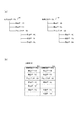
図6(a)では、旧組立品データと新組立品データ(以下、これらを新旧組立品データという。)の参照構造の一例を、それぞれ601と602に示す。新旧組立品データはトップアセンブリであるので、複数の部品やサブアセンブリから構成されている。例えば、旧組立品データAは、部品データBと部品データCとアセンブリデータDから構成されており、更にサブアセンブリであるアセンブリデータDは、部品データE・F・Gから構成されている。以下、アセンブリデータの参照先の部品やサブアセンブリを参照先データと称する。 In FIG. 6A, examples of reference structures of old assembly data and new assembly data (hereinafter, these are referred to as new and old assembly data) are shown in 601 and 602, respectively. Since the old and new assembly data is the top assembly, it is composed of multiple parts and subassemblies. For example, the old assembly data A is composed of part data B, part data C, and assembly data D, and assembly data D, which is a subassembly, is composed of part data E, F, and G. Hereinafter, the parts and subassemblies to which the assembly data is referred to are referred to as reference data.
ステップS502では、情報処理装置101のデータ管理部309は、ステップS501で取得した新旧組立品データの参照先である参照先データに関する情報を取得し、図6(b)に示すような比較表610を作成する。比較表610は、旧参照先データ名611と新参照先データ名612を備えており、それぞれ比較元と比較先の参照先データの名称を示している。旧組立品データの参照先データに対応する新組立品データの参照先データがあれば同じ行に並べて格納し、どちらか一方にしかない参照先データの場合には、当該参照先データが存在しない組立品データの項目は空欄にする。このようにして、図6(a)に示す旧組立品データAと新組立品データAの比較表610を作成した結果が図6(b)である。
In step S502, the
ステップS503では、情報処理装置101のデータ管理部309は、図7に示すような差分リスト700を生成する。ステップS503の処理では、空の状態の差分リスト700を生成する。
In step S503, the
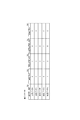
図7の差分リスト700は、設計変更前後でどのような差分があるのかを示すためのデータテーブルである。差分リスト700は、差分データ名701、追加フラグ702、形状変更フラグ703、位置姿勢変更フラグ704、削除フラグ705を備える。データテーブルのテーブル構成はこれに限らない。
The difference list 700 in FIG. 7 is a data table for showing what kind of difference exists before and after the design change. The difference list 700 includes a
差分データ名701は、設計変更前後で差分のあった参照先データの名称が格納される項目である。本実施形態でいう差分とは、設計変更前後の相違点のことをいう。例えば、旧組立品データに対する新たな参照先データの追加、参照先データの形状変更、参照先データの位置または姿勢の変更、旧組立品データからの参照先データの削除を指す。追加フラグ702、形状変更フラグ703、位置姿勢変更フラグ704、削除フラグ705は、これらの差分があった場合にフラグが立てられる項目である。
The
図5の説明に戻る。ステップS504では、情報処理装置101の変数制御部310は、カウンタの変数iを宣言し、初期値として0を代入する。そして、ステップS505では、情報処理装置101の変数制御部310は、変数iをインクリメントする。
Returning to the description of FIG. In step S504, the
ステップS506では、情報処理装置101のデータ管理部309は、比較表610のレコードのうち、i行目のレコード参照先データを外部メモリ211等から取得し、これを参照する。ここで取得するのは、旧参照先データ名611が示す、旧組立品データを構成する参照先データと、新参照先データ名612が示す、新組立品データを構成する参照先データである。旧参照先データ名611と新参照先データ名612のいずれかが空欄の場合には、名称が入力されている参照先データのみ取得する。
In step S506, the
ステップS507では、情報処理装置101のデータ比較部311は、ステップS506で取得した、旧組立品データを構成する参照先データと、新組立品データを構成する参照先データとを比較する。ここでいう比較は、新たに参照先データが追加されたか、参照先データの形状が変更されたか、参照先データの位置または姿勢が変更されたか、参照先データが削除されたか等を、ステップS506で取得した参照先データ同士を比較することで特定する(特定手段)。
In step S507, the
例えば、旧組立品データには存在しないが、新組立品データに存在する参照先データの場合(ステップS506で旧組立品データを構成する参照先データが取得できなかった場合)には、新たに追加された参照先データであると特定する。ステップS506で取得した旧組立品データの参照先データが有するポリゴン数と新組立品データの参照先データが有するポリゴン数とが一致しない場合には、形状変更がなされた参照先データであると特定する。一致不一致の判定はポリゴン数に限らず、体積や面積といった別の要素を用いた比較によってもよい。また、旧組立品データの参照先データの親であるアセンブリデータと新組立品データの参照先データの親であるアセンブリデータとが示すそれぞれの位置または姿勢を示す情報が一致しない場合、位置または姿勢が変更された参照先データであると特定する。旧組立品データには存在するが新組立品データには存在しない参照先データの場合(ステップS506で新組立品データを構成する参照先データが取得できなかった場合)には、削除された参照先データであると特定する。このいずれにも該当しないのであれば、取得した参照先データについては設計変更がなかったと特定する。 For example, in the case of the reference destination data that does not exist in the old assembly data but exists in the new assembly data (when the reference destination data constituting the old assembly data could not be acquired in step S506), a new reference data is newly used. Identify as added referenced data. If the number of polygons in the reference destination data of the old assembly data acquired in step S506 and the number of polygons in the reference destination data of the new assembly data do not match, it is specified as the reference destination data whose shape has been changed. To do. The determination of match / mismatch is not limited to the number of polygons, and may be made by comparison using other factors such as volume and area. Also, if the information indicating the position or orientation indicated by the assembly data that is the parent of the reference data of the old assembly data and the assembly data that is the parent of the reference data of the new assembly data does not match, the position or orientation Identifies that is the modified referenced data. In the case of reference data that exists in the old assembly data but does not exist in the new assembly data (when the reference data that constitutes the new assembly data could not be acquired in step S506), the deleted reference Identify as destination data. If none of these apply, it is specified that there was no design change for the acquired reference data.
このように比較した結果、ステップS506で参照した、新旧組立品データにおける参照先データに設計変更があったか、すなわち差分があるか否かを判定する。差分がある(追加、形状変更、位置または姿勢変更、削除があった)と判定した場合には、ステップS508に処理を進める。差分がないと判定した場合には、ステップS509に処理を進める。 As a result of such comparison, it is determined whether or not there is a design change in the reference destination data in the old and new assembly data referred to in step S506, that is, whether or not there is a difference. If it is determined that there is a difference (addition, shape change, position or posture change, deletion), the process proceeds to step S508. If it is determined that there is no difference, the process proceeds to step S509.
ステップS508では、情報処理装置101のデータ管理部309は、ステップS503で生成された差分リスト700に新たなレコードを追加し、ステップS506で参照した参照先データの名称を差分データ名701に追加する。そして、その差分内容に対応するフラグに“1”を格納する。つまりフラグを立てる。それ以外のフラグには“0”を格納する。このようにすることで、設計変更のあった参照先データに関する情報を差分リスト700に追加していく。すべての参照先データに対してステップS508を実行した結果が、図7に示す差分リスト700である。以下、設計変更のあった参照先データのことを、差分データと称する。
In step S508, the
ステップS509では、情報処理装置101のデータ管理部309は、比較表610のi行目が最終行(最終レコード)であるか否かを判定する。最終行であると判定した場合には、差分特定処理を終了し、ステップS401の次のステップに処理を進める。最終行でないと判定した場合には、ステップS505に処理を戻す。
In step S509, the
このようにして、旧組立品データを構成する複数の参照先データと、新組立品データを構成する複数の参照先データとを比較し、設計変更がなされた参照先データとその変更内容を特定する。 In this way, the plurality of reference data constituting the old assembly data is compared with the plurality of reference data constituting the new assembly data, and the reference data whose design has been changed and the changed contents are specified. To do.
図4に説明を戻す。ステップS401が完了すると、ステップS402では、情報処理装置101の仮想空間生成部304は、外部メモリ211に記憶された仮想空間情報を取得する。仮想空間情報とは、仮想空間を生成するための各種情報のことである。具体的には、仮想空間の形やその大きさ、また配置する三次元モデルやその配置場所といった、仮想空間を形作るために必要な情報である。そして、仮想空間生成部304は、取得した仮想空間情報を用いて、仮想空間を生成する。生成される仮想空間は、仮想空間情報が示す形や大きさの仮想空間であり、更には仮想空間情報が示す三次元モデルが仮想空間上に配置される。本実施形態では、仮想空間生成部304は、ステップS501で取得した旧組立品データと新組立品データとを仮想空間上に配置する。新旧組立品データは、前述した通りアセンブリデータであるので、参照先データを三次元モデルとして表示し、当該アセンブリデータに定義された位置や姿勢で配置する。これにより新旧組立品データを示す三次元モデルが仮想空間上に配置される。
The explanation is returned to FIG. When step S401 is completed, in step S402, the virtual
ステップS403では、情報処理装置101の現実空間画像取得部303は、HMD102の右目・左目ビデオカメラ221から現実空間画像を取得し、これらをRAM203に記憶する。
In step S403, the real space
ステップS404では、情報処理装置101の位置・姿勢特定部302は、HMD102の現実空間における位置及び姿勢を示す情報を取得する。前述した通り、HMD102が備えるオプティカルマーカ103を赤外線カメラ104が検知することで特定した位置及び姿勢を示す情報を、赤外線カメラ104から取得する。そして、位置・姿勢特定部302は、取得した位置及び姿勢を示す情報から仮想空間における位置及び姿勢を特定する。特定した位置及び姿勢は、HMD位置・姿勢情報としてRAM203に記憶する。この情報は現在のフレームにおけるHMD102の位置及び姿勢であるので、フレームが切り替わるごとにこの情報が更新される。
In step S404, the position /
ステップS405では、情報処理装置101の位置・姿勢特定部302は、ターゲットマーカ105の現実空間における位置及び姿勢を示す情報を特定する(位置特定手段)。具体的には、前述した通り、ターゲットマーカ105をHMD102が撮影した現実空間画像から検出する。そして、その現実空間画像に写るターゲットマーカ105の形状や右目・左目ビデオカメラ221で取得した2枚の現実空間画像から特定される視差によって、ターゲットマーカ105の現実空間における位置及び姿勢を推定する。そして、この現実空間における位置及び姿勢から仮想空間における位置及び姿勢を特定する。換言すれば、現実空間においてHMD102を装着するユーザから指定された位置に対応する仮想空間上の位置を特定するということである。特定した位置及び姿勢は、ターゲットマーカ位置・姿勢情報としてRAM203に記憶する。この情報は現在のフレームにおけるHMD102の位置及び姿勢であるので、フレームが切り替わるごとにこの情報が更新される。
In step S405, the position /
ステップS406では、情報処理装置101の画面生成部312は、ステップS508で参照先データが追加された差分リスト700を取得し、差分データ名701の一覧を含む操作画面を生成する。操作画面の一例を図8に示す。
In step S406, the
操作画面800は、表示設定としてターゲットボタン801と表示階層ボタン802と表示対象ボタン803とを備えている。ターゲットボタン801は、ターゲットマーカ105に差分データとして部品データを重畳表示させるのか、当該部品データを含むアセンブリデータを重畳表示させるのかを選択するためのボタンである。表示階層ボタン802は、ターゲットボタン801でアセンブリデータを重畳表示すると選択された場合に、いくつ上の階層のアセンブリデータを重畳表示させるのかを選択するためのボタンである。例えば、“1”が選択されると差分データの親であるアセンブリデータ、“2”が選択されると差分データの親の親であるアセンブリデータがターゲットマーカ105に重畳表示されることになる。表示対象ボタン803は、旧組立品データにおける差分データをターゲットマーカ105に重畳表示させるのか、新組立品データにおける差分データをターゲットマーカ105に重畳表示させるのかを選択するためのボタンである。
The
また、操作画面800は差分データリスト804を備えている。差分データリスト804は、差分リスト700の差分データ名701に示す差分データの名称が一覧表示される領域である。それぞれ差分データの名称がボタン形式で表示される。選択されたボタンに対応する差分データが、表示設定に従ってターゲットマーカ105に重畳表示される。
Further, the
この操作画面800は、ステップS402で生成された仮想空間上に配置されるので、三次元モデルとして生成する。具体的には、画面生成部312は操作画面800を表す画像データを生成し、三次元モデル制御部305が生成する三次元モデルの面にテクスチャとして貼り付けることで、仮想空間上に配置する操作画面800の三次元モデルを生成する。操作画面800を配置する位置は、あらかじめ決められた位置であってもよいし、仮想空間に設定されるHMD102の視点から所定距離・方向だけ離れた位置に設置し、視点に追従して配置位置を移動するようにしてもよい。
Since the
ステップS407では、情報処理装置101は、ユーザから指定された差分データを仮想空間上に配置するための処理を実行する。図9A及び図9Bに差分データ配置処理の詳細な処理の流れを示す。
In step S407, the
図9A及び図9Bは、差分データ配置処理の詳細な処理の流れの一例を示すフローチャートである。以下説明する、S901乃至S917の各ステップは、情報処理装置101のCPU201が各機能部を動作することにより実行される処理である。
9A and 9B are flowcharts showing an example of a detailed processing flow of the difference data arrangement processing. Each step of S901 to S917 described below is a process executed by the
ステップS901では、情報処理装置101の操作受付部313は、仮想空間に配置された操作画面800に対する操作内容を特定する。本実施形態においては、操作画面800に対する操作はターゲットマーカ105を用いて行われる。ターゲットマーカ105が指し示す方向にカーソルオブジェクトが重畳表示され、このカーソルオブジェクトと操作画面800上のボタンとが一定時間接触した場合に、当該ボタンが押下されたと判定する。
In step S901, the
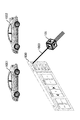
図10は、ターゲットマーカ105により操作画面800が操作されている様子を示す図である。仮想空間には、ステップS501で取得した旧組立品データ1001と新組立品データ1002と、ステップS406で生成された操作画面800とが配置されている。このような仮想空間を示す仮想空間画像が、後述する処理において現実空間画像に重畳されてHMD102に表示されている。更に、仮想空間生成部304は、ターゲットマーカ105の仮想空間における位置及び姿勢に基づいて、ターゲットマーカ105が指し示す方向に対して、カーソルオブジェクト1003を仮想空間に配置する。このカーソルオブジェクト1003は、HMD102を装着するユーザが現実空間でターゲットマーカ105を移動させても、カーソルオブジェクト1003がターゲットマーカ105の指し示す方向に追従する。そして、ユーザは、差分データリスト804に表示された差分データのうち、ターゲットマーカ105に重畳表示させたい場合には、このターゲットマーカ105のカーソルオブジェクト1003を、表示したい差分データの名称に対して一定時間接触させる。これにより、ボタン押下が行われる。
FIG. 10 is a diagram showing how the
ステップS902では、情報処理装置101の操作受付部313は、ステップS901で特定された操作内容が、現在、仮想空間上に配置している差分データとは異なる差分データに対応するボタンが選択されたか否かを判定する。例えば、現在仮想空間上に配置されている差分データが“部品データB”であり、新たに選択された差分データが“部品データC”である場合や、仮想空間上にどの差分データも配置されていない状態で、差分データに対応するボタンが押下された場合である。このような場合には、ステップS903に処理を進める。そうでない場合には、差分データ配置処理を終了し、ステップS407の次のステップに処理を進める。
In step S902, in the
ステップS903では、情報処理装置101のデータ管理部309は、カーソルオブジェクト1003によって押下されたボタンに対応する差分データの各種フラグ(追加フラグ702〜削除フラグ705)を参照する。以下、カーソルオブジェクト1003によって押下されたボタンに対応する差分データを、選択差分データと称する。
In step S903, the
ステップS904では、情報処理装置101のデータ管理部309は、選択差分データの追加フラグ702が“1”であるか否か、すなわち追加フラグ702が立っているか否かを判定する。選択差分データの追加フラグ702が“1”であると判定した場合には、ステップS905に処理を進める。選択差分データの追加フラグ702が“0”であると判定した場合には、ステップS908に処理を進める。
In step S904, the
ステップS905では、情報処理装置101のデータ管理部309は、新組立品データを構成する選択差分データを外部メモリ211から取得する。すなわち、旧組立品データに対して新たに追加された選択差分データを外部メモリ211から取得するということである。
In step S905, the
ステップS906では、情報処理装置101の三次元モデル制御部305は、仮想空間に配置されている新組立品データのうち、選択差分データの部分に対して色づけを行う。換言すれば、仮想空間に配置されている新組立品データにおいて選択差分データが識別可能な表示形態となるように設定を行う。そのため、表示形態としては色づけに限らず、選択差分データを点滅させたり、矢印等で識別表示したりしてもよい。
In step S906, the three-dimensional
ステップS907では、情報処理装置101の画面生成部312は、操作画面800の表示対象ボタン803を選択できない状態の画面として生成しなおし、仮想空間に再配置する。新たに追加された差分データであるということは、設計変更前は存在しなかったということなので、表示対象ボタン803で“OLD”が選択されたとしても表示するものがない。よって、表示対象ボタン803が押下できないようにしている。ステップS907が完了したらステップS911に処理を進める。
In step S907, the
一方、ステップS908では、情報処理装置101のデータ管理部309は、選択差分データの形状変更フラグ703が“1”であるか否か、すなわち形状変更フラグ703が立っているか否かを判定する。選択差分データの形状変更フラグ703が“1”であると判定した場合には、ステップS909に処理を進める。選択差分データの形状変更フラグ703が“0”であると判定した場合には、図9BのステップS913に処理を進める。
On the other hand, in step S908, the
ステップS909では、情報処理装置101のデータ管理部309は、新組立品データを構成する選択差分データを外部メモリ211から取得する。すなわち、形状変更後の選択差分データを外部メモリ211から取得するということである。新たに追加された差分データとは異なり、設計変更前の選択差分データも存在するが、ユーザは設計変更された形状について確認をしたいため、設計変更後の選択差分データを取得している。尚、どちらの選択差分データを最初に表示するのかが設定できてもよい。すなわち、設計変更前の選択差分データを初期表示する設定だった場合には、ステップS909は設計変更前の選択差分データを取得する。
In step S909, the
ステップS910では、情報処理装置101の三次元モデル制御部305は、仮想空間に配置されている新旧組立品データのうち、選択差分データの部分に対して色づけを行う(表示形態変更手段)。換言すれば、仮想空間に配置されている新旧組立品データにおいて選択差分データが識別可能な表示形態となるように設定を行う。そのため、表示形態としては色づけに限らず、選択差分データを点滅させたり、矢印等で識別表示したりしてもよい。ステップS910は、ステップS907とは異なり、旧組立品データにおいても選択差分データの表示形態を変更する。
In step S910, the three-dimensional
ステップS911では、情報処理装置101の距離算出部314は、ユーザの仮想空間における位置から、仮想空間に配置されている新組立品データの三次元モデルに含まれる選択差分データの三次元モデルの位置までの距離を算出する(距離取得手段)。選択差分データの位置は、選択差分データを示す三次元モデルの中心点の位置とするが、これに限らない。そして、算出された距離が所定距離以上(または所定距離より大きい)であるか否かを判定する。すなわち、算出された距離が所定の条件を満たすか否かを判定するということである。仮想空間に配置された新組立品データの三次元モデルの近くにユーザが存在するのであれば、ユーザは新組立品データに含まれる選択差分データの三次元モデルを直接確認すればよい。しかし、仮想空間に配置された新組立品データの三次元モデルから離れた位置にユーザが存在するのであれば、ユーザは新組立品データに近寄って確認しなければならない。よって、こうした場合にはターゲットマーカ105に選択差分データを重畳表示させることで、近寄る手間を軽減できる。そのため、ステップS911ではこれらの距離に関する判定を行っている。所定距離以上離れていると判定した場合には、ステップS912に処理を進める。そうでない場合には、差分データ配置処理を終了し、ステップS407の次のステップに処理を進める。
In step S911, the
尚、本実施形態ではステップS911を必ず実行する形態としているが、設定によりこれを実行しない形態であってもよい。すなわち、ステップS911で算出した距離に関わらず、取得した選択差分データの三次元モデルをターゲットマーカ105に重畳表示する形態であってもよい。
In this embodiment, step S911 is always executed, but it may not be executed depending on the setting. That is, regardless of the distance calculated in step S911, the three-dimensional model of the acquired selection difference data may be superimposed and displayed on the
ステップS912では、情報処理装置101の仮想空間生成部304は、ステップS405で特定したターゲットマーカ105の仮想空間における位置及び姿勢で、S905またはS909で取得した選択差分データの三次元モデルを配置する(配置手段)。こうすることで、現実空間画像に仮想空間画像を重畳した際に、ターゲットマーカ105の位置に選択差分データの三次元モデルが重畳されることになる。つまり、HMD102を装着するユーザは、あたかも現実空間のターゲットマーカ105に選択差分データの三次元モデルが貼り付いているかのように見える。ステップS912の処理が完了したら、差分データ配置処理を終了し、ステップS407の次のステップに処理を進める。
In step S912, the virtual
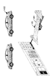
図11は、形状変更がなされた選択差分データがターゲットマーカ105に表示された様子を示す図である。図10に示すように、表示対象の差分データとして“部品データB”が選択されると、この“部品データB”の変更内容を示すフラグを確認する。すると、図7に示す通り、“部品データB”は形状変更フラグ703にフラグが立っているので、形状変更がなされた選択差分データであることがわかる。よって、ステップS909で設計変更後の選択差分データを外部メモリ211から取得し、この取得した選択差分データの三次元モデルをターゲットマーカ105の位置及び姿勢で仮想空間上に配置する。また、新旧組立品データの三次元モデルにおいて、選択差分データの三次元モデルの表示形態を変更し、選択差分データを他の参照先データとは識別可能にする。
FIG. 11 is a diagram showing how the selected difference data whose shape has been changed is displayed on the
そして、この仮想空間を示す仮想空間画像を生成して、現実空間画像に重畳した結果が図11である。図11に示す通り、ターゲットマーカ105の位置に設計変更後の選択差分データの三次元モデル(図11では、車のホイール)が重畳表示される。また、新旧組立品データの三次元モデルも表示されており、このうち選択差分データに対応する箇所が識別表示される。図11では、設計変更前の選択差分データが1101であり、設計変更後の選択差分データが1102である。いずれも新旧組立品データの三次元モデルを構成している選択差分データの三次元モデルである。このように新旧組立品データに組み込まれた状態の選択差分データとは別に、ユーザが有するターゲットマーカ105に選択差分データの三次元モデルを表示することで、設計変更がなされた選択差分データを手軽に確認することができる。
Then, the result of generating the virtual space image showing this virtual space and superimposing it on the real space image is shown in FIG. As shown in FIG. 11, a three-dimensional model (in FIG. 11, the wheel of the car) of the selected difference data after the design change is superimposed and displayed at the position of the
図9Bに説明を移す。ステップS913では、情報処理装置101の画面生成部312は、操作画面800のターゲットボタン801と表示階層ボタン802と表示対象ボタン803とを選択できない状態の画面として生成しなおし、仮想空間に再配置する。後述する位置または姿勢が変更された選択差分データと削除された選択差分データについては、設計変更後の状態を手元のターゲットマーカ105において確認する必要性があまりない。そのため後述する処理において、これらの選択差分データの三次元モデルはターゲットマーカ105に重畳させないので、操作画面800の各種ボタンも選択できないように制御する。
The explanation is transferred to FIG. 9B. In step S913, the
ステップS914では、情報処理装置101のデータ管理部309は、選択差分データの位置姿勢変更フラグ704が“1”であるか否か、すなわち位置姿勢変更フラグ704が立っているか否かを判定する。選択差分データの位置姿勢変更フラグ704が“1”であると判定した場合には、ステップS915に処理を進める。選択差分データの位置姿勢変更フラグ704が“0”であると判定した場合には、ステップS916に処理を進める。
In step S914, the
ステップS915では、情報処理装置101の三次元モデル制御部305は、仮想空間に配置されている新旧組立品データのうち、選択差分データの部分に対して色づけを行う。換言すれば、仮想空間に配置されている新旧組立品データにおいて選択差分データが識別可能な表示形態となるように設定を行う。そのため、表示形態としては色づけに限らず、選択差分データを点滅させたり、矢印等で識別表示したりしてもよい。そして、ターゲットマーカ105に、位置または姿勢が変更された選択差分データの三次元モデルを重畳表示するための処理を行わずに差分データ配置処理を終了し、ステップS407の次のステップに処理を進める。
In step S915, the three-dimensional
一方、ステップS916では、情報処理装置101のデータ管理部309は、選択差分データの削除フラグ705が“1”であるか否か、すなわち削除フラグ705が立っているか否かを判定する。選択差分データの削除フラグ705が“1”であると判定した場合には、ステップS917に処理を進める。選択差分データの削除フラグ705が“0”であると判定した場合には、差分データ配置処理を終了し、ステップS407の次のステップに処理を進める。
On the other hand, in step S916, the
ステップS917では、情報処理装置101の三次元モデル制御部305は、仮想空間に配置されている旧組立品データのうち、選択差分データの部分に対して色づけを行う。換言すれば、仮想空間に配置されている旧組立品データにおいて選択差分データが識別可能な表示形態となるように設定を行う。そのため、表示形態としては色づけに限らず、選択差分データを点滅させたり、矢印等で識別表示したりしてもよい。そして、ターゲットマーカ105に、削除された選択差分データの三次元モデルを重畳表示するための処理を行わずに差分データ配置処理を終了し、ステップS407の次のステップに処理を進める。
In step S917, the three-dimensional
尚、本実施形態においては、位置または姿勢が変更された選択差分データの三次元モデルはターゲットマーカ105に重畳表示させていないが、これらも重畳表示させてもよい。
In the present embodiment, the three-dimensional model of the selected difference data whose position or posture has been changed is not superimposed and displayed on the
図4に説明を戻す。ステップS407の処理が完了すると、ステップS408では、情報処理装置101は、操作画面800における表示設定の内容を反映するための処理を実行する。図12に表示設定反映処理の詳細な処理の流れを示す。
The explanation is returned to FIG. When the process of step S407 is completed, in step S408, the
図12は、表示設定反映処理の詳細な処理の流れの一例を示すフローチャートである。以下説明する、S1201乃至S1213の各ステップは、情報処理装置101のCPU201が各機能部を動作することにより実行される処理である。
FIG. 12 is a flowchart showing an example of a detailed processing flow of the display setting reflection processing. Each step of S1201 to S1213 described below is a process executed by the
ステップS1201では、情報処理装置101の操作受付部313は、仮想空間に配置された操作画面800に対する操作内容を特定する。特定方法は、ステップS901と同様である。
In step S1201, the
ステップS1202では、情報処理装置101の操作受付部313は、表示階層ボタン802に対する押下を受け付けたか否かを判定する。表示階層ボタン802に対する押下を受け付けたと判定した場合には、ステップS1203に処理を進める。そうでない場合には、ステップS1204に処理を進める。
In step S1202, the
ステップS1203では、情報処理装置101のデータ管理部309は、表示階層ボタン802に対する押下に応じて決定される、表示階層に関する情報をRAM203に保存する。表示階層ボタン802は、左右の矢印が押下されることで、表示階層の増減を行うことができる。この情報を用いて、どの階層のアセンブリデータまでを表示すればよいのか決定する。ステップS1203の処理が完了したら、ステップS1209に処理を進める。
In step S1203, the
ステップS1204では、情報処理装置101の操作受付部313は、表示対象ボタン803に対する押下を受け付けたか否かを判定する。表示対象ボタン803に対する押下を受け付けたと判定した場合には、ステップS1205に処理を進める。そうでない場合には、ステップS1208に処理を進める。
In step S1204, the
ステップS1205では、情報処理装置101の操作受付部313は、表示対象ボタン803のうち、“NEW”のボタンが押下されたのか、“OLD”のボタンが押下されたのかを判定する。“NEW”のボタンが押下されたと判定した場合には、ステップS1206に処理を進める。“OLD”のボタンが押下されたと判定した場合には、ステップS1207に処理を進める。
In step S1205, the
ステップS1206では、情報処理装置101のデータ管理部309は、新組立品データを構成する選択差分データを外部メモリ211から取得する。一方、ステップS1207では、情報処理装置101のデータ管理部309は、旧組立品データを構成する選択差分データを外部メモリ211から取得する。本実施形態では、形状変更が行われた選択差分データ以外は、表示対象ボタン803の操作が行えないように制御しているが、この制御を行わない場合には、選択差分データが存在しないために取得できない。そのため、取得できなかった場合には、表示設定反映処理を終了する形態であってもよい。
In step S1206, the
ステップS1208では、情報処理装置101の操作受付部313は、ターゲットボタン801に対する押下を受け付けたか否かを判定する。ターゲットボタン801に対する押下を受け付けたと判定した場合には、ステップS1209に処理を進める。そうでない場合には、表示設定反映処理を終了し、ステップS408の次のステップに処理を進める。
In step S1208, the
ステップS1209では、情報処理装置101の距離算出部314は、HMD102を装着するユーザの仮想空間における位置から、仮想空間に配置されている組立品データの三次元モデルに含まれる選択差分データの三次元モデルの位置までの距離を算出する。ここでいう選択差分データとは、ターゲットマーカ105に重畳表示する選択差分データに対応する、仮想空間上の組立品データ内の選択差分データである。例えば、新たに表示対象ボタン803で“OLD”が選択された場合には、旧組立品データの三次元モデルに含まれる、取得した設計変更前の選択差分データの三次元モデルの位置が基準となる。距離の算出は前述した通りである。そして、算出された距離が所定距離以上(または所定距離より大きい)であるか否かを判定する。所定距離以上離れていると判定した場合には、ステップS1210に処理を進める。そうでない場合には、表示設定反映処理を終了し、ステップS408の次のステップに処理を進める。
In step S1209, the
尚、本実施形態ではステップS1209を必ず実行する形態としているが、設定によりこれを実行しない形態であってもよい。すなわち、ステップS1209で算出した距離に関わらず、取得した選択差分データの三次元モデルをターゲットマーカ105に重畳表示する形態であってもよい。
In this embodiment, step S1209 is always executed, but it may not be executed depending on the setting. That is, regardless of the distance calculated in step S1209, the three-dimensional model of the acquired selection difference data may be superimposed and displayed on the
ステップS1210では、情報処理装置101の操作受付部313は、ターゲットボタン801のうち、“アセンブリ”のボタンが押下されたのか、“部品”のボタンが押下されたのかを判定する。“アセンブリ”のボタンが押下されたと判定した場合には、ステップS1211に処理を進める。“部品”のボタンが押下されたと判定した場合には、ステップS1213に処理を進める。
In step S1210, the
ステップS1211では、情報処理装置101のデータ管理部309は、ステップS1203で保存された階層の情報を取得し、ターゲットマーカ105に重畳する選択差分データから当該情報が示す階層の分だけ遡ったアセンブリデータを特定する。例えば、図6(a)の参照構造で説明する。ターゲットマーカ105に重畳する選択差分データが“部品データE”で、階層の情報が“1”である場合には、“部品データE”の1階層上のアセンブリデータが特定されるので、この場合は、“アセンブリデータD”が特定されることになる。
In step S1211, the
ステップS1212では、情報処理装置101の仮想空間生成部304は、ステップS405で特定したターゲットマーカ105の仮想空間における位置及び姿勢で、ステップS1211で取得したアセンブリデータの三次元モデルを配置する。すなわち、当該アセンブリデータを構成する参照先データを取得し、この参照先データの三次元モデルを当該アセンブリデータに設定された位置及び姿勢で配置して、アセンブリの三次元モデルを生成する。そして、この三次元モデルをターゲットマーカ105の位置及び姿勢で配置すればよい。
In step S1212, the virtual
一方、ステップS1213では、情報処理装置101の仮想空間生成部304は、ステップS405で特定したターゲットマーカ105の仮想空間における位置及び姿勢で、ターゲットマーカ105に重畳表示する選択差分データの三次元モデルを配置する。
On the other hand, in step S1213, the virtual
こうすることで、現実空間画像に仮想空間画像を重畳した際に、ターゲットマーカ105の位置に選択差分データまたはその親であるアセンブリの三次元モデルが重畳されることになる。ステップS1212またはS1213の処理が完了したら、表示設定反映処理を終了し、ステップS408の次のステップに処理を進める。
By doing so, when the virtual space image is superimposed on the real space image, the selection difference data or the three-dimensional model of the assembly which is the parent thereof is superimposed on the position of the
図4に説明を戻す。ステップS409では、情報処理装置101の仮想空間画像取得部306は、仮想空間上に設定された視点から仮想空間を撮像することにより仮想空間画像を取得し、これをRAM203等に記憶する(仮想空間画像生成手段)。尚、HMD102の右目・左目ディスプレイ222のそれぞれに表示するために右目用の仮想空間画像と左目用の仮想空間画像の2枚を取得する。
The explanation is returned to FIG. In step S409, the virtual space
ステップS410では、情報処理装置101の複合現実画像生成部307は、ステップS403で取得した現実空間画像とステップS409で取得した仮想空間画像とをRAM203等から読み出す。そして、当該現実空間画像に当該仮想空間画像を重畳し、複合現実画像を生成する。生成した複合現実画像はRAM203等に記憶する。尚、前述した通り、現実空間画像と仮想空間画像とは右目用と左目用の2枚ずつがRAM203等に記憶されているので、右目用の現実空間画像に右目用の仮想空間画像を重畳し、左目用の現実空間画像に左目用の仮想空間画像を重畳する。
In step S410, the mixed reality image generation unit 307 of the
ステップS411では、情報処理装置101の表示制御部308は、ステップS410で生成した複合現実画像をRAM203等から読み出し、ビデオコントローラ206を通じてHMD102の右目・左目ディスプレイ222に表示する。RAM203等に記憶された複合現実画像は、右目用と左目用の2枚が存在する。そのため、右目用の複合現実画像を右目・左目ディスプレイ222の右目のディスプレイに表示するよう制御し、左目用の複合現実画像を右目・左目ディスプレイ222の左目のディスプレイに表示するよう制御する。
In step S411, the
ステップS412では、情報処理装置101の操作受付部313は、HMD102を装着しているユーザに複合現実感を提示する処理の終了指示があったか否かを判定する。例えば、前述したステップS403乃至ステップS411の処理を実行する情報処理装置101のアプリケーションの停止指示や終了指示があったか否かを判定する。終了指示があったと判定した場合には、本一連の処理を終了する。終了指示があったと判定しなかった場合、すなわち終了指示がなかった場合にはステップS403に処理を戻し、終了指示があるまでステップS403乃至ステップS412の処理を繰り返す。
In step S412, the
図13は、形状変更前の選択差分データがターゲットマーカ105に重畳表示された様子を示す図である。ターゲットマーカ105によって表示対象ボタン803の“OLD”が選択されると、形状変更前の選択差分データが取得され、ターゲットマーカ105に重畳表示される。1301は、図11に示す1103の形状変更後の選択差分データが、形状変更後の選択差分データに入れ替わった様子を示している。このように、設計変更前後の選択差分データを切り替えて表示させることができる。
FIG. 13 is a diagram showing how the selection difference data before the shape change is superimposed and displayed on the
図14乃至図16は、形状変更以外の設計変更がなされた選択差分データの様子を示す。図14は、新たに追加された差分データが選択された場合を示している。新組立品データの1402に示すように、新しく差分データ(図14では車のウィング)が追加されていることがわかる。そのため、この選択差分データを新組立品データにおいて識別表示する。また、1401に示すように、ターゲットマーカ105に選択差分データの三次元モデルを重畳表示する。
14 to 16 show the state of the selected difference data in which the design change other than the shape change is made. FIG. 14 shows the case where the newly added difference data is selected. As shown in 1402 of the new assembly data, it can be seen that new difference data (the wing of the car in FIG. 14) has been added. Therefore, this selection difference data is identified and displayed in the new assembly data. Further, as shown in 1401, the three-dimensional model of the selected difference data is superimposed and displayed on the
図15は、位置または姿勢が変更された差分データが選択された場合を示している。選択差分データの三次元モデル(図15では車のドアミラー)は、旧組立品データにおける1501と新組立品データにおける1502とに示すように、位置が変更されている。そのため、この選択差分データを新旧組立品データにおいて識別表示する。また、位置または姿勢が変更された選択差分データの三次元モデルはターゲットマーカ105には重畳表示しないので、図15においても重畳表示されていないことがわかる。
FIG. 15 shows the case where the difference data whose position or posture has been changed is selected. The three-dimensional model of the selection difference data (car door mirror in FIG. 15) has been repositioned as shown in 1501 in the old assembly data and 1502 in the new assembly data. Therefore, this selection difference data is identified and displayed in the old and new assembly data. Further, since the three-dimensional model of the selected difference data whose position or posture has been changed is not superimposed and displayed on the
図16は、削除された差分データが選択された場合を示している。旧組立品データの1601に示すように、選択差分データ(図16では車のマフラー)は旧組立品データの三次元モデルには存在していたが、新組立品データからは削除されている。そのため、旧組立品データにおいて選択差分データを識別表示する。また、削除された選択差分データの三次元モデルはターゲットマーカ105には重畳表示しないので、図16においても重畳表示されていないことがわかる。
FIG. 16 shows the case where the deleted difference data is selected. As shown in 1601 of the old assembly data, the selection difference data (car muffler in FIG. 16) was present in the three-dimensional model of the old assembly data, but has been deleted from the new assembly data. Therefore, the selected difference data is identified and displayed in the old assembly data. Further, since the three-dimensional model of the deleted selection difference data is not superimposed and displayed on the
以上説明したように、設計変更された部品データが構成する三次元モデルを仮想空間上で操作することなく、当該部品データを仮想空間上で閲覧可能となる。 As described above, the component data can be browsed in the virtual space without operating the three-dimensional model composed of the redesigned component data in the virtual space.
本発明は、例えば、システム、装置、方法、プログラム若しくは記憶媒体等としての実施形態も可能であり、具体的には、複数の機器から構成されるシステムに適用してもよいし、また、1つの機器からなる装置に適用してもよい。 The present invention can be, for example, an embodiment as a system, an apparatus, a method, a program, a storage medium, or the like, and specifically, may be applied to a system composed of a plurality of devices, or 1 It may be applied to a device consisting of two devices.
なお、本発明は、前述した実施形態の機能を実現するソフトウェアのプログラムを、システム或いは装置に直接、或いは遠隔から供給するものを含む。そして、そのシステム或いは装置のコンピュータが前記供給されたプログラムコードを読み出して実行することによっても達成される場合も本発明に含まれる。 The present invention includes a software program that realizes the functions of the above-described embodiments, which is directly or remotely supplied to a system or an apparatus. The present invention also includes cases where the computer of the system or device can also read and execute the supplied program code.
したがって、本発明の機能処理をコンピュータで実現(実行可能と)するために、前記コンピュータにインストールされるプログラムコード自体も本発明を実現するものである。つまり、本発明は、本発明の機能処理を実現するためのコンピュータプログラム自体も含まれる。 Therefore, in order to realize (execute) the functional processing of the present invention on a computer, the program code itself installed on the computer also realizes the present invention. That is, the present invention also includes a computer program itself for realizing the functional processing of the present invention.
その場合、プログラムの機能を有していれば、オブジェクトコード、インタプリタにより実行されるプログラム、OSに供給するスクリプトデータ等の形態であってもよい。 In that case, as long as it has a program function, it may be in the form of an object code, a program executed by an interpreter, script data supplied to the OS, or the like.
プログラムを供給するための記録媒体としては、例えば、フレキシブルディスク、ハードディスク、光ディスク、光磁気ディスク、MO、CD−ROM、CD−R、CD−RWなどがある。また、磁気テープ、不揮発性のメモリカード、ROM、DVD(DVD−ROM,DVD−R)などもある。 Recording media for supplying programs include, for example, flexible disks, hard disks, optical disks, magneto-optical disks, MOs, CD-ROMs, CD-Rs, CD-RWs, and the like. There are also magnetic tapes, non-volatile memory cards, ROMs, DVDs (DVD-ROM, DVD-R) and the like.
その他、プログラムの供給方法としては、クライアントコンピュータのブラウザを用いてインターネットのホームページに接続する。そして、前記ホームページから本発明のコンピュータプログラムそのもの、若しくは圧縮され自動インストール機能を含むファイルをハードディスク等の記録媒体にダウンロードすることによっても供給できる。 In addition, as a program supply method, a browser of a client computer is used to connect to an Internet homepage. Then, the computer program itself of the present invention or a compressed file including the automatic installation function can be supplied from the homepage by downloading it to a recording medium such as a hard disk.
また、本発明のプログラムを構成するプログラムコードを複数のファイルに分割し、それぞれのファイルを異なるホームページからダウンロードすることによっても実現可能である。つまり、本発明の機能処理をコンピュータで実現するためのプログラムファイルを複数のユーザに対してダウンロードさせるWWWサーバも、本発明に含まれるものである。 It can also be realized by dividing the program code constituting the program of the present invention into a plurality of files and downloading each file from different homepages. That is, the present invention also includes a WWW server that allows a plurality of users to download a program file for realizing the functional processing of the present invention on a computer.
また、本発明のプログラムを暗号化してCD−ROM等の記憶媒体に格納してユーザに配布し、所定の条件をクリアしたユーザに対し、インターネットを介してホームページから暗号化を解く鍵情報をダウンロードさせる。そして、ダウンロードした鍵情報を使用することにより暗号化されたプログラムを実行してコンピュータにインストールさせて実現することも可能である。 In addition, the program of the present invention is encrypted, stored in a storage medium such as a CD-ROM, distributed to users, and the key information for decrypting the encryption is downloaded from the homepage to the user who clears the predetermined conditions. Let me. Then, by using the downloaded key information, it is possible to execute an encrypted program and install it on a computer.
また、コンピュータが、読み出したプログラムを実行することによって、前述した実施形態の機能が実現される。その他、そのプログラムの指示に基づき、コンピュータ上で稼動しているOSなどが、実際の処理の一部又は全部を行い、その処理によっても前述した実施形態の機能が実現され得る。 Further, the function of the above-described embodiment is realized by the computer executing the read program. In addition, based on the instruction of the program, the OS or the like running on the computer performs a part or all of the actual processing, and the function of the above-described embodiment can be realized by the processing.
さらに、記録媒体から読み出されたプログラムが、コンピュータに挿入された機能拡張ボードやコンピュータに接続された機能拡張ユニットに備わるメモリに書き込まれる。その後、そのプログラムの指示に基づき、その機能拡張ボードや機能拡張ユニットに備わるCPUなどが実際の処理の一部又は全部を行い、その処理によっても前述した実施形態の機能が実現される。 Further, the program read from the recording medium is written to the memory provided in the function expansion board inserted in the computer or the function expansion unit connected to the computer. After that, based on the instruction of the program, the function expansion board, the CPU provided in the function expansion unit, or the like performs a part or all of the actual processing, and the function of the above-described embodiment is also realized by the processing.
なお、前述した実施形態は、本発明を実施するにあたっての具体化の例を示したものに過ぎず、これらによって本発明の技術的範囲が限定的に解釈されてはならないものである。即ち、本発明はその技術思想、又はその主要な特徴から逸脱することなく、様々な形で実施することができる。 It should be noted that the above-described embodiments merely show examples of embodiment in carrying out the present invention, and the technical scope of the present invention should not be construed in a limited manner by these. That is, the present invention can be implemented in various forms without departing from the technical idea or its main features.
101 情報処理装置
102 HMD
103 オプティカルマーカ
104 赤外線カメラ
105 ターゲットマーカ
101
103
Claims (8)
第一の三次元モデルと第二の三次元モデルとで差がある部品を特定する特定手段と、
仮想空間上における前記第一の三次元モデルが配置される第一の位置および前記第二の三次元モデルが配置される第二の位置とは別の位置として前記情報処理装置に記憶される位置であって、前記第一の三次元モデルと第二の三次元モデルと同じ前記仮想空間上の第三の位置に、前記特定手段により特定された、前記第一の三次元モデルと第二の三次元モデルとで差がある部品を配置して表示すべく制御する制御手段と、
を備えることを特徴とする情報処理装置。 An information processing device for presenting a three-dimensional model composed of multiple parts.
Specific means for identifying parts that differ between the first 3D model and the second 3D model,
A position stored in the information processing device as a position different from the first position where the first three-dimensional model is arranged and the second position where the second three-dimensional model is arranged in the virtual space. The first three-dimensional model and the second three-dimensional model specified by the specific means at the same third position on the virtual space as the first three-dimensional model and the second three-dimensional model. A control means that controls the placement and display of parts that differ from the 3D model,
An information processing device characterized by being equipped with.
前記制御手段は、前記特定手段により特定される前記差がある部品のうち、設計変更がされた部品を、前記第三の位置に表示すべく制御することを特徴とする請求項1または2に記載の情報処理装置。 The parts having the difference include parts existing only in one of the first three-dimensional model and the second three-dimensional model, parts whose design has been changed, and parts whose position and orientation have been changed.
The control means according to claim 1 or 2, wherein the control means controls a part whose design has been changed among the parts having the difference specified by the specific means so as to be displayed at the third position. The information processing device described.
前記制御手段は、仮想空間におけるユーザの位置と、前記第三の位置とに基づいて生成した前記ユーザの位置から見た前記差がある部品の画像を、前記表示部における前記第三の位置に該当する位置に表示すべく制御することを特徴とする請求項1乃至4のいずれか1項に記載の情報処理装置。 The information processing device includes a display unit.
The control means displays an image of a component having a difference from the position of the user generated based on the position of the user in the virtual space and the position of the user at the third position on the display unit. The information processing apparatus according to any one of claims 1 to 4, wherein the information processing apparatus is controlled so as to be displayed at a corresponding position.
前記情報処理装置の特定取得手段が、第一の三次元モデルと第二の三次元モデルとで差がある部品を特定する特定ステップと、
前記情報処理装置の制御手段が、仮想空間上における前記第一の三次元モデルが配置される第一の位置および前記第二の三次元モデルが配置される第二の位置とは別の位置として前記情報処理装置に記憶される位置であって、前記第一の三次元モデルと第二の三次元モデルと同じ前記仮想空間上の第三の位置に、前記特定ステップにより特定された、前記第一の三次元モデルと第二の三次元モデルとで差がある部品を配置して表示すべく制御する制御ステップと、
を含む制御方法。 It is a control method of an information processing device for presenting a three-dimensional model composed of a plurality of parts.
The specific acquisition means of the information processing device has a specific step of identifying a part having a difference between the first three-dimensional model and the second three-dimensional model, and
The control means of the information processing device is set as a position on the virtual space different from the first position where the first three-dimensional model is arranged and the second position where the second three-dimensional model is arranged. The first position stored in the information processing apparatus, which is specified by the specific step at the third position on the virtual space which is the same as the first three-dimensional model and the second three-dimensional model. A control step that controls to arrange and display parts that differ between the first 3D model and the second 3D model,
Control methods including.
第一の三次元モデルと第二の三次元モデルとで差がある部品を特定する特定手段と、
仮想空間上における前記第一の三次元モデルが配置される第一の位置および前記第二の三次元モデルが配置される第二の位置とは別の位置として前記情報処理装置に記憶される位置であって、前記第一の三次元モデルと第二の三次元モデルと同じ前記仮想空間上の第三の位置に、前記特定手段により特定された、前記第一の三次元モデルと第二の三次元モデルとで差がある部品を配置して表示すべく制御する制御手段として機能させるためのプログラム。 An information processing device for presenting a three-dimensional model composed of multiple parts,
Specific means for identifying parts that differ between the first 3D model and the second 3D model,
A position stored in the information processing apparatus as a position on the virtual space different from the first position where the first three-dimensional model is arranged and the second position where the second three-dimensional model is arranged. The first three-dimensional model and the second three-dimensional model specified by the specific means at the same third position on the virtual space as the first three-dimensional model and the second three-dimensional model. A program to function as a control means to control the placement and display of parts that differ from the 3D model.
Priority Applications (2)
| Application Number | Priority Date | Filing Date | Title |
|---|---|---|---|
| JP2016130476A JP6860776B2 (en) | 2016-06-30 | 2016-06-30 | Virtual space controller, its control method, and program |
| JP2021053076A JP7208549B2 (en) | 2016-06-30 | 2021-03-26 | VIRTUAL SPACE CONTROL DEVICE, CONTROL METHOD THEREOF, AND PROGRAM |
Applications Claiming Priority (1)
| Application Number | Priority Date | Filing Date | Title |
|---|---|---|---|
| JP2016130476A JP6860776B2 (en) | 2016-06-30 | 2016-06-30 | Virtual space controller, its control method, and program |
Related Child Applications (1)
| Application Number | Title | Priority Date | Filing Date |
|---|---|---|---|
| JP2021053076A Division JP7208549B2 (en) | 2016-06-30 | 2021-03-26 | VIRTUAL SPACE CONTROL DEVICE, CONTROL METHOD THEREOF, AND PROGRAM |
Publications (3)
| Publication Number | Publication Date |
|---|---|
| JP2018005499A JP2018005499A (en) | 2018-01-11 |
| JP2018005499A5 JP2018005499A5 (en) | 2020-05-28 |
| JP6860776B2 true JP6860776B2 (en) | 2021-04-21 |
Family
ID=60946316
Family Applications (2)
| Application Number | Title | Priority Date | Filing Date |
|---|---|---|---|
| JP2016130476A Active JP6860776B2 (en) | 2016-06-30 | 2016-06-30 | Virtual space controller, its control method, and program |
| JP2021053076A Active JP7208549B2 (en) | 2016-06-30 | 2021-03-26 | VIRTUAL SPACE CONTROL DEVICE, CONTROL METHOD THEREOF, AND PROGRAM |
Family Applications After (1)
| Application Number | Title | Priority Date | Filing Date |
|---|---|---|---|
| JP2021053076A Active JP7208549B2 (en) | 2016-06-30 | 2021-03-26 | VIRTUAL SPACE CONTROL DEVICE, CONTROL METHOD THEREOF, AND PROGRAM |
Country Status (1)
| Country | Link |
|---|---|
| JP (2) | JP6860776B2 (en) |
Families Citing this family (6)
| Publication number | Priority date | Publication date | Assignee | Title |
|---|---|---|---|---|
| JP7095379B2 (en) * | 2018-04-23 | 2022-07-05 | 富士フイルムビジネスイノベーション株式会社 | Information processing equipment and programs |
| DE102018207987A1 (en) * | 2018-05-22 | 2019-11-28 | Siemens Aktiengesellschaft | Method and system for displaying a 3D model |
| JP7275484B2 (en) * | 2018-07-05 | 2023-05-18 | 凸版印刷株式会社 | Object Placement Support System, Object Placement Support Method and Program |
| JP7443014B2 (en) * | 2019-10-08 | 2024-03-05 | 大豊精機株式会社 | robot arm testing equipment |
| JPWO2023074817A1 (en) * | 2021-11-01 | 2023-05-04 | ||
| JP7311696B1 (en) | 2022-10-18 | 2023-07-19 | 川田テクノシステム株式会社 | MULTI-SCREEN DISPLAY SYSTEM, MULTI-SCREEN DISPLAY DEVICE, AND MULTI-SCREEN DISPLAY PROGRAM |
Family Cites Families (6)
| Publication number | Priority date | Publication date | Assignee | Title |
|---|---|---|---|---|
| JP2004178222A (en) * | 2002-11-26 | 2004-06-24 | Matsushita Electric Works Ltd | Method for evaluating assemblability and assemblability evaluation supporting device using the method |
| JP2008176425A (en) * | 2007-01-16 | 2008-07-31 | Ricoh Co Ltd | Catalog preparation system, parts catalog preparation method, program, and recording medium |
| JP2009070130A (en) | 2007-09-13 | 2009-04-02 | Ricoh Co Ltd | Apparatus, method, program and recording medium for creating parts catalog |
| JP5440186B2 (en) | 2010-01-06 | 2014-03-12 | 富士通株式会社 | Design support apparatus and design support program |
| JP5830004B2 (en) | 2012-12-11 | 2015-12-09 | 株式会社日立製作所 | 3D model generation apparatus, 3D model generation method, and 3D model generation program |
| JP6242709B2 (en) * | 2014-02-17 | 2017-12-06 | 株式会社日立製作所 | Assembly sequence generation apparatus and assembly sequence generation method |
-
2016
- 2016-06-30 JP JP2016130476A patent/JP6860776B2/en active Active
-
2021
- 2021-03-26 JP JP2021053076A patent/JP7208549B2/en active Active
Also Published As
| Publication number | Publication date |
|---|---|
| JP7208549B2 (en) | 2023-01-19 |
| JP2018005499A (en) | 2018-01-11 |
| JP2021108158A (en) | 2021-07-29 |
Similar Documents
| Publication | Publication Date | Title |
|---|---|---|
| JP7208549B2 (en) | VIRTUAL SPACE CONTROL DEVICE, CONTROL METHOD THEREOF, AND PROGRAM | |
| US11501224B2 (en) | Project management system with client interaction | |
| CN112926428B (en) | Method and system for training object detection algorithm using composite image and storage medium | |
| US9734634B1 (en) | Augmented reality product preview | |
| US9418378B2 (en) | Method and system for trying out a product in relation to a real world environment | |
| KR102130709B1 (en) | Method for providing digitial fashion based custom clothing making service using product preview | |
| JP6677890B2 (en) | Information processing system, its control method and program, and information processing apparatus, its control method and program | |
| EP2972675A1 (en) | Presenting object models in augmented reality images | |
| AU2016336030A1 (en) | Volumetric depth video recording and playback | |
| US11941763B2 (en) | Viewing system, model creation apparatus, and control method | |
| KR101875047B1 (en) | System and method for 3d modelling using photogrammetry | |
| KR20140130638A (en) | The smart fitting apparatus and method based real image | |
| CN111311759B (en) | Mobile augmented reality video editing system | |
| JP6376591B2 (en) | Data output device, data output method, and three-dimensional object manufacturing system | |
| JP6011567B2 (en) | Information processing apparatus, control method thereof, and program | |
| JP6152888B2 (en) | Information processing apparatus, control method and program thereof, and information processing system, control method and program thereof | |
| JP2017084215A (en) | Information processing system, control method thereof, and program | |
| US10726621B2 (en) | Traversal selection of components for a geometric model | |
| JP5999236B2 (en) | INFORMATION PROCESSING SYSTEM, ITS CONTROL METHOD, AND PROGRAM, AND INFORMATION PROCESSING DEVICE, ITS CONTROL METHOD, AND PROGRAM | |
| JP2020074108A (en) | Information processing system, control method thereof, and program | |
| JP6638326B2 (en) | Information processing system, control method thereof, and program | |
| US20150378661A1 (en) | System and method for displaying internal components of physical objects | |
| JP2018018362A (en) | Virtual space control device, control method thereof, and program | |
| JP2015121892A (en) | Image processing apparatus, and image processing method | |
| JP6703283B2 (en) | Information processing apparatus, control method thereof, and program |
Legal Events
| Date | Code | Title | Description |
|---|---|---|---|
| RD03 | Notification of appointment of power of attorney |
Free format text: JAPANESE INTERMEDIATE CODE: A7423 Effective date: 20161101 |
|
| RD04 | Notification of resignation of power of attorney |
Free format text: JAPANESE INTERMEDIATE CODE: A7424 Effective date: 20161101 |
|
| RD03 | Notification of appointment of power of attorney |
Free format text: JAPANESE INTERMEDIATE CODE: A7423 Effective date: 20180703 |
|
| RD04 | Notification of resignation of power of attorney |
Free format text: JAPANESE INTERMEDIATE CODE: A7424 Effective date: 20181031 |
|
| RD04 | Notification of resignation of power of attorney |
Free format text: JAPANESE INTERMEDIATE CODE: A7424 Effective date: 20190111 |
|
| A621 | Written request for application examination |
Free format text: JAPANESE INTERMEDIATE CODE: A621 Effective date: 20190627 |
|
| A521 | Request for written amendment filed |
Free format text: JAPANESE INTERMEDIATE CODE: A523 Effective date: 20200415 |
|
| A131 | Notification of reasons for refusal |
Free format text: JAPANESE INTERMEDIATE CODE: A131 Effective date: 20200901 |
|
| A521 | Request for written amendment filed |
Free format text: JAPANESE INTERMEDIATE CODE: A523 Effective date: 20201102 |
|
| A131 | Notification of reasons for refusal |
Free format text: JAPANESE INTERMEDIATE CODE: A131 Effective date: 20210126 |
|
| A521 | Request for written amendment filed |
Free format text: JAPANESE INTERMEDIATE CODE: A523 Effective date: 20210127 |
|
| TRDD | Decision of grant or rejection written | ||
| A01 | Written decision to grant a patent or to grant a registration (utility model) |
Free format text: JAPANESE INTERMEDIATE CODE: A01 Effective date: 20210224 |
|
| A61 | First payment of annual fees (during grant procedure) |
Free format text: JAPANESE INTERMEDIATE CODE: A61 Effective date: 20210309 |
|
| R151 | Written notification of patent or utility model registration |
Ref document number: 6860776 Country of ref document: JP Free format text: JAPANESE INTERMEDIATE CODE: R151 |
|
| R250 | Receipt of annual fees |
Free format text: JAPANESE INTERMEDIATE CODE: R250 |