JP6860619B2 - Work platform - Google Patents
Work platform Download PDFInfo
- Publication number
- JP6860619B2 JP6860619B2 JP2019113832A JP2019113832A JP6860619B2 JP 6860619 B2 JP6860619 B2 JP 6860619B2 JP 2019113832 A JP2019113832 A JP 2019113832A JP 2019113832 A JP2019113832 A JP 2019113832A JP 6860619 B2 JP6860619 B2 JP 6860619B2
- Authority
- JP
- Japan
- Prior art keywords
- receiving device
- traveling
- steering
- traveling machine
- unit
- Prior art date
- Legal status (The legal status is an assumption and is not a legal conclusion. Google has not performed a legal analysis and makes no representation as to the accuracy of the status listed.)
- Active
Links
Images


Description
本発明は、走行機体の自動操向制御が可能な作業車に関する。 The present invention relates to a work vehicle capable of automatic steering control of a traveling machine body.
従来の作業車が、例えば、下記特許文献1に記載されている。この作業車には、走行装置(特許文献1では「前車輪」「後車輪」)を有する走行機体と、圃場に対する作業を行う作業装置(特許文献1では「苗植付作業装置」)と、走行装置を操向可能な操向ユニット(特許文献1では「パワステバルブ」「パワステシリンダ」「自動制御弁」等)と、が備えられている。さらに、この作業車には、衛星測位システムにより位置情報を取得する受信装置(特許文献1では「GPS受信機」)と、取得される位置情報に基づいて走行機体が直進走行するように、操向ユニットを制御する制御部(特許文献1では「コントローラ」)と、が備えられている。この作業車は、受信装置で取得される位置情報のみに基づいて操向ユニットを制御し、走行機体の自動操向制御を行うようになっている。 A conventional work vehicle is described in, for example, Patent Document 1 below. This work vehicle includes a traveling machine having a traveling device (“front wheel” and “rear wheel” in Patent Document 1), a working device for performing work on a field (“seedling planting work device” in Patent Document 1), and a traveling device (“seedling planting work device” in Patent Document 1). A steering unit capable of steering a traveling device (in Patent Document 1, "power steering valve", "power steering cylinder", "automatic control valve", etc.) is provided. Further, this work vehicle is equipped with a receiving device (“GPS receiver” in Patent Document 1) that acquires position information by a satellite positioning system, and is operated so that the traveling vehicle travels straight based on the acquired position information. A control unit (“controller” in Patent Document 1) that controls the direction unit is provided. This work vehicle controls the steering unit based only on the position information acquired by the receiving device, and automatically controls the steering of the traveling aircraft.
また、下記特許文献2には、衛星測位システムにより位置情報を取得する受信装置と慣性情報を計測する慣性計測装置とが一体となった計測ユニットが記載されている。 Further, Patent Document 2 below describes a measurement unit in which a receiving device that acquires position information by a satellite positioning system and an inertial measurement unit that measures inertial information are integrated.
しかし、衛星測位システムにより受信装置から取得される位置情報は、実際の位置とのズレが大きくなる場合もあり、そのような場合、上記特許文献1に記載の作業車では、走行機体の自動操向制御を用いて作業装置による作業を正確に行うことが難しくなっていた。また、電波障害等が生じやすい状況下では、受信装置により取得される位置情報の情報量が不十分となり、走行機体の自動操向制御を行うこと自体が難しくなる場合があった。 However, the position information acquired from the receiving device by the satellite positioning system may have a large deviation from the actual position. In such a case, the work vehicle described in Patent Document 1 will automatically operate the traveling machine. It has become difficult to accurately perform the work by the working device by using the direction control. Further, in a situation where radio wave interference or the like is likely to occur, the amount of position information acquired by the receiving device may be insufficient, and it may be difficult to automatically control the steering of the traveling aircraft .
また、上記特許文献1に記載の作業車に、上記特許文献2に記載のように、衛星測位システムにより位置情報を取得する受信装置と慣性情報を計測する慣性計測装置とが一体となった計測ユニットを搭載し、受信装置により取得される位置情報と、慣性計測装置により計測される慣性情報と、に基づいて、走行機体の自動操向制御を行い、作業装置による作業の正確性をより向上させる場合がある。 Further , as described in Patent Document 2, the work vehicle described in Patent Document 1 is integrated with a receiving device that acquires position information by a satellite positioning system and an inertial measurement unit that measures inertial information. Equipped with a unit, based on the position information acquired by the receiving device and the inertial information measured by the inertial measurement unit, automatic steering control of the traveling aircraft is performed to further improve the accuracy of work by the working device. May cause you to.
ところで、受信装置は、周囲に電波を遮る遮蔽物が少なくなる箇所に配置することで、取得される位置情報の精度が高くなる特性を示す傾向がある。 Meanwhile, the receiving apparatus, by disposing the shield is small kuna Ru portion blocking the radio waves around, Ru tend showing a becomes higher characteristic accuracy of the position information obtained.
本発明の目的は、走行機体の自動操向制御が可能な作業車を提供することにある。 An object of the present invention is to provide a work vehicle capable of automatic steering control of a traveling machine body.
本発明の作業車は、走行装置を有する走行機体と、前記走行装置を操向可能な操向ユニットと、 衛星測位システムにより位置情報を取得する受信装置と、前記位置情報に基づいて、前記走行機体が目標ラインに沿って走行するように、前記操向ユニットを制御する制御部と、が備えられ、 前記受信装置を支持可能な支持部材が設けられ、前記支持部材が、使用状態と、前記使用状態よりも低い箇所に前記受信装置を位置させた格納状態と、に状態変更可能に前記受信装置を支持する。 The work vehicle of the present invention is a traveling machine having a traveling device, a steering unit capable of steering the traveling device, a receiving device for acquiring position information by a satellite positioning system, and the traveling based on the position information. A control unit that controls the steering unit is provided so that the aircraft travels along the target line, and a support member capable of supporting the receiving device is provided. The receiving device is supported so that the receiving device can be changed to a stored state in which the receiving device is located at a position lower than the used state.
上記構成において、前記上下方向に延びる左右一対のフレームの間に、前記受信装置が支持されていると好適である。In the above configuration, it is preferable that the receiving device is supported between the pair of left and right frames extending in the vertical direction.
上記構成において、左右一対のフレームの上端同士を連結する横フレームを備え、前記横フレームに前記受信装置が支持されていると好適である。In the above configuration, it is preferable that a horizontal frame for connecting the upper ends of the pair of left and right frames is provided, and the receiving device is supported by the horizontal frame.
上記構成において、前記使用状態では、前記受信装置の上端部が前記フレームの上端部よりも高い箇所に位置し、前記格納状態では、使用状態における前記受信装置の上端部が前記フレームの上端部よりも低い箇所に位置すると好適である。In the above configuration, in the used state, the upper end portion of the receiving device is located higher than the upper end portion of the frame, and in the stored state, the upper end portion of the receiving device in the used state is located above the upper end portion of the frame. It is preferable that it is located in a low place.
上記構成において、前記受信装置が、左右方向に沿った左右軸心周りに回動可能、且つ、前記使用状態と前記格納状態で位置固定可能に、支持されていると好適である。 In the above configuration, it is preferable that the receiving device is supported so as to be rotatable around the left-right axis along the left-right direction and to be fixed in position in the used state and the stored state.
以下、本発明の実施形態の一例を、図面に基づいて説明する。
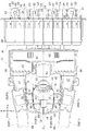
図1〜図3に示されるように、農作業車のうちの植播系水田作業車である乗用型の田植機(「作業車」の一例)には、走行装置Aを有する走行機体Cと、圃場に対する作業を行う作業装置と、が備えられている。田植機の作業装置は、圃場に対する苗の植え付けが可能な苗植付装置Wである。なお、図2に示す矢印Fが走行機体Cの「前」、矢印Bが走行機体Cの「後」、矢印Lが走行機体Cの「左」、矢印Rが走行機体Cの「右」である。
Hereinafter, an example of the embodiment of the present invention will be described with reference to the drawings.
As shown in FIGS. 1 to 3, a passenger-type rice transplanter (an example of a “working vehicle”), which is a planting-type paddy field work vehicle among agricultural work vehicles, includes a traveling machine C having a traveling device A and a traveling machine C. It is equipped with a work device for performing work on the field. The working device of the rice transplanter is a seedling planting device W capable of planting seedlings in a field. The arrow F shown in FIG. 2 is the “front” of the traveling machine C, the arrow B is the “rear” of the traveling machine C, the arrow L is the “left” of the traveling machine C, and the arrow R is the “right” of the traveling machine C. is there.
図1に示されるように、走行装置Aとしては、左右一対の前車輪10と左右一対の後車輪11とが備えられている。走行機体Cには、走行装置Aにおける左右の前車輪10を操向可能な操向ユニットUが備えられている。
As shown in FIG. 1, the traveling device A includes a pair of left and right
図1〜図3に示されるように、走行機体Cの前部には、開閉式のボンネット12が備えられている。ボンネット12内には、エンジン13が備えられている。ボンネット12の先端位置には、指標ラインLN(図6参照)を確認するための棒状のセンターマスコット14が備えられている。図1、図3に示されるように、走行機体Cには、前後方向に沿って延びる枠状の機体フレーム15が備えられている。機体フレーム15の前部には、支持支柱フレーム16が立設されている。
As shown in FIGS. 1 to 3, an openable and
〔苗植付装置について〕
図1に示されるように、苗植付装置Wは、油圧シリンダで構成される昇降シリンダ20の伸縮作動により昇降作動するリンク機構21を介して、走行機体Cの後端に昇降自在に連結されている。
[About seedling planting equipment]
As shown in FIG. 1, the seedling planting device W is movably connected to the rear end of the traveling machine body C via a
図1、図2に示されるように、苗植付装置Wには、4個の伝動ケース22、各伝動ケース22の後部の左側部及び右側部に回転自在に支持された回転ケース23、各回転ケース23の両端部に備えられた一対のロータリ式の植付アーム24、圃場の田面を整地する複数の整地フロート25、植え付け用のマット状苗が載置される苗載せ台26等が備えられている。つまり、苗植付装置Wは、8条植え型式に構成されている。
As shown in FIGS. 1 and 2, the seedling planting device W includes four
このように構成された苗植付装置Wは、苗載せ台26を左右に往復横送り駆動しながら、伝動ケース22から伝達される動力により各回転ケース23を回転駆動して、苗載せ台26の下部から各植付アーム24により交互に苗を取り出して圃場の田面に植え付けるようになっている。
The seedling planting device W configured in this way drives each
〔予備苗台について〕
図1〜図3に示されるように、走行機体Cにおけるボンネット12の左右側部には、苗植付装置Wに補給するための予備苗を載置可能な複数(例えば4つ)の通常予備苗台28(「予備苗台」の一例)、苗植付装置Wに補給するための予備苗を載置可能な1つのレール式予備苗台29(「予備苗台」の一例)が備えられている。また、走行機体Cにおけるボンネット12の左右側部には、各通常予備苗台28とレール式予備苗台29とを支持する左右一対の予備苗フレーム30と、左右の予備苗フレーム30の上部に亘って連結される連結フレーム31と、が備えられている。連結フレーム31は、前面視で、U字状の形状となっている。連結フレーム31の左右端部は、それぞれ、連結ブラケット32を介して、左右の予備苗フレーム30の上部に連結されている。
[About the spare seedling stand]
As shown in FIGS. 1 to 3, a plurality (for example, four) of normal spare seedlings on which spare seedlings for replenishing the seedling planting device W can be placed are placed on the left and right sides of the
〔マーカ装置について〕
図1に示されるように、苗植付装置Wの左右側部には、それぞれ、圃場の田面に指標ラインLN(図6、図7参照)を形成するためのマーカ装置33が備えられている。左右のマーカ装置33は、それぞれ、圃場の田面に接地して走行機体Cの走行に伴い圃場の田面に指標ラインLNを形成する作用姿勢、及び、圃場の田面から上方に離れた格納姿勢に操作自在に構成されている。
[About marker device]
As shown in FIG. 1, each of the left and right side portions of the seedling planting device W is provided with a
図1に示されるように、左右のマーカ装置33には、それぞれ、上下に揺動自在に苗植付装置Wに支持されたマーカアーム34と、マーカアーム34の先端部に自由回転自在に支持された周方向に複数の凸部体を有する回転体35と、が備えられている。また、左右右のマーカ装置33を作用姿勢及び格納姿勢に操作するマーカ用電動モータ(図示なし)が備えられている。各マーカ装置33は、作用姿勢にすることにより、走行機体Cの操向に伴って回転体35が地面を転動して、上面視で、点線状の指標ラインLN(図6参照)を形成するようになっている。
As shown in FIG. 1, the left and
〔運転部について〕
図1〜図3に示されるように、走行機体Cの中央部には、各種の運転操作が行われる運転部40が備えられている。運転部40には、運転者が着座可能な運転座席41、操縦塔42、前車輪10の手動の操向操作用のステアリングホイールにより構成される操向ハンドル43、前後進の切り換え操作や走行速度を変更操作が可能な主変速レバー44、操作レバー45等が備えられている。運転座席41は、走行機体Cの中央部に備えられている。操縦塔42に、操向ハンドル43、主変速レバー44、操作レバー45等が操作自在に備えられている。運転部40の足元部位には、搭乗ステップ46が設けられている。搭乗ステップ46の左右の外側位置には、補助ステップ47が設けられている。ボンネット12の左右両側には、搭乗ステップ46に段差なく連なる乗降通路としての乗降ステップ48が設けられている。乗降ステップ48の横外側に、左右の予備苗フレーム30がそれぞれ配置されている。
[About the driving part]
As shown in FIGS. 1 to 3, a driving
〔操作レバーについて〕
図2、図3に示される操作レバー45は、操向ハンドル43の下側の右横側に備えられている。詳細な図示はしないが、操作レバー45は中立位置から、上方の上昇位置、下方の下降位置、後方の右マーカ位置、及び、前方の左マーカ位置、の十字方向に操作自在に構成され、中立位置に付勢されている。
[About the operation lever]
The operating
操作レバー45を上昇位置に操作すると、植付クラッチ(図示なし)が遮断状態に操作されて、苗植付装置Wが上昇し、左右のマーカ装置33(図1参照)が格納姿勢に操作される。操作レバー45を下降位置に操作すると、植付クラッチ(図示なし)が遮断状態に操作され、左右のマーカ装置33が格納姿勢に操作され、苗植付装置Wが下降する。中央の整地フロート25が圃場の田面に接地すると、苗植付装置Wが圃場の田面に接地して停止した状態となる。
When the operating
操作レバー45を右マーカ位置に操作すると、右のマーカ装置33が格納姿勢から作用姿勢になる。操作レバー45を左マーカ位置に操作すると、左のマーカ装置33が格納姿勢から作用姿勢になる。
When the operating
運転部40の操縦塔42には、押圧操作式の自動操向スイッチ50(図5参照)が備えられている。自動操向スイッチ50は、操向ユニットUの自動操向の入り切りの切り換え操作を行うことが可能に構成されている。また、主変速レバー44には、操向ユニットUの自動操向制御に用いるティーチング方向TA(図6参照)を登録するための登録スイッチ52(図5参照)が備えられている。登録スイッチ52には、押圧操作式の第一登録ボタン52Aと、押圧操作式の第二登録ボタン52Bと、が備えられている。
The
〔操向ユニットについて〕
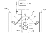
図4に示されるように、操向ユニットUには、上述の操向ハンドル43、操向ハンドル43に連動連結されるステアリング操作軸54、ステアリング操作軸54の回動に伴って揺動するピットマンアーム55、ピットマンアーム55に連動連結される左右の連繋機構56、ステアリングモータ58、ステアリング操作軸54にステアリングモータ58を連動連結するギヤ機構57等が備えられている。
[About steering unit]
As shown in FIG. 4, the steering unit U includes a
ステアリング操作軸54は、ピットマンアーム55、左右の連繋機構56を介して、左右の前車輪10に、それぞれ、連動連結されている。ステアリング操作軸54の回転量は、ステアリング操作軸54の下端部に備えられるロータリエンコーダからなる操向角センサ60(図5参照)により検出されるようになっている。
The
操向ユニットUの手動操向を行う場合には、運転者が操向ハンドル43を操作する操作力に、ステアリングモータ58による操向ハンドル43の操作に応じた補助力を付与してステアリング操作軸54を回動操作し、前車輪10の操向角度を変更するようになっている。一方、操向ユニットUの自動操向を行う場合には、ステアリングモータ58を駆動して、ステアリングモータ58の駆動力によりステアリング操作軸54を回動操作し、前車輪10の操向角度を変更するようになっている。
When manually steering the steering unit U, the steering operation shaft is provided with an auxiliary force corresponding to the operation of the steering handle 43 by the
〔受信装置を有する計測ユニットと慣性計測装置について〕
図1〜図3、図5に示されるように、走行機体Cには、衛星測位システムにより位置情報を取得する受信装置63及び主に、走行機体Cの傾き(ピッチ角、ロール角)を検出可能な副慣性計測装置64を有する計測ユニット61と、慣性情報を計測する主慣性計測装置62(「慣性計測装置」に相当)と、が備えられている。
[Measurement unit with receiver and inertial measurement unit]
As shown in FIGS. 1 to 3 and 5, the traveling aircraft C detects the tilt (pitch angle, roll angle) of the receiving
主慣性計測装置62、及び、副慣性計測装置64は、それぞれ、IMU(Inertial Measurement Unit)により構成されている。
The main
受信装置63及び副慣性計測装置64を有する計測ユニット61と、主慣性計測装置62と、は走行機体Cにおける異なる箇所に配置されている。また、受信装置63及び副慣性計測装置64を有する計測ユニット61と、主慣性計測装置62と、は走行機体Cにおける左右中心線CL上に配置されている。
The
上述の衛星測位システム(GNSS:Global Navigation Satelite System)には、その代表的なものとしてGPS(Global Positioning System)が挙げられる。GPSは、地球の上空を周回する複数のGPS衛星や、GPS衛星の追跡と管制を行う管制局や、測位を行う対象(走行機体C)が備える受信装置63を使用して受信装置63の位置を計測するものである。受信装置63は、衛星測位システムにより走行機体Cの位置情報を取得するために用いられる。
A typical example of the above-mentioned satellite positioning system (GNSS: Global Navigation Satellite System) is GPS (Global Positioning System). GPS uses a plurality of GPS satellites orbiting over the earth, a control station that tracks and controls GPS satellites, and a
図1〜図3に示されるように、受信装置63を有する計測ユニット61は、板状の支持プレート65を介して、連結フレーム31に取り付けられている。受信装置63を有する計測ユニット61は、走行機体Cの前部位置(特に、前車輪10よりも前側)に配置されている。このため、走行機体Cが進行方位を変更した場合には、走行機体Cの後端位置と比較して走行機体Cの前部位置の方が左右方向への変位量が大きく、受信装置63により取得される走行機体Cの自機位置NMの変化を高感度で検知できる。
As shown in FIGS. 1 to 3, the measuring
図3等に示されるように、連結フレーム31は、受信装置63を有する計測ユニット61が予備苗フレーム30の上端部よりも上方に位置する使用状態S1と、使用状態S1に対して上下反転し、受信装置63が予備苗フレーム30の上端部よりも下方に位置する格納状態S2と、に状態変更可能となっている。説明を加えると、連結フレーム31は、左右方向に沿った左右軸心X周りに回動可能、且つ、連結ブラケット32により、使用状態S1と格納状態S2の各状態で位置固定可能に、左右の予備苗フレーム30に支持されている。
As shown in FIG. 3 and the like, the connecting
図1、図3等に示されるように、連結フレーム31を使用状態S1にすることにより、受信装置63が、連結フレーム31と予備苗フレーム30とにより、高い箇所に支持されるものとなるので、走行機体Cの走行に伴い、予備苗フレーム30と連結フレーム31の撓みにより、受信装置63が揺れやすく、受信装置63により取得される位置情報に基づく走行機体Cの自機位置NMや自機方位NAの検出を精度よく行うことができる。さらに、連結フレーム31を使用状態S1にすることにより、受信装置63が走行機体Cにおける最上位の箇所に位置するものとなるため、受信装置63の電波の受信感度を高めることができ、受信装置63に電波障害が生じにくいものとなる。
As shown in FIGS. 1, 3 and the like, by setting the connecting
図2、図3に示されるように、計測ユニット61の受信装置63には、ハーネス66を接続するコネクタ部67が備えられている。コネクタ部67は、計測ユニット61の受信装置63から左右方向外側に延びている。ハーネス66は、連結フレーム31、予備苗フレーム30に沿わせて配索されている。さらに、コネクタ部67を保護するガード部材68が備えられている。ガード部材68は、支持プレート65に取り付けられている。ガード部材68は、コネクタ部67の前側を保護するようになっている。
As shown in FIGS. 2 and 3, the receiving
図1に示されるように、主慣性計測装置62は、走行機体C及び苗植付装置Wの前後方向における全長のうち前後方向中心の近傍の箇所に配置されている。説明を加えると、主慣性計測装置62は、走行機体Cの進行方向の旋回中心(走行機体Cのヨー軸の軸心)の近傍に配置されている。
As shown in FIG. 1, the main
具体的には、走行機体Cの後部には、後車輪11に駆動力を伝達する後車軸72を回動自在に支持する後車軸フレーム73(「取付部材」に相当)が備えられている。後車軸フレーム73は、走行装置Aの後車軸72の近傍に位置する剛性を有する部材となっている。主慣性計測装置62は、この後車軸フレーム73に取り付けられている。
Specifically, the rear portion of the traveling machine body C is provided with a rear axle frame 73 (corresponding to a “mounting member”) that rotatably supports the
説明を加えると、図1、図2に示されるように、主慣性計測装置62は、苗植付装置Wの近傍に位置している。また、主慣性計測装置62は、運転座席41の後側下方に位置している。
To add an explanation, as shown in FIGS. 1 and 2, the main
図5に示されるように、主慣性計測装置62には、主に、走行機体Cのヨー角度(走行機体Cの旋回角度)の角速度を検出可能なジャイロセンサ70と、互いに直交する3軸方向の加速度を検出可能な加速度センサ71と、が備えられている。つまり、主慣性計測装置62により計測される慣性情報には、ジャイロセンサ70により検出される方位変化情報と、加速度センサ71により検出される位置変化情報と、が含まれている。上述のように、主慣性計測装置62を、走行機体Cの進行方向の旋回中心の近傍に配置していることから、ジャイロセンサ70に生じる方位変化情報の積算誤差を小さく抑えることが可能になるとともに、加速度センサ71による位置変化情報の検出精度が高いものとなる。
As shown in FIG. 5, the main
〔制御構成について〕
図5に示されるように、走行機体Cには、操向ユニットUの自動操向についての制御を行う制御装置75が備えられている。制御装置75には、情報記憶部76と、ティーチング記憶部77と、旋回検出部78と、開始判定部79と、情報補正部80と、走行機体Cを走行させる目標ラインLMを生成する生成部81と、状態検出部82と、位置情報、及び、慣性情報に基づいて、走行機体Cが目標ラインLMに沿って走行するように、操向ユニットUを制御する制御部83と、が備えられている。
[Control configuration]
As shown in FIG. 5, the traveling machine body C is provided with a
制御装置75には、受信装置63と、副慣性計測装置64と、主慣性計測装置62におけるジャイロセンサ70、加速度センサ71、操向角センサ60、自動操向スイッチ50、登録スイッチ52等の情報が入力されている。
The
情報記憶部76は、受信装置63から取得される位置情報を、時間毎に記憶していくように構成されている。
The
ティーチング記憶部77は、登録スイッチ52の操作に基づいて、情報記憶部76に記憶された位置情報のうち2点の位置情報を用いて、ティーチング方向TAを算出するように構成されている。
The
旋回検出部78は、操向角センサ60から入力される操向ユニットUのステアリング操作軸54の操向角情報に基づいて、走行機体Cの旋回開始、及び、走行機体Cの旋回終了を検出するように構成されている。
The turning
開始判定部79は、走行機体Cの自動操向制御を開始するか否かの判定を行うように構成されている。
The
情報補正部80は、走行機体Cの自動操向制御の開始毎に、主慣性計測装置62により計測される慣性情報のうちジャイロセンサ70により検出される情報の積算誤差を、受信装置63により取得される位置情報、及び、副慣性計測装置64により計測される情報と、に基づいて補正処理を行うように構成されている。
The
生成部81は、ティーチング方向TAと、走行機体Cの自動操向制御の開始時の自機位置NM、及び、自機方位NAに基づいて、目標ラインLMを生成するように構成されている。
The
状態検出部82は、走行機体Cの自動操向制御中に、走行機体Cの自機位置NMと目標ラインLMとの距離偏差(ズレ距離)と、走行機体Cの自機方位NAとティーチング方向TAとの角度偏差(ズレ角度)と、を検出するように構成されている。
During the automatic steering control of the traveling aircraft C, the
制御部83は、状態検出部82から入力される情報に基づいて、操向ユニットUのステアリングモータ58の駆動を制御するように構成されている。
The
〔自動操向制御について〕
一例として、上面視で四角形の水田において苗の植え付け作業を行う場合について説明する。
図6に示されるように、まず、走行機体Cを圃場内の畦際の或る第一位置Q1に位置させ、登録スイッチ52の第一登録ボタン52A(図5参照)を操作する。そして、苗植付装置Wを上昇させ、且つ、整地フロート25を接地させた状態で、第一位置Q1から側部側の畦際の直線形状に沿って、走行機体Cを直進走行させ、反対側の畦際近くの第二位置Q2まで移動させてから、登録スイッチ52の第二登録ボタン52B(図5参照)を操作する。これにより、第一位置Q1において受信装置63により取得された位置情報と第二位置Q2において受信装置63により取得された位置情報とから、第一位置Q1と第二位置Q2とを結ぶ方向であるティーチング方向TAが生成される。
[About automatic steering control]
As an example, a case where seedlings are planted in a quadrangular paddy field in a top view will be described.
As shown in FIG. 6, first, the traveling machine C is positioned at a certain first position Q1 on the ridge in the field, and the
次に、図6に示されるように、操向ハンドル43の操作により、走行機体Cを手動で旋回させる。操向角センサ60により、走行機体Cの旋回開始が検出されると、苗植付装置W、整地フロート25、マーカ装置33とが、圃場の田面から自動的に上昇される。走行機体Cの旋回が終了すると、走行機体Cの旋回終了位置Q3が、操向角センサ60の検出結果に基づいて検出される。
Next, as shown in FIG. 6, the traveling machine body C is manually turned by operating the
走行機体Cの旋回終了位置Q3が検出されてから一定時間が経過するまで、且つ、自機方位NAとティーチング方向TAとのズレ角度が所定範囲内となるまで、自動操向スイッチ50の操作入力を受け付けない不感帯が設定されている。つまり、走行機体Cの状態が不感帯にある間は、自動操向スイッチ50が操作されても、自動操向制御は開始されない。走行機体Cの状態が不感帯にある間に、運転者は、センターマスコット14の先端部を見る目線の先に、指標ラインLNが合致するように、操向ユニットUを手動操向して、走行機体Cの位置合わせを行うことができる。
Operation input of the
そして、走行機体Cの状態が不感帯を抜けると、自動操向スイッチ50の操作入力が受け付けられ、自動操向スイッチ50が操作されると、制御開始位置Q4において受信装置63における位置情報い基づく走行機体Cの自機位置NM、自機方位NAが記憶される。
そして、受信装置63が設置されている位置から、走行機体Cの自機方位NAの方向に所定距離離れた箇所から、ティーチング方向TAと平行な直線状の目標ラインLMが生成される。これとともに、主慣性計測装置62により計測される情報が、受信装置63により取得された自機位置NMの位置情報、及び、受信装置63により取得された自機位置NMの位置情報と直前位置の位置情報に基づいて算出された自機方位NAに基づいて補正される。
Then, when the state of the traveling machine C passes through the dead zone, the operation input of the
Then, a linear target line LM parallel to the teaching direction TA is generated from a position separated from the position where the receiving
なお、図6では、図示の都合上、マーカ装置33により形成された指標ラインLNと、目標ラインLMとを少しずらしてあるが、実際は、運転者の目線が、センターマスコット14の先端部と指標ラインLNとが一致するように、手動の位置合わせが行われるので、指標ラインLNと略一致するように目標ラインLMが生成される。
In FIG. 6, for convenience of illustration, the index line LN formed by the
そして、これとともに、主に主慣性計測装置62に基づく、走行機体Cの自動操向制御が開始される。つまり、自動操向制御においては、主慣性計測装置62が主に用いられ、受信装置63が主慣性計測装置62の補正用に用いられる。具体的には、制御開始位置Q4における受信装置63により取得された位置情報に基づく自機位置NMと自機方位NAと、主慣性計測装置62のジャイロセンサ70により計測される角速度を積分処理して求められる方位変化情報と、主慣性計測装置62の加速度センサ71により計測される加速度を積分処理して求められる位置変化情報と、に基づいて、現在の自機位置NMや自機方位NAを求める。そして、現在の自機位置NMや自機方位NAが、目標ラインLM、ティーチング方向TAと合致するように操向ユニットUの自動操向が行われ、走行機体Cの自動操向制御が行われる。
Then, at the same time, the automatic steering control of the traveling machine body C is started mainly based on the main
走行機体Cの自動操向制御中に、自機方位NAとティーチング方向TAとの角度偏差(ズレ角度)がなく、自機位置NMと目標ラインLMとの距離偏差(ズレ距離)がない場合、操向ユニットUは操向制御されない。
また、走行機体Cの自動操向制御中に、自機方位NAとティーチング方向TAとの角度偏差(ズレ角度)があり、自機位置NMと目標ラインLMとの距離偏差(ズレ距離)がない場合、操向ユニットUは、自機方位NAとティーチング方向TAとの角度偏差(ズレ角度)をなくす方向に操向制御される。
また、走行機体Cの自動操向制御中に、自機方位NAとティーチング方向TAとの角度偏差(ズレ角度)があり、自機位置NMと目標ラインLMとの距離偏差(ズレ距離)がある場合には、操向ユニットUは、自機方位NAとティーチング方向TAとの角度偏差(ズレ角度)をなくす方向に操向制御される。
また、走行機体Cの自動操向制御中に、自機方位NAとティーチング方向TAとの角度偏差(ズレ角度)がなく、自機位置NMと目標ラインLMとの距離偏差(ズレ距離)がある場合、操向ユニットUは、自機位置NMと目標ラインLMとの距離偏差(ズレ距離)をなくす方向に操向制御される。
これにより、走行機体Cが、目標ラインLMに沿って正確に走行するものとなる。
When there is no angular deviation (deviation angle) between the own aircraft direction NA and the teaching direction TA and there is no distance deviation (deviation distance) between the own aircraft position NM and the target line LM during the automatic steering control of the traveling aircraft C. The steering unit U is not steering controlled.
Further, during the automatic steering control of the traveling aircraft C, there is an angular deviation (deviation angle) between the own aircraft direction NA and the teaching direction TA, and there is no distance deviation (deviation distance) between the own aircraft position NM and the target line LM. In this case, the steering unit U is steered and controlled in a direction that eliminates the angular deviation (deviation angle) between the own directional NA and the teaching direction TA.
Further, during the automatic steering control of the traveling aircraft C, there is an angular deviation (deviation angle) between the own aircraft direction NA and the teaching direction TA, and there is a distance deviation (deviation distance) between the own aircraft position NM and the target line LM. In this case, the steering unit U is steered and controlled in a direction that eliminates the angular deviation (deviation angle) between the own azimuth NA and the teaching direction TA.
Further, during the automatic steering control of the traveling aircraft C, there is no angular deviation (deviation angle) between the own aircraft direction NA and the teaching direction TA, and there is a distance deviation (deviation distance) between the own aircraft position NM and the target line LM. In this case, the steering unit U is steered and controlled in a direction that eliminates the distance deviation (deviation distance) between the own machine position NM and the target line LM.
As a result, the traveling machine C is accurately traveled along the target line LM.
このように、走行機体Cの自動操向制御中には、受信装置63により取得される位置情報が必須ではないので、仮に、走行機体Cの自動操向制御中に、受信装置63に電波障害等が発生した場合であっても、主慣性計測装置62により計測される慣性情報に基づいて走行機体Cの自動操向制御を継続でき、苗植付装置Wによる苗の植え付けを目標ラインLMに沿って正確に行うことができる。
As described above, since the position information acquired by the receiving
そして、走行機体Cが畦際に接近すると、運転者が自動操向スイッチ50を操作することにより、走行機体Cの自動操向制御が停止され、手動操向に切り換わる。そして、畦際で同様に旋回操作を行い、同様の操作を繰り返して、圃場への苗の植え付けを行ってゆく。これにより、運転者は、苗植付装置Wによる圃場への苗の植え付け中に操向ハンドル43の手動操作を行う必要がなく、苗の植え付け作業を、より正確に、より簡単に行うことができる。
Then, when the traveling aircraft C approaches the ridge, the driver operates the
〔自機位置の設定について〕
図7に示されるように、受信装置63は、走行機体Cの前部に配置されているが、データ処理の基準となる自機位置NMは、受信装置63の実際の設置位置ではなく、主慣性計測装置62の近傍位置に設定されている。データ処理の基準となる自機位置NMの設定は、受信装置63と自機位置NMとする箇所までの距離、及び、受信装置63や主慣性計測装置62に基づいて算出される自機方位NAに基づいて求められるようになっている。目標ラインLMに沿って正確に走行させたいのは、苗植付装置Wであるので、自機位置NMを、このように、苗植付装置Wの近傍に設定することにより、苗植付装置Wが目標ラインLMに沿って正確に走行するように、走行機体Cの自動操向制御が行うことができるものとなる。
[About setting the position of your own machine]
As shown in FIG. 7, the receiving
〔予備苗フレーム、通常予備苗台、レール式予備苗台、の関係について〕
図3に示されるように、左右の予備苗フレーム30には、それぞれ、支持支柱フレーム16に固定される固定部85と、固定部85から上向きに延びて左右内側に向けて傾斜する傾斜部86と、傾斜部86から上向きに延びる縦部87と、が備えられている。つまり、予備苗フレーム30の縦部87は、支持支柱フレーム16、及び、予備苗フレーム30の固定部85に対して、左右内側に所定距離Dだけオフセットしている。
[Relationship between spare seedling frame, normal spare seedling stand, rail type spare seedling stand]
As shown in FIG. 3, the left and right spare seedling frames 30 have a fixed
図1〜図3に示されるように、複数の通常予備苗台28は、それぞれ、予備苗フレーム30の縦部87に設けられる前後方向に沿いつつ前方に向かうにつれて左右内側に傾斜した前後軸心Y周りに揺動可能に予備苗フレーム30に支持されている。通常予備苗台28は、横姿勢E1と、縦姿勢E2と、に姿勢変更可能に構成されている。
As shown in FIGS. 1 to 3, each of the plurality of normal reserve seedling stands 28 is provided in the
図1〜図3に示されるように、通常予備苗台28を、横姿勢E1にすると、通常予備苗台28の載置面が略水平な状態となる。一方、通常予備苗台28を、横姿勢E1から縦姿勢E2にする際には、各通常予備苗台28を前後軸心Y周りに揺動して縦向きにする。これにより、縦姿勢E2の各通常予備苗台28が、予備苗フレーム30の縦部87側に寄った左右方向にコンパクトな状態となる。
As shown in FIGS. 1 to 3, when the normal spare seedling stand 28 is in the horizontal posture E1, the mounting surface of the normal spare seedling stand 28 is in a substantially horizontal state. On the other hand, when the normal spare seedling stand 28 is changed from the horizontal posture E1 to the vertical posture E2, each normal spare seedling stand 28 is swung around the anteroposterior axis Y to be oriented vertically. As a result, each of the normal spare seedling stands 28 in the vertical posture E2 becomes compact in the left-right direction closer to the
図1〜図3に示されるレール式予備苗台29には、前載置台88と、中央載置台89と、後載置台90と、が備えられている。中央載置台89は、一対の支持ブラケット91を介して、支持支柱フレーム16に固定されている。前載置台88は、左右方向に沿った前横軸心P1周りに揺動可能に中央載置台89の前端部に連結されている。後載置台90は、左右方向に沿った後横軸心P2周りに揺動自在に中央載置台89の後端部に連結されている。図1に示されるように、レール式予備苗台29は、展開状態F1と、折り畳み状態F2とに状態変更可能に構成されている。レール式予備苗台29を展開状態F1にすると、中央載置台89を中心にして、中央載置台89の前側に前載置台88が展開され、中央載置台89の後側に後載置台90が展開される。つまり、レール式予備苗台29を展開状態F1にすると、前載置台88と、中央載置台89と、後載置台90と、が前後に順に並ぶ状態となる。
The rail-type spare seedling table 29 shown in FIGS. 1 to 3 is provided with a front mounting table 88, a central mounting table 89, and a rear mounting table 90. The central mounting table 89 is fixed to the
図1に示されるように、レール式予備苗台29を展開状態F1から折り畳み状態F2にする際には、中央載置台89の前端に位置する前横軸心P1周りに前載置台88を揺動させて、中央載置台89の上側に前載置台88を折り畳んで位置させ、中央載置台89の後端に位置する後横軸心P2周りに後載置台90を揺動させて、中央載置台89の上側に後載置台90を位置させる。これにより、レール式予備苗台29を前後方向にコンパクトな折り畳み状態F2とすることができる。 As shown in FIG. 1, when the rail-type spare seedling stand 29 is changed from the unfolded state F1 to the folded state F2, the front mounting table 88 is shaken around the front horizontal axis P1 located at the front end of the central mounting table 89. By moving, the front mounting table 88 is folded and positioned on the upper side of the central mounting table 89, and the rear mounting table 90 is swung around the rear horizontal axis P2 located at the rear end of the central mounting table 89 to be center-mounted. The rear mounting table 90 is positioned above the table 89. As a result, the rail-type spare seedling stand 29 can be brought into a compact folded state F2 in the front-rear direction.
図1に示されるように、複数の通常予備苗台28は、縦並びで配置され、レール式予備苗台29は、最下段の通常予備苗台28の下方に配置されている。
As shown in FIG. 1, a plurality of normal spare seedling stands 28 are arranged vertically, and the rail type spare seedling stand 29 is arranged below the lowermost normal
すなわち、図1〜図3から理解されるように、予備苗フレーム30の縦部87を、支持支柱フレーム16、及び、予備苗フレーム30の固定部85に対して、左右内側に所定距離Dだけオフセットさせていることに加え、複数の通常予備苗台28を予備苗フレーム30の縦部87側に寄った左右方向にコンパクトな状態となった縦姿勢E2に姿勢変更して左右内側にオフセット可能にしていることにより、レール式予備苗台29を、予備苗フレーム30や通常予備苗台28に干渉することなく、展開状態F1から折り畳み状態F2に支障なく状態変更できるようになっている。また、複数の通常予備苗台28の方を左右内側にオフセット可能にしていることにより、例えば、レール式予備苗台29を左右外側にオフセットさせるよりも、走行機体Cの全体の左右幅を小さくできる。
That is, as can be understood from FIGS. 1 to 3, the
〔別実施形態〕
以下、本発明の別実施形態について説明する。下記の各別実施形態は、矛盾が生じない限り、複数組み合わせて上記実施形態に適用してもよい。なお、本発明の範囲は、これら実施形態の内容に限定されるものではない。
[Another Embodiment]
Hereinafter, another embodiment of the present invention will be described. Each of the following separate embodiments may be applied to the above embodiment in combination as long as there is no contradiction. The scope of the present invention is not limited to the contents of these embodiments.
(1)上記実施形態では、主に、主慣性計測装置62により計測される慣性情報に基づいて走行機体Cの自動操向制御を行い、主慣性計測装置62により計測される慣性情報を受信装置63により取得される位置情報に基づいて補正するものが例示されているが、これに限られない。例えば、主に、受信装置63により取得される位置情報に基づいて走行機体Cの自動操向制御を行い、受信装置63により取得される位置情報を、主慣性計測装置62により計測される慣性情報に基づいて補正するようにしてもよい。
(1) In the above embodiment, the automatic steering control of the traveling machine body C is mainly performed based on the inertial information measured by the main
(2)上記実施形態では、連結フレーム31が、左右方向に沿った左右軸心X周りに回動可能、且つ、使用状態S1と格納状態S2で位置固定可能に、左右の予備苗フレーム30に支持されているものが例示されているが、これに限られない。例えば、左右の予備苗フレーム30に対して着脱可能となっていてもよい。この場合、使用状態S1の連結フレーム31を、予備苗フレーム30から取り外し、上下反転させて、予備苗フレーム30に再び取り付けることにより、連結フレーム31が格納状態S2になる。
(2) In the above embodiment, the connecting
(3)上記実施形態では、受信装置63を一定の箇所に固定しているものが例示されているが、これに限られない。例えば、図8に示されるように、予備苗フレーム30に取り付け固定され、走行機体Cの前後方向に沿って延びるレール部材100上に、前後方向に沿って移動可能な状態で受信装置63が配置されていてもよい。これにより、受信装置63を、レール部材100上の2点間を移動させることにより、走行機体Cが停止したまま、走行機体Cの自機方位NA、受信装置63により取得される2点の位置情報に基づいて求めることができる。
(3) In the above embodiment, the receiving
(4)上記実施形態では、受信装置63を一つだけ備えているものが例示されているが、これに限られない。例えば、受信装置63が二つ以上備えられていてもよい。このようにすることで、走行機体Cが停止中においても、一つの受信装置63により取得される位置情報と、他の受信装置63により取得される位置情報と、に基づいて、走行機体Cの自機方位NAを求めることが可能となる。
(4) In the above embodiment, an example is provided in which only one
(5)上記実施形態では、コネクタ部67が、受信装置63の側面部から左右方向外側に延びているものが例示されているが、これに限られない。例えば、コネクタ部67が、受信装置63の上面部から上方に延びていたり、受信装置63の下面部から下方に延びていたり、受信装置63の前面部から前方に延びていたり、受信装置63の後面部から後方に延びていたりしてもよい。この場合、コネクタ部67を保護するガード部材68も、コネクタ部67の箇所に設けてあると好ましい。
(5) In the above embodiment, the
(6)上記実施形態では、ガード部材68が支持プレート65に取り付けられているものが例示されているが、これに限られない。例えば、ガード部材68が受信装置63自体に取り付けられていてもよい。
(6) In the above embodiment, the
(7)上記実施形態では、作業装置として、苗植付装置Wが備えられているものが例示されているが、これに限られない。例えば、作業装置として、苗植付装置Wに加えて、施肥装置や薬剤散布装置等が備えられていてもよい。 (7) In the above embodiment, the working device provided with the seedling planting device W is exemplified, but the working device is not limited to this. For example, as the working device, in addition to the seedling planting device W, a fertilizer application device, a chemical spraying device, or the like may be provided.
本発明は、作業装置として苗植付装置を備える上記乗用型の田植機以外にも、例えば、作業装置として播種装置を備える植播系水田作業車である乗用型の直播機、作業装置としてプラウ等を備えるトラクタ、若しくは、作業装置として刈取部等を備えるコンバイン等の農作業車、または、作業装置としてバケット等を備える建設作業車等の種々の作業車に利用できる。 In addition to the above-mentioned riding type rice transplanter equipped with a seedling planting device as a working device, the present invention also includes, for example, a riding type direct seeding machine which is a planting type paddy field work vehicle equipped with a seeding device as a working device, and a plow as a working device. It can be used for various work vehicles such as a tractor equipped with such as, a farm work vehicle such as a combine equipped with a cutting section or the like as a work device, or a construction work vehicle equipped with a bucket or the like as a work device.
28 :通常予備苗台(予備苗台)
29 :レール式予備苗台(予備苗台)
30 :予備苗フレーム
31 :連結フレーム
62 :主慣性計測装置(慣性計測装置)
63 :受信装置
66 :ハーネス
67 :コネクタ部
68 :ガード部材
72 :後車軸
73 :後車軸フレーム(取付部材)
81 :生成部
83 :制御部
A :走行装置
C :走行機体
U :操向ユニット
W :苗植付装置(作業装置)
S1 :使用状態
S2 :格納状態
LM :目標ライン
X :左右軸心
28: Normal spare seedling stand (spare seedling stand)
29: Rail type spare seedling stand (spare seedling stand)
30: Spare seedling frame 31: Connecting frame 62: Main inertial measurement unit (inertial measurement unit)
63: Receiver 66: Harness 67: Connector part 68: Guard member 72: Rear axle 73: Rear axle frame (mounting member)
81: Generation unit 83: Control unit A: Traveling device C: Traveling machine U: Steering unit W: Seedling planting device (working device)
S1: Used state S2: Stored state LM: Target line X: Left and right axis
Claims (5)
前記走行装置を操向可能な操向ユニットと、
衛星測位システムにより位置情報を取得する受信装置と、
前記位置情報に基づいて、前記走行機体が目標ラインに沿って走行するように、前記操向ユニットを制御する制御部と、が備えられ、
前記受信装置を支持可能な支持部材が設けられ、
前記支持部材が、使用状態と、前記使用状態よりも低い箇所に前記受信装置を位置させた格納状態と、に状態変更可能に前記受信装置を支持する作業車。 A traveling machine having a traveling device and
A steering unit capable of steering the traveling device and
A receiving device that acquires position information using a satellite positioning system,
A control unit that controls the steering unit so that the traveling aircraft travels along the target line based on the position information is provided.
A support member capable of supporting the receiving device is provided.
A work vehicle that supports the receiving device so that the supporting member can change its state between a used state and a stored state in which the receiving device is positioned at a position lower than the used state.
前記格納状態では、使用状態における前記受信装置の上端部が前記フレームの上端部よりも低い箇所に位置する請求項2又は3に記載の作業車。 In the used state, the upper end portion of the receiving device is located higher than the upper end portion of the frame.
The work vehicle according to claim 2 or 3, wherein in the retracted state, the upper end portion of the receiving device in the used state is located at a position lower than the upper end portion of the frame.
Priority Applications (3)
| Application Number | Priority Date | Filing Date | Title |
|---|---|---|---|
| JP2019113832A JP6860619B2 (en) | 2019-06-19 | 2019-06-19 | Work platform |
| JP2021053484A JP7174495B2 (en) | 2019-06-19 | 2021-03-26 | work vehicle |
| JP2022176258A JP2023009115A (en) | 2019-06-19 | 2022-11-02 | work vehicle |
Applications Claiming Priority (1)
| Application Number | Priority Date | Filing Date | Title |
|---|---|---|---|
| JP2019113832A JP6860619B2 (en) | 2019-06-19 | 2019-06-19 | Work platform |
Related Parent Applications (1)
| Application Number | Title | Priority Date | Filing Date |
|---|---|---|---|
| JP2019026703A Division JP6546362B2 (en) | 2019-02-18 | 2019-02-18 | Work vehicle |
Related Child Applications (1)
| Application Number | Title | Priority Date | Filing Date |
|---|---|---|---|
| JP2021053484A Division JP7174495B2 (en) | 2019-06-19 | 2021-03-26 | work vehicle |
Publications (2)
| Publication Number | Publication Date |
|---|---|
| JP2019162149A JP2019162149A (en) | 2019-09-26 |
| JP6860619B2 true JP6860619B2 (en) | 2021-04-14 |
Family
ID=68065076
Family Applications (3)
| Application Number | Title | Priority Date | Filing Date |
|---|---|---|---|
| JP2019113832A Active JP6860619B2 (en) | 2019-06-19 | 2019-06-19 | Work platform |
| JP2021053484A Active JP7174495B2 (en) | 2019-06-19 | 2021-03-26 | work vehicle |
| JP2022176258A Pending JP2023009115A (en) | 2019-06-19 | 2022-11-02 | work vehicle |
Family Applications After (2)
| Application Number | Title | Priority Date | Filing Date |
|---|---|---|---|
| JP2021053484A Active JP7174495B2 (en) | 2019-06-19 | 2021-03-26 | work vehicle |
| JP2022176258A Pending JP2023009115A (en) | 2019-06-19 | 2022-11-02 | work vehicle |
Country Status (1)
| Country | Link |
|---|---|
| JP (3) | JP6860619B2 (en) |
Family Cites Families (10)
| Publication number | Priority date | Publication date | Assignee | Title |
|---|---|---|---|---|
| JPS5652912U (en) * | 1979-10-01 | 1981-05-09 | ||
| JPH01109413A (en) * | 1987-10-22 | 1989-04-26 | Kubota Ltd | Steering control device for automatic travelling working vehicle |
| JPH09107717A (en) * | 1995-10-24 | 1997-04-28 | Kubota Corp | Apparatus for controlling posture of working machine |
| JPH09154308A (en) * | 1995-12-12 | 1997-06-17 | Kubota Corp | Posture controlling device in working machine |
| JP3240116B2 (en) * | 1996-06-24 | 2001-12-17 | 矢崎総業株式会社 | Wire harness holding mechanism |
| JP2008092818A (en) * | 2006-10-06 | 2008-04-24 | Yanmar Co Ltd | Agricultural work vehicle |
| EP1967931A3 (en) | 2007-03-06 | 2013-10-30 | Yamaha Hatsudoki Kabushiki Kaisha | Vehicle |
| JP2009028015A (en) | 2007-07-30 | 2009-02-12 | Yanmar Co Ltd | Agricultural work vehicle |
| JP5580855B2 (en) | 2012-06-12 | 2014-08-27 | 株式会社ソニー・コンピュータエンタテインメント | Obstacle avoidance device and obstacle avoidance method |
| JP5947626B2 (en) * | 2012-06-12 | 2016-07-06 | キヤノン株式会社 | INPUT DISPLAY DEVICE, ITS CONTROL METHOD, PROGRAM, AND PRINTING DEVICE |
-
2019
- 2019-06-19 JP JP2019113832A patent/JP6860619B2/en active Active
-
2021
- 2021-03-26 JP JP2021053484A patent/JP7174495B2/en active Active
-
2022
- 2022-11-02 JP JP2022176258A patent/JP2023009115A/en active Pending
Also Published As
| Publication number | Publication date |
|---|---|
| JP2023009115A (en) | 2023-01-19 |
| JP2019162149A (en) | 2019-09-26 |
| JP2021094039A (en) | 2021-06-24 |
| JP7174495B2 (en) | 2022-11-17 |
Similar Documents
| Publication | Publication Date | Title |
|---|---|---|
| JP6576237B2 (en) | Work vehicle | |
| JP7192018B2 (en) | work vehicle | |
| JP6643091B2 (en) | Farm work machine | |
| JP6552420B2 (en) | Work vehicle | |
| JP2023024520A5 (en) | ||
| JP6811655B2 (en) | Work platform | |
| JP7229303B2 (en) | traveling work machine | |
| JP7195381B2 (en) | traveling work machine | |
| JP7117886B2 (en) | work vehicle | |
| JP6921934B2 (en) | Agricultural work machine | |
| JP2019050776A (en) | Work vehicle | |
| JP6860619B2 (en) | Work platform | |
| JP6900291B2 (en) | Automatic steering system | |
| JP6891103B2 (en) | Planting work machine | |
| JP6546362B2 (en) | Work vehicle | |
| JP6962427B2 (en) | Crop extraction machine | |
| JP2022082811A (en) | Work vehicle | |
| JP2021175405A (en) | Agricultural implement | |
| JP6984640B2 (en) | Work vehicle | |
| JP6669225B2 (en) | Seedling transplanter | |
| JP6858595B2 (en) | Work platform | |
| JP7076494B2 (en) | Work vehicle | |
| JP6934510B2 (en) | Agricultural work machine | |
| JP6669226B2 (en) | Seedling transplanter | |
| JP7063365B2 (en) | Work vehicle |
Legal Events
| Date | Code | Title | Description |
|---|---|---|---|
| A621 | Written request for application examination |
Free format text: JAPANESE INTERMEDIATE CODE: A621 Effective date: 20190718 |
|
| A131 | Notification of reasons for refusal |
Free format text: JAPANESE INTERMEDIATE CODE: A131 Effective date: 20200728 |
|
| A521 | Written amendment |
Free format text: JAPANESE INTERMEDIATE CODE: A523 Effective date: 20200925 |
|
| TRDD | Decision of grant or rejection written | ||
| A01 | Written decision to grant a patent or to grant a registration (utility model) |
Free format text: JAPANESE INTERMEDIATE CODE: A01 Effective date: 20210224 |
|
| A61 | First payment of annual fees (during grant procedure) |
Free format text: JAPANESE INTERMEDIATE CODE: A61 Effective date: 20210326 |
|
| R150 | Certificate of patent or registration of utility model |
Ref document number: 6860619 Country of ref document: JP Free format text: JAPANESE INTERMEDIATE CODE: R150 |