JP6859926B2 - Solid electrolyte, its manufacturing method, gas sensor - Google Patents
Solid electrolyte, its manufacturing method, gas sensor Download PDFInfo
- Publication number
- JP6859926B2 JP6859926B2 JP2017213346A JP2017213346A JP6859926B2 JP 6859926 B2 JP6859926 B2 JP 6859926B2 JP 2017213346 A JP2017213346 A JP 2017213346A JP 2017213346 A JP2017213346 A JP 2017213346A JP 6859926 B2 JP6859926 B2 JP 6859926B2
- Authority
- JP
- Japan
- Prior art keywords
- solid electrolyte
- particles
- stabilizer
- concentration
- phase particles
- Prior art date
- Legal status (The legal status is an assumption and is not a legal conclusion. Google has not performed a legal analysis and makes no representation as to the accuracy of the status listed.)
- Active
Links
- 239000007784 solid electrolyte Substances 0.000 title claims description 166
- 238000004519 manufacturing process Methods 0.000 title claims description 17
- 239000002245 particle Substances 0.000 claims description 339
- 239000000843 powder Substances 0.000 claims description 73
- 239000000463 material Substances 0.000 claims description 65
- 239000003381 stabilizer Substances 0.000 claims description 64
- MCMNRKCIXSYSNV-UHFFFAOYSA-N Zirconium dioxide Chemical compound O=[Zr]=O MCMNRKCIXSYSNV-UHFFFAOYSA-N 0.000 claims description 62
- 239000002994 raw material Substances 0.000 claims description 57
- 239000013078 crystal Substances 0.000 claims description 38
- 229910002077 partially stabilized zirconia Inorganic materials 0.000 claims description 35
- PNEYBMLMFCGWSK-UHFFFAOYSA-N aluminium oxide Inorganic materials [O-2].[O-2].[O-2].[Al+3].[Al+3] PNEYBMLMFCGWSK-UHFFFAOYSA-N 0.000 claims description 29
- 238000002156 mixing Methods 0.000 claims description 29
- 239000000203 mixture Substances 0.000 claims description 22
- 229910052596 spinel Inorganic materials 0.000 claims description 21
- 239000011029 spinel Substances 0.000 claims description 21
- 238000010304 firing Methods 0.000 claims description 20
- 238000000465 moulding Methods 0.000 claims description 16
- RUDFQVOCFDJEEF-UHFFFAOYSA-N yttrium(III) oxide Inorganic materials [O-2].[O-2].[O-2].[Y+3].[Y+3] RUDFQVOCFDJEEF-UHFFFAOYSA-N 0.000 claims description 11
- 239000007789 gas Substances 0.000 description 107
- 238000005259 measurement Methods 0.000 description 45
- 239000000446 fuel Substances 0.000 description 24
- 239000010410 layer Substances 0.000 description 24
- 238000001514 detection method Methods 0.000 description 19
- 230000027311 M phase Effects 0.000 description 16
- 238000005336 cracking Methods 0.000 description 14
- 206010040844 Skin exfoliation Diseases 0.000 description 13
- 230000035882 stress Effects 0.000 description 11
- 238000009792 diffusion process Methods 0.000 description 10
- 238000000034 method Methods 0.000 description 9
- 239000011241 protective layer Substances 0.000 description 9
- 230000000694 effects Effects 0.000 description 8
- 239000012212 insulator Substances 0.000 description 8
- 238000004458 analytical method Methods 0.000 description 7
- 230000002093 peripheral effect Effects 0.000 description 7
- 238000000550 scanning electron microscopy energy dispersive X-ray spectroscopy Methods 0.000 description 7
- QVGXLLKOCUKJST-UHFFFAOYSA-N atomic oxygen Chemical compound [O] QVGXLLKOCUKJST-UHFFFAOYSA-N 0.000 description 6
- 230000006378 damage Effects 0.000 description 6
- 239000001301 oxygen Substances 0.000 description 6
- 229910052760 oxygen Inorganic materials 0.000 description 6
- 239000006104 solid solution Substances 0.000 description 6
- CPLXHLVBOLITMK-UHFFFAOYSA-N Magnesium oxide Chemical compound [Mg]=O CPLXHLVBOLITMK-UHFFFAOYSA-N 0.000 description 4
- 239000000919 ceramic Substances 0.000 description 4
- 238000002485 combustion reaction Methods 0.000 description 4
- 230000000052 comparative effect Effects 0.000 description 4
- 239000010931 gold Substances 0.000 description 4
- 238000010438 heat treatment Methods 0.000 description 4
- KDLHZDBZIXYQEI-UHFFFAOYSA-N palladium Substances [Pd] KDLHZDBZIXYQEI-UHFFFAOYSA-N 0.000 description 4
- BASFCYQUMIYNBI-UHFFFAOYSA-N platinum Substances [Pt] BASFCYQUMIYNBI-UHFFFAOYSA-N 0.000 description 4
- 238000010586 diagram Methods 0.000 description 3
- 238000011156 evaluation Methods 0.000 description 3
- 229910052737 gold Inorganic materials 0.000 description 3
- 238000005469 granulation Methods 0.000 description 3
- 230000003179 granulation Effects 0.000 description 3
- 230000008569 process Effects 0.000 description 3
- 239000002002 slurry Substances 0.000 description 3
- 238000012360 testing method Methods 0.000 description 3
- 230000009466 transformation Effects 0.000 description 3
- ODINCKMPIJJUCX-UHFFFAOYSA-N Calcium oxide Chemical compound [Ca]=O ODINCKMPIJJUCX-UHFFFAOYSA-N 0.000 description 2
- 229910020068 MgAl Inorganic materials 0.000 description 2
- 241000968352 Scandia <hydrozoan> Species 0.000 description 2
- 230000001133 acceleration Effects 0.000 description 2
- 239000000956 alloy Substances 0.000 description 2
- 229910045601 alloy Inorganic materials 0.000 description 2
- 230000008901 benefit Effects 0.000 description 2
- 239000000292 calcium oxide Substances 0.000 description 2
- 235000012255 calcium oxide Nutrition 0.000 description 2
- RKTYLMNFRDHKIL-UHFFFAOYSA-N copper;5,10,15,20-tetraphenylporphyrin-22,24-diide Chemical compound [Cu+2].C1=CC(C(=C2C=CC([N-]2)=C(C=2C=CC=CC=2)C=2C=CC(N=2)=C(C=2C=CC=CC=2)C2=CC=C3[N-]2)C=2C=CC=CC=2)=NC1=C3C1=CC=CC=C1 RKTYLMNFRDHKIL-UHFFFAOYSA-N 0.000 description 2
- 230000002950 deficient Effects 0.000 description 2
- 238000009826 distribution Methods 0.000 description 2
- 238000002149 energy-dispersive X-ray emission spectroscopy Methods 0.000 description 2
- 238000005530 etching Methods 0.000 description 2
- 230000010354 integration Effects 0.000 description 2
- 238000002955 isolation Methods 0.000 description 2
- 238000007561 laser diffraction method Methods 0.000 description 2
- 239000007788 liquid Substances 0.000 description 2
- 239000000395 magnesium oxide Substances 0.000 description 2
- 229910000510 noble metal Inorganic materials 0.000 description 2
- HJGMWXTVGKLUAQ-UHFFFAOYSA-N oxygen(2-);scandium(3+) Chemical compound [O-2].[O-2].[O-2].[Sc+3].[Sc+3] HJGMWXTVGKLUAQ-UHFFFAOYSA-N 0.000 description 2
- 229910052763 palladium Inorganic materials 0.000 description 2
- 229910052697 platinum Inorganic materials 0.000 description 2
- 238000013001 point bending Methods 0.000 description 2
- 239000011164 primary particle Substances 0.000 description 2
- 238000000790 scattering method Methods 0.000 description 2
- 239000011163 secondary particle Substances 0.000 description 2
- 229910052709 silver Inorganic materials 0.000 description 2
- 239000000126 substance Substances 0.000 description 2
- 230000008646 thermal stress Effects 0.000 description 2
- XLYOFNOQVPJJNP-UHFFFAOYSA-N water Substances O XLYOFNOQVPJJNP-UHFFFAOYSA-N 0.000 description 2
- LFQSCWFLJHTTHZ-UHFFFAOYSA-N Ethanol Chemical compound CCO LFQSCWFLJHTTHZ-UHFFFAOYSA-N 0.000 description 1
- 238000002441 X-ray diffraction Methods 0.000 description 1
- 238000013459 approach Methods 0.000 description 1
- 230000033228 biological regulation Effects 0.000 description 1
- 230000003197 catalytic effect Effects 0.000 description 1
- 230000008859 change Effects 0.000 description 1
- 238000005056 compaction Methods 0.000 description 1
- 238000012790 confirmation Methods 0.000 description 1
- 230000007423 decrease Effects 0.000 description 1
- 230000003247 decreasing effect Effects 0.000 description 1
- 238000009429 electrical wiring Methods 0.000 description 1
- 239000003792 electrolyte Substances 0.000 description 1
- 238000005516 engineering process Methods 0.000 description 1
- 230000002708 enhancing effect Effects 0.000 description 1
- 238000001125 extrusion Methods 0.000 description 1
- PCHJSUWPFVWCPO-UHFFFAOYSA-N gold Chemical compound [Au] PCHJSUWPFVWCPO-UHFFFAOYSA-N 0.000 description 1
- 230000005484 gravity Effects 0.000 description 1
- 238000000227 grinding Methods 0.000 description 1
- 238000007731 hot pressing Methods 0.000 description 1
- 230000001771 impaired effect Effects 0.000 description 1
- 230000006872 improvement Effects 0.000 description 1
- 238000001746 injection moulding Methods 0.000 description 1
- WABPQHHGFIMREM-UHFFFAOYSA-N lead(0) Chemical compound [Pb] WABPQHHGFIMREM-UHFFFAOYSA-N 0.000 description 1
- 238000013507 mapping Methods 0.000 description 1
- 238000000691 measurement method Methods 0.000 description 1
- 229910052751 metal Inorganic materials 0.000 description 1
- 239000002184 metal Substances 0.000 description 1
- AHKZTVQIVOEVFO-UHFFFAOYSA-N oxide(2-) Chemical compound [O-2] AHKZTVQIVOEVFO-UHFFFAOYSA-N 0.000 description 1
- 238000007750 plasma spraying Methods 0.000 description 1
- 238000005498 polishing Methods 0.000 description 1
- 230000009257 reactivity Effects 0.000 description 1
- 238000004626 scanning electron microscopy Methods 0.000 description 1
- 230000035939 shock Effects 0.000 description 1
- 239000004332 silver Substances 0.000 description 1
- 239000010944 silver (metal) Substances 0.000 description 1
- 239000007787 solid Substances 0.000 description 1
- 239000007921 spray Substances 0.000 description 1
- 230000000930 thermomechanical effect Effects 0.000 description 1
- 229910052727 yttrium Inorganic materials 0.000 description 1
- VWQVUPCCIRVNHF-UHFFFAOYSA-N yttrium atom Chemical compound [Y] VWQVUPCCIRVNHF-UHFFFAOYSA-N 0.000 description 1
Images


Classifications
-
- G—PHYSICS
- G01—MEASURING; TESTING
- G01N—INVESTIGATING OR ANALYSING MATERIALS BY DETERMINING THEIR CHEMICAL OR PHYSICAL PROPERTIES
- G01N27/00—Investigating or analysing materials by the use of electric, electrochemical, or magnetic means
- G01N27/26—Investigating or analysing materials by the use of electric, electrochemical, or magnetic means by investigating electrochemical variables; by using electrolysis or electrophoresis
- G01N27/403—Cells and electrode assemblies
- G01N27/406—Cells and probes with solid electrolytes
- G01N27/407—Cells and probes with solid electrolytes for investigating or analysing gases
- G01N27/4073—Composition or fabrication of the solid electrolyte
-
- C—CHEMISTRY; METALLURGY
- C04—CEMENTS; CONCRETE; ARTIFICIAL STONE; CERAMICS; REFRACTORIES
- C04B—LIME, MAGNESIA; SLAG; CEMENTS; COMPOSITIONS THEREOF, e.g. MORTARS, CONCRETE OR LIKE BUILDING MATERIALS; ARTIFICIAL STONE; CERAMICS; REFRACTORIES; TREATMENT OF NATURAL STONE
- C04B35/00—Shaped ceramic products characterised by their composition; Ceramics compositions; Processing powders of inorganic compounds preparatory to the manufacturing of ceramic products
- C04B35/622—Forming processes; Processing powders of inorganic compounds preparatory to the manufacturing of ceramic products
- C04B35/626—Preparing or treating the powders individually or as batches ; preparing or treating macroscopic reinforcing agents for ceramic products, e.g. fibres; mechanical aspects section B
- C04B35/62605—Treating the starting powders individually or as mixtures
- C04B35/62645—Thermal treatment of powders or mixtures thereof other than sintering
-
- C—CHEMISTRY; METALLURGY
- C04—CEMENTS; CONCRETE; ARTIFICIAL STONE; CERAMICS; REFRACTORIES
- C04B—LIME, MAGNESIA; SLAG; CEMENTS; COMPOSITIONS THEREOF, e.g. MORTARS, CONCRETE OR LIKE BUILDING MATERIALS; ARTIFICIAL STONE; CERAMICS; REFRACTORIES; TREATMENT OF NATURAL STONE
- C04B35/00—Shaped ceramic products characterised by their composition; Ceramics compositions; Processing powders of inorganic compounds preparatory to the manufacturing of ceramic products
- C04B35/01—Shaped ceramic products characterised by their composition; Ceramics compositions; Processing powders of inorganic compounds preparatory to the manufacturing of ceramic products based on oxide ceramics
- C04B35/48—Shaped ceramic products characterised by their composition; Ceramics compositions; Processing powders of inorganic compounds preparatory to the manufacturing of ceramic products based on oxide ceramics based on zirconium or hafnium oxides, zirconates, zircon or hafnates
- C04B35/486—Fine ceramics
-
- C—CHEMISTRY; METALLURGY
- C04—CEMENTS; CONCRETE; ARTIFICIAL STONE; CERAMICS; REFRACTORIES
- C04B—LIME, MAGNESIA; SLAG; CEMENTS; COMPOSITIONS THEREOF, e.g. MORTARS, CONCRETE OR LIKE BUILDING MATERIALS; ARTIFICIAL STONE; CERAMICS; REFRACTORIES; TREATMENT OF NATURAL STONE
- C04B35/00—Shaped ceramic products characterised by their composition; Ceramics compositions; Processing powders of inorganic compounds preparatory to the manufacturing of ceramic products
- C04B35/622—Forming processes; Processing powders of inorganic compounds preparatory to the manufacturing of ceramic products
- C04B35/626—Preparing or treating the powders individually or as batches ; preparing or treating macroscopic reinforcing agents for ceramic products, e.g. fibres; mechanical aspects section B
- C04B35/62605—Treating the starting powders individually or as mixtures
- C04B35/62695—Granulation or pelletising
-
- C—CHEMISTRY; METALLURGY
- C04—CEMENTS; CONCRETE; ARTIFICIAL STONE; CERAMICS; REFRACTORIES
- C04B—LIME, MAGNESIA; SLAG; CEMENTS; COMPOSITIONS THEREOF, e.g. MORTARS, CONCRETE OR LIKE BUILDING MATERIALS; ARTIFICIAL STONE; CERAMICS; REFRACTORIES; TREATMENT OF NATURAL STONE
- C04B35/00—Shaped ceramic products characterised by their composition; Ceramics compositions; Processing powders of inorganic compounds preparatory to the manufacturing of ceramic products
- C04B35/622—Forming processes; Processing powders of inorganic compounds preparatory to the manufacturing of ceramic products
- C04B35/64—Burning or sintering processes
-
- H—ELECTRICITY
- H01—ELECTRIC ELEMENTS
- H01B—CABLES; CONDUCTORS; INSULATORS; SELECTION OF MATERIALS FOR THEIR CONDUCTIVE, INSULATING OR DIELECTRIC PROPERTIES
- H01B1/00—Conductors or conductive bodies characterised by the conductive materials; Selection of materials as conductors
- H01B1/06—Conductors or conductive bodies characterised by the conductive materials; Selection of materials as conductors mainly consisting of other non-metallic substances
- H01B1/08—Conductors or conductive bodies characterised by the conductive materials; Selection of materials as conductors mainly consisting of other non-metallic substances oxides
-
- C—CHEMISTRY; METALLURGY
- C04—CEMENTS; CONCRETE; ARTIFICIAL STONE; CERAMICS; REFRACTORIES
- C04B—LIME, MAGNESIA; SLAG; CEMENTS; COMPOSITIONS THEREOF, e.g. MORTARS, CONCRETE OR LIKE BUILDING MATERIALS; ARTIFICIAL STONE; CERAMICS; REFRACTORIES; TREATMENT OF NATURAL STONE
- C04B2235/00—Aspects relating to ceramic starting mixtures or sintered ceramic products
- C04B2235/02—Composition of constituents of the starting material or of secondary phases of the final product
- C04B2235/30—Constituents and secondary phases not being of a fibrous nature
- C04B2235/32—Metal oxides, mixed metal oxides, or oxide-forming salts thereof, e.g. carbonates, nitrates, (oxy)hydroxides, chlorides
- C04B2235/3224—Rare earth oxide or oxide forming salts thereof, e.g. scandium oxide
- C04B2235/3225—Yttrium oxide or oxide-forming salts thereof
-
- C—CHEMISTRY; METALLURGY
- C04—CEMENTS; CONCRETE; ARTIFICIAL STONE; CERAMICS; REFRACTORIES
- C04B—LIME, MAGNESIA; SLAG; CEMENTS; COMPOSITIONS THEREOF, e.g. MORTARS, CONCRETE OR LIKE BUILDING MATERIALS; ARTIFICIAL STONE; CERAMICS; REFRACTORIES; TREATMENT OF NATURAL STONE
- C04B2235/00—Aspects relating to ceramic starting mixtures or sintered ceramic products
- C04B2235/02—Composition of constituents of the starting material or of secondary phases of the final product
- C04B2235/30—Constituents and secondary phases not being of a fibrous nature
- C04B2235/32—Metal oxides, mixed metal oxides, or oxide-forming salts thereof, e.g. carbonates, nitrates, (oxy)hydroxides, chlorides
- C04B2235/3231—Refractory metal oxides, their mixed metal oxides, or oxide-forming salts thereof
- C04B2235/3244—Zirconium oxides, zirconates, hafnium oxides, hafnates, or oxide-forming salts thereof
- C04B2235/3246—Stabilised zirconias, e.g. YSZ or cerium stabilised zirconia
-
- C—CHEMISTRY; METALLURGY
- C04—CEMENTS; CONCRETE; ARTIFICIAL STONE; CERAMICS; REFRACTORIES
- C04B—LIME, MAGNESIA; SLAG; CEMENTS; COMPOSITIONS THEREOF, e.g. MORTARS, CONCRETE OR LIKE BUILDING MATERIALS; ARTIFICIAL STONE; CERAMICS; REFRACTORIES; TREATMENT OF NATURAL STONE
- C04B2235/00—Aspects relating to ceramic starting mixtures or sintered ceramic products
- C04B2235/02—Composition of constituents of the starting material or of secondary phases of the final product
- C04B2235/50—Constituents or additives of the starting mixture chosen for their shape or used because of their shape or their physical appearance
- C04B2235/54—Particle size related information
- C04B2235/5418—Particle size related information expressed by the size of the particles or aggregates thereof
- C04B2235/5445—Particle size related information expressed by the size of the particles or aggregates thereof submicron sized, i.e. from 0,1 to 1 micron
-
- C—CHEMISTRY; METALLURGY
- C04—CEMENTS; CONCRETE; ARTIFICIAL STONE; CERAMICS; REFRACTORIES
- C04B—LIME, MAGNESIA; SLAG; CEMENTS; COMPOSITIONS THEREOF, e.g. MORTARS, CONCRETE OR LIKE BUILDING MATERIALS; ARTIFICIAL STONE; CERAMICS; REFRACTORIES; TREATMENT OF NATURAL STONE
- C04B2235/00—Aspects relating to ceramic starting mixtures or sintered ceramic products
- C04B2235/70—Aspects relating to sintered or melt-casted ceramic products
- C04B2235/74—Physical characteristics
- C04B2235/75—Products with a concentration gradient
-
- C—CHEMISTRY; METALLURGY
- C04—CEMENTS; CONCRETE; ARTIFICIAL STONE; CERAMICS; REFRACTORIES
- C04B—LIME, MAGNESIA; SLAG; CEMENTS; COMPOSITIONS THEREOF, e.g. MORTARS, CONCRETE OR LIKE BUILDING MATERIALS; ARTIFICIAL STONE; CERAMICS; REFRACTORIES; TREATMENT OF NATURAL STONE
- C04B2235/00—Aspects relating to ceramic starting mixtures or sintered ceramic products
- C04B2235/70—Aspects relating to sintered or melt-casted ceramic products
- C04B2235/74—Physical characteristics
- C04B2235/78—Grain sizes and shapes, product microstructures, e.g. acicular grains, equiaxed grains, platelet-structures
- C04B2235/785—Submicron sized grains, i.e. from 0,1 to 1 micron
-
- C—CHEMISTRY; METALLURGY
- C04—CEMENTS; CONCRETE; ARTIFICIAL STONE; CERAMICS; REFRACTORIES
- C04B—LIME, MAGNESIA; SLAG; CEMENTS; COMPOSITIONS THEREOF, e.g. MORTARS, CONCRETE OR LIKE BUILDING MATERIALS; ARTIFICIAL STONE; CERAMICS; REFRACTORIES; TREATMENT OF NATURAL STONE
- C04B2235/00—Aspects relating to ceramic starting mixtures or sintered ceramic products
- C04B2235/70—Aspects relating to sintered or melt-casted ceramic products
- C04B2235/74—Physical characteristics
- C04B2235/78—Grain sizes and shapes, product microstructures, e.g. acicular grains, equiaxed grains, platelet-structures
- C04B2235/786—Micrometer sized grains, i.e. from 1 to 100 micron
-
- C—CHEMISTRY; METALLURGY
- C04—CEMENTS; CONCRETE; ARTIFICIAL STONE; CERAMICS; REFRACTORIES
- C04B—LIME, MAGNESIA; SLAG; CEMENTS; COMPOSITIONS THEREOF, e.g. MORTARS, CONCRETE OR LIKE BUILDING MATERIALS; ARTIFICIAL STONE; CERAMICS; REFRACTORIES; TREATMENT OF NATURAL STONE
- C04B2235/00—Aspects relating to ceramic starting mixtures or sintered ceramic products
- C04B2235/70—Aspects relating to sintered or melt-casted ceramic products
- C04B2235/96—Properties of ceramic products, e.g. mechanical properties such as strength, toughness, wear resistance
- C04B2235/9607—Thermal properties, e.g. thermal expansion coefficient
Description
本発明は、部分安定化ジルコニアからなる固体電解質、その製造方法、固体電解質を備えるガスセンサに関する。 The present invention relates to a solid electrolyte made of partially stabilized zirconia, a method for producing the same, and a gas sensor including the solid electrolyte.
内燃機関の排気系等に、排ガス中の酸素濃度や空燃比等を検出する目的でガスセンサ素子が利用されている。このようなガスセンサ素子にはジルコニア等の酸化物イオン伝導性の固体電解質が用いられている。 Gas sensor elements are used in the exhaust system of an internal combustion engine for the purpose of detecting the oxygen concentration in the exhaust gas, the air-fuel ratio, and the like. An oxide ion conductive solid electrolyte such as zirconia is used for such a gas sensor element.
例えば、特許文献1には、固体電解質層を備えたセラミック積層体が開示されている。このようなセラミック積層体は、ガスセンサ等に用いられる。固体電解質層は、例えばアルミナ等からなる異種材料部材と接触した状態で使用される。例えばアルミナを含むセラミックスヒータの異種材料部材と接触した状態で使用される。また、有底筒状の固体電解質体を有するコップ型ガスセンサにおいては、固体電解質体は、その表面を覆うスピネル等からなる保護層の異種材料部材と接触した状態で使用されたり、1μm程度の電極を介して保護層により被覆した状態で使用される。保護層は、例えばプラズマ溶射等により形成される。
For example,
しかしながら、部分安定化ジルコニアからなる固体電解質と異種材料部材とは、熱膨張率差を生じることがある。したがって、冷熱サイクルにおいて固体電解質と異種材料部材との間で熱膨張率差に起因する破損が発生するおそれがある。例えばガスセンサでは、固体電解質と、セラミックスヒータや保護層等との間ではく離や亀裂の発生に繋がる。 However, a difference in thermal expansion coefficient may occur between the solid electrolyte composed of partially stabilized zirconia and the dissimilar material member. Therefore, in the thermal cycle, damage due to the difference in thermal expansion coefficient between the solid electrolyte and the dissimilar material member may occur. For example, in a gas sensor, it leads to peeling and cracking between the solid electrolyte and the ceramic heater, the protective layer, and the like.
近年、車両には、厳しい燃費、排出規制が要求されているなかで、例えば車載用のガスセンサには、その搭載位置の変更等により更なる高温環境下での信頼性が求められている。一方、ハイブリッド車やアイドルストップ車等の普及による頻繁なエンジンの停止/始動頻度が増加したり、低消費電力化の観点から停止時には、ヒータが頻繁にOFFにされる。したがって、冷熱サイクルの負荷増大に対する高い信頼性が要求されている。 In recent years, strict fuel consumption and emission regulations have been required for vehicles, and for example, in-vehicle gas sensors are required to have higher reliability in a higher temperature environment due to a change in the mounting position or the like. On the other hand, the frequency of frequent engine stop / start increases due to the spread of hybrid vehicles and idle stop vehicles, and the heater is frequently turned off when stopped from the viewpoint of low power consumption. Therefore, high reliability is required for an increase in the load of the cold cycle.
そこで、ガスセンサなどに用いられる固体電解質に対しても、冷熱サイクルにおける更なる安定性が要求される。つまり、例えば1000℃を超えるより高温領域での安定性が求められる。従来の固体電解質では、安定性に改良の余地があった。 Therefore, the solid electrolyte used for gas sensors and the like is also required to have further stability in the thermal cycle. That is, for example, stability in a higher temperature region exceeding 1000 ° C. is required. With conventional solid electrolytes, there was room for improvement in stability.
本発明は、かかる課題に鑑みてなされたものであり、例えばアルミナ、スピネル等の異種材料部材との熱膨張率差による破損を防止することができる固体電解質、その製造方法、この固体電解質を用いたガスセンサを提供しようとするものである。 The present invention has been made in view of the above problems, and uses, for example, a solid electrolyte capable of preventing damage due to a difference in thermal expansion coefficient with different material members such as alumina and spinel, a method for producing the same, and this solid electrolyte. It is intended to provide the gas sensor that was used.
本発明の一態様は、安定化剤がジルコニアに固溶した部分安定化ジルコニア(2)からなる固体電解質(1)であって、
上記部分安定化ジルコニアは、該部分安定化ジルコニアを構成する結晶粒子(3)として、粒子中心(O)における上記安定化剤の濃度が4.7モル%未満である安定化剤低濃度相粒子(33)と、粒子中心(O)における上記安定化剤の濃度が4.7モル%以上である安定化剤高濃度相粒子(34)とを含有し、平均粒径0.1μm以上(但し、平均粒径0.1μmを除く)の上記安定化剤低濃度相粒子が2粒子以上隣接した隣接粒子部を有し、
上記固体電解質の断面における上記安定化剤高濃度相粒子の存在率が、全ての結晶粒子に対する面積比率で70%以上である、固体電解質にある。
One aspect of the present invention is a solid electrolyte (1) composed of partially stabilized zirconia (2) in which the stabilizer is dissolved in zirconia.
The partially stabilized zirconia is a stabilizer low-concentration phase particle in which the concentration of the stabilizer at the particle center (O) is less than 4.7 mol% as the crystal particles (3) constituting the partially stabilized zirconia. (33) and the stabilizer high-concentration phase particles (34) in which the concentration of the stabilizer in the particle center (O) is 4.7 mol% or more, and the average particle size is 0.1 μm or more (however). , The stabilizer low-concentration phase particles having an average particle size of 0.1 μm) have two or more adjacent adjacent particle portions.
The presence of the stabilizer high-concentration phase particles in the cross section of the solid electrolyte is 70% or more in the area ratio with respect to all the crystal particles in the solid electrolyte.
本発明の他の態様は、上記固体電解質を備える、ガスセンサ(5)にある。 Another aspect of the present invention is the gas sensor (5) comprising the solid electrolyte.
本発明のさらに他の態様は、ジルコニア粒子からなる第1原料粉末(221)と、上記ジルコニア粒子が複数凝集した凝集粒子からなる第2原料粉末(222)と、安定化剤原料粉末(211)とを混合することにより、混合物(20)を得る混合工程(S1)と、
上記混合物を成形することにより成形体を得る成形工程(S2)と、
上記成形体を焼成することにより、部分安定化ジルコニアからなる固体電解質を得る焼成工程(S3)と、を有し、
上記混合工程は、上記第1原料粉末と上記安定化剤原料粉末とを混合する第1混合工程(S11)と、
上記第1混合工程後に上記第2原料粉末をさらに混合する第2混合工程(S12)と、を有する、固体電解質の製造方法にある。
Still another aspect of the present invention is a first raw material powder (221) composed of zirconia particles, a second raw material powder (222) composed of agglomerated particles in which a plurality of the zirconia particles are aggregated, and a stabilizer raw material powder (211). In the mixing step (S1) to obtain the mixture (20) by mixing with and
A molding step (S2) of obtaining a molded product by molding the above mixture, and
By firing the shaped body, it possesses a firing step to obtain a solid electrolyte consisting of partially stabilized zirconia (S3), and
The mixing step includes a first mixing step (S11) of mixing the first raw material powder and the stabilizer raw material powder.
A method for producing a solid electrolyte, which comprises a second mixing step (S12) in which the second raw material powder is further mixed after the first mixing step.
上記構成の固体電解質は、例えばアルミナ、スピネルなどの異種材料部材に熱膨張率が近づく。したがって、固体電解質と異種材料部材との熱膨張率差に起因する破損を防止できる。固体電解質は、例えば1000℃を超える高温域に曝される冷熱サイクルにおいても、異種材料部材との熱応力を低減できる。したがって、例えば固体電解質を異種材料部材と接触させて用いた時に、接触部にはく離が発生したり、亀裂が発生したりすることを防止できる。 The solid electrolyte having the above structure has a coefficient of thermal expansion close to that of different material members such as alumina and spinel. Therefore, damage due to the difference in thermal expansion coefficient between the solid electrolyte and the dissimilar material member can be prevented. The solid electrolyte can reduce the thermal stress with dissimilar material members even in a cold heat cycle exposed to a high temperature region exceeding 1000 ° C., for example. Therefore, for example, when a solid electrolyte is used in contact with a dissimilar material member, it is possible to prevent peeling or cracking at the contact portion.
隣接粒子部を有する固体電解質は、例えば焼成などによる製造時に、隣接粒子部が周囲の高濃度相粒子等から圧縮応力を受けにくい。これは、隣接粒子部を構成する2粒子以上の安定化剤低濃度相粒子の界面で、圧縮応力が緩和されるためであると考えられる。したがって、隣接粒子部が、製造時に熱的に安定な相を形成しやすい。つまり、不安定な相が少なくなっていると考えられる。その結果、上述のように、異種材料部材に熱膨張率が近づくと考えられる。 In a solid electrolyte having an adjacent particle portion, the adjacent particle portion is less likely to receive compressive stress from surrounding high-concentration phase particles or the like during production by, for example, firing. It is considered that this is because the compressive stress is relaxed at the interface of two or more particles of the stabilizer low-concentration phase particles constituting the adjacent particle portion. Therefore, the adjacent particle portions tend to form a thermally stable phase during production. That is, it is considered that the unstable phase is reduced. As a result, as described above, it is considered that the coefficient of thermal expansion approaches the dissimilar material members.
上記ガスセンサは、上記のように、例えばアルミナ、スピネルなどの異種材料部材との熱膨張率差が小さい固体電解質を備える。したがって、ガスセンサは、内部破損が起こり難く、例えば1000℃を超える高温環境にも耐えうる高い信頼性を示す。 As described above, the gas sensor includes a solid electrolyte having a small difference in thermal expansion coefficient from different material members such as alumina and spinel. Therefore, the gas sensor is less likely to be internally damaged and exhibits high reliability that can withstand a high temperature environment exceeding, for example, 1000 ° C.
上記固体電解質は、混合工程と、成形工程と、焼成工程とを行うことにより得られる。混合工程においては、第1原料粉末と、第2原料粉末と、安定化剤原料粉末とを混合する。第2原料粉末は、ジルコニア粒子の凝集粒子からなり、このような凝集粒子は、焼成工程において安定化剤原料粉末と反応し難く、凝集粒子を構成するジルコニア粒子には安定化剤が固溶し難くい。その結果、上述の安定化剤低濃度相粒子が生成される共に、安定化剤低濃度相粒子が2粒子以上隣接する隣接粒子部が形成される。このようにして、上記構成の固体電解質を得ることが可能になる。 The solid electrolyte is obtained by performing a mixing step, a molding step, and a firing step. In the mixing step, the first raw material powder, the second raw material powder, and the stabilizer raw material powder are mixed. The second raw material powder is composed of agglomerated particles of zirconia particles, and such agglomerated particles are difficult to react with the stabilizer raw material powder in the firing step, and the stabilizer is dissolved in the zirconia particles constituting the agglomerated particles. It's difficult. As a result, the above-mentioned stabilizer low-concentration phase particles are generated, and adjacent particle portions in which two or more stabilizer low-concentration phase particles are adjacent to each other are formed. In this way, it becomes possible to obtain the solid electrolyte having the above constitution.
焼成工程において、通常、ジルコニア粒子には圧縮応力が加わるが、凝集粒子においては、圧縮応力を受けない面が存在する。その結果、焼成工程においては、例えば降温時に、熱的により安定な相を形成しやすい。したがって、上記製造方法によって得られる固体電解質においては、熱的に不安定な相が少なくなると考えられる。 In the firing step, compressive stress is usually applied to zirconia particles, but agglomerated particles have a surface that is not subjected to compressive stress. As a result, in the firing step, for example, when the temperature is lowered, it is easy to form a thermally more stable phase. Therefore, in the solid electrolyte obtained by the above production method, it is considered that the number of thermally unstable phases is reduced.
以上のごとく、上記態様によれば、例えば1000℃を超える高温域に曝されても、アルミナ、スピネル等の異種材料部材との熱膨張率差による破損を防止することができる固体電解質、その製造方法、この固体電解質を用いたガスセンサを提供することができる。
なお、特許請求の範囲及び課題を解決する手段に記載した括弧内の符号は、後述する実施形態に記載の具体的手段との対応関係を示すものであり、本発明の技術的範囲を限定するものではない。
As described above, according to the above aspect, the production of a solid electrolyte capable of preventing damage due to the difference in thermal expansion coefficient with dissimilar material members such as alumina and spinel even when exposed to a high temperature range exceeding 1000 ° C., for example. A method, a gas sensor using this solid electrolyte can be provided.
The reference numerals in parentheses described in the scope of claims and the means for solving the problem indicate the correspondence with the specific means described in the embodiments described later, and limit the technical scope of the present invention. It's not a thing.
<実施形態1>
固体電解質に係る実施形態について、図1〜図6を参照して説明する。図1、図2(a)、図2(b)に例示されるように、固体電解質1は、部分安定化ジルコニア2からなる。部分安定化ジルコニア2は、所謂焼結体である。部分安定化ジルコニア2は、安定化剤がジルコニアに固溶した焼結体である。
<
The embodiment relating to the solid electrolyte will be described with reference to FIGS. 1 to 6. As illustrated in FIGS. 1, 2 (a) and 2 (b), the
安定化剤としては、イットリア、カルシア、マグネシア、スカンジア、イッテルビア等が例示される。部分安定化ジルコニアは、安定化剤として、これらのうち少なくとも1種を含有することができる。 Examples of the stabilizer include yttria, calcia, magnesia, scandia, and ittervia. Partially stabilized zirconia can contain at least one of these as a stabilizer.
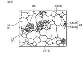
部分安定化ジルコニア2は、これを構成する結晶粒子3として、安定化剤低濃度相粒子33と安定化剤高濃度相粒子34とを含有する。安定化剤低濃度相粒子33のことを、適宜「低濃度相粒子33」といい、安定化剤高濃度相粒子34のことを、適宜「高濃度相粒子34」という。低濃度相粒子33及び高濃度相粒子34は、部分安定化ジルコニア2を構成する各結晶粒子3を安定化剤の固溶状態に基づいて区別したものである。つまり、安定化剤の固溶状態の観点でみた結晶粒子である。固溶状態は、安定化剤の固溶濃度状態ということもできる。
The partially stabilized zirconia 2 contains the stabilizer low-
低濃度相粒子33は、粒子中心Oにおけるイットリア等の安定化剤の濃度が4.7モル%未満である結晶粒子のことをいう。安定化剤の濃度の測定は、後述の走査型電子顕微鏡/エネルギー分散型X線分光法(つまり、SEM/EDX分析)によって、安定化剤中のイットリウム等の金属元素の濃度を測定することにより行われる。具体的な測定方法については、実験例において後述する。
The low-
図3に例示されるように、結晶粒子3の粒子中心は、結晶粒子3を水平方向と垂直方向での粒子の最大幅で囲われた長方形の重心のことである。低濃度相粒子33だけでなく、高濃度相粒子34についても同様である。
As illustrated in FIG. 3, the particle center of the
高濃度相粒子34は、低濃度相粒子33に該当しない結晶粒子のことをいう。つまり、粒子中心Oにおけるイットリア等の安定化剤の濃度が4.7モル%以上の結晶粒子のことをいう。部分安定化ジルコニア2の生成過程において、安定化剤は、ジルコニア粒子の表面から中心に向かって固溶していくと考えられ、表面から中心に向けて安定化剤の固溶濃度が低下する濃度勾配が形成されやすいと考えられる。したがって、粒子中心における安定化剤の濃度が4.7モル%以上の高濃度相粒子34は、通常、結晶粒子3の全体に安定化剤が十分固溶していると考えられる。高濃度相粒子34と低濃度相粒子33との合計量は100%となる。
The high-
部分安定化ジルコニア2は、平均粒径0.1μm以上の低濃度相粒子33が2粒子以上隣接した隣接粒子部35を有する。つまり、部分安定化ジルコニア2における固溶状態の結晶構造において、低濃度相粒子33が一次粒子を形成し、複数の低濃度相粒子33が隣接した連結粒子部は二次粒子を形成しているととらえることができる。
The partially stabilized zirconia 2 has an
隣接粒子部35を構成する低濃度相粒子33の平均粒径が0.1μm未満の場合には、連結粒子部を形成することによる利点が損なわれる。その結果、例えば異種材料部材との熱膨張率差が増大するおそれがある。熱膨張率差をより小さくするという観点から、低濃度相粒子33の平均粒径は0.2μm以上であることが好ましく、0.25μm以上であることがより好ましく、0.3μm以上であることがさらに好ましい。
When the average particle size of the low-
一方、材料強度がより高まるという観点から、隣接粒子部35を構成する低濃度相粒子33の平均粒径は1μm以下であることが好ましく、0.5μm以下であることがより好ましく、0.4μm以下であることがさらに好ましい。
On the other hand, from the viewpoint of further increasing the material strength, the average particle size of the low-
低濃度相粒子33の粒径は、図3に例示されるように、水平方向と垂直方向での粒子の最大幅で囲われた長方形における水平方向の長さL1と垂直方向の長さL2との算術平均で表される。低濃度相粒子33の平均粒径は、少なくとも30個の低濃度相粒子33の粒径の算術平均である。
As illustrated in FIG. 3, the particle sizes of the low-
隣接粒子部35では2粒子以上の低濃度相粒子33が隣接している。このような隣接粒子部35を結晶構造に有する固体電解質は、その製造の焼成時に、例えばC相からなる高濃度相粒子34から圧縮応力を受け難い。隣接粒子部35を構成する各低濃度相粒子33の界面で応力が緩和されるためである。したがって、焼成降温過程においてT相からM相への変態が起こり易くなる。これにより、熱力学的に不安定なT相が少なくなり、固体電解質が熱力学的に安定となる。その結果、アルミナやスピネルなどの異種材料部材との熱膨張率差が小さくなる。この効果をより高めるという観点から、固体電解質の部分安定化ジルコニア2は、低濃度相粒子33が3粒子以上隣接する隣接粒子部35を有することが好ましく、低濃度相粒子33が5粒子以上隣接する隣接粒子部35を有することがより好ましく、低濃度相粒子33が10粒子以上隣接する隣接粒子部35を有することがさらに好ましい。
In the
固体電解質の断面において、隣接粒子部35の存在率が低濃度相粒子33に対して面積比率で50%以上であることが好ましい。つまり、全ての低濃度相粒子33に対する隣接粒子部35の存在率が面積比換算で50%以上であることが好ましい。この場合には、隣接粒子部35を形成することによる上述の効果がより高まる。つまり、アルミナやスピネルなどの異種材料部材との熱膨張率差がより小さくなる。なお、熱力学の観点からは、低濃度相粒子33はM相としてとらえることができる。熱膨張率差をより小さくするという観点から、全低濃度相粒子33に対する隣接粒子部35の存在率は、70%以上であることがより好ましく、80%以上であることがさらに好ましい。面積比率の算出にあたっては、低濃度相粒子33の面積は、円周率πと、粒径/2の2乗との積から算出される。高濃度相粒子34、隣接粒子部35についても同様である。つまり、低濃度相粒子33、高濃度相粒子34、隣接粒子部35の面積は、それぞれの粒径の半分の長さの半径を有する円の面積となる。
In the cross section of the solid electrolyte, the abundance ratio of the
隣接粒子部35の存在率は、全ての結晶粒子に対して面積比率で8〜16%であることが好ましい。具体的には、隣接粒子部35の存在率は、高濃度相粒子34及び低濃度相粒子33の合計100%に対して、面積比率で8〜16%であることが好ましい。この場合にも、隣接粒子部35を形成することによる上述の効果がより高まる。つまり、アルミナやスピネルなどの異種材料部材との熱膨張率差がより小さくなる。
The abundance rate of the
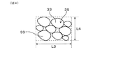
隣接粒子部35の平均粒径は1μm以上であることが好ましい。この場合には、固体電解質の製造の焼成時において、上述の圧縮応力を受け難くなるという効果が顕著になる。そのため、不安定なT相をより減らし、異種材料部材との熱膨張率差がより小さくなる。T相をさらに少なくするという観点から、隣接粒子部35の平均粒径は2μm以上であることがより好ましく、3μm以上であることがさらに好ましい。
The average particle size of the
また、隣接粒子部35の平均粒径は5μm以下であることが好ましい。この場合には、T相からM相に変態する際の発生応力を小さくすることができる。そのため、亀裂などの発生を防止し、固体電解質の強度が向上する。強度をより高めるという観点から、隣接粒子部35の平均粒径は4μm以下であることがより好ましく、3.5μm以下であることがさらに好ましい。
Further, the average particle size of the
隣接粒子部35の粒径は、図4に例示されるように、水平方向と垂直方向での粒子の最大幅で囲われた長方形における水平方向の長さL3と垂直方向の長さL4との算術平均で表される。隣接粒子部35の平均粒径は、少なくとも30個の隣接粒子部35の粒径の算術平均である。
As illustrated in FIG. 4, the particle size of the
また、固体電解質1の断面における高濃度相粒子34の存在率は、全ての結晶粒子3に対する面積比率で70%以上である。高濃度相粒子34の存在率は、全結晶粒子3、つまり、低濃度相粒子33と高濃度相粒子34との合計に対する高濃度相粒子34が占める面積割合である。
Further, the abundance rate of the high-
高濃度相粒子34の存在率が70%未満の場合には、固体電解質1の熱膨張率が小さくなる。その結果、固体電解質1を例えば熱膨張率が7〜10ppm/℃であるアルミナ、スピネル(MgAl2O4)などからなる異種材料部材と接触させて用いる際に、固体電解質1と異種材料部材4との間の熱膨張率差が大きくなる。したがって、固体電解質1を用いたガスセンサ等の装置内で、内部破壊が起こるおそれがある。具体的には、固体電解質1と異種材料部材4との間ではく離や亀裂が発生するおそれがある。アルミナやスピネルなどの異種材料部材4と固体電解質1との熱膨張率差をより小さくするという観点から、高濃度相粒子34の存在率は75%以上が好ましく、80%以上がより好ましい。
When the abundance rate of the high-
一方、技術常識に基づくと、部分安定化ジルコニア2は、これを構成する結晶粒子3として、結晶系の観点から、少なくともモノクリニック相粒子31とキュービック相粒子32とを含有するということができる。以下の説明において、モノクリニック相のことを、適宜「M相」といい、キュービック相のことを、適宜「C相」という。また、部分安定化ジルコニア2は、テトラゴナル相を含有していてもよく、テトラゴナル相のことを、適宜「T相」という。これらのC相、M相、T相は、部分安定化ジルコニア2を構成する各結晶粒子3を結晶相構造に基づいて区別したものである。つまり、結晶相を構成する結晶系の観点でみた結晶粒子である。なお、C相、M相、T相は、技術常識ではあるがX線回折分析により判定することが可能である。
On the other hand, based on common general knowledge, it can be said that the partially stabilized zirconia 2 contains at least monoclinic phase particles 31 and cubic phase particles 32 as the
高濃度相粒子34は、結晶系に基づくと室温ではC相からなるということができる。低濃度相粒子33は、結晶系に基づくと室温ではM相又はT相からなるということができる。低濃度相粒子33には、M相からなる粒子と、T相からなる粒子とが存在していてもよい。低濃度相粒子33は、隣接粒子部35を形成することによる上述の効果を十分に得るという観点からは、M相からなることが好ましい。M相からなる結晶粒子のことをM相粒子ということができ、M相の熱膨張率は2〜3ppm/℃である。C相からなる結晶粒子のことをC相粒子ということができ、C相の熱膨張率は10〜11ppm/℃である。T相からなる結晶粒子のことをT相粒子ということができ、T相の熱膨張率は、10〜11ppm/℃である。
Based on the crystal system, the high-
図2(b)に例示されるように、低濃度相粒子33、隣接粒子部35は高濃度相粒子34の粒界に形成される。低濃度相粒子33の平均粒径は、例えば高濃度相粒子34の平均粒径よりも小さい。
As illustrated in FIG. 2B, the low-
高濃度相粒子34の平均粒径は1μm以上であることが好ましい。この場合には、固体電解質の製造の焼成時において、高濃度相粒子34から低濃度相粒子33にかかる圧縮応力が小さくなる。その結果、隣接粒子部35を形成することによる利点が得られにくくなる。隣接粒子部35を形成することによる上述の効果をより十分に得るという観点から、高濃度相粒子34の平均粒径は2.5μm以上であることがより好ましく、3μm以上であることがさらに好ましい。
The average particle size of the high-
高濃度相粒子34の平均粒径は5μm以下であることが好ましい。この場合には、固体電解質1を構成する部分安定化ジルコニア2自体の強度が低下することを防止できる。強度をより高めるという観点から、高濃度相粒子34の平均粒径は4μm以下であることがより好ましく、3.5μm以下であることがさらに好ましい。高濃度相粒子34の粒径は、水平方向と垂直方向での粒子の最大幅で囲われた長方形における水平方向の長さL1と垂直方向の長さL2との算術平均で表される。高濃度相粒子34の平均粒径は、少なくとも30個の高濃度相粒子34の粒径の算術平均である。
The average particle size of the high-
固体電解質1は、例えばアルミナ、スピネルなどからなる異種材料部材と接触させて用いることができる。上記構成を有する固体電解質は、例えば1000℃を超える高温域に曝されるような冷熱サイクルにおいて、高温域まで熱膨張率を異種材料部材とマッチングさせることが可能となる。したがって、高温域に曝される用途においても熱衝撃割れを十分に防止することが可能になる。
The
本発明における効果を得るという観点からは、安定化剤の種類は特に限定されるわけではないが、安定化剤の化学的安定性が良好になるという観点から、安定化剤はイットリアからなることが好ましい。 From the viewpoint of obtaining the effect in the present invention, the type of stabilizer is not particularly limited, but from the viewpoint of improving the chemical stability of the stabilizer, the stabilizer is made of yttria. Is preferable.
図1に例示されるように、固体電解質が異種材料部材と接触するように構成された接触部を有することが好ましい。この場合には、固体電解質と異種材料部材との熱膨張率差の低減により、異種材料部材と固体電解質との間にはく離や亀裂が発生するという効果をより確実に得ることができる。なお、異種材料部材は、固体電解質とは異なる材質からなる部材である。接触部は、少なくとも一部で接触している部分であればよい。例えば接触面も接触部に含まれる。「固体電解質が異種材料部材と接触するように構成された接触部を有する」とは、固体電解質は、異種材料部材と接触させて用いられるものであること、つまり、異種材料部材に接触させる構成部位を有していること意味する。異種材料部材と実際に接触していることは必ずしも要求されない。固体電解質1は、例えばガスセンサに用いられ、このような固体電解質1は、排ガス等の測定ガスと接触するように構成されたガス接触部を有するということができる。
As illustrated in FIG. 1, it is preferable to have a contact portion configured such that the solid electrolyte comes into contact with a dissimilar material member. In this case, by reducing the difference in the coefficient of thermal expansion between the solid electrolyte and the dissimilar material member, it is possible to more reliably obtain the effect that peeling or cracking occurs between the dissimilar material member and the solid electrolyte. The dissimilar material member is a member made of a material different from that of the solid electrolyte. The contact portion may be a portion that is in contact with at least a part. For example, the contact surface is also included in the contact portion. "The solid electrolyte has a contact portion configured to be in contact with the dissimilar material member" means that the solid electrolyte is used in contact with the dissimilar material member, that is, a configuration in which the solid electrolyte is in contact with the dissimilar material member. It means having a part. Actual contact with dissimilar material members is not always required. The
次に、固体電解質の製造方法について説明する。図5及び図6に例示されるように、混合工程S1と、成形工程S2と、焼成工程S3とを行うことにより、固体電解質が得られる。 Next, a method for producing a solid electrolyte will be described. As illustrated in FIGS. 5 and 6, a solid electrolyte can be obtained by performing the mixing step S1, the molding step S2, and the firing step S3.
混合工程S1においては、第1原料粉末221と、第2原料粉末222と、安定化剤原料粉末211とを混合する。これにより混合物20を得る。第1原料粉末221及び第2原料粉末222は、いずれもジルコニア粒子からなるが、第2原料粉末222は、ジルコニア粒子が複数凝集した凝集粒子からなる。安定化剤原料粉末211は、イットリアなどの安定化剤からなる。第2原料粉末222は、第1原料粉末221よりも平均粒径の大きな粉末である。
In the mixing step S1, the first
安定化剤原料粉末211としては、イットリア粉末、カルシア粉末、マグネシア粉末、スカンジア粉末、イッテルビア粉末等を用いることができる。安定化剤原料粉末211としては、これらのうちの少なくとも1種を用いることができる。
As the stabilizer
第2原料粉末222は、ジルコニア粒子からなる原料粉末を熱処理することによって作製することができる。熱処理により、ジルコニア粒子同士が凝集する。これにより、凝集粒子からなる第2原料粉末222が得られる。凝集粒子はジルコニア粒子(つまり、1次粒子)が凝集してなる2次粒子であるということができる。
The second
第1原料粉末221、第2原料粉末222の平均粒径は、レーザ回折・散乱法によって求めた粒度分布における体積積算50%における粒径を意味する。レーザ回折・散乱法によって求めた粒度分布における体積積算50%における粒径のことを適宜「d50粒径」という。
The average particle size of the first
第1原料粉末221のd50粒径は、例えば0.2〜0.5μmの範囲とすることができる。一方、第2原料粉末222のd50粒径は、例えば1〜5μmの範囲とすることができる。
The d50 particle size of the first
混合工程は、さらに第1混合工程S11と第2混合工程S12とを有することが好ましい。第1混合工程S11においては、第1原料粉末221と安定化剤原料粉末211とを混合する。第2混合工程S12においては、第1混合工程S11後に第2原料粉末222を第1原料粉末221と安定化剤原料粉末211との混合物にさらに混合して混合物20を得る。
The mixing step preferably further includes a first mixing step S11 and a second mixing step S12. In the first mixing step S11, the first
混合物20は、成形の前にスラリー化することができる。スラリー化には、水、アルコール、液状有機物などの液体を使用できる。スラリー化した混合物については、造粒を行ってもよい。
The
次いで、成形工程S2を行う。成形工程S2においては、第1原料粉末221と第2原料粉末222と安定化剤原料粉末211とを含む混合物20を成形する。これにより成形体が得られる。成形方法は特に限定されず、圧粉成形、加圧成形、押出成形、射出成形、ホットプレス、冷間等方加圧成形、研削などが挙げられる。成形により、用途に応じて所望形状の成形体が得られる。例えば、板状、シート状、中空シート状、棒状、筒状、有底筒状等の各種形状の成形体を得ることができる。必要に応じて成形体に対して研削を行うことができる。
Next, the molding step S2 is performed. In the molding step S2, the
次いで、焼成工程S3においては、成形体を焼成する。この焼成により、部分安定化ジルコニア2が生成し、固体電解質1が得られる。焼成温度は、組成等に応じて適宜変更可能であるが、例えば1300〜1500℃である。
Next, in the firing step S3, the molded product is fired. By this firing, partially stabilized zirconia 2 is produced, and a
上記製造方法においては、ジルコニア原料の一部に安定化剤と難反応な凝集粒子からなる第2原料粉末222を用いている。これにより、焼成工程において上述の低濃度相粒子33が形成されると共に、隣接粒子部35が形成される。このようにして本実施形態の固体電解質1を得ることができる。
In the above production method, a second
本形態の固体電解質1は、安定化剤がジルコニアに固溶した部分安定化ジルコニア2からなる。部分安定化ジルコニア2は、これを構成する結晶粒子3として、低濃度相粒子33と高濃度相粒子34とを含有し、高濃度相粒子34の存在比率が70%以上である。
The
また、部分安定化ジルコニア2は、平均粒径0.1μm以上の低濃度相粒子33が2粒子以上隣接した隣接粒子部35を有する。
Further, the partially stabilized zirconia 2 has an
このような構成を有するため、固体電解質1は、上例えばアルミナ、スピネルなどの異種材料部材に熱膨張率が近づく。したがって、固体電解質1と異種材料部材4との熱膨張率差に起因する破損を防止できる。これは、隣接粒子部35を有する固体電解質1は、例えば焼成などによる製造時に、隣接粒子部35が周囲の高濃度相粒子34等から圧縮応力を受けにくいためである。つまり、隣接粒子部35を構成する2粒子以上の低濃度相粒子33の界面で、圧縮応力が緩和されるためであると考えられる。その結果、隣接粒子部35が、製造時に熱的に安定な相を形成しやすく、不安定な相が少なくなっていると考えられる。なお、熱的に安定な相は、M相であり、不安定な相は、T相であると考えられる。つまり、隣接粒子部35では、焼成時に不安定なT相から安定なM相への変態が起こり易く、T相が少なくなっていると考えられる。したがって、固体電解質1は、例えば1000℃を超える高温域に曝される冷熱サイクルにおいても、異種材料部材4との熱応力を低減できる。したがって、例えば固体電解質1を異種材料部材4と接触させて用いた時に、接触部にはく離が発生したり、亀裂が発生することを防止できる。
Since it has such a configuration, the
<比較形態1>
次に、比較形態の固体電解質について説明する。比較形態1の固体電解質9は、第2原料粉末を用いない点を除いては、実施形態1と同様の方法により製造される。
<
Next, a comparative form of the solid electrolyte will be described. The
具体的には、第1原料粉末と安定化剤原料粉末とを混合する。次いで、スラリー化して、成形、焼成する。このようにして、本形態の固体電解質9を得ることができる。
Specifically, the first raw material powder and the stabilizer raw material powder are mixed. Then, it is made into a slurry, molded and fired. In this way, the
図7に例示されるように、本形態の固体電解質9を構成する部分安定化ジルコニア90は、結晶粒子3として、C相粒子91及びM相粒子92を含有する。
As illustrated in FIG. 7, the partially stabilized
本形態では、凝集粒子からなる第2原料粉末を使用していない。そのため、第1原料粉末と安定化剤との反応性が高い。その結果、固溶された状態の図示は省略するが、C相粒子91だけでなく、M相粒子92の内部にまで安定化剤が固溶されている。これは、SEM/EDXにより確認できる。本形態の固体電解質9は、実施形態1のような隣接粒子部を有していない。したがって、異種材料部材との熱膨張率差が大きくなる。
In this embodiment, the second raw material powder composed of agglomerated particles is not used. Therefore, the reactivity between the first raw material powder and the stabilizer is high. As a result, although the illustration of the solid-dissolved state is omitted, the stabilizer is solid-solved not only in the C-
したがって、固体電解質は、例えば冷熱サイクルにおいて、熱膨張率が異種材料部材と大きく乖離しやすい。その結果、固体電解質と、例えばアルミナ、スピネル(MgAl2O4)などからなる異種材料部材とを接触して用いる際に、固体電解質と異種材料部材との熱膨張率差が大きくなり、固体電解質と異種材料部材との間ではく離や亀裂が発生するおそれがある。特に、例えば1000℃を超える高温域に曝されるような冷熱サイクルにおいては、熱膨張率差の乖離がより大きくなり、はく離や亀裂が発生し易くなる。 Therefore, the coefficient of thermal expansion of the solid electrolyte tends to be significantly different from that of the dissimilar material members, for example, in the thermal cycle. As a result, when the solid electrolyte and a dissimilar material member made of, for example, alumina or spinel (MgAl 2 O 4 ) are used in contact with each other, the difference in the coefficient of thermal expansion between the solid electrolyte and the dissimilar material member becomes large, and the solid electrolyte becomes large. There is a risk of peeling or cracking between the material and the dissimilar material member. In particular, in a cold cycle such as exposure to a high temperature region exceeding 1000 ° C., the difference in the coefficient of thermal expansion becomes larger, and peeling and cracking are likely to occur.
<実験例1>
実施例、比較例にかかる複数の固体電解質を作製、その性能を比較評価する。以下に本例における固体電解質の作製方法を説明する。
<Experimental example 1>
A plurality of solid electrolytes according to Examples and Comparative Examples are prepared, and their performances are compared and evaluated. The method for producing the solid electrolyte in this example will be described below.
まず、イットリア粉末と、d50粒径が0.30μmのジルコニア粉末とを混合し、整粒した。また、d50粒径が0.30μmのジルコニア粉末を1100℃で熱処理することにより、ジルコニア粒子同士を凝集させた。これにより、ジルコニア粒子の凝集粒子よりなるジルコニア凝集粉末を得た。次いで、ジルコニア粉末とイットリア粉末との混合物に、ジルコニア凝集粉末を混合した。d50粒径が0.30μmのジルコニア粉末が上述の第1原料粉末、ジルコニア凝集粉末が上述の第2原料粉末に相当する。イットリア粉末は、上述の安定化剤原料粉末に相当する。これらの混合割合は、目的の組成に合わせて調整できる。 First, yttria powder and zirconia powder having a d50 particle size of 0.30 μm were mixed and sized. Further, the zirconia powder having a d50 particle size of 0.30 μm was heat-treated at 1100 ° C. to agglomerate the zirconia particles. As a result, a zirconia agglomerated powder composed of agglomerated particles of zirconia particles was obtained. Then, the zirconia agglomerated powder was mixed with the mixture of the zirconia powder and the yttria powder. The zirconia powder having a d50 particle size of 0.30 μm corresponds to the above-mentioned first raw material powder, and the zirconia agglomerated powder corresponds to the above-mentioned second raw material powder. The yttria powder corresponds to the above-mentioned stabilizer raw material powder. The mixing ratio of these can be adjusted according to the desired composition.
次いで、ジルコニア粉末とイットリア粉末とジルコニア凝集粉末との混合物と、水とを混合し、混合物のスラリーを得た。混合物を構成する原料粒子の流動性を高めて所望形状に成形し易くするために、混合物のスラリーの造粒を行った。造粒は、例えばスプレー造粒により行う。 Then, a mixture of zirconia powder, yttria powder, and zirconia agglomerated powder was mixed with water to obtain a slurry of the mixture. In order to increase the fluidity of the raw material particles constituting the mixture and facilitate molding into a desired shape, the slurry of the mixture was granulated. Granulation is performed, for example, by spray granulation.
次に、混合物を成形して成形体を得た。成形は例えば圧粉成形により行う。本例においては、後述の各評価に用いるサンプル形状に成形した。 Next, the mixture was molded to obtain a molded product. Molding is performed, for example, by powder molding. In this example, it was molded into a sample shape used for each evaluation described later.
次に、成形体を温度1400℃にて焼成した。このようにして、固体電解質を得た。本例では、各原料の平均粒径、配合割合などを変更することにより、表1に示す試料1〜13の固体電解質を作製した。
Next, the molded product was fired at a temperature of 1400 ° C. In this way, a solid electrolyte was obtained. In this example, the solid electrolytes of
(低濃度相粒子、高濃度相粒子の判定、隣接粒子部の存在確認)
各試料から、幅5mm、長さ20mm、厚み2mmの測定試料を切り出した。この測定試料の表面を研磨後、サーマルエッチング処理を行った。サーマルエッチングは、温度1200℃で測定試料を1時間加熱することにより行った。SEM/EDX分析による組成分析により、Y元素のマッピングを測定試料の5箇所の領域について行った。そこで観察された粒子のうちY濃度が小さい粒子について、粒子中心のY濃度を測定した。その結果、粒子中心のY濃度が4.7モル%未満である粒子を低濃度相粒子とした。一方、粒子中心のY濃度が4.7モル%以上である粒子を高濃度相粒子とした。また、SEM/EDX分析により、低濃度相粒子が複数隣接する隣接粒子部の有無を確認した。低濃度相粒子の隣接は、例えば低濃度相粒子同士の界面の存在により確認することができるが、通常は、SEM/EDX分析により得られる画像を観察することにより簡単に判定できる。SEMの観察条件は次の通りである。装置:株式会社日立ハイテクノロジーズ製の「SU8220」、加速電圧:5kV、WD設定:8.0mm、電流:10mA、倍率:10000倍。また、EDXによる測定条件は次の通りである。装置:ブルカー社製の「Xflash6160」、加速電圧:5kV、WD設定:14mm、電流:5〜15mA、倍率:50000倍。電流は、検出量が40〜55kcpsとなるように調整した。
(Determination of low-concentration phase particles and high-concentration phase particles, confirmation of the presence of adjacent particles)
From each sample, a measurement sample having a width of 5 mm, a length of 20 mm, and a thickness of 2 mm was cut out. After polishing the surface of this measurement sample, thermal etching treatment was performed. Thermal etching was performed by heating the measurement sample at a temperature of 1200 ° C. for 1 hour. By composition analysis by SEM / EDX analysis, mapping of Y element was performed for 5 regions of the measurement sample. Among the particles observed there, the Y concentration at the center of the particles was measured for the particles having a small Y concentration. As a result, the particles having a Y concentration of less than 4.7 mol% at the center of the particles were designated as low-concentration phase particles. On the other hand, particles having a Y concentration of 4.7 mol% or more at the center of the particles were designated as high-concentration phase particles. In addition, SEM / EDX analysis confirmed the presence or absence of adjacent particle portions in which a plurality of low-concentration phase particles were adjacent to each other. Adjacency of low-concentration phase particles can be confirmed, for example, by the presence of an interface between low-concentration phase particles, but usually, it can be easily determined by observing an image obtained by SEM / EDX analysis. The SEM observation conditions are as follows. Equipment: "SU8220" manufactured by Hitachi High-Technologies Corporation, acceleration voltage: 5kV, WD setting: 8.0mm, current: 10mA, magnification: 10000 times. The measurement conditions by EDX are as follows. Equipment: "Xflash6160" manufactured by Bruker, acceleration voltage: 5kV, WD setting: 14mm, current: 5 to 15mA, magnification: 50,000 times. The current was adjusted so that the detected amount was 40 to 55 kcps.
次に、上述の5箇所の領域から、合計30個の低濃度相粒子を選択し、これらの粒径を上述の方法により測定した。そして、これら粒径の算術平均により低濃度相粒子の平均粒径を求めた。 Next, a total of 30 low-concentration phase particles were selected from the above-mentioned five regions, and their particle sizes were measured by the above-mentioned method. Then, the average particle size of the low-concentration phase particles was determined by the arithmetic mean of these particle sizes.
また、SEM/EDX分析によって得られる上述の5箇所の領域の画像内に孤立して存在する全ての低濃度相粒子の粒径と、全ての隣接粒子部の粒径とをそれぞれ求めた。各粒径rから、孤立して存在する低濃度相粒子、隣接粒子部の各面積Sは、下記の式(1)より算出される。次に、孤立して存在する各低濃度相粒子の面積の合計S1と、各隣接粒子部の面積の合計S2とから、下記式(2)より、全低濃度相粒子に対する隣接粒子部の存在率S3(単位:%)を算出した。各領域は12μm×9μmの領域とする。
S=πr2/4 ・・・(1)
S3=100×S2/(S1+S2) ・・・(2)
In addition, the particle sizes of all the low-concentration phase particles isolated in the images of the above-mentioned five regions obtained by SEM / EDX analysis and the particle sizes of all the adjacent particle portions were determined. From each particle size r, each area S of the low-concentration phase particles and the adjacent particle portions existing in isolation is calculated by the following formula (1). Next, from the total area S1 of each low-concentration phase particle existing in isolation and the total area S2 of each adjacent particle portion, the existence of the adjacent particle portion with respect to all the low-concentration phase particles is obtained from the following formula (2). The rate S3 (unit:%) was calculated. Each region is a region of 12 μm × 9 μm.
S = πr 2/4 ··· ( 1)
S3 = 100 × S2 / (S1 + S2) ・ ・ ・ (2)
また、全結晶粒子に対する隣接粒子部の存在率は、上述の各隣接粒子部の面積の合計S2を観察領域の面積で除することにより、算出される。隣接粒子部の存在率は、5箇所の領域における存在率の算術平均で表される。隣接粒子部の存在率は百分率で表される。 Further, the abundance ratio of the adjacent particle portions with respect to the total crystal particles is calculated by dividing the total S2 of the areas of the adjacent particle portions described above by the area of the observation region. The abundance of adjacent particle portions is represented by the arithmetic mean of the abundance in five regions. The abundance of adjacent particle parts is expressed as a percentage.
(全結晶粒子に対する高濃度相粒子の存在率)
Y元素のマッピングを測定試料の10箇所の領域について行った点を除いて、上述の方法と同様にしてSEM/EDX分析を行った。各領域内に含まれる全ての高濃度相粒子の粒径を測定し、式(1)から各高濃度相粒子の面積を算出した。各領域内における高濃度相粒子の存在率は、各高濃度相粒子の面積の合計を観察領域の面積で除することにより算出される。高濃度相粒子の存在率は、10箇所の領域における存在率の算術平均で表される。高濃度相粒子の存在率は百分率で表される。
(Abundance of high-concentration phase particles with respect to total crystal particles)
SEM / EDX analysis was performed in the same manner as described above, except that the Y element was mapped for 10 regions of the measurement sample. The particle size of all the high-concentration phase particles contained in each region was measured, and the area of each high-concentration phase particle was calculated from the formula (1). The abundance of high-concentration phase particles in each region is calculated by dividing the total area of each high-concentration phase particles by the area of the observation region. The abundance of high-concentration phase particles is represented by the arithmetic mean of the abundance in 10 regions. The abundance of high-concentration phase particles is expressed as a percentage.
(熱膨張率)
各試料から、幅5mm、長さ20mm、厚み2mmの測定試料を切り出した。測定試料について、室温〜1050℃間の熱膨張挙動を測定した。室温は25℃である。熱膨張挙動の測定には、熱機械分析装置(つまり、TMA)を用いた。TMAとしては、ブルカー・エイエックスエス社製のTMA4000SAを用いた。測定に使用する標準サンプルには、アルミナ焼結体を用いた。なお、測定は各試料について5回ずつ行った。そして、熱膨張挙動における500℃から600℃までの傾きを熱膨張率とした。表1には、5回の測定の平均値を示す。判断基準は、異種材料との熱膨張係数のマッチングの観点から、熱膨張係数8〜9ppm/℃の場合を「良」と判定し、8.3〜8.7ppm/℃の場合を「優」と判定し、8ppm/℃未満、9ppm/℃を超える場合を「不良」と判定した。
(Coefficient of thermal expansion)
From each sample, a measurement sample having a width of 5 mm, a length of 20 mm, and a thickness of 2 mm was cut out. The thermal expansion behavior of the measurement sample was measured between room temperature and 1050 ° C. Room temperature is 25 ° C. A thermomechanical analyzer (that is, TMA) was used to measure the thermal expansion behavior. As the TMA, TMA4000SA manufactured by Bruker AXS Co., Ltd. was used. An alumina sintered body was used as the standard sample used for the measurement. The measurement was performed 5 times for each sample. Then, the slope from 500 ° C. to 600 ° C. in the thermal expansion behavior was defined as the coefficient of thermal expansion. Table 1 shows the average value of 5 measurements. From the viewpoint of matching the coefficient of thermal expansion with dissimilar materials, the judgment criteria is that a case with a coefficient of thermal expansion of 8 to 9 ppm / ° C is judged as "good", and a case with a coefficient of thermal expansion of 8.3 to 8.7 ppm / ° C is judged as "excellent". When it was less than 8 ppm / ° C. and exceeded 9 ppm / ° C., it was judged as “defective”.

表1より知られるように、試料2、試料3、試料5、試料6、試料8〜試料13のように、全結晶粒子に対する高濃度相粒子の存在率が70%以上であり、平均粒径0.1μm以上の低濃度相粒子が2粒子以上隣接した隣接粒子部を有する固体電解質は、熱膨張率が8〜9ppm/℃となる。したがって、これらの固体電解質は、アルミナ、スピネルなどからなる異種材料部材との熱膨張率差が小さい。したがって、冷熱サイクルにおいて、固体電解質と異種材料部材との間ではく離や亀裂が発生することを防止できる。
As is known from Table 1, the abundance of high-concentration phase particles with respect to all crystal particles is 70% or more, and the average particle size is as shown in Sample 2,
また、表1より知られるように、固体電解質の断面において、低濃度相粒子に対する隣接粒子部の存在率が面積比率で50%以上であると、アルミナやスピネルなどの異種材料部材との熱膨張率差がより小さくなる。さらに、全ての結晶粒子に対する隣接粒子部の存在率を面積比率で8〜16%にすることでも、異種材料部材との熱膨張率差がより小さくなる。 Further, as is known from Table 1, when the abundance ratio of the adjacent particle portion with respect to the low-concentration phase particles is 50% or more in the area ratio in the cross section of the solid electrolyte, thermal expansion with dissimilar material members such as alumina and spinel The rate difference becomes smaller. Further, by setting the abundance ratio of the adjacent particle portion with respect to all the crystal particles to 8 to 16% in the area ratio, the difference in the coefficient of thermal expansion with the dissimilar material member becomes smaller.
<実験例2>
実験例1と同様に、複数の固体電解質を作製、その性能を比較評価する。本例においては、強度の観点からも性能評価を行う。
<Experimental example 2>
Similar to Experimental Example 1, a plurality of solid electrolytes are prepared and their performances are compared and evaluated. In this example, the performance is also evaluated from the viewpoint of strength.
まず、実験例1と同様にして、各原料の平均粒径、配合割合などを変更することにより、表2に示す試料14〜21の固体電解質を作製した。各試料について、実験例1と同様の測定を行うと共に、さらに以下の測定を行った。 First, the solid electrolytes of Samples 14 to 21 shown in Table 2 were prepared by changing the average particle size, blending ratio, etc. of each raw material in the same manner as in Experimental Example 1. For each sample, the same measurement as in Experimental Example 1 was performed, and the following measurement was further performed.
(隣接粒子部の平均粒径)
実験例1と同様にして、隣接粒子部の有無を確認し、確認された隣接粒子部の粒径を上述の方法により測定した。そして、複数箇所の領域から、合計30個の隣接粒子部を選択し、これら粒径の算術平均により隣接粒子部の平均粒径を求めた。
(Average particle size of adjacent particles)
In the same manner as in Experimental Example 1, the presence or absence of the adjacent particle portion was confirmed, and the particle size of the confirmed adjacent particle portion was measured by the above method. Then, a total of 30 adjacent particle portions were selected from a plurality of regions, and the average particle diameter of the adjacent particle portions was determined by the arithmetic mean of these particle sizes.
(高濃度相粒子の平均粒径)
実験例1と同様にして、高濃度相粒子の判定を行い、確認された高濃度相粒子の粒径を上述の方法により測定した。そして、複数箇所の領域から、合計30個の高濃度相粒子を選択し、これら粒径の算術平均により高濃度相粒子の平均粒径を求めた。
(Average particle size of high-concentration phase particles)
The high-concentration phase particles were determined in the same manner as in Experimental Example 1, and the particle size of the confirmed high-concentration phase particles was measured by the above method. Then, a total of 30 high-concentration phase particles were selected from a plurality of regions, and the average particle size of the high-concentration phase particles was determined by the arithmetic mean of these particle sizes.
(強度)
幅5mm、長さ45mm、厚み5mmの測定試料を切り出した。この測定試料から、JIS R1601:2008に記載の4点曲げ強さ試験にしたがって、強度評価サンプルを作製した。次いで、JIS R1601:2008に準拠して4点曲げ強さ試験を行った。その結果を強度とする。なお、試験は、各試料について10回ずつ行った。表にはその平均値を示す。強度は250MPa以上である場合を「良」とし、250MPa未満の場合を「不良」と判定した。強度が250MPa未満の場合には、固体電解質を例えばセンサなどに組み付ける際にクラックが発生するおそれがある。つまり、装置内への組み付け強度を確保するという観点から、固体電解質の強度は250MPa以上であることが好ましい。
(Strength)
A measurement sample having a width of 5 mm, a length of 45 mm, and a thickness of 5 mm was cut out. From this measurement sample, a strength evaluation sample was prepared according to the 4-point bending strength test described in JIS R1601: 2008. Then, a 4-point bending strength test was performed in accordance with JIS R1601: 2008. The result is the strength. The test was performed 10 times for each sample. The table shows the average value. When the strength was 250 MPa or more, it was judged as "good", and when it was less than 250 MPa, it was judged as "bad". If the strength is less than 250 MPa, cracks may occur when the solid electrolyte is assembled to, for example, a sensor. That is, from the viewpoint of ensuring the assembling strength in the apparatus, the strength of the solid electrolyte is preferably 250 MPa or more.
また、熱膨張率、強度の判定のいずれかが「不良」となった場合を「×」と評価した。また、熱膨張率、強度の判定のいずれも「不良」ではなく、いずれか一方でも「優」であった場合を「◎」と評価した。さらに、熱膨張率、強度の判定のいずれもが「良」であった場合を「○」と評価した。これらは、固体電解質を積層型のガスセンサ素子に適用する場合における適性を評価したものである。「◎」が適性に優れ、「○」は適性が良好であること意味する。「×」は適性において好ましくはないことを意味する。 In addition, the case where either the coefficient of thermal expansion or the determination of the strength was "defective" was evaluated as "x". In addition, neither the coefficient of thermal expansion nor the strength was judged to be "poor", and the case where either one was "excellent" was evaluated as "◎". Further, when both the coefficient of thermal expansion and the judgment of the strength were "good", it was evaluated as "◯". These are evaluations of suitability when a solid electrolyte is applied to a laminated gas sensor element. “◎” means that the aptitude is excellent, and “○” means that the aptitude is good. "X" means unfavorable in aptitude.
表2より知られるように、高濃度相粒子の存在率が70%以上であり、平均粒径0.1μm以上の低濃度相粒子が2粒子以上隣接した隣接粒子部を有する固体電解質は、熱膨張率が8〜9ppm/℃となる。したがって、これらの固体電解質は、アルミナ、スピネルなどからなる異種材料部材との熱膨張率差が小さい。したがって、冷熱サイクルにおいて、固体電解質と異種材料部材との間ではく離や亀裂が発生することを防止できる。 As is known from Table 2, a solid electrolyte in which the abundance of high-concentration phase particles is 70% or more and two or more low-concentration phase particles having an average particle size of 0.1 μm or more have adjacent particle portions adjacent to each other is thermally generated. The expansion rate is 8 to 9 ppm / ° C. Therefore, these solid electrolytes have a small difference in thermal expansion coefficient from dissimilar material members made of alumina, spinel, and the like. Therefore, it is possible to prevent peeling and cracking between the solid electrolyte and the dissimilar material members in the thermal cycle.
また、隣接粒子部の平均粒径が1〜5μmである場合には、異種材料との熱膨張率差がより小さくなり、さらに固体電解質の強度が向上する。また、高濃度相粒子の平均粒径が1〜5μmである場合にも、異種材料との熱膨張率差がより小さくなり、さらに固体電解質の強度が向上する。 Further, when the average particle size of the adjacent particle portions is 1 to 5 μm, the difference in thermal expansion coefficient with different materials becomes smaller, and the strength of the solid electrolyte is further improved. Further, even when the average particle size of the high-concentration phase particles is 1 to 5 μm, the difference in the coefficient of thermal expansion with different materials becomes smaller, and the strength of the solid electrolyte is further improved.
<実施形態2>
次に、固体電解質を用いたガスセンサ5の実施形態について説明する。なお、実施形態2以降において用いた符号のうち、既出の実施形態において用いた符号と同一のものは、特に示さない限り、既出の実施形態におけるものと同様の構成要素等を表す。
<Embodiment 2>
Next, an embodiment of the gas sensor 5 using the solid electrolyte will be described. In addition, among the codes used in the second and subsequent embodiments, the same codes as those used in the above-described embodiments represent the same components and the like as those in the above-mentioned embodiments, unless otherwise specified.
本形態のガスセンサ5は、図8及び図9に示すように、センサ素子6を備えている。本形態のセンサ素子6は、ガスを検出するガスセンサ素子である。センサ素子6は、固体電解質1と、検出電極62と、基準電極63と、拡散抵抗層66とを有する。つまり、ガスセンサ5は、センサ素子6内に固体電解質1を備える。検出電極62及び基準電極63は、固体電解質1の両表面601A、602Aにそれぞれ形成されている。検出電極62及び基準電極63は、互いに対向する位置に形成された一対の電極を形成している。拡散抵抗層66は、検出電極62に到達する排ガスG等の測定ガスの流量を制限する。ガスセンサ5は、一対の電極62、63の間に電圧が印加された状態においてこれらの電極62、63の間に生じる限界電流の大きさによって、排ガスGの酸素濃度(つまり、空燃比)を検出する限界電流式のものである。
As shown in FIGS. 8 and 9, the gas sensor 5 of this embodiment includes a
以下に、本形態のガスセンサ5について詳説する。なお、以降の説明において、ガスセンサ5の軸方向Xにおける排ガスG等の測定ガスに曝される側と先端側X1といい、その反対側を基端側X2という。 The gas sensor 5 of this embodiment will be described in detail below. In the following description, the side exposed to the measurement gas such as the exhaust gas G in the axial direction X of the gas sensor 5 and the tip side X1 are referred to, and the opposite side is referred to as the proximal end side X2.
(ガスセンサ)
ガスセンサ5は、車両等の内燃機関の排気管に配置されて使用される。本形態のように限界電流式のガスセンサ5は、排気管を流れる排ガスGの空燃比を定量的に検出する空燃比センサとして使用される。このガスセンサ5は、排ガスGの空燃比がリッチ側にある場合と、リーン側にある場合とのいずれにおいても、空燃比を定量的に求めることができる。
(Gas sensor)
The gas sensor 5 is arranged and used in the exhaust pipe of an internal combustion engine such as a vehicle. The limit current type gas sensor 5 as in this embodiment is used as an air-fuel ratio sensor that quantitatively detects the air-fuel ratio of the exhaust gas G flowing through the exhaust pipe. The gas sensor 5 can quantitatively determine the air-fuel ratio regardless of whether the air-fuel ratio of the exhaust gas G is on the rich side or the lean side.
ここで、排ガスGの空燃比とは、内燃機関において燃焼された際の燃料と空気との混合比率のことをいう。また、リッチ側とは、排ガスGの空燃比が、燃料と空気が完全燃焼するときの理論空燃比に比べて、燃料が多い側にあることをいう。リーン側とは、排ガスGの空燃比が、理論空燃比に比べて燃料が少ない側にあることをいう。 Here, the air-fuel ratio of the exhaust gas G refers to the mixing ratio of fuel and air when burned in an internal combustion engine. Further, the rich side means that the air-fuel ratio of the exhaust gas G is on the side where the fuel is abundant as compared with the stoichiometric air-fuel ratio when the fuel and the air are completely combusted. The lean side means that the air-fuel ratio of the exhaust gas G is on the side where the fuel is less than the stoichiometric air-fuel ratio.
本形態のガスセンサ5においては、排ガスの酸素濃度を検出することにより、排ガスの空燃比が検出される。空燃比センサとしてのガスセンサ5は、実質的には、リーン側においては、排ガスGの酸素濃度を検出する一方、リッチ側においては、排ガスGの未燃ガス濃度を検出することになる。 In the gas sensor 5 of this embodiment, the air-fuel ratio of the exhaust gas is detected by detecting the oxygen concentration of the exhaust gas. The gas sensor 5 as an air-fuel ratio sensor substantially detects the oxygen concentration of the exhaust gas G on the lean side, while it detects the unburned gas concentration of the exhaust gas G on the rich side.
図8に示すように、ガスセンサ5は、センサ素子6の他に、ハウジング71、先端側カバー72、基端側カバー73等を有する。ハウジング71は、排気管に取り付けられて絶縁碍子74を介してセンサ素子6を保持する。先端側カバー72は、ハウジング71の先端側X1に取り付けられてセンサ素子6を覆う。先端側カバー72は、2重構造であり、内側カバー721と外側カバー722とからなる。基端側カバー73は、ハウジング71の基端側X2に取り付けられてセンサ素子6の電気配線用の端子75等を覆う。
As shown in FIG. 8, the gas sensor 5 includes a
(センサ素子)
図9に例示されるように、センサ素子6としては、例えば積層型センサ素子が用いられる。つまり、センサ素子6は、基準電極63と板状の固体電解質1と検出電極62とが順次積層された積層体から構成することができる。
(Sensor element)
As illustrated in FIG. 9, as the
図9に例示されるように、センサ素子6は、例えば板状の固体電解質1を有する。固体電解質1は、測定ガス面601Aと基準ガス面602Aとを有する。測定ガス面601Aは、排ガスGなどの測定ガスに曝される面である。一方、基準ガス面602Aは、大気A等の基準ガスに曝される面である。測定ガス面601Aと基準ガス面602Aとは、固体電解質1における相互に反対の面となる。
As illustrated in FIG. 9, the
検出電極62は、固体電解質1の測定ガス面601Aに設けられる。一方、基準電極63は基準ガス面602Aに設けられる。センサ素子6がこのような積層型センサ素子からなる場合には、ヒータ64を構成する発熱体641が絶縁体642を介して固体電解質1に積層される。絶縁体642は例えばアルミナからなる。
The
検出電極62は、測定ガス室68に面している。測定ガス室68内には、多孔質の拡散抵抗層66を経由した測定ガスが導入される。測定ガス室68は、固体電解質1と、測定ガス室形成層681と、拡散抵抗層66とにより囲まれた空間である。検出電極62が固体電解質1に接触して形成され、さらに、測定ガス室68の構造部材である測定ガス室形成層681が固体電解質1に接触して形成されている。検出電極62が排ガスG等の測定ガスに晒され、基準電極63とともにガス検出を行う部位である。検出電極62はリード線76が接続された端子75に電気的に接続される。
The
基準電極63は基準ガス室69に面している。基準ガス室69内には、基端側カバー73の通過孔731を経由して基端側X2から大気A等の基準ガスが導入される。なお、センサ素子6としては、積層型センサ素子に代えて後述のコップ型センサ素子を用いることも可能である。
The
検出電極62は、先端側カバー72に設けられた通過孔723、724、725を通って先端側カバー42内に流入する排ガスG等の測定ガスに晒される。基準電極63は、基端側カバー73に設けられた通過孔731を通って基端側カバー73内から固体電解質1の基準ガス室69内に流入する大気A等の基準ガスに晒される。
The
ヒータ64は、通電によって発熱するものであり、内燃機関及びガスセンサ5の起動時等において、固体電解質1及び各電極62、63を活性温度に加熱するものである。ヒータ64は、アルミナ焼結体からなる絶縁体642と、その内部に形成された発熱体641とからなる。絶縁体642を構成するアルミナ焼結体は、固体電解質に接触している。つまり、センサ素子6は、固体電解質1と、アルミナ焼結体からなる異種材料部材4とが接触した構造体であり、固体電解質1はアルミナからなる異種材料部材4との接触部1A(具体的には接触面)を有している。ヒータを構成する絶縁体642は、基準ガス室69を形成する構造部材でもあり、基準ガス室形成層としても役割も果たす。
The
また、固体電解質1には、測定ガス面601A側に、測定ガス室68を構成する測定ガス室形成層681が積層形成されている。測定ガス室形成層681はアルミナからなる。つまり、固体電解質1は、基準ガス面602A側において上述のヒータ64を構成する絶縁体642(つまり、異種材料部材4)と接触し、測定ガス面601A側において測定ガス室形成層681(つまり、異種材料部材4)と接触している。固体電解質1は、測定ガス面601Aにおいて測定ガスと接触する。測定ガス面601Aは、上述のガス接触部であるということができる。
Further, in the
拡散抵抗層66は例えばスピネルの多孔質体からなる。また、拡散抵抗層66の表面には、アルミナからなる遮蔽層60が設けられている。この遮蔽層60は、ガスを透過しない緻密体からなる。先端側カバー72内に流入した排ガスGは、拡散抵抗層66を通過して検出電極62の測定部50に至る。図9に例示されるセンサ素子6の構成では、拡散抵抗層66は、固体電解質1に接触していないが、拡散抵抗層66を固体電解質1に接触させる構成を採用することも可能である。この場合には、拡散抵抗層66が異種材料部材4となる。
The
(固体電解質)
固体電解質1は、部分安定化ジルコニア2からなる。具体的には、実施形態1に記載の固体電解質が用いられる。この固体電解質1は、アルミナやスピネルとの熱膨張率差が小さい。したがって、冷熱サイクルにおいて、ヒータ64や測定ガス室形成層681と固体電解質1との間ではく離や亀裂が起こり難い。また、固体電解質1は例えば1000℃を超える高温域に曝される冷熱サイクルでも、ヒステリスにおける熱膨張率差が小さく、アルミナやスピネルと高温域での熱膨張率差が小さい。したがって、高温域に曝されても固体電解質1と、ヒータ64や測定ガス室形成層681等の異種材料部材4との間ではく離や亀裂が起こり難い。これは、ガスセンサ5を1000℃を超える用途に適用しても、ガスセンサ5は高い信頼性を維持しながら測定ガスの検出が可能であることを意味する。
(Solid electrolyte)
The
(電極)
本形態の検出電極62の材質は、酸素等に対する触媒活性を有するものであれば特に限定されない。例えば検出電極62は、貴金属成分として、Au(金)、Ag(銀)、Pd(パラジウム)とAgの混合物又は合金、PtとAuの混合物又は合金のうちのいずれかの組成を含有することができる。また、基準電極63の材質についても特に限定されず、貴金属成分として、Pt(白金)、Au、Ag、Pd等を含有することができる。
(electrode)
The material of the
また、センサ素子6として、積層型センサ素子に代えて、図10に例示されるように、例えば有底円筒型(具体的には、コップ型)のセンサ素子を用いることもできる。このようなコップ型センサ素子は、有底円筒形状(具体的には、コップ形状)の固体電解質1、検出電極62、及び基準電極63を有する。検出電極62は固体電解質1の外周面601Aに設けられる。基準電極63は固体電解質1の内周面602Aに設けられている。このようなコップ型センサ素子においては、センサ素子6の内部に図示を省略する棒状ヒータが挿入される。ヒータは、センサ素子6を所望温度に加熱する。
Further, as the
検出電極62は、固体電解質1の外周面601Aに設けられる。さらに、固体電解質の外周面601Aには、多孔質の保護層625が形成される。図10においては、保護層625は多孔質体であり、例えばスピネルからなる。この場合にも、上述の積層型センサ素子の場合と同様に、固体電解質1と、保護層625等の異種材料部材4との間ではく離や亀裂が起こり難くなる。したがって、コップ型センサ素子を備えるガスセンサ5においても、ガスセンサ5は高い信頼性を維持しながら測定ガスの検出が可能になる。なお、図10の例示においては、保護層625と固体電解質1との間に検出電極62が存在するが、検出電極62は、必ずしも外周面601Aの全体に形成されるわけではなく、通常は非形成部が存在する。したがって、構成の図示を省略するが、保護層625と固体電解質1とは接触する部分が存在している。
The
また、基準電極63は、コップ型の固体電解質1の内周面に設けられるが、基準電極63は、内周面の全体に設けられても部分的に設けられていてもよい。部分的に設けられる場合には、ヒータを構成するアルミナと、固体電解質とが接触する場合がある。この場合でも、固体電解質1が熱的に安定であることから、積層型センサ素子の場合と同様に、固体電解質1とヒータ等の異種材料部材4との間でのはく離や亀裂が起こり難くなる。
Further, the
本発明は上記各実施形態に限定されるものではなく、その要旨を逸脱しない範囲において種々の実施形態に適用することが可能である。例えば実施形態1における固体電解質は、固体酸化物形燃料電池(SOFC)燃料電池に用いることも可能である。この場合には、固体電解質は、例えばアノード層、カソード層との接触面を有する。構成の図示を省略するが、アノード層、固体電解質からなる電解質層、カソード層が順次積層された燃料電池単セルに、固体電解質を適用することが可能である。さらに、複数の燃料電池単セルを、セパレータを介して積層することより、スタック型の燃料電池を構築することができる。また、ガスセンサとしては、空燃比センサの他に、酸素センサ、NOxセンサ等があり、固体電解質はこれらのセンサに適用することも可能である。
The present invention is not limited to each of the above embodiments, and can be applied to various embodiments without departing from the gist thereof. For example, the solid electrolyte in
1 固体電解質
2 部分安定化ジルコニア
3 結晶粒子
33 安定化剤低濃度相粒子
34 安定化剤高濃度相粒子
35 隣接粒子部
1 Solid electrolyte 2 Partially stabilized
Claims (10)
上記部分安定化ジルコニアは、該部分安定化ジルコニアを構成する結晶粒子(3)として、粒子中心(O)における上記安定化剤の濃度が4.7モル%未満である安定化剤低濃度相粒子(33)と、粒子中心(O)における上記安定化剤の濃度が4.7モル%以上である安定化剤高濃度相粒子(34)とを含有し、平均粒径0.1μm以上(但し、平均粒径0.1μmを除く)の上記安定化剤低濃度相粒子が2粒子以上隣接した隣接粒子部を有し、
上記固体電解質の断面における上記安定化剤高濃度相粒子の存在率が、全ての結晶粒子に対する面積比率で70%以上である、固体電解質。 A solid electrolyte (1) composed of partially stabilized zirconia (2) in which the stabilizer is dissolved in zirconia.
The partially stabilized zirconia is a stabilizer low-concentration phase particle in which the concentration of the stabilizer at the particle center (O) is less than 4.7 mol% as the crystal particles (3) constituting the partially stabilized zirconia. (33) and the stabilizer high-concentration phase particles (34) in which the concentration of the stabilizer in the particle center (O) is 4.7 mol% or more, and the average particle size is 0.1 μm or more (however). , The stabilizer low-concentration phase particles having an average particle size of 0.1 μm) have two or more adjacent adjacent particle portions.
A solid electrolyte in which the abundance of the stabilizer high-concentration phase particles in the cross section of the solid electrolyte is 70% or more in terms of the area ratio with respect to all the crystal particles.
上記混合物を成形することにより成形体を得る成形工程(S2)と、
上記成形体を焼成することにより、部分安定化ジルコニアからなる固体電解質を得る焼成工程(S3)と、を有し、
上記混合工程は、上記第1原料粉末と上記安定化剤原料粉末とを混合する第1混合工程(S11)と、
上記第1混合工程後に上記第2原料粉末をさらに混合する第2混合工程(S12)と、を有する、固体電解質の製造方法。 A mixture (221) by mixing a first raw material powder (221) composed of zirconia particles, a second raw material powder (222) composed of agglomerated particles in which a plurality of the zirconia particles are aggregated, and a stabilizer raw material powder (211). 20) and the mixing step (S1)
A molding step (S2) of obtaining a molded product by molding the above mixture, and
By firing the shaped body, it possesses a firing step to obtain a solid electrolyte consisting of partially stabilized zirconia (S3), and
The mixing step includes a first mixing step (S11) of mixing the first raw material powder and the stabilizer raw material powder.
A method for producing a solid electrolyte, which comprises a second mixing step (S12) in which the second raw material powder is further mixed after the first mixing step.
Priority Applications (5)
| Application Number | Priority Date | Filing Date | Title |
|---|---|---|---|
| JP2017213346A JP6859926B2 (en) | 2017-11-03 | 2017-11-03 | Solid electrolyte, its manufacturing method, gas sensor |
| CN201880071066.6A CN111372905B (en) | 2017-11-03 | 2018-10-12 | Solid electrolyte, method for producing same, and gas sensor |
| DE112018005236.2T DE112018005236T5 (en) | 2017-11-03 | 2018-10-12 | Solid electrolyte, its manufacturing process and gas sensor |
| PCT/JP2018/038082 WO2019087736A1 (en) | 2017-11-03 | 2018-10-12 | Solid electrolyte, method for preparing same, and gas sensor |
| US16/864,256 US11656196B2 (en) | 2017-11-03 | 2020-05-01 | Solid electrolyte, manufacturing method thereof, and gas sensor |
Applications Claiming Priority (1)
| Application Number | Priority Date | Filing Date | Title |
|---|---|---|---|
| JP2017213346A JP6859926B2 (en) | 2017-11-03 | 2017-11-03 | Solid electrolyte, its manufacturing method, gas sensor |
Publications (3)
| Publication Number | Publication Date |
|---|---|
| JP2019085285A JP2019085285A (en) | 2019-06-06 |
| JP2019085285A5 JP2019085285A5 (en) | 2020-02-06 |
| JP6859926B2 true JP6859926B2 (en) | 2021-04-14 |
Family
ID=66332478
Family Applications (1)
| Application Number | Title | Priority Date | Filing Date |
|---|---|---|---|
| JP2017213346A Active JP6859926B2 (en) | 2017-11-03 | 2017-11-03 | Solid electrolyte, its manufacturing method, gas sensor |
Country Status (5)
| Country | Link |
|---|---|
| US (1) | US11656196B2 (en) |
| JP (1) | JP6859926B2 (en) |
| CN (1) | CN111372905B (en) |
| DE (1) | DE112018005236T5 (en) |
| WO (1) | WO2019087736A1 (en) |
Families Citing this family (1)
| Publication number | Priority date | Publication date | Assignee | Title |
|---|---|---|---|---|
| WO2022254989A1 (en) * | 2021-06-01 | 2022-12-08 | 株式会社デンソー | Solid electrolyte and gas sensor |
Family Cites Families (29)
| Publication number | Priority date | Publication date | Assignee | Title |
|---|---|---|---|---|
| JPS6013464B2 (en) * | 1978-04-10 | 1985-04-08 | 株式会社デンソー | Solid electrolyte body for oxygen concentration sensor |
| JPS5546130A (en) * | 1978-09-29 | 1980-03-31 | Hitachi Ltd | Oxygen sensor |
| JPS5642909A (en) | 1979-09-18 | 1981-04-21 | Ngk Insulators Ltd | Solid electrolyte |
| JPS60155568A (en) * | 1984-01-25 | 1985-08-15 | 東レ株式会社 | Partially stabilized zirconia sintered body |
| JPH0788251B2 (en) | 1985-11-06 | 1995-09-27 | 株式会社日立製作所 | Zirconia sintered body |
| JP2616772B2 (en) * | 1987-05-22 | 1997-06-04 | 株式会社デンソー | Method for producing proton conductive ceramics |
| JPH04357165A (en) * | 1991-05-29 | 1992-12-10 | Ngk Insulators Ltd | Zirconia porcelain and electrochemical element using the same |
| JP3475548B2 (en) * | 1994-04-19 | 2003-12-08 | 株式会社デンソー | Layered ceramic body, oxygen sensor and method for producing the same |
| JPH09124365A (en) | 1995-09-01 | 1997-05-13 | Denso Corp | Oxygen sensor element |
| JP3959762B2 (en) * | 1996-11-12 | 2007-08-15 | 東ソー株式会社 | Zirconia fine powder for solid electrolyte and method for producing the same |
| JP2000202406A (en) | 1999-01-19 | 2000-07-25 | Sanyo Electric Co Ltd | Organic matter disposal device |
| JP4198855B2 (en) | 1999-02-03 | 2008-12-17 | 日本特殊陶業株式会社 | Stacked oxygen sensor element and air-fuel ratio sensor |
| KR20010104686A (en) * | 1999-10-08 | 2001-11-26 | 추후기재 | Composite electrodes for solid state electrochemical devices |
| JP4043425B2 (en) * | 2003-09-08 | 2008-02-06 | 株式会社ニッカトー | Zirconia heat treatment material |
| EP1794087A1 (en) * | 2004-09-01 | 2007-06-13 | Advanced Nanotechnology Limited | A zirconia ceramic |
| ES2328588T3 (en) * | 2005-11-29 | 2009-11-16 | TETRA LAVAL HOLDINGS & FINANCE SA | UNIT TO STERILIZE PACKAGING MATERIAL FOR A MACHINE TO PACK VERTIBLE FOOD PRODUCTS. |
| JP2009104990A (en) * | 2007-10-25 | 2009-05-14 | Nippon Shokubai Co Ltd | Method of manufacturing electrolyte sheet for solid oxide fuel cell and electrolyte sheet |
| JP2010170792A (en) * | 2009-01-21 | 2010-08-05 | Ngk Insulators Ltd | Laminate |
| JP4724772B2 (en) * | 2009-02-06 | 2011-07-13 | 株式会社日本自動車部品総合研究所 | Solid electrolyte for gas sensor, method for producing the same, and gas sensor using the same |
| JP5194051B2 (en) * | 2010-05-14 | 2013-05-08 | 日本特殊陶業株式会社 | Gas sensor element and gas sensor |
| WO2012105579A1 (en) * | 2011-01-31 | 2012-08-09 | Toto株式会社 | Solid electrolyte material and solid oxide fuel cell provided with same |
| JP5516468B2 (en) * | 2011-03-23 | 2014-06-11 | 住友大阪セメント株式会社 | Composite ceramic material, method for producing the same, and solid oxide fuel cell |
| WO2013088674A1 (en) * | 2011-12-14 | 2013-06-20 | 日本特殊陶業株式会社 | Electrode for gas sensor, and gas sensor |
| JP6131166B2 (en) * | 2012-11-22 | 2017-05-17 | 株式会社デンソー | Electrode for gas sensor and gas sensor element using the same |
| JP5716008B2 (en) * | 2012-12-27 | 2015-05-13 | 株式会社デンソー | Method for producing partially stabilized zirconia porcelain |
| EP3202749A1 (en) * | 2013-03-11 | 2017-08-09 | Kuraray Noritake Dental Inc. | Zirconia sintered body, and zirconia composition and calcined body |
| DE202015009889U1 (en) * | 2014-06-23 | 2021-01-28 | Tosoh Corporation | Colored translucent zirconia sintered body and powder, and application thereof |
| JP6405969B2 (en) * | 2014-12-10 | 2018-10-17 | 株式会社デンソー | Solid electrolyte body and gas sensor |
| JP6717766B2 (en) | 2017-02-23 | 2020-07-01 | サンコール株式会社 | Long leg brace with actuator |
-
2017
- 2017-11-03 JP JP2017213346A patent/JP6859926B2/en active Active
-
2018
- 2018-10-12 WO PCT/JP2018/038082 patent/WO2019087736A1/en active Application Filing
- 2018-10-12 CN CN201880071066.6A patent/CN111372905B/en active Active
- 2018-10-12 DE DE112018005236.2T patent/DE112018005236T5/en active Pending
-
2020
- 2020-05-01 US US16/864,256 patent/US11656196B2/en active Active
Also Published As
| Publication number | Publication date |
|---|---|
| CN111372905B (en) | 2022-07-29 |
| US20200256822A1 (en) | 2020-08-13 |
| US11656196B2 (en) | 2023-05-23 |
| DE112018005236T5 (en) | 2020-06-18 |
| CN111372905A (en) | 2020-07-03 |
| WO2019087736A1 (en) | 2019-05-09 |
| JP2019085285A (en) | 2019-06-06 |
Similar Documents
| Publication | Publication Date | Title |
|---|---|---|
| JP6533426B2 (en) | Gas sensor element and gas sensor | |
| JP6577408B2 (en) | Gas sensor element and gas sensor | |
| JP6678134B2 (en) | Gas sensor element and gas sensor | |
| WO2020246174A1 (en) | Method for manufacturing gas sensor element, gas sensor element, and gas sensor | |
| US11592418B2 (en) | Solid electrolyte, manufacturing method thereof, and gas sensor | |
| US11643365B2 (en) | Solid electrolyte, producing method thereof, and gas sensor | |
| JP4980996B2 (en) | Gas sensor element and gas sensor | |
| US10228342B2 (en) | Solid electrolyte body and gas sensor | |
| JP6859926B2 (en) | Solid electrolyte, its manufacturing method, gas sensor | |
| US11927561B2 (en) | Solid electrolyte for gas sensor and gas sensor | |
| JP6752184B2 (en) | Gas sensor element and gas sensor | |
| WO2020195346A1 (en) | Solid electrolyte and gas sensor | |
| JP2018112492A (en) | Gas sensor element and gas sensor | |
| CN111492235B (en) | Sensor element and gas sensor | |
| JP2018080963A (en) | Solid electrolyte body for gas sensor element, manufacturing method thereof and gas sensor element | |
| JP2019027993A (en) | Gas sensor element and gas sensor | |
| JP2006105612A (en) | Manufacturing method of gas sensor | |
| JP2018112483A (en) | Gas sensor element and gas sensor | |
| JP2004294122A (en) | Oxygen sensor element |
Legal Events
| Date | Code | Title | Description |
|---|---|---|---|
| A521 | Request for written amendment filed |
Free format text: JAPANESE INTERMEDIATE CODE: A523 Effective date: 20191223 |
|
| A621 | Written request for application examination |
Free format text: JAPANESE INTERMEDIATE CODE: A621 Effective date: 20200423 |
|
| TRDD | Decision of grant or rejection written | ||
| A01 | Written decision to grant a patent or to grant a registration (utility model) |
Free format text: JAPANESE INTERMEDIATE CODE: A01 Effective date: 20210224 |
|
| A61 | First payment of annual fees (during grant procedure) |
Free format text: JAPANESE INTERMEDIATE CODE: A61 Effective date: 20210309 |
|
| R151 | Written notification of patent or utility model registration |
Ref document number: 6859926 Country of ref document: JP Free format text: JAPANESE INTERMEDIATE CODE: R151 |
|
| R250 | Receipt of annual fees |
Free format text: JAPANESE INTERMEDIATE CODE: R250 |