JP6859624B2 - Fuel cell system and its control method - Google Patents

Fuel cell system and its control method Download PDF

Info

Publication number
JP6859624B2
JP6859624B2 JP2016148468A JP2016148468A JP6859624B2 JP 6859624 B2 JP6859624 B2 JP 6859624B2 JP 2016148468 A JP2016148468 A JP 2016148468A JP 2016148468 A JP2016148468 A JP 2016148468A JP 6859624 B2 JP6859624 B2 JP 6859624B2
Authority
JP
Japan
Prior art keywords
fuel cell
fuel
cell system
circuit
voltage
Prior art date
Legal status (The legal status is an assumption and is not a legal conclusion. Google has not performed a legal analysis and makes no representation as to the accuracy of the status listed.)
Active
Application number
JP2016148468A
Other languages
Japanese (ja)
Other versions
JP2018018697A (en
Inventor
真一 宮崎
真一 宮崎
Current Assignee (The listed assignees may be inaccurate. Google has not performed a legal analysis and makes no representation or warranty as to the accuracy of the list.)
Nissan Motor Co Ltd
Original Assignee
Nissan Motor Co Ltd
Priority date (The priority date is an assumption and is not a legal conclusion. Google has not performed a legal analysis and makes no representation as to the accuracy of the date listed.)
Filing date
Publication date
Application filed by Nissan Motor Co Ltd filed Critical Nissan Motor Co Ltd
Priority to JP2016148468A priority Critical patent/JP6859624B2/en
Publication of JP2018018697A publication Critical patent/JP2018018697A/en
Application granted granted Critical
Publication of JP6859624B2 publication Critical patent/JP6859624B2/en
Active legal-status Critical Current
Anticipated expiration legal-status Critical

Links

Images

Classifications

    • YGENERAL TAGGING OF NEW TECHNOLOGICAL DEVELOPMENTS; GENERAL TAGGING OF CROSS-SECTIONAL TECHNOLOGIES SPANNING OVER SEVERAL SECTIONS OF THE IPC; TECHNICAL SUBJECTS COVERED BY FORMER USPC CROSS-REFERENCE ART COLLECTIONS [XRACs] AND DIGESTS
    • Y02TECHNOLOGIES OR APPLICATIONS FOR MITIGATION OR ADAPTATION AGAINST CLIMATE CHANGE
    • Y02EREDUCTION OF GREENHOUSE GAS [GHG] EMISSIONS, RELATED TO ENERGY GENERATION, TRANSMISSION OR DISTRIBUTION
    • Y02E60/00Enabling technologies; Technologies with a potential or indirect contribution to GHG emissions mitigation
    • Y02E60/30Hydrogen technology
    • Y02E60/50Fuel cells
    • YGENERAL TAGGING OF NEW TECHNOLOGICAL DEVELOPMENTS; GENERAL TAGGING OF CROSS-SECTIONAL TECHNOLOGIES SPANNING OVER SEVERAL SECTIONS OF THE IPC; TECHNICAL SUBJECTS COVERED BY FORMER USPC CROSS-REFERENCE ART COLLECTIONS [XRACs] AND DIGESTS
    • Y02TECHNOLOGIES OR APPLICATIONS FOR MITIGATION OR ADAPTATION AGAINST CLIMATE CHANGE
    • Y02TCLIMATE CHANGE MITIGATION TECHNOLOGIES RELATED TO TRANSPORTATION
    • Y02T90/00Enabling technologies or technologies with a potential or indirect contribution to GHG emissions mitigation
    • Y02T90/40Application of hydrogen technology to transportation, e.g. using fuel cells

Landscapes

  • Fuel Cell (AREA)
  • Electric Propulsion And Braking For Vehicles (AREA)

Description

この発明は、燃料電池の発電を停止する燃料電池システム及びその制御方法に関する。 The present invention relates to a fuel cell system for stopping power generation of a fuel cell and a control method thereof.

燃料電池システムとしては、燃料電池の発電を停止した後に燃料電池のカソード極に酸素が存在していると、カソード極において劣化反応が生じてしまうものがある。このような劣化反応を抑制するために、燃料電池の発電を停止してからあらたに酸化剤ガスをカソード極へ供給するまでの間、アノード極に対しカソード極が正となる極性の直流電圧を燃料電池に印加する技術が提案されている(例えば、特許文献1)。 In some fuel cell systems, if oxygen is present at the cathode electrode of the fuel cell after the power generation of the fuel cell is stopped, a deterioration reaction occurs at the cathode electrode. In order to suppress such a deterioration reaction, a DC voltage having a polarity in which the cathode electrode is positive with respect to the anode electrode is applied between the time when the fuel cell power generation is stopped and the time when the oxidant gas is newly supplied to the cathode electrode. A technique for applying to a fuel cell has been proposed (for example, Patent Document 1).

特開2009−170388号公報JP-A-2009-170388

上述のような燃料電池システムにおいては、カソード極での劣化反応は抑制されるものの、あらたにカソード極に酸化剤ガスの供給を開始するまで燃料電池に直流電圧を印加し続けるため、燃料電池の停止中に使用される電力量が増加してしまうという問題がある。 In the fuel cell system as described above, although the deterioration reaction at the cathode electrode is suppressed, the DC voltage is continuously applied to the fuel cell until the supply of the oxidant gas to the cathode electrode is newly started. There is a problem that the amount of power used during stoppage increases.

本発明は、このような問題点に着目してなされたものであり、燃料電池の停止中におけるエネルギー損失の増加を抑制する燃料電池システム及びその制御方法を提供することを目的とする。 The present invention has been made focusing on such a problem, and an object of the present invention is to provide a fuel cell system and a control method thereof that suppress an increase in energy loss while the fuel cell is stopped.

本発明のある態様によれば、燃料電池システムは、燃料電池のカソード極に酸化剤を供給するアクチュエータと、前記アノード極から酸化剤を含むガスを排出する排気弁と、前記燃料電池のアノード極に燃料を供給する供給弁とを含む。そして燃料電池システムは、前記カソード極に対して電圧又は電流を印加するための印加回路と、前記燃料電池への燃料及び酸化剤の供給量を制御して前記燃料電池の発電を行う発電制御部と、前記燃料電池の発電を停止する場合には、前記アクチュエータを停止して前記カソード極の酸化剤を消費するように前記供給弁を制御する停止制御部とを含む。前記停止制御部は、前記供給弁及び前記排気弁を閉じるときには、前記印加回路により前記アノード極から前記カソード極への燃料の排出を抑えるための所定の電圧を印加するか否かを選択する回路制御部を備えることを特徴とする燃料電池システム。 According to an aspect of the present invention, the fuel cell system comprises an actuator that supplies an oxidant to the cathode electrode of the fuel cell, an exhaust valve that discharges a gas containing an oxidant from the anode electrode, and an anode electrode of the fuel cell. Includes a supply valve that supplies fuel to the. The fuel cell system is an application circuit for applying a voltage or a current to the cathode electrode, and a power generation control unit that controls the supply amount of fuel and an oxidant to the fuel cell to generate power of the fuel cell. And, when the power generation of the fuel cell is stopped, the stop control unit which stops the actuator and controls the supply valve so as to consume the oxidant of the cathode electrode is included. When closing the supply valve and the exhaust valve, the stop control unit selects whether or not to apply a predetermined voltage for suppressing fuel discharge from the anode pole to the cathode pole by the application circuit. A fuel cell system characterized by having a control unit.

この態様によれば、燃料電池の発電を停止する場合には、印加回路を用いて選択的に、カソード極への燃料の排出を抑制するための所定の電圧が燃料電池に印加される。これにより、カソード極への燃料透過に伴って失われる燃料電池の発電電力量よりも印加回路の消費電力量が上回るときに印加回路から燃料電池への電圧印加を停止することが可能になる。したがって、燃料電池の停止中に生じるエネルギー損失の増加を抑制することができる。 According to this aspect, when the power generation of the fuel cell is stopped, a predetermined voltage for suppressing the discharge of fuel to the cathode electrode is selectively applied to the fuel cell by using the application circuit. This makes it possible to stop the voltage application from the application circuit to the fuel cell when the power consumption of the application circuit exceeds the power generation amount of the fuel cell that is lost due to the permeation of fuel to the cathode electrode. Therefore, it is possible to suppress an increase in energy loss that occurs while the fuel cell is stopped.

図1は、本発明の実施形態における燃料電池システムの構成例を示す構成図である。FIG. 1 is a configuration diagram showing a configuration example of a fuel cell system according to an embodiment of the present invention. 図2は、燃料電池システムを制御するコントローラの機能構成の一例を示すブロック図である。FIG. 2 is a block diagram showing an example of a functional configuration of a controller that controls a fuel cell system. 図3は、電圧印加回路を用いてアノード極に燃料を保持する処理を説明する図である。FIG. 3 is a diagram illustrating a process of holding fuel at the anode electrode using a voltage application circuit. 図4は、燃料電池の停止中におけるカソード極への燃料の透過に伴う損失電力量と電圧印加回路の消費電力量との時間変化を示す図である。FIG. 4 is a diagram showing a time change between the amount of power loss due to the permeation of fuel through the cathode electrode and the amount of power consumption of the voltage application circuit while the fuel cell is stopped. 図5は、アイドルストップ期間ごとの燃料電池の発電を停止した頻度を示す図である。FIG. 5 is a diagram showing the frequency at which the power generation of the fuel cell is stopped for each idle stop period. 図6は、燃料電池を構成する各電池セルの水素透過流速のバラツキを考慮した電圧印加回路の電圧設定手法を説明する図である。FIG. 6 is a diagram illustrating a voltage setting method of a voltage application circuit in consideration of variations in hydrogen permeation flow velocity of each battery cell constituting a fuel cell. 図7は、本実施形態における燃料電池システムの制御方法の一例を示すフローチャートである。FIG. 7 is a flowchart showing an example of the control method of the fuel cell system in the present embodiment. 図8は、アイドルストップ停止処理に関する処理手順例を示すフローチャートである。FIG. 8 is a flowchart showing an example of a processing procedure related to the idle stop stop process. 図9は、残留酸化剤消費処理に関する処理手順例を示すフローチャートである。FIG. 9 is a flowchart showing an example of a processing procedure relating to the residual oxidizing agent consumption treatment. 図10は、逆バイアス電圧印加処理に関する処理手順例を示すフローチャートである。FIG. 10 is a flowchart showing an example of a processing procedure related to the reverse bias voltage application process. 図11は、本発明の第2実施形態における電圧印加回路の構成の一例を示す回路図である。FIG. 11 is a circuit diagram showing an example of the configuration of the voltage application circuit according to the second embodiment of the present invention. 図12は、本発明の第3実施形態における電圧印加回路の構成の一例を示す回路図である。FIG. 12 is a circuit diagram showing an example of the configuration of the voltage application circuit according to the third embodiment of the present invention.

以下、添付図面を参照しながら本発明の実施形態について説明する。 Hereinafter, embodiments of the present invention will be described with reference to the accompanying drawings.

(第1実施形態)
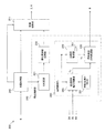
図1は、本発明の第1実施形態における燃料電池システム100の構成の一例を示す図である。
(First Embodiment)
FIG. 1 is a diagram showing an example of the configuration of the fuel cell system 100 according to the first embodiment of the present invention.

燃料電池システム100は、燃料電池に対して外部から発電に必要となる燃料ガス及び酸化剤ガスを供給して燃料電池を電気負荷に応じて発電させる電源システムを構成する。 The fuel cell system 100 constitutes a power supply system that supplies the fuel cell with the fuel gas and the oxidizing agent gas required for power generation from the outside to generate the fuel cell according to the electric load.

燃料電池システム100は、燃料電池スタック1と、酸化剤ガス給排装置2と、燃料ガス給排装置3と、スタック冷却装置4と、負荷装置5と、電圧印加回路6と、コントローラ200とを含む。 The fuel cell system 100 includes a fuel cell stack 1, an oxidant gas supply / discharge device 2, a fuel gas supply / discharge device 3, a stack cooling device 4, a load device 5, a voltage application circuit 6, and a controller 200. Including.

燃料電池スタック1は、負荷装置5に接続されて負荷装置5に電力を供給する積層電池である。燃料電池スタック1は、例えば数百V(ボルト)の直流の電圧を生じる。 The fuel cell stack 1 is a laminated battery that is connected to the load device 5 and supplies electric power to the load device 5. The fuel cell stack 1 produces, for example, a DC voltage of several hundred V (volts).

燃料電池は、ひとつの電池セルであり、アノード極(燃料極)と、カソード極(酸化剤極)と、アノード極とカソード極で挟まれる電解質膜と、により構成される。燃料電池では、アノード極に水素を含有する燃料ガス(アノードガス)と、カソード極に酸素を含有する酸化剤ガス(カソードガス)とが、電解質膜において電気化学反応(発電反応)を起こす。アノード極及びカソード極では、以下の電気化学反応が進行する。 A fuel cell is one battery cell, and is composed of an anode electrode (fuel electrode), a cathode electrode (oxidizing agent electrode), and an electrolyte membrane sandwiched between the anode electrode and the cathode electrode. In a fuel cell, a fuel gas containing hydrogen at the anode electrode (anode gas) and an oxidizing agent gas containing oxygen at the cathode electrode (cathode gas) cause an electrochemical reaction (power generation reaction) in the electrolyte membrane. The following electrochemical reactions proceed at the anode electrode and the cathode electrode.

アノード極 : 2H2 → 4H+ + 4e- ・・・(1)
カソード極 : 4H+ +4e- + O2 → 2H2O ・・・(2)
Anode pole: 2H 2 → 4H + + 4e- ・ ・ ・ (1)
Cathode pole: 4H + + 4e- + O 2 → 2H 2 O ・ ・ ・ (2)

上記(1)及び(2)に示した電気化学反応により起電力が発生するとともに水が生成される。燃料電池スタック1に形成された燃料電池の各々は直列に接続されており、各燃料電池に生じるセル電圧の総和が燃料電池スタック1の出力電圧となる。 Electromotive force is generated and water is generated by the electrochemical reaction shown in (1) and (2) above. Each of the fuel cells formed in the fuel cell stack 1 is connected in series, and the sum of the cell voltages generated in each fuel cell is the output voltage of the fuel cell stack 1.

燃料電池スタック1は、燃料ガス給排装置3から燃料ガスが供給されるとともに酸化剤ガス給排装置2から酸化剤ガスが供給される。 In the fuel cell stack 1, fuel gas is supplied from the fuel gas supply / discharge device 3, and oxidant gas is supplied from the oxidant gas supply / discharge device 2.

酸化剤ガス給排装置2は、燃料電池スタック1のカソード極に酸化剤ガスを供給すると共に、燃料電池スタック1のカソード極から排出される酸化剤オフガスを大気に排出する装置である。すなわち、酸化剤ガス給排装置2は、燃料電池スタック1のカソード極に酸化剤ガスを供給する酸化剤供給手段を構成する。 The oxidant gas supply / discharge device 2 is a device that supplies the oxidant gas to the cathode electrode of the fuel cell stack 1 and discharges the oxidant off gas discharged from the cathode electrode of the fuel cell stack 1 to the atmosphere. That is, the oxidant gas supply / discharge device 2 constitutes an oxidant supply means for supplying the oxidant gas to the cathode electrode of the fuel cell stack 1.

酸化剤ガス給排装置2は、酸化剤ガス供給通路21と、吸入流量センサ22と、コンプレッサ23と、カソード圧力センサ24と、酸化剤ガス排出通路25と、カソード調圧弁26と、バイパス通路27と、バイパス弁28とを含む。 The oxidant gas supply / discharge device 2 includes an oxidant gas supply passage 21, an intake flow rate sensor 22, a compressor 23, a cathode pressure sensor 24, an oxidant gas discharge passage 25, a cathode pressure regulating valve 26, and a bypass passage 27. And a bypass valve 28.

酸化剤ガス供給通路21は、燃料電池スタック1に酸化剤ガスを供給するための通路である。酸化剤ガス供給通路21の一端は開口しており、他端は、燃料電池スタック1の酸化剤ガス入口孔に接続される。 The oxidant gas supply passage 21 is a passage for supplying the oxidant gas to the fuel cell stack 1. One end of the oxidant gas supply passage 21 is open, and the other end is connected to the oxidant gas inlet hole of the fuel cell stack 1.

吸入流量センサ22は、コンプレッサ23よりも上流の酸化剤ガス供給通路21に設けられ、コンプレッサ23により吸入される酸化剤ガスの流量を検出する。吸入流量センサ22は、検出した流量を示す信号をコントローラ200に出力する。 The suction flow rate sensor 22 is provided in the oxidant gas supply passage 21 upstream of the compressor 23, and detects the flow rate of the oxidant gas sucked by the compressor 23. The suction flow rate sensor 22 outputs a signal indicating the detected flow rate to the controller 200.

コンプレッサ23は、燃料電池スタックのカソード極に酸化剤を供給するアクチュエータを構成する。コンプレッサ23は、酸化剤ガス供給通路21に設けられる。本実施形態のコンプレッサ23は、酸化剤ガス供給通路21の開口から酸素を含有する空気を取り込み、その空気を酸化剤ガスとして燃料電池スタック1に供給する。 The compressor 23 constitutes an actuator that supplies an oxidant to the cathode electrode of the fuel cell stack. The compressor 23 is provided in the oxidant gas supply passage 21. The compressor 23 of the present embodiment takes in air containing oxygen from the opening of the oxidant gas supply passage 21 and supplies the air as an oxidant gas to the fuel cell stack 1.

カソード圧力センサ24は、コンプレッサ23よりも下流の酸化剤ガス供給通路21に設けられる。カソード圧力センサ24は、燃料電池スタック1のカソード極に供給される酸化剤ガスの圧力の大きさを検出する。カソード圧力センサ24は、検出した圧力を示す信号をカソード極の圧力値としてコントローラ200に出力する。 The cathode pressure sensor 24 is provided in the oxidant gas supply passage 21 downstream of the compressor 23. The cathode pressure sensor 24 detects the magnitude of the pressure of the oxidant gas supplied to the cathode electrode of the fuel cell stack 1. The cathode pressure sensor 24 outputs a signal indicating the detected pressure to the controller 200 as a pressure value of the cathode electrode.

酸化剤ガス排出通路25は、燃料電池スタック1のカソード極から排出される酸化剤オフガスを外気へ排出するための通路である。酸化剤ガス排出通路25の一端は、燃料電池スタック1の酸化剤ガス出口孔に接続され、他端は開口している。 The oxidant gas discharge passage 25 is a passage for discharging the oxidant off gas discharged from the cathode electrode of the fuel cell stack 1 to the outside air. One end of the oxidant gas discharge passage 25 is connected to the oxidant gas outlet hole of the fuel cell stack 1, and the other end is open.

カソード調圧弁26は、燃料電池スタック1のカソード極から酸化剤オフガスを排出する排気弁を構成する。カソード調圧弁26は、酸化剤ガス排出通路25に設けられる。カソード調圧弁26としては、例えば弁の開度を段階的に変更可能な電磁弁が用いられる。カソード調圧弁26は、コントローラ200によって開閉制御される。この開閉制御によって燃料電池スタック1のカソード極に供給される酸化剤ガスの圧力が所望の圧力に調節される。 The cathode pressure regulating valve 26 constitutes an exhaust valve that discharges oxidant off gas from the cathode electrode of the fuel cell stack 1. The cathode pressure regulating valve 26 is provided in the oxidant gas discharge passage 25. As the cathode pressure regulating valve 26, for example, a solenoid valve capable of stepwise changing the opening degree of the valve is used. The cathode pressure regulating valve 26 is controlled to open and close by the controller 200. By this open / close control, the pressure of the oxidant gas supplied to the cathode electrode of the fuel cell stack 1 is adjusted to a desired pressure.

バイパス通路27は、コンプレッサ23により吐出される酸化剤ガスの一部を外気へ排出するために、燃料電池スタック1を迂回するように配設された通路である。バイパス通路27は、コンプレッサ23よりも下流の酸化剤ガス供給通路21から分岐してカソード調圧弁26よりも上流の酸化剤ガス排出通路25に接続される。 The bypass passage 27 is a passage arranged so as to bypass the fuel cell stack 1 in order to discharge a part of the oxidant gas discharged by the compressor 23 to the outside air. The bypass passage 27 branches from the oxidant gas supply passage 21 downstream of the compressor 23 and is connected to the oxidant gas discharge passage 25 upstream of the cathode pressure regulating valve 26.

バイパス弁28は、バイパス通路27に設けられる。バイパス弁28は、コンプレッサ23により吐出される酸化剤ガスの一部を、燃料電池スタック1に供給することなく外気へ排出する。バイパス弁28としては、例えば弁の開度を段階的に変更可能な電磁弁が用いられる。バイパス弁28は、コントローラ200によって開閉制御される。この開閉制御によって燃料電池スタック1に酸化剤ガスが過剰に供給されるのを回避することが可能になる。 The bypass valve 28 is provided in the bypass passage 27. The bypass valve 28 discharges a part of the oxidant gas discharged by the compressor 23 to the outside air without supplying it to the fuel cell stack 1. As the bypass valve 28, for example, a solenoid valve whose opening degree can be changed stepwise is used. The bypass valve 28 is controlled to open and close by the controller 200. This open / close control makes it possible to prevent the fuel cell stack 1 from being excessively supplied with the oxidant gas.

燃料ガス給排装置3は、燃料電池スタック1のアノード極に燃料ガスを供給すると共に、燃料電池スタック1から排出される燃料オフガスを燃料電池スタック1のアノード極に循環させる装置である。すなわち、燃料ガス給排装置3は、燃料電池スタック1に燃料ガスを供給する燃料供給手段を構成する。 The fuel gas supply / discharge device 3 is a device that supplies fuel gas to the anode pole of the fuel cell stack 1 and circulates the fuel off gas discharged from the fuel cell stack 1 to the anode pole of the fuel cell stack 1. That is, the fuel gas supply / discharge device 3 constitutes a fuel supply means for supplying fuel gas to the fuel cell stack 1.

燃料ガス給排装置3は、高圧タンク31と、燃料ガス供給通路32と、アノード調圧弁33と、合流部34と、アノード圧力センサ35と、燃料ガス循環通路36と、アノード循環ポンプ37と、パージ通路38と、パージ弁39とを含む。 The fuel gas supply / discharge device 3 includes a high-pressure tank 31, a fuel gas supply passage 32, an anode pressure regulating valve 33, a confluence 34, an anode pressure sensor 35, a fuel gas circulation passage 36, an anode circulation pump 37, and the like. The purge passage 38 and the purge valve 39 are included.

高圧タンク31は、燃料電池スタック1に供給される燃料ガスを高圧状態に保って貯蔵する。 The high-pressure tank 31 stores the fuel gas supplied to the fuel cell stack 1 in a high-pressure state.

燃料ガス供給通路32は、高圧タンク31に貯蔵された燃料ガスを燃料電池スタック1のアノード極に供給するための通路である。燃料ガス供給通路32の一端は高圧タンク31に接続され、他端は燃料電池スタック1の燃料ガス入口孔に接続される。 The fuel gas supply passage 32 is a passage for supplying the fuel gas stored in the high-pressure tank 31 to the anode pole of the fuel cell stack 1. One end of the fuel gas supply passage 32 is connected to the high pressure tank 31, and the other end is connected to the fuel gas inlet hole of the fuel cell stack 1.

アノード調圧弁33は、燃料電池スタック1のアノード極に燃料を供給する供給弁を構成する。アノード調圧弁33は、高圧タンク31と合流部34との間の燃料ガス供給通路32に設けられる。本実施形態では、アノード調圧弁33として弁の開度を段階的に変更可能な電磁弁が用いられる。アノード調圧弁33は、コントローラ200によって開閉制御される。この開閉制御によって、燃料電池スタック1のアノード極に供給される燃料ガスの圧力が調節される。 The anode pressure regulating valve 33 constitutes a supply valve for supplying fuel to the anode electrode of the fuel cell stack 1. The anode pressure regulating valve 33 is provided in the fuel gas supply passage 32 between the high pressure tank 31 and the merging portion 34. In the present embodiment, as the anode pressure regulating valve 33, a solenoid valve whose opening degree can be changed stepwise is used. The anode pressure regulating valve 33 is controlled to open and close by the controller 200. By this open / close control, the pressure of the fuel gas supplied to the anode electrode of the fuel cell stack 1 is adjusted.

合流部34は、アノード調圧弁33よりも下流の燃料ガス供給通路32に設けられる。合流部34は、アノード調圧弁33からの燃料ガスと燃料ガス循環通路36からの燃料オフガスとの混合ガスを燃料電池スタック1に供給する。合流部34には、例えばエゼクタが設けられる。エゼクタは、アノード調圧弁33から供給される燃料ガスの流速を加速して負圧を生じさせることにより、燃料電池スタック1から排出された燃料オフガスを吸引する。 The merging portion 34 is provided in the fuel gas supply passage 32 downstream of the anode pressure regulating valve 33. The merging portion 34 supplies the fuel cell stack 1 with a mixed gas of the fuel gas from the anode pressure regulating valve 33 and the fuel off gas from the fuel gas circulation passage 36. The merging portion 34 is provided with, for example, an ejector. The ejector sucks the fuel off gas discharged from the fuel cell stack 1 by accelerating the flow velocity of the fuel gas supplied from the anode pressure regulating valve 33 to generate a negative pressure.

アノード圧力センサ35は、合流部34よりも下流の燃料ガス供給通路32に設けられる。アノード圧力センサ35は、燃料電池スタック1におけるアノード極に供給される燃料ガスの圧力の大きさを検出する。アノード圧力センサ35は、検出した圧力を示す信号をアノード極の圧力値としてコントローラ200に出力する。 The anode pressure sensor 35 is provided in the fuel gas supply passage 32 downstream of the confluence 34. The anode pressure sensor 35 detects the magnitude of the pressure of the fuel gas supplied to the anode electrode in the fuel cell stack 1. The anode pressure sensor 35 outputs a signal indicating the detected pressure to the controller 200 as a pressure value of the anode electrode.

燃料ガス循環通路36は、燃料電池スタック1から排出された燃料オフガスを燃料ガス供給通路32に循環させるための通路である。燃料ガス循環通路36の一端は燃料電池スタック1の燃料ガス出口孔に接続され、他端は合流部34の吸引口に接続される。 The fuel gas circulation passage 36 is a passage for circulating the fuel off gas discharged from the fuel cell stack 1 to the fuel gas supply passage 32. One end of the fuel gas circulation passage 36 is connected to the fuel gas outlet hole of the fuel cell stack 1, and the other end is connected to the suction port of the merging portion 34.

アノード循環ポンプ37は、燃料ガス循環通路36に設けられる。アノード循環ポンプ37は、合流部34を介して燃料電池スタック1のアノード極に燃料オフガスを循環させる。 The anode circulation pump 37 is provided in the fuel gas circulation passage 36. The anode circulation pump 37 circulates the fuel off gas to the anode electrode of the fuel cell stack 1 via the merging portion 34.

パージ通路38は、燃料電池スタック1から排出される燃料オフガス中の水蒸気や窒素などの不純物を排出するための通路である。パージ通路38の一端は、燃料電池スタック1の燃料ガス出口孔とアノード循環ポンプ37との間の燃料ガス循環通路36に接続され、他端はカソード調圧弁26よりも下流の酸化剤ガス排出通路25に接続される。 The purge passage 38 is a passage for discharging impurities such as water vapor and nitrogen in the fuel off gas discharged from the fuel cell stack 1. One end of the purge passage 38 is connected to the fuel gas circulation passage 36 between the fuel gas outlet hole of the fuel cell stack 1 and the anode circulation pump 37, and the other end is an oxidant gas discharge passage downstream of the cathode pressure regulating valve 26. Connected to 25.

パージ弁39は、パージ通路38に設けられている。パージ弁39は、燃料オフガス中の不純物を酸化剤ガス排出通路25に排出する。水素を含む燃料オフガスが酸化剤ガス排出通路25に排出されることにより、水素が空気によって希釈されるので、燃料電池システム100から排出される排ガス中の水素濃度を規定値以下に維持することが可能になる。 The purge valve 39 is provided in the purge passage 38. The purge valve 39 discharges impurities in the fuel off gas to the oxidant gas discharge passage 25. When the fuel off gas containing hydrogen is discharged into the oxidant gas discharge passage 25, hydrogen is diluted by air, so that the hydrogen concentration in the exhaust gas discharged from the fuel cell system 100 can be maintained below the specified value. It will be possible.

なお、気液分離装置をパージ弁39の上流に設けるようにしてもよい。これにより、燃料オフガスから水蒸気をより確実に取り除くことができる。 The gas-liquid separation device may be provided upstream of the purge valve 39. As a result, water vapor can be more reliably removed from the fuel off gas.

スタック冷却装置4は、冷媒を用いて燃料電池スタック1の温度を燃料電池の発電に適した所定の温度に調整する装置である。 The stack cooling device 4 is a device that adjusts the temperature of the fuel cell stack 1 to a predetermined temperature suitable for power generation of the fuel cell by using a refrigerant.

スタック冷却装置4は、冷却水循環通路41と、冷却水ポンプ42と、ラジエータ43と、バイパス通路44と、三方弁45と、スタック入口水温センサ46と、スタック出口水温センサ47とを含む。 The stack cooling device 4 includes a cooling water circulation passage 41, a cooling water pump 42, a radiator 43, a bypass passage 44, a three-way valve 45, a stack inlet water temperature sensor 46, and a stack outlet water temperature sensor 47.

冷却水循環通路41は、燃料電池スタック1に冷却水を循環させるための通路である。冷却水循環通路41の一端は燃料電池スタック1の冷却水入口孔に接続され、他端は燃料電池スタック1の冷却水出口孔に接続される。 The cooling water circulation passage 41 is a passage for circulating cooling water in the fuel cell stack 1. One end of the cooling water circulation passage 41 is connected to the cooling water inlet hole of the fuel cell stack 1, and the other end is connected to the cooling water outlet hole of the fuel cell stack 1.

冷却水ポンプ42は、冷却水循環通路41に設けられる。冷却水ポンプ42は、ラジエータ43を介して燃料電池スタック1に冷却水を供給する。冷却水ポンプ42の回転速度は、コントローラ200によって制御される。 The cooling water pump 42 is provided in the cooling water circulation passage 41. The cooling water pump 42 supplies cooling water to the fuel cell stack 1 via the radiator 43. The rotation speed of the cooling water pump 42 is controlled by the controller 200.

ラジエータ43は、冷却水ポンプ42よりも下流の冷却水循環通路41に設けられる。ラジエータ43は、燃料電池スタック1を通過することで温められた冷却水を冷却する。 The radiator 43 is provided in the cooling water circulation passage 41 downstream of the cooling water pump 42. The radiator 43 cools the cooled cooling water that has been warmed by passing through the fuel cell stack 1.

バイパス通路44は、ラジエータ43を迂回して冷却水を燃料電池スタック1に直接循環させるための通路である。バイパス通路44の一端は冷却水ポンプ42とラジエータ43との間の冷却水循環通路41に接続され、他端は三方弁45に接続される。 The bypass passage 44 is a passage for bypassing the radiator 43 and directly circulating the cooling water to the fuel cell stack 1. One end of the bypass passage 44 is connected to the cooling water circulation passage 41 between the cooling water pump 42 and the radiator 43, and the other end is connected to the three-way valve 45.

三方弁45は、ラジエータ43と燃料電池スタック1の冷却水入口孔との間の冷却水循環通路41であってバイパス通路44が合流する部分に設けられる。 The three-way valve 45 is provided in a cooling water circulation passage 41 between the radiator 43 and the cooling water inlet hole of the fuel cell stack 1 at a portion where the bypass passage 44 joins.

三方弁45としては、例えばサーモスタットにより構成される。サーモスタットにおいては、燃料電池スタック1の温度が低くなり過ぎると、冷却水の温度が所定の開弁温度以下になるので、ラジエータ43から燃料電池スタック1への通路が閉じた状態となる。これにより、バイパス通路44を経由してきた相対的に温かい冷却水のみが燃料電池スタック1に供給されるので、ラジエータ43を経由してくる冷却水よりも高温の冷却水が燃料電池スタック1に供給されることになる。 The three-way valve 45 is composed of, for example, a thermostat. In the thermostat, if the temperature of the fuel cell stack 1 becomes too low, the temperature of the cooling water becomes equal to or lower than the predetermined valve opening temperature, so that the passage from the radiator 43 to the fuel cell stack 1 is closed. As a result, only the relatively warm cooling water that has passed through the bypass passage 44 is supplied to the fuel cell stack 1, so that the cooling water that is hotter than the cooling water that has passed through the radiator 43 is supplied to the fuel cell stack 1. Will be done.

一方、燃料電池スタック1の温度が高くなり過ぎると、冷却水の温度が上述の開弁温度よりも高くなるので、ラジエータ43から燃料電池スタック1への冷却水通路が徐々に開き始める。これにより、バイパス通路44を経由してきた冷却水と、ラジエータ43を経由してきた冷却水とが混合されるので、バイパス通路44を経由してくる冷却水よりも低温の冷却水が燃料電池スタック1に供給されることになる。 On the other hand, if the temperature of the fuel cell stack 1 becomes too high, the temperature of the cooling water becomes higher than the valve opening temperature described above, so that the cooling water passage from the radiator 43 to the fuel cell stack 1 gradually begins to open. As a result, the cooling water that has passed through the bypass passage 44 and the cooling water that has passed through the radiator 43 are mixed, so that the cooling water having a temperature lower than that of the cooling water that has passed through the bypass passage 44 is the fuel cell stack 1. Will be supplied to.

スタック入口水温センサ46は、燃料電池スタック1の冷却水入口孔の近傍に位置する冷却水循環通路41に設けられる。スタック入口水温センサ46は、燃料電池スタック1に流入する冷却水の温度(以下「スタック入口水温」という。)を検出する。スタック入口水温センサ46は、検出した温度を示す信号をコントローラ200に出力する。 The stack inlet water temperature sensor 46 is provided in the cooling water circulation passage 41 located near the cooling water inlet hole of the fuel cell stack 1. The stack inlet water temperature sensor 46 detects the temperature of the cooling water flowing into the fuel cell stack 1 (hereinafter referred to as “stack inlet water temperature”). The stack inlet water temperature sensor 46 outputs a signal indicating the detected temperature to the controller 200.

スタック出口水温センサ47は、燃料電池スタック1の冷却水出口孔の近傍に位置する冷却水循環通路41に設けられる。スタック出口水温センサ47は、燃料電池スタック1から排出された冷却水の温度(以下「スタック出口水温」という。)を検出する。スタック出口水温センサ47は、検出した温度を示す検出信号をコントローラ200に出力する。 The stack outlet water temperature sensor 47 is provided in the cooling water circulation passage 41 located near the cooling water outlet hole of the fuel cell stack 1. The stack outlet water temperature sensor 47 detects the temperature of the cooling water discharged from the fuel cell stack 1 (hereinafter referred to as “stack outlet water temperature”). The stack outlet water temperature sensor 47 outputs a detection signal indicating the detected temperature to the controller 200.

負荷装置5は、燃料電池スタック1の発電電力により駆動する装置である。負荷装置5としては、例えば、車両を駆動する電動モータや、燃料電池スタック1の発電を補助する補機、電動モータを制御する制御ユニットなどにより構成される。燃料電池スタック1の補機としては、例えば、コンプレッサ23や、バイパス通路44に設けられるヒータ(不図示)などが挙げられる。 The load device 5 is a device driven by the generated power of the fuel cell stack 1. The load device 5 includes, for example, an electric motor for driving the vehicle, an auxiliary machine for assisting the power generation of the fuel cell stack 1, a control unit for controlling the electric motor, and the like. Examples of the auxiliary machine of the fuel cell stack 1 include a compressor 23 and a heater (not shown) provided in the bypass passage 44.

あるいは、負荷装置5は、DC/DCコンバータを備え、DC/DCコンバータの一方に電動モータ用インバータが接続され、他方にバッテリが接続される構成であってもよい。この場合、負荷装置5の制御ユニットは、バッテリの残容量を考慮して燃料電池スタック1に要求する要求電力を設定し、その要求電力をコントローラ200に出力する。例えば、負荷装置5の制御ユニットは、アクセルペダルの踏込み量を検出し、検出した踏込み量が大きくなるほど、負荷装置5の要求電力を大きくする。 Alternatively, the load device 5 may include a DC / DC converter, and the inverter for the electric motor may be connected to one of the DC / DC converters and the battery may be connected to the other. In this case, the control unit of the load device 5 sets the required power required for the fuel cell stack 1 in consideration of the remaining capacity of the battery, and outputs the required power to the controller 200. For example, the control unit of the load device 5 detects the amount of depression of the accelerator pedal, and the larger the detected amount of depression, the larger the required power of the load device 5.

負荷装置5と燃料電池スタック1との間には、電流センサ51及び電圧センサ52が設けられている。 A current sensor 51 and a voltage sensor 52 are provided between the load device 5 and the fuel cell stack 1.

電流センサ51は、燃料電池スタック1の正極端子1pに接続され、燃料電池スタック1から取り出される電流の大きさを検出する。電流センサ51は、燃料電池スタック1を構成する各電池セルの電流を検出するものであってもよい。電流センサ51は、検出した電流の大きさを示す信号をコントローラ200に出力する。 The current sensor 51 is connected to the positive electrode terminal 1p of the fuel cell stack 1 and detects the magnitude of the current taken out from the fuel cell stack 1. The current sensor 51 may detect the current of each battery cell constituting the fuel cell stack 1. The current sensor 51 outputs a signal indicating the magnitude of the detected current to the controller 200.

電圧センサ52については、一端が燃料電池スタック1の正極端子1pに接続され他端が負極端子1nに接続される。電圧センサ52は、燃料電池スタック1の正極端子1pと負極端子1nとの間の電圧を検出する。電圧センサ52は、燃料電池スタック1を構成する各電池セルの電圧を検出するものであってもよい。電圧センサ52は、検出した電圧の大きさを示す信号をコントローラ200に出力する。 Regarding the voltage sensor 52, one end is connected to the positive electrode terminal 1p of the fuel cell stack 1 and the other end is connected to the negative electrode terminal 1n. The voltage sensor 52 detects the voltage between the positive electrode terminal 1p and the negative electrode terminal 1n of the fuel cell stack 1. The voltage sensor 52 may detect the voltage of each battery cell constituting the fuel cell stack 1. The voltage sensor 52 outputs a signal indicating the magnitude of the detected voltage to the controller 200.

電圧印加回路6は、燃料電池のアノード極からカソード極への燃料の排出を抑制するたに、燃料電池スタック1に逆バイアスの電圧を印加する回路である。本実施形態では、電圧印加回路6は、燃料電池のアノード極に印加される電位よりも高い電位がカソード極に印加されるように燃料電池スタック1の負極端子1nに電圧又は電流を印加する。 The voltage application circuit 6 is a circuit that applies a reverse bias voltage to the fuel cell stack 1 in order to suppress the discharge of fuel from the anode electrode to the cathode electrode of the fuel cell. In the present embodiment, the voltage application circuit 6 applies a voltage or current to the negative electrode terminal 1n of the fuel cell stack 1 so that a potential higher than the potential applied to the anode electrode of the fuel cell is applied to the cathode electrode.

電圧印加回路6と燃料電池スタック1との間には、電流センサ61及び電圧センサ62が設けられている。 A current sensor 61 and a voltage sensor 62 are provided between the voltage application circuit 6 and the fuel cell stack 1.

電流センサ61は、電圧印加回路6から燃料電池スタック1に供給される電流を検出する検出手段を構成する。電流センサ61は、電圧印加回路6から燃料電池スタック1の負極端子1nに供給される電流の大きさを検出してコントローラ200に出力する。電圧センサ52は、電圧印加回路6によって燃料電池スタック1に印加される電圧の大きさを検出してコントローラ200に出力する。 The current sensor 61 constitutes a detecting means for detecting the current supplied from the voltage application circuit 6 to the fuel cell stack 1. The current sensor 61 detects the magnitude of the current supplied from the voltage application circuit 6 to the negative electrode terminal 1n of the fuel cell stack 1 and outputs the magnitude of the current to the controller 200. The voltage sensor 52 detects the magnitude of the voltage applied to the fuel cell stack 1 by the voltage application circuit 6 and outputs it to the controller 200.

コントローラ200は、中央演算装置(CPU)、読み出し専用メモリ(ROM)、ランダムアクセスメモリ(RAM)、及び入出力インタフェース(I/Oインタフェース)を備えたマイクロコンピューターで構成される。 The controller 200 is composed of a microcomputer including a central arithmetic unit (CPU), a read-only memory (ROM), a random access memory (RAM), and an input / output interface (I / O interface).

コントローラ200は、吸入流量センサ22、カソード圧力センサ24、アノード圧力センサ35、スタック入口水温センサ46、スタック出口水温センサ47、電流センサ61、及び電圧センサ62の出力信号を取得する。さらにコントローラ200は、負荷装置5から燃料電池スタック1に対して要求される要求電力を取得する。コントローラ200は、これらのパラメータを用いて、酸化剤ガス給排装置2、燃料ガス給排装置3、スタック冷却装置4、及び電圧印加回路6の動作を制御する。 The controller 200 acquires the output signals of the suction flow rate sensor 22, the cathode pressure sensor 24, the anode pressure sensor 35, the stack inlet water temperature sensor 46, the stack outlet water temperature sensor 47, the current sensor 61, and the voltage sensor 62. Further, the controller 200 acquires the required power required for the fuel cell stack 1 from the load device 5. The controller 200 uses these parameters to control the operations of the oxidant gas supply / discharge device 2, the fuel gas supply / discharge device 3, the stack cooling device 4, and the voltage application circuit 6.

例えば、コントローラ200は、負荷装置5の要求電力に基づいて燃料電池スタック1に供給される酸化剤ガスの目標流量及び目標圧力を演算し、演算した目標流量及び目標圧力を用いてコンプレッサ23のトルク、及びカソード調圧弁26の開度を制御する。さらにコントローラ200は、上記の負荷装置5の要求電力に基づいて燃料電池スタック1に供給される燃料ガスの目標圧力を演算し、演算した目標圧力を用いて、アノード調圧弁33の開度、アノード循環ポンプ37のトルク、及びパージ弁39の開度を制御する。 For example, the controller 200 calculates the target flow rate and target pressure of the oxidant gas supplied to the fuel cell stack 1 based on the required power of the load device 5, and uses the calculated target flow rate and target pressure to torque the compressor 23. , And the opening degree of the cathode pressure regulating valve 26 is controlled. Further, the controller 200 calculates the target pressure of the fuel gas supplied to the fuel cell stack 1 based on the required power of the load device 5, and uses the calculated target pressure to set the opening degree of the anode pressure regulating valve 33 and the anode. The torque of the circulation pump 37 and the opening degree of the purge valve 39 are controlled.

また、コントローラ200は、燃料電池システム100の排ガス中の水素濃度が規定値以下となるようコンプレッサ23のトルクを制御し、コンプレッサ23の吐出流量が発電に必要となる酸化剤ガスの目標流量を上回る場合には、バイパス弁28を開ける。また、コントローラ200は、コンプレッサ23のサージを回避するためにコンプレッサ23のトルクを、燃料電池スタック1の発電に必要となるトルクよりも大きくする場合につても、バイパス弁28の開度を調整する。 Further, the controller 200 controls the torque of the compressor 23 so that the hydrogen concentration in the exhaust gas of the fuel cell system 100 is equal to or less than a specified value, and the discharge flow rate of the compressor 23 exceeds the target flow rate of the oxidant gas required for power generation. In that case, the bypass valve 28 is opened. Further, the controller 200 adjusts the opening degree of the bypass valve 28 even when the torque of the compressor 23 is made larger than the torque required for power generation of the fuel cell stack 1 in order to avoid the surge of the compressor 23. ..

さらに、コントローラ200は、スタック入口水温センサ46の検出値とスタック出口水温センサ47の検出値との平均値を燃料電池スタック1の温度として算出し、算出した燃料電池スタック1の温度に基づいて冷却水ポンプ42のトルクを制御する。例えば、コントローラ200は、燃料電池スタック1の温度が高くなるほど、冷却水ポンプ42のトルクを高くする。これにより、燃料電池スタック1の温度上昇が抑制される。 Further, the controller 200 calculates the average value of the detected value of the stack inlet water temperature sensor 46 and the detected value of the stack outlet water temperature sensor 47 as the temperature of the fuel cell stack 1, and cools the controller 200 based on the calculated temperature of the fuel cell stack 1. The torque of the water pump 42 is controlled. For example, the controller 200 increases the torque of the cooling water pump 42 as the temperature of the fuel cell stack 1 increases. As a result, the temperature rise of the fuel cell stack 1 is suppressed.

コントローラ200は、燃料電池システム100の燃費を向上させるために、車両のEVキーがON状態であっても、負荷装置5の作動状態に応じて燃料電池スタック1の発電を停止する。例えば、信号待ちで車両が停止した状態や、車両の走行中に電動モータへの電力供給がバッテリの出力で賄える状態などの一定の状態において、コントローラ200は燃料電池スタック1の発電を停止する。 In order to improve the fuel efficiency of the fuel cell system 100, the controller 200 stops the power generation of the fuel cell stack 1 according to the operating state of the load device 5 even when the EV key of the vehicle is ON. For example, the controller 200 stops the power generation of the fuel cell stack 1 in a certain state such as a state in which the vehicle is stopped waiting for a signal or a state in which the power supply to the electric motor can be covered by the output of the battery while the vehicle is running.

このように、燃料電池システム100が作動中においてコントローラ200が負荷装置5の作動状態に応じて燃料電池スタック1の発電を一旦停止することをアイドルストップ停止処理(IS停止処理)という。そして燃料電池スタック1の発電が停止した状態のことをアイドルストップ状態(IS状態)という。 In this way, when the controller 200 temporarily stops the power generation of the fuel cell stack 1 according to the operating state of the load device 5 while the fuel cell system 100 is operating, it is called an idle stop stop process (IS stop process). The state in which the power generation of the fuel cell stack 1 is stopped is called the idle stop state (IS state).

燃料電池スタック1のアイドルストップ状態では、コントローラ200は、少なくとも酸化剤ガス給排装置2及び燃料ガス給排装置3の作動を停止する。その結果、燃料電池スタック1においてはアノード極から電解質膜を介してカソード極へと発電用の燃料が透過してしまい、燃料電池システム100の燃費が低下する。 In the idle stop state of the fuel cell stack 1, the controller 200 stops the operation of at least the oxidant gas supply / discharge device 2 and the fuel gas supply / discharge device 3. As a result, in the fuel cell stack 1, the fuel for power generation permeates from the anode electrode to the cathode electrode via the electrolyte membrane, and the fuel cell system 100 is reduced in fuel efficiency.

この対策として電圧印加回路6を用いて燃料電池スタック1に逆バイアスの電圧を印加することにより、カソード極へ透過してくる燃料ガスをアノード極へ戻すことが可能になる。これにより、カソード極への燃料の排出は抑制されるものの、電圧印加回路6から燃料電池スタック1に電圧を印加し続けることに伴って電圧印加回路6で消費される電力量が増加する。その結果、IS中における電圧印加回路6の消費電力量が増加してしまい、反って燃料電池システム100の燃費が低下することになる。 As a countermeasure, by applying a reverse bias voltage to the fuel cell stack 1 using the voltage application circuit 6, it is possible to return the fuel gas permeating to the cathode electrode to the anode electrode. As a result, although the discharge of fuel to the cathode electrode is suppressed, the amount of power consumed by the voltage application circuit 6 increases as the voltage is continuously applied from the voltage application circuit 6 to the fuel cell stack 1. As a result, the power consumption of the voltage application circuit 6 during IS increases, and the fuel consumption of the fuel cell system 100 decreases.

そこで本実施形態のコントローラ200は、燃料電池スタック1の停止中に燃料電池システム100の燃費の低下を回避するため、燃料電池スタック1の停止状態に応じて、電圧印加回路6から燃料電池スタック1に対して電圧を印加するか否かを選択する。 Therefore, the controller 200 of the present embodiment has the fuel cell stack 1 from the voltage application circuit 6 depending on the stopped state of the fuel cell stack 1 in order to avoid a decrease in the fuel cell system 100 while the fuel cell stack 1 is stopped. Select whether or not to apply a voltage to the fuel cell.

次に本実施形態におけるコントローラ200の構成について詳細に説明する。 Next, the configuration of the controller 200 in this embodiment will be described in detail.

図2は、本実施形態におけるコントローラ200の機能構成の一例を示すブロック図である。 FIG. 2 is a block diagram showing an example of the functional configuration of the controller 200 in the present embodiment.

コントローラ200は、発電制御部210と、制御切替部211と、停止制御部220と、を備える。 The controller 200 includes a power generation control unit 210, a control switching unit 211, and a stop control unit 220.

発電制御部210は、負荷装置5の作動状態に応じて、燃料電池スタック1に供給される酸化剤ガス及び燃料ガスの状態を操作して燃料電池スタック1の発電量を制御する。 The power generation control unit 210 controls the amount of power generated by the fuel cell stack 1 by manipulating the states of the oxidant gas and the fuel gas supplied to the fuel cell stack 1 according to the operating state of the load device 5.

例えば、発電制御部210は、負荷装置5から要求電力を取得し、取得した要求電力に基づいて、酸化剤ガスの目標流量及び目標圧力を算出するとともに燃料ガスの目標圧力を算出する。発電制御部210は、その酸化剤ガスの目標流量及び目標圧力に基づいて酸化剤ガス給排装置2の作動を制御するとともに燃料ガスの目標圧力に基づいて燃料ガス給排装置3の作動を制御する。 For example, the power generation control unit 210 acquires the required electric power from the load device 5, calculates the target flow rate and the target pressure of the oxidant gas, and calculates the target pressure of the fuel gas based on the acquired required electric power. The power generation control unit 210 controls the operation of the oxidant gas supply / discharge device 2 based on the target flow rate and the target pressure of the oxidant gas, and controls the operation of the fuel gas supply / discharge device 3 based on the target pressure of the fuel gas. To do.

また、発電制御部210は、負荷装置5の作動状態を示す装置状態情報をIS判定部221に出力する。装置状態情報には、例えば、燃料電池スタック1に対する要求電力や、アクセルペダルの踏込み量、ブレーキペダルの踏込み量などが示されている。 Further, the power generation control unit 210 outputs device state information indicating the operating state of the load device 5 to the IS determination unit 221. The device state information includes, for example, the required power for the fuel cell stack 1, the amount of depression of the accelerator pedal, the amount of depression of the brake pedal, and the like.

停止制御部220は、燃料電池スタック1の発電を停止する場合に、酸化剤ガス給排装置2の動作を停止して燃料電池スタック1におけるカソード極に滞留する酸化剤を消費するように負荷装置5及びアノード調圧弁33を制御する。 When the power generation of the fuel cell stack 1 is stopped, the stop control unit 220 stops the operation of the oxidant gas supply / discharge device 2 and consumes the oxidant staying at the cathode electrode of the fuel cell stack 1. 5 and the anode pressure regulating valve 33 are controlled.

例えば、停止制御部220は、燃料電池スタック1がIS状態に遷移する場合には、コンプレッサ23の駆動を停止して、負荷装置5を用いて燃料電池スタック1から電流を取り出すとともにアノード調圧弁33の開度を制御してカソード極に滞留する酸化剤ガスを発電反応により消費する。 For example, when the fuel cell stack 1 transitions to the IS state, the stop control unit 220 stops driving the compressor 23, draws a current from the fuel cell stack 1 using the load device 5, and outputs an anode pressure regulating valve 33. The oxidant gas staying at the cathode electrode is consumed by the power generation reaction by controlling the opening degree of.

停止制御部220は、IS判定部221と、酸化剤消費処理部222と、回路制御部300とを備える。 The stop control unit 220 includes an IS determination unit 221, an oxidant consumption processing unit 222, and a circuit control unit 300.

IS判定部221は、燃料電池スタック1がIS状態に遷移可能か否かを判定する。例えば、IS判定部221は、発電制御部210から装置状態情報としてブレーキペダルの踏込み量や負荷装置5の要求電力を取得し、ブレーキペダルの踏込み量がゼロよりも大きく、かつ、負荷装置5の要求電力がゼロになった場合には、燃料電池スタック1がIS状態に遷移可能であると判定する。 The IS determination unit 221 determines whether or not the fuel cell stack 1 can transition to the IS state. For example, the IS determination unit 221 acquires the brake pedal depression amount and the required power of the load device 5 as device status information from the power generation control unit 210, the brake pedal depression amount is larger than zero, and the load device 5 When the required power becomes zero, it is determined that the fuel cell stack 1 can transition to the IS state.

あるいは、IS判定部221は、負荷装置5におけるバッテリの残容量とアクセルペダルの踏込み量とに基づいて、バッテリの電力を用いて負荷装置5の要求電力を賄えると判断した場合には、燃料電池スタック1がIS状態に遷移可能であると判定する。 Alternatively, when the IS determination unit 221 determines that the power of the battery can be used to cover the required power of the load device 5 based on the remaining capacity of the battery in the load device 5 and the amount of depression of the accelerator pedal, the fuel cell It is determined that the stack 1 can transition to the IS state.

IS判定部221は、燃料電池スタック1がIS状態に遷移可能であると判定した場合には、燃料電池スタック1の停止を指示する停止信号を酸化剤消費処理部222に出力する。 When the IS determination unit 221 determines that the fuel cell stack 1 can transition to the IS state, the IS determination unit 221 outputs a stop signal instructing the fuel cell stack 1 to stop to the oxidant consumption processing unit 222.

酸化剤消費処理部222は、燃料電池スタック1のカソード極に滞留する酸化剤を消費する処理を実行する。 The oxidant consumption processing unit 222 executes a process of consuming the oxidant retained in the cathode electrode of the fuel cell stack 1.

本実施形態では、酸化剤消費処理部222は、IS判定部221から停止信号を受信した場合には、コンプレッサ23の動作を停止する。そして酸化剤消費処理部222は、例えば負荷装置5に備えられたバッテリに対して、燃料電池スタック1から電流を供給する。これにより、燃料電池スタック1における酸化剤ガスと燃料ガスが発電反応を起こすので、燃料電池スタック1のカソード極に滞留する酸化剤ガスを消費することができる。 In the present embodiment, the oxidant consumption processing unit 222 stops the operation of the compressor 23 when it receives a stop signal from the IS determination unit 221. Then, the oxidant consumption processing unit 222 supplies a current from the fuel cell stack 1 to, for example, the battery provided in the load device 5. As a result, the oxidant gas and the fuel gas in the fuel cell stack 1 cause a power generation reaction, so that the oxidant gas staying in the cathode electrode of the fuel cell stack 1 can be consumed.

このとき、酸化剤消費処理部222は、燃料電池スタック1の発電反応に伴ってアノード極の燃料ガスが不足する場合には、アノード調圧弁33を開いて燃料電池スタック1に燃料ガスを供給する。一方、燃料電池スタック1のアノード極に燃料ガスが多量に残留している場合には、酸化剤消費処理部222はアノード調圧弁33を閉じてもよい。 At this time, when the fuel gas at the anode electrode is insufficient due to the power generation reaction of the fuel cell stack 1, the oxidant consumption processing unit 222 opens the anode pressure regulating valve 33 to supply the fuel gas to the fuel cell stack 1. .. On the other hand, when a large amount of fuel gas remains in the anode electrode of the fuel cell stack 1, the oxidant consumption processing unit 222 may close the anode pressure regulating valve 33.

酸化剤消費処理部222は、燃料電池スタック1の停止状態に応じて、燃料電池スタック1におけるカソード極の酸化剤ガスが消費されたか否かを判断する。例えば、酸化剤消費処理部222は、コンプレッサ23を停止してから所定の時間を経過した場合には、カソード極の酸化剤ガスが消費されたと判断する。あるいは、酸化剤消費処理部222は、カソード極における酸素濃度を推定し、酸素濃度の推定値が、カソード極で劣化反応が生じる酸素濃度閾値を下回った場合に、カソード極の酸化剤ガスが消費されたと判断してもよい。 The oxidant consumption processing unit 222 determines whether or not the oxidant gas at the cathode electrode in the fuel cell stack 1 has been consumed according to the stopped state of the fuel cell stack 1. For example, the oxidant consumption processing unit 222 determines that the oxidant gas at the cathode electrode has been consumed when a predetermined time has elapsed since the compressor 23 was stopped. Alternatively, the oxidant consumption processing unit 222 estimates the oxygen concentration at the cathode electrode, and when the estimated value of the oxygen concentration falls below the oxygen concentration threshold at which the deterioration reaction occurs at the cathode electrode, the oxidant gas at the cathode electrode is consumed. It may be determined that it has been done.

酸化剤消費処理部222は、燃料電池スタック1におけるカソード極の酸化剤ガスが消費されたと判断した場合には、カソード調圧弁26及びアノード調圧弁33を閉じるとともにパージ弁39を閉じる。すなわち、酸化剤消費処理部222は、燃料電池スタック1のアノード極及びカソード極の両者を密閉状態にする。これにより、燃料電池スタック1はIS状態に遷移する。酸化剤消費処理部222は、燃料電池スタック1の発電が停止すると、カソード極の酸化剤ガスを消費する処理が完了した旨を示す完了信号を回路制御部300に出力する。 When the oxidant consumption processing unit 222 determines that the oxidant gas at the cathode electrode in the fuel cell stack 1 has been consumed, the cathode pressure regulating valve 26 and the anode pressure regulating valve 33 are closed and the purge valve 39 is closed. That is, the oxidant consumption processing unit 222 closes both the anode electrode and the cathode electrode of the fuel cell stack 1 in a sealed state. As a result, the fuel cell stack 1 transitions to the IS state. When the power generation of the fuel cell stack 1 is stopped, the oxidant consumption processing unit 222 outputs a completion signal indicating that the processing for consuming the oxidant gas at the cathode electrode is completed to the circuit control unit 300.

回路制御部300は、酸化剤消費処理部222から完了信号を受信した場合に、電圧印加回路6を用いて燃料電池スタック1への逆バイアス電圧を選択的に供給又は停止する。すなわち、回路制御部300は、酸化剤消費処理部222によりアノード調圧弁33及びパージ弁39が閉じられたときに、電圧印加回路6を用いて燃料電池スタック1におけるアノード極からカソード極への燃料ガスの排出を抑制する処理を実行するか停止するかを選択する。 When the circuit control unit 300 receives the completion signal from the oxidant consumption processing unit 222, the circuit control unit 300 selectively supplies or stops the reverse bias voltage to the fuel cell stack 1 by using the voltage application circuit 6. That is, when the anode pressure regulating valve 33 and the purge valve 39 are closed by the oxidant consumption processing unit 222, the circuit control unit 300 uses the voltage application circuit 6 to fuel fuel from the anode electrode to the cathode electrode in the fuel cell stack 1. Select whether to execute or stop the process of suppressing gas emission.

回路制御部300は、IS時間取得部310と、透過燃料電力換算部320と、回路消費電力保持部321と、燃料排出抑制処理部330とを備える。 The circuit control unit 300 includes an IS time acquisition unit 310, a permeated fuel power conversion unit 320, a circuit power consumption holding unit 321 and a fuel emission suppression processing unit 330.

IS時間取得部310は、燃料電池スタック1におけるカソード極の酸化剤を消費してから燃料電池スタック1の発電が再開(復帰)するまでのIS時間Tsを予測する。例えば、メモリ111には、実験データ等を通じてあらかじめ定められたIS時間Tsが記憶されており、IS時間取得部310は、酸化剤消費処理部222から完了信号を受信した場合には、メモリ111に記憶されたIS時間Tsを取得する。 The IS time acquisition unit 310 predicts the IS time Ts from the consumption of the oxidizer at the cathode electrode of the fuel cell stack 1 to the restart (return) of power generation of the fuel cell stack 1. For example, the memory 111 stores a predetermined IS time Ts through experimental data or the like, and when the IS time acquisition unit 310 receives a completion signal from the oxidant consumption processing unit 222, the memory 111 stores the IS time Ts. Acquire the stored IS time Ts.

本実施形態では、燃料電池システム100を搭載した車両の速度と、車両の速度を考慮したIS時間Tsとの関係を示す時間テーブルがIS時間取得部310にあらかじめ記録される。IS時間取得部310は、酸化剤消費処理部222から完了信号を受信した場合には、時間テーブルを参照して、車両の速度の検出値に関係付けられたIS時間Tsを算出する。 In the present embodiment, a time table showing the relationship between the speed of the vehicle equipped with the fuel cell system 100 and the IS time Ts in consideration of the speed of the vehicle is recorded in advance in the IS time acquisition unit 310. When the IS time acquisition unit 310 receives the completion signal from the oxidant consumption processing unit 222, the IS time acquisition unit 310 refers to the time table and calculates the IS time Ts associated with the detected value of the vehicle speed.

あるいは、IS時間取得部310は、燃料電池スタック1の発電を停止してから発電を開始するまでの経過期間を計測し、計測した経過期間をメモリ311に記憶する。IS時間取得部310は、経過期間を計測するたびにメモリ311に記録し、メモリ111に記録された複数の経過期間の平均値をIS期間Tsとして設定するようにしてもよい。これにより、車両の使用状態が反映されたIS時間Tsが設定されるので、IS時間Tsの予測精度を向上させることができる。 Alternatively, the IS time acquisition unit 310 measures the elapsed period from the stop of the power generation of the fuel cell stack 1 to the start of the power generation, and stores the measured elapsed period in the memory 311. The IS time acquisition unit 310 may record in the memory 311 each time the elapsed period is measured, and set the average value of the plurality of elapsed periods recorded in the memory 111 as the IS period Ts. As a result, the IS time Ts that reflects the usage state of the vehicle is set, so that the prediction accuracy of the IS time Ts can be improved.

このように、IS時間取得部310は、燃料電池スタック1の発電が停止した場合に、発電の停止から復帰するまでのIS時間Tsを予測する。そしてIS時間取得部310は、算出したIS時間Tsを燃料排出抑制処理部330に出力する。 In this way, the IS time acquisition unit 310 predicts the IS time Ts from the stop of the power generation to the recovery when the power generation of the fuel cell stack 1 is stopped. Then, the IS time acquisition unit 310 outputs the calculated IS time Ts to the fuel emission suppression processing unit 330.

透過燃料電力換算部320は、IS中に燃料電池スタック1のアノード極からカソード極への燃料ガスの透過量を燃料電池スタック1の発電電力量に換算して燃料電池システム100の損失電力量として算出する。例えば、透過燃料電力換算部320は、あらかじめ定められた燃料ガスの透過量を用いて燃料電池システム100の損失電力量を演算する。そして透過燃料電力換算部320は、換算した損失電力量が電圧印加回路6の消費電力量を上回るタイミングを予測する。 The permeated fuel power conversion unit 320 converts the amount of fuel gas permeated from the anode pole to the cathode pole of the fuel cell stack 1 into the amount of power generated by the fuel cell stack 1 during IS and uses it as the amount of power lost in the fuel cell system 100. calculate. For example, the permeation fuel power conversion unit 320 calculates the amount of power loss of the fuel cell system 100 using a predetermined amount of permeation of fuel gas. Then, the permeated fuel power conversion unit 320 predicts the timing when the converted power loss amount exceeds the power consumption amount of the voltage application circuit 6.

本実施形態の透過燃料電力換算部320は、酸化剤消費処理部222から完了信号を受信した場合には、燃料電池スタック1におけるアノード極に残留する水素の残留量mH2_eを算出する。 When the permeation fuel power conversion unit 320 of the present embodiment receives the completion signal from the oxidant consumption processing unit 222, the permeation fuel power conversion unit 320 calculates the residual amount of hydrogen remaining in the anode electrode in the fuel cell stack 1 m H2_e.

例えば、透過燃料電力換算部320は、次式(1)及び(2)のように、コンプレッサ23の停止時における水素の残留量mH2_s及び酸素の残留量mO2_sを算出する。 For example, the transparent fuel power conversion unit 320, as shown in the following equation (1) and (2), calculates the remaining amount m H2_s and residual amount m O2_s of oxygen hydrogen in the stop of the compressor 23.

Figure 0006859624
Figure 0006859624

式(1)においては、燃料電池スタック1におけるアノード極の容積Va、アノード極の圧力Pa及びアノード極の水素濃度CH2と、燃料電池スタック1の温度Tと、所定のガス定数Rとが用いられる。これらのパラメータは、カソード極への燃料の透過量に関するパラメータに相当する。 In the formula (1), the volume Va of the anode electrode in the fuel cell stack 1, the pressure Pa of the anode electrode, the hydrogen concentration C H2 of the anode electrode, the temperature T of the fuel cell stack 1, and the predetermined gas constant R are used. Be done. These parameters correspond to the parameters relating to the amount of fuel permeated through the cathode electrode.

アノード極の容積Vaはあらかじめ求められた値であり、アノード極の圧力Paはアノード圧力センサ35の検出値であり、燃料電池スタック1の温度Tはスタック入口水温センサ46及びスタック出口水温センサ47の検出値を用いて算出される値である。アノード極の水素濃度CH2は所定の演算処理により求められる値である。なお、水素濃度CH2については、燃料電池スタック1の内部に濃度センサを設け、その濃度センサの検出値を用いてもよい。 The volume Va of the anode electrode is a value obtained in advance, the pressure Pa of the anode electrode is the detection value of the anode pressure sensor 35, and the temperature T of the fuel cell stack 1 is the water temperature sensor 46 at the stack inlet and the water temperature sensor 47 at the stack outlet. It is a value calculated using the detected value. The hydrogen concentration C H2 at the anode electrode is a value obtained by a predetermined arithmetic process. Regarding the hydrogen concentration C H2 , a concentration sensor may be provided inside the fuel cell stack 1 and the detection value of the concentration sensor may be used.

式(2)においては、式(1)中のアノード極の容積Va、圧力Pa、及び水素濃度CH2に代えて、燃料電池スタック1におけるカソード極の容積Vc、カソード極の圧力Pc及びカソード極の酸素濃度CO2が用いられる。 In the formula (2), the volume Vc of the cathode pole, the pressure Pc of the cathode pole, and the cathode pole in the fuel cell stack 1 are replaced with the volume Va, the pressure Pa, and the hydrogen concentration C H2 of the anode pole in the formula (1). Oxygen concentration C O 2 is used.

カソード極の容積Vcはあらかじめ求められた値であり、カソード極の圧力Pcはカソード圧力センサ24の検出値である。カソード極の酸素濃度CO2は所定の演算処理により求められる値である。なお、酸素濃度CO2については燃料電池スタック1の内部に濃度センサを設け、その濃度センサの検出値を用いてもよい。 The volume Vc of the cathode electrode is a value obtained in advance, and the pressure Pc of the cathode electrode is a value detected by the cathode pressure sensor 24. The oxygen concentration C O 2 at the cathode electrode is a value obtained by a predetermined arithmetic process. For the oxygen concentration CO2 , a concentration sensor may be provided inside the fuel cell stack 1 and the detection value of the concentration sensor may be used.

透過燃料電力換算部320は、水素の残留量mH2_s及び酸素の残留量mO2_sを算出すると、次式(3)のように、カソード極の酸素を消費した後のアノード極に残留する燃料ガスの残留量mH2_eを算出する。 When the permeated fuel power conversion unit 320 calculates the residual amount of hydrogen m H2_s and the residual amount of oxygen m O2_s , the fuel gas remaining in the anode pole after consuming oxygen in the cathode pole as shown in the following equation (3). Residual amount m H2_e is calculated.

Figure 0006859624
Figure 0006859624

透過燃料電力換算部320は、算出した燃料ガスの残留量mH2_eに基づいて、次式(4)に示すように、燃料電池スタック1におけるアノード極からカソード極への燃料の透過に伴う燃料電池システム100の損失電力量Wleakを算出する。この燃料電池システム100の損失電力量Wpumpとは、アノード極からカソード極へ水素が透過しなければ燃料電池スタック1において発電することができた電力量のことである。 Based on the calculated residual amount of fuel gas m H2_e , the permeated fuel power conversion unit 320 is a fuel cell associated with permeation of fuel from the anode electrode to the cathode electrode in the fuel cell stack 1 as shown in the following equation (4). Calculate the power loss W leak of the system 100. The amount of power loss W pump of the fuel cell system 100 is the amount of power that could be generated in the fuel cell stack 1 unless hydrogen permeates from the anode electrode to the cathode electrode.

Figure 0006859624
Figure 0006859624

式(4)においては、残留水素を損失電力に換算する換算値A[kJ]と、アノード極からカソード極へ水素が透過する際に生じる抵抗の大きさを示す水素透過抵抗RH2[s/m3]と、アノード極の容積Va[m3]とが用いられる。これらのパラメータは、カソード極への燃料の透過量に相当する。 In the formula (4), the conversion value A [kJ] for converting the residual hydrogen into the lost power and the hydrogen permeation resistance R H2 [s /] indicating the magnitude of the resistance generated when hydrogen permeates from the anode electrode to the cathode electrode. m 3 ] and the volume of the anode electrode Va [m 3 ] are used. These parameters correspond to the amount of fuel permeated through the cathode electrode.

換算値Aは、透過した水素によって生じる発電電力の他に燃料電池スタック1の発電効率も加味されている。 The converted value A takes into account the power generation efficiency of the fuel cell stack 1 in addition to the power generated by the permeated hydrogen.

水素透過抵抗RH2は、アノード極からカソード極への水素の透過度、すなわち水素の透過のし易さを表わす指標のひとつであり、水素透過抵抗RH2が大きくなるほど、水素の透過度は小さくなる。 The hydrogen permeation resistance R H2 is one of the indexes showing the permeability of hydrogen from the anode electrode to the cathode electrode, that is, the ease of permeation of hydrogen. The larger the hydrogen permeation resistance R H2, the smaller the hydrogen permeation. Become.

水素透過抵抗RH2は、カソード極に透過する水素をアノード極に留める(戻す)のに必要となる供給電流に反比例する。詳細には、電圧印加回路6から電圧を印加しているときのアノード極の水素モル濃度c[mol/m3]と電圧印加回路6の供給電流I/2F[
mol/s]との関係から、水素透過度は、供給電流I/2F÷水素モル濃度c[m3
s]となる。水素透過度は、水素透過抵抗RH2の逆数であるので、水素透過抵抗RH2は水素モル濃度c÷供給電流I/2Fとなる。
The hydrogen permeation resistor R H2 is inversely proportional to the supply current required to retain (return) the hydrogen permeating through the cathode electrode to the anode electrode. Specifically, the molar concentration of hydrogen in the anode electrode when a voltage is applied from the voltage application circuit 6 c [mol / m 3 ] and the supply current I / 2F [of the voltage application circuit 6].
From the relationship with [mol / s], the hydrogen permeability is the supply current I / 2F ÷ hydrogen molar concentration c [m 3 /].
s]. Hydrogen permeability, because it is the reciprocal of the hydrogen permeation resistance R H2, hydrogen permeation resistance R H2 is hydrogen molar concentration c ÷ supply current I / 2F.

したがって、透過燃料電力換算部320は、電流センサ61から検出値を取得し、取得した検出値により所定の換算値を除して水素透過抵抗RH2を求めてもよい。これにより、IS中の燃料電池システム100の損失電力量Wpumpを精度良く求めることができる。 Therefore, the permeated fuel power conversion unit 320 may obtain a detected value from the current sensor 61 and divide the obtained detected value by a predetermined converted value to obtain the hydrogen permeation resistance R H2 . As a result, the amount of power loss W pump of the fuel cell system 100 in IS can be accurately obtained.

式(4)に示すように、燃料電池スタック1を密閉してから時間tが経過するにつれて、燃料電池システム100の損失電力量Wleakは水素の残留量mH2_eに換算値Aを乗じた電力量(mH2_e×A)に収束する。 As shown in the formula (4), as time t elapses after the fuel cell stack 1 is sealed, the power loss W leak of the fuel cell system 100 is the power obtained by multiplying the residual amount of hydrogen m H2_e by the converted value A. Converges to quantity (m H2_e × A).

このように、透過燃料電力換算部320は、燃料電池スタック1におけるアノード極からカソード極への水素の透過に伴う燃料電池システム100の損失電力量を演算する。 In this way, the permeated fuel power conversion unit 320 calculates the amount of power lost in the fuel cell system 100 due to the permeation of hydrogen from the anode electrode to the cathode electrode in the fuel cell stack 1.

回路消費電力保持部321は、燃料電池スタック1のカソード極からアノード極へ水素を戻すために逆バイアスの電圧を燃料電池スタック1に印加するときの電圧印加回路6の消費電力Ppumpを保持する。電圧印加回路6の消費電力Ppumpは、次式(5)に従って求められる。 The circuit power consumption holding unit 321 holds the power consumption P pump of the voltage application circuit 6 when a reverse bias voltage is applied to the fuel cell stack 1 in order to return hydrogen from the cathode pole to the anode pole of the fuel cell stack 1. .. The power consumption P pump of the voltage application circuit 6 is obtained according to the following equation (5).

Figure 0006859624
Figure 0006859624

Figure 0006859624
Figure 0006859624

透過燃料電力換算部320は、次式(7)を用いて、回路消費電力保持部321に保持された消費電力Ppumpに時間tを乗算して、電圧印加回路6の消費電力量Wpumpを算出する。 Using the following equation (7), the permeated fuel power conversion unit 320 multiplies the power consumption P pump held by the circuit power consumption holding unit 321 by the time t to obtain the power consumption W pump of the voltage application circuit 6. calculate.

Figure 0006859624
Figure 0006859624

透過燃料電力換算部320は、IS中の電圧印加回路6の消費電力量Wpumpが燃料電池システム100の損失電力量Wleakを超えるまでの印加時間を算出し、算出した印加時間を電力超過閾値Tcとして燃料排出抑制処理部330を出力する。なお、電力超過閾値Tcの算出手法については図4を参照して後述する。 The permeated fuel power conversion unit 320 calculates the application time until the power consumption W pump of the voltage application circuit 6 in IS exceeds the power loss W leak of the fuel cell system 100, and sets the calculated application time as the power excess threshold. The fuel emission suppression processing unit 330 is output as Tc. The method for calculating the power excess threshold Tc will be described later with reference to FIG.

燃料排出抑制処理部330は、電圧印加回路6を用いて燃料電池スタック1におけるアノード極からカソード極への燃料の排出を抑制するか否かを選択する。 The fuel emission suppression processing unit 330 selects whether or not to suppress the emission of fuel from the anode electrode to the cathode electrode in the fuel cell stack 1 by using the voltage application circuit 6.

本実施形態では、燃料排出抑制処理部330は、IS時間取得部310からIS時間の予測値Tsを取得し、透過燃料電力換算部320から電力超過閾値Tcを取得する。そして燃料排出抑制処理部330は、IS時間の予測値Tsが電力超過閾値Tc以下である場合には、電圧印加回路6から燃料電池スタック1へ逆バイアスの電圧を印加する。 In the present embodiment, the fuel emission suppression processing unit 330 acquires the predicted value Ts of the IS time from the IS time acquisition unit 310, and acquires the power excess threshold value Tc from the permeated fuel power conversion unit 320. Then, when the predicted value Ts of the IS time is equal to or less than the power excess threshold value Tc, the fuel emission suppression processing unit 330 applies a reverse bias voltage from the voltage application circuit 6 to the fuel cell stack 1.

一方、燃料排出抑制処理部330は、IS時間の予測値Tsが電力超過閾値Tcよりも大きい場合には、電圧印加回路6による逆バイアス電圧の印加を抑制する。すなわち、燃料排出抑制処理部330は、IS状態における電圧印加回路6の消費電力量Wpumpが燃料の透過に伴う損失電力量Wleakを上回る蓋然性が高い場合には、燃料電池システム100の燃費を考慮して電圧印加回路6による電圧印加を停止する。 On the other hand, when the predicted value Ts of the IS time is larger than the power excess threshold value Tc, the fuel emission suppression processing unit 330 suppresses the application of the reverse bias voltage by the voltage application circuit 6. That is, when it is highly probable that the power consumption W pump of the voltage application circuit 6 in the IS state exceeds the power loss W leak due to the permeation of the fuel, the fuel emission suppression processing unit 330 determines the fuel consumption of the fuel cell system 100. In consideration, the voltage application by the voltage application circuit 6 is stopped.

このように、停止制御部220は、燃料電池スタック1の発電を一旦停止する場合には、電圧印加回路6の消費電力量Wpumpと燃料透過に伴う損失電力量Wleakとの大小関係に応じて、電圧印加回路6から燃料電池スタック1へ電圧を選択的に印加する。 In this way, when the power generation of the fuel cell stack 1 is temporarily stopped, the stop control unit 220 responds to the magnitude relationship between the power consumption W pump of the voltage application circuit 6 and the power loss W leak due to fuel permeation. Then, the voltage is selectively applied from the voltage application circuit 6 to the fuel cell stack 1.

図3は、電圧印加回路6を用いて燃料電池スタック1に逆バイアスの電圧を印加した場合における燃料電池スタック1の内部状態を説明する概念図である。 FIG. 3 is a conceptual diagram illustrating an internal state of the fuel cell stack 1 when a reverse bias voltage is applied to the fuel cell stack 1 using the voltage application circuit 6.

図3に示すように、酸化剤消費処理部222によりカソード極11の酸素が消費されるので、燃料電池スタック1のカソード極11には主に窒素N2が存在する。なお、窒素N2の他には、水蒸気や微量の酸素ガスなどがカソード極11に存在する場合もある。 As shown in FIG. 3, since oxygen in the cathode electrode 11 is consumed by the oxidant consumption processing unit 222, nitrogen N 2 is mainly present in the cathode electrode 11 of the fuel cell stack 1. In addition to nitrogen N 2 , water vapor, a small amount of oxygen gas, or the like may be present at the cathode electrode 11.

発電を停止した直後の燃料電池スタック1においては、アノード極13の圧力がカソード極11の圧力よりも高いことから、アノード極13から電解質膜12を介してカソード極11に水素が透過してくる。 In the fuel cell stack 1 immediately after the power generation is stopped, since the pressure of the anode pole 13 is higher than the pressure of the cathode pole 11, hydrogen permeates from the anode pole 13 to the cathode pole 11 via the electrolyte membrane 12. ..

一方、電圧印加回路6により、アノード極13に供給する電位を基準にしてアノード極13の供給電位よりも高い電位がカソード極11に供給される。これにより、カソード極11の透過水素H2は水素イオンH+と電子e-に分離されて水素イオンH+がアノード極13へと移動する。そして、アノード極13において電圧印加回路6から供給される電子e-と水素イオンH+とが結合して水素H2が発生する。 On the other hand, the voltage application circuit 6 supplies a potential higher than the supply potential of the anode pole 13 to the cathode pole 11 with reference to the potential supplied to the anode pole 13. As a result, the permeated hydrogen H 2 of the cathode electrode 11 is separated into the hydrogen ion H + and the electron e , and the hydrogen ion H + moves to the anode electrode 13. Then, at the anode electrode 13, the electron e supplied from the voltage application circuit 6 and the hydrogen ion H + are combined to generate hydrogen H 2.

このように、燃料電池スタック1に逆バイアスの電圧を印加することにより、電解質膜12を介してアノード極13からカソード極11へと透過してきた水素をアノード極13へ戻すことができる。よって、アノード極13からカソード極11への水素の排出量を抑制することができる。 By applying a reverse bias voltage to the fuel cell stack 1 in this way, hydrogen that has permeated from the anode pole 13 to the cathode pole 11 via the electrolyte membrane 12 can be returned to the anode pole 13. Therefore, the amount of hydrogen discharged from the anode pole 13 to the cathode pole 11 can be suppressed.

一方、アノード極13からカソード極11へ透過する水素の量よりも多くの水素をアノード極13へ戻すことはできないことから、電圧印加回路6から燃料電池スタック1に逆バイアスの電圧を印加し続けると、反って燃料電池システム100の燃費が低下する場合がある。 On the other hand, since it is not possible to return more hydrogen to the anode pole 13 than the amount of hydrogen that permeates from the anode pole 13 to the cathode pole 11, the reverse bias voltage is continuously applied from the voltage application circuit 6 to the fuel cell stack 1. On the contrary, the fuel cell system 100 may have a reduced fuel efficiency.

図4は、透過燃料電力換算部320による電力超過閾値Tcの算出手法の一例を説明する図である。 FIG. 4 is a diagram illustrating an example of a method for calculating the power excess threshold value Tc by the permeated fuel power conversion unit 320.

図4には、電圧印加回路6を停止した状態におけるカソード極11への水素透過に伴う損失電力量Wleakが実線により示され、電圧印加回路6の消費電力量Wpumpが点線により示されており、横軸は互いに共通の時間軸である。 In FIG. 4, the power loss W leak due to hydrogen permeation to the cathode electrode 11 when the voltage application circuit 6 is stopped is shown by a solid line, and the power consumption W pump of the voltage application circuit 6 is shown by a dotted line. The horizontal axis is the time axis common to each other.

図4に示すように、カソード極11の酸素を消費してから時間が経過するに従って水素の透過に伴う損失電力量Wleakは所定の値に収束する。これは、アノード極13の水素濃度とカソード極11の水素濃度との水素濃度差が小さくなるからである。 As shown in FIG. 4, as time elapses after consuming oxygen in the cathode electrode 11, the amount of power loss W leak due to the permeation of hydrogen converges to a predetermined value. This is because the difference in hydrogen concentration between the hydrogen concentration of the anode electrode 13 and the hydrogen concentration of the cathode electrode 11 becomes small.

本実施形態においては、透過燃料電力換算部320が、カソード極11への水素透過に伴う損失電力量Wleakと電圧印加回路6の消費電力量Wpumpとの交点を損益分岐とし、その交点に対応する経過時間を電力超過閾値Tcとして設定する。そして、IS時間取得部310によって予測されたIS時間Tsが電力超過閾値Tcよりも小さい場合に限り、燃料排出抑制処理部330が、電圧印加回路6から燃料電池スタック1に逆バイアスの電圧を印加する。 In the present embodiment, the permeation fuel power conversion unit 320 sets the intersection of the power loss W leak due to the permeation of hydrogen to the cathode electrode 11 and the power consumption W pump of the voltage application circuit 6 as a profit / loss branch, and sets the intersection as the profit / loss branch. The corresponding elapsed time is set as the power excess threshold Tc. Then, only when the IS time Ts predicted by the IS time acquisition unit 310 is smaller than the power excess threshold value Tc, the fuel emission suppression processing unit 330 applies a reverse bias voltage from the voltage application circuit 6 to the fuel cell stack 1. To do.

これにより、電圧印加回路6の消費電力量pumpよりも大きな損失電力量Wleakに相当する水素の量をアノード極13へ戻すことが可能になるので、燃料電池システム100の燃費を向上させることができる。一方、IS時間Tsが電力超過閾値Tcよりも大きい場合には電圧印加回路6による電圧印加が抑制されるので、電圧印加回路6で電力が無駄に消費されることを抑制することができる。 As a result, the amount of hydrogen corresponding to the power loss W leak, which is larger than the power consumption pump of the voltage application circuit 6, can be returned to the anode pole 13, so that the fuel consumption of the fuel cell system 100 can be improved. it can. On the other hand, when the IS time Ts is larger than the power excess threshold value Tc, the voltage application by the voltage application circuit 6 is suppressed, so that it is possible to prevent the voltage application circuit 6 from wasting power.

図5は、IS時間ごとに燃料電池スタック1がIS状態に遷移した頻度を示す統計データの一例を示す図である。 FIG. 5 is a diagram showing an example of statistical data showing the frequency at which the fuel cell stack 1 transitions to the IS state for each IS time.

図5に示すように、IS時間が電力超過閾値Tcよりも短い特定の時間において頻度が高くなるものの、IS時間が電力超過閾値Tcに対して長くなるほど頻度が緩やかに低下する。したがって、燃料電池スタック1の発電を停止する場合に、電圧印加回路6から燃料電池スタック1へ逆バイアスの電圧を選択的に印加することにより、燃料電池システム100のトータルの燃費を向上させることができる。 As shown in FIG. 5, the frequency increases at a specific time shorter than the power excess threshold Tc, but the frequency gradually decreases as the IS time becomes longer than the power excess threshold Tc. Therefore, when the power generation of the fuel cell stack 1 is stopped, the total fuel efficiency of the fuel cell system 100 can be improved by selectively applying the reverse bias voltage from the voltage application circuit 6 to the fuel cell stack 1. it can.

図6は、電圧印加回路6により燃料電池スタック1へ逆バイアスの電圧を印加する手法を説明する図である。 FIG. 6 is a diagram illustrating a method of applying a reverse bias voltage to the fuel cell stack 1 by the voltage application circuit 6.

図6には、燃料電池スタック1を構成する8個の電池セル1乃至8についての水素透過流速Jleakが示されている。図6に示すように、各電池セル1乃至8は固体差等があるため、アノード極からカソード極への水素の透過流速は電池セルごとに異なる。 FIG. 6 shows the hydrogen permeation flow velocity J leak for the eight battery cells 1 to 8 constituting the fuel cell stack 1. As shown in FIG. 6, since each battery cell 1 to 8 has individual differences and the like, the permeation flow velocity of hydrogen from the anode electrode to the cathode electrode differs for each battery cell.

一般に、電圧印加回路6から電池セルに供給される電流を大きくするほど、アノード極への水素の返還量を増やすことが可能になる。しかしながら、カソード極への水素の透過量よりも多くの水素を戻すことはできないため、電池セルに供給される電流を必要以上に大きくしてしまうと、水素イオンH+と電子e-に分離する水素H2が存在しないことから、電解質膜を構成するカーボンの腐食や水の分解などの望ましくない反応が起ってしまう。 Generally, as the current supplied from the voltage application circuit 6 to the battery cell is increased, the amount of hydrogen returned to the anode electrode can be increased. However, since it is not possible to return more hydrogen than the amount of hydrogen permeated to the cathode electrode, if the current supplied to the battery cell is made larger than necessary, hydrogen ions H + and electrons e - will be separated. Since the absence of hydrogen H 2 , undesired reactions such as corrosion of carbon constituting the electrolyte membrane and decomposition of water occur.

図6に示すように、電池セル7の水素透過流速が最も小さいため、電圧印加回路6から各電池セル1乃至8に供給される電流値は、電池セル7の水素透過流速に相当する電流値以下にしなければならない。 As shown in FIG. 6, since the hydrogen permeation flow velocity of the battery cell 7 is the smallest, the current value supplied from the voltage application circuit 6 to each of the battery cells 1 to 8 is a current value corresponding to the hydrogen permeation flow velocity of the battery cell 7. Must be:

電池セル7の水素透過流速に相当する電流値よりも大きな電流が電圧印加回路6から各電池セル1乃至8に供給されると、電池セル7の電圧値が急峻に大きくなる。したがって、回路制御部300は、電池セル1乃至8の電圧値の全てが急峻に大きくならないように電圧印加回路6の電流値を高くする。 When a current larger than the current value corresponding to the hydrogen permeation flow velocity of the battery cell 7 is supplied from the voltage application circuit 6 to the battery cells 1 to 8, the voltage value of the battery cell 7 sharply increases. Therefore, the circuit control unit 300 increases the current value of the voltage application circuit 6 so that all the voltage values of the battery cells 1 to 8 do not suddenly increase.

図7は、本実施形態におけるコントローラ200による制御方法に関する処理手順の一例を示すフローチャートである。 FIG. 7 is a flowchart showing an example of a processing procedure related to the control method by the controller 200 in the present embodiment.

ステップS1においてコントローラ200は、負荷装置5の要求電力に基づいて、燃料電池スタック1への燃料ガスの供給圧力と酸化剤ガスの供給流量及び供給圧力とを操作することにより燃料電池スタック1の発電を制御する。 In step S1, the controller 200 generates electricity in the fuel cell stack 1 by operating the supply pressure of the fuel gas to the fuel cell stack 1, the supply flow rate of the oxidant gas, and the supply pressure based on the required power of the load device 5. To control.

ステップS2においてコントローラ200は、燃料電池スタック1の発電を停止するIS状態に遷移可能であるか否かを判定する。例えば、IS判定部221は、負荷装置5の要求電力と、負荷装置5に電力を供給可能なバッテリの残容量とを用いて、燃料電池スタック1がIS状態に遷移可能であるか否かを判定する。 In step S2, the controller 200 determines whether or not it is possible to transition to the IS state in which the power generation of the fuel cell stack 1 is stopped. For example, the IS determination unit 221 determines whether or not the fuel cell stack 1 can transition to the IS state by using the required power of the load device 5 and the remaining capacity of the battery capable of supplying power to the load device 5. judge.

ステップS3においてコントローラ200は、燃料電池スタック1の発電を停止するIS停止処理を実行する。IS停止処理については図7を参照して後述する。 In step S3, the controller 200 executes an IS stop process for stopping the power generation of the fuel cell stack 1. The IS stop process will be described later with reference to FIG.

ステップS4においてコントローラ200は、燃料電池スタック1をIS状態から復帰させる必要があるか否かを判断する。例えば、コントローラ200は、アクセルペダルの踏込み量がゼロよりも大きくなった場合や、負荷装置5の要求電力がバッテリの供給可能電力を上回った場合などにIS状態から復帰させる必要があると判断する。 In step S4, the controller 200 determines whether or not the fuel cell stack 1 needs to be returned from the IS state. For example, the controller 200 determines that it is necessary to recover from the IS state when the amount of depression of the accelerator pedal becomes larger than zero, or when the required power of the load device 5 exceeds the power that can be supplied by the battery. ..

そしてコントローラ200は、IS状態から復帰させる必要がないと判断した場合には、IS状態から復帰させる必要があるとの判断がなされるまでステップS3の処理を継続する。 Then, when the controller 200 determines that it is not necessary to return from the IS state, the controller 200 continues the process of step S3 until it is determined that it is necessary to return from the IS state.

ステップS5においてコントローラ200は、IS状態から復帰させる必要があると判断した場合には、燃料電池システム100を停止するか否かを判断する。例えば、コントローラ200は、車両のEVキーがOFFに設定された場合には、燃料電池システム100の運転を停止すると判断する。 When the controller 200 determines in step S5 that it is necessary to return from the IS state, it determines whether or not to stop the fuel cell system 100. For example, the controller 200 determines that the operation of the fuel cell system 100 is stopped when the EV key of the vehicle is set to OFF.

コントローラ200は、燃料電池スタック1を停止しないと判断した場合には、電圧印加回路6による逆バイアス電圧の印加を停止してステップS1の処理に戻り、燃料電池スタック1の発電を再開する復帰処理を実行する。そして燃料電池システム100を停止するとの判断がなされるまで、コントローラ200は、ステップS1乃至S4の処理を繰り返し実行する。 When the controller 200 determines that the fuel cell stack 1 is not stopped, the controller 200 stops the application of the reverse bias voltage by the voltage application circuit 6 and returns to the process of step S1 to resume the power generation of the fuel cell stack 1. To execute. Then, the controller 200 repeatedly executes the processes of steps S1 to S4 until it is determined that the fuel cell system 100 is to be stopped.

コントローラ200は、燃料電池システム100を停止すると判断した場合には、燃料電池スタック1の停止処理を実行して、燃料電池システム100の制御方法の一連の処理手順を終了する。 When the controller 200 determines that the fuel cell system 100 is to be stopped, the controller 200 executes the stop processing of the fuel cell stack 1 to end a series of processing procedures of the control method of the fuel cell system 100.

なお、ステップS3とステップS4との間に、ステップ5の処理と同じように燃料電池システム100を停止するか否かを判断する判断処理を加えてもよい。これにより、IS停止処理から燃料電池システム100を停止する処理に直接移行することが可能になる。 In addition, a determination process for determining whether or not to stop the fuel cell system 100 may be added between steps S3 and S4 in the same manner as the process in step 5. This makes it possible to directly shift from the IS stop process to the process of stopping the fuel cell system 100.

図8は、ステップS3で実行されるIS停止処理に関する処理手順の一例を示すフローチャートである。 FIG. 8 is a flowchart showing an example of a processing procedure related to the IS stop processing executed in step S3.

ステップS31においてコントローラ200は、燃料電池スタック1への酸化剤ガスの供給を停止する。本実施形態ではコントローラ200は、コンプレッサ23の駆動を停止するとともにパージ弁39を閉じる。 In step S31, the controller 200 stops the supply of the oxidant gas to the fuel cell stack 1. In the present embodiment, the controller 200 stops driving the compressor 23 and closes the purge valve 39.

ステップS32においてコントローラ200は、カソード極11に残留する酸化剤ガスを消費する残留酸化剤消費処理を実行する。残留酸化剤消費処理については図9を参照して後述する。 In step S32, the controller 200 executes a residual oxidant consumption process that consumes the oxidant gas remaining on the cathode electrode 11. The residual oxidant consumption treatment will be described later with reference to FIG.

ステップS33においてコントローラ200は、残留酸化剤消費処理を実行した後、アノード調圧弁33及びカソード調圧弁26を閉じる。これにより、燃料電池スタック1の発電が停止して燃料電池スタック1がIS状態になる。 In step S33, the controller 200 closes the anode pressure regulating valve 33 and the cathode pressure regulating valve 26 after executing the residual oxidant consumption treatment. As a result, the power generation of the fuel cell stack 1 is stopped, and the fuel cell stack 1 is put into the IS state.

ステップS34においてコントローラ200は、上述の式(3)のように、燃料電池スタック1を密閉した状態におけるアノード極13の水素の残留量mH2_eを算出する。 In step S34, the controller 200 calculates the residual amount of hydrogen m H2_e of the anode electrode 13 in the state where the fuel cell stack 1 is sealed, as in the above equation (3).

ステップS35においてコントローラ200は、上述の式(4)のように、カソード極11への水素の透過に伴う損失電力量Wleakを算出する。 In step S35, the controller 200 calculates the amount of power loss W leak due to the permeation of hydrogen to the cathode electrode 11 as in the above equation (4).

ステップS36においてコントローラ200は、上述の式(5)のように水素透過流速Jleakに基づき電圧印加回路6の消費電力Ppumpを算出して、式(7)のように消費電力量Wpumpを求める。水素透過流速Jleakは、電流センサ61の検出値に基づいて算出される。電流センサ61の検出値は、前回のIS停止処理中に検出したものでもよく、あるいは、コントローラ200は、一時的に電圧印加回路6から燃料電池スタック1に逆バイアス電圧を印加し、その間に電流センサ61で電流値を検出してもよい。 In step S36, the controller 200 calculates the power consumption P pump of the voltage application circuit 6 based on the hydrogen permeation flow velocity J leak as in the above equation (5), and calculates the power consumption W pump as in the equation (7). Ask. The hydrogen permeation flow velocity J leak is calculated based on the detected value of the current sensor 61. The detected value of the current sensor 61 may be the one detected during the previous IS stop processing, or the controller 200 temporarily applies a reverse bias voltage from the voltage application circuit 6 to the fuel cell stack 1, and a current during that time. The current value may be detected by the sensor 61.

ステップS37においてコントローラ200は、図5に示したように、電圧印加回路6の消費電力量Wpumpが損失電力量Wleakを超えるタイミングを示す電力超過閾値Tcを算出する。 In step S37, as shown in FIG. 5, the controller 200 calculates the power excess threshold value Tc indicating the timing when the power consumption amount W pump of the voltage application circuit 6 exceeds the power loss amount W leak.

ステップS38においてコントローラ200は、ステップS33の処理後、すなわち燃料電池スタック1の発電の停止後、燃料電池スタック1の発電を再開するまでのIS期間Tsを予測する。本実施形態のコントローラ200は、車速ごとに予め定められたIS時間を示すIS時間テーブルを参照して、車速を検出した値に関係付けられたIS時間Tsを取得する。 In step S38, the controller 200 predicts the IS period Ts from the processing of step S33, that is, after the stop of the power generation of the fuel cell stack 1 to the restart of the power generation of the fuel cell stack 1. The controller 200 of the present embodiment refers to the IS time table showing the IS time predetermined for each vehicle speed, and acquires the IS time Ts associated with the detected value of the vehicle speed.

ステップS39においてコントローラ200は、予測したIS時間Tsが電力超過閾値Tcよりも短いか否かを判断する。 In step S39, the controller 200 determines whether or not the predicted IS time Ts is shorter than the power excess threshold Tc.

ステップS40においてコントローラ200は、IS時間の予測値Tsが電力超過閾値Tcよりも小さい場合には、電圧印加回路6を用いて燃料電池スタック1へ逆バイアス電圧を印加する逆バイアス電圧印加処理を実行する。逆バイアス電圧印加処理については図10を参照して後述する。 In step S40, the controller 200 executes a reverse bias voltage application process of applying a reverse bias voltage to the fuel cell stack 1 using the voltage application circuit 6 when the predicted value Ts of the IS time is smaller than the power excess threshold Tc. To do. The reverse bias voltage application process will be described later with reference to FIG.

ステップS40の処理が終了した場合、又は、ステップS40でIS時間の予測値Tsが電力超過閾値Tc以上である場合には、ステップS3のIS停止処理が終了し、図7に示した制御方法の処理手順に戻ってステップS4の処理に進む。 When the process of step S40 is completed, or when the predicted value Ts of the IS time is equal to or greater than the power excess threshold Tc in step S40, the IS stop process of step S3 is completed, and the control method shown in FIG. The process returns to the process procedure and proceeds to the process of step S4.

図10は、ステップS32で実行される残留酸化剤消費処理に関する処理手順の一例を示すフローチャートである。 FIG. 10 is a flowchart showing an example of a processing procedure related to the residual oxidant consumption treatment executed in step S32.

ステップS321においてコントローラ200は、負荷装置5を用いて燃料電池スタック1から電流を取り出す。これにより、燃料電池スタック1の発電反応によってカソード極11に残留する酸化剤ガスが消費される。 In step S321, the controller 200 draws current from the fuel cell stack 1 using the load device 5. As a result, the oxidant gas remaining in the cathode electrode 11 is consumed by the power generation reaction of the fuel cell stack 1.

例えば、負荷装置5と燃料電池スタック1との間にスイッチが接続されている構成では、コントローラ200は、スイッチを遮断状態から接続状態に切り替える。あるいは、負荷装置5が燃料電池スタック1とバッテリとの間にDC/DCコンバータを接続した構成を有する場合には、コントローラ200は、DC/DCコンバータを操作して燃料電池スタック1からバッテリへ電流を供給する。コントローラ200は、必要に応じてアノード調圧弁33の開度を制御して燃料電池スタック1の発電に必要となる燃料ガスの量をアノード極に供給するものであってもよい。 For example, in a configuration in which a switch is connected between the load device 5 and the fuel cell stack 1, the controller 200 switches the switch from the cutoff state to the connected state. Alternatively, when the load device 5 has a configuration in which a DC / DC converter is connected between the fuel cell stack 1 and the battery, the controller 200 operates the DC / DC converter to generate a current from the fuel cell stack 1 to the battery. To supply. The controller 200 may control the opening degree of the anode pressure regulating valve 33 as necessary to supply the amount of fuel gas required for power generation of the fuel cell stack 1 to the anode electrode.

ステップS322においてコントローラ200は、電圧センサ52を用いて燃料電池スタック1に形成された各電池セルの電圧値を取得し、取得した各電池セルの電圧値の平均値Vmeanを算出する。なお、コントローラ200は、各電池セルのうち特定の電池セルの電圧値をそれぞれ取得して平均値Vmeanを算出するようにしてもよい。 In step S322, the controller 200 acquires the voltage value of each battery cell formed in the fuel cell stack 1 by using the voltage sensor 52, and calculates the average value V mean of the acquired voltage values of each battery cell. The controller 200 may acquire the voltage value of a specific battery cell among the battery cells and calculate the average value V mean.

ステップS323においてコントローラ200は、各電池セルの電圧値の平均値Vmeanが閾値Vth1よりも小さいか否かを判断する。例えば、閾値Vth1は、カソード極11の酸素を十分に消費できているか否かを判定するためにあらかじめ定められた値である。そしてコントローラ200は、各電池セルの電圧値の平均値Vmeanが劣化閾値Vth1よりも大きい又は等しい場合には、ステップS321の処理に戻り、各電池セルの電圧の平均値Vmeanが劣化閾値Vth1よりも小さくなるまで、ステップS321及びS322の処理を繰り返し行う。 In step S323, the controller 200 determines whether or not the average value V mean of the voltage values of each battery cell is smaller than the threshold value V th1. For example, the threshold value V th1 is a predetermined value for determining whether or not oxygen in the cathode electrode 11 is sufficiently consumed. Then, when the average value V mean of the voltage values of each battery cell is larger than or equal to the deterioration threshold V th1 , the controller 200 returns to the process of step S321, and the average value V mean of the voltage values of each battery cell is the deterioration threshold. The processes of steps S321 and S322 are repeated until the value becomes smaller than V th1.

ステップS324においてコントローラ200は、各電池セルの電圧の平均値Vmeanが閾値Vth1よりも小さくなった場合には、燃料電池スタック1からの電流の取出しを停止する。例えば、コントローラ200は、負荷装置5と燃料電池スタック1との間の接続を遮断する。 In step S324, the controller 200 stops taking out the current from the fuel cell stack 1 when the average value V mean of the voltage of each battery cell becomes smaller than the threshold value V th1. For example, the controller 200 breaks the connection between the load device 5 and the fuel cell stack 1.

ステップS324の処理が終了すると、ステップS32の残留酸化剤消費処理が終了するので、図8に示したIS停止処理の処理手順に戻ってステップS33の処理に進む。 When the process of step S324 is completed, the residual oxidant consumption process of step S32 is completed, so the process returns to the process procedure of the IS stop process shown in FIG. 8 and proceeds to the process of step S33.

図10は、ステップS40で実行される逆バイアス電圧印加処理に関する処理手順の一例を示すフローチャートである。 FIG. 10 is a flowchart showing an example of a processing procedure related to the reverse bias voltage application process executed in step S40.

ステップS401においてコントローラ200は、図3に示したように、電圧印加回路6から燃料電池スタック1に逆バイアスの電圧を印加する。 In step S401, the controller 200 applies a reverse bias voltage from the voltage application circuit 6 to the fuel cell stack 1 as shown in FIG.

ステップS402においてコントローラ200は、燃料電池スタック1の各電池セルの電圧値のうち最大値Vmaxを取得する。 In step S402, the controller 200 acquires the maximum value V max of the voltage values of each battery cell of the fuel cell stack 1.

ステップS403においてコントローラ200は、取得した最大値Vmaxが所定の電圧範囲内にあるか否かを判断する。 In step S403, the controller 200 determines whether or not the acquired maximum value V max is within a predetermined voltage range.

電圧値が最大値Vmaxとなる電池セルに対して電流が過剰に供給されると、電解質膜を構成するカーボンの腐食が生じる。その結果、カーボンを腐食させるには大きなエネルギーが必要となることから、当該電池セルの電圧値Vmaxは急峻に上昇する。したがって、所定の電圧範囲の上限値は、カーボンの腐食が発生しないような電圧値に設定される。 When an excessive current is supplied to a battery cell having a maximum voltage value of V max , the carbon constituting the electrolyte membrane is corroded. As a result, a large amount of energy is required to corrode the carbon, so that the voltage value V max of the battery cell rises sharply. Therefore, the upper limit of the predetermined voltage range is set to a voltage value at which carbon corrosion does not occur.

一方、所定の電圧範囲の下限値は、図3に示したように、電圧値が最大値Vmaxとなる電池セルにおいて電解質膜12のカソード極側の水素H2を水素イオンH+と電子e-に分離してアノード極側で水素H2に戻すのに最低限必要となる電圧値に設定される。例えば、所定の電圧範囲の下限値は、0.2〜0.3V(ボルト)の範囲内の電圧値に設定される。 On the other hand, as shown in FIG. 3, the lower limit of the predetermined voltage range is that the hydrogen H 2 on the cathode electrode side of the electrolyte membrane 12 is hydrogen ion H + and the electron e in the battery cell where the voltage value is the maximum value V max. - is set to a voltage value that is the minimum required to return the hydrogen H 2 is separated at the anode electrode side to. For example, the lower limit of a predetermined voltage range is set to a voltage value in the range of 0.2 to 0.3 V (volt).

ステップS404においてコントローラ200は、各電池セルの電圧値の最大値Vmaxが所定の電圧範囲内にある場合には、各電池セルの電圧値の最大値Vmaxが所定の電圧範囲内に収まるよう電圧印加回路6から燃料電池スタック1のカソード極11に供給される電流の大きさを調整する。 The controller 200 in step S404, when the maximum value V max of the voltage value of each battery cell is within a predetermined voltage range, such that the maximum value V max of the voltage value of each battery cell is within a predetermined voltage range The magnitude of the current supplied from the voltage application circuit 6 to the cathode electrode 11 of the fuel cell stack 1 is adjusted.

ステップS405においてコントローラ200は、各電池セルの電圧値の最大値Vmaxが所定の電圧範囲内にある場合には、ステップS4の判断と同様、燃料電池スタック1がIS状態から復帰するか否かを判断する。そしてコントローラ200は、燃料電池スタック1がIS状態から復帰するとの判断がなされるまでステップS402乃至S404の処理を繰り返し行う。すなわち、コントローラ200は、燃料電池スタック1がIS状態から復帰するまで電圧印加回路6から燃料電池スタック1への逆バイアス電圧の印加を継続する。 In step S405, when the maximum value V max of the voltage value of each battery cell is within a predetermined voltage range, the controller 200 determines whether or not the fuel cell stack 1 returns from the IS state, as in the determination in step S4. To judge. Then, the controller 200 repeats the processes of steps S402 to S404 until it is determined that the fuel cell stack 1 returns from the IS state. That is, the controller 200 continues to apply the reverse bias voltage from the voltage application circuit 6 to the fuel cell stack 1 until the fuel cell stack 1 returns from the IS state.

ステップS406においてコントローラ200は、燃料電池スタック1がIS状態から復帰するとの判断がなされた場合には、電圧印加回路6から燃料電池スタック1への逆バイアス電圧の印加を停止する。これにより、ステップS40の逆バイアス電圧印加処理が終了するため、図8に示したIS停止処理に戻る。 When it is determined in step S406 that the fuel cell stack 1 returns from the IS state, the controller 200 stops applying the reverse bias voltage from the voltage application circuit 6 to the fuel cell stack 1. As a result, the reverse bias voltage application process in step S40 is completed, so the process returns to the IS stop process shown in FIG.

本発明の第1実施形態によれば、燃料電池システム100は、燃料電池1のカソード極11に酸化剤を供給するアクチュエータを構成するコンプレッサ23と、カソード極11から酸化剤を排出する排気弁を構成するカソード調圧弁26とを含む。さらに燃料電池システム100は、燃料電池1のアノード極13に燃料を供給する供給弁を構成するアノード調圧弁33と、カソード極11に対して電圧又は電流を印加するための電圧印加回路6とを含む。 According to the first embodiment of the present invention, the fuel cell system 100 includes a compressor 23 constituting an actuator for supplying an oxidant to the cathode pole 11 of the fuel cell 1 and an exhaust valve for discharging the oxidant from the cathode pole 11. The cathode pressure regulating valve 26 is included. Further, the fuel cell system 100 includes an anode pressure regulating valve 33 constituting a supply valve for supplying fuel to the anode pole 13 of the fuel cell 1 and a voltage applying circuit 6 for applying a voltage or current to the cathode pole 11. Including.

そして燃料電池システム100は、燃料電池1への燃料及び酸化剤の供給量を制御して燃料電池1の発電を行う発電制御部210と、燃料電池1の発電を停止する場合には、コンプレッサ23を停止してカソード極11の酸化剤を消費するようにアノード調圧弁33を制御する停止制御部220とを含む。停止制御部220は、アノード調圧弁33及びカソード調圧弁26を閉じるときには、電圧印加回路6によりアノード極13からカソード極11への燃料の排出を抑えるための所定の電圧を印加するか否かを選択する回路制御部300を備える。 The fuel cell system 100 has a power generation control unit 210 that controls the amount of fuel and oxidant supplied to the fuel cell 1 to generate power in the fuel cell 1, and a compressor 23 when the power generation in the fuel cell 1 is stopped. Includes a stop control unit 220 that controls the anode pressure regulating valve 33 so as to stop and consume the oxidant of the cathode electrode 11. When closing the anode pressure regulating valve 33 and the cathode pressure regulating valve 26, the stop control unit 220 determines whether or not a predetermined voltage for suppressing fuel discharge from the anode pole 13 to the cathode pole 11 is applied by the voltage application circuit 6. The circuit control unit 300 to be selected is provided.

このように、本実施形態によれば、回路制御部300は、燃料電池1の発電を停止する場合には、選択的に電圧印加回路6を用いて、カソード極への燃料の排出を抑制するための所定の電圧を燃料電池1に印加する。これにより、アノード極13からカソード極11への燃料透過に伴って失われる燃料電池1の発電電力量よりも電圧印加回路6の消費電力量が上回る場合には電圧印加回路6から燃料電池1への電圧印加を停止することが可能になる。したがって、燃料電池1の停止中に失われるエネルギー損失の増加を抑制することができる。 As described above, according to the present embodiment, when the circuit control unit 300 stops the power generation of the fuel cell 1, the circuit control unit 300 selectively uses the voltage application circuit 6 to suppress the discharge of fuel to the cathode electrode. A predetermined voltage for this purpose is applied to the fuel cell 1. As a result, when the power consumption of the voltage application circuit 6 exceeds the power generated by the fuel cell 1 that is lost due to the permeation of fuel from the anode pole 13 to the cathode pole 11, the voltage application circuit 6 moves to the fuel cell 1. It becomes possible to stop the voltage application of. Therefore, it is possible to suppress an increase in energy loss lost while the fuel cell 1 is stopped.

また、本実施形態によれば、回路制御部300は、アノード極13からカソード極11への燃料の透過量に関するパラメータに基づいて電圧印加回路6による電圧の印加を停止する。燃料の透過量に関するパラメータとして、燃料の透過に伴って失われる燃料電池の発電電力量を示す損失電力量Wleakを用いることにより、電圧印加回路6の消費電力量Wpumpを超えないように、電圧印加回路6による電圧の印加を停止することが可能になる。 Further, according to the present embodiment, the circuit control unit 300 stops the application of the voltage by the voltage application circuit 6 based on the parameter related to the amount of fuel permeated from the anode pole 13 to the cathode pole 11. By using the power loss W leak , which indicates the amount of power generated by the fuel cell that is lost due to the permeation of the fuel, as a parameter related to the permeation amount of the fuel, the power consumption amount W pump of the voltage application circuit 6 is not exceeded. It becomes possible to stop the application of the voltage by the voltage application circuit 6.

また、本実施形態によれば、燃料の透過量に関するパラメータは、図4に示したように、燃料の透過量に基づく損失電力量Wleakと電圧印加回路6の消費電力量Wpumpとに基づいて設定される閾値Tcである。 Further, according to the present embodiment, as shown in FIG. 4, the parameters related to the permeation amount of the fuel are based on the power loss W leak based on the permeation amount of the fuel and the power consumption W pump of the voltage application circuit 6. It is a threshold Tc set by.

例えば、閾値Tcは、IS中の燃料電池システム100の損失電力量Wleakと電圧印加回路6の消費電力量Wpumpとの交点に設定してもよい。このように閾値Tcを設定することにより、電圧印加回路6の消費電力量Wpumpが燃料電池システム100の損失電力量Wleakを上回るタイミングを特定することが可能になる。 For example, the threshold value Tc may be set at the intersection of the power loss W leak of the fuel cell system 100 in IS and the power consumption W pump of the voltage application circuit 6. By setting the threshold value Tc in this way, it is possible to specify the timing at which the power consumption W pump of the voltage application circuit 6 exceeds the power loss W leak of the fuel cell system 100.

したがって、燃料の透過量に基づく損失電力量Wleakと電圧印加回路6の消費電力量Wpumpとを用いることにより、電圧印加回路6の消費電力量Wpumpが損失電力量Wleakを上回るIS時間を予測することができる。 Therefore, by using the power loss W leak based on the permeation amount of the fuel and the power consumption W pump of the voltage application circuit 6, the power consumption W pump of the voltage application circuit 6 exceeds the power loss W leak for IS time. Can be predicted.

また、本実施形態によれば、回路制御部300は、式(3)及び式(4)に示したように、燃料電池スタック1のアノード極13に残留する燃料の残留量mH2_eに基づいて損失電力量Wleakを演算する。これにより、燃料電池1の内部状態に合わせて燃料透過に伴う損失電力量Wleakが補正されるので、電圧印加回路6による電圧供給の要否を的確に選択することができる。 Further, according to the present embodiment, as shown in the equations (3) and (4), the circuit control unit 300 is based on the residual amount of fuel m H2_e remaining in the anode pole 13 of the fuel cell stack 1. Calculate the power loss W leak. As a result, the amount of power loss W leak due to fuel permeation is corrected according to the internal state of the fuel cell 1, so that the necessity of voltage supply by the voltage application circuit 6 can be accurately selected.

また、本実施形態によれば、回路制御部300は、式(1)に示したように、燃料電池1の発電を停止する直前におけるアノード極13の圧力Pa、アノード極13の燃料濃度CH2及びアノード極13の容積Vaのうちの少なくとも1つのパラメータに基づいて燃料の残留量mH2_eを算出する。これにより、燃料電池1の内部状態に応じた損失電力量Wleakを算出することができる。 Further, according to the present embodiment, as shown in the equation (1), the circuit control unit 300 has a pressure Pa of the anode pole 13 immediately before stopping the power generation of the fuel cell 1 and a fuel concentration C H2 of the anode pole 13. And the residual amount of fuel m H2_e is calculated based on at least one parameter of the volume Va of the anode electrode 13. Thereby, the amount of power loss W leak according to the internal state of the fuel cell 1 can be calculated.

また、本実施形態によれば、回路制御部300は、上述の式(4)のように、燃料の残留量mH2_eと、アノード極13からカソード極11への燃料の透過度を示す透過抵抗RH2と、アノード極13の容積Vaとを用いて損失電力量Wleakを演算する。これにより、燃料電池1の停止状態に応じた損失電力量Wleakが求められるので、電圧印加回路6による電圧印加の要否を正確に判定することが可能になる。したがって、燃料電池の停止中におけるエネルギー損失の増加をより一層的確に抑制することが可能になる。 Further, according to the present embodiment, the circuit control unit 300 has a transmission resistance indicating the residual amount of fuel m H2_e and the permeability of the fuel from the anode pole 13 to the cathode pole 11 as described in the above equation (4). The amount of power loss W leak is calculated using R H2 and the volume Va of the anode electrode 13. As a result, the amount of power loss W leak according to the stopped state of the fuel cell 1 can be obtained, so that it is possible to accurately determine whether or not the voltage is applied by the voltage application circuit 6. Therefore, it becomes possible to more accurately suppress the increase in energy loss when the fuel cell is stopped.

また、本実施形態によれば、燃料電池システム100は、電圧印加回路6から燃料電池1に供給される電流の大きさを検出する検出手段を構成する電流センサ61をさらに含む。そして回路制御部300は、電流センサ61によって検出される電流の大きさに応じて燃料の透過度を示す透過抵抗RH2を設定する。これにより、燃料の透過に伴う損失電力量Wleakを精度良く求めることができる。 Further, according to the present embodiment, the fuel cell system 100 further includes a current sensor 61 constituting a detecting means for detecting the magnitude of the current supplied from the voltage application circuit 6 to the fuel cell 1. Then, the circuit control unit 300 sets the transmission resistor R H2 indicating the permeability of the fuel according to the magnitude of the current detected by the current sensor 61. As a result, the amount of power loss W leak due to the permeation of fuel can be accurately obtained.

また、本実施形態によれば、燃料の透過に関するパラメータとして、図4に示したように、燃料の透過量によって定められる閾値Tcが用いられる。回路制御部300は、燃料電池1のアイドルストップ期間(IS期間)Tsが閾値Tcを超える場合に、電圧印加回路6による電圧の印加を抑制又は禁止する。 Further, according to the present embodiment, as shown in FIG. 4, a threshold value Tc determined by the amount of fuel permeation is used as a parameter related to fuel permeation. The circuit control unit 300 suppresses or prohibits the application of voltage by the voltage application circuit 6 when the idle stop period (IS period) Ts of the fuel cell 1 exceeds the threshold value Tc.

このため、回路制御部300は、電圧印加回路6の消費電力量Wpumpが燃料透過に伴う損失電力量Wleakを超えると予測した場合に、電圧印加回路6による電圧の印加を事前に禁止することができる。また、回路制御部300は、電圧印加回路6の消費電力量Wpumpが燃料透過に伴う損失電力量Wleakを超えた時点において、電圧印加回路6による電圧の印加を停止することもできる。したがって、燃料電池1の停止中に生じるエネルギー損失の増加を抑制することができる。 Therefore, when the circuit control unit 300 predicts that the power consumption W pump of the voltage application circuit 6 exceeds the power loss W leak due to fuel permeation, the circuit control unit 300 prohibits the application of the voltage by the voltage application circuit 6 in advance. be able to. Further, the circuit control unit 300 can also stop the application of the voltage by the voltage application circuit 6 when the power consumption W pump of the voltage application circuit 6 exceeds the power loss W leak due to fuel permeation. Therefore, it is possible to suppress an increase in energy loss that occurs while the fuel cell 1 is stopped.

また、本実施形態によれば、IS期間Tsは、実験やシミュレーション等を通じて予め定められた期間に設定される。これにより、燃料電池1の発電を停止した時点、すなわち燃料電池1がIS状態に遷移した時点で電圧印加回路6による電圧印加の要否を判定することが可能になる。 Further, according to the present embodiment, the IS period Ts is set to a predetermined period through experiments, simulations, and the like. This makes it possible to determine whether or not voltage is applied by the voltage application circuit 6 when the power generation of the fuel cell 1 is stopped, that is, when the fuel cell 1 transitions to the IS state.

また、本実施形態によれば、回路制御部300は、燃料電池1の発電を停止してから当該発電を開始するまでの期間を示す情報を保持するメモリ311を含む。回路制御部300のIS時間取得部310は、燃料電池1の発電を停止してから当該発電を開始するまでの期間を計測して計測した期間をメモリ311に記録する。そしてIS時間取得部310は、燃料電池がIS状態に遷移するときに、メモリ311に記録された複数の期間の平均値を、IS期間Tsとして設定する。 Further, according to the present embodiment, the circuit control unit 300 includes a memory 311 that holds information indicating a period from when the power generation of the fuel cell 1 is stopped to when the power generation is started. The IS time acquisition unit 310 of the circuit control unit 300 measures the period from the stop of the power generation of the fuel cell 1 to the start of the power generation, and records the measured period in the memory 311. Then, the IS time acquisition unit 310 sets the average value of the plurality of periods recorded in the memory 311 as the IS period Ts when the fuel cell transitions to the IS state.

これにより、燃料電池システム100を搭載した車両の使用状況に合わせてIS期間Tsが設定されるので、IS期間Tsを予測する精度を高めることができる。したがって、電圧印加回路6による電圧印加の要否の判定精度を向上させることができる。 As a result, the IS period Ts is set according to the usage status of the vehicle equipped with the fuel cell system 100, so that the accuracy of predicting the IS period Ts can be improved. Therefore, it is possible to improve the accuracy of determining whether or not the voltage is applied by the voltage application circuit 6.

また、本実施形態によれば、燃料電池1は、車両を駆動するモータを含む負荷装置5に対して電力を供給する。そして回路制御部300は、車両の速度が大きくなるときには、車両の速度が小さいときに比べてIS期間Tsを小さな値に設定する。これにより、車両の走行中にはIS期間Tsが短く設定され、車両の停止中にはIS期間Tsが長く設定されるので、IS期間Tsの予測精度を高めることができる。 Further, according to the present embodiment, the fuel cell 1 supplies electric power to the load device 5 including the motor for driving the vehicle. Then, the circuit control unit 300 sets the IS period Ts to a smaller value when the speed of the vehicle is high than when the speed of the vehicle is low. As a result, the IS period Ts is set short while the vehicle is running, and the IS period Ts is set long while the vehicle is stopped, so that the prediction accuracy of the IS period Ts can be improved.

また、本実施形態によれば、燃料電池1は、複数の電池セルを有する。そして回路制御部300は、燃料電池1のうちアノード極13からカソード極11への燃料の透過流速Jleakが小さい電池セルの電圧値に基づいて電圧印加回路6の電圧値を設定する。 Further, according to the present embodiment, the fuel cell 1 has a plurality of battery cells. Then, the circuit control unit 300 sets the voltage value of the voltage application circuit 6 based on the voltage value of the battery cell in which the permeation flow velocity J leak of the fuel from the anode pole 13 to the cathode pole 11 of the fuel cell 1 is small.

電池セルにおける燃料の透過流速Jleakが小さくなるほど、その電池セルに供給可能な電流値は小さくなる。電池セルに過剰な電流が供給されると電池セルの電圧値が大きくなることから、このような特性を利用して電圧印加回路6の電圧値を適切に設定することができる。 The smaller the permeation flow velocity J leak of the fuel in the battery cell, the smaller the current value that can be supplied to the battery cell. Since the voltage value of the battery cell increases when an excessive current is supplied to the battery cell, the voltage value of the voltage application circuit 6 can be appropriately set by utilizing such characteristics.

(第2実施形態)
図11は、本発明の第2実施形態における電圧印加回路6の構成を示す回路図である。
(Second Embodiment)
FIG. 11 is a circuit diagram showing the configuration of the voltage application circuit 6 according to the second embodiment of the present invention.

本実施形態の電圧印加回路6は、燃料電池スタック1を構成する3つのセル群1a乃至1cに対して、それぞれ、逆バイアスの電圧を印加する電源回路6a乃至6cを備えている。 The voltage application circuit 6 of the present embodiment includes power supply circuits 6a to 6c for applying reverse bias voltages to the three cell groups 1a to 1c constituting the fuel cell stack 1, respectively.

電源回路6aは、所定数の電池セルで構成されるセル群1aに接続され、電源回路6bは、所定数の電池セルで構成されるセル群1bに接続され、電源回路6cは、所定数の電池セルで構成されるセル群1cに接続される。 The power supply circuit 6a is connected to a cell group 1a composed of a predetermined number of battery cells, the power supply circuit 6b is connected to a cell group 1b composed of a predetermined number of battery cells, and the power supply circuit 6c is connected to a predetermined number of cell groups 1b. It is connected to the cell group 1c composed of battery cells.

コントローラ200の回路制御部300は、電源回路6a乃至6cの各々について、図10で示した逆バイアス電圧印加処理を実行する。例えば、回路制御部300は、電圧センサ62aを用いて電池セルの電圧値の最大値Vmaxを取得し、取得した最大値Vmaxが所定の電圧範囲内にあるか監視する。そして回路制御部300は、最大値Vmaxが所定の電圧範囲内にない場合には、電源回路6aの出力電流を変化させることにより、最大値Vmaxが所定の電圧範囲内に収まるように電源回路6aの電圧値を制御する。 The circuit control unit 300 of the controller 200 executes the reverse bias voltage application process shown in FIG. 10 for each of the power supply circuits 6a to 6c. For example, the circuit control unit 300 acquires the maximum value V max of the voltage value of the battery cell by using the voltage sensor 62a, and monitors whether the acquired maximum value V max is within a predetermined voltage range. When the maximum value V max is not within the predetermined voltage range, the circuit control unit 300 changes the output current of the power supply circuit 6a so that the maximum value V max falls within the predetermined voltage range. The voltage value of the circuit 6a is controlled.

このように、燃料電池スタック1のセル群1a乃至1cごとに別々に電源回路6a乃至6cを設けることにより、セル群1a乃至1cにおける各電池セルの固体差が小さくなる蓋然性が高まる。したがって、各電池セルに供給される電流の大きさを、各電池セルの水素透過速度に相当する電流値に近づけることが可能になるので、燃料電池スタック1におけるアノード極からカソード極への燃料の排出を抑制することができる。 As described above, by separately providing the power supply circuits 6a to 6c for each of the cell groups 1a to 1c of the fuel cell stack 1, it is highly probable that the individual difference of each battery cell in the cell groups 1a to 1c becomes small. Therefore, the magnitude of the current supplied to each battery cell can be brought close to the current value corresponding to the hydrogen permeation rate of each battery cell, so that the fuel from the anode electrode to the cathode electrode in the fuel cell stack 1 can be brought close to each other. Emissions can be suppressed.

本実施形態によれば、電圧印加回路6は、燃料電池スタック1のうちの所定数の電池セルを構成する各セル群1a乃至1cごとに接続される複数の電源回路6a乃至6cを有する。回路制御部300は、各電源回路6a乃至6cごとに、当該電源回路に接続されるセル群のうち燃料の透過流速が最も小さい電池セルの電圧値に基づいて、当該電源回路からセル群に供給される電圧値を設定する。これにより、燃料電池スタック1の全体に電圧を印加する場合に比べて、各電池セルの燃料透過流速に相当する電流値に近づけることが可能になる。 According to the present embodiment, the voltage application circuit 6 has a plurality of power supply circuits 6a to 6c connected for each cell group 1a to 1c constituting a predetermined number of battery cells in the fuel cell stack 1. The circuit control unit 300 supplies each of the power supply circuits 6a to 6c from the power supply circuit to the cell group based on the voltage value of the battery cell having the smallest fuel permeation flow velocity among the cell groups connected to the power supply circuit. Set the voltage value to be used. This makes it possible to approach the current value corresponding to the fuel permeation flow velocity of each battery cell as compared with the case where the voltage is applied to the entire fuel cell stack 1.

(第3実施形態)
図12は、本発明の第3実施形態における電圧印加回路6及び燃料電池スタック1の構成を示す回路図である。
(Third Embodiment)
FIG. 12 is a circuit diagram showing the configuration of the voltage application circuit 6 and the fuel cell stack 1 according to the third embodiment of the present invention.

燃料電池スタック1は。多数の電池セルにより構成されている。ここでは、便宜的に2つの電池セル101及び102のみが示されている。 Fuel cell stack 1 is. It is composed of a large number of battery cells. Here, for convenience, only two battery cells 101 and 102 are shown.

電池セル101には、定電圧ダイオード101a及びスイッチ回路101bが接続され、電池セル102には、定電圧ダイオード102a及びスイッチ回路102bが接続されている。 A constant voltage diode 101a and a switch circuit 101b are connected to the battery cell 101, and a constant voltage diode 102a and a switch circuit 102b are connected to the battery cell 102.

定電圧ダイオード101a及び12aは、両端の電圧を一定の電圧値に維持する素子である。定電圧ダイオード101a及び12aの各々について、両端の電圧が一定の電圧値よりも大きくなる場合には、電流を通過させることにより両端の電圧が一定に維持される。 The constant voltage diodes 101a and 12a are elements that maintain the voltage across the ends at a constant voltage value. When the voltage across the constant voltage diodes 101a and 12a is larger than a constant voltage value, the voltage across the constant voltage diodes 101a and 12a is kept constant by passing a current.

スイッチ回路101b及び12nは、それぞれ定電圧ダイオード101a及び11bを電池セル101及び12に接続する回路である。例えば、スイッチ回路101bは、電圧印加回路6により電池セル101に逆バイアスの電圧を印加する場合に定電圧ダイオード101aを電池セル101に並列接続し、電池セル101への電圧の印加を停止する場合に電池セル101から定電圧ダイオード101aを切り離す。スイッチ回路102bもスイッチ回路101bと同様である。 The switch circuits 101b and 12n are circuits for connecting the constant voltage diodes 101a and 11b to the battery cells 101 and 12, respectively. For example, in the switch circuit 101b, when a reverse bias voltage is applied to the battery cell 101 by the voltage application circuit 6, a constant voltage diode 101a is connected in parallel to the battery cell 101 to stop applying the voltage to the battery cell 101. The constant voltage diode 101a is disconnected from the battery cell 101. The switch circuit 102b is the same as the switch circuit 101b.

図12では、燃料電池スタック1のうち電池セル101の水素透過流速が最も早いことを想定している。コントローラ200の回路制御部300は、電圧印加回路6から電池セル101の水素透過流速に相当する電流値I1を供給するとともに、スイッチ回路101b及び12bを接続状態に切り替える。 In FIG. 12, it is assumed that the hydrogen permeation flow velocity of the battery cell 101 in the fuel cell stack 1 is the fastest. The circuit control unit 300 of the controller 200 supplies the current value I1 corresponding to the hydrogen permeation flow velocity of the battery cell 101 from the voltage application circuit 6, and switches the switch circuits 101b and 12b to the connected state.

これにより、電池セル101には電流I1が流れる。一方、電池セル102の水素透過流速は電池セル101の水素透過流速よりも遅いため、電池セル102には過剰に電流が供給されることになり、電池セル102の電圧値は大きくなる。これに伴って定電圧ダイオード102aには所定の電圧値よりも大きな電圧が印加されることから、電池セル102の電圧値が所定の電圧値に下がるまで定電圧ダイオード102a自身に電流I2が流れる。これにより、電池セル102には、電池セル102の水素透過流速に相当する電流(I1−I2)が流れることになる。 As a result, the current I1 flows through the battery cell 101. On the other hand, since the hydrogen permeation flow velocity of the battery cell 102 is slower than the hydrogen permeation flow velocity of the battery cell 101, an excessive current is supplied to the battery cell 102, and the voltage value of the battery cell 102 becomes large. Along with this, a voltage larger than the predetermined voltage value is applied to the constant voltage diode 102a, so that the current I2 flows through the constant voltage diode 102a itself until the voltage value of the battery cell 102 drops to the predetermined voltage value. As a result, a current (I1-I2) corresponding to the hydrogen permeation flow velocity of the battery cell 102 flows through the battery cell 102.

このように、本実施形態では、燃料電池スタック1を構成する電池セルごとに、定電圧ダイオード、及び、電池セルと定電圧ダイオードとの間を接続するスイッチ回路を接続することより、電池セルの水素透過流速に応じた電流を供給することができる。したがって、燃料電池スタック1を構成する電池セルの各々について、アノード極からカソード極への燃料の排出を抑制してアノード極に燃料を保持することができる。 As described above, in the present embodiment, the constant voltage diode and the switch circuit connecting the battery cell and the constant voltage diode are connected to each battery cell constituting the fuel cell stack 1 to obtain the battery cell. A current corresponding to the hydrogen permeation flow velocity can be supplied. Therefore, for each of the battery cells constituting the fuel cell stack 1, it is possible to suppress the discharge of fuel from the anode pole to the cathode pole and hold the fuel in the anode pole.

以上、本発明の実施形態について説明したが、上記実施形態は本発明の適用例の一部を示したに過ぎず、本発明の技術的範囲を上記実施形態の具体的構成に限定する趣旨ではない。 Although the embodiments of the present invention have been described above, the above embodiments are only a part of the application examples of the present invention, and the technical scope of the present invention is limited to the specific configurations of the above embodiments. Absent.

例えば、回路制御部300は、燃料電池スタック1の停止時における燃料ガスの残留量mH2_eが少ないほど、電圧印加回路6から印加される逆バイアスの電圧値を小さくしたり、燃料電池スタック1の停止後の経過時間(IS時間)が上述の電力超過閾値Tcに近づくほど、逆バイアスの電圧値を小さくしたりするようにしてもよい。 For example, in the circuit control unit 300, the smaller the residual amount m H2_e of the fuel gas when the fuel cell stack 1 is stopped, the smaller the voltage value of the reverse bias applied from the voltage application circuit 6 or the fuel cell stack 1 The reverse bias voltage value may be reduced as the elapsed time (IS time) after the stop approaches the above-mentioned power excess threshold Tc.

すなわち、回路制御部300は、アノード極13からカソード極11への燃料の透過量に関するパラメータ(例えば燃料ガスの残留量mH2_eやIS時間など)に基づいて電圧印加回路6から継続して印加される電圧の大きさを抑制するようにしてもよい。これにより、電圧印加回路6の消費電力を低減することができ、燃料電池スタック1の停止中におけるエネルギー損失の増加を抑制することができる。 That is, the circuit control unit 300 is continuously applied from the voltage application circuit 6 based on the parameters related to the amount of fuel permeated from the anode pole 13 to the cathode pole 11 (for example, the residual amount of fuel gas m H2_e, IS time, etc.). The magnitude of the voltage may be suppressed. As a result, the power consumption of the voltage application circuit 6 can be reduced, and the increase in energy loss while the fuel cell stack 1 is stopped can be suppressed.

なお、上記実施形態は、適宜組み合わせ可能である。 The above embodiments can be combined as appropriate.

1 燃料電池スタック(燃料電池)
6 電圧印加回路
6a〜6c 電源回路
23 コンプレッサ(アクチュエータ)
25 カソード調圧弁(排気弁)
33 アノード調圧弁(供給弁)
61 電流センサ(検出手段)
100 燃料電池システム
210 発電制御部
200 停止制御部
211 メモリ
300 回路制御部
1 Fuel cell stack (fuel cell)
6 Voltage application circuit 6a to 6c Power supply circuit 23 Compressor (actuator)
25 Cathode pressure regulating valve (exhaust valve)
33 Anode pressure regulating valve (supply valve)
61 Current sensor (detection means)
100 Fuel cell system 210 Power generation control unit 200 Stop control unit 211 Memory 300 Circuit control unit

Claims (16)

燃料電池のカソード極に酸化剤を供給するアクチュエータと、
前記カソード極から酸化剤を含むガスを排出する排気弁と、
前記燃料電池のアノード極に燃料を供給する供給弁と、
前記カソード極に対して電圧又は電流を印加するための印加回路と、
前記燃料電池への燃料及び酸化剤の供給量を制御して前記燃料電池の発電を行う発電制御部と、
前記燃料電池の発電を停止する場合には、前記アクチュエータを停止して前記カソード極の酸化剤を消費するように前記供給弁を制御する停止制御部と、を含み、
前記停止制御部は、前記供給弁及び前記排気弁を閉じるときには、前記印加回路により前記アノード極から前記カソード極への燃料の排出を抑えるための所定の電圧を印加するか否かを選択する回路制御部を備え、
前記回路制御部は、前記燃料電池の発電を一旦停止させるアイドルストップ期間中に前記印加回路が前記カソード極に所定の電圧を印加することを選択するものとし、前記選択時から前記アイドルストップ期間が終了するまでの前記印加回路の消費電力量と、前記選択時から前記アイドルストップ期間が終了するまでの前記アノード極から前記カソード極への前記燃料の透過に伴う損失電力量と、を算出することで、前記消費電力量が前記損失電力量を超えるまでの印加時間を算出し、前記アイドルストップ期間が前記印加時間以下となったときに前記選択を実行することを特徴とする燃料電池システム。
An actuator that supplies an oxidizer to the cathode electrode of a fuel cell,
An exhaust valve that discharges a gas containing an oxidizing agent from the cathode electrode,
A supply valve that supplies fuel to the anode electrode of the fuel cell,
An application circuit for applying a voltage or current to the cathode electrode, and
A power generation control unit that controls the amount of fuel and oxidant supplied to the fuel cell to generate electricity from the fuel cell.
When stopping the power generation of the fuel cell, it includes a stop control unit that stops the actuator and controls the supply valve so as to consume the oxidizing agent of the cathode electrode.
When closing the supply valve and the exhaust valve, the stop control unit selects whether or not to apply a predetermined voltage for suppressing fuel discharge from the anode electrode to the cathode electrode by the application circuit. Equipped with a control unit
The circuit control unit selects to apply a predetermined voltage to the cathode electrode during the idle stop period during which the power generation of the fuel cell is temporarily stopped, and the idle stop period is set from the time of the selection. To calculate the power consumption of the applied circuit until the end and the power loss due to the permeation of the fuel from the anode pole to the cathode pole from the time of the selection to the end of the idle stop period. The fuel cell system is characterized in that the application time until the power consumption exceeds the power loss is calculated, and the selection is executed when the idle stop period becomes equal to or less than the application time.
請求項1に記載の燃料電池システムであって、
前記回路制御部は、前記アノード極から前記カソード極への燃料の透過量に関するパラメータに基づいて、前記印加回路により印加される電圧の大きさを抑制する、
燃料電池システム。
The fuel cell system according to claim 1.
The circuit control unit suppresses the magnitude of the voltage applied by the application circuit based on the parameter relating to the amount of fuel permeated from the anode electrode to the cathode electrode.
Fuel cell system.
請求項1又は2に記載の燃料電池システムであって、
前記回路制御部は、前記アノード極から前記カソード極への燃料の透過量に関するパラメータに基づいて、前記供給弁及び前記排気弁を閉じてから前記印加回路により継続して印加される電圧を停止する、
燃料電池システム。
The fuel cell system according to claim 1 or 2.
The circuit control unit closes the supply valve and the exhaust valve and then stops the voltage continuously applied by the application circuit based on the parameter relating to the amount of fuel permeated from the anode electrode to the cathode electrode. ,
Fuel cell system.
請求項2又は3に記載の燃料電池システムであって、
前記パラメータは、前記燃料の透過量に基づく損失電力量と前記印加回路の消費電力量とを用いて定められる、
燃料電池システム。
The fuel cell system according to claim 2 or 3.
The parameter is determined by using the amount of power loss based on the amount of permeation of the fuel and the amount of power consumption of the applied circuit.
Fuel cell system.
請求項4に記載の燃料電池システムであって、
前記回路制御部は、前記アノード極に残留する燃料の残留量に基づいて前記損失電力量を演算する、
燃料電池システム。
The fuel cell system according to claim 4.
The circuit control unit calculates the power loss amount based on the residual amount of fuel remaining in the anode electrode.
Fuel cell system.
請求項5に記載の燃料電池システムであって、
前記回路制御部は、前記燃料電池の発電を停止するときの前記アノード極の圧力、燃料濃度及び容積のうちの少なくともひとつを用いて前記燃料の残留量を算出する、
燃料電池システム。
The fuel cell system according to claim 5.
The circuit control unit calculates the residual amount of the fuel by using at least one of the pressure, the fuel concentration, and the volume of the anode electrode when the power generation of the fuel cell is stopped.
Fuel cell system.
請求項5に記載の燃料電池システムであって、
前記回路制御部は、前記アノード極に残留する燃料の残留量と前記アノード極から前記カソード極への燃料の透過度と前記アノード極の容積とを用いて、前記損失電力量を演算する、
燃料電池システム。
The fuel cell system according to claim 5.
The circuit control unit calculates the amount of power loss by using the residual amount of fuel remaining in the anode pole, the permeability of fuel from the anode pole to the cathode pole, and the volume of the anode pole.
Fuel cell system.
請求項7に記載の燃料電池システムであって、
前記印加回路から前記燃料電池に供給される電流を検出する検出手段をさらに含み、
前記回路制御部は、前記検出手段により検出される電流の大きさに応じて前記燃料の透過度を設定する、
燃料電池システム。
The fuel cell system according to claim 7.
The detection means for detecting the current supplied from the application circuit to the fuel cell is further included.
The circuit control unit sets the permeability of the fuel according to the magnitude of the current detected by the detection means.
Fuel cell system.
請求項2から請求項8までのいずれか1項に記載の燃料電池システムであって、
前記パラメータは、前記燃料の透過量によって定められる閾値であり、
前記回路制御部は、前記燃料電池のアイドルストップ期間が前記閾値を超える場合には、前記印加回路による電圧の印加を抑制する、
燃料電池システム。
The fuel cell system according to any one of claims 2 to 8.
The parameter is a threshold value determined by the permeation amount of the fuel.
When the idle stop period of the fuel cell exceeds the threshold value, the circuit control unit suppresses the application of voltage by the application circuit.
Fuel cell system.
請求項9に記載の燃料電池システムであって、
前記アイドルストップ期間は、予め定められた期間である、
燃料電池システム。
The fuel cell system according to claim 9.
The idle stop period is a predetermined period.
Fuel cell system.
請求項9に記載の燃料電池システムであって、
前記燃料電池の発電を停止してから当該発電を開始するまでの期間を示す情報を保持する保持部をさらに含み、
前記回路制御部は、
前記期間を計測するたびに前記保持部に記録し、
前記保持部に記録された複数の期間の平均値を、前記アイドルストップ期間として設定する、
燃料電池システム。
The fuel cell system according to claim 9.
Further including a holding unit for holding information indicating a period from when the power generation of the fuel cell is stopped to when the power generation is started.
The circuit control unit
Every time the period is measured, it is recorded in the holding unit.
The average value of the plurality of periods recorded in the holding unit is set as the idle stop period.
Fuel cell system.
請求項9に記載の燃料電池システムであって、
前記燃料電池は、車両を駆動するモータに対して電力を供給し、
前記回路制御部は、前記車両の速度が大きくなるときには、前記車両の速度が小さいときに比べて前記アイドルストップ期間を小さな値に設定する、
燃料電池システム。
The fuel cell system according to claim 9.
The fuel cell supplies electric power to the motor that drives the vehicle.
When the speed of the vehicle increases, the circuit control unit sets the idle stop period to a smaller value than when the speed of the vehicle decreases.
Fuel cell system.
請求項1から請求項12までのいずれか1項に記載の燃料電池システムであって、
前記燃料電池は、複数の電池セルを有し、
前記回路制御部は、前記燃料電池のうち前記アノード極から前記カソード極への燃料の透過流速が小さい電池セルの電圧値に基づいて前記印加回路の電圧値を設定する、
燃料電池システム。
The fuel cell system according to any one of claims 1 to 12.
The fuel cell has a plurality of battery cells and has a plurality of battery cells.
The circuit control unit sets the voltage value of the applied circuit based on the voltage value of the battery cell in which the permeation flow velocity of the fuel from the anode electrode to the cathode electrode of the fuel cell is small.
Fuel cell system.
請求項12に記載の燃料電池システムであって、
前記印加回路は、前記燃料電池のうちの所定数の電池セルを構成するセル群ごとに接続される複数の電源回路を有し、
前記回路制御部は、前記電源回路ごとに、当該電源回路に接続される前記セル群のうち前記燃料の透過流速が最も小さい電池セルの電圧値に基づいて当該セル群に供給される電圧値を設定する、
燃料電池システム。
The fuel cell system according to claim 12.
The application circuit has a plurality of power supply circuits connected for each cell group constituting a predetermined number of battery cells in the fuel cell.
For each power supply circuit, the circuit control unit determines the voltage value supplied to the cell group based on the voltage value of the battery cell having the smallest fuel permeation flow velocity among the cell groups connected to the power supply circuit. Set,
Fuel cell system.
請求項1に記載の燃料電池システムであって、
前記回路制御部は、前記イドルストップ期間の予測値を予測し、前記予測値が前記印加回路の消費電力量が前記アノード極から前記カソード極への前記燃料の透過に伴う損失電力量を超えるまでの加時間以下となったときに前記印加回路による電圧の印加を開始する、
燃料電池システム。
The fuel cell system according to claim 1.
The circuit control unit predicts the predicted value of the idle-stop period, the predicted value exceeds the power loss amount due to permeation of the fuel from the power consumption the anode of the application circuit to said cathode electrode to start the application of the voltage by the applying circuit when it becomes less marked pressure time to,
Fuel cell system.
燃料電池のカソード極に酸化剤を供給するアクチュエータと、前記カソード極から酸化剤を含むガスを排出する排気弁と、前記燃料電池のアノード極に燃料を供給する供給弁と、前記カソード極に対して電圧又は電流を印加するための印加回路と、を含む燃料電池システムの制御方法であって、
前記燃料電池への燃料及び酸化剤の供給量を制御して前記燃料電池の発電を行う発電ステップと、
前記燃料電池の発電を停止する場合には、前記アクチュエータを停止して前記カソード極の酸化剤を消費するように前記供給弁を制御する停止制御ステップと、を含み、
前記停止制御ステップは、前記供給弁及び前記排気弁を閉じるときには、前記印加回路により前記アノード極から前記カソード極への燃料の排出を抑えるための所定の電圧を印加するか否かを選択する回路制御ステップを備え、
前記回路制御ステップにおいて、前記燃料電池の発電を一旦停止させるアイドルストップ期間中に前記印加回路が前記カソード極に所定の電圧を印加することを選択するものとし、前記選択時から前記アイドルストップ期間が終了するまでの前記印加回路の消費電力量と、前記選択時から前記アイドルストップ期間が終了するまでの前記アノード極から前記カソード極への前記燃料の透過に伴う損失電力量と、を算出することで、前記消費電力量が前記損失電力量を超えるまでの印加時間を算出し、前記アイドルストップ期間が前記印加時間以下となったときに前記選択を実行することを特徴とする燃料電池システムの制御方法。
An actuator that supplies an oxidant to the cathode electrode of a fuel cell, an exhaust valve that discharges a gas containing an oxidant from the cathode electrode, a supply valve that supplies fuel to the anode electrode of the fuel cell, and the cathode electrode. A method of controlling a fuel cell system, including an application circuit for applying voltage or current.
A power generation step in which the amount of fuel and oxidant supplied to the fuel cell is controlled to generate power in the fuel cell, and
When stopping the power generation of the fuel cell, it includes a stop control step of stopping the actuator and controlling the supply valve so as to consume the oxidizing agent of the cathode electrode.
The stop control step is a circuit that selects whether or not a predetermined voltage for suppressing fuel discharge from the anode pole to the cathode pole is applied by the application circuit when the supply valve and the exhaust valve are closed. With control steps
In the circuit control step, it is assumed that the application circuit selects to apply a predetermined voltage to the cathode electrode during the idle stop period during which the power generation of the fuel cell is temporarily stopped, and the idle stop period is set from the time of the selection. To calculate the power consumption of the applied circuit until the end and the power loss due to the permeation of the fuel from the anode pole to the cathode pole from the time of the selection to the end of the idle stop period. Control of the fuel cell system , wherein the application time until the power consumption exceeds the power loss is calculated, and the selection is executed when the idle stop period becomes equal to or less than the application time. Method.
JP2016148468A 2016-07-28 2016-07-28 Fuel cell system and its control method Active JP6859624B2 (en)

Priority Applications (1)

Application Number Priority Date Filing Date Title
JP2016148468A JP6859624B2 (en) 2016-07-28 2016-07-28 Fuel cell system and its control method

Applications Claiming Priority (1)

Application Number Priority Date Filing Date Title
JP2016148468A JP6859624B2 (en) 2016-07-28 2016-07-28 Fuel cell system and its control method

Publications (2)

Publication Number Publication Date
JP2018018697A JP2018018697A (en) 2018-02-01
JP6859624B2 true JP6859624B2 (en) 2021-04-14

Family

ID=61081993

Family Applications (1)

Application Number Title Priority Date Filing Date
JP2016148468A Active JP6859624B2 (en) 2016-07-28 2016-07-28 Fuel cell system and its control method

Country Status (1)

Country Link
JP (1) JP6859624B2 (en)

Families Citing this family (3)

* Cited by examiner, † Cited by third party
Publication number Priority date Publication date Assignee Title
DE102019135087A1 (en) 2019-12-19 2021-06-24 Zf Cv Systems Global Gmbh Method and device for slip control of a vehicle wheel
CN112590570B (en) * 2020-12-30 2024-02-02 深圳市氢蓝时代动力科技有限公司 Fuel cell power supply system, method and storage medium
CN114927728B (en) * 2022-04-13 2023-09-12 东风汽车集团股份有限公司 Shutdown and bleed control method and device for fuel cell system and vehicle

Also Published As

Publication number Publication date
JP2018018697A (en) 2018-02-01

Similar Documents

Publication Publication Date Title
US9716283B2 (en) Method of starting fuel cell system
EP3389126B1 (en) Fuel cell system control method and fuel cell system
JP5005910B2 (en) Fuel cell system and charge control method for power storage device
US10854900B2 (en) Fuel cell system and control method for fuel cell system
JP6400044B2 (en) Fuel cell system and its operation stop method
KR102496256B1 (en) Control method and control system of hydrogen purging
JP6376184B2 (en) Fuel cell system and vehicle
JP6859624B2 (en) Fuel cell system and its control method
JP2006236862A (en) Fuel cell system and vehicle loading it
JP2007258117A (en) Fuel cell system
JP2008103228A (en) Fuel cell system
JP2017182943A (en) Method for controlling fuel cell system
JP5783974B2 (en) Method for starting fuel cell system and fuel cell system
JP5034160B2 (en) Fuel cell system
JP6972920B2 (en) Fuel cell system
JP2007066717A (en) Fuel cell system and method for operating it
US11508978B2 (en) Fuel cell system
JP2016110835A (en) Fuel battery system and control method for the same
JP7434091B2 (en) fuel cell system
JP2009076261A (en) Fuel cell system and its starting method
JP6031564B2 (en) Method for starting fuel cell system and fuel cell system
JP2015170440A (en) fuel cell system
JP2006139935A (en) Control device for fuel cell system
JP2015170447A (en) fuel cell system
JP7208832B2 (en) FUEL CELL SYSTEM, VEHICLE, AND CONTROL METHOD FOR FUEL CELL SYSTEM

Legal Events

Date Code Title Description
RD02 Notification of acceptance of power of attorney

Free format text: JAPANESE INTERMEDIATE CODE: A7422

Effective date: 20161205

A621 Written request for application examination

Free format text: JAPANESE INTERMEDIATE CODE: A621

Effective date: 20190328

A131 Notification of reasons for refusal

Free format text: JAPANESE INTERMEDIATE CODE: A131

Effective date: 20200128

A521 Written amendment

Free format text: JAPANESE INTERMEDIATE CODE: A523

Effective date: 20200312

A131 Notification of reasons for refusal

Free format text: JAPANESE INTERMEDIATE CODE: A131

Effective date: 20200804

A521 Written amendment

Free format text: JAPANESE INTERMEDIATE CODE: A523

Effective date: 20200930

TRDD Decision of grant or rejection written
A01 Written decision to grant a patent or to grant a registration (utility model)

Free format text: JAPANESE INTERMEDIATE CODE: A01

Effective date: 20210224

A61 First payment of annual fees (during grant procedure)

Free format text: JAPANESE INTERMEDIATE CODE: A61

Effective date: 20210309

R151 Written notification of patent or utility model registration

Ref document number: 6859624

Country of ref document: JP

Free format text: JAPANESE INTERMEDIATE CODE: R151