JP6856074B2 - Measuring method, measuring device and measuring system - Google Patents
Measuring method, measuring device and measuring system Download PDFInfo
- Publication number
- JP6856074B2 JP6856074B2 JP2018534326A JP2018534326A JP6856074B2 JP 6856074 B2 JP6856074 B2 JP 6856074B2 JP 2018534326 A JP2018534326 A JP 2018534326A JP 2018534326 A JP2018534326 A JP 2018534326A JP 6856074 B2 JP6856074 B2 JP 6856074B2
- Authority
- JP
- Japan
- Prior art keywords
- light
- flow path
- sample
- unit
- measured
- Prior art date
- Legal status (The legal status is an assumption and is not a legal conclusion. Google has not performed a legal analysis and makes no representation as to the accuracy of the status listed.)
- Expired - Fee Related
Links
- 238000000034 method Methods 0.000 title claims description 53
- 239000007788 liquid Substances 0.000 claims description 155
- 229910052751 metal Inorganic materials 0.000 claims description 137
- 239000002184 metal Substances 0.000 claims description 137
- 239000000126 substance Substances 0.000 claims description 107
- 238000012545 processing Methods 0.000 claims description 106
- 238000005534 hematocrit Methods 0.000 claims description 104
- 238000005259 measurement Methods 0.000 claims description 100
- 230000003287 optical effect Effects 0.000 claims description 85
- 238000001514 detection method Methods 0.000 claims description 68
- 210000004369 blood Anatomy 0.000 claims description 28
- 239000008280 blood Substances 0.000 claims description 28
- 238000000691 measurement method Methods 0.000 claims description 18
- 210000003743 erythrocyte Anatomy 0.000 claims description 12
- 238000002198 surface plasmon resonance spectroscopy Methods 0.000 claims description 12
- 230000008569 process Effects 0.000 claims description 4
- 239000010408 film Substances 0.000 description 155
- 239000000523 sample Substances 0.000 description 123
- 230000005284 excitation Effects 0.000 description 83
- 230000007246 mechanism Effects 0.000 description 26
- 238000006243 chemical reaction Methods 0.000 description 20
- 238000002835 absorbance Methods 0.000 description 18
- 238000003860 storage Methods 0.000 description 17
- 238000012986 modification Methods 0.000 description 16
- 230000004048 modification Effects 0.000 description 16
- 238000012546 transfer Methods 0.000 description 16
- 239000011248 coating agent Substances 0.000 description 14
- 238000000576 coating method Methods 0.000 description 14
- 239000000463 material Substances 0.000 description 14
- 238000010521 absorption reaction Methods 0.000 description 12
- 239000007924 injection Substances 0.000 description 11
- 238000002347 injection Methods 0.000 description 11
- 238000012360 testing method Methods 0.000 description 10
- 239000000975 dye Substances 0.000 description 9
- 230000008859 change Effects 0.000 description 7
- 230000000694 effects Effects 0.000 description 7
- 230000035945 sensitivity Effects 0.000 description 7
- 238000009434 installation Methods 0.000 description 6
- 239000011347 resin Substances 0.000 description 6
- 229920005989 resin Polymers 0.000 description 6
- 238000010517 secondary reaction Methods 0.000 description 6
- 210000002966 serum Anatomy 0.000 description 6
- 230000003416 augmentation Effects 0.000 description 5
- 239000007853 buffer solution Substances 0.000 description 5
- 238000012937 correction Methods 0.000 description 5
- 238000010586 diagram Methods 0.000 description 5
- 238000010790 dilution Methods 0.000 description 5
- 239000012895 dilution Substances 0.000 description 5
- 238000002372 labelling Methods 0.000 description 5
- PCHJSUWPFVWCPO-UHFFFAOYSA-N gold Chemical compound [Au] PCHJSUWPFVWCPO-UHFFFAOYSA-N 0.000 description 4
- 229910052737 gold Inorganic materials 0.000 description 4
- 239000010931 gold Substances 0.000 description 4
- 239000012535 impurity Substances 0.000 description 4
- 230000001678 irradiating effect Effects 0.000 description 4
- 229920003229 poly(methyl methacrylate) Polymers 0.000 description 4
- 239000004926 polymethyl methacrylate Substances 0.000 description 4
- 102000001554 Hemoglobins Human genes 0.000 description 3
- 108010054147 Hemoglobins Proteins 0.000 description 3
- 229910052782 aluminium Inorganic materials 0.000 description 3
- XAGFODPZIPBFFR-UHFFFAOYSA-N aluminium Chemical compound [Al] XAGFODPZIPBFFR-UHFFFAOYSA-N 0.000 description 3
- 238000011088 calibration curve Methods 0.000 description 3
- 239000011521 glass Substances 0.000 description 3
- 230000012447 hatching Effects 0.000 description 3
- 238000002360 preparation method Methods 0.000 description 3
- 238000007493 shaping process Methods 0.000 description 3
- 229910052709 silver Inorganic materials 0.000 description 3
- 239000004332 silver Substances 0.000 description 3
- 239000000243 solution Substances 0.000 description 3
- RYGMFSIKBFXOCR-UHFFFAOYSA-N Copper Chemical compound [Cu] RYGMFSIKBFXOCR-UHFFFAOYSA-N 0.000 description 2
- 108091005804 Peptidases Proteins 0.000 description 2
- XUIMIQQOPSSXEZ-UHFFFAOYSA-N Silicon Chemical compound [Si] XUIMIQQOPSSXEZ-UHFFFAOYSA-N 0.000 description 2
- BQCADISMDOOEFD-UHFFFAOYSA-N Silver Chemical compound [Ag] BQCADISMDOOEFD-UHFFFAOYSA-N 0.000 description 2
- 229910045601 alloy Inorganic materials 0.000 description 2
- 239000000956 alloy Substances 0.000 description 2
- 238000000149 argon plasma sintering Methods 0.000 description 2
- 239000003153 chemical reaction reagent Substances 0.000 description 2
- 229910052802 copper Inorganic materials 0.000 description 2
- 239000010949 copper Substances 0.000 description 2
- CVSVTCORWBXHQV-UHFFFAOYSA-N creatine Chemical compound NC(=[NH2+])N(C)CC([O-])=O CVSVTCORWBXHQV-UHFFFAOYSA-N 0.000 description 2
- 238000000151 deposition Methods 0.000 description 2
- 230000008021 deposition Effects 0.000 description 2
- 238000013461 design Methods 0.000 description 2
- 239000003989 dielectric material Substances 0.000 description 2
- 239000003085 diluting agent Substances 0.000 description 2
- 239000007850 fluorescent dye Substances 0.000 description 2
- 238000001215 fluorescent labelling Methods 0.000 description 2
- 239000003219 hemolytic agent Substances 0.000 description 2
- 230000031700 light absorption Effects 0.000 description 2
- 238000004519 manufacturing process Methods 0.000 description 2
- QSHDDOUJBYECFT-UHFFFAOYSA-N mercury Chemical compound [Hg] QSHDDOUJBYECFT-UHFFFAOYSA-N 0.000 description 2
- 229910052753 mercury Inorganic materials 0.000 description 2
- 238000007747 plating Methods 0.000 description 2
- 239000012088 reference solution Substances 0.000 description 2
- 239000012488 sample solution Substances 0.000 description 2
- 229910052710 silicon Inorganic materials 0.000 description 2
- 239000010703 silicon Substances 0.000 description 2
- 238000004544 sputter deposition Methods 0.000 description 2
- 239000010409 thin film Substances 0.000 description 2
- 238000007740 vapor deposition Methods 0.000 description 2
- 238000009423 ventilation Methods 0.000 description 2
- 238000003466 welding Methods 0.000 description 2
- 238000002965 ELISA Methods 0.000 description 1
- 102000004190 Enzymes Human genes 0.000 description 1
- 108090000790 Enzymes Proteins 0.000 description 1
- 206010018910 Haemolysis Diseases 0.000 description 1
- 102000036675 Myoglobin Human genes 0.000 description 1
- 108010062374 Myoglobin Proteins 0.000 description 1
- 102000035195 Peptidases Human genes 0.000 description 1
- 239000004365 Protease Substances 0.000 description 1
- 102100037486 Reverse transcriptase/ribonuclease H Human genes 0.000 description 1
- 239000000853 adhesive Substances 0.000 description 1
- 230000001070 adhesive effect Effects 0.000 description 1
- 239000002313 adhesive film Substances 0.000 description 1
- 239000000427 antigen Substances 0.000 description 1
- 102000036639 antigens Human genes 0.000 description 1
- 108091007433 antigens Proteins 0.000 description 1
- 230000003190 augmentative effect Effects 0.000 description 1
- 230000008033 biological extinction Effects 0.000 description 1
- 230000015572 biosynthetic process Effects 0.000 description 1
- 210000000601 blood cell Anatomy 0.000 description 1
- 230000000295 complement effect Effects 0.000 description 1
- 229960003624 creatine Drugs 0.000 description 1
- 239000006046 creatine Substances 0.000 description 1
- 238000002788 crimping Methods 0.000 description 1
- 150000001925 cycloalkenes Chemical class 0.000 description 1
- 238000003745 diagnosis Methods 0.000 description 1
- 201000010099 disease Diseases 0.000 description 1
- 208000037265 diseases, disorders, signs and symptoms Diseases 0.000 description 1
- 238000006073 displacement reaction Methods 0.000 description 1
- 238000009826 distribution Methods 0.000 description 1
- 230000005281 excited state Effects 0.000 description 1
- 239000000284 extract Substances 0.000 description 1
- 238000001917 fluorescence detection Methods 0.000 description 1
- 238000001506 fluorescence spectroscopy Methods 0.000 description 1
- 230000004907 flux Effects 0.000 description 1
- -1 for example Substances 0.000 description 1
- 239000012634 fragment Substances 0.000 description 1
- 239000003574 free electron Substances 0.000 description 1
- 230000008588 hemolysis Effects 0.000 description 1
- 230000002949 hemolytic effect Effects 0.000 description 1
- 238000003384 imaging method Methods 0.000 description 1
- 229910044991 metal oxide Inorganic materials 0.000 description 1
- 150000004706 metal oxides Chemical class 0.000 description 1
- 239000002504 physiological saline solution Substances 0.000 description 1
- 230000010287 polarization Effects 0.000 description 1
- 239000004417 polycarbonate Substances 0.000 description 1
- 229920000515 polycarbonate Polymers 0.000 description 1
- 229920000642 polymer Polymers 0.000 description 1
- 102000004169 proteins and genes Human genes 0.000 description 1
- 108090000623 proteins and genes Proteins 0.000 description 1
- 229920006395 saturated elastomer Polymers 0.000 description 1
- 239000004065 semiconductor Substances 0.000 description 1
- 238000001179 sorption measurement Methods 0.000 description 1
- 230000000087 stabilizing effect Effects 0.000 description 1
- 238000005406 washing Methods 0.000 description 1
Images


Classifications
-
- G—PHYSICS
- G01—MEASURING; TESTING
- G01N—INVESTIGATING OR ANALYSING MATERIALS BY DETERMINING THEIR CHEMICAL OR PHYSICAL PROPERTIES
- G01N21/00—Investigating or analysing materials by the use of optical means, i.e. using sub-millimetre waves, infrared, visible or ultraviolet light
- G01N21/17—Systems in which incident light is modified in accordance with the properties of the material investigated
- G01N21/41—Refractivity; Phase-affecting properties, e.g. optical path length
-
- B—PERFORMING OPERATIONS; TRANSPORTING
- B01—PHYSICAL OR CHEMICAL PROCESSES OR APPARATUS IN GENERAL
- B01L—CHEMICAL OR PHYSICAL LABORATORY APPARATUS FOR GENERAL USE
- B01L3/00—Containers or dishes for laboratory use, e.g. laboratory glassware; Droppers
- B01L3/50—Containers for the purpose of retaining a material to be analysed, e.g. test tubes
- B01L3/502—Containers for the purpose of retaining a material to be analysed, e.g. test tubes with fluid transport, e.g. in multi-compartment structures
-
- G—PHYSICS
- G01—MEASURING; TESTING
- G01N—INVESTIGATING OR ANALYSING MATERIALS BY DETERMINING THEIR CHEMICAL OR PHYSICAL PROPERTIES
- G01N21/00—Investigating or analysing materials by the use of optical means, i.e. using sub-millimetre waves, infrared, visible or ultraviolet light
- G01N21/62—Systems in which the material investigated is excited whereby it emits light or causes a change in wavelength of the incident light
- G01N21/63—Systems in which the material investigated is excited whereby it emits light or causes a change in wavelength of the incident light optically excited
- G01N21/64—Fluorescence; Phosphorescence
- G01N21/645—Specially adapted constructive features of fluorimeters
- G01N21/648—Specially adapted constructive features of fluorimeters using evanescent coupling or surface plasmon coupling for the excitation of fluorescence
-
- G—PHYSICS
- G01—MEASURING; TESTING
- G01N—INVESTIGATING OR ANALYSING MATERIALS BY DETERMINING THEIR CHEMICAL OR PHYSICAL PROPERTIES
- G01N33/00—Investigating or analysing materials by specific methods not covered by groups G01N1/00 - G01N31/00
- G01N33/48—Biological material, e.g. blood, urine; Haemocytometers
- G01N33/483—Physical analysis of biological material
- G01N33/487—Physical analysis of biological material of liquid biological material
- G01N33/49—Blood
- G01N33/4915—Blood using flow cells
-
- G—PHYSICS
- G01—MEASURING; TESTING
- G01N—INVESTIGATING OR ANALYSING MATERIALS BY DETERMINING THEIR CHEMICAL OR PHYSICAL PROPERTIES
- G01N33/00—Investigating or analysing materials by specific methods not covered by groups G01N1/00 - G01N31/00
- G01N33/48—Biological material, e.g. blood, urine; Haemocytometers
- G01N33/50—Chemical analysis of biological material, e.g. blood, urine; Testing involving biospecific ligand binding methods; Immunological testing
- G01N33/53—Immunoassay; Biospecific binding assay; Materials therefor
- G01N33/543—Immunoassay; Biospecific binding assay; Materials therefor with an insoluble carrier for immobilising immunochemicals
- G01N33/54366—Apparatus specially adapted for solid-phase testing
-
- G—PHYSICS
- G01—MEASURING; TESTING
- G01N—INVESTIGATING OR ANALYSING MATERIALS BY DETERMINING THEIR CHEMICAL OR PHYSICAL PROPERTIES
- G01N33/00—Investigating or analysing materials by specific methods not covered by groups G01N1/00 - G01N31/00
- G01N33/48—Biological material, e.g. blood, urine; Haemocytometers
- G01N33/50—Chemical analysis of biological material, e.g. blood, urine; Testing involving biospecific ligand binding methods; Immunological testing
- G01N33/53—Immunoassay; Biospecific binding assay; Materials therefor
- G01N33/543—Immunoassay; Biospecific binding assay; Materials therefor with an insoluble carrier for immobilising immunochemicals
- G01N33/551—Immunoassay; Biospecific binding assay; Materials therefor with an insoluble carrier for immobilising immunochemicals the carrier being inorganic
- G01N33/553—Metal or metal coated
-
- B—PERFORMING OPERATIONS; TRANSPORTING
- B01—PHYSICAL OR CHEMICAL PROCESSES OR APPARATUS IN GENERAL
- B01L—CHEMICAL OR PHYSICAL LABORATORY APPARATUS FOR GENERAL USE
- B01L2300/00—Additional constructional details
- B01L2300/06—Auxiliary integrated devices, integrated components
- B01L2300/0627—Sensor or part of a sensor is integrated
- B01L2300/0663—Whole sensors
-
- B—PERFORMING OPERATIONS; TRANSPORTING
- B01—PHYSICAL OR CHEMICAL PROCESSES OR APPARATUS IN GENERAL
- B01L—CHEMICAL OR PHYSICAL LABORATORY APPARATUS FOR GENERAL USE
- B01L2300/00—Additional constructional details
- B01L2300/08—Geometry, shape and general structure
- B01L2300/0861—Configuration of multiple channels and/or chambers in a single devices
- B01L2300/0877—Flow chambers
-
- B—PERFORMING OPERATIONS; TRANSPORTING
- B01—PHYSICAL OR CHEMICAL PROCESSES OR APPARATUS IN GENERAL
- B01L—CHEMICAL OR PHYSICAL LABORATORY APPARATUS FOR GENERAL USE
- B01L2300/00—Additional constructional details
- B01L2300/12—Specific details about materials
-
- B—PERFORMING OPERATIONS; TRANSPORTING
- B01—PHYSICAL OR CHEMICAL PROCESSES OR APPARATUS IN GENERAL
- B01L—CHEMICAL OR PHYSICAL LABORATORY APPARATUS FOR GENERAL USE
- B01L2300/00—Additional constructional details
- B01L2300/16—Surface properties and coatings
- B01L2300/168—Specific optical properties, e.g. reflective coatings
-
- G—PHYSICS
- G01—MEASURING; TESTING
- G01N—INVESTIGATING OR ANALYSING MATERIALS BY DETERMINING THEIR CHEMICAL OR PHYSICAL PROPERTIES
- G01N21/00—Investigating or analysing materials by the use of optical means, i.e. using sub-millimetre waves, infrared, visible or ultraviolet light
- G01N21/17—Systems in which incident light is modified in accordance with the properties of the material investigated
- G01N21/55—Specular reflectivity
- G01N21/552—Attenuated total reflection
- G01N21/553—Attenuated total reflection and using surface plasmons
Landscapes
- Health & Medical Sciences (AREA)
- Life Sciences & Earth Sciences (AREA)
- Immunology (AREA)
- Engineering & Computer Science (AREA)
- Chemical & Material Sciences (AREA)
- Biomedical Technology (AREA)
- Hematology (AREA)
- Physics & Mathematics (AREA)
- General Health & Medical Sciences (AREA)
- Analytical Chemistry (AREA)
- Molecular Biology (AREA)
- Urology & Nephrology (AREA)
- Biochemistry (AREA)
- Pathology (AREA)
- General Physics & Mathematics (AREA)
- Food Science & Technology (AREA)
- Medicinal Chemistry (AREA)
- Cell Biology (AREA)
- Biotechnology (AREA)
- Microbiology (AREA)
- Biophysics (AREA)
- Inorganic Chemistry (AREA)
- Ecology (AREA)
- Nuclear Medicine, Radiotherapy & Molecular Imaging (AREA)
- Clinical Laboratory Science (AREA)
- Chemical Kinetics & Catalysis (AREA)
- Investigating, Analyzing Materials By Fluorescence Or Luminescence (AREA)
- Investigating Or Analysing Materials By Optical Means (AREA)
- Investigating Or Analysing Biological Materials (AREA)
Description
本発明は、血液を含む検体中の被測定物質を測定する測定方法、測定装置および測定システムに関する。 The present invention relates to a measuring method, a measuring device and a measuring system for measuring a substance to be measured in a sample containing blood.
臨床検査において、タンパク質やDNAなどの、検体中の微量の被測定物質を高感度かつ定量的に検出することができれば、患者の状態を迅速に把握して治療を行うことが可能となる。たとえば、血液中の抗原(被測定物質)を測定する場合、検体としては、患者から採取された全血、またはその全血から血球成分が分離された血漿または血清が使用され得る。また、患者の状態を把握するためには、血漿または血清に対する被測定物質の量(濃度)を測定する必要がある。しかしながら、全血に対する血漿または血清の割合は患者ごとに異なるため、検体として全血を使用して被測定物質の量を示す測定値を取得した場合には、全血に対する血漿または血清の割合に応じて当該測定値を補正する必要がある。このとき、測定値の補正には、ヘマトクリット値が用いられ得る。従来、ヘマトクリット値および上記測定値に基づいて、被測定物質の量を決定する方法が知られている(例えば、特許文献1参照)。 If a small amount of a substance to be measured in a sample, such as protein or DNA, can be detected with high sensitivity and quantitatively in a clinical test, it is possible to quickly grasp the patient's condition and perform treatment. For example, when measuring an antigen (substance to be measured) in blood, whole blood collected from a patient or plasma or serum in which a blood cell component is separated from the whole blood can be used as a sample. In addition, in order to grasp the patient's condition, it is necessary to measure the amount (concentration) of the substance to be measured with respect to plasma or serum. However, since the ratio of plasma or serum to whole blood varies from patient to patient, when whole blood is used as a sample and a measured value indicating the amount of the substance to be measured is obtained, the ratio of plasma or serum to whole blood is used. It is necessary to correct the measured value accordingly. At this time, the hematocrit value can be used to correct the measured value. Conventionally, a method of determining the amount of a substance to be measured based on the hematocrit value and the above-mentioned measured value is known (see, for example, Patent Document 1).
特許文献1に記載の測定方法では、検体中の血液と、色素との呈色反応を利用している。まず、ヘモグロビンに対して特異的な吸収波長を有する第1の光と、色素に対して特異的な吸収波長を有する第2の光とによって検体の吸光度をそれぞれ測定する。ヘマトクリット値は、第1の光に対する検体の吸光度と、第2の光に対する検体の吸光度とに基づいて決定される。血漿または血清中の被測定物質の量を示す測定値は、決定されたヘマトクリット値と、第2の光に対する検体の吸光度とに基づいて決定される。
The measuring method described in
特許文献1に記載の測定方法では、検体を試験紙に吸収させた状態で吸光度の測定が行われる。試験紙ごとに微細構造が異なるため、試験紙による光(第1の光および第2の光)の散乱にばらつきが生じてしまい、吸光度を高精度に測定できないことがある。また、第1の光および第2の光が色素によって吸収されてしまい、吸光度を高精度に測定できないこともある。このため、特許文献1に記載の測定方法には、ヘマトクリット値を高精度に決定できないという問題がある。
In the measuring method described in
ヘマトクリット値をより高精度に決定する観点から、試験紙の厚みを大きくすることで検体中の光路長を長くして、検体による光の吸収量を高めるという方法が考えられる。しかしながら、この方法では、試験紙による散乱および色素による吸収の寄与が大きくなってしまうため、ヘマトクリット値の測定精度を高めることは難しい。 From the viewpoint of determining the hematocrit value with higher accuracy, it is conceivable to increase the thickness of the test paper to lengthen the optical path length in the sample and increase the amount of light absorbed by the sample. However, with this method, it is difficult to improve the measurement accuracy of the hematocrit value because the contribution of scattering by the test paper and absorption by the dye becomes large.
本発明の目的は、ヘマトクリット値を高精度に決定し、血液を含む検体中の被測定物質の量を高精度に測定できる測定方法、測定装置および測定システムを提供することである。 An object of the present invention is to provide a measuring method, a measuring device and a measuring system capable of determining a hematocrit value with high accuracy and measuring the amount of a substance to be measured in a sample containing blood with high accuracy.
上記課題を解決するため、本発明の一実施の形態に係る測定方法は、血液を含む検体中の量を測定するための測定方法であって、液体を収容するための空洞である流路と、前記流路内を通過した光を、前記流路内を再度通過するように鏡面反射させるための反射部と、を有する測定チップの前記流路内に、前記被測定物質を含む前記検体を導入し、前記検体中の前記被測定物質の量を示す測定値を取得する工程と、前記検体が前記流路内に存在する状態で、赤血球が吸収する波長の光を含む第1の光が前記流路内の前記検体を透過し、前記反射部で反射し、かつ前記流路内の前記検体を再度透過することで得られる第2の光を検出する工程と、前記第2の光の検出結果に基づいて、前記検体のヘマトクリット値を決定する工程と、前記ヘマトクリット値に基づいて前記測定値を補正する工程と、を含む。 In order to solve the above problems, the measuring method according to the embodiment of the present invention is a measuring method for measuring the amount in a sample containing blood, and has a flow path which is a cavity for accommodating a liquid. The sample containing the substance to be measured is placed in the flow path of the measuring chip having a reflecting portion for mirror-reflecting the light that has passed through the flow path so as to pass through the flow path again. A step of introducing and obtaining a measured value indicating the amount of the substance to be measured in the sample, and a first light including light having a wavelength absorbed by red blood cells while the sample is present in the flow path. A step of detecting a second light obtained by transmitting the sample in the flow path, reflecting the sample in the reflection portion, and transmitting the sample in the flow path again, and the step of detecting the second light. It includes a step of determining the hematocrit value of the sample based on the detection result and a step of correcting the measured value based on the hematocrit value.
上記課題を解決するため、本発明の一実施の形態に係る測定装置は、血液を含む検体中の被測定物質の量を測定するための測定装置であって、液体を収容するための空洞である流路と、前記流路内を通過した光を、前記流路内を再度通過するように鏡面反射させるための反射部と、を有する測定チップを保持するためのチップホルダーと、前記チップホルダーに保持された前記測定チップの前記流路内に、前記検体中の前記被測定物質が存在する状態で、前記検体中の前記被測定物質の量を示す測定値を取得するための測定値取得部と、赤血球が吸収する波長の光を含む第1の光を出射するための光出射部と、前記検体が前記流路内に存在する状態で、前記光出射部が前記反射部に向けて前記第1の光を出射したときに、前記第1の光が前記流路内の前記検体を透過し、前記反射部で反射し、かつ前記流路内の前記検体を再度透過することで得られる第2の光を検出するための光検出部と、前記光検出部による前記第2の光の検出結果に基づいて前記検体のヘマトクリット値を決定するとともに、前記ヘマトクリット値に基づいて前記測定値を補正する処理部と、を有する。 In order to solve the above problems, the measuring device according to the embodiment of the present invention is a measuring device for measuring the amount of a substance to be measured in a sample containing blood, and is a cavity for accommodating a liquid. A chip holder for holding a measurement chip having a certain flow path and a reflecting portion for mirror-reflecting light that has passed through the flow path so as to pass through the flow path again, and the chip holder. Acquisition of a measured value for acquiring a measured value indicating the amount of the measured substance in the sample in a state where the substance to be measured in the sample is present in the flow path of the measuring chip held in the sample. A unit, a light emitting unit for emitting a first light including light having a wavelength absorbed by red blood cells, and a light emitting unit directed toward the reflecting unit while the sample is present in the flow path. When the first light is emitted, the first light is transmitted through the sample in the flow path, reflected by the reflection portion, and again transmitted through the sample in the flow path. The hematocrit value of the sample is determined based on the light detection unit for detecting the second light and the detection result of the second light by the light detection unit, and the measurement value is determined based on the hematocrit value. It has a processing unit for correcting the above.
上記課題を解決するため、本発明の一実施の形態に係る測定システムは、血液を含む検体中の被測定物質の量を測定するための測定システムであって、液体を収容するための空洞である流路と、前記流路内を通過した光を、前記流路内を再度通過するように鏡面反射させるための反射部と、を有する測定チップと、前記流路内に、前記検体中の前記被測定物質が存在する状態で、前記検体中の前記被測定物質の量を示す測定値を取得するための測定値取得部と、赤血球が吸収する波長の光を含む第1の光を出射するための光出射部と、前記検体が前記流路内に存在する状態で、前記光出射部が前記反射部に向けて前記第1の光を出射したときに、前記第1の光が前記流路内の前記検体を透過し、前記反射部で反射し、かつ前記流路内の前記検体を再度透過することで得られる第2の光を検出するための光検出部と、前記光検出部による前記第2の光の検出結果に基づいて前記検体のヘマトクリット値を決定するとともに、前記ヘマトクリット値に基づいて前記測定値を補正する処理部と、を有する。 In order to solve the above problems, the measurement system according to the embodiment of the present invention is a measurement system for measuring the amount of a substance to be measured in a sample containing blood, and is a cavity for accommodating a liquid. A measuring chip having a certain flow path and a reflecting portion for mirror-reflecting light that has passed through the flow path so as to pass through the flow path again, and in the flow path, in the sample. In the presence of the substance to be measured, a measurement value acquisition unit for acquiring a measurement value indicating the amount of the substance to be measured in the sample and a first light including light having a wavelength absorbed by red blood cells are emitted. When the light emitting unit emits the first light toward the reflecting unit in a state where the light emitting unit and the sample are present in the flow path, the first light is said to be said. A light detection unit for detecting a second light obtained by transmitting the sample in the flow path, reflecting the sample in the flow path, and transmitting the sample in the flow path again, and the light detection unit. It has a processing unit that determines the hematoclit value of the sample based on the detection result of the second light by the unit and corrects the measured value based on the hematocrit value.
本発明によれば、ヘマトクリット値を高精度に決定でき、血液を含む検体中の被測定物質の量を高精度に測定することができる。 According to the present invention, the hematocrit value can be determined with high accuracy, and the amount of the substance to be measured in the sample containing blood can be measured with high accuracy.
以下、本発明の実施の形態について、図面を参照して詳細に説明する。ここでは、本発明に係る測定装置および測定システムの代表例として、表面プラズモン励起増強蛍光分光法(Surface Plasmon-field enhanced Fluorescence Spectroscopy:以下「SPFS」と略記する)を利用した測定装置(SPFS装置)および測定システムについて説明する。 Hereinafter, embodiments of the present invention will be described in detail with reference to the drawings. Here, as a typical example of the measuring device and the measuring system according to the present invention, a measuring device (SPFS device) using a surface plasmon-field enhanced Fluorescence Spectroscopy (hereinafter abbreviated as “SPFS”). And the measurement system will be described.
[実施の形態1]
(測定システム)
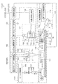
図1は、実施の形態1に係る測定システム1の構成の一例を示す模式図である。本実施の形態に係る測定システム1は、測定チップ10およびSPFS装置100を有する。測定システム1は、血液を含む検体中の被測定物質の量を測定するためのシステムである。[Embodiment 1]
(Measurement system)
FIG. 1 is a schematic view showing an example of the configuration of the
図1に示されるように、SPFS装置100は、励起光出射部(特許請求の範囲では、「第2の光出射部」と称している)110、シグナル検出部120、送液部130、搬送部140、光出射部150、光検出部160および制御処理部(処理部)170を有する。実施の形態1では、励起光出射部110およびシグナル検出部120は、ともに検体中の被測定物質の量を示す測定値を取得するための測定値取得部を構成する。光出射部150および光検出部160は、検体のヘマトクリット値を取得するためのヘマトクリット値取得部を構成する。
As shown in FIG. 1, the SPFS apparatus 100 includes an excitation light emitting unit (referred to as a “second light emitting unit” in the claims) 110, a
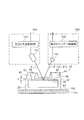
図2は、実施の形態1に係る測定システム1におけるヘマトクリット値取得部の構成を示す断面模式図である。図2は、図1の紙面に対する垂直な面に対して法線方向から見たときの図である。図1において、光出射部150および光検出部160は、便宜上、紙面に沿って配列されているが、光出射部150および光検出部160は、図2に示されるように、図1の紙面に垂直な方向に沿って配列されている。図2においては、測定チップ10内の光路を示すために、測定チップ10の断面へのハッチングを省略している。なお、図1において、光δ’の光軸が点線で示されているのは、光δ1の光軸および光δ’の光軸が図1の紙面に垂直な平面内に含まれることを示している。FIG. 2 is a schematic cross-sectional view showing the configuration of the hematocrit value acquisition unit in the
SPFS装置100は、搬送部140のチップホルダー(ホルダー)142に測定チップ10を装着した状態で使用される。そこで、先に測定チップ10について説明し、その後にSPFS装置100について説明する。
The SPFS device 100 is used with the measuring
(測定チップ)
測定チップ10は、プリズム20、金属膜30および流路蓋40を有する。本実施の形態では、測定チップ10の流路蓋40は、後述の液体チップ50と一体化されている。(Measuring chip)
The measuring
プリズム20は、入射面21、成膜面22および出射面23を有する。入射面21は、励起光出射部110からの励起光α(特許請求の範囲では、「第8の光」と称している)をプリズム20の内部に入射させる。成膜面22上には、金属膜30が配置されている。プリズム20の内部に入射した励起光αは、プリズム20と金属膜30との界面(成膜面22)で反射されて反射光となる。出射面23は、反射光をプリズム20の外部に出射させる。
The
プリズム20の形状は、特に限定されない。本実施の形態では、プリズム20の形状は、台形を底面とする柱体である。台形の一方の底辺に対応する面が成膜面22であり、一方の脚に対応する面が入射面21であり、他方の脚に対応する面が出射面23である。底面となる台形は、等脚台形であることが好ましい。これにより、入射面21と出射面23とが対称になり、励起光αのS波成分がプリズム20内に滞留しにくくなる。
The shape of the
入射面21は、励起光出射部110からの励起光αが入射面21で反射して励起光出射部110に戻らないように形成される。励起光αの光源がレーザーダイオード(以下「LD」ともいう)である場合、励起光αがLDに戻ると、LDの励起状態が乱れてしまい、励起光αの波長や出力が変動してしまう。そこで、理想的な共鳴角または増強角を中心とする走査範囲において、励起光αが入射面21に垂直に入射しないように、入射面21の角度が設定される。
The
ここで「共鳴角」とは、金属膜30に対する励起光αの入射角を走査した場合に、出射面23から出射される励起光αの反射光の光量が最小となるときの、入射角を意味する。また、「増強角」とは、金属膜30に対する励起光αの入射角を走査した場合に、測定チップ10の上方に放出される励起光αと同一波長の散乱光(以下「プラズモン散乱光」という)γの光量が最大となるときの、入射角を意味する。本実施の形態では、入射面21と成膜面22との角度および成膜面22と出射面23との角度は、いずれも約80°である。
Here, the "resonance angle" refers to the incident angle when the amount of reflected light of the excitation light α emitted from the
なお、測定チップ10の設計により、共鳴角(およびその極近傍にある増強角)が概ね決まる。設計要素は、プリズム20の屈折率や、金属膜30の屈折率、金属膜30の厚み、金属膜30の消衰係数、励起光αの波長などである。金属膜30上に捕捉された被測定物質によって共鳴角および増強角がシフトするが、その量は数度未満である。
The resonance angle (and the augmentation angle in the immediate vicinity thereof) is roughly determined by the design of the
プリズム20は、励起光αに対して透明な誘電体からなる。プリズム20は、複屈折特性を少なからず有する。プリズム20の材料の例には、樹脂およびガラスが含まれる。プリズム20を構成する樹脂の例には、ポリメタクリル酸メチル(PMMA)、ポリカーボネート(PC)、およびシクロオレフィン系ポリマーが含まれる。プリズム20の材料は、好ましくは、屈折率が1.4〜1.6であり、かつ複屈折が小さい樹脂である。
The
詳細については後述するが、本実施の形態では、金属膜30は、プリズム20側の面において、表面プラズモン共鳴を生じる場所を提供するとともに、流路41側の面において、流路41内を通過した光を反射させる「反射部」として機能する。
Although details will be described later, in the present embodiment, the
金属膜30は、プリズム20の成膜面22上に配置されている。これにより、成膜面22に全反射条件で入射した励起光αの光子と、金属膜30中の自由電子との間で表面プラズモン共鳴(Surface Plasmon Resonance:以下「SPR」と略記する)が生じ、金属膜30の表面上に局在場光(一般に「エバネッセント光」または「近接場光」とも呼ばれる)を生じさせることができる。局在場光は、金属膜30の表面から励起光αの波長程度離れた距離まで及ぶ。金属膜30は、成膜面22上の全面に形成されていてもよいし、成膜面22上の一部に形成されていてもよい。本実施の形態では、金属膜30は、成膜面22の全面に形成されている。
The
金属膜30は、光出射部150から出射された、流路41内を通過した光を、流路41内を再度通過するように鏡面反射させる。本実施の形態では、金属膜30は、流路蓋40で測定チップ10内に入射した第1の光δ1を流路蓋40に向けて鏡面反射させる。金属膜30の反射率は、例えば、40〜98%である。また、金属膜30の材料として、銀やアルミニウムなどを用いて金属膜30を形成した場合には、反射率が高い金属膜30が得られる。この場合、金属膜30の反射率は、例えば、85〜98%である。The
金属膜30には、被測定物質を捕捉するための捕捉体が固定化されている。金属膜30上において、捕捉体が固定化されている領域を、特に「反応場」という。捕捉体は、金属膜30の全面に固定化されていてもよいし、表面の一部に固定化されていてもよい。第1の光δ1が捕捉体により散乱されるのを抑制する観点からは、金属膜30の、反射部として機能する領域(第1の光δ1が鏡面反射する領域)においては、捕捉体は固定化されていないことが好ましい。また、捕捉体は、被測定物質に特異的に結合する。このため、被測定物質は、捕捉体を介して金属膜30上に固定化され得る。A trapping body for capturing the substance to be measured is immobilized on the
捕捉体の種類は、被測定物質を捕捉することができれば特に限定されない。たとえば、捕捉体は、被測定物質に特異的に結合可能な抗体(1次抗体)またはその断片、被測定物質に特異的に結合可能な酵素などである。 The type of capture body is not particularly limited as long as it can capture the substance to be measured. For example, the trap is an antibody (primary antibody) or a fragment thereof that can specifically bind to the substance to be measured, an enzyme that can specifically bind to the substance to be measured, or the like.
金属膜30の材料は、表面プラズモン共鳴を生じさせ得るとともに、その表面で光を鏡面反射できる金属であれば特に限定されない。金属膜30の材料の例には、金、銀、銅、アルミニウム、およびこれらの合金が含まれる。本実施の形態では、金属膜30は、金薄膜である。金属膜30の厚みは、特に限定されないが、SPRを効率的に発生させる観点から、20〜60nmの範囲内が好ましい。金属膜30の形成方法は、特に限定されない。金属膜30の形成方法の例には、スパッタリング、蒸着、メッキが含まれる。
The material of the
流路蓋40は、金属膜30上に配置されている。金属膜30がプリズム20の成膜面22の一部にのみ形成されている場合、流路蓋40は、成膜面22上に配置されていてもよい。本実施の形態では、流路蓋40は、金属膜30の上に配置されている。金属膜30上に流路蓋40を配置することで液体を収容するための空洞である流路41が形成される。本実施の形態では、流路41は、底面と、天面と、当該底面および当該天面を接続する一対の側面とを有する。本明細書中、流路41のプリズム20側の面を「流路41の底面」といい、流路41の、流路41の底面と対向する面を「流路41の天面」という。また、流路41の天面と流路41の底面との間隔を流路41の高さhとする。
The
図2に示されるように、流路蓋40は、枠体42、液体注入部被膜フィルム43および液体貯蔵部被膜フィルム44を有する。枠体42には、2つの貫通孔が形成されている。枠体42の裏面には、凹部(流路溝)が形成されている。金属膜30(およびプリズム20)上に流路蓋40(枠体42)が配置され、当該凹部の開口部が金属膜30により閉塞されることで、流路41が形成される。さらに、一方の貫通孔の開口部が液体注入部被膜フィルム43により閉塞されることで、液体注入部45が形成され、他方の貫通孔の開口部が液体貯蔵部被膜フィルム44により閉塞されることで、液体貯蔵部46が形成される。液体貯蔵部被膜フィルム44には、通気孔47が設けられている。
As shown in FIG. 2, the
局在場光が及ぶ領域を十分に確保する観点からは、流路41の高さh(流路溝の深さ)は、ある程度大きいことが好ましい。流路41内に混入する不純物の量を低減する観点からは、流路41の高さh(流路溝の深さ)は、小さいことが好ましい。このような観点から、流路41の高さhは、0.05〜0.15mmの範囲内であることが好ましい。流路41の両端は、流路41内と外部とを連通させるように、流路蓋40に形成された液体注入部45および液体貯留部46とそれぞれ接続されている(図2参照)。
From the viewpoint of sufficiently securing the region covered by the localized field light, the height h (depth of the flow path groove) of the
枠体42は、金属膜30上から放出される光(蛍光βおよびプラズモン散乱光γ)と、金属膜30に向けて出射される第1の光δ1(および第1の光δ1と同じ波長の光δ’(後述))とに対して透明な材料からなることが好ましい。枠体42の材料の例には、ガラスおよび樹脂が含まれる。当該樹脂の例には、ポリメタクリル酸メチル樹脂(PMMA)が含まれる。また、上記の光に対して透明であれば、枠体42の他の部分は、不透明な材料で形成されていてもよい。枠体42は、例えば、両面テープや接着剤などによる接着や、レーザー溶着、超音波溶着、クランプ部材を用いた圧着などにより金属膜30またはプリズム20に接合されている。The
液体注入部被覆フィルム43は、ピペットチップ134を挿入可能であり、かつピペットチップ134を挿入した際には、ピペットチップ134の外周に隙間なく密着することが可能なフィルムである。たとえば、液体注入部被覆フィルム43は、弾性フィルムおよび粘着フィルムの2層フィルムである。液体注入部被覆フィルム43には、ピペットチップ134を挿入するための微細な貫通孔を設けられていてもよい。本実施の形態では、液体注入部被覆フィルム43に外径が1.2mmのピペットチップ挿入用貫通孔48が設けられている。
The liquid injection
前述のとおり、液体貯留部被覆フィルム44は、通気孔47を有する。液体貯留部被覆フィルム44の構成は、特に制限されない。たとえば、液体貯留部被覆フィルム44は、前述の液体注入部被覆フィルム43と同様の2層フィルムであってもよい。
As described above, the liquid storage
前述のとおり、本実施の形態では、測定チップ10および液体チップ50は、一体化されている(図1参照)。より具体的には、枠体42および液体チップ50が一体化されている。液体チップ50は、液体を収容する容器である。また、液体チップ50は、分注された検体を収容したり、液体を所期の濃度に希釈したりするために用いられてもよい。液体チップ50は、液体を収容するためのウェルを有する。ウェルの開口部は、液体を収容した状態でフィルムなどにより閉塞されていてもよい。ウェルの開口部を閉塞するフィルムは、液体チップ50の使用前にユーザーにより取り除かれてもよい。また、ピペットチップ134がフィルムを貫くことができる場合は、ウェルの開口部がフィルムで閉塞された状態で液体チップ50が使用されてもよい。
As described above, in the present embodiment, the measuring
液体チップ50に収容される液体の例には、血液を含む検体や、蛍光物質で標識された捕捉体を含む標識液、洗浄液(緩衝液)、第1の光δ1に対して透明な液体(後述の参照液、第1の液)、溶血剤、色素を含む液体(後述の第2の液)およびこれらの希釈液が含まれる。Examples of the liquid contained in the
測定チップ10および液体チップ50は、通常、測定のたびに交換される。また、測定チップ10は、好ましくは各片の長さが数mm〜数cmの構造物であるが、「チップ」の範疇に含まれないより小型の構造物またはより大型の構造物であってもよい。
The measuring
(SPFS装置)
次に、SPFS装置100の各構成要素について説明する。前述のとおり、SPFS装置100は、励起光出射部110、シグナル検出部120、送液部130、搬送部140、光出射部150、光検出部160および制御処理部(処理部)170を有する。(SPFS device)
Next, each component of the SPFS apparatus 100 will be described. As described above, the SPFS device 100 includes an excitation
励起光出射部110は、励起光α(特許請求の範囲では、「第8の光」と称している)を出射する。蛍光βの検出時には、励起光出射部110は、金属膜30で表面プラズモン共鳴が発生するように、金属膜30に対するP波を入射面21に向けて出射する。ここで「励起光」とは、蛍光物質を直接もしくは間接に励起させる光である。たとえば、励起光αは、プリズム20を介して金属膜30に表面プラズモン共鳴が生じる角度で照射されたときに、蛍光物質を励起させる局在場光を金属膜30の表面上に生じさせる光である。励起光出射部110は、光源ユニット111、角度調整機構112および光源制御部113を含む。
The excitation
第1の光源ユニット111は、コリメートされ、かつ波長および光量が一定の光を、金属膜30の裏面における照射スポットの形状が略円形となるように出射する。第1の光源ユニット111は、例えば、光源、ビーム整形光学系、APC機構および温度調整機構(いずれも不図示)を含む。
The first
光源の種類は、特に限定されず、例えばレーザーダイオード(LD)である。光源の他の例には、発光ダイオードや水銀灯などのレーザー光源が含まれる。光源から出射される励起光αの波長は、例えば、400nm〜1000nmの範囲内である。光源から出射される励起光αがビームでない場合は、励起光αは、レンズや鏡、スリットなどによりビームに変換される。また、光源から出射される励起光αが単色光でない場合は、励起光αは、回折格子などにより単色光に変換される。さらに、光源から出射される励起光αが直線偏光でない場合は、励起光αは、偏光子などにより直線偏光の光に変換される。 The type of light source is not particularly limited, and is, for example, a laser diode (LD). Other examples of light sources include laser light sources such as light emitting diodes and mercury lamps. The wavelength of the excitation light α emitted from the light source is, for example, in the range of 400 nm to 1000 nm. When the excitation light α emitted from the light source is not a beam, the excitation light α is converted into a beam by a lens, a mirror, a slit, or the like. When the excitation light α emitted from the light source is not monochromatic light, the excitation light α is converted into monochromatic light by a diffraction grating or the like. Further, when the excitation light α emitted from the light source is not linearly polarized light, the excitation light α is converted into linearly polarized light by a polarizer or the like.
ビーム整形光学系は、例えば、コリメーターやバンドパスフィルター、直線偏光フィルター、半波長板、スリット、ズーム手段などを含む。ビーム整形光学系は、これらのすべてを含んでいてもよいし、一部を含んでいてもよい。 The beam shaping optical system includes, for example, a collimator, a bandpass filter, a linear polarizing filter, a half wave plate, a slit, a zoom means, and the like. The beam shaping optical system may include all of these, or may include some of them.
コリメーターは、光源から出射された励起光αをコリメートする。 The collimator collimates the excitation light α emitted from the light source.
バンドパスフィルターは、光源から出射された励起光αを中心波長のみの狭帯域光にする。光源から出射された励起光αは、若干の波長分布幅を有しているためである。 The bandpass filter converts the excitation light α emitted from the light source into narrow-band light having only a central wavelength. This is because the excitation light α emitted from the light source has a slight wavelength distribution width.
直線偏光フィルターは、光源から出射された励起光αを直線偏光の光にする。 The linearly polarized light filter converts the excitation light α emitted from the light source into linearly polarized light.
半波長板は、金属膜30にP波成分が入射するように光の偏光方向を調整する。
The half-wave plate adjusts the polarization direction of light so that the P wave component is incident on the
スリットおよびズーム手段は、金属膜30の裏面における照射スポットの形状が所定サイズの円形となるように、光源から出射された励起光αのビーム径や輪郭形状などを調整する。
The slit and the zoom means adjust the beam diameter and contour shape of the excitation light α emitted from the light source so that the shape of the irradiation spot on the back surface of the
APC機構は、光源の出力が一定となるように光源を制御する。より具体的には、APC機構は、励起光αから分岐させた光の光量を不図示のフォトダイオードなどで検出する。そして、APC機構は、回帰回路で投入エネルギーを制御することで、光源の出力を一定に制御する。 The APC mechanism controls the light source so that the output of the light source is constant. More specifically, the APC mechanism detects the amount of light branched from the excitation light α with a photodiode (not shown) or the like. Then, the APC mechanism controls the output of the light source to be constant by controlling the input energy with the regression circuit.
温度調整機構は、例えば、ヒーターやペルチェ素子などである。光源から出射された励起光αの波長およびエネルギーは、温度によって変動することがある。このため、温度調整機構で光源の温度を一定に保つことにより、光源から出射された励起光αの波長およびエネルギーを一定に制御する。 The temperature adjusting mechanism is, for example, a heater or a Peltier element. The wavelength and energy of the excitation light α emitted from the light source may fluctuate depending on the temperature. Therefore, by keeping the temperature of the light source constant by the temperature adjusting mechanism, the wavelength and energy of the excitation light α emitted from the light source are controlled to be constant.
角度調整機構112は、金属膜30(プリズム20と金属膜30との界面(成膜面22))に対する励起光αの入射角を調整する。角度調整機構112は、プリズム20を介して金属膜30の所定の位置に向けて所定の入射角で光を照射するために、光源から出射された励起光αの光軸とチップホルダー142とを相対的に回転させる。たとえば、角度調整機構112は、金属膜30上において励起光αの光軸と直交する軸(図1の紙面に対して垂直な軸)を中心として光源ユニット111を回動させる。このとき、入射角を走査しても金属膜30上での照射スポットの位置がほとんど変化しないように、回転軸の位置を設定する。特に、回転中心の位置を、入射角の走査範囲の両端における2つの光源から出射された励起光αの光軸の交点近傍(成膜面22上の照射位置と入射面21との間)に設定することで、照射位置のズレを極小化することができる。
The
前述のとおり、光源から金属膜30に対して出射された励起光αの入射角のうち、プラズモン散乱光γの光量が最大となる角度が増強角である。光源から出射された励起光αの入射角を増強角またはその近傍の角度に設定することで、高強度の蛍光βおよびプラズモン散乱光γを検出することが可能となる。プリズム20の材料および形状、金属膜30の厚み、流路41内の液体の屈折率などにより、光源から出射された励起光αの基本的な入射条件が決まるが、流路41内の捕捉体の種類および量、プリズム20の形状誤差などにより、最適な入射条件はわずかに変動する。このため、測定ごとに最適な増強角を求めることが好ましい。
As described above, among the incident angles of the excitation light α emitted from the light source to the
第1の光源制御部113は、第1の光源ユニット111に含まれる各種機器を制御して、第1の光源ユニット111からの励起光αの出射を制御する。第1の光源制御部113は、例えば、演算装置、制御装置、記憶装置、入力装置および出力装置を含む公知のコンピュータやマイコンなどによって構成される。
The first light
シグナル検出部120は、金属膜30上に、検体中の被測定物質が存在する状態で、励起光出射部110がプリズム20を介して金属膜30に、表面プラズモン共鳴が生じる入射角で励起光αを照射したときに、測定チップ10で生じるシグナル(例えば、蛍光β、反射光またはプラズモン散乱光γ)を検出する。被測定物質は、流路41内で固定化されていてもよいし、固定化されていなくてもよい。本実施の形態では、シグナル検出部120は、金属膜30上に、検体中に含まれていた被測定物質が固定化され、かつ流路41内に検体が存在しない状態で、上記シグナルを検出する。シグナル検出部120は、検出したシグナル量(例えば、蛍光βの光量、反射光δ’の光量、またはプラズモン散乱光γの光量)を示す信号を制御処理部170に出力する。シグナル検出部120は、受光光学系ユニット121、位置切替え機構122および第1のセンサー制御部127を含む。
In the
受光光学系ユニット121は、測定チップ10の金属膜30の法線上に配置される。受光光学系ユニット121は、第1のレンズ123、光学フィルター124、第2のレンズ125および第1の受光センサー126を含む。
The light receiving
位置切替え機構122は、光学フィルター124の位置を、受光光学系ユニット121における光路上または光路外に切り替える。具体的には、第1の受光センサー126が蛍光βを検出するときには、光学フィルター124を受光光学系ユニット121の光路上に配置し、第1の受光センサー126がプラズモン散乱光γを検出するときには、光学フィルター124を受光光学系ユニット121の光路外に配置する。
The
第1のレンズ123は、例えば、集光レンズであり、金属膜30上から出射される光(シグナル)を集光する。第2のレンズ125は、例えば、結像レンズであり、第1のレンズ123で集光された光を第1の受光センサー126の受光面に結像させる。両レンズの間において、光は、略平行の光束となっている。
The
光学フィルター124は、第1のレンズ123および第2のレンズ125の間に配置されている。光学フィルター124は、蛍光検出時においては、光学フィルター124に入射する光のうち、蛍光成分のみを透過させ、励起光成分(プラズモン散乱光γ)を除去する。これにより、蛍光成分のみを第1の受光センサー126に導き、高いS/N比で蛍光βを検出することができる。光学フィルター124の種類の例には、励起光反射フィルター、短波長カットフィルターおよびバンドパスフィルターが含まれる。光学フィルター124の例には、所定の光成分を反射する多層膜を含むフィルターと、所定の光成分を吸収する色ガラスフィルターとが含まれる。
The
第1の受光センサー126は、蛍光βおよびプラズモン散乱光γを検出する。第1の受光センサー126は、微量の被測定物質からの微弱な蛍光βを検出することが可能な、高い感度を有する。第1の受光センサー126は、例えば、光電子増倍管(PMT)やアバランシェフォトダイオード(APD)、シリコンフォトダイオード(SiPD)などである。
The first
第1のセンサー制御部127は、第1の受光センサー126の出力値の検出や、当該出力値による第1の受光センサー126の感度の管理、適切な出力値を得るための第1の受光センサー126の感度の変更などを制御する。第1のセンサー制御部127は、例えば、演算装置、制御装置、記憶装置、入力装置および出力装置を含む公知のコンピュータやマイコンなどによって構成される。
The first
送液部130は、チップホルダー142に保持された測定チップ10の流路41内に、液体チップ50内の液体を供給する。また、送液部130は、測定チップ10の流路41内から液体を除去する。さらに、送液部130は、液体チップ50内の液体を分注し、かつ希釈する。送液部130は、ピペット131およびピペット制御部135を含む。
The
ピペット131は、シリンジポンプ132と、シリンジポンプ132に接続されたノズルユニット133と、ノズルユニット133の先端に装着されたピペットチップ134とを有する。シリンジポンプ132内のプランジャーの往復運動によって、ピペットチップ134における液体の吸引および排出が定量的に行われる。
The
ピペット制御部135は、シリンジポンプ132の駆動装置、およびノズルユニット133の移動装置を含む。シリンジポンプ132の駆動装置は、シリンジポンプ132のプランジャーを往復運動させるための装置であり、例えば、ステッピングモーターを含む。ノズルユニット133の移動装置は、例えば、ノズルユニット133を、垂直方向に自在に動かす。ノズルユニット133の移動装置は、例えば、ロボットアーム、2軸ステージまたは上下動自在なターンテーブルによって構成される。
The
ピペット制御部135は、シリンジポンプ132を駆動して、液体チップ50から各種液体をピペットチップ134内に吸引させる。そして、ピペット制御部135は、ノズルユニット133を移動させて、測定チップ10の流路41内にピペットチップ134を挿入させるとともに、シリンジポンプ132を駆動して、ピペットチップ134内の液体を流路41内に注入させる。また、液体の導入後、ピペット制御部135は、シリンジポンプ132を駆動して、流路41内の液体をピペットチップ134内に吸引させる。このように流路41内の液体を順次交換することによって、反応場において捕捉体と被測定物質を反応させたり(1次反応)、被測定物質と蛍光物質で標識された捕捉体とを反応させたりする(2次反応)。また、送液部130は、上記のように液体チップ50内の液体を吸引したり、吐出したりすることで、検体を分注したり、希釈したりする。
The
搬送部140は、測定チップ10を設置位置、検体中の被測定物質の量を示す測定値を取得するための第1の測定位置、ヘマトクリット値を取得するための第2の測定位置または送液位置に搬送し、固定する。ここで「設置位置」とは、測定チップ10をSPFS装置100に設置するための位置である。また、「第1の測定位置」とは、励起光出射部110が測定チップ10に向けて励起光αを出射したときに、測定チップ10から放出されるシグナルをシグナル検出部120が検出する位置である。また、「第2の測定位置」とは、光出射部150が金属膜30に向けて第1の光δ1を出射したときに、測定チップ10内で反射した光δ’を光検出部160が検出する位置である。さらに、「送液位置」とは、送液部130が測定チップ10の流路41内に液体を供給するか、または測定チップ10の流路41内の液体を除去する位置である。The
搬送部140は、搬送ステージ141およびチップホルダー142を含む。
The
搬送ステージ141は、チップホルダー142を一方向およびその逆方向に移動させる。搬送ステージ141も、励起光αや、励起光αの反射光、蛍光β、プラズモン散乱光γ、第1の光δ1、第1の光δ1の反射光δ’などの光の光路を妨げない形状である。搬送ステージ141は、例えば、ステッピングモーターなどで駆動される。The
チップホルダー142は、搬送ステージ141に固定されており、測定チップ10を着脱可能に保持する。チップホルダー142の形状は、測定チップ10を保持することができ、かつ励起光αや励起光αの反射光、蛍光β、プラズモン散乱光γ、第1の光δ1、第1の光δ1の反射光δ’などの光の光路を妨げない形状である。たとえば、チップホルダー142には、上記の光が通過するための開口が設けられている。The
光出射部150は、赤血球が吸収する波長の光を含む第1の光δ1を出射する。本実施の形態では、光出射部150は、流路41側から金属膜30に向けて第1の光δ1を出射する。第1の光δ1は、赤血球に含まれるヘモグロビンが吸収する波長の光を含むことが好ましい。光出射部150は、第2の光源ユニット151および第2の光源制御部152を含む。The
第2の光源ユニット151は、コリメートされ、かつ波長および光量が一定の第1の光δ1を、金属膜30に向けて出射する。第2の光源ユニット151は、例えば、光源、コリメーター、APC機構および温度調整機構(いずれも不図示)を含む。コリメーター、APC機構および温度調整機構については、第1の光源ユニット111のコリメーター、APC機構および温度調整機構と同様であるため、その説明を省略する。光源の温度変化による第1の光δ1の波長のばらつきを抑制する観点から、第2の光源ユニット151は、温度調整機構を有することが好ましい。 The second light source unit 151 emits a first light δ 1 that is collimated and has a constant wavelength and a constant amount of light toward the
金属膜30の外縁部よりも内側に第1の光δ1を照射して、第1の光δ1が金属膜30以外の領域に照射されることによるエネルギー効率の低下を抑制する観点から、光源は、レーザー光源であることが好ましい。レーザー光源は、LEDのような指向性が低い光源と比較して、より小さい照射スポットで金属膜30に第1の光δ1を照射することができる。光源は、例えば、レーザーダイオード(LD)である。光源の他の例には、発光ダイオードや水銀灯などのレーザー光源が含まれる。光出射部150からの第1の光δ1の中心波長は、例えば、500〜650nmである。光源から出射される第1の光δ1がビームでない場合は、第1の光δ1は、レンズや鏡、スリットなどによりビームに変換される。 From the viewpoint of irradiating the first light δ 1 inside the outer edge of the
第2の光源制御部152は、第2の光源ユニット151に含まれる各種機器を制御して、第2の光源ユニット151からの第1の光δ1の出射を制御する。第2の光源制御部152は、例えば、演算装置、制御装置、記憶装置、入力装置および出力装置を含む公知のコンピュータやマイコンなどによって構成される。The second light
光検出部160は、第1の光δ1が測定チップ10内で反射することで得られる光δ’を検出する。たとえば、流路41内に検体が存在する状態では、光検出部160は、光出射部150が金属膜30に向けて第1の光δ1を出射したときに、第1の光δ1が流路41内の検体を透過し、金属膜30で反射し、かつ流路41内の検体を再度透過することで得られる第2の光δ2を検出する。光検出部160は、検出した光δ’の光量を示す信号を出力する。光検出部160は、第2の受光センサー161および第2のセンサー制御部162を含む。The
第2の受光センサー161は、測定チップ10内で反射した第1の光δ1である光δ’を検出する。第2の受光センサー161は、例えば、光電子増倍管(PMT)やアバランシェフォトダイオード(APD)、シリコンフォトダイオード(SiPD)などである。The second
第2のセンサー制御部162は、第2の受光センサー161の出力値の検出や、当該出力値による第2の受光センサー161の感度の管理、適切な出力値を得るための第2の受光センサー161の感度の変更などを制御する。第2のセンサー制御部162は、例えば、演算装置、制御装置、記憶装置、入力装置および出力装置を含む公知のコンピュータやマイコンなどによって構成される。
The second
前述のとおり、図2は、実施の形態1に係る測定システム1におけるヘマトクリット値取得部の構成を示す断面模式図である。図2は、第1の光δ1の光軸と、第1の光δ1の測定チップ10での反射光δ’の光軸とを含む平面(図1の紙面に対して垂直な面)に対して垂直な方向から見たときの図である。図2に示されるように、光出射部150(第2の光源ユニット151)および光検出部160(第2の受光センサー161)は、第1の光δ1の光軸と、第1の光δ1の反射光δ’の光軸とを含む平面が流路41の長手方向に沿うように配置されていることが好ましい。これにより、流路41の長手方向において、第1の光δ1の照射スポットの位置がずれたとしても、第1の光δ1が流路41以外の領域に照射されることを抑制することができる。また、第1の光δ1が金属膜30に対して垂直に入射した場合と比較して、第1の光δ1が金属膜30に対して斜めから入射した場合には、金属膜30上における第1の光δ1の照射スポットの形状は、一方向に伸びた形状となる。金属膜30に対する第1の光δ1の入射角に応じて照射スポットが伸びる方向は、流路41の長手方向に沿っていることが好ましい。これにより、照射スポットが伸びる方向が流路41の短手方向に沿う場合と比較して、照射スポットの位置がずれたとしても、第1の光δ1が流路41(金属膜30)以外の領域に照射されるのを抑制することができる。なお、照射スポットの位置ずれの原因には、搬送ステージ141におけるチップホルダー142の位置決め誤差や、チップホルダー142に対する測定チップ10の設置誤差などが含まれる。As described above, FIG. 2 is a schematic cross-sectional view showing the configuration of the hematocrit value acquisition unit in the
制御処理部170は、角度調整機構112、第1の光源制御部113、位置切替え機構122、第1のセンサー制御部127、ピペット制御部135、搬送ステージ141、第2の光源制御部152および第2のセンサー制御部162を制御する。制御処理部170は、シグナル検出部120(第1の受光センサー126)および光検出部160(第2の受光センサー161)の検出結果を処理する処理部としても機能する。本実施の形態では、制御処理部170は、シグナル検出部120による蛍光βの検出結果に基づいて、検体中の被測定物質の量を示す測定値を決定する。また、制御処理部170は、光検出部160による第2の光δ2の検出結果に基づいて検体のヘマトクリット値を決定する。これとともに、制御処理部170は、ヘマトクリット値に基づいて上記測定値を補正する。これにより、制御処理部170は、血漿または血清中の被測定物質の量(濃度)を決定する。また、制御処理部170には、上記の検出結果を処理する際に使用される所定の情報(例えば、種々の変換係数、検量線に関するデータ)などがあらかじめ記録されていてもよい。本実施の形態では、制御処理部170には、ヘマトクリット関連値(後述)をヘマトクリット値に変換するための係数があらかじめ記録されている。制御処理部170は、例えば、演算装置、制御装置、記憶装置、入力装置および出力装置を含む公知のコンピュータやマイコンなどによって構成される。The control processing unit 170 includes an
(SPFS装置における光路)
図1に示されるように、励起光αは、入射面21からプリズム20内に入射する。プリズム20内に入射した励起光αは、金属膜30に全反射角度(SPRが生じる角度)で入射する。このように、金属膜30に対して励起光αをSPRが生じる角度で照射することで、金属膜30上に局在場光を発生させることができる。この局在場光により、金属膜30上に存在する被測定物質を標識する蛍光物質が励起され、蛍光βが放出される。SPFS装置100は、蛍光物質から放出された蛍光βの光量(強度)を検出する。なお、特に図示していないが、金属膜30での励起光αの反射光は、出射面23でプリズム20外に出射する。(Optical path in SPFS device)
As shown in FIG. 1, the excitation light α is incident on the
また、図2に示されるように、本実施の形態では、第1の光δ1は、流路蓋40の枠体42を介して流路41(測定チップ10)内に入射する。第1の光δ1は、測定チップ10内で反射して光δ’となる。光δ’は、流路蓋40の枠体42を介して流路41(測定チップ10)外に出射される。SPFS装置100は、測定チップ10から出射された光δ’の光量(強度)を検出する。Further, as shown in FIG. 2, in the present embodiment, the first light δ 1 is incident on the flow path 41 (measurement chip 10) via the
本明細書において、測定チップ10内での第1の光δ1の反射光δ’には、流路41内に存在する液体の種類または測定チップ10内の反射位置に応じて異なる符号が付されている。流路41内に検体が存在する場合、第1の光δ1は、流路41内の検体を透過し、金属膜30で反射し、かつ流路41内の検体を再度透過して第2の光δ2となる。第1の光δ1に対して透明な参照液で、流路41内が満たされている場合、第1の光δ1は、流路41内の参照液を透過し、金属膜30で反射し、かつ流路41内の参照液を再度透過して第7の光δ7となる。In the present specification, the reflected light δ'of the first light δ 1 in the measuring
(測定システムの動作手順)
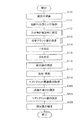
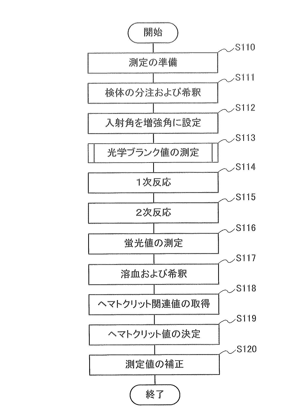
次に、実施の形態1に係る測定システム1の動作手順(実施の形態1に係る測定方法)について説明する。図3は、測定システム1の動作手順の一例を示すフローチャートである。図4は、図3に示される光学ブランク値の測定工程(工程S113)内の工程を示すフローチャートである。本実施の形態では、検体中の被測定物質の量を示す測定値として、蛍光βの光量である蛍光値が測定される。(Measurement system operation procedure)
Next, the operation procedure of the
まず、測定の準備をする(工程S110)。具体的には、SPFS装置100の設置位置に配置されたチップホルダー142に、測定チップ10を設置する。測定チップ10の金属膜30上に保存試薬が存在する場合は、捕捉体が適切に被測定物質を捕捉できるように、金属膜30上を洗浄して保存試薬を除去する。
First, preparation for measurement is performed (step S110). Specifically, the measuring
次いで、検体を分注し、希釈する(工程S111)。具体的には、制御処理部170は、ピペット制御部135を制御して、液体チップ50内の検体を、測定値(蛍光値)測定用の第1の検体と、ヘマトクリット値測定用の第2の検体とに分ける。第1の検体および第2の検体は、それぞれ液体チップ50の空のウェルに収容される。本工程S111では、測定精度および測定感度の観点から、第1の検体をさらに希釈する。第1の検体を希釈しないと、検体中の不純物が捕捉体に吸着(非特異吸着)する量が増加して、ノイズが増加してしまい、結果として、測定精度を悪化させてしまうおそれがある。また、捕捉体の量と比較して被測定物質の量が多すぎる場合、捕捉体で捕捉できる被測定物質の量が飽和してしまい、高濃度な検体の濃度を特定することができなくなってしまう。希釈液としては、例えば、生理食塩水が使用され得る。第1の検体は、例えば、2〜50倍に希釈される。
Then, the sample is dispensed and diluted (step S111). Specifically, the control processing unit 170 controls the
次いで、金属膜30(成膜面22)に対する励起光αの入射角を増強角に設定する(工程S112)。具体的には、制御処理部170は、搬送ステージ141を制御して、測定チップ10を設置位置から送液位置に移動させる。制御処理部170は、ピペット制御部135を制御して、液体チップ50内の励起光αに対して透明な参照液(後述)を流路41内に提供する。制御処理部170は、搬送ステージ141を制御して、測定チップ10を送液位置から第1の測定位置に移動させる。制御処理部170は、位置切替え機構122を制御して、光学フィルター124を受光光学系ユニット121の光路外に移動させる。制御処理部170は、第1の光源制御部113、角度調整部112および第1のセンサー制御部127を制御して、第1の光源ユニット111から励起光αを、金属膜30の所定の位置に、金属膜30に対する励起光αの入射角度を走査しながら照射するとともに、第1の受光センサー126でプラズモン散乱光γを検出する。これにより、制御処理部170は、励起光αの入射角と、プラズモン散乱光γの光量との関係を含むデータを得る。得られたデータは、制御処理部170に記憶される。そして、制御処理部170は、データを解析して、プラズモン散乱光γの光量が最大となる入射角である増強角を決定する。最後に、制御処理部170は、角度調整部112を制御して、金属膜30(成膜面22)に対する励起光αの入射角を決定した増強角に設定する。
Next, the incident angle of the excitation light α with respect to the metal film 30 (film-forming surface 22) is set to the enhancement angle (step S112). Specifically, the control processing unit 170 controls the
なお、増強角は、プリズム20の素材および形状、金属膜30の厚み、流路41内の液体の屈折率などにより決まるが、流路41内の捕捉体の種類および量、プリズム20の形状誤差などの各種要因によりわずかに変動する。このため、測定を行うたびに増強角を決定することが好ましい。増強角は、0.1°程度のオーダーで決定される。
The augmentation angle is determined by the material and shape of the
次いで、光学ブランク値を測定する(工程S113)。本実施の形態において、光学ブランク値は、蛍光値(測定値)の決定に使用される第1のブランク値と、ヘマトクリット値の決定に使用される第2のブランク値とを含む。ここで、「第1のブランク値」とは、参照液が流路41内に存在する状態で、測定チップ10の上方に放出される背景光の光量を意味する。また、「第2のブランク値」とは、参照液が流路41内に存在する状態で、光出射部150が金属膜30に向けて第1の光δ1を出射したときに、第1の光δ1が流路41内の参照液を透過し、金属膜30で反射し、かつ流路41内の参照液を再度透過することで得られる第7の光δ7の光量を意味する。Next, the optical blank value is measured (step S113). In the present embodiment, the optical blank value includes a first blank value used for determining the fluorescence value (measured value) and a second blank value used for determining the hematocrit value. Here, the "first blank value" means the amount of background light emitted above the measuring
本実施の形態では、参照液は、励起光αおよび第1の光δ1に対して透明である。なお、参照液の屈折率は、検体の屈折率と同じか同程度であることが好ましい。これにより、流路41内に参照液が存在する場合と、流路41内に検体が存在する場合とにおいて、枠体42の流路溝(凹部)の底面(流路41の天面)における第1の光δ1の反射率を同じか同程度にすることができるとともに、金属膜30の表面における光δの反射率を同じか同程度にすることができる。In this embodiment, the reference liquid is transparent to the excitation light α and the first light δ 1. The refractive index of the reference liquid is preferably the same as or about the same as the refractive index of the sample. As a result, in the case where the reference liquid is present in the
図4に示されるように、工程S113では、まず、第1のブランク値を測定する(工程S1131)。制御処理部170は、位置切替え機構122を制御して、光学フィルター124を受光光学系ユニット121の光路上に移動させる。次いで、制御処理部170は、第1の光源制御部113を制御して、金属膜30(成膜面22)に向けて第1の光源ユニット111から励起光αを出射させる。これと同時に、制御処理部170は、第1の光センサー制御部127を制御して、第1の受光センサー126で蛍光βとほぼ同じ波長の光の光量を検出する。これにより、第1の受光センサー126は、蛍光値の測定(工程S116)においてノイズとなる光の光量(第1のブランク値)を測定することができる。第1のブランク値は、制御処理部170に送信され、記録される。
As shown in FIG. 4, in step S113, first, the first blank value is measured (step S1131). The control processing unit 170 controls the
次いで、第2のブランク値を測定する(工程S1132)。制御処理部170は、搬送ステージ141を制御して、測定チップ10を第1の測定位置から第2の測定位置に移動させる。次いで、制御処理部170は、第2の光源制御部152を制御して、第2の光源ユニット151から金属膜30に第1の光δ1を照射させる。これと同時に、制御処理部170は、第2の光センサー制御部162を制御して、第2の受光センサー161で、金属膜30で反射した第7の光δ7を検出する。これにより、第2の受光センサー161は、ヘマトクリット値の測定においてノイズとなる光の光量(第2のブランク値)を測定することができる。第2のブランク値は、制御処理部170に送信され、記録される。なお、第2のブランク値は、下記式(1)で表される参照液の吸光度OD1として記録されてもよい。
次いで、検体中の被測定物質と金属膜30上の捕捉体とを反応させる(1次反応;工程S114)。具体的には、制御処理部170は、搬送ステージ141を制御して、測定チップ10を第2の測定位置から送液位置に移動させる。この後、制御処理部170は、ピペット制御部135を制御して、流路41内の参照液を排出し、工程S111において希釈された第1の検体を流路41内に提供する。これにより、検体中に被測定物質が存在する場合には、被測定物質の少なくとも一部は金属膜30上の捕捉体により捕捉される。なお、第1の検体は、溶血していない。この後、流路41内を緩衝液などで洗浄して、捕捉体に捕捉されなかった物質を除去する。なお、被測定物質の例には、トロポニン、ミオグロビンおよびクレアチンキナーゼ−MB(CK−MB)が含まれる。
Next, the substance to be measured in the sample is reacted with the trapped material on the metal film 30 (primary reaction; step S114). Specifically, the control processing unit 170 controls the
次いで、反射膜30上の捕捉体に捕捉された被測定物質を蛍光物質で標識する(2次反応;工程S115)。具体的には、制御処理部170は、ピペット制御部135を制御して、液体チップ50内の蛍光標識液を流路41内に提供する。これにより、被測定物質を蛍光物質で標識することができる。蛍光標識液は、例えば、蛍光物質で標識された抗体(2次抗体)を含む緩衝液である。この後、流路41内を緩衝液などで洗浄し、遊離の蛍光物質などを除去する。
Next, the substance to be measured captured by the trapped body on the
次いで、反応場の被測定物質を標識している蛍光物質から放出される蛍光βを検出して、蛍光値を測定する(工程S116)。具体的には、制御処理部170は、ピペット制御部135を制御して、液体チップ50内の測定用の緩衝液を流路41内に提供する。制御処理部170は、搬送ステージ141を制御して、測定チップ10を送液位置から第1の測定位置に移動させる。この後、制御処理部170は、第1の光源制御部113を制御して、検体中に含まれていた被測定物質が固定化され、かつ検体が存在しない状態で、励起光出射部110の第1の光源ユニット111から励起光αを、プリズム20を介して捕捉体が固定化されている領域に対応する金属膜30の裏面に、表面プラズモン共鳴が生じる入射角で照射する。これとともに、制御処理部170は、第1のセンサー制御部127を制御して、測定チップ10内で生じる蛍光β(シグナル)を第1の受光センサー126で検出する。これにより、第1の受光センサー126は、蛍光βの光量である蛍光値(測定値)を取得する。蛍光値は、制御処理部170に送信され、記録される。なお、本明細書中、「検体が存在しない状態」とは、流路41内から検体を除去する操作が行われた状態をいう。すなわち、流路41内に検体が実質的に存在していなければよく、流路41内に除去しきれなかった検体がわずかに残存していてもよい。
Next, the fluorescence β emitted from the fluorescent substance labeling the substance to be measured in the reaction field is detected, and the fluorescence value is measured (step S116). Specifically, the control processing unit 170 controls the
次いで、工程S111において分注された第2の検体中の血液を溶血するとともに、希釈する(工程S117)。制御処理部170は、ピペット制御部135を制御して、液体チップ50内に収容されている第2の検体中に、他の液体チップ50内に収容されている溶血剤を提供する。これにより、第2の検体中の血液を溶血するとともに、希釈することができる。このとき、第2の検体は、例えば、1〜20倍に希釈される。このとき、第2の検体の希釈倍率が1倍の場合、第2の検体は希釈されていないことを示している。希釈倍率が大きいほど、検体の吸収光量は少なくなる。このため、希釈倍率が大きすぎると、十分な測定分解能が得られなくなる。
Next, the blood in the second sample dispensed in step S111 is hemolyzed and diluted (step S117). The control processing unit 170 controls the
次いで、ヘマトクリット関連値を取得する(工程S118)。具体的には、制御処理部170は、搬送ステージ141を制御して、測定チップ10を第1の測定位置から送液位置に移動させる。制御処理部170は、ピペット制御部135を制御して、液体チップ50中の血液が溶血した状態の検体を流路41内に提供する。次いで、制御処理部170は、搬送ステージ141を制御して、測定チップ10を送液位置から第2の測定位置に移動させる。次いで、検体が流路41内に存在する状態で、制御処理部170は、光出射部150の第2の光源制御部152を制御して、第2の光源ユニット151から金属膜30に第1の光δ1を照射させる。これと同時に、制御処理部170は、第2のセンサー制御部162を制御して、第2の受光センサー161で、流路41内の検体を透過し、金属膜30で反射し、かつ流路41内の検体を再度透過した第2の光δ2を検出する。これにより、第2の受光センサー161は、第2の光δ2の光量を測定する。測定値は、制御処理部170に送信され、記録される。なお、第2の光δ2の光量は、下記式(2)で表される検体の吸光度OD2として記録されてもよい。
検体の吸光度OD2は、検体による光の吸収に起因するシグナル成分と、それ以外の要因に起因するノイズ成分(第2のブランク値)とを含む。したがって、制御処理部170は、工程S118で得られた検体の吸光度OD2から、工程S1132で得られたノイズ成分(第2のブランク値)を引くことで、シグナル成分を算出することができる。制御処理部170は、本工程S118で得られた測定値(第2の光δ2の光量または検体の吸光度OD2)と、工程S1132で得られた測定値(第7の光δ7の光量または参照液の吸光度OD1)とに基づいて、下記式(3)で表されるヘマトクリット関連値Hct’を算出する。
なお、検体(ヘモグロビン)の吸光度は、第1の光δ1の波長に応じて変化する。第1の光δ1の波長を安定させて、高精度に吸光度を測定する観点から、光出射部150の光源の温度を一定に保たれるように調整することが好ましい。The absorbance of the sample (hemoglobin) changes according to the wavelength of the first light δ 1. From the viewpoint of stabilizing the wavelength of the first light δ 1 and measuring the absorbance with high accuracy, it is preferable to adjust the temperature of the light source of the
次いで、ヘマトクリット値を決定する(工程S119)。制御処理部170は、光検出部160による第2の光δ2の検出結果に基づいて検体のヘマトクリット値を決定する。本実施の形態では、制御処理部170は、制御処理部170にあらかじめ記録されている補正係数を、工程S118で得られたヘマトクリット関連値に掛けることにより、ヘマトクリット値Hctを算出する。Next, the hematocrit value is determined (step S119). The control processing unit 170 determines the hematocrit value of the sample based on the detection result of the second light δ 2 by the photodetection unit 160. In the present embodiment, the control processing unit 170 calculates the hematocrit value Hct by multiplying the hematocrit-related value obtained in step S118 by the correction coefficient recorded in advance in the control processing unit 170.
なお、前述のとおり、吸光度は、光出射部150から出射される第1の光δ1の波長に応じて変化する。このため、より正確なヘマトクリット値を得る観点からは、第1の光δ1の波長に基づいて、ヘマトクリット値を補正することが好ましい。たとえば、第1の光δ1の波長の基準値を520nmとしてヘマトクリット値を算出した場合を考える。この場合、光検出部160が検出した第2の光δ2の波長が530nmであったときは、測定値と基準値とのずれ量(10nm)に相当する赤血球の吸収率(吸光量)のずれ量を考慮して、第1の光δ1の波長が520nmのときの値となるようにヘマトクリット値Hctを補正すればよい。As described above, the absorbance changes according to the wavelength of the first light δ 1 emitted from the
最後に、ヘマトクリット値に基づいて測定値を補正する(工程S120)。蛍光値は、被測定物質を標識する蛍光物質に由来する蛍光成分(シグナル成分)と、蛍光物質以外の要因に起因するノイズ成分(第1のブランク値)とを含む。したがって、制御処理部170は、工程S116で得られた蛍光値から、工程S1131で得られた第1のブランク値を引くことで、検体中の被測定物質の量を示す測定値(シグナル成分)を算出することができる。さらに、制御処理部170は、算出された測定値に以下の式(4)で表される変換係数cを掛けることで、算出された測定値を血漿中の被測定物質の量に変換する。
以上の手順により、血漿中の被測定物質の量を決定することができる。 By the above procedure, the amount of the substance to be measured in plasma can be determined.
なお、ヘマトクリット値を高精度に測定する観点から、第2のブランク値の測定(工程S1132)は、蛍光値の測定(工程S116)の後に行われてもよい。これにより、第2のブランク値の測定(工程S1132)と、ヘマトクリット関連値の取得(工程S118)との時間間隔を短くして、光出射部150の光源のパワーの変動や、光出射部150の温度変化に起因する第1の光δ1の波長の変動などの影響を小さくすることができる。さらに、1次反応および2次反応に起因して、金属膜30の表面における第1の光δ1の散乱状態が変化することも考えられるが、1次反応および2次反応の後に第2のブランク値の測定(工程S1132)と、ヘマトクリット関連値の取得(工程S118)とを行うことで、上記の散乱状態の変化の影響が及ばない。このような観点から、蛍光値の測定(工程S116)の後に第2のブランク値の測定(工程S1132)を行うことは好ましい。From the viewpoint of measuring the hematocrit value with high accuracy, the second blank value measurement (step S1132) may be performed after the fluorescence value measurement (step S116). As a result, the time interval between the measurement of the second blank value (step S1132) and the acquisition of the hematocrit-related value (step S118) is shortened, and the power fluctuation of the light source of the
また、入射角を増強角に設定する工程(工程S112)、光学ブランク値を測定する工程(工程S113)および1次反応を行う工程(工程S114)をこの順番に行う態様について説明した。しかし、本発明に係る測定方法および測定装置では、これらの順番に限定されない。たとえば、1次反応を行った後に入射角を増強角に設定してもよいし、光学ブランク値を測定した後に1次反応を行ってもよい。 Further, a mode in which the step of setting the incident angle to the augmented angle (step S112), the step of measuring the optical blank value (step S113), and the step of performing the primary reaction (step S114) are described in this order. However, in the measuring method and measuring device according to the present invention, the order is not limited to these. For example, the incident angle may be set to the augmentation angle after the primary reaction is performed, or the primary reaction may be performed after measuring the optical blank value.
また、1次反応を行う工程(工程S114)の後に、2次反応を行う工程(工程S115)を行った(2工程方式)。しかしながら、被測定物質を蛍光物質で標識するタイミングは、特に限定されない。たとえば、測定チップ10の流路41内に試料液を導入する前に、試料液に標識液を添加して被測定物質を予め蛍光物質で標識しておいてもよい。また、測定チップ10の流路内に試料液と標識液を同時に注入してもよい。前者の場合は、測定チップ10の流路41内に試料液を注入することで、蛍光物質で標識されている被測定物質が捕捉体により捕捉される。後者の場合は、被測定物質が蛍光物質で標識されるとともに、被測定物質が捕捉体により捕捉される。いずれの場合も、測定チップ10の流路41内に試料液を導入することで、1次反応および2次反応の両方を完了することができる(1工程方式)。
Further, after the step of performing the primary reaction (step S114), the step of performing the secondary reaction (step S115) was performed (two-step method). However, the timing of labeling the substance to be measured with the fluorescent substance is not particularly limited. For example, before introducing the sample liquid into the
(効果)
本実施の形態では、液体を収容するための流路41が空洞となっている。このため、本実施の形態に係る測定方法では、検体を試験紙に吸収させた状態で光学測定を行う従来の測定方法のように、試験紙による光の散乱が生じない。また、本実施の形態に係る測定方法では、色素による呈色反応を利用している従来の測定方法のように、色素による光の吸収も生じない。これらの結果として、本実施の形態に係る測定方法では、検体のヘマトクリット値を高精度に測定することができ、血漿中の被測定物質の量を高精度に決定することができる。(effect)
In the present embodiment, the
また、本実施の形態に係る測定方法では、金属膜30によって第2の光δ2となる光を流路41内において往復させる。これにより、金属膜30による反射を利用しない場合と比較して、第2の光δ2となる光の流路41内の光路長を長くすることができる。この結果として、検体による光の吸収量を多くして、ヘマトクリット値を高精度に測定できる。これにより、血漿中の被測定物質の量を高精度に決定することができる。また、従来の測定方法では、試験紙による散乱によって、検体中の光の光路長がばらついてしまうのに対して、本実施の形態に係る測定方法では、流路41は、形状が一定の空洞となっているため、検体中の光の光路長が安定する。このような観点からも、ヘマトクリット値を高精度に測定でき、血漿中の被測定物質の量を高精度に決定することができる。Further, in the measurement method according to the present embodiment, the
また、本実施の形態に係る測定方法では、SPFSを利用して検体に含まれる被測定物質の量を示す測定値(蛍光値)を取得している。SPRが生じるように励起光αが金属膜30に照射されたとき、局在場光は、金属膜30の表面から励起光αの波長程度離れた領域にしか及ばない。すなわち、蛍光値を測定する観点からは、当該領域を超えて流路41の高さを大きくする必要性は小さい。一方、流路41の高さを大きくすることにより、流路41内に混入し得る不純物の量が増えてしまい、蛍光値の測定精度が低下してしまう可能性もある。このような観点からは、流路41の高さは、小さいことが好ましい。しかしながら、流路41の高さが小さいと、流路41内の光の光路長も短くなってしまうため、検体による吸光量が小さくなり、ヘマトクリット値を高精度に測定できないとも考えられる。したがって、検体による吸光量を十分に確保しつつ、ヘマトクリット値を高精度に測定する観点からは、流路41の高さは、大きいことが好ましい。この点に関して、本実施の形態に係る測定方法では、流路41の高さは小さいものの、金属膜30を設けることによって検体中の光の光路長を長くしている。したがって、流路41内に混入し得る不純物の量を抑制しつつ、検体による吸光量も確保することができる。結果として、蛍光値およびヘマトクリット値をともに高精度に測定することができる。
Further, in the measurement method according to the present embodiment, a measured value (fluorescence value) indicating the amount of the substance to be measured contained in the sample is acquired by using SPFS. When the
また、本実施の形態に係る測定方法では、工程S1132において第2のブランク値を測定し、ノイズ成分の影響を除去することができる(工程S118)。このため、ヘマトクリット値をより高精度に測定することができる。 Further, in the measurement method according to the present embodiment, the second blank value can be measured in step S1132 to remove the influence of the noise component (step S118). Therefore, the hematocrit value can be measured with higher accuracy.
さらに、上記実施の形態では、1次反応(工程S114)の前に第2のブランク値の測定(工程S1132)を行った。このため、仮に、1次反応の後の流路41内の洗浄が十分でなく、流路41内に血液が残存してしまったとしても、第2のブランク値の測定に、血液の残存による影響が及ばないため、ヘマトクリット値を高精度に測定することができる。このような観点から、1次反応(工程S114)の前に第2のブランク値の測定(工程S1132)を行うことは好ましい。
Further, in the above embodiment, the measurement of the second blank value (step S1132) was performed before the primary reaction (step S114). Therefore, even if the inside of the
さらに、本実施の形態では、血液が溶血した状態の検体を透過した第2の光δ2の検出結果に基づいて、ヘマトクリット値を決定した。血液を溶血させることにより、赤血球による光の散乱の影響を小さくすることができる。この結果として、ヘマトクリット値をより高精度に測定でき、血漿中の被測定物質の量をより高精度に決定することができる。一方で、蛍光値の測定に使用される第1の検体は、血液を溶血させていない。これにより、溶血によって赤血球中のプロテアーゼ(タンパク質分解酵素)が赤血球外に流れ出し、被測定物質を分解してしまうことを防止し、蛍光値をより高精度に測定することができる。Further, in the present embodiment, the hematocrit value was determined based on the detection result of the second light δ 2 transmitted through the sample in which the blood was hemolyzed. By hemolyzing the blood, the effect of light scattering by red blood cells can be reduced. As a result, the hematocrit value can be measured with higher accuracy, and the amount of the substance to be measured in plasma can be determined with higher accuracy. On the other hand, the first sample used for measuring the fluorescence value does not hemolyze the blood. This prevents the protease (proteolytic enzyme) in the erythrocytes from flowing out of the erythrocytes due to hemolysis and decomposing the substance to be measured, so that the fluorescence value can be measured with higher accuracy.
[実施の形態2]
実施の形態2では、流路の高さに基づいてヘマトクリット値を補正する。実施の形態2に係る測定システムおよび測定装置の構成は、光検出部を除いて実施の形態1に係る測定システムおよび測定装置と同じ構成であるため、同じ構成要素については、同じ符号を付してその説明を省略する。[Embodiment 2]
In the second embodiment, the hematocrit value is corrected based on the height of the flow path. Since the configuration of the measurement system and the measuring device according to the second embodiment is the same as that of the measuring system and the measuring device according to the first embodiment except for the photodetector, the same components are designated by the same reference numerals. The explanation is omitted.
(測定システムおよびSPFS装置)
図1は、実施の形態2に係る測定システム2の構成を示す模式図である。図1に示されるように、測定システム2は、測定チップ10およびSPFS装置200を有する。SPFS装置200は、励起光出射部110、シグナル検出部120、送液部130、搬送部140、光出射部150、光検出部260および制御処理部(処理部)270を有する。実施の形態2では、光出射部150および光検出部260は、検体のヘマトクリット値を取得するためのヘマトクリット値取得部を構成する。(Measurement system and SPFS device)
FIG. 1 is a schematic view showing the configuration of the measurement system 2 according to the second embodiment. As shown in FIG. 1, the measurement system 2 has a
光検出部260は、測定チップ10内での第1の光δ1の反射光である光δ’を検出する。光検出部260は、検出した光δ’の光量を示す信号を出力する。光検出部260は、第2の受光センサー261および第2のセンサー制御部162を含む。The
第2の受光センサー261は、測定チップ10内での第1の光δ1の反射光である光δ’を受光するためのアレイセンサーである。第2の受光センサー261の種類の例には、1次元撮像素子(ラインセンサー)または2次元撮像素子(イメージセンサー)である。第2の受光センサー261の例には、電荷結合素子(CCD)および相補型金属酸化膜半導体素子(CMOS)が含まれる。The second
制御処理部270は、流路41の高さを測定するための制御が加わる点を除いて、実施の形態1に係る制御処理部170と同様であるため、その説明を省略する。
Since the control processing unit 270 is the same as the control processing unit 170 according to the first embodiment except that the control for measuring the height of the
(測定システムの動作手順)
次に、実施の形態2に係る測定システム2の動作手順(実施の形態2に係る測定方法)について説明する。図5は、測定システム2の動作手順の一例を示すフローチャートである。(Measurement system operation procedure)
Next, the operation procedure of the measurement system 2 according to the second embodiment (the measurement method according to the second embodiment) will be described. FIG. 5 is a flowchart showing an example of the operation procedure of the measurement system 2.
実施の形態1に係る測定方法と同様にして、測定の準備(工程S110)から検体の分注および希釈(工程S111)までの工程を行う。 In the same manner as the measurement method according to the first embodiment, the steps from preparation for measurement (step S110) to dispensing and dilution of the sample (step S111) are performed.
次いで、流路41の高さを測定する(工程S200)。具体的には、制御処理部270は、搬送ステージ141を制御して、測定チップ10を設置位置から第2の測定位置に移動させる。この後、制御処理部270は、第2の光源制御部152を制御して、第2の光源ユニット151から金属膜30に向けて第1の光δ1を出射させる。これと同時に、制御処理部270は、第2のセンサー制御部162を制御して、流路41内が空洞である第1の状態で、第1の光δ1が流路41内を通過し、金属膜30で反射し、かつ流路41内を再度通過することで得られる第3の光δ3と、第1の光δ1が流路41の、金属膜30に対向する面(流路41の天面)で反射することで得られる第4の光δ4と、第1の光δ1が枠体42の天面で反射することで得られる第9の光δ9とを第2の受光センサー(アレイセンサー)261により、それぞれ区別して検出する。第3の光δ3の検出結果と、第4の光δ4の検出結果とは、制御処理部270に送信され、記録される。Next, the height of the
次いで、制御処理部270は、搬送ステージ141を制御して、測定チップ10を第2の測定位置から送液位置に移動させる。制御処理部270は、ピペット制御部135を制御して、液体チップ50内に収容されている第1の光δ1に対して透明な第1の液を提供する。第1の液の屈折率は、空気の屈折率(1.0)より大きく、かつ流路蓋40(枠体42)の屈折率(1.5)に近いほど好ましい。制御処理部270は、搬送ステージ141を制御して、測定チップ10を送液位置から第2の測定位置に再度移動させる。次いで、制御処理部270は、第2の光源ユニット151から金属膜30に第1の光δ1を照射させる。これと同時に、制御処理部270は、第2のセンサー制御部162を制御して、第1の液で、流路41内が満たされている第2の状態で、第1の光δ1が流路41内の第1の液を透過し、金属膜30で反射し、かつ流路41内の第1の液を再度透過することで得られる第5の光δ5と、第1の光δ1が枠体42の天面で反射することで得られる第9の光δ9とを第2の受光センサー(アレイセンサー)261により検出する。第5の光δ5の検出結果は、制御処理部270に送信され、記録される。Next, the control processing unit 270 controls the
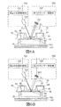
図6A、Bは、流路41の高さの測定について説明するための図であり、実施の形態2に係る測定システム2におけるヘマトクリット値取得部の構成を示す模式図である。図6A、Bにおいては、測定チップ10内の光路を示すために、測定チップ10の断面へのハッチングを省略している。なお、図6Aは、流路41内が空洞である状態(第1の状態)を示しており、図6Bは、第1の液で流路41内が満たされている状態(第2の状態)を示している。
6A and 6B are diagrams for explaining the measurement of the height of the
まず、第1の状態における第3の光δ3、第4の光δ4および第9の光δ9の検出について説明する。図6Aに示されるように、第2の光源ユニット151から出射された第1の光δ1は、金属膜30の表面(流路41の底面)だけではなく、枠体42の天面と、枠体42の凹部の底面(流路41の天面)とでも反射する。異なる位置で反射した光δ’(第3の光δ3、第4の光δ4および第9の光δ9)は、第2の受光センサー261の異なる位置に到達する。第9の光δ9、第4の光δ4および第3の光δ3は、この順で光出射部150から離れた位置の、第2の受光センサー261(アレイセンサー)の受光面に到達する。このように、第2の受光センサー261は、測定チップ10内における反射位置が異なる光の光量をそれぞれ区別して測定することができる。First, the detection of the third light δ 3 , the fourth light δ 4, and the ninth light δ 9 in the first state will be described. As shown in FIG. 6A, the first light δ 1 emitted from the second
次いで、第2の状態における第5の光δ5および第9の光δ9の検出について説明する。図6Bに示されるように、第2の光源ユニット151から出射された第1の光δ1は、金属膜30の表面(流路41の底面)だけでなく、枠体42の天面でも反射する。第1の状態の場合と比較して、第2の状態においては、枠体42の凹部の底面(流路41の天面)で、光が反射しない。これは、枠体42の屈折率と同程度の屈折率を有する第1の液が流路41内に満たされているためである。Next, the detection of the fifth light δ 5 and the ninth light δ 9 in the second state will be described. As shown in FIG. 6B, the first light δ 1 emitted from the second
そして、第1の状態における第3の光δ3、第4の光δ4および第9の光δ9の検出結果と、第2の状態における第5の光δ5および第9の光δ9の検出結果とに基づいて、流路41の高さを決定する。たとえば、第1の状態における検出結果と、第2の状態における検出結果とに基づいて下記の表1に示されるデータが得られたとする。表1では、反射位置No.、各反射位置での反射率と、第1の状態における結果および第2の状態で得られる結果(反射率)の差分とを示している。Then, the detection results of the third light δ 3 , the fourth light δ 4 and the ninth light δ 9 in the first state, and the fifth light δ 5 and the ninth light δ 9 in the second state. The height of the
第1の状態および第2の状態において、反射位置1での反射率は、互いに同じであり、4%であった。また、反射位置3での反射率も、第1の状態および第2の状態において、互いに同じであり、60%であった。一方で、第1の状態における反射位置2での反射率と、第2の状態における反射位置2での反射率とは、互いに異なっていた。
In the first state and the second state, the reflectances at the
流路41の底面以外の位置における反射率と比較して、流路41の底面での反射率は大きい。すなわち、反射率が大きい反射位置3は、流路41の底面であると決定され得る。このように、流路41の底面の位置は、高精度に検出され得る。
The reflectance at the bottom surface of the
これに対して、流路41の天面での反射率と枠体42の天面での反射率とは、互いに同程度であり、かつ小さい。このため、流路41の天面の位置および枠体42の天面の位置は、高精度に検出され難い。そこで、制御処理部270は、第1の状態における検出結果と、第2の状態における検出結果との差分を取ることにより、反射位置2で反射した第4の光δ4のピークのみを抽出し、反射位置2を決定することができる。前述のとおり、第1の状態および第2の状態において屈折率が変化する反射位置2は、流路41の天面と決定され得る。On the other hand, the reflectance on the top surface of the
反射位置2が決定されると、残りの反射位置1も決定され得る。第1の状態および第2の状態において、屈折率が変化しない反射位置1は、枠体42の天面であると決定され得る。
Once the reflection position 2 is determined, the remaining
したがって、制御処理部270は、流路41の底面の位置と、流路41の天面の位置とに基づいて、流路41の高さを決定することができる。
Therefore, the control processing unit 270 can determine the height of the
次いで、実施の形態1に係る測定方法と同様にして、入射角の増強角への設定(工程S112)からヘマトクリット関連値の取得(工程S118)までの工程を行う。 Next, in the same manner as the measurement method according to the first embodiment, the steps from setting the incident angle to the enhanced angle (step S112) to acquiring the hematocrit-related value (step S118) are performed.
次いで、ヘマトクリット値を決定する(工程S219)。制御処理部270は、光検出部160による第2の光δ2の検出結果に基づいて検体のヘマトクリット値を決定する。本実施の形態では、制御処理部270は、制御処理部270にあらかじめ記録されている補正係数を、工程S118で得られたヘマトクリット関連値に掛けることにより、ヘマトクリット値を算出する。さらに、本実施の形態では、工程S200で測定された流路41の高さに基づいて、ヘマトクリット値を補正する。たとえば、流路41の高さの基準値を100μmとしてヘマトクリット値を算出した場合を考える。この場合、流路41の高さの測定値が110μmであったときは、測定値と基準値とのずれ量(10μm)、つまり流路41の高さのずれ量に相当する検体の吸収率(吸光量)の変化量を考慮して、流路41の高さが100μmのときの値となるようにヘマトクリット値を補正すればよい。Next, the hematocrit value is determined (step S219). The control processing unit 270 determines the hematocrit value of the sample based on the detection result of the second light δ 2 by the photodetection unit 160. In the present embodiment, the control processing unit 270 calculates the hematocrit value by multiplying the hematocrit-related value obtained in step S118 by the correction coefficient recorded in advance in the control processing unit 270. Further, in the present embodiment, the hematocrit value is corrected based on the height of the
最後に、実施の形態1での測定値の補正(工程S120)と同様にして、ヘマトクリット値に基づいて測定値を補正する。実施の形態2では、制御処理部270は、ヘマトクリット値として、工程S219で得られた補正後のヘマトクリット値を使用する。 Finally, the measured value is corrected based on the hematocrit value in the same manner as in the correction of the measured value in the first embodiment (step S120). In the second embodiment, the control processing unit 270 uses the corrected hematocrit value obtained in step S219 as the hematocrit value.
以上の手順により、血漿中の被測定物質の量(濃度)を決定することができる。 By the above procedure, the amount (concentration) of the substance to be measured in plasma can be determined.
(効果)
実施の形態2では、実施の形態1の効果に加えて、より高精度にヘマトクリット値を測定し、より高精度に血漿中の被測定物質の量を決定することができる。実施の形態2では、流路41の高さに基づいてヘマトクリット値を補正することで、測定チップ10の製造時における寸法誤差の影響を取り除くことができる。これにより、測定チップ10に要求される寸法精度を低減することができる。(effect)
In the second embodiment, in addition to the effect of the first embodiment, the hematocrit value can be measured with higher accuracy and the amount of the substance to be measured in plasma can be determined with higher accuracy. In the second embodiment, the hematocrit value is corrected based on the height of the
[実施の形態3]
実施の形態3でも、流路の高さに基づいてヘマトクリット値を補正する。実施の形態3に係る測定システムおよび測定装置は、測定装置の動作手順(測定方法)を除いて、実施の形態1に係る測定システムおよび測定装置と同じであるため、同じ構成要素については、同じ符号を付してその説明を省略する。[Embodiment 3]
Also in the third embodiment, the hematocrit value is corrected based on the height of the flow path. Since the measuring system and the measuring device according to the third embodiment are the same as the measuring system and the measuring device according to the first embodiment except for the operation procedure (measurement method) of the measuring device, the same components are the same. The description will be omitted with reference to the reference.
(測定システムおよびSPFS装置)
図1は、実施の形態3に係る測定システム3の構成を示す模式図である。図1に示されるように、測定システム3は、測定チップ10およびSPFS装置300を有する。SPFS装置300は、励起光出射部110、シグナル検出部120、送液部130、搬送部140、光出射部150、光検出部160および制御処理部(処理部)370を有する。(Measurement system and SPFS device)
FIG. 1 is a schematic view showing the configuration of the
制御処理部370は、流路41の高さを測定するための制御が加わる点を除いて、実施の形態1に係る制御処理部170と同様であるため、その説明を省略する。なお、制御処理部370には、後述の第6の光δ6の検出結果に基づいて、流路41の高さを決定するための検量線に関するデータが記録されている。Since the control processing unit 370 is the same as the control processing unit 170 according to the first embodiment except that the control for measuring the height of the
(SPFS装置の動作手順)
実施の形態3に係る測定システム3の動作手順(実施の形態3に係る測定方法)について説明する。図7は、測定システム3の動作手順の一例を示すフローチャートである。(Operation procedure of SPFS device)
The operation procedure of the
実施の形態1に係る測定方法と同様にして、測定の準備(工程S110)からヘマトクリット関連値の取得(工程S118)までの工程を行う。 In the same manner as the measurement method according to the first embodiment, the steps from the preparation for measurement (step S110) to the acquisition of hematocrit-related values (step S118) are performed.
次いで、流路41の高さを測定する(工程S300)。具体的には、制御処理部370は、搬送ステージ141を制御して、測定チップ10を第2の測定位置から送液位置に移動させる。この後、制御処理部370は、ピペット制御部135を制御して、流路41内の液体を排出し、液体チップ50内に収容されている、第1の光δ1の少なくとも一部の波長の光を吸収する色素を含む第2の液を提供する。制御処理部370は、搬送ステージ141を制御して、測定チップ10を送液位置から第2の測定位置に再度移動させる。次いで、制御処理部370は、第2の光源ユニット151から金属膜30に第1の光δ1を照射させる。これと同時に、制御処理部370は、第2のセンサー制御部162を制御して、第2の液で流路41内が満たされている状態で、第1の光δ1が流路41内の第2の液を透過し、金属膜30で反射し、かつ流路41内の第2の液を再度透過して第6の光δ6を第2の受光センサー161により検出する。第6の光δ6の検出結果は、制御処理部370に送信され、記録される。Next, the height of the
制御処理部370は、光検出部160による第6の光δ6の検出結果に基づいて、流路41の高さを決定する。第2の液中の第6の光δ6の光路長は、流路41の高さに応じて変化する。第2の液中での第6の光δ6の色素による吸収量は、第2の液中での第6の光δ6の光路長に応じて変化する。したがって、第6の光δ6の光量に基づいて、流路41の高さを決定することができる。たとえば、制御処理部370は、あらかじめ作成しておいた検量線と、第6の光δ6の検出結果(光量)とに基づいて、流路41の高さを決定する。The control processing unit 370 determines the height of the
次いで、ヘマトクリット値を決定する(工程S319)。制御処理部370は、光検出部160の検出結果に基づいて検体のヘマトクリット値を決定する。本実施の形態では、制御処理部370は、制御処理部370にあらかじめ記録されている補正係数を、工程S118で得られたヘマトクリット関連値に掛けることにより、ヘマトクリット値を算出する。さらに、実施の形態3では、工程S300で測定された流路41の高さに基づいて、ヘマトクリット値を補正する。たとえば、流路41の高さの基準値を100μmとしてヘマトクリット値を算出した場合を考える。この場合、流路41の高さの測定値が110μmであったときは、測定値と基準値とのずれ量(10μm)、つまり流路41高さのずれ量に相当する検体の吸収率(吸光量)の変化量を考慮して、流路41の高さが100μmのときの値となるようにヘマトクリット値を補正すればよい。
Next, the hematocrit value is determined (step S319). The control processing unit 370 determines the hematocrit value of the sample based on the detection result of the
最後に、実施の形態1での測定値の補正(工程S120)と同様にして、ヘマトクリット値に基づいて測定値を補正する。実施の形態3では、制御処理部370は、ヘマトクリット値として、工程S319で得られた補正後のヘマトクリット値を使用する。 Finally, the measured value is corrected based on the hematocrit value in the same manner as in the correction of the measured value in the first embodiment (step S120). In the third embodiment, the control processing unit 370 uses the corrected hematocrit value obtained in step S319 as the hematocrit value.
以上の手順により、血漿中の被測定物質の量を決定することができる。 By the above procedure, the amount of the substance to be measured in plasma can be determined.
(効果)
実施の形態3では、実施の形態2と同様の効果を得られる。(effect)
In the third embodiment, the same effect as that of the second embodiment can be obtained.
[変形例]
(変形例1)
上記実施の形態1〜3では、金属膜である金属膜30において、第1の光δ1を鏡面反射させるとともに、表面プラズモン共鳴を生じさせる態様について説明したが、本発明はこの態様に限定されない。図8は、変形例1に係る測定システムにおけるヘマトクリット値取得部の構成を示す模式図である。図8においては、測定チップ10’内の光路を示すために、測定チップ10’の断面へのハッチングを省略している。図8に示されるように、第1の光δ1を鏡面反射させるための反射部30’と、表面プラズモンを生じさせる金属膜30とが別体として形成されていてもよい。なお、変形例1に係る測定チップ10’のプリズム20は、励起光αおよび第1の光δ1(および第1の光δ1と同じ波長の光δ’)に対して透明な誘電体からなる。[Modification example]
(Modification example 1)
In the first to third embodiments described above, a mode in which the first light δ 1 is specularly reflected and surface plasmon resonance is generated in the
変形例1に係る測定チップ10’では、反射部30’は、流路41を挟んでプリズム20と対向するように配置されており、金属膜30は、プリズム20上に配置されている。変形例1では、反射部30’は、枠体42の凹部の底面(流路41の天面)に配置されている。
In the measuring chip 10'according to the first modification, the reflecting portion 30'is arranged so as to face the
反射部30’の材料は、その表面で光を鏡面反射できる金属であれば特に限定されない。反射部30’の材料の例には、金、銀、銅、アルミニウム、およびこれらの合金が含まれる。変形例1では、反射部30’は、金薄膜である。反射部30’の厚みは、特に限定されないが、20nm〜10μmの範囲内が好ましい。反射部30’の形成方法は、特に限定されない。反射部30’の形成方法の例には、スパッタリング、蒸着、メッキが含まれる。 The material of the reflecting portion 30'is not particularly limited as long as it is a metal capable of specularly reflecting light on its surface. Examples of materials for the reflector 30'include gold, silver, copper, aluminum, and alloys thereof. In the first modification, the reflective portion 30'is a gold thin film. The thickness of the reflecting portion 30'is not particularly limited, but is preferably in the range of 20 nm to 10 μm. The method of forming the reflective portion 30'is not particularly limited. Examples of methods for forming the reflective portion 30'include sputtering, vapor deposition, and plating.
変形例1では、光出射部150は、プリズム20側から反射部30’に向けて第1の光δ1を出射する。光検出部160は、光出射部150が反射部30’に向けて第1の光δ1をプリズム20側から出射したときに、第1の光δ1が流路41内を通過し、反射部30’で反射し、かつ流路41内を再度通過した光を検出する。In the first modification, the
(変形例2)
上記実施の形態1〜3では、測定値取得部とヘマトクリット値測定部とが別体である態様について説明したが、本発明はこの態様に限定されない。図9は、変形例2に係る測定システムにおける測定値取得部およびヘマトクリット値取得部の構成を示す模式図である。図9に示されるように、測定値取得部およびヘマトクリット値取得部は、一体として構成されていてもよい。変形例2に係るSPFS装置は、必要に応じて、他の光学素子を有していてもよい。変形例2に係るSPFS装置は、第2の光源ユニット151からの第1の光δ1を反射するためのミラー153を有する。(Modification 2)
In the first to third embodiments, the mode in which the measured value acquisition unit and the hematocrit value measuring unit are separate bodies has been described, but the present invention is not limited to this mode. FIG. 9 is a schematic diagram showing the configurations of a measured value acquisition unit and a hematocrit value acquisition unit in the measurement system according to the second modification. As shown in FIG. 9, the measured value acquisition unit and the hematocrit value acquisition unit may be configured as one. The SPFS apparatus according to the second modification may have other optical elements, if necessary. The SPFS apparatus according to the second modification has a mirror 153 for reflecting the first light δ 1 from the second light source unit 151.
変形例2に係るSPFS装置では、シグナル検出部120のシグナルを集光するための光学レンズ(第1レンズ123および第2レンズ125)は、第1の光δ1を金属膜30に導くとともに、測定チップ10内での第1の光δ1の反射光δ’(例えば、第2の光δ2)を受光素子に導く光学レンズとしても機能する。また、シグナルを検出するための受光素子(第1の受光センサー126)は、第1の光δ1の測定チップ10内での反射光δ’(例えば、第2の光δ2)を受光するための第2の受光センサー161としても機能する。このように、測定値取得部およびヘマトクリット値測定部が一体として構成されていることは、測定装置のコストの低減と、測定装置の小型化との観点から好ましい。また、第1の測定位置と、第2の測定位置との間の移動が不要となるため、測定時間を短くすることもできる。なお、変形例2では、光学フィルター124は、光δ’に対して透明であってもよいし、光δ’に対して透明でなくてもよい。光学フィルター124が光δ’に対して透明でない場合、光δ’を検出する際に、光学フィルター124は光路外に退避される。In the SPFS apparatus according to the second modification, the optical lenses (
また、上記実施の形態2、3に係る測定装置200、300の構成は、上記の態様に限定されない。上記実施の形態2、3に係る測定装置200、300では、流路41の高さを測定するための光(第3の光δ3、第4の光δ4、第6の光δ6および第9の光δ9)を受光する受光センサーとしては、第2の光δ2を受光する第2の受光センサー161、261と同じ受光センサーを使用する場合について説明したが、本発明はこの態様に限定されない。流路41の高さを測定するための上記光を受光する受光センサーと、第2の光δ2を受光するための第2の受光センサーとは、異なっていてもよい。測定装置の大型化を避ける観点からは、流路41の高さを測定するための上記光を受光するための受光センサーと、第2の光δ2を受光するための受光センサーとは、同じであることが好ましい。Further, the configurations of the measuring devices 200 and 300 according to the second and third embodiments are not limited to the above aspects. In the measuring devices 200 and 300 according to the second and third embodiments, the light for measuring the height of the flow path 41 (third light δ 3 , fourth light δ 4 , sixth light δ 6 and As the light receiving sensor that receives the ninth light δ 9 ), the case where the same light receiving sensor as the second
また、上記実施の形態2、3では、流路41の高さを測定するとき、およびヘマトクリット値を測定するときにおいて、同一の光源ユニット(第2の光源ユニット151)を使用したが、使用される光源ユニットは、異なっていてもよい。
Further, in the above-described
また、流路41の高さを測定する場合に、測定装置200、300のヘマトクリット値測定部を使用しなくてもよい。たとえば、レーザー変位計のような他の光学装置が準備されてもよい。
Further, when measuring the height of the
また、上記実施の形態2、3では、流路41の高さを測定する態様について説明したが、本発明はこの態様に限定されない。流路41の高さに関する情報は、測定チップの製造時にあらかじめ測定されていてもよい。流路41の高さに関する情報は、制御処理部270、370にあらかじめ記録されていてもよいし、バーコードなどの識別子として測定チップに付されていてもよい。これにより、被測定物質の量を測定するときに、流路41の高さを測定しなくてもよいため、被測定物質の測定時間(診断時間)を短くすることができる。
Further, in the second and third embodiments, the mode of measuring the height of the
また、上記実施の形態2、3では、流路41の高さに基づいてヘマトクリット値を補正する態様について説明したが、流路41の高さの代わりに第2の光δ2となる光の流路41内の光路長に基づいてヘマトクリット値を補正してもよい。Further, in the second and third embodiments, the mode of correcting the hematocrit value based on the height of the
さらに、上記実施の形態1〜3では、SPSF法を利用し、測定値として蛍光物質からの蛍光βの蛍光値を測定する態様について説明したが、本発明はこの態様に限定されない。たとえば、SPR法を利用し、測定値として励起光αの反射光の光量を測定してもよい。または、本発明は、ELISA法やRIfS法、QCM法などを利用して測定値を取得してもよい。 Further, in the first to third embodiments described above, an embodiment in which the fluorescence value of fluorescence β from a fluorescent substance is measured as a measurement value by using the SPSF method has been described, but the present invention is not limited to this embodiment. For example, the SPR method may be used to measure the amount of reflected light of the excitation light α as a measured value. Alternatively, in the present invention, the measured value may be acquired by using an ELISA method, an RIfS method, a QCM method, or the like.
本出願は、2016年8月18日出願の特願2016−160753に基づく優先権を主張する。当該出願明細書および図面に記載された内容は、すべて本願明細書に援用される。 This application claims priority under Japanese Patent Application No. 2016-160753 filed on August 18, 2016. All the contents described in the application specification and drawings are incorporated in the specification of the present application.
本発明に係る被測定物質の測定方法、測定装置および測定システムは、被測定物質を高い信頼性で検出することができるため、例えば疾患の検査などに有用である。 The method for measuring a substance to be measured, a measuring device, and a measuring system according to the present invention can detect the substance to be measured with high reliability, and are therefore useful for, for example, a disease test.
1、2、3 測定システム
10、10’ 測定チップ
20 プリズム
21 入射面
22 成膜面
23 出射面
30 金属膜
30’ 反射部
40 流路蓋
41 流路
42 枠体
43 液体注入部被膜フィルム
44 液体貯蔵部被膜フィルム
45 液体注入部
46 液体貯蔵部
47 通気孔
48 ピペットチップ用貫通孔
50 液体チップ
100、200、300 SPFS装置
110 励起光出射部(第2の光出射部)
111 第1の光源ユニット
112 角度調整機構
113 第1の光源制御部
120 シグナル検出部
121 受光光学系ユニット
122 位置切替え機構
123 第1のレンズ
124 光学フィルター
125 第2のレンズ
126 第1の受光センサー
127 第1のセンサー制御部
130 送液部
131 ピペット
132 シリンジポンプ
133 ノズルユニット
134 ピペットチップ
135 ピペット制御部
140 搬送部
141 搬送ステージ
142 チップホルダー
150 光出射部
151 第2の光源ユニット
152 第2の光源制御部
153 ミラー
160、260 光検出部
161、261 第2の受光センサー
162 第2のセンサー制御部
170、270、370 制御処理部
α 励起光(第8の光)
β 蛍光
γ プラズモン散乱光
δ1 第1の光
δ’ 測定チップ内での第1の光の反射光
δ2 第2の光
δ3 第3の光
δ4 第4の光
δ5 第5の光
δ7 第7の光
δ9 第9の光1, 2, 3
111 First
β Fluorescent γ Plasmon scattered light δ 1 First light δ'Reflected light of the first light in the measuring chip δ 2 Second light δ 3 Third light δ 4 Fourth light δ 5 Fifth light δ 7 7th light δ 9 9th light
Claims (21)
液体を収容するための空洞である流路と、前記流路内を通過した光を、前記流路内を再度通過するように鏡面反射させるための反射部と、を有する測定チップの前記流路内に、前記被測定物質を含む前記検体を導入し、前記検体中の前記被測定物質の量を示す測定値を取得する工程と、
前記検体が前記流路内に存在する状態で、赤血球が吸収する波長の光を含む第1の光が前記流路内の前記検体を透過し、前記反射部で反射し、かつ前記流路内の前記検体を再度透過することで得られる第2の光を検出する工程と、
前記第2の光の検出結果、並びに、前記第2の光となる光の前記流路内の光路長、前記流路の高さ、および前記第1の光の波長の少なくとも1つに基づいて、前記検体のヘマトクリット値を決定する工程と、
前記ヘマトクリット値に基づいて前記測定値を補正する工程と、
を含む、測定方法。 It is a measuring method for measuring the amount of a substance to be measured in a sample containing blood.
The flow path of the measuring chip having a flow path that is a cavity for accommodating a liquid and a reflecting portion for mirror-reflecting light that has passed through the flow path so as to pass through the flow path again. A step of introducing the sample containing the substance to be measured into the sample and obtaining a measured value indicating the amount of the substance to be measured in the sample.
In a state where the sample is present in the flow path, first light including light having a wavelength absorbed by red blood cells is transmitted through the sample in the flow path, reflected by the reflection portion, and in the flow path. The step of detecting the second light obtained by passing through the sample again, and
Based on the detection result of the second light and at least one of the optical path length in the flow path of the light to be the second light, the height of the flow path, and the wavelength of the first light. , The step of determining the hematocrit value of the sample, and
A step of correcting the measured value based on the hematocrit value, and
Measurement methods, including.
前記第1の光に対して透明な第1の液で、前記流路内が満たされている第2の状態で、前記第1の光が前記流路内の前記第1の液を透過し、前記反射部で反射し、かつ前記流路内の前記第1の液を再度透過することで得られる第5の光をアレイセンサーにより検出する工程と、
前記第3の光、前記第4の光および前記第5の光の検出結果に基づいて、前記第2の光となる光の前記流路内の光路長または前記流路の高さを決定する工程と、
をさらに含む、請求項1に記載の測定方法。 A third obtained by passing the first light through the flow path, reflecting the light at the reflection portion, and passing through the flow path again in the first state where the inside of the flow path is hollow. And the step of detecting the fourth light obtained by reflecting the first light on the surface of the flow path facing the reflecting portion by the array sensor.
In a second state in which the flow path is filled with the first liquid that is transparent to the first light, the first light passes through the first liquid in the flow path. The step of detecting the fifth light, which is reflected by the reflecting portion and is obtained by re-transmitting the first liquid in the flow path, by the array sensor.
Based on the detection results of the third light, the fourth light, and the fifth light, the optical path length or the height of the flow path in the flow path of the light to be the second light is determined. Process and
Further comprising measuring method according to claim 1.
前記第6の光の検出結果に基づいて、前記第2の光となる光の前記流路内の光路長または前記流路の高さを決定する工程と、
をさらに含む、請求項1に記載の測定方法。 The first light is the first light in the flow path while the flow path is filled with a second liquid containing a dye that absorbs light having at least a part of the wavelength of the first light. A step of detecting a sixth light obtained by transmitting the liquid of 2 and reflecting the light at the reflecting portion and transmitting the second liquid in the flow path again.
A step of determining the optical path length or the height of the flow path in the flow path of the light to be the second light based on the detection result of the sixth light.
Further comprising measuring method according to claim 1.
前記ヘマトクリット値を決定する工程では、前記第2の光の検出結果、前記第7の光の検出結果、並びに、前記第2の光となる光の前記流路内の光路長、前記流路の高さ、および前記第1の光の波長の少なくとも1つに基づいて、前記ヘマトクリット値を決定する、
請求項1〜4のいずれか一項に記載の測定方法。 In a state where the reference liquid transparent to the first light is present in the flow path, the first light passes through the reference liquid in the flow path, is reflected by the reflection portion, and is said to be described. Further including a step of detecting a seventh light obtained by passing through the reference liquid in the flow path.
In the step of determining the hematocrit value, the detection result of the second light, the detection result of the seventh light , the optical path length in the flow path of the light to be the second light, and the flow path of the flow path. The hematocrit value is determined based on the height and at least one of the wavelengths of the first light .
The measuring method according to any one of claims 1 to 4.
前記測定値を取得する工程では、前記金属膜上に、前記検体中に含まれていた前記被測定物質が固定化され、かつ前記検体が存在しない状態で、前記プリズムを介して前記金属膜に、表面プラズモン共鳴が生じる入射角で第8の光を照射したときに生じる、前記被測定物質の量を示すシグナルを検出して、前記測定値を取得し、
前記第2の光を検出する工程では、前記検体が前記流路内に存在する状態で、前記プリズム側から前記反射部に前記第1の光を照射する、
請求項1〜6のいずれか一項に記載の測定方法。 The measuring chip is arranged so as to face the prism, the metal film arranged on the prism, the flow path arranged on the metal film, and the flow path across the flow path. With the reflective part,
In the step of acquiring the measured value, the substance to be measured contained in the sample is immobilized on the metal film, and the sample is not present on the metal film via the prism. , The measured value is obtained by detecting the signal indicating the amount of the substance to be measured, which is generated when the eighth light is irradiated at the incident angle at which surface plasmon resonance occurs.
In the step of detecting the second light, the first light is irradiated from the prism side to the reflecting portion while the sample is present in the flow path.
The measuring method according to any one of claims 1 to 6.
前記測定値を取得する工程では、前記反射部上に、前記検体中に含まれていた前記被測定物質が固定化され、かつ前記検体が存在しない状態で、前記プリズムを介して前記反射部に、表面プラズモン共鳴が生じる入射角で第8の光を照射したときに生じる、前記被測定物質の量を示すシグナルを検出して、前記測定値を取得し、
前記第2の光を検出する工程では、前記検体が前記流路内に存在する状態で、前記流路側から前記反射部に前記第1の光を照射する、
請求項1〜6のいずれか一項に記載の測定方法。 The measuring chip has a prism, a reflection portion which is a metal film arranged on the prism, and a flow path arranged on the reflection portion.
In the step of acquiring the measured value, the substance to be measured contained in the sample is immobilized on the reflective portion, and the sample is not present on the reflective portion via the prism. , A signal indicating the amount of the substance to be measured, which is generated when the eighth light is irradiated at an incident angle at which surface plasmon resonance occurs, is detected to obtain the measured value.
In the step of detecting the second light, the first light is irradiated from the flow path side to the reflection portion while the sample is present in the flow path.
The measuring method according to any one of claims 1 to 6.
液体を収容するための空洞である流路と、前記流路内を通過した光を、前記流路内を再度通過するように鏡面反射させるための反射部と、を有する測定チップを保持するためのチップホルダーと、
前記チップホルダーに保持された前記測定チップの前記流路内に、前記検体中の前記被測定物質が存在する状態で、前記検体中の前記被測定物質の量を示す測定値を取得するための測定値取得部と、
赤血球が吸収する波長の光を含む第1の光を出射するための光出射部と、
前記検体が前記流路内に存在する状態で、前記光出射部が前記反射部に向けて前記第1の光を出射したときに、前記第1の光が前記流路内の前記検体を透過し、前記反射部で反射し、かつ前記流路内の前記検体を再度透過することで得られる第2の光を検出するための光検出部と、
前記光検出部による前記第2の光の検出結果、並びに、前記第2の光となる光の前記流路内の光路長、前記流路の高さ、および前記第1の光の波長の少なくとも1つに基づいて前記検体のヘマトクリット値を決定するとともに、前記ヘマトクリット値に基づいて前記測定値を補正する処理部と、
を有する、測定装置。 A measuring device for measuring the amount of a substance to be measured in a sample containing blood.
To hold a measuring chip having a flow path that is a cavity for accommodating a liquid and a reflecting portion for mirror-reflecting light that has passed through the flow path so as to pass through the flow path again. Chip holder and
To obtain a measured value indicating the amount of the substance to be measured in the sample in a state where the substance to be measured in the sample is present in the flow path of the measurement chip held in the chip holder. Measurement value acquisition unit and
A light emitting part for emitting a first light including light having a wavelength absorbed by red blood cells,
When the light emitting unit emits the first light toward the reflecting unit while the sample is present in the flow path, the first light passes through the sample in the flow path. Then, a light detection unit for detecting the second light that is reflected by the reflection unit and is obtained by passing the sample in the flow path again.
At least the detection result of the second light by the photodetector , the optical path length in the flow path of the light to be the second light, the height of the flow path, and the wavelength of the first light. A processing unit that determines the hematocrit value of the sample based on one and corrects the measured value based on the hematocrit value.
Has a measuring device.
前記光検出部は、
前記流路内が空洞である状態で、前記光出射部が前記反射部に向けて前記第1の光を出射したときに、前記第1の光が前記流路内を通過し、前記反射部で反射し、かつ前記流路内を再度通過することで得られる第3の光と、前記第1の光が、前記流路の、前記反射部に対向する面で反射することで得られる第4の光とを検出し、かつ
前記第1の光に対して透明な第1の液で前記流路内が満たされている状態で、前記光出射部が前記反射部に向けて前記第1の光を出射したときに、前記第1の光が前記流路内の前記第1の液を透過し、前記反射部で反射し、かつ前記流路内の前記第1の液を再度透過することで得られる第5の光を検出し、
前記処理部は、前記アレイセンサーによる前記第3の光、前記第4の光および前記第5の光の検出結果に基づいて、前記第2の光となる光の前記流路内の光路長または前記流路の高さを決定する、
請求項10に記載の測定装置。 The photodetector has an array sensor for receiving the second light.
The photodetector
When the light emitting portion emits the first light toward the reflecting portion in a state where the inside of the flow path is hollow, the first light passes through the flow path and the reflecting portion. The third light obtained by reflecting in the flow path and passing through the flow path again, and the first light obtained by reflecting the first light on the surface of the flow path facing the reflecting portion. In a state where the light of 4 is detected and the inside of the flow path is filled with the first liquid that is transparent to the first light, the light emitting portion is directed toward the reflecting portion. When the light is emitted, the first light transmits the first liquid in the flow path, is reflected by the reflection portion, and is transmitted again through the first liquid in the flow path. Detecting the fifth light obtained by
Based on the detection results of the third light, the fourth light, and the fifth light by the array sensor, the processing unit may perform an optical path length in the flow path of the light to be the second light. Determining the height of the flow path,
The measuring device according to claim 10.
前記処理部は、前記光検出部による前記第6の光の検出結果に基づいて、前記第2の光となる光の前記流路内の光路長または前記流路の高さを決定する、
請求項10に記載の測定装置。 The light detection unit is a second liquid containing a dye that absorbs light having a wavelength of at least a part of the first light, and the light emitting unit reflects the light while the inside of the flow path is filled. When the first light is emitted toward a portion, the first light passes through the second liquid in the flow path, is reflected by the reflection portion, and is the first in the flow path. The sixth light obtained by transmitting the liquid of 2 again is detected, and the light is detected.
The processing unit determines the optical path length or the height of the flow path in the flow path of the light to be the second light based on the detection result of the sixth light by the light detection unit.
The measuring device according to claim 10.
前記処理部は、前記第2の光の検出結果、前記第7の光の検出結果、並びに、前記第2の光となる光の前記流路内の光路長、前記流路の高さ、および前記第1の光の波長の少なくとも1つに基づいて、前記ヘマトクリット値を決定する、
請求項10〜14のいずれか一項に記載の測定装置。 When the light emitting unit emits the first light toward the reflecting unit in a state where a reference liquid transparent to the first light is present in the flow path, the light detecting unit emits the first light toward the reflecting unit. , The first light is transmitted through the reference liquid in the flow path, is reflected by the reflection portion, and is transmitted again through the reference liquid in the flow path to detect the seventh light. ,
The processing unit has the detection result of the second light, the detection result of the seventh light , the optical path length in the flow path of the light to be the second light, the height of the flow path, and the height of the flow path. The hematocrit value is determined based on at least one of the first light wavelengths .
The measuring device according to any one of claims 10 to 14.
前記測定値取得部は、
第8の光を出射するための第2の光出射部と、
前記金属膜上に、前記検体に含まれていた前記被測定物質が固定化され、かつ前記検体が存在しない状態で、前記第2の光出射部が前記プリズムを介して前記金属膜に向けて、表面プラズモン共鳴が生じる入射角で前記第8の光を出射したときに生じる、前記被測定物質の量を示すシグナルを検出するためのシグナル検出部と、
を有し、
前記光出射部は、前記プリズム側から前記反射部に向けて前記第1の光を出射し、
前記処理部は、前記シグナル検出部の検出結果に基づいて前記測定値を取得する、
請求項10〜16のいずれか一項に記載の測定装置。 The measuring chip is arranged so as to face the prism, the metal film arranged on the prism, the flow path arranged on the metal film, and the flow path across the flow path. Has the above-mentioned reflective part
The measured value acquisition unit
A second light emitting part for emitting the eighth light, and
In a state where the substance to be measured contained in the sample is immobilized on the metal film and the sample does not exist, the second light emitting portion is directed toward the metal film via the prism. , A signal detection unit for detecting a signal indicating the amount of the substance to be measured, which is generated when the eighth light is emitted at an incident angle at which surface plasmon resonance occurs.
Have,
The light emitting unit emits the first light from the prism side toward the reflecting unit.
The processing unit acquires the measured value based on the detection result of the signal detection unit.
The measuring device according to any one of claims 10 to 16.
前記測定値取得部は、
第8の光を出射するための第2の光出射部と、
前記金属膜上に、前記検体に含まれていた前記被測定物質が固定化され、かつ前記検体が存在しない状態で、前記第2の光出射部が前記プリズムを介して前記金属膜に向けて、表面プラズモン共鳴が生じる入射角で前記第8の光を出射したときに生じる、前記被測定物質の量を示すシグナルを検出するためのシグナル検出部と、
を有し、
前記光出射部は、前記流路側から前記反射部に向けて前記第1の光を出射し、
前記処理部は、前記シグナル検出部の検出結果に基づいて前記測定値を取得する、
請求項10〜16のいずれか一項に記載の測定装置。 The measuring chip has a prism, a reflection portion which is a metal film arranged on the prism, and a flow path arranged on the reflection portion.
The measured value acquisition unit
A second light emitting part for emitting the eighth light, and
In a state where the substance to be measured contained in the sample is immobilized on the metal film and the sample does not exist, the second light emitting portion is directed toward the metal film via the prism. , A signal detection unit for detecting a signal indicating the amount of the substance to be measured, which is generated when the eighth light is emitted at an incident angle at which surface plasmon resonance occurs.
Have,
The light emitting portion emits the first light from the flow path side toward the reflecting portion.
The processing unit acquires the measured value based on the detection result of the signal detection unit.
The measuring device according to any one of claims 10 to 16.
前記光学レンズは、前記第1の光を前記反射部に導くとともに、前記第2の光を前記受光素子に導く光学レンズとしても機能し、
前記受光素子は、前記第2の光を受光するための受光素子としても機能する、
請求項19に記載の測定装置。 The signal detection unit includes an optical lens for collecting the signal and a light receiving element for receiving the signal.
The optical lens functions as an optical lens that guides the first light to the reflecting portion and also guides the second light to the light receiving element.
The light receiving element also functions as a light receiving element for receiving the second light.
The measuring device according to claim 19.
液体を収容するための空洞である流路と、前記流路内を通過した光を、前記流路内を再度通過するように鏡面反射させるための反射部と、を有する測定チップと、
前記流路内に、前記検体中の前記被測定物質が存在する状態で、前記検体中の前記被測定物質の量を示す測定値を取得するための測定値取得部と、
赤血球が吸収する波長の光を含む第1の光を出射するための光出射部と、
前記検体が前記流路内に存在する状態で、前記光出射部が前記反射部に向けて前記第1の光を出射したときに、前記第1の光が前記流路内の前記検体を透過し、前記反射部で反射し、かつ前記流路内の前記検体を再度透過することで得られる第2の光を検出するための光検出部と、
前記光検出部による前記第2の光の検出結果、並びに、前記第2の光となる光の前記流路内の光路長、前記流路の高さ、および前記第1の光の波長の少なくとも1つに基づいて前記検体のヘマトクリット値を決定するとともに、前記ヘマトクリット値に基づいて前記測定値を補正する処理部と、
を有する、測定システム。 A measurement system for measuring the amount of substance to be measured in a sample containing blood.
A measuring chip having a flow path that is a cavity for accommodating a liquid and a reflecting portion for mirror-reflecting light that has passed through the flow path so as to pass through the flow path again.
In a state where the substance to be measured in the sample is present in the flow path, a measurement value acquisition unit for acquiring a measurement value indicating the amount of the substance to be measured in the sample, and a measurement value acquisition unit.
A light emitting part for emitting a first light including light having a wavelength absorbed by red blood cells,
When the light emitting unit emits the first light toward the reflecting portion while the sample is present in the flow path, the first light passes through the sample in the flow path. Then, a light detection unit for detecting the second light that is reflected by the reflection unit and is obtained by passing the sample in the flow path again.
At least the detection result of the second light by the photodetector , the optical path length in the flow path of the light to be the second light, the height of the flow path, and the wavelength of the first light. A processing unit that determines the hematocrit value of the sample based on one and corrects the measured value based on the hematocrit value.
Has a measurement system.
Applications Claiming Priority (3)
| Application Number | Priority Date | Filing Date | Title |
|---|---|---|---|
| JP2016160753 | 2016-08-18 | ||
| JP2016160753 | 2016-08-18 | ||
| PCT/JP2017/027868 WO2018034143A1 (en) | 2016-08-18 | 2017-08-01 | Measurement method, measurement apparatus, and measurement system |
Publications (2)
| Publication Number | Publication Date |
|---|---|
| JPWO2018034143A1 JPWO2018034143A1 (en) | 2019-06-13 |
| JP6856074B2 true JP6856074B2 (en) | 2021-04-07 |
Family
ID=61196502
Family Applications (1)
| Application Number | Title | Priority Date | Filing Date |
|---|---|---|---|
| JP2018534326A Expired - Fee Related JP6856074B2 (en) | 2016-08-18 | 2017-08-01 | Measuring method, measuring device and measuring system |
Country Status (4)
| Country | Link |
|---|---|
| US (1) | US11047798B2 (en) |
| EP (1) | EP3505913A4 (en) |
| JP (1) | JP6856074B2 (en) |
| WO (1) | WO2018034143A1 (en) |
Families Citing this family (4)
| Publication number | Priority date | Publication date | Assignee | Title |
|---|---|---|---|---|
| US11169089B2 (en) * | 2016-09-14 | 2021-11-09 | Konica Minolta, Inc. | Surface plasmon resonance measurement method for measuring amount of substance in a specimen including whole blood |
| CN111093830A (en) * | 2017-07-18 | 2020-05-01 | 分子装置有限公司 | Object picking device with imaging-based pipette tip positioning |
| JP7292285B2 (en) * | 2018-08-13 | 2023-06-16 | 大塚製薬株式会社 | Surface plasmon resonance fluorescence analysis device and surface plasmon resonance fluorescence analysis method |
| CN112485438B (en) * | 2020-11-10 | 2022-07-22 | 深圳市科曼医疗设备有限公司 | Specific protein reaction detection method and device |
Family Cites Families (14)
| Publication number | Priority date | Publication date | Assignee | Title |
|---|---|---|---|---|
| JPH01104114A (en) | 1987-10-19 | 1989-04-21 | Fuji Giken Kk | Culture base for mushroom |
| US5331958A (en) * | 1992-03-31 | 1994-07-26 | University Of Manitoba | Spectrophotometric blood analysis |
| JP3586743B2 (en) | 1995-10-09 | 2004-11-10 | アークレイ株式会社 | Measurement method with corrected hematocrit value |
| JPH11104114A (en) * | 1997-09-30 | 1999-04-20 | Terumo Corp | Measuring device of blood characteristics |
| US6064474A (en) * | 1998-02-06 | 2000-05-16 | Optical Sensors, Inc. | Optical measurement of blood hematocrit incorporating a self-calibration algorithm |
| JP4129867B2 (en) * | 2002-07-18 | 2008-08-06 | 日機装株式会社 | Hematocrit sensor |
| US7271912B2 (en) * | 2003-04-15 | 2007-09-18 | Optiscan Biomedical Corporation | Method of determining analyte concentration in a sample using infrared transmission data |
| JP5427362B2 (en) | 2008-03-25 | 2014-02-26 | テルモ株式会社 | Method and apparatus for measuring hematocrit value or blood component concentration |
| EP2136210B1 (en) | 2008-06-18 | 2018-08-15 | Horiba, Ltd. | Body fluid sample analyzer |
| JP5806884B2 (en) * | 2010-09-24 | 2015-11-10 | 株式会社堀場製作所 | Whole blood immunoassay device and whole blood immunoassay method |
| WO2014049704A1 (en) | 2012-09-26 | 2014-04-03 | テルモ株式会社 | Measuring tip |
| EP3112847A4 (en) * | 2014-02-25 | 2017-10-04 | Konica Minolta, Inc. | Measurement method and measurement device |
| JPWO2016039149A1 (en) * | 2014-09-10 | 2017-06-22 | コニカミノルタ株式会社 | Detection method and detection apparatus |
| JP2016160753A (en) | 2015-02-26 | 2016-09-05 | 尼寺空圧工業株式会社 | Air compressor with engine |
-
2017
- 2017-08-01 WO PCT/JP2017/027868 patent/WO2018034143A1/en not_active Ceased
- 2017-08-01 EP EP17841370.4A patent/EP3505913A4/en not_active Withdrawn
- 2017-08-01 US US16/322,832 patent/US11047798B2/en not_active Expired - Fee Related
- 2017-08-01 JP JP2018534326A patent/JP6856074B2/en not_active Expired - Fee Related
Also Published As
| Publication number | Publication date |
|---|---|
| EP3505913A1 (en) | 2019-07-03 |
| US11047798B2 (en) | 2021-06-29 |
| JPWO2018034143A1 (en) | 2019-06-13 |
| US20200182784A1 (en) | 2020-06-11 |
| EP3505913A4 (en) | 2019-07-03 |
| WO2018034143A1 (en) | 2018-02-22 |
Similar Documents
| Publication | Publication Date | Title |
|---|---|---|
| JP6369533B2 (en) | Measuring method and measuring device | |
| JP6635168B2 (en) | Surface plasmon resonance fluorescence analysis method | |
| US9535004B2 (en) | Surface plasmon resonance fluorescence analysis method and surface plasmon resonance fluorescence analysis device | |
| JP6424890B2 (en) | Surface plasmon enhanced fluorescence measurement method, surface plasmon enhanced fluorescence measurement device and analysis chip | |
| JP6777090B2 (en) | Surface plasmon resonance fluorescence analysis method and surface plasmon resonance fluorescence analyzer | |
| JP6856074B2 (en) | Measuring method, measuring device and measuring system | |
| JP6791248B2 (en) | Detection method and detection device | |
| JP6848975B2 (en) | Measuring method | |
| JP6888548B2 (en) | Measuring method | |
| JP6760384B2 (en) | Measuring method | |
| JP6805637B2 (en) | Hematocrit value measuring method, hematocrit value measuring device, amount of substance to be measured, and amount of substance to be measured | |
| WO2017057136A1 (en) | Surface plasmon-field enhanced fluorescence spectroscopy and measurement kit | |
| JP6954116B2 (en) | Measuring method, measuring device and measuring chip | |
| JP7405846B2 (en) | Measuring method and measuring device | |
| JP6702046B2 (en) | Detection method and detection device | |
| JP7469309B2 (en) | Measurement method and device | |
| JPWO2016072307A1 (en) | Detection apparatus and detection method | |
| WO2016147774A1 (en) | Measuring method and measuring device |
Legal Events
| Date | Code | Title | Description |
|---|---|---|---|
| RD02 | Notification of acceptance of power of attorney |
Free format text: JAPANESE INTERMEDIATE CODE: A7422 Effective date: 20190708 |
|
| RD04 | Notification of resignation of power of attorney |
Free format text: JAPANESE INTERMEDIATE CODE: A7424 Effective date: 20191016 |
|
| A621 | Written request for application examination |
Free format text: JAPANESE INTERMEDIATE CODE: A621 Effective date: 20200318 |
|
| A131 | Notification of reasons for refusal |
Free format text: JAPANESE INTERMEDIATE CODE: A131 Effective date: 20200908 |
|
| A521 | Request for written amendment filed |
Free format text: JAPANESE INTERMEDIATE CODE: A523 Effective date: 20201106 |
|
| TRDD | Decision of grant or rejection written | ||
| A01 | Written decision to grant a patent or to grant a registration (utility model) |
Free format text: JAPANESE INTERMEDIATE CODE: A01 Effective date: 20210216 |
|
| A61 | First payment of annual fees (during grant procedure) |
Free format text: JAPANESE INTERMEDIATE CODE: A61 Effective date: 20210301 |
|
| R150 | Certificate of patent or registration of utility model |
Ref document number: 6856074 Country of ref document: JP Free format text: JAPANESE INTERMEDIATE CODE: R150 |
|
| LAPS | Cancellation because of no payment of annual fees |