JP6856012B2 - Separator for fuel cells - Google Patents
Separator for fuel cells Download PDFInfo
- Publication number
- JP6856012B2 JP6856012B2 JP2017239807A JP2017239807A JP6856012B2 JP 6856012 B2 JP6856012 B2 JP 6856012B2 JP 2017239807 A JP2017239807 A JP 2017239807A JP 2017239807 A JP2017239807 A JP 2017239807A JP 6856012 B2 JP6856012 B2 JP 6856012B2
- Authority
- JP
- Japan
- Prior art keywords
- base material
- titanium
- separator
- carbon
- titanium base
- Prior art date
- Legal status (The legal status is an assumption and is not a legal conclusion. Google has not performed a legal analysis and makes no representation as to the accuracy of the status listed.)
- Active
Links
Images


Classifications
-
- H—ELECTRICITY
- H01—ELECTRIC ELEMENTS
- H01M—PROCESSES OR MEANS, e.g. BATTERIES, FOR THE DIRECT CONVERSION OF CHEMICAL ENERGY INTO ELECTRICAL ENERGY
- H01M8/00—Fuel cells; Manufacture thereof
- H01M8/02—Details
- H01M8/0202—Collectors; Separators, e.g. bipolar separators; Interconnectors
- H01M8/0204—Non-porous and characterised by the material
- H01M8/0206—Metals or alloys
-
- C—CHEMISTRY; METALLURGY
- C23—COATING METALLIC MATERIAL; COATING MATERIAL WITH METALLIC MATERIAL; CHEMICAL SURFACE TREATMENT; DIFFUSION TREATMENT OF METALLIC MATERIAL; COATING BY VACUUM EVAPORATION, BY SPUTTERING, BY ION IMPLANTATION OR BY CHEMICAL VAPOUR DEPOSITION, IN GENERAL; INHIBITING CORROSION OF METALLIC MATERIAL OR INCRUSTATION IN GENERAL
- C23C—COATING METALLIC MATERIAL; COATING MATERIAL WITH METALLIC MATERIAL; SURFACE TREATMENT OF METALLIC MATERIAL BY DIFFUSION INTO THE SURFACE, BY CHEMICAL CONVERSION OR SUBSTITUTION; COATING BY VACUUM EVAPORATION, BY SPUTTERING, BY ION IMPLANTATION OR BY CHEMICAL VAPOUR DEPOSITION, IN GENERAL
- C23C8/00—Solid state diffusion of only non-metal elements into metallic material surfaces; Chemical surface treatment of metallic material by reaction of the surface with a reactive gas, leaving reaction products of surface material in the coating, e.g. conversion coatings, passivation of metals
- C23C8/60—Solid state diffusion of only non-metal elements into metallic material surfaces; Chemical surface treatment of metallic material by reaction of the surface with a reactive gas, leaving reaction products of surface material in the coating, e.g. conversion coatings, passivation of metals using solids, e.g. powders, pastes
- C23C8/62—Solid state diffusion of only non-metal elements into metallic material surfaces; Chemical surface treatment of metallic material by reaction of the surface with a reactive gas, leaving reaction products of surface material in the coating, e.g. conversion coatings, passivation of metals using solids, e.g. powders, pastes only one element being applied
- C23C8/64—Carburising
-
- H—ELECTRICITY
- H01—ELECTRIC ELEMENTS
- H01M—PROCESSES OR MEANS, e.g. BATTERIES, FOR THE DIRECT CONVERSION OF CHEMICAL ENERGY INTO ELECTRICAL ENERGY
- H01M8/00—Fuel cells; Manufacture thereof
- H01M8/02—Details
- H01M8/0202—Collectors; Separators, e.g. bipolar separators; Interconnectors
-
- H—ELECTRICITY
- H01—ELECTRIC ELEMENTS
- H01M—PROCESSES OR MEANS, e.g. BATTERIES, FOR THE DIRECT CONVERSION OF CHEMICAL ENERGY INTO ELECTRICAL ENERGY
- H01M8/00—Fuel cells; Manufacture thereof
- H01M8/02—Details
- H01M8/0202—Collectors; Separators, e.g. bipolar separators; Interconnectors
- H01M8/0204—Non-porous and characterised by the material
- H01M8/0213—Gas-impermeable carbon-containing materials
-
- H—ELECTRICITY
- H01—ELECTRIC ELEMENTS
- H01M—PROCESSES OR MEANS, e.g. BATTERIES, FOR THE DIRECT CONVERSION OF CHEMICAL ENERGY INTO ELECTRICAL ENERGY
- H01M8/00—Fuel cells; Manufacture thereof
- H01M8/02—Details
- H01M8/0202—Collectors; Separators, e.g. bipolar separators; Interconnectors
- H01M8/0204—Non-porous and characterised by the material
- H01M8/0223—Composites
- H01M8/0228—Composites in the form of layered or coated products
-
- H—ELECTRICITY
- H01—ELECTRIC ELEMENTS
- H01M—PROCESSES OR MEANS, e.g. BATTERIES, FOR THE DIRECT CONVERSION OF CHEMICAL ENERGY INTO ELECTRICAL ENERGY
- H01M8/00—Fuel cells; Manufacture thereof
- H01M8/02—Details
- H01M8/0202—Collectors; Separators, e.g. bipolar separators; Interconnectors
- H01M8/023—Porous and characterised by the material
- H01M8/0232—Metals or alloys
-
- H—ELECTRICITY
- H01—ELECTRIC ELEMENTS
- H01M—PROCESSES OR MEANS, e.g. BATTERIES, FOR THE DIRECT CONVERSION OF CHEMICAL ENERGY INTO ELECTRICAL ENERGY
- H01M8/00—Fuel cells; Manufacture thereof
- H01M8/02—Details
- H01M8/0202—Collectors; Separators, e.g. bipolar separators; Interconnectors
- H01M8/0247—Collectors; Separators, e.g. bipolar separators; Interconnectors characterised by the form
-
- H—ELECTRICITY
- H01—ELECTRIC ELEMENTS
- H01M—PROCESSES OR MEANS, e.g. BATTERIES, FOR THE DIRECT CONVERSION OF CHEMICAL ENERGY INTO ELECTRICAL ENERGY
- H01M8/00—Fuel cells; Manufacture thereof
- H01M8/02—Details
- H01M8/0202—Collectors; Separators, e.g. bipolar separators; Interconnectors
- H01M8/0258—Collectors; Separators, e.g. bipolar separators; Interconnectors characterised by the configuration of channels, e.g. by the flow field of the reactant or coolant
-
- H—ELECTRICITY
- H01—ELECTRIC ELEMENTS
- H01M—PROCESSES OR MEANS, e.g. BATTERIES, FOR THE DIRECT CONVERSION OF CHEMICAL ENERGY INTO ELECTRICAL ENERGY
- H01M8/00—Fuel cells; Manufacture thereof
- H01M8/10—Fuel cells with solid electrolytes
- H01M8/1004—Fuel cells with solid electrolytes characterised by membrane-electrode assemblies [MEA]
-
- H—ELECTRICITY
- H01—ELECTRIC ELEMENTS
- H01M—PROCESSES OR MEANS, e.g. BATTERIES, FOR THE DIRECT CONVERSION OF CHEMICAL ENERGY INTO ELECTRICAL ENERGY
- H01M8/00—Fuel cells; Manufacture thereof
- H01M8/10—Fuel cells with solid electrolytes
- H01M2008/1095—Fuel cells with polymeric electrolytes
-
- H—ELECTRICITY
- H01—ELECTRIC ELEMENTS
- H01M—PROCESSES OR MEANS, e.g. BATTERIES, FOR THE DIRECT CONVERSION OF CHEMICAL ENERGY INTO ELECTRICAL ENERGY
- H01M2250/00—Fuel cells for particular applications; Specific features of fuel cell system
- H01M2250/20—Fuel cells in motive systems, e.g. vehicle, ship, plane
-
- H—ELECTRICITY
- H01—ELECTRIC ELEMENTS
- H01M—PROCESSES OR MEANS, e.g. BATTERIES, FOR THE DIRECT CONVERSION OF CHEMICAL ENERGY INTO ELECTRICAL ENERGY
- H01M8/00—Fuel cells; Manufacture thereof
- H01M8/02—Details
- H01M8/0202—Collectors; Separators, e.g. bipolar separators; Interconnectors
- H01M8/0247—Collectors; Separators, e.g. bipolar separators; Interconnectors characterised by the form
- H01M8/0254—Collectors; Separators, e.g. bipolar separators; Interconnectors characterised by the form corrugated or undulated
-
- Y—GENERAL TAGGING OF NEW TECHNOLOGICAL DEVELOPMENTS; GENERAL TAGGING OF CROSS-SECTIONAL TECHNOLOGIES SPANNING OVER SEVERAL SECTIONS OF THE IPC; TECHNICAL SUBJECTS COVERED BY FORMER USPC CROSS-REFERENCE ART COLLECTIONS [XRACs] AND DIGESTS
- Y02—TECHNOLOGIES OR APPLICATIONS FOR MITIGATION OR ADAPTATION AGAINST CLIMATE CHANGE
- Y02E—REDUCTION OF GREENHOUSE GAS [GHG] EMISSIONS, RELATED TO ENERGY GENERATION, TRANSMISSION OR DISTRIBUTION
- Y02E60/00—Enabling technologies; Technologies with a potential or indirect contribution to GHG emissions mitigation
- Y02E60/30—Hydrogen technology
- Y02E60/50—Fuel cells
-
- Y—GENERAL TAGGING OF NEW TECHNOLOGICAL DEVELOPMENTS; GENERAL TAGGING OF CROSS-SECTIONAL TECHNOLOGIES SPANNING OVER SEVERAL SECTIONS OF THE IPC; TECHNICAL SUBJECTS COVERED BY FORMER USPC CROSS-REFERENCE ART COLLECTIONS [XRACs] AND DIGESTS
- Y02—TECHNOLOGIES OR APPLICATIONS FOR MITIGATION OR ADAPTATION AGAINST CLIMATE CHANGE
- Y02P—CLIMATE CHANGE MITIGATION TECHNOLOGIES IN THE PRODUCTION OR PROCESSING OF GOODS
- Y02P70/00—Climate change mitigation technologies in the production process for final industrial or consumer products
- Y02P70/50—Manufacturing or production processes characterised by the final manufactured product
Description
燃料電池の電極を含む発電部同士を区画するように、発電部に接触する燃料電池用のセパレータの製造方法に関する。 The present invention relates to a method for manufacturing a separator for a fuel cell that comes into contact with the power generation unit so as to partition the power generation units including the electrodes of the fuel cell.
従来から、燃料電池では、固体高分子電解質膜の両面に、一対の電極が形成された膜電極接合体を含む発電部を単セルとし、発電部は、燃料ガスである水素ガス、および、エアなどの酸化剤ガス等のガス流路が形成されたセパレータにより区画されている。燃料電池は、セパレータを介して、単セルを複数個重ね合わせたスタックとして構成される。このような燃料電池用のセパレータは、スタック内において発生した電流を隣接したセルに流す役割を担っているので、高い導電性及び導電耐久性が求められている。 Conventionally, in a fuel cell, a power generation unit including a membrane electrode assembly in which a pair of electrodes are formed on both sides of a solid polymer electrolyte membrane is a single cell, and the power generation unit is hydrogen gas as a fuel gas and air. It is partitioned by a separator in which a gas flow path for an oxidizing agent gas or the like is formed. The fuel cell is configured as a stack in which a plurality of single cells are stacked via a separator. Since such a separator for a fuel cell plays a role of passing a current generated in the stack to an adjacent cell, high conductivity and conductive durability are required.
このような燃料電池用のセパレータの製造方法として、たとえば、特許文献1および2には、ガス流路が形成されたチタン基材の表面のうち、発電部に接触する表面に、非晶質炭素などの導電性カーボン膜を成膜する燃料電池用のセパレータの製造方法が提案されている。
As a method for manufacturing such a separator for a fuel cell, for example, in
しかしながら、特許文献1および2に示す製造方法で得られるセパレータでは、チタン基材と導電性カーボン膜の密着力が弱い領域が存在する可能性がある。この密着力の弱い領域は、燃料電池の使用環境下において、チタン基材と導電性カーボン膜との界面が酸化し易く、セパレータと発電部との接触抵抗が上昇することが懸念される。
However, in the separators obtained by the production methods shown in
本発明は、このような点を鑑みてなされたものであり、チタン基材の表面のうち、発電部と接触する表面に形成された導電性カーボン膜の密着力を高めることにより、燃料電池の使用環境下での耐食性を向上させることができる燃料電池用のセパレータの製造方法を提供する。 The present invention has been made in view of these points, and is used in a fuel cell by increasing the adhesion of a conductive carbon film formed on the surface of a titanium base material that comes into contact with a power generation unit. Provided is a method for manufacturing a separator for a fuel cell, which can improve corrosion resistance under a usage environment.
前記課題を鑑みて、本発明に係る燃料電池用のセパレータの製造方法は、燃料電池の電極を含む発電部同士を区画するように、前記発電部に接触する接触部分を有し、前記接触部分に導電性カーボン膜が成膜された燃料電池用のセパレータの製造方法であって、前記セパレータの基材として、前記接触部分の形状に応じて形成された複数の凸部と、該凸部同士の間に形成されたガス流路用の凹部と、を有したチタン基材を準備する準備工程と、前記凸部にカーボンシートを接触させた状態で、前記凸部に前記カーボンシートの炭素が拡散するように、前記チタン基材に対して熱処理を行う熱処理工程と、を含むことを特徴とする。 In view of the above problems, the method for manufacturing a separator for a fuel cell according to the present invention has a contact portion that contacts the power generation portion so as to partition the power generation portions including the electrodes of the fuel cell, and the contact portion. A method for manufacturing a separator for a fuel cell having a conductive carbon film formed on the surface of the separator, wherein a plurality of convex portions formed according to the shape of the contact portion and the convex portions are used as a base material of the separator. In the preparatory step of preparing a titanium base material having a recess for a gas flow path formed between the two, and in a state where the carbon sheet is in contact with the convex portion, the carbon of the carbon sheet is formed in the convex portion. It is characterized by including a heat treatment step of performing a heat treatment on the titanium base material so as to diffuse.
本発明によれば、カーボンシートを、チタン基材の少なくとも凸部に接触させた状態で、熱処理を行うことにより、チタン基材の接触部分の表面において、カーボンシートの炭素をチタン基材の母材に拡散させることができる。これにより、チタン基材の母材の表面を均一に覆うように、炭化チタン層を形成することができる。 According to the present invention, the carbon of the carbon sheet is the mother of the titanium base material on the surface of the contact portion of the titanium base material by performing the heat treatment in a state where the carbon sheet is in contact with at least the convex portion of the titanium base material. It can be diffused into the material. Thereby, the titanium carbide layer can be formed so as to uniformly cover the surface of the base material of the titanium base material.
このようにして、凸部の母材の表面に炭化チタン層を形成することにより、後の工程で、炭化チタン層の表面に導電性カーボン膜を成膜することができ、チタン基材の凸部と導電性カーボン膜との密着力を高めた接触部分を得ることができる。特に、本実施形態では、カーボンシートは可撓性を有しているので、チタン基材の表面のうち、凸部の表面にカーボンシートを簡単に倣わせ、この状態で熱処理を行うことができる。これにより、よりムラなく均一な炭化チタン層を形成することができる。 By forming the titanium carbide layer on the surface of the base material of the convex portion in this way, a conductive carbon film can be formed on the surface of the titanium carbide layer in a later step, and the convexity of the titanium base material can be formed. It is possible to obtain a contact portion in which the adhesion between the portion and the conductive carbon film is enhanced. In particular, in the present embodiment, since the carbon sheet has flexibility, the carbon sheet can be easily imitated on the surface of the convex portion of the surface of the titanium base material, and the heat treatment can be performed in this state. .. As a result, a more uniform and uniform titanium carbide layer can be formed.
より好ましい態様としては、前記熱処理工程後の前記凸部に前記導電性カーボン膜を成膜する成膜工程を含む。この態様によれば、接触部分の炭化チタン層の炭素と導電性カーボン膜の炭素との結合により、炭化チタン層と導電性カーボン膜との密着力を高めることができる。特に、プラズマCVDにより、導電性カーボン膜を成膜すれば、炭化チタン層の炭素と、導電性カーボン膜の炭素との結合力をより高めることができる。 A more preferable embodiment includes a film forming step of forming the conductive carbon film on the convex portion after the heat treatment step. According to this aspect, the adhesion between the titanium carbide layer and the conductive carbon film can be enhanced by the bonding between the carbon of the titanium carbide layer at the contact portion and the carbon of the conductive carbon film. In particular, if a conductive carbon film is formed by plasma CVD, the bonding force between the carbon of the titanium carbide layer and the carbon of the conductive carbon film can be further enhanced.
ここで、例えば、熱処理工程前に、チタン基材の不動態膜をエッチングにより予め除去してもよいが、より好ましい態様としては、前記熱処理工程後、前記成膜工程前に、前記凸部をエッチングすることにより、前記凸部の表面に形成された酸化チタンの不動態膜を除去する。この態様によれば、後述するように、熱処理工程を行った酸化チタンの不動態膜の膜厚は、これを行っていないものよりも薄いため、エッチング時間を短縮することができる。 Here, for example, the passivation film of the titanium base material may be removed in advance by etching before the heat treatment step, but in a more preferable embodiment, the convex portion is removed after the heat treatment step and before the film formation step. By etching, the passivation film of titanium oxide formed on the surface of the convex portion is removed. According to this aspect, as will be described later, the film thickness of the passivation film of titanium oxide subjected to the heat treatment step is thinner than that without this, so that the etching time can be shortened.
さらに好ましい態様としては、前記準備工程において、プレス加工により、前記チタン基材を成形する。この態様によれば、熱処理工程において、炭化チタン層が形成される前に、プレス成形することにより、チタン基材を成形するので、成形性が高いチタン基材から、前記凸部および凹部を簡単に成形することができる。 In a more preferred embodiment, the titanium base material is molded by press working in the preparatory step. According to this aspect, in the heat treatment step, the titanium base material is formed by press molding before the titanium carbide layer is formed, so that the convex portions and the concave portions can be easily formed from the titanium base material having high moldability. Can be molded into.
前記熱処理工程において、前記チタン基材と、前記カーボンシートを交互に積み重ねた状態で、前記熱処理を行う。この態様によれば、チタン基材とカーボンシートを交互に積み重ねることにより、カーボンシートの両面にチタン基材の凸部に接触させながら、熱処理を行うことができる。これにより、セパレータの生産性を高めることができる。 In the heat treatment step, the heat treatment is performed in a state where the titanium base material and the carbon sheet are alternately stacked. According to this aspect, by alternately stacking the titanium base material and the carbon sheet, the heat treatment can be performed while contacting the convex portions of the titanium base material on both sides of the carbon sheet. Thereby, the productivity of the separator can be increased.
本発明によれば、チタン基材の表面のうち、発電部と接触する表面に形成された導電性カーボン膜の密着力を高めることにより、燃料電池の使用環境下での耐食性が向上し、発電部との接触抵抗の上昇を抑えることができる。 According to the present invention, by increasing the adhesion of the conductive carbon film formed on the surface of the titanium base material that comes into contact with the power generation portion, the corrosion resistance in the usage environment of the fuel cell is improved, and power generation is performed. It is possible to suppress an increase in contact resistance with the part.
以下、本発明の構成を図面に示す実施の形態の一例に基づいて詳細に説明する。以下では、一例として、燃料電池車に搭載される燃料電池またはこれを含む燃料電池システムに本発明を適用した場合を例示して説明するが、適用範囲がこのような例に限られることはない。 Hereinafter, the configuration of the present invention will be described in detail based on an example of an embodiment shown in the drawings. In the following, as an example, a case where the present invention is applied to a fuel cell mounted on a fuel cell vehicle or a fuel cell system including the present invention will be described as an example, but the scope of application is not limited to such an example. ..
1.セパレータ3を含む燃料電池10について
図1は、本発明の実施形態に係るセパレータ3を備えた燃料電池10の要部の模式的断面図である。図1に示すように、燃料電池(燃料電池スタック)10には、基本単位であるセル(単電池)1が複数積層されている。各セル1は、酸化剤ガス(例えば空気)と、燃料ガス(例えば水素ガス)と、の電気化学反応により起電力を発生する固体高分子型燃料電池である。セル1は、MEGA(Membrane Electrode & Gas Diffusion Layer Assembly)2と、MEGA(発電部)2同士を区画するように、MEGA2に接触するセパレータ(燃料電池用のセパレータ)3とを備えている。なお、本実施形態では、MEGA2は、一対のセパレータ3、3により、挟持されている。
1. 1. Regarding the
MEGA2は、膜電極接合体(MEA:Membrane Electrode Assembly)4と、この両面に配置されたガス拡散層7、7とが、一体化されたものである。膜電極接合体4は、電解質膜5と、電解質膜5を挟むように接合された一対の電極6、6と、からなる。電解質膜5は、固体高分子材料で形成されたプロトン伝導性のイオン交換膜からなり、電極6は、たとえば、白金などの触媒を担持した例えば多孔質のカーボン素材により形成される。電解質膜5の一方側に配置された電極6がアノードとなり、他方側の電極6がカソードとなる。ガス拡散層7は、例えばカーボンペーパ若しくはカーボンクロス等のカーボン多孔質体、または、金属メッシュ若しくは発泡金属等の金属多孔質体などのガス透過性を有する導電性部材によって形成される。
MEGA2 is a combination of a membrane electrode assembly (MEA) 4 and
本実施形態では、MEGA2が、燃料電池10の発電部であり、セパレータ3は、MEGA2のガス拡散層7に接触している。また、ガス拡散層7が省略されている場合には、膜電極接合体4が発電部であり、この場合には、セパレータ3は、膜電極接合体4に接触している。したがって、燃料電池10の発電部は、膜電極接合体4を含むものであり、セパレータ3に接触する。セパレータ3は、導電性やガス不透過性などに優れた金属を基材とする板状の部材であって、その一面側の接触部分31が、MEGA2のガス拡散層7と当接し、他面側の接触部分32が隣接する他のセパレータ3の他面側と当接している。接触部分31、32は、発電部であるMEGA2で発電した電力を集電する集電部である。
In the present embodiment, the MEGA 2 is the power generation unit of the
本実施形態では、各セパレータ3は、波形に形成されている。セパレータ3の形状は、波の形状が等脚台形をなし、かつ波の頂部が平坦で、この頂部の両端が等しい角度をなして角張っている。つまり、各セパレータ3は、表側から見ても裏側から見ても、ほぼ同じ形状であり、この頂部(凸部)が、セパレータ3の接触部分31、32となる。具体的には、MEGA2の一方のガス拡散層7には、セパレータ3の頂部である接触部分31が面接触し、MEGA2の他方のガス拡散層7には、セパレータ3の頂部である接触部分32が面接触している。
In this embodiment, each
一方の電極(すなわちアノード)6側のガス拡散層7とセパレータ3との間に画成されるガス流路21は、燃料ガスが流通する流路であり、他方の電極(すなわちカソード)6側のガス拡散層7とセパレータ3との間に画成されるガス流路22は、酸化剤ガスが流通する流路である。セル1を介して対向する一方のガス流路21に燃料ガスが供給され、他方のガス流路22に酸化剤ガスが供給されると、セル1内で電気化学反応が生じて起電力が生じる。
The
さらに、あるセル1と、それに隣接するもうひとつのセル1とは、アノードとなる電極6とカソードとなる電極6とを向き合わせて配置されている。また、あるセル1のアノードとなる電極6に沿って配置されたセパレータ3の背面側の接触部分32と、もうひとつのセル1のカソードとなる電極6に沿って配置されたセパレータ3の背面側の接触部分32とが、面接触している。隣接する2つのセル1間で面接触するセパレータ3、3の間に画成される空間23には、セル1を冷却する冷媒としての水が流通する。
Further, one
2.セパレータ3の製造方法について
以下に、図2〜図8を参照して、本実施形態に係るセパレータ3の製造方法を説明する。図2は、図1に示す燃料電池用のセパレータ3の製造方法を説明するためのフロー図である。なお、以下に、燃料ガス用のガス流路21が形成されたセパレータ3の製造方法を説明するが、酸化剤ガス用のガス流路22が形成されたセパレータ3の製造方法も同様であるので、その詳細な説明を省略する。
2. Regarding the manufacturing method of the
2−1.準備工程S1について
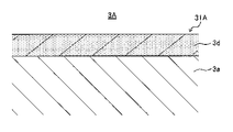
図3は、図2に示す準備工程におけるセパレータ3の基材となるチタン基材3Aの模式的断面図である。図4は、図3に示す凸部31Aの拡大断面図である。図2に示すように、本実施形態では、まず、準備工程S1を行う。
2-1. Regarding the preparation step S1, FIG. 3 is a schematic cross-sectional view of the
準備工程S1では、セパレータ3の基材として、接触部分31の形状に応じて形成された複数の凸部31A、31A、…と、凸部31A、31A同士の間に形成されたガス流路用の凹部21Aと、を有したチタン基材3Aを準備する。なお、凸部31Aが形成された面と反対側には、接触部分32の形状に応じた凸部32Aが形成され、これらの間には冷却水用の凹部23Aが形成される。本実施形態では、以下に示すシート状のチタン基材を準備し、このチタン基材に対してプレス加工により、チタン基材3Aに成形する。以下にその詳細を説明する。
In the preparation step S1, for the gas flow path formed between the plurality of
この工程では、まず、冷間の圧延材からなるシート状のチタン基材を準備する。チタン基材は、チタンまたはチタン合金からなる。チタンとしては、例えば、JIS H 4600に規定される1〜4種を挙げることができる。また、チタン合金としては、例えば、Ti−Al、Ti−Nb、Ti−Ta、Ti−6Al−4V、Ti−Pdを挙げることができる。ただし、いずれの場合も前記例示に限定されない。 In this step, first, a sheet-shaped titanium base material made of a cold rolled material is prepared. The titanium substrate is made of titanium or a titanium alloy. Examples of titanium include 1 to 4 types specified in JIS H 4600. Examples of the titanium alloy include Ti-Al, Ti-Nb, Ti-Ta, Ti-6Al-4V, and Ti-Pd. However, in any case, the present invention is not limited to the above examples.
チタン又はチタン合金製の基材とすることにより、軽く、耐食性に優れたものとすることができる。チタン基材の厚さは、厚さ0.05〜1mmの冷間板材とするのが好ましい。厚さをこの範囲とすると、セパレータの軽量化及び薄型化の要求を満足し、セパレータとしての強度及びハンドリング性を備え、セパレータの形状にプレス加工することが比較的容易となる。 By using a base material made of titanium or a titanium alloy, it can be made light and excellent in corrosion resistance. The thickness of the titanium base material is preferably a cold plate material having a thickness of 0.05 to 1 mm. When the thickness is within this range, the requirements for weight reduction and thinning of the separator are satisfied, the strength and handleability of the separator are provided, and it is relatively easy to press work into the shape of the separator.
シート状のチタン基材に対してプレス加工により、シート状のチタン基材から、接触部分31の形状に応じて形成された複数の凸部31A、31A、…と、凸部31A、31A同士の間に形成されたガス流路用の凹部21Aと、を成形する。後述する熱処理工程S2における炭化チタン層3dが形成される前に、プレス加工により、チタン基材3Aを成形するので、成形性が高いチタン基材から、前記凸部31Aおよび凹部21A等を簡単に成形することができる。
A plurality of
ここで、チタン基材3Aの表面には、図4に示すように、酸化チタン(具体的にはTiO2)の不動態膜3bが形成されている。この不動態膜3bは、大気中(酸素ガスを含む雰囲気下)で、チタンが自然酸化した二酸化チタンからなる酸化皮膜である。さらに、酸化チタンの不動態膜3bと、母材3aとの間には、局所的に炭化チタン3cが部分的に形成されている。この炭化チタン3cは、シート状のチタン基材3Aを圧延する際に圧延油に含まれる炭化水素の炭素が、圧延後の焼鈍時に、チタンに拡散したものである。
Here, as shown in FIG. 4, a
2−2.熱処理工程S2について
次に、熱処理工程S2を行う。図5は、図2に示す熱処理工程S2を説明するための図である。図6は、図5に示す熱処理工程S2後の凸部の拡大断面図である。熱処理工程S2では、チタン基材3Aのうち、少なくとも発電部2に接触する接触部分31に対応する凸部31Aに、カーボンシート9を接触させた状態で、凸部31Aに、カーボンシート9の炭素が拡散するように、チタン基材3Aに対して熱処理を行う。なお、本実施形態では、反対側に形成された凸部32Aにもカーボンシート9を接触させた状態で、同様の処理を同時に行う。
2-2. Heat treatment step S2 Next, the heat treatment step S2 is performed. FIG. 5 is a diagram for explaining the heat treatment step S2 shown in FIG. FIG. 6 is an enlarged cross-sectional view of the convex portion after the heat treatment step S2 shown in FIG. In the heat treatment step S2, the carbon of the
カーボンシート9は、その表面が炭素を含む可撓性を有したシートであればよく、炭化チタン層を形成することができるのであれば特に限定されない。シート材として、例えば、カーボンペーパ、カーボンクロス、または炭素フェルトなどを挙げることができ、凸部31Aの表面に均一に接触するものであれば、その素材は特に限定されるものではない。たとえば、カーボンシート9としては、紙材または樹脂シートの両面にカーボンブラック等の炭素粒子を均一に担持したシートであってもよい。この他にも、カーボンシート9としては、炭素繊維をシート状にした織物または不織布などであってもよく、それらに樹脂を含浸させたものであってもよい。
The
本実施形態では、図5に示すように、熱処理工程S2において、チタン基材3Aとカーボンシート9とを交互に積み重ねた状態で、熱処理を行う。これにより、複数のチタン基材3Aを一度に熱処理することができ、生産性を高めることができる。本実施形態では、より具体的には、下段に位置するチタン基材3Aの凸部31Aが、上段に位置するチタン基材3Aの凹部23Aに対向するように、カーボンシート9を挟み込む。これにより、可撓性を有するカーボンシート9を、凸部31Aの表面に倣うように、凸部31Aに接触させることができる。この結果、後述する熱処理により、凸部31Aに、均一に炭素を拡散させることができる。なお、カーボンシート9を挟んで、下段の凸部31Aの一部が、上段の凹部23Aに入り込んでもよい。また、カーボンシート9は、熱処理工程S2後、再利用してもよい。
In the present embodiment, as shown in FIG. 5, in the heat treatment step S2, the heat treatment is performed in a state where the
ここで、熱処理工程S2では、図5に示すように、チタン基材3Aとカーボンシート9を積み重ねた状態で、加熱炉内に投入し、凸部31Aに、カーボンシート9の炭素が拡散するように、チタン基材3Aに対して熱処理を行う。これにより、図6に示すように、チタン基材3Aの母材3aの表面に均一な炭化チタン層3dが形成される。なお、炭化チタン層3dの表面には、チタンの自然酸化により形成された二酸化チタンからなる不動態膜3bが存在する。
Here, in the heat treatment step S2, as shown in FIG. 5, the
具体的には、熱処理工程S2により、図4に示す部分的に存在していた炭化チタン3cの炭素がチタン基材3Aの母材3aに拡散するとともに、カーボンシート9からの炭素の拡散により消滅し、チタン基材3Aの母材3aの表面には、炭化チタン層3dが均一に形成される。
Specifically, in the heat treatment step S2, the partially existing carbon of
さらに、この熱処理工程S2において、炭化チタン層3dが形成されることにより、図6に示す炭化チタン層3dの表面に形成される不動態膜3bの膜厚は、図4に示すチタン基材3Aの上に形成される不動態膜3bの厚みよりも薄くなる。これは、炭化チタンはチタンよりも活性が低いため、炭化チタン層3dの表面では、母材3aの表面よりも、酸化し難いことによると考えられる。
Further, in the heat treatment step S2, the thickness of the
なお、この熱処理により、準備工程S1時より不動態膜3bの膜厚が減少することから、熱処理工程S2の処理条件により、不動態膜3bを略消滅させてもよく、準備工程S1において、エッチング処理により不動態膜3bを除去し、この状態で熱処理工程S2を行ってもよい。これにより、後述するエッチング処理工程S3を省略できる場合がある。
Since the film thickness of the
上述した熱処理では、カーボンシート9の炭素が、チタン基材3Aに拡散することができるのであれば、その雰囲気条件は特に限定されないが、好ましくは、無酸素雰囲気下(より好ましくは真空雰囲気下)で、これらを加熱する。ここで、真空雰囲気下としては、たとえば、1.0×10⁻²Pa以下の圧力雰囲気下である。これにより、カーボンシート9の炭素のチタン基材3Aへの拡散をより促進することができる。
In the heat treatment described above, as long as the carbon of the
上述した熱処理における熱処理条件は、カーボンシート9の炭素が、チタン基材3Aに拡散することができるのであれば、その条件は特に限定されないが、より好ましくは、加熱温度が500℃〜650℃であり、かつ、加熱時間が2〜4時間の加熱条件である。このような加熱条件で、熱処理を行うことにより、チタン基材3Aにカーボンシート9の炭素が拡散し易くなる。
Heat treatment conditions in the above-mentioned heat treatment, the carbon of the
ここで、加熱温度が650℃を超えた場合には、炭素の蒸発と、チタン基材3Aの母材3a内への炭素の拡散が活発となり、炭化チタン層3dが形成され難いことがある。一方、加熱温度が500℃未満である場合には、チタン基材3Aの母材3a内の炭素の拡散が十分ではなく、炭化チタン層3dの形成に時間を要する。
Here, when the heating temperature exceeds 650 ° C., the evaporation of carbon and the diffusion of carbon into the
ここで、加熱時間が4時間を超えた場合には、チタン基材3Aとカーボンシート9の自重により、下段に配置されたチタン基材3Aが変形することがある。一方、加熱時間が2時間未満である場合には、チタン基材3Aの母材3aへの炭素の拡散が十分でない場合がある。
Here, when the heating time exceeds 4 hours, the
2−3.エッチング処理工程S3について
次に、エッチング処理工程S3を行う。エッチング処理工程S3では、熱処理工程S2後、後述する成膜工程S4前に、凸部31A、32Aをエッチングする。これにより、凸部31A、32Aの表面に形成された酸化チタンの不動態膜3bを除去する。
2-3. About the etching process step S3 Next, the etching process step S3 is performed. In the etching process step S3, the
このような結果、図7に示すように、チタン基材3Aの接触部分32の表面に、炭化チタン層3dを露出させることができる。さらに上述したように、熱処理工程S2を行った酸化チタンの不動態膜3bの膜厚は、これを行っていないものよりも薄いため、エッチング時間を短縮することができる。
As a result, as shown in FIG. 7, the
不動態膜3bを除去することができ、新たに不動態膜等の酸化皮膜が形成されないのであれば、エッチングは、プラズマなどを利用したドライエッチング、または、硫酸水溶液などの酸性溶液に浸漬するウエットエッチングなど、どちらであってもよい。本実施形態では、好ましい態様として、プラズマによるエッチングを行う。具体的には、減圧雰囲気下で、チタン基材3Aを投入し、プラズマ化したアルゴンガスなどの不活性ガス由来の元素を、表面に接触させる。これにより、チタン基材3Aから不動態膜3bを除去する。このようなエッチングを行うことにより、チタン基材3Aから不動態膜3bを簡単に除去することができる。
If the
2−4.成膜工程S4について
次に、成膜工程S4を行う。成膜工程S4では、エッチング処理工程S3後の、チタン基材3Aの少なくとも凸部31A、32Aに、導電性カーボン膜3eを形成する(図8参照)。これにより、セパレータ3を得ることができる。
2-4. About the film forming step S4 Next, the film forming step S4 is performed. In the film forming step S4, the
導電性カーボン膜3eの成形にあたっては、真空蒸着、スパッタリング、イオンプレーティング、イオンビームミキシングなどを利用した物理気相成長法(PVD)により導電性カーボン膜3eを形成してもよく、プラズマ処理などを利用した化学気相成長法(CVD)により導電性カーボン膜3eを形成してもよい。
In molding the
本実施形態では、成膜装置(図示せず)を用いてプラズマCVDにより導電性カーボン膜3eを成膜する。具体的には、成膜室(図示せず)にチタン基材3Aを導入した後、直流バイアス電圧を印加し、チタン基材3Aと陽極(図示せず)との間にグロー放電プラズマを発生させる。本実施形態では、陽極はチタン基材3Aと平行に、かつ両面に対向するように配置し、両面同時にプラズマを発生させる。次に、アセチレンガス等の炭化水素系ガスを、成膜室に導入し、イオン化した炭素を、露出した炭化チタン層3dの表面に吸着させる。これにより、チタン基材3Aの表面において、炭化チタン層3dの表面で炭素が成長し、非晶質炭素からなる導電性カーボン膜3eを得ることができる。
In the present embodiment, the
このようにして、凸部31A、32Aを含むチタン基材3Aの両面に、導電性カーボン膜3eを成膜することができる。導電性カーボン膜3eの厚さに限定はないが、例えば10〜80nmの厚さである。たとえば、導電性カーボン膜3eの膜厚が、10nm未満である場合、セパレータの耐食性が低くなり、抵抗が上昇することがある。一方、導電性カーボン膜3eの膜厚が、80nmを超えた場合、導電性カーボン膜3eの内部応力が高まり、チタン基材3Aから導電性カーボン膜3eが剥離することがある。
In this way, the
本実施形態では、熱処理により形成された炭化チタン層3dの炭素と、導電性カーボン膜3eの炭素との結合が強固になり、炭化チタン層3dと導電性カーボン膜3eとの密着力を向上させることができる。これにより、燃料電池10の発電時に生成する生成水に、セパレータ3が晒されたとしても、炭化チタン層3dと導電性カーボン膜3eとの密着状態を確保することができる。この結果、発電部2に対するセパレータ3の接触抵抗の上昇を抑えることができ、セパレータ3の信頼性を確保することができる。
In the present embodiment, the bond between the carbon of the
以下に、本実施形態を実施例に基づいて説明する。 Hereinafter, the present embodiment will be described based on examples.
〔実施例〕
以下に示す方法で、実施例に係るセパレータに相当する試験体を作製した。まず、純チタン(材質:JIS1種)からなる厚さ0.1mmチタン板(圧延材)より、所定のサイズのセパレータの形状に成形し、チタン基材とした。アルカリ系の洗浄液で洗浄を行った。
〔Example〕
A test body corresponding to the separator according to the example was prepared by the method shown below. First, a titanium plate (rolled material) having a thickness of 0.1 mm made of pure titanium (material: JIS type 1) was molded into a separator shape of a predetermined size to form a titanium base material. Cleaning was performed with an alkaline cleaning solution.
次に、チタン基材にカーボンシートを交互に積み重ねて、加熱炉内に投入し、室内の圧力が10−6Paとなるように、真空引きし、600℃、2時間の加熱条件で、チタン基材を熱処理した。得られたチタン基材の断面を透過型電子顕微鏡(TEM)で観察した。この結果を図9Aおよび図9Bに示す。図9Aは、実施例に係るチタン基材の断面写真である。図9Bは、図9Aのチタン基材の拡大断面写真である。 Next, carbon sheets were alternately stacked on a titanium base material, put into a heating furnace , evacuated so that the pressure in the room became 10-6 Pa, and titanium was heated at 600 ° C. for 2 hours. The substrate was heat treated. The cross section of the obtained titanium substrate was observed with a transmission electron microscope (TEM). The results are shown in FIGS. 9A and 9B. FIG. 9A is a cross-sectional photograph of the titanium base material according to the embodiment. FIG. 9B is an enlarged cross-sectional photograph of the titanium base material of FIG. 9A.
熱処理後のチタン基材を、成膜装置に導入し、成膜室内の圧力を10Paにし、成膜室内の温度を300℃にした後、DCで2.0kVの直流バイアス電圧をチタン基材に印加し、チタン基材3Aと陽極との間にグロー放電プラズマを発生させた。この状態で、アルゴンガスを室内に供給し、チタン基材の表面に、プラズマ化したアルゴンを接触させ、チタン基材のエッチング処理を行った。
The heat-treated titanium base material is introduced into the film forming apparatus, the pressure in the film forming chamber is set to 10 Pa, the temperature in the film forming chamber is set to 300 ° C., and then a DC bias voltage of 2.0 kV in DC is applied to the titanium base material. It was applied to generate a glow discharge plasma between the
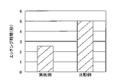
なお、チタン基材の表面に形成された不動態膜(酸化チタン層)が、完全に除去されるまで、エッチング処理を行い、その時間を測定した。この結果を図11に示す。図11は、実施例および後述する比較例に係るチタン基材のエッチング時間を示したグラフである。 The etching treatment was performed until the passivation film (titanium oxide layer) formed on the surface of the titanium base material was completely removed, and the time was measured. The result is shown in FIG. FIG. 11 is a graph showing the etching time of the titanium base material according to the examples and the comparative examples described later.
次に、成膜ガスとして、成膜装置の室内に、炭化水素系ガス(アセチレンガス)を供給し、DCで2.0〜3.0kVの範囲に収まるように直流バイアス電圧を印加し、プラズマCVDにより、導電性カーボン膜を成膜した。これにより、燃料電池用のセパレータに相当する試験体を得た。 Next, as a film-forming gas, a hydrocarbon-based gas (acetylene gas) is supplied into the chamber of the film-forming apparatus, and a DC bias voltage is applied so as to be within the range of 2.0 to 3.0 kV at DC, and plasma is generated. A conductive carbon film was formed by CVD. As a result, a test body corresponding to a separator for a fuel cell was obtained.
〔比較例〕
実施例と同じように、試験体を作製した。比較例が実施例と相違する点は、カーボンシートを用いて熱処理を行わなかった点である。なお、エッチング処理前のチタン基材の断面を透過型電子顕微鏡(TEM)で観察した。この結果を図10A〜図10Cに示す。図10Aは、比較例に係るチタン基材の断面写真である。図10Bは、図10Aのチタン基材のうち、炭化チタンが形成されていない部分の拡大断面写真である。図10Cは、図10Aのチタン基材のうち、炭化チタンが形成された部分の拡大断面写真である。また比較例の場合も、チタン基材の表面に形成された不動態膜(酸化チタン層)が、完全に除去されるまで、エッチング処理を行い、その時間を測定した。この結果を図11に示す。
[Comparative example]
Specimens were prepared in the same manner as in the examples. The difference between the comparative examples and the examples is that the heat treatment was not performed using the carbon sheet. The cross section of the titanium base material before the etching treatment was observed with a transmission electron microscope (TEM). The results are shown in FIGS. 10A-10C. FIG. 10A is a cross-sectional photograph of a titanium base material according to a comparative example. FIG. 10B is an enlarged cross-sectional photograph of a portion of the titanium base material of FIG. 10A in which titanium carbide is not formed. FIG. 10C is an enlarged cross-sectional photograph of a portion of the titanium base material of FIG. 10A in which titanium carbide is formed. Also in the case of the comparative example, the etching treatment was performed until the passivation film (titanium oxide layer) formed on the surface of the titanium base material was completely removed, and the time was measured. The result is shown in FIG.
<腐食耐久試験>
実施例および比較例に係る試験体に対して、日本工業規格の金属材料の電気化学的高温腐食試験法(JIS Z2294)に準じた耐食性試験(定電位腐食試験)を行った。大気解放系の装置において、温調水により80℃に温度調整された硫酸水溶液(300ml,pH3)に試験体を浸した。この状態で、白金板からなる対極と試験体(試料極)とを電気的に接続することにより、対極と試料極との間に0.9Vの電位差を生じさせ、試験体を腐食させた。なお、参照電極によって試験体の電位を一定に保持した。また、試験時間は50時間程度とした。
<Corrosion durability test>
Corrosion resistance test (constant potential corrosion test) according to the electrochemical high temperature corrosion test method (JIS Z2294) of Japanese Industrial Standards was performed on the test bodies according to Examples and Comparative Examples. In the air release system device, the test piece was immersed in a sulfuric acid aqueous solution (300 ml, pH 3) whose temperature was adjusted to 80 ° C. by temperature control water. In this state, by electrically connecting the counter electrode made of the platinum plate and the test body (sample electrode), a potential difference of 0.9 V was generated between the counter electrode and the sample electrode, and the test body was corroded. The potential of the test piece was kept constant by the reference electrode. The test time was about 50 hours.
<接触抵抗試験>
腐食試験前(初期)、腐食試験100時間、腐食試験200時間における、実施例および比較例に係る試験体に対して、接触抵抗試験を行った。具体的には、各試験体に、燃料電池の拡散層に相当するカーボンペーパ(厚さ0.5mm)を載せ、測定治具により一定荷重(1MPa)を付与しながら測定した。この状態で、電流計により試験体に流れる電流が1Aとなるように、電源からの電流を調整して流し、試験体に印加される電圧を電圧計で測定し、試験体とカーボンペーパとの接触抵抗値を算出した。具体的には、実施例の腐食試験前の接触抵抗値を1として、各接触抵抗比を算出した。この結果を図12に示す。図12は、実施例および比較例に係る試験体の腐食時間と、接触抵抗比との関係を示したグラフである。
<Contact resistance test>
Before the corrosion test (initial stage), the corrosion test was performed for 100 hours, and the corrosion test was performed for 200 hours. Specifically, carbon paper (thickness 0.5 mm) corresponding to the diffusion layer of the fuel cell was placed on each test piece, and measurement was performed while applying a constant load (1 MPa) with a measuring jig. In this state, adjust the current from the power supply so that the current flowing through the test piece is 1A with an ammeter, measure the voltage applied to the test piece with a voltmeter, and connect the test piece and carbon paper. The contact resistance value was calculated. Specifically, each contact resistance ratio was calculated with the contact resistance value before the corrosion test of the example as 1. The result is shown in FIG. FIG. 12 is a graph showing the relationship between the corrosion time of the test pieces according to the examples and the comparative examples and the contact resistivity ratio.
〔結果および考察〕
図9Aおよび図9Bに示すように、カーボンシートを接触させて、熱処理を行った実施例のチタン基材の母材の表面には、炭化チタン層が形成されており、炭化チタン層の表面には、不動態膜が形成されていた。
〔Results and Discussion〕
As shown in FIGS. 9A and 9B, a titanium carbide layer is formed on the surface of the base material of the titanium base material of the example in which the carbon sheets are brought into contact with each other and heat-treated, and the surface of the titanium carbide layer is formed. A passivation membrane was formed.
一方、図10A〜図10Cに示すように、実施例の如く熱処理を行っていないチタン基材の母材の表面には、炭化チタンが部分的に存在し、これらを覆うように不動態膜が形成されていた。また、炭化チタンが形成されていない部分に被覆された不動態膜(図10B参照)の膜厚は、炭化チタンが形成された部分に被覆された不動態膜(図10C参照)の膜厚および実施例の不動態膜の膜厚よりも厚かった。 On the other hand, as shown in FIGS. 10A to 10C, titanium carbide is partially present on the surface of the base material of the titanium base material which has not been heat-treated as in the examples, and a passivation film is formed so as to cover these. It was formed. The thickness of the passivation film (see FIG. 10B) coated on the portion where titanium carbide is not formed is the thickness of the passivation film (see FIG. 10C) coated on the portion where titanium carbide is formed. It was thicker than the thickness of the passivation film of the example.
なお、図10A〜図10Cから明らかなように、実施例のチタン基材を熱処理する前のチタン基材の母材の表面には、局所的に炭化チタンが形成されていると考えられるが、実施例の如く熱処理を行うことにより、チタン基材の表面に、均一な厚みの炭化チタン層がカーボンシートが接触した表面全体に形成されたと考えられる。 As is clear from FIGS. 10A to 10C, it is considered that titanium carbide is locally formed on the surface of the base material of the titanium base material before the titanium base material of the examples is heat-treated. It is considered that by performing the heat treatment as in the examples, a titanium carbide layer having a uniform thickness was formed on the entire surface of the titanium base material in contact with the carbon sheet.
図11に示すように、実施例に係るチタン基材のエッチング時間は、比較例に係るチタン基材のエッチング時間よりも短かった。これは、実施例に係るチタン基材に形成された不動態膜の膜厚が、比較例のものよりも薄いことによると考えられる。以上のことから、実施例の如く、チタン基材にカーボンシートを接触させて、カーボンシートの炭素をチタン基材に拡散し、炭化チタン層を形成すれば、チタン基材の表層の不動態膜の厚さは、薄くなると考えられる。 As shown in FIG. 11, the etching time of the titanium base material according to the example was shorter than the etching time of the titanium base material according to the comparative example. It is considered that this is because the film thickness of the passivation film formed on the titanium base material according to the example is thinner than that of the comparative example. From the above, as in the examples, if the carbon sheet is brought into contact with the titanium base material, the carbon of the carbon sheet is diffused into the titanium base material to form the titanium carbide layer, the passivation film on the surface layer of the titanium base material is formed. The thickness of is considered to be thin.
図12に示すように、実施例の試験体の接触抵抗比は、いずれの場合も、比較例のものよりも小さかった。これは、実施例の試験体では、炭化チタン層に、導電性カーボン膜が形成されることにより、炭化チタン層の炭素と、導電性カーボン膜の炭素が強固に結合していることによると考えられる。この結果、実施例の試験体は、比較例のものよりも、チタン基材と導電性カーボン膜の密着性が高く、腐食耐久性に強いと考えられる。 As shown in FIG. 12, the contact resistivity ratio of the test piece of the example was smaller than that of the comparative example in each case. It is considered that this is because in the test body of the example, the carbon of the titanium carbide layer and the carbon of the conductive carbon film are firmly bonded by forming the conductive carbon film on the titanium carbide layer. Be done. As a result, it is considered that the test body of the example has higher adhesion between the titanium base material and the conductive carbon film than that of the comparative example, and is more resistant to corrosion.
以上、本発明の一実施形態について詳述したが、本発明は、前記の実施形態に限定されるものではなく、特許請求の範囲に記載された本発明の精神を逸脱しない範囲で、種々の設計変更を行うことができるものである。 Although one embodiment of the present invention has been described in detail above, the present invention is not limited to the above-described embodiment, and various types are described within the scope of the claims as long as the spirit of the present invention is not deviated. It is possible to make design changes.
本実施形態では、熱処理工程において、カーボンシートとチタン基材(セパレータ成形材)とを交互に積み重ねて熱処理を行ったが、1つのチタン基材にカーボンシートを挟み込むことにより、熱処理を行ってもよい。 In the present embodiment, in the heat treatment step, the carbon sheet and the titanium base material (separator molding material) are alternately stacked to perform the heat treatment, but even if the heat treatment is performed by sandwiching the carbon sheet between one titanium base material. Good.
2:MEGA(発電部)、3:セパレータ(燃料電池用のセパレータ)、3A:チタン基材、3a:母材、3b:不動態膜、3d:炭化チタン層、3e:導電性カーボン膜、9:カーボンシート、6:電極、21,22:ガス流路、21A:凹部、31,32:接触部分、31A,32A:凸部 2: MEGA (power generation unit) 3: Separator (separator for fuel cell), 3A: Titanium base material, 3a: Base material, 3b: Passivation film, 3d: Titanium carbide layer, 3e: Conductive carbon film, 9 : Carbon sheet, 6: Electrode, 21,22: Gas flow path, 21A: Concave, 31, 32: Contact part, 31A, 32A: Convex part
Claims (4)
前記セパレータの基材として、前記接触部分の形状に応じて形成された複数の凸部と、該凸部同士の間に形成されたガス流路用の凹部と、を有したチタン基材を準備する準備工程と、
前記凸部にカーボンシートを接触するように配置し、前記凸部にカーボンシートが接触した状態で、前記凸部に前記カーボンシートの炭素が拡散するように、前記チタン基材に対して熱処理を行う熱処理工程と、
前記熱処理工程後、前記カーボンシートを前記基材から取り除く取り除き工程と、
前記取り除き工程後、前記凸部に前記導電性カーボン膜を成膜する成膜工程と、を含むことを特徴とする燃料電池用のセパレータの製造方法。 A method for manufacturing a separator for a fuel cell, which has a contact portion in contact with the power generation portion and has a conductive carbon film formed on the contact portion so as to partition the power generation portions including electrodes of the fuel cell. hand,
As the base material of the separator, a titanium base material having a plurality of convex portions formed according to the shape of the contact portion and a concave portion for a gas flow path formed between the convex portions is prepared. Preparation process and
The carbon sheet is arranged so as to be in contact with the convex portion, and the titanium base material is heat-treated so that the carbon of the carbon sheet is diffused to the convex portion in a state where the carbon sheet is in contact with the convex portion. The heat treatment process to be performed and
After the heat treatment step, a removal step of removing the carbon sheet from the base material and a step of removing the carbon sheet from the base material
A method for producing a separator for a fuel cell , which comprises a film forming step of forming the conductive carbon film on the convex portion after the removing step.
Priority Applications (6)
| Application Number | Priority Date | Filing Date | Title |
|---|---|---|---|
| JP2017239807A JP6856012B2 (en) | 2017-12-14 | 2017-12-14 | Separator for fuel cells |
| KR1020180129559A KR102166959B1 (en) | 2017-12-14 | 2018-10-29 | Separator for fuel cell |
| DE102018131019.6A DE102018131019A1 (en) | 2017-12-14 | 2018-12-05 | FUEL CELL SEPARATOR |
| US16/216,033 US11069905B2 (en) | 2017-12-14 | 2018-12-11 | Fuel cell separator |
| CA3027406A CA3027406C (en) | 2017-12-14 | 2018-12-13 | Fuel cell separator |
| CN201811524505.2A CN109962255A (en) | 2017-12-14 | 2018-12-13 | The partition of fuel cell |
Applications Claiming Priority (1)
| Application Number | Priority Date | Filing Date | Title |
|---|---|---|---|
| JP2017239807A JP6856012B2 (en) | 2017-12-14 | 2017-12-14 | Separator for fuel cells |
Publications (3)
| Publication Number | Publication Date |
|---|---|
| JP2019106345A JP2019106345A (en) | 2019-06-27 |
| JP2019106345A5 JP2019106345A5 (en) | 2019-11-21 |
| JP6856012B2 true JP6856012B2 (en) | 2021-04-07 |
Family
ID=66674538
Family Applications (1)
| Application Number | Title | Priority Date | Filing Date |
|---|---|---|---|
| JP2017239807A Active JP6856012B2 (en) | 2017-12-14 | 2017-12-14 | Separator for fuel cells |
Country Status (6)
| Country | Link |
|---|---|
| US (1) | US11069905B2 (en) |
| JP (1) | JP6856012B2 (en) |
| KR (1) | KR102166959B1 (en) |
| CN (1) | CN109962255A (en) |
| CA (1) | CA3027406C (en) |
| DE (1) | DE102018131019A1 (en) |
Families Citing this family (2)
| Publication number | Priority date | Publication date | Assignee | Title |
|---|---|---|---|---|
| JP7359124B2 (en) * | 2020-10-12 | 2023-10-11 | トヨタ自動車株式会社 | Manufacturing method of fuel cell separator |
| CN115537725A (en) * | 2022-08-31 | 2022-12-30 | 西北工业大学 | Corrosion-resistant material, preparation method thereof and metal bipolar plate |
Family Cites Families (18)
| Publication number | Priority date | Publication date | Assignee | Title |
|---|---|---|---|---|
| JPS4825894B1 (en) | 1964-10-24 | 1973-08-02 | ||
| JPS5133270B2 (en) | 1971-08-09 | 1976-09-18 | ||
| JP2002170582A (en) * | 2000-12-04 | 2002-06-14 | Nisshin Steel Co Ltd | Fuel battery separator and manufacturing method thereof |
| JP4825894B2 (en) | 2009-04-15 | 2011-11-30 | トヨタ自動車株式会社 | Fuel cell separator and method for producing the same |
| JP4886884B2 (en) * | 2010-07-20 | 2012-02-29 | 株式会社神戸製鋼所 | Titanium fuel cell separator and method for producing the same |
| JP5507495B2 (en) | 2010-07-20 | 2014-05-28 | 株式会社神戸製鋼所 | Method for producing titanium fuel cell separator |
| JP4886885B2 (en) | 2010-07-20 | 2012-02-29 | 株式会社神戸製鋼所 | Titanium fuel cell separator |
| JP5342518B2 (en) | 2010-07-20 | 2013-11-13 | 株式会社神戸製鋼所 | Method for producing titanium fuel cell separator |
| JP5108976B2 (en) * | 2011-02-14 | 2012-12-26 | 株式会社神戸製鋼所 | Fuel cell separator |
| JP5575696B2 (en) * | 2011-04-28 | 2014-08-20 | 株式会社神戸製鋼所 | Manufacturing method of fuel cell separator |
| JP5378552B2 (en) | 2012-01-30 | 2013-12-25 | 株式会社豊田中央研究所 | Amorphous carbon film, method for forming amorphous carbon film, conductive member provided with amorphous carbon film, and separator for fuel cell |
| JP6122589B2 (en) * | 2012-07-20 | 2017-04-26 | 株式会社神戸製鋼所 | Fuel cell separator |
| JP5894053B2 (en) | 2012-10-12 | 2016-03-23 | トヨタ自動車株式会社 | Fuel cell separator manufacturing equipment |
| JP6061702B2 (en) | 2013-01-30 | 2017-01-18 | 株式会社神戸製鋼所 | Material for fuel cell separator and method for producing fuel cell separator |
| JP5968857B2 (en) * | 2013-11-11 | 2016-08-10 | 株式会社神戸製鋼所 | Method for producing titanium fuel cell separator |
| KR20160067959A (en) | 2013-11-11 | 2016-06-14 | 가부시키가이샤 고베 세이코쇼 | Titanium separator material for fuel cells, and method for producing titanium separator material for fuel cells |
| JP6160584B2 (en) * | 2014-09-19 | 2017-07-12 | トヨタ自動車株式会社 | Manufacturing method of fuel cell separator |
| JP6160877B2 (en) * | 2015-04-13 | 2017-07-12 | トヨタ自動車株式会社 | Manufacturing method of fuel cell separator and fuel cell separator |
-
2017
- 2017-12-14 JP JP2017239807A patent/JP6856012B2/en active Active
-
2018
- 2018-10-29 KR KR1020180129559A patent/KR102166959B1/en active IP Right Grant
- 2018-12-05 DE DE102018131019.6A patent/DE102018131019A1/en not_active Withdrawn
- 2018-12-11 US US16/216,033 patent/US11069905B2/en active Active
- 2018-12-13 CA CA3027406A patent/CA3027406C/en active Active
- 2018-12-13 CN CN201811524505.2A patent/CN109962255A/en active Pending
Also Published As
| Publication number | Publication date |
|---|---|
| CN109962255A (en) | 2019-07-02 |
| DE102018131019A1 (en) | 2019-06-19 |
| JP2019106345A (en) | 2019-06-27 |
| US20190190035A1 (en) | 2019-06-20 |
| CA3027406A1 (en) | 2019-06-14 |
| KR20190071577A (en) | 2019-06-24 |
| CA3027406C (en) | 2021-05-11 |
| KR102166959B1 (en) | 2020-10-16 |
| US11069905B2 (en) | 2021-07-20 |
Similar Documents
| Publication | Publication Date | Title |
|---|---|---|
| RU2521077C2 (en) | Metallic retaining plate for fuel cell with cover film on its surface and method of its production | |
| JP5467768B2 (en) | Method for producing polymer composite ion / electron conductive membrane | |
| CA2747858C (en) | Fuel cell separator material, fuel cell separator using same, fuel cell stack, and method for producing fuel cell separator material | |
| TW200836395A (en) | Method for producing separator for fuel cell, separator for fuel cell, and fuel cell | |
| WO2006126613A1 (en) | Separator for fuel cell and method for producing same | |
| JP5634604B2 (en) | Separator for fuel cell and method for producing the same | |
| JP3936095B2 (en) | Fuel cell | |
| JP6856012B2 (en) | Separator for fuel cells | |
| JP6973029B2 (en) | Manufacturing method of separator for fuel cell and separator material | |
| JP4919953B2 (en) | Method, gas diffusion electrode, and electrode assembly for forming a noble metal coating on a gas diffusion medium | |
| US8492053B2 (en) | Surface treated carbon coatings for flow field plates | |
| JP4622383B2 (en) | Hydrogen separation substrate | |
| JP7424323B2 (en) | Fuel cell | |
| JP2001068129A (en) | Separator for fuel cell, manufacture thereof and fuel cell | |
| JP5614468B2 (en) | Manufacturing method of gas diffusion electrode for fuel cell | |
| JP4239461B2 (en) | Manufacturing method of membrane electrode assembly | |
| JP5375208B2 (en) | Fuel cell manufacturing method, fuel cell | |
| JP5061544B2 (en) | Fuel cell | |
| JP2006202735A (en) | Battery characteristic evaluation of fuel cell | |
| TWI445238B (en) | Bipolar plate and fuel cell utilizing the same | |
| KR20240045882A (en) | Separator for fuel cell and manufacturing method thereof | |
| JP2022073337A (en) | Fuel cell separator and manufacturing method of fuel cell separator | |
| JP2005302610A (en) | Fuel cell, and manufacturing method for metal diffusion layers therefor | |
| JP2020155299A (en) | Method for manufacturing separator for fuel cell | |
| JP2009104932A (en) | Fuel cell separator and its manufacturing method |
Legal Events
| Date | Code | Title | Description |
|---|---|---|---|
| A521 | Request for written amendment filed |
Free format text: JAPANESE INTERMEDIATE CODE: A523 Effective date: 20191009 |
|
| A621 | Written request for application examination |
Free format text: JAPANESE INTERMEDIATE CODE: A621 Effective date: 20191009 |
|
| A131 | Notification of reasons for refusal |
Free format text: JAPANESE INTERMEDIATE CODE: A131 Effective date: 20200728 |
|
| A977 | Report on retrieval |
Free format text: JAPANESE INTERMEDIATE CODE: A971007 Effective date: 20200722 |
|
| A521 | Request for written amendment filed |
Free format text: JAPANESE INTERMEDIATE CODE: A523 Effective date: 20200918 |
|
| TRDD | Decision of grant or rejection written | ||
| A01 | Written decision to grant a patent or to grant a registration (utility model) |
Free format text: JAPANESE INTERMEDIATE CODE: A01 Effective date: 20210216 |
|
| A61 | First payment of annual fees (during grant procedure) |
Free format text: JAPANESE INTERMEDIATE CODE: A61 Effective date: 20210301 |
|
| R151 | Written notification of patent or utility model registration |
Ref document number: 6856012 Country of ref document: JP Free format text: JAPANESE INTERMEDIATE CODE: R151 |