以下、本発明に係る遊技機の実施の形態について次の順序で説明する。なお、実施の形態では弾球遊技機を例に挙げる。
<1.弾球遊技機の構造>
<2.回胴遊技機の構成>
<3.遊技機の枠部における装飾ランプの態様>
Hereinafter, embodiments of the gaming machine according to the present invention will be described in the following order. In the embodiment, a bullet game machine will be taken as an example.
<1. Structure of bullet game machine >
<2. Configuration of rotating game machine >
<3. Aspects of decorative lamps in the frame of the game machine>
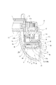
<1.弾球遊技機の構造>
まず図1〜図4を参照して、実施の形態としての弾球遊技機100の構成を説明する。
図1及び図2は実施の形態の弾球遊技機100の外観を示す正面側の斜視図であり、図3は遊技盤の正面図である。図4は弾球遊技機100の内部構成の概略的なブロック図である。
図1,図2,図3に示す弾球遊技機100は、主に「枠部」と「遊技盤部」から成る。
「枠部」は以下説明する前枠102,外枠104、前扉105、操作パネル107を有して構成される。「遊技盤部」は図3の遊技盤103から成る。以下の説明上で、「枠部」「枠側」とは前枠102,外枠104、前扉105、操作パネル107の総称とする。また「盤部」「盤側」とは遊技盤103を示す。
<1. Structure of bullet game machine >
First, the configuration of the ball game machine 100 as an embodiment will be described with reference to FIGS. 1 to 4.
1 and 2 are front perspective views showing the appearance of the ball game machine 100 of the embodiment, and FIG. 3 is a front view of the game board. FIG. 4 is a schematic block diagram of the internal configuration of the ball game machine 100.
The ball game machine 100 shown in FIGS. 1, 2 and 3 is mainly composed of a “frame portion” and a “game board portion”.
The "frame portion" includes a front frame 102, an outer frame 104, a front door 105, and an operation panel 107, which will be described below. The "game board section" is composed of the game board 103 of FIG. In the following description, the "frame portion" and "frame side" are a general term for the front frame 102, the outer frame 104, the front door 105, and the operation panel 107. Further, "board portion" and "board side" refer to the game board 103.
図1に示すように弾球遊技機100は、木製の外枠104の前面に額縁状の前枠102が開閉可能に取り付けられている。図示していないが、この前枠102の裏面には遊技盤収納フレームが形成されており、その遊技盤収納フレーム内に図3に示す遊技盤103が装着される。これにより遊技盤103の表面に形成した遊技領域103aが前枠102の開口部102aから図1の弾球遊技機100の前面側に臨む状態となる。
なお遊技領域103aの前側には、透明ガラス(後述の透明ガラス15)を支持した前扉105が設けられており、遊技領域103aは透明ガラスを介して前面の遊技者側に表出される。透明ガラスは遊技領域を保護するための保護ガラス(保護板)として機能する。
As shown in FIG. 1, in the ball game machine 100, a frame-shaped front frame 102 is attached to the front surface of a wooden outer frame 104 so as to be openable and closable. Although not shown, a game board storage frame is formed on the back surface of the front frame 102, and the game board 103 shown in FIG. 3 is mounted in the game board storage frame. As a result, the game area 103a formed on the surface of the game board 103 faces the front side of the ball game machine 100 of FIG. 1 from the opening 102a of the front frame 102.
A front door 105 supporting transparent glass (transparent glass 15 described later) is provided on the front side of the game area 103a, and the game area 103a is exposed to the front player side via the transparent glass. The transparent glass functions as a protective glass (protective plate) for protecting the game area.
前扉105は軸支機構106により前枠102に対して開閉可能に取り付けられている。そして前扉105の所定位置に設けられた図示しない扉ロック解除用キーシリンダを操作することで、前枠102に対する前扉105のロック状態を解除し、前扉105を前側に開放できる構造とされている。また扉ロック解除用キーシリンダの操作によっては、外枠104に対する前枠102のロック状態も解除可能な構成とされている。
また前扉105の前面側には、枠側の発光手段として装飾ランプ120wが各所に設けられている。装飾ランプ120wは、例えばLEDによる発光動作として、演出用の発光動作、エラー告知用の発光動作、動作状態に応じた発光動作などを行う。
The front door 105 is attached to the front frame 102 so as to be openable and closable by a shaft support mechanism 106. Then, by operating a door unlocking key cylinder (not shown) provided at a predetermined position of the front door 105, the locked state of the front door 105 with respect to the front frame 102 can be released, and the front door 105 can be opened to the front side. ing. Further, the lock state of the front frame 102 with respect to the outer frame 104 can be released by operating the door lock release key cylinder.
Further, on the front side of the front door 105, decorative lamps 120w are provided in various places as light emitting means on the frame side. For example, the decorative lamp 120w performs a light emitting operation for directing, a light emitting operation for error notification, a light emitting operation according to an operating state, and the like as a light emitting operation by an LED.
前扉105の下側には操作パネル107が設けられている。この操作パネル107も、図示しない軸支機構により、前枠102に対して開閉可能とされている。なお、操作パネル107は、前枠102と一体になって形成されることにより前枠102に対する開閉が不能とされていてもよい。
操作パネル107には、上受け皿ユニット108、下受け皿ユニット109、発射操作ハンドル110が設けられている(図2参照)。
An operation panel 107 is provided below the front door 105. The operation panel 107 can also be opened and closed with respect to the front frame 102 by a shaft support mechanism (not shown). The operation panel 107 may be formed integrally with the front frame 102 so that it cannot be opened or closed with respect to the front frame 102.
The operation panel 107 is provided with an upper saucer unit 108, a lower saucer unit 109, and a firing operation handle 110 (see FIG. 2).
上受け皿ユニット108には、弾球に供される遊技球を貯留する上受け皿108aが形成されている。下受け皿ユニット109には、上受け皿108aに貯留しきれない遊技球を貯留する下受け皿109aが形成されている。
また上受け皿ユニット108には、上受け皿108aに貯留された遊技球を下受け皿109a側に抜くための球抜きボタン116が設けられている。下受け皿ユニット109には、下受け皿109aに貯留された遊技球を弾球遊技機100の下方に抜くための球抜きレバー117が設けられている。
また上受け皿ユニット108には、図示しない遊技球貸出装置に対して遊技球の払い出しを要求するための球貸しボタン114と、遊技球貸出装置に挿入した有価価値媒体の返却を要求するためのカード返却ボタン115とが設けられている。
さらに上受け皿ユニット108には、演出ボタン111、十字キー113が設けられている。演出ボタン111は、所定の入力受付期間中に内蔵ランプが点灯されて操作可能となり、その内蔵ランプ点灯時に押下することにより演出に変化をもたらすことができる押しボタンとされる。また十字キー113は遊技者が演出状況に応じた操作や演出設定等のための操作を行う操作子である。
The upper saucer unit 108 is formed with an upper saucer 108a for storing a game ball to be used for a ball. The lower saucer unit 109 is formed with a lower saucer 109a for storing game balls that cannot be stored in the upper saucer 108a.
Further, the upper tray unit 108 is provided with a ball pulling button 116 for pulling out the game ball stored in the upper tray 108a toward the lower tray 109a. The lower tray unit 109 is provided with a ball pulling lever 117 for pulling out the game ball stored in the lower tray 109a below the bullet game machine 100.
Further, the upper tray unit 108 includes a ball lending button 114 for requesting the payout of the game ball to the game ball lending device (not shown), and a card for requesting the return of the valuable value medium inserted in the game ball lending device. A return button 115 is provided.
Further, the upper tray unit 108 is provided with an effect button 111 and a cross key 113. The effect button 111 is a push button that can be operated by turning on the built-in lamp during a predetermined input acceptance period, and can bring about a change in the effect by pressing the effect button 111 when the built-in lamp is lit. Further, the cross key 113 is an operator for the player to perform an operation according to the effect situation, an operation for setting the effect, and the like.
発射操作ハンドル110は操作パネル107の右端部側に設けられ、遊技者が弾球のために図4に示す発射装置156を作動させる操作子である。
また前扉105の上部の両側と、発射操作ハンドル110の近傍には、演出音を音響出力するスピーカ125が設けられている。
The launch operation handle 110 is provided on the right end side of the operation panel 107, and is an operator for the player to operate the launch device 156 shown in FIG. 4 for the ball.
Further, speakers 125 for acoustically outputting the effect sound are provided on both sides of the upper part of the front door 105 and in the vicinity of the firing operation handle 110.
次に図3を参照して、遊技盤103の構成について説明する。遊技盤103は、略正方形状の木製合板または樹脂板を主体として構成されている。この遊技盤103には、発射された遊技球を案内する球誘導レール131が盤面区画部材として環状に装着されており、この球誘導レール131に取り囲まれた略円形状の領域が遊技領域103aとなっている。
Next, the configuration of the game board 103 will be described with reference to FIG. The game board 103 is mainly composed of a substantially square wooden plywood or resin board. A ball guide rail 131 for guiding the launched game ball is annularly mounted on the game board 103 as a board surface partition member, and a substantially circular region surrounded by the ball guide rail 131 is referred to as a game area 103a. It has become.
この遊技領域103aの略中央部には、主液晶表示装置132M(LCD:Liquid Crystal Display)が設けられており、その右方には副液晶表示装置132Sが設けられている。
主液晶表示装置132Mでは、後述する演出制御基板151の制御の下、背景画像上で、例えば左、中、右の3つの装飾図柄の変動表示が行われる。また通常演出、リーチ演出、スーパーリーチ演出などの各種の演出画像の表示も行われる。
A main liquid crystal display device 132M (LCD: Liquid Crystal Display) is provided in a substantially central portion of the game area 103a, and a sub liquid crystal display device 132S is provided on the right side thereof.
In the main liquid crystal display device 132M, under the control of the effect control board 151, which will be described later,, for example, three decorative symbols, left, middle, and right, are variablely displayed on the background image. In addition, various production images such as normal production, reach production, and super reach production are also displayed.
また遊技領域103a内には、主液晶表示装置132Mの表示面の周囲を囲むように、センター飾り135Cが設けられている。
センター飾り135Cは、そのデザインにより装飾効果を発揮するだけでなく、周囲の遊技球から主液晶表示装置132Mの表示面を保護する作用を持つ。さらにセンター飾り135Cは、遊技球の打ち出しの強さまたはストローク長による遊技球の流路の左右打ち分けを可能とする部材としても機能する。すなわち球誘導レール131を介して遊技領域103a上部に打ち出された遊技球の流下経路は、センター飾り135Cによって分割された左遊技領域103bと右遊技領域103cのいずれかを流下することとなる。いわゆる左打ちの場合、遊技球は左遊技領域103bを流下していき、右打ちの場合、遊技球は右遊技領域103cを流下していく。
Further, in the game area 103a, a center decoration 135C is provided so as to surround the display surface of the main liquid crystal display device 132M.
The center decoration 135C not only exerts a decorative effect due to its design, but also has a function of protecting the display surface of the main liquid crystal display device 132M from surrounding game balls. Further, the center decoration 135C also functions as a member that enables the left and right strikes of the flow path of the game ball according to the launch strength or the stroke length of the game ball. That is, the flow path of the game ball launched above the game area 103a via the ball guide rail 131 flows down either the left game area 103b or the right game area 103c divided by the center decoration 135C. In the case of so-called left-handed, the game ball flows down the left game area 103b, and in the case of right-handed, the game ball flows down the right game area 103c.
また左遊技領域103bの下方には、左下飾り135Lが設けられ、装飾効果を発揮するとともに左遊技領域103bとしての範囲を規定する。
同様に右遊技領域103cの下方には右下飾り135Rが設けられ、装飾効果を発揮するとともに左遊技領域103bとしての範囲を規定する。
なお、遊技領域103a(左遊技領域103b及び右遊技領域103c)内には、所要各所に釘149や風車147が設けられて遊技球の多様な流下経路を形成する。
また主液晶表示装置132Mの下方にはセンターステージ135Sが設けられており、装飾効果を発揮するとともに、遊技球の遊動領域として機能する。
なお図3には示していないが、センター飾り135Cには、適所に視覚的演出効果を奏する可動体役物170が設けられている。
Further, a lower left decoration 135L is provided below the left game area 103b to exert a decorative effect and define a range as the left game area 103b.
Similarly, a lower right decoration 135R is provided below the right game area 103c to exert a decorative effect and define the range as the left game area 103b.
In the game area 103a (left game area 103b and right game area 103c), nails 149 and windmills 147 are provided at required locations to form various flow paths of the game ball.
Further, a center stage 135S is provided below the main liquid crystal display device 132M, which exerts a decorative effect and functions as a floating area of a game ball.
Although not shown in FIG. 3, the center decoration 135C is provided with a movable body accessory 170 that exerts a visual effect at an appropriate position.
遊技領域103aの右上縁付近には、複数個のLEDを配置して形成されたドット表示器による図柄表示部133が設けられている。
この図柄表示部133では、所定のドット領域により、第1特別図柄表示部、第2特別図柄表示部、及び普通図柄表示部が形成され、第1特別図柄、第2特別図柄、及び普通図柄のそれぞれの変動表示動作(変動開始および変動停止を一セットする変動表示動作)が行われる。
なお、上述した主液晶表示装置132Mは、図柄表示部133による第1、第2特別図柄の変動表示と時間的に同調して、画像による装飾図柄を変動表示する。
Near the upper right edge of the game area 103a, a symbol display unit 133 formed by arranging a plurality of LEDs is provided.
In the symbol display unit 133, a first special symbol display unit, a second special symbol display unit, and a normal symbol display unit are formed by a predetermined dot area, and the first special symbol, the second special symbol, and the ordinary symbol are formed. Each fluctuation display operation (variation display operation that sets fluctuation start and fluctuation stop) is performed.
The main liquid crystal display device 132M described above temporally synchronizes with the variable display of the first and second special symbols by the symbol display unit 133 to display the decorative symbol by the image in a variable manner.
センター飾り135Cの下方には、上始動口141(第1の特別図柄始動口)を有する入賞装置が設けられ、さらにその下方には下始動口142a(第2の特別図柄始動口)を備える普通変動入賞装置142が設けられている。
上始動口141及び下始動口142aの内部には、遊技球の通過を検出する検出センサ(図4に示す上始動口センサ171,下始動口センサ172)が形成されている。
上始動口141は、図柄表示部133における第1特別図柄の変動表示動作の始動条件に係る入賞口で、始動口開閉手段(始動口を開放または拡大可能にする手段)を有しない入賞率固定型の入賞装置となっている。
Below the center decoration 135C, a winning device having an upper starting port 141 (first special symbol starting port) is provided, and further below, a lower starting port 142a (second special symbol starting port) is provided. A variable winning device 142 is provided.
Inside the upper starting port 141 and the lower starting port 142a, detection sensors (upper starting port sensor 171 and lower starting port sensor 172 shown in FIG. 4) for detecting the passage of the game ball are formed.
The upper starting port 141 is a winning opening related to the starting condition of the variable display operation of the first special symbol on the symbol display unit 133, and has a fixed winning rate without a starting opening opening / closing means (means for opening or expanding the starting port). It is a type winning device.
下始動口142aを有する普通変動入賞装置142は、始動口開閉手段により始動口の遊技球の入賞率を変動可能な入賞率変動型の入賞装置として構成されている。すなわち下始動口142aを開放または拡大可能にする左右一対の可動翼片(可動部材)142bを備えた、いわゆる電動チューリップ型の入賞装置である。
この普通変動入賞装置142の下始動口142aは、図柄表示部133における第2特別図柄の変動表示動作の始動条件に係る入賞口である。そして、この下始動口142aの入賞率は可動翼片142bの作動状態に応じて変動する。すなわち可動翼片142bが開いた状態では、入賞が容易となり、可動翼片142bが閉じた状態では、入賞が困難又は不可能となるように構成されている。
The ordinary variable winning device 142 having the lower starting port 142a is configured as a winning rate variable winning device in which the winning rate of the game ball at the starting port can be changed by the starting port opening / closing means. That is, it is a so-called electric tulip-type winning device provided with a pair of left and right movable wing pieces (movable members) 142b that allow the lower starting port 142a to be opened or expanded.
The lower starting port 142a of the normal variable winning device 142 is a winning opening related to the starting condition of the variable display operation of the second special symbol in the symbol display unit 133. The winning rate of the lower starting port 142a varies depending on the operating state of the movable wing piece 142b. That is, when the movable wing piece 142b is open, winning is easy, and when the movable wing piece 142b is closed, winning is difficult or impossible.
また普通変動入賞装置142の左右には、一般入賞口143が複数個設けられている。各一般入賞口143の内部には、遊技球の通過を検出する検出センサ(図4に示す一般入賞口センサ174)が形成されている。
また右遊技領域103cの下部側には、遊技球が通過可能なゲート(特定通過領域)からなる普通図柄始動口144が設けられている。この普通図柄始動口144は、図柄表示部133における普通図柄の変動表示動作に係る入賞口であり、その内部には、通過する遊技球を検出するセンサ(図4に示すゲートセンサ173)が形成されている。
Further, a plurality of general winning openings 143 are provided on the left and right sides of the ordinary variable winning device 142. Inside each general winning opening 143, a detection sensor (general winning opening sensor 174 shown in FIG. 4) for detecting the passage of a game ball is formed.
Further, on the lower side of the right game area 103c, a normal symbol start port 144 composed of a gate (specific passage area) through which the game ball can pass is provided. The normal symbol start port 144 is a winning opening related to the fluctuation display operation of the normal symbol in the symbol display unit 133, and a sensor (gate sensor 173 shown in FIG. 4) for detecting a passing game ball is formed inside the winning opening. Has been done.
右遊技領域103c内の普通図柄始動口144から普通変動入賞装置142へかけての流下経路途中には第1特別変動入賞装置145(特別電動役物)が設けられている。
第1特別変動入賞装置145は、突没式の開放扉145bにより第1大入賞口145aを閉鎖/開放する構造とされている。また、その内部には第1大入賞口145aへの遊技球の通過を検出するセンサ(図4の第1大入賞口センサ175)が形成されている。
第1大入賞口145aの周囲は、右下飾り135Rが遊技盤103の表面から膨出した状態となっており、その膨出部分の上辺及び開放扉145bの上面が右遊技領域103cの下流案内部を形成している。従って、開放扉145bが盤内部側に引き込まれることで、下流案内部に達した遊技球は容易に第1大入賞口145aに入る状態となる。
A first special variable winning device 145 (special electric accessory) is provided in the middle of the flow path from the normal symbol starting port 144 in the right game area 103c to the normal variable winning device 142.
The first special variable winning device 145 has a structure in which the first large winning opening 145a is closed / opened by a recessed opening door 145b. Further, a sensor (first prize opening sensor 175 in FIG. 4) for detecting the passage of the game ball through the first prize opening 145a is formed inside the sensor.
Around the first large winning opening 145a, the lower right decoration 135R is in a state of bulging from the surface of the game board 103, and the upper side of the bulging portion and the upper surface of the open door 145b are the downstream guide of the right game area 103c. Forming a part. Therefore, when the open door 145b is pulled into the inside of the board, the game ball that has reached the downstream guide portion easily enters the first large winning opening 145a.
また普通変動入賞装置142の下方には、第2特別変動入賞装置146(特別電動役物)が設けられている。第2特別変動入賞装置146は、下部が軸支されて開閉可能な開放扉146bにより、その内側の第2大入賞口146aを閉鎖/開放する構造とされている。また、その内部には第2大入賞口146aへの遊技球の通過を検出するセンサ(図4の第2大入賞口センサ176)が形成されている。
開放扉146bが開かれることで第2大入賞口146aが開放される。この状態では、左遊技領域103b或いは右遊技領域103cを流下してきた遊技球は、高い確率で第2大入賞口146aに入ることとなる。
A second special variable winning device 146 (special electric accessory) is provided below the normal variable winning device 142. The second special variable winning device 146 has a structure in which the second large winning opening 146a inside is closed / opened by an open door 146b whose lower portion is pivotally supported and can be opened and closed. Further, a sensor for detecting the passage of the game ball through the second special winning opening 146a (second large winning opening sensor 176 in FIG. 4) is formed inside the sensor.
When the opening door 146b is opened, the second large winning opening 146a is opened. In this state, the game ball that has flowed down the left game area 103b or the right game area 103c has a high probability of entering the second large winning opening 146a.
以上のように盤面の遊技領域には、入賞口として上始動口141、下始動口142a、普通図柄始動口144、第1大入賞口145a、第2大入賞口146a、一般入賞口143が形成されている。
本実施の形態の弾球遊技機100においては、これら入賞口のうち、普通図柄始動口144以外の入賞口への入賞があった場合には、各入賞口別に設定された入賞球1個当りの賞球数が遊技球払出装置155(図4参照)から払い出される。
なお、これらの各入賞口に入賞しなかった遊技球は、アウト口148を介して遊技領域103aから排出される。
ここで「入賞」とは、入賞口がその内部に遊技球を取り込んだり、ゲートを遊技球が通過したりすることをいう。実際には入賞口ごとに形成されたセンサ(各入賞検出スイッチ)により遊技球が検出された場合、その入賞口に「入賞」が発生したものとして扱われる。
As described above, the upper start opening 141, the lower start opening 142a, the normal symbol start opening 144, the first major winning opening 145a, the second major winning opening 146a, and the general winning opening 143 are formed in the game area of the board surface. Has been done.
In the ball game machine 100 of the present embodiment, if there is a prize in a prize opening other than the normal symbol start opening 144 among these winning openings, one winning ball set for each winning opening is used. The number of prize balls is paid out from the game ball payout device 155 (see FIG. 4).
The game balls that do not win in each of these winning openings are discharged from the gaming area 103a via the out opening 148.
Here, "winning" means that the winning opening takes in the game ball inside the winning opening, or the game ball passes through the gate. Actually, when a game ball is detected by a sensor (each winning detection switch) formed for each winning opening, it is treated as if a "winning" has occurred in the winning opening.
以上のような盤面において、センター飾り135C、左下飾り135L、右下飾り135R、センターステージ135S、第1特別変動入賞装置145、第2特別変動入賞装置146、さらには図3には示していない可動体役物170には、詳細には図示していないが各所に、盤側の発光手段として装飾ランプ120bが設けられている。
装飾ランプ120bは、例えばLEDによる発光動作として、演出用の発光動作、エラー告知用の発光動作、動作状態に応じた発光動作などを行う。
On the board as described above, the center decoration 135C, the lower left decoration 135L, the lower right decoration 135R, the center stage 135S, the first special variable winning device 145, the second special variable winning device 146, and further, the movable not shown in FIG. Although not shown in detail, the body accessory 170 is provided with decorative lamps 120b as light emitting means on the board side at various places.
For example, the decorative lamp 120b performs a light emitting operation for directing, a light emitting operation for error notification, a light emitting operation according to an operating state, and the like as a light emitting operation by an LED.
次に弾球遊技機100の制御系の構成について説明する(図4参照)。
本実施の形態の弾球遊技機100は、その制御構成を形成する基板として主に、主制御基板150、演出制御基板151、液晶制御基板152、払出制御基板153、発射制御基板154、電源基板158が設けられている。
Next, the configuration of the control system of the ball game machine 100 will be described (see FIG. 4).
The ball game machine 100 of the present embodiment mainly includes a main control board 150, an effect control board 151, a liquid crystal control board 152, a payout control board 153, a launch control board 154, and a power supply board as substrates forming the control configuration thereof. 158 is provided.
主制御基板150は、マイクロコンピュータ等が搭載され、弾球遊技機100の遊技動作全般に係る統括的な制御を行う。
演出制御基板151は、マイクロコンピュータ等が搭載され、主制御基板150から演出制御コマンドを受けて、画像表示、発光、音響出力を用いた各種の演出動作を実行させるための制御を行う。
液晶制御基板152はマイクロコンピュータやビデオプロセッサ等が搭載され、演出制御基板151からの表示制御コマンドを受けて、主液晶表示装置132Mによる表示動作の制御や副液晶表示装置132Sによる表示動作の制御を行う。
The main control board 150 is equipped with a microcomputer or the like, and performs comprehensive control related to the overall game operation of the ball game machine 100.
The effect control board 151 is equipped with a microcomputer or the like, and receives an effect control command from the main control board 150 to perform control for executing various effect operations using image display, light emission, and acoustic output.
The liquid crystal control board 152 is equipped with a microcomputer, a video processor, etc., and receives a display control command from the effect control board 151 to control the display operation by the main liquid crystal display device 132M and the display operation by the sub liquid crystal display device 132S. Do.
払出制御基板153は、マイクロコンピュータ等が搭載され、主制御基板150から払出制御コマンドを受けて、遊技球払出装置155による賞球の払い出し制御を行う。
発射制御基板154は、弾球遊技機100に設けられている発射装置156による遊技球の発射動作の制御を行う。
電源基板158は、外部電源(例えばAC24V)からAC/DC変換、さらにはDC/DC変換を行い、各部に動作電源電圧Vccを供給する。なお電源経路の図示は省略している。
The payout control board 153 is equipped with a microcomputer or the like, and receives a payout control command from the main control board 150 to control the payout of prize balls by the game ball payout device 155.
The launch control board 154 controls the launch operation of the game ball by the launch device 156 provided in the ball game machine 100.
The power supply board 158 performs AC / DC conversion and further DC / DC conversion from an external power supply (for example, AC24V), and supplies an operating power supply voltage Vcc to each part. The illustration of the power supply path is omitted.
主制御基板150及びその周辺回路について述べる。
主制御基板150は、マイクロコンピュータを構成するCPU(Central Processing Unit)、ROM(Read Only Memory)、RAM(Random Access Memory)を搭載している。また主制御基板150は、各部とのインターフェース回路、乱数を生成する乱数回路、各種の時間計数のためのCTC(Counter Timer Circuit)、上記CPUに割込み信号を与える割込コントローラなども備えている。
The main control board 150 and its peripheral circuits will be described.
The main control board 150 is equipped with a CPU (Central Processing Unit), a ROM (Read Only Memory), and a RAM (Random Access Memory) that constitute a microcomputer. Further, the main control board 150 also includes an interface circuit with each part, a random number circuit for generating random numbers, a CTC (Counter Timer Circuit) for counting various times, an interrupt controller for giving an interrupt signal to the CPU, and the like.
この主制御基板150は、盤面の遊技領域の各入賞手段(上始動口141、下始動口142a、普通図柄始動口144、第1大入賞口145a、第2大入賞口146a、一般入賞口143)に設けられるセンサの検出信号を受信する構成となっている。
すなわち、上始動口センサ171、下始動口センサ172、ゲートセンサ173、一般入賞口センサ174、第1大入賞口センサ175、第2大入賞口センサ176のそれぞれの検出信号が主制御基板150に供給される。
なお、これらのセンサ(171〜176)は、入球した遊技球を検出する検出スイッチにより構成されるが、具体的にはフォトスイッチや近接スイッチなどの無接点スイッチや、マイクロスイッチなどの有接点スイッチで構成することができる。
主制御基板150は、これらのセンサ(171〜176)のそれぞれの検出信号の受信に応じて処理を行う。例えば抽選処理、図柄変動制御、賞球払出制御、演出制御コマンド送信制御、外部データ送信処理などを行う。
The main control board 150 has each winning means (upper starting port 141, lower starting port 142a, normal symbol starting port 144, first large winning opening 145a, second large winning opening 146a, general winning opening 143) in the game area of the board surface. ) Is configured to receive the detection signal of the sensor.
That is, the detection signals of the upper start opening sensor 171, the lower start opening sensor 172, the gate sensor 173, the general winning opening sensor 174, the first special winning opening sensor 175, and the second major winning opening sensor 176 are transmitted to the main control board 150. Be supplied.
These sensors (171 to 176) are composed of detection switches that detect the game ball that has entered, but specifically, non-contact switches such as photo switches and proximity switches, and contacts such as micro switches. It can be configured with a switch.
The main control board 150 performs processing according to the reception of the detection signals of each of these sensors (171 to 176). For example, lottery processing, symbol variation control, prize ball payout control, effect control command transmission control, external data transmission processing, and the like are performed.
主制御基板150には、所定の位置に配置される電波センサ197、磁気センサ198、振動センサ199の検出信号を受信する構成となっている。
電波センサ197、磁気センサ198、振動センサ199は、不正検出のために用いられる。
電波センサ197は、弾球遊技機100の外部から発せられる電波を検出して電波検出信号を主制御基板150に出力する。
磁気センサ198としては、例えば複数の磁気センサが各入賞口や始動口に近接して配置されており、外部からの磁気を検出して磁気検出信号を主制御基板150に出力する。
振動センサ199は、弾球遊技機100に与えられた振動を検出し、振動検出信号を主制御基板150に出力する。
The main control board 150 is configured to receive the detection signals of the radio wave sensor 197, the magnetic sensor 198, and the vibration sensor 199 arranged at predetermined positions.
The radio wave sensor 197, the magnetic sensor 198, and the vibration sensor 199 are used for fraud detection.
The radio wave sensor 197 detects a radio wave emitted from the outside of the ball game machine 100 and outputs a radio wave detection signal to the main control board 150.
As the magnetic sensor 198, for example, a plurality of magnetic sensors are arranged close to each winning port and starting port, detect magnetism from the outside, and output a magnetic detection signal to the main control board 150.
The vibration sensor 199 detects the vibration given to the ball game machine 100 and outputs the vibration detection signal to the main control board 150.
また主制御基板150には、下始動口142aの可動翼片142bを開閉駆動する普通電動役物ソレノイド177が接続され、主制御基板150は遊技進行状況に応じて制御信号を送信して普通電動役物ソレノイド177の駆動動作を実行させ、可動翼片142bの開閉動作を実行させる。
さらに、主制御基板150には、第1大入賞口145aの開放扉145bを開閉駆動する第1大入賞口ソレノイド178と、第2大入賞口146aの開放扉146bを開閉駆動する第2大入賞口ソレノイド179が接続されている。主制御基板150は、いわゆる大当たり状況に応じて、第1大入賞口ソレノイド178又は第2大入賞口ソレノイド179を駆動制御して、第1大入賞口145a又は第2大入賞口146aの開放動作を実行させる。
Further, a normal electric accessory solenoid 177 for opening and closing the movable wing piece 142b of the lower starting port 142a is connected to the main control board 150, and the main control board 150 transmits a control signal according to the progress of the game and is normally electric. The driving operation of the accessory solenoid 177 is executed, and the opening / closing operation of the movable wing piece 142b is executed.
Further, the main control board 150 has a first large winning opening solenoid 178 that opens and closes and drives the open door 145b of the first large winning opening 145a, and a second large winning opening that opens and closes and drives the open door 146b of the second large winning opening 146a. The mouth solenoid 179 is connected. The main control board 150 drives and controls the first special winning opening solenoid 178 or the second special winning opening solenoid 179 according to the so-called jackpot situation, and opens the first special winning opening 145a or the second special winning opening 146a. To execute.
また主制御基板150には、図柄表示部133が接続されており、図柄表示部133に制御信号を送信して、各種図柄表示(LEDの消灯/点灯/点滅)を実行させる。これにより図柄表示部133における第1特別図柄表示部180、第2特別図柄表示部181、普通図柄表示部182での表示動作が実行される。
Further, a symbol display unit 133 is connected to the main control board 150, and a control signal is transmitted to the symbol display unit 133 to execute various symbol displays (LEDs are turned off / on / blinking). As a result, the display operation on the first special symbol display unit 180, the second special symbol display unit 181 and the normal symbol display unit 182 on the symbol display unit 133 is executed.
また主制御基板150には、枠用外部端子基板157が接続される。主制御基板150は、遊技進行に関する情報を、枠用外部端子基板157を介して図示しないホールコンピュータに送信可能となっている。遊技進行に関する情報とは、例えば大当り当選情報、賞球数情報、図柄変動表示実行回数情報などの情報である。ホールコンピュータとは、パチンコホールの弾球遊技機100を統括的に管理する管理コンピュータであり、弾球遊技機100の外部に設置されている。
Further, a frame external terminal board 157 is connected to the main control board 150. The main control board 150 can transmit information regarding the progress of the game to a hall computer (not shown) via the frame external terminal board 157. The information regarding the game progress is, for example, information such as jackpot winning information, prize ball number information, and symbol variation display execution count information. The hall computer is a management computer that comprehensively manages the ball game machine 100 of the pachinko hall, and is installed outside the ball game machine 100.
また主制御基板150には、払出制御基板153が接続されている。払出制御基板153は、図示しないCPUを内蔵したマイクロプロセッサ、ROM、RAMを搭載し、マイクロコンピュータを構成している。
この払出制御基板153には、発射装置156を制御する発射制御基板154と、遊技球の払い出しを行う遊技球払出装置155が接続されている。
主制御基板150は、払出制御基板153に対し、払い出しに関する制御コマンドを送信する。払出制御基板153は当該制御コマンドに応じて遊技球払出装置155を制御し、遊技球の払い出しを実行させる。
また払出制御基板153は、主制御基板150に対して、払い出し動作状態に関する情報(払出状態信号)を送信可能となっている。主制御基板150側では、この払出状態信号によって、遊技球払出装置155が正常に機能しているか否かを監視する。具体的には、賞球の払い出し動作の際に、玉詰まりや賞球の払い出し不足といった不具合が発生したか否かを監視している。
A payout control board 153 is connected to the main control board 150. The payout control board 153 is equipped with a microprocessor, ROM, and RAM incorporating a CPU (not shown), and constitutes a microcomputer.
The payout control board 153 is connected to a launch control board 154 that controls the launch device 156 and a game ball payout device 155 that pays out the game balls.
The main control board 150 transmits a control command related to payout to the payout control board 153. The payout control board 153 controls the game ball payout device 155 in response to the control command to execute the payout of the game ball.
Further, the payout control board 153 can transmit information (payout state signal) regarding the payout operation state to the main control board 150. On the main control board 150 side, this payout status signal is used to monitor whether or not the game ball payout device 155 is functioning normally. Specifically, it monitors whether or not a problem such as jamming or insufficient payout of prize balls has occurred during the payout operation of the prize balls.
また主制御基板150は、特別図柄変動表示に関する情報を含む演出制御コマンドを、演出制御基板151に送信する。なお、主制御基板150から演出制御基板151への演出制御コマンドの送信は一方向通信により実行されるようにしている。これは、外部からの不正行為による不正な信号が演出制御基板151を介して主制御基板150に入力されることを防止するためである。
Further, the main control board 150 transmits an effect control command including information regarding the special symbol variation display to the effect control board 151. The transmission of the effect control command from the main control board 150 to the effect control board 151 is executed by one-way communication. This is to prevent an illegal signal due to an illegal act from the outside from being input to the main control board 150 via the effect control board 151.
続いて演出制御基板151及びその周辺回路について説明する。
演出制御基板151は、マイクロコンピュータを構成するCPU、ROM、RAMを搭載している。また演出制御基板151は、各部とのインターフェース回路、演出のための抽選用乱数を生成する乱数生成回路、各種の時間計数のためのCTC、上記CPUに割込み信号を与える割込コントローラ回路なども備えている。
この演出制御基板151は、演出制御プログラム及び主制御基板150から受信した演出制御コマンドに基づいて、各種演出動作のための演算処理や各演出手段の制御を行う。演出手段とは、この弾球遊技機100の場合、主液晶表示装置132M、副液晶表示装置132S、装飾ランプ120w、120b、スピーカ125及び可動体役物170となる。
演出制御基板151の主な役割は、主制御基板150からの演出制御コマンドの受信、演出制御コマンドに基づく演出の選択決定、主液晶表示装置132M側や副液晶表示装置132Sへの演出制御コマンドの送信、スピーカ125による出力音制御、装飾ランプ120w,120b(LED)の発光制御、可動体役物170の動作制御などとなる。
Subsequently, the effect control board 151 and its peripheral circuits will be described.
The effect control board 151 is equipped with a CPU, a ROM, and a RAM that constitute a microcomputer. Further, the effect control board 151 also includes an interface circuit with each part, a random number generation circuit for generating lottery random numbers for effect, CTC for various time counting, an interrupt controller circuit for giving an interrupt signal to the CPU, and the like. ing.
The effect control board 151 performs arithmetic processing for various effect operations and controls of each effect means based on the effect control program and the effect control command received from the main control board 150. In the case of the ball game machine 100, the effect means are a main liquid crystal display device 132M, a sub liquid crystal display device 132S, decorative lamps 120w and 120b, a speaker 125, and a movable body accessory 170.
The main roles of the effect control board 151 are to receive the effect control command from the main control board 150, determine the selection of the effect based on the effect control command, and to send the effect control command to the main liquid crystal display device 132M side and the sub liquid crystal display device 132S. Transmission, output sound control by the speaker 125, light emission control of the decorative lamps 120w and 120b (LED), operation control of the movable body accessory 170, and the like.
演出制御基板151は、主液晶表示装置132M側や副液晶表示装置132S側への演出制御コマンドの送信を行うが、その演出制御コマンドは、液晶インターフェース基板166を介して液晶制御基板152に送られる。
The effect control board 151 transmits an effect control command to the main liquid crystal display device 132M side and the sub liquid crystal display device 132S side, and the effect control command is sent to the liquid crystal control board 152 via the liquid crystal interface board 166. ..
液晶制御基板152は、主液晶表示装置132Mや副液晶表示装置132Sの表示制御を行う。この液晶制御基板152には、画像展開処理や画像の描画などの映像出力処理全般の制御を行うVDP(Video Display Processor)、画像展開処理を行う画像データが格納された画像ROM、展開した画像データを一時的に記憶するVRAM(Video RAM)、液晶制御用のCPU、液晶制御用のROM、液晶制御用のRAM等を備えている。
液晶制御基板152は、これらの構成により、演出制御基板151からの演出制御コマンドに基づいて各種の画像データを生成し、主液晶表示装置132Mや副液晶表示装置132Sに出力する。これによって主液晶表示装置132Mや副液晶表示装置132Sにおいて各種の演出画像が表示される。
The liquid crystal control board 152 controls the display of the main liquid crystal display device 132M and the sub liquid crystal display device 132S. The liquid crystal control board 152 includes a VDP (Video Display Processor) that controls overall video output processing such as image expansion processing and image drawing, an image ROM that stores image data that performs image expansion processing, and expanded image data. It is equipped with a VRAM (Video RAM) that temporarily stores the data, a CPU for controlling the liquid crystal, a ROM for controlling the liquid crystal, a RAM for controlling the liquid crystal, and the like.
With these configurations, the liquid crystal control board 152 generates various image data based on the effect control command from the effect control board 151, and outputs the various image data to the main liquid crystal display device 132M and the sub liquid crystal display device 132S. As a result, various effects images are displayed on the main liquid crystal display device 132M and the sub liquid crystal display device 132S.
また演出制御基板151は、光演出や音演出の制御を行う。このため演出制御基板151には枠ドライバ部161、盤ドライバ部162及び音源IC(Integrated Circuit)159が接続されている。
枠ドライバ部161は、枠側の装飾ランプ部163のLEDについて発光駆動を行う。なお、装飾ランプ部163とは、図1に示したように枠側に設けられている装飾ランプ120wを総括的に示したものである。
盤ドライバ部162は、盤側の装飾ランプ部164のLEDについて発光駆動を行う。なお、装飾ランプ部164とは、図3に示したように盤側に設けられている装飾ランプ120bを総括的に示したものである。
また盤ドライバ部162は、可動体役物駆動部165のモータの駆動も行う。可動体役物駆動部165は、盤側に形成されている1又は複数の可動体役物170を駆動する1又は複数の各モータを総括的に示している。
なおこの例では盤ドライバ部162は、盤側に形成されている可動体役物170を駆動する可動体役物駆動部165のモータの駆動も行うものとしているが、装飾ランプ部164の各LEDを発光駆動するドライバ部と、可動体役物駆動部165のモータを駆動するドライバ部が別体として設けられても良い。
Further, the effect control board 151 controls the light effect and the sound effect. Therefore, the frame driver unit 161 and the board driver unit 162 and the sound source IC (Integrated Circuit) 159 are connected to the effect control board 151.
The frame driver unit 161 emits light from the LED of the decorative lamp unit 163 on the frame side. The decorative lamp portion 163 is a general representation of the decorative lamp 120w provided on the frame side as shown in FIG.
The panel driver unit 162 drives the LED of the decorative lamp unit 164 on the panel side to emit light. The decorative lamp portion 164 is a general representation of the decorative lamp 120b provided on the board side as shown in FIG.
The panel driver unit 162 also drives the motor of the movable body accessory drive unit 165. The movable body accessory drive unit 165 collectively indicates one or a plurality of motors for driving one or a plurality of movable body accessory 170s formed on the panel side.
In this example, the board driver unit 162 also drives the motor of the movable body accessory drive unit 165 that drives the movable body accessory 170 formed on the panel side, but each LED of the decorative lamp unit 164 The driver unit that drives the light emitting and the driver unit that drives the motor of the movable body accessory drive unit 165 may be provided as separate bodies.
可動体役物駆動部165としては、例えば複数の役物に対応して複数のモータ(例えばステッピングモータ)が設けられる。
各モータには原点位置が規定されている。原点位置は、例えば役物が図3の盤面に通常は表出しない位置などとされる。
モータが原点位置にあるか否かを演出制御基板151側で確認できるようにするため、各モータには原点スイッチ168が設けられている。例えばフォトインタラプタが用いられる。この原点スイッチ168の情報が演出制御基板151のCPUによって検知される。
As the movable body accessory drive unit 165, for example, a plurality of motors (for example, a stepping motor) are provided corresponding to a plurality of accessories.
The origin position is specified for each motor. The origin position is, for example, a position where the accessory does not normally appear on the board surface of FIG.
Each motor is provided with an origin switch 168 so that it can be confirmed on the effect control board 151 side whether or not the motor is in the origin position. For example, a photo interrupter is used. The information of the origin switch 168 is detected by the CPU of the effect control board 151.
また演出制御基板151は、スピーカ125により所望の音を出力させるべく、音源IC159に対する制御を行う。音源IC159には音データROM169が接続されており、音源IC159は音データROM169から必要な音データ(再生するフレーズの音データ)を取得して音声信号出力を行う。
音源IC159は、複数チャネルのフレーズをミキシングして所定本数(チャネル数)の音声信号を得る。図1に示したように、本例の場合、スピーカ125は複数設けられるため、音源IC159の出力チャネル数は例えばLch,Rchの2チャネルなど(ステレオ出力)が可能となる。上記のミキシングにより、演出制御基板151より再生指示された複数チャネルのフレーズを同時再生可能とされる。
Further, the effect control board 151 controls the sound source IC 159 so that the speaker 125 outputs a desired sound. A sound data ROM 169 is connected to the sound source IC 159, and the sound source IC 159 acquires necessary sound data (sound data of a phrase to be reproduced) from the sound data ROM 169 and outputs a voice signal.
The sound source IC 159 mixes phrases of a plurality of channels to obtain a predetermined number (number of channels) of audio signals. As shown in FIG. 1, in the case of this example, since a plurality of speakers 125 are provided, the number of output channels of the sound source IC 159 can be, for example, two channels of Lch and Rch (stereo output). By the above mixing, it is possible to simultaneously reproduce the phrases of a plurality of channels instructed to be reproduced by the effect control board 151.
音源IC159による出力音声信号はアンプ部167で増幅された後、スピーカ125に対して与えられる。
なお、図4では図示の都合上、音源IC159の出力チャネル数を1つとしているが、実際にはアンプ部167及びスピーカ125は例えばLch、Rchに対応した出力チャネルがそれぞれ設けられ、ステレオによる音再生が可能とされる。
また、上記では音源IC159を演出制御基板151とは別体に設けるものとしたが、音源IC159は演出制御基板151上に設けることもできる。
The output audio signal from the sound source IC 159 is amplified by the amplifier unit 167 and then given to the speaker 125.
In FIG. 4, the number of output channels of the sound source IC 159 is set to one for convenience of illustration, but in reality, the amplifier unit 167 and the speaker 125 are provided with output channels corresponding to, for example, Lch and Rch, respectively, and the sound is produced in stereo. Playback is possible.
Further, in the above, the sound source IC 159 is provided separately from the effect control board 151, but the sound source IC 159 can also be provided on the effect control board 151.
また演出制御基板151には、遊技者が操作可能な操作部160が接続され、操作部160からの操作検出信号を受信可能となっている。この操作部160は、図1で説明した演出ボタン111、十字キー113と、それらの操作検出機構のことである。
演出制御基板151は、操作部160からの操作検出信号に応じて、各種演出制御を行うことができる。
Further, an operation unit 160 that can be operated by the player is connected to the effect control board 151, and an operation detection signal from the operation unit 160 can be received. The operation unit 160 refers to the effect button 111 and the cross key 113 described with reference to FIG. 1, and their operation detection mechanisms.
The effect control board 151 can perform various effect controls in response to an operation detection signal from the operation unit 160.
演出制御基板151は、主制御基板150から送られてくる演出制御コマンドに基づき、あらかじめ用意された複数種類の演出パターンの中から抽選によりあるいは一意に演出パターンを決定し、必要なタイミングで各種演出手段を制御する。これにより、演出パターンに対応する主液晶表示装置132M、副液晶表示装置132Sによる演出画像の表示、スピーカ125からの音再生、装飾ランプ部163、164(装飾ランプ120w、120b)におけるLEDの点灯点滅駆動、可動体役物駆動部165のモータによる可動体役物170の動作が実現され、時系列的に種々の演出パターンが展開されていく。
The effect control board 151 determines the effect pattern by lottery or uniquely from a plurality of types of effect patterns prepared in advance based on the effect control command sent from the main control board 150, and various effects are performed at the required timing. Control the means. As a result, the main liquid crystal display device 132M and the sub liquid crystal display device 132S corresponding to the effect pattern display the effect image, reproduce the sound from the speaker 125, and turn on and blink the LEDs in the decorative lamp units 163 and 164 (decorative lamps 120w and 120b). The operation of the movable body accessory 170 by the motor of the drive and the movable body accessory drive unit 165 is realized, and various production patterns are developed in chronological order.
<2.回胴遊技機の構成>
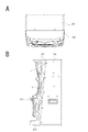
続いて図5〜図9により実施の形態の回胴遊技機200の構成を説明する。
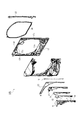
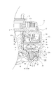
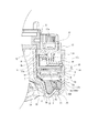
図5は回胴遊技機200の正面図、図6Aは平面図、図6Bは右側面図、図7は前面パネル202の背面図、図8は本体ケース201の正面図である。
<2. Configuration of rotating game machine >
Subsequently, the configuration of the rotating cylinder game machine 200 of the embodiment will be described with reference to FIGS. 5 to 9.
5 is a front view of the rotating drum game machine 200, FIG. 6A is a plan view, FIG. 6B is a right side view, FIG. 7 is a rear view of the front panel 202, and FIG. 8 is a front view of the main body case 201.
本実施の形態の回胴遊技機200は、図6からわかるように、矩形箱状の本体ケース201と、各種の遊技部材を装着した前面パネル202とが、図示しないヒンジ機構を介して連結され、前面パネル202が本体ケース201に対して開閉可能に構成されている。
In the rotating cylinder game machine 200 of the present embodiment, as can be seen from FIG. 6, a rectangular box-shaped main body case 201 and a front panel 202 on which various game members are mounted are connected via a hinge mechanism (not shown). The front panel 202 is configured to be openable and closable with respect to the main body case 201.
図8に示すように、本体ケース201の略中央には、3つの回転リール(回胴)204a,204b,204cを備える図柄回転ユニット203が配置されている。また、その下側に、メダル払出装置205が配置されている。
各回転リール204a,204b,204cには、後述する各種図柄、例えばBB(ビッグボーナス)やRB(レギュラーボーナス)用の図柄や、各種のフルーツ図柄、リプレイ図柄などが描かれている。
メダル払出装置205は、メダルを貯留するメダルタンク205aを有する。また払出ケース205b内に、図9で後述する払出モータ275、払出接続基板273、ホッパー基板274、メダル払出センサ276等が収納されている。
メダルタンク205aに貯留されたメダルは、払出モータ275の回転に基づいて、払出口205cから図面手前方向に向けて導出される。なお限界量を越えて貯留されたメダルは超過メダル導出部205dを通して補助タンク206に落下するよう構成されている。
As shown in FIG. 8, a symbol rotating unit 203 including three rotating reels (rotating reels) 204a, 204b, and 204c is arranged substantially in the center of the main body case 201. Further, a medal payout device 205 is arranged below the medal payout device 205.
On each of the rotating reels 204a, 204b, 204c, various symbols described later, for example, symbols for BB (big bonus) and RB (regular bonus), various fruit symbols, replay symbols, and the like are drawn.
The medal payout device 205 has a medal tank 205a for storing medals. Further, the payout motor 275, the payout connection board 273, the hopper board 274, the medal payout sensor 276, and the like, which will be described later in FIG. 9, are housed in the payout case 205b.
The medals stored in the medal tank 205a are led out from the payout outlet 205c toward the front of the drawing based on the rotation of the payout motor 275. The medals stored in excess of the limit amount are configured to fall into the auxiliary tank 206 through the excess medal lead-out unit 205d.
メダル払出装置205に隣接して電源基板241が配置される。また、図柄回転ユニット203の上方に主制御基板240が配置され、主制御基板240に隣接して回胴設定基板271が配置されている。
また図柄回転ユニット203の内部には、図9に示す回胴LED中継基板256と回胴中継基板253とが設けられ、図柄回転ユニット203に隣接して外部集中端子板270が配置されている。
さらに、本体ケース201においては、図柄回転ユニット203の側方に前面パネル202の開放(ドアの開放)を検知するためのドア開放センサ235が設けられている。
A power supply board 241 is arranged adjacent to the medal payout device 205. Further, the main control board 240 is arranged above the symbol rotation unit 203, and the rotating cylinder setting board 271 is arranged adjacent to the main control board 240.
Further, inside the symbol rotating unit 203, a rotating cylinder LED relay board 256 and a rotating cylinder relay board 253 shown in FIG. 9 are provided, and an external centralized terminal plate 270 is arranged adjacent to the symbol rotating unit 203.
Further, in the main body case 201, a door opening sensor 235 for detecting the opening of the front panel 202 (opening of the door) is provided on the side of the symbol rotating unit 203.
図5に示すように、前面パネル202の上部にはLCDユニット207が配置されている。このLCDユニット207には、遊技動作を盛り上げるためなどに各種のキャラクタが表示される。
またLCDユニット207の下部には、回転リール204a,204b,204cを表出させる表示窓208が形成されている。この表示窓208を通しては、各回転リール204a,204b,204cの回転方向に、各々3個程度の図柄が見えるようにされている。そして、例えば合計9個の図柄の水平方向の二本(又は三本)と、対角線方向の二本が仮想的な停止ラインとなる。
なお、図柄回転ユニット203の内部には、回転リール204a,204b,204cが停止した状態において視認される9個の図柄それぞれを内側から照射可能な位置に回胴用LEDが配置されている(不図示)。それぞれの回胴用LEDはそれぞれの回転リールの回転状態や停止状態、或いは各種演出に応じて点灯・消灯される。
As shown in FIG. 5, the LCD unit 207 is arranged on the upper part of the front panel 202. Various characters are displayed on the LCD unit 207 in order to excite the game operation.
Further, at the lower part of the LCD unit 207, a display window 208 for displaying the rotary reels 204a, 204b, 204c is formed. Through the display window 208, about three symbols can be seen in each of the rotation directions of the rotary reels 204a, 204b, and 204c. Then, for example, a total of nine symbols in the horizontal direction (or three) and two in the diagonal direction serve as virtual stop lines.
Inside the symbol rotating unit 203, a rotating cylinder LED is arranged at a position where each of the nine symbols visually recognized when the rotating reels 204a, 204b, and 204c are stopped can be irradiated from the inside (not). Illustrated). Each rotating cylinder LED is turned on and off according to the rotating state and the stopped state of each rotating reel, or various effects.
表示窓208を介して視認可能とされる3つの回転リール204a,204b,204cは、回胴遊技機100でいうところの遊技領域とされている。即ち、表示窓208や後述する透明ガラス15を介して遊技者が視認可能とされる部分は、遊技者が遊技中に主に視線を向ける遊技領域とされる。
なお、このような遊技領域はあくまで一例である。遊技領域は、「遊技球が転動可能な領域」、「遊技球が転動しているかのような映像が表示される表示領域」、「遊技結果(図柄の変動および停止)が表示される表示領域」、「機械または映像によるリールの回転表示が行われる表示領域」、「表示器単体」、「可動式役物単体」など、遊技に関連する演出手段の一部または全部を含む領域である。
表示領域の形状は、円形や方形は当然含まれ、更に、多角形や瓢箪型などのその他形状が含まれていてもよい。また、平面領域を指す場合に限らず、奥行きを含めた立体領域を示す場合もある。
The three rotary reels 204a, 204b, and 204c, which are visible through the display window 208, are defined as a gaming area in the rotating cylinder gaming machine 100. That is, the portion that can be visually recognized by the player through the display window 208 and the transparent glass 15 described later is a gaming area in which the player mainly directs his / her line of sight during the game.
It should be noted that such a game area is just an example. In the game area, "the area where the game ball can roll", "the display area where the image as if the game ball is rolling", and "the game result (change and stop of the symbol) are displayed" are displayed. In an area that includes a part or all of the effect means related to the game, such as "display area", "display area where the rotation display of the reel by machine or image is performed", "display unit", "movable accessory unit", etc. is there.
The shape of the display area naturally includes a circle or a square, and may further include other shapes such as a polygon or a gourd. Further, the present invention is not limited to the case of pointing to a plane region, and may also indicate a three-dimensional region including depth.
表示窓208の下方には、遊技状態を示すLED群209や、遊技成果として払出されるメダル数を表示する払出表示部210や、貯留数表示部211が設けられている。
LED群209は、例えば、当ゲームに投入されたメダルの枚数を示すLEDや再遊技状態を示すLED、回胴を回転させる準備が整ったことを示すLED(当ゲームの遊技に要する所定枚数のメダルの投入が完了したことを示すLED)、メダルの投入の受付状態を示すLEDなどで構成されている。
払出表示部210は、7セグメントLEDを2個連設して構成されており、払出メダル数を特定すると共に、何らかの異常事態の発生時には、異常内容を表示するエラー表示器としても機能する。
貯留数表示部211は、クレジット状態で貯留されているメダル数が表示されている。
Below the display window 208, an LED group 209 indicating the game state, a payout display unit 210 for displaying the number of medals to be paid out as a game result, and a storage number display unit 211 are provided.
The LED group 209 includes, for example, an LED indicating the number of medals inserted in the game, an LED indicating the replay state, and an LED indicating that the rotating cylinder is ready to rotate (a predetermined number of LEDs required for the game of the game). It is composed of an LED (LED) indicating that the insertion of medals has been completed, an LED indicating the acceptance status of insertion of medals, and the like.
The payout display unit 210 is configured by connecting two 7-segment LEDs in succession, and functions as an error display for specifying the number of payout medals and displaying the contents of the abnormality when an abnormal situation occurs.
The storage number display unit 211 displays the number of medals stored in the credit state.
表示窓208の上方、左、右には、LED演出部215a,215b,215cが設けられている。LED演出部215a,215b,215cは、所定の絵柄、意匠が施され、内側に配置されたLEDによって光による演出が実行されるように構成されている。ここでいうLED演出部215a,215b,215cは、弾球遊技機100の装飾ランプに相当する。
LED演出部215a,215b,215cで実行される演出は、例えば、BBやRBに当選したことを示す演出や、AT(アシストタイム)やART(アシストリプレイタイム)等の状態を示す演出、AT中やART中のアシスト演出等である。
なお、個々の説明は省略するが、前面パネル202には、演出や動作状態を提示するためのLEDとして他のLEDが各種配置されている。
LED effect units 215a, 215b, and 215c are provided above, left, and right of the display window 208. The LED effect units 215a, 215b, and 215c are provided with a predetermined pattern and design, and are configured so that the effect by light is executed by the LED arranged inside. The LED effect units 215a, 215b, and 215c referred to here correspond to decorative lamps of the ball game machine 100.
The effects executed by the LED effect units 215a, 215b, and 215c include, for example, an effect indicating that the BB and RB have been won, an effect indicating the state of AT (assist time), ART (assist replay time), and the like, and during AT. And assist production during ART.
Although individual description is omitted, various other LEDs are arranged on the front panel 202 as LEDs for presenting the effect and the operating state.
前面パネル202の中央右側には、メダルを投入するメダル投入口212が設けられ、これに近接して、メダル投入口212に詰まったメダルを返却させるための返却ボタン213が設けられている。
また、前面パネル202の中央左側には、クレジット状態のメダルを払出すクレジット精算ボタン214と、クレジット状態のメダルを擬似的に三枚投入するマックス投入ボタン216とが設けられている。
A medal insertion slot 212 for inserting medals is provided on the right side of the center of the front panel 202, and a return button 213 for returning medals packed in the medal insertion slot 212 is provided in the vicinity of the medal insertion slot 212.
Further, on the left side of the center of the front panel 202, a credit settlement button 214 for paying out medals in the credit state and a max insertion button 216 for inserting three medals in the credit state in a pseudo manner are provided.
また、前面パネル202には、回転リール204a,204b,204cの回転を開始させるためのスタートレバー217と、回転中の回転リール204a,204b,204cを停止させるための停止ボタン218a,218b,218cが設けられている。
遊技者がスタートレバー217を操作すると、通常は、3つの回転リール204a,204b,204cが正方向に回転を開始する。但し、内部当選状態を予告するリール演出のために、回転リール204a,204b,204cの全部又は一部が、変則的に回転(いわゆる「演出回転」)した上で正方向の回転を開始する場合もある。
更に、前面パネル202には、演出のための操作子や設定を行うための操作子として、十字キー224と演出ボタン225が設けられている。
Further, the front panel 202 has a start lever 217 for starting the rotation of the rotary reels 204a, 204b, 204c and stop buttons 218a, 218b, 218c for stopping the rotating rotary reels 204a, 204b, 204c. It is provided.
When the player operates the start lever 217, normally, the three rotary reels 204a, 204b, and 204c start rotating in the positive direction. However, in the case where all or part of the rotating reels 204a, 204b, and 204c rotate irregularly (so-called "effect rotation") and then start rotating in the positive direction for the reel effect that announces the internal winning state. There is also.
Further, the front panel 202 is provided with a cross key 224 and an effect button 225 as an operator for the effect and an operator for performing the setting.
前面パネル202の下方には、メダルを蓄える横長の受け皿219と、メダル払出装置205の払出口205cに連通するメダル導出口220とが設けられている。
また前面パネル202の上方左右、及び下方左右にはスピーカ230a,230b,230c,230dが配置されている。
Below the front panel 202, a horizontally long saucer 219 for storing medals and a medal outlet 220 communicating with the payout outlet 205c of the medal payout device 205 are provided.
Further, speakers 230a, 230b, 230c, 230d are arranged on the upper left and right and the lower left and right of the front panel 202.
図7に示すように前面パネル202の裏側は、図5で示したメダル投入口212に投入されたメダルの選別を行うメダル選別装置221と、メダル選別装置221により不適正と判別されたメダルをメダル導出口220に案内する返却通路222とが設けられている。
また、前面パネル202の裏側上部には、基板ケース223が配置されている。この基板ケース223には、図9で述べる演出制御基板242、演出インターフェース基板243、液晶制御基板244、液晶インターフェース基板245などが収容されている。
またメダル選別装置221の側方には、各種の遊技部材と主制御基板240との間の信号を中継する遊技中継基板260(図9で後述する)が設けられている。
As shown in FIG. 7, on the back side of the front panel 202, a medal sorting device 221 for sorting medals inserted into the medal slot 212 shown in FIG. 5 and medals determined to be inappropriate by the medal sorting device 221 are displayed. A return passage 222 that guides the medal outlet 220 is provided.
A substrate case 223 is arranged on the upper part of the back side of the front panel 202. The substrate case 223 houses the effect control board 242, the effect interface board 243, the liquid crystal control board 244, the liquid crystal interface board 245, and the like described in FIG.
Further, on the side of the medal sorting device 221 is provided a game relay board 260 (described later in FIG. 9) that relays signals between various game members and the main control board 240.
図9は、回胴遊技機200の内部の制御構成の概略的なブロック図である。本実施の形態の回胴遊技機200は、その制御構成が主制御基板240を中心に構成されている。
主制御基板240は、CPU、RAM、ROM等を備えたマイクロコンピュータやインターフェースのための回路等が搭載され、回胴遊技機200の遊技動作全般に係る統括的な制御を行う。例えば主制御基板240が回転リール204a,204b,204cを含む各種の遊技部材の動作を制御するとともに、動作状況を把握する。また遊技動作に応じて演出を実行させる。
主制御基板240は、電源基板241、演出インターフェース基板243、回胴中継基板253、遊技中継基板260、外部集中端子板270、回胴設定基板271、払出接続基板273との間で各種信号(コマンドや検出信号等)のやりとりを行う。
FIG. 9 is a schematic block diagram of the internal control configuration of the rotating drum game machine 200. The rotating cylinder game machine 200 of the present embodiment has a control configuration centered on a main control board 240.
The main control board 240 is equipped with a microcomputer equipped with a CPU, RAM, ROM, etc., a circuit for an interface, and the like, and performs comprehensive control related to the overall game operation of the rotating cylinder game machine 200. For example, the main control board 240 controls the operation of various gaming members including the rotary reels 204a, 204b, and 204c, and grasps the operation status. In addition, the production is executed according to the game operation.
The main control board 240 has various signals (commands) between the power supply board 241, the effect interface board 243, the rotating cylinder relay board 253, the game relay board 260, the external centralized terminal board 270, the rotating cylinder setting board 271, and the payout connection board 273. And detection signals, etc.) are exchanged.
電源基板241は、AC24Vを受けて、これを整流・平滑して直流電圧を得る。そして電源基板241はコンバータ回路を備えて各部に必要な電源電圧を生成する。図では主制御基板240を介して各部に与えられる主制御電源電圧V1、及び演出インターフェース基板243を介して各部に与えられる演出制御電源電圧V2を示している。
また電源基板241には電源遮断状態を検出する電源監視回路や、主制御基板240にバックアップ電源電圧を供給するバックアップ電源回路なども設けられている。
The power supply board 241 receives AC24V and rectifies and smoothes it to obtain a DC voltage. Then, the power supply board 241 includes a converter circuit and generates a power supply voltage required for each part. The figure shows the main control power supply voltage V1 given to each part via the main control board 240 and the effect control power supply voltage V2 given to each part via the effect interface board 243.
Further, the power supply board 241 is also provided with a power supply monitoring circuit for detecting a power supply cutoff state, a backup power supply circuit for supplying a backup power supply voltage to the main control board 240, and the like.
演出制御基板242は、CPU、ROM、RAM等を備えたマイクロコンピュータやインターフェースのための回路等が搭載され、回胴遊技機200の演出動作に関する制御を行う。
演出制御基板242は、演出インターフェース基板243を介して主制御基板240からのコマンドを受け取る。例えば主制御基板240は、演出制御基板242に対して、スピーカ230a〜230dによる音演出、LEDランプや冷陰極線管放電管によるランプ演出、LCDユニット207による図柄演出を実現するための制御コマンドを出力し、演出制御基板242はその制御コマンドに応じた演出制御処理を行う。
また演出制御基板242では、主制御基板240から内部抽選結果を特定する制御コマンド(遊技開始コマンド)受けると、内部抽選結果に対応してアシストタイム当選状態とするか否かのAT抽選を実行する。
なお、演出制御基板242においてAT抽選に当選した後の所定回数のゲーム(AT中)では、小役当選状態において、その図柄を停止ラインに整列できるよう、3つの回転リール204の停止順序を遊技者に報知している。
また演出制御基板242は、主制御基板240からのリール演出実行を示す制御コマンドを受けると、主制御基板240で実行するリール演出に対応する演出動作を開始する。
これらのような演出制御動作のため、演出制御基板242は、演出インターフェース基板243を通して各部と必要な通信を行う。
The effect control board 242 is equipped with a microcomputer equipped with a CPU, ROM, RAM, etc., a circuit for an interface, and the like, and controls the effect operation of the rotating drum game machine 200.
The effect control board 242 receives a command from the main control board 240 via the effect interface board 243. For example, the main control board 240 outputs a control command to the effect control board 242 to realize a sound effect by the speakers 230a to 230d, a lamp effect by the LED lamp or the cold cathode wire tube discharge tube, and a design effect by the LCD unit 207. Then, the effect control board 242 performs the effect control process according to the control command.
Further, in the effect control board 242, when a control command (game start command) for specifying the internal lottery result is received from the main control board 240, an AT lottery for whether or not to enter the assist time winning state is executed in response to the internal lottery result. ..
In the game (during AT) a predetermined number of times after winning the AT lottery on the effect control board 242, the stop order of the three rotating reels 204 is played so that the symbols can be aligned with the stop line in the small winning combination winning state. Notify the person.
Further, when the effect control board 242 receives a control command indicating the reel effect execution from the main control board 240, the effect control board 242 starts the effect operation corresponding to the reel effect executed by the main control board 240.
For the effect control operation as described above, the effect control board 242 performs necessary communication with each unit through the effect interface board 243.
演出制御基板242は、演出インターフェース基板243、及び液晶インターフェース基板245を介して液晶制御基板244に接続されている。
液晶制御基板244は、LCDユニット207における画像表示による演出の制御を行う。この液晶制御基板244には、VDP、画像ROM、VRAM、液晶制御用のCPU、液晶制御用のROM、液晶制御用のRAM等が搭載される。
このような液晶制御基板244は、演出制御基板242からの表示演出に関するコマンドを受け付け、それに応じて表示駆動信号を生成する。そして液晶インターフェース基板245を介してLCDユニット207に表示駆動信号を供給し、画像表示を実行させる。
The effect control board 242 is connected to the liquid crystal control board 244 via the effect interface board 243 and the liquid crystal interface board 245.
The liquid crystal control board 244 controls the effect of displaying an image on the LCD unit 207. The liquid crystal control board 244 is equipped with a VDP, an image ROM, a VRAM, a CPU for controlling the liquid crystal, a ROM for controlling the liquid crystal, a RAM for controlling the liquid crystal, and the like.
Such a liquid crystal control board 244 receives a command related to a display effect from the effect control board 242 and generates a display drive signal accordingly. Then, a display drive signal is supplied to the LCD unit 207 via the liquid crystal interface board 245 to execute image display.
また、演出制御基板242は、演出インターフェース基板243を介してスピーカ中継基板247を制御し、スピーカ230a〜230dを用いた音演出を実行させる。
また演出制御基板242は、演出インターフェース基板243を介して、LED基板248や回胴LED中継基板256を経由して各種のLEDによるランプ演出を実現する。
LED基板248には、例えば図5に示したLED演出部215a,215b,215cとしてのLEDが配置されている。
回胴LED中継基板256は、第1回胴LED基板250a、第2回胴LED基板250b、第3回胴LED基板250cについて演出制御基板242からのLED駆動信号を中継する。
第1回胴LED基板250aには、回転リール204aの図柄を内側から照射する回胴用LEDが配置されている。第2回胴LED基板250bには、回転リール204bの図柄を内側から照射する回胴用LEDが配置されている。また、第3回胴LED基板250cには、回転リール204cの図柄を内側から照射する回胴用LEDが配置されている。
Further, the effect control board 242 controls the speaker relay board 247 via the effect interface board 243, and causes the sound effect using the speakers 230a to 230d to be executed.
Further, the effect control board 242 realizes a lamp effect by various LEDs via the effect interface board 243 and the LED board 248 and the rotating cylinder LED relay board 256.
On the LED substrate 248, for example, LEDs as LED effect units 215a, 215b, and 215c shown in FIG. 5 are arranged.
The rotating cylinder LED relay board 256 relays LED drive signals from the effect control board 242 for the first cylinder LED substrate 250a, the second cylinder LED substrate 250b, and the third cylinder LED substrate 250c.
On the first cylinder LED substrate 250a, a rotating cylinder LED that irradiates the design of the rotary reel 204a from the inside is arranged. On the second cylinder LED substrate 250b, a rotating cylinder LED that irradiates the design of the rotary reel 204b from the inside is arranged. Further, on the third cylinder LED substrate 250c, a rotating cylinder LED that irradiates the design of the rotary reel 204c from the inside is arranged.
主制御基板240は、遊技中継基板260を介して、回胴遊技機200の各種遊技部材に接続されている。
遊技表示基板261は、遊技状態を示すLED群209や、7セグメントLEDを有した払出表示部210や、同じく7セグメントLEDを有した貯留数表示部211を搭載している。主制御基板240は、遊技表示基板261に対して、遊技中継基板260を介して制御コマンドを送信し、遊技状態に応じた表示を実行させるように制御している。
The main control board 240 is connected to various game members of the rotating cylinder game machine 200 via the game relay board 260.
The game display board 261 is equipped with an LED group 209 indicating a game state, a payout display unit 210 having a 7-segment LED, and a storage number display unit 211 also having a 7-segment LED. The main control board 240 controls the game display board 261 to transmit a control command via the game relay board 260 to execute the display according to the game state.
始動スイッチ基板262には、スタートレバー217による始動スイッチが搭載されている。
停止スイッチ基板263には停止ボタン218a、218b、218cによる停止スイッチが搭載されている。
貯留メダル投入スイッチ基板264には、マックス投入ボタン216の投入スイッチが搭載されている。
精算スイッチ基板265にはクレジット清算ボタン214の清算スイッチが搭載されている。
主制御基板240は、これらの基板(261〜265)のスイッチによる遊技者操作の検出信号を、遊技中継基板260を介して受信する。
A start switch by a start lever 217 is mounted on the start switch board 262.
The stop switch board 263 is equipped with a stop switch by the stop buttons 218a, 218b, and 218c.
The input switch of the max input button 216 is mounted on the storage medal insertion switch board 264.
The settlement switch board 265 is equipped with a settlement switch of the credit settlement button 214.
The main control board 240 receives the detection signal of the player operation by the switches of these boards (261 to 265) via the game relay board 260.
ドアセンサ266は、前面パネル202の鍵穴に対して設けられたセンサである。ドアセンサ266によって遊技の中止解除動作を認識可能とされている。
メダル通過センサ267及びレバー検出センサ268は、メダル選別装置221に設けられている。メダル通過センサ267は、例えばフォトインタラプタで構成され、選別された正規のメダルの通過を検出するセンサである。レバー検出センサ268は、例えばフォトマイクロセンサで構成され、メダル投入口212から投入されたメダルの通過を検出するセンサである。つまり、メダル投入口212から投入されたメダルは、レバー検出センサ268を通過した後に正規のメダルだけが選別された後、メダル通過センサ267によりその通過が検出される。
主制御基板240は、これらのセンサ(266,267,268)の検出信号を、遊技中継基板260を介して受信する。さらに主制御基板240は、受信したセンサの検出信号により投入されたメダルの投入時間や通過方向を検出し、所定の規定に合致した場合にのみ投入メダルとして受け付け、それ以外の場合には投入メダルエラーとして処理する。
ブロッカーソレノイド269は、不正メダルの通過を阻止するブロッカーをON/OFFに駆動する。主制御基板240は、遊技中継基板260を介してブロッカーソレノイド269を制御する。
The door sensor 266 is a sensor provided for the keyhole of the front panel 202. The door sensor 266 makes it possible to recognize the canceling / canceling operation of the game.
The medal passing sensor 267 and the lever detection sensor 268 are provided in the medal sorting device 221. The medal passage sensor 267 is a sensor composed of, for example, a photo interrupter, and detects the passage of selected regular medals. The lever detection sensor 268 is composed of, for example, a photomicro sensor, and is a sensor that detects the passage of medals inserted from the medal insertion slot 212. That is, after the medals inserted from the medal insertion slot 212 have passed through the lever detection sensor 268 and only the regular medals are selected, the passage of the medals is detected by the medal passage sensor 267.
The main control board 240 receives the detection signals of these sensors (266,267,268) via the game relay board 260. Further, the main control board 240 detects the insertion time and the passing direction of the inserted medals by the detection signal of the received sensor, accepts the inserted medals as the inserted medals only when the predetermined regulations are met, and accepts the inserted medals in other cases. Treat as an error.
The blocker solenoid 269 drives the blocker that blocks the passage of illegal medals ON / OFF. The main control board 240 controls the blocker solenoid 269 via the game relay board 260.
また主制御基板240は、回胴中継基板253を経由して、回転リール204a,204b,204cを回転させる3つのステッピングモータ(第1回胴ステッピングモータ254a、第2回胴ステッピングモータ254b、第3回胴ステッピングモータ254c)と接続されている。
さらに主制御基板240は、回胴中継基板253を経由して、回転リール204a,204b,204cの原点位置を検出するための3つのインデックスセンサ(第1回胴インデックスセンサ255a、第2回胴インデックスセンサ255b、第3回胴インデックスセンサ255c)に接続されている。
主制御基板240は、ステッピングモータ254a,254b,254cを駆動又は停止させることによって、回転リール204a,204b,204cの回転動作と、目的位置での停止動作を実現している。また主制御基板240は、インデックスセンサ255a,255b,255cの検出信号に基づき、回転リール204a,204b,204cの原点位置を検知できる。
Further, the main control board 240 has three stepping motors (1st cylinder stepping motor 254a, 2nd cylinder stepping motor 254b, 3rd) that rotate the rotary reels 204a, 204b, 204c via the rotating cylinder relay board 253. It is connected to the rotating cylinder stepping motor 254c).
Further, the main control board 240 has three index sensors (1st cylinder index sensor 255a, 2nd cylinder index) for detecting the origin positions of the rotary reels 204a, 204b, 204c via the rotating cylinder relay board 253. It is connected to the sensor 255b and the third body index sensor 255c).
The main control board 240 realizes the rotation operation of the rotary reels 204a, 204b, 204c and the stop operation at the target position by driving or stopping the stepping motors 254a, 254b, 254c. Further, the main control board 240 can detect the origin position of the rotary reels 204a, 204b, 204c based on the detection signals of the index sensors 255a, 255b, 255c.
また主制御基板240は、払出接続基板273を介してメダル払出のための装置部にも接続されている。メダル払出のための装置部として、メダル払出制御を行うホッパー基板274と、払出モータ275と、メダル払出センサ276が設けられている。
ホッパー基板274は、主制御基板240からの制御コマンドに基づいて払出モータ275を回転させて、所定量のメダルを払出しする。
メダル払出センサ276は、払出メダルの通過を検出する。メダル払出センサ276による検出信号は、払出メダル枚数が不足したり払出動作が行われないなどの払出異常状態の検出に用いられる。
The main control board 240 is also connected to a device unit for paying out medals via a payout connection board 273. As a device unit for medal payout, a hopper board 274 for controlling medal payout, a payout motor 275, and a medal payout sensor 276 are provided.
The hopper board 274 rotates the payout motor 275 based on a control command from the main control board 240 to pay out a predetermined amount of medals.
The medal payout sensor 276 detects the passage of the payout medal. The detection signal by the medal payout sensor 276 is used to detect an abnormal payout state such as an insufficient number of medal payouts or a payout operation not being performed.
また主制御基板240は外部集中端子板270に接続されている。外部集中端子板270は例えばホールコンピュータに接続されており、主制御基板240は外部集中端子板270を通してメダルの投入枚数やメダルの払出枚数などをホールコンピュータに出力している。
また主制御基板240は、回胴設定基板271にも接続されている。回胴設定基板271は、係員が設定キースイッチ272を用いて設定した設定値を示す信号などを出力している。設定値とは、当該回胴遊技機200で実行される抽選処理の当選確率などを、設定1から設定6まで6段階で規定するもので、遊技ホールの営業戦略に基づいて適宜に設定される。
Further, the main control board 240 is connected to the external centralized terminal board 270. The external centralized terminal board 270 is connected to, for example, a hall computer, and the main control board 240 outputs the number of medals inserted and the number of medals paid out to the hall computer through the external centralized terminal board 270.
The main control board 240 is also connected to the rotating cylinder setting board 271. The rotating cylinder setting board 271 outputs a signal or the like indicating a set value set by a staff member using the setting key switch 272. The set value defines the winning probability of the lottery process executed by the rotating game machine 200 in 6 stages from setting 1 to setting 6, and is appropriately set based on the business strategy of the game hall. ..
<3.遊技機の枠部における装飾ランプの態様>
以上の弾球遊技機100における枠部や回胴遊技機200における前面パネル202に装着された装飾ランプの態様について説明していく。なお以下では各種の態様を弾球遊技機100に採用した例を用いて説明していくが、以下に述べる各種の態様もしくはその技術思想は全て回胴遊技機200にも適用できる。
<3. Aspects of decorative lamps in the frame of the game machine>
The mode of the decorative lamp mounted on the frame portion of the bullet game machine 100 and the front panel 202 of the rotating cylinder game machine 200 will be described. In the following, various aspects will be described using an example in which the ball game machine 100 is adopted, but all of the various aspects described below or their technical ideas can be applied to the rotating cylinder game machine 200.
弾球遊技機100の枠部としての前扉105には、前述したように各種の装飾ランプ120wが設けられている。装飾ランプ120w及び周辺部材について、種々の構成例を用いて説明する。
As described above, various decorative lamps 120w are provided on the front door 105 as the frame portion of the ball game machine 100. The decorative lamp 120w and peripheral members will be described with reference to various configuration examples.
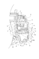
先ず、前扉105の第1の実施の形態について、各図を参照して説明する。
図10は弾球遊技機100の前扉105の正面図、図11は右側面図である。
図10及び図11に示す弾球遊技機100の前扉105は、左右に延びる上辺部1と下辺部2、上下に延びる右辺部3と左辺部4によって枠状とされている。
前扉105における上辺部1、右辺部3及び左辺部4は、遊技盤103の前面に配置された透明ガラスよりも前方(遊技者側)に突出されている。右辺部3は、図51に示すように、左辺部4よりも前方へ突出された状態とされている。
右辺部3の外方側の側面は外方側面部3aとされ、内方側の側面部は内方側面部3bとされ、前方側の面は前方面部3cとされている。上辺部1は、上方側の面とされた上面部1aと下方側の面とされた下面部1bと前面側の前面部1cとされている。
First, the first embodiment of the front door 105 will be described with reference to each figure.
FIG. 10 is a front view of the front door 105 of the ball game machine 100, and FIG. 11 is a right side view.
The front door 105 of the ball game machine 100 shown in FIGS. 10 and 11 has a frame shape formed by an upper side portion 1 and a lower side portion 2 extending left and right, and a right side portion 3 and a left side portion 4 extending vertically.
The upper side portion 1, the right side portion 3 and the left side portion 4 of the front door 105 project forward (on the player side) from the transparent glass arranged on the front surface of the game board 103. As shown in FIG. 51, the right side portion 3 is in a state of protruding forward from the left side portion 4.
The outer side surface of the right side portion 3 is the outer side surface portion 3a, the inner side surface portion is the inner side surface portion 3b, and the front side surface is the front surface portion 3c. The upper side portion 1 is an upper surface portion 1a as an upper surface, a lower surface portion 1b as a lower surface, and a front surface portion 1c on the front surface side.
なお、本実施の形態においては、左辺部4についても透明ガラスより前方に位置している。上辺部1,下辺部2,右辺部3,左辺部4と透明ガラスのそれぞれの前後方向の位置関係は各種の例が考えられる。
In the present embodiment, the left side portion 4 is also located in front of the transparent glass. Various examples can be considered for the positional relationship between the upper side portion 1, the lower side portion 2, the right side portion 3, the left side portion 4 and the transparent glass in the front-rear direction.
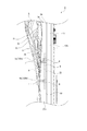
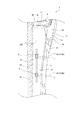
図12及び図13は、前扉105の右辺部3付近の分解斜視図である。
弾球遊技機100の前扉105は、扉ベース17に各種の部品が取り付けられて構成されている。
扉ベース17は、略中央に略円形の孔HYが形成された基部17aと、基部17aの左右の両端部から前方に突出された上下に延びる板状の第1突出板17b,17bと、それぞれの第1突出板17bの内側に離隔して設けられ第1突出板17bと対向する第2突出板17c,17cが設けられている(図12,図13及び図14参照)。
基部17aに設けられた孔HYを介して遊技盤103の遊技領域103aが前面側(遊技者側)に臨む状態となる。
12 and 13 are exploded perspective views of the vicinity of the right side portion 3 of the front door 105.
The front door 105 of the bullet game machine 100 is configured by attaching various parts to the door base 17.
The door base 17 has a base portion 17a in which a substantially circular hole HY is formed in a substantially central portion, and plate-shaped first protruding plates 17b and 17b extending forward from both left and right ends of the base portion 17a, respectively. The second protruding plates 17c and 17c are provided separately inside the first protruding plate 17b and face the first protruding plate 17b (see FIGS. 12, 13 and 14).
The game area 103a of the game board 103 faces the front side (player side) through the hole HY provided in the base portion 17a.
扉ベース17の後方側には断面形状がハット状とされた枠状の保持フレーム18が取り付けられており、扉ベース17(又は装飾カバー5)と保持フレーム18に挟持されるように透明ガラス15が保持される(図14参照)。
透明ガラス15は、強化ガラスなどの素材で形成されていてもよいが、透明の樹脂素材で形成されていてもよい。
A frame-shaped holding frame 18 having a hat-shaped cross section is attached to the rear side of the door base 17, and the transparent glass 15 is sandwiched between the door base 17 (or the decorative cover 5) and the holding frame 18. Is retained (see FIG. 14).
The transparent glass 15 may be formed of a material such as tempered glass, but may also be formed of a transparent resin material.
扉ベース17の基部17aの一部と第1突出板17bと第2突出板17cは、前方に開放されたコ字状とされている。扉ベース17の前方には、該コ字状を前方から閉塞するようにハーネスカバー19,19が取り付けられている。
扉ベース17の基部17a、第1突出板17b、第2突出板17c及びハーネスカバー19によって囲まれた上下に延びる空間は、前扉105に取り付けられる各種の基板へ接続されるハーネス等が収納されるスペースとされている。
A part of the base portion 17a of the door base 17, the first protruding plate 17b, and the second protruding plate 17c are U-shaped open to the front. Harness covers 19 and 19 are attached to the front of the door base 17 so as to close the U-shape from the front.
The vertically extending space surrounded by the base portion 17a, the first protruding plate 17b, the second protruding plate 17c, and the harness cover 19 of the door base 17 houses harnesses and the like connected to various boards attached to the front door 105. It is said to be a space.
扉ベース17の前面側には右フレーム板金20と図示しない左フレーム板金が取り付けられている。右フレーム板金20は、前扉105の右辺部3及び上辺部1の右半分に亘って取り付けられている。左フレーム板金は、左辺部4及び上辺部1の左半分に亘って取り付けられている。
A right frame sheet metal 20 and a left frame sheet metal (not shown) are attached to the front side of the door base 17. The right frame sheet metal 20 is attached to the right side portion 3 of the front door 105 and the right half of the upper side portion 1. The left frame sheet metal is attached over the left half of the left side portion 4 and the upper side portion 1.
扉ベース17の右辺部分の後方には扉ベース17の強度を補強するための右補強板金22が取り付けられている。同様に、扉ベース17の左辺部分の後方には図示しない左補強板金が取り付けられている。
A right reinforcing sheet metal 22 for reinforcing the strength of the door base 17 is attached to the rear of the right side portion of the door base 17. Similarly, a left reinforcing sheet metal (not shown) is attached to the rear of the left side portion of the door base 17.
扉ベース17は、右辺部3を構成する部分が右フレーム板金20及び右補強板金22によって挟持されることにより、強度向上が図られている。扉ベース17の左辺部4を構成する部分は、左フレーム板金及び左補強板金に挟持されることにより、同様に強度向上が図られている。
特に、扉ベース17のうち右辺部3及び左辺部4を構成する部分は縦に細長い形状とされているため、各種の板金によって補強され強度が確保されることにより、破損等が効果的に防止されている。
また、扉ベース17は、右辺部3及び左辺部4の一部を構成する細い部分が第1突出板17b及び第2突出板17cによって補強され、更なる強度向上が図られている。
これらの補強により、扉ベース17を樹脂で形成することができるため、前扉105の軽量化を実現することができる。
The strength of the door base 17 is improved by sandwiching the portion constituting the right side portion 3 between the right frame sheet metal 20 and the right reinforcing sheet metal 22. The portion constituting the left side portion 4 of the door base 17 is similarly improved in strength by being sandwiched between the left frame sheet metal and the left reinforcing sheet metal.
In particular, since the portion of the door base 17 that constitutes the right side portion 3 and the left side portion 4 has a vertically elongated shape, damage and the like are effectively prevented by being reinforced by various sheet metals and ensuring strength. Has been done.
Further, in the door base 17, the narrow portions forming a part of the right side portion 3 and the left side portion 4 are reinforced by the first protruding plate 17b and the second protruding plate 17c, and the strength is further improved.
With these reinforcements, the door base 17 can be formed of resin, so that the weight of the front door 105 can be reduced.
右フレーム板金20の前方には例えば樹脂素材などで形成された取付ベース21が取り付けられており、取付ベース21にはLED基板9が取り付けられている。LED基板9にはLED9a(装飾ランプ120w)が載置されている(図14参照)。
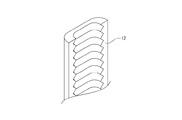
LED基板9の前方には、LED9aから出射された光を拡散させるための凹凸が形成された内部カバー12が配置され、その前方には同じく光を拡散させるための凹凸が形成された装飾カバー5が取り付けられている。
なお、内部カバー12や装飾カバー5は、左辺部4や上辺部1にも設けられている。
A mounting base 21 made of, for example, a resin material is mounted in front of the right frame sheet metal 20, and an LED substrate 9 is mounted on the mounting base 21. An LED 9a (decorative lamp 120w) is mounted on the LED substrate 9 (see FIG. 14).
An inner cover 12 having irregularities for diffusing the light emitted from the LED 9a is arranged in front of the LED substrate 9, and a decorative cover 5 having irregularities for diffusing the light is also formed in front of the inner cover 12. Is installed.
The inner cover 12 and the decorative cover 5 are also provided on the left side portion 4 and the upper side portion 1.
LED基板9は、図24に示すように、内部カバー12と取付ベース21で挟み止めされて保持されていてもよい。この場合、LED基板9を取り付けるための専用のネジ等が不要となる。即ち、内部カバー12を取付ベース21に固定する際にLED基板9の取付ベース21に対する固定も行われる。これにより、部品点数の削減及びコスト削減に寄与する。また、取付工数の削減も実現可能である。
また、LED基板9にネジ孔を設けなくてよいことから、部品実装面を有効活用することができ、また、ネジによる粉吹きの発生を防止することができる。
As shown in FIG. 24, the LED substrate 9 may be held by being sandwiched between the inner cover 12 and the mounting base 21. In this case, a dedicated screw or the like for attaching the LED board 9 becomes unnecessary. That is, when the inner cover 12 is fixed to the mounting base 21, the LED substrate 9 is also fixed to the mounting base 21. This contributes to the reduction of the number of parts and the cost. In addition, it is possible to reduce the installation man-hours.
Further, since it is not necessary to provide screw holes in the LED substrate 9, it is possible to effectively utilize the component mounting surface and prevent the occurrence of powder blowing by the screws.
また、図14に示すように内部カバー12の一部が取付ベース21と離隔して設けられている場合においても、内部カバー12の後面に押さえ部が設けられ、内部カバー12の取り付けの際に該押さえ部がLED基板9を前方から押さえつけるようにしてLED基板9の固定が行われるように構成してもよい。
Further, even when a part of the inner cover 12 is provided apart from the mounting base 21 as shown in FIG. 14, a holding portion is provided on the rear surface of the inner cover 12, and when the inner cover 12 is mounted, the holding portion is provided. The pressing portion may be configured to press the LED substrate 9 from the front so that the LED substrate 9 is fixed.
ハーネスカバー19、右フレーム板金20の一部、取付ベース21、LED基板9、内部カバー12は、扉ベース17と装飾カバー5によって形成される配置空間23に配置された状態とされている(図14参照)。
内部カバー12及び装飾カバー5は、少なくとも一部がLED9aからの光を通す透明部材や半透明部材等で形成されている。具体的には、強化ガラスやアクリル素材やポリカーボネート素材などである。なお、装飾カバー5は、遊技者がLED9aに直接触れることが不可能なように設けられる保護カバーとしての機能を有する。
なお、内部カバー12は必須の構成ではなく、後述する各例においては内部カバー12が設けられていない場合もある。また、図14に示す内部カバー12の配置態様は一例であり、他の例については後述する。
The harness cover 19, a part of the right frame sheet metal 20, the mounting base 21, the LED board 9, and the inner cover 12 are arranged in the arrangement space 23 formed by the door base 17 and the decorative cover 5 (FIG. 6). 14).
At least a part of the inner cover 12 and the decorative cover 5 is formed of a transparent member, a translucent member, or the like that allows light from the LED 9a to pass through. Specifically, it is a tempered glass, an acrylic material, a polycarbonate material, or the like. The decorative cover 5 has a function as a protective cover provided so that the player cannot directly touch the LED 9a.
The inner cover 12 is not an indispensable configuration, and the inner cover 12 may not be provided in each example described later. Further, the arrangement mode of the inner cover 12 shown in FIG. 14 is an example, and other examples will be described later.
装飾カバー5の外方側の側面は外方側面部5aとされ、内方側の側面部は内方側面部5bとされ、前方側の面は前方面部5cとされている(図1,図2参照)。
The outer side surface of the decorative cover 5 is the outer side surface portion 5a, the inner side surface portion is the inner side surface portion 5b, and the front side surface is the front surface portion 5c (FIGS. 1, 1). (See Fig. 2).
装飾ランプ120wは、遊技領域の周囲(外周側)に複数配置されている。複数の装飾ランプ120wのうち、一部は左右方向に離隔して配置され、一部は上下方向に離隔して配置されている。
A plurality of decorative lamps 120w are arranged around the game area (outer peripheral side). Of the plurality of decorative lamps 120w, some are arranged apart from each other in the left-right direction, and some are arranged apart from each other in the vertical direction.
前述のように、遊技者が遊技中に主に視線を向ける領域が遊技領域とされる。従って、遊技領域の周囲に配置される装飾ランプ120wからは遊技領域を効率的に照射する光が出射される。
As described above, the area in which the player mainly directs his / her line of sight during the game is defined as the game area. Therefore, the decorative lamp 120w arranged around the game area emits light that efficiently irradiates the game area.
なお、前扉105の右辺部3は、外方側面部3a、内方側面部3b、前方面部3c以外の分け方をしてもよい。
例えば、前扉105は、扉ベース17に対して装飾カバー5が複数取り付けられている。具体的には、右辺部3を構成する装飾カバー5や左辺部4を構成する装飾カバー5などである。これらの複数の装飾カバー5は複数の部材で構成された装飾体27として扱うことが可能である。即ち、装飾体27は透明ガラス15の周縁部を囲むように(或いは遊技領域を囲むように)配置されている。
このような装飾体27について、遊技領域に面する側としての内側部27bと、それとは反対側とされた外側部27aとに分けてもよい。具体的に、図52では、一点鎖線よりも外側の領域が外側部27a、一点鎖線よりも内側の領域が内側部27bとされている。外側部27a及び内側部27bは、ある点や稜線を境に分けられる。この場合には、右辺部3の外方側面部3a、左辺部4の外方側面部、上辺部1の上面部1aは外側部27aとされる。また、右辺部3の内方側面部3b、左辺部4の内方側面部、上辺部1の下面部1bは内側部27bとされる。
The right side portion 3 of the front door 105 may be divided into a division other than the outer side surface portion 3a, the inner side surface portion 3b, and the front surface portion 3c.
For example, the front door 105 has a plurality of decorative covers 5 attached to the door base 17. Specifically, there are a decorative cover 5 that constitutes the right side portion 3, a decorative cover 5 that constitutes the left side portion 4, and the like. These plurality of decorative covers 5 can be treated as a decorative body 27 composed of a plurality of members. That is, the decorative body 27 is arranged so as to surround the peripheral edge portion of the transparent glass 15 (or to surround the game area).
Such a decorative body 27 may be divided into an inner portion 27b as a side facing the game area and an outer portion 27a as a side opposite to the inner portion 27b. Specifically, in FIG. 52, the region outside the alternate long and short dash line is the outer portion 27a, and the region inside the alternate long and short dash line is the inner portion 27b. The outer portion 27a and the inner portion 27b are separated by a certain point or ridgeline. In this case, the outer side surface portion 3a of the right side portion 3, the outer side surface portion of the left side portion 4, and the upper surface portion 1a of the upper side portion 1 are referred to as the outer side portion 27a. Further, the inner side surface portion 3b of the right side portion 3, the inner side surface portion of the left side portion 4, and the lower surface portion 1b of the upper side portion 1 are referred to as inner portions 27b.
遊技領域103aに面する側である内側部27bとは、実施の形態における右辺部3を例に挙げれば、内方側面部3bに相当するとともに装飾カバー5の形状(或いは右辺部3の形状)によっては、前方面部3cの全部又は一部が内側部27bに相当する場合もある。
即ち、あくまでも遊技領域103aに面する側とその反対側として分けたときに、面する側となる部分が「内側部」に相当する。
同様に、遊技領域103aに面する側の反対側である外側部27aとは、実施の形態における右辺部3を例に挙げれば、外方側面部3aに相当するとともに装飾カバー5の形状(或いは右辺部3の形状)によっては、前方面部3cの全部又は一部が外側部27aに相当する場合もある。
即ち、あくまでも遊技領域103aに面する側とその反対側として分けたときに、反対側となる部分が「外側部」に相当する。
The inner portion 27b on the side facing the game area 103a corresponds to the inner side surface portion 3b and the shape of the decorative cover 5 (or the shape of the right side portion 3), taking the right side portion 3 in the embodiment as an example. Depending on the case, all or a part of the front surface portion 3c may correspond to the inner portion 27b.
That is, when the side facing the game area 103a and the side opposite to the game area 103a are divided, the portion facing the game area 103a corresponds to the "inner part".
Similarly, the outer side portion 27a opposite to the side facing the game area 103a corresponds to the outer side surface portion 3a and the shape of the decorative cover 5 (or, for example, the right side portion 3 in the embodiment). Depending on the shape of the right side portion 3), all or part of the front surface portion 3c may correspond to the outer portion 27a.
That is, when the side facing the game area 103a and the side opposite to the game area 103a are divided, the portion on the opposite side corresponds to the "outer portion".
図15及び図16に右辺部3の一部を拡大して示す。
図15A,図15B,図15Cは、右辺部3を外方側から示す斜視図である。図16A,図16B,図16Cは、右辺部3を内方側から示す斜視図である。
各図に示すように、右辺部3は、外方側(右方側)及び内方側(左方側)にそれぞれ一つの光透過部6または複数の光透過部6,6,・・・が設けられている。光透過部6に凹凸形状が施されている場合には、右辺部3の内部に配置された装飾ランプ120wから出射される光が光透過部6を通過する際に光りが拡散されて弾球遊技機100の外部に出射される。
これにより、装飾ランプ120wから出射された演出光を用いた効果的な光演出を行うことができる。
A part of the right side portion 3 is enlarged and shown in FIGS. 15 and 16.
15A, 15B, and 15C are perspective views showing the right side portion 3 from the outside. 16A, 16B, and 16C are perspective views showing the right side portion 3 from the inside.
As shown in each figure, the right side portion 3 has one light transmitting portion 6 or a plurality of light transmitting portions 6, 6, ... On the outer side (right side) and the inner side (left side), respectively. Is provided. When the light transmitting portion 6 is provided with an uneven shape, the light emitted from the decorative lamp 120w arranged inside the right side portion 3 is diffused when passing through the light transmitting portion 6 and is a bullet. It is emitted to the outside of the game machine 100.
As a result, it is possible to perform an effective light effect using the effect light emitted from the decorative lamp 120w.
光透過部6の一部は、内部に配置された装飾ランプ120wを視認するための視認部7とされている。
本実施の形態では、視認部7は以下に示す三つの定義の何れかで考えることができる。
A part of the light transmitting portion 6 is a viewing portion 7 for visually recognizing the decorative lamp 120w arranged inside.
In the present embodiment, the visual recognition unit 7 can be considered by any of the following three definitions.
<定義1>
視認部7は、前扉105の内部に設けられたLED9a(装飾ランプ120w)が直接視認可能(確認可能)とされたものを指していてもよい。
定義1による視認部7であれば、LED9aの不具合を明確に発見することができ、メンテナンス性の著しい向上が図られる。
<Definition 1>
The visual recognition unit 7 may refer to an LED 9a (decorative lamp 120w) provided inside the front door 105 that is directly visible (verifiable).
With the visual recognition unit 7 according to the definition 1, a defect of the LED 9a can be clearly found, and maintainability can be significantly improved.
<定義2>
また、視認部7は、前扉105の内部に設けられたLED9aのうち対象とされた一つのLED9aから発せられる光が視認可能(確認可能)とされたものを指していてもよい。即ち、視認対象とされたLED9aの点灯及び非点灯状態が認識可能とされたものであってもよい。
定義による視認部7であれば、直接LED9aを視認できないことにより、外観デザイン性に配慮しつつ個々のLED9aの不具合を確認することができ、メンテナンス性の向上が図られる。
<Definition 2>
Further, the visual recognition unit 7 may refer to one of the LEDs 9a provided inside the front door 105 in which the light emitted from one of the targeted LEDs 9a is visible (verifiable). That is, the lighting and non-lighting states of the LED 9a to be visually recognized may be recognizable.
By the definition of the visual recognition unit 7, since the LED 9a cannot be directly visually recognized, it is possible to confirm the defect of each LED 9a while considering the appearance design, and the maintainability is improved.
<定義3>
更に、視認部7は、故障したLED9aが搭載されているLED基板9を特定可能(確認可能)とされたものを指していてもよい。例えば、何れのLED9aが故障して非点灯となったかは特定できないとしても、そのLED9aが搭載されているLED基板9を特定可能であれば、基板交換が必要なLED基板9が前扉105を分解等しなくても識別可能となるため、メンテナンス性の向上を図ることが可能となる。複数のLED9a,9a,・・・が密集して配置されている場合などに適用可能である。
<Definition 3>
Further, the visual recognition unit 7 may refer to an LED substrate 9 on which the failed LED 9a is mounted, which can be identified (confirmed). For example, even if it is not possible to specify which LED 9a has failed and turned off, if the LED board 9 on which the LED 9a is mounted can be specified, the LED board 9 that needs to be replaced has the front door 105. Since it can be identified without disassembling, it is possible to improve maintainability. This is applicable when a plurality of LEDs 9a, 9a, ... Are densely arranged.
次に、視認部7の態様について、いくつかの例を説明する。
まず視認部7の第1例として、視認部7と周辺部8(或いは区切り部25)が共に光透過性を有するが、周辺部8(或いは区切り部25)よりも視認部7の方が高い視認性を有する例を説明する。
例えば外方側面部5aの視認部7として図15A,図15B,図15Cの各図に示すように、光透過部6のうち視認部7の部分は高い透明性を有する部材または形状で形成され、視認部7の周辺部8は視認部7よりも透明性が低い部材または形状で形成されている。
透明性が高いとは、例えば、全透過光に対して拡散光が少ない状態などをいう。即ち、内部に配置された各部が視認し易い状態とされる。
逆に透明性が低いとは、内部から出射された光を認識できるものの内部に配置された各部の視認性は劣る状態とされる。
なお、周辺部8は、光透過部6のうち視認部7を除いた部分の一部であってもよいし、光透過部6のうち視認部7を除いた部分の全部であってもよい。また、周辺部8は光透過部6を含まずに不透明な部材で形成されていてもよい。
Next, some examples will be described with respect to the aspect of the visual recognition unit 7.
First, as a first example of the visual recognition portion 7, both the visual recognition portion 7 and the peripheral portion 8 (or the partition portion 25) have light transmission, but the visual recognition portion 7 is higher than the peripheral portion 8 (or the partition portion 25). An example having visibility will be described.
For example, as the visible portion 7 of the outer side surface portion 5a, as shown in each of FIGS. 15A, 15B, and 15C, the portion of the light transmitting portion 6 of the visible portion 7 is formed of a member or shape having high transparency. The peripheral portion 8 of the visual recognition portion 7 is formed of a member or shape having a lower transparency than the visual recognition portion 7.
High transparency means, for example, a state in which diffused light is less than all transmitted light. That is, each part arranged inside is in a state where it is easy to see.
On the contrary, when the transparency is low, it means that the light emitted from the inside can be recognized, but the visibility of each part arranged inside is inferior.
The peripheral portion 8 may be a part of the light transmitting portion 6 excluding the visual viewing portion 7, or may be the entire portion of the light transmitting portion 6 excluding the visual visual portion 7. .. Further, the peripheral portion 8 may be formed of an opaque member without including the light transmitting portion 6.
図15Aは、右辺部3の外方側面部3aのうち、装飾カバー5の一部とされた部分の略全てが光透過部6とされ、その一部が視認部7とされている。視認部7は内面及び(又は)外面に凹凸が形成されていないプレーンで透明な部材とされている。
視認部7の周辺の周辺部8は、装飾カバー5の外方側面部5aにおける視認部7を除く略全ての部分(図中の梨地で示す)とされており、半透明の部材で形成されている。
In FIG. 15A, substantially all of the outer side surface portion 3a of the right side portion 3 which is a part of the decorative cover 5 is a light transmitting portion 6, and a part thereof is a viewing portion 7. The visual recognition portion 7 is a plain and transparent member having no irregularities formed on the inner surface and / or the outer surface.
The peripheral portion 8 around the visible portion 7 is substantially all the portions (indicated by the satin finish in the drawing) of the outer side surface portion 5a of the decorative cover 5 except for the visible portion 7, and is formed of a translucent member. ing.
図15Bは、右辺部3の外方側面部3aに三つの光透過部6,6,6が形成されている。三つの光透過部6には、それぞれ視認部7と周辺部8が一つずつ形成されている。
視認部7は内面及び(又は)外面に凹凸が形成されていない透明な部材とされ、図中に梨地で示す周辺部8は半透明の部材で形成されている。右辺部3の外方側面部3aを構成する部分のうち、装飾カバー5の外方側面部5aにおける光透過部6以外の部分(図中の塗りつぶし部分)及び扉ベース17の一部(第1突出板17b)は不透明な部材で形成されている。
In FIG. 15B, three light transmitting portions 6, 6 and 6 are formed on the outer side surface portion 3a of the right side portion 3. Each of the three light transmitting portions 6 is formed with a viewing portion 7 and a peripheral portion 8.
The visual recognition portion 7 is a transparent member having no irregularities formed on the inner surface and / or the outer surface, and the peripheral portion 8 shown by a satin finish in the drawing is formed of a translucent member. Of the portions constituting the outer side surface portion 3a of the right side portion 3, the portion other than the light transmitting portion 6 (filled portion in the drawing) and the part of the door base 17 (first) in the outer side surface portion 5a of the decorative cover 5. The protruding plate 17b) is made of an opaque member.
図15Cは、右辺部3の外方側面部3a(装飾カバー5の外方側面部5a)に二つの光透過部6,6が形成されている。光透過部6,6のうち、上方に位置する光透過部6には、二つの視認部7,7が形成されており、それ以外の部分は周辺部8とされている。下方に位置する光透過部6には、視認部7が形成されておらず、非視認部16とされている。視認部7は内面及び(又は)外面に凹凸が形成されていない透明な部材とされ、周辺部8は半透明の部材で形成されている。右辺部3の外方側面部3aを構成する部分のうち、装飾カバー5の外方側面部5aにおける光透過部6以外の部分(図中の塗りつぶし部分)及び扉ベース17の一部(第1突出板17b)は不透明な部材で形成されている。
以上のように視認部7と周辺部8が共に光透過性を有するが、周辺部8よりも視認部7の方が高い視認性を有する態様は、内方側面部5bにも適用できる。後述のように上辺部1の上面部1aに視認部7を設ける場合にも適用できる。
In FIG. 15C, two light transmitting portions 6 and 6 are formed on the outer side surface portion 3a of the right side portion 3 (the outer side surface portion 5a of the decorative cover 5). Of the light transmitting portions 6 and 6, the light transmitting portion 6 located above is formed with two viewing portions 7 and 7, and the other portions are peripheral portions 8. The light transmitting portion 6 located below is not formed with the visible portion 7, and is regarded as the non-visible portion 16. The visual recognition portion 7 is a transparent member having no irregularities formed on the inner surface and / or the outer surface, and the peripheral portion 8 is formed of a translucent member. Of the portions constituting the outer side surface portion 3a of the right side portion 3, the portion other than the light transmitting portion 6 (filled portion in the drawing) and the part of the door base 17 (first) in the outer side surface portion 5a of the decorative cover 5. The protruding plate 17b) is made of an opaque member.
As described above, both the visual recognition portion 7 and the peripheral portion 8 have light transmission, but the aspect in which the visual recognition portion 7 has higher visibility than the peripheral portion 8 can also be applied to the inner side surface portion 5b. As will be described later, it can also be applied to the case where the visual recognition portion 7 is provided on the upper surface portion 1a of the upper side portion 1.
視認部7の第2例として、光透過性の無い部材で囲まれた視認部7が設けられた例を説明する。
図16A,図16B,図16Cの各図に示すように、光透過部6のうち視認部7の周辺部8は光透過性の無い部材で形成され、視認部7の部分は周辺部8よりも透明性を有した部材で形成されている。視認部7は、内部の認識ができるように高い透明性を有していてもよいし、内部を認識できないが内部から出射された光は認識できる低い透明性を有していてもよい。
As a second example of the visual recognition unit 7, an example in which the visual recognition unit 7 surrounded by a member having no light transmission is provided will be described.
As shown in FIGS. 16A, 16B, and 16C, the peripheral portion 8 of the visible portion 7 of the light transmitting portion 6 is formed of a member having no light transmission, and the portion of the visual visual portion 7 is formed from the peripheral portion 8. Is also made of a transparent member. The visual recognition unit 7 may have high transparency so that the inside can be recognized, or may have low transparency so that the light emitted from the inside cannot be recognized but the inside cannot be recognized.
図16Aは、右辺部3の内方側面部3b(装飾カバー5の内方側面部5b)のうち、一部が光透過部6とされ、且つ光透過部6とされた領域全てが視認部7とされている。内方側面部3bのその他の部分(図中の塗りつぶし部分)は、視認部7の周辺部8とされている。
In FIG. 16A, of the inner side surface portion 3b of the right side portion 3 (inner side surface portion 5b of the decorative cover 5), a part of the light transmitting portion 6 and the entire region designated as the light transmitting portion 6 are visible portions. It is said to be 7. The other portion (filled portion in the drawing) of the inner side surface portion 3b is a peripheral portion 8 of the visual recognition portion 7.
図16Bは、右辺部3の内方側面部3b(装飾カバー5の内方側面部5b)に三つの光透過部6,6,6が設けられ、且つ、それぞれの光透過部6が視認部7とされている。内方側面部3bのその他の部分(図中の塗りつぶし部分)は、三つの視認部7,7,7の周辺部8とされている。
In FIG. 16B, three light transmitting portions 6, 6 and 6 are provided on the inner side surface portion 3b of the right side portion 3 (inner side surface portion 5b of the decorative cover 5), and each light transmitting portion 6 is a visible portion. It is said to be 7. The other portion (filled portion in the drawing) of the inner side surface portion 3b is a peripheral portion 8 of the three visual recognition portions 7, 7, 7.
図16Cは、右辺部3の内方側面部3b(装飾カバー5の内方側面部5b)に四つの光透過部6,6,6,6が設けられ、その中の二つは視認部7が設けられていない非視認部16とされ、残りの二つは視認部7,7とされている。二つの視認部7,7の周辺部分は周辺部8とされている。
視認部7とされた光透過部6は内面及び外面に凹凸が形成されていない透明な部材とされており、非視認部16とされた光透過部6,6は例えば半透明の部材で形成されている。周辺部8は不透明な部材で形成されている。
In FIG. 16C, four light transmitting portions 6, 6, 6, 6 are provided on the inner side surface portion 3b of the right side portion 3 (inner side surface portion 5b of the decorative cover 5), and two of them are the viewing portions 7. The non-visible part 16 is not provided, and the remaining two are the visible parts 7 and 7. The peripheral portion of the two visual recognition portions 7 and 7 is the peripheral portion 8.
The light transmitting portion 6 as the visible portion 7 is a transparent member having no irregularities formed on the inner and outer surfaces, and the light transmitting portions 6 and 6 as the non-visible portion 16 are formed of, for example, a translucent member. Has been done. The peripheral portion 8 is formed of an opaque member.
視認部7の第3例として、視認部7とその周辺部8にそれぞれ異なる凹凸形状が形成された例を説明する。
図17Aは装飾カバー5を外方側面部5a側から見た側面図であり、図17Bは図17AのA−A断面図である。図17A,図17Bに示す例では、装飾カバー5の外方側面部5aの略全体が光透過部6とされ、光透過部6の一部が視認部7とされている。視認部7は二つ設けられており、それぞれの視認部7の周辺は周辺部8とされている。
視認部7の第3例は、図17Bに示すように、光透過部6における視認部7と周辺部8に異なる凹凸形状が形成されている。具体的には、視認部7及び周辺部8は、発光演出を行うために内部に配置された装飾ランプ120wから出射された光を拡散させるための凹凸形状が内面に形成されている。視認部7と周辺部8のそれぞれの内面に形成された凹凸形状が異なる形状とされていることにより、光の拡散態様が異なるようにされている。
これにより、視認部7が拡散板として機能しながらLED9aの不具合を発見するための機能を備えることとなる。
As a third example of the visual recognition portion 7, an example in which different uneven shapes are formed on the visual recognition portion 7 and its peripheral portion 8 will be described.
FIG. 17A is a side view of the decorative cover 5 as viewed from the outer side surface portion 5a side, and FIG. 17B is a sectional view taken along the line AA of FIG. 17A. In the examples shown in FIGS. 17A and 17B, substantially the entire outer side surface portion 5a of the decorative cover 5 is a light transmitting portion 6, and a part of the light transmitting portion 6 is a viewing portion 7. Two viewing units 7 are provided, and the periphery of each viewing unit 7 is a peripheral portion 8.
In the third example of the visual recognition portion 7, as shown in FIG. 17B, different uneven shapes are formed in the visual recognition portion 7 and the peripheral portion 8 in the light transmitting portion 6. Specifically, the visual recognition portion 7 and the peripheral portion 8 are formed on the inner surface with an uneven shape for diffusing the light emitted from the decorative lamp 120w arranged inside in order to produce a light emitting effect. The uneven shape formed on the inner surface of each of the visual recognition portion 7 and the peripheral portion 8 has a different shape, so that the light diffusion mode is different.
As a result, the visual recognition unit 7 is provided with a function for finding a defect of the LED 9a while functioning as a diffuser plate.
視認部7の内面に形成された凹凸形状は周辺部8の内面に形成された凹凸形状よりも緩やかな形状に形成されている。これにより、視認部7は、右辺部3の内部に対する視認性が周辺部8よりも高くされている。
なお、視認部7に形成された凹凸形状と周辺部8に形成された凹凸形状が異なる他の例として、一つ一つの山谷の形状は同じであるが、山谷の形状の間隔が異なるようにされていてもよい。具体的には、視認部7に形成された凹凸形状は山と山の間隔が5mmとされ、周辺部8に形成された凹凸形状は山と山の間隔が1mmとされていてもよい。これによっても、視認部7の内部に対する視認性を周辺部8よりも高くすることが可能である。
The uneven shape formed on the inner surface of the visual recognition portion 7 is formed to be a gentler shape than the uneven shape formed on the inner surface of the peripheral portion 8. As a result, the visibility portion 7 has higher visibility to the inside of the right side portion 3 than the peripheral portion 8.
As another example in which the concave-convex shape formed in the visual recognition portion 7 and the concave-convex shape formed in the peripheral portion 8 are different, the shapes of the peaks and valleys are the same, but the intervals between the shapes of the peaks and valleys are different. It may have been. Specifically, the uneven shape formed in the visual recognition portion 7 may have a mountain-to-mountain distance of 5 mm, and the uneven shape formed in the peripheral portion 8 may have a mountain-to-mountain distance of 1 mm. This also makes it possible to make the visibility of the inside of the visibility portion 7 higher than that of the peripheral portion 8.
視認部7の第4例として、視認部7が開閉可能とされた例を説明する。
図18に示すように、光透過部6における視認部7がスライド式の窓とされている。
図18Aは視認部7を閉じた状態を示した図であり、図18Bは視認部7を開けた状態を示した図である。
スライド式とされた視認部7は、例えば半透明の部材で形成されており、閉じた状態でも内部に配置されたLED9aの点灯状態が把握することが可能とされている。また、開けた状態とした場合、内部に配置されたLED9aのうち何れのLED9aが故障しているかを把握可能とされている。
視認部7の周辺部8は、不透明な部材で形成されていてもよいし、内部に光を拡散するための凹凸形状が形成されていてもよい。少なくとも視認部7よりも視認性が低下した状態とされている。
閉じた状態において、故障しているLED基板9が特定可能である場合、何れの基板が故障しているかを特定すればよい場合は視認部7を閉じた状態でメンテナンスを行い、故障しているLED9aの特定が必要な場合には視認部7を開けた状態でメンテナンスを行えばよい。
即ち、メンテナンスの態様に応じた弾球遊技機100の運用が可能となる。
As a fourth example of the visual recognition unit 7, an example in which the visual recognition unit 7 can be opened and closed will be described.
As shown in FIG. 18, the visual recognition portion 7 in the light transmitting portion 6 is a sliding window.
FIG. 18A is a diagram showing a state in which the visual recognition unit 7 is closed, and FIG. 18B is a diagram showing a state in which the visual recognition unit 7 is open.
The sliding visual recognition unit 7 is made of, for example, a translucent member, and it is possible to grasp the lighting state of the LED 9a arranged inside even in the closed state. Further, when the LED 9a is opened, it is possible to grasp which of the LEDs 9a arranged inside is out of order.
The peripheral portion 8 of the visual recognition portion 7 may be formed of an opaque member, or may have an uneven shape for diffusing light inside. At least, the visibility is lower than that of the visibility unit 7.
In the closed state, if the failed LED board 9 can be identified, and if it is sufficient to identify which board is broken, maintenance is performed with the visual recognition unit 7 closed, and the failure occurs. When it is necessary to specify the LED 9a, maintenance may be performed with the visual recognition unit 7 open.
That is, the ball game machine 100 can be operated according to the mode of maintenance.
視認部7の第5例として、視認部7が開閉可能とされた別の例を説明する。
図19に示すように、光透過部6における視認部7が開閉式の窓とされている。
図19Aは視認部7を閉じた状態を示した図であり、図19Bは視認部7を開けた状態を示した図である。
視認部7は、例えば上述した定義1を適用した場合、開放した状態において、LED基板9に載置されたLED9aが直接視認可能とされている。また、視認部7を閉じた状態においては、LED9aの発光が確認できる状態とされている。開状態及び閉状態のそれぞれのLED9aに対する視認性の態様はあくまで一例であり、他にも各種の例が考えられる。例えば、開状態において視認部7が配置空間23にアクセス可能な穴状とされるのではなく、内側に透明な板状の部材が設けられていてもよい。その場合には、視認部7に光を拡散させるための凹凸形状が形成されて内部に対する視認性が低くされ、開状態においては透明な板状の部材を介して内部に対する高い視認性が保たれていてもよい。これにより、弾球遊技機100の内部に対する不正なアクセスを防止することができる。この点については、図18に示すスライド式の窓とされた視認部7についても同様の構成を採用することが可能である。
開閉式の窓とされた視認部7においても、スライド式の窓とされた視認部7と同様の効果を得ることができる。
As a fifth example of the visual recognition unit 7, another example in which the visual recognition unit 7 can be opened and closed will be described.
As shown in FIG. 19, the visual recognition portion 7 in the light transmitting portion 6 is an openable / closable window.
FIG. 19A is a diagram showing a state in which the visual recognition unit 7 is closed, and FIG. 19B is a diagram showing a state in which the visual recognition unit 7 is open.
When the definition 1 described above is applied to the viewing unit 7, for example, the LED 9a mounted on the LED substrate 9 can be directly viewed in the open state. Further, when the visual recognition unit 7 is closed, the light emission of the LED 9a can be confirmed. The mode of visibility for each of the LED 9a in the open state and the closed state is only an example, and various other examples can be considered. For example, instead of the visible portion 7 having a hole shape that allows access to the arrangement space 23 in the open state, a transparent plate-shaped member may be provided inside. In that case, a concavo-convex shape for diffusing light is formed in the visibility portion 7 to reduce visibility to the inside, and in the open state, high visibility to the inside is maintained through a transparent plate-shaped member. May be. This makes it possible to prevent unauthorized access to the inside of the ball game machine 100. Regarding this point, the same configuration can be adopted for the visual recognition unit 7 which is a sliding window shown in FIG.
The same effect as that of the viewing unit 7 which is a sliding window can be obtained in the viewing unit 7 which is an opening / closing window.
なお、図15乃至図19の各図に示す視認部7の態様は組合せが合理的でない場合を除き、いかようにも組み合わせることが可能である。例えば、図15Aと図16Aを適用し、半透明とされた周辺部8を備えた視認部7と不透明とされた周辺部8を備えた視認部7の双方を備えていてもよい。
It should be noted that the modes of the visual recognition unit 7 shown in each of FIGS. 15 to 19 can be combined in any way except when the combination is not rational. For example, by applying FIGS. 15A and 16A, both a visual recognition portion 7 having a semi-transparent peripheral portion 8 and a visual recognition portion 7 having an opaque peripheral portion 8 may be provided.
また、視認部7は右辺部3の前方面部3cに設けられていてもよい。前方面部3cに設けられている場合には、作業者が弾球遊技機100の前方から視認部7を介してLED9a自体やLED9aからの発光を識別可能とされるため、高いメンテナンス性を獲得することができる。
Further, the visual recognition portion 7 may be provided on the front surface portion 3c of the right side portion 3. When the front surface portion 3c is provided, the operator can identify the light emitted from the LED 9a itself or the LED 9a from the front of the ball game machine 100 via the visual recognition portion 7, and thus high maintainability is obtained. can do.
以下、視認部7の具体的な各種の例を<3−1>〜<3−87>として説明する。<3−1>〜<3−86>の各例は、次のタイプA〜Dのいずれか1つ又は複数に該当する。該当するタイプについては<>内に付記しておく。
・タイプA:視認部7が外方(外方側面部3a)にある
・タイプB:視認部7が内方(内方側面部3b)にある
・タイプC1:視認部7の態様が内方と外方で同じ
・タイプC2:視認部7の態様が内方と外方で異なる
・タイプD:視認部7が上方(上辺部1の上面部1a)にある
Hereinafter, various specific examples of the visual recognition unit 7 will be described as <3-1> to <3-87>. Each example of <3-1> to <3-86> corresponds to any one or more of the following types A to D. Applicable types are added in <>.
-Type A: The visual recognition part 7 is on the outer side (outer side surface part 3a) -Type B: The visual recognition part 7 is on the inner side (inner side surface part 3b) -Type C1: The aspect of the visual recognition part 7 is inward Same as on the outside ・ Type C2: The mode of the visible part 7 is different on the inside and the outside ・ Type D: The visible part 7 is on the upper side (upper surface part 1a of the upper side part 1)
なお、視認部7が外方にあるとするタイプAの例の説明では、各例の図示にかかわらず、内方に視認部7があるものと無いもののいずれもが想定される。
同様に、視認部7が内方にあるとするタイプBの例の説明では、各例の図示にかかわらず、外方に視認部7があるものと無いもののいずれもが想定される。
同様に、視認部7が上方にあるとするタイプDの例の説明では、外方や内方に視認部7が無いもの、一方にあるもの、両方にあるもののいずれもが想定される。
さらに「外方」とは右辺部3の外方側面部3aを想定して説明するが、各例は左辺部の外方側面部としても実現可能である。
同様に「内方」とは右辺部3の内方側面部3aを想定して説明するが、各例は左辺部の内方側面部としても実現可能である。
In the description of the type A example in which the visual recognition unit 7 is located on the outside, it is assumed that the visual recognition unit 7 is present or not on the inside, regardless of the illustration of each example.
Similarly, in the description of the type B example in which the visual recognition portion 7 is located on the inside, it is assumed that the visual viewing portion 7 is present or not on the outside, regardless of the illustration of each example.
Similarly, in the description of the type D example in which the visual recognition portion 7 is located above, it is assumed that there is no visual recognition portion 7 on the outside or inside, one on one side, or one on both sides.
Further, although the “outer” is described assuming the outer side surface portion 3a of the right side portion 3, each example can also be realized as the outer side surface portion of the left side portion.
Similarly, although the “inner side” is described assuming the inner side surface portion 3a of the right side portion 3, each example can also be realized as the inner side surface portion of the left side portion.
タイプC1,C2における同じ又は異なる「態様」とは、例として次のような事項が想定される。
・外方と内方における視認部7の有無
・外方と内方における視認部7の数
・外方と内方における視認部7の位置(水平方向に対応する位置であるか否か)
・外方と内方における視認部7の形状
・外方と内方において視認部7が形成される部品
・外方と内方における視認部7の機能(上述の定義1,2,3の別)
もちろんこれらは例示であり同じ又は異なる「態様」としては他にも想定される。
そして「態様が同じ」とは、以上の例うちの少なくとも1つが同じということである。
The same or different "modes" in types C1 and C2 are assumed to have the following items as examples.
-Presence or absence of the visible part 7 on the outside and the inside-Number of the visible parts 7 on the outside and the inside-Position of the visible part 7 on the outside and the inside (whether or not the position corresponds to the horizontal direction)
-Shape of the visible part 7 on the outside and inside-Parts where the visible part 7 is formed on the outside and inside-Functions of the visible part 7 on the outside and inside (separate definitions 1, 2 and 3 above) )
Of course, these are examples, and other the same or different "modes" are envisioned.
And "the same aspect" means that at least one of the above examples is the same.
また、以下の各例で示す視認部7は、遊技機に設けられた複数のLED9a(装飾ランプ120w)のうち、特定の発光体(装飾ランプ120w、LED9a)の点灯状態や非点灯状態を確認可能なように設けられているものである。視認部7は、点灯状態のみを確認可能とされていてもよいし、非点灯状態のみを確認可能とされていてもよいし、対象とする発光体の点灯状態および非点灯状態を確認可能とされていてもよい。
Further, the visual recognition unit 7 shown in each of the following examples confirms the lighting state and the non-lighting state of a specific light emitting body (decorative lamp 120w, LED9a) among the plurality of LEDs 9a (decorative lamps 120w) provided in the game machine. It is provided as possible. The visual recognition unit 7 may be able to confirm only the lighting state, may be able to confirm only the non-lighting state, and may be able to confirm the lighting state and the non-lighting state of the target light emitter. It may have been done.
それぞれの視認部7が対象とする特定のLED9aとしては各種の例が考えられる。後述するように、演出上重要な役割を担う発光体であってもよいし、報知上重要な役割を担う発光体であってもよい。
また、特定の位置に配置された発光体であってもよい。具体的には、視認部7が右辺部3の外方側面部3aに設けられている場合には、該視認部7と略同じ高さに位置する発光体のうち最も右方に位置する発光体の点灯状態/非点灯状態を確認可能とされた視認部7とされていてもよい。同様に、視認部7が右辺部3の内方側面部3bに設けられている場合には、その視認部7の対象とされた発光体は右辺部3の中に位置する発光体のうちで該視認部7と略同じ高さに位置し、且つ、最も左側に位置するものであってもよい。
Various examples can be considered as the specific LED 9a targeted by each visual recognition unit 7. As will be described later, it may be a light emitting body that plays an important role in the production, or may be a light emitting body that plays an important role in the notification.
Further, it may be a light emitting body arranged at a specific position. Specifically, when the visual recognition portion 7 is provided on the outer side surface portion 3a of the right side portion 3, the light emitting body located on the rightmost side of the light emitting bodies located at substantially the same height as the visual recognition portion 7 is emitted. The visual recognition unit 7 may be such that the lighting state / non-lighting state of the body can be confirmed. Similarly, when the visual recognition portion 7 is provided on the inner side surface portion 3b of the right side portion 3, the light emitter targeted by the visual recognition portion 7 is among the light emitters located in the right side portion 3. It may be located at substantially the same height as the visual recognition unit 7 and may be located on the leftmost side.
また、特定の位置に配置された発光体の別の例を挙げる。発光体がそれぞれ載置された複数の基板が前後に重ねられた状態で右辺部3の内部に配置されている場合には、後方に位置する基板上(遊技者から遠い方の基板上)に載置された発光体の点灯状態/非点灯状態が確認し難い可能性がある。そのような場合には、後方に位置する基板上に載置された発光体が特定の位置に配置された発光体とされていてもよい。
In addition, another example of a luminous body arranged at a specific position will be given. When a plurality of substrates on which the light emitters are mounted are arranged inside the right side portion 3 in a state of being stacked back and forth, they are placed on the substrate located at the rear (on the substrate far from the player). It may be difficult to confirm the lighting state / non-lighting state of the mounted light emitter. In such a case, the light emitting body placed on the substrate located at the rear may be regarded as the light emitting body arranged at a specific position.
更に、特定の位置に配置された発光体の別の例を挙げる。発光体には、複数の発光体が一定に範囲に密集されて配置されるものや、単独で他の発光体からある程度の距離離隔されて配置されるものがある。
密集されて配置された発光体は、何れか一つの発光体が故障して常時非点灯状態となった場合に、何れの発光体が故障したのか確認し難い虞がある。
このような場合には、一定の範囲内に密集されて配置された複数の発光体が特定の位置に配置された発光体とされていてもよい。
In addition, another example of a luminous body arranged at a specific position will be given. Some illuminants are arranged so that a plurality of illuminants are densely arranged in a certain range, and some illuminants are arranged alone at a certain distance from other illuminants.
When any one of the light emitting bodies is in a densely arranged state and the light emitting body is always turned off, it may be difficult to confirm which light emitting body has failed.
In such a case, a plurality of illuminants densely arranged within a certain range may be regarded as illuminants arranged at specific positions.
換言すれば、視認部7から視認可能とされた発光体は、設計者が重要な発光体と認識したものであり、前述した特定の発光体と考える事ができる。
後述の各例においては、特定の位置に配置された発光体や特定の発光体を第1発光体として記載する。
In other words, the light emitting body that can be visually recognized from the visual recognition unit 7 is recognized by the designer as an important light emitting body, and can be considered as the above-mentioned specific light emitting body.
In each example described later, a light emitting body arranged at a specific position or a specific light emitting body is described as a first light emitting body.
光透過部6の中には、発光体の点灯状態/非点灯状態を確認可能なように設けられた視認部7や、演出光を出射するために設けられた演出光透過部26がある。演出光透過部26は演出光を出射するだけの機能を有していてもよいし、視認部7としての機能を併せて有していてもよい。
演出光透過部26に光拡散用の凹凸形状が設けられている場合や、演出光透過部26と発光体の間に内部カバー12が設けられている場合には、発光体の点灯状態/非点灯状態の確認がし難い場合がある。そのような発光体を特定の位置に配置された発光体として視認部7を設けてもよい。
The light transmitting unit 6 includes a visual recognition unit 7 provided so that the lighting state / non-lighting state of the light emitting body can be confirmed, and an effect light transmitting unit 26 provided for emitting the effect light. The effect light transmitting unit 26 may have a function of only emitting the effect light, or may also have a function as a visual unit 7.
When the effect light transmitting portion 26 is provided with an uneven shape for light diffusion, or when the internal cover 12 is provided between the effect light transmitting portion 26 and the light emitting body, the lighting state / non-lighting state of the light emitting body. It may be difficult to check the lighting status. The visual recognition unit 7 may be provided as a light emitting body in which such a light emitting body is arranged at a specific position.
<3−1:タイプA>
視認部7が外方にある場合の一例を説明する。
図14は、右辺部3付近の断面図である。図示するように、前扉105は、右辺部3の外方側(右方側)及び内方側(左方側)にそれぞれ設けられた光透過部6,6,・・・の一部からは内部に配置された非点灯状態の装飾ランプ120wを視認可能とされている。即ち、光透過部6の一形態とされる視認部7についても、視認部7を介して内部に配置された非点灯状態の装飾ランプ120wを視認可能とされている。例えば、図15に示す視認部7の一態様を適用することで実現可能である。
<3-1: Type A>
An example of the case where the visual recognition unit 7 is on the outside will be described.
FIG. 14 is a cross-sectional view of the vicinity of the right side portion 3. As shown in the figure, the front door 105 is formed from a part of the light transmitting portions 6, 6, ... Provided on the outer side (right side) and the inner side (left side) of the right side portion 3, respectively. Is able to visually recognize the non-lit decorative lamp 120w arranged inside. That is, even for the visual recognition unit 7, which is a form of the light transmitting portion 6, the non-lighting decorative lamp 120w arranged inside can be visually recognized via the visual recognition unit 7. For example, it can be realized by applying one aspect of the visual recognition unit 7 shown in FIG.
右辺部3の外方側に非点灯状態の装飾ランプ120wを視認可能な視認部7が設けられていることにより、装飾ランプ120wが点灯しないなどの不具合を早期に発見することが可能となる。特に、遊技者が遊技中の弾球遊技機100においては、右辺部3の内方側に設けられた視認部7からは装飾ランプ120wが視認し難い可能性があるが、そのような状態においても、外方側に設けられた視認部7から装飾ランプ120wの不具合を発見できるため、好適である。
換言すれば、前枠102に対して開閉可能に取り付けられた前扉105を備え、前扉105の内部に配置された発光体(装飾ランプ120w)を視認可能な視認部7が前扉105の外方側の側面部(外方側面部3a)に形成されていてもよい。
By providing a visible portion 7 on the outer side of the right side portion 3 that allows the decorative lamp 120w in the non-lit state to be visually recognized, it is possible to detect a defect such that the decorative lamp 120w does not light at an early stage. In particular, in the ball game machine 100 in which the player is playing, the decorative lamp 120w may be difficult to see from the visual recognition portion 7 provided on the inner side of the right side portion 3, but in such a state, it may be difficult to see. However, it is preferable because a defect of the decorative lamp 120w can be found from the visual recognition portion 7 provided on the outer side.
In other words, the front door 105 is provided with the front door 105 that can be opened and closed with respect to the front frame 102, and the visual unit 7 that can visually recognize the light emitting body (decorative lamp 120w) arranged inside the front door 105 is the front door 105. It may be formed on the outer side surface portion (outer side surface portion 3a).
また、所定の遊技が可能な遊技領域103aを備えた弾球遊技機100においては、遊技領域103aの外周側に位置し、上下方向および左右方向に複数配置された発光体(装飾ランプ120w)と、遊技者が発光体に接触できないように設けられたカバー体(装飾カバー5)と、を備え、発光体は、所定位置に配置された第1発光体を含み、カバー体は、遊技領域103aに面する側である内側部27bと、該内側部27bとは反対側である外側部27aとを有し、カバー体における外側部27aに、第1発光体を直接視認可能な視認部7が設けられていてもよい。
Further, in the ball game machine 100 provided with the game area 103a capable of performing a predetermined game, the ball game machine 100 is located on the outer peripheral side of the game area 103a and is arranged with a plurality of light emitting bodies (decorative lamp 120w) arranged in the vertical direction and the horizontal direction. A cover body (decorative cover 5) provided so that the player cannot come into contact with the light emitting body, the light emitting body includes a first light emitting body arranged at a predetermined position, and the cover body includes a game area 103a. An inner portion 27b on the side facing the inner portion and an outer portion 27a on the side opposite to the inner portion 27b, and a visible portion 7 capable of directly recognizing the first light emitting body is provided on the outer portion 27a of the cover body. It may be provided.
より具体的には、弾球遊技機100においては、前枠102に対して開閉可能に取り付けられ周縁部のうちの上下に延びる部分の少なくとも一部が遊技者側に突出する突出部(右辺部3)とされた前扉105を備え、突出部は、内部に発光体(装飾ランプ120w)が配置され発光体から発せられる光を拡散させる凹凸が形成され外方側の側面部(外方側面部3a)に発光体を視認可能な視認部7が形成された構成とされていることにより、上記効果を発揮することができる。
More specifically, in the ball game machine 100, at least a part of the peripheral portion that is openably and closably attached to the front frame 102 and extends vertically extends toward the player (right side portion). The front door 105 as described in 3) is provided, and the protruding portion has a light emitting body (decorative lamp 120w) arranged inside, and unevenness for diffusing the light emitted from the light emitting body is formed, and the outer side surface portion (outer side surface) is formed. The above effect can be exhibited by the configuration in which the visual recognition portion 7 capable of visually recognizing the light emitting body is formed in the portion 3a).
なお、図14では装飾カバー5に視認部7を設けているが、装飾カバー5以外の場所に視認部7を設けるようにしてもよい。その場合には、装飾(意匠)に影響を及ぼさない形態とすることができる。
また視認部7が外方側面部3aにのみ形成されることも考えられる。特に装飾カバー5の外方側面部5aにのみ形成されることも考えられる。その場合、視認部7が遊技者からみた場合の意匠性に影響を与えないようにすることができる。
Although the decorative cover 5 is provided with the visual recognition portion 7 in FIG. 14, the visual recognition portion 7 may be provided at a place other than the decorative cover 5. In that case, the form may not affect the decoration (design).
It is also conceivable that the visual recognition portion 7 is formed only on the outer side surface portion 3a. In particular, it is conceivable that the decorative cover 5 is formed only on the outer side surface portion 5a. In that case, it is possible to prevent the visual recognition unit 7 from affecting the design when viewed from the player.
<3−2:タイプB>
視認部7が内方にある場合の一例を説明する。
弾球遊技機100の右方に壁などが設置されているような状況下では、右辺部3の外方側(右方)から弾球遊技機100を確認することが難しい状況などがあり得る。そのような場合においては、図14に示すように、装飾ランプ120wを視認できる視認部7が右辺部3の内方側に設けられていることにより、装飾ランプ120wの不具合を発見しやすくなり、メンテナンス効率の向上を図ることができる。
<3-2: Type B>
An example of the case where the visual recognition unit 7 is inside will be described.
In a situation where a wall or the like is installed on the right side of the ball game machine 100, it may be difficult to check the ball game machine 100 from the outside (right side) of the right side portion 3. .. In such a case, as shown in FIG. 14, since the visual recognition portion 7 capable of visually recognizing the decorative lamp 120w is provided on the inner side of the right side portion 3, it becomes easier to find a defect of the decorative lamp 120w. Maintenance efficiency can be improved.
即ち、右辺部3の外方側に設けられた視認部7や内方側に設けられた視認部7から内部に配置された非点灯状態の装飾ランプ120wが視認できることは、装飾ランプ120wの不具合の早期発見に資する。特に、非点灯状態の装飾ランプ120wを視認できることにより、装飾ランプ120wの故障等を容易に発見することができ、弾球遊技機100のメンテナンス効率の向上を図ることができる。
換言すれば、前枠102に対して開閉可能に取り付けられた前扉105を備え、前扉105の内部に配置された発光体(装飾ランプ120w)を視認可能な視認部7が前扉105の内方側の側面部(内方側面部3b)に形成されていてもよい。
That is, the fact that the non-lit decorative lamp 120w arranged inside can be visually recognized from the visual recognition portion 7 provided on the outer side of the right side portion 3 and the visual recognition portion 7 provided on the inner side is a defect of the decorative lamp 120w. Contributes to early detection of. In particular, by visually recognizing the decorative lamp 120w in the non-lit state, it is possible to easily find a failure of the decorative lamp 120w and improve the maintenance efficiency of the ball game machine 100.
In other words, the front door 105 is provided with the front door 105 that can be opened and closed with respect to the front frame 102, and the visual unit 7 that can visually recognize the light emitting body (decorative lamp 120w) arranged inside the front door 105 is the front door 105. It may be formed on the inner side surface portion (inner side surface portion 3b).
より具体的には、弾球遊技機100においては、前枠102に対して開閉可能に取り付けられ周縁部のうちの上下に延びる部分の少なくとも一部が遊技者側に突出する突出部とされた前扉105を備え、突出部は、内部に発光体(装飾ランプ120w)が配置され発光体から発せられる光を拡散させる凹凸が形成され内方側の側面部(内方側面部3b)に発光体を視認可能な視認部7が形成されることにより、上記効果を奏することができる。
More specifically, in the ball game machine 100, at least a part of the peripheral portion that is openably and closably attached to the front frame 102 and extends vertically is a protruding portion that protrudes toward the player. A front door 105 is provided, and a light emitting body (decorative lamp 120w) is arranged inside the protruding portion, and unevenness is formed to diffuse the light emitted from the light emitting body, and light is emitted to the inner side surface portion (inner side surface portion 3b). The above effect can be achieved by forming the visible portion 7 that allows the body to be visually recognized.
また、遊技領域103aの少なくとも一部を囲むように弾球遊技機100の前方に突出して形成され、内部に発光体(装飾ランプ120w)が配置される装飾体27を備え、装飾体27は遊技領域103aに面する側である内側部27bと、該内側部27bとは反対側である外側部27aとを有し、発光体は、所定位置に配置された第1発光体を含み、内側部27bに、第1発光体を視認可能な視認部7が設けられていてもよい。
Further, the decorative body 27 is provided with a decorative body 27 which is formed so as to project forward of the bullet game machine 100 so as to surround at least a part of the game area 103a and in which a light emitting body (decorative lamp 120w) is arranged. It has an inner portion 27b that faces the region 103a and an outer portion 27a that is opposite to the inner portion 27b, and the illuminant includes a first illuminant arranged at a predetermined position and is an inner portion. 27b may be provided with a visual recognition unit 7 capable of visually recognizing the first light emitting body.
なお、図14では装飾カバー5に視認部7を設けているが、装飾カバー5以外の場所に視認部7を設けるようにしてもよい。その場合には、装飾(意匠)に影響を及ぼさない形態とすることができる。
また視認部7が内方側面部3bにのみ形成されることも考えられる。特に装飾カバー5の内方側面部5bにのみ形成されることも考えられる。
Although the decorative cover 5 is provided with the visual recognition portion 7 in FIG. 14, the visual recognition portion 7 may be provided at a place other than the decorative cover 5. In that case, the form may not affect the decoration (design).
It is also conceivable that the visual recognition portion 7 is formed only on the inner side surface portion 3b. In particular, it is conceivable that the decorative cover 5 is formed only on the inner side surface portion 5b.
<3−3:タイプA、B、C1>
視認部7が同じ態様で外方と内方の両方にある場合の一例を説明する。
装飾ランプ120wを視認できる視認部7が右辺部3の外方側及び内方側の双方に設けられていることにより、装飾ランプ120wの故障等を更に容易に発見することができ、メンテナンス性の更なる向上を図ることができる(図14参照)。
即ち、前枠102に対して開閉可能に取り付けられた前扉105を備え、前扉105の内部に配置された発光体(装飾ランプ120w)を視認可能な視認部7が前扉105の外方側の側面部(外方側面部3a)及び内方側の側面部(内方側面部3b)に形成されていてもよい。
<3-3: Types A, B, C1>
An example will be described in which the viewing unit 7 is located on both the outer side and the inner side in the same manner.
Since the visual recognition portion 7 capable of visually recognizing the decorative lamp 120w is provided on both the outer side and the inner side of the right side portion 3, it is possible to more easily detect a failure of the decorative lamp 120w and the like, and it is easy to maintain. Further improvement can be achieved (see FIG. 14).
That is, the front door 105 is provided so as to be openable and closable with respect to the front frame 102, and the visible portion 7 capable of visually recognizing the light emitting body (decorative lamp 120w) arranged inside the front door 105 is outside the front door 105. It may be formed on the side surface portion (outer side surface portion 3a) and the inner side surface portion (inner side surface portion 3b).
より具体的には、弾球遊技機100においては、前枠102に対して開閉可能に取り付けられ周縁部のうちの上下に延びる部分の少なくとも一部が遊技者側に突出する突出部とされた前扉105を備え、突出部は、内部に発光体(装飾ランプ120w)が配置され発光体から発せられる光を拡散させる凹凸が形成され外方側の側面部(外方側面部3a)及び内方側の側面部(内方側面部3b)にそれぞれ発光体を視認可能な視認部7が形成されることにより上記効果を奏することができる。
More specifically, in the ball game machine 100, at least a part of the peripheral portion that is openably and closably attached to the front frame 102 and extends vertically is a protruding portion that protrudes toward the player. A front door 105 is provided, and a light emitting body (decorative lamp 120w) is arranged inside the protruding portion, and unevenness is formed to diffuse the light emitted from the light emitting body, and the outer side surface portion (outer side surface portion 3a) and the inner side portion are formed. The above effect can be achieved by forming a visual recognition portion 7 capable of visually recognizing the light emitting body on each of the side surface portions (inner side surface portion 3b) on the side side.
また、遊技領域103aの少なくとも一部を囲むように弾球遊技機100の前方に突出して形成され、内部に発光体(装飾ランプ120w)が配置される装飾体27を備え、装飾体27は遊技領域103aに面する側である内側部27bと、該内側部27bとは反対側である外側部27aとを有し、発光体は、所定位置に配置された第1発光体を含み、外側部27a及び内側部27bのそれぞれに、第1発光体を直接視認可能な視認部7が設けられていてもよい。
Further, the decorative body 27 is provided with a decorative body 27 which is formed so as to project forward of the bullet game machine 100 so as to surround at least a part of the game area 103a and in which a light emitting body (decorative lamp 120w) is arranged. It has an inner portion 27b that faces the region 103a and an outer portion 27a that is opposite to the inner portion 27b, and the illuminant includes a first illuminant arranged at a predetermined position and is an outer portion. Each of the 27a and the inner portion 27b may be provided with a visual recognition portion 7 capable of directly visually recognizing the first light emitting body.
なお図14において、内方及び外方で視認部7の数や位置の態様が同じであるとすれば、作業者は内方と外方の視認部7を認識し易いことになる。
It should be noted that, in FIG. 14, if the number and the position of the visual recognition portions 7 are the same on the inner and outer sides, the operator can easily recognize the inner and outer visual recognition portions 7.
<3−4:タイプA、C2>
視認部7が外方にあり外方と内方で態様が異なる例を説明する。
右辺部3は、外方側に非点灯状態の装飾ランプ120wを視認可能な視認部7が設けられると共に内方側には非点灯状態の装飾ランプ120wを視認可能な視認部7が設けられていない構成とされていてもよい(図20参照)。
即ち、前枠102に対して開閉可能に取り付けられた前扉105を備え、前扉105の内部に配置された発光体(装飾ランプ120w)を視認可能な視認部7が前扉105の外方側の側面部(外方側面部3a)に形成されていると共に内方側の側面部(内方側面部3b)には視認部7が形成されていない構成とされていてもよい。
<3-4: Type A, C2>
An example will be described in which the visual recognition unit 7 is located on the outside and the modes differ between the outside and the inside.
The right side portion 3 is provided with a visible portion 7 capable of visually recognizing the non-lit decorative lamp 120w on the outer side, and is provided with a visible portion 7 capable of visually recognizing the non-lit decorative lamp 120w on the inner side. It may not have a configuration (see FIG. 20).
That is, the front door 105 is provided so as to be openable and closable with respect to the front frame 102, and the visible portion 7 capable of visually recognizing the light emitter (decorative lamp 120w) arranged inside the front door 105 is outside the front door 105. The visible portion 7 may not be formed on the inner side surface portion (inner side surface portion 3b) while being formed on the side side surface portion (outer side surface portion 3a).
より具体的には、弾球遊技機100においては、前枠102に対して開閉可能に取り付けられ周縁部のうちの上下に延びる部分の少なくとも一部が遊技者側に突出する突出部とされた前扉105を備え、突出部は、内部に発光体(装飾ランプ120w)が配置され発光体から発せられる光を拡散させる凹凸が形成され外方側の側面部(外方側面部3a)に発光体を視認可能な視認部7が形成されると共に内方側の側面部(内方側面部3b)には発光体を視認可能な視認部7が形成されていない構成とされていてもよい。
これは、右辺部3の内方側に視認部7が設けられていなくてもよいし、右辺部3の内方側に視認部7が設けられているが該視認部7からは非点灯状態の装飾ランプ120wが視認不可能(但し装飾ランプ120wからの光は視認可能)とされていてもよい。
More specifically, in the ball game machine 100, at least a part of the peripheral portion that is openably and closably attached to the front frame 102 and extends vertically is a protruding portion that protrudes toward the player. A front door 105 is provided, and a light emitting body (decorative lamp 120w) is arranged inside the protruding portion, and unevenness is formed to diffuse the light emitted from the light emitting body, and light is emitted from the outer side surface portion (outer side surface portion 3a). The visible portion 7 capable of visually recognizing the body may be formed, and the visible portion 7 capable of visually recognizing the light emitting body may not be formed on the inner side surface portion (inner side surface portion 3b).
This is because the visual recognition portion 7 may not be provided on the inner side of the right side portion 3, or the visual recognition portion 7 is provided on the inner side of the right side portion 3, but is not lit from the visual recognition portion 7. The decorative lamp 120w of the above may be invisible (however, the light from the decorative lamp 120w is visible).
右辺部3の内方側に非点灯状態の装飾ランプ120wを視認可能な視認部7が設けられていないことにより、遊技者が装飾ランプ120wの故障に気がつきにくく、遊戯興趣を削がれる可能性を低減させることができる。
そして、右辺部3の外方側に非点灯状態の装飾ランプ120wを視認可能な視認部7が設けられていることにより、例えばホールスタッフなどが装飾ランプ120wの不具合を発見することが可能とされている。即ち、遊技者の興趣を削ぐこと無く弾球遊技機100のメンテナンス性の向上を図ることができる。
Since the visual unit 7 that can visually recognize the non-lit decorative lamp 120w is not provided on the inner side of the right side portion 3, it is difficult for the player to notice the failure of the decorative lamp 120w, and there is a possibility that the play interest is lost. Can be reduced.
Further, by providing a visual recognition portion 7 capable of visually recognizing the non-lit decorative lamp 120w on the outer side of the right side portion 3, for example, a hall staff or the like can discover a defect of the decorative lamp 120w. ing. That is, it is possible to improve the maintainability of the ball game machine 100 without compromising the interest of the player.
<3−5:タイプA>
視認部7が外方にある一例を説明する。
外方側において、非点灯状態の装飾ランプ120wが視認可能な代わりに、点灯状態の装飾ランプ120wが認識可能とされていてもよい。
例えば、装飾ランプ120wとしての発光体そのものが視認不能であっても、当該装飾ランプ120wが発光した状態が認識可能であれば、装飾ランプ120wの不具合を発見することができる。
<3-5: Type A>
An example in which the visual recognition unit 7 is located on the outside will be described.
On the outer side, instead of the non-lit decorative lamp 120w being visible, the lit decorative lamp 120w may be recognizable.
For example, even if the light emitting body itself as the decorative lamp 120w is invisible, if the state in which the decorative lamp 120w emits light can be recognized, a defect of the decorative lamp 120w can be found.
このため、右辺部3の外方側面部3aに視認部7が設けられており、当該視認部7からは点灯状態の発光体が認識可能とされていてもよい。
非点灯状態の発光体が視認できず点灯状態の発光状態が認識できる状態とは、例えば、図21に示すように、視認部7と発光体(LED9a)の間に不透明部材24が配置されており視認部7を介してLED9aを直接視認できないが、発光時に発せられる光は不透明部材24や周辺部材に反射されて確認できる場合である。
また、視認部7が半透明の部材で形成されている場合(図22)や、視認部7に光拡散用の凹凸形状が形成されている場合(図23)も、発光体の視認はできないが光が透過するため、点灯状態の発光体が確認できる。
Therefore, a visual recognition portion 7 may be provided on the outer side surface portion 3a of the right side portion 3, and the light emitting body in the lit state may be recognizable from the visual recognition portion 7.
The state in which the light emitting body in the non-lighting state cannot be visually recognized and the light emitting state in the lighting state can be recognized is, for example, as shown in FIG. 21, an opaque member 24 is arranged between the visual recognition unit 7 and the light emitting body (LED9a). This is a case where the LED 9a cannot be directly visually recognized through the viewing unit 7, but the light emitted at the time of light emission is reflected by the opaque member 24 and the peripheral members and can be confirmed.
Further, the light emitting body cannot be visually recognized even when the visual recognition portion 7 is formed of a translucent member (FIG. 22) or when the visual recognition portion 7 is formed with an uneven shape for light diffusion (FIG. 23). Since light is transmitted through, the illuminant in the lit state can be confirmed.
即ち、前枠102に対して開閉可能に取り付けられた前扉105を備え、前扉105の内部に配置された発光体(装飾ランプ120w)から発せられる光を視認可能な視認部7が前扉105の外方側の側面部(外方側面部3a)に形成されていてもよい。
That is, the front door 105 is provided with a front door 105 that can be opened and closed with respect to the front frame 102, and the front door has a visual recognition unit 7 that can visually recognize the light emitted from the light emitting body (decorative lamp 120w) arranged inside the front door 105. It may be formed on the outer side surface portion (outer side surface portion 3a) of the 105.
より具体的には、弾球遊技機100においては、前枠102に対して開閉可能に取り付けられ周縁部のうちの上下に延びる部分の少なくとも一部が遊技者側に突出する突出部とされた前扉105を備え、突出部は、内部に発光体(装飾ランプ120w)が配置され発光体から発せられる光を拡散させる凹凸が形成され外方側の側面部(外方側面部3a)に発光体から発せられる光を視認可能な視認部7が形成されていてもよい。
More specifically, in the ball game machine 100, at least a part of the peripheral portion that is openably and closably attached to the front frame 102 and extends vertically is a protruding portion that protrudes toward the player. A front door 105 is provided, and a light emitting body (decorative lamp 120w) is arranged inside the protruding portion, and unevenness is formed to diffuse the light emitted from the light emitting body, and light is emitted from the outer side surface portion (outer side surface portion 3a). A visual recognition portion 7 that can visually recognize the light emitted from the body may be formed.
また、遊技領域103aの少なくとも一部を囲むように弾球遊技機100の前方に突出して形成され、内部に発光体(装飾ランプ120w)が配置される装飾体27を備え、装飾体27は遊技領域103aに面する側である内側部27bと、該内側部27bとは反対側である外側部27aとを有し、発光体は、所定位置に配置された第1発光体を含み、外側部27aに、第1発光体の点灯状態を確認可能な視認部7が設けられていてもよい。
Further, the decorative body 27 is provided with a decorative body 27 which is formed so as to project forward of the bullet game machine 100 so as to surround at least a part of the game area 103a and in which a light emitting body (decorative lamp 120w) is arranged. It has an inner portion 27b that faces the region 103a and an outer portion 27a that is opposite to the inner portion 27b, and the illuminant includes a first illuminant arranged at a predetermined position and is an outer portion. The 27a may be provided with a visual recognition unit 7 capable of confirming the lighting state of the first light emitting body.
弾球遊技機100に各種設けられている発光体そのものを視認できることは、遊技機の意匠によっては好ましくない場合がある。本構成によれば、発光体自体が視認できてしまうことを防止しつつ発光体から発せられる光を視認可能とする視認部7が設けられていることにより、発光体の不具合を発見可能な弾球遊技機100を提供することが可能である。
特に、外方側にそのような視認部7が設けられていることで、遊技者に発光体が見えてしまい遊戯興趣を削がれることを防止することができる。また、ホールスタッフによる目視での点検作業などの効率を上昇させることができる。
It may not be preferable depending on the design of the game machine to be able to visually recognize the light emitting bodies themselves provided in the ball game machine 100. According to this configuration, a bullet that can detect defects in the light emitting body by providing a visual recognition unit 7 that makes it possible to visually recognize the light emitted from the light emitting body while preventing the light emitting body itself from being visible. It is possible to provide the ball game machine 100.
In particular, by providing such a visual recognition unit 7 on the outer side, it is possible to prevent the player from seeing the light emitting body and losing the interest in playing games. In addition, the efficiency of visual inspection work by hall staff can be improved.
なお、発光体(LED9a)自体は視認可能だが周囲の色彩に同調しているために発光体自体の視認がし難い場合であっても、同様の効果を得ることができる。また、この場合には、LED9aが発光した状態で初めてLED9aの位置が認識されるため、発光していない状態のLED9aが意匠に与える影響は限定的となる。
Even if the light emitting body (LED9a) itself is visible but it is difficult to visually recognize the light emitting body itself because it is synchronized with the surrounding colors, the same effect can be obtained. Further, in this case, since the position of the LED 9a is recognized only when the LED 9a emits light, the influence of the LED 9a in the non-light emitting state on the design is limited.
<3−6:タイプB>
視認部7が内方にある一例を説明する。
点灯状態の発光体を視認可能な視認部7について、弾球遊技機100の前扉105の右辺部3の内方側面部3bに設けられていてもよい(図21,図22,図23参照)。
即ち、前枠102に対して開閉可能に取り付けられた前扉105を備え、前扉105の内部に配置された発光体(装飾ランプ120w)から発せられる光を視認可能な視認部7が前扉105の内方側の側面部(内方側面部3b)に形成されていてもよい。
<3-6: Type B>
An example in which the visual recognition unit 7 is located inside will be described.
The visible portion 7 capable of visually recognizing the lit light emitter may be provided on the inner side surface portion 3b of the right side portion 3 of the front door 105 of the ball game machine 100 (see FIGS. 21, 22, and 23). ).
That is, the front door 105 is provided with a front door 105 that can be opened and closed with respect to the front frame 102, and the front door is a visual recognition unit 7 that can visually recognize the light emitted from the light emitting body (decorative lamp 120w) arranged inside the front door 105. It may be formed on the inner side surface portion (inner side surface portion 3b) of 105.
より具体的には、弾球遊技機100においては、前枠102に対して開閉可能に取り付けられ周縁部のうちの上下に延びる部分の少なくとも一部が遊技者側に突出する突出部とされた前扉105を備え、突出部は、内部に発光体(装飾ランプ120w)が配置され発光体から発せられる光を拡散させる凹凸が形成され内方側の側面部(内方側面部3b)に発光体から発せられる光を視認可能な視認部7が形成されていてもよい。
More specifically, in the ball game machine 100, at least a part of the peripheral portion that is openably and closably attached to the front frame 102 and extends vertically is a protruding portion that protrudes toward the player. A front door 105 is provided, and a light emitting body (decorative lamp 120w) is arranged inside the protruding portion, and unevenness is formed to diffuse the light emitted from the light emitting body, and light is emitted to the inner side surface portion (inner side surface portion 3b). A visual recognition portion 7 that can visually recognize the light emitted from the body may be formed.
また、遊技領域103aの少なくとも一部を囲むように弾球遊技機100の前方に突出して形成され、内部に発光体(装飾ランプ120w)が配置される装飾体27を備え、装飾体27は遊技領域103aに面する側である内側部27bと、該内側部27bとは反対側である外側部27aとを有し、発光体は、所定位置に配置された第1発光体を含み、内側部27bに、第1発光体の点灯状態を確認可能な視認部7が設けられていてもよい。
Further, the decorative body 27 is provided with a decorative body 27 which is formed so as to project forward of the bullet game machine 100 so as to surround at least a part of the game area 103a and in which a light emitting body (decorative lamp 120w) is arranged. It has an inner portion 27b that faces the region 103a and an outer portion 27a that is opposite to the inner portion 27b, and the illuminant includes a first illuminant arranged at a predetermined position and is an inner portion. 27b may be provided with a visual recognition unit 7 capable of confirming the lighting state of the first light emitting body.
内方側に設けられた視認部7からは直接発光体の視認はできないことで、遊技者が発光体自体を視認することはなく、遊戯興趣を削ぐことが無い。また、発光体から発せられる光の視認は可能とされることで、発光体の不具合を発見することができ、メンテナンス性の向上を図ることができる。
Since the light emitting body cannot be directly visually recognized from the visual recognition unit 7 provided on the inner side, the player does not visually recognize the light emitting body itself, and the play interest is not reduced. Further, by making it possible to visually recognize the light emitted from the light emitting body, it is possible to discover a defect in the light emitting body and improve maintainability.
<3−7:タイプA、B、C1>
視認部7が同じ態様で外方と内方にある一例を説明する。
右辺部3の外方側面部3a及び内方側面部3bそれぞれに発光体の点灯状態を認識可能な視認部7が設けられていてもよい(図21,図22,図23参照)。
即ち、前枠102に対して開閉可能に取り付けられた前扉105を備え、前扉105の内部に配置された発光体(装飾ランプ120w)から発せられる光を視認可能な視認部7が前扉105の外方側の側面部(外方側面部3a)及び内方側の側面部(内方側面部3b)に形成されていてもよい。
<3-7: Types A, B, C1>
An example in which the visual recognition unit 7 is located on the outer side and the inner side in the same manner will be described.
A visual recognition portion 7 capable of recognizing the lighting state of the light emitting body may be provided on each of the outer side surface portion 3a and the inner side surface portion 3b of the right side portion 3 (see FIGS. 21, 22, and 23).
That is, the front door 105 is provided with a front door 105 that can be opened and closed with respect to the front frame 102, and the front door 7 is a visual recognition unit 7 that can visually recognize the light emitted from the light emitting body (decorative lamp 120w) arranged inside the front door 105. It may be formed on the outer side surface portion (outer side surface portion 3a) and the inner side side surface portion (inner side surface portion 3b) of the 105.
より具体的には、弾球遊技機100においては、前枠102に対して開閉可能に取り付けられ周縁部のうちの上下に延びる部分の少なくとも一部が遊技者側に突出する突出部とされた前扉105を備え、突出部は、内部に発光体(装飾ランプ120w)が配置され発光体から発せられる光を拡散させる凹凸が形成され外方側の側面部(外方側面部3a)及び内方側の側面部(内方側面部3b)にそれぞれ発光体から発せられる光を視認可能な視認部7が形成されていてもよい。
More specifically, in the ball game machine 100, at least a part of the peripheral portion that is openably and closably attached to the front frame 102 and extends vertically is a protruding portion that protrudes toward the player. A front door 105 is provided, and a light emitting body (decorative lamp 120w) is arranged inside the protruding portion, and unevenness is formed to diffuse the light emitted from the light emitting body, and the outer side surface portion (outer side surface portion 3a) and the inner side portion are formed. A visual recognition portion 7 that can visually recognize the light emitted from the light emitting body may be formed on each of the side surface portions (inner side surface portion 3b) on the side side.
また、遊技領域103aの少なくとも一部を囲むように弾球遊技機100の前方に突出して形成され、内部に発光体(装飾ランプ120w)が配置される装飾体27を備え、装飾体27は遊技領域103aに面する側である内側部27bと、該内側部27bとは反対側である外側部27aとを有し、発光体は、所定位置に配置された第1発光体を含み、外側部27a及び内側部27bのそれぞれに、第1発光体の点灯状態を確認可能な視認部7が設けられていてもよい。
Further, the decorative body 27 is provided with a decorative body 27 which is formed so as to project forward of the bullet game machine 100 so as to surround at least a part of the game area 103a and in which a light emitting body (decorative lamp 120w) is arranged. It has an inner portion 27b that faces the region 103a and an outer portion 27a that is opposite to the inner portion 27b, and the illuminant includes a first illuminant arranged at a predetermined position and is an outer portion. Each of the 27a and the inner portion 27b may be provided with a visual recognition unit 7 capable of confirming the lighting state of the first light emitting body.
右辺部3の外方側面部3a及び内方側面部3bの双方に視認部7が設けられていることにより、発光体の不具合の早期発見を期することができ、メンテナンス性の向上を図ることができる。
また図21,図22,図23の各例において、内方及び外方で視認部7の態様が同じであることで、作業者は視認部7を認識し易い。
By providing the visual recognition portions 7 on both the outer side surface portion 3a and the inner side surface portion 3b of the right side portion 3, it is possible to expect early detection of defects in the light emitting body and improve maintainability. Can be done.
Further, in each of the examples of FIGS. 21, 22, and 23, since the mode of the visual recognition unit 7 is the same inside and outside, the operator can easily recognize the visual recognition unit 7.
<3−8:タイプA、C2>
視認部7が外方にあり外方と内方で態様が異なる例を説明する。
右辺部3は、外方側面部3aに発光体の点灯状態が視認可能な視認部7が設けられ、内方側面部3bには同様の視認部7が設けられていない構成とされていてもよい(図24参照)。即ち、前枠102に対して開閉可能に取り付けられた前扉105を備え、前扉105の内部に配置された発光体(装飾ランプ120w)から発せられる光を視認可能な視認部7が前扉105の外方側の側面部(外方側面部3a)に形成されていると共に内方側の側面部(内方側面部3b)には視認部7が形成されていない構成とされていてもよい。
<3-8: Type A, C2>
An example will be described in which the visual recognition unit 7 is located on the outside and the modes differ between the outside and the inside.
The right side portion 3 is configured such that the outer side surface portion 3a is provided with a visual recognition portion 7 capable of visually recognizing the lighting state of the light emitting body, and the inner side surface portion 3b is not provided with the same visual recognition portion 7. Good (see FIG. 24). That is, the front door 105 is provided with a front door 105 that can be opened and closed with respect to the front frame 102, and the front door is a visual recognition unit 7 that can visually recognize the light emitted from the light emitting body (decorative lamp 120w) arranged inside the front door 105. Even if it is formed on the outer side surface portion (outer side surface portion 3a) of the 105 and the visible portion 7 is not formed on the inner side side surface portion (inner side surface portion 3b). Good.
より具体的には、弾球遊技機100においては、前枠102に対して開閉可能に取り付けられ周縁部のうちの上下に延びる部分の少なくとも一部が遊技者側に突出する突出部とされた前扉105を備え、突出部は、内部に発光体(装飾ランプ120w)が配置され発光体から発せられる光を拡散させる凹凸が形成され外方側の側面部(外方側面部3a)に発光体から発せられる光を視認可能な視認部7が形成されると共に内方側の側面部(内方側面部3b)には発光体から発せられる光を視認可能な視認部7が形成されていない構成とされていてもよい。
これは、右辺部3の内方側に視認部7が設けられていなくてもよいし、右辺部3の内方側に視認部7が設けられているが該視認部7からは装飾ランプ120wの点灯状態が認識できないようにされていてもよい。また、右辺部3の内方側に視認部7からは、装飾ランプ120wの何れかが点灯状態とされていることを確認できるが、何れの装飾ランプ120wが点灯状態であるかは特定できない状態とされていてもよい。
More specifically, in the ball game machine 100, at least a part of the peripheral portion that is openably and closably attached to the front frame 102 and extends vertically is a protruding portion that protrudes toward the player. A front door 105 is provided, and a light emitting body (decorative lamp 120w) is arranged inside the protruding portion, and unevenness is formed to diffuse the light emitted from the light emitting body, and light is emitted from the outer side surface portion (outer side surface portion 3a). A visible portion 7 capable of visually recognizing the light emitted from the body is formed, and a visible portion 7 capable of visually recognizing the light emitted from the light emitting body is not formed on the inner side surface portion (inner side surface portion 3b). It may be configured.
This is because the visual recognition portion 7 may not be provided on the inner side of the right side portion 3, or the visual recognition portion 7 is provided on the inner side of the right side portion 3, but the decorative lamp 120w is provided from the visual recognition portion 7. The lighting state of is not recognizable. Further, it can be confirmed from the visual recognition unit 7 on the inner side of the right side portion 3 that any of the decorative lamps 120w is in the lit state, but it is not possible to specify which of the decorative lamps 120w is in the lit state. It may be said.
右辺部3の内方側に装飾ランプ120wの点灯状態を視認可能な視認部7が設けられていないことにより、遊技者が装飾ランプ120wの故障に気がつきにくく、遊戯興趣を削がれる可能性を低減させることができる。そして、右辺部3の外方側に非点灯状態の装飾ランプ120wを視認可能な視認部7が設けられていることにより、例えばホールスタッフなどが装飾ランプ120wの不具合を発見することが可能とされている。即ち、遊技者の興趣を削ぐこと無く弾球遊技機100のメンテナンス性の向上を図ることができる。
Since the visual unit 7 that can visually recognize the lighting state of the decorative lamp 120w is not provided on the inner side of the right side portion 3, it is difficult for the player to notice the failure of the decorative lamp 120w, and there is a possibility that the play interest may be reduced. It can be reduced. Further, by providing a visual recognition portion 7 capable of visually recognizing the non-lit decorative lamp 120w on the outer side of the right side portion 3, for example, a hall staff or the like can discover a defect of the decorative lamp 120w. ing. That is, it is possible to improve the maintainability of the ball game machine 100 without compromising the interest of the player.
<3−9:タイプA、B、C1>
視認部7が同じ態様で外方と内方の両方にある場合の一例を説明する。
特定の装飾ランプ120wtについては、非点灯状態において、右辺部3の内方側に設けられた視認部7及び外方側に設けられた視認部7の双方から視認可能とされていてもよい(図25A、図25B、図25C参照)。
<3-9: Types A, B, C1>
An example will be described in which the viewing unit 7 is located on both the outer side and the inner side in the same manner.
The specific decorative lamp 120 wt may be made visible from both the visible portion 7 provided on the inner side and the visible portion 7 provided on the outer side of the right side portion 3 in the non-lighting state (the specific decorative lamp 120 wt). 25A, 25B, 25C).
即ち、前枠102に対して開閉可能に取り付けられた前扉105を備え、前扉105の内部に配置された発光体(特定の装飾ランプ120wt)を視認可能な視認部7が前扉105の外方側の側面部(外方側面部3a)及び内方側の側面部(内方側面部3b)に形成されていてもよい。
That is, the front door 105 is provided with the front door 105 that can be opened and closed with respect to the front frame 102, and the visual recognition unit 7 that can visually recognize the light emitting body (specific decorative lamp 120 wt) arranged inside the front door 105 is the front door 105. It may be formed on the outer side surface portion (outer side surface portion 3a) and the inner side side surface portion (inner side surface portion 3b).
より具体的には、弾球遊技機100においては、前枠102に対して開閉可能に取り付けられ周縁部のうちの上下に延びる部分の少なくとも一部が遊技者側に突出する突出部とされた前扉105を備え、突出部は、内部に発光体(特定の装飾ランプ120wt)が配置され外方側の側面部(外方側面部3a)及び内方側の側面部(内方側面部3b)に発光体を視認可能な視認部7が形成されていてもよい。
More specifically, in the ball game machine 100, at least a part of the peripheral portion that is openably and closably attached to the front frame 102 and extends vertically is a protruding portion that protrudes toward the player. A front door 105 is provided, and a light emitting body (specific decorative lamp 120 wt) is arranged inside the protruding portion, and the outer side surface portion (outer side surface portion 3a) and the inner side side surface portion (inner side surface portion 3b) are arranged. ) May be formed with a visible portion 7 capable of visually recognizing the light emitting body.
特定の装飾ランプ120wtとは、各種の報知に使用されるものや光演出において重要な役割を担うものなどである。例えば、エラー報知用に用いられる発光体や、出現頻度の高い演出に用いられる発光体(即ち発光機会が多いもの)や、期待度の高い演出に用いられる発光体などである。これらの装飾ランプ120wが点灯不可能な状態にある場合、遊技者が不利益を被る可能性がある。
従って、そのような装飾ランプ120wが非点灯状態で視認可能とされていることは、発光手段の不具合を早期に発見する上で好適である。
The specific decorative lamp 120 wt is one used for various notifications, one that plays an important role in light production, and the like. For example, a light emitting body used for error notification, a light emitting body used for an effect having a high frequency of appearance (that is, one having many light emitting opportunities), a light emitting body used for an effect with a high degree of expectation, and the like. If these decorative lamps 120w cannot be turned on, the player may suffer a disadvantage.
Therefore, it is preferable that such a decorative lamp 120w is visible in a non-lighting state in order to detect a defect of the light emitting means at an early stage.
また、遊技領域103aの少なくとも一部を囲むように弾球遊技機100の前方に突出して形成され、内部に発光体(装飾ランプ120w)が配置される装飾体27を備え、装飾体27は遊技領域103aに面する側である内側部27bと、該内側部27bとは反対側である外側部27aとを有し、発光体は、所定位置に配置された第1発光体を含み、外側部27a及び内側部27bのそれぞれに、第1発光体の点灯状態および非点灯状態を確認可能な視認部7が設けられていてもよい。
点灯状態および非点灯状態が確認可能とされることにより、点灯すべきときに点灯していない不具合を確認することができるだけでなく、点灯すべきでないときに点灯している不具合を確認することができる。
Further, the decorative body 27 is provided with a decorative body 27 which is formed so as to project forward of the bullet game machine 100 so as to surround at least a part of the game area 103a and in which a light emitting body (decorative lamp 120w) is arranged. It has an inner portion 27b that faces the region 103a and an outer portion 27a that is opposite to the inner portion 27b, and the illuminant includes a first illuminant arranged at a predetermined position and is an outer portion. Each of the 27a and the inner portion 27b may be provided with a visual recognition unit 7 capable of confirming the lighting state and the non-lighting state of the first light emitting body.
By making it possible to check the lit state and the non-lit state, it is possible not only to confirm the defect that is not lit when it should be lit, but also to confirm the defect that is lit when it should not be lit. it can.
<3−10:タイプA、B>
視認部7が外方と内方の両方にある場合の一例を説明する。
右辺部3の内部に配置された装飾ランプ120wの全てが、右辺部3の内方側に設けられた視認部7或いは外方側に設けられた視認部7の少なくとも一方から非点灯状態で視認可能とされていてもよい。
<3-10: Types A and B>
An example of the case where the visual recognition unit 7 is located on both the outer side and the inner side will be described.
All of the decorative lamps 120w arranged inside the right side portion 3 are visually recognized in a non-lit state from at least one of the visibility portion 7 provided on the inner side of the right side portion 3 or the visibility portion 7 provided on the outer side. It may be possible.
例えば或る装飾ランプ120wは図26のように、外方側に設けられた視認部7から非点灯状態で視認可能とされている。この場合、図示する2つの装飾ランプ120wは、2つの視認部7によってそれぞれ視認可能である。
図示しない他の装飾ランプ120wも、外方側又は内方側に設けられた視認部7の一方又は両方から非点灯状態で視認可能とされている。
即ち右辺部3の全ての装飾ランプ120wが、外方又は内方の視認部7のいずれかから非点灯状態で視認可能とされている。
For example, as shown in FIG. 26, a certain decorative lamp 120w can be visually recognized from a viewing unit 7 provided on the outer side in a non-lit state. In this case, the two decorative lamps 120w shown in the figure can be visually recognized by the two viewing units 7.
Other decorative lamps 120w (not shown) can also be visually recognized from one or both of the visual recognition portions 7 provided on the outer side or the inner side in a non-lighting state.
That is, all the decorative lamps 120w on the right side portion 3 can be visually recognized from either the outer or inner visual viewing portion 7 in a non-lit state.
これにより、右辺部3の内部に配置された装飾ランプ120wのうち何れのものが不具合により非点灯状態となってしまっても、早期に発見することができ、弾球遊技機100の正常な状態を保つことができる。
As a result, even if any of the decorative lamps 120w arranged inside the right side portion 3 is turned off due to a defect, it can be detected at an early stage, and the normal state of the ball game machine 100 can be detected. Can be kept.
<3−11:タイプA、B、C1>
視認部7が同じ態様で外方と内方の両方にある場合の一例を説明する。
特定の装飾ランプ120wtについては、右辺部3の内方側に設けられた視認部7t及び外方側に設けられた視認部7tの双方から点灯状態が確認可能とされていてもよい(図27参照)。
<3-11: Types A, B, C1>
An example will be described in which the viewing unit 7 is located on both the outer side and the inner side in the same manner.
Regarding the specific decorative lamp 120 wt, the lighting state may be confirmed from both the visual recognition portion 7t provided on the inner side and the visual recognition portion 7t provided on the outer side of the right side portion 3 (FIG. 27). reference).
図27には、右辺部3の内部に一つのLED基板9が配置されており、該LED基板9の前面側には上下に離隔して二つのLED9aが載置されている。
上方のLED9aが特定の装飾ランプ120wtとすると、装飾ランプ120wtについては、右辺部3の外方側面部3aに形成された視認部7t(図27A参照)と右辺部3の内方側面部3bに形成された視認部7t(図27B参照)の双方から点灯状態が認識できるように構成されている。
一方、下方のLED9aについては、発光の視認が可能とされる視認部7が外方側面部3a及び内方側面部3bの何れにも形成されていない。
即ち、前枠102に対して開閉可能に取り付けられた前扉105を備え、前扉105の内部に配置された発光体(特定の装飾ランプ120wt)から発せられる光を視認可能な視認部7tが前扉105の外方側の側面部(外方側面部3a)及び内方側の側面部(内方側面部3b)に形成されていてもよい。
In FIG. 27, one LED board 9 is arranged inside the right side portion 3, and two LEDs 9a are placed on the front side of the LED board 9 separated from each other in the vertical direction.
Assuming that the upper LED 9a is a specific decorative lamp 120 wt, the decorative lamp 120 wt is formed on the visible portion 7t (see FIG. 27A) formed on the outer side surface portion 3a of the right side portion 3 and the inner side surface portion 3b of the right side portion 3. The lighting state can be recognized from both of the formed visual recognition units 7t (see FIG. 27B).
On the other hand, with respect to the lower LED 9a, the visual recognition portion 7 capable of visually recognizing the light emission is not formed on either the outer side surface portion 3a or the inner side surface portion 3b.
That is, a visual recognition unit 7t that includes a front door 105 that is openable and closable to the front frame 102 and can visually recognize the light emitted from a light emitting body (specific decorative lamp 120 wt) arranged inside the front door 105. It may be formed on the outer side surface portion (outer side surface portion 3a) and the inner side side surface portion (inner side surface portion 3b) of the front door 105.
より具体的には、弾球遊技機100においては、前枠102に対して開閉可能に取り付けられ周縁部のうちの上下に延びる部分の少なくとも一部が遊技者側に突出する突出部とされた前扉105を備え、突出部は、内部に発光体(特定の装飾ランプ120wt)が配置され外方側の側面部(外方側面部3a)及び内方側の側面部(内方側面部3b)に発光体の発光を視認可能な視認部7tが形成されていてもよい。
More specifically, in the ball game machine 100, at least a part of the peripheral portion that is openably and closably attached to the front frame 102 and extends vertically is a protruding portion that protrudes toward the player. A front door 105 is provided, and a light emitting body (specific decorative lamp 120 wt) is arranged inside the protruding portion, and the outer side surface portion (outer side surface portion 3a) and the inner side side surface portion (inner side surface portion 3b) are arranged. ) May be formed with a visual recognition portion 7t capable of visually recognizing the light emission of the light emitting body.
また、遊技領域103aの少なくとも一部を囲むように弾球遊技機100の前方に突出して形成され、内部に発光体(装飾ランプ120w)が配置される装飾体27を備え、装飾体27は遊技領域103aに面する側である内側部27bと、該内側部27bとは反対側である外側部27aとを有し、発光体は、所定位置に配置された第1発光体を含み、外側部27a及び内側部27bのそれぞれに、第1発光体の点灯状態を確認可能な視認部7が設けられていてもよい。
Further, the decorative body 27 is provided with a decorative body 27 which is formed so as to project forward of the bullet game machine 100 so as to surround at least a part of the game area 103a and in which a light emitting body (decorative lamp 120w) is arranged. It has an inner portion 27b that faces the region 103a and an outer portion 27a that is opposite to the inner portion 27b, and the illuminant includes a first illuminant arranged at a predetermined position and is an outer portion. Each of the 27a and the inner portion 27b may be provided with a visual recognition unit 7 capable of confirming the lighting state of the first light emitting body.
上述したような特定の装飾ランプ120wtについて、直接発光体の視認ができなくても発光しているか否かの判別が視認部7tから視認できることは、重要な装飾ランプ120wtの不具合を早期に発見する上で好適である。
これには、外方側面部3aや内方側面部3bに設けられた視認部7tに光拡散用の凹凸形状が施されていることにより発光体の直接の視認ができなくされていてもよいし、光拡散用の凹凸形状が施されていないが発光体が直接視認できるような場所に配置されていなくてもよい。
With respect to the specific decorative lamp 120 wt as described above, it is possible to visually determine whether or not the light emitting body is emitting light even if the light emitting body cannot be directly visually recognized from the visual recognition unit 7t. Suitable for the above.
For this purpose, the light emitting body may not be directly visible because the visible portion 7t provided on the outer side surface portion 3a and the inner side surface portion 3b is provided with an uneven shape for light diffusion. However, it does not have to be arranged in a place where the light emitting body can be directly seen, although the uneven shape for light diffusion is not provided.
特定の装飾ランプ120wt以外の装飾ランプ120wについては、何れの発光体が点灯及び消灯しているか分からないようにされていてもよい。
例えば、発光体が故障した際に、その発光体が特定の装飾ランプ120wtであった場合は、何れの発光体が故障したか分かるように視認部7tから識別可能とされ、故障した発光体がそれ以外の装飾ランプ120wであった場合には、何れの発光体が故障したのか判別不可能とされていてもよい。
但し、故障した発光体が載置されているLED基板9が特定可能な程度には判別可能とされていてもよい。これにより、重要な演出に使用される特定の装飾ランプ120wtが故障した際には、作業者が容易に故障したLED9aを特定できるため、交換作業などがしやすい。
With respect to the decorative lamp 120w other than the specific decorative lamp 120wt, it may not be known which light emitter is turned on or off.
For example, when a light emitting body fails, if the light emitting body is a specific decorative lamp 120 wt, it can be identified from the visual recognition unit 7t so that which light emitting body has failed can be identified, and the failed light emitting body can be identified. In the case of other decorative lamps 120w, it may be impossible to determine which light emitting body has failed.
However, the LED substrate 9 on which the failed light emitter is mounted may be discriminated to the extent that it can be identified. As a result, when a specific decorative lamp 120 wt used for an important effect fails, the operator can easily identify the failed LED 9a, so that replacement work or the like can be easily performed.
なお、特定の装飾ランプ120wt以外の複数の装飾ランプ120wに対応する視認部7が一つ設けられ、視認部7からは複数の装飾ランプ120wのうちどれが故障しているか把握できないが何れかが故障していることが把握できるようにされていてもよい。即ち、光演出上重要な特定の装飾ランプ120wtについては故障が把握できるように専用の視認部7tが設けられることにより、特定の装飾ランプ120wtの故障を発見することが容易とされ、それ以外の複数の装飾ランプ120wについては一つの視認部7によって故障の把握が可能とされることにより、多数の視認部7を設けずに意匠性の低下を免れると共に、装飾ランプ120wtや装飾ランプ120wに対するメンテナンス性の向上を図ることができる。換言すれば、少ない視認部7によって多数の装飾ランプ120wt、120wを効率よくメンテナンスすることが可能となる。
It should be noted that one visual recognition unit 7 corresponding to a plurality of decorative lamps 120w other than the specific decorative lamp 120wt is provided, and it is not possible for the visual recognition unit 7 to grasp which of the plurality of decorative lamps 120w is out of order. It may be made so that it can be grasped that it is out of order. That is, for a specific decorative lamp 120 wt, which is important for light production, a dedicated visual recognition unit 7t is provided so that a failure can be grasped, so that it is easy to find a failure of the specific decorative lamp 120 wt, and other than that. Since it is possible to grasp the failure of the plurality of decorative lamps 120w by one viewing unit 7, it is possible to avoid deterioration of the design without providing a large number of viewing units 7, and maintenance of the decorative lamp 120wt and the decorative lamp 120w is maintained. It is possible to improve the sex. In other words, it is possible to efficiently maintain a large number of decorative lamps 120 wt and 120 w with a small number of visual recognition units 7.
<3−12:タイプA>
視認部7が外方にある一例を説明する。
前扉105の右辺部3においては、図23に示すように前方面部3cに形成された光拡散用の凹凸形状と外方側面部3aに設けられた視認部7に形成された光拡散用の凹凸形状が異なっていてもよい。
即ち、前枠102に対して開閉可能に取り付けられ内部に発光体(装飾ランプ120w)が配置された前扉105を備え、前扉105の前方側の面部(前方面部3c)に発光体から発せられる光を拡散させる凹凸が形成され外方側の側面部(外方側面部3a)に発光体の発光を視認可能な視認部7が形成され、視認部7は前方側の面部に形成された凹凸とは異なる光拡散用の凹凸が形成されていてもよい。
<3-12: Type A>
An example in which the visual recognition unit 7 is located on the outside will be described.
In the right side portion 3 of the front door 105, as shown in FIG. 23, the concave-convex shape for light diffusion formed on the front surface portion 3c and the light diffusion portion formed on the visual recognition portion 7 provided on the outer side surface portion 3a. The uneven shape of the door may be different.
That is, the front door 105 is provided so as to be openable and closable to the front frame 102 and the light emitting body (decorative lamp 120w) is arranged inside, and the front surface portion (front surface portion 3c) of the front door 105 is provided with the light emitting body. An unevenness for diffusing the emitted light is formed, a visual recognition portion 7 capable of visually recognizing the light emission of the light emitter is formed on the outer side surface portion (outer side surface portion 3a), and the visibility portion 7 is formed on the front side surface portion. The unevenness for light diffusion different from the unevenness may be formed.
より具体的には、弾球遊技機100においては、前枠102に対して開閉可能に取り付けられ周縁部のうちの上下に延びる部分の少なくとも一部が遊技者側に突出する突出部とされた前扉105を備え、突出部は、内部に発光体(装飾ランプ120w)が配置され前方側の面部(前方面部3c)に発光体から発せられる光を拡散させる凹凸が形成され外方側の側面部(外方側面部3a)に発光体の発光を視認可能な視認部7が形成され、視認部7は前方側の面部に形成された凹凸とは異なる光拡散用の凹凸が形成されていてもよい。
More specifically, in the ball game machine 100, at least a part of the peripheral portion that is openably and closably attached to the front frame 102 and extends vertically is a protruding portion that protrudes toward the player. A front door 105 is provided, and a light emitting body (decorative lamp 120w) is arranged inside the protruding portion, and an uneven surface for diffusing the light emitted from the light emitting body is formed on the front surface portion (front surface portion 3c) on the outer side. A visible portion 7 capable of visually recognizing the light emission of the light emitting body is formed on the side surface portion (outer side surface portion 3a), and the visible portion 7 is formed with irregularities for light diffusion different from the irregularities formed on the front surface portion. You may.
前方面部3cと視認部7に形成された光拡散用の凹凸形状が異なる形状とされることで、発光体の発光の有無を確認するための視認部7の識別を容易にすることができ、発光体の不具合確認に係る作業効率を高めることができる。
また視認部7を介して直接は装飾ランプ120wを視認できないことで外観意匠に影響を与えない。
By making the uneven shape for light diffusion formed on the front surface portion 3c and the visibility portion 7 different, it is possible to easily identify the visibility portion 7 for confirming the presence or absence of light emission of the light emitting body. , It is possible to improve the work efficiency related to the confirmation of defects in the light emitter.
Further, since the decorative lamp 120w cannot be directly visually recognized through the visual recognition unit 7, the appearance design is not affected.
また、遊技領域103aの少なくとも一部を囲むように弾球遊技機100の前方に突出して形成され、内部に発光体(装飾ランプ120w)が配置される装飾体27を備え、装飾体27は遊技領域103aに面する側である内側部27bと、該内側部27bとは反対側である外側部27aとを有し、発光体は所定位置に配置された第1発光体を含み、外側部27aに、第1発光体の点灯状態を確認可能な視認部7が設けられ、装飾体27には、第1発光体から発せられる光を演出光として遊技者が視認可能な演出光透過部26が、視認部7とは別に設けられ、装飾体27の演出光透過部26には、通過する光を拡散および/または変色させるための第1の装飾が施され、視認部7には第1の装飾とは異なる第2の装飾が施されていてもよい。
Further, the decorative body 27 is provided with a decorative body 27 which is formed so as to project forward of the bullet game machine 100 so as to surround at least a part of the game area 103a and in which a light emitting body (decorative lamp 120w) is arranged. It has an inner portion 27b that faces the region 103a and an outer portion 27a that is opposite to the inner portion 27b, and the illuminant includes a first illuminant arranged at a predetermined position, and the outer portion 27a. A visual viewing unit 7 capable of confirming the lighting state of the first light emitting body is provided, and the decorative body 27 has a directing light transmitting unit 26 that can be visually recognized by the player using the light emitted from the first light emitting body as the directing light. The directing light transmitting portion 26 of the decorative body 27 is provided with a first decoration for diffusing and / or discoloring the passing light, and the visual viewing portion 7 is provided with a first decoration. A second decoration different from the decoration may be applied.
即ち、演出光透過部26に第1の装飾として光拡散用の凹凸形状を設けることで、演出光透過部26からは発光体の直接の視認がし難くされると共に、視認部7には演出光透過部26に設けた装飾とは異なる装飾として有色透明な凹凸の無い形状とすることが考えられる。このような場合には、演出光透過部26からは演出光が出射されると共に発光体が見えてしまうことによる遊戯興趣の低下を押さえつつ、視認部7からは発光体の発光状態が確認できるようにされることにより発光体が適切に点灯していることを確認することが容易となる。
That is, by providing the effect light transmitting portion 26 with a concave-convex shape for light diffusion as the first decoration, it is difficult for the effect light transmitting portion 26 to directly see the light emitting body, and the viewing portion 7 is provided with the effect light. As a decoration different from the decoration provided on the transparent portion 26, it is conceivable that the shape is colored and transparent and has no unevenness. In such a case, the light emitting state of the light emitting body can be confirmed from the visual recognition unit 7 while suppressing the deterioration of the playfulness due to the effect light being emitted from the effect light transmitting unit 26 and the light emitting body being visible. By doing so, it becomes easy to confirm that the light emitting body is properly lit.
なお、前扉105の前方側の面部(前方面部3c)に形成された光透過部6と視認部7とで異なる装飾が施された別の例として、透明/半透明部材の色が異なるようにされていてもよい。
具体的には、前方面部3cに形成された光透過部6および視認部7は共に凹凸形状が形成されておらず有色透明の樹脂素材で形成されており、光透過部6と視認部7とでは樹脂素材の色のみが異なるようにされていてもよい。
また、前方面部3cに形成された光透過部6は有色透明の樹脂素材で凹凸形状を有して形成され、視認部7は有色透明の樹脂素材で平坦な形状に形成されていてもよい。
即ち、光透過部6と視認部7は、凹凸形状の有無、樹脂素材の有色/無色、有色である場合の色のうち、少なくとも一つ以上の要素が異なるようにされていれば、異なる装飾態様を有しているとされる。
As another example in which the light transmitting portion 6 and the viewing portion 7 formed on the front surface portion (front surface portion 3c) of the front door 105 are decorated differently, the colors of the transparent / translucent members are different. It may be done.
Specifically, the light transmitting portion 6 and the viewing portion 7 formed on the front surface portion 3c are both formed of a colored transparent resin material without forming an uneven shape, and the light transmitting portion 6 and the viewing portion 7 are formed. Only the color of the resin material may be different from that of.
Further, the light transmitting portion 6 formed on the front surface portion 3c may be formed of a colored transparent resin material having an uneven shape, and the visual viewing portion 7 may be formed of a colored transparent resin material having a flat shape. ..
That is, the light transmitting portion 6 and the visual viewing portion 7 are decorated differently as long as at least one or more elements of the presence or absence of the uneven shape, the colored / colorless resin material, and the colored color are different. It is said to have an aspect.
<3−13:タイプA>
同じく視認部7が外方にある一例を説明する。
前扉105の右辺部3は、図14に示すように、前方面部3cに光拡散用の凹凸形状が設けられると共に、外方側面部3aに設けられた視認部7には光拡散用の凹凸形状が設けられておらず右辺部3の内部に対する高い視認性が確保された状態とされていてもよい。
即ち、前枠102に対して開閉可能に取り付けられ内部に発光体(装飾ランプ120w)が配置された前扉105を備え、前扉105の前方側の面部(前方面部3c)には発光体から発せられる光を拡散させる凹凸が形成され、外方側の側面部(外方側面部3a)には発光体の発光を視認可能且つ光を拡散させる凹凸が形成されていない視認部7が形成されていてもよい。
<3-13: Type A>
Similarly, an example in which the visual recognition unit 7 is located on the outside will be described.
As shown in FIG. 14, the right side portion 3 of the front door 105 is provided with a concave-convex shape for light diffusion on the front surface portion 3c, and the visible portion 7 provided on the outer side surface portion 3a is provided for light diffusion. The uneven shape may not be provided and high visibility to the inside of the right side portion 3 may be ensured.
That is, the front door 105 is provided so as to be openable and closable to the front frame 102 and the light emitting body (decorative lamp 120w) is arranged inside, and the light emitting body is provided on the front surface portion (front surface portion 3c) of the front door 105. An unevenness that diffuses the light emitted from the light is formed, and a visible portion 7 is formed on the outer side surface portion (outer side surface portion 3a) so that the light emission of the light emitter can be visually recognized and the unevenness that diffuses the light is not formed. It may have been done.
より具体的には、弾球遊技機100においては、前枠102に対して開閉可能に取り付けられ周縁部のうちの上下に延びる部分の少なくとも一部が遊技者側に突出する突出部とされた前扉105を備え、突出部は、内部に発光体(装飾ランプ120w)が配置され一部に発光体から発せられる光を拡散させる凹凸が形成され外方側の側面部(外方側面部3a)に発光体の発光を視認可能且つ光を拡散させる凹凸が形成されていない視認部7が設けられていてもよい。
前方面部3cに光拡散用の凹凸形状が設けられ、外方側面部3aの視認部7には凹凸形状が設けられていないことにより、発光体による光演出を適切に行うことができると共に発光体の不具合の確認を行うための視認部7を容易に識別し作業効率を高めることができる。
More specifically, in the ball game machine 100, at least a part of the peripheral portion that is openably and closably attached to the front frame 102 and extends vertically is a protruding portion that protrudes toward the player. A front door 105 is provided, and a light emitting body (decorative lamp 120w) is arranged inside the protruding portion, and unevenness for diffusing the light emitted from the light emitting body is partially formed on the protruding portion, and the outer side surface portion (outer side surface portion 3a) is formed. ) May be provided with a visual recognition portion 7 capable of visually recognizing the light emission of the light emitting body and having no unevenness for diffusing the light.
Since the front surface portion 3c is provided with an uneven shape for light diffusion and the visible portion 7 of the outer side surface portion 3a is not provided with an uneven shape, it is possible to appropriately produce light by the light emitting body and emit light. It is possible to easily identify the visual recognition unit 7 for confirming a defect in the body and improve work efficiency.
<3−14:タイプB>
視認部7が内方にある一例を説明する。
前扉105の右辺部3の更に別の例として、図23に示すように、前方面部3cに形成された光拡散用の凹凸形状と内方側面部3bに設けられた視認部7に形成された光拡散用の凹凸形状が異なっていてもよい。
即ち、前枠102に対して開閉可能に取り付けられ内部に発光体(装飾ランプ120w)が配置された前扉105を備え、前扉105の前方側の面部(前方面部3c)に発光体から発せられる光を拡散させる凹凸が形成され、前扉105の内方側の側面部(内方側面部3b)に発光体の発光を視認可能な視認部7が形成され、視認部7は前方側の面部に形成された凹凸とは異なる光拡散用の凹凸が形成されていてもよい。
<3-14: Type B>
An example in which the visual recognition unit 7 is located inside will be described.
As yet another example of the right side portion 3 of the front door 105, as shown in FIG. 23, the concave-convex shape for light diffusion formed on the front surface portion 3c and the visible portion 7 provided on the inner side surface portion 3b are formed. The uneven shape for light diffusion may be different.
That is, the front door 105 is provided so as to be openable and closable to the front frame 102 and the light emitting body (decorative lamp 120w) is arranged inside, and the front surface portion (front surface portion 3c) of the front door 105 is provided with the light emitting body. Concavities and convexities that diffuse the emitted light are formed, and a visual recognition portion 7 that can visually recognize the light emission of the light emitter is formed on the inner side surface portion (inner side surface portion 3b) of the front door 105, and the visibility portion 7 is on the front side. The unevenness for light diffusion different from the unevenness formed on the surface portion of the door may be formed.
より具体的には、弾球遊技機100においては、前枠102に対して開閉可能に取り付けられ周縁部のうちの上下に延びる部分の少なくとも一部が遊技者側に突出する突出部とされた前扉105を備え、突出部は、内部に発光体(装飾ランプ120w)が配置され前方側の面部(前方面部3c)に発光体から発せられる光を拡散させる凹凸が形成され内方側の側面部(内方側面部3b)に発光体の発光を視認可能な視認部7が形成され、視認部7は前方側の面部に形成された凹凸とは異なる光拡散用の凹凸が形成されていてもよい。
More specifically, in the ball game machine 100, at least a part of the peripheral portion that is openably and closably attached to the front frame 102 and extends vertically is a protruding portion that protrudes toward the player. A front door 105 is provided, and a light emitting body (decorative lamp 120w) is arranged inside the protruding portion, and an uneven surface for diffusing the light emitted from the light emitting body is formed on the front surface portion (front surface portion 3c) on the inner side. A visible portion 7 capable of visually recognizing the light emission of the light emitting body is formed on the side surface portion (inner side surface portion 3b), and the visible portion 7 is formed with irregularities for light diffusion different from the irregularities formed on the front surface portion. You may.
また、遊技領域103aの少なくとも一部を囲むように弾球遊技機100の前方に突出して形成され、内部に発光体(装飾ランプ120w)が配置される装飾体27を備え、装飾体27は遊技領域103aに面する側である内側部27bと、該内側部27bとは反対側である外側部27aとを有し、発光体は、所定位置に配置された第1発光体を含み、内側部27bに、第1発光体の点灯状態および/または非点灯状態を確認可能な視認部7が設けられ、装飾体27に第1発光体から発せられる光を演出光として遊技者が視認可能な演出光透過部26が、視認部7とは別に設けられ、演出光透過部26には、通過する光を拡散および/または変色させるための第1の装飾が施され、視認部7には第1の装飾とは異なる第2の装飾が施されていてもよい。
Further, the decorative body 27 is provided with a decorative body 27 which is formed so as to project forward of the bullet game machine 100 so as to surround at least a part of the game area 103a and in which a light emitting body (decorative lamp 120w) is arranged. It has an inner portion 27b that faces the region 103a and an outer portion 27a that is opposite to the inner portion 27b, and the illuminant includes a first illuminant arranged at a predetermined position and is an inner portion. The 27b is provided with a visual viewing unit 7 capable of confirming the lighting state and / or the non-lighting state of the first light emitting body, and the decorative body 27 is a production that the player can visually recognize using the light emitted from the first light emitting body as the directing light. A light transmitting portion 26 is provided separately from the visual viewing portion 7, the effect light transmitting portion 26 is provided with a first decoration for diffusing and / or discoloring the passing light, and the visual viewing portion 7 is provided with a first decoration. A second decoration different from the decoration of the above may be applied.
前方面部3cと視認部7に形成された光拡散用の凹凸形状が異なる形状とされることで、発光体の発光の有無を確認するための視認部7の識別を容易にすることができ、発光体の不具合確認に係る作業効率を高めることができる。
また視認部7を介して直接は装飾ランプ120wを視認できないことで外観意匠に影響を与えないため、特に遊技者が視認しやすい内方側に視認部7を設ける場合に好適である。
By making the uneven shape for light diffusion formed on the front surface portion 3c and the visibility portion 7 different, it is possible to easily identify the visibility portion 7 for confirming the presence or absence of light emission of the light emitting body. , It is possible to improve the work efficiency related to the confirmation of defects in the light emitter.
Further, since the decorative lamp 120w cannot be directly visually recognized through the visual recognition portion 7, the appearance design is not affected. Therefore, it is particularly suitable when the visual recognition portion 7 is provided on the inner side where the player can easily see.
<3−15:タイプB>
同じく視認部7が内方にある一例を説明する。
また、前扉105の右辺部3は、図14に示すように、前方面部3cに光拡散用の凹凸形状が形成されると共に内方側面部3bに設けられた視認部7には光拡散用の凹凸形状が形成されておらず右辺部3の内部に対する高い視認性が確保された状態とされていてもよい。
即ち、前枠102に対して開閉可能に取り付けられ内部に発光体(装飾ランプ120w)が配置された前扉105を備え、前扉105の前方側の面部(前方面部3c)に発光体から発せられる光を拡散させる凹凸が形成され内方側の側面部(内方側面部3b)に発光体の発光を視認可能な視認部7が形成され、視認部7には光拡散用の凹凸が形成されていない構成とされてもよい。
<3-15: Type B>
Similarly, an example in which the visual recognition unit 7 is located inside will be described.
Further, as shown in FIG. 14, the right side portion 3 of the front door 105 has a concave-convex shape for light diffusion formed on the front surface portion 3c and light diffusion on the visual recognition portion 7 provided on the inner side surface portion 3b. It is also possible that the concave-convex shape for use is not formed and high visibility to the inside of the right side portion 3 is ensured.
That is, the front door 105 is provided so as to be openable and closable to the front frame 102 and the light emitting body (decorative lamp 120w) is arranged inside, and the front surface portion (front surface portion 3c) of the front door 105 is provided with the light emitting body. Concavities and convexities for diffusing the emitted light are formed, and a visual recognition portion 7 capable of visually recognizing the light emission of the light emitter is formed on the inner side surface portion (inner side surface portion 3b), and the visual recognition portion 7 has irregularities for light diffusion. The configuration may not be formed.
より具体的には、弾球遊技機100においては、前枠102に対して開閉可能に取り付けられ周縁部のうちの上下に延びる部分の少なくとも一部が遊技者側に突出する突出部とされた前扉105を備え、突出部は、内部に発光体(装飾ランプ120w)が配置され発光体から発せられる光を拡散させる凹凸が形成され内方側の側面部(内方側面部3b)に発光体の発光を視認可能且つ光を拡散させる凹凸が形成されていない視認部7が設けられていてもよい。
More specifically, in the ball game machine 100, at least a part of the peripheral portion that is openably and closably attached to the front frame 102 and extends vertically is a protruding portion that protrudes toward the player. A front door 105 is provided, and a light emitting body (decorative lamp 120w) is arranged inside the protruding portion, and unevenness is formed to diffuse the light emitted from the light emitting body, and light is emitted to the inner side surface portion (inner side surface portion 3b). A visual recognition portion 7 may be provided so that the light emission of the body can be visually recognized and the unevenness for diffusing the light is not formed.
前方面部3cに光拡散用の凹凸形状が設けられ、内方側面部3bの視認部7には凹凸形状が設けられていないことにより、発光体による光演出を適切に行うことができると共に発光体の不具合の確認を行うための視認部7が確保され視認部7の識別が容易となり作業効率を高めることができる。
Since the front surface portion 3c is provided with an uneven shape for light diffusion and the visible portion 7 of the inner side surface portion 3b is not provided with an uneven shape, it is possible to appropriately produce light by the light emitting body and emit light. A visual recognition unit 7 for confirming a defect in the body is secured, the visual recognition unit 7 can be easily identified, and work efficiency can be improved.
<3−16:タイプA、B、C1>
視認部7が同じ態様で外方及び内方の両方にある例を説明する。
前扉105の右辺部3においては、図23に示すように、前方面部3cに形成された光拡散用の凹凸形状は、外方側面部3a及び内方側面部3bに形成された光拡散用の凹凸形状と異なる形状とされていてもよい。
即ち、前枠102に対して開閉可能に取り付けられ内部に発光体(装飾ランプ120w)が配置された前扉105を備え、前扉105の前方側の面部(前方面部3c)に発光体から発せられる光を拡散させる凹凸が形成され外方側の側面部(外方側面部3a)及び内方側の側面部(内方側面部3b)に発光体の発光を視認可能な視認部7が形成され、視認部7は前方側の面部に形成された凹凸とは異なる光拡散用の凹凸が形成されていてもよい。
<3-16: Types A, B, C1>
An example in which the viewing unit 7 is located both outward and inward in the same manner will be described.
In the right side portion 3 of the front door 105, as shown in FIG. 23, the uneven shape for light diffusion formed on the front surface portion 3c is the light diffusion formed on the outer side surface portion 3a and the inner side surface portion 3b. The shape may be different from the uneven shape for use.
That is, the front door 105 is provided so as to be openable and closable to the front frame 102 and the light emitting body (decorative lamp 120w) is arranged inside, and the front surface portion (front surface portion 3c) of the front door 105 is provided with the light emitting body. An unevenness that diffuses the emitted light is formed, and a visual recognition portion 7 that can visually recognize the light emission of the light emitter is formed on the outer side surface portion (outer side surface portion 3a) and the inner side side surface portion (inner side surface portion 3b). The visible portion 7 may be formed with irregularities for light diffusion different from the irregularities formed on the front surface portion.
より具体的には、弾球遊技機100においては、前枠102に対して開閉可能に取り付けられ周縁部のうちの上下に延びる部分の少なくとも一部が遊技者側に突出する突出部とされた前扉105を備え、突出部は、内部に発光体(装飾ランプ120w)が配置され前方側の面部(前方面部3c)に発光体から発せられる光を拡散させる凹凸が形成され外方側の側面部(外方側面部3a)及び内方側の側面部(内方側面部3b)に発光体の発光を視認可能な視認部7が形成され、視認部7は前方側の面部に形成された凹凸とは異なる光拡散用の凹凸が形成されていてもよい。
More specifically, in the ball game machine 100, at least a part of the peripheral portion that is openably and closably attached to the front frame 102 and extends vertically is a protruding portion that protrudes toward the player. A front door 105 is provided, and a light emitting body (decorative lamp 120w) is arranged inside the protruding portion, and unevenness for diffusing the light emitted from the light emitting body is formed on the front surface portion (front surface portion 3c) on the outer side. A visual recognition portion 7 capable of visually recognizing the light emission of the illuminant is formed on the side surface portion (outer side surface portion 3a) and the inner side surface portion (inner side surface portion 3b), and the visibility portion 7 is formed on the front side surface portion. An unevenness for light diffusion different from the unevenness may be formed.
また、遊技領域103aの少なくとも一部を囲むように弾球遊技機100の前方に突出して形成され、内部に発光体(装飾ランプ120w)が配置される装飾体27を備え、装飾体27は遊技領域103aに面する側である内側部27bと、該内側部27bとは反対側である外側部27aとを有し、発光体は、所定位置に配置された第1発光体を含み、外側部27a及び内側部27bのそれぞれに、第1発光体の点灯状態および/または非点灯状態を確認可能な視認部7が設けられ、装飾体27に第1発光体から発せられる光を演出光として遊技者が視認可能な演出光透過部26が、視認部7とは別に設けられ、演出光透過部26には、通過する光を拡散および/または変色させるための第1の装飾が施され、視認部7には第1の装飾とは異なる第2の装飾が施されていてもよい。
Further, the decorative body 27 is provided with a decorative body 27 which is formed so as to project forward of the bullet game machine 100 so as to surround at least a part of the game area 103a and in which a light emitting body (decorative lamp 120w) is arranged. It has an inner portion 27b that faces the region 103a and an outer portion 27a that is opposite to the inner portion 27b, and the illuminant includes a first illuminant arranged at a predetermined position and is an outer portion. Each of the 27a and the inner portion 27b is provided with a visual recognition portion 7 capable of confirming the lighting state and / or the non-lighting state of the first light emitting body, and the decorative body 27 is played with the light emitted from the first light emitting body as the directing light. A directing light transmitting portion 26 that can be visually recognized by a person is provided separately from the viewing portion 7, and the directing light transmitting portion 26 is provided with a first decoration for diffusing and / or discoloring the passing light, and is visually recognized. The part 7 may be provided with a second decoration different from the first decoration.
これにより、前方面部3cから拡散される光によって光演出を行うことができると共に、外方側面部3a及び内方側面部3bから拡散される光によって内部に配置された装飾ランプ120wの不具合等を確認することができる。外方側面部3a及び内方側面部3bから拡散された光は、光演出の一部を担うことも可能とされている。
As a result, the light effect can be produced by the light diffused from the front surface portion 3c, and the decorative lamp 120w arranged inside by the light diffused from the outer side surface portion 3a and the inner side surface portion 3b can be defective. Can be confirmed. The light diffused from the outer side surface portion 3a and the inner side surface portion 3b can also play a part of the light effect.
<3−17:タイプA、B、C1>
視認部7が同じ態様で外方及び内方の両方にある例を説明する。
前扉105の右辺部3においては、図14に示すように、前方面部3cに光拡散用の凹凸形状が形成されると共に外方側面部3a及び内方側面部3bに設けられた視認部7には光拡散用の凹凸形状が形成されなくてもよい。
即ち、前枠102に対して開閉可能に取り付けられ内部に発光体(装飾ランプ120w)が配置された前扉105を備え、前扉105の前方側の面部(前方面部3c)には発光体から発せられる光を拡散させる凹凸が形成され、外方側の側面部(外方側面部3a)及び内方側の側面部(内方側面部3b)には発光体の発光を視認可能且つ光を拡散させる凹凸が形成されていない視認部7が形成されていてもよい。
<3-17: Types A, B, C1>
An example in which the viewing unit 7 is located both outward and inward in the same manner will be described.
In the right side portion 3 of the front door 105, as shown in FIG. 14, a concave-convex shape for light diffusion is formed on the front surface portion 3c, and a visual recognition portion provided on the outer side surface portion 3a and the inner side surface portion 3b. No. 7 does not have to have an uneven shape for light diffusion.
That is, the front door 105 is provided so as to be openable and closable to the front frame 102 and the light emitting body (decorative lamp 120w) is arranged inside, and the light emitting body is provided on the front surface portion (front surface portion 3c) of the front door 105. The unevenness that diffuses the light emitted from the light is formed, and the light emission of the light emitter can be visually recognized and the light is emitted from the outer side surface portion (outer side surface portion 3a) and the inner side side surface portion (inner side surface portion 3b). The visual recognition portion 7 may be formed in which the unevenness for diffusing the light is not formed.
より具体的には、弾球遊技機100においては、前枠102に対して開閉可能に取り付けられ周縁部のうちの上下に延びる部分の少なくとも一部が遊技者側に突出する突出部とされた前扉105を備え、突出部は、内部に発光体(装飾ランプ120w)が配置され一部に発光体から発せられる光を拡散させる凹凸が形成され外方側の側面部(外方側面部3a)及び内方側の側面部(内方側面部3b)に光を拡散させる凹凸が形成されていない発光体の発光を視認するための視認部7が設けられていてもよい。
More specifically, in the ball game machine 100, at least a part of the peripheral portion that is openably and closably attached to the front frame 102 and extends vertically is a protruding portion that protrudes toward the player. A front door 105 is provided, and a light emitting body (decorative lamp 120w) is arranged inside the protruding portion, and unevenness is formed in a part of the protrusion to diffuse the light emitted from the light emitting body, and the outer side surface portion (outer side surface portion 3a) is formed. ) And the inner side surface portion (inner side surface portion 3b) may be provided with a visual recognition portion 7 for visually recognizing the light emission of the light emitting body in which the unevenness for diffusing the light is not formed.
これにより、これにより、前方面部3cから拡散される光によって光演出を行うことができると共に、外方側面部3a及び内方側面部3bに設けられた視認部7からは装飾ランプ120wの不具合を確認することができる。特に、視認部7に光拡散用の凹凸形状が形成されておらず、例えば平坦な板状或いは緩いカーブ形状とされることにより、装飾ランプ120wの不具合を容易に確認することが可能性となる。
As a result, the light effect can be produced by the light diffused from the front surface portion 3c, and the decorative lamp 120w is defective from the visual recognition portion 7 provided on the outer side surface portion 3a and the inner side surface portion 3b. Can be confirmed. In particular, the visible portion 7 is not formed with an uneven shape for light diffusion, and for example, a flat plate shape or a gentle curved shape makes it possible to easily confirm a defect of the decorative lamp 120w. ..
<3−18:タイプC2>
視認部7の態様が外方と内方で異なる例を説明する。
例えば前扉105の右辺部3は、例えば、内方側面部3bに設けられた視認部7と前方面部3cに光を拡散させるための同様の凹凸が形成されると共に、外方側面部3aに設けられた視認部7にはそれとは異なる光拡散用の凹凸が形成されていてもよい(図28参照)。
図28に示す例では、右辺部3の内方側面部3bに形成された視認部7と前方面部3cには粗い(険しい)凹凸形状が形成されており、右辺部3の外方側面部3aに形成された視認部7には緩い凹凸形状が形成されている。
<3-18: Type C2>
An example in which the mode of the visual recognition unit 7 differs between the outer side and the inner side will be described.
For example, the right side portion 3 of the front door 105 is formed with similar irregularities for diffusing light on the visual recognition portion 7 and the front surface portion 3c provided on the inner side surface portion 3b, and the outer side surface portion 3a. The visible portion 7 provided in the above may be formed with irregularities for light diffusion different from those (see FIG. 28).
In the example shown in FIG. 28, the visible portion 7 and the front surface portion 3c formed on the inner side surface portion 3b of the right side portion 3 are formed with a rough (steep) uneven shape, and the outer side surface portion of the right side portion 3 is formed. The visible portion 7 formed in 3a has a loose uneven shape.
即ち、前枠102に対して開閉可能に取り付けられ内部に発光体(装飾ランプ120w)が配置された前扉105を備え、前扉105の前方側の面部(前方面部3c)に発光体から発せられる光を拡散させる凹凸が形成され外方側の側面部(外方側面部3a)及び内方側の側面部(内方側面部3b)に発光体の発光を視認可能な視認部7が形成され、内方側の側面部に形成された視認部7には前方側の面部に形成された凹凸と同じ光拡散用の凹凸が形成され、外方側の側面部に形成された視認部7には前方側の面部に形成された凹凸と異なる光拡散用の凹凸が形成されていてもよい。
That is, the front door 105 is provided so as to be openable and closable to the front frame 102 and the light emitting body (decorative lamp 120w) is arranged inside, and the front surface portion (front surface portion 3c) of the front door 105 is provided with the light emitting body. Concavities and convexities that diffuse the emitted light are formed, and a visible portion 7 capable of visually recognizing the light emission of the light emitter is formed on the outer side surface portion (outer side surface portion 3a) and the inner side side surface portion (inner side surface portion 3b). The visible portion 7 formed on the inner side surface portion is formed with the same light diffusion unevenness as the unevenness formed on the front side surface portion, and is formed on the outer side surface portion. The unevenness for light diffusion different from the unevenness formed on the front surface portion may be formed in 7.
より具体的には、弾球遊技機100においては、前枠102に対して開閉可能に取り付けられ周縁部のうちの上下に延びる部分の少なくとも一部が遊技者側に突出する突出部(右辺部3)とされた前扉105を備え、突出部は、内部に発光体(装飾ランプ120w)が配置され前方側の面部(前方面部3c)に発光体から発せられる光を拡散させる凹凸が形成され外方側の側面部(外方側面部3a)及び内方側の側面部(内方側面部3b)に発光体の発光を視認可能な視認部7が形成され、内方側の側面部に形成された視認部7には前方側の面部に形成された凹凸と同じ光拡散用の凹凸が形成され、外方側の側面部に形成された視認部7には前方側の面部に形成された凹凸と異なる光拡散用の凹凸が形成されていてもよい。
More specifically, in the ball game machine 100, at least a part of the peripheral portion that is openably attached to the front frame 102 and extends vertically extends toward the player (right side portion). The front door 105 as described in 3) is provided, and the projecting portion is provided with a light emitting body (decorative lamp 120w) arranged inside, and unevenness is formed on the front surface portion (front surface portion 3c) to diffuse the light emitted from the light emitting body. A visible portion 7 capable of visually recognizing the light emission of the illuminant is formed on the outer side surface portion (outer side surface portion 3a) and the inner side side surface portion (inner side surface portion 3b), and the inner side surface portion is formed. The visible portion 7 formed on the front side is formed with the same unevenness for light diffusion as the unevenness formed on the front surface portion, and the visible portion 7 formed on the outer side surface portion is formed on the front side surface portion. An unevenness for light diffusion different from the unevenness formed may be formed.
例えば、内方側面部3bの視認部7と前方面部3cに同様の凹凸が形成されることにより、一体感のある光演出を実現することができる。また、外方側面部3aの視認部7には、それとは異なる光拡散用の凹凸形状を設けることで、光演出に寄与すると共に何れの発光体(装飾ランプ120w)に不具合が起きているのかを確認し易い構成とすることも可能である。
より具体的には、右辺部3の内部に三つのLED9aを搭載したLED基板9が載置されており、内方側面部3bの視認部7と前方面部3cには、三つのLED9aの何れかが故障して不点灯となってしまっても光演出に影響が少ないように光を拡散させる凹凸形状が施され、外方側面部3aの視認部7には、光演出のための光拡散を行うと共にLED9aが故障した場合には故障したLED9aを特定可能な凹凸形状が施されていてもよい。
これにより、遊技者が主に視認する内方側面部3bや前方面部3cには故障した発光体が発生しても認識しにくいようにしつつ(即ち遊戯興趣を妨げることなく)、弾球遊技機100の側方(右方)から弾球遊技機100を視認することの多いホールスタッフなどにとっては発光体の故障を認識しやすいようにすることができる。
For example, by forming similar irregularities on the visible portion 7 of the inner side surface portion 3b and the front surface portion 3c, it is possible to realize a light effect with a sense of unity. Further, by providing the visual portion 7 of the outer side surface portion 3a with a concave-convex shape for light diffusion different from that, it contributes to the light effect and which light emitting body (decorative lamp 120w) has a problem. It is also possible to make the configuration easy to confirm.
More specifically, an LED substrate 9 on which three LEDs 9a are mounted is mounted inside the right side portion 3, and any of the three LEDs 9a is mounted on the visual recognition portion 7 and the front surface portion 3c of the inner side surface portion 3b. A concave-convex shape that diffuses light is provided so that light is not affected even if the light is turned off due to a failure, and the visible portion 7 of the outer side surface portion 3a is light diffused for light production. If the LED 9a fails, the concave and convex shape that can identify the failed LED 9a may be provided.
As a result, even if a failed illuminant is generated on the inner side surface portion 3b and the front surface portion 3c that the player mainly sees, it is difficult to recognize (that is, without hindering the game entertainment), and the ball game For hall staff and the like who often see the ball game machine 100 from the side (right side) of the machine 100, it is possible to easily recognize the failure of the light emitting body.
<3−19:タイプC2>
同じく、視認部7の態様が外方と内方で異なる例を説明する。
内方側面部3bの視認部7と前方面部3cに設けられた光演出用の凹凸形状を同様の形状とし、外方側面部3aの視認部7を異ならせる例としての別の例である。
即ち、前枠102に対して開閉可能に取り付けられ内部に発光体(装飾ランプ120w)が配置された前扉105を備え、前扉105の前方側の面部(前方面部3c)には発光体から発せられる光を拡散させる凹凸が形成され、外方側の側面部(外方側面部3a)及び内方側の側面部(内方側面部3b)には発光体の発光を視認可能な視認部7が形成され、内方側の側面部に形成された視認部7には前方側の面部に形成された凹凸と同じ光拡散用の凹凸が形成され、外方側の側面部に形成された視認部7には光拡散用の凹凸が形成されていなくてもよい(図29参照)。
<3-19: Type C2>
Similarly, an example in which the mode of the visual recognition unit 7 differs between the outer side and the inner side will be described.
This is another example as an example in which the visible portion 7 of the inner side surface portion 3b and the uneven shape for light effect provided on the front surface portion 3c have the same shape, and the visible portion 7 of the outer side surface portion 3a is different. ..
That is, the front door 105 is provided so as to be openable and closable to the front frame 102 and the light emitting body (decorative lamp 120w) is arranged inside, and the light emitting body is provided on the front surface portion (front surface portion 3c) of the front door 105. Concavities and convexities that diffuse the light emitted from the light are formed, and the light emission of the light emitter can be visually recognized on the outer side surface portion (outer side surface portion 3a) and the inner side side surface portion (inner side surface portion 3b). The portion 7 is formed, and the visible portion 7 formed on the inner side surface portion is formed with the same unevenness for light diffusion as the unevenness formed on the front side surface portion, and is formed on the outer side surface portion. The visible portion 7 may not have irregularities for light diffusion (see FIG. 29).
より具体的には、弾球遊技機100においては、前枠102に対して開閉可能に取り付けられ周縁部のうちの上下に延びる部分の少なくとも一部が遊技者側に突出する突出部(右辺部3)とされた前扉105を備え、突出部は、内部に発光体(装飾ランプ120w)が配置され前方側の面部(前方面部3c)に発光体から発せられる光を拡散させる凹凸が形成され外方側の側面部(外方側面部3a)及び内方側の側面部(内方側面部3b)に発光体の発光を視認可能な視認部7が形成され、内方側の側面部に形成された視認部7には前方側の面部に形成された凹凸と同じ光拡散用の凹凸が形成され、外方側の側面部に形成された視認部7には光拡散用の凹凸が形成されていなくてもよい。
このような構成を用いた弾球遊技機100においても、上記の効果を奏することが可能である。即ち、遊技者の遊戯興趣を妨げること無く、ホールスタッフなどのメンテナンス作業の効率向上を図ることができる。
More specifically, in the ball game machine 100, at least a part of the peripheral portion that is openably and closably attached to the front frame 102 and extends vertically extends toward the player (right side portion). The front door 105 as described in 3) is provided, and the projecting portion is provided with a light emitting body (decorative lamp 120w) arranged inside, and unevenness is formed on the front surface portion (front surface portion 3c) to diffuse the light emitted from the light emitting body. A visible portion 7 capable of visually recognizing the light emission of the light emitter is formed on the outer side surface portion (outer side surface portion 3a) and the inner side side surface portion (inner side surface portion 3b), and the inner side surface portion is formed. The visible portion 7 formed on the front side is formed with the same unevenness for light diffusion as the unevenness formed on the front surface portion, and the visible portion 7 formed on the outer side surface portion is provided with unevenness for light diffusion. It does not have to be formed.
Even in the ball game machine 100 using such a configuration, the above effect can be obtained. That is, it is possible to improve the efficiency of maintenance work such as hall staff without hindering the player's playfulness.
<3−20:タイプC2>
同じく類似する構成として、視認部7の態様が外方と内方で異なる例を説明する。
例えば、外方側面部3aに設けられた視認部7と前方面部3cに光演出用に光を拡散させるための同様の凹凸が形成されると共に、内方側面部3bに設けられた視認部7にはそれとは異なる光拡散用の凹凸が形成されていてもよい(図30参照)。
即ち、前枠102に対して開閉可能に取り付けられ内部に発光体(装飾ランプ120w)が配置された前扉105を備え、前扉105の前方側の面部(前方面部3c)に発光体から発せられる光を拡散させる凹凸が形成され外方側の側面部(外方側面部3a)及び内方側の側面部(内方側面部3b)に発光体の発光を視認可能な視認部7が形成され、外方側の側面部に形成された視認部7には前方側の面部に形成された凹凸と同じ光拡散用の凹凸が形成され、内方側の側面部に形成された視認部7には前方側の面部に形成された凹凸と異なる光拡散用の凹凸が形成されていてもよい。
<3-20: Type C2>
As a similarly similar configuration, an example in which the mode of the visual recognition unit 7 differs between the outer side and the inner side will be described.
For example, the visible portion 7 provided on the outer side surface portion 3a and the front surface portion 3c are formed with similar irregularities for diffusing light for light production, and the visible portion provided on the inner side surface portion 3b. 7 may have irregularities for light diffusion different from that (see FIG. 30).
That is, the front door 105 is provided so as to be openable and closable to the front frame 102 and the light emitting body (decorative lamp 120w) is arranged inside, and the front surface portion (front surface portion 3c) of the front door 105 is provided with the light emitting body. An unevenness that diffuses the emitted light is formed, and a visual recognition portion 7 that can visually recognize the light emission of the light emitter is formed on the outer side surface portion (outer side surface portion 3a) and the inner side side surface portion (inner side surface portion 3b). The visible portion 7 formed on the outer side surface portion is formed with the same unevenness for light diffusion as the unevenness formed on the front side surface portion, and is formed on the inner side surface portion. The unevenness for light diffusion different from the unevenness formed on the front surface portion may be formed in 7.
より具体的には、弾球遊技機100においては、前枠102に対して開閉可能に取り付けられ周縁部のうちの上下に延びる部分の少なくとも一部が遊技者側に突出する突出部(右辺部3)とされた前扉105を備え、突出部は、内部に発光体(装飾ランプ120w)が配置され前方側の面部(前方面部3c)に発光体から発せられる光を拡散させる凹凸が形成され外方側の側面部(外方側面部3a)及び内方側の側面部(内方側面部3b)に発光体の発光を視認可能な視認部7が形成され、外方側の側面部に形成された視認部7には前方側の面部に形成された凹凸と同じ光拡散用の凹凸が形成され、内方側の側面部に形成された視認部7には前方側の面部に形成された凹凸と異なる光拡散用の凹凸が形成されていてもよい。
More specifically, in the ball game machine 100, at least a part of the peripheral portion that is openably attached to the front frame 102 and extends vertically extends toward the player (right side portion). The front door 105 as described in 3) is provided, and the projecting portion is provided with a light emitting body (decorative lamp 120w) arranged inside, and unevenness is formed on the front surface portion (front surface portion 3c) to diffuse the light emitted from the light emitting body. A visible portion 7 capable of visually recognizing the light emission of the illuminant is formed on the outer side surface portion (outer side surface portion 3a) and the inner side side surface portion (inner side surface portion 3b), and the outer side surface portion is formed. The visible portion 7 formed on the front side is formed with the same unevenness for light diffusion as the unevenness formed on the front surface portion, and the visible portion 7 formed on the inner side surface portion is formed on the front side surface portion. An unevenness for light diffusion different from the unevenness formed may be formed.
例えば、右辺部3の内部に三つのLED9aを搭載したLED基板9が載置されており、演出の期待度に応じて三つのLED9aのうち不点灯とするLED9aを異ならせる光演出を行う場合を考える。外方側面部3aの視認部7と前方面部3cには、三つのLED9aの何れかを不点灯としても何れのLED9aが不点灯であるか判別し難い凹凸形状を施した場合、当該弾球遊技機100を遊戯する遊技者以外の人(即ち前方面部3c及び外方側面部3aを主に視認可能な人)にとっては、何れのLED9aが消灯しているか分かり難いため、期待度の高い光演出であっても必要以上の注目を集めることを防止することができる。そして、内方側面部3bの視認部7には不点灯のLED9aを特定可能な凹凸形状が施した場合、内方側面部3bを視認可能な当該弾球遊技機100の遊技者にとっては、その演出が期待度の高いものか否かを判別することが可能となるため、遊戯興趣の高い光演出を行うことができる。即ち、期待度の高い演出を行う場合には、必要以上に周囲の注意を引きつけてしまう虞があるが、このような構成にすることで周囲の注意を過度に集めることなく遊技者にとって満足できる光演出を実行することが可能となる。
For example, a case where an LED board 9 on which three LEDs 9a are mounted is mounted inside the right side portion 3 and a light effect is performed in which the LED 9a that is not lit among the three LEDs 9a is different depending on the degree of expectation of the effect. Think. When the visible portion 7 and the front surface portion 3c of the outer side surface portion 3a are provided with an uneven shape that makes it difficult to determine which LED 9a is not lit even if any of the three LEDs 9a is not lit, the bullet It is difficult for a person other than the player who plays the game machine 100 (that is, a person who can mainly see the front surface portion 3c and the outer side surface portion 3a) to know which LED 9a is turned off, so the expectation is high. Even if it is a light effect, it is possible to prevent it from attracting more attention than necessary. Then, when the visible portion 7 of the inner side surface portion 3b is provided with a concavo-convex shape capable of identifying the non-lighting LED 9a, the player of the ball game machine 100 who can visually recognize the inner side surface portion 3b can see the uneven shape. Since it is possible to determine whether or not the production has a high degree of expectation, it is possible to perform a light production with a high degree of playfulness. That is, when performing a production with a high degree of expectation, there is a risk of attracting the attention of the surroundings more than necessary, but with such a configuration, the player can be satisfied without excessively gathering the attention of the surroundings. It is possible to perform a light effect.
<3−21:タイプC2>
同じく、視認部7の態様が外方と内方で異なる例を説明する。
外方側面部3aの視認部7と前方面部3cに設けられた光演出用の凹凸形状を同様の形状とし、内方側面部3bの視認部7を異ならせる例として、別の例も考えられる。
即ち、前枠102に対して開閉可能に取り付けられ内部に発光体(装飾ランプ120w)が配置された前扉105を備え、前扉105の前方側の面部(前方面部3c)には発光体から発せられる光を拡散させる凹凸が形成され、外方側の側面部(外方側面部3a)及び内方側の側面部(内方側面部3b)には発光体の発光を視認可能な視認部7が形成され、外方側の側面部に形成された視認部7には前方側の面部に形成された凹凸と同じ光拡散用の凹凸が形成され、内方側の側面部に形成された視認部7には光拡散用の凹凸が形成されていなくてもよい(図31参照)。
<3-21: Type C2>
Similarly, an example in which the mode of the visual recognition unit 7 differs between the outer side and the inner side will be described.
Another example is considered as an example in which the visible portion 7 of the outer side surface portion 3a and the uneven shape for light effect provided on the front surface portion 3c have the same shape, and the visible portion 7 of the inner side surface portion 3b is different. Be done.
That is, the front door 105 is provided so as to be openable and closable to the front frame 102 and the light emitting body (decorative lamp 120w) is arranged inside, and the light emitting body is provided on the front surface portion (front surface portion 3c) of the front door 105. Concavities and convexities that diffuse the light emitted from the light are formed, and the light emission of the light emitter can be visually recognized on the outer side surface portion (outer side surface portion 3a) and the inner side side surface portion (inner side surface portion 3b). The portion 7 is formed, and the visible portion 7 formed on the outer side surface portion is formed with the same unevenness for light diffusion as the unevenness formed on the front side surface portion, and is formed on the inner side surface portion. The visible portion 7 may not have irregularities for light diffusion (see FIG. 31).
より具体的には、弾球遊技機100においては、前枠102に対して開閉可能に取り付けられ周縁部のうちの上下に延びる部分の少なくとも一部が遊技者側に突出する突出部(右辺部3)とされた前扉105を備え、突出部は、内部に発光体(装飾ランプ120w)が配置され前方側の面部(前方面部3c)に発光体から発せられる光を拡散させる凹凸が形成され外方側の側面部(外方側面部3a)及び内方側の側面部(内方側面部3b)に発光体の発光を視認可能な視認部7が形成され、外方側の側面部に形成された視認部7には前方側の面部に形成された凹凸と同じ光拡散用の凹凸が形成され、内方側の側面部に形成された視認部7には光拡散用の凹凸が形成されていなくてもよい。
このような構成を用いた弾球遊技機100においても、上記のような効果を奏することが可能である。即ち、必要以上に周囲の注目を浴びずに遊戯興趣の高い光演出を行うことが可能となる。
More specifically, in the ball game machine 100, at least a part of the peripheral portion that is openably and closably attached to the front frame 102 and extends vertically extends toward the player (right side portion). The front door 105 as described in 3) is provided, and the projecting portion is provided with a light emitting body (decorative lamp 120w) arranged inside, and unevenness is formed on the front surface portion (front surface portion 3c) to diffuse the light emitted from the light emitting body. The outer side surface portion (outer side surface portion 3a) and the inner side side surface portion (inner side surface portion 3b) are formed with a visual recognition portion 7 capable of visually recognizing the light emission of the illuminant, and the outer side surface portion is formed. The visible portion 7 formed in is formed with the same unevenness for light diffusion as the unevenness formed on the front surface portion, and the visible portion 7 formed on the inner side surface portion has unevenness for light diffusion. It does not have to be formed.
Even in the ball game machine 100 using such a configuration, the above-mentioned effect can be obtained. That is, it is possible to perform a light production with a high playfulness without attracting the attention of the surroundings more than necessary.
<3−22:タイプA>
視認部7が外方にある一例を説明する。
前扉105は、前枠102に対して開閉可能とされているため、前枠102よりも前方に位置している。また、前扉105の右辺部3の内部には装飾ランプ120wなどの発光体が載置されたLED基板9が配置されており、LED基板9は前枠102よりも前方に位置している(図14参照)。
例えば、前枠102に対して開閉可能に取り付けられ発光体(装飾ランプ120w)が載置された基板(LED基板9)が内部に配置された前扉105を備え、前扉105の外方側の側面部(外方側面部3a)には発光体の発光を視認可能な視認部7が形成され、視認部7から視認可能な基板は前枠102よりも前方に位置されている。
<3-22: Type A>
An example in which the visual recognition unit 7 is located on the outside will be described.
Since the front door 105 can be opened and closed with respect to the front frame 102, the front door 105 is located in front of the front frame 102. Further, an LED substrate 9 on which a light emitter such as a decorative lamp 120w is placed is arranged inside the right side portion 3 of the front door 105, and the LED substrate 9 is located in front of the front frame 102 (). See FIG. 14).
For example, the front door 105 is provided with a substrate (LED substrate 9) that is openably and closably attached to the front frame 102 and on which a light emitting body (decorative lamp 120w) is mounted, and is provided on the outer side of the front door 105. A visible portion 7 capable of visually recognizing the light emission of the light emitting body is formed on the side surface portion (outer side surface portion 3a) of the above, and the substrate visible from the visible portion 7 is located in front of the front frame 102.
より具体的には、弾球遊技機100においては、前枠102に対して開閉可能に取り付けられ周縁部のうちの上下に延びる部分の少なくとも一部が遊技者側に突出する突出部とされた前扉105を備え、突出部は、発光体(装飾ランプ120w)が載置された基板(LED基板9)が内部に配置され発光体から発せられる光を拡散させる凹凸が形成され外方側の側面部(外方側面部3a)に発光体の発光を視認可能な視認部7が形成され、視認部7から視認可能な基板は前枠102よりも前方に位置されている。
More specifically, in the ball game machine 100, at least a part of the peripheral portion that is openably and closably attached to the front frame 102 and extends vertically is a protruding portion that protrudes toward the player. A front door 105 is provided, and a substrate (LED substrate 9) on which a light emitting body (decorative lamp 120w) is placed is arranged inside the protruding portion, and unevenness for diffusing the light emitted from the light emitting body is formed on the outer side. A visible portion 7 capable of visually recognizing the light emission of the light emitting body is formed on the side surface portion (outer side surface portion 3a), and the substrate visible from the visible portion 7 is located in front of the front frame 102.
遊技領域103aの少なくとも一部を囲むように弾球遊技機100の前方に突出して形成され内部に発光体(装飾ランプ120w)と光拡散用の内部カバー12が配置される装飾体27と、を有した扉体を備え、発光体は、所定位置に配置された第1発光体を含み、装飾体27は遊技領域103aに面する側である内側部27bと、該内側部27bとは反対側である外側部27aとを有し、外側部27aに第1発光体の点灯状態および/または非点灯状態を確認可能な視認部7が設けられ、第1発光体が載置された基板(LED基板9)は扉体(前扉105)の内部に位置されていてもよい。
A light emitting body (decorative lamp 120w) formed so as to project forward of the ball game machine 100 so as to surround at least a part of the game area 103a, and a decorative body 27 on which an inner cover 12 for light diffusion is arranged. The light emitting body includes the first light emitting body arranged at a predetermined position, and the decorative body 27 has an inner portion 27b on the side facing the game area 103a and a side opposite to the inner portion 27b. A substrate (LED) having an outer side portion 27a, which is provided with a visual recognition portion 7 capable of confirming the lighting state and / or the non-lighting state of the first light emitting body on the outer side portion 27a, and on which the first light emitting body is mounted. The substrate 9) may be located inside the door body (front door 105).
外方側面部3aに設けられた視認部7から視認可能なLED基板9が前枠102よりも前方(遊技者側)に配置されていることにより、LED基板9及び発光体(LED9a)が視認部7の近くに位置することとなるため、発光体から発せられる光が減衰する前に視認部7から外部に放出され、光演出の効果を高めることができる。
The LED substrate 9 and the light emitting body (LED9a) can be visually recognized by arranging the LED substrate 9 visible from the visual recognition portion 7 provided on the outer side surface portion 3a in front of the front frame 102 (on the player side). Since it is located near the unit 7, the light emitted from the light emitting body is emitted to the outside from the visual unit 7 before it is attenuated, and the effect of the light effect can be enhanced.
<3−23:タイプB>
視認部7が内方にある一例を説明する。
前枠102に対して開閉可能に取り付けられ発光体(装飾ランプ120w)が載置された基板(LED基板9)が内部に配置された前扉105を備え、前扉105の内方側の側面部(内方側面部3b)には発光体の発光を視認可能な視認部7が形成され、視認部7から視認可能な基板は前枠102よりも前方に位置されていてもよい(図14参照)。
<3-23: Type B>
An example in which the visual recognition unit 7 is located inside will be described.
The front door 105 is provided with a substrate (LED substrate 9) that is openably and closably attached to the front frame 102 and on which a light emitting body (decorative lamp 120w) is placed, and is provided on the inner side surface of the front door 105. A visual recognition portion 7 capable of visually recognizing the light emission of the light emitting body is formed in the portion (inner side surface portion 3b), and the substrate visible from the visual recognition portion 7 may be located in front of the front frame 102 (FIG. 14). reference).
より具体的には、弾球遊技機100においては、前枠102に対して開閉可能に取り付けられ周縁部のうちの上下に延びる部分の少なくとも一部が遊技者側に突出する突出部とされた前扉105を備え、突出部は、発光体(装飾ランプ120w)が載置された基板(LED基板9)が内部に配置され発光体から発せられる光を拡散させる凹凸が形成され内方側の側面部(内方側面部3b)に発光体の発光を視認可能な視認部7が形成され、視認部7から視認可能な基板は前枠102よりも前方に位置されていてもよい。
これによっても、発光体から発せられる光が減衰する前に視認部7から外部に放出されるため、発光体から発せられる光が減衰する前に視認部7から外部に放出され、光演出の効果を高めることができる。
More specifically, in the ball game machine 100, at least a part of the peripheral portion that is openably and closably attached to the front frame 102 and extends vertically is a protruding portion that protrudes toward the player. A front door 105 is provided, and a substrate (LED substrate 9) on which a light emitting body (decorative lamp 120w) is placed is arranged inside the protruding portion, and unevenness is formed to diffuse the light emitted from the light emitting body on the inner side. A visual recognition portion 7 capable of visually recognizing the light emission of the light emitting body is formed on the side surface portion (inner side surface portion 3b), and the substrate visible from the visual recognition portion 7 may be located in front of the front frame 102.
Even with this, since the light emitted from the light emitting body is emitted to the outside from the visual recognition unit 7 before being attenuated, the light emitted from the light emitting body is emitted to the outside from the visual recognition unit 7 before being attenuated, which has the effect of producing light. Can be enhanced.
また、遊技領域103aの少なくとも一部を囲むように弾球遊技機100の前方に突出して形成され内部に発光体(装飾ランプ120w)が配置される装飾体27、を有した扉体(前扉105)を備え、装飾体27は遊技領域103aに面する側である内側部27bと、該内側部27bとは反対側である外側部27aとを有し、発光体は、所定位置に配置された第1発光体を含み、内側部27bに、第1発光体の点灯状態および/または非点灯状態を確認可能な視認部7が設けられ、装飾体27に第1発光体から発せられる光を演出光として遊技者が視認可能な演出光透過部26が、視認部7とは別に設けられ、演出光透過部26には、通過する光を拡散および/または変色させるための第1の装飾が施され、視認部7には第1の装飾とは異なる第2の装飾が施され、第1発光体が載置された基板(LED基板9)は扉体の内部に位置されていてもよい。
Further, a door body (front door) having a decorative body 27, which is formed so as to project forward of the ball game machine 100 so as to surround at least a part of the game area 103a and in which a light emitting body (decorative lamp 120w) is arranged. 105), the decorative body 27 has an inner portion 27b on the side facing the game area 103a and an outer portion 27a on the side opposite to the inner portion 27b, and the light emitting body is arranged at a predetermined position. The inner portion 27b is provided with a visual recognition portion 7 capable of confirming the lighting state and / or the non-lighting state of the first light emitting body, and the decorative body 27 is provided with the light emitted from the first light emitting body. A directing light transmitting portion 26 that can be visually recognized by the player as the directing light is provided separately from the visual viewing portion 7, and the directing light transmitting portion 26 is provided with a first decoration for diffusing and / or discoloring the passing light. The visual recognition unit 7 is provided with a second decoration different from the first decoration, and the substrate (LED substrate 9) on which the first light emitter is placed may be located inside the door body. ..
即ち、発光体が載置された基板を視認部7が内側部27bに設けられた前扉105の内部に設けることで、視認部7を介して基板或いは発光体を視認し易くすることができる。これにより、発光体の不具合を発見し易くすることができる。
That is, by providing the substrate on which the light emitting body is placed inside the front door 105 provided with the visual recognition portion 7 on the inner portion 27b, the substrate or the light emitting body can be easily visually recognized through the visual recognition portion 7. .. This makes it easier to find defects in the light emitter.
<3−24:タイプA、B、C1>
視認部7が同じ態様で外方と内方の両方にある場合の一例を説明する。
右辺部3の外方側面部3aに設けられた視認部7と内方側面部3bに設けられた視認部7の双方から視認可能なLED基板9について、前枠102よりも前方に位置されていてもよい(図14参照)。
即ち、前枠102に対して開閉可能に取り付けられ発光体(装飾ランプ120w)が載置された基板(LED基板9)が内部に配置された前扉105を備え、前扉105の外方側の側面部(外方側面部3a)及び内方側の側面部(内方側面部3b)には発光体の発光を視認可能な視認部7が形成され、視認部7から視認可能な基板は前枠102よりも前方に位置されていてもよい。
<3-24: Types A, B, C1>
An example will be described in which the viewing unit 7 is located on both the outer side and the inner side in the same manner.
The LED substrate 9 that can be visually recognized from both the visibility portion 7 provided on the outer side surface portion 3a of the right side portion 3 and the visibility portion 7 provided on the inner side surface portion 3b is located in front of the front frame 102. It may be (see FIG. 14).
That is, the front door 105 is provided with a substrate (LED substrate 9) that is openably and closably attached to the front frame 102 and on which a light emitting body (decorative lamp 120w) is mounted, and is provided on the outer side of the front door 105. A visible portion 7 capable of visually recognizing the light emission of the light emitting body is formed on the side surface portion (outer side surface portion 3a) and the inner side surface portion (inner side surface portion 3b) of the above. It may be located in front of the front frame 102.
より具体的には、弾球遊技機100においては、前枠102に対して開閉可能に取り付けられ周縁部のうちの上下に延びる部分の少なくとも一部が遊技者側に突出する突出部とされた前扉105を備え、突出部は、発光体(装飾ランプ120w)が載置された基板(LED基板9)が内部に配置され発光体から発せられる光を拡散させる凹凸が形成され外方側の側面部(外方側面部3a)及び内方側の側面部(内方側面部3b)に発光体の発光を視認可能な視認部7が形成され、双方の視認部7から視認可能な基板が前枠102よりも前方に位置されていてもよい。
More specifically, in the ball game machine 100, at least a part of the peripheral portion that is openably and closably attached to the front frame 102 and extends vertically is a protruding portion that protrudes toward the player. A front door 105 is provided, and a substrate (LED substrate 9) on which a light emitting body (decorative lamp 120w) is placed is arranged inside the protruding portion, and unevenness for diffusing the light emitted from the light emitting body is formed on the outer side. A visible portion 7 capable of visually recognizing the light emission of the light emitting body is formed on the side surface portion (outer side surface portion 3a) and the inner side surface portion (inner side surface portion 3b), and the substrate visible from both visible portions 7 is formed. It may be located in front of the front frame 102.
また、発光体(装飾ランプ120w)が内部に配置される装飾体27を有した扉体(前扉105)を備え、装飾体27は、遊技領域103aの少なくとも一部を囲むように弾球遊技機100の前方に突出して形成され、遊技領域103aに面する側である内側部27bと該内側部27bとは反対側である外側部27aとを有し、発光体は、所定位置に配置された第1発光体を含み、外側部27a及び内側部27bのそれぞれに、第1発光体の点灯状態および/または非点灯状態を確認可能な視認部7が設けられ、第1発光体が載置された基板(LED基板9)は扉体の内部に位置されていてもよい。
Further, a door body (front door 105) having a decorative body 27 in which a light emitting body (decorative lamp 120w) is arranged is provided, and the decorative body 27 is a ball game so as to surround at least a part of the game area 103a. It is formed so as to project forward of the machine 100, has an inner portion 27b on the side facing the game area 103a and an outer portion 27a on the side opposite to the inner portion 27b, and the light emitting body is arranged at a predetermined position. Each of the outer portion 27a and the inner portion 27b is provided with a visual recognition portion 7 capable of confirming the lighting state and / or the non-lighting state of the first light emitting body, and the first light emitting body is placed on the outer portion 27a and the inner portion 27b. The board (LED board 9) may be located inside the door body.
これにより、発光体から発せられる光が減衰する前に外方側面部3a及び内方側面部3bに設けられたそれぞれの視認部7から放出され、効果の高い光演出を行うことができる。
As a result, before the light emitted from the light emitting body is attenuated, it is emitted from the respective visual recognition portions 7 provided on the outer side surface portion 3a and the inner side surface portion 3b, so that a highly effective light effect can be performed.
<3−25:タイプA、B、C2>
視認部7が異なる態様で外方と内方の両方にある一例を説明する。
右辺部3の外方側面部3aに設けられた視認部7から視認可能なLED基板9と内方側面部3bに設けられた視認部7から視認可能なLED基板9とでは、前枠102に対する位置が異なるようにされていてもよい。
つまり前枠102に対して開閉可能に取り付けられ発光体(装飾ランプ120w)が載置された基板(LED基板9)が内部に配置された前扉105を備え、前扉105の外方側の側面部(外方側面部3a)及び内方側の側面部(内方側面部3b)には発光体の発光を視認可能な視認部7が形成され、一方の視認部7から視認可能な基板は前枠102よりも前方に位置されると共に他方の視認部7から視認可能な基板は前枠102よりも後方に位置するようにされてもよい(図32参照)。
<3-25: Types A, B, C2>
An example in which the visual recognition unit 7 is located on both the outer side and the inner side in different modes will be described.
The LED substrate 9 visible from the visual recognition portion 7 provided on the outer side surface portion 3a of the right side portion 3 and the LED substrate 9 visible from the visual recognition portion 7 provided on the inner side surface portion 3b are relative to the front frame 102. The positions may be different.
That is, the front door 105 is provided with a substrate (LED substrate 9) mounted so as to be openable and closable with respect to the front frame 102 and on which a light emitting body (decorative lamp 120w) is mounted, and is provided on the outer side of the front door 105. A visible portion 7 capable of visually recognizing the light emission of the light emitting body is formed on the side surface portion (outer side surface portion 3a) and the inner side surface portion (inner side surface portion 3b), and the substrate is visible from one of the visible portions 7. May be positioned in front of the front frame 102 and the substrate visible from the other viewing unit 7 may be located behind the front frame 102 (see FIG. 32).
より具体的には、弾球遊技機100においては、前枠102に対して開閉可能に取り付けられ周縁部のうちの上下に延びる部分の少なくとも一部が遊技者側に突出する突出部とされた前扉105を備え、突出部は、発光体(装飾ランプ120w)が載置された基板(LED基板9)が内部に配置され発光体から発せられる光を拡散させる凹凸が形成され外方側の側面部(外方側面部3a)及び内方側の側面部(内方側面部3b)に発光体の発光を視認可能な視認部7が形成され、一方の視認部7から視認可能な基板は前枠102よりも前方に位置されると共に他方の視認部7から視認可能な基板は前枠102よりも後方に位置するようにされてもよい。
More specifically, in the ball game machine 100, at least a part of the peripheral portion that is openably and closably attached to the front frame 102 and extends vertically is a protruding portion that protrudes toward the player. A front door 105 is provided, and a substrate (LED substrate 9) on which a light emitting body (decorative lamp 120w) is placed is arranged inside the protruding portion, and unevenness for diffusing the light emitted from the light emitting body is formed on the outer side. A visible portion 7 capable of visually recognizing the light emission of the light emitting body is formed on the side surface portion (outer side surface portion 3a) and the inner side surface portion (inner side surface portion 3b), and the substrate visible from one of the visible portions 7 is The substrate that is located in front of the front frame 102 and is visible from the other viewing unit 7 may be located behind the front frame 102.
光演出に用いられる光を筐体外部に放出する視認部7に対するLED基板9の位置がそれぞれ異なる位置とされることで、種々の光演出を実現することができる。また、視認部7から放出される光の角度をLED基板9の位置で変えることができるため、その点でも各種の光演出の実現に資する。
Various light effects can be realized by setting the positions of the LED substrates 9 with respect to the visual recognition unit 7 that emits the light used for the light effect to the outside of the housing at different positions. Further, since the angle of the light emitted from the visual recognition unit 7 can be changed by the position of the LED substrate 9, it also contributes to the realization of various light effects.
<3−26:タイプA>
視認部7が外方にある一例を説明する。
視認部7が設けられた前扉105は、弾球遊技機100のテーマに基づく意匠を施したものであってもよい。即ち、視認部7が設けられた右辺部3においても、意匠としての凹凸形状が施され、該凹凸形状を利用して光を拡散させる光演出が行われてもよい。
換言すれば、前枠102に対して開閉可能に取り付けられた前扉105を備え、前扉105に装飾カバー5が設けられ、前扉105の内部に配置された発光体(装飾ランプ120w)による発光を視認可能な視認部7が装飾カバー5の外方側の側面部(外方側面部5a)に形成されていてもよい(図12参照)。
<3-26: Type A>
An example in which the visual recognition unit 7 is located on the outside will be described.
The front door 105 provided with the visual recognition unit 7 may be designed based on the theme of the ball game machine 100. That is, the right side portion 3 provided with the visual recognition portion 7 may also be provided with an uneven shape as a design, and a light effect for diffusing light may be performed using the uneven shape.
In other words, a front door 105 that is openable and closable to the front frame 102 is provided, a decorative cover 5 is provided on the front door 105, and a light emitter (decorative lamp 120w) arranged inside the front door 105 is used. A visible portion 7 capable of visually recognizing light emission may be formed on an outer side surface portion (outer side surface portion 5a) of the decorative cover 5 (see FIG. 12).
より具体的には、弾球遊技機100においては、前枠102に対して開閉可能に取り付けられ周縁部のうちの上下に延びる部分の少なくとも一部が遊技者側に突出する突出部とされた前扉105を備え、突出部は、内部に発光体(装飾ランプ120w)が配置され発光体から発せられる光を拡散させる凹凸が意匠として外表面に形成され該意匠の一部として外方側の側面部(外方側面部3a)に発光体の発光を視認可能な視認部7が形成されていてもよい。
More specifically, in the ball game machine 100, at least a part of the peripheral portion that is openably and closably attached to the front frame 102 and extends vertically is a protruding portion that protrudes toward the player. A front door 105 is provided, and a light emitting body (decorative lamp 120w) is arranged inside the protruding portion, and unevenness for diffusing the light emitted from the light emitting body is formed on the outer surface as a design, and the protrusion is on the outer side as a part of the design. A visual recognition portion 7 that can visually recognize the light emission of the light emitting body may be formed on the side surface portion (outer side surface portion 3a).
また、所定の遊技が可能な遊技領域103aを備えた弾球遊技機100においては、遊技領域103aの外周側に位置し、上下方向および左右方向に複数配置された発光体(装飾ランプ120w)と、遊技者が発光体に接触できないように設けられたカバー体(装飾カバー5)と、を備え、発光体は、所定位置に配置された第1発光体を含み、カバー体は、遊技領域103aに面する側である内側部27bと、該内側部27bとは反対側である外側部27aとを有し、カバー体における外側部27aに、第1発光体の点灯状態および/または非点灯状態を確認可能な視認部7が設けられていてもよい。
Further, in the ball game machine 100 provided with the game area 103a capable of performing a predetermined game, the ball game machine 100 is located on the outer peripheral side of the game area 103a and is arranged with a plurality of light emitters (decorative lamp 120w) in the vertical direction and the horizontal direction. A cover body (decorative cover 5) provided so that the player cannot come into contact with the light emitting body, the light emitting body includes a first light emitting body arranged at a predetermined position, and the cover body includes a game area 103a. It has an inner portion 27b on the side facing the inner portion and an outer portion 27a on the side opposite to the inner portion 27b, and the outer portion 27a of the cover body is in a lit state and / or a non-lit state of the first light emitting body. A visual recognition unit 7 may be provided so as to be able to confirm.
視認部7を装飾カバー5に設ける場合には、視認部7を別途専用に設ける必要がない。また、視認部7の形状等を意匠に合わせることにより、視認部7を目立たなくさせることが可能である。
なお、上述した全ての例において、前扉105の前方側の面に意匠装飾としての凹凸形状が施されていてもよい。
When the viewing unit 7 is provided on the decorative cover 5, it is not necessary to separately provide the viewing unit 7 for exclusive use. Further, by matching the shape and the like of the visual recognition portion 7 with the design, it is possible to make the visual recognition portion 7 inconspicuous.
In all the above-mentioned examples, the front surface of the front door 105 may be provided with an uneven shape as a design decoration.
カバー体(装飾カバー5)は、発光体(装飾ランプ120w)から発せられる光を演出光として遊技者が視認可能な演出光透過部26が視認部7とは別に設けられていてもよい。
演出光透過部26が別途設けられていることにより、効果的な光演出を行うことが可能となる。また、演出光透過部26は、視認部7とは異なる装飾により発光体を直接視認不能とされていてもよい。これにより、発光体からの演出光が拡散等されずに直接遊技者の目に届くことがないため、目を痛めてしまう可能性が低減される。
The cover body (decorative cover 5) may be provided with a directing light transmitting portion 26 that can be visually recognized by the player using the light emitted from the light emitting body (decorative lamp 120w) as the directing light, separately from the viewing portion 7.
By separately providing the effect light transmitting portion 26, it is possible to perform an effective light effect. Further, the effect light transmitting unit 26 may make the light emitting body directly invisible due to a decoration different from that of the visual viewing unit 7. As a result, the directing light from the light emitting body is not diffused and does not reach the player's eyes directly, so that the possibility of damaging the eyes is reduced.
更に、演出光透過部26は、発光体が載置された基板(LED基板9)の載置面に対向する部分を有し、視認部7は、載置面に対向する部分を有していないように構成されていてもよい。
これにより、発光体から発せられる演出光は主に演出光透過部26から遊技者に届けられるため、効果的な演出を行うことができると共に、発光体から発せられる光の一部は視認部7を介して作業者に届けられるため、発光体の不具合を発見することが可能とされている。換言すれば、発光体から発せられる光は、少なくとも2種類の経路を経由して弾球遊技機100の外部に出射される。
Further, the effect light transmitting portion 26 has a portion facing the mounting surface of the substrate (LED substrate 9) on which the light emitting body is mounted, and the visual recognition portion 7 has a portion facing the mounting surface. It may be configured so that it does not exist.
As a result, the directing light emitted from the light emitting body is mainly delivered to the player from the directing light transmitting portion 26, so that effective directing can be performed, and a part of the light emitted from the light emitting body is a visual recognition portion 7. Since it is delivered to the worker via, it is possible to find a defect in the light emitter. In other words, the light emitted from the light emitting body is emitted to the outside of the ball game machine 100 via at least two types of paths.
そして、装飾体27は、遊技領域103aの前方に配置される保護板(透明ガラス15)の周囲の少なくとも一部(例えば上方、左方及び右方)を囲むように保護板の平面よりも弾球遊技機100の前方に突出して形成されている。これにより、装飾体27の内部に配置された発光体から演出光が保護板の前方(即ち遊技者方向)に向けて効率的に出射され、効果的な光演出を行うことが可能となる。
Then, the decorative body 27 is more bullet than the flat surface of the protective plate so as to surround at least a part (for example, upper, left and right) around the protective plate (transparent glass 15) arranged in front of the game area 103a. It is formed so as to project forward of the ball game machine 100. As a result, the effect light is efficiently emitted from the light emitting body arranged inside the decorative body 27 toward the front of the protective plate (that is, toward the player), and effective light effect can be performed.
<3−27:タイプB>
視認部7が内方にある一例を説明する。
別の例として、装飾カバー5の内方側の側面部に視認部7が設けられていてもよい(図33参照)。
即ち、前枠102に対して開閉可能に取り付けられた前扉105を備え、前扉105に装飾カバー5が設けられ、前扉105の内部に配置された発光体(装飾ランプ120w)による発光を視認可能な視認部7が装飾カバー5の内方側の側面部(内方側面部5b)に形成されていてもよい。
<3-27: Type B>
An example in which the visual recognition unit 7 is located inside will be described.
As another example, the visual recognition portion 7 may be provided on the inner side surface portion of the decorative cover 5 (see FIG. 33).
That is, the front door 105 is provided so as to be openable and closable to the front frame 102, the decorative cover 5 is provided on the front door 105, and the light emitting body (decorative lamp 120w) arranged inside the front door 105 emits light. The visible visible portion 7 may be formed on the inner side surface portion (inner side surface portion 5b) of the decorative cover 5.
より具体的には、弾球遊技機100においては、前枠102に対して開閉可能に取り付けられ周縁部のうちの上下に延びる部分の少なくとも一部が遊技者側に突出する突出部とされた前扉105を備え、突出部は、内部に発光体(装飾ランプ120w)が配置され発光体から発せられる光を拡散させる凹凸が意匠として外表面に形成され該意匠の一部として内方側の側面部(内方側面部5b)に発光体の発光を視認可能な視認部7が形成されていてもよい。
More specifically, in the ball game machine 100, at least a part of the peripheral portion that is openably and closably attached to the front frame 102 and extends vertically is a protruding portion that protrudes toward the player. A front door 105 is provided, and a light emitting body (decorative lamp 120w) is arranged inside the protruding portion, and unevenness for diffusing the light emitted from the light emitting body is formed on the outer surface as a design, and the protrusion is on the inner side as a part of the design. A visual recognition portion 7 capable of visually recognizing the light emission of the light emitting body may be formed on the side surface portion (inner side surface portion 5b).
内方側面部5bに設けられた視認部7についても、装飾カバー5に設けることにより、視認部7を別途専用に設ける必要がない。
そして、視認部7の形状等を意匠に合わせることにより、視認部7を目立たなくさせることが可能である。
As for the visual recognition portion 7 provided on the inner side surface portion 5b, it is not necessary to separately provide the visual recognition portion 7 by providing it on the decorative cover 5.
Then, by matching the shape and the like of the visual recognition portion 7 with the design, it is possible to make the visual recognition portion 7 inconspicuous.
また、遊技領域103aの少なくとも一部を囲むように弾球遊技機100の前方に突出して形成され、内部に発光体(装飾ランプ120w)が配置される装飾体27を備え、装飾体27は、遊技者が発光体に接触できないようにカバー体(装飾カバー5)を有し、装飾体27は遊技領域103aに面する側である内側部27bと、該内側部27bとは反対側である外側部27aとを有し、発光体は、第1の所定位置に配置された第1発光体及び第2の所定位置に配置された第2発光体を含み、装飾体27の内部には第1発光体及び第2発光体が載置された基板(LED基板9)が配置され、カバー体における内側部27bの一部となる部分に発光体の点灯状態および/または非点灯状態を確認可能な視認部7が複数設けられ、複数の視認部7からは第1発光体及び第2発光体のうちそれぞれ別々の発光体の点灯状態および/または非点灯状態を確認可能とされていてもよい。
Further, the decorative body 27 is provided with a decorative body 27 which is formed so as to project forward of the bullet game machine 100 so as to surround at least a part of the game area 103a and in which a light emitting body (decorative lamp 120w) is arranged. The decorative body 27 has a cover body (decorative cover 5) so that the player cannot come into contact with the light emitting body, and the decorative body 27 has an inner portion 27b on the side facing the game region 103a and an outer side opposite to the inner portion 27b. The light emitting body includes a first light emitting body arranged at a first predetermined position and a second light emitting body arranged at a second predetermined position, and has a first light emitting body inside the decorative body 27. A substrate (LED substrate 9) on which the light emitting body and the second light emitting body are placed is arranged, and the lighting state and / or the non-lighting state of the light emitting body can be confirmed in a portion of the cover body which is a part of the inner portion 27b. A plurality of visual recognition units 7 may be provided, and the lighting state and / or non-lighting state of each of the first light emitting body and the second light emitting body may be confirmed from the plurality of visual recognition units 7.
即ち、装飾カバー5のうち内側部27bに該当する部分に複数の視認部7が設けられ、それぞれの視認部7からは別々の発光体が確認可能とされることにより、作業者は同一方向から複数の発光体を一度に確認することが可能となり、作業の効率化を図ることができる。また、一つの部材である装飾カバー5に複数の視認部7を設ける場合には、他の部材には視認部7を形成する必要がなくなり、装飾カバー5以外の部材における製造の簡素化を図ることができる。
That is, a plurality of visual recognition portions 7 are provided in the portion of the decorative cover 5 corresponding to the inner portion 27b, and different light emitting bodies can be confirmed from the respective visual recognition portions 7, so that the operator can confirm from the same direction. It is possible to check a plurality of light emitters at once, and it is possible to improve work efficiency. Further, when a plurality of visual recognition portions 7 are provided on the decorative cover 5 which is one member, it is not necessary to form the visual recognition portions 7 on the other members, and the manufacturing of the members other than the decorative cover 5 is simplified. be able to.
<3−28:タイプA、B、C1>
視認部7が同じ態様で外方と内方にある例を説明する。
外方側面部3a及び内方側面部3bに設けられた視認部7について同様の構成としてもよい。即ち、図12及び図33に示すように、前枠102に対して開閉可能に取り付けられた前扉105を備え、前扉105に装飾カバー5が設けられ、前扉105の内部に配置された発光体(装飾ランプ120w)による発光を視認可能な視認部7が装飾カバー5の外方側の側面部(外方側面部5a)及び内方側の側面部(内方側面部5b)に形成されていてもよい。
<3-28: Types A, B, C1>
An example in which the visual recognition unit 7 is located on the outer side and the inner side in the same manner will be described.
The visual recognition portion 7 provided on the outer side surface portion 3a and the inner side surface portion 3b may have the same configuration. That is, as shown in FIGS. 12 and 33, the front door 105 is provided so as to be openable and closable to the front frame 102, and the decorative cover 5 is provided on the front door 105 and is arranged inside the front door 105. Visible portions 7 that can visually recognize the light emitted by the light emitting body (decorative lamp 120w) are formed on the outer side surface portion (outer side surface portion 5a) and the inner side side surface portion (inner side surface portion 5b) of the decorative cover 5. It may have been done.
より具体的には、弾球遊技機100においては、前枠102に対して開閉可能に取り付けられ周縁部のうちの上下に延びる部分の少なくとも一部が遊技者側に突出する突出部とされた前扉105を備え、突出部は、内部に発光体(装飾ランプ120w)が配置され発光体から発せられる光を拡散させる凹凸が意匠として外表面に形成され該意匠の一部として外方側の側面部(外方側面部5a)及び内方側の側面部(内方側面部5b)に発光体の発光を視認可能な視認部7が形成されていてもよい。
More specifically, in the ball game machine 100, at least a part of the peripheral portion that is openably and closably attached to the front frame 102 and extends vertically is a protruding portion that protrudes toward the player. A front door 105 is provided, and a light emitting body (decorative lamp 120w) is arranged inside the protruding portion, and unevenness for diffusing the light emitted from the light emitting body is formed on the outer surface as a design, and the protrusion is on the outer side as a part of the design. A visual recognition portion 7 capable of visually recognizing the light emission of the light emitting body may be formed on the side surface portion (outer side surface portion 5a) and the inner side surface portion (inner side surface portion 5b).
また、遊技領域103aの少なくとも一部を囲むように弾球遊技機100の前方に突出して形成され、内部に発光体(装飾ランプ120w)が配置され、遊技者が発光体に接触できないようにカバー体(装飾カバー5)を有した装飾体27を備え、カバー体は遊技領域103aに面する側である内側部27bと、該内側部27bとは反対側である外側部27aとを有し、発光体は、所定位置に配置された第1発光体を含み、外側部27a及び内側部27bのそれぞれに、発光体の点灯状態および/または非点灯状態を確認可能な視認部7が設けられていてもよい。
Further, it is formed so as to project forward of the ball game machine 100 so as to surround at least a part of the game area 103a, and a light emitting body (decorative lamp 120w) is arranged inside to cover the player so that the player cannot touch the light emitting body. A decorative body 27 having a body (decorative cover 5) is provided, and the cover body has an inner portion 27b on the side facing the game area 103a and an outer portion 27a on the side opposite to the inner portion 27b. The light emitting body includes a first light emitting body arranged at a predetermined position, and each of the outer portion 27a and the inner portion 27b is provided with a visual recognition unit 7 capable of confirming the lighting state and / or the non-lighting state of the light emitting body. You may.
このような構成であっても、視認部7を別途専用に設ける必要がなく、視認部7の形状等を意匠に合わせることにより、視認部7を目立たなくさせることが可能である。
Even with such a configuration, it is not necessary to separately provide the visual recognition unit 7, and it is possible to make the visual recognition unit 7 inconspicuous by matching the shape and the like of the visual recognition unit 7 to the design.
<3−29:タイプA、B、C2>
視認部7が異なる態様で外方と内方の両方にある例を説明する。
外方側面部3aに設けられた視認部7と内方側面部3bに設けられた視認部7とで異なる態様としてもよい。
例えば、前枠102に対して開閉可能に取り付けられ内部に配置された発光体(装飾ランプ120w)から発せられる光を拡散する凹凸形状が形成された装飾カバー5を有し発光体から発せられる光を視認可能な視認部7が形成された前扉105を備え、内方側においては装飾カバー5の内方側面部5bに視認部7が形成され、外方側においては、装飾カバー5以外の前扉105の外方側面部3aに視認部7が形成されていてもよい(図34参照)。
<3-29: Types A, B, C2>
An example in which the visual recognition unit 7 is located on both the outer side and the inner side in different modes will be described.
The visual recognition portion 7 provided on the outer side surface portion 3a and the visual recognition portion 7 provided on the inner side surface portion 3b may have different modes.
For example, the light emitted from the light emitter has a decorative cover 5 having an uneven shape that diffuses the light emitted from the light emitter (decorative lamp 120w) that is openably attached to the front frame 102 and is arranged inside. The front door 105 is provided with a visible portion 7 capable of visually recognizing the light, and the visible portion 7 is formed on the inner side surface portion 5b of the decorative cover 5 on the inner side, and the visible portion 7 is formed on the outer side other than the decorative cover 5. A visual recognition portion 7 may be formed on the outer side surface portion 3a of the front door 105 (see FIG. 34).
より具体的には、弾球遊技機100においては、前枠102に対して開閉可能に取り付けられ周縁部のうちの上下に延びる部分の少なくとも一部が遊技者側に突出する突出部とされた前扉105を備え、突出部は、内部に発光体(装飾ランプ120w)が配置され発光体から発せられる光を拡散させる凹凸が形成され外方側の側面部(外方側面部3a)に発光体を視認可能な視認部7が形成されると共に内方側の側面部(内方側面部3b)には発光体を視認可能な視認部7が形成されていない構成とされていてもよい。
More specifically, in the ball game machine 100, at least a part of the peripheral portion that is openably and closably attached to the front frame 102 and extends vertically is a protruding portion that protrudes toward the player. A front door 105 is provided, and a light emitting body (decorative lamp 120w) is arranged inside the protruding portion, and unevenness is formed to diffuse the light emitted from the light emitting body, and light is emitted from the outer side surface portion (outer side surface portion 3a). The visible portion 7 capable of visually recognizing the body may be formed, and the visible portion 7 capable of visually recognizing the light emitting body may not be formed on the inner side surface portion (inner side surface portion 3b).
遊技者が遊技中に目に入る内方側に形成された視認部7については、意匠が施された意匠カバー5に設けることで視認部7を目立たなくさせることができる。
そして,外方側に形成された視認部7については、装飾カバー5以外の部分に設けることで、視認部7の存在が装飾カバー5に施される意匠に影響を及ぼすことがなく、視認部7を考慮せずに装飾カバー5の意匠を決定することができる。
The visual recognition portion 7 formed on the inner side that the player sees during the game can be made inconspicuous by providing the visual recognition portion 7 on the designed cover 5.
By providing the visual recognition portion 7 formed on the outer side in a portion other than the decorative cover 5, the presence of the visual recognition portion 7 does not affect the design applied to the decorative cover 5, and the visual recognition portion 7 is provided. The design of the decorative cover 5 can be determined without considering 7.
<3−30:タイプA>
視認部7が外方にある一例を説明する。
視認部7は、一つの側面に複数個が設けられていてもよい。
例えば、前扉105の外方側面部3aに複数の視認部7が設けられていてもよい(図12参照)。
つまり前枠102に対して開閉可能に取り付けられた前扉105を備え、前扉105の内部に配置された発光体(装飾ランプ120w)から発せられる光を視認可能な複数の視認部7が前扉105の外方側の側面部(外方側面部3a)に形成されていてもよい。
<3-30: Type A>
An example in which the visual recognition unit 7 is located on the outside will be described.
A plurality of visual recognition units 7 may be provided on one side surface.
For example, a plurality of visual recognition portions 7 may be provided on the outer side surface portion 3a of the front door 105 (see FIG. 12).
That is, the front door 105 is provided so as to be openable and closable to the front frame 102, and a plurality of visual recognition units 7 capable of visually recognizing the light emitted from the light emitting body (decorative lamp 120w) arranged inside the front door 105 are in front. It may be formed on the outer side surface portion (outer side surface portion 3a) of the door 105.
より具体的には、弾球遊技機100においては、前枠102に対して開閉可能に取り付けられ周縁部のうちの上下に延びる部分の少なくとも一部が遊技者側に突出する突出部とされた前扉105を備え、突出部は、内部に発光体(装飾ランプ120w)が配置され外方側の側面部(外方側面部3a)に発光体の発光を視認可能な視認部7が複数形成されていてもよい。
More specifically, in the ball game machine 100, at least a part of the peripheral portion that is openably and closably attached to the front frame 102 and extends vertically is a protruding portion that protrudes toward the player. A front door 105 is provided, and a light emitting body (decorative lamp 120w) is arranged inside the protruding portion, and a plurality of visual recognition portions 7 capable of visually recognizing the light emission of the light emitting body are formed on the outer side surface portion (outer side surface portion 3a). It may have been done.
また、遊技領域103aの少なくとも一部を囲むように弾球遊技機100の前方に突出して形成され、内部に発光体(装飾ランプ120w)が配置される装飾体27を備え、装飾体27は遊技領域103aに面する側である内側部27bと、該内側部27bとは反対側である外側部27aとを有し、発光体は、所定位置に配置された一つの発光体またはそれぞれが異なる所定位置に配置された複数の発光体とされた第1発光体を含み、外側部27aに、少なくとも一つの第1発光体の点灯状態を確認可能とされた視認部7が複数設けられていてもよい。
Further, the decorative body 27 is provided with a decorative body 27 which is formed so as to project forward of the bullet game machine 100 so as to surround at least a part of the game area 103a and in which a light emitting body (decorative lamp 120w) is arranged. It has an inner portion 27b that faces the region 103a and an outer portion 27a that is opposite to the inner portion 27b, and the illuminant is one illuminant arranged at a predetermined position or a predetermined illuminant that is different from each other. Even if the outer side portion 27a is provided with a plurality of visual recognition units 7 capable of confirming the lighting state of at least one first light emitting body, including the first light emitting body as a plurality of light emitting bodies arranged at the positions. Good.
視認部7が複数設けられることにより、視認可能な装飾ランプ120w(或いは発せられる光が視認可能な装飾ランプ120w)の数が多くなるため、装飾ランプ120wの不具合を発見する可能性を高めることができ、メンテナンス性の向上を図ることができる。
複数の視認部7は、直接装飾ランプ120w(即ち発光体自身)を視認可能なものと、装飾ランプ120wは視認可能ではないが装飾ランプ120wからの光を視認可能なものが混在していてもよい。これにより、装飾ランプ120wを直接視認可能か否かにとらわれることなく視認部7を適切な場所に設けることが可能となる。
By providing a plurality of viewing units 7, the number of visible decorative lamps 120w (or decorative lamps 120w in which the emitted light can be visually recognized) increases, so that the possibility of finding a defect in the decorative lamps 120w can be increased. It is possible to improve maintainability.
Even if the plurality of visual recognition units 7 are a mixture of those that can directly visually recognize the decorative lamp 120w (that is, the light emitter itself) and those that can visually recognize the light from the decorative lamp 120w although the decorative lamp 120w is not visible. Good. As a result, the visual recognition unit 7 can be provided at an appropriate place regardless of whether or not the decorative lamp 120w is directly visible.
<3−31:タイプB>
視認部7が内方にある一例を説明する。
前扉105の内方側面部3bに複数の視認部7が設けられていてもよい(図33参照)。 つまり、前枠102に対して開閉可能に取り付けられた前扉105を備え、前扉105の内部に配置された発光体(装飾ランプ120w)から発せられる光を視認可能な複数の視認部7が前扉105の内方側の側面部(内方側面部3b)に形成されていてもよい。
<3-31: Type B>
An example in which the visual recognition unit 7 is located inside will be described.
A plurality of visual recognition portions 7 may be provided on the inner side surface portion 3b of the front door 105 (see FIG. 33). That is, a plurality of visual recognition units 7 are provided with a front door 105 that is openable and closable to the front frame 102, and can visually recognize the light emitted from the light emitting body (decorative lamp 120w) arranged inside the front door 105. It may be formed on the inner side surface portion (inner side surface portion 3b) of the front door 105.
より具体的には、弾球遊技機100においては、前枠102に対して開閉可能に取り付けられ周縁部のうちの上下に延びる部分の少なくとも一部が遊技者側に突出する突出部とされた前扉105を備え、突出部は、内部に発光体(装飾ランプ120w)が配置され内方側の側面部(内方側面部3b)に発光体の発光を視認可能な視認部7が複数形成されていてもよい。
More specifically, in the ball game machine 100, at least a part of the peripheral portion that is openably and closably attached to the front frame 102 and extends vertically is a protruding portion that protrudes toward the player. A front door 105 is provided, and a light emitting body (decorative lamp 120w) is arranged inside the protruding portion, and a plurality of visual recognition portions 7 capable of visually recognizing the light emission of the light emitting body are formed on the inner side surface portion (inner side surface portion 3b). It may have been done.
また、遊技領域103aの少なくとも一部を囲むように弾球遊技機100の前方に突出して形成され、内部に発光体(装飾ランプ120w)が配置される装飾体27を備え、装飾体27は遊技領域103aに面する側である内側部27bと、該内側部27bとは反対側である外側部27aとを有し、発光体は、所定位置に配置された第1発光体を含み、第1発光体は、一つの発光体またはそれぞれが異なる所定位置に配置された複数の発光体とされ、内側部27bに、少なくとも一つの第1発光体の点灯状態および/または非点灯状態を確認可能とされた視認部7が複数設けられていてもよい。
Further, the decorative body 27 is provided with a decorative body 27 which is formed so as to project forward of the bullet game machine 100 so as to surround at least a part of the game area 103a and in which a light emitting body (decorative lamp 120w) is arranged. It has an inner portion 27b that faces the region 103a and an outer portion 27a that is opposite to the inner portion 27b, and the illuminant includes a first illuminant arranged at a predetermined position and is a first. The illuminant is one illuminant or a plurality of illuminants arranged at different predetermined positions, and it is possible to confirm the lit state and / or the non-lit state of at least one first illuminant on the inner portion 27b. A plurality of the visible units 7 may be provided.
これによっても、装飾ランプ120wの不具合を発見し易くすることができ、メンテナンス性の向上を図ることができる。
This also makes it easier to find defects in the decorative lamp 120w and improves maintainability.
<3−32:タイプA、B、C1>
視認部7が同じ態様で外方と内方の両方にある例を説明する。
前扉105の外方側面部3aと内方側面部3bのそれぞれに複数の視認部7が設けられていてもよい(図12及び図33参照)。
つまり、前枠102に対して開閉可能に取り付けられた前扉105を備え、前扉105の内部に配置された発光体(装飾ランプ120w)から発せられる光を視認可能な複数の視認部7が前扉105の外方側の側面部(外方側面部3a)及び内方側の側面部(内方側面部3b)のそれぞれに形成されていてもよい。
<3-32: Types A, B, C1>
An example in which the visual recognition unit 7 is located on both the outer side and the inner side in the same manner will be described.
A plurality of visual recognition portions 7 may be provided on each of the outer side surface portion 3a and the inner side surface portion 3b of the front door 105 (see FIGS. 12 and 33).
That is, a plurality of visual recognition units 7 are provided with a front door 105 that is openably and closably attached to the front frame 102, and can visually recognize the light emitted from the light emitting body (decorative lamp 120w) arranged inside the front door 105. It may be formed on each of the outer side surface portion (outer side surface portion 3a) and the inner side side surface portion (inner side surface portion 3b) of the front door 105.
より具体的には、弾球遊技機100においては、前枠102に対して開閉可能に取り付けられ周縁部のうちの上下に延びる部分の少なくとも一部が遊技者側に突出する突出部とされた前扉105を備え、突出部は、内部に発光体(装飾ランプ120w)が配置され外方側の側面部(外方側面部3a)及び内方側の側面部(内方側面部3b)のそれぞれに発光体の発光を視認可能な複数の視認部7が形成されていてもよい。
More specifically, in the ball game machine 100, at least a part of the peripheral portion that is openably and closably attached to the front frame 102 and extends vertically is a protruding portion that protrudes toward the player. The front door 105 is provided, and the projecting portion is formed on the outer side surface portion (outer side surface portion 3a) and the inner side side surface portion (inner side surface portion 3b) in which a light emitting body (decorative lamp 120w) is arranged. A plurality of visual recognition portions 7 that can visually recognize the light emission of the light emitting body may be formed in each of them.
また、発光体(装飾ランプ120w)が内部に配置される装飾体27を有した扉体(前扉105)を備え、装飾体27は、遊技領域103aの少なくとも一部を囲むように弾球遊技機100の前方に突出して形成され、遊技領域103aに面する側である内側部27bと該内側部27bとは反対側である外側部27aとを有し、発光体は、所定位置に配置された一つの発光体またはそれぞれが異なる所定位置に配置された複数の発光体とされた第1発光体を含み、外側部27a及び内側部27bのそれぞれに、第1発光体の点灯状態および/または非点灯状態を確認可能な視認部7が設けられ、外側部27a及び内側部27bの少なくとも一方には視認部7が複数設けられ、第1発光体が載置された基板(LED基板9)は扉体の内部に位置されていてもよい。
Further, a door body (front door 105) having a decorative body 27 in which a light emitting body (decorative lamp 120w) is arranged is provided, and the decorative body 27 is a ball game so as to surround at least a part of the game area 103a. It is formed so as to project forward of the machine 100, has an inner portion 27b on the side facing the game area 103a and an outer portion 27a on the side opposite to the inner portion 27b, and the light emitting body is arranged at a predetermined position. A single light emitter or a first light emitter as a plurality of light emitters, each of which is arranged at a different predetermined position, is included, and the lighting state and / or the first light emitting body of the first light emitter is placed on each of the outer portion 27a and the inner portion 27b, respectively. A visible portion 7 capable of confirming a non-lighting state is provided, a plurality of visible portions 7 are provided on at least one of the outer portion 27a and the inner portion 27b, and the substrate (LED substrate 9) on which the first light emitting body is mounted is provided. It may be located inside the door body.
発光体からの発光、或いは、発光体自体を視認可能な視認部7が複数設けられることは、発光体の不具合の発見の観点から好適である。更に、そのような視認部7が外方側面部3a及び内方側面部3bの双方に設けられることは、弾球遊技機100における発光体の不具合を複数の方向から確認することが可能となるため、メンテナンス性の向上に寄与することができる。
It is preferable from the viewpoint of finding defects in the light emitting body that a plurality of visual recognition units 7 that can visually recognize the light emitting body from the light emitting body or the light emitting body itself are provided. Further, if such a visual recognition portion 7 is provided on both the outer side surface portion 3a and the inner side surface portion 3b, it is possible to confirm the defect of the light emitting body in the ball game machine 100 from a plurality of directions. Therefore, it can contribute to the improvement of maintainability.
<3−33:タイプC2>
視認部7の態様が内方と外方で異なる例を説明する。
前扉105の外方側面部3aには複数の視認部7が設けられる一方、内方側面部3bには多くても一つの視認部7が設けられる構成としてもよい(図35A,図35B参照)。
つまり、前枠102に対して開閉可能に取り付けられた前扉105を備え、前扉105の内部に配置された発光体(装飾ランプ120w)から発せられる光を視認可能な視認部7が前扉105の外方側の側面部(外方側面部3a)に複数設けられると共に内方側の側面部(内方側面部3b)には視認部7が設けられない構成としてもよい。
<3-33: Type C2>
An example in which the mode of the visual recognition unit 7 is different between the inner side and the outer side will be described.
A plurality of visual recognition portions 7 may be provided on the outer side surface portion 3a of the front door 105, while at most one visual recognition portion 7 may be provided on the inner side surface portion 3b (see FIGS. 35A and 35B). ).
That is, the front door 105 is provided with the front door 105 that can be opened and closed with respect to the front frame 102, and the visual unit 7 that can visually recognize the light emitted from the light emitter (decorative lamp 120w) arranged inside the front door 105 is the front door. A plurality of external side surface portions (outer side surface portions 3a) of 105 may be provided, and a visual recognition portion 7 may not be provided on the inner side side surface portion (inner side surface portion 3b).
より具体的には、弾球遊技機100においては、前枠102に対して開閉可能に取り付けられ周縁部のうちの上下に延びる部分の少なくとも一部が遊技者側に突出する突出部とされた前扉105を備え、突出部は、内部に発光体(装飾ランプ120w)が配置され外方側の側面部(外方側面部3a)に複数の視認部7が設けられ、内方側の側面部(内方側面部3b)には視認部7が設けられない構成とされていてもよい。
More specifically, in the ball game machine 100, at least a part of the peripheral portion that is openably and closably attached to the front frame 102 and extends vertically is a protruding portion that protrudes toward the player. A front door 105 is provided, and a light emitting body (decorative lamp 120w) is arranged inside the protruding portion, and a plurality of viewing portions 7 are provided on the outer side surface portion (outer side surface portion 3a), and the inner side surface is provided. The visual portion 7 may not be provided on the portion (inner side surface portion 3b).
外方側面部3aに複数の視認部7が設けられることにより、装飾ランプ120wの不具合の早期発見に期すると共に、内方側面部3bに視認部7を設けないことで遊技者が視認部7を介して装飾ランプ120wの不具合を認識してしまうことを防止することができ、延いては遊戯興趣を削がれてしまうことを抑制することができる。
なお、内方に視認部7を設けない例や、逆に外方に視認部7を設けない例も考えられる。
By providing a plurality of visual recognition portions 7 on the outer side surface portion 3a, it is possible to detect a defect of the decorative lamp 120w at an early stage, and by not providing the visual recognition portion 7 on the inner side surface portion 3b, the player can see the visual recognition portion 7 It is possible to prevent the decorative lamp 120w from being recognized as a defect through the above, and it is possible to prevent the play entertainment from being lost.
It should be noted that there may be a case where the visual recognition unit 7 is not provided on the inner side, or conversely, a case where the visual recognition unit 7 is not provided on the outer side.
<3−34:タイプA>
視認部7が外方にある一例を説明する。
発光体(装飾ランプ120w)を載置した基板に対して、複数の視認部7が設けられていてもよい。
例えば、前枠102に対して開閉可能に取り付けられ内部に基板(LED基板9)が配置された前扉105を備え、基板に載置された発光体(装飾ランプ120w)から発せられる光を視認可能な複数の視認部7が前扉105の外方側の側面部(外方側面部3a)に形成され、複数の視認部7から基板が視認可能とされた構成であってもよい(図25A参照)。
<3-34: Type A>
An example in which the visual recognition unit 7 is located on the outside will be described.
A plurality of visual recognition units 7 may be provided on the substrate on which the light emitting body (decorative lamp 120w) is placed.
For example, it is provided with a front door 105 that is openably and closably attached to the front frame 102 and has a substrate (LED substrate 9) arranged inside, and visually recognizes light emitted from a light emitting body (decorative lamp 120w) mounted on the substrate. A plurality of possible visual recognition portions 7 may be formed on the outer side surface portion (outer side surface portion 3a) of the front door 105, and the substrate may be visible from the plurality of visual recognition portions 7 (FIG. See 25A).
より具体的には、弾球遊技機100においては、前枠102に対して開閉可能に取り付けられ周縁部のうちの上下に延びる部分の少なくとも一部が遊技者側に突出する突出部とされた前扉105を備え、突出部は、発光体(装飾ランプ120w)が載置された基板(LED基板9)が内部に配置され外方側の側面部(外方側面部3a)に発光体の発光を視認可能な視認部7が複数形成され、基板は、複数の視認部それぞれから視認可能とされていてもよい。
More specifically, in the ball game machine 100, at least a part of the peripheral portion that is openably and closably attached to the front frame 102 and extends vertically is a protruding portion that protrudes toward the player. A front door 105 is provided, and a substrate (LED substrate 9) on which a light emitting body (decorative lamp 120w) is placed is arranged inside the protruding portion, and a light emitting body is provided on an outer side surface portion (outer side surface portion 3a). A plurality of visible units 7 capable of visually recognizing light emission may be formed, and the substrate may be made visible from each of the plurality of visible units.
発光体が載置された基板及び発光体からの発光を視認可能な視認部7が複数設けられることにより、発光体の不具合の発見をし易くすることができ、メンテナンス性の向上を図ることができる。例えば、特に重要なLED基板9に対して複数の視認部7が設けられることは、LED基板9上に載置された重要なLED9aを監視することが容易となるため、弾球遊技機100を最良の状態で保つことの一助となる。
また、視認部7に正対した状態でLED基板9が視認可能となるように構成することも可能である。これにより、LED基板9上に載置されたLED9aを視認することが容易となり、不具合の早期発見がし易くなるため、メンテナンス性の更なる向上を図ることができる。
By providing a substrate on which the light emitting body is placed and a plurality of visual recognition units 7 that can visually recognize the light emitted from the light emitting body, it is possible to easily find a defect in the light emitting body and improve maintainability. it can. For example, if a plurality of visual recognition units 7 are provided for the particularly important LED substrate 9, it becomes easy to monitor the important LED 9a mounted on the LED substrate 9, so that the ball game machine 100 can be used. It helps to keep it in the best condition.
It is also possible to configure the LED substrate 9 so that it can be visually recognized while facing the visual recognition unit 7. As a result, it becomes easy to visually recognize the LED 9a mounted on the LED substrate 9, and it becomes easy to detect a defect at an early stage, so that the maintainability can be further improved.
また、遊技領域103aの少なくとも一部を囲むように弾球遊技機100の前方に突出して形成され、内部に発光体(装飾ランプ120w)が配置される装飾体27を備え、発光体は、所定位置に配置された第1発光体を含み、装飾体27は遊技領域103aに面する側である内側部27bと、該内側部27bとは反対側である外側部27aとを有し、外側部27aに左右方向を向く平面部10が形成され、平面部10に第1発光体の点灯状態および/または非点灯状態を確認可能な視認部7が設けられ、平面部10に連続した部分は所定方向に湾曲する曲面部11とされ、装飾体27の内部には第1発光体が載置された基板(LED基板9)が配置され、複数の視認部7のそれぞれから基板が視認可能とされていてもよい。
Further, a decorative body 27 is provided which is formed so as to project forward of the ball game machine 100 so as to surround at least a part of the game area 103a and in which a light emitting body (decorative lamp 120w) is arranged. The decorative body 27 includes the first light emitting body arranged at the position, and the decorative body 27 has an inner portion 27b on the side facing the game area 103a and an outer portion 27a on the side opposite to the inner portion 27b. A flat surface portion 10 facing in the left-right direction is formed on 27a, a visual recognition portion 7 capable of confirming the lighting state and / or non-lighting state of the first light emitting body is provided on the flat surface portion 10, and a portion continuous with the flat surface portion 10 is predetermined. The curved surface portion 11 is curved in the direction, and a substrate (LED substrate 9) on which the first light emitting body is placed is arranged inside the decorative body 27 so that the substrate can be visually recognized from each of the plurality of visual recognition portions 7. You may be.
平面部10に連続した部分が曲面部11とされることにより、平面部10に形成された視認部7からの基板の確認のし易さと比較して曲面部11に形成された演出光透過部26などからの基板の確認がし難くされる。即ち、相対的に曲面部11を介した基板の確認がし難くされ(視認し難くされ)、曲面部11を介した適切な光演出を行うことが可能となる。
Since the portion continuous with the flat surface portion 10 is the curved surface portion 11, the effect light transmitting portion formed on the curved surface portion 11 is compared with the ease of checking the substrate from the visual recognition portion 7 formed on the flat surface portion 10. It is difficult to confirm the substrate from 26 and the like. That is, it is relatively difficult to confirm the substrate via the curved surface portion 11 (it is difficult to visually recognize the substrate), and it is possible to perform an appropriate light effect via the curved surface portion 11.
なお、それぞれの視認部7から異なるLED9aが視認できるように構成されていてもよい。
例えば、前扉105にLED基板9を視認可能な視認部7が設けられている。LED基板9には、二つのLED9aが実装されている。二つの視認部7からはそれぞれ別のLED9aが視認可能とされていてもよい(図26参照)。
つまり、前枠102に対して開閉可能に取り付けられ内部に基板(LED基板9)が配置された前扉105を備え、基板に載置された複数の発光体(装飾ランプ120w)から発せられる光を視認可能な複数の視認部7が前扉105の外方側の側面部(外方側面部3a)に形成され、複数の視認部からはそれぞれ別の発光体が視認可能とされた構成であってもよい。
In addition, it may be configured so that different LEDs 9a can be visually recognized from each viewing unit 7.
For example, the front door 105 is provided with a visual recognition unit 7 that allows the LED substrate 9 to be visually recognized. Two LEDs 9a are mounted on the LED substrate 9. Different LEDs 9a may be visible from the two viewing units 7 (see FIG. 26).
That is, the light emitted from a plurality of light emitters (decorative lamp 120w) mounted on the substrate is provided with the front door 105 which is openably and closably attached to the front frame 102 and the substrate (LED substrate 9) is arranged inside. A plurality of visual recognition portions 7 are formed on the outer side surface portion (outer side surface portion 3a) of the front door 105, and different light emitting bodies can be visually recognized from the plurality of visual recognition portions. There may be.
より具体的には、弾球遊技機100においては、前枠102に対して開閉可能に取り付けられ周縁部のうちの上下に延びる部分の少なくとも一部が遊技者側に突出する突出部とされた前扉105を備え、突出部は、複数の発光体(装飾ランプ120w)が載置された基板(LED基板9)が内部に配置され外方側の側面部(外方側面部3a)に発光体の発光を視認可能な視認部7が複数形成され、視認部7からはそれぞれ別の発光体が視認可能とされていてもよい。
More specifically, in the ball game machine 100, at least a part of the peripheral portion that is openably and closably attached to the front frame 102 and extends vertically is a protruding portion that protrudes toward the player. A front door 105 is provided, and a substrate (LED substrate 9) on which a plurality of light emitters (decorative lamps 120w) are mounted is arranged inside the protruding portion, and light is emitted from an outer side surface portion (outer side surface portion 3a). A plurality of visual recognition units 7 capable of visually recognizing the light emission of the body may be formed, and different light emitting bodies may be visually visible from the visual recognition units 7.
それぞれの視認部7から異なる発光体が視認可能とされることで、多くの発光体の不具合を直接視認することで発見することができ、メンテナンス性の向上を図ることができる。
特に、視認部7と発光体が1対1の関係となるように構成した場合には、内部の発光体の配置状態を視認部7により理解しながら発光体の異常を判断できる。即ち、異常動作した発光体が何れのものであるかを判断する場合に明確になる。
Since different light emitting bodies can be visually recognized from the respective visual recognition units 7, defects of many light emitting bodies can be found by directly visually viewing, and maintainability can be improved.
In particular, when the visual recognition unit 7 and the light emitting body are configured to have a one-to-one relationship, the abnormality of the light emitting body can be determined while the visual recognition unit 7 understands the arrangement state of the light emitting body inside. That is, it becomes clear when it is determined which light emitter is abnormally operating.
また、遊技領域103aの少なくとも一部を囲むように弾球遊技機100の前方に突出して形成され、内部に発光体(装飾ランプ120w)が配置される装飾体27を備え、発光体は、それぞれ所定位置に配置された第1発光体と第2発光体を含み、装飾体27は遊技領域103aに面する側である内側部27bと、該内側部27bとは反対側である外側部27aとを有し、外側部27aに左右方向を向く平面部10が形成され、平面部10に第1発光体の点灯状態および/または非点灯状態を確認可能な視認部7が設けられ、平面部10に連続した部分は所定方向に湾曲する曲面部11とされ、装飾体27の内部には第1発光体および第2発光体が載置された基板(LED基板9)が配置され、複数の視認部7のそれぞれからは第1発光体及び第2発光体のうち別々の発光体の点灯状態および/または非点灯状態を確認可能とされていてもよい。
Further, a decorative body 27 is provided which is formed so as to project forward of the ball game machine 100 so as to surround at least a part of the game area 103a and in which a light emitting body (decorative lamp 120w) is arranged. The decorative body 27 includes a first light emitting body and a second light emitting body arranged at predetermined positions, and the decorative body 27 has an inner portion 27b on the side facing the game region 103a and an outer portion 27a on the side opposite to the inner portion 27b. A flat surface portion 10 facing the left-right direction is formed on the outer side portion 27a, and the flat surface portion 10 is provided with a visual recognition portion 7 capable of confirming the lighting state and / or the non-lighting state of the first light emitting body. The portion continuous with the above is a curved surface portion 11 curved in a predetermined direction, and a substrate (LED substrate 9) on which the first light emitting body and the second light emitting body are placed is arranged inside the decorative body 27, and a plurality of visually recognized parts are visually recognized. From each of the parts 7, it may be possible to confirm the lighting state and / or the non-lighting state of different light emitting bodies of the first light emitting body and the second light emitting body.
例えば、曲面部11と平面部10に光演出用の装飾が同じ態様で施されていたとしても、曲面部11を介すよりも平面部10を介す方が内部に配置された基板や載置された発光体の視認がし易い。即ち、曲面部11と平面部10を装飾体27が備える構成において、平面部10に発光体を確認するための視認部7を形成することは好適である。更に、基板に載置された複数の発光体をそれぞれ視認可能な視認部7が複数形成されていることにより、発光体の不具合を広く確認することが可能となる。
For example, even if the curved surface portion 11 and the flat surface portion 10 are decorated in the same manner for light effect, the substrate or mounting placed internally through the flat surface portion 10 rather than through the curved surface portion 11. It is easy to see the placed illuminant. That is, in a configuration in which the decorative body 27 includes the curved surface portion 11 and the flat surface portion 10, it is preferable to form a visual recognition portion 7 on the flat surface portion 10 for confirming the light emitting body. Further, since a plurality of visual recognition units 7 that can visually recognize the plurality of light emitting bodies mounted on the substrate are formed, it is possible to widely confirm the defects of the light emitting bodies.
<3−35:タイプB>
視認部7が内方にある一例を説明する。
前扉105の内方側の側面部(内方側面部3b)に視認部7が設けられ、それぞれの視認部7から同じLED基板9が視認可能とされていてもよい。
つまり、前枠102に対して開閉可能に取り付けられ内部に基板(LED基板9)が配置された前扉105を備え、基板に載置された発光体(装飾ランプ120w)から発せられる光を視認可能な複数の視認部7が前扉105の内方側の側面部(内方側面部3b)に形成され、複数の視認部から基板が視認可能とされた構成であってもよい(図36参照)。
<3-35: Type B>
An example in which the visual recognition unit 7 is located inside will be described.
A visual recognition portion 7 may be provided on the inner side surface portion (inner side surface portion 3b) of the front door 105 so that the same LED substrate 9 can be visually recognized from each of the visual recognition portions 7.
That is, the front door 105 is provided so as to be openable and closable to the front frame 102 and the substrate (LED substrate 9) is arranged inside, and the light emitted from the light emitting body (decorative lamp 120w) mounted on the substrate can be visually recognized. A plurality of possible visual recognition portions 7 may be formed on the inner side surface portion (inner side surface portion 3b) of the front door 105 so that the substrate can be visually recognized from the plurality of visual recognition portions (FIG. 36). reference).
より具体的には、弾球遊技機100においては、前枠102に対して開閉可能に取り付けられ周縁部のうちの上下に延びる部分の少なくとも一部が遊技者側に突出する突出部とされた前扉105を備え、突出部は、発光体(装飾ランプ120w)が載置された基板(LED基板9)が内部に配置され内方側の側面部(内方側面部3b)に発光体の発光を視認可能な視認部7が複数形成され、基板は、複数の視認部それぞれから視認可能とされていてもよい。
More specifically, in the ball game machine 100, at least a part of the peripheral portion that is openably and closably attached to the front frame 102 and extends vertically is a protruding portion that protrudes toward the player. A front door 105 is provided, and as for the protruding portion, a substrate (LED substrate 9) on which a light emitting body (decorative lamp 120w) is placed is arranged inside, and a light emitting body is formed on an inner side surface portion (inner side surface portion 3b). A plurality of visible units 7 capable of visually recognizing light emission may be formed, and the substrate may be made visible from each of the plurality of visible units.
また、遊技領域103aの少なくとも一部を囲むように弾球遊技機100の前方に突出して形成され、内部に発光体(装飾ランプ120w)が載置された基板(LED基板9)が配置される装飾体27を備え、装飾体27は遊技領域103aに面する側である内側部27bと、該内側部27bとは反対側である外側部27aとを有し、発光体は、所定位置に配置された第1発光体を含み、第1発光体は、一つの発光体またはそれぞれが異なる所定位置に配置された複数の発光体とされ、内側部27bに、少なくとも一つの第1発光体の点灯状態および/または非点灯状態を確認可能とされた視認部7が複数設けられ、複数の視認部7のそれぞれから基板が視認可能とされていてもよい。
Further, a substrate (LED substrate 9) formed so as to project forward of the ball game machine 100 so as to surround at least a part of the game area 103a and on which a light emitting body (decorative lamp 120w) is placed is arranged. The decorative body 27 is provided, and the decorative body 27 has an inner portion 27b on the side facing the game area 103a and an outer portion 27a on the side opposite to the inner portion 27b, and the light emitting body is arranged at a predetermined position. The first illuminant is one illuminant or a plurality of illuminants arranged at different predetermined positions, and at least one first illuminant is lit on the inner portion 27b. A plurality of visual recognition units 7 capable of confirming the state and / or the non-lighting state may be provided, and the substrate may be visible from each of the plurality of visual recognition units 7.
図36に示す例では、右辺部3の内部に一つのLED基板9が配置されており、該LED基板9には二つのLED9aが上下に離隔して実装されている。右辺部3の内方側面部3bには上下に離隔して二つの視認部7が形成されている。
上方に形成された視認部7からは上側のLED9aが視認可能とされている。また、下方に形成された視認部7からは下側のLED9aが視認可能とされている。即ち、それぞれの視認部7から一つのLED基板9が視認可能とされており、且つ、それぞれの視認部7からは別のLED9aが視認可能とされている。
このような構成によっても、LED基板9の不具合を早期に発見することができ、メンテナンス性の向上を図ることができる。
そして、視認部7に正対した状態でLED基板9が視認可能となるように構成することで、効果を更に高めることが可能となる。
In the example shown in FIG. 36, one LED substrate 9 is arranged inside the right side portion 3, and two LEDs 9a are vertically separated from each other on the LED substrate 9. Two viewing portions 7 are formed on the inner side surface portion 3b of the right side portion 3 so as to be separated from each other at the top and bottom.
The upper LED 9a can be visually recognized from the viewing unit 7 formed above. Further, the lower LED 9a can be visually recognized from the viewing unit 7 formed below. That is, one LED substrate 9 can be visually recognized from each visual recognition unit 7, and another LED 9a can be visually recognized from each visual recognition unit 7.
Even with such a configuration, a defect in the LED substrate 9 can be detected at an early stage, and maintainability can be improved.
Then, the effect can be further enhanced by configuring the LED substrate 9 so that it can be visually recognized while facing the visual recognition unit 7.
なお、それぞれの視認部7から異なるLEDが視認できるように構成されていてもよい。
つまり、前枠102に対して開閉可能に取り付けられ内部に基板(LED基板9)が配置された前扉105を備え、基板に載置された複数の発光体(装飾ランプ120w)から発せられる光を視認可能な複数の視認部7が前扉105の内方側の側面部(内方側面部3b)に形成され、複数の視認部からはそれぞれ別の発光体が視認可能とされた構成であってもよい(図36参照)。
In addition, it may be configured so that different LEDs can be visually recognized from each viewing unit 7.
That is, the light emitted from a plurality of light emitters (decorative lamps 120w) mounted on the substrate is provided with the front door 105 which is openably and closably attached to the front frame 102 and the substrate (LED substrate 9) is arranged inside. A plurality of visual recognition portions 7 are formed on the inner side surface portion (inner side surface portion 3b) of the front door 105, and different light emitting bodies can be visually recognized from the plurality of visual recognition portions. It may be present (see FIG. 36).
より具体的には、弾球遊技機100においては、前枠102に対して開閉可能に取り付けられ周縁部のうちの上下に延びる部分の少なくとも一部が遊技者側に突出する突出部とされた前扉105を備え、突出部は、複数の発光体(装飾ランプ120w)が載置された基板(LED基板9)が内部に配置され内方側の側面部(内方側面部3b)に発光体の発光を視認可能な視認部7が複数形成され、視認部7からはそれぞれ別の発光体が視認可能とされていてもよい。
More specifically, in the ball game machine 100, at least a part of the peripheral portion that is openably and closably attached to the front frame 102 and extends vertically is a protruding portion that protrudes toward the player. A front door 105 is provided, and a substrate (LED substrate 9) on which a plurality of light emitters (decorative lamps 120w) are mounted is arranged inside the protruding portion, and light is emitted from an inner side surface portion (inner side surface portion 3b). A plurality of visual recognition units 7 capable of visually recognizing the light emission of the body may be formed, and different light emitting bodies may be visually visible from the visual recognition units 7.
また、遊技領域103aの少なくとも一部を囲むように弾球遊技機100の前方に突出して形成され、内部に発光体(装飾ランプ120w)が配置される装飾体27を備え、装飾体27は遊技領域103aに面する側である内側部27bと、該内側部27bとは反対側である外側部27aとを有し、発光体は、第1の所定位置に配置された第1発光体及び第2の所定位置に配置された第2発光体を含み、装飾体27の内部には第1発光体及び第2発光体が載置された基板(LED基板9)が配置され、内側部27bに発光体の点灯状態および/または非点灯状態を確認可能な視認部7が複数設けられ、複数の視認部7からは第1発光体及び第2発光体のうちそれぞれ別々の発光体の点灯状態および/または非点灯状態を確認可能とされていてもよい。
それぞれの視認部7から異なる発光体が視認可能とされることで、多くの発光体の不具合を直接視認することで発見することができ、メンテナンス性の向上を図ることができる。
Further, the decorative body 27 is provided with a decorative body 27 which is formed so as to project forward of the bullet game machine 100 so as to surround at least a part of the game area 103a and in which a light emitting body (decorative lamp 120w) is arranged. It has an inner portion 27b that faces the region 103a and an outer portion 27a that is opposite to the inner portion 27b, and the illuminants are a first illuminant and a first illuminant arranged at a first predetermined position. A substrate (LED substrate 9) on which the first light emitting body and the second light emitting body are placed is arranged inside the decorative body 27 including the second light emitting body arranged at a predetermined position of 2, and is provided on the inner portion 27b. A plurality of visual recognition units 7 capable of confirming the lighting state and / or non-lighting state of the light emitting body are provided, and the lighting state and the lighting state of each of the first light emitting body and the second light emitting body are provided from the plurality of visual recognition units 7. / Or it may be possible to confirm the non-lighting state.
Since different light emitting bodies can be visually recognized from the respective visual recognition units 7, defects of many light emitting bodies can be found by directly visually viewing, and maintainability can be improved.
<3−36:タイプA、B、C1>
視認部7が同じ態様で外方と内方の両方にある例を説明する。
前扉105の外方側及び内方側の側面部(外方側面部3a、内方側面部3b)の双方に複数の視認部7がそれぞれ設けられ、右辺部3の内部に配置された或る一つのLED基板9は内方のそれぞれの視認部7から視認可能とされ、或る一つのLED基板9は外方のそれぞれの視認部7からも視認可能とされていてもよい。
つまり、前枠102に対して開閉可能に取り付けられ内部に基板(LED基板9)が配置された前扉105を備え、基板に載置された発光体(装飾ランプ120w)から発せられる光を視認可能な複数の視認部7が前扉105の外方側の側面部(外方側面部3a)及び内方側の側面部(内方側面部3b)にそれぞれ形成され、外方側の側面部に形成された複数の視認部から同一の基板が視認可能とされると共に、内方側の側面部に形成された複数の視認部からも同一の基板が視認可能とされた構成であってもよい(図25A及び図25B参照)。
この構成においては、内方側の側面部に設けられた複数の視認部7から視認可能な基板と外方側の側面部に設けられた複数の視認部7視認可能な基板が同じ基板とされていてもよいし、異なる基板とされていてもよい。
<3-36: Types A, B, C1>
An example in which the visual recognition unit 7 is located on both the outer side and the inner side in the same manner will be described.
A plurality of visual recognition portions 7 are provided on both the outer side surface portion and the inner side side surface portion (outer side surface portion 3a, inner side surface portion 3b) of the front door 105, and are arranged inside the right side portion 3. One LED substrate 9 may be visible from each of the inner viewing units 7, and one LED substrate 9 may be visible from each of the outer viewing units 7.
That is, the front door 105 is provided so as to be openable and closable to the front frame 102 and the substrate (LED substrate 9) is arranged inside, and the light emitted from the light emitting body (decorative lamp 120w) mounted on the substrate can be visually recognized. A plurality of possible visual recognition portions 7 are formed on the outer side surface portion (outer side surface portion 3a) and the inner side side surface portion (inner side surface portion 3b) of the front door 105, respectively, and the outer side surface portion is formed. Even if the same substrate can be visually recognized from a plurality of visual recognition portions formed in the above, and the same substrate can be visually recognized from a plurality of visual recognition portions formed on the inner side surface portion. Good (see FIGS. 25A and 25B).
In this configuration, a substrate that can be visually recognized from a plurality of visible portions 7 provided on the inner side surface portion and a plurality of visible portions 7 visible substrates provided on the outer side surface portion are regarded as the same substrate. It may be a different substrate.
より具体的には、弾球遊技機100においては、前枠102に対して開閉可能に取り付けられ周縁部のうちの上下に延びる部分の少なくとも一部が遊技者側に突出する突出部とされた前扉105を備え、突出部は、発光体(装飾ランプ120w)が載置された基板(LED基板9)が内部に配置され外方側の側面部(外方側面部3a)及び内方側の側面部(内方側面部3b)に発光体の発光を視認可能な視認部7がそれぞれ複数形成され、一方の側面に形成された複数の視認部7から一つの基板が視認可能とされていてもよい。
More specifically, in the ball game machine 100, at least a part of the peripheral portion that is openably and closably attached to the front frame 102 and extends vertically is a protruding portion that protrudes toward the player. A front door 105 is provided, and a substrate (LED substrate 9) on which a light emitting body (decorative lamp 120w) is mounted is arranged inside the protruding portion, and the outer side surface portion (outer side surface portion 3a) and the inner side side are provided. A plurality of visual recognition portions 7 capable of visually recognizing the light emission of the light emitting body are formed on the side surface portion (inner side surface portion 3b) of the above, and one substrate can be visually recognized from the plurality of visual recognition portions 7 formed on one side surface. You may.
外方側面部3aの複数の視認部7から一つのLED基板9が視認可能とされていることにより、不具合を早期に発見することができる。そして、内方側面部3bの複数の視認部7からも別の一つのLED基板9が視認可能とされていることにより、視認可能なLED基板9が複数となるため、メンテナンス性の向上を図ることができる。
また、一つのLED基板9に対して、外方側面部3aに設けられた複数の視認部7と内方側面部3bに設けられた複数の視認部7の双方から視認可能とする構成でもよい。これにより、特に重要なLED基板9の不具合を発見することがより容易となる。
Since one LED substrate 9 can be visually recognized from the plurality of visual recognition portions 7 of the outer side surface portion 3a, a defect can be detected at an early stage. Further, since another LED substrate 9 can be visually recognized from the plurality of visible portions 7 of the inner side surface portion 3b, the number of visible LED substrates 9 is increased, so that the maintainability is improved. be able to.
Further, one LED substrate 9 may be made visible to both the plurality of visual recognition portions 7 provided on the outer side surface portion 3a and the plurality of visual recognition portions 7 provided on the inner side surface portion 3b. .. This makes it easier to find a particularly important defect of the LED substrate 9.
また、遊技領域103aの少なくとも一部を囲むように弾球遊技機100の前方に突出して形成され、内部に発光体(装飾ランプ120w)が載置された基板(LED基板9)が配置される装飾体27を備え、装飾体27は遊技領域103aに面する側である内側部27bと、該内側部27bとは反対側である外側部27aとを有し、発光体は、所定位置に配置された一つの発光体またはそれぞれが異なる所定位置に配置された複数の発光体とされた第1発光体を含み、外側部27a及び内側部27bのそれぞれに、少なくとも一つの(一部の)第1発光体の点灯状態および/または非点灯状態を確認可能な視認部7が複数設けられ、複数の視認部のそれぞれからは基板が視認可能とされ、装飾体27に第1発光体から発せられる光を演出光として遊技者が視認可能な演出光透過部26が、視認部7とは別に設けられ、演出光透過部26には、通過する光を拡散および/または変色させるための第1の装飾が施され、視認部7には第1の装飾とは異なる第2の装飾が施されていてもよい。
Further, a substrate (LED substrate 9) is arranged so as to project forward of the ball game machine 100 so as to surround at least a part of the game area 103a and on which a light emitting body (decorative lamp 120w) is placed. The decorative body 27 is provided, and the decorative body 27 has an inner portion 27b on the side facing the game area 103a and an outer portion 27a on the side opposite to the inner portion 27b, and the light emitting body is arranged at a predetermined position. Includes a single light emitter or a first light emitter, each of which is a plurality of light emitters arranged at different predetermined positions, and at least one (partial) first light emitter in each of the outer portion 27a and the inner portion 27b. A plurality of visual recognition units 7 capable of confirming the lighting state and / or the non-lighting state of the 1 light emitting body are provided, the substrate can be visually recognized from each of the plurality of visual recognition parts, and the decorative body 27 is emitted from the first light emitting body. A directing light transmitting portion 26 that can be visually recognized by the player using light as the directing light is provided separately from the visual viewing portion 7, and the directing light transmitting portion 26 is a first for diffusing and / or discoloring the passing light. The decoration is applied, and the visual recognition portion 7 may be provided with a second decoration different from the first decoration.
例えば、演出光透過部26には光を拡散させるための凹凸形状が第1の装飾として施されることにより、効果的な光演出を行うことができる。また、視認部7は演出光透過部26とは異なる第2の装飾として、光の色を変えるような有色透明かつ平坦な形状を有しているような場合には、視認部7を介して有色の光を出射する演出が行われつつ視認部7から視認可能なLED9aの視認性は確保されるため、作業者による不具合発見をし易くすることが可能である。
For example, the effect light transmitting portion 26 is provided with an uneven shape for diffusing light as a first decoration, so that an effective light effect can be performed. Further, as a second decoration different from the effect light transmitting portion 26, the visual viewing unit 7 has a colored transparent and flat shape that changes the color of the light, via the visual viewing unit 7. Since the visibility of the LED 9a that can be visually recognized from the viewing unit 7 is ensured while the effect of emitting colored light is performed, it is possible to facilitate the operator to find a defect.
なお、それぞれの視認部7から異なるLED9aが視認できるように構成されていてもよい。
つまり、前枠102に対して開閉可能に取り付けられ内部に基板(LED基板9)が配置された前扉105を備え、基板に載置された複数の発光体(装飾ランプ120w)から発せられる光を視認可能な複数の視認部7が前扉105の外方側の側面部(外方側面部3a)及び内方側の側面部(内方側面部3b)にそれぞれ形成され、複数の視認部からはそれぞれ別の発光体が視認可能とされた構成であってもよい(図26及び図36参照)。
In addition, it may be configured so that different LEDs 9a can be visually recognized from each viewing unit 7.
That is, the light emitted from a plurality of light emitters (decorative lamps 120w) mounted on the substrate is provided with the front door 105 which is openably and closably attached to the front frame 102 and the substrate (LED substrate 9) is arranged inside. A plurality of visual recognition portions 7 are formed on the outer side surface portion (outer side surface portion 3a) and the inner side side surface portion (inner side surface portion 3b) of the front door 105, respectively. From the above, different light emitting bodies may be visually recognizable (see FIGS. 26 and 36).
より具体的には、弾球遊技機100においては、前枠102に対して開閉可能に取り付けられ周縁部のうちの上下に延びる部分の少なくとも一部が遊技者側に突出する突出部とされた前扉105を備え、突出部は、複数の発光体(装飾ランプ120w)が載置された基板(LED基板9)が内部に配置され外方側の側面部(外方側面部3a)及び内方側の側面部(内方側面部3b)に発光体の発光を視認可能な視認部7がそれぞれ複数形成され、視認部7からはそれぞれ別の発光体が視認可能とされていてもよい。
それぞれの視認部7から異なる発光体が視認可能とされることで、多くの発光体の不具合を直接視認することで発見することができ、メンテナンス性の向上を図ることができる。
More specifically, in the ball game machine 100, at least a part of the peripheral portion that is openably and closably attached to the front frame 102 and extends vertically is a protruding portion that protrudes toward the player. A front door 105 is provided, and a substrate (LED substrate 9) on which a plurality of light emitters (decorative lamps 120w) are mounted is arranged inside the protruding portion, and the outer side surface portion (outer side surface portion 3a) and the inner side portion are arranged. A plurality of visually recognizable portions 7 capable of visually recognizing the light emission of the light emitting body may be formed on the side surface portion (inner side surface portion 3b) on the side side, and different light emitting bodies may be visually recognizable from the visual recognition unit 7.
Since different light emitting bodies can be visually recognized from the respective visual recognition units 7, defects of many light emitting bodies can be found by directly visually viewing, and maintainability can be improved.
また、遊技領域103aの少なくとも一部を囲むように弾球遊技機100の前方に突出して形成され、内部に発光体(装飾ランプ120w)が載置された基板(LED基板9)が配置される装飾体27を備え、装飾体27は遊技領域103aに面する側である内側部27bと、該内側部27bとは反対側である外側部27aとを有し、発光体は、それぞれが異なる所定位置に配置された複数の発光体とされた第1発光体を含み、外側部27a及び内側部27bのそれぞれに、少なくとも一つの(一部の)第1発光体の点灯状態および/または非点灯状態を確認可能な視認部7が複数設けられ、外側部27a及び内側部27bのうち同じ側に設けられた複数の視認部7からは複数の第1発光体のうちそれぞれ別々の発光体の点灯状態および/または非点灯状態を確認可能とされ、装飾体27に第1発光体から発せられる光を演出光として遊技者が視認可能な演出光透過部26が、視認部7とは別に設けられ、演出光透過部26には、通過する光を拡散および/または変色させるための第1の装飾が施され、視認部7には第1の装飾とは異なる第2の装飾が施されていてもよい。
Further, a substrate (LED substrate 9) is arranged so as to project forward of the ball game machine 100 so as to surround at least a part of the game area 103a and on which a light emitting body (decorative lamp 120w) is placed. The decorative body 27 is provided, and the decorative body 27 has an inner portion 27b that faces the game area 103a and an outer portion 27a that is opposite to the inner portion 27b. A plurality of light emitters arranged at positions include a first light emitter, and at least one (partial) first light emitter is lit and / or not lit on each of the outer portion 27a and the inner portion 27b. A plurality of visual recognition units 7 capable of confirming the state are provided, and the plurality of visual recognition units 7 provided on the same side of the outer portion 27a and the inner portion 27b turn on different light emitters among the plurality of first light emitters. A directing light transmitting portion 26, which allows the player to be able to confirm the state and / or the non-lighting state and is visible to the player using the light emitted from the first light emitting body as the directing light, is provided on the decorative body 27 separately from the visual viewing portion 7. The effect light transmitting portion 26 is provided with a first decoration for diffusing and / or discoloring the passing light, and the viewing portion 7 is provided with a second decoration different from the first decoration. May be good.
例えば、演出光透過部26には光を拡散させるための凹凸形状が第1の装飾として施されることにより、効果的な光演出を行うことができる。また、視認部7は演出光透過部26とは異なる第2の装飾として、光の色を変えるような有色透明かつ平坦な形状を有しているような場合には、視認部7を介して有色の光を出射する演出が行われつつ視認部7から視認可能なLED9aの視認性は確保されるため、作業者による不具合発見をし易くすることが可能である。そして、内側部27aおよび外側部27bのうち、同じ側に設けられた複数の視認部7からはそれぞれ別々の(異なる)発光体の点灯状態や非点灯状態が確認可能とされることにより、少ない視認部7で多数の発光体の不具合有無を確認することが可能となり、メンテナンス性の向上が図られる。
For example, the effect light transmitting portion 26 is provided with an uneven shape for diffusing light as a first decoration, so that an effective light effect can be performed. Further, as a second decoration different from the effect light transmitting portion 26, the visual viewing unit 7 has a colored transparent and flat shape that changes the color of the light, via the visual viewing unit 7. Since the visibility of the LED 9a that can be visually recognized from the viewing unit 7 is ensured while the effect of emitting colored light is performed, it is possible to facilitate the operator to find a defect. Then, among the inner portion 27a and the outer portion 27b, the lighting state and the non-lighting state of different (different) light emitters can be confirmed from the plurality of visual recognition units 7 provided on the same side, so that the number is small. It is possible to confirm the presence or absence of defects in a large number of light emitters with the visual recognition unit 7, and the maintainability is improved.
<3−37:タイプC2>
視認部7が内方と外方で態様が異なる例を説明する。
外方側及び内方側の側面部(外方側面部3a、内方側面部3b)のうち、一方のみに複数の視認部7が設けられ、該複数の視認部7からは一つの基板が視認可能とされていてもよい。
つまり、前枠102に対して開閉可能に取り付けられ内部に基板(LED基板9)が配置された前扉105を備え、基板に載置された発光体(装飾ランプ120w)から発せられる光を視認可能な複数の視認部7が前扉105の外方側の側面部(外方側面部3a)に形成され、外方側の側面部に形成された複数の視認部7から同一の基板が視認可能(とされると共に、内方側の側面部には視認部7が形成されていなくてもよい。
例えば内方側においては図24に示す態様、外方側においては図25Aに示す態様とされているような例が考えられる。
<3-37: Type C2>
An example in which the visual recognition unit 7 has different modes on the inner side and the outer side will be described.
A plurality of visual recognition portions 7 are provided only on one of the outer side surface portions and the inner side surface portions (outer side surface portion 3a, inner side surface portion 3b), and one substrate is provided from the plurality of visual recognition portions 7. It may be visible.
That is, the front door 105 is provided so as to be openable and closable to the front frame 102 and the substrate (LED substrate 9) is arranged inside, and the light emitted from the light emitting body (decorative lamp 120w) mounted on the substrate can be visually recognized. A plurality of possible viewing portions 7 are formed on the outer side surface portion (outer side surface portion 3a) of the front door 105, and the same substrate can be visually recognized from the plurality of viewing portions 7 formed on the outer side surface portion. It is possible (and it is not necessary that the visible portion 7 is formed on the inner side surface portion.
For example, the mode shown in FIG. 24 on the inner side and the mode shown in FIG. 25A on the outer side can be considered.
より具体的には、弾球遊技機100においては、前枠102に対して開閉可能に取り付けられ周縁部のうちの上下に延びる部分の少なくとも一部が遊技者側に突出する突出部とされた前扉105を備え、突出部は、発光体(装飾ランプ120w)が載置された基板(LED基板9)が内部に配置され外方側の側面部(外方側面部3a)に発光体の発光を視認可能な視認部7がそれぞれ複数形成され、該複数の視認部7から一つの基板が視認可能とされ、内方側の側面部(内方側面部3b)には視認部7が形成されていなくてもよい。
More specifically, in the ball game machine 100, at least a part of the peripheral portion that is openably and closably attached to the front frame 102 and extends vertically is a protruding portion that protrudes toward the player. A front door 105 is provided, and a substrate (LED substrate 9) on which a light emitting body (decorative lamp 120w) is placed is arranged inside the protruding portion, and the light emitting body is formed on an outer side surface portion (outer side surface portion 3a). A plurality of visual recognition portions 7 capable of visually recognizing light emission are formed, one substrate can be visually recognized from the plurality of visual recognition portions 7, and a visual recognition portion 7 is formed on an inner side surface portion (inner side surface portion 3b). It does not have to be.
前扉105の内部にLED9aを搭載した基板を視認可能な視認部7が外方側面部3aに複数設けられることにより、視認対象の基板の不具合を早期に発見することが可能となる。また、内方側面部3bには当該基板を視認可能な視認部7が設けられていないことで、遊技者が不具合を認識してしまい遊戯興趣を削がれてしまう可能性を低減させることができる。
By providing a plurality of visual recognition portions 7 on the outer side surface portion 3a that can visually recognize the substrate on which the LED 9a is mounted inside the front door 105, it is possible to detect a defect of the substrate to be visually recognized at an early stage. Further, since the inner side surface portion 3b is not provided with the visual recognition portion 7 capable of visually recognizing the substrate, it is possible to reduce the possibility that the player recognizes the defect and loses the play interest. it can.
なお、一方の側面部に設けられた複数の視認部7からそれぞれ別の発光体が視認可能とされていてもよい。
つまり、前枠102に対して開閉可能に取り付けられ内部に基板(LED基板9)が配置された前扉105を備え、基板に載置された発光体(装飾ランプ120w)から発せられる光を視認可能な複数の視認部7が前扉105の外方側の側面部(外方側面部3a)に形成され、外方側の側面部に形成された複数の視認部7からそれぞれ異なる発光体が視認可能とされると共に、内方側の側面部には視認部7が形成されていなくてもよい。
例えば内方側においては図24に示す態様、外方側においては図26に示す態様とされているような例が考えられる。
It should be noted that different light emitting bodies may be visible from a plurality of visual recognition portions 7 provided on one side surface portion.
That is, the front door 105 is provided so as to be openable and closable to the front frame 102 and the substrate (LED substrate 9) is arranged inside, and the light emitted from the light emitting body (decorative lamp 120w) mounted on the substrate can be visually recognized. A plurality of possible visual recognition portions 7 are formed on the outer side surface portion (outer side surface portion 3a) of the front door 105, and different light emitting bodies are formed from the plurality of visual recognition portions 7 formed on the outer side surface portion. It is made visible, and the visible portion 7 may not be formed on the inner side surface portion.
For example, the mode shown in FIG. 24 on the inner side and the mode shown in FIG. 26 on the outer side can be considered.
より具体的には、弾球遊技機100においては、前枠102に対して開閉可能に取り付けられ周縁部のうちの上下に延びる部分の少なくとも一部が遊技者側に突出する突出部とされた前扉105を備え、突出部は、発光体(装飾ランプ120w)が載置された基板(LED基板9)が内部に配置され外方側の側面部(外方側面部3a)に発光体の発光を視認可能な視認部7がそれぞれ複数形成され、該複数の視認部7からはそれぞれ異なる発光体が視認可能とされ、内方側の側面部(内方側面部3b)には視認部7が形成されていなくてもよい。
More specifically, in the ball game machine 100, at least a part of the peripheral portion that is openably and closably attached to the front frame 102 and extends vertically is a protruding portion that protrudes toward the player. The front door 105 is provided, and as for the protruding portion, a substrate (LED substrate 9) on which a light emitting body (decorative lamp 120w) is placed is arranged inside, and a light emitting body is formed on an outer side surface portion (outer side surface portion 3a). A plurality of visual recognition portions 7 capable of visually recognizing light emission are formed, and different light emitting bodies can be visually recognized from the plurality of visual recognition portions 7, and the visual recognition portion 7 is formed on the inner side surface portion (inner side surface portion 3b). May not be formed.
外方側面部3aにのみ複数の視認部7が設けられることにより、遊技者が遊技している状態においても係員等が発光体の不具合を発見することが容易とされる。そして、複数の視認部7からそれぞれ異なる発光体が視認可能とされていることにより、不具合の生じた発光体を発見できる可能性が高められる。
By providing the plurality of visual recognition portions 7 only on the outer side surface portion 3a, it is easy for a staff member or the like to find a defect in the light emitting body even when the player is playing a game. Then, since different light emitting bodies can be visually recognized from the plurality of visual recognition units 7, the possibility that the defective light emitting body can be found is increased.
<3−38:タイプA>
視認部7が外方にある一例を説明する。
複数の視認部7は、図15乃至図17、図37の各図のように、離隔して設けられていてもよい。
つまり、前枠102に対して開閉可能に取り付けられ内部に基板(LED基板9)が配置された前扉105を備え、基板に載置された発光体(装飾ランプ120w)から発せられる光を視認可能な複数の視認部7が前扉105の外方側の側面部(外方側面部3a)に離隔して形成されていてもよい。
<3-38: Type A>
An example in which the visual recognition unit 7 is located on the outside will be described.
The plurality of visual recognition units 7 may be provided apart from each other as shown in FIGS. 15 to 17 and 37.
That is, the front door 105 is provided so as to be openable and closable to the front frame 102 and the substrate (LED substrate 9) is arranged inside, and the light emitted from the light emitting body (decorative lamp 120w) mounted on the substrate can be visually recognized. A plurality of possible visual recognition portions 7 may be formed so as to be separated from each other on the outer side surface portion (outer side surface portion 3a) of the front door 105.
より具体的には、弾球遊技機100においては、前枠102に対して開閉可能に取り付けられ周縁部のうちの上下に延びる部分の少なくとも一部が遊技者側に突出する突出部とされた前扉105を備え、突出部は、発光体(装飾ランプ120w)が載置された基板(LED基板9)が内部に配置され外方側の側面部(外方側面部3a)に発光体の発光を視認可能な視認部7がそれぞれ複数形成され、該複数の視認部7の間には区切り部25(例えば周辺部8の一部)が形成されていてもよい。
More specifically, in the ball game machine 100, at least a part of the peripheral portion that is openably and closably attached to the front frame 102 and extends vertically is a protruding portion that protrudes toward the player. A front door 105 is provided, and as for the protruding portion, a substrate (LED substrate 9) on which a light emitting body (decorative lamp 120w) is placed is arranged inside, and a light emitting body is provided on an outer side surface portion (outer side surface portion 3a). A plurality of visually recognizable portions 7 capable of visually recognizing light emission may be formed, and a dividing portion 25 (for example, a part of a peripheral portion 8) may be formed between the plurality of visible portions 7.
区切り部25は、二つの視認部7,7を離隔して設けるために視認部7,7間に設けられた部分とされている。
二つの視認部7,7とは異なる態様とされた部分であり、例えば、視認部7がある程度の光透過性を有する部材で形成されているのに対し区切り部25は不透明な部材で形成されていることが考えられる。また、視認部7と同様に区切り部25も光透過性を有するが、視認部7とは異なる凹凸形状が形成されていてもよい。他にも、視認部7が無色透明の光透過性のある部材で形成され、区切り部25は有色の光透過性の部材で形成されていてもよい。即ち、視認部7と区切り部25は何らかの態様が異なって形成されている。
The dividing portion 25 is a portion provided between the viewing portions 7 and 7 in order to provide the two viewing portions 7 and 7 apart from each other.
It is a portion that has a different aspect from the two visual recognition portions 7 and 7. For example, the visual recognition portion 7 is formed of a member having a certain degree of light transmission, whereas the partition portion 25 is formed of an opaque member. It is possible that Further, although the dividing portion 25 also has light transmission like the viewing portion 7, a concave-convex shape different from that of the viewing portion 7 may be formed. In addition, the visible portion 7 may be formed of a colorless and transparent light-transmitting member, and the dividing portion 25 may be formed of a colored light-transmitting member. That is, the visual recognition portion 7 and the partition portion 25 are formed in some manner differently.
区切り部25は、視認部7の周辺部8の一部として設けられていてもよいし、周辺部8以外の部分として設けられていてもよい。
例えば、図15Cに示す視認部7,7の間に設けられた区切り部25は、周辺部8の一部とされている。また、図15Bに示す視認部7,7の間に設けられた区切り部25は、周辺部8以外の部分(即ち図中の塗りつぶし部分)とされている。
The dividing portion 25 may be provided as a part of the peripheral portion 8 of the visual recognition portion 7, or may be provided as a portion other than the peripheral portion 8.
For example, the dividing portion 25 provided between the viewing portions 7 and 7 shown in FIG. 15C is a part of the peripheral portion 8. Further, the dividing portion 25 provided between the viewing portions 7 and 7 shown in FIG. 15B is a portion other than the peripheral portion 8 (that is, a filled portion in the drawing).
周辺部8によって複数の視認部7は離隔して設けるようにすることで、意匠性を妨げないような小さな視認部7複数を広範囲に分散させた構成とすることができる。即ち、デザイン性を保ったまま広範囲の発光体の不具合を確認することができるようになる。
By providing the plurality of visual recognition portions 7 at a distance from each other by the peripheral portion 8, a plurality of small visual recognition portions 7 that do not interfere with the design can be widely dispersed. That is, it becomes possible to confirm a wide range of defects in the light emitting body while maintaining the design.
また、遊技領域103aの少なくとも一部を囲むように弾球遊技機100の前方に突出して形成され、内部に発光体(装飾ランプ120w)が配置される装飾体27を備え、発光体は、所定位置に配置された一つの発光体またはそれぞれが異なる所定位置に配置された複数の発光体とされた第1発光体を含み、装飾体27は遊技領域103aに面する側である内側部27bと、該内側部27bとは反対側である外側部27aとを有し、外側部27aに左右方向を向く平面部10が形成され、平面部10に第1発光体の点灯状態および/または非点灯状態を確認可能な視認部7が複数設けられ、複数の視認部7間には区切り部25が設けられていてもよい。
Further, a decorative body 27 is provided which is formed so as to project forward of the ball game machine 100 so as to surround at least a part of the game area 103a and in which a light emitting body (decorative lamp 120w) is arranged. The decorative body 27 includes a first light emitting body arranged at a position or a plurality of light emitting bodies arranged at different predetermined positions, and the decorative body 27 has an inner portion 27b on the side facing the game area 103a. The outer portion 27a is opposite to the inner portion 27b, and a flat portion 10 facing the left-right direction is formed on the outer portion 27a, and the first light emitter is lit and / or not lit on the flat portion 10. A plurality of visual recognition units 7 capable of confirming the state may be provided, and a partition 25 may be provided between the plurality of visual recognition units 7.
これにより、複数の視認部7がより明確とされ、それぞれの視認部7に対応した発光体(即ちそれぞれの視認部7から視認可能な発光体)が明確になり、発光体の確認作業を容易に行うことができる。また、平面部10に設けられた視認部7の間に区切り部25が形成されることにより、区切り部25を簡易な形状とすることができ、製造が容易となる。
As a result, the plurality of visual recognition units 7 are made clearer, and the light emitting bodies corresponding to the respective visual recognition units 7 (that is, the light emitting bodies that can be seen from each visual recognition unit 7) are clarified, and the confirmation work of the light emitting bodies is easy. Can be done. Further, since the dividing portion 25 is formed between the viewing portions 7 provided on the flat surface portion 10, the dividing portion 25 can be made into a simple shape, and the manufacturing becomes easy.
<3−39:タイプA>
同じく視認部7が外方にある一例を説明する。
LED基板9は、それぞれの視認部7に正対したときに視認部7と視認部7の間に設けられた区切り部25に一部または全部が隠れるように配置されていてもよい。
つまり、前枠102に対して開閉可能に取り付けられ内部に基板(LED基板9)が配置された前扉105を備え、基板に載置された発光体(装飾ランプ120w)から発せられる光を視認可能な複数の視認部7が前扉105の外方側の側面部(外方側面部3a)に形成され、複数の視認部7の間には区切り部25が形成され、区切り部25に正対したときに区切り部25によって隠れる部分に少なくとも基板の一部が配置されていてもよい(図37参照)。
<3-39: Type A>
Similarly, an example in which the visual recognition unit 7 is located on the outside will be described.
The LED substrate 9 may be arranged so that a part or all of the LED substrate 9 is hidden by a partition portion 25 provided between the visual recognition unit 7 and the visual recognition unit 7 when facing each of the visual recognition units 7.
That is, the front door 105 is provided so as to be openable and closable to the front frame 102 and the substrate (LED substrate 9) is arranged inside, and the light emitted from the light emitting body (decorative lamp 120w) mounted on the substrate can be visually recognized. A plurality of possible viewing portions 7 are formed on the outer side surface portion (outer side surface portion 3a) of the front door 105, a dividing portion 25 is formed between the plurality of viewing portions 7, and the dividing portion 25 is positive. On the other hand, at least a part of the substrate may be arranged in a portion hidden by the dividing portion 25 (see FIG. 37).
より具体的には、弾球遊技機100においては、前枠102に対して開閉可能に取り付けられ周縁部のうちの上下に延びる部分の少なくとも一部が遊技者側に突出する突出部とされた前扉105を備え、突出部は、発光体(装飾ランプ120w)が載置された基板(LED基板9)が内部に配置され外方側の側面部(外方側面部3a)に発光体の発光を視認可能な視認部7が複数形成されると共に、複数の視認部7の間には区切り部25が形成され、区切り部25に正対したときに区切り部25によって隠れる部分に少なくとも基板の一部が配置されていてもよい。
More specifically, in the ball game machine 100, at least a part of the peripheral portion that is openably and closably attached to the front frame 102 and extends vertically is a protruding portion that protrudes toward the player. A front door 105 is provided, and as for the protruding portion, a substrate (LED substrate 9) on which a light emitting body (decorative lamp 120w) is placed is arranged inside, and a light emitting body is formed on an outer side surface portion (outer side surface portion 3a). A plurality of visually recognizable portions 7 capable of visually recognizing light emission are formed, and a partition portion 25 is formed between the plurality of visible portions 7, and at least a portion of the substrate is hidden by the partition portion 25 when facing the partition portion 25. A part may be arranged.
上記構成において、特に基板の全体が区切り部25の背面側に(つまり視認部7に正対したときに基板が区切り部25によって隠れるように)配置されることにより、視認部7から直接LED基板9が見難くなり、意匠性を損なわない設計がし易くされる。
また、基板が視認できることが意匠性に影響を与えない場合は、LED基板9の一部が区切り部25に隠れずに視認部7を介して視認可能とされることにより、視認部7のLED確認機能が明確に作業者に理解されやすくなる。
In the above configuration, in particular, the entire substrate is arranged on the back side of the dividing portion 25 (that is, the substrate is hidden by the dividing portion 25 when facing the viewing portion 7), so that the LED substrate is directly from the viewing portion 7. 9 becomes difficult to see, and it becomes easy to design without impairing the design.
Further, when the visibility of the substrate does not affect the design, the LED of the visibility portion 7 is made visible through the visibility portion 7 without being hidden by the partition portion 25. The confirmation function is clearly easier for the operator to understand.
また、遊技領域103aの少なくとも一部を囲むように弾球遊技機100の前方に突出して形成され、内部に発光体(装飾ランプ120w)が載置された基板(LED基板9)が配置される装飾体27を備え、発光体は、所定位置に配置された一つの発光体またはそれぞれが異なる所定位置に配置された複数の発光体とされた第1発光体を含み、装飾体27は遊技領域103aに面する側である内側部27bと、該内側部27bとは反対側である外側部27aとを有し、外側部27aに左右方向を向く平面部10が形成され、平面部10に第1発光体の点灯状態および/または非点灯状態を確認可能な視認部7が複数設けられ、複数の視認部7間には区切り部25が設けられ、区切り部25に正対した状態において、区切り部25に重なる位置に基板の一部が配置されていてもよい。
Further, a substrate (LED substrate 9) formed so as to project forward of the ball game machine 100 so as to surround at least a part of the game area 103a and on which a light emitting body (decorative lamp 120w) is placed is arranged. The decorative body 27 includes a first light emitting body which is a single light emitting body arranged at a predetermined position or a plurality of light emitting bodies arranged at different predetermined positions, and the decorative body 27 is a game area. It has an inner portion 27b that faces 103a and an outer portion 27a that is opposite to the inner portion 27b. 1 A plurality of visual recognition units 7 capable of confirming the lighting state and / or non-lighting state of the light emitting body are provided, and a partitioning portion 25 is provided between the plurality of visualizing portions 7, and the partitioning portion 25 is provided in a state of facing the partitioning portion 25. A part of the substrate may be arranged at a position overlapping the portion 25.
平面部10に設けられた視認部7の間に区切り部25が形成されることにより、区切り部25を簡易な形状とすることができ、製造が容易となる。更に、区切り部25によって隠れる部分に基板の一部が配置されることにより、意匠性をある程度確保しつつ発光体の不具合を発見するための環境を提供することができる。
By forming the dividing portion 25 between the visible portions 7 provided on the flat surface portion 10, the dividing portion 25 can be made into a simple shape, and the manufacturing becomes easy. Further, by arranging a part of the substrate in the portion hidden by the partition portion 25, it is possible to provide an environment for discovering a defect of the light emitting body while ensuring a certain degree of design.
<3−40:タイプA>
同じく視認部7が外方にある一例を説明する。
LED基板9における電子部品実装面においては、区切り部25によって視認不可となる部分にはLEDを配置しなくてもよい。
つまり、前枠102に対して開閉可能に取り付けられ内部に基板(LED基板9)が配置された前扉105を備え、基板に載置された発光体(装飾ランプ120w)から発せられる光を視認可能な複数の視認部7が前扉105の外方側の側面部(外方側面部3a)に離隔して形成され、前扉105における二つの視認部7の間の部分が区切り部25とされ、区切り部25によって視認不可となる基板の部分には発光体を載置しないように構成されていてもよい(図37参照)。
<3-40: Type A>
Similarly, an example in which the visual recognition unit 7 is located on the outside will be described.
On the electronic component mounting surface of the LED board 9, the LED does not have to be arranged in the portion that cannot be seen by the dividing portion 25.
That is, the front door 105 is provided so as to be openable and closable to the front frame 102 and the substrate (LED substrate 9) is arranged inside, and the light emitted from the light emitting body (decorative lamp 120w) mounted on the substrate can be visually recognized. A plurality of possible visual recognition portions 7 are formed so as to be separated from each other on the outer side surface portion (outer side surface portion 3a) of the front door 105, and the portion between the two visual recognition portions 7 on the front door 105 is separated from the partition portion 25. The light emitting body may not be placed on the portion of the substrate that is invisible by the dividing portion 25 (see FIG. 37).
より具体的には、弾球遊技機100においては、前枠102に対して開閉可能に取り付けられ周縁部のうちの上下に延びる部分の少なくとも一部が遊技者側に突出する突出部とされた前扉105を備え、突出部は、発光体(装飾ランプ120w)が載置された基板(LED基板9)が内部に配置され外方側の側面部(外方側面部3a)に発光体の発光を視認可能な視認部7が複数形成されると共に、複数の視認部の間に区切り部25が形成され、区切り部25によって視認不可となる基板の部分には発光体を載置しないように構成されていてもよい。
More specifically, in the ball game machine 100, at least a part of the peripheral portion that is openably and closably attached to the front frame 102 and extends vertically is a protruding portion that protrudes toward the player. A front door 105 is provided, and as for the protruding portion, a substrate (LED substrate 9) on which a light emitting body (decorative lamp 120w) is placed is arranged inside, and a light emitting body is formed on an outer side surface portion (outer side surface portion 3a). A plurality of visible portions 7 capable of visually recognizing light emission are formed, and a partition portion 25 is formed between the plurality of visible portions so that the light emitting body is not placed on a portion of the substrate that cannot be visually recognized by the partition portion 25. It may be configured.
これにより、視認部7と対向する基板の部品実装面において、区切り部25により視認が不可能になる発光体が設けられていないため、発光体の不具合を発見することが可能となり、メンテナンス性の向上を図ることができる。
なお、区切り部25を跨いでLED基板9を設けた場合に、区切り部25及び視認部7に正対した状態で区切り部25の後方に位置する部分にはLED9aを載置しなくてもよい。これにより、視認部7と対向する部品実装面においては、発光体の視認(或いは発光体から発せられる光の視認)が容易となるため、発光体の不具合発見に寄与することができる。
As a result, since the light emitting body that cannot be visually recognized by the dividing portion 25 is not provided on the component mounting surface of the substrate facing the visual viewing unit 7, it is possible to find a defect in the light emitting body, which makes it easy to maintain. It can be improved.
When the LED substrate 9 is provided across the partition portion 25, the LED 9a does not have to be placed on the portion located behind the partition portion 25 in a state of facing the partition portion 25 and the visual recognition portion 7. .. As a result, the light emitting body can be easily visually recognized (or the light emitted from the light emitting body can be visually recognized) on the component mounting surface facing the viewing unit 7, which can contribute to finding a defect in the light emitting body.
<3−41:タイプA>
同じく視認部7が外方にある一例を説明する。
LED基板9が区切り部25に被らないように配置してもよい。
つまり、前枠102に対して開閉可能に取り付けられ内部に基板(LED基板9)が配置された前扉105を備え、基板に載置された発光体(装飾ランプ120w)から発せられる光を視認可能な複数の視認部7が前扉105の外方側の側面部(外方側面部3a)に離隔して形成され、前扉105における二つの視認部7の間の部分が区切り部25とされ、区切り部25によって視認不可となる部分には基板を配置しないように構成されていてもよい(図38参照)。
<3-41: Type A>
Similarly, an example in which the visual recognition unit 7 is located on the outside will be described.
The LED substrate 9 may be arranged so as not to cover the partition portion 25.
That is, the front door 105 is provided so as to be openable and closable to the front frame 102 and the substrate (LED substrate 9) is arranged inside, and the light emitted from the light emitting body (decorative lamp 120w) mounted on the substrate can be visually recognized. A plurality of possible visual recognition portions 7 are formed so as to be separated from each other on the outer side surface portion (outer side surface portion 3a) of the front door 105, and the portion between the two visual recognition portions 7 on the front door 105 is separated from the partition portion 25. The substrate may not be arranged in the portion that is not visible due to the dividing portion 25 (see FIG. 38).
より具体的には、弾球遊技機100においては、前枠102に対して開閉可能に取り付けられ周縁部のうちの上下に延びる部分の少なくとも一部が遊技者側に突出する突出部とされた前扉105を備え、突出部は、発光体(装飾ランプ120w)が載置された基板(LED基板9)が内部に配置され外方側の側面部(外方側面部3a)に発光体の発光を視認可能な視認部7が複数形成されると共に、複数の視認部の間に区切り部25が形成され、区切り部25によって視認不可となる基板の部分には発光体を載置しないように構成されていてもよい。
More specifically, in the ball game machine 100, at least a part of the peripheral portion that is openably and closably attached to the front frame 102 and extends vertically is a protruding portion that protrudes toward the player. A front door 105 is provided, and as for the protruding portion, a substrate (LED substrate 9) on which a light emitting body (decorative lamp 120w) is placed is arranged inside, and a light emitting body is formed on an outer side surface portion (outer side surface portion 3a). A plurality of visible portions 7 capable of visually recognizing light emission are formed, and a partition portion 25 is formed between the plurality of visible portions so that the light emitting body is not placed on a portion of the substrate that cannot be visually recognized by the partition portion 25. It may be configured.
これによっても、視認部7に正対した状態において区切り部25の後方に位置する部分には発光体が位置しないため、発光体の視認性が向上し、発光体の不具合発見に寄与することができる。
Even with this, since the light emitting body is not located at the portion located behind the dividing portion 25 in the state of facing the visual viewing unit 7, the visibility of the light emitting body is improved and it contributes to finding a defect of the light emitting body. it can.
<3−42:タイプB>
視認部7が内方にある一例を説明する。
視認部7と区切り部25を備えた構成は、前扉105の内方側面部3bに設けられていてもよい。
例えば、前枠102に対して開閉可能に取り付けられ内部に基板(LED基板9)が配置された前扉105を備え、基板に載置された発光体(装飾ランプ120w)から発せられる光を視認可能な複数の視認部7が前扉105の内方側の側面部(内方側面部3b)に離隔して形成されていてもよい(図39参照)。
<3-42: Type B>
An example in which the visual recognition unit 7 is located inside will be described.
The configuration including the viewing portion 7 and the dividing portion 25 may be provided on the inner side surface portion 3b of the front door 105.
For example, the front door 105 is provided so as to be openable and closable to the front frame 102 and the substrate (LED substrate 9) is arranged inside, and the light emitted from the light emitting body (decorative lamp 120w) mounted on the substrate can be visually recognized. A plurality of possible visual recognition portions 7 may be formed apart from each other on the inner side surface portion (inner side surface portion 3b) of the front door 105 (see FIG. 39).
より具体的には、弾球遊技機100においては、前枠102に対して開閉可能に取り付けられ周縁部のうちの上下に延びる部分の少なくとも一部が遊技者側に突出する突出部とされた前扉105を備え、突出部は、発光体(装飾ランプ120w)が載置された基板(LED基板9)が内部に配置され内方側の側面部(内方側面部3b)に発光体の発光を視認可能な視認部7がそれぞれ複数形成され、該複数の視認部7の間には区切り部25が形成されていてもよい。
More specifically, in the ball game machine 100, at least a part of the peripheral portion that is openably and closably attached to the front frame 102 and extends vertically is a protruding portion that protrudes toward the player. A front door 105 is provided, and as for the protruding portion, a substrate (LED substrate 9) on which a light emitting body (decorative lamp 120w) is placed is arranged inside, and a light emitting body is formed on an inner side surface portion (inner side surface portion 3b). A plurality of visually recognizable portions 7 capable of visually recognizing the light emission may be formed, and a dividing portion 25 may be formed between the plurality of visually recognizable portions 7.
また、遊技領域103aの少なくとも一部を囲むように弾球遊技機100の前方に突出して形成され、内部に発光体(装飾ランプ120w)が配置される装飾体27を備え、装飾体27は遊技領域103aに面する側である内側部27bと、該内側部27bとは反対側である外側部27aとを有し、発光体は、所定位置に配置された第1発光体を含み、第1発光体は、一つの発光体またはそれぞれが異なる所定位置に配置された複数の発光体とされ、内側部27bに、少なくとも一つの第1発光体の点灯状態および/または非点灯状態を確認可能とされた視認部7が複数設けられ、複数の視認部7間には区切り部25が設けられていてもよい。
Further, the decorative body 27 is provided with a decorative body 27 which is formed so as to project forward of the bullet game machine 100 so as to surround at least a part of the game area 103a and in which a light emitting body (decorative lamp 120w) is arranged. It has an inner portion 27b that faces the region 103a and an outer portion 27a that is opposite to the inner portion 27b, and the illuminant includes a first illuminant arranged at a predetermined position and is a first. The illuminant is one illuminant or a plurality of illuminants arranged at different predetermined positions, and it is possible to confirm the lit state and / or the non-lit state of at least one first illuminant on the inner portion 27b. A plurality of the visible parts 7 may be provided, and a dividing portion 25 may be provided between the plurality of visible parts 7.
内方側面部3bにおいては、区切り部25が設けられていることにより、右辺部3の内部の少なくとも一部が遊技者から見難くされるため、意匠性の向上を図ることができる。また、右辺部3の内部に設けられた発光体から発せられる光の一部は視認可能となるため、発光体の不具合を発見することも可能となる。
特に、内方側面部3bは外方側面部3aよりも遊技者から見やすい位置とされるため、そのような場所にある視認部7が区切り部25によって互いに離隔されて配置されることにより、視認部7を目立たなくさせることが可能となる。即ち、視認部7によって意匠性が損なわれることを防止することができる。また、小さな視認部7を離隔して多数配置しても、意匠性に与える影響が限定的となるため好適である。
Since the inner side surface portion 3b is provided with the dividing portion 25, at least a part of the inside of the right side portion 3 is made difficult for the player to see, so that the design can be improved. Further, since a part of the light emitted from the light emitting body provided inside the right side portion 3 becomes visible, it is possible to find a defect in the light emitting body.
In particular, since the inner side surface portion 3b is located at a position that is easier for the player to see than the outer side surface portion 3a, the visibility portion 7 in such a location is arranged so as to be separated from each other by the partition portion 25, so that the visibility can be visually recognized. It is possible to make the part 7 inconspicuous. That is, it is possible to prevent the visual appearance portion 7 from impairing the design. Further, even if a large number of small visual recognition portions 7 are arranged at a distance, the influence on the design is limited, which is preferable.
<3−43:タイプB>
同じく視認部7が内方にある一例を説明する。
また、前枠102に対して開閉可能に取り付けられ内部に基板(LED基板9)が配置された前扉105を備え、基板に載置された発光体(装飾ランプ120w)から発せられる光を視認可能な複数の視認部7が前扉105の内方側の側面部(内方側面部3b)に形成され、複数の視認部7の間には区切り部25が形成され、区切り部25に正対したときに区切り部25によって隠れる部分に少なくとも基板の一部が配置されていてもよい(図39参照)。
<3-43: Type B>
Similarly, an example in which the visual recognition unit 7 is located inside will be described.
Further, the front door 105 is provided so as to be openable and closable to the front frame 102 and the substrate (LED substrate 9) is arranged inside, and the light emitted from the light emitting body (decorative lamp 120w) mounted on the substrate can be visually recognized. A plurality of possible viewing portions 7 are formed on the inner side surface portion (inner side surface portion 3b) of the front door 105, a dividing portion 25 is formed between the plurality of viewing portions 7, and the dividing portion 25 is positive. On the other hand, at least a part of the substrate may be arranged in a portion hidden by the dividing portion 25 (see FIG. 39).
より具体的には、弾球遊技機100においては、前枠102に対して開閉可能に取り付けられ周縁部のうちの上下に延びる部分の少なくとも一部が遊技者側に突出する突出部とされた前扉105を備え、突出部は、発光体(装飾ランプ120w)が載置された基板(LED基板9)が内部に配置され内方側の側面部(内方側面部3b)に発光体の発光を視認可能な視認部7が複数形成されると共に、複数の視認部7の間には区切り部25が形成され、区切り部25に正対したときに区切り部25によって隠れる部分に少なくとも基板の一部が配置されていてもよい。
More specifically, in the ball game machine 100, at least a part of the peripheral portion that is openably and closably attached to the front frame 102 and extends vertically is a protruding portion that protrudes toward the player. A front door 105 is provided, and a substrate (LED substrate 9) on which a light emitting body (decorative lamp 120w) is placed is arranged inside the protruding portion, and the light emitting body is formed on an inner side surface portion (inner side surface portion 3b). A plurality of visually recognizable portions 7 capable of visually recognizing light emission are formed, and a partition portion 25 is formed between the plurality of visible portions 7, and at least a portion of the substrate is hidden by the partition portion 25 when facing the partition portion 25. A part may be arranged.
また、遊技領域103aの少なくとも一部を囲むように弾球遊技機100の前方に突出して形成され、内部に発光体(装飾ランプ120w)が載置された基板(LED基板9)が配置される装飾体27を備え、装飾体27は遊技領域103aに面する側である内側部27bと、該内側部27bとは反対側である外側部27aとを有し、発光体は、所定位置に配置された第1発光体を含み、第1発光体は、一つの発光体またはそれぞれが異なる所定位置に配置された複数の発光体とされ、内側部27bに、少なくとも一つの第1発光体の点灯状態および/または非点灯状態を確認可能とされた視認部7が複数設けられ、複数の視認部7間には区切り部25が設けられ、区切り部25に正対した状態において、区切り部25に重なる位置に基板の一部が配置されていてもよい。
Further, a substrate (LED substrate 9) formed so as to project forward of the ball game machine 100 so as to surround at least a part of the game area 103a and on which a light emitting body (decorative lamp 120w) is placed is arranged. The decorative body 27 is provided, and the decorative body 27 has an inner portion 27b on the side facing the game area 103a and an outer portion 27a on the side opposite to the inner portion 27b, and the light emitting body is arranged at a predetermined position. The first illuminant is one illuminant or a plurality of illuminants arranged at different predetermined positions, and at least one first illuminant is lit on the inner portion 27b. A plurality of visual recognition units 7 capable of confirming a state and / or a non-lighting state are provided, a partitioning portion 25 is provided between the plurality of visual recognition portions 7, and the partitioning portion 25 is in a state of facing the dividing portion 25. A part of the substrate may be arranged at the overlapping position.
内方側面部3bにおいては、区切り部25が設けられ、区切り部25によって見難くされる部分に基板の一部が配置されることにより、該基板の一部が遊技者に見難くされ、意匠性を高めると共に、遊技機の美観を損ねない構成とすることが可能となる。
In the inner side surface portion 3b, a partition portion 25 is provided, and a part of the substrate is arranged in a portion that is difficult to see by the partition portion 25, so that a part of the substrate is difficult to see by the player, and the design is good. It is possible to make the configuration so as not to spoil the aesthetic appearance of the game machine.
<3−44:タイプB>
同じく視認部7が内方にある一例を説明する。
前枠102に対して開閉可能に取り付けられ内部に基板(LED基板9)が配置された前扉105を備え、基板に載置された発光体(装飾ランプ120w)から発せられる光を視認可能な複数の視認部7が前扉105の内方側の側面部(内方側面部3b)に離隔して形成され、前扉105における二つの視認部7の間の部分が区切り部25とされ、区切り部25によって視認不可となる基板の部分には発光体を載置しないように構成されていてもよい(図39参照)。
<3-44: Type B>
Similarly, an example in which the visual recognition unit 7 is located inside will be described.
A front door 105 that is openable and closable to the front frame 102 and has a substrate (LED substrate 9) arranged inside is provided, and light emitted from a light emitting body (decorative lamp 120w) mounted on the substrate can be visually recognized. A plurality of viewing portions 7 are formed so as to be separated from each other on the inner side surface portion (inner side surface portion 3b) of the front door 105, and a portion between the two viewing portions 7 on the front door 105 is used as a dividing portion 25. The light emitting body may not be placed on the portion of the substrate that is invisible by the dividing portion 25 (see FIG. 39).
より具体的には、弾球遊技機100においては、前枠102に対して開閉可能に取り付けられ周縁部のうちの上下に延びる部分の少なくとも一部が遊技者側に突出する突出部とされた前扉105を備え、突出部は、発光体(装飾ランプ120w)が載置された基板(LED基板9)が内部に配置され内方側の側面部(内方側面部3b)に発光体の発光を視認可能な視認部7が複数形成されると共に、複数の視認部の間に区切り部25が形成され、区切り部25によって視認不可となる基板の部分には発光体を載置しないように構成されていてもよい。
More specifically, in the ball game machine 100, at least a part of the peripheral portion that is openably and closably attached to the front frame 102 and extends vertically is a protruding portion that protrudes toward the player. A front door 105 is provided, and as for the protruding portion, a substrate (LED substrate 9) on which a light emitting body (decorative lamp 120w) is placed is arranged inside, and a light emitting body is formed on an inner side surface portion (inner side surface portion 3b). A plurality of visible portions 7 capable of visually recognizing light emission are formed, and a partition portion 25 is formed between the plurality of visible portions so that the light emitting body is not placed on a portion of the substrate that cannot be visually recognized by the partition portion 25. It may be configured.
これにより、視認部7と対向する基板の部品実装面において、区切り部25により視認が不可能になる発光体が設けられていないため、発光体の不具合を発見することが可能となり、メンテナンス性の向上を図ることができる。
なお、区切り部25を跨いでLED基板9を設けた場合に、区切り部25及び視認部7に正対した状態で区切り部25の後方に位置する部分にはLED9aを載置しなくてもよい。これにより、視認部7と対向する部品実装面においては、発光体の視認(或いは発光体から発せられる光の視認)が容易となるため、発光体の不具合発見に好適である。
As a result, since the light emitting body that cannot be visually recognized by the dividing portion 25 is not provided on the component mounting surface of the substrate facing the visual viewing unit 7, it is possible to find a defect in the light emitting body, which makes it easy to maintain. It can be improved.
When the LED substrate 9 is provided across the partition portion 25, the LED 9a does not have to be placed on the portion located behind the partition portion 25 in a state of facing the partition portion 25 and the visual recognition portion 7. .. As a result, the light emitting body can be easily visually recognized (or the light emitted from the light emitting body can be visually recognized) on the component mounting surface facing the viewing unit 7, which is suitable for finding a defect in the light emitting body.
<3−45:タイプB>
同じく視認部7が内方にある一例を説明する。
前枠102に対して開閉可能に取り付けられ内部に基板(LED基板9)が配置された前扉105を備え、基板に載置された発光体(装飾ランプ120w)から発せられる光を視認可能な複数の視認部7が前扉105の内方側の側面部(内方側面部3b)に離隔して形成され、前扉105における二つの視認部7の間の部分が区切り部25とされ、区切り部25によって視認不可となる部分には基板を配置しないように構成されていてもよい(図40参照)。
<3-45: Type B>
Similarly, an example in which the visual recognition unit 7 is located inside will be described.
A front door 105 that is openable and closable to the front frame 102 and has a substrate (LED substrate 9) arranged inside is provided, and light emitted from a light emitting body (decorative lamp 120w) mounted on the substrate can be visually recognized. A plurality of viewing portions 7 are formed so as to be separated from each other on the inner side surface portion (inner side surface portion 3b) of the front door 105, and a portion between the two viewing portions 7 on the front door 105 is used as a dividing portion 25. The substrate may not be arranged in the portion that cannot be seen by the dividing portion 25 (see FIG. 40).
より具体的には、弾球遊技機100においては、前枠102に対して開閉可能に取り付けられ周縁部のうちの上下に延びる部分の少なくとも一部が遊技者側に突出する突出部とされた前扉105を備え、突出部は、発光体(装飾ランプ120w)が載置された基板(LED基板9)が内部に配置され内方側の側面部(内方側面部3b)に発光体の発光を視認可能な視認部7が複数形成されると共に、複数の視認部の間に区切り部25が形成され、区切り部25によって視認不可となる基板の部分には発光体を載置しないように構成されていてもよい。
これによっても、視認部7に正対した状態において区切り部25の後方に位置する部分には発光体が位置しないため、発光体の視認性が向上し、発光体の不具合発見に寄与することができる。
更に、LED基板9に載置された発光体からの光が直接視認部7を介して外部(遊技者側)に放出されるため、特定のLED基板9について本構成を採用することで演出効果を高め、遊技性を向上させることができる。また、発光体の発光量を抑えても十分な演出を行うことができるため、消費電力の削減に寄与することができる。
More specifically, in the ball game machine 100, at least a part of the peripheral portion that is openably and closably attached to the front frame 102 and extends vertically is a protruding portion that protrudes toward the player. A front door 105 is provided, and as for the protruding portion, a substrate (LED substrate 9) on which a light emitting body (decorative lamp 120w) is placed is arranged inside, and a light emitting body is formed on an inner side surface portion (inner side surface portion 3b). A plurality of visible portions 7 capable of visually recognizing light emission are formed, and a partition portion 25 is formed between the plurality of visible portions so that the light emitting body is not placed on a portion of the substrate that cannot be visually recognized by the partition portion 25. It may be configured.
Even with this, since the light emitting body is not located at the portion located behind the dividing portion 25 in the state of facing the visual viewing unit 7, the visibility of the light emitting body is improved and it contributes to finding a defect of the light emitting body. it can.
Further, since the light from the light emitting body mounted on the LED substrate 9 is directly emitted to the outside (player side) via the visual recognition unit 7, by adopting this configuration for the specific LED substrate 9, the effect is produced. It is possible to improve the playability. Further, since a sufficient effect can be obtained even if the amount of light emitted from the light emitting body is suppressed, it is possible to contribute to the reduction of power consumption.
<3−46:タイプA、B、C1>
視認部7が同じ態様で外方と内方の両方にある例を説明する。
視認部7と区切り部25を備えた構成は、前扉105の外方側の側面部(外方側面部3a)と内方側の側面部(内方側面部3b)の双方に設けられていてもよい。
例えば、前枠102に対して開閉可能に取り付けられ内部に基板(LED基板9)が配置された前扉105を備え、外方側の側面部(外方側面部3a)及び内方側の側面部(内方側面部3b)のそれぞれに、基板に載置された発光体(装飾ランプ120w)から発せられる光を視認可能な複数の視認部7が離隔して形成されていてもよい(図37、図39参照)。
<3-46: Types A, B, C1>
An example in which the visual recognition unit 7 is located on both the outer side and the inner side in the same manner will be described.
The configuration including the viewing portion 7 and the dividing portion 25 is provided on both the outer side surface portion (outer side surface portion 3a) and the inner side side surface portion (inner side surface portion 3b) of the front door 105. You may.
For example, it is provided with a front door 105 that is openably and closably attached to the front frame 102 and has a substrate (LED substrate 9) arranged inside, and has an outer side surface portion (outer side surface portion 3a) and an inner side surface portion. A plurality of visual recognition portions 7 capable of visually recognizing the light emitted from the light emitting body (decorative lamp 120w) mounted on the substrate may be formed separately from each of the portions (inner side surface portions 3b) (FIG. 37, see FIG. 39).
より具体的には、弾球遊技機100においては、前枠102に対して開閉可能に取り付けられ周縁部のうちの上下に延びる部分の少なくとも一部が遊技者側に突出する突出部とされた前扉105を備え、突出部は、発光体(装飾ランプ120w)が載置された基板(LED基板9)が内部に配置され外方側の側面部(外方側面部3a)及び内方側の側面部(内方側面部3b)にはそれぞれ発光体の発光を視認可能な複数の視認部7と視認部7の間に形成された区切り部25が設けられていてもよい。
More specifically, in the ball game machine 100, at least a part of the peripheral portion that is openably and closably attached to the front frame 102 and extends vertically is a protruding portion that protrudes toward the player. A front door 105 is provided, and a substrate (LED substrate 9) on which a light emitting body (decorative lamp 120w) is mounted is arranged inside the protruding portion, and the outer side surface portion (outer side surface portion 3a) and the inner side are arranged. The side surface portion (inner side surface portion 3b) may be provided with a partition portion 25 formed between the plurality of visual recognition portions 7 capable of visually recognizing the light emission of the light emitting body.
外方側面部3a及び内方側面部3bの双方に区切り部25を設けつつ視認部7を複数設けることで、区切り部25を利用して高い意匠性を保ちつつ視認部7を生成することが容易となり、設計の効率化及び設計自由度の向上を図ることができる。
特に、外方側面部3aから視認可能な基板と内方側面部3bから視認可能な基板が同じ場合においては、当該視認可能な基板に対して異なる方向から不具合の有無を確認することができ、作業効率の向上を図ることができる。
By providing a plurality of visual recognition portions 7 while providing the dividing portions 25 on both the outer side surface portion 3a and the inner side surface portion 3b, it is possible to generate the visual recognition portion 7 while maintaining high design by using the dividing portions 25. It becomes easy, and it is possible to improve the efficiency of design and the degree of freedom of design.
In particular, when the substrate visible from the outer side surface portion 3a and the substrate visible from the inner side surface portion 3b are the same, it is possible to confirm the presence or absence of a defect with respect to the visible substrate from different directions. Work efficiency can be improved.
また、遊技領域103aの少なくとも一部を囲むように弾球遊技機100の前方に突出して形成され、内部に発光体(装飾ランプ120w)が配置され、遊技者が発光体に接触できないようにカバー体(装飾カバー5)を有した装飾体27を備え、カバー体は遊技領域103aに面する側である内側部27bと、該内側部27bとは反対側である外側部27aとを有し、発光体は、所定位置に配置された一つの発光体またはそれぞれが異なる所定位置に配置された複数の発光体を含み、外側部27a及び内側部27bのそれぞれに、発光体の点灯状態および/または非点灯状態を確認可能な視認部7が設けられ、外側部27a及び内側部27bの少なくとも一方には、視認部7が複数設けられ、複数の視認部7間には区切り部25が設けられていてもよい。
Further, it is formed so as to project forward of the ball game machine 100 so as to surround at least a part of the game area 103a, and a light emitting body (decorative lamp 120w) is arranged inside to cover the player so that the player cannot touch the light emitting body. A decorative body 27 having a body (decorative cover 5) is provided, and the cover body has an inner portion 27b on the side facing the game area 103a and an outer portion 27a on the side opposite to the inner portion 27b. The illuminant includes one illuminant arranged at a predetermined position or a plurality of illuminants arranged at different predetermined positions, and the outer portion 27a and the inner portion 27b are each lit and / or illuminating state of the illuminant. A visual recognition portion 7 capable of confirming a non-lighting state is provided, a plurality of visual recognition portions 7 are provided on at least one of the outer portion 27a and the inner portion 27b, and a partition portion 25 is provided between the plurality of visual recognition portions 7. You may.
カバー体に視認部7が複数設けられ、外複数の視認部7の間の部分が区切り部25とされることにより、区切り部25もカバー体に設けられることとなる。従って、カバー体に形成された装飾を区切り部25にも採用することができ、一体感のあるカバー体とすることができる。また、その中にある視認部7は、作業者にとって他の部分と区別しやすいため、作業効率の向上にも寄与することができる。
A plurality of visual recognition portions 7 are provided on the cover body, and a portion between the plurality of external visual recognition portions 7 is used as a partition portion 25, so that the partition portion 25 is also provided on the cover body. Therefore, the decoration formed on the cover body can also be adopted for the partition portion 25, and the cover body with a sense of unity can be obtained. Further, since the visual recognition unit 7 in the visual unit 7 can be easily distinguished from other parts by the operator, it can contribute to the improvement of work efficiency.
<3−47:タイプA、B、C1>
視認部7が同じ態様で外方と内方の両方にある例を説明する。
前枠102に対して開閉可能に取り付けられ内部に基板(LED基板9)が配置された前扉105を備え、外方側の側面部(外方側面部3a)及び内方側の側面部(内方側面部3b)のそれぞれに、基板に載置された発光体(装飾ランプ120w)から発せられる光を視認可能な複数の視認部7が形成され、複数の視認部7の間には区切り部25が形成され、区切り部25に正対したときに区切り部25によって隠れる部分に少なくとも基板の一部が配置されていてもよい(図37、図39参照)。
<3-47: Types A, B, C1>
An example in which the visual recognition unit 7 is located on both the outer side and the inner side in the same manner will be described.
A front door 105 that is openably attached to the front frame 102 and has a substrate (LED substrate 9) arranged inside is provided, and an outer side surface portion (outer side surface portion 3a) and an inner side side portion (outer side surface portion 3a) are provided. A plurality of visual recognition portions 7 capable of visually recognizing the light emitted from the light emitting body (decorative lamp 120w) mounted on the substrate are formed on each of the inner side surface portions 3b), and the plurality of visual recognition portions 7 are separated from each other. At least a part of the substrate may be arranged in a portion where the portion 25 is formed and is hidden by the partition portion 25 when facing the partition portion 25 (see FIGS. 37 and 39).
より具体的には、弾球遊技機100においては、前枠102に対して開閉可能に取り付けられ周縁部のうちの上下に延びる部分の少なくとも一部が遊技者側に突出する突出部とされた前扉105を備え、突出部は、発光体(装飾ランプ120w)が載置された基板(LED基板9)が内部に配置され外方側の側面部(外方側面部3a)及び内方側の側面部(内方側面部3b)にはそれぞれ発光体の発光を視認可能な視認部7が複数形成され、それぞれの側面部において少なくとも二つの視認部の間に区切り部25が形成され、区切り部25に正対したときに区切り部25によって隠れる部分に少なくとも基板の一部が配置されていてもよい。
More specifically, in the ball game machine 100, at least a part of the peripheral portion that is openably and closably attached to the front frame 102 and extends vertically is a protruding portion that protrudes toward the player. A front door 105 is provided, and a substrate (LED substrate 9) on which a light emitting body (decorative lamp 120w) is mounted is arranged inside the protruding portion, and the outer side surface portion (outer side surface portion 3a) and the inner side are arranged. A plurality of visual recognition portions 7 capable of visually recognizing the light emission of the light emitting body are formed on each of the side surface portions (inner side surface portions 3b), and a partition portion 25 is formed between at least two visual recognition portions on each side surface portion. At least a part of the substrate may be arranged in a portion hidden by the dividing portion 25 when facing the portion 25.
LED基板9の全部が区切り部25に隠れるように配置されることにより、視認部7から直接LED基板9が見難くなり、意匠性を損なわない設計がし易くされる。特に、内方側面部3b側からLED基板9が見難くなることで、遊技者からの美観を損ね難い設計が容易となる。
また、基板が視認できることが意匠性に影響を与えない場合は、LED基板9の一部が区切り部25に隠れずに視認部7を介して視認可能とされることにより、外方側面部3a側においても内方側面部3b側においても視認部7のLED確認機能が明確に作業者に理解されやすくなる。
By arranging the entire LED substrate 9 so as to be hidden by the partition portion 25, it becomes difficult to see the LED substrate 9 directly from the visual recognition portion 7, and it is easy to design the LED substrate 9 without impairing the design. In particular, since the LED substrate 9 is difficult to see from the inner side surface portion 3b side, it becomes easy to design the LED substrate 9 so as not to spoil the aesthetic appearance from the player.
Further, when the visibility of the substrate does not affect the design, a part of the LED substrate 9 is made visible through the visibility portion 7 without being hidden by the partition portion 25, so that the outer side surface portion 3a is visible. The LED confirmation function of the visual recognition unit 7 can be clearly understood by the operator both on the side and on the inner side surface portion 3b side.
また、遊技領域103aの少なくとも一部を囲むように弾球遊技機100の前方に突出して形成され、内部に発光体(装飾ランプ120w)が載置された基板(LED基板9)が配置され、遊技者が発光体に接触できないようにカバー体(装飾カバー5)を有した装飾体27を備え、カバー体は遊技領域103aに面する側である内側部27bと、該内側部27bとは反対側である外側部27aとを有し、発光体は、所定位置に配置された一つの発光体またはそれぞれが異なる所定位置に配置された複数の発光体を含み、外側部27a及び内側部27bのそれぞれに、発光体の点灯状態および/または非点灯状態を確認可能な視認部7が設けられ、外側部27a及び内側部27bの少なくとも一方には、視認部7が複数設けられ、複数の視認部7間には区切り部25が設けられ、区切り部25に正対した状態において、区切り部25に重なる位置に基板の一部が配置されていてもよい。
Further, a substrate (LED substrate 9) formed so as to project forward of the ball game machine 100 so as to surround at least a part of the game area 103a and on which a light emitting body (decorative lamp 120w) is placed is arranged. A decorative body 27 having a cover body (decorative cover 5) is provided so that the player cannot come into contact with the light emitting body, and the cover body is opposite to the inner portion 27b on the side facing the game area 103a and the inner portion 27b. It has an outer side portion 27a, and the light emitting body includes one light emitting body arranged at a predetermined position or a plurality of light emitting bodies arranged at different predetermined positions, and of the outer portion 27a and the inner portion 27b. Each of them is provided with a viewing unit 7 capable of confirming the lighting state and / or the non-lighting state of the light emitting body, and a plurality of viewing units 7 are provided on at least one of the outer portion 27a and the inner portion 27b. A partition portion 25 may be provided between the seven, and a part of the substrate may be arranged at a position overlapping the partition portion 25 in a state of facing the partition portion 25.
カバー体に視認部7が複数設けられ、外複数の視認部7の間の部分が区切り部25とされることにより、区切り部25もカバー体に設けられることとなる。従って、カバー体に形成された装飾を区切り部25にも採用することができ、一体感のあるカバー体とすることができる。また、その中にある視認部7は、作業者にとって他の部分と区別しやすいため、作業効率の向上にも寄与することができる。
更に、一体感のあるカバー体の区切り部25によって隠れる位置に基板が配置されることにより、基板の少なくとも一部は装飾によって見えにくくされるため、基板が見えてしまうことによる意匠性の低下を防止することができる。
A plurality of visual recognition portions 7 are provided on the cover body, and a portion between the plurality of external visual recognition portions 7 is used as a partition portion 25, so that the partition portion 25 is also provided on the cover body. Therefore, the decoration formed on the cover body can also be adopted for the partition portion 25, and the cover body with a sense of unity can be obtained. Further, since the visual recognition unit 7 in the visual unit 7 can be easily distinguished from other parts by the operator, it can contribute to the improvement of work efficiency.
Further, since the substrate is arranged at a position hidden by the partition portion 25 of the cover body having a sense of unity, at least a part of the substrate is obscured by decoration, so that the design is deteriorated due to the substrate being visible. Can be prevented.
<3−48:タイプA、B、C1>
視認部7が同じ態様で外方と内方の両方にある例を説明する。
前枠102に対して開閉可能に取り付けられ内部に基板(LED基板9)が配置された前扉105を備え、外方側の側面部(外方側面部3a)及び内方側の側面部(内方側面部3b)のそれぞれに、基板に載置された発光体(装飾ランプ120w)から発せられる光を視認可能な複数の視認部7が区切り部25を挟んで離隔して形成され、区切り部25によって視認不可となる基板の部分には発光体を載置しないように構成されていてもよい(図37、図39参照)。
<3-48: Types A, B, C1>
An example in which the visual recognition unit 7 is located on both the outer side and the inner side in the same manner will be described.
A front door 105 that is openable and closable to the front frame 102 and has a substrate (LED substrate 9) arranged inside is provided, and an outer side surface portion (outer side surface portion 3a) and an inner side side portion (outer side surface portion 3a) are provided. A plurality of visible parts 7 capable of visually recognizing the light emitted from the light emitting body (decorative lamp 120w) mounted on the substrate are formed on each of the inner side surface portions 3b) so as to be separated from each other with the dividing portion 25 interposed therebetween. The light emitting body may not be placed on the portion of the substrate that is invisible by the portion 25 (see FIGS. 37 and 39).
より具体的には、弾球遊技機100においては、前枠102に対して開閉可能に取り付けられ周縁部のうちの上下に延びる部分の少なくとも一部が遊技者側に突出する突出部とされた前扉105を備え、突出部は、発光体(装飾ランプ120w)が載置された基板(LED基板9)が内部に配置され外方側の側面部(外方側面部3a)及び内方側の側面部(内方側面部3b)にはそれぞれ発光体の発光を視認可能な視認部7が複数形成され、それぞれの側面部において少なくとも二つの視認部の間に区切り部25が形成され、区切り部25によって視認不可となる基板の部分には発光体を載置しないように構成されていてもよい。
More specifically, in the ball game machine 100, at least a part of the peripheral portion that is openably and closably attached to the front frame 102 and extends vertically is a protruding portion that protrudes toward the player. A front door 105 is provided, and a substrate (LED substrate 9) on which a light emitting body (decorative lamp 120w) is mounted is arranged inside the protruding portion, and the outer side surface portion (outer side surface portion 3a) and the inner side side are provided. A plurality of visual recognition portions 7 capable of visually recognizing the light emission of the light emitting body are formed on each of the side surface portions (inner side surface portions 3b), and a partition portion 25 is formed between at least two visual recognition portions on each side surface portion. The light emitting body may not be placed on the portion of the substrate that is invisible by the portion 25.
これにより、視認部7と対向する基板の部品実装面において、区切り部25により視認が不可能になる発光体が設けられていないため、発光体の不具合を発見することが可能となり、外方側面部3a側においても内方側面部3b側においてもメンテナンス性の向上を図ることができる。
As a result, since the light emitting body that cannot be visually recognized by the dividing portion 25 is not provided on the component mounting surface of the substrate facing the visual viewing portion 7, it is possible to find a defect in the light emitting body, and the outer side surface can be found. Maintainability can be improved on both the inner side surface portion 3b side and the inner side surface portion 3b side.
<3−49:タイプA、B、C1>
視認部7が同じ態様で外方と内方の両方にある例を説明する。
前枠102に対して開閉可能に取り付けられ内部に基板(LED基板9)が配置された前扉105を備え、前扉105の外方側の側面部(外方側面部3a)及び内方側の側面部(内方側面部3b)にはそれぞれにおいて、基板に載置された発光体(装飾ランプ120w)から発せられる光を視認可能な複数の視認部7が離隔して形成され、二つの視認部7の間の部分が区切り部25とされ、区切り部25によって視認不可となる部分には基板を配置しないように構成されていてもよい(図38、図40参照)。
<3-49: Types A, B, C1>
An example in which the visual recognition unit 7 is located on both the outer side and the inner side in the same manner will be described.
A front door 105 that is openably attached to the front frame 102 and has a substrate (LED substrate 9) arranged inside is provided, and the outer side surface portion (outer side surface portion 3a) and the inner side of the front door 105 are provided. On each of the side surface portions (inner side surface portions 3b), a plurality of visual recognition portions 7 capable of visually recognizing the light emitted from the light emitting body (decorative lamp 120w) mounted on the substrate are formed at a distance from each other. The portion between the visible portions 7 may be a partition portion 25, and the substrate may not be arranged in the portion that cannot be visually recognized by the partition portion 25 (see FIGS. 38 and 40).
より具体的には、弾球遊技機100においては、前枠102に対して開閉可能に取り付けられ周縁部のうちの上下に延びる部分の少なくとも一部が遊技者側に突出する突出部とされた前扉105を備え、突出部は、発光体(装飾ランプ120w)が載置された基板(LED基板9)が内部に配置され外方側の側面部(外方側面部3a)及び内方側の側面部(内方側面部3b)を有し、外方側の側面部(外方側面部3a)及び内方側の側面部(内方側面部3b)にはそれぞれ、発光体の発光を視認可能な視認部7が複数形成されると共に複数の視認部の間に区切り部25が形成され、区切り部25によって視認不可となる基板の部分には発光体を載置しないように構成されていてもよい。
これによっても、視認部7に正対した状態において区切り部25の後方に位置する部分には発光体が位置しないため、外方側面部3a側においても内方側面部3b側においても、発光体の視認性が向上し、発光体の不具合発見に寄与することができる。
More specifically, in the ball game machine 100, at least a part of the peripheral portion that is openably and closably attached to the front frame 102 and extends vertically is a protruding portion that protrudes toward the player. A front door 105 is provided, and a substrate (LED substrate 9) on which a light emitting body (decorative lamp 120w) is mounted is arranged inside the protruding portion, and the outer side surface portion (outer side surface portion 3a) and the inner side are arranged. (Inner side surface portion 3b), and the outer side surface portion (outer side surface portion 3a) and the inner side surface portion (inner side surface portion 3b) emit light from the light emitting body, respectively. A plurality of visible visible portions 7 are formed, and a partition portion 25 is formed between the plurality of visible portions, and the light emitting body is not placed on the portion of the substrate that cannot be visually recognized by the partition portion 25. You may.
Even with this, since the light emitting body is not located at the portion located behind the dividing portion 25 in the state of facing the visual viewing portion 7, the light emitting body is not located on the outer side surface portion 3a side or the inner side surface portion 3b side. The visibility of the light emitting body is improved, which can contribute to the detection of defects in the light emitting body.
<3−50:タイプC2>
視認部7が外方と内方で態様が異なる例を説明する。
視認部7と区切り部25を備えた構成は、前扉105の外方側の側面部(外方側面部3a)及び内方側の側面部(内方側面部3b)のうち一方にのみ設けられていてもよい。
即ち、前枠102に対して開閉可能に取り付けられ内部に基板(LED基板9)が配置された前扉105を備え、前扉105の外方側の側面部(外方側面部3a)及び内方側の側面部(内方側面部3b)の何れか一方にのみ、基板に載置された発光体(装飾ランプ120w)から発せられる光を視認可能な複数の視認部7が離隔して形成されていてもよい。
例えば外方が図37のように構成され内方が図37とは異なる態様とされる例や、また内方が図39のように構成され外方が図39とは異なる態様とされる例が考えられる。
<3-50: Type C2>
An example in which the visual recognition unit 7 has different modes on the outside and the inside will be described.
The configuration including the viewing portion 7 and the dividing portion 25 is provided only on one of the outer side surface portion (outer side surface portion 3a) and the inner side side surface portion (inner side surface portion 3b) of the front door 105. It may be.
That is, the front door 105 is provided so as to be openable and closable to the front frame 102 and the substrate (LED substrate 9) is arranged inside, and the outer side surface portion (outer side surface portion 3a) and the inner side portion of the front door 105 are provided. A plurality of visible parts 7 capable of visually recognizing the light emitted from the light emitting body (decorative lamp 120w) mounted on the substrate are formed separately on only one of the side side portions (inner side surface portion 3b). It may have been done.
For example, an example in which the outer side is configured as shown in FIG. 37 and the inner side is different from FIG. 37, and an example in which the inner side is configured as shown in FIG. 39 and the outer side is different from FIG. 39. Can be considered.
より具体的には、弾球遊技機100においては、前枠102に対して開閉可能に取り付けられ周縁部のうちの上下に延びる部分の少なくとも一部が遊技者側に突出する突出部とされた前扉105を備え、突出部は、発光体(装飾ランプ120w)が載置された基板(LED基板9)が内部に配置され、外方側の側面部(外方側面部3a)及び内方側の側面部(内方側面部3b)の何れか一方にのみ、発光体の発光を視認可能な視認部7が複数形成され、該複数の視認部7の間には区切り部25が形成されていてもよい。
More specifically, in the ball game machine 100, at least a part of the peripheral portion that is openably and closably attached to the front frame 102 and extends vertically is a protruding portion that protrudes toward the player. A front door 105 is provided, and a substrate (LED substrate 9) on which a light emitting body (decorative lamp 120w) is mounted is arranged inside the protruding portion, and an outer side surface portion (outer side surface portion 3a) and an inner side portion are arranged. A plurality of visual recognition portions 7 capable of visually recognizing the light emission of the light emitting body are formed only on one of the side side surface portions (inner side surface portions 3b), and a partition portion 25 is formed between the plurality of visual recognition portions 7. You may be.
例えば、区切り部25が内方側面部3bにのみに設けられた構成であれば、内方側面部3bの演出のための装飾として、光を外部に射出する透明部分と射出しない不透明部分が混在した装飾を採用した場合に、光演出のための透明部分を視認部7として利用することができる。即ち、演出のための意匠性を妨げずに視認部7を設けることができる。
特に、外方側面部3aに区切り部25及び視認部7を設けないことにより、視認部7が内方側面部3bのみにあることになり、視認部7が意匠に隠れて遊技者に意識されにくくなる。
For example, if the partition portion 25 is provided only on the inner side surface portion 3b, a transparent portion that emits light to the outside and an opaque portion that does not emit light are mixed as decoration for the production of the inner side surface portion 3b. When the decoration is adopted, the transparent portion for the light effect can be used as the visual recognition unit 7. That is, the visual recognition unit 7 can be provided without interfering with the design for the production.
In particular, by not providing the dividing portion 25 and the viewing portion 7 on the outer side surface portion 3a, the viewing portion 7 is located only on the inner side surface portion 3b, and the viewing portion 7 is hidden by the design and is conscious of the player. It becomes difficult.
また、内方側面部3bには区切り部25及び視認部7を設けずに、外方側面部3aのみに設けた場合、外方側面部3aに区切り部25を挟んで視認部7が離散的に設けられることになるため、遊技者からは気づかれにくく、また内方側面部3bにおいては視認部7が無いため、視認部7の配置に起因する意匠デザインの制限を無くすことができる。
Further, when the inner side surface portion 3b is provided only with the outer side surface portion 3a without providing the dividing portion 25 and the viewing portion 7, the viewing portions 7 are discrete with the dividing portion 25 sandwiched between the outer side surface portions 3a. Since it is provided in the above, it is difficult for the player to notice it, and since there is no visible portion 7 in the inner side surface portion 3b, the limitation of the design design due to the arrangement of the visible portion 7 can be eliminated.
<3−51:タイプC2>
視認部7が外方と内方で態様が異なる例を説明する。
前枠102に対して開閉可能に取り付けられ内部に基板(LED基板9)が配置された前扉105を備え、前扉105の外方側の側面部(外方側面部3a)及び内方側の側面部(内方側面部3b)の何れか一方にのみ、基板に載置された発光体(装飾ランプ120w)から発せられる光を視認可能な視認部7が複数形成され、複数の視認部7の間には区切り部25が形成され、区切り部25に正対したときに区切り部25によって隠れる部分に少なくとも基板の一部が配置されていてもよい。
例えば外方が図37のように構成され内方が図37とは異なる態様とされる例や、また内方が図39のように構成され外方が図39とは異なる態様とされる例が考えられる。
<3-51: Type C2>
An example in which the visual recognition unit 7 has different modes on the outside and the inside will be described.
A front door 105 that is openably attached to the front frame 102 and has a substrate (LED substrate 9) arranged inside is provided, and the outer side surface portion (outer side surface portion 3a) and the inner side of the front door 105 are provided. A plurality of visual recognition portions 7 capable of visually recognizing the light emitted from the light emitting body (decorative lamp 120w) mounted on the substrate are formed only on one of the side surface portions (inner side surface portions 3b) of the above. A partition 25 is formed between the sevens, and at least a part of the substrate may be arranged in a portion hidden by the partition 25 when facing the partition 25.
For example, an example in which the outer side is configured as shown in FIG. 37 and the inner side is different from FIG. 37, and an example in which the inner side is configured as shown in FIG. 39 and the outer side is different from FIG. 39. Can be considered.
より具体的には、弾球遊技機100においては、前枠102に対して開閉可能に取り付けられ周縁部のうちの上下に延びる部分の少なくとも一部が遊技者側に突出する突出部とされた前扉105を備え、突出部は、発光体(装飾ランプ120w)が載置された基板(LED基板9)が内部に配置され、突出部の外方側の側面部(外方側面部3a)及び内方側の側面部(内方側面部3b)の何れか一方にのみ、発光体の発光を視認可能な視認部7が区切り部25を挟んで複数形成され、区切り部25に正対したときに区切り部25によって隠れる部分に少なくとも基板の一部が配置されていてもよい。
More specifically, in the ball game machine 100, at least a part of the peripheral portion that is openably and closably attached to the front frame 102 and extends vertically is a protruding portion that protrudes toward the player. A front door 105 is provided, and a substrate (LED substrate 9) on which a light emitting body (decorative lamp 120w) is mounted is arranged inside the projecting portion, and a side surface portion (outer side surface portion 3a) on the outer side of the projecting portion is provided. A plurality of visible parts 7 capable of visually recognizing the light emission of the light emitting body are formed on only one of the inner side surface portion (inner side surface portion 3b) with the partition portion 25 interposed therebetween, and face the partition portion 25. At least a part of the substrate may be arranged in a portion hidden by the dividing portion 25.
例えば、内方側面部3bに視認部7及び区切り部25が設けられており、区切り部25に隠れるようにLED基板9を配置した場合には、LED基板9が遊技者から視認されにくくなるため、基板が視認できてしまうことによる意匠性の低下を生じさせない。そして、外方側面部3aにおいては視認部7及び区切り部25が設けられ、且つ区切り部25にLED基板9を配置しないことにより、作業者による基板の視認性が確保され、不具合の発見が容易とされる。
For example, if the viewing portion 7 and the dividing portion 25 are provided on the inner side surface portion 3b and the LED substrate 9 is arranged so as to be hidden by the dividing portion 25, the LED substrate 9 is less likely to be visually recognized by the player. , The design is not deteriorated due to the visible substrate. The outer side surface portion 3a is provided with the visibility portion 7 and the partition portion 25, and by not arranging the LED substrate 9 on the partition portion 25, the visibility of the substrate by the operator is ensured and defects can be easily found. It is said that.
<3−52:タイプC2>
視認部7が外方と内方で態様が異なる例を説明する。
前枠102に対して開閉可能に取り付けられ内部に基板(LED基板9)が配置された前扉105を備え、前扉105の外方側の側面部(外方側面部3a)及び内方側の側面部(内方側面部3b)の何れか一方にのみ、基板に載置された発光体(装飾ランプ120w)から発せられる光を視認可能な複数の視認部7が離隔して形成され、視認部7の間の部分が区切り部25とされ、区切り部25によって視認不可となる基板の部分には発光体を載置しないように構成されていてもよい。
例えば外方が図37のように構成され内方が図37とは異なる態様とされる例や、また内方が図39のように構成され外方が図39とは異なる態様とされる例が考えられる。
<3-52: Type C2>
An example in which the visual recognition unit 7 has different modes on the outside and the inside will be described.
A front door 105 that is openable and closable to the front frame 102 and has a substrate (LED substrate 9) arranged inside is provided, and the outer side surface portion (outer side surface portion 3a) and inner side of the front door 105 are provided. A plurality of visual recognition portions 7 capable of visually recognizing the light emitted from the light emitting body (decorative lamp 120w) mounted on the substrate are formed separately on only one of the side surface portions (inner side surface portions 3b) of the above. The portion between the viewing portions 7 may be a partition portion 25, and the light emitting body may not be placed on the portion of the substrate that cannot be visually recognized by the partition portion 25.
For example, an example in which the outer side is configured as shown in FIG. 37 and the inner side is different from FIG. 37, and an example in which the inner side is configured as shown in FIG. 39 and the outer side is different from FIG. 39. Can be considered.
より具体的には、弾球遊技機100においては、前枠102に対して開閉可能に取り付けられ周縁部のうちの上下に延びる部分の少なくとも一部が遊技者側に突出する突出部とされた前扉105を備え、突出部は、発光体(装飾ランプ120w)が載置された基板(LED基板9)が内部に配置され、突出部の外方側の側面部(外方側面部3a)及び内方側の側面部(内方側面部3b)の何れか一方にのみ、発光体の発光を視認可能な視認部7が区切り部25を挟んで複数形成され、区切り部25によって視認不可となる基板の部分には発光体を載置しないように構成されていてもよい。
More specifically, in the ball game machine 100, at least a part of the peripheral portion that is openably and closably attached to the front frame 102 and extends vertically is a protruding portion that protrudes toward the player. A front door 105 is provided, and a substrate (LED substrate 9) on which a light emitting body (decorative lamp 120w) is placed is arranged inside the projecting portion, and a side surface portion (outer side surface portion 3a) on the outer side of the projecting portion is provided. A plurality of visible parts 7 capable of visually recognizing the light emission of the light emitting body are formed on only one of the inner side surface portion (inner side surface portion 3b) with the partition portion 25 interposed therebetween, and the partition portion 25 makes it invisible. The light emitting body may not be placed on the portion of the substrate.
例えば、LED基板9の中で内方側面部3bに設けられた区切り部25によって視認し難い部分(或いは視認不可となる部分)にLED9aを配置することにより、遊技者からLED9aが視認し難くされ、意匠性を妨げずに発光演出を行うことが可能となる。また、LED9aから出射した光が直接遊技者の目に届くことが防止されるため、遊技者の目を保護することにも繋がる。
一方、LED基板9の中で外方側面部3aに設けられた区切り部25によって視認し難い部分(或いは視認不可となる部分)にLED9aを配置しないことにより、外方側からLED9aを視認することが容易となり、LED9aの不具合の早期発見に寄与することができる。また、LED9aから射出される光が直接視認部7を介して遊技機外に放出されるため、高い演出効果を得ることができると共に、少ない個数のLED9aで強い光を遊技機外に出射することができるため、消費電力の削減に寄与することができる。
For example, by arranging the LED 9a in a portion of the LED substrate 9 that is difficult to see (or a portion that cannot be seen) by the dividing portion 25 provided on the inner side surface portion 3b, the LED 9a is made difficult for the player to see. , It is possible to produce light emission without disturbing the design. Further, since the light emitted from the LED 9a is prevented from directly reaching the eyes of the player, it also protects the eyes of the player.
On the other hand, the LED 9a is visually recognized from the outside by not arranging the LED 9a in a portion of the LED substrate 9 that is difficult to see (or is invisible) by the partition portion 25 provided on the outer side surface portion 3a. This facilitates the process and contributes to the early detection of defects in the LED 9a. Further, since the light emitted from the LED 9a is directly emitted to the outside of the game machine via the visual recognition unit 7, a high effect can be obtained, and strong light can be emitted to the outside of the game machine with a small number of LEDs 9a. Therefore, it can contribute to the reduction of power consumption.
<3−53:タイプC2>
視認部7が外方と内方で態様が異なる例を説明する。
前枠102に対して開閉可能に取り付けられ内部に基板(LED基板9)が配置された前扉105を備え、前扉105の外方側の側面部(外方側面部3a)及び内方側の側面部(内方側面部3b)の何れか一方にのみ、基板に載置された発光体(装飾ランプ120w)から発せられる光を視認可能な複数の視認部7が離隔して形成され、少なくとも二つの視認部7の間の部分が区切り部25とされ、区切り部25によって視認不可となる部分には基板を配置しないように構成されていてもよい。
例えば外方が図38のように構成され内方が図38とは異なる態様とされる例や、また内方が図40のように構成され外方が図40とは異なる態様とされる例が考えられる。
<3-53: Type C2>
An example in which the visual recognition unit 7 has different modes on the outside and the inside will be described.
A front door 105 that is openably attached to the front frame 102 and has a substrate (LED substrate 9) arranged inside is provided, and the outer side surface portion (outer side surface portion 3a) and the inner side of the front door 105 are provided. A plurality of visible parts 7 capable of visually recognizing the light emitted from the light emitting body (decorative lamp 120w) mounted on the substrate are formed separately on only one of the side surface portions (inner side surface portions 3b) of the above. A portion between at least two visible portions 7 may be a partition portion 25, and the substrate may not be arranged in a portion that cannot be visually recognized by the partition portion 25.
For example, an example in which the outer side is configured as shown in FIG. 38 and the inner side is different from FIG. 38, and an example in which the inner side is configured as shown in FIG. 40 and the outer side is different from FIG. 40. Can be considered.
より具体的には、弾球遊技機100においては、前枠102に対して開閉可能に取り付けられ周縁部のうちの上下に延びる部分の少なくとも一部が遊技者側に突出する突出部とされた前扉105を備え、突出部は、発光体(装飾ランプ120w)が載置された基板(LED基板9)が内部に配置され、突出部の外方側の側面部(外方側面部3a)及び内方側の側面部(内方側面部3b)の何れか一方にのみ、発光体の発光を視認可能な視認部7が区切り部25を挟んで複数形成され、区切り部25によって視認不可となる基板の部分には発光体を載置しないように構成されていてもよい。
More specifically, in the ball game machine 100, at least a part of the peripheral portion that is openably and closably attached to the front frame 102 and extends vertically is a protruding portion that protrudes toward the player. A front door 105 is provided, and a substrate (LED substrate 9) on which a light emitting body (decorative lamp 120w) is placed is arranged inside the projecting portion, and a side surface portion (outer side surface portion 3a) on the outer side of the projecting portion is provided. A plurality of visible parts 7 capable of visually recognizing the light emission of the light emitting body are formed on only one of the inner side surface portion (inner side surface portion 3b) with the partition portion 25 interposed therebetween, and the partition portion 25 makes it invisible. The light emitting body may not be placed on the portion of the substrate.
例えば、外方側面部3aに設けられた視認部7からは遊技者がLED基板9を視認し難いため、視認部7から内部に配置されたLED基板9を視認できたとしても遊技者から見た意匠性を妨げにくい。従って、LED基板9を区切り部25によって視認し難い場所に配置しないようにするなどして、LED基板9上において視認部7から視認しやすい位置にLED9aを配置することでLED9aの不具合の発見を容易にすることができる。
一方、内方側面部3bに設けられた視認部7からLED基板9上に配置されたLED9aが視認できてしまうと、意匠性を妨げてしまう虞がある。そのような場合には、LED基板9を外方側とは異なる態様で配置することが好適である。
For example, since it is difficult for the player to visually recognize the LED substrate 9 from the visual recognition portion 7 provided on the outer side surface portion 3a, even if the LED substrate 9 arranged inside can be visually recognized from the visual recognition portion 7, the player can see the LED substrate 9. It does not interfere with the design. Therefore, the defect of the LED 9a can be found by arranging the LED 9a on the LED substrate 9 at a position easily visible from the visual recognition portion 7 by not arranging the LED substrate 9 in a place difficult to see by the dividing portion 25. Can be facilitated.
On the other hand, if the LED 9a arranged on the LED substrate 9 can be visually recognized from the visual recognition portion 7 provided on the inner side surface portion 3b, the design may be hindered. In such a case, it is preferable to arrange the LED substrate 9 in a manner different from that on the outer side.
<3−54:タイプA>
視認部7が外方にある一例を説明する。
前扉105の外方側の側面部(外方側面部3a)には左方を向く面を備えた平面部10が設けられていてもよい(図14参照)。
つまり、前枠102に対して開閉可能に取り付けられ内部に発光体(装飾ランプ120w)が配置された前扉105を備え、発光体からの発光を視認可能な視認部7が前扉105に形成され、前扉105が前枠102に対して閉じられた状態において、前枠102から連続した前扉105の外方側の側面部(外方側面部3a)の部分には側方を向く平面部10が形成されていてもよい。
<3-54: Type A>
An example in which the visual recognition unit 7 is located on the outside will be described.
A flat surface portion 10 having a surface facing to the left may be provided on the outer side surface portion (outer side surface portion 3a) of the front door 105 (see FIG. 14).
That is, the front door 105 is provided with a front door 105 that is openably and closably attached to the front frame 102 and has a light emitting body (decorative lamp 120w) arranged inside, and a visual recognition unit 7 that can visually recognize light emitted from the light emitting body is formed in the front door 105. In a state where the front door 105 is closed with respect to the front frame 102, a flat surface facing sideways is provided on the outer side surface portion (outer side surface portion 3a) of the front door 105 that is continuous from the front frame 102. The portion 10 may be formed.
より具体的には、弾球遊技機100においては、前枠102に対して開閉可能に取り付けられ周縁部のうちの上下に延びる部分の少なくとも一部が遊技者側に突出する突出部とされた前扉105を備え、突出部は、内部に発光体(装飾ランプ120w)が配置され発光体から発せられる光を拡散させる凹凸が形成され発光体の発光を視認可能な視認部7が形成され、前扉105が前枠102に対して閉じられた状態において、前枠102から連続した前扉105の外方側の側面部(外方側面部3a)の部分には側方を向く平面部10が形成されていてもよい。
More specifically, in the ball game machine 100, at least a part of the peripheral portion that is openably and closably attached to the front frame 102 and extends vertically is a protruding portion that protrudes toward the player. A front door 105 is provided, and a light emitting body (decorative lamp 120w) is arranged inside the protruding portion, and unevenness for diffusing the light emitted from the light emitting body is formed, and a visual viewing portion 7 capable of visually recognizing the light emission of the light emitting body is formed. When the front door 105 is closed with respect to the front frame 102, a flat surface portion 10 facing sideways is provided on the outer side surface portion (outer side surface portion 3a) of the front door 105 that is continuous from the front frame 102. May be formed.
右辺部3の外方側面部3aが前方へ広がるまっすぐな部分(左右方向を向く平面部10)を設けることにより、装飾を施した右辺部3が遊技者側に突出されるように形成されている。これにより、右辺部3の内部に配置されたLED9aから出射される光を様々な方向に拡散させることが可能となる。更に、右辺部3に光拡散用の凹凸が形成されるなどして拡散構造を備えていれば、より演出光の出射範囲を拡げることができる。これには、後述する内部カバー12が右辺部3の内部に設けられていても同様の効果を得ることができる。また、前方(遊技者側)に右辺部3が突出されることにより、少ないLED9aを用いて高い演出効果を得ることができる。
By providing a straight portion (flat surface portion 10 facing the left-right direction) in which the outer side surface portion 3a of the right side portion 3 extends forward, the decorated right side portion 3 is formed so as to project toward the player. There is. This makes it possible to diffuse the light emitted from the LED 9a arranged inside the right side portion 3 in various directions. Further, if the right side portion 3 is provided with a diffusion structure such as an unevenness for light diffusion, the emission range of the directing light can be further expanded. For this purpose, the same effect can be obtained even if the inner cover 12 described later is provided inside the right side portion 3. Further, since the right side portion 3 is projected forward (on the player side), a high effect can be obtained by using a small number of LEDs 9a.
<3−55:タイプA>
視認部7が外方にある一例を説明する。
視認部7は平面部10に設けられていてもよい(図14参照)。
つまり、前枠102に対して開閉可能に取り付けられ内部に発光体(装飾ランプ120w)が配置された前扉105を備え、発光体からの発光を視認可能な視認部7が前扉105の外方側の側面部(外方側面部3a)の平面部10に形成されていてもよい。
<3-55: Type A>
An example in which the visual recognition unit 7 is located on the outside will be described.
The visual recognition portion 7 may be provided on the flat surface portion 10 (see FIG. 14).
That is, the front door 105 is provided so as to be openable and closable with respect to the front frame 102 and the light emitting body (decorative lamp 120w) is arranged inside, and the visual recognition unit 7 capable of visually recognizing the light emitted from the light emitting body is outside the front door 105. It may be formed on the flat surface portion 10 of the side surface portion (outer side surface portion 3a) on the side side.
より具体的には、弾球遊技機100においては、前枠102に対して開閉可能に取り付けられ周縁部のうちの上下に延びる部分の少なくとも一部が遊技者側に突出する突出部とされた前扉105を備え、突出部は、内部に発光体(装飾ランプ120w)が配置され発光体から発せられる光を拡散させる凹凸が形成され外方側の側面部(外方側面部3a)の平面部10に発光体の発光を視認可能な視認部7が形成されていてもよい。
More specifically, in the ball game machine 100, at least a part of the peripheral portion that is openably and closably attached to the front frame 102 and extends vertically is a protruding portion that protrudes toward the player. The front door 105 is provided, and the protrusion is formed with irregularities on which a light emitting body (decorative lamp 120w) is arranged and diffuses the light emitted from the light emitting body, and the flat surface of the outer side surface portion (outer side surface portion 3a). A visual recognition unit 7 that can visually recognize the light emission of the light emitting body may be formed in the unit 10.
また、遊技領域103aの少なくとも一部を囲むように弾球遊技機100の前方に突出して形成され、内部に発光体(装飾ランプ120w)が配置される装飾体27を備え、発光体は、所定位置に配置された第1発光体を含み、装飾体27は遊技領域103aに面する側である内側部27bと、該内側部27bとは反対側である外側部27aとを有し、外側部27aに左右方向を向く平面部10が形成され、平面部10に第1発光体の点灯状態および/または非点灯状態を確認可能な視認部7が設けられていてもよい。
Further, a decorative body 27 is provided which is formed so as to project forward of the ball game machine 100 so as to surround at least a part of the game area 103a and in which a light emitting body (decorative lamp 120w) is arranged. The decorative body 27 includes the first light emitting body arranged at the position, and the decorative body 27 has an inner portion 27b on the side facing the game area 103a and an outer portion 27a on the side opposite to the inner portion 27b, and is an outer portion. A flat surface portion 10 facing in the left-right direction may be formed on the 27a, and the flat surface portion 10 may be provided with a visual recognition portion 7 capable of confirming the lighting state and / or the non-lighting state of the first light emitting body.
右辺部3の外方側面部3aが前方へ広がるまっすぐな部分(左右方向を向く平面部10)を備え、該まっすぐな部分に視認部7が設けられることで、右辺部3の内部に対する視認性が高い視認部7とすることができ、メンテナンス性の向上を図ることができる。
The outer side surface portion 3a of the right side portion 3 is provided with a straight portion (flat surface portion 10 facing in the left-right direction) extending forward, and the viewing portion 7 is provided in the straight portion, so that the visibility to the inside of the right side portion 3 is visible. The visible portion 7 can be provided with a high degree of maintenance, and maintainability can be improved.
<3−56:タイプA>
視認部7が外方にある一例を説明する。
前扉105の外方側面部3aに設けられた平面部10に連続する部分は、前方に向かうに従って所定方向(例えば左方)に変位する曲面部11とされていてもよい(図14参照)。
つまり、前枠102に対して開閉可能に取り付けられ内部に発光体(装飾ランプ120w)が配置された前扉105を備え、発光体からの発光を視認可能な視認部7が前扉105に形成され、前扉105が前枠102に対して閉じられた状態において、前枠102から連続した前扉105の外方側の側面部(外方側面部3a)の部分は側方を向く平面部10として形成され、平面部10に連続した部分は所定方向に湾曲する曲面部11とされていてもよい。
<3-56: Type A>
An example in which the visual recognition unit 7 is located on the outside will be described.
The portion continuous with the flat surface portion 10 provided on the outer side surface portion 3a of the front door 105 may be a curved surface portion 11 that is displaced in a predetermined direction (for example, to the left) toward the front (see FIG. 14). ..
That is, the front door 105 is provided with a front door 105 that is openably and closably attached to the front frame 102 and has a light emitting body (decorative lamp 120w) arranged inside, and a visual recognition portion 7 that can visually recognize the light emitted from the light emitting body is formed in the front door 105. Then, in a state where the front door 105 is closed with respect to the front frame 102, the portion of the outer side surface portion (outer side surface portion 3a) of the front door 105 continuous from the front frame 102 is a flat surface portion facing sideways. The portion formed as 10 and continuous with the flat surface portion 10 may be a curved surface portion 11 curved in a predetermined direction.
より具体的には、弾球遊技機100においては、前枠102に対して開閉可能に取り付けられ周縁部のうちの上下に延びる部分の少なくとも一部が遊技者側に突出する突出部とされた前扉105を備え、突出部は、内部に発光体(装飾ランプ120w)が配置され発光体から発せられる光を拡散させる凹凸が形成され発光体の発光を視認可能な視認部7が形成され、前扉105が前枠102に対して閉じられた状態において、前枠102から連続した前扉105の外方側の側面部(外方側面部3a)の部分は側方を向く平面部10として形成され、平面部10に連続した部分は所定方向に湾曲する曲面部11とされていてもよい。
More specifically, in the ball game machine 100, at least a part of the peripheral portion that is openably and closably attached to the front frame 102 and extends vertically is a protruding portion that protrudes toward the player. A front door 105 is provided, and a light emitting body (decorative lamp 120w) is arranged inside the protruding portion, and unevenness is formed to diffuse the light emitted from the light emitting body, and a visual viewing portion 7 capable of visually recognizing the light emission of the light emitting body is formed. In a state where the front door 105 is closed with respect to the front frame 102, the portion of the outer side surface portion (outer side surface portion 3a) of the front door 105 continuous from the front frame 102 is a flat surface portion 10 facing sideways. The portion formed and continuous with the flat surface portion 10 may be a curved surface portion 11 curved in a predetermined direction.
また、遊技領域103aの少なくとも一部を囲むように弾球遊技機100の前方に突出して形成され、内部に発光体(装飾ランプ120w)が配置される装飾体27を備え、発光体は、所定位置に配置された第1発光体を含み、装飾体27は遊技領域103aに面する側である内側部27bと、該内側部27bとは反対側である外側部27aとを有し、外側部27aに左右方向を向く平面部10が形成され、平面部10に第1発光体の点灯状態および/または非点灯状態を確認可能な視認部7が設けられ、平面部10に連続した部分は所定方向に湾曲する曲面部11とされていてもよい。
Further, a decorative body 27 is provided which is formed so as to project forward of the ball game machine 100 so as to surround at least a part of the game area 103a and in which a light emitting body (decorative lamp 120w) is arranged. The decorative body 27 includes the first light emitting body arranged at the position, and the decorative body 27 has an inner portion 27b on the side facing the game area 103a and an outer portion 27a on the side opposite to the inner portion 27b, and is an outer portion. A flat surface portion 10 facing in the left-right direction is formed on 27a, a visual recognition portion 7 capable of confirming the lighting state and / or non-lighting state of the first light emitting body is provided on the flat surface portion 10, and a portion continuous with the flat surface portion 10 is predetermined. It may be a curved surface portion 11 that curves in the direction.
所定方向に湾曲する曲面部11とは、例えば、外方側面部3aの平面部10から前方に続く部分が前方にいくに従って左方に変位する曲面とされている。これにより、外方側面部3aの平面部10よりも遊技機の外方側に右辺部3が突出しないため、コンパクトな弾球遊技機100とすることができる。即ち、左右方向に並べられた複数の弾球遊技機100において、遊技機間の距離を小さくすることができ、遊技機を狭い間隔で設置することが可能となる。
また、平面部10に続く曲面部11が曲面とされていることにより、内部に配置されたLED9aからの出射光が自然に多方向に拡散され、少ないLED9aを用いて高い演出効果を得ることができる。即ち、曲面部11に光透過部6が設けられることが光演出を行う上では望ましい。
The curved surface portion 11 that curves in a predetermined direction is, for example, a curved surface in which a portion of the outer side surface portion 3a that continues forward from the flat surface portion 10 is displaced to the left as it goes forward. As a result, the right side portion 3 does not protrude to the outer side of the game machine from the flat surface portion 10 of the outer side surface portion 3a, so that the ball game machine 100 can be made compact. That is, in the plurality of ball game machines 100 arranged in the left-right direction, the distance between the game machines can be reduced, and the game machines can be installed at narrow intervals.
Further, since the curved surface portion 11 following the flat surface portion 10 is a curved surface, the light emitted from the LED 9a arranged inside is naturally diffused in multiple directions, and a high effect can be obtained by using a small number of LEDs 9a. it can. That is, it is desirable that the curved surface portion 11 is provided with the light transmitting portion 6 in order to perform the light effect.
<3−57:タイプB>
視認部7が内方にある一例を説明する。
平面部10については前扉105の内方側面部3bに設けられていてもよい(図14参照)。
つまり、前枠102に対して開閉可能に取り付けられ内部に発光体(装飾ランプ120w)が配置された前扉105を備え、発光体からの発光を視認可能な視認部7が前扉105に形成され、前扉105が前枠102に対して閉じられた状態において、前枠102から連続した前扉105の内方側の側面部(内方側面部3b)の部分には側方を向く平面部10が形成されていてもよい。
<3-57: Type B>
An example in which the visual recognition unit 7 is located inside will be described.
The flat surface portion 10 may be provided on the inner side surface portion 3b of the front door 105 (see FIG. 14).
That is, the front door 105 is provided with a front door 105 that is openably and closably attached to the front frame 102 and has a light emitting body (decorative lamp 120w) arranged inside, and a visual recognition unit 7 that can visually recognize the light emitted from the light emitting body is formed in the front door 105. In a state where the front door 105 is closed with respect to the front frame 102, a flat surface facing sideways is provided on the inner side surface portion (inner side surface portion 3b) of the front door 105 continuous from the front frame 102. The portion 10 may be formed.
より具体的には、弾球遊技機100においては、前枠102に対して開閉可能に取り付けられ周縁部のうちの上下に延びる部分の少なくとも一部が遊技者側に突出する突出部とされた前扉105を備え、突出部は、内部に発光体(装飾ランプ120w)が配置され発光体から発せられる光を拡散させる凹凸が形成され発光体の発光を視認可能な視認部7が形成され、前扉105が前枠102に対して閉じられた状態において、前枠102から連続した前扉105の内方側の側面部(内方側面部3b)の部分には側方を向く平面部10が形成されていてもよい。
More specifically, in the ball game machine 100, at least a part of the peripheral portion that is openably and closably attached to the front frame 102 and extends vertically is a protruding portion that protrudes toward the player. A front door 105 is provided, and a light emitting body (decorative lamp 120w) is arranged inside the protruding portion, and unevenness for diffusing the light emitted from the light emitting body is formed, and a visual viewing portion 7 capable of visually recognizing the light emission of the light emitting body is formed. When the front door 105 is closed with respect to the front frame 102, a flat surface portion 10 facing sideways is provided on the inner side surface portion (inner side surface portion 3b) of the front door 105 that is continuous from the front frame 102. May be formed.
また、遊技領域103aの少なくとも一部を囲むように弾球遊技機100の前方に突出して形成され、内部に発光体(装飾ランプ120w)が配置される装飾体27を備え、発光体は、所定位置に配置された第1発光体を含み、装飾体27は遊技領域103aに面する側である内側部27bと、該内側部27bとは反対側である外側部27aとを有し、内側部27bに左右方向を向く平面部10が形成され、内側部27bに第1発光体の点灯状態および/または非点灯状態を確認可能な視認部7が設けられていてもよい。
Further, a decorative body 27 is provided which is formed so as to project forward of the ball game machine 100 so as to surround at least a part of the game area 103a and in which a light emitting body (decorative lamp 120w) is arranged. The decorative body 27 includes the first light emitting body arranged at the position, and the decorative body 27 has an inner portion 27b which is a side facing the game area 103a and an outer portion 27a which is a side opposite to the inner portion 27b. A flat surface portion 10 facing in the left-right direction may be formed on the 27b, and a visual recognition portion 7 capable of confirming the lighting state and / or the non-lighting state of the first light emitting body may be provided on the inner portion 27b.
右辺部3の内方側面部3bが前方へ広がるまっすぐな部分(左右方向を向く平面部10)を備えていることにより、右辺部3の平面部10に連続する曲面部11が前方に突出されるため、様々な方向に演出光を拡散させやすい。また、右辺部3の内部に拡散構造を有していれば、より演出光の出射範囲を拡げることができる。他にも、前方(遊技者側)に右辺部3が突出されることにより、少ないLED9aを用いて高い演出効果を得ることができる。
また、右辺部3の内方側面部3bがやや前方を向く面とされるよりも左右方向を向く面とされることにより、遊技者の視線方向と内方側面部3bが広がる方向が略平行とされるため、遊技者が視認部7を介して右辺部3の内部構造を視認し難くされ、装飾カバー5に施された意匠性を妨げずに済む。そして、この場合には、装飾カバー5の内方側の面に光拡散のための適切な凹凸形状が施されることにより、左右方向を向く内方側面部3bからも遊技者に向かって演出光が拡散されるため、効果の高い光演出を行うことができる。
Since the inner side surface portion 3b of the right side portion 3 is provided with a straight portion (flat surface portion 10 facing in the left-right direction) extending forward, the curved surface portion 11 continuous with the flat surface portion 10 of the right side portion 3 is projected forward. Therefore, it is easy to diffuse the directing light in various directions. Further, if the right side portion 3 has a diffusion structure inside, the emission range of the directing light can be further expanded. In addition, since the right side portion 3 is projected forward (on the player side), a high effect can be obtained by using a small number of LEDs 9a.
Further, since the inner side surface portion 3b of the right side portion 3 is a surface facing the left-right direction rather than the surface facing slightly forward, the line-of-sight direction of the player and the direction in which the inner side surface portion 3b spreads are substantially parallel. Therefore, it is difficult for the player to visually recognize the internal structure of the right side portion 3 through the visibility portion 7, and the design of the decorative cover 5 is not impaired. Then, in this case, the inner surface of the decorative cover 5 is provided with an appropriate uneven shape for light diffusion, so that the inner side surface portion 3b facing in the left-right direction also directs the player toward the player. Since the light is diffused, it is possible to produce a highly effective light effect.
<3−58:タイプB>
視認部7が内方にある一例を説明する。
視認部7は前扉105の内方側側面部3bにおける平面部10に設けられていてもよい(図14参照)。
つまり、前枠102に対して開閉可能に取り付けられ内部に発光体(装飾ランプ120w)が配置された前扉105を備え、発光体からの発光を視認可能な視認部7が前扉105の内方側の側面部(内方側面部3b)の平面部10に形成されていてもよい。
<3-58: Type B>
An example in which the visual recognition unit 7 is located inside will be described.
The visual recognition portion 7 may be provided on the flat surface portion 10 of the inner side side surface portion 3b of the front door 105 (see FIG. 14).
That is, the front door 105 is provided so as to be openable and closable to the front frame 102 and the light emitting body (decorative lamp 120w) is arranged inside, and the visual recognition unit 7 capable of visually recognizing the light emitted from the light emitting body is inside the front door 105. It may be formed on the flat surface portion 10 of the side surface portion (inner side surface portion 3b) on the side side.
より具体的には、弾球遊技機100においては、前枠102に対して開閉可能に取り付けられ周縁部のうちの上下に延びる部分の少なくとも一部が遊技者側に突出する突出部とされた前扉105を備え、突出部は、内部に発光体(装飾ランプ120w)が配置され発光体から発せられる光を拡散させる凹凸が形成され内方側の側面部(内方側面部3b)の平面部10に発光体の発光を視認可能な視認部7が形成されていてもよい。
More specifically, in the ball game machine 100, at least a part of the peripheral portion that is openably and closably attached to the front frame 102 and extends vertically is a protruding portion that protrudes toward the player. The front door 105 is provided, and the protruding portion is formed with irregularities on which a light emitting body (decorative lamp 120w) is arranged and diffuses the light emitted from the light emitting body, and the flat surface of the inner side surface portion (inner side surface portion 3b). A visual recognition portion 7 capable of visually recognizing the light emission of the light emitting body may be formed in the portion 10.
また、遊技領域103aの少なくとも一部を囲むように弾球遊技機100の前方に突出して形成され、内部に発光体(装飾ランプ120w)が配置される装飾体27を備え、発光体は、所定位置に配置された第1発光体を含み、装飾体27は遊技領域103aに面する側である内側部27bと、該内側部27bとは反対側である外側部27aとを有し、内側部27bに左右方向を向く平面部10が形成され、平面部10に第1発光体の点灯状態および/または非点灯状態を確認可能な視認部7が設けられていてもよい。
Further, a decorative body 27 is provided which is formed so as to project forward of the ball game machine 100 so as to surround at least a part of the game area 103a and in which a light emitting body (decorative lamp 120w) is arranged. The decorative body 27 includes the first light emitting body arranged at the position, and the decorative body 27 has an inner portion 27b which is a side facing the game area 103a and an outer portion 27a which is a side opposite to the inner portion 27b. A flat surface portion 10 facing in the left-right direction may be formed on the 27b, and the flat surface portion 10 may be provided with a visual recognition portion 7 capable of confirming the lighting state and / or the non-lighting state of the first light emitting body.
右辺部3の内方側面部3bに設けられた前方へ広がるまっすぐな部分(左右方向を向く平面部10)に視認部7を設けることで、遊技者の視線方向(前方から後方)と視認部7の表面が略平行となるため、遊技者にとって右辺部3の内部が見難くされ、遊戯興趣の低下を防止することができる。
By providing the visual recognition portion 7 in the straight portion (flat surface portion 10 facing the left-right direction) provided on the inner side surface portion 3b of the right side portion 3 and extending forward, the player's line-of-sight direction (from front to rear) and the visual recognition portion Since the surfaces of No. 7 are substantially parallel, it is difficult for the player to see the inside of the right side portion 3, and it is possible to prevent the player from deteriorating the playfulness.
<3−59:タイプB>
視認部7が内方にある一例を説明する。
前扉105の内方側面部3bに設けられた平面部10に連続する部分が曲面部11とされていてもよい(図14参照)。
つまり、前枠102に対して開閉可能に取り付けられ内部に発光体(装飾ランプ120w)が配置された前扉105を備え、発光体からの発光を視認可能な視認部7が前扉105に形成され、前扉105が前枠102に対して閉じられた状態において、前枠102から連続した前扉105の内方側の側面部(内方側面部3b)の部分は側方を向く平面部10として形成され、平面部10に連続した部分は所定方向に湾曲する曲面部11とされていてもよい。
<3-59: Type B>
An example in which the visual recognition unit 7 is located inside will be described.
A portion continuous with the flat surface portion 10 provided on the inner side surface portion 3b of the front door 105 may be a curved surface portion 11 (see FIG. 14).
That is, the front door 105 is provided with a front door 105 that is openably and closably attached to the front frame 102 and has a light emitting body (decorative lamp 120w) arranged inside, and a visual recognition unit 7 that can visually recognize light emitted from the light emitting body is formed in the front door 105. Then, in a state where the front door 105 is closed with respect to the front frame 102, the portion of the inner side surface portion (inner side surface portion 3b) of the front door 105 continuous from the front frame 102 is a flat surface portion facing sideways. The portion formed as 10 and continuous with the flat surface portion 10 may be a curved surface portion 11 curved in a predetermined direction.
より具体的には、弾球遊技機100においては、前枠102に対して開閉可能に取り付けられ周縁部のうちの上下に延びる部分の少なくとも一部が遊技者側に突出する突出部とされた前扉105を備え、突出部は、内部に発光体(装飾ランプ120w)が配置され発光体から発せられる光を拡散させる凹凸が形成され発光体の発光を視認可能な視認部7が形成され、前扉105が前枠102に対して閉じられた状態において、前枠102から連続した前扉105の内方側の側面部(内方側面部3b)の部分は側方を向く平面部10として形成され、平面部10に連続した部分は所定方向に湾曲する曲面部11とされていてもよい。
More specifically, in the ball game machine 100, at least a part of the peripheral portion that is openably and closably attached to the front frame 102 and extends vertically is a protruding portion that protrudes toward the player. A front door 105 is provided, and a light emitting body (decorative lamp 120w) is arranged inside the protruding portion, and unevenness is formed to diffuse the light emitted from the light emitting body, and a visual viewing portion 7 capable of visually recognizing the light emission of the light emitting body is formed. In a state where the front door 105 is closed with respect to the front frame 102, the portion of the inner side surface portion (inner side surface portion 3b) of the front door 105 continuous from the front frame 102 is a flat surface portion 10 facing sideways. The portion formed and continuous with the flat surface portion 10 may be a curved surface portion 11 curved in a predetermined direction.
また、遊技領域103aの少なくとも一部を囲むように弾球遊技機100の前方に突出して形成され、内部に発光体(装飾ランプ120w)が配置される装飾体27を備え、発光体は、所定位置に配置された第1発光体を含み、装飾体27は遊技領域103aに面する側である内側部27bと、該内側部27bとは反対側である外側部27aとを有し、内側部27bに左右方向を向く平面部10が形成され、平面部10に連続した部分は所定方向に湾曲する曲面部11とされ、内側部27bに第1発光体の点灯状態および/または非点灯状態を確認可能な視認部7が設けられていてもよい。
Further, a decorative body 27 is provided which is formed so as to project forward of the ball game machine 100 so as to surround at least a part of the game area 103a and in which a light emitting body (decorative lamp 120w) is arranged. The decorative body 27 includes the first light emitting body arranged at the position, and the decorative body 27 has an inner portion 27b on the side facing the game region 103a and an outer portion 27a on the side opposite to the inner portion 27b. A flat surface portion 10 facing in the left-right direction is formed on 27b, a portion continuous with the flat surface portion 10 is a curved surface portion 11 curved in a predetermined direction, and a lighting state and / or a non-lighting state of the first light emitter is displayed on the inner portion 27b. A visible unit 7 that can be confirmed may be provided.
右辺部3の内方側面部3bが前方へ広がるまっすぐな部分(左右方向を向く平面部10)を備えていることにより、右辺部3の平面部10に連続する曲面部11が前方に突出されるため、遊技者側に近い位置で曲面部11が位置することとなり、遊技者に近い位置で演出光を曲面部11から照射することができ、高い演出効果を得ることができる。
特に、曲面部11が遊技者に向けて凸形状とされることにより、遊技者を中心とした広角度に演出光を届けることができ、効果的な演出を行うことができる。
Since the inner side surface portion 3b of the right side portion 3 is provided with a straight portion (flat surface portion 10 facing in the left-right direction) extending forward, the curved surface portion 11 continuous with the flat surface portion 10 of the right side portion 3 is projected forward. Therefore, the curved surface portion 11 is located at a position close to the player side, and the effect light can be emitted from the curved surface portion 11 at a position close to the player, and a high effect effect can be obtained.
In particular, since the curved surface portion 11 has a convex shape toward the player, it is possible to deliver the effect light to a wide angle centered on the player, and it is possible to perform an effective effect.
<3−60:タイプA、B、C1>
視認部7が同じ態様で外方と内方の両方にある例を説明する。
平面部10は、前扉105の外方側の側面部(外方側面部3a)及び内方側の側面部(内方側面部3b)の双方に設けられていてもよい(図14参照)。
つまり、前枠102に対して開閉可能に取り付けられ内部に発光体(装飾ランプ120w)が配置された前扉105を備え、発光体からの発光を視認可能な視認部7が前扉105に形成され、前扉105が前枠102に対して閉じられた状態において、前枠102から連続した前扉105の外方側の側面部(外方側面部3a)の部分及び内方側の側面部(内方側面部3b)の部分には側方を向く平面部10が形成されていてもよい。
<3-60: Types A, B, C1>
An example in which the visual recognition unit 7 is located on both the outer side and the inner side in the same manner will be described.
The flat surface portion 10 may be provided on both the outer side surface portion (outer side surface portion 3a) and the inner side side surface portion (inner side surface portion 3b) of the front door 105 (see FIG. 14). ..
That is, the front door 105 is provided with a front door 105 that is openably and closably attached to the front frame 102 and has a light emitting body (decorative lamp 120w) arranged inside, and a visual recognition unit 7 that can visually recognize light emitted from the light emitting body is formed in the front door 105. Then, in a state where the front door 105 is closed with respect to the front frame 102, the outer side surface portion (outer side surface portion 3a) and the inner side side surface portion of the front door 105 continuous from the front frame 102. A flat surface portion 10 facing sideways may be formed in the portion (inner side surface portion 3b).
より具体的には、弾球遊技機100においては、前枠102に対して開閉可能に取り付けられ周縁部のうちの上下に延びる部分の少なくとも一部が遊技者側に突出する突出部とされた前扉105を備え、突出部は、内部に発光体(装飾ランプ120w)が配置され発光体から発せられる光を拡散させる凹凸が形成され発光体の発光を視認可能な視認部7が形成され、前扉105が前枠102に対して閉じられた状態において、前枠102から連続した前扉105の外方側の側面部(外方側面部3a)の部分及び内方側の側面部(内方側面部3b)の部分には側方を向く平面部10が形成されていてもよい。
More specifically, in the ball game machine 100, at least a part of the peripheral portion that is openably and closably attached to the front frame 102 and extends vertically is a protruding portion that protrudes toward the player. A front door 105 is provided, and a light emitting body (decorative lamp 120w) is arranged inside the protruding portion, and unevenness for diffusing the light emitted from the light emitting body is formed, and a visual viewing portion 7 capable of visually recognizing the light emission of the light emitting body is formed. When the front door 105 is closed with respect to the front frame 102, the outer side surface portion (outer side surface portion 3a) and the inner side side surface portion (inner side) of the front door 105 continuous from the front frame 102. A flat surface portion 10 facing sideways may be formed in the portion of the side surface portion 3b).
右辺部3の外方側面部3a及び内方側面部3bそれぞれに前方へ広がるまっすぐな部分(左右方向を向く平面部10)が設けられることにより、装飾を施した右辺部3が遊技者側に突出されるように形成されている。これにより、右辺部3の内部に配置されたLED9aから出射される光を様々な方向に拡散させることが可能となる。更に、右辺部3に光拡散用の凹凸が形成されるなどして拡散構造を備えていれば、より演出光の出射範囲を拡げることができる。これには、後述する内部カバー12が右辺部3の内部に設けられていても同様の効果を得ることができる。また、前方(遊技者側)に右辺部3が突出されることにより、少ないLED9aを用いて高い演出効果を得ることができる。
The outer side surface portion 3a and the inner side surface portion 3b of the right side portion 3 are each provided with a straight portion (flat portion 10 facing the left-right direction) that extends forward, so that the decorated right side portion 3 is on the player side. It is formed so as to protrude. This makes it possible to diffuse the light emitted from the LED 9a arranged inside the right side portion 3 in various directions. Further, if the right side portion 3 is provided with a diffusion structure such as an unevenness for light diffusion, the emission range of the directing light can be further expanded. For this purpose, the same effect can be obtained even if the inner cover 12 described later is provided inside the right side portion 3. Further, since the right side portion 3 is projected forward (on the player side), a high effect can be obtained by using a small number of LEDs 9a.
<3−61:タイプA、B、C1>
視認部7が同じ態様で外方と内方の両方にある例を説明する。
視認部7は前扉105の外方側の側面部(外方側面部3a)及び内方側の側面部(内方側面部3b)それぞれの平面部10に設けられていてもよい(図14参照)。
つまり、前枠102に対して開閉可能に取り付けられ内部に発光体(装飾ランプ120w)が配置された前扉105を備え、発光体からの発光を視認可能な視認部7が前扉105の外方側の側面部(外方側面部3a)及び内方側の側面部(内方側面部3b)の平面部10それぞれに形成されていてもよい。
<3-61: Types A, B, C1>
An example in which the visual recognition unit 7 is located on both the outer side and the inner side in the same manner will be described.
The visual recognition portion 7 may be provided on the flat surface portion 10 of each of the outer side surface portion (outer side surface portion 3a) and the inner side side surface portion (inner side surface portion 3b) of the front door 105 (FIG. 14). reference).
That is, the front door 105 is provided so as to be openable and closable to the front frame 102 and the light emitting body (decorative lamp 120w) is arranged inside, and the visual recognition unit 7 capable of visually recognizing the light emitted from the light emitting body is outside the front door 105. It may be formed on each of the flat surface portions 10 of the lateral side surface portion (outer side surface portion 3a) and the inner side surface portion (inner side surface portion 3b).
より具体的には、弾球遊技機100においては、前枠102に対して開閉可能に取り付けられ周縁部のうちの上下に延びる部分の少なくとも一部が遊技者側に突出する突出部とされた前扉105を備え、突出部は、内部に発光体(装飾ランプ120w)が配置され発光体から発せられる光を拡散させる凹凸が形成され外方側の側面部(外方側面部3a)及び内方側の側面部(内方側面部3b)の平面部10それぞれに発光体の発光を視認可能な視認部7が形成されていてもよい。
More specifically, in the ball game machine 100, at least a part of the peripheral portion that is openably and closably attached to the front frame 102 and extends vertically is a protruding portion that protrudes toward the player. A front door 105 is provided, and a light emitting body (decorative lamp 120w) is arranged inside the protruding portion, and unevenness is formed to diffuse the light emitted from the light emitting body, and the outer side surface portion (outer side surface portion 3a) and the inner side portion are formed. A visual recognition portion 7 capable of visually recognizing the light emission of the light emitter may be formed on each of the flat surface portions 10 of the side surface portion (inner side surface portion 3b) on the side side.
また、遊技領域103aの少なくとも一部を囲むように弾球遊技機100の前方に突出して形成され、内部に発光体(装飾ランプ120w)が配置される装飾体27を備え、発光体は、所定位置に配置された第1発光体を含み、装飾体27は遊技領域103aに面する側である内側部27bと、該内側部27bとは反対側である外側部27aとを有し、外側部27a及び内側部27bのそれぞれに、左右方向を向く平面部10が形成され、平面部10のそれぞれに、第1発光体の点灯状態および/または非点灯状態を確認可能な視認部7が設けられていてもよい。
Further, a decorative body 27 is provided which is formed so as to project forward of the ball game machine 100 so as to surround at least a part of the game area 103a and in which a light emitting body (decorative lamp 120w) is arranged. The decorative body 27 includes the first light emitting body arranged at the position, and the decorative body 27 has an inner portion 27b on the side facing the game area 103a and an outer portion 27a on the side opposite to the inner portion 27b, and is an outer portion. A flat surface portion 10 facing in the left-right direction is formed on each of the 27a and the inner portion 27b, and each of the flat surface portions 10 is provided with a visual recognition portion 7 capable of confirming the lighting state and / or the non-lighting state of the first light emitter. You may be.
右辺部3の外方側面部3a及び内方側面部3bのそれぞれに前方へ広がるまっすぐな部分(左右方向を向く平面部10)が設けられ、且つそれぞれのまっすぐな部分に視認部7が設けられることで、右辺部3の内部に対する視認性が高い視認部7とすることができ、メンテナンス性の向上を図ることができる。
また、内方側面部3bにおいては、遊技者の視線方向(前方から後方)と視認部7の表面が略平行となるため、遊技者にとって右辺部3の内部が見難くされ、遊戯興趣の低下を防止することができる。
A straight portion (a flat portion 10 facing the left-right direction) extending forward is provided on each of the outer side surface portion 3a and the inner side surface portion 3b of the right side portion 3, and a visual recognition portion 7 is provided on each straight portion. As a result, the visible portion 7 having high visibility to the inside of the right side portion 3 can be formed, and the maintainability can be improved.
Further, in the inner side surface portion 3b, the line-of-sight direction (from the front to the rear) of the player and the surface of the visual recognition portion 7 are substantially parallel, so that it is difficult for the player to see the inside of the right side portion 3 Can be prevented.
<3−62:タイプA、B、C1>
視認部7が同じ態様で外方と内方の両方にある例を説明する。
前扉105の外方側面部3a及び外方側面部3aに設けられた平面部10に連続する部分が曲面部11とされていてもよい(図14参照)。
つまり、前枠102に対して開閉可能に取り付けられ内部に発光体(装飾ランプ120w)が配置された前扉105を備え、発光体からの発光を視認可能な視認部7が前扉105に形成され、前扉105が前枠102に対して閉じられた状態において、前枠102から連続した前扉105の外方側の側面部(外方側面部3a)及び内方側の側面部(内方側面部3b)の部分は側方を向く平面部10として形成され、平面部10に連続した部分は曲面部11とされていてもよい。
<3-62: Types A, B, C1>
An example in which the visual recognition unit 7 is located on both the outer side and the inner side in the same manner will be described.
A portion continuous with the flat surface portion 10 provided on the outer side surface portion 3a and the outer side surface portion 3a of the front door 105 may be a curved surface portion 11 (see FIG. 14).
That is, the front door 105 is provided with a front door 105 that is openably and closably attached to the front frame 102 and has a light emitting body (decorative lamp 120w) arranged inside, and a visual recognition portion 7 that can visually recognize light emitted from the light emitting body is formed in the front door 105. Then, in a state where the front door 105 is closed with respect to the front frame 102, the outer side surface portion (outer side surface portion 3a) and the inner side side surface portion (inner side) of the front door 105 continuous from the front frame 102. The portion of the side surface portion 3b) may be formed as a flat surface portion 10 facing sideways, and the portion continuous with the flat surface portion 10 may be a curved surface portion 11.
より具体的には、弾球遊技機100においては、前枠102に対して開閉可能に取り付けられ周縁部のうちの上下に延びる部分の少なくとも一部が遊技者側に突出する突出部とされた前扉105を備え、突出部は、内部に発光体(装飾ランプ120w)が配置され発光体から発せられる光を拡散させる凹凸が形成され発光体の発光を視認可能な視認部7が形成され、前扉105が前枠102に対して閉じられた状態において、前枠102から連続した前扉105の外方側の側面部(外方側面部3a)及び内方側の側面部(内方側面部3b)の部分は側方を向く平面部10として形成され、平面部10に連続した部分は曲面部11とされていてもよい。
More specifically, in the ball game machine 100, at least a part of the peripheral portion that is openably and closably attached to the front frame 102 and extends vertically is a protruding portion that protrudes toward the player. A front door 105 is provided, and a light emitting body (decorative lamp 120w) is arranged inside the protruding portion, and unevenness is formed to diffuse the light emitted from the light emitting body, and a visual viewing portion 7 capable of visually recognizing the light emission of the light emitting body is formed. In a state where the front door 105 is closed with respect to the front frame 102, the outer side surface portion (outer side surface portion 3a) and the inner side side surface portion (inner side surface portion) of the front door 105 continuous from the front frame 102. The portion of the portion 3b) may be formed as a flat surface portion 10 facing sideways, and the portion continuous with the flat surface portion 10 may be a curved surface portion 11.
また、遊技領域103aの少なくとも一部を囲むように弾球遊技機100の前方に突出して形成され、内部に発光体(装飾ランプ120w)が配置される装飾体27を備え、発光体は、所定位置に配置された第1発光体を含み、装飾体27は遊技領域103aに面する側である内側部27bと、該内側部27bとは反対側である外側部27aとを有し、外側部27a及び内側部27bのそれぞれに、左右方向を向く平面部10が形成され、平面部10のそれぞれに、第1発光体の点灯状態および/または非点灯状態を確認可能な視認部7が設けられ、外側部27aの平面部10及び内側部27bの平面部10に連続した部分は所定方向に湾曲する曲面部11とされていてもよい。
Further, a decorative body 27 is provided which is formed so as to project forward of the ball game machine 100 so as to surround at least a part of the game area 103a and in which a light emitting body (decorative lamp 120w) is arranged. The decorative body 27 includes the first light emitting body arranged at the position, and the decorative body 27 has an inner portion 27b on the side facing the game area 103a and an outer portion 27a on the side opposite to the inner portion 27b. A flat surface portion 10 facing in the left-right direction is formed on each of the 27a and the inner portion 27b, and each of the flat surface portions 10 is provided with a visual recognition portion 7 capable of confirming the lighting state and / or the non-lighting state of the first light emitter. The portion continuous with the flat surface portion 10 of the outer portion 27a and the flat surface portion 10 of the inner portion 27b may be a curved surface portion 11 curved in a predetermined direction.
例えば、外方側面部3aの平面部10から前方に続く部分が前方に凸形状とされた曲面とされ、そのまま内方側面部3bの平面部10に接続されている。これにより、外方側面部3aの平面部10よりも遊技機の外方側に右辺部3が突出しないため、コンパクトな弾球遊技機100とすることができると共に、内方側に右辺部3が突出しないため、遊技盤が右辺部3によって見難くされることもない。
また、平面部10に続く曲面部11が曲面とされていることにより、内部に配置されたLED9aからの出射光が自然に多方向に拡散され、少ないLED9aを用いて高い演出効果を得ることができる。
更に、曲面部11が遊技者に向けて凸形状とされることにより、遊技者を中心とした広角度に演出光を届けることができ、効果的な演出を行うことができる。
For example, a portion of the outer side surface portion 3a that continues forward from the flat surface portion 10 has a curved surface that is convex forward, and is directly connected to the flat surface portion 10 of the inner side surface portion 3b. As a result, the right side portion 3 does not protrude to the outer side of the game machine from the flat surface portion 10 of the outer side surface portion 3a, so that the compact ball game machine 100 can be obtained and the right side portion 3 to the inner side. Is not projected, so that the game board is not obscured by the right side portion 3.
Further, since the curved surface portion 11 following the flat surface portion 10 is a curved surface, the light emitted from the LED 9a arranged inside is naturally diffused in multiple directions, and a high effect can be obtained by using a small number of LEDs 9a. it can.
Further, since the curved surface portion 11 has a convex shape toward the player, it is possible to deliver the effect light to a wide angle centered on the player, and it is possible to perform an effective effect.
<3−63:タイプC2>
視認部7の態様が外方と内方で異なる例を説明する。
前扉105の外方側の側面部(外方側面部3a)及び内方側の側面部(内方側面部3b)のうち、一方のみが平面部10を備えていてもよい。図41は、外方側面部3aのみに平面部10が設けられた例を示す図である。
例えば、前枠102に対して開閉可能に取り付けられ内部に発光体(装飾ランプ120w)が配置された前扉105を備え、発光体からの発光を視認可能な視認部7が前扉105に形成され、前扉105が前枠102に対して閉じられた状態において、前枠102から連続した前扉105の外方側の側面部(外方側面部3a)及び内方側の側面部(内方側面部3b)の何れか一方のみに側方を向く平面部10が形成されていてもよい。
<3-63: Type C2>
An example in which the mode of the visual recognition unit 7 differs between the outer side and the inner side will be described.
Only one of the outer side surface portion (outer side surface portion 3a) and the inner side side surface portion (inner side surface portion 3b) of the front door 105 may have the flat surface portion 10. FIG. 41 is a diagram showing an example in which the flat surface portion 10 is provided only on the outer side surface portion 3a.
For example, the front door 105 is provided with a front door 105 that is openable and closable to the front frame 102 and has a light emitting body (decorative lamp 120w) arranged inside, and a visual recognition unit 7 that can visually recognize light emitted from the light emitting body is formed in the front door 105. Then, in a state where the front door 105 is closed with respect to the front frame 102, the outer side surface portion (outer side surface portion 3a) and the inner side side surface portion (inner side) of the front door 105 continuous from the front frame 102. A flat surface portion 10 facing sideways may be formed on only one of the side surface portions 3b).
より具体的には、弾球遊技機100においては、前枠102に対して開閉可能に取り付けられ周縁部のうちの上下に延びる部分の少なくとも一部が遊技者側に突出する突出部とされた前扉105を備え、突出部は、内部に発光体(装飾ランプ120w)が配置され発光体から発せられる光を拡散させる凹凸が形成され発光体の発光を視認可能な視認部7が形成され、前扉105が前枠102に対して閉じられた状態において、前枠102から連続した前扉105の外方側の側面部(外方側面部3a)及び内方側の側面部(内方側面部3b)の何れか一方のみに側方を向く平面部10が形成されていてもよい。
More specifically, in the ball game machine 100, at least a part of the peripheral portion that is openably and closably attached to the front frame 102 and extends vertically is a protruding portion that protrudes toward the player. A front door 105 is provided, and a light emitting body (decorative lamp 120w) is arranged inside the protruding portion, and unevenness for diffusing the light emitted from the light emitting body is formed, and a visual viewing portion 7 capable of visually recognizing the light emission of the light emitting body is formed. In a state where the front door 105 is closed with respect to the front frame 102, the outer side surface portion (outer side surface portion 3a) and the inner side side surface portion (inner side surface portion) of the front door 105 continuous from the front frame 102. A flat surface portion 10 facing sideways may be formed on only one of the portions 3b).
外方側面部3aには左右方向を向く平面部10が設けられずに内方側面部3bにだけ平面部10が設けられることにより、外方側面部3aから側方(左方向)よりも前方側に向けて光が出射されるため、高い演出効果を得ることができると共に、内方側面部3bには平面部10が設けられることにより、平面部10に視認部7が設けられたとしても遊技者の視線方向が視認部7の表面に対して略平行となるため、視認部7を介して右辺部3の内部が視認し難くされ、意匠性を損なわずに効果的な演出を行うことが可能となる。
即ち、外方側面部3a及び内方側面部3bの双方において、効果の高い光演出を行うことが可能となる。
The outer side surface portion 3a is not provided with the flat surface portion 10 facing the left-right direction, but the flat surface portion 10 is provided only on the inner side surface portion 3b, so that the outer side surface portion 3a is provided in front of the side (left direction). Since the light is emitted toward the side, a high effect can be obtained, and even if the flat surface portion 10 is provided with the visual viewing portion 7 by providing the flat surface portion 10 on the inner side surface portion 3b. Since the line-of-sight direction of the player is substantially parallel to the surface of the visual recognition portion 7, it is difficult to visually recognize the inside of the right side portion 3 through the visual recognition portion 7, and effective production is performed without impairing the design. Is possible.
That is, it is possible to perform a highly effective light effect on both the outer side surface portion 3a and the inner side surface portion 3b.
また、外方側面部3aに平面部10を設けると共に内方側面部3bには平面部10を設けない場合には、外方側面部3aに設けられた平面部10によって右辺部3が前方に突出して設けられると共に内方側面部3bが前方にいくに従って右方(外方)に変位する曲面とされることにより右辺部3と左辺部4と透明ガラス15に囲まれた空間が広くされるため、遊技者が圧迫感を感じることなく遊技可能となる。また、そのような広い空間を利用した効果的な光演出を行うことも可能となる。
Further, when the flat surface portion 10 is provided on the outer side surface portion 3a and the flat surface portion 10 is not provided on the inner side surface portion 3b, the flat surface portion 10 provided on the outer side surface portion 3a causes the right side portion 3 to move forward. The space surrounded by the right side portion 3, the left side portion 4, and the transparent glass 15 is widened by forming a curved surface that is provided so as to project and the inner side surface portion 3b is displaced to the right (outward) as it goes forward. Therefore, the player can play without feeling oppressive. In addition, it is possible to perform an effective light effect using such a large space.
<3−64:タイプC2>
視認部7の態様が外方と内方で異なる例を説明する。
視認部7は前扉105の外方側の側面部(外方側面部3a)の平面部10及び内方側の側面部(内方側面部3b)の平面部10のうち、何れか一方のみに設けられていてもよい。図41は、外方側面部3aの平面部10に視認部7が設けられ、内方側面部3bには視認部7が設けられていない状態を示す図である。
例えば、前枠102に対して開閉可能に取り付けられ内部に発光体(装飾ランプ120w)が配置された前扉105を備え、発光体からの発光を視認可能な視認部7が前扉105の外方側の側面部(外方側面部3a)の平面部10及び内方側の側面部(内方側面部3b)の平面部10の何れか一方のみに形成されていてもよい。
<3-64: Type C2>
An example in which the mode of the visual recognition unit 7 differs between the outer side and the inner side will be described.
The viewing unit 7 is only one of the flat surface portion 10 of the outer side surface portion (outer side surface portion 3a) and the flat surface portion 10 of the inner side surface portion (inner side surface portion 3b) of the front door 105. It may be provided in. FIG. 41 is a diagram showing a state in which the viewing portion 7 is provided on the flat surface portion 10 of the outer side surface portion 3a and the viewing portion 7 is not provided on the inner side surface portion 3b.
For example, a front door 105 that is openably attached to the front frame 102 and has a light emitting body (decorative lamp 120w) arranged inside is provided, and a visual recognition unit 7 that can visually recognize light emitted from the light emitting body is outside the front door 105. It may be formed on only one of the flat surface portion 10 of the side surface portion (outer side surface portion 3a) and the flat surface portion 10 of the inner side surface portion (inner side surface portion 3b).
より具体的には、弾球遊技機100においては、前枠102に対して開閉可能に取り付けられ周縁部のうちの上下に延びる部分の少なくとも一部が遊技者側に突出する突出部とされた前扉105を備え、突出部は、内部に発光体(装飾ランプ120w)が配置され発光体から発せられる光を拡散させる凹凸が形成され外方側の側面部(外方側面部3a)の平面部10及び内方側の側面部(内方側面部3b)の平面部10の何れか一方のみに発光体の発光を視認可能な視認部7が形成されていてもよい。
More specifically, in the ball game machine 100, at least a part of the peripheral portion that is openably and closably attached to the front frame 102 and extends vertically is a protruding portion that protrudes toward the player. The front door 105 is provided, and the protruding portion is formed with irregularities on which a light emitting body (decorative lamp 120w) is arranged and diffuses the light emitted from the light emitting body, and the flat surface of the outer side surface portion (outer side surface portion 3a). A visual recognition portion 7 capable of visually recognizing the light emission of the light emitter may be formed on only one of the flat portion 10 of the portion 10 and the inner side surface portion (inner side surface portion 3b).
具体的には、外方側面部3aに設けられた視認部7からは何れのLED9a或いは何れのLED基板9に不具合が生じたか把握できるため、メンテナンス性の向上を図ることができると共に、内方側面部3bに視認部7ではない光透過部6(即ち非視認部16)が設けられている場合には、何れのLED9a或いは何れのLED基板9から光が出射されているか分からないような自然な光演出が可能となる。特に、複数のLED9aを順に点灯(或いは消灯)させていくような演出を行う場合には、シームレスな光演出を行うことができるため、高い演出効果を得ることができる。
Specifically, since it is possible to grasp which LED 9a or which LED substrate 9 has a problem from the visual recognition portion 7 provided on the outer side surface portion 3a, it is possible to improve maintainability and the inner side. When the side surface portion 3b is provided with a light transmitting portion 6 (that is, a non-visible portion 16) that is not a visible portion 7, it is natural that it is not possible to know which LED 9a or which LED substrate 9 emits light. Light production is possible. In particular, when performing an effect of turning on (or extinguishing) a plurality of LEDs 9a in order, a seamless light effect can be performed, so that a high effect can be obtained.
<3−65:タイプC2>
視認部7の態様が外方と内方で異なる例を説明する。
前扉105の外方側の側面部(外方側面部3a)及び内方側の側面部(内方側面部3b)のうち、一方のみに所定方向に湾曲する曲面部11が設けられていてもよい(図41参照)。
例えば、前枠102に対して開閉可能に取り付けられ内部に発光体(装飾ランプ120w)が配置された前扉105を備え、発光体からの発光を視認可能な視認部7が前扉105に形成され、前扉105が前枠102に対して閉じられた状態において、前扉105の外方側の側面部(外方側面部3a)及び内方側の側面部(内方側面部3b)の何れか一方のみに、前枠102から連続した側方を向く平面部10及び平面部10から連続した所定方向に湾曲された曲面部11を備えていてもよい。
<3-65: Type C2>
An example in which the mode of the visual recognition unit 7 differs between the outer side and the inner side will be described.
A curved surface portion 11 that curves in a predetermined direction is provided on only one of the outer side surface portion (outer side surface portion 3a) and the inner side side surface portion (inner side surface portion 3b) of the front door 105. It may be good (see FIG. 41).
For example, the front door 105 is provided with a front door 105 that is openably and closably attached to the front frame 102 and has a light emitting body (decorative lamp 120w) arranged inside, and a visual recognition unit 7 that can visually recognize light emitted from the light emitting body is formed in the front door 105. Then, in a state where the front door 105 is closed with respect to the front frame 102, the outer side surface portion (outer side surface portion 3a) and the inner side side surface portion (inner side surface portion 3b) of the front door 105 Only one of them may be provided with a flat surface portion 10 that is continuous from the front frame 102 and faces sideways, and a curved surface portion 11 that is continuous from the flat surface portion 10 and curved in a predetermined direction.
より具体的には、弾球遊技機100においては、前枠102に対して開閉可能に取り付けられ周縁部のうちの上下に延びる部分の少なくとも一部が遊技者側に突出する突出部とされた前扉105を備え、突出部は、内部に発光体(装飾ランプ120w)が配置され発光体から発せられる光を拡散させる凹凸が形成され発光体の発光を視認可能な視認部7が形成され、前扉105が前枠102に対して閉じられた状態において、前扉105の外方側の側面部(外方側面部3a)及び内方側の側面部(内方側面部3b)の何れか一方のみに、前枠102から連続した側方を向く平面部10及び平面部10から連続した所定方向に湾曲する曲面部11を備えていてもよい。
More specifically, in the ball game machine 100, at least a part of the peripheral portion that is openably and closably attached to the front frame 102 and extends vertically is a protruding portion that protrudes toward the player. A front door 105 is provided, and a light emitting body (decorative lamp 120w) is arranged inside the protruding portion, and unevenness is formed to diffuse the light emitted from the light emitting body, and a visual viewing portion 7 capable of visually recognizing the light emission of the light emitting body is formed. With the front door 105 closed with respect to the front frame 102, either the outer side surface portion (outer side surface portion 3a) or the inner side side surface portion (inner side surface portion 3b) of the front door 105. Only one of them may be provided with a flat surface portion 10 that is continuous from the front frame 102 and faces sideways, and a curved surface portion 11 that is continuous from the flat surface portion 10 and curves in a predetermined direction.
例えば、外方側面部3aに設けられた平面部10に続く部分は、遊技機内方側(左方)に略直角曲がるように形成され、内方側面部3bは、該直角部分に緩やかに接続するように湾曲された曲面部11とされている。この場合には、遊技者に向けて凸形状とされた曲面部11全てを光照射面として有効利用できるため、遊技者に対して効果の高い光演出を行うことができる。
For example, the portion of the outer side surface portion 3a following the flat surface portion 10 is formed so as to bend substantially at a right angle to the inside side (left side) of the game machine, and the inner side surface portion 3b is gently connected to the right angle portion. The curved surface portion 11 is curved so as to do so. In this case, since all of the curved surface portions 11 having a convex shape toward the player can be effectively used as the light irradiation surface, it is possible to perform a highly effective light effect on the player.
<3−66:タイプA>
視認部7が外方にある一例を説明する。
図42は、装飾カバー5の内側に配置された内部カバー12の例を示すものである。内部カバー12は、装飾カバー5の外方側面部5aに設けられた視認部7の一部よりも前方に位置している。
つまり、前枠102に対して開閉可能に取り付けられ内部に発光体(装飾ランプ120w)が配置された前扉105を備え、前扉105の外方側の側面部(外方側面部3a)には発光体の発光を視認可能な視認部7が形成され、前扉105の内部には少なくとも一部の視認部7よりも前方に光拡散用の内部カバー12が設けられていてもよい。
<3-66: Type A>
An example in which the visual recognition unit 7 is located on the outside will be described.
FIG. 42 shows an example of the inner cover 12 arranged inside the decorative cover 5. The inner cover 12 is located in front of a part of the visual recognition portion 7 provided on the outer side surface portion 5a of the decorative cover 5.
That is, the front door 105 is provided so as to be openable and closable to the front frame 102 and the light emitting body (decorative lamp 120w) is arranged inside, and is provided on the outer side surface portion (outer side surface portion 3a) of the front door 105. Is formed with a visible portion 7 capable of visually recognizing the light emitted from the light emitting body, and an inner cover 12 for light diffusion may be provided inside the front door 105 in front of at least a part of the visible portion 7.
より具体的には、弾球遊技機100においては、前枠102に対して開閉可能に取り付けられ周縁部のうちの上下に延びる部分の少なくとも一部が遊技者側に突出する突出部とされた前扉105を備え、突出部は、内部に発光体(装飾ランプ120w)と発光体から発せられる光を拡散させる凹凸が形成された内部カバー12とが配置され外方側の側面部(外方側面部3a)に発光体の発光を視認可能な視認部7が形成され、内部カバー12は少なくとも一部の視認部7よりも前方に配置されている。
More specifically, in the ball game machine 100, at least a part of the peripheral portion that is openably and closably attached to the front frame 102 and extends vertically is a protruding portion that protrudes toward the player. A front door 105 is provided, and a projecting portion is provided with a light emitting body (decorative lamp 120w) and an inner cover 12 having irregularities formed to diffuse light emitted from the light emitting body. A visual recognition portion 7 capable of visually recognizing the light emission of the light emitting body is formed on the side surface portion 3a), and the inner cover 12 is arranged in front of at least a part of the visual recognition portion 7.
また、遊技領域103aの少なくとも一部を囲むように弾球遊技機100の前方に突出して形成され、内部に発光体(装飾ランプ120w)と光拡散用の内部カバー12が配置される装飾体27を備え、発光体は、所定位置に配置された第1発光体を含み、装飾体27は遊技領域103aに面する側である内側部27bと、該内側部27bとは反対側である外側部27aとを有し、外側部27aに第1発光体の点灯状態および/または非点灯状態を確認可能な視認部7が設けられ、内部カバー12は外側部27aに設けられた視認部7の少なくとも一部よりも前方に位置していてもよい。
Further, the decorative body 27 is formed so as to project forward of the ball game machine 100 so as to surround at least a part of the game area 103a, and a light emitting body (decorative lamp 120w) and an internal cover 12 for light diffusion are arranged inside. The light emitting body includes a first light emitting body arranged at a predetermined position, and the decorative body 27 has an inner portion 27b on the side facing the game area 103a and an outer portion on the opposite side to the inner portion 27b. The outer side portion 27a is provided with a viewing portion 7 capable of confirming the lighting state and / or the non-lighting state of the first light emitting body, and the inner cover 12 is at least the viewing portion 7 provided on the outer portion 27a. It may be located in front of a part.
内部カバー12が外方側面部5aに形成された視認部7よりも前方に配置されることにより、弾球遊技機100の側方(外方側面部5a)から内部カバー12を介さずに装飾カバー5の内部に配置された発光体を視認が可能となるため、発光体の不具合を確認することができる。
特に、内方側面部5bからは内部カバー12を介して装飾カバー5の内部が認識可能とされると共に、外方側面部5aからは、内部カバー12を介さずに装飾カバー5の内部(LED9自体やLED9aの発光)が確認できるようにすることにより、遊技者からは視認し難い外方側(右辺部3においては右方側)から装飾カバー5の内部に対する良好な視認性を確保することが可能となる。これにより、作業者のメンテナンス作業の効率を向上させることができる。
By arranging the inner cover 12 in front of the visual recognition portion 7 formed on the outer side surface portion 5a, the inner cover 12 is decorated from the side (outer side surface portion 5a) of the ball game machine 100 without going through the inner cover 12. Since the light emitting body arranged inside the cover 5 can be visually recognized, it is possible to confirm the defect of the light emitting body.
In particular, the inside of the decorative cover 5 can be recognized from the inner side surface portion 5b via the inner cover 12, and the inside of the decorative cover 5 (LED 9) is recognized from the outer side surface portion 5a without passing through the inner cover 12. By making it possible to confirm itself and the light emission of the LED 9a), good visibility to the inside of the decorative cover 5 is ensured from the outside side (the right side in the right side portion 3) which is difficult for the player to see. Is possible. As a result, the efficiency of the maintenance work of the operator can be improved.
<3−67:タイプB>
視認部7が内方にある一例を説明する。
内部カバー12は、装飾カバー5の内方側面部5bに設けられた視認部7の一部よりも前方に位置するように配置されてもよい(図42参照)。
つまり、前枠102に対して開閉可能に取り付けられ内部に発光体(装飾ランプ120w)が配置された前扉105を備え、前扉105の内方側の側面部(内方側面部3b)には発光体の発光を視認可能な視認部7が形成され、前扉105の内部には少なくとも一部の視認部7よりも前方に光拡散用の内部カバー12が設けられていてもよい。
<3-67: Type B>
An example in which the visual recognition unit 7 is located inside will be described.
The inner cover 12 may be arranged so as to be located in front of a part of the visual recognition portion 7 provided on the inner side surface portion 5b of the decorative cover 5 (see FIG. 42).
That is, the front door 105 is provided so as to be openable and closable to the front frame 102 and the light emitting body (decorative lamp 120w) is arranged inside, and is provided on the inner side surface portion (inner side surface portion 3b) of the front door 105. Is formed with a visible portion 7 capable of visually recognizing the light emitted from the light emitting body, and an inner cover 12 for light diffusion may be provided inside the front door 105 in front of at least a part of the visible portion 7.
より具体的には、弾球遊技機100においては、前枠102に対して開閉可能に取り付けられ周縁部のうちの上下に延びる部分の少なくとも一部が遊技者側に突出する突出部とされた前扉105を備え、突出部は、内部に発光体(装飾ランプ120w)と発光体から発せられる光を拡散させる凹凸が形成された内部カバー12とが配置され内方側の側面部(内方側面部3b)に発光体の発光を視認可能な視認部7が形成され、内部カバー12は少なくとも一部の視認部7よりも前方に配置されている。
More specifically, in the ball game machine 100, at least a part of the peripheral portion that is openably and closably attached to the front frame 102 and extends vertically is a protruding portion that protrudes toward the player. A front door 105 is provided, and a projecting portion is provided with a light emitting body (decorative lamp 120w) and an inner cover 12 having irregularities formed to diffuse the light emitted from the light emitting body. A visual recognition portion 7 capable of visually recognizing the light emission of the light emitting body is formed on the side surface portion 3b), and the inner cover 12 is arranged in front of at least a part of the visual recognition portion 7.
内部カバー12が内方側面部5bに形成された視認部7よりも前方に配置されることにより、弾球遊技機100を遊技する遊技者側から内部カバー12を介さずに装飾カバー5の内部に配置された発光体を視認が可能となるため、作業者は発光体の不具合を確認することが容易となる。
この場合、遊技者まで発光体の視認がし易くなってしまうが、これに対しては視線と平行な表面を有する平面部10に視認部7を設けることや、遊技者の目と発光体の間に区切り部25が位置するように発光体の位置を考慮することにより、遊技者から発光体の視認をし難くすることができ、意匠性の低下を生じさせないようにすることが可能である。
By arranging the inner cover 12 in front of the visual recognition portion 7 formed on the inner side surface portion 5b, the inside of the decorative cover 5 is arranged from the player side playing the ball game machine 100 without going through the inner cover 12. Since the light emitting body arranged in the light can be visually recognized, the operator can easily confirm the defect of the light emitting body.
In this case, it becomes easy for the player to visually recognize the light emitting body. To deal with this, the viewing unit 7 is provided on the flat surface portion 10 having a surface parallel to the line of sight, or the player's eyes and the light emitting body are provided. By considering the position of the light emitting body so that the partition portion 25 is located between them, it is possible to make it difficult for the player to visually recognize the light emitting body, and it is possible to prevent the deterioration of the design. ..
<3−68:タイプA、B、C1>
視認部7が同じ態様で外方と内方の両方にある例を説明する。
内部カバー12は、装飾カバー5の外方側面部5a及び内方側面部5bに設けられた視認部7の何れか一つよりも前方に位置するように配置されていてもよい(図42参照)。
つまり、前枠102に対して開閉可能に取り付けられ内部に発光体(装飾ランプ120w)が配置された前扉105を備え、前扉105の外方側の側面部(外方側面部3a)及び内方側の側面部(内方側面部3b)にはそれぞれ発光体の発光を視認可能な視認部7が形成され、前扉105の内部には少なくとも一部の視認部7よりも前方に光拡散用の内部カバー12が設けられていてもよい。
<3-68: Types A, B, C1>
An example in which the visual recognition unit 7 is located on both the outer side and the inner side in the same manner will be described.
The inner cover 12 may be arranged so as to be located in front of any one of the visible portions 7 provided on the outer side surface portion 5a and the inner side surface portion 5b of the decorative cover 5 (see FIG. 42). ).
That is, the front door 105 is provided so as to be openable and closable to the front frame 102 and the light emitting body (decorative lamp 120w) is arranged inside, and the outer side surface portion (outer side surface portion 3a) of the front door 105 and the outer side surface portion 3a. A visible portion 7 capable of visually recognizing the light emission of the light emitting body is formed on each of the inner side surface portions (inner side surface portion 3b), and light is emitted inside the front door 105 in front of at least a part of the visible portion 7. An inner cover 12 for diffusion may be provided.
より具体的には、弾球遊技機100においては、前枠102に対して開閉可能に取り付けられ周縁部のうちの上下に延びる部分の少なくとも一部が遊技者側に突出する突出部とされた前扉105を備え、突出部は、内部に発光体(装飾ランプ120w)と発光体から発せられる光を拡散させる凹凸が形成された内部カバー12とが配置され外方側の側面部(外方側面部3a)及び内方側の側面部(内方側面部3b)にそれぞれ発光体の発光を視認可能な視認部7が形成され、内部カバー12は少なくとも一部の視認部7よりも前方に配置されている。
More specifically, in the ball game machine 100, at least a part of the peripheral portion that is openably and closably attached to the front frame 102 and extends vertically is a protruding portion that projects toward the player. The front door 105 is provided, and the projecting portion is provided with a light emitting body (decorative lamp 120w) and an inner cover 12 having an uneven surface for diffusing the light emitted from the light emitting body. A visual recognition portion 7 capable of visually recognizing the light emission of the light emitting body is formed on each of the side surface portion 3a) and the inner side surface portion (inner side surface portion 3b), and the inner cover 12 is at least in front of the partial visual recognition portion 7. Have been placed.
内部カバー12よりも後方にLED9aが配置され、且つ該LED9aを視認可能な視認部7が内部カバー12に配置されることにより、内部カバー12を介さずにLED9a自体の視認もしくは演出光の視認が可能となる。この場合、内部カバー12による拡散の影響がない状態で確認できるため、故障の起きたLED9aを特定し易くされる。LED9a自体が視認できるのであれば、異常のあったLED9aの特定が更にし易くされる。望ましくは、全てのLED9aについて内部カバー12の後方に位置することで、作業者の視点を変えることにより全てのLED9aの視認がし易くされるため、LED9aの発光の不具合の発見に好適である。
By arranging the LED 9a behind the inner cover 12 and arranging the viewing portion 7 capable of visually recognizing the LED 9a on the inner cover 12, the LED 9a itself or the directing light can be visually recognized without going through the inner cover 12. It will be possible. In this case, since it can be confirmed without being affected by diffusion by the inner cover 12, it is easy to identify the failed LED 9a. If the LED 9a itself can be visually recognized, it will be easier to identify the abnormal LED 9a. Desirably, by locating all the LEDs 9a behind the inner cover 12, it becomes easier to visually recognize all the LEDs 9a by changing the viewpoint of the operator, which is suitable for finding a defect in the light emission of the LEDs 9a.
<3−69:タイプC2>
視認部7が外方と内方で態様が異なる例を説明する。
内部カバー12は、装飾カバー5に設けられた視認部7との前後方向の位置関係が外方側面部5aと内方側面部5bで異なる態様とされていてもよい(図43参照)。
つまり、前枠102に対して開閉可能に取り付けられ内部に発光体(装飾ランプ120w)が配置された前扉105を備え、前扉105の外方側の側面部(外方側面部3a)及び内方側の側面部(内方側面部3b)にはそれぞれ発光体の発光を視認可能な視認部7が形成され、前扉105の内部に設けられた光拡散用の内部カバー12は外方側の側面部に設けられた視認部7に対する前後方向の位置関係と内方側の側面部に設けられた視認部7に対する前後方向の位置関係が異なるように構成されていてもよい。
<3-69: Type C2>
An example in which the visual recognition unit 7 has different modes on the outside and the inside will be described.
The inner cover 12 may have a different positional relationship with the visual recognition portion 7 provided on the decorative cover 5 in the front-rear direction between the outer side surface portion 5a and the inner side surface portion 5b (see FIG. 43).
That is, the front door 105 is provided so as to be openable and closable to the front frame 102 and the light emitting body (decorative lamp 120w) is arranged inside, and the outer side surface portion (outer side surface portion 3a) of the front door 105 and the outer side surface portion 3a. A visual recognition portion 7 capable of visually recognizing the light emission of the light emitting body is formed on each of the inner side surface portions (inner side surface portion 3b), and the light diffusion inner cover 12 provided inside the front door 105 is on the outside. The positional relationship in the front-rear direction with respect to the visual recognition portion 7 provided on the side side surface portion and the positional relationship in the front-rear direction with respect to the visual recognition portion 7 provided on the inner side surface portion may be different.
例えば、内部カバー12は、前扉105の内方側面部3bに設けられた視認部7の全てよりも後方に位置している。図43に示す例では、内方側面部3bにおいては、内部カバー12よりも前方に視認部7が設けられている。また、外報側面部3aにおいては、内部カバー12よりも後方に視認部7が設けられている。
これにより、内方側面部3bに設けられた視認部7からは直接LED9aが視認できず、少なくとも内部カバー12を介して視認可能となるため、装飾カバー5の意匠性が低下してしまうことを防止することができる。
また、内部カバー12は、前扉105の外方側面部3aに設けられた視認部7の一部よりも前方に位置している。これにより、内部カバー12の後方に位置する視認部7からはLED9aが内部カバー12を介さずに視認することができるため、LED9aの故障発見に寄与することができる。
For example, the inner cover 12 is located behind all of the visual recognition portions 7 provided on the inner side surface portion 3b of the front door 105. In the example shown in FIG. 43, in the inner side surface portion 3b, the visual recognition portion 7 is provided in front of the inner cover 12. Further, in the external newsletter side surface portion 3a, a visual recognition portion 7 is provided behind the inner cover 12.
As a result, the LED 9a cannot be directly seen from the viewing portion 7 provided on the inner side surface portion 3b, but can be visually recognized at least through the inner cover 12, so that the design of the decorative cover 5 is deteriorated. Can be prevented.
Further, the inner cover 12 is located in front of a part of the visual recognition portion 7 provided on the outer side surface portion 3a of the front door 105. As a result, the LED 9a can be visually recognized from the viewing unit 7 located behind the inner cover 12 without going through the inner cover 12, which can contribute to the detection of failure of the LED 9a.
なお、内方側面部3bに設けられた視認部7に光拡散用の凹凸形状が形成されている場合には、内方側面部3bに設けられた凹凸形状と内部カバー12に設けられた凹凸形状の双方により高い光拡散効果を得ることができるため、発光演出の際に何れのLED9aが発光しているか非常に分かり難くすることができ、効果的な光演出を行うことができる。特に、離隔して配置された複数のLED9aを順に点灯及び消灯させるような演出を行う場合には、円滑に発光部分が移動しているように見える高い演出効果を備えた発光演出を行うことができる。
When the visible portion 7 provided on the inner side surface portion 3b has a concave-convex shape for light diffusion, the concave-convex shape provided on the inner side surface portion 3b and the uneven shape provided on the inner cover 12 Since a high light diffusion effect can be obtained depending on both shapes, it is possible to make it very difficult to know which LED 9a is emitting light at the time of light emission effect, and it is possible to perform effective light effect. In particular, when performing an effect of turning on and off a plurality of LEDs 9a arranged at a distance in order, it is possible to perform a light emitting effect having a high effect of making it appear that the light emitting portion is moving smoothly. it can.
<3−70:タイプD>
視認部7が上方(上辺部1の上面部1a)にある一例を説明する。以下、<3−86>まではタイプDの例となる。
<3-70: Type D>
An example in which the visual recognition portion 7 is located above (the upper surface portion 1a of the upper side portion 1) will be described. Hereinafter, <3-86> is an example of type D.
弾球遊技機100の前扉105における上辺部1は遊技者側(前方)に突出した形状とされている。上辺部1の内部にはLED9a等の発光体(装飾ランプ120w)を載置した基板(LED基板9)が取り付けられており、上面部1aには視認部7が設けられている。
上面部1aに設けられた視認部7は、LED基板9に載置された発光体(装飾ランプ120w)を非点灯の状態で視認可能とされていてもよい(図44参照)。
つまり、前枠102に対して開閉可能に取り付けられた前扉105を備え、前扉105の内部に配置された発光体(装飾ランプ120w)を視認可能な視認部7が前扉105の上面部(上辺部1の上面部1a)に形成されていてもよい。
The upper side portion 1 of the front door 105 of the ball game machine 100 has a shape protruding toward the player side (front). A substrate (LED substrate 9) on which a light emitting body (decorative lamp 120w) such as an LED 9a is placed is mounted inside the upper side portion 1, and a visual recognition portion 7 is provided on the upper surface portion 1a.
The visual recognition portion 7 provided on the upper surface portion 1a may be able to visually recognize the light emitting body (decorative lamp 120w) mounted on the LED substrate 9 in a non-lit state (see FIG. 44).
That is, the front door 105 is provided so as to be openable and closable with respect to the front frame 102, and the visible portion 7 capable of visually recognizing the light emitter (decorative lamp 120w) arranged inside the front door 105 is the upper surface portion of the front door 105. It may be formed on (the upper surface portion 1a of the upper side portion 1).
より具体的には、弾球遊技機100においては、前枠102に対して開閉可能に取り付けられ周縁部のうちの左右に延びる部分の少なくとも一部が遊技者側に突出する突出部(上辺部1)とされた前扉105を備え、突出部は、内部に発光体(装飾ランプ120w)が配置され発光体から発せられる光を拡散させる凹凸が形成され上面部(上辺部1の上面部1a)に発光体を視認可能な視認部7が形成された構成とされていてもよい。
More specifically, in the ball game machine 100, at least a part of the peripheral portion that is openably and closably attached to the front frame 102 and extends to the left and right protrudes toward the player (upper side portion). The front door 105 described as 1) is provided, and the protruding portion is formed with irregularities in which a light emitting body (decorative lamp 120w) is arranged and diffuses the light emitted from the light emitting body, and the upper surface portion (upper surface portion 1a of the upper side portion 1) is formed. ) May be configured to have a visible portion 7 capable of visually recognizing the light emitting body.
前扉105の上辺部1の上面部1aは、遊技中に視認しにくいため、意匠性を考慮する必要性が小さい。そのため、意匠性を損なわずに視認部7を設けることができる。加えて、視認部7が設けられることにより、弾球遊技機100の分解等をしなくても上辺部1の内部に設けられた装飾ランプ120w(LED9a)の故障等の発見が可能となるため、メンテナンス性の向上を図ることができる。
Since the upper surface portion 1a of the upper side portion 1 of the front door 105 is difficult to see during the game, there is little need to consider the design. Therefore, the visual recognition unit 7 can be provided without impairing the design. In addition, since the visual recognition unit 7 is provided, it is possible to detect a failure of the decorative lamp 120w (LED9a) provided inside the upper side portion 1 without disassembling the ball game machine 100. , Maintenance can be improved.
<3−71:タイプD>
上辺部1の上面部1aに設けられた視認部7は、LED基板9に載置された発光体(装飾ランプ120w)から発せられる光を視認可能とされていてもよい(図45参照)。
つまり、前枠102に対して開閉可能に取り付けられた前扉105を備え、前扉105の内部に配置された発光体(装飾ランプ120w)から発せられる光を視認可能な視認部7が前扉105の上面部(上辺部1の上面部1a)に形成されていてもよい。
<3-71: Type D>
The visual recognition portion 7 provided on the upper surface portion 1a of the upper side portion 1 may be capable of visually recognizing the light emitted from the light emitting body (decorative lamp 120w) mounted on the LED substrate 9 (see FIG. 45).
That is, the front door 105 is provided with the front door 105 that can be opened and closed with respect to the front frame 102, and the front door 7 is a visual recognition unit 7 that can visually recognize the light emitted from the light emitting body (decorative lamp 120w) arranged inside the front door 105. It may be formed on the upper surface portion (upper surface portion 1a of the upper side portion 1) of 105.
より具体的には、弾球遊技機100においては、前枠102に対して開閉可能に取り付けられ周縁部のうちの左右に延びる部分の少なくとも一部が遊技者側に突出する突出部(上辺部1)とされた前扉105を備え、突出部は、内部に発光体(装飾ランプ120w)が配置され発光体から発せられる光を拡散させる凹凸が形成され上面部(上辺部1の上面部1a)に発光体から発せられる光を視認可能な視認部7が形成されていてもよい。
More specifically, in the ball game machine 100, at least a part of the peripheral portion that is openably and closably attached to the front frame 102 and extends to the left and right protrudes toward the player (upper side portion). The front door 105 described as 1) is provided, and the protruding portion is formed with irregularities in which a light emitting body (decorative lamp 120w) is arranged and diffuses light emitted from the light emitting body, and an upper surface portion (upper surface portion 1a of the upper side portion 1) is formed. ) May be formed with a visible portion 7 capable of visually recognizing the light emitted from the light emitting body.
上辺部1の上面部1aに設けられた視認部7を介して内部に設けられたLED9aが直接視認できず、出射される光が視認可能な態様例としては、例えば、視認部7に光拡散用の凹凸形状が形成されており内部の視認性が多少低下している場合などである。
このような態様を採用した場合、上辺部1の内部に配置されたLED9aを用いた演出光が上面部1aに設けられた視認部7を介して外部に拡散されることによる高い演出効果を得ることができると共に、視認部7を介してLED9aからの演出光が確認できることによるLED9aの故障等を作業員が把握することができるため、不具合の早期発見に期することができる。
As an example of an embodiment in which the LED 9a provided inside cannot be directly visually recognized via the visual recognition portion 7 provided on the upper surface portion 1a of the upper side portion 1 and the emitted light can be visually recognized, for example, light is diffused to the visual recognition portion 7. This is the case when the uneven shape is formed and the visibility inside is slightly reduced.
When such an aspect is adopted, a high effect is obtained by diffusing the effect light using the LED 9a arranged inside the upper side portion 1 to the outside through the visual recognition portion 7 provided on the upper surface portion 1a. In addition, since the worker can grasp the failure of the LED 9a due to the fact that the effect light from the LED 9a can be confirmed through the visual recognition unit 7, it is possible to anticipate the early detection of the defect.
<3−72:タイプD>
前扉105の上辺部1においては、前面部1cに形成された光拡散用の凹凸形状と上面部1aに設けられた視認部7に形成された光拡散用の凹凸形状が異なっていてもよい(図45参照)。
つまり、前枠102に対して開閉可能に取り付けられ内部に発光体(装飾ランプ120w)が配置された前扉105を備え、前扉105の前方側の面部(上辺部1の前面部1c)に発光体から発せられる光を拡散させる凹凸が形成され上面部(上辺部1の上面部1a)に発光体の発光を視認可能な視認部7が形成され、視認部7は前方側の面部に形成された凹凸とは異なる光拡散用の凹凸が形成されていてもよい。
<3-72: Type D>
In the upper side portion 1 of the front door 105, the uneven shape for light diffusion formed on the front surface portion 1c and the uneven shape for light diffusion formed on the visual recognition portion 7 provided on the upper surface portion 1a may be different. (See FIG. 45).
That is, the front door 105 is provided so as to be openable and closable to the front frame 102 and the light emitting body (decorative lamp 120w) is arranged inside, and is provided on the front surface portion (front portion 1c of the upper side portion 1) of the front door 105. Concavities and convexities that diffuse the light emitted from the light emitting body are formed, and a visual recognition portion 7 capable of visually recognizing the light emission of the light emitting body is formed on the upper surface portion (upper surface portion 1a of the upper side portion 1), and the visual recognition portion 7 is formed on the front surface portion. An unevenness for light diffusion different from the unevenness formed may be formed.
より具体的には、弾球遊技機100においては、前枠102に対して開閉可能に取り付けられ周縁部のうちの左右に延びる部分の少なくとも一部が遊技者側に突出する突出部(上辺部1)とされた前扉105を備え、突出部は、内部に発光体(装飾ランプ120w)が配置され前方側の面部(上辺部1の前面部1c)に発光体から発せられる光を拡散させる凹凸が形成され上面部(上辺部1の上面部1a)に発光体の発光を視認可能な視認部7が形成され、視認部7は前方側の面部に形成された凹凸とは異なる光拡散用の凹凸が形成されていてもよい。
More specifically, in the ball game machine 100, at least a part of the peripheral portion that is openably attached to the front frame 102 and extends to the left and right protrudes toward the player (upper side portion). The front door 105 described as 1) is provided, and the projecting portion has a light emitting body (decorative lamp 120w) arranged inside and diffuses the light emitted from the light emitting body to the front surface portion (front portion 1c of the upper side portion 1). An unevenness is formed, and a visual recognition portion 7 capable of visually recognizing the light emission of the light emitter is formed on the upper surface portion (upper surface portion 1a of the upper side portion 1), and the visual recognition portion 7 is for light diffusion different from the unevenness formed on the front surface portion. Concavities and convexities may be formed.
例えば、上辺部1の前面部1cに設けられた光拡散用の凹凸形状を上面部1aに設けられた視認部7に形成された凹凸形状よりも細かくして演出光を多方向に拡散させることにより、前面部1cに設けられた光透過部6を目立たせることができる。換言すれば、上面部1aに設けられた視認部7を目立たなくさせることができる。
これにより、視認部7が意匠性を妨げることを防止すると共に、内部に設けられたLED9aの視認(或いはLED9aからの演出光の視認)が可能とされることによるメンテナンス性の向上を図ることができる。
For example, the uneven shape for light diffusion provided on the front surface portion 1c of the upper side portion 1 is made finer than the uneven shape formed on the visual recognition portion 7 provided on the upper surface portion 1a to diffuse the directing light in multiple directions. As a result, the light transmitting portion 6 provided on the front surface portion 1c can be made to stand out. In other words, the visible portion 7 provided on the upper surface portion 1a can be made inconspicuous.
As a result, it is possible to prevent the visual recognition unit 7 from interfering with the design, and to improve maintainability by making it possible to visually recognize the LED 9a provided inside (or visually recognize the directing light from the LED 9a). it can.
<3−73:タイプD>
前扉105の上辺部1の別例として、上辺部1の前面部1cに光拡散用の凹凸形状が設けられると共に、上面部1aに設けられた視認部7には光拡散用の凹凸形状が設けられておらず上辺部1の内部に対する高い視認性が確保された状態とされていてもよい(図44参照)。
即ち、前枠102に対して開閉可能に取り付けられ内部に発光体(装飾ランプ120w)が配置された前扉105を備え、前扉105の前方側の面部(上辺部1の前面部1c)には発光体から発せられる光を拡散させる凹凸が形成され、上面部(上辺部1の上面部1a)には発光体の発光を視認可能且つ光を拡散させる凹凸が形成されていない視認部7が形成されていてもよい。
<3-73: Type D>
As another example of the upper side portion 1 of the front door 105, the front surface portion 1c of the upper side portion 1 is provided with an uneven shape for light diffusion, and the visual recognition portion 7 provided on the upper surface portion 1a is provided with an uneven shape for light diffusion. It may be in a state where high visibility to the inside of the upper side portion 1 is ensured without being provided (see FIG. 44).
That is, the front door 105 is provided so as to be openable and closable to the front frame 102 and the light emitting body (decorative lamp 120w) is arranged inside, and is provided on the front surface portion (front portion 1c of the upper side portion 1) of the front door 105. Is formed with irregularities for diffusing the light emitted from the light emitting body, and the visible portion 7 is formed on the upper surface portion (upper surface portion 1a of the upper side portion 1) so that the light emission of the light emitting body can be visually recognized and the unevenness for diffusing the light is not formed. It may be formed.
より具体的には、弾球遊技機100においては、前枠102に対して開閉可能に取り付けられ周縁部のうちの左右に延びる部分の少なくとも一部が遊技者側に突出する突出部(上辺部1)とされた前扉105を備え、突出部は、内部に発光体(装飾ランプ120w)が配置され一部に発光体から発せられる光を拡散させる凹凸が形成され上面部(上辺部1の上面部1a)に発光体の発光を視認可能且つ光を拡散させる凹凸が形成されていない視認部7が設けられていてもよい。
More specifically, in the ball game machine 100, at least a part of the peripheral portion that is openably and closably attached to the front frame 102 and extends to the left and right protrudes toward the player (upper side portion). The front door 105 as described in 1) is provided, and the protruding portion has a light emitting body (decorative lamp 120w) arranged inside and is partially formed with irregularities for diffusing the light emitted from the light emitting body, and is formed on the upper surface portion (upper side portion 1). A visible portion 7 may be provided on the upper surface portion 1a) so that the light emission of the light emitting body can be visually recognized and the unevenness for diffusing the light is not formed.
これにより、凹凸形状が設けられていない視認部7から出射される演出光よりも上辺部1の前面部1cに設けられた光拡散用の凹凸形状を介して周囲に展開される演出光の方が高い演出効果を備えたものとなる。また、視認部7から出射される光は凹凸形状を通過しないため、主に上方に向けて出射されることとなり、遊技者に対する演出効果が低くされる。即ち、遊技者が上面部1aに設けられた視認部7を意識する可能性が低くなるため、視認部7の存在が意匠を妨げる可能性が低くされる。
また、視認部7に凹凸形状が設けられていないため、内部に配置されたLED9aに対する視認性、或いはLED9aからの演出光に対する視認性は高くなり、不具合の発見に寄与することができる。
As a result, the directing light that is developed to the surroundings through the uneven shape for light diffusion provided on the front surface portion 1c of the upper side portion 1 is more than the directing light emitted from the visual recognition portion 7 that is not provided with the uneven shape. Will have a high effect. Further, since the light emitted from the visual recognition unit 7 does not pass through the uneven shape, it is mainly emitted upward, and the effect on the player is reduced. That is, since the player is less likely to be aware of the visual recognition portion 7 provided on the upper surface portion 1a, the possibility that the presence of the visual recognition portion 7 interferes with the design is reduced.
Further, since the visual recognition portion 7 is not provided with the uneven shape, the visibility of the LED 9a arranged inside or the visibility of the directing light from the LED 9a is high, which can contribute to the discovery of defects.
<3−74:タイプD>
前扉105は前枠102に対して開閉可能に構成されており、従って、前扉105は前枠102に対して前方に位置している。前扉105の上辺部1の内部には装飾ランプ120wなどの発光体が載置されたLED基板9が配置されており、LED基板9は前枠102よりも前方に位置している(図44,図45参照)。
即ち、前枠102に対して開閉可能に取り付けられ発光体(装飾ランプ120w)が載置された基板(LED基板9)が内部に配置された前扉105を備え、前扉105の上面部(上辺部1の上面部1a)には発光体の発光を視認可能な視認部7が形成され、視認部7から視認可能な基板は前枠102よりも前方に位置されている。
<3-74: Type D>
The front door 105 is configured to be openable and closable with respect to the front frame 102, and therefore the front door 105 is located forward with respect to the front frame 102. An LED substrate 9 on which a light emitter such as a decorative lamp 120w is mounted is arranged inside the upper side portion 1 of the front door 105, and the LED substrate 9 is located in front of the front frame 102 (FIG. 44). , See FIG. 45).
That is, the front door 105 is provided with a substrate (LED substrate 9) that is openably and closably attached to the front frame 102 and on which a light emitting body (decorative lamp 120w) is placed, and an upper surface portion (upper surface portion) of the front door 105. A visual recognition portion 7 capable of visually recognizing the light emission of the light emitting body is formed on the upper surface portion 1a) of the upper side portion 1, and the substrate visible from the visual recognition portion 7 is located in front of the front frame 102.
より具体的には、弾球遊技機100においては、前枠102に対して開閉可能に取り付けられ周縁部のうちの左右に延びる部分の少なくとも一部が遊技者側に突出する突出部(上辺部1)とされた前扉105を備え、突出部は、発光体(装飾ランプ120w)が載置された基板(LED基板9)が内部に配置され発光体から発せられる光を拡散させる凹凸が形成され上面部(上辺部1の上面部1a)に発光体の発光を視認可能な視認部7が形成され、視認部7から視認可能な基板は前枠102よりも前方に位置されている。
More specifically, in the ball game machine 100, at least a part of the peripheral portion that is openably and closably attached to the front frame 102 and extends to the left and right protrudes toward the player (upper side portion). The front door 105 described as 1) is provided, and a substrate (LED substrate 9) on which a light emitting body (decorative lamp 120w) is placed is arranged inside the protruding portion, and unevenness is formed to diffuse the light emitted from the light emitting body. A visible portion 7 capable of visually recognizing the light emission of the light emitting body is formed on the upper surface portion (upper surface portion 1a of the upper side portion 1), and the substrate visible from the visible portion 7 is located in front of the front frame 102.
また、発光体(装飾ランプ120w)が内部に配置される装飾体27を有した扉体(前扉105)を備え、装飾体27は、遊技領域103aの少なくとも一部を囲むように弾球遊技機100の前方に突出して形成され、遊技領域103aに面する側である内側部27bと該内側部27bとは反対側である外側部27aとを有し、発光体は、所定位置に配置された第1発光体を含み、外側部27aに第1発光体の点灯状態および/または非点灯状態を確認可能な視認部7が設けられ、第1発光体が載置された基板(LED基板9)は扉体の内部に位置されていてもよい。
Further, a door body (front door 105) having a decorative body 27 in which a light emitting body (decorative lamp 120w) is arranged is provided, and the decorative body 27 is a ball game so as to surround at least a part of the game area 103a. It is formed so as to project forward of the machine 100, has an inner portion 27b on the side facing the game area 103a and an outer portion 27a on the side opposite to the inner portion 27b, and the light emitting body is arranged at a predetermined position. A substrate (LED substrate 9) on which the first light emitting body is mounted is provided with a visual viewing unit 7 on the outer side portion 27a, which includes the first light emitting body and can confirm the lighting state and / or the non-lighting state of the first light emitting body. ) May be located inside the door body.
上辺部1に設けられたLED基板9が前枠102よりも前方に位置することにより、LED基板9に載置されたLED9aも前枠102より前方に位置することとなる。これにより、遊技者に対してより近い位置で光が射出されるため、効果の高い演出効果を得ることができる。また、一定の光量を満たす演出を行う場合に、LED9aが遊技者に近い位置にあるため、LED9aから出射される光を弱くしても高い演出効果を得ることができ、消費電力の削減に寄与することができる。
Since the LED substrate 9 provided on the upper side portion 1 is located in front of the front frame 102, the LED 9a mounted on the LED substrate 9 is also located in front of the front frame 102. As a result, the light is emitted at a position closer to the player, so that a highly effective effect can be obtained. Further, since the LED 9a is located close to the player when performing an effect satisfying a certain amount of light, a high effect can be obtained even if the light emitted from the LED 9a is weakened, which contributes to reduction of power consumption. can do.
<3−75:タイプD>
視認部7が設けられた前扉105は、弾球遊技機100のテーマに基づく意匠を施したものであってもよい。即ち、視認部7が設けられた上辺部1においても、意匠としての凹凸形状が施され、該凹凸形状を利用して光を拡散させる光演出が行われてもよい(図44参照)。
即ち、前枠102に対して開閉可能に取り付けられた前扉105を備え、前扉105に装飾カバー5が設けられ、前扉105の内部に配置された発光体(装飾ランプ120w)による発光を視認可能な視認部7が装飾カバー5の上面部(上辺部1の上面部1a)に形成されていてもよい。
<3-75: Type D>
The front door 105 provided with the visual recognition unit 7 may be designed based on the theme of the ball game machine 100. That is, the upper side portion 1 provided with the visual recognition portion 7 may also be provided with a concave-convex shape as a design, and a light effect for diffusing light may be performed using the concave-convex shape (see FIG. 44).
That is, the front door 105 is provided so as to be openable and closable to the front frame 102, the decorative cover 5 is provided on the front door 105, and the light emitting body (decorative lamp 120w) arranged inside the front door 105 emits light. The visible visible portion 7 may be formed on the upper surface portion (upper surface portion 1a of the upper side portion 1) of the decorative cover 5.
より具体的には、弾球遊技機100においては、前枠102に対して開閉可能に取り付けられ周縁部のうちの左右に延びる部分の少なくとも一部が遊技者側に突出する突出部(上辺部1)とされた前扉105を備え、突出部は、内部に発光体(装飾ランプ120w)が配置され発光体から発せられる光を拡散させる凹凸が意匠として外表面に形成され該意匠の一部として上面部(上辺部1の上面部1a)に発光体の発光を視認可能な視認部7が形成されていてもよい。
More specifically, in the ball game machine 100, at least a part of the peripheral portion that is openably and closably attached to the front frame 102 and extends to the left and right protrudes toward the player (upper side portion). The front door 105 as described in 1) is provided, and a light emitting body (decorative lamp 120w) is arranged inside the protruding portion, and unevenness that diffuses the light emitted from the light emitting body is formed on the outer surface as a design and is a part of the design. As a result, a visual recognition portion 7 capable of visually recognizing the light emission of the light emitting body may be formed on the upper surface portion (upper surface portion 1a of the upper side portion 1).
また、発光体(装飾ランプ120w)が内部に配置される装飾体27を有した扉体(前扉105)を備え、装飾体27は、遊技領域103aの少なくとも一部を囲むように弾球遊技機100の前方に突出して形成され、遊技領域103aに面する側である内側部27bと該内側部27bとは反対側である外側部27aとを有し、発光体に接触できないように設けられたカバー体(装飾カバー5)を備え、発光体は、所定位置に配置された第1発光体を含み、カバー体における外側部27aの一部としての上面部1aに第1発光体の点灯状態および/または非点灯状態を確認可能な視認部7が設けられ、第1発光体が載置された基板(LED基板9)は扉体の内部に位置されていてもよい。
Further, a door body (front door 105) having a decorative body 27 in which a light emitting body (decorative lamp 120w) is arranged is provided, and the decorative body 27 is a ball game so as to surround at least a part of the game area 103a. It is formed so as to project forward of the machine 100, has an inner portion 27b on the side facing the game area 103a and an outer portion 27a on the side opposite to the inner portion 27b, and is provided so as not to come into contact with the light emitting body. The cover body (decorative cover 5) is provided, and the light emitting body includes the first light emitting body arranged at a predetermined position, and the first light emitting body is lit on the upper surface portion 1a as a part of the outer side portion 27a of the cover body. The substrate (LED substrate 9) on which the first light emitting body is mounted may be located inside the door body by providing a visual recognition unit 7 capable of confirming the non-lighting state.
視認部7を上辺部1の前面側に配置された装飾カバー5に設けることで、視認部7が光演出のためにLED9aからの光を遊技機の外部に放出するための演出部として機能すると共に、LED9aの不具合を発見するための視認部として機能することができる。即ち、LED9aの不具合を発見するためだけの専用の視認部7を設ける必要が無く、光演出のための光透過部6を視認部7として流用できるため、装飾カバー5の形状を簡易化することが可能となり、加工のための工数やコストを削減することができる。
By providing the viewing unit 7 on the decorative cover 5 arranged on the front side of the upper side portion 1, the viewing unit 7 functions as an effect unit for emitting the light from the LED 9a to the outside of the game machine for the light effect. At the same time, it can function as a visual recognition unit for finding a defect of the LED 9a. That is, it is not necessary to provide a dedicated viewing unit 7 only for finding a defect of the LED 9a, and the light transmitting unit 6 for light production can be diverted as the viewing unit 7, so that the shape of the decorative cover 5 can be simplified. This makes it possible to reduce the man-hours and costs for processing.
<3−76:タイプD>
上辺部1の上面部1aには、複数の視認部7が設けられている(図44参照)。
即ち、前枠102に対して開閉可能に取り付けられた前扉105を備え、前扉105の内部に配置された発光体(装飾ランプ120w)から発せられる光を視認可能な複数の視認部7が前扉105の上面部(上辺部1の上面部1a)に形成されている。
<3-76: Type D>
A plurality of visual recognition portions 7 are provided on the upper surface portion 1a of the upper side portion 1 (see FIG. 44).
That is, a plurality of visual recognition units 7 are provided with a front door 105 that is openably and closably attached to the front frame 102, and can visually recognize the light emitted from the light emitting body (decorative lamp 120w) arranged inside the front door 105. It is formed on the upper surface portion (upper surface portion 1a of the upper side portion 1) of the front door 105.
より具体的には、弾球遊技機100においては、前枠102に対して開閉可能に取り付けられ周縁部のうちの左右に延びる部分の少なくとも一部が遊技者側に突出する突出部(上辺部1)とされた前扉105を備え、突出部は、内部に発光体(装飾ランプ120w)が配置され上面部(上辺部1の上面部1a)に発光体の発光を視認可能な視認部7が複数形成されている。
More specifically, in the ball game machine 100, at least a part of the peripheral portion that is openably and closably attached to the front frame 102 and extends to the left and right protrudes toward the player (upper side portion). The front door 105 described as 1) is provided, and the projecting portion is a visible portion 7 in which a light emitting body (decorative lamp 120w) is arranged inside and the light emission of the light emitting body can be visually recognized on the upper surface portion (upper surface portion 1a of the upper side portion 1). Are formed in plurality.
また、遊技領域103aの少なくとも一部を囲むように弾球遊技機100の前方に突出して形成され、内部に発光体(装飾ランプ120w)が配置される装飾体27を備え、装飾体27は遊技領域103aに面する側である内側部27bと、該内側部27bとは反対側である外側部27aとを有し、発光体は、所定位置に配置された第1発光体を含み、第1発光体は、一つの発光体またはそれぞれが異なる所定位置に配置された複数の発光体とされ、外側部27aに、少なくとも一つの第1発光体の点灯状態および/または非点灯状態を確認可能とされた視認部が複数設けられていてもよい。
Further, the decorative body 27 is provided with a decorative body 27 which is formed so as to project forward of the bullet game machine 100 so as to surround at least a part of the game area 103a and in which a light emitting body (decorative lamp 120w) is arranged. It has an inner portion 27b that faces the region 103a and an outer portion 27a that is opposite to the inner portion 27b, and the illuminant includes a first illuminant arranged at a predetermined position and is a first. The illuminant is one illuminant or a plurality of illuminants arranged at different predetermined positions, and it is possible to confirm the lit state and / or the non-lit state of at least one first illuminant on the outer portion 27a. A plurality of visible units may be provided.
複数の視認部7が設けられることにより、上辺部1の内部に配置されたLED9aの不具合を発見することが容易とされる。また、複数のLED9aを視認部7から視認可能な構成とすることも容易となる。
更に、弾球遊技機100の配置によってはLED9aが視認し難い視認部7が存在する可能性があるが、視認部7が複数とされていることにより、何れかの視認部7からLED9aを視認できる可能性が高くなり、メンテナンス性の向上に寄与することができる。
By providing the plurality of visual recognition portions 7, it is easy to find a defect of the LED 9a arranged inside the upper side portion 1. Further, it becomes easy to configure the plurality of LEDs 9a to be visible from the visual recognition unit 7.
Further, depending on the arrangement of the ball game machine 100, there may be a viewing unit 7 in which the LED 9a is difficult to see. However, since the viewing unit 7 is a plurality of, the LED 9a can be visually recognized from any of the viewing units 7. There is a high possibility that it can be done, and it can contribute to the improvement of maintainability.
<3−77:タイプD>
発光体(装飾ランプ120w)を載置した基板に対して、複数の視認部7が設けられていてもよい(図44参照)。この場合には、例えば、前枠102に対して開閉可能に取り付けられ内部に基板(LED基板9)が配置された前扉105を備え、基板に載置された発光体(装飾ランプ120w)から発せられる光を視認可能な複数の視認部7が前扉105の上面部(上辺部1の上面部1a)に形成され、複数の視認部から基板が視認可能とされた構成であってもよい。
<3-77: Type D>
A plurality of visual recognition units 7 may be provided on the substrate on which the light emitting body (decorative lamp 120w) is placed (see FIG. 44). In this case, for example, from a light emitter (decorative lamp 120w) mounted on the substrate, the front door 105 is provided so as to be openable and closable with respect to the front frame 102 and the substrate (LED substrate 9) is arranged inside. A plurality of visual recognition portions 7 capable of visually recognizing the emitted light may be formed on the upper surface portion (upper surface portion 1a of the upper side portion 1) of the front door 105 so that the substrate can be visually recognized from the plurality of visual recognition portions. ..
より具体的には、弾球遊技機100においては、前枠102に対して開閉可能に取り付けられ周縁部のうちの左右に延びる部分の少なくとも一部が遊技者側に突出する突出部(上辺部1)とされた前扉105を備え、突出部は、発光体(装飾ランプ120w)が載置された基板(LED基板9)が内部に配置され上面部(上辺部1の上面部1a)に発光体の発光を視認可能な視認部7が複数形成され、基板は、複数の視認部それぞれから視認可能とされていてもよい。
More specifically, in the ball game machine 100, at least a part of the peripheral portion that is openably and closably attached to the front frame 102 and extends to the left and right protrudes toward the player (upper side portion). The front door 105 described as 1) is provided, and a substrate (LED substrate 9) on which a light emitting body (decorative lamp 120w) is placed is arranged inside the protruding portion on an upper surface portion (upper surface portion 1a of the upper side portion 1). A plurality of visual recognition units 7 capable of visually recognizing the light emission of the light emitting body may be formed, and the substrate may be visible from each of the plurality of visual recognition units.
一つのLED基板9に対して複数の視認部7が設けられていることにより、対象とされたLED基板9の不具合発見を容易にすることができる。また、LED基板9に複数の発光体(LED9a)が載置されている場合には、それぞれのLED9aの不具合を発見可能なように複数の視認部7を配置することで、LED9aの不具合有無に対する確認作業のしやすさを確保することができ、メンテナンス性の向上を図ることができる。
By providing a plurality of visual recognition units 7 for one LED board 9, it is possible to easily find a defect in the target LED board 9. Further, when a plurality of light emitters (LED9a) are mounted on the LED substrate 9, by arranging a plurality of visual recognition units 7 so that a defect of each LED 9a can be found, the presence or absence of a defect of the LED 9a can be determined. The ease of confirmation work can be ensured, and maintainability can be improved.
<3−78:タイプD>
それぞれの視認部7から異なるLED9aが視認できるように構成されていてもよい。
例えば、前扉105の上辺部1内に配置されたLED基板9を視認可能な視認部7が上面部1aに設けられている。LED基板9には、二つのLED9aが実装されている。二つの視認部7からはそれぞれ別のLED9aが視認可能とされていてもよい(図44参照)。
つまり、前枠102に対して開閉可能に取り付けられ内部に基板(LED基板9)が配置された前扉105を備え、基板に載置された複数の発光体(装飾ランプ120w)から発せられる光を視認可能な複数の視認部7が前扉105の上面部(上辺部1の上面部1a)に形成され、複数の視認部からはそれぞれ別の発光体が視認可能とされた構成であってもよい。
<3-78: Type D>
It may be configured so that different LEDs 9a can be visually recognized from each viewing unit 7.
For example, a visible portion 7 capable of visually recognizing the LED substrate 9 arranged in the upper side portion 1 of the front door 105 is provided on the upper surface portion 1a. Two LEDs 9a are mounted on the LED substrate 9. Different LEDs 9a may be visible from the two viewing units 7 (see FIG. 44).
That is, the light emitted from a plurality of light emitters (decorative lamp 120w) mounted on the substrate is provided with the front door 105 which is openably and closably attached to the front frame 102 and the substrate (LED substrate 9) is arranged inside. A plurality of visual recognition portions 7 are formed on the upper surface portion (upper surface portion 1a of the upper side portion 1) of the front door 105, and different light emitting bodies can be visually recognized from the plurality of visual recognition portions. May be good.
より具体的には、弾球遊技機100においては、前枠102に対して開閉可能に取り付けられ周縁部のうちの左右に延びる部分の少なくとも一部が遊技者側に突出する突出部(上辺部1)とされた前扉105を備え、突出部は、複数の発光体(装飾ランプ120w)が載置された基板(LED基板9)が内部に配置され上面部(上辺部1の上面部1a)に発光体の発光を視認可能な視認部7が複数形成され、視認部7からはそれぞれ別の発光体が視認可能とされていてもよい。
More specifically, in the ball game machine 100, at least a part of the peripheral portion that is openably and closably attached to the front frame 102 and extends to the left and right protrudes toward the player (upper side portion). The front door 105 described as 1) is provided, and a substrate (LED substrate 9) on which a plurality of light emitters (decorative lamps 120w) are placed is arranged inside the protruding portion, and an upper surface portion (upper surface portion 1a of the upper side portion 1) is arranged inside. ), A plurality of visual recognition units 7 capable of visually recognizing the light emission of the light emitting body may be formed, and different light emitting bodies may be visually visible from the visual recognition unit 7.
一つのLED基板9に対して複数の視認部7が設けられ、更に、対象のLED基板9に載置された異なるLED9aをそれぞれの視認部7から視認可能とされることにより、LED基板9の全体的な不具合確認に寄与することができる。
A plurality of visual recognition units 7 are provided for one LED substrate 9, and different LEDs 9a mounted on the target LED substrate 9 can be visually recognized from the respective visual recognition units 7 so that the LED substrate 9 can be visually recognized. It can contribute to the overall defect confirmation.
<3−79:タイプD>
上面部に設けられた複数の視認部7は離隔して設けられていてもよい(図44参照)。
つまり、前枠102に対して開閉可能に取り付けられ内部に基板(LED基板9)が配置された前扉105を備え、基板に載置された発光体(装飾ランプ120w)から発せられる光を視認可能な複数の視認部7が前扉105の上面部(上辺部1の上面部1a)に離隔して形成されていてもよい。
<3-79: Type D>
The plurality of visual recognition portions 7 provided on the upper surface portion may be provided apart from each other (see FIG. 44).
That is, the front door 105 is provided so as to be openable and closable to the front frame 102 and the substrate (LED substrate 9) is arranged inside, and the light emitted from the light emitting body (decorative lamp 120w) mounted on the substrate can be visually recognized. A plurality of possible visual recognition portions 7 may be formed at intervals on the upper surface portion (upper surface portion 1a of the upper side portion 1) of the front door 105.
より具体的には、弾球遊技機100においては、前枠102に対して開閉可能に取り付けられ周縁部のうちの左右に延びる部分の少なくとも一部が遊技者側に突出する突出部(上辺部1)とされた前扉105を備え、突出部は、発光体(装飾ランプ120w)が載置された基板(LED基板9)が内部に配置され上面部(上辺部1の上面部1a)に発光体の発光を視認可能な視認部7がそれぞれ複数形成され、該複数の視認部7の間には区切り部25が形成されていてもよい。
More specifically, in the ball game machine 100, at least a part of the peripheral portion that is openably and closably attached to the front frame 102 and extends to the left and right protrudes toward the player (upper side portion). The front door 105 described as 1) is provided, and a substrate (LED substrate 9) on which a light emitting body (decorative lamp 120w) is placed is arranged inside the protruding portion on an upper surface portion (upper surface portion 1a of the upper side portion 1). A plurality of visual recognition portions 7 capable of visually recognizing the light emission of the light emitting body may be formed, and a partition portion 25 may be formed between the plurality of visual recognition portions 7.
また、遊技領域103aの少なくとも一部を囲むように弾球遊技機100の前方に突出して形成され、内部に発光体(装飾ランプ120w)が配置される装飾体27を備え、装飾体27は遊技領域103aに面する側である内側部27bと、該内側部27bとは反対側である外側部27aとを有し、発光体は、所定位置に配置された第1発光体を含み、第1発光体は、一つの発光体またはそれぞれが異なる所定位置に配置された複数の発光体とされ、外側部27aに、少なくとも一つの第1発光体の点灯状態および/または非点灯状態を確認可能とされた視認部が複数設けられ、複数の視認部7間には区切り部25が設けられていてもよい。
Further, the decorative body 27 is provided with a decorative body 27 which is formed so as to project forward of the bullet game machine 100 so as to surround at least a part of the game area 103a and in which a light emitting body (decorative lamp 120w) is arranged. It has an inner portion 27b that faces the region 103a and an outer portion 27a that is opposite to the inner portion 27b, and the illuminant includes a first illuminant arranged at a predetermined position and is a first. The illuminant is one illuminant or a plurality of illuminants arranged at different predetermined positions, and it is possible to confirm the lit state and / or the non-lit state of at least one first illuminant on the outer portion 27a. A plurality of the visible parts are provided, and a dividing part 25 may be provided between the plurality of visible parts 7.
周辺部8によって複数の視認部7は離隔して設けるようにすることで、意匠性を妨げないような小さな視認部7複数を広範囲に分散させた構成とすることができる。即ち、デザイン性を保ったまま広範囲の発光体の不具合を確認することができるようになる。
特に、LED基板9に載置された複数のLED9aに対応する位置関係で視認部7を配置することにより、視認部7の配置態様からLED基板9上に載置されたLED9aの配置態様が類推できるため、作業者のメンテナンス作業の効率を向上させることができる。
By providing the plurality of visual recognition portions 7 at a distance from each other by the peripheral portion 8, a plurality of small visual recognition portions 7 that do not interfere with the design can be widely dispersed. That is, it becomes possible to confirm a wide range of defects in the light emitting body while maintaining the design.
In particular, by arranging the visual recognition unit 7 in a positional relationship corresponding to a plurality of LEDs 9a mounted on the LED substrate 9, the arrangement mode of the LED 9a mounted on the LED substrate 9 can be inferred from the arrangement mode of the visual recognition unit 7. Therefore, the efficiency of the maintenance work of the operator can be improved.
<3−80:タイプD>
LED基板9は、二つの視認部7から視認可能なように区切り部25を跨いで設けられてもよい(図44参照)。
つまり、前枠102に対して開閉可能に取り付けられ内部に基板(LED基板9)が配置された前扉105を備え、基板に載置された発光体(装飾ランプ120w)から発せられる光を視認可能な複数の視認部7が前扉105の上面部(上辺部1の上面部1a)に離隔して形成され、複数の視認部7からは一つの基板を視認可能とされていてもよい。
<3-80: Type D>
The LED substrate 9 may be provided so as to be visible from the two viewing portions 7 so as to straddle the dividing portion 25 (see FIG. 44).
That is, the front door 105 is provided so as to be openable and closable to the front frame 102 and the substrate (LED substrate 9) is arranged inside, and the light emitted from the light emitting body (decorative lamp 120w) mounted on the substrate can be visually recognized. A plurality of possible visual recognition portions 7 may be formed so as to be separated from the upper surface portion (upper surface portion 1a of the upper side portion 1) of the front door 105, and one substrate may be visible from the plurality of visual recognition portions 7.
より具体的には、弾球遊技機100においては、前枠102に対して開閉可能に取り付けられ周縁部のうちの左右に延びる部分の少なくとも一部が遊技者側に突出する突出部(上辺部1)とされた前扉105を備え、突出部は、発光体(装飾ランプ120w)が載置された基板(LED基板9)が内部に配置され上面部(上辺部1の上面部1a)に発光体の発光を視認可能な視認部7が複数形成されると共に、少なくとも二つの視認部の間に区切り部25が形成され、区切り部25で区切られた二つの視認部7の双方から基板を視認可能とされていてもよい。
More specifically, in the ball game machine 100, at least a part of the peripheral portion that is openably attached to the front frame 102 and extends to the left and right protrudes toward the player (upper side portion). The front door 105 described as 1) is provided, and a substrate (LED substrate 9) on which a light emitting body (decorative lamp 120w) is placed is arranged inside the protruding portion on an upper surface portion (upper surface portion 1a of the upper side portion 1). A plurality of visual recognition portions 7 capable of visually recognizing the light emission of the light emitting body are formed, and a partition portion 25 is formed between at least two visual recognition portions, and the substrate is formed from both of the two visual recognition portions 7 separated by the partition portions 25. It may be visible.
区切り部25を跨いでLED基板9が配置されることにより、少なくともLED基板9の一部が視認部7から視認し難くされるため、意匠性の向上を図ることができる。
また、LED基板9の全ての部分が区切り部25に隠れるように配置する場合には、視認部7からLED基板9が更に視認し難くされるため、意匠性の更なる向上を図ることができる。
By arranging the LED substrate 9 across the dividing portion 25, at least a part of the LED substrate 9 is hard to be visually recognized from the visual recognition portion 7, so that the design can be improved.
Further, when all the portions of the LED substrate 9 are arranged so as to be hidden by the partition portion 25, the LED substrate 9 is more difficult to be visually recognized from the visual recognition portion 7, so that the design can be further improved.
<3−81:タイプD>
LED基板9における電子部品実装面においては、区切り部25によって視認不可となる部分にはLED9aを配置しなくてもよい(図44参照)。
例えば、前枠102に対して開閉可能に取り付けられ内部に基板(LED基板9)が配置された前扉105を備え、基板に載置された発光体(装飾ランプ120w)から発せられる光を視認可能な複数の視認部7が前扉105の上面部(上辺部1の上面部1a)に離隔して形成され、前扉105における二つの視認部7の間の部分が区切り部25とされ、区切り部25によって視認不可となる基板の部分には発光体を載置しないように構成されていてもよい。
<3-81: Type D>
On the electronic component mounting surface of the LED substrate 9, the LED 9a may not be arranged in a portion that cannot be seen by the dividing portion 25 (see FIG. 44).
For example, it is provided with a front door 105 that is openably and closably attached to the front frame 102 and has a substrate (LED substrate 9) arranged inside, and visually recognizes light emitted from a light emitting body (decorative lamp 120w) mounted on the substrate. A plurality of possible visual recognition portions 7 are formed so as to be separated from each other on the upper surface portion (upper surface portion 1a of the upper side portion 1) of the front door 105, and the portion between the two visual recognition portions 7 on the front door 105 is a partition portion 25. The light emitting body may not be placed on the portion of the substrate that is invisible by the dividing portion 25.
より具体的には、弾球遊技機100においては、前枠102に対して開閉可能に取り付けられ周縁部のうちの左右に延びる部分の少なくとも一部が遊技者側に突出する突出部(上辺部1)とされた前扉105を備え、突出部は、発光体(装飾ランプ120w)が載置された基板(LED基板9)が内部に配置され上面部(上辺部1の上面部1a)に発光体の発光を視認可能な視認部7が複数形成されると共に、複数の視認部の間に区切り部25が形成され、区切り部25によって視認不可となる基板の部分には発光体を載置しないように構成されていてもよい。
More specifically, in the ball game machine 100, at least a part of the peripheral portion that is openably attached to the front frame 102 and extends to the left and right protrudes toward the player (upper side portion). The front door 105 described as 1) is provided, and a substrate (LED substrate 9) on which a light emitting body (decorative lamp 120w) is placed is arranged inside the protruding portion on an upper surface portion (upper surface portion 1a of the upper side portion 1). A plurality of visible parts 7 capable of visually recognizing the light emission of the light emitting body are formed, and a partition portion 25 is formed between the plurality of visible parts, and the light emitting body is placed on a portion of the substrate that cannot be visually recognized by the partition portion 25. It may be configured not to.
区切り部25によって隠れる位置にLED9aが配置されていないことにより、LED9aの視認性(或いはLED9aから出射される光の視認性)が確保され、LED9aの不具合の早期発見に寄与することができる。
Since the LED 9a is not arranged at a position hidden by the dividing portion 25, the visibility of the LED 9a (or the visibility of the light emitted from the LED 9a) is ensured, which can contribute to the early detection of defects in the LED 9a.
<3−82:タイプD>
また、LED基板9が区切り部25に被らないように配置してもよい(図46参照)。
つまり、前枠102に対して開閉可能に取り付けられ内部に基板(LED基板9)が配置された前扉105を備え、基板に載置された発光体(装飾ランプ120w)から発せられる光を視認可能な複数の視認部7が前扉105の上面部(上辺部1の上面部1a)に離隔して形成され、前扉105における二つの視認部7の間の部分が区切り部25とされ、区切り部25によって視認不可となる部分には基板を配置しないように構成されていてもよい。
<3-82: Type D>
Further, the LED substrate 9 may be arranged so as not to cover the partition portion 25 (see FIG. 46).
That is, the front door 105 is provided so as to be openable and closable to the front frame 102 and the substrate (LED substrate 9) is arranged inside, and the light emitted from the light emitting body (decorative lamp 120w) mounted on the substrate can be visually recognized. A plurality of possible visual recognition portions 7 are formed so as to be separated from each other on the upper surface portion (upper surface portion 1a of the upper side portion 1) of the front door 105, and the portion between the two visual recognition portions 7 on the front door 105 is a partition portion 25. The substrate may not be arranged in the portion that cannot be seen by the dividing portion 25.
より具体的には、弾球遊技機100においては、前枠102に対して開閉可能に取り付けられ周縁部のうちの左右に延びる部分の少なくとも一部が遊技者側に突出する突出部(上辺部1)とされた前扉105を備え、突出部は、発光体(装飾ランプ120w)が載置された基板(LED基板9)が内部に配置され上面部(上辺部1の上面部1a)に発光体の発光を視認可能な視認部7が複数形成されると共に、複数の視認部の間に区切り部25が形成され、区切り部25によって視認不可となる基板の部分には発光体を載置しないように構成されていてもよい。
More specifically, in the ball game machine 100, at least a part of the peripheral portion that is openably attached to the front frame 102 and extends to the left and right protrudes toward the player (upper side portion). The front door 105 described as 1) is provided, and a substrate (LED substrate 9) on which a light emitting body (decorative lamp 120w) is placed is arranged inside the protruding portion on an upper surface portion (upper surface portion 1a of the upper side portion 1). A plurality of visible parts 7 capable of visually recognizing the light emission of the light emitting body are formed, and a partition portion 25 is formed between the plurality of visible parts, and the light emitting body is placed on a portion of the substrate that cannot be visually recognized by the partition portion 25. It may be configured not to.
区切り部25によって隠れる位置にLED9aを配置しないだけでなく、LED基板9自体を区切り部25によって視認し難い位置に配置しないことにより、LED9aやその他のLED基板9に対する不具合を発見することが容易となり、メンテナンス性の向上に寄与することができる。
Not only is the LED 9a not placed in a position hidden by the partition 25, but the LED board 9 itself is not placed in a position that is difficult to see by the partition 25, which makes it easier to find defects in the LED 9a and other LED boards 9. , Can contribute to the improvement of maintainability.
<3−83:タイプD>
前扉105の上面部(上辺部1の上面部1a)には上下を向く面を備えた平面部13が設けられていてもよい(図44,図45,図46参照)。
つまり、前枠102に対して開閉可能に取り付けられ内部に発光体(装飾ランプ120w)が配置された前扉105を備え、発光体からの発光を視認可能な視認部7が前扉105に形成され、前扉105が前枠102に対して閉じられた状態において、前枠102から連続した前扉105の上面部(上辺部1の上面部1a)の部分には上方を向く平面部13が形成されていてもよい。
<3-83: Type D>
The upper surface portion (upper surface portion 1a of the upper side portion 1) of the front door 105 may be provided with a flat surface portion 13 having a surface facing up and down (see FIGS. 44, 45, and 46).
That is, the front door 105 is provided with a front door 105 that is openably and closably attached to the front frame 102 and has a light emitting body (decorative lamp 120w) arranged inside, and a visual recognition unit 7 that can visually recognize light emitted from the light emitting body is formed in the front door 105. In a state where the front door 105 is closed with respect to the front frame 102, a flat surface portion 13 facing upward is provided on the upper surface portion (upper surface portion 1a of the upper side portion 1) of the front door 105 continuous from the front frame 102. It may be formed.
より具体的には、弾球遊技機100においては、前枠102に対して開閉可能に取り付けられ周縁部のうちの左右に延びる部分の少なくとも一部が遊技者側に突出する突出部(上辺部1)とされた前扉105を備え、突出部は、内部に発光体(装飾ランプ120w)が配置され発光体から発せられる光を拡散させる凹凸が形成され発光体の発光を視認可能な視認部7が形成され、前扉105が前枠102に対して閉じられた状態において、前枠102から連続した前扉105の上面部(上辺部1の上面部1a)の部分には上方を向く平面部13が形成されていてもよい。
More specifically, in the ball game machine 100, at least a part of the peripheral portion that is openably and closably attached to the front frame 102 and extends to the left and right protrudes toward the player (upper side portion). The front door 105 described as 1) is provided, and the protruding portion is a visible portion in which a light emitting body (decorative lamp 120w) is arranged inside and unevenness is formed to diffuse the light emitted from the light emitting body so that the light emitted from the light emitting body can be visually recognized. 7 is formed, and in a state where the front door 105 is closed with respect to the front frame 102, a flat surface facing upward is provided on the upper surface portion (upper surface portion 1a of the upper side portion 1) of the front door 105 continuous from the front frame 102. The portion 13 may be formed.
上辺部1の上面部1aに前方に向かって略まっすぐな部分を設けることにより、その前方に位置する前面部1cが遊技者に近い位置まで張り出す形状とされる。即ち、前面部1cに形成された光拡散用の光透過部6などが遊技者に近い位置とされるため、演出効果の高い光演出を行うことが可能となる。
By providing a substantially straight portion toward the front on the upper surface portion 1a of the upper side portion 1, the front surface portion 1c located in front of the upper surface portion 1a is formed to project to a position close to the player. That is, since the light diffusing light transmitting portion 6 or the like formed on the front surface portion 1c is located close to the player, it is possible to perform a light effect having a high effect.
<3−84:タイプD>
更に、視認部7は平面部13に設けられていてもよい(図44,図45,図46参照)。
つまり、前枠102に対して開閉可能に取り付けられ内部に発光体(装飾ランプ120w)が配置された前扉105を備え、発光体からの発光を視認可能な視認部7が前扉105の上面部(上辺部1の上面部1a)の平面部13に形成されていてもよい。
<3-84: Type D>
Further, the visual recognition portion 7 may be provided on the flat surface portion 13 (see FIGS. 44, 45 and 46).
That is, the front door 105 is provided so as to be openable and closable to the front frame 102 and the light emitting body (decorative lamp 120w) is arranged inside, and the visual recognition unit 7 capable of visually recognizing the light emitted from the light emitting body is the upper surface of the front door 105. It may be formed on the flat surface portion 13 of the portion (the upper surface portion 1a of the upper side portion 1).
より具体的には、弾球遊技機100においては、前枠102に対して開閉可能に取り付けられ周縁部のうちの左右に延びる部分の少なくとも一部が遊技者側に突出する突出部(上辺部1)とされた前扉105を備え、突出部は、内部に発光体(装飾ランプ120w)が配置され発光体から発せられる光を拡散させる凹凸が形成され上面部(上辺部1の上面部1a)の平面部13に発光体の発光を視認可能な視認部7が形成されていてもよい。
More specifically, in the ball game machine 100, at least a part of the peripheral portion that is openably and closably attached to the front frame 102 and extends to the left and right protrudes toward the player (upper side portion). The front door 105 described as 1) is provided, and the protruding portion is formed with irregularities in which a light emitting body (decorative lamp 120w) is arranged and diffuses the light emitted from the light emitting body, and the upper surface portion (upper surface portion 1a of the upper side portion 1) is formed. ) May be formed with a visual recognition portion 7 capable of visually recognizing the light emission of the light emitting body.
また、遊技領域103aの少なくとも一部を囲むように弾球遊技機100の前方に突出して形成され、内部に発光体(装飾ランプ120w)が配置される装飾体27を備え、発光体は、所定位置に配置された第1発光体を含み、装飾体27は遊技領域103aに面する側である内側部27bと、該内側部27bとは反対側である外側部27aとを有し、外側部27aとしての上面部1aに上方を向く平面部13が形成され、平面部13に第1発光体の点灯状態および/または非点灯状態を確認可能な視認部7が設けられていてもよい。
Further, a decorative body 27 is provided which is formed so as to project forward of the ball game machine 100 so as to surround at least a part of the game area 103a and in which a light emitting body (decorative lamp 120w) is arranged. The decorative body 27 includes a first light emitting body arranged at a position, and has an inner portion 27b on the side facing the game area 103a and an outer portion 27a on the side opposite to the inner portion 27b. A flat surface portion 13 facing upward may be formed on the upper surface portion 1a as the 27a, and the flat surface portion 13 may be provided with a visual viewing portion 7 capable of confirming the lighting state and / or the non-lighting state of the first light emitting body.
略上方を向く面とされた上面部1aの平面部13に視認部7が設けられることにより、遊技者から視認部7が視認されにくい。また、上辺部1の内部に配置されたLED基板9やLED9aも視認部7を介して視認し難くされるため、LED基板9やLED9aが意匠に影響を与えない構成とすることができる。即ち、視認部を自由に設けることが可能となる。
Since the visual recognition portion 7 is provided on the flat surface portion 13 of the upper surface portion 1a which is a surface facing substantially upward, it is difficult for the player to visually recognize the visual recognition portion 7. Further, since the LED substrate 9 and the LED 9a arranged inside the upper side portion 1 are also made difficult to be visually recognized via the visual recognition portion 7, the LED substrate 9 and the LED 9a can be configured so as not to affect the design. That is, the visual recognition portion can be freely provided.
また、立ち上がった状態で上方から弾球遊技機100を見下ろすことで、視認部7を介してLED基板9やLED9a(或いはLED9aから出射される光)の視認が可能となるため、LED9aの不具合等を発見することが可能となる。
なお、視認部7に光拡散のための凹凸形状が形成されている場合には、視認部7自体は視認し難くても視認部7を介して拡散される演出光は遊技者に届くため、上面部1aに設けられた視認部7であっても光演出に用いられる光透過部6としての機能を備えることが可能である。
Further, by looking down at the ball game machine 100 from above in the standing state, the LED substrate 9 and the LED 9a (or the light emitted from the LED 9a) can be visually recognized through the visual recognition unit 7, so that there is a problem with the LED 9a. Can be found.
When the visual recognition portion 7 is formed with an uneven shape for light diffusion, the directing light diffused through the visual recognition portion 7 reaches the player even if the visual recognition portion 7 itself is difficult to see. Even the visual recognition portion 7 provided on the upper surface portion 1a can have a function as a light transmitting portion 6 used for light production.
<3−85:タイプD>
前扉105の上面部(上辺部1の上面部1a)に設けられた平面部13に連続する部分は前方に凸形状とされた曲面部14とされていてもよい(図44,図45,図46参照)。
つまり、前枠102に対して開閉可能に取り付けられ内部に発光体(装飾ランプ120w)が配置された前扉105を備え、発光体からの発光を視認可能な視認部7が前扉105に形成され、前扉105が前枠102に対して閉じられた状態において、前枠102から連続した前扉105の上面部(上辺部1の上面部1a)の部分は上方を向く平面部13として形成され、平面部13に連続した部分は所定方向(下方)に湾曲する曲面部14とされていてもよい。
<3-85: Type D>
The portion continuous with the flat surface portion 13 provided on the upper surface portion (upper surface portion 1a of the upper side portion 1) of the front door 105 may be a curved surface portion 14 having a convex shape in the forward direction (FIGS. 44, 45, 4). See FIG. 46).
That is, the front door 105 is provided with a front door 105 that is openably and closably attached to the front frame 102 and has a light emitting body (decorative lamp 120w) arranged inside, and a visual recognition unit 7 that can visually recognize light emitted from the light emitting body is formed in the front door 105. In a state where the front door 105 is closed with respect to the front frame 102, the portion of the upper surface portion (upper surface portion 1a of the upper side portion 1) of the front door 105 continuous from the front frame 102 is formed as a flat surface portion 13 facing upward. The portion continuous with the flat surface portion 13 may be a curved surface portion 14 curved in a predetermined direction (downward).
より具体的には、弾球遊技機100においては、前枠102に対して開閉可能に取り付けられ周縁部のうちの左右に延びる部分の少なくとも一部が遊技者側に突出する突出部(上辺部1)とされた前扉105を備え、突出部は、内部に発光体(装飾ランプ120w)が配置され発光体から発せられる光を拡散させる凹凸が形成され発光体の発光を視認可能な視認部7が形成され、前扉105が前枠102に対して閉じられた状態において、前枠102から連続した前扉105の上面部(上辺部1の上面部1a)の部分は上方を向く平面部13として形成され、平面部13に連続した部分は所定方向(下方)に湾曲する曲面部14とされていてもよい。
More specifically, in the ball game machine 100, at least a part of the peripheral portion that is openably and closably attached to the front frame 102 and extends to the left and right protrudes toward the player (upper side portion). The front door 105 described as 1) is provided, and the protruding portion is a visible portion in which a light emitting body (decorative lamp 120w) is arranged inside and unevenness is formed to diffuse the light emitted from the light emitting body so that the light emitted from the light emitting body can be visually recognized. 7 is formed, and in a state where the front door 105 is closed with respect to the front frame 102, the portion of the upper surface portion (upper surface portion 1a of the upper side portion 1) of the front door 105 continuous from the front frame 102 is a flat surface portion facing upward. The portion formed as 13 and continuous with the flat surface portion 13 may be a curved surface portion 14 curved in a predetermined direction (downward).
また、遊技領域103aの少なくとも一部を囲むように弾球遊技機100の前方に突出して形成され、内部に発光体(装飾ランプ120w)が配置される装飾体27を備え、発光体は、所定位置に配置された第1発光体を含み、装飾体27は遊技領域103aに面する側である内側部27bと、該内側部27bとは反対側である外側部27aとを有し、外側部27aとしての上面部1aに上方を向く平面部13が形成され、平面部13に連続した部分は所定方向に湾曲する曲面部14とされ、平面部13に第1発光体の点灯状態および/または非点灯状態を確認可能な視認部7が設けられていてもよい。
Further, a decorative body 27 is provided which is formed so as to project forward of the ball game machine 100 so as to surround at least a part of the game area 103a and in which a light emitting body (decorative lamp 120w) is arranged. The decorative body 27 includes the first light emitting body arranged at the position, and the decorative body 27 has an inner portion 27b on the side facing the game area 103a and an outer portion 27a on the side opposite to the inner portion 27b, and is an outer portion. A flat surface portion 13 facing upward is formed on the upper surface portion 1a as 27a, a portion continuous with the flat surface portion 13 is a curved surface portion 14 curved in a predetermined direction, and the flat surface portion 13 is in a lighting state of the first light emitter and / or. A visual recognition unit 7 that can confirm the non-lighting state may be provided.
平面部13に連続する部分が下方に曲がる曲面部14とされることにより、前面部1cが自然と前方を向く面を備えることとなり、前面部1cに設けられた凹凸形状を介して前方(即ち遊技者側)に効率よく光を拡散させることができる。即ち、遊技者に対して効果の高い光演出を行うことができる。
Since the portion continuous with the flat surface portion 13 is a curved surface portion 14 that bends downward, the front surface portion 1c naturally has a surface facing forward, and the front portion 1c is provided with a concave-convex shape provided in the front surface portion 1c. Light can be efficiently diffused to the player side). That is, it is possible to perform a highly effective light effect on the player.
<3−86:タイプD>
前扉105の上辺部1の装飾カバー5の内部には、図47に示すように、内部カバー12が設けられている。
内部カバー12は、装飾カバー5の上面部(上辺部1の上面部1a)に設けられた視認部7よりも前方に位置している。
具体的には、前枠102に対して開閉可能に取り付けられ内部に発光体(装飾ランプ120w)が配置された前扉105を備え、前扉105の上面部(上辺部1の上面部1a)には発光体の発光を視認可能な視認部7が形成され、前扉105の内部には少なくとも一部が左右方向における同じ位置に位置する視認部7の何れよりも前方に光拡散用の内部カバー12が設けられていてもよい。
より具体的には、弾球遊技機100においては、前枠102に対して開閉可能に取り付けられ周縁部のうちの左右に延びる部分の少なくとも一部が遊技者側に突出する突出部(上辺部1)とされた前扉105を備え、突出部は、内部に発光体(装飾ランプ120w)と発光体から発せられる光を拡散させる凹凸が形成された内部カバー12とが配置され上面部(上辺部1の上面部1a)に発光体の発光を視認可能な視認部7が形成され、内部カバー12は少なくとも一部が左右方向における同じ位置に位置する視認部7の何れよりも前方に配置されている。
<3-86: Type D>
As shown in FIG. 47, an inner cover 12 is provided inside the decorative cover 5 of the upper side portion 1 of the front door 105.
The inner cover 12 is located in front of the visual recognition portion 7 provided on the upper surface portion (upper surface portion 1a of the upper side portion 1) of the decorative cover 5.
Specifically, the front door 105 is provided so as to be openable and closable with respect to the front frame 102 and a light emitter (decorative lamp 120w) is arranged inside, and the upper surface portion of the front door 105 (the upper surface portion 1a of the upper side portion 1). A visual recognition portion 7 capable of visually recognizing the light emission of the light emitting body is formed in the front door 105, and an inside for light diffusion is formed inside the front door 105 in front of any of the visual recognition portions 7 located at the same position in the left-right direction. A cover 12 may be provided.
More specifically, in the ball game machine 100, at least a part of the peripheral portion that is openably and closably attached to the front frame 102 and extends to the left and right protrudes toward the player (upper side portion). The front door 105 described as 1) is provided, and the projecting portion is provided with a light emitting body (decorative lamp 120w) and an inner cover 12 having irregularities for diffusing the light emitted from the light emitting body, and is arranged on the upper surface portion (upper side). A visual recognition portion 7 capable of visually recognizing the light emission of the light emitting body is formed on the upper surface portion 1a) of the portion 1, and the inner cover 12 is arranged in front of any of the visual recognition portions 7 located at the same position in the left-right direction at least in part. ing.
内部カバー12が上面部1aに形成された視認部7よりも前方に配置されることにより、弾球遊技機100の上方から視認部7を介してLED基板9やLED9aを視認する場合に、内部カバー12を介さずに視認可能とされるため、LED9aの不具合の発見をしやすくすることができる。
By arranging the inner cover 12 in front of the viewing portion 7 formed on the upper surface portion 1a, when the LED substrate 9 and the LED 9a are visually recognized from above the ball game machine 100 via the viewing portion 7, the inside is displayed. Since it is visible without going through the cover 12, it is possible to easily find a defect in the LED 9a.
<3−87:変形例>
ここでは、上述した以外の変形例を述べる。
前述した各例では、右辺部3の内部に設けられた内部カバー12に設けられた光拡散用の凹凸形状は、凹凸の山(谷)が上下方向に延びるように構成された例を説明したが、山(谷)が水平方向に延びるように構成されていてもよい(図48参照)。
<3-87: Modification example>
Here, a modification other than the above will be described.
In each of the above-mentioned examples, an example is described in which the uneven shape for light diffusion provided on the inner cover 12 provided inside the right side portion 3 is configured such that the uneven peaks (valleys) extend in the vertical direction. However, the peaks (valleys) may be configured to extend in the horizontal direction (see FIG. 48).
同様に、装飾カバー5の内面に設けられた光拡散用の凹凸形状は、凹凸の山(谷)が水平方向に延びるように構成された例を説明したが、山(谷)が垂直方向に延びる構成されていてもよい(図49参照)。
内部カバー12に設けられた凹凸形状の延びる方向と装飾カバー5に形成された凹凸形状の延びる方向が異なる方向とされることにより、右辺部3の内部に設けられたLED9aから出射される光が多方向に拡散され、発光演出の演出効果を高めることができる。
Similarly, the uneven shape for light diffusion provided on the inner surface of the decorative cover 5 has been described as an example in which the uneven peaks (valleys) are configured to extend in the horizontal direction, but the peaks (valleys) are in the vertical direction. It may be configured to extend (see FIG. 49).
By setting the extending direction of the concave-convex shape provided on the inner cover 12 and the extending direction of the concave-convex shape formed on the decorative cover 5 to be different directions, the light emitted from the LED 9a provided inside the right side portion 3 is emitted. It is diffused in multiple directions, and the effect of light emission can be enhanced.
この効果は、上述したように内部カバー12に形成された凹凸形状の伸びる方向が上下方向とされ装飾カバー5に形成された凹凸形状の伸びる方向が水平方向とされた構成であっても得ることができる。
また、水平方向及び垂直方向の組合せだけでなく、それ以外の方向(斜め45°など)であってもよい。
This effect can be obtained even in a configuration in which the extending direction of the concave-convex shape formed on the inner cover 12 is the vertical direction and the extending direction of the concave-convex shape formed on the decorative cover 5 is the horizontal direction as described above. Can be done.
Further, not only the combination of the horizontal direction and the vertical direction but also other directions (oblique 45 °, etc.) may be used.
右辺部3の内部に設けられたLED基板9について、前述した各例では、前後方向を向くように配置されていたが、左右方向を向くようにされていてもよい。その場合には、例えば二つの左右方向を向くLED基板9,9を対向して配置してもよい(図50参照)。
それぞれのLED基板9の対向する面とは反対の面にLED9aが配置されている場合には、外方側面部3aに設けられた視認部7からは右側(外方側)に配置されたLED基板9からの発光が確認可能とされ、内方側面部3bに設けられた視認部7からは左方(内方側)に配置されたLED基板9からの発光が確認可能とされる。
従って、視認部7によって異なるLED基板9に載置されたLED9aからの発光が確認可能とされるため、何れのLED9aに不具合が発生したか明確に識別することができる。即ち、メンテナンス性の向上を図ることができる。
The LED substrate 9 provided inside the right side portion 3 is arranged so as to face the front-rear direction in each of the above-described examples, but may be arranged so as to face the left-right direction. In that case, for example, two LED substrates 9 and 9 facing in the left-right direction may be arranged so as to face each other (see FIG. 50).
When the LEDs 9a are arranged on the surface opposite to the opposite surface of each LED substrate 9, the LEDs arranged on the right side (outer side) from the visual recognition portion 7 provided on the outer side surface portion 3a. The light emission from the substrate 9 can be confirmed, and the light emission from the LED substrate 9 arranged on the left side (inner side) can be confirmed from the visual recognition unit 7 provided on the inner side surface portion 3b.
Therefore, since the light emission from the LEDs 9a mounted on the different LED substrates 9 can be confirmed by the visual recognition unit 7, it is possible to clearly identify which LED 9a has a problem. That is, maintainability can be improved.
上記のタイプDで述べた各構造例は、上辺部1の上面部1aと下面部1bを置き換えたものも考えられる。具体的には、視認部7が上辺部1の上面部1aに設けられる代わりに上辺部1の下面部1bに設けられていてもよい。視認部7がLED9aからの演出光を遊技者に対して効果的に届ける光透過部6として機能する場合には、下面部1bに視認部7が設けられることにより、演出効果を高めることが可能である。
In each structural example described in the above type D, it is conceivable that the upper surface portion 1a and the lower surface portion 1b of the upper side portion 1 are replaced. Specifically, the visual recognition portion 7 may be provided on the lower surface portion 1b of the upper side portion 1 instead of being provided on the upper surface portion 1a of the upper side portion 1. When the viewing unit 7 functions as a light transmitting unit 6 that effectively delivers the effect light from the LED 9a to the player, the effect can be enhanced by providing the viewing unit 7 on the lower surface portion 1b. Is.
上記した主な各例では、視認部7が内方側(または外方側)に複数設けられる場合に、上下方向に離隔して設けられる例を説明したが、図30に示すように、前後方向に離隔して設けられていてもよい。図30では、外方側面部3aにおいて前後に離隔して二つの視認部7,7が設けられている。
このような態様は、他の各例にも矛盾が無い限り適用することが可能である。
また、図30では、装飾カバー5において前後方向に離隔して二つの視認部7が設けられているが、装飾カバー5に一つの視認部7が設けられると共に扉ベース17の第1突出板17bに一つの視認部7が設けられることにより二つの視認部7,7が前後に離隔して位置していてもよい。
In each of the above-mentioned main examples, when a plurality of visual recognition portions 7 are provided on the inner side (or outer side), an example in which they are provided apart in the vertical direction has been described. It may be provided so as to be separated in the direction. In FIG. 30, two viewing portions 7 and 7 are provided on the outer side surface portion 3a so as to be separated from each other in the front-rear direction.
Such an embodiment can be applied as long as there is no contradiction in each of the other examples.
Further, in FIG. 30, although the decorative cover 5 is provided with two viewing portions 7 separated from each other in the front-rear direction, the decorative cover 5 is provided with one viewing portion 7 and the first protruding plate 17b of the door base 17 is provided. The two viewing units 7 and 7 may be separated from each other in the front-rear direction by providing one viewing unit 7 in the door.
なお、外方側面部3aや内方側面部3bに左右方向を向く平面部10が形成された例を説明したが、完全に左右方向を向く面でなくてもよい。即ち、略左右方向を向く平面部10とされていてもよい。
Although the example in which the flat surface portion 10 facing the left-right direction is formed on the outer side surface portion 3a and the inner side surface portion 3b, the surface may not be completely facing the left-right direction. That is, it may be a flat surface portion 10 that faces substantially the left-right direction.
なお、上述した各種の例は、組合せが合理的でない場合を除きいかようにも組み合わせることが可能である。各種の組合せにより、それぞれの効果を複合的に得ることができる。
It should be noted that the various examples described above can be combined in any way except when the combination is not rational. By various combinations, each effect can be obtained in a complex manner.