JP6853652B2 - Radiation imaging device, radiation imaging system, drive method and program of radiation imaging device - Google Patents
Radiation imaging device, radiation imaging system, drive method and program of radiation imaging device Download PDFInfo
- Publication number
- JP6853652B2 JP6853652B2 JP2016217501A JP2016217501A JP6853652B2 JP 6853652 B2 JP6853652 B2 JP 6853652B2 JP 2016217501 A JP2016217501 A JP 2016217501A JP 2016217501 A JP2016217501 A JP 2016217501A JP 6853652 B2 JP6853652 B2 JP 6853652B2
- Authority
- JP
- Japan
- Prior art keywords
- signal
- radiation
- sensitivity
- time
- radiation imaging
- Prior art date
- Legal status (The legal status is an assumption and is not a legal conclusion. Google has not performed a legal analysis and makes no representation as to the accuracy of the status listed.)
- Active
Links
- 230000005855 radiation Effects 0.000 title claims description 204
- 238000003384 imaging method Methods 0.000 title claims description 113
- 238000000034 method Methods 0.000 title claims description 24
- 230000035945 sensitivity Effects 0.000 claims description 121
- 238000005070 sampling Methods 0.000 claims description 61
- 238000012545 processing Methods 0.000 claims description 29
- 238000006243 chemical reaction Methods 0.000 claims description 17
- 230000004044 response Effects 0.000 claims description 12
- 230000000977 initiatory effect Effects 0.000 claims 1
- 230000003287 optical effect Effects 0.000 description 101
- 238000009825 accumulation Methods 0.000 description 30
- 230000006870 function Effects 0.000 description 12
- 238000001514 detection method Methods 0.000 description 10
- 229920006395 saturated elastomer Polymers 0.000 description 8
- 238000009792 diffusion process Methods 0.000 description 7
- 230000003321 amplification Effects 0.000 description 4
- 230000007547 defect Effects 0.000 description 4
- 238000002474 experimental method Methods 0.000 description 4
- 238000003199 nucleic acid amplification method Methods 0.000 description 4
- 239000000758 substrate Substances 0.000 description 4
- 239000003990 capacitor Substances 0.000 description 3
- 238000012937 correction Methods 0.000 description 3
- 238000010586 diagram Methods 0.000 description 3
- 230000000694 effects Effects 0.000 description 3
- 230000001678 irradiating effect Effects 0.000 description 3
- 230000003071 parasitic effect Effects 0.000 description 3
- 230000001360 synchronised effect Effects 0.000 description 3
- 238000013459 approach Methods 0.000 description 2
- 239000013078 crystal Substances 0.000 description 2
- 230000006378 damage Effects 0.000 description 2
- 230000006866 deterioration Effects 0.000 description 2
- 238000002347 injection Methods 0.000 description 2
- 239000007924 injection Substances 0.000 description 2
- 239000002245 particle Substances 0.000 description 2
- 238000010187 selection method Methods 0.000 description 2
- 239000004065 semiconductor Substances 0.000 description 2
- 238000012546 transfer Methods 0.000 description 2
- 208000034530 PLAA-associated neurodevelopmental disease Diseases 0.000 description 1
- 235000014676 Phragmites communis Nutrition 0.000 description 1
- XUIMIQQOPSSXEZ-UHFFFAOYSA-N Silicon Chemical compound [Si] XUIMIQQOPSSXEZ-UHFFFAOYSA-N 0.000 description 1
- 206010047571 Visual impairment Diseases 0.000 description 1
- JJWKPURADFRFRB-UHFFFAOYSA-N carbonyl sulfide Chemical compound O=C=S JJWKPURADFRFRB-UHFFFAOYSA-N 0.000 description 1
- 238000007599 discharging Methods 0.000 description 1
- 238000007689 inspection Methods 0.000 description 1
- 238000004519 manufacturing process Methods 0.000 description 1
- 238000003672 processing method Methods 0.000 description 1
- 229910052710 silicon Inorganic materials 0.000 description 1
- 239000010703 silicon Substances 0.000 description 1
- 230000002194 synthesizing effect Effects 0.000 description 1
- 239000010409 thin film Substances 0.000 description 1
Images


Classifications
-
- G—PHYSICS
- G01—MEASURING; TESTING
- G01T—MEASUREMENT OF NUCLEAR OR X-RADIATION
- G01T1/00—Measuring X-radiation, gamma radiation, corpuscular radiation, or cosmic radiation
- G01T1/16—Measuring radiation intensity
- G01T1/17—Circuit arrangements not adapted to a particular type of detector
-
- G—PHYSICS
- G01—MEASURING; TESTING
- G01T—MEASUREMENT OF NUCLEAR OR X-RADIATION
- G01T7/00—Details of radiation-measuring instruments
-
- H—ELECTRICITY
- H04—ELECTRIC COMMUNICATION TECHNIQUE
- H04N—PICTORIAL COMMUNICATION, e.g. TELEVISION
- H04N25/00—Circuitry of solid-state image sensors [SSIS]; Control thereof
- H04N25/30—Circuitry of solid-state image sensors [SSIS]; Control thereof for transforming X-rays into image signals
-
- H—ELECTRICITY
- H04—ELECTRIC COMMUNICATION TECHNIQUE
- H04N—PICTORIAL COMMUNICATION, e.g. TELEVISION
- H04N25/00—Circuitry of solid-state image sensors [SSIS]; Control thereof
- H04N25/50—Control of the SSIS exposure
- H04N25/57—Control of the dynamic range
-
- H—ELECTRICITY
- H04—ELECTRIC COMMUNICATION TECHNIQUE
- H04N—PICTORIAL COMMUNICATION, e.g. TELEVISION
- H04N5/00—Details of television systems
- H04N5/30—Transforming light or analogous information into electric information
- H04N5/32—Transforming X-rays
Landscapes
- Engineering & Computer Science (AREA)
- Multimedia (AREA)
- Signal Processing (AREA)
- Physics & Mathematics (AREA)
- Health & Medical Sciences (AREA)
- Life Sciences & Earth Sciences (AREA)
- General Physics & Mathematics (AREA)
- High Energy & Nuclear Physics (AREA)
- Molecular Biology (AREA)
- Spectroscopy & Molecular Physics (AREA)
- Transforming Light Signals Into Electric Signals (AREA)
- Measurement Of Radiation (AREA)
Description
本発明は、放射線撮像装置、放射線撮像システム、放射線撮像装置の駆動方法およびプログラムに関する。 The present invention relates to a radiation imaging device, a radiation imaging system, a method and a program for driving the radiation imaging device.
光電変換素子と薄膜トランジスタ(TFT)などのスイッチ素子とを組み合わせた画素がアレイ状に配された平面型の画素パネルを含む放射線撮像装置が広く利用されている。特許文献1には、ダイナミックレンジを確保するために、光電変換素子として用いるフォトダイオード(PD)のピクセル静電容量と、PDにスイッチ素子を介して接続された低感度用コンデンサと、を用いたX線検出器が示されている。X線の照射後に、まず、ピクセル静電容量に集められた電荷がサンプリングされる。次いで、PDと低感度用コンデンサとの間のスイッチ素子をオン動作させ、ピクセル静電容量と低感度用コンデンサとの間で電荷を再分配した後、再度サンプリングを行う。1回のX線の照射に対して感度の範囲の異なる2つの信号を読み出すことによって、ダイナミックレンジを拡大することができる。
A radiation imaging device including a flat pixel panel in which pixels combining a photoelectric conversion element and a switch element such as a thin film transistor (TFT) are arranged in an array is widely used. In
特許文献1に示されるX線検出器では、X線の照射後に信号電荷をサンプリングするため、入射する線量が多い場合や蓄積時間が長い場合、蓄積される電荷量が多くなり、X線の照射中にピクセル静電容量が飽和してしまう可能性がある。より高感度に撮像するためには、少ない電荷の変化に対して感度を有するようにピクセル静電容量を小さくする必要があるため、ピクセル静電容量がより飽和しやすくなる。ピクセル静電容量が飽和した場合、得られる放射線画像のリニアリティが悪化しうる。
In the X-ray detector shown in
本発明は、放射線撮像装置においてダイナミックレンジを拡大するのに有利な技術を提供することを目的とする。 An object of the present invention is to provide a technique advantageous for expanding a dynamic range in a radiation imaging device.
上記課題に鑑みて、本発明の実施形態に係る放射線撮像装置は、第1の感度および第1の感度よりも低い第2の感度で放射線を検出する複数の画素を含む放射線撮像装置であって、複数の画素のそれぞれは、入射する放射線に応じた電荷を生成する変換素子で生成された電荷を蓄積する容量と、変換素子とスイッチ素子を介して接続された追加容量と、を含み、スイッチ素子をオフ動作させることによって第1の感度で動作し、スイッチ素子をオン動作させることによって第2の感度で動作し、放射線撮像装置への放射線の照射の開始に応じて、第1の感度で、照射された放射線に応じた信号を蓄積するための動作を開始し、前記信号を蓄積するための動作の開始から、放射線が照射される期間よりも短い第1の時間の経過後、蓄積された信号を第1の信号としてサンプリングし、次いで、前記スイッチ素子を前記オン動作させて第2の感度に切り替え、照射された放射線に応じた信号を蓄積し、放射線撮像装置への放射線の照射の終了に応じて、前記オン動作させた前記スイッチ素子を前記オフ動作させた後、蓄積された信号を第2の信号としてサンプリングし、第1の信号および第2の信号に基づいた放射線画像を生成するために、第1の信号および第2の信号を出力することを特徴とする。 In view of the above problems, the radiation imaging device according to the embodiment of the present invention is a radiation imaging device including a plurality of pixels that detect radiation with a first sensitivity and a second sensitivity lower than the first sensitivity. Each of the plurality of pixels includes a capacitance that stores the charge generated by the conversion element that generates the charge according to the incident radiation, and an additional capacitance that is connected to the conversion element via the switch element, and is a switch. By turning the element off, it operates with the first sensitivity, and by turning the switch element on, it operates with the second sensitivity. , starts an operation for storing a signal corresponding to the irradiated radiation, from the start of the operation for storing the signal, after a short first time than the period in which the radiation is irradiated, it is accumulated The signal is sampled as the first signal, then the switch element is turned on to switch to the second sensitivity, the signal corresponding to the irradiated radiation is accumulated, and the radiation imaging device is irradiated with the radiation. in response to the end, after the was turned on the switch element was the off-operation, sampling the stored signal as a second signal, generating a radiation image based on the first signal and the second signal In order to do so, it is characterized in that a first signal and a second signal are output.
上記手段によって、放射線撮像装置においてダイナミックレンジを拡大するのに有利な技術を提供する。 By the above means, the technique which is advantageous for expanding the dynamic range in a radiation imaging apparatus is provided.
以下、本発明に係る放射線撮像装置の具体的な実施形態を、添付図面を参照して説明する。以下の説明及び図面において、複数の図面に渡って共通の構成については共通の符号を付している。そのため、複数の図面を相互に参照して共通する構成を説明し、共通の符号を付した構成については適宜説明を省略する。なお、本発明における放射線には、放射線崩壊によって放出される粒子(光子を含む)の作るビームであるα線、β線、γ線などの他に、同程度以上のエネルギを有するビーム、例えばX線や粒子線、宇宙線なども含みうる。 Hereinafter, specific embodiments of the radiation imaging apparatus according to the present invention will be described with reference to the accompanying drawings. In the following description and drawings, common reference numerals are given to common configurations across a plurality of drawings. Therefore, a common configuration will be described with reference to each other of the plurality of drawings, and the description of the configuration with a common reference numeral will be omitted as appropriate. The radiation in the present invention includes beams having the same or higher energy, for example, X, in addition to α-rays, β-rays, γ-rays, etc., which are beams produced by particles (including photons) emitted by radiation decay. It can also include lines, particle beams, cosmic rays, etc.
第1の実施形態
図1〜6を参照して、本発明の実施形態による放射線撮像装置の構成、及び、駆動方法について説明する。図1は、本発明の第1の実施形態における放射線撮像装置100を備える放射線撮像システムSYSの全体構成例を示すシステムブロック図である。放射線撮像システムSYSは、放射線撮像装置100、システム制御部101、表示部102、照射制御部103および放射線源104を含む。
First Embodiment With reference to FIGS. 1 to 6, the configuration of the radiation imaging apparatus according to the embodiment of the present invention and the driving method will be described. FIG. 1 is a system block diagram showing an overall configuration example of a radiation imaging system SYS including the
放射線撮像装置100は、放射線撮像によって被検体の内部情報を示す画像データを取得し、画像データをシステム制御部101に出力する。システム制御部101は、放射線撮像装置100から出力された画像データに対して画像処理やデータ処理を行う処理部として機能する。また、システム制御部101は、それぞれのユニット間で制御信号の授受を行い、放射線撮像装置100や照射制御部103を含む放射線撮像システムSYS全体のシステム制御や同期制御を行う制御部としても機能する。表示部102は、例えばディスプレイを含み、放射線撮像装置100からシステム制御部101を介して出力される画像データに基づいて、放射線画像を表示する。例えば、放射線照射に対応したフレーム画像データが、放射線撮像装置100からシステム制御部101に転送され、システム制御部101で画像処理が行われた後、表示部102に放射線画像がリアルタイムに表示される。
The
照射制御部103は、放射線撮像の際に、放射線撮像装置100と同期するようにシステム制御部101から制御される。照射制御部103は、システム制御部101から出力される制御信号に応じて、放射線の照射を行うための信号を放射線発生装置である放射線源104に出力する。放射線源104は、照射制御部103から出力される信号に応じて、放射線撮像を行うための放射線を発生する。換言すると、システム制御部101は、放射線撮像装置の放射線撮像装置100へ放射線を照射するための放射線源104に、照射制御部103を介して放射線の照射を制御するための信号を出力する。
The
放射線撮像装置100は、センサパネル105と読出部ROと制御部109とを含む。読出部ROは、センサパネル105から出力される画像用信号を読み出す。制御部109は、システム制御部101との間で制御信号などの信号の授受を行いながら放射線撮像装置100内の各ユニットを制御する。
The
センサパネル105には、複数のセンサユニット106が配列される。それぞれのセンサユニット106は、例えば、シリコンウェーハなどの半導体の基板を用いて公知の半導体製造プロセスによって作製され、CMOS型の撮像素子である画素が2次元アレイ状に配されたセンサチップである。それぞれのセンサユニット106は、被検体の内部情報を示す画像用信号を取得するための撮像領域を有する。また、それぞれのセンサユニット106は、撮像領域の他に、遮光されたオプティカルブラック領域を有していてもよい。それぞれのセンサユニット106は、ダイシングなどによって物理的に分離されたものでありうる。換言すると、センサパネル105に配される複数のセンサユニット106は、それぞれのセンサユニット106ごとに分離可能な構成を有しうる。複数のセンサユニット106を不図示の板状の基台の上にタイリングすることによって、センサパネル105を大型化することが可能となる。センサユニット106に形成される画素の変換素子は、互いに隣接するセンサユニット106の境界を挟んで、センサユニット106内部と同等のピッチで配されるように、それぞれのセンサユニット106がタイリングされる。図1に示す構成では、説明を容易にするため、センサユニット106が2行×7列タイリングされた構成を示すが、センサパネル105の構成は、この構成に限られるものではない。
A plurality of
センサパネル105の放射線を照射するための入射面の側には、例えば、放射線を光に変換するシンチレータ(不図示)が配され、センサパネル105のそれぞれのセンサユニットに配された画素によって、放射線から変換された光に応じた電気信号が得られる。本実施形態では、放射線をシンチレータによって光に変換し、変換された光を光電変換する間接型の変換素子を備える画素を用いた撮像装置の構成例を示すが、放射線を直接、電気信号に変換する直接型の変換素子を用いた撮像装置であってもよい。
On the side of the incident surface for irradiating the radiation of the
読出部ROは、例えば、差動アンプ107とアナログデジタル(A/D)変換を行うA/D変換器108と、を含む。差動アンプ107およびA/D変換器108の構成および動作については後述する。
The reading unit RO includes, for example, a
センサパネル105の上辺部、及び、下辺部には、信号の授受、または、電源の供給を行うための電極が配される。電極は、フライングリード式プリント配線板(不図示)などによって外部回路に接続される。例えば、センサパネル105からの画像用信号は、電極を介して読出部ROによって読み出され、また、制御部109からの制御信号は、電極を介してセンサパネル105に供給される。
Electrodes for sending and receiving signals or supplying power are arranged on the upper side portion and the lower side portion of the
制御部109は、センサパネル105、差動アンプ107、A/D変換器108の動作を制御し、例えば、それぞれのセンサユニット106に供給する基準電圧の設定やそれぞれの画素の駆動制御、動作モード制御を行う。また、制御部109は、読出部のA/D変換器108によってA/D変換されたセンサパネル105の各センサから出力された画像用信号(デジタルデータ)を用いて単位期間ごとに1つのフレームデータを生成する。生成されたフレームデータは、画像データとしてシステム制御部101に出力される。
The
制御部109とシステム制御部101との間では、各種インタフェースを介して、制御コマンドなどの制御信号や画像データなどの授受が行われる。制御用インタフェース110は、駆動モードや各種パラメータなどの撮像情報や設定情報の授受を行うためのインタフェースである。また、制御用インタフェース110は、放射線撮像装置100の動作状態などの装置情報の授受を行ってもよい。画像データインタフェース111は、放射線撮像装置100から出力される画像用信号に基づく画像データをシステム制御部101に出力するためのインタフェースである。また、制御部109は、放射線撮像装置100が撮像可能な状態になったことをREADY信号112によってシステム制御部101に通知する。システム制御部101は、制御部109から出力されるREADY信号112に応じて、放射線の照射開始(曝射)のタイミングを、同期信号113によって制御部109に通知する。システム制御部101は、制御部109から出力される曝射許可信号114がイネーブル状態の間に、照射制御部103に制御信号を出力し、放射線の照射を開始させる。
Control signals such as control commands and image data are exchanged between the
以上のような構成によって、放射線撮像システムSYSにおける各ユニットの制御、例えば駆動制御、同期制御、駆動モード制御などがなされる。例えば、システム制御部101に、ユーザが動作モードや各種パラメータなどの撮像情報などを入力するための情報入力部や情報入力端末などの入力部(不図示)が接続されていてもよく、各ユニットの制御は、ユーザによって入力された撮像情報に基づいてなされる。例えば、システム制御部101は、駆動モード設定部として機能し、ユーザの入力した撮像情報に基づいて駆動モードを選択し、放射線撮像システムSYSが動作するように放射線撮像システムSYS全体を制御する。そして、放射線撮像装置100は、センサパネル105から読み出された画素からの画像用信号を、1つ1つの単位期間ごとにフレームデータを生成し、画像用信号に基づいた画像データとしてシステム制御部101に出力する。システム制御部101は、画像データに対して所定の画像処理やデータ処理を行い、画像データに基づく放射線画像を表示部102に表示させる。
With the above configuration, control of each unit in the radiation imaging system SYS, for example, drive control, synchronous control, drive mode control, and the like is performed. For example, an information input unit for the user to input imaging information such as an operation mode and various parameters and an input unit (not shown) such as an information input terminal may be connected to the
放射線撮像システムSYSにおける各ユニットは、上記構成に限られるものではなく、各ユニットの構成は、目的などに応じて、適宜変更されてもよい。例えば、システム制御部101と照射制御部103などの2つ以上のユニットの各機能が、1つのユニットによって達成されてもよい。また例えば、本実施形態において、放射線撮像装置100とシステム制御部101とは、別々のユニットとして示されているが、これに限られることはない。放射線撮像装置100は、放射線撮像装置100の備える各機能に加え、システム制御部101や表示部102、照射制御部103の一部またはすべての機能を含んでいてもよい。例えば、システム制御部101の画像処理を行う処理部としての機能が放射線撮像装置100に含まれるなど、あるユニットの一部の機能が、他のユニットによって達成されてもよい。また例えば、システム制御部101の画像処理を行う処理部として機能と、システム制御を行う制御部としての機能とが、それぞれ別のユニットによって達成されるなど、それぞれのユニットが、機能によって別のユニットに分かれていてもよい。
Each unit in the radiation imaging system SYS is not limited to the above configuration, and the configuration of each unit may be appropriately changed depending on the purpose and the like. For example, each function of two or more units such as the
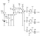
図2は、センサパネル105のそれぞれのセンサユニット106に配される1つの画素PIXの回路構成例を示している。図2において、フォトダイオードPDは光電変換素子であり、入射する放射線に応じて前述のシンチレータで生じた光を電気信号に変換する。具体的には、シンチレータで生じた光の光量に応じた量の電荷がフォトダイオードPDで発生する。本実施形態において、上述のように間接型の変換素子を用いたセンサパネル105を考えており、放射線を検出するための検出素子としてフォトダイオードPDを用いる構成を示したが、これに限られることはない。放射線を検出するための検出素子として、例えば、放射線を直接電気信号に変換する直接型の変換素子を用いてもよい。
FIG. 2 shows a circuit configuration example of one pixel PIX arranged in each
容量Cfdは、フォトダイオードPDで発生した電荷を蓄積するためのフローティングディフュージョン(浮遊拡散領域)の容量である。また、容量Cfdには、フォトダイオードPDに寄生する寄生容量も含まれうる。トランジスタM1は、画素PIXの放射線に対する感度を切り替えるためのスイッチ素子である。容量Cfd1は、画素PIXの感度切り替え用の追加容量であり、トランジスタM1を介してフォトダイオードPDに接続される。この構成によって、それぞれの画素PIXにおいて、フォトダイオードPDで生成された電荷を蓄積するための容量の容量値が変更可能となり、画素PIXの放射線に対する感度が切り替えられる。 The capacitance Cfd is the capacitance of the floating diffusion (floating diffusion region) for accumulating the electric charge generated by the photodiode PD. In addition, the capacitance Cfd may also include a parasitic capacitance parasitic on the photodiode PD. The transistor M1 is a switch element for switching the sensitivity of the pixel PIX to radiation. The capacitance Cfd1 is an additional capacitance for switching the sensitivity of the pixel PIX, and is connected to the photodiode PD via the transistor M1. With this configuration, in each pixel PIX, the capacitance value of the capacitance for accumulating the electric charge generated by the photodiode PD can be changed, and the sensitivity of the pixel PIX to radiation can be switched.
トランジスタM2は、フォトダイオードPD、容量Cfd、容量Cfd1に蓄積された電荷を放電させるためのリセットスイッチである。トランジスタM4は、ソースフォロアとして動作するための増幅MOSトランジスタ(画素アンプ)である。トランジスタM3はトランジスタM4を動作状態とさせるための選択スイッチである。 The transistor M2 is a reset switch for discharging the electric charge accumulated in the photodiode PD, the capacitance Cfd, and the capacitance Cfd1. The transistor M4 is an amplification MOS transistor (pixel amplifier) for operating as a source follower. The transistor M3 is a selection switch for putting the transistor M4 into an operating state.
トランジスタM4の後段には、フォトダイオードPDを含む光電変換部で発生するkTCノイズを除去するためのクランプ回路が設けられる。容量Cclはクランプ容量であり、トランジスタM5は、クランプ用のクランプスイッチである。トランジスタM7は、ソースフォロアとして動作する増幅MOSトランジスタ(画素アンプ)である。トランジスタM6はトランジスタM7を動作状態とするための選択スイッチである。 A clamp circuit for removing kTC noise generated in the photoelectric conversion unit including the photodiode PD is provided in the subsequent stage of the transistor M4. The capacitance Ccl is the clamp capacitance, and the transistor M5 is a clamp switch for clamping. The transistor M7 is an amplification MOS transistor (pixel amplifier) that operates as a source follower. The transistor M6 is a selection switch for putting the transistor M7 into an operating state.
トランジスタM7の後段には、3つのサンプルホールド回路が設けられた保持部が配される。トランジスタM8、M11は、それぞれ放射線から変換された光によって生成される画像用信号である光信号を蓄積するためのサンプルホールド回路を構成するサンプルホールドスイッチである。容量CS1および容量CS2は、光信号用ホールド容量である。トランジスタM14は基準電圧の信号を蓄積するためのサンプルホールド回路を構成するサンプルホールドスイッチである。容量CNは、基準信号用ホールド容量である。トランジスタM10、M13は、ソースフォロアとして動作する光信号の増幅MOSトランジスタ(画素アンプ)である。アナログスイッチM9、M12は、トランジスタM10およびトランジスタM13で増幅された光信号を、それぞれ光信号出力部S1、S2へ出力するための転送スイッチである。トランジスタM16は、ソースフォロアとしての動作する基準信号の増幅MOSトランジスタ(画素アンプ)である。アナログスイッチM15は、トランジスタM16で増幅された基準信号を基準信号出力部Nへ出力するための転送スイッチである。 A holding portion provided with three sample holding circuits is arranged after the transistor M7. The transistors M8 and M11 are sample hold switches that form a sample hold circuit for accumulating an optical signal, which is an image signal generated by light converted from radiation, respectively. The capacitance CS1 and the capacitance CS2 are hold capacitances for optical signals. The transistor M14 is a sample hold switch that constitutes a sample hold circuit for accumulating a signal of a reference voltage. The capacitance CN is a hold capacitance for a reference signal. The transistors M10 and M13 are optical signal amplification MOS transistors (pixel amplifiers) that operate as source followers. The analog switches M9 and M12 are transfer switches for outputting the optical signals amplified by the transistors M10 and M13 to the optical signal output units S1 and S2, respectively. The transistor M16 is a reference signal amplification MOS transistor (pixel amplifier) that operates as a source follower. The analog switch M15 is a transfer switch for outputting the reference signal amplified by the transistor M16 to the reference signal output unit N.
信号ENは、トランジスタM3、M6のゲートに接続され、トランジスタM4、M7の動作状態を制御するための制御信号である。信号ENがハイレベルのとき、トランジスタM4、M7は同時に動作状態となる。信号PRESは、トランジスタM2のゲートに接続され、トランジスタM2の動作状態を制御するための制御信号(リセット信号)である。信号PRESがハイレベルのとき、トランジスタM2はオン動作し、フォトダイオードPD、容量Cfd、Cfd1に蓄積された電荷を放電させる。信号PCLは、トランジスタM5のゲートに接続され、トランジスタM5を制御するための制御信号である。信号PCLがハイレベルのとき、トランジスタM5がオン動作し、容量Cclを基準電圧VCLにセットする。信号TS1は、トランジスタM8のゲートに接続され、光信号のサンプルホールドを制御する制御信号である。信号TS1をハイレベルとし、トランジスタM8をオン動作させることで、光信号がトランジスタM7を介して容量CS1に一括転送される。次いで、すべての画素PIX一括で信号TS1をローレベルとし、トランジスタM8をオフ動作させることで、サンプルホールド回路の容量CS1への光信号のサンプリングが完了する。信号TS2信号は、トランジスタM11のゲートに接続され、信号TS1と同様に動作し、サンプルホールド回路の容量CS2への光信号のサンプリングを行う。信号TNは、トランジスタM14のゲートに接続され、基準信号のサンプルホールドを制御する制御信号である。信号TNをハイレベルとし、トランジスタM14をオン動作させることで、基準信号がトランジスタM7を介して容量CNに一括転送される。次いで、すべての画素一括で信号TNをローレベルとし、トランジスタM14をオフ動作させることで、サンプルホールド回路の容量CNへの基準信号のサンプリングが完了する。容量CS1、CS2、CNへのサンプルホールド後は、トランジスタM8、M11、M14がオフとなり、容量CS1、CS2、CNは、前段の蓄積回路と切り離される。このため、再度サンプリングを行うまで蓄積された光信号、基準信号は、それぞれアナログスイッチM9、12、15を導通状態にすることによって、非破壊で読み出すことができる。つまり、トランジスタM8、M11、M14を非導通状態にしている間、保持している光信号および基準信号を、任意のタイミングで読み出すことができる。 The signal EN is a control signal connected to the gate of the transistors M3 and M6 to control the operating state of the transistors M4 and M7. When the signal EN is at a high level, the transistors M4 and M7 are in the operating state at the same time. The signal PRESS is a control signal (reset signal) connected to the gate of the transistor M2 and for controlling the operating state of the transistor M2. When the signal PRESS is at a high level, the transistor M2 is turned on to discharge the charges accumulated in the photodiode PD, the capacitances Cfd, and Cfd1. The signal PCL is a control signal connected to the gate of the transistor M5 to control the transistor M5. When the signal PCL is at a high level, the transistor M5 is turned on and the capacitance Ccl is set to the reference voltage VCL. The signal TS1 is a control signal connected to the gate of the transistor M8 and controlling the sample hold of the optical signal. By setting the signal TS1 to a high level and turning on the transistor M8, the optical signal is collectively transferred to the capacitance CS1 via the transistor M7. Next, the signal TS1 is set to a low level for all the pixels PIX at once, and the transistor M8 is turned off to complete the sampling of the optical signal to the capacitance CS1 of the sample hold circuit. The signal TS2 signal is connected to the gate of the transistor M11 and operates in the same manner as the signal TS1 to sample the optical signal to the capacitance CS2 of the sample hold circuit. The signal TN is a control signal connected to the gate of the transistor M14 and controlling the sample hold of the reference signal. By setting the signal TN to a high level and turning on the transistor M14, the reference signal is collectively transferred to the capacitance CN via the transistor M7. Next, by setting the signal TN to a low level for all the pixels and turning off the transistor M14, sampling of the reference signal to the capacitance CN of the sample hold circuit is completed. After the sample is held in the capacitances CS1, CS2, and CN, the transistors M8, M11, and M14 are turned off, and the capacitances CS1, CS2, and CN are separated from the storage circuit in the previous stage. Therefore, the optical signal and the reference signal accumulated until sampling is performed again can be read out non-destructively by making the analog switches M9, 12 and 15, respectively, in a conductive state. That is, the optical signal and the reference signal held while the transistors M8, M11, and M14 are in the non-conducting state can be read out at an arbitrary timing.
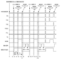
図3は、図2に示す画素PIXが配された放射線撮像装置において、ダイナミックレンジを拡大し、固定フレームレートで1つのフレームあたりの放射線の照射時間に制限がある場合の、動画を撮像する駆動例を示すタイミングチャートである。以下、動画撮像において、画素PIXの動作開始から光信号用ホールド容量である容量CS1、CS2および基準信号用ホールド容量である容量CNに電荷がサンプリングされるまでの制御信号のタイミングについて、図3を用いて説明する。 FIG. 3 shows a drive for capturing a moving image in a radiation imaging device in which the pixel PIX shown in FIG. 2 is arranged, when the dynamic range is expanded and the irradiation time of radiation per frame is limited at a fixed frame rate. It is a timing chart which shows an example. Hereinafter, in moving image imaging, FIG. 3 shows the timing of control signals from the start of operation of the pixel PIX to the sampling of charges in the capacities CS1 and CS2 which are hold capacities for optical signals and the capacities CN which are hold capacities for reference signals. It will be described using.
まず、時刻t1において動画撮像、静止画撮像などの駆動モードや、感度、蓄積時間、放射線の照射時間などの各種パラメータなど撮像情報の設定および撮像開始の設定がなされる。撮像情報の設定は、ユーザが駆動モードや各種パラメータを1つ1つ入力してもよい。また例えば、撮像情報の設定は、システム制御部101が複数の撮像条件が保存されたメモリを有し、ユーザが複数の撮像条件の中から適宜、選択することによって撮像情報として設定してもよい。
First, at time t1, the drive modes such as moving image imaging and still image imaging, and various parameters such as sensitivity, accumulation time, and radiation irradiation time are set and imaging information is set and imaging start is set. The user may input the drive mode and various parameters one by one in the setting of the imaging information. Further, for example, the setting of the imaging information may be set as the imaging information by the
次いで、時刻t2から撮像のための駆動が開始される。まず、時刻t2で始まるリセット駆動Rについて説明する。リセット駆動Rは、それぞれの画素PIXのリセットとクランプとを行う駆動である。まず、時刻t2で、システム制御部101からの同期信号113がハイレベルになったことを制御部109が検知すると、信号ENをハイレベルにし、画素アンプであるトランジスタM4、画素アンプであるトランジスタM7をオン状態にする。次に、信号WIDEと信号PRESをハイレベルにし、感度を切り替えるためのトランジスタM1をオン動作させた状態で、フォトダイオードPDを基準電圧VRESに接続する。次いで、信号PCLをハイレベルにすることによってクランプスイッチであるトランジスタM5をオン動作させ、クランプ容量である容量CclのトランジスタM7側を基準電圧VCLに接続する。同時に、信号TS1、TS2、TNをハイレベルにし、トランジスタM8、M11、M14をオン動作させる。
Then, the drive for imaging is started from time t2. First, the reset drive R starting at time t2 will be described. The reset drive R is a drive for resetting and clamping each pixel PIX. First, when the
次いで、時刻t3で、信号WIDEをローレベルにしてトランジスタM1をオフ動作とし、画素PIXの感度を高感度で放射線を検出するモードに切り替える。さらに、信号PRESをローレベルにしてリセットを終了し、容量CclのトランジスタM4側にリセット電圧がセットされる。また、容量Cfd1もトランジスタM1側がリセット電圧で保持され、不定電圧が生じることを防ぐ。そして、トランジスタM5をオフ動作とし、基準電圧VCLと基準電圧VRESの差分の電圧に応じた電荷が容量Cclに蓄積されクランプが終了する。また同時に、トランジスタM8、M11、M14もオフ動作とされ、容量CS1、CS2、CNに、基準電圧VCLがセットされたときの基準信号がサンプルホールドされる。光信号をサンプリングするための容量CS1、CS2および基準信号をサンプリングするための容量CNの電荷を、サンプリングが行われる前に一定にすることによって、残像の影響が低減される。 Then, at time t3, the signal WIDE is set to a low level, the transistor M1 is turned off, and the sensitivity of the pixel PIX is switched to a mode for detecting radiation with high sensitivity. Further, the signal PRESS is set to a low level, the reset is completed, and the reset voltage is set on the transistor M4 side of the capacitance Ccl. Further, the capacitance Cfd1 is also held on the transistor M1 side by the reset voltage to prevent an indefinite voltage from being generated. Then, the transistor M5 is turned off, and the electric charge corresponding to the difference voltage between the reference voltage VCL and the reference voltage VRES is accumulated in the capacitance Ccl to complete the clamping. At the same time, the transistors M8, M11, and M14 are also turned off, and the reference signal when the reference voltage VCL is set in the capacitances CS1, CS2, and CN is sample-held. The effect of afterimages is reduced by keeping the charges of the capacitances CS1 and CS2 for sampling the optical signal and the capacitance CN for sampling the reference signal constant before sampling is performed.
時刻t3において、リセット駆動Rを終了し、画素PIXが蓄積状態となったため、制御部109は、曝射許可信号114をイネーブルにし放射線の照射を要求する。時間t3は、それぞれの画素において、照射された放射線に応じた信号(電荷)を蓄積するための動作を開始する時間といえる。曝射許可信号114をイネーブルにすることによる放射線の照射の開始に応じて、フォトダイオードPD、フローティングディフュージョンの容量Cfdへの電荷の蓄積が始まる。つまり、時刻t3から高感度で、照射された放射線に応じた信号の蓄積が開始される。また、信号ENをローレベルとし、画素アンプを構成するトランジスタM4、M7が非動作状態となる。
At time t3, the reset drive R is terminated and the pixel PIX is in the accumulated state. Therefore, the
リセット駆動Rは、放射線撮像装置100に配された画素PIXに対して一括して行う。後に続くリセット駆動Rも、同様のタイミングで制御される。動画や静止画の撮像時、画素間や走査線間の時間的スイッチングのずれによって発生する画像ズレを防止するため、放射線撮像装置100に配されるすべての画素PIXにおいて同一のタイミング、同一の期間でリセット駆動Rが行われうる。その後、放射線の照射によって電荷の蓄積が行われ、それぞれの画素PIXのフォトダイオードPDで発生した信号電荷が容量CfdおよびフォトダイオードPDの寄生容量に蓄積される。
The reset drive R is collectively performed on the pixels PIX arranged in the
次に時刻t4から始まる高感度のサンプリング駆動SHについて説明する。時刻t4で、信号ENをハイレベルにしトランジスタM3、M6をオン動作させる。これによって、容量Cfdに蓄積された電荷は、電荷/電圧変換されソースフォロアとして動作し画素アンプを構成するトランジスタM4によって電圧として容量Cclに出力される。トランジスタM4の出力はリセットノイズを含むが、クランプ回路によってリセット駆動Rの際にトランジスタM7側を基準電圧VCLにセットしているため、リセットノイズが除去された光信号として画素アンプを構成するトランジスタM7に出力される。次に、放射線の照射によって生成された画像用信号である光信号のサンプリングを制御する信号TS1をハイレベルとし、トランジスタM8をオン動作させる。これによって、光信号は画素アンプを構成するトランジスタM7を介して、光信号用ホールド容量である容量CS1に一括転送される。このときの光信号は、信号WIDEをローレベルとしているため、高感度で取得された信号である。時刻t5で、信号TS1をローレベルとし、トランジスタM8をオフ動作させることによって、容量CS1に高感度で取得された光信号がサンプリングされる。サンプリング駆動SHでは、放射線の検出の開始から放射線の照射される期間よりも短い時間で容量Cfdに蓄積された信号が、高感度のモードの光信号としてサンプリングされる。 Next, a high-sensitivity sampling drive SH starting from time t4 will be described. At time t4, the signal EN is set to a high level and the transistors M3 and M6 are turned on. As a result, the charge accumulated in the capacitance Cfd is converted into charge / voltage and operates as a source follower, and is output to the capacitance Ccl as a voltage by the transistor M4 constituting the pixel amplifier. The output of the transistor M4 contains reset noise, but since the transistor M7 side is set to the reference voltage VCL at the time of reset drive R by the clamp circuit, the transistor M7 constituting the pixel amplifier as an optical signal from which the reset noise has been removed. Is output to. Next, the signal TS1 that controls the sampling of the optical signal, which is an image signal generated by irradiation with radiation, is set to a high level, and the transistor M8 is turned on. As a result, the optical signal is collectively transferred to the capacitance CS1 which is the hold capacitance for the optical signal via the transistor M7 constituting the pixel amplifier. The optical signal at this time is a signal acquired with high sensitivity because the signal WIDE is set to a low level. At time t5, the signal TS1 is set to a low level and the transistor M8 is turned off, so that the optical signal acquired with high sensitivity is sampled in the capacitance CS1. In the sampling drive SH, the signal accumulated in the capacitance Cfd is sampled as an optical signal in the high-sensitivity mode in a time shorter than the period of irradiation of the radiation from the start of the detection of the radiation.
次に信号WIDEをハイレベルとし、感度を切り替えるためのスイッチ素子であるトランジスタM1をオン動作させる。トランジスタM1がオン動作することによって、フローティングディフュージョンの容量が増え、画素の感度が高感度から低感度へと変化するとともに、引き続き照射された放射線に応じた信号を蓄積する。 Next, the signal WIDE is set to a high level, and the transistor M1 which is a switch element for switching the sensitivity is turned on. When the transistor M1 is turned on, the capacitance of the floating diffusion increases, the sensitivity of the pixel changes from high sensitivity to low sensitivity, and a signal corresponding to the continuously irradiated radiation is accumulated.
次いで、時刻t6で、信号ENをハイレベルにしトランジスタM3、M6をオン動作させる。次に、信号TS2をハイレベルとし、トランジスタM11をオン動作させることによって、低感度で取得された光信号が、画素アンプを構成するトランジスタM7を介してもう一つの光信号用ホールド容量である容量CS2に一括転送される。時刻t7で、信号TS2をローレベルとし、トランジスタM11をオフ動作させることによって、容量CS2に低感度で取得された光信号がサンプリングされる。サンプリング駆動SLでは、放射線の検出の開始から放射線の照射が終了するまでに容量Cfdおよび容量Cfd1に蓄積された信号が、低感度のモードの光信号としてサンプリングされる。 Next, at time t6, the signal EN is set to a high level and the transistors M3 and M6 are turned on. Next, by setting the signal TS2 to a high level and turning on the transistor M11, the optical signal acquired with low sensitivity is a capacitance that is another hold capacitance for the optical signal via the transistor M7 constituting the pixel amplifier. It is collectively transferred to CS2. At time t7, the signal TS2 is set to a low level and the transistor M11 is turned off, so that the optical signal acquired with low sensitivity is sampled in the capacitance CS2. In the sampling drive SL, the signals accumulated in the capacitance Cfd and the capacitance Cfd1 from the start of radiation detection to the end of radiation irradiation are sampled as optical signals in the low-sensitivity mode.
次に、信号PRESをハイレベルとし、トランジスタM2をオン動作させ、容量Cfd、Cfd1を基準電圧VRESにリセットする。次いで、信号PCLをハイレベルとする。容量Cclには、電圧VCLと電圧VRESとの差分の電圧にリセットノイズが重畳した電荷が蓄積される。更に信号TNをハイレベルとし、トランジスタM14をオン動作させることによって、基準電圧VCLにセットされた際の基準信号を基準信号用ホールド容量である容量CNに転送する。続いて時刻t8で、信号TNをローレベルとし、トランジスタM14をオフ動作させることによって、容量CNに基準信号がサンプリングされる。さらに、信号PRES、PCL、ENをローレベルとし、サンプリング駆動SLを終了する。 Next, the signal PRESS is set to a high level, the transistor M2 is turned on, and the capacitances Cfd and Cfd1 are reset to the reference voltage VRES. Next, the signal PCL is set to a high level. In the capacitance Ccl, an electric charge in which reset noise is superimposed on the voltage difference between the voltage VCL and the voltage VRES is accumulated. Further, by setting the signal TN to a high level and turning on the transistor M14, the reference signal when the reference voltage VCL is set is transferred to the capacitance CN which is the hold capacitance for the reference signal. Subsequently, at time t8, the signal TN is set to a low level and the transistor M14 is turned off, so that the reference signal is sampled in the capacitance CN. Further, the signals PRESS, PCL, and EN are set to low levels, and the sampling drive SL is terminated.
高感度に放射線を検出するためには、容量Cfdを小さくし、蓄積される電荷に対する感度を高くする必要がある。このため、入射する線量が多い条件や蓄積時間が長い条件で撮像を行った場合、蓄積される電荷量が多くなり、容量Cfdが飽和してしまう可能性がある。容量Cfdが飽和すると、容量Cfdに蓄積された電荷に基づく光信号のリニアリティが悪化し、生成される放射線画像が劣化してしまう。また、容量Cfdが飽和に近づいた場合であっても、フォトダイオードPDやフローティングディフュージョンを構成するSi基板に例えばSi基板表面のダングリングボンドなどの結晶欠陥があると、蓄積された電荷が欠陥からリークする可能性がある。電荷のリークが発生した場合、光信号のリニアリティが悪化し、放射線画像が劣化してしまう。 In order to detect radiation with high sensitivity, it is necessary to reduce the capacitance Cfd and increase the sensitivity to the accumulated charge. Therefore, when the image is taken under the condition that the incident dose is large or the accumulation time is long, the accumulated charge amount increases and the capacitance Cfd may be saturated. When the capacitance Cfd is saturated, the linearity of the optical signal based on the charge accumulated in the capacitance Cfd deteriorates, and the generated radiographic image deteriorates. Further, even when the capacitance Cfd approaches saturation, if the Si substrate constituting the photodiode PD or the floating diffusion has a crystal defect such as a dangling bond on the surface of the Si substrate, the accumulated charge is caused by the defect. There is a possibility of leaking. When a charge leak occurs, the linearity of the optical signal deteriorates and the radiographic image deteriorates.
そこで、本実施形態において、高感度で放射線を検出するための蓄積時間を低感度で放射線を検出するための蓄積時間よりも短くする。具体的には、低感度で放射線を検出するための蓄積時間である時刻t3から時刻t7までの時間TLよりも、高感度で放射線を検出するための蓄積時間である時刻t3から時刻t5までの時間THを短くする。例えば、時間THを時間TLの半分に設定してもよい。照射される放射線に応じた信号の蓄積を開始し、放射線の検出を開始してから、放射線が照射される期間である時刻t3から時刻t6までよりも短い時間THの経過後、蓄積された電荷を高感度でサンプリングする。その後、感度を低感度に切り替えることによって、容量Cfdが飽和しにくくなる。これによって、容量Cfdの飽和による光信号のリニアリティの悪化を抑制できる。また、容量Cfdが飽和に近づきにくくなり、フォトダイオードPDや容量Cfdを構成するSi基板に結晶欠陥があっても、電荷のリークが抑制され、リニアリティの悪化が抑制される。本発明者が実験を行ったところ、時間TLを266ミリ秒(ms)、時間THを133msと設定し、高感度および低感度で光信号を取得した結果、リニアリティが悪化する画素は発生しなかった。 Therefore, in the present embodiment, the accumulation time for detecting radiation with high sensitivity is made shorter than the accumulation time for detecting radiation with low sensitivity. Specifically, from time t3 to time t5, which is the accumulation time for detecting radiation with high sensitivity, rather than the time TL from time t3 to time t7, which is the accumulation time for detecting radiation with low sensitivity. Shorten the time TH. For example, the time TH may be set to half the time TL. After starting the accumulation of signals according to the irradiated radiation and starting the detection of radiation, the accumulated charge has elapsed for a shorter time TH than the time t3 to time t6, which is the period during which the radiation is irradiated. Is sampled with high sensitivity. After that, by switching the sensitivity to low sensitivity, the capacitance Cfd is less likely to be saturated. As a result, deterioration of the linearity of the optical signal due to saturation of the capacitance Cfd can be suppressed. Further, the capacitance Cfd is less likely to approach saturation, and even if there is a crystal defect in the photodiode PD or the Si substrate constituting the capacitance Cfd, charge leakage is suppressed and deterioration of linearity is suppressed. When the present inventor conducted an experiment, the time TL was set to 266 milliseconds (ms) and the time TH was set to 133 ms, and as a result of acquiring optical signals with high sensitivity and low sensitivity, no pixel with deteriorated linearity was generated. It was.
ここで、時間THと時間TLとの比は、高感度と低感度との感度の比に基づいて、適宜決定すればよい。例えば、高感度が低感度と比較して感度が5倍であった場合、時間THは時間TLの1/5としてもよい。時間THは、ユーザによって設定される放射線の強度や時間TLなどの撮像条件や、放射線撮像装置の有する高感度と低感度との感度の比などに応じて、適宜決定すればよい。例えば、撮像情報の設定は、システム制御部101が複数の時間TH、時間TLなどを含む撮像条件が保存されたメモリを有し、ユーザが選択した条件に合わせて時間THを決定してもよい。
Here, the ratio of the time TH and the time TL may be appropriately determined based on the ratio of the sensitivity of the high sensitivity and the sensitivity of the low sensitivity. For example, when the high sensitivity is 5 times the sensitivity as compared with the low sensitivity, the time TH may be 1/5 of the time TL. The time TH may be appropriately determined according to the imaging conditions such as the radiation intensity and the time TL set by the user, the ratio of the high sensitivity to the low sensitivity of the radiation imaging device, and the like. For example, in setting the imaging information, the
サンプリング駆動SHおよびサンプリング駆動SLは、放射線撮像装置100に配されたすべての画素PIXにおいて一括して行う。後に続くサンプリング駆動SH、SLも、同様のタイミングで制御される。サンプリング駆動SLの後、時刻t9にて再びリセット駆動Rが行われ、次のフレームのフォトダイオードPDでの放射線の検出(照射される放射線に応じた信号の蓄積)が開始される。
The sampling drive SH and the sampling drive SL are collectively performed in all the pixel PIXs arranged in the
高感度と低感度との光信号および基準信号の画素PIXからの出力は、時刻t6の曝射許可信号114の停止による放射線の照射の終了に応じたサンプリング駆動SLの終了後、画素PIXごとに行われる。基準信号の出力は、高感度の光信号の出力(ROH)と低感度の光信号の出力(ROL)との何れの期間に行われてもよい。アナログスイッチM9、M12、M15をオン動作させることによって、容量CS1、CS2、CNの電圧が、それぞれ画素アンプを構成するトランジスタM10、M13、M16を通して、それぞれ光信号出力部S1、S2と基準信号出力部Nとに転送される。
The output of the high-sensitivity and low-sensitivity optical signals and reference signals from the pixel PIX is for each pixel PIX after the end of the sampling drive SL according to the end of radiation irradiation due to the stop of the
図2の画素回路において、フォトダイオードPDでの放射線に応じた信号の蓄積の開始のタイミングは、図3に示すリセット完了後に信号PCLをローレベルにしてクランプが完了した時刻t3や時刻t10である。また、信号の蓄積を終了し、放射線の検出を終了するタイミングは、信号TS2がローレベルになり低感度で取得した光信号をサンプリングした時刻t7である。そこで、光信号および基準信号をサンプルリングするサンプリング駆動SLとサンプリング駆動SHの間に、リセット駆動Rを挿入することによって、1フレームあたりの電荷を蓄積する時間を制限している。図3において、時刻t6で始まるサンプリング駆動SLと時刻t11で始まるサンプリング駆動SHとの間に、時刻t9で始まるリセット駆動Rを挿入する。これによって、実質的な蓄積時間である高感度の放射線の照射時間を時刻t10から時刻t12の時間TH、および、低感度の放射線の照射時間を時刻t10から時刻t14の時間TLに制限している。 In the pixel circuit of FIG. 2, the timing of starting the accumulation of the signal corresponding to the radiation in the photodiode PD is the time t3 or the time t10 when the signal PCL is set to the low level and the clamp is completed after the reset shown in FIG. 3 is completed. .. Further, the timing at which the signal accumulation is finished and the radiation detection is finished is the time t7 when the signal TS2 becomes low level and the optical signal acquired with low sensitivity is sampled. Therefore, the time for accumulating the electric charge per frame is limited by inserting the reset drive R between the sampling drive SL for sampling the optical signal and the reference signal and the sampling drive SH. In FIG. 3, a reset drive R starting at time t9 is inserted between the sampling drive SL starting at time t6 and the sampling drive SH starting at time t11. As a result, the irradiation time of high-sensitivity radiation, which is a substantial accumulation time, is limited to the time TH from time t10 to time t12, and the irradiation time of low-sensitivity radiation is limited to the time TL from time t10 to time t14. ..
また、画素PIXから光信号および基準信号の読み出しが可能な期間は、時刻t7のサンプルリングの終了時から、容量CS1、CS2、CNに、次のフレームのリセット駆動Rが再び開始される時刻t9までの間である。低感度サンプリング駆動SL終了後に、それぞれの画素PIXから高感度および低感度で取得された各光信号の出力が行われる。 Further, the period during which the optical signal and the reference signal can be read from the pixel PIX is the time t9 when the reset drive R of the next frame is restarted in the capacitances CS1, CS2, and CN from the end of the sample ring at time t7. Until. After the low-sensitivity sampling drive SL is completed, each optical signal acquired with high sensitivity and low sensitivity is output from each pixel PIX.
本実施形態では、時刻t1で撮像情報の設定および撮像開始の設定がされた後、時刻t2から時刻t9までの各工程の動作を繰り返すことによって動画を撮像する例を示すが、これに限られるものではない。例えば、時刻t1から時刻t9までの各工程の動作を1回、行うことによって静止画を撮像してもよい。 In the present embodiment, after the imaging information is set and the imaging start is set at time t1, a moving image is captured by repeating the operation of each step from time t2 to time t9, but the present invention is limited to this. It's not a thing. For example, a still image may be captured by performing the operation of each step from time t1 to time t9 once.
また、本実施形態では、制御部109から曝射許可信号114がイネーブルになることによって放射線の照射が開始されるが、放射線の照射の開始のタイミングは、これに限られることはない。例えば、放射線撮像装置100のセンサパネル105などに、放射線の照射開始を検出するための開始検出画素を設けてもよい。この場合、時刻t1から、それぞれの画素PIXはリセット駆動Rを繰り返す。開始検出画素が放射線の照射の開始を検出したことに応じて、時間t3からの放射線の入射によって生成される信号(電荷)を蓄積するための動作を開始してもよい。その後、電荷の蓄積の開始から、撮像情報などで得られる放射線が照射される期間よりも短い時間THの経過後、サンプリング駆動SHを行い、次いで、それぞれの画素PIXを低感度のモードに切り替える。さらに、開始検出画素によって放射線の照射の終了を検出し、放射線の照射の終了に応じて、時刻t6からのサンプリング駆動SLを行ってもよい。
Further, in the present embodiment, the radiation irradiation is started by enabling the exposure permission signal 114 from the
図4は、センサユニット106の内部構造の構成例を模式的に示す図である。それぞれのセンサユニット106は、チップセレクト端子CS、光信号出力端子TS1、光信号出力端子TS2、基準信号出力端子TN、垂直走査回路スタート信号端子VST、垂直走査回路クロック端子CLKV、水平走査回路スタート信号端子HST、水平走査回路クロック端子CLKHの各端子を含む。また、センサユニット106には、列方向にm個×行方向にn個の画素PIXが2次元アレイ状に配列されている。垂直走査回路403は、行方向に並ぶ画素PIXを行ごとに選択し、垂直走査クロックCLKVに同期して画素群を順次、副走査方向である垂直方向に走査する。垂直走査回路403は、例えば、シフトレジスタで構成されうる。水平走査回路404は、垂直走査回路403によって選択された主査方向である列方向の画素PIXの列信号線を、水平走査クロックCLKHに同期して順次、1画素ずつ選択する。それぞれの画素PIXは、垂直走査回路403に接続された行信号線405がイネーブルになることによって、列信号線406、407、408に、それぞれサンプリングされた高感度と低感度との光信号および基準信号を出力する。列信号線406、407、408に出力された各信号を水平走査回路404が順次選択することによって、アナログ出力線409、410、411にそれぞれ画素PIXの各信号が順次出力される。以上のように、センサユニット106は、垂直走査回路403、水平走査回路404を使用したXYアドレス方式によるスイッチング動作によって画素PIXの選択が行われる。それぞれの画素PIXの光信号、基準信号は、列信号線406、407、408およびアナログ出力線409、410、411を通して光信号出力端子TS1、光信号出力端子TS2、基準信号出力端子TNから出力される。
FIG. 4 is a diagram schematically showing a configuration example of the internal structure of the
図5は、それぞれの画素PIXから出力される光信号および基準信号をA/D変換する差動アンプ107およびA/D変換器108を含む読出部ROの構成例を示す図である。光信号出力端子TS1、TS2からの出力は、それぞれ入力スイッチM50、入力スイッチM51に接続される。入力スイッチM50は信号SW1によって動作し、入力スイッチM51は信号SW2によって動作する。信号SW1および信号SW2は、画素PIXから出力される各信号の破壊や、素子の破壊を防ぐため、同時にオン動作しないように制御される。
FIG. 5 is a diagram showing a configuration example of a reading unit RO including a
例えば、それぞれの画素PIXの高感度と低感度との光信号および基準信号が同時に出力される場合でも、まず、信号SW1をハイレベル、信号SW2をローレベルに制御する。そして、図4に示す画素PIX(1、1)から順に画素PIX(n、m)までの高感度で取得した光信号と基準信号とを読み出す。次いで、信号SW1をローレベル、信号SW2をハイレベルに制御して、画素PIX(1、1)から順に画素PIX(n、m)までの低感度で取得した光信号と基準信号とを読み出してもよい。 For example, even when an optical signal and a reference signal having high sensitivity and low sensitivity of each pixel PIX are output at the same time, first, the signal SW1 is controlled to a high level and the signal SW2 is controlled to a low level. Then, the optical signal and the reference signal acquired with high sensitivity from the pixel PIX (1, 1) shown in FIG. 4 to the pixel PIX (n, m) are read out in order. Next, the signal SW1 is controlled to a low level and the signal SW2 is controlled to a high level, and the optical signal and the reference signal acquired with low sensitivity from the pixel PIX (1, 1) to the pixel PIX (n, m) are read out. May be good.
また例えば、まず、信号SW1をハイレベル、信号SW2をローレベルに制御して、画素PIX(1、1)から順に画素PIX(n、1)までの高感度で取得した光信号と基準信号とを読み出す。次いで、信号SW1をローレベル、信号SW2をハイレベルに制御して、画素PIX(1、1)から順に画素PIX(n、1)までの低感度で取得した光信号と基準信号とを読み出す。次に、垂直走査回路403に垂直走査クロックCLKVをあたえて、副走査方向に1つ走査することによって、画素PIX(1、2)から順に(n、2)を選択する。再度、信号SW1をハイレベル、信号SW2をローレベルに制御して、画素PIX(1、2)から順に画素PIX(n、2)までの高感度で取得した光信号と基準信号とを読み出す。次いで、信号SW1をローレベル、信号SW2をハイレベルに制御して、画素PIX(1、2)から順に画素PIX(n、2)までの低感度で取得した光信号と基準信号とを読み出す。このように、行単位で信号SW1と信号SW2とを制御して、画素PIX(1、1)から順に画素PIX(n、m)までの各信号を読み出してもよい。
Further, for example, first, the signal SW1 is controlled to a high level and the signal SW2 is controlled to a low level, and the optical signal and the reference signal acquired with high sensitivity from the pixel PIX (1, 1) to the pixel PIX (n, 1) are obtained. Is read. Next, the signal SW1 is controlled to a low level and the signal SW2 is controlled to a high level, and the optical signal and the reference signal acquired with low sensitivity from the pixel PIX (1, 1) to the pixel PIX (n, 1) are read out. Next, the vertical scanning clock CLKV is applied to the
差動アンプ107は、マイナス側入力に高感度または低感度で取得した光信号が入力され、プラス側入力に基準信号が入力される。差動アンプ107で基準信号から光信号を減算することによって、画素PIX内のそれぞれの画素アンプでの熱ノイズ、1/fノイズ、温度差、プロセスばらつきによる固定パターンノイズ(FPN)などが除去されうる。差動アンプ107の出力は、A/D変換器108に入力される。A/D変換器108は、信号ADCLKからクロック信号を受け取り、信号ADCLKがハイレベルに切り替わるタイミングでA/D変換されたデジタルの光信号ADOUTを、センサユニット106ごとに制御部109に出力する。
In the
制御部109に送信された高感度および低感度の光信号ADOUTは、画像データインタフェース111によって、読出部で読み出された順に画像データとしてシステム制御部101に送信される。システム制御部101では、画像データインタフェース111を介して入力した高感度および低感度の光信号ADOUTを用いてダイナミックレンジ拡大のための画像処理が行われる。
The high-sensitivity and low-sensitivity optical signals ADOUT transmitted to the
次に、ダイナミックレンジを拡大するための画像処理の方法を、図6のフローチャートを用いて説明する。放射線撮像装置100から高感度および低感度で取得した光信号ADOUTの画素データを受信すると、システム制御部101は、画像処理を開始する(ステップS120)。まず、センサパネル105の特性を補正するため、ステップS121でオフセット補正、ステップS122でゲイン補正、ステップS123で欠陥補正の各処理が実施される。ステップS121〜S123の各処理によって、それぞれの画素PIXの画素値と、当該画素PIXの周辺に配された画素PIXの画素値との相関関係が保たれた状態にする。また、本実施形態において、センサパネル105は、複数のセンサユニット106によって構成される。このため、ステップS121〜S123の各処理によって、センサユニット106間での特性の補正もなされうる。
Next, a method of image processing for expanding the dynamic range will be described with reference to the flowchart of FIG. Upon receiving the pixel data of the optical signal ADOUT acquired from the
次いで、ステップS124で画像中の画素の位置を表す変数であるaを0に初期化する。変数aの最大値bは、図1に示す構成を有するセンサパネル105の場合、それぞれのセンサユニット106に画素PIXがn×m個配されるため、b=n×m×7×2となる。
Next, in step S124, a, which is a variable representing the position of the pixel in the image, is initialized to 0. In the case of the
ここで、画素位置がaのときの低感度で取得した光信号ADOUT(以下、低感度画像と呼ぶ。)の画素値をPLa、高感度で取得した光信号ADOUT(以下、高感度画像と呼ぶ。)の画素値をPHaとする。ステップS125では、低感度画像の画素値PLaに対して、時間THと時間TLとに応じた係数を適用する。具体的には、高感度と低感度とのゲイン比Gと高感度の蓄積時間THと低感度の蓄積時間TLとの比TH/TLとで示される係数(G・TH/TL)を、画素値PLaに乗算する。 Here, the pixel value of the optical signal ADOUT (hereinafter referred to as a low-sensitivity image) acquired with low sensitivity when the pixel position is a is PLa, and the optical signal ADOUT (hereinafter referred to as a high-sensitivity image) acquired with high sensitivity. ) Is PHa. In step S125, a coefficient corresponding to the time TH and the time TL is applied to the pixel value PLa of the low-sensitivity image. Specifically, the coefficient (G · TH / TL) represented by the gain ratio G between the high sensitivity and the low sensitivity and the ratio TH / TL between the high sensitivity storage time TH and the low sensitivity storage time TL is set as a pixel. Multiply the value PLa.
次いで、ステップS126で高感度画像の画素値PHaの大きさによって、画素PIXの放射線画像を構成する画素値Paの値の選択方法を振り分ける。本実施形態において、A/D変換器108でA/D変換されたデジタルの光信号ADOUTが16ビット(0〜65535LBS)の場合を示す。
Next, in step S126, the method of selecting the value of the pixel value Pa constituting the radiation image of the pixel PIX is sorted according to the size of the pixel value PHa of the high-sensitivity image. In the present embodiment, the case where the digital optical signal ADOUT A / D converted by the A /
高感度画像の画素値PHaが30000LSBよりも小さい場合、高感度画像の画素値PHaを画素PIXの画素値Paとする(ステップS127)。一方、高感度画像の画素値PHaが40000LSBよりも大きい場合、ステップS125で係数の適用された低感度画像の画素値PLaを画素PIXの画素値Paとする(ステップS129)。また、高感度画像の画素値PH0が30000LSB以上かつ40000LSB以下の場合は、画素値PLaおよび画素値PHaを合成することによって、画素PIXの画素値Paを生成する。このとき、所定の重み付け係数kを用いて、(1−k)・PHa+k・PLaで求まる値を当該画素PIXの画素値Paとしてもよい。係数kは、0よりも大きく、かつ1未満の値を有しうる。 When the pixel value PHa of the high-sensitivity image is smaller than 30,000 LSB, the pixel value PHa of the high-sensitivity image is set to the pixel value Pa of the pixel PIX (step S127). On the other hand, when the pixel value PHa of the high-sensitivity image is larger than 40,000 LSB, the pixel value PLa of the low-sensitivity image to which the coefficient is applied in step S125 is set as the pixel value Pa of the pixel PIX (step S129). When the pixel value PH0 of the high-sensitivity image is 30,000 LSB or more and 40,000 LSB or less, the pixel value Pa of the pixel PIX is generated by synthesizing the pixel value PLa and the pixel value PHa. At this time, using a predetermined weighting coefficient k, the value obtained by (1-k) · PHa + k · PLa may be the pixel value Pa of the pixel PIX. The coefficient k can have a value greater than 0 and less than 1.
次いで、ステップS130で、画素位置を表す変数aに1を加算し、ステップS131で変数aの値が最大値bより小さい場合は、ステップS125に戻り、次の画素位置の画素値Paの生成を開始する。ステップS131で、変数aの値が最大値b以上場合は、ステップS132に進み、画像処理を終了する。 Next, in step S130, 1 is added to the variable a representing the pixel position, and if the value of the variable a is smaller than the maximum value b in step S131, the process returns to step S125 to generate the pixel value Pa of the next pixel position. Start. If the value of the variable a is equal to or greater than the maximum value b in step S131, the process proceeds to step S132 to end the image processing.
以上のように、放射線撮像装置100のセンサパネル105のすべての画素PIXに対して、高感度画像と低感度画像とに基づいた画素値Paの生成を行い、ダイナミックレンジを拡大した放射線画像を生成することができる。本実施形態では、画素値Paの選択方法を振り分ける際、画素値PHaに対するしきい値を固定としたが、蓄積時間THと蓄積時間TLとの比TH/TLに依存して、変更してもよい。また、本実施形態では、画素値PHaによって画素値Paの選択方法を振り分けたが、例えば、すべての画像PIXに対してステップS128の処理を行ってもよい。
As described above, the pixel value Pa based on the high-sensitivity image and the low-sensitivity image is generated for all the pixel PIX of the
第2の実施形態
図7、8を参照して、本発明の実施形態による放射線撮像装置の構成、及び、駆動方法について説明する。図7は、本発明の第2の実施形態におけるセンサパネル105のそれぞれのセンサユニット106に配された1つの画素PIXの回路構成例を示している。図2に示した画素PIXと比較して、保持部のサンプルホールド回路が2つとなり、光信号を蓄積するためのサンプルホールド回路が1つとなっている点で異なる。これ以外の構成は、上述の第1の実施形態で示したセンサユニット106などと同様であってよい。
Second Embodiment With reference to FIGS. 7 and 8, the configuration of the radiation imaging apparatus according to the embodiment of the present invention and the driving method will be described. FIG. 7 shows a circuit configuration example of one pixel PIX arranged in each
図8は、図7示す画素PIXが配された撮像装置において、ダイナミックレンジを拡大し、固定フレームレートで1つのフレームあたりの放射線の照射時間に制限がある場合の動画を撮像する駆動例を示すタイミングチャートである。以下、動画撮像において、光信号用ホールド容量である容量CS1および基準信号用ホールド容量である容量CNに電荷がサンプリングされるまでの制御信号のタイミングについて、図8を用いて説明する。時刻t1から時刻t4までの動作は、上述の第1の実施形態と同様のため、ここでは説明を省略し、時刻t4からの動作について説明する。 FIG. 8 shows a driving example in which the dynamic range is expanded and a moving image is captured at a fixed frame rate when the irradiation time of radiation per frame is limited in the imaging device in which the pixel PIX shown in FIG. 7 is arranged. It is a timing chart. Hereinafter, in moving image imaging, the timing of the control signal until the charge is sampled in the capacitance CS1 which is the hold capacitance for the optical signal and the capacitance CN which is the hold capacitance for the reference signal will be described with reference to FIG. Since the operation from the time t1 to the time t4 is the same as that of the first embodiment described above, the description thereof will be omitted here, and the operation from the time t4 will be described.
時刻t4から高感度のサンプリング駆動SHが始まる。時刻t4で、信号ENをハイレベルにしトランジスタM3、M6をオン動作させる。これによって、容量Cfdに蓄積された電荷は、電荷/電圧変換されソースフォロアとして動作し画素アンプを構成するトランジスタM4によって電圧として容量Cclに出力される。トランジスタM4の出力はリセットノイズを含むが、クランプ回路によってリセット駆動Rの際にトランジスタM7側を基準電圧VCLにセットしているため、リセットノイズが除去された光信号として画素アンプを構成するトランジスタM7に出力される。次に、放射線の照射によって生成された信号のサンプリングを制御する信号TS1をハイレベルとし、トランジスタM8をオン動作させる。これによって、光信号は画素アンプを構成するトランジスタM7を介して、光信号用ホールド容量である容量CS1に一括転送される。このときの光信号は、信号WIDEをローレベルとしているため、高感度で取得された信号である。時刻t5で、信号TS1をローレベルとし、トランジスタM8をオフ動作させることによって、容量CS1に高感度の光信号がサンプリングされる。 High-sensitivity sampling drive SH starts at time t4. At time t4, the signal EN is set to a high level and the transistors M3 and M6 are turned on. As a result, the charge accumulated in the capacitance Cfd is converted into charge / voltage and operates as a source follower, and is output to the capacitance Ccl as a voltage by the transistor M4 constituting the pixel amplifier. The output of the transistor M4 contains reset noise, but since the transistor M7 side is set to the reference voltage VCL at the time of reset drive R by the clamp circuit, the transistor M7 constituting the pixel amplifier as an optical signal from which the reset noise has been removed. Is output to. Next, the signal TS1 that controls the sampling of the signal generated by the irradiation of radiation is set to a high level, and the transistor M8 is turned on. As a result, the optical signal is collectively transferred to the capacitance CS1 which is the hold capacitance for the optical signal via the transistor M7 constituting the pixel amplifier. The optical signal at this time is a signal acquired with high sensitivity because the signal WIDE is set to a low level. At time t5, the signal TS1 is set to a low level and the transistor M8 is turned off, so that a highly sensitive optical signal is sampled in the capacitance CS1.
次に信号WIDEをハイレベルとし、感度を切り替えるためのスイッチ素子であるトランジスタM1をオン動作させる。トランジスタM1がオン動作することによって、フローティングディフュージョンの容量が増え、画素の感度が高感度から低感度へと変化する。続いて、本実施形態では、図7に示すように、光信号用のサンプルホールド回路が1つしかないことから、高感度のサンプリング駆動SHの後、低感度サンプリング駆動SLを行うまでに取得した光信号を出力する読み出し処理が行われる(ROH)。 Next, the signal WIDE is set to a high level, and the transistor M1 which is a switch element for switching the sensitivity is turned on. When the transistor M1 is turned on, the capacitance of the floating diffusion increases, and the sensitivity of the pixel changes from high sensitivity to low sensitivity. Subsequently, in the present embodiment, as shown in FIG. 7, since there is only one sample hold circuit for the optical signal, it was acquired before performing the low-sensitivity sampling drive SL after the high-sensitivity sampling drive SH. A readout process that outputs an optical signal is performed (ROH).
次に高感度の光信号が、光信号用のサンプルホールド回路の容量CS1から出力された後、時刻t6で信号ENをハイレベルにし、トランジスタM4、M6をオン動作させる。次に、信号TS1をハイレベルとし、トランジスタM8をオンすることによって、低感度の光信号が、画素アンプを構成するトランジスタM7を通して容量CS1に一括転送される。時刻t7で信号TS1をローレベルとし、トランジスタM8をオフ動作させることによって、容量CS1に低感度での光信号がサンプリングされる。 Next, after a high-sensitivity optical signal is output from the capacitance CS1 of the sample hold circuit for the optical signal, the signal EN is set to a high level at time t6, and the transistors M4 and M6 are turned on. Next, by setting the signal TS1 to a high level and turning on the transistor M8, the low-sensitivity optical signal is collectively transferred to the capacitance CS1 through the transistor M7 constituting the pixel amplifier. By setting the signal TS1 to a low level at time t7 and turning off the transistor M8, a low-sensitivity optical signal is sampled in the capacitance CS1.
次に、信号PRESをハイレベルとし、トランジスタM2をオン動作させ、容量Cfd、Cfd1を基準電圧VRESにリセットする。次いで、信号PCLをハイレベルとする。容量Cclには、電圧VCLと電圧VRESとの差分の電圧にリセットノイズが重畳した電荷が蓄積される。更に信号TNをハイレベルとし、トランジスタM14をオン動作させることによって、基準電圧VCLにセットされた際の基準信号を基準信号用ホールド容量である容量CNに転送する。続いて時刻t8で、信号TNをローレベルとし、トランジスタM14をオフ動作させることによって、容量CNに基準信号がサンプリングされる。さらに、信号PRES、PCL、ENをローレベルとし、低感度サンプリング駆動SLを終了する。低感度サンプリング駆動SLの後、サンプリングされた低感度の光信号を出力する読み出し処理が行われる(ROL)。低感度の光信号を出力する期間(ROL)において、基準信号の出力も行われる。 Next, the signal PRESS is set to a high level, the transistor M2 is turned on, and the capacitances Cfd and Cfd1 are reset to the reference voltage VRES. Next, the signal PCL is set to a high level. In the capacitance Ccl, an electric charge in which reset noise is superimposed on the voltage difference between the voltage VCL and the voltage VRES is accumulated. Further, by setting the signal TN to a high level and turning on the transistor M14, the reference signal when the reference voltage VCL is set is transferred to the capacitance CN which is the hold capacitance for the reference signal. Subsequently, at time t8, the signal TN is set to a low level and the transistor M14 is turned off, so that the reference signal is sampled in the capacitance CN. Further, the signals PRESS, PCL, and EN are set to low levels, and the low-sensitivity sampling drive SL is terminated. After the low-sensitivity sampling drive SL, a readout process for outputting a sampled low-sensitivity optical signal is performed (ROL). The reference signal is also output during the period (ROL) in which the low-sensitivity optical signal is output.
本実施形態においても、低感度で放射線を検出するための蓄積時間である時刻t3から時刻t7までの時間TLに対して、高感度で放射線を検出するための蓄積時間である時刻t3から時刻t5まで時間THは短い。電荷の蓄積を開始してから、放射線が照射される期間である時刻t3から時刻t6までよりも短い時間THの経過後、蓄積された電荷を高感度でサンプリングし、感度を低感度に切り替えることによって、容量Cfdが飽和しにくくなる。これによって、上述の第1の実施形態と同様の効果が得られる。本発明者が実験を行ったところ、時間TLを266ms、時間THを133msと設定し、高感度および低感度で光信号を取得した結果、リニアリティが悪化する画素は発生しなかった。 Also in the present embodiment, the accumulation time for detecting radiation with high sensitivity is from time t3 to time t5 with respect to the time TL from time t3 to time t7, which is the accumulation time for detecting radiation with low sensitivity. Time TH is short. After a period of time TH shorter than the time t3 to time t6, which is the period during which radiation is irradiated, has elapsed since the start of charge accumulation, the accumulated charge is sampled with high sensitivity and the sensitivity is switched to low sensitivity. Therefore, the capacitance Cfd is less likely to be saturated. As a result, the same effect as that of the first embodiment described above can be obtained. When the present inventor conducted an experiment, the time TL was set to 266 ms and the time TH was set to 133 ms, and as a result of acquiring optical signals with high sensitivity and low sensitivity, no pixel whose linearity deteriorated was generated.
サンプリング駆動SHおよびサンプリング駆動SLは、放射線撮像装置100に配されたすべての画素PIXにおいて一括して行う。後に続くサンプリング駆動SH、SLも、同様のタイミングで制御される。サンプリング駆動SLの後、時刻t9にて再びリセット駆動Rが行われ、次のフレームのフォトダイオードPDでの蓄積が開始される。
The sampling drive SH and the sampling drive SL are collectively performed in all the pixel PIXs arranged in the
それぞれの光信号および基準信号の走査は画素PIXごとに行われる。アナログスイッチM9、M15をオン動作させることによって、容量CS1、CNの電圧が、それぞれ画素アンプを構成するトランジスタM10、M16を通して、それぞれ光信号出力部S1と基準信号出力部Nとに転送される。 Scanning of each optical signal and reference signal is performed for each pixel PIX. By turning on the analog switches M9 and M15, the voltages of the capacitances CS1 and CN are transferred to the optical signal output unit S1 and the reference signal output unit N, respectively, through the transistors M10 and M16 constituting the pixel amplifier, respectively.
図7の画素回路において、フォトダイオードPDの蓄積開始のタイミングは、図8に示すリセット完了後に信号PCLをローレベルにしてクランプが完了した時刻t3や時刻t10である。また蓄積終了のタイミングは信号TS1のうち、信号TS1がローレベルになり、低感度で取得した光信号をサンプリングした時刻t7である。そこで、光信号および基準信号をサンプルリングするサンプリング駆動SLとサンプリング駆動SHの間に、リセット駆動Rを挿入することによって、1フレームあたりの蓄積時間を制限している。図8において、時刻t6で始まるサンプリング駆動SLと時刻t11で始まるサンプリング駆動SHとの間に、時刻t9で始まるリセット駆動Rを挿入する。これによって、実質的な蓄積時間である高感度の放射線の照射時間を時刻t10から時刻t12の時間TH、および、低感度の放射線の照射時間を時刻t10から時刻t14の時間TLに制限している。 In the pixel circuit of FIG. 7, the timing of starting the accumulation of the photodiode PD is the time t3 or the time t10 when the signal PCL is set to a low level and the clamp is completed after the reset shown in FIG. 8 is completed. Further, the timing of the end of storage is the time t7 when the signal TS1 of the signal TS1 becomes low level and the optical signal acquired with low sensitivity is sampled. Therefore, the accumulation time per frame is limited by inserting the reset drive R between the sampling drive SL for sampling the optical signal and the reference signal and the sampling drive SH. In FIG. 8, a reset drive R starting at time t9 is inserted between the sampling drive SL starting at time t6 and the sampling drive SH starting at time t11. As a result, the irradiation time of high-sensitivity radiation, which is a substantial accumulation time, is limited to the time TH from time t10 to time t12, and the irradiation time of low-sensitivity radiation is limited to the time TL from time t10 to time t14. ..
画素PIXから高感度の光信号および基準信号の読み出しが可能な期間は、時刻t5のサンプルリングの終了時から、容量CS1にサンプリング駆動SLによって低感度の光信号がサンプリングされる時刻t6までの間である。また、低感度の光信号および基準信号の読み出しが可能な期間は、時刻t7のサンプルリングの終了時から、容量CS1、CNに、次のフレームのリセット駆動Rが再び開始される時刻t9までの間である。 The period during which the high-sensitivity optical signal and the reference signal can be read from the pixel PIX is from the end of the sample ring at time t5 to the time t6 when the low-sensitivity optical signal is sampled by the sampling drive SL in the capacitance CS1. Is. Further, the period during which the low-sensitivity optical signal and the reference signal can be read is from the end of the sample ring at time t7 to the time t9 when the reset drive R of the next frame is restarted in the capacitances CS1 and CN. Between.
第3の実施形態
図9を参照して、本発明の実施形態による放射線撮像装置の駆動方法について説明する。図9は、本発明の第3の実施形態におけるダイナミックレンジを拡大し、固定フレームレートで1つのフレームあたりの放射線の照射時間に制限がある場合の動画を撮像する駆動例を示すタイミングチャートである。放射線撮像装置や画素PIXの構成は、上述の第1の実施形態と同様であってよい。
Third Embodiment With reference to FIG. 9, a method of driving the radiation imaging apparatus according to the embodiment of the present invention will be described. FIG. 9 is a timing chart showing a driving example in which the dynamic range in the third embodiment of the present invention is expanded and a moving image is captured when the irradiation time of radiation per frame is limited at a fixed frame rate. .. The configuration of the radiation imaging device and the pixel PIX may be the same as in the first embodiment described above.
上述の第1および第2の実施形態では、リセット駆動R後に信号WIDEを1回、ハイレベルに遷移させることによって、画素PIXを高感度から低感度に切り替えて、低感度のサンプリングを行っている。しかし、感度を切り替えるためのトランジスタM1において、スイッチをオンまたはオフすると、チャージインジェクションと呼ばれる現象によって、信号WIDEから電荷が注入あるいは放出されうることが知られている。つまり、リセット駆動Rの後に信号WIDEをハイレベルに遷移させることによって、信号WIDEから電荷が注入されうる。このため、サンプリングされる低感度の光信号にオフセットが発生してしまう可能性がある。本発明者が実験を行ったところ、放射線の非照射時にA/D変換器108で読み出した高感度の光信号ADOUTが約8000LSBであった。一方、トランジスタM1を動作させた後、読み出した低感度の光信号ADOUTは約10000LSBと約2000LSB大きくなっていた。A/D変換器108の分解能を16ビットとすると、A/D変換器108の出力範囲は0〜65535LSBである。一般的に各種ばらつきを考慮し、放射線が照射されていない状態から放射線の強度が最大の状態の範囲は、A/D変換器108の出力範囲のうち50000LSB程度の範囲で表現される。したがって、低感度の画像のダイナミックレンジが約2000LSB狭くなることを意味する。
In the first and second embodiments described above, the pixel PIX is switched from high sensitivity to low sensitivity by shifting the signal WIDE to a high level once after the reset drive R, and low sensitivity sampling is performed. .. However, it is known that when the switch is turned on or off in the transistor M1 for switching the sensitivity, charges can be injected or discharged from the signal WIDE by a phenomenon called charge injection. That is, by shifting the signal WIDE to a high level after the reset drive R, charges can be injected from the signal WIDE. Therefore, there is a possibility that an offset will occur in the sampled low-sensitivity optical signal. When the present inventor conducted an experiment, the high-sensitivity optical signal ADOUT read by the A /
図9は、このチャージインジェクションによって低感度の画像のダイナミックレンジが狭くなることを防止するための駆動制御の一例を示すタイミングチャートである。以下、動画撮像において、光信号用ホールド容量である容量CS1、CS2および基準信号用ホールド容量である容量CNに電荷がサンプリングされるまでの制御信号のタイミングについて、図9を用いて説明する。時刻t1から時刻t5までの動作は、上述の第1の実施形態と同様のため、ここでは説明を省略し、時刻t5からの動作について説明する。 FIG. 9 is a timing chart showing an example of drive control for preventing the dynamic range of a low-sensitivity image from being narrowed by this charge injection. Hereinafter, in moving image imaging, the timing of control signals until charges are sampled in the capacities CS1 and CS2, which are hold capacities for optical signals, and the capacities CN, which are hold capacities for reference signals, will be described with reference to FIG. Since the operation from the time t1 to the time t5 is the same as that of the first embodiment described above, the description thereof will be omitted here, and the operation from the time t5 will be described.
サンプリング駆動SHによって高感度の光信号を容量CS1にサンプリングした後、時刻t5で信号WIDEをハイレベルとし、感度を切り替えるためのスイッチ素子であるトランジスタM1をオン動作させる。トランジスタM1がオン動作することによって、フローティングディフュージョンの容量が増え、画素の感度が高感度から低感度のモードへと変化する。 After sampling a high-sensitivity optical signal to the capacitance CS1 by the sampling drive SH, the signal WIDE is set to a high level at time t5, and the transistor M1 which is a switch element for switching the sensitivity is turned on. When the transistor M1 is turned on, the capacitance of the floating diffusion increases, and the sensitivity of the pixel changes from the high sensitivity to the low sensitivity mode.
次いで、時刻t6で、信号ENをハイレベルにしトランジスタM3、M6をオン動作させる。次に、信号WIDEをローレベルとし、感度切り替え用のスイッチ素子であるトランジスタM1をオフ動作とする。これによって、信号WIDEから電荷が放出されることになる。すなわち、時刻t5で信号WIDEをハイレベルとし、トランジスタM1をON動作としたときに、信号WIDEから注入された電荷が、時刻t6で放出され、低感度の光信号の電圧レベルが補正される。 Next, at time t6, the signal EN is set to a high level and the transistors M3 and M6 are turned on. Next, the signal WIDE is set to a low level, and the transistor M1 which is a switch element for sensitivity switching is turned off. As a result, electric charges are emitted from the signal WIDE. That is, when the signal WIDE is set to a high level at time t5 and the transistor M1 is turned on, the charge injected from the signal WIDE is released at time t6, and the voltage level of the low-sensitivity optical signal is corrected.
次に、信号TS2をハイレベルとし、トランジスタM11をオン動作させることによって、低感度で取得された光信号が画素アンプを構成するトランジスタM7を通して光信号用ホールド容量である容量CS2に一括転送される。時刻t7で、信号TS2をローレベルとし、トランジスタM11をオフ動作させることによって、容量CS2に低感度で取得された光信号がサンプリングされる。 Next, by setting the signal TS2 to a high level and turning on the transistor M11, the optical signal acquired with low sensitivity is collectively transferred to the capacitance CS2 which is the hold capacitance for the optical signal through the transistor M7 constituting the pixel amplifier. .. At time t7, the signal TS2 is set to a low level and the transistor M11 is turned off, so that the optical signal acquired with low sensitivity is sampled in the capacitance CS2.
次いで、信号PRESをハイレベルとし、トランジスタM2をオン動作させ、容量Cfd、Cfd1を基準電圧VRESにリセットする。次いで、信号PCLをハイレベルとする。容量Cclには、電圧VCLと電圧VRESとの差分の電圧にリセットノイズが重畳した電荷が蓄積される。更に信号TNをハイレベルとし、トランジスタM14をオン動作させることによって、基準電圧VCLにセットされた際の基準信号を基準信号用ホールド容量である容量CNに転送する。続いて時刻t8で、信号TNをローレベルとし、トランジスタM14をオフ動作させることによって、容量CNに基準信号がサンプリングされる。さらに、信号PRES、PCL、ENをローレベルとし、サンプリング駆動SLを終了する。高感度と低感度との光信号および基準信号の画素PIXからの出力は、サンプリング駆動SLの終了後、上述の第1の実施形態と同様に、画素PIXごとに行われる。 Next, the signal PRESS is set to a high level, the transistor M2 is turned on, and the capacitances Cfd and Cfd1 are reset to the reference voltage VRES. Next, the signal PCL is set to a high level. In the capacitance Ccl, an electric charge in which reset noise is superimposed on the voltage difference between the voltage VCL and the voltage VRES is accumulated. Further, by setting the signal TN to a high level and turning on the transistor M14, the reference signal when the reference voltage VCL is set is transferred to the capacitance CN which is the hold capacitance for the reference signal. Subsequently, at time t8, the signal TN is set to a low level and the transistor M14 is turned off, so that the reference signal is sampled in the capacitance CN. Further, the signals PRESS, PCL, and EN are set to low levels, and the sampling drive SL is terminated. The output of the high-sensitivity and low-sensitivity optical signals and reference signals from the pixel PIX is performed for each pixel PIX after the end of the sampling drive SL, as in the first embodiment described above.
低感度の光信号のサンプリングを行う前にトランジスタM1をオフさせることによって、実験では、放射線非照射時の高感度の光信号ADOUTが約8000LSBであったのに対し、低感度の光信号ADOUTも約8000LSBと略同等になった。本実施形態の駆動方法を用いることによって、低感度のデジタル画像データのダイナミックレンジも高感度のデジタル画像データと同等のダイナミックレンジが確保できる。また、本実施形態においても、電荷の蓄積を開始してから、放射線が照射される期間よりも短い時間THの経過後、蓄積された電荷を高感度でサンプリングし、感度を低感度に切り替えることによって、容量Cfdが飽和しにくくなる。これによって、上述の第1の実施形態と同様の効果が得られる。 By turning off the transistor M1 before sampling the low-sensitivity optical signal, in the experiment, the high-sensitivity optical signal ADOUT at the time of non-irradiation was about 8000 LSB, whereas the low-sensitivity optical signal ADOUT was also It became almost equivalent to about 8000 LSB. By using the driving method of the present embodiment, it is possible to secure a dynamic range of low-sensitivity digital image data equivalent to that of high-sensitivity digital image data. Further, also in the present embodiment, after the lapse of TH for a time shorter than the period of irradiation from the start of charge accumulation, the accumulated charge is sampled with high sensitivity and the sensitivity is switched to low sensitivity. Therefore, the capacitance Cfd is less likely to be saturated. As a result, the same effect as that of the first embodiment described above can be obtained.
以上、本発明に係る実施形態を3形態示したが、本発明はこれらの実施形態に限定されないことはいうまでもなく、本発明の要旨を逸脱しない範囲で、上述した実施形態は適宜変更、組み合わせが可能である。 Although three embodiments of the present invention have been shown above, it goes without saying that the present invention is not limited to these embodiments, and the above-described embodiments are appropriately modified without departing from the gist of the present invention. Combination is possible.
例えば、上述の実施形態では、光信号用のサンプルホールド回路を1つまたは2つ備えた画素PIXを用いて説明を行ったが、それぞれの画素PIXが、光信号用に3つ以上のサンプルホールド回路を備えていてもよい。この場合、感度を切り替えるための追加容量およびフォトダイオードPDと追加容量との間に配されるトランジスタなどのスイッチ素子が、それぞれ2つ以上、配されてもよい。 For example, in the above-described embodiment, the pixel PIX provided with one or two sample hold circuits for optical signals has been described, but each pixel PIX has three or more sample holds for optical signals. It may be provided with a circuit. In this case, two or more switch elements such as an additional capacitance for switching the sensitivity and a transistor arranged between the photodiode PD and the additional capacitance may be arranged.
また例えば、本実施形態では、設定される放射線の蓄積時間が短い場合は、リニアリティが悪化する画素が発生しにくくなるため、高感度の蓄積時間THと低感度の蓄積時間TLを同じ時間としてもよい。 Further, for example, in the present embodiment, when the set radiation accumulation time is short, pixels whose linearity deteriorates are less likely to occur. Therefore, even if the high-sensitivity accumulation time TH and the low-sensitivity accumulation time TL are set to the same time. Good.
また、本実施形態では、高感度用の蓄積時間THと低感度用の蓄積時間TLの比に基づいて、放射線画像に用いる画素値の生成を行ったが、これに限られることはない。例えば、高感度の光信号から取得される実効的な放射線の線量と、低感度の光信号から取得される実効的な放射線の線量の比に応じた係数を用いて、画素値の生成を行ってもよい。これによっても、精度の高い画素値の生成が可能となる。 Further, in the present embodiment, the pixel value used for the radiographic image is generated based on the ratio of the accumulation time TH for high sensitivity and the accumulation time TL for low sensitivity, but the present invention is not limited to this. For example, pixel values are generated using a coefficient corresponding to the ratio of the effective radiation dose obtained from a high-sensitivity optical signal to the effective radiation dose obtained from a low-sensitivity optical signal. You may. This also makes it possible to generate highly accurate pixel values.
また、本発明は、プログラムないしソフトウェアをコンピュータにより実行することによってもなされうる。具体的には、例えば、上述の実施形態の機能を実現するプログラムが、ネットワーク又は各種記憶媒体を介して、システムないし装置に供給される。システムないし装置のコンピュータ(またはCPUやMPU等)は、その後、該プログラムを読み出して実行する。 The present invention can also be made by executing a program or software on a computer. Specifically, for example, a program that realizes the functions of the above-described embodiment is supplied to the system or device via a network or various storage media. The computer (or CPU, MPU, etc.) of the system or device then reads and executes the program.
100:放射線撮像装置、PIX:画素 100: Radiation imaging device, PIX: Pixel
Claims (14)
前記複数の画素のそれぞれは、
入射する放射線に応じた電荷を生成する変換素子で生成された電荷を蓄積する容量と、前記変換素子とスイッチ素子を介して接続された追加容量と、を含み、前記スイッチ素子をオフ動作させることによって前記第1の感度で動作し、前記スイッチ素子をオン動作させることによって前記第2の感度で動作し、
前記放射線撮像装置への放射線の照射の開始に応じて、前記第1の感度で、照射された放射線に応じた信号を蓄積するための動作を開始し、
前記信号を蓄積するための動作の開始から、放射線が照射される期間よりも短い第1の時間の経過後、蓄積された信号を第1の信号としてサンプリングし、
次いで、前記スイッチ素子を前記オン動作させて前記第2の感度に切り替え、照射された放射線に応じた信号を蓄積し、前記放射線撮像装置への放射線の照射の終了に応じて、前記オン動作させた前記スイッチ素子を前記オフ動作させた後、蓄積された信号を第2の信号としてサンプリングし、
前記第1の信号および前記第2の信号に基づいた放射線画像を生成するために、前記第1の信号および前記第2の信号を出力することを特徴とする放射線撮像装置。 A radiation imaging apparatus including a plurality of pixels that detects radiation with a first sensitivity and a second sensitivity lower than the first sensitivity.
Each of the plurality of pixels
To operate the switch element off, including a capacity for accumulating the charge generated by the conversion element that generates a charge according to the incident radiation and an additional capacity connected to the conversion element via the switch element. Operates at the first sensitivity, and operates at the second sensitivity by turning on the switch element.
In response to the start of irradiation of the radiation imaging device with radiation, the operation for accumulating the signal corresponding to the irradiated radiation is started with the first sensitivity.
From the start of the operation for storing the signal, after the lapse of the first time period shorter than the period of the radiation is irradiated, sampling the stored signal as a first signal,
Then, the switching element is the on operation switches to the second sensitivity, accumulating a signal representative of the radiation emitted, in response to the end of irradiation of radiation to the previous SL radiation imaging apparatus, the on-operation after the switching element is allowed to the oFF operation, sampling the stored signal as a second signal,
A radiographic imaging apparatus comprising outputting the first signal and the second signal in order to generate a radiographic image based on the first signal and the second signal.
前記複数の画素のそれぞれは、前記第1の信号および前記第2の信号を前記処理部に出力し、
前記処理部は、前記第1の信号および前記第2の信号に基づいて前記放射線画像を生成することを特徴とする請求項1に記載の放射線撮像装置。 The radiation imaging apparatus further includes a processing unit, and includes a processing unit.
Each of the plurality of pixels outputs the first signal and the second signal to the processing unit.
The radiation imaging apparatus according to claim 1, wherein the processing unit generates the radiation image based on the first signal and the second signal.
前記第1の信号の大きさが第1の大きさよりも小さい場合、前記第1の信号に基づいて前記放射線画像を生成し、
前記第1の信号の大きさが前記第1の大きさよりも小さい第2の大きさよりも小さい場合、前記係数が適用された前記第2の信号に基づいて前記放射線画像を生成し、
前記第1の信号の大きさが前記第1の大きさ以下かつ前記第2の大きさ以上の場合、前記第1の信号および前記係数が適用された前記第2の信号に基づいて前記放射線画像を生成することを特徴とする請求項2に記載の放射線撮像装置。 The processing unit has a time from the start of the operation for accumulating the signal to sampling the first signal, and a time from the start of the operation for accumulating the signal to the sampling of the second signal. , Is applied to the second signal,
When the magnitude of the first signal is smaller than the first magnitude, the radiographic image is generated based on the first signal.
When the magnitude of the first signal is smaller than the second magnitude, which is smaller than the first magnitude, the radiographic image is generated based on the second signal to which the coefficient is applied.
When the magnitude of the first signal is equal to or less than the first magnitude and greater than or equal to the second magnitude, the radiographic image is based on the first signal and the second signal to which the coefficient is applied. The radiation imaging apparatus according to claim 2, wherein the radiation imaging apparatus is produced.
前記第1の信号をサンプリングした後かつ前記第2の信号をサンプリングするまでの間に前記第1の信号を出力し、
前記第2の信号をサンプリングした後、前記第2の信号を出力することを特徴とする請求項1乃至5の何れか1項に記載の放射線撮像装置。 Each of the plurality of pixels
The first signal is output after sampling the first signal and before sampling the second signal.
The radiation imaging apparatus according to any one of claims 1 to 5, wherein the second signal is sampled and then the second signal is output.
放射線を発生するための放射線発生装置と、
を備えることを特徴とする放射線撮像システム。 The radiation imaging apparatus according to any one of claims 1 to 8.
A radiation generator for generating radiation and
A radiation imaging system characterized by being equipped with.
前記複数の画素のそれぞれは、入射する放射線に応じた電荷を生成する変換素子で生成された電荷を蓄積する容量と、前記変換素子とスイッチ素子を介して接続された追加容量と、を含み、前記スイッチ素子をオフ動作させることによって前記第1の感度で動作し、前記スイッチ素子をオン動作させることによって前記第2の感度で動作し、
前記放射線撮像装置への放射線の照射の開始に応じて、前記複数の画素のそれぞれに前記第1の感度で、照射された放射線に応じた信号を蓄積するための動作を開始させる第1の工程と、
前記信号を蓄積するための動作の開始から、放射線が照射される期間よりも短い第1の時間の経過後、前記複数の画素のそれぞれにおいて蓄積された信号を第1の信号としてサンプリングさせる第2の工程と、
次いで、前記スイッチ素子を前記オン動作させて前記複数の画素のそれぞれを前記第2の感度に切り替え、照射された放射線に応じた信号を蓄積させ、前記放射線撮像装置への放射線の照射の終了に応じて、前記オン動作させた前記スイッチ素子を前記オフ動作させた後、前記複数の画素のそれぞれにおいて蓄積された信号を第2の信号としてサンプリングさせる第3の工程と、
前記第1の信号および前記第2の信号に基づいた放射線画像を生成するために、前記複数の画素のそれぞれから前記第1の信号および前記第2の信号を出力させる第4の工程と、
を含むことを特徴とする駆動方法。 A method for driving a radiation imaging device including a plurality of pixels for detecting radiation with a first sensitivity and a second sensitivity lower than the first sensitivity.
Each of the plurality of pixels includes a capacity for accumulating charges generated by a conversion element that generates charges according to incident radiation, and an additional capacity connected to the conversion element via a switch element. By turning the switch element off, it operates with the first sensitivity, and by turning the switch element on, it operates with the second sensitivity.
A first step of initiating an operation for accumulating a signal corresponding to the irradiated radiation with the first sensitivity in each of the plurality of pixels in response to the start of irradiation of the radiation imaging device with radiation. When,
From the start of the operation for storing the signal, after the lapse of the first time period shorter than the period of the radiation is irradiated, Ru is sampled signals accumulated in each of the plurality of pixels as a first signal the Step 2 and
Then, switching the switching element to the second sensitivity each of the plurality of pixels by the ON operation, to accumulate a signal representative of the radiation emitted, the end of irradiation of radiation to the previous SL radiographic imaging device and in the after the oN operation is the switching element was allowed to the oFF operation, a third step of sampling the accumulated signal in each of the plurality of pixels as a second signal according to,
A fourth step of outputting the first signal and the second signal from each of the plurality of pixels in order to generate a radiographic image based on the first signal and the second signal.
A driving method characterized by including.
前記複数の画素のそれぞれは、 Each of the plurality of pixels
前記放射線撮像装置への放射線の照射の開始に応じて、前記第1の感度で、照射された放射線に応じた信号を蓄積するための動作を開始し、 In response to the start of irradiation of the radiation imaging device with radiation, the operation for accumulating the signal corresponding to the irradiated radiation is started with the first sensitivity.
信号を蓄積するための動作の開始から、放射線が照射される期間よりも短い第1の時間の経過後、蓄積された信号を第1の信号としてサンプリングし、次いで、前記第2の感度に切り替え、照射された放射線に応じた信号を蓄積し、 After the lapse of a first time shorter than the period of irradiation from the start of the operation for accumulating the signal, the accumulated signal is sampled as the first signal and then switched to the second sensitivity. , Accumulates signals according to the irradiated radiation,
前記放射線撮像装置への放射線の照射の終了に応じて、蓄積された信号を第2の信号としてサンプリングし、 The accumulated signal is sampled as a second signal in response to the end of irradiation of the radiation imaging device with radiation.
前記第1の信号および前記第2の信号に基づいた放射線画像を生成するために、前記第1の信号および前記第2の信号を出力し、 In order to generate a radiographic image based on the first signal and the second signal, the first signal and the second signal are output.
前記放射線撮像装置は、処理部を更に含み、 The radiation imaging apparatus further includes a processing unit, and includes a processing unit.
前記複数の画素のそれぞれは、前記第1の信号および前記第2の信号を前記処理部に出力し、 Each of the plurality of pixels outputs the first signal and the second signal to the processing unit.
前記処理部は、信号を蓄積するための動作の開始から前記第1の信号をサンプリングするまでの時間と、信号を蓄積するための動作の開始から前記第2の信号をサンプリングするまでの時間と、に応じた係数を前記第2の信号に適用し、 The processing unit has a time from the start of the operation for accumulating the signal to sampling the first signal, and a time from the start of the operation for accumulating the signal to the sampling of the second signal. , Is applied to the second signal,
前記第1の信号の大きさが第1の大きさよりも小さい場合、前記第1の信号に基づいて前記放射線画像を生成し、 When the magnitude of the first signal is smaller than the first magnitude, the radiographic image is generated based on the first signal.
前記第1の信号の大きさが前記第1の大きさよりも小さい第2の大きさよりも小さい場合、前記係数が適用された前記第2の信号に基づいて前記放射線画像を生成し、 When the magnitude of the first signal is smaller than the second magnitude, which is smaller than the first magnitude, the radiographic image is generated based on the second signal to which the coefficient is applied.
前記第1の信号の大きさが前記第1の大きさ以下かつ前記第2の大きさ以上の場合、前記第1の信号および前記係数が適用された前記第2の信号に基づいて前記放射線画像を生成することを特徴とする放射線撮像装置。 When the magnitude of the first signal is equal to or less than the first magnitude and greater than or equal to the second magnitude, the radiographic image is based on the first signal and the second signal to which the coefficient is applied. A radiation imaging device characterized in producing.
前記複数の画素のそれぞれは、 Each of the plurality of pixels
前記放射線撮像装置への放射線の照射の開始に応じて、前記第1の感度で、照射された放射線に応じた信号を蓄積するための動作を開始し、 In response to the start of irradiation of the radiation imaging device with radiation, the operation for accumulating the signal corresponding to the irradiated radiation is started with the first sensitivity.
信号を蓄積するための動作の開始から、放射線が照射される期間よりも短い第1の時間の経過後、蓄積された信号を第1の信号としてサンプリングし、次いで、前記第2の感度に切り替え、照射された放射線に応じた信号を蓄積し、 After the lapse of a first time shorter than the period of irradiation from the start of the operation for accumulating the signal, the accumulated signal is sampled as the first signal and then switched to the second sensitivity. , Accumulates signals according to the irradiated radiation,
前記放射線撮像装置への放射線の照射の終了に応じて、蓄積された信号を第2の信号としてサンプリングし、 The accumulated signal is sampled as a second signal in response to the end of irradiation of the radiation imaging device with radiation.
前記第1の信号および前記第2の信号に基づいた放射線画像を生成するために、前記第1の信号および前記第2の信号を出力し、 In order to generate a radiographic image based on the first signal and the second signal, the first signal and the second signal are output.
前記放射線撮像装置は、処理部を更に含み、 The radiation imaging apparatus further includes a processing unit, and includes a processing unit.
前記複数の画素のそれぞれは、前記第1の信号および前記第2の信号を前記処理部に出力し、 Each of the plurality of pixels outputs the first signal and the second signal to the processing unit.
前記処理部は、前記第1の信号から取得される実効的な放射線の線量と、前記第2の信号から取得される実効的な放射線の線量と、に応じた係数を前記第1の信号および前記第2の信号の少なくとも一方に適用し、少なくとも一方に前記係数が適用された前記第1の信号および前記第2の信号に基づいて前記放射線画像を生成することを特徴とする放射線撮像装置。 The processing unit sets a coefficient according to the effective radiation dose obtained from the first signal and the effective radiation dose obtained from the second signal with the first signal and the first signal. A radiographic imaging apparatus that is applied to at least one of the second signals and generates the radiographic image based on the first signal and the second signal to which the coefficient is applied to at least one of the signals.
Priority Applications (3)
| Application Number | Priority Date | Filing Date | Title |
|---|---|---|---|
| JP2016217501A JP6853652B2 (en) | 2016-11-07 | 2016-11-07 | Radiation imaging device, radiation imaging system, drive method and program of radiation imaging device |
| PCT/JP2017/033499 WO2018083894A1 (en) | 2016-11-07 | 2017-09-15 | Radiation imaging device, radiation imaging system, driving method for radiation imaging device and program |
| US16/394,159 US11194058B2 (en) | 2016-11-07 | 2019-04-25 | Radiation imaging apparatus, radiation imaging system, drive method for radiation imaging apparatus, and non-transitory computer-readable storage medium |
Applications Claiming Priority (1)
| Application Number | Priority Date | Filing Date | Title |
|---|---|---|---|
| JP2016217501A JP6853652B2 (en) | 2016-11-07 | 2016-11-07 | Radiation imaging device, radiation imaging system, drive method and program of radiation imaging device |
Publications (3)
| Publication Number | Publication Date |
|---|---|
| JP2018078394A JP2018078394A (en) | 2018-05-17 |
| JP2018078394A5 JP2018078394A5 (en) | 2019-12-05 |
| JP6853652B2 true JP6853652B2 (en) | 2021-03-31 |
Family
ID=62075938
Family Applications (1)
| Application Number | Title | Priority Date | Filing Date |
|---|---|---|---|
| JP2016217501A Active JP6853652B2 (en) | 2016-11-07 | 2016-11-07 | Radiation imaging device, radiation imaging system, drive method and program of radiation imaging device |
Country Status (3)
| Country | Link |
|---|---|
| US (1) | US11194058B2 (en) |
| JP (1) | JP6853652B2 (en) |
| WO (1) | WO2018083894A1 (en) |
Families Citing this family (4)
| Publication number | Priority date | Publication date | Assignee | Title |
|---|---|---|---|---|
| JP7397593B2 (en) * | 2019-07-23 | 2023-12-13 | キヤノン株式会社 | Radiation imaging device, image acquisition method and program |
| JP2021136554A (en) * | 2020-02-26 | 2021-09-13 | キヤノン株式会社 | Radiation imaging apparatus, radiation imaging system, driving method of radiation imaging apparatus, and program |
| JP2022003747A (en) * | 2020-06-23 | 2022-01-11 | ソニーセミコンダクタソリューションズ株式会社 | Imaging device |
| CN115278100B (en) * | 2022-07-19 | 2023-10-17 | 杭州海康微影传感科技有限公司 | Pixel unit circuit, signal acquisition device and signal acquisition method |
Family Cites Families (27)
| Publication number | Priority date | Publication date | Assignee | Title |
|---|---|---|---|---|
| US6243441B1 (en) * | 1999-07-13 | 2001-06-05 | Edge Medical Devices | Active matrix detector for X-ray imaging |
| JP3731729B2 (en) * | 2000-12-20 | 2006-01-05 | 松下電器産業株式会社 | Image composition circuit |
| JP4387644B2 (en) * | 2002-08-05 | 2009-12-16 | キヤノン株式会社 | Method and apparatus for determining dose of X-rays irradiated to subject |
| US7431500B2 (en) * | 2003-04-01 | 2008-10-07 | Analogic Corporation | Dynamic exposure control in radiography |
| JP2006068512A (en) * | 2004-08-06 | 2006-03-16 | Canon Inc | Imaging apparatus, imaging system, imaging method, and computer program |
| JP5037078B2 (en) * | 2006-09-15 | 2012-09-26 | 富士フイルム株式会社 | Solid-state imaging device and driving method thereof |
| US7616243B2 (en) * | 2007-03-07 | 2009-11-10 | Altasens, Inc. | Method and apparatus for improving and controlling dynamic range in an image sensor |
| US8546765B2 (en) | 2008-06-26 | 2013-10-01 | Trixell | High dynamic range X-ray detector with improved signal to noise ratio |
| EP2411840B1 (en) * | 2009-03-26 | 2018-06-13 | Koninklijke Philips N.V. | Data acquisition |
| US8605862B2 (en) * | 2010-09-27 | 2013-12-10 | General Electric Company | Digital X-ray detector with increased dynamic range |
| WO2013061186A1 (en) * | 2011-10-26 | 2013-05-02 | Koninklijke Philips Electronics N.V. | Radiographic apparatus for detecting photons with offset correction |
| JP5986443B2 (en) * | 2012-07-13 | 2016-09-06 | 富士フイルム株式会社 | Radiographic imaging apparatus, control method and program for detecting sensitivity at start of radiation irradiation |
| JP5832966B2 (en) * | 2012-07-17 | 2015-12-16 | 富士フイルム株式会社 | Radiation image capturing apparatus, radiation image capturing system, detection sensitivity control method and program for starting radiation irradiation |
| JP6159062B2 (en) | 2012-07-31 | 2017-07-05 | キヤノン株式会社 | Imaging apparatus and control method thereof |
| JP6116152B2 (en) | 2012-07-31 | 2017-04-19 | キヤノン株式会社 | Image sensor driving apparatus and method, and radiographic imaging apparatus |
| JP6140008B2 (en) * | 2013-07-01 | 2017-05-31 | キヤノン株式会社 | Radiation imaging apparatus and radiation inspection apparatus |
| JP6334908B2 (en) | 2013-12-09 | 2018-05-30 | キヤノン株式会社 | IMAGING DEVICE, ITS CONTROL METHOD, AND IMAGING ELEMENT |
| JP2015136546A (en) * | 2014-01-23 | 2015-07-30 | キヤノン株式会社 | Radiation imaging apparatus and control method thereof |
| JP6608132B2 (en) | 2014-11-17 | 2019-11-20 | キヤノン株式会社 | Radiation imaging apparatus and radiation imaging system |
| US9998691B2 (en) * | 2015-03-11 | 2018-06-12 | Canon Kabushiki Kaisha | Pixel, a solid-state imaging device, and an imaging apparatus having barrier region between photoelectric conversion portions in parallel |
| JP5897752B1 (en) * | 2015-05-14 | 2016-03-30 | ブリルニクスジャパン株式会社 | Solid-state imaging device, driving method thereof, and electronic apparatus |
| JP6413927B2 (en) * | 2015-05-25 | 2018-10-31 | コニカミノルタ株式会社 | Dynamic analysis apparatus and dynamic analysis system |
| JP6674222B2 (en) * | 2015-10-09 | 2020-04-01 | キヤノン株式会社 | Radiation imaging apparatus and control method of radiation imaging apparatus |
| CN108353139B (en) * | 2015-11-06 | 2021-04-02 | Ams 传感器比利时股份有限公司 | Analog-to-digital conversion and method of analog-to-digital conversion |
| JP2017192605A (en) * | 2016-04-22 | 2017-10-26 | コニカミノルタ株式会社 | Radiographic image capturing system and radiographic image capturing apparatus |
| JP6708474B2 (en) * | 2016-04-28 | 2020-06-10 | キヤノン株式会社 | Imaging device and radiation imaging system |
| JP6951158B2 (en) | 2017-09-05 | 2021-10-20 | キヤノン株式会社 | Radiation imaging device, its driving method and radiation imaging system |
-
2016
- 2016-11-07 JP JP2016217501A patent/JP6853652B2/en active Active
-
2017
- 2017-09-15 WO PCT/JP2017/033499 patent/WO2018083894A1/en active Application Filing
-
2019
- 2019-04-25 US US16/394,159 patent/US11194058B2/en active Active
Also Published As
| Publication number | Publication date |
|---|---|
| JP2018078394A (en) | 2018-05-17 |
| US20190250284A1 (en) | 2019-08-15 |
| WO2018083894A1 (en) | 2018-05-11 |
| US11194058B2 (en) | 2021-12-07 |
Similar Documents
| Publication | Publication Date | Title |
|---|---|---|
| JP5516960B2 (en) | Solid-state imaging device, driving method of solid-state imaging device, and electronic apparatus | |
| JP5167677B2 (en) | Solid-state imaging device, driving method for solid-state imaging device, signal processing method for solid-state imaging device, and imaging device | |
| JP6159062B2 (en) | Imaging apparatus and control method thereof | |
| US11194058B2 (en) | Radiation imaging apparatus, radiation imaging system, drive method for radiation imaging apparatus, and non-transitory computer-readable storage medium | |
| US10742911B2 (en) | Radiation imaging apparatus, control method for radiation imaging apparatus, and non-transitory computer-readable storage medium | |
| JP6579741B2 (en) | Imaging apparatus and radiation imaging system | |
| US9838619B2 (en) | Radiation imaging apparatus and radiation inspection apparatus | |
| US9467631B2 (en) | Radiation imaging apparatus, method of driving the same, and radiation inspection apparatus | |
| WO2004043061A1 (en) | Area image sensor | |
| US20190230299A1 (en) | Imaging apparatus and radiation imaging system | |
| KR102167915B1 (en) | Imaging apparatus and radiographic imaging system | |
| JP5222068B2 (en) | Imaging device | |
| US10969501B2 (en) | Radiation imaging apparatus, driving method therefor, and radiation imaging system | |
| JP5222029B2 (en) | IMAGING DEVICE, IMAGING SYSTEM, AND IMAGING DEVICE CONTROL METHOD | |
| JP2018014573A (en) | Imaging device, radiation imaging system, method of driving imaging device, and program | |
| WO2021172167A1 (en) | Radiography device, radiography system, drive method for radiography device, and program | |
| JP2022092710A (en) | Radiation imaging apparatus, radiation imaging system, method for controlling radiation imaging apparatus, and program | |
| JP2020088765A (en) | Radiation imaging apparatus and control method therefor | |
| JP2021168450A (en) | Radiation imaging apparatus, radiation imaging system, method for driving radiation imaging apparatus, and program | |
| JP6373442B2 (en) | Radiation imaging apparatus and radiation inspection apparatus | |
| JP2021136553A (en) | Radiation imaging apparatus, radiation imaging system, driving method of radiation imaging apparatus, and program | |
| JP2015095759A (en) | Radiation imaging device, and radiation imaging system |
Legal Events
| Date | Code | Title | Description |
|---|---|---|---|
| A521 | Request for written amendment filed |
Free format text: JAPANESE INTERMEDIATE CODE: A523 Effective date: 20191023 |
|
| A621 | Written request for application examination |
Free format text: JAPANESE INTERMEDIATE CODE: A621 Effective date: 20191023 |
|
| A131 | Notification of reasons for refusal |
Free format text: JAPANESE INTERMEDIATE CODE: A131 Effective date: 20200811 |
|
| A521 | Request for written amendment filed |
Free format text: JAPANESE INTERMEDIATE CODE: A523 Effective date: 20201012 |
|
| RD01 | Notification of change of attorney |
Free format text: JAPANESE INTERMEDIATE CODE: A7421 Effective date: 20210103 |
|
| A521 | Request for written amendment filed |
Free format text: JAPANESE INTERMEDIATE CODE: A523 Effective date: 20210113 |
|
| TRDD | Decision of grant or rejection written | ||
| A01 | Written decision to grant a patent or to grant a registration (utility model) |
Free format text: JAPANESE INTERMEDIATE CODE: A01 Effective date: 20210212 |
|
| A61 | First payment of annual fees (during grant procedure) |
Free format text: JAPANESE INTERMEDIATE CODE: A61 Effective date: 20210312 |
|
| R151 | Written notification of patent or utility model registration |
Ref document number: 6853652 Country of ref document: JP Free format text: JAPANESE INTERMEDIATE CODE: R151 |