JP6853281B2 - Razor with handle with through holes - Google Patents
Razor with handle with through holes Download PDFInfo
- Publication number
- JP6853281B2 JP6853281B2 JP2018567663A JP2018567663A JP6853281B2 JP 6853281 B2 JP6853281 B2 JP 6853281B2 JP 2018567663 A JP2018567663 A JP 2018567663A JP 2018567663 A JP2018567663 A JP 2018567663A JP 6853281 B2 JP6853281 B2 JP 6853281B2
- Authority
- JP
- Japan
- Prior art keywords
- razor
- handle
- razor blade
- cartridge
- hook
- Prior art date
- Legal status (The legal status is an assumption and is not a legal conclusion. Google has not performed a legal analysis and makes no representation as to the accuracy of the status listed.)
- Active
Links
- 238000004873 anchoring Methods 0.000 claims description 23
- 238000005520 cutting process Methods 0.000 claims description 9
- 230000000284 resting effect Effects 0.000 claims 1
- 238000004140 cleaning Methods 0.000 description 32
- XLYOFNOQVPJJNP-UHFFFAOYSA-N water Substances O XLYOFNOQVPJJNP-UHFFFAOYSA-N 0.000 description 27
- 238000010168 coupling process Methods 0.000 description 10
- 238000000034 method Methods 0.000 description 10
- 230000008878 coupling Effects 0.000 description 8
- 238000005859 coupling reaction Methods 0.000 description 8
- 238000012986 modification Methods 0.000 description 4
- 230000004048 modification Effects 0.000 description 4
- 230000000694 effects Effects 0.000 description 3
- 238000005461 lubrication Methods 0.000 description 3
- 238000004519 manufacturing process Methods 0.000 description 3
- 238000005406 washing Methods 0.000 description 3
- 239000007788 liquid Substances 0.000 description 2
- 238000013459 approach Methods 0.000 description 1
- 238000007599 discharging Methods 0.000 description 1
- 230000003670 easy-to-clean Effects 0.000 description 1
- 239000006260 foam Substances 0.000 description 1
- 230000001050 lubricating effect Effects 0.000 description 1
- 239000000463 material Substances 0.000 description 1
- 230000001151 other effect Effects 0.000 description 1
- 238000007790 scraping Methods 0.000 description 1
Images


Classifications
-
- B—PERFORMING OPERATIONS; TRANSPORTING
- B26—HAND CUTTING TOOLS; CUTTING; SEVERING
- B26B—HAND-HELD CUTTING TOOLS NOT OTHERWISE PROVIDED FOR
- B26B21/00—Razors of the open or knife type; Safety razors or other shaving implements of the planing type; Hair-trimming devices involving a razor-blade; Equipment therefor
- B26B21/40—Details or accessories
- B26B21/52—Handles, e.g. tiltable, flexible
- B26B21/521—Connection details, e.g. connection to razor heads
-
- B—PERFORMING OPERATIONS; TRANSPORTING
- B26—HAND CUTTING TOOLS; CUTTING; SEVERING
- B26B—HAND-HELD CUTTING TOOLS NOT OTHERWISE PROVIDED FOR
- B26B21/00—Razors of the open or knife type; Safety razors or other shaving implements of the planing type; Hair-trimming devices involving a razor-blade; Equipment therefor
- B26B21/08—Razors of the open or knife type; Safety razors or other shaving implements of the planing type; Hair-trimming devices involving a razor-blade; Equipment therefor involving changeable blades
- B26B21/14—Safety razors with one or more blades arranged transversely to the handle
- B26B21/22—Safety razors with one or more blades arranged transversely to the handle involving several blades to be used simultaneously
- B26B21/222—Safety razors with one or more blades arranged transversely to the handle involving several blades to be used simultaneously with the blades moulded into, or attached to, a changeable unit
-
- B—PERFORMING OPERATIONS; TRANSPORTING
- B26—HAND CUTTING TOOLS; CUTTING; SEVERING
- B26B—HAND-HELD CUTTING TOOLS NOT OTHERWISE PROVIDED FOR
- B26B21/00—Razors of the open or knife type; Safety razors or other shaving implements of the planing type; Hair-trimming devices involving a razor-blade; Equipment therefor
- B26B21/40—Details or accessories
- B26B21/4012—Housing details, e.g. for cartridges
- B26B21/4018—Guard elements
-
- B—PERFORMING OPERATIONS; TRANSPORTING
- B26—HAND CUTTING TOOLS; CUTTING; SEVERING
- B26B—HAND-HELD CUTTING TOOLS NOT OTHERWISE PROVIDED FOR
- B26B21/00—Razors of the open or knife type; Safety razors or other shaving implements of the planing type; Hair-trimming devices involving a razor-blade; Equipment therefor
- B26B21/40—Details or accessories
- B26B21/52—Handles, e.g. tiltable, flexible
- B26B21/522—Ergonomic details, e.g. shape, ribs or rubber parts
-
- B—PERFORMING OPERATIONS; TRANSPORTING
- B26—HAND CUTTING TOOLS; CUTTING; SEVERING
- B26B—HAND-HELD CUTTING TOOLS NOT OTHERWISE PROVIDED FOR
- B26B21/00—Razors of the open or knife type; Safety razors or other shaving implements of the planing type; Hair-trimming devices involving a razor-blade; Equipment therefor
- B26B21/40—Details or accessories
- B26B21/44—Means integral with, or attached to, the razor for storing shaving-cream, styptic, or the like
- B26B21/443—Lubricating strips attached to the razor head
Description
本発明は、かみそりハンドルとこれを用いたかみそりに関し、より詳細には、かみそりハンドルに洗浄用貫通孔が形成されたかみそりに関する。 The present invention relates to a razor handle and a razor using the same, and more particularly to a razor in which a cleaning through hole is formed in the razor handle.
カートリッジかみそりは、一般にかみそりの刃が安着され、皮膚とかみそりの刃とが安全に接触するようにガードなどとともに提供され、かみそりの刃の突出程度を適切に決定するかみそり刃カートリッジと、前記かみそり刃カートリッジに結合され、ユーザーが手で握って制御できるように提供されるハンドルで構成される。 Cartridge razors are generally provided with a guard or the like so that the razor blade is rested and the skin and the razor blade are in safe contact, and the razor blade cartridge that appropriately determines the degree of protrusion of the razor blade and the razor mentioned above. It consists of a handle that is coupled to the blade cartridge and provided for the user to hold and control.
一般に、かみそりの刃及びカートリッジの洗浄のためには、カートリッジ全体を水に浸して剃り残しを排出する方式、流水でカートリッジの前面あるいは後面を洗浄する方法を用いる。ただし、前記の方法を用いる場合、かみそりの刃間の狭い間隔、複雑なカートリッジの内部構造により円滑に洗浄が行われず、剃りくずが依然として内部に残っているか、適切な排出が行われないという問題がある。 Generally, for cleaning the razor blade and the cartridge, a method of immersing the entire cartridge in water to discharge unshaved parts and a method of cleaning the front surface or the rear surface of the cartridge with running water are used. However, when the above method is used, there is a problem that the razor blades are closely spaced, the internal structure of the cartridge is complicated, and the cleaning is not performed smoothly, and the shavings are still left inside or the razor is not discharged properly. There is.
また、一般的に横長く形成されるカートリッジの中心部を集中的に用いてひげを剃るが、カートリッジの中心部は、カートリッジの後面にハンドルが連結されており、洗浄が困難である問題がある。 In addition, the central portion of the cartridge, which is generally formed horizontally long, is intensively used for shaving, but the central portion of the cartridge has a problem that the handle is connected to the rear surface of the cartridge, which makes cleaning difficult. ..
本発明が解決しようとする課題は、ハンドルを貫通してカートリッジに連なる貫通孔を備える、洗浄が容易なかみそりを提供することにある。 An object to be solved by the present invention is to provide an easy-to-clean razor provided with a through hole that penetrates the handle and connects to the cartridge.
本発明の課題は、以上で言及した課題に制限されず、言及されていないまた他の課題は、下記の記載から当業者に明確に理解できるであろう。 The subject matter of the present invention is not limited to the subject matter mentioned above, and other issues not mentioned above will be clearly understood by those skilled in the art from the following description.
前記課題を解決するための本発明の実施形態によるかみそりは、少なくとも一つのかみそりの刃を有するかみそり刃カートリッジと、前記かみそり刃カートリッジの後面と結合されるハンドルとを備え、前記ハンドルの外形の少なくとも一部に沿って延びる貫通孔が前記ハンドル上に形成され、前記貫通孔は、前記かみそり刃カートリッジの後面に向くように形成される第1開放面と、前記第1開放面と対向する第2開放面とを備える。前記第2開放面は、前記ハンドルの上面に形成され、前記かみそり刃カートリッジから離れて形成されている。 A razor according to an embodiment of the present invention for solving the above problems includes a razor blade cartridge having at least one razor blade and a handle coupled to the rear surface of the razor blade cartridge, and at least the outer shape of the handle. A through hole extending along a part thereof is formed on the handle, and the through hole is a first open surface formed so as to face the rear surface of the razor blade cartridge and a second open surface facing the first open surface. It has an open surface. The second open surface is formed on the upper surface of the handle and is formed away from the razor blade cartridge.
また、前記貫通孔は、前記第1開放面と隣接し、前記少なくとも一つのかみそり刃の刃先が向く方向に開放される第3開放面をさらに備え得る。 Further, the through hole may further include a third open surface that is adjacent to the first open surface and is opened in a direction in which the cutting edge of at least one razor blade faces.
前記かみそり刃カートリッジの後面に第1フックと第2フックとが形成され、前記ハンドルは、前記第1フックに結合される第1係止部と前記第2フックに結合される第2係止部とを備えることにより、前記かみそり刃カートリッジの後面に結合され得る。 A first hook and a second hook are formed on the rear surface of the razor blade cartridge, and the handle has a first locking portion coupled to the first hook and a second locking portion coupled to the second hook. And can be coupled to the rear surface of the razor blade cartridge.
前記かみそり刃カートリッジは、前記第1フックの位置と対応する前面の箇所に前記少なくとも一つのかみそりの刃が挿入される安着部が形成され得、前記ハンドルは、前記ハンドルの取っ手部から前記かみそり刃カートリッジに近い方向に向かって横断面積が広くなるように形成され得る。 The razor blade cartridge, the obtained is seating part is formed at least one razor blade at a location of the front is inserted and the corresponding position of the first hook, the handle, the razor from the handle portion of the handle It may be formed so that the cross-sectional area increases toward the direction closer to the blade cartridge.
前記かみそり刃カートリッジは、前記少なくとも一つのかみそりの刃が収容される刃ハウジング及び前記刃ハウジングと組み立てられ、前記少なくとも一つのかみそりの刃を前記刃ハウジングに固定するカートリッジフレームを備え、前記刃ハウジングは、前記カートリッジフレームの前面に垂直な方向において前記前面よりも突出した刃ハウジングガード部を備え得る。 The razor blade cartridge, said assembled with blade housing and said blade housing in which the blade of the at least one razor is accommodated, comprising a cartridge frame for fixing the blade of said at least one of the razor to the blade housing, the blade housing , The blade housing guard portion may be provided so as to project from the front surface in a direction perpendicular to the front surface of the cartridge frame.
前記刃ハウジングの側面は、外部に露出され得、前記かみそり刃カートリッジは、前記安着部が位置する面の、前記少なくとも一つのかみそり刃の刃先が向く方向の側にガード部をさらに備え得る。
The side surface of the blade housing may be exposed to the outside, and the razor blade cartridge may further include a guard portion on the surface on which the anchoring portion is located, in the direction in which the cutting edge of at least one razor blade faces.
本発明の実施形態によれば、少なくとも次のような効果がある。 According to the embodiment of the present invention, there are at least the following effects.
ハンドルの外形の一部に沿って延びた貫通孔を介して洗浄水を供給することによって、かみそり刃カートリッジの洗浄を容易にすることができる。 Cleaning of the razor blade cartridge can be facilitated by supplying cleaning water through a through hole extending along a portion of the outer shape of the handle.
下方により開いた開放面を提供することによって洗浄水及び剃り残しの排出を円滑にする。 Smooth drainage of wash water and unshaved residue by providing an open surface that is more open downwards.
本発明による効果は、以上で例示した内容によって制限されず、更に、様々な効果が本明細書に含まれている。言及されていないまた他の効果は、特許請求の範囲の記載から当業者に明確に理解できるであろう。 The effects according to the present invention are not limited by the contents illustrated above, and various effects are included in the present specification. Other effects not mentioned will be clearly apparent to those skilled in the art from the claims.
本発明の利点及び特徴、並びにそれらを達成する方法は、添付する図面と共に詳細に後述されている実施形態を参照すると明確になるであろう。しかし、本発明は、以下に開示する実施形態に限定されず、異なる多様な形態で具現されることができ、本実施形態は、単に本発明の開示を完全にし、本発明が属する技術分野における通常の知識を有する者に発明の範疇を完全に知らせるために提供されるものであり、本発明は、請求項の範疇によってのみ定義される。明細書全体にわたって同一参照符号は同一の構成要素を指す。 The advantages and features of the present invention, as well as the methods for achieving them, will become clear with reference to the embodiments described in detail below with the accompanying drawings. However, the present invention is not limited to the embodiments disclosed below, and can be embodied in various different forms. The present invention merely completes the disclosure of the present invention and is used in the technical field to which the present invention belongs. It is provided to fully inform those with ordinary knowledge of the scope of the invention, and the present invention is defined only by the claims. The same reference numerals refer to the same components throughout the specification.
他に定義されなければ、本明細書で使用されるすべての用語(技術及び科学的用語を含む)は、本発明が属する技術分野における通常の知識を有する者に共通して理解できる意味で使用され得る。また、一般に使用される辞典に定義されている用語は、特に明白な定義がない限り、理想的または過度に解釈されない。 Unless otherwise defined, all terms used herein (including technical and scientific terms) are used in a way that is commonly understood by those with ordinary knowledge in the technical field to which the present invention belongs. Can be done. Also, the terms defined in commonly used dictionaries are not ideally or over-interpreted unless there is a clear definition.
本明細書で使用される用語は、実施形態を説明するためのものであり、本発明を制限するものではない。本明細書では、単数形は、文言で特に言及しない限り、複数形も含む。明細書で使用される「含む(comprises)」及び/または「含む(comprising)」は、言及された構成要素の他に一つ以上の他の構成要素の存在または追加を排除しない。 The terms used herein are for purposes of describing embodiments and are not intended to limit the invention. In the present specification, the singular form also includes the plural form unless otherwise specified in the wording. As used herein, "comprises" and / or "comprising" does not preclude the presence or addition of one or more other components in addition to the mentioned components.
また、本明細書で記述する実施形態は、本発明の理想的な例示図である断面図及び/または概略図を参考にして説明する。したがって、製造技術及び/または許容誤差などによって例示図の形態が変形され得る。また、本発明に示す各図面において、各構成要素は、説明の便宜上、多少拡大または縮小して示す場合もある。明細書全体にわたって同一参照符号は同一構成要素を指し、「及び/または」は、言及されたアイテムのそれぞれと1つ以上の任意の組み合わせを含む。 Moreover, the embodiment described in this specification will be described with reference to a cross-sectional view and / or a schematic view which are ideal exemplary views of the present invention. Therefore, the form of the illustrated figure may be deformed depending on the manufacturing technique and / or the tolerance. Further, in each of the drawings shown in the present invention, each component may be slightly enlarged or reduced for convenience of explanation. The same reference numerals refer to the same components throughout the specification, and "and / or" includes each of the items mentioned and one or more arbitrary combinations.
空間的に相対的な用語は、図面に示している方向に加えて使用時または動作時の構成要素の互いに異なる方向を含む用語として理解しなければならない。構成要素は、異なる方向に配向されてもよく、これにより、空間的に相対的な用語は配向によって解釈され得る。 Spatial relative terms should be understood as terms that include different directions of components in use or operation in addition to the directions shown in the drawings. The components may be oriented in different directions, whereby spatially relative terms can be interpreted by orientation.
以下、添付する図面を参照して本発明の好ましい実施形態の構成を詳細に説明する。 Hereinafter, the configuration of a preferred embodiment of the present invention will be described in detail with reference to the accompanying drawings.
図1は、本発明の一実施形態によるかみそりハンドル30とかみそり刃カートリッジ20とが結合されたかみそりの形態を示す斜視図である。
FIG. 1 is a perspective view showing a form of a razor in which a razor handle 30 and a
図1を参照すれば、本発明の一実施形態によるかみそりは、ハンドル30とかみそり刃カートリッジ20で構成されている。ハンドル30は、かみそり刃カートリッジ20にフック結合方式で結合される。これについては詳しく後述する。
Referring to FIG. 1, the razor according to the embodiment of the present invention is composed of a
かみそりのハンドル30は、ユーザーが握ってかみそりを操作する用途に使用されるように長く延長された棒形状で構成された取っ手部32と、かみそり刃カートリッジ20と結合され、貫通孔31が形成される一端で構成される。
The
取っ手部32は、ユーザーに適切なグリップ感を提供する必要があるため、取っ手部32の側面にかみそりの長さ方向と垂直な方向に向かう規則的な凹凸パターンが形成され、ユーザの手と接触する表面積を増加させ、摩擦力を増加させることで、水とシェービングフォーム、シェービングジェルなどの潤滑性のある液体を多量に使用してひげを剃る環境においてもかみそりがユーザーの手から簡単に離脱しないようにする。取っ手部32の下面はグリップ感の提供とは関係ないので、中空のキャビティ(cavity)の形態で構成できる。したがって、製造過程のシンプル化と材料節減を達成できる。
Since the
ハンドル30の一端は、かみそり刃カートリッジ20と結合される。ハンドル30が完全にまっすぐな直線に形成され、その一端にカートリッジをハンドル30の長さ方向に垂直に配置することもできるが、ユーザーが手を水平方向に動かしてひげを剃らなければならない不便な点があるので、ユーザーが自然にかみそりを握ったとき、かみそり刃カートリッジ20の切削面がひげを剃ろうとする皮膚に自然に接触できるように、取っ手部32の進行方向から一定の角度が曲がった形状でハンドル30の一端を構成し得る。
One end of the
ハンドル30の一端には、貫通孔31がハンドル30の外形に沿って形成される。貫通孔31は、ハンドル30の外形の少なくとも一部に沿って延長され得、ハンドル30の上面と下面とにそれぞれの開放面が存在してハンドル30を貫通する。貫通孔31の詳細な構成については、図3及び図4を参照して後述する。
A through
本発明の一実施形態によるかみそりのハンドル30は、取っ手部32からかみそり刃カートリッジ20に近い方向に行くほど横断面積が広くなるように形成され得る。したがって、ハンドル30の取っ手部32は、ユーザーが手に把持した状態で用いるのに適した横断面積で構成し、ハンドル30の一端は、かみそり刃カートリッジ20に結合するのに適した横断面積で構成して使用上の便宜性を高めることができる。
The
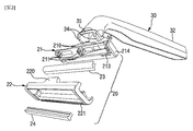
図2は、本発明の一実施形態によるかみそりハンドル30及びかみそり刃カートリッジ20の分解図である。
FIG. 2 is an exploded view of the razor handle 30 and the
図2を参照すれば、かみそり刃カートリッジ20は、刃ハウジング21、少なくとも一つのかみそりの刃23、カートリッジフレーム22で構成され、ガード部をさらに備え得る。
Referring to FIG. 2, the
刃ハウジング21は、少なくとも一つのかみそりの刃23を収容し得、前記かみそりの刃23は、刃ハウジング21の前面部に位置する安着部211に挿入される。安着部211は、かみそりの刃23の下端が挿入されることにより、かみそりの刃23を刃ハウジング21に固定させる。安着部211は、必ずしも刃ハウジング21全体にわたって形成されなければならないものでなく、かみそりの刃23が刃ハウジング21から離脱せずに固定されることにより、切削時に加えられる力に耐えてひげ剃りが円滑に行われる程度にかみそりの刃23を固定できれば十分である。したがって、図2に示すように刃ハウジング21の長方向の両端と長方向の中央とに安着部211が位置し得る。安着部211の配置は、これに限定されず、刃ハウジング21の長方向に沿って均等な間隔で4箇所に配置されるなどの多様な実施形態が可能である。安着部211の一実施形態と異なる配置については、本発明の他の実施形態を説明する際に図6を参照して後述する。
本発明の一実施形態では、かみそりの刃23と安着部211とが刃ハウジング21の短方向に沿ってそれぞれ2個配置される場合を示しているが、かみそりの刃23と安着部211の個数は、これに限定されない。かみそりの刃23は、少なくとも一つで、最大に結合しようとするかみそりの刃23の個数に応じて安着部211の個数が対応して決定される。
In one embodiment of the present invention, two
安着部211の下方には、刃ハウジング21の一部が前面に向かって突出した形態で構成され得る。この部位は、刃ハウジング21がカートリッジフレーム22と結合されたとき、カートリッジフレーム22の前面よりもさらに前面に向かって突出するように構成され、刃ハウジングガード213として作用し得る。刃ハウジングガード213は、刃ハウジング21がカートリッジフレーム22との結合をさらに堅固にするため、追加的に接触するか、引っかかる突起部として作用し得、ひげを剃るときに皮膚にかみそりの刃23よりも先に接触され、切削面を決定するガードの役割を果たし得る。別途、組み立てられるカートリッジフレーム22にガード部が形成されるか、別のガード部品を結合及び取り付ける従来の状況とは異なり、かみそりの刃23が安着する安着部211と同じ部品である刃ハウジング21にガードが位置する。したがって、かみそりの刃23とガードとの間に所望する高さで形成することが難しく、製造及び組み立て時の公差が発生する従来のかみそりに比べて、かみそりの刃23とガードとの高さを合わせることが容易であるため、切削面の形成に有利である。
Below the anchoring
刃ハウジングの側面214は、刃ハウジング21の側方に位置する面であり、ユーザーがかみそり刃カートリッジ20とハンドル30とを結合または分離するとき、かみそり刃カートリッジ20を、滑ることなく容易に把持できように平らな面で両面が平行に構成され得、カートリッジフレーム22と結合した後も側方に露出されるか、突出するように構成し得る。
The
カートリッジフレーム22は、刃ハウジング21を覆ってかみそりの刃23が前面に向かって露出するように、外周を除いた中心部が開放された形態で形成される。
The
カートリッジフレーム22は、刃ハウジング21の前面から結合されるが、結合過程でカートリッジフレーム22の前面の両側端が、刃ハウジング21と安着部211とに挿入されたかみそりの刃23をかみそり刃カートリッジ20の後面に向かって押すように結合される。したがって、かみそりの刃23の下端が安着部211に挿入されていたことでは、かみそりの刃23が堅固に固定されていると保証できないが、カートリッジフレーム22が刃ハウジング21と堅固に結合及び固定されることにより、かみそりの刃23も堅く固定される。カートリッジフレーム22の前面の両側端の内側面と刃ハウジング21の前面の側端の形状は、対応するように形成され、刃ハウジング21とカートリッジフレーム22とが容易に結合されるようにし得る。
The
カートリッジフレーム22の前面の下端には、フレームガード221が形成され、切削面を決定する役割を果たすか、くし形態のガード(comb guard)で形成されて切削しようとする体毛をすいて整列する役割を果たす。ただし、フレームガード221の形態及び位置は、これに限定されるものではなく、カートリッジフレーム22の前面の上端にも位置し得、くし形態のガードではない他の形態でもよい。
A
カートリッジフレーム22の前面部の下端には、潤滑バンド24が配置され、ひげを剃るときに潤滑力を提供し得る。ただし、これは一つの実施形態であり、潤滑バンド24は、カートリッジフレーム22の前面部の上端に配置され得る。
A
かみそり刃カートリッジ20の後面にハンドル30が結合されるためには、本発明の一実施形態によるかみそりのかみそり刃カートリッジ20は、刃ハウジング21に第1フック210を備え、カートリッジフレーム22に第2フック220を備えてハンドル30と対応するようにする。
In order to connect the
第1フック210は、刃ハウジング21の後面に備えられるフックであり、かみそりの刃23の配置方向に垂直なかみそり刃カートリッジ20の短方向に沿って配置され、かみそり刃カートリッジ20の後面が向かう方向に沿って突出してハンドル30の一端の側面を保持し得る。第1フック210は、ハンドル30の一端の領域と同様の間隔をあけて配置される2つのサイドフックを備え、これらのサイドフックは互いに平行で、かみそり刃カートリッジ20の短方向に沿っている。したがって、サイドフックは、ハンドル30の一端の両側面をハンドル30の内側方向に保持してハンドル30をかみそり刃カートリッジ20に固定させ得る。
The
第2フック220は、カートリッジフレーム22の後面に備えられるフックであり、カートリッジフレーム22の後面の上端に配置され、かみそりの刃23の配置方向に平行に延び、かみそり刃カートリッジ20の後面が向く方向に沿って突出してハンドル30の一端の上面を保持し得る。
The
第1フック210及び第2フック220は、突出するように構成し、結合とともにハンドル30の一端面を固定する部材で表現したが、フックという表現は、これに限定されるものではなく、ハンドル30の一端に配置される突起を収容できる溝形態で構成されるなど、ハンドル30の一端とかみそり刃カートリッジ20の一端とを接触及び締結して固定できる構造であり、前記構造がハンドル30に配置される係止部の構造と対応できるものであれば、本発明で説明した構造以外の構造を用いてもよい。
The
ハンドル30の一端には、前記第1フック210及び第2フック220に対応する第1係止部34と第2係止部35とが形成される。
At one end of the
第1係止部34は、ハンドル30の一端の貫通孔31の一方側の開口である第1開放面310の側面に配置され、ハンドル30の側方に突出する。第1係止部34は、刃ハウジング21の後面に位置する第1フック210に対応するようにその長さが形成される。第1フック210が2つのサイドフックを備える場合、前記サイドフックに対応するように第1係止部34の個数及び第1係止部34間の間隔が形成される。
The
第2係止部35は、ハンドル30の一端の貫通孔31の一方側の開口である第1開放面310の上面に配置され、ハンドル30の上方に突出する。第2係止部35は、結合時に第2フック220に対応するように形態及び位置が決定される。
The
前記構造は、一つの実施形態にすぎず、当業者に自明なものであれば、フック以外の他の結合構造を用いてもよく、第2フック220の位置もカートリッジフレーム22の後面の下端に位置し得、第2係止部35の位置もこれに対応するように変更してもよい。
The structure is only one embodiment, and a coupling structure other than the hook may be used as long as it is obvious to those skilled in the art, and the position of the
図1、図3及び図4を参照して、それぞれ分離されたハンドル30とかみそり刃カートリッジ20とが結合される過程及び貫通孔31の形状について説明する。
The process of connecting the separated
図3は、本発明の一実施形態によるかみそりハンドル30とかみそり刃カートリッジ20とが分離された形態を示す斜視図であり、図4は、本発明の一実施形態によるかみそりハンドル30とかみそり刃カートリッジ20とが分離された形態を、図2の反対方向から見た斜視図である。
FIG. 3 is a perspective view showing a form in which the razor handle 30 and the
図1、図3及び図4を参照すれば、第1フック210は第1係止部34と、第2フック220は第2係止部35と、それぞれ対応して結合時に互いに締結される関係になる。
With reference to FIGS. 1, 3 and 4, the
かみそり刃カートリッジ20の後面とハンドル30の一端を接触させた後、互いに向かって外力を与えると、第1係止部34が第1フック210と刃ハウジング21の後面との間の空間に押されて入り、第1フック210によって引っかかってかみそり刃カートリッジ20の長方向及びかみそり刃カートリッジ20の前後面が向かう方向に離脱しないように固定される。それと同時に、第2係止部35が第2フック220とカートリッジフレーム22の後面との間の空間に押されて入り、第2フック220によって引っかかってかみそり刃カートリッジ20の短方向及びかみそり刃カートリッジ20の前後面が向かう方向に離脱しないように固定される。
When the rear surface of the
したがって、第1フック210と第1係止部34との結合によってハンドル30がかみそり刃カートリッジ20の長方向に離脱することが制限され、第2フック220と第2係止部35との結合によってハンドル30がかみそり刃カートリッジ20の短方向に離脱することが制限され、第1フック210及び第2フック220が、第1係止部34及び第2係止部35に結合され、ハンドル30がかみそり刃カートリッジ20の前後面が向かう方向に離脱することが防止されることで、かみそり刃カートリッジ20の短方向にキャップを離脱させようとしたり、ひげ剃りをかみそり刃カートリッジ20の短方向にするなどの理由で外力が加わる場合、かみそり刃カートリッジ20がハンドル30から離脱する危険性を防止できる。
Therefore, the coupling of the
また、刃ハウジング21に配置された第1フック210のみがハンドル30と結合するものではなく、カートリッジフレーム22に配置された第2フック220がかみそり刃カートリッジ20とハンドル30との間の結合に関与するので、かみそり刃カートリッジ20とハンドル30との結合により、刃ハウジング21とカートリッジフレーム22とがより堅く固定される。
Further, not only the
ハンドル30の一端とかみそり刃カートリッジ20の後面のフックが円滑に結合されるために、第1フック210及び第2フック220は、かみそり刃カートリッジ20の前面から後面に向かってテーパ状に形成され得る。これに対応してハンドル30の一端の第1係止部34及び第2係止部35もハンドル30の取っ手部32からかみそり刃カートリッジ20に向かう方向にテーパ状に形成され得る。したがって、フックまたは係止部がテーパ状に形成されて斜面をなすと、係止部がかみそり刃カートリッジ20の後面に挿入されるとき、前記斜面に沿ってより少ない力でも容易に進入して結合され得る。
The
図3及び図4を参照すれば、本発明の一実施形態のかみそりハンドル30が有する貫通孔31の一側の開口である第1開放面310、第2開放面311及び第3開放面312を確認し得る。
With reference to FIGS. 3 and 4, the first
第1開放面310は、ハンドル30の一端にかみそり刃カートリッジ20に向かうように形成され、第2開放面311は、ハンドル30の上面に形成される。したがって、貫通孔31は、第1開放面310と第2開放面311とをつなぎハンドル30を貫通する構造であり、ハンドル30のプロファイルの少なくとも一部に沿って延長される。
The first
第2開放面311は、第1開放面310に対向するように配置される。ここで、対向するとは、第1開放面310から第2開放面311に向かってハンドル30を貫通させた通路が貫通孔31になって、第1開放面310と第2開放面311とが貫通孔31の一方向開口と反対側の他方向開口になることを意味する。
The second
前記貫通孔31は、両開口がハンドル30の一端と上面とに形成された構造であるので、一開放面に水のような液体が進入する場合、他の開放面に排出される。したがって、このような構造を用いて、第2開放面311を介して洗浄水を注入する場合には、かみそり刃カートリッジ20の後面と隣接する第1開放面310とを介して洗浄水が排出され、かみそり刃カートリッジ20への洗浄水の供給、洗浄が行われ得る。特にかみそり刃カートリッジ20の中心部は、通常の方法で円滑に洗浄されないので、前記のような方法で容易に洗浄することができる。これらの特性は、ハンドル30の取っ手部32からかみそり刃カートリッジ20に向かう第1開放面310に近づくほど、ハンドル30の横断面積が広くなる本発明の一実施形態のハンドル30の特徴と結合して洗浄効率をさらに向上させることができる。
Since the through
貫通孔31は、第1開放面310と隣接して下方に開放される第3開放面312をさらに備える。したがって、第2開放面311に洗浄水が注入される場合は、第1開放面310を介してかみそり刃カートリッジ20に洗浄水が供給されると同時に、第3開放面312にも洗浄水の一部が供給されて洗浄水の洗浄によってかみそり刃カートリッジ20から排出される剃り残しを排出できる。
The through
ただし、前述したように、洗浄方法は第2開放面311に洗浄水を注入することに限定されるものではなく、かみそり刃カートリッジ20の前面を介して洗浄水が注入され、第1開放面310に洗浄水と剃り残しとが排出され、第2開放面311と第3開放面312とに引き続き排出される洗浄方法、第3開放面312に洗浄水が注入され、第1開放面310を介してかみそり刃カートリッジ20の後面に洗浄水が供給されることにより、かみそり刃カートリッジ20の前面に剃り残しを排出する洗浄方法などをユーザーが選択できる。
However, as described above, the cleaning method is not limited to injecting the cleaning water into the second
図5は、本発明の一実施形態によるかみそり刃カートリッジ20の背面図である。
FIG. 5 is a rear view of the
図5を参照すれば、第1フック210は、刃ハウジング21の短方向のすべてにわたって形成されるものではなく、第1フック210の下端には、フック溝212が形成される。かみそり刃カートリッジ20とハンドル30との結合が行われると、フック溝212には、図2のハンドル30で確認できる係止延長部36が位置する。係止延長部36は、第1係止部34と隣接するように位置し、ハンドル30のプロファイルに沿って延長されるので、かみそり刃カートリッジ20の短方向にも第1フック210によって引っかかる。したがって、ハンドル30がかみそり刃カートリッジ20の短方向に沿って離脱しようとすることを第2係止部35と共に防止する役割をする。
Referring to FIG. 5, the
図6は、本発明の一実施形態によるかみそりの背面図である。 FIG. 6 is a rear view of a razor according to an embodiment of the present invention.
図6を参照すれば、かみそり刃カートリッジ20の後面にハンドル30が結合された場合、貫通孔31を介してかみそり刃カートリッジ20の後面の観察が可能であることを確認できる。したがって、前記貫通孔31の後方に位置する第2開放面311を介して洗浄水を注入する時、前方に位置してかみそり刃カートリッジ20の後面と隣接する第1開放面310を介して洗浄水が供給されてかみそり10を後面から洗浄することが可能である。
With reference to FIG. 6, when the
一方、かみそり10の後方から貫通孔31を介して確認できるように、安着部211は貫通孔31を介して観察が可能である。したがって、刃ハウジング21に安着したかみそりの刃23に直接洗浄水が供給されることを安着部211が遮っているので、かみそりの刃23の中心部の洗浄が多少不十分である。
On the other hand, the anchoring
図7は、本発明の他の実施形態によるかみそり刃カートリッジ40の背面図である。
FIG. 7 is a rear view of the
したがって、前述したように洗浄が不十分である問題を解決するために、図7を参照すれば、安着部411をかみそり刃カートリッジ40の中心ではなく、第1フック410に対応する位置に配置することにより、かみそり刃カートリッジ40の中心部が露出され得る。
Therefore, in order to solve the problem of insufficient cleaning as described above, referring to FIG. 7, the anchoring
図8は、本発明の他の実施形態によるかみそりの背面図である。 FIG. 8 is a rear view of a razor according to another embodiment of the present invention.
図8を参照すれば、ハンドル30がかみそり刃カートリッジ40に結合された後も貫通孔31を介して観察できるかみそり刃カートリッジ40の後面を安着部411が遮っていないことが確認できる。本発明の他の実施形態によって、かみそりの後方に配置された第2開放面311に洗浄水が注入されると、かみそり刃カートリッジ40に隣接して配置された第1開放面310に洗浄水が排出され、安着部411がかみそり刃カートリッジ40の後面を遮っていないので、かみそりの刃23の中心部が流入した洗浄水によって円滑に洗浄され得る。
With reference to FIG. 8, it can be confirmed that the anchoring
図5において、かみそりの刃23の安着部211は、かみそり刃カートリッジ20の長方向両端と中心に位置してかみそりの刃23を3箇所で保持する。
In FIG. 5, the anchoring
図7において、かみそりの刃23の安着部411は、第1フック210の位置に対応する刃ハウジング21の前面の箇所にそれぞれ一つずつ位置し、かみそり刃カートリッジ40長方向両端に位置してかみそりの刃23を4箇所で保持する。前記図7の他の実施形態の安着部411の配置形態により、刃ハウジング21の中心部に位置していた安着部211が両側に移動したものと同じであるので、貫通孔31を介してかみそり刃カートリッジ40の後面に供給された洗浄水がかみそり刃カートリッジ40の中心部をより旨く洗浄できる。
In FIG. 7, one anchoring
本発明が属する技術分野における通常の知識を有する者は、本発明がその技術的思想や必須の特徴を変更せず、他の具体的な形で実施できることを理解できるだろう。したがって、上記実施形態は、すべての面において例示的なものであり、限定的なものではないと理解しなければならない。本発明の範囲は、前記詳細な説明ではなく、後述する特許請求の範囲によって示され、特許請求の範囲の意味及び範囲並びにその均等概念から導き出されるすべての変更または変形された形態が本発明の範囲に含まれると解釈しなければならない。 Those who have ordinary knowledge in the technical field to which the present invention belongs will understand that the present invention can be carried out in other concrete forms without changing its technical ideas and essential features. Therefore, it should be understood that the above embodiments are exemplary in all respects and are not limiting. The scope of the present invention is shown not by the above detailed description but by the scope of claims described later, and all modified or modified forms of the present invention derived from the meaning and scope of the claims and the concept of equality thereof are described in the present invention. It must be interpreted as being included in the scope.
本発明は前述した好ましい実施形態について説明したが、発明の要旨と範囲から外れない範囲で、様々な修正や変形をすることは可能である。したがって、添付する特許請求の範囲は、本発明の要旨に属する限り、これらの変更や変形を含むことができる。
Although the present invention has described the preferred embodiments described above, various modifications and modifications can be made without departing from the gist and scope of the invention. Therefore, the appended claims may include these modifications and modifications as long as they belong to the gist of the present invention.
Claims (8)
前記かみそり刃カートリッジの後面と結合されるハンドルとを備え、
前記ハンドルの外形の少なくとも一部に沿って延びる貫通孔が前記ハンドルに形成され、
前記貫通孔は、前記かみそり刃カートリッジの後面に向くように形成される第1開放面と、前記第1開放面と対向する第2開放面を備え、
前記第2開放面は、前記ハンドルの上面に形成され、前記かみそり刃カートリッジから離れて形成されている、
かみそり。 With a razor blade cartridge that contains at least one razor blade,
A handle that is coupled to the rear surface of the razor blade cartridge
A through hole extending along at least a part of the outer shape of the handle is formed in the handle.
The through hole includes a first open surface formed so as to face the rear surface of the razor blade cartridge, and a second open surface facing the first open surface .
The second open surface is formed on the upper surface of the handle and is formed away from the razor blade cartridge.
Razor.
前記ハンドルは、前記第1フックに結合される第1係止部と前記第2フックに結合される第2係止部とを備えることにより、前記かみそり刃カートリッジの後面に結合される請求項1に記載のかみそり。 A first hook and a second hook are formed on the rear surface of the razor blade cartridge, and the first hook and the second hook are formed.
Claim 1 in which the handle is coupled to the rear surface of the razor blade cartridge by providing a first locking portion coupled to the first hook and a second locking portion coupled to the second hook. Razor described in.
前記刃ハウジングは、前記カートリッジフレームの前面に垂直な方向において前記前面よりもさらに突出した刃ハウジングガード部を備える請求項1に記載のかみそり。 The razor blade cartridge comprises a blade housing that houses the at least one razor blade and a cartridge frame that is assembled with the blade housing and secures the at least one razor blade to the blade housing.
The razor according to claim 1, wherein the blade housing includes a blade housing guard portion that projects further from the front surface in a direction perpendicular to the front surface of the cartridge frame.
Applications Claiming Priority (3)
| Application Number | Priority Date | Filing Date | Title |
|---|---|---|---|
| KR1020160079379A KR101730415B1 (en) | 2016-06-24 | 2016-06-24 | Razor with perforated handle |
| KR10-2016-0079379 | 2016-06-24 | ||
| PCT/KR2016/008489 WO2017222107A1 (en) | 2016-06-24 | 2016-08-02 | Razor comprising handle with through-hole |
Publications (3)
| Publication Number | Publication Date |
|---|---|
| JP2019518570A JP2019518570A (en) | 2019-07-04 |
| JP2019518570A5 JP2019518570A5 (en) | 2019-08-29 |
| JP6853281B2 true JP6853281B2 (en) | 2021-03-31 |
Family
ID=58704962
Family Applications (1)
| Application Number | Title | Priority Date | Filing Date |
|---|---|---|---|
| JP2018567663A Active JP6853281B2 (en) | 2016-06-24 | 2016-08-02 | Razor with handle with through holes |
Country Status (7)
| Country | Link |
|---|---|
| US (1) | US10875199B2 (en) |
| EP (1) | EP3476559B1 (en) |
| JP (1) | JP6853281B2 (en) |
| KR (1) | KR101730415B1 (en) |
| CN (1) | CN109153138B (en) |
| ES (1) | ES2881650T3 (en) |
| WO (1) | WO2017222107A1 (en) |
Families Citing this family (5)
| Publication number | Priority date | Publication date | Assignee | Title |
|---|---|---|---|---|
| EP3771530A1 (en) * | 2019-07-31 | 2021-02-03 | Bic Violex S.A. | Mechanical assembly of a skin care device, skin care device and process for manufacturing thereof |
| JP7146288B2 (en) | 2020-01-29 | 2022-10-04 | 匠技研株式会社 | Blade holder for cutting chain food |
| US20220088810A1 (en) * | 2020-09-21 | 2022-03-24 | Beauty Perspectives, LLC | Razor handle |
| KR102540000B1 (en) * | 2020-10-30 | 2023-06-05 | 가부시키가이샤 카이지루시 하모노 카이하츠 센타 | Shaver |
| JP6825162B1 (en) * | 2020-10-30 | 2021-02-03 | 株式会社貝印刃物開発センター | razor |
Family Cites Families (51)
| Publication number | Priority date | Publication date | Assignee | Title |
|---|---|---|---|---|
| US3703764A (en) | 1971-03-15 | 1972-11-28 | Gillette Co | Razor blade assembly |
| ES400641A1 (en) * | 1971-03-15 | 1975-01-16 | Gillette Co | Razors |
| US4094063A (en) * | 1976-12-15 | 1978-06-13 | The Gillette Company | Razor assembly with pivotally mounted cartridge |
| JPS5951149B2 (en) | 1977-08-10 | 1984-12-12 | 株式会社日立製作所 | Bipolar semiconductor memory device |
| US4212103A (en) | 1978-10-27 | 1980-07-15 | Schuman Hoole April | Razor |
| US4228586A (en) * | 1979-02-23 | 1980-10-21 | Thierry Timothy T | Shaving apparatus |
| US4308663A (en) * | 1979-12-31 | 1982-01-05 | Warner-Lambert Company | Razor handle with latch for pivotable cartridge |
| US4392303A (en) | 1979-12-31 | 1983-07-12 | Warner-Lambert Company | One-piece razor handle |
| JPS596675B2 (en) * | 1980-10-20 | 1984-02-14 | 株式会社貝印刃物開発センター | safety razor |
| NZ202924A (en) * | 1982-01-27 | 1986-06-11 | Wilkinson Sword Ltd | A razor blade assembly |
| US4492024A (en) * | 1982-09-17 | 1985-01-08 | The Gillette Company | Razor blade assembly |
| US4692986A (en) * | 1985-09-27 | 1987-09-15 | Warner Lambert Company | Razor cartridge with shaving aid |
| US4850107A (en) | 1988-10-04 | 1989-07-25 | Valliades John F | Razor assembly |
| ES2299951T3 (en) | 1991-11-27 | 2008-06-01 | The Gillette Company | RAZORS. |
| US5335417A (en) * | 1992-07-27 | 1994-08-09 | Genero Claude P | Hand razor |
| KR950004998B1 (en) * | 1992-11-27 | 1995-05-17 | 고광철 | Wet razor having air-washing device |
| US5265337A (en) | 1992-12-21 | 1993-11-30 | Robert Lowder | Self-cleaning razor |
| US6212777B1 (en) | 1993-09-29 | 2001-04-10 | The Gillette Company | Safety razors |
| US5402574A (en) * | 1994-05-20 | 1995-04-04 | Milner; Joshua P. | Shaving apparatus |
| ES2138241T3 (en) | 1994-10-03 | 2000-01-01 | Gillette Co | SHAVING MACHINE STRUCTURE. |
| US6516518B1 (en) | 1996-01-12 | 2003-02-11 | The Gillette Company | Razor blade unit |
| WO1997035693A2 (en) | 1996-03-27 | 1997-10-02 | Warner-Lambert Company | Shaving system with uniform shaving forces |
| US6041926A (en) | 1996-04-10 | 2000-03-28 | The Gillette Company | Dispensing razor blade cartridges used with a handle |
| US5787586A (en) | 1996-04-10 | 1998-08-04 | The Gillette Company | Shaving system and method |
| US5956851A (en) | 1996-04-10 | 1999-09-28 | The Gillette Company | Shaving system including handle and replaceable cartridges |
| US5687485A (en) | 1996-05-15 | 1997-11-18 | The Gillette Company | Razor handle |
| US5956848A (en) | 1997-02-27 | 1999-09-28 | The Gillette Company | Shaving system |
| US6499218B2 (en) * | 1998-12-28 | 2002-12-31 | Manual Antonio Rocha | Four sided dual blade shaver |
| US6305082B1 (en) * | 1999-06-18 | 2001-10-23 | Vincent F. Troncoso | Flush out cleanable razor |
| US6684513B1 (en) | 2000-02-29 | 2004-02-03 | The Gillette Company | Razor blade technology |
| US7043842B1 (en) * | 2003-03-27 | 2006-05-16 | William Taylor | Automatic rinsing razor system |
| US7007390B2 (en) * | 2003-09-10 | 2006-03-07 | Bradley Mislove | Water irrigated and articulated razor |
| GB2408010B (en) * | 2003-11-17 | 2007-03-28 | Knowledge & Merchandising Inc | Shaving product |
| CL2008001727A1 (en) * | 2007-06-12 | 2010-02-05 | Gillette Co | Razor comprising a handle with a proximal and a distal end, an adapter neck pivotally attached to the proximal end of the handle, a pump attached to a feeder channel, a cartridge connection fork, and a shaver cartridge. to shave. |
| KR20090067229A (en) * | 2007-12-21 | 2009-06-25 | 허정범 | Cream shaver |
| US8209867B2 (en) * | 2008-10-02 | 2012-07-03 | The Gillette Company | Shaving razors and cartridges |
| KR20100091622A (en) * | 2009-02-11 | 2010-08-19 | 주식회사 도루코 | Integrated cartridge |
| US20130081276A1 (en) | 2011-09-30 | 2013-04-04 | Kevin James Wain | Biasing shaving razors |
| US20130291390A1 (en) * | 2012-05-01 | 2013-11-07 | The Gillette Company | Handle for a shaving razor |
| US8887401B2 (en) * | 2012-06-18 | 2014-11-18 | Anthony J. Oxford | Rotating blade assembly |
| US9283685B2 (en) * | 2012-07-26 | 2016-03-15 | Shavelogic, Inc. | Pivoting razors |
| WO2014051842A1 (en) * | 2012-09-27 | 2014-04-03 | Shavelogic, Inc. | Shaving systems |
| WO2014051843A1 (en) * | 2012-09-28 | 2014-04-03 | Shavelogic, Inc. | Shaving systems |
| US20140116211A1 (en) * | 2012-10-25 | 2014-05-01 | Shavelogic, Inc. | Dedicated Attachment Systems for Consumer Products |
| KR101977754B1 (en) * | 2012-12-21 | 2019-05-13 | 빅-비올렉스 에스아 | Shaver with interchangeable cartridge, cartridge and head and handle assembly for such shaver |
| JP6053955B2 (en) * | 2012-12-21 | 2016-12-27 | ビック・バイオレクス・エス・エー | Shaver with replaceable cartridge, cartridge and head handle assembly for such a shaver |
| JP6293464B2 (en) * | 2013-11-27 | 2018-03-14 | 株式会社貝印刃物開発センター | razor |
| WO2016019975A1 (en) * | 2014-08-04 | 2016-02-11 | Bic-Violex Sa | A razor handle comprising an insert freely movable within a cavity and razor comprising such a razor handle |
| EP3372358B1 (en) * | 2017-03-10 | 2021-07-21 | The Gillette Company LLC | Razor handle |
| US11141873B2 (en) * | 2017-04-18 | 2021-10-12 | The Gillette Company Llc | Shaving razor system |
| US20190084169A1 (en) * | 2017-09-15 | 2019-03-21 | Little Acorn Shave Company Inc. | Razor handle |
-
2016
- 2016-06-24 KR KR1020160079379A patent/KR101730415B1/en active IP Right Grant
- 2016-08-02 US US16/313,099 patent/US10875199B2/en active Active
- 2016-08-02 EP EP16906382.3A patent/EP3476559B1/en active Active
- 2016-08-02 ES ES16906382T patent/ES2881650T3/en active Active
- 2016-08-02 JP JP2018567663A patent/JP6853281B2/en active Active
- 2016-08-02 WO PCT/KR2016/008489 patent/WO2017222107A1/en unknown
- 2016-08-02 CN CN201680085421.6A patent/CN109153138B/en active Active
Also Published As
| Publication number | Publication date |
|---|---|
| EP3476559A4 (en) | 2020-02-19 |
| ES2881650T3 (en) | 2021-11-30 |
| EP3476559A1 (en) | 2019-05-01 |
| KR101730415B1 (en) | 2017-04-26 |
| JP2019518570A (en) | 2019-07-04 |
| US20190224873A1 (en) | 2019-07-25 |
| US10875199B2 (en) | 2020-12-29 |
| CN109153138B (en) | 2021-03-23 |
| CN109153138A (en) | 2019-01-04 |
| EP3476559B1 (en) | 2021-06-30 |
| WO2017222107A1 (en) | 2017-12-28 |
Similar Documents
| Publication | Publication Date | Title |
|---|---|---|
| JP6853281B2 (en) | Razor with handle with through holes | |
| KR101703514B1 (en) | Razor | |
| US4480387A (en) | Cleaning device for razors | |
| US8801316B1 (en) | Water jet toothbrush assembly | |
| JP2018535768A (en) | Handle assembly, cartridge and razor including them | |
| KR20120026017A (en) | The two sided razor for rough and finishing shave | |
| KR100582029B1 (en) | Scissors for hair-care | |
| KR20110001826U (en) | A hair dyeing device | |
| KR200466246Y1 (en) | Attach on and off mustache inflow-guid of electric razor | |
| US6643885B2 (en) | Method of molding a plastic brace into a sponge mop head and apparatus for retaining a sponge mop head within a plastic brace | |
| KR200436776Y1 (en) | Dyeing utensil | |
| KR101383113B1 (en) | shaver with rotation type razor blade cartridge | |
| JP5917268B2 (en) | Trigger type liquid ejector | |
| US20160355052A1 (en) | Device for cleaning a paint roller | |
| KR20030018794A (en) | Hairdressing scissor assembly | |
| KR100712367B1 (en) | Razor blade | |
| KR200293605Y1 (en) | Shaver with washing function | |
| KR200262255Y1 (en) | scissors with razor and thinning function | |
| KR200255476Y1 (en) | Combination a razor with a toothbrush | |
| KR200263262Y1 (en) | clean shaver | |
| KR200209890Y1 (en) | A hair pin | |
| JP4002031B2 (en) | Shampoo machine | |
| KR20220052506A (en) | Hair brush capable of easily removing hair | |
| KR200399258Y1 (en) | Toothbrush with Shaver | |
| JPH01221195A (en) | Mustache and underarm hair shaver with improved sharpness |
Legal Events
| Date | Code | Title | Description |
|---|---|---|---|
| A521 | Request for written amendment filed |
Free format text: JAPANESE INTERMEDIATE CODE: A523 Effective date: 20190711 |
|
| A621 | Written request for application examination |
Free format text: JAPANESE INTERMEDIATE CODE: A621 Effective date: 20190711 |
|
| A131 | Notification of reasons for refusal |
Free format text: JAPANESE INTERMEDIATE CODE: A131 Effective date: 20200811 |
|
| A521 | Request for written amendment filed |
Free format text: JAPANESE INTERMEDIATE CODE: A523 Effective date: 20201109 |
|
| TRDD | Decision of grant or rejection written | ||
| A01 | Written decision to grant a patent or to grant a registration (utility model) |
Free format text: JAPANESE INTERMEDIATE CODE: A01 Effective date: 20210302 |
|
| A61 | First payment of annual fees (during grant procedure) |
Free format text: JAPANESE INTERMEDIATE CODE: A61 Effective date: 20210311 |
|
| R150 | Certificate of patent or registration of utility model |
Ref document number: 6853281 Country of ref document: JP Free format text: JAPANESE INTERMEDIATE CODE: R150 |
|
| R250 | Receipt of annual fees |
Free format text: JAPANESE INTERMEDIATE CODE: R250 |