EP3476559B1 - Razor comprising handle with through-hole - Google Patents
Razor comprising handle with through-hole Download PDFInfo
- Publication number
- EP3476559B1 EP3476559B1 EP16906382.3A EP16906382A EP3476559B1 EP 3476559 B1 EP3476559 B1 EP 3476559B1 EP 16906382 A EP16906382 A EP 16906382A EP 3476559 B1 EP3476559 B1 EP 3476559B1
- Authority
- EP
- European Patent Office
- Prior art keywords
- handle
- razor
- cartridge
- razor blade
- hook
- Prior art date
- Legal status (The legal status is an assumption and is not a legal conclusion. Google has not performed a legal analysis and makes no representation as to the accuracy of the status listed.)
- Active
Links
- 238000005406 washing Methods 0.000 description 31
- XLYOFNOQVPJJNP-UHFFFAOYSA-N water Substances O XLYOFNOQVPJJNP-UHFFFAOYSA-N 0.000 description 26
- 238000010168 coupling process Methods 0.000 description 11
- 238000000034 method Methods 0.000 description 10
- 230000008878 coupling Effects 0.000 description 9
- 238000005859 coupling reaction Methods 0.000 description 9
- 238000005520 cutting process Methods 0.000 description 5
- 230000000694 effects Effects 0.000 description 4
- 239000007788 liquid Substances 0.000 description 3
- 230000001050 lubricating effect Effects 0.000 description 3
- 238000004519 manufacturing process Methods 0.000 description 3
- 230000000903 blocking effect Effects 0.000 description 1
- 238000004140 cleaning Methods 0.000 description 1
- 230000001815 facial effect Effects 0.000 description 1
- 239000006260 foam Substances 0.000 description 1
- 238000007429 general method Methods 0.000 description 1
- 238000005461 lubrication Methods 0.000 description 1
- 239000000463 material Substances 0.000 description 1
- 238000012986 modification Methods 0.000 description 1
- 230000004048 modification Effects 0.000 description 1
Images


Classifications
-
- B—PERFORMING OPERATIONS; TRANSPORTING
- B26—HAND CUTTING TOOLS; CUTTING; SEVERING
- B26B—HAND-HELD CUTTING TOOLS NOT OTHERWISE PROVIDED FOR
- B26B21/00—Razors of the open or knife type; Safety razors or other shaving implements of the planing type; Hair-trimming devices involving a razor-blade; Equipment therefor
- B26B21/40—Details or accessories
- B26B21/52—Handles, e.g. tiltable, flexible
- B26B21/521—Connection details, e.g. connection to razor heads
-
- B—PERFORMING OPERATIONS; TRANSPORTING
- B26—HAND CUTTING TOOLS; CUTTING; SEVERING
- B26B—HAND-HELD CUTTING TOOLS NOT OTHERWISE PROVIDED FOR
- B26B21/00—Razors of the open or knife type; Safety razors or other shaving implements of the planing type; Hair-trimming devices involving a razor-blade; Equipment therefor
- B26B21/08—Razors of the open or knife type; Safety razors or other shaving implements of the planing type; Hair-trimming devices involving a razor-blade; Equipment therefor involving changeable blades
- B26B21/14—Safety razors with one or more blades arranged transversely to the handle
- B26B21/22—Safety razors with one or more blades arranged transversely to the handle involving several blades to be used simultaneously
- B26B21/222—Safety razors with one or more blades arranged transversely to the handle involving several blades to be used simultaneously with the blades moulded into, or attached to, a changeable unit
-
- B—PERFORMING OPERATIONS; TRANSPORTING
- B26—HAND CUTTING TOOLS; CUTTING; SEVERING
- B26B—HAND-HELD CUTTING TOOLS NOT OTHERWISE PROVIDED FOR
- B26B21/00—Razors of the open or knife type; Safety razors or other shaving implements of the planing type; Hair-trimming devices involving a razor-blade; Equipment therefor
- B26B21/40—Details or accessories
- B26B21/4012—Housing details, e.g. for cartridges
- B26B21/4018—Guard elements
-
- B—PERFORMING OPERATIONS; TRANSPORTING
- B26—HAND CUTTING TOOLS; CUTTING; SEVERING
- B26B—HAND-HELD CUTTING TOOLS NOT OTHERWISE PROVIDED FOR
- B26B21/00—Razors of the open or knife type; Safety razors or other shaving implements of the planing type; Hair-trimming devices involving a razor-blade; Equipment therefor
- B26B21/40—Details or accessories
- B26B21/52—Handles, e.g. tiltable, flexible
- B26B21/522—Ergonomic details, e.g. shape, ribs or rubber parts
-
- B—PERFORMING OPERATIONS; TRANSPORTING
- B26—HAND CUTTING TOOLS; CUTTING; SEVERING
- B26B—HAND-HELD CUTTING TOOLS NOT OTHERWISE PROVIDED FOR
- B26B21/00—Razors of the open or knife type; Safety razors or other shaving implements of the planing type; Hair-trimming devices involving a razor-blade; Equipment therefor
- B26B21/40—Details or accessories
- B26B21/44—Means integral with, or attached to, the razor for storing shaving-cream, styptic, or the like
- B26B21/443—Lubricating strips attached to the razor head
Definitions
- a cartridge razor has a razor blade seated thereon and is provided together with a guard or the like so that the razor blade safely comes into contact with the skin.
- the cartridge razor includes a razor blade cartridge configured to suitably determine a degree to which the razor blade protrudes, and a handle coupled to the razor blade cartridge and provided to be hand-held and controlled by a user.
- One aspect of the present disclosure provides a razor which is easy to wash and includes a through-hole connected to a cartridge via a handle.
- GB 1 377 134 A discloses a razor comprises a handle and a blade being connected to a transversely extending support. Slots are provided in the support facing the cartridge and being open to the opposite side.
- US 2001/003869 A1 discloses a safety razor with a detachable and replaceable shaving head.
- the razor is provided within an elongated handle having a channel located in the center of the handle with an opening at the base of said handle and an opening into the blade cavity whereby water can travel from the opening in the end of the handle to the shaving head.
- a razor includes a razor blade cartridge including at least one razor blade, and a handle coupled to a rear of the razor blade cartridge, the handle comprising a handle portion in the form of a long extending bar having a lower surface in the form of a hollow cavity, wherein:
- the through-hole may further include a third open area which is adjacent to the first open area and is open in a downward direction.
- a first hook and a second hook may be formed at the rear of the razor blade cartridge, and the handle may include a first locking portion configured to be coupled to the first hook and a second locking portion configured to be coupled to the second hook.
- a seating portion configured to secure the at least one razor blade is formed at a position which corresponds to a position of the first hook, and the handle may be formed such that a width of the handle increases from a handle portion of the handle toward an end of the handle coupled to the razor blade cartridge.
- the razor blade cartridge may further include a blade housing in which the at least one razor blade is accommodated, and a cartridge frame coupled to the blade housing and configured to secure the at least one razor blade to the blade housing, wherein the blade housing includes a blade housing guard portion which protrudes past a front surface of the cartridge frame.
- a side surface of the blade housing may be externally exposed, and the razor blade cartridge may further include a guard portion disposed below a position of the razor blade at a surface at which the seating portion is disposed.
- washing water is supplied through a through-hole which extends along a portion of a profile of a handle, washing of a razor blade cartridge can be facilitated.
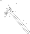
- FIG. 1 is a perspective view illustrating a form in which a razor handle 30 and a razor blade cartridge 20 are coupled according to an embodiment of the present disclosure.
- a razor according to an embodiment of the present disclosure includes the handle 30 and the razor blade cartridge 20.
- the handle 30 is coupled to the razor blade cartridge 20 using a hook coupling method. This will be described in detail below.
- the handle 30 of the razor includes a handle portion 32 which is in the form of a long extending bar so as to be held and used for the purpose of manipulating the razor by a user, and one end which is coupled to the razor blade cartridge 20 and has a through-hole 31 formed therein.
- the handle portion 32 Since the handle portion 32 has to provide a suitable grip feeling to the user, regular concave and convex patterns are formed at a side surface of the handle portion 32 in a direction which is perpendicular to a longitudinal direction of the razor such that a surface area in contact with the user's hand is increased and a frictional force is increased. In this way, the razor is prevented from easily falling out of the user's hand even in a shaving environment in which water and a large amount of a lubricating liquid such as shaving foam and shaving gel are used. Since a lower surface of the handle portion 32 is irrelevant to the provision of a grip feeling, the lower surface may be configured in the form of a hollow cavity. Therefore, simplification of a manufacturing process and saving of materials can be achieved.
- the handle 30 is coupled to the razor blade cartridge 20.
- the handle 30 may be formed in a straight shape and have the cartridge disposed at the one end thereof to be perpendicular to a longitudinal direction of the handle 30.
- the one end of the handle 30 may be configured in the form that is bent at a predetermined angle from an advancing direction of the handle portion 32 so that a cutting surface of the razor blade cartridge 20 naturally comes into contact with the skin to be shaved when the user naturally holds the razor.
- the through-hole 31 is formed along a profile of the handle 30 at the one end of the handle 30.
- the through-hole 31 may extend along at least a portion of the profile of the handle 30, and an open surface is present at each of an upper surface and a lower surface of the handle 30 and passes through the handle 30.
- a detailed configuration of the through-hole 31 will be described below with reference to FIGS. 3 and 4 .
- the handle 30 of the razor may be formed such that a transverse cross-sectional area of the handle 30 progressively widens from the handle portion 32 toward the razor blade cartridge 20. Therefore, user convenience can be improved by configuring the handle portion 32 of the handle 30 to have a transverse cross-sectional area that is suitable for the handle portion 32 to be used while being gripped by the user's hand and by configuring the one end of the handle 30 to have a transverse cross-sectional area that is suitable for the one end of the handle 30 to be coupled to the razor blade cartridge 20.
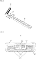
- FIG. 2 is an exploded view of the razor handle 30 and the razor blade cartridge 20 according to an embodiment of the present disclosure.
- the razor blade cartridge 20 includes a blade housing 21, at least one razor blade 23, and a cartridge frame 22 and may further include a guard portion.
- the blade housing 21 may accommodate the at least one razor blade 23, and the razor blade 23 is inserted into a seating portion 211 disposed at a front portion of the blade housing 21. A lower end of the razor blade 23 is inserted into the seating portion 211 such that the seating portion 211 fixes the razor blade 23 to the blade housing 21. It is not necessary for the seating portion 211 to be formed throughout the entire blade housing 21, and it is sufficient as long as the seating portion 211 is able to fix the razor blade 23 to the extent that the razor blade 23 is fixed without being detached from the blade housing 21 and is able to withstand a force applied during cutting such that shaving is smoothly performed. Therefore, as illustrated in FIG.
- the seating portion 211 may be disposed at both ends and the center of the blade housing 21 in a long direction of the blade housing 21.
- the arrangement of the seating portion 211 is not limited thereto, and various embodiments such as an embodiment in which the seating portion 211 is disposed at each of four positions at equal intervals in the long direction of the blade housing 21 may be possible.
- the arrangement of the seating portion 211 which is different from the above embodiment will be described below in description of another embodiment of the present disclosure with reference to FIG. 6 .
- Two razor blades 23 and two seating portions 211 are respectively adjacently disposed in a short direction of the blade housing 21 in the above embodiment of the present disclosure, but the number of razor blades 23 and seating portions 211 is not limited thereto.
- the number of razor blades 23 may be 1 or greater, and the number of seating portions 211 is determined corresponding to the maximum number of razor blades 23 desired to be coupled.
- a portion of the blade housing 21 may be configured to protrude forward below the seating portion 211. This portion may be configured to further protrude forward past a front surface of the cartridge frame 22 when the blade housing 21 is coupled to the cartridge frame 22 and may serve as a blade housing guard 213.
- the blade housing guard 213 may serve as a protrusion with which or to which the blade housing 21 additionally comes into contact or is locked in order to be more firmly coupled to the cartridge frame 22, or may also serve as a guard that comes into contact with the skin first during shaving before the razor blade 23 and determines a cutting surface.
- the guard is disposed in the blade housing 21, which is the same component as the seating portion 211 on which the razor blade 23 is seated. Therefore, in comparison to a conventional razor in which it is difficult to form a desired height difference between the razor blade 23 and the guard and tolerance occurs during manufacture and assembly, it is easy to adjust a height difference between the razor blade 23 and the guard and thus advantageous in forming a desired cutting surface.
- Side surfaces 214 of the blade housing are surfaces disposed at sides of the blade housing 21.
- the side surfaces 214 may be configured as two surfaces parallel to each other so that the user is able to easily grip the razor blade cartridge 20, without the razor blade cartridge 20 being slipped from the user's hand, when the user couples or separates the razor blade cartridge 20 and the handle 30 to or from each other.
- the side surfaces 214 may be configured to be exposed or protrude sideward even after the side surfaces 214 are coupled to the cartridge frame 22.
- the cartridge frame 22 is formed such that a central portion excluding an outer periphery is open.
- the cartridge frame 22 is coupled from a front surface of the blade housing 21.
- both side ends of the front surface of the cartridge frame 22 are coupled to press the razor blade 23, which is inserted into the blade housing 21 and the seating portion 211, toward a rear surface of the razor blade cartridge 20. Therefore, a lower portion of the razor blade 23 being inserted into the seating portion 211 may not alone firmly secure the razor blade 23, but by the cartridge frame 22 being firmly coupled and fixed to the blade housing 21, the razor blade 23 may also be firmly secured.
- the shape of the inner surfaces of both side ends of the front surface of the cartridge frame 22 and the shape of side ends of the front surface of the blade housing 21 are formed to correspond to each other so that the blade housing 21 and the cartridge frame 22 may be easily coupled.
- a frame guard 221 may be formed at a lower end of the front surface of the cartridge frame 22 and serve to determine a cutting surface, or may be formed as a comb guard and serve to brush and align facial hair desired to be cut. However, the form and position of the frame guard 221 are not limited thereto.
- the frame guard 221 may also be disposed at an upper end of the front surface of the cartridge frame 22 or may have forms other than the comb guard form.
- a lubricating band 24 may be disposed at a lower end of a front portion of the cartridge frame 22 and provide lubrication during shaving. However, this is merely one embodiment, and the lubricating band 24 may also be disposed at an upper end of the front portion of the cartridge frame 22.
- the razor blade cartridge 20 of the razor includes a first hook 210 formed at the blade housing 21, and a second hook 220 is disposed at the cartridge frame 22 and made to correspond to the handle 30.
- the first hook 210 is a hook disposed at a rear surface of the blade housing 21.
- the first hook 210 may be disposed perpendicular to the direction in which the razor blade 23 is arranged, and may protrude rearward from the rear surface of the razor blade cartridge 20 to be coupled to a side surface of the one end of the handle 30.
- the first hook 210 may include two parallel side hooks having a distance therebetween which is similar to a size of the one end of the handle 30. Therefore, the side hooks may hold both side surfaces of the one end of the handle 30 toward the inside of the handle 30 and may fix the handle 30 to the razor blade cartridge 20.
- the second hook 220 is a hook disposed at a rear surface of the cartridge frame 22.
- the second hook 220 may be disposed at an upper end of the rear surface of the cartridge frame 22, may extend to be parallel to the direction in which the razor blade 23 is arranged, and may protrude rearward to be coupled to an upper surface of the one end of the handle 30.
- the first hook 210 and the second hook 220 have been described as members which protrude to fix a surface of the one end of the handle 30, but the meaning of the expression "hook” is not limited thereto.
- a structure other than the structure described herein, such as the form of a groove capable of accommodating a protrusion disposed at one end of the handle 30, may be used for the hooks as long as the structure is able to fix one end of the handle 30 and one end of the razor blade cartridge 20 to each other by bring the two in contact and engaging the two, and the structure is able to correspond to a structure of locking portions disposed at the handle 30.
- the first locking portion 34 is disposed at a side surface of a first open area 310, which is one side opening of the through-hole 31 at the one end of the handle 30, and protrudes toward the side of the handle 30.
- a length of the first locking portion 34 is formed such that the first locking portion 34 corresponds to the first hook 210 disposed at the rear surface of the blade housing 21.
- the number of first locking portions 34 correspond to the number of side hooks
- an interval between the first locking portions 34 correspond to an interval between the side hooks.
- the second locking portion 35 is disposed at an upper surface of the first open area 310, which is the one side opening of the through-hole 31 at the one end of the handle 30, and protrudes toward the top of the handle 30.
- the form and position of the second locking portion 35 are determined such that the second locking portion 35 corresponds to the second hook 220 during coupling.
- the above-mentioned structure is merely one embodiment, and coupling structures other than the hooks may be used as long as the structures are evident to those of ordinary skill in the art.
- the position of the second hook 220 may also be changed to a lower end of the rear surface of the cartridge frame 22, and the position of the second locking portion 35 may be changed corresponding thereto.
- FIG. 3 is a perspective view illustrating a form in which the razor handle 30 and the razor blade cartridge 20 are separated according to an embodiment of the present disclosure
- FIG. 4 is a perspective view illustrating the form, in which the razor handle 30 and the razor blade cartridge 20 are separated according to the embodiment of the present disclosure, in a direction opposite from FIG. 2 .
- the first hook 210 corresponds to the first locking portion 34 and is engaged therewith during coupling while the second hook 220 corresponds to the second locking portion 35 and is engaged therewith during coupling.
- the first locking portion 34 is pushed into a space between the first hook 210 and the rear surface of the blade housing 21 and is locked to the first hook 210 and fixed so as not to be detached in a long direction of the razor blade cartridge 20 and a direction in which the front and rear surfaces of the razor blade cartridge 20 face each other.
- the second locking portion 35 is pushed into a space between the second hook 220 and the rear surface of the cartridge frame 22 and is locked to the second hook 220 and fixed so as not to be detached in the short direction of the razor blade cartridge 20 and the direction in which the front and rear surfaces of the razor blade cartridge 20 face each other.
- the handle 30 is restricted from being detached in the long direction of the razor blade cartridge 20; due to the coupling between the second hook 220 and the second locking portion 35, the handle 30 is restricted from being detached in the short direction of the razor blade cartridge 20; and due to the first hook 210 and the second hook 220 being coupled to the first locking portion 34 and the second locking portion 35, respectively, the handle 30 is prevented from being detached in the direction in which the front and rear surfaces of the razor blade cartridge 20 face each other. In this way, when an external force is applied due to attempting to detach a cap in the short direction of the razor blade cartridge 20 or performing shaving in the short direction of the razor blade cartridge 20, the risk that the razor blade cartridge 20 might be detached from the handle 30 may be eliminated.
- the blade housing 21 and the cartridge frame 22 are more firmly fixed to each other due to the coupling between the razor blade cartridge 20 and the handle 30.
- the first hook 210 and the second hook 220 may be formed to be tapered in a direction from the front surface to the rear surface of the razor blade cartridge 20.
- the first locking portion 34 and the second locking portion 35 of the one end of the handle 30 may also be formed to be tapered in a direction from the handle portion 32 of the handle 30 toward the razor blade cartridge 20. Therefore, when the hooks or locking portions are formed to be tapered and form an inclined surface, when the locking portions are inserted into the rear surface of the razor blade cartridge 20, the locking portions may easily enter the rear surface and be coupled thereto along the inclined surface with a small force.
- the first open area 310, a second open area 311, and a third open area 312, which are one-side openings of the through-hole 31 of the razor handle 30 of an embodiment of the present disclosure, may be seen.
- the first open area 310 is formed at the one end of the handle 30 so as to face the razor blade cartridge 20, and the second open area 311 is formed at the upper surface of the handle 30. Therefore, the through-hole 31 has a structure that connects the first open area 310 and the second open area 311 and passes through the handle 30, and the through-hole 31 extends along at least a portion of the profile of the handle 30.
- the second open area 311 is disposed opposite the first open area 310.
- being disposed opposite means that a path formed through the handle 30 from the first open area 310 to the second open area 311 becomes the through-hole 31 and thus the first open area 310 and the second open area 311 become one opening and the other opening, which is at the opposite side of the one opening.
- the through-hole 31 has a structure in which the both openings are formed at the one end and the upper surface of the handle 30, when a liquid such as water is introduced through one open area, the liquid is discharged through the other open area. Therefore, when washing water is injected through the second open area 311 using such a structure, the washing water may be discharged through the first open area 310, which is adjacent to the rear surface of the razor blade cartridge 20, the washing water may be supplied to the razor blade cartridge 20, and washing may be performed. Particularly, since a central portion of the razor blade cartridge 20 is not smoothly washed using a general method, the central portion may be easily washed using the above-described method.
- Such a characteristic may be combined with the feature of the handle 30 of the embodiment of the present disclosure in that the transverse cross-sectional area of the handle 30 progressively widens from the handle portion 32 of the handle 30 toward the first open area 310 facing the razor blade cartridge 20, and the combination may further improve the washing efficiency.
- the through-hole 31 may further include the third open area 312 which is adjacent to the first open area 310 and is open in a downward direction when the razor is held by a user. Therefore, when washing water is injected into the second open area 311, while the washing water is supplied to the razor blade cartridge 20 through the first open area 310, a portion of the washing water may also be supplied to the third open area 312 so that shaving debris discharged from the razor blade cartridge 20 may be discharged by washing using the washing water.
- a washing method is not limited to that described above in which washing water is injected into the second open area 311.
- FIG. 5 is a rear view of the razor blade cartridge 20 according to an embodiment of the present disclosure.
- the first hook 210 may not be formed across the entire blade housing 21 in the short direction of the blade housing 21, and a hook groove 212 may be formed at a lower end of the first hook 210.
- a locking extension portion 36 that may be seen in the handle 30 of FIG. 2 is disposed in the hook groove 212. Since the locking extension portion 36 is disposed adjacent to the first locking portion 34 and extends along the profile of the handle 30, the locking extension portion 36 is also locked to the first hook 210 in the short direction of the razor blade cartridge 20. Therefore, together with the second locking portion 35, the locking extension portion 36 serves to prevent the handle 30 from being detached in the short direction of the razor blade cartridge 20.
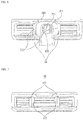
- FIG. 6 is a rear view of a razor according to an embodiment of the present disclosure.
- the rear surface of the razor blade cartridge 20 can be observed through the through-hole 31 when the handle 30 is coupled to the rear surface of the razor blade cartridge 20. Therefore, when washing water is injected through the second open area 311 which is disposed at a rear portion of the through-hole 31, the washing water is supplied through the first open area 310 which is disposed at a front portion of the through-hole 31 and is adjacent to the rear surface of the razor blade cartridge 20, and the razor 10 may be washed from the rear surface.
- the seating portion 211 may be observed through the through-hole 31. Therefore, the seating portion 211 may block a direct supply of washing water to the razor blade 23 seated on the blade housing 21, and thus washing of a central portion of the razor blade 23 may be somewhat insufficient.
- FIG. 7 is a rear view of a razor blade cartridge 40 according to another embodiment of the present disclosure.
- a seating portion 411 may be disposed at a position corresponding to a first hook 410 instead of being disposed at the center of the razor blade cartridge 40 such that a central portion of the razor blade cartridge 40 is exposed.
- FIG. 8 is a rear view of a razor according to another embodiment of the present disclosure.
- FIG. 8 it can be seen that, even after the handle 30 is coupled to the razor blade cartridge 40, a rear surface of the razor blade cartridge 40 that may be observed through the through-hole 31 is not blocked by the seating portion 411.
- the washing water when washing water is injected into the second open area 311 disposed at a rear portion of the razor, the washing water is discharged to the first open area 310 which is disposed adjacent to the razor blade cartridge 40, and since the seating portion 411 is not blocking the rear surface of the razor blade cartridge 40, the central portion of the razor blade 23 may be smoothly washed by the introduced washing water.
- the seating portion 211 of the razor blade 23 is disposed at both ends and the center of the razor blade cartridge 20 in the long direction of the razor blade cartridge 20 and thus holds the razor blade 23 from three spots.
- the seating portion 411 of the razor blade 23 is disposed at each position at the front surface of the blade housing 21 corresponding to a position of the first hook 210 and is disposed at both ends of the razor blade cartridge 40 in the long direction of the razor blade cartridge 40 and thus holds the razor blade 23 from four spots. Since the form of arrangement of the seating portions 411 of the other embodiment of FIG. 7 is equivalent to a case in which the seating portions 211, which have been disposed at the center of the blade housing 21, are moved toward both sides, the washing water supplied to the rear surface of the razor blade cartridge 40 through the through-hole 31 may wash the central portion of the razor blade cartridge 40 better.
Landscapes
- Life Sciences & Earth Sciences (AREA)
- Forests & Forestry (AREA)
- Engineering & Computer Science (AREA)
- Mechanical Engineering (AREA)
- Dry Shavers And Clippers (AREA)
- Packaging Of Annular Or Rod-Shaped Articles, Wearing Apparel, Cassettes, Or The Like (AREA)
Description
- Generally, a cartridge razor has a razor blade seated thereon and is provided together with a guard or the like so that the razor blade safely comes into contact with the skin. The cartridge razor includes a razor blade cartridge configured to suitably determine a degree to which the razor blade protrudes, and a handle coupled to the razor blade cartridge and provided to be hand-held and controlled by a user.
- Generally, for cleaning a razor blade and a cartridge, a method in which the entire cartridge is dipped in water and shaving debris is discharged and a method in which a front surface or a rear surface of the cartridge is washed with flowing water are used. However, when such methods are used, there are problems in that washing is not smoothly performed due to a narrow interval between razor blades and a complex internal structure of the cartridge, and shaving debris still remains inside the cartridge or is not properly discharged.
- In addition, generally, shaving is performed by intensively using a central portion of the cartridge which is formed long horizontally. However, there is a problem in that it is difficult to wash the central portion of the cartridge due to a handle connected to a rear surface of the cartridge.
- One aspect of the present disclosure provides a razor which is easy to wash and includes a through-hole connected to a cartridge via a handle.
- It should be noted that objects of the present disclosure are not limited to the above-mentioned objects, and other unmentioned objects of the present disclosure will be clearly understood by those skilled in the art from the following descriptions.
-
GB 1 377 134 A -
US 2001/003869 A1 discloses a safety razor with a detachable and replaceable shaving head. The razor is provided within an elongated handle having a channel located in the center of the handle with an opening at the base of said handle and an opening into the blade cavity whereby water can travel from the opening in the end of the handle to the shaving head. - To achieve the above objects, a razor according to an embodiment of the present disclosure includes a razor blade cartridge including at least one razor blade, and a handle coupled to a rear of the razor blade cartridge, the handle comprising a handle portion in the form of a long extending bar having a lower surface in the form of a hollow cavity, wherein:
- a through-hole which extends along at least a portion of a profile of the handle is formed on the handle;
- the through-hole includes a first open area facing the rear of the razor blade cartridge and a second open area formed at an upper surface of the handle, the second open area being opposite the first open area.
- In some embodiments, the through-hole may further include a third open area which is adjacent to the first open area and is open in a downward direction.
- In some embodiments, a first hook and a second hook may be formed at the rear of the razor blade cartridge, and the handle may include a first locking portion configured to be coupled to the first hook and a second locking portion configured to be coupled to the second hook.
- In some embodiments, a seating portion configured to secure the at least one razor blade is formed at a position which corresponds to a position of the first hook, and the handle may be formed such that a width of the handle increases from a handle portion of the handle toward an end of the handle coupled to the razor blade cartridge.
- In some embodiments, the razor blade cartridge may further include a blade housing in which the at least one razor blade is accommodated, and a cartridge frame coupled to the blade housing and configured to secure the at least one razor blade to the blade housing, wherein the blade housing includes a blade housing guard portion which protrudes past a front surface of the cartridge frame.
- A side surface of the blade housing may be externally exposed, and the razor blade cartridge may further include a guard portion disposed below a position of the razor blade at a surface at which the seating portion is disposed.
- According to embodiments of the present disclosure, there are at least the following advantageous effects.
- Since washing water is supplied through a through-hole which extends along a portion of a profile of a handle, washing of a razor blade cartridge can be facilitated.
- By providing an open surface which is more perforated downward, discharge of washing water and shaving debris can be facilitated.
- Advantageous effects according to the present disclosure are not limited to those mentioned above, and various other advantageous effects are included herein. Still other unmentioned effects should be clearly understood by those of ordinary skill in the art from the claims below.
-
-
FIG. 1 is a perspective view illustrating a form in which a razor handle and a cartridge are coupled according to an embodiment of the present disclosure. -
FIG. 2 is an exploded view of the razor handle and the cartridge according to an embodiment of the present disclosure. -
FIG. 3 is a perspective view illustrating a form in which the razor handle and the cartridge are separated according to an embodiment of the present disclosure. -
FIG. 4 is a perspective view illustrating the form, in which the razor handle and the cartridge are separated according to the embodiment of the present disclosure, in a direction opposite fromFIG. 2 . -
FIG. 5 is a rear view of a cartridge according to an embodiment of the present disclosure. -
FIG. 6 is a rear view of a razor according to an embodiment of the present disclosure. -
FIG. 7 is a rear view of a cartridge according to another embodiment of the present disclosure. -
FIG. 8 is a rear view of a razor according to another embodiment of the present disclosure. - Advantages and features of the present disclosure and a method of achieving the same should become clear with embodiments described in detail below with reference to the accompanying drawings. However, the present disclosure is not limited to the embodiments disclosed below and may be realized in various other forms. The present embodiments make the disclosure complete and are provided to completely inform one of ordinary skill in the art to which the present disclosure pertains of the scope of the disclosure. The present disclosure is defined only by the scope of the claims. Like reference numerals refer to like elements throughout.
- Unless otherwise defined, all terms including technical and scientific terms used herein have the same meaning as commonly understood by one of ordinary skill in the art to which the present disclosure pertains. Terms, such as those defined in commonly used dictionaries, are not to be construed in an idealized or overly formal sense unless expressly so defined herein.
- Terms used herein are for describing the embodiments and are not intended to limit the present disclosure. In the present specification, a singular expression includes a plural expression unless the context clearly indicates otherwise. "Comprises" and/or "comprising" used herein do not preclude the existence or the possibility of adding one or more elements other than those mentioned.
- In addition, embodiments herein will be described with reference to cross-sectional views and/or schematic views, which are ideal exemplary views of the present disclosure. Therefore, the form of an exemplary view may be deformed due to a manufacturing technique and/or an allowable error. In addition, in each drawing of the present disclosure, each element may have been somewhat enlarged or reduced in consideration of convenience of description. Like reference numerals refer to like elements throughout, and "and/or" includes each mentioned item and all of one or more combinations of the mentioned items.
- Spatially relative terms are intended to encompass different orientations of elements in use or operation in addition to the orientation depicted in the drawings. An element may be oriented in a different direction, and accordingly, spatially relative terms may be interpreted according to orientations.
- Hereinafter, configurations of exemplary embodiments of the present disclosure will be described in detail with reference to the accompanying drawings.
-
FIG. 1 is a perspective view illustrating a form in which a razor handle 30 and arazor blade cartridge 20 are coupled according to an embodiment of the present disclosure. - Referring to
FIG. 1 , a razor according to an embodiment of the present disclosure includes thehandle 30 and therazor blade cartridge 20. Thehandle 30 is coupled to therazor blade cartridge 20 using a hook coupling method. This will be described in detail below. - The
handle 30 of the razor includes ahandle portion 32 which is in the form of a long extending bar so as to be held and used for the purpose of manipulating the razor by a user, and one end which is coupled to therazor blade cartridge 20 and has a through-hole 31 formed therein. - Since the
handle portion 32 has to provide a suitable grip feeling to the user, regular concave and convex patterns are formed at a side surface of thehandle portion 32 in a direction which is perpendicular to a longitudinal direction of the razor such that a surface area in contact with the user's hand is increased and a frictional force is increased. In this way, the razor is prevented from easily falling out of the user's hand even in a shaving environment in which water and a large amount of a lubricating liquid such as shaving foam and shaving gel are used. Since a lower surface of thehandle portion 32 is irrelevant to the provision of a grip feeling, the lower surface may be configured in the form of a hollow cavity. Therefore, simplification of a manufacturing process and saving of materials can be achieved. - One end of the
handle 30 is coupled to therazor blade cartridge 20. Thehandle 30 may be formed in a straight shape and have the cartridge disposed at the one end thereof to be perpendicular to a longitudinal direction of thehandle 30. However, in this case, since there is an inconvenience in that the user has to perform shaving by moving his or her hand in a horizontal direction, the one end of thehandle 30 may be configured in the form that is bent at a predetermined angle from an advancing direction of thehandle portion 32 so that a cutting surface of therazor blade cartridge 20 naturally comes into contact with the skin to be shaved when the user naturally holds the razor. - The through-
hole 31 is formed along a profile of thehandle 30 at the one end of thehandle 30. The through-hole 31 may extend along at least a portion of the profile of thehandle 30, and an open surface is present at each of an upper surface and a lower surface of thehandle 30 and passes through thehandle 30. A detailed configuration of the through-hole 31 will be described below with reference toFIGS. 3 and4 . - The
handle 30 of the razor according to an embodiment of the present disclosure may be formed such that a transverse cross-sectional area of thehandle 30 progressively widens from thehandle portion 32 toward therazor blade cartridge 20. Therefore, user convenience can be improved by configuring thehandle portion 32 of thehandle 30 to have a transverse cross-sectional area that is suitable for thehandle portion 32 to be used while being gripped by the user's hand and by configuring the one end of thehandle 30 to have a transverse cross-sectional area that is suitable for the one end of thehandle 30 to be coupled to therazor blade cartridge 20. -
FIG. 2 is an exploded view of the razor handle 30 and therazor blade cartridge 20 according to an embodiment of the present disclosure. - Referring to
FIG. 2 , therazor blade cartridge 20 includes ablade housing 21, at least onerazor blade 23, and acartridge frame 22 and may further include a guard portion. - The
blade housing 21 may accommodate the at least onerazor blade 23, and therazor blade 23 is inserted into aseating portion 211 disposed at a front portion of theblade housing 21. A lower end of therazor blade 23 is inserted into theseating portion 211 such that theseating portion 211 fixes therazor blade 23 to theblade housing 21. It is not necessary for theseating portion 211 to be formed throughout theentire blade housing 21, and it is sufficient as long as theseating portion 211 is able to fix therazor blade 23 to the extent that therazor blade 23 is fixed without being detached from theblade housing 21 and is able to withstand a force applied during cutting such that shaving is smoothly performed. Therefore, as illustrated inFIG. 2 , theseating portion 211 may be disposed at both ends and the center of theblade housing 21 in a long direction of theblade housing 21. The arrangement of theseating portion 211 is not limited thereto, and various embodiments such as an embodiment in which theseating portion 211 is disposed at each of four positions at equal intervals in the long direction of theblade housing 21 may be possible. The arrangement of theseating portion 211 which is different from the above embodiment will be described below in description of another embodiment of the present disclosure with reference toFIG. 6 . - Two
razor blades 23 and twoseating portions 211 are respectively adjacently disposed in a short direction of theblade housing 21 in the above embodiment of the present disclosure, but the number ofrazor blades 23 andseating portions 211 is not limited thereto. The number ofrazor blades 23 may be 1 or greater, and the number ofseating portions 211 is determined corresponding to the maximum number ofrazor blades 23 desired to be coupled. - A portion of the
blade housing 21 may be configured to protrude forward below theseating portion 211. This portion may be configured to further protrude forward past a front surface of thecartridge frame 22 when theblade housing 21 is coupled to thecartridge frame 22 and may serve as ablade housing guard 213. Theblade housing guard 213 may serve as a protrusion with which or to which theblade housing 21 additionally comes into contact or is locked in order to be more firmly coupled to thecartridge frame 22, or may also serve as a guard that comes into contact with the skin first during shaving before therazor blade 23 and determines a cutting surface. Unlike a conventional situation in which a guard portion is formed in the separately-assembledcartridge frame 22 or a separate guard component is coupled and installed therein, the guard is disposed in theblade housing 21, which is the same component as theseating portion 211 on which therazor blade 23 is seated. Therefore, in comparison to a conventional razor in which it is difficult to form a desired height difference between therazor blade 23 and the guard and tolerance occurs during manufacture and assembly, it is easy to adjust a height difference between therazor blade 23 and the guard and thus advantageous in forming a desired cutting surface. - Side surfaces 214 of the blade housing are surfaces disposed at sides of the
blade housing 21. The side surfaces 214 may be configured as two surfaces parallel to each other so that the user is able to easily grip therazor blade cartridge 20, without therazor blade cartridge 20 being slipped from the user's hand, when the user couples or separates therazor blade cartridge 20 and thehandle 30 to or from each other. Alternatively, the side surfaces 214 may be configured to be exposed or protrude sideward even after the side surfaces 214 are coupled to thecartridge frame 22. - To cover the
blade housing 21 and allow therazor blade 23 to be exposed forward, thecartridge frame 22 is formed such that a central portion excluding an outer periphery is open. - The
cartridge frame 22 is coupled from a front surface of theblade housing 21. In the coupling process, both side ends of the front surface of thecartridge frame 22 are coupled to press therazor blade 23, which is inserted into theblade housing 21 and theseating portion 211, toward a rear surface of therazor blade cartridge 20. Therefore, a lower portion of therazor blade 23 being inserted into theseating portion 211 may not alone firmly secure therazor blade 23, but by thecartridge frame 22 being firmly coupled and fixed to theblade housing 21, therazor blade 23 may also be firmly secured. The shape of the inner surfaces of both side ends of the front surface of thecartridge frame 22 and the shape of side ends of the front surface of theblade housing 21 are formed to correspond to each other so that theblade housing 21 and thecartridge frame 22 may be easily coupled. - A
frame guard 221 may be formed at a lower end of the front surface of thecartridge frame 22 and serve to determine a cutting surface, or may be formed as a comb guard and serve to brush and align facial hair desired to be cut. However, the form and position of theframe guard 221 are not limited thereto. Theframe guard 221 may also be disposed at an upper end of the front surface of thecartridge frame 22 or may have forms other than the comb guard form. - A lubricating
band 24 may be disposed at a lower end of a front portion of thecartridge frame 22 and provide lubrication during shaving. However, this is merely one embodiment, and thelubricating band 24 may also be disposed at an upper end of the front portion of thecartridge frame 22. - For the
handle 30 to be coupled to the rear surface of therazor blade cartridge 20, therazor blade cartridge 20 of the razor according to an embodiment of the present disclosure includes afirst hook 210 formed at theblade housing 21, and asecond hook 220 is disposed at thecartridge frame 22 and made to correspond to thehandle 30. - The
first hook 210 is a hook disposed at a rear surface of theblade housing 21. Thefirst hook 210 may be disposed perpendicular to the direction in which therazor blade 23 is arranged, and may protrude rearward from the rear surface of therazor blade cartridge 20 to be coupled to a side surface of the one end of thehandle 30. Thefirst hook 210 may include two parallel side hooks having a distance therebetween which is similar to a size of the one end of thehandle 30. Therefore, the side hooks may hold both side surfaces of the one end of thehandle 30 toward the inside of thehandle 30 and may fix thehandle 30 to therazor blade cartridge 20. - The
second hook 220 is a hook disposed at a rear surface of thecartridge frame 22. Thesecond hook 220 may be disposed at an upper end of the rear surface of thecartridge frame 22, may extend to be parallel to the direction in which therazor blade 23 is arranged, and may protrude rearward to be coupled to an upper surface of the one end of thehandle 30. - The
first hook 210 and thesecond hook 220 have been described as members which protrude to fix a surface of the one end of thehandle 30, but the meaning of the expression "hook" is not limited thereto. A structure other than the structure described herein, such as the form of a groove capable of accommodating a protrusion disposed at one end of thehandle 30, may be used for the hooks as long as the structure is able to fix one end of thehandle 30 and one end of therazor blade cartridge 20 to each other by bring the two in contact and engaging the two, and the structure is able to correspond to a structure of locking portions disposed at thehandle 30. - A
first locking portion 34 and asecond locking portion 35 which correspond to thefirst hook 210 and thesecond hook 220, respectively, are formed at the one end of thehandle 30. - The
first locking portion 34 is disposed at a side surface of a firstopen area 310, which is one side opening of the through-hole 31 at the one end of thehandle 30, and protrudes toward the side of thehandle 30. A length of thefirst locking portion 34 is formed such that thefirst locking portion 34 corresponds to thefirst hook 210 disposed at the rear surface of theblade housing 21. When thefirst hook 210 includes two side hooks, the number offirst locking portions 34 correspond to the number of side hooks, and an interval between thefirst locking portions 34 correspond to an interval between the side hooks. - The
second locking portion 35 is disposed at an upper surface of the firstopen area 310, which is the one side opening of the through-hole 31 at the one end of thehandle 30, and protrudes toward the top of thehandle 30. The form and position of thesecond locking portion 35 are determined such that thesecond locking portion 35 corresponds to thesecond hook 220 during coupling. - The above-mentioned structure is merely one embodiment, and coupling structures other than the hooks may be used as long as the structures are evident to those of ordinary skill in the art. The position of the
second hook 220 may also be changed to a lower end of the rear surface of thecartridge frame 22, and the position of thesecond locking portion 35 may be changed corresponding thereto. - A process in which the
handle 30 and therazor blade cartridge 20, which are separate from each other, are coupled and an appearance of the through-hole 31 will be described with reference toFIGS. 1 ,3 , and4 . -
FIG. 3 is a perspective view illustrating a form in which the razor handle 30 and therazor blade cartridge 20 are separated according to an embodiment of the present disclosure, andFIG. 4 is a perspective view illustrating the form, in which the razor handle 30 and therazor blade cartridge 20 are separated according to the embodiment of the present disclosure, in a direction opposite fromFIG. 2 . - Referring to
FIGS. 1 ,3 , and4 , thefirst hook 210 corresponds to thefirst locking portion 34 and is engaged therewith during coupling while thesecond hook 220 corresponds to thesecond locking portion 35 and is engaged therewith during coupling. - When the rear surface of the
razor blade cartridge 20 and the one end of thehandle 30 are brought into contact and then an external force is applied from each one toward the other, thefirst locking portion 34 is pushed into a space between thefirst hook 210 and the rear surface of theblade housing 21 and is locked to thefirst hook 210 and fixed so as not to be detached in a long direction of therazor blade cartridge 20 and a direction in which the front and rear surfaces of therazor blade cartridge 20 face each other. Simultaneously, thesecond locking portion 35 is pushed into a space between thesecond hook 220 and the rear surface of thecartridge frame 22 and is locked to thesecond hook 220 and fixed so as not to be detached in the short direction of therazor blade cartridge 20 and the direction in which the front and rear surfaces of therazor blade cartridge 20 face each other. - Therefore, due to the coupling between the
first hook 210 and thefirst locking portion 34, thehandle 30 is restricted from being detached in the long direction of therazor blade cartridge 20; due to the coupling between thesecond hook 220 and thesecond locking portion 35, thehandle 30 is restricted from being detached in the short direction of therazor blade cartridge 20; and due to thefirst hook 210 and thesecond hook 220 being coupled to thefirst locking portion 34 and thesecond locking portion 35, respectively, thehandle 30 is prevented from being detached in the direction in which the front and rear surfaces of therazor blade cartridge 20 face each other. In this way, when an external force is applied due to attempting to detach a cap in the short direction of therazor blade cartridge 20 or performing shaving in the short direction of therazor blade cartridge 20, the risk that therazor blade cartridge 20 might be detached from thehandle 30 may be eliminated. - In addition, since the
first hook 210 disposed at theblade housing 21 is not the only one coupled to thehandle 30, and thesecond hook 220 disposed at thecartridge frame 22 is involved in the coupling between therazor blade cartridge 20 and thehandle 30, theblade housing 21 and thecartridge frame 22 are more firmly fixed to each other due to the coupling between therazor blade cartridge 20 and thehandle 30. - For smooth coupling between the one end of the
handle 30 and the hooks of the rear surface of therazor blade cartridge 20, thefirst hook 210 and thesecond hook 220 may be formed to be tapered in a direction from the front surface to the rear surface of therazor blade cartridge 20. Corresponding to this, thefirst locking portion 34 and thesecond locking portion 35 of the one end of thehandle 30 may also be formed to be tapered in a direction from thehandle portion 32 of thehandle 30 toward therazor blade cartridge 20. Therefore, when the hooks or locking portions are formed to be tapered and form an inclined surface, when the locking portions are inserted into the rear surface of therazor blade cartridge 20, the locking portions may easily enter the rear surface and be coupled thereto along the inclined surface with a small force. - Referring to
FIGS. 3 and4 , the firstopen area 310, a secondopen area 311, and a thirdopen area 312, which are one-side openings of the through-hole 31 of the razor handle 30 of an embodiment of the present disclosure, may be seen. - The first
open area 310 is formed at the one end of thehandle 30 so as to face therazor blade cartridge 20, and the secondopen area 311 is formed at the upper surface of thehandle 30. Therefore, the through-hole 31 has a structure that connects the firstopen area 310 and the secondopen area 311 and passes through thehandle 30, and the through-hole 31 extends along at least a portion of the profile of thehandle 30. - The second
open area 311 is disposed opposite the firstopen area 310. Here, being disposed opposite means that a path formed through thehandle 30 from the firstopen area 310 to the secondopen area 311 becomes the through-hole 31 and thus the firstopen area 310 and the secondopen area 311 become one opening and the other opening, which is at the opposite side of the one opening. - Since the through-
hole 31 has a structure in which the both openings are formed at the one end and the upper surface of thehandle 30, when a liquid such as water is introduced through one open area, the liquid is discharged through the other open area. Therefore, when washing water is injected through the secondopen area 311 using such a structure, the washing water may be discharged through the firstopen area 310, which is adjacent to the rear surface of therazor blade cartridge 20, the washing water may be supplied to therazor blade cartridge 20, and washing may be performed. Particularly, since a central portion of therazor blade cartridge 20 is not smoothly washed using a general method, the central portion may be easily washed using the above-described method. Such a characteristic may be combined with the feature of thehandle 30 of the embodiment of the present disclosure in that the transverse cross-sectional area of thehandle 30 progressively widens from thehandle portion 32 of thehandle 30 toward the firstopen area 310 facing therazor blade cartridge 20, and the combination may further improve the washing efficiency. - The through-
hole 31 may further include the thirdopen area 312 which is adjacent to the firstopen area 310 and is open in a downward direction when the razor is held by a user. Therefore, when washing water is injected into the secondopen area 311, while the washing water is supplied to therazor blade cartridge 20 through the firstopen area 310, a portion of the washing water may also be supplied to the thirdopen area 312 so that shaving debris discharged from therazor blade cartridge 20 may be discharged by washing using the washing water. - However, a washing method is not limited to that described above in which washing water is injected into the second
open area 311. A washing method in which washing water is injected through the front surface of therazor blade cartridge 20 and the washing water and shaving debris are discharged to the firstopen area 310 and then subsequently discharged to the secondopen area 311 and the thirdopen area 312, a washing method in which washing water is injected into the thirdopen area 312 and the washing water is supplied to the rear surface of therazor blade cartridge 20 through the firstopen area 310 such that shaving debris is discharged to the front surface of therazor blade cartridge 20, or the like may be selected by the user. -
FIG. 5 is a rear view of therazor blade cartridge 20 according to an embodiment of the present disclosure. - Referring to
FIG. 5 , thefirst hook 210 may not be formed across theentire blade housing 21 in the short direction of theblade housing 21, and ahook groove 212 may be formed at a lower end of thefirst hook 210. When therazor blade cartridge 20 and thehandle 30 are coupled, alocking extension portion 36 that may be seen in thehandle 30 ofFIG. 2 is disposed in thehook groove 212. Since thelocking extension portion 36 is disposed adjacent to thefirst locking portion 34 and extends along the profile of thehandle 30, the lockingextension portion 36 is also locked to thefirst hook 210 in the short direction of therazor blade cartridge 20. Therefore, together with thesecond locking portion 35, the lockingextension portion 36 serves to prevent thehandle 30 from being detached in the short direction of therazor blade cartridge 20. -
FIG. 6 is a rear view of a razor according to an embodiment of the present disclosure. - Referring to
FIG. 6 , it can be seen that the rear surface of therazor blade cartridge 20 can be observed through the through-hole 31 when thehandle 30 is coupled to the rear surface of therazor blade cartridge 20. Therefore, when washing water is injected through the secondopen area 311 which is disposed at a rear portion of the through-hole 31, the washing water is supplied through the firstopen area 310 which is disposed at a front portion of the through-hole 31 and is adjacent to the rear surface of therazor blade cartridge 20, and therazor 10 may be washed from the rear surface. - Meanwhile, as can be seen through the through-
hole 31 from the rear of therazor 10, theseating portion 211 may be observed through the through-hole 31. Therefore, theseating portion 211 may block a direct supply of washing water to therazor blade 23 seated on theblade housing 21, and thus washing of a central portion of therazor blade 23 may be somewhat insufficient. -
FIG. 7 is a rear view of arazor blade cartridge 40 according to another embodiment of the present disclosure. - Therefore, referring to
FIG. 7 , in order to solve the above-described problem in that washing may be insufficient, aseating portion 411 may be disposed at a position corresponding to afirst hook 410 instead of being disposed at the center of therazor blade cartridge 40 such that a central portion of therazor blade cartridge 40 is exposed. -
FIG. 8 is a rear view of a razor according to another embodiment of the present disclosure. - Referring to
FIG. 8 , it can be seen that, even after thehandle 30 is coupled to therazor blade cartridge 40, a rear surface of therazor blade cartridge 40 that may be observed through the through-hole 31 is not blocked by theseating portion 411. According to another embodiment of the present disclosure, when washing water is injected into the secondopen area 311 disposed at a rear portion of the razor, the washing water is discharged to the firstopen area 310 which is disposed adjacent to therazor blade cartridge 40, and since theseating portion 411 is not blocking the rear surface of therazor blade cartridge 40, the central portion of therazor blade 23 may be smoothly washed by the introduced washing water. - In
FIG. 5 , theseating portion 211 of therazor blade 23 is disposed at both ends and the center of therazor blade cartridge 20 in the long direction of therazor blade cartridge 20 and thus holds therazor blade 23 from three spots. - In
FIG. 7 , theseating portion 411 of therazor blade 23 is disposed at each position at the front surface of theblade housing 21 corresponding to a position of thefirst hook 210 and is disposed at both ends of therazor blade cartridge 40 in the long direction of therazor blade cartridge 40 and thus holds therazor blade 23 from four spots. Since the form of arrangement of theseating portions 411 of the other embodiment ofFIG. 7 is equivalent to a case in which theseating portions 211, which have been disposed at the center of theblade housing 21, are moved toward both sides, the washing water supplied to the rear surface of therazor blade cartridge 40 through the through-hole 31 may wash the central portion of therazor blade cartridge 40 better. - Those of ordinary skill in the art to which the present disclosure pertains should understand that the present disclosure may be practiced in other specific forms without changing the technical idea or essential features thereof. Therefore, the embodiments described herein are illustrative in all aspects and should not be understood as limiting. The scope of the present disclosure is shown by the claims below rather than the detailed description given above, and all changes or modifications derived from the meaning and the scope of the claims should be interpreted as belonging to the scope of the present disclosure.
- Although the present disclosure has been described above in relation to the above-mentioned exemplary embodiments thereof, the present disclosure may be modified or changed in various ways without departing from the scope of the attached claims.
Claims (8)
- A razor comprising:a razor blade cartridge (20) including at least one razor blade (23); anda handle (30) coupled to a rear of the razor blade cartridge (20), the handle (30) comprising a handle portion (32) in the form of a long extending bar having a lower surface in the form of a hollow cavity, wherein:a through-hole (31) which extends along at least a portion of a profile of the handle (30) is formed on the handle;the through-hole (31) includes a first open area (310) facing the rear of the razor blade cartridge (20) and a second open area (311) formed at an upper surface of the handle, the second open area (311) being opposite the first open area.
- The razor of claim 1, wherein the through-hole further includes a third open area (312) which is adjacent to the first open area (310).
- The razor of claim 1, wherein:a first hook (210) and a second hook (220) are formed at the rear of the razor blade cartridge (20); andthe handle (30) includes a first locking portion (34) configured to be coupled to the first hook (210) and a second locking portion (35) configured to be coupled to the second hook (220).
- The razor of claim 3, wherein the razor blade cartridge (20) comprises a seating portion (211) configured to secure the at least one razor blade (23) formed at a position which corresponds to a position of the first hook (210).
- The razor of claim 1, wherein a width of the handle (30) increases from a handle portion (32) of the handle toward an end of the handle coupled to the razor blade cartridge (20).
- The razor of claim 1, wherein the razor blade cartridge (20) further includes:a blade housing (21) in which the at least one razor blade (23) is accommodated; anda cartridge frame (22) coupled to the blade housing (21) and configured to secure the at least one razor blade (23) to the blade housing (21),wherein the blade housing (21) includes a blade housing guard portion which protrudes past a front surface of the cartridge frame (22) in a direction perpendicular to the front surface.
- The razor of claim 6, wherein a side surface of the blade housing (21) is exposed to the outside.
- The razor of claim 4, wherein the razor blade cartridge (20) further includes a guard portion in front of the razor blade (23) in a shaving direction.
Applications Claiming Priority (2)
| Application Number | Priority Date | Filing Date | Title |
|---|---|---|---|
| KR1020160079379A KR101730415B1 (en) | 2016-06-24 | 2016-06-24 | Razor with perforated handle |
| PCT/KR2016/008489 WO2017222107A1 (en) | 2016-06-24 | 2016-08-02 | Razor comprising handle with through-hole |
Publications (3)
| Publication Number | Publication Date |
|---|---|
| EP3476559A1 EP3476559A1 (en) | 2019-05-01 |
| EP3476559A4 EP3476559A4 (en) | 2020-02-19 |
| EP3476559B1 true EP3476559B1 (en) | 2021-06-30 |
Family
ID=58704962
Family Applications (1)
| Application Number | Title | Priority Date | Filing Date |
|---|---|---|---|
| EP16906382.3A Active EP3476559B1 (en) | 2016-06-24 | 2016-08-02 | Razor comprising handle with through-hole |
Country Status (7)
| Country | Link |
|---|---|
| US (1) | US10875199B2 (en) |
| EP (1) | EP3476559B1 (en) |
| JP (1) | JP6853281B2 (en) |
| KR (1) | KR101730415B1 (en) |
| CN (1) | CN109153138B (en) |
| ES (1) | ES2881650T3 (en) |
| WO (1) | WO2017222107A1 (en) |
Families Citing this family (5)
| Publication number | Priority date | Publication date | Assignee | Title |
|---|---|---|---|---|
| EP3771530B1 (en) * | 2019-07-31 | 2024-08-28 | BIC Violex Single Member S.A. | Mechanical assembly of a skin care device, skin care device and process for manufacturing thereof |
| JP7146288B2 (en) | 2020-01-29 | 2022-10-04 | 匠技研株式会社 | Blade holder for cutting chain food |
| US20220088810A1 (en) * | 2020-09-21 | 2022-03-24 | Beauty Perspectives, LLC | Razor handle |
| JP6825162B1 (en) * | 2020-10-30 | 2021-02-03 | 株式会社貝印刃物開発センター | razor |
| WO2022091425A1 (en) * | 2020-10-30 | 2022-05-05 | 株式会社貝印刃物開発センター | Razor |
Family Cites Families (51)
| Publication number | Priority date | Publication date | Assignee | Title |
|---|---|---|---|---|
| US3703764A (en) | 1971-03-15 | 1972-11-28 | Gillette Co | Razor blade assembly |
| ES400641A1 (en) | 1971-03-15 | 1975-01-16 | Gillette Co | Razors |
| US4094063A (en) * | 1976-12-15 | 1978-06-13 | The Gillette Company | Razor assembly with pivotally mounted cartridge |
| JPS5951149B2 (en) | 1977-08-10 | 1984-12-12 | 株式会社日立製作所 | Bipolar semiconductor memory device |
| US4212103A (en) * | 1978-10-27 | 1980-07-15 | Schuman Hoole April | Razor |
| US4228586A (en) * | 1979-02-23 | 1980-10-21 | Thierry Timothy T | Shaving apparatus |
| US4308663A (en) * | 1979-12-31 | 1982-01-05 | Warner-Lambert Company | Razor handle with latch for pivotable cartridge |
| US4392303A (en) * | 1979-12-31 | 1983-07-12 | Warner-Lambert Company | One-piece razor handle |
| JPS596675B2 (en) * | 1980-10-20 | 1984-02-14 | 株式会社貝印刃物開発センター | safety razor |
| NZ202924A (en) * | 1982-01-27 | 1986-06-11 | Wilkinson Sword Ltd | A razor blade assembly |
| US4492024A (en) * | 1982-09-17 | 1985-01-08 | The Gillette Company | Razor blade assembly |
| US4692986A (en) * | 1985-09-27 | 1987-09-15 | Warner Lambert Company | Razor cartridge with shaving aid |
| US4850107A (en) | 1988-10-04 | 1989-07-25 | Valliades John F | Razor assembly |
| DE69233729T2 (en) | 1991-11-27 | 2009-03-12 | The Gillette Co., Boston | shavers |
| US5335417A (en) * | 1992-07-27 | 1994-08-09 | Genero Claude P | Hand razor |
| KR950004998B1 (en) * | 1992-11-27 | 1995-05-17 | 고광철 | Wet razor having air-washing device |
| US5265337A (en) * | 1992-12-21 | 1993-11-30 | Robert Lowder | Self-cleaning razor |
| US6212777B1 (en) | 1993-09-29 | 2001-04-10 | The Gillette Company | Safety razors |
| US5402574A (en) * | 1994-05-20 | 1995-04-04 | Milner; Joshua P. | Shaving apparatus |
| ATE186489T1 (en) | 1994-10-03 | 1999-11-15 | Gillette Co | WET SHAVING CONSTRUCTION |
| US6516518B1 (en) | 1996-01-12 | 2003-02-11 | The Gillette Company | Razor blade unit |
| AU2129597A (en) * | 1996-03-27 | 1997-10-17 | Warner-Lambert Company | Shaving system with uniform shaving forces |
| US6041926A (en) | 1996-04-10 | 2000-03-28 | The Gillette Company | Dispensing razor blade cartridges used with a handle |
| US5956851A (en) | 1996-04-10 | 1999-09-28 | The Gillette Company | Shaving system including handle and replaceable cartridges |
| US5787586A (en) * | 1996-04-10 | 1998-08-04 | The Gillette Company | Shaving system and method |
| US5687485A (en) | 1996-05-15 | 1997-11-18 | The Gillette Company | Razor handle |
| US5956848A (en) | 1997-02-27 | 1999-09-28 | The Gillette Company | Shaving system |
| US6499218B2 (en) * | 1998-12-28 | 2002-12-31 | Manual Antonio Rocha | Four sided dual blade shaver |
| US6305082B1 (en) * | 1999-06-18 | 2001-10-23 | Vincent F. Troncoso | Flush out cleanable razor |
| US6684513B1 (en) | 2000-02-29 | 2004-02-03 | The Gillette Company | Razor blade technology |
| US7043842B1 (en) * | 2003-03-27 | 2006-05-16 | William Taylor | Automatic rinsing razor system |
| US7007390B2 (en) * | 2003-09-10 | 2006-03-07 | Bradley Mislove | Water irrigated and articulated razor |
| GB2408010B (en) | 2003-11-17 | 2007-03-28 | Knowledge & Merchandising Inc | Shaving product |
| CL2008001727A1 (en) * | 2007-06-12 | 2010-02-05 | Gillette Co | Razor comprising a handle with a proximal and a distal end, an adapter neck pivotally attached to the proximal end of the handle, a pump attached to a feeder channel, a cartridge connection fork, and a shaver cartridge. to shave. |
| KR20090067229A (en) * | 2007-12-21 | 2009-06-25 | 허정범 | Cream shaver |
| US8209867B2 (en) | 2008-10-02 | 2012-07-03 | The Gillette Company | Shaving razors and cartridges |
| KR20100091622A (en) * | 2009-02-11 | 2010-08-19 | 주식회사 도루코 | Integrated cartridge |
| US20130081276A1 (en) | 2011-09-30 | 2013-04-04 | Kevin James Wain | Biasing shaving razors |
| US20130291390A1 (en) * | 2012-05-01 | 2013-11-07 | The Gillette Company | Handle for a shaving razor |
| US8887401B2 (en) * | 2012-06-18 | 2014-11-18 | Anthony J. Oxford | Rotating blade assembly |
| US9283685B2 (en) * | 2012-07-26 | 2016-03-15 | Shavelogic, Inc. | Pivoting razors |
| WO2014051842A1 (en) * | 2012-09-27 | 2014-04-03 | Shavelogic, Inc. | Shaving systems |
| WO2014051843A1 (en) * | 2012-09-28 | 2014-04-03 | Shavelogic, Inc. | Shaving systems |
| US20140116211A1 (en) * | 2012-10-25 | 2014-05-01 | Shavelogic, Inc. | Dedicated Attachment Systems for Consumer Products |
| JP6053955B2 (en) * | 2012-12-21 | 2016-12-27 | ビック・バイオレクス・エス・エー | Shaver with replaceable cartridge, cartridge and head handle assembly for such a shaver |
| EP2934828B1 (en) * | 2012-12-21 | 2019-02-06 | BIC-Violex S.A. | Shaver with interchangeable cartridge and head and handle assembly for such shaver |
| JP6293464B2 (en) * | 2013-11-27 | 2018-03-14 | 株式会社貝印刃物開発センター | razor |
| WO2016019975A1 (en) * | 2014-08-04 | 2016-02-11 | Bic-Violex Sa | A razor handle comprising an insert freely movable within a cavity and razor comprising such a razor handle |
| EP3372358B1 (en) * | 2017-03-10 | 2021-07-21 | The Gillette Company LLC | Razor handle |
| US11141873B2 (en) * | 2017-04-18 | 2021-10-12 | The Gillette Company Llc | Shaving razor system |
| US20190084169A1 (en) * | 2017-09-15 | 2019-03-21 | Little Acorn Shave Company Inc. | Razor handle |
-
2016
- 2016-06-24 KR KR1020160079379A patent/KR101730415B1/en active IP Right Grant
- 2016-08-02 JP JP2018567663A patent/JP6853281B2/en active Active
- 2016-08-02 CN CN201680085421.6A patent/CN109153138B/en active Active
- 2016-08-02 ES ES16906382T patent/ES2881650T3/en active Active
- 2016-08-02 WO PCT/KR2016/008489 patent/WO2017222107A1/en unknown
- 2016-08-02 US US16/313,099 patent/US10875199B2/en active Active
- 2016-08-02 EP EP16906382.3A patent/EP3476559B1/en active Active
Also Published As
| Publication number | Publication date |
|---|---|
| KR101730415B1 (en) | 2017-04-26 |
| JP2019518570A (en) | 2019-07-04 |
| WO2017222107A1 (en) | 2017-12-28 |
| US10875199B2 (en) | 2020-12-29 |
| EP3476559A4 (en) | 2020-02-19 |
| CN109153138A (en) | 2019-01-04 |
| ES2881650T3 (en) | 2021-11-30 |
| US20190224873A1 (en) | 2019-07-25 |
| EP3476559A1 (en) | 2019-05-01 |
| CN109153138B (en) | 2021-03-23 |
| JP6853281B2 (en) | 2021-03-31 |
Similar Documents
| Publication | Publication Date | Title |
|---|---|---|
| US11351688B2 (en) | Razor | |
| EP3476559B1 (en) | Razor comprising handle with through-hole | |
| KR102021555B1 (en) | A protective cover for a shaving cartridge, a shaving assembly, a razor, a method of shaving with such a razor and a method of manufacturing a protective cover | |
| ES2317215T3 (en) | SHAVING MACHINE WITH ADDITIONAL CUTTING BLADE. | |
| KR101082303B1 (en) | Razor | |
| KR102454956B1 (en) | Protectors for razor cartridges, shaving assemblies, wet razors, methods of using such wet razors and methods of making such protectors | |
| CA2276882C (en) | Device for trimming and shaping a beard or moustache | |
| US20240208093A1 (en) | Razor cartridge | |
| JP6865726B2 (en) | Razor cartridge and razor cartridge assembly | |
| BR112016023790B1 (en) | STATIONARY BLADE, BLADES SET, METHOD FOR THE MANUFACTURING OF A STATIONARY BLADE COMPOSED OF METAL AND PLASTIC, AND METHOD FOR THE MANUFACTURING OF A BLADES SET | |
| ES2927451T3 (en) | trimmer shaver | |
| KR20120026017A (en) | The two sided razor for rough and finishing shave | |
| US7243428B2 (en) | Hair brush and replaceable cutting unit for hair brush | |
| KR20110001826U (en) | A hair dyeing device | |
| EP3960402B1 (en) | Razor cartridge | |
| CN220807471U (en) | Eyebrow pencil tool bit and eyebrow pencil of easily assembling | |
| KR100712367B1 (en) | Razor blade | |
| JP4065009B2 (en) | Haircut razor and haircut replacement razor | |
| JP4314434B2 (en) | Razor with spacer | |
| KR20240145918A (en) | razor assembly | |
| KR101597078B1 (en) | Haircutting scissor for creation of hair style | |
| JPH05123460A (en) | Linear type safety razor | |
| KR20010103120A (en) | scissors with razor and thinning function |
Legal Events
| Date | Code | Title | Description |
|---|---|---|---|
| STAA | Information on the status of an ep patent application or granted ep patent |
Free format text: STATUS: THE INTERNATIONAL PUBLICATION HAS BEEN MADE |
|
| PUAI | Public reference made under article 153(3) epc to a published international application that has entered the european phase |
Free format text: ORIGINAL CODE: 0009012 |
|
| STAA | Information on the status of an ep patent application or granted ep patent |
Free format text: STATUS: REQUEST FOR EXAMINATION WAS MADE |
|
| STAA | Information on the status of an ep patent application or granted ep patent |
Free format text: STATUS: REQUEST FOR EXAMINATION WAS MADE |
|
| 17P | Request for examination filed |
Effective date: 20190124 |
|
| AK | Designated contracting states |
Kind code of ref document: A1 Designated state(s): AL AT BE BG CH CY CZ DE DK EE ES FI FR GB GR HR HU IE IS IT LI LT LU LV MC MK MT NL NO PL PT RO RS SE SI SK SM TR |
|
| AX | Request for extension of the european patent |
Extension state: BA ME |
|
| DAV | Request for validation of the european patent (deleted) | ||
| DAX | Request for extension of the european patent (deleted) | ||
| REG | Reference to a national code |
Ref country code: DE Ref legal event code: R079 Ref document number: 602016060169 Country of ref document: DE Free format text: PREVIOUS MAIN CLASS: B26B0021400000 Ipc: B26B0021220000 |
|
| A4 | Supplementary search report drawn up and despatched |
Effective date: 20200117 |
|
| RIC1 | Information provided on ipc code assigned before grant |
Ipc: B26B 21/22 20060101AFI20200113BHEP Ipc: B26B 21/52 20060101ALI20200113BHEP |
|
| GRAP | Despatch of communication of intention to grant a patent |
Free format text: ORIGINAL CODE: EPIDOSNIGR1 |
|
| STAA | Information on the status of an ep patent application or granted ep patent |
Free format text: STATUS: GRANT OF PATENT IS INTENDED |
|
| INTG | Intention to grant announced |
Effective date: 20210209 |
|
| GRAS | Grant fee paid |
Free format text: ORIGINAL CODE: EPIDOSNIGR3 |
|
| GRAA | (expected) grant |
Free format text: ORIGINAL CODE: 0009210 |
|
| STAA | Information on the status of an ep patent application or granted ep patent |
Free format text: STATUS: THE PATENT HAS BEEN GRANTED |
|
| AK | Designated contracting states |
Kind code of ref document: B1 Designated state(s): AL AT BE BG CH CY CZ DE DK EE ES FI FR GB GR HR HU IE IS IT LI LT LU LV MC MK MT NL NO PL PT RO RS SE SI SK SM TR |
|
| REG | Reference to a national code |
Ref country code: CH Ref legal event code: EP |
|
| REG | Reference to a national code |
Ref country code: AT Ref legal event code: REF Ref document number: 1405925 Country of ref document: AT Kind code of ref document: T Effective date: 20210715 |
|
| REG | Reference to a national code |
Ref country code: DE Ref legal event code: R096 Ref document number: 602016060169 Country of ref document: DE |
|
| REG | Reference to a national code |
Ref country code: IE Ref legal event code: FG4D |
|
| REG | Reference to a national code |
Ref country code: LT Ref legal event code: MG9D |
|
| PG25 | Lapsed in a contracting state [announced via postgrant information from national office to epo] |
Ref country code: FI Free format text: LAPSE BECAUSE OF FAILURE TO SUBMIT A TRANSLATION OF THE DESCRIPTION OR TO PAY THE FEE WITHIN THE PRESCRIBED TIME-LIMIT Effective date: 20210630 Ref country code: BG Free format text: LAPSE BECAUSE OF FAILURE TO SUBMIT A TRANSLATION OF THE DESCRIPTION OR TO PAY THE FEE WITHIN THE PRESCRIBED TIME-LIMIT Effective date: 20210930 Ref country code: HR Free format text: LAPSE BECAUSE OF FAILURE TO SUBMIT A TRANSLATION OF THE DESCRIPTION OR TO PAY THE FEE WITHIN THE PRESCRIBED TIME-LIMIT Effective date: 20210630 |
|
| REG | Reference to a national code |
Ref country code: NL Ref legal event code: MP Effective date: 20210630 |
|
| REG | Reference to a national code |
Ref country code: AT Ref legal event code: MK05 Ref document number: 1405925 Country of ref document: AT Kind code of ref document: T Effective date: 20210630 |
|
| PG25 | Lapsed in a contracting state [announced via postgrant information from national office to epo] |
Ref country code: SE Free format text: LAPSE BECAUSE OF FAILURE TO SUBMIT A TRANSLATION OF THE DESCRIPTION OR TO PAY THE FEE WITHIN THE PRESCRIBED TIME-LIMIT Effective date: 20210630 Ref country code: RS Free format text: LAPSE BECAUSE OF FAILURE TO SUBMIT A TRANSLATION OF THE DESCRIPTION OR TO PAY THE FEE WITHIN THE PRESCRIBED TIME-LIMIT Effective date: 20210630 Ref country code: NO Free format text: LAPSE BECAUSE OF FAILURE TO SUBMIT A TRANSLATION OF THE DESCRIPTION OR TO PAY THE FEE WITHIN THE PRESCRIBED TIME-LIMIT Effective date: 20210930 Ref country code: LV Free format text: LAPSE BECAUSE OF FAILURE TO SUBMIT A TRANSLATION OF THE DESCRIPTION OR TO PAY THE FEE WITHIN THE PRESCRIBED TIME-LIMIT Effective date: 20210630 Ref country code: GR Free format text: LAPSE BECAUSE OF FAILURE TO SUBMIT A TRANSLATION OF THE DESCRIPTION OR TO PAY THE FEE WITHIN THE PRESCRIBED TIME-LIMIT Effective date: 20211001 |
|
| REG | Reference to a national code |
Ref country code: ES Ref legal event code: FG2A Ref document number: 2881650 Country of ref document: ES Kind code of ref document: T3 Effective date: 20211130 |
|
| PG25 | Lapsed in a contracting state [announced via postgrant information from national office to epo] |
Ref country code: AT Free format text: LAPSE BECAUSE OF FAILURE TO SUBMIT A TRANSLATION OF THE DESCRIPTION OR TO PAY THE FEE WITHIN THE PRESCRIBED TIME-LIMIT Effective date: 20210630 Ref country code: EE Free format text: LAPSE BECAUSE OF FAILURE TO SUBMIT A TRANSLATION OF THE DESCRIPTION OR TO PAY THE FEE WITHIN THE PRESCRIBED TIME-LIMIT Effective date: 20210630 Ref country code: CZ Free format text: LAPSE BECAUSE OF FAILURE TO SUBMIT A TRANSLATION OF THE DESCRIPTION OR TO PAY THE FEE WITHIN THE PRESCRIBED TIME-LIMIT Effective date: 20210630 Ref country code: PT Free format text: LAPSE BECAUSE OF FAILURE TO SUBMIT A TRANSLATION OF THE DESCRIPTION OR TO PAY THE FEE WITHIN THE PRESCRIBED TIME-LIMIT Effective date: 20211102 Ref country code: NL Free format text: LAPSE BECAUSE OF FAILURE TO SUBMIT A TRANSLATION OF THE DESCRIPTION OR TO PAY THE FEE WITHIN THE PRESCRIBED TIME-LIMIT Effective date: 20210630 Ref country code: RO Free format text: LAPSE BECAUSE OF FAILURE TO SUBMIT A TRANSLATION OF THE DESCRIPTION OR TO PAY THE FEE WITHIN THE PRESCRIBED TIME-LIMIT Effective date: 20210630 Ref country code: SM Free format text: LAPSE BECAUSE OF FAILURE TO SUBMIT A TRANSLATION OF THE DESCRIPTION OR TO PAY THE FEE WITHIN THE PRESCRIBED TIME-LIMIT Effective date: 20210630 Ref country code: SK Free format text: LAPSE BECAUSE OF FAILURE TO SUBMIT A TRANSLATION OF THE DESCRIPTION OR TO PAY THE FEE WITHIN THE PRESCRIBED TIME-LIMIT Effective date: 20210630 |
|
| PG25 | Lapsed in a contracting state [announced via postgrant information from national office to epo] |
Ref country code: PL Free format text: LAPSE BECAUSE OF FAILURE TO SUBMIT A TRANSLATION OF THE DESCRIPTION OR TO PAY THE FEE WITHIN THE PRESCRIBED TIME-LIMIT Effective date: 20210630 |
|
| REG | Reference to a national code |
Ref country code: DE Ref legal event code: R097 Ref document number: 602016060169 Country of ref document: DE Ref country code: CH Ref legal event code: PL |
|
| PG25 | Lapsed in a contracting state [announced via postgrant information from national office to epo] |
Ref country code: MC Free format text: LAPSE BECAUSE OF FAILURE TO SUBMIT A TRANSLATION OF THE DESCRIPTION OR TO PAY THE FEE WITHIN THE PRESCRIBED TIME-LIMIT Effective date: 20210630 |
|
| REG | Reference to a national code |
Ref country code: BE Ref legal event code: MM Effective date: 20210831 |
|
| PG25 | Lapsed in a contracting state [announced via postgrant information from national office to epo] |
Ref country code: LI Free format text: LAPSE BECAUSE OF NON-PAYMENT OF DUE FEES Effective date: 20210831 Ref country code: DK Free format text: LAPSE BECAUSE OF FAILURE TO SUBMIT A TRANSLATION OF THE DESCRIPTION OR TO PAY THE FEE WITHIN THE PRESCRIBED TIME-LIMIT Effective date: 20210630 Ref country code: CH Free format text: LAPSE BECAUSE OF NON-PAYMENT OF DUE FEES Effective date: 20210831 |
|
| PLBE | No opposition filed within time limit |
Free format text: ORIGINAL CODE: 0009261 |
|
| STAA | Information on the status of an ep patent application or granted ep patent |
Free format text: STATUS: NO OPPOSITION FILED WITHIN TIME LIMIT |
|
| PG25 | Lapsed in a contracting state [announced via postgrant information from national office to epo] |
Ref country code: LU Free format text: LAPSE BECAUSE OF NON-PAYMENT OF DUE FEES Effective date: 20210802 Ref country code: AL Free format text: LAPSE BECAUSE OF FAILURE TO SUBMIT A TRANSLATION OF THE DESCRIPTION OR TO PAY THE FEE WITHIN THE PRESCRIBED TIME-LIMIT Effective date: 20210630 |
|
| 26N | No opposition filed |
Effective date: 20220331 |
|
| PG25 | Lapsed in a contracting state [announced via postgrant information from national office to epo] |
Ref country code: IT Free format text: LAPSE BECAUSE OF FAILURE TO SUBMIT A TRANSLATION OF THE DESCRIPTION OR TO PAY THE FEE WITHIN THE PRESCRIBED TIME-LIMIT Effective date: 20210630 Ref country code: IE Free format text: LAPSE BECAUSE OF NON-PAYMENT OF DUE FEES Effective date: 20210802 Ref country code: BE Free format text: LAPSE BECAUSE OF NON-PAYMENT OF DUE FEES Effective date: 20210831 |
|
| PG25 | Lapsed in a contracting state [announced via postgrant information from national office to epo] |
Ref country code: LT Free format text: LAPSE BECAUSE OF FAILURE TO SUBMIT A TRANSLATION OF THE DESCRIPTION OR TO PAY THE FEE WITHIN THE PRESCRIBED TIME-LIMIT Effective date: 20210630 |
|
| PG25 | Lapsed in a contracting state [announced via postgrant information from national office to epo] |
Ref country code: CY Free format text: LAPSE BECAUSE OF FAILURE TO SUBMIT A TRANSLATION OF THE DESCRIPTION OR TO PAY THE FEE WITHIN THE PRESCRIBED TIME-LIMIT Effective date: 20210630 |
|
| PG25 | Lapsed in a contracting state [announced via postgrant information from national office to epo] |
Ref country code: HU Free format text: LAPSE BECAUSE OF FAILURE TO SUBMIT A TRANSLATION OF THE DESCRIPTION OR TO PAY THE FEE WITHIN THE PRESCRIBED TIME-LIMIT; INVALID AB INITIO Effective date: 20160802 |
|
| PGFP | Annual fee paid to national office [announced via postgrant information from national office to epo] |
Ref country code: ES Payment date: 20230908 Year of fee payment: 8 |
|
| PG25 | Lapsed in a contracting state [announced via postgrant information from national office to epo] |
Ref country code: MK Free format text: LAPSE BECAUSE OF FAILURE TO SUBMIT A TRANSLATION OF THE DESCRIPTION OR TO PAY THE FEE WITHIN THE PRESCRIBED TIME-LIMIT Effective date: 20210630 |
|
| PG25 | Lapsed in a contracting state [announced via postgrant information from national office to epo] |
Ref country code: TR Free format text: LAPSE BECAUSE OF FAILURE TO SUBMIT A TRANSLATION OF THE DESCRIPTION OR TO PAY THE FEE WITHIN THE PRESCRIBED TIME-LIMIT Effective date: 20210630 |
|
| PGFP | Annual fee paid to national office [announced via postgrant information from national office to epo] |
Ref country code: GB Payment date: 20240613 Year of fee payment: 9 |
|
| PGFP | Annual fee paid to national office [announced via postgrant information from national office to epo] |
Ref country code: FR Payment date: 20240611 Year of fee payment: 9 |
|
| PG25 | Lapsed in a contracting state [announced via postgrant information from national office to epo] |
Ref country code: MT Free format text: LAPSE BECAUSE OF FAILURE TO SUBMIT A TRANSLATION OF THE DESCRIPTION OR TO PAY THE FEE WITHIN THE PRESCRIBED TIME-LIMIT Effective date: 20210630 |
|
| PGFP | Annual fee paid to national office [announced via postgrant information from national office to epo] |
Ref country code: DE Payment date: 20240604 Year of fee payment: 9 |