JP6851156B2 - Methods, systems and equipment for lining the cargo compartment of an aircraft - Google Patents
Methods, systems and equipment for lining the cargo compartment of an aircraft Download PDFInfo
- Publication number
- JP6851156B2 JP6851156B2 JP2016161688A JP2016161688A JP6851156B2 JP 6851156 B2 JP6851156 B2 JP 6851156B2 JP 2016161688 A JP2016161688 A JP 2016161688A JP 2016161688 A JP2016161688 A JP 2016161688A JP 6851156 B2 JP6851156 B2 JP 6851156B2
- Authority
- JP
- Japan
- Prior art keywords
- metal
- layer
- liner
- metal layer
- composite layer
- Prior art date
- Legal status (The legal status is an assumption and is not a legal conclusion. Google has not performed a legal analysis and makes no representation as to the accuracy of the status listed.)
- Active
Links
- 238000000034 method Methods 0.000 title claims description 26
- 239000002184 metal Substances 0.000 claims description 346
- 229910052751 metal Inorganic materials 0.000 claims description 346
- 239000002131 composite material Substances 0.000 claims description 218
- 230000035699 permeability Effects 0.000 claims description 73
- 238000002844 melting Methods 0.000 claims description 26
- 230000008018 melting Effects 0.000 claims description 26
- 239000011888 foil Substances 0.000 claims description 20
- 239000004744 fabric Substances 0.000 claims description 19
- 239000007769 metal material Substances 0.000 claims description 18
- 230000002787 reinforcement Effects 0.000 claims description 4
- 230000003014 reinforcing effect Effects 0.000 description 43
- 239000000463 material Substances 0.000 description 19
- 229910000831 Steel Inorganic materials 0.000 description 6
- RTAQQCXQSZGOHL-UHFFFAOYSA-N Titanium Chemical compound [Ti] RTAQQCXQSZGOHL-UHFFFAOYSA-N 0.000 description 6
- 239000010959 steel Substances 0.000 description 6
- 239000010936 titanium Substances 0.000 description 6
- 229910052719 titanium Inorganic materials 0.000 description 6
- 239000006260 foam Substances 0.000 description 5
- 239000011521 glass Substances 0.000 description 4
- 230000004888 barrier function Effects 0.000 description 3
- 230000009970 fire resistant effect Effects 0.000 description 3
- 230000000149 penetrating effect Effects 0.000 description 3
- 230000008569 process Effects 0.000 description 3
- KXGFMDJXCMQABM-UHFFFAOYSA-N 2-methoxy-6-methylphenol Chemical compound [CH]OC1=CC=CC([CH])=C1O KXGFMDJXCMQABM-UHFFFAOYSA-N 0.000 description 2
- 239000011152 fibreglass Substances 0.000 description 2
- 230000007246 mechanism Effects 0.000 description 2
- 239000005011 phenolic resin Substances 0.000 description 2
- 229920001568 phenolic resin Polymers 0.000 description 2
- 239000002994 raw material Substances 0.000 description 2
- 230000002411 adverse Effects 0.000 description 1
- 230000001934 delay Effects 0.000 description 1
- 239000000446 fuel Substances 0.000 description 1
- 239000000383 hazardous chemical Substances 0.000 description 1
- 238000012423 maintenance Methods 0.000 description 1
- 230000002035 prolonged effect Effects 0.000 description 1
- 239000011819 refractory material Substances 0.000 description 1
- 230000007480 spreading Effects 0.000 description 1
Images


Classifications
-
- A—HUMAN NECESSITIES
- A62—LIFE-SAVING; FIRE-FIGHTING
- A62C—FIRE-FIGHTING
- A62C3/00—Fire prevention, containment or extinguishing specially adapted for particular objects or places
- A62C3/07—Fire prevention, containment or extinguishing specially adapted for particular objects or places in vehicles, e.g. in road vehicles
- A62C3/08—Fire prevention, containment or extinguishing specially adapted for particular objects or places in vehicles, e.g. in road vehicles in aircraft
-
- B—PERFORMING OPERATIONS; TRANSPORTING
- B32—LAYERED PRODUCTS
- B32B—LAYERED PRODUCTS, i.e. PRODUCTS BUILT-UP OF STRATA OF FLAT OR NON-FLAT, e.g. CELLULAR OR HONEYCOMB, FORM
- B32B15/00—Layered products comprising a layer of metal
- B32B15/02—Layer formed of wires, e.g. mesh
-
- B—PERFORMING OPERATIONS; TRANSPORTING
- B32—LAYERED PRODUCTS
- B32B—LAYERED PRODUCTS, i.e. PRODUCTS BUILT-UP OF STRATA OF FLAT OR NON-FLAT, e.g. CELLULAR OR HONEYCOMB, FORM
- B32B15/00—Layered products comprising a layer of metal
- B32B15/04—Layered products comprising a layer of metal comprising metal as the main or only constituent of a layer, which is next to another layer of the same or of a different material
- B32B15/08—Layered products comprising a layer of metal comprising metal as the main or only constituent of a layer, which is next to another layer of the same or of a different material of synthetic resin
-
- B—PERFORMING OPERATIONS; TRANSPORTING
- B32—LAYERED PRODUCTS
- B32B—LAYERED PRODUCTS, i.e. PRODUCTS BUILT-UP OF STRATA OF FLAT OR NON-FLAT, e.g. CELLULAR OR HONEYCOMB, FORM
- B32B15/00—Layered products comprising a layer of metal
- B32B15/18—Layered products comprising a layer of metal comprising iron or steel
-
- B—PERFORMING OPERATIONS; TRANSPORTING
- B32—LAYERED PRODUCTS
- B32B—LAYERED PRODUCTS, i.e. PRODUCTS BUILT-UP OF STRATA OF FLAT OR NON-FLAT, e.g. CELLULAR OR HONEYCOMB, FORM
- B32B27/00—Layered products comprising a layer of synthetic resin
- B32B27/18—Layered products comprising a layer of synthetic resin characterised by the use of special additives
- B32B27/20—Layered products comprising a layer of synthetic resin characterised by the use of special additives using fillers, pigments, thixotroping agents
-
- B—PERFORMING OPERATIONS; TRANSPORTING
- B32—LAYERED PRODUCTS
- B32B—LAYERED PRODUCTS, i.e. PRODUCTS BUILT-UP OF STRATA OF FLAT OR NON-FLAT, e.g. CELLULAR OR HONEYCOMB, FORM
- B32B3/00—Layered products comprising a layer with external or internal discontinuities or unevennesses, or a layer of non-planar shape; Layered products comprising a layer having particular features of form
- B32B3/02—Layered products comprising a layer with external or internal discontinuities or unevennesses, or a layer of non-planar shape; Layered products comprising a layer having particular features of form characterised by features of form at particular places, e.g. in edge regions
- B32B3/04—Layered products comprising a layer with external or internal discontinuities or unevennesses, or a layer of non-planar shape; Layered products comprising a layer having particular features of form characterised by features of form at particular places, e.g. in edge regions characterised by at least one layer folded at the edge, e.g. over another layer ; characterised by at least one layer enveloping or enclosing a material
-
- B—PERFORMING OPERATIONS; TRANSPORTING
- B32—LAYERED PRODUCTS
- B32B—LAYERED PRODUCTS, i.e. PRODUCTS BUILT-UP OF STRATA OF FLAT OR NON-FLAT, e.g. CELLULAR OR HONEYCOMB, FORM
- B32B3/00—Layered products comprising a layer with external or internal discontinuities or unevennesses, or a layer of non-planar shape; Layered products comprising a layer having particular features of form
- B32B3/02—Layered products comprising a layer with external or internal discontinuities or unevennesses, or a layer of non-planar shape; Layered products comprising a layer having particular features of form characterised by features of form at particular places, e.g. in edge regions
- B32B3/06—Layered products comprising a layer with external or internal discontinuities or unevennesses, or a layer of non-planar shape; Layered products comprising a layer having particular features of form characterised by features of form at particular places, e.g. in edge regions for securing layers together; for attaching the product to another member, e.g. to a support, or to another product, e.g. groove/tongue, interlocking
-
- B—PERFORMING OPERATIONS; TRANSPORTING
- B32—LAYERED PRODUCTS
- B32B—LAYERED PRODUCTS, i.e. PRODUCTS BUILT-UP OF STRATA OF FLAT OR NON-FLAT, e.g. CELLULAR OR HONEYCOMB, FORM
- B32B3/00—Layered products comprising a layer with external or internal discontinuities or unevennesses, or a layer of non-planar shape; Layered products comprising a layer having particular features of form
- B32B3/02—Layered products comprising a layer with external or internal discontinuities or unevennesses, or a layer of non-planar shape; Layered products comprising a layer having particular features of form characterised by features of form at particular places, e.g. in edge regions
- B32B3/08—Layered products comprising a layer with external or internal discontinuities or unevennesses, or a layer of non-planar shape; Layered products comprising a layer having particular features of form characterised by features of form at particular places, e.g. in edge regions characterised by added members at particular parts
-
- B—PERFORMING OPERATIONS; TRANSPORTING
- B32—LAYERED PRODUCTS
- B32B—LAYERED PRODUCTS, i.e. PRODUCTS BUILT-UP OF STRATA OF FLAT OR NON-FLAT, e.g. CELLULAR OR HONEYCOMB, FORM
- B32B3/00—Layered products comprising a layer with external or internal discontinuities or unevennesses, or a layer of non-planar shape; Layered products comprising a layer having particular features of form
- B32B3/26—Layered products comprising a layer with external or internal discontinuities or unevennesses, or a layer of non-planar shape; Layered products comprising a layer having particular features of form characterised by a particular shape of the outline of the cross-section of a continuous layer; characterised by a layer with cavities or internal voids ; characterised by an apertured layer
- B32B3/266—Layered products comprising a layer with external or internal discontinuities or unevennesses, or a layer of non-planar shape; Layered products comprising a layer having particular features of form characterised by a particular shape of the outline of the cross-section of a continuous layer; characterised by a layer with cavities or internal voids ; characterised by an apertured layer characterised by an apertured layer, the apertures going through the whole thickness of the layer, e.g. expanded metal, perforated layer, slit layer regular cells B32B3/12
-
- B—PERFORMING OPERATIONS; TRANSPORTING
- B32—LAYERED PRODUCTS
- B32B—LAYERED PRODUCTS, i.e. PRODUCTS BUILT-UP OF STRATA OF FLAT OR NON-FLAT, e.g. CELLULAR OR HONEYCOMB, FORM
- B32B5/00—Layered products characterised by the non- homogeneity or physical structure, i.e. comprising a fibrous, filamentary, particulate or foam layer; Layered products characterised by having a layer differing constitutionally or physically in different parts
- B32B5/02—Layered products characterised by the non- homogeneity or physical structure, i.e. comprising a fibrous, filamentary, particulate or foam layer; Layered products characterised by having a layer differing constitutionally or physically in different parts characterised by structural features of a fibrous or filamentary layer
- B32B5/024—Woven fabric
-
- B—PERFORMING OPERATIONS; TRANSPORTING
- B32—LAYERED PRODUCTS
- B32B—LAYERED PRODUCTS, i.e. PRODUCTS BUILT-UP OF STRATA OF FLAT OR NON-FLAT, e.g. CELLULAR OR HONEYCOMB, FORM
- B32B5/00—Layered products characterised by the non- homogeneity or physical structure, i.e. comprising a fibrous, filamentary, particulate or foam layer; Layered products characterised by having a layer differing constitutionally or physically in different parts
- B32B5/22—Layered products characterised by the non- homogeneity or physical structure, i.e. comprising a fibrous, filamentary, particulate or foam layer; Layered products characterised by having a layer differing constitutionally or physically in different parts characterised by the presence of two or more layers which are next to each other and are fibrous, filamentary, formed of particles or foamed
- B32B5/24—Layered products characterised by the non- homogeneity or physical structure, i.e. comprising a fibrous, filamentary, particulate or foam layer; Layered products characterised by having a layer differing constitutionally or physically in different parts characterised by the presence of two or more layers which are next to each other and are fibrous, filamentary, formed of particles or foamed one layer being a fibrous or filamentary layer
- B32B5/26—Layered products characterised by the non- homogeneity or physical structure, i.e. comprising a fibrous, filamentary, particulate or foam layer; Layered products characterised by having a layer differing constitutionally or physically in different parts characterised by the presence of two or more layers which are next to each other and are fibrous, filamentary, formed of particles or foamed one layer being a fibrous or filamentary layer another layer next to it also being fibrous or filamentary
-
- B—PERFORMING OPERATIONS; TRANSPORTING
- B32—LAYERED PRODUCTS
- B32B—LAYERED PRODUCTS, i.e. PRODUCTS BUILT-UP OF STRATA OF FLAT OR NON-FLAT, e.g. CELLULAR OR HONEYCOMB, FORM
- B32B7/00—Layered products characterised by the relation between layers; Layered products characterised by the relative orientation of features between layers, or by the relative values of a measurable parameter between layers, i.e. products comprising layers having different physical, chemical or physicochemical properties; Layered products characterised by the interconnection of layers
- B32B7/04—Interconnection of layers
- B32B7/12—Interconnection of layers using interposed adhesives or interposed materials with bonding properties
-
- B—PERFORMING OPERATIONS; TRANSPORTING
- B64—AIRCRAFT; AVIATION; COSMONAUTICS
- B64C—AEROPLANES; HELICOPTERS
- B64C1/00—Fuselages; Constructional features common to fuselages, wings, stabilising surfaces or the like
-
- B—PERFORMING OPERATIONS; TRANSPORTING
- B64—AIRCRAFT; AVIATION; COSMONAUTICS
- B64C—AEROPLANES; HELICOPTERS
- B64C1/00—Fuselages; Constructional features common to fuselages, wings, stabilising surfaces or the like
- B64C1/06—Frames; Stringers; Longerons ; Fuselage sections
- B64C1/066—Interior liners
-
- B—PERFORMING OPERATIONS; TRANSPORTING
- B64—AIRCRAFT; AVIATION; COSMONAUTICS
- B64C—AEROPLANES; HELICOPTERS
- B64C1/00—Fuselages; Constructional features common to fuselages, wings, stabilising surfaces or the like
- B64C1/22—Other structures integral with fuselages to facilitate loading, e.g. cargo bays, cranes
-
- B—PERFORMING OPERATIONS; TRANSPORTING
- B64—AIRCRAFT; AVIATION; COSMONAUTICS
- B64C—AEROPLANES; HELICOPTERS
- B64C1/00—Fuselages; Constructional features common to fuselages, wings, stabilising surfaces or the like
- B64C1/40—Sound or heat insulation, e.g. using insulation blankets
-
- B—PERFORMING OPERATIONS; TRANSPORTING
- B64—AIRCRAFT; AVIATION; COSMONAUTICS
- B64C—AEROPLANES; HELICOPTERS
- B64C1/00—Fuselages; Constructional features common to fuselages, wings, stabilising surfaces or the like
- B64C1/40—Sound or heat insulation, e.g. using insulation blankets
- B64C1/403—Arrangement of fasteners specially adapted therefor, e.g. of clips
-
- B—PERFORMING OPERATIONS; TRANSPORTING
- B32—LAYERED PRODUCTS
- B32B—LAYERED PRODUCTS, i.e. PRODUCTS BUILT-UP OF STRATA OF FLAT OR NON-FLAT, e.g. CELLULAR OR HONEYCOMB, FORM
- B32B2262/00—Composition or structural features of fibres which form a fibrous or filamentary layer or are present as additives
- B32B2262/10—Inorganic fibres
- B32B2262/101—Glass fibres
-
- B—PERFORMING OPERATIONS; TRANSPORTING
- B32—LAYERED PRODUCTS
- B32B—LAYERED PRODUCTS, i.e. PRODUCTS BUILT-UP OF STRATA OF FLAT OR NON-FLAT, e.g. CELLULAR OR HONEYCOMB, FORM
- B32B2307/00—Properties of the layers or laminate
- B32B2307/30—Properties of the layers or laminate having particular thermal properties
- B32B2307/306—Resistant to heat
- B32B2307/3065—Flame resistant or retardant, fire resistant or retardant
-
- B—PERFORMING OPERATIONS; TRANSPORTING
- B32—LAYERED PRODUCTS
- B32B—LAYERED PRODUCTS, i.e. PRODUCTS BUILT-UP OF STRATA OF FLAT OR NON-FLAT, e.g. CELLULAR OR HONEYCOMB, FORM
- B32B2307/00—Properties of the layers or laminate
- B32B2307/30—Properties of the layers or laminate having particular thermal properties
- B32B2307/308—Heat stability
-
- B—PERFORMING OPERATIONS; TRANSPORTING
- B32—LAYERED PRODUCTS
- B32B—LAYERED PRODUCTS, i.e. PRODUCTS BUILT-UP OF STRATA OF FLAT OR NON-FLAT, e.g. CELLULAR OR HONEYCOMB, FORM
- B32B2605/00—Vehicles
-
- B—PERFORMING OPERATIONS; TRANSPORTING
- B32—LAYERED PRODUCTS
- B32B—LAYERED PRODUCTS, i.e. PRODUCTS BUILT-UP OF STRATA OF FLAT OR NON-FLAT, e.g. CELLULAR OR HONEYCOMB, FORM
- B32B2605/00—Vehicles
- B32B2605/18—Aircraft
-
- F—MECHANICAL ENGINEERING; LIGHTING; HEATING; WEAPONS; BLASTING
- F41—WEAPONS
- F41H—ARMOUR; ARMOURED TURRETS; ARMOURED OR ARMED VEHICLES; MEANS OF ATTACK OR DEFENCE, e.g. CAMOUFLAGE, IN GENERAL
- F41H5/00—Armour; Armour plates
- F41H5/02—Plate construction
- F41H5/04—Plate construction composed of more than one layer
- F41H5/0442—Layered armour containing metal
- F41H5/0457—Metal layers in combination with additional layers made of fibres, fabrics or plastics
-
- F—MECHANICAL ENGINEERING; LIGHTING; HEATING; WEAPONS; BLASTING
- F42—AMMUNITION; BLASTING
- F42D—BLASTING
- F42D5/00—Safety arrangements
- F42D5/04—Rendering explosive charges harmless, e.g. destroying ammunition; Rendering detonation of explosive charges harmless
- F42D5/045—Detonation-wave absorbing or damping means
Landscapes
- Engineering & Computer Science (AREA)
- Mechanical Engineering (AREA)
- Aviation & Aerospace Engineering (AREA)
- Health & Medical Sciences (AREA)
- Public Health (AREA)
- Business, Economics & Management (AREA)
- Emergency Management (AREA)
- Textile Engineering (AREA)
- Laminated Bodies (AREA)
Description
本特許は、概して、貨物室に関し、詳細には、航空機の貨物室を裏打ちするための方法、システム及び装置に関する。 The patent relates generally to the cargo hold, and more specifically to methods, systems and devices for lining the cargo hold of an aircraft.
多くの場合、航空機は、移動中に貨物(例えば、商業貨物、乗客荷物、軍装備品、等)を積み込む貨物室を含む。場合によっては、火災が、航空機の貨物室で起こり得る。貨物室から航空機の他の部分(例えば、電気制御装置、操縦室、客室)への火災の広がりを妨げるために、幾つかの既知の航空機は、貨物室を耐火性のライナーで裏打ちする。ライナーは、火災の広がりを妨げ、火災を鎮火させて、安全な飛行を維持するために、及び/又は、火災が航空機の他の部分に達する前に、航空機を安全に着陸させるために、パイロットが有する時間を増加させる。場合によっては、ライナーは、高温で及び/又は長い時間、炎に曝された場合、劣化し、炎を貨物室から漏れさせる。 Aircraft often include a cargo hold for loading cargo (eg, commercial cargo, passenger luggage, military equipment, etc.) on the move. In some cases, a fire can occur in the cargo hold of an aircraft. To prevent the spread of fire from the cargo hold to other parts of the aircraft (eg, electrical controls, cockpits, cabins), some known aircraft line the cargo hold with a refractory liner. The liner is a pilot to prevent the spread of the fire, to extinguish the fire and maintain a safe flight, and / or to land the aircraft safely before the fire reaches the rest of the aircraft. Increases the time that the aircraft has. In some cases, the liner deteriorates when exposed to flames at high temperatures and / or for long periods of time, causing the flames to leak out of the cargo hold.
例示的な装置は、区画に耐火炎透過性を提供するための耐火性の複合層を有するライナー、及び複合層に結合され、複合層の構造剛性を増加させ、複合層が火に曝されたときに提供される耐火炎透過性を増加させるための第一の金属層を含む。 An exemplary device is coupled to a liner having a refractory composite layer to provide flame permeability to the compartment, and the composite layer, increasing the structural rigidity of the composite layer and exposing the composite layer to fire. Includes a first metal layer to increase the flame permeability that is sometimes provided.
例示的なシステムは、区画に耐火炎透過性を提供するための耐火性の複合層を有するライナー、及び第一の複合層に結合され、複合層の構造剛性を増加させ、複合層によって提供される耐火炎透過性を増加させるための第一の金属層を含む。 An exemplary system is provided by a liner having a refractory composite layer to provide flame permeability to the compartment, and coupled to a first composite layer to increase the structural rigidity of the composite layer. Includes a first metal layer to increase refractory flame permeability.
例示的な方法は、第一の金属層を耐火性の複合層に結合することと、耐火性の複合層及び第一の金属層を支持体に取り付けることと、を含む。耐火性の複合層は、耐火炎透過性を区画に提供する。第一の金属層は、耐火性の複合層の構造剛性を増加させ、火に曝されたときに耐火性の複合層によって提供される耐火炎透過性を増加させる。 An exemplary method comprises bonding the first metal layer to a refractory composite layer and attaching the refractory composite layer and the first metal layer to a support. The refractory composite layer provides flame permeation to the compartment. The first metal layer increases the structural rigidity of the refractory composite layer and increases the flame permeability provided by the refractory composite layer when exposed to fire.
更に、本開示は、以下の条項による例を含む。 In addition, the disclosure includes examples under the following provisions:
条項1. 区画に耐火炎透過性を提供するための耐火性の複合層を有するライナーと、複合層に結合され、複合層の構造剛性を増加させ、複合層が火に曝されたときに提供される耐火炎透過性を増加させるための第一の金属層と、を備える装置。 Clause 1. A liner with a fire-resistant composite layer to provide flame permeability to the compartment and the fire resistance that is bonded to the composite layer to increase the structural rigidity of the composite layer and provide when the composite layer is exposed to fire. A device comprising a first metal layer for increasing flame permeability.
条項2. 第一の金属層が、カ氏約2000度以上の融点を有する金属材料から構成される、条項1に記載の装置。 Clause 2. The device according to Clause 1, wherein the first metal layer is made of a metal material having a melting point of about 2000 degrees Fahrenheit or higher.
条項3. 第一の金属層が、複合層の構造剛性を増加させ、複合層が火に曝されたときに提供される耐火炎透過性を増加させるために、グリッド状構造を形成する金属ストラップを備える、条項1又は2に記載の装置。 Clause 3. The first metal layer comprises metal straps that form a grid-like structure to increase the structural rigidity of the composite layer and increase the flame permeability provided when the composite layer is exposed to fire. The device according to clause 1 or 2.
条項4. 第一の金属層及び複合層を航空機支持体に取り付けるためのファスナを更に備える、条項1から3のいずれか一項に記載の装置。 Clause 4. The device according to any one of Articles 1 to 3, further comprising a fastener for attaching the first metal layer and the composite layer to the aircraft support.
条項5. 第一の金属層が、ファスナの少なくとも一つに隣接し、当該少なくとも一つのファスナに隣接する複合層の構造剛性を増加させ、複合層によって提供される耐火炎透過性を増加させるための、金属プレート又は金属ワッシャーを含む、条項4に記載の装置。 Clause 5. A metal for which the first metal layer is adjacent to at least one of the fasteners and increases the structural rigidity of the composite layer adjacent to the at least one fastener and increases the flame permeability provided by the composite layer. The device according to clause 4, which includes a plate or a metal washer.
条項6. 第一の金属層が、区画に提供される耐火炎透過性を増加させるための、開口部のない金属ホイル層から構成される、条項1に記載の装置。 Clause 6. The device of clause 1, wherein the first metal layer comprises a metal foil layer without openings for increasing the flame permeability provided to the compartment.
条項7. 第一の金属層が、区画に提供される耐火炎透過性を増加させるための金属メッシュ、金属クロス、又は金属スクリーンから構成され、第一の金属層が、第一の金属層を通って延びる開口を画定する、条項1に記載の装置。 Clause 7. The first metal layer is composed of a metal mesh, metal cloth, or metal screen to increase the flame permeability provided to the compartment, and the first metal layer extends through the first metal layer. The device of clause 1 that defines an opening.
条項8. 複合層の構造剛性を増加させ、複合層によって提供される耐火炎透過性を増加させるための、第一の金属層と異なる第二の金属層であって、カ氏約2000度以上の融点を有する金属材料から構成される第二の金属層を、更に備える、条項1から7のいずれか一項に記載の装置。 Clause 8. A second metal layer different from the first metal layer for increasing the structural rigidity of the composite layer and increasing the flame permeability provided by the composite layer, having a melting point of about 2000 degrees Fahrenheit or higher. The device according to any one of Articles 1 to 7, further comprising a second metal layer made of a metallic material.
条項9. 第一の金属層又は第二の金属層のうちの一方が、開口部のない金属ホイル層から構成され、第一の金属層又は第二の金属層のうちの他方が、金属メッシュ、金属クロス、又は金属スクリーンから構成され、第二の金属層の位置が、第一の金属層の位置に対してオフセットされる、条項8に記載の装置。 Clause 9. One of the first metal layer or the second metal layer is composed of a metal foil layer without openings, and the other of the first metal layer or the second metal layer is a metal mesh, a metal cloth. , Or the apparatus of clause 8, wherein the position of the second metal layer is offset with respect to the position of the first metal layer, which comprises a metal screen.
条項10. 第二の金属層が、複合層の構造剛性を増加させ、複合層によって提供される耐火炎透過性を増加させるための補強グリッドを形成する、条項8に記載の装置。 Clause 10. The device according to clause 8, wherein the second metal layer forms a reinforcing grid for increasing the structural rigidity of the composite layer and increasing the flame permeability provided by the composite layer.
条項11. 第一の金属層が、ボンディング又はコキュアによって複合層に結合される、条項1に記載の装置。 Clause 11. The device according to Clause 1, wherein the first metal layer is bonded to the composite layer by bonding or cocure.
条項12. 区画に耐火炎透過性を提供するための耐火性の複合層を有するライナーと、第一の複合層に結合され、複合層の構造剛性を増加させ、複合層によって提供される耐火炎透過性を増加させるための第一の金属層と、を備える、システム。 Clause 12. A liner with a refractory composite layer to provide flame permeability to the compartment, combined with the first composite layer, increases the structural rigidity of the composite layer and provides the flame permeability provided by the composite layer. A system, comprising a first metal layer for increasing.
条項13. 第一の金属層が、カ氏約2000度以上の融点を有する金属材料から構成される、条項12に記載のシステム。 Clause 13. The system according to Clause 12, wherein the first metal layer is composed of a metal material having a melting point of about 2000 degrees Fahrenheit or higher.
条項14. 第一の金属層及び複合層を航空機支持体に取り付けるためのファスナを更に備える、条項12又は13に記載のシステム。 Clause 14. The system according to clause 12 or 13, further comprising a fastener for attaching the first metal layer and composite layer to the aircraft support.
条項15. 第一の金属層が、区画の表面に提供される耐火炎透過性を増加させるための金属ホイル、金属メッシュ、金属クロス、又は金属スクリーンを含む、条項12に記載のシステム。 Clause 15. 12. The system of clause 12, wherein the first metal layer comprises a metal foil, metal mesh, metal cloth, or metal screen to increase the flame permeability provided on the surface of the compartment.
条項16. 複合層の構造剛性を増加させ、複合層によって提供される耐火炎透過性を増加させるための、第一の金属層の反対側で複合層に結合された第二の金属層であって、カ氏約2000度以上の融点を有する金属材料から構成される第二の金属層を、更に備える、条項12から15のいずれか一項に記載のシステム。 Clause 16. A second metal layer bonded to the composite layer on the opposite side of the first metal layer to increase the structural rigidity of the composite layer and increase the flame permeability provided by the composite layer, Fahrenheit. The system according to any one of Articles 12 to 15, further comprising a second metal layer made of a metal material having a melting point of about 2000 degrees or higher.
条項17. 第一の金属層を耐火性の複合層に結合することと、耐火性の複合層及び第一の金属層を支持体に取り付けることと、を含み、耐火性の複合層は、耐火炎透過性を区画に提供し、第一の金属層は、耐火性の複合層の構造剛性を増加させ、火に曝されたときに耐火性の複合層によって提供される耐火炎透過性を増加させる、方法。 Clause 17. The refractory composite layer comprises the bonding of the first metal layer to the refractory composite layer and the attachment of the refractory composite layer and the first metal layer to the support, and the refractory composite layer is flame permeable. The first metal layer increases the structural rigidity of the refractory composite layer and increases the flame permeability provided by the refractory composite layer when exposed to fire. ..
条項18. 耐火性の複合層及び第一の金属層を航空機支持体に取り付けることが、耐火性の複合層をファスナによって支持体に取り付けることを含む、条項17に記載の方法。 Clause 18. 17. The method of clause 17, wherein attaching the refractory composite layer and the first metal layer to the aircraft support comprises attaching the refractory composite layer to the support by a fastener.
条項19. 第一の金属層を耐火性の複合層に結合することが、区画に提供される耐火炎透過性を増加させるために、金属ホイル、金属メッシュ、金属クロス、又は金属スクリーンを耐火性の複合層に結合することを含む、条項17に記載の方法。 Clause 19. Bonding the first metal layer to the refractory composite layer fire-resistant composite layer of metal foil, metal mesh, metal cloth, or metal screen to increase the flame permeability provided to the compartment. The method of clause 17, which comprises combining with.
条項20. 第一の耐火性の複合層が火に曝されたときに、第一の耐火性の複合層の構造剛性を増加させるために、第一の金属層の反対側で耐火性の複合層に第二の金属層を結合することを、更に含む、条項17から19のいずれか一項に記載の方法。 Clause 20. When the first refractory composite layer is exposed to fire, the refractory composite layer is placed on the opposite side of the first metal layer in order to increase the structural rigidity of the first refractory composite layer. The method of any one of Articles 17-19, further comprising bonding two metal layers.
図は、縮尺通りではない。その代わりに、複数の層及び領域を明確にするために、層の厚さが、図で拡大され得る。可能な場合には、同じ又は類似の部分を参照するために、同じ参照番号が、図面及び添付の明細書を通して用いられるであろう。本特許において用いられる場合、何らかの部分(例えば、層、フィルム、領域、又はプレート)が、他の部分の上に何らかの方法で位置付けられている(例えば、〜の上に位置付けられている、〜の上に置かれている、〜の上に配置されている、又は〜の上に形成されている、等)と述べることは、参照された部分が、他の部分と接触していること、又は参照された部分が、1つ以上の中間の部分がその間に置かれて、他の部分より上にあること、を意味する。何らかの部分が他の部分と接触していると述べることは、その2つの部分の間に中間の部分が存在しないことを意味する。 The figure is not on scale. Instead, the thickness of the layers can be magnified in the figure to clarify multiple layers and regions. Where possible, the same reference numbers will be used throughout the drawings and accompanying specifications to refer to the same or similar parts. As used in this patent, some part (eg, a layer, film, region, or plate) is somehow positioned on top of another (eg, on top of). To state that it is placed on, placed on, or formed on, etc.) means that the referenced part is in contact with another part, or The referenced part means that one or more intermediate parts are placed in between and above the other parts. To state that one part is in contact with another means that there is no intermediate part between the two parts.
多くの知られている航空機(例えば、旅客機、貨物機、軍用機、等)は、航空機の飛行中に貨物が積み込まれる貨物室を含む。例えば、幾つかの旅客機は、飛行中に乗客の荷物、貨物(例えば、原材料、二次材料、製品、等)及び/又は郵便を積み込むために、客室の下に貨物室を含む。幾つかの例において、貨物機(例えば、貨物航空機、貨物輸送機、空輸機、貨物ジェット機、等)の貨物室は、貨物機が旅客機に比べて多くの貨物を輸送することを可能にするため、航空機のかなりの部分を使う。 Many known aircraft (eg, passenger aircraft, freighters, military aircraft, etc.) include cargo compartments where cargo is loaded during the flight of the aircraft. For example, some airliners include a cargo hold under the cabin to load passenger luggage, cargo (eg, raw materials, secondary materials, products, etc.) and / or mail during flight. In some examples, the cargo hold of a freighter (eg, freighter, freighter, airlift, freight jet, etc.) allows the freighter to carry more cargo than a passenger plane. , Use a significant portion of the aircraft.
貨物室からの火災の広がりを妨げる及び/又は遅らせるために、多くの知られている航空機は、貨物室内に火災を一時的に封じ込めるために、貨物室の壁に沿って配置されたライナーを含む。航空機の他の部分への火災の広がりを妨げるために、幾つかの既知のライナーは、火が貨物室の壁を突き抜けるのを遅らせる耐火性の複合材料から構成される。このようにして、航空機のパイロットには、火が航空機の他のエリア(例えば、電子制御装置、操縦室、客室)に広がる前に、安全に着陸するための時間が提供される。しかしながら、そのような既知のライナーは、長い時間及び/又は高温で火に曝されると、劣化することがあり得、それにより、そのような条件下で火が貨物室から広がることを可能にする。例えば、長い時間、火に曝された場合、幾つかの既知のライナーは、分解する、崩れる、崩壊する、及び/又は他の仕方で構造剛性を失い得る。その結果、火が貨物室の壁(例えば、非耐火性で可燃性の材料から構成された壁)に曝され、壁を突き抜けることがあり、航空機の他の部分に広がる。 To prevent and / or delay the spread of fire from the cargo hold, many known aircraft include liners placed along the walls of the cargo hold to temporarily contain the fire in the cargo hold. .. To prevent the spread of fire to other parts of the aircraft, some known liners are composed of a refractory composite material that delays the fire from penetrating the walls of the cargo hold. In this way, aircraft pilots are provided with time to land safely before the fire spreads to other areas of the aircraft (eg, electronic controls, cockpits, cabins). However, such known liners can deteriorate when exposed to fire for extended periods of time and / or at high temperatures, thereby allowing the fire to spread out of the cargo hold under such conditions. To do. For example, when exposed to fire for extended periods of time, some known liners can decompose, collapse, collapse, and / or otherwise lose structural rigidity. As a result, the fire is exposed to the walls of the cargo hold (eg, walls made of non-flammable and flammable materials), which can penetrate the walls and spread to other parts of the aircraft.
政府機関(例えば、連邦航空局、以後、「FAA」)は、貨物室のライナーが、所定の時間、所定の温度に耐えることを求める規則を制定した。例えば、FAAは、航空機貨物室ライナーが、5分間、カ氏1600度の温度の火に耐えることができることを、求めている。追加的に又は代替的に、航空機貨物室のライナーは、カ氏1600度を超える温度に曝され、それにより、劣化する前に、ライナーが火に耐えることができる時間を短縮させ得る。 Government agencies (eg, the Federal Aviation Administration, hereafter "FAA") have enacted rules that require cargo compartment liners to withstand a given temperature for a given amount of time. For example, the FAA requires an aircraft cargo hold liner to withstand a fire at a temperature of 1600 degrees Fahrenheit for 5 minutes. Additional or alternative, the liner in the aircraft cargo hold may be exposed to temperatures above 1600 degrees Fahrenheit, thereby reducing the amount of time the liner can withstand fire before it deteriorates.
本書に開示された例示的な方法、システム、及び装置は、ライナが火に曝されることに耐えることのできる温度及び/又は時間を増加させるために、耐久性のある、軽量の、構造剛性のある、及び/又は耐火炎透過性の、航空機貨物室のライナーを提供する。 The exemplary methods, systems, and equipment disclosed herein are durable, lightweight, and structurally rigid to increase the temperature and / or time that the liner can withstand exposure to fire. And / or flame permeable, to provide an aircraft cargo hold liner.
本書に開示された例示的な装置は、耐火炎透過性を航空機貨物室に提供する耐火性の複合層と、複合層に結合され、複合層が火に曝されたときに、複合層の構造剛性を増加させる金属層と、を含む。金属層は、複合層に結合され、航空機にかなりの重量を追加することなく、複合層の構造剛性を増加させ、従って、複合層によって提供される耐火炎透過性を増加させる。換言すると、複合層に提供される耐火炎透過性を増加させることに加えて、金属層は軽量であり、複合層の構造剛性を増加させる。例えば、金属層は、金属ストラップ、フレーム、メッシュ、クロス、スクリーン、又はホイルから構成され、それらは、複合層の構造剛性を増加させるためにライナーに含まれる金属材料の量を減少させる。更に、金属層は複合層の構造剛性を増加させるので、複合材料の量(例えば、厚さ)が、複合層によって提供される耐火炎透過性を損なうことなく、複合層の重量を減少させるために、減少され得る。航空機の貨物室ライナーに追加される重量を減少させることにより、航空機を推進するのに必要な燃料の量が、著しく増加することがなく、及び/又は航空機によって輸送することのできる貨物の量が、著しく減少することがない。その結果、例示的な装置の金属層は、航空機の使用に関連する費用を大幅に増加させることなく、貨物室に提供される耐火炎透過性を増加させる。 The exemplary devices disclosed herein are a refractory composite layer that provides flame permeability to the aircraft cargo compartment and the structure of the composite layer when coupled to the composite layer and exposed to fire. Includes a metal layer that increases rigidity. The metal layer is bonded to the composite layer and increases the structural rigidity of the composite layer without adding significant weight to the aircraft, thus increasing the flame permeability provided by the composite layer. In other words, in addition to increasing the flame permeability provided to the composite layer, the metal layer is lightweight and increases the structural rigidity of the composite layer. For example, the metal layer is composed of metal straps, frames, meshes, cloths, screens, or foils, which reduce the amount of metal material contained in the liner to increase the structural rigidity of the composite layer. In addition, because the metal layer increases the structural rigidity of the composite layer, the amount of composite material (eg, thickness) reduces the weight of the composite layer without compromising the flame permeability provided by the composite layer. Can be reduced. By reducing the weight added to the aircraft cargo compartment liner, the amount of fuel required to propel the aircraft does not increase significantly and / or the amount of cargo that can be transported by the aircraft , Does not decrease significantly. As a result, the metal layer of the exemplary device increases the flame permeability provided to the cargo hold without significantly increasing the costs associated with the use of the aircraft.
例示的な装置の金属層は、金属層が、長時間、火に曝されている間、その構造剛性を維持することを可能にする相当に高い融点(例えば、カ氏2000度、カ氏2500度、カ氏3000度)を有する材料から構成される。例示的な装置の金属層が複合層に結合されているので、相当に高い融点のために維持される金属層の構造剛性が、複合層の構造剛性を増加させる。その結果、例示的な装置のライナーは、長時間、航空機貨物室の外側フレームに対して位置を維持し、それ故、長時間、耐火炎透過性を航空機貨物室に提供する。 The metal layer of an exemplary device has a significantly higher melting point (eg, 2000 degrees Fahrenheit, 2500 degrees Fahrenheit,) which allows the metal layer to maintain its structural rigidity during prolonged exposure to fire. It is composed of a material having a temperature of 3000 degrees Fahrenheit. Since the metal layer of the exemplary device is bonded to the composite layer, the structural rigidity of the metal layer maintained due to the considerably higher melting point increases the structural rigidity of the composite layer. As a result, the liner of the exemplary device maintains its position relative to the outer frame of the aircraft cargo hold for extended periods of time, thus providing flame resistance to the aircraft cargo hold for extended periods of time.
幾つかの例において、金属層は、例示的な装置が、カ氏1600度よりかなり高い温度を有する火に耐える、及び/又は5分よりかなり長い間(例えば、7分、10分、20分、30分、等)、火に耐えることを可能にする融点(例えば、カ氏約2000度以上)を有する金属材料から構成される。幾つかの例において、金属層は、例示的な装置が、カ氏約2300度の温度を有する火に耐えることを可能にする材料から構成される。例えば、金属層は、(例えば、カ氏約2500度の融点を有する)鋼鉄又は(例えば、カ氏約3000度の融点を有する)チタンから構成され得る。 In some examples, the metal layer allows the exemplary device to withstand a fire having a temperature well above 1600 degrees Fahrenheit and / or for much longer than 5 minutes (eg, 7 minutes, 10 minutes, 20 minutes, It is composed of a metallic material having a melting point (eg, about 2000 degrees Fahrenheit or higher) that allows it to withstand fire (30 minutes, etc.). In some examples, the metal layer is composed of a material that allows the exemplary device to withstand a fire having a temperature of about 2300 degrees Fahrenheit. For example, the metal layer can be composed of steel (eg, having a melting point of about 2500 degrees Fahrenheit) or titanium (eg, having a melting point of about 3000 degrees Fahrenheit).
例示的な装置の金属層は、グリッド状構造を形成するストラップを含み得る。幾つかの例において、金属層は、貨物室の外側境界に隣接する航空機支持体にライナーを取り付けるそれぞれのファスナに隣接するプレート又はワッシャーを含む。金属ストラップによって形成されるグリッド状構造、プレート及び/又はワッシャーは、ライナーに含まれる金属材料の量、及び故に重量を減少させながら、複合層に構造剛性を提供する。このようにして、例示的装置の金属層は、航空機の性能に悪影響を与えるライナーの重量を著しく増加させずに、貨物室に提供される耐火炎透過性を増加させる。 The metal layer of the exemplary device may include straps that form a grid-like structure. In some examples, the metal layer includes a plate or washer adjacent to each fastener that attaches a liner to the aircraft support adjacent to the outer boundary of the cargo hold. The grid-like structure, plates and / or washers formed by the metal straps provide structural rigidity to the composite layer while reducing the amount of metallic material contained in the liner and thus the weight. In this way, the metal layer of the exemplary device increases the flame permeability provided to the cargo hold without significantly increasing the weight of the liner, which adversely affects the performance of the aircraft.
金属層は、複合層の構造剛性を増加させることに加えて、貨物室に提供される耐火炎透過性を増加させる、開口部のないホイル層を含み得る。例えば、ホイル層は、かなりの重量をライナーに追加することなく、複合層に構造剛性を提供する金属材料の薄層である。幾つかの例において、金属材料の薄いホイル層は、約0.0005インチから0.003インチの厚さを有する。ホイル層は複合層に結合されるので、ホイル層は、複合層の位置を維持し、故に、複合層によって提供される耐火炎透過性を増加させる。更に、ホイル層は、かなり高い融点を有する金属材料の、開口部のない層から構成されるので、ホイル層は、貨物室に提供される耐火炎透過性を更に増加させる火炎バリアシステムを形成する。 The metal layer may include an openless foil layer that increases the flame permeability provided to the cargo hold, in addition to increasing the structural rigidity of the composite layer. For example, the foil layer is a thin layer of metallic material that provides structural rigidity to the composite layer without adding significant weight to the liner. In some examples, a thin foil layer of metallic material has a thickness of about 0.0005 inches to 0.003 inches. Since the foil layer is bonded to the composite layer, the foil layer maintains the position of the composite layer and therefore increases the flame permeability provided by the composite layer. In addition, since the foil layer is composed of a non-opening layer of metallic material with a fairly high melting point, the foil layer forms a flame barrier system that further increases the flame permeability provided to the cargo hold. ..
幾つかの例において、金属層は、複合層の構造剛性を増加させ、更に貨物室に提供される耐火炎透過性を増加させる金属メッシュ、金属クロス、又は金属スクリーンを含む。そのような例の金属メッシュ、クロス、又はスクリーンは、複合層に提供される増加した構造剛性を損なうことなく、ライナーに追加される重量を減少させるために、金属層を通って延びる開口(例えば、約0.25インチまでの長さ及び/又は幅を有する開口)を画定し得る。複合層の位置を維持することによって、金属メッシュ、クロス、又はスクリーンは、複合層によって提供される耐火炎透過性を増加させる。更に、幾つかの例おいて、金属メッシュ、クロス、又はスクリーンは、貨物室に提供される耐火炎透過性を更に増加させる火炎バリアシステムを形成する。例えば、金属メッシュ、クロス、又はスクリーンは、金属メッシュ、クロス、又はスクリーンによって提供される耐火炎透過性を大幅に減少させることなく、ライナーに追加される重量を減少させるために、約0.05インチ以下の開口を含む。 In some examples, the metal layer comprises a metal mesh, metal cloth, or metal screen that increases the structural rigidity of the composite layer and also increases the flame permeability provided to the cargo hold. Such examples of metal meshes, cloths, or screens have openings (eg, eg) that extend through the metal layer to reduce the weight added to the liner without compromising the increased structural rigidity provided to the composite layer. An opening having a length and / or width of up to about 0.25 inches) can be defined. By maintaining the position of the composite layer, the metal mesh, cloth, or screen increases the flame permeability provided by the composite layer. Moreover, in some examples, the metal mesh, cloth, or screen forms a flame barrier system that further increases the flame permeability provided to the cargo hold. For example, a metal mesh, cloth, or screen is about 0.05 to reduce the weight added to the liner without significantly reducing the flame permeability provided by the metal mesh, cloth, or screen. Includes openings of inches or less.
幾つかの例において、装置は、複合層の構造剛性を更に増加させるために、第二の金属層を含む。例えば、装置は、複合層の構造剛性を増加させるために、及び/又は貨物室に提供される耐火炎透過性を増加させるために、金属ストラップ、金属プレート、金属ワッシャー、金属ホイル、金属メッシュ、金属クロス及び/又は金属スクリーンの任意の組合せから構成された層を含み得る。 In some examples, the device includes a second metal layer to further increase the structural rigidity of the composite layer. For example, the device has metal straps, metal plates, metal washers, metal foils, metal meshes, to increase the structural rigidity of the composite layer and / or to increase the flame permeability provided to the cargo hold. It may include a layer composed of any combination of metal cloth and / or metal screen.
例示的な装置は、火炎透過を制限するために、車両貨物ライナーシステムを形成する、複数の開口及び複合積層板を有するフレームアレスタシステムとして働き得る。例えば、フレームアレスタシステムは、火炎又は火が区画(例えば、貨物室)から漏れるのを防止し、火炎又は火が、区画内に少なくとも一時的に封じ込められる又は閉じ込められるように、区画に沿ってフレームアレスタシステムが裏打ちされている。鎮火させるため、及び/又は航空機を安全に着陸させるために、パイロットが有する時間を増加させるために、車両貨物ライナーシステムは、火災事象への曝露中及び/又は曝露後に、貨物室の外側境界に対して、位置を維持する。 An exemplary device can act as a frame arrester system with multiple openings and composite laminates that form a vehicle cargo liner system to limit flame permeation. For example, a frame arrester system prevents flames or fire from leaking out of a compartment (eg, cargo compartment) and frames along the compartment so that the flame or fire is at least temporarily contained or confined within the compartment. The arrester system is backed. To extinguish the fire and / or to increase the pilot's time to land the aircraft safely, the vehicle cargo liner system is placed on the outer boundary of the cargo hold during and / or after exposure to a fire event. On the other hand, maintain the position.
図面を参照すると、図1は、胴体104から横方向外側に延びる翼102(例えば、右翼と左翼)を含む例示的な航空機100を示す。示された例の翼102の各々が、パイロン108を介して航空機エンジン106を支持する。貨物室110が、示された例の胴体104内に配置される。
With reference to the drawings, FIG. 1 shows an
図2は、本書の教示による、例示的なライナー200を有する例示的な貨物室110を示す。図2に示されるように、貨物室110は、フロア202、天井204、フロア202と天井204の間に延びる側壁206、208、及び側壁206、208に隣接し、フロア202と天井204の間に延びる端壁210によって画定される。示された例において、ドアは、端壁210の反対側にあり、貨物が、貨物室110の中に入れる、及び/又は貨物室110から取り除かれることを可能にする。他の例において、ドアが、貨物室110の他の壁(例えば、側壁206、側壁208、端壁210)に沿って配置される。
FIG. 2 shows an
示された例のライナー200は、複合層212及び金属層(又は補強グリッド)214を含む。図2に示されるように、ライナー200の金属層(又は補強グリッド)214(例えば、金属フレーム)及び複合層212は、貨物室110の外側境界216に隣接する。航空機100が貨物機である例において、貨物室110の外側境界216は、胴体104の表面に隣接する(図1)。航空機100が旅客機である例において、貨物室110の外側境界216は、客室及び胴体104の表面に隣接する。境界216に隣接して配置するために、複合層212及び金属層(又は補強グリッド)214が、貨物室110のフロア202から延びる航空機支持体218に結合される。示された例において、ライナー200は、側壁206、208、端壁210、及び天井204に沿って延びる。照明システム220が、天井204に沿ってライナー200を覆い、貨物室110に照明を提供する。
The
示された例の貨物室110は、航空機100(図1)の飛行中に貨物を積み込むためのものである。航空機100が旅客機である幾つかの例において、貨物室110は、客室の下に置かれ、乗客の荷物、貨物(例えば、原材料、二次材料、製品、等)、郵便及び/又は他の貨物を積み込む。航空機100が貨物機(例えば、貨物航空機、貨物輸送機、空輸機、貨物ジェット機、等)及び/又は軍用機である幾つかの例において、貨物室110が大量の貨物、軍装備品及び/又は他の貨物を積み込むことを可能にするため、貨物室110は、航空機100の胴体104(図1)のかなりの部分を使う。
The
示された例のライナー200は、貨物室110から航空機100の他の部分への火の広がりを防ぐ、妨げる及び/又は遅らせるために、貨物室110の境界216に沿って配置される。例えば、貨物室110内に火を閉じ込めるために、ライナー200の複合層212は、織られた繊維ガラス(例えば、Sガラス、Eガラス、等)で強化されたフェノール樹脂などの耐火性の複合材料から構成される。複合層212の耐火性の材料は、火が航空機の他のエリア、部分及び/又は区画に接触する、着火する、及び/又は他の方法で広がるのを防ぐ。換言すると、ライナー200の複合層212は、貨物室110の境界216においてバリアを形成し、耐火炎透過性を貨物室110に提供し、航空機100の他の部分への火の広がりを妨げる。
The
幾つかの例において、複合層212の厚さは、航空機の種類(例えば、旅客機、貨物機、軍用機、等)、意図された貨物の種類(例えば、乗客荷物、郵便、危険物、軍装備品、等)、複合層200の材料(例えば、織られた繊維ガラス(例えば、Sガラス、Eガラス、等)で強化されたフェノール樹脂などの耐火性の複合材料)、及び/又は貨物室110内の複合層200の場所に依存して変わる。例えば、制御システムの電気部品に隣接する複合層212の部分は、火が制御システムに到達するのを防ぐために、複合層212の他の部分と比べて、相当に厚い。
In some examples, the thickness of the
幾つかの例において、ある時間の間の及び/又は高温での火への曝露は、ライナ200の複合層212を劣化させ、従って、複合層212の構造剛性を低下させ得る。示された例の金属層(又は補強グリッド)214が、複合層212に結合され、複合層212が火に曝露されたときに、複合層212の構造剛性を増加させる。幾つかの例において、金属層(又は補強グリッド)214が複合層212の構造剛性を増加させるので、複合層212の厚さは、複合層212によって提供される耐火炎透過性を損なうことなく、例示的なライナー200において低減される。
In some examples, exposure to fire for a period of time and / or at high temperatures may degrade the
金属層(又は補強グリッド)214は、金属層(又は補強グリッド)214が、長い時間(例えば、5分よりかなり長い、例えば、7分、10分、20分、30分、など)及び/又はかなり高い温度(例えば、カ氏1600度よりかなり高い)において火に曝されたときに、構造剛性を維持することを可能にする、かなり高い融点(例えば、カ氏約2000度以上)を有する材料から構成される。幾つかの例において、金属層(又は補強グリッド)214の材料の融点は、金属層(又は補強グリッド)214が、カ氏約2300度の温度を有する環境で構造剛性を維持することを可能にする。幾つかの例において、金属層(又は補強グリッド)214は、金属層(又は補強グリッド)214が、かなり高い温度で構造剛性を維持することを可能にするカ氏約2500度の融点を有する鋼鉄から構成される。幾つかの例において、金属層(又は補強グリッド)214は、金属層(又は補強グリッド)214が、かなり高い温度で構造剛性を維持することを可能にするカ氏約3000度の融点を有するチタンから構成される。換言すると、金属層(又は補強グリッド)214は、他の材料(例えば、複合層212の材料)が劣化する及び/又は構造剛性を失う環境において、構造剛性を保持する。 The metal layer (or reinforcement grid) 214 is such that the metal layer (or reinforcement grid) 214 has a longer time (eg, significantly longer than 5 minutes, eg, 7 minutes, 10 minutes, 20 minutes, 30 minutes, etc.) and / or Consists of a material with a fairly high melting point (eg, about 2000 degrees Fahrenheit or higher) that allows structural rigidity to be maintained when exposed to fire at fairly high temperatures (eg, well above 1600 degrees Fahrenheit). Will be done. In some examples, the melting point of the material of the metal layer (or reinforcing grid) 214 allows the metal layer (or reinforcing grid) 214 to maintain structural rigidity in an environment having a temperature of about 2300 degrees Fahrenheit. .. In some examples, the metal layer (or reinforcing grid) 214 is made from steel having a melting point of about 2500 degrees Fahrenheit, which allows the metal layer (or reinforcing grid) 214 to maintain structural rigidity at fairly high temperatures. It is composed. In some examples, the metal layer (or reinforcing grid) 214 is made from titanium having a melting point of about 3000 degrees Fahrenheit, which allows the metal layer (or reinforcing grid) 214 to maintain structural rigidity at fairly high temperatures. It is composed. In other words, the metal layer (or reinforcing grid) 214 retains structural rigidity in an environment where other materials (eg, the material of the composite layer 212) deteriorate and / or lose structural rigidity.
示された例の金属層(又は補強グリッド)214は、ライナー200に結合されるので、金属グリッド214は、複合層212に構造上の支持を提供することによって、複合層212の構造剛性を増加させる。このようにして、金属層(又は補強グリッド)214は、さもなければ複合層212が、火に曝された途端に壊れる、崩れる及び/又は崩壊するような場合に、貨物室110の境界216において、複合層212の位置を維持する。次に、複合層212は、長い時間の間、及び/又はかなり高い温度(例えば、カ氏1600度よりかなり高い)で火に曝されたときに、航空機支持体218に取り付けられたままであり、貨物室110の境界216で耐火炎透過性を提供し続ける。例えば、政府機関の規則(例えば、貨物ライナーが5分間カ氏1600度の火に耐えることを求めるFAA規則)に比べて、金属層(又は補強グリッド)214及び複合層212は、ライナー200が貨物室110の境界216に耐火炎透過性を提供する時間及び/又は温度を大幅に増加させる。その結果、例示的ライナー200の金属層(又は補強グリッド)214及び複合層212は、火が貨物室110から航空機の他のエリアに広がる前に航空機を安全に着陸させるためにパイロットが有している時間を、大幅に増加させる。
Since the metal layer (or reinforcing grid) 214 of the example shown is coupled to the
図3A〜図3Bは、図2の貨物室110に耐火炎透過性を提供するための例示的ライナー200を示す。詳細には、図3Aは、例示的ライナー200の部分断面図であり、図3Bは、例示的ライナー200の部分正面図である。
3A-3B show an
図3A及び図3Bの金属層(又は補強グリッド)214は、金属材料(例えば、鋼鉄、チタン)から構成されたストラップ302を含む。金属層(又は補強グリッド)214のストラップ302が、例えば、コキュア又はボンディングによって複合層212に結合される。示された例において、ライナー200の金属層(又は補強グリッド)214及び複合層212は、ファスナ304及び/又は他の締結機構によって航空機支持体218に取り付けられる。複合層212及び金属層(又は補強グリッド)214を航空機支持体218に結合するために、示された例のファスナ304は、金属層(又は補強グリッド)214、複合層212、及び航空機支持体218を通って延び、それぞれのナット308によって受けられる(例えば、固定されて受けられる、ねじ止めされる)ボルト306を含む。例えば、締結機構(例えば、ファスナ304)は、カ氏1600度よりかなり高い温度に耐える材料(複数可)から構成される。幾つかの例において、ファスナ304は、カ氏約2500度の融点を有する鋼鉄及び/又はカ氏約3000度の融点を有するチタンから構成され、ファスナ304が、かなり高い温度に耐えることを可能にする。図3Bに示されたライナー200の部分は、ファスナ304のうちの4つを含む。他の例では、より多くのファスナ304(例えば、ファスナ304のうちの2つ)又はより少ないファスナ304(ファスナ304のうちの8つ)が、図3Bに示されたライナー200の部分を航空機支持体218に取り付け得る。
The metal layer (or reinforcing grid) 214 of FIGS. 3A and 3B includes a
図3Bに示されるように、ストラップ302は、ライナー200に大した重量を追加することなく、隣接する複合層212の構造剛性を増加させるグリッド状パターンを形成する。このようにして、複合層212に提供される耐火炎透過性を増加させることに加えて、金属層(又は補強グリッド)214のストラップ302は、軽量であり、複合層212の構造剛性を増加させる。詳細には、図3Bは、金属層(又は補強グリッド)214の一部を示し、ストラップ302のうちの2つが、ストラップ302のうちの他の3つと直角に交差している。他の例において、金属層(又は補強グリッド)214のストラップ302は、ライナー200に大した重量を追加することなく、隣接する複合層212の構造剛性を増加させる他のパターン(例えば、平行な縦列、平行な横列、三角形、等)を形成し得る。
As shown in FIG. 3B, the
示された例の金属層(又は補強グリッド)214は、ライナー200の内側表面310に沿って置かれ、それにより、金属層(又は補強グリッド)214が、貨物室110(図2)に露出され、ライナー200が、金属層(又は補強グリッド)214と貨物室110の外側境界216(図2)の間に配置される。他の例において、金属層(又は補強グリッド)214が、ライナー200の外側表面312に沿って置かれてもよく、それにより、金属層(又は補強グリッド)214が、境界216に隣接し、ライナー200が、貨物室110と金属層(又は補強グリッド)214の間に置かれる。示された例のライナー200は、単一の複合層(例えば、複合層212)を含むけれども、他の例は、貨物室110に提供される耐火炎透過性を増加させるために、複数の複合層を含んでもよい。幾つかのそのような例において、金属層(又は補強グリッド)214が、2つの複合層の間に配置されてもよく、それにより、金属層(又は補強グリッド)214が露出しない。幾つかの例において、ライナー200の構造剛性を増加させる他の材料層(例えば、ハニカム層、ハニカムサンドイッチ層、発泡体層)が、ライナー200に含まれてもよい。
The metal layer (or reinforcing grid) 214 of the example shown is placed along the
図4A〜図7は、図2の貨物室110に耐火炎透過性を提供する、金属層を有する他のライナーの例を示す。詳細には、図4A〜図4Bは、金属ワッシャー又はプレート402を含む例示的なライナー400を示し、図5は、金属層502、504を含む例示的なライナー500を示し、図6は、金属層602、604を含む例示的なライナー600を示し、図7は、金属層(又は補強グリッド)214、金属層502、及び金属層602を含む例示的なライナー700を示す。
4A-7 show examples of other liners with a metal layer that provide flame permeability to the
例示的なライナー400、500、600、700の金属層(例えば、金属層502、504、602、604及び金属層(又は補強グリッド)214)は、かなり高い融点(例えば、カ氏約2000度以上)を有する材料から構成され、金属層が、長い時間(例えば、7分、10分、20分、30分、等)及び/又はかなり高い温度(例えば、カ氏1600度よりかなり高い)で火に曝されたときに、構造剛性を維持することを可能にする。幾つかの例において、金属層の材料は、カ氏約2300度の温度を有する環境で金属層の構造剛性を維持する融点を有する。幾つかの例において、金属層は、かなり高い温度で構造剛性を維持することを可能にするカ氏約2500度の融点を有する鋼鉄から構成される。幾つかの例において、金属層は、かなり高い温度で構造剛性を維持することを可能にするカ氏約3000度の融点を有するチタンから構成される。言い換えると、金属層は、他の材料(例えば、図4A〜図7の複合層212の材料)が劣化する及び/又は構造剛性を失う環境において、構造剛性を保持する。
The metal layers of the
図4A〜図7の例示的なライナー400、500、600、700において、金属層は、複合層(例えば、図4A〜図7の複合層212)に支持を提供し、複合層が火に曝されたときに、貨物室(例えば、図2の貨物室110)の外側境界(例えば、図2の外側境界216)に対する複合層の位置を維持する。次に、複合層は、長時間及び/又はかなり高い温度で火に曝されたときに、航空機支持体(例えば、航空機支持体218)に取り付けられたままであり、貨物室110に耐火炎透過性を提供し続ける。例えば、例示的なライナー400、500、600、700の金属層及び複合層は、貨物室に耐火炎透過性が提供される時間及び/又は温度を大幅に増加させる。
In the
図4A〜図4Bは、図2の貨物室110に耐火炎透過性を提供するための例示的なライナー400を示す。詳細には、図4Aは、例示的ライナー400の部分断面図であり、図4Bは、例示的ライナー400の部分正面図である。図4A及び図4Bに示されるように、金属ワッシャー又はプレート402が、ファスナ304のうちのそれぞれのファスナに隣接して配置され、ライナー400に大した重量を追加することなく、複合層212の構造剛性を増加させる。プレート402は、例えば、コキュア又はボンディングにより複合層212に結合される。示された例において、ファスナ304が、金属プレート402及び複合層212を航空機支持体218に取り付ける。
4A-4B show an
図4Aに示されるように、金属プレート402が、ライナー400の内側表面404に沿って置かれ、それにより、金属プレート402が、貨物室110(図2)に露出され、ライナー400が、金属プレート402と貨物室110の外側境界216(図2)との間に配置される。他の例において、金属プレート402が、ライナー400の外側表面406に沿って置かれてもよく、それにより、金属プレート402は、境界216に隣接し、ライナー400が、貨物室110と金属プレート402との間に置かれる。示された例のライナー400は、単一の複合層(例えば、複合層212)を含むけれども、他の例は、貨物室110に提供される耐火炎透過性を増加させるために、複数の複合層を含んでもよい。幾つかのそのような例において、金属層(又は補強グリッド)214の金属プレート402が、2つの複合層の間に配置されてもよく、それにより、プレート402が露出しない。幾つかの例において、ライナー400の構造剛性を増加させる他の材料層(例えば、ハニカム層、ハニカムサンドイッチ層、発泡体層)が、ライナー400に含まれてもよい。
As shown in FIG. 4A, a
図5に示されるように、例示的なライナー500は、交互の金属層502、504及び複合層212、506を含む。示された例の金属層502、504は、金属材料の、開口部のないシート又はホイルである(例えば、開口、穴及び/又は空洞のない金属層)。示された例において、金属層502、504は、大した重量をライナー500に追加しない薄層から構成される。金属層502、金属層504、複合層212及び/又は複合層506は、例えばコキュア又はボンディングによって結合され、ライナー500を形成する。
As shown in FIG. 5, the
示された例において、金属層502は、貨物室110(図2)に露出されているライナー500の内側表面508を定め、複合層506は、貨物室110の外側境界216(図2)に隣接する外側表面510を定める。幾つかの例において、ライナー500は、ライナー500の金属層502、504及び複合層212、506をファスナ(例えば、図3Aのファスナ304)によって航空機支持体(例えば、図3Aの航空機支持体218)に結合することによって、貨物室110(図2)の境界216(図2)に隣接して配置される。長時間及び/又はかなりの高温で火に曝されたときに、金属層502、504は、複合層212、506に支持を提供し、航空機支持体(例えば、図2の航空機支持体218)に対するライナー500の位置を維持する。その結果、ライナー500は、航空機支持体218に取り付けられたままであり、貨物室110に耐火炎透過性を提供し続ける。
In the example shown, the
例示的なライナー500が、図5を参照して記載されるが、ライナー500の層(例えば、複合層212、506及び金属層502、504)の順序は、変えられてもよく、及び/又は記載された層の幾つかは、変更及び/又は除去されてもよい。幾つかの例において、複合層212、506のうちの一つが、内側表面508を定め、及び/又は金属層502、504のうちの一つが、ライナー500の外側表面510を定めるように、ライナー500が再配列される。幾つかの例において、金属層502、複合層212、金属層504及び/又は複合層506が、ライナー500から除去される。幾つかの例において、金属ホイル、複合材料及び/又は他の材料(例えば、ハニカム層、ハニカムサンドイッチ層、発泡体層)の追加層が、ライナー500に含まれ、ライナー500の構造剛性及び/又は貨物室110に提供される耐火炎透過性を更に増加させる。
An
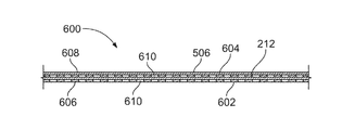
図6の例示的なライナー600は、交互の金属層602、604及び複合層212、506を含む。金属層602、金属層604、複合層212及び/又は複合層506は、例えばコキュア又はボンディングによって結合され、ライナー600を形成する。
The
示された例において、金属層602は、貨物室110(図2)に露出されているライナー600の内側表面606を定め、複合層506は、貨物室110の外側境界216(図2)に隣接する外側表面608を定める。幾つかの例において、ライナー600は、ライナー600の金属層602、604及び複合層212、506をファスナ(例えば、図3Aのファスナ304)によって航空機支持体(例えば、図3Aの航空機支持体218)に結合することによって、貨物室110(図2)の境界216(図2)に隣接して配置される。
In the example shown, the
図6に示されるように、金属層602、604の各々が、それぞれの金属層602、604を通って延びる穴又は開口610を定める。幾つかの例において、金属層602、604の各々が、開口610を定める金属メッシュ、金属クロス、又は金属スクリーンである。例えば、金属層602、604のメッシュ、クロス、又はスクリーンによって形成される開口610は、約0.25インチまでの長さ及び/又は幅を有する。開口610は、例示的なライナー600の金属層602、604の重量を減少させ、従って、飛行中に航空機100(図1)によって運ばれる重量を減少させる。長時間及び/又はかなりの高温で火に曝されたときに、金属層602、604は、複合層212、506に支持を提供し、航空機支持体(例えば、図2の航空機支持体218)に対するライナー600の位置を維持する。その結果、ライナー500は、航空機支持体218に取り付けられたままであり、貨物室110に耐火炎透過性を提供し続ける。
As shown in FIG. 6, each of the metal layers 602, 604 defines a hole or
例示的なライナー600が、図6を参照して記載されるが、ライナー600の層(例えば、複合層212、506及び金属層602、604)の順序は、変えられてもよく、及び/又は記載された層の幾つかは、変更及び/又は除去されてもよい。幾つかの例において、複合層212、506のうちの一つが、内側表面606を定め、及び/又は金属層602、604のうちの一つが、ライナー600の外側表面608を定めるように、ライナー600が再配列される。幾つかの例において、金属層602、複合層212、金属層604及び/又は複合層506が、ライナー600から除去される。幾つかの例において、金属メッシュ、金属クロス、金属スクリーン、複合材料及び/又は他の材料(例えば、ハニカム層、ハニカムサンドイッチ層、発泡体層)の追加層が、ライナー600に含まれ、ライナー600の構造剛性及び/又は貨物室110に提供される耐火炎透過性を更に増加させる。
An
図7を参照し、例示的なライナー700は、図2の貨物室110に提供される耐火炎透過性を増加させる。図7に示されるように、ライナー700は、複合層212、506、金属層602、及び金属層502を含む。示された例において、複合層212は、貨物室110に露出されているライナー700の内側表面702を定め、金属層502は、貨物室110の境界216に隣接する外側表面704を定める。金属層(又は補強グリッド)214のストラップ302が、ライナー700の内側表面702に結合される。
With reference to FIG. 7, the
図7に示されるように、金属層602が、複合層212と複合層506の間に配置される。金属層602の一部710が、金属層502によって覆われないようにして、金属層502の第一の部分706及び第二の部分708が、金属層602と部分的に重なる。金属層602が、金属層502からオフセットされ、ライナー700の重量を減少させ、従って、飛行中に航空機100(図1)によって運ばれる重量を減少させる。
As shown in FIG. 7, the
幾つかの例において、金属層(又は補強グリッド)214、複合層212、金属層602、複合層506及び/又は金属層502が、コキュア又はボンディングによって結合され、ライナー700を形成する。貨物室110(図2)の外側境界216(図2)に隣接してライナー700を配置するために、ライナー700の複合層212、金属層(又は補強グリッド)214、金属層502、複合層506及び/又は金属層602が、ファスナ304によって境界216に隣接して航空機支持体218に結合される。
In some examples, the metal layer (or reinforcing grid) 214, the
示された例の金属層(又は補強グリッド)214及び金属層502、602が、ライナー700の複合層212、506に結合され、ライナー700が長時間及び/又はかなりの高温で火に曝されたときに、複合層212、506の構造剛性を増加させる。その結果、ライナー700が火及び/又はかなりの高温に曝されたときに、ライナー500は、航空機支持体218に取り付けられたままであり、貨物室110に耐火炎透過性を提供し続ける。
The metal layers (or reinforcing grids) 214 and the metal layers 502, 602 of the example shown were coupled to the
例示的なライナー700が、図7を参照して記載されるが、ライナー600の層(例えば、複合層212、金属層(又は補強グリッド)214、金属層502、複合層506、金属層602)の順序は、変えられてもよく、及び/又は記載された層の幾つかは、変更及び/又は除去されてもよい。幾つかの例において、複合層212、金属層(又は補強グリッド)214、金属層502、複合層506及び/又は金属層602が、ライナー700から除去される。幾つかの例において、金属メッシュ、金属クロス、金属スクリーン、金属ホイル、複合材料及び/又は他の材料(例えば、ハニカム層、ハニカムサンドイッチ層、発泡体層)の追加層が、ライナー700に含まれ、ライナー600の構造剛性及び/又は貨物室110に提供される耐火炎透過性を更に増加させる。
An
図5〜図7の示された例において、それぞれのライナー500、600、700の金属層(例えば、図5の金属層502、504、図6の金属層602、604、図7の金属層502、602)が、耐火炎透過性を提供し、貨物室110に提供される耐火炎透過性を更に増加させる。金属層502、504の開口部のないホイル及び金属層602、604のメッシュ、クロス、又はスクリーンは、かなり高い融点を有する金属材料から構成されるので、金属層502,504,602,604は、ライナー500、600、700によって提供される耐火炎透過性を増加させる。例えば、金属層502,504,602,604が、鋼鉄から構成される場合、金属層502,504,602,604は、カ氏約2500度以下の温度を有する火がライナー500を突き抜けるのを防止及び/又は阻止する。金属層502,504,602,604が、チタンから構成される場合、金属層502,504,602,604は、カ氏約3000度以下の温度を有する火がライナー500を突き抜けるのを防止及び/又は阻止する。その結果、例示的なライナー500、600、700の金属層502,504,602,604は、貨物室110に耐火炎透過性が提供される時間及び/又は温度を大幅に増加させる。
In the examples shown in FIGS. 5 to 7, the metal layers of the
図8は、航空機貨物室に耐火炎透過性を提供する例示的な方法800を表すフローチャートである。例示的な方法800が、図8に示されたフローチャートを参照して記載されるが、航空機貨物室に耐火炎透過性を提供する多くの他の方法が、代替的に使用され得る。例えば、ブロックの実行の順序は変えられてもよく、及び/又は記載されたブロックの幾つかは、変更、除去、及び/又は結合されてもよい。
FIG. 8 is a flow chart illustrating an
航空機貨物室に耐火炎透過性を提供する例示的な方法800は、図2の例示的な航空機貨物室110並びに図2及び図3A〜図3Bの例示的なライナー200、図4A〜図4Bの例示的なライナー400、図5の例示的なライナー500、図6の例示的なライナー600及び/又は図7の例示的なライナー700に関連して、論じられる。例示的な方法800は、例示的な航空機貨物室110に耐火炎透過性を提供するために、例示的なライナー200、例示的なライナー400、例示的なライナー500、例示的なライナー600及び/又は例示的なライナー700を組立てるために用いられ得るので、下記の構成要素の機能と実質的に類似した又は同一の機能を有する図2〜図7に同定された構成要素は、再度詳細に説明しない。代わりに、同じ参照番号が、同様の構造に用いられる。
An
本書に開示された例示的な方法800は、ライナーの耐火性の複合層に金属層を結合することによって、開始する(ブロック802)。ライナー(例えば、図2〜図3Bのライナー200、図4A〜図4Bのライナー400、図5のライナー500、図6のライナー600、図7のライナー700)の複合層(例えば、図2〜図7の複合層212、図5〜図7の複合層506)は、航空機(例えば、図1の航空機100)の貨物室(例えば、図1及び図2の貨物室110)に耐火炎透過性を提供する。複合層の構造剛性を増加させるために、金属層が、複合層に結合される。例えば、金属層が、コキュア及び/又はボンディングプロセスによって、耐火性の複合層に結合される。
The
幾つかの例において、金属層は、金属ストラップ(例えば、図3A、図3B及び図7の金属ストラップ302)、金属ストラップから形成された金属グリッド(例えば、図2、図3A、図3B、及び図7の金属層(又は補強グリッド)214)並びに/又は金属プレート若しくはワッシャー(例えば、図4A及び図4Bの金属プレート402)である。幾つかの例において、金属層は、金属ホイル(例えば、図5及び図7の金属層502、図5の金属層504)、金属メッシュ(例えば、図6〜図7の金属層602、図6の金属層604)、金属クロス(例えば、図6〜図7の金属層602、図6の金属層604)並びに/又は金属スクリーン(例えば、図6〜図7の金属層602、図6の金属層604)であり、航空機貨物室の表面に提供される耐火炎透過性を増加させる。
In some examples, the metal layer is a metal strap (eg,
ブロック802の後に、例示的な方法800は、他の金属層が含まれるべきかどうかを決定する(ブロック804)。他の金属層が含まれるべきである場合、複合層に提供される構造剛性を増加させるために、他の金属層が、少なくとも一つの層に結合される(ブロック806)。例えば、他の金属層が、コキュア及び/又はボンディングプロセスによって、ブロック802の金属層及び/又はブロック802の複合層に結合され得る。
After
幾つかの例において、他の金属層は、金属ストラップ(例えば、図3A、図3B及び図7の金属ストラップ302)、金属ストラップから形成された金属グリッド(例えば、図2、図3A、図3B、及び図7の金属層(又は補強グリッド)214)並びに/又は金属プレート若しくはワッシャー(例えば、図4A及び図4Bの金属プレート402)である。幾つかの例において、他の金属層は、金属ホイル(例えば、図5及び図7の金属層502、図5の金属層504)、金属メッシュ(例えば、図6〜図7の金属層602、図6の金属層604)、金属クロス(例えば、図6〜図7の金属層602、図6の金属層604)並びに/又は金属スクリーン(例えば、図6〜図7の金属層602、図6の金属層604)であり、航空機貨物室の表面に提供される耐火炎透過性を増加させる。
In some examples, the other metal layer is a metal strap (eg,
他の金属層が、少なくとも一つの他の層に結合された後、更に他の金属層が含まれるべきかどうかを決定するために、ブロック804が、繰り返される。更に他の金属層が含まれるべきである場合、ブロック806及びブロック804が、繰り返される。他の金属層が含まれるべきでないことが決定されると、例示的な方法800は、他の複合層が含まれるべきかどうかを決定する(ブロック808)。
After the other metal layer is bonded to at least one other layer, block 804 is repeated to determine if additional metal layers should be included.
他の複合層が含まれるべきである場合、航空機貨物室の表面に提供される耐火炎透過性を増加させるために、複合層が、少なくとも一つの層(例えば、ブロック802の金属層、ブロック802の複合層、ブロック806の金属層)に結合される(ブロック810)。例えば、他の複合層(例えば、図2〜図7の複合層212、図5〜図7の複合層506)が、コキュア及び/又はボンディングプロセスによってライナーの少なくとも一つの層に結合される。
If other composite layers should be included, the composite layer may be at least one layer (eg, the metal layer of
他の複合層が、少なくとも一つの層に結合された後、更に他の複合層が含まれるべきかどうかを決定するために、ブロック808が、繰り返される。他の複合層が含まれるべきである場合、ブロック810及びブロック808が、繰り返される。例えば、他の複合層が、ブロック802の金属層、ブロック802の複合層、ブロック806の金属層及び/又はブロック810の他の複合層に結合され得る。
After the other composite layer has been attached to at least one layer, block 808 is repeated to determine if additional composite layers should be included.
他の複合層が含まれるべきでない場合、例示的な方法800は、他の金属層が含まれるべきかどうかを決定する(ブロック812)。他の金属層が含まれるべきである場合、例示的な方法800は、ブロック806に戻り、複合層(複数可)の構造剛性を更に増加させるため及び/又は航空機貨物室の表面に提供される耐火炎透過性を更に増加させるために、他の金属層を少なくとも一つの層に結合させる。例えば、他の金属層が、ブロック802の金属層、ブロック802の複合層、ブロック806の金属層及び/又はブロック810の複合層に結合され得る。他の金属層がブロック806で結合された後、他の金属層又は複合層が含まれるべきでないことを、例示的な方法800が決定するまで、ブロック804、806、808、812が繰り返される。
If no other composite layer should be included, the
他の金属層が含まれるべきでない場合、例示的な方法800は、結合された金属層及び複合層を、航空機貨物室の表面に又は航空機貨物室の表面に隣接する航空機支持体(例えば、図2、図3A,図4A、及び図7の航空機支持体218)に取り付けて、表面に耐火炎透過性を提供する(ブロック814)。幾つかの例において、結合された金属層及び複合層は、ファスナ(例えば、図3A〜図4B、図7のファスナ304)によって表面及び/又は航空機支持体に取り付けられる。例えば、金属層及び複合層は、金属層、複合層、及び航空機支持体を通って延び、ナット(例えば、図3Aのナット308)によって受けられる(例えば、ねじ止めされる)ボルト(例えば、図3Aのボルト306)を介して航空機支持体に取り付けられる。
If no other metal layer should be included, the
幾つかの例示的な装置が、本書に記載されたが、本特許の対象範囲は、それに限定されない。逆に、本特許は、文字通りに又は均等論の下で補正された請求項の範囲に適正に入る全ての方法、装置、及び製品に及ぶ。
Although some exemplary devices have been described herein, the scope of this patent is not limited thereto. Conversely, this patent extends to all methods, devices, and products that fall within the claims, either literally or under the doctrine of equivalents.
Claims (10)
前記複合層(212)の構造剛性を増加させ、前記複合層(212)が火に曝されるときに提供される前記耐火炎透過性を増加させるための、前記複合層(212)に結合された第一の金属層(214)と
を備え、前記第一の金属層(214)が、カ氏2000度以上の融点を有する金属材料から構成され、グリッド状構造を形成する金属ストラップを備える、装置。 A liner (200) having a refractory composite layer (212) to provide flame permeability to the compartment,
Coupled to the composite layer (212) to increase the structural rigidity of the composite layer (212) and increase the flame permeability provided when the composite layer (212) is exposed to fire. A device comprising a first metal layer (214), wherein the first metal layer (214) is composed of a metal material having a melting point of 2000 degrees Fahrenheit or higher and includes a metal strap forming a grid-like structure. ..
前記複合層の構造剛性を増加させ、前記複合層によって提供される前記耐火炎透過性を増加させるための、前記複合層に結合された第一の金属層(214)と
を備え、前記第一の金属層(214)が、カ氏2000度以上の融点を有する金属材料から構成され、グリッド状構造を形成する金属ストラップを備える、システム。 With a liner having a refractory composite layer (212) to provide flame permeability to the compartments,
The structural rigidity of the composite layer is increased, the for increasing the fire flame permeability provided by the combined layer, before a first metal layer bonded to Kifuku if layer (214), the A system in which a first metal layer (214) is composed of a metal material having a melting point of 2000 degrees Fahrenheit or higher and comprises a metal strap forming a grid-like structure.
前記耐火性の複合層を有するライナー(200)及び前記第一の金属層を支持体(218)に取り付けることと
を含み、前記耐火性の複合層は、耐火炎透過性を区画に提供し、前記第一の金属層は、前記耐火性の複合層の構造剛性を増加させ、火に曝されたときに前記耐火性の複合層によって提供される前記耐火炎透過性を増加させる、方法。 A first metal layer (214) composed of a metal material having a melting point of 2000 degrees Fahrenheit or higher and having a metal strap forming a grid-like structure is formed into a liner (200) having a refractory composite layer (212). To combine and
The refractory composite layer comprises attaching the liner (200) having the refractory composite layer and the first metal layer to the support (218), the refractory composite layer providing flame resistance to the compartment. A method in which the first metal layer increases the structural rigidity of the refractory composite layer and increases the flame permeability provided by the refractory composite layer when exposed to fire.
Applications Claiming Priority (2)
| Application Number | Priority Date | Filing Date | Title |
|---|---|---|---|
| US14/837,394 US20170056694A1 (en) | 2015-08-27 | 2015-08-27 | Methods, systems and apparatus for lining an aircraft cargo compartment |
| US14/837,394 | 2015-08-27 |
Publications (3)
| Publication Number | Publication Date |
|---|---|
| JP2017104493A JP2017104493A (en) | 2017-06-15 |
| JP2017104493A5 JP2017104493A5 (en) | 2019-10-03 |
| JP6851156B2 true JP6851156B2 (en) | 2021-03-31 |
Family
ID=56799312
Family Applications (1)
| Application Number | Title | Priority Date | Filing Date |
|---|---|---|---|
| JP2016161688A Active JP6851156B2 (en) | 2015-08-27 | 2016-08-22 | Methods, systems and equipment for lining the cargo compartment of an aircraft |
Country Status (7)
| Country | Link |
|---|---|
| US (1) | US20170056694A1 (en) |
| EP (1) | EP3135472A1 (en) |
| JP (1) | JP6851156B2 (en) |
| CN (1) | CN106477022A (en) |
| BR (1) | BR102016019678B1 (en) |
| CA (1) | CA2935048C (en) |
| RU (1) | RU2719096C2 (en) |
Families Citing this family (4)
| Publication number | Priority date | Publication date | Assignee | Title |
|---|---|---|---|---|
| US9988160B1 (en) * | 2017-05-04 | 2018-06-05 | The Boeing Company | Airplane fire detection system |
| US10525636B2 (en) * | 2017-06-19 | 2020-01-07 | Rohr, Inc. | Process for forming a fiber-reinforced composite structure |
| US10436118B2 (en) * | 2017-06-19 | 2019-10-08 | Rohr, Inc. | Acoustic panel with folding chamber |
| US11566761B2 (en) | 2019-01-17 | 2023-01-31 | Koito Manufacturing Co., Ltd. | Wall lamp |
Family Cites Families (12)
| Publication number | Priority date | Publication date | Assignee | Title |
|---|---|---|---|---|
| JPS57105739U (en) * | 1980-12-23 | 1982-06-29 | ||
| JPS6478946A (en) * | 1987-09-18 | 1989-03-24 | Yokohama Rubber Co Ltd | Interior fitting material |
| US5252160A (en) * | 1990-11-15 | 1993-10-12 | Auto Air Composites, Inc. | Method of manufacturing a metal/composite spinner cone |
| US6890638B2 (en) * | 2002-10-10 | 2005-05-10 | Honeywell International Inc. | Ballistic resistant and fire resistant composite articles |
| DE102004001083B8 (en) * | 2004-01-05 | 2013-06-13 | Airbus Operations Gmbh | Insulation structure for the internal insulation of a vehicle |
| DE102006020147A1 (en) * | 2006-05-02 | 2007-11-15 | Airbus Deutschland Gmbh | Fire barrier for aircraft to protect from burn-out between cargo and passenger cab, has burnout-safety-panel for blocking fire in partition wall area of aircraft body |
| ITRM20070501A1 (en) * | 2007-09-27 | 2009-03-28 | Nautical Service Srl | PANEL IN COMPOSITE MATERIALS RESISTANT TO THE FLAME THROUGH AERO, NAVAL AND LAND APPLICATIONS AND ITS LOCKING SYSTEMS. |
| WO2009134299A2 (en) * | 2008-03-14 | 2009-11-05 | Kaneka Corporation | Fire barrier protection for airplanes comprising graphite films |
| US20120090452A1 (en) * | 2010-10-15 | 2012-04-19 | Ashok Em Sudhakar | Ballistic panel with configurable shielding |
| ES2779035T3 (en) * | 2012-03-27 | 2020-08-13 | Unifrax I Llc | Fire Barrier Layer and Fire Barrier Film Laminate |
| US9580164B2 (en) * | 2013-07-10 | 2017-02-28 | The Boeing Company | Apparatus and methods for joining aircraft composite structures |
| US10252091B2 (en) * | 2013-09-09 | 2019-04-09 | The Boeing Company | Fire-retaining containers |
-
2015
- 2015-08-27 US US14/837,394 patent/US20170056694A1/en not_active Abandoned
-
2016
- 2016-06-30 RU RU2016126334A patent/RU2719096C2/en active
- 2016-06-30 CA CA2935048A patent/CA2935048C/en active Active
- 2016-08-22 JP JP2016161688A patent/JP6851156B2/en active Active
- 2016-08-23 EP EP16185354.4A patent/EP3135472A1/en active Pending
- 2016-08-25 BR BR102016019678-7A patent/BR102016019678B1/en active IP Right Grant
- 2016-08-26 CN CN201610737296.4A patent/CN106477022A/en active Pending
Also Published As
| Publication number | Publication date |
|---|---|
| CA2935048C (en) | 2021-06-01 |
| BR102016019678A2 (en) | 2017-07-25 |
| CN106477022A (en) | 2017-03-08 |
| CA2935048A1 (en) | 2017-02-27 |
| EP3135472A1 (en) | 2017-03-01 |
| RU2719096C2 (en) | 2020-04-17 |
| BR102016019678B1 (en) | 2021-10-05 |
| US20170056694A1 (en) | 2017-03-02 |
| JP2017104493A (en) | 2017-06-15 |
Similar Documents
| Publication | Publication Date | Title |
|---|---|---|
| JP6851156B2 (en) | Methods, systems and equipment for lining the cargo compartment of an aircraft | |
| AU640426B2 (en) | Containers for use on aircraft for the protection of aircraft structures | |
| EP0435650B1 (en) | Aircraft body member | |
| RU2413651C2 (en) | Aircraft fuselage | |
| US6915861B2 (en) | Ballistic fire protection packaging system | |
| EP2723638B1 (en) | Flight vehicle fairing having vibration-damping blankets | |
| EP2565027B1 (en) | Non-ceramic structural panel with ballistic protection | |
| US5985362A (en) | Insulation system for transport aircraft | |
| US8899523B2 (en) | Fire protection space for aircraft passengers provided with the aid of fuselage skin of fibre-metal laminates | |
| JP5539955B2 (en) | Aircraft fuselage with burn-through resistance | |
| DE102015015340B4 (en) | sandwich component | |
| GB2238283A (en) | Protecting aircraft structures from the effects of explosions | |
| US10196124B2 (en) | Aircraft external part with inflatable panels | |
| DE102020002099B4 (en) | Vacuum insulation panel with at least one support layer, interior trim panel with the vacuum insulation panel and aircraft with the interior trim panel and / or the vacuum insulation panel | |
| EP3235721B1 (en) | System and method of suppressing an unexpected combustion event |
Legal Events
| Date | Code | Title | Description |
|---|---|---|---|
| A521 | Request for written amendment filed |
Free format text: JAPANESE INTERMEDIATE CODE: A523 Effective date: 20190822 |
|
| A621 | Written request for application examination |
Free format text: JAPANESE INTERMEDIATE CODE: A621 Effective date: 20190822 |
|
| A977 | Report on retrieval |
Free format text: JAPANESE INTERMEDIATE CODE: A971007 Effective date: 20200521 |
|
| A131 | Notification of reasons for refusal |
Free format text: JAPANESE INTERMEDIATE CODE: A131 Effective date: 20200602 |
|
| A521 | Request for written amendment filed |
Free format text: JAPANESE INTERMEDIATE CODE: A523 Effective date: 20200902 |
|
| TRDD | Decision of grant or rejection written | ||
| A01 | Written decision to grant a patent or to grant a registration (utility model) |
Free format text: JAPANESE INTERMEDIATE CODE: A01 Effective date: 20210302 |
|
| A61 | First payment of annual fees (during grant procedure) |
Free format text: JAPANESE INTERMEDIATE CODE: A61 Effective date: 20210309 |
|
| R150 | Certificate of patent or registration of utility model |
Ref document number: 6851156 Country of ref document: JP Free format text: JAPANESE INTERMEDIATE CODE: R150 |
|
| R250 | Receipt of annual fees |
Free format text: JAPANESE INTERMEDIATE CODE: R250 |