JP6849416B2 - An image forming apparatus including a sheet transfer device and a sheet transfer device. - Google Patents

An image forming apparatus including a sheet transfer device and a sheet transfer device. Download PDF

Info

Publication number
JP6849416B2
JP6849416B2 JP2016233353A JP2016233353A JP6849416B2 JP 6849416 B2 JP6849416 B2 JP 6849416B2 JP 2016233353 A JP2016233353 A JP 2016233353A JP 2016233353 A JP2016233353 A JP 2016233353A JP 6849416 B2 JP6849416 B2 JP 6849416B2
Authority
JP
Japan
Prior art keywords
rotating body
body unit
shaft
moving shaft
sheet
Prior art date
Legal status (The legal status is an assumption and is not a legal conclusion. Google has not performed a legal analysis and makes no representation as to the accuracy of the status listed.)
Active
Application number
JP2016233353A
Other languages
Japanese (ja)
Other versions
JP2018090359A (en
Inventor
鈴木 洋平
洋平 鈴木
俊介 岡崎
俊介 岡崎
Current Assignee (The listed assignees may be inaccurate. Google has not performed a legal analysis and makes no representation or warranty as to the accuracy of the list.)
Canon Inc
Original Assignee
Canon Inc
Priority date (The priority date is an assumption and is not a legal conclusion. Google has not performed a legal analysis and makes no representation as to the accuracy of the date listed.)
Filing date
Publication date
Application filed by Canon Inc filed Critical Canon Inc
Priority to JP2016233353A priority Critical patent/JP6849416B2/en
Priority to US15/825,933 priority patent/US10584006B2/en
Priority to CN201711231724.7A priority patent/CN108116913B/en
Publication of JP2018090359A publication Critical patent/JP2018090359A/en
Application granted granted Critical
Publication of JP6849416B2 publication Critical patent/JP6849416B2/en
Active legal-status Critical Current
Anticipated expiration legal-status Critical

Links

Images

Classifications

    • BPERFORMING OPERATIONS; TRANSPORTING
    • B65CONVEYING; PACKING; STORING; HANDLING THIN OR FILAMENTARY MATERIAL
    • B65HHANDLING THIN OR FILAMENTARY MATERIAL, e.g. SHEETS, WEBS, CABLES
    • B65H3/00Separating articles from piles
    • B65H3/02Separating articles from piles using friction forces between articles and separator
    • B65H3/06Rollers or like rotary separators
    • BPERFORMING OPERATIONS; TRANSPORTING
    • B65CONVEYING; PACKING; STORING; HANDLING THIN OR FILAMENTARY MATERIAL
    • B65HHANDLING THIN OR FILAMENTARY MATERIAL, e.g. SHEETS, WEBS, CABLES
    • B65H5/00Feeding articles separated from piles; Feeding articles to machines
    • B65H5/06Feeding articles separated from piles; Feeding articles to machines by rollers or balls, e.g. between rollers
    • B65H5/062Feeding articles separated from piles; Feeding articles to machines by rollers or balls, e.g. between rollers between rollers or balls
    • BPERFORMING OPERATIONS; TRANSPORTING
    • B65CONVEYING; PACKING; STORING; HANDLING THIN OR FILAMENTARY MATERIAL
    • B65HHANDLING THIN OR FILAMENTARY MATERIAL, e.g. SHEETS, WEBS, CABLES
    • B65H3/00Separating articles from piles
    • B65H3/02Separating articles from piles using friction forces between articles and separator
    • B65H3/06Rollers or like rotary separators
    • B65H3/0638Construction of the rollers or like rotary separators
    • BPERFORMING OPERATIONS; TRANSPORTING
    • B65CONVEYING; PACKING; STORING; HANDLING THIN OR FILAMENTARY MATERIAL
    • B65HHANDLING THIN OR FILAMENTARY MATERIAL, e.g. SHEETS, WEBS, CABLES
    • B65H3/00Separating articles from piles
    • B65H3/02Separating articles from piles using friction forces between articles and separator
    • B65H3/06Rollers or like rotary separators
    • B65H3/0669Driving devices therefor
    • BPERFORMING OPERATIONS; TRANSPORTING
    • B65CONVEYING; PACKING; STORING; HANDLING THIN OR FILAMENTARY MATERIAL
    • B65HHANDLING THIN OR FILAMENTARY MATERIAL, e.g. SHEETS, WEBS, CABLES
    • B65H3/00Separating articles from piles
    • B65H3/02Separating articles from piles using friction forces between articles and separator
    • B65H3/06Rollers or like rotary separators
    • B65H3/0684Rollers or like rotary separators on moving support, e.g. pivoting, for bringing the roller or like rotary separator into contact with the pile
    • GPHYSICS
    • G03PHOTOGRAPHY; CINEMATOGRAPHY; ANALOGOUS TECHNIQUES USING WAVES OTHER THAN OPTICAL WAVES; ELECTROGRAPHY; HOLOGRAPHY
    • G03GELECTROGRAPHY; ELECTROPHOTOGRAPHY; MAGNETOGRAPHY
    • G03G15/00Apparatus for electrographic processes using a charge pattern
    • G03G15/65Apparatus which relate to the handling of copy material
    • G03G15/6529Transporting
    • BPERFORMING OPERATIONS; TRANSPORTING
    • B65CONVEYING; PACKING; STORING; HANDLING THIN OR FILAMENTARY MATERIAL
    • B65HHANDLING THIN OR FILAMENTARY MATERIAL, e.g. SHEETS, WEBS, CABLES
    • B65H2402/00Constructional details of the handling apparatus
    • B65H2402/50Machine elements
    • B65H2402/51Joints, e.g. riveted or magnetic joints
    • BPERFORMING OPERATIONS; TRANSPORTING
    • B65CONVEYING; PACKING; STORING; HANDLING THIN OR FILAMENTARY MATERIAL
    • B65HHANDLING THIN OR FILAMENTARY MATERIAL, e.g. SHEETS, WEBS, CABLES
    • B65H2402/00Constructional details of the handling apparatus
    • B65H2402/50Machine elements
    • B65H2402/54Springs, e.g. helical or leaf springs
    • BPERFORMING OPERATIONS; TRANSPORTING
    • B65CONVEYING; PACKING; STORING; HANDLING THIN OR FILAMENTARY MATERIAL
    • B65HHANDLING THIN OR FILAMENTARY MATERIAL, e.g. SHEETS, WEBS, CABLES
    • B65H2402/00Constructional details of the handling apparatus
    • B65H2402/60Coupling, adapter or locking means
    • BPERFORMING OPERATIONS; TRANSPORTING
    • B65CONVEYING; PACKING; STORING; HANDLING THIN OR FILAMENTARY MATERIAL
    • B65HHANDLING THIN OR FILAMENTARY MATERIAL, e.g. SHEETS, WEBS, CABLES
    • B65H2403/00Power transmission; Driving means
    • B65H2403/40Toothed gearings
    • B65H2403/42Spur gearing
    • BPERFORMING OPERATIONS; TRANSPORTING
    • B65CONVEYING; PACKING; STORING; HANDLING THIN OR FILAMENTARY MATERIAL
    • B65HHANDLING THIN OR FILAMENTARY MATERIAL, e.g. SHEETS, WEBS, CABLES
    • B65H2404/00Parts for transporting or guiding the handled material
    • B65H2404/10Rollers
    • B65H2404/13Details of longitudinal profile
    • B65H2404/134Axle
    • B65H2404/1342Built-up, i.e. arrangement for mounting axle element on roller body
    • B65H2404/13421Built-up, i.e. arrangement for mounting axle element on roller body involving two elements, i.e. an element at each end of roller body
    • BPERFORMING OPERATIONS; TRANSPORTING
    • B65CONVEYING; PACKING; STORING; HANDLING THIN OR FILAMENTARY MATERIAL
    • B65HHANDLING THIN OR FILAMENTARY MATERIAL, e.g. SHEETS, WEBS, CABLES
    • B65H2601/00Problem to be solved or advantage achieved
    • B65H2601/30Facilitating or easing
    • B65H2601/32Facilitating or easing entities relating to handling machine
    • B65H2601/324Removability or inter-changeability of machine parts, e.g. for maintenance
    • BPERFORMING OPERATIONS; TRANSPORTING
    • B65CONVEYING; PACKING; STORING; HANDLING THIN OR FILAMENTARY MATERIAL
    • B65HHANDLING THIN OR FILAMENTARY MATERIAL, e.g. SHEETS, WEBS, CABLES
    • B65H2601/00Problem to be solved or advantage achieved
    • B65H2601/60Miscellaneous
    • B65H2601/61Refurbishing; Renewing the handling machine; Upgrading modifying functions of the handling machine
    • BPERFORMING OPERATIONS; TRANSPORTING
    • B65CONVEYING; PACKING; STORING; HANDLING THIN OR FILAMENTARY MATERIAL
    • B65HHANDLING THIN OR FILAMENTARY MATERIAL, e.g. SHEETS, WEBS, CABLES
    • B65H2801/00Application field
    • B65H2801/03Image reproduction devices

Description

本発明は、シートを搬送するシート搬送装置及びシート搬送装置を備える画像形成装置に関する。 The present invention relates to a sheet transporting device for transporting sheets and an image forming apparatus including the sheet transporting device.

従来、電子写真方式等の画像形成装置としては、給紙カセットに収容されたシートを画像形成部に搬送するシート搬送装置を備え、シート搬送装置によって搬送されるシートに画像を形成する構成が広く知られている。このようなシート搬送装置には、給紙カセットに収容されたシートを給送する給送ローラと、給送ローラによって給送されたシートを画像形成部に向かって搬送する搬送ローラを備えたものがある。給送ローラ及び搬送ローラは、ローラの表面と給紙カセットに収容されたシートとの表面の摩擦力を利用してシートを搬送しており、シートとの摩擦によりローラの表面が少しずつ摩耗するため、定期的に交換することが必要となる。 Conventionally, as an image forming apparatus such as an electrophotographic method, a sheet conveying device for conveying a sheet housed in a paper feed cassette to an image forming unit is provided, and an image is widely formed on a sheet conveyed by the sheet conveying device. Are known. Such a sheet transport device includes a feed roller that feeds the sheets contained in the paper feed cassette, and a transport roller that transports the sheets fed by the feed rollers toward the image forming unit. There is. The feeding roller and the conveying roller convey the sheet by using the frictional force between the surface of the roller and the surface of the sheet housed in the paper feed cassette, and the surface of the roller is gradually worn by the friction with the sheet. Therefore, it is necessary to replace it regularly.

特許文献1には、給送ローラと搬送ローラを回転体ユニットとしてユニット化し、ユーザやサービスマン(以下、ユーザと称する)によって回転体ユニットを交換することが可能に構成されたシート搬送装置の構成が開示されている。回転体ユニットの一端側は、バネによって回転体ユニットに対して付勢されたスライド軸に軸支されており、他端側は、回転体ユニットを挟んでスライド軸と反対側に設けられた駆動軸によって軸支されている。特許文献1では以下の動作によって回転体ユニットの交換を行っている。 Patent Document 1 describes a configuration of a sheet transfer device in which a feeding roller and a transfer roller are unitized as a rotating body unit, and the rotating body unit can be replaced by a user or a serviceman (hereinafter referred to as a user). Is disclosed. One end side of the rotating body unit is pivotally supported by a slide shaft urged against the rotating body unit by a spring, and the other end side is a drive provided on the opposite side of the slide shaft across the rotating body unit. It is pivotally supported by a shaft. In Patent Document 1, the rotating body unit is replaced by the following operation.

まず、ユーザは、バネによって回転体ユニット対して付勢されたスライド軸の付勢力に抗して回転体ユニットを駆動軸からスライド軸に向かう方向にスライド移動させ、駆動軸と回転体ユニットとの係合を解除する。その後、スライド軸からの付勢力を受けている状態で、スライド軸との係合を解除する方向に回転体ユニットを移動させ、シート搬送装置から回転体ユニットを取り外す。回転体ユニットをシート搬送装置に取り付ける際には、まず、バネによって付勢された状態のスライド軸に回転体ユニットの一端側を差し込み、回転体ユニットの一端側をスライド軸と係合させつつバネの付勢力に抗してスライド軸と駆動軸との間を押し広げる。その後、回転体ユニットをスライド軸と駆動軸との間に位置させ、回転体ユニットの他端側を駆動軸と係合することが可能な位置に合わせ、回転体ユニットの位置が合った後にスライド軸の付勢力がかかっている方向に回転体ユニットを移動させる。これにより、回転体ユニットと駆動軸が係合し、回転体ユニットがシート搬送装置に取り付けられる。 First, the user slides the rotating body unit in the direction from the drive shaft to the slide shaft against the urging force of the slide shaft urged against the rotating body unit by the spring, and causes the drive shaft and the rotating body unit to move. Disengage. Then, while receiving the urging force from the slide shaft, the rotating body unit is moved in the direction of disengagement with the slide shaft, and the rotating body unit is removed from the seat transfer device. When attaching the rotating body unit to the seat transfer device, first, one end side of the rotating body unit is inserted into the slide shaft in a state of being urged by the spring, and the spring while engaging the one end side of the rotating body unit with the slide shaft. It pushes between the slide shaft and the drive shaft against the urging force of. After that, the rotating body unit is positioned between the slide shaft and the drive shaft, the other end side of the rotating body unit is aligned with the position where it can be engaged with the drive shaft, and the rotating body unit is slid after being aligned. Move the rotating body unit in the direction in which the urging force of the shaft is applied. As a result, the rotating body unit and the drive shaft are engaged with each other, and the rotating body unit is attached to the seat transfer device.

特開2016−11213号公報Japanese Unexamined Patent Publication No. 2016-11213

特許文献1の構成においては、シート搬送装置に対して回転体ユニットの交換を行う際に、ユーザは、バネによって付勢されたスライド軸の付勢力に抗しながら回転体ユニットを取り外す必要があった。 In the configuration of Patent Document 1, when exchanging the rotating body unit with respect to the seat transfer device, the user needs to remove the rotating body unit while resisting the urging force of the slide shaft urged by the spring. It was.

そこで、本発明は、スライド軸の付勢力に抗する必要なく、回転体ユニットを取り外すことが可能なシート搬送装置を提供することを目的とする。 Therefore, an object of the present invention is to provide a sheet transfer device capable of removing the rotating body unit without having to resist the urging force of the slide shaft.

前述の課題を解決するために、本発明は、シートを搬送することが可能な搬送回転体と、前記搬送回転体を保持する保持部材と、を有する回転体ユニットと、前記回転体ユニットの一端側を支持し、前記回転体ユニットに駆動源からの駆動力を伝達する支持軸と、前記回転体ユニットの他端側を支持し、前記支持軸の軸線方向に移動することが可能な移動軸と、前記移動軸を付勢する第1付勢部材と、を備え、前記第1付勢部材が前記移動軸を付勢することにより、前記移動軸が前記回転体ユニットを前記支持軸に向かって付勢し、前記回転体ユニットが前記支持軸と前記移動軸によって支持されるシート搬送装置において、前記移動軸は、前記支持軸と前記移動軸によって前記回転体ユニットを支持する第1の位置と、前記移動軸が前記回転体ユニットを付勢する付勢力に抗する方向に関して前記第1の位置よりも離れた第2の位置と、に移動可能であって、前記支持軸の軸線方向に関して、前記付勢力に抗して前記回転体ユニットを前記支持軸によって支持されない位置に移動させることにより前記移動軸が前記第1の位置から前記第2の位置に移動し、前記シート搬送装置から前記回転体ユニットを取り外す場合に前記第2の位置に移動した前記移動軸を前記第2の位置に係止する係止機構を備えることを特徴とする。 In order to solve the above-mentioned problems, the present invention has a rotating body unit having a transporting rotating body capable of transporting a sheet, a holding member for holding the transporting rotating body, and one end of the rotating body unit. A support shaft that supports the side and transmits the driving force from the drive source to the rotating body unit, and a moving shaft that supports the other end side of the rotating body unit and can move in the axial direction of the supporting shaft. And a first urging member for urging the moving shaft, and the first urging member urges the moving shaft so that the moving shaft directs the rotating body unit toward the supporting shaft. In a sheet transport device in which the rotating body unit is urged and supported by the supporting shaft and the moving shaft, the moving shaft is a first position in which the rotating body unit is supported by the supporting shaft and the moving shaft. And, with respect to the axial direction of the support shaft, the moving shaft can move to a second position farther from the first position with respect to a direction against the urging force for urging the rotating body unit. By moving the rotating body unit to a position not supported by the support shaft against the urging force, the moving shaft is moved from the first position to the second position, and the sheet transporting device is used to move the rotating body unit to the second position. It is characterized by including a locking mechanism that locks the moving shaft that has moved to the second position to the second position when the rotating body unit is removed.

本発明によると、スライド軸の付勢力に抗する必要なく、シート搬送装置から回転体ユニットを取り外すことが可能である。 According to the present invention, it is possible to remove the rotating body unit from the seat transfer device without having to resist the urging force of the slide shaft.

実施例1のシート搬送装置を備える画像形成装置の構成を説明する概略断面図である。It is schematic cross-sectional view explaining the structure of the image forming apparatus which comprises the sheet transfer apparatus of Example 1. FIG. 実施例1の給送部の構成を説明する斜視図である。It is a perspective view explaining the structure of the feeding part of Example 1. FIG. 実施例1の回転体ユニットの構成を説明する斜視図である。It is a perspective view explaining the structure of the rotating body unit of Example 1. FIG. 実施例1において、支持軸及び移動軸と回転体ユニットとの係合を説明する模式図である。FIG. 5 is a schematic diagram illustrating the engagement between the support shaft and the moving shaft and the rotating body unit in the first embodiment. 実施例1において、シート搬送方向に沿って切断した際の給送部の概略断面図である。FIG. 5 is a schematic cross-sectional view of a feeding portion when the sheet is cut along the sheet transport direction in the first embodiment. 実施例1における回転体ユニットの姿勢の切り替えを説明する模式図である。It is a schematic diagram explaining the switching of the posture of the rotating body unit in Example 1. 実施例1において、シート搬送方向に沿って切断した際の回転体ユニットの概略断面図である。FIG. 5 is a schematic cross-sectional view of a rotating body unit when cut along a sheet transport direction in the first embodiment. 実施例1の画僧形成装置において、開閉部材としてのアクセスドアを開けた状態を説明する概略断面図である。FIG. 5 is a schematic cross-sectional view illustrating a state in which an access door as an opening / closing member is opened in the painting device forming apparatus of the first embodiment. 実施例1において、給送部から回転体ユニットを取り出す際の動作を説明する模式図である。FIG. 5 is a schematic diagram illustrating an operation when the rotating body unit is taken out from the feeding unit in the first embodiment. 実施例1において、給送部に回転体ユニットを取り付ける際の動作を説明する模式図である。FIG. 5 is a schematic diagram illustrating an operation when a rotating body unit is attached to a feeding unit in the first embodiment. 実施例1の移動軸の係止機構を説明する模式図である。It is a schematic diagram explaining the locking mechanism of the moving shaft of Example 1. FIG. 実施例1における、移動軸と付勢部材との係合を説明する模式図である。It is a schematic diagram explaining the engagement between a moving shaft and an urging member in Example 1. FIG. 実施例2における、移動軸の構成を説明する模式図である。It is a schematic diagram explaining the structure of the moving axis in Example 2. FIG. 実施例2の係止機構の構成を説明する模式図である。It is a schematic diagram explaining the structure of the locking mechanism of Example 2. 実施例2の移動軸の係止機構を説明する模式図である。It is a schematic diagram explaining the locking mechanism of the moving shaft of Example 2. 実施例3の給送部の構成を説明する模式図である。It is a schematic diagram explaining the structure of the feeding part of Example 3. FIG.

以下、図面を参照して、この発明の好適な実施例を例示的に詳しく説明する。なお、以下の実施例においては、本発明のシート給送装置を備える画像形成装置としてのレーザービームプリンタを用いた例について説明する。ただし、この実施例に記載されている構成要素はあくまで例示であり、特に特定的な記載がない限りは、本発明の範囲を限定する趣旨のものではない。 Hereinafter, preferred embodiments of the present invention will be described in detail, exemplary, with reference to the drawings. In the following examples, an example using a laser beam printer as an image forming apparatus including the sheet feeding device of the present invention will be described. However, the components described in this embodiment are merely examples, and are not intended to limit the scope of the present invention unless otherwise specified.

(実施例1)
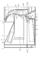
図1は、本実施例のシート搬送装置を備える画像形成装置1の構成を示す概略断面図である。図1に示すように、画像形成装置1は、電子写真記録方式によって画像を形成するものであり、装置本体2(以下、本体2と称する)と、シート収容部としての給紙カセット3と、給送部4と、画像形成部5と、定着部6と、排紙トレイ7と、を備える。
(Example 1)
FIG. 1 is a schematic cross-sectional view showing the configuration of an image forming apparatus 1 including the sheet conveying apparatus of this embodiment. As shown in FIG. 1, the image forming apparatus 1 forms an image by an electrophotographic recording method, and includes an apparatus main body 2 (hereinafter referred to as a main body 2), a paper feed cassette 3 as a sheet accommodating portion, and a paper feed cassette 3. A feeding unit 4, an image forming unit 5, a fixing unit 6, and a paper ejection tray 7 are provided.

給紙カセット3は、シートSを積載する積載板30を有し、積載板30は、シートSを給送する給送回転体としての給送ローラ41aにシートSの最上面が当接する位置まで上昇することが可能である。シートSの最上面が給送ローラ41aに当接すると、シートSは、図示矢印R1方向に回転する給送ローラ41aによって、搬送回転体としての搬送ローラ41bと分離ローラ42によって形成される分離ニップ部Nに給送される。シートSは分離ニップ部Nにおいて1枚ずつ分離された後に画像形成部5に向かって搬送される。 The paper feed cassette 3 has a loading plate 30 for loading the sheet S, and the loading plate 30 reaches a position where the uppermost surface of the sheet S comes into contact with the feeding roller 41a as a feeding rotating body for feeding the sheet S. It is possible to rise. When the uppermost surface of the sheet S comes into contact with the feeding roller 41a, the sheet S is formed by the feeding roller 41a rotating in the direction of arrow R1 shown by the feeding roller 41b and the separating roller 42 as the transport rotating body. It is sent to the department N. The sheets S are separated one by one at the separation nip portion N and then conveyed toward the image forming portion 5.

画像形成部5は、像担持体としての感光体ドラム51と、露光手段52と、現像手段53と、転写ローラ54と、を有する。コントローラ等の制御手段(不図示)が画像信号を受信することによって画像形成動作が開始され、感光体ドラム51は回転駆動される。感光体ドラム51は回転過程で、不図示の帯電手段により一様に帯電処理され、露光手段52により画像信号に応じて露光される。これにより、感光体ドラム51の表面上に静電潜像が形成され、その後、現像手段53により現像されることで感光体ドラム51の表面上にトナー像が形成される。転写ローラ54は、感光体ドラム51に当接して転写ニップ部を形成する。感光体ドラム51の表面上に形成されたトナー像は、転写ニップ部において給送部4によって給送されたシートSに転写された後に、定着部6において加熱及び加圧されることでシートS上に定着される。このようにして、画像形成部5においてシートS上に画像が形成され、定着部6を通過し、印刷が終了したシートSは排紙トレイ7に排出される。 The image forming unit 5 includes a photoconductor drum 51 as an image carrier, an exposure means 52, a developing means 53, and a transfer roller 54. When a control means (not shown) such as a controller receives the image signal, the image forming operation is started, and the photoconductor drum 51 is rotationally driven. In the rotation process, the photoconductor drum 51 is uniformly charged by a charging means (not shown), and is exposed by the exposure means 52 according to the image signal. As a result, an electrostatic latent image is formed on the surface of the photoconductor drum 51, and then the toner image is formed on the surface of the photoconductor drum 51 by being developed by the developing means 53. The transfer roller 54 comes into contact with the photoconductor drum 51 to form a transfer nip portion. The toner image formed on the surface of the photoconductor drum 51 is transferred to the sheet S fed by the feeding section 4 at the transfer nip section, and then heated and pressurized in the fixing section 6 to form the sheet S. Settled on top. In this way, the image is formed on the sheet S in the image forming unit 5, passes through the fixing unit 6, and the printed sheet S is discharged to the paper ejection tray 7.

[給送部]
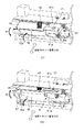
次に、給送部4の詳細な構成について図2(a)〜(b)を用いて説明する。図2(a)は図1における図示矢印A方向から見た際の給送部4の斜視図である。また、図2(b)は図1における図示矢印B方向から見た際の給送部4の斜視図である。
[Feeding section]
Next, the detailed configuration of the feeding unit 4 will be described with reference to FIGS. 2A to 2B. FIG. 2A is a perspective view of the feeding unit 4 when viewed from the direction of arrow A in FIG. Further, FIG. 2B is a perspective view of the feeding unit 4 when viewed from the direction of the arrow B in FIG. 1.

図2(a)に示すように、給送部4は、枠体22と、モータM(駆動源)によって駆動されるカップリング軸23(支持軸)と、回転体ユニット41と、分離ユニット43と、スライド軸25(移動軸)と、を有している。また、給送部4は、積載板30に積載されたシートSの最上面を検知する検知部材44を有している。なお、カップリング軸23とスライド軸25は枠体22に支持されており、スライド軸25は、スライド軸25の軸線方向に関して移動可能に設けられている。 As shown in FIG. 2A, the feeding unit 4 includes a frame body 22, a coupling shaft 23 (support shaft) driven by a motor M (drive source), a rotating body unit 41, and a separation unit 43. And a slide shaft 25 (moving shaft). Further, the feeding unit 4 has a detecting member 44 that detects the uppermost surface of the sheet S loaded on the loading plate 30. The coupling shaft 23 and the slide shaft 25 are supported by the frame body 22, and the slide shaft 25 is provided so as to be movable in the axial direction of the slide shaft 25.

さらに、図2(b)に示すように、給送部4は、回転体ユニット41の姿勢を切り替える給送ローラアーム45と、給送ローラアーム45を付勢するバネ46(第3付勢部材)と、を有する。給送ローラアーム45は、鉛直方向に関して移動可能な状態で枠体22に設けられており、回転体ユニット41のホルダ41cに設けられる係合部としての爪部c1と係合することが可能な被係合部である。バネ46が給送ローラアーム45を付勢することで、回転体ユニット41を給紙カセット3の積載板30に積載されたシートSに向かって付勢することが可能である。回転体ユニット41の姿勢を切り替える方法に関しては後に詳しく説明する。 Further, as shown in FIG. 2B, the feeding unit 4 includes a feeding roller arm 45 for switching the posture of the rotating body unit 41 and a spring 46 (third urging member) for urging the feeding roller arm 45. ) And. The feeding roller arm 45 is provided on the frame body 22 in a state of being movable in the vertical direction, and can be engaged with the claw portion c1 as an engaging portion provided on the holder 41c of the rotating body unit 41. It is an engaged part. By urging the feeding roller arm 45 by the spring 46, it is possible to urge the rotating body unit 41 toward the sheet S loaded on the loading plate 30 of the paper feed cassette 3. The method of switching the posture of the rotating body unit 41 will be described in detail later.

図3は、給送部4に装着された回転体ユニット41の構成を説明する模式図である。また、図4(a)は、図3における図示矢印C方向から見た際の回転体ユニット41の構成を説明する模式図であり、図4(b)は、図3における図示矢印D方向から見た際の回転体ユニット41の模式図である。 FIG. 3 is a schematic view illustrating the configuration of the rotating body unit 41 mounted on the feeding unit 4. 4 (a) is a schematic view illustrating the configuration of the rotating body unit 41 when viewed from the direction of arrow C in FIG. 3, and FIG. 4 (b) is a schematic view for explaining the configuration of the rotating body unit 41 when viewed from the direction of arrow C in FIG. It is a schematic diagram of the rotating body unit 41 when seen.

図3に示すように、回転体ユニット41は、保持部材としてのホルダ41cと、ホルダ41cに回転可能に支持される給送ローラ41aと、搬送ローラ41bと、を有する。給送ローラ41aは、シート搬送方向に関して、搬送ローラ41bよりも上流側に設けられており、給紙カセット3に収容されたシートSを搬送ローラ41bに向けて給送する。搬送ローラ41bの一端側はカップリング軸23によって軸支されており、他端側はスライド軸25によって軸支されている。本実施例の構成においては、搬送ローラ41bがカップリング軸23とスライド軸25に軸支されることによって、回転体ユニット41の一端側がカップリング軸23によって支持され、回転体ユニット41の他端側がスライド軸25によって支持される。なお、給送ローラ41a及び搬送ローラ41bの外周面は、ゴムなどの弾性体により形成されている。 As shown in FIG. 3, the rotating body unit 41 has a holder 41c as a holding member, a feeding roller 41a rotatably supported by the holder 41c, and a transport roller 41b. The feed roller 41a is provided on the upstream side of the transport roller 41b in the sheet transport direction, and feeds the sheet S housed in the paper feed cassette 3 toward the transport roller 41b. One end side of the transport roller 41b is pivotally supported by the coupling shaft 23, and the other end side is pivotally supported by the slide shaft 25. In the configuration of this embodiment, the transport roller 41b is pivotally supported by the coupling shaft 23 and the slide shaft 25, so that one end side of the rotating body unit 41 is supported by the coupling shaft 23 and the other end of the rotating body unit 41. The side is supported by the slide shaft 25. The outer peripheral surfaces of the feeding roller 41a and the transport roller 41b are formed of an elastic body such as rubber.

回転体ユニット41のホルダ41は、給送部4に対して回転体ユニット41を着脱する際にユーザやサービスマン(以下、ユーザと称する)が把持することが可能なガイド部c2を有し、ガイド部c2の両端部はホルダ41cによって回転可能に支持されている。ガイド部c2は、搬送ローラ41bがカップリング軸23及びスライド軸25に軸支され、シートSを搬送する状態においては、枠体22に対して不図示のスナップフィットによって保持される。なお、ガイド部c2は、枠体22に対して保持された状態においては、シートSの搬送を案内する搬送路の壁面に保持され、シートSの搬送をガイドすることが可能である。 The holder 41 of the rotating body unit 41 has a guide portion c2 that can be grasped by a user or a serviceman (hereinafter referred to as a user) when the rotating body unit 41 is attached to or detached from the feeding unit 4. Both ends of the guide portion c2 are rotatably supported by the holder 41c. The guide portion c2 is held by a snap fit (not shown) with respect to the frame body 22 in a state where the transport roller 41b is pivotally supported by the coupling shaft 23 and the slide shaft 25 and the seat S is transported. In the state of being held by the frame body 22, the guide portion c2 is held on the wall surface of the transport path for guiding the transport of the sheet S, and can guide the transport of the sheet S.

給送ローラ41aの回転軸線上には給送ギア47が設けられており、給送ギア47が回転すると、不図示のワンウェイ機構を介して給送ローラ41aに駆動力が伝達され、給送ローラ41aが回転する。また、搬送ローラ41bの回転軸線上には、カップリング軸23と係合してカップリング軸23の駆動力を給送ギア47に伝達する搬送ギア48が設けられている。 A feed gear 47 is provided on the rotation axis of the feed roller 41a. When the feed gear 47 rotates, a driving force is transmitted to the feed roller 41a via a one-way mechanism (not shown), and the feed roller 41a is fed. 41a rotates. Further, on the rotation axis of the transport roller 41b, a transport gear 48 that engages with the coupling shaft 23 and transmits the driving force of the coupling shaft 23 to the feed gear 47 is provided.

図4(a)に示すように、カップリング軸23は、搬送ギア48の係合溝48aと係合することによって搬送ローラ41bを軸支し、不図示のワンウェイ機構を介して搬送ローラ41bに駆動力を伝達する。また、図4(b)に示すように、スライド軸25は、搬送ローラ41bに設けられる係合穴b1と係合することにより、搬送ローラ41bを軸支する。 As shown in FIG. 4A, the coupling shaft 23 pivotally supports the transfer roller 41b by engaging with the engagement groove 48a of the transfer gear 48, and connects to the transfer roller 41b via a one-way mechanism (not shown). Transmits the driving force. Further, as shown in FIG. 4B, the slide shaft 25 pivotally supports the transport roller 41b by engaging with the engagement hole b1 provided in the transport roller 41b.

本実施例においては、駆動源としてのモータMが停止した際に、給送ローラ41a及び搬送ローラ41bとシートSとの間に働く摩擦力がシートSの搬送の妨げにならないように、不図示のワンウェイ機構を設けている。この不図示のワンウェイ機構により、モータMが停止し給送ローラ41a及び搬送ローラ41bに駆動力が伝達されない場合において、給送ローラ41a及び搬送ローラ41bはシートSの搬送に従動して回転することが可能である。 In this embodiment, when the motor M as a drive source is stopped, the frictional force acting between the feeding roller 41a and the transport roller 41b and the seat S does not hinder the transport of the seat S, so that it is not shown. One-way mechanism is provided. By this one-way mechanism (not shown), when the motor M is stopped and the driving force is not transmitted to the feed roller 41a and the transport roller 41b, the feed roller 41a and the transport roller 41b rotate in accordance with the transport of the seat S. Is possible.

図5は、シート搬送方向に沿って切断した際の給送部4の概略断面図である。図5に示すように、搬送ギア48と給送ギア47との間には、複数のギア49a、49b、49cから構成される伝達ギア部49が設けられており、伝達ギア部49は、ホルダ41cに対して回転可能に支持されている。即ち、モータMの駆動力がカップリング軸23を介して搬送ギア48に伝達されると、搬送ギア48と搬送ローラ41bが回転し、且つ、伝達ギア部49を介して給送ギア47に駆動力が伝達されることで給送ローラ41aが回転する。 FIG. 5 is a schematic cross-sectional view of the feeding unit 4 when cut along the sheet transport direction. As shown in FIG. 5, a transmission gear portion 49 composed of a plurality of gears 49a, 49b, 49c is provided between the transfer gear 48 and the feed gear 47, and the transmission gear portion 49 is a holder. It is rotatably supported with respect to 41c. That is, when the driving force of the motor M is transmitted to the transfer gear 48 via the coupling shaft 23, the transfer gear 48 and the transfer roller 41b rotate and are driven to the feed gear 47 via the transmission gear portion 49. The feeding roller 41a rotates by transmitting the force.

[積載板のリフトアップ制御]
次に、積載板30のリフトアップ制御について、図5を用いて説明する。図5に示すように、回転体ユニット41にはシートSの積載面を検知する検知部材44が設けられている。検知部材44は、給送ローラ41aの回転軸線の延長線上に支点を有し、ホルダ41cに回動可能に支持されている。不図示のモータの駆動力によって積載板30が上昇すると、積載板30に積載された最上面のシートSが、検知部材44に当接する。そして、積載板30が更に上昇し、検知部材44が所定角度回動すると、不図示のセンサによって検知部材44が検知され、積載板30を駆動するモータが不図示の制御部によって停止される。
[Lift-up control of loading plate]
Next, the lift-up control of the loading plate 30 will be described with reference to FIG. As shown in FIG. 5, the rotating body unit 41 is provided with a detection member 44 that detects the loading surface of the seat S. The detection member 44 has a fulcrum on an extension of the rotation axis of the feeding roller 41a, and is rotatably supported by the holder 41c. When the loading plate 30 is raised by the driving force of a motor (not shown), the uppermost sheet S loaded on the loading plate 30 comes into contact with the detection member 44. Then, when the loading plate 30 is further raised and the detection member 44 rotates by a predetermined angle, the detection member 44 is detected by a sensor (not shown), and the motor driving the loading plate 30 is stopped by a control unit (not shown).

この状態において、積載板30に積載された最上面のシートSは給送ローラ41aと接触し、モータMからカップリング軸23に駆動力が伝達されることで搬送ローラ41bと給送ローラ41aが回転する。これにより、シートSは給送ローラ41aによって分離ニップ部Nに給送され、分離ニップ部Nにおいて搬送ローラ41aと分離ローラ42によって1枚ずつに分離された後に画像形成部5に搬送される。積載板30に積載されたシートSの枚数が減少すると、バネ46の付勢力によって回転体ユニット41が徐々に下方に移動し、給送ローラ41a及び検知部材44が下方に移動する。 In this state, the uppermost sheet S loaded on the loading plate 30 comes into contact with the feeding roller 41a, and the driving force is transmitted from the motor M to the coupling shaft 23 to cause the transport roller 41b and the feeding roller 41a to move. Rotate. As a result, the sheet S is fed to the separation nip portion N by the feeding roller 41a, separated into one sheet by the transport roller 41a and the separation roller 42 at the separation nip portion N, and then transported to the image forming unit 5. When the number of sheets S loaded on the loading plate 30 decreases, the rotating body unit 41 gradually moves downward due to the urging force of the spring 46, and the feeding roller 41a and the detection member 44 move downward.

そして、一定枚数のシートSが給送され、検知部材44が回動して不図示のセンサに検知されない位置に到達すると、不図示のセンサによって検知される位置まで検知部材44が回動するように、不図示の制御部が積載板30を上昇させる。このようにして、積載板30に積載された最上面のシートSの高さは、常に一定の範囲内となるように制御される。 Then, when a fixed number of sheets S are fed and the detection member 44 rotates to reach a position not detected by a sensor (not shown), the detection member 44 rotates to a position detected by a sensor (not shown). In addition, a control unit (not shown) raises the loading plate 30. In this way, the height of the uppermost sheet S loaded on the loading plate 30 is controlled so as to always be within a certain range.

[回転体ユニットの姿勢の切り替え]
次に、回転体ユニット41の姿勢の切り替えについて、図6(a)〜(b)、図7を用いて説明する。図6(a)は、給送ローラ41aが給紙カセット3に収容されたシートSを給送することが可能なときの回転体ユニット41の姿勢を説明する模式図である。図6(b)は、給送ローラ41aが給紙カセット3に収容されたシートSと接触せず、シートSの給送を行わない際の回転体ユニット41の姿勢を説明する模式図である。なお、図6(a)〜(b)は、図1における図示矢印B方向から見た際の模式図である。図7は、シート搬送方向に沿って切断した際の回転体ユニット41の拡大断面図である。
[Switching the posture of the rotating body unit]
Next, switching the posture of the rotating body unit 41 will be described with reference to FIGS. 6 (a) to 6 (b) and FIG. 7. FIG. 6A is a schematic view illustrating the posture of the rotating body unit 41 when the feeding roller 41a can feed the sheet S housed in the paper feed cassette 3. FIG. 6B is a schematic view illustrating the posture of the rotating body unit 41 when the feeding roller 41a does not come into contact with the sheet S housed in the paper feed cassette 3 and the sheet S is not fed. .. 6 (a) to 6 (b) are schematic views when viewed from the direction of the arrow B in FIG. FIG. 7 is an enlarged cross-sectional view of the rotating body unit 41 when cut along the sheet transport direction.

図7に示すように、ホルダ41cは、給送ローラアーム45と係合する係合部としての爪部c1と、給送ローラアーム45と当接する当接部c3を有する。爪部c1と当接部c3は、給送ローラアーム45に対してそれぞれ接触部P1と接触部P2で接触しており、それぞれの接触部において力がつり合った状態で、回転体ユニット41は給送ローラアーム45によって保持される。 As shown in FIG. 7, the holder 41c has a claw portion c1 as an engaging portion that engages with the feeding roller arm 45, and a contact portion c3 that abuts on the feeding roller arm 45. The claw portion c1 and the contact portion c3 are in contact with the feeding roller arm 45 at the contact portion P1 and the contact portion P2, respectively, and the rotating body unit 41 is in a state where the forces are balanced at the respective contact portions. It is held by the feeding roller arm 45.

図6(a)、図6(b)に示すように、給送ローラアーム45は、第1の制御レバー16と第2の制御レバー17によって姿勢を切り替えられる。第1の制御レバー16及び第2の制御レバー17は、枠体22に不図示の支持軸によって回動自在に配置されており、第1の制御レバー16及び第2の制御レバー17の回動軸線を図6(a)及び図6(b)に一点鎖線を用いてそれぞれ示した。給紙カセット3が本体2に装着される場合においては、図6(a)に示すように、第1の制御レバー16の当接面16aが給紙カセット3によって押圧され、第1の制御レバー16が図示矢印J1方向に回動する。第1の制御レバー16が図示矢印J1方向に回動すると第2の制御レバー17が押圧され、第2の制御レバー17が図示矢印K1方向に回動する。第2の制御レバー17が回動すると、給送ローラアーム45はバネ46の付勢力によって図6(a)に示される姿勢となる。この時、給送ローラアーム45に保持される回転体ユニット41は、給送ローラ41aが給紙カセット3に収容されるシートSと当接することが可能な位置に移動し、シートSを給送することが可能な姿勢となる。 As shown in FIGS. 6A and 6B, the feeding roller arm 45 can be switched between the postures of the feeding roller arm 45 by the first control lever 16 and the second control lever 17. The first control lever 16 and the second control lever 17 are rotatably arranged on the frame body 22 by a support shaft (not shown), and the rotation of the first control lever 16 and the second control lever 17 The axes are shown in FIGS. 6 (a) and 6 (b) using alternate long and short dash lines, respectively. When the paper cassette 3 is mounted on the main body 2, as shown in FIG. 6A, the contact surface 16a of the first control lever 16 is pressed by the paper cassette 3, and the first control lever is pressed. 16 rotates in the direction of arrow J1 shown in the figure. When the first control lever 16 rotates in the direction of arrow J1 shown in the drawing, the second control lever 17 is pressed, and the second control lever 17 rotates in the direction of arrow K1 in the drawing. When the second control lever 17 rotates, the feeding roller arm 45 takes the posture shown in FIG. 6A due to the urging force of the spring 46. At this time, the rotating body unit 41 held by the feeding roller arm 45 moves to a position where the feeding roller 41a can come into contact with the sheet S housed in the paper feed cassette 3, and feeds the sheet S. It becomes a posture that can be done.

一方で、給紙カセット3が本体2に装着されない場合においては、図6(b)に示すように、不図示の付勢バネによって第1の制御レバー16は図示矢印J2方向に回動し、第2の制御レバー17は図示矢印K2方向に回動する。ここで、図示矢印J2方向は図6(a)中における図示矢印J1方向と逆の方向であり、図示矢印K2方向は図6(a)中における図示矢印K1方向と逆の方向である。不図示の付勢バネは、給送ローラアーム45の重量及びバネ46の付勢力よりも強い付勢力を有し、この付勢力によって付勢される第2の制御レバー17によって給送ローラアーム45は図6(b)に示される姿勢となる。この時、給送ローラアーム45に保持される回転体ユニット41は、給紙カセット3の装着を邪魔しない位置に移動する。 On the other hand, when the paper cassette 3 is not mounted on the main body 2, as shown in FIG. 6B, the first control lever 16 is rotated in the direction of arrow J2 shown by an urging spring (not shown). The second control lever 17 rotates in the direction of arrow K2 shown in the figure. Here, the direction of the illustrated arrow J2 is the direction opposite to the direction of the illustrated arrow J1 in FIG. 6A, and the direction of the illustrated arrow K2 is the direction opposite to the direction of the illustrated arrow K1 in FIG. 6A. The urging spring (not shown) has a urging force stronger than the weight of the feeding roller arm 45 and the urging force of the spring 46, and the feeding roller arm 45 is urged by the second control lever 17 urged by the urging force. Is the posture shown in FIG. 6 (b). At this time, the rotating body unit 41 held by the feeding roller arm 45 moves to a position that does not interfere with the mounting of the paper feed cassette 3.

[回転体ユニットの着脱方法]
次に、回転体ユニット41を着脱する方法について図6(b)、図7〜図10を用いて説明する。図8は、画像形成装置1の開閉部材としてのアクセスドア9を開けた状態を説明する概略断面図である。図8に示すように、回転体ユニットの着脱時には、画像形成装置1の本体に設けられるアクセスドア9を図示矢印Q方向に開けることで、分離ユニット43及び回転体ユニット41を目視することが可能となる。なお、アクセスドア9を開けることによって、画像形成装置1内でシートSのジャムが発生した場合のジャム処理や、画像形成部5のメンテナンスなどを行うことができる。
[How to attach / detach the rotating body unit]
Next, a method of attaching and detaching the rotating body unit 41 will be described with reference to FIGS. 6 (b) and 7 to 10. FIG. 8 is a schematic cross-sectional view illustrating a state in which the access door 9 as an opening / closing member of the image forming apparatus 1 is opened. As shown in FIG. 8, when the rotating body unit is attached or detached, the separation unit 43 and the rotating body unit 41 can be visually observed by opening the access door 9 provided in the main body of the image forming apparatus 1 in the direction of the arrow Q shown in the drawing. It becomes. By opening the access door 9, it is possible to perform jam processing when the sheet S is jammed in the image forming apparatus 1, maintenance of the image forming unit 5, and the like.

回転体ユニット41を着脱する際、ユーザは、まず本体2から給紙カセット3を引き出し、回転体ユニット41を図6(b)に示す位置に移動させる。その後、図8に示すように、本体2に開閉可能に設けられたアクセスドア9を開け、給送部4に取り付けられた分離ユニット43及び回転体ユニット41を目視することが可能な状態とする。 When attaching / detaching the rotating body unit 41, the user first pulls out the paper feed cassette 3 from the main body 2 and moves the rotating body unit 41 to the position shown in FIG. 6 (b). After that, as shown in FIG. 8, the access door 9 provided to be openable and closable on the main body 2 is opened so that the separation unit 43 and the rotating body unit 41 attached to the feeding unit 4 can be visually observed. ..

ユーザによる回転体ユニット41の着脱は、以下の手順で行われる。まず、給送部4に対して回転体ユニット41を取り外す手順について、図9(a)〜(d)を用いて説明を行う。 The user attaches / detaches the rotating body unit 41 according to the following procedure. First, the procedure for removing the rotating body unit 41 from the feeding unit 4 will be described with reference to FIGS. 9 (a) to 9 (d).

図9(a)は、回転体ユニット41を取り外すために、分離ユニット43の位置を移動させた際の給送部4の状態を説明する模式図である。図9(a)に示すように、本実施例においては、回転体ユニット41を着脱する際に、まず、枠体22に取り付けられている分離ユニット43を図示矢印Y方向に移動させる。その後、図示矢印Y方向と交差する方向である図示矢印X方向に分離ユニット43を引き抜くことで分離ユニット43を枠体22から取り外す。そして、回転体ユニット41を取り外すために、枠体22に保持されているガイド部c2を図示矢印W方向へ回動させる。これにより、ユーザはガイド部c2を把持することが可能となる。 FIG. 9A is a schematic view illustrating a state of the feeding unit 4 when the position of the separating unit 43 is moved in order to remove the rotating body unit 41. As shown in FIG. 9A, in this embodiment, when the rotating body unit 41 is attached / detached, first, the separation unit 43 attached to the frame body 22 is moved in the direction of the arrow Y in the drawing. After that, the separation unit 43 is removed from the frame 22 by pulling out the separation unit 43 in the direction shown by the arrow X, which is the direction intersecting the direction shown by the arrow Y. Then, in order to remove the rotating body unit 41, the guide portion c2 held by the frame body 22 is rotated in the direction of the arrow W in the drawing. This allows the user to grip the guide portion c2.

図9(b)は、カップリング軸23の軸線方向に関して、回転体ユニット41をカップリング軸23からスライド軸25に向かう方向(図示矢印Y方向)に移動させた際の給送部4の状態を説明する模式図である。図9(b)に示すように、ユーザが回転体ユニット41のガイド部c2を把持して図示矢印Y方向に移動させると、回転体ユニット41の移動にともない、軸線方向に関して移動可能に設けられるスライド軸25も図示矢印Y方向に移動する。スライド軸25は、所定の距離を移動した後に係止機構により移動後の位置で係止される。スライド軸25の移動動作、及びスライド軸25の係止機構に関しては後に詳しく説明する。 FIG. 9B shows a state of the feeding unit 4 when the rotating body unit 41 is moved from the coupling shaft 23 toward the slide shaft 25 (in the direction of the arrow Y in the drawing) with respect to the axial direction of the coupling shaft 23. It is a schematic diagram explaining. As shown in FIG. 9B, when the user grasps the guide portion c2 of the rotating body unit 41 and moves it in the direction of the arrow Y in the drawing, the rotating body unit 41 is provided so as to be movable in the axial direction as the rotating body unit 41 moves. The slide shaft 25 also moves in the Y direction shown by the arrow. After moving a predetermined distance, the slide shaft 25 is locked at the moved position by the locking mechanism. The moving operation of the slide shaft 25 and the locking mechanism of the slide shaft 25 will be described in detail later.

図9(b)の状態においては、回転体ユニット41を図示矢印Y方向へ移動させたことにより、搬送ギア48の係合溝48aとカップリング軸23との係合が解除され、搬送ローラ41bはカップリング軸23によって軸支されていない状態となる。 In the state of FIG. 9B, by moving the rotating body unit 41 in the direction of the arrow Y in the drawing, the engagement between the engagement groove 48a of the transfer gear 48 and the coupling shaft 23 is released, and the transfer roller 41b Is not supported by the coupling shaft 23.

図9(c)は、回転体ユニット41を図示矢印Y方向と逆の方向に移動させ、スライド軸25と搬送ローラ41bとの係合を解除させた際の給送部4の状態を説明する模式図である。図9(c)に示すように、ガイド部c2を把持した状態で、スライド軸25が搬送ローラ41bを軸支している距離の分回転体ユニット41を図示矢印Y方向とは逆の方向に移動させると、スライド軸25と搬送ローラ41bの係合穴b1との係合が解除される。これにより、搬送ローラ41bはスライド軸25によって軸支されていない状態となり、回転体ユニット41はカップリング軸23とスライド軸25とによって支持されていない状態となる。 FIG. 9C describes a state of the feeding unit 4 when the rotating body unit 41 is moved in the direction opposite to the direction of the arrow Y in the drawing to disengage the slide shaft 25 and the transport roller 41b. It is a schematic diagram. As shown in FIG. 9C, with the guide portion c2 gripped, the rotating body unit 41 is moved in the direction opposite to the direction of the arrow Y in the drawing by the distance that the slide shaft 25 pivotally supports the transport roller 41b. When it is moved, the engagement between the slide shaft 25 and the engagement hole b1 of the transfer roller 41b is released. As a result, the transport roller 41b is not supported by the slide shaft 25, and the rotating body unit 41 is not supported by the coupling shaft 23 and the slide shaft 25.

図7に示すように、この時、回転体ユニット41は、ホルダ41cに形成された爪部c1と給送ローラアーム45が係合し、当接部c3が給送ローラアーム45に当接している。この状態において、回転体ユニット41は自重により鉛直方向に関して下向きに移動しようとするが、爪部c1及び当接部c3がそれぞれ、接触部P1、接触部P2で給送ローラアーム45と接触してつり合った状態となる。これにより、回転体ユニット41は枠体22に設けられる給送ローラアーム45に保持され、ユーザがガイド部c2から手を離しても、回転体ユニット41が給送部4の内部等に落下しない。このように、本実施例においては、ユーザが回転体ユニット41から手を離した場合においても、回転体ユニット41が給送部4の内部に落下しない状態を、回転体ユニット41が保持された状態であるとする。なお、本実施例では、給送ローラアーム45と当接する当接部c3を設けたが、当接部c3を設けず、爪部c1とホルダ41cが給送ローラアーム45と接触する構成であっても良い。 As shown in FIG. 7, at this time, in the rotating body unit 41, the claw portion c1 formed on the holder 41c and the feeding roller arm 45 are engaged with each other, and the contact portion c3 is in contact with the feeding roller arm 45. There is. In this state, the rotating body unit 41 tries to move downward in the vertical direction due to its own weight, but the claw portion c1 and the contact portion c3 come into contact with the feeding roller arm 45 at the contact portion P1 and the contact portion P2, respectively. It will be in a balanced state. As a result, the rotating body unit 41 is held by the feeding roller arm 45 provided on the frame body 22, and even if the user releases his / her hand from the guide part c2, the rotating body unit 41 does not fall into the inside of the feeding part 4 or the like. .. As described above, in this embodiment, the rotating body unit 41 is held so that the rotating body unit 41 does not fall into the feeding unit 4 even when the user releases the rotating body unit 41. Suppose it is in a state. In this embodiment, the contact portion c3 that comes into contact with the feed roller arm 45 is provided, but the contact portion c3 is not provided, and the claw portion c1 and the holder 41c come into contact with the feed roller arm 45. You may.

図9(d)は、回転体ユニット41を給送部4から取り外す際の給送部4の状態を説明する模式図である。図9(d)に示すように、回転体ユニット41がカップリング軸23及びスライド軸25によって支持されていない図9(c)の状態において、回転体ユニット41を図示矢印X方向に引き抜くことで、給送部4から回転体ユニット41を取り外す事ができる。この際、給送ローラ41a、搬送ローラ41bと検知部材44は、回転体ユニット41として一体になっているため、回転体ユニット41を取り外すことで、これらの部材を同時に交換することが可能である。 FIG. 9D is a schematic view illustrating a state of the feeding unit 4 when the rotating body unit 41 is removed from the feeding unit 4. As shown in FIG. 9D, by pulling out the rotating body unit 41 in the direction of arrow X in the drawing in the state of FIG. 9C in which the rotating body unit 41 is not supported by the coupling shaft 23 and the slide shaft 25. , The rotating body unit 41 can be removed from the feeding unit 4. At this time, since the feeding roller 41a, the transport roller 41b, and the detection member 44 are integrated as the rotating body unit 41, these members can be replaced at the same time by removing the rotating body unit 41. ..

以上の手順により、ユーザは、片手でガイド部c2を把持した状態のまま、容易に回転体ユニット41の取り外しを行うことが可能である。次に、回転体ユニット41を給送部4に取り付ける際の手順について、図10(a)〜(b)を用いて説明する。 According to the above procedure, the user can easily remove the rotating body unit 41 while holding the guide portion c2 with one hand. Next, the procedure for attaching the rotating body unit 41 to the feeding unit 4 will be described with reference to FIGS. 10A to 10B.

図10(a)は、回転体ユニット41を給送部4に対して取り付ける際の給送部4の状態を説明する模式図である。図10(a)に示すように、ユーザは、回転体ユニット41のガイド部c2を把持した状態で、回転体ユニット41を給送部4に対して、図示矢印U方向に向かって挿入する。図示矢印U方向は、カップリング軸23の軸線方向と交差する方向であり、図9(d)における図示矢印X方向と反対の方向である。この時、前述の回転体ユニット41の取り外しの過程で、スライド軸25は移動した状態で係止されているため、回転体ユニット41を図示矢印U方向に挿入する際に、スライド軸25が障害とならないようになっている。 FIG. 10A is a schematic view illustrating a state of the feeding unit 4 when the rotating body unit 41 is attached to the feeding unit 4. As shown in FIG. 10A, the user inserts the rotating body unit 41 into the feeding unit 4 in the direction of the arrow U in the drawing while holding the guide portion c2 of the rotating body unit 41. The illustrated arrow U direction is a direction that intersects the axial direction of the coupling shaft 23, and is a direction opposite to the illustrated arrow X direction in FIG. 9 (d). At this time, since the slide shaft 25 is locked in the moved state in the process of removing the rotating body unit 41 described above, the slide shaft 25 is obstructed when the rotating body unit 41 is inserted in the direction of the arrow U shown in the drawing. It is designed not to be.

回転体ユニット41を給送部4に対して挿入していく過程で、図7に示すように、ホルダ41cに形成された爪部c1が給送ローラアーム45と係合する。爪部c1は、規制面c4を有しており、ユーザは爪部c1が給送ローラアーム45と係合してから規制面c4が給送ローラアーム45に当接するまで、回転体ユニット41を給送部4に対して挿入する。爪部c1が給送ローラアーム45に当接することにより、回転体ユニット41は、図示矢印U方向に関して、規制面c4と給送ローラアーム45が当接する位置よりもさらに給送ローラアーム45に向かうことが出来なくなり、移動が規制される。即ち、ユーザは、回転体ユニット41を図10(a)における図示矢印U方向に向かってそれ以上移動できなくなる位置まで挿入する。この時、回転体ユニット41は、搬送ローラ41b、カップリング軸23、スライド軸25が略同一の軸線上に配置された状態で、給送ローラアーム45によって保持される。 In the process of inserting the rotating body unit 41 into the feeding portion 4, as shown in FIG. 7, the claw portion c1 formed in the holder 41c engages with the feeding roller arm 45. The claw portion c1 has a regulating surface c4, and the user can press the rotating body unit 41 from the engagement of the claw portion c1 with the feeding roller arm 45 until the regulating surface c4 abuts on the feeding roller arm 45. It is inserted into the feeding unit 4. When the claw portion c1 abuts on the feeding roller arm 45, the rotating body unit 41 faces the feeding roller arm 45 further than the position where the regulation surface c4 and the feeding roller arm 45 abut in the direction of the arrow U in the drawing. It will not be possible and movement will be restricted. That is, the user inserts the rotating body unit 41 to a position where it cannot move any further in the direction of the arrow U shown in FIG. 10 (a). At this time, the rotating body unit 41 is held by the feeding roller arm 45 in a state where the transport roller 41b, the coupling shaft 23, and the slide shaft 25 are arranged on substantially the same axis.

図10(b)は、回転体ユニット41が給送ローラアーム45によって保持された際の給送部4の状態を説明する模式図である。この状態においては、図7に示すように、係合部c1と当接部c3によって回転体ユニット41が給送ローラアーム45に保持されているため、ユーザがガイド部c2から手を離しても、回転体ユニット41は給送部4の内部等に落下しない。 FIG. 10B is a schematic view illustrating a state of the feeding unit 4 when the rotating body unit 41 is held by the feeding roller arm 45. In this state, as shown in FIG. 7, since the rotating body unit 41 is held by the feeding roller arm 45 by the engaging portion c1 and the contact portion c3, even if the user releases his / her hand from the guide portion c2. , The rotating body unit 41 does not fall into the inside of the feeding unit 4 or the like.

図10(b)の状態において、ユーザがガイド部c2から手を離し、スライド軸25に設けられた突起部25bを図示矢印T1方向に回動させると、後述の係止機構によるスライド軸25の係止が解除され、スライド軸25が図示矢印V方向に移動する。スライド軸25が図示矢印V方向に移動すると、スライド軸25が搬送ローラ41bの係合穴b1と係合し、スライド軸25によって搬送ローラ41bが軸支される。さらに、スライド軸に押されることにより、搬送ローラ41bはカップリング軸23に向かって図示矢印V方向に移動し、搬送ローラ41bの回転軸線上に設けられる搬送ギア48の係合溝48aがカップリング軸23と係合する。これにより、搬送ローラ41bはカップリング軸23とスライド軸25によって軸支され、回転体ユニット41はカップリング軸23とスライド軸25によって支持された状態となる。 In the state of FIG. 10B, when the user releases the guide portion c2 and rotates the protrusion 25b provided on the slide shaft 25 in the direction of the arrow T1 shown in the drawing, the slide shaft 25 by the locking mechanism described later The lock is released, and the slide shaft 25 moves in the direction of the arrow V shown in the figure. When the slide shaft 25 moves in the direction of the arrow V in the drawing, the slide shaft 25 engages with the engaging hole b1 of the transport roller 41b, and the transport roller 41b is pivotally supported by the slide shaft 25. Further, when pushed by the slide shaft, the transport roller 41b moves toward the coupling shaft 23 in the direction of the arrow V shown in the drawing, and the engaging groove 48a of the transport gear 48 provided on the rotation axis of the transport roller 41b is coupled. Engage with shaft 23. As a result, the transport roller 41b is pivotally supported by the coupling shaft 23 and the slide shaft 25, and the rotating body unit 41 is supported by the coupling shaft 23 and the slide shaft 25.

そして、回転体ユニット41がカップリング軸とスライド軸によって支持された状態で、枠体22に対してガイド部c2を不図示のスナップフィットによって保持させることで、給送部4に対する回転体ユニット41の取り付けが完了する。なお、スライド軸25の係止が解除されることにより搬送ローラ41bが図示矢印V方向に移動する際には、爪部c1は搬送ローラ41bの移動に合わせて、給送ローラアーム45との係合を維持しつつ図示矢印V方向に移動する。 Then, in a state where the rotating body unit 41 is supported by the coupling shaft and the slide shaft, the guide portion c2 is held by the snap fit (not shown) with respect to the frame body 22, so that the rotating body unit 41 with respect to the feeding unit 4 is held. Installation is complete. When the transport roller 41b moves in the direction of the arrow V in the drawing by releasing the lock of the slide shaft 25, the claw portion c1 engages with the feed roller arm 45 in accordance with the movement of the transport roller 41b. It moves in the direction of the arrow V shown in the figure while maintaining the alignment.

その後、分離ユニット43を取り外した手順と反対の手順によって分離ユニット43を給送部4に取り付け、開いた状態のアクセスドア9を閉じることで、画像形成装置1における回転体ユニット41の交換が完了する。 After that, the separation unit 43 is attached to the feeding unit 4 by the procedure opposite to the procedure for removing the separation unit 43, and the access door 9 in the open state is closed to complete the replacement of the rotating body unit 41 in the image forming apparatus 1. To do.

以上説明したように、本実施例においては、回転体ユニット41のホルダ41cに設けられた係合部としての爪部c1が、給送部4の枠体22に設けられる被係合部としての給送ローラアーム45と係合する。これにより、回転体ユニット41がカップリング軸23及びスライド軸25によって支持されていない状態においても、回転体ユニット41が枠体22に設けられる給送ローラアーム45に保持される。したがって、給送部4に対して回転体ユニット41の着脱を行う際にユーザが回転体ユニット41から手を離した場合であっても、回転体ユニット41が給送部4の内部等に落下しないため、給送部4に対する回転体ユニット41の着脱性を向上させる事ができる。 As described above, in the present embodiment, the claw portion c1 as the engaging portion provided on the holder 41c of the rotating body unit 41 is used as the engaged portion provided on the frame body 22 of the feeding portion 4. Engage with the feed roller arm 45. As a result, the rotating body unit 41 is held by the feeding roller arm 45 provided on the frame body 22 even when the rotating body unit 41 is not supported by the coupling shaft 23 and the slide shaft 25. Therefore, even if the user releases the rotating body unit 41 when attaching / detaching the rotating body unit 41 to / from the feeding unit 4, the rotating body unit 41 falls into the inside of the feeding unit 4 or the like. Therefore, the detachability of the rotating body unit 41 with respect to the feeding unit 4 can be improved.

また、本実施例においては、爪部c1の規制面c4を給送ローラアーム45に突き当てることで、カップリング軸23と、搬送ローラ41bと、スライド軸25が略同一の軸線上に配置されるように設計されている。これにより、ユーザは、回転体ユニット41の挿入の動作のみで、搬送ギア48の係合溝48aと搬送ローラ41bの係合穴b1がそれぞれカップリング軸23とスライド軸25と係合することが可能な位置に回転体ユニット41を配置することが可能である。 Further, in the present embodiment, the coupling shaft 23, the transport roller 41b, and the slide shaft 25 are arranged on substantially the same axis by abutting the regulation surface c4 of the claw portion c1 against the feed roller arm 45. It is designed to be. As a result, the user can engage the engagement groove 48a of the transfer gear 48 and the engagement hole b1 of the transfer roller 41b with the coupling shaft 23 and the slide shaft 25, respectively, only by inserting the rotating body unit 41. It is possible to arrange the rotating body unit 41 at a possible position.

なお、本実施例においては、分離ユニット43を給送部4の枠体22から完全に取り外した後に回転体ユニット41の着脱を行った。しかし、これに限らず、分離ユニット43を給送部4から完全に取り外さず、図9(a)に示すように、分離ユニット43を図示矢印Y方向に移動させ、給送部4が分離ユニット43を保持している状態で回転体ユニット41の着脱を行っても良い。この場合、回転体ユニット41の着脱を行う際に必要な空間に重ならない位置まで、分離ユニット43を図示矢印Y方向に移動させればよい。 In this embodiment, the rotating body unit 41 was attached / detached after the separation unit 43 was completely removed from the frame body 22 of the feeding unit 4. However, not limited to this, the separation unit 43 is not completely removed from the feeding unit 4, and as shown in FIG. 9A, the separation unit 43 is moved in the direction of the arrow Y in the drawing, and the feeding unit 4 moves the separation unit 4. The rotating body unit 41 may be attached / detached while holding the 43. In this case, the separation unit 43 may be moved in the direction of the arrow Y in the drawing to a position where the rotating body unit 41 does not overlap the space required for attachment / detachment.

また、本実施例においては、回転体ユニット41のホルダ41cにユーザが把持することが可能なガイド部c2を設けたが、これに限らず、ガイド部c2を設けなくても良い。この場合、ユーザは、ホルダ41cを把持して回転体ユニット41の着脱動作を行うことが可能である。 Further, in this embodiment, the holder 41c of the rotating body unit 41 is provided with the guide portion c2 that can be gripped by the user, but the present invention is not limited to this, and the guide portion c2 may not be provided. In this case, the user can grasp the holder 41c and perform the attachment / detachment operation of the rotating body unit 41.

[スライド軸の係止機構]
次に、スライド軸25を枠体22に対して係止する係止機構に関して、図11(a)〜(d)を用いて説明する。なお、図11(a)〜(d)はスライド軸25の係止機構を説明するために、必要最低限の構成要素を示した模式図である。
[Slide shaft locking mechanism]
Next, the locking mechanism for locking the slide shaft 25 with respect to the frame body 22 will be described with reference to FIGS. 11A to 11D. 11 (a) to 11 (d) are schematic views showing the minimum necessary components for explaining the locking mechanism of the slide shaft 25.

図11(a)は、ユーザが回転体ユニット41を図示矢印Y方向に移動させる前のスライド軸25の状態を説明する模式図である。本実施例においては、回転体ユニット41を図示矢印Y方向に移動させる前のスライド軸25の位置を初期位置(第1の位置)とする。図11(a)の状態において、スライド軸25は初期位置で搬送ローラ41bを軸支しており、回転体ユニット41はカップリング軸23とスライド軸25によって支持されている。 FIG. 11A is a schematic view illustrating a state of the slide shaft 25 before the user moves the rotating body unit 41 in the direction of the arrow Y in the drawing. In this embodiment, the position of the slide shaft 25 before moving the rotating body unit 41 in the direction of the arrow Y in the drawing is set as the initial position (first position). In the state of FIG. 11A, the slide shaft 25 pivotally supports the transport roller 41b at the initial position, and the rotating body unit 41 is supported by the coupling shaft 23 and the slide shaft 25.

図11(a)に示すように、枠体22は、スライド軸25に設けられた溝部25aと係合する突起部22aと、スライド軸25を付勢する付勢バネ36(第1付勢部材)を保持するための保持部22bと、を有する。また、枠体22は、スライド軸25を図示矢印Y方向に移動可能及び回動可能に支持する支持部22cと、支持部22dと、を有する。付勢バネ36は、スライド軸25を押圧する押圧部36aを有する。 As shown in FIG. 11A, the frame body 22 has a protrusion 22a that engages with a groove 25a provided on the slide shaft 25 and an urging spring 36 (first urging member) that urges the slide shaft 25. ), And a holding portion 22b. Further, the frame body 22 has a support portion 22c that movably and rotatably supports the slide shaft 25 in the direction of the arrow Y in the drawing, and a support portion 22d. The urging spring 36 has a pressing portion 36a that presses the slide shaft 25.

スライド軸25は、溝部25aと、突起部25bと、付勢バネ36の押圧部36aによって押圧される被押圧面25cと、スライド軸25の軸線方向への移動を規制することが可能な規制部25dと、を有する。スライド軸25は、付勢バネ36の押圧部36aが被押圧面25cを押圧することによって、回転体ユニット41にむかって付勢される。溝部25aは、スライド軸25の軸線方向に延伸しつつ、ねじれるように形成されている。また、スライド軸25の溝部25aには、スライド軸25が係止される際にスライド軸25の軸線方向への移動を規制する規制面a1が形成されている。 The slide shaft 25 has a groove portion 25a, a protrusion 25b, a pressed surface 25c pressed by the pressing portion 36a of the urging spring 36, and a regulating portion capable of restricting the movement of the slide shaft 25 in the axial direction. It has 25d and. The slide shaft 25 is urged toward the rotating body unit 41 by the pressing portion 36a of the urging spring 36 pressing the pressed surface 25c. The groove portion 25a is formed so as to be twisted while extending in the axial direction of the slide shaft 25. Further, the groove portion 25a of the slide shaft 25 is formed with a regulation surface a1 that regulates the movement of the slide shaft 25 in the axial direction when the slide shaft 25 is locked.

給送部4に対して回転体ユニット41を取り外す際にユーザが回転体ユニット41を図示矢印Y方向に移動させると、スライド軸25が回転体ユニット41に押されて図示矢印Y方向に移動する。このとき、付勢バネ36の押圧部36aは、スライド軸25の被押圧面25cによって付勢バネ36の付勢方向とは逆方向に押圧される。 When the user moves the rotating body unit 41 in the direction of the arrow Y in the drawing when removing the rotating body unit 41 with respect to the feeding unit 4, the slide shaft 25 is pushed by the rotating body unit 41 and moves in the direction of the arrow Y in the drawing. .. At this time, the pressing portion 36a of the urging spring 36 is pressed by the pressed surface 25c of the slide shaft 25 in the direction opposite to the urging direction of the urging spring 36.

図11(b)は、スライド軸25が図示矢印Y方向に移動している際のスライド軸25の状態を説明する模式図である。この状態においては、スライド軸25は突起部22aと溝部25aとの係合を維持しつつ、溝部25aのねじれ方向に沿って図示矢印T2方向に回転しながら、付勢バネ36の付勢力に抗する方向である図示矢印Y方向に移動する。 FIG. 11B is a schematic view illustrating a state of the slide shaft 25 when the slide shaft 25 is moving in the direction of the arrow Y in the drawing. In this state, the slide shaft 25 resists the urging force of the urging spring 36 while maintaining the engagement between the protrusion 22a and the groove 25a and rotating in the direction of the arrow T2 shown along the twisting direction of the groove 25a. It moves in the direction of the arrow Y shown in the figure.

図11(c)は、スライド軸25の規制部25dが枠体22の支持部22cと接触した際のスライド軸25の状態を説明する模式図である。図11(c)に示すように、スライド軸25が図示矢印Y方向に移動することによって規制部25dが支持部22cと接触すると、スライド軸25はそれ以上先に移動することが出来なくなる。この時、付勢バネ36の押圧部36aは、スライド軸25に設けられる係合溝25fと対向する位置に移動する。 FIG. 11C is a schematic view illustrating a state of the slide shaft 25 when the regulation portion 25d of the slide shaft 25 comes into contact with the support portion 22c of the frame body 22. As shown in FIG. 11C, when the regulation portion 25d comes into contact with the support portion 22c by moving the slide shaft 25 in the direction of the arrow Y in the drawing, the slide shaft 25 cannot move any further. At this time, the pressing portion 36a of the urging spring 36 moves to a position facing the engaging groove 25f provided on the slide shaft 25.

図11(d)は、スライド軸25が係止された際のスライド軸25の状態を説明する模式図である。本実施例においては、この時のスライド軸25の位置を係止位置(第2の位置)とする。図12は、付勢バネ36の押圧部36aとスライド軸25の係合溝25fとの係合状態を説明する模式図である。 FIG. 11D is a schematic view illustrating a state of the slide shaft 25 when the slide shaft 25 is locked. In this embodiment, the position of the slide shaft 25 at this time is set as the locking position (second position). FIG. 12 is a schematic view illustrating an engaged state between the pressing portion 36a of the urging spring 36 and the engaging groove 25f of the slide shaft 25.

図11(c)の状態において、スライド軸25は、付勢バネ36の押圧部36aに押圧されて図示矢印Y方向と逆の方向に移動した後に、突起部22aが規制面a1と当接する。図11(d)に示すように、突起部22aが溝部25aと係合し、規制面a1に規制されている状態においては、スライド軸25はそれ以上先に移動することが出来なくなり、移動が規制され、係止位置において係止される。また、このとき、図12に示すように、押圧部36aが係合溝25fと係合することにより、スライド軸25は回転も規制される。このように、本実施例においては、枠体22に設けられる突起部22aとスライド軸25に設けられる溝部25aによって構成される係止機構により、スライド軸25が、図11(d)に示される係止位置で係止される。 In the state of FIG. 11C, the slide shaft 25 is pressed by the pressing portion 36a of the urging spring 36 and moves in the direction opposite to the direction of the arrow Y in the drawing, and then the protrusion 22a comes into contact with the regulation surface a1. As shown in FIG. 11D, when the protrusion 22a is engaged with the groove 25a and is regulated by the regulation surface a1, the slide shaft 25 cannot move any further, and the movement cannot be performed. It is regulated and locked at the locking position. Further, at this time, as shown in FIG. 12, the rotation of the slide shaft 25 is also restricted by engaging the pressing portion 36a with the engaging groove 25f. As described above, in the present embodiment, the slide shaft 25 is shown in FIG. 11D by the locking mechanism composed of the protrusion 22a provided on the frame body 22 and the groove portion 25a provided on the slide shaft 25. It is locked at the locking position.

回転体ユニット41が給送ローラアーム45によって保持され、スライド軸25の係止を解除する際には、図10(b)及び図11(d)に示すように、ユーザが突起部25bを図示矢印T1方向に回動させる。これにより、付勢バネ36の押圧部36aは係合溝25fを乗り越え、且つ、突起部22aは規制面a1によって規制されない状態となる。そして、付勢バネ36の付勢力により押圧部36aが被押圧面25cを押圧し、突起部22aは溝部25aに沿って、図11(a)における図示矢印Y方向と逆の方向に移動を開始する。この結果、スライド軸25は係止位置から初期位置へと移動する。この時、突起部22aが溝部25aのねじれ方向に沿って移動するため、スライド軸25は図示矢印T1方向に回転しながら、搬送ローラ41bの係合穴b1と係合する位置に移動する。 When the rotating body unit 41 is held by the feeding roller arm 45 and the slide shaft 25 is released from the lock, the user illustrates the protrusion 25b as shown in FIGS. 10 (b) and 11 (d). Rotate in the direction of arrow T1. As a result, the pressing portion 36a of the urging spring 36 gets over the engaging groove 25f, and the protruding portion 22a is not regulated by the regulating surface a1. Then, the pressing portion 36a presses the pressed surface 25c by the urging force of the urging spring 36, and the protrusion 22a starts moving along the groove portion 25a in the direction opposite to the direction shown by the arrow Y in FIG. 11A. To do. As a result, the slide shaft 25 moves from the locked position to the initial position. At this time, since the protrusion 22a moves along the twisting direction of the groove 25a, the slide shaft 25 moves to a position where it engages with the engagement hole b1 of the transport roller 41b while rotating in the direction of the arrow T1 shown in the drawing.

以上説明したように、本実施例においては、カップリング軸23の軸線方向に関して回転体ユニット41をカップリング軸23に支持されない位置に移動させることにより、スライド軸25が付勢バネ36の付勢力に抗して初期位置から係止位置に移動する。そして、スライド軸25は係止位置において係止機構によって係止される。このように、スライド軸25の係止機構を設けることにより、ユーザが回転体ユニット41を着脱する際にスライド軸25を係止位置に係止した状態で維持することができるため、より広い空間で回転体ユニット41の着脱動作を行うことができる。これにより、回転体ユニット41の着脱性を向上させることが可能である。 As described above, in the present embodiment, the slide shaft 25 is urged by the urging spring 36 by moving the rotating body unit 41 to a position not supported by the coupling shaft 23 in the axial direction of the coupling shaft 23. It moves from the initial position to the locking position against the above. Then, the slide shaft 25 is locked by the locking mechanism at the locking position. By providing the locking mechanism of the slide shaft 25 in this way, when the user attaches / detaches the rotating body unit 41, the slide shaft 25 can be maintained in a locked state at the locking position, so that a wider space can be obtained. The rotating body unit 41 can be attached and detached. This makes it possible to improve the detachability of the rotating body unit 41.

また、本実施例においては、カップリング軸23の軸線方向に関して、回転体ユニット41を移動させることにより、駆動源としてのモータMと接続されていないスライド軸25を、初期位置から係止位置に移動させることが可能である。即ち、本実施例の構成はモータMと接続されるカップリング軸23を移動させない構成である。駆動源の駆動が伝達されるように接続されたカップリング軸を移動させる場合、カップリング軸の移動に伴い駆動を伝達するための部材も同時に移動する必要がある。または、駆動源からカップリング軸に駆動を伝達する伝達経路を複数設けてカップリング軸の移動位置に応じて切り替える必要がある。しかし、これらの場合には構成が複雑となり、コストアップや装置の大型化を招いてしまう可能性がある。これに対し、本実施例は駆動源としてのモータMと接続されていないスライド軸25が移動する構成を有することから、簡易的な構成で回転体ユニット41の着脱性を向上させることが可能である。 Further, in this embodiment, by moving the rotating body unit 41 in the axial direction of the coupling shaft 23, the slide shaft 25 which is not connected to the motor M as a drive source is moved from the initial position to the locking position. It is possible to move it. That is, the configuration of this embodiment is such that the coupling shaft 23 connected to the motor M is not moved. When moving the connected coupling shaft so that the drive of the drive source is transmitted, it is necessary to move the member for transmitting the drive at the same time as the coupling shaft moves. Alternatively, it is necessary to provide a plurality of transmission paths for transmitting the drive from the drive source to the coupling shaft and switch the drive according to the movement position of the coupling shaft. However, in these cases, the configuration becomes complicated, which may lead to an increase in cost and an increase in size of the device. On the other hand, since the present embodiment has a configuration in which the slide shaft 25 not connected to the motor M as a drive source moves, it is possible to improve the detachability of the rotating body unit 41 with a simple configuration. is there.

さらに、本実施例においては、回転体ユニット41を移動させる動作によってスライド軸25が初期位置から係止位置に移動し、係止位置において係止される。即ち、ユーザの手でスライド軸25を移動させて係止する必要がなく、回転体ユニット41の取り外し時に回転体ユニット41を移動させる動作のみで、スライド軸25を移動させ係止させることが可能である。また、回転体ユニット41の取り付け時においては、突起部25bを回動させる動作だけで、スライド軸25の係止を解除することができ、スライド軸25を係止位置から初期位置に移動させることが可能である。スライド軸25の係止を解除する動作により、回転体ユニット41はカップリング軸23とスライド軸25によって支持される。このように、本実施例の構成においては、回転体ユニット41の着脱性を向上させることができる。 Further, in this embodiment, the slide shaft 25 is moved from the initial position to the locking position by the operation of moving the rotating body unit 41, and is locked at the locking position. That is, it is not necessary to move and lock the slide shaft 25 by the user's hand, and it is possible to move and lock the slide shaft 25 only by moving the rotating body unit 41 when removing the rotating body unit 41. Is. Further, when the rotating body unit 41 is attached, the lock of the slide shaft 25 can be released only by rotating the protrusion 25b, and the slide shaft 25 can be moved from the locked position to the initial position. Is possible. The rotating body unit 41 is supported by the coupling shaft 23 and the slide shaft 25 by the operation of releasing the lock of the slide shaft 25. As described above, in the configuration of this embodiment, the detachability of the rotating body unit 41 can be improved.

なお、本実施例においては、スライド軸25の係止を解除しない状態で給送部4に分離ユニット43を取り付けようとすると、スライド軸25の突起部25bが分離ユニット43と干渉し、分離ユニット43の取り付けがうまくいかない構成となっている。これにより、回転体ユニット41が給送部4に完全に装着されない状態において分離ユニット43を装着してしまう誤装着を抑制することが可能である。しかし、本実施例はこれに限らず、例えば、スライド軸25の突起部25bをユーザが回動させず、分離ユニット43の取り付け動作を行う際に分離ユニット43が突起部25bと接触することでスライド軸25の係止を解除する構成としても良い。このような構成により、簡易的な構成でスライド軸25の係止を解除することができ、また、回転体ユニット41が給送部4に完全に装着されない状態において分離ユニット43を装着してしまう誤装着を抑制することが出来る。 In this embodiment, if the separation unit 43 is attached to the feeding unit 4 without releasing the lock of the slide shaft 25, the protrusion 25b of the slide shaft 25 interferes with the separation unit 43 and the separation unit 43 is attached. The configuration is such that the installation of 43 does not go well. As a result, it is possible to suppress erroneous mounting of the separation unit 43 when the rotating body unit 41 is not completely mounted on the feeding unit 4. However, this embodiment is not limited to this, and for example, the separation unit 43 comes into contact with the protrusion 25b when the user does not rotate the protrusion 25b of the slide shaft 25 and the separation unit 43 is attached. It may be configured to release the lock of the slide shaft 25. With such a configuration, the lock of the slide shaft 25 can be released with a simple configuration, and the separation unit 43 is mounted in a state where the rotating body unit 41 is not completely mounted on the feeding unit 4. It is possible to suppress erroneous mounting.

本実施例においては、給送ローラ41a、搬送ローラ41b及び分離ローラ42を、それぞれローラで構成したが、これに限らず、ベルト等の回転体で構成してもよい。 In this embodiment, the feeding roller 41a, the conveying roller 41b, and the separating roller 42 are each composed of rollers, but the present invention is not limited to this, and a rotating body such as a belt may be used.

さらに、本実施例においては、カップリング軸23が搬送ギア48と係合し、スライド軸25が係合穴b1と係合することにより、回転体ユニット41がカップリング軸23とスライド軸25に支持される構成について説明した。しかし、これに限らず、回転体ユニット41のホルダ41cに、給送ギア47と搬送ギア48に駆動力を伝達することが可能であってカップリング軸23が係合可能なギアと、スライド軸25が係合可能な係合部を設けてもよい。このような構成においても、回転体ユニット41をカップリング軸23とスライド軸25によって支持することが可能である。 Further, in this embodiment, the coupling shaft 23 engages with the transfer gear 48, and the slide shaft 25 engages with the engagement hole b1, so that the rotating body unit 41 becomes the coupling shaft 23 and the slide shaft 25. The supported configurations have been described. However, the present invention is not limited to this, and the holder 41c of the rotating body unit 41 can transmit the driving force to the feed gear 47 and the transfer gear 48, and the coupling shaft 23 can engage with the gear and the slide shaft. An engaging portion with which 25 can be engaged may be provided. Even in such a configuration, the rotating body unit 41 can be supported by the coupling shaft 23 and the slide shaft 25.

本実施例においては、スライド軸25の係止を解除した際に搬送ローラ41bがスライド軸25によってカップリング軸23に向かう方向に押され、回転体ユニット41がカップリング軸23とスライド軸25によって支持される構成について説明した。しかし、これに限らず、例えば、回転体ユニット41の爪部c1を給送ローラアーム45に係合させた状態でユーザによって回転体ユニット41をカップリング軸23に支持される位置に移動させ、その後、スライド軸25の係止を解除しても良い。このような構成においても、スライド軸25の係止が解除した際にスライド軸25が係止位置から初期位置に移動することにより、回転体ユニット41をカップリング軸23とスライド軸25によって支持することが可能である。 In this embodiment, when the slide shaft 25 is unlocked, the transport roller 41b is pushed by the slide shaft 25 in the direction toward the coupling shaft 23, and the rotating body unit 41 is pushed by the coupling shaft 23 and the slide shaft 25. The supported configurations have been described. However, the present invention is not limited to this, for example, the rotating body unit 41 is moved by the user to a position supported by the coupling shaft 23 in a state where the claw portion c1 of the rotating body unit 41 is engaged with the feeding roller arm 45. After that, the lock of the slide shaft 25 may be released. Even in such a configuration, the rotating body unit 41 is supported by the coupling shaft 23 and the slide shaft 25 by moving the slide shaft 25 from the locked position to the initial position when the lock of the slide shaft 25 is released. It is possible.

また、本実施例においては、ホルダ41cに設けられる係合部としての爪部c1を、給送部4に設けられる被係合部としての給送ローラアーム45に係合させる構成について説明したが、これに限らない。例えば、ホルダ41c若しくは給送ローラ41aに係合部としての溝や孔を設け、給送部4にホルダ41c若しくは給送ローラ41aに設けられた溝や孔と係合可能な被係合部としての板金や軸を設けても良い。 Further, in the present embodiment, the configuration in which the claw portion c1 as the engaging portion provided on the holder 41c is engaged with the feeding roller arm 45 as the engaged portion provided on the feeding portion 4 has been described. , Not limited to this. For example, the holder 41c or the feeding roller 41a is provided with a groove or a hole as an engaging portion, and the feeding portion 4 is provided as an engaged portion capable of engaging with the groove or the hole provided in the holder 41c or the feeding roller 41a. Sheet metal or shaft may be provided.

さらに、本実施例においては、不図示のモータの駆動力によって積載板30を上昇させる構成としたが、これに限らず、モータなどの駆動源を設けずにバネなどの付勢部材によって積載板30を給送ローラ41aに向かって付勢する構成としても良い。 Further, in this embodiment, the loading plate 30 is raised by the driving force of a motor (not shown), but the present invention is not limited to this, and the loading plate is not limited to this and is provided by an urging member such as a spring without providing a driving source such as a motor. The 30 may be urged toward the feeding roller 41a.

(実施例2)
実施例1においては、枠体22に設けられる突起部22aと、スライド軸25に設けられる溝部25aと、を有する係止機構により、スライド軸25を係止位置に係止する構成について説明した。これに対し、実施例2では、枠体222に設けられる溝部222aと、スライド軸225に設けられるロックリブ225aと、ロックレバー27と、レバーバネ28と、を有する係止機構により、スライド軸225を係止位置に係止する構成について説明する。なお、本実施例の構成は、スライド軸225を係止位置に係止する係止機構の構成を除いて実施例1と同様であるので、実施例1と同様の部分については同様の符号を付して説明を省略する。
(Example 2)
In the first embodiment, a configuration has been described in which the slide shaft 25 is locked at the locking position by a locking mechanism having a protrusion 22a provided on the frame 22 and a groove 25a provided on the slide shaft 25. On the other hand, in the second embodiment, the slide shaft 225 is engaged by a locking mechanism having a groove portion 222a provided on the frame body 222, a lock rib 225a provided on the slide shaft 225, a lock lever 27, and a lever spring 28. A configuration for locking at the stop position will be described. The configuration of this embodiment is the same as that of the first embodiment except for the configuration of the locking mechanism that locks the slide shaft 225 to the locking position. The description will be omitted.

図13は、本実施例におけるスライド軸225の構成を説明する模式図であり、図13に示すように、スライド軸225は、突起部としてのロックリブ225aと、被押圧面225cと、規制部225dと、を有する。 FIG. 13 is a schematic view illustrating the configuration of the slide shaft 225 in this embodiment. As shown in FIG. 13, the slide shaft 225 has a lock rib 225a as a protrusion, a pressed surface 225c, and a regulation portion 225d. And have.

図14(a)は、本実施例の係止機構を図1における図示矢印A方向の斜め上方から見た時の模式図であり、図14(b)は、本実施例の係止機構を図1における図示矢印B方向の斜め上方から見た時の模式図である。図15(a)は、ユーザが回転体ユニット41を図示矢印Y方向(カップリング軸23から離れる方)に移動させる前の係止機構を説明する模式図であり、図15(b)は、スライド軸225が図示矢印Y方向に移動している際の係止機構を説明する模式図である。図15(c)は、スライド軸225が係止された際の係止機構を説明する模式図である。 FIG. 14 (a) is a schematic view of the locking mechanism of this embodiment when viewed from diagonally above in the direction of arrow A in FIG. 1, and FIG. 14 (b) shows the locking mechanism of this embodiment. It is a schematic view when viewed from diagonally above in the direction of arrow B in FIG. FIG. 15 (a) is a schematic view illustrating the locking mechanism before the user moves the rotating body unit 41 in the direction of the arrow Y (the direction away from the coupling shaft 23), and FIG. 15 (b) is a schematic view. It is a schematic diagram explaining the locking mechanism when the slide shaft 225 is moving in the direction of arrow Y in the drawing. FIG. 15C is a schematic view illustrating a locking mechanism when the slide shaft 225 is locked.

図14(a)に示すように、枠体222はスライド軸225の軸線方向に延伸する溝部222aを有し、ロックリブ225aが溝部222aに挿入され、スライド軸225は、スライド軸225の軸線方向に移動可能な状態で枠体222に支持される。なお、スライド軸225は、溝部222aとは別に枠体222に設けられる不図示の支持部によって鉛直方向に落下しないように支持されている。また、枠体222は、スライド軸225を付勢する付勢バネ236(第1の付勢部材)を保持するための保持部222bを有する。 As shown in FIG. 14A, the frame body 222 has a groove portion 222a extending in the axial direction of the slide shaft 225, the lock rib 225a is inserted into the groove portion 222a, and the slide shaft 225 is in the axial direction of the slide shaft 225. It is supported by the frame 222 in a movable state. The slide shaft 225 is supported by a support portion (not shown) provided on the frame body 222 separately from the groove portion 222a so as not to fall in the vertical direction. Further, the frame body 222 has a holding portion 222b for holding the urging spring 236 (first urging member) that urges the slide shaft 225.

図14(b)に示すように、付勢バネ236は、スライド軸225の被押圧面225cを押圧する押圧部236aを有し、押圧部236aが被押圧面225cを押圧することによって、スライド軸225は回転体ユニット41に向かって付勢される。なお、押圧部236aは、被押圧面225cと規制部225dとの間に配置された状態で被押圧面225cを押圧する。 As shown in FIG. 14B, the urging spring 236 has a pressing portion 236a that presses the pressed surface 225c of the slide shaft 225, and the pressing portion 236a presses the pressed surface 225c to press the slide shaft. The 225 is urged toward the rotating body unit 41. The pressing portion 236a presses the pressed surface 225c in a state of being arranged between the pressed surface 225c and the restricting portion 225d.

さらに、枠体222は、係止部材としてのロックレバー27を回動自在に支持する支持部222cと、ロックレバー27の回転を規制する回転規制部222dと、を有する。また、ロックレバー27は、ユーザが押圧することが可能な押圧面27aと、ロックリブ225aの移動を規制するリブ規制面27bと、スライド軸225が移動する際にロックリブ225aと摺擦するリブ摺擦面27cと、を有する。ロックレバー27は、枠体222に設けられるレバーバネ28(第2付勢部材)により、図14(a)における時計回り方向に回転するように付勢されているが、回転規制部222dによって時計回り方向の回転を規制される。 Further, the frame body 222 has a support portion 222c that rotatably supports the lock lever 27 as a locking member, and a rotation regulation portion 222d that regulates the rotation of the lock lever 27. Further, the lock lever 27 has a pressing surface 27a that can be pressed by the user, a rib regulating surface 27b that restricts the movement of the lock rib 225a, and a rib rubbing that rubs against the lock rib 225a when the slide shaft 225 moves. It has a surface 27c and. The lock lever 27 is urged to rotate in the clockwise direction in FIG. 14A by a lever spring 28 (second urging member) provided on the frame body 222, but the lock lever 27 is urged to rotate clockwise by the rotation regulating unit 222d. Directional rotation is restricted.

次に、図15(a)〜(c)を用いて、本実施例におけるスライド軸225の係止機構に関して詳細に説明する。 Next, the locking mechanism of the slide shaft 225 in this embodiment will be described in detail with reference to FIGS. 15 (a) to 15 (c).

図15(a)の状態において、スライド軸225は初期位置(第1の位置)で回転体ユニット41をカップリング軸23に向かって付勢しており、回転体ユニット41はカップリング軸23及びスライド軸225によって支持されている。実施例1と同様に、回転体ユニット41を取り外す際には、ユーザはまず、回転体ユニット41を図示矢印Y方向に移動させ、カップリング軸23による回転体ユニット41の支持を解除する。回転体ユニット41の移動に伴い、スライド軸225は付勢バネ236の付勢力に抗して図示矢印Y方向に移動するため、図15(a)に示すように、ロックリブ225aも図示矢印Y方向に移動する。 In the state of FIG. 15A, the slide shaft 225 urges the rotating body unit 41 toward the coupling shaft 23 at the initial position (first position), and the rotating body unit 41 includes the coupling shaft 23 and the coupling shaft 23. It is supported by a slide shaft 225. Similar to the first embodiment, when removing the rotating body unit 41, the user first moves the rotating body unit 41 in the direction of the arrow Y in the drawing to release the support of the rotating body unit 41 by the coupling shaft 23. As the rotating body unit 41 moves, the slide shaft 225 moves in the direction of the arrow Y in the drawing against the urging force of the urging spring 236. Therefore, as shown in FIG. 15A, the lock rib 225a also moves in the direction of the arrow Y in the drawing. Move to.

この時、ロックリブ225aはリブ摺擦面27cと摺擦しながら図示矢印Y方向に移動し、図15(b)に示すように、ロックレバー27はレバーバネ28の付勢力に抗する方向(反時計回り方向)に回動する。そして、スライド軸225が付勢バネ236の付勢力に抗してさらに図示矢印Y方向に移動すると、ロックリブ225aはリブ摺擦面27cを超えて図15(c)の位置に到達する。ロックリブ225aが図15(c)の位置に到達すると、ロックレバー27は、レバーバネ28に付勢されて図15(c)における時計回り方向に回動した後に、回転規制部222dによって回転を規制される。 At this time, the lock rib 225a moves in the direction of the arrow Y in the drawing while rubbing against the rib rubbing surface 27c, and as shown in FIG. 15B, the lock lever 27 is in a direction (counterclockwise) that opposes the urging force of the lever spring 28. Rotate in the clockwise direction). Then, when the slide shaft 225 further moves in the direction of the arrow Y shown in the drawing against the urging force of the urging spring 236, the lock rib 225a exceeds the rib rubbing surface 27c and reaches the position shown in FIG. 15 (c). When the lock rib 225a reaches the position shown in FIG. 15 (c), the lock lever 27 is urged by the lever spring 28 to rotate clockwise in FIG. 15 (c), and then the rotation is restricted by the rotation regulating unit 222d. To.

この時、ロックリブ225aは、ロックレバー27のリブ規制面27bと当接した状態で移動を規制される。スライド軸225は、付勢バネ236の付勢力により図示矢印V方向に付勢されるが、ロックリブ225aがロックレバー27によって移動を規制されることにより、図15(c)に示される位置で移動が規制される。図15(c)におけるスライド軸225の位置を係止位置(第2の位置)とする。このように、スライド軸225は、溝部222aと、ロックリブ225aと、ロックレバー27と、レバーバネ28と、を有する係止機構により、係止位置で係止される。 At this time, the lock rib 225a is restricted from moving in a state of being in contact with the rib regulation surface 27b of the lock lever 27. The slide shaft 225 is urged in the direction of the arrow V shown in the figure by the urging force of the urging spring 236, but the lock rib 225a is restricted from moving by the lock lever 27, so that the slide shaft 225 moves at the position shown in FIG. Is regulated. The position of the slide shaft 225 in FIG. 15C is defined as the locking position (second position). As described above, the slide shaft 225 is locked at the locking position by the locking mechanism having the groove portion 222a, the lock rib 225a, the lock lever 27, and the lever spring 28.

図15(c)の状態においてスライド軸225の係止を解除する場合、ユーザは、回転体ユニット41をスライド軸225とカップリング軸23によって支持されることが可能な位置に配置した状態でロックレバー27の押圧面27aを押圧する。これにより、ロックレバー27は、レバーバネ28の付勢力に抗して反時計回り方向に回転し、ロックリブ225aとリブ規制面27bとの当接が解除される。その結果、スライド軸225の軸線方向に関してロックリブ225aは移動を規制されない状態となり、付勢バネ236の付勢力によってスライド軸225は回転体ユニット41に向かって付勢され、係止位置から初期位置に移動する。その後、回転体ユニット41はスライド軸225とカップリング軸23によって支持され、回転体ユニット41の取り付けが完了する。 When unlocking the slide shaft 225 in the state of FIG. 15C, the user locks the rotating body unit 41 in a position where it can be supported by the slide shaft 225 and the coupling shaft 23. The pressing surface 27a of the lever 27 is pressed. As a result, the lock lever 27 rotates counterclockwise against the urging force of the lever spring 28, and the contact between the lock rib 225a and the rib regulation surface 27b is released. As a result, the lock rib 225a is not restricted from moving in the axial direction of the slide shaft 225, and the slide shaft 225 is urged toward the rotating body unit 41 by the urging force of the urging spring 236 to move from the locked position to the initial position. Moving. After that, the rotating body unit 41 is supported by the slide shaft 225 and the coupling shaft 23, and the mounting of the rotating body unit 41 is completed.

このように、本実施例の構成においても、回転体ユニット41を移動させることによって、スライド軸225を付勢バネ236の付勢力に抗して初期位置から係止位置に移動させ、係止位置において係止することが可能である。したがって、本実施例においても実施例1と同様の効果を得ることが可能である。 As described above, also in the configuration of the present embodiment, by moving the rotating body unit 41, the slide shaft 225 is moved from the initial position to the locking position against the urging force of the urging spring 236, and the locking position. It is possible to lock in. Therefore, it is possible to obtain the same effect as that of the first embodiment in the present embodiment.

(実施例3)
実施例1においては、係合部としての爪部c1を給送ローラアーム45に係合させることにより、カップリング軸23及びスライド軸25によって支持されていない状態で回転体ユニット41を給送ローラアーム45によって保持する構成について説明した。これに対し、実施例3においては、カップリング軸23及びスライド軸25によって支持されていない状態で、回転体ユニット341が給送ローラアーム345によって保持されない構成について、図16(a)〜(b)を用いて説明を行う。なお、本実施例の構成は、回転体ユニット341の構成と、給送ローラアーム345の構成を除いて実施例1と同様であるので、実施例1と同様の部分については同様の符号を付して説明を省略する。
(Example 3)
In the first embodiment, by engaging the claw portion c1 as the engaging portion with the feeding roller arm 45, the rotating body unit 41 is fed by the feeding roller in a state where it is not supported by the coupling shaft 23 and the slide shaft 25. The configuration held by the arm 45 has been described. On the other hand, in the third embodiment, the rotating body unit 341 is not held by the feeding roller arm 345 in a state where the rotating body unit 341 is not supported by the coupling shaft 23 and the slide shaft 25. ) Will be used for explanation. Since the configuration of this embodiment is the same as that of the first embodiment except for the configuration of the rotating body unit 341 and the configuration of the feeding roller arm 345, the same parts as those of the first embodiment are designated by the same reference numerals. The explanation will be omitted.

図16(a)は、回転体ユニット341を取り付ける際に、カップリング軸23及びスライド軸25によって支持されていない状態の回転体ユニット341を説明する模式図である。また、図16(b)は、回転体ユニット341を取り付ける際に、カップリング軸23の軸線方向に回転体ユニット341を移動させてカップリング軸23によって回転体ユニット341を支持した状態を説明する模式図である。なお、本実施例における、回転体ユニット341の取り外し動作、及び、スライド軸25の係止機構は実施例1と同様であるため説明を省略する。 FIG. 16A is a schematic view illustrating the rotating body unit 341 in a state where the rotating body unit 341 is not supported by the coupling shaft 23 and the slide shaft 25 when the rotating body unit 341 is attached. Further, FIG. 16B describes a state in which the rotating body unit 341 is moved in the axial direction of the coupling shaft 23 and the rotating body unit 341 is supported by the coupling shaft 23 when the rotating body unit 341 is attached. It is a schematic diagram. Since the removal operation of the rotating body unit 341 and the locking mechanism of the slide shaft 25 in this embodiment are the same as those in the first embodiment, the description thereof will be omitted.

図16(a)に示すように、本実施例の回転体ユニット341を給送部304に取り付ける際には、ユーザはまず、係止位置で係止されたスライド軸25とカップリング軸23の間に回転体ユニット341を挿入する。この時、回転体ユニット341はカップリング軸23及びスライド軸25によって支持されていない状態であり、回転体ユニット341のホルダ341cに設けられる係合部としての爪部c31は給送ローラアーム345と係合していない状態である。 As shown in FIG. 16A, when the rotating body unit 341 of this embodiment is attached to the feeding unit 304, the user first obtains the slide shaft 25 and the coupling shaft 23 locked at the locked position. The rotating body unit 341 is inserted between them. At this time, the rotating body unit 341 is not supported by the coupling shaft 23 and the slide shaft 25, and the claw portion c31 as the engaging portion provided on the holder 341c of the rotating body unit 341 is with the feeding roller arm 345. It is not engaged.

この状態から、ユーザは回転体ユニット341を図示矢印V方向にスライドさせ、図16(b)に示すように、カップリング軸23によって回転体ユニット341が支持される状態とする。この時、爪部c31は姿勢切替部材としての給送ローラアーム345と係合する。給送ローラアーム345はバネ346(第4付勢部材)によって付勢されており、バネ346が給送ローラアーム345を付勢することで、回転体ユニット341を給紙カセット3の積載板30に積載されたシートSに向かって付勢することが可能である。 From this state, the user slides the rotating body unit 341 in the direction of the arrow V in the drawing, and as shown in FIG. 16B, the rotating body unit 341 is supported by the coupling shaft 23. At this time, the claw portion c31 engages with the feed roller arm 345 as the posture switching member. The feeding roller arm 345 is urged by a spring 346 (fourth urging member), and the spring 346 urges the feeding roller arm 345 to cause the rotating body unit 341 to be urged by the loading plate 30 of the paper feed cassette 3. It is possible to urge the seat S loaded on the vehicle.

図16(b)の状態においては、カップリング軸23と、搬送ローラ341bと、スライド軸25が略同一の軸線上に配置されている。即ち、回転体ユニット341はカップリング軸23及びスライド軸25によって支持されることが可能な位置に配置されている。したがって、この状態でスライド軸25の係止を解除し、スライド軸25を係止位置から初期位置に移動させることにより、回転体ユニット341はカップリング軸23及びスライド軸25によって支持され、回転体ユニット341の取り付けが完了する。 In the state of FIG. 16B, the coupling shaft 23, the transport roller 341b, and the slide shaft 25 are arranged on substantially the same axis. That is, the rotating body unit 341 is arranged at a position where it can be supported by the coupling shaft 23 and the slide shaft 25. Therefore, by releasing the lock of the slide shaft 25 in this state and moving the slide shaft 25 from the locked position to the initial position, the rotating body unit 341 is supported by the coupling shaft 23 and the slide shaft 25, and the rotating body is supported. Installation of unit 341 is completed.

本実施例においては、回転体ユニット341がカップリング軸23によって支持された際に、爪部c31と給送ローラアーム345が係合する。これにより、回転体ユニット341の軸方向の移動範囲の全域に被係合部としての給送ローラアーム345を形成する必要がなく、給送ローラアーム345の長さを短く調整する事が可能である。また、給送ローラアーム345の長さを調整することが可能であるため、給送ローラアーム345の剛性や先端の配置精度を高める事ができ、設計の自由度を向上させることが出来る。 In this embodiment, when the rotating body unit 341 is supported by the coupling shaft 23, the claw portion c31 and the feeding roller arm 345 engage with each other. As a result, it is not necessary to form the feed roller arm 345 as the engaged portion in the entire axial movement range of the rotating body unit 341, and the length of the feed roller arm 345 can be adjusted to be short. is there. Further, since the length of the feeding roller arm 345 can be adjusted, the rigidity of the feeding roller arm 345 and the placement accuracy of the tip can be increased, and the degree of freedom in design can be improved.

なお、本実施例においては、ユーザによって、回転体ユニット341がカップリング軸23に支持される位置に回転体ユニット341を移動させた後に、スライド軸25の係止を解除した。しかし、これに限らず、図16(a)の状態においてスライド軸25の係止を解除し、スライド軸25が回転体ユニット341をカップリング軸23にむかって付勢することで回転体ユニット341を図示矢印V方向に移動させても良い。この場合、スライド軸25に付勢された回転体ユニット341がカップリング軸23及びスライド軸25に支持されるのとほぼ同時に、爪部c31が給送ローラアーム345と係合し、回転体ユニット341の取り付けが完了する。 In this embodiment, the user moves the rotating body unit 341 to a position where the rotating body unit 341 is supported by the coupling shaft 23, and then releases the lock of the slide shaft 25. However, the present invention is not limited to this, and in the state of FIG. 16A, the slide shaft 25 is released from the lock, and the slide shaft 25 urges the rotating body unit 341 toward the coupling shaft 23, whereby the rotating body unit 341 is released. May be moved in the direction of the arrow V in the figure. In this case, almost at the same time that the rotating body unit 341 urged by the slide shaft 25 is supported by the coupling shaft 23 and the slide shaft 25, the claw portion c31 engages with the feeding roller arm 345, and the rotating body unit Installation of 341 is completed.

また、上記実施例では、電気写真方式の画像形成装置に本発明を適用する例を示したが、本発明は、これに限定されることはなく、例えば、インクジェット方式の画像形成装置など、電子写真方式以外の画像形成装置に適用してもよい。 Further, in the above-described embodiment, an example in which the present invention is applied to an electrophotographic image forming apparatus is shown, but the present invention is not limited to this, and for example, an electronic image forming apparatus such as an inkjet type image forming apparatus is used. It may be applied to an image forming apparatus other than the photographic method.

1 画像形成装置
4 給送部(シート搬送装置)
22a 突起部(係止機構)
25a 溝部(係止機構)
23 カップリング軸(支持軸)
25 スライド軸(移動軸)
36 付勢バネ(付勢部材)
41 回転体ユニット
41b 搬送ローラ(搬送回転体)
41c ホルダ(保持部材)
1 Image forming device 4 Feeding unit (sheet transfer device)
22a Protrusion (locking mechanism)
25a groove (locking mechanism)
23 Coupling shaft (support shaft)
25 Slide axis (movement axis)
36 Biasing spring (Bouncer)
41 Rotating body unit 41b Conveying roller (conveying rotating body)
41c holder (holding member)

Claims (21)

シートを搬送することが可能な搬送回転体と、前記搬送回転体を保持する保持部材と、を有する回転体ユニットと、前記回転体ユニットの一端側を支持し、前記回転体ユニットに駆動源からの駆動力を伝達する支持軸と、前記回転体ユニットの他端側を支持し、前記支持軸の軸線方向に移動することが可能な移動軸と、前記移動軸を付勢する第1付勢部材と、を備え、前記第1付勢部材が前記移動軸を付勢することにより、前記移動軸が前記回転体ユニットを前記支持軸に向かって付勢し、前記回転体ユニットが前記支持軸と前記移動軸によって支持されるシート搬送装置において、
前記移動軸は、前記支持軸と前記移動軸によって前記回転体ユニットを支持する第1の位置と、前記移動軸が前記回転体ユニットを付勢する付勢力に抗する方向に関して前記第1の位置よりも離れた第2の位置と、に移動可能であって、
前記支持軸の軸線方向に関して、前記付勢力に抗して前記回転体ユニットを前記支持軸によって支持されない位置に移動させることにより前記移動軸が前記第1の位置から前記第2の位置に移動し、
前記シート搬送装置から前記回転体ユニットを取り外す場合に前記第2の位置に移動した前記移動軸を前記第2の位置に係止する係止機構を備えることを特徴とするシート搬送装置。
A rotating body unit having a transporting rotating body capable of transporting a sheet, a holding member for holding the transporting rotating body, and one end side of the rotating body unit are supported, and the rotating body unit is connected to the rotating body unit from a drive source. A support shaft that transmits the driving force of the above, a moving shaft that supports the other end side of the rotating body unit and can move in the axial direction of the supporting shaft, and a first urging that urges the moving shaft. A member, and the first urging member urges the moving shaft, whereby the moving shaft urges the rotating body unit toward the supporting shaft, and the rotating body unit urges the supporting shaft. In the sheet transfer device supported by the moving shaft,
The moving shaft has a first position for supporting the rotating body unit by the supporting shaft and the moving shaft, and the first position with respect to a direction in which the moving shaft opposes the urging force for urging the rotating body unit. Can be moved to a second position, which is farther away,
With respect to the axial direction of the support shaft, the moving shaft moves from the first position to the second position by moving the rotating body unit to a position not supported by the support shaft against the urging force. ,
A sheet transport device comprising a locking mechanism that locks the moving shaft that has moved to the second position to the second position when the rotating body unit is removed from the sheet transport device.
前記係止機構により前記移動軸が前記第2の位置に係止された状態で、前記回転体ユニットを前記移動軸によって支持されない位置に移動させ、前記シート搬送装置から前記回転体ユニットを取り外すことを特徴とする請求項1に記載のシート搬送装置。 With the moving shaft locked to the second position by the locking mechanism, the rotating body unit is moved to a position not supported by the moving shaft, and the rotating body unit is removed from the seat transfer device. The sheet transport device according to claim 1. 前記係止機構による前記移動軸の係止を解除した場合、前記第1付勢部材の付勢力により前記移動軸が前記第2の位置から前記第1の位置に移動することを特徴とする請求項1又は2に記載のシート搬送装置。 When the moving shaft is released from the locking mechanism, the moving shaft moves from the second position to the first position by the urging force of the first urging member. Item 2. The sheet transfer device according to item 1 or 2. 前記回転体ユニットを、前記支持軸及び前記移動軸によって支持されることが可能な位置に配置した状態で前記移動軸の係止を解除することにより、前記第2の位置から前記第1の位置に移動する前記移動軸によって前記回転体ユニットが前記支持軸に向かって付勢されて移動し、前記回転体ユニットが前記支持軸及び前記移動軸によって支持されることを特徴とする請求項3に記載のシート搬送装置。 By releasing the lock of the moving shaft in a state where the rotating body unit is arranged at a position where it can be supported by the supporting shaft and the moving shaft, the first position from the second position is released. 3. The movement of the rotating body unit is urged and moved toward the support shaft by the moving shaft, and the rotating body unit is supported by the support shaft and the moving shaft. The sheet transfer device according to the description. 前記回転体ユニットが前記支持軸によって支持された状態で前記移動軸の係止を解除することにより、前記第2の位置から前記第1の位置に移動する前記移動軸によって前記回転体ユニットが前記支持軸に向かって付勢され、前記回転体ユニットが前記支持軸及び前記移動軸によって支持されることを特徴とする請求項3に記載のシート搬送装置。 By releasing the lock of the moving shaft while the rotating body unit is supported by the support shaft, the rotating body unit is moved from the second position to the first position by the moving shaft. The sheet transfer device according to claim 3, wherein the rotating body unit is urged toward a support shaft and the rotating body unit is supported by the support shaft and the moving shaft. 前記係止機構は、前記シート搬送装置の枠体に設けられる突起部と、前記移動軸に設けられ、前記突起部と当接する規制面が形成される溝部と、を有し、前記突起部は前記溝部と係合しており、前記移動軸は、前記突起部と前記溝部との係合を維持しつつ前記第1の位置から前記第2の位置に移動し、前記第2の位置において前記規制面が前記突起部に当接することで前記第1付勢部材に付勢される前記移動軸が係止されることを特徴とする請求項1乃至5のいずれか1項に記載のシート搬送装置。 The locking mechanism has a protrusion provided on the frame of the sheet transport device and a groove provided on the moving shaft on which a regulating surface abutting the protrusion is formed, and the protrusion has a protrusion. It is engaged with the groove portion, and the moving shaft moves from the first position to the second position while maintaining the engagement between the protrusion portion and the groove portion, and at the second position, the movement is performed. The sheet transport according to any one of claims 1 to 5, wherein the moving shaft urged by the first urging member is locked when the regulating surface abuts on the protrusion. apparatus. 前記溝部は、前記移動軸の軸線方向に延伸しつつねじれるように形成され、前記移動軸が前記第1の位置と前記第2の位置との間を移動する場合、前記移動軸は、前記溝部のねじれ方向に沿って回転しながら移動することを特徴とする請求項6に記載のシート搬送装置。 The groove portion is formed so as to be twisted while extending in the axial direction of the moving shaft, and when the moving shaft moves between the first position and the second position, the moving shaft is formed by the groove portion. The sheet transport device according to claim 6, wherein the sheet transport device moves while rotating along the twisting direction of the vehicle. 前記係止機構は、前記シート搬送装置の枠体に設けられ、前記移動軸の軸線方向に関して延伸する溝部と、前記移動軸に設けられ、前記溝部に挿入される突起部と、前記突起部の移動を規制する係止部材と、前記係止部材を付勢する第2付勢部材と、を有し、前記移動軸は、前記移動軸の軸線方向に関して移動可能な状態で前記枠体に支持され、前記移動軸が前記第2の位置に移動した場合、前記突起部が前記第2付勢部材に付勢された前記係止部材によって移動を規制され、前記移動軸は前記第2の位置で係止されることを特徴とする請求項1乃至5のいずれか1項に記載のシート搬送装置。 The locking mechanism is provided on the frame body of the sheet transport device, and has a groove portion extending in the axial direction of the moving shaft, a protrusion provided on the moving shaft and inserted into the groove portion, and the protrusion portion. It has a locking member that regulates movement and a second urging member that urges the locking member, and the moving shaft is supported on the frame body in a state of being movable with respect to the axial direction of the moving shaft. When the moving shaft moves to the second position, the protrusion is restricted from moving by the locking member urged by the second urging member, and the moving shaft moves to the second position. The sheet transport device according to any one of claims 1 to 5, wherein the sheet transfer device is locked by. 前記係止部材は、前記枠体に設けられる支持部によって回動自在に支持されており、前記突起部と摺擦する摺擦面と、前記突起部と当接する規制面と、を有し、前記移動軸が前記第1の位置から前記第2の位置に移動する場合、前記突起部が前記摺擦面と摺擦しつつ移動することにより前記係止部材が前記第2付勢部材の付勢力に抗して回動し、前記突起部が前記摺擦面を超えて前記移動軸が前記第2の位置に到達すると、前記突起部が前記第2付勢部材に付勢された前記係止部材の前記規制面と当接することで前記第1付勢部材に付勢される前記移動軸の移動が規制され、前記移動軸が前記第2の位置で係止されることを特徴とする請求項8に記載のシート搬送装置。 The locking member is rotatably supported by a support portion provided on the frame body, and has a rubbing surface that rubs against the protrusion and a regulation surface that abuts on the protrusion. When the moving shaft moves from the first position to the second position, the protrusion moves while rubbing against the rubbing surface, so that the locking member is attached to the second urging member. When the protrusion rotates against the force and the moving shaft reaches the second position beyond the rubbing surface, the protrusion is urged by the second urging member. The movement of the moving shaft urged by the first urging member is restricted by abutting with the regulating surface of the stopping member, and the moving shaft is locked at the second position. The sheet transfer device according to claim 8. 前記搬送回転体の一端側が前記支持軸によって軸支され、他端側が前記移動軸によって軸支されることにより、前記回転体ユニットが前記支持軸と前記移動軸によって支持されることを特徴とする請求項1乃至9のいずれか1項に記載のシート搬送装置。 One end side of the transport rotating body is pivotally supported by the support shaft, and the other end side is pivotally supported by the moving shaft, whereby the rotating body unit is supported by the support shaft and the moving shaft. The sheet transport device according to any one of claims 1 to 9. 前記回転体ユニットは、前記支持軸と係合することが可能な係合溝を有する搬送ギアを有し、前記係合溝と前記支持軸とが係合することで前記搬送回転体が前記支持軸によって軸支されることを特徴とする請求項10に記載のシート搬送装置。 The rotating body unit has a transport gear having an engaging groove capable of engaging with the support shaft, and the transport rotating body supports the transport rotating body by engaging the engaging groove with the support shaft. The sheet transfer device according to claim 10, wherein the sheet transfer device is pivotally supported by a shaft. 前記搬送ギアは、前記搬送回転体の回転軸線上に配置されることを特徴とする請求項11に記載のシート搬送装置。 The sheet transfer device according to claim 11, wherein the transfer gear is arranged on the rotation axis of the transfer rotating body. 前記搬送回転体には、前記移動軸と係合することが可能な係合穴が形成されており、前記係合穴と前記移動軸とが係合することで前記搬送回転体が前記移動軸によって軸支されることを特徴とする請求項10乃至12のいずれか1項に記載のシート搬送装置。 The transport rotating body is formed with an engaging hole capable of engaging with the moving shaft, and the transport rotating body is engaged with the moving shaft by engaging the engaging hole with the moving shaft. The sheet transport device according to any one of claims 10 to 12, wherein the sheet transfer device is pivotally supported by the vehicle. シートを収容する収容部を備え、前記回転体ユニットは、シート搬送方向に関して前記搬送回転体よりも上流側に、前記収容部に収容されたシートを前記搬送回転体に向けて給送する給送回転体を有し、前記給送回転体は前記保持部材によって保持されることを特徴とする請求項1乃至13のいずれか1項に記載のシート搬送装置。 The rotating body unit is provided with an accommodating portion for accommodating a sheet, and the rotating body unit feeds the sheet accommodated in the accommodating portion toward the conveying rotating body on the upstream side of the conveying rotating body in the sheet conveying direction. The sheet transport device according to any one of claims 1 to 13, further comprising a rotating body, wherein the feeding rotating body is held by the holding member. 前記保持部材は、前記シート搬送装置に設けられる被係合部と係合可能な係合部を有し、前記回転体ユニットが前記支持軸と前記移動軸の少なくとも一方によって支持されていない状態において前記係合部が前記被係合部と係合することにより、前記回転体ユニットが前記被係合部に保持されることを特徴とする請求項14に記載のシート搬送装置。 The holding member has an engaging portion that can be engaged with an engaged portion provided in the sheet transport device, and the rotating body unit is not supported by at least one of the supporting shaft and the moving shaft. The sheet transfer device according to claim 14, wherein the rotating body unit is held by the engaged portion by engaging the engaging portion with the engaged portion. 前記回転体ユニットは、前記係合部と前記被係合部が係合した状態で前記支持軸の軸線方向に移動することが可能であることを特徴とする請求項15に記載のシート搬送装置。 The sheet transport device according to claim 15, wherein the rotating body unit can move in the axial direction of the support shaft in a state where the engaging portion and the engaged portion are engaged. .. 前記被係合部を付勢する第3付勢部材を備え、前記収容部に収容されたシートに向かって前記第3付勢部材が前記被係合部を付勢することにより、前記係合部と前記被係合部が係合した状態で前記回転体ユニットが前記収容部に収容されたシートに向かって付勢されることを特徴とする請求項15又は16に記載のシート搬送装置。 A third urging member for urging the engaged portion is provided, and the third urging member urges the engaged portion toward a sheet accommodated in the accommodating portion, whereby the engaging portion is engaged. The sheet transporting device according to claim 15 or 16, wherein the rotating body unit is urged toward a seat housed in the housing part in a state where the portion and the engaged part are engaged with each other. 前記回転体ユニットが前記支持軸と前記移動軸によって支持された際に前記回転体ユニットの姿勢を切り替える姿勢切替部材と、前記姿勢切替部材を付勢する第4付勢部材と、を備え、前記第4付勢部材は、前記姿勢切替部材を前記収容部に収容されたシートに向かって付勢することを特徴とする請求項14に記載のシート搬送装置。 A posture switching member for switching the posture of the rotating body unit when the rotating body unit is supported by the support shaft and the moving shaft, and a fourth urging member for urging the posture switching member are provided. The sheet transport device according to claim 14, wherein the fourth urging member urges the posture switching member toward a seat accommodated in the accommodating portion. 前記保持部材は、前記回転体ユニットが前記支持軸と前記移動軸によって支持された際に前記姿勢切替部材と係合可能な係合部を有し、前記第4付勢部材が前記姿勢切替部材を付勢することにより、前記係合部が前記姿勢切替部材と係合した状態で前記回転体ユニットが前記収容部に収容されたシートに向かって付勢されることを特徴とする請求項18に記載のシート搬送装置。 The holding member has an engaging portion that can engage with the posture switching member when the rotating body unit is supported by the support shaft and the moving shaft, and the fourth urging member is the posture switching member. 18. The rotating body unit is urged toward the seat accommodated in the accommodating portion in a state where the engaging portion is engaged with the posture switching member. The sheet transfer device according to. 前記回転体ユニットが前記収容部に収容されたシートに向かって付勢されることにより、前記給送回転体が前記収容部に収容されたシートと当接することが可能であることを特徴とする請求項17又は19に記載のシート搬送装置。 By urging the rotating body unit toward the seat accommodated in the accommodating portion, the feeding rotating body can come into contact with the sheet accommodated in the accommodating portion. The sheet transport device according to claim 17 or 19. シートに画像を形成する画像形成部と、前記画像形成部において画像を形成されるシートを搬送する請求項1乃至20のいずれか1項に記載のシート搬送装置と、を備えることを特徴とする画像形成装置。
The sheet transporting device according to any one of claims 1 to 20, wherein an image forming unit for forming an image on a sheet and a sheet transporting device for transporting a sheet on which an image is formed in the image forming portion are provided. Image forming device.
JP2016233353A 2016-11-30 2016-11-30 An image forming apparatus including a sheet transfer device and a sheet transfer device. Active JP6849416B2 (en)

Priority Applications (3)

Application Number Priority Date Filing Date Title
JP2016233353A JP6849416B2 (en) 2016-11-30 2016-11-30 An image forming apparatus including a sheet transfer device and a sheet transfer device.
US15/825,933 US10584006B2 (en) 2016-11-30 2017-11-29 Sheet conveying apparatus and image forming apparatus provided with the sheet conveying apparatus
CN201711231724.7A CN108116913B (en) 2016-11-30 2017-11-30 Sheet conveying apparatus and image forming apparatus having the same

Applications Claiming Priority (1)

Application Number Priority Date Filing Date Title
JP2016233353A JP6849416B2 (en) 2016-11-30 2016-11-30 An image forming apparatus including a sheet transfer device and a sheet transfer device.

Publications (2)

Publication Number Publication Date
JP2018090359A JP2018090359A (en) 2018-06-14
JP6849416B2 true JP6849416B2 (en) 2021-03-24

Family

ID=62193231

Family Applications (1)

Application Number Title Priority Date Filing Date
JP2016233353A Active JP6849416B2 (en) 2016-11-30 2016-11-30 An image forming apparatus including a sheet transfer device and a sheet transfer device.

Country Status (3)

Country Link
US (1) US10584006B2 (en)
JP (1) JP6849416B2 (en)
CN (1) CN108116913B (en)

Families Citing this family (7)

* Cited by examiner, † Cited by third party
Publication number Priority date Publication date Assignee Title
JP6840510B2 (en) * 2016-10-31 2021-03-10 キヤノン株式会社 Sheet transfer device and image forming device
JP6929085B2 (en) * 2017-02-21 2021-09-01 キヤノン株式会社 Sheet feeding device and image forming device
JP7297452B2 (en) 2019-01-18 2023-06-26 キヤノン株式会社 sheet feeding device, image reading device, image forming device
CN111606088B (en) * 2019-02-25 2022-02-01 深圳市亿和精密科技集团有限公司 Detachable paper taking device
JP7400290B2 (en) * 2019-09-25 2023-12-19 ブラザー工業株式会社 Sheet feeding device and image forming device
JP7379047B2 (en) * 2019-09-27 2023-11-14 キヤノン株式会社 Sheet feeding device and image forming device
JP7377458B2 (en) * 2020-02-14 2023-11-10 株式会社リコー Conveyance guide, sheet conveyance device and image forming device

Family Cites Families (22)

* Cited by examiner, † Cited by third party
Publication number Priority date Publication date Assignee Title
JPS4826563Y1 (en) * 1969-05-23 1973-08-03
JPS5869273U (en) 1981-11-02 1983-05-11 トヨタ自動車株式会社 Inspection equipment using electrical resistance method
JP3278341B2 (en) * 1996-01-09 2002-04-30 キヤノン株式会社 Roller support device, sheet material feeding device, document reading device, and image recording device
JPH11227962A (en) 1998-02-09 1999-08-24 Ricoh Co Ltd Paper feeding device
JP3923641B2 (en) 1998-02-18 2007-06-06 株式会社リコー Image forming apparatus
JPH11343038A (en) 1998-06-02 1999-12-14 Ricoh Co Ltd Paper feeding device
JP3733785B2 (en) 1999-05-21 2006-01-11 コニカミノルタホールディングス株式会社 Paper feeding device and image forming apparatus
JP3782631B2 (en) * 1999-12-17 2006-06-07 株式会社リコー Paper feeder
JP2005206312A (en) 2004-01-22 2005-08-04 Matsushita Electric Ind Co Ltd Paper feeder and printing device
US7590649B2 (en) 2005-12-20 2009-09-15 At&T Intellectual Property, I,L.P. Methods, systems, and computer program products for implementing intelligent agent services
JP4740293B2 (en) 2008-04-24 2011-08-03 株式会社沖データ Paper feeding device and image forming apparatus
JP5591057B2 (en) 2010-10-13 2014-09-17 キヤノン株式会社 Sheet conveying apparatus and image forming apparatus
JP2012218865A (en) * 2011-04-07 2012-11-12 Canon Electronics Inc Sheet feeding device
JP5663528B2 (en) * 2012-06-14 2015-02-04 京セラドキュメントソリューションズ株式会社 Sheet conveying apparatus and image forming apparatus provided with the same
JP2014205543A (en) 2013-04-12 2014-10-30 キヤノン株式会社 Sheet feeding device and image formation device
JP6429683B2 (en) 2014-03-17 2018-11-28 キヤノン株式会社 Feeding apparatus and image forming apparatus
JP6465698B2 (en) * 2014-03-17 2019-02-06 キヤノン株式会社 Feeding apparatus and image forming apparatus
US9617091B2 (en) * 2014-06-03 2017-04-11 Canon Kabushiki Kaisha Feeding device and image forming device
JP6676304B2 (en) 2015-07-31 2020-04-08 キヤノン株式会社 Rotating unit, sheet conveying device, and image forming device
US9862558B2 (en) 2015-09-30 2018-01-09 Kyocera Document Solutions Inc. Sheet feeding device and image forming apparatus
JP6632336B2 (en) 2015-11-05 2020-01-22 キヤノン株式会社 Feed mounting unit and image forming apparatus
JP2017132600A (en) 2016-01-28 2017-08-03 キヤノン株式会社 Sheet feeder

Also Published As

Publication number Publication date
CN108116913A (en) 2018-06-05
CN108116913B (en) 2020-03-17
US10584006B2 (en) 2020-03-10
US20180148285A1 (en) 2018-05-31
JP2018090359A (en) 2018-06-14

Similar Documents

Publication Publication Date Title
JP6849416B2 (en) An image forming apparatus including a sheet transfer device and a sheet transfer device.
JP4514239B2 (en) Color electrophotographic image forming apparatus
JP5034609B2 (en) Image forming apparatus
JP5585875B2 (en) Feeding apparatus and image forming apparatus
JP6676304B2 (en) Rotating unit, sheet conveying device, and image forming device
JP4916557B2 (en) Color electrophotographic image forming apparatus
CN108016905B (en) Sheet conveying apparatus and image forming apparatus
JP6303640B2 (en) Image forming apparatus
CN110187624B (en) Opening and closing mechanism and image forming apparatus
JP5858230B2 (en) Feeding apparatus and image forming apparatus
CN107608191B (en) Image forming apparatus
US10656587B2 (en) Sheet conveying device and image forming apparatus
CN108121184B (en) Sheet conveying apparatus, method of detaching rotary member unit therefrom, and image forming apparatus
JP2010038952A (en) Image forming apparatus
JP7080734B2 (en) An image forming device including a sheet transfer device, a method for removing a rotating body unit from the sheet transfer device, and a sheet transfer device.
JP2002347954A (en) Paper feed cassette and paper feeder
JP5495127B2 (en) Feeding apparatus and image forming apparatus
JP2010208810A (en) Sheet ejecting device, image forming device and sheet processing device
JP2008105781A (en) Sheet feeder and image forming device
JP7013185B2 (en) Sheet transfer device and image forming device
JP7377458B2 (en) Conveyance guide, sheet conveyance device and image forming device
US20220033206A1 (en) Image forming apparatus and sheet feeding apparatus
US20240069487A1 (en) Image forming apparatus
JP6942586B2 (en) Sheet transfer device and image forming device
US20220269215A1 (en) Paper feed device and image forming apparatus

Legal Events

Date Code Title Description
A621 Written request for application examination

Free format text: JAPANESE INTERMEDIATE CODE: A621

Effective date: 20191125

A977 Report on retrieval

Free format text: JAPANESE INTERMEDIATE CODE: A971007

Effective date: 20201028

A131 Notification of reasons for refusal

Free format text: JAPANESE INTERMEDIATE CODE: A131

Effective date: 20201110

A521 Request for written amendment filed

Free format text: JAPANESE INTERMEDIATE CODE: A523

Effective date: 20210106

TRDD Decision of grant or rejection written
A01 Written decision to grant a patent or to grant a registration (utility model)

Free format text: JAPANESE INTERMEDIATE CODE: A01

Effective date: 20210202

A61 First payment of annual fees (during grant procedure)

Free format text: JAPANESE INTERMEDIATE CODE: A61

Effective date: 20210304

R151 Written notification of patent or utility model registration

Ref document number: 6849416

Country of ref document: JP

Free format text: JAPANESE INTERMEDIATE CODE: R151