JP2010038952A - Image forming apparatus - Google Patents
Image forming apparatus Download PDFInfo
- Publication number
- JP2010038952A JP2010038952A JP2008198283A JP2008198283A JP2010038952A JP 2010038952 A JP2010038952 A JP 2010038952A JP 2008198283 A JP2008198283 A JP 2008198283A JP 2008198283 A JP2008198283 A JP 2008198283A JP 2010038952 A JP2010038952 A JP 2010038952A
- Authority
- JP
- Japan
- Prior art keywords
- opening
- recording material
- pressure
- image forming
- closing member
- Prior art date
- Legal status (The legal status is an assumption and is not a legal conclusion. Google has not performed a legal analysis and makes no representation as to the accuracy of the status listed.)
- Granted
Links
Images


Abstract
Description
本発明は、シート等の記録材上に画像を形成する機能を備えた、例えば、複写機、プリンタ、ファクシミリなどの画像形成装置に関するものである。 The present invention relates to an image forming apparatus having a function of forming an image on a recording material such as a sheet, such as a copying machine, a printer, and a facsimile.
従来、複写機・プリンタ・ファクシミリなどの画像形成装置においては、電子写真・静電記録・磁気記録等の作像プロセス手段により記録材に転写方式または直接方式で未定着可視像を形成する。そして、記録材上の未定着可視像を定着手段で永久固着像として記録材を画像形成物として出力する。 2. Description of the Related Art Conventionally, in an image forming apparatus such as a copying machine, a printer, or a facsimile, an unfixed visible image is formed on a recording material by an image forming process means such as electrophotography, electrostatic recording, and magnetic recording. Then, the unfixed visible image on the recording material is output as a permanently fixed image by the fixing means, and the recording material is output as an image formed product.
定着手段としては、記録材を定着ニップで挟持搬送して記録材を加熱・加圧することにより、可視像を記録材に定着させる、熱ローラ方式、フィルム加熱方式等の接触加熱方式の定着装置が広く用いられている。 As a fixing means, a recording material is sandwiched and conveyed by a fixing nip, and the recording material is heated and pressed to fix the visible image on the recording material, and a contact heating method fixing device such as a heat roller method or a film heating method is used. Is widely used.
これらの接触加熱方式の定着装置を用いた画像形成装置では、この定着装置内で記録材のジャムが発生した場合には、画像形成装置本体に対して開閉可能で定着装置部分を開放するよう、定着装置近傍に設けられた開閉部を開き、詰まった記録材の除去を行う。 In the image forming apparatus using the contact heating type fixing device, when a jam of the recording material occurs in the fixing device, the image forming apparatus main body can be opened and closed to open the fixing device portion. The opening / closing part provided in the vicinity of the fixing device is opened to remove the jammed recording material.
この時、定着ニップ部には加圧力がかかっている為、不用意に記録材を除去しようとすると、記録材を破損させ、破損した記録材片が装置内に残留し、定着装置の部品にダメージを与える可能性があった。 At this time, pressure is applied to the fixing nip, so if you try to remove the recording material carelessly, the recording material will be damaged, and the damaged recording material piece will remain in the device, causing it to become part of the fixing device. There was a possibility of doing damage.
そこで、特許文献1,2では、定着装置用紙搬送方向下流側近傍に設けられた開閉部の開閉動作と連動して定着ニップ部の加圧力を解除するような機構が開示されている。また、特許文献3では定着装置へのアクセスが画像形成装置前方からに限られた構成の場合に、作像プロセス手段の脱着に連動して定着ニップ圧を解除、セットする機構が開示されている。
しかしながら、上記のような従来の構成では、ジャムした記録材の位置によっては記録材を除去し難い場合がある。 However, in the conventional configuration as described above, it may be difficult to remove the recording material depending on the position of the jammed recording material.
例えば、定着ニップ部に記録材先端が挟持された状態でジャムが検知された場合、記録材搬送方向後方に設けられた開閉部から記録材を除去しようとした場合、定着ニップ圧が解除されていても、記録材先端をつかみ記録材搬送方向へ引き抜くことは困難である。これは、安全面の問題から作業者が定着ニップ部近傍を直接触れられない様に構成されているためである。 For example, if a jam is detected with the leading end of the recording material held in the fixing nip portion, the fixing nip pressure is released when attempting to remove the recording material from the opening / closing portion provided in the rear of the recording material conveyance direction. However, it is difficult to grasp the leading end of the recording material and pull it out in the recording material conveyance direction. This is because it is configured so that the operator cannot directly touch the vicinity of the fixing nip portion due to a safety problem.
従って作業者は、後方の開閉部を開き、定着ニップ部の圧力を解除した後に画像形成装置前側の開閉部を開き、記録材の後端をつかみ記録材搬送方向とは逆方向に引き抜いて記録材を除去する必要がある。 Therefore, the operator opens the opening / closing part at the rear, releases the pressure at the fixing nip part, opens the opening / closing part on the front side of the image forming apparatus, grasps the rear end of the recording material, and pulls out in the direction opposite to the recording material conveyance direction. The material needs to be removed.
また、定着装置へのアクセスが装置前方方向からに限られる場合も、記録材後端が定着
ニップ部に挟持された状態でジャムが検知された場合には、次のようにして記録材を引き抜く必要がある。すなわち、画像形成装置前方の開閉部材を開け、作像プロセス部を画像形成装置から取り外し、定着ニップ部の圧力を解除した後に、排出口から記録材搬送方向に記録材を引き抜く必要がある。
Even when access to the fixing device is limited from the front side of the device, if a jam is detected with the trailing edge of the recording material held between the fixing nips, the recording material is pulled out as follows. There is a need. That is, it is necessary to open the opening / closing member in front of the image forming apparatus, remove the image forming process unit from the image forming apparatus, release the pressure in the fixing nip, and then pull out the recording material from the discharge port in the recording material conveyance direction.
本発明は上記したような事情に鑑みてなされたものであり、次に示す画像形成装置を提供することを目的とする。それは、記録材のいかなる部分が定着ニップ部に挟持されている場合においても、ジャム処理作業時に定着ニップ部の圧力をより確実に解除し、記録材の破損を防止し、定着手段の構成部材にもダメージを与えること無くジャム処理作業が行える画像形成装置である。 The present invention has been made in view of the circumstances as described above, and an object thereof is to provide the following image forming apparatus. Even if any part of the recording material is clamped in the fixing nip portion, the pressure in the fixing nip portion is more reliably released during the jam processing operation, and the recording material is prevented from being damaged. Is an image forming apparatus that can perform jam processing without causing damage.
上記目的を達成するために本発明にあっては、
記録材に未定着画像を形成する画像形成手段と、
未定着画像が形成された記録材を、圧付与手段により加圧力が付与されたニップ部で挟持搬送して前記未定着画像を前記記録材に定着させる定着手段と、
を備えた画像形成装置において、
前記ニップ部で挟持搬送される記録材の搬送方向に対して交差する装置本体の2つの側面のうち一方の側面に設けられ、装置本体に対して開閉可能な第1開閉部材と、
前記2つの側面のうち他方の側面に設けられ、装置本体に対して開閉可能な第2開閉部材と、
前記ニップ部の加圧力を解除する第1圧解除手段と、
前記ニップ部の加圧力を解除する第2圧解除手段と、
前記第1開閉部材の開動作と前記第1圧解除手段の圧解除動作とを連動させる第1連動手段と、
前記第2開閉部材の開動作と前記第2圧解除手段の圧解除動作とを連動させる第2連動手段と、
前記第1開閉部材の開閉状態を検知する第1検知手段と、
前記第2開閉部材の開閉状態を検知する第2検知手段と、
前記第1検知手段及び前記第2検知手段のうち少なくともいずれか一方の検知手段により、前記第1開閉部材及び前記第2開閉部材のうち少なくともいずれか一方の開閉部材が開状態にあると検知された場合に、前記画像形成手段による画像形成動作を規制する制御手段と、
を備え、
前記第1開閉部材及び前記第2開閉部材のうち少なくともいずれか一方の開閉部材の開動作が行われた場合、前記開動作に連動して前記ニップ部の加圧力が解除されるとともに、前記制御手段により前記画像形成動作が規制されることを特徴とする。
In order to achieve the above object, the present invention provides:
Image forming means for forming an unfixed image on a recording material;
A fixing unit for fixing the unfixed image to the recording material by sandwiching and conveying the recording material on which the unfixed image is formed at a nip portion to which pressure is applied by a pressure applying unit;
In an image forming apparatus comprising:
A first opening / closing member that is provided on one of the two side surfaces of the apparatus main body that intersects the conveyance direction of the recording material that is nipped and conveyed by the nip portion, and that can be opened and closed with respect to the apparatus main body;
A second opening / closing member provided on the other side surface of the two side surfaces and capable of opening and closing with respect to the apparatus main body;
First pressure release means for releasing the pressure applied to the nip portion;
A second pressure releasing means for releasing the applied pressure of the nip portion;
First interlocking means for interlocking the opening operation of the first opening and closing member and the pressure releasing operation of the first pressure releasing means;
Second interlocking means for interlocking the opening operation of the second opening / closing member and the pressure releasing operation of the second pressure releasing means;
First detecting means for detecting an open / closed state of the first opening / closing member;
Second detection means for detecting an open / closed state of the second opening / closing member;
At least one of the first detection means and the second detection means detects that at least one of the first opening / closing member and the second opening / closing member is in an open state. Control means for regulating the image forming operation by the image forming means,
With
When an opening operation of at least one of the first opening / closing member and the second opening / closing member is performed, the pressure applied to the nip portion is released in conjunction with the opening operation, and the control The image forming operation is restricted by the means.
本発明によれば、記録材のいかなる部分が定着ニップ部に挟持されている場合でも、ジャム処理作業時に定着ニップ部の圧力をより確実に解除し、記録材の破損を防止し、定着手段の構成部材にもダメージを与えること無くジャム処理作業が行うことが可能となる。 According to the present invention, even when any portion of the recording material is held by the fixing nip portion, the pressure of the fixing nip portion is more reliably released during the jam processing operation, and the recording material is prevented from being damaged. It is possible to perform a jam processing operation without damaging the constituent members.
以下に図面を参照して、この発明を実施するための最良の形態を例示的に詳しく説明する。ただし、この実施の形態に記載されている構成部品の寸法、材質、形状それらの相対配置などは、発明が適用される装置の構成や各種条件により適宜変更されるべきものであり、この発明の範囲を以下の実施の形態に限定する趣旨のものではない。 The best mode for carrying out the present invention will be exemplarily described in detail below with reference to the drawings. However, the dimensions, materials, shapes, and relative arrangements of the components described in this embodiment should be appropriately changed according to the configuration of the apparatus to which the invention is applied and various conditions. It is not intended to limit the scope to the following embodiments.
本発明は、記録材に未定着画像を形成し、その未定着画像を定着手段のニップ部で挟持
搬送することにより加熱、加圧することにより、記録材に定着させ機外へ排出する、プリンタ、複写機、ファクシミリ等の画像形成装置に関するものである。
The present invention relates to a printer that forms an unfixed image on a recording material, and heats and presses the unfixed image by nipping and conveying the unfixed image at a nip portion of a fixing unit, thereby fixing the recording material and discharging it to the outside of the apparatus. The present invention relates to an image forming apparatus such as a copying machine or a facsimile.
以下、本発明の実施例1を図面に基づいて説明する。 Embodiment 1 of the present invention will be described below with reference to the drawings.
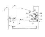
図1は、本発明の実施例1に係る画像形成装置の概略構成を示す断面図である。本実施例の画像形成装置は転写式電子写真方式のレーザビームプリンタである。 FIG. 1 is a cross-sectional view illustrating a schematic configuration of an image forming apparatus according to Embodiment 1 of the present invention. The image forming apparatus of this embodiment is a transfer type electrophotographic laser beam printer.
まず、図1を用いて本実施例の画像形成装置の全体的な構成について説明する。 First, the overall configuration of the image forming apparatus of this embodiment will be described with reference to FIG.
プリント開始の信号が装置に入力されると、レーザスキャナ31が画像情報に応じたレーザ光を、図1において反時計回りに回転している感光ドラムDの表面上に照射し、感光ドラムDの表面上に静電潜像が形成される。この静電潜像は現像部30によりトナー現像される。なお、以下の説明では、図1に示す断面の状態において、反時計回り、時計回りをいうものとする。
When a print start signal is input to the apparatus, the
また、プリント開始の信号が画像形成装置に入力されると、図示しない記録材積載部に収納されている記録材Sが時計回りに回転する給送ローラR1によって最上位の記録材から順に繰り出される。 When a print start signal is input to the image forming apparatus, the recording material S accommodated in a recording material stacking unit (not shown) is sequentially fed out from the uppermost recording material by a feeding roller R1 that rotates clockwise. .
繰り出された記録材Sは、搬送ローラ対R2,R3によって感光ドラムDと転写ローラTRの間の転写部に送られる。転写部を通過する記録材Sには感光ドラムDの表面上に形成されたトナー像が転写ローラによって転写されていく。転写部を通過することで未定着のトナー像(未定着画像)が形成された記録材Sは定着手段としての定着装置へと送られる。ここで、感光ドラムD、現像部30及び転写ローラTRは、画像形成手段に相当する。
The fed recording material S is sent to a transfer portion between the photosensitive drum D and the transfer roller TR by the conveying roller pair R2, R3. A toner image formed on the surface of the photosensitive drum D is transferred to the recording material S passing through the transfer portion by the transfer roller. The recording material S on which an unfixed toner image (unfixed image) is formed by passing through the transfer portion is sent to a fixing device as fixing means. Here, the photosensitive drum D, the developing
定着装置で記録材Sは加圧ローラ21と加熱ユニット22で形成される定着ニップ部(ニップ部)で挟持され、加熱加圧されることにより、転写されたトナー像が記録材表面に定着される。定着装置を通過した記録材Sは作業者(操作者)により選択された排出部から排出される。
In the fixing device, the recording material S is sandwiched by a fixing nip portion (nip portion) formed by the
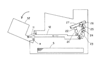
図2は、本実施例の画像形成装置の装置前側に設けられた装置前側開閉部32と、定着ニップ部の圧解除手段との連動部を示している。図3は、本実施例において、装置前側開閉部32の開状態における圧解除手段の連動部を示している。ここで、装置前側開閉部32は、定着ニップ部で挟持搬送される記録材の搬送方向に対して交差する装置本体の2つの側面のうち一方の側面に設けられ、装置本体に対して開閉可能に設けられた第1開閉部材に相当する。
FIG. 2 shows an interlocking portion between the apparatus front side opening /
定着部の加熱ユニット22が、圧付与手段としての加圧板27及び加圧バネ28により加圧ローラ21に押圧されることで、定着ニップ部には加圧力が付与されている。装置前側開閉部32は、画像形成装置に対して支点(支持部)aを中心に反時計回りに回動するように配設されており、リンクアーム小11、リンクアーム大12、リンクギア23、アイドラギア24、アイドラギア25を介して圧解除カム26に連結されている。ここで、リンクアーム小11、リンクアーム大12、リンクギア23、アイドラギア24、アイドラギア25は、装置前側開閉部32の開動作と、圧解除カム26の圧解除動作を連動させる第1連動手段に相当する。また、圧解除カム26は、第1圧解除手段に相当する。
The fixing
リンクアーム小11は装置前側開閉部32と連結部bで、リンクアーム大12とは連結
部cで回動可能に連結されている。また、リンクアーム大12は、図示しない保持部材によって水平方向にだけ往復移動可能に保持されている。
The
リンクギア23は、支点dを中心に回動可能に連結部eによってリンクアーム大12と連結されている。リンクギア23の扇形部は歯車歯型を有しており、アイドラギア24、アイドラギア25に回転モーメントを伝達する。また、圧解除カム26の扇形部は歯車歯型を有しており、アイドラギア25と連結されている。
The
装置前側開閉部32を反時計回りに回転させると、各伝達部材を介して圧解除カム26が反時計回りに回転することで加圧板27と当接し、さらに加圧板27を押し上げることで(図3に示す点線の位置から実線の位置に移動)、定着ニップ部の圧力が解除される。ここで、装置前側開閉部32の開動作によって圧解除カム26が加圧板27を押し上げる場合、加圧バネ28により定着ニップ部に付与された加圧力が、開放された装置前側開閉部32にかかる力(支点aに作用する力)の反力(抗力)として作用することとなる。
When the front opening / closing
装置前側開閉部32と画像形成装置本体との間には、レーザスキャナからのレーザ光漏れや、動作中の駆動歯車へのユーザアクセス防止等の安全面への配慮から、第1検知手段として図示しないインターロックスイッチ機構の安全装置が設けられている。
Between the apparatus front side opening / closing
このことにより、装置前側開閉部32が開放された場合にはプリント動作(画像形成動作)が規制(禁止)され、装置前側開閉部32が閉じられない限り、プリント待機状態、及びプリント動作が再開されることは無い。この為、定着ニップ部の圧力が解除されたままの状態でプリント動作が開始することはない。
As a result, when the apparatus front side opening / closing
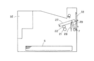
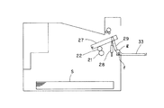
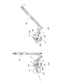
図4は、本実施例の画像形成装置の装置後側に設けられた装置後側開閉部33と定着ニップ部の圧解除手段との連動部を示している。図5は、本実施例において、装置後側開閉部33の開状態における圧解除手段の連動部を示している。ここで、装置後側開閉部33は、定着ニップ部で挟持搬送される記録材の搬送方向に対して交差する装置本体の2つの側面のうち他方の側面に設けられ、装置本体に対して開閉可能に設けられた第2開閉部材に相当する。
FIG. 4 shows an interlocking portion between the apparatus rear side opening /
装置後側開閉部33は、支点fを中心に時計回りに回動するように配設されている。圧解除アーム29は、図示しない保持部材によりh方向にだけ往復移動可能に保持されている。
The apparatus rear side opening / closing
装置後側開閉部33を時計回りに回転させると、装置後側開閉部33のカム形状gが圧解除アーム29と当接し、圧解除アーム29をh方向に押し上げる。押し上げられた圧解除アーム29は加圧板27と当接し、さらに加圧板27を押し上げることで、定着ニップ部の圧力が解除される。ここで、装置後側開閉部33の開動作によって圧解除アーム29が加圧板27を押し上げる場合、加圧バネ28により定着ニップ部に付与された加圧力が、開放された装置後側開閉部33にかかる力(支点fに作用する力)の反力として作用することとなる。装置後側開閉部33のカム形状gは、装置後側開閉部33の開動作と、圧解除アーム29の圧解除動作とを連動させる第2連動手段に相当する。また、圧解除アーム29は、第2圧解除手段に相当する。
When the apparatus rear side opening / closing
図6は、装置後側開閉部33と装置後側開閉検知手段との連動部を示す概略図であり、(a)は装置後側開閉部33の閉状態を示し、(b)は装置後側開閉部33の開状態をしめしている。
6A and 6B are schematic views showing an interlocking portion between the apparatus rear side opening / closing
本実施例においては、装置後側開閉検知手段(第2検知手段)として、定着部出口(下
流側)に配設された排出センサを用いている。排出センサは、フォトインタラプタ42、斜光フラグ43、定着排出ガイド44aと図示しないセンサバネにより構成されており、記録材搬送経路を搬送される記録材を検知する記録材検知手段に相当する。
In this embodiment, a discharge sensor disposed at the fixing unit outlet (downstream side) is used as the apparatus rear side opening / closing detection means (second detection means). The discharge sensor includes a
フォトインタラプタ42は、定着排出ガイド44aの下部に配置されている。斜光フラグ43は記録材幅方向に伸びた軸部を中心として回動可能に定着排出ガイド44aに保持されており、図示しないバネの押圧力により、待機中は斜光フラグ43の斜光部がフォトインタラプタ42の発光部と受光部を遮蔽する姿勢で保持されている。ここで、記録材幅方向とは、記録材の搬送方向に対して略直交する記録材の幅方向をいう。
The
記録材が定着ニップ部を通過すると、記録材先端が斜光フラグ43と接触し、斜光フラグ43は定着排出ガイド44aと係合された軸を中心に時計回りに回転し、斜光フラグ43の斜光部が移動する。このことで、フォトインタラプタ42の発光部と受光部との間で信号の受け渡しが行われ、その信号が画像形成装置の制御手段としての制御部に入力される。
When the recording material passes through the fixing nip portion, the leading end of the recording material comes into contact with the
何らかの原因でジャムが発生し、記録材が定着部に滞留した場合、斜光フラグ43は回転した位置に保持され、フォトインタラプタ42からは連続して制御部に信号が入力される。この信号が一定時間以上出力された場合には、制御部はプリント動作を停止する。
When a jam occurs for some reason and the recording material stays in the fixing unit, the
センサリンク40は定着排出ガイド44aに支点jを中心に回動可能かつ、定着排出ガイド44aに設けられた爪部44bとセンサリンク40の爪部とに両端を係合されたセンサリンクバネ41により、引っ張り方向の力を受けた状態で保持されている。ここで、センサリンク40は、装置後側開閉部33の開動作と、排出センサの検知動作とを連動させる第3連動手段に相当する。
The
装置後側開閉部33が閉じた状態では、図6(a)に示すように、センサリンク40と装置後側開閉部33とは当接しており、斜光フラグ43は定着ニップ部を通過した記録材を検知可能な姿勢で保持される。
In the state where the apparatus rear side opening / closing
装置後側開閉部33が開いた状態においては、図6(b)に示すように、センサリンク40と装置後側開閉部33が離間するため、センサリンク40はセンサリンクバネ41の引っ張り力により、図6(b)に示す矢印方向に回動し斜光フラグ43に当接する。
In the state where the apparatus rear side opening / closing
センサリンク40から回転モーメントを受けた斜光フラグ43は、定着排出ガイド44aに係合された軸を中心に時計回りに回転することで、斜光フラグ43の斜光部が移動し、フォトインタラプタ42の発光部と受光部の間で信号の受け渡しが行われる。この信号が一定時間以上出力された場合には、制御部はプリント動作を停止する。
The
このように構成することにより、作業者が装置後側開閉部33を開き、定着部に滞留した記録材を除去した場合にも、画像形成装置は動作停止状態が維持されるため、定着ニップ部の圧力が解除された状態でプリント動作が再開されることはない。
With this configuration, even when the operator opens the rear opening /
したがって、記録材のいかなる部分が定着ニップ部に挟持されている場合においても、作業者のジャム処理作業時に確実に定着ニップ部の圧力を解除し、記録材の破損を予防し、定着装置の構成部材にもダメージを与えること無くジャム処理作業が行える。 Therefore, even when any part of the recording material is sandwiched by the fixing nip portion, the pressure of the fixing nip portion is surely released at the time of an operator's jam processing operation, and the damage of the recording material is prevented. Jam processing can be performed without damaging the members.
また、近年、画像形成装置の小型化が進み、装置前側開閉部32は装置外装、マルチサイズ給送ユニット、記録材搬送ガイド等の複数の部材からなる場合も多々ある。そのため、部品自重により、装置前側開閉部32の支点aに負荷がかかることが懸念される。ここ
で、マルチサイズ給送ユニットは、記録材を収容可能に設けられ画像形成手段に記録材を給送する給送ユニットに相当する。また、記録材搬送ガイドは、記録材搬送経路に沿って設けられ記録材をガイドする記録材ガイド部材に相当する。
In recent years, the size of image forming apparatuses has been reduced, and the apparatus front side opening /
そこで、装置前側開閉部32を開けた際の定着ニップ圧解除量P1と、装置後側開閉部33を開けた際の定着ニップ圧解除量P2が、P1>P2となるように圧解除カム26の回動量と圧解除アーム29の移動量を設定するとよい。
Accordingly, the
このように設定することで、前後どちらの開閉部を先に開けた場合においても、定着ニップ部の加圧力が、装置前側開閉部32を開けた際に装置前側開閉部32の支点aに係る回転モーメントの反力となりダンパ効果を得ることが可能となる。
By setting in this way, the pressure applied to the fixing nip portion is related to the fulcrum a of the apparatus front side opening / closing
このように、圧解除カム26の回動量(圧解除量)と圧解除アーム29の移動量(圧解除量)とは、次に示すような開閉部材に対応する圧解除手段の圧解除量の方が大きくなるように設定されているとよい。それは、装置前側開閉部32を開けた際に装置前側開閉部32にかかる力(支点aに作用する力)と、装置後側開閉部33を開けた際に装置後側開閉部33に係る力(支点fに作用する力)とのうち大きな力がかかる開閉部材である。
Thus, the rotation amount (pressure release amount) of the
なお、本実施例においては、装置前側開閉部32と画像形成装置本体との間には、インターロックスイッチ機構の安全装置を設けることで、装置前側開閉部32の開閉状態を検知していたが、これに限るものではない。すなわち、装置後側開閉部33の開閉検知同様、記録材搬送経路を搬送される記録材を検知する記録材検知手段を用いる(利用する、兼用する)ものであってもよい。
In this embodiment, the safety state of the interlock switch mechanism is provided between the apparatus front opening / closing
次に、本発明の実施例2について説明する。 Next, a second embodiment of the present invention will be described.
図7は、本実施例において、装置前側開閉部32及び装置後側開閉部33と、定着ニップ部の圧解除手段との連動部を示した図であり、
る。図8は、装置後側開閉部を開けた際に発生する回転モーメントを装置前側開閉部との連動部への伝達を遮断する構成を説明するための図であって、前側伝達ギア24a、後側伝達ギア24bの概略構成を説明するための図である。また、図8において、(a)は、前側伝達ギア24a側(図7に示す図面の手前側)から見た斜視図であり、(b)は圧縮バネ24c側から見た斜視図である。なお、本実施例の画像形成装置の基本構成は、実施例1と同様のため、本実施例においては、実施例1に対して異なる構成部分について述べることとし、実施例1と同様の構成部分については、その説明を省略する。
FIG. 7 is a view showing an interlocking portion between the apparatus front side opening / closing
The FIG. 8 is a view for explaining a configuration for interrupting the transmission of the rotational moment generated when the apparatus rear side opening / closing part is opened to the interlocking part with the apparatus front side opening / closing part. It is a figure for demonstrating schematic structure of the
装置前側開閉部32は、画像形成装置に対して支点aを中心に反時計回りに回動するように配設されている。そして、装置前側開閉部32は、リンクアーム小11、リンクアーム大12、リンクギア23、前側伝達ギア24a、後側伝達ギア24b、アイドラギア25を介して圧解除カム26に連結されている。ここで、リンクアーム小11、リンクアーム大12、リンクギア23、前側伝達ギア24a、後側伝達ギア24b、アイドラギア25は、装置前側開閉部32の開動作と、圧解除カム26の圧解除動作とを連動させる第1連動手段に相当する。
The apparatus front side opening / closing
リンクアーム小11は装置前側開閉部32と連結部bで、リンクアーム大12とは連結部cで回動可能に連結されている。また、リンクアーム大12は、図示しない保持部材によって水平方向にだけ往復移動可能に保持されている。
The
リンクギア23は、支点dを中心に回動可能に連結部eによってリンクアーム大12と
連結されている。リンクギア23の扇形部は歯車歯型を有しており、前側伝達ギア24aに回転モーメントを伝達する。
The
前側伝達ギア24aと後側伝達ギア24bは、互いに接する接触面(軸方向に略直交する面)に、前側伝達ギア24aから後側伝達ギア24bに反時計回りの回転モーメントのみが伝達されるように係合凹部24a1、係合凸部24b1がそれぞれ設けられている。
The
係合凹部24a1は、周方向に対して略垂直をなす平面部24a2と、平面部24a2から周方向に延びて、接触面まで傾斜して設けられた傾斜部24a3とから構成されている。 The engaging recess 24a1 includes a flat portion 24a2 that is substantially perpendicular to the circumferential direction, and an inclined portion 24a3 that extends from the flat portion 24a2 in the circumferential direction and is inclined to the contact surface.
係合凸部24b1は、周方向に対して略垂直をなす平面部24b2と、平面部24b2から周方向に延びて、接触面まで傾斜して設けられた傾斜部24b3とから構成されている。 The engaging convex portion 24b1 includes a flat portion 24b2 that is substantially perpendicular to the circumferential direction, and an inclined portion 24b3 that extends in the circumferential direction from the flat portion 24b2 and is inclined to the contact surface.
そして、前側伝達ギア24aと後側伝達ギア24bは、圧縮バネ24cにより、係合凹部24a1と係合凸部24b1とが互いに係合する方向に押圧されている。
The
前側伝達ギア24aに反時計回りの回転モーメントが作用した場合、係合凹部24a1の平面部24a2と、係合凸部24b1の平面部24b2とが係合する(噛み合う)ことにより、前側伝達ギア24aから後側伝達ギア24bに回転モーメントが伝達される。
When a counterclockwise rotational moment is applied to the
ここで、前側伝達ギア24aに時計回りの回転モーメントが作用した場合、又は、後側伝達ギア24bに反時計回りの回転モーメントが作用した場合、係合凹部24a1と係合凸部24b1とは、互いに滑り、一方が回転しながら当接離間を繰り返すこととなる。この場合、圧縮バネ24cの押圧力に抗して係合状態が解除される方向、すなわち回転軸方向であって、互いに離間する方向に前側伝達ギア24a又は後側伝達ギア24bが移動(スライド)する。この為、前側伝達ギア24aと後側伝達ギア24bとの間で、回転モーメントの伝達が行われることはない。
Here, when a clockwise rotational moment acts on the
また、圧解除カム26の扇形部は歯車歯型を有しており、アイドラギア25と連結されている。装置前側開閉部32を反時計回りに回転させると、各伝達部材を介して圧解除カム26が反時計回りに回転することで加圧板27と当接し、さらに加圧板27を押し上げることで、定着ニップ部の圧力が解除される。
The sector of the
装置後側開閉部33は、支点fを中心に時計回りに回動するよう配設されており、扇形部には歯車歯型を有している。
The apparatus rear side opening / closing
装置後側開閉部33を時計回りに回転させると、装置後側開閉部33の歯車歯型部もともに支点fを中心に回転し、後側伝達ギア24bと噛合うこととなる。
When the apparatus rear side opening / closing
これにより、後側伝達ギア24bに反時計回りの方向の回転モーメントが付与され、アイドラギア25を介して圧解除カム26が反時計回りに回転することで加圧板27と当接し、さらに加圧板27を押し上げることで、定着ニップ部の圧力が解除される。
As a result, a counterclockwise rotational moment is applied to the
この時、前側伝達ギア24aと、後側伝達ギア24bの伝達面の斜面同士、すなわち、係合凹部24a1と係合凸部24b1とは、上述したように互いに滑ることとなる。この場合、圧縮バネ24cの押圧力に抗して係合状態が解除される方向、すなわち回転軸方向に後側伝達ギア24bが移動する為、前側伝達ギア24aには回転モーメントが付与されない。
At this time, the slopes of the transmission surfaces of the
ここで、後側伝達ギア24b及びアイドラギア25は、装置後側開閉部33の開動作と、圧解除カム26の圧解除動作とを連動させる第2連動手段に相当する。
Here, the
本実施例では、上述したように、装置前側開閉部32の開動作と圧解除動作とを連動させる第1連動手段は、装置後側開閉部33の開動作と圧解除動作とを連動させる第2連動手段を含んでいる。このような構成は、装置後側開閉部33が、装置前側開閉部32よりも定着装置から近い位置に配設されることで容易に実現可能となる。
In the present embodiment, as described above, the first interlocking means for linking the opening operation of the apparatus front side opening / closing
このように構成することで、単一(同一)の圧解除手段で、装置前側後側両方の開閉部材の開動作に連動して定着ニップ部の加圧力を解除可能となる。 With this configuration, the pressure applied to the fixing nip portion can be released by a single (same) pressure release means in conjunction with the opening operation of both the front and rear opening / closing members.
したがって、本実施例の画像形成装置においては、実施例1の画像形成装置の構成よりも簡単な構成で、実施例1と同様の効果を得ることが可能となる。 Therefore, the image forming apparatus of the present embodiment can obtain the same effects as those of the first embodiment with a simpler configuration than that of the image forming apparatus of the first embodiment.
11 リンクアーム小
12 リンクアーム大
21 加圧ローラ
22 加熱ユニット
23 リンクギア、
24 アイドラギア
25 アイドラギア
26 圧解除カム
28 加圧板27及び加圧バネ
29 圧解除アーム
30 現像部
32 装置前側開閉部
33 装置後側開閉部
42 フォトインタラプタ
43 斜光フラグ
44a 定着排出ガイド
g カム形状
D 感光ドラム
S 記録材
TR 転写ローラ
11 Link arm small 12 Link arm large 21
24
Claims (6)
未定着画像が形成された記録材を、圧付与手段により加圧力が付与されたニップ部で挟持搬送して前記未定着画像を前記記録材に定着させる定着手段と、
を備えた画像形成装置において、
前記ニップ部で挟持搬送される記録材の搬送方向に対して交差する装置本体の2つの側面のうち一方の側面に設けられ、装置本体に対して開閉可能な第1開閉部材と、
前記2つの側面のうち他方の側面に設けられ、装置本体に対して開閉可能な第2開閉部材と、
前記ニップ部の加圧力を解除する第1圧解除手段と、
前記ニップ部の加圧力を解除する第2圧解除手段と、
前記第1開閉部材の開動作と前記第1圧解除手段の圧解除動作とを連動させる第1連動手段と、
前記第2開閉部材の開動作と前記第2圧解除手段の圧解除動作とを連動させる第2連動手段と、
前記第1開閉部材の開閉状態を検知する第1検知手段と、
前記第2開閉部材の開閉状態を検知する第2検知手段と、
前記第1検知手段及び前記第2検知手段のうち少なくともいずれか一方の検知手段により、前記第1開閉部材及び前記第2開閉部材のうち少なくともいずれか一方の開閉部材が開状態にあると検知された場合に、前記画像形成手段による画像形成動作を規制する制御手段と、
を備え、
前記第1開閉部材及び前記第2開閉部材のうち少なくともいずれか一方の開閉部材の開動作が行われた場合、前記開動作に連動して前記ニップ部の加圧力が解除されるとともに、前記制御手段により前記画像形成動作が規制されることを特徴とする画像形成装置。 Image forming means for forming an unfixed image on a recording material;
A fixing unit for fixing the unfixed image to the recording material by sandwiching and conveying the recording material on which the unfixed image is formed at a nip portion to which pressure is applied by a pressure applying unit;
In an image forming apparatus comprising:
A first opening / closing member that is provided on one of the two side surfaces of the apparatus main body that intersects the conveyance direction of the recording material that is nipped and conveyed by the nip portion, and that can be opened and closed with respect to the apparatus main body;
A second opening / closing member provided on the other side surface of the two side surfaces and capable of opening and closing with respect to the apparatus main body;
First pressure release means for releasing the pressure applied to the nip portion;
A second pressure releasing means for releasing the applied pressure of the nip portion;
First interlocking means for interlocking the opening operation of the first opening and closing member and the pressure releasing operation of the first pressure releasing means;
Second interlocking means for interlocking the opening operation of the second opening / closing member and the pressure releasing operation of the second pressure releasing means;
First detecting means for detecting an open / closed state of the first opening / closing member;
Second detection means for detecting an open / closed state of the second opening / closing member;
At least one of the first detection means and the second detection means detects that at least one of the first opening / closing member and the second opening / closing member is in an open state. Control means for regulating the image forming operation by the image forming means,
With
When an opening operation of at least one of the first opening / closing member and the second opening / closing member is performed, the pressure applied to the nip portion is released in conjunction with the opening operation, and the control An image forming apparatus, wherein the image forming operation is restricted by means.
前記第2開閉部材は、装置本体の外装と、記録材搬送経路に沿って設けられ記録材をガイドする記録材ガイド部材とを含み、
前記第1圧解除手段の圧解除量の大きさは、前記第2圧解除手段の圧解除量の大きさよりも大きくなるように設けられていることを特徴とする請求項1乃至4のいずれか1項に記載の画像形成装置。 The first opening / closing member is provided along the recording material conveyance path, and is provided along the recording material conveyance path, the exterior of the apparatus main body, a feeding unit that is capable of accommodating the recording material and feeds the recording material to the image forming unit. A recording material guide member to be
The second opening / closing member includes an exterior of the apparatus main body, and a recording material guide member that is provided along the recording material conveyance path and guides the recording material,
5. The pressure release amount of the first pressure release means is provided to be larger than the pressure release amount of the second pressure release means. 2. The image forming apparatus according to item 1.
前記第1連動手段は、前記第2連動手段を含むことを特徴とする請求項1乃至5のいずれか1項に記載の画像形成装置。 The first pressure releasing means and the second pressure releasing means are the same means,
6. The image forming apparatus according to claim 1, wherein the first interlocking unit includes the second interlocking unit.
Priority Applications (1)
| Application Number | Priority Date | Filing Date | Title |
|---|---|---|---|
| JP2008198283A JP5247285B2 (en) | 2008-07-31 | 2008-07-31 | Image forming apparatus |
Applications Claiming Priority (1)
| Application Number | Priority Date | Filing Date | Title |
|---|---|---|---|
| JP2008198283A JP5247285B2 (en) | 2008-07-31 | 2008-07-31 | Image forming apparatus |
Publications (3)
| Publication Number | Publication Date |
|---|---|
| JP2010038952A true JP2010038952A (en) | 2010-02-18 |
| JP2010038952A5 JP2010038952A5 (en) | 2011-09-22 |
| JP5247285B2 JP5247285B2 (en) | 2013-07-24 |
Family
ID=42011620
Family Applications (1)
| Application Number | Title | Priority Date | Filing Date |
|---|---|---|---|
| JP2008198283A Active JP5247285B2 (en) | 2008-07-31 | 2008-07-31 | Image forming apparatus |
Country Status (1)
| Country | Link |
|---|---|
| JP (1) | JP5247285B2 (en) |
Cited By (6)
| Publication number | Priority date | Publication date | Assignee | Title |
|---|---|---|---|---|
| JP2012058454A (en) * | 2010-09-08 | 2012-03-22 | Canon Inc | Image forming device |
| JP2012093700A (en) * | 2010-09-30 | 2012-05-17 | Brother Ind Ltd | Image forming apparatus |
| EP2444858A3 (en) * | 2010-09-30 | 2013-11-13 | Brother Kogyo Kabushiki Kaisha | Image forming apparatus |
| JP2014167613A (en) * | 2013-01-31 | 2014-09-11 | Canon Inc | Image forming apparatus |
| JP2015055741A (en) * | 2013-09-11 | 2015-03-23 | 京セラドキュメントソリューションズ株式会社 | Fixing device and image forming apparatus |
| JP2019207378A (en) * | 2018-05-30 | 2019-12-05 | キヤノン株式会社 | Image forming apparatus |
Citations (4)
| Publication number | Priority date | Publication date | Assignee | Title |
|---|---|---|---|---|
| JPH0517047A (en) * | 1991-07-11 | 1993-01-26 | Canon Inc | Sensing device |
| JPH08137181A (en) * | 1994-11-11 | 1996-05-31 | Minolta Co Ltd | Image forming device |
| JP2000137419A (en) * | 1998-11-02 | 2000-05-16 | Canon Inc | Image forming device |
| JP2001022236A (en) * | 1999-07-12 | 2001-01-26 | Matsushita Graphic Communication Systems Inc | Image forming device |
-
2008
- 2008-07-31 JP JP2008198283A patent/JP5247285B2/en active Active
Patent Citations (4)
| Publication number | Priority date | Publication date | Assignee | Title |
|---|---|---|---|---|
| JPH0517047A (en) * | 1991-07-11 | 1993-01-26 | Canon Inc | Sensing device |
| JPH08137181A (en) * | 1994-11-11 | 1996-05-31 | Minolta Co Ltd | Image forming device |
| JP2000137419A (en) * | 1998-11-02 | 2000-05-16 | Canon Inc | Image forming device |
| JP2001022236A (en) * | 1999-07-12 | 2001-01-26 | Matsushita Graphic Communication Systems Inc | Image forming device |
Cited By (9)
| Publication number | Priority date | Publication date | Assignee | Title |
|---|---|---|---|---|
| JP2012058454A (en) * | 2010-09-08 | 2012-03-22 | Canon Inc | Image forming device |
| JP2012093700A (en) * | 2010-09-30 | 2012-05-17 | Brother Ind Ltd | Image forming apparatus |
| US8509654B2 (en) | 2010-09-30 | 2013-08-13 | Brother Kogyo Kabushiki Kaisha | Image forming apparatus having mechanism for placing fixing unit in nip relaxed state |
| EP2444858A3 (en) * | 2010-09-30 | 2013-11-13 | Brother Kogyo Kabushiki Kaisha | Image forming apparatus |
| US8693918B2 (en) | 2010-09-30 | 2014-04-08 | Brother Kogyo Kabushiki Kaisha | Image forming apparatus having mechanism for placing fixing unit in nip relaxed state |
| JP2014167613A (en) * | 2013-01-31 | 2014-09-11 | Canon Inc | Image forming apparatus |
| JP2015055741A (en) * | 2013-09-11 | 2015-03-23 | 京セラドキュメントソリューションズ株式会社 | Fixing device and image forming apparatus |
| JP2019207378A (en) * | 2018-05-30 | 2019-12-05 | キヤノン株式会社 | Image forming apparatus |
| JP7102232B2 (en) | 2018-05-30 | 2022-07-19 | キヤノン株式会社 | Image forming device |
Also Published As
| Publication number | Publication date |
|---|---|
| JP5247285B2 (en) | 2013-07-24 |
Similar Documents
| Publication | Publication Date | Title |
|---|---|---|
| JP5587038B2 (en) | Image forming apparatus | |
| JP5554981B2 (en) | Fixing apparatus and image forming apparatus | |
| JP5247285B2 (en) | Image forming apparatus | |
| US9377748B2 (en) | Image forming apparatus | |
| JP4873487B2 (en) | Image forming apparatus | |
| JP2010117731A (en) | Color electrophotographic image forming apparatus | |
| US9170536B2 (en) | Fixing device having pressure release member supported reciprocably, and image forming apparatus equipped therewith | |
| JP4958467B2 (en) | Image forming apparatus | |
| JP4636927B2 (en) | Image forming apparatus | |
| JP5993798B2 (en) | Fixing apparatus and image forming apparatus | |
| JP6459922B2 (en) | Image forming apparatus | |
| JP6866076B2 (en) | Image forming device and sheet transfer device | |
| JP2002296948A (en) | Image forming apparatus | |
| JP6323377B2 (en) | Sheet conveying apparatus and image forming apparatus provided with the same | |
| JP5914400B2 (en) | Image forming apparatus | |
| JP2004053987A (en) | Image forming apparatus | |
| JP2012042775A (en) | Image forming device | |
| JP2010256809A (en) | Image forming apparatus | |
| US20230324841A1 (en) | Image forming apparatus | |
| JP6292902B2 (en) | Image forming apparatus | |
| JP2004142845A (en) | Detection device | |
| JP5459544B2 (en) | Sheet conveying apparatus and image forming apparatus using the same | |
| JP7382022B2 (en) | Sheet conveyance device and image forming device | |
| JP2008310192A (en) | Fixing portion structure of image forming apparatus | |
| JP2016142908A (en) | Image forming apparatus |
Legal Events
| Date | Code | Title | Description |
|---|---|---|---|
| A621 | Written request for application examination |
Free format text: JAPANESE INTERMEDIATE CODE: A621 Effective date: 20110801 |
|
| A521 | Written amendment |
Free format text: JAPANESE INTERMEDIATE CODE: A523 Effective date: 20110810 |
|
| A977 | Report on retrieval |
Free format text: JAPANESE INTERMEDIATE CODE: A971007 Effective date: 20121114 |
|
| A131 | Notification of reasons for refusal |
Free format text: JAPANESE INTERMEDIATE CODE: A131 Effective date: 20121120 |
|
| A521 | Written amendment |
Free format text: JAPANESE INTERMEDIATE CODE: A523 Effective date: 20130118 |
|
| TRDD | Decision of grant or rejection written | ||
| A01 | Written decision to grant a patent or to grant a registration (utility model) |
Free format text: JAPANESE INTERMEDIATE CODE: A01 Effective date: 20130312 |
|
| A61 | First payment of annual fees (during grant procedure) |
Free format text: JAPANESE INTERMEDIATE CODE: A61 Effective date: 20130409 |
|
| R151 | Written notification of patent or utility model registration |
Ref document number: 5247285 Country of ref document: JP Free format text: JAPANESE INTERMEDIATE CODE: R151 |
|
| FPAY | Renewal fee payment (event date is renewal date of database) |
Free format text: PAYMENT UNTIL: 20160419 Year of fee payment: 3 |