JP6849357B2 - Manufacturing method of 3D modeling equipment and 3D modeled objects - Google Patents
Manufacturing method of 3D modeling equipment and 3D modeled objects Download PDFInfo
- Publication number
- JP6849357B2 JP6849357B2 JP2016181368A JP2016181368A JP6849357B2 JP 6849357 B2 JP6849357 B2 JP 6849357B2 JP 2016181368 A JP2016181368 A JP 2016181368A JP 2016181368 A JP2016181368 A JP 2016181368A JP 6849357 B2 JP6849357 B2 JP 6849357B2
- Authority
- JP
- Japan
- Prior art keywords
- photocurable resin
- light
- light transmitting
- film
- dimensional modeling
- Prior art date
- Legal status (The legal status is an assumption and is not a legal conclusion. Google has not performed a legal analysis and makes no representation as to the accuracy of the status listed.)
- Active
Links
Images


Description
本発明は、容器中に収容した光硬化性樹脂に光照射を行い、3次元造形物を製造する3次元造形装置および3次元造形物の製造方法に関する。 The present invention relates to a three-dimensional modeling apparatus for producing a three-dimensional model by irradiating a photocurable resin contained in a container with light, and a method for producing the three-dimensional model.
近年、未硬化状態の光硬化性樹脂を露光し、固化(硬化)させる工程を繰り返して造形物を形成する3次元造形技術の開発が進められている。この種の3次元造形装置では、造形ステージないし固化済みの造形物(ワーク)上に1層ずつ塗布ローラなどにより材料の光硬化性樹脂を塗布し、光照射を繰り返す構成が知られている。また、容器に収容した光硬化性樹脂中に造形ステージ(ないし造形物の造形済み部分)を浸漬し、下方または上方から光照射を行って層造形を行い、次層の造形のために造形ステージを上方または下方に移動させる構成も知られている。 In recent years, the development of a three-dimensional modeling technique for forming a modeled object by repeating a process of exposing an uncured photocurable resin and solidifying (curing) it has been promoted. In this type of three-dimensional modeling apparatus, it is known that a photocurable resin as a material is applied layer by layer on a modeling stage or a solidified modeled object (work) by a coating roller or the like, and light irradiation is repeated. In addition, the modeling stage (or the modeled part of the modeled object) is immersed in the photocurable resin contained in the container, and light irradiation is performed from below or above to perform layer modeling, and the modeling stage is used for modeling the next layer. Is also known to move up or down.
後者の構成では、前者の構成のような塗布機構を用いないため、例えば造形装置の機械的な構成や制御が簡単である利点があるが、積層方向の造形速度が遅いことが問題とされている(特許文献1)。この造形速度を低下させる要因の1つは、造形条件によっては樹脂の容器、例えば硬化光を透過させる光透過部材の部位で光硬化性樹脂の固着(ないし粘度上昇)が起きる問題である。この場合には、例えば1層を造形した後、次層のためにステージを昇降させる場合に、固着ないし粘度上昇の起きている部位を強制的に引き剥す工程が必要となり、このために造形速度が低下する。また、造形ステージの移動装置に大きな駆動力が必要となる問題もある。また、造形速度を低下させる他の要因は、1層の造形後に造形ステージを移動させた時、これも造形条件にもよるが、次の造形層を形成する空間への光硬化性樹脂の供給が迅速に行われない問題である。 Since the latter configuration does not use a coating mechanism like the former configuration, there is an advantage that the mechanical configuration and control of the modeling apparatus are simple, for example, but the problem is that the modeling speed in the stacking direction is slow. (Patent Document 1). One of the factors that lowers the molding speed is a problem that the photocurable resin sticks (or increases in viscosity) at a resin container, for example, a portion of a light transmitting member that transmits cured light, depending on the molding conditions. In this case, for example, when one layer is formed and then the stage is raised or lowered for the next layer, a step of forcibly peeling off the portion where the sticking or viscosity increase occurs is required, and for this reason, the forming speed is required. Decreases. There is also a problem that a large driving force is required for the moving device of the modeling stage. Another factor that reduces the modeling speed is the supply of the photocurable resin to the space where the next modeling layer is formed when the modeling stage is moved after the modeling of one layer, which also depends on the modeling conditions. Is a problem that is not done quickly.
光透過面ないしは光照射面と、光固化層の引き剥がしを容易とするため、光透過面ないしは光照射面の部分を移動可能なフィルム材料で構成し、このフィルム材料を移動しながら光照射・光硬化を行う構成が提案されている(特許文献2)。 In order to facilitate the peeling of the light transmitting surface or light irradiation surface and the photosolidification layer, the light transmission surface or light irradiation surface is made of a movable film material, and light irradiation is performed while moving this film material. A configuration for photocuring has been proposed (Patent Document 2).
また、容器の特定部位、例えば硬化光を透過させる光透過部材の近傍の空間領域において、光硬化性樹脂の硬化(重合)を阻害する状態を形成する手法が提案されている(特許文献3)。この構成では、例えば容器中の光硬化性樹脂に臨む光透過部材をガス透過部材から構成し、その外側から光硬化性樹脂中に光硬化性樹脂の硬化(重合)を阻害する気体(例えば酸素原子を含むもの)を透過させる。この構成によれば、ガス透過部材を透過した気体によって光透過部材の近傍の空間において光硬化性樹脂の硬化(重合)が阻止される。従って、光透過部材に対する固着や、ステージ移動速度を低下させ、次層のための溶融樹脂の供給速度の低下が抑制される。このような構成によって、例えば動画像として硬化光を照射するとともに連続的なステージ移動を行うことなどによって、連続的かつ高速な積層造形動作を行えるようになる可能性がある。 Further, a method of forming a state of inhibiting the curing (polymerization) of the photocurable resin in a specific part of the container, for example, a spatial region in the vicinity of a light transmitting member that transmits cured light has been proposed (Patent Document 3). .. In this configuration, for example, the light transmitting member facing the photocurable resin in the container is composed of a gas transmitting member, and a gas (for example, oxygen) that inhibits the curing (polymerization) of the photocurable resin into the photocurable resin from the outside thereof. (Contains atoms) is transmitted. According to this configuration, the gas transmitted through the gas transmitting member prevents the photocurable resin from curing (polymerizing) in the space in the vicinity of the light transmitting member. Therefore, sticking to the light transmitting member and lowering the stage moving speed are suppressed, and the lowering of the supply speed of the molten resin for the next layer is suppressed. With such a configuration, for example, by irradiating cured light as a moving image and continuously moving the stage, there is a possibility that continuous and high-speed laminated modeling operation can be performed.
しかしながら、特許文献2のようにフィルムを移動しながら固化(ないし粘度上昇)した部位を剥離する構成では、硬化面積により剥離抵抗が増大し、剥離困難になる問題や、剥離時の荷重により硬化層が変形する、といった問題があった。
However, in the configuration of peeling the solidified (or increasing viscosity) portion while moving the film as in
特に、硬化光を動画形式で連続的に照射し、これと同期的に造形ステージを連続的に移動する造形方式では酸素阻害層の厚みが0.02mm〜0.2mm程度と非常に薄い為、逐次材料をその薄さで供給するのは時間を要していた。 In particular, in the modeling method in which the curing light is continuously irradiated in a moving image format and the modeling stage is continuously moved in synchronization with this, the thickness of the oxygen inhibition layer is very thin, about 0.02 mm to 0.2 mm. It took time to sequentially supply the material in its thinness.
そこで、光硬化性樹脂の供給速度を上げるため、造形物の各層での断面積を小さくすることや、造形物を複数ブロックに分割して造形するような工夫が行われる。また、光硬化性樹脂に粘度の低い材料を使用する対策なども取られることがある。造形物の各層での断面積を小さくするために、例えばラティス構造のように造形層を小さくまたは小分けにすると、造形物の強度が低くなる問題が生じる。そもそも、ラティス形態のような構造は、必ずしも製造したい所期の造形物の構造に一致しない場合がある。 Therefore, in order to increase the supply speed of the photocurable resin, measures are taken to reduce the cross-sectional area of each layer of the modeled object or to divide the modeled object into a plurality of blocks for modeling. In addition, measures such as using a material having a low viscosity for the photocurable resin may be taken. If the modeling layer is made small or subdivided, for example, in a lattice structure, in order to reduce the cross-sectional area of each layer of the modeled object, there arises a problem that the strength of the modeled object is lowered. In the first place, a structure such as a lattice form may not always match the structure of the desired model to be manufactured.
また、光硬化性樹脂に粘度が低い材料を使用した場合には、固化時の収縮が大きくなり造形物の変形が起きる問題や、光硬化時の重合度が上がらずに強度低下を招いたり、耐熱性が低くなる、といった問題が生じる可能性がある。 In addition, when a material having a low viscosity is used for the photocurable resin, there is a problem that shrinkage during solidification becomes large and deformation of the modeled object occurs, and the degree of polymerization during photocuring does not increase, resulting in a decrease in strength. Problems such as low heat resistance may occur.
そこで、粘度の低い材料を使用し固化層への材料供給を早めるため、動画投影などにより光硬化を行う造形フェーズを急速に実行し、造形フェーズ後に後処理工程としてポストキュア法を実行する手法も考えられている。このポストキュア法では、樹脂の強度を上げるため、光や熱を加えることにより未硬化部分を硬化する工程が行われる。しかし、ポストキュアにより2次硬化を行う場合には、硬化時の寸法変化や変形などの問題が生じる可能性がある。 Therefore, in order to use a material with low viscosity and accelerate the supply of materials to the solidified layer, there is also a method of rapidly executing the modeling phase in which photocuring is performed by moving images, etc., and the post-cure method as a post-treatment process after the modeling phase. It is considered. In this post-cure method, in order to increase the strength of the resin, a step of curing the uncured portion by applying light or heat is performed. However, when secondary curing is performed by post-curing, problems such as dimensional change and deformation during curing may occur.
上記のように、光硬化性樹脂の供給速度を考慮して、造形物(固化層)を小分けにしたり、光硬化性樹脂の粘度を低下させたりすることは、本質的な解決とはいえず、しかも他の好ましくない副作用が種々生じる問題がある。そのため、光硬化性樹脂の粘度を徒らに低下させることなく、肉抜き部分の少ない、ソリッドな造形を行う場合には、従来では、ステージを移動させた後の次層のための狭い空間に精度良く未硬化の材料を充填時間が増大しがちであった。 As described above, considering the supply rate of the photocurable resin, dividing the modeled object (solidified layer) into small pieces or reducing the viscosity of the photocurable resin is not an essential solution. Moreover, there is a problem that various other unfavorable side effects occur. Therefore, in the case of performing solid modeling with few lightening parts without reducing the viscosity of the photocurable resin, conventionally, in a narrow space for the next layer after moving the stage. The filling time of uncured material with high accuracy tended to increase.
また、特許文献3のように硬化阻害性の気体を透過させる手法によっても、粘度の高い樹脂や1層の照射(硬化)面積の大きな形状の造形物では、例えば25〜35μmの厚みの次層のための空間に材料を充填する時間を短縮するのはそれ程容易ではない。
Further, even by a method of permeating a curing-inhibiting gas as in
本発明の課題は、上記の諸問題に鑑み、硬化光を透過させる光透過部材の付近などにおいて光硬化性樹脂の固化、固着や粘度低下を抑制しつつ、容易かつ高速に造形ステージおよび造形済み部分を移動できるようにすることにある。 In view of the above problems, the subject of the present invention is that the molding stage and the molding have been completed easily and at high speed while suppressing solidification, sticking and viscosity decrease of the photocurable resin in the vicinity of a light transmitting member that transmits cured light. It is to make the part movable.
上記課題を解決するため、本発明の3次元造形装置においては、光硬化性樹脂を収容する容器と、前記光硬化性樹脂を光硬化させた造形済み部位を支持する基台と、前記基台を移動させるための移動装置と、前記光硬化性樹脂を光硬化させる光を照射する光照射装置と、前記光照射装置と前記基台の間に設けられた光透過部材と、前記光硬化性樹脂に面して、酸素を含む気体を吸着させて供給するフィルムと、前記光透過部材と前記光硬化性樹脂の間で前記フィルムを移動させる搬送装置と、を備えた構成を採用した。 In order to solve the above problems, in the three-dimensional modeling apparatus of the present invention, a container for accommodating a photocurable resin, a base for supporting a molded portion obtained by photocuring the photocurable resin, and the base. A moving device for moving the photocurable resin, a light irradiating device for irradiating light for photocuring the photocurable resin, a light transmitting member provided between the light irradiating device and the base, and the photocuring property. A configuration including a film that adsorbs and supplies a gas containing oxygen facing the resin and a transport device that moves the film between the light transmitting member and the photocurable resin is adopted.
上記構成によって、本発明は、硬化光を透過させる光透過部材の付近などにおいて、光硬化性樹脂の固化、固着や粘度低下を抑制しつつ、容易かつ高速に造形ステージおよび造形済み部分を移動することができる。 With the above configuration, the present invention easily and quickly moves the molding stage and the molded portion in the vicinity of a light transmitting member that transmits cured light, while suppressing solidification, sticking, and decrease in viscosity of the photocurable resin. be able to.
以下、添付図面に示す実施例を参照して本発明を実施するための形態につき説明する。なお、以下に示す実施例はあくまでも一例であり、例えば細部の構成については本発明の趣旨を逸脱しない範囲において当業者が適宜変更することができる。また、本実施形態で取り上げる数値は、参考数値であって、本発明を限定するものではない。 Hereinafter, embodiments for carrying out the present invention will be described with reference to the examples shown in the accompanying drawings. It should be noted that the examples shown below are merely examples, and for example, those skilled in the art can appropriately change the detailed configuration without departing from the spirit of the present invention. Further, the numerical values taken up in the present embodiment are reference numerical values and do not limit the present invention.
<実施形態1>
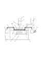
図1は本実施形態1において、3次元造形物を製造するための3次元造形装置の構成を断面構造として示したものである。図1において、容器5中には、溶融(未硬化)状態の光硬化性樹脂1が収容されている。
<
FIG. 1 shows the configuration of a three-dimensional modeling apparatus for manufacturing a three-dimensional modeled object in the first embodiment as a cross-sectional structure. In FIG. 1, the
光硬化性樹脂1は、例えばラジカル重合系樹脂材料としては、アクリレート系の材料である。特にその場合、光硬化性樹脂1の材質は、オリゴマーとしてはウレタンアクリレート系、エポキシアクリレート系、ポリエステルアクリレート系、アクリルアクリレート系などから選ばれる。
The
本実施形態では、容器5の上方から、光透過板6、および後述の酸素吸着フィルム12のような、光硬化性樹脂1に対して硬化阻害性を有する気体を供給する供給部材を介して光硬化性樹脂1を硬化させるための光照射を行う。この硬化阻害性を有する気体の供給部材としての酸素吸着フィルム12は、フィルムの形態、後述のフィルムロール13のような形状に巻装可能な可撓性を有する材質から構成することができる。酸素吸着フィルム12のより詳細な構成例については以下で後述する。
In the present embodiment, light is emitted from above the
造形ステージ3は造形物2の造形済み部位を支持する基台として機能し、造形物2の固化、造形の進行に伴い、昇降装置4によって、造形ステージ3を下方に移動させる。この造形ステージ3の移動に伴ない、造形物2の造形済み部位の上方に次層のための光硬化性樹脂1が供給される。その後、次層を造形のための光照射を行う。
The
硬化光は、例えば光源8、ミラーユニット9、レンズユニット10から成る光照射部から照射する。光源8は、例えばレーザ光源などであり、光硬化性樹脂1が例えば紫外線硬化型である場合には、光源8の照射光の波長は、例えば光硬化性樹脂1の材質などの条件に適した200〜400nm程度の範囲で選択される。硬化光の典型的な光波長としては、254nmや365nmが用いられる。ただし、光源8の照射光の波長は必ずしも紫外線領域に限定されるものではなく、光硬化性樹脂1の材質によっては他の波長領域の照射光を用いてもよい。ミラーユニット9は、ガルバノミラーユニットなどから構成され、レンズユニット10を介してXY方向に光源8の照射スポットを走査する。これにより、光硬化性樹脂1の造形物2の特定の高さに対応する例えば1層分の形状に相当する部位を硬化させることができる。
The cured light is emitted from, for example, a light irradiation unit including a
また、レーザスポットの平面走査による光照射方式に限定のみならず、光硬化性樹脂1の材質や粘度のような特性によっては、光源8、ミラーユニット9、レンズユニット10から成る光照射部は動画像を面照射するようなプロジェクタとして構成してもよい。
Further, not only the light irradiation method by plane scanning of the laser spot is limited, but also the light irradiation unit including the
図1の構成では、光硬化性樹脂1を硬化させるための光照射は容器5の上方向から行うため、容器5の上部に、光透過性の材質から構成した光透過部材、即ち光透過性蓋を配置する。図1では光透過板6がこの光透過性蓋に相当する。また、容器5の側壁部も、造形の進行を視認、あるいは不図示のカメラなどにより撮影する、などの目的で光透過性の材質から構成することができる。
In the configuration of FIG. 1, since the light irradiation for curing the
光透過板6は、PTFE、PFA、PE、PP、PC、PMMA、石英、ガラスなどの光透過性のある材質から構成する。
The
本実施形態では、未硬化、液状の光硬化性樹脂1は、供給装置7によって、光透過板6の下面ないしそのごく近傍高さの液位となるよう供給することができる。例えば、供給装置7は、光硬化性樹脂1の液位を検出する不図示の液位検出手段の出力に応じて自動的に光硬化性樹脂1を容器5内に供給するような構成を設けてもよい。
In the present embodiment, the uncured, liquid
本実施形態では、光透過板6の下面において、酸素吸着フィルム12を搬送し、直接、光透過板6の下面のほぼ全体が光硬化性樹脂1が触れないよう構成する。このため、酸素吸着フィルム12は、光透過板6の下面にほぼ相当する幅を有する。ここで、酸素吸着フィルム12の「幅」方向は図1紙面の奥行き方向に相当する寸法である。
In the present embodiment, the
酸素吸着フィルム12は、気体吸着性を有し、光硬化性樹脂1に対して硬化阻害性を有する気体を供給する供給部材に相当する。硬化阻害性を有する気体としては、単体としての酸素、即ち酸素やオゾンなどの同素体を含有する気体であり、例えば純酸素や空気が考えられる。ただし、光硬化性樹脂1に、例えば上記のアクリルアクリレート系のものとは異なる材質を用いる場合などについては、その材質に対して硬化阻害性を有する気体として単体としての酸素以外の物質を含むものを用いることができる。そして、その場合、本実施形態の酸素吸着フィルム12は、当該の単体としての酸素以外の物質を含む硬化阻害性を有する気体に対する吸着性を有するフィルムを用いることになる。
The
図4は酸素吸着フィルム12の断面構造の一例を示している。図4の例では、造形領域11側に配置される気体透過層23、酸素吸着層22、光透過板6側に配置される硬質層24の3層から構成されている。
FIG. 4 shows an example of the cross-sectional structure of the
酸素吸着フィルム12の酸素吸着層22としては、例えば、パーフルオロ化合物や鉄粉、活性炭、またはこれらの充填された熱可塑性の樹脂を用いる。また、気体透過層23としてポリ塩化ビニリデンコート二軸延伸ポリプロピレンやポリ塩化ビニリデンコートポリエステルなどを用いる。酸素吸着フィルム12の全体厚みは0.02mm〜0.2mm程度とする。ただし、酸素吸着フィルム12の全体の厚みは造形エリアの大きさと樹脂の種類、粘度を考慮し、濡れ性と強度、酸素阻害性などを考慮して適宜選択すればよい。
As the
図1の構成では、硬質層24は光透過板6と接しており、気体透過層23は、容器5内で光硬化性樹脂1に接触する。光硬化性樹脂1にラジカル重合系、アクリレート系を用いる場合、酸素吸着フィルム12の酸素吸着層22により保持された酸素、オゾンは、気体透過層23を介して酸素吸着フィルム12と接した未硬化の光硬化性樹脂1の硬化が阻害される。即ち、硬化光が照射されても、造形領域11付近の光硬化性樹脂1の硬化が阻害される。
In the configuration of FIG. 1, the
酸素吸着フィルム12の各層の厚みは使用する樹脂の種類や粘度、フィルムへの酸素やオゾンの供給量により種々変更可能である。例えば気体透過層23は0.005mm〜0.1mm、酸素吸着層22は0.01mm〜0.3mm、硬質層24は0.005mm〜0.3mmの範囲が考えられる。
The thickness of each layer of the
また、硬質層24には、気体透過層23に比べ硬度の高いポリ塩化ビニリデンコート二軸延伸ポリプロピレンやポリ塩化ビニリデンコートポリエステル等の気体透過性素材を用いることができる。これにより、硬質層24と光透過板6間に入り込んだ樹脂の硬化を抑制できる。
Further, as the
酸素吸着フィルム12は、フィルムロール13の形態に巻装された状態から、巻き取り装置15の巻き取り力によって巻きほどかれ、光透過板6と未硬化の樹脂の間、特に光透過板6の下面を通過するよう搬送される。巻き取り装置15の内部には、不図示の巻き取りローラ、巻き取り駆動力を発生する電動モータ、適当な巻き取り速度形成するための減速機などが配置される。
The oxygen-adsorbing
酸素吸着フィルム12の搬送装置は、ロール形状の酸素吸着フィルム12を巻きほどく駆動力を発生する巻き取り装置15と、光透過板6と光硬化性樹脂1の間へと巻きほどかれた酸素吸着フィルム12を導くガイドローラ12a、12a…を備える。
The transport device for the
即ち、酸素吸着フィルム12の搬送経路は、ガイドローラ12a、12a…によって規定される。そして酸素吸着フィルム12は、光透過板6の図中右方端部近傍を貫通するスリット6aを通過して光透過板6の下面に入る。光透過板6の下面を通過した酸素吸着フィルム12は、光透過板6の左方端部近傍を貫通するスリット6aを通過して、再度、光透過板6の上方に抜け、ガイドローラ12a、12a…を経て、巻き取り装置15によって巻き取られる。
That is, the transport path of the
また、酸素吸着フィルム12はフィルムロール13の下流で、かつ光透過板6下面への搬入側のスリット6aよりも上流側に配置された気体供給装置14内を通過する。気体供給装置14は、光硬化性樹脂1の重合ないし架橋、従ってその硬化を阻害する気体を供給して酸素吸着フィルム12に吸着させる。気体供給装置14が供給する気体としては、例えば単体としての酸素を含む気体、例えば空気や、純酸素、オゾンを含む気体とする。気体供給装置14は、例えば、コロナ放電やストリーマー放電方式のオゾン発生装置や、ボンベなどの容器から純酸素を供給する酸素供給装置によって構成することができる。また、気体供給装置14から酸素吸着フィルム12に供給する酸素やオゾンは、電気的な駆動のみならず、化学的な発生方式によって発生させてもよい。
Further, the
気体供給装置14で供給された酸素やオゾンは、図2に示す気体透過層23を通り、酸素吸着層22に到達し、酸素吸着層22中のパーフルオロ化合物や鉄粉、活性炭に吸着され、保持される。なお、気体供給装置14から酸素吸着フィルム12に供給する酸素の量、および巻き取り装置15による酸素吸着フィルム12の搬送速度などの制御条件は、光硬化性樹脂1の種類や密度、粘度に応じて定めることができる。例えば、光透過板6の下面における酸素吸着フィルム12の搬送速度は、数mm〜数10mm/s程度の値から選択することができる。
Oxygen and ozone supplied by the
図2は、図1の構成において、造形領域11付近の構造を拡大して示している。図2の構造では、光透過板6の硬化光の出射面16は、光硬化性樹脂1方向に凸となる凸面、例えば円筒面によって、緩やかな曲面として構成してある。この出射面16の曲面構造によって、光透過板6を光学的には凸レンズとして機能させることができる。
FIG. 2 shows an enlarged structure in the vicinity of the
酸素吸着フィルム12は、巻き取り装置15の駆動力によって曲面構成の光透過板6の出射面16に沿って、図の右から左へと搬送される。このような出射面16の曲面構造によって、酸素吸着フィルム12を光透過板6に密着した状態で搬送することができる。
The
また、出射面16の曲面形状を適宜に設計することにより、例えばミラーユニット9で走査され、造形領域11の周辺部に向かう硬化光の歪曲を防止することができる。例えば、出射面16の曲面形状を適宜選択することにより、硬化光が広がる際の周辺部の歪曲を防止し、硬化光を目的の硬化層全体に渡って垂直に侵入する事が出来る。このように、出射面16の曲面形状を適宜選択することにより、硬化光を硬化層全体に歪曲せず垂直に照射することができ、造形物2の上面の硬化層の中央と外周とでほぼ均等な光硬化形状精度を得ることができる。
Further, by appropriately designing the curved surface shape of the
光源8から硬化光を照射することによって、光透過板6および酸素吸着フィルム12の下方の造形領域11の部位において、光硬化性樹脂1が硬化する。連続造形の場合であれば、例えば光源8から動画形態で硬化光を照射しながら、昇降装置4によって同時に造形ステージ3を連続的に下降させることができる。また、1層ずつの間欠造形の場合は、ミラーユニット9によって、硬化光を造形領域11の部位で平面走査して1層造形した後、昇降装置4により造形ステージ3を適当な距離、例えば0.02mm〜0.2mm下方へ移動させる。
By irradiating the curing light from the
本実施形態では、造形ステージ3移動を行う時、ステージ移動と同時、もしくは移動完了後、フィルム巻き取り装置15を作動させ、光透過板6の下面において、酸素吸着フィルム12を搬送する。即ち、気体供給装置14で硬化阻害性を有する気体、例えば酸素やオゾンを新しく吸着した酸素吸着フィルム12を順次、光透過板6の下面に搬入する。これにより、造形領域11付近に硬化阻害性を有する気体、例えば酸素やオゾンを供給することができる。
In the present embodiment, when the
図5は、図1(後述の図3の実施形態2の構成においても同様)の造形装置の制御系の構成を示している。 FIG. 5 shows the configuration of the control system of the modeling apparatus of FIG. 1 (the same applies to the configuration of the second embodiment of FIG. 3 described later).
図6の構成は、制御装置の主体的機能を受け持つCPU601を中心にROM602、RAM603、インターフェース604、608、ネットワークインターフェース609などを配置したものである。
In the configuration of FIG. 6,
CPU601には、ROM602、RAM603、および各種のインターフェース604、608、ないし609が接続される。ROM602には、BIOS等の基本プログラムが格納される。ROM602の記憶領域には、書き換え可能な例えばE(E)PROMのようなデバイスが含まれていてよい。RAM603は、CPU601の演算処理結果を一時的に記憶するワークエリアとして用いられる。CPU601は、ROM602に記録(格納)されたプログラムを実行することにより、後述の造形制御手順を実行する。
A
後述の造形制御手順を実行させるプログラムをROM602に記録(格納)する場合、この記録媒体は本発明を実施するための制御手順を格納したコンピュータ読み取り可能な記録媒体を構成する。なお、後述の制御手順を実行させるプログラムは、ROM602のような固定的な記録媒体に格納する他、各種フラッシュメモリや光(磁気)ディスクのような着脱可能なコンピュータ読み取り可能な記録媒体に格納してもよい。このような格納形態は、本発明を実施する制御手順を実行させるプログラムをインストールしたり更新したりする場合に利用できる。また、このような制御プログラムをインストールしたり更新したりする場合、上記のような着脱可能な記録媒体を用いる他、ネットワークインターフェース609を介してネットワーク611からプログラムをダウンロードする方式を利用できる。
When a program for executing a modeling control procedure described later is recorded (stored) in
CPU601は、インターフェース609を介して、ネットワークインターフェース609を介して接続された、例えばTCP/IPのようなプロトコルを用いて通信を行うネットワーク(不図示)上の他の資源と通信することができる。ネットワークインターフェース609は、例えば有線接続(IEEE 802.3など)、無線接続(IEEE802.xxなど)などの各種のネットワーク通信方式によって構成することができる。ネットワーク611に配置されたサーバから後述の造形制御プログラムをダウンロードしてROM602やHDD604にインストールしたり、あるいは既にインストールされているプログラムを新版に更新したりすることもできる。
The
造形物2を積層的に3次元(3D)造形するための3次元(3D)データは、例えば3DCADのようなデータ形式で、上位のホスト装置610からインターフェース608を介して送信される。インターフェース608は各種の例えば各種のシリアルないしパラレルインターフェース規格に基づき構成することができる。また、ホスト装置610は、ネットワーク端末としてネットワーク611に接続することもできる。この場合も、ホスト装置610は上記同様に本造形装置に対して造形データを供給することができる。
The three-dimensional (3D) data for three-dimensionally (3D) modeling the
CPU601は、インターフェース604、および光照射制御部605を介して、光源8およびミラーユニット9を制御する。また、CPU601はインターフェース604、およびステージ制御部607を介して昇降装置4の昇降を制御する。また、CPU601はインターフェース604、およびフィルム制御部606を介して気体供給装置14や巻き取り装置15を制御する。CPU601は、これらの各部を所期の造形シーケンスに応じて制御することにより、全体の造形工程を進行させる。
The
インターフェース604は、例えば各種のシリアルないしパラレルインターフェース規格に基づき構成できる。なお、図6では簡略化のためインターフェース604は1ブロックで示しているが、インターフェース604の右側に図示した各部の通信仕様などに応じてそれぞれ異なる通信方式を持つインターフェース回路によって構成されていてよい。
The
次に図1、図2、図4を参照しつつ上記構成における動作につき説明する。図7は、図1の装置における造形制御手順の流れを示している。図7の手順は例えばCPU601(制御装置:コンピュータ)が読み取り、かつ実行可能な制御プログラムとして記述され、例えばROM602(あるいは不図示の外部記憶装置)に格納しておくことができる。 Next, the operation in the above configuration will be described with reference to FIGS. 1, 2, and 4. FIG. 7 shows the flow of the modeling control procedure in the device of FIG. The procedure of FIG. 7 is described as a control program that can be read and executed by, for example, CPU 601 (control device: computer), and can be stored in, for example, ROM 602 (or an external storage device (not shown)).
造形に先立ち、供給装置7によって容器5中に溶解(未硬化)状態の光硬化性樹脂1を供給する。あるいはこの手続きは作業者の手動操作によって行ってもよい。供給装置7により光硬化性樹脂1を供給する構成においては、光硬化性樹脂1の液面レベルを検出する適当な液位検出手段の出力に応じて、容器5中の光硬化性樹脂1の量が自動的に適量に制御されるような自動制御を行ってもよい。また、供給装置7を配置する場合は、容器5中から光硬化性樹脂1を吸入、排出させるような樹脂回収装置を追加し、樹脂回収装置から樹脂供給装置、さらに再度、容器5へと光硬化性樹脂1を循環させるような構成を取ってもよい。
Prior to modeling, the
造形物2の3D造形データは予めホスト装置610などから送信される。この3D造形データを例えば複数の造形層の(断面)形状データへと変換することにより、造形物2を構成する複数層分の造形データが生成される。光硬化性樹脂1が容器5中に供給され、造形すべき造形物2の造形データを取得すると、CPU601は図7のステップS0において、造形を開始するか否かを判定する。この造形開始の判定は、ホスト装置610などから造形開始の指令が到来したか否かを判定したり、不図示の操作パネルで所定の造形開始操作が行われたか否かを判定したりすることによって行う。
The 3D modeling data of the modeled
図7のステップS10とS13に示した工程は、造形物2の1層分を造形する時の制御手順に相当する。即ち、これらのステップは光照射(S10)、および造形ステージ移動(S13)である。ステップS10〜S15を繰り返し実行することにより、積層的に造形物2を造形することができる。
The steps shown in steps S10 and S13 of FIG. 7 correspond to a control procedure when one layer of the modeled
図7のステップS10では、CPU601は、光照射制御部605を介して光源8を点灯させ、ミラーユニット9によって当該の造形層の形状に応じて光源8の照射光を走査させる。これにより、光源8からの硬化光はミラーユニット9、レンズユニット10から光透過板6、酸素吸着フィルム12を透過し、造形領域11付近の光硬化性樹脂1に照射され、その部位を硬化させる。ステップS13では、CPU601は、ステージ制御部607を介して造形ステージ3を移動、例えば図1の構成では下降させる。
In step S10 of FIG. 7, the
先に触れた通り、造形方式には、いわゆる連続造形方式と間欠造形方式がある。例えば連続造形方式では、光照射(S10)と、造形ステージ移動(S13)と、を同期的かつ並行的に行う。連続造形の場合、ミラーユニット9に替えて動画投影ユニットなどが用いられ、CPU601は、硬化光を動画イメージとして連続的に照射させる。ステージ制御部607を介して造形ステージ3を連続的に移動させる速度は、動画構成の硬化光のフレームレートなどに応じて決定すればよい。
As mentioned earlier, there are two types of modeling methods: the so-called continuous modeling method and the intermittent modeling method. For example, in the continuous modeling method, light irradiation (S10) and modeling stage movement (S13) are performed synchronously and in parallel. In the case of continuous modeling, a moving image projection unit or the like is used instead of the
一方、間欠造形方式においては、CPU601は、光照射(S10)と、造形ステージ移動(S13)と、交互に実行させる。光照射(S10)では、CPU601は、ミラーユニット9を制御し、造形物2の1層分に相当する形状をカバーするよう硬化光によって造形領域11付近を平面走査させる。この時、造形ステージ3は停止状態とし、1層分の光照射(S10)が終了すると、ステージ制御部607を介して造形ステージ3を1層分の厚みにほぼ相当する量だけ移動、例えば図1の構成では下降させる。
On the other hand, in the intermittent modeling method, the
図7の制御例では、連続造形方式および間欠造形方式のいずれの場合でも、光照射(S10)および造形ステージ移動(S13)を行うに先立ち、気体供給装置14および巻き取り装置15を起動して、酸素吸着フィルム12の搬送を開始させる(S4)。これにより、常に重合(固化)阻害性を有するガス、例えば酸素やオゾンを保持した酸素吸着フィルム12の新しい部位を少量ずつ光透過板6と造形領域11の間に送り込む。
In the control example of FIG. 7, in both the continuous modeling method and the intermittent modeling method, the
ステップS14では、造形物2の造形が終了したか、例えば、造形物2を形成する全ての造形データを用いて光照射(S10)および造形ステージ移動(S13)を行ったか否かを判定する。光照射(S10)および造形ステージ移動(S13)は、造形物2を形成する全ての造形データを処理し終るまで繰り返し実行される。
In step S14, it is determined whether or not the modeling of the modeled
造形物2の造形が終了すると、ステップS15に移行し、気体供給装置14および巻き取り装置15を停止させ、酸素吸着フィルム12の搬送を終了させる。
When the modeling of the modeled
以上のように、本実施形態によれば、造形領域11、特に酸素吸着フィルム12に面する部位の光硬化性樹脂1の固化反応が阻害され、硬化しないよう制御できる。このため、特に、造形領域11と光透過板6ないし酸素吸着フィルム12との界面付近で造形物2の固着や、不要な光硬化性樹脂1の粘度上昇が生じるのを確実に抑制することができる。
As described above, according to the present embodiment, the solidification reaction of the
従って、本実施形態では、間欠造形の場合は、1層の光硬化ごとに造形物2をフィルムから引き剥す、といった操作が不要となり、高速に造形ステージ3の移動を実行できる。また、連続造形の場合は、昇降装置4は不要な抵抗を受けずに連続的に造形ステージ3を移動させることができる。
Therefore, in the present embodiment, in the case of intermittent modeling, it is not necessary to perform an operation such as peeling the modeled
また、光硬化性樹脂1に接している酸素吸着フィルム12を一定の速度で搬送し続けることにより、造形領域11付近、特に、造形ステージ3の移動により生じた低圧部付近に流れを生じ、この部分を撹拌することができる。これにより、次に固化させる造形層のための材料となる光硬化性樹脂1の造形領域11付近への流入を促進することができる。これにより、固化させる造形層のための材料となる光硬化性樹脂1の造形領域11付近への流入速度を向上させることができ、速やかに次層のための硬化光を照射することができ、3次元造形の速度を高速化することができる。
Further, by continuing to convey the
<実施形態2>
図3は、本実施形態2における3次元造形装置の構造を、図1に準じた形式で示している。図3の3次元造形装置においても、制御系の構造および、造形制御手順については、上記実施形態1の図6、図7に示したものとほぼ同等のものを用いることができる。また、本実施形態では、実施形態1と同一ないし同等の部材には同一の参照符号を付し、それらについては重複した説明を省略するものとする。
<
FIG. 3 shows the structure of the three-dimensional modeling apparatus according to the second embodiment in a format according to FIG. Also in the three-dimensional modeling apparatus of FIG. 3, as for the structure of the control system and the modeling control procedure, those substantially the same as those shown in FIGS. 6 and 7 of the first embodiment can be used. Further, in the present embodiment, the same or equivalent members as those in the first embodiment are designated by the same reference numerals, and duplicate description thereof will be omitted.
本実施形態においても、酸素吸着フィルム12は、光硬化性樹脂に対して硬化阻害性を有する気体を供給する供給部材に相当する。本実施形態でも、酸素吸着フィルム12は、フィルムロール13の形態から、巻き取り装置15の駆動力によって巻きほどかれ、その途中で、ガイドローラ12a、12a…によって光透過板6に接した状態で搬送される。
Also in this embodiment, the
図3の構造で、図1と異なるのは、図3では樹脂付着装置20、およびクリーニング装置21が配置されている点である。樹脂付着装置20は、酸素吸着フィルム12が光透過板6の下面に搬入されるよりも上流の位置に配置してある。クリーニング装置21は、酸素吸着フィルム12が光透過板6の下面から搬出された後の下流の位置に配置してある。樹脂付着装置20およびクリーニング装置21は、例えば、それぞれ図の奥行き方向が長手となるような樋状の容器として構成することができる。酸素吸着フィルム12は、図示のようにガイドローラ12a、12a…によって、樹脂付着装置20から光透過板6の下面に搬入され、そしてクリーニング装置21を介して搬出されるようガイドされる。
The structure of FIG. 3 differs from that of FIG. 1 in that the
樹脂付着装置20は、その内部に光硬化性樹脂1と同じ液状の樹脂を収容し、対向配置された樹脂供給ローラ20aによって、樹脂材料を通過する酸素吸着フィルム12の両面に付着させる。
The
一方、クリーニング装置21は、内部に対向配置されたガイドローラ21bと、クリーニングブレード21aを備える。このクリーニングブレード21aによって、光透過板6の下面から搬出されてきた酸素吸着フィルム12の両面に付着した光硬化性樹脂を掻き取り、クリーニング装置21内に回収する。
On the other hand, the
上記以外の3次元造形装置の構成、および造形動作ないし造形制御は、上述の実施形態1と同様である。造形動作、造形制御、およびその作用効果の基本部分は、上述の実施形態1と同等であるため、ここでは重複は省略する。特に、本実施形態2によれば、酸素吸着フィルム12が光透過板6の下面に搬入される直前、および光透過板6の下面から搬出された直後の位置に、樹脂付着装置20およびクリーニング装置21を配置している。このように、本実施形態では、酸素吸着フィルム12が光透過板6の下面に搬入される前、ないしは酸素吸着フィルム12が光硬化性樹脂1内に搬入される前に、酸素吸着フィルム12の両面に光硬化性樹脂1を付着させる。これにより、光透過板6の下面を通過する酸素吸着フィルム12と容器5内の光硬化性樹脂1とのなじみがよくなり、酸素吸着フィルム12を所期の搬送速度でスムーズに移動させることができる。また、予め酸素吸着フィルム12の表面に付着させた光硬化性樹脂に酸素、オゾンなどの固化阻害性の気体を供給した上で、光透過板6の下面へと酸素吸着フィルム12を搬入できる。このため、確実に固化や粘度上昇を抑制したい造形領域11付近、特に光透過板6の近傍に確実に固化阻害性の気体を送り込むことができる。さらに、光透過板6の下面から搬出された直後の位置でクリーニング装置21により酸素吸着フィルム12に付着した光硬化性樹脂1を除去できるため、3次元造形装置内の不要な位置に光硬化性樹脂1が飛散するのを防ぐことができる。
The configuration of the three-dimensional modeling apparatus other than the above, and the modeling operation or modeling control are the same as those in the above-described first embodiment. Since the basic parts of the modeling operation, the modeling control, and the operation and effect thereof are the same as those in the above-described first embodiment, duplication is omitted here. In particular, according to the second embodiment, the
<実施形態3>
図1あるいは図3に示した実施形態1および2の構成では、容器5の上方から硬化光を照射し、造形進行に伴い、造形ステージ3を下降させる基本構成を示した。しかしながら、硬化光の照射方向、造形ステージ3の移動方向は本実施形態の図5に示すように、実施形態1および2の構成とは異なる方向に取ることもできる。
<
In the configurations of the first and second embodiments shown in FIGS. 1 or 3, a basic configuration is shown in which the
図5は、図1、図3などと同等の形式により本実施形態3の3次元造形装置の構成を示している。図5の構成では、光硬化性樹脂1を収容した容器5は、例えば上方が開放された形状で、硬化光を透過させる光透過板6は容器5の底面に配置されている。本実施形態では、光源8、ミラーユニット9およびレンズユニット10は光透過板6の下方に配置され、下方から光透過板6を介して硬化光を造形領域11に照射する。
FIG. 5 shows the configuration of the three-dimensional modeling apparatus of the third embodiment in the same format as those of FIGS. 1 and 3. In the configuration of FIG. 5, the
造形物2は、造形領域11で造形ステージ3の下面に形成される。従って、本実施形態では、造形の進行に応じて、造形ステージ3は昇降装置4によって上方に移動させる。図1および図3の構成と本実施形態の図5の構成の実質的な相違は、造形物2の造形を進行させる方向、即ち、硬化光の照射方向と、それに伴う造形ステージ3の移動方向のみである。
The modeled
本実施形態においても、酸素吸着フィルム12は、光硬化性樹脂に対して硬化阻害性を有する気体を供給する供給部材に相当する。本実施形態でも、酸素吸着フィルム12は、フィルムロール13の形態から、巻き取り装置15の駆動力によって巻きほどかれ、その途中で、ガイドローラ12a、12a…によって光透過板6に接した状態で搬送される。
Also in this embodiment, the
なお、図5では、光透過板6の断面は、単なる矩形として示してあるが、図2の例と同様に酸素吸着フィルム12に接する面を、同フィルムないし造形領域11の方向に向かって凸の曲面形状として構成してもよい。これにより、図2に関連して説明したものと同じ作用効果を期待できる。
Although the cross section of the
また、図5の構成では、図3の例と同様に、樹脂付着装置20およびクリーニング装置21を配置している。これら樹脂付着装置20およびクリーニング装置21の作用、および効果は、図3に関連して説明したものと同様である。また、図1と図3の対比から明らかなように、図5の構成において、樹脂付着装置20およびクリーニング装置21は必ずしも必須のものではなく、これらを省略した構成も考えられる。また、図5では、容器5内に光硬化性樹脂1を供給する供給装置7は図示を省略してあるが、図1ないし図3の場合と同様の供給装置7を配置してもよい。
Further, in the configuration of FIG. 5, the
図5のような構成であっても、上述の通り、造形領域11、特に酸素吸着フィルム12に面する部位の光硬化性樹脂1の固化反応が阻害され、硬化しないよう制御できる。このため、特に、造形領域11と光透過板6ないし酸素吸着フィルム12との界面付近で、造形物2の固着や、不要な光硬化性樹脂1の粘度上昇が生じるのを確実に抑制することができる。
Even with the configuration as shown in FIG. 5, as described above, the solidification reaction of the
従って、本実施形態では、間欠造形の場合は、1層の光硬化ごとに造形物2をフィルムから引き剥すような操作が不要となり、高速に造形ステージ3の移動を実行できる。また、連続造形の場合は、昇降装置4は不要な抵抗を受けずに連続的に造形ステージ3を移動させることができる。
Therefore, in the present embodiment, in the case of intermittent modeling, it is not necessary to perform an operation of peeling the modeled
また、光硬化性樹脂1に接している酸素吸着フィルム12を一定の速度で搬送し続けることにより、造形領域11付近、特に、造形ステージ3の移動により生じた低圧部付近を撹拌することができる。これにより、次に固化させる造形層のための材料となる光硬化性樹脂1の造形領域11付近への流入を促進することができる。これにより、固化させる造形層のための材料となる光硬化性樹脂1の造形領域11付近への流入速度を向上させることができ、速やかに次層のための硬化光を照射することができ、3次元造形の速度を高速化することができる。
Further, by continuing to convey the
本発明は、上述の実施例の1以上の機能を実現するプログラムをネットワーク又は記憶媒体を介してシステムまたは装置に供給し、そのシステムまたは装置のコンピュータにおける1つ以上のプロセッサーがプログラムを読出し実行する処理でも実現可能である。また、1以上の機能を実現する回路(例えば、ASIC)によっても実現可能である。 The present invention supplies a program that realizes one or more functions of the above-described embodiment to a system or device via a network or storage medium, and one or more processors in the computer of the system or device reads and executes the program. It can also be realized by processing. It can also be realized by a circuit (for example, ASIC) that realizes one or more functions.
1…光硬化性樹脂、2…造形物、3…造形ステージ、4…昇降装置、5…容器、6…光透過板、7…供給装置、8…光源、9…ミラーユニット、10…レンズユニット、11…造形領域、12…酸素吸着フィルム、13…フィルムロール、14…気体供給装置、15…巻き取り装置、20…樹脂付着装置、21…クリーニング装置、22…酸素吸着層、23…気体透過層、24…硬質層、601…CPU、602…ROM、603…RAM、604…インターフェース、605…光照射制御部、606…フィルム制御部、607…ステージ制御部、609…ネットワークインターフェース、610…ホスト装置。 1 ... Photocurable resin, 2 ... Modeled object, 3 ... Modeling stage, 4 ... Lifting device, 5 ... Container, 6 ... Light transmitting plate, 7 ... Supply device, 8 ... Light source, 9 ... Mirror unit, 10 ... Lens unit , 11 ... Modeling area, 12 ... Oxygen adsorption film, 13 ... Film roll, 14 ... Gas supply device, 15 ... Winding device, 20 ... Resin adhesion device, 21 ... Cleaning device, 22 ... Oxygen adsorption layer, 23 ... Gas permeation Layer, 24 ... Hard layer, 601 ... CPU, 602 ... ROM, 603 ... RAM, 604 ... Interface, 605 ... Light irradiation control unit, 606 ... Film control unit, 607 ... Stage control unit, 609 ... Network interface, 610 ... Host apparatus.
Claims (16)
前記光硬化性樹脂を光硬化させた造形済み部位を支持する基台と、
前記基台を移動させるための移動装置と、
前記光硬化性樹脂を光硬化させる光を照射する光照射装置と、
前記光照射装置と前記基台の間に設けられた光透過部材と、
前記光硬化性樹脂に面して、酸素を含む気体を吸着させて供給するフィルムと、
前記光透過部材と前記光硬化性樹脂の間で前記フィルムを移動させる搬送装置と、
を備えた3次元造形装置。 A container that houses the photocurable resin and
A base that supports the molded part obtained by photocuring the photocurable resin, and
A moving device for moving the base and
A light irradiation device that irradiates light that photocures the photocurable resin, and
A light transmitting member provided between the light irradiation device and the base,
A film that faces the photocurable resin and adsorbs and supplies a gas containing oxygen ,
A transport device for moving the film between the light transmitting member and the photocurable resin, and
3D modeling device equipped with.
前記制御部が、前記光照射装置の光照射により前記光硬化性樹脂を硬化させる光照射工程と、
前記制御部が、前記移動装置により前記基台を移動させる移動工程と、
前記制御部が、前記搬送装置により前記光透過部材と前記光硬化性樹脂の間で前記フィルムを搬送させる搬送工程と、
を備え、前記制御部は、前記光照射工程と並行して、前記移動工程および前記搬送工程を実行させ、連続的に3次元造形物の造形を行う3次元造形物の製造方法。 A container for accommodating a photocurable resin, a base for supporting a molded portion obtained by photocuring the photocurable resin, a moving device for moving the base, and photocuring the photocurable resin. A light irradiating device that irradiates the light to be made, a light transmitting member provided between the light irradiating device and the base, a film that faces the photocurable resin and supplies a gas containing oxygen, and the above. By a three-dimensional modeling device including a transport device for moving the film material between the light transmitting member and the photocurable resin, the light irradiation device, the moving device, and a control unit for controlling the transport device. In the method of manufacturing a three-dimensional model that manufactures a model,
A light irradiation step in which the control unit cures the photocurable resin by light irradiation of the light irradiation device.
A moving step in which the control unit moves the base by the moving device,
A transfer step in which the control unit conveys the film between the light transmitting member and the photocurable resin by the transfer device.
A method for manufacturing a three-dimensional modeled object, wherein the control unit executes the moving step and the transporting process in parallel with the light irradiation step to continuously model the three-dimensional modeled object.
前記光硬化性樹脂を光硬化させた造形済み部位を支持する基台と、 A base that supports the molded part obtained by photocuring the photocurable resin, and
前記基台を移動させるための移動装置と、 A moving device for moving the base and
前記光硬化性樹脂を光硬化させる光を照射する光照射装置と、 A light irradiation device that irradiates light that photocures the photocurable resin, and
前記光照射装置と前記基台の間に設けられた光透過部材と、 A light transmitting member provided between the light irradiation device and the base,
前記光硬化性樹脂に面して、前記光硬化性樹脂に対して硬化阻害性を有する気体を供給する供給部材と、 A supply member facing the photocurable resin and supplying a gas having a curing inhibitory property to the photocurable resin.
前記光透過部材と前記光硬化性樹脂の間で前記供給部材を移動させる搬送装置と、 A transport device that moves the supply member between the light transmitting member and the photocurable resin, and
を備え、With
前記供給部材が前記搬送装置によって前記光透過部材と前記光硬化性樹脂の間に搬入される前の位置で、前記供給部材に前記光硬化性樹脂を付着させる樹脂付着装置を備えた3次元造形装置。 Three-dimensional modeling provided with a resin adhering device for adhering the photocurable resin to the supply member at a position before the supply member is carried between the light transmitting member and the photocurable resin by the transport device. apparatus.
前記光硬化性樹脂を光硬化させた造形済み部位を支持する基台と、 A base that supports the molded part obtained by photocuring the photocurable resin, and
前記基台を移動させるための移動装置と、 A moving device for moving the base and
前記光硬化性樹脂を光硬化させる光を照射する光照射装置と、 A light irradiation device that irradiates light that photocures the photocurable resin, and
前記光照射装置と前記基台の間に設けられた光透過部材と、 A light transmitting member provided between the light irradiation device and the base,
前記光硬化性樹脂に面して、前記光硬化性樹脂に対して硬化阻害性を有する気体を供給する供給部材と、 A supply member facing the photocurable resin and supplying a gas having a curing inhibitory property to the photocurable resin.
前記光透過部材と前記光硬化性樹脂の間で前記供給部材を移動させる搬送装置と、 A transport device that moves the supply member between the light transmitting member and the photocurable resin, and
を備え、With
前記供給部材が前記搬送装置によって前記光透過部材と前記光硬化性樹脂の間から搬出された後の位置で、前記供給部材の表面の樹脂を除去するクリーニング装置を備えた3次元造形装置。 A three-dimensional modeling device provided with a cleaning device for removing resin on the surface of the supply member at a position after the supply member is carried out from between the light transmitting member and the photocurable resin by the transport device.
前記光硬化性樹脂を光硬化させた造形済み部位を支持する基台と、 A base that supports the molded part obtained by photocuring the photocurable resin, and
前記基台を移動させるための移動装置と、 A moving device for moving the base and
前記光硬化性樹脂を光硬化させる光を照射する光照射装置と、 A light irradiation device that irradiates light that photocures the photocurable resin, and
前記光照射装置と前記基台の間に設けられた光透過部材と、 A light transmitting member provided between the light irradiation device and the base,
前記光硬化性樹脂に面して、前記光硬化性樹脂に対して硬化阻害性を有する気体を供給する供給部材と、 A supply member facing the photocurable resin and supplying a gas having a curing inhibitory property to the photocurable resin.
前記光透過部材と前記光硬化性樹脂の間で前記供給部材を移動させる搬送装置と、 A transport device that moves the supply member between the light transmitting member and the photocurable resin, and
を備え、With
前記光透過部材の、前記供給部材に接する面が前記供給部材に向かって凸の曲面形状を有する3次元造形装置。 A three-dimensional modeling device in which a surface of the light transmitting member in contact with the supply member has a curved surface shape that is convex toward the supply member.
Priority Applications (4)
| Application Number | Priority Date | Filing Date | Title |
|---|---|---|---|
| JP2016181368A JP6849357B2 (en) | 2016-09-16 | 2016-09-16 | Manufacturing method of 3D modeling equipment and 3D modeled objects |
| US15/681,760 US11130286B2 (en) | 2016-09-07 | 2017-08-21 | Three-dimensional manufacturing apparatus, three-dimensional manufactured object producing method, and container for three-dimensional manufacturing apparatus |
| KR1020170109802A KR102225135B1 (en) | 2016-09-07 | 2017-08-30 | Three-dimensional manufacturing apparatus, three-dimensional manufactured object producing method, and container for three-dimensional manufacturing apparatus |
| CN201710792463.XA CN107791512B (en) | 2016-09-07 | 2017-09-05 | Three-dimensional manufacturing apparatus, three-dimensional manufactured object manufacturing method, and container for three-dimensional manufacturing apparatus |
Applications Claiming Priority (1)
| Application Number | Priority Date | Filing Date | Title |
|---|---|---|---|
| JP2016181368A JP6849357B2 (en) | 2016-09-16 | 2016-09-16 | Manufacturing method of 3D modeling equipment and 3D modeled objects |
Publications (2)
| Publication Number | Publication Date |
|---|---|
| JP2018043462A JP2018043462A (en) | 2018-03-22 |
| JP6849357B2 true JP6849357B2 (en) | 2021-03-24 |
Family
ID=61692715
Family Applications (1)
| Application Number | Title | Priority Date | Filing Date |
|---|---|---|---|
| JP2016181368A Active JP6849357B2 (en) | 2016-09-07 | 2016-09-16 | Manufacturing method of 3D modeling equipment and 3D modeled objects |
Country Status (1)
| Country | Link |
|---|---|
| JP (1) | JP6849357B2 (en) |
Families Citing this family (2)
| Publication number | Priority date | Publication date | Assignee | Title |
|---|---|---|---|---|
| JP6848574B2 (en) * | 2017-03-22 | 2021-03-24 | 日本電気株式会社 | Laminated modeling equipment and laminated modeling method |
| CN111497230A (en) * | 2019-01-31 | 2020-08-07 | 三纬国际立体列印科技股份有限公司 | 3D forming method |
Family Cites Families (4)
| Publication number | Priority date | Publication date | Assignee | Title |
|---|---|---|---|---|
| US5122441A (en) * | 1990-10-29 | 1992-06-16 | E. I. Du Pont De Nemours And Company | Method for fabricating an integral three-dimensional object from layers of a photoformable composition |
| JP4033987B2 (en) * | 1998-11-19 | 2008-01-16 | ナブテスコ株式会社 | Optical 3D modeling method |
| US9636873B2 (en) * | 2012-05-03 | 2017-05-02 | B9Creations, LLC | Solid image apparatus with improved part separation from the image plate |
| EP2956823B2 (en) * | 2013-02-12 | 2019-07-03 | CARBON3D, Inc. | Continuous liquid interphase printing |
-
2016
- 2016-09-16 JP JP2016181368A patent/JP6849357B2/en active Active
Also Published As
| Publication number | Publication date |
|---|---|
| JP2018043462A (en) | 2018-03-22 |
Similar Documents
| Publication | Publication Date | Title |
|---|---|---|
| US10987869B2 (en) | Continuous pull three-dimensional printing | |
| CN110914058B (en) | Adhesive film three-dimensional printing system and method | |
| EP3204217B1 (en) | Shifting a curing location during 3d printing | |
| KR102225135B1 (en) | Three-dimensional manufacturing apparatus, three-dimensional manufactured object producing method, and container for three-dimensional manufacturing apparatus | |
| EP3808540A1 (en) | Apparatus for separation of cured resin layer from resin support in additive manufacturing | |
| US8678805B2 (en) | System and method for layerwise production of a tangible object | |
| US20120007287A1 (en) | Method and apparatus for layerwise production of a 3d object | |
| US20190126536A1 (en) | Cartridge vat-based additive manufacturing apparatus and method | |
| JP6058819B2 (en) | 3D object production | |
| KR20180022571A (en) | Three dimensional manufacturing apparatus and method for manufacturing three dimensional manufactured product | |
| JP2008155477A (en) | Three-dimensional modeling apparatus | |
| CN110997282A (en) | Method and system for stereolithography three-dimensional printing | |
| JP6849357B2 (en) | Manufacturing method of 3D modeling equipment and 3D modeled objects | |
| JP2021518289A (en) | Bottom-up photocurable 3D printing equipment and related usage with independent elastic membrane system and tilt criteria | |
| JP2022010038A (en) | Additive manufacturing method for functionally graded material | |
| JP2001009921A (en) | Stereo lithography device | |
| US20210260819A1 (en) | Systems, apparatuses, and methods for manufacturing three dimensional objects via continuously curing photopolymers, utilising a vessel containing an interface fluid | |
| JP2023524883A (en) | System and method for high resolution negative 3D printer | |
| JP6896388B2 (en) | Manufacturing method of 3D modeling equipment and 3D modeled objects | |
| JP3392177B2 (en) | Photocurable resin supply device | |
| CN117500656A (en) | System and method for stereolithography three-dimensional printing | |
| JP2019142197A (en) | Molding apparatus, container, and manufacturing method of molding | |
| US11639027B2 (en) | Systems, apparatus, and methods for curing of a photopolymer via lateral vacuum release during an additive manufacturing process | |
| JP2000153556A (en) | Optical method for shaping object three-dimensionally | |
| KR102515653B1 (en) | 3D Printer |
Legal Events
| Date | Code | Title | Description |
|---|---|---|---|
| A621 | Written request for application examination |
Free format text: JAPANESE INTERMEDIATE CODE: A621 Effective date: 20190910 |
|
| RD02 | Notification of acceptance of power of attorney |
Free format text: JAPANESE INTERMEDIATE CODE: A7422 Effective date: 20200206 |
|
| RD04 | Notification of resignation of power of attorney |
Free format text: JAPANESE INTERMEDIATE CODE: A7424 Effective date: 20200207 |
|
| A977 | Report on retrieval |
Free format text: JAPANESE INTERMEDIATE CODE: A971007 Effective date: 20200925 |
|
| A131 | Notification of reasons for refusal |
Free format text: JAPANESE INTERMEDIATE CODE: A131 Effective date: 20200929 |
|
| A521 | Written amendment |
Free format text: JAPANESE INTERMEDIATE CODE: A523 Effective date: 20201113 |
|
| TRDD | Decision of grant or rejection written | ||
| A01 | Written decision to grant a patent or to grant a registration (utility model) |
Free format text: JAPANESE INTERMEDIATE CODE: A01 Effective date: 20210202 |
|
| A61 | First payment of annual fees (during grant procedure) |
Free format text: JAPANESE INTERMEDIATE CODE: A61 Effective date: 20210304 |
|
| R151 | Written notification of patent or utility model registration |
Ref document number: 6849357 Country of ref document: JP Free format text: JAPANESE INTERMEDIATE CODE: R151 |