JP6848376B2 - Display device - Google Patents

Display device Download PDF

Info

Publication number
JP6848376B2
JP6848376B2 JP2016222307A JP2016222307A JP6848376B2 JP 6848376 B2 JP6848376 B2 JP 6848376B2 JP 2016222307 A JP2016222307 A JP 2016222307A JP 2016222307 A JP2016222307 A JP 2016222307A JP 6848376 B2 JP6848376 B2 JP 6848376B2
Authority
JP
Japan
Prior art keywords
optical
refractive index
display device
optical sheet
optical layer
Prior art date
Legal status (The legal status is an assumption and is not a legal conclusion. Google has not performed a legal analysis and makes no representation as to the accuracy of the status listed.)
Active
Application number
JP2016222307A
Other languages
Japanese (ja)
Other versions
JP2018081166A (en
Inventor
後藤 正浩
正浩 後藤
龍児 橋本
龍児 橋本
関口 博
博 関口
Current Assignee (The listed assignees may be inaccurate. Google has not performed a legal analysis and makes no representation or warranty as to the accuracy of the list.)
Dai Nippon Printing Co Ltd
Original Assignee
Dai Nippon Printing Co Ltd
Priority date (The priority date is an assumption and is not a legal conclusion. Google has not performed a legal analysis and makes no representation as to the accuracy of the date listed.)
Filing date
Publication date
Application filed by Dai Nippon Printing Co Ltd filed Critical Dai Nippon Printing Co Ltd
Priority to JP2016222307A priority Critical patent/JP6848376B2/en
Publication of JP2018081166A publication Critical patent/JP2018081166A/en
Application granted granted Critical
Publication of JP6848376B2 publication Critical patent/JP6848376B2/en
Active legal-status Critical Current
Anticipated expiration legal-status Critical

Links

Images

Description

本発明は、観察者に映像を表示する表示装置に関するものである。 The present invention relates to a display device that displays an image to an observer.

従来、LCD(Liquid Crystal Display)や有機ELディスプレイ等の映像源による映像を、光学系を介して観察者に観察させる頭部装着型の表示装置、いわゆるヘッドマウントディスプレイ(HMD)が提案されている(例えば、特許文献1)。このような頭部装着型の表示装置は、レンズ等の光学系によって映像源から投射される映像光を拡大して鮮明な映像を観察者に表示している。
このような表示装置に用いられる映像源は、映像を構成する複数の画素領域と、各画素領域間に設けられ、映像の表示に寄与しない非画素領域とが設けられている。このような映像源から出射された映像光をレンズにより拡大した場合、画素領域により構成される映像だけでなく、非画素領域が起因となる非映像領域も拡大されてしまうこととなり、映像だけでなく非映像領域も観察者に視認されてしまう場合があり、鮮明な映像の表示の妨げとなる場合があった。
Conventionally, a head-mounted display device (HMD) has been proposed in which an observer observes an image from an image source such as an LCD (Liquid Crystal Display) or an organic EL display via an optical system. (For example, Patent Document 1). Such a head-mounted display device magnifies the image light projected from the image source by an optical system such as a lens and displays a clear image to the observer.
The image source used in such a display device is provided with a plurality of pixel areas constituting the image and a non-pixel area provided between the pixel areas and not contributing to the display of the image. When the image light emitted from such an image source is magnified by a lens, not only the image composed of the pixel area but also the non-image area caused by the non-pixel area is enlarged. In some cases, the non-image area may be visually recognized by the observer, which may hinder the display of a clear image.

特表2011−509417号公報Japanese Patent Publication No. 2011-509417

本発明の課題は、映像源の画素領域間に存在する非画素領域が起因となる非映像領域が視認されてしまうことを抑制することができる表示装置を提供することである。 An object of the present invention is to provide a display device capable of suppressing visual recognition of a non-image region caused by a non-pixel region existing between pixel regions of an image source.

本発明は、以下のような解決手段により、前記課題を解決する。なお、理解を容易にするために、本発明の実施形態に対応する符号を付して説明するが、これに限定されるものではない。 The present invention solves the above problems by the following solutions. In addition, in order to facilitate understanding, the description will be given with reference numerals corresponding to the embodiments of the present invention, but the present invention is not limited thereto.

第1の発明は、複数の画素領域が配列され映像光を出射する映像源(11)と、前記映像光を拡大して観察者側へ出射するレンズ(12)と、前記映像源(11)と前記レンズ(12)との間、又は、前記レンズ(12)の観察者側に配置される光学シート(20)と、を備え、前記光学シート(20)は、少なくとも2層以上の光学層(21,22,23)が積層され、隣接する前記光学層(21,22,23)の間の界面に凸状又は凹状の単位形状(21a,23a)が複数形成されており、前記光学層(21,22,23)は、屈折率が隣接する光学層(22)よりも高い高屈折率光学層(21,23)と、前記高屈折率光学層(21,23)よりも屈折率の低い低屈折率光学層(22)とにより構成されており、前記高屈折率光学層(21,23)のF線に対する屈折率をn1Fとし、前記高屈折率光学層(21,23)のd線に対する屈折率をn1dとし、前記高屈折率光学層(21,23)のC線に対する屈折率をn1Cとし、前記低屈折率光学層(22)のF線に対する屈折率をn2Fとし、前記低屈折率光学層(22)のd線に対する屈折率をn2dとし、前記低屈折率光学層(22)のC線に対する屈折率をn2Cとし、F線における屈折率比をΔn=n1F/n2Fとし、d線における屈折率比をΔn=n1d/n2dとし、C線における屈折率比をΔn=n1C/n2Cとし、Δν=(Δn−1)/(Δn−Δn)と定義したとき、Δν≧10を満たす表示装置(1)である。 The first invention comprises an image source (11) in which a plurality of pixel regions are arranged and emits image light, a lens (12) that magnifies the image light and emits it to the observer side, and the image source (11). The optical sheet (20) includes an optical sheet (20) arranged between the lens (12) and the lens (12) or on the observer side of the lens (12), and the optical sheet (20) has at least two or more optical layers. (21, 22, 23) are laminated, and a plurality of convex or concave unit shapes (21a, 23a) are formed at the interface between the adjacent optical layers (21, 22, 23), and the optical layers are formed. (21, 22, 23) has a high refractive index optical layer (21, 23) having a higher refractive index than the adjacent optical layer (22) and a higher refractive index than the high refractive index optical layer (21, 23). It is composed of a low refractive coefficient optical layer (22), and the refractive index of the high refractive index optical layer (21,23) with respect to F line is n 1F , and the high refractive index optical layer (21,23) has a refractive index of n1F. The refractive index for the d-line is n 1d , the refractive index for the C-line of the high-refractive-index optical layer (21, 23) is n 1C, and the refractive index for the F-line of the low-refractive-index optical layer (22) is n 2F. The refractive index of the low refractive index optical layer (22) with respect to the d line is n 2d , the refractive index of the low refractive index optical layer (22) with respect to the C line is n 2C, and the refractive index ratio of the F line is Δn. F = n 1F / n 2F , the refractive index ratio on the d line is Δn d = n 1d / n 2d , the refractive index ratio on the C line is Δn C = n 1C / n 2C, and Δν d = (Δn d −). 1) When defined as / (Δn F − Δn C ), it is a display device (1) that satisfies Δν d ≧ 10.

第2の発明は、第1の発明に記載の表示装置(1)において、前記単位形状(21a,23a)が形成された界面を介して互いに隣接する前記光学層(21,22,23)の屈折率の差Δnが、0.005≦Δn≦0.1を満たすこと、を特徴とする表示装置(1)である。 A second invention relates to the display device (1) according to the first invention, wherein the optical layers (21, 22, 23) are adjacent to each other via an interface on which the unit shapes (21a, 23a) are formed. The display device (1) is characterized in that the difference in refractive index Δn satisfies 0.005 ≦ Δn ≦ 0.1.

第3の発明は、第1の発明又は第2の発明に記載の表示装置(1)において、前記光学シート(20)と前記映像源(11)との間の距離は、前記画素領域の配列ピッチの100倍以上であること、を特徴とする表示装置(1)である。 According to the third invention, in the display device (1) according to the first invention or the second invention, the distance between the optical sheet (20) and the image source (11) is an arrangement of the pixel regions. The display device (1) is characterized in that the pitch is 100 times or more the pitch.

第4の発明は、第1の発明から第3の発明までのいずれかに記載の表示装置(1)において、前記単位形状(21a,23a)は、凸状であって、前記光学シート(20)の厚み方向に直交するシート面内の第1の方向に延在し、前記シート面内の前記第1の方向に直交する第2の方向に配列され、前記光学シート(20)の厚み方向に平行であって前記第2の方向に平行な断面における断面形状が略円弧状に形成されていること、を特徴とする表示装置(1)である。 The fourth invention is the display device (1) according to any one of the first to third inventions, wherein the unit shapes (21a, 23a) are convex and the optical sheet (20). ) Extends in the first direction in the sheet surface orthogonal to the thickness direction, and is arranged in the second direction orthogonal to the first direction in the sheet surface, in the thickness direction of the optical sheet (20). The display device (1) is characterized in that the cross-sectional shape in the cross section parallel to and parallel to the second direction is formed in a substantially arc shape.

第5の発明は、第1の発明から第3の発明までのいずれかに記載の表示装置(1)において、前記単位形状(21a,23a)は、凸状であって、前記光学シート(20)の厚み方向に直交するシート面内の第1の方向に延在し、前記シート面内の前記第1の方向に直交する第2の方向に配列され、前記光学シート(20)の厚み方向に平行であって前記第2の方向に平行な断面における断面形状が略三角形状に形成されていること、を特徴とする表示装置(1)である。 The fifth invention is the display device (1) according to any one of the first to third inventions, wherein the unit shapes (21a, 23a) are convex and the optical sheet (20). ) Extends in the first direction in the sheet surface orthogonal to the thickness direction, and is arranged in the second direction orthogonal to the first direction in the sheet surface, in the thickness direction of the optical sheet (20). The display device (1) is characterized in that the cross-sectional shape in the cross section parallel to and parallel to the second direction is formed in a substantially triangular shape.

第6の発明は、第1の発明から第3の発明までのいずれかに記載の表示装置(1)において、前記単位形状(21a,23a)は、凸状であって、前記光学シート(20)の厚み方向に直交するシート面に沿って配列された略四角錐形状に形成されていること、を特徴とする表示装置(1)である。 The sixth invention is the display device (1) according to any one of the first to third inventions, wherein the unit shapes (21a, 23a) are convex and the optical sheet (20). The display device (1) is characterized in that it is formed in a substantially quadrangular pyramid shape arranged along a sheet surface orthogonal to the thickness direction of).

第7の発明は、第1の発明から第6の発明までのいずれかに記載の表示装置(1)において、前記光学シート(20)は、3層以上の前記光学層(21,22,23)を有し、隣接する前記光学層(21,22,23)の間の各界面に設けられた前記単位形状(21a,23a)のシート面方向における延在方向は、前記光学シート(20)の厚み方向から見て交差していること、を特徴とする表示装置(1)である。 A seventh invention is the display device (1) according to any one of the first to sixth inventions, wherein the optical sheet (20) has three or more optical layers (21, 22, 23). ), And the extending direction of the unit shape (21a, 23a) provided at each interface between the adjacent optical layers (21, 22, 23) in the sheet surface direction is the optical sheet (20). The display device (1) is characterized in that it intersects when viewed from the thickness direction of the above.

本発明によれば、表示装置は、映像源の画素領域間に存在する非画素領域が起因となる非映像領域が視認されてしまうことを抑制することができる。 According to the present invention, the display device can prevent the non-image region caused by the non-pixel region existing between the pixel regions of the image source from being visually recognized.

本実施形態の頭部装着型の表示装置1を説明する図である。図1は、表示装置1を鉛直方向上側から見た図である。It is a figure explaining the head-mounted display device 1 of this embodiment. FIG. 1 is a view of the display device 1 as viewed from above in the vertical direction. 本実施形態の表示装置1に用いられる光学シート20の詳細を説明する図である。It is a figure explaining the detail of the optical sheet 20 used for the display device 1 of this embodiment. 本実施形態の表示装置1に用いられる光学シート20の輝度と拡散角との関係を示す図である。It is a figure which shows the relationship between the brightness and the diffusion angle of the optical sheet 20 used for the display device 1 of this embodiment. 本実施形態の表示装置1によって表示された画像の例を示す図である。It is a figure which shows the example of the image displayed by the display device 1 of this embodiment. 比較例の表示装置5を説明する図である。It is a figure explaining the display device 5 of the comparative example. 第1光学層21と第2光学層22と第3光学層23とに用いる樹脂の屈折率とアッベ数とを示す図である。It is a figure which shows the refractive index and the Abbe number of the resin used for the 1st optical layer 21, the 2nd optical layer 22 and the 3rd optical layer 23. 4種類の構成の光学シート20の観察結果と指標Δνの計算値とを示す図である。It is a figure which shows the observation result of the optical sheet 20 of four kinds of configurations, and the calculated value of the index Δν d. 本実施形態の表示装置1に用いられる光学シート20の他の形態の詳細を説明する図である。It is a figure explaining the detail of another embodiment of the optical sheet 20 used for the display device 1 of this embodiment. 本実施形態の表示装置1に用いられる光学シート20の他の形態の詳細を説明する図である。It is a figure explaining the detail of another embodiment of the optical sheet 20 used for the display device 1 of this embodiment. 図8及び図9に示す他の形態の光学シート20の輝度と拡散角との関係を示す図である。It is a figure which shows the relationship between the brightness and the diffusion angle of the optical sheet 20 of another form shown in FIG. 8 and FIG. 図8及び図9に示す光学シート20に設けられる単位形状21aの別の形態を示す図である。8 is a diagram showing another form of the unit shape 21a provided on the optical sheet 20 shown in FIGS. 8 and 9. 図8及び図9に示す光学シート20の別の形態を説明する図である。It is a figure explaining another form of the optical sheet 20 shown in FIG. 8 and FIG. 図8及び図9に示す光学シート20の別の形態を説明する図である。It is a figure explaining another form of the optical sheet 20 shown in FIG. 8 and FIG. 本実施形態の表示装置1に用いられる光学シート20の他の形態を説明する図である。It is a figure explaining another embodiment of the optical sheet 20 used for the display device 1 of this embodiment. 図14に示す他の形態の光学シート20の輝度と拡散角との関係を示す図である。It is a figure which shows the relationship between the brightness and the diffusion angle of the optical sheet 20 of another form shown in FIG. 図14に示す光学シート20の別の形態を説明する図である。It is a figure explaining another form of the optical sheet 20 shown in FIG. 図14に示す光学シート20の別の形態を説明する図である。It is a figure explaining another form of the optical sheet 20 shown in FIG. 図14に示す光学シート20の別の形態を説明する図である。It is a figure explaining another form of the optical sheet 20 shown in FIG. 本実施形態の頭部装着型の表示装置1の他の形態を説明する図である。It is a figure explaining another embodiment of the head-mounted display device 1 of this embodiment. 変形形態の光学シート120を説明する図である。It is a figure explaining the optical sheet 120 of a deformed form.

以下、図面等を参照して、本発明の実施形態について説明する。なお、図1を含め、以下に示す各図は、模式的に示した図であり、各部の大きさ、形状は、理解を容易にするために、適宜誇張している。
本明細書中において、記載する各部材の寸法等の数値及び材料名等は、実施形態としての一例であり、これに限定されるものではなく、適宜選択して使用してよい。
本明細書中において、形状や幾何学的条件を特定する用語、例えば、平行や直交等の用語については、厳密に意味するところに加え、同様の光学的機能を奏し、平行や直交と見なせる程度の誤差を有する状態も含むものとする。
本明細書中において、シート面とは、シート状の部材において、そのシート全体として見たときにおける、シートの平面方向となる面を示すものであるとする。
Hereinafter, embodiments of the present invention will be described with reference to the drawings and the like. It should be noted that each of the figures shown below, including FIG. 1, is a diagram schematically shown, and the size and shape of each part are exaggerated as appropriate for easy understanding.
In the present specification, numerical values such as dimensions of each member and material names described are examples of embodiments, and the present invention is not limited to these, and may be appropriately selected and used.
In the present specification, terms that specify a shape or a geometric condition, for example, terms such as parallel and orthogonal, have the same optical function in addition to their strict meanings, and can be regarded as parallel or orthogonal. It shall also include the state having the error of.
In the present specification, the sheet surface refers to a surface of a sheet-like member that is in the plane direction of the sheet when viewed as a whole.

(実施形態)
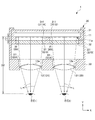
図1は、本実施形態の頭部装着型の表示装置1を説明する図である。図1は、表示装置1を鉛直方向上側から見た図である。
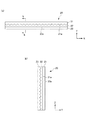
図2は、本実施形態の表示装置1に用いられる光学シート20の詳細を説明する図である。図2(a)は、光学シート20の水平面(XY面)に平行な断面における断面図であり、図2(b)は、図2(a)のb部断面図である。図2(c)は、図2(a)のc部詳細を示す図であり、図2(d)は、図2(b)のd部詳細を示す図である。
図3は、本実施形態の表示装置1に用いられる光学シート20の輝度と拡散角との関係を示す図である。
図4は、本実施形態の表示装置1によって表示された画像の例を示す図である。
図5は、比較例の表示装置5を説明する図である。図5(a)は、比較例の表示装置5の構成を説明する図であり、図1に対応する図である。図5(a)では、理解を容易にするために、表示装置5として、映像源51とレンズ52のみを示している。図5(b)は、比較例の表示装置5によって表示された画像の例を示す図である。
(Embodiment)
FIG. 1 is a diagram illustrating a head-mounted display device 1 of the present embodiment. FIG. 1 is a view of the display device 1 as viewed from above in the vertical direction.
FIG. 2 is a diagram illustrating details of the optical sheet 20 used in the display device 1 of the present embodiment. FIG. 2A is a cross-sectional view of the optical sheet 20 in a cross section parallel to the horizontal plane (XY plane), and FIG. 2B is a cross-sectional view taken along the line b of FIG. 2A. 2 (c) is a diagram showing the details of the c portion of FIG. 2 (a), and FIG. 2 (d) is a diagram showing the details of the d portion of FIG. 2 (b).
FIG. 3 is a diagram showing the relationship between the brightness and the diffusion angle of the optical sheet 20 used in the display device 1 of the present embodiment.
FIG. 4 is a diagram showing an example of an image displayed by the display device 1 of the present embodiment.
FIG. 5 is a diagram illustrating a display device 5 of a comparative example. FIG. 5A is a diagram for explaining the configuration of the display device 5 of the comparative example, and is a diagram corresponding to FIG. In FIG. 5A, only the image source 51 and the lens 52 are shown as the display device 5 for easy understanding. FIG. 5B is a diagram showing an example of an image displayed by the display device 5 of the comparative example.

なお、図1を含め以下に示す図中及び以下の説明において、理解を容易にするために、観察者がその頭部に表示装置1を装着した状態において、鉛直方向(上下方向)をZ方向とし、水平方向をX方向及びY方向とする。また、この水平方向のうち、光学シート20の厚み方向をY方向とし、その厚み方向に直交する左右方向をX方向とする。このY方向の−Y側を観察者側とし、+Y側を映像源側(背面側)とする。 In addition, in the figure shown below including FIG. 1 and in the following description, in order to facilitate understanding, the vertical direction (vertical direction) is the Z direction when the observer wears the display device 1 on the head. The horizontal direction is the X direction and the Y direction. Further, of the horizontal directions, the thickness direction of the optical sheet 20 is the Y direction, and the left-right direction orthogonal to the thickness direction is the X direction. The −Y side in the Y direction is the observer side, and the + Y side is the image source side (rear side).

表示装置1は、観察者がその頭部に装着し、観察者の眼前に映像を表示する、いわゆるヘッドマウントディスプレイ(HMD)である。図1に示すように、本実施形態の頭部装着型の表示装置1は、筐体30の内側に、映像源11と、レンズ12と、光学シート20とを備えており、筐体30が観察者の眼前となるようにその頭部に装着することによって、映像源11に表示された映像を光学シート20、レンズ12を介して観察者の眼Eに視認させることができる。
なお、図1において、表示装置1は、観察者の両眼E1,E2に対して映像を表示する例を挙げて説明するが、これに限定されるものでなく、例えば、観察者の片側の眼E1に対して配置され、その眼E1に対して映像を表示する形態としてもよい。
The display device 1 is a so-called head-mounted display (HMD) that the observer wears on his / her head and displays an image in front of the observer's eyes. As shown in FIG. 1, the head-mounted display device 1 of the present embodiment includes an image source 11, a lens 12, and an optical sheet 20 inside the housing 30, and the housing 30 is provided. By attaching the image to the head of the observer so as to be in front of the observer's eyes, the image displayed on the image source 11 can be visually recognized by the observer's eye E via the optical sheet 20 and the lens 12.
In FIG. 1, the display device 1 will be described with reference to an example in which an image is displayed to both eyes E1 and E2 of the observer, but the present invention is not limited to this, and for example, one side of the observer. It may be arranged with respect to the eye E1 and display an image with respect to the eye E1.

筐体30は、左右方向に横長の矩形の箱型の筐体であり、その内側に、映像源11を保持する保持部31、光学シート20(20A,20B)を保持する保持部32、レンズ12(12A,12B)を保持する保持部33を備えている。この筐体30は、例えば、不図示のベルト等により、観察者の頭部に装着可能である。
保持部31は、映像源11を保持する部材であり、その映像源11の表示面11a側の面に、観察者の眼E(E1,E2)及びレンズ12(12A,12B)に対応する位置に開口部311(311A,311B)を有している。本実施形態では、映像源11は、この保持部31(すなわち、表示装置1)に着脱可能に保持される。映像源11から出射した映像光Lは、この開口部311(311A,311B)を通ってレンズ12(12A,12B)へ入射する。
The housing 30 is a rectangular box-shaped housing that is horizontally long in the left-right direction, and inside the housing 30, a holding portion 31 that holds the image source 11, a holding portion 32 that holds the optical sheets 20 (20A, 20B), and a lens. A holding portion 33 for holding 12 (12A, 12B) is provided. The housing 30 can be attached to the observer's head by, for example, a belt (not shown).
The holding portion 31 is a member that holds the image source 11, and is positioned on the surface of the image source 11 on the display surface 11a side corresponding to the observer's eyes E (E1, E2) and the lenses 12 (12A, 12B). Has an opening 311 (311A, 311B). In the present embodiment, the image source 11 is detachably held by the holding unit 31 (that is, the display device 1). The image light L emitted from the image source 11 enters the lens 12 (12A, 12B) through the openings 311 (311A, 311B).

保持部32は、保持部31及び映像源11よりも観察者側(−Y側)に位置し、光学シート20を保持する部材である。保持部32は、開口部311(311A,311B)に対応する位置に設けられた開口部321(321A,321B)内に、光学シート20(20A,20B)が嵌めこまれ、保持されている。
この保持部32と前述の保持部31とは、一体となってY方向に移動可能であり、Y方向において所望の位置で固定可能である。したがって、観察者の視力等に応じて、映像源11及び光学シート20とレンズ12との間の距離(レンズ12に対するY方向における位置)を調整可能(ピント調整可能)である。なお、これに限らず、保持部31及び保持部32は、Y方向の位置が固定された形態としてもよい。
保持部33は、保持部32及び光学シート20よりも観察者側(−Y側)に位置し、レンズ12(12A,12B)を保持する部材である。この保持部33は、光学シート20(20A,20B)に対応する位置に開口部331(331A,331B)を有し、その開口部331(331A,331B)内にレンズ12(12A,12B)が嵌めこまれ、保持されている。
The holding portion 32 is a member that is located on the observer side (−Y side) of the holding portion 31 and the image source 11 and holds the optical sheet 20. The holding portion 32 is held by fitting the optical sheet 20 (20A, 20B) into the openings 321 (321A, 321B) provided at positions corresponding to the openings 311 (311A, 311B).
The holding portion 32 and the above-mentioned holding portion 31 can be integrally moved in the Y direction, and can be fixed at a desired position in the Y direction. Therefore, the distance (position in the Y direction with respect to the lens 12) between the image source 11 and the optical sheet 20 and the lens 12 can be adjusted (focus can be adjusted) according to the visual acuity of the observer and the like. Not limited to this, the holding portion 31 and the holding portion 32 may be in a form in which the positions in the Y direction are fixed.
The holding portion 33 is a member that is located on the observer side (−Y side) of the holding portion 32 and the optical sheet 20 and holds the lens 12 (12A, 12B). The holding portion 33 has an opening 331 (331A, 331B) at a position corresponding to the optical sheet 20 (20A, 20B), and a lens 12 (12A, 12B) is placed in the opening 331 (331A, 331B). It is fitted and held.

映像源11は、映像光Lを出射し、表示面11aに映像を表示するマイクロディスプレイであり、例えば、透過型の液晶表示デバイスや、反射型の液晶表示デバイス、有機EL等を使用することができる。本実施形態の映像源11は、例えば、対角が5インチの有機ELディスプレイが使用される。
映像源11は、その表示面11aが観察者側(−Y側)となるようにして、保持部31に保持されている。
なお、本実施形態では、この表示装置1は、映像源11を1つ備える例を示したが、これに限らず、例えば、後述するレンズ12A,12B及び観察者の眼E1,E2にそれぞれ対応する2台の映像源を備える形態としてもよい。
The image source 11 is a microdisplay that emits image light L and displays an image on the display surface 11a. For example, a transmissive liquid crystal display device, a reflective liquid crystal display device, an organic EL, or the like can be used. it can. As the image source 11 of the present embodiment, for example, an organic EL display having a diagonal of 5 inches is used.
The image source 11 is held by the holding unit 31 so that the display surface 11a is on the observer side (−Y side).
In the present embodiment, the display device 1 includes one image source 11, but the display device 1 is not limited to this, and corresponds to, for example, the lenses 12A and 12B described later and the observer's eyes E1 and E2, respectively. It may be in the form of having two video sources.

レンズ12(12A,12B)は、映像源11から出射された映像光Lを拡大して観察者側に出射する凸レンズである。本実施形態では、映像源11及び光学シート20(20A,20B)よりも観察者側(−Y側)に配置されている。レンズ12は、透光性の高いガラス製又は樹脂製である。
レンズ12の映像源側(背面側、+Y側)の表面には、反射抑制層12aが形成されている。この反射抑制層12aは、例えば、汎用の反射防止機能を有する材料(例えば、フッ化マグネシウム(MgF)、二酸化ケイ素(SiO)、フッ素系光学用コーティング剤等)を所定の膜厚でコーティングする等により設けてもよいし、光の波長より小さなピッチで形成された微小な凹凸形状を有するモスアイ構造を光の入射側の面に有することにより反射抑制機能を奏する層をレンズ12の映像源側に一体に積層して設けてもよい。
The lens 12 (12A, 12B) is a convex lens that magnifies the image light L emitted from the image source 11 and emits it to the observer side. In the present embodiment, the image source 11 and the optical sheet 20 (20A, 20B) are arranged on the observer side (-Y side). The lens 12 is made of highly translucent glass or resin.
A reflection suppression layer 12a is formed on the surface of the lens 12 on the image source side (back surface side, + Y side). The antireflection layer 12a is coated with, for example, a material having a general-purpose antireflection function (for example, magnesium fluoride (MgF 2 ), silicon dioxide (SiO 2 ), a fluorine-based optical coating agent, etc.) with a predetermined film thickness. A layer that exerts a reflection suppression function by having a moth-eye structure having a minute uneven shape formed at a pitch smaller than the wavelength of light on the surface on the incident side of light is provided as an image source of the lens 12. It may be integrally laminated on the side.

このような反射抑制層12aを設けることにより、レンズ12に入射する光がレンズ12の映像源側で反射して光学シート20側へ向かい、光学シート20の表面で再度反射する等により迷光となることを抑制し、映像のコントラストや明るさの向上を図ることができる。
また、反射抑制層12aは、さらに、レンズ12の観察者側(−Y側)の面に設けてもよい。この位置にさらに反射抑制層12aを設けることにより、レンズ12から映像光が出射する際に、レンズ12と空気との界面で反射し、レンズ12内で迷光となることを抑制でき、映像のコントラスト等を向上できる。
By providing such a reflection suppression layer 12a, the light incident on the lens 12 is reflected on the image source side of the lens 12 toward the optical sheet 20 side, and is reflected again on the surface of the optical sheet 20 to become stray light. This can be suppressed and the contrast and brightness of the image can be improved.
Further, the reflection suppression layer 12a may be further provided on the surface of the lens 12 on the observer side (−Y side). By further providing the reflection suppression layer 12a at this position, when the image light is emitted from the lens 12, it can be suppressed that the image light is reflected at the interface between the lens 12 and the air and becomes stray light in the lens 12, and the contrast of the image can be suppressed. Etc. can be improved.

光学シート20は、図1に示すように、映像源11とレンズ12との間に配置されている。レンズ12は、映像源11から出射した映像光Lを微少に拡散する拡散機能を有する光透過性のあるシートである。
本実施形態では、観察者の両眼E1,E2に対応して、それぞれ、レンズ12A,12B及び光学シート20A,20Bが設けられている。しかし、これに限らず、例えば、レンズ12A,12Bの領域をカバーできる程度に大きい1枚の光学シート20を、レンズ12よりも映像源側(背面側、−Y側)に配置する形態としてもよい。
As shown in FIG. 1, the optical sheet 20 is arranged between the image source 11 and the lens 12. The lens 12 is a light-transmitting sheet having a diffusing function of slightly diffusing the image light L emitted from the image source 11.
In this embodiment, lenses 12A and 12B and optical sheets 20A and 20B are provided corresponding to the observer's binoculars E1 and E2, respectively. However, the present invention is not limited to this, and for example, one optical sheet 20 large enough to cover the regions of the lenses 12A and 12B may be arranged on the image source side (rear side, −Y side) of the lens 12. Good.

従来、主に使用されている頭部装着型の表示装置5(以下、比較例の表示装置5という)は、図5(a)に示すように、上述の光学シート20を備えていない形態であり、映像源51から出射された映像光Lをレンズ52により拡大して、その映像を観察者に表示していた。
映像源51及び映像源11に用いられる有機EL等のディスプレイは、その表示部に映像を形成する画素領域G1が複数配列されており、また、各画素領域G1間には映像の形成に寄与しない非画素領域G2が設けられている。そのため、比較例の表示装置5では、映像源51から出射する映像光Lにより表示される映像は、レンズ52を介して拡大された場合に、図5(b)に示すように、画素領域G1による映像F1だけでなく、非画素領域G2が起因となる非映像領域F2も拡大されてしまう。そして、非映像領域F2も明瞭に観察者に視認され、鮮明な映像表示の妨げとなってしまう場合があった。
As shown in FIG. 5A, the head-mounted display device 5 (hereinafter referred to as the display device 5 of the comparative example), which is mainly used conventionally, is in a form not provided with the above-mentioned optical sheet 20. There, the image light L emitted from the image source 51 was magnified by the lens 52, and the image was displayed to the observer.
A display such as an organic EL used for the image source 51 and the image source 11 has a plurality of pixel regions G1 for forming an image arranged in the display portion thereof, and does not contribute to the formation of an image between the pixel regions G1. A non-pixel region G2 is provided. Therefore, in the display device 5 of the comparative example, when the image displayed by the image light L emitted from the image source 51 is magnified through the lens 52, as shown in FIG. 5B, the pixel region G1 Not only the image F1 due to the above, but also the non-image area F2 caused by the non-pixel area G2 is enlarged. Then, the non-image area F2 is also clearly visible to the observer, which may hinder a clear image display.

これに対して、本実施形態の表示装置1では、上述の光学シート20を設けることにより、映像源11から出射した映像光を微少に拡散させ、図4に示すように、その拡散された映像光によって、非画素領域G2が起因となる非映像領域F2が観察者に視認されてしまうことを抑制することができる。 On the other hand, in the display device 1 of the present embodiment, by providing the above-mentioned optical sheet 20, the image light emitted from the image source 11 is slightly diffused, and as shown in FIG. 4, the diffused image is diffused. It is possible to prevent the observer from visually recognizing the non-image region F2 caused by the non-pixel region G2 due to the light.

本実施形態の光学シート20は、図2に示すように、映像源側(背面側、+Y側)から順に、反射抑制層24、第1光学層21、第2光学層22、第3光学層23が積層されている。光学シート20は、この第1光学層21及び第2光学層22の界面と、第2光学層22及び第3光学層23の界面とに、それぞれ単位形状21a、単位形状23aが複数形成されている。
第1光学層21は、光学シート20の厚み方向(Y方向)において、第2光学層22及び第3光学層23よりも映像源側(+Y側)に位置し、光透過性を有する層である。第1光学層21の映像源側の面は、略平坦に形成されている。第1光学層21の観察者側(−Y側)の面には、図2(a)に示すように、凸状の単位形状21aが複数形成されている。単位形状21aは、観察者側(−Y側)に凸となっている。
この単位形状21aは、第1光学層21の観察者側の面に沿うようにして、上下方向(Z方向)に延在し、延在方向に直交する左右方向(X方向)に複数配列されている。また、単位形状21aは、左右方向及び厚み方向に平行な面(XY面)における断面形状が略円弧状に形成されたレンチキュラーレンズ形状である。ここで、略円弧状とは、真円の円弧だけでなく、楕円や長円等の一部を含む曲線状の形状を含むものをいう。
As shown in FIG. 2, the optical sheet 20 of the present embodiment has a reflection suppression layer 24, a first optical layer 21, a second optical layer 22, and a third optical layer in this order from the image source side (rear side, + Y side). 23 are laminated. The optical sheet 20 has a plurality of unit shapes 21a and a plurality of unit shapes 23a formed at the interface between the first optical layer 21 and the second optical layer 22 and the interface between the second optical layer 22 and the third optical layer 23, respectively. There is.
The first optical layer 21 is a layer having light transmittance and is located on the image source side (+ Y side) of the second optical layer 22 and the third optical layer 23 in the thickness direction (Y direction) of the optical sheet 20. is there. The surface of the first optical layer 21 on the image source side is formed to be substantially flat. As shown in FIG. 2A, a plurality of convex unit shapes 21a are formed on the surface of the first optical layer 21 on the observer side (−Y side). The unit shape 21a is convex toward the observer side (−Y side).
A plurality of the unit shapes 21a extend in the vertical direction (Z direction) along the surface of the first optical layer 21 on the observer side, and are arranged in a plurality of horizontal directions (X direction) orthogonal to the extending direction. ing. Further, the unit shape 21a is a lenticular lens shape in which the cross-sectional shape on a plane (XY plane) parallel to the left-right direction and the thickness direction is formed in a substantially arc shape. Here, the substantially arcuate shape means not only a perfect circular arc but also a curved shape including a part such as an ellipse or an oval.

第3光学層23は、光学シート20の最も観察者側(−Y側)に位置する光透過性を有する層である。第3光学層23の観察者側の面は、光学シート20を透過した映像光が出射する面であり、略平坦に形成されている。第3光学層23の映像源側(+Y側)の面は、図2(b)に示すように、凸状の単位形状23aが複数形成されている。単位形状23aは、映像源側(+Y側)に凸となっている。
この単位形状23aは、第3光学層23の映像源側の面に沿うようにして、左右方向(X方向)に延在し、延在方向に直交する鉛直方向(Z方向)に複数配列されており、鉛直方向及び厚み方向に平行な面(YZ面)における断面形状が略円弧状に形成されたレンチキュラーレンズ形状である。
The third optical layer 23 is a light-transmitting layer located on the most observer side (−Y side) of the optical sheet 20. The surface of the third optical layer 23 on the observer side is a surface on which the image light transmitted through the optical sheet 20 is emitted, and is formed substantially flat. As shown in FIG. 2B, a plurality of convex unit shapes 23a are formed on the surface of the third optical layer 23 on the image source side (+ Y side). The unit shape 23a is convex toward the image source side (+ Y side).
A plurality of the unit shapes 23a extend in the left-right direction (X direction) along the surface of the third optical layer 23 on the image source side, and are arranged in a plurality of vertical directions (Z direction) orthogonal to the extending direction. It is a lenticular lens shape in which the cross-sectional shape on a plane (YZ plane) parallel to the vertical direction and the thickness direction is formed in a substantially arc shape.

光学シート20の厚み方向(シート面の法線方向、Y方向)から見て、第3光学層23に設けられた単位形状23aの延在方向(X方向)と第1光学層21に設けられた単位形状21aの延在方向(Z方向)とは、交差(直交)している。
また、光学シート20の厚み方向(シート面の法線方向、Y方向)から見て、単位形状21aの配列方向(X方向)と単位形状23aの配列方向(Z方向)とは、交差(直交)している。
Seen from the thickness direction of the optical sheet 20 (normal direction of the sheet surface, Y direction), the unit shape 23a provided in the third optical layer 23 is provided in the extending direction (X direction) and the first optical layer 21. It intersects (orthogonally) with the extending direction (Z direction) of the unit shape 21a.
Further, when viewed from the thickness direction of the optical sheet 20 (normal direction of the sheet surface, Y direction), the arrangement direction (X direction) of the unit shape 21a and the arrangement direction (Z direction) of the unit shape 23a intersect (orthogonal). )are doing.

第2光学層22は、第1光学層21及び第3光学層23間に設けられた光透過性を有する層である。第2光学層22の両面は、第1光学層21の単位形状21a側の面と、第3光学層23の単位形状23a側の面とが互いに対向するようにして配置されている。 The second optical layer 22 is a light-transmitting layer provided between the first optical layer 21 and the third optical layer 23. Both sides of the second optical layer 22 are arranged so that the surface of the first optical layer 21 on the unit shape 21a side and the surface of the third optical layer 23 on the unit shape 23a side face each other.

本実施形態の光学シート20は、映像源側の面から入射角度0°で入射して観察者側に出射した透過光の半値角αが、0.05°≦α≦0.2°を満たし、透過光の最大輝度が1/20となる拡散角βが、β≦5×αを満たすようにして形成されている。
ここで、光学シート20の半値角αとは、図3に示すように、光の輝度が最大値となる光学シート20のシート面を観察する位置を基準(観察角度0度)として、画面左右方向及び画面上下方向において、光の輝度が最大値の半分の値になる観察角度のうち絶対値が最も大きい角度をいう。また、拡散角βは、光の輝度が最大値となる光学シート20のシート面を観察する位置を基準(観察角度0度)として、画面左右方向及び画面上下方向において、光の輝度が最大値の1/20の値になる観察角度のうち絶対値が最も大きい角度をいう。
また、本実施形態の光学シート20は、互いに隣接する光学層の屈折率差、すなわち、第1光学層21及び第2光学層22の屈折率差Δn1と、第2光学層22及び第3光学層23の屈折率差Δn2とが、それぞれ0.005≦Δn1≦0.1、0.005≦Δn2≦0.1を満たすようにして形成されている。
In the optical sheet 20 of the present embodiment, the half-value angle α of the transmitted light incident from the surface on the image source side at an incident angle of 0 ° and emitted to the observer side satisfies 0.05 ° ≤ α ≤ 0.2 °. The diffusion angle β at which the maximum brightness of the transmitted light is 1/20 is formed so as to satisfy β ≦ 5 × α.
Here, the half-value angle α of the optical sheet 20 refers to the left and right sides of the screen with reference to the position at which the sheet surface of the optical sheet 20 at which the brightness of light is maximum is observed (observation angle 0 degrees), as shown in FIG. The angle with the largest absolute value among the observation angles at which the brightness of light is half the maximum value in the direction and the vertical direction of the screen. Further, the diffusion angle β is the maximum value of the light brightness in the left-right direction of the screen and the top-down direction of the screen with reference to the position where the sheet surface of the optical sheet 20 at which the brightness of light is maximum is observed (observation angle 0 degree). The angle with the largest absolute value among the observation angles that are 1/20 of the value of.
Further, the optical sheet 20 of the present embodiment has a refractive index difference between the optical layers adjacent to each other, that is, a refractive index difference Δn1 between the first optical layer 21 and the second optical layer 22, and the second optical layer 22 and the third optical layer. The refractive index difference Δn2 of the layer 23 is formed so as to satisfy 0.005 ≦ Δn1 ≦ 0.1 and 0.005 ≦ Δn2 ≦ 0.1, respectively.

このように、光学シート20の半値角α及び拡散角βの値の範囲と、単位形状21a,23aが形成された面を界面として互いに隣接する層の屈折率差Δn1,Δn2の範囲とを規定することによって、本実施形態の表示装置1は、映像源11から出射した映像光Lを鉛直方向や左右方向に微少に拡散することができる。これにより、表示装置1は、観察者に鮮明な映像を表示するとともに、映像光Lの微少な拡散によって映像源11の非画素領域G2が起因となる非映像領域F2が目立ってしまうことを抑制することができる。
上述の効果をより効果的に奏する観点から、光学シート20の拡散角βは、半値角αに略等しいか、それに近い値であることがより望ましい。
In this way, the range of the values of the half-value angle α and the diffusion angle β of the optical sheet 20 and the range of the refractive index differences Δn1 and Δn2 of the layers adjacent to each other with the surface on which the unit shapes 21a and 23a are formed as an interface are defined. By doing so, the display device 1 of the present embodiment can slightly diffuse the image light L emitted from the image source 11 in the vertical direction and the left-right direction. As a result, the display device 1 displays a clear image to the observer and suppresses the non-image area F2 caused by the non-pixel area G2 of the image source 11 from becoming conspicuous due to the minute diffusion of the image light L. can do.
From the viewpoint of more effectively achieving the above-mentioned effects, it is more desirable that the diffusion angle β of the optical sheet 20 is substantially equal to or close to the half-value angle α.

仮に、半値角αが0.05°未満である場合、光学シートによって光の拡散される範囲が狭くなりすぎてしまい、非画素領域G2が起因となる非映像領域F2を目立たなくする効果が弱まり、非映像領域F2が観察者に視認されやすくなるので望ましくない。また、半値角αが0.2°よりも大きい場合、映像光の拡散される範囲が広くなりすぎてしまい、映像の鮮明さが低下してしまうので望ましくない。
また、仮に、拡散角βが5×αよりも大きい場合、輝度の低い映像光の拡散される範囲が広くなりすぎてしまい、映像の鮮明さが低下してしまうので望ましくない。
さらに、屈折率差Δn1,Δn2が0.005未満である場合、光学層間の屈折率差が小さくなりすぎ、光学層間における映像光の屈折が生じ難くなってしまい、十分な拡散作用が発揮されなくなるため望ましくない。また、屈折率差Δn1,Δn2が0.1よりも大きい場合、光学層間における光の屈折が大きくなりすぎてしまい、光学シートを透過する映像光が不鮮明になってしまうので望ましくない。
If the half-value angle α is less than 0.05 °, the range in which light is diffused by the optical sheet becomes too narrow, and the effect of making the non-image region F2 caused by the non-pixel region G2 inconspicuous is weakened. This is not desirable because the non-image area F2 is easily visible to the observer. Further, when the half-value angle α is larger than 0.2 °, the diffusion range of the image light becomes too wide and the sharpness of the image is lowered, which is not desirable.
Further, if the diffusion angle β is larger than 5 × α, the diffusion range of the low-luminance video light becomes too wide, and the sharpness of the video is lowered, which is not desirable.
Further, when the refractive index difference Δn1 and Δn2 are less than 0.005, the refractive index difference between the optical layers becomes too small, the refraction of the image light between the optical layers becomes difficult to occur, and a sufficient diffusion action cannot be exhibited. Therefore, it is not desirable. Further, when the refractive index differences Δn1 and Δn2 are larger than 0.1, the refraction of light between the optical layers becomes too large, and the image light transmitted through the optical sheet becomes unclear, which is not desirable.

第1光学層21及び第3光学層23は、それぞれ、光透過性の高いPC(ポリカーボネート)樹脂、MS(メチルメタクリレート・スチレン)樹脂、アクリル系樹脂等から形成されており、本実施形態では、第1光学層21及び第3光学層23はともに同じ材料で形成され、同じ屈折率を有している。
また、第2光学層22は、光透過性の高いウレタンアクリレート樹脂や、エポキシアクリレート樹脂等の紫外線硬化型樹脂等から形成されており、本実施形態では、第1光学層21及び第3光学層23の屈折率よりも低い屈折率となっている。
The first optical layer 21 and the third optical layer 23 are each made of a highly light-transmitting PC (polycarbonate) resin, MS (methylmethacrylate / styrene) resin, acrylic resin, or the like. Both the first optical layer 21 and the third optical layer 23 are made of the same material and have the same refractive index.
Further, the second optical layer 22 is formed of a urethane acrylate resin having high light transmittance, an ultraviolet curable resin such as an epoxy acrylate resin, or the like. In the present embodiment, the first optical layer 21 and the third optical layer are formed. The refractive index is lower than the refractive index of 23.

表示装置1は、レンズ12により映像を拡大して表示するので、光学シート20による色分散によって生じる色にじみ(色斑)も拡大されて観察される。したがって、光学シート20は、色にじみを生じない、又は、色にじみを目立たない程度に抑えることが望ましい。色にじみは、単一の材料であれば、用いる材料のアッベ数を規定することにより、管理することが可能である。しかし、本実施形態の光学シート20は、第1光学層21及び第3光学層23はともに同じ材料で形成されているが、これらの間に構成されている第2光学層22は、異なる材料により構成されており、屈折率も異なる。よって、単純にアッベ数を規定するだけでは、色にじみを抑えることが難しい。 Since the display device 1 magnifies and displays the image by the lens 12, the color bleeding (color spots) caused by the color dispersion by the optical sheet 20 is also magnified and observed. Therefore, it is desirable that the optical sheet 20 does not cause color bleeding or suppresses color bleeding to an inconspicuous degree. Color bleeding can be controlled by specifying the Abbe number of the material to be used if it is a single material. However, in the optical sheet 20 of the present embodiment, the first optical layer 21 and the third optical layer 23 are both made of the same material, but the second optical layer 22 configured between them is made of a different material. The refractive index is also different. Therefore, it is difficult to suppress color bleeding by simply specifying the Abbe number.

そこで、屈折率の異なる複数の材料から構成されている光学シート20を用いる表示装置1において、色にじみを目立たないように抑えることができる条件を各種実験及び検討を行い研究した。その結果、以下に示す値(Δν)をもって管理することが可能であり、その数値範囲についても適切な範囲が判明した。以下、この条件について説明する。 Therefore, in the display device 1 using the optical sheet 20 composed of a plurality of materials having different refractive indexes, various experiments and studies have been conducted to study the conditions under which the color bleeding can be suppressed so as not to be conspicuous. As a result, it was possible to manage with the values shown below (Δν d ), and an appropriate numerical range was found. This condition will be described below.

上述したように、第1光学層21及び第3光学層23は第2光学層22よりも屈折率の高い樹脂により形成された高屈折率光学層である。また、第2光学層22は、第1光学層21及び第3光学層23よりも屈折率の低い樹脂により形成された低屈折率光学層である。
ここで、以下に示すΔνを色にじみを管理するための指標として定義する。
高屈折率光学層のF線に対する屈折率をn1Fとする。
高屈折率光学層のd線に対する屈折率をn1dとする。
高屈折率光学層のC線に対する屈折率をn1Cとする。
低屈折率光学層のF線に対する屈折率をn2Fとする。
低屈折率光学層のd線に対する屈折率をn2dとする。
低屈折率光学層のC線に対する屈折率をn2Cとする。
F線における屈折率比をΔn=n1F/n2Fとする。
d線における屈折率比をΔn=n1d/n2dとする。
C線における屈折率比をΔn=n1C/n2Cとする。
これらの各屈折率から、以下の指標Δνを定義する。
Δν=(Δn−1)/(Δn−Δn
As described above, the first optical layer 21 and the third optical layer 23 are high refractive index optical layers formed of a resin having a higher refractive index than the second optical layer 22. Further, the second optical layer 22 is a low refractive index optical layer formed of a resin having a lower refractive index than the first optical layer 21 and the third optical layer 23.
Here, Δν d shown below is defined as an index for managing color bleeding.
Let n 1F be the refractive index of the high refractive index optical layer with respect to the F line.
Let n 1d be the refractive index of the high refractive index optical layer with respect to the d line.
Let n 1C be the refractive index of the high refractive index optical layer with respect to the C line.
Let n 2F be the refractive index of the low refractive index optical layer with respect to the F line.
Let n 2d be the refractive index of the low refractive index optical layer with respect to the d line.
Let n 2C be the refractive index of the low refractive index optical layer with respect to C line.
The refractive index ratio in the F line is Δn F = n 1F / n 2F .
The refractive index ratio on the d line is Δn d = n 1d / n 2d .
The refractive index ratio in the C line is Δn C = n 1C / n 2C .
From each of these refractive indexes, the following index Δν d is defined.
Δν d = (Δn d -1) / (Δn F − Δn C )

次に、上記Δνの値が、実際にどのようになるかについて、具体例を挙げて説明する。
図6は、第1光学層21と第2光学層22と第3光学層23とに用いる樹脂の屈折率とアッベ数とを示す図である。
ここでは、樹脂A,B,C,D,Eの5種類の樹脂を用意した。それぞれについて、F線(波長486nm)に対する屈折率n、d線(波長589nm)に対する屈折率n1d、C線(波長656nm)に対する屈折率n1Cと、参考のためアッベ数とを図示した。
Next, a specific example will be described as to what the value of Δν d actually becomes.
FIG. 6 is a diagram showing the refractive index and Abbe number of the resin used for the first optical layer 21, the second optical layer 22, and the third optical layer 23.
Here, five types of resins A, B, C, D, and E were prepared. For each, the refractive index n F for the F line (wavelength 486 nm), the refractive index n 1d for the d line (wavelength 589 nm) , the refractive index n 1C for the C line (wavelength 656 nm), and the Abbe number are shown for reference.

図6に示した5種類の樹脂から、第1光学層21と第2光学層22と第3光学層23とに用いる樹脂の組合せとして、4種類の構成の光学シート20を実際に作製して、映像源11を白色で表示したときに色にじみを目視観察した。この観察結果を、上記指標Δνの計算値と共に図7に示す。
図7は、4種類の構成の光学シート20の観察結果と指標Δνの計算値とを示す図である。
構成1のΔν=8.1505の構成では、色にじみがわずかではあるが残っていた。
From the five types of resins shown in FIG. 6, an optical sheet 20 having four types of configurations is actually produced as a combination of resins used for the first optical layer 21, the second optical layer 22, and the third optical layer 23. When the image source 11 was displayed in white, color bleeding was visually observed. The observation result is shown in FIG. 7 together with the calculated value of the index Δν d.
FIG. 7 is a diagram showing observation results of the optical sheets 20 having four types of configurations and calculated values of the index Δν d.
In the configuration of Δν d = 8.1505 in configuration 1, color bleeding was slightly left.

これに対して、構成3のΔν=12.1154では、色にじみは、確認できなかった。また、この構成3よりもΔνが大きい値となる構成2及び構成4についても、色にじみは、確認されなかった。
よって、Δν≧10を満たせば、色にじみを抑えることができる。本実施形態の光学シート20では、図7中の構成2から構成4の樹脂構成を採用しており、色にじみを抑えた映像を観察可能である。
On the other hand, in Δν d = 12.1154 of the configuration 3, no color bleeding could be confirmed. Further, no color bleeding was confirmed in the configurations 2 and 4, in which Δν d is larger than that of the configuration 3.
Therefore, if Δν d ≧ 10 is satisfied, color bleeding can be suppressed. The optical sheet 20 of the present embodiment adopts the resin configurations of configurations 2 to 4 in FIG. 7, and it is possible to observe an image in which color bleeding is suppressed.

なお、ここでは、Δνの上限を規定していないが、これは以下の理由による。
ここで提案している指標Δνは、本発明独自の指標であるが、アッベ数の考え方に似た値である。アッベ数は、以下の式により表すことができる。
アッベ数ν=(n−1)/(n−n
本発明では、このアッベ数の概念をさらに発展させて、高屈折率光学層と低屈折率光学層との間の屈折率比に着目し、この屈折率比を用いてアッベ数に近い計算式によって指標Δνを求めている。
アッベ数が大きいと分散が小さいことを示し、分散は小さければ小さいほどよく、よって、単一素材の光学部材において色にじみを抑制する場合には、アッベ数の上限については規定する必要はない。
これと同様に、本発明の指標Δνについても、その数値が大きくなるほど、光学シート20全体としての色分散が小さいことを表すこととなるので、この指標Δνの値が大きければ大きいほど望ましい。よって、色にじみを低減するためには、下限のみ規定すればよい。
Although the upper limit of Δν d is not specified here, this is due to the following reasons.
The index Δν d proposed here is an index unique to the present invention, but is a value similar to the concept of Abbe number. The Abbe number can be expressed by the following formula.
Abbe number ν d = (n d -1) / (n F −n C )
In the present invention, the concept of Abbe number is further developed to focus on the refractive index ratio between the high refractive index optical layer and the low refractive index optical layer, and a calculation formula close to the Abbe number is used using this refractive index ratio. The index Δν d is obtained by.
A large Abbe number indicates a small dispersion, and a smaller dispersion is better. Therefore, when suppressing color bleeding in an optical member made of a single material, it is not necessary to specify an upper limit of the Abbe number.
Similarly, as for the index Δν d of the present invention, the larger the value, the smaller the color dispersion of the optical sheet 20 as a whole. Therefore, the larger the value of the index Δν d , the more desirable it is. .. Therefore, in order to reduce color bleeding, only the lower limit needs to be specified.

また、単位形状21aのXY断面における断面形状が円弧状に形成されている場合、図2(c)に示すように、第1光学層21に形成される単位形状21aの左右方向(X方向)における配列ピッチをP1とし、単位形状21aのXY断面における円弧状の断面形状の曲率半径をR1としたときに、単位形状21aは、0.05≦P1/R1≦1.0の範囲で形成されるのが望ましい。
また同様に、単位形状23aのYZ断面における断面形状が円弧状に形成されている場合、図2(d)に示すように、第3光学層23に形成される単位形状23aの鉛直方向(Z方向)における配列ピッチをP2とし、単位形状23aのYZ断面における円弧状の断面形状の曲率半径をR2としたときに、単位形状23aは、0.05≦P2/R2≦1.0の範囲で形成されるのが望ましい。
When the cross-sectional shape of the unit shape 21a in the XY cross section is formed in an arc shape, as shown in FIG. 2C, the unit shape 21a formed in the first optical layer 21 is in the left-right direction (X direction). The unit shape 21a is formed in the range of 0.05 ≦ P1 / R1 ≦ 1.0 when the arrangement pitch in the above is P1 and the radius of curvature of the arcuate cross-sectional shape in the XY cross section of the unit shape 21a is R1. Is desirable.
Similarly, when the cross-sectional shape of the unit shape 23a in the YZ cross section is formed in an arc shape, as shown in FIG. 2D, the unit shape 23a formed in the third optical layer 23 is in the vertical direction (Z). When the arrangement pitch in (direction) is P2 and the radius of curvature of the arcuate cross-sectional shape in the YZ cross section of the unit shape 23a is R2, the unit shape 23a is in the range of 0.05 ≦ P2 / R2 ≦ 1.0. It is desirable to be formed.

このように単位形状21a及び単位形状23aの配列ピッチP1,P2及び曲率半径R1,R2を上述の範囲で形成することによって、表示装置1は、映像源11から出射された映像光を効率よく均等に上下方向及び左右方向に微少に拡散させることができる。
なお、本実施形態の光学シート20は、単位形状21aと単位形状23aとは、その断面形状が同じ形状であり、P1=P2、R1=R2となるように形成されている。
By forming the array pitches P1 and P2 and the radii of curvature R1 and R2 of the unit shape 21a and the unit shape 23a in the above range in this way, the display device 1 efficiently equalizes the video light emitted from the video source 11. It can be slightly diffused in the vertical direction and the horizontal direction.
The optical sheet 20 of the present embodiment has the same cross-sectional shape as the unit shape 21a and the unit shape 23a, and is formed so that P1 = P2 and R1 = R2.

また、本実施形態では、単位形状21aの配列ピッチP1及び単位形状23aの配列ピッチP2は、それぞれ、0.1mm≦P1≦0.5mm、0.1≦P1≦0.5mmを満たすことが好ましい。仮に、配列ピッチP1,P2が0.1mm未満であると、このような寸法の単位形状21a,23aを製造するのが困難となり、また、光の回折現象が生じやすくなり、回折光の影響によって映像が不鮮明になるので好ましくない。また、配列ピッチP1,P2が0.5mmよりも大きい場合、隣り合う単位形状間のラインが視認されてしまう場合があり、好ましくない。 Further, in the present embodiment, it is preferable that the arrangement pitch P1 of the unit shape 21a and the arrangement pitch P2 of the unit shape 23a satisfy 0.1 mm ≦ P1 ≦ 0.5 mm and 0.1 ≦ P1 ≦ 0.5 mm, respectively. .. If the array pitches P1 and P2 are less than 0.1 mm, it becomes difficult to manufacture unit shapes 21a and 23a having such dimensions, and a light diffraction phenomenon is likely to occur, which is affected by the diffracted light. This is not preferable because the image becomes unclear. Further, when the arrangement pitches P1 and P2 are larger than 0.5 mm, lines between adjacent unit shapes may be visually recognized, which is not preferable.

さらに、本実施形態の光学シート20は、第1光学層21の映像源側(背面側、+Y側)に、反射抑制層24が設けられている。
この反射抑制層24は、レンズ12の映像源側に設けられた反射抑制層12aと同様に、例えば、汎用の反射防止機能を有する材料(例えば、フッ化マグネシウム(MgF)、二酸化ケイ素(SiO)、フッ素系光学用コーティング剤等)を所定の膜厚でコーティングする等により設けてもよい。また、映像源11が表示装置に固定され、着脱不可能である場合等には、光の波長より小さなピッチで形成された微小な凹凸形状を有するモスアイ構造を光の入射側の面に有することにより反射抑制機能を奏する層を光学シート20の映像源側に一体に積層して設けてもよい。
Further, the optical sheet 20 of the present embodiment is provided with a reflection suppression layer 24 on the image source side (back surface side, + Y side) of the first optical layer 21.
Similar to the reflection suppression layer 12a provided on the image source side of the lens 12, the reflection suppression layer 24 is, for example, a material having a general-purpose antireflection function (for example, magnesium fluoride (MgF 2 ), silicon dioxide (SiO)). 2 ), a fluorine-based optical coating agent, etc.) may be provided by coating with a predetermined film thickness. Further, when the image source 11 is fixed to the display device and cannot be attached or detached, a moth-eye structure having a minute uneven shape formed at a pitch smaller than the wavelength of the light is provided on the surface on the incident side of the light. A layer that exhibits a reflection suppression function may be integrally laminated on the image source side of the optical sheet 20.

反射抑制層24を光学シート20の映像源側に設けることにより、光学シート20に入射する光が光学シート20の映像源側の面で反射して映像源11側へ向かうことによる映像の明るさの低下を抑制できる。
また、反射抑制層24を光学シート20の映像源側に設けることにより、光学シート20に入射する光が光学シート20の映像源側の面で反射して映像源11側へ向かい、映像源11の表示面11aで再度反射する等により迷光となることを抑制し、映像のコントラスト向上を図ることができる。
By providing the reflection suppression layer 24 on the image source side of the optical sheet 20, the light incident on the optical sheet 20 is reflected by the surface of the optical sheet 20 on the image source side and directed toward the image source 11, resulting in the brightness of the image. Can be suppressed.
Further, by providing the reflection suppression layer 24 on the image source side of the optical sheet 20, the light incident on the optical sheet 20 is reflected by the surface of the optical sheet 20 on the image source side and heads toward the image source 11, and the image source 11 It is possible to suppress stray light due to reflection on the display surface 11a of the above and improve the contrast of the image.

なお、反射抑制層24は、さらに、光学シート20の観察者側(−Y側)の面に設けてもよい。この位置にさらに反射抑制層24を設けることにより、光学シート20から映像光が出射する際に、光学シート20と空気との界面で反射し、光学シート20内で迷光となることを抑制でき、映像のコントラスト等を向上できる。
また、光学シート20の映像源側(+Y側)の面に、ハードコート機能や、防汚機能等を有する層を設けてもよい。このような層を設けることにより、映像源11が筐体30に着脱可能である場合に、映像源11を筐体30から外したときに、光学シート20が傷ついたり、汚れが付着したりして、映像の視認の妨げになることを抑制できる。
The reflection suppression layer 24 may be further provided on the surface of the optical sheet 20 on the observer side (−Y side). By further providing the reflection suppression layer 24 at this position, when the image light is emitted from the optical sheet 20, it can be suppressed that the image light is reflected at the interface between the optical sheet 20 and the air and becomes stray light in the optical sheet 20. The contrast of the image can be improved.
Further, a layer having a hard coat function, an antifouling function, or the like may be provided on the surface of the optical sheet 20 on the image source side (+ Y side). By providing such a layer, when the image source 11 is detachable from the housing 30, the optical sheet 20 may be damaged or dirty when the image source 11 is removed from the housing 30. Therefore, it is possible to suppress the hindrance to the visual recognition of the image.

本実施形態の表示装置1は、Y方向における映像源11の表示面11aから光学シート20の映像源側(−Y側)の面までの距離D1が、映像源11の画素領域G1の配列ピッチの寸法d(画素領域G1の2つの配列方向において配列ピッチが異なる場合は、小さい方の配列ピッチとする)の100倍以上である。仮に、距離D1が、寸法dの100倍未満であると、画素領域G1によるモアレが視認されたり、非画素領域G2に起因する非映像領域が目立って観察されやすくなるため、好ましくない。
一般的に、表示装置1に用いられる映像源11の画素領域G1の配列ピッチdは、400〜500ppi(pixel per inch)である。本実施形態では、例えば、映像源11の画素領域G1の配列ピッチdは、d=0.0508mm(500ppi)であり、映像源11の表示面11aから光学シート20の映像源側(−Y側)の面までのY方向における距離D1は、5.08mmである。
In the display device 1 of the present embodiment, the distance D1 from the display surface 11a of the image source 11 to the image source side (−Y side) surface of the optical sheet 20 in the Y direction is the arrangement pitch of the pixel region G1 of the image source 11. It is 100 times or more of the dimension d (when the arrangement pitch is different in the two arrangement directions of the pixel region G1, the smaller arrangement pitch is used). If the distance D1 is less than 100 times the dimension d, moire due to the pixel region G1 can be visually recognized, and the non-image region due to the non-pixel region G2 can be easily observed, which is not preferable.
Generally, the array pitch d of the pixel region G1 of the image source 11 used in the display device 1 is 400 to 500 ppi (pixel per inch). In the present embodiment, for example, the arrangement pitch d of the pixel region G1 of the image source 11 is d = 0.0508 mm (500 ppi), and the image source side (−Y side) of the optical sheet 20 is from the display surface 11a of the image source 11. The distance D1 in the Y direction to the plane of) is 5.08 mm.

また、本実施形態の表示装置1は、上述のように、レンズ12よりも映像源側(+Y側)に光学シート20が位置するので、映像源11が筐体30に着脱可能である表示装置1において映像源11を筐体30から外した場合等に、筐体内に侵入した埃やゴミ等の異物によってレンズ12が破損したり汚れたりすることがない。また、光学シート20の映像源側が異物等で汚れた場合にも、単位形状を傷つけることなく、ふき取ることが可能である。
また、特に、モスアイ構造を有する反射抑制層に関しては、高い反射抑制効果を有しているが、破損しやすいために観察者の指等が触れない位置に設けることが重要となる。本実施形態の表示装置1では、レンズ12よりも映像源側(+Y側)に光学シート20が位置するので、そのような反射抑制層を光学シート20の観察者側やレンズ12の映像源側等に設けることができ、より高い反射抑制効果が得られ、映像のコントラストや明るさの向上を図ることができる。
Further, in the display device 1 of the present embodiment, as described above, since the optical sheet 20 is located on the image source side (+ Y side) of the lens 12, the image source 11 can be attached to and detached from the housing 30. When the image source 11 is removed from the housing 30 in No. 1, the lens 12 is not damaged or soiled by foreign matter such as dust or dirt that has entered the housing. Further, even when the image source side of the optical sheet 20 is contaminated with foreign matter or the like, it can be wiped off without damaging the unit shape.
Further, in particular, the reflection suppression layer having a moth-eye structure has a high reflection suppression effect, but it is easily damaged, so it is important to provide it at a position where the observer's finger or the like does not touch. In the display device 1 of the present embodiment, since the optical sheet 20 is located on the image source side (+ Y side) of the lens 12, such a reflection suppression layer is provided on the observer side of the optical sheet 20 or on the image source side of the lens 12. It can be provided in the like, a higher reflection suppression effect can be obtained, and the contrast and brightness of the image can be improved.

次に、映像源11から出射された映像光Lが観察者の眼E(E1,E2)に届くまでの動作について説明する。
図1に示すように、映像源11から出射した映像光Lは、光学シート20(20A,20B)の映像源側(+Y側)の面に入射する。そして、光学シート20に入射した映像光Lは、第1光学層21を透過して、第1光学層21及び第2光学層22との界面の単位形状21aによって、左右方向(X方向)に微少に拡散して第2光学層22内を透過する。
第2光学層22を透過した映像光Lは、第2光学層22及び第3光学層23との界面に形成された単位形状23aによって、鉛直方向(Z方向)に微少に拡散し、第3光学層23を透過して光学シート20の観察者側(−Y側)の面から出射する。
光学シート20を透過した映像光Lは、レンズ12(12A,12B)へ入射する。そして、レンズ12により、映像光Lが拡大され、観察者側(−Y側)へ出射する。
Next, the operation until the image light L emitted from the image source 11 reaches the observer's eyes E (E1, E2) will be described.
As shown in FIG. 1, the image light L emitted from the image source 11 is incident on the surface of the optical sheet 20 (20A, 20B) on the image source side (+ Y side). Then, the image light L incident on the optical sheet 20 passes through the first optical layer 21 and is in the left-right direction (X direction) due to the unit shape 21a of the interface between the first optical layer 21 and the second optical layer 22. It diffuses slightly and transmits through the second optical layer 22.
The image light L transmitted through the second optical layer 22 is slightly diffused in the vertical direction (Z direction) by the unit shape 23a formed at the interface between the second optical layer 22 and the third optical layer 23, and the third optical layer 22 is transmitted. It passes through the optical layer 23 and exits from the surface of the optical sheet 20 on the observer side (−Y side).
The image light L transmitted through the optical sheet 20 is incident on the lenses 12 (12A, 12B). Then, the image light L is magnified by the lens 12 and emitted to the observer side (−Y side).

映像光Lは、光学シート20により左右方向及び鉛直方向に微少に拡散させられる。そのため、レンズ12により画像が拡大されても、観察者の眼Eによって視認される画像には、図4に示すように、比較例の表示装置5の場合に比して(図5(b)参照)、映像源11の非画素領域G2が起因となる非映像領域F2が目立ってしまうことを極力抑制することができ、鮮明な映像を表示することができる。
しかも、上述のように、映像源11と光学シート20との間には、十分な距離D1が設けられているので、映像光を適度に拡散させて非映像領域F2が目立って観察されることを抑制でき、かつ、画素領域G1及び非画素領域G2によるモアレ等の発生も十分抑制できる。
The image light L is slightly diffused in the left-right direction and the vertical direction by the optical sheet 20. Therefore, even if the image is magnified by the lens 12, the image visually recognized by the observer's eye E is as shown in FIG. 4 as compared with the case of the display device 5 of the comparative example (FIG. 5 (b)). (See), it is possible to suppress the non-image region F2 caused by the non-pixel region G2 of the image source 11 from being conspicuous as much as possible, and it is possible to display a clear image.
Moreover, as described above, since a sufficient distance D1 is provided between the image source 11 and the optical sheet 20, the non-image area F2 is conspicuously observed by appropriately diffusing the image light. And the occurrence of moire and the like due to the pixel region G1 and the non-pixel region G2 can be sufficiently suppressed.

また、指標Δν≧10を満たすように樹脂を組み合わせることにより、色にじみ(色斑)を抑えた良好な画像を観察可能である。 Further, by combining the resins so as to satisfy the index Δν d ≧ 10, it is possible to observe a good image in which color bleeding (color spots) is suppressed.

次に、本実施形態の表示装置1に用いられる光学シート20の製造方法について説明する。
上述したように、光学シート20の第1光学層21及び第3光学層23に設けられた各単位形状21a、単位形状23aは、互いに同じ形状に形成されているため、まず、この凸状の単位形状に対応する凹形状が設けられた金型を使用して、単位形状が形成されたシート状部材を押出成形法や、射出成形法等により形成する。
それから、単位形状が形成されたシート状部材を、所定の寸法に裁断して、第1光学層21及び第3光学層23を得る。
このように、単位形状21a及び単位形状23aが同形状に形成されている場合、1枚のシート状部材から第1光学層21及び第3光学層23を同時に切り出すことができ、光学シート20の製造効率を向上させることができる。
Next, a method of manufacturing the optical sheet 20 used in the display device 1 of the present embodiment will be described.
As described above, since the unit shapes 21a and the unit shapes 23a provided on the first optical layer 21 and the third optical layer 23 of the optical sheet 20 are formed in the same shape as each other, first, they are convex. Using a mold provided with a concave shape corresponding to the unit shape, a sheet-shaped member having the unit shape formed is formed by an extrusion molding method, an injection molding method, or the like.
Then, the sheet-shaped member having the unit shape formed is cut into predetermined dimensions to obtain the first optical layer 21 and the third optical layer 23.
When the unit shape 21a and the unit shape 23a are formed in the same shape as described above, the first optical layer 21 and the third optical layer 23 can be simultaneously cut out from one sheet-like member, and the optical sheet 20 can be formed. The manufacturing efficiency can be improved.

続いて、第1光学層21の単位形状21a側の面上に、第2光学層22を形成する樹脂を充填し、その樹脂と、第3光学層23の単位形状23a側の面とを貼り合わせて、第1光学層21及び第3光学層23間に所定の距離を設けた状態で樹脂を硬化させる。このとき、第1光学層21及び第3光学層23は、単位形状21aの延在方向と単位形状23aの延在方向とが互いに交差(直交)するようにして配置される。
これにより、第1光学層21、第2光学層22、第3光学層23が順次積層された状態となる。さらに、第1光学層21の表面(第2光学層22側とは反対側の面)に、反射抑制層24を設けることにより、光学シート20が完成する。
Subsequently, a resin forming the second optical layer 22 is filled on the surface of the first optical layer 21 on the unit shape 21a side, and the resin and the surface of the third optical layer 23 on the unit shape 23a side are attached. At the same time, the resin is cured with a predetermined distance between the first optical layer 21 and the third optical layer 23. At this time, the first optical layer 21 and the third optical layer 23 are arranged so that the extending direction of the unit shape 21a and the extending direction of the unit shape 23a intersect (orthogonally) with each other.
As a result, the first optical layer 21, the second optical layer 22, and the third optical layer 23 are sequentially laminated. Further, the optical sheet 20 is completed by providing the reflection suppression layer 24 on the surface of the first optical layer 21 (the surface opposite to the second optical layer 22 side).

以上より、本実施形態の表示装置1は、映像源11とレンズ12との間に、少なくとも2層以上の光学層を有し、各光学層間の界面に単位形状21a,23aが複数形成された光学シート20を備え、単位形状21a,23aが界面に形成された隣接する光学層の屈折率差Δn1,Δn2が、それぞれ0.005≦Δn1≦0.1、0.005≦Δn2≦0.1を満たし、映像源11の表示面11aから光学シート20の映像源側(+Y側)の面までの距離D1は、画素領域G1の配列ピッチdの100倍以上である。これにより、表示装置1は、映像源11から出射した映像光Lを微少に拡散することができ、観察者に鮮明な映像を表示するとともに、映像源11の非画素領域G2が起因となる非映像領域F2が観察者に視認されてしまうことを抑制することができる。 From the above, the display device 1 of the present embodiment has at least two or more optical layers between the image source 11 and the lens 12, and a plurality of unit shapes 21a and 23a are formed at the interface between the optical layers. The refractive index differences Δn1 and Δn2 of the adjacent optical layers provided with the optical sheet 20 and having the unit shapes 21a and 23a formed at the interface are 0.005 ≦ Δn1 ≦ 0.1 and 0.005 ≦ Δn2 ≦ 0.1, respectively. The distance D1 from the display surface 11a of the image source 11 to the image source side (+ Y side) surface of the optical sheet 20 is 100 times or more the arrangement pitch d of the pixel region G1. As a result, the display device 1 can slightly diffuse the image light L emitted from the image source 11, display a clear image to the observer, and the non-pixel region G2 of the image source 11 is the cause. It is possible to prevent the image area F2 from being visually recognized by the observer.

また、本実施形態の表示装置1は、上述のように、レンズ12よりも映像源側(+Y側)に光学シート20が位置するので、映像源11が表示装置1(筐体30)から外された状態であったとしても、侵入した埃やごみ等の異物からレンズ12を保護することができ、異物によってレンズ12が破損したり汚れたりするがなく、光学シート20の映像源側表面が汚れたり曇ったりした場合等も、単位形状を傷つけることなく、ふき取ることが可能である。
また、本実施形態の表示装置1は、映像源11と光学シート20とがY方向において一体となって移動可能であり、Y方向においてピント調整の等のために映像源11を動かした場合にも、映像源11と光学シート20との間の距離D1を一定としたままY方向に移動可能である。したがって、非画素領域G2に起因する非映像領域F2が観察者に視認されることを抑制する光学シート20の拡散効果を維持したままピント調整作業を行うことができる。
また、本実施形態の表示装置1は、光学シート20の映像源側(入光側、+Y側)の面に反射抑制層24を備え、レンズ12の映像源側の面に反射抑制層12aを備えているので、迷光を抑制し、映像の明るさやコントラストを向上できる。
Further, in the display device 1 of the present embodiment, as described above, since the optical sheet 20 is located on the image source side (+ Y side) of the lens 12, the image source 11 is outside the display device 1 (housing 30). The lens 12 can be protected from foreign matter such as dust and dirt that has entered, and the lens 12 is not damaged or soiled by the foreign matter, and the surface of the optical sheet 20 on the image source side is covered. Even when it becomes dirty or cloudy, it can be wiped off without damaging the unit shape.
Further, in the display device 1 of the present embodiment, when the image source 11 and the optical sheet 20 are integrally movable in the Y direction and the image source 11 is moved for focus adjustment or the like in the Y direction. Also, the distance D1 between the image source 11 and the optical sheet 20 can be kept constant and can be moved in the Y direction. Therefore, the focus adjustment work can be performed while maintaining the diffusion effect of the optical sheet 20 that suppresses the non-image region F2 caused by the non-pixel region G2 from being visually recognized by the observer.
Further, the display device 1 of the present embodiment includes a reflection suppression layer 24 on the image source side (light entry side, + Y side) of the optical sheet 20, and a reflection suppression layer 12a on the image source side surface of the lens 12. Since it is equipped, stray light can be suppressed and the brightness and contrast of the image can be improved.

また、本実施形態の表示装置1は、単位形状21aが、凸状であって、光学シート20の厚み方向(Y方向)に直交するシート面(XZ面)内のZ方向(第1の方向)に延在し、シート面内のZ方向に直交するX方向(第2の方向)に配列され、光学シート20の厚み方向及び配列方向に平行な断面(XY面)における断面形状が略円弧状に形成されている。同様に、単位形状23aが、凸状であって、光学シート20の厚み方向(Y方向)に直交するシート面(XZ面)内のX方向に延在し、シート面内のX方向に直交するZ方向に配列され、光学シート20の厚み方向及び配列方向に平行な断面(YZ面)における断面形状が円弧状に形成されている。これにより、表示装置1は、単位形状21a,23aを通過する映像光を効率よく均等に拡散させることができる。 Further, in the display device 1 of the present embodiment, the unit shape 21a is convex and is orthogonal to the thickness direction (Y direction) of the optical sheet 20 in the Z direction (first direction) in the sheet surface (XZ direction). ), Arranged in the X direction (second direction) orthogonal to the Z direction in the sheet surface, and the cross-sectional shape in the cross section (XY plane) parallel to the thickness direction and the arrangement direction of the optical sheet 20 is approximately circular. It is formed in an arc shape. Similarly, the unit shape 23a is convex, extends in the X direction in the sheet surface (XZ surface) orthogonal to the thickness direction (Y direction) of the optical sheet 20, and is orthogonal to the X direction in the sheet surface. The optical sheet 20 is arranged in the Z direction, and the cross-sectional shape in the cross section (YZ plane) parallel to the thickness direction and the arrangement direction of the optical sheet 20 is formed in an arc shape. As a result, the display device 1 can efficiently and evenly diffuse the video light passing through the unit shapes 21a and 23a.

また、本実施形態の表示装置1は、光学シート20に入射角度0で入射した透過光における半値角αが0.05°≦α≦0.2°を満たし、最大輝度が1/20となる光学シート20の拡散角βが、β≦5×αを満たすようにして形成されている。これにより、映像源11から出射した映像光Lを微少に拡散することができ、観察者に鮮明な映像を表示するとともに、映像源11の非画素領域G2が起因となる非映像領域F2が観察者に視認されてしまうことを抑制する効果を高めることができる。 Further, in the display device 1 of the present embodiment, the half-value angle α of the transmitted light incident on the optical sheet 20 at an incident angle of 0 satisfies 0.05 ° ≦ α ≦ 0.2 °, and the maximum brightness becomes 1/20. The diffusion angle β of the optical sheet 20 is formed so as to satisfy β ≦ 5 × α. As a result, the image light L emitted from the image source 11 can be slightly diffused to display a clear image to the observer, and the non-image area F2 caused by the non-pixel area G2 of the image source 11 is observed. It is possible to enhance the effect of suppressing being visually recognized by a person.

さらに、本実施形態の表示装置1は、光学シート20が3層以上の光学層を有しており、隣り合う光学層間の各界面に設けられた単位形状21a及び単位形状23aのシート面内における延在方向(Z方向、X方向)が、光学シート20の厚み方向から見て直交(交差)している。これにより、表示装置1は、映像源11から出射した映像光を複数の方向(左右方向及び鉛直方向)に拡散させることができ、映像源11の非画素領域が起因となる非映像領域をより効果的に目立たなくすることができる。 Further, in the display device 1 of the present embodiment, the optical sheet 20 has three or more optical layers, and the unit shape 21a and the unit shape 23a provided at each interface between adjacent optical layers are in the sheet surface. The extending directions (Z direction, X direction) are orthogonal (intersect) when viewed from the thickness direction of the optical sheet 20. As a result, the display device 1 can diffuse the image light emitted from the image source 11 in a plurality of directions (horizontal direction and vertical direction), and can further reduce the non-image area caused by the non-pixel area of the image source 11. It can be effectively made inconspicuous.

さらにまた、指標Δν≧10を満たすように樹脂を組み合わせることにより、色にじみ(色斑)を抑えた良好な画像を観察可能である。 Furthermore, by combining the resins so as to satisfy the index Δν d ≧ 10, it is possible to observe a good image in which color bleeding (color spots) is suppressed.

なお、第1光学層21の単位形状21a及び第3光学層23の単位形状23aの各配列方向や、各配列方向及び光学シート20の厚み方向に沿った断面での単位形状21a,23aの断面形状に関しては、上述の例に限らず、適宜変更してよい。
以下に、本実施形態の表示装置1に用いられる光学シート20の他の形態について説明する。
It should be noted that the cross sections of the unit shapes 21a and 23a in the respective arrangement directions of the unit shape 21a of the first optical layer 21 and the unit shape 23a of the third optical layer 23, and the cross sections along the respective arrangement directions and the thickness direction of the optical sheet 20. The shape is not limited to the above example, and may be changed as appropriate.
Hereinafter, other embodiments of the optical sheet 20 used in the display device 1 of the present embodiment will be described.

例えば、光学シート20は、単位形状21aの延在方向が鉛直方向(Z方向)であり、単位形状23aの延在方向が左右方向(X方向)であり、これらが直交する例を説明したが、光学シート20の単位形状21aの延在方向が、左右方向に対して45°傾斜した方向(上下方向に対して45°傾斜)であり、単位形状23aの延在方向が、左右方向に対して−45°に傾斜した方向であり、Y方向から見て、単位形状21aの延在方向と単位形状23aの延在方向とが交差(この場合は、直交)する形態としてもよい。 For example, in the optical sheet 20, the extending direction of the unit shape 21a is the vertical direction (Z direction), and the extending direction of the unit shape 23a is the left-right direction (X direction). The extending direction of the unit shape 21a of the optical sheet 20 is a direction inclined by 45 ° with respect to the left-right direction (inclined by 45 ° with respect to the vertical direction), and the extending direction of the unit shape 23a is inclined with respect to the left-right direction. The direction is inclined at −45 °, and the extending direction of the unit shape 21a and the extending direction of the unit shape 23a may intersect (in this case, orthogonally) when viewed from the Y direction.

また、光学シート20の単位形状21aの延在方向が鉛直方向(Z方向)に対して傾斜する角度、及び、単位形状23aの延在方向が左右方向(X方向)に対して傾斜する角度は、上記の45°に限らず、例えば、15°や30°等としてもよく、映像源11の画素の配列や所望する光学性能等に応じて、各単位形状の延在方向を適宜設定してよい。これにより、非画素領域G2に起因する非映像領域F2を目立たせなくする効果をさらに高めることができる。
また、一方の単位形状の延在方向が、他方の単位形状の延在方向と直交以外の角度で交差するようにしてもよい。このような形態としても、非画素領域G2に起因する非映像領域F2を目立たせなくする効果をさらに高めることができる。
Further, the angle at which the extending direction of the unit shape 21a of the optical sheet 20 is inclined with respect to the vertical direction (Z direction) and the angle at which the extending direction of the unit shape 23a is inclined with respect to the left-right direction (X direction) are , Not limited to the above 45 °, for example, 15 °, 30 °, etc., and the extending direction of each unit shape is appropriately set according to the arrangement of the pixels of the image source 11 and the desired optical performance. Good. As a result, the effect of making the non-image region F2 caused by the non-pixel region G2 inconspicuous can be further enhanced.
Further, the extending direction of one unit shape may intersect with the extending direction of the other unit shape at an angle other than orthogonal. Even in such a form, the effect of making the non-image region F2 caused by the non-pixel region G2 inconspicuous can be further enhanced.

図8及び図9は、本実施形態の表示装置1に用いられる光学シート20の他の形態の詳細を説明する図である。
図8(a)は、他の形態の光学シート20の斜視図である。図8(b)は、図8(a)のb−b断面図である。図8(c)は、図8(a)のc−c断面図である。図9(a)は、図8(b)のa部詳細を示す図であり、図9(b)は、図8(c)のb部詳細を示す図である。
図8,図9に示す他の形態の光学シート20を含め以下に示す光学シート20の他の形態に関して、上述の実施形態と同様の機能を果たす部分には同一の符号を付して、適宜重複する説明を省略する。また、図8及び図9を含め以下に示す光学シート20の他の形態を示す図面について、理解を容易にするために、反射抑制層24を備えない形態を示しているが、適宜、第1光学層21の映像源側(背面側、+Y側)に前述のような反射抑制層24を設けてもよい。
図8及び図9に示すx方向、y方向、z方向は互いに直交し、y方向は、Y方向と平行である。また、x方向は、X方向に対して45°をなし、z方向は、Z方向に対して45°をなしている。
8 and 9 are views for explaining details of other embodiments of the optical sheet 20 used in the display device 1 of the present embodiment.
FIG. 8A is a perspective view of the optical sheet 20 of another form. FIG. 8B is a cross-sectional view taken along the line bb of FIG. 8A. FIG. 8 (c) is a cross-sectional view taken along the line cc of FIG. 8 (a). 9 (a) is a diagram showing the details of the a part of FIG. 8 (b), and FIG. 9 (b) is a diagram showing the details of the b part of FIG. 8 (c).
With respect to the other forms of the optical sheet 20 shown below, including the optical sheet 20 of the other forms shown in FIGS. 8 and 9, the parts that perform the same functions as those of the above-described embodiment are designated by the same reference numerals as appropriate. Duplicate explanations will be omitted. Further, in order to facilitate understanding, the drawings showing other forms of the optical sheet 20 shown below, including FIGS. 8 and 9, are shown in which the reflection suppression layer 24 is not provided. The reflection suppression layer 24 as described above may be provided on the image source side (back surface side, + Y side) of the optical layer 21.
The x-direction, y-direction, and z-direction shown in FIGS. 8 and 9 are orthogonal to each other, and the y-direction is parallel to the Y-direction. Further, the x direction is 45 ° with respect to the X direction, and the z direction is 45 ° with respect to the Z direction.

図8及び図9に示す光学シート20において、第1光学層21の観察者側(−y側、−Y側)の面に形成される単位形状21aは、図8(a),(b)に示すように、第1光学層21の観察者側の面に沿うようにして、左右方向(X方向)に対して45°傾斜したx方向に延在し、鉛直方向(Z方向)に対して45°傾斜したz方向に複数配列されている。第3光学層23の映像源側(+y側、+Y側)の面に形成される単位形状23aは、図8(a),(c)に示すように、第3光学層23の映像源側の面に沿うようにして、鉛直方向(Z方向)に対して45°傾斜したz方向に延在し、左右方向(X方向)に対して45°傾斜したx方向に複数配列されている。
単位形状21aの延在方向(x方向)と単位形状23aの延在方向(z方向)とは、交差(直交)しており、単位形状21aの配列方向(z方向)と単位形状23aの配列方向(x方向)とは、交差(直交)している。
In the optical sheet 20 shown in FIGS. 8 and 9, the unit shape 21a formed on the observer side (−y side, −Y side) surface of the first optical layer 21 is shown in FIGS. 8 (a) and 8 (b). As shown in, along the surface of the first optical layer 21 on the observer side, it extends in the x direction inclined by 45 ° with respect to the left-right direction (X direction), and extends in the x direction with respect to the vertical direction (Z direction). A plurality of optics are arranged in the z direction inclined by 45 °. As shown in FIGS. 8A and 8C, the unit shape 23a formed on the image source side (+ y side, + Y side) surface of the third optical layer 23 is on the image source side of the third optical layer 23. Along the plane of the above, it extends in the z direction inclined by 45 ° with respect to the vertical direction (Z direction), and a plurality of arrangements are arranged in the x direction inclined by 45 ° with respect to the left-right direction (X direction).
The extending direction (x direction) of the unit shape 21a and the extending direction (z direction) of the unit shape 23a intersect (orthogonally), and the arrangement direction of the unit shape 21a (z direction) and the arrangement of the unit shape 23a The direction (x direction) intersects (orthogonal).

また、この単位形状21aは、z方向及びy方向に平行な面(yz面)における断面形状が略三角形状、いわゆるプリズム形状に形成されている。同様に、単位形状23aは、x方向及びy方向に平行な面(xy面)における断面形状が略三角形状、いわゆるプリズム形状に形成されている。
ここで、略三角形状とは、二等辺三角形や、正三角形等を含む三角形状だけでなく、三角形状の頂部が曲面や平面に面取りされた形状や、三角形状の斜面が微小に湾曲された形状等も含むものをいう。
Further, the unit shape 21a is formed so that the cross-sectional shape of the plane (yz plane) parallel to the z direction and the y direction is substantially triangular, that is, a so-called prism shape. Similarly, the unit shape 23a is formed so that the cross-sectional shape of the plane parallel to the x-direction and the y-direction (xy plane) is substantially triangular, that is, a so-called prism shape.
Here, the substantially triangular shape is not only a triangular shape including an isosceles triangle or an equilateral triangle, but also a shape in which the top of the triangular shape is chamfered to a curved surface or a plane, or a triangular slope is slightly curved. It also includes the shape and the like.

図8及び図9では、単位形状21a,23aは、それぞれ、光学シート20の厚み方向に平行であって、配列方向に平行な断面における断面形状が二等辺三角形状に形成されている例を示している。また、単位形状21a,23aは、その二等辺三角形状が各配列方向に連続した状態で形成されている。
図9(a)に示すように、単位形状21aのz方向における配列ピッチをP1とし、単位形状21aの頂角をθ1とし、図9(b)に示すように、単位形状23aのx方向における配列ピッチをP2とし、単位形状23aの頂角をθ2とする。配列ピッチP1,P2、頂角θ1,θ2は、例えば、P1=P2=0.2mm、θ1=θ2=175°である。
8 and 9 show an example in which the unit shapes 21a and 23a are parallel to the thickness direction of the optical sheet 20, respectively, and the cross-sectional shape in the cross section parallel to the arrangement direction is formed in an isosceles right triangle shape. ing. Further, the unit shapes 21a and 23a are formed in a state in which their isosceles triangles are continuous in each arrangement direction.
As shown in FIG. 9A, the arrangement pitch of the unit shape 21a in the z direction is P1, the apex angle of the unit shape 21a is θ1, and as shown in FIG. 9B, the unit shape 23a is in the x direction. The arrangement pitch is P2, and the apex angle of the unit shape 23a is θ2. The array pitches P1 and P2 and the apex angles θ1 and θ2 are, for example, P1 = P2 = 0.2 mm and θ1 = θ2 = 175 °.

図8及び図9に示す光学シート20では、単位形状21a,23aの配列ピッチP1,P2は、それぞれ0.1mm≦P1≦0.5mm、0.1mm≦P2≦0.5mmを満たすことが望ましい。仮に、配列ピッチP1,P2が0.1mm未満であると、このような寸法の単位形状21a,23aを製造するのが困難となり、また、光の回折現象が生じやすくなり、回折光の影響によって映像が不鮮明になるので好ましくない。また、配列ピッチP1,P2が0.5mmよりも大きい場合、隣り合う単位形状間のラインが視認されてしまう場合があり、好ましくない。 In the optical sheet 20 shown in FIGS. 8 and 9, it is desirable that the array pitches P1 and P2 of the unit shapes 21a and 23a satisfy 0.1 mm ≦ P1 ≦ 0.5 mm and 0.1 mm ≦ P2 ≦ 0.5 mm, respectively. .. If the array pitches P1 and P2 are less than 0.1 mm, it becomes difficult to manufacture unit shapes 21a and 23a having such dimensions, and a light diffraction phenomenon is likely to occur, which is affected by the diffracted light. This is not preferable because the image becomes unclear. Further, when the arrangement pitches P1 and P2 are larger than 0.5 mm, lines between adjacent unit shapes may be visually recognized, which is not preferable.

人間の眼には、左右方向(X方向)に延在するラインが、左右方向に対して傾斜した方向や、鉛直方向(Z方向)に延在するライン等よりも視認しやすくなる傾向がある。
そのため、上述のように、各単位形状の延在する方向を左右方向に対して傾斜させることによって、本実施形態の表示装置1は、単位形状が起因となるラインを観察者に対して視認され難くすることができ、表示される映像をより鮮明に観察者に視認させることができる。
To the human eye, a line extending in the left-right direction (X direction) tends to be easier to see than a line inclined in the left-right direction or a line extending in the vertical direction (Z direction). ..
Therefore, as described above, by inclining the extending direction of each unit shape with respect to the left-right direction, the display device 1 of the present embodiment can visually recognize the line caused by the unit shape to the observer. It can be made difficult, and the displayed image can be visually recognized by the observer more clearly.

図8及び図9に示す光学シート20は、第1光学層21と第2光学層22との屈折率差Δn1、及び、第2光学層22と第3屈折率層との屈折率差Δn2が、前述の実施形態と同じ範囲であることが好ましい。
図8及び図9に示す光学シート20は、映像源11の画素領域G1の配列ピッチをdとし、映像源11の表示面11aから表示装置1を装着する観察者の眼E(この表示装置1において想定される観察者の眼Eの位置)がまでの距離をD2(図1参照)としたときに、入射角度0°で映像源側から入射して観察者側から出射した透過光の最大輝度が1/10となる拡散角γが、以下の式(1)を満たすように形成されている。また、入射角度0°で映像源側から入射して観察者側から出射した透過光の半値角αが、以下の式(2)を満たすようにして形成されていることがより好ましい。
式(1) arctan(d/D2)≦γ≦3×arctan(d/D2)
式(2) arctan(d/D2)≦α≦3×arctan(d/D2)
The optical sheet 20 shown in FIGS. 8 and 9 has a refractive index difference Δn1 between the first optical layer 21 and the second optical layer 22 and a refractive index difference Δn2 between the second optical layer 22 and the third optical layer 22. , It is preferable that the range is the same as that of the above-described embodiment.
In the optical sheet 20 shown in FIGS. 8 and 9, the arrangement pitch of the pixel region G1 of the image source 11 is d, and the eye E of the observer who wears the display device 1 from the display surface 11a of the image source 11 (this display device 1). When the distance to (the position of the observer's eye E assumed in the above) is D2 (see FIG. 1), the maximum amount of transmitted light incident from the image source side and emitted from the observer side at an incident angle of 0 °. The diffusion angle γ having a brightness of 1/10 is formed so as to satisfy the following equation (1). Further, it is more preferable that the half-value angle α of the transmitted light incident from the image source side and emitted from the observer side at an incident angle of 0 ° is formed so as to satisfy the following equation (2).
Equation (1) arctan (d / D2) ≤ γ ≤ 3 × arctan (d / D2)
Equation (2) arctan (d / D2) ≤ α ≤ 3 × arctan (d / D2)

図10は、図8及び図9に示す他の形態の光学シート20の輝度と拡散角との関係を示す図である。
図8及び図9に示す光学シート20の輝度と拡散角との関係は、図10(a)に示すように、略三角形状に形成された単位形状の斜面に対応して2つのピークを有した波形や、図10(b)に示すように、ピークの幅が広い波形となる。拡散角γとは、図10(a)に示すように、2つのピークの中心となる位置(図10(a)中の輝度の軸線、図10(b)においては幅の広いピークの中心位置(図10(b)中の輝度の軸線))から、画面左右方向及び画面上下方向において、透過光の輝度が最大値の1/10の値になる観察角度のうち絶対値が最も大きい角度をいう。
また、この光学シート20の半値角αは、2つのピークの中心となる位置(図10(a)中の輝度の軸線、図10(b)においては幅の広いピークの中心位置(図10(b)中の輝度の軸線))から、画面左右方向及び画面上下方向において、光の輝度が最大値の半分の値になる観察角度のうち絶対値が最も大きい角度をいう。
FIG. 10 is a diagram showing the relationship between the brightness and the diffusion angle of the optical sheet 20 of another form shown in FIGS. 8 and 9.
As shown in FIG. 10A, the relationship between the brightness and the diffusion angle of the optical sheet 20 shown in FIGS. 8 and 9 has two peaks corresponding to a unit-shaped slope formed in a substantially triangular shape. As shown in FIG. 10B, the waveform is a waveform with a wide peak width. As shown in FIG. 10 (a), the diffusion angle γ is the center position of the two peaks (the axis of the luminance in FIG. 10 (a), and the center position of the wide peak in FIG. 10 (b)). From (the axis of the brightness in FIG. 10B)), the angle at which the absolute value is the largest among the observation angles at which the brightness of the transmitted light becomes 1/10 of the maximum value in the left-right direction of the screen and the top-down direction of the screen is selected. Say.
Further, the half-value angle α of the optical sheet 20 is the center position of the two peaks (the axis of the luminance in FIG. 10 (a), and the center position of the wide peak in FIG. 10 (b) (FIG. 10 (a)). b) From the axis of brightness in))), it means the angle with the largest absolute value among the observation angles at which the brightness of light becomes half the maximum value in the left-right direction of the screen and the top-down direction of the screen.

仮に、拡散角γがarctan(d/D2)未満である場合、光学シート20による光の拡散される範囲が狭くなりすぎてしまい、非画素領域G2が起因となる非映像領域F2が目立って観察されるので望ましくない。また、拡散角γが3×arctan(d/D2)よりも大きい場合、映像光の拡散される範囲が広くなりすぎてしまい、映像のぼやけが生じてしまい、映像の鮮明さが低下してしまうので望ましくない。
また、仮に、半値角αがarctan(d/D2)未満である場合も、拡散角γの場合と同様に、光学シートによる光の拡散される範囲が狭くなりすぎてしまい、非画素領域G2が起因となる非映像領域F2が目立って視認されやすくなるので望ましくない。また、半値角αが3×arctan(d/D2)よりも大きい場合も、拡散角γの場合と同様に、映像光の拡散される範囲が広くなりすぎてしまい、映像がぼやけてしまい、映像の鮮明さが低下してしまうので望ましくない。
If the diffusion angle γ is less than arctan (d / D2), the range in which the light is diffused by the optical sheet 20 becomes too narrow, and the non-image region F2 caused by the non-pixel region G2 is conspicuously observed. It is not desirable because it is done. Further, when the diffusion angle γ is larger than 3 × arctan (d / D2), the diffusion range of the image light becomes too wide, the image becomes blurry, and the sharpness of the image deteriorates. So not desirable.
Further, even if the half-value angle α is less than arctan (d / D2), the range in which the light is diffused by the optical sheet becomes too narrow as in the case of the diffusion angle γ, and the non-pixel region G2 becomes. It is not desirable because the non-image area F2 that causes the problem is conspicuously visible. Further, when the half-value angle α is larger than 3 × arctan (d / D2), the diffusion range of the image light becomes too wide as in the case of the diffusion angle γ, and the image becomes blurred and the image becomes blurred. It is not desirable because it reduces the sharpness of.

また、仮に、第1光学層21と第2光学層22との屈折率差Δn1、及び、第2光学層22と第3光学層23との屈折率差Δn2が0.1よりも大きい場合、上述の式(1)及び式(2)を満たすように、各単位形状を扁平状に形成する必要性が生じてしまい、そのような単位形状を有する光学シートの製造が困難となるので望ましくない。
なお、この図8及び図9に示す他の形態の光学シート20においては、製造をより容易にするとともに、非映像領域F2を目立たなくするのに十分な程度に光を屈折させる観点から、屈折率差Δn1,Δn2は、0.05であることがより望ましい。
Further, if the refractive index difference Δn1 between the first optical layer 21 and the second optical layer 22 and the refractive index difference Δn2 between the second optical layer 22 and the third optical layer 23 are larger than 0.1, It is not desirable because it becomes necessary to form each unit shape in a flat shape so as to satisfy the above formulas (1) and (2), which makes it difficult to manufacture an optical sheet having such a unit shape. ..
The optical sheets 20 of the other forms shown in FIGS. 8 and 9 are refracted from the viewpoint of making the production easier and refracting light to a degree sufficient to make the non-image region F2 inconspicuous. It is more desirable that the rate differences Δn1 and Δn2 are 0.05.

また、上述の説明及び図8,図9では、単位形状21a,23aは、光学シート20の厚み方向に平行であって、その単位形状の配列方向に平行な断面における断面形状が二等辺三角形状である例を示したが、これに限定されるものでなく、単位形状21a,23aについては、以下に示すような形態としてもよい。 Further, in the above description and FIGS. 8 and 9, the unit shapes 21a and 23a are parallel to the thickness direction of the optical sheet 20, and the cross-sectional shape in the cross section parallel to the arrangement direction of the unit shape is an isosceles right triangle shape. However, the present invention is not limited to this, and the unit shapes 21a and 23a may be in the form shown below.

図11は、図8及び図9に示す光学シート20に設けられる単位形状21aの別の形態を示す図である。図11の各図は、それぞれ図9(a)に対応する図である。なお、図11は、第1光学層21の単位形状21aの別の形態について図示するが、第3光学層23の単位形状23aについても同様である。
例えば、図11(a)に示すように、同断面における三角形状の頂部が曲面S1により形成される形態としてもよいし、図11(b)に示すように、三角形状の頂部が平坦面S2により形成される形態としてもよい。
また、図11(c)に示すように、同断面における三角形状の斜面が平坦な面ではなく微少に湾曲した曲面S3、S4により形成されるようにしてもよい。
各単位形状を上述のような形態とした光学シートは、図2に示す光学シートと同様の効果を奏することができる。
FIG. 11 is a diagram showing another form of the unit shape 21a provided on the optical sheet 20 shown in FIGS. 8 and 9. Each figure of FIG. 11 is a diagram corresponding to FIG. 9 (a). Although FIG. 11 illustrates another form of the unit shape 21a of the first optical layer 21, the same applies to the unit shape 23a of the third optical layer 23.
For example, as shown in FIG. 11 (a), the triangular top in the same cross section may be formed by the curved surface S1, or as shown in FIG. 11 (b), the triangular top may be a flat surface S2. It may be a form formed by.
Further, as shown in FIG. 11C, the triangular slope in the same cross section may be formed by curved surfaces S3 and S4 that are slightly curved instead of a flat surface.
An optical sheet having each unit shape as described above can have the same effect as the optical sheet shown in FIG.

図12は、図8及び図9に示す光学シート20の別の形態を説明する図である。図12(a)は、厚み方向(Y方向)に平行であって、左右方向(X方向)に平行な断面(XY断面)における断面図であり、図12(b)は、厚み方向(Y方向)に平行であって鉛直方向(Z方向)に平行な断面(YZ断面)における断面図である。
前述の図8及び図9では、単位形状21a,23aは、その断面形状が略三角形状(プリズム形状)であり、単位形状21aが、左右方向(X方向)に対して45°傾斜したx方向に延在し、鉛直方向(Z方向)に対して45°傾斜したz方向に複数配列され、単位形状23aが、鉛直方向(Z方向)に対して45°傾斜したz方向に延在し、左右方向(X方向)に対して45°傾斜したx方向に複数配列される光学シートを示したが、これに限定されるものでない。
FIG. 12 is a diagram illustrating another form of the optical sheet 20 shown in FIGS. 8 and 9. FIG. 12 (a) is a cross-sectional view (XY cross section) parallel to the thickness direction (Y direction) and parallel to the left-right direction (X direction), and FIG. 12 (b) is a cross-sectional view in the thickness direction (Y). It is a cross-sectional view in the cross section (YZ cross section) parallel to the direction) and parallel to the vertical direction (Z direction).
In FIGS. 8 and 9 described above, the unit shapes 21a and 23a have a substantially triangular cross-sectional shape (prism shape), and the unit shape 21a is inclined by 45 ° with respect to the left-right direction (X direction) in the x direction. A plurality of units are arranged in the z direction, which is inclined by 45 ° with respect to the vertical direction (Z direction), and the unit shape 23a extends in the z direction, which is inclined by 45 ° with respect to the vertical direction (Z direction). Although a plurality of optical sheets arranged in the x direction inclined by 45 ° with respect to the left-right direction (X direction) are shown, the present invention is not limited to this.

例えば、図8及び図9に示す光学シート20は、単位形状21aが、図12(a)に示すように、鉛直方向(X方向)に延在し、左右方向(X方向)に複数配列され、単位形状23aが、図12(b)に示すように、左右方向(X方向)に延在し、鉛直方向(Z方向)に複数配列される形態としてもよい。
この図12に示す光学シート20において、第1光学層21と第2光学層22との屈折率差Δn1、第2光学層22と第3光学層23との屈折率差Δn2は、前述の実施形態と同じ範囲であることが好ましい。
光学シート20をこのような形態としても、上述の実施形態と同様に、映像源11から出射した映像光を微少に拡散させ、図4に示すように、その拡散された映像光によって、非画素領域G2が起因となる非映像領域F2が観察者に視認されてしまうことを抑制することができる。
For example, in the optical sheet 20 shown in FIGS. 8 and 9, the unit shape 21a extends in the vertical direction (X direction) as shown in FIG. 12A, and a plurality of unit shapes 21a are arranged in the left-right direction (X direction). As shown in FIG. 12B, the unit shape 23a may extend in the left-right direction (X direction) and may be arranged in a plurality of units in the vertical direction (Z direction).
In the optical sheet 20 shown in FIG. 12, the refractive index difference Δn1 between the first optical layer 21 and the second optical layer 22 and the refractive index difference Δn2 between the second optical layer 22 and the third optical layer 23 are the same as described above. It is preferably in the same range as the form.
Even if the optical sheet 20 is in such a form, the image light emitted from the image source 11 is slightly diffused as in the above-described embodiment, and as shown in FIG. 4, the diffused image light causes non-pixels. It is possible to prevent the non-video region F2 caused by the region G2 from being visually recognized by the observer.

図13は、図8及び図9に示す光学シート20の別の形態を説明する図である。図13(a)は、厚み方向(Y方向)に平行であって、左右方向(X方向)に平行な断面(XY断面)における断面図であり、図13(b)は、厚み方向(Y方向)に平行であって鉛直方向(Z方向)に平行な断面(YZ断面)における断面図である。図13(c)は、第1光学層21を観察者側(−Y側)の面から見た斜視図である。
光学シート20は、図13に示すように、第1光学層21及び第2光学層22の2層から構成される形態とし、第1光学層21の観察者側(−Y側)の面に略四角錐形状の単位形状21aが、鉛直方向及び左右方向に複数隙間なく配列されるようにしてもよい。ここで、略四角錐形状とは、完全な四角錐の形状だけでなく、四角錐の頂部が曲面や平面に面取りされた形状や、四角錐の各三角形状の斜面が微小に湾曲された形状等も含むものをいう。なお、図13に示す略四角錐形状の単位形状21aは、鉛直方向(Z方向)及び左右方向(X方向)に対して傾斜(例えば、45°傾斜)した方向に配列される形態としてもよい。
FIG. 13 is a diagram illustrating another form of the optical sheet 20 shown in FIGS. 8 and 9. FIG. 13 (a) is a cross-sectional view (XY cross section) parallel to the thickness direction (Y direction) and parallel to the left-right direction (X direction), and FIG. 13 (b) is a cross-sectional view in the thickness direction (Y). It is a cross-sectional view in the cross section (YZ cross section) parallel to the direction) and parallel to the vertical direction (Z direction). FIG. 13C is a perspective view of the first optical layer 21 as viewed from the observer side (−Y side).
As shown in FIG. 13, the optical sheet 20 has a form composed of two layers, a first optical layer 21 and a second optical layer 22, and is formed on the surface of the first optical layer 21 on the observer side (−Y side). A plurality of unit shapes 21a having a substantially quadrangular pyramid shape may be arranged in the vertical direction and the left-right direction without any gaps. Here, the substantially quadrangular pyramid shape is not only a perfect quadrangular pyramid shape, but also a shape in which the top of the quadrangular pyramid is chamfered to a curved surface or a plane, or a shape in which each triangular slope of the quadrangular pyramid is slightly curved. Etc. are also included. The unit shape 21a having a substantially quadrangular pyramid shape shown in FIG. 13 may be arranged in a direction inclined (for example, 45 ° inclined) with respect to the vertical direction (Z direction) and the left-right direction (X direction). ..

また、光学シート20を、図13に示すように、第1光学層21及び第2光学層22の2層から構成される形態とした場合であっても、指標Δν≧10を満たすように樹脂を組み合わせることにより、色にじみ(色斑)を抑えた良好な画像を観察可能である。 Further, as shown in FIG. 13, even when the optical sheet 20 is formed of two layers, the first optical layer 21 and the second optical layer 22, the index Δν d ≧ 10 is satisfied. By combining resins, it is possible to observe a good image with suppressed color bleeding (color spots).

光学シート20を図13に示す形態としても、映像源11から出射した映像光を微少に拡散させ、図4に示すように、その拡散された映像光によって、非画素領域G2が起因となる非映像領域F2が観察者に視認されてしまうことを抑制することができる。また、上述の図2に示す光学シート20や図8及び図9に示す光学シート20等に比して層構成を減らすことができ、光学シート20を薄型化したり、軽量化したりすることが可能となる。さらに、光学シート20をより容易に安価に製造することも可能となる。 Even when the optical sheet 20 is in the form shown in FIG. 13, the image light emitted from the image source 11 is slightly diffused, and as shown in FIG. 4, the diffused image light causes the non-pixel region G2 to be non-pixel. It is possible to prevent the image area F2 from being visually recognized by the observer. Further, the layer structure can be reduced as compared with the optical sheet 20 shown in FIG. 2 and the optical sheet 20 shown in FIGS. 8 and 9, and the optical sheet 20 can be made thinner or lighter. It becomes. Further, the optical sheet 20 can be manufactured more easily and inexpensively.

図14は、本実施形態の表示装置1に用いられる光学シート20の他の形態を説明する図である。図14(a)は、光学シート20の水平面(XY面)に平行な断面における断面図であり、図14(b)は、図14(a)のb部断面図である。図14(c)は、図14(a)のc部詳細を示す図であり、図14(d)は、図14(b)のd部詳細を示す図である。
図14に示す光学シート20は、第1光学層21及び第2光学層22の界面に凸状の単位形状21aが複数形成され、第2光学層22及び第3光学層23の界面に凸状の単位形状23aが複数形成されている。
FIG. 14 is a diagram illustrating another embodiment of the optical sheet 20 used in the display device 1 of the present embodiment. 14 (a) is a cross-sectional view taken along the horizontal plane (XY plane) of the optical sheet 20, and FIG. 14 (b) is a cross-sectional view taken along the line b of FIG. 14 (a). 14 (c) is a diagram showing the details of the c portion of FIG. 14 (a), and FIG. 14 (d) is a diagram showing the details of the d portion of FIG. 14 (b).
In the optical sheet 20 shown in FIG. 14, a plurality of convex unit shapes 21a are formed at the interface between the first optical layer 21 and the second optical layer 22, and the optical sheet 20 is convex at the interface between the second optical layer 22 and the third optical layer 23. A plurality of unit shapes 23a are formed.

第1光学層21の観察者側(−Y側)の面には、図14(a)に示すように、単位形状21aと平坦部21bとが交互に設けられている。この単位形状21a及び平坦部21bは、第1光学層21の観察者側の面に沿うようにして、鉛直方向(Z方向)に延在し、左右方向(X方向)に複数配列されている。
また、第3光学層23の映像源側(+Y側)の面は、図14(b)に示すように、単位形状23aと平坦部23bとが交互に複数形成されている。この単位形状23a及び平坦部23bは、第3光学層23の映像源側の面に沿うようにして、左右方向(X方向)に延在し、鉛直方向(Z方向)に複数配列されている。
第3光学層23に設けられた単位形状23a及び平坦部23bは、その延在方向(X方向)が、上述の第1光学層21に設けられた単位形状21a及び平坦部21bの延在方向(Z方向)と交差(直交)している。
As shown in FIG. 14A, the unit shape 21a and the flat portion 21b are alternately provided on the surface of the first optical layer 21 on the observer side (−Y side). The unit shape 21a and the flat portion 21b extend in the vertical direction (Z direction) along the surface of the first optical layer 21 on the observer side, and are arranged in a plurality in the left-right direction (X direction). ..
Further, as shown in FIG. 14B, a plurality of unit shapes 23a and flat portions 23b are alternately formed on the surface of the third optical layer 23 on the image source side (+ Y side). The unit shape 23a and the flat portion 23b extend in the left-right direction (X direction) along the surface of the third optical layer 23 on the image source side, and a plurality of them are arranged in the vertical direction (Z direction). ..
The extending direction (X direction) of the unit shape 23a and the flat portion 23b provided on the third optical layer 23 is the extending direction of the unit shape 21a and the flat portion 21b provided on the first optical layer 21 described above. It intersects (orthogonally) with (Z direction).

図14に示す他の形態の光学シート20において、単位形状21aは、図14(c)に示すように、第1光学層21の観察者側の面(−Y側の面)から凸となり、XY断面における断面形状が略円弧状になるように形成されている。ここで、略円弧状とは、真円の円弧だけでなく、楕円や長円等の一部を含む曲線状の形状を含むものをいう。
図14に示す光学シート20では、単位形状21aは、円弧状に形成されており、その曲率半径がR1であり、左右方向(X方向)における幅寸法がW1である。単位形状21a(平坦部21b)の左右方向における配列ピッチはP1である。
In the optical sheet 20 of the other form shown in FIG. 14, the unit shape 21a is convex from the observer side surface (−Y side surface) of the first optical layer 21 as shown in FIG. 14 (c). The cross-sectional shape of the XY cross section is formed to be substantially arcuate. Here, the substantially arcuate shape means not only a perfect circular arc but also a curved shape including a part such as an ellipse or an oval.
In the optical sheet 20 shown in FIG. 14, the unit shape 21a is formed in an arc shape, the radius of curvature thereof is R1, and the width dimension in the left-right direction (X direction) is W1. The arrangement pitch of the unit shape 21a (flat portion 21b) in the left-right direction is P1.

同様に、単位形状23aは、図14(d)に示すように、第3光学層23の映像源側の面(+Y側の面)から凸となり、YZ断面における断面形状が略円弧状に形成されている。図14に示す光学シート20では、単位形状23aは、円弧状に形成されており、その曲率半径がR2であり、鉛直方向(Z方向)における幅寸法はW2である。単位形状23a(平坦部23b)の鉛直方向における配列ピッチは、P2である。
さらに、第1光学層21及び第3光学層23に設けられた各単位形状及び各平坦部は、それぞれ同等の寸法に形成されており、例えば、W1=W2=0.1mm、P1=P2=0.24mm、R1=R2=0.5mmである。
Similarly, as shown in FIG. 14D, the unit shape 23a is convex from the image source side surface (+ Y side surface) of the third optical layer 23, and the cross-sectional shape in the YZ cross section is formed in a substantially arc shape. Has been done. In the optical sheet 20 shown in FIG. 14, the unit shape 23a is formed in an arc shape, the radius of curvature thereof is R2, and the width dimension in the vertical direction (Z direction) is W2. The arrangement pitch of the unit shape 23a (flat portion 23b) in the vertical direction is P2.
Further, each unit shape and each flat portion provided on the first optical layer 21 and the third optical layer 23 are formed to have the same dimensions, for example, W1 = W2 = 0.1 mm, P1 = P2 =. It is 0.24 mm and R1 = R2 = 0.5 mm.

図14に示す光学シート20では、単位形状21aの配列ピッチP1及び単位形状23aの配列ピッチP2は、0.1mm≦P1≦0.5mm、0.1mm≦P2≦0.5mmを満たすことが好ましい。
仮に、配列ピッチP1,P2が0.1mm未満である場合、単位形状の配置間隔が細かくなりすぎてしまい、回折光の影響が大きくなり、映像が不鮮明になるので望ましくない。また、単位形状の製造も困難となる。
また、仮に、P1、P2が0.5mmよりも大きい場合、単位形状21a,23aの配置間隔が粗くなりすぎてしまい、観察者に非映像領域F2が視認されやすくなるため望ましくない。
また、図14に示す光学シート20において、第1光学層21と第2光学層22との屈折率差Δn1、第2光学層22と第3光学層23との屈折率差Δn2は、前述の実施形態と同じ範囲であることが好ましい。
In the optical sheet 20 shown in FIG. 14, the arrangement pitch P1 of the unit shape 21a and the arrangement pitch P2 of the unit shape 23a preferably satisfy 0.1 mm ≦ P1 ≦ 0.5 mm and 0.1 mm ≦ P2 ≦ 0.5 mm. ..
If the arrangement pitches P1 and P2 are less than 0.1 mm, the arrangement intervals of the unit shapes become too fine, the influence of the diffracted light becomes large, and the image becomes unclear, which is not desirable. In addition, it becomes difficult to manufacture a unit shape.
Further, if P1 and P2 are larger than 0.5 mm, the arrangement interval of the unit shapes 21a and 23a becomes too coarse, and the non-image area F2 is easily visually recognized by the observer, which is not desirable.
Further, in the optical sheet 20 shown in FIG. 14, the refractive index difference Δn1 between the first optical layer 21 and the second optical layer 22 and the refractive index difference Δn2 between the second optical layer 22 and the third optical layer 23 are described above. It is preferably in the same range as the embodiment.

図14に示す光学シート20は、映像源11から出射され、光学シート20の映像源側の面から入射した光のうち、平坦部21b、平坦部23bを透過した光を直接観察者側に出射させるとともに、単位形状21aに入射した光を左右方向へ拡散させ、また、単位形状23aに入射した光を鉛直方向に拡散させて、レンズ12側へ出射させることができる。
これにより、表示装置1は、観察者に鮮明な映像を表示するとともに、映像光の微少な拡散によって、映像源11の非画素領域G2が起因となる非映像領域F2が目立ってしまうことを抑制することができる。特に、平坦部21b、平坦部23bを透過した光は、ほとんど拡散されないため、このような形態とすることにより、観察者に届く映像光をより鮮明に表示することができる。
The optical sheet 20 shown in FIG. 14 is emitted from the image source 11, and among the light incident from the surface of the optical sheet 20 on the image source side, the light transmitted through the flat portion 21b and the flat portion 23b is directly emitted to the observer side. At the same time, the light incident on the unit shape 21a can be diffused in the left-right direction, and the light incident on the unit shape 23a can be diffused in the vertical direction to be emitted to the lens 12 side.
As a result, the display device 1 displays a clear image to the observer and suppresses the non-image area F2 caused by the non-pixel area G2 of the image source 11 from becoming conspicuous due to the minute diffusion of the image light. can do. In particular, since the light transmitted through the flat portion 21b and the flat portion 23b is hardly diffused, the image light reaching the observer can be displayed more clearly by adopting such a form.

図15は、図14に示す他の形態の光学シート20の輝度と拡散角との関係を示す図である。
上述の効果を効果的に奏するために、図14に示す光学シート20は、図15(a)に示すように、映像源側から入射角度0°で入射して観察者側から出射した透過光の左右方向及び鉛直方向における拡散角が−0.1°以上0.1°以下の範囲において、光の輝度が最大輝度に近い状態であるとともに、同拡散角が0.1°以上0.3°以下と、−0.3°以上−0.1°以下との範囲においても所定の輝度を維持するようにして形成される。
具体的には、左右方向及び鉛直方向における拡散角が−0.1°以上0.1°以下の範囲の透過光量が、それぞれ光学シート20を透過する全透過光量の30%以上となり、また、左右方向及び鉛直方向における拡散角が−0.3°以上0.3°以下の範囲の透過光量が、それぞれ光学シート20を透過する全透過光量の95%以上となるように形成されている。
FIG. 15 is a diagram showing the relationship between the brightness and the diffusion angle of the optical sheet 20 of another form shown in FIG.
In order to effectively exert the above-mentioned effect, as shown in FIG. 15A, the optical sheet 20 shown in FIG. 14 is a transmitted light incident from the image source side at an incident angle of 0 ° and emitted from the observer side. In the range where the diffusion angle in the horizontal and vertical directions is −0.1 ° or more and 0.1 ° or less, the brightness of the light is close to the maximum brightness and the diffusion angle is 0.1 ° or more and 0.3. It is formed so as to maintain a predetermined brightness even in the range of ° or less and −0.3 ° or more and −0.1 ° or less.
Specifically, the amount of transmitted light in the range where the diffusion angles in the left-right direction and the vertical direction are −0.1 ° or more and 0.1 ° or less is 30% or more of the total amount of transmitted light transmitted through the optical sheet 20, respectively. The amount of transmitted light in the range where the diffusion angles in the left-right direction and the vertical direction are −0.3 ° or more and 0.3 ° or less is formed so as to be 95% or more of the total amount of transmitted light transmitted through the optical sheet 20, respectively.

さらに、図14に示す光学シート20の左右方向及び鉛直方向における拡散角が0.1°以上0.3°以下の範囲の透過光量が、光学シート20を透過する全透過光量の20%以上となり、拡散角が−0.3°以上−0.1°以下の範囲の透過光量が、光学シート20を透過する全透過光量の20%以上となるように形成されている。
ここで、光学シート20の拡散角とは、光の輝度が最大値となる光学シート20のシート面の観察位置から、画面左右方向及び画面上下方向における観察角度をいう。
Further, the amount of transmitted light in the range where the diffusion angle of the optical sheet 20 shown in FIG. 14 in the left-right direction and the vertical direction is 0.1 ° or more and 0.3 ° or less is 20% or more of the total amount of transmitted light transmitted through the optical sheet 20. The amount of transmitted light in the range of the diffusion angle of −0.3 ° or more and −0.1 ° or less is formed so as to be 20% or more of the total amount of transmitted light transmitted through the optical sheet 20.
Here, the diffusion angle of the optical sheet 20 refers to an observation angle in the left-right direction of the screen and the up-down direction of the screen from the observation position of the sheet surface of the optical sheet 20 at which the brightness of light is the maximum value.

このように、図14に示す光学シート20の特定の拡散角の範囲における透過光量を規定することによって、本実施形態の表示装置1は、映像源11から出射した映像光のうち、平坦部21b,23bに入射した光をほとんど拡散させることなく透過させるとともに、単位形状21a,23aに入射した光を鉛直方向や左右方向に微少に拡散させることができる。
これにより、表示装置1は、観察者に鮮明な映像を表示するとともに、映像光の微少な拡散によって映像源11の非画素領域G2が起因となる非映像領域F2が目立ってしまうことを抑制することができる。特に、平坦部21b,23bを透過した光はほとんど拡散されないため、このような光学シート20を用いることにより、より鮮明な映像を観察者に届けることができ、映像のぼやけが生じてしまうことを極力抑制することができる。
In this way, by defining the amount of transmitted light in the range of the specific diffusion angle of the optical sheet 20 shown in FIG. 14, the display device 1 of the present embodiment has the flat portion 21b of the image light emitted from the image source 11. The light incident on the units 21a and 23b can be transmitted with almost no diffusion, and the light incident on the unit shapes 21a and 23a can be slightly diffused in the vertical direction and the left-right direction.
As a result, the display device 1 displays a clear image to the observer and suppresses the non-image area F2 caused by the non-pixel area G2 of the image source 11 from becoming conspicuous due to the minute diffusion of the image light. be able to. In particular, since the light transmitted through the flat portions 21b and 23b is hardly diffused, by using such an optical sheet 20, a clearer image can be delivered to the observer, and the image is blurred. It can be suppressed as much as possible.

仮に、拡散角が−0.1°以上0.1°以下における透過光量が、図14に示す光学シート20を透過する全透過光量の30%未満となる場合、観察者側に届く光量が少なくなりすぎてしまい、映像の鮮明さが失われ、ぼやけてしまうので望ましくない。
また、拡散角が−0.3°以上0.3°以下における透過光量が、図14に示す光学シート20を透過する全透過光量の95%未満となる場合、観察者側に届く映像の光量が少なくなりすぎてしまい、映像が暗くなってしまうので望ましくない。
さらに、拡散角が0.1°以上0.3°以下における透過光量と、拡散角が−0.3°以上−0.1°以下における透過光量とが、それぞれ図14に示す光学シート20を透過する全透過光量の20%未満となる場合、単位形状21a,23aによる映像光の微少な拡散が少なくなりすぎてしまい、映像源11の非画素領域G2が起因となる非映像領域F2が目立ちやすくなってしまうので望ましくない。
If the amount of transmitted light when the diffusion angle is −0.1 ° or more and 0.1 ° or less is less than 30% of the total amount of transmitted light transmitted through the optical sheet 20 shown in FIG. 14, the amount of light reaching the observer side is small. It is not desirable because it becomes too sharp, the image becomes unclear, and it becomes blurry.
Further, when the amount of transmitted light when the diffusion angle is −0.3 ° or more and 0.3 ° or less is less than 95% of the total amount of transmitted light transmitted through the optical sheet 20 shown in FIG. 14, the amount of light of the image reaching the observer side. It is not desirable because the number of images becomes too small and the image becomes dark.
Further, the amount of transmitted light when the diffusion angle is 0.1 ° or more and 0.3 ° or less and the amount of transmitted light when the diffusion angle is −0.3 ° or more and −0.1 ° or less are the optical sheet 20 shown in FIG. When the amount of transmitted light is less than 20%, the minute diffusion of the image light due to the unit shapes 21a and 23a becomes too small, and the non-image area F2 caused by the non-pixel area G2 of the image source 11 is conspicuous. It is not desirable because it makes it easier.

さらに、図14に示す他の形態の光学シート20では、光学シート20の左右方向及び鉛直方向における拡散角が−0.1°以上0.1°以下の範囲の透過光量が、光学シート20を透過する全透過光量の30%以上であり、拡散角が0.5×sin−1(d/D2)以上、5×sin−1(d/D2)以下の範囲の透過光量が、全透過光量の20%以上であり、拡散角が−5×sin−1(d/D2)以上、−0.5×sin−1(d/D2)以下の範囲の透過光量が、全透過光量の20%以上である場合においても、上述と同様の効果を奏することができる。
すなわち、表示装置1は、映像源11から出射した映像光を鉛直方向や左右方向に微少に拡散することができ、観察者にぼやけの少ない鮮明な映像を表示するとともに、映像源11の非画素領域G2が起因となる非映像領域F2が観察者に視認されてしまうことを抑制することができる。また、表示装置1の仕様(画素の配列ピッチdや、観察者の眼Eと表示面11aとの距離D2)に合わせて、適宜、特定の拡散角の範囲を規定することができるので、より効率よく鮮明な映像の表示と、非映像領域F2の視認の抑制とを実現することができる。
Further, in the optical sheet 20 of another form shown in FIG. 14, the amount of transmitted light in the range where the diffusion angle in the left-right direction and the vertical direction of the optical sheet 20 is −0.1 ° or more and 0.1 ° or less is different from that of the optical sheet 20. The amount of transmitted light in the range of 30% or more of the total amount of transmitted light and the diffusion angle of 0.5 × sin -1 (d / D2) or more and 5 × sin -1 (d / D2) or less is the total amount of transmitted light. The amount of transmitted light in the range of -5 x sin -1 (d / D2) or more and -0.5 x sin -1 (d / D2) or less is 20% of the total transmitted light amount. Even in the above cases, the same effect as described above can be obtained.
That is, the display device 1 can slightly diffuse the image light emitted from the image source 11 in the vertical direction and the left-right direction, display a clear image with less blurring to the observer, and the non-pixels of the image source 11. It is possible to prevent the non-image region F2 caused by the region G2 from being visually recognized by the observer. Further, the range of a specific diffusion angle can be appropriately defined according to the specifications of the display device 1 (the pixel arrangement pitch d and the distance D2 between the observer's eye E and the display surface 11a). It is possible to efficiently display a clear image and suppress the visual recognition of the non-image area F2.

図16、図17、図18は、図14に示す光学シート20の別の形態を説明する図である。図16(a)、図17(a)、図18(a)は、それぞれ図14(a)に対応する図であり、また、図16(b)、図17(b)、図18(b)は、それぞれ図14(b)に対応する図である。
図14に示す他の形態の光学シート20において、単位形状21aは、例えば、図16に示すように、第1光学層21の観察者側(−Y側)の面から凸となり、XY断面における断面形状が三角形状に形成され、単位形状23aが、第3光学層23の映像源側(+Y側)の面から凸となり、YZ断面における断面形状が三角形状である形態としてもよい。
16, 17, and 18 are views for explaining another form of the optical sheet 20 shown in FIG. 16 (a), 17 (a), and 18 (a) are views corresponding to FIG. 14 (a), respectively, and FIGS. 16 (b), 17 (b), and 18 (b), respectively. ) Are diagrams corresponding to FIG. 14 (b), respectively.
In the optical sheet 20 of the other form shown in FIG. 14, the unit shape 21a becomes convex from the observer side (−Y side) surface of the first optical layer 21, as shown in FIG. 16, for example, and has a XY cross section. The cross-sectional shape may be formed in a triangular shape, the unit shape 23a may be convex from the surface of the third optical layer 23 on the image source side (+ Y side), and the cross-sectional shape in the YZ cross section may be triangular.

また、単位形状21a,23aは、凸状ではなく、凹状であってもよい。
例えば、図17に示すように、単位形状21aは、第1光学層21の観察者側(−Y側)の面から窪んだ凹状であり、そのXY断面における断面形状は、円弧状に形成された2つの凸面が左右方向において互いに対向する形態としてもよい。
同様に、単位形状23aは、第3光学層23の映像源側(+Y側)の面から窪んだ凹状であり、そのXY断面における断面形状は、円弧状に形成された2つの凸面が鉛直方向において互いに対向する形態としてもよい。
Further, the unit shapes 21a and 23a may be concave instead of convex.
For example, as shown in FIG. 17, the unit shape 21a is a concave shape recessed from the observer side (−Y side) surface of the first optical layer 21, and the cross-sectional shape in the XY cross section thereof is formed in an arc shape. The two convex surfaces may face each other in the left-right direction.
Similarly, the unit shape 23a is a concave shape recessed from the image source side (+ Y side) surface of the third optical layer 23, and the cross-sectional shape in the XY cross section is such that two convex surfaces formed in an arc shape are in the vertical direction. It may be in the form of facing each other.

さらに、図18に示すように、XY断面における断面形状が三角形状であって、第1光学層21の観察者側の面(−Y側の面)から窪んだ凹状である単位形状21aと、YZ断面における断面形状が三角形状であって、第3光学層23の映像源側の面(+Y側の面)から窪んだ凹状である単位形状23aを備える形態としてもよい。
上述のような凸状又は凹状の形態としても、表示装置1は、映像源11から出射された光のうち、平坦部21b、平坦部23bを透過した光をほとんど拡散させることなく観察者側に出射させるとともに、単位形状21aに入射した光を左右方向へ微少に拡散させ、また、単位形状23aに入射した光を鉛直方向に微少に拡散させて観察者側へ出射させることができる。
これにより、表示装置1は、観察者にぼやけの少ない鮮明な映像を表示するとともに、映像光の微少な拡散によって映像源11の非画素領域G2に起因する非映像領域F2が目立って観察されることを抑制することができる。
Further, as shown in FIG. 18, the unit shape 21a in which the cross-sectional shape in the XY cross section is triangular and recessed from the observer side surface (−Y side surface) of the first optical layer 21 and The cross-sectional shape of the YZ cross section may be triangular and may include a unit shape 23a that is concave from the image source side surface (+ Y side surface) of the third optical layer 23.
Even in the convex or concave form as described above, the display device 1 displays the light emitted from the image source 11 to the observer side without diffusing the light transmitted through the flat portion 21b and the flat portion 23b. In addition to emitting the light, the light incident on the unit shape 21a can be slightly diffused in the left-right direction, and the light incident on the unit shape 23a can be slightly diffused in the vertical direction and emitted to the observer side.
As a result, the display device 1 displays a clear image with less blurring to the observer, and the non-image area F2 caused by the non-pixel area G2 of the image source 11 is conspicuously observed due to the minute diffusion of the image light. Can be suppressed.

図19は、本実施形態の頭部装着型の表示装置1の他の形態を説明する図である。
図19に示すように、光学シート20をレンズ12よりも観察者側(−Y側)に配置してもよい。このような配置を採用しても、表示装置1は、観察者にぼやけの少ない鮮明な映像を表示するとともに、映像光の微少な拡散によって映像源11の非画素領域G2に起因する非映像領域F2が目立って観察されることを抑制することができる。
光学シート20を、図19に示すように、レンズ12よりも観察者側(−Y側)に配置した場合であっても、指標Δν≧10を満たすように樹脂を組み合わせることにより、色にじみ(色斑)を抑えた良好な画像を観察可能である。
FIG. 19 is a diagram illustrating another embodiment of the head-mounted display device 1 of the present embodiment.
As shown in FIG. 19, the optical sheet 20 may be arranged on the observer side (−Y side) of the lens 12. Even if such an arrangement is adopted, the display device 1 displays a clear image with less blurring to the observer, and the non-image area caused by the non-pixel area G2 of the image source 11 due to the minute diffusion of the image light. It is possible to prevent F2 from being noticeably observed.
As shown in FIG. 19, even when the optical sheet 20 is arranged on the observer side (−Y side) of the lens 12, the color bleeding is caused by combining the resins so as to satisfy the index Δν d ≧ 10. It is possible to observe a good image with suppressed (color spots).

(変形形態)
以上説明した実施形態等に限定されることなく、種々の変形や変更が可能であって、それらも本発明の範囲内である。
(Transformed form)
Various modifications and changes are possible without being limited to the embodiments described above, and these are also within the scope of the present invention.

(1)実施形態において、第1光学層21及び第3光学層23はともに同じ材料で形成され、同じ屈折率を有している例を挙げて説明した。これに限らず、例えば、第1光学層21と第3光学層23とは、異なる材料で構成してもよい。その場合においても、指標Δν≧10を満たすように樹脂を組み合わせることにより、色にじみ(色斑)を抑えた良好な画像を観察可能である。 (1) In the embodiment, the first optical layer 21 and the third optical layer 23 are both formed of the same material and have the same refractive index. Not limited to this, for example, the first optical layer 21 and the third optical layer 23 may be made of different materials. Even in that case, by combining the resins so as to satisfy the index Δν d ≧ 10, it is possible to observe a good image in which color bleeding (color spots) is suppressed.

(2)実施形態において、光学シート20は、第1光学層21、第2光学層22、第3光学層23の3つの光学層が順次、積層された層構成を有する例を示したが、これに限定されるものでない。
例えば、光学シート20は、所望する光学性能等に応じて、第1光学層21及び第2光学層22の2層が積層された形態としてもよく、また、4層以上の光学層を備える形態としてもよい。その場合においても、指標Δν≧10を満たすように樹脂を組み合わせることにより、色にじみ(色斑)を抑えた良好な画像を観察可能である。
(2) In the embodiment, the optical sheet 20 shows an example having a layer structure in which three optical layers of the first optical layer 21, the second optical layer 22, and the third optical layer 23 are sequentially laminated. It is not limited to this.
For example, the optical sheet 20 may be in a form in which two layers of the first optical layer 21 and the second optical layer 22 are laminated, or a form in which four or more optical layers are provided, depending on the desired optical performance and the like. May be. Even in that case, by combining the resins so as to satisfy the index Δν d ≧ 10, it is possible to observe a good image in which color bleeding (color spots) is suppressed.

(3)実施形態において、光学シート20の隣り合う光学層の界面には、単位形状21a,23aが形成される例を示したが、これに限定されるものでない。
図20は、変形形態の光学シート120を説明する図である。
例えば、図20に示すように、光学シート120を第1光学層121及び第2光学層122の2層構造とし、第1光学層121及び第2光学層122間に微細な単位形状がランダムに設けられ、界面が粗面状となり単位形状121aを形成する形態としてもよい。
このような形態としても、映像源11から出射した映像光を光学シート120により微少に拡散することができ、表示装置1において、映像源11の非画素領域G2に起因する非映像領域F2を目立たなくすることができる。また、この場合、上述の実施形態の表示装置1に用いられる図2等に示す光学シート20に比して、層構成を減らすことができ、光学シートを薄型化したり、軽量化したりすることが可能となる。さらに、指標Δν≧10を満たすように樹脂を組み合わせることにより、色にじみ(色斑)を抑えた良好な画像を観察可能である。
(3) In the embodiment, an example is shown in which unit shapes 21a and 23a are formed at the interface between adjacent optical layers of the optical sheet 20, but the present invention is not limited to this.
FIG. 20 is a diagram illustrating a modified form of the optical sheet 120.
For example, as shown in FIG. 20, the optical sheet 120 has a two-layer structure of a first optical layer 121 and a second optical layer 122, and fine unit shapes are randomly formed between the first optical layer 121 and the second optical layer 122. It may be provided so that the interface becomes rough and the unit shape 121a is formed.
Even in such a form, the image light emitted from the image source 11 can be slightly diffused by the optical sheet 120, and the non-image area F2 caused by the non-pixel area G2 of the image source 11 is conspicuous in the display device 1. Can be eliminated. Further, in this case, the layer structure can be reduced as compared with the optical sheet 20 shown in FIG. 2 or the like used for the display device 1 of the above-described embodiment, and the optical sheet can be made thinner or lighter. It will be possible. Further, by combining the resins so as to satisfy the index Δν d ≧ 10, it is possible to observe a good image in which color bleeding (color spots) is suppressed.

(4)実施形態において、光学シート20は、保持部32に保持される形態を示したがこれに限らず、例えば、映像源11を保持する保持部31の開口部311の観察者側等に開口部311を塞ぐように接合される形態等としてもよいし、レンズ12を保持する保持部33の開口部331の映像源側に開口部331を塞ぐように貼り付けられる形態としてもよい。 (4) In the embodiment, the optical sheet 20 is held by the holding portion 32, but the present invention is not limited to this, and is not limited to this, for example, on the observer side of the opening 311 of the holding portion 31 that holds the image source 11. It may be joined so as to close the opening 311 or may be attached to the image source side of the opening 331 of the holding portion 33 holding the lens 12 so as to close the opening 331.

(5)実施形態において、光学シート20は、映像源側(+Y側)に第1光学層21が配置され、観察者側(−Y側)に第3光学層23が配置される例を示したが、これに限定されるものでなく、第1光学層21が観察者側に、第3光学層23が映像源側に配置されるようにしてもよい。 (5) In the embodiment, the optical sheet 20 shows an example in which the first optical layer 21 is arranged on the image source side (+ Y side) and the third optical layer 23 is arranged on the observer side (−Y side). However, the present invention is not limited to this, and the first optical layer 21 may be arranged on the observer side and the third optical layer 23 may be arranged on the image source side.

(6)実施形態において、光学シート20は、第1光学層21及び第3光学層23の屈折率が、第2光学層22の屈折率よりも高い例を説明したが、これに限定されるものでなく、例えば、第1光学層21及び第3光学層23の屈折率が、第2光学層22の屈折率よりも低くなるようにしてもよい。 (6) In the embodiment, the optical sheet 20 has described an example in which the refractive indexes of the first optical layer 21 and the third optical layer 23 are higher than the refractive index of the second optical layer 22, but the present invention is limited thereto. However, for example, the refractive index of the first optical layer 21 and the third optical layer 23 may be lower than the refractive index of the second optical layer 22.

(7)実施形態において、第2光学層22は、紫外線硬化型樹脂により構成される層である例を示したが、これに限定されるものでなく、例えば、透過性のある粘着剤により構成され、第1光学層21及び第3光学層23を接合するようにしてもよい。この場合、第2光学層22を構成する粘着剤の屈折率は、第1光学層21及び第3光学層23の屈折率に対して、屈折率差が0.005以上、0.1以下の範囲で設定される必要がある。また、指標Δν≧10を満たすように樹脂を組み合わせることにより、色にじみ(色斑)を抑えた良好な画像を観察可能である。 (7) In the embodiment, the second optical layer 22 is an example of a layer made of an ultraviolet curable resin, but the present invention is not limited to this, and the second optical layer 22 is made of, for example, a transparent adhesive. Then, the first optical layer 21 and the third optical layer 23 may be joined. In this case, the refractive index of the pressure-sensitive adhesive constituting the second optical layer 22 is 0.005 or more and 0.1 or less with respect to the refractive index of the first optical layer 21 and the third optical layer 23. Must be set in range. Further, by combining the resins so as to satisfy the index Δν d ≧ 10, it is possible to observe a good image in which color bleeding (color spots) is suppressed.

(8)実施形態において、映像源11は、表示装置1に予め固定され、着脱不可能である形態としてもよい。 (8) In the embodiment, the image source 11 may be fixed to the display device 1 in advance and may be non-detachable.

なお、実施形態及び変形形態は、適宜組み合わせて用いることもできるが、詳細な説明は省略する。また、本発明は以上説明した実施形態等によって限定されることはない。 The embodiments and modifications can be used in combination as appropriate, but detailed description thereof will be omitted. Further, the present invention is not limited to the embodiments described above.

1 表示装置
5 表示装置(従来)
11 映像源
11a 表示面
12 レンズ
12A レンズ
12B レンズ
12a 反射抑制層
20 光学シート
20A 光学シート
20B 光学シート
21 第1光学層
21a 単位形状
21b 平坦部
22 第2光学層
23 第3光学層
23a 単位形状
23b 平坦部
24 反射抑制層
30 筐体
31 保持部
32 保持部
33 保持部
51 映像源(従来)
52 レンズ(従来)
120 光学シート
121 第1光学層
121a 単位形状
122 第2光学層
311 開口部
321 開口部
331 開口部
1 Display device 5 Display device (conventional)
11 Image source 11a Display surface 12 Lens 12A Lens 12B Lens 12a Reflection suppression layer 20 Optical sheet 20A Optical sheet 20B Optical sheet 21 First optical layer 21a Unit shape 21b Flat part 22 Second optical layer 23 Third optical layer 23a Unit shape 23b Flat part 24 Reflection suppression layer 30 Housing 31 Holding part 32 Holding part 33 Holding part 51 Video source (conventional)
52 lens (conventional)
120 Optical sheet 121 First optical layer 121a Unit shape 122 Second optical layer 311 Opening 321 Opening 331 Opening

Claims (7)

頭部装着型の表示装置であって、
複数の画素領域が配列され映像光を出射する映像源と、
前記映像光を拡大して観察者側へ出射するレンズと、
前記映像源と前記レンズとの間、又は、前記レンズの観察者側に配置される光学シートと、
を備え、
前記光学シートは、少なくとも2層以上の光学層が積層され、隣接する前記光学層の間の界面に凸状又は凹状の単位形状が複数形成されており、
前記単位形状は、前記光学層の間において前記映像光を屈折させて拡散させる形状であり、
前記光学層は、屈折率が隣接する光学層よりも高い高屈折率光学層と、前記高屈折率光学層よりも屈折率の低い低屈折率光学層とにより構成されており、
前記高屈折率光学層のF線に対する屈折率をn1Fとし、
前記高屈折率光学層のd線に対する屈折率をn1dとし、
前記高屈折率光学層のC線に対する屈折率をn1Cとし、
前記低屈折率光学層のF線に対する屈折率をn2Fとし、
前記低屈折率光学層のd線に対する屈折率をn2dとし、
前記低屈折率光学層のC線に対する屈折率をn2Cとし、
F線における屈折率比をΔn=n1F/n2Fとし、
d線における屈折率比をΔn=n1d/n2dとし、
C線における屈折率比をΔn=n1C/n2Cとし、
Δν=(Δn−1)/(Δn−Δn)と定義したとき、
Δν≧10を満たす表示装置。
It is a head-mounted display device.
An image source in which multiple pixel areas are arranged and emits image light,
A lens that magnifies the image light and emits it to the observer side.
An optical sheet arranged between the image source and the lens or on the observer side of the lens.
With
At least two or more optical layers are laminated on the optical sheet, and a plurality of convex or concave unit shapes are formed at the interface between the adjacent optical layers.
The unit shape is a shape that refracts and diffuses the image light between the optical layers.
The optical layer is composed of a high refractive index optical layer having a higher refractive index than an adjacent optical layer and a low refractive index optical layer having a lower refractive index than the high refractive index optical layer.
The refractive index of the high refractive index optical layer with respect to the F line is set to n 1F .
The refractive index of the high-refractive-index optical layer with respect to the d-line is n 1d .
The refractive index of the high refractive index optical layer with respect to C line is set to n 1C .
Let n 2F be the refractive index of the low refractive index optical layer with respect to the F line.
Let n 2d be the refractive index of the low refractive index optical layer with respect to the d line.
The refractive index of the low refractive index optical layer with respect to C line is set to n 2C .
The refractive index ratio in the F line is Δn F = n 1F / n 2F .
The refractive index ratio on the d line is Δn d = n 1d / n 2d .
The refractive index ratio on the C line is Δn C = n 1C / n 2C .
When Δν d = (Δn d -1) / (Δn F − Δn C ),
A display device that satisfies Δν d ≧ 10.
請求項1に記載の表示装置において、
前記単位形状が形成された界面を介して互いに隣接する前記光学層の屈折率の差Δnが、0.005≦Δn≦0.1を満たすこと、
を特徴とする表示装置。
In the display device according to claim 1,
The difference Δn of the refractive indexes of the optical layers adjacent to each other through the interface on which the unit shape is formed satisfies 0.005 ≦ Δn ≦ 0.1.
A display device characterized by.
請求項1又は請求項2に記載の表示装置において、
前記光学シートと前記映像源との間の距離は、前記画素領域の配列ピッチの100倍以上であること、
を特徴とする表示装置。
In the display device according to claim 1 or 2.
The distance between the optical sheet and the image source shall be 100 times or more the array pitch of the pixel region.
A display device characterized by.
請求項1から請求項3までのいずれか1項に記載の表示装置において、
前記単位形状は、凸状であって、前記光学シートの厚み方向に直交するシート面内の第1の方向に延在し、前記シート面内の前記第1の方向に直交する第2の方向に配列され、前記光学シートの厚み方向に平行であって前記第2の方向に平行な断面における断面形状が略円弧状に形成されていること、
を特徴とする表示装置。
In the display device according to any one of claims 1 to 3.
The unit shape is convex, extends in a first direction in the sheet surface orthogonal to the thickness direction of the optical sheet, and extends in a second direction orthogonal to the first direction in the sheet surface. The cross-sectional shape in the cross section parallel to the thickness direction of the optical sheet and parallel to the second direction is formed in a substantially arc shape.
A display device characterized by.
請求項1から請求項3までのいずれか1項に記載の表示装置において、
前記単位形状は、凸状であって、前記光学シートの厚み方向に直交するシート面内の第1の方向に延在し、前記シート面内の前記第1の方向に直交する第2の方向に配列され、前記光学シートの厚み方向に平行であって前記第2の方向に平行な断面における断面形状が略三角形状に形成されていること、
を特徴とする表示装置。
In the display device according to any one of claims 1 to 3.
The unit shape is convex, extends in a first direction in the sheet surface orthogonal to the thickness direction of the optical sheet, and extends in a second direction orthogonal to the first direction in the sheet surface. The cross-sectional shape in the cross section parallel to the thickness direction of the optical sheet and parallel to the second direction is formed in a substantially triangular shape.
A display device characterized by.
請求項1から請求項3までのいずれか1項に記載の表示装置において、
前記単位形状は、凸状であって、前記光学シートの厚み方向に直交するシート面に沿って配列された略四角錐形状に形成されていること、
を特徴とする表示装置。
In the display device according to any one of claims 1 to 3.
The unit shape is convex and is formed in a substantially quadrangular pyramid shape arranged along a sheet surface orthogonal to the thickness direction of the optical sheet.
A display device characterized by.
請求項1から請求項6までのいずれか1項に記載の表示装置において、
前記光学シートは、3層以上の前記光学層を有し、隣接する前記光学層の間の各界面に設けられた前記単位形状のシート面方向における延在方向は、前記光学シートの厚み方向から見て交差していること、
を特徴とする表示装置。
In the display device according to any one of claims 1 to 6,
The optical sheet has three or more layers of the optical layers, and the extending direction of the unit shape provided at each interface between the adjacent optical layers in the sheet surface direction is from the thickness direction of the optical sheet. Seeing and crossing,
A display device characterized by.
JP2016222307A 2016-11-15 2016-11-15 Display device Active JP6848376B2 (en)

Priority Applications (1)

Application Number Priority Date Filing Date Title
JP2016222307A JP6848376B2 (en) 2016-11-15 2016-11-15 Display device

Applications Claiming Priority (1)

Application Number Priority Date Filing Date Title
JP2016222307A JP6848376B2 (en) 2016-11-15 2016-11-15 Display device

Publications (2)

Publication Number Publication Date
JP2018081166A JP2018081166A (en) 2018-05-24
JP6848376B2 true JP6848376B2 (en) 2021-03-24

Family

ID=62197784

Family Applications (1)

Application Number Title Priority Date Filing Date
JP2016222307A Active JP6848376B2 (en) 2016-11-15 2016-11-15 Display device

Country Status (1)

Country Link
JP (1) JP6848376B2 (en)

Families Citing this family (1)

* Cited by examiner, † Cited by third party
Publication number Priority date Publication date Assignee Title
WO2019026748A1 (en) * 2017-08-02 2019-02-07 シャープ株式会社 Display device and head-mounted display

Family Cites Families (6)

* Cited by examiner, † Cited by third party
Publication number Priority date Publication date Assignee Title
JPH0821991A (en) * 1994-07-08 1996-01-23 Sony Corp Picture display device
JP4504728B2 (en) * 2003-11-21 2010-07-14 健爾 西 Image display device and simulation device
EP1768463A4 (en) * 2004-05-17 2011-04-13 Zeon Corp Electroluminescent element, lighting equipment, and display device
JP4788314B2 (en) * 2005-11-30 2011-10-05 大日本印刷株式会社 Light diffusion sheet, transmissive screen, rear projection display device, and liquid crystal display device
JP2010122390A (en) * 2008-11-18 2010-06-03 Sharp Corp Light diffusion sheet and liquid crystal display device provided with the same
JP2013003272A (en) * 2011-06-14 2013-01-07 Dainippon Printing Co Ltd Light diffusion sheet and transmission type display device

Also Published As

Publication number Publication date
JP2018081166A (en) 2018-05-24

Similar Documents

Publication Publication Date Title
JP7215612B2 (en) Display device
US20180180892A1 (en) Optical element and display device
JP6183413B2 (en) Display device
JP2018120008A (en) Screen and image display device
JP6027155B2 (en) Transflective reflection sheet, display device
US10466393B2 (en) Display device
JP2016110080A (en) Light guide plate and display device
JP2017032785A (en) Display device
JP6848376B2 (en) Display device
JP6972642B2 (en) Display device
JP6805756B2 (en) Display device
JP6308323B1 (en) Display device
JP2016110108A (en) Light guide plate and display device
JP6565458B2 (en) Optical sheet, display device
JP6957869B2 (en) Display device
JP6859655B2 (en) Display device
US10168535B2 (en) Optical element and display device
JP2018100998A (en) Display device
JP2018055035A (en) Display device
JP2018087893A (en) Display
JP2018066884A (en) Display device
JP2018055034A (en) Display device
JP6147311B2 (en) Transflective reflection sheet, display device
JP6354896B2 (en) Display device
WO2018199252A1 (en) Display device

Legal Events

Date Code Title Description
A621 Written request for application examination

Free format text: JAPANESE INTERMEDIATE CODE: A621

Effective date: 20190926

A977 Report on retrieval

Free format text: JAPANESE INTERMEDIATE CODE: A971007

Effective date: 20200831

A131 Notification of reasons for refusal

Free format text: JAPANESE INTERMEDIATE CODE: A131

Effective date: 20200915

A521 Request for written amendment filed

Free format text: JAPANESE INTERMEDIATE CODE: A523

Effective date: 20201007

TRDD Decision of grant or rejection written
A01 Written decision to grant a patent or to grant a registration (utility model)

Free format text: JAPANESE INTERMEDIATE CODE: A01

Effective date: 20210202

A61 First payment of annual fees (during grant procedure)

Free format text: JAPANESE INTERMEDIATE CODE: A61

Effective date: 20210215

R150 Certificate of patent or registration of utility model

Ref document number: 6848376

Country of ref document: JP

Free format text: JAPANESE INTERMEDIATE CODE: R150