JP6183413B2 - Display device - Google Patents
Display device Download PDFInfo
- Publication number
- JP6183413B2 JP6183413B2 JP2015113032A JP2015113032A JP6183413B2 JP 6183413 B2 JP6183413 B2 JP 6183413B2 JP 2015113032 A JP2015113032 A JP 2015113032A JP 2015113032 A JP2015113032 A JP 2015113032A JP 6183413 B2 JP6183413 B2 JP 6183413B2
- Authority
- JP
- Japan
- Prior art keywords
- optical
- optical sheet
- display device
- sheet
- lens
- Prior art date
- Legal status (The legal status is an assumption and is not a legal conclusion. Google has not performed a legal analysis and makes no representation as to the accuracy of the status listed.)
- Active
Links
Images


Description
本発明は、観察者に映像光を表示する表示装置に関するものである。 The present invention relates to a display device that displays image light to an observer.
従来、LCD(Liquid Crystal Display)や有機ELディスプレイ等の映像源による映像を、光学系を介して観察者に観察させる頭部装着型の表示装置、いわゆるヘッドマウントディスプレイ(HMD)が提案されている(例えば、特許文献1)。このような頭部装着型の表示装置は、レンズ等の光学系によって映像源から投射される映像光を拡大して鮮明な映像を観察者側に表示している。
ここで、このような表示装置に用いられる映像源は、映像を構成する複数の画素領域と、各画素領域間に設けられ、映像の表示に寄与しない非画素領域とが設けられている。このような映像源から出射された映像光をレンズにより拡大した場合、画素領域により構成される映像だけでなく、非画素領域が起因となる非映像領域も拡大されてしまうこととなり、映像だけでなく非映像領域も観察者に視認されてしまう場合があり、鮮明な映像の表示の妨げとなる場合があった。
2. Description of the Related Art Conventionally, a head-mounted display device, a so-called head mounted display (HMD), that allows an observer to observe an image from an image source such as an LCD (Liquid Crystal Display) or an organic EL display through an optical system has been proposed. (For example, patent document 1). Such a head-mounted display device enlarges image light projected from an image source by an optical system such as a lens and displays a clear image on the viewer side.
Here, the video source used in such a display device is provided with a plurality of pixel areas constituting the video and non-pixel areas that are provided between the pixel areas and do not contribute to video display. When the image light emitted from such an image source is enlarged by a lens, not only the image constituted by the pixel area, but also the non-image area caused by the non-pixel area is enlarged, and only the image is obtained. In some cases, the non-video area may be visually recognized by the observer, which may hinder the display of a clear video.
本発明の課題は、映像源の画素間に存在する非画素領域が起因となる非映像領域が視認されてしまうのを抑制することができる表示装置を提供することである。 The subject of this invention is providing the display apparatus which can suppress that the non-video area | region resulting from the non-pixel area | region which exists between the pixels of a video source originates.
本発明は、以下のような解決手段により、前記課題を解決する。なお、理解を容易にするために、本発明の実施形態に対応する符号を付して説明するが、これに限定されるものではない。
第1の発明は、複数配列された画素領域から映像光(L)を出射する映像源(11)と、前記映像光を拡大して観察者側へ出射するレンズ(12)と、前記映像源及び前記レンズ間、又は、前記レンズの観察者側に配置される光学シート(20)とを備え、前記光学シートは、少なくとも2層以上の光学層(21、22、23)を有し、各前記光学層間の界面に微細な凸形状(21a、23a)が複数形成されていること、を特徴とする表示装置(1)である。
第2の発明は、第1の発明の表示装置において、互いに隣接する前記光学層の屈折率の差Δnが、0.005≦Δn≦0.1を満たすこと、を特徴とする表示装置である。
第3の発明は、第1の発明又は第2の発明の表示装置において、前記光学シートの半値角αが、0.05°≦α≦0.2°を満たすこと、を特徴とする表示装置である。
第4の発明は、第1の発明から第3の発明までのいずれか1項の表示装置において、最大輝度が1/20となる前記光学シートの視野角βが、β≦5×αを満たすこと、を特徴とする表示装置である。
第5の発明は、第1の発明から第4の発明までのいずれかの表示装置(1)において、前記凸形状(21a、23a)は、前記光学シート(20)の厚み方向(Y方向)に直交するシート面(XZ面)内の第1の方向(Z方向、X方向)に延在し、前記シート面内の前記第1の方向に交差する第2の方向(X方向、Z方向)に配列され、前記光学シートの厚み方向に平行であって前記第2の方向に平行な断面における断面形状が略円弧状に形成されていること、を特徴とする表示装置である。
第6の発明は、複数配列された画素領域から映像光(L)を出射する映像源(11)と、前記映像光を拡大して観察者側へ出射するレンズ(12)と、前記映像源及び前記レンズ間、又は、前記レンズの観察者側に配置される光学シート(20)とを備え、前記光学シート(20)は、3層以上の光学層を有し、各前記光学層間の各界面に凸形状が複数形成されており、各前記凸形状は、前記光学シートの厚み方向に直交するシート面内に延在し、各前記凸形状の前記シート面(XZ面)内における延在方向(Z方向、X方向)は、前記光学シートの厚み方向(Y方向)から見て交差していること、を特徴とする表示装置である。
第7の発明は、第6の発明の表示装置において、互いに隣接する前記光学層の屈折率の差Δnが、0.005≦Δn≦0.1を満たすこと、を特徴とする表示装置である。
第8の発明は、第6の発明又は第7の発明の表示装置において、前記光学シートの半値角αが、0.05°≦α≦0.2°を満たすこと、を特徴とする表示装置である。
第9の発明は、第6の発明から第8の発明までのいずれか1項の表示装置において、最大輝度が1/20となる前記光学シートの視野角βが、β≦5×αを満たすこと、を特徴とする表示装置である。
The present invention solves the above problems by the following means. In addition, in order to make an understanding easy, although the code | symbol corresponding to embodiment of this invention is attached | subjected and demonstrated, it is not limited to this.
According to a first aspect of the present invention, there is provided an image source (11) for emitting image light (L) from a plurality of arranged pixel regions, a lens (12) for enlarging and emitting the image light to an observer side, and the image source And an optical sheet (20) disposed between the lenses or on the viewer side of the lens, and the optical sheet has at least two optical layers (21, 22, 23 ) , the possible fine convex at the interface between the optical layer (21a, 23a) is formed with a plurality of a display device according to claim (1).
A second invention is the display device according to the first invention, wherein a difference Δn in refractive index between adjacent optical layers satisfies 0.005 ≦ Δn ≦ 0.1. .
According to a third aspect of the present invention, in the display device of the first or second aspect, the half-value angle α of the optical sheet satisfies 0.05 ° ≦ α ≦ 0.2 °. It is.
According to a fourth invention, in the display device according to any one of the first invention to the third invention, the viewing angle β of the optical sheet at which the maximum luminance is 1/20 satisfies β ≦ 5 × α. This is a display device characterized by the above.
According to a fifth invention, in any one of the display devices (1) from the first invention to the fourth invention , the convex shape (21a, 23a) is a thickness direction (Y direction) of the optical sheet (20). A second direction (X direction, Z direction) that extends in a first direction (Z direction, X direction) in the sheet surface (XZ plane) orthogonal to the first plane and intersects the first direction in the sheet surface The cross-sectional shape in a cross section parallel to the thickness direction of the optical sheet and parallel to the second direction is formed in a substantially arc shape.
According to a sixth aspect of the present invention, there is provided an image source (11) that emits image light (L) from a plurality of arranged pixel regions, a lens (12) that expands the image light and emits the image light to an observer side, and the image source and between the lens, or an optical sheet (20) disposed on the viewer's side of the lens, the optical sheet (20) has three or more layers of optical layers, between each of said optical layer A plurality of convex shapes are formed on each interface , and each convex shape extends in a sheet surface orthogonal to the thickness direction of the optical sheet, and extends in the sheet surface (XZ surface) of each convex shape. The present invention is a display device characterized in that the present direction (Z direction, X direction) intersects when viewed from the thickness direction (Y direction) of the optical sheet.
A seventh invention is the display device according to the sixth invention, wherein a difference Δn in refractive index between the optical layers adjacent to each other satisfies 0.005 ≦ Δn ≦ 0.1. .
According to an eighth aspect of the present invention, in the display device according to the sixth or seventh aspect, the half-value angle α of the optical sheet satisfies 0.05 ° ≦ α ≦ 0.2 °. It is.
According to a ninth invention, in the display device according to any one of the sixth invention to the eighth invention, the viewing angle β of the optical sheet at which the maximum luminance is 1/20 satisfies β ≦ 5 × α. This is a display device characterized by the above.
本発明によれば、映像源の画素間に存在する非画素領域が起因となる非映像領域が視認されてしまうのを抑制することができる。 ADVANTAGE OF THE INVENTION According to this invention, it can suppress that the non-image area | region which originates in the non-pixel area | region which exists between the pixels of an image source becomes visible.
以下、図面等を参照して、本発明の実施形態について説明する。なお、図1を含め、以下に示す各図は、模式的に示した図であり、各部の大きさ、形状は、理解を容易にするために、適宜誇張している。
本明細書中に記載する各部材の寸法等の数値及び材料名等は、実施形態としての一例であり、これに限定されるものではなく、適宜選択して使用してよい。
本明細書中において、形状や幾何学的条件を特定する用語、例えば、平行や直交等の用語については、厳密に意味するところに加え、同様の光学的機能を奏し、平行や直交と見なせる程度の誤差を有する状態も含むものとする。
Embodiments of the present invention will be described below with reference to the drawings. In addition, each figure shown below including FIG. 1 is the figure shown typically, and the magnitude | size and shape of each part are exaggerated suitably for easy understanding.
Numerical values such as dimensions and material names of the respective members described in the present specification are examples of the embodiment, and the present invention is not limited thereto, and may be appropriately selected and used.
In this specification, terms that specify shape and geometric conditions, for example, terms such as parallel and orthogonal, are strictly meanings, have similar optical functions, and can be regarded as parallel and orthogonal It also includes a state having an error of.
(実施形態)
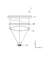
図1は、本実施形態の頭部装着型の表示装置1を説明する図である。図1は、表示装置1を鉛直方向上側から見た図である。
図2は、実施形態の表示装置に用いられる光学シートの詳細を説明する図である。図2(a)は、光学シートの水平面に平行な断面における断面図であり、図2(b)は、図2(a)のb部断面図である。図2(c)は、図2(a)のc部詳細を示す図であり、図2(d)は、図2(b)のd部詳細を示す図である。
図3は、実施形態の表示装置に用いられる光学シートの輝度と視野角の関係を示す図である。
図4は、実施形態の表示装置によって表示された画像の例を示す図である。
図5は、比較例の表示装置を説明する図である。図5(a)は、比較例の表示装置の構成を説明する図であり、図1に対応する図である。図5(b)は、比較例の表示装置によって表示された画像の例を示す図である。
(Embodiment)
FIG. 1 is a diagram illustrating a head-mounted display device 1 according to this embodiment. FIG. 1 is a view of the display device 1 as viewed from above in the vertical direction.
FIG. 2 is a diagram illustrating details of the optical sheet used in the display device of the embodiment. Fig.2 (a) is sectional drawing in a cross section parallel to the horizontal surface of an optical sheet, FIG.2 (b) is b section sectional drawing of Fig.2 (a). FIG. 2C is a diagram showing details of the portion c in FIG. 2A, and FIG. 2D is a diagram showing details of the portion d in FIG. 2B.
FIG. 3 is a diagram illustrating the relationship between the luminance and the viewing angle of the optical sheet used in the display device of the embodiment.
FIG. 4 is a diagram illustrating an example of an image displayed by the display device according to the embodiment.
FIG. 5 is a diagram illustrating a display device of a comparative example. FIG. 5A is a diagram for explaining the configuration of the display device of the comparative example, and corresponds to FIG. FIG. 5B is a diagram illustrating an example of an image displayed by the display device of the comparative example.
なお、図1を含め以下に示す図中及び以下の説明において、理解を容易にするために、観察者が頭部に表示装置1を装着した状態において、鉛直方向をZ方向とし、水平方向をX方向及びY方向とする。また、この水平方向のうち、光学シートの厚み方向をY方向とし、その厚み方向に直交する左右方向をX方向とする。このY方向の−Y側を観察者側とし、+Y側を背面側とする。 In addition, in the figure shown below including FIG. 1 and the following description, in order to make an understanding easy, in a state where the viewer wears the display device 1 on the head, the vertical direction is the Z direction, and the horizontal direction is Let it be X direction and Y direction. Of these horizontal directions, the thickness direction of the optical sheet is the Y direction, and the left-right direction perpendicular to the thickness direction is the X direction. The −Y side in the Y direction is the observer side, and the + Y side is the back side.
表示装置1は、観察者が頭部に装着し、観察者の眼前に映像を表示する、いわゆるヘッドマウントディスプレイ(HMD)である。図1に示すように、本実施形態の頭部装着型の表示装置1は、不図示のメガネフレームの内側に、映像源11と、レンズ12と、光学シート20とを備えており、観察者がメガネフレームを頭部に装着することによって、映像源11に表示された映像光を光学シート20、レンズ12を介して観察者の眼Eに視認させることができる。なお、図1において、表示装置1は、観察者の片側の眼Eに対して配置される例で説明するが、これに限定されるものでなく、観察者の両方の眼のそれぞれに配置されるようにしてもよい。
映像源11は、映像光を表示するマイクロディスプレイであり、例えば、透過型の液晶表示デバイスや、反射型の液晶表示デバイス、有機EL等を使用することができる。本実施形態の映像源11は、例えば、対角が5インチの有機ELディスプレイが使用される。
レンズ12は、映像源11から出射された映像光を拡大して観察者側に出射する凸レンズであり、本実施形態では、表示装置1の最も観察者側(−Y側)に配置されている。
The display device 1 is a so-called head mounted display (HMD) that an observer wears on the head and displays an image in front of the eyes of the observer. As shown in FIG. 1, the head-mounted display device 1 of the present embodiment includes an
The
The
光学シート20は、図1に示すように、映像源11及びレンズ12間であって、レンズ12に近接する位置に配置されており、映像源11から出射した映像光を微少に拡散する拡散機能を有した光透過性のあるシートである。
ここで、従来、主に使用されている頭部装着型の表示装置(以下、比較例の表示装置という)は、図5(a)に示すように、上述の光学シートを備えていない形態であり、映像源から出射された映像光をレンズにより拡大して観察者側に表示していた。ここで、映像源に用いられる有機EL等のディスプレイは、その表示部に映像を形成する画素領域が複数配列されており、また、各画素領域間には映像の形成に寄与しない非画素領域が設けられている。そのため、映像源から出射する映像光は、レンズを介して拡大された場合に、図5(b)に示すように、画素領域による映像だけでなく、非画素領域が起因となる非映像領域も拡大されてしまうこととなり、映像だけでなく、その非映像領域も観察者に視認され、鮮明な映像表示の妨げとなってしまう場合があった。
そこで、本実施形態の表示装置1には、上述したように、光学シート20が設けられており、映像源11から出射した映像光を微少に拡散させ、図4に示すように、その拡散された映像光によって、非画素領域が起因となる非映像領域が観察者に視認されてしまうのを抑制することができる。
As shown in FIG. 1, the
Here, a head-mounted display device that has been mainly used conventionally (hereinafter referred to as a display device of a comparative example) does not include the above-described optical sheet as shown in FIG. Yes, the image light emitted from the image source is magnified by the lens and displayed on the viewer side. Here, a display such as an organic EL used as a video source has a plurality of pixel areas that form an image on the display unit, and a non-pixel area that does not contribute to the formation of an image between the pixel areas. Is provided. Therefore, when the image light emitted from the image source is magnified through the lens, as shown in FIG. 5B, not only the image by the pixel region but also the non-image region caused by the non-pixel region In other words, not only the video but also the non-video area is visually recognized by the observer, which may hinder clear video display.
Therefore, as described above, the
光学シート20は、図2に示すように、背面側(+Y側)から順に、第1光学層21、第2光学層22、第3光学層23が積層されている。光学シート20は、この第1光学層21及び第2光学層22の界面と、第2光学層22及び第3光学層23の界面とに、それぞれ凸形状21a、凸形状23aが複数形成されている。
第1光学層21は、光学シート20の最も背面側(+Y側)に位置する光透過性を有する層であり、その背面側の面は、映像源11から出射された映像光が入射する面であり、略平坦に形成されている。第1光学層21の観察者側(−Y側)の面には、図2(a)に示すように、凸形状21aが複数形成されている。この凸形状21aは、第1光学層21の観察者側の面に沿うようにして、鉛直方向(Z方向)に延在し、左右方向(X方向)に複数配列されており、左右方向及び厚み方向に平行な面(XY面)における断面形状が略円弧状に形成されたレンチキュラーレンズ形状である。ここで、略円弧状とは、真円の円弧だけでなく、楕円や長円等の一部を含む曲線状の形状を含むものをいう。
As shown in FIG. 2, the
The first
第3光学層23は、光学シート20の最も観察者側(−Y側)に位置する光透過性を有する層であり、その観察者側の面は、光学シート20を透過した映像光が出射する面であり、略平坦に形成されている。第3光学層23の背面側(+Y側)の面は、図2(b)に示すように、凸形状23aが複数形成されている。この凸形状23aは、第3光学層23の背面側の面に沿うようにして、左右方向(X方向)に延在し、鉛直方向(Z方向)に複数配列されており、鉛直方向及び厚み方向に平行な面(YZ面)における断面形状が略円弧状に形成されたレンチキュラーレンズ形状である。
すなわち、第3光学層23に設けられた凸形状23aは、その延在方向(X方向)が、上述の第1光学層21に設けられた凸形状21aの延在方向(Z方向)と交差(直交)している。
第2光学層22は、第1光学層21及び第3光学層23間に設けられた光透過性を有する層であり、第1光学層21の凸形状21a側の面と、第3光学層23の凸形状23a側の面とが互いに対向するようにして配置されている。
The third
That is, the extending direction (X direction) of the
The second
本実施形態の光学シート20は、その半値角αが、0.05°≦α≦0.2°を満たし、最大輝度が1/20となる視野角βが、β≦5×αを満たすようにして形成されている。ここで、光学シート20の半値角αとは、図3に示すように、光の輝度が最大値となる光学シート20のシート面の観察位置から、画面左右方向及び画面上下方向において、光の輝度が最大値の半分の値になる観察角度をいう。また、視野角βは、光の輝度が最大値となる光学シート20のシート面の観察位置から、画面左右方向及び画面上下方向において、光の輝度が最大値の1/20の値になる観察角度をいう。
また、本実施形態の光学シート20は、互いに隣接する各層の屈折率差、すなわち第1光学層21及び第2光学層22の屈折率差Δn1と、第2光学層22及び第3光学層23の屈折率差Δn2とが、それぞれ0.005≦Δn1≦0.1、0.005≦Δn2≦0.1を満たすようにして形成されている。
The
Further, the
このように、光学シート20の半値角α及び視野角βの値の範囲と、互いに隣接する層の屈折率差(Δn1、Δn2)の範囲とを規定することによって、本実施形態の表示装置1は、映像源11から出射した映像光を鉛直方向や左右方向に微少に拡散することができる。これにより、表示装置1は、観察者側に鮮明な映像を表示するとともに、映像光の微少な拡散によって映像源11の非画素領域が起因となる非映像領域が目立ってしまうのを抑制することができる。
上述の効果をより効果的に奏する観点から、光学シート20の視野角βは、半値角αに等しいか、それに近い値であることがより望ましい。
As described above, by defining the range of the half-value angle α and the viewing angle β of the
From the viewpoint of more effectively achieving the above-described effects, it is more desirable that the viewing angle β of the
仮に、半値角αが0.05°未満である場合、光学シートによる光の拡散される範囲が狭くなりすぎてしまい、非画素領域が起因となる非映像領域を目立たなくすることができなくなるので望ましくない。また、半値角αが0.2°よりも大きい場合、映像光の拡散される範囲が広くなりすぎてしまい、映像の鮮明さが低下してしまうので望ましくない。
また、仮に、視野角βが5×αよりも大きい場合、輝度の低い映像光の拡散される範囲が広くなりすぎてしまい、映像の鮮明さが低下してしまうので望ましくない。
更に、互いに隣接する層の屈折率差(Δn1、Δn2)が0.005未満である場合、各層間の屈折率差が小さくなりすぎてしまい、各層間における映像光の屈折が生じ難くなってしまい、十分な拡散作用が発揮されなくなるため望ましくない。また、互いに隣接する層の屈折率差(Δn1、Δn2)が0.1よりも大きい場合、各層間における光の屈折が大きくなりすぎてしまい、光学シートを透過する映像光が不鮮明になってしまうので望ましくない。
If the half-value angle α is less than 0.05 °, the range in which light is diffused by the optical sheet becomes too narrow, and the non-image area caused by the non-pixel area cannot be made inconspicuous. Not desirable. On the other hand, when the half-value angle α is larger than 0.2 °, the range in which the image light is diffused becomes too wide, which is not desirable because the sharpness of the image is lowered.
Also, if the viewing angle β is larger than 5 × α, the range in which the low-brightness video light is diffused becomes too wide, which is not desirable because the sharpness of the video is reduced.
Furthermore, when the refractive index difference (Δn1, Δn2) between adjacent layers is less than 0.005, the refractive index difference between the layers becomes too small, and the refraction of the image light between the layers becomes difficult to occur. This is not desirable because a sufficient diffusion effect is not exhibited. Further, when the refractive index difference (Δn1, Δn2) between adjacent layers is larger than 0.1, the refraction of light between the layers becomes too large, and the image light transmitted through the optical sheet becomes unclear. So undesirable.
第1光学層21及び第3光学層23は、それぞれ、光透過性の高いPC(ポリカーボネート)樹脂、MS(メチルメタクリレート・スチレン)樹脂、アクリル系樹脂等から形成されており、本実施形態では、第1光学層21及び第3光学層23はともに同じ材料で形成され、同じ屈折率を有している。
また、第2光学層22は、光透過性の高いウレタンアクリレート樹脂や、エポキシアクリレート樹脂等の紫外線硬化型樹脂等から形成されており、本実施形態では、第1光学層21及び第3光学層23の屈折率よりも低い屈折率で形成されている。
また、凸形状21aのXY断面における断面形状が円弧状に形成されている場合、図2(c)に示すように、第1光学層21に形成される凸形状21aの左右方向(X方向)における配列ピッチをP1とし、凸形状21aのXY断面における円弧状の断面形状の曲率半径をR1としたときに、凸形状21aは、0.05≦P1/R1≦1.0の範囲で形成されるのが望ましい。
また同様に、凸形状23aのYZ断面における断面形状が円弧状に形成されている場合、図2(d)に示すように、第3光学層23に形成される凸形状23aの鉛直方向(Z方向)における配列ピッチをP2とし、凸形状23aのYZ断面における円弧状の断面形状の曲率半径をR2としたときに、凸形状23aは、0.05≦P2/R2≦1.0の範囲で形成されるのが望ましい。
The first
Further, the second
When the cross-sectional shape of the
Similarly, when the cross-sectional shape of the
このように凸形状21a及び凸形状23aの配列ピッチ及び曲率半径を上述の範囲で形成することによって、表示装置1は、映像源11から出射された映像光を効率よく均等に上下方向及び左右方向に微少に拡散させることができる。
なお、本実施形態の光学シート20は、凸形状21a及び凸形状23aが互いに同じ形状、すなわちP1=P2、R1=R2となるように形成されている。
In this way, by forming the arrangement pitch and the radius of curvature of the
The
次に、映像源11から出射された映像光Lが観察者の眼Eに届くまでの動作について説明する。
図1に示すように、映像源11から出射した映像光Lは、光学シート20の背面側(+Y側)の面に入射する。そして、光学シート20に入射した映像光Lは、第1光学層21を透過して、第1光学層21及び第2光学層22との界面の凸形状21aによって、左右方向(X方向)に微少に拡散して第2光学層22内を透過する。
第2光学層22を透過した映像光Lは、第2光学層22及び最3光学層23との界面に形成された凸形状23aによって、鉛直方向(Z方向)に微少に拡散し、第3光学層23を透過して光学シート20の観察者側(−Y側)の面から出射する。
続いて、光学シート20の観察者側の面から出射した映像光Lは、レンズ12へ入射して観察者の眼Eへ向けて出射する。ここで、映像源11から出射された映像光Lは、光学シート20により左右方向及び鉛直方向に微少に拡散させられる。そのため、映像光Lは、レンズ12により拡大されたとしても、観察者の眼Eによって視認される画像には、図4に示すように、上述の比較例の表示装置の場合に比して(図5(b)参照)、映像源11の非画素領域が起因となる非映像領域が目立ってしまうのを極力抑制することができ、鮮明な映像を表示することができる。
Next, an operation until the video light L emitted from the
As shown in FIG. 1, the image light L emitted from the
The image light L transmitted through the second
Subsequently, the image light L emitted from the surface on the viewer side of the
次に、本実施形態の表示装置1に用いられる光学シート20の製造方法について説明する。
上述したように、光学シート20の第1光学層21及び第3光学層23に設けられた各凸形状21a、凸形状23aは、互いに同じ形状に形成されているため、まず、この凸形状に対応する凹形状が設けられた金型を使用して、凸形状が形成されたシート状部材を押出成形法や、射出成形法等により形成する。
それから、凸形状が形成されたシート状部材を、所定の寸法に裁断して、第1光学層21及び第3光学層23を得る。このように、凸形状21a及び凸形状23aが同形状に形成されている場合、1枚のシート状部材から第1光学層21及び第3光学層23を同時に切り出すことができ、光学シート20の製造効率を向上させることができる。
続いて、第1光学層21の凸形状21a側の面上に、第2光学層22を形成する樹脂を充填し、その樹脂と、第3光学層23の凸形状23a側の面とを貼り合わせて、第1光学層21及び第3光学層23間に所定の距離を設けた状態で樹脂を硬化させる。このとき、第1光学層21及び第3光学層23は、凸形状21aの延在方向と凸形状23aの延在方向とが互いに交差(直交)するようにして配置される。
以上により、第1光学層21、第2光学層22、第3光学層23が順次積層された光学シート20が完成する。
Next, the manufacturing method of the
As described above, the
Then, the sheet-like member on which the convex shape is formed is cut into a predetermined dimension, and the first
Subsequently, a resin for forming the second
Thus, the
以上より、本実施形態の表示装置1は、少なくとも2層以上の層構成を有し、各層間の界面に微細な凸形状が複数形成された光学シート20を備え、光学シート20の互いに隣接する層の屈折率差Δn1、Δn2が、それぞれ0.005≦Δn1≦0.1、0.005≦Δn2≦0.1を満たし、半値角αが0.05°≦α≦0.2°を満たし、最大輝度が1/20となる光学シート20の視野角βが、β≦5×αを満たすようにして形成されている。これにより、表示装置1は、映像源11から出射した映像光を鉛直方向や左右方向に微少に拡散することができ、観察者側に鮮明な映像を表示するとともに、映像源11の非画素領域が起因となる非映像領域が観察者に視認されてしまうのを抑制することができる。
As described above, the display device 1 of the present embodiment includes the
また、本実施形態の表示装置1は、凸形状21aが、光学シート20の厚み方向(Y方向)に直交するシート面(XZ面)内のZ方向(第1の方向)に延在し、シート面内のZ方向に直交するX方向(第2の方向)に配列され、光学シート20の厚み方向に平行であってX方向(第2の方向)に平行な断面(XY面)における断面形状が略円弧状に形成されている。同様に、凸形状23aが、光学シート20の厚み方向(Y方向)に直交するシート面(XZ面)内のX方向に延在し、シート面内のX方向に直交するZ方向に配列され、光学シート20の厚み方向に平行であってZ方向に平行な断面(YZ面)における断面形状が円弧状に形成されている。これにより、表示装置1は、凸形状を通過する映像光を効率よく均等に拡散させることができる。
Further, in the display device 1 of the present embodiment, the
更に、本実施形態の表示装置1は、光学シート20が3層以上の層構成を有しており、各層間の各界面に設けられた凸形状21a及び凸形状23aのシート面内における延在方向(Z方向、X方向)が、光学シート20の厚み方向から見て直交(交差)している。これにより、表示装置1は、映像源11から出射した映像光を複数の方向(左右方向及び鉛直方向)に拡散させることができ、映像源11の非画素領域が起因となる非映像領域をより効果的に目立たなくすることができる。
Furthermore, in the display device 1 of the present embodiment, the
以上、本発明の実施形態について説明したが、本発明は前述した実施形態に限定されるものではなく、後述する変形形態のように種々の変形や変更が可能であって、それらも本発明の技術的範囲内である。また、実施形態に記載した効果は、本発明から生じる最も好適な効果を列挙したに過ぎず、本発明による効果は、実施形態に記載したものに限定されない。なお、前述した実施形態及び後述する変形形態は、適宜組み合わせて用いることもできるが、詳細な説明は省略する。 Although the embodiments of the present invention have been described above, the present invention is not limited to the above-described embodiments, and various modifications and changes can be made as in the modifications described later, and these are also included in the present invention. Within the technical scope. In addition, the effects described in the embodiments are merely a list of the most preferable effects resulting from the present invention, and the effects of the present invention are not limited to those described in the embodiments. It should be noted that the above-described embodiment and modifications described later can be used in appropriate combination, but detailed description thereof is omitted.
(変形形態)
図6は、表示装置に用いられる光学シートの変形形態を説明する図である。
(1)上述の実施形態において、光学シート20は、第1光学層21、第2光学層22、第3光学層23の3層が順次、積層された層構成を有する例を示したが、これに限定されるものでない。例えば、光学シート20は、図6に示すように、第1光学層及び第2光学層の2層が積層された構成を有してもよく、また、4層以上の層構成を有するようにしてもよい。
(Deformation)
FIG. 6 is a diagram for explaining a modification of the optical sheet used in the display device.
(1) In the above-described embodiment, the
(2)上述の実施形態において、光学シート20の各層の界面には、レンチキュラーレンズ形状が形成される例を示したが、これに限定されるものでない。例えば、図6に示すように、光学シート120を第1光学層121及び第2光学層122の2層構造とし、第1光学層121及び第2光学層122間に微細な凸形状がランダムに設けられるようにしてもよい。このようにしても、映像源から出射した映像光を光学シート120により微少に拡散することができ、表示装置は、映像源11の非画素領域が起因となる非映像領域を目立たなくすることができる。また、この場合、上述の実施形態の表示装置に用いられる光学シートに比して、層構成を減らすことができ、光学シートを薄型化したり、軽量化したりすることが可能となる。
(2) In the above-described embodiment, an example in which a lenticular lens shape is formed at the interface of each layer of the
(3)上述の実施形態において、光学シート20は、映像源11及びレンズ12間に配置される例を説明するが、これに限定されるものでなく、レンズ12の観察者側(−Y側)に配置されるようにしてもよい。このような形態としても、表示装置1は、映像源11から出射した映像光をレンズ12で拡大させた後に微小に拡散させるので、映像源11の非画素領域が起因となる非映像領域を目立たなくして、映像を表示することができる。また、この場合、レンズの観察者側の面を光学シートにより覆うことができるので、光学シートによりレンズを保護することも可能である。
(3) In the above-described embodiment, an example in which the
(4)上述の実施形態において、光学シート20は、背面側に第1光学層21が配置され、観察者側に第3光学層23が配置される例を示したが、これに限定されるものでなく、第1光学層21が観察者側に、第3光学層23が背面側に配置されるようにしてもよい。
(4) In the above-described embodiment, the
(5)上述の実施形態において、光学シート20は、凸形状21aの延在方向が鉛直方向(Z方向)であり、凸形状23aの延在方向が左右方向(X方向)であり、両者が直交する例を説明したが、これに限定されるものでない。例えば、光学シート20の凸形状21aの延在方向が、左右方向に対して45°傾斜した方向であり、凸形状23aの延在方向が、左右方向に対して−45°に傾斜した方向であるようにしてもよく、映像源11の画素の配列等に応じて、各凸形状の延在方向を適宜設定するようにしてもよい。
また、一方の凸形状の延在方向が、他方の凸形状の延在方向と直交以外の角度で交差するようにしてもよい。
(5) In the above-described embodiment, in the
Further, the extending direction of one convex shape may intersect with the extending direction of the other convex shape at an angle other than orthogonal.
(6)上述の実施形態において、光学シート20は、第1光学層21及び第3光学層23の屈折率が、第2光学層22の屈折率よりも高い例で説明したが、これに限定されるものでなく、例えば、第1光学層21及び第3光学層23の屈折率が、第2光学層22の屈折率よりも低くなるようにしてもよい。
(6) In the above-described embodiment, the
(7)上述の実施形態において、第2光学層22は、紫外線硬化型樹脂により構成される層である例を示したが、これに限定されるものでなく、例えば、透過性のある粘着剤により構成され、第1光学層21及び第3光学層23を接合するようにしてもよい。この場合、第2光学層22を構成する粘着剤の屈折率は、第1光学層21及び第3光学層23の屈折率に対して、屈折率差が0.005以上、0.1以下の範囲で設定される必要がある。
(7) In the above-described embodiment, the example in which the second
1 表示装置
11 映像源
12 レンズ
20 光学シート
21 第1光学層
21a 凸形状
22 第2光学層
23 第3光学層
23a 凸形状
E 観察者の眼
DESCRIPTION OF SYMBOLS 1
Claims (9)
前記映像光を拡大して観察者側へ出射するレンズと、
前記映像源及び前記レンズ間、又は、前記レンズの観察者側に配置される光学シートとを備え、
前記光学シートは、少なくとも2層以上の光学層を有し、各前記光学層間の界面に凸形状が複数形成されており、
前記光学シートの半値角αが、0.05°≦α≦0.2°を満たすこと、
を特徴とする表示装置。 An image source for emitting image light from a plurality of arranged pixel regions;
A lens that magnifies and emits the image light to the viewer side;
An optical sheet disposed between the image source and the lens or on the viewer side of the lens;
The optical sheet has at least two or more optical layers, and a plurality of convex shapes are formed at the interface between the optical layers ,
The half-value angle α of the optical sheet satisfies 0.05 ° ≦ α ≦ 0.2 °,
A display device.
前記映像光を拡大して観察者側へ出射するレンズと、 A lens that magnifies and emits the image light to the viewer side;
前記映像源及び前記レンズ間、又は、前記レンズの観察者側に配置される光学シートとを備え、 An optical sheet disposed between the image source and the lens or on the viewer side of the lens;
前記光学シートは、少なくとも2層以上の光学層を有し、各前記光学層間の界面に凸形状が複数形成されており、 The optical sheet has at least two or more optical layers, and a plurality of convex shapes are formed at the interface between the optical layers,
前記光学シートの半値角をαとした場合に、 When the half-value angle of the optical sheet is α,
最大輝度が1/20となる前記光学シートの視野角βが、β≦5×αを満たすこと、 The viewing angle β of the optical sheet having a maximum luminance of 1/20 satisfies β ≦ 5 × α,
を特徴とする表示装置。 A display device.
前記光学シートの半値角αが、0.05°≦α≦0.2°を満たすこと、
を特徴とする表示装置。 The display device according to claim 2 ,
The half-value angle α of the optical sheet satisfies 0.05 ° ≦ α ≦ 0.2 °,
A display device.
互いに隣接する前記光学層の屈折率の差Δnが、0.005≦Δn≦0.1を満たすこと、
を特徴とする表示装置。 In the display device according to any one of claims 1 to 3 ,
The refractive index difference Δn of the optical layers adjacent to each other satisfies 0.005 ≦ Δn ≦ 0.1;
A display device.
前記凸形状は、前記光学シートの厚み方向に直交するシート面内の第1の方向に延在し、前記シート面内の前記第1の方向に交差する第2の方向に配列され、前記光学シートの厚み方向に平行であって前記第2の方向に平行な断面における断面形状が略円弧状に形成されていること、
を特徴とする表示装置。 In the display device according to any one of claims 1 to 4,
The convex shape extends in a first direction in a sheet surface orthogonal to the thickness direction of the optical sheet, and is arranged in a second direction intersecting the first direction in the sheet surface, and the optical The cross-sectional shape in a cross section parallel to the thickness direction of the sheet and parallel to the second direction is formed in a substantially arc shape,
A display device.
前記映像光を拡大して観察者側へ出射するレンズと、
前記映像源及び前記レンズ間、又は、前記レンズの観察者側に配置される光学シートとを備え、
前記光学シートは、3層以上の光学層を有し、各前記光学層間の各界面に凸形状が複数形成されており、
各前記凸形状は、前記光学シートの厚み方向に直交するシート面内に延在し、
各前記凸形状の前記シート面内における延在方向は、前記光学シートの厚み方向から見て交差しており、
前記光学シートの半値角αが、0.05°≦α≦0.2°を満たすこと、
を特徴とする表示装置。 An image source for emitting image light from a plurality of arranged pixel regions;
A lens that magnifies and emits the image light to the viewer side;
An optical sheet disposed between the image source and the lens or on the viewer side of the lens;
The optical sheet has three or more optical layers, and a plurality of convex shapes are formed at each interface between the optical layers,
Each of the convex shapes extends in a sheet plane orthogonal to the thickness direction of the optical sheet,
The extending direction in the sheet surface of each convex shape intersects when viewed from the thickness direction of the optical sheet ,
The half-value angle α of the optical sheet satisfies 0.05 ° ≦ α ≦ 0.2 °,
A display device.
前記映像光を拡大して観察者側へ出射するレンズと、 A lens that magnifies and emits the image light to the viewer side;
前記映像源及び前記レンズ間、又は、前記レンズの観察者側に配置される光学シートとを備え、 An optical sheet disposed between the image source and the lens or on the viewer side of the lens;
前記光学シートは、3層以上の光学層を有し、各前記光学層間の各界面に凸形状が複数形成されており、 The optical sheet has three or more optical layers, and a plurality of convex shapes are formed at each interface between the optical layers,
各前記凸形状は、前記光学シートの厚み方向に直交するシート面内に延在し、 Each of the convex shapes extends in a sheet plane orthogonal to the thickness direction of the optical sheet,
各前記凸形状の前記シート面内における延在方向は、前記光学シートの厚み方向から見て交差しており、 The extending direction in the sheet surface of each convex shape intersects when viewed from the thickness direction of the optical sheet,
前記光学シートの半値角をαとした場合に、 When the half-value angle of the optical sheet is α,
最大輝度が1/20となる前記光学シートの視野角βが、β≦5×αを満たすこと、 The viewing angle β of the optical sheet having a maximum luminance of 1/20 satisfies β ≦ 5 × α,
を特徴とする表示装置。 A display device.
前記光学シートの半値角αが、0.05°≦α≦0.2°を満たすこと、
を特徴とする表示装置。 The display device according to claim 7 ,
The half-value angle α of the optical sheet satisfies 0.05 ° ≦ α ≦ 0.2 °,
A display device.
互いに隣接する前記光学層の屈折率の差Δnが、0.005≦Δn≦0.1を満たすこと、
を特徴とする表示装置。 The display device according to any one of claims 6 to 8 ,
The refractive index difference Δn of the optical layers adjacent to each other satisfies 0.005 ≦ Δn ≦ 0.1;
A display device.
Priority Applications (1)
| Application Number | Priority Date | Filing Date | Title |
|---|---|---|---|
| JP2015113032A JP6183413B2 (en) | 2015-06-03 | 2015-06-03 | Display device |
Applications Claiming Priority (1)
| Application Number | Priority Date | Filing Date | Title |
|---|---|---|---|
| JP2015113032A JP6183413B2 (en) | 2015-06-03 | 2015-06-03 | Display device |
Related Child Applications (1)
| Application Number | Title | Priority Date | Filing Date |
|---|---|---|---|
| JP2017142689A Division JP6354896B2 (en) | 2017-07-24 | 2017-07-24 | Display device |
Publications (3)
| Publication Number | Publication Date |
|---|---|
| JP2016224364A JP2016224364A (en) | 2016-12-28 |
| JP2016224364A5 JP2016224364A5 (en) | 2017-06-01 |
| JP6183413B2 true JP6183413B2 (en) | 2017-08-23 |
Family
ID=57745723
Family Applications (1)
| Application Number | Title | Priority Date | Filing Date |
|---|---|---|---|
| JP2015113032A Active JP6183413B2 (en) | 2015-06-03 | 2015-06-03 | Display device |
Country Status (1)
| Country | Link |
|---|---|
| JP (1) | JP6183413B2 (en) |
Families Citing this family (5)
| Publication number | Priority date | Publication date | Assignee | Title |
|---|---|---|---|---|
| US11073692B2 (en) | 2017-03-02 | 2021-07-27 | Sharp Kabushiki Kaisha | Display apparatus and head mount display |
| JP6972642B2 (en) * | 2017-04-28 | 2021-11-24 | 大日本印刷株式会社 | Display device |
| JP6264493B1 (en) * | 2017-05-19 | 2018-01-24 | 大日本印刷株式会社 | Display device |
| WO2018199252A1 (en) * | 2017-04-28 | 2018-11-01 | 大日本印刷株式会社 | Display device |
| JP6308323B1 (en) * | 2017-08-08 | 2018-04-11 | 大日本印刷株式会社 | Display device |
Family Cites Families (6)
| Publication number | Priority date | Publication date | Assignee | Title |
|---|---|---|---|---|
| JP3512431B2 (en) * | 1992-05-26 | 2004-03-29 | オリンパス株式会社 | Video display device |
| JPH07110470A (en) * | 1993-10-13 | 1995-04-25 | Sega Enterp Ltd | Display device |
| JP2012255819A (en) * | 2011-06-07 | 2012-12-27 | Dainippon Printing Co Ltd | Image source unit and display device |
| JP2013003276A (en) * | 2011-06-14 | 2013-01-07 | Dainippon Printing Co Ltd | Liquid crystal display device |
| JP2013003272A (en) * | 2011-06-14 | 2013-01-07 | Dainippon Printing Co Ltd | Light diffusion sheet and transmission type display device |
| JP6697849B2 (en) * | 2015-01-21 | 2020-05-27 | ソニー株式会社 | Wearable display device and image display method |
-
2015
- 2015-06-03 JP JP2015113032A patent/JP6183413B2/en active Active
Also Published As
| Publication number | Publication date |
|---|---|
| JP2016224364A (en) | 2016-12-28 |
Similar Documents
| Publication | Publication Date | Title |
|---|---|---|
| JP6183413B2 (en) | Display device | |
| JP5817904B1 (en) | Light guide plate, display device | |
| WO2018088342A1 (en) | Display apparatus and head-mounted display | |
| JP2017032785A (en) | Display device | |
| JP5843043B1 (en) | Light guide plate, display device | |
| JP2017097256A (en) | Display device | |
| JP6600952B2 (en) | Transflective reflection sheet, display device | |
| JP6606184B2 (en) | 3D display device | |
| US10509230B2 (en) | Virtual display apparatus | |
| JP2018194814A (en) | Display device | |
| JP5896075B1 (en) | Light guide plate, display device | |
| JP6354896B2 (en) | Display device | |
| JP2018189742A (en) | Display device | |
| JP6565458B2 (en) | Optical sheet, display device | |
| JP5439786B2 (en) | Light diffusion sheet, liquid crystal image source unit, and liquid crystal display device | |
| JP6848376B2 (en) | Display device | |
| JP6308323B1 (en) | Display device | |
| JP6805756B2 (en) | Display device | |
| JP6859655B2 (en) | Display device | |
| JP2018100998A (en) | Display device | |
| JP2018066884A (en) | Display device | |
| JP2016114885A (en) | Head-mounted display device | |
| JP2018055034A (en) | Display device | |
| JP2018055035A (en) | Display device | |
| JP6957869B2 (en) | Display device |
Legal Events
| Date | Code | Title | Description |
|---|---|---|---|
| RD04 | Notification of resignation of power of attorney |
Free format text: JAPANESE INTERMEDIATE CODE: A7424 Effective date: 20160928 |
|
| A521 | Written amendment |
Free format text: JAPANESE INTERMEDIATE CODE: A523 Effective date: 20170414 |
|
| A621 | Written request for application examination |
Free format text: JAPANESE INTERMEDIATE CODE: A621 Effective date: 20170414 |
|
| A871 | Explanation of circumstances concerning accelerated examination |
Free format text: JAPANESE INTERMEDIATE CODE: A871 Effective date: 20170414 |
|
| A975 | Report on accelerated examination |
Free format text: JAPANESE INTERMEDIATE CODE: A971005 Effective date: 20170501 |
|
| A131 | Notification of reasons for refusal |
Free format text: JAPANESE INTERMEDIATE CODE: A131 Effective date: 20170606 |
|
| A521 | Written amendment |
Free format text: JAPANESE INTERMEDIATE CODE: A523 Effective date: 20170613 |
|
| TRDD | Decision of grant or rejection written | ||
| A01 | Written decision to grant a patent or to grant a registration (utility model) |
Free format text: JAPANESE INTERMEDIATE CODE: A01 Effective date: 20170627 |
|
| A61 | First payment of annual fees (during grant procedure) |
Free format text: JAPANESE INTERMEDIATE CODE: A61 Effective date: 20170710 |
|
| R150 | Certificate of patent or registration of utility model |
Ref document number: 6183413 Country of ref document: JP Free format text: JAPANESE INTERMEDIATE CODE: R150 |