JP6847397B2 - Water spouting device - Google Patents

Water spouting device Download PDF

Info

Publication number
JP6847397B2
JP6847397B2 JP2017065553A JP2017065553A JP6847397B2 JP 6847397 B2 JP6847397 B2 JP 6847397B2 JP 2017065553 A JP2017065553 A JP 2017065553A JP 2017065553 A JP2017065553 A JP 2017065553A JP 6847397 B2 JP6847397 B2 JP 6847397B2
Authority
JP
Japan
Prior art keywords
rectifying unit
passage
hot water
water
generating element
Prior art date
Legal status (The legal status is an assumption and is not a legal conclusion. Google has not performed a legal analysis and makes no representation as to the accuracy of the status listed.)
Active
Application number
JP2017065553A
Other languages
Japanese (ja)
Other versions
JP2018167164A (en
Inventor
慧 渡邊
慧 渡邊
清岳 浮貝
清岳 浮貝
雄也 永田
雄也 永田
Current Assignee (The listed assignees may be inaccurate. Google has not performed a legal analysis and makes no representation or warranty as to the accuracy of the list.)
Toto Ltd
Original Assignee
Toto Ltd
Priority date (The priority date is an assumption and is not a legal conclusion. Google has not performed a legal analysis and makes no representation as to the accuracy of the date listed.)
Filing date
Publication date
Application filed by Toto Ltd filed Critical Toto Ltd
Priority to JP2017065553A priority Critical patent/JP6847397B2/en
Publication of JP2018167164A publication Critical patent/JP2018167164A/en
Application granted granted Critical
Publication of JP6847397B2 publication Critical patent/JP6847397B2/en
Active legal-status Critical Current
Anticipated expiration legal-status Critical

Links

Images

Landscapes

  • Bidet-Like Cleaning Device And Other Flush Toilet Accessories (AREA)
  • Bathtubs, Showers, And Their Attachments (AREA)
  • Nozzles (AREA)

Description

本発明は、吐水装置に関し、特に、吐水口から湯水(湯又は水)を往復振動させながら吐出する吐水装置に関する。 The present invention relates to a water spouting device, and more particularly to a water spouting device that discharges hot water (hot water or water) from a spout while reciprocally vibrating.

吐水口から吐出される湯水の方向が振動的に変化するシャワーヘッドが知られている。このシャワーヘッドのような吐水装置においては、供給される湯水の給水圧によりノズルを振動的に駆動し、吐出口から吐出される湯水の方向を変化させている。このようなタイプの吐水装置では、単一の吐水口から広い範囲に湯水を吐出することができるので、広い範囲に吐水可能な吐水装置をコンパクトに構成できることが期待される。 A shower head in which the direction of hot water discharged from a spout changes oscillatingly is known. In a water discharge device such as this shower head, the nozzle is oscillated by the supply pressure of the supplied hot water to change the direction of the hot water discharged from the discharge port. In such a type of water spouting device, hot water can be discharged from a single spout to a wide range, so it is expected that a water spouting device capable of spouting water over a wide range can be compactly configured.

一方、特開2000−120141号公報(特許文献1)には、温水洗浄便座装置が記載されている。この温水洗浄便座装置においては、流体素子ノズルを使用して自励発振を誘発し、洗浄水の噴出方向を振動的に変化させている。具体的には、この温水洗浄便座装置においては図23に示すように、噴射ノズル102の両側にフィードバック流路104が設けられている。各フィードバック流路104は、噴射ノズル102と連通したループ状の流路であり、噴射ノズル102内を流れる洗浄水の一部が流入して循環するように構成されている。また、噴射ノズル102は、楕円形断面の噴射口102aに向けてテーパ状に広がる形状に構成されている。 On the other hand, Japanese Patent Application Laid-Open No. 2000-12141 (Patent Document 1) describes a warm water washing toilet seat device. In this warm water washing toilet seat device, a fluid element nozzle is used to induce self-excited oscillation to vibrately change the direction in which the washing water is ejected. Specifically, in this warm water washing toilet seat device, as shown in FIG. 23, feedback flow paths 104 are provided on both sides of the injection nozzle 102. Each feedback flow path 104 is a loop-shaped flow path that communicates with the injection nozzle 102, and is configured so that a part of the cleaning water flowing in the injection nozzle 102 flows in and circulates. Further, the injection nozzle 102 is configured to have a shape that tapers toward the injection port 102a having an elliptical cross section.

洗浄水が供給されると、噴射ノズル102から噴射される洗浄水は、コアンダ効果(Coanda effect)により、楕円形断面の噴射口102aの何れか一方の側の壁面に引き寄せられ、これに沿うように噴射される(図23の状態a)。洗浄水が一方の壁面に沿って噴射されると、洗浄水が噴射されている側のフィードバック流路104内にも洗浄水が流入し、フィードバック流路104内の圧力が上昇する。この圧力上昇により、噴射されている洗浄水が押され、洗浄水は反対側の壁面に引き寄せられ、反対側の壁面に沿って噴射されるようになる(図23の状態a→b→c)。さらに、反対側の壁面に沿って洗浄水がされると、今度は、反対側のフィードバック流路104内の圧力が上昇し、噴射洗浄水は押し戻される(図23の状態c→b→a)。この作用を繰り返すことにより、噴射される洗浄水は、図23の状態aとcの間で振動的に方向が変化する。 When the cleaning water is supplied, the cleaning water injected from the injection nozzle 102 is attracted to the wall surface on one side of the injection port 102a having an elliptical cross section by the Coanda effect so as to follow the Coanda effect. (State a in FIG. 23). When the wash water is sprayed along one of the wall surfaces, the wash water also flows into the feedback flow path 104 on the side where the wash water is sprayed, and the pressure in the feedback flow path 104 rises. Due to this pressure increase, the sprayed washing water is pushed, the washing water is attracted to the wall surface on the opposite side, and is sprayed along the wall surface on the opposite side (state a → b → c in FIG. 23). .. Further, when the washing water is poured along the wall surface on the opposite side, the pressure in the feedback flow path 104 on the opposite side rises, and the jet washing water is pushed back (state c → b → a in FIG. 23). .. By repeating this action, the jetted washing water vibrates in direction between the states a and c in FIG. 23.

また、特開2004−275985号公報(特許文献2)には、純流体素子が記載されている。この純流体素子は、流体噴出ノズルを横断するように、連結ダクトが設けられており、この連結ダクトの作用により、流体噴出ノズル内の上側又は下側の圧力が交互に上昇する。この圧力上昇により押された噴流は、コアンダ効果により、流体噴出ノズルの上側板に沿った噴流、又は下側板に沿った噴流となり、これらの状態が一定周期で繰り返され、噴射方向が振動的に変化する流れとなる。 Further, Japanese Patent Application Laid-Open No. 2004-275985 (Patent Document 2) describes a pure fluid element. The pure fluid element is provided with a connecting duct so as to cross the fluid ejection nozzle, and the action of the connecting duct alternately increases the pressure on the upper side or the lower side in the fluid ejection nozzle. Due to the Coanda effect, the jet pushed by this pressure rise becomes a jet along the upper plate of the fluid ejection nozzle or a jet along the lower plate, and these states are repeated at regular intervals, and the injection direction oscillates. It will be a changing flow.

さらに、特公昭58−49300号公報(特許文献3)には、振動スプレー装置が記載されている。この振動スプレー装置は、図24に示す構成を有するものであり、前室110内で発生するカルマン渦を利用して、出口112から噴射される噴流の方向を振動的に変化させるものである。まず、入口孔114から前室110内に流入した流体は、前室110内に島状に設けられた三角形断面の障害物116に衝突する。流体が衝突すると、障害物116の下流側には、障害物116の上側と下側に交互にカルマン渦が発生し、渦列となる。 Further, Japanese Patent Publication No. 58-49300 (Patent Document 3) describes a vibration spray device. This vibration spray device has the configuration shown in FIG. 24, and uses the Karman vortex generated in the anterior chamber 110 to vibrately change the direction of the jet flow injected from the outlet 112. First, the fluid flowing into the anterior chamber 110 from the inlet hole 114 collides with an obstacle 116 having a triangular cross section provided in the anterior chamber 110 in an island shape. When the fluid collides, Karman vortices are alternately generated on the upper side and the lower side of the obstacle 116 on the downstream side of the obstacle 116 to form a vortex train.

このカルマン渦の渦列は、成長しながら出口112に到達する。出口112近傍においては、渦列の渦が存在する側の流速が速く、反対側の流速が遅くなる。図24に示す例においては、カルマン渦は障害物116の上側と下側で交互に発生し、この渦列が順次出口112まで到達するので、出口112近傍では、上側の流速が速い状態と、下側の流速が速い状態が交互に現れる。上側の流速が速い状態では、流速の速い流体が出口112上側の壁面110aに衝突して方向が変えられ、出口112から噴射される流体は、全体として斜め下方に向かう噴流となる。一方、下側の流速が速い状態では、流速の速い流体が出口112下側の壁面110bに衝突し、出口112からは斜め上方に向かう噴流が噴射される。このような状態が交互に繰り返されることにより、出口112からの噴流は往復振動しながら噴射される。 The vortex street of this Karman vortex reaches the outlet 112 while growing. In the vicinity of the outlet 112, the flow velocity on the side where the vortex of the vortex train exists is high, and the flow velocity on the opposite side is slow. In the example shown in FIG. 24, Karman vortices are alternately generated on the upper side and the lower side of the obstacle 116, and the vortex trains reach the outlet 112 in sequence. Therefore, in the vicinity of the outlet 112, the flow velocity on the upper side is high. The lower flow velocity is alternating. In the state where the flow velocity on the upper side is high, the fluid having a high flow velocity collides with the wall surface 110a on the upper side of the outlet 112 to change the direction, and the fluid jetted from the outlet 112 becomes a jet flow obliquely downward as a whole. On the other hand, when the flow velocity on the lower side is high, the fluid having a high flow velocity collides with the wall surface 110b on the lower side of the outlet 112, and a jet flowing diagonally upward is ejected from the outlet 112. By alternately repeating such a state, the jet flow from the outlet 112 is jetted while reciprocating and vibrating.

以上、特許文献1乃至3に記載されている流体素子をシャワーヘッド等の吐水装置に応用して、湯水を往復振動させながら吐出することも考えられる。 As described above, it is conceivable to apply the fluid element described in Patent Documents 1 to 3 to a water discharge device such as a shower head to discharge hot water while reciprocating and vibrating it.

特開2000−120141号公報Japanese Unexamined Patent Publication No. 2000-12141 特開2004−275985号公報Japanese Unexamined Patent Publication No. 2004-275985 特公昭58−49300号公報Special Publication No. 58-49300

まず、散水ノズルを振動的に駆動して吐出される湯水の方向を変化させる吐水装置は、ノズルを駆動する必要があるため、ノズル周辺の構造が複雑になり、複数のノズルをコンパクトに吐水装置に収納することが難しいという問題がある。また、このタイプの吐水装置では、ノズルが物理的に動くため、可動部分に摩耗が発生しやすく、摩耗を回避するためには、可動部を構成する部材の材質の選択に制約を受けるという問題がある。さらに、複雑な構造の可動部分を摩耗しにくい材料で形成する必要があるため、コスト高になるという問題がある。 First, a water discharge device that vibrates to drive a watering nozzle to change the direction of hot water to be discharged needs to drive the nozzle, which complicates the structure around the nozzle and compactly discharges multiple nozzles. There is a problem that it is difficult to store in. Further, in this type of water discharge device, since the nozzle physically moves, wear is likely to occur in the moving part, and in order to avoid the wear, there is a problem that the selection of the material of the member constituting the moving part is restricted. There is. Further, since it is necessary to form the moving portion of a complicated structure with a material that is not easily worn, there is a problem that the cost is high.

一方、特許文献1乃至3に記載されているタイプの噴射装置は流体素子による発振現象を利用したものであり、可動部材を設けることなく流体の噴射方向を変化させることができるため、簡単な構成で、コンパクトにノズル部分を構成できるという利点がある。
しかしながら、特許文献1及び2に記載の流体素子をシャワーヘッド等の吐水装置に応用した場合には、噴射される湯水の浴び心地が良くないという問題が、本件発明者により見出された。ここで、発明者が目標としている良好な浴び心地とは、大きな液滴の湯水が、広範囲に万遍なく吐出されている状態を意味している。即ち、シャワーヘッドから吐出される湯水の液滴が過度に小さい場合には湯水がミスト状となり、同量の湯水を浴びていたとしてもシャワーを浴びている実感を得ることができない。また、吐出される湯水が吐水範囲内で不均一になっていると、使用者が意図してシャワーをあてた部分を均一に洗い流すことができず、使用感の悪いものとなる。
On the other hand, the injection devices of the types described in Patent Documents 1 to 3 utilize the oscillation phenomenon by the fluid element, and can change the injection direction of the fluid without providing a movable member, and thus have a simple configuration. Therefore, there is an advantage that the nozzle portion can be constructed compactly.
However, when the fluid elements described in Patent Documents 1 and 2 are applied to a water discharge device such as a shower head, the present inventor has found a problem that the jetted hot water is not comfortable to bathe. Here, the good bathing comfort that the inventor aims at means a state in which large droplets of hot water are evenly discharged over a wide area. That is, when the droplets of hot water discharged from the shower head are excessively small, the hot water becomes mist-like, and even if the same amount of hot water is taken, the feeling of taking a shower cannot be obtained. Further, if the discharged hot water is not uniform within the discharge range, the portion to which the shower is intentionally applied by the user cannot be washed out uniformly, resulting in a poor usability.

ここで、特許文献1及び2に記載されている流体素子は、噴出される流体がコアンダ効果により壁面に沿って流れるという現象を利用したものであるため、吐出範囲内に噴射される流体にムラができてしまう。即ち、図23に示す温水便座装置においては、噴射される洗浄水は状態a、b、cの間を遷移するものであるが、実際には、噴流が壁面に引き寄せられている状態aや状態cの期間が長く、それらの間の状態(状態b付近)をとる期間は極僅かである。このため、特許文献1及び2に記載されている流体素子をシャワーヘッド等の吐水装置に応用した場合、吐水範囲の周辺部分の吐水量が多く、中央付近の吐水量が少ない「中抜け」した状態となり、浴び心地の悪いものとなってしまう。 Here, since the fluid elements described in Patent Documents 1 and 2 utilize the phenomenon that the ejected fluid flows along the wall surface due to the Coanda effect, the fluid ejected within the discharge range is uneven. Will be created. That is, in the warm water toilet seat device shown in FIG. 23, the injected washing water transitions between the states a, b, and c, but in reality, the jet stream is attracted to the wall surface. The period of c is long, and the period of taking a state (near state b) between them is very short. Therefore, when the fluid elements described in Patent Documents 1 and 2 are applied to a water discharge device such as a shower head, the amount of water discharged in the peripheral portion of the water discharge range is large and the amount of water discharged in the vicinity of the center is small. It becomes a state and becomes uncomfortable to bathe.

これに対して特許文献3に記載されている流体素子は、カルマン渦を応用したものであるため、噴流が壁面に引き寄せられながら流れるという現象は殆ど発生していない。このため、吐水方向が振動的に変化することにより形成される吐水範囲内において、ほぼ均一な吐水量を得ることができる。また、図24に示す流体素子をシャワーヘッド等の吐水装置に応用した場合、出口112から噴射される湯水の流速を高くすると、湯水は大きな速度で壁面110a(又は110b)に衝突して大きく方向転換される。このため、流量が大きい状態では、出口112から噴射される湯水は広い範囲に広がり吐水範囲が広くなる。しかしながら、湯水の流速を極めて高くすると、噴射された湯水が細かな液滴に分解されてしまい、湯水が往復振動する振動平面と直交する方向にも吐水が広がってしまう。このように湯水が細かな液滴に分解されてしまうと、流速を高くした場合でも湯水を浴びた使用者に心地良い刺激感を与えることができず、使用感の悪いものとなってしまう。 On the other hand, since the fluid element described in Patent Document 3 is an application of the Karman vortex, the phenomenon that the jet flow is attracted to the wall surface and flows hardly occurs. Therefore, it is possible to obtain a substantially uniform amount of water discharged within the water discharge range formed by the vibrationally changing the direction of water discharge. Further, when the fluid element shown in FIG. 24 is applied to a water discharge device such as a shower head, when the flow velocity of the hot water injected from the outlet 112 is increased, the hot water collides with the wall surface 110a (or 110b) at a high speed and the direction is large. Be converted. Therefore, when the flow rate is large, the hot water injected from the outlet 112 spreads over a wide range and the discharge range becomes wide. However, if the flow velocity of the hot water is extremely high, the jetted hot water is decomposed into fine droplets, and the spouting water spreads in the direction orthogonal to the vibration plane in which the hot water vibrates back and forth. If the hot water is decomposed into fine droplets in this way, even if the flow velocity is increased, it is not possible to give a comfortable stimulus to the user who has been exposed to the hot water, and the feeling of use becomes poor.

従って、本発明は、簡単な構造で、コンパクトに構成することができ、使用感に優れた吐水を得ることができる吐水装置を提供することを目的としている。 Therefore, an object of the present invention is to provide a water discharge device having a simple structure, which can be compactly configured, and which can obtain water discharge with excellent usability.

上述した課題を解決するために、本発明は、吐水口から湯水を往復振動させながら吐出させる吐水装置であって、吐水装置本体と、この吐水装置本体に設けられ、供給された湯水を所定の振動平面内で往復振動させながら吐出する振動発生素子と、を有し、振動発生素子は、吐水装置本体から供給された湯水が流入する給水通路と、この給水通路の流路断面の一部を閉塞するように、給水通路の下流側端部に配置され、給水通路によって導かれた湯水が衝突することで、その下流側に交互に反対回りの渦を発生させる湯水衝突部と、給水通路の下流側に設けられ、湯水衝突部により形成された渦をく渦列通路と、この渦列通路の下流側に設けられ、振動平面と夫々平行に配置された2つの壁面、及び振動平面に対して直角に向けられた2つの側壁面によって囲まれ、渦列通路の上流端よりも幅の狭い通路である第1整流部と、この第1整流部の下流側に設けられ第2整流部と、を有し、第2整流部は、振動平面と夫々平行に配置された2つの平面部のみから構成されていることを特徴としている。 In order to solve the above-mentioned problems, the present invention is a water spouting device that discharges hot water from a spout while reciprocally vibrating, and a water spouting device main body and hot water water provided and supplied to the water spouting device main body are predetermined. It has a vibration generating element that discharges while reciprocating in a vibration plane, and the vibration generating element includes a water supply passage into which hot water supplied from the water discharge device main body flows in and a part of the flow path cross section of the water supply passage. The hot water collision part, which is arranged at the downstream end of the water supply passage so as to block, and the hot water collision part guided by the water supply passage collides with each other to generate vortices in opposite directions alternately on the downstream side, and the water supply passage. provided downstream, and Uzuretsu passage rather guide the vortices formed by the hot water collision portion, provided downstream of the vortex street passage, vibration plane, respectively disposed parallel to two walls which, and the vibration plane surrounded by the two side wall surfaces oriented at right angles against the first rectifying portion is a narrow passage also width than the upstream end of the vortex passage, a second rectifier which is provided on the downstream side of the first rectifier possess a part, a second rectifier unit is characterized by being composed of only two planar portions arranged in parallel vibration plane, respectively.

このように構成された本発明によれば、振動発生素子により、吐水装置から吐出される湯水を往復振動させることができるので、コンパクトで簡単な構造で、1つの吐水口から広い範囲に湯水を吐出することができる。また、吐出するノズルを動かすことなく、吐水方向を変化させることができるので、可動部の摩耗等の問題がなく、低コストで、耐久性の高い吐水装置を構成することができる。 According to the present invention configured in this way, the hot water discharged from the water spouting device can be reciprocally vibrated by the vibration generating element, so that the hot water can be spread over a wide range from one spout with a compact and simple structure. It can be discharged. Further, since the water discharge direction can be changed without moving the discharge nozzle, there is no problem such as wear of the moving portion, and a low cost and highly durable water discharge device can be configured.

本件発明者は、上記のような構成により、吐出される湯水を往復振動させることには成功した。しかしながら、本件発明者は、吐出された湯水を浴びることによる心地良い刺激感を得るため、吐水口から吐出される流速を非常に高くした場合に、吐出された湯水が吐水口の比較的近傍で細かな液滴に分解してしまうという新たな技術課題に直面した。心地良い刺激感を得るべく、吐出される湯水の流速を高くしたとしても、噴射された湯水が細かな液滴に分解されてしまうと、湯水を浴びた使用者に十分な刺激感を与えることはできない。この湯水の液滴への分解により、吐出された湯水は、湯水が往復振動している振動平面内ばかりでなく、振動平面に直交する方向にも広がり、細かな液滴に分解してしまう。 The inventor of the present invention has succeeded in reciprocating and vibrating the discharged hot water with the above configuration. However, in order to obtain a pleasant stimulus feeling by bathing in the discharged hot water, the inventor of the present invention, when the flow velocity discharged from the spout is extremely high, the discharged hot water is relatively close to the spout. We faced a new technical problem of breaking down into fine droplets. Even if the flow velocity of the discharged hot water is increased in order to obtain a comfortable stimulating feeling, if the sprayed hot water is decomposed into fine droplets, the user who has been exposed to the hot water will be given a sufficient stimulating feeling. Can't. Due to the decomposition of the hot water into droplets, the discharged hot water spreads not only in the vibration plane in which the hot water reciprocates, but also in the direction orthogonal to the vibration plane, and decomposes into fine droplets.

この新たな技術課題を解決するには、渦列通路を通過した湯水への整流性を高めるため、整流通路を長く構成することが考えられる。しかしながら、整流通路を長く構成すると、整流通路が湯水の往復振動の妨げになってしまう。また、仮に整流通路が湯水の往復振動の妨げにならなかったとしても、剥離部で剥離した湯水が拡大する整流通路の壁面に再付着しやすく、これによりコアンダ効果が発生してしまう。上記のように、コアンダ効果が発生すると、往復振動する湯水の流れが、吐水範囲の周辺部分に偏ってしまい、吐出される湯水は浴び心地の悪いものとなってしまう。このコアンダ効果の発生を避けるため、整流通路の広がり角度を極端に大きくすると、振動発生素子の先端部の設計に無理が生じ、剥離部等を形成するための壁面が極端に薄くなってしまう等、製品化が困難な形態になることが分かった。 In order to solve this new technical problem, it is conceivable to construct a long rectifying passage in order to improve the rectifying property of the hot water that has passed through the vortex-row passage. However, if the rectifying passage is long, the rectifying passage hinders the reciprocating vibration of hot water. Further, even if the rectifying passage does not interfere with the reciprocating vibration of the hot water, the hot water peeled at the peeling portion easily reattaches to the wall surface of the expanding rectifying passage, which causes the Coanda effect. As described above, when the Coanda effect occurs, the flow of hot water that vibrates reciprocally is biased toward the peripheral portion of the water discharge range, and the discharged hot water becomes uncomfortable to bathe. If the expansion angle of the rectifying passage is made extremely large in order to avoid the occurrence of this Coanda effect, the design of the tip of the vibration generating element becomes unreasonable, and the wall surface for forming the peeled portion or the like becomes extremely thin. , It turned out that it becomes a form that is difficult to commercialize.

本件発明者は、上記のような試行錯誤を繰り返しながら鋭意研究開発を進めた結果、上記の本件発明の構造に到達した。即ち、本件発明によれば、渦列通路を通過した湯水を、まず第1整流部に導き、次いで第2整流部に導く。第1整流部においては、流入した湯水の、振動平面に平行な方向の乱れ、及び振動平面に直交する方向の乱れを抑制する。これにより、流入した湯水を、所定の吐水範囲でムラなく吐水することが可能となる。しかしながら、第1整流部を通過させただけでは、吐出される湯水の流速を非常に高くしたとき、湯水が往復振動する振動平面に対して直交する方向に流れが広がり、湯水が細かな液滴に分解してしまう。そこで、本件発明者は、第1整流部の下流側に、振動平面に直交する方向の乱れを抑制する第2整流部を設けることにより、上記の問題を解決した。この第2整流部は振動平面に平行な方向の乱れを抑制しないため、第2整流部を設けることにより吐水範囲を狭くしたり、コアンダ効果を発生させることなく、吐出される湯水の、振動平面に直交する方向の広がりを抑制することができる。このように、本件発明によれば、第1整流部及び第2整流部を二段階に設けることにより、吐水範囲内にほぼ一定に液滴を分布させることができると共に、吐出される湯水の流速を非常に高くして心地良い刺激感を得ることができる。
また、このように構成された本発明によれば、第2整流部が振動平面に平行な2つの平面部から構成されているので、第1整流部からの流れが振動平面内に広がった場合も、流れが第2整流部を構成する壁面に衝突することがない。このため、第2整流部では、確実に、振動平面に直交する方向の湯水の広がりだけを抑制することができ、振動平面内の往復振動を阻害することがない。
As a result of diligent research and development while repeating the above-mentioned trial and error, the present inventor has reached the above-mentioned structure of the present invention. That is, according to the present invention, the hot water that has passed through the vortex street passage is first guided to the first rectifying section and then to the second rectifying section. In the first rectifying unit, the turbulence of the inflowing hot water in the direction parallel to the vibration plane and the turbulence in the direction orthogonal to the vibration plane are suppressed. As a result, the inflowing hot water can be discharged evenly within a predetermined water discharge range. However, when the flow velocity of the discharged hot water is very high, the flow spreads in the direction orthogonal to the vibration plane where the hot water reciprocates just by passing through the first rectifying unit, and the hot water is fine droplets. It will be disassembled into. Therefore, the present inventor has solved the above problem by providing a second rectifying unit that suppresses turbulence in the direction orthogonal to the vibration plane on the downstream side of the first rectifying unit. Since this second rectifying unit does not suppress turbulence in the direction parallel to the vibration plane, the vibration plane of the discharged hot water without narrowing the water discharge range or causing the Coanda effect by providing the second rectifying unit. It is possible to suppress the spread in the direction orthogonal to. As described above, according to the present invention, by providing the first rectifying unit and the second rectifying unit in two stages, the droplets can be distributed almost uniformly within the water discharge range, and the flow velocity of the discharged hot water is discharged. Can be made very high to obtain a pleasant stimulating feeling.
Further, according to the present invention configured in this way, since the second rectifying section is composed of two flat sections parallel to the vibration plane, when the flow from the first rectifying section spreads in the vibration plane. However, the flow does not collide with the wall surface constituting the second rectifying unit. Therefore, the second rectifying unit can surely suppress only the spread of hot water in the direction orthogonal to the vibration plane, and does not hinder the reciprocating vibration in the vibration plane.

本発明において、好ましくは、第2整流部を構成する2つの平面部の幅は、第1整流部の下流端における幅よりも広く構成されている。 In the present invention, preferably, the width of the two plane portions constituting the second rectifying unit is wider than the width at the downstream end of the first rectifying unit.

このように構成された本発明によれば、第2整流部の幅が第1整流部の下流端の幅よりも広く構成されているので、往復振動により第1整流部から広がりながら吐出する湯水の流れに対しても、振動平面に直交する方向の乱れを第2整流部により抑制することができる。この結果、振動平面に直交する方向の湯水の広がりを、より広範囲で抑制することができ、より心地良い刺激感を得ることができる。 According to the present invention configured in this way, since the width of the second rectifying section is wider than the width of the downstream end of the first rectifying section, hot water discharged while spreading from the first rectifying section due to reciprocating vibration. The second rectifying unit can suppress the turbulence in the direction orthogonal to the vibration plane. As a result, the spread of hot water in the direction orthogonal to the vibration plane can be suppressed in a wider range, and a more comfortable feeling of stimulation can be obtained.

また、本発明は、吐水口から湯水を往復振動させながら吐出させる吐水装置であって、吐水装置本体と、この吐水装置本体に設けられ、供給された湯水を所定の振動平面内で往復振動させながら吐出する振動発生素子と、を有し、振動発生素子は、吐水装置本体から供給された湯水が流入する給水通路と、この給水通路の流路断面の一部を閉塞するように、給水通路の下流側端部に配置され、給水通路によって導かれた湯水が衝突することで、その下流側に交互に反対回りの渦を発生させる湯水衝突部と、給水通路の下流側に設けられ、湯水衝突部により形成された渦を導く渦列通路と、この渦列通路の下流側に設けられ、振動平面と夫々平行に配置された2つの壁面、及び振動平面に対して直角に向けられた2つの側壁面によって囲まれ、渦列通路の上流端よりも幅の狭い通路である第1整流部と、この第1整流部の下流側に設けられた第2整流部と、を有し、第2整流部は、振動平面と夫々平行に配置された2つの壁面、及び振動平面に対して直角に向けられた2つの側壁面によって囲まれ、第1の整流部よりも幅が広い通路であることを特徴としている。Further, the present invention is a water discharge device that discharges hot water from a water discharge port while reciprocally vibrating, and causes the water discharge device main body and the hot water supplied to the water discharge device main body to vibrate reciprocally within a predetermined vibration plane. It has a vibration generating element that discharges while being discharged, and the vibration generating element has a water supply passage through which hot water supplied from the main body of the water discharge device flows in, and a water supply passage so as to block a part of the flow path cross section of the water supply passage. The hot water collision part, which is located at the downstream end of the water supply passage and collides with the hot water guided by the water supply passage, alternately generates a vortex in the opposite direction on the downstream side, and the hot water water is provided on the downstream side of the water supply passage. A vortex path that guides the vortex formed by the collision part, two wall surfaces that are provided on the downstream side of this vortex path and are arranged parallel to the vibration plane, and 2 that are oriented at right angles to the vibration plane. It has a first rectifying section, which is surrounded by two side wall surfaces and has a width narrower than the upstream end of the spiral passage, and a second rectifying section provided on the downstream side of the first rectifying section. The two rectifying sections are surrounded by two wall surfaces arranged parallel to the vibration plane and two side wall surfaces oriented at right angles to the vibration plane, and are wider passages than the first rectifying section. It is characterized by that.
また、本発明において、好ましくは、第2整流部の2つの側壁面は、第1整流部から吐出された湯水が干渉しない位置に設けられている。Further, in the present invention, preferably, the two side wall surfaces of the second rectifying unit are provided at positions where the hot water discharged from the first rectifying unit does not interfere.

本発明において、好ましくは、渦列通路は、その幅が一定に構成され、第1整流部は、その幅が、渦列通路の幅よりも狭く形成されている。
このように構成された本発明によれば、渦列通路の幅が一定に構成され、この渦列通路が幅の狭い第1整流部に接続されているので、導かれた湯水が渦列通路の下流端において急激に偏向され、より大きな振幅で湯水を往復振動させることができ、広い吐水範囲を得ることができる。
In the present invention, preferably, the width of the vortex passage is configured to be constant, and the width of the first rectifying unit is formed to be narrower than the width of the vortex passage.
According to the present invention configured in this way, the width of the vortex row passage is configured to be constant, and since this vortex row passage is connected to the narrow first rectifying section, the guided hot water is vortex passage. It is sharply deflected at the downstream end of the water, and the hot water can be reciprocally oscillated with a larger amplitude, and a wide water discharge range can be obtained.

本発明において、好ましくは、吐水装置本体は、振動発生素子の第2整流部を挿入するための吐出開口部を備え、振動発生素子は、第2整流部が吐出開口部の縁と接するように、吐水装置本体に取り付けられる。 In the present invention, preferably, the water discharge device main body is provided with a discharge opening for inserting the second rectifying portion of the vibration generating element, and the vibration generating element is such that the second rectifying portion is in contact with the edge of the discharge opening. , Attached to the main body of the water discharge device.

このように構成された本発明によれば、振動発生素子の第2整流部が、吐水装置本体の吐出開口部の縁と接しているので、湯水を往復振動させる振動発生素子に作用する反力が、振動発生素子自体を振動させ、異音等が発生するのを抑制することができる。これにより、異音の発生等がない、高級感のある吐水装置を提供することができる。 According to the present invention configured in this way, since the second rectifying unit of the vibration generating element is in contact with the edge of the discharge opening of the water discharge device main body, the reaction force acting on the vibration generating element that reciprocates the hot water. However, it is possible to vibrate the vibration generating element itself and suppress the generation of abnormal noise or the like. As a result, it is possible to provide a high-class water discharge device that does not generate abnormal noise or the like.

本発明の吐水装置によれば、簡単な構造で、コンパクトに構成することができ、使用感に優れた吐水を得ることができる。 According to the water spouting device of the present invention, it is possible to obtain water spouting having a simple structure, a compact structure, and an excellent usability.

本発明の第1実施形態によるシャワーヘッドの外観を示す斜視図である。It is a perspective view which shows the appearance of the shower head by 1st Embodiment of this invention. 本発明の第1実施形態によるシャワーヘッドの全断面図である。It is a full sectional view of the shower head by 1st Embodiment of this invention. 本発明の第1実施形態によるシャワーヘッドに備えられている振動発生素子の外観を示す斜視図である。It is a perspective view which shows the appearance of the vibration generating element provided in the shower head by 1st Embodiment of this invention. 本発明の第1実施形態における振動発生素子の平面断面図である。It is a plan sectional view of the vibration generating element in 1st Embodiment of this invention. 本発明の第1実施形態における振動発生素子の垂直断面図である。It is a vertical cross-sectional view of the vibration generating element in 1st Embodiment of this invention. 本発明の実施形態によるシャワーヘッドに備えられている振動発生素子における湯水の流れを解析した流体シミュレーションの結果を示す図である。It is a figure which shows the result of the fluid simulation which analyzed the flow of hot water in the vibration generating element provided in the shower head by embodiment of this invention. 本発明の第1実施形態によるシャワーヘッドに備えられている単一の振動発生素子から吐出された湯水の流れを示すストロボ写真の一例である。This is an example of a strobe photograph showing the flow of hot water discharged from a single vibration generating element provided in the shower head according to the first embodiment of the present invention. 本発明の第1実施形態によるシャワーヘッドに備えられている振動発生素子から吐出される湯水の状態を示す写真である。It is a photograph which shows the state of the hot water discharged from the vibration generating element provided in the shower head by 1st Embodiment of this invention. 比較例として、第2整流部を備えていない振動発生素子から吐出される湯水の状態を示す写真である。As a comparative example, it is a photograph which shows the state of hot water discharged from the vibration generating element which does not have a 2nd rectifying part. 本発明の第2実施形態によるシャワーヘッドに備えられている振動発生素子の外観を示す斜視図である。It is a perspective view which shows the appearance of the vibration generating element provided in the shower head by 2nd Embodiment of this invention. 本発明の第2実施形態における振動発生素子の平面断面図である。It is a top sectional view of the vibration generating element in the 2nd Embodiment of this invention. 本発明の第2実施形態における振動発生素子の垂直断面図である。It is a vertical sectional view of the vibration generating element in the 2nd Embodiment of this invention. 本発明の第2実施形態における振動発生素子の変形例の平面断面図である。It is a plan sectional view of the modification of the vibration generating element in 2nd Embodiment of this invention. 本発明の第2実施形態における振動発生素子を、シャワーヘッドの内部に取り付けた状態を示す断面図である。It is sectional drawing which shows the state which the vibration generating element in 2nd Embodiment of this invention is attached to the inside of a shower head. 本発明の第3実施形態によるシャワーヘッドに備えられている振動発生素子の外観を示す斜視図である。It is a perspective view which shows the appearance of the vibration generating element provided in the shower head according to 3rd Embodiment of this invention. 本発明の第3実施形態における振動発生素子の平面断面図である。It is a plane sectional view of the vibration generating element in 3rd Embodiment of this invention. 本発明の第3実施形態における振動発生素子の垂直断面図である。It is a vertical sectional view of the vibration generating element in 3rd Embodiment of this invention. 本発明の第3実施形態によるシャワーヘッドに備えられている振動発生素子における湯水の流れを解析した流体シミュレーションの結果を示す図である。It is a figure which shows the result of the fluid simulation which analyzed the flow of hot water in the vibration generating element provided in the shower head by the 3rd Embodiment of this invention. 本発明の第3実施形態によるシャワーヘッドに備えられている単一の振動発生素子から吐出された湯水の流れを示すストロボ写真の一例である。This is an example of a strobe photograph showing the flow of hot water discharged from a single vibration generating element provided in the shower head according to the third embodiment of the present invention. 本発明の第3実施形態によるシャワーヘッドに備えられている振動発生素子から吐出される湯水の状態を示す写真である。It is a photograph which shows the state of the hot water discharged from the vibration generating element provided in the shower head by the 3rd Embodiment of this invention. 比較例として、第2整流部を備えていない振動発生素子から吐出される湯水の状態を示す写真である。As a comparative example, it is a photograph which shows the state of hot water discharged from the vibration generating element which does not have a 2nd rectifying part. 本発明の第4実施形態によるシャワーヘッドに備えられている振動発生素子の外観を示す斜視図である。It is a perspective view which shows the appearance of the vibration generating element provided in the shower head according to 4th Embodiment of this invention. 本発明の第4実施形態における振動発生素子の平面断面図である。It is a plane sectional view of the vibration generating element in 4th Embodiment of this invention. 本発明の第4実施形態における振動発生素子の垂直断面図である。It is a vertical cross-sectional view of the vibration generating element in 4th Embodiment of this invention. 本発明の第5実施形態によるシャワーヘッドに備えられている振動発生素子の外観を示す斜視図である。It is a perspective view which shows the appearance of the vibration generating element provided in the shower head according to 5th Embodiment of this invention. 本発明の第5実施形態における振動発生素子の平面断面図である。It is a plane sectional view of the vibration generating element in 5th Embodiment of this invention. 本発明の第5実施形態における振動発生素子の垂直断面図である。It is a vertical sectional view of the vibration generating element in 5th Embodiment of this invention. 特許文献1に記載されている流体素子の作用を示す図である。It is a figure which shows the operation of the fluid element described in Patent Document 1. 特許文献3に記載されている流体素子の構成を示す図である。It is a figure which shows the structure of the fluid element described in Patent Document 3.

次に、添付図面を参照して、本発明の好ましい実施形態の吐水装置であるシャワーヘッドを説明する。
まず、図1乃至図8を参照して、本発明の第1実施形態によるシャワーヘッドを説明する。図1は本発明の第1実施形態によるシャワーヘッドの外観を示す斜視図である。図2は本発明の第1実施形態によるシャワーヘッドの全断面図である。図3は本発明の第1実施形態によるシャワーヘッドに備えられている振動発生素子の外観を示す斜視図である。また、図4Aは、本実施形態における振動発生素子の平面断面図であり、図4Bは、振動発生素子の垂直断面図である。
Next, a shower head, which is a water discharge device according to a preferred embodiment of the present invention, will be described with reference to the accompanying drawings.
First, the shower head according to the first embodiment of the present invention will be described with reference to FIGS. 1 to 8. FIG. 1 is a perspective view showing the appearance of a shower head according to the first embodiment of the present invention. FIG. 2 is an overall cross-sectional view of the shower head according to the first embodiment of the present invention. FIG. 3 is a perspective view showing the appearance of the vibration generating element provided in the shower head according to the first embodiment of the present invention. Further, FIG. 4A is a plan sectional view of the vibration generating element according to the present embodiment, and FIG. 4B is a vertical sectional view of the vibration generating element.

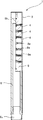
図1に示すように、本実施形態のシャワーヘッド1は、概ね円柱形のシャワーヘッド本体2と、このシャワーヘッド本体2内に、軸線方向に一直線に並べて埋め込まれた7つの振動発生素子4と、を有する。
本実施形態のシャワーヘッド1は、シャワーヘッド本体2の基端部に接続されたシャワーホース(図示せず)から湯水が供給されると、各振動発生素子4の吐水口4aから湯水が往復振動しながら吐出される。なお、本実施形態においては、湯水は、シャワーヘッド本体2の中心軸線に概ね直交する振動平面内で、所定の中心角を有する扇形を形成するように、各吐水口4aから吐出される。
As shown in FIG. 1, the shower head 1 of the present embodiment includes a shower head main body 2 having a substantially cylindrical shape, and seven vibration generating elements 4 embedded in the shower head main body 2 in a straight line in the axial direction. , Have.
In the shower head 1 of the present embodiment, when hot water is supplied from a shower hose (not shown) connected to the base end portion of the shower head main body 2, the hot water vibrates reciprocally from the spout 4a of each vibration generating element 4. It is discharged while being discharged. In the present embodiment, hot water is discharged from each spout 4a so as to form a fan shape having a predetermined central angle in a vibration plane substantially orthogonal to the central axis of the shower head main body 2.

次に、図2を参照して、シャワーヘッド1の内部構造を説明する。
図2に示すように、シャワーヘッド本体2内には、通水路を形成する通水路形成部材6と、各振動発生素子4を保持する振動発生素子保持部材8が内蔵されている。本実施形態においては、これらのシャワーヘッド本体2、通水路形成部材6、及び振動発生素子保持部材8により吐水装置本体が構成されている。
通水路形成部材6は、概ね円筒形の部材であり、シャワーヘッド本体2の内部に供給された湯水の流路を形成するように構成されている。通水路形成部材6の基端部には、シャワーホース接続部材6aが水密的に接続されるようになっている。また、通水路形成部材6の先端部は、半円形断面状に切り欠かれており、この切り欠き部分に振動発生素子保持部材8が配置される。
Next, the internal structure of the shower head 1 will be described with reference to FIG.
As shown in FIG. 2, a water passage forming member 6 for forming a water passage and a vibration generating element holding member 8 for holding each vibration generating element 4 are built in the shower head main body 2. In the present embodiment, the water discharge device main body is composed of the shower head main body 2, the water passage forming member 6, and the vibration generating element holding member 8.
The water passage forming member 6 is a member having a substantially cylindrical shape, and is configured to form a flow path of hot water supplied to the inside of the shower head main body 2. A shower hose connecting member 6a is watertightly connected to the base end portion of the water passage forming member 6. Further, the tip portion of the water passage forming member 6 is cut out in a semicircular cross section, and the vibration generating element holding member 8 is arranged in the cutout portion.

振動発生素子保持部材8は、概ね半円柱形の部材であり、通水路形成部材6の切り欠き部に配置されることにより、円柱形が形成されるようになっている。また、通水路形成部材6と振動発生素子保持部材8の間にはパッキン6bが配置され、これらの間の水密性が確保されている。さらに、振動発生素子保持部材8には、各振動発生素子4を挿入して保持するための7つの素子挿入孔8aが、概ね等間隔に、軸線方向に一直線に並べて形成されている。これにより、通水路形成部材6の中に流入した湯水は、振動発生素子保持部材8に保持された各振動発生素子4の背面側に流入し、正面に設けられた吐水口4aから吐出される。また、各素子挿入孔8aは、シャワーヘッド本体2の中心軸線に直交する平面に対して僅かに傾斜するように設けられており、各振動発生素子4から噴射される湯水は、全体としてシャワーヘッド本体2の軸線方向にも僅かに広がるように吐出される。 The vibration generating element holding member 8 is a member having a substantially semi-cylindrical shape, and is arranged in a notch portion of the water passage forming member 6 to form a cylindrical shape. Further, a packing 6b is arranged between the water passage forming member 6 and the vibration generating element holding member 8, and watertightness between them is ensured. Further, in the vibration generating element holding member 8, seven element insertion holes 8a for inserting and holding each vibration generating element 4 are formed in a straight line in the axial direction at substantially equal intervals. As a result, the hot water that has flowed into the water passage forming member 6 flows into the back side of each vibration generating element 4 held by the vibration generating element holding member 8 and is discharged from the spout 4a provided on the front surface. .. Further, each element insertion hole 8a is provided so as to be slightly inclined with respect to a plane orthogonal to the central axis of the shower head main body 2, and the hot water injected from each vibration generating element 4 is the shower head as a whole. It is discharged so as to spread slightly in the axial direction of the main body 2.

次に、図3及び図4を参照して、本実施形態のシャワーヘッドに内蔵されている振動発生素子4の構成を説明する。
図3に示すように、振動発生素子4は概ね薄い直方体状の部材であり、その正面側の先端には長方形の吐水口4aが設けられ、背面側の端部には鍔部4bが形成されている。さらに、振動発生素子4の周囲を一周するように、鍔部4bと平行に溝4cが設けられている。この溝4cにはOリング(図示せず)が嵌め込まれ、振動発生素子保持部材8の素子挿入孔8aとの間の水密性が確保される。また、振動発生素子4は、鍔部4bにより振動発生素子保持部材8に対して位置決めされると共に、水圧による振動発生素子保持部材8からの脱落が防止されている。
Next, the configuration of the vibration generating element 4 built in the shower head of the present embodiment will be described with reference to FIGS. 3 and 4.
As shown in FIG. 3, the vibration generating element 4 is a substantially thin rectangular parallelepiped member, and a rectangular water spout 4a is provided at the tip on the front side thereof, and a flange portion 4b is formed at the end on the back side. ing. Further, a groove 4c is provided in parallel with the flange portion 4b so as to go around the circumference of the vibration generating element 4. An O-ring (not shown) is fitted in the groove 4c to ensure watertightness between the vibration generating element holding member 8 and the element insertion hole 8a. Further, the vibration generating element 4 is positioned with respect to the vibration generating element holding member 8 by the flange portion 4b, and is prevented from falling off from the vibration generating element holding member 8 due to water pressure.

図4Aは図3のA−A線に沿う断面図であり、図4Bは図3のB−B線に沿う断面図である。
図4Aに示すように、振動発生素子4の内部には、長手方向に貫通するように長方形断面の通路が形成されている。この通路は、上流側から順に、給水通路10a、渦列通路10b、第1整流部10c、第2整流部10dとして形成されている。これら長方形断面の通路の各長辺は吐出される湯水が振動する振動平面と平行な方向(図4Aの紙面の方向)に向けられている。
4A is a cross-sectional view taken along the line AA of FIG. 3, and FIG. 4B is a cross-sectional view taken along the line BB of FIG.
As shown in FIG. 4A, a passage having a rectangular cross section is formed inside the vibration generating element 4 so as to penetrate in the longitudinal direction. This passage is formed as a water supply passage 10a, a vortex train passage 10b, a first rectifying section 10c, and a second rectifying section 10d in order from the upstream side. Each long side of the passage having a rectangular cross section is directed in a direction parallel to the vibration plane in which the discharged hot water vibrates (direction of the paper surface in FIG. 4A).

給水通路10aは、振動発生素子4背面側の流入口4dから延びる断面積一定の長方形断面の直線状の通路である。
渦列通路10bは、給水通路10aの下流側に、給水通路10aに連なるように(段差なく)設けられた長方形断面の通路である。即ち、給水通路10aの下流端と、渦列通路10bの上流端は、同一の寸法形状を有している。渦列通路10bの対向する一対の壁面(両側壁面)は、渦列通路10b全体に亘って、下流側に向けて流路断面積が縮小するようにテーパして構成されている。即ち、渦列通路10bは、その全体が下流側に向けて細く、次第に幅が狭くなるテーパ部分として構成されている。なお、本明細書において、「幅」とは、振動発生素子4の内部に形成された各通路の中心軸線Aを横断する、振動平面と平行な方向の長さを意味するものとする。
The water supply passage 10a is a linear passage having a rectangular cross section extending from the inflow port 4d on the back side of the vibration generating element 4 and having a constant cross-sectional area.
The vortex row passage 10b is a passage having a rectangular cross section provided on the downstream side of the water supply passage 10a so as to be connected to the water supply passage 10a (without a step). That is, the downstream end of the water supply passage 10a and the upstream end of the vortex street passage 10b have the same dimensions and shape. The pair of opposite wall surfaces (wall surfaces on both sides) of the vortex passage 10b are configured to be tapered over the entire vortex passage 10b so that the cross-sectional area of the flow path decreases toward the downstream side. That is, the vortex street passage 10b is configured as a tapered portion whose entire width is narrowed toward the downstream side and gradually narrows. In the present specification, the "width" means a length in a direction parallel to the vibration plane, which crosses the central axis A of each passage formed inside the vibration generating element 4.

第1整流部10cは、渦列通路10bと連通するように下流側に設けられた長方形断面の短い通路であり、断面積一定で直線状に形成されている。この第1整流部10cにより、渦列通路10bによって導かれた渦列を含む湯水が整流され、第2整流部10dに流出する。この第1整流部10cの流路断面積は、渦列通路10bの下流側端部の流路断面積よりも小さく構成されており、渦列通路10bと第1整流部10cの間には段部12が形成されている。この段部12の表面である段部壁面は、渦列通路10bの中心軸線Aに対して直交する方向に向けられている。従って、渦列通路10bのテーパした壁面(テーパ部分壁面)と段部壁面の為す角度は90゜よりも大きく(90゜+α゜)なる。また、段部壁面の長さは、テーパ部分壁面の長さよりも短く構成されている。 The first rectifying unit 10c is a passage having a short rectangular cross section provided on the downstream side so as to communicate with the vortex train passage 10b, and is formed in a straight line with a constant cross-sectional area. The first rectifying unit 10c rectifies the hot water containing the vortex train guided by the vortex train passage 10b, and flows out to the second rectifying unit 10d. The flow path cross-sectional area of the first rectifying section 10c is smaller than the flow path cross-sectional area of the downstream end of the vortex column passage 10b, and there is a step between the vortex column passage 10b and the first rectifying section 10c. The part 12 is formed. The step wall surface, which is the surface of the step 12, is oriented in a direction orthogonal to the central axis A of the vortex street passage 10b. Therefore, the angle formed by the tapered wall surface (tapered portion wall surface) and the stepped wall surface of the vortex row passage 10b is larger than 90 ° (90 ° + α °). Further, the length of the stepped wall surface is shorter than the length of the tapered portion wall surface.

第2整流部10dは、第1整流部10cと連なるように、第1整流部10cの下流側に設けられている。また、第2整流部10dは、第1整流部10cの流路の幅と同一の幅に形成された、互いに平行に配置された2つの平面部13から構成されている。即ち、第1整流部10cの長方形断面の流路から吐出した湯水は、第2整流部10dを構成する、第1整流部10cと同一の幅の2枚の平行な平面部13の間に流入する。図3に示すように、これらの平面部13は、概ね直方体状に形成されている振動発生素子4の先端面4eから突出するように設けられている。換言すれば、第2整流部10dの各平面部13は、第1整流部10cの流路の床面及び天井面(図4Aの紙面に平行な壁面)と同一平面で連なっている一方、第2整流部10dには側壁面(図4Aの紙面に垂直な壁面)が存在しない。 The second rectifying unit 10d is provided on the downstream side of the first rectifying unit 10c so as to be connected to the first rectifying unit 10c. Further, the second rectifying unit 10d is composed of two flat surface portions 13 formed in the same width as the width of the flow path of the first rectifying unit 10c and arranged in parallel with each other. That is, the hot water discharged from the flow path of the rectangular cross section of the first rectifying unit 10c flows into the two parallel flat surface portions 13 having the same width as the first rectifying unit 10c constituting the second rectifying unit 10d. To do. As shown in FIG. 3, these flat surface portions 13 are provided so as to project from the tip surface 4e of the vibration generating element 4 which is formed in a substantially rectangular parallelepiped shape. In other words, each flat surface portion 13 of the second rectifying unit 10d is connected to the floor surface and ceiling surface (wall surface parallel to the paper surface of FIG. 4A) of the flow path of the first rectifying unit 10c on the same plane, while the first 2 The rectifying unit 10d does not have a side wall surface (a wall surface perpendicular to the paper surface of FIG. 4A).

即ち、第1整流部10cの側壁面は第2整流部10dにかけて、270゜の折れ角βで振動発生素子4の先端面4eに連なっている。換言すれば、湯水の流路は、平行な側壁面(広がり角=0゜)を有する第1整流部10cから、振動平面内において広がり角θ=180゜で広がる第2整流部10dに接続される。このように、第1整流部10cから第2整流部10dに連なる流路は、上下方向(図4Aの紙面に垂直な方向)には同一の高さで連続している一方、振動平面内では階段状に急激に広くなる。このため、第1整流部10cから流出した湯水の流れを、第2整流部10dにおいて幅方向(図4Aにおける上下方向)に規制する壁面はなく、第1整流部10cから流出した湯水は、第2整流部10dにおいて、幅方向には無制限に広がることができる。 That is, the side wall surface of the first rectifying unit 10c is connected to the tip surface 4e of the vibration generating element 4 at a bending angle β of 270 ° over the second rectifying unit 10d. In other words, the flow path of hot water is connected from the first rectifying section 10c having a parallel side wall surface (spreading angle = 0 °) to the second rectifying section 10d spreading at a spreading angle θ = 180 ° in the vibration plane. To. In this way, the flow paths connecting the first rectifying unit 10c to the second rectifying unit 10d are continuous at the same height in the vertical direction (direction perpendicular to the paper surface of FIG. 4A), but in the vibration plane. It widens rapidly in a staircase pattern. Therefore, there is no wall surface that regulates the flow of hot water flowing out from the first rectifying unit 10c in the width direction (vertical direction in FIG. 4A) in the second rectifying unit 10d, and the hot water flowing out from the first rectifying unit 10c is the first. 2 In the rectifying unit 10d, it can spread indefinitely in the width direction.

次に、図4Bに示すように、給水通路10a、渦列通路10b、第1整流部10c、及び第2整流部10dの高さ方向に対向する壁面(天井面及び床面)は、全て同一平面上に設けられている。即ち、給水通路10a、渦列通路10b、第1整流部10c、及び第2整流部10dの高さは全て同一で、一定である。
なお、本実施形態においては、第2整流部10dの長さ(振動発生素子4の中心軸線A方向の長さ)は、第1整流部10cの通路の長さ(振動発生素子4の中心軸線A方向の長さ)の約1.5倍に形成されている。好ましくは、第2整流部10dの長さを、第1整流部10cの通路の長さの約0.25倍乃至約10倍に形成する。
Next, as shown in FIG. 4B, the water supply passage 10a, the vortex passage 10b, the first rectifying section 10c, and the wall surface (ceiling surface and floor surface) facing the second rectifying section 10d in the height direction are all the same. It is provided on a flat surface. That is, the heights of the water supply passage 10a, the vortex street passage 10b, the first rectifying unit 10c, and the second rectifying unit 10d are all the same and constant.
In the present embodiment, the length of the second rectifying unit 10d (the length of the vibration generating element 4 in the central axis A direction) is the length of the passage of the first rectifying unit 10c (the central axis of the vibration generating element 4). It is formed about 1.5 times the length in the A direction). Preferably, the length of the second rectifying unit 10d is formed to be about 0.25 to about 10 times the length of the passage of the first rectifying unit 10c.

一方、図4Aに示すように、給水通路10aの下流側端部(給水通路10aと渦列通路10bの接続部近傍)には湯水衝突部14が形成されており、この湯水衝突部14は給水通路10aの流路断面の一部を閉塞するように設けられている。この湯水衝突部14は、給水通路10aの高さ方向に対向する壁面(天井面及び床面)を連結するように延びる三角柱状の部分であり、給水通路10aの幅方向の中央に、島状に配置されている。湯水衝突部14の断面は、直角二等辺三角形状に形成されており、その斜辺が給水通路10aの中心軸線Aと直交するように配置され、また、直角二等辺三角形の直角の部分は下流側に向くように配置されている。この湯水衝突部14を設けることにより、その下流側にカルマン渦が生成され、吐水口4aから吐出される湯水が往復振動される。また、本実施形態においては、湯水衝突部14は、直角二等辺三角形の斜辺の部分(湯水衝突部14の上流端)が、給水通路10aと渦列通路10bの境界線上に位置するように配置されている。 On the other hand, as shown in FIG. 4A, a hot water collision portion 14 is formed at the downstream end portion of the water supply passage 10a (near the connection portion between the water supply passage 10a and the vortex train passage 10b), and the hot water collision portion 14 is used for supplying water. It is provided so as to block a part of the flow path cross section of the passage 10a. The hot water collision portion 14 is a triangular columnar portion extending so as to connect the wall surfaces (ceiling surface and floor surface) facing each other in the height direction of the water supply passage 10a, and has an island shape in the center of the water supply passage 10a in the width direction. Is located in. The cross section of the hot and cold water collision portion 14 is formed in a right-angled isosceles triangle shape, and its hypotenuse is arranged so as to be orthogonal to the central axis A of the water supply passage 10a, and the right-angled portion of the right-angled isosceles triangle is on the downstream side. It is arranged so that it faces the right angle. By providing the hot water collision portion 14, a Karman vortex is generated on the downstream side thereof, and the hot water discharged from the spout 4a is reciprocally vibrated. Further, in the present embodiment, the hot water collision portion 14 is arranged so that the hypotenuse portion (upstream end of the hot water collision portion 14) of the right-angled isosceles triangle is located on the boundary line between the water supply passage 10a and the vortex passage passage 10b. Has been done.

なお、本実施形態において、渦列通路10bの側壁面と、中心軸線Aとの為す角(図4Aにおける角α)は約7゜である。好ましくは、側壁面と中心軸線Aとの為す角は約3゜乃至約25゜に設定する。このように角度を設定することにより、吐出流量の変化に伴う吐水範囲の変化を抑制しながら、コアンダ効果の発生を抑制することができる。 In the present embodiment, the angle formed by the side wall surface of the vortex street passage 10b and the central axis A (angle α in FIG. 4A) is about 7 °. Preferably, the angle formed by the side wall surface and the central axis A is set to about 3 ° to about 25 °. By setting the angle in this way, it is possible to suppress the occurrence of the Coanda effect while suppressing the change in the water discharge range due to the change in the discharge flow rate.

次に、図5乃至図8を新たに参照して、本発明の実施形態によるシャワーヘッド1の作用を説明する。
図5は、本発明の実施形態によるシャワーヘッド1に備えられている振動発生素子4における湯水の流れを解析した流体シミュレーションの結果を示す図である。図6は、本発明の実施形態によるシャワーヘッド1に備えられている単一の振動発生素子4から吐出された湯水の流れを示すストロボ写真の一例である。
Next, the operation of the shower head 1 according to the embodiment of the present invention will be described with reference to FIGS. 5 to 8.
FIG. 5 is a diagram showing the result of a fluid simulation that analyzes the flow of hot water in the vibration generating element 4 provided in the shower head 1 according to the embodiment of the present invention. FIG. 6 is an example of a strobe photograph showing the flow of hot water discharged from a single vibration generating element 4 provided in the shower head 1 according to the embodiment of the present invention.

まず、シャワーホース(図示せず)から供給された湯水は、シャワーヘッド本体2内の通水路形成部材6(図2)に流入し、さらに、振動発生素子保持部材8に保持された各振動発生素子4の流入口4d(図4)に流入する。各振動発生素子4の流入口4dから給水通路10aに流入した湯水は、その流路の一部を閉塞するように設けられた湯水衝突部14に衝突する。これにより、湯水衝突部14の下流側には、交互に反対回りのカルマン渦の渦列が形成される。この湯水衝突部14により形成されたカルマン渦は、テーパ状に先が細くなった渦列通路10bによって導かれながら成長し、第1整流部10cに至る。 First, the hot water supplied from the shower hose (not shown) flows into the water passage forming member 6 (FIG. 2) in the shower head main body 2, and further, each vibration generated held by the vibration generating element holding member 8. It flows into the inflow port 4d (FIG. 4) of the element 4. The hot water flowing into the water supply passage 10a from the inflow port 4d of each vibration generating element 4 collides with the hot water collision portion 14 provided so as to block a part of the flow path. As a result, a series of Karman vortices in opposite directions are alternately formed on the downstream side of the hot water collision portion 14. The Karman vortex formed by the hot water collision portion 14 grows while being guided by the tapered vortex train passage 10b, and reaches the first rectifying portion 10c.

この渦列通路10b内における湯水の流れを流体シミュレーションにより解析した結果が図5の(a)欄〜(c)欄である。この流体シミュレーションに示されているように、湯水衝突部14の下流側には渦が発生し、その部分で流速が高くなっている。この流速の高い部分(図5において色の濃い部分)は湯水衝突部14の両側に交互に表れ、渦列は渦列通路10bの壁面に沿って吐水口4aに向かって進行する。渦列通路10bの下流側の第1整流部10cに流入した湯水は、ここで振動平面(図5の紙面に平行な面)に平行な方向の乱れ、及び振動平面に直交する方向の乱れが抑制され、整流される。この第1整流部10cを通過した湯水は、第2整流部10dにおいて、振動平面に直交する方向の乱れのみが抑制され、整流される。 The results of analyzing the flow of hot water in the vortex passage 10b by fluid simulation are shown in columns (a) to (c) of FIG. As shown in this fluid simulation, a vortex is generated on the downstream side of the hot water collision portion 14, and the flow velocity is high in that portion. The high flow velocity portions (dark colored portions in FIG. 5) appear alternately on both sides of the hot water collision portion 14, and the vortex train travels along the wall surface of the vortex train passage 10b toward the spout 4a. The hot water that has flowed into the first rectifying section 10c on the downstream side of the spiral passage 10b has turbulence in the direction parallel to the vibration plane (the plane parallel to the paper surface in FIG. 5) and turbulence in the direction orthogonal to the vibration plane. Suppressed and rectified. The hot water that has passed through the first rectifying unit 10c is rectified by the second rectifying unit 10d by suppressing only the turbulence in the direction orthogonal to the vibration plane.

第2整流部10dを経て吐水口4aから吐出される湯水は、吐水口4aにおける流速分布に基づいて曲げられ、流速の高い部分が図5における上下方向に移動するに従って、吐出方向が変化する。即ち、湯水の流速の高い部分が図5における吐水口4aの上端に位置する状態では、湯水は下方に向けて噴射され、流速の高い部分が吐水口4aの下端に位置する状態では、湯水は上方に向けて噴射される。このように、湯水衝突部14の下流側に交互にカルマン渦を発生させることにより、吐水口4aにおいて流速分布が発生して、噴流が偏向する。また、渦列の進行により流速の速い部分の位置が往復運動するため、噴射される湯水も振動平面(図5の紙面に平行な面)内で往復振動する。この際、第2整流部10dは、振動平面と平行に配置された2つの平面部13のみから構成されている(図3に示すように側壁面が設けられていない)ため、振動平面に直交する方向の乱れのみを抑制し、振動平面内での湯水の往復振動には殆ど影響を与えない。 The hot water discharged from the spout 4a via the second rectifying unit 10d is bent based on the flow velocity distribution at the spout 4a, and the discharge direction changes as the portion having a high flow velocity moves in the vertical direction in FIG. That is, when the portion having a high flow velocity of the hot water is located at the upper end of the spout 4a in FIG. 5, the hot water is jetted downward, and when the portion having a high flow velocity is located at the lower end of the spout 4a, the hot water is sprayed. It is injected upward. In this way, by alternately generating Karman vortices on the downstream side of the hot water collision portion 14, a flow velocity distribution is generated at the spout 4a, and the jet flow is deflected. Further, since the position of the portion having a high flow velocity reciprocates due to the progress of the vortex train, the jetted hot water also reciprocates in the vibration plane (the plane parallel to the paper surface of FIG. 5). At this time, since the second rectifying unit 10d is composed of only two plane portions 13 arranged parallel to the vibration plane (the side wall surface is not provided as shown in FIG. 3), the second rectifying unit 10d is orthogonal to the vibration plane. It suppresses only the turbulence in the direction of vibration, and has almost no effect on the reciprocating vibration of hot water in the vibration plane.

また、渦列通路10bと第1整流部10cの間には段部12が設けられているため、渦列通路10bのテーパした壁面(テーパ部分壁面)に沿う流れは、ここで剥離されて第1整流部10cに流入する。この段部12により流れが壁面から剥離されることにより、第1整流部10cの側壁面において発生するコアンダ効果が抑制される。また、第1整流部10cの下流側の第2整流部10dには側壁面が設けられておらず、急激に広がっている(広がり角θ=180゜)ため、第2整流部10dにおいてはコアンダ効果は発生しない。このため、吐水口4aから吐出される湯水は、コアンダ効果の影響を殆ど受けることがなく、滑らかに往復移動される。従って、段部12は、渦列通路10bの壁面に沿った流れを剥離させ、コアンダ効果を抑制する剥離部として作用する。さらに、段部12の表面である段部壁面は、剥離部壁面として機能する。 Further, since the step portion 12 is provided between the vortex passage passage 10b and the first rectifying portion 10c, the flow along the tapered wall surface (tapered portion wall surface) of the vortex passage passage 10b is peeled off here. 1 Flows into the rectifying unit 10c. Since the flow is separated from the wall surface by the step portion 12, the Coanda effect generated on the side wall surface of the first rectifying portion 10c is suppressed. Further, since the second rectifying unit 10d on the downstream side of the first rectifying unit 10c is not provided with a side wall surface and rapidly expands (spread angle θ = 180 °), the second rectifying unit 10d has a Coanda. No effect occurs. Therefore, the hot water discharged from the spout 4a is hardly affected by the Coanda effect and is smoothly reciprocated. Therefore, the step portion 12 acts as a peeling portion that separates the flow along the wall surface of the vortex street passage 10b and suppresses the Coanda effect. Further, the stepped wall surface, which is the surface of the stepped portion 12, functions as a peeling portion wall surface.

次に、図6に示す、本実施形態における振動発生素子4から吐出された湯水の流れを示すストロボ写真では、吐水方向が滑らかに往復移動しているため、整った正弦波状の流れが得られている。このように、本実施形態における振動発生素子4によれば、大粒の液滴が、広い範囲にムラなく吐出される浴び心地の良いシャワー吐水を得ることができる。 Next, in the strobe photograph showing the flow of hot water discharged from the vibration generating element 4 in the present embodiment shown in FIG. 6, since the water discharge direction smoothly reciprocates, a well-ordered sinusoidal flow can be obtained. ing. As described above, according to the vibration generating element 4 in the present embodiment, it is possible to obtain a comfortable shower water discharge in which large droplets are evenly discharged over a wide range.

次に、図7及び図8を参照して、振動発生素子4に設けられている第2整流部10dの効果を説明する。
図7は、本実施形態のシャワーヘッド1に備えられている振動発生素子4から吐出される湯水の状態を示す写真である。図8は、比較例として、第2整流部10dを備えていない振動発生素子から吐出される湯水の状態を示す写真である。図7における振動発生素子と図8における振動発生素子は、第2整流部10dの有無を除き、同一の構成を有する。また、図7及び図8において、左側の2枚の写真は流速4m/secで振動発生素子から吐出する湯水の状態を示し、右側の2枚の写真は流速8m/secで振動発生素子から吐出する湯水の状態を示している。さらに、図7及び図8において、上段の写真は振動発生素子から吐出する湯水を振動平面に直交する方向から撮影したものであり、下段の写真は湯水を振動平面に平行な方向から撮影したものである。
Next, the effect of the second rectifying unit 10d provided on the vibration generating element 4 will be described with reference to FIGS. 7 and 8.
FIG. 7 is a photograph showing the state of hot water discharged from the vibration generating element 4 provided in the shower head 1 of the present embodiment. FIG. 8 is a photograph showing a state of hot water discharged from a vibration generating element not provided with the second rectifying unit 10d as a comparative example. The vibration generating element in FIG. 7 and the vibration generating element in FIG. 8 have the same configuration except for the presence / absence of the second rectifying unit 10d. Further, in FIGS. 7 and 8, the two photographs on the left side show the state of hot water discharged from the vibration generating element at a flow velocity of 4 m / sec, and the two photographs on the right side show the state of hot water discharged from the vibration generating element at a flow velocity of 8 m / sec. It shows the state of hot water. Further, in FIGS. 7 and 8, the upper photograph is taken from the direction perpendicular to the vibration plane of the hot water discharged from the vibration generating element, and the lower photograph is taken from the direction parallel to the vibration plane. Is.

まず、図7に示すように、流速4m/secで振動発生素子から吐出する湯水は、振動平面内において綺麗な正弦波状に振動される(図7の左上)と共に、振動平面に直交する方向には殆ど広がることなく(図7の左下)一直線に吐出されている。一方、振動発生素子から吐出する湯水の流速を非常に高くし、8m/secとした場合には、振動平面内における正弦波状の湯水の振動に乱れは生じる(図7の右上)ものの、振動平面に直交する方向の湯水の広がりは抑制されている(図7の右下)。このため、8m/secの流速で吐出された湯水を浴びた使用者には、心地良い刺激感を与えることができる。 First, as shown in FIG. 7, the hot water discharged from the vibration generating element at a flow velocity of 4 m / sec is vibrated in a beautiful sinusoidal shape in the vibration plane (upper left in FIG. 7) and in the direction orthogonal to the vibration plane. Is discharged in a straight line with almost no spread (lower left in FIG. 7). On the other hand, when the flow velocity of the hot water discharged from the vibration generating element is set to 8 m / sec, the vibration of the sinusoidal hot water in the vibration plane is disturbed (upper right in FIG. 7), but the vibration plane. The spread of hot water in the direction orthogonal to is suppressed (lower right in FIG. 7). Therefore, a comfortable stimulus can be given to the user who has been exposed to the hot water discharged at a flow rate of 8 m / sec.

次に、図8に示すように、比較例として、第2整流部10dを備えていない振動発生素子から吐出される湯水は、流速4m/secの場合には、本実施形態の第2整流部10dを備えた振動発生素子から吐出される湯水とほぼ同等に正弦波状の流れとなっている(図8の左上及び左下)。これに対し、流速が8m/secにされた場合には、振動発生素子から吐出された湯水は、正弦波の形態をとどめておらず(図8の右上)、また、振動平面に直交する方向にも大きく流れが広がってしまっていることがわかる(図8の右下)。これは、振動発生素子から吐出される湯水が、吐水口の比較的近傍で細かな液滴に分解されているためである。このように、吐出された湯水の流れが細かな液滴に分解されてしまうと、流速を8m/secに高めたとしても、湯水を浴びた使用者には心地良い刺激感を与えることができない。本実施形態の振動発生素子(図7)では、第2整流部10dを備えているため、吐出される湯水の流速を非常に高くした場合でも、湯水の流れが振動平面に直交する方向に広がるのが抑制され(図7の右下)、使用者に心地良い刺激感を与えることができる。 Next, as shown in FIG. 8, as a comparative example, the hot water discharged from the vibration generating element not provided with the second rectifying unit 10d has the second rectifying unit of the present embodiment when the flow velocity is 4 m / sec. The flow is sinusoidal, which is almost the same as the hot water discharged from the vibration generating element provided with 10d (upper left and lower left in FIG. 8). On the other hand, when the flow velocity is set to 8 m / sec, the hot water discharged from the vibration generating element does not remain in the form of a sine wave (upper right in FIG. 8), and the direction orthogonal to the vibration plane. It can be seen that the flow has spread significantly (lower right in FIG. 8). This is because the hot water discharged from the vibration generating element is decomposed into fine droplets relatively in the vicinity of the spout. In this way, if the flow of the discharged hot water is decomposed into fine droplets, even if the flow velocity is increased to 8 m / sec, it is not possible to give a comfortable stimulus to the user who has been exposed to the hot water. .. Since the vibration generating element (FIG. 7) of the present embodiment includes the second rectifying unit 10d, the flow of hot water spreads in the direction orthogonal to the vibration plane even when the flow velocity of the discharged hot water is extremely high. Is suppressed (lower right of FIG. 7), and a pleasant stimulating feeling can be given to the user.

本発明の第1実施形態のシャワーヘッド1によれば、振動発生素子4に、第1整流部10c及び第2整流部10dを二段階に設ける(図4A)ことにより、吐水範囲内にほぼ一定に液滴を分布させることができると共に、吐出される湯水の流速を非常に高くして心地良い刺激感を得ることができる。 According to the shower head 1 of the first embodiment of the present invention, the vibration generating element 4 is provided with the first rectifying unit 10c and the second rectifying unit 10d in two stages (FIG. 4A), so that the water discharge range is substantially constant. The droplets can be distributed in the shower, and the flow velocity of the discharged hot water can be made very high to obtain a comfortable stimulating feeling.

また、本実施形態のシャワーヘッド1によれば、第2整流部10dが振動平面(図4Aの紙面に平行な平面)に平行な2つの平面部13から構成されているので、第1整流部10cからの流れが振動平面内に広がった場合も、流れが第2整流部10dを構成する壁面に衝突することがない。このため、第2整流部では、確実に、振動平面に直交する方向の湯水の広がりだけを抑制することができ、振動平面内の往復振動を阻害することがない。 Further, according to the shower head 1 of the present embodiment, since the second rectifying unit 10d is composed of two flat surfaces 13 parallel to the vibration plane (plane parallel to the paper surface of FIG. 4A), the first rectifying unit 10d is formed. Even when the flow from 10c spreads in the vibration plane, the flow does not collide with the wall surface constituting the second rectifying unit 10d. Therefore, the second rectifying unit can surely suppress only the spread of hot water in the direction orthogonal to the vibration plane, and does not hinder the reciprocating vibration in the vibration plane.

次に、図9及び図10を参照して、本発明の第2実施形態によるシャワーヘッドを説明する。
本実施形態のシャワーヘッドは、内蔵されている振動発生素子の構成のみが、上述した第1実施形態とは異なっている。従って、ここでは、本実施形態の第1実施形態とは異なる点のみを説明し、同様の構成、作用、効果については説明を省略する。
Next, the shower head according to the second embodiment of the present invention will be described with reference to FIGS. 9 and 10.
The shower head of the present embodiment differs from the above-described first embodiment only in the configuration of the built-in vibration generating element. Therefore, here, only the points different from the first embodiment of the present embodiment will be described, and the description of the same configuration, operation, and effect will be omitted.

図9は、本発明の第2実施形態における振動発生素子の斜視図である。また、図10Aは、本実施形態における振動発生素子の平面断面図であり、図10Bは、振動発生素子の垂直断面図である。
図9及び図10に示すように、本実施形態における振動発生素子30は、渦列通路の構成、及び第2整流部の構成が第1実施形態と異なっている。即ち、本実施形態においては、渦列通路の上流側が断面積一定の通路で構成されており、また、第2整流部の幅が第1整流部よりも広く構成されている。
FIG. 9 is a perspective view of the vibration generating element according to the second embodiment of the present invention. Further, FIG. 10A is a plan sectional view of the vibration generating element according to the present embodiment, and FIG. 10B is a vertical sectional view of the vibration generating element.
As shown in FIGS. 9 and 10, the vibration generating element 30 in the present embodiment is different from the first embodiment in the configuration of the vortex street passage and the configuration of the second rectifying unit. That is, in the present embodiment, the upstream side of the vortex train passage is configured by a passage having a constant cross-sectional area, and the width of the second rectifying section is wider than that of the first rectifying section.

図9に示すように、振動発生素子30は概ね薄い直方体状の部材であり、その正面側の先端には長方形の吐水口30aが設けられ、背面側の端部には鍔部30bが形成されている。さらに、振動発生素子30の周囲を一周するように、鍔部30bと平行に溝30cが設けられている。
図10Aに示すように、第1実施形態と同様に、振動発生素子30の内部には、長手方向に貫通するように長方形断面の通路が形成されている。この通路は、上流側から順に、給水通路32a、渦列通路32b、第1整流部32c、第2整流部32dとして形成されている。
As shown in FIG. 9, the vibration generating element 30 is a generally thin rectangular parallelepiped member, a rectangular parallelepiped member 30a is provided at the tip on the front side thereof, and a flange portion 30b is formed at the end on the back side. ing. Further, a groove 30c is provided in parallel with the flange portion 30b so as to go around the vibration generating element 30.
As shown in FIG. 10A, similarly to the first embodiment, a passage having a rectangular cross section is formed inside the vibration generating element 30 so as to penetrate in the longitudinal direction. This passage is formed as a water supply passage 32a, a vortex train passage 32b, a first rectifying unit 32c, and a second rectifying unit 32d in this order from the upstream side.

給水通路32aは、振動発生素子30背面側の流入口30dから延びる断面積一定の長方形断面の直線状の通路である。
渦列通路32bは、給水通路32aの下流側に、給水通路32aに連なるように設けられた長方形断面の通路である。即ち、給水通路32aの下流端と、渦列通路32bの上流端は、同一の寸法形状を有している。渦列通路32bの対向する一対の壁面(両側面)は、その上流側においては平行に形成され、下流側においては、下流端に向けて流路断面積が縮小するようにテーパして構成されたテーパ部分32eが設けられている。即ち、渦列通路32bは、上流端から断面積一定で延びた後、下流側に向けて次第に幅が狭くなるように構成されている。
The water supply passage 32a is a straight passage having a rectangular cross section extending from the inflow port 30d on the back side of the vibration generating element 30 and having a constant cross section.
The vortex row passage 32b is a passage having a rectangular cross section provided on the downstream side of the water supply passage 32a so as to be connected to the water supply passage 32a. That is, the downstream end of the water supply passage 32a and the upstream end of the vortex street passage 32b have the same dimensions and shape. The pair of facing wall surfaces (both side surfaces) of the vortex column passage 32b are formed in parallel on the upstream side thereof, and are tapered on the downstream side so that the cross-sectional area of the flow path decreases toward the downstream end. A tapered portion 32e is provided. That is, the vortex street passage 32b is configured so as to extend from the upstream end with a constant cross-sectional area and then gradually narrow toward the downstream side.

第1整流部32cは、渦列通路32b(テーパ部分32e)と連通するように下流側に設けられた長方形断面の通路であり、断面積一定で直線状に形成されている。この第1整流部32cにより、渦列通路32bによって導かれた渦列を含む湯水が整流され、第2整流部32dに流出する。この第1整流部32cの流路断面積は、渦列通路32b(テーパ部分32e)の下流側端部の流路断面積よりも小さく構成されており、渦列通路32bと第1整流部32cの間には剥離部である段部36が形成されている。この段部36の表面である段部壁面は、渦列通路32bの中心軸線Aに対して直交する方向に向けられている。従って、渦列通路32bのテーパした壁面(テーパ部分壁面)と段部壁面の為す角度は90゜よりも大きく(90゜+α゜)なる。また、段部壁面の長さは、テーパ部分壁面の長さよりもよりも短く構成されている。 The first rectifying unit 32c is a passage having a rectangular cross section provided on the downstream side so as to communicate with the vortex train passage 32b (tapered portion 32e), and is formed in a straight line with a constant cross-sectional area. The first rectifying unit 32c rectifies the hot water containing the vortex train guided by the vortex train passage 32b, and flows out to the second rectifying unit 32d. The flow path cross-sectional area of the first rectifying section 32c is smaller than the flow path cross-sectional area of the downstream end of the vortex row passage 32b (tapered portion 32e), and the vortex row passage 32b and the first rectifying section 32c A step portion 36, which is a peeling portion, is formed between the two. The step wall surface, which is the surface of the step 36, is oriented in a direction orthogonal to the central axis A of the vortex street passage 32b. Therefore, the angle formed by the tapered wall surface (tapered portion wall surface) and the stepped wall surface of the vortex row passage 32b is larger than 90 ° (90 ° + α °). Further, the length of the stepped wall surface is shorter than the length of the tapered portion wall surface.

第2整流部32dは、第1整流部32cと連なるように、第1整流部32cの下流側に設けられている。また、第2整流部32dは、第1整流部32cの流路の幅よりも広い幅を有する、互いに平行に配置された2つの平面部33から構成されている。即ち、第1整流部32cの長方形断面の流路から吐出した湯水は、第2整流部32dを構成する、第1整流部31cよりも幅が広い2枚の平行な平面部33の間に流入する。図9に示すように、これらの平面部33は、概ね直方体状に形成されている振動発生素子30の先端面30eから突出するように設けられている。換言すれば、第2整流部32dの各平面部33は、第1整流部32cの流路の床面及び天井面(図10Aの紙面に平行な壁面)と同一平面で連なっている一方、第2整流部32dには側壁面(図10Aの紙面に垂直な壁面)が存在しない。 The second rectifying unit 32d is provided on the downstream side of the first rectifying unit 32c so as to be connected to the first rectifying unit 32c. Further, the second rectifying unit 32d is composed of two flat surface portions 33 arranged in parallel with each other and having a width wider than the width of the flow path of the first rectifying unit 32c. That is, the hot water discharged from the flow path of the rectangular cross section of the first rectifying unit 32c flows into the two parallel flat surface portions 33 having a width wider than that of the first rectifying unit 31c, which constitute the second rectifying unit 32d. To do. As shown in FIG. 9, these flat surface portions 33 are provided so as to project from the tip surface 30e of the vibration generating element 30 which is formed in a substantially rectangular parallelepiped shape. In other words, each flat surface portion 33 of the second rectifying unit 32d is connected to the floor surface and ceiling surface (wall surface parallel to the paper surface of FIG. 10A) of the flow path of the first rectifying unit 32c on the same plane, while the first 2 The rectifying unit 32d does not have a side wall surface (a wall surface perpendicular to the paper surface of FIG. 10A).

即ち、第1整流部32cの側壁面は第2整流部32dにかけて、270゜の折れ角βで振動発生素子30の先端面30eに連なっている。換言すれば、湯水の流路は、平行な側壁面(広がり角=0゜)を有する第1整流部32cから、振動平面内において広がり角θ=180゜で広がる第2整流部32dに接続される。このように、第1整流部32cから第2整流部32dに連なる流路は、上下方向(図10Aの紙面に垂直な方向)には同一の高さで連続している一方、振動平面内では階段状に急激に広くなる。このため、第1整流部32cから流出した湯水の流れを、第2整流部32dにおいて幅方向(図10Aにおける上下方向)に規制する壁面はなく、第1整流部32cから流出した湯水は、第2整流部32dにおいて、幅方向には無制限に広がることができる。 That is, the side wall surface of the first rectifying unit 32c is connected to the tip surface 30e of the vibration generating element 30 at a bending angle β of 270 ° over the second rectifying unit 32d. In other words, the flow path of hot water is connected from the first rectifying unit 32c having a parallel side wall surface (spreading angle = 0 °) to the second rectifying unit 32d spreading at a spreading angle θ = 180 ° in the vibration plane. To. In this way, the flow paths connecting the first rectifying unit 32c to the second rectifying unit 32d are continuous at the same height in the vertical direction (direction perpendicular to the paper surface of FIG. 10A), but in the vibration plane. It widens rapidly in a staircase pattern. Therefore, there is no wall surface that regulates the flow of hot water flowing out from the first rectifying unit 32c in the width direction (vertical direction in FIG. 10A) in the second rectifying unit 32d, and the hot water flowing out from the first rectifying unit 32c is the first. In the 2 rectifying unit 32d, it can spread indefinitely in the width direction.

また、図10Bに示すように、本実施形態においても、第1実施形態と同様に、給水通路32a、渦列通路32b、第1整流部32c及び第2整流部32dの高さ方向に対向する壁面(天井面及び床面)は、全て同一平面上に設けられている。即ち、給水通路32a、渦列通路32b、第1整流部32c及び第2整流部32dの高さは全て同一で、一定である。
なお、本実施形態においては、第2整流部32dの長さ(振動発生素子30の中心軸線A方向の長さ)は、第1整流部32cの通路の長さ(振動発生素子30の中心軸線A方向の長さ)の約1.5倍に形成されている。好ましくは、第2整流部32dの長さを、第1整流部32cの通路の長さの約0.25倍乃至約10倍に形成する。また、本実施形態においては、第2整流部32dの幅は、第1整流部32cの通路の幅の約2倍に形成されている。好ましくは、第2整流部32dの幅を、第1整流部32cの通路の幅の約1倍乃至約3倍に形成する。
Further, as shown in FIG. 10B, also in the present embodiment, similarly to the first embodiment, the water supply passage 32a, the vortex street passage 32b, the first rectifying unit 32c, and the second rectifying unit 32d face each other in the height direction. The wall surfaces (ceiling surface and floor surface) are all provided on the same plane. That is, the heights of the water supply passage 32a, the vortex street passage 32b, the first rectifying unit 32c, and the second rectifying unit 32d are all the same and constant.
In the present embodiment, the length of the second rectifying unit 32d (the length of the vibration generating element 30 in the central axis A direction) is the length of the passage of the first rectifying unit 32c (the central axis of the vibration generating element 30). It is formed about 1.5 times the length in the A direction). Preferably, the length of the second rectifying unit 32d is formed to be about 0.25 to about 10 times the length of the passage of the first rectifying unit 32c. Further, in the present embodiment, the width of the second rectifying unit 32d is formed to be about twice the width of the passage of the first rectifying unit 32c. Preferably, the width of the second rectifying unit 32d is formed to be about 1 to about 3 times the width of the passage of the first rectifying unit 32c.

一方、図10Aに示すように、給水通路32aの下流側端部(給水通路32aと渦列通路32bの接続部近傍)には、給水通路32aの流路断面の一部を閉塞するように、湯水衝突部34が設けられている。この湯水衝突部34の構成は、第1実施形態と同様であるので、説明を省略する。 On the other hand, as shown in FIG. 10A, a part of the flow path cross section of the water supply passage 32a is blocked at the downstream end portion of the water supply passage 32a (near the connection portion between the water supply passage 32a and the vortex row passage 32b). A hot water collision portion 34 is provided. Since the configuration of the hot water collision portion 34 is the same as that of the first embodiment, the description thereof will be omitted.

また、渦列通路32bのテーパ部分32eの軸線方向の長さを、第1整流部32cの軸線方向の長さよりも長く形成しておくことにより、吐出される湯水の流量による吐出範囲の変化を十分に抑制できることが確認されている。好ましくは、テーパ部分32eの中心軸線A方向の長さは、第1整流部32cの中心軸線A方向の長さの4倍以上に形成する。また、渦列通路32bのテーパ部分32eの側壁面と、中心軸線Aとの為す角(図10Aにおける角α)は約7゜である。好ましくは、側壁面と中心軸線Aとの為す角は約3゜乃至約25゜に設定する。このように角度を設定することにより、吐出流量の変化に伴う吐水範囲の変化を抑制しながら、コアンダ効果の発生を抑制することができる。さらに、給水通路32a下流端の、湯水衝突部34によって一部が閉塞されている部分の流路断面積(給水通路32aの流路断面積から湯水衝突部34の投影面積を減じた面積)は、第1整流部32cの流路断面積よりも大きく構成されている。 Further, by forming the length of the tapered portion 32e of the vortex passage 32b in the axial direction longer than the length of the first rectifying unit 32c in the axial direction, the change in the discharge range due to the flow rate of the discharged hot water can be changed. It has been confirmed that it can be sufficiently suppressed. Preferably, the length of the tapered portion 32e in the central axis A direction is formed to be four times or more the length of the first rectifying unit 32c in the central axis A direction. Further, the angle formed by the side wall surface of the tapered portion 32e of the vortex passage 32b and the central axis A (angle α in FIG. 10A) is about 7 °. Preferably, the angle formed by the side wall surface and the central axis A is set to about 3 ° to about 25 °. By setting the angle in this way, it is possible to suppress the occurrence of the Coanda effect while suppressing the change in the water discharge range due to the change in the discharge flow rate. Further, the flow path cross-sectional area of the portion partially blocked by the hot water collision portion 34 at the downstream end of the water supply passage 32a (the area obtained by subtracting the projected area of the hot water collision portion 34 from the flow path cross-sectional area of the water supply passage 32a) is , It is configured to be larger than the flow path cross-sectional area of the first rectifying unit 32c.

また、渦列通路32bの下流側の第1整流部32cに流入した湯水は、ここで振動平面(図10Aの紙面に平行な面)に平行な方向の乱れ、及び振動平面に直交する方向の乱れが抑制され、整流される。この第1整流部32cを通過した湯水は、第2整流部32dにおいて、振動平面に直交する方向の乱れのみが抑制され、整流される。 Further, the hot water that has flowed into the first rectifying section 32c on the downstream side of the spiral passage 32b is turbulent in the direction parallel to the vibration plane (the plane parallel to the paper surface of FIG. 10A) and in the direction orthogonal to the vibration plane. Disturbance is suppressed and rectified. The hot water that has passed through the first rectifying unit 32c is rectified in the second rectifying unit 32d by suppressing only the turbulence in the direction orthogonal to the vibration plane.

第2整流部32dを経て吐水口30aから吐出される湯水は、吐水口30aにおける流速分布に基づいて曲げられ、流速の高い部分の移動に従って吐出方向が変化する。この際、第2整流部32dは、振動平面と平行に配置された2つの平面部33のみから構成されている(図9に示すように側壁面が設けられていない)ため、振動平面に直交する方向の乱れのみを抑制し、振動平面内での湯水の往復振動には殆ど影響を与えない。また、第2整流部32dの幅(平面部33の幅)は、第1整流部32cの流路断面の幅よりも広く形成されている。このため、第1整流部32cから往復振動しながら吐出され、幅方向において第1整流部32cよりも外側に向けて吐出される湯水も2つの平面部33の間を通るので、このような湯水に対しても第2整流部32dは振動平面に直交する方向の乱れを抑制することができる。これにより、吐出される湯水の振動平面に直交する方向の広がりを、より効果的に抑制することができる。 The hot water discharged from the spout 30a via the second rectifying unit 32d is bent based on the flow velocity distribution at the spout 30a, and the discharge direction changes as the portion having a high flow velocity moves. At this time, since the second rectifying unit 32d is composed of only two plane portions 33 arranged parallel to the vibration plane (the side wall surface is not provided as shown in FIG. 9), it is orthogonal to the vibration plane. It suppresses only the turbulence in the direction of vibration, and has almost no effect on the reciprocating vibration of hot water in the vibration plane. Further, the width of the second rectifying unit 32d (the width of the flat surface portion 33) is formed to be wider than the width of the flow path cross section of the first rectifying unit 32c. Therefore, the hot water discharged from the first rectifying unit 32c while reciprocating and vibrating, and the hot water discharged outward from the first rectifying unit 32c in the width direction also passes between the two flat surface portions 33. However, the second rectifying unit 32d can suppress turbulence in the direction orthogonal to the vibration plane. As a result, the spread of the discharged hot water in the direction orthogonal to the vibration plane can be suppressed more effectively.

なお、本発明の第2実施形態における振動発生素子30は、渦列通路32b及び第2整流部32dの構成が、上述した第1実施形態とは異なっているが、渦列通路32b又は第2整流部32dの構成の何れか一方を、第1実施形態における振動発生素子に適用することもできる。 The vibration generating element 30 according to the second embodiment of the present invention has a vortex passage 32b and a second rectifying unit 32d, although the configurations of the vortex passage 32b and the second rectifying unit 32d are different from those of the first embodiment described above, but the vortex passage 32b or the second Either one of the configurations of the rectifying unit 32d can be applied to the vibration generating element in the first embodiment.

本発明の第2実施形態のシャワーヘッドによれば、第2整流部32dの振動平面(図10Aの紙面に平行な平面)に平行な方向の幅が第1整流部32cの下流端の幅よりも広く構成されているので、往復振動により第1整流部32cから広がりながら吐出する湯水の流れに対しても、振動平面に直交する方向の乱れを第2整流部32dにより抑制することができる。この結果、振動平面に直交する方向の湯水の広がりを、より広範囲で抑制することができ、より心地良い刺激感を得ることができる。 According to the shower head of the second embodiment of the present invention, the width in the direction parallel to the vibration plane (plane parallel to the paper surface of FIG. 10A) of the second rectifying unit 32d is wider than the width of the downstream end of the first rectifying unit 32c. The second rectifying unit 32d can suppress the turbulence in the direction orthogonal to the vibration plane even with respect to the flow of hot water discharged while spreading from the first rectifying unit 32c due to the reciprocating vibration. As a result, the spread of hot water in the direction orthogonal to the vibration plane can be suppressed in a wider range, and a more comfortable feeling of stimulation can be obtained.

次に、図11を参照して、本発明の第2実施形態における振動発生素子の変形例を説明する。
図11は、本変形例による振動発生素子の平面断面図である。
本変形例による振動発生素子38は、第2整流部39の構成のみが上述した第2実施形態とは異なっている。
Next, a modified example of the vibration generating element according to the second embodiment of the present invention will be described with reference to FIG.
FIG. 11 is a plan sectional view of the vibration generating element according to the present modification.
The vibration generating element 38 according to this modification differs from the second embodiment described above only in the configuration of the second rectifying unit 39.

上述した第2実施形態においては、第2整流部32dは2つの平面部33(図9)から構成されており、第2整流部32dには側壁面が設けられていない。これに対して、本変形例においては、第2整流部39は幅広の長方形断面の通路から構成され、側壁面39aが設けられている。即ち、図11に示すように、第2整流部39は、第1整流部32cの下流側に設けられた長方形断面の通路であり、その高さは第1整流部32cの高さと同一で、幅が第1整流部32cの幅よりも広くなっている。即ち、湯水の流路は、第1整流部32cから第2整流部39にかけて、振動平面内において広がり角θ=180゜で階段状に急激に広くなった後、幅一定(広がり角=0゜)となっている。このように、本変形例においては、第2整流部39に側壁面39aが設けられているものの、その幅が第1整流部32cの幅よりも十分に広いため、第1整流部32cから往復振動しながら吐出される湯水と側壁面39aが干渉せず、吐出される湯水が側壁面39aに直接当たることはない。 In the second embodiment described above, the second rectifying unit 32d is composed of two flat surface portions 33 (FIG. 9), and the second rectifying unit 32d is not provided with a side wall surface. On the other hand, in this modification, the second rectifying unit 39 is composed of a passage having a wide rectangular cross section and is provided with a side wall surface 39a. That is, as shown in FIG. 11, the second rectifying unit 39 is a passage having a rectangular cross section provided on the downstream side of the first rectifying unit 32c, and its height is the same as the height of the first rectifying unit 32c. The width is wider than the width of the first rectifying unit 32c. That is, the flow path of the hot water suddenly widens stepwise at a spread angle θ = 180 ° in the vibration plane from the first rectifying section 32c to the second rectifying section 39, and then has a constant width (spread angle = 0 °). ). As described above, in this modification, although the side wall surface 39a is provided in the second rectifying unit 39, the width thereof is sufficiently wider than the width of the first rectifying unit 32c, so that the second rectifying unit 39 reciprocates from the first rectifying unit 32c. The hot water discharged while vibrating does not interfere with the side wall surface 39a, and the discharged hot water does not directly hit the side wall surface 39a.

従って、本変形例においても、第2整流部39は、振動平面に直交する方向の乱れのみを抑制し、振動平面内での湯水の往復振動には殆ど影響を与えない。なお、本変形例において、第2整流部39の幅(両側の側壁面39aの間の距離)は、第1整流部32cの幅の2倍に形成されている。このため、本変形例による振動発生素子38は、第2実施形態における振動発生素子と実質的に同一の作用、効果を奏するものである。 Therefore, even in this modification, the second rectifying unit 39 suppresses only the turbulence in the direction orthogonal to the vibration plane, and has almost no effect on the reciprocating vibration of hot water in the vibration plane. In this modification, the width of the second rectifying section 39 (distance between the side wall surfaces 39a on both sides) is formed to be twice the width of the first rectifying section 32c. Therefore, the vibration generating element 38 according to the present modification has substantially the same action and effect as the vibration generating element in the second embodiment.

なお、本変形例において、第2整流部39の基端を形成する基端壁面39bは、振動発生素子38の中心軸線Aと直交する方向に向けられている。即ち、第1整流部32cの通路を構成する内壁面と、第2整流部39の基端壁面39bは90゜に折れ曲がっている。換言すれば、第1整流部32cの側壁面は第2整流部39へかけて、270゜の折れ角βで広がっているが、この折れ角βは、吐出される湯水と基端壁面39bが干渉したり、コアンダ効果を発生させることがない限り任意に変更することができる。例えば、折れ角βを270゜よりも小さく形成することにより、振動発生素子38の第1整流部32cを構成する部分の肉厚を厚くすることができ、強度を増すことができる。また、第2整流部39の側壁面39aも、吐出される湯水と干渉しない限り任意の角度に向けることができる。
同様に、第1、第2実施形態における折れ角βも変更することができる。
In this modification, the base end wall surface 39b forming the base end of the second rectifying unit 39 is oriented in a direction orthogonal to the central axis A of the vibration generating element 38. That is, the inner wall surface forming the passage of the first rectifying unit 32c and the base end wall surface 39b of the second rectifying unit 39 are bent at 90 °. In other words, the side wall surface of the first rectifying section 32c extends toward the second rectifying section 39 at a bending angle β of 270 °, and this bending angle β includes the discharged hot water and the base end wall surface 39b. It can be changed arbitrarily as long as it does not interfere or cause the Coanda effect. For example, by forming the bending angle β smaller than 270 °, the wall thickness of the portion constituting the first rectifying unit 32c of the vibration generating element 38 can be increased, and the strength can be increased. Further, the side wall surface 39a of the second rectifying unit 39 can also be oriented at an arbitrary angle as long as it does not interfere with the discharged hot water.
Similarly, the bending angle β in the first and second embodiments can be changed.

さらに、図11に示した変形例では、第2整流部39自体が側壁面39aを備えていたが、振動発生素子を取り付けるシャワーヘッド本体2の構成によっても実質的に側壁面を備えた構成となる。
図12は、本発明の第2実施形態における振動発生素子30を、シャワーヘッドの内部に取り付けた状態を示す断面図である。
Further, in the modified example shown in FIG. 11, the second rectifying unit 39 itself has the side wall surface 39a, but the configuration of the shower head main body 2 to which the vibration generating element is attached also has a configuration in which the side wall surface is substantially provided. Become.
FIG. 12 is a cross-sectional view showing a state in which the vibration generating element 30 according to the second embodiment of the present invention is mounted inside the shower head.

図2を参照して説明したように、振動発生素子は、振動発生素子保持部材8に設けられた素子挿入孔8aに挿入されることにより、シャワーヘッド本体2内に固定され、その先端部がシャワーヘッド本体2に設けられた開口から露出している。即ち、図12に拡大して示すように、振動発生素子保持部材8の素子挿入孔8aに挿入された振動発生素子30の平面部33は、シャワーヘッド本体2に形成された吐出開口部2aに挿入される。これにより、シャワーヘッド本体2の吐出開口部2aの縁は、第2整流部32dを構成する2つの平面部33の側方に位置し、実質的に第2整流部32dの側壁面として機能する。また、図12に示すように、振動発生素子30を、その先端部がシャワーヘッド本体2の吐出開口部2aの縁に接するように取り付けることにより、往復振動する湯水を吐出する際の振動発生素子30自体の振動を抑制し、異音等の発生を抑制することができる。 As described with reference to FIG. 2, the vibration generating element is fixed in the shower head main body 2 by being inserted into the element insertion hole 8a provided in the vibration generating element holding member 8, and the tip portion thereof is fixed. It is exposed from the opening provided in the shower head main body 2. That is, as shown enlarged in FIG. 12, the flat surface portion 33 of the vibration generating element 30 inserted into the element insertion hole 8a of the vibration generating element holding member 8 is formed in the discharge opening 2a formed in the shower head main body 2. Will be inserted. As a result, the edge of the discharge opening 2a of the shower head main body 2 is located on the side of the two flat surface portions 33 constituting the second rectifying unit 32d, and substantially functions as a side wall surface of the second rectifying unit 32d. .. Further, as shown in FIG. 12, the vibration generating element 30 is attached so that the tip portion thereof is in contact with the edge of the discharge opening 2a of the shower head main body 2, so that the vibration generating element at the time of discharging hot water that vibrates reciprocally is discharged. It is possible to suppress the vibration of the 30 itself and suppress the generation of abnormal noise and the like.

このように、第2実施形態における振動発生素子30の第2整流部32dがシャワーヘッド本体2の吐出開口部2aに挿入された場合でも、第2整流部32dを構成する平面部33の幅は十分に広いため、往復振動しながら吐出される湯水が、吐出開口部2aの縁と干渉することはない。 As described above, even when the second rectifying unit 32d of the vibration generating element 30 in the second embodiment is inserted into the discharge opening 2a of the shower head main body 2, the width of the flat surface portion 33 constituting the second rectifying unit 32d is still large. Since it is sufficiently wide, the hot water discharged while reciprocating and vibrating does not interfere with the edge of the discharge opening 2a.

一方、第1実施形態における振動発生素子4は、第2整流部10dの幅が第1整流部10cの幅と同一であるため、第2整流部10dの側面が吐出開口部2aの縁と接するように振動発生素子4を配置すると、第1整流部10cから吐出した湯水が吐出開口部2aの縁と干渉しやすい。このため、好ましくは、吐出開口部2aの幅を第2整流部10dの幅よりも十分に広く構成するか、或いは、第2整流部10dがシャワーヘッド本体2の外表面から突出するように振動発生素子4を配置する。 On the other hand, in the vibration generating element 4 of the first embodiment, since the width of the second rectifying unit 10d is the same as the width of the first rectifying unit 10c, the side surface of the second rectifying unit 10d comes into contact with the edge of the discharge opening 2a. When the vibration generating element 4 is arranged in this way, the hot water discharged from the first rectifying unit 10c tends to interfere with the edge of the discharge opening 2a. Therefore, preferably, the width of the discharge opening 2a is set to be sufficiently wider than the width of the second rectifying unit 10d, or the second rectifying unit 10d vibrates so as to protrude from the outer surface of the shower head main body 2. The generating element 4 is arranged.

次に、図13乃至図18を参照して、本発明の第3実施形態によるシャワーヘッドを説明する。
本実施形態のシャワーヘッドは、内蔵されている振動発生素子の構成のみが、上述した第1実施形態とは異なっている。従って、ここでは、本実施形態の第1実施形態とは異なる点のみを説明し、同様の構成、作用、効果については説明を省略する。
Next, the shower head according to the third embodiment of the present invention will be described with reference to FIGS. 13 to 18.
The shower head of the present embodiment differs from the above-described first embodiment only in the configuration of the built-in vibration generating element. Therefore, here, only the points different from the first embodiment of the present embodiment will be described, and the description of the same configuration, operation, and effect will be omitted.

図13は、本発明の第3実施形態における振動発生素子の斜視図である。また、図14Aは、本実施形態における振動発生素子の平面断面図であり、図14Bは、振動発生素子の垂直断面図である。
図13及び図14に示すように、本実施形態における振動発生素子40は、渦列通路の構成が第1実施形態と異なっている。即ち、本実施形態においては、渦列通路全体が断面積一定の通路で構成されている。
FIG. 13 is a perspective view of the vibration generating element according to the third embodiment of the present invention. 14A is a plan sectional view of the vibration generating element according to the present embodiment, and FIG. 14B is a vertical sectional view of the vibration generating element.
As shown in FIGS. 13 and 14, the vibration generating element 40 in the present embodiment has a different configuration of the vortex street passage from the first embodiment. That is, in the present embodiment, the entire vortex street passage is composed of passages having a constant cross-sectional area.

図13に示すように、振動発生素子40は概ね薄い直方体状の部材であり、その正面側の先端には長方形の吐水口40aが設けられ、背面側の端部には鍔部40bが形成されている。さらに、振動発生素子40の周囲を一周するように、鍔部40bと平行に溝40cが設けられている。
図14Aに示すように、第1実施形態と同様に、振動発生素子40の内部には、長手方向に貫通するように長方形断面の通路が形成されている。この通路は、上流側から順に、給水通路42a、渦列通路42b、第1整流部42c、第2整流部42dとして形成されている。
As shown in FIG. 13, the vibration generating element 40 is a substantially thin rectangular parallelepiped member, and a rectangular water spout 40a is provided at the tip on the front side thereof, and a flange portion 40b is formed at the end on the back side. ing. Further, a groove 40c is provided in parallel with the flange portion 40b so as to go around the vibration generating element 40.
As shown in FIG. 14A, similarly to the first embodiment, a passage having a rectangular cross section is formed inside the vibration generating element 40 so as to penetrate in the longitudinal direction. This passage is formed as a water supply passage 42a, a vortex train passage 42b, a first rectifying section 42c, and a second rectifying section 42d in order from the upstream side.

給水通路42aは、振動発生素子40背面側の流入口40dから延びる断面積一定の長方形断面の直線状の通路である。
渦列通路42bは、給水通路42aの下流側に、給水通路42aに連なるように設けられた断面積一定で直線状に形成された長方形断面の通路である。即ち、給水通路42aと、渦列通路42bは、同一の断面形状を有している。従って、渦列通路42bの対向する一対の壁面(両側面)は、その全体が平行に形成されている。
The water supply passage 42a is a straight passage having a rectangular cross section extending from the inflow port 40d on the back side of the vibration generating element 40 and having a constant cross section.
The vortex-row passage 42b is a passage having a rectangular cross section formed linearly with a constant cross-sectional area provided on the downstream side of the water supply passage 42a so as to be connected to the water supply passage 42a. That is, the water supply passage 42a and the vortex row passage 42b have the same cross-sectional shape. Therefore, the pair of facing wall surfaces (both side surfaces) of the vortex street passage 42b are formed in parallel as a whole.

第1整流部42cは、渦列通路42bと連通するように下流側に設けられた長方形断面の通路であり、断面積一定で直線状に形成されている。この第1整流部42cにより、渦列通路42bによって導かれた渦列を含む湯水が整流され、第2整流部42dに流出する。この第1整流部42cの流路断面積は、渦列通路42bの流路断面積よりも小さく構成されており、渦列通路42bと第1整流部42cの間には剥離部である段部46が形成されている。この段部46の表面である段部壁面は、渦列通路42bの中心軸線Aに対して直交する方向に向けられている。従って、渦列通路42bの壁面と段部壁面の為す角度は90゜になる。 The first rectifying unit 42c is a passage having a rectangular cross section provided on the downstream side so as to communicate with the vortex train passage 42b, and is formed linearly with a constant cross-sectional area. The first rectifying unit 42c rectifies the hot water containing the vortex train guided by the vortex train passage 42b, and flows out to the second rectifying unit 42d. The flow path cross-sectional area of the first rectifying section 42c is smaller than the flow path cross-sectional area of the vortex column passage 42b, and a step portion which is a peeling section is formed between the vortex column passage 42b and the first rectifying section 42c. 46 is formed. The step wall surface, which is the surface of the step 46, is oriented in a direction orthogonal to the central axis A of the vortex street passage 42b. Therefore, the angle between the wall surface of the vortex passage 42b and the wall surface of the step portion is 90 °.

第2整流部42dは、第1整流部42cと連なるように、第1整流部42cの下流側に設けられている。また、第2整流部42dは、第1整流部42cの流路と同一の幅に形成された、互いに平行に配置された2つの平面部43から構成されている。即ち、第2整流部42dは振動発生素子40の先端面40eから突出するように設けられている。第1整流部42cの側壁面は第2整流部42dにかけて、270゜の折れ角βで先端面40eに連なり、湯水の流路は、広がり角=0゜の第1整流部42cから、振動平面内において広がり角θ=180゜で広がる第2整流部42dに接続される。これら第1整流部42c及び第2整流部42dの構成は、上述した第1実施形態と同様であるため、説明を省略する。 The second rectifying unit 42d is provided on the downstream side of the first rectifying unit 42c so as to be connected to the first rectifying unit 42c. Further, the second rectifying unit 42d is composed of two flat surface portions 43 formed in the same width as the flow path of the first rectifying unit 42c and arranged in parallel with each other. That is, the second rectifying unit 42d is provided so as to project from the tip surface 40e of the vibration generating element 40. The side wall surface of the first rectifying unit 42c is connected to the tip surface 40e at a bending angle β of 270 ° over the second rectifying unit 42d, and the flow path of hot water flows from the first rectifying unit 42c having a spreading angle = 0 ° to the vibration plane. It is connected to the second rectifying unit 42d that spreads inside with a spread angle θ = 180 °. Since the configurations of the first rectifying unit 42c and the second rectifying unit 42d are the same as those of the first embodiment described above, the description thereof will be omitted.

次に、給水通路42aの下流側端部(給水通路42aと渦列通路42bの接続部近傍)には、給水通路42aの流路断面の一部を閉塞するように、湯水衝突部44が設けられている。この湯水衝突部44の構成は、第1実施形態と同様であるので、説明を省略する。 Next, a hot water collision portion 44 is provided at the downstream end of the water supply passage 42a (near the connection portion between the water supply passage 42a and the vortex train passage 42b) so as to block a part of the flow path cross section of the water supply passage 42a. Has been done. Since the configuration of the hot water collision portion 44 is the same as that of the first embodiment, the description thereof will be omitted.

また、渦列通路42bの下流側の第1整流部42cに流入した湯水は、ここで振動平面(図14Aの紙面に平行な面)に平行な方向の乱れ、及び振動平面に直交する方向の乱れが抑制され、整流される。この第1整流部42cを通過した湯水は、第2整流部42dにおいて、振動平面に直交する方向の乱れのみが抑制され、整流される。 Further, the hot water that has flowed into the first rectifying section 42c on the downstream side of the spiral passage 42b is turbulent in the direction parallel to the vibration plane (the plane parallel to the paper surface of FIG. 14A) and in the direction orthogonal to the vibration plane. Disturbance is suppressed and rectified. The hot water that has passed through the first rectifying unit 42c is rectified by the second rectifying unit 42d by suppressing only the turbulence in the direction orthogonal to the vibration plane.

次に、図15乃至図18を新たに参照して、本発明の第3実施形態によるシャワーヘッドの作用を説明する。
図15は、本発明の第3実施形態によるシャワーヘッドに備えられている振動発生素子40における湯水の流れを解析した流体シミュレーションの結果を示す図である。図16は、本発明の実施形態によるシャワーヘッドに備えられている単一の振動発生素子40から吐出された湯水の流れを示すストロボ写真の一例である。
Next, the operation of the shower head according to the third embodiment of the present invention will be described with reference to FIGS. 15 to 18.
FIG. 15 is a diagram showing the result of a fluid simulation that analyzes the flow of hot water in the vibration generating element 40 provided in the shower head according to the third embodiment of the present invention. FIG. 16 is an example of a strobe photograph showing the flow of hot water discharged from a single vibration generating element 40 provided in the shower head according to the embodiment of the present invention.

本実施形態における振動発生素子40の渦列通路42b内における湯水の流れを流体シミュレーションにより解析した結果が図15の(a)欄〜(c)欄である。この流体シミュレーションに示されているように、湯水衝突部44の下流側には渦が発生し、その部分で流速が高くなっている。この流速の高い部分(図15において色の濃い部分)は湯水衝突部44の両側に交互に表れ、吐水口4aに向かって進行する。渦列通路42bの下流端に到達した渦を含む湯水は、段部46に当たって大きく偏向され、第1整流部42cに流入する。第1整流部42cに流入した湯水は、ここで振動平面(図15の紙面に平行な面)に平行な方向の乱れ、及び振動平面に直交する方向の乱れが抑制され、整流される。この第1整流部42cを通過した湯水は、第2整流部42dにおいて、振動平面に直交する方向の乱れのみが抑制され、整流される。 The results of analyzing the flow of hot water in the vortex passage 42b of the vibration generating element 40 in the present embodiment by fluid simulation are shown in columns (a) to (c) of FIG. As shown in this fluid simulation, a vortex is generated on the downstream side of the hot water collision portion 44, and the flow velocity is high in that portion. The portion having a high flow velocity (the portion having a dark color in FIG. 15) appears alternately on both sides of the hot water collision portion 44 and proceeds toward the spout 4a. The hot water containing the vortex that has reached the downstream end of the vortex train passage 42b is largely deflected by hitting the step portion 46 and flows into the first rectifying portion 42c. The hot water flowing into the first rectifying unit 42c is rectified by suppressing turbulence in the direction parallel to the vibration plane (plane parallel to the paper surface in FIG. 15) and turbulence in the direction orthogonal to the vibration plane. The hot water that has passed through the first rectifying unit 42c is rectified by the second rectifying unit 42d by suppressing only the turbulence in the direction orthogonal to the vibration plane.

第2整流部42dを経て吐水口40aから吐出される湯水は、吐水口40aにおける流速分布に基づいて強く曲げられ、流速の高い部分が図15における上下方向に移動するに従って、吐出方向が変化する。これにより、噴射される湯水も振動平面(図15の紙面に平行な面)内で往復振動する。この際、第2整流部42dは、振動平面と平行に配置された2つの平面部43のみから構成されている(図13に示すように側壁面が設けられていない)ため、振動平面に直交する方向の乱れのみを抑制し、振動平面内での湯水の往復振動には殆ど影響を与えない。 The hot water discharged from the spout 40a via the second rectifying unit 42d is strongly bent based on the flow velocity distribution at the spout 40a, and the discharge direction changes as the high flow velocity portion moves in the vertical direction in FIG. .. As a result, the jetted hot water also vibrates reciprocally within the vibration plane (the plane parallel to the paper surface of FIG. 15). At this time, since the second rectifying unit 42d is composed of only two plane portions 43 arranged parallel to the vibration plane (the side wall surface is not provided as shown in FIG. 13), the second rectifying unit 42d is orthogonal to the vibration plane. It suppresses only the turbulence in the direction of vibration, and has almost no effect on the reciprocating vibration of hot water in the vibration plane.

また、渦列通路42bと第1整流部42cの間には段部46が設けられているため、渦列通路42bのテーパした壁面(テーパ部分壁面)に沿う流れは、ここで剥離されて第1整流部42cに流入する。この段部46により流れが壁面から剥離され、強く偏向されることにより、第1整流部42cの側壁面においてはコアンダ効果は実質的に発生しない。また、第1整流部42cの下流側の第2整流部42dには側壁面が設けられていないため、第2整流部42dにおいてはコアンダ効果は発生しない。従って、段部46は、渦列通路42bの壁面に沿った流れを剥離させる剥離部として作用する。さらに、段部46の表面である段部壁面は、剥離部壁面として機能する。 Further, since the step portion 46 is provided between the vortex passage passage 42b and the first rectifying portion 42c, the flow along the tapered wall surface (tapered portion wall surface) of the vortex passage passage 42b is peeled off here. 1 Flows into the rectifying unit 42c. The flow is separated from the wall surface by the step portion 46 and is strongly deflected, so that the Coanda effect does not substantially occur on the side wall surface of the first rectifying portion 42c. Further, since the second rectifying unit 42d on the downstream side of the first rectifying unit 42c is not provided with a side wall surface, the Coanda effect does not occur in the second rectifying unit 42d. Therefore, the step portion 46 acts as a peeling portion that separates the flow along the wall surface of the vortex street passage 42b. Further, the stepped wall surface, which is the surface of the stepped portion 46, functions as a peeling portion wall surface.

次に、図16に示す、本実施形態における振動発生素子40から吐出された湯水の流れを示すストロボ写真では、吐水方向の往復移動により、概ね正弦波状に振動する流れが得られている。このように、本実施形態における振動発生素子40によれば、吐水口40aから吐出される湯水の流速を高くすると、湯水は大きな速度で段部46に衝突して大きく方向転換することができるので、湯水の流れを強く偏向することができ、第1実施形態における振動発生素子4よりも広い範囲に吐出されるシャワー吐水を得ることができる。 Next, in the strobe photograph showing the flow of hot water discharged from the vibration generating element 40 in the present embodiment shown in FIG. 16, a flow that vibrates in a substantially sinusoidal shape is obtained by reciprocating movement in the water discharge direction. As described above, according to the vibration generating element 40 in the present embodiment, when the flow velocity of the hot water discharged from the spout 40a is increased, the hot water collides with the step 46 at a high speed and can change the direction greatly. , The flow of hot water can be strongly deflected, and shower water discharged to a wider range than the vibration generating element 4 in the first embodiment can be obtained.

次に、図17及び図18を参照して、振動発生素子40に設けられている第2整流部42dの効果を説明する。
図17は、本実施形態のシャワーヘッド1に備えられている振動発生素子4から吐出される湯水の状態を示す写真である。図18は、比較例として、第2整流部42dを備えていない振動発生素子から吐出される湯水の状態を示す写真である。図17における振動発生素子と図18における振動発生素子は、第2整流部42dの有無を除き、同一の構成を有する。また、図17及び図18において、左側の2枚の写真は流速4m/secで振動発生素子から吐出する湯水の状態を示し、右側の2枚の写真は流速8m/secで振動発生素子から吐出する湯水の状態を示している。さらに、図17及び図18において、上段の写真は振動発生素子から吐出する湯水を振動平面に直交する方向から撮影したものであり、下段の写真は湯水を振動平面に平行な方向から撮影したものである。
Next, the effect of the second rectifying unit 42d provided on the vibration generating element 40 will be described with reference to FIGS. 17 and 18.
FIG. 17 is a photograph showing a state of hot water discharged from the vibration generating element 4 provided in the shower head 1 of the present embodiment. FIG. 18 is a photograph showing a state of hot water discharged from a vibration generating element not provided with the second rectifying unit 42d as a comparative example. The vibration generating element in FIG. 17 and the vibration generating element in FIG. 18 have the same configuration except for the presence / absence of the second rectifying unit 42d. Further, in FIGS. 17 and 18, the two photographs on the left side show the state of hot water discharged from the vibration generating element at a flow velocity of 4 m / sec, and the two photographs on the right side show the state of hot water discharged from the vibration generating element at a flow velocity of 8 m / sec. It shows the state of hot water. Further, in FIGS. 17 and 18, the upper photograph is taken from the direction perpendicular to the vibration plane of the hot water discharged from the vibration generating element, and the lower photograph is taken from the direction parallel to the vibration plane. Is.

まず、図17に示すように、流速4m/secで振動発生素子から吐出する湯水は、振動平面内において広い角度範囲で振動される(図17の左上)と共に、振動平面に直交する方向にはあまり広がることなく(図17の左下)一直線に吐出されている。一方、振動発生素子から吐出する湯水の流速を非常に高くし、8m/secとした場合には、振動平面内における振動に乱れは生じるものの、より広い角度範囲で振動し(図17の右上)、振動平面に直交する方向の湯水の広がりも或る程度抑制されている(図17の右下)。 First, as shown in FIG. 17, the hot water discharged from the vibration generating element at a flow velocity of 4 m / sec is vibrated in a wide angle range in the vibration plane (upper left in FIG. 17) and in the direction orthogonal to the vibration plane. It is discharged in a straight line without spreading too much (lower left in FIG. 17). On the other hand, when the flow velocity of the hot water discharged from the vibration generating element is set to 8 m / sec, the vibration in the vibration plane is disturbed, but the vibration occurs in a wider angle range (upper right in FIG. 17). The spread of hot water in the direction orthogonal to the vibration plane is also suppressed to some extent (lower right of FIG. 17).

次に、図18に示すように、比較例として、第2整流部42dを備えていない振動発生素子から吐出される湯水は、流速4m/secの場合でも乱れが大きく、振動平面に直交する方向にも広がっている(図18の左上及び左下)。さらに、流速が8m/secにされた場合には、振動発生素子から吐出された湯水は、吐出直後に細かな液滴に分解され、振動平面に直交する方向にも大きく流れが広がってしまっていることがわかる(図18の右上及び右下)。このように、吐出された湯水の流れが細かな液滴に分解されてしまうと、流速を8m/secに高めたとしても、湯水を浴びた使用者には心地良い刺激感を与えることができない。本実施形態の振動発生素子(図17)では、第2整流部42dを備えているため、吐出される湯水の流速を非常に高くした場合でも、湯水の流れが振動平面に直交する方向に広がるのが抑制され(図17の右下)、使用者に心地良い刺激感を与えることができる。 Next, as shown in FIG. 18, as a comparative example, the hot water discharged from the vibration generating element not provided with the second rectifying unit 42d has a large turbulence even at a flow velocity of 4 m / sec, and is in a direction orthogonal to the vibration plane. (Upper left and lower left in FIG. 18). Further, when the flow velocity is set to 8 m / sec, the hot water discharged from the vibration generating element is decomposed into fine droplets immediately after the discharge, and the flow spreads greatly in the direction orthogonal to the vibration plane. It can be seen that there is (upper right and lower right in FIG. 18). In this way, if the flow of the discharged hot water is decomposed into fine droplets, even if the flow velocity is increased to 8 m / sec, it is not possible to give a comfortable stimulus to the user who has been exposed to the hot water. .. Since the vibration generating element (FIG. 17) of the present embodiment includes the second rectifying unit 42d, the flow of hot water spreads in the direction orthogonal to the vibration plane even when the flow velocity of the discharged hot water is extremely high. Is suppressed (lower right of FIG. 17), and a pleasant stimulating feeling can be given to the user.

次に、図19及び図20を参照して、本発明の第4実施形態によるシャワーヘッドを説明する。
本実施形態のシャワーヘッドは、内蔵されている振動発生素子の構成のみが、上述した第3実施形態とは異なっている。従って、ここでは、本実施形態の第3実施形態とは異なる点のみを説明し、同様の構成、作用、効果については説明を省略する。
Next, the shower head according to the fourth embodiment of the present invention will be described with reference to FIGS. 19 and 20.
The shower head of the present embodiment differs from the above-described third embodiment only in the configuration of the built-in vibration generating element. Therefore, here, only the points different from the third embodiment of the present embodiment will be described, and the description of the same configuration, operation, and effect will be omitted.

図19は、本発明の第4実施形態における振動発生素子の斜視図である。また、図20Aは、本実施形態における振動発生素子の平面断面図であり、図20Bは、振動発生素子の垂直断面図である。
図19及び図20に示すように、本実施形態における振動発生素子50は、第2整流部の構成が第3実施形態と異なっている。
FIG. 19 is a perspective view of the vibration generating element according to the fourth embodiment of the present invention. 20A is a plan sectional view of the vibration generating element according to the present embodiment, and FIG. 20B is a vertical sectional view of the vibration generating element.
As shown in FIGS. 19 and 20, the vibration generating element 50 in the present embodiment has a different configuration of the second rectifying unit from the third embodiment.

図19に示すように、振動発生素子50は概ね薄い直方体状の部材であり、その正面側の先端には長方形の吐水口50aが設けられ、背面側の端部には鍔部50bが形成されている。さらに、振動発生素子50の周囲を一周するように、鍔部50bと平行に溝50cが設けられている。 As shown in FIG. 19, the vibration generating element 50 is a generally thin rectangular parallelepiped member, and a rectangular water spout 50a is provided at the tip on the front side thereof, and a flange portion 50b is formed at the end on the back side. ing. Further, a groove 50c is provided in parallel with the flange portion 50b so as to go around the vibration generating element 50.

図20Aに示すように、第3実施形態と同様に、振動発生素子50の内部には、長手方向に貫通するように長方形断面の通路が形成されている。この通路は、上流側から順に、給水通路52a、渦列通路52b、第1整流部52c、第2整流部52dとして形成されている。
これらのうち、給水通路52a、渦列通路52b、及び第1整流部52cの構成は、上述した第3実施形態と同様であるため説明を省略する。また、渦列通路52bと第1整流部52cの間には剥離部である段部56が形成されている。この段部56の構成も上述した第3実施形態と同様であるため説明を省略する。
As shown in FIG. 20A, similarly to the third embodiment, a passage having a rectangular cross section is formed inside the vibration generating element 50 so as to penetrate in the longitudinal direction. This passage is formed as a water supply passage 52a, a vortex train passage 52b, a first rectifying unit 52c, and a second rectifying unit 52d in order from the upstream side.
Of these, the configurations of the water supply passage 52a, the vortex train passage 52b, and the first rectifying unit 52c are the same as those in the third embodiment described above, and thus the description thereof will be omitted. Further, a stepped portion 56, which is a peeling portion, is formed between the vortex street passage 52b and the first rectifying portion 52c. Since the configuration of the step portion 56 is the same as that of the third embodiment described above, the description thereof will be omitted.

第2整流部52dは、第1整流部52cと連なるように、第1整流部52cの下流側に設けられている。また、第2整流部52dは、第1整流部52cの流路よりも幅の広い、互いに平行に配置された2つの平面部53から構成されている。即ち、第2整流部52dは振動発生素子50の先端面50eから突出するように設けられている。第1整流部52cの側壁面は第2整流部52dにかけて、270゜の折れ角βで先端面50eに連なり、湯水の流路は、広がり角=0゜の第1整流部52cから、振動平面内において広がり角θ=180゜で広がる第2整流部52dに接続される。これら第1整流部52c及び第2整流部52dの構成は、上述した第2実施形態と同様であるため、説明を省略する。 The second rectifying unit 52d is provided on the downstream side of the first rectifying unit 52c so as to be connected to the first rectifying unit 52c. Further, the second rectifying unit 52d is composed of two flat surfaces 53 arranged in parallel with each other, which are wider than the flow path of the first rectifying unit 52c. That is, the second rectifying unit 52d is provided so as to project from the tip surface 50e of the vibration generating element 50. The side wall surface of the first rectifying unit 52c is connected to the tip surface 50e at a bending angle β of 270 ° over the second rectifying unit 52d, and the flow path of the hot water flows from the first rectifying unit 52c having a spreading angle = 0 ° to the vibration plane. It is connected to the second rectifying unit 52d that spreads inside with a spread angle θ = 180 °. Since the configurations of the first rectifying unit 52c and the second rectifying unit 52d are the same as those of the second embodiment described above, the description thereof will be omitted.

なお、本実施形態においては、第2整流部52dの長さ(振動発生素子50の中心軸線A方向の長さ)は、第1整流部52cの通路の長さ(振動発生素子50の中心軸線A方向の長さ)の約1.5倍に形成されている。好ましくは、第2整流部52dの長さを、第1整流部52cの通路の長さの約0.25倍乃至約10倍に形成する。また、本実施形態においては、第2整流部52dの幅は、第1整流部52cの通路の幅の約2倍に形成されている。好ましくは、第2整流部52dの幅を、第1整流部52cの通路の幅の約1倍乃至約3倍に形成する。 In the present embodiment, the length of the second rectifying unit 52d (the length of the vibration generating element 50 in the central axis A direction) is the length of the passage of the first rectifying unit 52c (the central axis of the vibration generating element 50). It is formed about 1.5 times the length in the A direction). Preferably, the length of the second rectifying unit 52d is formed to be about 0.25 to about 10 times the length of the passage of the first rectifying unit 52c. Further, in the present embodiment, the width of the second rectifying unit 52d is formed to be about twice the width of the passage of the first rectifying unit 52c. Preferably, the width of the second rectifying unit 52d is formed to be about 1 to about 3 times the width of the passage of the first rectifying unit 52c.

また、給水通路52aの下流側端部(給水通路52aと渦列通路52bの接続部近傍)には、給水通路52aの流路断面の一部を閉塞するように、湯水衝突部54が設けられている。この湯水衝突部54の構成は、第1実施形態と同様であるので、説明を省略する。 Further, at the downstream end of the water supply passage 52a (near the connection portion between the water supply passage 52a and the vortex passage 52b), a hot water collision portion 54 is provided so as to block a part of the flow path cross section of the water supply passage 52a. ing. Since the configuration of the hot water collision portion 54 is the same as that of the first embodiment, the description thereof will be omitted.

振動発生素子50において、渦列通路52bの下流側の第1整流部52cに流入した湯水は、ここで振動平面(図20Aの紙面に平行な面)に平行な方向の乱れ、及び振動平面に直交する方向の乱れが抑制され、整流される。この第2整流部52cを通過した湯水は、第2整流部52dにおいて、振動平面に直交する方向の乱れのみが抑制され、整流される。また、第2整流部52dの幅(平面部53の幅)は、第1整流部52cの流路断面の幅よりも広く形成されている。このため、第1整流部52cから往復振動しながら吐出され、幅方向において第1整流部52cよりも外側に向けて吐出される湯水も2つの平面部53の間を通るので、このような湯水に対しても第2整流部52dは振動平面に直交する方向の乱れを抑制することができる。これにより、吐出される湯水の振動平面に直交する方向の広がりを、より効果的に抑制することができる。 In the vibration generating element 50, the hot water that has flowed into the first rectifying section 52c on the downstream side of the spiral passage 52b is turbulent in the direction parallel to the vibration plane (the plane parallel to the paper surface of FIG. 20A) and becomes the vibration plane. Disturbances in orthogonal directions are suppressed and rectified. The hot water that has passed through the second rectifying unit 52c is rectified by the second rectifying unit 52d by suppressing only the turbulence in the direction orthogonal to the vibration plane. Further, the width of the second rectifying unit 52d (the width of the flat surface portion 53) is formed to be wider than the width of the flow path cross section of the first rectifying unit 52c. Therefore, the hot water discharged from the first rectifying unit 52c while reciprocating and vibrating, and the hot water discharged outward from the first rectifying unit 52c in the width direction also passes between the two flat surface portions 53. However, the second rectifying unit 52d can suppress turbulence in the direction orthogonal to the vibration plane. As a result, the spread of the discharged hot water in the direction orthogonal to the vibration plane can be suppressed more effectively.

また、本実施形態における振動発生素子50についても、図11及び図12に示した変形例と同様の変更を行うことができる。即ち、本実施形態における振動発生素子50に対しても、第2整流部52dに側壁面(図示せず)を設けたり、平面部53がシャワーヘッド本体2の吐出開口部2aの縁に接するように振動発生素子50を配置することができる。即ち、第2整流部52dの幅は十分に広いため、第1整流部52cから往復振動しながら吐出される湯水と側壁面(図示せず)が干渉せず、吐出される湯水が側壁面に直接当たることはない。 Further, the vibration generating element 50 in the present embodiment can be changed in the same manner as the modified examples shown in FIGS. 11 and 12. That is, also for the vibration generating element 50 in the present embodiment, a side wall surface (not shown) is provided on the second rectifying unit 52d, or the flat surface portion 53 is in contact with the edge of the discharge opening 2a of the shower head main body 2. The vibration generating element 50 can be arranged in. That is, since the width of the second rectifying unit 52d is sufficiently wide, the hot water discharged from the first rectifying unit 52c while reciprocating and vibrating does not interfere with the side wall surface (not shown), and the discharged hot water flows to the side wall surface. There is no direct hit.

次に、図21及び図22を参照して、本発明の第5実施形態によるシャワーヘッドを説明する。
本実施形態のシャワーヘッドは、内蔵されている振動発生素子の構成のみが、上述した第1実施形態とは異なっている。従って、ここでは、本実施形態の第1実施形態とは異なる点のみを説明し、同様の構成、作用、効果については説明を省略する。
Next, the shower head according to the fifth embodiment of the present invention will be described with reference to FIGS. 21 and 22.
The shower head of the present embodiment differs from the above-described first embodiment only in the configuration of the built-in vibration generating element. Therefore, here, only the points different from the first embodiment of the present embodiment will be described, and the description of the same configuration, operation, and effect will be omitted.

図21は、本発明の第5実施形態における振動発生素子の斜視図である。また、図22Aは、本実施形態における振動発生素子の平面断面図であり、図22Bは、振動発生素子の垂直断面図である。
図21及び図22に示すように、本実施形態における振動発生素子60は、第1整流部及び第2整流部の構成が第1実施形態と異なっている。
FIG. 21 is a perspective view of the vibration generating element according to the fifth embodiment of the present invention. 22A is a plan sectional view of the vibration generating element according to the present embodiment, and FIG. 22B is a vertical sectional view of the vibration generating element.
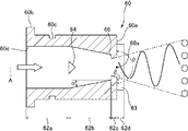
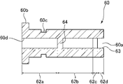
As shown in FIGS. 21 and 22, the vibration generating element 60 in the present embodiment has a different configuration of the first rectifying unit and the second rectifying unit from the first embodiment.

図21に示すように、振動発生素子60は概ね薄い直方体状の部材であり、その正面側の先端には長方形の吐水口60aが設けられ、背面側の端部には鍔部60bが形成されている。さらに、振動発生素子60の周囲を一周するように、鍔部60bと平行に溝60cが設けられている。 As shown in FIG. 21, the vibration generating element 60 is a generally thin rectangular parallelepiped member, a rectangular parallelepiped member 60a is provided at the tip on the front side thereof, and a flange portion 60b is formed at the end on the back side. ing. Further, a groove 60c is provided in parallel with the flange portion 60b so as to go around the vibration generating element 60.

図22Aに示すように、第1実施形態と同様に、振動発生素子60の内部には、長手方向に貫通するように長方形断面の通路が形成されている。この通路は、上流側から順に、給水通路62a、渦列通路62b、第1整流部62c、第2整流部62dとして形成されている。
これらのうち、給水通路62a、及び渦列通路62bの構成は、上述した第1実施形態と同様であるため説明を省略する。また、渦列通路62bと第1整流部62cの間には剥離部である段部66が形成されている。この段部66の構成も上述した第3実施形態と同様であるため説明を省略する。
As shown in FIG. 22A, similarly to the first embodiment, a passage having a rectangular cross section is formed inside the vibration generating element 60 so as to penetrate in the longitudinal direction. This passage is formed as a water supply passage 62a, a vortex train passage 62b, a first rectifying section 62c, and a second rectifying section 62d in order from the upstream side.
Of these, the configurations of the water supply passage 62a and the vortex train passage 62b are the same as those in the first embodiment described above, and thus the description thereof will be omitted. Further, a step portion 66, which is a peeling portion, is formed between the vortex street passage 62b and the first rectifying portion 62c. Since the configuration of the step portion 66 is the same as that of the third embodiment described above, the description thereof will be omitted.

第1整流部62cは、渦列通路62bと連なるように、渦列通路62bの下流側に設けられた長方形断面の通路である。また、第1整流部62cの対向する一対の壁面(両側壁面)は、下流側に向けて流路断面積が拡大するようにテーパして構成されている。即ち、第1整流部62cの幅は、下流側に向けて広くなるように構成されている。このように、渦列通路62bの側壁面に沿う流れを剥離させる段部66の下流側に、流路断面積が拡大するようにテーパした第1整流部62cが設けられているため、第1整流部62c内を流れる湯水は、その側壁面から剥離しやすい。しかしながら、このように形成された第1整流部62cによっても、振動平面内における湯水の流れの広がりを、第1整流部62cの広がり以下に抑制する作用がある。従って、本実施形態における第1整流部62cも、渦列通路62bを通過した湯水の流れの、振動平面に平行な方向の乱れ、及び振動平面に直交する方向の乱れを抑制する第1整流部として機能する。また、第1整流部62cのテーパ角度は比較的小さいため、第1整流部62cを構成する部材の肉厚が極端に薄くなることはない。 The first rectifying unit 62c is a passage having a rectangular cross section provided on the downstream side of the vortex train passage 62b so as to be connected to the vortex train passage 62b. Further, the pair of facing wall surfaces (wall surfaces on both sides) of the first rectifying unit 62c are tapered so that the cross-sectional area of the flow path expands toward the downstream side. That is, the width of the first rectifying unit 62c is configured to widen toward the downstream side. As described above, since the first rectifying portion 62c tapered so as to expand the cross-sectional area of the flow path is provided on the downstream side of the step portion 66 that separates the flow along the side wall surface of the vortex train passage 62b, the first The hot water flowing in the rectifying portion 62c easily separates from the side wall surface thereof. However, the first rectifying unit 62c formed in this way also has an effect of suppressing the spread of the flow of hot water in the vibration plane to be less than the spread of the first rectifying unit 62c. Therefore, the first rectifying unit 62c in the present embodiment also suppresses the turbulence of the flow of hot water passing through the spiral passage 62b in the direction parallel to the vibration plane and the turbulence in the direction orthogonal to the vibration plane. Functions as. Further, since the taper angle of the first rectifying unit 62c is relatively small, the wall thickness of the members constituting the first rectifying unit 62c does not become extremely thin.

第2整流部62dは、第1整流部62cと連なるように、第1整流部62cの下流側に設けられている。また、第2整流部62dは、第1整流部62cの流路の下流端よりも幅の広い、互いに平行に配置された2つの平面部63から構成されている。即ち、第2整流部62dは振動発生素子60の先端面60eから突出するように設けられている。第1整流部62cの側壁面は第2整流部62dにかけて、約250゜の折れ角βで先端面60eに連なり、湯水の流路は、広がり角=40゜の第1整流部62cから、振動平面内において広がり角θ=180゜で広がる第2整流部62dに接続される。この第2整流部62dの構成は、上述した第1実施形態と同様であるため、説明を省略する。 The second rectifying unit 62d is provided on the downstream side of the first rectifying unit 62c so as to be connected to the first rectifying unit 62c. Further, the second rectifying unit 62d is composed of two flat surfaces 63 arranged in parallel with each other, which are wider than the downstream end of the flow path of the first rectifying unit 62c. That is, the second rectifying unit 62d is provided so as to project from the tip surface 60e of the vibration generating element 60. The side wall surface of the first rectifying section 62c is connected to the tip surface 60e at a bending angle β of about 250 ° over the second rectifying section 62d, and the flow path of hot water vibrates from the first rectifying section 62c having a spreading angle of 40 °. It is connected to the second rectifying unit 62d that spreads in a plane with a spreading angle θ = 180 °. Since the configuration of the second rectifying unit 62d is the same as that of the first embodiment described above, the description thereof will be omitted.

なお、本実施形態においては、第2整流部62dの長さ(振動発生素子60の中心軸線A方向の長さ)は、第1整流部62cの通路の長さ(振動発生素子60の中心軸線A方向の長さ)の約1.5倍に形成されている。好ましくは、第2整流部62dの長さを、第1整流部62cの通路の長さの約0.25倍乃至約10倍に形成する。また、本実施形態においては、第2整流部62dの幅は、第1整流部62cの上流端における通路の幅の約2倍に形成されている。好ましくは、第2整流部62dの幅を、第1整流部62cの通路の幅の約1倍乃至約3倍に形成する。 In the present embodiment, the length of the second rectifying unit 62d (the length of the vibration generating element 60 in the central axis A direction) is the length of the passage of the first rectifying unit 62c (the central axis of the vibration generating element 60). It is formed to be about 1.5 times the length in the A direction). Preferably, the length of the second rectifying unit 62d is formed to be about 0.25 to about 10 times the length of the passage of the first rectifying unit 62c. Further, in the present embodiment, the width of the second rectifying unit 62d is formed to be about twice the width of the passage at the upstream end of the first rectifying unit 62c. Preferably, the width of the second rectifying unit 62d is formed to be about 1 to about 3 times the width of the passage of the first rectifying unit 62c.

また、給水通路62aの下流側端部(給水通路62aと渦列通路62bの接続部近傍)には、給水通路62aの流路断面の一部を閉塞するように、湯水衝突部64が設けられている。この湯水衝突部64の構成は、第1実施形態と同様であるので、説明を省略する。 Further, at the downstream end of the water supply passage 62a (near the connection portion between the water supply passage 62a and the vortex passage 62b), a hot water collision portion 64 is provided so as to block a part of the flow path cross section of the water supply passage 62a. ing. Since the configuration of the hot water collision portion 64 is the same as that of the first embodiment, the description thereof will be omitted.

振動発生素子60において、渦列通路62bの下流側の第1整流部62cに流入した湯水は、ここで振動平面(図22Aの紙面に平行な面)に平行な方向の乱れ、及び振動平面に直交する方向の乱れが抑制され、整流される。この第2整流部62cを通過した湯水は、第2整流部62dにおいて、振動平面に直交する方向の乱れのみが抑制され、整流される。また、第2整流部62dの幅(平面部63の幅)は、第1整流部62cの下流端における流路断面の幅よりも広く形成されている。このため、第1整流部62cから往復振動しながら吐出され、幅方向において第1整流部62cよりも外側に向けて吐出される湯水も2つの平面部63の間を通るので、このような湯水に対しても第2整流部62dは振動平面に直交する方向の乱れを抑制することができる。これにより、吐出される湯水の振動平面に直交する方向の広がりを、より効果的に抑制することができる。 In the vibration generating element 60, the hot water flowing into the first rectifying section 62c on the downstream side of the spiral passage 62b is turbulent in the direction parallel to the vibration plane (the plane parallel to the paper surface of FIG. 22A) and becomes the vibration plane. Disturbances in orthogonal directions are suppressed and rectified. The hot water that has passed through the second rectifying unit 62c is rectified by the second rectifying unit 62d by suppressing only the turbulence in the direction orthogonal to the vibration plane. Further, the width of the second rectifying unit 62d (the width of the flat surface portion 63) is formed to be wider than the width of the cross section of the flow path at the downstream end of the first rectifying unit 62c. Therefore, the hot water discharged from the first rectifying unit 62c while reciprocating and vibrating, and the hot water discharged outward from the first rectifying unit 62c in the width direction also passes between the two flat surface portions 63. However, the second rectifying unit 62d can suppress turbulence in the direction orthogonal to the vibration plane. As a result, the spread of the discharged hot water in the direction orthogonal to the vibration plane can be suppressed more effectively.

また、本実施形態における振動発生素子60についても、図11及び図12に示した変形例と同様の変更を行うことができる。即ち、本実施形態における振動発生素子60に対しても、第2整流部62dに側壁面(図示せず)を設けたり、平面部63がシャワーヘッド本体2の吐出開口部2aの縁に接するように振動発生素子60を配置することができる。即ち、第2整流部62dの幅は十分に広いため、第1整流部62cから往復振動しながら吐出される湯水と側壁面(図示せず)が干渉せず、吐出される湯水が側壁面に直接当たることはない。 Further, the vibration generating element 60 in the present embodiment can be changed in the same manner as the modified examples shown in FIGS. 11 and 12. That is, also for the vibration generating element 60 in the present embodiment, a side wall surface (not shown) is provided on the second rectifying unit 62d, or the flat surface portion 63 is in contact with the edge of the discharge opening 2a of the shower head main body 2. The vibration generating element 60 can be arranged in. That is, since the width of the second rectifying unit 62d is sufficiently wide, the hot water discharged from the first rectifying unit 62c while reciprocating and vibrating does not interfere with the side wall surface (not shown), and the discharged hot water is sent to the side wall surface. There is no direct hit.

以上、本発明の好ましい実施形態を説明したが、上述した実施形態に種々の変更を加えることができる。特に、上述した実施形態においては、本発明をシャワーヘッドに適用していたが、台所のシンクや洗面台等で使用する水栓装置や、便座等に備えられる温水洗浄装置等、任意の吐水装置に本発明を適用することができる。また、上述した実施形態においては、シャワーヘッドに複数の振動発生素子が備えられていたが、吐水装置には適用に応じて任意の個数の振動発生素子を備えることができ、単一の振動発生素子を備えた吐水装置を構成することもできる。 Although the preferred embodiment of the present invention has been described above, various modifications can be made to the above-described embodiment. In particular, in the above-described embodiment, the present invention has been applied to a shower head, but any water spouting device such as a faucet device used in a kitchen sink or a wash basin, a hot water washing device provided in a toilet seat, or the like. The present invention can be applied to. Further, in the above-described embodiment, the shower head is provided with a plurality of vibration generating elements, but the water discharge device can be provided with an arbitrary number of vibration generating elements depending on the application, and a single vibration generating element can be provided. A water discharge device including an element can also be configured.

なお、上述した本発明の実施形態において、振動発生素子内の通路について、便宜的に「幅」、「高さ」等の用語を用いて形状を説明したが、これらの用語は振動発生素子を設ける方向を規定するものではなく、振動発生素子は任意の方向に向けて使用することができる。例えば、上述した実施形態における「高さ」の方向を水平方向に向けて振動発生素子を使用することもできる。 In the above-described embodiment of the present invention, the shape of the passage in the vibration generating element has been described using terms such as "width" and "height" for convenience, but these terms refer to the vibration generating element. The direction of provision is not specified, and the vibration generating element can be used in any direction. For example, it is also possible to use the vibration generating element with the "height" direction in the above-described embodiment directed to the horizontal direction.

1 本発明の第1実施形態の吐水装置であるシャワーヘッド
2 シャワーヘッド本体
4 振動発生素子
4a 吐水口
4b 鍔部
4c 溝
4d 流入口
4e 先端面
6 通水路形成部材
6a シャワーホース接続部材
6b パッキン
8 振動発生素子保持部材
8a 素子挿入孔
10a 給水通路
10b 渦列通路
10c 第1整流部
10d 第2整流部
12 段部(剥離部)
13 平面部
14 湯水衝突部
30 振動発生素子
30a 吐水口
30b 鍔部
30c 溝
30d 流入口
30e 先端面
32a 給水通路
32b 渦列通路
32c 第1整流部
32d 第2整流部
32e テーパ部分
33 平面部
34 湯水衝突部
36 段部(剥離部)
38 振動発生素子
39 第2整流部
39a 側壁面
39b 基端壁面
40 振動発生素子
40a 吐水口
40b 鍔部
40c 溝
40d 流入口
40e 先端面
42a 給水通路
42b 渦列通路
42c 第1整流部
42d 第2整流部
43 平面部
44 湯水衝突部
46 段部(剥離部)
50 振動発生素子
50a 吐水口
50b 鍔部
50c 溝
50d 流入口
50e 先端面
52a 給水通路
52b 渦列通路
52c 第1整流部
52d 第2整流部
53 平面部
54 湯水衝突部
56 段部(剥離部)
60 振動発生素子
60a 吐水口
60b 鍔部
60c 溝
60d 流入口
60e 先端面
62a 給水通路
62b 渦列通路
62c 第1整流部
62d 第2整流部
63 平面部
64 湯水衝突部
66 段部(剥離部)
102 噴射ノズル
102a 噴射口
104 フィードバック流路
110 前室
110a 壁面
110b 壁面
112 出口
114 入口孔
116 障害物
1 Shower head which is a water discharge device according to the first embodiment of the present invention 2 Shower head main body 4 Vibration generator 4a Water discharge port 4b Flange 4c Groove 4d Inflow port 4e Tip surface 6 Water passage forming member 6a Shower hose connection member 6b Packing 8 Vibration generating element holding member 8a Element insertion hole 10a Water supply passage 10b Swirl passage 10c 1st rectifying part 10d 2nd rectifying part 12 steps (peeling part)
13 Flat surface 14 Hot water collision part 30 Vibration generating element 30a Spout 30b Border 30c Groove 30d Inflow port 30e Tip surface 32a Water supply passage 32b Swirl passage 32c 1st rectifying part 32d 2nd rectifying part 32e Tapered part 33 Flat part 34 Hot water Collision part 36 steps (peeling part)
38 Vibration generating element 39 Second rectifying part 39a Side wall surface 39b Base end wall surface 40 Vibration generating element 40a Spout 40b Border 40c Groove 40d Inflow port 40e Tip surface 42a Water supply passage 42b Swirl passage 42c First rectifying part 42d Second rectifying Part 43 Flat part 44 Hot water collision part 46 Step part (peeling part)
50 Vibration generating element 50a Water spout 50b Border 50c Groove 50d Inflow port 50e Tip surface 52a Water supply passage 52b Vortex passage 52c 1st rectifying part 52d 2nd rectifying part 53 Flat part 54 Hot water collision part 56 Step part (peeling part)
60 Vibration generating element 60a Water spout 60b Border 60c Groove 60d Inflow port 60e Tip surface 62a Water supply passage 62b Vortex passage 62c 1st rectifying part 62d 2nd rectifying part 63 Flat part 64 Hot water collision part 66 Step part (peeling part)
102 Injection nozzle 102a Injection port 104 Feedback flow path 110 Front chamber 110a Wall surface 110b Wall surface 112 Outlet 114 Inlet hole 116 Obstacle

Claims (6)

吐水口から湯水を往復振動させながら吐出させる吐水装置であって、
吐水装置本体と、
この吐水装置本体に設けられ、供給された湯水を所定の振動平面内で往復振動させながら吐出する振動発生素子と、を有し、
上記振動発生素子は、
上記吐水装置本体から供給された湯水が流入する給水通路と、
この給水通路の流路断面の一部を閉塞するように、上記給水通路の下流側端部に配置され、上記給水通路によって導かれた湯水が衝突することで、その下流側に交互に反対回りの渦を発生させる湯水衝突部と、
上記給水通路の下流側に設けられ、上記湯水衝突部により形成された渦をく渦列通路と、
この渦列通路の下流側に設けられ、上記振動平面と夫々平行に配置された2つの壁面、及び上記振動平面に対して直角に向けられた2つの側壁面によって囲まれ、上記渦列通路の上流端よりも幅の狭い通路である第1整流部と、
この第1整流部の下流側に設けられ第2整流部と、
を有し、
上記第2整流部は、上記振動平面と夫々平行に配置された2つの平面部のみから構成されていることを特徴とする吐水装置。
It is a water spouting device that discharges hot water from the spout while reciprocating and vibrating.
Water spouting device body and
It has a vibration generating element provided in the main body of the water discharge device and discharging the supplied hot water while reciprocally vibrating in a predetermined vibration plane.
The vibration generating element is
The water supply passage into which the hot water supplied from the water discharge device main body flows in, and
It is arranged at the downstream end of the water supply passage so as to block a part of the cross section of the flow path of the water supply passage, and when the hot water guided by the water supply passage collides with the water, it alternately turns in the opposite direction to the downstream side. The hot and cold water collision part that generates the vortex of
Is provided on the downstream side of the water supply passage, and Uzuretsu passage rather guide the vortices formed by the hot water collision portion,
The vortex passage is surrounded by two wall surfaces provided on the downstream side of the vortex passage and arranged parallel to the vibration plane and two side wall surfaces oriented at right angles to the vibration plane. The first vortex section, which is a passage narrower than the upstream end,
A second rectifying portion provided on the downstream side of the first rectifier,
Have a,
The second rectifying unit is a water discharge device characterized in that it is composed of only two flat surfaces arranged in parallel with the vibration plane.
上記第2整流部を構成する上記2つの平面部の幅は、上記第1整流部の下流端における幅よりも広く構成されている請求項1記載の吐水装置。 The water discharge device according to claim 1, wherein the width of the two flat surfaces constituting the second rectifying unit is wider than the width at the downstream end of the first rectifying unit. 吐水口から湯水を往復振動させながら吐出させる吐水装置であって、It is a water spouting device that discharges hot water from the spout while reciprocating and vibrating.
吐水装置本体と、 Water spouting device body and
この吐水装置本体に設けられ、供給された湯水を所定の振動平面内で往復振動させながら吐出する振動発生素子と、を有し、 It has a vibration generating element provided in the main body of the water discharge device and discharging the supplied hot water while reciprocally vibrating in a predetermined vibration plane.
上記振動発生素子は、 The vibration generating element is
上記吐水装置本体から供給された湯水が流入する給水通路と、 The water supply passage into which the hot water supplied from the water discharge device main body flows in, and
この給水通路の流路断面の一部を閉塞するように、上記給水通路の下流側端部に配置され、上記給水通路によって導かれた湯水が衝突することで、その下流側に交互に反対回りの渦を発生させる湯水衝突部と、 It is arranged at the downstream end of the water supply passage so as to block a part of the cross section of the flow path of the water supply passage, and when the hot water guided by the water supply passage collides with the water, it alternately turns in the opposite direction to the downstream side. The hot and cold water collision part that generates the vortex of
上記給水通路の下流側に設けられ、上記湯水衝突部により形成された渦を導く渦列通路と、 A vortex passage that is provided on the downstream side of the water supply passage and guides a vortex formed by the hot water collision portion, and a vortex passage that guides the vortex.
この渦列通路の下流側に設けられ、上記振動平面と夫々平行に配置された2つの壁面、及び上記振動平面に対して直角に向けられた2つの側壁面によって囲まれ、上記渦列通路の上流端よりも幅の狭い通路である第1整流部と、 The vortex passage is surrounded by two wall surfaces provided on the downstream side of the vortex passage and arranged parallel to the vibration plane and two side wall surfaces oriented at right angles to the vibration plane. The first vortex section, which is a passage narrower than the upstream end,
この第1整流部の下流側に設けられた第2整流部と、 The second rectifying unit provided on the downstream side of the first rectifying unit and
を有し、 Have,
上記第2整流部は、上記振動平面と夫々平行に配置された2つの壁面、及び上記振動平面に対して直角に向けられた2つの側壁面によって囲まれ、上記第1の整流部よりも幅が広い通路であることを特徴とする吐水装置。 The second rectifying unit is surrounded by two wall surfaces arranged parallel to the vibration plane and two side wall surfaces oriented at right angles to the vibration plane, and is wider than the first rectifying unit. A water spouting device characterized by a wide passage.
上記第2整流部の2つの側壁面は、上記第1整流部から吐出された湯水が干渉しない位置に設けられている請求項3記載の吐水装置。The water discharge device according to claim 3, wherein the two side wall surfaces of the second rectifying unit are provided at positions where the hot water discharged from the first rectifying unit does not interfere with each other. 上記渦列通路は、その幅が一定に構成され、上記第1整流部は、その幅が、上記渦列通路の幅よりも狭く形成されている請求項1乃至4の何れか1項に記載の吐水装置。 The first rectifying unit is formed according to any one of claims 1 to 4, wherein the width of the vortex passage is constant, and the width of the first rectifying unit is narrower than the width of the vortex passage. Water spouting device. 上記吐水装置本体は、上記振動発生素子の上記第2整流部を挿入するための吐出開口部を備え、上記振動発生素子は、上記第2整流部が上記吐出開口部の縁と接するように、上記吐水装置本体に取り付けられる請求項1乃至5の何れか1項に記載の吐水装置。 The water discharge device main body includes a discharge opening for inserting the second rectifying portion of the vibration generating element, and the vibration generating element is such that the second rectifying portion is in contact with the edge of the discharge opening. The water discharge device according to any one of claims 1 to 5, which is attached to the water discharge device main body.
JP2017065553A 2017-03-29 2017-03-29 Water spouting device Active JP6847397B2 (en)

Priority Applications (1)

Application Number Priority Date Filing Date Title
JP2017065553A JP6847397B2 (en) 2017-03-29 2017-03-29 Water spouting device

Applications Claiming Priority (1)

Application Number Priority Date Filing Date Title
JP2017065553A JP6847397B2 (en) 2017-03-29 2017-03-29 Water spouting device

Publications (2)

Publication Number Publication Date
JP2018167164A JP2018167164A (en) 2018-11-01
JP6847397B2 true JP6847397B2 (en) 2021-03-24

Family

ID=64019786

Family Applications (1)

Application Number Title Priority Date Filing Date
JP2017065553A Active JP6847397B2 (en) 2017-03-29 2017-03-29 Water spouting device

Country Status (1)

Country Link
JP (1) JP6847397B2 (en)

Families Citing this family (9)

* Cited by examiner, † Cited by third party
Publication number Priority date Publication date Assignee Title
JP7296224B2 (en) * 2019-03-15 2023-06-22 株式会社Lixil Dispensing device and dispensing system
US11739517B2 (en) 2019-05-17 2023-08-29 Kohler Co. Fluidics devices for plumbing fixtures
JP2021016747A (en) * 2019-07-24 2021-02-15 株式会社Lixil Discharge device and bathroom equipment
JP7356633B2 (en) * 2019-08-30 2023-10-05 Toto株式会社 Water discharging device
JP7519242B2 (en) * 2020-09-08 2024-07-19 株式会社Lixil Discharge Device
JP7668095B2 (en) * 2020-09-09 2025-04-24 株式会社Lixil Discharge Device
JP7523010B2 (en) * 2021-02-24 2024-07-26 Toto株式会社 Water discharge device
JP2023125078A (en) * 2022-02-28 2023-09-07 Toto株式会社 Water discharging device
WO2023106370A1 (en) * 2021-12-10 2023-06-15 Toto株式会社 Water discharging device

Family Cites Families (4)

* Cited by examiner, † Cited by third party
Publication number Priority date Publication date Assignee Title
US5035361A (en) * 1977-10-25 1991-07-30 Bowles Fluidics Corporation Fluid dispersal device and method
JPH0246802B2 (en) * 1977-12-09 1990-10-17 Piitaa Bauaa
JP2000027266A (en) * 1998-07-08 2000-01-25 Toto Ltd Human body washing nozzle
JP6048656B2 (en) * 2012-12-11 2016-12-21 パナソニックIpマネジメント株式会社 shower head

Also Published As

Publication number Publication date
JP2018167164A (en) 2018-11-01

Similar Documents

Publication Publication Date Title
JP6847397B2 (en) Water spouting device
JP6905205B2 (en) Water spouting device
TWI617274B (en) Spouting device
CN111032972A (en) Liquid Jet Shapers and Spray Shapers
JP6674621B2 (en) Water spouting device
EP3500372B1 (en) Shower head producing a suspension of water droplets in air
JP6681015B2 (en) Water discharge device
JP6688455B2 (en) shower head
JP6827647B2 (en) Water spouting device
WO2023106370A1 (en) Water discharging device
JP6236751B1 (en) Water discharge device
JP6674632B2 (en) Water spouting device
CN109972700B (en) Water discharge device
JPH0631994Y2 (en) Shower nozzle
JP6699072B2 (en) Water discharge device
JP2025068659A (en) Shower device
WO2017057327A1 (en) Water discharging device
JP2024095517A (en) Shower device
JP2025033117A (en) Water discharge device
JP2024095518A (en) Shower device
JP2023086504A (en) Water discharge device
JP2024095519A (en) Shower device

Legal Events

Date Code Title Description
A621 Written request for application examination

Free format text: JAPANESE INTERMEDIATE CODE: A621

Effective date: 20200120

A977 Report on retrieval

Free format text: JAPANESE INTERMEDIATE CODE: A971007

Effective date: 20201106

A131 Notification of reasons for refusal

Free format text: JAPANESE INTERMEDIATE CODE: A131

Effective date: 20201112

A521 Request for written amendment filed

Free format text: JAPANESE INTERMEDIATE CODE: A523

Effective date: 20210108

TRDD Decision of grant or rejection written
A01 Written decision to grant a patent or to grant a registration (utility model)

Free format text: JAPANESE INTERMEDIATE CODE: A01

Effective date: 20210201

A61 First payment of annual fees (during grant procedure)

Free format text: JAPANESE INTERMEDIATE CODE: A61

Effective date: 20210214

R150 Certificate of patent or registration of utility model

Ref document number: 6847397

Country of ref document: JP

Free format text: JAPANESE INTERMEDIATE CODE: R150