[第1実施形態]
以下、本発明の好適な実施の形態を図面に基づいて説明する。なお、遊技機の説明における前後左右とは、遊技中の遊技者から見た方向を指すものとする。
[First Embodiment]
Hereinafter, preferred embodiments of the present invention will be described with reference to the drawings. In the description of the game machine, the front, back, left, and right refer to the direction seen by the player during the game.
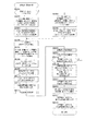
〔遊技機全体図〕
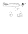
図1は、遊技機を説明する図である。
[Overall view of the game machine]
FIG. 1 is a diagram illustrating a game machine.
遊技機10は島設備に固定される枠11に、ヒンジを介して開閉回動自在に取り付けられる開閉枠を備える。開閉枠は、前面枠12(本体枠)及びガラス枠15によって構成されている。
The game machine 10 includes an opening / closing frame that is rotatably attached to the frame 11 fixed to the island equipment via a hinge. The opening / closing frame is composed of a front frame 12 (main body frame) and a glass frame 15.
前面枠12には、遊技盤30(図2参照)が配設されるとともに、遊技盤30の前面を覆うカバーガラス14を有するガラス枠15が取り付けられる。カバーガラス14は、遊技盤30に形成される遊技領域32(図2参照)を視認可能とする遊技視認領域として機能する。
A game board 30 (see FIG. 2) is arranged on the front frame 12, and a glass frame 15 having a cover glass 14 covering the front surface of the game board 30 is attached. The cover glass 14 functions as a game viewing area that makes the game area 32 (see FIG. 2) formed on the game board 30 visible.
前面枠12及びガラス枠15は、それぞれ個別に開放することが可能となっている。例えば、ガラス枠15のみを開放することで、遊技盤30の遊技領域32にアクセスすることができる。また、前面枠12をガラス枠15が開放されていない状態で開放することで、遊技盤30の裏面側に配設された遊技制御装置(主基板)100(図7参照)等にアクセスすることができる。
The front frame 12 and the glass frame 15 can be opened individually. For example, by opening only the glass frame 15, the game area 32 of the game board 30 can be accessed. Further, by opening the front frame 12 in a state where the glass frame 15 is not opened, the game control device (main board) 100 (see FIG. 7) and the like arranged on the back surface side of the game board 30 can be accessed. Can be done.
ガラス枠15のカバーガラス14周囲の縁部分には、種々の枠構成部材が配設されている。
Various frame constituent members are arranged on the edge portion around the cover glass 14 of the glass frame 15.
ガラス枠15の上部中央及び左側部には、遊技状態に応じて発光演出可能な装飾装置18a,18bが配設されている。装飾装置18a,18bは、内部にLED等の照明部材を収容しており、遊技状態に応じた発光演出を行う。これら装飾装置18a,18bの内部に配設される照明部材は、枠装飾装置18(図4参照)の一部を構成している。
Decorative devices 18a and 18b capable of producing light emission according to the game state are arranged in the upper center and the left side of the glass frame 15. The decoration devices 18a and 18b accommodate lighting members such as LEDs inside, and perform a light emitting effect according to the game state. The lighting members arranged inside the decorative devices 18a and 18b form a part of the frame decorative device 18 (see FIG. 4).
ガラス枠15の上右角部分及び上左角部分には、上スピーカ19aがそれぞれ配設される。これら上スピーカ19aとは別に遊技機10の下部には、2つの下スピーカ19bが設けられている。下スピーカ19bは、ガラス枠15の下左角部分及び前面枠12の下右角部分に配設されている。これら上スピーカ19a及び下スピーカ19bは、効果音や警報音、報知音等を発するものである。
An upper speaker 19a is arranged at the upper right corner portion and the upper left corner portion of the glass frame 15, respectively. Apart from these upper speakers 19a, two lower speakers 19b are provided at the lower part of the game machine 10. The lower speaker 19b is arranged in the lower left corner portion of the glass frame 15 and the lower right corner portion of the front frame 12. The upper speaker 19a and the lower speaker 19b emit sound effects, alarm sounds, notification sounds, and the like.
ガラス枠15の右側部には、遊技機10の上下方向に延設されるとともに、前方(遊技者側)に向かって突出する突出演出ユニット13が配設されている。突出演出ユニット13は、遊技の進行状態に応じて発光演出等を行う演出装置である。突出演出ユニット13の内部に配設される照明部材も枠装飾装置18(図4参照)の一部を構成している。
On the right side of the glass frame 15, a projecting effect unit 13 that extends in the vertical direction of the game machine 10 and projects forward (on the player side) is arranged. The protrusion effect unit 13 is an effect device that performs a light emission effect or the like according to the progress state of the game. The lighting member arranged inside the protrusion effect unit 13 also constitutes a part of the frame decoration device 18 (see FIG. 4).
ガラス枠15の下部には、遊技球を貯留可能な上皿21を有する上皿ユニットが取り付けられている。上皿21は、上面が開口した箱状に形成されている。上皿21に貯留されている遊技球は、一球ずつ球発射装置(図示省略)に供給される。
An upper plate unit having an upper plate 21 capable of storing game balls is attached to the lower part of the glass frame 15. The upper plate 21 is formed in a box shape with an open upper surface. The game balls stored in the upper plate 21 are supplied to the ball launcher (not shown) one by one.
上皿ユニットは、遊技者からの入力操作を受け付ける演出操作装置と、遊技者からの入力操作を受け付ける球貸操作装置と、遊技状態に応じて発光演出等を行う装飾装置22と、をさらに備える。
The upper plate unit further includes an effect operation device that receives an input operation from the player, a ball lending operation device that accepts an input operation from the player, and a decoration device 22 that performs a light emission effect or the like according to the game state. ..
演出操作装置は、演出ボタン25にタッチパネル25bを組み込んだ操作装置であり、遊技者が操作しやすいように上皿ユニットの上部中央に設けられている。
The effect operation device is an operation device in which the touch panel 25b is incorporated in the effect button 25, and is provided in the center of the upper part of the upper plate unit so that the player can easily operate it.
遊技者が演出操作装置を操作することによって、表示装置41(図2参照)に表示される特図変動表示ゲーム等において遊技者の操作を介入させた演出を行うことができる。例えば、演出パターン(演出態様)を選択したり、始動記憶に対応する変動表示ゲームの結果を事前に予告する予告演出を実行したりすることができる。なお、変動表示ゲームには特図変動表示ゲームが含まれ、単に変動表示ゲームとした場合には、本明細書では特図変動表示ゲームを指すものとする。
By operating the effect operation device by the player, it is possible to perform an effect in which the player's operation is intervened in the special figure variation display game or the like displayed on the display device 41 (see FIG. 2). For example, it is possible to select an effect pattern (effect mode) or execute a notice effect that announces the result of the variable display game corresponding to the start memory in advance. The variable display game includes a special figure variable display game, and when it is simply a variable display game, it is referred to as a special figure variable display game in this specification.
また、変動表示ゲームの実行中だけでなく、非実行中に遊技者が演出操作装置を操作することによっても演出パターンを変更するようにしてもよい。
Further, the effect pattern may be changed not only during the execution of the variable display game but also by the player operating the effect operation device during the non-execution.
なお、変動表示ゲームが実行される際の遊技状態は、複数の遊技状態からなる。通常遊技状態(通常状態)とは、特別な遊技状態が発生していない遊技状態である。また、特別な遊技状態とは、例えば、特定遊技状態としての時短状態や変動表示ゲームにおいて特別結果(例えば大当り)の発生確率が高い状態(確変状態、確率変動状態)、大当り状態(特別遊技状態)、小当り遊技状態(小当り状態)である。
The game state when the variable display game is executed consists of a plurality of game states. The normal gaming state (normal state) is a gaming state in which no special gaming state has occurred. Further, the special gaming state is, for example, a time saving state as a specific gaming state, a state in which the probability of occurrence of a special result (for example, a jackpot) is high (probability variation state, probability fluctuation state), or a jackpot state (special gaming state) in a variable display game. ), Small hit game state (small hit state).
ここで、確変状態(特定遊技状態)は、次の大当りが発生するまで継続するもの(ループタイプ)、所定回数の変動表示ゲームが実行されるまで継続するもの(回数切りタイプ、ST)、及び所定の確率転落抽選に当選するまで継続するもの(転落抽選タイプ)等がある。
Here, the probability change state (specific game state) continues until the next big hit occurs (loop type), continues until a predetermined number of variable display games are executed (number cut type, ST), and There are things that continue until a predetermined probability fall lottery is won (fall lottery type).
さらに、確変状態を発生させるか否かを大当り図柄乱数によって決定せずに、大当りが発生した場合に必ず確変状態を発生させるようにしてもよいし、特定領域を備える入賞装置等を設け、特定領域を遊技球が通過した場合に確変状態を発生させるようにしてもよい。
Further, it may be possible to always generate a probabilistic state when a big hit occurs without determining whether or not to generate a probabilistic state by a big hit symbol random number, or to provide a winning device or the like provided with a specific area to specify. A probabilistic state may be generated when the game ball passes through the area.
球貸操作装置は、遊技者が遊技球を借りる場合に操作する操作装置であって、上皿ユニットの上部右側に設けられている。球貸操作装置は、球貸ボタン27と、返却ボタン28と、残高表示部26と、を備えている。球貸ボタン27は遊技球を借りる場合に遊技者が操作するボタンであり、返却ボタン28は遊技機10に隣接するように配置されるカードユニット(図示省略)からプリペイドカード等を排出させる場合に遊技者が操作するボタンである。残高表示部26は、プリペイドカード等の残高が表示される表示領域である。
The ball lending operation device is an operation device operated when a player rents a game ball, and is provided on the upper right side of the upper plate unit. The ball lending operation device includes a ball lending button 27, a return button 28, and a balance display unit 26. The ball lending button 27 is a button operated by the player when renting a game ball, and the return button 28 is a button for ejecting a prepaid card or the like from a card unit (not shown) arranged adjacent to the game machine 10. It is a button operated by the player. The balance display unit 26 is a display area for displaying the balance of a prepaid card or the like.
装飾装置22は、内部にLED等の照明部材を収容しており、遊技状態に応じて発光演出等を行う装置であって、上皿ユニットの前側部分に設けられている。装飾装置22の内部に配設される照明部材は、枠装飾装置18(図4参照)の一部を構成している。
The decoration device 22 is a device that houses a lighting member such as an LED inside and performs a light emitting effect or the like according to a game state, and is provided on the front side portion of the upper plate unit. The lighting member arranged inside the decoration device 22 constitutes a part of the frame decoration device 18 (see FIG. 4).
上記した上皿ユニット等を備えるガラス枠15の下方であって、前面枠12の下部には、球発射装置(図示省略)の動作を制御するための操作ハンドル24と、遊技球を貯留可能な下皿23とが設けられている。
An operation handle 24 for controlling the operation of the ball launcher (not shown) and a game ball can be stored in the lower part of the front frame 12 below the glass frame 15 provided with the above-mentioned upper plate unit and the like. A lower plate 23 is provided.
操作ハンドル24は、前面枠12の右下部であって、右側の下スピーカ19bの下方に配置されている。遊技者が操作ハンドル24を回動操作することによって、球発射装置は上皿21から供給された遊技球を遊技盤30の遊技領域32に発射する。球発射装置から発射される遊技球の発射速度は、操作ハンドル24の回動操作量が大きくなるほど速くなるように設定されている。即ち、球発射装置は、遊技領域に遊技球を発射する勢(速度)である発射勢を、遊技者による操作ハンドル24の操作に対応して変更でき、発射勢の異なる種々の発射態様で遊技球を発射できる。発射態様には、遊技領域32の左側において遊技球を流下させる左打ち(通常打ち)と、遊技領域32の右側において遊技球を流下させる右打ちが含まれる。
The operation handle 24 is located at the lower right of the front frame 12 and below the lower speaker 19b on the right side. When the player rotates the operation handle 24, the ball launcher launches the game ball supplied from the upper plate 21 into the game area 32 of the game board 30. The rate of fire of the game ball launched from the ball launcher is set to increase as the amount of rotation of the operation handle 24 increases. That is, the ball launching device can change the firing force, which is the force (speed) for launching the game ball into the game area, in response to the operation of the operation handle 24 by the player, and the game can be played in various launch modes having different launching forces. Can fire a ball. The launch mode includes a left-handed hit (normal hit) in which the game ball is allowed to flow down on the left side of the game area 32, and a right-handed hit in which the game ball is caused to flow down on the right side of the game area 32.
下皿23は、上皿ユニットに対して所定の間隔をあけて、上皿ユニットの下方に配置されている。下皿23は、当該下皿23の底面を上下方向に貫通する球抜き穴23aと、球抜き穴23aを開閉するための開閉操作部23bと、を有している。遊技者が開閉操作部23bを操作して、球抜き穴23aを開くことによって、下皿23に貯留されていた遊技球を球抜き穴23aを通じて外部に排出することができる。
The lower plate 23 is arranged below the upper plate unit at a predetermined distance from the upper plate unit. The lower plate 23 has a ball extraction hole 23a that penetrates the bottom surface of the lower plate 23 in the vertical direction, and an opening / closing operation unit 23b for opening and closing the ball extraction hole 23a. When the player operates the opening / closing operation unit 23b to open the ball pulling hole 23a, the game ball stored in the lower plate 23 can be discharged to the outside through the ball pulling hole 23a.
〔遊技盤〕
続いて、図2Aを参照して、遊技機10の遊技盤30について説明する。図2Aは、遊技機10に備えられる遊技盤30の正面図である。
[Game board]
Subsequently, the game board 30 of the game machine 10 will be described with reference to FIG. 2A. FIG. 2A is a front view of the game board 30 provided in the game machine 10.
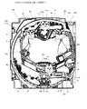
図2Aに示すように、遊技盤30は、各種部材の取付ベースとなる平板状の遊技盤本体30aを備える。遊技盤本体30aは木製又は合成樹脂製であって、当該遊技盤本体30aの前面にはガイドレール31で囲まれた遊技領域32が設けられている。遊技機10は、ガイドレール31で囲まれた遊技領域32内に球発射装置から遊技球を発射して遊技を行うように構成されている。遊技領域32には遊技球の流下方向を変換する部材として風車や障害釘等が配設されており、発射された遊技球はこれら部材により転動方向を変えながら遊技領域32を流下する。
As shown in FIG. 2A, the game board 30 includes a flat plate-shaped game board main body 30a that serves as a mounting base for various members. The game board main body 30a is made of wood or synthetic resin, and a game area 32 surrounded by a guide rail 31 is provided on the front surface of the game board main body 30a. The game machine 10 is configured to launch a game ball from a ball launcher into a game area 32 surrounded by a guide rail 31 to play a game. A windmill, an obstacle nail, or the like is arranged in the game area 32 as a member for changing the flow direction of the game ball, and the launched game ball flows down the game area 32 while changing the rolling direction by these members.
遊技領域32の略中央には、変動表示ゲームの表示領域となる窓部を形成するセンターケース(前面構成体)40が取り付けられている。センターケース40に形成された窓部の後方には、複数の識別情報を変動表示(可変表示)する演出表示装置(変動表示装置)としての表示装置41が配置されている。表示装置41は、例えば、液晶ディスプレイを備え、センターケース40の窓部を介して遊技盤30の前面側から表示内容が視認可能となるように配置される。なお、表示装置41は、液晶ディスプレイを備えるものに限らず、ELやCRT等のディスプレイを備えるものであってもよい。
A center case (front component) 40 that forms a window portion that serves as a display area for a variable display game is attached to substantially the center of the game area 32. Behind the window portion formed in the center case 40, a display device 41 as an effect display device (variable display device) that variablely displays (variablely displays) a plurality of identification information is arranged. The display device 41 is provided with, for example, a liquid crystal display, and is arranged so that the displayed contents can be visually recognized from the front side of the game board 30 through the window portion of the center case 40. The display device 41 is not limited to the one provided with a liquid crystal display, and may be provided with a display such as an EL or CRT.
表示装置41の表示画面(表示部)には、複数の変動表示領域が設けられており、各変動表示領域に識別情報(特別図柄)や変動表示ゲームを演出するキャラクタが表示される。その他、表示画面には遊技の進行に基づく画像(大当り表示やファンファーレ表示、エンディング表示等)が表示される。
A plurality of variable display areas are provided on the display screen (display unit) of the display device 41, and identification information (special symbol) and a character that directs the variable display game are displayed in each variable display area. In addition, images based on the progress of the game (big hit display, fanfare display, ending display, etc.) are displayed on the display screen.
また、センターケース40には、遊技領域32を流下する遊技球をセンターケース40の内側に導くためのワープ通路40eへの流入口40aと、ワープ通路40eを通過した遊技球が転動可能なステージ部40bとが設けられている。センターケース40のステージ部40bは、始動入賞口36及び普通変動入賞装置37の上方に配置されているため、ステージ部40b上で転動した遊技球は始動入賞口36又は普通変動入賞装置37に入賞しやすくなっている。
Further, in the center case 40, an inflow port 40a to the warp passage 40e for guiding the game ball flowing down the game area 32 to the inside of the center case 40, and a stage on which the game ball passing through the warp passage 40e can roll. A portion 40b is provided. Since the stage portion 40b of the center case 40 is arranged above the starting winning opening 36 and the normal variable winning device 37, the game ball rolled on the stage portion 40b is placed in the starting winning opening 36 or the normal variable winning device 37. It is easier to win a prize.
センターケース40の上部及び右側部には、それぞれ上部演出ユニット40c及び側部演出ユニット40dが設けられる。上部演出ユニット40c及び側部演出ユニット40dは、盤装飾装置46(図4参照)及び盤演出装置44(図4参照)の一部を構成している。
An upper effect unit 40c and a side effect unit 40d are provided on the upper part and the right side of the center case 40, respectively. The upper effect unit 40c and the side effect unit 40d form a part of the board decoration device 46 (see FIG. 4) and the board effect device 44 (see FIG. 4).
センターケース40の右側方の遊技領域32には、普通図柄始動ゲート(普図始動ゲート)34が設けられている。普図始動ゲート34の内部には、当該普図始動ゲート34を通過した遊技球を検出するためのゲートスイッチ(SW)34a(図3参照)が設けられている。遊技領域32内に打ち込まれた遊技球が普図始動ゲート34を通過すると、普図変動表示ゲームが実行される。
A normal symbol start gate (normal symbol start gate) 34 is provided in the game area 32 on the right side of the center case 40. Inside the normal drawing start gate 34, a gate switch (SW) 34a (see FIG. 3) for detecting a game ball that has passed through the normal drawing start gate 34 is provided. When the game ball driven into the game area 32 passes through the normal map start gate 34, the normal map variation display game is executed.
センターケース40の左下方の遊技領域32には一般入賞口35が配置されており、センターケース40の右下方の遊技領域32にも一般入賞口35が配置されている。これら一般入賞口35への遊技球の入賞は、一般入賞口35に備えられた入賞口スイッチ(SW)35a〜35n(図3参照)によって検出される。
A general winning opening 35 is arranged in the lower left game area 32 of the center case 40, and a general winning opening 35 is also arranged in the lower right game area 32 of the center case 40. The winning of the game ball into the general winning opening 35 is detected by the winning opening switches (SW) 35a to 35n (see FIG. 3) provided in the general winning opening 35.
センターケース40の下方の遊技領域32には、特図変動表示ゲームの開始条件を付与する始動入賞口(第1始動入賞領域)36が設けられ、その直下には第2始動入賞口(第2始動入賞領域)を備えた普通変動入賞装置37が設けられる。普通変動入賞装置37は、上端側が手前側に倒れる方向に回動することで、遊技球が流入し易い状態に変換する可動部材(可動片)37bを備える。可動部材37bが閉状態である場合には遊技球が普通変動入賞装置37に入賞できないようになっている。遊技球が始動入賞口36又は普通変動入賞装置37に入賞した場合には、補助遊技として特図変動表示ゲームが実行される。
In the game area 32 below the center case 40, a start winning opening (first starting winning area) 36 for giving a start condition for the special figure variation display game is provided, and a second starting winning opening (second start winning area) is provided immediately below the start winning opening (first starting winning area) 36. An ordinary variable winning device 37 provided with a starting winning area) is provided. The normal variable winning device 37 includes a movable member (movable piece) 37b that converts the game ball into a state in which the game ball easily flows in by rotating in a direction in which the upper end side falls toward the front side. When the movable member 37b is in the closed state, the game ball cannot win the normal variable winning device 37. When the game ball wins the starting winning opening 36 or the normal variable winning device 37, the special figure variable display game is executed as an auxiliary game.
可動部材37bは、所謂ベロ型の普通電動役物であり、普図変動表示ゲームの結果が所定の停止表示態様となった場合に、普電ソレノイド37c(図3参照)を介して回動して開いて、遊技球が普通変動入賞装置37に流入しやすい開状態(遊技者にとって有利な入賞容易状態)に変化する。
The movable member 37b is a so-called tongue-type ordinary electric accessory, and rotates via the normal electric solenoid 37c (see FIG. 3) when the result of the normal figure variation display game is in a predetermined stop display mode. It opens and changes to an open state (a state in which the game ball is easy to win, which is advantageous for the player), in which the game ball easily flows into the normally variable winning device 37.
なお、可動部材37bは、後述する遊技制御装置100によって制御される。遊技制御装置100は、普図変動表示ゲームの変動時間を短縮したり普図変動表示ゲームの当り確率を通常よりも高確率としたりすることで入賞容易状態の発生頻度を高めたり、通常遊技状態で発生する入賞容易状態よりも入賞容易状態の発生時間を長くしたりすることで、前述の特定遊技状態として時短状態(普電サポート状態)を発生させる。なお、確変状態(潜伏確変状態を除く)においても、重複して時短状態(普電サポート状態)が発生する。
The movable member 37b is controlled by the game control device 100, which will be described later. The game control device 100 increases the frequency of occurrence of a winning easy state by shortening the fluctuation time of the normal map variation display game and setting the hit probability of the normal map variation display game to a higher probability than usual, or a normal game state. By making the time for which the easy-to-win state occurs longer than the easy-to-win state that occurs in the above-mentioned specific game state, a time-saving state (general electric support state) is generated. In addition, even in the probabilistic state (excluding the latent probabilistic state), the time saving state (normal power support state) occurs in duplicate.
普通変動入賞装置37の右下方の遊技領域32には、大入賞口ソレノイド(39b)(図3参照)によって上端側が手前側に倒れる方向に回動することで大入賞口を開放するアタッカ形式の開閉扉39cを有する特別変動入賞装置39が設けられている。特別変動入賞装置39は、特図変動表示ゲームの結果によって大入賞口を閉じた状態(遊技者にとって不利な閉塞状態)から開放状態(遊技者にとって有利な特別遊技状態)に変換し、大入賞口内への遊技球の流入を容易にさせることで、遊技者に所定の遊技価値(賞球)を付与するようになっている。なお、大入賞口内には、当該大入賞口に入った遊技球を検出する検出手段としてカウントスイッチ39a(図3参照)が配設されている。また、特別変動入賞装置39の大入賞口内や大入賞口近傍(大入賞口の周囲)には、大入賞口を照らす1つ又は複数の大入賞口LED39d(フルカラーLED)が配設されている。
In the game area 32 at the lower right of the normal variable winning device 37, the large winning opening solenoid (39b) (see FIG. 3) rotates in the direction in which the upper end side falls toward the front side to open the large winning opening. A special variable winning device 39 having an opening / closing door 39c is provided. The special variable prize device 39 converts the large prize opening from a closed state (a closed state disadvantageous to the player) to an open state (a special game state advantageous to the player) according to the result of the special figure variation display game, and wins a large prize. By facilitating the inflow of game balls into the mouth, a predetermined game value (prize ball) is given to the player. A count switch 39a (see FIG. 3) is provided in the large winning opening as a detection means for detecting the game ball that has entered the large winning opening. In addition, one or a plurality of large winning openings LEDs 39d (full-color LEDs) that illuminate the large winning openings are arranged in the large winning opening of the special variable winning device 39 or in the vicinity of the large winning opening (around the large winning opening). ..
一般入賞口35、始動入賞口36、普通変動入賞装置37、及び特別変動入賞装置39の大入賞口に遊技球が入賞すると、払出制御装置200(図3参照)は、入賞した入賞口の種類に応じた数の賞球を払出装置から上皿21に排出する。また、普通変動入賞装置37の下方の遊技領域32には、入賞口等に入賞しなかった遊技球を回収するアウト口30bが設けられている。
When a game ball wins a prize in the general winning opening 35, the starting winning opening 36, the normal variable winning device 37, and the large winning opening of the special variable winning device 39, the payout control device 200 (see FIG. 3) determines the type of winning opening. The number of prize balls corresponding to the above is discharged from the payout device to the upper plate 21. Further, in the game area 32 below the normal variable winning device 37, an out port 30b for collecting game balls that have not won a prize in the winning opening or the like is provided.
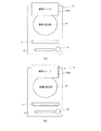
また、遊技領域32の外側であって遊技盤本体30aの右下角部には、特図変動表示ゲーム(特図1変動表示ゲーム、特図2変動表示ゲーム)及び普図変動表示ゲームを実行する一括表示装置50が設けられている。一括表示装置50は、現在の遊技状態等の情報を表示する表示部51〜60を備える(図2B参照)。
Further, a special figure variation display game (special figure 1 variation display game, special figure 2 variation display game) and a normal figure variation display game are executed in the lower right corner of the game board main body 30a outside the game area 32. A batch display device 50 is provided. The batch display device 50 includes display units 51 to 60 that display information such as the current gaming state (see FIG. 2B).
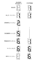
図2Bは、一括表示装置50の構成を示す図である。一括表示装置50は、7セグメント型の表示器(LEDランプ)等で構成された変動表示ゲーム用の第1特図変動表示部51(特図1表示器、ランプD1)及び第2特図変動表示部52(特図2表示器、ランプD2)と、普図変動表示ゲーム用の変動表示部53(普図表示器、ランプD8、D10、D18)と、各変動表示ゲームの始動(保留)記憶数報知用の記憶表示部(特図1保留表示器54、特図2保留表示器55、普図保留表示器56)と、を有している。特図1保留表示器54はランプD11、D12により構成される。特図2保留表示器55は、ランプD13、D14により構成される。普図保留表示器56は、ランプD15、D16により構成される。
FIG. 2B is a diagram showing the configuration of the batch display device 50. The batch display device 50 includes a first special figure fluctuation display unit 51 (special figure 1 display, lamp D1) and a second special figure fluctuation for a fluctuation display game composed of a 7-segment type display (LED lamp) and the like. Display unit 52 (special figure 2 display, lamp D2), variable display unit 53 for normal figure variable display game (normal figure display, lamps D8, D10, D18), and start (hold) of each variable display game. It has a storage display unit (special figure 1 hold display 54, special figure 2 hold display 55, normal figure hold display 56) for notifying the number of stored figures. Special figure 1 The hold indicator 54 is composed of lamps D11 and D12. The special figure 2 hold indicator 55 is composed of lamps D13 and D14. The normal figure hold indicator 56 is composed of lamps D15 and D16.
また、一括表示装置50には、右打ち時(右打ちすべき時)又は左打ち時(通常打ち時)であることを報知する第1遊技状態表示部57(第1遊技状態表示器、ランプD7)、時短状態が発生すると点灯して時短状態発生を報知する第2遊技状態表示部58(第2遊技状態表示器、ランプD17)、遊技機10の電源投入時に大当りの確率状態が高確率状態となっていることを表示する第3遊技状態表示部59(第3遊技状態表示器、確率状態表示部、ランプD9)、大当り時のラウンド数(特別変動入賞装置39の開閉回数)を表示するラウンド表示部60(ランプD3−D6)が設けられている。
Further, the batch display device 50 is provided with a first game status display unit 57 (first game status indicator, lamp) that notifies that it is a right-handed hit (when it should be right-handed) or a left-handed hit (when it should be hit normally). D7), the second game state display unit 58 (second game state display, lamp D17) that lights up when a time saving state occurs to notify the occurrence of the time saving state, and the probability state of a big hit when the power of the game machine 10 is turned on is high. The third game status display unit 59 (third game status display, probability status display unit, lamp D9) that displays the status, and the number of rounds at the time of a big hit (the number of times the special variable winning device 39 is opened and closed) are displayed. A round display unit 60 (lamps D3-D6) is provided.
特図1表示器51と特図2表示器52において、変動表示ゲームは、識別情報(例えば、中央のセグメント)の点灯消灯(点滅)を繰り返す変動表示によって実行される。なお、特図1表示器51、特図2表示器52は、このようなセグメント型の表示部に限らず、複数のLEDの集合体により構成されていてもよいし、変動表示を実行する場合に、表示器として設けられるすべてのLEDにより全点灯全消灯(全LEDの同時点滅)や、循環点灯(何れか1のLEDから所定時間毎に所定の順序で点灯し、消灯する)、または複数のLEDのうちの所定数のLEDによる点灯消灯(点滅)や循環点灯によって行ってもよい。普図表示器53においても、変動表示ゲームは、ランプD10、D18の点灯消灯を繰り返す変動表示(点滅)によって実行される。また、普図表示器53も特図1表示器51、特図2表示器52と同様に適宜構成することが可能である。
In the special figure 1 display 51 and the special figure 2 display 52, the variation display game is executed by the variation display in which the identification information (for example, the central segment) is repeatedly turned on and off (blinking). The special figure 1 display 51 and the special figure 2 display 52 are not limited to such a segment type display unit, and may be composed of an aggregate of a plurality of LEDs, or when a variable display is executed. In addition, all the LEDs provided as indicators turn on and off all (simultaneous blinking of all LEDs), circular lighting (turns on and off in a predetermined order from any one LED at predetermined time intervals), or a plurality of LEDs. It may be performed by turning on / off (blinking) or circulating lighting by a predetermined number of LEDs among the LEDs. Also in the normal diagram display 53, the variation display game is executed by the variation display (blinking) in which the lamps D10 and D18 are repeatedly turned on and off. Further, the normal figure display 53 can be appropriately configured in the same manner as the special figure 1 display 51 and the special figure 2 display 52.
ランプ表示装置80は、図柄(後述の第四特別図柄)として点灯表示と消灯表示を繰り返す変動表示(点滅)を実行するランプ表示部1、2(LED)と、各特図変動表示ゲームの始動(保留)記憶数報知用のランプ表示部3−6(LED)を有する。なお、ランプ表示装置80は、演出制御装置300(後述)で制御される。
The lamp display device 80 includes lamp display units 1 and 2 (LEDs) that execute variable display (blinking) that repeats lighting display and extinguishing display as a symbol (fourth special symbol described later), and start of each special figure variation display game. (Hold) It has a lamp display unit 3-6 (LED) for notifying the number of stored items. The lamp display device 80 is controlled by the effect control device 300 (described later).
ランプ表示部1、2は、変動表示として所定の点滅周期(例えば200msec(ミリ秒))で点滅する。一括表示装置50の特図1表示器51、特図2表示器52、普図表示器53における変動表示の変動時間が遊技制御装置100で計測されるのに対して、ランプ表示装置80のランプ表示部1、2の変動時間は演出制御装置300(後述)で計測される。
The lamp display units 1 and 2 blink at a predetermined blinking cycle (for example, 200 msec (millisecond)) as a variable display. While the fluctuation time of the fluctuation display on the special figure 1 display 51, the special figure 2 display 52, and the general figure display 53 of the batch display device 50 is measured by the game control device 100, the lamp of the lamp display device 80 The fluctuation time of the display units 1 and 2 is measured by the effect control device 300 (described later).
ランプ表示部3、4(特図1保留LED1、特図1保留LED2)は、消灯状態、点灯状態、点滅状態の組合せによって、特図1保留数(第1始動記憶数)を表示する。同様に、ランプ表示部5、6(特図2保留LED1、特図2保留LED2)は、消灯状態、点灯状態、点滅状態の組合せによって、特図2保留数(第2始動記憶数)を表示する。ランプ表示部3−6は、大当り発生により保留数の表示を終了するが、大当り状態中以外の場合(表示装置41で後述のリーチが発生している場合も含む)では、保留数の表示を行う。
The lamp display units 3 and 4 (special figure 1 hold LED 1, special figure 1 hold LED 2) display the special figure 1 hold number (first start memory number) according to the combination of the off state, the lit state, and the blinking state. Similarly, the lamp display units 5 and 6 (special figure 2 hold LED 1, special figure 2 hold LED 2) display the special figure 2 hold number (second start memory number) depending on the combination of the off state, the lit state, and the blinking state. To do. The lamp display unit 3-6 ends the display of the number of holds due to the occurrence of a big hit, but displays the number of holds when the display device 41 is not in the state of a big hit (including the case where the display device 41 has a reach described later). Do.
次に、遊技機10における遊技の流れ、普図変動表示ゲーム及び特図変動表示ゲームの詳細について説明する。
Next, the flow of the game in the game machine 10, the normal map variation display game, and the special map variation display game will be described in detail.
遊技機10では、図示しない球発射装置から遊技領域32に向けて遊技球が打ち出されることによって遊技が行われる。打ち出された遊技球は、遊技領域32内の各所に配置された障害釘や風車等によって転動方向を変えながら遊技領域32を流下し、普図始動ゲート34、一般入賞口35、始動入賞口36、普通変動入賞装置37、又は特別変動入賞装置39に入賞するか、遊技領域32の最下部に設けられたアウト口30bへ流入し、遊技領域32から排出される。そして、一般入賞口35、始動入賞口36、普通変動入賞装置37、又は特別変動入賞装置39に遊技球が入賞すると、入賞した入賞口の種類に応じた数の賞球が払出装置を介して上皿21に排出される。
In the game machine 10, a game is performed by launching a game ball toward the game area 32 from a ball launching device (not shown). The launched game ball flows down the game area 32 while changing the rolling direction by obstacle nails, windmills, etc. arranged in various places in the game area 32, and the normal drawing start gate 34, the general winning opening 35, and the starting winning opening. 36, the normal variable winning device 37, or the special variable winning device 39 is won, or the ball flows into the out port 30b provided at the bottom of the game area 32 and is discharged from the game area 32. Then, when a game ball wins a general winning opening 35, a starting winning opening 36, a normal variable winning device 37, or a special variable winning device 39, a number of winning balls corresponding to the type of winning winning opening is dispensed through the payout device. It is discharged to the upper plate 21.
普図始動ゲート34には、当該普図始動ゲート34を通過した遊技球を検出するゲートスイッチ34a(図3参照)が設けられている。遊技球が普図始動ゲート34を通過すると、ゲートスイッチ34aによって検出され、このときに抽出された当り判定用乱数値の判定結果に基づき普図変動表示ゲームが実行される。
The normal drawing start gate 34 is provided with a gate switch 34a (see FIG. 3) for detecting a game ball that has passed through the normal drawing start gate 34. When the game ball passes through the normal map start gate 34, it is detected by the gate switch 34a, and the normal map variation display game is executed based on the determination result of the hit determination random number value extracted at this time.
普図変動表示ゲームを開始できない状態、例えば、既に普図変動表示ゲームが行われており当該普図変動表示ゲームが終了していない場合や、普図変動表示ゲームの結果が当りとなって普通変動入賞装置37が開放状態に変換されている場合に、遊技球が普図始動ゲート34を通過すると、普図始動記憶数が上限数未満ならば当該記憶数が加算(+1)される。
A state in which the normal map fluctuation display game cannot be started, for example, when the normal map variable display game has already been played and the normal map variable display game has not ended, or when the result of the normal map variable display game is a hit, it is normal. When the game ball passes through the normal drawing start gate 34 when the variable winning device 37 is converted to the open state, the storage number is added (+1) if the normal drawing start storage number is less than the upper limit number.
普図始動記憶には普図変動表示ゲームの当りはずれを決定するための当り判定用乱数値が記憶されており、この当り判定用乱数値が判定値と一致した場合に、当該普図変動表示ゲームが当りとなって特定の結果態様(特定結果)が導出される。
The hit judgment random value for determining the hit / miss of the normal figure fluctuation display game is stored in the normal figure start memory, and when the hit judgment random value matches the judgment value, the normal figure change display is displayed. The game wins and a specific result mode (specific result) is derived.
普図変動表示ゲームは、一括表示装置50に設けられた普図表示器53で実行されるようになっている。普図表示器53は、普通識別情報(普図)として点灯状態の場合に当りを示し、消灯状態の場合にはずれを示すLEDから構成され、このLEDを点滅表示することで普通識別情報の変動表示を行い、所定の変動表示時間の経過後、LEDを点灯又は消灯することで結果を表示するようになっている。
The normal map variation display game is executed by the normal map display 53 provided in the batch display device 50. The normal figure display 53 is composed of LEDs that indicate a hit when the normal identification information (normal figure) is lit and a deviation when the normal identification information (normal figure) is off, and the normal identification information fluctuates by blinking the LED. The display is performed, and after a predetermined variation display time has elapsed, the result is displayed by turning on or off the LED.
普図始動ゲート34通過時に抽出された普図乱数値が当り値である場合には、普図表示器53に表示される普通図柄が当り状態で停止し、当り状態となる。このとき、普電ソレノイド37c(図3参照)が駆動されることにより、可動部材37bが所定の時間(例えば0.3秒間)だけ開状態に変換され、普通変動入賞装置37への遊技球の入賞が許容される。
When the normal figure random value extracted when passing through the normal figure start gate 34 is a hit value, the normal symbol displayed on the normal figure display 53 stops in the hit state and becomes the hit state. At this time, by driving the normal electric solenoid 37c (see FIG. 3), the movable member 37b is converted into the open state for a predetermined time (for example, 0.3 seconds), and the game ball to the normal variable winning device 37 Winning is allowed.
遊技球の始動入賞口36への入賞及び普通変動入賞装置37への入賞は、始動口1スイッチ36a(図3参照)及び始動口2スイッチ37a(図3参照)によって検出される。始動入賞口36に入賞した遊技球は特図1変動表示ゲームの始動入賞球として検出され、所定の上限数を限度に記憶されるとともに、普通変動入賞装置37に入賞した遊技球は特図2変動表示ゲームの始動入賞球として検出され、所定の上限数を限度に記憶される。
The winning of the game ball to the starting winning opening 36 and the winning of the ordinary variable winning device 37 are detected by the starting opening 1 switch 36a (see FIG. 3) and the starting opening 2 switch 37a (see FIG. 3). The game ball that has won the start winning opening 36 is detected as the start winning ball of the special figure 1 variable display game, and is stored up to a predetermined upper limit, and the game ball that has won the normal variable winning device 37 is special figure 2. It is detected as a start winning ball of a variable display game, and is stored up to a predetermined upper limit.
特図変動表示ゲームの始動入賞球の検出時には、大当り乱数値や大当り図柄乱数値、各変動パターン乱数値等が抽出される。これら乱数値は、遊技制御装置100の特図保留記憶領域(RAMの一部)に特図始動入賞記憶として各々所定回数分(例えば最大で8回分)を限度に記憶される。特図始動入賞記憶の記憶数は、一括表示装置50の始動入賞数報知用の特図1保留表示器54や特図2保留表示器55に表示されるとともに、表示装置41の表示画面にも表示される。
When the start winning ball of the special figure fluctuation display game is detected, the jackpot random number value, the jackpot symbol random value, each fluctuation pattern random value, and the like are extracted. These random numbers are stored in the special figure reservation storage area (a part of the RAM) of the game control device 100 as the special figure start winning memory for a predetermined number of times (for example, up to 8 times). The number of special figure start prize memories stored is displayed on the special figure 1 hold display 54 and the special figure 2 hold display 55 for notifying the start prize number of the batch display device 50, and is also displayed on the display screen of the display device 41. Is displayed.
遊技制御装置100は、始動入賞口36への入賞若しくは第1始動記憶に基づいて、特図1表示器51で特図1変動表示ゲームを実行する。また、遊技制御装置100は、普通変動入賞装置37への入賞若しくは第2始動記憶に基づいて、特図2表示器52で特図2変動表示ゲームを実行する。
The game control device 100 executes the special figure 1 variation display game on the special figure 1 display 51 based on the winning of the start winning opening 36 or the first start memory. Further, the game control device 100 executes the special figure 2 variable display game on the special figure 2 display 52 based on the winning of the normal variable winning device 37 or the second start memory.
特図1変動表示ゲーム(第1特図変動表示ゲーム)及び特図2変動表示ゲーム(第2特図変動表示ゲーム)は、特図1表示器51及び特図2表示器52において識別情報(特別図柄、特図)を変動表示した後に所定の結果態様を停止表示することで行われる。また、表示装置41では、各特図変動表示ゲームに対応して複数種類の識別情報(例えば、数字、記号、キャラクタ図柄など)を変動表示させる飾り特図変動表示ゲームが実行される。
The special figure 1 variable display game (1st special figure variable display game) and the special figure 2 variable display game (2nd special figure variable display game) have identification information (identification information) on the special figure 1 display 51 and the special figure 2 display 52. This is performed by displaying the special symbol (special symbol) in a variable manner and then stopping and displaying the predetermined result mode. Further, the display device 41 executes a decorative special figure variation display game in which a plurality of types of identification information (for example, numbers, symbols, character symbols, etc.) are variablely displayed corresponding to each special figure variation display game.
表示装置41における飾り特図変動表示ゲームは、前述した数字等で構成される飾り特別図柄(識別情報)が左(第一特別図柄)、右(第二特別図柄)、中(第三特別図柄)の順に変動表示(スクロール表示)を開始して、所定時間後に変動している図柄を順次停止させて、特図変動表示ゲームの結果を表示することで行われる。また、表示装置41では、興趣向上のためにキャラクタの出現等の多様な演出表示が行われる。さらに、飾り特図変動表示ゲームでは、他の飾り特別図柄(識別情報)として、ランプ表示装置80のランプ表示部1、2において、点灯表示と消灯表示の繰り返し(点滅)によって第四特別図柄が変動する。ランプ表示部1、2の変動表示は、開始から所定時間後に、はずれの場合は「消灯」、大当りもしくは小当りの場合は「点灯」で停止する。
In the decorative special symbol variation display game on the display device 41, the decorative special symbol (identification information) composed of the above-mentioned numbers and the like is left (first special symbol), right (second special symbol), and middle (third special symbol). ) Is started, the fluctuating symbols are sequentially stopped after a predetermined time, and the result of the special figure fluctuation display game is displayed. In addition, the display device 41 performs various effect displays such as the appearance of characters in order to improve the interest. Further, in the decorative special symbol variation display game, as another decorative special symbol (identification information), the fourth special symbol is displayed by repeating (blinking) the lighting display and the extinguishing display on the lamp display units 1 and 2 of the lamp display device 80. fluctuate. The fluctuation display of the lamp display units 1 and 2 is stopped after a predetermined time from the start by "turning off" in the case of a miss and "lighting" in the case of a big hit or a small hit.
始動入賞口36又は普通変動入賞装置37への遊技球の入賞が所定のタイミングでなされた場合(入賞検出時の大当り乱数値が大当り値である場合)には、特図変動表示ゲームの結果として表示図柄により特定の結果態様(特別結果態様)が導出され、大当り状態(特別遊技状態)となる。これに対応して、表示装置41の表示態様は特別結果態様(例えば「7,7,7」等の数字が揃った状態)となる。
When the game ball is won in the starting winning opening 36 or the normal variable winning device 37 at a predetermined timing (when the big hit random value at the time of winning detection is the big hit value), as a result of the special figure variation display game. A specific result mode (special result mode) is derived from the displayed symbol, and a jackpot state (special game state) is set. Correspondingly, the display mode of the display device 41 becomes a special result mode (for example, a state in which numbers such as "7, 7, 7" are aligned).
このとき、特別変動入賞装置39は、大入賞口ソレノイド(39b)(図3参照)への通電によって、大入賞口が所定の時間(例えば30秒)だけ閉状態から開状態に変換される。すなわち、特別変動入賞装置39に備えられた大入賞口が所定の時間又は所定数の遊技球が入賞するまで大きく開き、この間遊技者は多くの遊技球を獲得することができるという特典が付与される。
At this time, the special variable winning device 39 is converted from the closed state to the open state for a predetermined time (for example, 30 seconds) by energizing the large winning opening solenoid (39b) (see FIG. 3). That is, the large winning opening provided in the special variable winning device 39 opens wide until a predetermined time or a predetermined number of game balls are won, during which the player is given the privilege of being able to acquire a large number of game balls. To.
第1始動入賞口36又は普通変動入賞装置37への遊技球の入賞が所定のタイミングでなされた場合(入賞検出時の大当り乱数値が小当り値である場合)には、特図変動表示ゲームの結果として表示図柄により特定結果態様(小当り結果態様)が導出され、小当り状態となる。これに対応して、表示装置41の表示態様は小当り結果態様となる。なお、本実施形態では、小当りの判定にも大当り乱数値が使用されるが、小当り値(小当り判定値)は、大当り値(大当り判定値)と異なる。
When the game ball is won in the first starting winning opening 36 or the normal variable winning device 37 at a predetermined timing (when the big hit random value at the time of winning detection is the small hit value), the special figure variation display game As a result of, a specific result mode (small hit result mode) is derived from the displayed symbol, and the small hit state is obtained. Correspondingly, the display mode of the display device 41 becomes a small hit result mode. In the present embodiment, the big hit random value is also used for the small hit determination, but the small hit value (small hit determination value) is different from the big hit value (big hit determination value).
このとき、特別変動入賞装置39は、大入賞口ソレノイド39b(図3参照)への通電によって、大入賞口が所定の短時間だけ閉状態から開状態に変換される。なお、大入賞口の全開放時間は、小当り状態(小当り遊技状態)の方が大当り状態(特別遊技状態)よりも短いため、小当り状態では大当り状態よりも遊技者が獲得可能な遊技価値(獲得球数)が少ない。なお、小当り状態と大当り状態では両方とも大入賞口が開放状態となるが、大当り状態を第1特別遊技状態と呼び、小当り状態を第2特別遊技状態と呼んでもよい。
At this time, the special variable winning device 39 changes the large winning opening from the closed state to the open state for a predetermined short time by energizing the large winning opening solenoid 39b (see FIG. 3). Since the full opening time of the big winning opening is shorter in the small hit state (small hit game state) than in the big hit state (special game state), the game that the player can acquire in the small hit state than in the big hit state. The value (number of balls acquired) is small. In both the small hit state and the big hit state, the big winning opening is open, but the big hit state may be called the first special gaming state, and the small hit state may be called the second special gaming state.
ここで、大当りと小当りとの違いについて説明する。
Here, the difference between a big hit and a small hit will be described.
大当りとは条件装置の作動を伴う特別結果であり、小当りとは条件装置の作動を伴わない特定結果である。条件装置とは、特図変動表示ゲームで大当りが発生(大当り図柄の停止表示)した場合に作動するもので、条件装置が作動するとは、例えば大当り状態が発生して特別電動役物としての特別変動入賞装置39を連続して作動させるための特定のフラグがセットされることを意味する。条件装置が作動しないとは、例えば小当り抽選に当選した場合のように上述の特定のフラグがセットされないことを意味する。なお、「条件装置」は、上記のようなソフトウェア的にオンオフされるフラグのようなソフトウェア手段であっても良いし、電気的にオンオフされるスイッチのようなハードウェア手段であっても良い。また、「条件装置」は、その作動が電動役物の連続作動に必要条件とされる装置として、パチンコ遊技機の分野においては一般的に使用されている用語であり、本明細書においても同様の意味を有する用語として使用している。
A big hit is a special result with the operation of the condition device, and a small hit is a specific result without the operation of the condition device. The condition device operates when a big hit occurs (stop display of the big hit symbol) in the special figure fluctuation display game, and when the condition device operates, for example, a big hit state occurs and it is special as a special electric accessory. It means that a specific flag for continuously operating the variable winning device 39 is set. The fact that the condition device does not operate means that the above-mentioned specific flag is not set as in the case of winning a small hit lottery, for example. The "conditional device" may be a software means such as a flag that is turned on / off by software as described above, or a hardware means such as a switch that is turned on / off electrically. Further, "conditional device" is a term generally used in the field of pachinko gaming machines as a device whose operation is a necessary condition for continuous operation of an electric accessory, and the same applies to this specification. It is used as a term that has the meaning of.
具体的には、大当りの場合は、大当りフラグが設定されることにより特別変動入賞装置が開放されるのに対して、小当りの場合は、小当りフラグが設定されることにより特別変動入賞装置が開放される。
Specifically, in the case of a big hit, the special variable winning device is opened by setting the big hit flag, whereas in the case of a small hit, the special variable winning device is set by setting the small hit flag. Is released.
なお、特図1表示器51及び特図2表示器52は、別々の表示器として構成してもよいし同一の表示器として構成してもよいが、各特図変動表示ゲームが同時に実行されないように設定される。
The special figure 1 display 51 and the special figure 2 display 52 may be configured as separate indicators or the same indicator, but the special figure variation display games are not executed at the same time. Is set.
表示装置41における飾り特図変動表示ゲームについては、特図1変動表示ゲームと特図2変動表示ゲームとを別々の表示装置や別々の表示領域で実行するようにしてもよいし、同一の表示装置や表示領域で実行するようにしてもよい。この場合、特図1変動表示ゲーム及び特図2変動表示ゲームに対応する飾り特図変動表示ゲームが同時に実行されないようにする。なお、特図2変動表示ゲームは、特図1変動表示ゲームよりも優先して実行されるようになっており、特図1変動表示ゲームと特図2変動表示ゲームの始動記憶があり、特図変動表示ゲームの実行が可能な状態になった場合は特図2変動表示ゲームが実行される。
Regarding the decorative special figure variable display game in the display device 41, the special figure 1 variable display game and the special figure 2 variable display game may be executed in different display devices or different display areas, or the same display may be executed. It may be executed in the device or the display area. In this case, the decorative special figure variable display game corresponding to the special figure 1 variable display game and the special figure 2 variable display game is prevented from being executed at the same time. The special figure 2 variable display game is executed with priority over the special figure 1 variable display game, and there is a memory of starting the special figure 1 variable display game and the special figure 2 variable display game. When the figure variation display game can be executed, the special figure 2 variation display game is executed.
なお、以下の説明において、特図1変動表示ゲームと特図2変動表示ゲームを区別しない場合は、単に特図変動表示ゲームと称する。
In the following description, when the special figure 1 variable display game and the special figure 2 variable display game are not distinguished, they are simply referred to as a special figure variable display game.
また、特に限定されるわけではないが、上記始動入賞口36内の始動口1スイッチ36a、普通変動入賞装置37内の始動口2スイッチ37a、ゲートスイッチ34a、入賞口スイッチ35a、カウントスイッチ(39a)には、磁気検出用のコイルを備え該コイルに金属が近接すると磁界が変化する現象を利用して遊技球を検出する非接触型の磁気近接センサ(以下、近接スイッチと称する)が使用されている。また、遊技機10のガラス枠15等に設けられたガラス枠開放検出スイッチ63や前面枠(遊技枠)12等に設けられた前面枠開放検出スイッチ64(本体枠開放検出スイッチ)には、機械的な接点を有するマイクロスイッチを用いることができる。
Further, although not particularly limited, the starting port 1 switch 36a in the starting winning port 36, the starting port 2 switch 37a in the normal variable winning device 37, the gate switch 34a, the winning port switch 35a, and the count switch (39a). ) Uses a non-contact magnetic proximity sensor (hereinafter referred to as a proximity switch) which is provided with a coil for magnetic detection and detects a game ball by utilizing the phenomenon that the magnetic field changes when a metal approaches the coil. ing. Further, the glass frame opening detection switch 63 provided on the glass frame 15 or the like of the game machine 10 or the front frame opening detection switch 64 (main body frame opening detection switch) provided on the front frame (game frame) 12 or the like is used as a machine. Microswitches with similar contacts can be used.
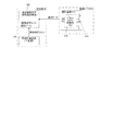
〔遊技制御装置〕
図3は、遊技機10の遊技制御系のブロック図である。遊技機10は遊技制御装置100(主基板)を備え、遊技制御装置100は、遊技を統括的に制御する主制御装置(主基板)であって、遊技用マイクロコンピュータ(以下、遊技用マイコンと称する)111を有するCPU部110と、入力ポートを有する入力部120と、出力ポートやドライバなどを有する出力部130、CPU部110と入力部120と出力部130との間を接続するデータバス140などからなる。
[Game control device]
FIG. 3 is a block diagram of the game control system of the game machine 10. The game machine 10 includes a game control device 100 (main board), and the game control device 100 is a main control device (main board) that collectively controls a game, and is a game microcomputer (hereinafter referred to as a game microcomputer). A data bus 140 that connects a CPU unit 110 having a 111 (referred to as), an input unit 120 having an input port, an output unit 130 having an output port, a driver, and the like, a CPU unit 110, an input unit 120, and an output unit 130. And so on.
CPU部110は、アミューズメントチップ(IC)と呼ばれる遊技用マイコン(CPU)111と、水晶振動子のような発振子を備え、CPUの動作クロックやタイマ割込み、乱数生成回路の基準となるクロックを生成する発振回路(水晶発振器)113などを有する。遊技制御装置100及び該遊技制御装置100によって駆動されるソレノイドやモータなどの電子部品には、電源装置400で生成されたDC32V,DC12V,DC5Vなど所定のレベルの直流電圧が供給されて動作可能にされる。
The CPU unit 110 includes a gaming microcomputer (CPU) 111 called an amusement chip (IC) and an oscillator such as a crystal oscillator, and generates an operating clock of the CPU, a timer interrupt, and a clock that serves as a reference for a random number generation circuit. It has an oscillator circuit (crystal oscillator) 113 and the like. A predetermined level of DC voltage such as DC32V, DC12V, DC5V generated by the power supply device 400 is supplied to the game control device 100 and electronic components such as a solenoid and a motor driven by the game control device 100 to enable operation. Will be done.
電源装置400は、24Vの交流電源からDC32Vの直流電圧を生成するACDCコンバータやDC32Vの電圧からDC12V,DC5Vなどのより低いレベルの直流電圧を生成するDC−DCコンバータなどを有する通常電源部410と、遊技用マイコン111の内部のRAMに対して停電時に電源電圧を供給するバックアップ電源部420と、停電監視回路を有し、遊技制御装置100に停電の発生、回復を知らせる停電監視信号やリセット信号などの制御信号を生成して出力する制御信号生成部430などを備える。
The power supply device 400 includes a normal power supply unit 410 having an ACDC converter that generates a DC voltage of DC32V from a 24V AC power supply, a DC-DC converter that generates a lower level DC voltage such as DC12V, DC5V, etc. from a DC32V voltage. , A backup power supply unit 420 that supplies a power supply voltage to the internal RAM of the game microcomputer 111 in the event of a power failure, and a power failure monitoring circuit, and a power failure monitoring signal or reset signal that notifies the game control device 100 of the occurrence or recovery of a power failure. It is provided with a control signal generation unit 430 and the like that generate and output a control signal such as.
本実施形態では、電源装置400は、遊技制御装置100と別個に構成されているが、バックアップ電源部420及び制御信号生成部430は、別個の基板上あるいは遊技制御装置100と一体、すなわち、主基板上に設けるように構成してもよい。遊技盤30及び遊技制御装置100は機種変更の際に交換の対象となるので、実施例のように、電源装置400若しくは主基板とは別の基板にバックアップ電源部420及び制御信号生成部430を設けることにより、交換の対象から外しコストダウンを図ることができる。
In the present embodiment, the power supply device 400 is configured separately from the game control device 100, but the backup power supply unit 420 and the control signal generation unit 430 are integrated on a separate board or with the game control device 100, that is, the main unit. It may be configured to be provided on a substrate. Since the game board 30 and the game control device 100 are to be replaced when the model is changed, the backup power supply unit 420 and the control signal generation unit 430 are mounted on a board different from the power supply device 400 or the main board as in the embodiment. By providing it, it is possible to exclude it from the target of replacement and reduce the cost.
バックアップ電源部420は、電解コンデンサのような大容量のコンデンサ1つで構成することができる。バックアップ電源は、遊技制御装置100の遊技用マイコン111(特に内蔵RAM)に供給され、停電中あるいは電源遮断後もRAMに記憶されたデータが保持されるようになっている。制御信号生成部430は、例えば通常電源部410で生成された32Vの電圧を監視してそれが例えば17V以下に下がると停電発生を検出して停電監視信号を変化させるとともに、所定時間後にリセット信号を出力する。また、電源投入時や停電回復時にもその時点から所定時間経過後にリセット信号を出力する。
The backup power supply unit 420 can be configured by one large-capacity capacitor such as an electrolytic capacitor. The backup power supply is supplied to the game microcomputer 111 (particularly the built-in RAM) of the game control device 100, and the data stored in the RAM is retained even during a power failure or even after the power is cut off. The control signal generation unit 430 monitors the voltage of 32V generated by the normal power supply unit 410, for example, detects the occurrence of a power failure when it drops to 17V or less, changes the power failure monitoring signal, and resets the signal after a predetermined time. Is output. Also, when the power is turned on or when the power is restored, a reset signal is output after a predetermined time has elapsed from that point.
また、遊技制御装置100(主基板)は、操作者の回転操作等によってオンすることによって遊技条件(遊技)に関する設定値を変更可能な状態にする設定キースイッチ93と、操作者の操作に応じて遊技条件に関する設定値を変更可能な設定値変更スイッチ102と、を備える。本実施形態では、遊技条件(遊技)に関する設定値は、大当り確率の確率設定値であるが、大当り確率以外の他の遊技条件(小当り確率や確変突入率など)も確率設定値に応じて変更可能である。設定キースイッチ93と設定値変更スイッチ102は、遊技条件に関する設定(設定値)を変更可能な設定変更手段(設定変更装置42)を構成する。なお、本実施形態において、設定値を確定させるための確定信号として、操作ハンドル24に設けられたタッチスイッチのタッチスイッチ信号を利用するが、操作可能な確定ボタンスイッチ(操作手段、操作部)を遊技制御装置100に設けて、確定ボタンスイッチからの信号を、設定値を確定させるための確定信号として利用してもよい。
Further, the game control device 100 (main board) has a setting key switch 93 that makes it possible to change a set value related to a game condition (game) by turning it on by an operator's rotation operation or the like, and according to the operator's operation. It is provided with a setting value change switch 102 capable of changing a setting value related to a game condition. In the present embodiment, the set value related to the game condition (game) is the probability set value of the jackpot probability, but the game conditions other than the jackpot probability (small hit probability, probability variation inrush rate, etc.) also depend on the probability set value. It can be changed. The setting key switch 93 and the setting value changing switch 102 constitute a setting changing means (setting changing device 42) capable of changing the setting (setting value) related to the game condition. In the present embodiment, the touch switch signal of the touch switch provided on the operation handle 24 is used as the confirmation signal for confirming the set value, but an operable confirmation button switch (operation means, operation unit) is used. The signal from the confirmation button switch may be provided in the game control device 100 and used as a confirmation signal for confirming the set value.
設定キースイッチ93と設定値変更スイッチ102は、遊技機10内部の遊技制御装置100上に設けられることによって、前面枠12(本体枠)が開放されなければ操作できない位置(アクセスできない位置)に配置される。即ち、一般の遊技者は、設定キースイッチ93と設定値変更スイッチ102にアクセスして操作することができない。なお、本実施形態において、設定キースイッチ93と設定値変更スイッチ102は、遊技制御装置100上に組み付けるようにして設けるが、電源装置400の電源基板上など、前面枠12(本体枠)が開放されなければアクセスできない位置に設けてもよい。
The setting key switch 93 and the setting value change switch 102 are provided on the game control device 100 inside the game machine 10 and are arranged at a position (inaccessible position) that cannot be operated unless the front frame 12 (main body frame) is opened. Will be done. That is, a general player cannot access and operate the setting key switch 93 and the setting value change switch 102. In the present embodiment, the setting key switch 93 and the setting value change switch 102 are provided so as to be assembled on the game control device 100, but the front frame 12 (main body frame) is open, such as on the power supply board of the power supply device 400. It may be provided in a position where it cannot be accessed unless it is provided.
遊技機10の電源投入の際に、前面枠12(本体枠)が開放されて設定キースイッチ93がオンした状態にある場合、操作者が設定値変更スイッチ102(設定値変更ボタン)を操作することによって、大当りの確率や確変突入率などの遊技条件に関する設定(設定値)を変更することができる。即ち、電源投入のときに、前面枠12が開放され設定キースイッチ93がオンした状態が、設定(設定値)の変更が可能となる設定可変状態となる。通常の手順では、操作者は、前面枠12を開放して設定キースイッチ93を回転操作してオン位置にし電源投入を行うと、設定変更中の状態に相当する設定可変状態となる。設定可変状態は、スピーカからの音声によって報知されてもよい。なお、電源投入のときに、ガラス枠15が開放され設定キースイッチ93がオンした状態を設定可変状態としてもよいし、前面枠12とガラス枠15の両方が開放され設定キースイッチ93がオンした状態を設定可変状態としてもよい
When the power of the game machine 10 is turned on, when the front frame 12 (main body frame) is opened and the setting key switch 93 is turned on, the operator operates the setting value change switch 102 (setting value change button). This makes it possible to change the settings (set values) related to the game conditions such as the probability of a big hit and the probability variation inrush rate. That is, when the power is turned on, the state in which the front frame 12 is opened and the setting key switch 93 is turned on becomes a setting variable state in which the setting (setting value) can be changed. In a normal procedure, when the operator opens the front frame 12 and rotates the setting key switch 93 to turn it on and turn on the power, the setting becomes a variable state corresponding to the state in which the setting is being changed. The variable setting state may be notified by voice from the speaker. When the power is turned on, the state in which the glass frame 15 is opened and the setting key switch 93 is turned on may be set as a variable setting state, or both the front frame 12 and the glass frame 15 are opened and the setting key switch 93 is turned on. The state may be set to a variable state.
本実施形態において、遊技条件に関する設定値は、6段階で規定され、設定値1(設定1)、設定値2(設定2)、設定値3(設定3)、設定値4(設定4)、設定値5(設定5)、設定値6(設定6)がある。設定値1が遊技者に最も不利な設定であり、設定値6が遊技者に最も有利な設定である。設定値1、2が低設定であり、設定値3、4が中間の設定(中間設定)であり、設定値5、6が高設定である。
In the present embodiment, the setting values related to the game conditions are defined in 6 stages, and the setting value 1 (setting 1), the setting value 2 (setting 2), the setting value 3 (setting 3), the setting value 4 (setting 4), There are a setting value 5 (setting 5) and a setting value 6 (setting 6). The setting value 1 is the most disadvantageous setting for the player, and the setting value 6 is the most advantageous setting for the player. The setting values 1 and 2 are low settings, the setting values 3 and 4 are intermediate settings (intermediate settings), and the setting values 5 and 6 are high settings.
設定値変更処理では、操作者によって設定値変更スイッチ102(設定値変更ボタン)が操作される度に、設定値(設定)を設定値1→設定値2→設定値3→設定値4→設定値5→設定値6→設定値1→設定値2→・・・のように変更して選択する。なお、設定値変更ボタンの操作ではなく、設定キースイッチ93を所定の位置に回転操作して設定値を変更する構成としてもよい。また、設定値は6段階に限られない。そして、選択されている1〜6の設定値が、7セグメント型の表示器である確率設定値表示装置143等に表示される。なお、確率設定値表示装置143は、電気回路を介して設定値変更スイッチ102の操作に直接連動して表示を変化させてよい。後述のように、一括表示装置50の変動表示ゲーム用の第1特図変動表示部51及び/又は第2特図変動表示部52に、選択されている1〜6の設定値を表示してもよい。
In the setting value change process, each time the operator operates the setting value change switch 102 (setting value change button), the setting value (setting) is set to the setting value 1 → the setting value 2 → the setting value 3 → the setting value 4 → the setting. Change and select value 5 → set value 6 → set value 1 → set value 2 → ... Instead of operating the set value change button, the setting key switch 93 may be rotated to a predetermined position to change the set value. Moreover, the set value is not limited to 6 steps. Then, the selected set values 1 to 6 are displayed on the probability set value display device 143 or the like, which is a 7-segment type display. The probability set value display device 143 may change the display directly in conjunction with the operation of the set value change switch 102 via the electric circuit. As will be described later, the selected set values 1 to 6 are displayed on the first special figure fluctuation display unit 51 and / or the second special figure fluctuation display unit 52 for the fluctuation display game of the batch display device 50. May be good.
操作者が操作ハンドル24に触れることによってタッチスイッチ信号が遊技制御装置100に入力されると、選択(変更)された設定値(即ち設定)が確定してRWM(記憶手段)内の確率設定値領域に記憶され、設定値変更処理は終了する。なお、タッチスイッチ信号に関係なく、設定値変更後に設定キースイッチ93をオフしたり、設定可変状態になってから所定時間経過すると、遊技制御装置100が設定値(即ち設定)を確定して記憶する構成も可能である。
When the touch switch signal is input to the game control device 100 by the operator touching the operation handle 24, the selected (changed) set value (that is, the setting) is fixed and the probability set value in the RWM (storage means) is determined. It is stored in the area, and the setting value change process ends. Regardless of the touch switch signal, when the setting key switch 93 is turned off after the set value is changed or a predetermined time elapses after the setting is changed to the variable state, the game control device 100 determines the set value (that is, the setting) and stores it. It is also possible to configure it.
一方、遊技機10の電源投入後に、前面枠12(本体枠)を開放して設定キースイッチ93を回転操作してオフ状態からオン状態にすると、設定値確認モード(設定確認状態)になる。設定値確認モードでは、確率設定値表示装置143に表示された設定値を確認できる。一括表示装置50の変動表示ゲーム用の第1特図変動表示部51及び/又は第2特図変動表示部52に、選択されている1〜6の設定値を表示して確認してもよい。設定値確認モード(設定確認状態)は、スピーカからの音声によって報知されてもよい。
On the other hand, when the front frame 12 (main body frame) is opened and the setting key switch 93 is rotated to change the setting key switch 93 from the off state to the on state after the power of the game machine 10 is turned on, the set value confirmation mode (setting confirmation state) is set. In the set value confirmation mode, the set value displayed on the probability set value display device 143 can be confirmed. The selected set values 1 to 6 may be displayed and confirmed on the first special figure fluctuation display unit 51 and / or the second special figure fluctuation display unit 52 for the variation display game of the batch display device 50. .. The set value confirmation mode (setting confirmation state) may be notified by voice from the speaker.
なお、設定値変更スイッチ102(設定値変更ボタン)はRAM初期化スイッチ(RAMクリアスイッチ)としても使用可能であり、電源投入(電源復旧)の際に初期化スイッチがオン状態であると初期化スイッチ信号が生成され、これに基づき遊技用マイコン111内のRAM111c及び払出制御装置200内のRAMに記憶されている情報を強制的に初期化する処理が行われる。特に限定されるわけではないが初期化スイッチ信号は電源投入時に読み込まれ、停電監視信号は遊技用マイコン111が実行するメインプログラムのメインループの中で繰り返し読み込まれる。リセット信号は強制割込み信号の一種であり、制御システム全体をリセットさせる。
The setting value change switch 102 (setting value change button) can also be used as a RAM initialization switch (RAM clear switch), and is initialized when the initialization switch is in the ON state when the power is turned on (power recovery). A switch signal is generated, and based on this, a process of forcibly initializing the information stored in the RAM 111c in the gaming microcomputer 111 and the RAM in the payout control device 200 is performed. Although not particularly limited, the initialization switch signal is read when the power is turned on, and the power failure monitoring signal is repeatedly read in the main loop of the main program executed by the gaming microcomputer 111. A reset signal is a type of forced interrupt signal that resets the entire control system.
遊技用マイコン111は、CPU(中央処理ユニット:マイクロプロセッサ)111a、読出し専用のROM(リードオンリメモリ)111b及び随時読出し書込み可能なRAM(ランダムアクセスメモリ)111cを備える。
The game microcomputer 111 includes a CPU (central processing unit: microprocessor) 111a, a read-only ROM (read-only memory) 111b, and a RAM (random access memory) 111c that can be read and written at any time.
ROM111bは、遊技制御のための不変の情報(プログラム、固定データ、各種乱数の判定値等)を不揮発的に記憶し、RAM111cは、遊技制御時にCPU111aの作業領域や各種信号や乱数値の記憶領域として利用される。ROM111b又はRAM111cとして、EEPROMのような電気的に書換え可能な不揮発性メモリを用いてもよい。
The ROM 111b non-volatilely stores invariant information (program, fixed data, determination value of various random numbers, etc.) for game control, and the RAM 111c is a work area of the CPU 111a and a storage area of various signals and random numbers during game control. It is used as. As the ROM 111b or the RAM 111c, an electrically rewritable non-volatile memory such as EEPROM may be used.
また、ROM111bは、例えば、特図変動表示ゲームの実行時間、演出内容、リーチ状態の発生の有無などを規定する変動パターン(変動態様)を決定するための変動パターンテーブルを記憶している。変動パターンテーブルとは、始動記憶として記憶されている変動パターン乱数1〜3をCPU111aが参照して変動パターンを決定するためのテーブルである。また、変動パターンテーブルには、結果がはずれとなる場合に選択されるはずれ変動パターンテーブル、結果が大当りとなる場合に選択される大当り変動パターンテーブル等が含まれる。さらに、これらのパターンテーブルには、リーチ状態となった後の変動パターンである後半変動パターンを決定するためのテーブル(後半変動グループテーブルや後半変動パターン選択テーブル等)、リーチ状態となる前の変動パターンである前半変動パターンを決定するためのテーブル(前半変動グループテーブルや前半変動パターン選択テーブル等)が含まれている。
Further, the ROM 111b stores, for example, a variation pattern table for determining a variation pattern (variation mode) that defines the execution time of the special figure variation display game, the effect content, the presence / absence of the occurrence of the reach state, and the like. The variation pattern table is a table for the CPU 111a to refer to the variation pattern random numbers 1 to 3 stored as the start memory to determine the variation pattern. Further, the fluctuation pattern table includes a missed fluctuation pattern table selected when the result is missed, a jackpot fluctuation pattern table selected when the result is a jackpot, and the like. Further, these pattern tables include a table for determining the latter half fluctuation pattern, which is a fluctuation pattern after reaching the reach state (second half fluctuation group table, second half fluctuation pattern selection table, etc.), and fluctuation before reaching the reach state. A table for determining the first half fluctuation pattern, which is a pattern (first half fluctuation group table, first half fluctuation pattern selection table, etc.) is included.
ここでリーチ(リーチ状態)とは、表示状態が変化可能な表示装置を有し、該表示装置が時期を異ならせて複数の表示結果を導出表示し、該複数の表示結果が予め定められた特別結果態様となった場合に、遊技状態が遊技者にとって有利な遊技状態(特別遊技状態)となる遊技機10において、複数の表示結果の一部がまだ導出表示されていない段階で、既に導出表示されている表示結果が特別結果態様となる条件を満たしている表示状態をいう。また、別の表現をすれば、リーチ状態とは、表示装置の変動表示制御が進行して表示結果が導出表示される前段階にまで達した時点でも、特別結果態様となる表示条件からはずれていない表示態様をいう。そして、例えば、特別結果態様が揃った状態を維持しながら複数の変動表示領域による変動表示を行う状態(いわゆる全回転リーチ)もリーチ状態に含まれる。また、リーチ状態とは、表示装置の表示制御が進行して表示結果が導出表示される前段階にまで達した時点での表示状態であって、表示結果が導出表示される以前に決定されている複数の変動表示領域の表示結果の少なくとも一部が特別結果態様となる条件を満たしている場合の表示状態をいう。
Here, the reach (reach state) has a display device whose display state can be changed, and the display device derives and displays a plurality of display results at different times, and the plurality of display results are predetermined. In the gaming machine 10 in which the gaming state becomes an advantageous gaming state (special gaming state) for the player when the special result mode is adopted, a part of the plurality of display results is already derived and displayed at a stage where the display is not yet derived. A display state in which the displayed display result satisfies the condition of the special result mode. In other words, the reach state is out of the display condition that is the special result mode even when the variable display control of the display device progresses and the display result reaches the stage before the derivation display. Refers to a display mode that does not exist. Further, for example, a state in which variation display is performed by a plurality of variation display areas (so-called full rotation reach) while maintaining a state in which the special result modes are aligned is also included in the reach state. The reach state is a display state at the time when the display control of the display device progresses and reaches the stage before the display result is derived and displayed, and is determined before the display result is derived and displayed. It refers to a display state when at least a part of the display results of a plurality of variable display areas satisfies the condition of the special result mode.
よって、例えば、特図変動表示ゲームに対応して表示装置に表示される飾り特図変動表示ゲームが、表示装置における左、中、右の変動表示領域の各々で所定時間複数の識別情報を変動表示した後、左、右、中の順で変動表示を停止して結果態様を表示するものである場合、左、右の変動表示領域で、特別結果態様となる条件を満たした状態(例えば、同一の識別情報)で変動表示が停止した状態がリーチ状態となる。他に、すべての変動表示領域の変動表示を一旦停止した時点で、左、中、右のうちいずれか二つの変動表示領域で特別結果態様となる条件を満たした状態(例えば、同一の識別情報となった状態、ただし特別結果態様は除く)をリーチ状態とし、リーチ状態から残りの一つの変動表示領域を変動表示するようにしてもよい。
Therefore, for example, the decorative special figure variation display game displayed on the display device corresponding to the special figure variation display game changes a plurality of identification information for a predetermined time in each of the left, middle, and right variation display areas on the display device. After the display, when the variation display is stopped in the order of left, right, and middle to display the result mode, the left and right variation display areas satisfy the conditions for the special result mode (for example,). The state in which the variable display is stopped with the same identification information) is the reach state. In addition, when the fluctuation display of all the fluctuation display areas is temporarily stopped, the condition of the special result mode in any two of the left, middle, and right fluctuation display areas is satisfied (for example, the same identification information). (However, the special result mode is excluded) may be set as the reach state, and the remaining one variable display area may be variable-displayed from the reach state.
そして、リーチ状態には複数のリーチ演出が含まれ、特別結果態様(大当り態様)が導出される可能性が異なる(期待値が異なる)リーチ演出の系統として、ノーマルリーチ(Nリーチ)、スペシャル1リーチ(SP1リーチ)、スペシャル2リーチ(SP2リーチ)、スペシャル3リーチ(SP3リーチ)、プレミアリーチが設定されている。なお、大当りの期待度(期待値)は、リーチなし<ノーマルリーチ<スペシャル1リーチ<スペシャル2リーチ<スペシャル3リーチ<プレミアリーチの順に高くなるようになっている。また、リーチ状態は、少なくとも特図変動表示ゲームで特別結果態様が導出される場合(大当りとなる場合)における変動表示態様に含まれるようになっている。すなわち、特図変動表示ゲームで特別結果態様が導出されないと判定する場合(はずれとなる場合)における変動表示態様に含まれることもある。よって、リーチ状態が発生した状態は、リーチ状態が発生しない場合と比較して大当りとなる可能性の高い状態である。
The reach state includes a plurality of reach effects, and as a system of reach effects in which the possibility of deriving a special result mode (big hit mode) is different (expected value is different), normal reach (N reach) and special 1 reach are used. (SP1 reach), special 2 reach (SP2 reach), special 3 reach (SP3 reach), and premier reach are set. The expected degree of jackpot (expected value) increases in the order of no reach <normal reach <special 1 reach <special 2 reach <special 3 reach <premier reach. In addition, the reach state is included in the variation display mode at least when the special result mode is derived (when it becomes a big hit) in the special figure variation display game. That is, it may be included in the variation display mode when it is determined that the special result mode is not derived in the special figure variation display game (when it is out of order). Therefore, the state in which the reach state occurs is more likely to be a big hit than the case in which the reach state does not occur.
CPU111aは、ROM111b内の遊技制御用プログラムを実行して、払出制御装置200や演出制御装置300に対する制御信号(コマンド)を生成したりソレノイドや表示装置の駆動信号を生成して出力して遊技機10全体の制御を行う。また、図示しないが、遊技用マイコン111は、特図変動表示ゲームの大当りを判定するための大当り乱数や大当りの図柄を決定するための大当り図柄乱数、小当りの図柄を決定するための小当り図柄乱数、特図変動表示ゲームでの変動パターン(各種リーチやリーチなしの変動表示における変動表示ゲームの実行時間等を含む)を決定するための変動パターン乱数等を生成するための乱数生成回路と、発振回路113からの発振信号(原クロック信号)に基づいてCPU111aに対する所定周期(例えば、4msec(ミリ秒))のタイマ割込み信号や乱数生成回路の更新タイミングを与えるクロックを生成するクロックジェネレータを備えている。
The CPU 111a executes a game control program in the ROM 111b to generate a control signal (command) for the payout control device 200 and the effect control device 300, or generate and output a drive signal for a solenoid or a display device to output the game machine. 10 Control the entire system. Further, although not shown, the gaming microcomputer 111 includes a jackpot random number for determining a jackpot of a special figure variation display game, a jackpot symbol random number for determining a jackpot symbol, and a small hit for determining a small hit symbol. With a random number generation circuit for generating fluctuation pattern random numbers, etc. for determining fluctuation patterns in symbol random numbers and special figure fluctuation display games (including execution time of fluctuation display games in various reach and fluctuation display without reach) The clock generator is provided to generate a timer interrupt signal having a predetermined period (for example, 4 msec (milliseconds)) for the CPU 111a based on the oscillation signal (original clock signal) from the oscillation circuit 113 and a clock that gives an update timing of the random number generation circuit. ing.
また、CPU111aは、特図変動表示ゲームに関する処理において、ROM111bに記憶されている複数の変動パターンテーブルの中から、いずれか一の変動パターンテーブルを取得する。具体的には、CPU111aは、特図変動表示ゲームの遊技結果(大当りあるいははずれ)や、現在の遊技状態としての特図変動表示ゲームの確率状態(通常確率状態あるいは高確率状態)、始動記憶数などに基づいて、複数の変動パターンテーブルの中から、いずれか一の変動パターンテーブルを選択して取得する。ここで、CPU111aは、特図変動表示ゲームを実行する場合に、ROM111bに記憶された複数の変動パターンテーブルのうち、いずれか一の変動パターンテーブルを取得する変動振り分け情報取得手段をなす。
Further, the CPU 111a acquires any one of the fluctuation pattern tables stored in the ROM 111b in the process related to the special figure fluctuation display game. Specifically, the CPU 111a determines the game result (big hit or miss) of the special figure variation display game, the probability state (normal probability state or high probability state) of the special figure variation display game as the current game state, and the start memory number. Based on the above, one of the fluctuation pattern tables is selected and acquired from the plurality of fluctuation pattern tables. Here, the CPU 111a serves as a variation distribution information acquisition means for acquiring any one of the plurality of variation pattern tables stored in the ROM 111b when the special figure variation display game is executed.
払出制御装置200は、CPU、ROM、RAM、入力インタフェース、出力インタフェース等を備え、遊技制御装置100からの賞球払出し指令(コマンドやデータ)に従って、払出ユニットの払出モータ91を駆動させ、賞球を払い出させるための制御を行う。また、払出制御装置200は、カードユニット600からの貸球要求信号に基づいて払出ユニットの払出モータ91を駆動させ、貸球を払い出させるための制御を行う。
The payout control device 200 includes a CPU, ROM, RAM, input interface, output interface, etc., and drives the payout motor 91 of the payout unit in accordance with a prize ball payout command (command or data) from the game control device 100 to drive the prize ball. Control to pay out. Further, the payout control device 200 drives the payout motor 91 of the payout unit based on the ball lending request signal from the card unit 600, and controls for paying out the ball lending.
遊技用マイコン111の入力部120には、遊技機に対する電波の発射を検出する電波センサ62(盤電波センサ)、普図始動ゲート34のゲートスイッチ34a、第1始動入賞口36内の始動口1スイッチ36a、第2始動入賞口37内の始動口2スイッチ37a、入賞口スイッチ35a、特別変動入賞装置39の大入賞口スイッチ39aに接続され、これらのスイッチから供給されるハイレベルが11Vでロウレベルが7Vのような負論理の信号が入力され、0V−5Vの正論理の信号に変換するインタフェースチップ(近接I/F)121が設けられている。
The input unit 120 of the game microcomputer 111 includes a radio wave sensor 62 (panel radio wave sensor) for detecting the emission of radio waves to the game machine, a gate switch 34a of the normal drawing start gate 34, and a start port 1 in the first start winning opening 36. It is connected to the switch 36a, the start port 2 switch 37a in the second start winning port 37, the winning port switch 35a, and the large winning port switch 39a of the special variable winning device 39, and the high level supplied from these switches is low level at 11V. An interface chip (proximity I / F) 121 is provided in which a negative logic signal such as 7V is input and converted into a positive logic signal of 0V-5V.
近接I/F121の出力は、第2入力ポート123又は第3入力ポート124に供給されデータバス140を介して遊技用マイコン111に読み込まれる。なお、近接I/F121の出力のうち、ゲートスイッチ34a、始動口1スイッチ36a、始動口2スイッチ37a、入賞口スイッチ35a、大入賞口スイッチ39aの検出信号は第3入力ポート124に入力される。
The output of the proximity I / F 121 is supplied to the second input port 123 or the third input port 124 and read into the gaming microcomputer 111 via the data bus 140. Of the outputs of the proximity I / F 121, the detection signals of the gate switch 34a, the start port 1 switch 36a, the start port 2 switch 37a, the winning port switch 35a, and the large winning port switch 39a are input to the third input port 124. ..
また、近接I/F121の出力のうち、電波センサ62の検出信号及びセンサやスイッチの異常を検出した際に出力される異常検知信号は第2入力ポート123に入力される。
Further, among the outputs of the proximity I / F 121, the detection signal of the radio wave sensor 62 and the abnormality detection signal output when an abnormality of the sensor or the switch is detected are input to the second input port 123.
また、第2入力ポート123には、遊技機10の前面枠12等に設けられた不正検出用の磁気センサスイッチ61の検出信号、遊技機10のガラス枠15等に設けられたガラス枠開放検出スイッチ63、前面枠12(本体枠)等に設けられた前面枠開放検出スイッチ64(本体枠開放検出スイッチ)からの信号が入力される。なお、振動を検出する振動センサスイッチを遊技機に設け、検出信号が第2入力ポート123に入力されるようにしてもよい。
Further, the second input port 123 includes a detection signal of a magnetic sensor switch 61 for fraud detection provided on the front frame 12 or the like of the game machine 10, and a glass frame opening detection provided on the glass frame 15 or the like of the game machine 10. A signal is input from the front frame opening detection switch 64 (main body frame opening detection switch) provided on the switch 63, the front frame 12 (main body frame), and the like. A vibration sensor switch for detecting vibration may be provided in the game machine so that the detection signal is input to the second input port 123.
また、第2入力ポート123(入力ポート3)は、設定キースイッチ93からの設定キースイッチ信号と、設定値変更スイッチ102からの設定値変更スイッチ信号を取り込んでデータバス140を介して遊技用マイコン111に供給する。
Further, the second input port 123 (input port 3) takes in the setting key switch signal from the setting key switch 93 and the setting value change switch signal from the setting value change switch 102, and is a gaming microcomputer via the data bus 140. Supply to 111.
また、近接I/F121の出力のうち、第3入力ポート124への出力は、遊技制御装置100から中継基板70を介して図示しない試射試験装置へも供給されるようになっている。さらに、近接I/F121の出力のうち始動口1スイッチ36aと始動口2スイッチ37aの検出信号は、第3入力ポート124の他、遊技用マイコン111に入力されるように構成されている。
Further, among the outputs of the proximity I / F 121, the output to the third input port 124 is also supplied from the game control device 100 to a test firing test device (not shown) via the relay board 70. Further, among the outputs of the proximity I / F 121, the detection signals of the start port 1 switch 36a and the start port 2 switch 37a are configured to be input to the gaming microcomputer 111 in addition to the third input port 124.
前述のように近接I/F121は、信号のレベル変換機能を有する。このようなレベル変換機能を可能にするため、近接I/F121には、電源装置400から通常のICの動作に必要な例えば5Vのような電圧の他に、12Vの電圧が供給されるようになっている。
As described above, the proximity I / F 121 has a signal level conversion function. In order to enable such a level conversion function, the proximity I / F 121 is supplied with a voltage of 12V in addition to the voltage such as 5V required for normal IC operation from the power supply device 400. It has become.
第3入力ポート124が保持しているデータは、遊技用マイコン111が第3入力ポート124に割り当てられているアドレスをデコードすることによってイネーブル信号CE2をアサート(有効レベルに変化)することよって、読み出すことができる。第2入力ポート123や後述の第1入力ポート122も同様である。
The data held by the third input port 124 is read out by asserting the enable signal CE2 (changing to an effective level) by the gaming microcomputer 111 decoding the address assigned to the third input port 124. be able to. The same applies to the second input port 123 and the first input port 122 described later.
また、入力部120には、払出制御装置200から出力される枠電波不正信号、払出ビジー信号、払出異常を示すステータス信号、払出前の遊技球の不足を示すシュート球切れスイッチ信号、オーバーフローを示すオーバーフロースイッチ信号、操作ハンドル24に設けられたタッチスイッチの入力に基づくタッチスイッチ信号、アウト球検出スイッチからのアウト球検出スイッチ信号を取り込んでデータバス140を介して遊技用マイコン111に供給する第1入力ポート122が設けられている。オーバーフロースイッチ信号は、下皿23に遊技球が所定量以上貯留されていること(満杯になったこと)を検出したときに出力される信号である。枠電波不正信号は前面枠12(本体枠)に設けられた枠電波センサが電波を検出することに基づき出力される信号であり、払出ビジー信号は払出制御装置200がコマンドを受付可能な状態か否かを示す信号である。本実施形態において、アウト球検出スイッチ(不図示)は、遊技領域に発射されて遊技を終えた全ての遊技球を検出するものである。アウト球検出スイッチ(不図示)は、アウト口30bを通過する遊技球のみを検出してもよい。
Further, the input unit 120 indicates a frame radio wave illegal signal output from the payout control device 200, a payout busy signal, a status signal indicating a payout abnormality, a shoot ball out switch signal indicating a shortage of game balls before payout, and an overflow. The first that takes in the overflow switch signal, the touch switch signal based on the input of the touch switch provided on the operation handle 24, and the out ball detection switch signal from the out ball detection switch and supplies them to the gaming microcomputer 111 via the data bus 140. An input port 122 is provided. The overflow switch signal is a signal output when it is detected that a predetermined amount or more of game balls are stored (full) in the lower plate 23. The frame radio wave invalid signal is a signal output based on the frame radio wave sensor provided on the front frame 12 (main body frame) detecting the radio wave, and the payout busy signal is in a state where the payout control device 200 can accept a command. It is a signal indicating whether or not. In the present embodiment, the out-ball detection switch (not shown) detects all the game balls that have been fired into the game area and finished the game. The out ball detection switch (not shown) may detect only the game ball passing through the out port 30b.
また、入力部120には、電源装置400からの停電監視信号やリセット信号などの信号を遊技用マイコン111等に入力するためのシュミットバッファ125が設けられており、シュミットバッファ125はこれらの入力信号からノイズを除去する機能を有する。電源装置400からの停電監視信号は、一旦第1入力ポート122に入力され、データバス140を介して遊技用マイコン111に取り込まれる。つまり、前述の各種スイッチからの信号と同等の信号として扱われる。遊技用マイコン111に設けられている外部からの信号を受ける端子の数には制約があるためである。
Further, the input unit 120 is provided with a Schmidt buffer 125 for inputting a signal such as a power failure monitoring signal or a reset signal from the power supply device 400 to the gaming microcomputer 111 or the like, and the Schmidt buffer 125 is provided with these input signals. It has a function to remove noise from. The power failure monitoring signal from the power supply device 400 is once input to the first input port 122, and is taken into the gaming microcomputer 111 via the data bus 140. That is, it is treated as a signal equivalent to the signal from the various switches described above. This is because there is a limit to the number of terminals provided on the gaming microcomputer 111 that receive signals from the outside.
一方、シュミットバッファ125によりノイズ除去されたリセット信号RSTは、遊技用マイコン111に設けられているリセット端子に直接入力されるとともに、出力部130の各ポートに供給される。また、リセット信号RSTは出力部130を介さずに直接中継基板70に出力することで、試射試験装置に出力するために中継基板70のポート(図示省略)に保持される試射試験信号をオフするように構成されている。
On the other hand, the reset signal RST from which noise has been removed by the Schmidt buffer 125 is directly input to the reset terminal provided in the gaming microcomputer 111 and is supplied to each port of the output unit 130. Further, the reset signal RST is output directly to the relay board 70 without going through the output unit 130 to turn off the test firing test signal held in the port (not shown) of the relay board 70 for output to the test firing test apparatus. It is configured as follows.
また、リセット信号RSTを中継基板70を介して試射試験装置に出力可能に構成するようにしてもよい。なお、リセット信号RSTは入力部120の各ポート122,123,124には供給されない。リセット信号RSTが入る直前に遊技用マイコン111によって出力部130の各ポートに設定されたデータはシステムの誤動作を防止するためリセットする必要があるが、リセット信号RSTが入る直前に入力部120の各ポートから遊技用マイコン111が読み込んだデータは、遊技用マイコン111のリセットによって廃棄されるためである。
Further, the reset signal RST may be configured to be output to the test firing test apparatus via the relay board 70. The reset signal RST is not supplied to the ports 122, 123, and 124 of the input unit 120. The data set in each port of the output unit 130 by the gaming microcomputer 111 just before the reset signal RST is input needs to be reset in order to prevent the system from malfunctioning, but each of the input units 120 immediately before the reset signal RST is input. This is because the data read by the gaming microcomputer 111 from the port is discarded by resetting the gaming microcomputer 111.
出力部130には、遊技用マイコン111から演出制御装置300への通信経路及び遊技用マイコン111から払出制御装置200への通信経路に配されるシュミットバッファ132が設けられている。遊技制御装置100から演出制御装置300及び払出制御装置200へは、シリアル通信でデータが送信される。なお、演出制御装置300の側から遊技制御装置100へ信号を入力できないようにした片方向通信とされている。
The output unit 130 is provided with a Schmidt buffer 132 arranged on a communication path from the game microcomputer 111 to the effect control device 300 and a communication path from the game microcomputer 111 to the payout control device 200. Data is transmitted from the game control device 100 to the effect control device 300 and the payout control device 200 by serial communication. It should be noted that the one-way communication is such that a signal cannot be input to the game control device 100 from the effect control device 300 side.
さらに、出力部130には、データバス140に接続され図示しない認定機関の試射試験装置へ変動表示ゲームの特図図柄情報を知らせるデータや大当りの確率状態を示す信号などを中継基板70を介して出力するバッファ133が実装可能に構成されている。バッファ133は遊技店に設置される実機(量産販売品)としてのパチンコ遊技機の遊技制御装置(主基板)には実装されない部品である。なお、前記近接I/F121から出力される始動口スイッチなど加工の必要のないスイッチの検出信号は、バッファ133を通さずに中継基板70を介して試射試験装置に供給される。
Further, the output unit 130 is connected to the data bus 140, and data for notifying the special symbol information of the variable display game to the test firing test device of the accreditation body (not shown), a signal indicating the probability state of the jackpot, and the like are transmitted via the relay board 70. The output buffer 133 is configured to be mountable. The buffer 133 is a component that is not mounted on the game control device (main board) of a pachinko gaming machine as an actual machine (mass production product) installed in a game store. The detection signal of a switch that does not need to be processed, such as a start port switch output from the proximity I / F 121, is supplied to the test firing test apparatus via the relay board 70 without passing through the buffer 133.
一方、磁気センサスイッチ61や電波センサ62のようにそのままでは試射試験装置に供給できない検出信号は、一旦遊技用マイコン111に取り込まれて他の信号若しくは情報に加工されて、例えば遊技機が遊技制御できない状態であることを示すエラー信号としてデータバス140からバッファ133、中継基板70を介して試射試験装置に供給される。
On the other hand, a detection signal that cannot be supplied to the test firing test device as it is, such as the magnetic sensor switch 61 and the radio wave sensor 62, is once taken into the game microcomputer 111 and processed into other signals or information, for example, the game machine controls the game. It is supplied from the data bus 140 to the test firing test apparatus via the buffer 133 and the relay board 70 as an error signal indicating that the state cannot be achieved.
なお、中継基板70には、バッファ133から出力された信号を取り込んで試射試験装置に供給するポートや、バッファを介さないスイッチの検出信号の信号線を中継して伝達するコネクタなどが設けられている。中継基板70上のポートには、遊技用マイコン111から出力されるチップイネーブル信号CEも供給され、該信号CEにより選択制御されたポートの信号が試射試験装置に供給されるようになっている。
The relay board 70 is provided with a port that takes in the signal output from the buffer 133 and supplies it to the test firing test apparatus, a connector that relays and transmits the signal line of the switch detection signal that does not go through the buffer, and the like. There is. A chip enable signal CE output from the gaming microcomputer 111 is also supplied to the port on the relay board 70, and the signal of the port selectively controlled by the signal CE is supplied to the test firing test apparatus.
また、出力部130には、データバス140に接続され普通変動入賞装置37を開放させるソレノイド(普電ソレノイド)37c、特別変動入賞装置39を開放させるソレノイド(大入賞口ソレノイド)39bの開閉データを出力するための第2出力ポート134が設けられている。
Further, the output unit 130 receives open / close data of a solenoid (normal electric solenoid) 37c connected to the data bus 140 to open the normal variable winning device 37 and a solenoid (large winning port solenoid) 39b to open the special variable winning device 39. A second output port 134 for output is provided.
また、出力部130には、一括表示装置50に表示する内容に応じてLEDのアノード端子が接続されているセグメント線のオン/オフデータを出力するための第3出力ポート135、一括表示装置50のLEDのカソード端子が接続されているデジット線のオン/オフデータを出力するための第4出力ポート136が設けられている。
Further, the output unit 130 has a third output port 135 for outputting on / off data of the segment line to which the anode terminal of the LED is connected according to the content to be displayed on the batch display device 50, and the batch display device 50. A fourth output port 136 is provided for outputting on / off data of the digit line to which the cathode terminal of the LED is connected.
また、出力部130には、大当り情報など遊技機10に関する情報を外部情報端子71に出力するための第5出力ポート137が設けられている。外部情報端子71にはフォトリレーが備えられ、例えば遊技店に設置された外部装置(情報収集端末や遊技場内部管理装置(ホールコンピュータ)など)に接続可能であり、遊技機10に関する情報を外部装置に供給することができるようになっている。また、第5出力ポート137からはシュミットバッファ132を介して払出制御装置200に発射許可信号も出力される。
Further, the output unit 130 is provided with a fifth output port 137 for outputting information about the game machine 10 such as jackpot information to the external information terminal 71. The external information terminal 71 is provided with a photo relay, which can be connected to, for example, an external device (such as an information collection terminal or a game hall internal management device (hall computer)) installed in a game store, and provides information about the game machine 10 to the outside. It can be supplied to the device. Further, a launch permission signal is also output from the fifth output port 137 to the payout control device 200 via the Schmidt buffer 132.
また、出力部130には、設定値(確率設定値)の情報を確率設定値表示装置143に出力するための第6出力ポート141(確率設定値表示出力ポート)が設けられている。本実施形態において、確率設定値表示装置143は、7セグメント型の表示器(LEDランプ)であるが、設定値(確率設定値)の情報を、第6出力ポート141からドライバ(LEDドライバ)を介して確率設定値表示装置143に出力してよい。
Further, the output unit 130 is provided with a sixth output port 141 (probability set value display output port) for outputting information on the set value (probability set value) to the probability set value display device 143. In the present embodiment, the probability set value display device 143 is a 7-segment type display (LED lamp), but the information of the set value (probability set value) is transmitted from the sixth output port 141 to the driver (LED driver). It may be output to the probability set value display device 143 via the device.
さらに、出力部130には、第2出力ポート134から出力される普電ソレノイド37cや大入賞口ソレノイド39bの開閉データ信号を受けてソレノイド駆動信号を生成し出力する第1ドライバ(駆動回路)138a、第3出力ポート135から出力される一括表示装置50の電流供給側のセグメント線のオン/オフ駆動信号を出力する第2ドライバ138b、第4出力ポート136から出力される一括表示装置50の電流引き込み側のデジット線のオン/オフ駆動信号を出力する第3ドライバ138c、第5出力ポート137から管理装置等の外部装置に供給する外部情報信号を外部情報端子71に出力する第4ドライバ138dが設けられている。
Further, the output unit 130 receives the open / close data signal of the general electric current solenoid 37c and the grand prize opening solenoid 39b output from the second output port 134, generates a solenoid drive signal, and outputs the first driver (drive circuit) 138a. , The current of the batch display device 50 output from the second driver 138b and the fourth output port 136 that output the on / off drive signal of the segment line on the current supply side of the batch display device 50 output from the third output port 135. The third driver 138c that outputs the on / off drive signal of the digit line on the lead-in side, and the fourth driver 138d that outputs the external information signal supplied from the fifth output port 137 to the external device such as the management device to the external information terminal 71. It is provided.
第1ドライバ138aには、32Vで動作するソレノイドを駆動できるようにするため、電源電圧としてDC32Vが電源装置400から供給される。また、一括表示装置50のセグメント線を駆動する第2ドライバ138bには、DC12Vが供給される。デジット線を駆動する第3ドライバ138cは、表示データに応じたデジット線を電流で引き抜くためのものであるため、電源電圧は12V又は5Vのいずれであってもよい。
DC32V is supplied from the power supply device 400 as a power supply voltage to the first driver 138a so that a solenoid operating at 32V can be driven. Further, DC12V is supplied to the second driver 138b that drives the segment line of the batch display device 50. Since the third driver 138c for driving the digit wire is for pulling out the digit wire corresponding to the display data with a current, the power supply voltage may be either 12V or 5V.
12Vを出力する第2ドライバ138bによりセグメント線を介してLEDのアノード端子に電流を流し込み、接地電位を出力する第3ドライバ138cによりカソード端子よりセグメント線を介して電流を引き抜くことで、ダイナミック駆動方式で順次選択されたLEDに電源電圧が流れて点灯される。外部情報信号を外部情報端子71に出力する第4ドライバ138dは、外部情報信号に12Vのレベルを与えるため、DC12Vが供給される。なお、バッファ133や第2出力ポート134、第1ドライバ138a等は、遊技制御装置100の出力部130、すなわち、主基板ではなく、中継基板70側に設けるようにしてもよい。
A dynamic drive system in which a current is passed through the anode terminal of the LED via the segment wire by the second driver 138b that outputs 12V, and a current is drawn from the cathode terminal via the segment wire by the third driver 138c that outputs the ground potential. The power supply voltage flows through the LEDs selected in sequence with, and the LEDs are turned on. The fourth driver 138d, which outputs the external information signal to the external information terminal 71, supplies the external information signal with a level of 12V, so that DC12V is supplied. The buffer 133, the second output port 134, the first driver 138a, and the like may be provided on the output unit 130 of the game control device 100, that is, on the relay board 70 side instead of the main board.
さらに、出力部130には、外部の検査装置250へ各遊技機の識別コードやプログラムなどの情報を送信するためのフォトカプラ139が設けられている。フォトカプラ139は、遊技用マイコン111が検査装置250との間でシリアル通信によってデータの送受信を行えるように双方通信可能に構成されている。なお、かかるデータの送受信は、通常の汎用マイクロプロセッサと同様に遊技用マイコン111が有するシリアル通信端子を利用して行われるため、入力ポート122,123,124のようなポートは設けられていない。
Further, the output unit 130 is provided with a photocoupler 139 for transmitting information such as an identification code and a program of each game machine to an external inspection device 250. The photocoupler 139 is configured so that the gaming microcomputer 111 can communicate with the inspection device 250 by serial communication. Since such data transmission / reception is performed using the serial communication terminal of the gaming microcomputer 111 as in the case of a normal general-purpose microprocessor, ports such as input ports 122, 123, and 124 are not provided.
さらに、出力部130には、第2出力ポート134から出力されるシリアルデータ(制御用データ、点灯パターンデータ、キャラクタコード(文字コード)など)を受けて、状態表示装置152を駆動するドライバ150が設けられている。本実施形態では、状態表示装置152は、複数(4つ)の7セグメント型(点部分を含めると8セグメント型)の表示器(LEDランプ)からなり、ドライバ150はLEDドライバであるが、これに限られるものではない。
Further, the output unit 130 receives a serial data (control data, lighting pattern data, character code (character code), etc.) output from the second output port 134, and a driver 150 that drives the status display device 152. It is provided. In the present embodiment, the status display device 152 is composed of a plurality of (4) 7-segment type (8-segment type including the point portion) display (LED lamp), and the driver 150 is an LED driver. It is not limited to.
状態表示装置152は、遊技制御装置100(主基板)上に設けられるものであるが、他の場所に設けられてもよい。例えば、状態表示装置152は、4桁の7セグメント型(点部分を含めると8セグメント型)の表示器であり、役物比率や出玉率や排出球数を表示可能である。なお、状態表示装置152は、役物比率や出玉率や排出球数を直接的に表示するものに限られずに、排出球数、出玉率、役物比率を間接的に表示するものでもよい。即ち、状態表示装置152は、役物比率や出玉率や排出球数に関する情報を表示できればよい。
The status display device 152 is provided on the game control device 100 (main board), but may be provided at another location. For example, the status display device 152 is a 4-digit 7-segment type (8-segment type including the point portion) display, and can display the accessory ratio, the ball ejection rate, and the number of ejected balls. The status display device 152 is not limited to directly displaying the bonus ball ratio, the ball ejection rate, and the number of ejected balls, but may also indirectly display the number of ejected balls, the ball ejection rate, and the bonus ball ratio. Good. That is, the state display device 152 only needs to be able to display information on the accessory ratio, the ball ejection rate, and the number of ejected balls.
ここで、排出球数は、遊技領域32から排出された遊技球の数(アウト球数とも呼ぶ)であり、入賞口を通過した遊技球の数(入賞数)とアウト口30bを通過した遊技球の数との合計である。排出球数は、球発射装置から遊技領域32に発射された遊技球の個数である発射球数と基本的に同じになる。排出球数は、アウト球検出スイッチの信号をカウント(計数)することにより取得できる。本実施形態では、入賞口には、一般入賞口35、始動入賞口36(第1始動入賞口、始動口1)、普通変動入賞装置37(第2始動入賞口、始動口2)、及び、特別変動入賞装置39(大入賞口)が含まれる。排出球数は、カウントダウン表示され、(100−排出球数)が表示され、100個(所定個数)までしかカウントされない。なお、排出球数は、「00」から「99」へとカウントアップ表示されてもよい。
Here, the number of ejected balls is the number of game balls ejected from the game area 32 (also referred to as the number of out balls), the number of game balls that have passed through the winning opening (the number of winning balls), and the number of games that have passed through the out opening 30b. It is the total with the number of spheres. The number of ejected balls is basically the same as the number of launched balls, which is the number of game balls launched from the ball launching device into the game area 32. The number of ejected balls can be obtained by counting the signal of the out ball detection switch. In the present embodiment, the winning openings include a general winning opening 35, a starting winning opening 36 (first starting winning opening, starting opening 1), a normal variable winning device 37 (second starting winning opening, starting opening 2), and A special variable winning device 39 (large winning opening) is included. The number of ejected balls is displayed as a countdown, (100-number of ejected balls) is displayed, and only up to 100 (predetermined number) are counted. The number of ejected balls may be counted up and displayed from "00" to "99".
出玉率は、排出球数(或は発射球数)に対する賞球数の合計の比率(割合)であり、(獲得球数÷排出球数)×100(%)で計算される。即ち、出玉率は、排出球数100個当りの獲得球数(賞球数の合計)となる。
The payout rate is the ratio (ratio) of the total number of prize balls to the number of ejected balls (or the number of launched balls), and is calculated by (number of acquired balls ÷ number of ejected balls) × 100 (%). That is, the ball output rate is the number of acquired balls (total number of prize balls) per 100 ejected balls.
なお、本実施形態では、出玉率は、排出球数が100個になる度に、排出球数が0から100個になるまでの間の獲得球数から簡易に求められる。即ち、排出球数は、100個(所定個数)までしかカウントされない。なお、排出球数が100個(所定個数)になる度に、出玉率は、排出球数が1から100個に変化するまでの間の最新の出玉率へと更新される。これにより、状態表示装置152に獲得球数(賞球数の合計)をそのまま表示すれば、出玉率が表示されることになる。
In the present embodiment, the ball ejection rate is simply obtained from the number of acquired balls between the number of ejected balls from 0 to 100 each time the number of ejected balls reaches 100. That is, the number of ejected balls is counted only up to 100 (predetermined number). In addition, every time the number of ejected balls reaches 100 (predetermined number), the payout rate is updated to the latest payout rate until the number of ejected balls changes from 1 to 100. As a result, if the number of acquired balls (total number of prize balls) is displayed as it is on the status display device 152, the payout rate will be displayed.
例えば、役物比率は、所定期間(例えば、遊技機10の電源投入から現在まで)に入賞口に入賞したことで得られた全賞球数(賞球の合計数)のうち、大当り状態中に大入賞口に入賞したことで得られた賞球数(役物別獲得球数)の割合(%)(=いわゆる連続役物比率)である。なお、役物比率は、全賞球数のうち、大入賞口に入賞したことで得られた賞球数(大当り状態中と小当り状態中)の割合(=大入賞口比率)でもよいし、或は、大入賞口及び普通変動入賞装置37(第2始動入賞口)に入賞したことで得られた賞球数の割合(=一般的に使用されるいわゆる役物比率(全役物比率))でもよい。
For example, the bonus ratio is in the jackpot state out of the total number of prize balls (total number of prize balls) obtained by winning a prize in the winning opening during a predetermined period (for example, from the power-on of the game machine 10 to the present). It is the ratio (%) (= so-called continuous character ratio) of the number of prize balls (the number of balls acquired by the character) obtained by winning the big prize opening. The bonus ratio may be the ratio of the number of prize balls (during the big hit state and the small hit state) obtained by winning the big prize opening (= the large winning opening ratio) to the total number of prize balls. Or, the ratio of the number of prize balls obtained by winning the large prize opening and the ordinary variable winning device 37 (second starting winning opening) (= the so-called bonus ratio (total bonus ratio) commonly used )) May be used.
〔演出制御装置〕
次に、図4を用いて、演出制御装置300(サブ基板)の構成について説明する。図4は、遊技機10の演出制御系のブロック図である。
[Production control device]
Next, the configuration of the effect control device 300 (sub-board) will be described with reference to FIG. FIG. 4 is a block diagram of the effect control system of the game machine 10.
演出制御装置300は、遊技用マイコン111と同様にアミューズメントチップ(IC)からなる主制御用マイコン(CPU)311と、主制御用マイコン311からのコマンドやデータに従って表示装置41への映像表示のための画像処理を行うグラフィックプロセッサとしてのVDP(Video Display Processor)312と、各種のメロディや効果音などをスピーカ19から再生させるため音の出力を制御する音源LSI314を備えている。
The effect control device 300 is for displaying images on the display device 41 according to commands and data from the main control microcomputer (CPU) 311 composed of an amusement chip (IC) and the main control microcomputer 311 like the game microcomputer 111. It is provided with a VDP (Video Display Processor) 312 as a graphic processor that performs image processing, and a sound source LSI 314 that controls sound output in order to reproduce various melody and sound effects from the speaker 19.
主制御用マイコン311には、CPUが実行するプログラムや各種データを格納したPROM(プログラマブルリードオンリメモリ)からなるプログラムROM321、作業領域を提供するRAM322、停電時に電力が供給されなくとも記憶内容を保持可能なFeRAM323、現在の日時(年月日や曜日、時刻など)を示す情報を生成する計時手段をなすRTC(リアルタイムクロック)338が接続されている。なお、主制御用マイコン311の内部にも作業領域を提供するRAMが設けられている。
The main control microcomputer 311 holds a program ROM 321 composed of a PROM (programmable read-only memory) that stores programs executed by the CPU and various data, a RAM 322 that provides a work area, and stored contents even if power is not supplied in the event of a power failure. A possible FeRAM 323 and an RTC (real-time clock) 338 that serves as a timekeeping means for generating information indicating the current date and time (year, month, day, day, time, etc.) are connected. A RAM that provides a work area is also provided inside the main control microcomputer 311.
また、主制御用マイコン311にはWDT(ウォッチドッグ・タイマ)回路324が接続されている。主制御用マイコン311は、遊技用マイコン111からのコマンドを解析し、演出内容を決定してVDP312に出力映像の内容を指示したり、音源LSI314への再生音の指示、装飾ランプの点灯、モータやソレノイドの駆動制御、演出時間の管理などの処理を実行する。
A WDT (watchdog timer) circuit 324 is connected to the main control microcomputer 311. The main control microcomputer 311 analyzes commands from the game microcomputer 111, determines the production content, instructs the VDP 312 of the content of the output video, instructs the sound source LSI 314 of the reproduced sound, lights the decorative lamp, and the motor. And the drive control of the solenoid, the management of the production time, and so on.
VDP312には、作業領域を提供するRAM312aや、画像を拡大、縮小処理するためのスケーラ312bが設けられている。また、VDP312にはキャラクタ画像や映像データが記憶された画像ROM325や、画像ROM325から読み出されたキャラクタなどの画像データを展開したり加工したりするのに使用される超高速なVRAM(ビデオRAM)326が接続されている。
The VDP 312 is provided with a RAM 312a that provides a work area and a scaler 312b for enlarging / reducing an image. Further, the VDP 312 has an image ROM 325 in which character images and video data are stored, and an ultra-high-speed VRAM (video RAM) used for developing and processing image data such as characters read from the image ROM 325. ) 326 is connected.
特に限定されるわけではないが、主制御用マイコン311とVDP312との間は、パラレル方式でデータの送受信が行われるように構成されている。パラレル方式でデータを送受信することで、シリアルの場合よりも短時間にコマンドやデータを送信することができる。
Although not particularly limited, the main control microcomputer 311 and the VDP 312 are configured to transmit and receive data in a parallel manner. By sending and receiving data in parallel, commands and data can be sent in a shorter time than in the case of serial.
VDP312から主制御用マイコン311へは、表示装置41の映像とガラス枠15や遊技盤30に設けられている装飾ランプの点灯を同期させるための垂直同期信号VSYNC、データの送信タイミングを与える同期信号STSが入力される。なお、VDP312から主制御用マイコン311へは、VRAMへの描画の終了等処理状況を知らせるため割込み信号INT0〜n及び主制御用マイコン311からのコマンドやデータの受信待ちの状態にあることを知らせるためのウェイト信号WAITなども入力される。
From the VDP 312 to the main control microcomputer 311, a vertical synchronization signal VSYNC for synchronizing the video of the display device 41 with the lighting of the decorative lamps provided on the glass frame 15 and the game board 30, and a synchronization signal for giving data transmission timing. STS is input. It should be noted that the VDP 312 informs the main control microcomputer 311 that it is in a state of waiting for reception of interrupt signals INT0 to n and commands and data from the main control microcomputer 311 in order to notify the processing status such as the end of drawing in VRAM. The wait signal WAIT and the like for this is also input.
演出制御装置300には、LVDS(小振幅信号伝送)方式で表示装置41に送信する映像信号を生成する信号変換回路313が設けられている。VDP312から信号変換回路313へは、映像データ、水平同期信号HSYNC及び垂直同期信号VSYNCが入力されるようになっており、VDP312で生成された映像は、信号変換回路313を介して表示装置41に表示される。
The effect control device 300 is provided with a signal conversion circuit 313 that generates a video signal to be transmitted to the display device 41 by an LVDS (small amplitude signal transmission) method. Video data, a horizontal synchronization signal HSYNC, and a vertical synchronization signal VSYNC are input from the VDP 312 to the signal conversion circuit 313, and the video generated by the VDP 312 is transmitted to the display device 41 via the signal conversion circuit 313. Is displayed.
音源LSI314には音声データが記憶された音ROM327が接続されている。主制御用マイコン311と音源LSI314は、アドレス/データバス340を介して接続されている。また、音源LSI314から主制御用マイコン311へは割込み信号INTが入力されるようになっている。演出制御装置に300には、ガラス枠15に設けられた上スピーカ19a及び前面枠12に設けられた下スピーカ19bを駆動するオーディオパワーアンプなどからなるアンプ回路337が設けられており、音源LSI314で生成された音声はアンプ回路337を介して上スピーカ19a及び下スピーカ19bから出力される。
A sound ROM 327 in which audio data is stored is connected to the sound source LSI 314. The main control microcomputer 311 and the sound source LSI 314 are connected via the address / data bus 340. Further, an interrupt signal INT is input from the sound source LSI 314 to the main control microcomputer 311. The effect control device 300 is provided with an amplifier circuit 337 including an audio power amplifier for driving the upper speaker 19a provided on the glass frame 15 and the lower speaker 19b provided on the front frame 12, and the sound source LSI 314. The generated sound is output from the upper speaker 19a and the lower speaker 19b via the amplifier circuit 337.
また、演出制御装置300には、遊技制御装置100から送信されるコマンドを受信するインタフェースチップ(コマンドI/F)331が設けられている。コマンドI/F331を介して、遊技制御装置100から演出制御装置300に送信された飾り特図保留数コマンド、飾り特図コマンド、変動コマンド、停止情報コマンド等を、演出制御指令信号(演出コマンド)として受信する。遊技制御装置100の遊技用マイコン111はDC5Vで動作し、演出制御装置300の主制御用マイコン311はDC3.3Vで動作するため、コマンドI/F331には信号のレベル変換の機能が設けられている。
Further, the effect control device 300 is provided with an interface chip (command I / F) 331 that receives a command transmitted from the game control device 100. The effect control command signal (effect command) is a decorative special figure hold number command, a decorative special figure command, a variation command, a stop information command, etc. transmitted from the game control device 100 to the effect control device 300 via the command I / F331. Receive as. Since the game microcomputer 111 of the game control device 100 operates at DC 5 V and the main control microcomputer 311 of the effect control device 300 operates at DC 3.3 V, the command I / F 331 is provided with a signal level conversion function. There is.
また、演出制御装置300には、遊技盤30(センターケース40を含む)に設けられているLED(発光ダイオード)を有する盤装飾装置46を駆動制御する盤装飾LED制御回路332、ガラス枠15に設けられているLED(発光ダイオード)を有する枠装飾装置(例えば枠装飾装置18等)を駆動制御する枠装飾LED制御回路333、遊技盤30(センターケース40を含む)に設けられている盤演出装置44(例えば表示装置41における演出表示と協働して演出効果を高める可動役物等)を駆動制御する盤演出可動体制御回路334が設けられている。なお、盤装飾装置46には、前述のランプ表示装置80が含まれてよい。
Further, the effect control device 300 includes a board decoration LED control circuit 332 and a glass frame 15 for driving and controlling a board decoration device 46 having an LED (light emitting diode) provided on the game board 30 (including the center case 40). A board effect provided on a frame decoration LED control circuit 333 and a game board 30 (including a center case 40) for driving and controlling a frame decoration device having an LED (light emitting diode) (for example, a frame decoration device 18 or the like). A panel effect movable body control circuit 334 for driving and controlling a device 44 (for example, a movable accessory that enhances the effect of the effect in cooperation with the effect display on the display device 41) is provided. The board decoration device 46 may include the above-mentioned lamp display device 80.
ランプやモータ及びソレノイドなどを駆動制御するこれらの制御回路332〜334は、アドレス/データバス340を介して主制御用マイコン311と接続されている。なお、ガラス枠15に設けられているモータ等の枠演出装置を駆動制御する枠演出可動体制御回路を備えていてもよい。
These control circuits 332 to 334 that drive and control lamps, motors, solenoids, and the like are connected to the main control microcomputer 311 via the address / data bus 340. A frame effect movable body control circuit for driving and controlling a frame effect device such as a motor provided on the glass frame 15 may be provided.
さらに、演出制御装置300には、ガラス枠15に設けられた演出ボタン25に内蔵されている演出ボタンスイッチ25a、演出ボタン25の表面に設けられているタッチパネル25b、盤演出装置44内のモータの初期位置等を検出する演出役物スイッチ47(演出モータスイッチ)のオン/オフ状態を検出して主制御用マイコン311に検出信号を入力する機能や、演出制御装置300に設けられた音量調節スイッチ335の状態を検出して主制御用マイコン311に検出信号を入力するスイッチ入力回路336が設けられている。
Further, the effect control device 300 includes an effect button switch 25a built in the effect button 25 provided on the glass frame 15, a touch panel 25b provided on the surface of the effect button 25, and a motor in the board effect device 44. A function of detecting the on / off state of the effect switch 47 (effect motor switch) for detecting the initial position and inputting a detection signal to the main control microcomputer 311 and a volume control switch provided in the effect control device 300. A switch input circuit 336 that detects the state of the 335 and inputs the detection signal to the main control microcomputer 311 is provided.
電源装置400の通常電源部410は、前述のような構成を有する演出制御装置300やそれによって制御される電子部品に対して所望のレベルの直流電圧を供給するため、モータやソレノイドを駆動するためのDC32V、液晶パネルからなる表示装置41、モータやLEDを駆動するためのDC12V、コマンドI/F331の電源電圧となるDC5Vの他に、モータやLED、スピーカを駆動するためのDC15Vの電圧を生成するように構成されている。
The normal power supply unit 410 of the power supply device 400 drives a motor or a solenoid in order to supply a desired level of DC voltage to the effect control device 300 having the above-described configuration and the electronic components controlled by the effect control device 300. DC32V, display device 41 consisting of liquid crystal panel, DC12V for driving motors and LEDs, DC5V for driving command I / F331, and DC15V for driving motors, LEDs, and speakers. It is configured to do.
さらに、主制御用マイコン311として、3.3Vあるいは1.2Vのような低電圧で動作するLSIを使用する場合には、DC5Vに基づいてDC3.3VやDC1.2Vを生成するためのDC−DCコンバータが演出制御装置300に設けられる。なお、DC−DCコンバータは通常電源部410に設けるようにしてもよい。
Further, when an LSI operating at a low voltage such as 3.3V or 1.2V is used as the main control microcomputer 311, DC-for generating DC3.3V or DC1.2V based on DC5V A DC converter is provided in the effect control device 300. The DC-DC converter may be provided in the normal power supply unit 410.
電源装置400の制御信号生成部430により生成されたリセット信号は、主制御用マイコン311に供給され、当該デバイスをリセット状態にする。また、主制御用マイコン311から出力される形で、VDP312(VDPRESET信号)、音源LSI314、スピーカを駆動するアンプ回路337(SNDRESET信号)、ランプやモータなどを駆動制御する制御回路332〜334(IORESET信号)に供給され、これらをリセット状態にする。また、演出制御装置300には遊技機10の各所を冷却する冷却FAN45が接続され、演出制御装置300の電源が投入された状態では冷却FAN45が駆動するようにされている。
The reset signal generated by the control signal generation unit 430 of the power supply device 400 is supplied to the main control microcomputer 311 to put the device in the reset state. Further, the VDP 312 (VDP RESET signal), the sound source LSI 314, the amplifier circuit 337 (SNDRESET signal) for driving the speaker, and the control circuit 332-334 (IOReSET) for driving and controlling the lamp and the motor are output from the main control microcomputer 311. It is supplied to the signal) and puts them in the reset state. Further, a cooling FAN 45 for cooling various parts of the game machine 10 is connected to the effect control device 300, and the cooling FAN 45 is driven when the power of the effect control device 300 is turned on.
次に、これらの制御回路において行われる遊技制御について説明する。遊技制御装置100の遊技用マイコン111のCPU111aでは、普図始動ゲート34に備えられたゲートスイッチ34aからの遊技球の検出信号の入力に基づき、普図の当り判定用乱数値を抽出してROM111bに記憶されている判定値と比較し、普図変動表示ゲームの当り外れを判定する。
Next, the game control performed in these control circuits will be described. The CPU 111a of the game microcomputer 111 of the game control device 100 extracts a random value for hit determination in the normal figure based on the input of the detection signal of the game ball from the gate switch 34a provided in the normal figure start gate 34, and ROM 111b. Compared with the judgment value stored in, the hit / miss of the normal figure variation display game is judged.
そして、普図表示器に、識別図柄を所定時間変動表示した後、停止表示する普図変動表示ゲームを表示する。普図変動表示ゲームの結果が当りの場合は、普図表示器に特別の結果態様を表示するとともに、普電ソレノイド37cを動作させ、普通変動入賞装置37の可動部材37bを所定時間(例えば、0.3秒間)前述のように開放する制御を行う。すなわち、遊技制御装置100が、変換部材(可動部材37b)の変換制御を行う変換制御実行手段をなす。なお、普図変動表示ゲームの結果がはずれの場合は、普図表示器にはずれの結果態様を表示する制御を行う。
Then, after displaying the identification symbol in a variable time for a predetermined time on the normal map display, the normal map variation display game in which the identification symbol is stopped and displayed is displayed. When the result of the normal fluctuation display game is a hit, a special result mode is displayed on the normal figure display, the normal electric solenoid 37c is operated, and the movable member 37b of the normal fluctuation winning device 37 is operated for a predetermined time (for example,). (0.3 seconds) Control to open as described above. That is, the game control device 100 serves as a conversion control execution means for performing conversion control of the conversion member (movable member 37b). If the result of the normal map variation display game is out of alignment, the normal map display is controlled to display the result mode of the deviation.
また、始動入賞口36に備えられた始動口1スイッチ36aからの遊技球の検出信号の入力に基づき始動入賞(始動記憶)を記憶し、始動記憶に基づき、特図1変動表示ゲームの大当り判定用乱数値を抽出してROM111bに記憶されている判定値と比較し、特図1変動表示ゲームの当り外れを判定する。
Further, the start winning (starting memory) is memorized based on the input of the detection signal of the game ball from the starting opening 1 switch 36a provided in the starting winning opening 36, and the jackpot determination of the special figure 1 variation display game is made based on the starting memory. The random value for use is extracted and compared with the determination value stored in the ROM 111b to determine the hit / miss of the special figure 1 variation display game.
また、普通変動入賞装置37に備えられた始動口2スイッチ37aからの遊技球の検出信号の入力に基づき始動記憶を記憶し、始動記憶に基づき、特図2変動表示ゲームの大当り判定用乱数値を抽出してROM111bに記憶されている判定値と比較し、特図2変動表示ゲームの当り外れを判定する。
Further, the start memory is memorized based on the input of the detection signal of the game ball from the start port 2 switch 37a provided in the normal variable winning device 37, and the random value for jackpot determination of the special figure 2 variable display game is memorized based on the start memory. Is extracted and compared with the determination value stored in the ROM 111b, and the hit / miss of the special figure 2 variation display game is determined.
そして、遊技制御装置100のCPU111aは、特図1変動表示ゲームや特図2変動表示ゲームの判定結果を含む制御信号(演出制御コマンド)を、演出制御装置300に出力する。そして、特図1表示器51や特図2表示器52に、識別図柄を所定時間変動表示した後、停止表示する特図変動表示ゲームを表示する。すなわち、遊技制御装置100が、遊技領域32を流下する遊技球の始動入賞領域(第1始動入賞口36、普通変動入賞装置37)への入賞に基づき変動表示ゲームの進行制御を行う遊技制御手段をなす。
Then, the CPU 111a of the game control device 100 outputs a control signal (effect control command) including the determination result of the special figure 1 variation display game and the special figure 2 variation display game to the effect control device 300. Then, the special figure variation display game is displayed on the special figure 1 display 51 and the special figure 2 display 52 after the identification symbol is variablely displayed for a predetermined time and then stopped and displayed. That is, the game control device 100 controls the progress of the variable display game based on the winning of the starting winning area (first starting winning opening 36, normal variable winning device 37) of the game ball flowing down the game area 32. Make.
また、演出制御装置300では、遊技制御装置100からの制御信号に基づき、表示装置41で特図変動表示ゲームに対応した飾り特図変動表示ゲームを表示する。さらに、演出制御装置300では、遊技制御装置100からの制御信号に基づき、演出状態の設定や、スピーカ19a,19bからの音の出力、各種LEDの発光を制御する処理等を行う。すなわち、演出制御装置300が、遊技(変動表示ゲーム等)に関する演出を制御する演出制御手段をなす。
Further, in the effect control device 300, based on the control signal from the game control device 100, the display device 41 displays the decorative special figure variation display game corresponding to the special figure variation display game. Further, the effect control device 300 performs processing such as setting the effect state, outputting sounds from the speakers 19a and 19b, and controlling the light emission of various LEDs, based on the control signal from the game control device 100. That is, the effect control device 300 serves as an effect control means for controlling the effect related to the game (variable display game, etc.).
そして、遊技制御装置100のCPU111aは、特図変動表示ゲームの結果が当りの場合は、特図1表示器51や特図2表示器52に特別結果態様を表示するとともに、特別遊技状態を発生させる。特別遊技状態を発生させる処理においては、CPU111aは、例えば、大入賞口ソレノイド39bにより特別変動入賞装置39の開閉扉39cを開放させ、大入賞口内への遊技球の流入を可能とする制御を行う。
Then, when the result of the special figure variation display game is a hit, the CPU 111a of the game control device 100 displays the special result mode on the special figure 1 display 51 and the special figure 2 display 52, and generates a special game state. Let me. In the process of generating the special game state, the CPU 111a controls, for example, by opening the opening / closing door 39c of the special variable winning device 39 by the large winning opening solenoid 39b to allow the game ball to flow into the special winning opening. ..
そして、大入賞口に所定個数(例えば、10個)の遊技球が入賞するか、大入賞口の開放から所定の開放可能時間(例えば、27秒又は0.05秒)が経過するかのいずれかの条件が達成されるまで大入賞口を開放することを1ラウンド(R)とし、これを所定ラウンド回数(例えば、15回、11回又は2回)継続する(繰り返す)制御(サイクル遊技)を行う。すなわち、遊技制御装置100が、停止結果態様が特別結果態様となった場合に、大入賞口を開閉する制御を行う大入賞口開閉制御手段をなす。また、特図変動表示ゲームの結果がはずれの場合は、特図1表示器51や特図2表示器52にはずれの結果態様を表示する制御を行う。
Then, either a predetermined number (for example, 10) of game balls wins in the large winning opening, or a predetermined opening time (for example, 27 seconds or 0.05 seconds) elapses from the opening of the large winning opening. One round (R) is to open the big winning opening until the above condition is achieved, and this is continued (repeated) a predetermined number of rounds (for example, 15 times, 11 times or 2 times) control (cycle game). I do. That is, the game control device 100 serves as a large winning opening opening / closing control means for controlling the opening / closing of the large winning opening when the stop result mode becomes the special result mode. Further, when the result of the special figure variation display game is out of alignment, the special figure 1 display 51 and the special figure 2 display 52 are controlled to display the result mode of the deviation.
また、遊技制御装置100は、特図変動表示ゲームの結果態様に基づき、特別遊技状態の終了後に、遊技状態として高確率状態を発生可能となっている。高確率状態(確変状態)は、特図変動表示ゲームにて当り結果となる確率が、通常確率状態と比較して高い状態である。また、特図1変動表示ゲーム及び特図2変動表示ゲームのどちらの特図変動表示ゲームの結果態様に基づき高確率状態となっても、特図1変動表示ゲーム及び特図2変動表示ゲームの両方が高確率状態となる。
Further, the game control device 100 can generate a high probability state as a game state after the end of the special game state based on the result mode of the special figure variation display game. The high probability state (probability change state) is a state in which the probability of a hit result in the special figure fluctuation display game is higher than that of the normal probability state. Further, regardless of which of the special figure 1 variable display game and the special figure 2 variable display game results in a high probability state, the special figure 1 variable display game and the special figure 2 variable display game Both are in a high probability state.
また、遊技制御装置100は、特図変動表示ゲームの結果態様に基づき、特別遊技状態の終了後に、遊技状態として時短状態(特定遊技状態)を発生可能となっている。時短状態においては、普図変動表示ゲーム及び普通変動入賞装置37を時短動作状態とする制御を行い、普通変動入賞装置37が通常動作状態である場合よりも、単位時間当りの普通変動入賞装置37の開放時間が実質的に多くなるように制御するため、普電サポート状態となる。なお、潜伏確変状態を除く高確率状態(通常の確変状態)でも、重複して時短状態にして普電サポートを実行する。
Further, the game control device 100 can generate a time saving state (specific game state) as a game state after the end of the special game state, based on the result mode of the special figure variation display game. In the time saving state, the normal fluctuation display game and the normal fluctuation winning device 37 are controlled to be in the time saving operation state, and the normal fluctuation winning device 37 per unit time is controlled as compared with the case where the normal fluctuation winning device 37 is in the normal operating state. Since the game is controlled so that the opening time of the game is substantially increased, the game is in the normal power support state. In addition, even in the high probability state (normal probability change state) excluding the latent probability change state, the time saving state is duplicated and the normal electric support is executed.
例えば、時短状態においては、前述の普図変動表示ゲームの実行時間(普図変動時間)を通常の第1変動表示時間よりも短い第2変動表示時間にする時間短縮変動が可能である(例えば、10000msecが1000msec)。なお、時短状態においては、特図変動表示ゲームの実行時間(特図変動時間)も通常より短縮され、特図変動表示ゲームの時間短縮変動も実行する。
For example, in the time-reduced state, it is possible to shorten the time so that the execution time (normal figure fluctuation time) of the above-mentioned normal figure fluctuation display game is set to the second fluctuation display time shorter than the normal first fluctuation display time (for example). 10000 msec is 1000 msec). In the time saving state, the execution time of the special figure fluctuation display game (special figure fluctuation time) is also shorter than usual, and the time reduction fluctuation of the special figure fluctuation display game is also executed.
また、時短状態においては、普図変動表示ゲームの結果を表示する普図停止時間を第1停止時間(例えば1604msec)よりも短い第2停止時間(例えば704msec)となるように制御することが可能である。
Further, in the time saving state, it is possible to control the normal figure stop time for displaying the result of the normal figure fluctuation display game to be a second stop time (for example, 704 msec) shorter than the first stop time (for example, 1604 msec). Is.
また、時短状態においては、普図変動表示ゲームが当り結果となって普通変動入賞装置37が開放される場合に、開放時間(普電開放時間)が通常状態の第1開放時間(例えば100msec)よりも長い第2開放時間(例えば1352msec)となるように制御することが可能である。
Further, in the time saving state, when the normal fluctuation winning device 37 is opened as a result of the normal fluctuation display game, the opening time (normal power opening time) is the first opening time (for example, 100 msec) in the normal state. It is possible to control the second opening time to be longer (for example, 1352 msec).
また、時短状態においては、普図変動表示ゲームの1回の当り結果に対して、普通変動入賞装置37の開放回数(普電開放回数)を第1開放回数(例えば2回)よりも多い回数(例えば、4回)の第2開放回数に設定することが可能である。また、時短状態においては、普図変動表示ゲームの当り結果となる確率(普図確率)を通常動作状態である場合の通常確率(低確率)よりも高い高確率とすることが可能である。
Further, in the time saving state, the number of times the normal fluctuation winning device 37 is opened (the number of times the normal electric power is opened) is larger than the number of times the first opening number (for example, 2 times) is obtained with respect to one hit result of the normal fluctuation display game. It is possible to set the second opening number of times (for example, 4 times). Further, in the time saving state, the probability of hitting the result of the normal map variation display game (normal figure probability) can be set to a higher probability than the normal probability (low probability) in the normal operating state.
時短状態においては、普図変動時間、普図停止時間、普電開放回数、普電開放時間、普図確率のいずれか一つ又は複数を変化させることで普通変動入賞装置37を開状態に状態変換する時間を通常よりも延長するようにする。これにより、時短状態では、通常遊技状態よりも普通変動入賞装置37への入賞が容易化して、単位時間当たりの特図変動表示ゲームの実行回数が通常遊技状態よりも増加可能である。また、変化させるものが異なる複数種類の時短状態を設定することも可能である。また、通常動作状態において可動部材37bを開放しないように設定(普図確率が0)してもよい。また、当りとなった場合に第1開放態様と第2開放態様のいずれかを選択するようにしてもよい。この場合、第1開放態様と第2開放態様の選択確率を異ならせてもよい。また、高確率状態と時短状態は、それぞれ独立して発生可能であり、両方を同時に発生することも可能であるし一方のみを発生させることも可能である。
In the time saving state, the normal fluctuation winning device 37 is opened by changing any one or more of the normal fluctuation time, the normal stop time, the number of times the normal power is opened, the normal power opening time, and the normal probability. Try to extend the conversion time longer than usual. As a result, in the time saving state, the winning of the normal variable winning device 37 becomes easier than in the normal game state, and the number of executions of the special figure variation display game per unit time can be increased as compared with the normal game state. It is also possible to set a plurality of types of time saving states in which different things are changed. Further, the movable member 37b may be set not to be opened in the normal operating state (probability of normal drawing is 0). Further, when a hit occurs, either the first open mode or the second open mode may be selected. In this case, the selection probabilities of the first open mode and the second open mode may be different. Further, the high probability state and the time saving state can be generated independently, and both can be generated at the same time, or only one can be generated.
[遊技制御装置の制御]
以下、このような遊技を行う遊技機の制御について説明する。まず、上記遊技制御装置100の遊技用マイクロコンピュータ(遊技用マイコン)111によって実行される制御について説明する。遊技用マイコン111による制御処理は、主に図5A及び図5Bに示すメイン処理と、所定時間周期(例えば4msec)で行われる図9に示すタイマ割込み処理とからなる。
[Control of game control device]
Hereinafter, control of a gaming machine that performs such a game will be described. First, the control executed by the game microcomputer (game microcomputer) 111 of the game control device 100 will be described. The control process by the game microcomputer 111 mainly includes the main process shown in FIGS. 5A and 5B and the timer interrupt process shown in FIG. 9 performed in a predetermined time cycle (for example, 4 msec).
〔メイン処理(遊技制御装置)〕
まず、メイン処理について説明する。図5A及び図5Bは、遊技制御装置100によるメイン処理の手順を示すフローチャートである。メイン処理は、電源が投入されることで開始される。なお、遊技制御装置100が実行する処理のフローチャートにおいて、ステップの符号(番号)は「A****」と表されている。
[Main processing (game control device)]
First, the main process will be described. 5A and 5B are flowcharts showing a procedure of main processing by the game control device 100. The main process is started when the power is turned on. In the flowchart of the process executed by the game control device 100, the code (number) of the step is represented as "A ***".
図5Aに示すように、遊技制御装置100は、メイン処理を開始すると、まず、割込みを禁止する処理を実行する(A1001)。さらに、割込み発生時にレジスタ等の値を退避する領域の先頭アドレスであるスタックポインタを設定するスタックポインタ設定処理を実行する(A1002)。
As shown in FIG. 5A, when the game control device 100 starts the main process, it first executes a process of disabling interrupts (A1001). Further, a stack pointer setting process for setting the stack pointer, which is the start address of the area for saving the value of the register or the like when an interrupt occurs, is executed (A1002).
続いて、使用するレジスタバンクとしてレジスタバンク0を指定し(A1003)、所定のレジスタにRAM先頭アドレスの上位アドレスをセットする(A1004)。例えば、RAMのアドレスが0000h〜01FFhの範囲である場合に、上位アドレスとして00hをセットする。
Subsequently, register bank 0 is designated as the register bank to be used (A1003), and the upper address of the RAM start address is set in a predetermined register (A1004). For example, when the RAM address is in the range of 0000h to 01FFh, 00h is set as the upper address.
次に、遊技制御装置100は、発射禁止の信号を出力して発射許可信号を禁止状態に設定する(A1005)。発射許可信号は遊技制御装置100と払出制御装置200の少なくとも一方が発射禁止の信号を出力している場合に禁止状態に設定され、遊技球の発射が禁止されるようになっている。その後、遊技制御装置100は、入力ポート3(第2入力ポート123)の状態を読み込む(A1006)。これにより、設定キースイッチ93、設定値変更スイッチ102、ガラス枠開放検出スイッチ63、前面枠開放検出スイッチ64(本体枠開放検出スイッチ)からの信号を読み込むことができる。
Next, the game control device 100 outputs a firing prohibition signal and sets the firing permission signal to the prohibited state (A1005). The launch permission signal is set to a prohibited state when at least one of the game control device 100 and the payout control device 200 outputs a launch prohibition signal, and the launch of the game ball is prohibited. After that, the game control device 100 reads the state of the input port 3 (second input port 123) (A1006). As a result, signals from the setting key switch 93, the setting value change switch 102, the glass frame opening detection switch 63, and the front frame opening detection switch 64 (main body frame opening detection switch) can be read.
さらに、遊技制御装置100は、電源ディレイタイマを設定する(A1007)。電源ディレイタイマに所定の初期値を設定することにより、主制御手段をなす遊技制御装置100からの指示に従い種々の制御を行う従制御手段(例えば、払出制御装置200や演出制御装置300)のプログラムが正常に起動するまで待機するための待機時間(例えば3秒)が設定される。これにより、電源投入の際に仮に遊技制御装置100が先に立ち上がって従制御装置(例えば払出制御装置200や演出制御装置300)が立ち上がる前にコマンドを従制御装置に送ってしまい、従制御装置がコマンドを取りこぼすことを回避することができる。すなわち、遊技制御装置100が、電源投入時において、主制御手段(遊技制御装置100)の起動を遅らせて従制御装置(払出制御装置200、演出制御装置300等)の起動を待つための所定の待機時間を設定する待機手段をなす。
Further, the game control device 100 sets a power supply delay timer (A1007). A program of a slave control means (for example, a payout control device 200 or an effect control device 300) that performs various controls according to instructions from a game control device 100 that serves as a main control means by setting a predetermined initial value in the power delay timer. A waiting time (for example, 3 seconds) for waiting until is normally started is set. As a result, when the power is turned on, the game control device 100 temporarily starts up first and sends a command to the slave control device before the slave control device (for example, the payout control device 200 or the effect control device 300) starts up, and the slave control device Can prevent the command from being missed. That is, when the power is turned on, the game control device 100 delays the activation of the main control means (game control device 100) and waits for the activation of the slave control devices (payout control device 200, effect control device 300, etc.). It serves as a waiting means for setting the waiting time.
また、電源ディレイタイマの計時は、RAMの正当性判定(チェックサム算出)の対象とならない記憶領域(正当性判定対象外のRAM領域又はレジスタ等)を用いて行われる。これにより、RAM領域のチェックサム等のチェックデータを算出する際に、一部のRAM領域を除外して算出する必要がないため電源投入時の制御が複雑になることを防止することができる。
Further, the timing of the power delay timer is performed using a storage area (RAM area or register, etc. that is not subject to the validity determination) that is not subject to the validity determination (checksum calculation) of the RAM. As a result, when calculating check data such as a checksum of a RAM area, it is not necessary to exclude a part of the RAM area for calculation, so that it is possible to prevent the control at the time of power-on from becoming complicated.
なお、第2入力ポート123(入力ポート3)には、設定キースイッチ93からの設定キースイッチ信号と設定値変更スイッチ102からの設定値変更スイッチ信号が入力されるようになっており、待機時間の開始前に第2入力ポート123の状態を読み込むことで、設定キースイッチ93や設定値変更スイッチ102の操作を確実に検出できる。すなわち、待機時間の経過後に設定キースイッチ93や設定値変更スイッチ102の状態を読み込むようにすると、待機時間の経過を待ってから設定キースイッチ93や設定値変更スイッチ102を操作したり、電源投入から待機時間の経過まで設定キースイッチ93や設定値変更スイッチ102を操作し続けたりする必要がある。しかし、待機時間の開始前に状態を読み込むことで、このような煩わしい操作を行わなくても電源投入後すぐに操作を行うことで検出されるようになり、電源投入時に行った設定キースイッチ93や設定値変更スイッチ102の操作が受け付けられないような事態を防止できる。
The setting key switch signal from the setting key switch 93 and the setting value change switch signal from the setting value change switch 102 are input to the second input port 123 (input port 3), and the standby time By reading the state of the second input port 123 before the start of, the operation of the setting key switch 93 and the setting value change switch 102 can be reliably detected. That is, if the state of the setting key switch 93 or the setting value change switch 102 is read after the standby time has elapsed, the setting key switch 93 or the setting value change switch 102 is operated or the power is turned on after the standby time has elapsed. It is necessary to continue to operate the setting key switch 93 and the setting value change switch 102 until the elapse of the standby time. However, by reading the state before the start of the standby time, it can be detected by performing the operation immediately after the power is turned on without performing such a troublesome operation, and the setting key switch 93 performed at the time of turning on the power. And the situation where the operation of the setting value change switch 102 is not accepted can be prevented.
電源ディレイタイマを設定すると(A1007)、遊技制御装置100は、待機時間の計時と、待機時間中における停電の発生を監視する処理とを実行する(A1008からA1012)。
When the power delay timer is set (A1007), the game control device 100 executes time counting of the standby time and a process of monitoring the occurrence of a power failure during the standby time (A1008 to A1012).
停電監視処理が開始されると、遊技制御装置100は、まず、電源装置400から入力されている停電監視信号をポート及びデータバスを介して読み込んでチェックする回数(例えば2回)を設定し(A1008)、停電監視信号がオンである否かを判定する(A1009)。
When the power failure monitoring process is started, the game control device 100 first sets the number of times (for example, twice) to read and check the power failure monitoring signal input from the power supply device 400 via the port and the data bus (for example, twice). A1008), it is determined whether or not the power failure monitoring signal is on (A1009).
遊技制御装置100は、停電監視信号がオンである場合には(A1009の結果が「Y」)、ステップA1008の処理で設定したチェック回数分停電監視信号のオン状態が継続しているか否かを判定する(A1010)。そして、チェック回数分停電監視信号のオン状態が継続していない場合には(A1010の結果が「N」)、ステップA1009の停電監視信号がオンであるか否かを判定する処理に戻る。
When the power failure monitoring signal is on (the result of A1009 is "Y"), the game control device 100 determines whether or not the power failure monitoring signal is continuously on for the number of checks set in the process of step A1008. Judgment (A1010). Then, if the power failure monitoring signal has not been turned on for the number of checks (the result of A1010 is "N"), the process returns to the process of determining whether or not the power failure monitoring signal in step A1009 is on.
また、遊技制御装置100は、チェック回数分停電監視信号のオン状態が継続している場合(A1010の結果が「Y」)、すなわち、停電が発生していると判定した場合には、遊技機の電源が遮断されるまで待機する。このように、所定期間に亘り停電監視信号を受信し続けた場合に停電が発生したと判定することで、ノイズなどにより停電を誤検知することを防止でき、電源投入時における不具合に適切に対処することができる。
Further, when the game control device 100 determines that the power failure monitoring signal has been turned on for the number of checks (the result of A1010 is "Y"), that is, when it is determined that a power failure has occurred, the game control device 100 is a game machine. Wait until the power is turned off. In this way, by determining that a power failure has occurred when the power failure monitoring signal is continuously received for a predetermined period, it is possible to prevent false detection of a power failure due to noise or the like, and appropriately deal with problems when the power is turned on. can do.
すなわち、遊技制御装置100が、所定の待機時間において停電の発生を監視する停電監視手段をなす。これにより、主制御手段をなす遊技制御装置100の起動を遅らせている期間において発生した停電に対応することが可能となり、電源投入時における不具合に適切に対処することができる。なお、待機時間の終了まではRAMへのアクセスが許可されておらず、前回の電源遮断時の記憶内容が保持されたままとなっているため、ここでの停電発生時にはバックアップの処理等は行う必要がない。したがって、待機時間中に停電が発生してもRAMのバックアップを取る必要がなく、制御の負担を軽減することができる。
That is, the game control device 100 serves as a power failure monitoring means for monitoring the occurrence of a power failure during a predetermined standby time. As a result, it is possible to deal with a power failure that occurs during the period in which the activation of the game control device 100, which is the main control means, is delayed, and it is possible to appropriately deal with a problem at the time of turning on the power. Note that access to the RAM is not permitted until the end of the standby time, and the stored contents at the time of the previous power cutoff are retained, so backup processing etc. is performed when a power failure occurs here. No need. Therefore, even if a power failure occurs during the standby time, it is not necessary to back up the RAM, and the burden of control can be reduced.
一方、遊技制御装置100は、停電監視信号がオンでない場合(A1009の結果が「N」)、すなわち、停電が発生していない場合には、電源投入ディレイタイマを−1更新し(A1011)、タイマの値が0であるか否かを判定する(A1012)。タイマの値が0でない場合(A1012の結果が「N」)、すなわち、待機時間が終了していない場合には、ステップA1008の停電監視信号のチェック回数を設定する処理に戻る。
On the other hand, the game control device 100 updates the power-on delay timer by -1 when the power failure monitoring signal is not on (the result of A1009 is "N"), that is, when a power failure has not occurred (A1011). It is determined whether or not the value of the timer is 0 (A1012). If the value of the timer is not 0 (the result of A1012 is "N"), that is, if the standby time has not ended, the process returns to the process of setting the number of times the power failure monitoring signal is checked in step A1008.
また、遊技制御装置100は、タイマの値が0である場合(A1012の結果が「Y」)、すなわち、待機時間が終了した場合には、RAMやEEPROM等の読出し書込み可能なRWM(リードライトメモリ)のアクセスを許可し(A1013)、全出力ポートにオフデータを出力(出力が無い状態に設定)する(A1014)。
Further, when the value of the timer is 0 (the result of A1012 is "Y"), that is, when the standby time has expired, the game control device 100 has a read / write RWM (read / write) such as a RAM or EEPROM. (Memory) access is permitted (A1013), and off-data is output to all output ports (set to no output) (A1014).
次に、遊技制御装置100は、シリアルポート(遊技用マイコン111に予め搭載されているポートで、本実施形態では、演出制御装置300や払出制御装置200との通信に使用)を設定する(A1015)。さらに、状態表示装置152を駆動するドライバ150を初期設定する(A1016)。
Next, the game control device 100 sets a serial port (a port previously mounted on the game microcomputer 111, which is used for communication with the effect control device 300 and the payout control device 200 in the present embodiment) (A1015). ). Further, the driver 150 for driving the status display device 152 is initially set (A1016).
ここで、遊技制御装置100は、初期設定の内容に対応する制御用データを含むコマンドを、第2出力ポート134(シリアル通信回路)の送信バッファに書き込んでドライバ150に送信する。例えば、遊技制御装置100は、初期設定においてデューティ比を設定する。デューティ比は、状態表示装置152の各LEDの明るさに対応する。デューティ比に対応する制御用データは、ドライバ150(LEDドライバ)のデューティ設定部で使用される。各LEDを省電力で暗めにするため、ドライバ150のデューティ比を通常より小さくしてよい。次に、遊技制御装置100は、初期設定において、状態表示装置152の使用桁数を設定する。本実施形態では、使用桁数は4である。使用桁数に対応する制御用データは、ドライバ150(LEDドライバ)の桁数設定部で使用される。
Here, the game control device 100 writes a command including control data corresponding to the contents of the initial setting to the transmission buffer of the second output port 134 (serial communication circuit) and transmits the command to the driver 150. For example, the game control device 100 sets the duty ratio in the initial setting. The duty ratio corresponds to the brightness of each LED of the status display device 152. The control data corresponding to the duty ratio is used in the duty setting unit of the driver 150 (LED driver). In order to save power and darken each LED, the duty ratio of the driver 150 may be made smaller than usual. Next, the game control device 100 sets the number of digits used in the status display device 152 in the initial setting. In this embodiment, the number of digits used is four. The control data corresponding to the number of digits used is used in the digit number setting unit of the driver 150 (LED driver).
次に、遊技制御装置100は、RWM内の停電検査領域1の値が正常な停電検査領域チェックデータであるか否かを判定する(A1017)。そして、正常であれば(A1017の結果が「Y」)、RWM内の停電検査領域2の値が正常な停電検査領域チェックデータであるか否かを判定する(A1018)。
Next, the game control device 100 determines whether or not the value of the power failure inspection area 1 in the RWM is normal power failure inspection area check data (A1017). Then, if it is normal (the result of A1017 is "Y"), it is determined whether or not the value of the power failure inspection area 2 in the RWM is the normal power failure inspection area check data (A1018).
さらに、遊技制御装置100は、停電検査領域2の値が正常であれば(A1018の結果が「Y」)、RWM内の所定領域(例えば遊技制御用作業領域)のチェックサムを算出するチェックサム算出処理を実行し(A1019)、算出されたチェックサムと電源断時のチェックサムが一致するか否かを判定する(A1020)。チェックサムが一致する場合には(A1020の結果が「Y」)、RAM111cは正常であり、RAMクリア先頭アドレス2を設定する(A1021)。
Further, if the value of the power failure inspection area 2 is normal (the result of A1018 is “Y”), the game control device 100 calculates a checksum of a predetermined area (for example, a game control work area) in the RWM. The calculation process is executed (A1019), and it is determined whether or not the calculated checksum and the checksum at the time of power failure match (A1020). If the checksums match (the result of A1020 is "Y"), the RAM 111c is normal, and the RAM clear start address 2 is set (A1021).
図5Cは、遊技用マイコン111のRAM111cの構成を示す図である。図5Cのように、RAMクリア先頭アドレス2は、確率設定値領域をクリア対象のRAM領域から外すように設定される。RAMクリア先頭アドレス2によって、クリア対象のRAM領域は、図5Cのクリア領域#2となる。クリア領域#2は、乱数領域、制御用情報領域、遊技制御用スタック領域を含む。乱数領域は、各種初期値乱数を記憶する初期値乱数領域と、変動パターン乱数を記憶する変動パターン乱数領域を含む。制御用情報領域は、停電検査領域1からチェックサム領域までの領域であり、停電検査領域1、停電検査領域2、チェックサム領域などを含む。なお、乱数領域はクリア領域#2から除いてもよい。なお、クリア領域#2に、役物比率など状態表示装置152に表示する情報を記憶する状態表示用作業領域と、状態表示装置152に表示する情報を処理するための状態表示用スタック領域は含まれない。
FIG. 5C is a diagram showing the configuration of the RAM 111c of the gaming microcomputer 111. As shown in FIG. 5C, the RAM clear start address 2 is set so as to exclude the probability set value area from the RAM area to be cleared. Due to the RAM clear start address 2, the RAM area to be cleared becomes the clear area # 2 in FIG. 5C. The clear area # 2 includes a random number area, a control information area, and a game control stack area. The random number area includes an initial value random number area for storing various initial value random numbers and a variable pattern random number area for storing variable pattern random numbers. The control information area is an area from the power failure inspection area 1 to the checksum area, and includes the power failure inspection area 1, the power failure inspection area 2, the checksum area, and the like. The random number area may be excluded from the clear area # 2. The clear area # 2 includes a status display work area for storing information to be displayed on the status display device 152 such as the accessory ratio, and a status display stack area for processing the information to be displayed on the status display device 152. I can't.
なお、図5Cにおいて、確率設定値領域、乱数領域、制御用情報領域からなる遊技制御用作業領域と遊技制御用スタック領域との間に、未使用領域を設けてもよい。また、状態表示用作業領域と状態表示用スタック領域との間に、未使用領域を設けてもよい。また、状態表示用スタック領域がRAM111cのアドレスの最後尾に配置され、図5Cの最後尾の未使用領域(図5Cの最下部)をなくしてもよい。
In FIG. 5C, an unused area may be provided between the game control work area and the game control stack area, which are composed of a probability setting value area, a random number area, and a control information area. Further, an unused area may be provided between the status display work area and the status display stack area. Further, the status display stack area may be arranged at the end of the address of the RAM 111c, and the unused area at the end of FIG. 5C (the bottom of FIG. 5C) may be eliminated.
次に、遊技制御装置100は、確率設定変更中(設定可変状態中、設定変更状態中)であるか否かを判定する(A1022)。遊技制御装置100は、確率設定変更中である場合に(A1022の結果が「Y」)、ステップA1036−A1041の確率設定変更中の処理を実行する。確率設定値変更中フラグ(A1038)がセットされている場合に確率設定変更中であると判定できる。
Next, the game control device 100 determines whether or not the probability setting is being changed (in the setting variable state, in the setting changing state) (A1022). When the probability setting is being changed (the result of A1022 is “Y”), the game control device 100 executes the process during the probability setting change in steps A1036-A1041. When the probability setting value changing flag (A1038) is set, it can be determined that the probability setting value is being changed.
遊技制御装置100は、確率設定変更中でない場合に(A1022の結果が「N」)、前面枠12(本体枠)は開放状態であるか否か判定する(A1023)。前面枠開放検出スイッチ64(本体枠開放検出スイッチ)からの信号が入力されている場合に、前面枠12(本体枠)は開放状態であると判定できる。なお、ステップA1023では、前面枠12の代わりにガラス枠15が開放状態であるか否か判定してもよいし、前面枠12とガラス枠15の両方が開放状態であるか否か判定してもよい。なお、ガラス枠開放検出スイッチ63からの信号が入力されている場合に、ガラス枠15は開放状態であると判定できる。
The game control device 100 determines whether or not the front frame 12 (main body frame) is in the open state when the probability setting is not being changed (the result of A1022 is “N”) (A1023). When a signal from the front frame open detection switch 64 (main body frame open detection switch) is input, it can be determined that the front frame 12 (main body frame) is in the open state. In step A1023, it may be determined whether or not the glass frame 15 is in the open state instead of the front frame 12, and it is determined whether or not both the front frame 12 and the glass frame 15 are in the open state. May be good. When the signal from the glass frame open detection switch 63 is input, it can be determined that the glass frame 15 is in the open state.
遊技制御装置100は、前面枠12(本体枠)が開放状態である場合に(A1023の結果が「Y」)、設定キースイッチ93はオンであるか否かを判定する(A1024)。設定キースイッチ93がオンである場合に(A1024の結果が「Y」)、設定(設定値)の変更が可能となる設定可変状態であるため、ステップA1036−A1041の設定可変状態でのRAM初期化処理(RAMクリア処理)と設定変更中の処理を実行する。
The game control device 100 determines whether or not the setting key switch 93 is on when the front frame 12 (main body frame) is in the open state (the result of A1023 is “Y”) (A1024). When the setting key switch 93 is on (the result of A1024 is "Y"), the setting (setting value) can be changed. Therefore, the RAM is initially set in the variable setting state of steps A1036-A1041. The conversion process (RAM clear process) and the process during setting change are executed.
遊技制御装置100は、前面枠12(本体枠)が開放状態でない場合(閉状態の場合)(A1023の結果が「N」)、又は、設定キースイッチ93がオフの場合に(A1024の結果が「N」)、設定値変更スイッチ102がオンしているか否かを判定する(A1025)。設定値変更スイッチ102がオンしていない場合に(A1025の結果が「N」)、ステップA1031−A1035の通常の電源投入時(電源復旧時)の処理を実行する。
In the game control device 100, when the front frame 12 (main body frame) is not in the open state (when the main body frame) is not in the open state (when the result of A1023 is "N"), or when the setting key switch 93 is off (the result of A1024 is). “N”), it is determined whether or not the set value change switch 102 is turned on (A1025). When the set value change switch 102 is not turned on (the result of A1025 is “N”), the normal power-on (power restoration) process of steps A1031-A1035 is executed.
一方、遊技制御装置100は、設定値変更スイッチ102がオンしている場合に(A1025の結果が「Y」)、ステップA1042−A1045のRAM初期化(RAMクリア)の処理を実行する。なお、ここで、設定キースイッチ93のオフ状態で、電源投入の際に設定値変更スイッチ102が操作されて(押されて)オンしているため、設定値変更スイッチ102はRAM初期化スイッチ(RAMクリアスイッチ)として使用されていることになる。なお、前面枠12の閉状態(A1023の結果が「N」)で、設定値変更スイッチ102がオンする状況は実際にはない。初期化スイッチとしても機能し得る設定値変更スイッチ102は外部からの操作が可能な初期化操作部をなし、遊技制御装置100が、初期化操作部が操作されたことに基づきRAMに記憶されたデータを初期化する初期化手段をなす。
On the other hand, when the set value change switch 102 is turned on (the result of A1025 is "Y"), the game control device 100 executes the RAM initialization (RAM clear) process of steps A1042-A1045. Here, since the setting value change switch 102 is operated (pressed) and turned on when the power is turned on in the off state of the setting key switch 93, the setting value change switch 102 is a RAM initialization switch ( It will be used as a RAM clear switch). It should be noted that there is actually no situation in which the set value change switch 102 is turned on when the front frame 12 is in the closed state (the result of A1023 is “N”). The setting value change switch 102, which can also function as an initialization switch, serves as an initialization operation unit that can be operated from the outside, and the game control device 100 is stored in the RAM based on the operation of the initialization operation unit. It serves as an initialization means for initializing data.
また、遊技制御装置100は、停電検査領域のチェックデータが正常なデータでないと判定された場合(A1017の結果が「N」、又は、A1018の結果が「N」)、チェックサムが一致しない場合には(A1020の結果が「N」)、RAM111cの異常が生じており、ステップA1026以降のRAM異常に対処する処理に移行する。まず、RAMクリア先頭アドレス1を設定する(A1026)。図5Cのように、RAMクリア先頭アドレス1は、遊技制御用作業領域の先頭アドレスであるため、確率設定値領域もクリア対象のRAM領域に含まれる。RAMクリア先頭アドレス1によって、クリア対象のRAM領域は、図5Cのクリア領域#1に設定される。クリア領域#1は、遊技制御用作業領域(確率設定値領域、乱数領域、制御用情報領域からなる)、及び、遊技制御用スタック領域を含む。なお、クリア領域#1に、状態表示装置152に表示する情報を記憶する状態表示用作業領域と、状態表示装置152に表示する情報を処理するための状態表示用スタック領域は含まれない。
Further, when the game control device 100 determines that the check data in the power failure inspection area is not normal data (the result of A1017 is "N" or the result of A1018 is "N"), the checksums do not match. (The result of A1020 is "N"), the abnormality of the RAM 111c has occurred, and the process proceeds to the process of coping with the RAM abnormality after step A1026. First, the RAM clear start address 1 is set (A1026). As shown in FIG. 5C, since the RAM clear start address 1 is the start address of the game control work area, the probability set value area is also included in the RAM area to be cleared. The RAM clearing start address 1 sets the RAM area to be cleared to the clearing area # 1 in FIG. 5C. The clear area # 1 includes a game control work area (composed of a probability setting value area, a random number area, and a control information area), and a game control stack area. The clear area # 1 does not include a status display work area for storing information to be displayed on the status display device 152 and a status display stack area for processing information to be displayed on the status display device 152.
次に、遊技制御装置100は、前面枠12(本体枠)は開放状態であるか否か判定する(A1027)。前面枠開放検出スイッチ64(本体枠開放検出スイッチ)からの信号が入力されている場合に、前面枠12は開放状態であると判定できる。
Next, the game control device 100 determines whether or not the front frame 12 (main body frame) is in the open state (A1027). When a signal from the front frame open detection switch 64 (main body frame open detection switch) is input, it can be determined that the front frame 12 is in the open state.
遊技制御装置100は、前面枠12が開放状態である場合に(A1027の結果が「Y」)、設定キースイッチ93はオンであるか否かを判定する(A1028)。設定キースイッチ93がオンである場合に(A1028の結果が「Y」)、設定値の変更が可能となる設定可変状態であるため、ステップA1036−A1041の設定可変状態でのRAM初期化処理(RAMクリア処理)と設定変更中の処理を実行する。なお、この場合のRAM初期化処理でのクリア対象のRAM領域は、図5Cのクリア領域#1となる。従って、RAM異常が解消できる。
The game control device 100 determines whether or not the setting key switch 93 is on when the front frame 12 is in the open state (the result of A1027 is “Y”) (A1028). When the setting key switch 93 is on (the result of A1028 is "Y"), the setting value can be changed. Therefore, the RAM initialization process in the setting variable state of steps A1036-A1041 ( RAM clear processing) and processing during setting change are executed. The RAM area to be cleared in the RAM initialization process in this case is the clear area # 1 in FIG. 5C. Therefore, the RAM abnormality can be eliminated.
遊技制御装置100は、前面枠12(本体枠)が開放状態でない場合(閉状態の場合)(A1027の結果が「N」)、又は、設定キースイッチ93がオフの場合に(A1028の結果が「N」)、遊技者に設定変更することを促すための設定変更指示のコマンドを演出制御装置300(演出制御基板)に送信する(A1029)。なお、設定変更指示のコマンドを受信した演出制御装置300は、遊技者に設定変更することを促す設定変更指示表示を表示装置41に表示する。設定変更指示表示により、遊技者が設定変更を行おうとして設定キースイッチ93がオンになり(A1028の結果が「Y」)、設定変更の際のRAMクリア処理(A1036)によって、RAM異常が解消できる。
In the game control device 100, when the front frame 12 (main body frame) is not in the open state (closed state) (the result of A1027 is "N"), or when the setting key switch 93 is off (the result of A1028 is). “N”), a command for instructing the player to change the setting is transmitted to the effect control device 300 (effect control board) (A1029). The effect control device 300 that has received the setting change instruction command displays a setting change instruction display on the display device 41 that prompts the player to change the setting. The setting change instruction display turns on the setting key switch 93 when the player tries to change the setting (the result of A1028 is "Y"), and the RAM clear process (A1036) at the time of setting change eliminates the RAM abnormality. it can.
その後、遊技制御装置100は、RWMへのアクセスを禁止する処理を実行し(A1030)、遊技機の電源が遮断されるまで待機する。
After that, the game control device 100 executes a process of prohibiting access to the RWM (A1030), and waits until the power of the game machine is cut off.
次に、ステップA1031−A1035の通常の電源投入時(電源復旧時)の処理を説明する。
Next, the process at the time of normal power-on (power restoration) in steps A1031-A1035 will be described.
遊技制御装置100は、まず、初期化すべき領域に停電復旧時の初期値をセーブする(A1031)。初期化すべき領域とは、図5Cのクリア領域#2(乱数領域、制御用情報領域、遊技制御用スタック領域)となる。ここで、制御用情報領域には、停電検査領域、チェックサム領域及びエラー不正監視に係る領域が含まれる。なお、払出制御装置200がコマンドを受付可能な状態か否かを示す信号である払出ビジー信号の状態を記憶するビジー信号ステータス領域もクリアされ、払出ビジー信号の状態を確定していないことを示す不定状態とされる。その後、遊技制御装置100は、RWM内の遊技状態を記憶する領域を調べて遊技状態が高確率状態であるか否かを判定する(A1032)。
The game control device 100 first saves the initial value at the time of power failure recovery in the area to be initialized (A1031). The area to be initialized is the clear area # 2 (random number area, control information area, game control stack area) of FIG. 5C. Here, the control information area includes a power failure inspection area, a checksum area, and an area related to error fraud monitoring. The busy signal status area for storing the state of the payout busy signal, which is a signal indicating whether or not the payout control device 200 can accept the command, is also cleared, indicating that the state of the payout busy signal has not been determined. It is in an indefinite state. After that, the game control device 100 examines an area in the RWM that stores the game state and determines whether or not the game state is a high-probability state (A1032).
ここで、遊技制御装置100は、遊技状態が高確率状態でない場合には(A1032の結果が「N」)、ステップA1033及びステップA1034の処理をスキップして、ステップA1035の処理に移行する。また、遊技状態が高確率状態である場合には(A1032の結果が「Y」)、高確率報知フラグ領域にオン情報をセーブし(A1033)、例えば一括表示装置50に設けられる高確率報知LED(第3遊技状態表示部59、エラー表示器)のオン(点灯)データをセグメント領域にセーブする(A1034)。そして、後述の特図ゲーム処理を合理的に実行するために用意されている処理番号に対応する停電復旧時のコマンドを演出制御装置300(演出制御基板)に送信し(A1035)、ステップA1046の処理に移行する。
Here, when the game state is not a high probability state (the result of A1032 is “N”), the game control device 100 skips the processes of step A1033 and step A1034 and shifts to the process of step A1035. Further, when the gaming state is a high probability state (the result of A1032 is "Y"), the on information is saved in the high probability notification flag area (A1033), for example, the high probability notification LED provided in the batch display device 50. The on (lighting) data of (third game status display unit 59, error display) is saved in the segment area (A1034). Then, a command at the time of power failure recovery corresponding to the processing number prepared for rationally executing the special figure game processing described later is transmitted to the effect control device 300 (effect control board) (A1035), and in step A1046. Move to processing.
次に、ステップA1036−A1041の設定可変状態でのRAM初期化処理(RAMクリア処理)と設定変更中の処理を説明する。
Next, the RAM initialization process (RAM clear process) in the variable setting state and the process during the setting change in steps A1036-A1041 will be described.
遊技制御装置100は、まず、クリア対象のRAM領域を0クリアする(A1036)。クリア対象のRAM領域は、RAM111cが正常である場合に(A1020の結果が「Y」)、RAMクリア先頭アドレス2が設定されているため、図5Cのクリア領域#2となる。RAM111cが異常である場合に(A1020の結果が「N」)、RAMクリア先頭アドレス1が設定されているため、図5Cのクリア領域#1となる。即ち、RAM正常時には確率設定値領域はクリアされないが、RAM異常時には、確率設定値領域もクリアされることになる。
The game control device 100 first clears the RAM area to be cleared to 0 (A1036). The RAM area to be cleared is the clear area # 2 in FIG. 5C because the RAM clear start address 2 is set when the RAM 111c is normal (the result of A1020 is “Y”). When the RAM 111c is abnormal (the result of A1020 is "N"), the RAM clear start address 1 is set, so that the clear area # 1 in FIG. 5C is obtained. That is, the probability set value area is not cleared when the RAM is normal, but the probability set value area is also cleared when the RAM is abnormal.
次に、遊技制御装置100は、初期化すべき領域にRAM初期化時の初期値をセーブする(A1037)。なお、この時点では、前面枠12が開放状態であることが前提であり、セキュリティ信号を出力するためのセキュリティ信号制御タイマ(後述)の初期値をセーブし、前面枠12(本体枠)が開放されたことなどを外部装置(ホールコンピュータなど)に出力できるようにする。なお、RAM異常時に確率設定値領域がクリアされた場合には、デフォルト値(例えば設定値1)を確率設定値領域に初期値としてセーブしてよい。
Next, the game control device 100 saves the initial value at the time of RAM initialization in the area to be initialized (A1037). At this point, it is assumed that the front frame 12 is in the open state, the initial value of the security signal control timer (described later) for outputting the security signal is saved, and the front frame 12 (main body frame) is opened. Make it possible to output what has been done to an external device (hall computer, etc.). If the probability set value area is cleared when the RAM is abnormal, the default value (for example, set value 1) may be saved as an initial value in the probability set value area.
そして、遊技制御装置100は、設定変更が可能となる設定可変状態であること(即ち、設定変更中であること)を示す確率設定値変更中フラグをセットする(A1038)。続いて、確率設定値に対応する確率設定値表示データを確率設定値変更時の初期データとして確率設定値表示データ領域にセーブし(A1039)、確率設定値領域の値をロードし、確率設定値変更時の初期データとして作業用確率設定値領域にセーブする(A1040)。続いて、設定可変状態(確率設定変更中)であることを示す確率設定変更中のコマンドを演出制御装置300(演出制御基板)に送信し(A1041)、ステップA1046の処理に移行する。確率設定変更中のコマンドによって、演出制御装置300は、設定可変状態(確率設定変更中)であることを認識できる。
Then, the game control device 100 sets a probability setting value changing flag indicating that the setting can be changed (that is, the setting is being changed) (A1038). Subsequently, the probability setting value display data corresponding to the probability setting value is saved in the probability setting value display data area as the initial data when the probability setting value is changed (A1039), the value in the probability setting value area is loaded, and the probability setting value is loaded. It is saved in the working probability setting value area as the initial data at the time of change (A1040). Subsequently, a command during the probability setting change indicating that the setting is in the variable state (probability setting is being changed) is transmitted to the effect control device 300 (effect control board) (A1041), and the process proceeds to step A1046. By the command during the probability setting change, the effect control device 300 can recognize that the setting is in the variable state (probability setting is being changed).
次に、ステップA1042−A1045のRAM初期化スイッチ(RAMクリアスイッチ、設定値変更スイッチ102)によるRAM初期化(RAMクリア)の処理を説明する。
Next, the RAM initialization (RAM clear) process by the RAM initialization switch (RAM clear switch, set value change switch 102) in steps A1042-A1045 will be described.
遊技制御装置100は、まず、RAMクリア先頭アドレス2を設定し(A1042)、クリア対象のRAM領域を0クリアする(A1043)。クリア先頭アドレス2が設定されているため、クリア対象のRAM領域RAMは、図5Cのクリア領域#2となる。このため、RAM初期化スイッチ(設定値変更スイッチ102)の操作によるRAM初期化(RAMクリア)の処理において、確率設定値領域はクリアされない。
The game control device 100 first sets the RAM clear start address 2 (A1042), and clears the RAM area to be cleared to 0 (A1043). Since the clear start address 2 is set, the RAM area RAM to be cleared is the clear area # 2 in FIG. 5C. Therefore, the probability set value area is not cleared in the RAM initialization (RAM clear) process by operating the RAM initialization switch (set value change switch 102).
次に、遊技制御装置100は、初期化すべき領域にRAM初期化時の初期値をセーブする(A1044)。ここで、初期化すべき領域とは、例えば、客待ちデモ領域及び演出モードの設定に係る領域である。そして、RAM初期化時のコマンドを演出制御装置300(演出制御基板)に送信し(A1045)、ステップA1046の処理に移行する。
Next, the game control device 100 saves the initial value at the time of RAM initialization in the area to be initialized (A1044). Here, the area to be initialized is, for example, a customer waiting demo area and an area related to the setting of the effect mode. Then, the command at the time of RAM initialization is transmitted to the effect control device 300 (effect control board) (A1045), and the process proceeds to step A1046.
なお、ステップA1035の処理で送信される停電復旧時のコマンド及びステップA1045の処理で送信されるRAM初期化時のコマンドには、遊技機の種類を示す機種指定コマンド、特図1,2の保留数を示す飾り特図1保留数コマンド及び飾り特図2保留数コマンド、確率の状態を示す確率情報コマンドが含まれる。また、電源遮断時や電源投入時の状態に応じて、電源遮断時に特図変動表示ゲームの実行中であった場合は復旧画面コマンド、電源遮断時に客待ち中であった場合は客待ちデモコマンド、電源投入されたこと示す電源投入コマンドが含まれる。さらに、機種によって演出モードの状態を示す演出モード情報コマンド、演出回数情報コマンド、高確率状態での残りゲーム数を示す高確率回数情報コマンドが含まれる。なお、RAM初期化時のコマンドには、RAM初期化のコマンド(RAMクリアのコマンド)も含まれる。RAM初期化のコマンド(RAMクリアのコマンド)を受信した演出制御装置300は、例えば、表示装置41に客待ちデモを表示し、盤装飾装置46等のLEDとスピーカの音でRAM初期化(RAMクリア)の報知を30秒間行う。
The command at the time of power failure recovery transmitted in the process of step A1035 and the command at the time of RAM initialization transmitted in the process of step A1045 include a model designation command indicating the type of the gaming machine and the hold of special figures 1 and 2. Includes a decorative special figure 1 hold number command indicating a number, a decorative special figure 2 hold number command, and a probability information command indicating a probability state. In addition, depending on the state when the power is turned off or turned on, the recovery screen command is used when the special figure fluctuation display game is running when the power is turned off, and the customer waiting demo command is used when waiting for customers when the power is turned off. Includes a power-on command to indicate that the power has been turned on. Further, depending on the model, an effect mode information command indicating the state of the effect mode, an effect number information command, and a high probability number information command indicating the number of remaining games in the high probability state are included. The RAM initialization command also includes a RAM initialization command (RAM clear command). Upon receiving the RAM initialization command (RAM clear command), the effect control device 300 displays a customer waiting demo on the display device 41, and initializes the RAM (RAM) with the sound of the LED and the speaker of the board decoration device 46 or the like. Clear) notification is performed for 30 seconds.
さらに、停電復旧時のコマンド及びRAM初期化時のコマンドには、遊技機10の設定値(確率設定値)の情報である設定値情報を示す設定値情報コマンド(確率設定値情報コマンド)が含まれる。遊技制御装置100は、電源の復旧(投入)時に、一度だけ設定値情報コマンドを演出制御装置300に送信するだけでよく、以降、演出制御装置300は自身が記憶した設定値情報を参照して演出制御を行える。
Further, the command at the time of power failure recovery and the command at the time of RAM initialization include a setting value information command (probability setting value information command) indicating setting value information which is information on the setting value (probability setting value) of the game machine 10. Is done. The game control device 100 only needs to transmit the set value information command to the effect control device 300 only once when the power is restored (turned on), and thereafter, the effect control device 300 refers to the set value information stored by itself. You can control the production.
ステップA1035、A1041、A1045の処理の後、遊技制御装置100は、遊技用マイコン111(クロックジェネレータ)内のタイマ割込み信号及び乱数更新トリガ信号(CTC)を発生するCTC(Counter/Timer Circuit)回路を起動する(A1046)。なお、CTC回路は、遊技用マイコン111内のクロックジェネレータに設けられている。クロックジェネレータは、発振回路113からの発振信号(原クロック信号)を分周する分周回路と、分周された信号に基づいてCPU111aに対して所定周期(例えば、4ミリ秒)のタイマ割込み信号及び乱数生成回路に供給する乱数更新のトリガを与える信号CTCを発生するCTC回路とを備えている。
After the processing of steps A1035, A1041, and A1045, the game control device 100 installs a CTC (Counter / Timer Circuit) circuit that generates a timer interrupt signal and a random number update trigger signal (CTC) in the game microcomputer 111 (clock generator). Start (A1046). The CTC circuit is provided in the clock generator in the gaming microcomputer 111. The clock generator has a frequency dividing circuit that divides the oscillation signal (original clock signal) from the oscillation circuit 113, and a timer interrupt signal having a predetermined period (for example, 4 milliseconds) with respect to the CPU 111a based on the divided signal. It also includes a CTC circuit that generates a signal CTC that triggers a random number update to be supplied to the random number generation circuit.
ステップA1046のCTC起動処理の実行後、遊技制御装置100は、乱数生成回路を起動設定する(A1047)。具体的には、乱数生成回路内の所定のレジスタ(CTC更新許可レジスタ)に乱数生成回路を起動させるためのコード(指定値)の設定などがCPU111aによって行われる。また、乱数生成回路のハードウェアで生成されるハード乱数(ここでは大当り乱数)のビット転置パターンの設定も行われる。
After executing the CTC activation process in step A1046, the game control device 100 activates and sets the random number generation circuit (A1047). Specifically, the CPU 111a sets a code (designated value) for activating the random number generation circuit in a predetermined register (CTC update permission register) in the random number generation circuit. In addition, the bit transposition pattern of the hard random number (here, the jackpot random number) generated by the hardware of the random number generation circuit is also set.
ビット転置パターンとは、抽出した乱数のビット配置(上段のビット転置前の配置)を、予め定められた順で入れ替えて異なるビット配置(下段のビット転置後の配置)として格納する際の入れ替え方を定めるパターンである。
The bit transposition pattern is a method of exchanging the extracted random number bits (arrangement before the upper bit transposition) in a predetermined order and storing them as different bit arrangements (arrangement after the lower bit transposition). It is a pattern that determines.
本実施形態では、ビット転置パターンに従い乱数のビットを入れ替えることで、乱数の規則性を崩すことができるとともに、乱数の秘匿性を高めることができる。なお、ビット転置パターンは、固定された単一のパターンであってもよいし、予め用意された複数のパターンから選択するようにしてもよい。また、ユーザーが任意に設定できるようにしてもよい。
In the present embodiment, by exchanging the bits of the random number according to the bit transposition pattern, the regularity of the random number can be broken and the confidentiality of the random number can be enhanced. The bit transposition pattern may be a fixed single pattern, or may be selected from a plurality of patterns prepared in advance. In addition, the user may be able to set it arbitrarily.
その後、遊技制御装置100は、電源投入時の乱数生成回路内の所定のレジスタ(ソフト乱数レジスタ1〜n)の値を抽出し、対応する各種初期値乱数(大当り図柄を決定する乱数(大当り図柄乱数1、大当り図柄乱数2)、小当り図柄を決定する乱数(小当り図柄乱数)、普図の当りを決定する乱数(当り乱数)、普図の当り図柄を決定する乱数(当り図柄乱数)等)の初期値(スタート値)としてRWMの所定領域にセーブし(A1048)、割込みを許可する(A1049)。本実施形態で使用するCPU111a内の乱数生成回路においては、電源投入ごとにソフト乱数レジスタの初期値が変わるように構成されているため、この値を各種初期値乱数の初期値(スタート値)とすることで、ソフトウェアで生成される乱数の規則性を崩すことができ、遊技者による不正な乱数の取得を困難にすることができる。
After that, the game control device 100 extracts the values of predetermined registers (soft random number registers 1 to n) in the random number generation circuit when the power is turned on, and corresponds to various initial value random numbers (random numbers for determining the big hit symbol (big hit symbol). Random number 1, big hit symbol random number 2), random number that determines the small hit symbol (small hit symbol random number), random number that determines the hit of the ordinary figure (win random number), random number that determines the hit symbol of the ordinary figure (win symbol random number) Etc.) are saved in a predetermined area of the RWM (A1048) as an initial value (start value), and an interrupt is permitted (A1049). In the random number generation circuit in the CPU 111a used in the present embodiment, the initial value of the soft random number register is configured to change each time the power is turned on. Therefore, this value is used as the initial value (start value) of various initial value random numbers. By doing so, the regularity of the random numbers generated by the software can be broken, and it is possible to make it difficult for the player to acquire an illegal random number.
続いて、遊技制御装置100は、各種初期値乱数の値を更新して乱数の規則性を崩すための初期値乱数更新処理を実行する(A1050)。なお、特に限定されるわけではないが、本実施形態においては、大当り乱数、大当り図柄乱数、当り乱数は乱数生成回路において生成される乱数を使用して生成するように構成されている。ただし、大当り乱数はCPUの動作クロックと同等以上の速度のクロックを基にして更新される所謂「高速カウンタ」であり、大当り図柄乱数、当り乱数はプログラムの処理単位であるタイマ割込み処理と同周期となるCTC出力(タイマ割込み処理のCTC(CTC0)とは別のCTC(CTC2))を基にして更新される「低速カウンタ」である。
Subsequently, the game control device 100 executes an initial value random number update process for updating the values of various initial value random numbers to break the regularity of the random numbers (A1050). Although not particularly limited, in the present embodiment, the big hit random number, the big hit symbol random number, and the hit random number are configured to be generated by using the random numbers generated in the random number generation circuit. However, the jackpot random number is a so-called "high-speed counter" that is updated based on a clock whose speed is equal to or higher than the operating clock of the CPU, and the jackpot symbol random number and the hit random number have the same cycle as the timer interrupt processing, which is the processing unit of the program. It is a "low speed counter" that is updated based on the CTC output (CTC (CTC2) different from CTC (CTC0) of timer interrupt processing).
また、大当り図柄乱数、当り図柄乱数においては、乱数が一巡するごとに各々の初期値乱数(ソフトウェアで生成)を用いてスタート値を変更する所謂「初期値変更方式」を採用している。なお、前記各乱数は、+1あるいは1によるカウンタ式更新でもよいし、一巡するまで範囲内のすべての値が重複なくバラバラに出現するランダム式更新でもよい。つまり、大当り乱数はハードウェアのみで更新される乱数であり、大当り図柄乱数、当り乱数はハードウェア及びソフトウェアで更新される乱数である。
Further, in the big hit symbol random number and the hit symbol random number, a so-called "initial value change method" is adopted in which the start value is changed by using each initial value random number (generated by software) every time the random number goes around. It should be noted that each of the random numbers may be a counter-type update by +1 or 1, or a random-type update in which all the values in the range appear separately without duplication until one cycle is completed. That is, the jackpot random number is a random number updated only by the hardware, and the jackpot symbol random number and the hit random number are random numbers updated by the hardware and software.
ステップA1050の初期値乱数更新処理の後、遊技制御装置100は、電源装置400から入力されている停電監視信号をポート及びデータバスを介して読み込んでチェックする回数を設定し(A1051)、停電監視信号がオンであるか否かを判定する(A1052)。停電監視信号がオンでない場合には(A1052の結果が「N」)、ステップA1050の初期値乱数更新処理に戻る。すなわち、停電が発生していない場合には、初期値乱数更新処理と停電監視信号のチェック(ループ処理)を繰り返し行う。初期値乱数更新処理(A1050)の前に割込みを許可する(A1049)ことによって、初期値乱数更新処理中にタイマ割込みが発生すると割込み処理が優先して実行されるようになり、タイマ割込みが初期値乱数更新処理によって待機させられることで割込み処理が圧迫されることを回避することができる。なお、設定変更中(設定可変状態中)は、初期値乱数更新に係るステップA1046、A1047、A1048、A1050の処理を実行しなくてもよい。
After the initial value random number update process in step A1050, the game control device 100 sets the number of times to read and check the power failure monitoring signal input from the power supply device 400 via the port and the data bus (A1051), and power failure monitoring. It is determined whether or not the signal is on (A1052). If the power failure monitoring signal is not on (the result of A1052 is “N”), the process returns to the initial value random number update process in step A1050. That is, when a power failure has not occurred, the initial value random number update process and the power failure monitoring signal check (loop process) are repeated. By permitting an interrupt before the initial value random number update process (A1050) (A1049), if a timer interrupt occurs during the initial value random number update process, the interrupt process is preferentially executed, and the timer interrupt is initially executed. It is possible to avoid pressure on interrupt processing by making it wait by the value random number update processing. While the setting is being changed (during the variable setting state), it is not necessary to execute the processes of steps A1046, A1047, A1048, and A1050 related to the initial value random number update.
なお、ステップA1050の初期値乱数更新処理は、メイン処理のほか、タイマ割込み処理の中においても初期値乱数更新処理を行う方法もあり、そのような方法を採用した場合には両方で初期値乱数更新処理が実行されることを回避するため、メイン処理で初期値乱数更新処理を行う場合には割込みを禁止してから更新して割込みを解除する必要がある。一方、本実施形態のようにタイマ割込み処理の中での初期値乱数更新処理はせず、メイン処理内のみにした場合には初期値乱数更新処理の前に割込みを解除しても何ら問題はなく、それによってメイン処理が簡素化されるという利点がある。
In the initial value random number update process of step A1050, in addition to the main process, there is also a method of performing the initial value random number update process in the timer interrupt process, and when such a method is adopted, the initial value random number is used in both cases. In order to prevent the update process from being executed, when the initial value random number update process is performed in the main process, it is necessary to disable the interrupt and then update to release the interrupt. On the other hand, if the initial value random number update process is not performed in the timer interrupt process as in the present embodiment and only in the main process, there is no problem even if the interrupt is canceled before the initial value random number update process. It has the advantage of simplifying the main process.
停電監視信号がオンである場合には(A1052の結果が「Y」)、遊技制御装置100は、ステップA1051の処理で設定したチェック回数分停電監視信号のオン状態が継続しているか否かを判定する(A1053)。そして、チェック回数分停電監視信号のオン状態が継続していない場合には(A1053の結果が「N」)、ステップA1052に戻り、停電監視信号がオンであるか否かを判定する。
When the power failure monitoring signal is on (the result of A1052 is "Y"), the game control device 100 determines whether or not the power failure monitoring signal is continuously on for the number of checks set in the process of step A1051. Judgment (A1053). Then, if the power failure monitoring signal has not been turned on for the number of checks (the result of A1053 is "N"), the process returns to step A1052 to determine whether or not the power failure monitoring signal is on.
また、遊技制御装置100は、チェック回数分停電監視信号のオン状態が継続している場合(A1053の結果が「Y」)、すなわち、停電が発生していると判定した場合には、一旦割込みを禁止し(A1054)、全出力ポートにオフデータを出力する(A1055)。
Further, the game control device 100 interrupts once when the on state of the power failure monitoring signal continues for the number of checks (the result of A1053 is "Y"), that is, when it is determined that a power failure has occurred. (A1054) and output off-data to all output ports (A1055).
その後、遊技制御装置100は、停電検査領域1に停電検査領域チェックデータ1をセーブし(A1056)、停電検査領域2に停電検査領域チェックデータ2をセーブする(A1057)。さらに、RWMの電源遮断時のチェックサムを算出するチェックサム算出処理を実行し(A1058)、さらに、算出したチェックサムをセーブする(A1059)。最後に、RWMへのアクセスを禁止する処理を実行し(A1060)、遊技機の電源が遮断されるまで待機する。
After that, the game control device 100 saves the power failure inspection area check data 1 in the power failure inspection area 1 (A1056), and saves the power failure inspection area check data 2 in the power failure inspection area 2 (A1057). Further, a checksum calculation process for calculating the checksum when the power of the RWM is turned off is executed (A1058), and the calculated checksum is saved (A1059). Finally, a process for prohibiting access to the RWM is executed (A1060), and the game waits until the power of the gaming machine is turned off.
このように、停電検査領域にチェックデータをセーブするとともに、電源遮断時のチェックサムを算出することで、電源の遮断の前にRWMに記憶されていた情報が正しくバックアップされているか否かを電源再投入時に判断することができる。
In this way, by saving the check data in the power failure inspection area and calculating the checksum when the power is turned off, it is possible to check whether the information stored in the RWM before the power is cut off is correctly backed up. It can be judged at the time of re-input.
以上のことから、遊技を統括的に制御する主制御手段(遊技制御装置100)と、該主制御手段からの指示に従い種々の制御を行う従制御手段(払出制御装置200、演出制御装置300等)と、を備える遊技機において、主制御手段は、電源投入時において、当該主制御手段の起動を遅らせて従制御装置の起動を待つための所定の待機時間を設定する待機手段(遊技制御装置100)と、当該所定の待機時間において停電の発生を監視する停電監視手段(遊技制御装置100)と、を備えていることとなる。
From the above, a main control means (game control device 100) that comprehensively controls the game and a sub-control means (payout control device 200, effect control device 300, etc.) that perform various controls according to instructions from the main control means, etc. ), The main control means is a standby means (game control device) that delays the activation of the main control means and sets a predetermined standby time for waiting for the activation of the slave control device when the power is turned on. 100) and a power failure monitoring means (game control device 100) for monitoring the occurrence of a power failure during the predetermined standby time are provided.
また、各種装置に電力を供給する電源装置400を備え、当該電源装置400は、停電の発生を検出した際に停電監視信号を出力するように構成され、停電監視手段(遊技制御装置100)は、所定期間に亘り停電監視信号を受信し続けた場合に停電が発生したと判定するようにしていることとなる。
Further, a power supply device 400 for supplying electric power to various devices is provided, and the power supply device 400 is configured to output a power failure monitoring signal when the occurrence of a power failure is detected, and the power failure monitoring means (game control device 100) is , It is determined that a power failure has occurred when the power failure monitoring signal is continuously received for a predetermined period.
また、主制御手段(遊技制御装置100)は、データを記憶可能なRAM111cと、外部からの操作が可能な初期化操作部(初期化スイッチ)と、初期化操作部が操作されたことに基づきRAM111cに記憶されたデータを初期化する初期化手段(遊技制御装置100)と、を備え、当該初期化手段の操作状態を待機時間の開始前に読み込むようにしていることとなる。
Further, the main control means (game control device 100) is based on the fact that the RAM 111c capable of storing data, the initialization operation unit (initialization switch) capable of being operated from the outside, and the initialization operation unit are operated. An initialization means (game control device 100) for initializing the data stored in the RAM 111c is provided, and the operation state of the initialization means is read before the start of the standby time.
また、主制御手段(遊技制御装置100)は、待機時間の経過後にRAM111cへのアクセスを許可するようにしていることとなる。
Further, the main control means (game control device 100) is configured to allow access to the RAM 111c after the standby time has elapsed.
〔タイマ割込み処理〕
次に、タイマ割込み処理について説明する。図6は、タイマ割込み処理の手順を示すフローチャートである。タイマ割込み処理は、クロックジェネレータ内のCTC回路で生成される周期的なタイマ割込み信号がCPU111aに入力されることで開始される。遊技用マイコン111においてタイマ割込みが発生すると、タイマ割込み処理が開始される。
[Timer interrupt processing]
Next, timer interrupt processing will be described. FIG. 6 is a flowchart showing the procedure of timer interrupt processing. The timer interrupt process is started by inputting a periodic timer interrupt signal generated by the CTC circuit in the clock generator to the CPU 111a. When a timer interrupt occurs in the gaming microcomputer 111, the timer interrupt processing is started.
タイマ割込み処理が開始されると、遊技制御装置100は、まず、使用するレジスタバンクとしてレジスタバンク1を指定し(A1301)、所定のレジスタにRAM先頭アドレスの上位アドレスをセットする(A1302)。タイマ割込み処理の開始時にメイン処理で使用するレジスタバンク0からレジスタバンク1に切り替えることで、メイン処理で使っているレジスタを退避したのと同等になる。なお、タイマ割込み処理が開始されると、自動的に割込み禁止状態になる。
When the timer interrupt processing is started, the game control device 100 first designates the register bank 1 as the register bank to be used (A1301), and sets the upper address of the RAM start address in the predetermined register (A1302). By switching from register bank 0 used in main processing to register bank 1 at the start of timer interrupt processing, it is equivalent to saving the register used in main processing. When the timer interrupt processing is started, the interrupt is automatically disabled.
次に、遊技制御装置100は、各種センサやスイッチからの入力や、信号の取り込み、すなわち、各入力ポートの状態を読み込む入力処理を実行する(A1303)。さらに、各種処理でセットされた出力データに基づき、ソレノイド(大入賞口ソレノイド39b)等のアクチュエータの駆動制御などを行うための出力処理を実行する(A1304)。なお、メイン処理におけるステップA1005の処理で発射禁止の信号を出力した場合は、この出力処理が行われることで発射許可の信号が出力され、発射許可信号を許可状態に設定可能な状態とされる。
Next, the game control device 100 executes input from various sensors and switches, capture of signals, that is, input processing for reading the state of each input port (A1303). Further, based on the output data set in the various processes, the output process for controlling the drive of the actuator such as the solenoid (the winning opening solenoid 39b) is executed (A1304). When a launch prohibition signal is output in the process of step A1005 in the main process, the launch permission signal is output by performing this output process, and the launch permission signal can be set to the permitted state. ..
次に、遊技制御装置100は、乱数更新処理1(A1305)、乱数更新処理2(A1306)を実行する。乱数更新処理1は、初期値乱数更新処理の対象となっている大当り図柄乱数、小当り図柄乱数、当り乱数、当り図柄乱数の初期値(スタート値)を更新するための処理である。乱数更新処理2は、特図1,特図2の変動表示ゲームにおける変動パターンを決定するための変動パターン乱数を更新する処理である。なお、確率設定変更中(設定可変状態中)である場合に乱数更新処理1と乱数更新処理2を実行しなくてよい。その後、始動口1スイッチ36a、始動口2スイッチ37a、ゲートスイッチ34a、入賞口スイッチ35a、大入賞口スイッチ39aから正常な信号の入力があるか否かの監視や、エラーの監視(前面枠やガラス枠が開放されていないかなど)を行う入賞口スイッチ/状態監視処理を実行する(A1307)。
Next, the game control device 100 executes the random number update process 1 (A1305) and the random number update process 2 (A1306). The random number update process 1 is a process for updating the initial value (start value) of the big hit symbol random number, the small hit symbol random number, the hit random number, and the hit symbol random number, which are the targets of the initial value random number update process. The random number update process 2 is a process of updating the variation pattern random number for determining the variation pattern in the variation display game of the special figures 1 and 2. It is not necessary to execute the random number update process 1 and the random number update process 2 when the probability setting is being changed (the setting is in the variable state). After that, monitoring of whether or not there is a normal signal input from the starting port 1 switch 36a, the starting port 2 switch 37a, the gate switch 34a, the winning port switch 35a, and the large winning port switch 39a, and monitoring of errors (front frame and The winning opening switch / status monitoring process for performing (whether the glass frame is not opened, etc.) is executed (A1307).
次に、遊技制御装置100は、確率設定値を変更するための確率設定値変更処理を実行する(A1308)。続いて、確率設定変更中(設定可変状態中)であるか否かを判定する(A1309)。確率設定変更中であるか否かは、確率設定値変更中フラグ(A1038)によって判定できる。次に、確率設定確認中(設定確認状態中)であるか否かを判定する(A1310)。後述の確率設定値確認モード中フラグがセットされている場合に、確率設定確認中であると判定できる。
Next, the game control device 100 executes a probability setting value changing process for changing the probability setting value (A1308). Subsequently, it is determined whether or not the probability setting is being changed (in the setting variable state) (A1309). Whether or not the probability setting is being changed can be determined by the probability setting value changing flag (A1038). Next, it is determined whether or not the probability setting is being confirmed (the setting is being confirmed) (A1310). When the flag in the probability setting value confirmation mode described later is set, it can be determined that the probability setting is being confirmed.
遊技制御装置100は、確率設定変更中でも確率設定確認中でもない場合に(A1310の結果が「N」)、各種処理で送信バッファにセットされたコマンドを払出制御装置200に出力する払出コマンド送信処理を実行する(A1311)。さらに、特図変動表示ゲームに関する処理を行う特図ゲーム処理を実行し(A1312)、次に、普図変動表示ゲームに関する処理を行う普図ゲーム処理を実行する(A1313)。遊技制御装置100は、確率設定変更中である場合に(A1309の結果が「Y」)又は確率設定確認中である場合に(A1310の結果が「Y」)、必要がないため、払出コマンド送信処理(A1311)、特図ゲーム処理(A1312)、普図ゲーム処理(A1313)を実行せず、ステップA1314の処理に移行する。
When the game control device 100 is neither changing the probability setting nor confirming the probability setting (the result of A1310 is "N"), the game control device 100 performs a payout command transmission process for outputting the command set in the transmission buffer in various processes to the payout control device 200. Execute (A1311). Further, a special figure game process for performing processing related to the special figure variation display game is executed (A1312), and then a normal figure game process for performing processing related to the normal figure variation display game is executed (A1313). The game control device 100 does not need to transmit the payout command when the probability setting is being changed (the result of A1309 is "Y") or when the probability setting is being confirmed (the result of A1310 is "Y"). The process (A1311), the special figure game process (A1312), and the normal figure game process (A1313) are not executed, and the process proceeds to the process of step A1314.
次に、遊技制御装置100は、遊技機10に設けられ、特図変動ゲームの表示や遊技に関する各種情報を表示するセグメントLEDを所望の内容を表示するように駆動するセグメントLED編集処理を実行する(A1314)。
Next, the game control device 100 executes a segment LED editing process which is provided in the game machine 10 and drives a segment LED for displaying a special figure variation game and various information related to the game so as to display desired contents. (A1314).
さらに、遊技制御装置100は、磁気センサスイッチ61からの検出信号をチェックして異常がないか否かを判定する磁石不正監視処理を実行する(A1315)。例えば、磁石不正監視処理では、異常があった場合に磁石不正フラグ領域に磁石不正発生フラグをセーブする。さらに、遊技盤の電波センサ62からの検出信号をチェックして異常がないか否かを判定する電波不正監視処理(盤電波不正監視処理)を実行する(A1316)。例えば、電波不正監視処理では、異常があった場合に盤電波不正フラグ領域に盤電波不正発生フラグをセーブする。
Further, the game control device 100 executes a magnet fraud monitoring process of checking the detection signal from the magnetic sensor switch 61 to determine whether or not there is an abnormality (A1315). For example, in the magnet fraud monitoring process, the magnet fraud generation flag is saved in the magnet fraud flag area when an abnormality occurs. Further, a radio wave fraud monitoring process (board radio wave fraud monitoring process) for checking the detection signal from the radio wave sensor 62 of the game board and determining whether or not there is an abnormality is executed (A1316). For example, in the radio wave fraud monitoring process, when an abnormality occurs, the board radio wave fraud occurrence flag is saved in the board radio wave fraud flag area.
その後、遊技制御装置100は、外部の各種装置に出力する信号を出力バッファにセットする外部情報編集処理を実行する(A1317)。そして、状態表示装置152への出力データを編集して出力する状態表示編集出力処理を実行する(A1318)。状態表示編集出力処理では、状態表示装置152への出力データとして、役物比率や出玉率や排出球数などを計算してよい。また、状態表示編集出力処理では、電源投入(電源復旧)時において状態表示用作業領域のチェックサムを計算して電源断時のチェックサムと一致しない場合に、状態表示用作業領域と状態表示用スタック領域をクリアしてもよい。その後、タイマ割込み処理を終了する。なお、タイマ割込み処理のリターンの際、割込み禁止状態の復元やレジスタバンクの指定の復元は、自動的に行われる構成とするが、使用するCPUによっては、外部情報編集処理の後に、割込みを許可する処理やレジスタバンクの指定をレジスタバンク0に戻す処理を行ってもよい。
After that, the game control device 100 executes an external information editing process for setting signals to be output to various external devices in the output buffer (A1317). Then, the state display edit output process for editing and outputting the output data to the state display device 152 is executed (A1318). In the state display edit output process, the accessory ratio, the ball output rate, the number of ejected balls, and the like may be calculated as the output data to the state display device 152. In the status display edit output process, if the checksum of the status display work area is calculated when the power is turned on (power recovery) and does not match the checksum when the power is turned off, the status display work area and the status display are used. You may clear the stack area. After that, the timer interrupt processing is terminated. When returning the timer interrupt processing, the interrupt disabled state is restored and the register bank specification is automatically restored. However, depending on the CPU used, interrupts are permitted after the external information editing processing. Processing or processing to return the designation of the register bank to register bank 0 may be performed.
〔出力処理〕
次に、前述のタイマ割込み処理における出力処理(A1304)の詳細について説明する。図7は、出力処理の手順を示すフローチャートである。
[Output processing]
Next, the details of the output processing (A1304) in the above-mentioned timer interrupt processing will be described. FIG. 7 is a flowchart showing the procedure of output processing.
遊技制御装置100は、まず、一括表示装置(LED)50のセグメントのデータを出力するポート135(図3参照)にオフデータを出力(リセット)する(A1601)。次に、大入賞口ソレノイド39bのデータを出力するソレノイド出力ポート134に出力するデータを合成して出力する(A1602)。
The game control device 100 first outputs (reset) off-data to the port 135 (see FIG. 3) that outputs the segment data of the batch display device (LED) 50 (A1601). Next, the data to be output to the solenoid output port 134 that outputs the data of the large winning opening solenoid 39b is combined and output (A1602).
そして、遊技制御装置100は、一括表示装置(LED)50のデジット線を順次スキャンするためのデジットカウンタの値を更新する(A1603)。さらに、デジットカウンタの値に対応するLEDのデジット線の出力データを取得する(A1604)。そして、取得したデータと外部情報データを合成し(A1605)、合成したデータをデジット出力・外部情報出力用の第4出力ポート136に出力する(A1606)。その後、デジットカウンタの値に対応するRWM内のセグメント領域からセグメント線の出力データをロードし(A1607)、ロードしたデータをセグメント出力用の第3出力ポート135に出力する(A1608)。
Then, the game control device 100 updates the value of the digit counter for sequentially scanning the digit lines of the batch display device (LED) 50 (A1603). Further, the output data of the LED digit line corresponding to the value of the digit counter is acquired (A1604). Then, the acquired data and the external information data are combined (A1605), and the combined data is output to the fourth output port 136 for digit output / external information output (A1606). After that, the output data of the segment line is loaded from the segment area in the RWM corresponding to the value of the digit counter (A1607), and the loaded data is output to the third output port 135 for segment output (A1608).
続いて、遊技制御装置100は、外部情報端子71に出力するデータをロードして合成し(A1609)、さらに、合成したデータと発射許可の出力データを合成し(A1610)、最終的に合成したデータを外部情報・発射許可信号出力用の第5出力ポート137に出力する(A1611)。
Subsequently, the game control device 100 loads and synthesizes the data to be output to the external information terminal 71 (A1609), further synthesizes the synthesized data and the output data of the launch permission (A1610), and finally synthesizes them. The data is output to the fifth output port 137 for outputting the external information / launch permission signal (A1611).
次に、遊技制御装置100は、確率設定値表示のオフ出力データを設定する(A1612)。オフ出力データは、確率設定値表示を行わない期間の出力データ(消灯するためのブランクデータ)である。そして、確率設定値の表示を許可する確率設定値表示許可フラグがセットされているか判定する(A1613)。確率設定値表示許可フラグは、後述の確率設定値変更処理で設定されるものである。
Next, the game control device 100 sets the off output data of the probability set value display (A1612). The off output data is output data (blank data for turning off the lights) during the period when the probability set value is not displayed. Then, it is determined whether or not the probability setting value display permission flag that permits the display of the probability setting value is set (A1613). The probability set value display permission flag is set in the probability set value change process described later.
遊技制御装置100は、確率設定値表示許可フラグがセットされている場合に(A1613の結果が「Y」)、確率設定値表示データ領域から確率設定値表示データをロードし(A1614)、ロードした確率設定値表示データを確率設定値表示出力ポート(第6出力ポート141)に出力する(A1615)。確率設定値表示許可フラグがセットされていない場合に(A1613の結果が「N」)、確率設定値表示データをロードせず、オフ出力データを確率設定値表示出力ポート(第6出力ポート141)に出力する(A1615)。従って、確率設定値表示許可フラグがセットされている場合に、確率設定値表示装置143に確率設定値が表示され、確率設定値表示許可フラグがセットされていない場合に、確率設定値表示装置143は消灯する(ブランク表示)。
When the probability set value display permission flag is set (the result of A1613 is “Y”), the game control device 100 loads the probability set value display data from the probability set value display data area (A1614) and loads the data. The probability set value display data is output to the probability set value display output port (sixth output port 141) (A1615). When the probability setting value display permission flag is not set (the result of A1613 is "N"), the probability setting value display data is not loaded and the off output data is displayed as the probability setting value display output port (sixth output port 141). Is output to (A1615). Therefore, when the probability setting value display permission flag is set, the probability setting value is displayed on the probability setting value display device 143, and when the probability setting value display permission flag is not set, the probability setting value display device 143 is displayed. Turns off (blank display).
次に、試射試験装置への試験信号を出力する中継基板70上の試験端子出力ポート1に出力するデータをロードして合成し、中継基板70上の試験端子出力ポート1に合成したデータを出力する(A1616)。その後、試射試験装置への試験信号を出力する中継基板70上の試験端子出力ポート2に出力するデータをロードして合成し、中継基板70上の試験端子出力ポート2に合成したデータを出力する(A1617)。
Next, the data to be output to the test terminal output port 1 on the relay board 70 that outputs the test signal to the test firing test apparatus is loaded and synthesized, and the combined data is output to the test terminal output port 1 on the relay board 70. (A1616). After that, the data to be output to the test terminal output port 2 on the relay board 70 that outputs the test signal to the test firing test apparatus is loaded and synthesized, and the combined data is output to the test terminal output port 2 on the relay board 70. (A1617).
次に、遊技制御装置100は、試射試験装置への試験信号を出力する中継基板70上の試験端子出力ポート3に出力するデータをロードして合成し、中継基板70上の試験端子出力ポート3へ合成したデータを出力する(A1618)。さらに、試射試験装置の試験信号を出力する中継基板70上の試験端子出力ポート4に出力するデータをロードして合成し、中継基板70上の試験端子出力ポート4に合成したデータを出力する(A1619)。そして、試射試験装置への試験信号を出力する中継基板70上の試験端子出力ポート5に出力するデータをロードして合成し、中継基板70上の試験端子出力ポート5に合成したデータを出力し(A1620)、出力処理を終了する。
Next, the game control device 100 loads and synthesizes the data to be output to the test terminal output port 3 on the relay board 70 that outputs the test signal to the test firing test device, synthesizes the data, and synthesizes the test terminal output port 3 on the relay board 70. The combined data is output to (A1618). Further, the data to be output to the test terminal output port 4 on the relay board 70 that outputs the test signal of the test firing test apparatus is loaded and synthesized, and the combined data is output to the test terminal output port 4 on the relay board 70 ( A1619). Then, the data to be output to the test terminal output port 5 on the relay board 70 that outputs the test signal to the test firing test apparatus is loaded and synthesized, and the combined data is output to the test terminal output port 5 on the relay board 70. (A1620), the output process is terminated.
その後、遊技制御装置100は、確率設定値の試験信号出力データをロードする(A1621)。ここでは、確率設定値に関する試験信号出力データとして、確率設定値表示装置143(7セグメント型の表示器)の表示データそのもの、即ち、確率設定値表示データ領域の確率設定値表示データを出力する。なお、試験信号出力データは、設定値を表す数値データ(1〜6)でもよいし、その他の形態の出力データでもよい。そして、設定キースイッチ93がオンであるか否かを判定する(A1622)。設定キースイッチ93がオンである場合に(A1622の結果が「Y」)、ロードしたデータと設定キースイッチオン情報を合成し(A1623)、合成したデータを試験信号出力ポート6に出力する(A1624)。一方、設定キースイッチ93がオフである場合に(A1622の結果が「N」)、確率設定値の試験信号出力データをそのまま試験信号出力ポート6に出力する(A1624)。
After that, the game control device 100 loads the test signal output data of the probability set value (A1621). Here, as the test signal output data related to the probability setting value, the display data itself of the probability setting value display device 143 (7-segment type display), that is, the probability setting value display data in the probability setting value display data area is output. The test signal output data may be numerical data (1 to 6) representing a set value, or may be output data of another form. Then, it is determined whether or not the setting key switch 93 is on (A1622). When the setting key switch 93 is on (the result of A1622 is "Y"), the loaded data and the setting key switch on information are combined (A1623), and the combined data is output to the test signal output port 6 (A1624). ). On the other hand, when the setting key switch 93 is off (the result of A1622 is “N”), the test signal output data of the probability set value is output to the test signal output port 6 as it is (A1624).
〔入賞口スイッチ/状態監視処理〕
図8は、入賞口スイッチ/状態監視処理の手順を示すフローチャートである。入賞口スイッチ/状態監視処理は、タイマ割込み処理におけるステップA1307にて実行される。
[Winning opening switch / status monitoring process]
FIG. 8 is a flowchart showing the procedure of the winning opening switch / status monitoring process. The winning port switch / status monitoring process is executed in step A1307 of the timer interrupt process.
遊技制御装置100は、まず、確率設定変更中(設定可変状態中)であるか否かを判定する(A2001)。遊技制御装置100は、確率設定変更中でない場合に(A2001の結果が「N」)、確率設定確認中(設定確認状態中)であるか否かを判定する(A2002)。確率設定確認中でない場合に(A2001の結果が「N」)、通常の通り、ステップA2003からA2010までの監視処理等を実行する。一方、確率設定変更中である場合に(A2001の結果が「Y」)又は確率設定確認中である場合に(A2002の結果が「Y」)、ガラス枠15が解放されている場合もあるため何れかの入賞口に手で遊技球を入れられる可能性があり、監視処理等を行っても意味がないため、ステップA2003からA2010までの監視処理等を実行せず、ステップA2011の処理に移行する。
The game control device 100 first determines whether or not the probability setting is being changed (in the setting variable state) (A2001). The game control device 100 determines whether or not the probability setting is being confirmed (the setting is being confirmed) when the probability setting is not being changed (the result of A2001 is “N”) (A2002). When the probability setting is not being confirmed (the result of A2001 is "N"), the monitoring process from steps A2003 to A2010 is executed as usual. On the other hand, the glass frame 15 may be released when the probability setting is being changed (the result of A2001 is “Y”) or when the probability setting is being confirmed (the result of A2002 is “Y”). Since there is a possibility that a game ball can be inserted into one of the winning openings by hand and there is no point in performing monitoring processing, etc., the monitoring processing from steps A2003 to A2010 is not executed, and the process proceeds to step A2011. To do.
遊技制御装置100は、確率設定変更中でない場合に(A2001の結果が「N」)、大入賞口(特別変動入賞装置39)内の大入賞口スイッチ39a(2個)の一方に対応する入賞口監視テーブル1を準備する(A2003)。そして、大入賞口が開いていないにもかかわらず大入賞口に不正な入賞がないかを監視するとともに正常な入賞を検出する不正&入賞監視処理を実行する(A2004)。
When the probability setting is not being changed (the result of A2001 is "N"), the game control device 100 wins a prize corresponding to one of the large prize opening switches 39a (two) in the large winning opening (special variable winning device 39). The mouth monitoring table 1 is prepared (A2003). Then, even though the large winning opening is not open, the fraud & winning monitoring process for detecting whether or not there is an illegal winning in the large winning opening is executed (A2004).
その後、遊技制御装置100は、大入賞口(特別変動入賞装置39)内の大入賞口スイッチ39a(2個)の他方に対応する入賞口監視テーブル2を準備する(A2005)。そして、不正入賞を監視するとともに正常な入賞を検出する不正&入賞監視処理を実行する(A2006)。
After that, the game control device 100 prepares a winning opening monitoring table 2 corresponding to the other of the large winning opening switches 39a (two) in the large winning opening (special variable winning device 39) (A2005). Then, the fraudulent and winning monitoring process for monitoring the fraudulent winning and detecting the normal winning is executed (A2006).
そして、遊技制御装置100は、普通変動入賞装置37内の始動口2スイッチ37aに対応する入賞口監視テーブルを準備する(A2007)。そして、不正入賞を監視するとともに正常な入賞を検出する不正&入賞監視処理を実行する(A2008)。続いて、不正監視が不要な入賞口スイッチの入賞口監視テーブルを準備する(A2009)。不正監視が不要な入賞口スイッチは、始動口1スイッチ36aと一般入賞口35の入賞口スイッチ(SW)35aである。
Then, the game control device 100 prepares a winning opening monitoring table corresponding to the starting opening 2 switch 37a in the normal variable winning device 37 (A2007). Then, the fraudulent & winning monitoring process for monitoring the fraudulent winning and detecting the normal winning is executed (A2008). Subsequently, a winning opening monitoring table for the winning opening switch that does not require fraud monitoring is prepared (A2009). The winning opening switches that do not require fraud monitoring are the starting opening 1 switch 36a and the winning opening switch (SW) 35a of the general winning opening 35.
次に、遊技制御装置100は、入賞数を更新する入賞数カウンタ更新処理を実行する(A2010)。そして、状態を監視すべき複数のスイッチ並びに信号のうちいずれのスイッチ又は信号を今回の監視の対象とするかを順番に指定するための状態スキャンカウンタを更新する(A2011)。状態スキャンカウンタは0から3の範囲で更新される。
Next, the game control device 100 executes a winning number counter update process for updating the winning number (A2010). Then, the state scan counter for sequentially designating which of the plurality of switches for monitoring the state and which switch or signal is to be monitored this time is updated (A2011). The status scan counter is updated in the range 0-3.
その後、遊技制御装置100は、状態スキャンカウンタの値に応じて、監視する状態を設定するための遊技機状態監視テーブル1を準備する(A2012)。そして、エラーが発生しているかなどの状態を判定する遊技機状態チェック処理を実行する(A2013)。なお、遊技機状態チェック処理の詳細は、後述する。
After that, the game control device 100 prepares the game machine state monitoring table 1 for setting the state to be monitored according to the value of the state scan counter (A2012). Then, a game machine state check process for determining a state such as whether an error has occurred is executed (A2013). The details of the game machine state check process will be described later.
状態スキャンカウンタの値を遊技機状態監視テーブル1に参照することで、状態スキャンカウンタの値が0である場合はスイッチのコネクタ抜けなどの発生により出力される異常検知信号1に基づく状態(スイッチ異常1エラー)の監視が設定され、状態スキャンカウンタの値が1である場合は払出制御装置200からのシュート玉切れスイッチ信号に基づく状態(シュート球切れエラー)の監視が設定される。状態スキャンカウンタの値が2である場合はオーバーフロースイッチ信号に基づく状態(オーバーフローエラー)の監視が設定され、状態スキャンカウンタの値が3である場合は払出異常ステータス信号に基づく状態(払い出し異常エラー)の監視が設定される。
By referring to the value of the status scan counter in the game machine status monitoring table 1, if the value of the status scan counter is 0, the status based on the abnormality detection signal 1 output due to the occurrence of disconnection of the switch connector, etc. (switch abnormality) (1 error) monitoring is set, and when the value of the status scan counter is 1, monitoring of the status (shoot ball burnout error) based on the shoot ball burnout switch signal from the payout control device 200 is set. If the value of the status scan counter is 2, the status monitoring based on the overflow switch signal (overflow error) is set, and if the value of the status scan counter is 3, the status based on the payout error status signal (payout error). Monitoring is set up.
次に、遊技制御装置100は、状態スキャンカウンタの値に応じて、監視する状態を設定するための遊技機状態監視テーブル2を準備する(A2014)。そして、エラーが発生しているかなどの状態を判定する遊技機状態チェック処理を実行する(A2015)。
Next, the game control device 100 prepares the game machine state monitoring table 2 for setting the state to be monitored according to the value of the state scan counter (A2014). Then, a game machine state check process for determining a state such as whether an error has occurred is executed (A2015).
状態スキャンカウンタの値を遊技機状態監視テーブル2に参照することで、状態スキャンカウンタの値が0である場合はガラス枠開放検出スイッチから出力される信号に基づく状態(ガラス枠開放エラー)の監視が設定され、状態スキャンカウンタの値が1である場合は前面枠開放検出スイッチから出力される信号に基づく状態(本体枠開放エラー、前面枠開放エラー)の監視が設定される。また、状態スキャンカウンタの値が2である場合は枠電波不正信号に基づく状態(枠電波不正)の監視が設定され、状態スキャンカウンタの値が3である場合はタッチスイッチ信号に基づく状態の監視が設定される。
By referring to the value of the status scan counter in the game machine status monitoring table 2, if the value of the status scan counter is 0, the status (glass frame opening error) based on the signal output from the glass frame opening detection switch is monitored. Is set and the value of the status scan counter is 1, monitoring of the status (main unit frame opening error, front frame opening error) based on the signal output from the front frame opening detection switch is set. Further, when the value of the state scan counter is 2, the monitoring of the state based on the frame radio wave invalid signal (frame radio wave illegal) is set, and when the value of the state scan counter is 3, the monitoring of the state based on the touch switch signal is set. Is set.
次に、遊技制御装置100は、状態スキャンカウンタの値が0であるか否かを判定する(A2016)。そして、エラースキャンカウンタの値が0でない場合には(A2016の結果が「N」)、入賞口スイッチ/状態監視処理を終了する。この場合は、次に参照する遊技機状態監視テーブル3に状態の監視対象がない場合である。
Next, the game control device 100 determines whether or not the value of the state scan counter is 0 (A2016). Then, when the value of the error scan counter is not 0 (the result of A2016 is "N"), the winning opening switch / status monitoring process is terminated. In this case, there is no status monitoring target in the game machine status monitoring table 3 to be referred to next.
また、遊技制御装置100は、エラースキャンカウンタの値が0である場合には(A2016の結果が「Y」)、遊技機状態監視テーブル3を準備し(A2017)、エラーが発生しているかなどの状態を判定する遊技機状態チェック処理を実行する(A2018)。
Further, when the value of the error scan counter is 0 (the result of A2016 is "Y"), the game control device 100 prepares the game machine state monitoring table 3 (A2017), and whether an error has occurred, etc. The game machine state check process for determining the state of is executed (A2018).
状態スキャンカウンタの値を遊技機状態監視テーブル3に参照することで、状態スキャンカウンタの値が0である場合はスイッチのコネクタ抜けなどの発生により出力される異常検知信号2に基づく状態(スイッチ異常2エラー)の監視が設定される。なお、遊技機状態監視テーブル3には状態スキャンカウンタが1から3の場合は定義されていない。
By referring to the value of the status scan counter in the game machine status monitoring table 3, if the value of the status scan counter is 0, the status based on the abnormality detection signal 2 output due to the occurrence of disconnection of the switch connector (switch abnormality). 2 error) monitoring is set. It should be noted that the game machine status monitoring table 3 is not defined when the status scan counters are 1 to 3.
その後、遊技制御装置100は、払出制御装置200が払出制御を開始可能であるかを示す払出ビジー信号に基づきビジー信号ステータス(払出ビジー信号フラグ)を設定する払出ビジー信号チェック処理を実行し(A2019)、入賞口スイッチ/状態監視処理を終了する。
After that, the game control device 100 executes a payout busy signal check process for setting a busy signal status (payout busy signal flag) based on the payout busy signal indicating whether the payout control device 200 can start payout control (A2019). ), End the winning opening switch / status monitoring process.
なお、ステップA2017からA2019までの処理は、タイマ割込み毎に更新される状態スキャンカウンタの値が0の場合のみ実行されるため、4回のタイマ割込みに1回の割合で実行されることとなる。すなわち、タイマ割込みが4ms毎に行われる場合は、16ms毎にA2017からA2019までの処理が行われることとなる。
Since the processes from steps A2017 to A2019 are executed only when the value of the state scan counter updated for each timer interrupt is 0, they are executed once every four timer interrupts. .. That is, when the timer interrupt is performed every 4 ms, the processes from A2017 to A2019 are performed every 16 ms.
なお、不正&入賞監視処理(A2008)において、大入賞口(特別変動入賞装置39)や普通変動入賞装置37に関する入賞数と役物別獲得球数(賞球数の合計)をカウントし記憶し、さらに、入賞数と役物別獲得球数の情報を演出コマンドとして設定してよい。入賞数カウンタ更新処理(A2010)において、始動入賞口36と一般入賞口35に関する入賞数と役物別獲得球数(賞球数の合計)をカウントし記憶し、さらに、入賞数と役物別獲得球数の情報を演出コマンドとして設定してよい。また、入賞口スイッチ/状態監視処理(図8)において、アウト球検出スイッチによってアウト球数(排出球数)をカウントし記憶し、さらに、アウト球数の情報を演出コマンド(アウト球数コマンド)として設定してよい。出玉率は、排出球数に対する全賞球数(全役物別獲得球数)の比率(割合)である。役物比率は、例えば、全賞球数のうち、大入賞口に入賞したことで得られた賞球数(役物別獲得球数)の割合(%)(=いわゆる連続役物比率)である。状態表示編集出力処理(A1318)で、状態表示装置152への出力データとして、役物比率や出玉率や排出球数などを計算してよい。
In the fraud & prize monitoring process (A2008), the number of prizes and the number of balls won by character (total number of prize balls) related to the large prize opening (special variable prize device 39) and the normal variable prize device 37 are counted and stored. Furthermore, information on the number of prizes and the number of balls acquired for each character may be set as an effect command. In the winning number counter update process (A2010), the number of winnings related to the starting winning opening 36 and the general winning opening 35 and the number of winning balls by character (total number of winning balls) are counted and stored, and further, the number of winnings and each character are stored. Information on the number of acquired balls may be set as an effect command. Further, in the winning opening switch / status monitoring process (FIG. 8), the number of out balls (number of ejected balls) is counted and stored by the out ball detection switch, and the information on the number of out balls is further output as a production command (out ball number command). May be set as. The payout rate is the ratio (ratio) of the total number of prize balls (the number of balls acquired by all the characters) to the number of discharged balls. The bonus ratio is, for example, the ratio (%) (= so-called continuous bonus ratio) of the number of prize balls (the number of balls won by the bonus) obtained by winning the big prize opening out of the total number of prize balls. is there. In the state display edit output process (A1318), the accessory ratio, the payout rate, the number of ejected balls, and the like may be calculated as the output data to the state display device 152.
〔遊技機状態チェック処理〕
図9は、遊技機状態チェック処理の手順を示すフローチャートである。遊技機状態チェック処理は、図8に示した入賞口スイッチ/状態監視処理におけるステップA2013、A2015及びA2018にて実行される。
[Game machine status check process]
FIG. 9 is a flowchart showing the procedure of the game machine state check process. The game machine state check process is executed in steps A2013, A2015, and A2018 in the winning opening switch / state monitoring process shown in FIG.
遊技制御装置100は、まず、状態スキャンカウンタに対応する状態監視テーブルを取得する(A2201)。状態スキャンカウンタは遊技状態に対応して0から3の範囲の値が設定されている。なお、状態監視テーブルと状態スキャンカウンタとの関係については、図8に示した入賞口スイッチ/状態監視処理にて説明した通りである。
The game control device 100 first acquires a state monitoring table corresponding to the state scan counter (A2201). The state scan counter is set to a value in the range of 0 to 3 according to the gaming state. The relationship between the status monitoring table and the status scan counter is as described in the winning opening switch / status monitoring process shown in FIG.
続いて、遊技制御装置100は、チェック対象の信号がオンであるか否かを判定する(A2202)。チェック対象の信号がオンでない場合(A2202の結果が「N」)、すなわち、チェック対象の信号がオフの場合には、状態フラグとして状態オフフラグを準備し(A2203)、対象の状態オフコマンドを取得し、準備する(A2204)。さらに、対象の状態オフ監視タイマ比較値を取得する(A2205)。状態オフフラグは、エラー系の信号に関しては、正常状態を示し、タッチスイッチ信号に関しては、タッチ無しの状態を示す。
Subsequently, the game control device 100 determines whether or not the signal to be checked is on (A2202). When the signal to be checked is not on (the result of A2202 is "N"), that is, when the signal to be checked is off, a state off flag is prepared as a state flag (A2203), and the target state off command is acquired. And prepare (A2204). Further, the target state-off monitoring timer comparison value is acquired (A2205). The state off flag indicates a normal state for an error-type signal, and indicates a non-touch state for a touch switch signal.
一方、遊技制御装置100は、チェック対象の信号がオンの場合には(A2202の結果が「Y」)、状態フラグとして状態オンフラグを準備し(A2206)、対象の状態オンコマンドを取得し、準備する(A2207)。さらに、対象の状態オン監視タイマ比較値を取得する(A2208)。状態オンフラグは、エラー系の信号に関しては、異常又は不正状態を示し、タッチスイッチ信号に関しては、タッチ有りの状態を示す。
On the other hand, when the signal to be checked is on (the result of A2202 is "Y"), the game control device 100 prepares the state on flag as the state flag (A2206), acquires the target state on command, and prepares it. (A2207). Further, the target state-on monitoring timer comparison value is acquired (A2208). The state-on flag indicates an abnormal or invalid state for an error-type signal, and indicates a touched state for a touch switch signal.
ステップA2205又はステップA2208の処理が終了すると、遊技制御装置100は、対象の信号制御領域の値が取得された信号の状態と一致するか否かを判定する(A2209)。一致する場合には(A2209の結果が「Y」)、ステップA2212の処理に移行する。一致していない場合には(A2209の結果が「N」)、対象の信号制御領域に取得した信号状態をセーブし(A2210)、対象の状態監視タイマをクリアする(A2211)。
When the process of step A2205 or step A2208 is completed, the game control device 100 determines whether or not the value of the target signal control area matches the state of the acquired signal (A2209). If they match (the result of A2209 is "Y"), the process proceeds to step A2212. If they do not match (the result of A2209 is "N"), the acquired signal state is saved in the target signal control area (A2210), and the target state monitoring timer is cleared (A2211).
続いて、遊技制御装置100は、対象の状態監視タイマを+1更新する(A2212)。さらに、更新された状態監視タイマの値が対応するタイマ比較値以上であるか否かを判定する(A2213)。更新された状態監視タイマの値が対応するタイマ比較値未満の場合には(A2213の結果が「N」)、遊技機状態チェック処理を終了する。
Subsequently, the game control device 100 updates the target state monitoring timer by +1 (A2212). Further, it is determined whether or not the value of the updated condition monitoring timer is equal to or greater than the corresponding timer comparison value (A2213). If the updated status monitoring timer value is less than the corresponding timer comparison value (the result of A2213 is "N"), the game machine status check process is terminated.
一方、遊技制御装置100は、更新された状態監視タイマの値が対応するタイマ比較値以上の場合には(A2213の結果が「Y」)、状態監視タイマを−1更新し、タイマ比較値−1の値に留める(A2214)。さらに、準備した状態フラグが対象の状態フラグ領域の値と一致するか否かを判定する(A2215)。一致している場合には(A2215の結果が「Y」)、遊技機状態チェック処理を終了する。
On the other hand, when the updated status monitoring timer value is equal to or greater than the corresponding timer comparison value (the result of A2213 is "Y"), the game control device 100 updates the status monitoring timer by -1 and the timer comparison value-. Keep the value at 1 (A2214). Further, it is determined whether or not the prepared state flag matches the value of the target state flag area (A2215). If they match (the result of A2215 is "Y"), the game machine status check process ends.
一方、遊技制御装置100は、準備した状態フラグが対象の状態フラグ領域の値と一致していない場合には(A2215の結果が「N」)、準備した状態フラグを対象の状態フラグ領域にセーブする(A2216)。最後に、演出コマンドを設定する演出コマンド設定処理を実行し(A2217)、遊技機状態チェック処理を終了する。ここでの演出コマンドは、状態オフコマンドか状態オンコマンドの何れかである。状態オンコマンドがエラー系のコマンドであれば、演出制御装置300にエラー報知を開始させる。演出コマンド設定処理では、シリアル送信バッファに演出コマンドを書き込み、演出コマンドが演出制御装置300に送信されることになる。
On the other hand, when the prepared state flag does not match the value of the target state flag area (the result of A2215 is “N”), the game control device 100 saves the prepared state flag in the target state flag area. (A2216). Finally, the effect command setting process for setting the effect command is executed (A2217), and the game machine status check process is completed. The effect command here is either a state off command or a state on command. If the state-on command is an error-type command, the effect control device 300 is started to notify the error. In the effect command setting process, the effect command is written in the serial transmission buffer, and the effect command is transmitted to the effect control device 300.
〔確率設定値変更処理〕
次に、前述のタイマ割込み処理における確率設定値変更処理(A1308)の詳細について説明する。図10は、確率設定値変更処理の手順を示すフローチャートである。
[Probability setting value change processing]
Next, the details of the probability set value change process (A1308) in the timer interrupt process described above will be described. FIG. 10 is a flowchart showing the procedure of the probability set value changing process.
遊技制御装置100は、まず、確率設定値変更中(設定可変状態中)であるか否かを判定する(A2401)。確率設定値変更中でない場合に(A2401の結果が「N」)、確率設定値を確認するための確率設定値確認処理を実行する(A2402)。
The game control device 100 first determines whether or not the probability set value is being changed (the setting is in the variable state) (A2401). When the probability set value is not being changed (the result of A2401 is "N"), the probability set value confirmation process for confirming the probability set value is executed (A2402).
遊技制御装置100は、確率設定値変更中である場合に(A2401の結果が「Y」)、確率設定値消灯タイマが0でなければ−1更新し(A2403)、確率設定値消灯タイマは0であるか否かを判定する(A2404)。確率設定値消灯タイマが0である場合に(A2404の結果が「Y」)、確率設定値表示許可フラグをセットし(A2405)、ステップA2406の処理に移行する。確率設定値消灯タイマが0でない場合に(A2404の結果が「N」)、何もせず、ステップA2406の処理に移行する。
When the probability set value is being changed (the result of A2401 is "Y"), the game control device 100 updates -1 if the probability set value off timer is not 0 (A2403), and the probability set value off timer is 0. (A2404). When the probability set value extinguishing timer is 0 (the result of A2404 is “Y”), the probability set value display permission flag is set (A2405), and the process proceeds to step A2406. When the probability set value extinguishing timer is not 0 (the result of A2404 is "N"), nothing is done and the process proceeds to step A2406.
そして、遊技制御装置100は、ステップA2406において、確率設定値が変更済みであるか否かを判定する(A2406)。後述の確率設定値変更済みフラグがセットされている場合に、確率設定値が変更済みである。確率設定値が変更済みである場合に(A2406の結果が「Y」)、ステップA2416からA2421の設定変更終了の処理を実行する。
Then, in step A2406, the game control device 100 determines whether or not the probability set value has been changed (A2406). When the probability setting value changed flag described later is set, the probability setting value has been changed. When the probability setting value has been changed (the result of A2406 is "Y"), the process of ending the setting change in steps A2416 to A2421 is executed.
遊技制御装置100は、確率設定値が変更済みでない場合に(A2406の結果が「N」)、設定値変更スイッチ102からの入力があるか否かを判定する(A2407)。設定値変更スイッチ102からの入力がない場合に(A2407の結果が「N」)、ステップA2411の処理に移行する。
When the probability set value has not been changed (the result of A2406 is "N"), the game control device 100 determines whether or not there is an input from the set value change switch 102 (A2407). When there is no input from the set value change switch 102 (the result of A2407 is "N"), the process proceeds to step A2411.
遊技制御装置100は、設定値変更スイッチ102からの入力がある場合に(A2407の結果が「Y」)、作業用確率設定値領域の値を0〜5の範囲で+1更新する(A2408)。このように、設定値変更スイッチ102が操作される度に、作業用確率設定値領域の値が1だけ増加する。なお、作業用確率設定値領域の値が5になった後、設定値変更スイッチ102が操作されると、作業用確率設定値領域の値は0に戻るようにしてよい。作業用確率設定値領域の値0〜5は、6段階の確率設定値1〜6に対応する。なお、確率設定値は6段階に限られるものではない。
When there is an input from the set value change switch 102 (the result of A2407 is "Y"), the game control device 100 updates the value of the work probability set value area by +1 in the range of 0 to 5 (A2408). In this way, each time the setting value change switch 102 is operated, the value of the working probability setting value area is increased by 1. When the setting value change switch 102 is operated after the value of the working probability setting value area becomes 5, the value of the working probability setting value area may return to 0. The values 0 to 5 in the working probability setting value region correspond to the probability setting values 1 to 6 in 6 stages. The probability setting value is not limited to 6 steps.
そして、遊技制御装置100は、作業用確率設定値に対応する確率設定値表示データを確率設定値表示データ領域にセーブする(A2409)。次に、確率設定値消灯タイマ領域に初期値(例えば100ms)をセーブする(A2410)。この初期値は、確率設定値表示装置143が消灯(ブランク表示)する消灯期間(ブランク期間)に対応する。
Then, the game control device 100 saves the probability setting value display data corresponding to the work probability setting value in the probability setting value display data area (A2409). Next, the initial value (for example, 100 ms) is saved in the probability set value extinguishing timer area (A2410). This initial value corresponds to the extinguishing period (blank period) in which the probability setting value display device 143 is extinguished (blank display).
このように、確率設定値消灯タイマが0である場合に、確率設定値表示許可フラグをセットすることによって、確率設定値表示データが設定変更中の確率設定値(作業用確率設定値)として確率設定値表示装置143に表示され、確率設定値消灯タイマが0でない場合に、確率設定値表示装置143は消灯する。確率設定値消灯タイマによって設定値変更スイッチ102(設定値変更ボタン)が操作されてから所定の消灯期間だけ消灯するため、設定が一段階だけしかない場合(設定値が1のみである場合)でも、設定値変更スイッチ102が操作されたことが確率設定値表示装置143で視認できる。
In this way, when the probability setting value extinguishing timer is 0, by setting the probability setting value display permission flag, the probability setting value display data becomes the probability setting value (working probability setting value) during the setting change. It is displayed on the set value display device 143, and when the probability setting value extinguishing timer is not 0, the probability setting value display device 143 is extinguished. Since the set value change switch 102 (set value change button) is turned off for a predetermined turn-off period after the probability set value off timer operates, even if there is only one step of setting (when the set value is only 1). , The probability setting value display device 143 can visually confirm that the setting value change switch 102 has been operated.
次に、遊技制御装置100は、操作ハンドル24に設けられたタッチスイッチからのタッチスイッチ信号の入力があるか否かを判定する(A2411)。タッチスイッチ信号の入力がない場合に(A2411の結果が「N」)、確率設定値変更処理を終了する。タッチスイッチ信号の入力がある場合に(A2411の結果が「Y」)、作業用確率設定値領域の値をロードし、確率設定値領域にセーブする(A2412)。タッチスイッチ信号は、設定値を確定させるための確定信号となる。そして、確定した確率設定値に対応する値0〜5が確率設定値領域に記憶されることになる。
Next, the game control device 100 determines whether or not there is an input of a touch switch signal from the touch switch provided on the operation handle 24 (A2411). When there is no input of the touch switch signal (the result of A2411 is "N"), the probability setting value change process is terminated. When there is an input of the touch switch signal (the result of A2411 is "Y"), the value in the working probability setting value area is loaded and saved in the probability setting value area (A2412). The touch switch signal is a confirmation signal for confirming the set value. Then, the values 0 to 5 corresponding to the determined probability set value are stored in the probability set value area.
なお、設定キースイッチ93をオフしたり、設定可変状態になってから所定時間経過すると、確率設定値を確定して確率設定値領域に記憶する構成も可能である。また、操作可能な確定ボタンスイッチ(操作手段、操作部)を遊技制御装置100に新たに設けて、この確定ボタンスイッチからの信号を、設定値を確定させるための確定信号として利用してもよい。即ち、タッチスイッチの操作の代わりに、新たに設けた確定ボタンスイッチの操作を確定操作としてもよい。
It is also possible to set the probability setting value and store it in the probability setting value area when a predetermined time elapses after the setting key switch 93 is turned off or the setting is changed to the variable state. Further, an operable confirmation button switch (operation means, operation unit) may be newly provided in the game control device 100, and the signal from the confirmation button switch may be used as a confirmation signal for confirming the set value. .. That is, instead of the operation of the touch switch, the operation of the newly provided confirmation button switch may be the confirmation operation.
続いて、遊技制御装置100は、確率設定値に対応する確率設定値表示データを確率設定値表示データ領域にセーブする(A2413)。これにより、確定した確率設定値が確率設定値表示装置143に表示される。そして、確率設定値が変更済みであることを示す確率設定値変更済みフラグをセットし(A2414)、確率設定値が変更されたことを示す確率設定値変更のコマンドを演出制御装置300(演出制御基板)に送信し(A2415)、確率設定値変更処理を終了する。
Subsequently, the game control device 100 saves the probability set value display data corresponding to the probability set value in the probability set value display data area (A2413). As a result, the determined probability setting value is displayed on the probability setting value display device 143. Then, the probability setting value changed flag indicating that the probability setting value has been changed is set (A2414), and the command for changing the probability setting value indicating that the probability setting value has been changed is issued by the effect control device 300 (effect control). It is transmitted to the board) (A2415), and the probability setting value change process is completed.
ステップA2416からA2421の設定変更終了の処理において、遊技制御装置100は、まず、設定キースイッチ93はオフであるか否かを判定する(A2416)。設定キースイッチ93がオン状態の場合に(A2416の結果が「N」)、確率設定値変更処理を終了する。設定キースイッチ93はオフ状態の場合に(A2416の結果が「Y」)、RAMクリア先頭アドレス3を設定し(A2417)、クリア対象のRAM領域を0クリアする(A2418)。ここでのクリア対象のRAM領域は、図5Cのクリア領域#3となる。クリア領域#3は、制御用情報領域(停電検査領域1からチェックサム領域までの領域)と遊技制御用スタック領域からなり、確率設定値領域と乱数領域は除外されている。なお、クリア領域#3は、クリア領域#2から乱数領域を除いたものであり、設定変更中に更新した乱数は無駄にならない。クリア対象のRAM領域を0クリアすることによって、作業用確率設定値領域の情報や、確率設定値変更中フラグ、確率設定値変更済みフラグなど、設定変更のために使用した情報やフラグはクリアされる。
In the process of completing the setting change in steps A2416 to A2421, the game control device 100 first determines whether or not the setting key switch 93 is off (A2416). When the setting key switch 93 is in the ON state (the result of A2416 is “N”), the probability setting value change process is terminated. When the setting key switch 93 is in the off state (the result of A2416 is “Y”), the RAM clear start address 3 is set (A2417), and the RAM area to be cleared is cleared to 0 (A2418). The RAM area to be cleared here is the clear area # 3 in FIG. 5C. The clear area # 3 is composed of a control information area (area from the power failure inspection area 1 to the checksum area) and a game control stack area, and the probability setting value area and the random number area are excluded. The clear area # 3 is the clear area # 2 minus the random number area, and the random number updated during the setting change is not wasted. By clearing the RAM area to be cleared to 0, the information and flags used for setting changes such as the information of the probability setting value area for work, the probability setting value changing flag, and the probability setting value changed flag are cleared. The flag.
次に、遊技制御装置100は、初期化すべき領域にRAM初期化時の初期値をセーブする(A2419)。なお、設定変更終了の際であるため、セキュリティ信号を出力するためのセキュリティ信号制御タイマ(後述)の初期値をセーブし、前面枠12(本体枠)が開放されたことなどを外部装置(ホールコンピュータなど)に出力できるようにする。その後、確率設定値に対応する確率設定値表示データを確率設定値表示データ領域にセーブする(A2420)。これにより、設定変更終了の際の確率設定値が確率設定値表示装置143に表示され、維持される。
Next, the game control device 100 saves the initial value at the time of RAM initialization in the area to be initialized (A2419). Since it is the end of the setting change, the initial value of the security signal control timer (described later) for outputting the security signal is saved, and the front frame 12 (main body frame) is opened. Allow output to a computer, etc.). After that, the probability setting value display data corresponding to the probability setting value is saved in the probability setting value display data area (A2420). As a result, the probability setting value at the end of the setting change is displayed and maintained on the probability setting value display device 143.
次に、遊技制御装置100は、確率設定変更が終了したことを示す確率設定変更終了のコマンドを演出制御装置300(演出制御基板)に送信し(A2421)、メイン処理(図5B)に戻り、ステップA1049の処理に移行する。ここで送信するコマンドは、前述の機種指定コマンド、飾り特図1保留数コマンド、飾り特図2保留数コマンド、確率情報コマンド、設定値情報コマンド(確率設定値情報コマンド)、確率設定変更終了のコマンド(RAM初期化のコマンドでよい)である。機種によって、演出モード情報コマンド、演出回数情報コマンド、高確率回数情報コマンドが送信される。確率設定変更終了のコマンドを受信した演出制御装置300は、例えば、表示装置41に客待ちデモを表示し、盤装飾装置46等のLEDとスピーカの音でRAM初期化(RAMクリア)の報知を30秒間行う。
Next, the game control device 100 transmits a command for ending the probability setting change indicating that the probability setting change has been completed to the effect control device 300 (effect control board) (A2421), returns to the main process (FIG. 5B), and returns to the main process (FIG. 5B). The process proceeds to step A1049. The commands to be sent here are the above-mentioned model specification command, decoration special figure 1 hold number command, decoration special figure 2 hold number command, probability information command, setting value information command (probability setting value information command), and probability setting change completion. It is a command (a command for initializing RAM may be used). Depending on the model, the effect mode information command, the effect count information command, and the high probability count information command are transmitted. Upon receiving the command to end the probability setting change, the effect control device 300 displays a customer waiting demo on the display device 41, and notifies the RAM initialization (RAM clear) by the sound of the LED and the speaker of the board decoration device 46 or the like. Do this for 30 seconds.
〔確率設定値確認処理〕
次に、前述の確率設定値変更処理における確率設定値確認処理(A2402)の詳細について説明する。図11は、確率設定値確認処理の手順を示すフローチャートである。
[Probability setting value confirmation process]
Next, the details of the probability set value confirmation process (A2402) in the above-mentioned probability set value change process will be described. FIG. 11 is a flowchart showing the procedure of the probability set value confirmation process.
遊技制御装置100は、まず、確率設定値を確認可能なモードである確率設定値確認モード中(設定値確認可能状態中)であるか否かを判定する(A2501)。後述の確率設定値確認モード中フラグがセットされている場合に、確率設定値確認モード中であると判定できる。確率設定値確認モード中である場合に(A2501の結果が「Y」)、ステップA2509以降の処理を実行する。
The game control device 100 first determines whether or not it is in the probability set value confirmation mode (in the set value confirmable state), which is a mode in which the probability set value can be confirmed (A2501). When the flag in the probability setting value confirmation mode described later is set, it can be determined that the probability setting value confirmation mode is in progress. When the probability set value confirmation mode is in effect (the result of A2501 is “Y”), the processes of step A2509 and subsequent steps are executed.
遊技制御装置100は、確率設定値確認モード中でない場合に(A2501の結果が「N」)、確率設定値表示許可フラグをクリアする(A2502)。そして、遊技中であるか否かを判定する(A2503)。例えば、変動表示ゲーム実行中や大当り状態中であれば、遊技中であると判定できる。遊技中である場合に(A2503の結果が「Y」)、確率設定値の確認を不可とすべく確率設定値確認処理を終了する。遊技中でない場合に(A2503の結果が「N」)、設定キースイッチ93はオンであるか否かを判定する(A2504)。設定キースイッチ93がオフである場合に(A2504の結果が「N」)、確率設定値確認処理を終了する。
When the game control device 100 is not in the probability set value confirmation mode (the result of A2501 is “N”), the game control device 100 clears the probability set value display permission flag (A2502). Then, it is determined whether or not the game is in progress (A2503). For example, if the variable display game is being executed or the jackpot is in progress, it can be determined that the game is in progress. When the game is in progress (the result of A2503 is "Y"), the probability setting value confirmation process is terminated so that the probability setting value cannot be confirmed. When not in the game (the result of A2503 is "N"), it is determined whether or not the setting key switch 93 is on (A2504). When the setting key switch 93 is off (the result of A2504 is "N"), the probability setting value confirmation process ends.
遊技制御装置100は、設定キースイッチ93がオンである場合に(A2504の結果が「Y」)、確率設定値確認モード中フラグをセットする(A2505)。これにより、確率設定値変更中(設定可変状態中)でない場合において(A2401の結果が「N」)、設定キースイッチ93がオンになれば、確率設定値を確認可能な確率設定値確認モード(設定値確認可能状態)になる。続いて、確率設定値表示許可フラグをセットする(A2506)。これにより、出力処理(図7)によって、確率設定値表示データ領域からロードした確率設定値表示データに基づいて、確率設定値が確率設定値表示装置143に表示される。
The game control device 100 sets the probability set value confirmation mode flag (A2505) when the setting key switch 93 is on (the result of A2504 is “Y”). As a result, when the probability setting value is not being changed (the setting is in the variable state) (the result of A2401 is "N") and the setting key switch 93 is turned on, the probability setting value confirmation mode (which allows the probability setting value to be confirmed) The set value can be confirmed). Subsequently, the probability set value display permission flag is set (A2506). As a result, the probability set value is displayed on the probability set value display device 143 based on the probability set value display data loaded from the probability set value display data area by the output process (FIG. 7).
次に、遊技制御装置100は、セキュリティ信号を出力可能とするために、セキュリティ信号制御タイマ領域に初期値をセーブする(A2507)。設定値を確認するとセキュリティ信号が出力されることになり、前面枠12が開放されたことなどを外部装置(ホールコンピュータなど)に出力できるようになる。確率設定値確認中のコマンドを演出制御装置300(演出制御基板)に送信し(A2508)、確率設定値確認処理を終了する。
Next, the game control device 100 saves an initial value in the security signal control timer area in order to enable the output of the security signal (A2507). When the set value is confirmed, a security signal is output, and it becomes possible to output to an external device (such as a hall computer) that the front frame 12 has been opened. The command for confirming the probability set value is transmitted to the effect control device 300 (effect control board) (A2508), and the probability set value confirmation process is completed.
遊技制御装置100は、確率設定値確認モード中である場合に(A2501の結果が「Y」)、設定キースイッチ93はオンであるか否かを判定する(A2509)。設定キースイッチ93がオンである場合に(A2509の結果が「Y」)、確率設定値確認モードが継続し、確率設定値確認確率設定値確認処理を終了する。
When the game control device 100 is in the probability setting value confirmation mode (the result of A2501 is “Y”), the game control device 100 determines whether or not the setting key switch 93 is ON (A2509). When the setting key switch 93 is on (the result of A2509 is "Y"), the probability setting value confirmation mode continues, and the probability setting value confirmation probability setting value confirmation process ends.
遊技制御装置100は、設定キースイッチ93がオフである場合に(A2509の結果が「N」)、確率設定値確認モード中フラグをクリアする(A2510)。従って、設定キースイッチ93がオフすることによって、確率設定値確認モードが終了する。そして、確率設定値が確率設定値表示装置143に表示されないようにするため、確率設定値表示許可フラグをクリアする(A2511)。続いて、確率設定値確認が終了したことを示す確率設定値確認終了のコマンドを演出制御装置300(演出制御基板)に送信する(A2512)。
The game control device 100 clears the probability set value confirmation mode flag (A2510) when the setting key switch 93 is off (the result of A2509 is “N”). Therefore, when the setting key switch 93 is turned off, the probability setting value confirmation mode ends. Then, in order to prevent the probability set value from being displayed on the probability set value display device 143, the probability set value display permission flag is cleared (A2511). Subsequently, a command for completing the probability set value confirmation indicating that the probability set value confirmation is completed is transmitted to the effect control device 300 (effect control board) (A2512).
なお、以上において、設定値変更スイッチ102をRAM初期化スイッチ(RAMクリアスイッチ)としても使用可能であるように構成したが、設定値変更スイッチ102とは別にRAM初期化スイッチを設けてもよい。この場合に、電源投入(電源復旧)の際に、設定キースイッチ93とRAM初期化スイッチがオンであれば設定可変状態(設定変更状態)となり、設定キースイッチ93がオンでRAM初期化スイッチがオフであれば設定確認状態(設定値確認可能状態)となり、設定キースイッチ93がオフでRAM初期化スイッチがオンであればRAM初期化(RAMクリア)が可能になり、設定キースイッチ93とRAM初期化スイッチがオフであれば通常の電源投入(電源復旧)の状態となるように構成してもよい。さらに、設定キースイッチ93がオンからオフしたときに、設定値(設定)が確定するように構成してもよい。
In the above, the set value change switch 102 is configured to be usable as a RAM initialization switch (RAM clear switch), but a RAM initialization switch may be provided separately from the set value change switch 102. In this case, when the power is turned on (power restoration), if the setting key switch 93 and the RAM initialization switch are on, the setting is in a variable state (setting change state), and when the setting key switch 93 is on, the RAM initialization switch is turned on. If it is off, the setting is confirmed (the set value can be confirmed), and if the setting key switch 93 is off and the RAM initialization switch is on, RAM initialization (RAM clear) is possible, and the setting key switch 93 and RAM If the initialization switch is off, it may be configured to be in a normal power-on (power recovery) state. Further, the set value (setting) may be fixed when the setting key switch 93 is turned from on to off.
〔特図ゲーム処理〕
次に、前述のタイマ割込み処理における特図ゲーム処理(A1312)の詳細について説明する。図12は、特図ゲーム処理の手順を示すフローチャートである。特図ゲーム処理では、始動口1スイッチ36a及び始動口2スイッチ37aの入力の監視と、特図変動表示ゲームに関する処理全体の制御、特図の表示の設定を行う。
[Special game processing]
Next, the details of the special figure game processing (A1312) in the above-mentioned timer interrupt processing will be described. FIG. 12 is a flowchart showing the procedure of the special figure game processing. In the special figure game process, the inputs of the start port 1 switch 36a and the start port 2 switch 37a are monitored, the entire process related to the special figure variation display game is controlled, and the special figure display is set.
遊技制御装置100は、まず、始動口1スイッチ36a及び始動口2スイッチ37aの入賞を監視する始動口スイッチ監視処理を実行する(A2601)。始動口スイッチ監視処理では、始動入賞口36、第2始動入賞口をなす普通変動入賞装置37に遊技球が入賞すると、各種乱数(大当り乱数など)を抽出し、当該入賞に基づく特図変動表示ゲームの開始前の段階で入賞に基づく遊技結果を事前に判定する遊技結果事前判定を行う。なお、始動口スイッチ監視処理の詳細については後述する。
First, the game control device 100 executes a start port switch monitoring process for monitoring the winning of the start port 1 switch 36a and the start port 2 switch 37a (A2601). In the start port switch monitoring process, when a game ball wins a game ball in the start winning opening 36 and the normal variable winning device 37 forming the second starting winning opening, various random numbers (big hit random numbers, etc.) are extracted and a special figure variation display based on the winning is displayed. Predetermine the game result based on the winning at the stage before the start of the game. The details of the start port switch monitoring process will be described later.
次に、遊技制御装置100は、大入賞口スイッチ監視処理を実行する(A2602)。大入賞口スイッチ監視処理では、特別変動入賞装置39内に設けられたカウントスイッチ39aでの遊技球の検出を監視する。なお、大入賞口スイッチ監視処理の詳細については後述する。
Next, the game control device 100 executes a large winning opening switch monitoring process (A2602). In the large winning opening switch monitoring process, the detection of the game ball by the count switch 39a provided in the special variable winning device 39 is monitored. The details of the large winning opening switch monitoring process will be described later.
次に、遊技制御装置100は、特図ゲーム処理タイマが0でなければ−1更新する(1だけ減算する)(A2603)。特図ゲーム処理タイマは、−1更新によって、タイマ割込み処理の割込み周期(4msec)の分だけ計時されることになる。なお、特図ゲーム処理タイマの最小値は0に設定されている。次に、特図ゲーム処理タイマが0であるか否かを判定する(A2604)。特図ゲーム処理タイマが0でない場合(A2604の結果が「N」)、ステップA2619の処理に移行する。
Next, the game control device 100 updates -1 (subtracts only 1) if the special figure game processing timer is not 0 (A2603). The special figure game processing timer is clocked by the interrupt cycle (4 msec) of the timer interrupt processing by updating -1. The minimum value of the special figure game processing timer is set to 0. Next, it is determined whether or not the special figure game processing timer is 0 (A2604). If the special figure game processing timer is not 0 (the result of A2604 is "N"), the process proceeds to step A2619.
遊技制御装置100は、特図ゲーム処理タイマが0である場合(A2604の結果が「Y」)、すなわち、タイムアップした又は既にタイムアップしていた場合には、特図ゲーム処理番号に対応する処理に分岐させるために参照する特図ゲームシーケンス分岐テーブルをレジスタに設定する(A2605)。さらに、特図ゲームシーケンス分岐テーブルを用いて特図ゲーム処理番号に対応する処理の分岐先アドレスを取得する(A2606)。続いて、特図ゲーム処理番号によるサブルーチンコールを行って、特図ゲーム処理番号に応じたゲーム分岐処理を実行する(A2607)。
The game control device 100 corresponds to the special figure game processing number when the special figure game processing timer is 0 (the result of A2604 is "Y"), that is, when the time is up or the time is already up. The special figure game sequence branch table to be referred to for branching to the process is set in the register (A2605). Further, the branch destination address of the process corresponding to the special figure game process number is acquired by using the special figure game sequence branch table (A2606). Subsequently, a subroutine call is made with the special figure game processing number to execute the game branching process according to the special figure game processing number (A2607).
遊技制御装置100は、ステップA2607にてゲーム処理番号が「0」の場合には、特図変動表示ゲームの変動開始を監視し、特図変動表示ゲームの変動開始の設定、演出の設定や、特図変動中処理を行うために必要な情報の設定等を行う特図普段処理を実行する(A2608)。なお、特図普段処理の詳細については、図17にて後述する。
When the game processing number is "0" in step A2607, the game control device 100 monitors the variation start of the special figure variation display game, sets the variation start of the special figure variation display game, sets the effect, and sets the effect. The special figure normal processing for setting the information necessary for performing the special figure changing processing is executed (A2608). The details of the special figure normal processing will be described later in FIG.
遊技制御装置100は、ステップA2607にてゲーム処理番号が「1」の場合には、特図の停止表示時間の設定や、特図表示中処理を行うために必要な情報の設定等を行う特図変動中処理を実行する(A2609)。なお、特図変動中処理の詳細については、図28にて後述する。
When the game processing number is "1" in step A2607, the game control device 100 sets the stop display time of the special figure, sets the information necessary for performing the processing during the special figure display, and the like. Figure The processing during fluctuation is executed (A2609). The details of the processing during the special figure change will be described later with reference to FIG. 28.
遊技制御装置100は、ステップA2607にてゲーム処理番号が「2」の場合には、特図変動表示ゲームの遊技結果が大当りであれば、大当りの種類に応じたファンファーレコマンドの設定や、各大当りの大入賞口開放パターンに応じたファンファーレ時間の設定、ファンファーレ/インターバル中処理を行うために必要な情報の設定等を行う特図表示中処理を実行する(A2610)。例えば、特図表示中処理では、特図変動表示ゲームの結果が大当りであれば、大当りファンファーレコマンド(演出コマンド)、大当りファンファーレ時間、確率情報コマンド(低確率)など必要な情報を設定して、ファンファーレ/インターバル中処理に係る処理番号「3」を設定し特図ゲーム処理番号領域にセーブする。特図変動表示ゲームの結果が小当りであれば、小当りファンファーレコマンド(演出コマンド)や小当りファンファーレ時間など必要な情報を設定して、小当りファンファーレ中処理に係る処理番号「7」を設定し特図ゲーム処理番号領域にセーブする。特図変動表示ゲームの結果が大当り又は小当りでなければ、特図普段処理に係る処理番号「0」を設定し特図ゲーム処理番号領域にセーブする。
When the game processing number is "2" in step A2607, the game control device 100 sets a fanfare command according to the type of jackpot and sets each jackpot if the game result of the special figure variation display game is a jackpot. The special figure display processing for setting the fanfare time according to the large winning opening opening pattern, setting the information necessary for performing the fanfare / interval processing, and the like is executed (A2610). For example, in the special figure display processing, if the result of the special figure fluctuation display game is a big hit, necessary information such as a big hit fanfare command (directing command), a big hit fanfare time, and a probability information command (low probability) is set. Set the processing number "3" related to the fanfare / interval processing and save it in the special figure game processing number area. If the result of the special figure fluctuation display game is a small hit, set the necessary information such as the small hit fanfare command (directing command) and the small hit fanfare time, and set the processing number "7" related to the processing during the small hit fanfare. Save to the special figure game processing number area. If the result of the special figure variation display game is not a big hit or a small hit, the processing number "0" related to the special figure normal processing is set and saved in the special figure game processing number area.
遊技制御装置100は、ステップA2607にてゲーム処理番号が「3」の場合には、大入賞口の開放時間の設定や開放回数の更新、大入賞口開放中処理を行うために必要な情報の設定等を行うファンファーレ/インターバル中処理を実行する(A2611)。例えば、ファンファーレ/インターバル中処理では、実行するラウンド遊技のラウンドに対応するラウンドコマンド(演出コマンド)や大入賞口の開放時間など必要な情報を設定して、大入賞口開放中処理に係る処理番号「4」を設定し特図ゲーム処理番号領域にセーブする。
When the game processing number is "3" in step A2607, the game control device 100 sets the opening time of the large winning opening, updates the number of opening times, and performs processing during opening of the large winning opening. The fanfare / interval processing for setting and the like is executed (A2611). For example, in the fanfare / interval processing, necessary information such as the round command (directing command) corresponding to the round of the round game to be executed and the opening time of the large winning opening is set, and the processing number related to the processing during the opening of the large winning opening is set. Set "4" and save in the special figure game processing number area.
遊技制御装置100は、ステップA2607にてゲーム処理番号が「4」の場合には、大当りラウンドが最終ラウンドでなければインターバルコマンドを設定する一方で最終ラウンドであればエンディングコマンドを設定する処理や、大入賞口残存球処理を行うために必要な情報の設定等を行う大入賞口開放中処理を実行する(A2612)。例えば、大入賞口開放中処理では、演出コマンドとしてのインターバルコマンドやエンディングコマンドなど必要な情報を設定して、大入賞口残存球処理に係る処理番号「5」を設定し特図ゲーム処理番号領域にセーブする。
When the game processing number is "4" in step A2607, the game control device 100 sets an interval command if the jackpot round is not the final round, while setting an ending command if it is the final round. The processing during the opening of the large winning opening is executed (A2612), in which information necessary for processing the remaining balls of the large winning opening is set. For example, in the processing while the large winning opening is open, necessary information such as an interval command or an ending command as an effect command is set, and the processing number "5" related to the processing of the remaining ball of the large winning opening is set and the special figure game processing number area is set. Save to.
遊技制御装置100は、ステップA2607にてゲーム処理番号が「5」の場合には、大当りラウンドが最終ラウンドであれば大入賞口内にある残存球が排出されるための時間を設定する処理や、大当り終了処理を行うために必要な情報の設定等を行う大入賞口残存球処理を実行する(A2613)。例えば、大入賞口残存球処理では、最終ラウンドでなければインターバル時間を特図ゲーム処理タイマ領域にセーブし、ファンファーレ/インターバル中処理に係る処理番号「3」を設定し特図ゲーム処理番号領域にセーブする。最終ラウンドであればエンディング時間を特図ゲーム処理タイマ領域にセーブし、大当り終了処理に係る処理番号「6」を設定し特図ゲーム処理番号領域にセーブする。
When the game processing number is "5" in step A2607, the game control device 100 sets a process for setting the time for the remaining balls in the big winning opening to be discharged if the big hit round is the final round. The big winning opening remaining ball processing for setting the information necessary for performing the big hit end processing is executed (A2613). For example, in the large winning opening remaining ball processing, if it is not the final round, the interval time is saved in the special figure game processing timer area, the processing number "3" related to the fanfare / interval processing is set, and the special figure game processing number area is set. Save. If it is the final round, the ending time is saved in the special figure game processing timer area, the processing number "6" related to the jackpot end processing is set, and the game is saved in the special figure game processing number area.
遊技制御装置100は、ステップA2607にてゲーム処理番号が「6」の場合には、特図普段処理を実行するために必要な情報の設定等を行う大当り終了処理を実行する(A2614)。例えば、大当り終了処理では、大当り状態終了後の確率状態や大当り状態終了後の普電サポート状態(時短状態)など必要な情報の設定を行い、これら確率状態や時短状態などを確率情報コマンド(演出コマンド)として設定し、特図普段処理に係る処理番号「0」を設定し特図ゲーム処理番号領域にセーブする。確率情報コマンドには、大当り状態終了後の確率状態(高確率/低確率)、及び、大当り状態終了後の普電サポート状態(時短状態)の継続ゲーム回数(時間短縮変動回数、電サポ回数)の情報などが含まれる。
When the game processing number is "6" in step A2607, the game control device 100 executes a jackpot end process for setting information necessary for executing the special figure normal process (A2614). For example, in the big hit end process, necessary information such as the probability state after the end of the big hit state and the normal power support state (time saving state) after the end of the big hit state is set, and these probability states and the time saving state are set by the probability information command (directing). Set as a command), set the processing number "0" related to the special figure normal processing, and save it in the special figure game processing number area. Probability information commands include the number of continuous games (number of time reduction fluctuations, number of electric support) of the probability state (high probability / low probability) after the end of the jackpot state and the normal power support state (time reduction state) after the end of the jackpot state. Information etc. are included.
遊技制御装置100は、ステップA2607にてゲーム処理番号が「7」の場合には、大入賞口の開放時間の設定や開放回数の更新、小当り中処理を行うために必要な情報の設定等を行う小当りファンファーレ中処理を実行する(A2615)。例えば、小当りファンファーレ中処理では、大入賞口の小当り開放時間など必要な情報を設定して、小当り中処理に係る処理番号「8」を設定し特図ゲーム処理番号領域にセーブする。
When the game processing number is "7" in step A2607, the game control device 100 sets the opening time of the large winning opening, updates the number of opening times, sets the information necessary for performing the small hit medium processing, and the like. (A2615). For example, in the small hit fanfare middle processing, necessary information such as the small hit opening time of the big winning opening is set, the processing number "8" related to the small hit middle processing is set, and the game is saved in the special figure game processing number area.
遊技制御装置100は、ステップA2607にてゲーム処理番号が「8」の場合には、小当り残存球処理を行うために必要な情報の設定等を行う小当り中処理を実行する(A2616)。例えば、小当り中処理では、小当り残存球処理時間など必要な情報を設定して、大入賞口残存球処理に係る処理番号「9」を設定し特図ゲーム処理番号領域にセーブする。
When the game processing number is "8" in step A2607, the game control device 100 executes a small hit middle process for setting information necessary for performing a small hit remaining ball process (A2616). For example, in the small hit middle processing, necessary information such as the small hit remaining ball processing time is set, the processing number “9” related to the large winning opening remaining ball processing is set, and the game is saved in the special figure game processing number area.
遊技制御装置100は、ステップA2607にてゲーム処理番号が「9」の場合には、小当り終了処理を行うために必要な情報の設定等を行う小当り残存球処理を実行する(A2617)。例えば、小当り残存球処理では、小当りエンディング時間など必要な情報を設定して、特図小当り終了処理に係る処理番号「10」を設定し特図1ゲーム処理番号領域にセーブする。
When the game processing number is "9" in step A2607, the game control device 100 executes the small hit remaining ball processing for setting the information necessary for performing the small hit end processing (A2617). For example, in the small hit remaining ball processing, necessary information such as the small hit ending time is set, the processing number “10” related to the special figure small hit end processing is set, and the game is saved in the special figure 1 game processing number area.
遊技制御装置100は、ステップA2607にてゲーム処理番号が「10」の場合には、特図普段処理を実行するために必要な情報の設定等を行う小当り終了処理を実行する(A2618)。
When the game processing number is "10" in step A2607, the game control device 100 executes a small hit end process for setting information necessary for executing the special figure normal process (A2618).
特図ゲーム処理番号に基づく処理が終了すると、遊技制御装置100は、特図1表示器51の変動を制御するための特図1変動制御テーブルを準備した後(A2619)、特図1表示器51に係る図柄変動制御処理を実行する(A2620)。そして、特図2表示器52の変動を制御するための特図2変動制御テーブルを準備した後(A2621)、特図2表示器52に係る図柄変動制御処理を実行する(A2622)。なお、図柄変動制御処理の詳細については、図29にて後述する。
When the processing based on the special figure game processing number is completed, the game control device 100 prepares the special figure 1 fluctuation control table for controlling the fluctuation of the special figure 1 display 51 (A2619), and then the special figure 1 display. The symbol variation control process according to 51 is executed (A2620). Then, after preparing the special figure 2 fluctuation control table for controlling the fluctuation of the special figure 2 display 52 (A2621), the symbol fluctuation control process related to the special figure 2 display 52 is executed (A2622). The details of the symbol variation control process will be described later with reference to FIG. 29.
〔始動口スイッチ監視処理〕
次に、特図ゲーム処理における始動口スイッチ監視処理(A2601)の詳細について説明する。図13は、始動口スイッチ監視処理の手順を示すフローチャートである。
[Starting port switch monitoring process]
Next, the details of the start port switch monitoring process (A2601) in the special figure game process will be described. FIG. 13 is a flowchart showing the procedure of the start port switch monitoring process.
遊技制御装置100は、まず、始動入賞口36(始動口1)に対する入賞監視テーブルを準備し(A2701)、ハード乱数取得処理を実行し(A2702)、始動入賞口36への入賞があるか否かを判定する(A2703)。始動入賞口36への入賞がない場合(A2703の結果が「N」)には、ステップA2709以降の処理を実行する。一方、始動入賞口36への入賞がある場合(A2703の結果が「Y」)、特図時短中(普電サポート状態中)であるか否かを判定する(A2704)。
First, the game control device 100 prepares a winning monitoring table for the starting winning opening 36 (starting opening 1) (A2701), executes a hard random number acquisition process (A2702), and determines whether or not there is a winning in the starting winning opening 36. (A2703). If there is no winning in the starting winning opening 36 (the result of A2703 is "N"), the processes after step A2709 are executed. On the other hand, when there is a prize in the start winning opening 36 (the result of A2703 is "Y"), it is determined whether or not the special figure time is shortened (during the normal electric support state) (A2704).
遊技制御装置100は、特図時短中(普電サポート状態中)でないと判定した場合(A2704の結果が「N」)、ステップA2707以降の処理を実行する。一方、特図時短中(普電サポート状態中)である場合(A2704の結果が「Y」)、右打ち指示報知コマンドを演出コマンドとして準備して(A2705)、演出コマンド設定処理を実行する(A2706)。
When it is determined that the game control device 100 is not in the special time reduction period (during the normal power support state) (the result of A2704 is "N"), the game control device 100 executes the processes after step A2707. On the other hand, when the special figure time is shortened (the result of A2704 is "Y"), the right-handed instruction notification command is prepared as an effect command (A2705), and the effect command setting process is executed (A2705). A2706).
即ち、普電サポート状態(時短状態)であれば、変動表示ゲームの確率状態(高確率状態/低確率状態)にかかわらず、右打ち指示報知コマンドを準備して、演出コマンド設定処理を実行する。本実施形態の場合、始動入賞口36へは左打ちでないと入賞せず、普通変動入賞装置37へは右打ちでないと入賞しない。また、右打ちでないと、遊技球が普図始動ゲート34を通過しない。したがって、普電サポート状態(時短状態)は、左打ちよりも右打ちの方が有利となるが、普電サポート状態中に始動入賞口36に入賞があった場合(すなわち、普電サポート状態中に左打ちされた場合)には、右打ち指示報知コマンドを演出制御装置300に送信し、演出制御装置300は、右打ちするよう指示する報知(警告)を表示装置41等によって実行する。
That is, in the normal electric support state (time saving state), the right-handed instruction notification command is prepared and the effect command setting process is executed regardless of the probability state (high probability state / low probability state) of the variable display game. .. In the case of the present embodiment, the starting winning opening 36 is not won unless it is left-handed, and the normal variable winning device 37 is not won unless it is right-handed. In addition, the game ball does not pass through the normal drawing start gate 34 unless it is hit right. Therefore, in the normal power support state (time saving state), right-handed is more advantageous than left-handed, but when there is a prize in the start winning opening 36 during the normal power support state (that is, during the normal power support state). When left-handed), a right-handed instruction notification command is transmitted to the effect control device 300, and the effect control device 300 executes a notification (warning) instructing right-handed by the display device 41 or the like.
次に、遊技制御装置100は、始動入賞口36(始動口1)による保留の情報を設定するテーブルを準備した後(A2707)、特図始動口スイッチ共通処理を実行する(A2708)。そして、第2始動入賞口(普通変動入賞装置37)に対する入賞監視テーブルを準備し(A2709)、ハード乱数取得処理を実行し(A2710)、第2始動入賞口への入賞があるか否かを判定する(A2711)。第2始動入賞口への入賞がない場合(A2711の結果が「N」)には、始動口スイッチ監視処理を終了する。
Next, the game control device 100 prepares a table for setting the information of the hold by the start winning opening 36 (starting opening 1) (A2707), and then executes the special figure starting opening switch common process (A2708). Then, a winning monitoring table for the second starting winning opening (normal variable winning device 37) is prepared (A2709), a hard random number acquisition process is executed (A2710), and whether or not there is a winning in the second starting winning opening is determined. Judgment (A2711). If there is no winning in the second starting opening winning opening (the result of A2711 is "N"), the starting opening switch monitoring process is terminated.
一方、遊技制御装置100は、第2始動入賞口への入賞がある場合(A2711の結果が「Y」)には、普通電動役物(普通変動入賞装置37)が作動中であるか否か、すなわち、普通変動入賞装置37が作動して遊技球の入賞が可能な開状態となっているか否かを判定する(A2712)。普通電動役物が作動中である場合(A2712の結果が「Y」)、ステップA2714の処理に移行する。
On the other hand, in the game control device 100, when there is a prize in the second start winning opening (the result of A2711 is "Y"), whether or not the ordinary electric accessory (ordinary variable winning device 37) is operating. That is, it is determined whether or not the normal variable winning device 37 is activated and the game ball is in the open state in which the winning can be won (A2712). When the normal electric accessory is in operation (the result of A2712 is “Y”), the process proceeds to step A2714.
一方、遊技制御装置100は、普通電動役物が作動中でない場合(A2712の結果が「N」)、普電不正発生中であるかを判定する(A2713)。普通変動入賞装置37への不正入賞数が不正発生判定個数(例えば5個)以上である場合に普電不正発生中であると判定する。普通変動入賞装置37は、閉状態では遊技球が入賞不可能であり、開状態でのみ遊技球が入賞可能である。従って、閉状態で遊技球が入賞した場合は何らかの異常や不正が発生した場合であり、このような閉状態で入賞した遊技球があった場合はその数を不正入賞数として計数する。そして、このように計数された不正入賞数が所定の不正発生判定個数(上限値)以上である場合に不正発生中と判定する。
On the other hand, when the normal electric accessory is not in operation (the result of A2712 is "N"), the game control device 100 determines whether or not the illegal electric power is occurring (A2713). When the number of fraudulent prizes to the ordinary variable winning device 37 is equal to or greater than the number of fraudulent occurrence determinations (for example, 5), it is determined that the Fuden fraud is occurring. In the normal variable winning device 37, the game ball cannot be won in the closed state, and the game ball can be won only in the open state. Therefore, if a game ball wins in the closed state, it means that some abnormality or fraud has occurred, and if there is a game ball that wins in such a closed state, the number is counted as the number of fraudulent prizes. Then, when the number of fraudulent winnings counted in this way is equal to or greater than the predetermined number of fraud occurrence determinations (upper limit value), it is determined that fraud has occurred.
遊技制御装置100は、普電不正発生中でない場合(A2713の結果が「N」)、第2始動入賞口(普通変動入賞装置37)による保留の情報を設定するテーブルを準備した後(A2714)、特図始動口スイッチ共通処理を実行し(A2715)、始動口スイッチ監視処理を終了する。また、A2713にて、普電不正発生中である(A2713の結果が「Y」)と判定した場合にも、始動口スイッチ監視処理を終了する。すなわち、第2始動記憶をそれ以上発生させないようにする。
The game control device 100 prepares a table for setting information on hold by the second start winning opening (normal variable winning device 37) when the normal electric fraud is not occurring (the result of A2713 is "N") (A2714). , The special figure start port switch common process is executed (A2715), and the start port switch monitoring process is terminated. Further, even when it is determined in A2713 that an illegal operation is occurring (the result of A2713 is "Y"), the start port switch monitoring process is terminated. That is, the second start memory is prevented from being generated any more.
〔特図始動口スイッチ共通処理〕
次に、始動口スイッチ監視処理における特図始動口スイッチ共通処理(A2708、A2715)の詳細について説明する。図14は、特図始動口スイッチ共通処理の手順を示すフローチャートである。特図始動口スイッチ共通処理は、始動口1スイッチ36aや始動口2スイッチ37aの入力があった場合に、各々の入力について共通して行われる処理である。
[Special figure start port switch common processing]
Next, the details of the special figure start port switch common process (A2708, A2715) in the start port switch monitoring process will be described. FIG. 14 is a flowchart showing a procedure for common processing of the special drawing start port switch. The special figure start port switch common process is a process that is commonly performed for each input when the start port 1 switch 36a and the start port 2 switch 37a are input.
遊技制御装置100は、まず、始動口1スイッチ36a及び始動口2スイッチ37aのうち、監視対象の始動口スイッチへの入賞の回数に関する情報を遊技機10の外部の管理装置に対して出力する回数である始動口信号出力回数をロードし(A2901)、ロードした値を+1更新して(A2902)、出力回数がオーバーフローするか否かを判定する(A2903)。出力回数がオーバーフローしない場合(A2903の結果が「N」)、更新後の値をRWMの始動口信号出力回数領域にセーブして(A2904)、ステップA2905の処理に移行する。一方、出力回数がオーバーフローする場合(A2903の結果が「Y」)、ステップA2905の処理に移行する。本実施形態では、始動口信号出力回数領域に「0」から「255」までの値を記憶することができる。そして、ロードした値が「255」である場合には+1更新によって更新後の値は「0」になり、出力回数がオーバーフローすると判定するよう構成されている。
First, the game control device 100 outputs information regarding the number of winnings to the monitoring target start port switch among the start port 1 switch 36a and the start port 2 switch 37a to the external management device of the game machine 10. The start port signal output number of times is loaded (A2901), the loaded value is updated by +1 (A2902), and it is determined whether or not the output number of times overflows (A2903). If the number of outputs does not overflow (the result of A2903 is "N"), the updated value is saved in the start port signal output count area of the RWM (A2904), and the process proceeds to step A2905. On the other hand, when the number of outputs overflows (the result of A2903 is "Y"), the process proceeds to step A2905. In the present embodiment, a value from "0" to "255" can be stored in the start port signal output frequency region. Then, when the loaded value is "255", the updated value becomes "0" by +1 update, and it is configured to determine that the number of outputs overflows.
次に、遊技制御装置100は、始動口1スイッチ36a及び始動口2スイッチ37aのうち、監視対象の始動口スイッチに対応する更新対象の特図保留数(始動記憶数)が上限値未満か否かを判定する(A2905)。更新対象の特図保留数が上限値未満でない場合(A2905の結果が「N」)は、特図始動口スイッチ共通処理を終了する。また、更新対象の特図保留数が上限値未満である場合(A2905の結果が「Y」)は、更新対象の特図保留数(特図1保留数又は特図2保留数)を+1更新して(A2906)、対象の始動口入賞フラグをセーブする(A2907)。
Next, in the game control device 100, among the start port 1 switch 36a and the start port 2 switch 37a, whether or not the number of special figure reservations (start memory number) to be updated corresponding to the start port switch to be monitored is less than the upper limit value. (A2905). If the number of special figure reservations to be updated is not less than the upper limit value (the result of A2905 is "N"), the special figure start port switch common processing is terminated. If the number of special figure reservations to be updated is less than the upper limit (the result of A2905 is "Y"), the number of special figure reservations to be updated (special figure 1 hold number or special figure 2 hold number) is updated by +1. Then (A2906), the target start opening winning flag is saved (A2907).
次に、遊技制御装置100は、監視対象の始動口スイッチ及び特図保留数に対応する乱数格納領域のアドレスを算出して(A2908)、ステップA2805にて準備した大当り乱数をRWMの大当り乱数格納領域にセーブする(A2909)。次に、監視対象の始動口スイッチの大当り図柄乱数を抽出し、準備して(A2910)、RWMの大当り図柄乱数格納領域にセーブする(A2911)。
Next, the game control device 100 calculates the address of the start port switch to be monitored and the random number storage area corresponding to the number of reserved special figures (A2908), and stores the jackpot random number prepared in step A2805 in the RWM jackpot random number. Save to the area (A2909). Next, the jackpot symbol random number of the start port switch to be monitored is extracted, prepared (A2910), and saved in the jackpot symbol random number storage area of the RWM (A2911).
次に、遊技制御装置100は、始動入賞口36(始動口1)への入賞であるか否かを判定する(A2912)。始動入賞口36への入賞でない場合(A2912の結果が「N」)には、ステップA2915の処理に移行する。一方、始動入賞口36への入賞である場合(A2912の結果が「Y」)、小当り図柄乱数を抽出し、準備して(A2913)、RWMの小当り図柄乱数格納領域にセーブする(A2914)。
Next, the game control device 100 determines whether or not the starting winning opening 36 (starting opening 1) has won a prize (A2912). If the starting winning opening 36 is not won (the result of A2912 is "N"), the process proceeds to step A2915. On the other hand, when the start winning opening 36 is won (the result of A2912 is "Y"), the small hit symbol random number is extracted and prepared (A2913), and saved in the small hit symbol random number storage area of the RWM (A2914). ).
次に、遊技制御装置100は、変動パターン乱数1から3を対応するRWMの変動パターン乱数格納領域にセーブして(A2915)、特図保留情報判定処理を実行する(A2916)。そして、監視対象の始動口スイッチ及び特図保留数に対応する飾り特図保留数コマンドを演出コマンドとして準備し(A2917)、演出コマンド設定処理(A2918)を実行して、特図始動口スイッチ共通処理を終了する。
Next, the game control device 100 saves the fluctuation pattern random numbers 1 to 3 in the corresponding fluctuation pattern random number storage area of the RWM (A2915), and executes the special figure reservation information determination process (A2916). Then, the start port switch to be monitored and the decorative special figure hold number command corresponding to the special figure hold number are prepared as the effect command (A2917), and the effect command setting process (A2918) is executed to be common to the special figure start port switch. End the process.
ここで、遊技制御装置100(RAM111c)は、始動入賞口36や普通変動入賞装置37の始動入賞領域への遊技球の流入に基づき、所定の乱数を抽出し前記変動表示ゲームの実行権利となる始動記憶として所定数を上限に記憶する始動記憶手段をなす。また、始動記憶手段(遊技制御装置100)は、第1始動入賞口(始動入賞口36)への遊技球の入賞に基づき抽出した各種の乱数値を、所定数を上限に第1始動記憶として記憶し、第2始動入賞口(普通変動入賞装置37)への遊技球の入賞に基づき抽出した各種の乱数値を、所定数を上限に第2始動記憶として記憶する。
Here, the game control device 100 (RAM111c) extracts a predetermined random number based on the inflow of the game ball into the starting winning opening 36 and the starting winning area of the normal variable winning device 37, and becomes the execution right of the variable display game. It serves as a start storage means for storing a predetermined number as a start memory up to an upper limit. Further, the start storage means (game control device 100) uses various random value values extracted based on the winning of the game ball to the first start winning opening (starting winning opening 36) as the first starting memory up to a predetermined number. It is stored, and various random value values extracted based on the winning of the game ball to the second starting winning opening (normal variable winning device 37) are stored as the second starting memory up to a predetermined number.
〔特図保留情報判定処理〕
次に、始動口スイッチ共通処理における特図保留情報判定処理(A2916)の詳細について説明する。図15は、特図保留情報判定処理の手順を示すフローチャートである。特図保留情報判定処理は、対応する始動記憶に基づく特図変動表示ゲームの開始タイミングより前に当該始動記憶に対応した結果関連情報の判定を行う先読み(事前判定)処理である。
[Special figure reservation information judgment processing]
Next, the details of the special figure hold information determination process (A2916) in the start port switch common process will be described. FIG. 15 is a flowchart showing the procedure of the special figure reservation information determination process. The special figure reservation information determination process is a look-ahead (pre-determination) process for determining result-related information corresponding to the start memory before the start timing of the special figure variation display game based on the corresponding start memory.
遊技制御装置100は、まず、ステップA2907にてセーブした始動口入賞フラグをチェックして、始動入賞口36(始動口1)への入賞であるか否かを判定する(A3001)。始動入賞口36への入賞でない場合(A3001の結果が「N」)、ステップA3004の処理に移行する。一方、始動入賞口36への入賞である場合(A3001の結果が「Y」)には、特図時短中(普電サポート状態中)であるか否かを判定する(A3002)。
First, the game control device 100 checks the start opening winning flag saved in step A2907, and determines whether or not the starting winning opening 36 (starting opening 1) has won a prize (A3001). If the starting winning opening 36 is not won (the result of A3001 is "N"), the process proceeds to step A3004. On the other hand, in the case of winning the starting winning opening 36 (the result of A3001 is "Y"), it is determined whether or not the special figure time is shortened (during the normal electric support state) (A3002).
遊技制御装置100は、特図時短中(普電サポート状態中)である場合(A3002の結果が「Y」)、特図保留情報判定処理を終了する。一方、特図時短中でない場合(A3002の結果が「N」)には、大当り中または小当り中であるか否かを判定する(A3003)。大当り中または小当り中である場合(A3003の結果が「Y」)、特図保留情報判定処理を終了する。
The game control device 100 ends the special figure reservation information determination process when the special figure time reduction is in progress (the result of A3002 is “Y”). On the other hand, when the special figure time is not shortened (the result of A3002 is "N"), it is determined whether or not the big hit or the small hit is in progress (A3003). When the big hit or the small hit is in progress (the result of A3003 is "Y"), the special figure reservation information determination process is terminated.
一方、遊技制御装置100は、大当り中または小当り中でない場合(A3003の結果が「N」)、大当り乱数値が大当り判定値と一致するか否かにより大当りであるかを判定する大当り判定処理を実行する(A3004)。そして、判定結果が大当りである場合(A3005の結果が「Y」)は、対象の始動口スイッチに対応する大当り図柄乱数チェックテーブルを設定し(A3006)、ステップA2910にて準備した大当り図柄乱数に対応する停止図柄情報を取得して(A3007)、ステップA3014の処理に移行する。
On the other hand, when the game control device 100 is not in the big hit or the small hit (the result of A3003 is "N"), the big hit determination process determines whether the big hit is a big hit depending on whether the big hit random value matches the big hit determination value. Is executed (A3004). Then, when the determination result is a big hit (the result of A3005 is "Y"), the big hit symbol random number check table corresponding to the target start port switch is set (A3006), and the big hit symbol random number prepared in step A2910 is used. The corresponding stop symbol information is acquired (A3007), and the process proceeds to step A3014.
遊技制御装置100は、判定結果が大当りでない場合(A3005の結果が「N」)は、第1始動口(始動入賞口36)への入賞であるか否かを判定する(A3008)。始動入賞口36への入賞でない場合(A3008の結果が「N」)、はずれの停止図柄情報を設定して(A3013)、ステップA3014の処理に移行する。
When the determination result is not a big hit (the result of A3005 is "N"), the game control device 100 determines whether or not the player has won the first starting port (starting winning opening 36) (A3008). If the start winning opening 36 is not won (the result of A3008 is "N"), the stop symbol information of the loss is set (A3013), and the process proceeds to the process of step A3014.
遊技制御装置100は、始動入賞口36への入賞である場合(A3008の結果が「Y」)、大当り乱数値が小当り判定値と一致するか否かにより小当りであるかを判定する小当り判定処理を実行する(A3009)。そして、判定結果が小当りでない場合(A3010の結果が「N」)、はずれの停止図柄情報を設定して(A3013)、ステップA3014の処理に移行する。一方、判定結果が小当りである場合(A3010の結果が「Y」)には、小当り図柄乱数チェックテーブルを設定し(A3011)、ステップA143にて準備した小当り図柄乱数に対応する停止図柄情報を取得して(A3012)、ステップA3014の処理に移行する。
When the game control device 100 wins a prize in the starting winning opening 36 (the result of A3008 is "Y"), the game control device 100 determines whether the jackpot is a small hit based on whether or not the jackpot random number value matches the small hit determination value. The hit determination process is executed (A3009). Then, when the determination result is not a small hit (the result of A3010 is "N"), the stop symbol information of the loss is set (A3013), and the process proceeds to the process of step A3014. On the other hand, when the determination result is a small hit (the result of A3010 is "Y"), the small hit symbol random number check table is set (A3011), and the stop symbol corresponding to the small hit symbol random number prepared in step A143 is set. The information is acquired (A3012), and the process proceeds to step A3014.
次に、遊技制御装置100は、対象の始動口スイッチ及び停止図柄情報に対応する先読み停止図柄コマンドを演出コマンドとして準備し(A3014)、演出コマンド設定処理を実行する(A3015)。次に、変動パターンを設定するためのパラメータである特図情報を設定する特図情報設定処理を行い(A3016)、特図変動表示ゲームの変動態様を設定する変動パターン設定処理を実行する(A3017)。
Next, the game control device 100 prepares a look-ahead stop symbol command corresponding to the target start port switch and stop symbol information as an effect command (A3014), and executes the effect command setting process (A3015). Next, the special figure information setting process for setting the special figure information which is a parameter for setting the variation pattern is performed (A3016), and the variation pattern setting process for setting the variation mode of the special figure variation display game is executed (A3017). ).
その後、遊技制御装置100は、特図変動表示ゲームの変動態様における前半変動パターンを示す前半変動番号及び後半変動パターンを示す後半変動番号に対応する先読み変動パターンコマンドを演出コマンドとして準備して(A3018)、演出コマンド設定処理を行い(A3019)、特図保留情報判定処理を終了する。なお、ステップA3016における特図情報設定処理、ステップA3017における変動パターン設定処理は、特図普段処理で特図変動表示ゲームの開始時に実行される処理と同様である。演出コマンド設定処理では、シリアル送信バッファに演出コマンドを書き込み、演出コマンドが演出制御装置300に送信されることになる。
After that, the game control device 100 prepares a look-ahead variation pattern command corresponding to the first half variation number indicating the first half variation pattern and the second half variation number indicating the second half variation pattern in the variation mode of the special figure variation display game as production commands (A3018). ), Performs the effect command setting process (A3019), and ends the special figure hold information determination process. The special figure information setting process in step A3016 and the variation pattern setting process in step A3017 are the same as the processes executed at the start of the special figure variation display game in the special figure normal processing. In the effect command setting process, the effect command is written in the serial transmission buffer, and the effect command is transmitted to the effect control device 300.
以上の処理により、先読み対象の始動記憶に基づく特図変動表示ゲームの結果を含む先読み図柄コマンドと、当該始動記憶に基づく特図変動表示ゲームでの変動パターンの情報を含む先読み変動パターンコマンドが準備され、演出制御装置300に送信される。これにより、始動記憶に対応した結果関連情報(大当りか否かや変動パターンの種類)の判定結果(先読み結果)を、対応する始動記憶に基づく特図変動表示ゲームの開始タイミングより前に演出制御装置300に対して知らせることができ、特に表示装置41に表示される飾り特図始動記憶表示を変化させるなどして、その特図変動表示ゲームの開始タイミングより前に遊技者に結果関連情報を報知することが可能となる。
By the above processing, a look-ahead symbol command including the result of the special figure variation display game based on the start memory of the look-ahead target and a look-ahead variation pattern command including information on the variation pattern in the special figure variation display game based on the start memory are prepared. And transmitted to the effect control device 300. As a result, the judgment result (look-ahead result) of the result-related information (whether or not it is a big hit and the type of fluctuation pattern) corresponding to the start memory is controlled to be produced before the start timing of the special figure variation display game based on the corresponding start memory. The device 300 can be notified, and in particular, the result-related information is given to the player before the start timing of the special figure variation display game by changing the decorative special figure start memory display displayed on the display device 41. It becomes possible to notify.
すなわち、遊技制御装置100が、始動記憶手段(遊技制御装置100)に始動記憶として記憶される乱数を、当該始動記憶に基づく変動表示ゲームの実行前に判定する(例えば特別結果となるか否か等を判定)事前判定手段をなす。なお、始動記憶に対応して記憶された乱数値を事前に判定する時期は、当該始動記憶が発生した始動入賞時だけではなく、当該始動記憶に基づく変動表示ゲームが行われる前であればいつでもよい。
That is, the game control device 100 determines a random number stored as a start memory in the start storage means (game control device 100) before executing the variation display game based on the start memory (for example, whether or not a special result is obtained). Etc.) Make a preliminary judgment means. It should be noted that the time for determining the random number value stored in advance corresponding to the start memory is not only at the start winning prize when the start memory occurs, but also at any time before the variable display game based on the start memory is performed. Good.
〔大入賞口スイッチ監視処理〕
次に、特図ゲーム処理における大入賞口スイッチ監視処理(A2602)の詳細について説明する。図16は、大入賞口スイッチ監視処理の手順を示すフローチャートである。
[Great winning opening switch monitoring process]
Next, the details of the large winning opening switch monitoring process (A2602) in the special figure game process will be described. FIG. 16 is a flowchart showing the procedure of the large winning opening switch monitoring process.
遊技制御装置100は、まず、特図ゲーム処理番号の値が「4」であるか、すなわち大入賞口開放中処理中であるか否かを判定する(A3101)。大入賞口開放中処理中である場合(A3101の結果が「Y」)、ステップA3105の処理に移行する。また、大入賞口開放中処理中でない場合(A3101の結果が「N」)、特図ゲーム処理番号の値が「5」であるか、すなわち大入賞口残存球処理中であるか否かを判定する(A3102)。
The game control device 100 first determines whether the value of the special figure game processing number is "4", that is, whether or not the processing is in progress while the large winning opening is open (A3101). If the process is in progress while the large winning opening is open (the result of A3101 is "Y"), the process proceeds to step A3105. In addition, when the processing is not in progress while the large winning opening is open (the result of A3101 is "N"), whether the value of the special figure game processing number is "5", that is, whether or not the remaining ball of the large winning opening is being processed. Judgment (A3102).
遊技制御装置100は、大入賞口残存球処理中である場合(A3102の結果が「Y」)、ステップA3105の処理に移行する。また、大入賞口残存球処理中でない場合(A3105の結果が「N」)、特図ゲーム処理番号の値が「8」であるか、すなわち小当り中処理中であるか否かを判定する(A3103)。小当り中処理中である場合(A3104の結果が「Y」)、ステップA3105の処理に移行する。また、小当り中処理中でない場合(A3103の結果が「N」)、特図ゲーム処理番号の値が「9」であるか、すなわち小当り残存球処理中であるか否かを判定する(A3104)。特図ゲーム処理タイマが0になるまで特図ゲーム処理番号は次に移行しないため、このように特図ゲーム処理番号によって遊技の進行状態をチェックすることができる。
When the game control device 100 is in the process of processing the remaining balls of the large winning opening (the result of A3102 is “Y”), the game control device 100 shifts to the process of step A3105. Further, when the processing of the remaining balls of the large winning opening is not in progress (the result of A3105 is "N"), it is determined whether the value of the special figure game processing number is "8", that is, whether or not the processing is in progress during the small hit. (A3103). When the processing during the small hit is in progress (the result of A3104 is "Y"), the process proceeds to the processing of step A3105. Further, when the small hit during processing is not in progress (the result of A3103 is "N"), it is determined whether the value of the special figure game processing number is "9", that is, whether or not the small hit remaining ball processing is in progress ( A3104). Since the special figure game processing number does not shift to the next until the special figure game processing timer becomes 0, the progress state of the game can be checked by the special figure game processing number in this way.
遊技制御装置100は、小当り残存球処理中でない場合(A3104の結果が「N」)、大入賞口スイッチ監視処理を終了する。また、小当り残存球処理中である場合(A3104の結果が「Y」)は、ステップA3105の処理に移行する。そして、入賞カウンタに0をセットして(A3105)、大入賞口スイッチ1(一方の大入賞口スイッチ39a)に入力があるか否かを判定する(A3106)。
When the game control device 100 is not processing the small hit remaining ball (the result of A3104 is "N"), the game control device 100 ends the large winning opening switch monitoring process. Further, when the small hit remaining ball processing is in progress (the result of A3104 is "Y"), the process proceeds to the processing of step A3105. Then, 0 is set in the winning counter (A3105), and it is determined whether or not there is an input in the large winning opening switch 1 (one of the large winning opening switches 39a) (A3106).
遊技制御装置100は、大入賞口スイッチ1に入力がない場合(A3106の結果が「N」)、大入賞口スイッチ2(他方の大入賞口スイッチ39a)に入力があるか否かを判定する(A3110)。また、大入賞口スイッチ1に入力がある場合(A3106の結果が「Y」)、大入賞口カウントコマンドを演出コマンドとして準備して(A3107)、演出コマンド設定処理(A3108)を実行する。そして、入賞カウンタを+1更新し(A3109)、大入賞口スイッチ2(他方の大入賞口スイッチ39a)に入力があるか否かを判定する(A3110)。
When the game control device 100 has no input to the big winning opening switch 1 (the result of A3106 is "N"), the game control device 100 determines whether or not there is an input to the big winning opening switch 2 (the other big winning opening switch 39a). (A3110). Further, when there is an input to the large winning opening switch 1 (the result of A3106 is "Y"), the large winning opening count command is prepared as an effect command (A3107), and the effect command setting process (A3108) is executed. Then, the winning counter is updated by +1 (A3109), and it is determined whether or not there is an input to the large winning opening switch 2 (the other large winning opening switch 39a) (A3110).
遊技制御装置100は、大入賞口スイッチ2に入力がない場合(A3110の結果が「N」)、入賞カウンタの値が0であるか否かを判定する(A3114)。また、大入賞口スイッチ2に入力がある場合(A3110の結果が「Y」)、大入賞口カウントコマンドを演出コマンドとして準備して(A3111)、演出コマンド設定処理(A3112)を実行する。そして、入賞カウンタを+1更新し(A3113)、入賞カウンタの値が0であるか否かを判定する(A3114)。
When there is no input to the large winning opening switch 2 (the result of A3110 is "N"), the game control device 100 determines whether or not the value of the winning counter is 0 (A3114). Further, when there is an input to the large winning opening switch 2 (the result of A3110 is "Y"), the large winning opening count command is prepared as an effect command (A3111), and the effect command setting process (A3112) is executed. Then, the winning counter is updated by +1 (A3113), and it is determined whether or not the value of the winning counter is 0 (A3114).
遊技制御装置100は、入賞カウンタの値が0である場合(A3114の結果が「Y」)は、大入賞口スイッチ監視処理を終了する。また、入賞カウンタの値が0でない場合(A3114の結果が「N」)、大入賞口残存球処理中であるか否かを判定する(A3115)。大入賞口残存球処理中である場合(A3115の結果が「Y」)、大入賞口スイッチ監視処理を終了し、大入賞口残存球処理中でない場合(A3115の結果が「N」)、小当り残存球処理中であるか否かを判定する(A3116)。
When the value of the winning counter is 0 (the result of A3114 is "Y"), the game control device 100 ends the large winning opening switch monitoring process. Further, when the value of the winning counter is not 0 (the result of A3114 is "N"), it is determined whether or not the large winning opening remaining ball processing is in progress (A3115). If the large winning opening remaining ball processing is in progress (A3115 result is "Y"), the large winning opening switch monitoring process is finished, and if the large winning opening remaining ball processing is not in progress (A3115 result is "N"), the small It is determined whether or not the remaining spheres are being processed (A3116).
遊技制御装置100は、小当り残存球処理中である場合(A3116の結果が「Y」)は、大入賞口スイッチ監視処理を終了し、小当り残存球処理中でない場合(A3116の結果が「N」)、入賞カウンタの値(1又は2)を大入賞口カウント数に加算し(A3117)、大入賞口カウント数が上限値(一のラウンドで入賞可能な遊技球数。例えば「9」)以上となったか否かを判定する(A3118)。
When the game control device 100 is processing the small hit remaining ball (the result of A3116 is "Y"), the game control device 100 ends the large winning opening switch monitoring process, and when the small hit remaining ball processing is not in progress (the result of A3116 is "Y"). N "), the value of the winning counter (1 or 2) is added to the number of winning openings (A3117), and the number of winning openings is the upper limit (the number of game balls that can be won in one round. For example," 9 ". ) Or not (A3118).
遊技制御装置100は、大入賞口カウント数が上限値以上となっていない場合(A3118の結果が「N」)、大入賞口スイッチ監視処理を終了する。また、大入賞口カウント数が上限値以上となった場合(A3118の結果が「Y」)、大入賞口カウント数を上限値に留め(A3119)、特図ゲーム処理タイマ領域を0クリアして(A3120)、小当り中処理中であるかを判定する(A3121)。
When the number of winning opening counts does not exceed the upper limit value (the result of A3118 is "N"), the game control device 100 ends the winning opening switch monitoring process. In addition, when the number of large winning openings exceeds the upper limit (the result of A3118 is "Y"), the number of large winning openings is kept at the upper limit (A3119), and the special figure game processing timer area is cleared to 0. (A3120), it is determined whether or not the processing is in progress during the small hit (A3121).
遊技制御装置100は、小当り中処理中でない場合(A3121の結果が「N」)、大入賞口スイッチ監視処理を終了し、小当り中処理中である場合(A3121の結果が「Y」)、大入賞口制御ポインタ領域に小当り開放動作終了の値をセーブして(A3122)、大入賞口スイッチ監視処理を終了する。これにより大入賞口が閉鎖されて一のラウンドが終了することとなる。
When the game control device 100 is not in the process of small hits (the result of A3121 is "N"), the game control device 100 ends the process of monitoring the large winning opening switch and is in the process of processing small hits (the result of A3121 is "Y"). , The value of the end of the small hit opening operation is saved in the large winning opening control pointer area (A3122), and the large winning opening switch monitoring process is terminated. As a result, the big prize opening will be closed and one round will end.
〔特図普段処理〕
次に、特図ゲーム処理における特図普段処理(A2608)の詳細について説明する。図17は、特図普段処理の手順を示すフローチャートである。
[Special figure normal processing]
Next, the details of the special figure normal processing (A2608) in the special figure game processing will be described. FIG. 17 is a flowchart showing the procedure of the special figure normal processing.
遊技制御装置100は、まず、特図2保留数(第2始動記憶数)が0であるか否かを判定する(A3201)。特図2保留数が0である場合(A3201の結果が「Y」)、特図1保留数(第1始動記憶数)が0であるか否かを判定する(A3205)。そして、特図1保留数が0である場合(A3205の結果が「Y」)、客待ちデモが開始済みであるか否かを判定し(A3209)、客待ちデモが開始済みでない場合(A3209の結果が「N」)は、客待ちデモフラグ領域に、客待ちデモ状態(客待ちデモ中の状態)であることを示す客待ちデモ中フラグをセットする(A3210)。
The game control device 100 first determines whether or not the special figure 2 hold number (second start storage number) is 0 (A3201). When the special figure 2 hold number is 0 (the result of A3201 is “Y”), it is determined whether or not the special figure 1 hold number (first start storage number) is 0 (A3205). Then, when the number of reserved special figures 1 is 0 (the result of A3205 is "Y"), it is determined whether or not the customer waiting demo has started (A3209), and when the customer waiting demo has not started (A3209). The result of (A3210) is that the customer waiting demo flag area is set with the customer waiting demo flag indicating that the customer waiting demo state (customer waiting demo is in progress) (A3210).
続けて、遊技制御装置100は、客待ちデモコマンドを演出コマンドとして準備して(A3211)、演出コマンド設定処理を行い(A3212)、処理番号として特図普段処理に係る「0」を設定する(A3213)。一方、ステップA3209にて、客待ちデモが開始済みである場合(A3209の結果が「Y」)も、処理番号として特図普段処理に係る「0」を設定する(A3213)。その後、特図ゲーム処理番号領域に処理番号をセーブして(A3214)、変動図柄判別フラグ領域をクリアする(A3215)。そして、大入賞口不正監視期間フラグ領域に不正監視期間中フラグをセーブして(A3216)、特図普段処理を終了する。
Subsequently, the game control device 100 prepares a customer waiting demo command as an effect command (A3211), performs an effect command setting process (A3212), and sets "0" related to the special figure normal process as the process number (A3212). A3213). On the other hand, even when the customer waiting demonstration has been started in step A3209 (the result of A3209 is "Y"), "0" related to the special figure normal processing is set as the processing number (A3213). After that, the processing number is saved in the special figure game processing number area (A3214), and the variable symbol discrimination flag area is cleared (A3215). Then, the flag is saved during the fraud monitoring period in the large winning opening fraud monitoring period flag area (A3216), and the special figure normal processing is terminated.
このように、客待ちデモコマンドは、特図1保留数(第1始動記憶数)と特図2保留数(第2始動記憶数)が0である場合に送信され、客待ちデモコマンドを受信した演出制御装置300は、表示装置41等に客待ちデモを表示する設定を行う。なお、遊技制御装置100は、操作ハンドル24のタッチスイッチからのタッチスイッチ信号がオフ信号となった場合にのみ、客待ちデモコマンドを送信する構成も可能である。
In this way, the customer waiting demo command is transmitted when the special figure 1 hold number (first start memory number) and the special figure 2 hold number (second start memory number) are 0, and the customer wait demo command is received. The effect control device 300 is set to display the customer waiting demo on the display device 41 or the like. The game control device 100 can also be configured to transmit a customer waiting demo command only when the touch switch signal from the touch switch of the operation handle 24 becomes an off signal.
また、遊技制御装置100は、特図2保留数が0でない場合(A3201の結果が「N」)、特図2変動開始処理を実行し(A3202)、特図2保留数に対応する飾り特図保留数コマンド(飾り特図2保留数コマンド)を演出コマンドとして準備して(A3203)、演出コマンド設定処理を実行し(A3204)、特図普段処理を終了する。
Further, when the special figure 2 hold number is not 0 (the result of A3201 is "N"), the game control device 100 executes the special figure 2 fluctuation start process (A3202), and the decorative feature corresponding to the special figure 2 hold number. The figure hold number command (decorative special figure 2 hold number command) is prepared as an effect command (A3203), the effect command setting process is executed (A3204), and the special figure normal process is terminated.
また、遊技制御装置100は、特図1保留数が0でない場合(A3205の結果が「N」)、特図1変動開始処理を実行し(A3206)、特図1保留数に対応する飾り特図保留数コマンド(飾り特図1保留数コマンド)を演出コマンドとして準備して(A3207)、演出コマンド設定処理を実行し(A3208)、特図普段処理を終了する。
Further, when the special figure 1 hold number is not 0 (the result of A3205 is "N"), the game control device 100 executes the special figure 1 fluctuation start process (A3206), and the decorative feature corresponding to the special figure 1 hold number. The figure hold number command (decorative special figure 1 hold number command) is prepared as an effect command (A3207), the effect command setting process is executed (A3208), and the special figure normal process is terminated.
このように、特図2保留数のチェックを特図1保留数のチェックよりも先に行うことで、特図2保留数が0でない場合には特図2変動開始処理(A3202)が実行されることとなる。すなわち、特図2変動表示ゲームが特図1変動表示ゲームに優先して実行されることとなる。つまり、遊技制御装置100が、第2始動記憶手段(遊技制御装置100)に第2始動記憶がある場合には、当該第2始動記憶に基づく変動表示ゲームを、第1始動記憶に基づく変動表示ゲームよりも優先的に実行する優先制御手段をなす。
In this way, by checking the special figure 2 hold number before the check of the special figure 1 hold number, the special figure 2 fluctuation start process (A3202) is executed when the special figure 2 hold number is not 0. The Rukoto. That is, the special figure 2 variable display game is executed in preference to the special figure 1 variable display game. That is, when the game control device 100 has a second start memory in the second start storage means (game control device 100), the variation display game based on the second start memory is displayed as a variation display based on the first start memory. It is a priority control means that is executed with priority over the game.
〔特図1変動開始処理〕
次に、特図普段処理における特図1変動開始処理(A3206)の詳細について説明する。図18は、特図1変動開始処理の手順を示すフローチャートである。特図1変動開始処理は、特図1変動表示ゲームの開始時に行う処理である。
[Special Figure 1 Fluctuation Start Processing]
Next, the details of the special figure 1 fluctuation start processing (A3206) in the special figure normal processing will be described. FIG. 18 is a flowchart showing the procedure of the special figure 1 fluctuation start processing. The special figure 1 variation start process is a process performed at the start of the special figure 1 variation display game.
遊技制御装置100は、実行する特図変動表示ゲームの種別(ここでは特図1)を示す特図1変動フラグを変動図柄判別フラグ領域にセーブする(A3401)。続いて、特図1変動表示ゲームが大当りであるか否かを判別するための大当りフラグ1にはずれ情報や大当り情報を設定する大当りフラグ1設定処理を実行する(A3402)。大当りフラグ1設定処理の詳細については後述する。
The game control device 100 saves the special figure 1 fluctuation flag indicating the type of the special figure variation display game to be executed (here, special figure 1) in the variable symbol determination flag area (A3401). Subsequently, the jackpot flag 1 setting process for setting the jackpot flag 1 deviation information and the jackpot information for determining whether or not the special figure 1 variable display game is a jackpot is executed (A3402). The details of the jackpot flag 1 setting process will be described later.
次に、遊技制御装置100は、特図1停止図柄(図柄情報)の設定に係る特図1停止図柄設定処理を実行する(A3403)。特図1停止図柄設定処理の詳細については後述する。さらに、遊技制御装置100は、変動パターンを設定するためのパラメータである特図情報を設定する特図情報設定処理を実行する(A3404)。
Next, the game control device 100 executes the special figure 1 stop symbol setting process related to the setting of the special figure 1 stop symbol (symbol information) (A3403). The details of the special figure 1 stop symbol setting process will be described later. Further, the game control device 100 executes a special figure information setting process for setting special figure information which is a parameter for setting a fluctuation pattern (A3404).
続いて、遊技制御装置100は、特図1変動表示ゲームの変動パターンの設定に関する種々の情報を参照するための情報が設定されたテーブルである特図1変動パターン設定情報テーブルを準備する(A3405)。その後、遊技制御装置100は、特図1変動表示ゲームにおける変動態様である変動パターンを設定する変動パターン設定処理を実行する(A3406)。
Subsequently, the game control device 100 prepares a special figure 1 variation pattern setting information table, which is a table in which information for referring to various information regarding the setting of the variation pattern of the special figure 1 variation display game is set (A3405). ). After that, the game control device 100 executes a variation pattern setting process for setting a variation pattern, which is a variation mode in the special figure 1 variation display game (A3406).
次に、遊技制御装置100は、特図1変動表示ゲームの変動開始の情報を設定する変動開始情報設定処理を実行し(A3407)、特図1変動開始処理を終了する。変動開始情報設定処理では、変動パターン(変動パターン番号)に対応する変動時間値を取得し、特図ゲーム処理タイマ領域にセーブする。そして、特図1変動表示ゲームに関して、変動パターン番号に対応する変動コマンド(MODE、ACTION)を演出コマンドとして準備して、演出コマンド設定処理を行う。
Next, the game control device 100 executes the variation start information setting process (A3407) for setting the variation start information of the special figure 1 variation display game, and ends the special figure 1 variation start process. In the fluctuation start information setting process, the fluctuation time value corresponding to the fluctuation pattern (variation pattern number) is acquired and saved in the special figure game processing timer area. Then, with respect to the special figure 1 variation display game, variation commands (MODE, ACTION) corresponding to the variation pattern numbers are prepared as effect commands, and the effect command setting process is performed.
そして、遊技制御装置100は、処理番号として特図変動中処理に係る「1」を設定し(A3408)、特図ゲーム処理番号領域に処理番号をセーブする(A3409)。
Then, the game control device 100 sets “1” related to the special figure changing process as the process number (A3408), and saves the process number in the special figure game process number area (A3409).
そして、遊技制御装置100は、客待ちデモフラグ領域をクリアし(A3410)、特図1の変動開始に関する信号を試験信号出力データ領域にセーブする(A3411)。その後、特図1変動制御フラグ領域に変動中フラグをセーブし(A3412)、特図1点滅制御タイマ領域に点滅制御タイマ(特図1表示器51の点滅の周期のタイマ)の初期値(例えば100ms)を設定する(A3413)。続いて、特図1変動図柄番号領域に初期値(例えば0)をセーブし(A3414)、特図1変動開始処理を終了する。
Then, the game control device 100 clears the customer waiting demo flag area (A3410), and saves the signal relating to the start of fluctuation in FIG. 1 in the test signal output data area (A3411). After that, the changing flag is saved in the special figure 1 fluctuation control flag area (A3412), and the initial value (for example, the timer of the blinking cycle of the special figure 1 display 51) of the blinking control timer (timer of the blinking cycle of the special figure 1 display 51) is saved in the special figure 1 blinking control timer area. 100 ms) is set (A3413). Subsequently, the initial value (for example, 0) is saved in the special figure 1 variation symbol number area (A3414), and the special figure 1 variation start process is terminated.
〔特図2変動開始処理〕
次に、特図普段処理における特図2変動開始処理(A3202)の詳細について説明する。図19は、特図2変動開始処理の手順を示すフローチャートである。特図2変動開始処理は、特図2変動表示ゲームの開始時に行う処理であって、図18に示した特図1変動開始処理での処理と同様の処理を、第2始動記憶を対象として行うものである。
[Special figure 2 fluctuation start processing]
Next, the details of the special figure 2 fluctuation start processing (A3202) in the special figure normal processing will be described. FIG. 19 is a flowchart showing a procedure of special drawing 2 fluctuation start processing. The special figure 2 variation start process is a process performed at the start of the special figure 2 variation display game, and is the same process as the process in the special figure 1 variation start process shown in FIG. 18 for the second start memory. It is something to do.
遊技制御装置100は、まず、実行する特図変動表示ゲームの種別(ここでは特図2)を示す特図2変動フラグを変動図柄判別フラグ領域にセーブする(A3501)。続いて、特図2変動表示ゲームが大当りであるか否かを判別するための大当りフラグ2にはずれ情報や大当り情報を設定する大当りフラグ2設定処理を実行する(A3502)。
First, the game control device 100 saves the special figure 2 fluctuation flag indicating the type of the special figure variation display game to be executed (here, special figure 2) in the variable symbol determination flag area (A3501). Subsequently, the jackpot flag 2 setting process for setting the jackpot flag 2 deviation information and the jackpot information for determining whether or not the special figure 2 variable display game is a jackpot is executed (A3502).
次に、遊技制御装置100は、特図2停止図柄(図柄情報)の設定に係る特図2停止図柄設定処理を実行する(A3503)。さらに、変動パターンを設定するためのパラメータである特図情報を設定する特図情報設定処理を実行する(A3504)。続いて、特図2変動表示ゲームの変動パターンの設定に関する種々の情報を参照するための情報が設定されたテーブルである特図2変動パターン設定情報テーブルを準備する(A3505)。
Next, the game control device 100 executes the special figure 2 stop symbol setting process related to the setting of the special figure 2 stop symbol (symbol information) (A3503). Further, the special figure information setting process for setting the special figure information which is a parameter for setting the fluctuation pattern is executed (A3504). Subsequently, a special figure 2 variation pattern setting information table, which is a table in which information for referring to various information regarding the setting of the variation pattern of the special figure 2 variation display game is set, is prepared (A3505).
その後、遊技制御装置100は、特図2変動表示ゲームの変動パターンを設定する変動パターン設定処理を実行する(A3506)。そして、特図2変動表示ゲームの変動開始の情報を設定する変動開始情報設定処理を実行する(A3507)。変動開始情報設定処理では、変動パターン(変動パターン番号)に対応する変動時間値を取得し、特図ゲーム処理タイマ領域にセーブする。そして、特図2変動表示ゲームに関して、変動パターン番号に対応する変動コマンド(MODE、ACTION)を演出コマンドとして準備して、演出コマンド設定処理を行う。
After that, the game control device 100 executes a variation pattern setting process for setting the variation pattern of the special figure 2 variation display game (A3506). Then, the variation start information setting process for setting the variation start information of the special figure 2 variation display game is executed (A3507). In the fluctuation start information setting process, the fluctuation time value corresponding to the fluctuation pattern (variation pattern number) is acquired and saved in the special figure game processing timer area. Then, regarding the special figure 2 variation display game, a variation command (MODE, ACTION) corresponding to the variation pattern number is prepared as an effect command, and the effect command setting process is performed.
次に、遊技制御装置100は、まず、処理番号として特図変動中処理に係る「1」を設定し(A3508)、特図ゲーム処理番号領域に処理番号をセーブする(A3509)。
Next, the game control device 100 first sets "1" related to the special figure changing process as the process number (A3508), and saves the process number in the special figure game process number area (A3509).
そして、遊技制御装置100は、客待ちデモフラグ領域をクリアし(A3510)、特図2の変動開始に関する信号を試験信号出力データ領域にセーブする(A3511)。その後、特図2変動制御フラグ領域に変動中フラグをセーブし(A3512)、特図2点滅制御タイマ領域に点滅制御タイマ(特図2表示器52の点滅の周期のタイマ)の初期値(例えば100ms)を設定する(A3513)。続いて、特図2変動図柄番号領域に初期値(例えば0)をセーブし(A3414)、特図2変動開始処理を終了する。
Then, the game control device 100 clears the customer waiting demo flag area (A3510), and saves the signal relating to the start of fluctuation in FIG. 2 in the test signal output data area (A3511). After that, the changing flag is saved in the special figure 2 fluctuation control flag area (A3512), and the initial value (for example, the timer of the blinking cycle of the special figure 2 display 52) of the blinking control timer (timer of the blinking cycle of the special figure 2 indicator 52) is saved in the special figure 2 blinking control timer area. 100 ms) is set (A3513). Subsequently, the initial value (for example, 0) is saved in the special figure 2 variation symbol number area (A3414), and the special figure 2 variation start process is terminated.
〔大当りフラグ1設定処理〕
次に、特図1変動開始処理における大当りフラグ1設定処理(A3402)の詳細について説明する。図20は、大当りフラグ1設定処理の手順を示すフローチャートである。
[Big hit flag 1 setting process]
Next, the details of the jackpot flag 1 setting process (A3402) in the special figure 1 fluctuation start process will be described. FIG. 20 is a flowchart showing the procedure of the jackpot flag 1 setting process.
遊技制御装置100は、まず、小当りフラグ領域にはずれ情報をセーブして(A3601)、大当りフラグ1領域にはずれ情報をセーブする(A3602)。次に、RWMの特図1大当り乱数格納領域(保留数1用)から大当り乱数をロードし、準備して(A3603)、当該特図1大当り乱数格納領域(保留数1用)を0クリアする(A3604)。なお、保留数1用とは、消化順序が最先(ここでは特図1のうちで最先)の特図始動記憶についての情報(乱数等)を格納する領域である。その後、準備した大当り乱数値が大当り判定値と一致するか否かに応じて大当りであるか否かを判定する大当り判定処理を実行する(A3605)。
The game control device 100 first saves the deviation information in the small hit flag area (A3601), and saves the deviation information in the big hit flag 1 area (A3602). Next, the jackpot random number is loaded from the special figure 1 jackpot random number storage area (for the number of hold 1) of RWM, prepared (A3603), and the special figure 1 jackpot random number storage area (for the number of hold 1) is cleared to 0. (A3604). The number of hold 1 is an area for storing information (random numbers, etc.) about the special figure start memory in which the digestion order is the earliest (here, the earliest in the special figure 1). After that, a jackpot determination process for determining whether or not the prepared jackpot random number value is a jackpot according to whether or not it matches the jackpot determination value is executed (A3605).
遊技制御装置100は、大当り判定処理(A3605)の判定結果が大当りである場合(A3606の結果が「Y」)、ステップA3602にてはずれ情報をセーブした大当りフラグ1領域に大当り情報を上書きしてセーブし(A3607)、大当りフラグ1設定処理を終了する。一方、大当り判定処理(A3605)の判定結果が大当りでない場合(A3606の結果が「N」)、準備した大当り乱数値が小当り判定値と一致するか否かに応じて小当りであるか否かを判定する小当り判定処理を実行する(A3608)。
When the determination result of the jackpot determination process (A3605) is a jackpot (the result of A3606 is "Y"), the game control device 100 overwrites the jackpot information in the jackpot flag 1 area in which the loss information is saved in step A3602. Save (A3607) and end the jackpot flag 1 setting process. On the other hand, when the judgment result of the big hit judgment process (A3605) is not a big hit (the result of A3606 is "N"), whether or not the prepared big hit random number value matches the small hit judgment value is a small hit. A small hit determination process for determining whether or not is executed (A3608).
遊技制御装置100は、小当り判定処理(A3608)の判定結果が小当りである場合(A3609の結果が「Y」)、ステップA3601にてはずれ情報をセーブした小当りフラグ領域に小当り情報を上書きしてセーブし(A3610)、大当りフラグ1設定処理を終了する。一方、小当り判定処理(A3608)の判定結果が小当りでない場合(A3609の結果が「N」)は、大当りフラグ1領域にも小当りフラグ領域にもはずれ情報をセーブしたまま大当りフラグ1設定処理を終了する。このように、本実施形態において、特図1変動表示ゲームの結果は、「大当り」、「小当り」、及び「はずれ」のうちの何れかとなる。
〔大当りフラグ2設定処理〕
次に、特図2変動開始処理における大当りフラグ2設定処理(A3502)の詳細について説明する。図21は、大当りフラグ2設定処理の手順を示すフローチャートである。この処理は、図20に示した大当りフラグ1設定処理での処理と同様の処理を、第2始動記憶を対象として行うものである。
When the determination result of the small hit determination process (A3608) is a small hit (the result of A3609 is "Y"), the game control device 100 transmits the small hit information to the small hit flag area in which the loss information is saved in step A3601. Overwrite and save (A3610), and end the jackpot flag 1 setting process. On the other hand, when the judgment result of the small hit determination process (A3608) is not a small hit (the result of A3609 is "N"), the big hit flag 1 is set while the information is saved in both the large hit flag 1 area and the small hit flag area. End the process. As described above, in the present embodiment, the result of the special figure 1 variable display game is any one of "big hit", "small hit", and "missing".
[Big hit flag 2 setting process]
Next, the details of the jackpot flag 2 setting process (A3502) in the special figure 2 fluctuation start process will be described. FIG. 21 is a flowchart showing the procedure of the jackpot flag 2 setting process. In this process, the same process as the process in the jackpot flag 1 setting process shown in FIG. 20 is performed for the second start memory.
遊技制御装置100は、まず、大当りフラグ2領域にはずれ情報をセーブする(A3701)。次に、RWMの特図2大当り乱数格納領域(保留数1用)から大当り乱数をロードし、準備して(A3702)、当該特図2大当り乱数格納領域(保留数1用)を0クリアする(A3703)。なお、保留数1用とは、消化順序が最先(ここでは特図2のうちで最先)の特図始動記憶についての情報(乱数等)を格納する領域である。その後、準備した大当り乱数値が大当り判定値と一致するか否かに応じて大当りであるか否かを判定する大当り判定処理を実行する(A3704)。
The game control device 100 first saves the deviation information in the jackpot flag 2 area (A3701). Next, the jackpot random number is loaded from the special figure 2 big hit random number storage area (for the number of hold 1) of RWM, prepared (A3702), and the special figure 2 big hit random number storage area (for the number of hold 1) is cleared to 0. (A3703). The number of hold 1 is an area for storing information (random numbers, etc.) about the special figure start memory in which the digestion order is the earliest (here, the earliest in the special figure 2). After that, a jackpot determination process for determining whether or not the prepared jackpot random number value is a jackpot according to whether or not it matches the jackpot determination value is executed (A3704).
遊技制御装置100は、大当り判定処理(A3704)の判定結果が大当りである場合(A3705の結果が「Y」)、ステップA3701にてはずれ情報をセーブした大当りフラグ2領域に大当り情報を上書きしてセーブし(A3706)、大当りフラグ2設定処理を終了する。一方、大当り判定処理(A3704)の判定結果が大当りでない場合(A3705の結果が「N」)、大当りフラグ2にはずれ情報をセーブしたまま大当りフラグ2設定処理を終了する。このように、本実施形態において、特図2変動表示ゲームの結果は、「大当り」及び「はずれ」のうちの何れかとなる。
When the determination result of the jackpot determination process (A3704) is a jackpot (the result of A3705 is "Y"), the game control device 100 overwrites the jackpot information in the jackpot flag 2 area where the loss information is saved in step A3701. Save (A3706) and end the jackpot flag 2 setting process. On the other hand, when the determination result of the jackpot determination process (A3704) is not a jackpot (the result of A3705 is "N"), the jackpot flag 2 setting process is terminated while saving the information that the jackpot flag 2 is out of alignment. As described above, in the present embodiment, the result of the special figure 2 variable display game is either "big hit" or "missing".
〔大当り判定処理〕
次に、大当りフラグ1設定処理と大当りフラグ2設定処理等における大当り判定処理(A3605、A3704)の詳細について説明する。図22は、大当り判定処理の手順を示すフローチャートである。なお、大当り判定処理は、タイマ割込み処理中に実行される他の処理における大当り判定処理に共通する処理であり、特図保留情報判定処理のステップA3004などでも実行される。
[Big hit judgment process]
Next, the details of the jackpot determination processing (A3605, A3704) in the jackpot flag 1 setting processing, the jackpot flag 2 setting processing, and the like will be described. FIG. 22 is a flowchart showing the procedure of the jackpot determination process. The jackpot determination process is a process common to the jackpot determination process in other processes executed during the timer interrupt process, and is also executed in step A3004 of the special figure hold information determination process.
遊技制御装置100は、まず、確率設定値に対応する上限判定値のテーブル(上限判定値テーブル)を設定する(A3801)。上限判定値テーブルは、高確率状態の場合と低確率状態の場合のそれぞれに関して、確率設定値に応じて上限判定値を定めるものである。そして、大当り判定値の下限判定値を設定し(A3802)、対象の大当り乱数の値が下限判定値未満であるか否かを判定する(A3803)。なお、大当りであるとは大当り乱数が大当り判定値と一致することである。大当り判定値は連続する複数の値であり、大当り乱数が、大当り判定値の下限の値である下限判定値以上で、かつ、大当り判定値の上限の値である上限判定値以下である場合に、大当りであると判定される。
The game control device 100 first sets a table of upper limit determination values (upper limit determination value table) corresponding to the probability setting value (A3801). The upper limit determination value table determines the upper limit determination value according to the probability setting value for each of the high probability state and the low probability state. Then, the lower limit determination value of the jackpot determination value is set (A3802), and it is determined whether or not the value of the target jackpot random number is less than the lower limit determination value (A3803). The big hit means that the big hit random number matches the big hit determination value. The jackpot judgment value is a plurality of consecutive values, and the jackpot random number is equal to or higher than the lower limit judgment value which is the lower limit value of the jackpot judgment value and is equal to or less than the upper limit judgment value which is the upper limit value of the jackpot judgment value. , It is judged to be a big hit.
遊技制御装置100は、対象の大当り乱数の値が下限判定値未満である場合(A3803の結果が「Y」)、判定結果としてはずれ(大当り以外)を設定し(A3808)、大当り判定処理を終了する。
When the value of the target jackpot random number is less than the lower limit determination value (the result of A3803 is "Y"), the game control device 100 sets a deviation (other than the jackpot) as the determination result (A3808), and ends the jackpot determination process. To do.
また、遊技制御装置100は、大当り乱数の値が下限判定値未満でない場合には(A3803の結果が「N」)、大当りの発生確率が高確率状態(確変状態)であるか否かを判定する(A3804)。そして、高確率状態である場合には(A3804の結果が「Y」)、上限判定値テーブルを用いて、確率設定値に対応して高確率中の上限判定値を設定する(A3805)。一方、高確率状態でない場合には(A3804の結果が「N」)、上限判定値テーブルを用いて、確率設定値に対応して低確率中の上限判定値を設定する(A3806)。
Further, when the value of the jackpot random number is not less than the lower limit determination value (the result of A3803 is "N"), the game control device 100 determines whether or not the jackpot occurrence probability is in the high probability state (probability variation state). (A3804). Then, in the case of a high probability state (the result of A3804 is "Y"), the upper limit determination value in the high probability is set corresponding to the probability setting value using the upper limit determination value table (A3805). On the other hand, when the probability is not high (the result of A3804 is "N"), the upper limit determination value in the low probability is set corresponding to the probability setting value using the upper limit determination value table (A3806).
遊技制御装置100は、大当り乱数の値の上限判定値を設定すると、対象の大当り乱数の値が上限判定値より大きいか否かを判定する(A3807)。大当り乱数の値が上限判定値より大きい場合(A3807の結果が「Y」)、判定結果としてはずれ(大当り以外)を設定する(A3808)。一方、大当り乱数の値が上限判定値より大きくない場合(A3807の結果が「N」)、判定結果として大当りを設定する(A3809)。判定結果を設定すると、大当り判定処理を終了する。
When the upper limit determination value of the value of the jackpot random number is set, the game control device 100 determines whether or not the value of the target jackpot random number is larger than the upper limit determination value (A3807). When the value of the jackpot random number is larger than the upper limit determination value (the result of A3807 is "Y"), a deviation (other than the jackpot) is set as the determination result (A3808). On the other hand, when the value of the jackpot random number is not larger than the upper limit determination value (the result of A3807 is "N"), the jackpot is set as the determination result (A3809). When the judgment result is set, the jackpot judgment process ends.
〔小当り判定処理〕
次に、大当りフラグ1設定処理における小当り判定処理(A3608)の詳細について説明する。図23は、小当り判定処理の手順を示すフローチャートである。なお、小当り判定処理は、タイマ割込み処理中に実行される他の処理における小当り判定処理に共通する処理であり、特図保留情報判定処理のステップA3009などでも実行される。
[Small hit judgment processing]
Next, the details of the small hit determination process (A3608) in the big hit flag 1 setting process will be described. FIG. 23 is a flowchart showing the procedure of the small hit determination process. The small hit determination process is a process common to the small hit determination process in other processes executed during the timer interrupt process, and is also executed in step A3009 of the special figure hold information determination process.
遊技制御装置100は、まず、確率設定値に対応する小当り上限判定値を設定する(A3901)。そして、対象(特図1)の大当り乱数の値が小当り下限判定値未満であるか否かを判定する(A3902)。なお、小当りであるとは大当り乱数が小当り判定値と一致することである。小当り判定値は連続する複数の値であり、大当り乱数が、小当り判定値の下限の値である小当り下限判定値以上で、かつ、小当り判定値の上限の値である小当り上限判定値以下である場合に、小当りであると判定される。
The game control device 100 first sets a small hit upper limit determination value corresponding to the probability set value (A3901). Then, it is determined whether or not the value of the big hit random number of the target (Special Figure 1) is less than the small hit lower limit determination value (A3902). The small hit means that the big hit random number matches the small hit determination value. The small hit judgment value is a plurality of consecutive values, and the big hit random number is equal to or higher than the small hit lower limit judgment value which is the lower limit value of the small hit judgment value, and the small hit upper limit is the upper limit value of the small hit judgment value. If it is less than or equal to the judgment value, it is judged to be a small hit.
当然ながら、同じ特図変動表示ゲームの結果が小当り且つ大当りとなることを避けるべく、小当り判定値の範囲(小当り下限判定値と小当り上限判定値の間)は、前述の大当り判定値の範囲(下限判定値と上限判定値の間)とは重ならない。なお、本実施形態では、独自に小当り乱数を設けることはせず、小当りの判定にも大当り乱数を利用するが、独自の小当り乱数を設ける構成も可能である。
As a matter of course, in order to avoid that the result of the same special figure variation display game is a small hit and a big hit, the range of the small hit judgment value (between the small hit lower limit judgment value and the small hit upper limit judgment value) is the above-mentioned big hit judgment. It does not overlap the range of values (between the lower limit judgment value and the upper limit judgment value). In the present embodiment, the small hit random number is not provided independently, and the large hit random number is also used for determining the small hit, but it is also possible to provide an original small hit random number.
遊技制御装置100は、対象(特図1)の大当り乱数の値が小当り下限判定値未満である場合(A3902の結果が「Y」)、判定結果としてはずれを設定し(A3904)、小当り判定処理を終了する。
When the value of the big hit random number of the target (special figure 1) is less than the small hit lower limit determination value (the result of A3902 is "Y"), the game control device 100 sets a deviation as the determination result (A3904), and the small hit The judgment process ends.
また、遊技制御装置100は、大当り乱数の値が小当り下限判定値未満でない場合には(A3902の結果が「N」)、対象(特図1)の大当り乱数の値が小当り上限判定値より大きいか否かを判定する(A3903)。大当り乱数の値が小当り上限判定値より大きい場合(A3903の結果が「Y」)、判定結果としてはずれを設定する(A3904)。一方、大当り乱数の値が小当り上限判定値より大きくない場合(A3903の結果が「N」)、判定結果として小当りを設定する(A3905)。判定結果を設定すると、小当り判定処理を終了する。
Further, in the game control device 100, when the value of the big hit random number is not less than the small hit lower limit determination value (the result of A3902 is "N"), the value of the big hit random number of the target (special figure 1) is the small hit upper limit determination value. It is determined whether or not it is larger (A3903). When the value of the big hit random number is larger than the small hit upper limit determination value (the result of A3903 is "Y"), the deviation is set as the determination result (A3904). On the other hand, when the value of the big hit random number is not larger than the small hit upper limit determination value (the result of A3903 is "N"), the small hit is set as the determination result (A3905). When the determination result is set, the small hit determination process ends.
〔大当り確率、小当り確率〕
図24(A)(B)(C)は、上述の大当り判定処理(図22)と小当り判定処理(図23)の結果として決定される特図変動表示ゲームの大当り確率と小当り確率を各設定(各設定値)に対して例示するテーブルである。
[Big hit probability, small hit probability]
24 (A), (B), and (C) show the big hit probability and the small hit probability of the special figure variation display game determined as a result of the above-mentioned big hit determination process (FIG. 22) and small hit determination process (FIG. 23). It is a table which exemplifies for each setting (each setting value).
図24(A)の例では、設定(各設定値)ごとに大当り確率と小当り確率が異なる場合を示す。大当り確率(低確率時と高確率時)と小当り確率は、設定値が大きくなる(高い設定になる)とともに高くなり、設定値が大きいほど大当りが発生し易くなり遊技者に有利となる。なお、大当り確率は、図22の上限判定値と下限判定値の差分を大当り乱数の値の範囲で割ったものである。大当り確率は、上限判定値の他に、下限判定値又は大当り乱数の値の範囲を設定値に対応して変更することによって、設定値に応じて変更できる。別例では、低確率時の大当り確率と高確率時の大当り確率のうち一方だけを、設定値が大きくなるとともに高くするように構成してもよい。大当り確率と小当り確率が設定(設定値)に応じて変化することによって、遊技者は設定(設定値)を大当り確率と小当り確率から推定する楽しみがあり、遊技の興趣が向上する。
In the example of FIG. 24A, a case where the big hit probability and the small hit probability are different for each setting (each set value) is shown. The jackpot probability (at low probability and high probability) and the small hit probability increase as the set value increases (the setting becomes higher), and the larger the set value, the more likely the jackpot to occur, which is advantageous to the player. The jackpot probability is obtained by dividing the difference between the upper limit determination value and the lower limit determination value in FIG. 22 by the range of the value of the jackpot random number. The jackpot probability can be changed according to the set value by changing the range of the lower limit determination value or the value of the jackpot random number corresponding to the set value in addition to the upper limit determination value. In another example, only one of the jackpot probability at the low probability and the jackpot probability at the high probability may be configured to increase as the set value increases. By changing the jackpot probability and the small hit probability according to the setting (set value), the player enjoys estimating the setting (set value) from the jackpot probability and the small hit probability, and the interest of the game is improved.
図24(B)の例では、設定1、2、3(設定値1、2、3)と設定4、5、6(設定値4、5、6)の大当り確率と小当り確率が同じに設定されている。なお、設定1〜3又は設定4〜6において、大当り確率と小当り確率は、設定値が大きくなる(高い設定になる)とともに高くなる。図24(B)の例では、遊技者は設定(設定値)を大当り確率と小当り確率から推定することが、図24(A)の場合より難しくなり、遊技者を飽きさせないようにできる。
In the example of FIG. 24 (B), the big hit probability and the small hit probability of the settings 1, 2, 3 (set values 1, 2, 3) and the settings 4, 5, 6 (set values 4, 5, 6) are the same. It is set. In addition, in the setting 1 to 3 or the setting 4 to 6, the big hit probability and the small hit probability become higher as the set value becomes larger (the setting becomes higher). In the example of FIG. 24 (B), it is more difficult for the player to estimate the setting (set value) from the jackpot probability and the small hit probability than in the case of FIG. 24 (A), and the player can be prevented from getting bored.
図24(C)の例では、設定(設定値)によらず、大当り確率(低確率時と高確率時)と小当り確率は同じである。この場合に、遊技者は設定(設定値)を他の設定判別要素から推定することになる。
In the example of FIG. 24C, the big hit probability (at the time of low probability and the time of high probability) and the small hit probability are the same regardless of the setting (set value). In this case, the player estimates the setting (setting value) from other setting discriminating elements.
他の設定判別要素としては、確変突入率(後述)、大当り終了後の普電サポートの継続回数(後述)、ST機での確変状態の継続回数、大当りラウンド回数(ラウンド数上限値)、特図変動表示ゲームの変動パターン(変動時間値)、特図ゲーム処理で設定される各種の時間(停止表示時間、ファンファーレ時間等)などがある。これら設定判別要素の所定の内容が選択される確率を設定値ごとに異ならせておけば、遊技者は設定値をこれら設定判別要素から推定することができる。
Other setting discriminating factors include the probability variation inrush rate (described later), the number of times the normal power support continues after the jackpot ends (described later), the number of times the probability variation state continues on the ST machine, the number of jackpot rounds (upper limit of the number of rounds), and special features. There are fluctuation patterns (variation time values) of the figure fluctuation display game, various times (stop display time, fanfare time, etc.) set in the special figure game processing. If the probability that a predetermined content of these setting discriminating elements is selected is made different for each set value, the player can estimate the set value from these setting discriminating elements.
〔特図1停止図柄設定処理〕
次に、特図1変動開始処理における特図1停止図柄設定処理(A3403)の詳細について説明する。図25は、特図1停止図柄設定処理の手順を示すフローチャートである。
[Special figure 1 stop symbol setting process]
Next, the details of the special figure 1 stop symbol setting process (A3403) in the special figure 1 fluctuation start process will be described. FIG. 25 is a flowchart showing the procedure of the special figure 1 stop symbol setting process.
遊技制御装置100は、まず、大当りフラグ1が大当りか否かを判定し(A4001)、大当りである場合(A4001の結果が「Y」)、特図1大当り図柄乱数格納領域(保留数1用)から大当り図柄乱数をロードする(A4002)。次に、特図1大当り図柄テーブルを設定する(A4003)。
The game control device 100 first determines whether or not the jackpot flag 1 is a jackpot (A4001), and if it is a jackpot (the result of A4001 is "Y"), the special figure 1 jackpot symbol random number storage area (for 1 hold number). ) To load the jackpot symbol random number (A4002). Next, the special figure 1 jackpot symbol table is set (A4003).
続いて、ロードした大当り図柄乱数に対応する停止図柄番号を取得し、特図1停止図柄番号領域にセーブする(A4004)。この処理により特別結果の種類(大当りの種類)が選択される。
Subsequently, the stop symbol number corresponding to the loaded jackpot symbol random number is acquired and saved in the special figure 1 stop symbol number area (A4004). This process selects the type of special result (type of jackpot).
その後、遊技制御装置100は、特図1大当り停止図柄情報テーブルを設定して(A4005)、停止図柄番号に対応する停止図柄パターンを取得し、停止図柄パターン領域にセーブする(A4006)。停止図柄パターンとは、特図表示器(ここでは特図1表示器51)での停止図柄や表示装置41での停止図柄を設定するためのものである。次に、停止図柄番号に対応するラウンド数上限値情報を取得し、ラウンド数上限値情報領域にセーブする(A4007)。
After that, the game control device 100 sets the special figure 1 big hit stop symbol information table (A4005), acquires the stop symbol pattern corresponding to the stop symbol number, and saves it in the stop symbol pattern area (A4006). The stop symbol pattern is for setting a stop symbol on the special symbol display (here, the special diagram 1 display 51) and a stop symbol on the display device 41. Next, the round number upper limit value information corresponding to the stop symbol number is acquired and saved in the round number upper limit value information area (A4007).
次に、遊技制御装置100は、停止図柄番号に対応する時間短縮判定データを取得し、時間短縮判定データ領域にセーブする(A4008)。時間短縮判定データには、大当り状態終了後の普電サポート状態(時短状態)の有無の情報が含まれる。
Next, the game control device 100 acquires the time reduction determination data corresponding to the stop symbol number and saves it in the time reduction determination data area (A4008). The time reduction determination data includes information on whether or not there is a normal power support state (time reduction state) after the end of the jackpot state.
その後、遊技制御装置100は、停止図柄パターン及び確率状態に対応する演出モード移行情報をセーブする(A4009)。そして、遊技制御装置100は、停止図柄パターンに対応する飾り特図1コマンドを準備する(A4018)。
After that, the game control device 100 saves the effect mode transition information corresponding to the stop symbol pattern and the probability state (A4009). Then, the game control device 100 prepares a decorative special figure 1 command corresponding to the stop symbol pattern (A4018).
なお、演出モード移行情報は、演出モードを移行させるための情報である。ここでの演出モード移行情報は、大当りの場合(A4001の結果が「Y」)に設定され大当り終了処理で使用される。即ち、演出モード移行情報によって、大当りを契機に演出モードを移行させることができる。また、上記のように演出モード移行情報は大当りの停止図柄パターン(確変大当り図柄/通常大当り図柄であるか等)に応じて設定されるため、大当り図柄の種類(大当りの種類)で、大当り終了後に移行する演出モードの移行先が変化することになる。また、上記のように演出モード移行情報は確率状態に応じて設定されるため、現在特図高確率状態(確変状態)中か否かによっても、演出モードの移行先が影響を受ける。
The effect mode transition information is information for shifting the effect mode. The effect mode transition information here is set in the case of a big hit (the result of A4001 is "Y") and is used in the big hit end process. That is, it is possible to shift the effect mode with the big hit as an opportunity by the effect mode transition information. Further, as described above, the effect mode transition information is set according to the jackpot stop symbol pattern (probability variation jackpot symbol / normal jackpot symbol, etc.), so the jackpot ends depending on the type of jackpot symbol (type of jackpot). The destination of the production mode that will be transferred later will change. Further, since the effect mode transition information is set according to the probability state as described above, the effect mode transition destination is affected by whether or not the special figure high probability state (probability change state) is currently in progress.
一方、遊技制御装置100は、大当りフラグ1が大当りでない場合(A4001の結果が「N」)、小当りフラグが小当りか否かを判定し(A4010)、小当りである場合(A4011の結果が「Y」)、特図1小当り図柄乱数格納領域(保留数1用)から小当り図柄乱数をロードする(A4011)。次に、特図1小当り図柄テーブルを設定し(A4012)、ロードした小当り図柄乱数に対応する停止図柄番号を取得し、特図1停止図柄番号領域にセーブする(A4013)。
On the other hand, when the big hit flag 1 is not a big hit (the result of A4001 is "N"), the game control device 100 determines whether or not the small hit flag is a small hit (A4010), and when it is a small hit (result of A4011). Is "Y"), and the small hit symbol random number is loaded from the special figure 1 small hit symbol random number storage area (for the number of hold 1) (A4011). Next, the special figure 1 small hit symbol table is set (A4012), the stop symbol number corresponding to the loaded small hit symbol random number is acquired, and the stop symbol number is saved in the special figure 1 stop symbol number area (A4013).
その後、遊技制御装置100は、停止図柄番号に対応する停止図柄パターンを取得し、停止図柄パターン領域にセーブして(A4014)、停止図柄パターンに対応する演出モード移行情報をセーブする(A4015)。ここでの演出モード移行情報は、小当りの場合(A4010の結果が「Y」)に設定され、小当りを契機に演出モードを移行させることができる。そして、停止図柄パターンに対応する飾り特図コマンドを準備する(A4018)。
After that, the game control device 100 acquires the stop symbol pattern corresponding to the stop symbol number, saves it in the stop symbol pattern area (A4014), and saves the effect mode transition information corresponding to the stop symbol pattern (A4015). The effect mode transition information here is set in the case of a small hit (the result of A4010 is "Y"), and the effect mode can be shifted with the small hit as an opportunity. Then, a decorative special symbol command corresponding to the stop symbol pattern is prepared (A4018).
また、小当りフラグが小当りでない場合(A4010の結果が「N」)は、はずれ時の停止図柄番号を特図1停止図柄番号領域にセーブし(A4016)、はずれ停止図柄パターンを停止図柄パターン領域にセーブして(A4017)、停止図柄パターンに対応する飾り特図コマンドを準備する(A4018)。以上の処理により、特図変動表示ゲームの結果に対応した停止図柄が設定される。
If the small hit flag is not a small hit (the result of A4010 is "N"), the stop symbol number at the time of loss is saved in the special figure 1 stop symbol number area (A4016), and the miss stop symbol pattern is saved as the stop symbol pattern. Save to the area (A4017) and prepare the decorative special symbol command corresponding to the stop symbol pattern (A4018). By the above processing, the stop symbol corresponding to the result of the special figure variation display game is set.
その後、飾り特図コマンドを飾り特図コマンド領域にセーブし(A4019)、演出コマンド設定処理を実行する(A4020)。この飾り特図コマンドは、演出制御装置300に送信される。そして、停止図柄番号に対応する図柄データを試験信号出力データ領域にセーブし(A4021)、特図1大当り図柄乱数格納領域(保留数1用)を0クリアし(A4022)、特図1小当り図柄乱数格納領域(保留数1用)を0クリアして(A4023)、特図1停止図柄設定処理を終了する。
After that, the decorative special figure command is saved in the decorative special figure command area (A4019), and the effect command setting process is executed (A4020). This decorative special drawing command is transmitted to the effect control device 300. Then, the symbol data corresponding to the stop symbol number is saved in the test signal output data area (A4021), the special figure 1 big hit symbol random number storage area (for the number of hold 1) is cleared to 0 (A4022), and the special figure 1 small hit. The symbol random number storage area (for 1 hold number) is cleared to 0 (A4023), and the special symbol 1 stop symbol setting process is completed.
〔特図2停止図柄設定処理〕
次に、特図2変動開始処理における特図2停止図柄設定処理(A3503)の詳細について説明する。図26は、特図2停止図柄設定処理の手順を示すフローチャートである。
[Special figure 2 stop symbol setting process]
Next, the details of the special figure 2 stop symbol setting process (A3503) in the special figure 2 fluctuation start process will be described. FIG. 26 is a flowchart showing the procedure of the special figure 2 stop symbol setting process.
遊技制御装置100は、まず、大当りフラグ2が大当りか否かを判定し(A4101)、大当りである場合(A4101の結果が「Y」)、特図2大当り図柄乱数格納領域(保留数1用)から大当り図柄乱数をロードする(A4102)。次に、特図2大当り図柄テーブルを設定する(A4103)。続いて、ロードした大当り図柄乱数に対応する停止図柄番号を取得し、特図2停止図柄番号領域にセーブする(A4104)。この処理により特別結果の種類(大当りの種類)が選択される。
The game control device 100 first determines whether or not the jackpot flag 2 is a jackpot (A4101), and if it is a jackpot (the result of A4101 is "Y"), the special figure 2 jackpot symbol random number storage area (for 1 hold number). ) To load the jackpot symbol random number (A4102). Next, the special figure 2 jackpot symbol table is set (A4103). Subsequently, the stop symbol number corresponding to the loaded jackpot symbol random number is acquired and saved in the special figure 2 stop symbol number area (A4104). This process selects the type of special result (type of jackpot).
その後、遊技制御装置100は、特図2大当り停止図柄情報テーブルを設定して(A4105)、停止図柄番号に対応する停止図柄パターンを取得し、停止図柄パターン領域にセーブする(A4106)。停止図柄パターンとは、特図表示器(ここでは特図2表示器52)での停止図柄や表示装置41での停止図柄を設定するためのものである。次に、停止図柄番号に対応するラウンド数上限値情報を取得し、ラウンド数上限値情報領域にセーブする(A4107)。
After that, the game control device 100 sets the special figure 2 big hit stop symbol information table (A4105), acquires the stop symbol pattern corresponding to the stop symbol number, and saves it in the stop symbol pattern area (A4106). The stop symbol pattern is for setting a stop symbol on the special symbol display (here, the special diagram 2 display 52) and a stop symbol on the display device 41. Next, the round number upper limit value information corresponding to the stop symbol number is acquired and saved in the round number upper limit value information area (A4107).
次に、遊技制御装置100は、停止図柄番号に対応する時間短縮判定データを取得し、
時間短縮判定データ領域にセーブする(A4108)。時間短縮判定データには、大当り状態終了後の普電サポート状態(時短状態)の有無の情報が含まれる。
Next, the game control device 100 acquires the time reduction determination data corresponding to the stop symbol number, and obtains the time reduction determination data.
Save in the time reduction determination data area (A4108). The time reduction determination data includes information on whether or not there is a normal power support state (time reduction state) after the end of the jackpot state.
その後、遊技制御装置100は、停止図柄パターン及び確率状態に対応する演出モード移行情報をセーブする(A4109)。ここでの演出モード移行情報は、大当りの場合(A4101の結果が「Y」)に設定され大当り終了処理で使用される。そして、遊技制御装置100は、停止図柄パターンに対応する飾り特図2コマンドを準備する(A4112)。
After that, the game control device 100 saves the effect mode transition information corresponding to the stop symbol pattern and the probability state (A4109). The effect mode transition information here is set in the case of a big hit (the result of A4101 is “Y”) and is used in the big hit end process. Then, the game control device 100 prepares a decorative special figure 2 command corresponding to the stop symbol pattern (A4112).
一方、遊技制御装置100は、大当りフラグ2が大当りでない場合(A4101の結果が「N」)、はずれ時の停止図柄番号を特図2停止図柄番号領域にセーブし(A4110)、はずれ停止図柄パターンを停止図柄パターン領域にセーブして(A4111)、停止図柄パターンに対応する飾り特図コマンドを準備する(A4112)。以上の処理により、特図変動表示ゲームの結果に対応した停止図柄が設定される。
On the other hand, when the jackpot flag 2 is not a jackpot (the result of A4101 is "N"), the game control device 100 saves the stop symbol number at the time of the loss in the special figure 2 stop symbol number area (A4110), and the miss stop symbol pattern. Is saved in the stop symbol pattern area (A4111), and a decorative special symbol command corresponding to the stop symbol pattern is prepared (A4112). By the above processing, the stop symbol corresponding to the result of the special figure variation display game is set.
その後、飾り特図コマンドを飾り特図コマンド領域にセーブし(A4113)、演出コマンド設定処理を実行する(A4114)。この飾り特図コマンドは、演出制御装置300に送信される。そして、停止図柄番号に対応する図柄データを試験信号出力データ領域にセーブし(A4115)、特図2大当り図柄乱数格納領域(保留数1用)を0クリアし(A4116)、特図2停止図柄設定処理を終了する。
After that, the decorative special figure command is saved in the decorative special figure command area (A4113), and the effect command setting process is executed (A4114). This decorative special drawing command is transmitted to the effect control device 300. Then, the symbol data corresponding to the stop symbol number is saved in the test signal output data area (A4115), the special figure 2 jackpot symbol random number storage area (for 1 hold number) is cleared to 0 (A4116), and the special figure 2 stop symbol is used. End the setting process.
〔特図大当り図柄振分の一例〕
図27は、上述の特図ゲーム処理によって制御される特図変動表示ゲームの大当り図柄振分(大当り内訳)を各設定に対して例示するテーブルである。
[Example of special figure jackpot symbol distribution]
FIG. 27 is a table illustrating the jackpot symbol distribution (big hit breakdown) of the special figure variation display game controlled by the above-mentioned special figure game processing for each setting.
図27は、大当りの種類を示す大当り図柄番号1〜6(停止図柄番号)とその振分率を規定する大当り図柄テーブルを各設定に対して例示する。図27のように、大当り図柄番号(大当りの種類、図柄1〜6)の振分率は、設定(設定値)に応じて変更でき、確変突入率は設定値が大きくなるほど高くなり遊技者に有利となる。なお、確変突入率は、大当り終了後の確率状態が高確率になる確変大当り図柄が全図柄に対して占める割合である。また、大当り終了後の普電サポートの回数は、特に通常大当り(大当り終了後の確率状態が低確率になるもの)に対して、設定1〜3又は設定4〜6において、設定値が大きくなるほど大きくなる。設定1、2、3(設定値1、2、3)と設定4、5、6(設定値4、5、6)の普電サポートの回数は同じに設定されている。なお、ST機では、確変状態の継続回数を設定値が大きくなるほど大きくするような構成も可能である。
FIG. 27 illustrates a jackpot symbol number 1 to 6 (stop symbol number) indicating the type of jackpot and a jackpot symbol table that defines the distribution rate for each setting. As shown in FIG. 27, the distribution rate of the jackpot symbol number (type of jackpot, symbols 1 to 6) can be changed according to the setting (set value), and the probability variation inrush rate becomes higher as the set value becomes larger for the player. It will be advantageous. The probability variation inrush rate is the ratio of the probability variation jackpot symbols that the probability state after the jackpot ends to a high probability to all the symbols. In addition, the number of times of normal power support after the end of the big hit is, in particular, as the set value becomes larger in settings 1 to 3 or settings 4 to 6, with respect to the normal big hit (the probability state after the end of the big hit becomes a low probability). growing. The number of times of normal power support for settings 1, 2, 3 (setting values 1, 2, 3) and settings 4, 5, 6 (setting values 4, 5, 6) is set to be the same. It should be noted that the ST machine can be configured to increase the number of continuations of the probabilistic state as the set value increases.
また、図27では、1回の大当りで付与されるラウンド回数(ラウンド数上限値、例えば2R、6R、16R)は設定値に対して変化しないが、ラウンド数を設定値が大きくなるほど大きくするような構成も可能である。また、図27では、特図2変動表示ゲームの大当りに対して、特図1変動表示ゲームの大当りよりも大きなラウンド回数が付与され易くなっており、特図2変動表示ゲームの方が特図1変動表示ゲームよりも遊技者に有利になっている。
Further, in FIG. 27, the number of rounds (upper limit value of the number of rounds, for example, 2R, 6R, 16R) given by one big hit does not change with respect to the set value, but the number of rounds is increased as the set value becomes larger. Configuration is also possible. Further, in FIG. 27, the jackpot of the special figure 2 variable display game is more likely to be given a larger number of rounds than the jackpot of the special figure 1 variable display game, and the special figure 2 variable display game is more likely to be given a special figure. 1 It is more advantageous to the player than the variable display game.
なお、図24(C)と同様に、設定(設定値)によらず、大当り図柄振分(大当り内訳)を同じにする構成も可能である。
As in FIG. 24C, it is possible to configure the jackpot symbol distribution (big hit breakdown) to be the same regardless of the setting (set value).
〔特図変動中処理〕
次に、特図ゲーム処理における特図変動中処理(A2609)の詳細について説明する。図28は、特図変動中処理の手順を示すフローチャートである。
[Processing during special figure fluctuation]
Next, the details of the special figure fluctuation processing (A2609) in the special figure game processing will be described. FIG. 28 is a flowchart showing a procedure of processing during special figure fluctuation.
遊技制御装置100は、まず、変動中の図柄に対応する図柄停止コマンド(特図1図柄停止コマンド又は特図2図柄停止コマンド)を演出コマンドとして準備し(A4701)、演出コマンド設定処理を実行する(A4702)。変動中の図柄は、変動図柄判別フラグ(特図1変動フラグ又は特図2変動フラグ)から判別できる。図柄停止コマンドを受信した演出制御装置300は、対応する飾り特図変動表示ゲーム(飾り特図1変動表示ゲーム又は飾り特図2変動表示ゲーム)を停止する。
First, the game control device 100 prepares a symbol stop command (special symbol 1 symbol stop command or special symbol 2 symbol stop command) corresponding to the changing symbol as an effect command (A4701), and executes the effect command setting process. (A4702). The fluctuating symbol can be discriminated from the fluctuating symbol discrimination flag (special figure 1 fluctuation flag or special figure 2 fluctuation flag). Upon receiving the symbol stop command, the effect control device 300 stops the corresponding decorative special figure variation display game (decorative special figure 1 variable display game or decorative special figure 2 variable display game).
次に、遊技制御装置100は、停止図柄パターンを示す停止図柄パターン番号に対応する表示時間を設定して(A4703)、設定した表示時間を特図ゲーム処理タイマ領域にセーブする(A4704)。本実施形態の場合、停止図柄パターンがはずれ図柄パターン、大当り図柄パターン、小当り図柄パターンである場合に、表示時間として共通に600msecを設定する。
Next, the game control device 100 sets a display time corresponding to the stop symbol pattern number indicating the stop symbol pattern (A4703), and saves the set display time in the special figure game processing timer area (A4704). In the case of the present embodiment, when the stop symbol pattern is an out-of-order symbol pattern, a big hit symbol pattern, or a small hit symbol pattern, 600 msec is commonly set as the display time.
次いで、遊技制御装置100は、特図表示中処理に係る処理番号「2」を設定し(A4705)、特図ゲーム処理番号領域に処理番号をセーブする(A4706)。
Next, the game control device 100 sets the process number "2" related to the process during display of the special figure (A4705), and saves the process number in the special figure game process number area (A4706).
次に、遊技制御装置100は、特図1の変動終了に関する信号を試験信号出力データ領域にセーブし(A4707)、さらに、特図2の変動終了に関する信号を試験信号出力データ領域にセーブする(A4708)。
Next, the game control device 100 saves the signal relating to the end of the fluctuation of FIG. 1 in the test signal output data area (A4707), and further saves the signal relating to the end of the fluctuation of FIG. 2 in the test signal output data area (A4707). A4708).
続いて、遊技制御装置100は、特図変動表示ゲームの実行回数に係る図柄確定回数信号を外部情報端子に出力する際に使用する図柄確定回数信号制御タイマ領域に制御タイマ初期値(例えば256msec)をセーブする(A4709)。
Subsequently, the game control device 100 has a control timer initial value (for example, 256 msec) in the symbol fixed number signal control timer area used when outputting the symbol fixed number signal related to the execution number of the special figure variation display game to the external information terminal. Is saved (A4709).
その後、遊技制御装置100は、特図1表示器51における特図1変動表示ゲームの制御用の情報として、特図1表示器51での変動停止に係る停止フラグを特図1変動制御フラグ領域にセーブする(A4710)。さらに、特図2表示器52における特図2変動表示ゲームの制御用の情報として、特図2表示器52での変動停止に係る停止フラグを特図2変動制御フラグ領域にセーブし(A4711)、特図変動中処理移行設定処理を終了する。
After that, the game control device 100 sets the stop flag related to the fluctuation stop on the special figure 1 display 51 as the information for controlling the special figure 1 fluctuation display game on the special figure 1 display 51 in the special figure 1 fluctuation control flag area. Save to (A4710). Further, as information for controlling the special figure 2 fluctuation display game on the special figure 2 display 52, the stop flag related to the fluctuation stop on the special figure 2 display 52 is saved in the special figure 2 fluctuation control flag area (A4711). , Ends the process transition setting process during special figure change.
〔図柄変動制御処理〕
図29に、前述の特図ゲーム処理における図柄変動制御処理(A2620、A2622)、後述の普図ゲーム処理における図柄変動制御処理を示した。図柄変動制御処理は、一括表示装置50の変動表示部における変動表示ゲームの特別図柄(第1特図、第2特図等)や普通図柄(普図)の変動の制御と、特別図柄や普通図柄の表示データの設定を行う処理である。
[Design fluctuation control processing]
FIG. 29 shows the symbol variation control process (A2620, A2622) in the special figure game process described above, and the symbol variation control process in the general map game process described later. The symbol fluctuation control process includes control of fluctuations in special symbols (first special figure, second special figure, etc.) and ordinary symbols (ordinary symbols) of the variation display game in the variation display unit of the batch display device 50, and special symbols and ordinary symbols. This is a process for setting the display data of the symbol.
遊技制御装置100は、まず、制御対象の図柄(例えば、第1特図、第2特図、及び普図の何れか)にかかる変動制御フラグが変動中であるかチェックする(A7501)。本実施形態の場合、ステップA2619、ステップA2621、ステップA7614にて準備した変動制御テーブル上に、変動制御フラグ領域の下位アドレス、点滅制御タイマの初期値、変動図柄番号上限判定値、表示テーブル2(停止用)のアドレス、表示テーブル1(変動用)のアドレスが定義されている。
First, the game control device 100 checks whether the fluctuation control flag related to the symbol to be controlled (for example, any of the first special figure, the second special figure, and the normal figure) is changing (A7501). In the case of this embodiment, the lower address of the fluctuation control flag area, the initial value of the blinking control timer, the fluctuation symbol number upper limit determination value, and the display table 2 ( The address of the display table 1 (for fluctuation) and the address of the display table 1 (for fluctuation) are defined.
遊技制御装置100は、制御対象の図柄にかかる変動中フラグが変動中である場合(A7502の結果が「Y」)、制御対象の図柄に対応する図柄表示テーブル(変動用)を取得する(A7503)。本実施形態の場合、ステップA2619、ステップA2621、ステップA7614にて準備した変動制御テーブル上に、図柄表示テーブル(変動用、表示テーブル1)のアドレスが定義されている。
When the changing flag related to the symbol to be controlled is changing (the result of A7502 is "Y"), the game control device 100 acquires the symbol display table (for variation) corresponding to the symbol to be controlled (A7503). ). In the case of the present embodiment, the address of the symbol display table (for variation, display table 1) is defined on the variation control table prepared in step A2619, step A2621, and step A7614.
次に、遊技制御装置100は、制御対象の点滅制御タイマを−1更新し(A7504)、更新後の点滅制御タイマが0であるかを判定して(A7505)、更新後の点滅制御タイマが0でない場合(A7505の結果が「N」)、制御対象の変動図柄番号領域の値に対応する表示データを取得する(A7508)。そして、取得した表示データを対象のセグメント領域にセーブして(A7511)、図柄変動制御処理を終了する。
Next, the game control device 100 updates the blinking control timer to be controlled by -1 (A7504), determines whether the updated blinking control timer is 0 (A7505), and the updated blinking control timer changes. If it is not 0 (the result of A7505 is "N"), the display data corresponding to the value of the variable symbol number area to be controlled is acquired (A7508). Then, the acquired display data is saved in the target segment area (A7511), and the symbol variation control process is terminated.
また、更新後の点滅制御タイマが0である場合(A7505の結果が「Y」)は、対象の点滅タイマ領域に対応する点滅制御タイマ初期値をセーブし(A7506)、制御対象の変動図柄番号を対応する範囲で+1更新して(A7507)、制御対象の変動図柄番号領域の値に対応する表示データを取得する(A7508)。そして、取得した表示データを対象のセグメント領域にセーブして(A7511)、図柄変動制御処理を終了する。
If the updated blinking control timer is 0 (the result of A7505 is "Y"), the initial value of the blinking control timer corresponding to the target blinking timer area is saved (A7506), and the variable symbol number of the controlled object is saved. Is updated by +1 in the corresponding range (A7507), and the display data corresponding to the value of the variable symbol number area of the control target is acquired (A7508). Then, the acquired display data is saved in the target segment area (A7511), and the symbol variation control process is terminated.
一方、遊技制御装置100は、制御対象の図柄にかかる変動中フラグが変動中でない場合(A7502の結果が「N」)は、制御対象の図柄に対応する図柄表示テーブル(停止用)を取得する(A7509)。本実施形態の場合、ステップA2619、ステップA2621、ステップA7614にて準備した変動制御テーブル上に、図柄表示テーブル(停止用、表示テーブル2)のアドレスが定義されている。次に、制御対象の停止図柄番号領域の値に対応する表示データを取得し(A7510)、取得した表示データを対象のセグメント領域にセーブして(A7511)、図柄変動制御処理を終了する。
On the other hand, when the changing flag related to the symbol to be controlled is not changing (the result of A7502 is "N"), the game control device 100 acquires the symbol display table (for stopping) corresponding to the symbol to be controlled. (A7509). In the case of this embodiment, the address of the symbol display table (for stop, display table 2) is defined on the fluctuation control table prepared in step A2619, step A2621, and step A7614. Next, the display data corresponding to the value of the stop symbol number area of the control target is acquired (A7510), the acquired display data is saved in the target segment area (A7511), and the symbol variation control process is terminated.
ステップA7506でセーブする点滅制御タイマ初期値は、処理対象のゲームに応じて準備されている変動制御テーブルにおいて定義された値がセーブされる。ここでは、点滅制御タイマ初期値として100msecに相当する値が定義されている。この点滅制御タイマ初期値は、一括表示装置50において変動時間中に点灯パターンを更新する間隔である。
As the initial value of the blinking control timer saved in step A7506, the value defined in the fluctuation control table prepared according to the game to be processed is saved. Here, a value corresponding to 100 msec is defined as the initial value of the blinking control timer. The initial value of the blinking control timer is an interval for updating the lighting pattern during the fluctuation time in the batch display device 50.
また、ステップA7507における対応する範囲は、処理対象のゲームに応じて準備されている変動制御テーブルにおいて定義された変動図柄番号上限判定値により規定される。ステップA7507において変動図柄番号を+1更新することで変動図柄番号上限値に達した場合は変動図柄番号を0にするようにされており、変動図柄番号は0〜(変動図柄番号上限判定値−1)の範囲で順次更新される。ステップA7508、A7511ではこの変動図柄番号に応じた表示データ(点灯パターン)を取得して表示する設定を行うようになっており、変動図柄番号上限判定値に等しい回数の点灯パターンの更新(変更)が行われることで一巡する表示が繰り返し行われることとなる。
Further, the corresponding range in step A7507 is defined by the fluctuation symbol number upper limit determination value defined in the fluctuation control table prepared according to the game to be processed. When the variable symbol number upper limit is reached by updating the variable symbol number by +1 in step A7507, the variable symbol number is set to 0, and the variable symbol number is 0 to (variable symbol number upper limit determination value -1). ) Will be updated sequentially. In steps A7508 and A7511, display data (lighting pattern) corresponding to the variable symbol number is acquired and displayed, and the lighting pattern is updated (changed) the number of times equal to the variable symbol number upper limit determination value. Is performed, the display that goes around is repeated.
このように処理対象のゲームに応じて準備されている変動制御テーブルにおいて点滅制御タイマ初期値と変動図柄番号上限値を定義することで、一括表示装置50において点灯パターンを更新させる間隔や表示が一巡する更新回数をゲームごとに設定することができる。
By defining the blinking control timer initial value and the fluctuation symbol number upper limit value in the fluctuation control table prepared according to the game to be processed in this way, the interval and display for updating the lighting pattern in the batch display device 50 are completed. The number of updates to be performed can be set for each game.
〔普図ゲーム処理〕
次に、タイマ割込み処理における普図ゲーム処理(A1313)の詳細について説明する。図30は、普図ゲーム処理の手順を示すフローチャートである。普図ゲーム処理では、ゲートスイッチ34aの入力の監視と、普図変動表示ゲームに関する処理全体の制御、普図の表示の設定等を行う。
[Public map game processing]
Next, the details of the normal figure game processing (A1313) in the timer interrupt processing will be described. FIG. 30 is a flowchart showing the procedure of the normal figure game processing. In the normal map game process, the input of the gate switch 34a is monitored, the entire process related to the normal map variation display game is controlled, and the normal map display is set.
遊技制御装置100は、まず、ゲートスイッチ34aからの入力を監視するゲートスイッチ監視処理を実行する(A7601)。ゲートスイッチ監視処理の詳細については、後述する。
First, the game control device 100 executes a gate switch monitoring process for monitoring the input from the gate switch 34a (A7601). Details of the gate switch monitoring process will be described later.
続いて、遊技制御装置100は、始動口2スイッチ37aからの入力を監視する普電入賞スイッチ監視処理を実行する(A7602)。
Subsequently, the game control device 100 executes a general electric winning switch monitoring process for monitoring the input from the start port 2 switch 37a (A7602).
次に、遊技制御装置100は、普図ゲーム処理タイマが0でなければ−1更新する(1だけ減算する)(A7603)。なお、普図ゲーム処理タイマの最小値は0に設定されている。そして、遊技制御装置100は、普図ゲーム処理タイマの値が0となったか否かを判定する(A7604)。
Next, the game control device 100 updates -1 (subtracts only 1) if the normal game processing timer is not 0 (A7603). The minimum value of the normal figure game processing timer is set to 0. Then, the game control device 100 determines whether or not the value of the normal figure game processing timer has become 0 (A7604).
遊技制御装置100は、普図ゲーム処理タイマの値が0である場合(A7604の結果が「Y」)、すなわち、タイムアップした又はすでにタイムアップしていた場合には、普図ゲーム処理番号に対応する処理に分岐させるために参照する普図ゲームシーケンス分岐テーブルをレジスタに設定する(A7605)。
When the value of the normal figure game processing timer is 0 (the result of A7604 is "Y"), that is, when the time is up or the time is already up, the game control device 100 is set to the normal figure game processing number. A general-purpose game sequence branch table to be referred to for branching to the corresponding process is set in the register (A7605).
さらに、遊技制御装置100は、設定された普図ゲームシーケンス分岐テーブルに基づいて普図ゲーム処理番号に対応する処理の分岐先アドレスを取得する(A7606)。そして、普図ゲーム処理番号によるサブルーチンコールを行って、普図ゲーム処理番号に応じたゲーム分岐処理を実行する(A7607)。
Further, the game control device 100 acquires the branch destination address of the process corresponding to the game process number of the game based on the set game sequence branch table of the game (A7606). Then, a subroutine call is made based on the game processing number of the game, and the game branching process according to the game processing number of the game is executed (A7607).
遊技制御装置100は、ステップA7607にてゲーム処理番号が「0」の場合には、普図変動表示ゲームの変動開始を監視し、普図変動表示ゲームの変動開始の設定や演出の設定や、普図変動中処理を行うために必要な情報の設定等を行う普図普段処理を実行する(A7608)。普図普段処理の詳細については、図32にて後述する。
When the game processing number is "0" in step A7607, the game control device 100 monitors the fluctuation start of the normal map variation display game, sets the fluctuation start of the normal map variation display game, sets the effect, and sets the effect. The normal processing is executed (A7608), in which information necessary for performing the processing during the fluctuation of the normal map is set. The details of the normal processing will be described later in FIG. 32.
また、遊技制御装置100は、ステップA7607にてゲーム処理番号が「1」の場合には、普図表示中処理を行うために必要な情報の設定等を行う普図変動中処理を実行する(A7609)。例えば、普図変動中処理では、普図表示中処理に移行するために、ゲーム処理番号として「2」を設定して普図ゲーム処理番号領域にセーブする他、普図表示時間を普図ゲーム処理タイマ領域にセーブする。
Further, when the game processing number is "1" in step A7607, the game control device 100 executes the normal map changing process for setting the information necessary for performing the normal map display processing (the game control device 100). A7609). For example, in the normal map fluctuation processing, in order to shift to the normal map display process, "2" is set as the game processing number and saved in the normal map game processing number area, and the normal map display time is set to the normal map game. Save to the processing timer area.
また、遊技制御装置100は、ステップA7607にてゲーム処理番号が「2」の場合には、普図変動表示ゲームの結果が当りであれば、時短状態中であるか否かに応じた普電開放時間の設定や、普図当り中処理を行うために必要な情報の設定等を行う普図表示中処理を実行する(A7610)。例えば、普図表示中処理では、普図変動表示ゲームの結果が当りの場合に、普図当り中処理に移行するために、ゲーム処理番号として「3」を設定して普図ゲーム処理番号領域にセーブする一方、はずれの場合に、普図普段処理に移行するために、ゲーム処理番号として「0」を設定して普図ゲーム処理番号領域にセーブする。
Further, in the game control device 100, when the game processing number is "2" in step A7607, if the result of the normal map variation display game is a hit, the normal power according to whether or not the time is shortened. The normal map display processing is executed (A7610), in which the opening time is set, the information necessary for performing the normal drawing per-game processing is set, and the like. For example, in the normal map display process, when the result of the normal map variable display game is a hit, "3" is set as the game process number and the normal map game process number area is set in order to shift to the normal map hit process. On the other hand, in the case of a loss, in order to shift to the normal game processing number, "0" is set as the game processing number and the game is saved in the normal game processing number area.
また、遊技制御装置100は、ステップA7607にてゲーム処理番号が「3」の場合は、普図当り中処理の継続、あるいは普電残存球処理を行うために必要な情報の設定等を行う普図当り中処理を実行する(A7611)。例えば、普図当り中処理では、所定回数だけ普通変動入賞装置37を開放するための設定を行った後、普電残存球処理に移行するために、ゲーム処理番号として「4」を設定して普図ゲーム処理番号領域にセーブする。
Further, when the game processing number is "3" in step A7607, the game control device 100 normally continues the processing during the normal drawing or sets the information necessary for performing the normal electric remaining ball processing. The middle process per figure is executed (A7611). For example, in the normal processing per figure, after setting to open the normal variable winning device 37 a predetermined number of times, "4" is set as the game processing number in order to shift to the normal electric remaining ball processing. Save to the normal game processing number area.
また、遊技制御装置100は、ステップA7607にてゲーム処理番号が「4」の場合は、普図当り終了処理を行うために必要な情報の設定等を行う普電残存球処理を実行する(A7612)。例えば、普電残存球処理では、普図当り終了処理に移行するために、ゲーム処理番号として「5」を設定して普図ゲーム処理番号領域にセーブする他、普図エンディング時間を普図ゲーム処理タイマ領域にセーブする。
Further, when the game processing number is "4" in step A7607, the game control device 100 executes the normal electric remaining ball processing for setting the information necessary for performing the normal drawing end processing (A7612). ). For example, in the Fuden remaining ball processing, in order to shift to the Fuzu hit end processing, "5" is set as the game processing number and saved in the Fuzu game processing number area, and the Fuzu ending time is set to the Fuzu game. Save to the processing timer area.
また、遊技制御装置100は、ステップA7607にてゲーム処理番号が「5」の場合は、普図普段処理(A7608)を行うために必要な情報の設定等を行う普図当り終了処理を実行する(A7613)。例えば、普図当り終了処理では、普図普段処理に移行するために、ゲーム処理番号として「0」を設定して普図ゲーム処理番号領域にセーブする。
Further, when the game processing number is "5" in step A7607, the game control device 100 executes the normal drawing end processing for setting the information necessary for performing the normal drawing normal processing (A7608). (A7613). For example, in the normal figure per end process, "0" is set as the game process number and saved in the normal figure game process number area in order to shift to the normal figure normal process.
その後、遊技制御装置100は、普図表示器53による普通図柄の変動を制御するための普図変動制御テーブルを準備する(A7614)。その後、普図表示器53による普通図柄の変動の制御に係る図柄変動制御処理を実行し(A7615)、普図ゲーム処理を終了する。
After that, the game control device 100 prepares a normal map fluctuation control table for controlling the fluctuation of the normal symbol by the normal map display 53 (A7614). After that, the symbol fluctuation control process related to the control of the fluctuation of the normal symbol by the normal symbol display 53 is executed (A7615), and the normal symbol game process is terminated.
一方、遊技制御装置100は、普図ゲーム処理タイマの値が0でない場合(A7604の結果が「N」)、すなわち、タイムアップしていない場合には、ステップA7614以降の処理を実行する。
On the other hand, the game control device 100 executes the processing after step A7614 when the value of the game processing timer is not 0 (the result of A7604 is "N"), that is, when the time is not up.
〔ゲートスイッチ監視処理〕
図31は、ゲートスイッチ監視処理の手順を示すフローチャートである。ゲートスイッチ監視処理は、図30に示した普図ゲーム処理におけるステップA7601にて実行される。
[Gate switch monitoring process]
FIG. 31 is a flowchart showing the procedure of the gate switch monitoring process. The gate switch monitoring process is executed in step A7601 in the normal map game process shown in FIG.
遊技制御装置100は、まず、ゲートスイッチ34aに入力があるか否かを判定する(A7701)。そして、ゲートスイッチ34aに入力がある場合(A7701の結果が「Y」)、右打ちする遊技状態であるか否かを判定する(A7702)。右打ちする遊技状態は、大当り状態、小当り状態、時短状態(普電サポート状態)である。右打ちする遊技状態である場合(A7702の結果が「Y」)、ステップA7705の処理に移行する。右打ちする遊技状態でない場合(A7702の結果が「N」)、左打ち指示報知コマンド(左打ち指示コマンド)を演出コマンドとして準備し(A7703)、演出コマンド設定処理を実行する(A7704)。左打ち指示報知コマンドを受信した演出制御装置300は、左打ちするよう指示する報知(警告)を表示装置41等によって実行する。
The game control device 100 first determines whether or not there is an input to the gate switch 34a (A7701). Then, when there is an input to the gate switch 34a (the result of A7701 is "Y"), it is determined whether or not the game is in a right-handed gaming state (A7702). The right-handed game state is a big hit state, a small hit state, and a time saving state (general electric support state). If the game is in a right-handed game state (the result of A7702 is "Y"), the process proceeds to step A7705. When the game is not in a right-handed game state (the result of A7702 is "N"), a left-handed instruction notification command (left-handed instruction command) is prepared as an effect command (A7703), and an effect command setting process is executed (A7704). The effect control device 300 that has received the left-handed instruction notification command executes a notification (warning) instructing the left-handed player by the display device 41 or the like.
次に、遊技制御装置100は、普図保留数を取得して当該普図保留数が上限値(例えば4)未満であるか否かを判定する(A7705)。遊技制御装置100は、普図保留数が上限値未満である場合には(A7705の結果が「Y」)、普図保留数を+1更新し(A7706)、更新後の普図保留数に対応する当り乱数格納領域のアドレスを算出する(A7707)。そして、当り乱数を抽出してRWMの当り乱数格納領域にセーブし(A7708)、当り図柄乱数を抽出し、当り図柄乱数格納領域にセーブし(A7709)、ゲートスイッチ監視処理を終了する。
Next, the game control device 100 acquires the number of reserved normal figures and determines whether or not the number of reserved normal figures is less than the upper limit value (for example, 4) (A7705). When the number of reserved normal figures is less than the upper limit (the result of A7705 is "Y"), the game control device 100 updates the number of reserved regular figures by +1 (A7706), and corresponds to the number of reserved regular figures after the update. The address of the random number storage area is calculated (A7707). Then, the hit random number is extracted and saved in the hit random number storage area of RWM (A7708), the hit symbol random number is extracted and saved in the hit symbol random number storage area (A7709), and the gate switch monitoring process is completed.
一方、遊技制御装置100は、ゲートスイッチ34aに入力がない場合(A7701の結果が「N」)、又は、普図保留数が上限値未満でないと判定された場合には(A7705の結果が「N」)、ゲートスイッチ監視処理を終了する。
On the other hand, when the game control device 100 has no input to the gate switch 34a (the result of A7701 is "N"), or when it is determined that the number of reserved figures is not less than the upper limit (the result of A7705 is "A7705". N "), the gate switch monitoring process is terminated.
〔普図普段処理〕
次に、普図ゲーム処理における普図普段処理(A7608)の詳細について説明する。図32は、普図普段処理の手順を示すフローチャートである。
[Usually processing]
Next, the details of the normal drawing normal processing (A7608) in the normal drawing game processing will be described. FIG. 32 is a flowchart showing a procedure for normal processing.
遊技制御装置100は、まず、普図保留数が0であるか否かを判定する(A7901)。普図保留数が0でない場合には(A7901の結果が「N」)、RWMの普図当り乱数格納領域(保留数1用)から当り乱数をロードし、RWMの普図当り図柄乱数格納領域(保留数1用)から当り図柄乱数をロードし、ロードした後の普図当り乱数格納領域(保留数1用)と普図当り図柄乱数格納領域(保留数1用)を0クリアする(A7902)。さらに、普図変動表示ゲームにて当り結果となる確率が通常よりも高い普図高確率中(高確率状態中)であるか否か、すなわち、時短状態(普電サポート状態)であるか否かを判定する(A7903)。なお、高確率中の普図当り確率は250/251であり、低確率中での普図当り確率は0/251である。
The game control device 100 first determines whether or not the number of reserved figures is 0 (A7901). If the number of reserved figures is not 0 (the result of A7901 is "N"), the hit random number is loaded from the random number storage area per RWM (for the number of reservations 1), and the random number storage area per symbol of RWM. The hit symbol random number is loaded from (for 1 hold number), and the random number storage area per normal figure (for 1 hold number) and the symbol random number storage area per normal figure (for 1 hold number) after loading are cleared to 0 (A7902). ). Furthermore, whether or not the probability of winning in the normal map fluctuation display game is higher than usual in the normal map high probability (in the high probability state), that is, whether or not the time is shortened (normal power support state). (A7903). The probability of hitting a normal figure in a high probability is 250/251, and the probability of hitting a normal figure in a low probability is 0/251.
遊技制御装置100は、普図高確率中でない場合(A7903の結果が「N」)、普図低確率中の下限判定値である低確率下限判定値(ここでは251)を設定し(A7904)、普図高確率中である場合(A7903の結果が「Y」)、普図高確率中の下限判定値である高確率下限判定値(ここでは1)を設定し(A7905)、ステップA7906の処理に移行する。
When the game control device 100 is not in the high probability of the normal figure (the result of A7903 is "N"), the game control device 100 sets the low probability lower limit judgment value (251 in this case) which is the lower limit judgment value in the low probability of the normal figure (A7904). , When the high probability of the normal figure is in progress (the result of A7903 is "Y"), the high probability lower limit judgment value (1 in this case) which is the lower limit judgment value in the high probability of the normal figure is set (A7905), and the step A7906 Move to processing.
遊技制御装置100は、当り乱数が上限判定値(ここでは251)以上であるか否か判定する(A7906)。なお、ここでの上限判定値は、普図高確率中と普図低確率中とで共通する。当り乱数が上限判定値以上である場合(A7906の結果が「Y」)、即ち、はずれの場合、ステップA7908の処理に移行する。当り乱数が上限判定値未満である場合(A7906の結果が「N」)、当り乱数が下限判定値未満であるか否かを判定する(A7907)。
The game control device 100 determines whether or not the winning random number is equal to or greater than the upper limit determination value (251 in this case) (A7906). The upper limit judgment value here is common to the high probability of the normal map and the low probability of the normal figure. If the winning random number is equal to or greater than the upper limit determination value (the result of A7906 is "Y"), that is, if it is out of order, the process proceeds to step A7908. When the hit random number is less than the upper limit determination value (the result of A7906 is "N"), it is determined whether or not the hit random number is less than the lower limit determination value (A7907).
遊技制御装置100は、当り乱数が下限判定値未満である場合(A7907の結果が「Y」)、即ち、はずれの場合、当りフラグ領域にはずれ情報をセーブする(A7908)。さらに、普図停止図柄番号としてはずれ停止図柄番号を設定し(A7909)、はずれ図柄情報を普図停止図柄情報領域にセーブし(A7910)、ステップA7914の処理に移行する。
The game control device 100 saves the hit flag area when the hit random number is less than the lower limit determination value (the result of A7907 is "Y"), that is, when the hit flag area is missed (A7908). Further, the out-of-order stop symbol number is set as the normal symbol stop symbol number (A7909), the out-of-order symbol information is saved in the normal symbol stop symbol information area (A7910), and the process proceeds to step A7914.
遊技制御装置100は、当り乱数が下限判定値未満でない場合(A7907の結果が「N」)、即ち、当りの場合、当りフラグ領域に当り情報をセーブし(A7911)、ロードした当り図柄乱数に対応する当り停止図柄番号を設定し(A7912)、当り停止図柄番号に対応する当り停止図柄情報を普図停止図柄情報領域にセーブし(A7913)、ステップA7914の処理に移行する。なお、当り停止図柄は、数種類存在してよく、本実施形態では2個存在する。
When the hit random number is not less than the lower limit determination value (the result of A7907 is "N"), that is, in the case of hit, the game control device 100 saves the hit information in the hit flag area (A7911) and converts it into the loaded hit symbol random number. The corresponding stop symbol number is set (A7912), the hit stop symbol information corresponding to the hit stop symbol number is saved in the normal symbol stop symbol information area (A7913), and the process proceeds to step A7914. In addition, there may be several kinds of hit stop symbols, and there are two in this embodiment.
次に、遊技制御装置100は、停止図柄番号を普図停止図柄領域にセーブし(A7914)、停止図柄番号を試験信号出力データ領域にセーブし(A7915)、普図当り乱数格納領域をシフトし(A7916)、シフト後の空き領域を0クリアした後(A7917)、普図保留数を−1更新する(A7918)。
Next, the game control device 100 saves the stop symbol number in the normal symbol stop symbol area (A7914), saves the stop symbol number in the test signal output data area (A7915), and shifts the random number storage area per normal diagram. (A7916), after clearing 0 in the free space after the shift (A7917), the number of reserved normal figures is updated by -1 (A7918).
すなわち、最も古い普図保留数1に関する普図変動表示ゲームが実行されることに伴い、普図保留数1以降に保留となっている普図保留数2〜4の順位を1つずつ繰り上げる。この処理により、普図当り乱数格納領域の普図保留数2用から普図保留数4用の値が、普図当り乱数格納領域の普図保留数1用から普図保留数3用に移動することとなる。そして、普図当り乱数格納領域の普図保留数4用の値がクリアされて、普図保留数が1デクリメントされる。
That is, as the oldest normal figure holding number 1 game is executed, the rankings of the normal figure holding numbers 2 to 4 that are held after the normal figure holding number 1 are moved up one by one. By this processing, the value for the number of holdings of the normal figure 2 to the number of holdings of the normal figure 4 in the random number storage area per normal figure is moved from the number of holdings of the normal figure 1 of the random number storage area per the normal figure to the number of holdings of the normal figure 3. Will be done. Then, the value for the number of reserved numbers 4 in the random number storage area per normal figure is cleared, and the number of reserved numbers is decremented by 1.
次に、遊技制御装置100は、変動パターン乱数3を抽出し(A7919)、変動パターン乱数3に対応する変動時間を設定し、普図ゲーム処理タイマ領域にセーブする(A7920)。例えば、変動時間は、確率200/256で500msec、確率40/256で1500msec、確率16/256で3000msecに振り分けられる。そして、普図変動中処理移行設定処理を実行し(A7921)、普図普段処理を終了する。例えば、普図変動中処理移行設定処理では、普図変動中処理に移行するための処理番号として「1」を設定し、処理番号を普図ゲーム処理番号領域にセーブする。そして、普図表示器の点滅周期のタイマの初期値である点滅制御タイマ初期値(例えば100msec)を普図点滅制御タイマ領域にセーブし、普図変動図柄番号領域に初期値(ここでは0)をセーブする。
Next, the game control device 100 extracts the variation pattern random number 3 (A7919), sets the variation time corresponding to the variation pattern random number 3, and saves it in the normal figure game processing timer area (A7920). For example, the fluctuation time is distributed to 500 msec with a probability of 200/256, 1500 msec with a probability of 40/256, and 3000 msec with a probability of 16/256. Then, the process transition setting process during the change of the normal figure is executed (A7921), and the normal process of the normal figure is terminated. For example, in the normal map changing process transition setting process, "1" is set as the process number for shifting to the normal figure changing process, and the process number is saved in the normal figure game process number area. Then, the blinking control timer initial value (for example, 100 msec), which is the initial value of the timer of the blinking cycle of the ordinary figure display, is saved in the ordinary figure blinking control timer area, and the initial value (0 in this case) is saved in the ordinary figure variation symbol number area. To save.
また、遊技制御装置100は、普図保留数が0である場合には(A7901の結果が「Y」)、普図普段処理に移行するための処理番号として「0」を設定し(A7922)、処理番号を普図ゲーム処理番号領域にセーブする(A7923)。その後、普電不正監視期間フラグ領域に不正監視期間中フラグをセーブし(A7924)、普図普段処理を終了する。
Further, the game control device 100 sets "0" as the processing number for shifting to the normal drawing normal processing when the number of holdings of the normal drawing is 0 (the result of A7901 is "Y") (A7922). , Save the processing number in the normal map game processing number area (A7923). After that, the flag during the fraud monitoring period is saved in the Fuden fraud monitoring period flag area (A7294), and the normal processing of the normal map is terminated.
〔外部情報編集処理〕
次に、タイマ割込み処理における外部情報編集処理(A1317)の詳細について説明する。図33は、外部情報編集処理の手順を示すフローチャートである。図33Aは外部情報編集処理の前半部分を示し、図33Bは外部情報編集処理の後半部分を示す。外部情報編集処理では、払出コマンド送信処理(A1311)、入賞口スイッチ/状態監視処理(A1307)、磁石不正監視処理(A1315)、盤電波不正監視処理(A1316)での監視結果に基づいて、情報収集端末や遊技場内部管理装置等の外部装置や試射試験装置に出力する情報を作成して出力バッファにセットする処理等を行う。
[External information editing process]
Next, the details of the external information editing process (A1317) in the timer interrupt process will be described. FIG. 33 is a flowchart showing the procedure of the external information editing process. FIG. 33A shows the first half of the external information editing process, and FIG. 33B shows the second half of the external information editing process. In the external information editing process, information is based on the monitoring results of the payout command transmission process (A1311), the winning opening switch / status monitoring process (A1307), the magnet fraud monitoring process (A1315), and the panel radio wave fraud monitoring process (A1316). Performs processing such as creating information to be output to an external device such as a collection terminal or amusement park internal management device or a test firing test device and setting it in the output buffer.
遊技制御装置100は、まず、ガラス枠開放エラーが発生中であるか否かを判定する(A9501)。ガラス枠開放エラーが発生中でない場合(A9501の結果が「N」)、本体枠開放エラー(前面枠開放エラー)が発生中であるか否かを判定する(A9502)。本体枠開放エラーが発生中でない場合(A9502の結果が「N」)、扉・枠開放信号のオフデータを外部情報出力データ領域にセーブし(A9503)、セキュリティ信号のオフデータを外部情報出力データ領域にセーブする(A9504)。
The game control device 100 first determines whether or not a glass frame opening error is occurring (A9501). When the glass frame opening error is not occurring (the result of A9501 is "N"), it is determined whether or not the main body frame opening error (front frame opening error) is occurring (A9502). When the main body frame opening error is not occurring (A9502 result is "N"), the off data of the door / frame opening signal is saved in the external information output data area (A9503), and the off data of the security signal is saved as the external information output data. Save to area (A9504).
遊技制御装置100は、ガラス枠開放エラーが発生中である場合(A9501の結果が「Y」)、又は、本体枠開放エラーが発生中である場合(A9502の結果が「Y」)、扉・枠開放信号のオンデータを外部情報出力データ領域にセーブし(A9505)、遊技機エラー状態信号のオンデータを試験信号出力データ領域にセーブする(A9506)。
When the glass frame opening error is occurring (the result of A9501 is "Y") or the main body frame opening error is occurring (the result of A9502 is "Y"), the game control device 100 has a door. The on-data of the frame opening signal is saved in the external information output data area (A9505), and the on-data of the game machine error status signal is saved in the test signal output data area (A9506).
遊技制御装置100は、ステップA9504、A9506の後、セキュリティ信号制御タイマが0でなければ−1更新し(A9507)、セキュリティ信号制御タイマが0であるか否か(タイムアップしたか否か)を判定する(A9508)。セキュリティ信号制御タイマの初期値は、初期化スイッチ(設定値変更スイッチ102)の操作等によりRAMに記憶されたデータが初期化されたときや、設定変更終了時に、所定時間(例えば256msec)が設定される(メイン処理のA1044、A2419)。そして、セキュリティ信号制御タイマはRAM初期化時や設定変更終了時から計時されることになる。また、セキュリティ信号制御タイマの初期値は、設定キースイッチ93や設定値変更スイッチ102の操作等により設定可変状態(設定変更モード)や設定確認状態(設定確認モード)になった場合に設定され(メイン処理のA1037、A2507)、確率設定値変更中フラグがセットされている設定変更中(設定可変状態中)や確率設定値確認モード中フラグがセットされている設定確認状態中は、セキュリティ信号をずっと出力するようにしてもよい。なお、確率設定値変更中フラグがクリアされるとき(A2418)ではなく、確率設定値変更済みフラグがセットされたときに(A2414)、セキュリティ信号制御タイマが0に設定され、セキュリティ信号の出力を終了する構成も可能である。
After steps A9504 and A9506, the game control device 100 updates -1 if the security signal control timer is not 0 (A9507), and determines whether or not the security signal control timer is 0 (whether or not the time is up). Judgment (A9508). The initial value of the security signal control timer is set by a predetermined time (for example, 256 msec) when the data stored in the RAM is initialized by operating the initialization switch (setting value change switch 102) or when the setting change is completed. (Main processing A1044, A2419). Then, the security signal control timer is clocked from the time when the RAM is initialized or the time when the setting change is completed. The initial value of the security signal control timer is set when the setting variable state (setting change mode) or the setting confirmation state (setting confirmation mode) is reached by operating the setting key switch 93 or the setting value change switch 102 (setting confirmation mode). Main processing A1037, A2507), Probability setting value changing flag is set During setting change (setting variable state) or probability setting value confirmation mode flag is set During setting confirmation state, a security signal is sent. You may output it all the time. The security signal control timer is set to 0 when the probability setting value changed flag is set (A2414), not when the probability setting value changing flag is cleared (A2418), and the security signal is output. It is also possible to configure it to end.
遊技制御装置100は、セキュリティ信号制御タイマが0でない場合(A9508の結果が「N」)、セキュリティ信号のオンデータを外部情報出力データ領域にセーブし(A9509)、ステップA9510の処理に移行する。即ち、RAMに記憶されたデータの初期化が行われたことが外部情報として出力される。
When the security signal control timer is not 0 (the result of A9508 is "N"), the game control device 100 saves the on-data of the security signal in the external information output data area (A9509), and proceeds to the process of step A9510. That is, it is output as external information that the data stored in the RAM has been initialized.
遊技制御装置100は、セキュリティ信号制御タイマが0である場合(A9508の結果が「Y」)、磁石不正が発生中であるか否かを判定する(A9510)。なお、磁石不正フラグ領域に磁石不正発生フラグがセーブされている場合に、磁石不正が発生中であると判定できる。磁石不正が発生中でない場合(A9510の結果が「N」)、さらに、盤電波不正が発生中であるか否かを判定する(A9511)。なお、盤電波不正フラグ領域に盤電波不正発生フラグがセーブされている場合に、盤電波不正が発生中であると判定できる。
When the security signal control timer is 0 (the result of A9508 is "Y"), the game control device 100 determines whether or not magnet fraud is occurring (A9510). When the magnet fraud generation flag is saved in the magnet fraud flag area, it can be determined that magnet fraud is occurring. When the magnet fraud is not occurring (the result of A9510 is "N"), it is further determined whether or not the panel radio wave fraud is occurring (A9511). When the board radio wave fraud occurrence flag is saved in the board radio wave fraud flag area, it can be determined that the board radio wave fraud is occurring.
遊技制御装置100は、盤電波不正が発生中でない場合(A9511の結果が「N」)、さらに、枠電波不正が発生中であるか否かを判定する(A9512)。枠電波不正が発生中でない場合(A9512の結果が「N」)、さらに、普電不正発生中であるか否かを判定する(A9513)。普電不正発生中でない場合(A9513の結果が「N」)、さらに、大入賞口不正が発生中であるか否か判定する(A9514)。なお、不正&入賞監視処理によって大入賞口に関しての不正入賞発生フラグが不正フラグ領域にセーブされている場合、大入賞口不正が発生中であると判定できる。大入賞口不正が発生中でない場合(A9514の結果が「N」)、スイッチ異常エラーが発生中であるか否かを判定する(A9515)。
When the board radio wave fraud is not occurring (the result of A9511 is "N"), the game control device 100 further determines whether or not the frame radio wave fraud is occurring (A9512). When the frame radio wave fraud is not occurring (the result of A9512 is "N"), it is further determined whether or not the Fukuden fraud is occurring (A9513). When the general electric fraud is not occurring (the result of A9513 is "N"), it is further determined whether or not the large winning opening fraud is occurring (A9514). If the fraudulent winning flag for the large winning slot is saved in the fraud flag area by the fraud & winning monitoring process, it can be determined that the fraudulent winning slot is occurring. When the big winning opening fraud is not occurring (the result of A9514 is "N"), it is determined whether or not a switch abnormality error is occurring (A9515).
遊技制御装置100は、スイッチのコネクタ抜けなどのスイッチ異常エラー(前述のスイッチ異常1エラー)が発生中である場合(A9515の結果が「N」)、遊技機エラー状態信号のオフデータを試験信号出力データ領域にセーブする(A9516)。スイッチ異常エラーが発生中である場合(A9515の結果が「Y」)、遊技機エラー状態信号のオンデータを試験信号出力データ領域にセーブする(A9518)。
When a switch abnormality error (the above-mentioned switch abnormality 1 error) such as a switch connector disconnection is occurring (the result of A9515 is "N"), the game control device 100 tests off-data of the game machine error status signal. Save to the output data area (A9516). When a switch abnormality error is occurring (the result of A9515 is "Y"), the on-data of the game machine error status signal is saved in the test signal output data area (A9518).
一方、遊技制御装置100は、磁石不正が発生中である場合(A9510の結果が「Y」)、盤電波不正が発生中である場合(A9511の結果が「Y」)、枠電波不正が発生中である場合(A9512の結果が「Y」)、普電不正発生中である場合(A9513の結果が「Y」)、又は、大入賞口不正が発生中である場合(A9514の結果が「Y」)、セキュリティ信号のオンデータを外部情報出力データ領域にセーブし(A9517)、遊技機エラー状態信号のオンデータを試験信号出力データ領域にセーブする(A9518)。セキュリティ信号のオンデータの設定によって、セキュリティ信号が外部情報として外部装置(ホールコンピュータなど)に出力される。
On the other hand, in the game control device 100, when the magnet fraud is occurring (the result of A9510 is "Y") and the panel radio fraud is occurring (the result of A9511 is "Y"), the frame radio fraud occurs. If it is inside (the result of A9512 is "Y"), if the fraudulent signal is occurring (the result of A9513 is "Y"), or if the fraudulent prize opening is occurring (the result of A9514 is "Y"). Y ”), the on-data of the security signal is saved in the external information output data area (A9517), and the on-data of the game machine error status signal is saved in the test signal output data area (A9518). Depending on the on-data setting of the security signal, the security signal is output to an external device (hall computer, etc.) as external information.
遊技制御装置100は、ステップA9516、A9518の後、払出予定の賞球数に関する情報を設定するメイン賞球信号編集処理を実行する(A9519)。続いて、遊技制御装置100は、始動口の入賞信号を編集する始動口信号編集処理を実行する(A9520)。
After steps A9516 and A9518, the game control device 100 executes a main prize ball signal editing process for setting information regarding the number of prize balls to be paid out (A9519). Subsequently, the game control device 100 executes a start port signal editing process for editing the winning signal of the start port (A9520).
次に、遊技制御装置100は、特図変動表示ゲームの実行回数に係る情報の出力時間を制御するための図柄確定回数制御タイマが0でなければ−1更新する(A9521)。なお、図柄確定回数制御タイマの最小値は0に設定されている。
Next, the game control device 100 updates -1 if the symbol confirmation number control timer for controlling the output time of the information related to the execution number of the special figure variation display game is not 0 (A9521). The minimum value of the symbol confirmation count control timer is set to 0.
そして、遊技制御装置100は、図柄確定回数制御タイマの値が0であるか否かを判定する(A9522)。図柄確定回数制御タイマの値が0である場合(A9522の結果が「Y」)、すなわち、タイムアップした又はすでにタイムアップしていた場合には、図柄確定回数信号のオフデータを外部情報出力データ領域にセーブし(A9523)、外部情報編集処理を終了する。
Then, the game control device 100 determines whether or not the value of the symbol confirmation number control timer is 0 (A9522). When the value of the symbol confirmation count control timer is 0 (the result of A9522 is "Y"), that is, when the time is up or has already been up, the off data of the symbol confirmation count signal is output as external information output data. Save to the area (A9523) and end the external information editing process.
また、遊技制御装置100は、図柄確定回数制御タイマの値が0でない場合(A9522の結果が「N」)、すなわち、タイムアップしていない場合には、図柄確定回数信号のオンデータを外部情報出力データ領域にセーブし(A9524)、外部情報編集処理を終了する。
Further, when the value of the symbol confirmation count control timer is not 0 (the result of A9522 is "N"), that is, when the time is not up, the game control device 100 provides on-data of the symbol confirmation count signal as external information. Save to the output data area (A9524) and end the external information editing process.
〔設定変更中の一括表示装置の表示〕
図34は、確率設定変更中(設定の変更が可能となる設定可変状態中)の一括表示装置50の各表示部の表示、即ち、一括表示装置50の各発光部(LEDランプD1−D18)の発光態様(点灯・消灯の態様)について説明する図である。
[Display of batch display device during setting change]
FIG. 34 shows the display of each display unit of the batch display device 50 during the probability setting change (during the setting variable state in which the setting can be changed), that is, each light emitting unit (LED lamp D1-D18) of the batch display device 50. It is a figure explaining the light emitting mode (the mode of turning on / off) of.
確率設定変更中において、遊技制御装置100は、電源投入の前の電源遮断時の遊技機10の状態(遊技状態など)によらず、所定の表示を一括表示装置50の特図変動表示ゲーム用の表示部51、52に表示する。例えば、電源投入の前の電源遮断時に大当り図柄が停止表示されていても、遊技制御装置100は、確率設定変更中において、一括表示装置50の電源遮断時の状態にかかわらず所定の表示を一括表示装置50の表示部51、52に表示できる。従って、確率設定変更中(設定可変状態)において、遊技機10の正面から視認し易い特図変動表示ゲーム用の表示部51、52での所定の表示によって、確率設定変更中であることや、遊技機10が遊技(例えば変動表示ゲーム)のできない状態であることを示唆することができる。
While the probability setting is being changed, the game control device 100 displays a predetermined display for the special figure variation display game of the batch display device 50 regardless of the state (game state, etc.) of the game machine 10 when the power is turned off before the power is turned on. Is displayed on the display units 51 and 52 of. For example, even if the jackpot symbol is stopped and displayed when the power is turned off before the power is turned on, the game control device 100 collectively displays a predetermined display regardless of the state when the power is turned off of the batch display device 50 while the probability setting is being changed. It can be displayed on the display units 51 and 52 of the display device 50. Therefore, while the probability setting is being changed (setting variable state), the probability setting is being changed by a predetermined display on the display units 51 and 52 for the special figure variation display game that is easy to see from the front of the game machine 10. It can be suggested that the game machine 10 is in a state where it cannot play a game (for example, a variable display game).
図34Aでは、確率設定変更中(設定可変状態中)において、一括表示装置50の特図1変動表示ゲーム用の第1特図変動表示部51(7セグメント型のLEDランプD1)に、所定の表示として確率設定値(ここでは6)が表示される。このように、確率設定変更中において、第1特図変動表示部51に変動停止時と異なる表示(通常と異なる表示)を行うことによって、遊技機10が遊技(例えば変動表示ゲーム)のできない状態であることを遊技機10の正面において明示できる。なお、第1特図変動表示部51及び第2特図変動表示部52の変動停止時の停止表示では、確率設定値を示す数字1〜6は使用されないものとする。
In FIG. 34A, while the probability setting is being changed (during the variable setting state), the first special figure fluctuation display unit 51 (7-segment type LED lamp D1) for the special figure 1 fluctuation display game of the batch display device 50 is designated. The probability set value (6 in this case) is displayed as a display. In this way, while the probability setting is being changed, the game machine 10 cannot play a game (for example, a variable display game) by displaying a different display (display different from the normal display) on the first special figure fluctuation display unit 51 when the fluctuation is stopped. Can be clearly indicated on the front of the game machine 10. It should be noted that the numbers 1 to 6 indicating the probability set values are not used in the stop display when the fluctuation of the first special figure fluctuation display unit 51 and the second special figure fluctuation display unit 52 is stopped.
例えば、遊技制御装置100は、作業用確率設定値に対応する確率設定値表示データ(A2409)や確率設定値に対応する確率設定値表示データ(A2413)に基づいて、第3出力ポート135と第4出力ポート136に出力データを出力して、作業用確率設定値や確率設定値を第1特図変動表示部51(LEDランプD1)に点灯表示又は点滅表示してよい(出力処理のA1603−A1608)。
For example, the game control device 100 has a third output port 135 and a third output port 135 based on the probability set value display data (A2409) corresponding to the work probability set value and the probability set value display data (A2413) corresponding to the probability set value. 4 Output data may be output to the output port 136, and the work probability setting value and the probability setting value may be lit or blinked on the first special figure variation display unit 51 (LED lamp D1) (output processing A1603-). A1608).
なお、一括表示装置50の特図2変動表示ゲーム用の第2特図変動表示部52(7セグメント型のLEDランプD2)に、確率設定値が点灯表示又は点滅表示されてもよい。また、第1特図変動表示部51と第2特図変動表示部52の両方を用いて、確率設定値が点灯表示又は点滅表示されてもよい。
The probability set value may be lit or blinked on the second special figure variation display unit 52 (7-segment type LED lamp D2) for the special figure 2 variation display game of the batch display device 50. Further, the probability set value may be displayed by lighting or blinking by using both the first special figure variation display unit 51 and the second special figure variation display unit 52.
さらに、設定変更する権限のない者が遊技機10から離れた場所で確率設定値を視認し難くするように、明るさを通常よりも弱くして確率設定値が点灯表示又は点滅表示されてもよい。
Furthermore, even if the brightness is made weaker than usual and the probability setting value is lit or blinking so that a person who does not have the authority to change the setting can hardly see the probability setting value at a place away from the game machine 10. Good.
図34Bでは、確率設定変更中において、第1特図変動表示部51(LEDランプD1)に、所定の表示として、確率設定変更中(設定可変状態中)であることを示唆する変更中情報表示(例えば文字「P」)が表示される。このように、確率設定変更中において、第1特図変動表示部51に変動停止時と異なる表示(通常と異なる表示)を行うことによって、遊技機10が遊技のできない状態であることを遊技機10の正面において明示できる。なお、第1特図変動表示部51及び第2特図変動表示部52の変動停止時の停止表示では、変更中情報表示(例えば文字「P」)と同じ識別情報(特別図柄)は使用されないものとする。
In FIG. 34B, during the probability setting change, the first special figure variation display unit 51 (LED lamp D1) displays the changing information suggesting that the probability setting is being changed (the setting is in the variable state) as a predetermined display. (For example, the letter "P") is displayed. In this way, while the probability setting is being changed, the game machine 10 is in a state in which the game cannot be played by displaying the first special figure fluctuation display unit 51 different from the display when the fluctuation is stopped (display different from the normal display). It can be specified in front of 10. Note that the same identification information (special symbol) as the changing information display (for example, the letter "P") is not used in the stop display when the fluctuation of the first special figure fluctuation display unit 51 and the second special figure fluctuation display unit 52 is stopped. It shall be.
例えば、遊技制御装置100は、確率設定変更中であると判定された場合に(A2401の結果が「Y」)、第3出力ポート135と第4出力ポート136への変更中情報表示に関する出力データを生成する処理を実行して(図10に処理ステップを追加する)、変更中情報表示を第1特図変動表示部51に点灯表示又は点滅表示してよい(出力処理のA1603−A1608)。また、例えば、遊技制御装置100は、前面枠12(本体枠)が開放状態で設定キースイッチ93がオンである場合に(A1024の結果が「Y」)、確率設定値変更中フラグをセットするときに(A1038)、第3出力ポート135と第4出力ポート136に出力データを出力して、変更中情報表示を第1特図変動表示部51(LEDランプD1)に点灯表示又は点滅表示してもよい。
For example, when it is determined that the probability setting is being changed (the result of A2401 is “Y”), the game control device 100 outputs data regarding the information display during the change to the third output port 135 and the fourth output port 136. Is executed (a processing step is added to FIG. 10), and the changing information display may be lit or blinked on the first special figure variation display unit 51 (output processing A1603-A1608). Further, for example, the game control device 100 sets the probability setting value changing flag when the front frame 12 (main body frame) is open and the setting key switch 93 is on (the result of A1024 is “Y”). Occasionally (A1038), the output data is output to the 3rd output port 135 and the 4th output port 136, and the changing information display is lit or blinked on the 1st special figure variation display unit 51 (LED lamp D1). You may.
なお、一括表示装置50の特図2変動表示ゲーム用の第2特図変動表示部52(7セグメント型のLEDランプD2)に、変更中情報表示が点灯表示又は点滅表示されてもよい。また、第1特図変動表示部51と第2特図変動表示部52の両方を用いて、変更中情報表示が点灯表示又は点滅表示されてもよい。
The changing information display may be lit or blinked on the second special figure variation display unit 52 (7-segment type LED lamp D2) for the special figure 2 variation display game of the batch display device 50. Further, the changing information display may be lit or blinked by using both the first special figure variation display unit 51 and the second special figure variation display unit 52.
図34Cでは、確率設定変更中において、第1特図変動表示部51に、所定の表示として、特別結果以外(大当り以外)の変動表示ゲームの停止結果(はずれ結果)と同じ表示が表示される。本実施形態において、はずれ結果(はずれ図柄)は、第1特図変動表示部51(7セグメント型のLEDランプD1)の中央のセグメントが点灯する表示である。このように、確率設定変更中において、第1特図変動表示部51に所定の表示を行うことによって、遊技機10が遊技の実行中でないことを遊技機10の正面において示唆できる。また、設定変更終了にRAM領域を0クリアするが(A2418)、はずれ結果(はずれ図柄)を確率設定変更中から表示しておくことによって、第1特図変動表示部51に表示するデータの初期値設定(A2419)が不要になる場合もある。
In FIG. 34C, while the probability setting is being changed, the first special figure variation display unit 51 displays the same display as the stop result (missing result) of the variation display game other than the special result (other than the big hit) as a predetermined display. .. In the present embodiment, the detachment result (disengagement symbol) is a display in which the central segment of the first special figure variation display unit 51 (7-segment type LED lamp D1) is lit. In this way, by performing a predetermined display on the first special figure variation display unit 51 while the probability setting is being changed, it can be suggested in front of the game machine 10 that the game machine 10 is not executing the game. Further, although the RAM area is cleared to 0 at the end of the setting change (A2418), by displaying the loss result (missing symbol) from the time when the probability setting is being changed, the initial data to be displayed on the first special figure variation display unit 51 is displayed. The value setting (A2419) may not be necessary.
例えば、遊技制御装置100は、確率設定変更中であると判定された場合に(A2401の結果が「Y」)、第3出力ポート135と第4出力ポート136へのはずれ結果(はずれ図柄)の表示に関する出力データを生成する処理を実行して(図10に処理ステップを追加する)、はずれ結果の表示を第1特図変動表示部51に点灯表示してよい(出力処理のA1603−A1608)。また、例えば、遊技制御装置100は、前面枠12(本体枠)が開放状態で設定キースイッチ93がオンである場合に(A1024の結果が「Y」)、確率設定値変更中フラグをセットするときに(A1038)、第3出力ポート135と第4出力ポート136に出力データを出力して、はずれ結果の表示を第1特図変動表示部51(LEDランプD1)に点灯表示してもよい。
For example, when the game control device 100 determines that the probability setting is being changed (the result of A2401 is "Y"), the result of disconnection to the third output port 135 and the fourth output port 136 (disengagement symbol) A process for generating output data related to the display may be executed (a processing step is added to FIG. 10), and the display of the deviation result may be lit and displayed on the first special figure variation display unit 51 (output process A1603-A1608). .. Further, for example, the game control device 100 sets the probability setting value changing flag when the front frame 12 (main body frame) is open and the setting key switch 93 is on (the result of A1024 is “Y”). Occasionally (A1038), output data may be output to the third output port 135 and the fourth output port 136, and the display of the disconnection result may be lit and displayed on the first special figure variation display unit 51 (LED lamp D1). ..
なお、一括表示装置50の特図2変動表示ゲーム用の第2特図変動表示部52(LEDランプD2)に、はずれ結果の表示が点灯表示されてもよい。また、第1特図変動表示部51と第2特図変動表示部52の両方を用いて、はずれ結果の表示が点灯表示されてもよい。
In addition, the display of the disconnection result may be lit and displayed on the second special figure variation display unit 52 (LED lamp D2) for the special figure 2 variation display game of the batch display device 50. Further, the display of the deviation result may be lit up by using both the first special figure variation display unit 51 and the second special figure variation display unit 52.
図34Dでは、確率設定変更中において、第1特図変動表示部51(LEDランプD1)に、所定の表示として、消灯表示が表示される。このように、確率設定変更中において、第1特図変動表示部51に変動停止時と異なる表示(通常と異なる表示)を行うことによって、遊技機10が遊技のできない状態であることを遊技機10の正面において明示できる。なお、第1特図変動表示部51及び第2特図変動表示部52の変動停止時の停止表示では、消灯表示は使用されないものとする。
In FIG. 34D, the extinguishing display is displayed as a predetermined display on the first special figure variation display unit 51 (LED lamp D1) while the probability setting is being changed. In this way, while the probability setting is being changed, the game machine 10 is in a state in which the game cannot be played by displaying the first special figure fluctuation display unit 51 different from the display when the fluctuation is stopped (display different from the normal display). It can be specified in front of 10. It should be noted that the extinguishing display is not used in the stop display when the fluctuation of the first special figure fluctuation display unit 51 and the second special figure fluctuation display unit 52 is stopped.
例えば、遊技制御装置100は、電源投入(電源復旧)から確率設定値が変更済みになるまで(A2406の結果が「Y」)、第3出力ポート135と第4出力ポート136への第1特図変動表示部51用の出力データを生成しないようにし、消灯表示を第1特図変動表示部51に表示してよい。
For example, the game control device 100 has the first feature to the third output port 135 and the fourth output port 136 from the time when the power is turned on (power restoration) until the probability set value is changed (the result of A2406 is "Y"). The output data for the figure variation display unit 51 may not be generated, and the extinguishing display may be displayed on the first special figure variation display unit 51.
なお、一括表示装置50の特図2変動表示ゲーム用の第2特図変動表示部52(7セグメント型のLEDランプD2)に、消灯表示されてもよい。また、第1特図変動表示部51と第2特図変動表示部52の両方で、消灯表示されてもよい。
In addition, the special figure 2 fluctuation display unit 52 (7-segment type LED lamp D2) for the special figure 2 fluctuation display game of the batch display device 50 may be turned off. Further, both the first special figure variation display unit 51 and the second special figure variation display unit 52 may turn off the display.
以上の図34Aから図34Dにおいて、確率設定変更中において、特図変動表示ゲーム用の表示部51、52(D1、D2)以外のLEDランプ(例えばLEDランプD3−D18)は、消灯されてもよいし、循環的に点灯させてアニメーションを表示してもよい。
In FIGS. 34A to 34D, even if the LED lamps (for example, LED lamps D3-D18) other than the display units 51 and 52 (D1, D2) for the special figure variation display game are turned off while the probability setting is being changed. Alternatively, the animation may be displayed by turning on the lights cyclically.
図34Eと図34Fでは、確率設定変更中において、一括表示装置50の全ての表示部(即ち、全ての発光部:LEDランプD1−D18)を点灯表示又は点滅表示することによって、所定の表示として、全点灯表示又は全点滅表示が一括表示装置50に表示される。このように、確率設定変更中において、一括表示装置50に変動停止時と異なる表示(通常と異なる表示)を行うことによって、遊技機10が遊技のできない状態であることを遊技機10の正面において明示できる。
In FIGS. 34E and 34F, all the display units (that is, all the light emitting units: LED lamps D1-D18) of the batch display device 50 are lit or blinked to be displayed as predetermined displays while the probability setting is being changed. , All-lit display or all-blinking display is displayed on the batch display device 50. In this way, while the probability setting is being changed, the batch display device 50 is displayed differently from the time when the fluctuation is stopped (display different from the normal display), so that the game machine 10 is in a state in which the game cannot be played. Can be specified.
なお、図34Fの全点滅表示は、一括表示装置50の全消灯表示と全点灯表示が所定時間間隔で繰り返されることによって、実行される。
The all-blinking display of FIG. 34F is executed by repeating the all-off display and the all-on display of the batch display device 50 at predetermined time intervals.
例えば、遊技制御装置100は、確率設定変更中であると判定された場合に(A2401の結果が「Y」)、第3出力ポート135と第4出力ポート136への全点灯表示又は全点滅表示に関する出力データを生成する処理を実行して、全点灯表示又は全点滅表示を一括表示装置50に表示してよい(出力処理のA1603−A1608)。また、例えば、遊技制御装置100は、前面枠12(本体枠)が開放状態で設定キースイッチ93がオンである場合に(A1024の結果が「Y」)、確率設定値変更中フラグをセットするときに(A1038)、第3出力ポート135と第4出力ポート136に出力データを出力して、全点灯表示又は全点滅表示を一括表示装置50(LEDランプD1−D18)に表示してもよい。
For example, when it is determined that the probability setting is being changed (the result of A2401 is "Y"), the game control device 100 displays all lights or blinks on the third output port 135 and the fourth output port 136. The process of generating output data related to the above may be executed, and the all-lit display or the all-blinking display may be displayed on the batch display device 50 (output processing A1603-A1608). Further, for example, the game control device 100 sets the probability setting value changing flag when the front frame 12 (main body frame) is open and the setting key switch 93 is on (the result of A1024 is “Y”). Occasionally (A1038), output data may be output to the third output port 135 and the fourth output port 136, and the full lighting display or the full blinking display may be displayed on the batch display device 50 (LED lamps D1-D18). ..
図34Gは、図34A−図34Fの一括表示装置50の他の構成例を示す。図34Gでは、一括表示装置50のLEDランプD1−D18の周囲において、遊技機10の性能(スペック)に関する性能表示が表示されている。なお、性能表示は印字されているが、LEDランプや液晶ディスプレイ等の発光によって表示されてもよい。性能表示として、設定1(最低設定)と設定6(最高設定)における低確率時における大当り確率の表示85a「1/300と1/200」、賞球数の表示85b「3&2&10&14」、ラウンド数上限値の表示85c「2,6,16」、型式(正式な名称)の表示85d「CRxxxxx」、確変大当りに関するリミットの有無の表示85e(ここでは「リミットなし」)が表示される。
FIG. 34G shows another configuration example of the batch display device 50 of FIGS. 34A-34F. In FIG. 34G, a performance display relating to the performance (spec) of the game machine 10 is displayed around the LED lamps D1-D18 of the batch display device 50. Although the performance display is printed, it may be displayed by light emission from an LED lamp, a liquid crystal display, or the like. As the performance display, the display of the jackpot probability at low probability in setting 1 (minimum setting) and setting 6 (highest setting) 85a "1/300 and 1/200", the display of the number of prize balls 85b "3 & 2 & 10 & 14", the upper limit of the number of rounds The value display 85c "2, 6, 16", the model (official name) display 85d "CRxxxxxx", and the display of the presence / absence of a limit regarding the probability variation jackpot 85e (here, "no limit") are displayed.
賞球数の表示85bでは、始動入賞口36、普通変動入賞装置37、一般入賞口35、及び特別変動入賞装置39の賞球数が順に表示される。確変大当りに関するリミットとは、連続して発生する確変大当りの回数が所定のリミット回数に制限されることを意味する(一回の大当りで所定のリミット回数(連荘回数)の大当りが発生可能になる)。
In the display of the number of prize balls 85b, the number of prize balls of the starting winning opening 36, the normal variable winning device 37, the general winning opening 35, and the special variable winning device 39 is displayed in order. The limit regarding the probability variation jackpot means that the number of consecutive probability variation jackpots is limited to a predetermined limit number (one jackpot can generate a predetermined limit number of jackpots (number of consecutive villas)). Become).
なお、低確率時における大当り確率の表示85aを設定1(最低設定)と設定6(最高設定)に対してだけ表示するため、一括表示装置50の周囲の空き領域に収まるように表示できる。なお、低確率時における大当り確率の表示85aを設定3(中間設定)に対してだけ表示したり、低確率時における大当り確率の表示85aを設定1(最低設定)と設定6(最高設定)のいずれか一方(最低値1/300と最高値1/200の一方)だけ表示したり、低確率時における大当り確率の範囲(1/300〜1/200)を表示してもよい。
Since the display 85a of the jackpot probability at the time of low probability is displayed only for setting 1 (minimum setting) and setting 6 (highest setting), it can be displayed so as to fit in the free area around the batch display device 50. The jackpot probability display 85a at low probability is displayed only for setting 3 (intermediate setting), and the jackpot probability display 85a at low probability is set 1 (minimum setting) and setting 6 (highest setting). Only one of them (one of the lowest value 1/300 and the highest value 1/200) may be displayed, or the range of the jackpot probability at the time of low probability (1/300 to 1/200) may be displayed.
また、低確率時における大当り確率のうち、一括表示装置50のLEDランプD1−D18の周囲で表示しきれないもの(設定2、4、5等の大当り確率)は、遊技領域32の外で一括表示装置50とは別部材の空き領域に表示してよい。なお、この別部材に一括表示装置50に表示したものを重複して表示してもよい。例えば、図2Aの遊技盤の右上や左下や左上の空き領域や、遊技領域32を区画する部材(ガイドレール31)などに、設定2、4、5等に対する低確率時における大当り確率を表示してもよい。或は、遊技領域内の空き領域(例えば左下の一般入賞口35の表面)に、設定2、4、5等に対する低確率時における大当り確率を表示してもよい。また、確変大当りに関するリミットの有無の表示85eは、リミットがある場合のみ「リミットあり」と表示され、リミットがない場合には何も表示しなくてよい。このように、一括表示装置50のLEDランプD1−D18の周囲に性能表示として表示する項目は適宜変更可能である。例えば、大当り時のラウンド数上限値の表示85cは別領域や表示装置41に表示する等、性能表示として表示する一部又は全部の項目は、必要に応じて一括表示装置50に表示させたり、表示させなくてもよい。
Further, among the jackpot probabilities at the time of low probability, those that cannot be displayed around the LED lamps D1-D18 of the batch display device 50 (big hit probabilities of settings 2, 4, 5, etc.) are collectively outside the game area 32. It may be displayed in an empty area of a member separate from the display device 50. It should be noted that what is displayed on the batch display device 50 may be duplicated on this separate member. For example, the jackpot probability at the time of low probability for the settings 2, 4, 5, etc. is displayed on the empty area of the upper right, lower left, upper left of the game board of FIG. 2A, the member (guide rail 31) that divides the game area 32, and the like. You may. Alternatively, the jackpot probability at the time of low probability for the settings 2, 4, 5, etc. may be displayed in the empty area in the game area (for example, the surface of the general winning opening 35 in the lower left). Further, the display 85e of the presence / absence of the limit regarding the probability variation jackpot is displayed as "with limit" only when there is a limit, and nothing may be displayed when there is no limit. In this way, the items to be displayed as the performance display around the LED lamps D1-D18 of the batch display device 50 can be changed as appropriate. For example, the display 85c of the upper limit of the number of rounds at the time of a big hit may be displayed in another area or the display device 41, and some or all items to be displayed as a performance display may be displayed on the batch display device 50 as needed. It does not have to be displayed.
また、演出制御装置300は、表示装置41に、設定変更中、設定確認中、及び/又は、客待ち中に、設定2、4、5等に対する低確率時における大当り確率を表示してもよい。演出制御装置300は、低確率時における大当り確率を予めメモリ(プログラムROM321等)に記憶しておいてよい。なお、この表示装置41に一括表示装置50に表示したものを重複して表示してもよい。各設定の大当り確率の表示の切替えは、演出ボタン25や十字キー等の操作部を操作することによって実行されてよい。
Further, the effect control device 300 may display the jackpot probability at the time of low probability for the settings 2, 4, 5, etc. on the display device 41 while changing the setting, confirming the setting, and / or waiting for the customer. .. The effect control device 300 may store the jackpot probability at the time of low probability in a memory (program ROM 321 or the like) in advance. It should be noted that the display device 41 may duplicate what is displayed on the batch display device 50. Switching the display of the jackpot probability of each setting may be executed by operating an operation unit such as the effect button 25 or the cross key.
図35(A)(B)は、確率設定変更中において、一括表示装置50の第1特図変動表示部51又は第2特図変動表示部52に所定の表示(ここでは確率設定値6)を表示する場合において、遊技機10の正面以外の斜め方向から所定の表示を視認し難くする構成を示す。この構成によって、確率設定変更中に、設定変更する権限のない者が遊技機10の斜め方向から所定の表示(特に確率設定値)を視認することを防止できる。
35 (A) and 35 (B) show a predetermined display on the first special figure fluctuation display unit 51 or the second special figure fluctuation display unit 52 of the batch display device 50 (here, the probability setting value 6) while the probability setting is being changed. Indicates a configuration that makes it difficult to visually recognize a predetermined display from an oblique direction other than the front of the game machine 10. With this configuration, it is possible to prevent a person who does not have the authority to change the setting from visually recognizing a predetermined display (particularly the probability setting value) from the oblique direction of the game machine 10 while changing the probability setting.
図35(A)では、一括表示装置50の正面に2つの窪み部51a、51b(凹部)を設けて、窪み部51a、51bの中にそれぞれ第1特図変動表示部51又は第2特図変動表示部52が配置される。図35(B)では、一括表示装置50の正面に、第1特図変動表示部51と第2特図変動表示部52を包囲する環状の壁部50a(凸部)を設ける。これによって、第1特図変動表示部51又は第2特図変動表示部52の表示を斜め方向から視認し難くなる。
In FIG. 35 (A), two recesses 51a and 51b (recesses) are provided in front of the batch display device 50, and the first special figure variation display section 51 or the second special figure is provided in the recesses 51a and 51b, respectively. The variation display unit 52 is arranged. In FIG. 35B, an annular wall portion 50a (convex portion) surrounding the first special figure variation display unit 51 and the second special figure variation display unit 52 is provided in front of the batch display device 50. This makes it difficult to visually recognize the display of the first special figure variation display unit 51 or the second special figure variation display unit 52 from an oblique direction.
[演出制御装置の制御]
以下に、演出制御装置300が演出制御用プログラムによって実行する制御(処理)を説明する。
[Control of production control device]
The control (process) executed by the effect control device 300 by the effect control program will be described below.
〔メイン処理(演出制御装置)〕
最初に、演出制御装置300によって実行されるメイン処理の詳細を説明する。図36は、演出制御装置300によって実行されるメイン処理(メインプログラム)の手順を示すフローチャートである。メイン処理は、遊技機10に電源が投入されると主制御用マイコン311(演出用マイコン)によって実行される。なお、演出制御装置300が実行する処理のフローチャートにおいて、ステップの符号(番号)は「B****」と表されている。
[Main processing (effect control device)]
First, the details of the main processing executed by the effect control device 300 will be described. FIG. 36 is a flowchart showing the procedure of the main process (main program) executed by the effect control device 300. The main process is executed by the main control microcomputer 311 (directing microcomputer) when the power is turned on to the game machine 10. In the flowchart of the process executed by the effect control device 300, the step code (number) is represented as "B ***".
演出制御装置300は、メイン処理の実行が開始されると、まず、割込みを禁止する(B0001)。次にCPU311及びVDP312の初期設定を実行し(B0002、B0003)、割込みを許可する(B0004)。割込みが許可されると、遊技制御装置100から送信されたコマンドを受信するコマンド受信割込み処理を実行可能な状態となる。
When the execution of the main process is started, the effect control device 300 first disables interrupts (B0001). Next, the initial settings of the CPU 311 and VDP 312 are executed (B0002, B0003), and interrupts are permitted (B0004). When the interrupt is permitted, the command reception interrupt process for receiving the command transmitted from the game control device 100 can be executed.
次に、演出制御装置300は、表示装置41等に表示する表示用データの生成を許可し(B0005)、乱数生成に用いる乱数シードを設定する(B0006)。そして、初期化すべき領域に電源投入時の初期値をセーブする(B0007)。
Next, the effect control device 300 permits the generation of display data to be displayed on the display device 41 or the like (B0005), and sets a random number seed to be used for random number generation (B0006). Then, the initial value at the time of turning on the power is saved in the area to be initialized (B0007).
続いて、演出制御装置300は、WDT(ウォッチドックタイマ)をクリアする(B0008)。WDTは、上述したCPU初期設定(B0002)で起動され、CPU311が正常に動作しているかどうかを監視する。WDTが一定周期を経過してもクリアされない場合は、WDTがタイムアップしてCPU311がリセットされる。
Subsequently, the effect control device 300 clears the WDT (watchdog timer) (B0008). The WDT is started with the above-mentioned CPU initial setting (B0002) and monitors whether or not the CPU 311 is operating normally. If the WDT is not cleared even after a certain period of time, the WDT time is up and the CPU 311 is reset.
その後、演出制御装置300は、計時手段としてのRTC(リアルタイムクロック)338から時刻の情報を読み込むRTC読込処理を実行する(B0009)。
After that, the effect control device 300 executes an RTC reading process for reading time information from the RTC (real-time clock) 338 as a timekeeping means (B0009).
RTC読込処理では、所定の周期(例えば1分おき)でRTC338から時刻の情報を読み込む構成としてもよく、ステップB0009へ処理が移行する度に時刻の情報を読み込む必要はない。また、演出制御装置300への電源投入(即ち遊技機10への電源投入)の際に、一度だけ、RTC読込処理を実行する構成としてもよい(RTC読込処理の位置を変えて、例えばステップB0003とB0004の間で実行してもよい)。演出制御装置300は、RAM内のタイマ領域に時刻を計時する時刻用タイマ(計時手段)を設定し、所定の周期でRTC338から時刻の情報を読み込んだ際又は電源投入時に一度だけRTC338から時刻の情報を読み込んだ際に、時刻用タイマをRTC338の時刻に合わせるよう調整してよい。そして、演出制御装置300は、RTC338に代えて、時刻用タイマを使用して各種処理を実行してもよい。このようにすれば、RTC338から時刻を読み込む処理の回数を低減でき、CPU311の負荷が減少する。
The RTC reading process may be configured to read the time information from the RTC 338 at a predetermined cycle (for example, every minute), and it is not necessary to read the time information every time the process shifts to step B0009. Further, the RTC reading process may be executed only once when the power is turned on to the effect control device 300 (that is, the power is turned on to the game machine 10) (the position of the RTC reading process may be changed, for example, step B0003). And B0004 may be executed). The effect control device 300 sets a time timer (timekeeping means) for measuring the time in the timer area in the RAM, and when the time information is read from the RTC 338 at a predetermined cycle or when the power is turned on, the time is set from the RTC 338 only once. When the information is read, the time timer may be adjusted to match the time of RTC338. Then, the effect control device 300 may execute various processes by using the time timer instead of the RTC 338. By doing so, the number of times of processing for reading the time from the RTC 338 can be reduced, and the load on the CPU 311 is reduced.
なお、RTC読込処理において、読み込んだ時刻が複数の所定時刻(第1所定時刻、第2所定時刻、・・・)のいずれかに合致する場合に、所定の演出を実行してよいが、複数の所定時刻の時間間隔を設定値に応じた確率で抽選することによって、遊技者はこの時間間隔から設定値を推定することができる。例えば、長い時間間隔の選択率が、設定値が大きいほど小さくなるように抽選されてよい。また、所定の演出を実行する実行期間を設定値に応じた確率で抽選することによって、遊技者は所定の演出の実行期間から設定値を推定することができる。例えば、長い実行期間の選択率が、設定値が大きいほど大きくなるように抽選されてよい。
In the RTC reading process, when the read time matches any of a plurality of predetermined times (first predetermined time, second predetermined time, ...), A predetermined effect may be executed, but a plurality of predetermined times may be executed. The player can estimate the set value from this time interval by drawing a lottery for the time interval of the predetermined time with a probability corresponding to the set value. For example, the lottery may be performed so that the selection rate at long time intervals becomes smaller as the set value is larger. In addition, the player can estimate the set value from the execution period of the predetermined effect by drawing a lottery for the execution period for executing the predetermined effect with a probability corresponding to the set value. For example, the lottery may be drawn so that the selection rate for a long execution period increases as the set value increases.
次に、演出制御装置300は、遊技者による演出ボタン25の操作信号(演出ボタンスイッチ25a又はタッチパネル25bの信号)を検出したり、検出した信号に応じて演出内容(設定)を変更したりする演出ボタン入力処理を実行する(B0010)。続いて、遊技場(遊技店)の責任者や遊技者等によるLEDや液晶の輝度、音量の変更などの操作を受け付けるホール・遊技者設定モード処理を実行する(B0011)。ホール・遊技者設定モード処理において、後述の演出ポイントに応じて、遊技者は演出をカスタマイズすることができる。
Next, the effect control device 300 detects the operation signal of the effect button 25 by the player (the signal of the effect button switch 25a or the touch panel 25b), or changes the effect content (setting) according to the detected signal. The effect button input process is executed (B0010). Subsequently, the hall / player setting mode process for accepting operations such as changing the brightness and volume of the LED or liquid crystal by the person in charge of the game hall (game store) or the player is executed (B0011). In the hall / player setting mode processing, the player can customize the effect according to the effect points described later.
次に、演出制御装置300は、演出ポイントの加算やクリアを実行する演出ポイント制御処理を実行する(B0012)。演出ポイント制御処理では、演出ポイントの加算対象となる演出や操作が実行されることで演出ポイントが加算される処理がされ、また、演出ポイントを次回の遊技に繰り越せるよう遊技終了時などに、例えば、演出ポイントの情報等を含む情報がQRコード(登録商標)として表示装置41に表示される。例えば、演出制御装置300は、ホール・遊技者設定モード処理において、QRコード(登録商標)を表示装置41に表示できる。なお、演出ポイントに加算する値(加算値)を設定値に応じた確率で抽選することによって、遊技者は加算値から設定値を推定することができる。例えば、大きな加算値の選択率が、設定値が大きいほど大きくなるように抽選してよい。
Next, the effect control device 300 executes an effect point control process for adding or clearing the effect points (B0012). In the effect point control process, the effect points are added by executing the effect or operation for which the effect points are to be added, and at the end of the game so that the effect points can be carried over to the next game. For example, information including information on production points and the like is displayed on the display device 41 as a QR code (registered trademark). For example, the effect control device 300 can display the QR code (registered trademark) on the display device 41 in the hall / player setting mode processing. The player can estimate the set value from the added value by drawing a value (added value) to be added to the effect points with a probability according to the set value. For example, the lottery may be performed so that the selection rate of the large addition value increases as the set value increases.
次に、演出制御装置300は、演出乱数などの乱数を更新するための乱数更新処理を実行し(B0013)、遊技制御装置100から受信した受信コマンドを解析して対応する受信コマンドチェック処理を実行する(B0014)。なお、受信コマンドチェック処理の詳細については、図37にて後述する。
Next, the effect control device 300 executes a random number update process for updating a random number such as an effect random number (B0013), analyzes the received command received from the game control device 100, and executes the corresponding received command check process. (B0014). The details of the received command check process will be described later with reference to FIG. 37.
次に、演出制御装置300は、表示装置41等の表示装置(表示手段)に表示する内容に合わせて各種データの更新を行ったり、表示装置41に表示する描画を表示フレームバッファに設定したりする演出表示編集処理を実行する(B0015)。このとき設定される描画データは、フレーム周期1/30秒(約33.3msec)以内にVDP312が描画を完了することができるものであれば問題なく表示装置41の画像を更新することができる。そして、表示フレームバッファへの描画準備を完了させて描画コマンド準備終了設定を実行する(B0016)。
Next, the effect control device 300 updates various data according to the contents to be displayed on the display device (display means) such as the display device 41, or sets the drawing to be displayed on the display device 41 in the display frame buffer. The effect display editing process to be performed is executed (B0015). As for the drawing data set at this time, the image of the display device 41 can be updated without any problem as long as the VDP 312 can complete the drawing within the frame period of 1/30 second (about 33.3 msec). Then, the preparation for drawing in the display frame buffer is completed, and the drawing command preparation end setting is executed (B0016).
続いて、演出制御装置300は、フレーム切替タイミングであるか否かを判定する(B0017)。フレーム切替タイミングでない場合は(B0017の結果が「N」)、フレーム切替タイミングになるまでB0017の処理を繰り返し、フレーム切替タイミングである場合は(B0017の結果が「Y」)、表示装置41への画面描画を指示する(B0018)。本実施形態のフレーム周期は1/30秒なので、例えば1/60秒(フレーム周期の1/2)毎の周期的なVブランク(画像更新)が2回実行されるとフレームの切り替えが行われる。なお、1/60秒で画像を更新せず、さらに間隔を大きくしてもよい。
Subsequently, the effect control device 300 determines whether or not it is the frame switching timing (B0017). If it is not the frame switching timing (the result of B0017 is "N"), the process of B0017 is repeated until the frame switching timing is reached, and if it is the frame switching timing (the result of B0017 is "Y"), the display device 41 is displayed. Instruct screen drawing (B0018). Since the frame period of this embodiment is 1/30 second, the frame is switched when the periodic V blank (image update) is executed twice every 1/60 second (1/2 of the frame period), for example. .. The image may not be updated in 1/60 seconds, and the interval may be further increased.
また、演出制御装置300は、スピーカ19から出力される音を制御するサウンド制御処理を実行する(B0019)。
Further, the effect control device 300 executes a sound control process for controlling the sound output from the speaker 19 (B0019).
また、演出制御装置300は、LED等からなる装飾装置(盤装飾装置46、枠装飾装置18)を制御する装飾制御処理を実行する(B0020)。装飾制御処理では、例えば、LED等の装飾装置の発光制御を実行する。
Further, the effect control device 300 executes a decoration control process for controlling a decoration device (board decoration device 46, frame decoration device 18) including LEDs and the like (B0020). In the decoration control process, for example, light emission control of a decoration device such as an LED is executed.
さらに、演出制御装置300は、モータ及びソレノイドで駆動される電動役物などの演出装置(盤演出装置44、枠演出装置)を制御する可動体制御処理を実行する(B0021)。可動体制御処理では、例えば、モータを駆動する役物動作演出を設定する。
Further, the effect control device 300 executes a movable body control process for controlling an effect device (board effect device 44, frame effect device) such as an electric accessory driven by a motor and a solenoid (B0021). In the movable body control process, for example, an accessory operation effect for driving the motor is set.
そして、演出制御装置300は、前述のB0021の処理を終えると、B0008の処理に戻る。以降、B0008からB0021までの処理を繰り返す。
Then, when the effect control device 300 finishes the process of B0021 described above, the effect control device 300 returns to the process of B0008. After that, the processes from B0008 to B0021 are repeated.
〔受信コマンドチェック処理〕
次に、図37を参照して、上述したメイン処理(図36)における受信コマンドチェック処理(B0014)の詳細について説明する。図37は、演出制御装置300によって実行される受信コマンドチェック処理の手順を示すフローチャートである。
[Receive command check process]
Next, with reference to FIG. 37, the details of the received command check process (B0014) in the above-mentioned main process (FIG. 36) will be described. FIG. 37 is a flowchart showing a procedure of the received command check process executed by the effect control device 300.
演出制御装置300は、まず、遊技制御装置100から受信したコマンド数をチェックするためにRAMのコマンド受信カウンタ領域のコマンド受信カウンタの値をコマンド受信数としてロードする(B1101)。そして、コマンド受信数が0でないか否かを判定する(B1102)。コマンド受信数が0である場合、すなわち、遊技制御装置100から受信したコマンドがない場合には(B1102の結果が「N」)、解析するコマンドがないので、受信コマンドチェック処理を終了する。
First, the effect control device 300 loads the value of the command reception counter in the command reception counter area of the RAM as the number of command receptions in order to check the number of commands received from the game control device 100 (B1101). Then, it is determined whether or not the number of command receptions is 0 (B1102). When the number of commands received is 0, that is, when there is no command received from the game control device 100 (the result of B1102 is "N"), there is no command to analyze, so the received command check process ends.
一方、演出制御装置300は、コマンド受信数が0でない場合、すなわち、遊技制御装置100からコマンドを受信している場合には(B1102の結果が「Y」)、コマンド受信カウンタ領域のコマンド受信カウンタ値をコマンド受信数分減算した後(B1103)、RAMの受信コマンドバッファの内容を解析用のコマンド領域にコピーする(B1104)。ここで、受信コマンドバッファはリングバッファなので、バッファ内の内容をコマンド領域にコピーする前にコマンド受信数を減算しても問題ない。また、コピー中に新たにコマンドを受信してもデータが上書きされることはない。
On the other hand, when the number of commands received is not 0, that is, when the command is received from the game control device 100 (the result of B1102 is "Y"), the effect control device 300 is a command reception counter in the command reception counter area. After subtracting the value by the number of received commands (B1103), the contents of the received command buffer of the RAM are copied to the command area for analysis (B1104). Here, since the received command buffer is a ring buffer, there is no problem even if the number of command received is subtracted before copying the contents in the buffer to the command area. Also, even if a new command is received during copying, the data will not be overwritten.
そして、演出制御装置300は、コマンド読出インデックスを0〜31の範囲で+1更新(1だけ加算)する(B1105)。受信コマンドバッファは受信したコマンドを32個まで保存できるよう構成されている。受信したコマンドは、コマンド読出インデックス0〜31の順に受信コマンドバッファに格納されており、ここではインデックス順に受信したコマンドを読み出して、解析用のコマンド領域にコピーする。なお、解析用のコマンド領域へのコピーが完了したタイミングで、読みだしたコマンド読出インデックスに対応する受信コマンドバッファの格納領域内はクリアされる。
Then, the effect control device 300 updates the command read index by +1 in the range of 0 to 31 (adds only 1) (B1105). The receive command buffer is configured to store up to 32 received commands. The received commands are stored in the received command buffer in the order of the command read index 0 to 31, and here, the received commands are read in the index order and copied to the command area for analysis. When the copy to the command area for analysis is completed, the storage area of the received command buffer corresponding to the read command read index is cleared.
演出制御装置300は、ステップB1101の処理にてロードしたコマンド受信数分のコマンドのコピーが完了したか否かを判定し(B1106)、コピーが完了していない場合は(B1106の結果が「N」)、ステップB1104からB1106の処理を繰り返す。
The effect control device 300 determines whether or not the copy of the command for the number of received commands loaded in the process of step B1101 is completed (B1106), and if the copy is not completed (the result of B1106 is "N". ”), The processing of steps B1104 to B1106 is repeated.
遊技制御装置100から送信されたコマンドを演出制御装置300が受信すると、受信コマンドバッファに受信したコマンドの内容が保存されると同時にコマンド受信カウンタ領域のコマンド受信カウンタ値が加算更新される。受信コマンドバッファには32個分のコマンドを保存することができるが、受信したコマンドの解析は、別途、解析用のコマンド領域で行われる。そして、解析用のコマンド領域に受信したコマンドの内容がコピーされると、受信コマンドバッファ及びコマンド受信カウンタ値はクリアされる。このように、受信コマンドバッファ内で直接解析を行わずに常に空き領域を確保しておくことで、コマンドの大量受信に備えることができる。
When the effect control device 300 receives the command transmitted from the game control device 100, the content of the received command is saved in the reception command buffer, and at the same time, the command reception counter value in the command reception counter area is added and updated. Although 32 commands can be stored in the received command buffer, the received commands are analyzed separately in the analysis command area. Then, when the content of the received command is copied to the command area for analysis, the received command buffer and the command reception counter value are cleared. In this way, by always securing a free area without performing direct analysis in the received command buffer, it is possible to prepare for a large amount of commands received.
続いて、演出制御装置300は、コピーが完了した場合には(B1106の結果が「Y])、解析用のコマンド領域の受信したコマンド内容をロードし(B1107)、内容を解析する受信コマンド解析処理を実行する(B1108)。なお、受信コマンド解析処理の詳細については、次の図38にて後述する。また、解析用のコマンド領域のアドレスを更新する(B1109)。その後、ステップB1101の処理にてロードしたコマンド受信数分のコマンドの解析が完了したか否かを判定し(B1110)、解析が完了していない場合は(B1110の結果が「N」)、ステップB1107からB1110の処理を繰り返す。解析が完了した場合には(B1110の結果が「Y])、受信コマンドチェック処理を終了する。
Subsequently, when the copy is completed (the result of B1106 is “Y]), the effect control device 300 loads the received command content of the command area for analysis (B1107), and analyzes the content of the received command. The process is executed (B1108). The details of the received command analysis process will be described later with reference to FIG. 38 below. Further, the address of the command area for analysis is updated (B1109). After that, the process of step B1101. It is determined whether or not the analysis of the command for the number of received commands loaded in is completed (B1110), and if the analysis is not completed (the result of B1110 is "N"), the processes of steps B1107 to B1110 are performed. repeat. When the analysis is completed (the result of B1110 is "Y]), the reception command check process is terminated.
〔受信コマンド解析処理〕
次に、図38を参照して、前述した受信コマンドチェック処理(図37)における受信コマンド解析処理(B1108)の詳細について説明する。図38は、演出制御装置300によって実行される受信コマンド解析処理の手順を示すフローチャートである。
[Received command analysis processing]
Next, with reference to FIG. 38, the details of the received command analysis process (B1108) in the above-mentioned received command check process (FIG. 37) will be described. FIG. 38 is a flowchart showing the procedure of the received command analysis process executed by the effect control device 300.
演出制御装置300は、まず、受信したコマンドの上位バイトをMODE部、下位バイトをACTION部(ACT部)として分離する(B1201)。遊技制御装置100から演出制御装置300に送信されるコマンドは、MODE部(MODEコマンド)及びACTION部(ACTIONコマンド)によって構成されており、通常、コマンドの種類を示すMODE部から連続して送信される。従って、受信したコマンドの上位、下位はMODE部、ACTION部の順に構成される。
First, the effect control device 300 separates the upper byte of the received command as a MODE unit and the lower byte as an ACTION unit (ACT unit) (B1201). The command transmitted from the game control device 100 to the effect control device 300 is composed of a MODE unit (MODE command) and an ACTION unit (ACTION command), and is usually continuously transmitted from the MODE unit indicating the type of command. To. Therefore, the upper and lower ranks of the received command are configured in the order of the MODE section and the ACTION section.
次に、演出制御装置300は、MODE部が正常範囲であるか否かを判定する(B1202)。すなわち、コマンドの種類を示すMODE部が取り得る値(種類を示すコマンド仕様として割り当てられた値)であるか否かを判定する。そして、MODE部が正常範囲である場合には(B1202の結果が「Y」)、同様にACTION部が正常範囲であるか否かを判定する(B1203)。すなわち、コマンドの内容(具体的な演出指示等)を示すACTION部が取り得る値(内容を示すコマンド仕様として割り当てられた値)であるか否かを判定する。そして、ACTION部が正常範囲である場合には(B1203の結果が「Y」)、さらに、MODE部に対するACTION部は正しい組み合せか否かを判定する(B1204)。すなわち、ACTION部の値が、MODE部によって特定される種類のコマンドが取り得る値であるのか否かを判定する。そして、正しい組み合せである場合には(B1204の結果が「Y」)、B1205以降の処理でコマンドの系統に応じたコマンド処理を実行する。
Next, the effect control device 300 determines whether or not the MODE unit is in the normal range (B1202). That is, it is determined whether or not the value (value assigned as the command specification indicating the type) that can be taken by the MODE unit indicating the type of the command. Then, when the MODE unit is in the normal range (the result of B1202 is “Y”), it is similarly determined whether or not the ACTION unit is in the normal range (B1203). That is, it is determined whether or not the value (value assigned as the command specification indicating the content) that can be taken by the ACTION unit indicating the content of the command (specific production instruction, etc.) is determined. Then, when the ACTION section is in the normal range (the result of B1203 is "Y"), the ACTION section for the MODE section determines whether or not the combination is correct (B1204). That is, it is determined whether or not the value of the ACTION section is a value that can be taken by a command of the type specified by the MODE section. Then, if the combination is correct (the result of B1204 is "Y"), the command processing according to the command system is executed in the processing after B1205.
演出制御装置300は、まず、MODE部の値が変動系コマンドの範囲か否かを判定する(B1205)。なお、変動系コマンドは、飾り特別図柄の変動パターンを指令するコマンドであり、変動コマンド(図42の変動開始情報設定処理で設定)がある。そして、MODE部が変動系コマンドを表す場合には(B1205の結果が「Y」)、変動系コマンド処理を実行し(B1206)、受信コマンド解析処理を終了する。
The effect control device 300 first determines whether or not the value of the MODE unit is within the range of the variable command (B1205). The variable command is a command for instructing a variable pattern of the special decorative symbol, and includes a variable command (set by the variable start information setting process in FIG. 42). Then, when the MODE unit represents a variable command (the result of B1205 is "Y"), the variable command process is executed (B1206), and the received command analysis process is terminated.
演出制御装置300は、MODE部が変動系コマンドを表していない場合には(B1205の結果が「N」)、次に、MODE部が大当り系コマンドの範囲か否かを判定する(B1207)。なお、大当り系コマンドは、大当り中の演出に関する動作(ファンファーレ画面やラウンド画面の表示など)を指令するコマンドであり、例えば、ファンファーレコマンド(特図表示中処理で設定)、ラウンドコマンド(ファンファーレ/インターバル中処理で設定)、インターバルコマンド(大入賞口開放中処理で設定)、エンディングコマンド(大入賞口開放中処理で設定)などである。そして、MODE部が大当り系コマンドを表す場合には(B1207の結果が「Y」)、大当り系コマンド処理を実行し(B1208)、受信コマンド解析処理を終了する。
When the MODE unit does not represent a variable command (the result of B1205 is "N"), the effect control device 300 then determines whether or not the MODE unit is within the range of the jackpot command (B1207). The jackpot command is a command that commands an operation (display of a fanfare screen or a round screen, etc.) related to the production during a jackpot. For example, a fanfare command (set by processing during special figure display) and a round command (fanfare / interval). These include intermediate commands (set in processing while the large winning opening is open), ending commands (set in processing while the large winning opening is open), and so on. Then, when the MODE unit represents a jackpot command (the result of B1207 is "Y"), the jackpot command process is executed (B1208), and the received command analysis process is terminated.
演出制御装置300は、MODE部が大当り系コマンドを表していない場合には(B1207の結果が「N」)、次に、MODE部が図柄系コマンドの範囲か否かを判定する(B1209)。なお、図柄系コマンドには、停止図柄パターンに対応する飾り特図1コマンド(A4018)、飾り特図2コマンド(A4112)がある。そして、MODE部が図柄系コマンドを表す場合には(B1209の結果が「Y」)、図柄系コマンド処理を実行し(B1210)、受信コマンド解析処理を終了する。
When the MODE unit does not represent a jackpot command (the result of B1207 is "N"), the effect control device 300 then determines whether or not the MODE unit is within the range of the symbol command (B1209). The symbol-based commands include a decorative special figure 1 command (A4018) and a decorative special figure 2 command (A4112) corresponding to the stop symbol pattern. Then, when the MODE unit represents a symbol-based command (the result of B1209 is "Y"), the symbol-based command process is executed (B1210), and the received command analysis process is terminated.
演出制御装置300は、MODE部が図柄系コマンドを表していない場合には(B1209の結果が「N」)、次に、MODE部が単発系コマンドの範囲か否かを判定する(B1211)。そして、MODE部が単発系コマンドを表す場合には(B1211の結果が「Y」)、単発系コマンド処理を実行し(B1212)、受信コマンド解析処理を終了する。
When the MODE unit does not represent a symbol-based command (the result of B1209 is "N"), the effect control device 300 then determines whether or not the MODE unit is within the range of a single-shot command (B1211). Then, when the MODE unit represents a single-shot command (the result of B1211 is "Y"), the single-shot command process is executed (B1212), and the received command analysis process is terminated.
演出制御装置300は、MODE部が単発系コマンドを表していない場合には(B1211の結果が「N」)、次に、MODE部が先読み図柄系コマンドの範囲か否かを判定する(B1213)。先読み図柄系コマンドには、前述の先読み停止図柄コマンド(図15のA3014)がある。そして、MODE部が先読み図柄系コマンドを表す場合には(B1213の結果が「Y」)、先読み図柄系コマンド処理を実行し(B1214)、受信コマンド解析処理を終了する。
When the MODE unit does not represent a single-shot command (the result of B1211 is "N"), the effect control device 300 then determines whether or not the MODE unit is within the range of the look-ahead symbol command (B1213). .. The look-ahead symbol command includes the above-mentioned look-ahead stop symbol command (A3014 in FIG. 15). Then, when the MODE unit represents a look-ahead symbol-based command (the result of B1213 is "Y"), the look-ahead symbol-based command process is executed (B1214), and the received command analysis process is terminated.
演出制御装置300は、MODE部が先読み図柄系コマンドを表していない場合には(B1213の結果が「N」)、次に、MODE部が先読み変動系コマンドの範囲か否かを判定する(B1215)。先読み変動系コマンドには、前述の先読み変動パターンコマンド(図15のA3018)がある。そして、MODE部が先読み変動系コマンドを表す場合には(B1215の結果が「Y」)、先読み変動系コマンド処理を実行し(B1216)、受信コマンド解析処理を終了する。
When the MODE unit does not represent the look-ahead symbol command (the result of B1213 is "N"), the effect control device 300 then determines whether the MODE unit is within the range of the look-ahead variable command (B1215). ). The look-ahead variation command includes the above-mentioned look-ahead variation pattern command (A3018 in FIG. 15). Then, when the MODE unit represents a look-ahead variable command (the result of B1215 is "Y"), the look-ahead variable command process is executed (B1216), and the received command analysis process is terminated.
一方、演出制御装置300は、MODE部が先読み変動系コマンドを表していない場合には(B1215の結果が「N」)、予期しないコマンド(例えば、テストモード中のみ使用するコマンド)を受信した可能性があるので、受信コマンド解析処理を終了する。また、MODE部が正常範囲でない場合(B1202の結果が「N」)、ACTION部が正常範囲でない場合(B1203の結果が「N」)、もしくは、MODE部に対するACTION部が正しい組合せでない場合も(B1204の結果が「N」)、受信コマンド解析処理を終了する。
On the other hand, if the MODE unit does not represent a look-ahead variable command (the result of B1215 is "N"), the effect control device 300 may have received an unexpected command (for example, a command used only in the test mode). Since there is a possibility, the received command analysis process is terminated. Further, when the MODE part is not in the normal range (the result of B1202 is "N"), the ACTION part is not in the normal range (the result of B1203 is "N"), or the ACTION part for the MODE part is not the correct combination ( The result of B1204 is "N"), and the received command analysis process is terminated.
〔単発系コマンド処理〕
次に、図39を参照して、前述した受信コマンド解析処理(図38)における単発系コマンド処理(B1212)の詳細について説明する。図39は、演出制御装置300によって実行される単発系コマンド処理の手順を示すフローチャートである。
[Single-shot command processing]
Next, with reference to FIG. 39, the details of the one-shot command processing (B1212) in the reception command analysis processing (FIG. 38) described above will be described. FIG. 39 is a flowchart showing a procedure of one-shot command processing executed by the effect control device 300.
演出制御装置300は、まず、MODE部が遊技機の種類を示す機種指定コマンドを表すか否かを判定する(B1301)。そして、MODE部が機種指定コマンドを表す場合には(B1301の結果が「Y」)、遊技機の種類を設定する機種設定処理を実行し(B1302)、単発系コマンド処理を終了する。
The effect control device 300 first determines whether or not the MODE unit represents a model designation command indicating the type of the game machine (B1301). Then, when the MODE unit represents a model designation command (the result of B1301 is "Y"), the model setting process for setting the type of the gaming machine is executed (B1302), and the single-shot command process is terminated.
演出制御装置300は、MODE部が機種指定コマンドを表していない場合には(B1301の結果が「N」)、次に、MODE部がRAM初期化のコマンドを表すか否かを判定する(B1303)。そして、MODE部がRAM初期化のコマンドを表す場合には(B1303の結果が「Y」)、RAM初期化の報知等を行うRAM初期化設定処理を実行し(B1304)、単発系コマンド処理を終了する。
When the MODE unit does not represent the model designation command (the result of B1301 is "N"), the effect control device 300 then determines whether or not the MODE unit represents the RAM initialization command (B1303). ). Then, when the MODE unit represents a RAM initialization command (the result of B1303 is "Y"), the RAM initialization setting process for notifying the RAM initialization and the like is executed (B1304), and the single-shot command process is performed. finish.
演出制御装置300は、MODE部がRAM初期化のコマンドを表していない場合には(B1303の結果が「N」)、次に、MODE部が停電復旧時のコマンドを表すか否かを判定する(B1305)。そして、MODE部が停電復旧時のコマンドを表す場合には(B1305の結果が「Y」)、停電復旧設定処理を実行し(B1306)、単発系コマンド処理を終了する。
When the MODE unit does not represent the RAM initialization command (the result of B1303 is "N"), the effect control device 300 then determines whether or not the MODE unit represents the command at the time of power failure recovery. (B1305). Then, when the MODE unit represents a command at the time of power failure recovery (the result of B1305 is "Y"), the power failure recovery setting process is executed (B1306), and the single-shot command process is terminated.
演出制御装置300は、MODE部が停電復旧時のコマンドを表していない場合には(B1305の結果が「N」)、次に、MODE部が客待ちデモコマンドを表すか否かを判定する(B1307)。そして、MODE部が客待ちデモコマンドを表す場合には(B1307の結果が「Y」)、客待ちデモ設定処理を実行し(B1308)、単発系コマンド処理を終了する。
The effect control device 300 determines whether or not the MODE unit represents a customer waiting demo command when the MODE unit does not represent a command at the time of power failure recovery (the result of B1305 is "N") (the result of B1305 is "N"). B1307). Then, when the MODE unit represents the customer waiting demo command (the result of B1307 is "Y"), the customer waiting demo setting process is executed (B1308), and the single-shot command process is terminated.
演出制御装置300は、MODE部が客待ちデモコマンドを表していない場合には(B1307の結果が「N」)、次に、MODE部が飾り特図1保留数コマンド(A2917、A3207)を表すか否かを判定する(B1309)。そして、MODE部が飾り特図1保留数コマンドを表す場合には(B1309の結果が「Y」)、特図1保留情報設定処理を実行し(B1310)、単発系コマンド処理を終了する。
In the effect control device 300, when the MODE section does not represent the customer waiting demo command (the result of B1307 is "N"), then the MODE section represents the decorative special figure 1 hold number command (A2917, A3207). It is determined whether or not to use (B1309). Then, when the MODE section represents the decorative special figure 1 hold number command (the result of B1309 is "Y"), the special figure 1 hold information setting process is executed (B1310), and the one-shot command process is terminated.
演出制御装置300は、MODE部が飾り特図1保留数コマンドを表していない場合には(B1309の結果が「N」)、次に、MODE部が飾り特図2保留数コマンド(A2917、A3203)を表すか否かを判定する(B1311)。そして、MODE部が飾り特図2保留数コマンドを表す場合には(B1311の結果が「Y」)、特図2保留情報設定処理を実行し(B1312)、単発系コマンド処理を終了する。
In the effect control device 300, when the MODE section does not represent the decorative special figure 1 hold number command (the result of B1309 is "N"), then the MODE section sets the decorative special figure 2 hold number command (A2917, A3203). ) Is determined (B1311). Then, when the MODE section represents the decorative special figure 2 hold number command (the result of B1311 is “Y”), the special figure 2 hold information setting process is executed (B1312), and the one-shot command process is terminated.
演出制御装置300は、MODE部が飾り特図2保留数コマンドを表していない場合には(B1311の結果が「N」)、次に、MODE部が確率情報コマンドを表すか否かを判定する(B1313)。そして、MODE部が確率情報コマンドを表す場合には(B1313の結果が「Y」)、確率情報設定処理を実行し(B1314)、単発系コマンド処理を終了する。
When the MODE unit does not represent the decorative special figure 2 hold number command (the result of B1311 is "N"), the effect control device 300 then determines whether or not the MODE unit represents the probability information command. (B1313). Then, when the MODE unit represents a probability information command (the result of B1313 is "Y"), the probability information setting process is executed (B1314), and the one-shot command process is terminated.
演出制御装置300は、MODE部が確率情報コマンドを表していない場合には(B1313の結果が「N」)、次に、MODE部がエラー/不正系のコマンドを表すか否かを判定する(B1315)。なお、エラー/不正系のコマンドとして、例えば、不正発生コマンド(不正の発生した際に不正&入賞監視処理で設定)、不正解除コマンド(不正の解除した際に不正&入賞監視処理で設定)、状態オフコマンド(A2204)、状態オンコマンド(A2207)がある。状態オンコマンドとして、ガラス枠開放検出スイッチ63からの信号の発生(ガラス枠開放エラー)や、前面枠開放検出スイッチ64(本体枠開放検出スイッチ)からの信号の発生(本体枠開放エラー、前面枠開放エラー)を示すコマンドがある。また、状態オフコマンドは、エラーの不発生を示す。
If the MODE unit does not represent a probability information command (the result of B1313 is "N"), the effect control device 300 then determines whether or not the MODE unit represents an error / invalid command (". B1315). In addition, as error / fraudulent commands, for example, fraud occurrence command (set by fraud & prize monitoring process when fraud occurs), fraud release command (set by fraud & prize monitoring process when fraud is canceled), There is a state off command (A2204) and a state on command (A2207). As a status on command, a signal is generated from the glass frame opening detection switch 63 (glass frame opening error) and a signal is generated from the front frame opening detection switch 64 (main body frame opening detection switch) (main body frame opening error, front frame). There is a command indicating (open error). In addition, the state off command indicates that no error has occurred.
そして、MODE部がエラー/不正系のコマンドを表す場合には(B1315の結果が「Y」)、エラーや不正の報知や報知解除をするためのエラー/不正設定処理を実行し(B1316)、単発系コマンド処理を終了する。
Then, when the MODE section represents an error / illegal command (the result of B1315 is "Y"), an error / illegal setting process for notifying or canceling the error or invalidity is executed (B1316). Terminates single-shot command processing.
演出制御装置300は、MODE部がエラー/不正系のコマンドを表していない場合には(B1315の結果が「N」)、次に、MODE部が演出モード切替用のコマンド(特図表示中処理等で設定)を表すか否かを判定する(B1317)。そして、MODE部が演出モード切替用のコマンドを表す場合には(B1317の結果が「Y」)、演出モード切替設定処理を実行し(B1318)、単発系コマンド処理を終了する。
In the effect control device 300, when the MODE unit does not represent an error / illegal command (the result of B1315 is "N"), the MODE unit then issues a command for switching the effect mode (processing during special figure display). Etc.) is determined (B1317). Then, when the MODE unit represents a command for switching the effect mode (the result of B1317 is "Y"), the effect mode switching setting process is executed (B1318), and the single-shot command process is terminated.
演出制御装置300は、MODE部が演出モード切替用のコマンドを表していない場合には(B1317の結果が「N」)、次に、MODE部がアウト球数コマンドを表すか否かを判定する(B1319)。そして、MODE部がアウト球数コマンドを表す場合には(B1319の結果が「Y」)、アウト球数受信時処理を実行し(B1320)、単発系コマンド処理を終了する。
When the effect control device 300 does not represent a command for switching the effect mode (the result of B1317 is "N"), the effect control device 300 then determines whether or not the MODE unit represents an out-ball count command. (B1319). Then, when the MODE unit represents the out-ball number command (the result of B1319 is "Y"), the out-ball number reception processing is executed (B1320), and the single-shot command processing is terminated.
演出制御装置300は、MODE部がアウト球数コマンドを表していない場合には(B1319の結果が「N」)、次に、MODE部がカウントのコマンド(A3107、A3111の大入賞口カウントコマンド)を表すか否かを判定する(B1321)。そして、MODE部がカウントのコマンドを表す場合には(B1321の結果が「Y」)、カウント情報設定処理を実行し(B1322)、単発系コマンド処理を終了する。
In the effect control device 300, when the MODE unit does not represent the out-ball number command (the result of B1319 is "N"), then the MODE unit counts the command (the large winning opening count command of A3107 and A3111). (B1321). Then, when the MODE unit represents a count command (the result of B1321 is "Y"), the count information setting process is executed (B1322), and the one-shot command process is terminated.
演出制御装置300は、MODE部がカウントのコマンドを表していない場合には(B1321の結果が「N」)、MODE部が設定値情報コマンド(確率設定値情報コマンド)を表すか否かを判定する(B1323)。設定値情報コマンドは、図5BのステップA1035の停電復旧時のコマンド及びステップA1045の処理で送信されるRAM初期化時のコマンドに含まれる。また、前述のように、ステップA2421の確率設定変更終了のコマンドに伴って、確率設定変更終了の際に設定値情報コマンドが遊技制御装置100から送信される。そして、MODE部が設定値情報コマンドを表す場合には(B1323の結果が「Y」)、設定値受信時処理を実行し(B1324)、単発系コマンド処理を終了する。設定値受信時処理では、設定値(確率設定値)をRAM等の記憶部に記憶するとともに必要な処理を実行する。
The effect control device 300 determines whether or not the MODE unit represents a set value information command (probability set value information command) when the MODE unit does not represent a count command (the result of B1321 is “N”). (B1323). The set value information command is included in the command at the time of power failure recovery in step A1035 of FIG. 5B and the command at the time of RAM initialization transmitted in the process of step A1045. Further, as described above, the set value information command is transmitted from the game control device 100 at the end of the probability setting change in accordance with the command of the end of the probability setting change in step A2421. Then, when the MODE unit represents the set value information command (the result of B1323 is "Y"), the set value reception processing is executed (B1324), and the single-shot command processing is terminated. In the set value reception processing, the set value (probability set value) is stored in a storage unit such as RAM and necessary processing is executed.
演出制御装置300は、MODE部が設定値情報コマンドを表していない場合には(B1323の結果が「N」)、MODE部が設定変更系のコマンドを表すか否かを判定する(B1325)。設定変更系のコマンドとして、例えば、設定変更指示のコマンド(A1029)、確率設定変更中のコマンド(A1041)、確率設定値変更のコマンド(A2415)、確率設定変更終了のコマンド(A2421)がある。そして、MODE部が設定変更系のコマンドを表す場合には(B1325の結果が「Y」)、設定変更系情報設定処理を実行し(B1326)、単発系コマンド処理を終了する。設定変更系情報設定処理では、設定変更系のコマンドの内容を記憶し、コマンドに対応する処理を実行する。例えば、設定変更指示のコマンドを受信した場合に、設定変更系情報設定処理では、遊技者に設定変更することを促す設定変更指示表示を表示装置41に表示する。また、確率設定変更中のコマンドを受信した場合に、設定変更系情報設定処理では、遊技者に設定変更中であること報知する設定変更中表示を表示装置41に表示する。
When the MODE unit does not represent the setting value information command (the result of B1323 is "N"), the effect control device 300 determines whether or not the MODE unit represents the setting change type command (B1325). Examples of the setting change command include a setting change instruction command (A1029), a probability setting change command (A1041), a probability setting value change command (A2415), and a probability setting change end command (A2421). Then, when the MODE unit represents a setting change system command (the result of B1325 is "Y"), the setting change system information setting process is executed (B1326), and the single-shot system command process is terminated. In the setting change information setting process, the contents of the setting change command are memorized and the process corresponding to the command is executed. For example, when a command for setting change instruction is received, in the setting change system information setting process, a setting change instruction display prompting the player to change the setting is displayed on the display device 41. Further, when the command during the probability setting change is received, in the setting change system information setting process, the setting changing display for notifying the player that the setting is being changed is displayed on the display device 41.
演出制御装置300は、MODE部が設定変更系のコマンドを表していない場合には(B1325の結果が「N」)、MODE部が設定確認系のコマンドを表すか否かを判定する(B1327)。設定確認系のコマンドとして、例えば、確率設定値確認中のコマンド(A2508)、確率設定値確認終了のコマンド(A2512)がある。そして、MODE部が設定確認系のコマンドを表す場合には(B1327の結果が「Y」)、設定確認系情報設定処理を実行し(B1328)、単発系コマンド処理を終了する。設定確認系情報設定処理では、設定確認系のコマンドの内容を記憶し、コマンドに対応する処理を実行する。例えば、確率設定値確認中のコマンドを受信した場合に、設定確認系情報設定処理では、遊技者に設定確認中であること報知する設定確認中表示を表示装置41に表示する。
The effect control device 300 determines whether or not the MODE unit represents a setting confirmation command when the MODE unit does not represent a setting change command (the result of B1325 is “N”) (B1327). .. As the command of the setting confirmation system, for example, there is a command (A2508) in which the probability setting value is being confirmed and a command (A2512) in which the probability setting value confirmation is completed. Then, when the MODE unit represents a setting confirmation system command (the result of B1327 is "Y"), the setting confirmation system information setting process is executed (B1328), and the single-shot system command process is terminated. In the setting confirmation system information setting process, the contents of the setting confirmation system command are memorized and the process corresponding to the command is executed. For example, when a command for confirming the probability setting value is received, the setting confirmation system information setting process displays a setting confirmation display on the display device 41 to notify the player that the setting is being confirmed.
次に、MODE部が図柄停止のコマンドを表すか否かを判定する(B1329)。なお、図柄停止のコマンドには、例えば、特図1の図柄停止コマンドと特図2の図柄停止コマンドがある。そして、MODE部が図柄停止のコマンドを表す場合には(B1329の結果が「Y」)、演出制御装置300は、次に、MODE部のコマンドが正常なコマンドであるか否かを判定する(B1330)。
Next, it is determined whether or not the MODE unit represents a command to stop the symbol (B1329). The symbol stop command includes, for example, a symbol stop command of special figure 1 and a symbol stop command of special figure 2. Then, when the MODE section represents a command to stop the symbol (the result of B1329 is "Y"), the effect control device 300 then determines whether or not the command of the MODE section is a normal command (". B1330).
MODE部のコマンドが正常なコマンドである場合には(B1330の結果が「Y」)、演出制御装置300は、対応する特図の停止態様を設定し(B1331)、全図柄が停止した後に遊技状態フラグを通常状態に設定して(B1332)、単発系コマンド処理を終了する。B1332の処理では、一例として、遊技状態フラグを通常状態に設定しているが、本処理が実行されるタイミングによって、遊技状態フラグは、「変動中」「大当り中」「小当り中」のフラグが設定される。
When the command of the MODE section is a normal command (the result of B1330 is "Y"), the effect control device 300 sets the stop mode of the corresponding special figure (B1331), and the game is played after all the symbols are stopped. The status flag is set to the normal status (B1332), and the single-shot command processing is terminated. In the process of B1332, the game state flag is set to the normal state as an example, but the game state flag is a flag of "changing", "big hit", and "small hit" depending on the timing when this process is executed. Is set.
一方、MODE部が図柄停止のコマンドを表していない場合(B1329の結果が「N」)、または、MODE部のコマンドが正常ではない場合(B1330の結果が「N」)には、演出制御装置300は、単発系コマンド処理を終了する。
On the other hand, when the MODE section does not represent the command to stop the symbol (the result of B1329 is "N"), or when the command of the MODE section is not normal (the result of B1330 is "N"), the effect control device. 300 ends the one-shot command processing.
〔先読み図柄系コマンド処理〕
次に、図40を参照して、前述した受信コマンド解析処理(図38)における先読み図柄系コマンド処理(B1214)の詳細について説明する。図40は、演出制御装置300によって実行される先読み図柄系コマンド処理の手順を示すフローチャートである。
[Look-ahead design command processing]
Next, with reference to FIG. 40, the details of the look-ahead symbol-based command processing (B1214) in the reception command analysis processing (FIG. 38) described above will be described. FIG. 40 is a flowchart showing a procedure of pre-reading symbol-based command processing executed by the effect control device 300.
演出制御装置300は、まず、最新保留情報が特図1保留(特図1始動記憶)の情報であるか否か、例えば、最新で受信した飾り特図保留数コマンドが飾り特図1保留数コマンドであるか否かを判定する(B1601)。最新保留情報が特図1保留の情報である場合(B1601の結果が「Y」)、先読み図柄系コマンド(先読み停止図柄コマンド)を特図1保留数に対応する特図1先読み図柄コマンド領域にセーブする(B1602)。
First, the effect control device 300 determines whether or not the latest hold information is the information of the special figure 1 hold (special figure 1 start memory), for example, the latest received decorative special figure hold number command is the decorative special figure 1 hold number. It is determined whether or not it is a command (B1601). When the latest hold information is the information of special figure 1 hold (the result of B1601 is "Y"), the look-ahead symbol system command (look-ahead stop symbol command) is set to the special figure 1 look-ahead symbol command area corresponding to the number of special figure 1 hold. Save (B1602).
演出制御装置300は、最新保留情報が特図1保留の情報でない場合(B1601の結果が「N」)、即ち、最新で受信した飾り特図保留数コマンドが飾り特図2保留数コマンドである場合、先読み図柄系コマンド(先読み停止図柄コマンド)を特図2保留数に対応する特図2先読み図柄コマンド領域にセーブする(B1603)。
In the effect control device 300, when the latest hold information is not the information on the special figure 1 hold (the result of B1601 is "N"), that is, the latest received decorative special figure hold number command is the decoration special figure 2 hold number command. In this case, the look-ahead symbol system command (look-ahead stop symbol command) is saved in the special figure 2 look-ahead symbol command area corresponding to the special figure 2 hold number (B1603).
演出制御装置300は、ステップB1602とB1603の後、先読み変動系コマンドの受信待ちであることを示す先読み変動系コマンド受信待ちフラグを設定する(B1604)。これは、先読み図柄系コマンドと先読み変動系コマンドがセットになっているため、遊技制御装置100から先読み図柄系コマンドに続いて先読み変動系コマンドが送信されるためである。その後、先読み図柄系コマンド処理を終了する。
After steps B1602 and B1603, the effect control device 300 sets a look-ahead variable command reception waiting flag indicating that the read-ahead variable command is waiting to be received (B1604). This is because the look-ahead symbol command and the look-ahead variable command are set, and the game control device 100 transmits the look-ahead variable command following the look-ahead symbol command. After that, the look-ahead symbol command processing is terminated.
〔先読み変動系コマンド処理〕
次に、図41を参照して、前述した受信コマンド解析処理(図38)における先読み変動系コマンド処理(B1216)の詳細について説明する。図41は、演出制御装置300によって実行される先読み変動系コマンド処理の手順を示すフローチャートである。
[Look-ahead variable command processing]
Next, with reference to FIG. 41, the details of the look-ahead variable command process (B1216) in the received command analysis process (FIG. 38) described above will be described. FIG. 41 is a flowchart showing a procedure of pre-reading variation command processing executed by the effect control device 300.
演出制御装置300は、まず、先読み変動系コマンドの受信待ち中であるか否かを判定する(B1701)。前述の先読み変動系コマンド受信待ちフラグ(B1604)が設定されている場合、先読み変動系コマンドの受信待ち中であると判定できる。先読み変動系コマンドの受信待ち中でない場合(B1701の結果が「N」)、先読み変動系コマンド処理を終了する。先読み変動系コマンドの受信待ち中である場合(B1701の結果が「Y」)、先読み変動系コマンド受信待ちフラグをクリアする(B1702)。
The effect control device 300 first determines whether or not the read-ahead variable command is waiting to be received (B1701). When the above-mentioned look-ahead variable command reception wait flag (B1604) is set, it can be determined that the read-ahead variable command is waiting to be received. If the read-ahead variable command is not waiting to be received (the result of B1701 is "N"), the look-ahead variable command processing is terminated. When the read-ahead variable command reception waiting flag is being waited for (the result of B1701 is "Y"), the look-ahead variable command reception waiting flag is cleared (B1702).
次に、演出制御装置300(サブ基板)は、最新保留情報の図柄(特図1又は特図2)の保留数に対応する先読み変動MODE変換テーブルを設定し(B1703)、先読み変動系コマンドのMODE部に対応してサブ内先読み変動コマンドMODE部を取得する(B1704)。次に、先読み変動ACT変換テーブルを設定し(B1705)、先読み変動系コマンドのACTION部(ACT部)に対応するサブ内先読み変動コマンドACT部を取得する(B1706)。
Next, the effect control device 300 (sub-board) sets a look-ahead variation MODE conversion table corresponding to the number of holds of the latest hold information symbol (special figure 1 or special figure 2) (B1703), and sets a look-ahead variation MODE command (B1703). Acquires the sub-internal look-ahead fluctuation command MODE unit corresponding to the MODE unit (B1704). Next, the look-ahead variation ACT conversion table is set (B1705), and the sub-internal look-ahead variation command ACT section corresponding to the look-ahead variation command ACTION section (ACT section) is acquired (B1706).
次に、演出制御装置300は、変換後のMODE部とACT部(即ち、サブ内先読み変動コマンドMODE部とACT部)が共に0以外であるか否かを判定する(B1707)。なお、正常(有効)なコマンドであれば0以外に変換される。変換後のMODE部、ACT部が共に0以外である場合(B1707の結果が「Y」)、変換後のMODE部とACT部から構成される変換後のコマンドを最新保留情報、保留数に対応する先読み変動コマンド領域(特図1先読み変動コマンド領域又は特図2先読み変動コマンド領域)にセーブする(B1708)。そして、先読みコマンド整合チェック処理を実行して(B1709)、変換後のMODE部とACT部の組合せが正常であるか否か判定する(B1710)。
Next, the effect control device 300 determines whether or not the converted MODE unit and ACT unit (that is, the sub-internal look-ahead fluctuation command MODE unit and ACT unit) are both other than 0 (B1707). If the command is normal (valid), it is converted to a command other than 0. When both the MODE section and ACT section after conversion are other than 0 (the result of B1707 is "Y"), the converted command consisting of the MODE section and ACT section after conversion corresponds to the latest hold information and the number of holds. Save in the look-ahead fluctuation command area (special figure 1 look-ahead change command area or special figure 2 look-ahead change command area) (B1708). Then, the look-ahead command consistency check process is executed (B1709), and it is determined whether or not the combination of the MODE unit and the ACT unit after conversion is normal (B1710).
なお、保留が変動表示ゲームを開始するときの保留数によって、MODE部に対応する前半変動の時間が変化する。保留が変動表示ゲームを開始するときに、保留が他になければ長めの前半変動になり、新たに保留が発生して保留数が多ければ短めの前半変動となる。従って、前半変動の時間値が遷移しても、演出制御装置300の内部コマンドが同じに扱えるように、受信した先読み変動系コマンドのMODE部をサブ内先読み変動コマンドMODE部に変換しておく。
It should be noted that the time of the first half fluctuation corresponding to the MODE section changes depending on the number of holds when the hold is changed and the display game is started. Hold changes When starting a display game, if there are no other holds, the first half will be longer, and if a new hold occurs and the number of holds is large, the first half will be shorter. Therefore, even if the time value of the first half fluctuation is changed, the MODE section of the received look-ahead fluctuation command is converted into the sub-internal look-ahead fluctuation command MODE section so that the internal command of the effect control device 300 can be handled in the same way.
また、リーチの種類は保留数に関係ないため、サブ内先読み変動コマンドACT部に対応する後半変動は保留数に依存しない。しかし、同一系統のリーチにも種類があるため、仮に先読み変動系コマンドのACT部(後半変動の値)を変換せずに、演出制御装置300がそのまま使うと数が多くなりチェックが困難になる。例えば、ノーマルリーチにも、ノーマルリーチ−1停止はずれ、ノーマルリーチ+1停止はずれなどの種類が存在する。従って、同一系統のリーチを示すACT部を、同じサブ内先読み変動コマンドACT部に変換することで、数を減らし、先読みコマンド整合チェック処理等のチェック処理の負担を軽減する。
Further, since the type of reach is not related to the number of holds, the latter half change corresponding to the sub-internal look-ahead change command ACT section does not depend on the number of holds. However, since there are different types of reach for the same system, if the effect control device 300 is used as it is without converting the ACT section (value of the latter half fluctuation) of the look-ahead fluctuation system command, the number will increase and it will be difficult to check. .. For example, there are various types of normal reach, such as normal reach-1 stop off and normal reach +1 stop off. Therefore, by converting the ACT unit showing the reach of the same system into the same sub-pre-reading variation command ACT unit, the number is reduced and the burden of the check processing such as the pre-reading command matching check processing is reduced.
次に、演出制御装置300は、変換後のMODE部とACT部(即ち、サブ内先読み変動コマンドMODE部とACT部)の少なくとも一方が0である場合(B1707の結果が「N」)、又は、変換後のMODE部とACT部の組合せが正常でない場合(B1710の結果が「N」)、変換後のコマンドに異常があるとして、先読み変動系コマンド処理を終了する。
Next, in the effect control device 300, when at least one of the converted MODE unit and ACT unit (that is, the sub-internal look-ahead variation command MODE unit and ACT unit) is 0 (the result of B1707 is "N"), or If the combination of the MODE unit and the ACT unit after conversion is not normal (the result of B1710 is "N"), it is considered that the command after conversion is abnormal, and the look-ahead variable command processing is terminated.
演出制御装置300は、変換後のMODE部とACT部の組合せが正常である場合(B1710の結果が「Y」)、先読み対象の保留情報(最新保留の情報)を先読み変動コマンド領域からロードし(B1711)、最新保留の先読み演出に関する先読み抽選処理を実行する(B1712)。先読み演出としては、例えば、連続予告演出(チャンス目先読み演出を含む)、先読みゾーン演出、保留変化予告などがある。続いて、最新保留の先読み予告演出(保留変化予告等)が発生するか否かを判定する(B1713)。最新保留の先読み予告演出が発生する場合(B1713の結果が「Y」)、選出された先読み演出に対応するポイント情報を設定する(B1714)。
When the combination of the MODE unit and the ACT unit after conversion is normal (the result of B1710 is "Y"), the effect control device 300 loads the hold information (latest hold information) to be read ahead from the look-ahead fluctuation command area. (B1711), a look-ahead lottery process relating to the latest hold look-ahead effect is executed (B1712). The look-ahead effect includes, for example, a continuous advance notice effect (including a chance look-ahead effect), a look-ahead zone effect, and a hold change advance notice. Subsequently, it is determined whether or not the latest hold look-ahead notice effect (hold change notice, etc.) occurs (B1713). When the latest hold look-ahead notice effect occurs (the result of B1713 is "Y"), the point information corresponding to the selected look-ahead effect is set (B1714).
次に、演出制御装置300は、発生する先読み予告演出(保留変化予告等)が直ちに開始する演出であるか否か判定する(B1715)。発生する先読み予告演出が直ちに開始する演出である場合(B1715の結果が「Y」)、選出された先読み演出に対応する表示を設定する(B1716)。そして、先読み変動系コマンド処理を終了する。
Next, the effect control device 300 determines whether or not the pre-reading advance notice effect (holding change notice, etc.) that occurs is an effect that immediately starts (B1715). When the pre-reading notice effect that occurs is an effect that starts immediately (the result of B1715 is "Y"), the display corresponding to the selected pre-reading effect is set (B1716). Then, the look-ahead variable command processing is terminated.
一方、演出制御装置300は、最新保留の先読み予告演出が発生しない場合(B1713の結果が「N」)、又は、発生する先読み予告演出が直ちに開始する演出でない場合(B1715の結果が「N」)、そのまま、先読み変動系コマンド処理を終了する。
On the other hand, in the effect control device 300, when the latest hold pre-reading notice effect does not occur (the result of B1713 is "N"), or when the generated pre-reading notice effect does not start immediately (the result of B1715 is "N"). ), As it is, end the look-ahead variable command processing.
〔図柄系コマンド処理〕
次に、図42を参照して、前述した受信コマンド解析処理(図38)における図柄系コマンド処理(B1210)の詳細について説明する。図42は、演出制御装置300によって実行される図柄系コマンド処理の手順を示すフローチャートである。
[Design command processing]
Next, with reference to FIG. 42, the details of the symbol-based command processing (B1210) in the reception command analysis processing (FIG. 38) described above will be described. FIG. 42 is a flowchart showing a procedure of symbol-based command processing executed by the effect control device 300.
演出制御装置300は、受信した図柄系コマンド(飾り特図1コマンド又は飾り特図2コマンド)のMODE部に対応する特図種別を設定する(B1801)。特図種別は、特図1又は特図2である。そして、図柄系コマンドのMODE部とACTION部(ACT部)の組合せに対応する図柄種別を設定し、RAM等の所定領域にセーブする(B1802)。ここで、特図1と特図2では、図柄の振分け割合が変わるので、MODE毎にテーブルを使用して、図柄種別を設定する。なお、本実施形態において、図柄種別は、はずれ図柄や、図27に示した2R確変大当り図柄(2R−A1等)、2R通常大当り図柄(2R−A2等)、6R確変大当り図柄(6R−A1等)、6R通常大当り図柄(6R−A2等)、16R確変大当り図柄(16R−A1等)、16R通常大当り図柄(16R−A2等)に対応する。
The effect control device 300 sets a special symbol type corresponding to the MODE unit of the received symbol-based command (decorative special figure 1 command or decorative special figure 2 command) (B1801). The special figure type is special figure 1 or special figure 2. Then, the symbol type corresponding to the combination of the MODE unit and the ACTION unit (ACT unit) of the symbol system command is set and saved in a predetermined area such as RAM (B1802). Here, since the distribution ratio of the symbols changes between the special figure 1 and the special figure 2, the symbol type is set by using the table for each MODE. In addition, in this embodiment, the symbol type is the outlier symbol, the 2R probability variation jackpot symbol (2R-A1 etc.), the 2R normal jackpot symbol (2R-A2 etc.), and the 6R probability variation jackpot symbol (6R-A1) shown in FIG. 27. Etc.), 6R normal jackpot symbol (6R-A2 etc.), 16R probability variation jackpot symbol (16R-A1 etc.), 16R normal jackpot symbol (16R-A2 etc.).
〔変動系コマンド処理〕
次に、図43を参照して、前述した受信コマンド解析処理(図38)における変動系コマンド処理(B1206)の詳細について説明する。図43は、演出制御装置300によって実行される変動系コマンド処理の手順を示すフローチャートである。
[Variable command processing]
Next, with reference to FIG. 43, the details of the variable command processing (B1206) in the reception command analysis processing (FIG. 38) described above will be described. FIG. 43 is a flowchart showing a procedure of variable command processing executed by the effect control device 300.
演出制御装置300は、受信した変動系コマンド(変動コマンド)の特図種別(特図1又は特図2)が未確定であるか否かを判定する(B1901)。特図種別が未確定である場合(B1901の結果が「Y」)、変動系コマンド処理を終了する。特図種別が未確定でない場合(B1901の結果が「N」)、受信した変動系コマンドと図柄系コマンドの組合せをチェックし(B1902)、変動系コマンドと図柄種別が不整合であるか否かを判定する(B1903)。ここで、不整合とは、はずれの変動系コマンドを受信したのに大当り図柄の図柄系コマンドを受信していた場合など、演出を行う上で矛盾してしまうことである。変動系コマンドと図柄種別が不整合である場合(B1903の結果が「Y」)、変動系コマンド処理を終了する。
The effect control device 300 determines whether or not the special figure type (special figure 1 or special figure 2) of the received variable system command (variable command) is undetermined (B1901). When the special figure type is undecided (the result of B1901 is "Y"), the variable command processing is terminated. If the special symbol type is not undetermined (the result of B1901 is "N"), the combination of the received variable command and symbol command is checked (B1902), and whether the variable command and symbol type are inconsistent. Is determined (B1903). Here, the inconsistency means that there is a contradiction in the production, such as when a design command of a jackpot symbol is received even though a variable command of an outlier is received. If the variable command and the symbol type are inconsistent (the result of B1903 is "Y"), the variable command processing is terminated.
演出制御装置300は、変動系コマンドと図柄種別が不整合でない場合(B1903の結果が「N」)、変動系コマンド(変動コマンド)から変動パターン種別を判別し(B1904)、変動中の演出である変動演出を設定する変動演出設定処理を実行する(B1905)。なお、同じ変動系コマンドに対して、複数の演出が存在する。続いて、遊技状態(P機状態)を示す遊技状態フラグに特図変動中を設定し(B1906)、連続予告演出の先読み演出回数(連続予告演出の残り回数)が0でなければ−1更新する(B1907)。
When the effect control device 300 determines the variation pattern type from the variation command (variation command) when the variation command and the symbol type are not inconsistent (the result of B1903 is "N"), the effect control device 300 determines the variation pattern type from the variation command (variation command) (B1904). A variation effect setting process for setting a certain variation effect is executed (B1905). There are multiple effects for the same variable command. Subsequently, the special figure changing is set in the game state flag indicating the game state (P machine state) (B1906), and if the number of pre-reading effects of the continuous advance notice effect (the remaining number of continuous advance notice effects) is not 0, the number is updated by -1. (B1907).
〔変動演出設定処理〕
次に、図44を参照して、前述した変動系コマンド処理(図43)における変動演出設定処理(B1905)の詳細について説明する。図44は、演出制御装置300によって実行される変動演出設定処理の手順を示すフローチャートである。
[Variable effect setting process]
Next, with reference to FIG. 44, the details of the variation effect setting process (B1905) in the variation system command process (FIG. 43) described above will be described. FIG. 44 is a flowchart showing a procedure of the variable effect setting process executed by the effect control device 300.
演出制御装置300は、まず、変動パターン種別が、リーチなし変動(リーチ状態にならない変動)であるか否かを判定する(B2001)。変動パターン種別がリーチなし変動である場合(B2001の結果が「Y」)、演出ポイントのポイント数、機種コード、特図種別、演出モード、設定値(確率設定値)に対応する前半予告振分グループアドレステーブルを設定し(B2002)、変動系コマンド(変動コマンド)のMODE部と特図種別の保留数に対応する前半予告振分グループテーブルのアドレスを取得する(B2003)。リーチなし変動の場合、保留数が多いほど変動時間が短縮されるため、保留数に対応するテーブルのアドレスを取得している。
First, the effect control device 300 determines whether or not the variation pattern type is reachless variation (variation that does not reach the reach state) (B2001). When the fluctuation pattern type is non-reach fluctuation (the result of B2001 is "Y"), the first half notice distribution corresponding to the number of production points, model code, special figure type, production mode, and set value (probability setting value) The group address table is set (B2002), and the address of the first half advance notice distribution group table corresponding to the MODE section of the variable command (variable command) and the number of reservations of the special figure type is acquired (B2003). In the case of non-reach fluctuation, the fluctuation time is shortened as the number of holds increases, so the address of the table corresponding to the number of holds is acquired.
演出制御装置300は、変動パターン種別がリーチなし変動でない場合(B2001の結果が「N」)、即ち、リーチあり変動である場合、演出ポイントのポイント数、機種コード、特図種別、演出モード、図柄種別、設定値(確率設定値)に対応する前半予告振分グループアドレステーブルを設定し(B2004)、変動系コマンド(変動コマンド)のMODE部と変動パターン種別に対応する前半予告振分グループテーブルのアドレスを取得する(B2005)。
When the fluctuation pattern type is not reachless fluctuation (the result of B2001 is “N”), that is, when the fluctuation pattern type is reach fluctuation, the effect control device 300 includes the number of production points, the model code, the special figure type, and the effect mode. Set the first half advance notice distribution group address table corresponding to the symbol type and set value (probability set value) (B2004), and set the MODE part of the variable command (variable command) and the first half advance notice distribution group table corresponding to the variable pattern type. Get the address of (B2005).
演出制御装置300は、ステップB2003、B2005の後、前半変動中(リーチ前)に出現する予告の抽選を行う(B2006)。なお、予告の抽選確率は、設定値に依存することになる。続いて、演出ポイントのポイント数、機種コード、特図種別、演出モード、図柄種別、設定値(確率設定値)に対応する後半予告振分グループアドレステーブルを設定し(B2007)、変動系コマンドのACT部に対応する後半予告振分グループテーブルのアドレスを取得し(B2008)、後半変動中(リーチ中)に出現する予告の抽選を行う(B2009)。なお、予告の抽選確率は、設定値に依存することになる。その後、変動系コマンド(変動コマンド)のMODE部、ACT部に対応する変動演出の内容を決定する(B2010)。なお、変動系コマンドから変動時間や主なリーチ内容などがわかる。
The effect control device 300 draws a lottery for advance notices that appear during the first half fluctuation (before reach) after steps B2003 and B2005 (B2006). The lottery probability of the advance notice depends on the set value. Next, set the second half notice distribution group address table corresponding to the number of production points, model code, special figure type, production mode, symbol type, and set value (probability setting value) (B2007), and set the variable command. The address of the second half notice distribution group table corresponding to the ACT section is acquired (B2008), and the notice lottery that appears during the second half fluctuation (during reach) is performed (B2009). The lottery probability of the advance notice depends on the set value. After that, the content of the variable effect corresponding to the MODE section and the ACT section of the variable command (variable command) is determined (B2010). In addition, the fluctuation time and main reach contents can be known from the fluctuation command.
次に、演出制御装置300は、予告の抽選結果に対応する演出(予告演出)の内容を決定する(B2011)。その後、例えばリーチ演出等の変動演出や予告演出の内容に応じて、飾り特図変動表示ゲームの停止図柄を決定する停止図柄設定処理を実行する(B2012)。ここで、はずれ図柄の場合にばらけ目を決定するなど、飾り停止図柄を具体的に決定する。
Next, the effect control device 300 determines the content of the effect (notice effect) corresponding to the lottery result of the advance notice (B2011). After that, a stop symbol setting process for determining the stop symbol of the decorative special symbol variation display game is executed according to the content of the variation effect such as the reach effect or the advance notice effect (B2012). Here, the decoration stop symbol is specifically determined, such as determining the looseness in the case of the out-of-order symbol.
次に、演出制御装置300は、リーチ演出等の変動演出の表示設定を行い(B2013)、予告演出の表示設定を行う(B2014)。続いて、特図種別に対応する保留減少(保留シフト)の表示設定を行い、例えば、今回変動する飾り特図に対応する保留表示が減る表示が設定される(B2015)。続いて、スピーカの音声による演出態様(音出力態様)を定める音声番号、装飾装置の発光による演出態様を定める装飾番号を設定する(B2016)。装飾装置(盤装飾装置46、枠装飾装置18)は、複数の装飾用発光部(装飾LED等)を有し、装飾番号で定められる発光態様(各LEDの色や発光タイミング等)で発光する。
Next, the effect control device 300 sets the display of the variable effect such as the reach effect (B2013), and sets the display of the notice effect (B2014). Subsequently, the display of the hold reduction (hold shift) corresponding to the special figure type is set, and for example, the display of reducing the hold display corresponding to the decorative special figure that fluctuates this time is set (B2015). Subsequently, a voice number that determines the effect mode (sound output mode) by the sound of the speaker and a decoration number that determines the effect mode by the light emission of the decoration device are set (B2016). The decoration device (board decoration device 46, frame decoration device 18) has a plurality of decorative light emitting units (decorative LEDs, etc.) and emits light in a light emitting mode (color, light emitting timing, etc. of each LED) defined by a decoration number. ..
なお、音声番号や装飾番号を、演出内容に基づいて設定するだけでなく、設定値(確率設定値)に応じた抽選確率で抽選して設定することも可能である。このようにすると、遊技者は、装飾装置の発光態様、即ち、装飾用発光部(LED)の発光態様から遊技機10の設定値(確率設定値)を推測することを楽しめる。
It is possible to set the voice number and the decoration number not only based on the effect content but also by drawing with a lottery probability according to the set value (probability setting value). In this way, the player can enjoy estimating the set value (probability set value) of the game machine 10 from the light emitting mode of the decorative device, that is, the light emitting mode of the decorative light emitting unit (LED).
次に、演出制御装置300は、特図種別に対応する飾り特図変動の表示設定を行い(B2017)、表示装置41で変動する前述の第一から第三の特別図柄以外に第四特別図柄(第4図柄、識別情報)に関する第4図柄変動の表示設定を行う(B2018)。なお、第4図柄変動は、表示装置41以外に設けた前述のランプ表示装置80のランプ表示部1、2(LED)で表示される。
Next, the effect control device 300 sets the display of the decorative special symbol variation corresponding to the special symbol type (B2017), and the fourth special symbol other than the above-mentioned first to third special symbols that fluctuate in the display device 41. The display setting of the fourth symbol variation regarding (fourth symbol, identification information) is performed (B2018). The fourth symbol variation is displayed by the lamp display units 1 and 2 (LED) of the lamp display device 80 provided in addition to the display device 41.
〔大当り系コマンド処理〕
次に、図45を参照して、前述した受信コマンド解析処理(図38)における大当り系コマンド処理(B1208)の詳細について説明する。図45は、演出制御装置300によって実行される大当り系コマンド処理の手順を示すフローチャートである。
[Big hit command processing]
Next, with reference to FIG. 45, the details of the jackpot command process (B1208) in the above-mentioned received command analysis process (FIG. 38) will be described. FIG. 45 is a flowchart showing a procedure of jackpot command processing executed by the effect control device 300.
演出制御装置300は、まず、受信した大当り系コマンドのMODE部がファンファーレを表すか否かを判定する(B2101)。大当り系コマンドのMODE部がファンファーレを表す場合(B2101の結果が「Y」)、即ち、大当り系コマンドがファンファーレコマンドである場合、ファンファーレ演出を設定するためのファンファーレ演出設定処理を実行する(B2102)。なお、ファンファーレコマンドには、今回の大当りのラウンド数上限値の情報が含まれている。続いて、現在の遊技機10の遊技状態(P機状態)を示す遊技状態フラグにファンファーレ中を設定し(B2103)、大当り系コマンド処理を終了する。なお、ラウンド数上限値は、図柄系コマンド(停止図柄パターンに対応する飾り特図コマンド)から判定される図柄種別からも得ることができる。
The effect control device 300 first determines whether or not the MODE unit of the received jackpot command represents a fanfare (B2101). When the MODE part of the jackpot command represents a fanfare (the result of B2101 is "Y"), that is, when the jackpot command is a fanfare command, the fanfare effect setting process for setting the fanfare effect is executed (B2102). .. The fanfare command includes information on the upper limit of the number of rounds for this big hit. Subsequently, the game state flag indicating the game state (P machine state) of the current game machine 10 is set to during fanfare (B2103), and the jackpot command process is terminated. The upper limit of the number of rounds can also be obtained from the symbol type determined from the symbol command (decorative special symbol command corresponding to the stop symbol pattern).
演出制御装置300は、受信した大当り系コマンドのMODE部がファンファーレを表さない場合には(B2101の結果が「N」)、大当り系コマンドのMODE部がラウンドを表すか否かを判定する(B2104)。MODE部がラウンドを表す場合(B2104の結果が「Y」)、即ち、大当り系コマンドがラウンドコマンドである場合、演出制御装置300は、ラウンド演出設定処理を実行し、現在の遊技機10の遊技状態(P機状態)を示す遊技状態フラグにラウンド中を設定し(B2105、B2106)、大当り系コマンド処理を終了する。
The effect control device 300 determines whether or not the MODE section of the jackpot command represents a round when the MODE section of the received jackpot command does not represent a fanfare (the result of B2101 is "N"). B2104). When the MODE unit represents a round (the result of B2104 is "Y"), that is, when the jackpot command is a round command, the effect control device 300 executes the round effect setting process, and the game of the current game machine 10. The game status flag indicating the status (P machine status) is set during the round (B2105, B2106), and the jackpot command processing is terminated.
受信した大当り系コマンドのMODE部がラウンドを表さない場合には(B2104の結果が「N」)、演出制御装置300は、大当り系コマンドのMODE部がインターバルを表すか否かを判定する(B2107)。MODE部がインターバルを表す場合(B2107の結果が「Y」)、即ち、大当り系コマンドがインターバルコマンドである場合、演出制御装置300は、インターバル演出設定処理を実行し、現在の遊技機10の遊技状態(P機状態)を示す遊技状態フラグにインターバル中を設定し(B2108、B2109)、大当り系コマンド処理を終了する。
If the MODE section of the received jackpot command does not represent a round (the result of B2104 is "N"), the effect control device 300 determines whether or not the MODE section of the jackpot command represents an interval (the result of B2104 is "N"). B2107). When the MODE unit represents an interval (the result of B2107 is "Y"), that is, when the jackpot command is an interval command, the effect control device 300 executes the interval effect setting process, and the game of the current game machine 10. The game status flag indicating the status (P machine status) is set during the interval (B2108, B2109), and the jackpot command processing is terminated.
受信した大当り系コマンドのMODE部がインターバルを表さない場合には(B2107の結果が「N」)、演出制御装置300は、大当り系コマンドのMODE部がエンディングを表すか否かを判定する(B2110)。MODE部がエンディングを表す場合(B2110の結果が「Y」)、即ち、大当り系コマンドがエンディングコマンドである場合、演出制御装置300は、エンディング演出を設定するためのエンディング演出設定処理を実行し、現在の遊技機10の遊技状態(P機状態)を示す遊技状態フラグにエンディング中を設定し(B2111、B2112)、大当り系コマンド処理を終了する。
If the MODE section of the received jackpot command does not represent the interval (the result of B2107 is "N"), the effect control device 300 determines whether or not the MODE section of the jackpot command represents the ending (the result of B2107 is "N"). B2110). When the MODE unit represents the ending (the result of B2110 is "Y"), that is, when the jackpot command is the ending command, the effect control device 300 executes the ending effect setting process for setting the ending effect. Ending is set in the game state flag indicating the game state (P machine state) of the current game machine 10 (B2111, B2112), and the jackpot command process is terminated.
なお、受信した大当り系コマンドのMODE部がエンディングを表さない場合には(B2110の結果が「N」)、演出制御装置300は、いずれの処理も実行せずに、大当り系コマンド処理を終了する。
If the MODE section of the received jackpot command does not represent the ending (the result of B2110 is "N"), the effect control device 300 ends the jackpot command processing without executing any processing. To do.
[第1実施形態の作用・効果]
第1実施形態によると、遊技機10は、始動条件の成立(例えば始動入賞口への入賞)に基づき識別情報を変動表示させる変動表示ゲームを表示部(例えば、第1特図変動表示部51又は第2特図変動表示部52)に表示可能な遊技制御手段(遊技制御装置100)を備え、変動表示ゲームの停止結果が特別結果となる場合に、遊技者にとって有利な特別遊技状態を発生させる。設定変更手段(例えば、設定キースイッチ93と設定値変更スイッチ102)は、遊技機10への電源投入の際に、遊技条件に関する設定(又は遊技に関する設定)を変更可能である。遊技制御手段(遊技制御装置100)は、遊技機10への電源投入の際に、設定の変更が可能となる設定可変状態に移行可能であり、設定可変状態に移行する前の電源遮断時の遊技機10の状態によらず、所定の表示を表示部に表示する(図34)。
[Action / effect of the first embodiment]
According to the first embodiment, the game machine 10 displays a variable display game (for example, the first special figure variable display unit 51) that displays the identification information in a variable manner based on the establishment of the starting condition (for example, winning a prize in the starting winning opening). Alternatively, when a game control means (game control device 100) that can be displayed on the second special figure variation display unit 52) is provided and the stop result of the variation display game becomes a special result, a special game state advantageous to the player is generated. Let me. The setting changing means (for example, the setting key switch 93 and the setting value changing switch 102) can change the setting related to the game condition (or the setting related to the game) when the power is turned on to the game machine 10. The game control means (game control device 100) can shift to a variable setting state in which the setting can be changed when the power is turned on to the game machine 10, and when the power is cut off before shifting to the variable setting state. A predetermined display is displayed on the display unit regardless of the state of the game machine 10 (FIG. 34).
従って、設定可変状態(設定変更中)において、遊技機10の正面から視認し易い特図変動表示ゲーム用の表示部での所定の表示によって、設定変更中であることや、遊技機10が遊技(例えば変動表示ゲーム)のできない状態であることを示唆することができる。なお、設定可変状態においても電源遮断時の遊技機10の状態を維持して、特図変動表示ゲーム用の表示部に変動停止時の通常の表示(はずれ図柄、大当り図柄)などを表示したままだと、例えば設定変更完了前に前面枠12(本体枠)を閉じてしまった場合などに、遊技のできる状態であると誤認させる可能性がある。
Therefore, in the variable setting state (changing the setting), the setting is being changed by the predetermined display on the display unit for the special figure variation display game that is easy to see from the front of the game machine 10, and the game machine 10 is playing the game. It can be suggested that (for example, a variable display game) is not possible. Even in the variable setting state, the state of the game machine 10 when the power is cut off is maintained, and the normal display (missing symbol, jackpot symbol) when the fluctuation is stopped is displayed on the display unit for the special figure fluctuation display game. Then, for example, when the front frame 12 (main body frame) is closed before the setting change is completed, there is a possibility that the game is mistaken for being in a state where the game can be played.
第1実施形態によると、遊技制御手段(遊技制御装置100)は、始動条件の成立に基づき識別情報を変動表示させる変動表示ゲームを発光部(例えば、LEDランプD1やD2)に表示可能である。遊技機10は、この発光部、及び、当該発光部と異なる他の発光部を含む表示装置(一括表示装置50)と、を備える。遊技制御手段は、設定の変更が可能となる設定可変状態において、表示装置の全ての発光部を点滅させてよい(図34F)。
According to the first embodiment, the game control means (game control device 100) can display a variable display game in which the identification information is variablely displayed based on the establishment of the starting condition on the light emitting unit (for example, LED lamps D1 and D2). .. The game machine 10 includes this light emitting unit and a display device (collective display device 50) including another light emitting unit different from the light emitting unit. The game control means may blink all the light emitting units of the display device in the variable setting state in which the setting can be changed (FIG. 34F).
従って、設定可変状態(設定変更中)において、表示装置(一括表示装置50)に通常と異なる表示を行うことによって、遊技機10が遊技のできない状態であることを遊技機10の正面において明示できる。
Therefore, in the variable setting state (setting is being changed), it is possible to clearly indicate on the front of the game machine 10 that the game machine 10 is in a state in which the game cannot be played by displaying a display device (batch display device 50) different from the usual one. ..
第1実施形態によると、遊技制御手段(遊技制御装置100)は、設定可変状態(設定変更中)において、設定可変状態であることを示唆する情報を表示部(例えば、第1特図変動表示部51又は第2特図変動表示部52)に表示してよい(図34B)。
According to the first embodiment, the game control means (game control device 100) displays information suggesting that the setting is in the variable state (for example, the first special figure variation display) in the setting variable state (setting is being changed). It may be displayed on the section 51 or the second special figure variation display section 52) (FIG. 34B).
従って、設定可変状態(設定変更中)において、変動表示ゲーム用の表示部に通常と異なる表示を行うことによって、遊技機10が遊技のできない状態であることを遊技機10の正面において明示できる。
Therefore, in the variable setting state (setting is being changed), it is possible to clearly indicate on the front of the game machine 10 that the game machine 10 is in a state in which the game cannot be played by displaying a display unit different from the usual one on the display unit for the variable display game.
第1実施形態によると、遊技制御手段(遊技制御装置100)は、設定可変状態(設定変更中)において、表示部(例えば、第1特図変動表示部51及び第2特図変動表示部52)を消灯してよい(図34D)。
According to the first embodiment, the game control means (game control device 100) has a display unit (for example, a first special figure variation display unit 51 and a second special figure variation display unit 52) in a variable setting state (setting is being changed). ) May be turned off (Fig. 34D).
従って、設定可変状態(設定変更中)において、変動表示ゲーム用の表示部に通常と異なる表示(変動表示ゲームの変動停止時と異なる表示)を行うことによって、遊技機10が遊技のできない状態であることを遊技機10の正面において明示できる。
Therefore, in the variable setting state (setting is being changed), the game machine 10 is in a state where the game cannot be played by displaying a different display (display different from the display when the fluctuation of the variable display game is stopped) on the display unit for the variable display game. It can be clearly stated in front of the game machine 10.
第1実施形態によると、遊技制御手段(遊技制御装置100)は、設定可変状態において、特別結果以外(大当り結果以外)の変動表示ゲームの停止結果(はずれ結果)と同じ表示を表示部(例えば、第1特図変動表示部51又は第2特図変動表示部52)に表示してよい(図34C)。
According to the first embodiment, the game control means (game control device 100) displays the same display as the stop result (missing result) of the variable display game other than the special result (other than the big hit result) in the variable setting state (for example, the display unit (for example). , The first special figure variation display unit 51 or the second special figure variation display unit 52) may be displayed (FIG. 34C).
従って、設定可変状態(設定変更中)において、変動表示ゲーム用の表示部に所定の表示を行うことによって、遊技機10が遊技の実行中でないことを遊技機10の正面において示唆できる。特別結果以外(大当り結果以外)の変動表示ゲームの停止結果(はずれ結果)を設定変更中から表示しておくことによって、変動表示ゲーム用の表示部に表示するデータに関して、設定変更終了時の初期値設定が不要になる。
Therefore, it can be suggested in front of the game machine 10 that the game machine 10 is not executing the game by performing a predetermined display on the display unit for the variable display game in the variable setting state (setting is being changed). By displaying the stop result (missing result) of the variable display game other than the special result (other than the big hit result) from the setting change, the data to be displayed on the display unit for the variable display game is initially set at the end of the setting change. No need to set values.
[第2実施形態]
図46から図49を参照して、第2実施形態について説明する。なお、以下で述べる以外の構成は、第1実施形態と同様でよい。また、以下の実施形態では、第1実施形態と同じ機能を果たす構成には同一の符号を用い、重複する記載を適宜省略して説明する。
[Second Embodiment]
A second embodiment will be described with reference to FIGS. 46 to 49. The configuration other than that described below may be the same as that of the first embodiment. Further, in the following embodiments, the same reference numerals are used for configurations that perform the same functions as those in the first embodiment, and duplicate descriptions will be omitted as appropriate.
第1実施形態は、はずれ図柄によるチャンス目先読み演出(チャンス目先読み予告)に関するものである。飾り特図変動表示ゲームの特定の停止結果態様(特定のはずれ停止図柄態様)であるチャンス目を設定値(確率設定値)に応じて抽選又は選択可能として、チャンス目によって設定値を示唆又は報知可能にする。
The first embodiment relates to a chance look-ahead effect (chance look-ahead notice) by an outlier symbol. The chance eye, which is a specific stop result mode (specific out-of-order stop symbol mode) of the decorative special figure variation display game, can be drawn or selected according to the set value (probability set value), and the set value is suggested or notified by the chance eye. to enable.
〔停止図柄設定処理〕
図46を参照して、第2実施形態に係る停止図柄設定処理を説明する。図46は、特図変動表示ゲームを実行する際の変動演出設定処理(図44)において、演出制御装置300によって実行される停止図柄設定処理(B2012)の手順を示すフローチャートである。停止図柄設定処理では、飾り特図変動表示ゲームの停止図柄(停止結果)が決定される。
[Stop symbol setting process]
The stop symbol setting process according to the second embodiment will be described with reference to FIG. 46. FIG. 46 is a flowchart showing the procedure of the stop symbol setting process (B2012) executed by the effect control device 300 in the variation effect setting process (FIG. 44) when the special figure variation display game is executed. In the stop symbol setting process, the stop symbol (stop result) of the decorative special symbol variation display game is determined.
演出制御装置300は、まず、受信した変動系コマンドに係る特図変動表示ゲームが大当りであるか否かを判定する(B2301)。特図変動表示ゲームが大当りである場合に(B2301の結果が「Y」)、図柄種別(B1802)に応じて大当り停止図柄(「2,2,2」等)を抽選する(B2302)。
The effect control device 300 first determines whether or not the special figure variation display game related to the received variable command is a big hit (B2301). When the special figure variation display game is a big hit (the result of B2301 is "Y"), a big hit stop symbol ("2,2,2", etc.) is drawn according to the symbol type (B1802) (B2302).
演出制御装置300は、特図変動表示ゲームが大当りでない場合に(B2301の結果が「N」)、連続予告演出としてのチャンス目先読み演出の先読み演出回数(連続予告演出の残り回数)が0であるか否かを判定する(B2303)。先読み演出回数(連続予告演出の残り回数)が0である場合に(B2303の結果が「Y」)、ステップB2308の処理に移行する。なお、先読み演出回数(連続予告演出の残り回数)の初期値は、先読み対象の保留の大当りの期待度、即ち、先読み対象の保留によって実行される特図変動表示ゲームの大当りの期待度に応じて設定してもよい。
When the special figure variation display game is not a big hit (the result of B2301 is "N"), the effect control device 300 has a chance as a continuous advance notice effect, and the number of look-ahead effects (the remaining number of continuous advance notice effects) is 0. It is determined whether or not there is (B2303). When the number of pre-reading effects (the remaining number of continuous advance notice effects) is 0 (the result of B2303 is “Y”), the process proceeds to step B2308. The initial value of the number of pre-reading effects (remaining number of continuous advance notice effects) depends on the expected degree of jackpot of the hold of the look-ahead target, that is, the expectation of the jackpot of the special figure variation display game executed by the hold of the look-ahead target. May be set.
演出制御装置300は、先読み演出回数(連続予告演出の残り回数)が0でない場合に(B2303の結果が「N」)、チャンス目停止図柄態様(チャンス目態様、はずれ図柄グループ)を先読み対象の保留の大当りの期待度に応じて設定する(B2304)。チャンス目停止図柄態様には、設定値を示唆又は報知することができない通常態様、設定値を示唆することができる特殊態様(設定示唆態様)、設定値を確定的に報知することができる確定態様(設定報知態様)がある(図47参照)。
When the number of pre-reading effects (remaining number of continuous advance notice effects) is not 0 (the result of B2303 is "N"), the effect control device 300 pre-reads the chance eye stop symbol mode (chance eye mode, missed symbol group). It is set according to the expected degree of the jackpot on hold (B2304). The chance eye stop symbol mode includes a normal mode in which the set value cannot be suggested or notified, a special mode in which the set value can be suggested (setting suggestion mode), and a definite mode in which the set value can be definitively notified. (Setting notification mode) (see FIG. 47).
例えば、先読み対象の保留(始動記憶)に係る特図変動表示ゲームにスペシャル1リーチ(SP1リーチ)が発生する場合に、チャンス目停止図柄態様を通常態様に設定し、スペシャル2リーチ(SP2リーチ)が発生する場合に特殊態様に設定し、スペシャル3リーチ(SP3リーチ)が発生する場合に確定態様に設定できる。前述のように大当りの期待度(期待値)はSP1リーチ<SP2リーチ<SP3リーチの順になっているため、チャンス目停止図柄態様を先読み対象の保留の大当りの期待度に応じて設定できる。なお、逆に、先読み対象の保留に係る特図変動表示ゲームにSP3リーチが発生する場合に、チャンス目停止図柄態様を通常態様に設定し、SP2リーチが発生する場合に特殊態様に設定し、SP3リーチが発生する場合に確定態様に設定してもよい。
For example, when a special 1 reach (SP1 reach) occurs in the special figure variation display game related to the hold (starting memory) of the look-ahead target, the chance eye stop symbol mode is set to the normal mode, and the special 2 reach (SP2 reach). Can be set in a special mode when a special 3 reach (SP3 reach) occurs, and can be set in a definite mode when a special 3 reach (SP3 reach) occurs. As described above, since the expected degree (expected value) of the jackpot is in the order of SP1 reach <SP2 reach <SP3 reach, the chance eye stop symbol mode can be set according to the expected degree of the jackpot of the hold to be read ahead. On the contrary, when SP3 reach occurs in the special figure variation display game related to the hold of the look-ahead target, the chance eye stop symbol mode is set to the normal mode, and when SP2 reach occurs, it is set to the special mode. When SP3 reach occurs, it may be set to a definite mode.
以上のように、チャンス目停止図柄態様を先読み対象の保留のリーチ種別(リーチ演出の系統)に対応して設定することによって、チャンス目停止図柄態様を先読み対象の保留の大当りの期待度に応じて設定できる。従って、チャンス目停止図柄態様によって、先読み演出として、先読み対象の保留の大当りの期待度を報知できる。なお、先読み対象の保留に係る特図変動表示ゲームで発生するリーチ種別は、先読み変動系コマンド(B1215)としての先読み変動パターンコマンドや変動演出の内容(B2010)からわかる。
As described above, by setting the chance eye stop symbol mode corresponding to the reach type (reach effect system) of the hold of the look-ahead target, the chance eye stop symbol mode is set according to the expectation of the jackpot of the hold of the look-ahead target. Can be set. Therefore, it is possible to notify the expectation of the jackpot of the hold of the look-ahead target as the look-ahead effect depending on the chance eye stop symbol mode. The reach type that occurs in the special figure variation display game related to the hold of the look-ahead target can be understood from the look-ahead variation pattern command as the look-ahead variation command (B1215) and the content of the variation effect (B2010).
次に、演出制御装置300は、設定値を示唆又は報知する設定示唆演出(設定関連演出)を実行するか否かを判定する(B2305)。チャンス目停止図柄態様が通常態様であり、設定示唆演出を実行しない場合に(B2305の結果が「N」)、通常態様のはずれ図柄態様(はずれ図柄グループ)から設定値とは無関係にはずれ停止図柄を抽選し(B2306)、停止図柄設定処理を終了する。チャンス目停止図柄態様が特殊態様又は確定態様であり、設定示唆演出を実行する場合に(B2305の結果が「Y」)、特殊態様であれば、特殊態様のはずれ図柄態様(はずれ図柄グループ)から設定値に応じた抽選確率ではずれ停止図柄を抽選し、確定態様であれば、確定態様のはずれ図柄態様(はずれ図柄グループ)から設定値に応じてはずれ停止図柄を確定(決定)する(B2307)。
Next, the effect control device 300 determines whether or not to execute the setting suggestion effect (setting-related effect) that suggests or notifies the set value (B2305). When the chance eye stop symbol mode is the normal mode and the setting suggestion effect is not executed (the result of B2305 is "N"), the missed symbol mode (missing symbol group) of the normal mode is deviated from the set value regardless of the set value. (B2306), and the stop symbol setting process is completed. When the chance eye stop symbol mode is a special mode or a definite mode and the setting suggestion effect is executed (the result of B2305 is "Y"), if it is a special mode, from the missed symbol mode (missing symbol group) of the special mode. A lottery stop symbol is drawn with a lottery probability according to a set value, and if it is a confirmed mode, a missed stop symbol is determined (determined) according to a set value from the missed symbol mode (missing symbol group) of the confirmed mode (B2307). ..
演出制御装置300は、先読み演出回数(連続予告演出の残り回数)が0である場合に(B2303の結果が「Y」)、設定値を示唆又は報知する設定示唆演出(設定関連演出)を実行するか否かを判定する(B2308)。例えば、抽選を行って当選した場合に、設定示唆演出を実行すると判定してよい。設定示唆演出を実行しない場合に(B2308の結果が「N」)、設定値とは無関係にはずれ停止図柄を抽選する(B2309)。設定示唆演出を実行する場合に(B2308の結果が「Y」)、設定値に応じた抽選確率ではずれ停止図柄を抽選する(B2310)。このように、先読み演出回数(連続予告演出の残り回数)が0でありチャンス目先読み演出を実行しない場合でも(B2303の結果が「Y」)、チャンス目先読み演出とは独立に設定示唆演出が実行できる。
The effect control device 300 executes a setting suggestion effect (setting-related effect) that suggests or notifies a set value when the number of pre-reading effects (remaining number of continuous advance notice effects) is 0 (the result of B2303 is “Y”). It is determined whether or not to do so (B2308). For example, when a lottery is performed and a prize is won, it may be determined that the setting suggestion effect is executed. When the setting suggestion effect is not executed (the result of B2308 is "N"), the shift stop symbol is drawn regardless of the set value (B2309). When the setting suggestion effect is executed (the result of B2308 is "Y"), the deviation stop symbol is drawn with the lottery probability according to the set value (B2310). In this way, even when the number of look-ahead effects (the remaining number of continuous advance notice effects) is 0 and the chance look-ahead effect is not executed (the result of B2303 is "Y"), the setting suggestion effect is independent of the chance look-ahead effect. Can be executed.
なお、ステップB2308からB2310までの処理は、オプションであり、実行しない構成としてもよい。
The processes from steps B2308 to B2310 are optional and may not be executed.
〔チャンス目停止図柄態様〕
図47は、チャンス目先読み演出におけるチャンス目停止図柄態様について説明する図である。チャンス目停止図柄態様には、通常態様、特殊態様(設定示唆態様)、確定態様(設定報知態様)がある。
[Chance stop design mode]
FIG. 47 is a diagram illustrating a chance eye stop symbol mode in the chance eye look-ahead effect. The chance eye stop symbol mode includes a normal mode, a special mode (setting suggestion mode), and a definite mode (setting notification mode).
通常態様のはずれ図柄態様(はずれ図柄グループ)には、例えば、「2,4,6」(青色)、「1,5,9」(緑色)、「3,7,7」(赤色)のはずれ停止図柄がある。特殊態様のはずれ図柄態様(はずれ図柄グループ)には、例えば、「2,4,6」(緑色)、「1,5,9」(赤色)、「3,7,7」(青色)のはずれ停止図柄がある。確定態様のはずれ図柄態様(はずれ図柄グループ)には、色彩は関係なく「○,1,1」「○,2,2」「○,3,3」「○,4,4」「○,5,5」「○,6,6」のはずれ停止図柄がある。なお、○は、左右中の3つの飾り識別図柄(識別情報)のうちの中と右の揃った2つの図柄(ゾロ目)と異なる任意の図柄を示す。
For example, "2,4,6" (blue), "1,5,9" (green), and "3,7,7" (red) are out of the normal mode. There is a stop symbol. For example, "2,4,6" (green), "1,5,9" (red), and "3,7,7" (blue) are out of the special mode. There is a stop symbol. "○, 1,1" "○, 2,2" "○, 3,3" "○, 4, 4" "○, 5" regardless of the color in the outlier symbol aspect (outlier symbol group) of the definite mode , 5 ”and“ ○, 6, 6 ”are out of place stop symbols. In addition, ◯ indicates an arbitrary symbol different from the two aligned symbols (doublet) in the three decorative identification symbols (identification information) in the left and right.
なお、確定態様(設定報知態様)のはずれ停止図柄は、通常態様と特殊態様で用いられていない色彩(例えば、青色、緑色、赤色以外の金色や虹色など)や形状を有して、わかりやすくなるように区別してもよい。
It should be noted that the out-of-order stop symbol in the definite mode (setting notification mode) has a color (for example, gold or rainbow color other than blue, green, red) and a shape that are not used in the normal mode and the special mode, and can be understood. It may be distinguished for ease of use.
通常態様では、各はずれ停止図柄の抽選における選択率(振分率)が設定(設定値)にかかわらず同じ値に定められている。従って、図47に示すように、通常態様の1つのはずれ停止図柄が選択された場合の各設定の確率(期待度)は同じ(100/6≒17%)となる。図47の確率は、特定のはずれ停止図柄が表示された場合に、遊技者が推測できる各設定値の期待度である。このため、通常態様は、遊技者が設定値を推定することができない態様、即ち、設定値を示唆又は報知することができない態様である。なお、図47の例では、1回の抽選における通常態様のはずれ停止図柄の選択率は、いずれも100/3(≒33.3)%である。
In the normal aspect, the selection rate (distribution rate) in the lottery of each out-of-order stop symbol is set to the same value regardless of the setting (set value). Therefore, as shown in FIG. 47, the probabilities (expectations) of each setting when one of the normal modes of the out-of-order stop symbol is selected are the same (100/6 ≈ 17%). The probability of FIG. 47 is the expected degree of each set value that can be estimated by the player when a specific out-of-order stop symbol is displayed. Therefore, the normal mode is a mode in which the player cannot estimate the set value, that is, a mode in which the set value cannot be suggested or notified. In the example of FIG. 47, the selection rate of the out-of-order stop symbol in the normal mode in one lottery is 100/3 (≈33.3)%.
特殊態様では、各はずれ停止図柄の抽選における選択率が設定(設定値)によって異なるように定められている。従って、図47に示すように、特殊態様の1つのはずれ停止図柄が選択された場合の各設定の確率(期待度)は異なる(一部の設定では同じでもよい)。このため、特殊態様は、遊技者が設定値を推定することができる態様、即ち、設定値を示唆することができる態様である。
In a special aspect, the selection rate in the lottery of each out-of-order stop symbol is set to be different depending on the setting (set value). Therefore, as shown in FIG. 47, the probabilities (expectations) of each setting when one of the special modes of the out-of-stop symbol is selected are different (the same may be applied in some settings). Therefore, the special aspect is an aspect in which the player can estimate the set value, that is, an aspect in which the set value can be suggested.
確定態様では、各はずれ停止図柄の抽選における選択率が、所定の1つの設定(設定値)に対してのみ100%に定められている。従って、図47に示すように、確定態様の1つのはずれ停止図柄が選択された場合に、所定の1つの設定である確率(期待度)が100%になり、他の設定である確率(期待度)は0%になる。このため、確定態様は、遊技者が設定値を認識できる態様、即ち、設定値を確定的に報知することができる態様である。
In the definite mode, the selection rate in the lottery of each out-of-order stop symbol is set to 100% only for one predetermined setting (set value). Therefore, as shown in FIG. 47, when one out-of-order stop symbol of the definite mode is selected, the probability (expectation degree) of one predetermined setting becomes 100%, and the probability of another setting (expectation). Degree) becomes 0%. Therefore, the definite mode is a mode in which the player can recognize the set value, that is, a mode in which the set value can be definitively notified.
なお、特殊態様の3つの飾り識別図柄は、特定の色彩を有することによって、設定値を示唆することができる。例えば、通常態様のはずれ停止図柄「2,4,6」(青色)は、設定値を示唆できない。しかし、通常態様のはずれ停止図柄「2,4,6」(青色)と数字部分が同じで色彩だけが異なる特殊態様のはずれ停止図柄「2,4,6」(緑色)は、特定の色彩(緑色)を有することによって、設定値を示唆できる。なお、特殊態様の3つの飾り識別図柄は、特定の形状を有することによって、設定値を示唆するようにしてもよい。
It should be noted that the three decorative identification symbols of the special aspect can suggest the set value by having a specific color. For example, the out-of-order stop symbol "2, 4, 6" (blue) in the normal mode cannot suggest a set value. However, the special aspect of the out-of-order stop symbol "2, 4, 6" (green), which has the same number part but only the color, is a specific color (green). By having (green), the set value can be suggested. It should be noted that the three decorative identification symbols of the special aspect may suggest a set value by having a specific shape.
図48は、ステップB2304のチャンス目停止図柄態様(チャンス目態様、はずれ図柄グループ)を選択する別例を示す図である。図48の例では、チャンス目停止図柄態様は、先読み対象の保留に係る特図変動表示ゲームが大当りの場合とはずれの場合とで異なる選択率(振分率)で抽選され設定される。従って、チャンス目停止図柄態様を先読み対象の保留のリーチ種別に対応して設定する場合と同様に、図48の例でも、チャンス目停止図柄態様によって、先読み演出として、先読み対象の保留の大当りの期待度を報知できる。なお、先読み対象の保留が大当りであるか又ははずれであるかは、図柄種別(B1802)からわかる。
FIG. 48 is a diagram showing another example of selecting the chance eye stop symbol mode (chance eye mode, out-of-order symbol group) in step B2304. In the example of FIG. 48, the chance eye stop symbol mode is set by lottery with a different selection rate (partsper notation rate) depending on whether the special figure variation display game related to the hold of the look-ahead target is a big hit or not. Therefore, similarly to the case where the chance eye stop symbol mode is set corresponding to the reach type of the hold of the look-ahead target, in the example of FIG. 48, the jackpot of the hold of the look-ahead target is set as the look-ahead effect depending on the chance eye stop symbol mode. The degree of expectation can be notified. It should be noted from the symbol type (B1802) whether the hold of the look-ahead target is a big hit or a miss.
図48(A)のように、通常態様<特殊態様<確定態様の順に先読み対象の保留の大当りの期待度が高くなってよい。或は、図48(B)のように、確定態様<特殊態様<通常態様の順に先読み対象の保留の大当りの期待度が高くなってよい。図48(B)の場合には、確定態様や特殊態様が選択されて、遊技者が先読み対象の保留の大当りの期待度が低いと認識しても、確定態様によって設定(設定値)が確定的に報知されるため、遊技者が落胆しなくなる。
As shown in FIG. 48 (A), the expectation of the jackpot of the hold of the look-ahead target may increase in the order of the normal mode <special mode <determined mode. Alternatively, as shown in FIG. 48 (B), the expectation of the jackpot of the hold of the look-ahead target may increase in the order of the definite mode <special mode <normal mode. In the case of FIG. 48 (B), even if the confirmation mode or the special mode is selected and the player recognizes that the expectation of the jackpot of the hold of the look-ahead target is low, the setting (setting value) is determined by the confirmation mode. The player will not be discouraged because he / she will be notified.
なお、図48の通常態様、特殊態様、確定態様の選択率をSP1リーチ、SP2リーチ、SP3リーチの選択率と同じにすれば、前述のように先読み対象の保留に係る特図変動表示ゲームにSP1リーチ、SP2リーチ、SP3リーチが発生する場合に対応して通常態様、特殊態様、確定態様を設定することと同じである。
If the selection rate of the normal mode, the special mode, and the definite mode of FIG. 48 is the same as the selection rate of the SP1 reach, the SP2 reach, and the SP3 reach, the special figure variation display game related to the hold of the look-ahead target can be obtained as described above. It is the same as setting the normal mode, the special mode, and the definite mode in response to the cases where the SP1 reach, the SP2 reach, and the SP3 reach occur.
なお、遊技機10の電源投入や遊技開始からの大当り回数、大当り開始から通常遊技状態に戻るまでの大当りの連荘回数(連チャン回数)、遊技機10の稼働時間が大きくなるに応じて、確定態様の選択率を高くする構成も可能である。確定態様は遊技者にとって特典となるため、この構成によって遊技機10の稼働を増加することができる。
In addition, as the power of the game machine 10 is turned on, the number of big hits from the start of the game, the number of consecutive villas of big hits from the start of the big hit to the return to the normal game state (the number of consecutive chans), and the operating time of the game machine 10 increase, It is also possible to increase the selectivity of the definite mode. Since the determination mode is a privilege for the player, the operation of the game machine 10 can be increased by this configuration.
以上のように、チャンス目停止図柄態様が先読み対象の保留の大当りの期待度と関連付けられ、チャンス目停止図柄態様(特に特殊態様、確定態様)のはずれ停止図柄が設定値に応じた確率で抽選できる。結果的に、はずれ停止図柄は、先読み対象の保留に係る特図変動表示ゲームの結果(大当り又ははずれ)、及び、設定値に応じた確率(選択率)で抽選されていることになる。
As described above, the chance eye stop symbol mode is associated with the expected degree of the jackpot of the hold to be read ahead, and the out-of-order stop symbol of the chance eye stop symbol mode (particularly special mode, fixed mode) is drawn with a probability according to the set value. it can. As a result, the missed stop symbol is drawn with the result (big hit or miss) of the special figure variation display game related to the hold of the look-ahead target and the probability (selection rate) according to the set value.
〔画面遷移〕
図49Aと図49Bは、第2実施形態に関して、表示装置41の表示画面を時系列で示した画面遷移図である。
〔Screen transition〕
49A and 49B are screen transition diagrams showing the display screens of the display device 41 in chronological order with respect to the second embodiment.
図49Aの(ア)は、飾り特図変動表示ゲームを実行中の表示画面である。飾り特別図柄(大図柄)の変動(↓↓↓)が変動表示領域610で実行中であり、飾り縮小図柄(小図柄)の変動(↓↓↓)が変動表示領域615で実行中である。表示装置41の表示画面の右上隅の特図1保留数表示部650と特図2保留数表示部660には、それぞれ、特図1保留数を示す数字「2」と特図2保留数を示す数字「0」が表示されている。
(A) of FIG. 49A is a display screen during execution of the decorative special figure variation display game. The variation (↓↓↓) of the decorative special symbol (large symbol) is being executed in the variable display area 610, and the variation (↓↓↓) of the decorative reduced symbol (small symbol) is being executed in the variable display area 615. In the upper right corner of the display screen of the display device 41, the special figure 1 hold number display unit 650 and the special figure 2 hold number display unit 660 are respectively designated with the number "2" indicating the special figure 1 hold number and the special figure 2 hold number. The indicated number "0" is displayed.
保留表示部630(始動記憶表示部)は、第1始動記憶を第1保留表示(第1始動記憶表示)として表示する第1保留表示部630aと、第2始動記憶を第2保留表示(第2始動記憶表示)として表示する第2保留表示部630bからなる。第1保留表示部630aに第1保留表示として保留表示633が2つ表示されている。第2保留表示部630bには、現時点で、保留表示633は表示されていない。また、四角形枠の保留消化領域640が表示画面の中央下部に表示される。実行中の特図変動表示ゲームに係る保留(この特図変動表示ゲームの実行権利となっていた始動記憶)を示す変動中保留表示633aが、保留消化領域640に表示されている。
The hold display unit 630 (start memory display unit) displays the first hold display unit 630a for displaying the first start memory as the first hold display (first start memory display) and the second hold display unit 630a for displaying the second start memory as the second hold display (first hold display). It is composed of a second hold display unit 630b to be displayed as (2 start memory display). Two hold displays 633 are displayed as the first hold display on the first hold display unit 630a. At present, the hold display 633 is not displayed on the second hold display unit 630b. Further, the reserved digestion area 640 of the quadrangular frame is displayed at the lower center of the display screen. A variable hold display 633a indicating a hold related to the special figure change display game being executed (starting memory that was the execution right of this special figure change display game) is displayed in the hold digestion area 640.
その後、(イ)では、始動入賞口36への入賞によって保留(第1始動記憶)が発生するとともに、発生した保留に対応する保留表示633(黒)は、保留変化予告により通常態様から態様(色)が変化した保留表示となっている。そして、大当りの期待度の高い発生した保留を先読み対象の保留として、チャンス目先読み演出(連続予告演出)が設定される(B1712、B1716)。また、特図1保留数表示部650における特図1保留数を示す数字「3」に増加する。
After that, in (a), a hold (first start memory) is generated by winning a prize in the start winning opening 36, and the hold display 633 (black) corresponding to the generated hold is changed from the normal mode to the mode (black) by the hold change notice. The color) is changed to the hold display. Then, a chance look-ahead effect (continuous notice effect) is set with the hold that has a high expectation of a big hit as the hold for the look-ahead target (B1712, B1716). Further, the number is increased to the number "3" indicating the number of special figure 1 reserved in the special figure 1 reserved number display unit 650.
そして、(ウ)では、飾り特図変動表示ゲームが終了して、第1回目のチャンス目先読み演出が、通常態様のはずれ停止図柄「2,4,6」(青色)の表示で実行される。ここで、チャンス目先読み演出であることを遊技者に認識させるようにはずれ停止図柄の全体又は一部を点滅させてもよい。なお、飾り特図変動表示ゲームの終了時に変動中保留表示633aは消去されている。通常態様では、遊技者が設定(設定値)を推定することができない。
Then, in (c), the decorative special figure variation display game ends, and the first chance look-ahead effect is executed with the display of the out-of-order stop symbol "2, 4, 6" (blue) in the normal mode. .. Here, the whole or a part of the disengagement stop symbol may be blinked so as to make the player recognize that it is a chance look-ahead effect. At the end of the decorative special figure variation display game, the variable pending display 633a is deleted. In the normal aspect, the player cannot estimate the setting (set value).
その後、(エ)では、次の飾り特図変動表示ゲームが実行中となる。保留表示633が右側に移動(保留シフト)するとともに、保留消化領域640に第1保留表示部630aの右端の保留表示633が移動する。また、特図1保留数表示部650における特図1保留数を示す数字が「2」に減少する。
After that, in (d), the next decorative special figure variation display game is being executed. The hold display 633 moves to the right side (hold shift), and the hold display 633 at the right end of the first hold display unit 630a moves to the hold digestion area 640. In addition, the number indicating the number of special figure 1 reserved in the special figure 1 reserved number display unit 650 is reduced to "2".
そして、(オ)では、飾り特図変動表示ゲームが終了して、第2回目のチャンス目先読み演出が、特殊態様(設定示唆態様)のはずれ停止図柄「1,5,9」(赤色)の表示で実行される。ここで、チャンス目先読み演出であることを遊技者に認識させるようはずれ停止図柄の全体又は一部を点滅させてもよい。特殊態様のはずれ停止図柄によって、設定(設定値)が示唆され、遊技者は設定(設定値)を推定することができる(図47によると設定4である確率が高い)。
Then, in (e), the decorative special figure variation display game is completed, and the second chance look-ahead effect is the out-of-order stop symbol "1, 5, 9" (red) in the special mode (setting suggestion mode). Run on display. Here, the whole or a part of the missed stop symbol may be blinked so that the player recognizes that it is a chance look-ahead effect. The setting (set value) is suggested by the out-of-order stop symbol of the special aspect, and the player can estimate the setting (set value) (the probability of setting 4 is high according to FIG. 47).
その後、(カ)では、次の飾り特図変動表示ゲームが実行中となる。保留表示633が右側に移動(保留シフト)するとともに、保留消化領域640に第1保留表示部630aの右端の保留表示633が移動する。また、特図1保留数表示部650における特図1保留数を示す数字が「1」に減少する。
After that, in (f), the next decorative special figure variation display game is being executed. The hold display 633 moves to the right side (hold shift), and the hold display 633 at the right end of the first hold display unit 630a moves to the hold digestion area 640. In addition, the number indicating the number of special figure 1 reserved in the special figure 1 reserved number display unit 650 is reduced to "1".
そして、図49Bの(キ)では、飾り特図変動表示ゲームが終了して、第3回目のチャンス目先読み演出が、確定態様(設定報知態様)のはずれ停止図柄「1,6,6」の表示で実行される。ここで、チャンス目先読み演出であることを遊技者に認識させるようはずれ停止図柄の全体又は一部を点滅させてもよい。確定態様のはずれ停止図柄によって、設定(設定値)が確定的に報知され、遊技者は設定(設定値)を認識することができる(図47によると設定6であることが確定する)。
Then, in (G) of FIG. 49B, the decorative special figure variation display game is completed, and the third chance look-ahead effect is the out-of-order stop symbol "1, 6, 6" in the confirmation mode (setting notification mode). Run on display. Here, the whole or a part of the missed stop symbol may be blinked so that the player recognizes that it is a chance look-ahead effect. The setting (set value) is definitively notified by the out-of-order stop symbol of the confirmation mode, and the player can recognize the setting (set value) (according to FIG. 47, the setting 6 is confirmed).
また、確定態様の場合には、文字画像としてのセリフ635を表示してもよい。セリフ635は、確定態様のはずれ停止図柄によって確定する設定(設定値)に応じて選択される。例えば、(キ)のようにはずれ停止図柄「○,6,6」で設定6(設定値6)が確定する場合には、「おめでとう!」と表示されるが、はずれ停止図柄「○,1,1」で設定1(設定値1)が確定する場合には、「残念」と表示されてもよい。
Further, in the case of the definite mode, the dialogue 635 as a character image may be displayed. The dialogue 635 is selected according to the setting (set value) to be determined by the out-of-order stop symbol in the determination mode. For example, when the setting 6 (set value 6) is confirmed by the disengagement stop symbol "○, 6, 6" as in (G), "Congratulations!" Is displayed, but the disengagement stop symbol "○, 1" is displayed. If setting 1 (setting value 1) is confirmed by ", 1", "sorry" may be displayed.
その後、(ク)では、先読み対象の保留によって次の飾り特図変動表示ゲームが実行中となる。保留表示633が右側に移動(保留シフト)するとともに、保留消化領域640に第1保留表示部630aの右端の先読み対象の保留表示633(黒)が移動する。また、特図1保留数表示部650における特図1保留数を示す数字が「0」に減少する。
After that, in (h), the next decorative special figure variation display game is being executed due to the hold of the look-ahead target. The hold display 633 moves to the right (hold shift), and the hold display 633 (black) to be read ahead at the right end of the first hold display unit 630a moves to the hold digestion area 640. In addition, the number indicating the number of special figure 1 reserved in the special figure 1 reserved number display unit 650 is reduced to "0".
その後、(ケ)では、飾り特図変動表示ゲームが終了して変動中保留表示633aが消去されるとともに、大当り停止図柄「5,5,5」が表示される。そして、(コ)では、特別遊技状態として大当りのラウンドが開始する。
After that, in (ke), the decorative special figure variation display game ends, the pending display 633a is erased, and the jackpot stop symbol "5, 5, 5" is displayed. Then, in (ko), a big hit round starts as a special game state.
以上の画面遷移に関して、図49Aの(オ)の特殊態様でも、文字画像としてのセリフを表示してもよい。セリフは、特殊態様のはずれ停止図柄に応じて選択されてよい。また、セリフと、特殊態様のはずれ停止図柄との組合せによって、設定を示唆する構成も可能である。例えば、はずれ停止図柄「1,5,9」(赤色)とセリフ「おめでとう!」の組合せでは、設定6(設定値6)である確率が高くなるようにし、はずれ停止図柄「1,5,9」(赤色)とセリフ「残念」では、設定1(設定値1)である確率が高くなるようにしてよい。
With respect to the above screen transition, the dialogue as a character image may be displayed even in the special aspect (e) of FIG. 49A. The dialogue may be selected according to the special aspect of the out-of-stop symbol. In addition, a configuration that suggests a setting is also possible by combining the dialogue and the out-of-order stop symbol of a special aspect. For example, in the combination of the detached stop symbol "1,5,9" (red) and the dialogue "Congratulations!", The probability of setting 6 (set value 6) is increased, and the detached stop symbol "1,5,9" is set. "(Red) and the line" Sorry "may increase the probability of setting 1 (setting value 1).
また、以上の図49の画面遷移に関して、確定態様のはずれ停止図柄が表示される場合のみ、目立つようにはずれ停止図柄の全体又は一部を点滅させてもよい。さらに、図49では、3回のチャンス目先読み演出でのチャンス目停止図柄態様は毎回異なるようにしたが、毎回、チャンス目停止図柄態様を同じ態様にしてもよい。そして、この同じ態様は、先読み対象の保留の大当りの期待度に応じて決定してもよい。
Further, with respect to the screen transition of FIG. 49 above, only when the disengagement stop symbol in the definite mode is displayed, the entire or part of the disengagement stop symbol may be blinked so as to be conspicuous. Further, in FIG. 49, the chance eye stop symbol mode in the three chance eye look-ahead effects is different each time, but the chance eye stop symbol mode may be the same each time. Then, this same aspect may be determined according to the expectation of the jackpot of the hold of the look-ahead target.
[第2実施形態の作用・効果]
第2実施形態によると、遊技機10は、始動条件の成立(例えば始動入賞口への入賞)に基づき複数の識別情報(飾り特別図柄)を変動表示させる変動表示ゲーム(飾り特図変動表示ゲーム)を表示装置41に表示可能な演出制御手段(演出制御装置300)を備え、変動表示ゲームの停止結果態様が特別結果態様(大当り結果態様)となる場合に、遊技者にとって有利な特別遊技状態を発生させる。設定変更手段(例えば、設定キースイッチ93と設定値変更スイッチ102)は、遊技条件に関する設定(設定値)を変更可能である。始動記憶手段(例えば、遊技制御装置100)は、始動条件の成立に基づき、変動表示ゲームの実行権利となる始動記憶を記憶可能である。事前判定手段(例えば、遊技制御装置100)は、始動記憶手段によって記憶される始動記憶に基づく変動表示ゲームが実行されるよりも前に当該始動記憶に関する変動表示ゲームの実行情報(例えば変動表示ゲームの結果や変動パターンなど)を当該始動記憶に基づく変動表示ゲームが実行されるよりも前に判定する。
[Action / effect of the second embodiment]
According to the second embodiment, the game machine 10 is a variable display game (decorative special figure variable display game) in which a plurality of identification information (decorative special symbols) are variablely displayed based on the establishment of a starting condition (for example, winning a prize in the starting winning opening). ) Is provided on the display device 41 (effect control device 300), and when the stop result mode of the variable display game becomes a special result mode (big hit result mode), a special gaming state advantageous for the player. To generate. The setting changing means (for example, the setting key switch 93 and the setting value changing switch 102) can change the setting (setting value) related to the game condition. The start storage means (for example, the game control device 100) can store the start memory that is the execution right of the variable display game based on the establishment of the start condition. The pre-determination means (for example, the game control device 100) provides execution information (for example, a variation display game) of the variation display game related to the start memory before the variation display game based on the start memory stored by the start storage means is executed. (Results, fluctuation patterns, etc.) are determined before the fluctuation display game based on the start memory is executed.
また、第2実施形態によると、演出制御手段(演出制御装置300)は、変動表示ゲーム(飾り特図変動表示ゲーム)の停止結果態様が特別結果態様(大当り結果態様)とならない場合に、当該停止結果態様を特定の停止結果態様(例えば特殊態様、確定態様)とすることによって、事前判定手段の判定結果に基づく予告演出(チャンス目先読み演出、チャンス目先読み予告)を実行可能である。さらに、演出制御手段(演出制御装置300)は、当該特定の停止結果態様(例えば特殊態様、確定態様)を用いて、設定(設定値)を示唆又は報知する設定関連演出(設定示唆演出)を実行可能である。
Further, according to the second embodiment, the effect control means (effect control device 300) is concerned when the stop result mode of the variable display game (decorative special figure variable display game) does not become the special result mode (big hit result mode). By setting the stop result mode to a specific stop result mode (for example, a special mode or a definite mode), it is possible to execute a notice effect (chance look-ahead effect, chance look-ahead notice) based on the determination result of the pre-determination means. Further, the effect control means (effect control device 300) uses the specific stop result mode (for example, special mode, final mode) to provide a setting-related effect (setting suggestion effect) that suggests or notifies a setting (set value). It is feasible.
従って、事前判定手段の判定結果に基づく予告演出において、設定(設定値)を示唆又は報知するも可能となるため、遊技者は、大当りとなるか否かの推測だけでなく設定(設定値)も推測でき、当該予告演出が単調になることを防止できる。このため、遊技の興趣が向上する。さらに、当該予告演出において、大当りの期待度が低い場合でも、遊技者は、設定(設定値)を推測する楽しみが増え、遊技の興趣が向上する。
Therefore, it is possible to suggest or notify the setting (set value) in the advance notice effect based on the determination result of the pre-determination means, so that the player not only guesses whether or not it will be a big hit but also sets (set value). Can also be inferred, and it is possible to prevent the advance notice effect from becoming monotonous. Therefore, the interest of the game is improved. Further, in the advance notice production, even if the expectation of the big hit is low, the player has more fun in guessing the setting (set value), and the interest of the game is improved.
第2実施形態によると、演出制御手段(演出制御装置300)は、特定の停止結果態様の複数の識別情報(飾り特別図柄)が特定の色彩を有することによって、設定関連演出を実行可能である。従って、遊技者は、停止結果態様の識別情報(飾り特別図柄)の色彩にも注目することになり、遊技の興趣が向上する。
According to the second embodiment, the effect control means (effect control device 300) can execute the setting-related effect by having a plurality of identification information (decorative special symbols) of a specific stop result mode have a specific color. .. Therefore, the player pays attention to the color of the identification information (decorative special pattern) of the stop result mode, and the interest of the game is improved.
第2実施形態によると、演出制御手段(演出制御装置300)は、特定の停止結果態様(例えば特殊態様、確定態様)の複数の識別情報(はずれ停止図柄)を、当該特定の停止結果態様を導出する変動表示ゲームを実行する際に選択する(図43、図44、図46)。従って、事前判定時ではなく、変動表示ゲームを実行する際に複数の識別情報(はずれ停止図柄)を選択できるため、事前判定時の処理(制御)の負担が軽減される。
According to the second embodiment, the effect control means (effect control device 300) applies a plurality of identification information (disengagement stop symbols) of a specific stop result mode (for example, a special mode, a definite mode) to the specific stop result mode. It is selected when the variable display game to be derived is executed (FIGS. 43, 44, 46). Therefore, since a plurality of identification information (disengagement stop symbols) can be selected when executing the variable display game instead of at the time of pre-determination, the burden of processing (control) at the time of pre-determination is reduced.
[第3実施形態]
図50から図54を参照して、第3実施形態について説明する。なお、以下で述べる以外の構成は、第1実施形態や第2実施形態と同様でよい。また、以下の実施形態では、第1実施形態や第2実施形態と同じ機能を果たす構成には同一の符号を用い、重複する記載を適宜省略して説明する。第3実施形態は、電源投入時の役物(可動部材)の初期動作に関するものである。
[Third Embodiment]
A third embodiment will be described with reference to FIGS. 50 to 54. The configurations other than those described below may be the same as those of the first embodiment and the second embodiment. Further, in the following embodiments, the same reference numerals are used for configurations that perform the same functions as those of the first embodiment and the second embodiment, and duplicate descriptions will be omitted as appropriate. The third embodiment relates to the initial operation of the accessory (movable member) when the power is turned on.
〔遊技機の裏面〕
始めに、図50を参照して、第3実施形態に係る遊技機10の裏面側に配設された遊技制御装置100(主基板)等の構成について説明する。図50は、第3実施形態に係る遊技機10の裏面図である。
[Back side of game machine]
First, with reference to FIG. 50, the configuration of the game control device 100 (main board) and the like arranged on the back surface side of the game machine 10 according to the third embodiment will be described. FIG. 50 is a back view of the gaming machine 10 according to the third embodiment.
遊技盤30の裏面には、スイッチベース738を介して遊技を統括的に制御する遊技制御装置100(主基板)が配設され、スイッチベース738の上方の制御ベース733を介して遊技制御装置100から送信される演出制御指令(演出コマンド)に基づいて表示装置41等を制御する演出制御装置300が配設される。演出制御装置300の後方には、演出制御装置300の裏面及び遊技制御装置100の裏面上部を覆う保護カバー737が設けられる。このように構成された遊技盤30が前面枠12の収納部に収納された状態では、遊技盤30の裏面に配設された保護カバー737及び遊技制御装置100は、前面枠12の後方に突出する。
On the back surface of the game board 30, a game control device 100 (main board) that collectively controls the game via the switch base 738 is arranged, and the game control device 100 is arranged via the control base 733 above the switch base 738. An effect control device 300 that controls the display device 41 and the like based on the effect control command (effect command) transmitted from is arranged. Behind the effect control device 300, a protective cover 737 that covers the back surface of the effect control device 300 and the upper part of the back surface of the game control device 100 is provided. When the game board 30 configured in this way is housed in the storage portion of the front frame 12, the protective cover 737 and the game control device 100 arranged on the back surface of the game board 30 project to the rear of the front frame 12. To do.
前面枠12の裏面上部には、島設備に設けられた補給装置(図示省略)から補給される遊技球を貯留するとともに、貯留した遊技球を整列させて流下させる貯留ユニット750が配設される。前面枠12の一方の内側部には、貯留ユニット750から流下してきた遊技球を上皿21(図1参照)に払い出す払出ユニット790が配設される。
At the upper part of the back surface of the front frame 12, a storage unit 750 for storing the game balls replenished from the replenishment device (not shown) provided in the island facility and for aligning and flowing down the stored game balls is arranged. .. A payout unit 790 that pays out the game balls that have flowed down from the storage unit 750 to the upper plate 21 (see FIG. 1) is arranged on one inner portion of the front frame 12.
また、前面枠12の裏面下部には、遊技制御装置100から送信されるデータに基づいて払出ユニット790の動作を制御する払出制御装置200と、操作ハンドル24の回動操作に基づいて遊技球を発射する球発射装置742と、カードユニット(図示省略)と接続する接続端子743と、各種装置に電力を供給する電源装置400とが配設される。
Further, on the lower part of the back surface of the front frame 12, a payout control device 200 that controls the operation of the payout unit 790 based on the data transmitted from the game control device 100, and a game ball based on the rotation operation of the operation handle 24 are placed. A ball launching device 742 for firing, a connection terminal 743 for connecting to a card unit (not shown), and a power supply device 400 for supplying electric power to various devices are arranged.
また、遊技制御装置100の裏面下部には、遊技条件に関する設定を変更可能な設定変更装置42(設定変更手段)の設定キースイッチ93(キースイッチ)及び設定値変更スイッチ102(設定値変更ボタンスイッチ、ボタンスイッチ)と、7セグメント型の確率設定値表示装置143(表示器、LEDランプ)と、が配設される。このように、設定キースイッチ93、設定値変更スイッチ102、及び確率設定値表示装置143は、遊技機10内部に設けられており、例えば前面枠12を開けなければ操作できない(アクセスできない)。すなわち、一般の遊技者は、設定変更装置42にアクセスして操作することができず、確率設定値表示装置143の表示も確認することはできない。また、設定キースイッチ93、設定値変更スイッチ102、及び確率設定値表示装置143は、遊技機10内部に設けられているので、後述する内部役物44a、44bや外部役物95aの初期動作によって隠蔽される(重なる)ことがない。
Further, on the lower part of the back surface of the game control device 100, a setting key switch 93 (key switch) and a setting value changing switch 102 (setting value changing button switch) of the setting changing device 42 (setting changing means) capable of changing the setting related to the game condition , Button switch) and a 7-segment type probability setting value display device 143 (display, LED lamp) are arranged. As described above, the setting key switch 93, the setting value change switch 102, and the probability setting value display device 143 are provided inside the game machine 10, and cannot be operated (accessible) unless, for example, the front frame 12 is opened. That is, a general player cannot access and operate the setting changing device 42, and cannot confirm the display of the probability setting value display device 143. Further, since the setting key switch 93, the setting value change switch 102, and the probability setting value display device 143 are provided inside the game machine 10, the initial operation of the internal accessories 44a and 44b and the external accessories 95a, which will be described later, causes It is not hidden (overlapping).
なお、確率設定値表示装置143は、内部役物44a、44bや外部役物95aの初期動作で隠蔽されない位置に設けられていればよく、例えば遊技盤30の前面に専用に設けてもよい。また、確率設定値を遊技盤30の前面から視認可能に表示する場合には、一括表示装置50の表示器(LEDランプ)等を確率設定値表示装置143として利用してもよく、表示装置41を確率設定値表示装置143として利用してもよい。さらに、このように遊技盤30の前面から視認可能に確率設定値表示装置143を設けた場合であっても、遊技者には見えず操作者のみが視認可能となることが好ましい。例えば、操作者が演出ボタン25に特定の操作をすることによって、確率設定値表示装置143の表示を見えるようにしてもよい。また、確率設定値表示装置143の表示は、遊技者が特殊の部材(例えば、偏光フィルター)を用いることによって、又は図示しないホールコンピュータからの特定の信号の受信によって見えるようにしてもよい。同様に、設定変更装置42は前面枠12が開放された場合にアクセス可能となることとしたが、遊技盤30の前面や表示装置41等に設けて操作者が特定の操作等をすることによって操作可能となるようにしてもよい。
The probability setting value display device 143 may be provided at a position that is not concealed by the initial operation of the internal accessories 44a and 44b and the external accessory 95a, and may be provided exclusively on the front surface of the game board 30, for example. Further, when the probability set value is visually displayed from the front of the game board 30, the display (LED lamp) or the like of the batch display device 50 may be used as the probability set value display device 143, and the display device 41 may be used. May be used as the probability set value display device 143. Further, even when the probability setting value display device 143 is provided so as to be visible from the front surface of the game board 30, it is preferable that the probability setting value display device 143 is not visible to the player and only the operator can see it. For example, the display of the probability setting value display device 143 may be made visible by the operator performing a specific operation on the effect button 25. Further, the display of the probability set value display device 143 may be made visible by the player by using a special member (for example, a polarizing filter) or by receiving a specific signal from a hall computer (not shown). Similarly, the setting changing device 42 is made accessible when the front frame 12 is opened, but it is provided on the front surface of the game board 30 or on the display device 41 or the like so that the operator can perform a specific operation or the like. It may be made operable.
また、図78(A)で後述する役物比率を表示する状態表示装置152の役物比率表示部68を確率設定値表示装置143として用いてもよく、確率設定値表示装置143として状態表示装置152の役物比率表示部68を用いる場合には、設定変更中又は設定確認中に、役物比率表示部68の4個の7セグメント型(点部分を含めると8セグメント型)の表示器900のうちいずれか一つ(例えば左端又は右端の表示器900)に確率設定値を表示すればよい。なお、設定変更中又は設定確認中以外は、役物比率表示部68には役物比率が表示される。したがって、役物比率表示部68を役物比率の表示及び設定値の表示に併用することができる。
Further, the accessory ratio display unit 68 of the status display device 152 that displays the accessory ratio described later in FIG. 78A may be used as the probability set value display device 143, and the state display device as the probability set value display device 143. When the accessory ratio display unit 68 of 152 is used, the four 7-segment type (8-segment type including the point portion) display 900 of the accessory ratio display unit 68 during the setting change or the setting confirmation. The probability set value may be displayed on any one of them (for example, the display 900 at the left end or the right end). The accessory ratio is displayed on the accessory ratio display unit 68 except when the setting is being changed or the setting is being confirmed. Therefore, the accessory ratio display unit 68 can be used together with the display of the accessory ratio and the display of the set value.
また、設定キースイッチ93の前面を覆うようにカバー部材を設けてもよい。このようにカバー部材を設けることで、設定キーを持っていない者や不正を行う者による設定キースイッチ93の操作を防止することができ、防犯効果を高くすることができる。さらに、カバー部材を設けるようにした場合において、カバー部材が設定キースイッチ93を覆ったか否かを検出するために検出センサを設けてもよい。検出センサからの検出信号が例えば図3に示すような第2入力ポート123に入力されることで、遊技制御装置100はカバー部材が設定キースイッチ93を覆ったか否かの判定を行うことができる。例えば、前面枠12が閉じられているのにカバー部材が設定キースイッチ93の前面を覆わない状態となっているときに、遊技制御装置100は、エラー報知を表示装置41やスピーカ19、LED、ランプ等から行うことによって、防犯対策や不正対策をとることができる。
Further, a cover member may be provided so as to cover the front surface of the setting key switch 93. By providing the cover member in this way, it is possible to prevent the operation of the setting key switch 93 by a person who does not have the setting key or a person who commits fraud, and it is possible to enhance the crime prevention effect. Further, when the cover member is provided, a detection sensor may be provided to detect whether or not the cover member covers the setting key switch 93. By inputting the detection signal from the detection sensor to the second input port 123 as shown in FIG. 3, for example, the game control device 100 can determine whether or not the cover member covers the setting key switch 93. .. For example, when the front frame 12 is closed but the cover member does not cover the front surface of the setting key switch 93, the game control device 100 sends an error notification to the display device 41, the speaker 19, the LED, and the like. Security measures and fraud measures can be taken by using a lamp or the like.
〔第3実施形態に係る演出制御装置〕
次に、図51を参照して、第3実施形態に係る演出制御装置300(サブ基板)の構成について説明する。図51は、第3実施形態に係る遊技機10の演出制御系の構成例を示すブロック図である。
[Production control device according to the third embodiment]
Next, with reference to FIG. 51, the configuration of the effect control device 300 (sub-board) according to the third embodiment will be described. FIG. 51 is a block diagram showing a configuration example of the effect control system of the game machine 10 according to the third embodiment.
第3実施形態の演出制御装置300では、図51に示すように、盤演出可動体制御回路334の代わりに可動体制御回路334aが設けられている点が第1実施形態の演出制御装置300(図4参照)とは相違する。
In the effect control device 300 of the third embodiment, as shown in FIG. 51, the effect control device 300 of the first embodiment is provided with the movable body control circuit 334a instead of the board effect movable body control circuit 334. (See FIG. 4).
演出制御装置300には、盤装飾装置46を駆動制御する盤装飾LED制御回路332と、枠装飾装置(例えば枠装飾装置18等)を駆動制御する枠装飾LED制御回路333とともに、可動体制御回路334aが設けられている。
The effect control device 300 includes a panel decoration LED control circuit 332 that drives and controls the board decoration device 46, and a frame decoration LED control circuit 333 that drives and controls the frame decoration device (for example, the frame decoration device 18 and the like), and a movable body control circuit. 334a is provided.
可動体制御回路334aは、遊技盤30(センターケース40を含む)に設けられている盤演出装置44を駆動制御するとともに、ガラス枠15に設けられている枠演出装置95を駆動制御する。
The movable body control circuit 334a drives and controls the board effect device 44 provided on the game board 30 (including the center case 40), and also drives and controls the frame effect device 95 provided on the glass frame 15.
盤演出装置44は、例えば図52Aに示すように、表示装置41における演出表示と協働して演出効果を高める内部役物44a、44b(内側可動部材)と図示しないモータ等を備える。
As shown in FIG. 52A, for example, the board effect device 44 includes internal accessories 44a and 44b (inner movable members) that enhance the effect in cooperation with the effect display on the display device 41, a motor (not shown), and the like.
図52Aは第3実施形態に係る遊技盤30の盤演出装置44が動作したときの正面図である。
FIG. 52A is a front view when the board effect device 44 of the game board 30 according to the third embodiment operates.
盤演出装置44の内部役物44aは、センターケース40の背面に遊技者から視認できないように収容されており、移動動作することで表示装置41の前方に位置し、表示装置41の上側を覆う。内部役物44aには、大当りの期待度が特に高いことを報知する「激熱」という文字が描かれている。同様に、盤演出装置44の内部役物44bは、移動動作することで表示装置41の前方に位置し、表示装置41の左下側を覆う。また、内部役物44bには、大当りの期待度が高いことを報知する「♪」という文字が描かれている。内部役物44bの移動動作とともに、スピーカから音声が発生してもよい。
The internal accessory 44a of the board effect device 44 is housed in the back surface of the center case 40 so as not to be visible to the player, and is located in front of the display device 41 by moving to cover the upper side of the display device 41. .. On the internal accessory 44a, the characters "super heat" are drawn to inform that the expectation of a big hit is particularly high. Similarly, the internal accessory 44b of the board effect device 44 is located in front of the display device 41 by moving, and covers the lower left side of the display device 41. In addition, the character "♪" is drawn on the internal accessory 44b to notify that the expectation of a big hit is high. Sound may be generated from the speaker along with the moving operation of the internal accessory 44b.
なお、演出制御装置300は、図44のステップB2006、B2009の予告抽選において、内部役物44a、44bを設定値に応じた選択率(確率)で抽選して動作させるようにすると、設定値を示唆できる。そして、遊技者は設定値を推測する楽しみが増え、遊技の興趣が向上する。
In addition, in the advance notice lottery of steps B2006 and B2009 of FIG. 44, the effect control device 300 sets the set value when the internal accessories 44a and 44b are drawn by lottery with a selection rate (probability) according to the set value. Can be suggested. Then, the player has more fun in guessing the set value, and the interest of the game is improved.
また、枠演出装置95は、例えば図52Bに示すように、表示装置41における演出表示と協働して演出効果を高める外部役物95a(外側可動部材)や図示しないモータ等を備える。
Further, as shown in FIG. 52B, for example, the frame effect device 95 includes an external accessory 95a (outer movable member) that enhances the effect of the effect in cooperation with the effect display on the display device 41, a motor (not shown), and the like.
図52Bは第3実施形態に係るガラス枠15(開放部)の枠演出装置95が動作したときの正面図である。
FIG. 52B is a front view when the frame effect device 95 of the glass frame 15 (open portion) according to the third embodiment operates.
枠演出装置95の外部役物95aは、ガラス枠15の内側に遊技者から視認できないように収容されており、枠演出装置95が駆動することでガラス枠15の上方で半球状の部材となって突出する。外部役物95aには、大当りの期待度が高いことを報知するキャラクタ95bが描かれている。なお、枠演出装置95は、ガラス枠15に限らず、前面枠12に設けてもよい。
The external accessory 95a of the frame effect device 95 is housed inside the glass frame 15 so as not to be visible to the player, and when the frame effect device 95 is driven, it becomes a hemispherical member above the glass frame 15. Protruding. On the external accessory 95a, a character 95b is drawn to notify that the expectation of a big hit is high. The frame effect device 95 is not limited to the glass frame 15, but may be provided on the front frame 12.
なお、演出制御装置300は、図44のステップB2006、B2009の予告抽選において、外部役物95aを設定値に応じた選択率(確率)で抽選して動作させるようにすると、設定値を示唆できる。そして、遊技者は設定値を推測する楽しみが増え、遊技の興趣が向上する。
The effect control device 300 can suggest the set value by drawing the external accessory 95a at a selection rate (probability) according to the set value in the advance notice lottery in steps B2006 and B2009 of FIG. 44. .. Then, the player has more fun in guessing the set value, and the interest of the game is improved.
そして、演出制御装置300は、可動体制御回路334aを用いて盤演出装置44及び枠演出装置95を駆動制御するために可動体制御処理を実行する。
Then, the effect control device 300 executes the movable body control process in order to drive and control the board effect device 44 and the frame effect device 95 using the movable body control circuit 334a.
〔可動体制御処理〕
図53は、第3実施形態に係る可動体制御処理の手順を示すフローチャートである。
[Movable body control process]
FIG. 53 is a flowchart showing the procedure of the movable body control process according to the third embodiment.
演出制御装置300は、まず、電源投入時であるか否かを判定する(B3001)。なお、停電復旧時であるか否かを判定することとしてもよい。
The effect control device 300 first determines whether or not the power is turned on (B3001). It should be noted that it may be determined whether or not the power failure is restored.
演出制御装置300は、電源投入時でないと判定した場合には(B3001の結果が「N」)、変動演出設定処理(図44)等で設定された演出内容に応じた通常の制御処理を開始する(B3003)。他方で、演出制御装置300は、電源投入時であると判定した場合には(B3001の結果が「Y」)、確率設定変更中のコマンドを受信しているか否かを判定する(B3002)。
When it is determined that the power is not turned on (the result of B3001 is "N"), the effect control device 300 starts a normal control process according to the effect content set in the variable effect setting process (FIG. 44). (B3003). On the other hand, when it is determined that the power is turned on (the result of B3001 is "Y"), the effect control device 300 determines whether or not the command for which the probability setting is being changed is received (B3002).
確率設定変更中のコマンドは、単発系コマンド処理(図39)で確率設定変更中のコマンドによってMODE部が設定変更系を表す場合に(B1325の結果が「Y」)、受信していると判定される。すなわち、前面枠12(本体枠、本体部)が開放され(図5AのA1023又はA1027の結果が「Y」)、設定変更装置42の設定キースイッチ93がオンにされることによって(A1024又はA1028の結果が「Y」)、確率設定変更中のコマンドが遊技制御装置100から演出制御装置300に送信される(図5BのA1041)。確率設定変更中に、設定変更装置42の設定値変更スイッチ102が押下されることで、遊技条件に関する設定値が変更される。また、変更された遊技条件に関する設定値の情報は、確率設定値表示装置143に表示される。
It is determined that the command whose probability setting is being changed has been received when the MODE section represents the setting change system by the command whose probability setting is being changed in the one-shot command processing (FIG. 39) (the result of B1325 is "Y"). Will be done. That is, the front frame 12 (main body frame, main body portion) is opened (the result of A1023 or A1027 in FIG. 5A is "Y"), and the setting key switch 93 of the setting changing device 42 is turned on (A1024 or A1028). The result is "Y"), and the command for which the probability setting is being changed is transmitted from the game control device 100 to the effect control device 300 (A1041 in FIG. 5B). When the setting value change switch 102 of the setting change device 42 is pressed during the probability setting change, the setting value related to the game condition is changed. Further, the information of the set value regarding the changed game condition is displayed on the probability set value display device 143.
演出制御装置300は、確率設定変更中のコマンドを受信していると判定した場合には(B3002の結果が「Y」)、確率設定変更終了のコマンドを受信しているか否かを判定する(B3004)。
When the effect control device 300 determines that the command for which the probability setting is being changed is being received (the result of B3002 is "Y"), the effect control device 300 determines whether or not the command for completing the probability setting change is being received ( B3004).
確率設定変更終了のコマンドは、単発系コマンド処理(図39)で確率設定変更終了のコマンドによってMODE部が設定変更系を表す場合に(B1325の結果が「Y」)、受信していると判定される。すなわち、確率設定値変更済みとなり(図10のA2406の結果が「Y」)、設定キースイッチ93がオフにされることによって(A2416の結果が「Y」)、確率設定変更終了のコマンドが遊技制御装置100から演出制御装置300に送信される(A2421)。
The command for ending the probability setting change is determined to be received when the MODE section represents the setting change system by the command for ending the probability setting change in the one-shot command processing (FIG. 39) (the result of B1325 is "Y"). Will be done. That is, the probability setting value has been changed (the result of A2406 in FIG. 10 is "Y"), and the setting key switch 93 is turned off (the result of A2416 is "Y"), so that the command to end the probability setting change is a game. It is transmitted from the control device 100 to the effect control device 300 (A2421).
他方で、演出制御装置300は、確率設定変更中のコマンドを受信していないと判定した場合(B3002の結果が「N」)、すなわち通常の電源投入時である場合には、本体枠開放エラー発生中であるか否かを判定する(B3006)。例えば、エラー/不正系のコマンドとして、本体枠開放エラー(前面枠開放エラー)を示す状態オンコマンドを受信した場合に(B1315)、本体枠開放エラー発生中であると判断できる。
On the other hand, when the effect control device 300 determines that the command during the probability setting change has not been received (the result of B3002 is "N"), that is, when the power is normally turned on, a main body frame opening error occurs. It is determined whether or not it is occurring (B3006). For example, when a state-on command indicating a main body frame opening error (front frame opening error) is received as an error / illegal command (B1315), it can be determined that a main body frame opening error is occurring.
演出制御装置300は、確率設定変更終了のコマンドを受信していると判定した場合(B3004の結果が「Y」)、すなわち確率設定変更が終了した場合には、本体枠開放エラー発生中であるか否かを判定する(B3006)。他方で、演出制御装置300は、確率設定変更終了のコマンドを受信していないと判定した場合(B3004の結果が「N」)、すなわち確率設定変更中である場合には、内部役物44a、44bのみ初期動作制御処理を開始する(B3005)。
When it is determined that the effect control device 300 has received the command to end the probability setting change (the result of B3004 is "Y"), that is, when the probability setting change is completed, a main body frame opening error is occurring. Whether or not it is determined (B3006). On the other hand, when the effect control device 300 determines that the command for ending the probability setting change has not been received (the result of B3004 is "N"), that is, when the probability setting is being changed, the internal accessory 44a, The initial operation control process is started only for 44b (B3005).
内部役物44a、44bの初期動作制御処理(B3005)では、例えば、盤演出装置44の内部役物44aを動かすモータ及び内部役物44bを動かすモータをそれぞれ駆動させて、内部役物44a、44bを表示装置41の前方に動作させた後、初期位置まで動作させる制御が行われる(初期動作制御)。また、例えば、内部役物44aの初期動作制御が完了した後に内部役物44bの初期動作制御が行われる。このように、内部役物44aの初期動作制御及び内部役物44bの初期動作制御は、順番に実行される。なお、内部役物44a、44bとは異なる他の内部役物をさらに取り付けた場合も同様に、それぞれの内部役物の初期動作制御が順番に実行される。なお、内部役物44aの初期動作制御及び内部役物44bの初期動作制御を同時に並行して実行してもよい。
In the initial operation control process (B3005) of the internal accessories 44a and 44b, for example, the motor for moving the internal accessory 44a and the motor for moving the internal accessory 44b of the board effect device 44 are driven to drive the internal accessories 44a and 44b, respectively. Is operated in front of the display device 41, and then controlled to operate to the initial position (initial operation control). Further, for example, the initial operation control of the internal accessory 44b is performed after the initial operation control of the internal accessory 44a is completed. In this way, the initial operation control of the internal accessory 44a and the initial operation control of the internal accessory 44b are executed in order. Similarly, when other internal accessories different from the internal accessories 44a and 44b are further attached, the initial operation control of each internal accessory is executed in order. The initial operation control of the internal accessory 44a and the initial operation control of the internal accessory 44b may be executed in parallel at the same time.
演出制御装置300は、本体枠開放エラー発生中であると判定した場合(B3006の結果が「Y」)には、すなわち前面枠12(本体枠)が開放されている場合には、内部役物44a、44bのみ初期動作制御処理を開始する(B3005)。このように、演出制御装置300は、設定変更装置42が操作されているか、前面枠12が開放されている場合には、内部役物44a、44bの初期動作制御処理のみを開始し、外部役物95aの初期動作を規制して実行させない規制手段として機能する。
When the effect control device 300 determines that an error in opening the main body frame is occurring (the result of B3006 is "Y"), that is, when the front frame 12 (main body frame) is open, the internal accessory The initial operation control process is started only for 44a and 44b (B3005). As described above, when the setting changing device 42 is operated or the front frame 12 is opened, the effect control device 300 starts only the initial operation control processing of the internal accessories 44a and 44b, and starts the external combination. It functions as a regulatory means that regulates the initial operation of the object 95a so that it is not executed.
他方で、演出制御装置300は、本体枠開放エラー発生中でないと判定した場合(B3006の結果が「N」)には、すなわち前面枠12(本体枠)が閉められている場合には、外部役物95aの初期動作の規制を解除し、内部役物44a、44bと外部役物95aの初期動作制御処理を開始する(B3007)。
On the other hand, when the effect control device 300 determines that the main body frame opening error is not occurring (the result of B3006 is "N"), that is, when the front frame 12 (main body frame) is closed, the external The regulation of the initial operation of the accessory 95a is released, and the initial operation control processing of the internal accessories 44a and 44b and the external accessory 95a is started (B3007).
内部役物44a、44bと外部役物95aの初期動作制御処理(B3007)において、盤演出装置44の内部役物44a、44bでは、B3005の処理と同様の初期動作制御が行われる。枠演出装置95の外部役物95aでは、外部役物95aを動かすモータを駆動させて、外部役物95aをガラス枠15(開放部)の上方から突出させるように動作させた後、初期位置まで動作させる制御が行われる(初期動作制御)。このように、演出制御装置300は、内部役物44a、44b及び外部役物95aの動作を制御する制御手段として機能する。なお、外部役物95aとは異なる他の外部役物をさらに取り付けた場合には、外部役物95aの初期動作制御及び他の外部役物の初期動作制御は、順番に実行される。
In the initial operation control processing (B3007) of the internal accessories 44a and 44b and the external accessory 95a, the internal accessories 44a and 44b of the board effect device 44 perform the same initial operation control as the processing of the B3005. In the external accessory 95a of the frame effect device 95, the motor for moving the external accessory 95a is driven so as to project the external accessory 95a from above the glass frame 15 (open portion), and then to the initial position. Control to operate is performed (initial operation control). In this way, the effect control device 300 functions as a control means for controlling the operations of the internal accessories 44a and 44b and the external accessory 95a. When another external accessory different from the external accessory 95a is further attached, the initial operation control of the external accessory 95a and the initial operation control of the other external accessory are executed in order.
また、内部役物44a、44bと外部役物95aの初期動作制御処理(B3007)において、可動する役物の数が多い内部役物44a、44bの初期動作制御にかかる時間の方が、外部役物95aの初期動作制御にかかる時間よりも長くなる。なお、可動する役物の数によらず、内部役物44a、44bの演出態様が複数あり動作が複雑となる場合においても、内部役物44a、44bの初期動作制御にかかる時間の方が、外部役物95aの初期動作制御にかかる時間よりも長くなる。また、センターケース40とガラス枠15(開放部)との間(例えば内部役物44a、44bと外部役物95aとの中間の位置)に、例えば遊技機10の中央側に向かって動作する可動する役物を設けた場合には、当該可動する役物に対しても外部役物95aと同じように初期動作制御を行うことが望ましい。すなわち、前面枠12(本体枠、本体部)が開放されている場合には、当該可動する役物の初期動作が、外部役物95aの初期動作と同様に規制されており実行されない。
Further, in the initial operation control process (B3007) of the internal accessories 44a and 44b and the external accessory 95a, the time required for the initial operation control of the internal accessories 44a and 44b having a large number of movable accessories is longer than the time required for the initial operation control of the external accessories 95a. It takes longer than the time required for the initial operation control of. In addition, regardless of the number of movable accessories, even when there are a plurality of production modes of the internal accessories 44a and 44b and the operation is complicated, the time required for the initial operation control of the internal accessories 44a and 44b is the external combination. It is longer than the time required for the initial operation control of the object 95a. Further, it is movable between the center case 40 and the glass frame 15 (open portion) (for example, a position between the internal accessories 44a and 44b and the external accessory 95a) toward the center side of the game machine 10, for example. When the accessory is provided, it is desirable to control the initial operation of the movable accessory in the same manner as the external accessory 95a. That is, when the front frame 12 (main body frame, main body portion) is open, the initial operation of the movable accessory is regulated and not executed in the same manner as the initial operation of the external accessory 95a.
なお、前面枠12(本体枠、本体部)が開放されている場合に、外部役物95aの初期動作を規制して実行されないようにしたが、外部役物95a(第1演出部、第1可動部材)全体の初期動作のみを規制し、すなわち外部役物95a全体の初期動作を実行せずに、当該初期動作以外の外部役物95aの可動部材(第2演出部、第2可動部材、キャラクタ95b)の動作態様(例えば振動や揺動等)や発光部材(第2演出部、第2可動部材)の発光態様(例えばキャラクタ95bの目(LED)が発光)といった初期態様については実行可能としてもよい。即ち、このような第2演出部は、第2演出部の所定動作(通常動作)を実行する前の初期状態において演出態様を初期態様に切替え可能である。このようにすることで、外部役物95aは、第1演出部の初期動作が規制され実行されていないときでも、開放された前面枠12(本体枠、本体部)の内部で第2演出部の初期態様を先行して実行することができる。
When the front frame 12 (main body frame, main body portion) is open, the initial operation of the external accessory 95a is regulated so as not to be executed, but the external accessory 95a (first effect unit, first). Only the initial operation of the entire movable member) is regulated, that is, the movable member of the external accessory 95a other than the initial operation (second effect unit, second movable member, etc.) without executing the initial operation of the entire external accessory 95a. Initial modes such as the operation mode (for example, vibration, rocking, etc.) of the character 95b) and the light emission mode (for example, the eyes (LED) of the character 95b) of the light emitting member (second effect unit, second movable member) can be executed. May be. That is, such a second effect unit can switch the effect mode to the initial mode in the initial state before executing the predetermined operation (normal operation) of the second effect unit. By doing so, the external accessory 95a has the second effect unit inside the opened front frame 12 (main body frame, body unit) even when the initial operation of the first effect unit is restricted and not executed. The initial aspects of can be executed in advance.
〔初期動作制御処理のタイミングチャート〕
次に、図54A及び図54Bを参照して、第3実施形態に係る演出制御装置300の初期動作制御処理のタイミングについて説明する。図54Aは第3実施形態に係る初期動作制御処理のタイミングの一例を示すタイミングチャートであり、図54Bは比較例の初期動作制御処理のタイミングの一例を示すタイミングチャートである。
[Timing chart of initial operation control processing]
Next, with reference to FIGS. 54A and 54B, the timing of the initial operation control process of the effect control device 300 according to the third embodiment will be described. FIG. 54A is a timing chart showing an example of the timing of the initial operation control process according to the third embodiment, and FIG. 54B is a timing chart showing an example of the timing of the initial operation control process of the comparative example.
まず、第3実施形態に係る初期動作制御処理のタイミングを、図54Aを参照して説明する。
First, the timing of the initial operation control process according to the third embodiment will be described with reference to FIG. 54A.
時刻T1で電源が投入されると、確率設定値変更中フラグと前面枠開放検出スイッチ64(本体枠開放検出スイッチ)の信号がオンになるとともに、内部役物44aの初期動作が実行開始される。なお、予め電源投入前に、前面枠12(本体枠)は開放され、設定キースイッチ93はオンにされるが、遊技制御装置100等は稼働していないので、電源が投入されるまで確率設定値変更中フラグ及び前面枠開放検出スイッチ64(本体枠開放検出スイッチ)の信号はオンにはならない。また、内部役物44aの初期動作制御処理が実行される(図53のB3005)。なお、外部役物95aの初期動作は規制されており実行されない。
When the power is turned on at time T1, the probability setting value changing flag and the signal of the front frame opening detection switch 64 (main body frame opening detection switch) are turned on, and the initial operation of the internal accessory 44a is started. .. Before turning on the power, the front frame 12 (main body frame) is opened and the setting key switch 93 is turned on, but since the game control device 100 and the like are not operating, the probability is set until the power is turned on. The value changing flag and the signal of the front frame open detection switch 64 (main body frame open detection switch) are not turned on. In addition, the initial operation control process of the internal accessory 44a is executed (B3005 in FIG. 53). The initial operation of the external accessory 95a is regulated and is not executed.
確率設定値変更中フラグはメイン処理(図5B)でセットされることで(A1038)、オンになり、確率設定値確認モード中フラグは確率設定値確認処理(図11)でセットされることで(A2505)、オンになる。これらのフラグに対応するコマンドが遊技制御装置100から演出制御装置300に送信される(図5BのA1041、図11のA2508)。また、前面枠開放検出スイッチ64(本体枠開放検出スイッチ)の信号がオンになると(A2202)、本体枠開放エラー(前面枠開放エラー)を示す状態オンコマンドが演出制御装置300に送信される(A2207、A2217)。
The probability setting value changing flag is set by the main process (Fig. 5B) (A1038) to turn it on, and the probability setting value confirmation mode flag is set by the probability setting value confirmation process (Fig. 11). (A2505), turn on. Commands corresponding to these flags are transmitted from the game control device 100 to the effect control device 300 (A1041 in FIG. 5B, A2508 in FIG. 11). Further, when the signal of the front frame opening detection switch 64 (main body frame opening detection switch) is turned on (A2202), a state on command indicating a main body frame opening error (front frame opening error) is transmitted to the effect control device 300 (). A2207, A2217).
時刻T2で操作者による確率設定値の変更が終了すると(図10のA2414、A2415)、確率設定値変更中フラグはクリアされてオフになり、確率設定値確認モード中フラグがセットされてオンになる(図11のA2505)。なお、第1実施形態では設定キースイッチ93がオフにされるまで確率設定値変更中フラグがオンになっていたが、第3実施形態では確率設定値の変更が終了することで確率設定値変更中フラグがオフなり、確率設定値確認モード中フラグがオンになるものとする。なお、第1実施形態と同様に確率設定値確認モード中フラグを省いて、設定キースイッチ93がオフにされるまで確率設定値変更中フラグをオンにしてもよい。
When the operator finishes changing the probability setting value at time T2 (A2414 and A2415 in FIG. 10), the probability setting value changing flag is cleared and turned off, and the probability setting value confirmation mode flag is set and turned on. (A2505 in FIG. 11). In the first embodiment, the flag for changing the probability setting value was on until the setting key switch 93 was turned off, but in the third embodiment, the probability setting value is changed when the change of the probability setting value is completed. It is assumed that the medium flag is turned off and the probability setting value confirmation mode flag is turned on. As in the first embodiment, the probability setting value confirmation mode flag may be omitted, and the probability setting value changing flag may be turned on until the setting key switch 93 is turned off.
そして、時刻T3で設定キースイッチ93がオフにされることによって、確率設定値確認モード中フラグはクリアされてオフになる(図11のA2510)。
Then, when the setting key switch 93 is turned off at time T3, the flag in the probability setting value confirmation mode is cleared and turned off (A2510 in FIG. 11).
時刻T3後の時刻t1では、内部役物44aの初期動作制御処理が終了することによって、内部役物44bの初期動作制御処理が実行される(図53のB3005)。
At time t1 after time T3, the initial operation control process of the internal accessory 44b is executed by ending the initial operation control process of the internal accessory 44a (B3005 in FIG. 53).
なお、本実施形態では、内部役物44a、44b及び外部役物95aの初期動作に要する時間(初期動作時間)をそれぞれ同じ時間にしているが、異なる時間としてもよい。例えば、複雑な動作態様となり易い内部役物44a、44bの初期動作時間が、外部役物95aの初期動作時間より長くなってもよい。また、演出制御装置300は、モータ出力を上げて内部役物44a、44bの初期動作の速度を上げることで、内部役物44a、44bの初期動作時間を外部役物95aの初期動作時間より短くしてもよい。
In the present embodiment, the time required for the initial operation of the internal accessory 44a, 44b and the external accessory 95a (initial operation time) is set to the same time, but different times may be used. For example, the initial operation time of the internal accessories 44a and 44b, which tend to be complicated operation modes, may be longer than the initial operation time of the external accessories 95a. Further, the effect control device 300 increases the motor output to increase the speed of the initial operation of the internal accessories 44a and 44b, so that the initial operation time of the internal accessories 44a and 44b is shorter than the initial operation time of the external accessories 95a. You may.
時刻T4で前面枠12(本体枠)が閉じられることによって、前面枠開放検出スイッチ64(本体枠開放検出スイッチ)の信号がオフになり、本体枠開放エラーの不発生を示す状態オフコマンド(A2204)がエラー/不正系のコマンドとして演出制御装置300に送信される。そして、外部役物95aの初期動作の規制が解除され、外部役物95aの初期動作制御処理が実行される(図53のB3007)。このように、本実施形態の初期動作制御処理では、前面枠12が開放されているときに、外部役物95aの初期動作制御処理が実行されることがない。
When the front frame 12 (main body frame) is closed at time T4, the signal of the front frame open detection switch 64 (main body frame open detection switch) is turned off, and the state off command (A2204) indicating that the main body frame open error has not occurred. ) Is transmitted to the effect control device 300 as an error / illegal command. Then, the regulation of the initial operation of the external accessory 95a is released, and the initial operation control process of the external accessory 95a is executed (B3007 in FIG. 53). As described above, in the initial operation control process of the present embodiment, the initial operation control process of the external accessory 95a is not executed when the front frame 12 is open.
時刻T4後の時刻t2では、内部役物44bの初期動作制御処理が終了する。このように本実施形態の初期動作制御処理では、内部役物44a、44bの初期動作制御処理は、外部役物95aの初期動作制御処理よりも先立って開始され、外部役物95aの初期動作制御処理よりも先に終了する。
At time t2 after time T4, the initial operation control process of the internal accessory 44b ends. As described above, in the initial operation control process of the present embodiment, the initial operation control process of the internal accessory 44a and 44b is started prior to the initial operation control process of the external accessory 95a, and the initial operation control of the external accessory 95a is performed. It ends before the process.
その後、時刻t3で、外部役物95aの初期動作制御処理が終了することで、遊技機10で遊技することができるようになる。
After that, at time t3, the initial operation control process of the external accessory 95a is completed, so that the game machine 10 can play a game.
次に、第3実施形態の比較例に係る初期動作制御処理のタイミングを、図54Bを参照して説明する。なお、比較例の確率設定値変更中フラグ、確率設定値確認モード中フラグ、及び前面枠開放検出スイッチ64の信号も、第3実施形態の初期動作制御処理と同じタイミングで時刻T1から時刻T4にかけてオンオフされる。
Next, the timing of the initial operation control process according to the comparative example of the third embodiment will be described with reference to FIG. 54B. The signals of the probability setting value changing flag, the probability setting value confirmation mode flag, and the front frame opening detection switch 64 in the comparative example are also from time T1 to time T4 at the same timing as the initial operation control process of the third embodiment. It is turned on and off.
ここで、比較例の内部役物44aは、時刻T1で電源が投入されても初期動作制御処理が実行されることがなく、時刻T1で前面枠12(本体枠)が閉じられることによって初期動作制御処理が実行される。したがって、比較例の内部役物44a及び外部役物95aの初期動作制御処理は、同じタイミング(時刻T4)で開始される。
Here, the internal accessory 44a of the comparative example does not execute the initial operation control process even when the power is turned on at the time T1, and the initial operation is performed by closing the front frame 12 (main body frame) at the time T1. Control processing is executed. Therefore, the initial operation control processing of the internal accessory 44a and the external accessory 95a of the comparative example is started at the same timing (time T4).
その後、時刻t3で、内部役物44a及び外部役物95aの初期動作制御処理が終了すると、内部役物44bの初期動作制御処理が実行される。一方で時刻t3は、上述のように本実施形態に係る初期動作制御処理によれば、遊技機10で遊技可能になる時刻である。
After that, at time t3, when the initial operation control processing of the internal accessory 44a and the external accessory 95a is completed, the initial operation control process of the internal accessory 44b is executed. On the other hand, the time t3 is the time when the game machine 10 can play the game according to the initial operation control process according to the present embodiment as described above.
そして、時刻t4で、内部役物44bの初期動作制御処理が終了することで、比較例の遊技機10でも遊技することができるようになる。このように、比較例の遊技機10では、遊技可能となる時刻が本実施形態の遊技機10よりも遅い時刻になる。
Then, at time t4, the initial operation control process of the internal accessory 44b is completed, so that the game machine 10 of the comparative example can also be played. As described above, in the gaming machine 10 of the comparative example, the time when the game becomes possible is later than that of the gaming machine 10 of the present embodiment.
なお、本実施形態の内部役物44a、44bは時刻T1で電源が投入されることで初期動作制御処理が実行されたが、時刻T4で前面枠12が閉じられた際に、外部役物95aと同じタイミングで初期動作制御処理が実行される内部役物を設けてもよい。例えば、大入賞口の開閉扉39cや普通変動入賞装置37の可動部材37bといった遊技に影響のある可動部材(内部役物)の動作態様を設定値に応じて変化させてもよく、この場合には、設定値が設定された後に当該設定値の動作態様に合わせた初期動作制御処理を実行してもよい。このように設定値が設定された後に初期動作制御処理を実行することで、遊技に影響のある可動部材(大入賞口の開閉扉39cや普通変動入賞装置37の可動部材37b、V入賞口(所定の領域)を開閉する可動部材)が当該設定値の動作態様に合わせて正常に動作するか確認することができる。なお、V入賞口(所定の領域)は、特別変動入賞装置39内に設けられることがある入賞装置であり、V入賞口に遊技球が入球した場合にV入賞の報知が行われ大当り終了後の確変状態(高確率状態、特定遊技状態、所定遊技状態の一つ)が確定する。また、このような遊技に影響のある可動部材の初期動作制御処理は、時刻T4で前面枠12が閉じられた際に限らず、時刻T3で設定キースイッチ93がオフにされたときに実行することとしてもよい。さらに、当該可動部材の初期動作制御処理を時刻T2の確率設定の変更が終了したときに実行することとしてもよい。
The internal accessories 44a and 44b of the present embodiment were subjected to the initial operation control process when the power was turned on at time T1, but when the front frame 12 was closed at time T4, the external accessories 95a An internal accessory that executes the initial operation control process at the same timing as the above may be provided. For example, the operation mode of the movable member (internal accessory) that affects the game, such as the opening / closing door 39c of the large winning opening and the movable member 37b of the normal variable winning device 37, may be changed according to the set value. May execute the initial operation control process according to the operation mode of the set value after the set value is set. By executing the initial operation control process after the set value is set in this way, movable members that affect the game (opening / closing door 39c of the large winning opening, movable member 37b of the normal variable winning device 37, V winning opening (V winning opening) It can be confirmed whether the movable member) that opens and closes the predetermined area) operates normally according to the operation mode of the set value. The V winning opening (predetermined area) is a winning device that may be provided in the special variable winning device 39, and when a game ball enters the V winning opening, a V winning notification is given and the big hit ends. The later probabilistic state (high probability state, specific game state, one of predetermined game states) is determined. Further, the initial operation control process of the movable member having an influence on such a game is executed not only when the front frame 12 is closed at the time T4 but also when the setting key switch 93 is turned off at the time T3. It may be that. Further, the initial operation control process of the movable member may be executed when the change of the probability setting at the time T2 is completed.
また、確率設定変更中のコマンドは、前面枠12(本体枠)が開放され(図5AのA1023又はA1027の結果が「Y」)、設定変更装置42の設定キースイッチ93がオンにされることによって(A1024又はA1028の結果が「Y」)、遊技制御装置100から演出制御装置300に送信されることとしたが(図5BのA1041)、前面枠12の開放状態に関わらず設定変更装置42の設定キースイッチ93がオンにされることによって送信されてもよい。さらに、設定キースイッチ93をオンにした後、設定値変更スイッチ102を始めに押下したタイミングで確率設定変更中のコマンドが送信されるようにしてもよい。
Further, for the command during the probability setting change, the front frame 12 (main body frame) is opened (the result of A1023 or A1027 in FIG. 5A is "Y"), and the setting key switch 93 of the setting change device 42 is turned on. (The result of A1024 or A1028 is "Y"), but it was decided to be transmitted from the game control device 100 to the effect control device 300 (A1041 in FIG. 5B), but the setting change device 42 regardless of the open state of the front frame 12. It may be transmitted by turning on the setting key switch 93 of. Further, after the setting key switch 93 is turned on, the command during the probability setting change may be transmitted at the timing when the setting value change switch 102 is first pressed.
さらに、電源を投入した後に設定キースイッチ93をオンにした場合や前面枠12を開放した場合に、確率設定値変更中フラグがセットされるようにして(確率設定変更中のコマンドが送信された状態)確率設定値を変更可能な設定可変状態としてもよく、さらにこの設定可変状態で確率設定値確認モード中フラグがセットされるようにして確率設定値を確認できる状態としてもよい。そして、確率設定値確認モード中フラグがセットされる場合には、内部役物44a、44b及び外部役物95aの動作を両方規制して実行されないようにしてもよく、初期位置に戻してもよい。なお、本実施形態の確率設定変更中のコマンドが送信されたときと同じように、確率設定値確認モード中フラグがセットされる場合に、内部役物44a、44bの初期動作制御処理を実行する一方で、外部役物95aの初期動作を規制して実行されないようにしてもよい。
Further, when the setting key switch 93 is turned on or the front frame 12 is opened after the power is turned on, the probability setting value changing flag is set (the command during the probability setting change is transmitted). State) The probability setting value may be changed in a variable setting state, and the probability setting value may be confirmed by setting the flag in the probability setting value confirmation mode in this variable setting state. Then, when the flag in the probability setting value confirmation mode is set, the operations of both the internal accessories 44a and 44b and the external accessory 95a may be restricted so as not to be executed, or may be returned to the initial position. .. It should be noted that the initial operation control processing of the internal accessories 44a and 44b is executed when the flag in the probability setting value confirmation mode is set in the same manner as when the command during the probability setting change of the present embodiment is transmitted. On the other hand, the initial operation of the external accessory 95a may be restricted so that it is not executed.
[第3実施形態の作用・効果]
第3実施形態に係る遊技領域32を有する遊技盤30が配設される開放可能な枠(例えばガラス枠15や前面枠12(本体枠))を備えた遊技機10は、枠の内側で所定の動作を実行する内側可動部材(内部役物44a、44b)と、枠の外側で所定の動作を実行する外側可動部材(外部役物95a)と、所定の条件の成立によって遊技に関する設定を変更可能な設定変更手段(設定変更装置42)と、内側可動部材と外側可動部材の動作を制御する制御手段(演出制御装置300)と、を備える。制御手段は、当該遊技機10に電源が投入されることで、内側可動部材及び外側可動部材の初期動作を実行可能であり、当該遊技機10に電源が投入されるとともに設定を変更可能とする状態になっている場合に、外側可動部材の初期動作を実行せず、内側可動部材の初期動作を実行可能とする。
[Action / effect of the third embodiment]
The game machine 10 provided with an openable frame (for example, a glass frame 15 or a front frame 12 (main body frame)) on which the game board 30 having the game area 32 according to the third embodiment is arranged is predetermined inside the frame. (Internal accessory 44a, 44b) that executes the operation of, and an outer movable member (external accessory 95a) that executes a predetermined operation on the outside of the frame, and the setting related to the game is changed when a predetermined condition is satisfied. It includes a possible setting changing means (setting changing device 42) and a control means (effect control device 300) for controlling the operation of the inner movable member and the outer movable member. The control means can execute the initial operation of the inner movable member and the outer movable member when the power is turned on to the game machine 10, and the setting can be changed when the power is turned on to the game machine 10. When it is in the state, the initial operation of the outer movable member is not executed, and the initial operation of the inner movable member can be executed.
このような遊技機10によれば、制御手段(演出制御装置300)は、遊技機10に電源が投入された場合において、設定を変更可能とする状態になっているとき(例えば、設定変更手段が操作されているとき(設定キースイッチ93がオンとなっているとき)や枠が開放されているとき)に、外側可動部材の初期動作が実行されない。そのため、設定変更手段を操作する際や、枠の開閉を行う際に、外側可動部材が操作者に接触することや枠に干渉することを抑制でき、遊技機において、可動部材の初期動作を適切に実行できる。
According to such a game machine 10, when the control means (effect control device 300) is in a state where the setting can be changed when the power is turned on to the game machine 10 (for example, the setting changing means). When is being operated (when the setting key switch 93 is on) or when the frame is open), the initial operation of the outer movable member is not executed. Therefore, when operating the setting changing means or opening / closing the frame, it is possible to prevent the outer movable member from coming into contact with the operator or interfering with the frame, and the initial operation of the movable member is appropriate in the gaming machine. Can be executed.
また、第3実施形態に係る遊技機10では、遊技に関する設定に対応した設定値を表示可能な設定表示装置(確率設定値表示装置143)をさらに備える。設定表示装置は、内側可動部材(内部役物44a、44b)及び外側可動部材(外部役物95a)の初期動作によって隠蔽されない位置に設けられる。このような遊技機10によれば、確率設定変更中に設定表示装置が内側可動部材や外側可動部材の初期動作によって隠蔽されることを回避できるので、操作者の操作が中断されることを抑制できる。
Further, the game machine 10 according to the third embodiment further includes a setting display device (probability setting value display device 143) capable of displaying a setting value corresponding to a setting related to the game. The setting display device is provided at a position that is not concealed by the initial operation of the inner movable member (internal accessory 44a, 44b) and the outer movable member (external accessory 95a). According to such a game machine 10, it is possible to prevent the setting display device from being concealed by the initial operation of the inner movable member and the outer movable member during the probability setting change, so that the operation of the operator is suppressed from being interrupted. it can.
第3実施形態に係る遊技機10では、制御手段(演出制御装置300)は、設定を変更可能とする状態が終了した場合に、外側可動部材(外部役物95a)の初期動作に関する規制を解除可能とする。このような遊技機10によれば、設定変更手段を操作する際や、枠の開閉を行う際に、外側可動部材が操作者に接触することや枠に干渉することを抑制できる。
In the game machine 10 according to the third embodiment, the control means (effect control device 300) releases the regulation regarding the initial operation of the outer movable member (external accessory 95a) when the state in which the setting can be changed ends. Make it possible. According to such a game machine 10, it is possible to prevent the outer movable member from coming into contact with the operator or interfering with the frame when operating the setting changing means or opening / closing the frame.
さらに、第3実施形態に係る遊技機10では、制御手段(演出制御装置300)は、外側可動部材(外部役物95a)の初期動作に要する時間よりも長い時間をかけて内側可動部材(内部役物44a、44b)の初期動作を実行する。このような遊技機10によれば、初期動作制御に要する時間が長い内側可動部材の初期動作は、確率設定変更中に開始され、初期動作制御に要する時間が短い外側可動部材の初期動作は、確率設定変更終了後に枠(前面枠12、本体枠)が閉じられることによって開始される。したがって、枠が閉じられてから同時に内側可動部材及び外側可動部材の初期動作を開始した場合と比べて、時間のかかる内側可動部材の初期動作を先行して開始できるので、遊技が開始可能となるまでの時間を短縮することができる。
Further, in the gaming machine 10 according to the third embodiment, the control means (effect control device 300) takes longer than the time required for the initial operation of the outer movable member (external accessory 95a) to take longer than the time required for the initial operation of the outer movable member (external accessory 95a). The initial operation of the accessories 44a, 44b) is executed. According to such a game machine 10, the initial operation of the inner movable member, which requires a long time for initial operation control, is started during the probability setting change, and the initial operation of the outer movable member, which requires a short time for initial operation control, is It is started by closing the frame (front frame 12, main body frame) after the probability setting change is completed. Therefore, as compared with the case where the initial operation of the inner movable member and the outer movable member is started at the same time after the frame is closed, the initial operation of the inner movable member, which takes time, can be started in advance, so that the game can be started. It is possible to shorten the time until.
また、第3実施形態に係る遊技機10では、制御手段(演出制御装置300)は、当該遊技機10に電源が投入された場合でも、設定変更手段(設定変更装置42)が操作されているか又は枠(前面枠12、本体枠)が開放されている場合に、外側可動部材(外部役物95a)の初期動作を規制する規制手段(演出制御装置300)を備える。このような遊技機10によれば、確率設定変更中や枠が開放されている場合に外側可動部材が動かなくなるので、外側可動部材が操作者に接触することや枠に干渉することを抑制できる。
Further, in the gaming machine 10 according to the third embodiment, is the control means (effect control device 300) operating the setting changing means (setting changing device 42) even when the power is turned on to the gaming machine 10? Alternatively, when the frame (front frame 12, main body frame) is open, a regulating means (effect control device 300) for restricting the initial operation of the outer movable member (external accessory 95a) is provided. According to such a game machine 10, since the outer movable member does not move when the probability setting is changed or the frame is opened, it is possible to prevent the outer movable member from coming into contact with the operator or interfering with the frame. ..
また、第3実施形態に係る遊技機10は、本体部(前面枠12、本体枠)に対して開閉可能に取り付けられる開放部(ガラス枠15)を備える。遊技機10は、開放部の外側で所定の動作を実行する第1演出部(外部役物95a、第1可動部材)と、所定条件の成立によって遊技に関する設定を変更可能な設定変更手段(設定変更装置42)と、第1演出部の動作を制御する制御手段(演出制御装置300)と、を備える。第1演出部には、所定の動作(通常動作)を実行する前の初期状態において演出態様を切替え可能な第2演出部(キャラクタ95b、第2可動部材)を有する。制御手段は、遊技機10に電源が投入されることで、第2演出部の初期態様及び第1演出部の初期動作を実行可能であり、遊技機10に電源が投入されるとともに設定を変更可能とする状態になっている場合に、第1演出部の初期動作を実行せず、第2演出部の初期態様を実行可能とする。このような遊技機10によれば、操作者に接触したり枠に干渉する可能性の低い第2演出部(キャラクタ95b、第2可動部材)を、第1演出部(外部役物95a、第1可動部材)の初期動作よりも先行して初期態様で初期化できる。
Further, the game machine 10 according to the third embodiment includes an open portion (glass frame 15) that can be opened and closed with respect to the main body portion (front frame 12, main body frame). The game machine 10 has a first effect unit (external accessory 95a, first movable member) that executes a predetermined operation outside the open portion, and a setting changing means (setting) that can change the setting related to the game when a predetermined condition is satisfied. It includes a changing device 42) and a control means (effect control device 300) for controlling the operation of the first effect unit. The first effect unit has a second effect unit (character 95b, second movable member) capable of switching the effect mode in the initial state before executing a predetermined operation (normal operation). The control means can execute the initial mode of the second effect unit and the initial operation of the first effect unit by turning on the power to the game machine 10, and changes the setting as the power is turned on to the game machine 10. When it is in the enable state, the initial operation of the first effect unit is not executed, and the initial mode of the second effect unit can be executed. According to such a game machine 10, the second effect unit (character 95b, second movable member), which is unlikely to come into contact with the operator or interfere with the frame, is the first effect unit (external accessory 95a, first). 1 It can be initialized in the initial mode prior to the initial operation of the movable member).
[第4実施形態]
図55から図67を参照して、第4実施形態について説明する。なお、以下で述べる以外の構成は、第1実施形態から第3実施形態までの実施形態と同様でよい。第4実施形態は、設定値を示唆し得る設定示唆演出に関するものである。
[Fourth Embodiment]
A fourth embodiment will be described with reference to FIGS. 55 to 67. The configurations other than those described below may be the same as those of the first to third embodiments. The fourth embodiment relates to a setting suggestion effect that can suggest a set value.
〔設定値受信時処理〕
始めに、図55を参照して、前述した単発系コマンド処理(図39)における設定値受信時処理(B1324)の詳細について説明する。図55は、第4実施形態に係る設定値受信時処理の手順を示すフローチャートである。
[Processing when receiving set value]
First, with reference to FIG. 55, the details of the set value reception processing (B1324) in the single-shot command processing (FIG. 39) described above will be described. FIG. 55 is a flowchart showing the procedure of the set value reception processing according to the fourth embodiment.
演出制御装置300は、まず、受信した設定値が正常なコマンドであるか否かを判定する(B4001)。正常なコマンドでない場合に(B4001の結果が「N」)、設定値受信時処理を終了する。正常なコマンドである場合に(B4001の結果が「Y」)、演出制御装置300のRAM等に設定値を記憶する(B4002)。そして、演出制御装置300は、設定値を示唆し得る設定示唆演出を所定の発光部で行うために、受信した設定値に応じて所定の発光部の発光態様(色)を抽選する(B4003)。所定の発光部は、例えば、突出演出ユニット13(図1参照)であり、所定の発光部の発光態様(色)は、遊技者に設定(設定値)を推定させる設定判別要素となる。なお、所定の発光部(演出装置)は、突出演出ユニット13に限らず、発光可能な照明部材(枠装飾装置18、装飾装置22、盤装飾装置46、大入賞口LED39d等)や表示装置41の表示画面を利用することができる。
The effect control device 300 first determines whether or not the received set value is a normal command (B4001). If the command is not normal (the result of B4001 is "N"), the processing at the time of receiving the set value is terminated. When the command is normal (the result of B4001 is "Y"), the set value is stored in the RAM or the like of the effect control device 300 (B4002). Then, the effect control device 300 draws a light emitting mode (color) of the predetermined light emitting unit according to the received set value in order to perform the setting suggestion effect that can suggest the set value in the predetermined light emitting unit (B4003). .. The predetermined light emitting unit is, for example, the protrusion effect unit 13 (see FIG. 1), and the light emitting mode (color) of the predetermined light emitting unit is a setting discriminating element that causes the player to estimate the setting (set value). The predetermined light emitting unit (effect device) is not limited to the protrusion effect unit 13, but is a lighting member (frame decoration device 18, decoration device 22, board decoration device 46, grand prize opening LED 39d, etc.) and a display device 41 that can emit light. You can use the display screen of.
〔初期発光態様の抽選テーブル〕
次に、図56を参照して、設定値受信時に、演出制御装置300が抽選する設定示唆演出の初期の発光態様(初期色)の選択率について説明する。図56は、第4実施形態の設定示唆演出の初期の発光態様を決定(初期色決定)するためのテーブルである。
[Lottery table for initial light emission mode]
Next, with reference to FIG. 56, the selection rate of the initial light emission mode (initial color) of the setting suggestion effect drawn by the effect control device 300 when the set value is received will be described. FIG. 56 is a table for determining the initial light emission mode (initial color determination) of the setting suggestion effect of the fourth embodiment.
設定示唆演出の初期色は、図56に示すように、例えば白、青、黄、緑、赤、虹の6種類から選択され、受信した設定値1〜6(設定1〜6)に応じて選択率や選択可能な種類が変化する。
As shown in FIG. 56, the initial color of the setting suggestion effect is selected from, for example, six types of white, blue, yellow, green, red, and rainbow, and is set according to the received setting values 1 to 6 (settings 1 to 6). The selection rate and selectable types change.
まず、受信した設定値に応じて選択可能な初期色の種類が変化することについて説明する。受信した設定値が設定1〜3の場合には、設定示唆演出の初期色は白、青、緑の中から選択される。他方で、受信した設定値が、設定4の場合には緑も初期色として選択可能になり、設定5の場合には緑とともに赤も選択可能になり、設定6の場合には全種類を選択可能になる。したがって、遊技者は、遊技機10の所定の発光部の初期色が、緑である場合には設定4以上であり、赤である場合には設定5以上であり、虹である場合には設定6であると推定することができる。
First, it will be described that the types of initial colors that can be selected change according to the received setting value. When the received setting values are settings 1 to 3, the initial color of the setting suggestion effect is selected from white, blue, and green. On the other hand, when the received setting value is setting 4, green can be selected as the initial color, in the case of setting 5, red can be selected together with green, and in the case of setting 6, all types can be selected. It will be possible. Therefore, the player sets the setting 4 or more when the initial color of the predetermined light emitting portion of the game machine 10 is green, the setting 5 or more when it is red, and the setting when it is a rainbow. It can be estimated to be 6.
次に、受信した設定値に応じて抽選で選択される初期色の選択率が変化することについて説明する。
Next, it will be described that the selection rate of the initial color selected by the lottery changes according to the received set value.
受信した設定値が設定1の場合には、初期色として白の選択率が80%、青の選択率が15%、黄の選択率が5%になる。そして、初期色としての白の選択率は、設定2の場合には75%、設定3の場合には70%等と、受信した設定値が高くなるにつれて選択率が低くなるように設定される。なお、本実施形態では、受信した設定値が1つ高くなる毎に、白の選択率が5%刻みで低下するように設定されているが、ある設定値の範囲(例えば設定4〜6)では同一となるように設定されてもよい。このように、設定値が低い時ほど初期色として白の選択率が高くなるので、遊技者は、所定の発光部の初期色が白になっている遊技機10を見つけた際に当該遊技機10が低設定の台である可能性が高いと推定し易くなる。
When the received setting value is setting 1, the selection rate of white is 80%, the selection rate of blue is 15%, and the selection rate of yellow is 5% as the initial color. The selection rate of white as the initial color is set to 75% in the case of setting 2, 70% in the case of setting 3, and so on, so that the selection rate decreases as the received set value increases. .. In the present embodiment, the white selectivity is set to decrease in 5% increments each time the received set value is increased by one, but a range of certain set values (for example, settings 4 to 6) is set. May be set to be the same. As described above, the lower the set value, the higher the selection rate of white as the initial color. Therefore, when the player finds the game machine 10 in which the initial color of the predetermined light emitting portion is white, the game machine is concerned. It is easy to estimate that 10 is likely to be a low setting platform.
他方で、初期色としての黄の選択率は、設定1の場合には5%、設定2の場合には10%、設定3〜6の場合には15%と、受信した設定値が高くなるにつれて選択率が高くなるように設定される。なお、本実施形態では設定3〜6の場合の黄の選択率が15%に固定されているが、設定値が高くなるにつれて選択率を高く設定してもよい。
On the other hand, the selection rate of yellow as the initial color is 5% in the case of setting 1, 10% in the case of setting 2, and 15% in the case of settings 3 to 6, and the received set value is high. The selection rate is set to increase as the color increases. In the present embodiment, the selection rate of yellow in the cases of settings 3 to 6 is fixed at 15%, but the selection rate may be set higher as the set value becomes higher.
また、設定4又は設定5で選択可能となる初期色(緑、赤)や設定6で選択可能となる初期色(緑、赤、虹)の選択率は、それぞれ5%に設定される。したがって、設定値が高い時ほど初期色として白以外が選択される確率が高くなるので、遊技者は、所定の発光部の初期色が白以外になっている遊技機10を見つけた際に当該遊技機10が高設定の台である可能性が高いと推定し易くなる。
The selection rate of the initial color (green, red) that can be selected in setting 4 or 5 and the initial color (green, red, rainbow) that can be selected in setting 6 is set to 5%, respectively. Therefore, the higher the set value, the higher the probability that a color other than white is selected as the initial color. Therefore, when the player finds the game machine 10 in which the initial color of the predetermined light emitting portion is other than white, the player concerned. It becomes easy to estimate that the game machine 10 is likely to be a platform with a high setting.
なお、各初期色の選択率は、図56の態様に限らず、適宜値を変えてもよい。例えば、設定6における虹の選択率は5%に限らず、1%としてもよく、10%としてもよい。この場合には、虹の選択率変更に合せて全体の選択率が100%となるように、他の色の選択率が適宜調整される。
The selectivity of each initial color is not limited to the mode shown in FIG. 56, and the value may be changed as appropriate. For example, the selection rate of the rainbow in setting 6 is not limited to 5%, and may be 1% or 10%. In this case, the selection rates of other colors are appropriately adjusted so that the overall selection rate becomes 100% in accordance with the change in the selection rate of the rainbow.
〔ファンファーレ演出設定処理〕
続いて、図57を参照して、設定示唆演出の発光態様が変化する態様として、前述した大当り系コマンド処理(図45)におけるファンファーレ演出設定処理(B2102)の詳細について説明する。図57は、第4実施形態に係るファンファーレ演出設定処理の手順を示すフローチャートである。
[Fanfare production setting process]
Subsequently, with reference to FIG. 57, details of the fanfare effect setting process (B2102) in the above-mentioned jackpot command process (FIG. 45) will be described as an aspect in which the light emitting mode of the setting suggestion effect changes. FIG. 57 is a flowchart showing the procedure of the fanfare effect setting process according to the fourth embodiment.
演出制御装置300は、まず、受信したファンファーレコマンドが正常なコマンドであるか否かを判定する(B4101)。正常なコマンドでない場合に(B4101の結果が「N」)、ファンファーレ演出設定処理を終了する。正常なコマンドである場合に(B4101の結果が「Y」)、演出制御装置300のRAM等に記憶されている大当り回数を+1更新する(B4102)。
The effect control device 300 first determines whether or not the received fanfare command is a normal command (B4101). If the command is not normal (the result of B4101 is "N"), the fanfare effect setting process is terminated. When the command is normal (the result of B4101 is "Y"), the number of jackpots stored in the RAM or the like of the effect control device 300 is updated by +1 (B4102).
そして、演出制御装置300は、大当り回数が所定回数となったか否かを判定する(B4103)。大当り回数が所定回数となっている場合に(B4103の結果が「Y」)、演出制御装置300は、受信した設定値に応じて所定の発光部の発光態様(色)を抽選し(B4104)、表示装置41におけるファンファーレ表示とスピーカからのファンファーレ音を設定値に応じて設定する(B4105)。所定回数は、3回、6回、9回・・・と特定(例えば3)の倍数ごとに設定されることができる。また、所定回数は、自然数であればよく、例えば奇数回ごと(1回、3回・・・)又は整数回ごと(2回、4回・・・)に設定されたり、特定の数列(例えば1回、2回、3回、5回、8回、13回・・・というフィボナッチ数列)となるように設定されたりすることができる。
Then, the effect control device 300 determines whether or not the number of big hits has reached a predetermined number (B4103). When the number of big hits is a predetermined number (the result of B4103 is "Y"), the effect control device 300 draws a light emitting mode (color) of a predetermined light emitting unit according to the received set value (B4104). , The fanfare display on the display device 41 and the fanfare sound from the speaker are set according to the set values (B4105). The predetermined number of times can be set for each specific (for example, 3) multiple such as 3 times, 6 times, 9 times, and so on. Further, the predetermined number of times may be a natural number, for example, it may be set every odd number (1 time, 3 times ...) Or every integer number (2 times, 4 times ...), or a specific sequence (for example, It can be set to be 1 time, 2 times, 3 times, 5 times, 8 times, 13 times, etc.).
他方で、大当り回数が所定回数となっていない場合に(B4103の結果が「N」)、演出制御装置300は、ファンファーレ表示とファンファーレ音を設定値に応じて設定する(B4105)。ここで、ファンファーレ表示とファンファーレ音を設定値に応じた選択率(確率)で抽選して設定してよい。その後、B4105の処理が終わると、演出制御装置300は、ファンファーレ演出設定処理を終了する。
On the other hand, when the number of big hits is not a predetermined number (the result of B4103 is "N"), the effect control device 300 sets the fanfare display and the fanfare sound according to the set values (B4105). Here, the fanfare display and the fanfare sound may be set by lottery with a selection rate (probability) according to the set value. After that, when the processing of B4105 is completed, the effect control device 300 ends the fanfare effect setting process.
〔発光態様の昇格抽選テーブル〕
次に、図58を参照して、大当り開始の際にファンファーレ演出設定処理における抽選(B4104)によって決定される設定示唆演出の昇格(ステップアップ)抽選による発光態様(昇格抽選色)の選択率について説明する。図58は、第4実施形態の設定示唆演出の昇格抽選による発光態様を決定(昇格抽選色決定)するためのテーブルである。図58(A)は所定の発光部の現在の色が白の場合の昇格抽選色決定用のテーブルであり、図58(B)は現在の色が青の場合の昇格抽選色決定用のテーブルである。
[Promotion lottery table for light emitting mode]
Next, with reference to FIG. 58, regarding the selection rate of the light emission mode (promotion lottery color) by the promotion (step-up) lottery of the setting suggestion effect determined by the lottery (B4104) in the fanfare effect setting process at the start of the big hit. explain. FIG. 58 is a table for determining the light emitting mode (determining the color of the promotion lottery) by the promotion lottery of the setting suggestion effect of the fourth embodiment. FIG. 58 (A) is a table for determining the promotion lottery color when the current color of the predetermined light emitting unit is white, and FIG. 58 (B) is a table for determining the promotion lottery color when the current color is blue. Is.
所定の発光部の現在の色が白の場合の設定示唆演出の昇格抽選色は、図58(A)に示すように、例えば昇格なし(白継続)、青、黄、緑、赤、虹の6種類から選択され、現在の設定値(設定1〜6)に応じて選択率や選択可能な種類が変化する。
As shown in FIG. 58 (A), the promotion lottery colors of the setting suggestion effect when the current color of the predetermined light emitting unit is white are, for example, no promotion (white continuation), blue, yellow, green, red, and rainbow. It is selected from 6 types, and the selection rate and selectable types change according to the current setting values (settings 1 to 6).
まず、現在の設定値に応じて選択可能な昇格抽選色の種類が変化することについて説明する。現在の設定値が設定1〜3の場合には、設定示唆演出の昇格抽選色は昇格なし、青、黄の中から選択される。他方で、現在の設定値が、設定4の場合には緑も昇格抽選色として選択可能になり、設定5の場合には緑とともに赤も選択可能になり、設定6の場合には全種類を選択可能になる。したがって、遊技者は、遊技機10の所定の発光部の昇格抽選色が緑である場合には設定4以上であり、赤である場合には設定5以上であり、虹である場合には設定6であると推定することができる。
First, it will be described that the types of promotion lottery colors that can be selected change according to the current set value. When the current set value is set 1 to 3, the promotion lottery color of the setting suggestion effect is selected from no promotion, blue, and yellow. On the other hand, if the current setting value is setting 4, green can be selected as a promotion lottery color, if setting 5, red as well as green can be selected, and if setting 6, all types can be selected. It becomes selectable. Therefore, the player sets the setting 4 or higher when the promotion lottery color of the predetermined light emitting portion of the game machine 10 is green, the setting 5 or higher when the color is red, and the setting when the color is rainbow. It can be estimated to be 6.
次に、現在の設定値に応じて抽選で選択される昇格抽選色の選択率が変化することについて説明する。
Next, it will be described that the selection rate of the promotion lottery color selected by the lottery changes according to the current set value.
現在の設定値が設定1の場合には、昇格抽選色として昇格なし(白継続)の選択率が80%、青の選択率が15%、黄の選択率が5%になる。そして、昇格抽選色としての昇格なしの選択率は、設定2の場合には75%、設定3の場合には70%等と、現在の設定値が高くなるにつれて選択率が低くなるように設定される。なお、本実施形態では、現在の設定値が1つ高くなる毎に、昇格なしの選択率が5%刻みで低下するように設定されているが、ある設定値の範囲(例えば設定4〜6)では同一となるように設定されてもよい。このように、設定値が低い時ほど昇格抽選色として昇格なし(白継続)の選択率が高くなるので、遊技者は、遊技中に所定の発光部の昇格抽選色が昇格なしの状態になっていることを確認することによって、遊技中の遊技機10が低設定の台である可能性が高いと推定し易くなる。
When the current setting value is setting 1, the selection rate of no promotion (white continuation) is 80%, the selection rate of blue is 15%, and the selection rate of yellow is 5% as the promotion lottery color. Then, the selection rate without promotion as the promotion lottery color is set to 75% in the case of setting 2, 70% in the case of setting 3, and so on, so that the selection rate decreases as the current setting value increases. Will be done. In the present embodiment, each time the current set value is increased by one, the selection rate without promotion is set to decrease in increments of 5%, but a range of certain set values (for example, settings 4 to 6) is set. ) May be set to be the same. In this way, the lower the set value, the higher the selection rate of no promotion (white continuation) as the promotion lottery color, so that the player is in a state where the promotion lottery color of the predetermined light emitting portion is not promoted during the game. By confirming that, it becomes easy to estimate that the gaming machine 10 being played is likely to be a platform with a low setting.
他方で、昇格抽選色としての黄の選択率は、設定1の場合には5%、設定2の場合には10%、設定3〜6の場合には15%と、現在の設定値が高くなるにつれて選択率が高くなるように設定される。なお、本実施形態では設定3〜6の場合の黄の選択率が15%に固定されているが、設定値が高くなるにつれて選択率を高く設定してもよい。
On the other hand, the selection rate of yellow as the promotion lottery color is 5% in the case of setting 1, 10% in the case of setting 2, and 15% in the case of settings 3 to 6, which are high current setting values. The selection rate is set to increase as the color increases. In the present embodiment, the selection rate of yellow in the cases of settings 3 to 6 is fixed at 15%, but the selection rate may be set higher as the set value becomes higher.
また、設定4又は設定5で選択可能となる昇格抽選色(緑、赤)や設定6で選択可能となる昇格抽選色(緑、赤、虹)の選択率は、それぞれ5%に設定される。したがって、設定値が高い時ほど昇格抽選色として昇格なし(白継続)以外が選択される確率が高くなるので、遊技者は、遊技中に所定の発光部の昇格抽選色が昇格によって変化していることを確認することによって、遊技中の遊技機10が高設定の台である可能性が高いと推定し易くなる。また、昇格抽選によって、遊技中の遊技機10が高設定の台である可能性が高いと推定できることによって、遊技者の継続遊技の動機につなげることができる。
The selection rate of the promotion lottery color (green, red) that can be selected in setting 4 or 5 and the promotion lottery color (green, red, rainbow) that can be selected in setting 6 is set to 5%, respectively. .. Therefore, the higher the set value, the higher the probability that a color other than no promotion (white continuation) will be selected as the promotion lottery color. Therefore, the player changes the promotion lottery color of the predetermined light emitting portion due to the promotion during the game. By confirming that the game machine 10 is in the game, it becomes easy to estimate that the game machine 10 is likely to be a high setting table. Further, by the promotion lottery, it can be estimated that the gaming machine 10 being played is likely to be a high setting platform, which can be linked to the motivation of the player to continue the game.
続いて、所定の発光部の現在の色が青の場合の設定示唆演出の昇格抽選色は、図58(B)に示すように、例えば昇格なし(青継続)、黄、緑、赤、虹の5種類から選択され、前述した現在の色が白の場合のときと同様に、現在の設定値1〜6(設定1〜6)に応じて選択率や選択可能な種類が変化する。
Subsequently, as shown in FIG. 58 (B), the promotion lottery colors of the setting suggestion effect when the current color of the predetermined light emitting unit is blue are, for example, no promotion (continuation of blue), yellow, green, red, and rainbow. The selection rate and selectable types change according to the current setting values 1 to 6 (settings 1 to 6), as in the case where the current color is white.
まず、現在の設定値に応じて選択可能な昇格抽選色の種類が変化することについて説明する。現在の設定値が設定1又は設定2の場合には、設定示唆演出の昇格抽選色は昇格なし又は黄のいずれかが選択される。他方で、現在の設定値が、設定3の場合には緑も昇格抽選色として選択可能になり、設定4又は設定5の場合には緑とともに赤も選択可能になり、設定6の場合には全種類を選択可能になる。したがって、遊技者は、遊技機10の所定の発光部の昇格抽選色が緑である場合には設定3以上であり、赤である場合には設定4以上であり、虹である場合には設定6であると推定することができる。
First, it will be described that the types of promotion lottery colors that can be selected change according to the current set value. When the current setting value is setting 1 or setting 2, either no promotion or yellow is selected as the promotion lottery color of the setting suggestion effect. On the other hand, if the current setting value is setting 3, green can be selected as a promotion lottery color, if setting 4 or setting 5, red as well as green can be selected, and if setting 6, red can be selected. All types can be selected. Therefore, the player sets the setting 3 or higher when the promotion lottery color of the predetermined light emitting portion of the game machine 10 is green, the setting 4 or higher when it is red, and the setting when it is a rainbow. It can be estimated to be 6.
次に、現在の設定値に応じて抽選で選択される昇格抽選色の選択率が変化することについて説明する。
Next, it will be described that the selection rate of the promotion lottery color selected by the lottery changes according to the current set value.
現在の設定値が設定1の場合には、昇格抽選色として昇格なし(青継続)の選択率が95%、黄の選択率が5%になる。そして、昇格抽選色としての昇格なしの選択率は、設定2や設定3の場合には80%、設定4の場合には75%等と、現在の設定値が高くなるにつれて選択率が低くなるように設定される。なお、本実施形態では、現在の設定値が1つ高くなる毎に、昇格なしの選択率が同じ値又は低下するように設定されている。このように、設定値が低い時ほど昇格抽選色として昇格なし(青継続)の選択率が高くなるので、遊技者は、遊技中に所定の発光部の昇格抽選色が昇格なしの状態になっていることを確認することによって、遊技中の遊技機10が低設定の台である可能性が高いと推定し易くなる。
When the current setting value is setting 1, the selection rate of no promotion (continuation of blue) as the promotion lottery color is 95%, and the selection rate of yellow is 5%. The selection rate without promotion as the promotion lottery color is 80% in the case of setting 2 and setting 3, 75% in the case of setting 4, and the selection rate decreases as the current setting value increases. Is set. In the present embodiment, the selection rate without promotion is set to be the same value or decrease each time the current set value is increased by one. In this way, the lower the set value, the higher the selection rate of no promotion (blue continuation) as the promotion lottery color, so that the player is in a state where the promotion lottery color of the predetermined light emitting portion is not promoted during the game. By confirming that, it becomes easy to estimate that the gaming machine 10 being played is likely to be a platform with a low setting.
他方で、昇格抽選色としての黄の選択率は、設定1の場合には5%、設定2の場合には20%、設定3又は設定4の場合には15%、設定5又は設定6の場合には20%に設定される。ここで、昇格抽選色としての黄の選択率は、設定3又は設定4の場合(15%)に比べて、低設定である設定2の場合(20%)の方が、高い選択率となっている。しかし、設定3の場合に昇格ありとなる選択率は、黄の選択率(15%)と緑の選択率(20%)との和となり、設定2の場合の昇格ありとなる選択率と同等となる。さらに、設定2の場合と比べて、設定3の場合には一気に2段階昇格して緑となる可能性があり、設定4の場合には3段階昇格して赤となる可能性がある。なお、設定5の場合には昇格抽選色が一気に赤まで3段階昇格する可能性があり、設定6の場合には虹まで4段階昇格する可能性がある。したがって、遊技者は、遊技中に所定の発光部の昇格抽選色が多段階昇格したことを確認することによって、遊技中の遊技機10が高設定の台である可能性が高いと推定し易くなる。
On the other hand, the selection rate of yellow as the promotion lottery color is 5% for setting 1, 20% for setting 2, 15% for setting 3 or setting 4, and setting 5 or setting 6. In some cases, it is set to 20%. Here, the selection rate of yellow as the promotion lottery color is higher in the case of setting 2 (20%), which is a low setting, than in the case of setting 3 or setting 4 (15%). ing. However, the selection rate with promotion in the case of setting 3 is the sum of the selection rate of yellow (15%) and the selection rate of green (20%), which is equivalent to the selection rate with promotion in the case of setting 2. It becomes. Further, as compared with the case of setting 2, in the case of setting 3, there is a possibility of being promoted by two steps at a stretch to become green, and in the case of setting 4, there is a possibility of being promoted by three steps and becoming red. In the case of setting 5, the promotion lottery color may be promoted to red in three stages at once, and in the case of setting 6, it may be promoted to rainbow in four stages. Therefore, it is easy for the player to estimate that the gaming machine 10 during the game is likely to be a high-setting platform by confirming that the promotion lottery color of the predetermined light emitting unit has been promoted in multiple stages during the game. Become.
また、所定の発光部の現在の色が緑以降の場合の設定示唆演出の昇格抽選色(図示せず)も、現在の色が青の場合と同様に、昇格なしか昇格して上位の色に変化するかの昇格抽選色決定を行うことができる。このような態様によれば、遊技者は、遊技中に所定の発光部の昇格抽選色がより上位(赤や虹)に昇格したことを確認することによって、遊技中の遊技機10が高設定の台である可能性が高いと推定し易くなる。
In addition, the promotion lottery color (not shown) of the setting suggestion effect when the current color of the predetermined light emitting part is green or later is also promoted or promoted to a higher color as in the case where the current color is blue. It is possible to determine the color of the promotion lottery to see if it changes to. According to such an aspect, the player confirms that the promotion lottery color of the predetermined light emitting unit has been promoted to a higher rank (red or rainbow) during the game, so that the game machine 10 during the game is set high. It is easy to estimate that it is likely to be the platform of.
なお、本実施形態では、ファンファーレ演出設定処理における抽選(B4104)において昇格抽選が行われる場合について説明したが、降格抽選を行うこととしてもよい。降格抽選を行うことによって、例えば、所定の発光部の現在の色が青の場合に白に変化させることができる。
In the present embodiment, the case where the promotion lottery is performed in the lottery (B4104) in the fanfare effect setting process has been described, but the demotion lottery may be performed. By performing the demotion lottery, for example, when the current color of the predetermined light emitting unit is blue, it can be changed to white.
また、降格抽選を行うようにした場合において、例えば、虹まで昇格した後は、降格抽選を行わないようにしてもよい。このように虹到達後に降格抽選を行わないようにすることによって、遊技者は高設定(設定6)の設定示唆演出に至ったという達成感を継続して得ることができ、遊技の興趣を向上させることができる。
Further, in the case where the demotion lottery is performed, for example, after being promoted to the rainbow, the demotion lottery may not be performed. By not performing the demotion lottery after reaching the rainbow in this way, the player can continue to obtain a sense of accomplishment that the setting suggestion effect of the high setting (setting 6) has been reached, and the interest of the game is improved. Can be made to.
さらに、昇格抽選では多段階昇格が可能であったが、降格抽選では一段階ずつ下位の色に降格させるようにしてもよい。このように降格抽選において、多段階降格する態様を避けることによって、設定示唆演出が低設定に一気に落ちて遊技者が落胆することを回避することができ、遊技の興趣を向上させることができる。
Further, in the promotion lottery, it was possible to promote in multiple stages, but in the demotion lottery, it may be demoted to a lower color one step at a time. In this way, in the demotion lottery, by avoiding the mode of demotion in multiple stages, it is possible to prevent the setting suggestion effect from suddenly dropping to a low setting and disappointing the player, and it is possible to improve the interest of the game.
また、各昇格抽選色の選択率は、図56で説明した初期色の選択率と同様に、図58の態様に限らず適宜値を変えることができる。例えば、設定6における虹の選択率は5%に限らず、1%としてもよく、10%としてもよい。また、現在の色が上位の色になるにつれて、さらに上位の色の選択率が高くなるようにしてもよい。具体的には、例えば設定6の場合において、現在の色が緑の場合に虹の選択率を10%に設定し、赤の場合に虹の選択率を35%に設定するなど、現在の色の階層に応じて上位の色の選択率を高くすることができる。
Further, the selection rate of each promotion lottery color is not limited to the mode shown in FIG. 58 and can be appropriately changed in the same manner as the selection rate of the initial color described with reference to FIG. 56. For example, the selection rate of the rainbow in setting 6 is not limited to 5%, and may be 1% or 10%. Further, as the current color becomes a higher color, the selection rate of the higher color may be further increased. Specifically, for example, in the case of setting 6, the current color is set to 10% when the current color is green, and the rainbow selection rate is set to 35% when the current color is red. It is possible to increase the selection rate of the upper color according to the hierarchy of.
〔エンディング演出設定処理〕
なお、前述した大当り系コマンド処理(図45)における設定示唆演出の発光態様が変化する態様は、ファンファーレ演出設定処理(B2102)に限らず(図57参照)、図59に示すようにエンディング演出設定処理(B2111)にて発生させることとしてもよい。図59は、第4実施形態の変形例に係るエンディング演出設定処理の手順を示すフローチャートである。
[Ending effect setting process]
The mode in which the light emitting mode of the setting suggestion effect in the above-mentioned jackpot command process (FIG. 45) changes is not limited to the fanfare effect setting process (B2102) (see FIG. 57), and the ending effect setting is shown in FIG. 59. It may be generated by the process (B2111). FIG. 59 is a flowchart showing the procedure of the ending effect setting process according to the modified example of the fourth embodiment.
演出制御装置300は、まず、受信したエンディングコマンドが正常なコマンドであるか否かを判定する(B4201)。正常なコマンドでない場合に(B4201の結果が「N」)、エンディング演出設定処理を終了する。正常なコマンドである場合に(B4201の結果が「Y」)、演出制御装置300のRAM等に記憶されている大当り回数を+1更新する(B4202)。
The effect control device 300 first determines whether or not the received ending command is a normal command (B4201). If the command is not normal (the result of B4201 is "N"), the ending effect setting process is terminated. When the command is normal (the result of B4201 is "Y"), the number of jackpots stored in the RAM or the like of the effect control device 300 is updated by +1 (B4202).
そして、演出制御装置300は、大当り回数が所定回数となったか否かを判定する(B4203)。大当り回数が所定回数となっている場合に(B4203の結果が「Y」)、演出制御装置300は、受信した設定値に応じて所定の発光部の発光態様(色)を抽選し(B4204)、表示装置41におけるエンディング表示とスピーカからのエンディング音を設定値に応じて設定する(B4205)。ここで、エンディング表示とエンディング音を設定値に応じた選択率(確率)で抽選して設定してよい。所定回数は、自然数であればよく、特定の倍数ごとや奇数回又は整数回ごとに設定されたり、特定の数列となるように設定されたりすることができる。
Then, the effect control device 300 determines whether or not the number of big hits has reached a predetermined number (B4203). When the number of big hits is a predetermined number (the result of B4203 is "Y"), the effect control device 300 draws a light emitting mode (color) of a predetermined light emitting unit according to the received set value (B4204). , The ending display on the display device 41 and the ending sound from the speaker are set according to the set values (B4205). Here, the ending display and the ending sound may be set by lottery with a selection rate (probability) according to the set value. The predetermined number of times may be a natural number, and may be set for each specific multiple, odd number, or integer number, or set to be a specific sequence.
他方で、大当り回数が所定回数となっていない場合に(B4203の結果が「N」)、演出制御装置300は、エンディング表示とエンディング音を設定値に応じて設定する(B4205)。その後、B4205の処理が終わると、演出制御装置300は、エンディング演出設定処理を終了する。
On the other hand, when the number of big hits is not a predetermined number (the result of B4203 is "N"), the effect control device 300 sets the ending display and the ending sound according to the set value (B4205). After that, when the processing of B4205 is completed, the effect control device 300 ends the ending effect setting process.
なお、大当り開始の際にエンディング演出設定処理における抽選(B4204)によって決定される設定示唆演出の昇格抽選による発光態様(昇格抽選色)の選択率については、図58で前述したファンファーレ演出設定処理における抽選(B4104)と同様でよい。
The selection rate of the light emitting mode (promotion lottery color) by the promotion lottery of the setting suggestion effect determined by the lottery (B4204) in the ending effect setting process at the start of the big hit is shown in the fanfare effect setting process described in FIG. 58. It may be the same as the lottery (B4104).
〔アウト球数受信時処理〕
また、アウト球数受信時に、設定示唆演出の発光態様を変化させてもよい。図60は、第4実施形態に係るアウト球数受信時処理(図39のB1320)の手順を示すフローチャートである。
[Processing when receiving the number of out balls]
Further, when the number of out balls is received, the light emitting mode of the setting suggestion effect may be changed. FIG. 60 is a flowchart showing the procedure of the out-ball number reception processing (B1320 in FIG. 39) according to the fourth embodiment.
演出制御装置300は、まず、受信したアウト球数コマンドが正常なコマンドであるか否かを判定する(B4301)。正常なコマンドでない場合に(B4301の結果が「N」)、アウト球数受信時処理を終了する。正常なコマンドである場合に(B4301の結果が「Y」)、演出制御装置300のRAM等にアウト球数を記憶する(B4302)。アウト球数は、例えば入賞口スイッチ/状態監視処理(図8)においてカウントされることができる。
The effect control device 300 first determines whether or not the received out-ball number command is a normal command (B4301). If the command is not normal (the result of B4301 is "N"), the processing at the time of receiving the number of out balls is terminated. When the command is normal (the result of B4301 is "Y"), the number of out balls is stored in the RAM or the like of the effect control device 300 (B4302). The number of out balls can be counted, for example, in the winning opening switch / state monitoring process (FIG. 8).
そして、演出制御装置300は、アウト球数が所定数となったか否かを判定する(B4303)。アウト球数が所定数となっている場合に(B4303の結果が「Y」)、演出制御装置300は、受信した設定値に応じて所定の発光部の発光態様(色)を抽選する(B4304)。所定数は、自然数であればよく、例えば特定の数の倍数ごと(1000球ごと等、即ち1000、2000、3000・・・)に設定されることができる。なお、抽選(B4304)による発光態様(昇格抽選色)の選択率は、図58で前述したファンファーレ演出設定処理における抽選(B4104)と同様でよい。
Then, the effect control device 300 determines whether or not the number of out balls has reached a predetermined number (B4303). When the number of out balls is a predetermined number (the result of B4303 is "Y"), the effect control device 300 draws a light emitting mode (color) of a predetermined light emitting unit according to the received set value (B4304). ). The predetermined number may be a natural number, and may be set, for example, every multiple of a specific number (every 1000 balls, that is, 1000, 2000, 3000 ...). The selection rate of the light emitting mode (promotion lottery color) by the lottery (B4304) may be the same as the lottery (B4104) in the fanfare effect setting process described above in FIG. 58.
他方で、アウト球数が所定数となっていない場合に(B4303の結果が「N」)、演出制御装置300は、アウト球数受信時処理を終了する。
On the other hand, when the number of out balls is not a predetermined number (the result of B4303 is "N"), the effect control device 300 ends the processing at the time of receiving the number of out balls.
〔RTC読込処理〕
さらに、メイン処理(図36)におけるRTC読込処理時(B0009)に、設定示唆演出の発光態様を変化させてもよい。図61は、第4実施形態に係るRTC読込処理(B0009)の手順を示すフローチャートである。
[RTC reading process]
Further, the light emitting mode of the setting suggestion effect may be changed during the RTC reading process (B0009) in the main process (FIG. 36). FIG. 61 is a flowchart showing the procedure of the RTC reading process (B0009) according to the fourth embodiment.
演出制御装置300は、まず、受信したRTC338からの信号が正常な信号であるか否かを判定する(B4401)。正常な信号でない場合に(B4401の結果が「N」)、RTC読込処理を終了する。正常な信号である場合に(B4401の結果が「Y」)、演出制御装置300は現在時刻を示す情報を取得する(B4402)。現在時刻を示す情報は、計時手段をなすRTC338からの信号によって生成される。
The effect control device 300 first determines whether or not the received signal from the RTC338 is a normal signal (B4401). If the signal is not normal (the result of B4401 is "N"), the RTC reading process is terminated. When the signal is normal (the result of B4401 is "Y"), the effect control device 300 acquires the information indicating the current time (B4402). Information indicating the current time is generated by a signal from RTC338, which serves as a timekeeping means.
そして、演出制御装置300は、遊技開始(又は電源投入)からの経過時間を演算し(B4403)、経過時間が所定時間となったか否かを判定する(B4404)。経過時間が所定時間となっている場合に(B4404の結果が「Y」)、演出制御装置300は、受信した設定値に応じて所定の発光部の発光態様(色)を抽選する(B4405)。所定時間は、例えば2時間ごとに設定されることができる(例えば、11時、13時、15時・・・)。なお、抽選(B4405)による発光態様(昇格抽選色)の選択率は、図58で前述したファンファーレ演出設定処理における抽選(B4104)と同様でよい。
Then, the effect control device 300 calculates the elapsed time from the start of the game (or power-on) (B4403), and determines whether or not the elapsed time has reached a predetermined time (B4404). When the elapsed time is a predetermined time (the result of B4404 is "Y"), the effect control device 300 draws a light emitting mode (color) of the predetermined light emitting unit according to the received set value (B4405). .. The predetermined time can be set, for example, every two hours (for example, 11:00, 13:00, 15:00 ...). The selection rate of the light emitting mode (promotion lottery color) by the lottery (B4405) may be the same as the lottery (B4104) in the fanfare effect setting process described above in FIG. 58.
他方で、経過時間が所定時間となっていない場合に(B4404の結果が「N」)、演出制御装置300は、RTC読込処理を終了する。
On the other hand, when the elapsed time has not reached the predetermined time (the result of B4404 is "N"), the effect control device 300 ends the RTC reading process.
〔カウント情報設定処理〕
また、単発系コマンド処理(図39)におけるカウント情報設定処理時(B1322)に、設定示唆演出の発光態様を変化させてもよい。図62は、第4実施形態に係るカウント情報設定処理の手順を示すフローチャートである。
[Count information setting process]
Further, the light emitting mode of the setting suggestion effect may be changed at the time of the count information setting process (B1322) in the single-shot command process (FIG. 39). FIG. 62 is a flowchart showing the procedure of the count information setting process according to the fourth embodiment.
演出制御装置300は、まず、受信したカウントのコマンド(大入賞口カウントコマンド)が正常なコマンドであるか否かを判定する(B4501)。正常なコマンドでない場合に(B4501の結果が「N」)、カウント情報設定処理を終了する。正常なコマンドである場合に(B4501の結果が「Y」)、演出制御装置300は大当たり動作中であるか否かを判定する(B4502)。大当たり動作中でない場合に(B4502の結果が「N」)、カウント情報設定処理を終了する。
The effect control device 300 first determines whether or not the received count command (large winning opening count command) is a normal command (B4501). If the command is not normal (the result of B4501 is "N"), the count information setting process is terminated. When the command is normal (the result of B4501 is "Y"), the effect control device 300 determines whether or not the jackpot operation is in progress (B4502). When the jackpot operation is not in progress (the result of B4502 is "N"), the count information setting process is terminated.
大当たり動作中である場合に(B4502の結果が「Y」)、演出制御装置300はカウント数を+1更新し(B4503)。獲得出玉数に大入賞口の賞球数を加算し(B4504)、獲得出玉数表示とカウント表示(カウント数の表示)の更新設定を行う(B4505)。ここで、カウント数と獲得出玉数は、大当り開始から通常遊技状態に戻るまでの連荘(連チャン)中のカウント数と獲得出玉数であるが、1回の大当りでのカウント数と獲得出玉数でもよいし、或は、遊技機10の電源投入からの合計のカウント数と獲得出玉数でもよい。
When the jackpot operation is in progress (the result of B4502 is "Y"), the effect control device 300 updates the count number by +1 (B4503). The number of winning balls of the large winning opening is added to the number of winning balls (B4504), and the number of winning balls is displayed and the count display (display of the number of counts) is updated (B4505). Here, the number of counts and the number of balls earned are the number of counts and the number of balls earned during the consecutive villas (ren-chan) from the start of the big hit to the return to the normal game state. It may be the number of acquired balls, or it may be the total number of counts from the power-on of the game machine 10 and the number of acquired balls.
そして、演出制御装置300は、獲得出玉数が所定数となったか否かを判定する(B4506)。獲得出玉数が所定数となっている場合に(B4506の結果が「Y」)、演出制御装置300は、受信した設定値に応じて大入賞口LED39dの発光態様(色)を昇格抽選する(B4507)。所定数は、自然数であればよく、例えば特定の数の倍数ごと(5000球ごと等、即ち5000、10000、15000・・・)に設定されることができる。なお、昇格抽選(B4507)による発光態様(昇格抽選色)の選択率は、図58で前述したファンファーレ演出設定処理における抽選(B4104)と同様でよい。次に、獲得出玉数表示とカウント表示等を、図63A、図63B、図64にて後述するように設定値に応じた表示設定とする(B4508)。ここでは、獲得出玉数表示とカウント表示等の表示態様を設定値に応じた選択率で抽選する。
Then, the effect control device 300 determines whether or not the number of acquired balls has reached a predetermined number (B4506). When the number of acquired balls is a predetermined number (the result of B4506 is "Y"), the effect control device 300 promotes the light emitting mode (color) of the large winning opening LED39d according to the received set value. (B4507). The predetermined number may be a natural number, and may be set, for example, every multiple of a specific number (every 5000 balls, that is, 5000, 10000, 15000 ...). The selection rate of the light emitting mode (promotion lottery color) by the promotion lottery (B4507) may be the same as the lottery (B4104) in the fanfare effect setting process described above in FIG. 58. Next, the display of the number of acquired balls, the count display, and the like are set according to the set values as described later in FIGS. 63A, 63B, and 64 (B4508). Here, the display modes such as the number of acquired balls and the count display are drawn at a selection rate according to the set value.
他方で、獲得出玉数が所定数となっていない場合に(B4506の結果が「N」)、演出制御装置300は、カウント情報設定処理を終了する。
On the other hand, when the number of acquired balls is not a predetermined number (the result of B4506 is "N"), the effect control device 300 ends the count information setting process.
なお、カウント情報設定処理では、大当たり動作中である場合に(B4502の結果が「Y」)、獲得出玉数に大入賞口の賞球数を加算して(B4504)、大入賞口LED39dの発光態様(色)を昇格抽選したが(B4507)、通常遊技状態中に獲得出玉数に始動入賞口36や普通変動入賞装置37への入賞を獲得出玉数に加算することによって、始動入賞口36や普通変動入賞装置37に設けた発光部(LED)を設定値に応じて発光させてもよい。
In the count information setting process, when the jackpot operation is in progress (the result of B4502 is "Y"), the number of winning balls of the winning opening is added to the number of winning balls (B4504), and the winning opening LED39d Although the light emission mode (color) was promoted by lottery (B4507), the starting prize was won by adding the winnings to the starting winning opening 36 and the normal variable winning device 37 to the number of winning balls during the normal game state. A light emitting unit (LED) provided in the mouth 36 or the ordinary variable winning device 37 may emit light according to a set value.
ここで、獲得出玉数表示とカウント表示の更新設定を設定値に応じた表示設定とすることについて、図63A及び図63Bを参照して説明する。図63Aは第4実施形態において大当りになった際の表示装置41の表示画面の一例を示す図であり、図63Bは別の一例を示す図である。図63A及び図63Bの例では、獲得出玉数が所定数となったときに、獲得出玉数表示やカウント表示やその他の情報の表示の表示態様を設定値に応じた選択率で抽選して表示設定する。
Here, it will be described with reference to FIGS. 63A and 63B that the update setting of the number of acquired balls and the count display is set according to the set value. FIG. 63A is a diagram showing an example of a display screen of the display device 41 when a big hit occurs in the fourth embodiment, and FIG. 63B is a diagram showing another example. In the examples of FIGS. 63A and 63B, when the number of acquired balls reaches a predetermined number, the display mode of the number of acquired balls, the count display, and the display of other information is drawn by a selection rate according to the set value. Display settings.
獲得出玉数が所定数(例えば5000)に達していない場合(B4506の結果が「N」)の大当りラウンド中の表示装置41の表示画面は、例えば図63Aに示すようになる。
The display screen of the display device 41 during the jackpot round when the number of acquired balls has not reached a predetermined number (for example, 5000) (the result of B4506 is “N”) is as shown in FIG. 63A, for example.
表示画面の左上隅には、現在の大当りラウンド数を表示するラウンド数表示676が例えば「1」Rと数字表記(アラビア数字(「1、2、3・・・」))で表示される。また、表示画面の右上隅及び左下隅には、右打ちするよう指示する報知である右打ち指示報知691が表示される。さらに、表示画面の左端には、大当り結果態様(大当り停止図柄、特別結果態様)となった直前の特別変動表示ゲームの大当り停止図柄「7,7,7」(停止結果、停止図柄)が例えば「7」と数字表記(アラビア数字)で表示される。そして、表示画面の右下隅には、演出ポイントを表示する演出ポイント表示678が例えば「0030」ptと数字表記(アラビア数字)で表示される。表示画面の右中隅には、獲得出玉数表示681やカウント表示682が、例えば「4910」両、「150」と数字表記(アラビア数字)で表示される。
In the upper left corner of the display screen, a round number display 676 that displays the current number of jackpot rounds is displayed, for example, as "1" R in numerical notation (Arabic numerals ("1, 2, 3 ...")). Further, in the upper right corner and the lower left corner of the display screen, a right-handed instruction notification 691 which is a notification for instructing a right-handed person is displayed. Further, at the left end of the display screen, for example, the jackpot stop symbol "7,7,7" (stop result, stop symbol) of the special variation display game immediately before the jackpot result mode (big hit stop symbol, special result mode) is displayed. It is displayed as "7" in numerical notation (Arabic numeral). Then, in the lower right corner of the display screen, an effect point display 678 for displaying the effect points is displayed, for example, as "0030" pt in numerical notation (Arabic numerals). In the right middle corner of the display screen, the number of winning balls display 681 and the count display 682 are displayed, for example, in numerical notation (Arabic numerals) such as "4910" and "150".
次に、獲得出玉数が所定数(例えば5000)となっている場合(B4506の結果が「Y」)の大当りラウンド中の表示装置41の表示画面は、例えば図63Bに示すようになる。
Next, the display screen of the display device 41 during the jackpot round when the number of acquired balls is a predetermined number (for example, 5000) (the result of B4506 is “Y”) is as shown in FIG. 63B, for example.
ここで、例えば設定値が低い場合ほど、図64(a)に示すように、現在の大当りラウンド数表示676(「壱」R)や演出ポイント表示678(「三十」pt)が漢字表記(漢字(「壱、弐、参・・・」))で表示され易くなる。また、現在の獲得出玉数表示681(「五千」両)やカウント表示682(「百五十七」)が漢字表記(漢字(「壱、弐、参・・・」))で表示され易くなる。
Here, for example, as the set value is lower, as shown in FIG. 64 (a), the current jackpot round number display 676 (“Ichi” R) and the production point display 678 (“30” pt) are expressed in kanji (“30” pt). It becomes easier to display in kanji ("Ichi, II, San ..."). In addition, the current number of balls won 681 ("5,000") and count display 682 ("157") are displayed in kanji (kanji ("Ichi, II, San ...")). It will be easier.
図64は、第4実施形態において、設定示唆演出としての獲得出玉数表示681やカウント表示682やその他の情報の表示(大当りラウンド数表示676、演出ポイント表示等)の表示態様を決定するためのテーブルの一例を示す図である。図64(A)は設定値に応じてアラビア数字(数字表記)又は漢字(漢字表記)の選択率(振分率)が変化することを示すテーブルであり、図64(B)は設定値に応じて色の選択率が変化することを示すテーブルである。
FIG. 64 is for determining a display mode of the number of acquired balls displayed 681, the count display 682, and other information (big hit round number display 676, effect point display, etc.) as a setting suggestion effect in the fourth embodiment. It is a figure which shows an example of the table of. FIG. 64 (A) is a table showing that the selection rate (distribution rate) of Arabic numerals (numerical notation) or Chinese characters (Kanji notation) changes according to the set value, and FIG. 64 (B) shows the set value. It is a table showing that the color selectivity changes accordingly.
例えば、設定1の場合には、数字表記の選択率が45%となり、漢字表記の選択率が55%となる。他方で設定6の場合には、数字表記の選択率が75%と高くなり、漢字表記の選択率が25%と低くなる。したがって、遊技者は、設定示唆演出が行われている場合に、表示画面の表示が数字表記であるか、又は漢字表記であるかを確認することで設定値を推定することができる。
For example, in the case of setting 1, the selection rate of the number notation is 45%, and the selection rate of the kanji notation is 55%. On the other hand, in the case of setting 6, the selection rate of the number notation is as high as 75%, and the selection rate of the kanji notation is as low as 25%. Therefore, the player can estimate the set value by confirming whether the display on the display screen is in numerical notation or kanji notation when the setting suggestion effect is performed.
なお、数字表記となる場合には、図63Aのように獲得出玉数が所定数となっていない場合と同じ表示画面になる。また、獲得出玉数が所定数となる場合に、設定値に応じて大当り停止図柄677を漢字表記(「七(又は漆)」)で表示させてもよく、「設定示唆演出発生!」等の文字などを表示画面に表示して遊技者に設定示唆演出が発生したことを報知してもよい。さらに、数字表記や漢字表記に加えて他の表記形式(例えばローマ数字(「I、II、III・・・」))で表示されるように選択率を設定してもよい。
In addition, in the case of numerical notation, the display screen is the same as in the case where the number of acquired balls is not a predetermined number as shown in FIG. 63A. In addition, when the number of balls to be acquired reaches a predetermined number, the jackpot stop symbol 677 may be displayed in kanji notation ("seven (or lacquer)") according to the set value, such as "setting suggestion effect occurs!" Characters and the like may be displayed on the display screen to notify the player that the setting suggestion effect has occurred. Further, the selectivity may be set so as to be displayed in other notation formats (for example, Roman numerals (“I, II, III ...”)) in addition to the number notation and the kanji notation.
また、設定示唆演出の表示態様の決定は、数字表記や漢字表記等の選択率を変更するとともに、図64(B)に示すように、設定値に応じて表示される色の選択率を変更してもよい。
Further, in determining the display mode of the setting suggestion effect, the selection rate of the number notation, the kanji notation, etc. is changed, and as shown in FIG. 64 (B), the selection rate of the displayed color is changed according to the set value. You may.
例えば、設定1の場合には、黒色の選択率が35%、青色の選択率が45%となる。他方で、設定6の場合には、黒色の選択率が70%と高くなり、青色の選択率が20%と低くなる。したがって、遊技者は、設定示唆演出が行われている場合に、表示画面の表示が何色になっているかを確認することで設定値を推定することができる。
For example, in the case of setting 1, the black selectivity is 35% and the blue selectivity is 45%. On the other hand, in the case of setting 6, the black selectivity is as high as 70% and the blue selectivity is as low as 20%. Therefore, the player can estimate the set value by checking the color of the display on the display screen when the setting suggestion effect is performed.
また、設定値が奇数(1、3、5)の場合には赤色の選択率が20%、偶数(2、4、6)の場合には赤色の選択率が10%となる。したがって、遊技者は、設定示唆演出が行われている場合に、表示画面の表示が赤色であるか否かを確認することで設定値が奇数又は偶数であることを推定することができる。
When the set value is odd (1, 3, 5), the red selectivity is 20%, and when the set value is even (2, 4, 6), the red selectivity is 10%. Therefore, the player can estimate that the set value is an odd number or an even number by checking whether or not the display on the display screen is red when the setting suggestion effect is performed.
このように、大当りラウンド中の表示装置41の表示画面の表示態様を設定値に応じて決定して設定示唆演出を行うことによって、遊技者は表示画面から設定値を推定することができる。なお、表示画面の表示態様は、数字表記等や色だけに限らず、文字の大きさやフォント等を変更することによって行ってもよい。また、設定示唆演出によって設定値に応じた所定の記号や図形等を表示画面に表示させることとしてもよい。
In this way, the player can estimate the set value from the display screen by determining the display mode of the display screen of the display device 41 during the jackpot round according to the set value and performing the setting suggestion effect. The display mode of the display screen is not limited to numerical notation and color, but may be changed by changing the size and font of characters. In addition, a predetermined symbol, figure, or the like corresponding to the set value may be displayed on the display screen by the setting suggestion effect.
〔発光態様変化(昇格等)の変形例〕
なお、所定の発光部の発光態様(色)は、特図変動表示ゲームの実行中に初期発光態様(初期色)から変化(昇格)させてもよい。この場合の大当りの期待度の関係性について、大当りではない場合(期待度が低い場合)には、設定値に対応した発光態様(初期色)となりそのまま変化しない態様や、設定値に対応した発光態様(初期色)から演出の期待度に対応した発光態様へと変化する態様としてもよい。なお、特図変動表示ゲームの終了後に、所定の発光部を、期待度に対応した発光態様から設定値に対応した発光態様(初期色)に戻してもよい。さらに、大当りではない場合(期待度が低い場合)において、遊技意欲の低下を抑制できるように、所定の発光部の発光態様を低設定値で昇格し易いようにする、具体的には、図58等の昇格抽選の表の設定1〜6の選択される割合が逆転する態様(例えば設定1〜3までと設定4〜6までとの選択される割合が逆転する態様)にして、遊技者が興味を持てるようにしてもよい。
[Modification example of light emission mode change (promotion, etc.)]
The light emitting mode (color) of the predetermined light emitting unit may be changed (promoted) from the initial light emitting mode (initial color) during the execution of the special figure variation display game. Regarding the relationship between the expectation of the jackpot in this case, if it is not a jackpot (when the expectation is low), the emission mode (initial color) corresponds to the set value and does not change as it is, or the emission corresponding to the set value. It may be a mode in which the mode (initial color) changes to a light emitting mode corresponding to the expected degree of production. After the end of the special figure variation display game, the predetermined light emitting unit may be returned from the light emitting mode corresponding to the expected degree to the light emitting mode (initial color) corresponding to the set value. Further, when it is not a big hit (when the degree of expectation is low), it is easy to promote the light emitting mode of a predetermined light emitting unit with a low set value so that a decrease in motivation for playing can be suppressed. The player is set so that the selected ratios of the settings 1 to 6 in the promotion lottery table such as 58 are reversed (for example, the selected ratios of the settings 1 to 3 and the settings 4 to 6 are reversed). May be interested.
他方で、大当りの場合(期待度が高い場合)においても同様に、設定値に対応した発光態様となりそのまま変化しない態様や、設定値に対応した発光態様から演出の期待度に対応した発光態様へと変化する態様としてもよい。なお、特図変動表示ゲームの終了後に、所定の発光部を、期待度に対応した発光態様から設定値に対応した発光態様(初期色)に戻してもよい。このように、設定示唆演出を実行可能な実行期間(例えば特図変動表示ゲームの実行中)において、特図変動表示ゲームの結果が大当り(特別結果)となる期待度に応じて、設定値に対応した発光態様(設定示唆演出)と演出の期待度に対応した発光態様(期待度を報知する期待度報知演出)とを切り替えることができる。
On the other hand, even in the case of a big hit (when the degree of expectation is high), similarly, the mode of light emission corresponding to the set value does not change as it is, or the mode of light emission corresponding to the set value is changed to the mode of light emission corresponding to the degree of expectation of the effect. It may be a mode that changes with. After the end of the special figure variation display game, the predetermined light emitting unit may be returned from the light emitting mode corresponding to the expected degree to the light emitting mode (initial color) corresponding to the set value. In this way, during the execution period in which the setting suggestion effect can be executed (for example, during the execution of the special figure variation display game), the set value is set according to the degree of expectation that the result of the special figure variation display game will be a big hit (special result). It is possible to switch between the corresponding light emitting mode (setting suggestion effect) and the light emitting mode corresponding to the expected degree of the effect (expected degree notification effect for notifying the expected degree).
従って、大当りの期待度が高い場合において、設定示唆演出から期待度報知演出に変更して大当りの期待度を報知すれば、遊技を盛り上げることができ遊技の興趣が向上する。逆に、期待度が低い場合において、期待度報知演出から設定示唆演出に変更すれば、遊技者に期待を持たせることができ、遊技の興趣が向上するとともに遊技機の稼働が向上する可能性がある。
Therefore, when the expectation of the big hit is high, if the expectation of the big hit is notified by changing from the setting suggestion effect to the expectation notification effect, the game can be excited and the interest of the game is improved. On the contrary, when the expectation level is low, if the expectation level notification effect is changed to the setting suggestion effect, the player can have expectations, which may improve the interest of the game and the operation of the game machine. There is.
さらに、大当りの場合(期待度が高い場合)において、表示装置41上の演出に注視させ易くするように、所定の発光部の発光態様を高設定値で昇格し難いようにする、具体的には、図58等の昇格抽選の表の設定1〜6の選択される割合が逆転する態様(例えば設定1〜3までと設定4〜6までとの選択される割合が逆転する態様)にして、高設定時の所定の発光部の発光態様を遊技者にとって興味のないものにしてもよい。このように、所定の発光部の発光態様を高設定値で昇格し難いようにすることができる。その結果、表示装置41上の期待度の高い演出と、所定の発光部の期待度の低い発光態様とで、過度に期待感を煽ることなくバランスよく遊技者に期待感を煽ることができるとともに、表示装置41上の演出と所定の発光部の発光態様とが対応していないことにより意外性のある演出となり、興趣を向上させることができる。
Further, in the case of a big hit (when the degree of expectation is high), the light emitting mode of the predetermined light emitting unit is made difficult to be promoted at a high set value so that the effect on the display device 41 can be easily watched. Is a mode in which the selected ratios of settings 1 to 6 in the promotion lottery table shown in FIG. 58 are reversed (for example, a mode in which the selected ratios of settings 1 to 3 and settings 4 to 6 are reversed). , The light emitting mode of the predetermined light emitting unit at the high setting may be not of interest to the player. In this way, it is possible to make it difficult to promote the light emitting mode of the predetermined light emitting unit at a high set value. As a result, it is possible to inspire the player's expectation in a well-balanced manner without excessively inciting the expectation by the highly expected effect on the display device 41 and the low expectation mode of the predetermined light emitting unit. Since the effect on the display device 41 and the light emitting mode of the predetermined light emitting unit do not correspond to each other, the effect is unexpected and the interest can be improved.
また、その他の場合(当落報知時や大当り開始時等の遊技者が表示装置41に注視する場合)において、所定の発光部を一旦演出に基づいた発光態様にして、表示装置41に注視しなくなる状態(状況)になることで設定値に基づいた割合の発光態様に戻してもよい。さらに、表示装置41で注視される演出が行われている場合でも、当該演出に関わらず設定値に基づいた割合の発光態様としてもよい。加えて、一旦期待度の低い発光態様(色)にしてから、演出に基づいた発光態様に変化させるようにしてもよい。
Further, in other cases (when the player gazes at the display device 41 at the time of hit notification or at the start of a big hit), the predetermined light emitting unit is once set to the light emitting mode based on the effect, and the display device 41 is not gazed at. When the state (situation) is reached, the light emission mode may be returned to the ratio based on the set value. Further, even when the effect of being watched by the display device 41 is performed, the light emission mode may be set to a ratio based on the set value regardless of the effect. In addition, the light emitting mode (color) with a low degree of expectation may be once changed to the light emitting mode based on the effect.
〔ホール・遊技者設定モード処理〕
次に、図65を参照して、上述したメイン処理(図36)におけるホール・遊技者設定モード処理(B0011)の詳細について説明する。図65は、演出制御装置300によって実行される第4実施形態に係るホール・遊技者設定モード処理の手順を示すフローチャートである。
[Hall / player setting mode processing]
Next, with reference to FIG. 65, the details of the hall / player setting mode processing (B0011) in the above-mentioned main processing (FIG. 36) will be described. FIG. 65 is a flowchart showing the procedure of the hall / player setting mode processing according to the fourth embodiment executed by the effect control device 300.
ホール・遊技者設定モード処理によって、ホール(遊技店)の責任者等が遊技機10の各種設定を行えるホール設定モード、又は、遊技者が遊技機10の各種設定を行える遊技者設定モードを起動させることができる。
Hall / player setting mode processing activates a hall setting mode in which the person in charge of the hall (game store) can make various settings for the game machine 10, or a player setting mode in which the player can make various settings for the game machine 10. Can be made to.
演出制御装置300は、まず、ホール設定モード中であるか否か判定する(B4601)。後述のホール設定モード中フラグが設定されている場合に、ホール設定モード中であると判定できる。ホール設定モード中である場合に(B4601の結果が「Y」)、B4606−B4616の処理を行って、ホール(遊技店)の責任者等による演出ボタン25(演出ボタンスイッチ25a、タッチパネル25b)の操作に基づいて、各種設定や各種調整を行う。
The effect control device 300 first determines whether or not the hall setting mode is in progress (B4601). When the hole setting mode flag described later is set, it can be determined that the hall setting mode is in progress. When in the hall setting mode (the result of B4601 is "Y"), the processing of B4606-B4616 is performed, and the effect button 25 (effect button switch 25a, touch panel 25b) by the person in charge of the hall (game store) or the like is used. Make various settings and adjustments based on the operation.
演出制御装置300は、ホール設定モード中でない場合に(B4601の結果が「N」)、遊技者設定モード中であるか否か判定する(B4602)。後述の遊技者設定モード中フラグが設定されている場合に、遊技者設定モード中であると判定できる。遊技者設定モード中である場合に(B4602の結果が「Y」)、B4620−B2425の処理を行って、遊技者による演出ボタン25の操作に基づいて各種設定や各種調整を行う。
When the effect control device 300 is not in the hall setting mode (the result of B4601 is “N”), the effect control device 300 determines whether or not the player is in the player setting mode (B4602). When the player setting mode flag described later is set, it can be determined that the player setting mode is in progress. When in the player setting mode (the result of B4602 is "Y"), the processing of B4620-B2425 is performed, and various settings and various adjustments are made based on the operation of the effect button 25 by the player.
演出制御装置300は、遊技者設定モード中でない場合に(B4602の結果が「N」)、ホール設定モード開始条件が成立したか否か判定する(B4603)。例えば、客待ち中に、ホール設定モードに入るための演出ボタン25の操作が操作信号として演出ボタン入力処理(B0010)で検出された場合などに、ホール設定モード開始条件が成立したと判定できる。なお、客待ち中とは、例えば、表示装置41に客待ち用の映像(客待ちデモ)が表示されるような状態である。ホール設定モード開始条件が成立していない場合に(B4603の結果が「N」)、B4617の処理を実行する。
When the effect control device 300 is not in the player setting mode (the result of B4602 is “N”), the effect control device 300 determines whether or not the hole setting mode start condition is satisfied (B4603). For example, it can be determined that the hall setting mode start condition is satisfied when the operation of the effect button 25 for entering the hall setting mode is detected as an operation signal in the effect button input process (B0010) while waiting for a customer. Note that waiting for customers is, for example, a state in which a video for waiting for customers (customer waiting demo) is displayed on the display device 41. When the hole setting mode start condition is not satisfied (the result of B4603 is "N"), the process of B4617 is executed.
演出制御装置300は、ホール設定モード開始条件が成立した場合に(B4603の結果が「Y」)、ホール設定モードにおける表示装置41に対する画面描画(ホール設定画面の描画)を開始するための画面描画開始設定を行う(B4604)。そして、ホール設定モード中フラグを設定する(B4605)。
The effect control device 300 draws a screen for starting screen drawing (drawing of the hall setting screen) for the display device 41 in the hall setting mode when the hall setting mode start condition is satisfied (the result of B4603 is “Y”). Set the start (B4604). Then, the flag in the hall setting mode is set (B4605).
次に、演出制御装置300は、ホールの責任者等による演出ボタン25の操作に基づいて、上スピーカ19a及び下スピーカ19bの音量を調整するホール音量調整処理(B4606)、枠装飾装置18や盤装飾装置46のLEDの輝度(明るさ)や発光色を調整するホールLED調整処理(B4607)、表示装置41の表示部(液晶ディスプレイ等)の輝度を調整する液晶輝度調整処理(B4608)、省電力の設定を行う省電力設定処理(B4609)を実行する。次に、演出制御装置300は、ロゴ役物の発光色等を設定するロゴカラー設定処理を実行する(B4610)。
Next, the effect control device 300 is a hall volume adjustment process (B4606) that adjusts the volumes of the upper speaker 19a and the lower speaker 19b based on the operation of the effect button 25 by the person in charge of the hall, the frame decoration device 18 and the board. Hall LED adjustment process (B4607) for adjusting the LED brightness (brightness) and emission color of the decoration device 46, liquid crystal brightness adjustment process (B4608) for adjusting the brightness of the display unit (liquid crystal display, etc.) of the display device 41, saving The power saving setting process (B4609) for setting the power is executed. Next, the effect control device 300 executes a logo color setting process for setting the emission color of the logo accessory (B4610).
続いて、設定確定操作入力があったか否か判定する(B4611)。演出ボタン25の設定確定操作による操作信号が演出ボタン入力処理(B0010)で検出された場合に、設定確定操作入力があったと判定できる。設定確定操作入力がない場合に(B4611の結果が「N」)、ホール・遊技者設定モード処理を終了する。
Subsequently, it is determined whether or not there has been a setting confirmation operation input (B4611). When the operation signal by the setting confirmation operation of the effect button 25 is detected by the effect button input process (B0010), it can be determined that the setting confirmation operation input has been performed. When there is no setting confirmation operation input (the result of B4611 is "N"), the hall / player setting mode processing is terminated.
そして、演出制御装置300は、設定確定操作入力があった場合に(B4611の結果が「Y」)、工場出荷時の設定で確定したか否か判定する(B4612)。設定確定操作以外に演出ボタン25の操作がなかった場合に、工場出荷時の設定で確定したと判定できる。工場出荷時の設定で確定しなかった場合に(B4612の結果が「N」)、B4614の処理に進む。工場出荷時の設定で確定した場合に(B4612の結果が「Y」)、工場出荷時の設定で各種設定や各種調整を行う工場出荷時設定処理を実行する(B4613)。工場出荷時の設定は、ROM321等のメモリに記憶されているデフォルトの設定である。次に、B4606−B4610やB4613で決定された音量や各種輝度などのホール設定データ(又はホール調整データ)をバックアップメモリ(例えばFeRAM323)に書き込む(B4614)。
Then, when there is a setting confirmation operation input (the result of B4611 is "Y"), the effect control device 300 determines whether or not the setting is confirmed by the factory default setting (B4612). When the effect button 25 is not operated other than the setting confirmation operation, it can be determined that the setting is confirmed by the factory default setting. If it is not confirmed by the factory default setting (the result of B4612 is "N"), the process proceeds to B4614. When the factory default setting is confirmed (the result of B4612 is "Y"), the factory default setting process for performing various settings and various adjustments with the factory default setting is executed (B4613). The factory default settings are the default settings stored in a memory such as ROM 321. Next, the hall setting data (or hall adjustment data) such as the volume and various brightnesses determined by B4606-B4610 and B4613 are written to the backup memory (for example, FeRAM323) (B4614).
次に、演出制御装置300は、ホール設定モードにおける表示装置41に対する画面描画を終了するための画面描画終了設定を行う(B4615)。そして、ホール設定モード中フラグをクリアする(B4616)。
Next, the effect control device 300 sets the screen drawing end setting for ending the screen drawing on the display device 41 in the hall setting mode (B4615). Then, the flag in the hole setting mode is cleared (B4616).
演出制御装置300は、ホール設定モード開始条件が成立していない場合に(B4603の結果が「N」)、遊技者設定モード開始条件が成立したか否か判定する(B4617)。客待ち中において、遊技者設定モードに入るための演出ボタン25の操作が操作信号として演出ボタン入力処理(B0010)で検出された場合などに、遊技者設定モード開始条件が成立したと判定できる。遊技者設定モード開始条件が成立していない場合に(B4617の結果が「N」)、ホール・遊技者設定モード処理を終了する。
When the hall setting mode start condition is not satisfied (the result of B4603 is “N”), the effect control device 300 determines whether or not the player setting mode start condition is satisfied (B4617). It can be determined that the player setting mode start condition is satisfied when the operation of the effect button 25 for entering the player setting mode is detected as an operation signal in the effect button input process (B0010) while waiting for a customer. When the player setting mode start condition is not satisfied (the result of B4617 is "N"), the hall / player setting mode processing is terminated.
演出制御装置300は、遊技者設定モード開始条件が成立した場合に(B4617の結果が「Y」)、遊技者設定モードにおける表示装置41に対する画面描画を開始するための画面描画開始設定を行う(B4618)。そして、遊技者設定モード中フラグを設定する(B4619)。
When the player setting mode start condition is satisfied (the result of B4617 is “Y”), the effect control device 300 sets the screen drawing start setting for starting the screen drawing on the display device 41 in the player setting mode (the result of B4617 is “Y”). B4618). Then, the player setting mode flag is set (B4619).
次に、演出制御装置300は、遊技者による演出ボタン25の操作に基づいて、上スピーカ10a及び下スピーカ10bの音量を調整する遊技者音量調整処理(B4620)と、枠装飾装置18や盤装飾装置46のLEDの輝度(明るさ)を調整する遊技者LED調整処理(B4621)を実行する。
Next, the effect control device 300 includes a player volume adjustment process (B4620) for adjusting the volumes of the upper speaker 10a and the lower speaker 10b based on the operation of the effect button 25 by the player, and the frame decoration device 18 and the board decoration. The player LED adjustment process (B4621) for adjusting the brightness (brightness) of the LED of the device 46 is executed.
続いて、演出制御装置300は、遊技者による演出ボタン25等の操作に基づいて演出をカスタマイズ(個別設定)する演出カスタマイズ処理を実行する(B4622)。そして、設定確定操作入力があったか否か判定する(B4623)。設定確定操作入力がない場合に(B4623の結果が「N」)、ホール・遊技者設定モード処理を終了する。設定確定操作入力があった場合に(B4623の結果が「Y」)、遊技者設定モードにおける表示装置41に対する画面描画を終了するための画面描画終了設定を行う(B4624)。そして、遊技者設定モード中フラグをクリアする(B4625)。なお、B4620−B4622で決定された音量や輝度などの遊技者設定データ(又は遊技者調整データ)は、消えてもよいため、バックアップメモリに書き込まない。
Subsequently, the effect control device 300 executes an effect customization process for customizing (individually setting) the effect based on the operation of the effect button 25 or the like by the player (B4622). Then, it is determined whether or not there is a setting confirmation operation input (B4623). When there is no setting confirmation operation input (the result of B4623 is "N"), the hall / player setting mode processing is terminated. When there is a setting confirmation operation input (the result of B4623 is "Y"), the screen drawing end setting for ending the screen drawing on the display device 41 in the player setting mode is performed (B4624). Then, the player setting mode flag is cleared (B4625). Note that the player setting data (or player adjustment data) such as the volume and brightness determined by B4620-B4622 may be erased, and therefore are not written to the backup memory.
〔ホール設定モードの表示画面例〕
図66Aは、第4実施形態において、ホール設定モードになっているときの表示装置41の表示画面の一例を示す図である。
[Example of display screen in hall setting mode]
FIG. 66A is a diagram showing an example of a display screen of the display device 41 when the hall setting mode is set in the fourth embodiment.
演出制御装置300は、ホール設定モード開始条件が成立することで(B4603の結果が「Y」)、ホール設定モードにおける画面描画を開始し(B4604)、図66Aに示すように、表示画面に音量設定窓711、発光色設定窓712、及び輝度設定窓713を表示する。音量設定窓711はホール音量調整処理(B4606)に用いられる表示であり、輝度設定窓713はホールLED調整処理(B4607)や液晶輝度調整処理(B4608)に用いられる表示である。発光色設定窓712は、ホールLED調整処理(B4607)に用いられる表示であり、上述したように所定の発光部で抽選テーブルに応じて行われる設定示唆演出を、ホール設定で選択したホール発光色に切り替えるための表示である。上述したようにこれらの音量設定窓711、発光色設定窓712、及び輝度設定窓713の操作は、ホールの責任者等による演出ボタン25の操作(タッチパネル25bの操作を含む)に基づいて行われる。
When the hall setting mode start condition is satisfied (the result of B4603 is "Y"), the effect control device 300 starts drawing the screen in the hall setting mode (B4604), and as shown in FIG. 66A, the volume is displayed on the display screen. The setting window 711, the emission color setting window 712, and the brightness setting window 713 are displayed. The volume setting window 711 is a display used for the hall volume adjustment process (B4606), and the brightness setting window 713 is a display used for the hall LED adjustment process (B4607) and the liquid crystal brightness adjustment process (B4608). The emission color setting window 712 is a display used for the hall LED adjustment process (B4607), and as described above, the setting suggestion effect performed according to the lottery table in the predetermined light emitting unit is selected in the hall setting. It is a display for switching to. As described above, the operations of the volume setting window 711, the emission color setting window 712, and the brightness setting window 713 are performed based on the operation of the effect button 25 (including the operation of the touch panel 25b) by the person in charge of the hall or the like. ..
発光色設定窓712で何れかの色がホール発光色として選択されることによって、ホール発光色を優先して所定の発光部に表示することができる。したがって、例えば高設定であることを示唆する赤や虹(特定の発光色)にホール発光色を設定しておくことによって、イベント等において高設定の台が豊富に並んでいるようにみせることができる。このように、発光色設定窓712とホールLED調整処理は、所定の発光部の発光態様に関する設定を、遊技者によって設定不能であるとともにホールの責任者等によってのみ設定可能な第2設定手段として機能する。なお、ホール設定モード中は、飾り特別図柄(識別情報)や保留表示部630、保留表示633、保留消化領域640、特図変動中保留表示643といった遊技に関係ある表示を非表示にしてもよい。ホール設定モードは遊技中に行われるものではないため、不必要なものを除外することで、ホール設定モードに係る表示を見易くすることができるとともに、処理負担の軽減を図ることができる。なお、遊技に関係ある表示を非表示にする場合に、飾り縮小図柄(小図柄)616のみを表示させるようにしてもよい。
By selecting any color as the hall emission color in the emission color setting window 712, the hall emission color can be preferentially displayed on a predetermined light emitting unit. Therefore, for example, by setting the hall emission color to red or rainbow (specific emission color), which suggests that the setting is high, it is possible to make it appear that abundant high setting stands are lined up at an event or the like. it can. As described above, the emission color setting window 712 and the hall LED adjustment process are used as a second setting means in which the setting regarding the light emission mode of the predetermined light emitting portion cannot be set by the player and can be set only by the person in charge of the hall or the like. Function. In the hall setting mode, display related to the game such as a decorative special symbol (identification information), a hold display unit 630, a hold display 633, a hold digestion area 640, and a special figure changing hold display 643 may be hidden. .. Since the hole setting mode is not performed during the game, it is possible to make the display related to the hole setting mode easier to see and reduce the processing load by excluding unnecessary ones. When the display related to the game is hidden, only the decorative reduced symbol (small symbol) 616 may be displayed.
また、設定示唆演出は、抽選テーブルに応じて行われるものよりもホール発光色が優先して表示されるようにしたが、客待ち中のみ優先して表示されるようにして、実際の遊技中はホール発光色よりも抽選テーブルに応じて行われる設定示唆演出を優先することができる。したがって、遊技者は、実際に遊技することによって遊技中の遊技機10の設定をより詳細に推定することができる。
In addition, in the setting suggestion effect, the hall emission color is displayed with priority over the one performed according to the lottery table, but it is displayed with priority only while waiting for customers, and during the actual game. Can prioritize the setting suggestion effect performed according to the lottery table over the hall emission color. Therefore, the player can estimate the setting of the gaming machine 10 during the game in more detail by actually playing the game.
〔遊技者設定モードの表示画面例〕
図66Bは、第4実施形態において、遊技者設定モードになっているときの表示装置41の表示画面の別の一例を示す図である。
[Example of display screen in player setting mode]
FIG. 66B is a diagram showing another example of the display screen of the display device 41 when the player setting mode is set in the fourth embodiment.
演出制御装置300は、遊技者設定モード開始条件が成立することで(B4617の結果が「Y」)、遊技者設定モードにおける画面描画を開始し(B4618)、図66Bに示すように、表示画面に音量設定窓711及び輝度設定窓713とともに発光有無設定窓714を表示する。音量設定窓711、輝度設定窓713、及び発光有無設定窓714の操作は、遊技者による演出ボタン25の操作に基づいて行われる(B4620、B4621)。遊技者設定モードにおいて、音量設定窓711は遊技者音量調整処理(B4620)に用いられる表示であり、輝度設定窓713及び発光有無設定窓714は遊技者LED調整処理(B4621)に用いられる表示である。
When the player setting mode start condition is satisfied (the result of B4617 is "Y"), the effect control device 300 starts drawing the screen in the player setting mode (B4618), and as shown in FIG. 66B, the display screen. Along with the volume setting window 711 and the brightness setting window 713, the light emission presence / absence setting window 714 is displayed. The operation of the volume setting window 711, the brightness setting window 713, and the light emission presence / absence setting window 714 is performed based on the operation of the effect button 25 by the player (B4620, B4621). In the player setting mode, the volume setting window 711 is a display used for the player volume adjustment process (B4620), and the brightness setting window 713 and the light emission presence / absence setting window 714 are displays used for the player LED adjustment process (B4621). is there.
発光有無設定窓714によって、所定の発光部の発光を行うか否かを選択でき、例えば遊技者が発光なしを選択することによって、所定の発光部の設定示唆演出に係る発光を行わないようにできる。このように、発光有無設定窓714と遊技者LED調整処理は、所定の発光部の発光態様に関する設定を遊技者によって設定可能な第1設定手段として機能する。なお、遊技中において、所定の発光部の発光態様(色)は、前述のように設定値に応じて制御(図55−図62)されるため、ホール設定モードと異なり、遊技者設定モードでは発光色設定窓712は表示されない。
With the light emitting presence / absence setting window 714, it is possible to select whether or not to emit light from the predetermined light emitting portion. it can. As described above, the light emitting presence / absence setting window 714 and the player LED adjustment process function as a first setting means in which the player can set the setting regarding the light emitting mode of the predetermined light emitting unit. During the game, the light emitting mode (color) of the predetermined light emitting unit is controlled according to the set value as described above (FIGS. 55 to 62). Therefore, unlike the hall setting mode, the player setting mode is used. The emission color setting window 712 is not displayed.
なお、遊技者設定モードでは、所定の発光部の発光の有無のみを選択できるようにしたが、所定の発光部の発光態様(色)等を含む演出装置の演出態様を設定値に応じてどの範囲で表示できるかを設定可能にしてもよいし、ホール設定モードと同様に発光色設定窓712によって演出装置の所定の発光部の演出態様(色)を設定可能にしてもよい。演出装置の演出態様は、演出制御装置300の設定値に依存した制御(図44、図55−図62)によって行われる演出態様であり、例えば照明部材の発光態様、内部役物44a、44bや外部役物95aの動作態様、表示装置41の表示画面への演出態様等である。また、演出装置の演出態様が、遊技者によってどの範囲で表示可能になるように設定されたかや、又は設定値に依存した設定示唆演出が行われているか否かを、遊技者設定モード等で確認可能にしてもよい。
In the player setting mode, only the presence / absence of light emission of a predetermined light emitting unit can be selected. However, which of the effect modes of the effect device including the light emission mode (color) of the predetermined light emitting unit is selected according to the set value. It may be possible to set whether or not it can be displayed in a range, or it may be possible to set the effect mode (color) of a predetermined light emitting unit of the effect device by the emission color setting window 712 as in the hall setting mode. The effect mode of the effect device is an effect mode performed by control depending on the set value of the effect control device 300 (FIGS. 44, 55-62), for example, a light emitting mode of the lighting member, internal accessories 44a, 44b, and the like. The operation mode of the external accessory 95a, the effect mode on the display screen of the display device 41, and the like. In addition, in the player setting mode or the like, it is determined in the player setting mode whether or not the effect mode of the effect device is set so that it can be displayed by the player, or whether or not the setting suggestion effect depending on the set value is performed. It may be identifiable.
また、演出制御装置300は、磁石不正監視処理(A1315)や、電波不正監視処理(A1316)等による不正が検出された場合には、設定示唆演出を行わないようにしてもよく、設定示唆演出における昇格抽選色等をリセットしてデフォルトの色(例えば白)で表示してもよい。
Further, the effect control device 300 may not perform the setting suggestion effect when fraud is detected by the magnet fraud monitoring process (A1315), the radio wave fraud monitoring process (A1316), or the like. The promotion lottery color and the like in the above may be reset and displayed in the default color (for example, white).
〔客待ちデモ設定処理〕
また、単発系コマンド処理(図39)における客待ちデモ設定処理時(B1308)に、設定示唆演出の発光態様ではなく、ホール設定モード(発光色設定窓712とホールLED調整処理)で設定されたホール発光色で所定の発光部を発光させる。図67は、第4実施形態に係る客待ちデモ設定処理の手順を示すフローチャートである。
[Customer waiting demo setting process]
Further, at the time of the customer waiting demo setting process (B1308) in the single-shot command process (FIG. 39), it was set in the hall setting mode (emission color setting window 712 and hall LED adjustment process) instead of the light emission mode of the setting suggestion effect. A predetermined light emitting part is made to emit light with a hall emission color. FIG. 67 is a flowchart showing the procedure of the customer waiting demo setting process according to the fourth embodiment.
演出制御装置300は、まず、受信した設定値が正常なコマンドであるか否かを判定する(B4701)。正常なコマンドでない場合に(B4701の結果が「N」)、客待ちデモ設定処理を終了する。正常なコマンドである場合に(B4701の結果が「Y」)、演出制御装置300はホール設定モードで設定されたホール設定の発光態様(ホール発光色)に所定の発光部の発光態様(色)を設定する(B4702)。そして、客待ちデモ開始設定を行い(B4703)、客待ちデモ設定処理を終了する。
The effect control device 300 first determines whether or not the received set value is a normal command (B4701). If the command is not normal (the result of B4701 is "N"), the customer waiting demo setting process ends. When the command is normal (the result of B4701 is "Y"), the effect control device 300 sets the light emitting mode (color) of the light emitting unit to the light emitting mode (hall emission color) of the hall setting set in the hall setting mode. Is set (B4702). Then, the customer waiting demo start setting is performed (B4703), and the customer waiting demo setting process is completed.
このように、客待ち中(客待ちデモ中)において、設定示唆演出の発光態様(色)ではなく、ホール設定モードで設定された発光態様(ホール発光色)が優先的に使用される。従って、特定の発光態様(特定の色=赤や虹等)に発光態様(ホール発光色)を設定しておくことによって、イベント等において高設定の台が豊富に並んでいるようにみせることができる。また、客待ち中では、設定示唆演出の発光態様(色)が所定の発光部に表示されず、遊技者が遊技して設定示唆演出の発光態様(色)を確認しようとするため、遊技機10の稼働が向上する可能性がある。
As described above, in the waiting for customers (during the demonstration of waiting for customers), the light emitting mode (hall light emitting color) set in the hall setting mode is preferentially used instead of the light emitting mode (color) of the setting suggestion effect. Therefore, by setting the light emission mode (hall light emission color) to a specific light emission mode (specific color = red, rainbow, etc.), it is possible to make it appear that abundant high setting stands are lined up at an event or the like. it can. In addition, while waiting for customers, the light emitting mode (color) of the setting suggestion effect is not displayed on the predetermined light emitting unit, and the player tries to check the light emission mode (color) of the setting suggestion effect by playing the game. There is a possibility that the operation of 10 will be improved.
なお、遊技者設定モードにおいて発光態様(色)が設定される場合には、客待ち中(客待ちデモ中)において、遊技者設定モードで設定された発光態様(色)が優先的に使用される構成も可能である。
When the light emitting mode (color) is set in the player setting mode, the light emitting mode (color) set in the player setting mode is preferentially used during the customer waiting (customer waiting demonstration). Configuration is also possible.
以上の第4実施形態において、演出装置(所定の発光部)の発光態様として、主に、色が設定値に依存して制御される例を示したが、演出装置の発光態様として、輝度(明るさ)や、点灯或は消灯させる又は点滅させることが含まれ、点滅させる場合には点滅周期なども含まれる。また、演出装置が可動体であれば、演出装置の動作態様も、発光態様と同様に、設定値に依存して制御されてよい。
In the above-mentioned fourth embodiment, an example in which the color is mainly controlled depending on the set value is shown as the light emitting mode of the effect device (predetermined light emitting unit), but the light emitting mode of the effect device is brightness ( Brightness), turning on, turning off, or blinking, and in the case of blinking, the blinking cycle is also included. Further, if the effect device is a movable body, the operation mode of the effect device may be controlled depending on the set value as in the light emitting mode.
[第4実施形態の作用・効果]
第4実施形態に係る遊技機10は、所定の演出を実行可能な演出装置(例えば、所定の発光部)と、演出装置を制御する演出制御手段(演出制御装置300)と、を備える。遊技機10は、遊技に関する設定に応じた設定値を変更可能な設定変更手段(設定変更装置42(設定キースイッチ93及び設定値変更スイッチ102))を備える。演出制御手段は、設定値に応じて演出装置の演出態様を変化させることによって、設定値を示唆し得る設定示唆演出を実行可能である。
[Action / effect of the fourth embodiment]
The gaming machine 10 according to the fourth embodiment includes an effect device (for example, a predetermined light emitting unit) capable of executing a predetermined effect, and an effect control means (effect control device 300) for controlling the effect device. The game machine 10 includes a setting changing means (setting changing device 42 (setting key switch 93 and setting value changing switch 102)) capable of changing the setting value according to the setting related to the game. The effect control means can execute a setting suggestion effect that can suggest a set value by changing the effect mode of the effect device according to the set value.
このような遊技機10によれば、遊技する前又は遊技中に遊技機10の設定を遊技者が当該遊技機10の状態のみから推定することができるようになり、設定値の示唆を適切に実行することができるので、遊技の興趣を向上させることができる。また、このように遊技機10の設定を遊技者が当該遊技機10のみから推定できるので、ホール営業において遊技機10の周辺に設定値を暗に示唆する設定示唆札(例えば設定4を示唆するサメ札、設定5を示唆するエビ札、設定6を示唆する鮟鱇札)を設置する必要がなくなり、遊技機10の周辺の空間を広く確保して見栄えを良くできるとともに、ホールの責任者等の負担を軽減することができる。
According to such a game machine 10, the player can estimate the setting of the game machine 10 only from the state of the game machine 10 before or during the game, and the suggestion of the set value is appropriately made. Since it can be executed, it is possible to improve the interest of the game. Further, since the player can estimate the setting of the game machine 10 only from the game machine 10 in this way, a setting suggestion tag (for example, setting 4 is suggested) that implicitly suggests the setting value around the game machine 10 in the hall business. It is no longer necessary to install a shark tag, a shrimp tag that suggests setting 5, and a goosefish tag that suggests setting 6, which can secure a large space around the game machine 10 and improve its appearance. The burden can be reduced.
第4実施形態に係る遊技機10の演出制御手段(演出制御装置300)は、演出装置の演出態様に関する設定を遊技者によって設定可能な第1設定手段(発光有無設定窓714、遊技者LED調整処理)と、演出装置の演出態様に関する設定を遊技者によって設定不能な第2設定手段(発光色設定窓712、ホールLED調整処理)と、を備える。演出制御手段は、設定示唆演出の演出態様を設定値又は第2設定手段によって変更可能である。このような遊技機10によれば、ホールの責任者等は、第2設定手段等によって、演出装置での設定示唆演出の演出態様として、高設定であることを示唆する演出態様(例えば、赤や虹等のホール発光色)を設定しておくことによって、遊技機10の見栄えを思い通りにでき、イベント等において高設定の台が豊富に並んでいるようにみせることができるので、遊技の興趣を向上させることができる。また、遊技者にとっても遊技者の好みに合う演出態様を設定できるため興趣を向上させることができる。その結果、ホール側と遊技者側との両方の設定に対するニーズを加味した演出態様を実行可能となる。
The effect control means (effect control device 300) of the game machine 10 according to the fourth embodiment is a first setting means (light emission presence / absence setting window 714, player LED adjustment) in which settings related to the effect mode of the effect device can be set by the player. Processing) and a second setting means (emission color setting window 712, hall LED adjustment processing) in which the player cannot set the setting related to the effect mode of the effect device. The effect control means can change the effect mode of the setting suggestion effect by the set value or the second setting means. According to such a game machine 10, the person in charge of the hall or the like suggests that the setting suggestion effect in the effect device is a high setting by the second setting means or the like (for example, red). By setting the hall emission color such as rainbow and rainbow), you can make the appearance of the game machine 10 as you like, and you can make it look like a lot of high setting stands are lined up at events etc. Can be improved. Further, the player can also set the production mode that suits the player's taste, so that the interest can be improved. As a result, it is possible to execute an effect mode that takes into account the needs for both the hall side and the player side settings.
第4実施形態に係る遊技機10は、設定示唆演出を実行可能な実行期間において、ゲーム(例えば特図変動表示ゲーム)の結果が特別結果となる期待度に応じて、設定示唆演出と当該期待度を報知する期待度報知演出とを切り替え可能とした。従って、特別結果となる期待度が高い場合において、設定示唆演出から期待度報知演出に変更して特別結果となる期待度を報知すれば、遊技を盛り上げることができ遊技の興趣が向上する。逆に、期待度が低い場合において、期待度報知演出から設定示唆演出に変更すれば、遊技者に期待を持たせることができ、遊技の興趣が向上するとともに遊技機の稼働が向上する可能性がある。
The game machine 10 according to the fourth embodiment has the setting suggestion effect and the expectation according to the degree of expectation that the result of the game (for example, the special figure variation display game) becomes a special result in the execution period in which the setting suggestion effect can be executed. It is possible to switch between the expected degree notification effect that notifies the degree. Therefore, when the expectation degree of the special result is high, if the setting suggestion effect is changed to the expectation degree notification effect and the expectation degree of the special result is notified, the game can be excited and the interest of the game is improved. On the contrary, when the expectation level is low, if the expectation level notification effect is changed to the setting suggestion effect, the player can have expectations, which may improve the interest of the game and the operation of the game machine. There is.
[第5実施形態]
図68から図69Bを参照して、第5実施形態について説明する。なお、以下で述べる以外の構成は、第1実施形態から第4実施形態までの実施形態と同様でよい。
[Fifth Embodiment]
A fifth embodiment will be described with reference to FIGS. 68 to 69B. The configurations other than those described below may be the same as those of the first to fourth embodiments.
〔保留消化領域の始動記憶が変化するときの画面遷移例〕
図68は、第5実施形態において、表示装置41の表示画面を時系列で示した画面遷移図であり、保留消化領域640の特図変動中保留表示643が保留変化するときの遊技全体の画面遷移の一例である。なお、特図変動中保留表示643の保留変化(消化中保留変化)の抽選は、例えば、変動演出設定処理(図44)の予告抽選(B2006又はB2009)にて行ってよい。
[Example of screen transition when the start memory of the reserved digestion area changes]
FIG. 68 is a screen transition diagram showing the display screens of the display device 41 in chronological order in the fifth embodiment, and is a screen of the entire game when the hold display 643 during the special figure change of the hold digestion area 640 is held and changed. This is an example of transition. The lottery for the hold change (hold change during digestion) of the special figure change hold display 643 may be performed by, for example, the advance notice lottery (B2006 or B2009) of the change effect setting process (FIG. 44).
図68の(あ)は、飾り特図変動表示ゲームが開始される前の表示装置41の表示画面である。
FIG. 68A is a display screen of the display device 41 before the decorative special figure variation display game is started.
表示装置41の表示画面の中央には、複数の変動表示領域610(左領域610A、右領域610B、中領域610C)が設けられ、左領域610Aには飾り第1図柄Aが、右領域610Bには飾り第1図柄Bが、中領域610Cには飾り第1図柄Cが、拡大表示され、「2,4,5」という図柄で停止表示されている。
A plurality of variable display areas 610 (left area 610A, right area 610B, middle area 610C) are provided in the center of the display screen of the display device 41, and the decorative first symbol A is in the left area 610A and the decorative first symbol A is in the right area 610B. The first decorative symbol B is enlarged and the first decorative symbol C is enlarged and displayed in the middle area 610C, and the first symbol C is stopped and displayed with the symbol "2, 4, 5".
表示画面の中央下部には、始動記憶表示領域として、保留消化領域640(特定表示部、変動中保留表示領域)と、保留表示部630と、が表示される。保留消化領域640及び保留表示部630は、変動表示領域610の変動表示よりも前面(上層のレイヤー)に優先して表示される。このような優先的な表示の設定は、例えば、演出表示編集処理にて実行されてよい(B0015)
At the lower center of the display screen, a hold digestion area 640 (specific display unit, a variable hold display area) and a hold display unit 630 are displayed as start memory display areas. The hold digestion area 640 and the hold display unit 630 are displayed in preference to the front surface (upper layer) of the change display of the change display area 610. Such a priority display setting may be executed, for example, in the effect display editing process (B0015).
保留消化領域640には、実行中(消化中)の特図変動表示ゲームに対応する特図変動中保留表示643(始動記憶表示、特図消化中保留表示)が表示される。また、保留消化領域640において、特図変動中保留表示643の背面(下層のレイヤー)には、特図変動中保留表示643の台座としての始動記憶表示背景640Aが低画質な状態で表示される。なお、図68から図69Bにおいて、始動記憶表示背景640Aの粗いハッチングは、始動記憶表示背景640Aが低画質な状態(第1表示態様)で表示されていることを示す。
In the hold digestion area 640, the special figure change hold display 643 (starting memory display, special figure digestion hold display) corresponding to the special figure change display game being executed (during digestion) is displayed. Further, in the reserved digestion area 640, the start memory display background 640A as the pedestal of the special figure changing hold display 643 is displayed in a low image quality on the back surface (lower layer) of the special figure changing hold display 643. .. Note that in FIGS. 68 to 69B, the coarse hatching of the start memory display background 640A indicates that the start memory display background 640A is displayed in a low image quality state (first display mode).
ここで、低画質な状態(第1表示態様)は、省電力性能の向上やグラフィック処理負担の軽減を遊技者に対する視認性向上よりも優先した状態であり、例えば、通常の表示状態よりも画素数が低くなること(例えば921,600画素未満で表示されること)、明るさやコントラストやガンマや彩度等が抑えられること(例えば100段階で50未満や、−100から+100まで調整できる場合に±0未満で表示されること)、解像度が低いこと(例えば720p(1280×720)未満の解像度で表示されること)、1秒当たりのフレームレート(fps)が低くなること(例えば30fps未満)、又は高圧縮された画像が表示されることである。例えば、VDP312等の処理によって遊技機10内で元の高画質な始動記憶表示背景640Aの画像に低画質処理が施されることによって、高画質なものに代えて、表示装置41の表示画面に低画質な始動記憶表示背景640Aを表示可能になる。また、例えば、始動記憶表示背景640Aの低画質の画像と高画質(又は通常画質)の画像の両方を画像ROM325に記憶しておき、低画質の画像と高画質の画像を状況に応じて差し替えて使用することによって、始動記憶表示背景640Aが低画質(又は高画質)で表示される。
Here, the low image quality state (first display mode) is a state in which improvement of power saving performance and reduction of graphic processing load are prioritized over improvement of visibility for the player, and for example, pixels are higher than the normal display state. When the number is low (for example, it is displayed with less than 921,600 pixels), brightness, contrast, gamma, saturation, etc. are suppressed (for example, it is less than 50 in 100 steps, or it can be adjusted from -100 to +100). It is displayed below ± 0), the resolution is low (for example, it is displayed at a resolution less than 720p (1280 x 720)), and the frame rate (fps) per second is low (for example, less than 30 fps). , Or a highly compressed image is displayed. For example, the image of the original high-quality start memory display background 640A is subjected to low-quality processing in the game machine 10 by processing such as VDP312, so that the display screen of the display device 41 is displayed instead of the high-quality one. It becomes possible to display a low-quality start memory display background 640A. Further, for example, both a low-quality image and a high-quality (or normal-quality) image of the start storage display background 640A are stored in the image ROM 325, and the low-quality image and the high-quality image are replaced depending on the situation. The start memory display background 640A is displayed in low image quality (or high image quality).
始動記憶表示背景640Aの上部には、始動記憶表示背景640Aと連動して変化する背景オブジェクト640Bが配置される。背景オブジェクト640Bは、例えば図68の(あ)に示すように左右端に配置される2つの双葉状の表示態様で表示される。背景オブジェクト640Bも、始動記憶表示背景640Aと同様に低画質な状態で表示される。また、背景オブジェクト640Bは、始動記憶表示背景640Aと同じ優先順位(同層のレイヤー)で、すなわち一体の態様で表示される。なお、始動記憶表示背景640Aと背景オブジェクト640Bは、例えば、変動演出設定処理(図44)のステップB2013において表示設定されてよい。また、背景オブジェクト640Bを始動記憶表示背景640Aの前面(上層のレイヤー)に優先して表示してもよい。加えて、逆に、始動記憶表示背景640Aを背景オブジェクト640Bの前面(上層のレイヤー)に優先して表示してもよい。
A background object 640B that changes in conjunction with the start memory display background 640A is arranged above the start memory display background 640A. The background object 640B is displayed in two Futaba-shaped display modes arranged at the left and right ends, for example, as shown in FIG. 68A. The background object 640B is also displayed in a low image quality state like the start memory display background 640A. Further, the background object 640B is displayed in the same priority (layers of the same layer) as the start memory display background 640A, that is, in an integrated manner. The start memory display background 640A and the background object 640B may be set for display in step B2013 of the variation effect setting process (FIG. 44), for example. Further, the background object 640B may be displayed in preference to the front surface (upper layer) of the start storage display background 640A. In addition, conversely, the start memory display background 640A may be displayed in preference to the front surface (upper layer) of the background object 640B.
保留表示部630には、未消化の始動記憶に対応する保留表示633(始動記憶表示、特図保留表示)が4個まで表示され、図68の(あ)では、保留表示633は保留表示部630に3個表示されている。保留表示633は、始動記憶表示背景640Aの一部に重ねて配置され、始動記憶表示背景640Aの前面に表示される。このように、演出制御装置300は、保留表示633を保留表示部630に表示し、特図変動中保留表示643を保留消化領域640に表示する制御を実行する始動記憶表示制御手段として機能する。演出制御装置300は、保留表示633と特図変動中保留表示643の表示設定を、例えば、保留シフト時には、変動演出設定処理(図44)のステップB2015において実行し、保留発生時には、単発系コマンド処理の特図1保留情報設定処理(B1310)又は特図2保留情報設定処理(B1312)で実行してよい。
Up to four hold displays 633 (start memory display, special figure hold display) corresponding to undigested start memory are displayed on the hold display unit 630, and in (A) of FIG. 68, the hold display 633 is the hold display unit. Three are displayed in 630. The hold display 633 is arranged so as to overlap a part of the start memory display background 640A and is displayed in front of the start memory display background 640A. As described above, the effect control device 300 functions as a start memory display control means for executing the control of displaying the hold display 633 on the hold display unit 630 and displaying the hold display 643 during the special figure change in the hold digestion area 640. The effect control device 300 executes the display settings of the hold display 633 and the special figure changing hold display 643 in step B2015 of the variation effect setting process (FIG. 44) at the time of hold shift, and when the hold occurs, a single-shot command. It may be executed in the special figure 1 hold information setting process (B1310) or the special figure 2 hold information setting process (B1312) of the process.
図68の(い)では、特図変動中保留表示643に対応して飾り特図変動表示ゲームが実行されているときの表示装置41の表示画面である。表示画面の複数の変動表示領域610では、飾り第1図柄A〜Cが通常の変動態様で変動表示されている。なお、以下の図において、飾り第1図柄A〜Cが通常の変動態様で変動表示されている場合には、変動表示されている飾り第1図柄A〜Cを「↓」で示す。
FIG. 68A is a display screen of the display device 41 when the decorative special figure variation display game is being executed corresponding to the special figure variation pending display 643. In the plurality of variable display areas 610 of the display screen, the decorative first symbols A to C are variablely displayed in a normal variable mode. In the following figures, when the decorative first symbols A to C are variablely displayed in a normal variation mode, the variable display first decorative symbols A to C are indicated by “↓”.
図68の(う)では、特図変動表示ゲームの実行中に所定の条件(例えば消化中保留変化や先読み予告等)の成立によって保留変化したときの表示装置41の表示画面である。ここでは、特図変動中保留表示643が保留変化するが、保留表示633が先読み予告演出として保留変化してもよい。消化中保留変化の場合には、例えば図68の(う)に示すように、特図変動中保留表示643は、保留変化することによって、通常の丸い表示態様から期待度の高いことを示唆する星状の表示態様になる。
FIG. 68 (c) is a display screen of the display device 41 when a predetermined condition (for example, a pending change during digestion, a look-ahead notice, etc.) is satisfied during execution of the special figure variation display game. Here, the hold display 643 is changed on hold during the special figure change, but the hold display 633 may be changed on hold as a look-ahead notice effect. In the case of a pending change during digestion, for example, as shown in FIG. It becomes a star-shaped display mode.
また、始動記憶表示背景640Aは、保留変化と同時に、低画質な状態から高画質な状態に表示が切り替えられる。なお、図68から図69Bにおいて、始動記憶表示背景640Aの細かいハッチングは、始動記憶表示背景640Aが高画質な状態で表示されていることを示す。始動記憶表示背景640Aと同様に、背景オブジェクト640Bも高画質な状態(第2表示態様)で表示される。背景オブジェクト640Bは、通常の双葉状の表示態様から期待度が高いことを示唆する花状の表示態様に変化する。なお、始動記憶表示背景640Aと背景オブジェクト640Bの画質や表示態様の変化は、予告として抽選された特図変動中保留表示643の保留変化(消化中保留変化)と同じタイミングで実行されるように、例えば、変動演出設定処理(図44)のステップB2013において表示設定されてよい。
Further, the display of the start memory display background 640A is switched from the low image quality state to the high image quality state at the same time as the hold change. In addition, in FIGS. 68 to 69B, the fine hatching of the start memory display background 640A indicates that the start memory display background 640A is displayed in a high-quality state. Similar to the start memory display background 640A, the background object 640B is also displayed in a high-quality state (second display mode). The background object 640B changes from a normal Futaba-shaped display mode to a flower-shaped display mode suggesting that the degree of expectation is high. It should be noted that the change in the image quality and the display mode of the start memory display background 640A and the background object 640B is executed at the same timing as the hold change (hold change during digestion) of the special figure changing hold display 643 drawn as a notice. For example, the display may be set in step B2013 of the variation effect setting process (FIG. 44).
ここで、高画質な状態(第2表示態様)は、遊技者に対する視認性向上を省電力性能の向上やグラフィック処理負担の軽減よりも優先した状態であり、例えば、通常の表示態様よりも画素数が高くなること(例えば921,600画素以上で表示されること)、明るさやコントラストやガンマや彩度等が強くなること(例えば100段階で50以上や、−100から+100まで調整できる場合に±0以上で表示されること)、解像度が高いこと(例えば720p(1280×720)以上の解像度で表示されること)、1秒当たりのフレームレート(fps)が高くなること(例えば30fps以上)、又は無圧縮の画像や圧縮率の小さい画像が表示されることである。
Here, the high image quality state (second display mode) is a state in which the improvement of visibility for the player is prioritized over the improvement of power saving performance and the reduction of the graphic processing load. For example, the pixel is higher than the normal display mode. When the number is high (for example, it is displayed with 921,600 pixels or more), the brightness, contrast, gamma, saturation, etc. are strong (for example, 50 or more in 100 steps, or when it can be adjusted from -100 to +100). It is displayed at ± 0 or more), the resolution is high (for example, it is displayed at a resolution of 720p (1280 × 720) or more), and the frame rate (fps) per second is high (for example, 30 fps or more). , Or an uncompressed image or an image with a small compression rate is displayed.
図68の(え)は、実行中の特図変動表示ゲームが終了して、変動表示領域610の停止結果(停止図柄)がはずれ結果態様(はずれ停止図柄)となる場合の表示装置41の表示画面である。変動表示領域610の飾り第1図柄A〜Cには、はずれ停止図柄として「3,7,2」が停止表示される。また、特図変動中保留表示643が消化されて非表示になるとともに、始動記憶表示背景640A及び背景オブジェクト640Bが高画質な状態から低画質な状態に切り替えられて表示される。背景オブジェクト640Bは、花状の表示態様から双葉状の表示態様に戻る。特図変動表示ゲームの終了時の始動記憶表示背景640A及び背景オブジェクト640Bの表示設定は、例えば単発系コマンド処理の停止設定(B1331)の一環として、図柄種別(はずれ図柄又は大当り図柄)に基づいて実行してよい。その後、保留表示633の最も古い始動記憶が特図変動中保留表示643に移動して、次の特図変動表示ゲームが開始される。なお、始動記憶表示背景640A及び背景オブジェクト640Bが高画質な状態から低画質な状態に切り替えられるタイミングは、特図変動中保留表示643が消化されて非表示になるときに限らず、所定の演出が終了したときや、飾り第1図柄A〜Cが停止表示されたとき、次の特図変動表示ゲームが開始されたとき等としてもよい。
(E) of FIG. 68 shows the display of the display device 41 when the running special figure variation display game ends and the stop result (stop symbol) of the variation display area 610 becomes the disengagement result mode (disengagement stop symbol). It is a screen. In the decorative first symbols A to C of the variable display area 610, "3,7,2" is stopped and displayed as the detached stop symbol. Further, the hold display 643 during the special figure change is digested and hidden, and the start memory display background 640A and the background object 640B are displayed by switching from the high image quality state to the low image quality state. The background object 640B returns from the flower-shaped display mode to the Futaba-shaped display mode. The display settings of the start memory display background 640A and the background object 640B at the end of the special figure variation display game are based on the symbol type (missing symbol or jackpot symbol), for example, as a part of the stop setting (B1331) of one-shot command processing. You may do it. After that, the oldest start memory of the hold display 633 moves to the hold display 643 during the special figure change, and the next special figure change display game is started. The timing at which the start memory display background 640A and the background object 640B are switched from the high image quality state to the low image quality state is not limited to when the hold display 643 during the special figure change is digested and hidden. May be completed, the first decorative symbols A to C may be stopped and displayed, or the next special figure variation display game may be started.
図68の(お)は、実行中の特図変動表示ゲームが終了して、変動表示領域610の停止結果(停止図柄)が大当り結果態様(大当り停止図柄、特別結果態様)となる場合の表示装置41の表示画面である。変動表示領域610の飾り第1図柄A〜Cには、大当り停止図柄として「3,3,3」が停止表示され、変動表示領域610の下方には「大当り!!」という文字が表示される。また、特図変動中保留表示643は消化されて非表示になるが、始動記憶表示背景640A及び背景オブジェクト640Bは高画質な状態が維持される。背景オブジェクト640Bの花状の表示態様もそのまま維持される。その後、大当りラウンドの遊技が開始され、大当りラウンド演出が実行される。
(O) of FIG. 68 is a display when the running special figure variation display game ends and the stop result (stop symbol) of the variation display area 610 becomes the jackpot result mode (big hit stop symbol, special result mode). This is a display screen of the device 41. In the decoration first symbols A to C of the variable display area 610, "3, 3, 3" is stopped and displayed as the big hit stop symbol, and the characters "big hit !!" are displayed below the variable display area 610. .. Further, the hold display 643 during the special figure change is digested and hidden, but the start memory display background 640A and the background object 640B are maintained in a high image quality state. The flower-shaped display mode of the background object 640B is also maintained as it is. After that, the game of the big hit round is started, and the big hit round production is executed.
なお、始動記憶表示背景640Aや背景オブジェクト640Bを低画質から高画質に切り替えることは、特図変動中保留表示643が星状の表示態様に保留変化する際(図68の(う))に限らず、その前の段階、すなわち特図変動表示ゲームを開始する際(図68の(あ)直後)や、消化中保留変化が発生する直前(図68の(い))の段階で高画質に切り替えてもよい。また、段階的に保留変化する場合や連続演出時(連続予告演出時又は擬似連続演出時)には、始動記憶表示背景640Aの画質を段階的に切り替えてもよい。また、例えば特図変動中保留表示643や保留表示633が白色等の明るい色で表示されている場合に、始動記憶表示背景640Aの色を黒色等の暗めの色に切り替えて、特図変動中保留表示643や保留表示633と区別が付き易くるようにしてもよい。さらに、始動記憶が記憶されて新たに保留表示633が発生する場合や、例えば保留表示が上限の4個に達してオーバーフローした場合や一般入賞口35に遊技球が入賞した場合等にも始動記憶表示背景640Aを高画質に切り替えて、遊技者に視認させ易くしてもよい。また、飾り特図変動表示ゲームの実行によって飾り第1図柄A〜Cが、特定の図柄(保留変化を示唆又は確定する保留変化図柄やチャンス目が停止した場合等)で停止又は仮停止したときに始動記憶表示背景640Aを高画質に切り替えることとしてもよい。
It should be noted that switching the start memory display background 640A and the background object 640B from low image quality to high image quality is limited to the case where the hold display 643 during the special figure change is changed to the star-shaped display mode ((c) in FIG. 68). However, the image quality is improved at the stage before that, that is, at the stage when the special figure fluctuation display game is started (immediately after (A) in FIG. 68) and immediately before the pending change during digestion occurs ((I) in FIG. 68). You may switch. Further, the image quality of the start memory display background 640A may be changed stepwise when the hold change is performed stepwise or when the continuous effect is produced (during the continuous advance notice effect or the pseudo continuous effect). Further, for example, when the hold display 643 or the hold display 633 during the special figure change is displayed in a bright color such as white, the color of the start memory display background 640A is switched to a dark color such as black, and the special figure is changing. It may be easy to distinguish from the hold display 643 and the hold display 633. Further, when the start memory is stored and a new hold display 633 is generated, for example, when the hold display reaches the upper limit of 4 and overflows, or when a game ball wins a prize in the general winning opening 35, the start memory is also started. The display background 640A may be switched to a high image quality to make it easier for the player to see. In addition, when the decoration special symbol variation display game is executed and the decoration first symbols A to C are stopped or temporarily stopped at a specific symbol (such as when the pending change symbol that suggests or confirms the pending change or the chance eye is stopped). The start memory display background 640A may be switched to high image quality.
加えて、第1表示態様は、始動記憶表示背景640Aや背景オブジェクト640Bを低画質で表示する態様に限らず、薄ら視認可能であるが始動記憶表示背景640Aや背景オブジェクト640Bを目立たなくさせる態様で表示してもよい。例えば、当該目立たなくさせる態様として、始動記憶表示背景640Aや背景オブジェクト640Bを被覆するように別の画像を始動記憶表示背景640Aや背景オブジェクト640Bの手前(前面、上層のレイヤー)に表示することができる。この場合の別の画像には、例えば、始動記憶表示背景640Aや背景オブジェクト640Bと同じであるが薄くなっている画像やモザイク画像、奥(背面、下層のレイヤー)の始動記憶表示背景640Aや背景オブジェクト640Bを視認できる透過性のある画像等を用いることができる。そして、第2表示態様は、始動記憶表示背景640Aや背景オブジェクト640Bを高画質で表示する態様に限らず、始動記憶表示背景640Aや背景オブジェクト640Bの手前に表示した別の画像を非表示にする態様で表示してもよい。
In addition, the first display mode is not limited to the mode in which the start memory display background 640A and the background object 640B are displayed in low image quality, but is a mode in which the start memory display background 640A and the background object 640B are inconspicuous although they are faintly visible. It may be displayed with. For example, as an aspect of making the background object inconspicuous, another image may be displayed in front of the start memory display background 640A or the background object 640B (front layer, upper layer) so as to cover the start memory display background 640A or the background object 640B. it can. Other images in this case include, for example, an image or mosaic image that is the same as the start memory display background 640A or background object 640B but is thinner, and the start memory display background 640A or background in the back (back surface, lower layer). A transparent image or the like in which the object 640B can be visually recognized can be used. The second display mode is not limited to displaying the start memory display background 640A and the background object 640B with high image quality, and hides another image displayed in front of the start memory display background 640A and the background object 640B. It may be displayed in an embodiment.
〔演出表示領域にて所定の演出が発生するときの画面遷移例〕
次に、図69Aを参照して、保留消化領域640とともに演出表示領域641が表示されるときの画面遷移例について説明する。図69Aは、第5実施形態において、表示装置41の表示画面を時系列で示した画面遷移図であり、演出表示領域641にて所定の演出が発生するときの遊技全体の画面遷移の一例である。なお、以下の図69A及び図69Bの説明においては、図68と重複する説明は、適宜省略する。
[Example of screen transition when a predetermined effect occurs in the effect display area]
Next, with reference to FIG. 69A, an example of screen transition when the effect display area 641 is displayed together with the reserved digestion area 640 will be described. FIG. 69A is a screen transition diagram showing the display screen of the display device 41 in chronological order in the fifth embodiment, and is an example of the screen transition of the entire game when a predetermined effect occurs in the effect display area 641. is there. In the following description of FIGS. 69A and 69B, the description overlapping with FIG. 68 will be omitted as appropriate.
図69Aの(か)は、飾り特図変動表示ゲームが開始される前の表示装置41の表示画面である。
FIG. 69A (?) Is a display screen of the display device 41 before the start of the decorative special figure variation display game.
表示装置41の表示画面において、複数の変動表示領域610には飾り第1図柄A〜Cが「2,4,5」という図柄で停止表示され、保留消化領域640には実行中の特図変動表示ゲームに対応する特図変動中保留表示643が表示される。また、保留消化領域640において、特図変動中保留表示643の背面(下層のレイヤー)には、特図変動中保留表示643の台座640Cと、低画質の始動記憶表示背景640Aとが、表示される。台座640Cは、始動記憶表示背景640Aの前面(上層のレイヤー)に優先して表示される。始動記憶表示背景640Aは、図68の始動記憶表示背景640Aよりも上部と左部の領域が狭くなっている。
On the display screen of the display device 41, the decorative first symbols A to C are stopped and displayed in the plurality of fluctuation display areas 610 with the symbols "2, 4, 5", and the special symbol fluctuation being executed is displayed in the reserved digestion area 640. The special figure changing hold display 643 corresponding to the display game is displayed. Further, in the reserved digestion area 640, the pedestal 640C of the special figure changing hold display 643 and the low-quality start memory display background 640A are displayed on the back surface (lower layer) of the special figure changing hold display 643. To. The pedestal 640C is preferentially displayed on the front surface (upper layer) of the start memory display background 640A. The starting memory display background 640A has a narrower upper and left area than the starting memory display background 640A of FIG. 68.
さらに、表示装置41の表示画面の左下端には特図変動表示ゲームに関する演出を表示可能な演出表示領域641が表示され、演出表示領域641には当該演出によって表示態様が変化可能な歩く女の子のキャラクタ641Aが、表示される。演出表示領域641とキャラクタ641Aとは、低画質な状態で表示される。なお、図69A及び図69Bにおいて、キャラクタ641Aを表す線が細いことは、キャラクタ641Aが低画質な状態で表示されていることを示す。演出表示領域641は、保留消化領域640及び保留表示部630と同様に、変動表示領域610よりも前面(上層のレイヤー)に優先して表示される。例えば、演出表示領域641は、保留消化領域640及び保留表示部630と同じレイヤーに表示され、表示の優先順位が同じ関係になる。また、キャラクタ641Aは、演出表示領域641の前面(上層のレイヤー)に優先して表示される。なお、キャラクタ641Aと演出表示領域641とを同じ優先順序(同層のレイヤー)で、すなわち一体の態様で表示してもよい。また、キャラクタ641Aは、保留消化領域640や保留表示部630の前面(上層のレイヤー)に優先して表示してもよく、逆に保留消化領域640や保留表示部630をキャラクタ641Aの前面に優先して表示してもよい。このように表示の優先順序は適宜変更することができる。
Further, an effect display area 641 capable of displaying an effect related to the special figure variation display game is displayed at the lower left end of the display screen of the display device 41, and the effect display area 641 is a walking girl whose display mode can be changed by the effect. Character 641A is displayed. The effect display area 641 and the character 641A are displayed in a low image quality state. In addition, in FIG. 69A and FIG. 69B, the thin line representing the character 641A indicates that the character 641A is displayed in a low image quality state. The effect display area 641 is displayed in preference to the front surface (upper layer) of the variable display area 610, similarly to the hold digestion area 640 and the hold display unit 630. For example, the effect display area 641 is displayed on the same layer as the hold digestion area 640 and the hold display unit 630, and the display priorities have the same relationship. Further, the character 641A is preferentially displayed on the front surface (upper layer) of the effect display area 641. The character 641A and the effect display area 641 may be displayed in the same priority order (layers of the same layer), that is, in an integrated manner. Further, the character 641A may be displayed with priority given to the front surface (upper layer) of the hold digestion area 640 and the hold display unit 630, and conversely, the hold digestion area 640 and the hold display unit 630 are given priority to the front surface of the character 641A. May be displayed. In this way, the display priority order can be changed as appropriate.
図69Aの(き)は、特図変動中保留表示643に対応して飾り特図変動表示ゲームが実行されているときの表示装置41の表示画面である。複数の変動表示領域610では、飾り第1図柄A〜Cが通常の変動態様で変動表示(「↓」)されている。
FIG. 69A is a display screen of the display device 41 when the decorative special figure variation display game is being executed corresponding to the special figure variation pending display 643. In the plurality of variable display areas 610, the decorative first symbols A to C are variable-displayed (“↓”) in a normal variable mode.
ここで、低画質なキャラクタ641Aは、図69Aの(き)に示すものとは別のキャラクタ(後述の高画質なキャラクタ641Bとも異なる別のキャラクタ)で表示してよい。また、低画質なキャラクタ641Aは、図69Aの(き)に示すものとは別の態様で表示してよい。例えば、低画質なキャラクタ641Aの別の態様は、図69Aの(き)の立っている態様に対して寝ている態様でよいし、図69Aの(き)の歩いて動作している態様に対して静止している態様でもよい。なお、キャラクタ641Aは、飾り特図変動表示ゲームが開始される前(図69Aの(か))において立ったまま静止している態様にして、飾り特図変動表示ゲームの開始後(図69Aの(き))は、歩いて動作している態様としてもよい。
Here, the low-quality character 641A may be displayed as a character different from the one shown in FIG. 69A (a different character different from the high-quality character 641B described later). Further, the low image quality character 641A may be displayed in a mode different from that shown in FIG. 69A. For example, another aspect of the low-quality character 641A may be a sleeping aspect with respect to the standing aspect of the (ki) in FIG. 69A, or a walking operation of the (ki) in FIG. 69A. On the other hand, it may be in a stationary mode. It should be noted that the character 641A is set to stand still before the decoration special figure variation display game is started ((ka) in FIG. 69A), and after the decoration special figure variation display game is started (FIG. 69A). (K)) may be a mode in which the player is walking and operating.
図69Aの(く)は、特図変動表示ゲームの実行中に演出表示領域641のキャラクタ641Aが所定の条件(例えば消化中保留変化や先読み予告や予告演出の発生等)の成立によってキャラクタ641Bに変化したときの表示装置41の表示画面である。キャラクタ641Bは、期待度が高いことを示唆するおにぎりを食べて喜ぶ女の子であり、高画質な状態で表示される。なお、図69A及び図69Bにおいて、キャラクタ641Bを表す線が太いことは、キャラクタ641Bが高画質な状態で表示されていることを示す。また、始動記憶表示背景640A、台座640C、保留消化領域640及び演出表示領域641も高画質な状態で表示される。また、所定の条件は、具体的には、キャラクタ641A(641B)が始動記憶表示背景640Aに一部侵入して特図変動中保留表示643や保留表示に作用する場合や、始動記憶表示背景640Aの近くに表示され特図変動中保留表示643や保留表示633に作用するタイミングまで待機するような保留変化演出を実行する場合である。そして、所定条件が成立して高画質のキャラクタ641Bに切り替えるタイミングは、キャラクタ641Aが始動記憶表示背景640Aに向かって移動するときや始動記憶表示背景640Aにの近くに表示されたときとすることができる。なお、キャラクタ641Aが特図変動中保留表示643や保留表示に作用したときに高画質なキャラクタ641Bに切り替えてもよく、キャラクタ641Aが始動記憶表示背景640Aに向かって移動するときや始動記憶表示背景640Aにの近くに表示されたときの次の特図変動表示ゲーム開始時等に高画質なキャラクタ641Bに切り替えてもよい。
In FIG. 69A, the character 641A in the effect display area 641 becomes the character 641B when a predetermined condition (for example, a change on hold during digestion, a look-ahead notice, a notice effect, etc.) is satisfied during the execution of the special figure variation display game. It is a display screen of the display device 41 when it changes. Character 641B is a girl who is pleased to eat rice balls, which suggests that expectations are high, and is displayed in a high-quality state. In addition, in FIG. 69A and FIG. 69B, the thick line representing the character 641B indicates that the character 641B is displayed in a high-quality state. In addition, the start memory display background 640A, the pedestal 640C, the hold digestion area 640, and the effect display area 641 are also displayed in high quality. Further, the predetermined condition is specifically that the character 641A (641B) partially invades the start memory display background 640A and acts on the hold display 643 or the hold display during the special figure change, or the start memory display background 640A. This is a case where a hold change effect is executed such that the hold display 643 or the hold display 633 is displayed in the vicinity of the special figure and waits until the timing of acting on the hold display 643 or the hold display 633. The timing for switching to the high-quality character 641B when the predetermined condition is satisfied may be when the character 641A moves toward the start memory display background 640A or is displayed near the start memory display background 640A. it can. It should be noted that the character 641A may be switched to the high-quality character 641B when the character 641A acts on the hold display 643 or the hold display during the special figure change, and when the character 641A moves toward the start memory display background 640A or the start memory display background. You may switch to the high-quality character 641B at the start of the next special figure variation display game when the character is displayed near the 640A.
ここで、高画質なキャラクタ641Bは、図69Aの(く)に示すものとは別のキャラクタ(後述の低画質なキャラクタ641Aとも異なる別のキャラクタ)で表示してよい。また、高画質なキャラクタ641Bは、図69Aの(く)に示すものとは別の態様で表示してよい。例えば、高画質なキャラクタ641Bの別の態様は、図69Aの(き)から歩く速度(動作速度)を速くしたものでよい。なお、図69Aの(き)では、低画質なキャラクタ641Aを静止しておき、図69Aの(く)では高画質なキャラクタ641Bを歩いて動作するようにしてもよい。
Here, the high-quality character 641B may be displayed as a character different from the one shown in FIG. 69A (another character different from the low-quality character 641A described later). Further, the high-quality character 641B may be displayed in a mode different from that shown in FIG. 69A. For example, another aspect of the high-quality character 641B may be one in which the walking speed (operating speed) is increased from (ki) in FIG. 69A. In FIG. 69A, the low-quality character 641A may be kept stationary, and in FIG. 69A, the high-quality character 641B may be walked and operated.
図69Aの(け)は、実行中の特図変動表示ゲームが終了して、変動表示領域610の停止図柄がはずれ停止図柄(「3,7,2」)となる場合の表示装置41の表示画面である。特図変動中保留表示643が消化されて非表示になるとともに、始動記憶表示背景640A、台座640C、及び演出表示領域641が低画質な状態で表示される。また、キャラクタ641Bは、通常のキャラクタ641Aに戻り、低画質な状態で表示される。その後、始動記憶が記憶されることで、次の特図変動表示ゲームが開始される。
FIG. 69A shows the display device 41 when the running special figure variation display game ends and the stop symbol in the variation display area 610 becomes a detached stop symbol (“3,7,2”). It is a screen. The pending display 643 during the special figure change is digested and hidden, and the start memory display background 640A, the pedestal 640C, and the effect display area 641 are displayed in a low image quality state. Further, the character 641B returns to the normal character 641A and is displayed in a low image quality state. After that, the start memory is stored, and the next special figure variation display game is started.
図69の(こ)は、実行中の特図変動表示ゲームが終了して、変動表示領域610の停止図柄が大当り停止図柄(「3,3,3」)となる場合の表示装置41の表示画面である。変動表示領域610の下方には「大当り!!」という文字が表示される。特図変動中保留表示643は消化されて非表示になるが、始動記憶表示背景640A、台座640C、及び演出表示領域641は高画質な状態が維持される。また、キャラクタ641Bのおにぎりを食べて喜ぶ女の子の演出表示もそのまま維持される。その後、大当りラウンドの遊技が開始され、大当りラウンド演出が実行される。
FIG. 69 (ko) shows the display device 41 when the running special figure variation display game ends and the stop symbol in the variation display area 610 becomes a big hit stop symbol (“3, 3, 3”). It is a screen. The characters "Big hit !!" are displayed below the variable display area 610. Although the hold display 643 during the special figure change is digested and hidden, the start memory display background 640A, the pedestal 640C, and the effect display area 641 are maintained in a high image quality state. In addition, the production display of the girl who is pleased to eat the rice ball of character 641B is maintained as it is. After that, the game of the big hit round is started, and the big hit round production is executed.
〔演出表示領域にて所定の演出が発生するときの別の画面遷移例〕
続いて、図69Bを参照して、保留消化領域640とともに演出表示領域641が表示されるときの別の画面遷移例について説明する。図69Bは、第5実施形態において、表示装置41の表示画面を時系列で示した画面遷移図であり、保留消化領域640、又は演出表示領域641にて所定の演出が発生するときの遊技全体の画面遷移の別の一例である。
[Another screen transition example when a predetermined effect occurs in the effect display area]
Subsequently, another screen transition example when the effect display area 641 is displayed together with the hold digestion area 640 will be described with reference to FIG. 69B. FIG. 69B is a screen transition diagram showing the display screens of the display device 41 in chronological order in the fifth embodiment, and is the entire game when a predetermined effect is generated in the hold digestion area 640 or the effect display area 641. This is another example of the screen transition of.
図69Bの(く’)は、図69Aの(き)から演出表示領域641にて所定の演出(例えば予告演出等)が発生するときの特図変動表示ゲーム中の表示装置41の表示画面である。所定の演出の発生によって、演出表示領域641のキャラクタ641Aは、期待度が高いことを示唆するキャラクタ641Bに変化する。そして、キャラクタ641Bと演出表示領域641とは、高画質な状態で表示される。他方で、保留消化領域640の始動記憶表示背景640Aと台座640Cは低画質な状態での表示が維持される。その後、変動表示領域610の停止図柄が、はずれ停止図柄(例えば「3,7,2」)となる場合には図69Aの(け)に進み、大当り停止図柄(例えば「3,3,3」)となる場合には図69Aの(こ)に進む。なお、演出表示領域641にて所定の演出が発生する場合には、演出表示領域641を保留消化領域640よりも前面(上層のレイヤー)に優先して表示してもよい。このようにすることで、例えば、演出表示領域641を最前面で拡大させて表示して、キャラクタ641Bによる演出を強調することができる。また、予告演出は、変動表示領域610の飾り第1図柄A〜Cがリーチとなる場合や、表示装置41の表示画面に表示されたボタン操作促進表示(操作促進画像)に応じて遊技者が演出ボタン25を操作した際等に発生可能である。
The (ku') in FIG. 69B is a display screen of the display device 41 during the special figure variation display game when a predetermined effect (for example, a notice effect) occurs in the effect display area 641 from the (ki) in FIG. 69A. is there. When the predetermined effect is generated, the character 641A in the effect display area 641 changes to the character 641B, which suggests that the degree of expectation is high. Then, the character 641B and the effect display area 641 are displayed in a high-quality state. On the other hand, the start memory display background 640A and the pedestal 640C of the reserved digestion area 640 are maintained in a low image quality state. After that, when the stop symbol of the variable display area 610 becomes the out-of-order stop symbol (for example, "3,7,2"), the process proceeds to (ke) of FIG. 69A, and the jackpot stop symbol (for example, "3,3,3") ), Proceed to (ko) in FIG. 69A. When a predetermined effect is generated in the effect display area 641, the effect display area 641 may be displayed in preference to the front surface (upper layer) of the hold digestion area 640. By doing so, for example, the effect display area 641 can be enlarged and displayed in the foreground to emphasize the effect by the character 641B. Further, the advance notice effect is performed by the player when the decorative first symbols A to C in the variable display area 610 reach, or according to the button operation promotion display (operation promotion image) displayed on the display screen of the display device 41. It can occur when the effect button 25 is operated or the like.
図69Bの(く’’)は、図69Aの(き)から保留消化領域640にて所定の演出(例えば消化中保留変化や先読み予告等)が発生するときの特図変動表示ゲーム中の表示装置41の表示画面である。所定の演出の発生によって、特図変動中保留表示643は、期待度が高いことを示唆する星状の表示態様に変化する。そして、台座640C、特図変動中保留表示643と始動記憶表示背景640Aとは、低画質な状態から高画質な状態に表示が切り替えられる。他方で、演出表示領域641のキャラクタ641Aはそのまま表示され続け、演出表示領域641とキャラクタ641Aとは低画質な状態での表示が維持される。なお、特図変動中保留表示643を星状の表示態様に変化させたことに対応させて、台座640Cの形状を例えば三日月形というように特図変動中保留表示643の表示態様と関連性のある形状に変化させてもよい。その後、変動表示領域610の停止図柄が、はずれ停止図柄(例えば「372」)となる場合には図69Aの(け)に進み、大当り停止図柄(例えば「333」)となる場合には図69Aの(こ)に進む。
The (ku'') in FIG. 69B is a display during the special figure variation display game when a predetermined effect (for example, a hold change during digestion, a look-ahead notice, etc.) occurs in the hold digestion area 640 from the (ki) in FIG. 69A. This is a display screen of the device 41. Upon the occurrence of a predetermined effect, the pending display 643 during the special figure change changes to a star-shaped display mode suggesting that the degree of expectation is high. Then, the display of the pedestal 640C, the special figure changing hold display 643, and the start memory display background 640A is switched from a low image quality state to a high image quality state. On the other hand, the character 641A in the effect display area 641 continues to be displayed as it is, and the effect display area 641 and the character 641A are maintained in a low image quality state. In response to the change of the special figure changing hold display 643 to the star-shaped display mode, the shape of the pedestal 640C is related to the display mode of the special figure changing hold display 643, for example, a crescent shape. It may be changed to a certain shape. After that, when the stop symbol of the variable display area 610 becomes the out-of-order stop symbol (for example, "372"), the process proceeds to (ke) of FIG. 69A, and when it becomes the jackpot stop symbol (for example, "333"), FIG. 69A Proceed to (ko).
なお、保留消化領域640にて所定の演出が発生する場合には、保留消化領域640を演出表示領域641よりも前面(上層のレイヤー)に優先して表示してもよい。このようにすることで、例えば、保留消化領域640を最前面で拡大させて表示して、特図変動中保留表示643や保留表示633の表示態様の変化を強調することができる。
When a predetermined effect is generated in the hold digestion area 640, the hold digestion area 640 may be displayed in preference to the front surface (upper layer) of the effect display area 641. By doing so, for example, the reserved digestion region 640 can be enlarged and displayed in the foreground, and the change in the display mode of the reserved display 643 or the reserved display 633 during the special figure change can be emphasized.
また、所定の演出の発生時、例えば保留変化に対応した演出で変化した色と同じ色に台座640cが変化する場合等において、台座640cも特図変動中保留表示643と同じように高画質になるが、高画質の度合は特図変動中保留表示643よりも低くする(特図変動中保留表示643より低画質にする)ようにしてもよい。このように台座640cの画質を特図変動中保留表示643の画質より相対的に落としても、演出の主となる部分である特図変動中保留表示643を遊技者は注視し易いので、遊技の興趣を維持しつつ、処理負担の軽減を図ることができる。
Further, when a predetermined effect occurs, for example, when the pedestal 640c changes to the same color as the color changed by the effect corresponding to the hold change, the pedestal 640c also has the same high image quality as the hold display 643 during the special figure change. However, the degree of high image quality may be made lower than the hold display 643 during the special figure change (the image quality may be lower than the hold display 643 during the special figure change). Even if the image quality of the pedestal 640c is lowered relative to the image quality of the special figure changing hold display 643 in this way, the player can easily gaze at the special figure changing hold display 643, which is the main part of the production. It is possible to reduce the processing load while maintaining the interest of.
他方で、所定の演出の発生時、例えば保留変化に対応した演出で変化した色と同じ色に台座640cが変化する場合等において、台座640cの高画質の度合を特図変動中保留表示643よりも高くする(特図変動中保留表示643より高画質にする)ようにしてもよい。高画質の台座640cの上に特図変動中保留表示643が相対的に低画質であえて表示されることにより意外性が生じ、かえって特図変動中保留表示643を目立せて、遊技の興趣を向上させることができる。
On the other hand, when a predetermined effect occurs, for example, when the pedestal 640c changes to the same color as the color changed by the effect corresponding to the hold change, the degree of high image quality of the pedestal 640c is changed from the hold display 643 during the special figure change. May be set to a higher value (higher image quality than the hold display 643 during special figure fluctuation). The special figure changing hold display 643 is intentionally displayed with relatively low image quality on the high-quality pedestal 640c, which causes unexpectedness. Can be improved.
さらに、特図変動中保留表示643が高画質になるときに、台座640cは低画質を維持するようにしてもよい。特図変動中保留表示643の装飾及び特図変動中保留表示643が消化中の保留であることを示す機能を台座640cは備えていればよく、低画質で表示しても当該機能は維持されるためである。
Further, the pedestal 640c may maintain a low image quality when the hold display 643 during the special figure change becomes high image quality. The pedestal 640c only needs to have the decoration of the special figure changing hold display 643 and the function indicating that the special figure changing hold display 643 is on hold during digestion, and the function is maintained even if the display is performed in low image quality. Because.
[第5実施形態の作用・効果]
第5実施形態に係る遊技機10は、始動条件の成立に基づき、複数の識別情報(識別図柄、飾り特別図柄、飾り第1図柄A〜C)による変動表示ゲーム(特図変動表示ゲーム)を表示可能な表示装置41を備え、変動表示ゲームの結果が特別結果(大当り結果態様、大当り停止図柄、特別結果態様)となった場合に、遊技者にとって有利な特別遊技状態を発生可能である。遊技機10は、始動条件の成立に基づき変動表示ゲームの実行権利となる始動記憶を記憶可能な始動記憶手段(遊技制御装置100)と、表示装置41において変動表示ゲームよりも優先して表示される始動記憶表示領域に、始動記憶に対応する始動記憶表示(特図変動中保留表示643、保留表示633)を表示する制御を実行可能な始動記憶表示制御手段(演出制御装置300)と、を備える。始動記憶表示制御手段は、始動記憶表示領域において始動記憶表示と重なるように、始動記憶表示の背面に始動記憶表示背景640Aを第1表示態様(例えば低画質)で表示し、所定条件の成立に基づき始動記憶表示背景640Aを第1表示態様とは異なる第2表示態様(例えば高画質)に切り替え可能である。
[Action / effect of the fifth embodiment]
The game machine 10 according to the fifth embodiment plays a variable display game (special figure variable display game) based on a plurality of identification information (identification symbol, decorative special symbol, decorative first symbol A to C) based on the establishment of the starting condition. A display device 41 capable of displaying is provided, and when the result of the variable display game becomes a special result (big hit result mode, big hit stop symbol, special result mode), a special gaming state advantageous to the player can be generated. The game machine 10 is displayed on the display device 41 with priority over the variable display game and the start storage means (game control device 100) capable of storing the start memory which is the execution right of the variable display game based on the establishment of the start condition. A start memory display control means (effect control device 300) capable of executing control to display a start memory display (hold display 643 during special figure change, hold display 633) corresponding to the start memory in the start memory display area. Be prepared. The start memory display control means displays the start memory display background 640A on the back surface of the start memory display in the first display mode (for example, low image quality) so as to overlap the start memory display in the start memory display area, and the predetermined condition is satisfied. Based on this, the start memory display background 640A can be switched to a second display mode (for example, high image quality) different from the first display mode.
このような遊技機10によれば、始動記憶表示の表示態様が変化する場合等所定条件の成立する場合に始動記憶表示背景640Aを第2表示態様(例えば高画質)で表示可能になり、その他の場合には始動記憶表示背景640Aを第1表示態様(例えば低画質)で表示させることができる。そのため、例えば台座640cがないと特図変動中保留表示643が飾り第1図柄A〜C等と混ざって見える可能性がある問題があったが、始動記憶表示を遊技者に視認させる必要がある場合に視認させ易く表示できるとともに、遊技者に視認させる必要が比較的少ない場合(期待度が低い場合等)に遊技機10の省電力性能の向上やグラフィック等の処理負担の軽減を図ることができる。したがって、遊技者に対する視認性の向上と、遊技機10の省電力性能の向上や処理負担の軽減を図ることを両立することができ、遊技機において、始動記憶表示領域の表示の仕方を改善することができる。また、例えば、始動記憶表示を遊技者に視認させる必要が比較的少ない場合には、相対的に目立たせたい変動表示領域610の識別情報(飾り第1図柄A〜C)が始動記憶表示よりも高画質で表示されることになるので、遊技者に識別情報を視認し易くさせることができる。加えて、その他の場合に始動記憶表示背景640Aが低画質で表示されることによって、遊技者が始動記憶表示領域に重要な情報があると勘違いすることを抑制できるとともに、液晶に表示画面の画像が焼き付くことを抑制することができる。
According to such a game machine 10, the start memory display background 640A can be displayed in the second display mode (for example, high image quality) when a predetermined condition is satisfied such as when the display mode of the start memory display changes. In the case of, the start memory display background 640A can be displayed in the first display mode (for example, low image quality). Therefore, for example, if there is no pedestal 640c, there is a problem that the hold display 643 during special figure change may appear mixed with the decorative first symbols A to C, etc., but it is necessary to make the player visually recognize the start memory display. In some cases, it can be displayed so that it can be easily visually recognized, and when it is relatively unnecessary for the player to visually recognize it (when the degree of expectation is low, etc.), it is possible to improve the power saving performance of the game machine 10 and reduce the processing load such as graphics. it can. Therefore, it is possible to improve the visibility for the player, improve the power saving performance of the game machine 10, and reduce the processing load, and improve the display method of the start memory display area in the game machine. be able to. Further, for example, when it is relatively less necessary for the player to visually recognize the start memory display, the identification information (decorative first symbols A to C) of the variable display area 610 to be relatively conspicuous is larger than the start memory display. Since it is displayed in high image quality, it is possible to make it easier for the player to visually recognize the identification information. In addition, in other cases, the start memory display background 640A is displayed in low image quality, so that it is possible to prevent the player from misunderstanding that there is important information in the start memory display area, and the image of the display screen on the liquid crystal. Can be suppressed from burning.
遊技機10は、表示装置41において変動表示ゲーム(特図変動表示ゲーム)よりも優先して表示される演出表示領域641に、変動表示ゲームに関する演出を表示する制御を実行可能な演出制御手段(演出制御装置300)をさらに備える。演出制御手段は、演出表示領域641において演出を第1表示態様(例えば低画質)で表示し、所定条件の成立に基づき演出を第2表示態様(例えば高画質)に切り替え可能である。このような遊技機10によれば、例えば演出表示領域641が飾り第1図柄A〜C等と混ざって見える可能性がある問題があったが、始動記憶表示(特図変動中保留表示643、保留表示633)だけでなく、演出表示領域641も所定条件の成立した場合に遊技者に視認させ易く表示することができ、上記した効果と同様の効果を奏することができる。
The game machine 10 is an effect control means (which can execute control to display an effect related to the variable display game in the effect display area 641 displayed on the display device 41 with priority over the variable display game (special figure variable display game). The effect control device 300) is further provided. The effect control means can display the effect in the first display mode (for example, low image quality) in the effect display area 641, and switch the effect to the second display mode (for example, high image quality) based on the establishment of a predetermined condition. According to such a game machine 10, for example, there is a problem that the effect display area 641 may be seen as being mixed with the decorative first symbols A to C, etc. Not only the hold display 633) but also the effect display area 641 can be easily displayed by the player when a predetermined condition is satisfied, and the same effect as the above-mentioned effect can be obtained.
第5実施形態に係る遊技機10は、始動条件の成立に基づき変動表示ゲーム(一括表示装置50での変動表示ゲーム)に対応する演出ゲーム(飾り特図変動表示ゲーム)を表示装置41にて実行可能な演出ゲーム手段(演出制御装置300)と、表示装置41において演出ゲーム(飾り特図変動表示ゲーム)よりも優先して表示される特定表示領域(演出表示領域641)と、該特定表示領域に表示される特定キャラクタ(キャラクタ641A、641B)の表示制御を実行可能な表示制御手段(演出制御装置300)と、を備える。表示制御手段(演出制御装置300)は、常態において特定表示領域を第1表示態様(例えば低画質)で表示するとともに、特定キャラクタを第1演出態様(例えば低画質)で表示し、所定条件の成立に基づいて特定表示領域を当該第1表示態様とは異なる第2表示態様(例えば高画質)に切り替えるとともに、特定キャラクタを第2演出態様(例えば高画質)に切り替え可能である。
The game machine 10 according to the fifth embodiment displays a production game (decorative special figure variation display game) corresponding to the variation display game (variation display game on the batch display device 50) on the display device 41 based on the establishment of the starting condition. A feasible effect game means (effect control device 300), a specific display area (effect display area 641) that is displayed with priority over the effect game (decorative special figure variation display game) on the display device 41, and the specific display. A display control means (effect control device 300) capable of executing display control of specific characters (characters 641A and 641B) displayed in the area is provided. The display control means (effect control device 300) displays the specific display area in the first display mode (for example, low image quality) and displays the specific character in the first effect mode (for example, low image quality) under a predetermined condition. Based on the establishment, the specific display area can be switched to a second display mode (for example, high image quality) different from the first display mode, and the specific character can be switched to the second effect mode (for example, high image quality).
従って、遊技者に視認させる必要が比較的少ない場合に、特定表示領域(演出表示領域641)を第1表示態様(例えば低画質)で表示するとともに、特定キャラクタを第1演出態様(例えば低画質)で表示し、遊技機10の省電力性能の向上や、表示制御手段(演出制御装置300)のグラフィック等の処理負担の軽減を図ることができる。逆に、遊技者に視認させる必要がある場合(所定条件の成立する場合)に、特定表示領域を第1表示態様(例えば低画質)とは異なる第2表示態様(例えば高画質)に切り替えるとともに、特定キャラクタを第1表示態様(例えば低画質)から第2演出態様(例えば高画質)に切り替え、遊技者に特定表示領域(演出表示領域641)と特定キャラクタ(キャラクタ641A、641B)を視認させ易くできる。
Therefore, when it is relatively less necessary for the player to visually recognize the specific display area (effect display area 641), the specific display area (effect display area 641) is displayed in the first display mode (for example, low image quality), and the specific character is displayed in the first effect mode (for example, low image quality). ), It is possible to improve the power saving performance of the game machine 10 and reduce the processing load of the graphic and the like of the display control means (effect control device 300). On the contrary, when it is necessary for the player to visually recognize the specific display area (for example, when a predetermined condition is satisfied), the specific display area is switched to a second display mode (for example, high image quality) different from the first display mode (for example, low image quality). , The specific character is switched from the first display mode (for example, low image quality) to the second effect mode (for example, high image quality), and the player is allowed to visually recognize the specific display area (effect display area 641) and the specific character (characters 641A, 641B). It can be made easy.
[第6実施形態]
図70から図88を参照して、第6実施形態について説明する。本実施形態は、状態表示装置152のドライバ150(ここではLEDドライバ153)とその初期設定に関するものである。なお、以下で述べる以外の構成は、第1実施形態から第5実施形態までの実施形態と同様でよい。
[Sixth Embodiment]
A sixth embodiment will be described with reference to FIGS. 70 to 88. The present embodiment relates to the driver 150 (here, the LED driver 153) of the status display device 152 and its initial setting. The configurations other than those described below may be the same as those of the first to fifth embodiments.
〔タイマ割込み処理〕
図70は、第6実施形態に係るタイマ割込み処理の手順を示すフローチャートである。図70に示すように、第6実施形態のタイマ割込み処理は、第1実施形態(図6)と同様であるが、状態表示編集出力処理(A1318)の後にLEDドライバ153(図71)を初期設定するLEDドライバ初期設定処理(A15001)が追加されていることが特徴である。また、LEDドライバ153の初期設定の後、LEDドライバ153の出力態様、すなわち状態表示装置152の表示態様を設定するためのLEDデータ送信処理(A16001)が行われる。本実施形態では、LEDドライバ153の構成について説明した後、LEDドライバ153の初期設定処理、LEDデータ送信処理について説明する。
[Timer interrupt processing]
FIG. 70 is a flowchart showing a procedure of timer interrupt processing according to the sixth embodiment. As shown in FIG. 70, the timer interrupt process of the sixth embodiment is the same as that of the first embodiment (FIG. 6), but the LED driver 153 (FIG. 71) is initially initialized after the status display edit output process (A1318). The feature is that the LED driver initial setting process (A15001) to be set is added. Further, after the initial setting of the LED driver 153, the LED data transmission process (A16001) for setting the output mode of the LED driver 153, that is, the display mode of the status display device 152 is performed. In this embodiment, after explaining the configuration of the LED driver 153, the initial setting process and the LED data transmission process of the LED driver 153 will be described.
なお、LEDドライバ初期設定処理(A15001)とLEDデータ送信処理(A16001)の順序を入れ替えてもよい。この場合には、LEDドライバ初期設定処理(A15001)は、次回のタイマ割込み処理におけるLEDデータ送信処理(A16001)のためにLEDドライバ153を初期設定することになる。
The order of the LED driver initial setting process (A15001) and the LED data transmission process (A16001) may be exchanged. In this case, the LED driver initial setting process (A15001) initializes the LED driver 153 for the LED data transmission process (A16001) in the next timer interrupt process.
〔LEDドライバ〕
図71は、第6実施形態に係るLEDドライバ153の構成を示す図である。なお、本実施形態のLEDドライバ153は、第1実施形態のドライバ150(図3)と同一のものである。また、後述の一括用ドライバ153a、役比用ドライバ153b、及び、出玉率/排出球数用ドライバ153cも、LEDドライバ153と同一のものである。
[LED driver]
FIG. 71 is a diagram showing the configuration of the LED driver 153 according to the sixth embodiment. The LED driver 153 of the present embodiment is the same as the driver 150 (FIG. 3) of the first embodiment. Further, the batch driver 153a, the combination ratio driver 153b, and the ball ejection rate / ejected ball number driver 153c, which will be described later, are also the same as the LED driver 153.
LEDドライバ153は、ダイナミック駆動方式(ダイナミック点灯方式)で順次選択された桁の表示器900(900−3(桁3),900−2(桁2),900−1(桁1),900−0(桁0))のLEDに通電して点灯する。状態表示装置152を構成する桁の表示器900は、7セグメント型(又は8セグメント型)の他、点状の8つのLEDランプをまとめたものを含む。LEDドライバ153は、アノードコモンでもカソードコモンのどちらでもよい。
The LED driver 153 uses the digit display 900 (900-3 (digit 3), 900-2 (digit 2), 900-1 (digit 1), 900-) sequentially selected by the dynamic drive method (dynamic lighting method). The 0 (digit 0)) LED is energized and lit. The digit display 900 constituting the status display device 152 includes a 7-segment type (or 8-segment type) and a group of eight dot-shaped LED lamps. The LED driver 153 may be either an anode common or a cathode common.
LEDドライバ153が、役比用ドライバ153bや出玉率/排出球数用ドライバ153cである場合には、点線のように、前段のLEDドライバ153(第1段の一括用ドライバ153aや第2段の役比用ドライバ153b)を介して、遊技用マイコン111から16ビットのコマンドが送信される。LEDドライバ153が一括用ドライバ153aである場合には、前段のLEDドライバ153を介さずに、遊技用マイコン111から直接16ビットのコマンドが送信される。
When the LED driver 153 is a combination ratio driver 153b or a ball ejection rate / ejected ball number driver 153c, the LED driver 153 in the previous stage (the first stage batch driver 153a or the second stage) is shown as shown by the dotted line. A 16-bit command is transmitted from the gaming microcomputer 111 via the combination driver 153b). When the LED driver 153 is a batch driver 153a, a 16-bit command is directly transmitted from the game microcomputer 111 without going through the LED driver 153 in the previous stage.
LEDドライバ153は、16ビットシフトレジスタ163、16ビットラッチ回路164、ラッチセレクタ165、4つの8ビットラッチ(ラッチ回路:桁0、桁1、桁2、桁3用)167a―167d、制御部173、発振部174、4対1のデータセレクタ183、キャラクタジェネレータ(デコーダ)185、2対1のデータセレクタ187、セグメント駆動部193、デジット駆動部195を備える。なお、制御部173は、桁数設定部175、デューティ設定部176、データ選択部177、スタンバイモード設定部178を備える。発振部174は、制御部173(特に桁数設定部175やデューティ設定部176)等において使用する信号を発生して送信する。8ビットラッチは、データレジスタとして機能する。さらに、LEDドライバ153は、LED(又はセグメント)の発光色を制御する発光色制御部を備えてよい。
The LED driver 153 includes a 16-bit shift register 163, a 16-bit latch circuit 164, a latch selector 165, and four 8-bit latches (latch circuit: for digit 0, digit 1, digit 2, digit 3) 167a-167d, control unit 173. , Oscillator 174, 4: 1 data selector 183, character generator (decoder) 185, 2: 1 data selector 187, segment drive unit 193, digit drive unit 195. The control unit 173 includes a digit number setting unit 175, a duty setting unit 176, a data selection unit 177, and a standby mode setting unit 178. The oscillation unit 174 generates and transmits a signal used by the control unit 173 (particularly the digit number setting unit 175 and the duty setting unit 176). The 8-bit latch functions as a data register. Further, the LED driver 153 may include an emission color control unit that controls the emission color of the LED (or segment).
16ビットのコマンドは、データ入力端子からLEDドライバ153の16ビットシフトレジスタ163に入力され、そのまま他のLEDドライバ153にデータ出力端子から出力可能である。16ビットシフトレジスタ163のデータは、16ビットラッチ回路164が遊技用マイコン111からのラッチ信号(ロード信号)を受信したタイミング(ラッチタイミング)で、16ビットラッチ回路164に保持される(セットされる)。
The 16-bit command is input to the 16-bit shift register 163 of the LED driver 153 from the data input terminal, and can be output to another LED driver 153 as it is from the data output terminal. The data of the 16-bit shift register 163 is held (set) in the 16-bit latch circuit 164 at the timing (latch timing) when the 16-bit latch circuit 164 receives the latch signal (load signal) from the gaming microcomputer 111. ).
16ビットラッチ回路164に保持されたコマンドのうち、上位8ビットは、ラッチセレクタ165、桁数設定部175、デューティ設定部176、データ選択部177、及び、スタンバイモード設定部178に送られる。16ビットラッチ回路164に保持されたコマンドのうち、下位8ビット(データ部)は、8ビットラッチ167a―167dに送られる。また、下位8ビットのデータ(必要なビット(例えば4ビット)だけでも可)が桁数設定部175、デューティ設定部176、データ選択部177、スタンバイモード設定部178にも送られる。
Of the commands held in the 16-bit latch circuit 164, the upper 8 bits are sent to the latch selector 165, the digit number setting unit 175, the duty setting unit 176, the data selection unit 177, and the standby mode setting unit 178. Of the commands held in the 16-bit latch circuit 164, the lower 8 bits (data unit) are sent to the 8-bit latch 167a-167d. Further, the lower 8 bits of data (only necessary bits (for example, 4 bits) are acceptable) are also sent to the digit number setting unit 175, the duty setting unit 176, the data selection unit 177, and the standby mode setting unit 178.
上位8ビット(アドレス部)が桁数設定部175のアドレス(例えば21H(16進数表現))を示す場合に、桁数設定部175は、16ビットラッチ回路164に保持された制御用データ(初期設定データ)のうち、下位8ビット(必要なビットだけでも可)を取込み、対応する桁数(例えばX0H〜X3H(16進数表現、Xは任意))を設定(初期設定)する。なお、この設定される桁数は、LEDドライバ153が駆動する表示器900の個数(桁数)であり、本実施形態では4である。
When the upper 8 bits (address unit) indicate the address of the digit number setting unit 175 (for example, 21H (hexary notation)), the digit number setting unit 175 is the control data (initial) held in the 16-bit latch circuit 164. Of the setting data), the lower 8 bits (only necessary bits are acceptable) are taken in, and the corresponding number of digits (for example, X0H to X3H (hexameric representation, X is arbitrary)) is set (initial setting). The number of digits to be set is the number (number of digits) of the display 900 driven by the LED driver 153, which is 4 in the present embodiment.
上位8ビットがデューティ設定部176のアドレス(例えば20H(16進数表現))を示す場合に、デューティ設定部176は、16ビットラッチ回路164に保持された制御用データ(初期設定データ)のうち、下位8ビット(必要なビットだけでも可)を取込み、対応するデューティ比(例えば、X0H〜XFH(16進数表現、Xは任意))を設定(初期設定)する。なお、表示器900のセグメント(LED)の明るさ(発光強度)を示すデューティ比は、ソースドライバの出力時間幅に対応する。ソースドライバは、アノードコモンの場合にはデジット駆動部195が対応し、カソードコモンの場合にはセグメント駆動部193が対応する。
When the upper 8 bits indicate the address of the duty setting unit 176 (for example, 20H (hexameric representation)), the duty setting unit 176 is out of the control data (initial setting data) held in the 16-bit latch circuit 164. The lower 8 bits (only necessary bits are acceptable) are taken in, and the corresponding duty ratios (for example, X0H to XFH (hexary representation, X is arbitrary)) are set (initial setting). The duty ratio indicating the brightness (light emission intensity) of the segment (LED) of the display 900 corresponds to the output time width of the source driver. The source driver corresponds to the digit drive unit 195 in the case of the anode common, and corresponds to the segment drive unit 193 in the case of the cathode common.
上位8ビットがデータ選択部177のアドレス(例えば27H(16進数表現))を示す場合に、データ選択部177は、16ビットラッチ回路164に保持された制御用データのうち、下位8ビット(必要なビットだけでも可)を取込み、キャラクタジェネレータ185によるデコードデータの使用/不使用を設定する。なお、データ選択部177と桁数設定部175のアドレスを同じにして、データ選択部177によるデコードデータの使用/不使用の設定と桁数設定部175の桁数設定を同時に行ってもよい(データ選択部177と桁数設定部175は下位8ビットで区別する)。
When the upper 8 bits indicate the address of the data selection unit 177 (for example, 27H (hexameric representation)), the data selection unit 177 has the lower 8 bits (necessary) of the control data held in the 16-bit latch circuit 164. Bits are acceptable), and the use / non-use of decoded data by the character generator 185 is set. The data selection unit 177 and the digit number setting unit 175 may have the same address, and the data selection unit 177 may set the use / non-use of the decoded data and the digit number setting unit 175 may set the number of digits at the same time (. The data selection unit 177 and the digit number setting unit 175 are distinguished by the lower 8 bits).
即ち、データ選択部177は、8ビットラッチのデータをキャラクタジェネレータ185によってデコードしてデコードデータとして使用するか、8ビットラッチのデータをそのまま非デコードデータとして使用するか否かを選択する。デコードされる場合には、8ビットラッチのデータは、キャラクタコードとみなされてキャラクタの点灯パターンデータにデコードされる。データ選択部177は、8ビットラッチのデータをそのまま非デコードデータとして使用する場合には、非デコードデータの選択を示すデータ選択信号を2対1のデータセレクタ187に送る。このように、データ選択部177は、デコード機能の使用の有無を、遊技制御装置100(遊技用マイコン111)からのコマンド(指令、制御用データを含む)に基づいて設定可能である。
That is, the data selection unit 177 selects whether to decode the 8-bit latch data by the character generator 185 and use it as decoded data, or to use the 8-bit latch data as it is as non-decoded data. When decoded, the 8-bit latch data is regarded as a character code and decoded into character lighting pattern data. When the 8-bit latch data is used as it is as non-decoded data, the data selection unit 177 sends a data selection signal indicating selection of the non-decoded data to the 2: 1 data selector 187. In this way, the data selection unit 177 can set whether or not to use the decoding function based on commands (including commands and control data) from the game control device 100 (game microcomputer 111).
上位8ビットがスタンバイモード設定部178のアドレス又はスタンバイモード設定部178向けのコマンド(例えば41H、1XH、0XH(16進数表現:Xは任意)など)を示す場合に、スタンバイモード設定部178は、16ビットラッチ回路164に保持された制御用データのうち、下位8ビット(必要なビットだけでも可)を取込む。そして、スタンバイモード設定部178は、例えば、セグメント駆動部193又はデジット駆動部195にオフ状態とするようスタンバイ信号を送信しLEDドライバ153をスタンバイモードに移行させたり(41Hの場合)、セグメント駆動部193とデジット駆動部195を強制的にオフし全ての桁の表示器900を消灯したり(0XH(BLANKデータ)の場合)、LEDドライバ153のセグメント駆動部193とデジット駆動部195をダイナミック駆動方式で通常動作させたりする(1XHの場合)。なお、スタンバイモードでは、各設定はクリアされず、直前の設定が保持される。また、通常動作では、セグメント駆動部193とデジット駆動部195を一度駆動させた後は、8ビットラッチにデータを格納するだけで、即、8ビットラッチのデータが表示器900の表示に反映される。
When the upper 8 bits indicate the address of the standby mode setting unit 178 or a command for the standby mode setting unit 178 (for example, 41H, 1XH, 0XH (hexary notation: X is arbitrary), etc.), the standby mode setting unit 178 sets the standby mode setting unit 178. Of the control data held in the 16-bit latch circuit 164, the lower 8 bits (only necessary bits are acceptable) are taken in. Then, the standby mode setting unit 178 transmits a standby signal to the segment drive unit 193 or the digit drive unit 195 to turn it off, and shifts the LED driver 153 to the standby mode (in the case of 41H), or the segment drive unit. Forcibly turn off 193 and digit drive unit 195 to turn off the display 900 of all digits (in the case of 0XH (BLANK data)), or dynamically drive the segment drive unit 193 and digit drive unit 195 of the LED driver 153. (In the case of 1XH) to operate normally. In the standby mode, each setting is not cleared and the previous setting is retained. Further, in the normal operation, after driving the segment drive unit 193 and the digit drive unit 195 once, the data of the 8-bit latch is immediately reflected on the display of the display 900 by simply storing the data in the 8-bit latch. To.
上位8ビットが8ビットラッチ167aのアドレス(例えば22H(16進数表現))を示す場合に、ラッチセレクタ165は、8ビットラッチ167aにラッチ信号を転送する。これによって、8ビットラッチ167aは、下位8ビット(データ部)の点灯パターンデータ又はキャラクタコードをラッチ(保持)して取り込む(セットする)。同様に、上位8ビットが8ビットラッチ167b−167dのいずれかのアドレス(例えば23H、24H、25H(16進数表現))を示す場合に、ラッチセレクタ165は、アドレスに対応する8ビットラッチ167b−167dのいずれかにラッチ信号を転送する。これによって、8ビットラッチ167b−167dは、自身宛ての下位8ビット(データ部)の点灯パターンデータ又はキャラクタコードをラッチして取り込むことができる。
The latch selector 165 transfers the latch signal to the 8-bit latch 167a when the upper 8 bits indicate the address of the 8-bit latch 167a (for example, 22H (hexary representation)). As a result, the 8-bit latch 167a latches (holds) and captures (sets) the lighting pattern data or character code of the lower 8 bits (data unit). Similarly, when the upper 8 bits indicate an address of any of the 8-bit latches 167b-167d (eg, 23H, 24H, 25H (hexameric representation)), the latch selector 165 determines the 8-bit latch 167b- corresponding to the address. Transfer the latch signal to any of the 167d. As a result, the 8-bit latch 167b-167d can latch and capture the lighting pattern data or the character code of the lower 8 bits (data unit) addressed to itself.
なお、ラッチセレクタ165には、遊技用マイコン111からのラッチ信号(ロード信号)が入力され、ラッチセレクタ165は、ラッチ信号を8ビットラッチ167a―167dのいずれか一つに転送して、8ビットラッチ167a―167dのいずれか一つを選択する。そして、8ビットラッチ167a―167dは、それぞれ自身宛ての桁0、桁1、桁2、桁3の表示器900用の表示データを保持できる。
A latch signal (load signal) from the gaming microcomputer 111 is input to the latch selector 165, and the latch selector 165 transfers the latch signal to any one of the 8-bit latches 167a-167d and has 8 bits. Select any one of the latches 167a-167d. Then, the 8-bit latches 167a-167d can hold the display data for the display 900 of the digit 0, the digit 1, the digit 2, and the digit 3, respectively, addressed to themselves.
4対1のデータセレクタ183は、ダイナミック駆動方式(ダイナミック点灯方式)を実現するため、デジット駆動部195が選択した各桁のデジット線に対応して、順次8ビットラッチ167a―167dのデータを選択する。4対1のデータセレクタ183は、選択した8ビットラッチ167a―167dのいずれか一つのデータを、キャラクタジェネレータ185及び2対1のデータセレクタ187に出力する。デジット線を選択は、デジット線にオン/オフ駆動信号を出力することにより行われ、アノードコモンの場合はデジット線にオン電圧が印加され、カソードコモンの場合はデジット線に電流引き込み電圧(オフ電圧)が印加される。なお、デジット駆動部195がどの桁のデジット線を選択しているかを示す情報が、4対1のデータセレクタ183に送信されてよい。
In order to realize the dynamic drive method (dynamic lighting method), the 4: 1 data selector 183 sequentially selects the data of the 8-bit latches 167a-167d corresponding to the digit lines of each digit selected by the digit drive unit 195. To do. The 4: 1 data selector 183 outputs the data of any one of the selected 8-bit latches 167a-167d to the character generator 185 and the 2: 1 data selector 187. The digit line is selected by outputting an on / off drive signal to the digit line. In the case of anode common, the on voltage is applied to the digit line, and in the case of cathode common, the current lead voltage (off voltage) is applied to the digit line. ) Is applied. Information indicating which digit digit digit line is selected by the digit drive unit 195 may be transmitted to the 4: 1 data selector 183.
例えば、デジット駆動部195が駆動信号を出力して桁0のデジット線を選択している場合には、8ビットラッチ167aのデータが選択される。同様に、デジット駆動部195が駆動信号を出力して桁1、桁2、桁3のデジット線を選択している場合には、8ビットラッチ167b、167c、167dのデータがそれぞれ選択される。
For example, when the digit drive unit 195 outputs a drive signal and selects the digit line of digit 0, the data of the 8-bit latch 167a is selected. Similarly, when the digit drive unit 195 outputs a drive signal and selects the digit lines of the digits 1, digit 2, and digit 3, the data of the 8-bit latches 167b, 167c, and 167d are selected, respectively.
キャラクタジェネレータ185は、4対1のデータセレクタ183から送られたデータをデコードする。4対1のデータセレクタ183から送られたデータがキャラクタコードである場合に、キャラクタジェネレータ185は、デコード処理によって、キャラクタコード(文字コード)を、そのキャラクタコードが示すキャラクタ(文字)の点灯パターンデータに変換する。
The character generator 185 decodes the data sent from the 4: 1 data selector 183. When the data sent from the 4: 1 data selector 183 is a character code, the character generator 185 uses decoding processing to obtain the character code (character code) and the lighting pattern data of the character (character) indicated by the character code. Convert to.
図72は、キャラクタコード(文字コード)とそれに対応するキャラクタの点灯パターンを例示する図である。なお、図72において、Xは任意(0又は1)であり、キャラクタコード「X10・・・・・B」は、小数点(Dp)を点灯させる場合の点灯パターンデータに対応する。キャラクタをどのようなキャラクタコードに対応付けるかは種々に定義可能であるが、キャラクタジェネレータ185は、キャラクタコード(入力)とキャラクタ(出力)(キャラクタの点灯パターンデータ)の対応付け関係を定義する論理回路などを備えている。例えば、キャラクタコード「X0011010B」は、キャラクタ「−」に対応し、セグメントgだけを点灯(オン)させる点灯パターンデータ((a,b,c,d,e,f,g,Dp)=(0,0,0,0,0,0,1,0))(例えば「00000010B」)に対応する。なお、一括用ドライバ153aは、非デコードデータを使用するため、セグメントgだけを点灯(オン)させる場合には、遊技用マイコン111から送信された点灯パターンデータ(例えば「00000010B」)をそのまま使用する。
FIG. 72 is a diagram illustrating a character code (character code) and a lighting pattern of a character corresponding to the character code (character code). In FIG. 72, X is arbitrary (0 or 1), and the character code “X10 ... B” corresponds to the lighting pattern data when the decimal point (Dp) is lit. It is possible to define variously what kind of character code the character is associated with, but the character generator 185 is a logic circuit that defines the correspondence relationship between the character code (input) and the character (output) (character lighting pattern data). And so on. For example, the character code “X0011010B” corresponds to the character “-” and lights (on) only the segment g. Lighting pattern data ((a, b, c, d, e, f, g, Dp) = (0). , 0,0,0,0,0,1,0)) (for example, "00000010B"). Since the batch driver 153a uses non-decoded data, when only the segment g is turned on, the lighting pattern data (for example, "00000010B") transmitted from the gaming microcomputer 111 is used as it is. ..
図71を参照した説明に戻る。LEDドライバ153が役比用ドライバ153b又は出玉率/排出球数用ドライバ153cであれば、遊技用マイコン111から送信されたキャラクタコードが8ビットラッチ167a―167dに保持されているため、キャラクタジェネレータ185は、キャラクタコードが示すキャラクタ(文字)の点灯パターンデータを出力する。しかし、LEDドライバ153が一括用ドライバ153aであれば、遊技用マイコン111から送信された適切な点灯パターンデータが8ビットラッチ167a―167dに既に保持されているため、偶発的な場合を除いて、キャラクタジェネレータ185は、デコード処理によって、適切な点灯パターンデータを不適切な点灯パターンデータに変換するだけになってしまう。なお、偶発的にこの適切な点灯パターンデータがキャラクタコードのいずれかに一致する場合には、一括用ドライバ153aのキャラクタジェネレータ185がキャラクタ(文字)の点灯パターンデータを出力することもある。
Return to the description with reference to FIG. 71. If the LED driver 153 is a combination driver 153b or a ball output rate / ejected ball number driver 153c, the character code transmitted from the game microcomputer 111 is held in the 8-bit latch 167a-167d, so that the character generator The 185 outputs the lighting pattern data of the character (character) indicated by the character code. However, if the LED driver 153 is a batch driver 153a, the appropriate lighting pattern data transmitted from the gaming microcomputer 111 is already held in the 8-bit latches 167a-167d, so that except for accidental cases, The character generator 185 only converts appropriate lighting pattern data into inappropriate lighting pattern data by the decoding process. If the appropriate lighting pattern data accidentally matches any of the character codes, the character generator 185 of the batch driver 153a may output the lighting pattern data of the character (character).
2対1のデータセレクタ187は、データ選択部177からのデータ選択信号に対応して、キャラクタジェネレータ185から出力されるデコードされたデータ(デコードデータ)と、4対1のデータセレクタ183から直接出力される非デコードデータのいずれか一つを選択してセグメント駆動部193に出力する。非デコードデータは、キャラクタジェネレータ185を介さずに4対1のデータセレクタ183から出力されるデータであり、8ビットラッチ167a―167dの8ビットデータそのものである。非デコードデータの選択を示すデータ選択信号が入力された場合に、2対1のデータセレクタ187は、非デコードデータを出力し、データ選択信号が入力されない場合には、デコードデータを出力する。
The 2: 1 data selector 187 directly outputs the decoded data (decoded data) output from the character generator 185 and the 4: 1 data selector 183 in response to the data selection signal from the data selection unit 177. One of the non-decoded data to be output is selected and output to the segment drive unit 193. The non-decoded data is data output from the 4: 1 data selector 183 without going through the character generator 185, and is the 8-bit data itself of the 8-bit latches 167a-167d. When a data selection signal indicating selection of non-decoded data is input, the 2 to 1 data selector 187 outputs undecoded data, and when no data selection signal is input, outputs decoded data.
LEDドライバ153が一括用ドライバ153aであれば、2対1のデータセレクタ187は、非デコードデータの選択を示すデータ選択信号が入力され、常に8ビットラッチ167a―167dに保持された適切な点灯パターンデータをセグメント駆動部193に出力することになる。一方、LEDドライバ153が役比用ドライバ153b又は出玉率/排出球数用ドライバ153cであれば、2対1のデータセレクタ187は、データ選択信号が入力されず、常にキャラクタ(文字)の点灯パターンデータ(デコードデータ)をセグメント駆動部193に出力することになる。
If the LED driver 153 is a batch driver 153a, the 2 to 1 data selector 187 receives a data selection signal indicating selection of non-decoded data and is always held in an 8-bit latch 167a-167d with an appropriate lighting pattern. The data will be output to the segment drive unit 193. On the other hand, if the LED driver 153 is a combination driver 153b or a ball output rate / ejected ball number driver 153c, the 2 to 1 data selector 187 does not input a data selection signal and always lights a character (character). The pattern data (decoded data) will be output to the segment drive unit 193.
セグメント駆動部193は、2対1のデータセレクタ187からの点灯パターンデータ(デコードデータ又は非デコードデータ)を、デジット駆動部195で選択されたデジット線に対応する桁の表示器900に出力する(ダイナミック駆動方式)。点灯パターンデータは、選択された桁(即ち選択されたデジット線)の表示器900の8つのLED(セグメントa−g、Dp又は点状の8つのLED)の発光のオンオフデータとなる。セグメント駆動部193は、アノードコモンの場合はセグメント線に電流引き込み電圧(オフ電圧)を駆動電圧として印加することによってLEDをオン状態(発光状態)とする。カソードコモンの場合はセグメント線にオン電圧を駆動電圧として印加することによってLEDをオン状態(発光状態)とする。
The segment drive unit 193 outputs the lighting pattern data (decoded data or non-decoded data) from the 2: 1 data selector 187 to the digit display 900 corresponding to the digit line selected by the digit drive unit 195 (. Dynamic drive system). The lighting pattern data becomes on / off data of light emission of eight LEDs (segment ag, Dp or dot-shaped eight LEDs) of the display 900 of the selected digit (that is, the selected digit line). In the case of the common anode, the segment drive unit 193 turns the LED on (light emitting state) by applying a current lead-in voltage (off voltage) to the segment line as a drive voltage. In the case of cathode common, the LED is turned on (light emitting state) by applying an on voltage to the segment line as a drive voltage.
表示器900の8つのLEDは、7セグメント型(点部分を含めると8セグメント型)の表示器900では、セグメントa−g、Dpとなる。一方、図34(A)の場合では、表示器900の8つのLEDは、点状の8つのLEDランプの集合(D3−D7、D8、D10、D18)、又は、点状の8つのLEDランプの集合(D9、D11−D16、D17)となり得る。
The eight LEDs of the display 900 are segments ag and Dp in the 7-segment type (8-segment type including the point portion) display 900. On the other hand, in the case of FIG. 34 (A), the eight LEDs of the display 900 are a set of eight dotted LED lamps (D3-D7, D8, D10, D18) or eight dotted LED lamps. Can be a set of (D9, D11-D16, D17).
デジット駆動部195は、駆動信号を出力して各桁のデジット線を選択する。デジット駆動部195は、駆動信号として、アノードコモンの場合はデジット線にオン電圧を印加し、カソードコモンの場合はデジット線に電流引き込み電圧(オフ電圧)を印加する。
The digit drive unit 195 outputs a drive signal and selects a digit line for each digit. As a drive signal, the digit drive unit 195 applies an on-voltage to the digit line in the case of the anode common, and applies a current lead-in voltage (off voltage) to the digit line in the case of the cathode common.
抵抗接続端子197(R−EXT端子)は、この端子とグランド(GND)間に外付け抵抗1個を接続することで、セグメント駆動部193とセグメント駆動部193から構成される定電流回路によってセグメント線に流れる電流値が設定可能になる。これにより、全LEDに共通の電流値を供給可能である。
The resistor connection terminal 197 (R-EXT terminal) is segmented by a constant current circuit composed of a segment drive unit 193 and a segment drive unit 193 by connecting one external resistor between this terminal and the ground (GND). The value of the current flowing through the line can be set. As a result, a current value common to all LEDs can be supplied.
さらに、LEDドライバ153の発光色制御部(図示せず)は、LED(又はセグメント)の発光色を制御する。発光色制御部は、メイン処理及びタイマ割込み処理において、LEDのカラー(色)に関するコマンド(制御用データ)を受信して、セグメント駆動部193に指令信号を送ってLEDの発光色を制御することができる。セグメント駆動部193は、発光色制御部からの指令信号に応じた色のセグメント線に駆動電圧を印加して駆動する。なお、セグメント線は、表示器900の各色のLED(又はセグメント)に対して設けられている。
Further, the emission color control unit (not shown) of the LED driver 153 controls the emission color of the LED (or segment). In the main processing and timer interrupt processing, the emission color control unit receives a command (control data) related to the LED color (color) and sends a command signal to the segment drive unit 193 to control the emission color of the LED. Can be done. The segment drive unit 193 drives by applying a drive voltage to the segment line of the color corresponding to the command signal from the emission color control unit. The segment line is provided for each color LED (or segment) of the display 900.
前記のように、第1実施形態のドライバ150は、メイン処理において初期設定されていた。このとき、ドライバ150(LEDドライバ153)の桁数設定部175、デューティ設定部176(さらに、データ選択部177、スタンバイモード設定部178)に対して初期設定が行われる。一方、第6実施形態では、タイマ割込み処理においても桁数設定部175、デューティ設定部176のうちの少なくとも一つに対して初期設定が行われる。これにより、メイン処理の後、ノイズ等によりLEDドライバ153(駆動手段)の設定値が不定の値になったとしても、タイマ割込み処理において正しい設定値にしてから駆動用データ(LEDコマンド)を出力することが可能となり、状態表示装置152のノイズ等に起因する消灯を回避することができる。また、桁数設定部175及びデューティ設定部176(さらに、データ選択部177、スタンバイモード設定部178)がタイマ割込み処理において初期設定される場合は、メイン処理における初期設定(A1016)を省略することができる。第6実施形態では、桁数設定部175及びデューティ設定部176に対して初期設定を行う場合を例にして説明する。
As described above, the driver 150 of the first embodiment was initially set in the main process. At this time, the initial setting is performed on the digit number setting unit 175 and the duty setting unit 176 (further, the data selection unit 177 and the standby mode setting unit 178) of the driver 150 (LED driver 153). On the other hand, in the sixth embodiment, even in the timer interrupt processing, the initial setting is performed for at least one of the digit number setting unit 175 and the duty setting unit 176. As a result, even if the set value of the LED driver 153 (driving means) becomes an indefinite value due to noise or the like after the main processing, the driving data (LED command) is output after the setting value is set to the correct value in the timer interrupt processing. It is possible to avoid turning off the light due to noise or the like of the status display device 152. Further, when the digit number setting unit 175 and the duty setting unit 176 (further, the data selection unit 177 and the standby mode setting unit 178) are initially set in the timer interrupt processing, the initial setting (A1016) in the main processing is omitted. Can be done. In the sixth embodiment, a case where initial setting is performed for the digit number setting unit 175 and the duty setting unit 176 will be described as an example.
〔初期設定コマンドの送信タイミングチャート〕
図73は、第6実施形態に係るLEDドライバに送信される初期設定コマンドとラッチとの関係を示す図である。なお、図73において、初期設定コマンドは、アドレス部(8ビット)を省略して示されている。遊技用マイコン111は、桁数設定部175用の初期設定データ(8ビット)を包含した初期設定コマンド(桁)((桁)は桁数の初期設定値)(16ビット)(図74)、デューティ設定部176用の初期設定データ(デュ)((デュ)はデューティ比の初期設定値)(8ビット)を包含した初期設定コマンド(デュ)(16ビット)(図74)を順に送信する。
[Initial setting command transmission timing chart]
FIG. 73 is a diagram showing the relationship between the initial setting command and the latch transmitted to the LED driver according to the sixth embodiment. In FIG. 73, the initial setting command is shown by omitting the address portion (8 bits). The gaming microcomputer 111 includes initial setting commands (digits) ((digits) are initial setting values for the number of digits) (16 bits) (FIG. 74) including initial setting data (8 bits) for the digit number setting unit 175. Initial setting commands (du) (16 bits) (FIG. 74) including initial setting data (du) ((du) is the initial setting value of the duty ratio) (8 bits) for the duty setting unit 176 are sequentially transmitted.
遊技用マイコン111は、初期設定コマンド(16ビット)を送信するごとにラッチ信号を出力する。遊技用マイコン111は初期設定コマンドの最終ビットを送信する際にラッチ信号を出力する。これによりLEDドライバ153の16ビットラッチ回路164に最初の初期設定コマンド(桁)(図74)が保持され、当該初期設定コマンド(桁)により桁数設定部175に初期設定データ(桁)が記憶される。そして、次のラッチ信号により16ビットラッチ回路164に次の初期設定コマンド(デュ)(図74)が保持され、当該初期設定コマンド(デュ)によりデューティ設定部176に初期設定データ(デュ)が記憶される。なお、図73では、桁数設定部175用の初期設定コマンドがデューティ設定部176用の初期設定コマンドよりも先に送信された形をとっているが、順番は逆になってもよい。
The game microcomputer 111 outputs a latch signal each time an initial setting command (16 bits) is transmitted. The game microcomputer 111 outputs a latch signal when transmitting the final bit of the initial setting command. As a result, the first initial setting command (digit) (FIG. 74) is held in the 16-bit latch circuit 164 of the LED driver 153, and the initial setting data (digit) is stored in the digit number setting unit 175 by the initial setting command (digit). Will be done. Then, the next initial setting command (du) (FIG. 74) is held in the 16-bit latch circuit 164 by the next latch signal, and the initial setting data (du) is stored in the duty setting unit 176 by the initial setting command (du). Will be done. In FIG. 73, the initial setting command for the digit number setting unit 175 is transmitted before the initial setting command for the duty setting unit 176, but the order may be reversed.
〔LEDドライバ初期設定処理〕
図74を参照して、第6実施形態に係るLEDドライバ初期設定処理(図70のA15001)を説明する。図74は、第6実施形態に係るLEDドライバ初期設定処理の手順を示すフローチャートである。なお、本実施形態では、LEDドライバ153が役比用ドライバ153bであり、役比用ドライバ153bに記憶するキャラクタコード(8ビット)が役物比率表示データである場合を例にして説明する。
[LED driver initial setting process]
The LED driver initial setting process (A15001 in FIG. 70) according to the sixth embodiment will be described with reference to FIG. 74. FIG. 74 is a flowchart showing the procedure of the LED driver initial setting process according to the sixth embodiment. In this embodiment, the case where the LED driver 153 is the combination ratio driver 153b and the character code (8 bits) stored in the combination ratio driver 153b is the accessory ratio display data will be described as an example.
遊技用マイコン111は、まず、桁数設定部175の使用桁数に係る初期設定コマンド(桁)を生成し(A15002)、当該初期設定コマンド(桁)をシリアル通信回路の送信バッファに書き込んでクロック信号とともに送信する(A15003)。次に、遊技用マイコン111は、デューティ設定部176のデューティ比に係る初期設定コマンド(デュ)を生成し(A15004)、当該初期設定コマンド(デュ)を前述同様に送信する(A15005)。
The game microcomputer 111 first generates an initial setting command (digit) related to the number of digits used by the digit number setting unit 175 (A15002), writes the initial setting command (digit) to the transmission buffer of the serial communication circuit, and clocks the clock. It is transmitted together with the signal (A15003). Next, the gaming microcomputer 111 generates an initial setting command (du) related to the duty ratio of the duty setting unit 176 (A1504), and transmits the initial setting command (du) in the same manner as described above (A15005).
〔LEDコマンドの送信タイミングチャート〕
図75は、第6実施形態に係るLEDドライバに送信されるLEDコマンドとラッチとの関係を示す図である。なお、図75において、LEDコマンドは、アドレス部(8ビット)を省略して示されている。遊技用マイコン111は、LEDコマンド(16ビット)を送信するごとにラッチ信号を出力する。遊技用マイコン111はLEDコマンドの最終ビットを送信する際にラッチ信号を出力する。
[LED command transmission timing chart]
FIG. 75 is a diagram showing the relationship between the LED command transmitted to the LED driver according to the sixth embodiment and the latch. In FIG. 75, the LED command is shown by omitting the address portion (8 bits). The game microcomputer 111 outputs a latch signal every time an LED command (16 bits) is transmitted. The game microcomputer 111 outputs a latch signal when transmitting the final bit of the LED command.
LEDドライバ153の16ビットラッチ回路164には、最初のラッチ信号により最初のLEDコマンド(桁0)が保持され、当該LEDコマンド(桁0)により8ビットラッチ167aに役物比率表示データ(桁0)が記憶される。同様に、16ビットラッチ回路164には、2番目のラッチ信号により2番目のLEDコマンド(桁1)が保持され、当該LEDコマンド(桁1)により8ビットラッチ167bに役物比率表示データ(桁1)が記憶される。16ビットラッチ回路164には、3番目のラッチ信号により3番目のLEDコマンド(桁2)が保持され、当該LEDコマンド(桁2)により8ビットラッチ167cに役物比率表示データ(桁2)が記憶される。16ビットラッチ回路164には、4番目のラッチ信号により4番目のLEDコマンド(桁3)が保持され、当該LEDコマンド(桁3)により8ビットラッチ167dに役物比率表示データ(桁3)が記憶される。
In the 16-bit latch circuit 164 of the LED driver 153, the first LED command (digit 0) is held by the first latch signal, and the accessory ratio display data (digit 0) is stored in the 8-bit latch 167a by the LED command (digit 0). ) Is memorized. Similarly, in the 16-bit latch circuit 164, the second LED command (digit 1) is held by the second latch signal, and the accessory ratio display data (digit) is stored in the 8-bit latch 167b by the LED command (digit 1). 1) is memorized. In the 16-bit latch circuit 164, the third LED command (digit 2) is held by the third latch signal, and the accessory ratio display data (digit 2) is stored in the 8-bit latch 167c by the LED command (digit 2). It will be remembered. In the 16-bit latch circuit 164, the fourth LED command (digit 3) is held by the fourth latch signal, and the accessory ratio display data (digit 3) is stored in the 8-bit latch 167d by the LED command (digit 3). It will be remembered.
〔LEDデータ送信処理〕
図76を参照して、第6実施形態に係るLEDドライバ送信処理を説明する。図76は、第6実施形態に係るLEDデータ送信処理の手順を示すフローチャートである。遊技用マイコン111は、まず、8ビットラッチ167aに記憶させる役物比率表示データ(桁0)を包含するLEDコマンド(桁0)(16ビット)を生成し(A16003)、当該LEDコマンド(桁0)をシリアル通信回路の送信バッファに書き込んでクロック信号とともに送信する(A16005)。
[LED data transmission processing]
The LED driver transmission process according to the sixth embodiment will be described with reference to FIG. 76. FIG. 76 is a flowchart showing the procedure of the LED data transmission process according to the sixth embodiment. The game microcomputer 111 first generates LED commands (digit 0) (16 bits) including the accessory ratio display data (digit 0) stored in the 8-bit latch 167a (A16003), and the LED command (digit 0). ) Is written in the transmission buffer of the serial communication circuit and transmitted together with the clock signal (A16005).
遊技用マイコン111は、8ビットラッチ167bに記憶する役物比率表示データ(桁1)を包含するLEDコマンド(桁1)を生成し(A16009)、当該LEDコマンド(桁1)を前述同様に送信する(A16011)。遊技用マイコン111は、8ビットラッチ167cに記憶させる役物比率表示データ(桁2)を包含するLEDコマンド(桁2)を生成し(A16015)、当該LEDコマンド(桁2)を送信する(A16017)。遊技用マイコン111は、8ビットラッチ167dに記憶させる役物比率表示データ(桁3)を包含するLEDコマンド(桁3)を生成し(A16021)、当該LEDコマンド(桁3)を送信する(A16023)。図76ではLEDコマンド(役物比率表示データ=キャラクタコード)を桁0、桁1、桁2、桁3の順で送信しているが、送信順序は任意に設定することができる。
The game microcomputer 111 generates an LED command (digit 1) including the accessory ratio display data (digit 1) stored in the 8-bit latch 167b (A16009), and transmits the LED command (digit 1) in the same manner as described above. (A16011). The game microcomputer 111 generates an LED command (digit 2) including the accessory ratio display data (digit 2) stored in the 8-bit latch 167c (A16015), and transmits the LED command (digit 2) (A16017). ). The game microcomputer 111 generates an LED command (digit 3) including the accessory ratio display data (digit 3) stored in the 8-bit latch 167d (A16021), and transmits the LED command (digit 3) (A16023). ). In FIG. 76, the LED command (character ratio display data = character code) is transmitted in the order of digit 0, digit 1, digit 2, and digit 3, but the transmission order can be set arbitrarily.
〔第1変形例に係るLEDドライバのカスケード接続〕
図77は、第6実施形態の第1変形例に係るLEDドライバ153(役比用ドライバ153b、出玉率/排出球数用ドライバ153c)のカスケード接続の詳細を示す。カスケード接続において、役比用ドライバ153bが第1段、出玉率/排出球数用ドライバ153cが第2段を構成する。遊技用マイコン111から送信されたシリアルデータ(初期設定コマンド、LEDコマンド)は、まず役比用ドライバ153bに送信され、役比用ドライバ153bから出玉率/排出球数用ドライバ153cにそのまま送信される。即ち、遊技用マイコン111から送信される初期設定データ、点灯パターンデータ、キャラクタコード(文字コード)などのシリアルデータは、順番に役比用ドライバ153b、出玉率/排出球数用ドライバ153cに伝送される。従って、遊技用マイコン111は、一つのシリアル通信回路を用いて、初期設定データ、点灯パターンデータ、キャラクタコードをシリアル方式で送信できる。なお、遊技用マイコン111は、役比用ドライバ153b、出玉率/排出球数用ドライバ153cに、クロック信号とラッチ信号(ロード信号)を並列的(パラレル)に送信する。
[Cascade connection of LED driver according to the first modification]
FIG. 77 shows the details of the cascade connection of the LED driver 153 (driver for combination ratio 153b, driver for ball ejection rate / number of ejected balls 153c) according to the first modification of the sixth embodiment. In the cascade connection, the driver ratio driver 153b constitutes the first stage, and the ball ejection rate / number of ejected balls driver 153c constitutes the second stage. The serial data (initial setting command, LED command) transmitted from the game microcomputer 111 is first transmitted to the combination ratio driver 153b, and is directly transmitted from the combination ratio driver 153b to the ball output rate / ejection ball number driver 153c. To. That is, the initial setting data, the lighting pattern data, the serial data such as the character code (character code) transmitted from the game microcomputer 111 are sequentially transmitted to the combination ratio driver 153b and the ball output rate / ejected ball number driver 153c. Will be done. Therefore, the gaming microcomputer 111 can transmit the initial setting data, the lighting pattern data, and the character code in a serial manner by using one serial communication circuit. The game microcomputer 111 transmits a clock signal and a latch signal (load signal) in parallel to the combination driver 153b and the ball ejection rate / ejected ball number driver 153c.
〔状態表示装置〕
図78(A)は、役物比率を表示する役物比率表示部68の詳細を示す図である。状態表示装置152における役物比率表示部68は、4個の7セグメント型(点部分を含めると8セグメント型)の表示器900を横方向に並べたものであり、右から桁0、桁1、桁2、桁3を示す4桁の7セグメント型の表示器900である。役物比率表示部68は、全役物比率の表示(例えば「y50.8」)と連続役物比率の表示(例えば「r58.4」)を切り換えて表示することができる。なお、桁3(右から第4番目の桁)は、全役物比率(一般的に使用される役物比率)を示す文字「y」、又は、連続役物比率を示す文字「r」を表示してよい。
[Status display device]
FIG. 78 (A) is a diagram showing details of the accessory ratio display unit 68 that displays the accessory ratio. The accessory ratio display unit 68 in the status display device 152 is a display unit 900 of four 7-segment type (8-segment type including the point portion) arranged in the horizontal direction, and the digit 0 and the digit 1 are arranged from the right. , A 4-digit 7-segment type display 900 indicating a digit 2 and a digit 3. The accessory ratio display unit 68 can switch between displaying the total accessory ratio (for example, “y50.8”) and displaying the continuous accessory ratio (for example, “r58.4”). The digit 3 (fourth digit from the right) is the letter "y" indicating the total bonus ratio (generally used bonus ratio) or the letter "r" indicating the continuous bonus ratio. May be displayed.
役比用ドライバ153b(図77)は、遊技用マイコン111から受信したキャラクタコード(文字コード)を、そのキャラクタコードが示すキャラクタ(文字)の点灯パターンデータに変換して、点灯パターンデータに基づいて役物比率表示部68の各桁(桁3、桁2、桁1、桁0)の表示器900の点灯を制御する。このキャラクタコード(役物比率表示データ)は、遊技制御装置100の遊技用マイコン111が算出した役物比率(図6、図70のA1318)の各桁の数値に対応する。役比用ドライバ153bは、デコードによって、キャラクタコードからそのキャラクタコードが示すキャラクタの点灯パターンデータを生成するキャラクタジェネレータ185(デコーダ)を有するとともに、キャラクタジェネレータ185によるデコードデータの使用/不使用を設定できる場合には、デコードデータを使用するように設定される。即ち、役比用ドライバ153bは、文字コードから役物比率表示部68の点灯データを生成するデコード機能の使用の有無を設定可能である。
The role ratio driver 153b (FIG. 77) converts the character code (character code) received from the gaming microcomputer 111 into the lighting pattern data of the character (character) indicated by the character code, and is based on the lighting pattern data. It controls the lighting of the display 900 of each digit (digit 3, digit 2, digit 1, digit 0) of the accessory ratio display unit 68. This character code (character ratio display data) corresponds to each digit value of the character ratio (A1318 in FIGS. 6 and 70) calculated by the game microcomputer 111 of the game control device 100. The combination driver 153b has a character generator 185 (decoder) that generates lighting pattern data of the character indicated by the character code from the character code by decoding, and can set the use / non-use of the decoded data by the character generator 185. In some cases, it is set to use decoded data. That is, the combination ratio driver 153b can set whether or not to use the decoding function that generates the lighting data of the accessory ratio display unit 68 from the character code.
図78(B)は、排出球数を表示する排出球数表示部66と出玉率を表示する出玉率表示部67の詳細を示す図である。状態表示装置152における排出球数表示部66と出玉率表示部67は、4個の7セグメント型(点部分を含めると8セグメント型)の表示器900を横方向に並べたものであり、右から桁0を示す表示器900、桁1を示す表示器900が排出球数表示部66に対応し、右から桁2を示す表示器900、桁3を示す表示器900が出玉率表示部67に対応する。逆に、右から桁0を示す表示器900、桁1を示す表示器900が出玉率表示部67に対応し、右から桁2を示す表示器900、桁3を示す表示器900が排出球数表示部66に対応させてもよい。排出球数表示部66と出玉率表示部67は同時に表示可能である。
FIG. 78 (B) is a diagram showing details of a discharge ball number display unit 66 that displays the number of discharged balls and a ball ejection rate display unit 67 that displays the ball ejection rate. The ejected ball number display unit 66 and the ball ejection rate display unit 67 in the status display device 152 are four 7-segment type (8-segment type including the point portion) display 900 arranged in the horizontal direction. From the right, the display 900 indicating digit 0 and the display 900 indicating digit 1 correspond to the number of ejected balls display unit 66, and from the right, the display 900 indicating digit 2 and the display 900 indicating digit 3 display the payout rate. Corresponds to part 67. On the contrary, the display 900 indicating the digit 0 and the display 900 indicating the digit 1 correspond to the ball ejection rate display unit 67 from the right, and the display 900 indicating the digit 2 and the display 900 indicating the digit 3 are discharged from the right. It may correspond to the ball number display unit 66. The number of ejected balls display unit 66 and the payout rate display unit 67 can be displayed at the same time.
出玉率/排出球数用ドライバ153c(図77)は、役比用ドライバ153bを介して遊技用マイコン111から受信したキャラクタコード(文字コード)を、そのキャラクタコードが示すキャラクタ(文字)の点灯パターンデータに変換して、点灯パターンデータに基づいて排出球数表示部66と出玉率表示部67の各桁の表示器900の点灯を制御する。出玉率/排出球数用ドライバ153cは、デコードによって、キャラクタコードをそのキャラクタコードが示すキャラクタの点灯パターンデータ(排出球数表示データ、又は出玉率表示データ)に変換するキャラクタジェネレータ185(デコーダ)を有するとともに、キャラクタジェネレータ185によるデコードデータの使用/不使用を設定できる場合には、デコードデータを使用するように設定される。即ち、出玉率/排出球数用ドライバ153cは、文字コードから排出球数表示部66と出玉率表示部67の点灯データを生成するデコード機能の使用の有無を設定可能である。
The ball ejection rate / ejected ball number driver 153c (FIG. 77) lights up a character code (character code) received from the game microcomputer 111 via the combination ratio driver 153b, and the character (character) indicated by the character code is lit. It is converted into pattern data, and the lighting of the display 900 of each digit of the ejection ball number display unit 66 and the ball ejection rate display unit 67 is controlled based on the lighting pattern data. The ball ejection rate / ejection ball number driver 153c converts the character code into lighting pattern data (ejection ball number display data or ball ejection rate display data) of the character indicated by the character code by decoding, and the character generator 185 (decoder). ), And if the use / non-use of the decoded data by the character generator 185 can be set, the decoded data is set to be used. That is, the ball ejection rate / ejection ball number driver 153c can set whether or not to use the decoding function that generates lighting data of the ejection ball number display unit 66 and the ejection ball number display unit 67 from the character code.
〔第1変形例に係る初期設定コマンドの送信タイミングチャート〕
図79は、第6実施形態の第1変形例に係る役比用ドライバ、及び、出玉率/排出球数用ドライバに送られる初期設定コマンドを示すタイミングチャートである。なお、図79において、初期設定コマンドは、アドレス部(8ビット)を省略して示されている。遊技用マイコン111は、出玉率/排出球数用ドライバ153cの桁数設定部175用の初期設定データ(8ビット)、役比用ドライバ153bの桁数設定部175用の初期設定データ(8ビット)の順に初期設定コマンド(32ビット)に含めた形で送信し、出玉率/排出球数用ドライバ153cのデューティ設定部176用の初期設定データ(8ビット)、役比用ドライバ153bのデューティ設定部176用の初期設定データ(8ビット)の順に初期設定コマンド(32ビット)に含めた形で送信する。
[Transmission timing chart of initial setting command according to the first modification]
FIG. 79 is a timing chart showing an initial setting command sent to the driver for the combination ratio and the driver for the payout rate / the number of ejected balls according to the first modification of the sixth embodiment. In FIG. 79, the initial setting command is shown by omitting the address portion (8 bits). The game microcomputer 111 includes initial setting data (8 bits) for the digit number setting unit 175 of the ball ejection rate / ejection ball number driver 153c and initial setting data (8 bits) for the digit number setting unit 175 of the role ratio driver 153b. The initial setting data (8 bits) for the duty setting unit 176 of the driver 153c for the payout rate / number of ejected balls and the combination driver 153b are transmitted in the order of (bits) included in the initial setting command (32 bits). The initial setting data (8 bits) for the duty setting unit 176 is transmitted in the order of being included in the initial setting command (32 bits).
遊技用マイコン111は、初期設定コマンド(32ビット)を送信するごとにラッチ信号を出力する。遊技用マイコン111は初期設定コマンドの最終ビットを送信する際にラッチ信号を出力する。これにより、出玉率/排出球数用ドライバ153cの桁数設定部175に初期設定データ(桁)cが記憶される。また同時に、当該ラッチ信号により、役比用ドライバ153bの桁数設定部175に初期設定データ(桁)bが記憶される。
The game microcomputer 111 outputs a latch signal every time an initial setting command (32 bits) is transmitted. The game microcomputer 111 outputs a latch signal when transmitting the final bit of the initial setting command. As a result, the initial setting data (digit) c is stored in the digit number setting unit 175 of the ball ejection rate / ejected ball number driver 153c. At the same time, the initial setting data (digit) b is stored in the digit number setting unit 175 of the combination driver 153b by the latch signal.
そして、次のラッチ信号により、出玉率/排出球数用ドライバ153cのデューティ設定部176に初期設定データ(デュ)cが記憶される。また同時に、当該ラッチ信号により、役比用ドライバ153bのデューティ設定部176に初期設定データ(デュ)bが記憶される。
Then, the initial setting data (du) c is stored in the duty setting unit 176 of the driver 153c for the ball ejection rate / the number of ejected balls by the next latch signal. At the same time, the initial setting data (du) b is stored in the duty setting unit 176 of the combination driver 153b by the latch signal.
〔出玉率/排出球数用ドライバ及び役比用ドライバの初期設定処理〕
図80を参照して、第6実施形態の第1変形例に係るLEDドライバ初期設定処理(図70のA15001)を説明する。図80は、第6実施形態の第1変形例に係る役比用ドライバ、及び、出玉率/排出球数用ドライバの初期設定処理の手順を示すフローチャートである。
[Initial setting process of driver for ball output rate / number of ejected balls and driver for role ratio]
The LED driver initial setting process (A15001 in FIG. 70) according to the first modification of the sixth embodiment will be described with reference to FIG. 80. FIG. 80 is a flowchart showing a procedure for initial setting processing of the driver for the combination ratio and the driver for the payout rate / the number of ejected balls according to the first modification of the sixth embodiment.
遊技用マイコン111は、まず出玉率/排出球数用ドライバ153cの桁数設定部175の使用桁数に係る初期設定データ(桁)c(8ビット)を包含する初期設定コマンド(桁)c(16ビット)を生成し(A15006)、役比用ドライバ153bの桁数設定部175の使用桁数に係る初期設定データ(桁)b(8ビット)を包含する初期設定コマンド(桁)b(16ビット)を生成し(A15007)、初期設定コマンド(桁)c、初期設定コマンド(桁)bの順に連結させた初期設定コマンド(桁)c,b(32ビット)をシリアル通信回路の送信バッファに書き込んでクロック信号とともに送信する(A15009)。
The game microcomputer 111 first has an initial setting command (digit) c including initial setting data (digits) c (8 bits) related to the number of digits used by the digit number setting unit 175 of the ball ejection rate / ejected ball number driver 153c. Initial setting command (digit) b (16 bits) that generates (16 bits) and includes initial setting data (digits) b (8 bits) related to the number of digits used by the digit number setting unit 175 of the role ratio driver 153b. 16 bits) is generated (A15007), and the initial setting commands (digits) c and b (32 bits) concatenated in the order of the initial setting command (digit) c and the initial setting command (digit) b are transmitted buffers of the serial communication circuit. Is written in and transmitted together with the clock signal (A15009).
次に遊技用マイコン111は、出玉率/排出球数用ドライバ153cのデューティ設定部176のデューティ比に係る初期設定データ(デュ)cを包含する初期設定コマンド(デュ)c(16ビット)を生成し(A15011)、役比用ドライバ153bのデューティ設定部176のデューティ比に係る初期設定データ(デュ)bを包含する初期設定コマンド(デュ)b(16ビット)を生成し(A15012)、初期設定コマンド(デュ)c、初期設定コマンド(デュ)bの順に連結させた初期設定コマンド(デュ)c,b(32ビット)を前述同様に送信する(A15014)。
Next, the gaming microcomputer 111 issues an initial setting command (du) c (16 bits) including initial setting data (du) c related to the duty ratio of the duty setting unit 176 of the ball ejection rate / ejected ball number driver 153c. Generated (A15011), the initial setting command (du) b (16 bits) including the initial setting data (du) b related to the duty ratio of the duty setting unit 176 of the duty ratio driver 153b is generated (A15012), and the initial setting command (du) b (16 bits) is generated. The initial setting commands (du) c and b (32 bits) concatenated in the order of the setting command (du) c and the initial setting command (du) b are transmitted in the same manner as described above (A15014).
〔第1変形例に係るLEDコマンドの送信タイミングチャート〕
図81は、第6実施形態の第1変形例に係る役比用ドライバ、及び、出玉率/排出球数用ドライバに送られるLEDコマンドを示すタイミングチャートである。ここで、役比用ドライバ153bに記憶されるキャラクタコードは、役物比率表示データ(桁0−桁3)であり、出玉率/排出球数用ドライバ153cに記憶されるキャラクタコードは、排出球数表示データ(桁0、桁1)又は出球率表示データ(桁2、桁3)である。なお、図81において、LEDコマンドは、アドレス部(8ビット)を省略して示されている。
[LED command transmission timing chart according to the first modification]
FIG. 81 is a timing chart showing LED commands sent to the combination driver according to the first modification of the sixth embodiment and the ball ejection rate / ejected ball number driver. Here, the character code stored in the combination driver 153b is the accessory ratio display data (digit 0-digit 3), and the character code stored in the ball output rate / ejection ball number driver 153c is ejected. The number of balls display data (digit 0, digit 1) or the ball output rate display data (digit 2, digit 3). In FIG. 81, the LED command is shown by omitting the address portion (8 bits).
遊技用マイコン111は、出玉率/排出球数用ドライバ153cの8ビットラッチ167aに記憶する排出球数表示データ(桁0)c(8ビット)、役比用ドライバ153bの8ビットラッチ167aに記憶する役物比率表示データ(桁0)b(8ビット)の順にこれらをLEDコマンド(32ビット)に含めた形で生成して送信し、次に、出玉率/排出球数用ドライバ153cの8ビットラッチ167bに記憶する排出球数表示データ(桁1)c(8ビット)、役比用ドライバ153bの8ビットラッチ167bに記憶する役物比率表示データ(桁1)bの順にこれらをLEDコマンド(32ビット)に含めた形で生成して送信する。
The game microcomputer 111 is used in the output ball number display data (digit 0) c (8 bits) stored in the 8-bit latch 167a of the ball ejection rate / ejection ball number driver 153c and in the 8-bit latch 167a of the role ratio driver 153b. The accessory ratio display data (digit 0) b (8 bits) to be stored is generated and transmitted in the order of including them in the LED command (32 bits), and then the ball output rate / ejected ball number driver 153c. The discharge ball number display data (digit 1) c (8 bits) stored in the 8-bit latch 167b of the above, and the accessory ratio display data (digit 1) b stored in the 8-bit latch 167b of the combination driver 153b are stored in this order. It is generated and transmitted in the form included in the LED command (32 bits).
ここで、遊技用マイコン111は、LEDコマンド(32ビット)を送信するごとにラッチ信号を出力する。遊技用マイコン111はLEDコマンドの最終ビットを送信する際にラッチ信号を出力する。これにより、出玉率/排出球数用ドライバ153cの8ビットラッチ167aに排出球数表示データ(桁0)cが記憶される。また同時に、当該ラッチ信号により、役比用ドライバ153bの8ビットラッチ167bに役物比率表示データ(桁0)bが記憶される。
Here, the game microcomputer 111 outputs a latch signal every time an LED command (32 bits) is transmitted. The game microcomputer 111 outputs a latch signal when transmitting the final bit of the LED command. As a result, the ejected ball number display data (digit 0) c is stored in the 8-bit latch 167a of the ball ejection rate / ejected ball number driver 153c. At the same time, the accessory ratio display data (digit 0) b is stored in the 8-bit latch 167b of the combination driver 153b by the latch signal.
そして、次のラッチ信号により、出玉率/排出球数用ドライバ153cの8ビットラッチ167bに排出球数表示データ(桁1)cが記憶される。また同時に、役比用ドライバ153bの8ビットラッチ167bに役物比率表示データ(桁1)bが記憶される。
Then, by the next latch signal, the ejected ball number display data (digit 1) c is stored in the 8-bit latch 167b of the ball ejection rate / ejected ball number driver 153c. At the same time, the accessory ratio display data (digit 1) b is stored in the 8-bit latch 167b of the combination driver 153b.
図81では図示を省略しているが、その後、遊技用マイコン111は、出玉率/排出球数用ドライバ153cの8ビットラッチ167cに記憶する出球率表示データ(桁2)c(8ビット)、役比用ドライバ153bの8ビットラッチ167cに記憶する役物比率表示データ(桁2)bの順にこれらをコマンド(32ビット)に含めた形で生成して送信し、次に、出玉率/排出球数用ドライバ153cの8ビットラッチ167bに記憶する出球率表示データ(桁3)c(8ビット)、役比用ドライバ153bの8ビットラッチ167dに記憶する役物比率表示データ(桁3)bの順にこれらをコマンド(32ビット)に含めた形で生成して送信する。
Although not shown in FIG. 81, after that, the game microcomputer 111 stores the ball ejection rate display data (digit 2) c (8 bits) stored in the 8-bit latch 167c of the ball ejection rate / ejection ball number driver 153c. ), The accessory ratio display data (digit 2) b stored in the 8-bit latch 167c of the combination ratio driver 153b is generated and transmitted in the order of including these in the command (32 bits), and then the ball is ejected. The output rate display data (digits 3) c (8 bits) stored in the 8-bit latch 167b of the rate / ejected ball number driver 153c, and the accessory ratio display data stored in the 8-bit latch 167d of the role ratio driver 153b (digits 3) c (8 bits). Digits 3) These are generated and transmitted in the order of b in the command (32 bits).
よって、次のラッチ信号により、出玉率/排出球数用ドライバ153cの8ビットラッチ167cに出球率表示データ(桁2)cが記憶される。また同時に、当該ラッチ信号により、役比用ドライバ153bの8ビットラッチ167cに役物比率表示データ(桁2)bが記憶される。
Therefore, according to the next latch signal, the ball ejection rate display data (digit 2) c is stored in the 8-bit latch 167c of the ball ejection rate / ejected ball number driver 153c. At the same time, the accessory ratio display data (digit 2) b is stored in the 8-bit latch 167c of the combination driver 153b by the latch signal.
さらに、次のラッチ信号により、出玉率/排出球数用ドライバ153cの8ビットラッチ167dに出球率表示データ(桁3)cが記憶される。また同時に、当該LEDコマンド(桁3)bにより役比用ドライバ153bの8ビットラッチ167dに役物比率表示データ(桁3)bが記憶される。
Further, by the next latch signal, the ball ejection rate display data (digit 3) c is stored in the 8-bit latch 167d of the ball ejection rate / ejected ball number driver 153c. At the same time, the accessory ratio display data (digit 3) b is stored in the 8-bit latch 167d of the combination driver 153b by the LED command (digit 3) b.
〔第1変形例に係るLEDデータ送信処理〕
図82を参照して、第6実施形態の第1変形例に係るLEDドライバ送信処理を説明する。図82は、第6実施形態の第1変形例に係るLEDデータ送信処理の手順を示すフローチャートである。
[LED data transmission process according to the first modification]
The LED driver transmission process according to the first modification of the sixth embodiment will be described with reference to FIG. 82. FIG. 82 is a flowchart showing the procedure of the LED data transmission process according to the first modification of the sixth embodiment.
遊技用マイコン111は、まず出玉率/排出球数用ドライバ153cの8ビットラッチ167aに記憶する排出球数表示データ(桁0)c(8ビット)を包含するLEDコマンド(桁0)c(16ビット)を生成し(A16002)、役比用ドライバ153bの8ビットラッチ176aに記憶する約物比率表示データ(桁0)bを包含するLEDコマンド(桁0)bを生成し(A16003)、LEDコマンド(桁0)c、LEDコマンド(桁0)bの順で連結させたLEDコマンド(桁0)c,b(32ビット)をシリアル通信回路の送信バッファに書き込んでクロック信号とともに送信する(A16006)。
The game microcomputer 111 first includes an LED command (digit 0) c (digit 0) c (digit 0) c (8 bits) including the discharge ball number display data (digit 0) c (8 bits) stored in the 8-bit latch 167a of the ball ejection rate / ejection ball number driver 153c. 16 bits) is generated (A16002), and an LED command (digit 0) b including the contract ratio display data (digit 0) b stored in the 8-bit latch 176a of the role ratio driver 153b is generated (A16003). LED commands (digit 0) c and b (32 bits) linked in the order of LED command (digit 0) c and LED command (digit 0) b are written to the transmission buffer of the serial communication circuit and transmitted together with the clock signal ( A16006).
遊技用マイコン111は、出玉率/排出球数用ドライバ153cの8ビットラッチ167bに記憶する排出球数表示データ(桁1)cを包含するLEDコマンド(桁1)cを生成し(A16008)、役比用ドライバ153bの8ビットラッチ176bに記憶する役物比率表示データ(桁1)bを包含するLEDコマンド(桁1)bを生成し(A16009)、LEDコマンド(桁1)c、LEDコマンド(桁1)bの順で連結させたLEDコマンド(桁1)c,bを前述同様に送信する(A16012)。
The game microcomputer 111 generates an LED command (digit 1) c including the output ball number display data (digit 1) c stored in the 8-bit latch 167b of the ball ejection rate / ejection ball number driver 153c (A1608). Generates an LED command (digit 1) b including the accessory ratio display data (digit 1) b stored in the 8-bit latch 176b of the combination driver 153b (A16009), and LED command (digit 1) c, LED. The LED commands (digit 1) c and b linked in the order of the commands (digit 1) b are transmitted in the same manner as described above (A16012).
遊技用マイコン111は、出玉率/排出球数用ドライバ153cの8ビットラッチ167cに記憶する出玉率表示データ(桁2)cを包含するLEDコマンド(桁2)cを生成し(A16014)、役比用ドライバ153bの8ビットラッチ176cに記憶する役物比率表示データ(桁2)bを包含するLEDコマンド(桁2)bを生成し(A16015)、LEDコマンド(桁2)c、LEDコマンド(桁2)bの順で連結させたLEDコマンド(桁2)c,bを前述同様に送信する(A16018)。
The game microcomputer 111 generates an LED command (digit 2) c including the ball ejection rate display data (digit 2) c stored in the 8-bit latch 167c of the ball ejection rate / ejection ball number driver 153c (A16014). Generates an LED command (digit 2) b including the accessory ratio display data (digit 2) b stored in the 8-bit latch 176c of the combination driver 153b (A16015), and LED command (digit 2) c, LED. The LED commands (digit 2) c and b linked in the order of the command (digit 2) b are transmitted in the same manner as described above (A16018).
遊技用マイコン111は、出玉率/排出球数用ドライバ153cの8ビットラッチ167dに記憶する出玉率表示データ(桁3)cを包含するLEDコマンド(桁3)cを生成し(A16020)、役比用ドライバ153bの8ビットラッチ176dに記憶する役物比率表示データ(桁3)bを包含するLEDコマンド(桁3)bを生成し(A16021)、LEDコマンド(桁3)c、LEDコマンド(桁3)bの順で連結させたLEDコマンド(桁3)c,bを前述同様に送信する(A16024)。
The game microcomputer 111 generates an LED command (digit 3) c including the ball ejection rate display data (digit 3) c stored in the 8-bit latch 167d of the ball ejection rate / ejection ball number driver 153c (A16020). Generates an LED command (digit 3) b including the accessory ratio display data (digit 3) b stored in the 8-bit latch 176d of the combination driver 153b (A16021), and LED command (digit 3) c, LED. The LED commands (digits 3) c and b linked in the order of the commands (digits 3) b are transmitted in the same manner as described above (A16024).
〔第2変形例に係る遊技制御装置〕
図83は、第6実施形態の第2変形例に係る遊技機の遊技制御系の構成例を示すブロック図である。第6実施形態の遊技制御装置100は、第1実施形態の遊技制御装置100と類似するが、当該遊技制御装置100に取り付けられていた状態表示装置152が、一括表示装置50に組み込まれた形となっている。また、本実施形態の遊技制御装置100には、一括用ドライバ153a、役比用ドライバ153b、出玉率/排出球数用ドライバ153cがその順でデータ信号線によりカスケード接続され、遊技用マイコン111から延びるデータ信号線が一括用ドライバ153aに接続されている。
[Game control device according to the second modification]
FIG. 83 is a block diagram showing a configuration example of a game control system of a game machine according to a second modification of the sixth embodiment. The game control device 100 of the sixth embodiment is similar to the game control device 100 of the first embodiment, but the state display device 152 attached to the game control device 100 is incorporated in the batch display device 50. It has become. Further, in the game control device 100 of the present embodiment, a batch driver 153a, a combination ratio driver 153b, and a ball ejection rate / ejected ball number driver 153c are cascaded in this order by a data signal line, and the game microcomputer 111 The data signal line extending from is connected to the batch driver 153a.
〔第2変形例に係るLEDドライバのカスケード接続〕
図84は、第6実施形態の第2変形例に係るLEDドライバのカスケード接続の詳細を示す図である。カスケード接続において、一括用ドライバ153aが第1段、役比用ドライバ153bが第2段、出玉率/排出球数用ドライバ153cが第3段を構成する。遊技用マイコン111から送信されたシリアルデータ(初期設定コマンド、LEDコマンド)は、一括用ドライバ153aに送信され、一括用ドライバ153aから役比用ドライバ153bにそのまま送信される。そして、役比用ドライバ153bに送信されたシリアルデータは、役比用ドライバ153bから出玉率/排出球数用ドライバ153cにそのまま送信される。即ち、遊技用マイコン111から送信される初期設定データ、点灯パターンデータ、キャラクタコード(文字コード)などのシリアルデータは、順番に一括用ドライバ153a、役比用ドライバ153b、出玉率/排出球数用ドライバ153cに伝送される。従って、遊技用マイコン111は、一つのシリアル通信回路を用いて、初期設定データ、点灯パターンデータ、キャラクタコードをシリアル方式で送信できる。なお、遊技用マイコン111は、一括用ドライバ153a、役比用ドライバ153b、出玉率/排出球数用ドライバ153cに、クロック信号とラッチ信号(ロード信号)を並列的(パラレル)に送信する。
[Cascade connection of LED driver according to the second modification]
FIG. 84 is a diagram showing details of cascade connection of the LED driver according to the second modification of the sixth embodiment. In the cascade connection, the batch driver 153a constitutes the first stage, the combination ratio driver 153b constitutes the second stage, and the ball ejection rate / ejected ball number driver 153c constitutes the third stage. The serial data (initial setting command, LED command) transmitted from the game microcomputer 111 is transmitted to the batch driver 153a, and is transmitted as it is from the batch driver 153a to the combination driver 153b. Then, the serial data transmitted to the combination ratio driver 153b is directly transmitted from the combination ratio driver 153b to the ball ejection rate / ejection ball number driver 153c. That is, the serial data such as the initial setting data, the lighting pattern data, and the character code (character code) transmitted from the game microcomputer 111 are, in order, the batch driver 153a, the role ratio driver 153b, the ball ejection rate / the number of ejected balls. It is transmitted to the driver 153c. Therefore, the gaming microcomputer 111 can transmit the initial setting data, the lighting pattern data, and the character code in a serial manner by using one serial communication circuit. The game microcomputer 111 transmits a clock signal and a latch signal (load signal) in parallel to the batch driver 153a, the combination ratio driver 153b, and the ball ejection rate / ejection ball number driver 153c.
一括用ドライバ153aは、遊技用マイコン111から受信した点灯パターンデータに応じて、一括表示部(不図示)の点灯を制御する。一括用ドライバ153aは、7セグメント型(点部分を含めると8セグメント型)の表示器900(LEDランプ)として、第1特図変動表示部51(D1)を桁0の表示器900、第2特図変動表示部52(D2)を桁1の表示器900として制御する(図2B等参照)。
The batch driver 153a controls the lighting of the batch display unit (not shown) according to the lighting pattern data received from the gaming microcomputer 111. The batch driver 153a is a 7-segment type (8-segment type including the point portion) display 900 (LED lamp), and the first special figure variation display unit 51 (D1) is a digit 0 display 900, second. The special figure variation display unit 52 (D2) is controlled as the display 900 of the digit 1 (see FIG. 2B and the like).
一括用ドライバ153aは、本来、4桁の7セグメント型(点部分を含めると8セグメント型)の表示器900そのものを制御するものであるが、普図変動表示ゲーム用の変動表示部53と、ラウンド表示部60と、第1遊技状態表示部57の点状の8つのLEDランプ(D3−D7、D8、D10、D18)を桁2の表示器900のセグメント(a−g、Dp)とみなして制御する(図2B等参照)。また、一括用ドライバ153aは、保留記憶表示部(特図1保留表示器54、特図2保留表示器55、普図保留表示器56)と、第2遊技状態表示部58、第3遊技状態表示部59の点状の8つのLEDランプ(D9、D11−D16、D17)を桁3の表示器900のセグメント(a−g、Dp)とみなして制御する(図2B等参照)。
The batch driver 153a originally controls the 4-digit 7-segment type (8-segment type including the point portion) display 900 itself. The round display unit 60 and the eight dotted LED lamps (D3-D7, D8, D10, D18) of the first game status display unit 57 are regarded as the segments (ag, Dp) of the display 900 of the digit 2. (See FIG. 2B, etc.). Further, the batch driver 153a includes a hold storage display unit (special figure 1 hold display 54, special figure 2 hold display 55, general figure hold display 56), a second game state display unit 58, and a third game state. The eight dot-shaped LED lamps (D9, D11-D16, D17) of the display unit 59 are controlled by regarding them as segments (ag, Dp) of the display 900 of the digit 3 (see FIG. 2B and the like).
なお、本実施形態では、実際には、一括用ドライバ153aは、役比用ドライバ153bと出玉率/排出球数用ドライバ153cと同種のLEDドライバ153(同じIC)であるが、一括用ドライバ153aは、キャラクタジェネレータ185を有しても、キャラクタジェネレータ185によるデコードデータを使用しない設定(不使用設定)とされている。
In the present embodiment, the batch driver 153a is actually an LED driver 153 (same IC) of the same type as the combination ratio driver 153b and the ball output rate / ejected ball number driver 153c, but the batch driver. Even if the 153a has the character generator 185, it is set so that the decoded data by the character generator 185 is not used (non-use setting).
〔第2変形例に係る初期設定コマンドの送信タイミングチャート〕
図85は、第6実施形態の第2変形例に係る一括用ドライバ、役比用ドライバ、及び、出玉率/排出球数用ドライバに送られる初期設定コマンドを示すタイミングチャートである。なお、図85において、初期設定コマンドは、アドレス部(8ビット)を省略して示されている。
[Transmission timing chart of initial setting command related to the second modification]
FIG. 85 is a timing chart showing an initial setting command sent to the batch driver, the combination ratio driver, and the ball ejection rate / ejected ball number driver according to the second modification of the sixth embodiment. In FIG. 85, the initial setting command is shown by omitting the address portion (8 bits).
遊技用マイコン111は、出玉率/排出球数用ドライバ153cの桁数設定部175用の初期設定データ(8ビット)、役比用ドライバ153bの桁数設定部175用の初期設定データ(8ビット)、一括用ドライバ153aの桁数設定部175用の初期設定データ(8ビット)の順にコマンド(48ビット)に含めた形で送信し、出玉率/排出球数用ドライバ153cのデューティ設定部176用の初期設定データ(桁)c(8ビット)、役比用ドライバ153bのデューティ設定部176用の初期設定データ(桁)b(8ビット)、一括用ドライバ153aのデューティ設定部176用の初期設定データ(桁)a(8ビット)の順にコマンド(48ビット)に含めた形で送信する。
The game microcomputer 111 includes initial setting data (8 bits) for the digit number setting unit 175 of the ball ejection rate / ejection ball number driver 153c and initial setting data (8 bits) for the digit number setting unit 175 of the role ratio driver 153b. Bit), the initial setting data (8 bits) for the digit number setting unit 175 of the batch driver 153a is transmitted in the form of being included in the command (48 bits), and the duty setting of the ball output rate / ejected ball number driver 153c Initial setting data (digit) c (8 bits) for unit 176, initial setting data (digit) b (8 bits) for duty setting unit 176 of the combination driver 153b, for duty setting unit 176 of batch driver 153a The initial setting data (digits) a (8 bits) of is transmitted in the form of being included in the command (48 bits).
遊技用マイコン111は、初期設定コマンド(48ビット)を送信するごとにラッチ信号を出力する。遊技用マイコン111は初期設定コマンドの最終ビットを送信する際にラッチ信号を出力する。これにより、出玉率/排出球数用ドライバ153cの桁数設定部175に初期設定データ(桁)cが記憶される。また同時に、当該ラッチ信号により、役比用ドライバ153bの桁数設定部175に初期設定データ(桁)bが記憶される。さらに同時に、当該ラッチ信号により、一括用ドライバ153aの桁数設定部175に初期設定データ(桁)aが記憶される。
The game microcomputer 111 outputs a latch signal each time an initial setting command (48 bits) is transmitted. The game microcomputer 111 outputs a latch signal when transmitting the final bit of the initial setting command. As a result, the initial setting data (digit) c is stored in the digit number setting unit 175 of the ball ejection rate / ejected ball number driver 153c. At the same time, the initial setting data (digit) b is stored in the digit number setting unit 175 of the combination driver 153b by the latch signal. At the same time, the initial setting data (digit) a is stored in the digit number setting unit 175 of the batch driver 153a by the latch signal.
そして、次のラッチ信号により、出玉率/排出球数用ドライバ153cのデューティ設定部176に初期設定データ(デュ)cが記憶される。また同時に、当該ラッチ信号により、役比用ドライバ153bのデューティ設定部176に初期設定データ(デュ)bが記憶される。さらに同時に、当該ラッチ信号により、一括用ドライバ153aのデューティ設定部176に初期設定データ(デュ)aが記憶される。
Then, the initial setting data (du) c is stored in the duty setting unit 176 of the driver 153c for the ball ejection rate / the number of ejected balls by the next latch signal. At the same time, the initial setting data (du) b is stored in the duty setting unit 176 of the combination driver 153b by the latch signal. At the same time, the initial setting data (du) a is stored in the duty setting unit 176 of the batch driver 153a by the latch signal.
〔出玉率/排出球数用ドライバ、役比用ドライバ、一括用ドライバの初期設定処理〕
図86を参照して、第6実施形態の第2変形例に係るLEDドライバ初期設定処理を説明する。図86は、第6実施形態の第2変形例に係る一括用ドライバ、役比用ドライバ、及び、出玉率/排出球数用ドライバの初期設定処理の手順を示すフローチャートである。
[Initial setting processing of driver for ball output rate / number of ejected balls, driver for role ratio, driver for batch]
The LED driver initial setting process according to the second modification of the sixth embodiment will be described with reference to FIG. 86. FIG. 86 is a flowchart showing a procedure for initial setting processing of the batch driver, the combination ratio driver, and the ball ejection rate / ejected ball number driver according to the second modification of the sixth embodiment.
遊技用マイコン111は、まず出玉率/排出球数用ドライバ153cの桁数設定部175の使用桁数に係る初期設定データ(桁)c(8ビット)を包含する初期設定コマンド(桁)c(16ビット)を生成し(A15006)、役比用ドライバ153bの桁数設定部175の使用桁数に係る初期設定データ(桁)b(8ビット)を包含する初期設定コマンド(桁)b(16ビット)を生成し(A15007)、一括用ドライバ153aの桁数設定部175の使用桁数に係る初期設定データ(桁)a(8ビット)を包含する初期設定コマンド(桁)a(16ビット)を生成し(A15008)、初期設定コマンド(桁)c、初期設定コマンド(桁)b、初期設定コマンド(桁)aの順に連結させた初期設定コマンド(桁)c,b,a(48ビット)をシリアル通信回路の送信バッファに書き込んでクロック信号とともに送信する(A15010)。
The game microcomputer 111 first has an initial setting command (digit) c including initial setting data (digits) c (8 bits) related to the number of digits used by the digit number setting unit 175 of the ball ejection rate / ejected ball number driver 153c. Initial setting command (digit) b (16 bits) that generates (16 bits) and includes initial setting data (digits) b (8 bits) related to the number of digits used by the digit number setting unit 175 of the combination driver 153b. Initial setting command (digit) a (16 bits) that generates (A15007) and includes initial setting data (digits) a (8 bits) related to the number of digits used by the digit number setting unit 175 of the batch driver 153a. ) (A15008), and the initial setting command (digit) c, b, a (48 bits) concatenated in the order of the initial setting command (digit) c, the initial setting command (digit) b, and the initial setting command (digit) a. ) Is written in the transmission buffer of the serial communication circuit and transmitted together with the clock signal (A15010).
次に遊技用マイコン111は、出玉率/排出球数用ドライバ153cのデューティ設定部176のデューティ比に係る初期設定データ(デュ)cを包含する初期設定コマンド(デュ)c(16ビット)を生成し(A15011)、役比用ドライバ153bのデューティ設定部176のデューティ比に係る初期設定データ(デュ)bを包含する初期設定コマンド(デュ)b(16ビット)を生成し(A15012)、一括用ドライバ153aのデューティ設定部176のデューティ比に係る初期設定データ(デュ)aを包含する初期設定コマンド(デュ)a(16ビット)を生成し(A15013)、初期設定コマンド(デュ)c、初期設定コマンド(デュ)b、初期設定コマンド(デュ)aの順に連結させた初期設定コマンド(デュ)c,b,a(48ビット)を前述同様に送信する(A15015)。
Next, the gaming microcomputer 111 issues an initial setting command (du) c (16 bits) including initial setting data (du) c related to the duty ratio of the duty setting unit 176 of the ball ejection rate / ejected ball number driver 153c. Generate (A15011), generate the initial setting command (du) b (16 bits) including the initial setting data (du) b related to the duty ratio of the duty setting unit 176 of the duty ratio driver 153b (A15012), and collectively. The initial setting command (du) a (16 bits) including the initial setting data (du) a related to the duty ratio of the duty setting unit 176 of the driver 153a is generated (A15013), the initial setting command (du) c, and the initial setting command (du) c. The initial setting commands (du) c, b, a (48 bits) concatenated in the order of the setting command (du) b and the initial setting command (du) a are transmitted in the same manner as described above (A15015).
〔第2変形例に係るLEDコマンドの送信タイミングチャート〕
図87は、第6実施形態の第2変形例に係る一括用ドライバ、役比用ドライバ、及び、出玉率/排出球数用ドライバに送られるLEDコマンドを示すタイミングチャートである。ここで、役比用ドライバ153bに記憶されるキャラクタコードは、役物比率表示データ(桁0−桁3)であり、出玉率/排出球数用ドライバ153cに記憶されるキャラクタコードは、排出球数表示データ(桁0、桁1)又は出球率表示データ(桁2、桁3)である。また、一括用ドライバ153aには点灯パターンデータ(桁0−桁3)(以後「点灯データ」と称す。)が記憶される。なお、図87において、LEDコマンドは、アドレス部(8ビット)を省略して示されている。
[LED command transmission timing chart according to the second modification]
FIG. 87 is a timing chart showing LED commands sent to the batch driver, the combination ratio driver, and the ball ejection rate / ejected ball number driver according to the second modification of the sixth embodiment. Here, the character code stored in the combination driver 153b is the accessory ratio display data (digit 0-digit 3), and the character code stored in the ball output rate / ejection ball number driver 153c is ejected. The number of balls display data (digit 0, digit 1) or the ball output rate display data (digit 2, digit 3). In addition, lighting pattern data (digit 0-digit 3) (hereinafter referred to as "lighting data") is stored in the batch driver 153a. In FIG. 87, the LED command is shown by omitting the address portion (8 bits).
遊技用マイコン111は、出玉率/排出球数用ドライバ153cの8ビットラッチ167aに記憶するキャラクタコード(桁0)c(8ビット)、役比用ドライバ153bの8ビットラッチ167aに記憶するキャラクタコード(桁0)b(8ビット)、一括用ドライバ153aの8ビットラッチ167aに記憶する点灯データ(桁0)a(8ビット)の順にこれらをLEDコマンド(桁0)c,b,a(48ビット)に含めた形で生成して送信し、次に、出玉率/排出球数用ドライバ153cの8ビットラッチ167bに記憶するキャラクタコード(桁1)c(8ビット)、役比用ドライバ153bの8ビットラッチ167bに記憶するキャラクタコード(桁1)b(8ビット)、一括用ドライバ153aの8ビットラッチ167bに記憶する点灯データ(桁1)a(8ビット)の順にこれらをLEDコマンド(桁1)c,b,a(48ビット)に含めた形で生成して送信する。
The game microcomputer 111 has a character code (digit 0) c (8 bits) stored in the 8-bit latch 167a of the ball ejection rate / ejected ball number driver 153c, and a character stored in the 8-bit latch 167a of the role ratio driver 153b. LED commands (digit 0) c, b, a (digit 0) b (8 bits) and lighting data (digit 0) a (8 bits) stored in the 8-bit latch 167a of the batch driver 153a are sent in this order. Character code (digit 1) c (8 bits) to be generated and transmitted in the form included in (48 bits), and then stored in the 8-bit latch 167b of the ball ejection rate / ejected ball number driver 153c, for the role ratio. The character code (digit 1) b (8 bits) stored in the 8-bit latch 167b of the driver 153b and the lighting data (digit 1) a (8 bits) stored in the 8-bit latch 167b of the batch driver 153a are displayed in this order. Generate and send in the form included in the command (digit 1) c, b, a (48 bits).
ここで、遊技用マイコン111は、LEDコマンド(48ビット)を送信するごとにラッチ信号を出力する。遊技用マイコン111はLEDコマンドの最終ビットを送信する際にラッチ信号を出力する。これにより、出玉率/排出球数用ドライバ153cの8ビットラッチ167aに排出球数表示データ(桁0)cが記憶される。また同時に、当該ラッチ信号により、役比用ドライバ153bの8ビットラッチ167bに役物比率表示データ(桁0)bが記憶される。さらに同時に、当該ラッチ信号により、一括用ドライバ153aの8ビットラッチ167aに点灯データ(桁0)aが記憶される。
Here, the game microcomputer 111 outputs a latch signal every time an LED command (48 bits) is transmitted. The game microcomputer 111 outputs a latch signal when transmitting the final bit of the LED command. As a result, the ejected ball number display data (digit 0) c is stored in the 8-bit latch 167a of the ball ejection rate / ejected ball number driver 153c. At the same time, the accessory ratio display data (digit 0) b is stored in the 8-bit latch 167b of the combination driver 153b by the latch signal. At the same time, the lighting data (digit 0) a is stored in the 8-bit latch 167a of the batch driver 153a by the latch signal.
そして、次のラッチ信号により、出玉率/排出球数用ドライバ153cの8ビットラッチ167bに排出球数表示データ(桁1)cが記憶される。また同時に、当該ラッチ信号により、役比用ドライバ153bの8ビットラッチ167bに役物比率表示データ(桁1)bが記憶される。さらに同時に、当該ラッチ信号により、一括用ドライバ153aの8ビットラッチ167bに点灯データ(桁1)aが記憶される。
Then, by the next latch signal, the ejected ball number display data (digit 1) c is stored in the 8-bit latch 167b of the ball ejection rate / ejected ball number driver 153c. At the same time, the accessory ratio display data (digit 1) b is stored in the 8-bit latch 167b of the combination driver 153b by the latch signal. At the same time, the lighting data (digit 1) a is stored in the 8-bit latch 167b of the batch driver 153a by the latch signal.
図87では図示を省略しているが、その後、遊技用マイコン111は、出玉率/排出球数用ドライバ153cの8ビットラッチ167cに記憶するキャラクタコード(桁2)c(8ビット)、役比用ドライバ153bの8ビットラッチ167cに記憶するキャラクタコード(桁2)b(8ビット)、一括用ドライバ153aの8ビットラッチ167cに記憶する点灯データ(桁2)a(8ビット)の順にこれらをLEDコマンド(桁2)c,b,a(48ビット)に含めた形で生成して送信し、次に、出玉率/排出球数用ドライバ153cの8ビットラッチ167dに記憶するキャラクタコード(桁3)c(8ビット)、役比用ドライバ153bの8ビットラッチ167dに記憶するキャラクタコード(桁3)b(8ビット)、一括用ドライバ153aの8ビットラッチ167dに記憶する点灯データ(桁3)a(8ビット)の順にこれらをLEDコマンド(桁3)c,b,a(48ビット)に含めた形で生成して送信する。
Although not shown in FIG. 87, after that, the gaming microcomputer 111 has a character code (digit 2) c (8 bits) and a combination of characters stored in the 8-bit latch 167c of the driver 153c for the payout rate / number of ejected balls. These are in the order of the character code (digit 2) b (8 bits) stored in the 8-bit latch 167c of the ratio driver 153b and the lighting data (digit 2) a (8 bits) stored in the 8-bit latch 167c of the batch driver 153a. Is generated and transmitted in the form of being included in the LED command (digit 2) c, b, a (48 bits), and then stored in the 8-bit latch 167d of the ball ejection rate / ejected ball number driver 153c. (Digit 3) c (8 bits), character code (digit 3) b (8 bits) stored in the 8-bit latch 167d of the combination driver 153b, lighting data stored in the 8-bit latch 167d of the batch driver 153a (digit 3) c (8 bits) Digits 3) These are generated and transmitted in the order of a (8 bits) in the form of being included in the LED command (digits 3) c, b, a (48 bits).
よって、次のラッチ信号により、出玉率/排出球数用ドライバ153cの8ビットラッチ167cに出玉率表示データ(桁2)cが記憶される。また同時に、役比用ドライバ153bの8ビットラッチ167cに役物比率表示データ(桁2)bが記憶される。さらに同時に、当該ラッチ信号により、一括用ドライバ153aの8ビットラッチ167cに点灯データ(桁2)aが記憶される。
Therefore, according to the next latch signal, the ball ejection rate display data (digit 2) c is stored in the 8-bit latch 167c of the ball ejection rate / ejected ball number driver 153c. At the same time, the accessory ratio display data (digit 2) b is stored in the 8-bit latch 167c of the combination driver 153b. At the same time, the lighting data (digit 2) a is stored in the 8-bit latch 167c of the batch driver 153a by the latch signal.
さらに、次のラッチ信号により、出玉率/排出球数用ドライバ153cの8ビットラッチ167dに出玉率表示データ(桁3)cが記憶される。また同時に、当該ラッチ信号により、役比用ドライバ153bの8ビットラッチ167dに役物比率表示データ(桁3)bが記憶される。さらに同時に、当該ラッチ信号により一括用ドライバ153aの8ビットラッチ167dに点灯データ(桁3)aが記憶される。
Further, by the next latch signal, the ball ejection rate display data (digit 3) c is stored in the 8-bit latch 167d of the ball ejection rate / ejected ball number driver 153c. At the same time, the accessory ratio display data (digit 3) b is stored in the 8-bit latch 167d of the combination driver 153b by the latch signal. At the same time, the lighting data (digit 3) a is stored in the 8-bit latch 167d of the batch driver 153a by the latch signal.
〔第2変形例に係るLEDデータ送信処理〕
図88を参照して、第6実施形態の第2変形例に係るLEDドライバ送信処理を説明する。図88は、第6実施形態の第2変形例に係るLEDデータ送信処理の手順を示すフローチャートである。
[LED data transmission process according to the second modification]
The LED driver transmission process according to the second modification of the sixth embodiment will be described with reference to FIG. 88. FIG. 88 is a flowchart showing the procedure of the LED data transmission process according to the second modification of the sixth embodiment.
遊技用マイコン111は、まず出玉率/排出球数用ドライバ153cの8ビットラッチ167aに記憶する排出球数表示データ(桁0)c(8ビット)を包含するLEDコマンド(桁0)c(16ビット)を生成し(A16002)、役比用ドライバ153bの8ビットラッチ176aに記憶する役物比率表示データ(桁0)bを包含するLEDコマンド(桁0)bを生成し(A16003)、一括用ドライバ153aの8ビットラッチ176aに記憶する点灯コード(桁0)a(特図1LEDの表示データ)を包含するLEDコマンド(桁0)aを生成する(A16004)。そして、LEDコマンド(桁0)c、LEDコマンド(桁0)b、LEDコマンド(桁0)aの順で連結させたLEDコマンド(桁0)c,b,a(48ビット)をシリアル通信回路の送信バッファに書き込んでクロック信号とともに送信する(A16007)。
The game microcomputer 111 first includes an LED command (digit 0) c (digit 0) c (digit 0) c (8 bits) including the discharge ball number display data (digit 0) c (8 bits) stored in the 8-bit latch 167a of the ball ejection rate / ejection ball number driver 153c. 16 bits) is generated (A16002), and an LED command (digit 0) b including the accessory ratio display data (digit 0) b stored in the 8-bit latch 176a of the role ratio driver 153b is generated (A16003). Generates an LED command (digit 0) a including a lighting code (digit 0) a (display data of LED in special figure 1) stored in the 8-bit latch 176a of the batch driver 153a (A1604). Then, the LED command (digit 0) c, b, a (48 bits) in which the LED command (digit 0) c, the LED command (digit 0) b, and the LED command (digit 0) a are connected in this order are connected to the serial communication circuit. It is written to the transmission buffer of the above and transmitted together with the clock signal (A16007).
遊技用マイコン111は、出玉率/排出球数用ドライバ153cの8ビットラッチ167bに記憶する排出球数表示データ(桁1)c(8ビット)を包含するLEDコマンド(桁1)c(16ビット)を生成し(A16008)、役比用ドライバ153bの8ビットラッチ176bに記憶する役物比率表示データ(桁1)bを包含するLEDコマンド(桁1)bを生成し(A16009)、一括用ドライバ153aの8ビットラッチ176bに記憶する点灯コード(桁1)a(特図2LEDの表示データ)を包含するLEDコマンド(桁1)aを生成する(A16010)。そして、LEDコマンド(桁1)c、LEDコマンド(桁1)b、LEDコマンド(桁1)aの順で連結させたLEDコマンド(桁1)c,b,a(48ビット)を前述同様に送信する(A16013)。
The gaming microcomputer 111 includes LED commands (digits 1) c (16) including ejection ball number display data (digits 1) c (8 bits) stored in the 8-bit latch 167b of the ball ejection rate / ejection ball number driver 153c. Bits) are generated (A16008), and an LED command (digit 1) b including the accessory ratio display data (digit 1) b stored in the 8-bit latch 176b of the role ratio driver 153b is generated (A16009), and collectively. Generates an LED command (digit 1) a including a lighting code (digit 1) a (display data of LED in special figure 2) stored in the 8-bit latch 176b of the driver 153a (A16010). Then, the LED commands (digit 1) c, b, a (48 bits) in which the LED command (digit 1) c, the LED command (digit 1) b, and the LED command (digit 1) a are connected in this order are applied in the same manner as described above. Send (A16013).
遊技用マイコン111は、出玉率/排出球数用ドライバ153cの8ビットラッチ167cに記憶する出玉率表示データ(桁2)c(8ビット)を包含するLEDコマンド(桁2)c(16ビット)を生成し(A16014)、役比用ドライバ153bの8ビットラッチ176cに記憶する役物比率表示データ(桁2)bを包含するLEDコマンド(桁2)bを生成し(A16015)、一括用ドライバ153aの8ビットラッチ176cに記憶する点灯コード(桁2)a(普図/ラウンド/第1遊技状態の表示データ)を包含するLEDコマンド(桁2)aを生成する(A16016)。そして、LEDコマンド(桁2)c、LEDコマンド(桁2)b、LEDコマンド(桁2)aの順で連結させたLEDコマンド(桁2)c,b,a(48ビット)を前述同様に送信する(A16019)。
The gaming microcomputer 111 includes LED commands (digits 2) c (16) including ball ejection rate display data (digits 2) c (8 bits) stored in the 8-bit latch 167c of the ball ejection rate / ejection ball number driver 153c. Bits) are generated (A16014), and LED commands (digits 2) b including the accessory ratio display data (digits 2) b stored in the 8-bit latch 176c of the role ratio driver 153b are generated (A16015) in a batch. Generates an LED command (digit 2) a including a lighting code (digit 2) a (display data of normal drawing / round / first game state) stored in the 8-bit latch 176c of the driver 153a (A16016). Then, the LED commands (digit 2) c, b, a (48 bits) in which the LED command (digit 2) c, the LED command (digit 2) b, and the LED command (digit 2) a are connected in this order are applied in the same manner as described above. Send (A16019).
遊技用マイコン111は、出玉率/排出球数用ドライバ153cの8ビットラッチ167dに記憶する出玉率表示データ(桁3)c(8ビット)を包含するLEDコマンド(桁3)c(16ビット)を生成し(A16020)、役比用ドライバ153bの8ビットラッチ176dに記憶する役物比率表示データ(桁3)bを包含するLEDコマンド(桁3)bを生成し(A16021)、一括用ドライバ153aの8ビットラッチ176dに記憶する点灯コード(桁3)a(保留/第2,第3遊技状態の表示データ)を包含するLEDコマンド(桁3)aを生成する(A16022)。そして、LEDコマンド(桁3)c、LEDコマンド(桁3)b、LEDコマンド(桁3)aの順で連結させたLEDコマンド(桁3)c,b,a(48ビット)を前述同様に送信する(A16025)。
The game microcomputer 111 includes LED commands (digits 3) c (16) including ball ejection rate display data (digits 3) c (8 bits) stored in the 8-bit latch 167d of the ball ejection rate / ejection ball number driver 153c. Bits) are generated (A16020), and LED commands (digits 3) b including the accessory ratio display data (digits 3) b stored in the 8-bit latch 176d of the combination ratio driver 153b are generated (A16021) in a batch. Generates an LED command (digit 3) a including a lighting code (digit 3) a (holding / display data of the second and third game states) stored in the 8-bit latch 176d of the driver 153a (A16022). Then, the LED commands (digit 3) c, b, a (48 bits) in which the LED command (digit 3) c, the LED command (digit 3) b, and the LED command (digit 3) a are connected in this order are applied in the same manner as described above. Send (A16025).
[第6実施形態の作用・効果]
第6実施形態によると、遊技機10は、遊技制御プログラム(遊技制御のための不変の情報(プログラム))を記憶する遊技制御プログラム記憶手段(ROM111b)と、遊技制御プログラム(遊技制御のための不変の情報(プログラム))により所定の演算処理を行う演算処理手段(遊技用マイコン111)と、演算処理手段(遊技用マイコン111)により出力された駆動用データ(LEDコマンド)に基づいて発光部(役物比率表示部68)を駆動させる駆動手段(LEDドライバ153)と、を備える。駆動手段(LEDドライバ153)には、発光部(役物比率表示部68)における発光態様を設定する設定部(桁数設定部175、デューティ設定部176)が設けられ、遊技制御プログラムは、遊技の進行を制御するメイン処理(A1001〜)と、所定時間毎にメイン処理(A1001〜)を中断させて実行される割込み処理(A1301〜)と、を含み、演算処理手段(遊技用マイコン111)は、割込み処理(A1301)において、設定部(桁数設定部175、デューティ設定部176)(複数の設定部のうちの少なくとも一つ)を初期設定する初期設定データを駆動手段(LEDドライバ153)に送信(A15001)した後、駆動用データ(LEDコマンド)を駆動手段(LEDドライバ153)に送信する。
[Action / effect of the sixth embodiment]
According to the sixth embodiment, the game machine 10 has a game control program storage means (ROM111b) for storing a game control program (invariant information (program) for game control) and a game control program (for game control). The light emitting unit is based on the arithmetic processing means (game microcomputer 111) that performs predetermined arithmetic processing based on the invariant information (program) and the drive data (LED command) output by the arithmetic processing means (game microcomputer 111). A driving means (LED driver 153) for driving (the accessory ratio display unit 68) is provided. The drive means (LED driver 153) is provided with setting units (digit number setting unit 175, duty setting unit 176) for setting the light emission mode in the light emitting unit (accessory ratio display unit 68), and the game control program is a game. A calculation processing means (game microcomputer 111) including a main process (A1011) for controlling the progress of the data and an interrupt process (A1301) executed by interrupting the main process (A1001) at predetermined time intervals. Drives means (LED driver 153) for initial setting data for initializing the setting unit (digit number setting unit 175, duty setting unit 176) (at least one of a plurality of setting units) in the interrupt processing (A1301). (A15001), and then the driving data (LED command) is transmitted to the driving means (LED driver 153).
これにより、メイン処理の後、ノイズ等によりLEDドライバ153(駆動手段)の設定値が不定の値になったとしても、割込み処理においてLEDドライバ153を正常に復帰させることが可能となり、正しい設定値にしてから駆動用データ(LEDコマンド)を出力することが可能となり、状態表示装置152(及び一括表示装置50)のノイズ等に起因する消灯を回避することができる。
As a result, even if the set value of the LED driver 153 (driving means) becomes an indefinite value due to noise or the like after the main processing, the LED driver 153 can be returned to normal in the interrupt processing, and the correct set value. After that, it becomes possible to output the driving data (LED command), and it is possible to avoid turning off the lights due to noise or the like of the status display device 152 (and the batch display device 50).
なお、割込み処理(A1301)において、駆動用データ(LEDコマンド)を駆動手段(LEDドライバ153)に送信した後、複数の設定部(桁数設定部175、デューティ設定部176)のうちの少なくとも一つを初期設定する初期設定データを駆動手段(LEDドライバ153)に送信する構成も可能である。この場合には、次回の割込み処理における駆動用データの送信のために、今回の割込み処理において初期設定データを駆動手段に送信して設定部を初期設定することになる。
In the interrupt process (A1301), after transmitting the driving data (LED command) to the driving means (LED driver 153), at least one of a plurality of setting units (digit number setting unit 175, duty setting unit 176). It is also possible to transmit the initial setting data for initializing one to the driving means (LED driver 153). In this case, in order to transmit the driving data in the next interrupt processing, the initial setting data is transmitted to the driving means in the current interrupt processing to initialize the setting unit.
即ち、割込み処理(A1301)において、駆動用データとともに初期設定データを駆動手段に送信する構成であれば、駆動用データと初期設定データの送信順序によらず、状態表示装置152(及び一括表示装置50)のノイズ等に起因する消灯を回避することができる。
That is, in the interrupt processing (A1301), if the initial setting data is transmitted to the driving means together with the driving data, the status display device 152 (and the batch display device) regardless of the transmission order of the driving data and the initial setting data. It is possible to avoid turning off the light due to the noise of 50) or the like.
また、第6実施形態によると、演算処理手段(遊技用マイコン111)は、メイン処理(A1001〜)においても、初期設定データを駆動手段(LEDドライバ153)に送信可能である。これにより、割込み処理が入る前でも状態表示装置152の消灯を回避することができる。
Further, according to the sixth embodiment, the arithmetic processing means (gaming microcomputer 111) can transmit the initial setting data to the driving means (LED driver 153) even in the main processing (A1001 to). As a result, it is possible to avoid turning off the status display device 152 even before the interrupt processing is performed.
また、第6実施形態によると、設定部(桁数設定部175、デューティ設定部176)は、発光部(役物比率表示部68)において発光させる発光素子(表示器900)の個数を設定する桁数設定部175と、発光素子(表示器900)におけるデューティ比を設定するデューティ設定部176と、を含む。
Further, according to the sixth embodiment, the setting unit (digit number setting unit 175, duty setting unit 176) sets the number of light emitting elements (display 900) to be emitted by the light emitting unit (accessory ratio display unit 68). It includes a digit number setting unit 175 and a duty setting unit 176 for setting a duty ratio in the light emitting element (display 900).
これにより、ノイズ等によりLEDドライバ153(駆動手段)の設定値が不定の値になったとしても、正しい設定値(発光素子の個数と、そのデューティ比(発光強度、明るさ))にしてから駆動用データ(LEDコマンド)を出力することが可能となり、状態表示装置152(及び一括表示装置50)のノイズ等に起因する消灯を回避することができる。
As a result, even if the set value of the LED driver 153 (driving means) becomes an indefinite value due to noise or the like, the correct set value (the number of light emitting elements and their duty ratio (light emitting intensity, brightness)) is set. It is possible to output drive data (LED command), and it is possible to avoid turning off the lights due to noise or the like of the status display device 152 (and the batch display device 50).
また、第6実施形態によると、発光部は、役物比率を表示する役物比率表示部68である。これにより、役物比率表示部68をメイン処理後においても遊技制御プログラムに従って確実に表示させることができる。
Further, according to the sixth embodiment, the light emitting unit is the accessory ratio display unit 68 that displays the accessory ratio. As a result, the accessory ratio display unit 68 can be reliably displayed according to the game control program even after the main processing.
[第7実施形態]
図3、図89から図93を参照して、第7実施形態について説明する。第7実施形態は、第1実施形態と同様の構成を有するが、試射試験装置に送信する試射試験信号(試験信号)、及び確率設定値(設定値)を変更する手順において第1実施形態とは相違する。なお、試射試験装置は、遊技機10の外部に存在する外部装置である。
[7th Embodiment]
A seventh embodiment will be described with reference to FIGS. 3, 89 to 93. The seventh embodiment has the same configuration as the first embodiment, but has the same configuration as the first embodiment in the procedure for changing the test firing test signal (test signal) and the probability set value (set value) transmitted to the test firing test apparatus. Is different. The test firing test device is an external device existing outside the game machine 10.
本実施形態が行われる装置構成は、図3に示すものと同様であるが、主に遊技制御装置100(遊技制御手段)、中継基板70が用いられ、遊技制御装置100は、遊技用マイコン111、設定変更装置42(設定キースイッチ93、設定値変更スイッチ102)、入力ポート123、データバス140、バッファ133、第6出力ポート141を備える。また遊技制御装置100には、設定変更装置42(設定キースイッチ93、設定値変更スイッチ102)、確率設定値表示装置143(表示部)が取り付けられている。なお、第1実施形態に記載のように、バッファ133には、出力ポート(図7の出力処理で使用する試験信号出力ポート1〜6に対応)が設けられている。
The device configuration in which the present embodiment is performed is the same as that shown in FIG. 3, but the game control device 100 (game control means) and the relay board 70 are mainly used, and the game control device 100 is the game microcomputer 111. , A setting changing device 42 (setting key switch 93, setting value changing switch 102), an input port 123, a data bus 140, a buffer 133, and a sixth output port 141. Further, the game control device 100 is provided with a setting changing device 42 (setting key switch 93, setting value changing switch 102) and a probability setting value display device 143 (display unit). As described in the first embodiment, the buffer 133 is provided with an output port (corresponding to the test signal output ports 1 to 6 used in the output process of FIG. 7).
入力ポート123、バッファ133(第2出力部)、第6出力ポート141(第1出力部)はデータバス140を介して遊技用マイコン111に接続されている。入力ポート123には設定キースイッチ93、設定値変更スイッチ102が接続されている。バッファ133には、中継基板70が接続されている。第6出力ポート141には確率設定値表示装置143が接続されている。
The input port 123, the buffer 133 (second output unit), and the sixth output port 141 (first output unit) are connected to the gaming microcomputer 111 via the data bus 140. A setting key switch 93 and a setting value change switch 102 are connected to the input port 123. A relay board 70 is connected to the buffer 133. A probability setting value display device 143 is connected to the sixth output port 141.
バッファ133(第2出力部)(試験信号出力ポート)及び第6出力ポート141(第1出力部)には、専用のアドレスがそれぞれ割り当てられており、遊技用マイコン111はアドレスを指定することによりバッファ133(試験信号出力ポート)と第6出力ポート141の任意のいずれかに情報を出力することができる。
Dedicated addresses are assigned to the buffer 133 (second output unit) (test signal output port) and the sixth output port 141 (first output unit), respectively, and the gaming microcomputer 111 specifies the addresses. Information can be output to any of the buffer 133 (test signal output port) and the sixth output port 141.
確率設定値表示装置143は、例えば図71に示す状態表示装置152同様に7セグメント型(ドット表示部を含めると8セグメント型)の表示器(LEDランプ)と、確率設定値の情報をLEDの点灯パターンを表す点灯パターンデータ(確率設定値表示データ)に変換するドライバにより構成されている。また、試射試験装置にも、確率設定値表示装置143と同様の表示器及びドライバを備えることができる。
The probability setting value display device 143 is, for example, a 7-segment type (8-segment type including the dot display unit) display (LED lamp) and the information of the probability setting value of the LED, like the state display device 152 shown in FIG. It is composed of a driver that converts lighting pattern data (probability setting value display data) representing the lighting pattern. Further, the test firing test device can also be provided with a display and a driver similar to the probability set value display device 143.
遊技用マイコン111は、第6出力ポート141に確率設定値領域の情報(確率設定値の確定値に対応する確率設定値表示データ)、又は作業用確率設定値領域の情報(確率設定値の暫定値に対応する確率設定値表示データ)を出力する。一方、遊技用マイコン111は、バッファ133(試験信号出力ポート)に確率設定値領域の情報を出力するが、作業用確率設定値領域の情報は出力しないようにしている。
The game microcomputer 111 has information in the probability setting value area (probability setting value display data corresponding to the fixed value of the probability setting value) or information in the work probability setting value area (probability setting value provisional) in the sixth output port 141. Probability setting value display data corresponding to the value) is output. On the other hand, the gaming microcomputer 111 outputs the information of the probability set value area to the buffer 133 (test signal output port), but does not output the information of the working probability set value area.
これにより、確率設定値表示装置143には確率設定値の確定値及び暫定値が表示される。また、試射試験装置が確率設定値表示装置143と同様の表示装置を備えている場合は、試射試験装置には確率設定値の確定値のみが表示される。
As a result, the probability set value display device 143 displays the fixed value and the provisional value of the probability set value. Further, when the test firing test device is provided with a display device similar to the probability set value display device 143, only the fixed value of the probability set value is displayed on the test firing test device.
〔第7実施形態の確率設定値変更処理〕
図89は、第7実施形態に係る確率設定値変更処理の手順を示すフローチャートである。第7実施形態に係る確率設定値変更処理は第1実施形態(図10)と同様であるが、ステップA2413とステップA2414の間にステップA20002が追加され、ステップA2420とステップA2421の間にステップA20003が追加されている。
[Probability setting value change processing of the seventh embodiment]
FIG. 89 is a flowchart showing the procedure of the probability set value changing process according to the seventh embodiment. The probability setting value changing process according to the seventh embodiment is the same as that of the first embodiment (FIG. 10), but step A20002 is added between step A2413 and step A2414, and step A20003 is added between step A2420 and step A2421. Has been added.
ステップA2002において、遊技用マイコン111は、確率設定値表示装置143に出力するものと同一の確率設定値の確定値に対応する点灯パターンデータ(確率設定値表示データ)を試射試験信号として試験信号出力データ領域にセーブする。例えば、点灯パターンデータと試験信号出力データは同一の「10111110B」((a,b,c,d,e,f,g,Dp)=(1,0,1,1,1,1,1,0))となる(点灯パターンデータについては第6実施形態参照のこと)。これにより、試射試験装置は、試射試験信号として確率設定値の確定値をデータ収集できるとともに、試射試験装置に表示器を備えている場合には確率設定値の確定値を表示することができる。
In step A2002, the gaming microcomputer 111 outputs a test signal using lighting pattern data (probability set value display data) corresponding to a fixed value of the same probability set value as that output to the probability set value display device 143 as a test firing test signal. Save to the data area. For example, the lighting pattern data and the test signal output data are the same "10111110B" ((a, b, c, d, e, f, g, Dp) = (1,0,1,1,1,1,1,1). 0)) (Refer to the sixth embodiment for lighting pattern data). As a result, the test firing test device can collect data as a fixed value of the probability set value as a test firing test signal, and can display the fixed value of the probability set value when the test firing test device is provided with a display.
ステップA20003において、遊技用マイコン111は、ステップA2418により一度消去された試射試験信号を再び試験信号出力データ領域にセーブする。これにより、確率設定値の変更処理後(メイン処理)においても試射試験装置は、試射試験信号として確率設定値の確定値をデータ収集できるとともに、試射試験装置に表示器を備えている場合には確率設定値の確定値を表示することができる。
In step A20003, the gaming microcomputer 111 saves the test firing test signal once erased by step A2418 in the test signal output data area again. As a result, the test firing test device can collect data as a fixed value of the probability setting value as a test firing test signal even after the probability setting value change process (main process), and if the test firing test device is equipped with a display, the test firing test device can collect data. The fixed value of the probability setting value can be displayed.
〔確率設定表示装置と試射試験装置における確率設定値の表示例〕
図90は、第7実施形態の設定変更時における、確率設定値表示装置143に送信される点灯パターンデータと、試射試験装置に送信される試射試験信号を7セグメント型(ドット表示部を含めると8セグメント型)の表示器に表示した場合の模式図である。ここでは、確率設定値を1から6に変更する場合を例にとって説明する。
[Display example of probability setting value in probability setting display device and test firing test device]
FIG. 90 shows a 7-segment type (including the dot display unit) of the lighting pattern data transmitted to the probability set value display device 143 and the test firing test signal transmitted to the test firing test device when the setting of the seventh embodiment is changed. It is a schematic diagram when it is displayed on the display of 8 segment type). Here, a case where the probability setting value is changed from 1 to 6 will be described as an example.
本実施形態では、設定キースイッチ93のオンオフに関わらず、確率設定値領域にセーブされている確率設定値に対応する確率設定値表示データを試射試験信号として試射試験表示データ領域にセーブするようになっている。試射試験装置は、試射試験信号として確率設定値の確定値を常時データ収集できるとともに、試射試験装置に表示器を備えている場合には確率設定値の確定値を常時表示することができる。
In the present embodiment, regardless of whether the setting key switch 93 is turned on or off, the probability setting value display data corresponding to the probability setting value saved in the probability setting value area is saved in the test firing test display data area as a test firing test signal. It has become. The test-fire test device can constantly collect data as a fixed value of the probability set value as a test-fire test signal, and can always display the fixed value of the probability set value when the test-fire test device is provided with a display.
初期状態においては、確率設定値表示装置143は消灯し、試射試験装置の表示器には、試射試験信号としての点灯パターンデータ(確率設定値表示データ)により確率設定値「1」が表示されている。
In the initial state, the probability setting value display device 143 is turned off, and the probability setting value "1" is displayed on the display of the test firing test device by the lighting pattern data (probability setting value display data) as the test firing test signal. There is.
次に、設定キースイッチ93をオン状態にすると、設定可変状態となり、遊技用マイコン111は、確率設定値領域の値をロードし、確率設定値変更時の初期データとして作業用確率設定値領域にセーブする(A1040)。この段階では、図89において、ステップA2401(=Y)→ステップA2406(=N)→ステップA2407(=N)→ステップA2411(=N)を繰り返すことになる。このとき、図90(図7に係る出力処理による表示)に示すように、確率設定値表示装置143には、点灯パターンデータとして「1」(暫定値)が表示されるが、試射試験装置の表示器の表示は「1」(変更前の確定値)のままとなる。
Next, when the setting key switch 93 is turned on, the setting becomes variable, and the game microcomputer 111 loads the value in the probability setting value area and sets it in the working probability setting value area as initial data when the probability setting value is changed. Save (A1040). At this stage, in FIG. 89, step A2401 (= Y) → step A2406 (= N) → step A2407 (= N) → step A2411 (= N) is repeated. At this time, as shown in FIG. 90 (display by the output process according to FIG. 7), "1" (provisional value) is displayed as the lighting pattern data on the probability setting value display device 143, but the test firing test device The display on the display remains "1" (fixed value before change).
次に、設定値変更スイッチ102が押下されると、図89においてステップA2407(=Y)となるので、ステップA2408−ステップA2410が実行される。このとき、図90に示すように、確率設定値表示装置143には所定の点灯ブランク期間(消灯期間)ののち「2」(暫定値)が表示されるが、試射試験装置の表示器の表示は「1」(変更前の確定値)のままとなる。
Next, when the set value change switch 102 is pressed, step A2407 (= Y) is performed in FIG. 89, so step A2408-step A2410 is executed. At this time, as shown in FIG. 90, "2" (provisional value) is displayed on the probability set value display device 143 after a predetermined lighting blank period (light-off period), but the display of the test firing test device is displayed. Remains "1" (fixed value before change).
設定値変更スイッチ102をさらに押下していくと、図89においてステップA2408−ステップA2410が繰り返される。このとき、図90に示すように、設定値変更スイッチ102を押下するたびに確率設定値表示装置143の表示は「3」→「4」→「5」→「6」(いずれも暫定値)と変化するが、試射試験装置の表示器の表示は「1」(変更前の確定値)のままとなる。
When the set value change switch 102 is further pressed, step A2408-step A2410 is repeated in FIG. 89. At this time, as shown in FIG. 90, each time the setting value change switch 102 is pressed, the display of the probability setting value display device 143 is "3"-> "4"-> "5"-> "6" (all are provisional values). However, the display on the display of the test firing test device remains "1" (confirmed value before the change).
そして、タッチスイッチから入力(ステップA2411(=Y))があると、ステップA2412、ステップA2413、ステップA20002が実行され、試験信号出力データ領域及び確率設定値表示データ領域に確率設定値「6」(確定値)に対応する確率設定値表示データが上書きされる。このとき、図90に示すように、確率設定値表示装置143の表示は「6」(暫定値)から「6」(確定値)となり、試射試験装置の表示器の表示は「1」(暫定値)から「6」(確定値)に変化する。
Then, when there is an input (step A2411 (= Y)) from the touch switch, step A2412, step A2413, and step A20002 are executed, and the probability setting value "6" is executed in the test signal output data area and the probability setting value display data area. The probability set value display data corresponding to the fixed value) is overwritten. At this time, as shown in FIG. 90, the display of the probability set value display device 143 changes from "6" (provisional value) to "6" (confirmed value), and the display of the test firing test device display is "1" (provisional value). The value changes from (value) to “6” (fixed value).
また、ステップA2406(=Y)及びステップA2416(=Y)を実行することで、ステップA2418が実行され、試験信号出力データ領域及び確率設定値表示データ領域にセーブされた確率設定値表示データ(確率設定値「6」)は一旦消去されるが、ステップA2420、ステップA20003により復活する。この場合、確率設定値表示装置143及び試射試験装置の表示器の表示は「6」(確定値)を維持する。
Further, by executing step A2406 (= Y) and step A2416 (= Y), step A2418 is executed, and the probability setting value display data (probability) saved in the test signal output data area and the probability setting value display data area. The set value "6") is temporarily erased, but is restored by step A2420 and step A20003. In this case, the display of the probability set value display device 143 and the display of the test firing test device maintains "6" (confirmed value).
最後に、設定キースイッチ93をオフにすることにより、図89に示すように、ステップA2420により確率設定値「6」に対応する確率設定値表示データが確率設定値表示データ領域にセーブされ、ステップA20003により確率設定値「6」に対応する試射試験信号(点灯パターンデータ)が試験信号出力データ領域にセーブされる。設定キースイッチ93をオフした時点で、確率設定値表示許可フラグがセットされていないため、その後の設定変更又は設定確認において確率設定値表示許可フラグがセットされるまで(A2405、A2502)、確率設定値表示装置143で確率設定値表示データは表示されない(ステップA1613(=N))。一方、試験信号出力データは、試射試験装置に送信され続ける(A1621、A1622、A1624)。よって、図90に示すように、確率設定値表示装置143は消灯し、試射試験装置の表示器において確率設定値「6」の表示が維持される。
Finally, by turning off the setting key switch 93, as shown in FIG. 89, the probability setting value display data corresponding to the probability setting value “6” is saved in the probability setting value display data area by step A2420, and the step According to A20003, the test firing test signal (lighting pattern data) corresponding to the probability set value "6" is saved in the test signal output data area. Since the probability setting value display permission flag is not set when the setting key switch 93 is turned off, the probability setting is performed until the probability setting value display permission flag is set in the subsequent setting change or setting confirmation (A2405, A2502). The probability set value display data is not displayed on the value display device 143 (step A1613 (= N)). On the other hand, the test signal output data continues to be transmitted to the test firing test apparatus (A1621, A1622, A1624). Therefore, as shown in FIG. 90, the probability set value display device 143 is turned off, and the display of the probability set value "6" is maintained on the display of the test firing test device.
〔第7実施形態の第1変形例〕
図91は、第7実施形態の第1変形例の設定変更時における、確率設定値表示装置143に送信される点灯パターンデータと、試射試験装置に送信される試射試験信号を7セグメント型(ドット表示部を含めると8セグメント型)の表示器に表示した場合の模式図である。
[First modification of the seventh embodiment]
FIG. 91 shows a 7-segment type (dot) of the lighting pattern data transmitted to the probability setting value display device 143 and the test firing test signal transmitted to the test firing test device when the setting of the first modification of the seventh embodiment is changed. It is a schematic diagram when it is displayed on the display of 8 segment type including the display part.
確率設定値表示装置143、及び試射試験装置の表示器は、7セグメントの点灯パターンデータ(a,b,c,d,e,f,g)及びドットデータ(Dp)(付加情報)が表示可能である(図71参照)。7セグセグメントに付随するドット表示部は、例えば、ドットデータ(Dp)が「1」のときは点灯し、「0」のときは消灯する。
The 7-segment lighting pattern data (a, b, c, d, e, f, g) and dot data (Dp) (additional information) can be displayed on the probability set value display device 143 and the display of the test firing test device. (See FIG. 71). The dot display unit attached to the 7-segment segment is, for example, turned on when the dot data (Dp) is "1" and turned off when the dot data (Dp) is "0".
前記のように、図7に示す出力処理(ステップA1621、ステップA1622(=Y)、ステップA1623、ステップA1624)において、試射試験信号と設定キースイッチオン情報を合成して出力している。一方、ステップA1621及びステップA1622(=N)により、設定キースイッチオン情報がないときは試射試験信号をそのまま出力している。
As described above, in the output process shown in FIG. 7 (step A1621, step A1622 (= Y), step A1623, step A1624), the test firing test signal and the setting key switch-on information are combined and output. On the other hand, according to step A1621 and step A1622 (= N), when there is no setting key switch-on information, the test firing test signal is output as it is.
本実施形態では、設定キースイッチ93がオン状態である場合に、設定キースイッチオン信号が遊技用マイコン111に入力される。ここで、設定キースイッチオン信号は、例えば「1」と表現することができる。一方、設定キースイッチ93がオフ状態であるときは設定キースイッチオフ信号(設定キースイッチオン信号がない状態)が遊技用マイコン111に入力されると考えることができる。このとき、設定キースイッチオフ信号は、例えば「0」と表現することができる。
In the present embodiment, when the setting key switch 93 is in the ON state, the setting key switch ON signal is input to the gaming microcomputer 111. Here, the setting key switch-on signal can be expressed as, for example, "1". On the other hand, when the setting key switch 93 is in the off state, it can be considered that the setting key switch off signal (the state in which there is no setting key switch on signal) is input to the gaming microcomputer 111. At this time, the setting key switch off signal can be expressed as, for example, "0".
そこで、本実施形態では、試射試験信号を点灯パターンデータとし、設定キースイッチオン情報をドットデータ(1)とし、設定キースイッチオフ情報をドットデータ(0)とし、点灯パターンデータとドットデータ(Dp=0or1)を合成したデータを試射試験装置に出力するようにしている。これにより、試射試験装置において、点灯パターンデータに基づき確率設定値の確定値が表示される。また、ドットデータ(1)の有無に伴うドット表示部の点灯・消灯により設定キースイッチ93のオンオフ状態、すなわち設定変更中か否かを把握することができる。本実施形態では、ドットデータ(1)によりドット表示部が点灯し設定変更中であることが把握することができ、ドットデータ(0)によりドット表示部が消灯し設定変更が終了したことを把握することができる。
Therefore, in the present embodiment, the test firing test signal is used as lighting pattern data, the setting key switch on information is used as dot data (1), the setting key switch off information is used as dot data (0), and the lighting pattern data and dot data (Dp) are used. = 0 or 1) is combined and the combined data is output to the test firing test device. As a result, in the test firing test apparatus, the fixed value of the probability set value is displayed based on the lighting pattern data. Further, the on / off state of the setting key switch 93, that is, whether or not the setting is being changed can be grasped by turning on / off the dot display unit depending on the presence / absence of the dot data (1). In the present embodiment, the dot data (1) indicates that the dot display unit is lit and the setting is being changed, and the dot data (0) indicates that the dot display unit is turned off and the setting change is completed. can do.
本実施形態では、遊技用マイコン111は、点灯パターンデータ(確率設定値の確定値)及びドットデータを包含するデータ(a,b,c,d,e,f,g,Dp)をバッファ133(試験信号出力ポート)及び中継基板70(図3)を介して試射試験装置に出力するように構成されている。これにより、試射試験装置は、現在の確率設定値の確定値のみならず、設定変更中か否かを把握することができる。
In the present embodiment, the gaming microcomputer 111 buffers data (a, b, c, d, e, f, g, Dp) including lighting pattern data (fixed value of probability setting value) and dot data (a, b, c, d, e, f, g, Dp). It is configured to output to the test firing test apparatus via the test signal output port) and the relay board 70 (FIG. 3). As a result, the test firing test apparatus can grasp not only the final value of the current probability setting value but also whether or not the setting is being changed.
図91に示すように、第1変形例においては、試射試験装置の表示器には、確率設定値の確定値が常時表示されるが、設定キースイッチ93をオンにすると、ドットが点灯し、確率設定値(暫定値)を「1」から「6」に切替えている間も当該確率設定値及びドットの点灯を維持する。そして、新たな設定値が確定すると、試射試験装置の表示器には更新後の確率設定値の確定値が表示され、設定キースイッチ93をオフにするとドットが消灯する。なお、ドットの点灯と消灯以外は、図90と同じである。
As shown in FIG. 91, in the first modification, the fixed value of the probability setting value is always displayed on the display of the test firing test apparatus, but when the setting key switch 93 is turned on, the dot lights up and the dot lights up. While the probability set value (provisional value) is switched from "1" to "6", the probability set value and the lighting of the dots are maintained. Then, when the new set value is confirmed, the confirmed value of the updated probability set value is displayed on the display of the test firing test apparatus, and when the setting key switch 93 is turned off, the dots are turned off. It is the same as FIG. 90 except that the dots are turned on and off.
〔第7実施形態の第2変形例〕
図92は、第7実施形態の第2変形例に係る確率設定値変更処理の手順を示すフローチャートである。第2変形例においては、設定変更中であることを示すドットデータ(Dp=0or1)を確率設定値表示装置143においても表示するようにし、設定変更を行う作業者が、設定変更中か否かを視覚的に判断できるようにしている。
[Second modification of the seventh embodiment]
FIG. 92 is a flowchart showing the procedure of the probability set value changing process according to the second modification of the seventh embodiment. In the second modification, the dot data (Dp = 0 or 1) indicating that the setting is being changed is also displayed on the probability setting value display device 143, and whether or not the worker who changes the setting is changing the setting. Can be visually judged.
図90と比較して図92では、ステップA2406とステップA2407の間にステップA20001が追加され、これに伴いステップA2409がステップA2409aに変更され、ステップA2413がステップ2413aに変更され、ステップA2420がステップA2420aに変更されている。
In FIG. 92, in comparison with FIG. 90, step A20001 is added between step A2406 and step A2407, and accordingly step A2409 is changed to step A2409a, step A2413 is changed to step 2413a, and step A2420 is changed to step A2420a. Has been changed to.
ステップA2406(=N)において、少なくとも設定キースイッチ93はオン状態となっている。よって、ステップA20001において、遊技用マイコン111は、作業用確率設定値に対応する確率設定値表示データ及びドットデータ(Dp=1)を確率設定値表示データ領域にセーブする。これにより、確率設定値表示装置143において設定値変更スイッチ入力前の確率設定値(暫定値)を、ドット表示部を点灯させつつ表示することができる。
In step A2406 (= N), at least the setting key switch 93 is in the ON state. Therefore, in step A2001, the gaming microcomputer 111 saves the probability setting value display data and the dot data (Dp = 1) corresponding to the work probability setting value in the probability setting value display data area. As a result, the probability set value (probable value) before the input of the set value change switch can be displayed on the probability set value display device 143 while the dot display unit is lit.
ステップA2409aにおいて、遊技用マイコン111は、作業用確率設定値に対応する確率設定値表示データ及びドットデータ(Dp=1)を確率設定値表示データ領域にセーブする。これにより、確率設定値表示装置143において設定値変更スイッチ入力により変化した確率設定値(暫定値)を、ドット表示部を点灯させつつ表示することができる。
In step A2409a, the gaming microcomputer 111 saves the probability set value display data and the dot data (Dp = 1) corresponding to the work probability set value in the probability set value display data area. As a result, the probability set value (provisional value) changed by the input of the set value change switch on the probability set value display device 143 can be displayed while the dot display unit is lit.
ステップA2413aにおいて、遊技用マイコン111は、作業用確率設定値に対応する確率設定値表示データ及びドットデータ(Dp=0)を確率設定値表示データ領域にセーブする。これにより、確率設定値表示装置143において設定値変更スイッチ入力後の確率設定値(確定値)を、ドット表示部を消灯させつつ表示することができる。
In step A2413a, the gaming microcomputer 111 saves the probability set value display data and the dot data (Dp = 0) corresponding to the work probability set value in the probability set value display data area. As a result, the probability set value (fixed value) after the setting value change switch is input can be displayed on the probability set value display device 143 while the dot display unit is turned off.
ステップA2420aにおいて、遊技用マイコン111は、作業用確率設定値に対応する確率設定値表示データ及びドットデータ(Dp=0)を確率設定値表示データ領域にセーブする。これにより、ドット表示部を消灯させたままにすることができる。なお、設定キースイッチ93をオフした時点で、確率設定値表示許可フラグがセットされていないため、その後の設定変更又は設定確認において確率設定値表示許可フラグがセットされるまで(A2405、A2502)、確率設定値表示装置143で確率設定値表示データは表示されない(ステップA1613(=N))。一方、試験信号出力データは、試射試験装置に送信され続ける(A1621、A1622、A1624)。
In step A2420a, the gaming microcomputer 111 saves the probability set value display data and the dot data (Dp = 0) corresponding to the work probability set value in the probability set value display data area. As a result, the dot display unit can be left off. Since the probability setting value display permission flag is not set when the setting key switch 93 is turned off, until the probability setting value display permission flag is set in the subsequent setting change or setting confirmation (A2405, A2502). The probability set value display data is not displayed on the probability set value display device 143 (step A1613 (= N)). On the other hand, the test signal output data continues to be transmitted to the test firing test apparatus (A1621, A1622, A1624).
図93は、第7実施形態の第2変形例の設定変更時における、確率設定値表示装置143に送信される点灯パターンデータと、試射試験装置に送信される試射試験信号を7セグメント型(ドット表示部を含めると8セグメント型)の表示器に表示した場合の模式図である。
FIG. 93 shows a 7-segment type (dot) of the lighting pattern data transmitted to the probability setting value display device 143 and the test firing test signal transmitted to the test firing test device when the setting of the second modification of the seventh embodiment is changed. It is a schematic diagram when it is displayed on the display of 8 segment type including the display part.
初期状態においては、確率設定値表示装置143は消灯し、試射試験装置の表示器には、試射試験信号(点灯パターンデータ)として確率設定値「1」が表示されている。なお、試射試験装置の表示器に表示される情報については、上記の第1変形例と同様であるので、以後の説明を省略する。
In the initial state, the probability setting value display device 143 is turned off, and the probability setting value "1" is displayed as the test firing test signal (lighting pattern data) on the display of the test firing test device. Since the information displayed on the display of the test firing test apparatus is the same as that of the first modification described above, the following description will be omitted.
次に、設定キースイッチ93をオン状態にすると、作業用確率設定値に対応する確率設定値表示データ及びドットデータ(1)が確率設定値表示データ領域にセーブされる(ステップA20001)。これにより、図93(図7に係る出力処理による表示)に示すように、確率設定値表示装置143には、点灯パターンデータとして「1」(暫定値)が表示され、ドット表示部が点灯する。
Next, when the setting key switch 93 is turned on, the probability setting value display data and the dot data (1) corresponding to the working probability setting value are saved in the probability setting value display data area (step A2001). As a result, as shown in FIG. 93 (display by the output process according to FIG. 7), the probability setting value display device 143 displays "1" (provisional value) as the lighting pattern data, and the dot display unit lights up. ..
次に、設定値変更スイッチ102が押下されると、図92においてステップA2407の判定結果が「Y」となるので、ステップA2408−ステップA2410が実行される。このとき、図93に示すように、確率設定値表示装置143には所定の点灯ブランク期間(消灯期間)ののち「2」(暫定値)が表示されドット表示部が点灯する。
Next, when the set value change switch 102 is pressed, the determination result of step A2407 is "Y" in FIG. 92, so step A2408-step A2410 is executed. At this time, as shown in FIG. 93, the probability set value display device 143 displays "2" (provisional value) after a predetermined lighting blank period (lighting period), and the dot display unit lights up.
設定値変更スイッチ102をさらに押下していくと、図92においてステップA2408、ステップA2409a、ステップA2410が繰り返される。このとき、図93に示すように、設定値変更スイッチ102を押下するたびに確率設定値表示装置143の表示は「3」→「4」→「5」→「6」(いずれも暫定値)と変化し、ドット表示部も確率設定値の表示に連動して点灯する。
When the set value change switch 102 is further pressed, step A2408, step A2409a, and step A2410 are repeated in FIG. 92. At this time, as shown in FIG. 93, each time the setting value change switch 102 is pressed, the display of the probability setting value display device 143 is "3"-> "4"-> "5"-> "6" (all are provisional values). And the dot display unit also lights up in conjunction with the display of the probability set value.
そして、タッチスイッチが入力(ステップA2411(=Y))されると、ステップA2412、ステップA2413a、ステップA20002が実行され、確率設定値表示データ領域に確率設定値「6」(確定値)に対応する確率設定値表示データが上書きされる。このとき、図93に示すように、確率設定値表示装置143の表示は「6」(暫定値)が点灯し、ドット表示部が点灯した状態から、「6」(確定値)が点灯しドット表示部が消灯した状態となる。これにより、作業者は確率設定値が「1」から「6」に更新されたことを視覚的に把握することができる。
Then, when the touch switch is input (step A2411 (= Y)), step A2412, step A2413a, and step A20002 are executed, and the probability set value display data area corresponds to the probability set value "6" (determined value). The probability setting value display data is overwritten. At this time, as shown in FIG. 93, the display of the probability setting value display device 143 is lit with "6" (provisional value), and from the state where the dot display unit is lit, "6" (fixed value) is lit with dots. The display is turned off. As a result, the operator can visually grasp that the probability setting value has been updated from "1" to "6".
最後に、設定キースイッチ93をオフにすることにより、図92に示すように、ステップA2420aにおいて確率設定値(確定値)に対応する確率設定値表示データ及びドットデータ(Dp=0)が確率設定値表示データ領域にセーブされる。なお、設定キースイッチ93をオフした時点で、確率設定値表示許可フラグがセットされていないため、その後の設定変更又は設定確認において確率設定値表示許可フラグがセットされるまで(A2405、A2502)、確率設定値表示装置143で確率設定値表示データは表示されない(ステップA1613(=N))。よって、図93に示すように、確率設定値表示装置143は消灯する。なお、図93において、試射試験装置の表示器のドット表示部の点灯を省略することもできる。
Finally, by turning off the setting key switch 93, as shown in FIG. 92, the probability setting value display data and the dot data (Dp = 0) corresponding to the probability setting value (determined value) are set to the probability in step A2420a. It is saved in the value display data area. Since the probability setting value display permission flag is not set when the setting key switch 93 is turned off, until the probability setting value display permission flag is set in the subsequent setting change or setting confirmation (A2405, A2502). The probability set value display data is not displayed on the probability set value display device 143 (step A1613 (= N)). Therefore, as shown in FIG. 93, the probability setting value display device 143 is turned off. In addition, in FIG. 93, it is also possible to omit lighting the dot display portion of the display of the test firing test apparatus.
[第7実施形態の作用・効果]
上記のように、第7実施形態に係る遊技機10は、始動条件の成立に基づき識別情報を変動表示させる変動表示ゲームを実行可能な遊技制御手段(遊技制御装置100の遊技用マイコン111)を備え、変動表示ゲームの停止結果が特別結果となる場合に、遊技者にとって有利な特別遊技状態を発生させる。遊技機10は、遊技に関する設定に応じた設定値を変更可能な設定変更手段(設定変更装置42)と、設定値を表示可能な表示部(確率設定値表示装置143)と、表示部用の点灯パターンデータ(確率設定値表示データ)が出力される第1出力部(第6出力ポート141)と、第1出力部とは異なる第2出力部(バッファ133、試験信号出力ポート)と、を備える。遊技制御手段(遊技用マイコン111)は、設定値に基づいて点灯パターンデータ(確率設定値表示データ)を生成し、第1出力部(第6出力ポート141)を介して表示部(確率設定値表示装置143)に出力し、点灯パターンデータを当該遊技機の試験信号(試射試験信号)として第2出力部(バッファ133、試験信号出力ポート)を介して外部装置(試射試験装置)に出力可能とする。
[Action / effect of the seventh embodiment]
As described above, the game machine 10 according to the seventh embodiment provides a game control means (game microcomputer 111 of the game control device 100) capable of executing a variable display game in which identification information is variablely displayed based on the establishment of a start condition. In preparation, when the stop result of the variable display game becomes a special result, a special gaming state advantageous to the player is generated. The game machine 10 has a setting changing means (setting changing device 42) capable of changing a setting value according to a setting related to the game, a display unit capable of displaying the set value (probability setting value display device 143), and a display unit. The first output unit (sixth output port 141) from which lighting pattern data (probability setting value display data) is output and the second output unit (buffer 133, test signal output port) different from the first output unit are Be prepared. The game control means (game microcomputer 111) generates lighting pattern data (probability set value display data) based on the set value, and displays the display unit (probability set value) via the first output unit (sixth output port 141). It can be output to the display device 143), and the lighting pattern data can be output as a test signal (test firing test signal) of the game machine to an external device (test firing test device) via the second output unit (buffer 133, test signal output port). And.
従って、外部装置(試射試験装置)に出力する試験信号(試射試験信号)を点灯パターンと同じデータとすることで、試験信号が未加工の正しい情報であると担保できるとともに、遊技機10の表示部(確率設定値表示装置143)において設定値表示を行っていないときも、遊技機10の外部に設けられた外部装置に確率設定値を報知することができる。また、設定変更中の未確定設定情報を第1出力部(第6出力ポート141)に出力する一方、第2出力部(バッファ133、試験信号出力ポート)には出力しない場合には、未確定設定情報を外部に出力しないようにでき、不要な情報による混乱を防止できる。
Therefore, by setting the test signal (test firing test signal) output to the external device (test firing test device) to the same data as the lighting pattern, it is possible to ensure that the test signal is unprocessed and correct information, and the display of the game machine 10. Even when the set value is not displayed in the unit (probability set value display device 143), the probability set value can be notified to an external device provided outside the game machine 10. Further, if the unconfirmed setting information during the setting change is output to the first output unit (sixth output port 141) but not to the second output unit (buffer 133, test signal output port), it is unconfirmed. Setting information can be prevented from being output to the outside, and confusion due to unnecessary information can be prevented.
本実施形態において、表示部(確率設定値表示装置143)は、点灯パターンデータ(確率設定値表示データ)に係る設定値と、当該設定値とは異なる付加情報(ドットデータ(Dp=0or1))を表示可能であり、設定変更手段(設定変更装置42)は、設定値の変更が可能である設定可変状態に移行させるためのスイッチ(設定キースイッチ93)を備え、遊技制御手段は、スイッチがオン状態のときに、付加情報(ドットデータ(Dp=1))を生成し、試験信号とともに付加情報を外部装置(試射試験装置)に出力可能とする。
In the present embodiment, the display unit (probability set value display device 143) has a set value related to lighting pattern data (probability set value display data) and additional information (dot data (Dp = 0 or 1)) different from the set value. The setting changing means (setting changing device 42) is provided with a switch (setting key switch 93) for shifting to a setting variable state in which the setting value can be changed, and the game control means is a switch. When in the ON state, additional information (dot data (Dp = 1)) is generated, and the additional information can be output to an external device (test firing test device) together with the test signal.
従って、外部装置(試射試験装置)において、点灯パターンデータに基づき設定値の確定値が表示される。また、外部装置は、付加情報(ドットデータ(Dp=1))の有無により、スイッチ(設定キースイッチ93)のオンオフ状態、すなわち設定変更中か否かを把握することができる。本実施形態では、例えば、外部装置(試射試験装置)において、付加情報としてのドットデータ(Dp=1)によりドット表示部が点灯し設定変更中であることが把握することができ、ドットデータ(Dp=0)によりドット表示部の消灯し設定変更が終了したことを把握することができる。
Therefore, in the external device (test firing test device), the final value of the set value is displayed based on the lighting pattern data. Further, the external device can grasp the on / off state of the switch (setting key switch 93), that is, whether or not the setting is being changed, depending on the presence or absence of the additional information (dot data (Dp = 1)). In the present embodiment, for example, in an external device (test firing test device), it can be understood that the dot display unit is lit by the dot data (Dp = 1) as additional information and the setting is being changed, and the dot data (dot data (Dp = 1)). By Dp = 0), it is possible to know that the dot display unit is turned off and the setting change is completed.
本実施形態において、表示部(確率設定値表示装置143)は、点灯パターンデータ(確率設定値表示データ)に係る設定値と、当該設定値とは異なる付加情報(ドットデータ(Dp=0or1))を表示可能であり、設定変更手段(設定変更装置42)は、設定値の変更が可能である設定可変状態に移行させるためのスイッチ(設定キースイッチ93)を備え、遊技制御手段(遊技用マイコン111)は、スイッチがオン状態のときに、付加情報(ドットデータ(Dp=1))を生成し、点灯パターンデータとともに付加情報を表示部(確率設定値表示装置143)に出力する。
In the present embodiment, the display unit (probability set value display device 143) has a set value related to lighting pattern data (probability set value display data) and additional information (dot data (Dp = 0 or 1)) different from the set value. The setting changing means (setting changing device 42) is provided with a switch (setting key switch 93) for shifting to a setting variable state in which the setting value can be changed, and the game control means (game microcomputer). 111) generates additional information (dot data (Dp = 1)) when the switch is on, and outputs the additional information together with the lighting pattern data to the display unit (probability setting value display device 143).
従って、付加情報(ドットデータ(Dp=0or1))を表示部に表示することにより(ドット表示部の点灯の有無により)、設定変更を行う作業者が、設定変更中か設定変更終了であるかを視覚的に判断することができる。
Therefore, by displaying the additional information (dot data (Dp = 0 or 1)) on the display unit (depending on whether or not the dot display unit is lit), whether the operator who changes the setting is changing the setting or has completed the setting change. Can be visually judged.
[第8実施形態]
図94Aは、第8実施形態に係る遊技制御系の構成例(その1)を示すブロック図である。第8実施形態に係る遊技制御系は第1実施形態と同様であるが、発明の効果を説明するために必要最小限の構成に簡略化して表示している。本実施形態では、遊技機10は、少なくとも遊技制御装置100(遊技制御手段)と電源装置400(電源手段)を備えている。電源装置400は、外部の定格電圧(例えば遊技島からのAC24V)が供給され所定の電源電圧(例えばDC32V,DC12V,DC5V)を生成して遊技制御装置100に出力する。
[8th Embodiment]
FIG. 94A is a block diagram showing a configuration example (No. 1) of the game control system according to the eighth embodiment. The game control system according to the eighth embodiment is the same as that of the first embodiment, but is simplified and displayed in the minimum necessary configuration for explaining the effect of the invention. In the present embodiment, the game machine 10 includes at least a game control device 100 (game control means) and a power supply device 400 (power supply means). The power supply device 400 is supplied with an external rated voltage (for example, AC24V from the game island) to generate a predetermined power supply voltage (for example, DC32V, DC12V, DC5V) and outputs it to the game control device 100.
遊技制御装置100には、確率設定値表示装置143A(確率設定値表示装置143)とドライバ143aが取り付けられている。確率設定値表示装置143Aは、電源装置400を構成する通常電源部410からの電力(例えばDC5V)を受けて駆動するものであり、ドライバ143aを介して第6出力ポート141に接続されている。ドライバ143aは、遊技用マイコン111が出力する確率設定値の情報を点灯パターンデータに変換して出力するものである。確率設定値表示装置143Aはドライバ143aから入力される点灯パターンデータにより確率設定値を表示することができる。
A probability setting value display device 143A (probability setting value display device 143) and a driver 143a are attached to the game control device 100. The probability set value display device 143A is driven by receiving electric power (for example, DC5V) from the normal power supply unit 410 constituting the power supply device 400, and is connected to the sixth output port 141 via the driver 143a. The driver 143a converts the information of the probability setting value output by the gaming microcomputer 111 into lighting pattern data and outputs the information. The probability set value display device 143A can display the probability set value by the lighting pattern data input from the driver 143a.
電源装置400には、確率設定値表示装置143Bが取り付けられている。確率設定値表示装置143Bは、遊技制御装置100を介することなく通常電源部410からの電力(例えばDC5V)を受けて駆動するものであり、ドライバ143aを介して第6出力ポート141に接続されている。よって、確率設定値表示装置143Bも、ドライバ143aから入力される点灯パターンデータにより確率設定値を表示することができる。このように、確率設定値表示装置143Bが電源装置400に配置されることにより、確率設定値の確認を容易に行うことができる。また、確率設定値表示装置143Bは、遊技制御装置100を介することなく通常電源部410からの電力(例えばDC5V)を受けて駆動するので、遊技制御装置100から確率設定値表示装置143Bに電力供給を行う配線を省略することができるので、コストダウンを図ることができる。
A probability setting value display device 143B is attached to the power supply device 400. The probability set value display device 143B is driven by receiving electric power (for example, DC5V) from the normal power supply unit 410 without going through the game control device 100, and is connected to the sixth output port 141 via the driver 143a. There is. Therefore, the probability setting value display device 143B can also display the probability setting value by the lighting pattern data input from the driver 143a. By arranging the probability set value display device 143B in the power supply device 400 in this way, the probability set value can be easily confirmed. Further, since the probability setting value display device 143B is driven by receiving electric power (for example, DC5V) from the normal power supply unit 410 without going through the game control device 100, the game control device 100 supplies power to the probability setting value display device 143B. Since the wiring for performing the above can be omitted, the cost can be reduced.
図94A(破線)に示すように、本実施形態では、設定値変更スイッチ102を電源装置400に取り付けることもできる。上記のように、設定値変更スイッチ102は、RAMクリアスイッチとしても使用することができる。よって、このような構成とすることにより、設定値変更スイッチ102を用いた設定変更、又はRAMクリアを行う際の作業効率性を高めることができる。
As shown in FIG. 94A (broken line), in the present embodiment, the set value change switch 102 can also be attached to the power supply device 400. As described above, the setting value change switch 102 can also be used as a RAM clear switch. Therefore, with such a configuration, it is possible to improve work efficiency when changing the setting using the setting value change switch 102 or clearing the RAM.
なお、確率設定値表示装置143A及び確率設定値表示装置143Bにおける確率設定値の表示及びドット表示部の点灯・消灯の制御は、第7実施形態と同様であるので説明を省略する。
Since the display of the probability setting value and the control of turning on / off the dot display unit in the probability setting value display device 143A and the probability setting value display device 143B are the same as those in the seventh embodiment, the description thereof will be omitted.
図94Bは、第8実施形態に係る遊技制御系の構成例(その2)を示すブロック図である。図94Bに示すように、第8実施形態では、遊技制御装置100にDC/DCコンバータ143b(電圧変換手段)を取り付け、その出力電圧を確率設定値表示装置143A及び確率設定値表示装置143Bに供給することも好適である。
FIG. 94B is a block diagram showing a configuration example (No. 2) of the game control system according to the eighth embodiment. As shown in FIG. 94B, in the eighth embodiment, a DC / DC converter 143b (voltage conversion means) is attached to the game control device 100, and the output voltage thereof is supplied to the probability setting value display device 143A and the probability setting value display device 143B. It is also preferable to do so.
図94Bの配置は、例えば、通常電源部410が確率設定値表示装置143A及び確率設定値表示装置143Bの駆動電圧(例えばDC5V)を生成しない場合や、当該駆動電圧を生成したとしても容量不足により確率設定値表示装置143A及び確率設定値表示装置143Bの駆動まで賄えない場合に好適な配置となる。このとき、DC/DCコンバータ143bの入力側に通常電源部410の出力電圧(例えばDC12V)が入力され、出力側(例えばDC5V)が確率設定値表示装置143A及び確率設定値表示装置143Bに接続される。
The arrangement of FIG. 94B is, for example, when the normal power supply unit 410 does not generate the drive voltage (for example, DC5V) of the probability set value display device 143A and the probability set value display device 143B, or even if the drive voltage is generated, due to insufficient capacity. This arrangement is suitable when the probability setting value display device 143A and the probability setting value display device 143B cannot be driven. At this time, the output voltage (for example, DC12V) of the normal power supply unit 410 is input to the input side of the DC / DC converter 143b, and the output side (for example, DC5V) is connected to the probability setting value display device 143A and the probability setting value display device 143B. To.
ここで、ドライバ143aから確率設定値表示装置143Bに点灯パターンデータを出力する配線143c、及びDC/DCコンバータ143bから確率設定値表示装置143Bに駆動電圧を供給する配線143dにおいて、遊技制御装置100と電源装置400との間を跨ぐ部分によりハーネスを形成し、遊技制御装置100及び電源装置400に配置される部分により、当該ハーネスに接続するコネクタをそれぞれ形成し、2つのコネクタを当該ハーネスにより接続する構成としてもよい。これにより、配線143c及び配線143dのいずれか一方の断線が発生する場合を低減し、確率設定値表示装置143Bの誤動作を防止できる。
Here, in the wiring 143c that outputs the lighting pattern data from the driver 143a to the probability setting value display device 143B and the wiring 143d that supplies the drive voltage from the DC / DC converter 143b to the probability setting value display device 143B, the game control device 100 and A harness is formed by a portion straddling the power supply device 400, a connector to be connected to the harness is formed by a portion arranged in the game control device 100 and the power supply device 400, and two connectors are connected by the harness. It may be configured. As a result, it is possible to reduce the case where one of the wiring 143c and the wiring 143d is disconnected, and prevent the probability set value display device 143B from malfunctioning.
[第8実施形態の作用・効果]
上記のように、第8実施形態に係る遊技機10は、始動条件の成立に基づき識別情報を変動表示させる変動表示ゲームを実行可能な遊技制御手段(遊技制御装置100)を備え、前記変動表示ゲームの停止結果が特別結果となる場合に、遊技者にとって有利な特別遊技状態を発生させる。遊技機10は、遊技機外部から供給される定格電圧から所定の電源電圧を生成して遊技制御手段に供給する電源手段(電源装置400)と、遊技に関する設定に応じた設定値を変更可能な設定変更手段(設定変更装置42)と、を備える。遊技制御手段(遊技制御装置100)は、確率設定値に係る点灯パターンデータ(確率設定値表示データ)を生成する。電源手段(電源装置400)は、点灯パターンデータ(確率設定値表示データ)に基づいて確率設定値を表示する表示部(確率設定値表示装置143B)を備える。
[Action / effect of the eighth embodiment]
As described above, the game machine 10 according to the eighth embodiment includes a game control means (game control device 100) capable of executing a variable display game in which identification information is variablely displayed based on the establishment of a starting condition, and the variable display is described. When the stop result of the game is a special result, a special game state advantageous to the player is generated. The game machine 10 can change the power supply means (power supply device 400) that generates a predetermined power supply voltage from the rated voltage supplied from the outside of the game machine and supplies it to the game control means, and the set value according to the setting related to the game. A setting changing means (setting changing device 42) is provided. The game control means (game control device 100) generates lighting pattern data (probability set value display data) related to the probability set value. The power supply means (power supply device 400) includes a display unit (probability setting value display device 143B) that displays the probability setting value based on the lighting pattern data (probability setting value display data).
従って、表示部(確率設定値表示装置143B)が電源手段(電源装置400)に配置されることにより、設定値の確認を容易に行うことができ、設定値の確認の機会を増やすことができる。
Therefore, by arranging the display unit (probability set value display device 143B) in the power supply means (power supply device 400), the set value can be easily confirmed, and the opportunity for confirming the set value can be increased. ..
本実施形態において、表示部(確率設定値表示装置143B)は、遊技制御手段(遊技制御装置100)を介さずに電源手段(電源装置400)から所定の電圧値の電源電圧(駆動電圧)が供給される。これにより、遊技制御手段から表示部に電力供給を行う配線を省略することができるので、コストダウンを図ることができる。
In the present embodiment, the display unit (probability set value display device 143B) receives a power supply voltage (drive voltage) of a predetermined voltage value from the power supply means (power supply device 400) without going through the game control means (game control device 100). Be supplied. As a result, the wiring for supplying electric power from the game control means to the display unit can be omitted, so that the cost can be reduced.
本実施形態において、遊技制御手段(遊技制御装置100)は、電源手段(電源装置400)から供給された電圧を変換して表示部(確率設定値表示装置143B)に供給する電圧変換手段(DC/DCコンバータ143b)を備える。
In the present embodiment, the game control means (game control device 100) converts the voltage supplied from the power supply means (power supply device 400) and supplies it to the display unit (probability set value display device 143B). / DC converter 143b) is provided.
従って、電源手段(電源装置400)が表示部(確率設定値表示装置143B)の駆動電圧(例えばDC5V)を生成しない場合や、当該駆動電圧を生成したとしても容量不足により表示部の駆動まで賄えない場合に電圧変換手段(DC/DCコンバータ143b)が確率設定値表示装置143Bに確実に電源電圧を供給することができる。
Therefore, when the power supply means (power supply device 400) does not generate the drive voltage (for example, DC5V) of the display unit (probability set value display device 143B), or even if the drive voltage is generated, the drive of the display unit is covered due to insufficient capacity. If this is not possible, the voltage conversion means (DC / DC converter 143b) can reliably supply the power supply voltage to the probability set value display device 143B.
本実施形態において、表示部(確率設定値表示装置143B)は、点灯パターンデータに係る設定値と、設定値とは異なる付加情報(ドットデータ(Dp=0or1))を表示可能であり、設定変更手段(設定変更装置42)は、設定値の変更が可能である設定可変状態に移行させるためのスイッチ(設定キースイッチ93)を備え、遊技制御手段(遊技制御装置100)は、スイッチ(設定キースイッチ93)がオン状態のときに、付加情報(ドットデータ(Dp=1))を生成し、点灯パターンデータとともに付加情報(ドットデータ(Dp=1))を表示部に出力する。
In the present embodiment, the display unit (probability setting value display device 143B) can display the set value related to the lighting pattern data and additional information (dot data (Dp = 0 or 1)) different from the set value, and the setting can be changed. The means (setting change device 42) includes a switch (setting key switch 93) for shifting to a variable setting state in which the set value can be changed, and the game control means (game control device 100) is a switch (setting key). When the switch 93) is in the ON state, additional information (dot data (Dp = 1)) is generated, and additional information (dot data (Dp = 1)) is output to the display unit together with the lighting pattern data.
従って、付加情報(ドットデータ(Dp=0or1))を表示部に表示することにより(ドット表示部の点灯の有無により)、設定変更を行う作業者が、設定変更中か設定変更終了であるかを電源手段(電源装置400)に配置された表示部の表示内容により視覚的に判断することができる。
Therefore, by displaying the additional information (dot data (Dp = 0 or 1)) on the display unit (depending on whether or not the dot display unit is lit), whether the operator who changes the setting is changing the setting or has completed the setting change. Can be visually determined by the display content of the display unit arranged in the power supply means (power supply device 400).
[第9実施形態]
図95から図100を参照して、第9実施形態について説明する。なお、以下で述べる以外の構成は、第1実施形態から第8実施形態までの実施形態と同様でよい。第9実施形態は、設定変更時の外部情報出力に関するものである。
[9th Embodiment]
A ninth embodiment will be described with reference to FIGS. 95 to 100. The configurations other than those described below may be the same as those of the first to eighth embodiments. The ninth embodiment relates to the output of external information when the setting is changed.
〔設定変更時の外部情報出力のタイミングチャート〕
始めに、図95を参照して、第9実施形態に係る設定変更時の外部情報出力のタイミングについて説明する。図95は、第9実施形態に係る設定変更時の外部情報出力のタイミングの一例を示すタイミングチャートである。
[Timing chart of external information output when changing settings]
First, with reference to FIG. 95, the timing of external information output when the setting is changed according to the ninth embodiment will be described. FIG. 95 is a timing chart showing an example of the timing of external information output when the setting is changed according to the ninth embodiment.
時刻u1で遊技機10の電源がオフにされた後、時刻u2で設定変更装置42(設定変更手段)の設定キースイッチ93(設定キー)がオン(第一態様)にされてから、時刻u3で遊技機10の電源が投入される。
After the power of the game machine 10 is turned off at time u1, the setting key switch 93 (setting key) of the setting changing device 42 (setting changing means) is turned on (first mode) at time u2, and then the time u3 The power of the game machine 10 is turned on.
時刻u3で遊技機10の電源が投入されると、遊技制御装置100は、設定キースイッチ93がオンにされていることから確率設定値変更中フラグをセットするとともに(A1038)、確率設定値表示許可フラグをセットし(A2405)、消灯状態であった確率設定値表示装置143(設定表示装置)に設定値を表示する(設定値表示、A1615)。
When the power of the game machine 10 is turned on at time u3, the game control device 100 sets the probability setting value changing flag (A1038) because the setting key switch 93 is turned on, and displays the probability setting value. The permission flag is set (A2405), and the set value is displayed on the probability set value display device 143 (setting display device) that has been turned off (set value display, A1615).
なお、本実施形態において、第1実施形態と異なり、役物比率を表示する状態表示装置152の役物比率表示部68(図78)を確率設定値表示装置143として用いる。即ち、設定変更中又は設定確認中に、役物比率表示部68(図78)の4個の7セグメント型(点部分を含めると8セグメント型)の表示器900のうちいずれか一つに確率設定値を表示すればよい。なお、設定変更中又は設定確認中以外は、役物比率表示部68には役物比率が表示される。従って、役物比率表示部68を役物比率の表示及び設定値の表示に併用する。また、状態表示装置152の役物比率表示部68を確率設定値表示装置143として用いるものだけに限定されず、第9実施形態で記載した外部情報出力に関する内容を他の実施形態(特に第1〜8実施形態)で確率設定値表示装置143を状態表示装置152とは独立に設けた場合にも適用してもよい。
In the present embodiment, unlike the first embodiment, the accessory ratio display unit 68 (FIG. 78) of the status display device 152 for displaying the accessory ratio is used as the probability set value display device 143. That is, during the setting change or setting confirmation, the probability is set to any one of the four 7-segment type (8-segment type including the point portion) display 900 of the accessory ratio display unit 68 (FIG. 78). The set value may be displayed. The accessory ratio is displayed on the accessory ratio display unit 68 except when the setting is being changed or the setting is being confirmed. Therefore, the accessory ratio display unit 68 is used together with the display of the accessory ratio and the display of the set value. Further, the present invention is not limited to the one in which the accessory ratio display unit 68 of the state display device 152 is used as the probability set value display device 143, and the contents related to the external information output described in the ninth embodiment are described in other embodiments (particularly, the first ~ 8 Embodiment) may also be applied when the probability set value display device 143 is provided independently of the state display device 152.
そして、確率設定値変更中フラグがセットされることで遊技機状態が遊技モードから設定変更モード(設定可変状態)に移行する。遊技モードは、設定変更モード(設定可変状態)や後述する設定確認モード(設定確認状態、設定値確認モード)以外の遊技機の状態を示す。
Then, the game machine state shifts from the game mode to the setting change mode (setting variable state) by setting the probability setting value changing flag. The game mode indicates the state of the game machine other than the setting change mode (setting variable state) and the setting confirmation mode (setting confirmation state, setting value confirmation mode) described later.
また、時刻u3で遊技機10の電源が投入されると、遊技制御装置100は、タイマ割り込み処理(図6)で外部情報編集処理(A1317、図33A及び図33B)を実行する。そして、外部情報編集処理の説明で前述したように設定変更モード(設定可変状態)になったことから、遊技制御装置100は、セキュリティ信号制御タイマの初期値を設定し(A1037)、セキュリティ信号を含む外部情報(所定の信号)を外部装置に出力する(外部情報出力オン、A1611)。外部装置(外部の各種装置)は、遊技機10外に設けられた装置であり、例えば情報収集端末や遊技場内部管理装置(ホールコンピュータ)である。本実施形態では、設定キースイッチ93のオン操作によってRAMに記憶されたデータが初期化された場合のセキュリティ信号制御タイマの初期値には、所定時間(例えば256msec)が設定される(A1037)。なお、セキュリティ信号制御タイマの初期値として設定される所定時間は、例えば図95の外部情報出力で示すような極端に長い時間(24hour等)でもよい。このように、遊技制御装置100は、外部装置に設定に関する情報(例えば設定変更モードや後述する設定確認モードに移行したこと示す情報)をセキュリティ信号に含めて外部情報として所定の信号を出力可能な外部信号出力手段として機能する。
Further, when the power of the game machine 10 is turned on at time u3, the game control device 100 executes the external information editing process (A1317, FIG. 33A and FIG. 33B) by the timer interrupt process (FIG. 6). Then, since the setting change mode (setting variable state) is set as described above in the explanation of the external information editing process, the game control device 100 sets the initial value of the security signal control timer (A1037) and sends the security signal. The included external information (predetermined signal) is output to the external device (external information output on, A1611). The external device (various external devices) is a device provided outside the game machine 10, and is, for example, an information collecting terminal or a game hall internal management device (hall computer). In the present embodiment, a predetermined time (for example, 256 msec) is set as the initial value of the security signal control timer when the data stored in the RAM is initialized by the on operation of the setting key switch 93 (A1037). The predetermined time set as the initial value of the security signal control timer may be an extremely long time (24 hours, etc.) as shown in the external information output of FIG. 95, for example. In this way, the game control device 100 can output a predetermined signal as external information by including information related to the setting (for example, information indicating that the setting change mode or the setting confirmation mode described later has been entered) in the external device. Functions as an external signal output means.
設定変更装置42(設定変更手段)の設定値変更スイッチ102(設定スイッチ、設定値変更ボタン)が操作者に操作(押下)されることによって、時刻u4では設定1から設定2になり、時刻u5では設定2から設定3になり、時刻u6では設定3から設定4になる。このように、設定値変更スイッチ102が操作される毎に、設定値(設定)が+1ずつ変更され、設定6の後、設定値変更スイッチ102が操作されることで設定1に変更される。具体的には、設定値変更スイッチ102が操作される毎に、設定値1→設定値2→設定値3→設定値4→設定値5→設定値6→設定値1→設定値2→・・・のように設定値(設定)が変更される。
When the setting value changing switch 102 (setting switch, setting value changing button) of the setting changing device 42 (setting changing means) is operated (pressed) by the operator, the setting 1 is changed to the setting 2 at the time u4, and the time u5 Then, the setting 2 is changed to the setting 3, and at the time u6, the setting is changed from the setting 3 to the setting 4. In this way, each time the setting value change switch 102 is operated, the setting value (setting) is changed by +1. After the setting 6, the setting value change switch 102 is operated to change to the setting 1. Specifically, every time the setting value change switch 102 is operated, the setting value 1 → the setting value 2 → the setting value 3 → the setting value 4 → the setting value 5 → the setting value 6 → the setting value 1 → the setting value 2 → ...・ ・ The setting value (setting) is changed as shown in.
その後、時刻u7で操作ハンドル24のタッチスイッチ信号がオンになることによって確率設定値変更済みフラグがセットされ(A2414)、確率設定値変更済みになる(A2406の結果が「Y」、設定確定)。その際、本実施形態では、設定変更モードにおいて設定が確定したという情報をセキュリティ信号に含めて外部情報(所定の信号)として出力するために、遊技制御装置100は、出力していた所定の信号を一旦オフにする。すなわち、時刻u3でセキュリティ信号制御タイマの初期値に極端に長い所定時間が設定されている場合でも、一時的に所定の信号の出力(外部情報出力)を中断させる。
After that, when the touch switch signal of the operation handle 24 is turned on at time u7, the probability setting value changed flag is set (A2414), and the probability setting value is changed (the result of A2406 is "Y", the setting is confirmed). .. At that time, in the present embodiment, in order to include the information that the setting is confirmed in the setting change mode in the security signal and output it as external information (predetermined signal), the game control device 100 outputs the predetermined signal. Turn off once. That is, even when an extremely long predetermined time is set in the initial value of the security signal control timer at time u3, the output of the predetermined signal (external information output) is temporarily interrupted.
そして、時刻u8で所定の信号の出力(外部情報出力)を中断しているときに、遊技制御装置100は、新たな所定の信号の出力(外部情報出力)を所定時間(所定のパルス幅、例えば256msec)オンにすることによって、設定変更モードにおいて設定が確定したという情報をセキュリティ信号に包含させた後、当該新たな所定の信号の出力をオフにする。その後、遊技制御装置100は、外部情報出力の中断を終了し、当該外部情報出力を再度オンにする。中断時間は、中断しているときに新たな所定の信号の出力を所定時間オンにする時間(所定のパルス幅、例えば256msec)と、当該新たな所定の信号の出力をオンにする時間の前に外部情報出力をオフにする時間(例えば256msec)及び後に当該新たな所定の信号の出力をオフにする時間(例えば256msec)と、を合わせた時間(例えば768msec)に設定される。
Then, when the output of a predetermined signal (external information output) is interrupted at time u8, the game control device 100 outputs a new predetermined signal (external information output) for a predetermined time (predetermined pulse width, By turning it on, for example, 256 msec), the security signal includes information that the setting has been confirmed in the setting change mode, and then the output of the new predetermined signal is turned off. After that, the game control device 100 ends the interruption of the external information output and turns on the external information output again. The interruption time is before the time for turning on the output of a new predetermined signal for a predetermined time (a predetermined pulse width, for example, 256 msec) and the time for turning on the output of the new predetermined signal when the signal is interrupted. The time for turning off the external information output (for example, 256 msec) and the time for turning off the output of the new predetermined signal (for example, 256 msec) are set to a total time (for example, 768 msec).
その後、時刻u9で設定キースイッチ93(設定キー)がオフ(第二態様)にされ、クリア対象のRAM領域が0クリアされることによって(A2417)、確率設定値変更中フラグとともに、セキュリティ信号制御タイマが所定時間経過したか否かに関わらず強制的にクリアされて、外部情報出力がオフになり、遊技機状態は設定変更モードから遊技モードになり、設定変更が終了する。また、クリア対象のRAM領域が0クリアされることで(A2417)、確率設定値表示許可フラグもクリアされ、設定値が表示されていた確率設定値表示装置143(本実施形態では、状態表示装置152の役物比率表示部68が兼用する)に役物比率が表示される(役物比率表示)。なお、確率設定値表示装置143と兼用される状態表示装置152には、役物比率に関する情報を表示する代わりに、出玉率や排出球数、ベース値(通常遊技状態における出玉率)に関する情報を表示してもよい(出玉率表示、排出球数表示、ベース値表示)。
After that, at time u9, the setting key switch 93 (setting key) is turned off (second mode), and the RAM area to be cleared is cleared to 0 (A2417), so that the security signal control is performed together with the probability setting value changing flag. The timer is forcibly cleared regardless of whether or not a predetermined time has elapsed, the external information output is turned off, the game machine state changes from the setting change mode to the game mode, and the setting change ends. Further, when the RAM area to be cleared is cleared to 0 (A2417), the probability setting value display permission flag is also cleared, and the probability setting value display device 143 (in this embodiment, the status display device) in which the set value is displayed is also cleared. The accessory ratio is displayed on the accessory ratio display unit 68 of 152 (also used by the accessory ratio display unit 68) (accessory ratio display). The state display device 152, which is also used as the probability set value display device 143, is related to the ball ejection rate, the number of ejected balls, and the base value (the ball ejection rate in the normal gaming state) instead of displaying the information on the accessory ratio. Information may be displayed (ball output rate display, ejected ball number display, base value display).
〔設定変更時の外部情報出力のタイミングチャートの変形例〕
次に、図96を参照して、図95の設定変更時の所定の信号の出力(外部情報出力)のタイミングの変形例について説明する。図96は、第9実施形態に係る設定変更時の外部情報出力のタイミングの変形例を示すタイミングチャートである。なお、図96では、図95の外部情報出力のタイミングのみを抜き出して説明する。
[Modification example of timing chart for external information output when changing settings]
Next, with reference to FIG. 96, a modified example of the timing of the output (external information output) of a predetermined signal when the setting of FIG. 95 is changed will be described. FIG. 96 is a timing chart showing a modified example of the timing of external information output when the setting is changed according to the ninth embodiment. In FIG. 96, only the timing of the external information output of FIG. 95 will be extracted and described.
始めに、図96(a)は、図95の設定変更時の所定の信号の出力(外部情報出力)のタイミングを示すタイミングチャートである。
First, FIG. 96A is a timing chart showing the timing of output (external information output) of a predetermined signal when the setting of FIG. 95 is changed.
前述のように、時刻u3において、設定キースイッチ93(設定キー)がオンにされている状態で遊技機10の電源が投入されると、遊技制御装置100は、外部情報出力(セキュリティ信号)をオンにする。
As described above, when the power of the game machine 10 is turned on while the setting key switch 93 (setting key) is turned on at the time u3, the game control device 100 outputs an external information (security signal). turn on.
そして、時刻u7で設定が確定すると(設定確定)、遊技制御装置100は、一時的に外部情報出力を中断させ、時刻u8で設定変更モードにおいて設定が確定したという情報をセキュリティ信号に含めて外部情報(所定の信号)として出力するために外部情報出力を所定時間(所定のパルス幅、例えば256msec)オンにした後、当該外部情報出力をオフにする。
Then, when the setting is confirmed at time u7 (setting confirmation), the game control device 100 temporarily suspends the external information output, and includes the information that the setting is confirmed in the setting change mode at time u8 in the security signal to the outside. After turning on the external information output for a predetermined time (a predetermined pulse width, for example, 256 msec) in order to output as information (a predetermined signal), the external information output is turned off.
その後、時刻u7からの中断時間(例えば768msec)の経過後、遊技制御装置100は、外部情報出力を再度オンにした後、時刻u9で設定キースイッチ93(設定キー)がオフにされることで当該外部情報出力をオフにして、遊技機状態を設定変更モードから遊技モードに移行させる。
After that, after the interruption time (for example, 768 msec) elapses from the time u7, the game control device 100 turns on the external information output again, and then the setting key switch 93 (setting key) is turned off at the time u9. The external information output is turned off, and the game machine state is changed from the setting change mode to the game mode.
次に、図96(b)を参照して、設定変更時の所定の信号の出力(外部情報出力)のタイミングの第1変形例について説明する。
Next, a first modification of the timing of the output of a predetermined signal (external information output) when the setting is changed will be described with reference to FIG. 96 (b).
時刻u3において、設定キースイッチ93がオンにされている状態で遊技機10の電源が投入されると、遊技制御装置100は、図96(a)と同様に、外部情報出力をオンにする。
At time u3, when the power of the game machine 10 is turned on while the setting key switch 93 is turned on, the game control device 100 turns on the external information output as in FIG. 96A.
そして、時刻u7における設定確定に伴い、遊技制御装置100は、外部情報出力をオフにする。
Then, as the setting is confirmed at the time u7, the game control device 100 turns off the external information output.
その後、時刻u8において、遊技制御装置100は、設定変更モードにおいて設定が確定したという情報をセキュリティ信号に含めて外部情報(所定の信号)として出力するために外部情報出力を所定時間(所定のパルス幅、例えば256msec)オンにした後、当該外部情報出力をオフにする。以後、外部情報出力はオフの状態が維持され、時刻u9で設定キースイッチ93がオフにされる。このように、本第1変形例では、時刻t7の設定確定時に外部情報出力を一時的に中断させるのではなく終了させてから、時刻t8で外部情報出力を所定時間オンにする。
After that, at time u8, the game control device 100 includes the information that the setting is confirmed in the setting change mode in the security signal and outputs the external information as external information (predetermined signal) for a predetermined time (predetermined pulse). After turning on the width, eg 256 msec), turn off the external information output. After that, the external information output is maintained in the off state, and the setting key switch 93 is turned off at time u9. As described above, in the first modification, when the setting of the time t7 is confirmed, the external information output is terminated instead of being temporarily interrupted, and then the external information output is turned on for a predetermined time at the time t8.
続いて、図96(c)を参照して、設定変更時の所定の信号の出力(外部情報出力)のタイミングの第2変形例について説明する。
Subsequently, a second modification of the timing of the output of a predetermined signal (external information output) when the setting is changed will be described with reference to FIG. 96 (c).
時刻u3で、設定キースイッチ93がオンにされている状態で遊技機10の電源が投入される場合において、本第2変形例では、外部情報出力はオフの状態が維持される。
At time u3, when the power of the game machine 10 is turned on with the setting key switch 93 turned on, the external information output is maintained in the off state in the second modification.
そして、時刻u7で設定が確定すると、遊技制御装置100は、外部情報出力を所定時間(例えば256msec)オンにする。その後、外部情報出力は再度オフの状態が維持され、時刻u9で設定キースイッチ93がオフにされる。このように、本第2変形例では、時刻t7の設定確定時に外部情報出力が所定時間オンにされ、設定確定時以外はオフの状態が維持される。
Then, when the setting is confirmed at the time u7, the game control device 100 turns on the external information output for a predetermined time (for example, 256 msec). After that, the external information output is maintained in the off state again, and the setting key switch 93 is turned off at time u9. As described above, in the second modification, the external information output is turned on for a predetermined time when the setting of the time t7 is confirmed, and is maintained in the off state except when the setting is confirmed.
さらに、図96(d)を参照して、設定変更時の外部情報出力のタイミングの第3変形例について説明する。
Further, with reference to FIG. 96 (d), a third modification example of the timing of external information output when the setting is changed will be described.
時刻u3において、設定キースイッチ93がオンにされている状態で遊技機10の電源が投入されると、遊技制御装置100は、図96(a)、(b)と同様に、外部情報出力をオンにする。
At time u3, when the power of the game machine 10 is turned on while the setting key switch 93 is turned on, the game control device 100 outputs external information as in FIGS. 96A and 96B. turn on.
その後、時刻u7で設定が確定すると、遊技制御装置100は、外部情報出力をオフにする。このように、本第3変形例では、時刻t3の電源投入時から時刻t7の設定確定時まで外部情報出力のオン状態が維持され、設定確定後はオフの状態になる。
After that, when the setting is confirmed at the time u7, the game control device 100 turns off the external information output. As described above, in the third modification, the on state of the external information output is maintained from the time when the power is turned on at time t3 to the time when the setting at time t7 is confirmed, and the state is turned off after the setting is confirmed.
〔設定確認時の外部情報出力のタイミングチャート〕
次に、図97を参照して、第9実施形態に係る設定確定時の所定の信号の出力(外部情報出力)のタイミングについて説明する。図97は、第9実施形態に係る設定確定時の外部情報出力のタイミングの一例を示すタイミングチャートである。
[Timing chart of external information output when checking settings]
Next, with reference to FIG. 97, the timing of output (external information output) of a predetermined signal at the time of finalizing the setting according to the ninth embodiment will be described. FIG. 97 is a timing chart showing an example of the timing of external information output when the setting is confirmed according to the ninth embodiment.
時刻u10で遊技機10の電源がオフにされた後、時刻u11で遊技機10の電源が投入される。そして、確率設定値表示装置143(状態表示装置152の役物比率表示部68が兼用する)は、時刻u11で遊技機10の電源が投入されたときの遊技状態が遊技モードであることから、役物比率を表示する(役物比率表示)。
After the power of the game machine 10 is turned off at the time u10, the power of the game machine 10 is turned on at the time u11. Since the probability set value display device 143 (also used by the accessory ratio display unit 68 of the state display device 152) is in the game mode when the power of the game machine 10 is turned on at time u11, the game mode is set. Display the character ratio (display the character ratio).
その後、時刻u12で遊技機10の電源がオンの状態で設定キースイッチ93(設定キー)がオンにされると、遊技制御装置100は、確率設定値確認モード中フラグをセットするとともに(A2505)、確率設定値表示許可フラグをセットし(A2506)、役物比率が表示されていた確率設定値表示装置143(設定表示装置)に設定値を表示する(設定値表示、A1615)。
After that, when the setting key switch 93 (setting key) is turned on while the power of the game machine 10 is turned on at time u12, the game control device 100 sets the probability setting value confirmation mode flag and sets the flag (A2505). , The probability set value display permission flag is set (A2506), and the set value is displayed on the probability set value display device 143 (setting display device) on which the accessory ratio is displayed (set value display, A1615).
そして、確率設定値確認モード中フラグがセットされることで遊技機状態が遊技モードから設定確認モード(設定確認状態)に移行する。
Then, the game machine state shifts from the game mode to the setting confirmation mode (setting confirmation state) by setting the flag in the probability setting value confirmation mode.
また、時刻u12で設定キースイッチ93がオンにされた際、遊技制御装置100は、タイマ割り込み処理(図6)で外部情報編集処理(A1317、図33A及び図33B)を実行している。そして、外部情報編集処理の説明で前述したように設定確認モード(設定確認状態)になったことから、セキュリティ信号制御タイマの初期値を設定し(A2507)、セキュリティ信号を含む外部情報(所定の信号)を外部装置に出力する(外部情報出力オン、A1611)。本実施形態では、設定キースイッチ93のオン操作によってRAMに記憶されたデータが初期化された場合のセキュリティ信号制御タイマの初期値には、所定時間(例えば256msec)が設定される(A2507)。なお、セキュリティ信号制御タイマの初期値として設定される所定時間は、例えば図97の外部情報出力で示すような極端に長い時間(24hour等)でもよい。
Further, when the setting key switch 93 is turned on at time u12, the game control device 100 executes the external information editing process (A1317, FIG. 33A and FIG. 33B) in the timer interrupt process (FIG. 6). Then, since the setting confirmation mode (setting confirmation state) is set as described above in the explanation of the external information editing process, the initial value of the security signal control timer is set (A2507), and the external information including the security signal (predetermined). (Signal) is output to an external device (external information output on, A1611). In the present embodiment, a predetermined time (for example, 256 msec) is set as the initial value of the security signal control timer when the data stored in the RAM is initialized by the on operation of the setting key switch 93 (A2507). The predetermined time set as the initial value of the security signal control timer may be an extremely long time (24 hours, etc.) as shown in the external information output of FIG. 97, for example.
その後、時刻u13で設定キースイッチ93がオフにされることによって、確率設定値確認モード中フラグとともにセキュリティ信号制御タイマが所定時間経過したか否かに関わらず強制的にクリアされて(A2510)、外部情報出力がオフになり、遊技機状態は設定確認モードから遊技モードになり、設定確認が終了する。また、併せて、確率設定値表示許可フラグがクリアされて(A2511)、設定値が表示されていた確率設定値表示装置143(設定表示装置)に役物比率が表示される(役物比率表示)。なお、役物比率表示に限らず、出玉率表示や排出球数表示、ベース値表示としてもよい。
After that, when the setting key switch 93 is turned off at time u13, the security signal control timer is forcibly cleared together with the probability setting value confirmation mode flag regardless of whether or not a predetermined time has elapsed (A2510). The external information output is turned off, the game machine status changes from the setting confirmation mode to the game mode, and the setting confirmation ends. At the same time, the probability setting value display permission flag is cleared (A2511), and the accessory ratio is displayed on the probability setting value display device 143 (setting display device) on which the set value is displayed (accessory ratio display). ). In addition to the accessory ratio display, the ball output rate display, the number of ejected balls may be displayed, and the base value may be displayed.
〔設定確認時の外部情報出力のタイミングチャートの変形例〕
次に、図98を参照して、図97の設定確認時の所定の信号の出力(外部情報出力)のタイミングの変形例について説明する。図98は、第9実施形態に係る設定確認時の外部情報出力のタイミングの変形例を示すタイミングチャートである。なお、図98では、図97の外部情報出力のタイミングのみを抜き出して説明する。
[Modification example of timing chart for external information output when checking settings]
Next, with reference to FIG. 98, a modified example of the timing of the output (external information output) of a predetermined signal at the time of confirming the setting of FIG. 97 will be described. FIG. 98 is a timing chart showing a modified example of the timing of external information output at the time of setting confirmation according to the ninth embodiment. In addition, in FIG. 98, only the timing of the external information output of FIG. 97 is extracted and described.
初めに、図98(a)は、図97の設定確定時の外部情報出力のタイミングを示すタイミングチャートである。
First, FIG. 98A is a timing chart showing the timing of external information output when the setting of FIG. 97 is finalized.
前述のように、時刻u11で電源が投入された後、時刻u12で設定キースイッチ93(設定キー)がオンにされると、遊技制御装置100は、外部情報出力(セキュリティ信号)をオンにする。
As described above, when the setting key switch 93 (setting key) is turned on at time u12 after the power is turned on at time u11, the game control device 100 turns on the external information output (security signal). ..
そして、時刻u13で設定キースイッチ93(設定キー)がオフにされると、遊技制御装置100は、外部情報出力をオフにして、遊技機状態を設定確認モードから遊技モードに移行させる。
Then, when the setting key switch 93 (setting key) is turned off at the time u13, the game control device 100 turns off the external information output and shifts the game machine state from the setting confirmation mode to the game mode.
次に図98(b)を参照して、設定確認時の外部情報出力のタイミングの変形例について説明する。
Next, with reference to FIG. 98 (b), a modified example of the timing of external information output at the time of setting confirmation will be described.
時刻u11で電源が投入された後、時刻u12で設定キースイッチ93がオンにされると、遊技制御装置100は、設定確認モードに移行したという情報をセキュリティ信号に含めて外部情報(所定の信号)として出力するために外部情報出力を所定時間(例えば256msec)オンにした後、当該外部情報出力をオフにする。以後、外部情報出力はオフの状態が維持され、時刻u13で設定キースイッチ93がオフにされると、遊技制御装置は、設定確認モードが終了し遊技モードに移行したという情報をセキュリティ信号に含めて外部情報(所定の信号)として出力するために外部情報出力を所定時間(例えば256msec)再度オンにした後、当該外部情報出力をオフにする。このように、設定確認時の外部情報出力のタイミングの変形例では、設定キースイッチ93がオン又はオフにされたときに外部情報出力が所定時間オンにされ、設定キースイッチ93がオン又はオフにされたとき以外では外部情報出力はオフの状態が維持される。
When the setting key switch 93 is turned on at time u12 after the power is turned on at time u11, the game control device 100 includes the information that the setting confirmation mode has been entered in the security signal and external information (predetermined signal). ) Is turned on for a predetermined time (for example, 256 msec), and then the external information output is turned off. After that, the external information output is maintained in the off state, and when the setting key switch 93 is turned off at time u13, the game control device includes the information that the setting confirmation mode has ended and the game mode has been entered in the security signal. The external information output is turned on again for a predetermined time (for example, 256 msec) in order to output it as external information (predetermined signal), and then the external information output is turned off. In this way, in the modified example of the timing of external information output at the time of setting confirmation, when the setting key switch 93 is turned on or off, the external information output is turned on for a predetermined time, and the setting key switch 93 is turned on or off. The external information output is kept off except when it is done.
〔変形例の設定変更時の外部情報出力のタイミングチャート〕
次に、図99及び図100を参照して、第9実施形態の変形例に係る設定変更時の所定の信号の出力(外部情報出力)のタイミングについて説明する。図99は、第9実施形態の変形例に係る設定変更時の外部情報出力のタイミングの一例を示すタイミングチャートである。なお、以下の図99及び図100の説明においては、図95と重複する説明は適宜省略する。
[Timing chart of external information output when changing the settings of the modified example]
Next, with reference to FIGS. 99 and 100, the timing of output (external information output) of a predetermined signal at the time of setting change according to the modified example of the ninth embodiment will be described. FIG. 99 is a timing chart showing an example of the timing of external information output when the setting is changed according to the modified example of the ninth embodiment. In the following description of FIGS. 99 and 100, the description overlapping with FIG. 95 will be omitted as appropriate.
本変形例では、設定値変更スイッチ102とは別にRAM初期化スイッチが独自に設けられる。そして、電源投入(電源復旧)の際に、設定キースイッチ93とRAM初期化スイッチがオンであれば設定変更モード(設定可変状態)となる。具体的には、設定キースイッチ93をオンした後、RAM初期化スイッチをオン操作(押下)しながら、遊技機10の電源をオンすると、設定変更モード(設定可変状態)に移行する。
In this modification, a RAM initialization switch is independently provided in addition to the setting value change switch 102. Then, when the power is turned on (power restoration), if the setting key switch 93 and the RAM initialization switch are on, the setting change mode (setting variable state) is set. Specifically, after turning on the setting key switch 93, when the power of the game machine 10 is turned on while turning on (pressing) the RAM initialization switch, the mode shifts to the setting change mode (setting variable state).
時刻w1で遊技機10の電源がオフにされた後、時刻w2で設定キースイッチ93(設定キー)がオンにされる。そして、時刻w3でRWMクリアスイッチを押下し、当該押下した状態を維持したまま時刻w4において遊技機10の電源が投入されることによって、確率設定値変更中フラグがセットされ(A1038)、第9実施形態の変形例に係る設定変更モードに移行する。第9実施形態の変形例に係る設定変更モードに移行すると、消灯状態であった確率設定値表示装置143(設定表示装置)に設定値が表示される(設定値表示、A1615)。その後、時刻w5でRWMクリアスイッチの押下した状態が解除され、時刻w6、w7、w8で設定値変更スイッチ102(設定スイッチ)が操作される毎に設定値(設定)が変更される。
After the power of the game machine 10 is turned off at the time w1, the setting key switch 93 (setting key) is turned on at the time w2. Then, the RWM clear switch is pressed at time w3, and the power of the game machine 10 is turned on at time w4 while maintaining the pressed state, so that the probability setting value changing flag is set (A1038), and the ninth The mode shifts to the setting change mode according to the modified example of the embodiment. When the mode shifts to the setting change mode according to the modification of the ninth embodiment, the set value is displayed on the probability set value display device 143 (setting display device) that was in the off state (set value display, A1615). After that, the pressed state of the RWM clear switch is released at time w5, and the set value (setting) is changed each time the set value change switch 102 (setting switch) is operated at times w6, w7, and w8.
そして、時刻w9で設定キースイッチ93がオフにされることによって確率設定値変更済みフラグがセットされ(A2414)、確率設定値変更済みになる(A2406の結果が「Y」、設定確定)。このように、本変形例では、操作ハンドル24のタッチスイッチ信号に代わり、設定キースイッチ93のオフによって設定が確定する。
Then, when the setting key switch 93 is turned off at time w9, the probability setting value changed flag is set (A2414), and the probability setting value is changed (the result of A2406 is "Y", the setting is confirmed). As described above, in this modification, the setting is confirmed by turning off the setting key switch 93 instead of the touch switch signal of the operation handle 24.
また、時刻w9で設定キースイッチ93がオフにされることによってクリア対象のRAM領域も0クリアされる(A2417)。そのため、確率設定値変更中フラグとともにセキュリティ信号制御タイマがクリアされて外部情報出力がオフになり、遊技機状態は設定変更モードから遊技モードになり、設定変更が終了する。クリア対象のRAM領域が0クリアされることで(A2417)、確率設定値表示許可フラグもクリアされ、設定値が表示されていた確率設定値表示装置143(設定表示装置)に役物比率が表示される(役物比率表示)。
Further, when the setting key switch 93 is turned off at the time w9, the RAM area to be cleared is also cleared to 0 (A2417). Therefore, the security signal control timer is cleared together with the probability setting value changing flag, the external information output is turned off, the game machine state changes from the setting change mode to the game mode, and the setting change ends. When the RAM area to be cleared is cleared to 0 (A2417), the probability setting value display permission flag is also cleared, and the accessory ratio is displayed on the probability setting value display device 143 (setting display device) on which the set value is displayed. (Display of accessory ratio).
その後、時刻w10で、遊技制御装置100は、設定変更モードにおいて設定が確定したという情報をセキュリティ信号に含めて外部情報(所定の信号)として出力するために外部情報出力を所定時間(所定のパルス幅、例えば256msec)オンにした後、当該外部情報出力をオフにする。このように、本変形例に係る設定変更時の外部情報出力のタイミングでは、時刻w9の設定確定時に外部情報出力を終了させてから、時刻w10で外部情報出力を所定時間オンにする。
After that, at time w10, the game control device 100 includes the information that the setting is confirmed in the setting change mode in the security signal and outputs the external information as external information (predetermined signal) for a predetermined time (predetermined pulse). After turning on the width, eg 256 msec), turn off the external information output. As described above, in the timing of external information output when the setting is changed according to this modification, the external information output is terminated when the setting of the time w9 is confirmed, and then the external information output is turned on for a predetermined time at the time w10.
続いて、図100は、第9実施形態の変形例に係る設定変更時の所定の信号の出力(外部情報出力)のタイミングを変えた別の一例である。なお、図100では、図99の外部情報出力のタイミングのみを抜き出して説明する。
Subsequently, FIG. 100 is another example in which the timing of the output of a predetermined signal (external information output) at the time of setting change according to the modified example of the ninth embodiment is changed. In FIG. 100, only the timing of the external information output of FIG. 99 will be extracted and described.
図100(a)は、図99の設定変更時の所定の信号の出力(外部情報出力)のタイミングを示すタイミングチャートである。
FIG. 100A is a timing chart showing the timing of output (external information output) of a predetermined signal when the setting of FIG. 99 is changed.
前述のように、時刻w4で設定キースイッチ93(設定キー)がオンにされている状態でRWMクリアスイッチが押下されながら遊技機10の電源が投入されると、遊技制御装置100は、外部情報出力をオンにする。
As described above, when the power of the game machine 10 is turned on while the RWM clear switch is pressed while the setting key switch 93 (setting key) is turned on at the time w4, the game control device 100 receives external information. Turn on the output.
そして、時刻w9で設定キースイッチ93がオフにされることで設定が確定すると(設定確定)、遊技制御装置100は、外部情報出力(セキュリティ信号)をオフにする。
Then, when the setting is confirmed by turning off the setting key switch 93 at the time w9 (setting confirmation), the game control device 100 turns off the external information output (security signal).
その後、時刻w10において、遊技制御装置100は、設定変更モードにおいて設定が確定したという情報をセキュリティ信号に含めて外部情報(所定の信号)として出力するために外部情報出力を所定時間(所定のパルス幅、例えば256msec)オンにした後、当該外部情報出力をオフにする。以後、外部情報出力はオフの状態が維持される。
After that, at time w10, the game control device 100 includes the information that the setting is confirmed in the setting change mode in the security signal and outputs the external information as external information (predetermined signal) for a predetermined time (predetermined pulse). After turning on the width, eg 256 msec), turn off the external information output. After that, the external information output is maintained in the off state.
次に、図100(b)を参照して、変形例に係る設定変更時の所定の信号の出力(外部情報出力)のタイミングを変えた第1変形例について説明する。
Next, with reference to FIG. 100 (b), a first modification in which the timing of output (external information output) of a predetermined signal at the time of setting change according to the modification is changed will be described.
時刻w4で、設定キースイッチ93がオンにされている状態でRWMクリアスイッチが押下されながら遊技機10の電源が投入される場合において、本第1変形例では、外部情報出力はオフの状態が維持される。
At time w4, when the power of the game machine 10 is turned on while the RWM clear switch is pressed while the setting key switch 93 is turned on, in the first modification, the external information output is turned off. Be maintained.
そして、時刻w9で設定キースイッチ93がオフにされることで設定が確定すると、遊技制御装置100は、外部情報出力を所定時間(例えば256msec)オンにする。その後、外部情報出力は再度オフの状態が維持される。このように、本第1変形例では、時刻w9の設定確定時に外部情報出力が所定時間オンにされ、設定確定時以外はオフの状態が維持される。
Then, when the setting is confirmed by turning off the setting key switch 93 at the time w9, the game control device 100 turns on the external information output for a predetermined time (for example, 256 msec). After that, the external information output is kept off again. As described above, in the first modification, the external information output is turned on for a predetermined time when the setting of the time w9 is confirmed, and is maintained in the off state except when the setting is confirmed.
さらに、図100(c)を参照して、変形例に係る設定変更時の所定の信号の出力(外部情報出力)のタイミングを変えた第2変形例について説明する。
Further, with reference to FIG. 100 (c), a second modification in which the timing of the output of a predetermined signal (external information output) at the time of setting change according to the modification is changed will be described.
時刻w4において、設定キースイッチ93がオンにされている状態でRWMクリアスイッチが押下されながら遊技機10の電源が投入されると、遊技制御装置100は、図100(a)と同様に、外部情報出力をオンにする。
At time w4, when the power of the game machine 10 is turned on while the RWM clear switch is pressed while the setting key switch 93 is turned on, the game control device 100 is subjected to the external operation as in FIG. 100 (a). Turn on information output.
その後、時刻w9で設定キースイッチ93がオフにされることで設定が確定すると、遊技制御装置100は、外部情報出力をオフにする。このように、本第2変形例では、時刻w4の電源投入時から時刻w9の設定確定時まで外部情報出力のオン状態が維持され、設定確定後はオフの状態になる。
After that, when the setting is confirmed by turning off the setting key switch 93 at the time w9, the game control device 100 turns off the external information output. As described above, in the second modification, the on state of the external information output is maintained from the time when the power is turned on at time w4 to the time when the setting at time w9 is confirmed, and the state is turned off after the setting is confirmed.
[第9実施形態の作用・効果]
第9実施形態に係る遊技機10は、識別情報(識別図柄、飾り特別図柄、飾り第1図柄A〜C)を変動表示させる変動表示ゲーム(特図変動表示ゲーム)の表示結果が特別結果(大当り結果態様、大当り停止図柄、特別結果態様)となった場合に遊技者に遊技価値を付与する特別遊技状態を発生可能である。遊技機10は、遊技条件に関する設定(設定値、確率設定値)を変更可能な設定変更手段(設定変更装置42)と、当該遊技機10外に設けられた外部装置(例えば情報収集端末や遊技場内部管理装置(ホールコンピュータ))に外部情報として所定の信号を出力可能な外部信号出力手段(遊技制御装置100)と、を備える。設定変更手段は、第一態様(オン)にされることで設定を変更可能な設定可変状態(設定変更モード)に移行可能な設定移行手段(設定キ―スイッチ93、設定キー)を備える。外部信号出力手段は、設定移行手段によって設定可変状態に移行したことに対応して、所定の信号の出力(外部信号出力(例えば、セキュリティ信号の出力))を行う。
[Action / effect of the ninth embodiment]
In the game machine 10 according to the ninth embodiment, the display result of the variable display game (special symbol variable display game) for variablely displaying the identification information (identification symbol, decorative special symbol, decorative first symbol A to C) is a special result ( It is possible to generate a special game state that gives a game value to a player when a big hit result mode, a big hit stop symbol, a special result mode) is obtained. The game machine 10 has a setting changing means (setting changing device 42) capable of changing settings (setting value, probability setting value) related to game conditions, and an external device (for example, an information collecting terminal or a game) provided outside the game machine 10. The field internal management device (hall computer) is provided with an external signal output means (game control device 100) capable of outputting a predetermined signal as external information. The setting changing means includes a setting shifting means (setting key switch 93, setting key) capable of shifting to a setting variable state (setting changing mode) in which the setting can be changed by being turned on. The external signal output means outputs a predetermined signal (external signal output (for example, output of a security signal)) in response to the shift to the variable setting state by the setting transition means.
このような遊技機10によれば、設定可変状態(設定変更モード)に移行したときに外部信号出力手段(遊技制御装置100)から外部装置に対して設定に関する情報(例えば設定変更モードに移行したことを示す情報)が外部情報(所定の信号)として出力されるので、外部装置を通じて遊技場管理者に報知することができる。その結果、遊技場管理者は、遊技場管理者が意図しないタイミング(例えば不正や機械トラブル等)で遊技機10が設定変更モードに移行した際、当該移行したことに速やかに気づくことができる。
According to such a game machine 10, when the setting is changed to the variable state (setting change mode), the information related to the setting (for example, the setting change mode) is changed from the external signal output means (game control device 100) to the external device. Since the information indicating that is output as external information (predetermined signal), it is possible to notify the game hall manager through an external device. As a result, when the game machine 10 shifts to the setting change mode at a timing unintended by the playground manager (for example, fraud or machine trouble), the game hall manager can quickly notice the shift.
また、第9実施形態に係る遊技機10では、設定変更手段(設定変更装置42)は、設定可変状態(設定変更モード)に移行しているときに操作されることで設定を変更可能な変更操作手段(設定値変更スイッチ102、設定スイッチ、設定値変更ボタン)を備える。外部信号出力手段(遊技制御装置100)は、変更操作手段によって設定(設定値、確率設定値)を変更した後、設定移行手段(設定キースイッチ93、設定キー)が第二態様(オフ)にされたことに対応して、所定の信号の出力(外部信号出力)を行う。したがって、このような遊技機10によれば、設定が変更された際に外部装置を通じて遊技場管理者に報知することができるので、遊技場管理者は、意図しないタイミングで遊技機10の設定が変更されたことに速やかに気づくことができる。
Further, in the game machine 10 according to the ninth embodiment, the setting changing means (setting changing device 42) can be changed by being operated while shifting to the setting variable state (setting changing mode). It is provided with operating means (setting value changing switch 102, setting switch, setting value changing button). In the external signal output means (game control device 100), after the setting (setting value, probability setting value) is changed by the changing operation means, the setting transition means (setting key switch 93, setting key) is changed to the second mode (off). A predetermined signal is output (external signal output) in response to the above. Therefore, according to such a game machine 10, when the setting is changed, the game field manager can be notified through an external device, so that the game field manager can set the game machine 10 at an unintended timing. You can quickly notice the change.
さらに、第9実施形態に係る遊技機10では、外部信号出力手段(遊技制御装置100)は、設定移行手段(設定キースイッチ93、設定キー)によって設定可変状態(設定変更モード)に移行したことに対応して、所定の信号の出力(外部信号出力)を開始し、設定移行手段が第二態様(オフ)にされたことに対応して、所定の信号の出力(外部信号出力)を終了する。このような遊技機10によれば、設定可変状態になっている間は所定の信号の出力(外部信号出力)のオンの状態が維持され、外部装置を通じて遊技場管理者に報知し続けることができるので、遊技場管理者は、意図しないタイミングで遊技機10が設定可変状態に移行していることに速やかに気づくことができる。また、遊技場管理者が意図的に設定変更する際に、当該設定変更に係る作業時間がどの程度の長さなのか外部装置で履歴(ログ)をとることができ、作業時間の効率化を図るための統計情報として用いることができる。
Further, in the game machine 10 according to the ninth embodiment, the external signal output means (game control device 100) is shifted to the setting variable state (setting change mode) by the setting transition means (setting key switch 93, setting key). Correspondingly, the output of the predetermined signal (external signal output) is started, and the output of the predetermined signal (external signal output) is terminated in response to the setting transition means being turned off. To do. According to such a game machine 10, the on state of the output of a predetermined signal (external signal output) is maintained while the setting is in the variable state, and the game hall manager is continuously notified through the external device. Therefore, the game hall manager can quickly notice that the game machine 10 has shifted to the variable setting state at an unintended timing. In addition, when the game hall manager intentionally changes the setting, the external device can keep a history (log) of how long the work time related to the setting change is, which improves the efficiency of the work time. It can be used as statistical information for planning.
また、第9実施形態に係る遊技機10では、外部信号出力手段(遊技制御装置100)は、設定移行手段(設定キースイッチ93、設定キー)が第二態様(オフ)にされたことに対応して、所定の信号の出力(外部信号出力)を終了した後、所定のパルス幅(例えば256msec)の信号を出力する。このような遊技機10によれば、設定可変状態になっている間だけでなく、設定移行手段が第二態様にされて設定が確定したときにも外部信号出力が所定のパルス幅で出力されるので、遊技場管理者は、意図しないタイミングで遊技機10が設定可変状態に移行した後、設定が確定したことに速やかに気づくことができる。
Further, in the game machine 10 according to the ninth embodiment, the external signal output means (game control device 100) corresponds to the setting transition means (setting key switch 93, setting key) being set to the second mode (off). Then, after finishing the output of the predetermined signal (external signal output), the signal having the predetermined pulse width (for example, 256 msec) is output. According to such a game machine 10, an external signal output is output with a predetermined pulse width not only while the setting is in the variable state but also when the setting transition means is set to the second mode and the setting is confirmed. Therefore, the game hall manager can quickly notice that the setting is confirmed after the game machine 10 shifts to the setting variable state at an unintended timing.
加えて、第9実施形態に係る遊技機10では、設定可変状態(設定変更モード)に移行する条件とは異なる条件(例えば、電源投入後に)で第一態様(オン)にされることで設定を確認可能な設定確認状態(設定確認モード)に移行可能な設定確認手段(設定キースイッチ93、設定キー)を備える。外部信号出力手段(遊技制御装置100)は、設定確認手段によって設定確認状態に移行している間、所定の信号の出力(外部信号出力)を行う。このような遊技機10によれば、設定変更状態に移行した際だけでなく設定確認状態に移行した際も、外部装置を通じて遊技場管理者に報知を行うことができるので、遊技場管理者は、意図しないタイミングで祐樹樹10が設定確認状態に移行したことを速やかに気づくことができる。なお、設定キースイッチ93(設定キー)は、設定移行手段と共に設定確認手段としても機能するようにしたが、設定移行手段としての設定キースイッチ93とは別のスイッチを設定確認手段として設けることとしてもよい。
In addition, in the game machine 10 according to the ninth embodiment, it is set by being turned on in the first mode (for example, after the power is turned on) under a condition different from the condition for shifting to the variable setting state (setting change mode). It is provided with a setting confirmation means (setting key switch 93, setting key) capable of shifting to a setting confirmation state (setting confirmation mode) in which the above can be confirmed. The external signal output means (game control device 100) outputs a predetermined signal (external signal output) while the setting confirmation means shifts to the setting confirmation state. According to such a game machine 10, the game field manager can be notified through an external device not only when the setting is changed to the setting confirmation state but also when the setting is confirmed. , It is possible to quickly notice that Yuki 10 has moved to the setting confirmation state at an unintended timing. The setting key switch 93 (setting key) is designed to function as a setting confirmation means together with the setting transfer means, but a switch different from the setting key switch 93 as the setting transfer means is provided as the setting confirmation means. May be good.
[第10実施形態]
図101から図103を参照して、第10実施形態について説明する。なお、以下で述べる以外の構成は、第1実施形態から第9実施形態までの実施形態と同様でよい。第10実施形態は、確率設定値の表示態様に関するものである。
[10th Embodiment]
The tenth embodiment will be described with reference to FIGS. 101 to 103. The configurations other than those described below may be the same as those of the first to ninth embodiments. A tenth embodiment relates to a display mode of a probability set value.
〔一括表示装置の表示〕
図101は、停止図柄番号(A4004、A4013、A4016、A7510)と当該停止図柄番号に対応する一括表示装置50の第1特図変動表示部51の点灯パターンと、確率設定値の点灯パターンと、を例示する図である。点灯パターンは、停止図柄パターン(A4006、A4014、A4017)に対応するものである。
[Display of batch display device]
FIG. 101 shows a stop symbol number (A4004, A4013, A4016, A7510), a lighting pattern of the first special figure variation display unit 51 of the batch display device 50 corresponding to the stop symbol number, a lighting pattern of a probability set value, and a lighting pattern. It is a figure exemplifying. The lighting pattern corresponds to the stop symbol pattern (A4006, A4014, A4017).
始めに、図101(a)は、停止図柄番号と当該停止図柄番号に対応する一括表示装置50の特図1変動表示ゲーム用の第1特図変動表示部51(7セグメント型(又は8セグメント型)のLEDランプD1(図34A等))の点灯パターンを例示する図である。
First, FIG. 101A shows a stop symbol number and a first special figure variation display unit 51 (7-segment type (or 8 segments)) for a special figure 1 variation display game of the batch display device 50 corresponding to the stop symbol number. It is a figure which illustrates the lighting pattern of the LED lamp D1 (FIG. 34A, etc.) of the type).
特図1変動表示ゲーム(第1特図変動表示ゲーム)において、遊技制御装置100は、特図1表示部51で識別情報(特別図柄、特図)を変動表示した後に所定の結果態様を停止表示する。識別情報が変動表示した後の所定の結果態様は、例えば、図101(a)に示す点灯パターンのうち所定の結果態様の停止図柄番号(0〜50)に対応する点灯パターンが選択される。
In the special figure 1 variable display game (first special figure variable display game), the game control device 100 stops a predetermined result mode after variable display of identification information (special symbol, special figure) on the special figure 1 display unit 51. indicate. As the predetermined result mode after the identification information is variablely displayed, for example, the lighting pattern corresponding to the stop symbol number (0 to 50) of the predetermined result mode is selected from the lighting patterns shown in FIG. 101 (a).
次に、図101(b)は、確率設定値の点灯パターンを例示する図である。
Next, FIG. 101B is a diagram illustrating a lighting pattern of the probability set value.
設定キースイッチ93(設定キー)がオンにされ、設定値が変更可能な状態(設定変更モード、設定可変モード)にされたことに対応して、図101(a)の識別情報が変動表示した後の所定の結果態様を示す点灯パターンから、図101(b)の確率設定値の点灯パターンに切り替わる。
The identification information in FIG. 101 (a) is displayed in a variable manner in response to the setting key switch 93 (setting key) being turned on and the setting value being changed (setting change mode, setting variable mode). The lighting pattern showing the predetermined result mode later is switched to the lighting pattern of the probability set value shown in FIG. 101 (b).
本実施形態に係る確率設定変更中(設定の変更が可能となる設定可変状態中)の一括表示装置50の各表示部の表示、即ち、一括表示装置50の各発光部(LEDランプD1−D18)の発光態様(点灯・消灯の態様)については、図34Aや図35で説明した第1実施形態に係る態様と同様に行うことができる。具体的には、第1特図変動表示部51には、作業用確率設定値に対応する確率設定値表示データ(A2409)や確率設定値に対応する確率設定値表示データ(A2413)に基づいて、作業用確率設定値や確率設定値を示す数字1〜6が点灯表示又は点滅表示される(出力処理のA1603−A1608)。
The display of each display unit of the batch display device 50 during the probability setting change (in the setting variable state in which the setting can be changed) according to the present embodiment, that is, each light emitting unit (LED lamp D1-D18) of the batch display device 50. ) Can be carried out in the same manner as in the mode according to the first embodiment described with reference to FIGS. 34A and 35. Specifically, the first special figure variation display unit 51 is based on the probability set value display data (A2409) corresponding to the work probability set value and the probability set value display data (A2413) corresponding to the probability set value. , The numbers 1 to 6 indicating the work probability setting value and the probability setting value are lit or blinking (A1603-A1608 for output processing).
このように、確率設定変更中において、第1特図変動表示部51に変動停止時と異なる表示(通常と異なる表示)を行うことによって、遊技機10が遊技(例えば変動表示ゲーム)のできない状態であることを遊技機10の正面において明示できる。なお、第1特図変動表示部51の変動停止時の停止表示(図101(a)の点灯パターン)では、確率設定値を示す数字1〜6は使用されないものとする。その結果、確率設定値の表示態様と、特図1変動表示ゲームの結果態様のような遊技に関する表示態様と、を容易に見分けることができる。
In this way, while the probability setting is being changed, the game machine 10 cannot play a game (for example, a variable display game) by displaying a different display (display different from the normal display) on the first special figure fluctuation display unit 51 when the fluctuation is stopped. Can be clearly indicated on the front of the game machine 10. It should be noted that the numbers 1 to 6 indicating the probability set values are not used in the stop display (lighting pattern of FIG. 101 (a)) when the fluctuation of the first special figure fluctuation display unit 51 is stopped. As a result, it is possible to easily distinguish between the display mode of the probability set value and the display mode related to the game such as the result mode of the special figure 1 variable display game.
続いて、図101(c)は、確率設定値の別の点灯パターンを例示する図である。第1特図変動表示部51には、図101(c)に示すように、少数点(ドット表示部Dp)を点灯させて作業用確率設定値や確率設定値を示す数字1〜6が点灯表示又は点滅表示されるようにしてもよい。このように、作業用確率設定値や確率設定値を示す数字1〜6が点灯表示又は点滅表示される際に、少数点(Dp)を点灯させるようにすることで、遊技機10が確率設定変更中であることを遊技機10の正面において示唆できる。
Subsequently, FIG. 101 (c) is a diagram illustrating another lighting pattern of the probability set value. As shown in FIG. 101 (c), the first special figure variation display unit 51 is lit with a small number of points (dot display unit Dp) and numbers 1 to 6 indicating a work probability set value and a probability set value are lit. It may be displayed or blinking. In this way, the game machine 10 sets the probability by lighting the decimal point (Dp) when the numbers 1 to 6 indicating the work probability setting value and the probability setting value are lit or blinking. It can be suggested in front of the game machine 10 that the change is in progress.
なお、一括表示装置50の特図2変動表示ゲーム用の第2特図変動表示部52(7セグメント型(又は8セグメント型)のLEDランプD2)に、図101(a)に示す停止図柄番号と当該停止図柄番号に対応する点灯パターンが、特図2変動表示ゲームで識別情報を変動表示した後の所定の結果態様として表示されてもよい。また、第2特図変動表示部52に、図101(b)、(c)に示す確率設定値が点灯表示又は点滅表示されてもよい。ここで、第2特図変動表示部52の変動停止時の停止表示(図101(a)の点灯パターン)でも、第1特図変動表示部51と同様に、確率設定値を示す数字1〜6は使用されないものとする。
The stop symbol number shown in FIG. 101 (a) is attached to the second special figure fluctuation display unit 52 (7-segment type (or 8-segment type) LED lamp D2) for the special figure 2 fluctuation display game of the batch display device 50. And the lighting pattern corresponding to the stop symbol number may be displayed as a predetermined result mode after the identification information is variablely displayed in the special figure 2 variable display game. Further, the probability set values shown in FIGS. 101 (b) and 101 (c) may be lit or blinked on the second special figure variation display unit 52. Here, even in the stop display (lighting pattern of FIG. 101 (a)) when the fluctuation of the second special figure fluctuation display unit 52 is stopped, the numbers 1 to indicate the probability set value are the same as those of the first special figure fluctuation display unit 51. 6 shall not be used.
さらに、設定値変更スイッチ102(設定スイッチ、設定値変更ボタン)が押されて確率設定値が変更される毎に、一括表示装置50の第1特図変動表示部51と第2特図変動表示部52とに、確率設定値を交互に切り替えて表示させてもよい。このように、第1特図変動表示部51と第2特図変動表示部52とに確率設定値を交互に切り替えて表示することで、設定値変更スイッチ102が押されて確率設定値が変更されたことを、より認識させ易くすることができる。
Further, each time the set value change switch 102 (setting switch, set value change button) is pressed and the probability set value is changed, the first special figure fluctuation display unit 51 and the second special figure fluctuation display of the batch display device 50 are displayed. The probability setting value may be alternately switched and displayed on the unit 52. In this way, by alternately switching and displaying the probability set value on the first special figure fluctuation display unit 51 and the second special figure fluctuation display unit 52, the set value change switch 102 is pressed to change the probability set value. It is possible to make it easier to recognize what has been done.
また、確率設定値の点灯パターンは、図101(a)に例示した停止図柄番号に対応する点灯パターンと異なるものが表示されるようにしたが、当該例示した停止図柄番号のうちはずれ図柄の停止図柄番号に対応する点灯パターンと異なるものが表示されるようにしてもよい。すなわち、確率設定値の点灯パターンが大当り図柄の点灯パターンと重複する可能性があるが、大当り図柄の点灯パターンが表示される確率は低くなっており、めったに表示されることはない。また、遊技者は大当りとなった場合には、特別遊技状態が終了するまで遊技を継続すると考えられるので、大当り図柄の点灯パターンが設定変更する際に表示されている確率は極めて小さい。したがって、このようにはずれ図柄の停止図柄番号に対応する点灯パターンと異なる点灯パターンが確率設定値として表示されることによっても、遊技機10が確率設定変更中であることを遊技機10の正面において示唆することができる。
Further, as the lighting pattern of the probability set value, a lighting pattern different from the lighting pattern corresponding to the stop symbol number illustrated in FIG. 101 (a) is displayed, but the stop symbol of the stopped symbol number illustrated is stopped. A pattern different from the lighting pattern corresponding to the symbol number may be displayed. That is, the lighting pattern of the probability set value may overlap with the lighting pattern of the jackpot symbol, but the probability that the lighting pattern of the jackpot symbol is displayed is low, and it is rarely displayed. Further, in the case of a big hit, the player is considered to continue the game until the special game state ends, so the probability that the lighting pattern of the big hit symbol is displayed when the setting is changed is extremely small. Therefore, even if a lighting pattern different from the lighting pattern corresponding to the stop symbol number of the misaligned symbol is displayed as the probability setting value, the game machine 10 is in the process of changing the probability setting in front of the game machine 10. Can be suggested.
加えて、確率設定変更中において、確率設定値を一括表示装置50の第1特図変動表示部51や第2特図変動表示部52に表示している間、第1特図変動表示部51や第2特図変動表示部52以外の一括表示装置50の全ての発光部(LEDランプD3−D18)を点滅表示させるようにしてもよい。このように、第1特図変動表示部51や第2特図変動表示部52以外の一括表示装置50の全ての発光部を、通常と異なる態様で点滅表示させることによっても、遊技機10が確率設定変更中であることを遊技機10の正面において示唆することができる。
In addition, while the probability setting value is being changed and the probability setting value is displayed on the first special figure fluctuation display unit 51 and the second special figure fluctuation display unit 52 of the batch display device 50, the first special figure fluctuation display unit 51 And all the light emitting units (LED lamps D3-D18) of the batch display device 50 other than the second special figure variation display unit 52 may be made to blink. In this way, the game machine 10 can also be displayed by blinking all the light emitting units of the batch display device 50 other than the first special figure fluctuation display unit 51 and the second special figure fluctuation display unit 52 in a mode different from the usual one. It can be suggested in front of the game machine 10 that the probability setting is being changed.
〔状態表示装置の表示〕
図102は、出玉率に関する情報を表示する状態表示装置152の詳細を示す図である。状態表示装置152は、4個の7セグメント型(点部分を含めると8セグメント型)の表示器900を横に並べたものであり、右から桁0、桁1、桁2、桁3を示す4桁の7セグメント型の表示器である。状態表示装置152は、遊技機10の電源投入から現在までの全体の出玉率(例えば図102に示す「bL.35」)と、直近の所定数(例えば6万発)の排出球数に対する出球率(例えば「b6.36」)と、を切り換えて表示することができる。なお、状態表示装置152は、出球率だけでなく、ベース値や役物比率を表示してもよい。また、本実施形態において、状態表示装置152は、確率設定値表示装置143としても用いられ、確率設定値を表示可能である。
[Display of status display device]
FIG. 102 is a diagram showing details of a state display device 152 that displays information regarding the payout rate. The status display device 152 is a display device 900 of four 7-segment type (8-segment type including the point portion) arranged side by side, and shows digit 0, digit 1, digit 2, and digit 3 from the right. It is a 4-digit 7-segment type display. The status display device 152 relates to the total ball ejection rate (for example, "bL.35" shown in FIG. 102) from the power-on of the game machine 10 to the present, and the number of ejected balls of the latest predetermined number (for example, 60,000 shots). The ball ejection rate (for example, "b6.36") can be switched and displayed. The state display device 152 may display not only the ball ejection rate but also the base value and the accessory ratio. Further, in the present embodiment, the state display device 152 is also used as the probability set value display device 143, and can display the probability set value.
続いて、図103は、確率設定値を示す数字を表示する状態表示装置152の詳細を示す図である。
Subsequently, FIG. 103 is a diagram showing details of the state display device 152 that displays a number indicating the probability set value.
図103(a)は、確率設定値を示す数字(例えば3)を左端の桁3に表示した状態表示装置152の一例である。桁3は、図102に示す出球率表示において、数字以外の文字(例えば「b」)が表示される桁である。したがって、桁3に確率設定値を表示することで、確率設定値以外の他の表示、すなわち遊技に関する表示(例えば出球率表示)における数字部分と確率設定値とが被ることがない。また、図102に示す出球率表示と異なり、確率設定値を表示する桁3以外の桁は消灯状態になる。その結果、確率設定値の表示態様と、出球率表示といった他の表示態様と、を容易に見分けることができる。
FIG. 103A is an example of the state display device 152 in which a number (for example, 3) indicating a probability setting value is displayed in the leftmost digit 3. The digit 3 is a digit in which a character other than a number (for example, “b”) is displayed in the ball ejection rate display shown in FIG. 102. Therefore, by displaying the probability set value in the digit 3, the numerical portion and the probability set value in the display other than the probability set value, that is, the display related to the game (for example, the ball output rate display) are not covered. Further, unlike the ball ejection rate display shown in FIG. 102, the digits other than the digit 3 displaying the probability set value are turned off. As a result, it is possible to easily distinguish between the display mode of the probability set value and other display modes such as the ball output rate display.
図103(b)は、確率設定値を示す数字(例えば3)を桁2に表示した状態表示装置152の一例である。図103(a)と同様に、確率設定値を表示する桁2以外の桁は消灯状態になる。そのため、このような表示態様によれば、確率設定値が表示されていることを認識し易くできる。
FIG. 103 (b) is an example of a state display device 152 in which a number (for example, 3) indicating a probability set value is displayed in a digit 2. Similar to FIG. 103 (a), the digits other than the digit 2 displaying the probability set value are turned off. Therefore, according to such a display mode, it is possible to easily recognize that the probability set value is displayed.
図103(c)は確率設定値を示す数字(例えば3)を桁1に表示した状態表示装置152の一例であり、図103(d)は確率設定値を示す数字を桁0に表示した状態表示装置152の一例である。確率設定値を表示する桁1又は桁0以外の桁は消灯状態になる。そのため、これらの表示態様によれば、桁2以外の桁を消灯状態にした図103(b)の一例と同様の効果を得ることができ、確率設定値が表示されていることを認識し易くできる。
FIG. 103 (c) is an example of a state display device 152 in which a number (for example, 3) indicating a probability set value is displayed in digit 1, and FIG. 103 (d) is a state in which a number indicating a probability set value is displayed in digit 0. This is an example of the display device 152. Digits other than digit 1 or digit 0 that display the probability set value are turned off. Therefore, according to these display modes, it is possible to obtain the same effect as in the example of FIG. 103 (b) in which the digits other than the digit 2 are turned off, and it is easy to recognize that the probability set value is displayed. it can.
図103(e)は確率設定値を示す数字(例えば3)を桁0から桁3の全てに表示した状態表示装置152の一例である。このように、状態表示装置152の全ての桁に確率設定値を示す同一の数字が並ぶことによって、他の遊技に関する表示と異なる表示態様となるので、確率設定値の表示態様と、出球率表示といった他の遊技に関する表示態様と、を容易に見分けることができる。
FIG. 103 (e) is an example of the state display device 152 in which a number (for example, 3) indicating a probability setting value is displayed in all digits 0 to 3. In this way, by arranging the same numbers indicating the probability set values in all the digits of the state display device 152, the display mode is different from the display related to other games. Therefore, the display mode of the probability set value and the ball output rate It is possible to easily distinguish the display mode from other game-related display modes such as display.
なお、状態表示装置152に表示する確率設定値が確率設定変更中(設定変更モード)における作業用確率設定値である場合には点滅表示にし、確定した設定を表示する確率設定値である場合には点灯表示とすることが好ましい。
If the probability setting value displayed on the status display device 152 is the work probability setting value during the probability setting change (setting change mode), the display is blinked, and if the probability setting value is the probability setting value for displaying the confirmed setting. Is preferably a lighting display.
また、設定変更モードにおいて作業用確率設定値(確率設定値)を表示する場合に、設定値変更スイッチ102(設定スイッチ、設定値変更ボタン)が押されて確率設定値が変更される毎に、状態表示装置152に表示する確率設定値の桁を一つずつずらしてもよい。具体的には、例えば、確率設定値を桁3に3と表示している場合に設定値変更スイッチ102が押されることで確率設定値を桁2に4と表示し、設定値変更スイッチ102が再度押されることで確率設定値を桁1に5と表示することができる。また、桁0で設定値変更スイッチ102が押された場合には、桁3に確率設定値を表示することができる。なお、状態表示装置152に表示する確率設定値の桁を一つずつずらす態様は、左から右にずらす態様に限られず、右から左にずら態様にしてもよい。
Further, when displaying the working probability setting value (probability setting value) in the setting change mode, each time the setting value change switch 102 (setting switch, setting value change button) is pressed and the probability setting value is changed, The digits of the probability set value displayed on the status display device 152 may be shifted one by one. Specifically, for example, when the probability setting value is displayed as 3 in the digit 3, the probability setting value is displayed as 4 in the digit 2 by pressing the setting value change switch 102, and the setting value change switch 102 is displayed. By pressing it again, the probability setting value can be displayed as 5 in digit 1. Further, when the set value change switch 102 is pressed at the digit 0, the probability set value can be displayed on the digit 3. The mode of shifting the digits of the probability set value displayed on the status display device 152 one by one is not limited to the mode of shifting from left to right, and may be a mode of shifting from right to left.
〔第10実施形態の変形例〕
また、第10実施形態では、表示装置(一括表示装置50や状態表示装置152)は確率設定値表示装置143としても機能し、遊技に関する表示(例えば識別情報を変動表示した後の表示結果としての所定の結果態様や、出球率、ベース値、役物比率)と遊技条件に関する設定値(確率設定値)とをそれぞれ表示可能であった。しかしながら、このように表示装置(一括表示装置50や状態表示装置152)を確率設定値表示装置143と兼用させる態様に限らず、第1実施形態と同様に、表示装置(一括表示装置50や状態表示装置152(第1表示装置))とは異なる独立した第2表示装置として確率設定値表示装置143を遊技機10上に設けてもよい。また、一方の表示装置で表示を行っている際は、他方の表示装置の表示を消灯してもよい。具体的には、例えば第2表示装置(確率設定値表示装置143)に確率設定値を表示している際は、第1表示装置(一括表示装置50、状態表示装置152)の遊技に関する表示を非表示にすることができる。
[Modified example of the tenth embodiment]
Further, in the tenth embodiment, the display device (collective display device 50 or status display device 152) also functions as a probability set value display device 143, and displays a game (for example, as a display result after variable display of identification information). It was possible to display a predetermined result mode, a ball output rate, a base value, a bonus ratio) and a set value (probability set value) related to the game condition. However, the display device (batch display device 50 or status display device 152) is not limited to the mode in which the display device (batch display device 50 or status display device 152) is also used as the probability set value display device 143, and the display device (batch display device 50 or status) is similar to the first embodiment. A probability set value display device 143 may be provided on the game machine 10 as an independent second display device different from the display device 152 (first display device). Further, when displaying on one display device, the display on the other display device may be turned off. Specifically, for example, when the probability setting value is displayed on the second display device (probability setting value display device 143), the display related to the game of the first display device (batch display device 50, status display device 152) is displayed. Can be hidden.
[第10実施形態の作用・効果]
第10実施形態に係る遊技機10は、識別情報(識別図柄、飾り特別図柄、飾り第1図柄A〜C)を変動表示させる変動表示ゲーム(特図変動表示ゲーム)の表示結果が特別結果(大当り結果態様、大当り停止図柄、特別結果態様)となった場合に遊技者に遊技価値を付与する特別遊技状態を発生可能な制御手段(遊技制御装置100)を備える。遊技機10は、遊技に関する表示(例えば識別情報を変動表示した後の表示結果としての所定の結果態様や出球率、ベース、役物比率)を表示可能な表示装置(一括表示装置50、状態表示装置152)と、遊技条件に関する設定値(確率設定値)を変更可能な設定変更手段(設定変更装置42)と、を備える。制御手段は、設定変更手段によって設定値が変更可能な状態(設定変更モード、設定可変状態)にされたことに対応して、遊技に関する表示とは異なる態様で当該設定値を表示装置に表示する。
[Action / effect of the tenth embodiment]
In the game machine 10 according to the tenth embodiment, the display result of the variable display game (special symbol variable display game) for variablely displaying the identification information (identification symbol, decorative special symbol, decorative first symbol A to C) is a special result ( A control means (game control device 100) capable of generating a special game state that gives a game value to a player when a big hit result mode, a big hit stop symbol, and a special result mode are obtained is provided. The game machine 10 is a display device (collective display device 50, state) capable of displaying a display related to the game (for example, a predetermined result mode, a ball output rate, a base, and a bonus ratio as a display result after variable display of identification information). A display device 152) and a setting changing means (setting changing device 42) capable of changing a setting value (probability setting value) related to a game condition are provided. The control means displays the set value on the display device in a mode different from the display related to the game in response to the setting value being changed by the setting changing means (setting change mode, setting variable state). ..
このような遊技機10によれば、確率設定値は、例えば変動表示ゲームにおいて識別情報を変動表示した後の所定の結果態様や出球率、ベース、役物比率といった遊技に関する表示とは異なる態様で表示装置(一括表示装置50、状態表示装置152)に表示されることになる。したがって、確率設定値の表示態様と、遊技に関する表示と、を容易に見分けることができる。
According to such a game machine 10, the probability setting value is different from the display related to the game such as a predetermined result mode after the identification information is variablely displayed in the variable display game, the ball output rate, the base, and the accessory ratio. Will be displayed on the display device (collective display device 50, status display device 152). Therefore, it is possible to easily distinguish between the display mode of the probability set value and the display related to the game.
第10実施形態に係る遊技機10では、制御手段(遊技制御装置100)は、遊技に関する表示(例えば識別情報を変動表示した後の所定の結果態様)として変動表示ゲーム(特図変動表示ゲーム)の表示結果を表示装置(一括表示装置50)に表示し、設定変更手段(設定変更装置42)によって設定値(確率設定値)が変更可能な状態(設定変更モード、設定可変状態)にされたことに対応して、遊技に関する表示から設定値に表示装置の表示を切り替える。このような遊技機10によれば、設定値が変更可能な状態に切り替えられたときに、遊技に関する表示とは異なる態様で設定値が表示装置に表示されることになるので、遊技機10が遊技(例えば変動表示ゲーム)のできない状態であることを遊技機10の正面において明示できる。
In the game machine 10 according to the tenth embodiment, the control means (game control device 100) is a variable display game (special figure variable display game) as a display related to the game (for example, a predetermined result mode after the identification information is variablely displayed). The display result of is displayed on the display device (batch display device 50), and the set value (probability setting value) can be changed by the setting changing means (setting changing device 42) (setting change mode, setting variable state). Correspondingly, the display of the display device is switched from the display related to the game to the set value. According to such a game machine 10, when the set value is switched to a state in which the set value can be changed, the set value is displayed on the display device in a mode different from the display related to the game. It can be clearly shown on the front of the game machine 10 that the game (for example, a variable display game) is not possible.
なお、表示装置(一括表示装置50や状態表示装置152)の表示態様は、確率設定変更中だけに限らず、確率設定確認中(設定確認モード、設定確認状態)においても、上述したような遊技に関する表示と異なる表示態様とすることができる。
The display mode of the display device (batch display device 50 or status display device 152) is not limited to the probability setting change, but also during the probability setting confirmation (setting confirmation mode, setting confirmation state) as described above. The display mode may be different from the display related to.
第10実施形態の変形例に係る遊技機10では、遊技に関する表示(例えば識別情報を変動表示した後の表示結果としての所定の結果態様や、出球率、ベース値、役物比率)を表示可能な第1表示装置(一括表示装置50、状態表示装置152)と、遊技条件に関する設定値(確率設定値)を変更可能な設定変更手段(設定変更装置42)と、設定値を表示可能な第2表示装置(確率設定値表示装置143)と、を備える。制御手段(遊技制御装置100)は、設定変更手段によって設定値が変更可能な状態(設定変更モード、設定可変状態)にされたことに対応して、遊技に関する表示とは異なる態様で当該設定値を第2表示装置に表示する。このような遊技機10によれば、遊技に関する表示と遊技条件に関する表示とがそれぞれ別の表示装置に表示されることになるので、遊技に関する表示と遊技条件に関する表示とを容易に見分けることができる。
In the game machine 10 according to the modified example of the tenth embodiment, a display related to the game (for example, a predetermined result mode as a display result after variable display of the identification information, a ball output rate, a base value, a bonus ratio) is displayed. A possible first display device (batch display device 50, status display device 152), a setting changing means (setting changing device 42) capable of changing a setting value (probability setting value) related to a game condition, and a setting value can be displayed. A second display device (probability set value display device 143) is provided. The control means (game control device 100) corresponds to the state in which the set value can be changed by the setting change means (setting change mode, setting variable state), and the set value is different from the display related to the game. Is displayed on the second display device. According to such a game machine 10, since the display related to the game and the display related to the game condition are displayed on different display devices, the display related to the game and the display related to the game condition can be easily distinguished. ..
また、第10実施形態の変形例に係る遊技機10では、制御手段(遊技制御装置100)は、遊技に関する表示(例えば識別情報を変動表示した後の表示結果としての所定の結果態様や、出球率、ベース値、役物比率)を第1表示装置(一括表示装置50、状態表示装置152)に表示し、設定変更手段(設定変更装置42)によって設定値(確率設定値)が変更可能な状態(設定変更モード、設定可変状態)にされたことに対応して、第1表示装置の遊技に関する表示を非表示にし、第2表示装置(確率設定値表示装置143)に設定値を表示する。このような遊技機10によれば、第2表示装置に設定値を表示している際に、第1表示装置の遊技に関する表示が非表示となるので、遊技機10が遊技(例えば変動表示ゲーム)のできない状態であることを容易に見分けることができる。
Further, in the game machine 10 according to the modified example of the tenth embodiment, the control means (game control device 100) displays a display related to the game (for example, a predetermined result mode as a display result after variable display of the identification information, or an output. The ball rate, base value, accessory ratio) are displayed on the first display device (collective display device 50, status display device 152), and the set value (probability setting value) can be changed by the setting changing means (setting changing device 42). (Setting change mode, variable setting state), the display related to the game of the first display device is hidden, and the set value is displayed on the second display device (probability setting value display device 143). To do. According to such a game machine 10, when the set value is displayed on the second display device, the display related to the game of the first display device is hidden, so that the game machine 10 is playing a game (for example, a variable display game). ) Cannot be easily identified.
[第11実施形態]
図104から図108を参照して、第11実施形態について説明する。なお、以下で述べる以外の構成は、第1実施形態から第10実施形態までの実施形態と同様でよい。また、以下の実施形態では、第1実施形態から第10実施形態までの実施形態と同じ機能を果たす構成には同一の符号を用い、重複する記載を適宜省略して説明する。第11実施形態は、小当り等に関するものである。
[11th Embodiment]
The eleventh embodiment will be described with reference to FIGS. 104 to 108. The configurations other than those described below may be the same as those of the first to tenth embodiments. Further, in the following embodiments, the same reference numerals are used for configurations that perform the same functions as those of the first to tenth embodiments, and duplicate descriptions will be omitted as appropriate. The eleventh embodiment relates to a small hit or the like.
〔大当り確率と小当り確率〕
図104Aと図104Bは、大当り判定処理(図22)と小当り判定処理(図23)の結果として決定される特図変動表示ゲームの大当り確率と小当り確率を各設定(各設定値)に対して例示するテーブルである。
[Big hit probability and small hit probability]
In FIGS. 104A and 104B, the big hit probability and the small hit probability of the special figure variation display game determined as a result of the big hit determination process (FIG. 22) and the small hit determination process (FIG. 23) are set to each setting (each set value). On the other hand, it is a table illustrated.
なお、本実施形態では、第1実施形態と異なり、小当りは特図2変動表示ゲームの結果として発生し、特図1変動表示ゲームの結果としては発生しない(特図1変動表示ゲームでは小当り確率は各設定で0である)。なお、第1実施形態では、特図1変動表示ゲームの結果としてのみ小当りは発生する(特図2変動表示ゲームでは小当り確率は各設定で0である)。
In the present embodiment, unlike the first embodiment, the small hit occurs as a result of the special figure 2 variable display game and does not occur as a result of the special figure 1 variable display game (small in the special figure 1 variable display game). The hit probability is 0 for each setting). In the first embodiment, the small hit occurs only as a result of the special figure 1 variable display game (in the special figure 2 variable display game, the small hit probability is 0 in each setting).
このため、図104Cと図104Dのように、大当りフラグ1設定処理と大当りフラグ2設定処理は、第1実施形態から制御内容が入れ替えられている。即ち、本実施形態の大当りフラグ1設定処理(図104C)は、第1実施形態の大当りフラグ2設定処理(図21)から「大当りフラグ2」と「特図2」を各々「大当りフラグ1」と「特図1」に置き換えたものに相当し、図104CのステップA17001−A17006は図21のステップA3701−A3706に対応する。また、本実施形態の大当りフラグ2設定処理(図104D)は、第1実施形態の大当りフラグ1設定処理(図20)から「大当りフラグ1」と「特図1」を各々「大当りフラグ2」と「特図2」に置き換えたものに相当し、図104DのステップA18001−A18010は図20のステップA3601−A3610に対応する。
Therefore, as shown in FIGS. 104C and 104D, the control contents of the jackpot flag 1 setting process and the jackpot flag 2 setting process are interchanged from the first embodiment. That is, in the jackpot flag 1 setting process (FIG. 104C) of the present embodiment, the “big hit flag 2” and the “special figure 2” are respectively “big hit flag 1” from the jackpot flag 2 setting process (FIG. 21) of the first embodiment. And "Special Figure 1" are replaced, and steps A17001-A17006 in FIG. 104C correspond to steps A3701-A3706 in FIG. Further, in the jackpot flag 2 setting process (FIG. 104D) of the present embodiment, the “big hit flag 1” and the “special figure 1” are respectively “big hit flag 2” from the jackpot flag 1 setting process (FIG. 20) of the first embodiment. And "Special Figure 2" are replaced, and steps A18001-A18010 in FIG. 104D correspond to steps A3601-A3610 in FIG.
図104AのパターンIのテーブルでは、小当りが発生する確率である小当り確率は、設定1<設定2<設定3<設定4<設定5<設定6の順序で増加する。また、大当りが発生する確率である大当り確率も、同様に、設定1<設定2<設定3<設定4<設定5<設定6の順序で増加する。即ち、設定値が大きくなるにつれて、大当り確率と小当り確率は増加し、大当り状態(第1特別遊技状態)と小当り状態(第2特別遊技状態)が発生し易くなり、特別変動入賞装置39(大入賞口)への入賞による獲得球数が増加して、遊技者に有利となる。
In the pattern I table of FIG. 104A, the small hit probability, which is the probability of small hits, increases in the order of setting 1 <setting 2 <setting 3 <setting 4 <setting 5 <setting 6. Similarly, the jackpot probability, which is the probability of a jackpot occurring, also increases in the order of setting 1 <setting 2 <setting 3 <setting 4 <setting 5 <setting 6. That is, as the set value increases, the big hit probability and the small hit probability increase, and the big hit state (first special game state) and the small hit state (second special game state) are likely to occur, and the special variable winning device 39 The number of balls won by winning the (large winning opening) increases, which is advantageous for the player.
なお、パターンIの設定1では、特図2変動表示ゲームの小当り確率は0(0%)であり小当りは発生しない。しかし、設定6では、特図2変動表示ゲームの小当り確率は約1(100%)に近い。このため、パターンIの設定6では、特図2変動表示ゲームの実行頻度が増大する普電サポート状態(時短状態、確変状態)において、特図2変動表示ゲームの度にほぼ小当りが発生するような「小当りRUSH」(小当りラッシュ)と呼ばれる状態となる。なお、設定6では、高確率時の大当り確率と小当り確率の合計は100%になっているため、高確率時の特図2変動表示ゲームでは大当りと小当りの何れかが発生する(はずれはない)。
In setting 1 of pattern I, the small hit probability of the special figure 2 variable display game is 0 (0%), and no small hit occurs. However, in setting 6, the small hit probability of the special figure 2 variable display game is close to about 1 (100%). Therefore, in the setting 6 of the pattern I, in the normal electric support state (time saving state, probability change state) in which the execution frequency of the special figure 2 variable display game increases, a small hit occurs almost every time the special figure 2 variable display game is played. It becomes a state called "small hit RUSH" (small hit rush). In setting 6, since the total of the big hit probability and the small hit probability at the high probability is 100%, either the big hit or the small hit occurs in the special figure 2 variable display game at the high probability (missing). Not).
なお、普電サポート状態では、普通変動入賞装置37の入賞容易状態の発生頻度を高めたり、入賞容易状態の発生時間を長くしたりすることで、特図2変動表示ゲームの実行頻度が増大する。また、普図始動ゲート34が遊技領域32の右側に位置するため、普電サポート状態では、右打ちの方が有利になり遊技者が右打ちすべき状態である。
In the normal electric support state, the execution frequency of the special figure 2 variable display game is increased by increasing the frequency of occurrence of the easy-to-win state of the normal variable winning device 37 and lengthening the occurrence time of the easy-to-win state. .. Further, since the normal drawing start gate 34 is located on the right side of the game area 32, in the normal electric support state, right-handed is more advantageous and the player should right-handed.
パターンIの設定4、5では、それぞれ、小当り確率は1/4と1/2であり、普電サポート状態(時短状態、確変状態)において、「1/4小当りRUSH」「1/2小当りRUSH」と呼ばれる状態となる。「1/4小当りRUSH」と「1/2小当りRUSH」では、「小当りRUSH」の約1/4と1/2の獲得球数が得られる。
In the settings 4 and 5 of the pattern I, the small hit probabilities are 1/4 and 1/2, respectively, and in the normal power support state (time saving state, probability change state), "1/4 small hit RUSH" and "1/2". It becomes a state called "small hit RUSH". With "1/4 small hit RUSH" and "1/2 small hit RUSH", about 1/4 and 1/2 of the number of acquired balls of "small hit RUSH" can be obtained.
パターンIの設定2では、小当り確率は、一般的な普図変動表示ゲームの当り確率と同程度であり、小当りによる獲得球数はほとんどない。パターンIの設定3では、小当り確率は、高確率時の大当り確率と同程度であり、小当りによる獲得球数は遊技者が意識できる程度には存在する。
In setting 2 of the pattern I, the small hit probability is about the same as the hit probability of a general general map variation display game, and the number of balls acquired by the small hit is almost nonexistent. In the setting 3 of the pattern I, the small hit probability is about the same as the big hit probability at the time of high probability, and the number of balls acquired by the small hit exists to the extent that the player can be aware of it.
なお、本実施形態では、設定値にかかわらず、高確率時の大当り確率の低確率時の大当り確率に対する比率は一定値(ここでは10倍)となっており、確率の制御が簡単になる場合がある。
In the present embodiment, regardless of the set value, the ratio of the jackpot probability at the high probability to the jackpot probability at the low probability is a constant value (10 times in this case), and the probability can be easily controlled. There is.
図104AのパターンIIのテーブルでは、パターンIとは逆で、小当り確率は、設定6<設定5<設定4<設定3<設定2<設定1の順序で増加する。パターンIIの大当り確率は、パターンIと同じく、設定1<設定2<設定3<設定4<設定5<設定6の順序で増加する。即ち、パターンIIでは、設定値が大きくなるにつれて、大当り確率は増加するが小当り確率は減少し、設定による獲得球数の差(設定差)がパターンIより縮まり、バランスがよくなる。
In the table of pattern II of FIG. 104A, contrary to pattern I, the small hit probability increases in the order of setting 6 <setting 5 <setting 4 <setting 3 <setting 2 <setting 1. The jackpot probability of pattern II increases in the order of setting 1 <setting 2 <setting 3 <setting 4 <setting 5 <setting 6 as in pattern I. That is, in pattern II, as the set value increases, the jackpot probability increases but the small hit probability decreases, and the difference in the number of acquired balls (setting difference) due to the setting is smaller than that of pattern I, and the balance is improved.
図104AのパターンIIIのテーブルでは、小当り確率は、設定4<設定5<設定6<設定1<設定2<設定3の順序で増加する。パターンIIIの大当り確率は、パターンIと同じく、設定1<設定2<設定3<設定4<設定5<設定6の順序で増加する。パターンIIIでも、設定による獲得球数の差(設定差)がパターンIより縮まり、バランスがよくなる。
In the table of pattern III of FIG. 104A, the small hit probability increases in the order of setting 4 <setting 5 <setting 6 <setting 1 <setting 2 <setting 3. The jackpot probability of pattern III increases in the order of setting 1 <setting 2 <setting 3 <setting 4 <setting 5 <setting 6 as in pattern I. Even in pattern III, the difference in the number of acquired balls (setting difference) due to the setting is smaller than that in pattern I, and the balance is improved.
図104AのパターンIVのテーブルでは、小当り確率は、設定3<設定2<設定1<設定6<設定5<設定4の順序で増加する。パターンIVの大当り確率は、パターンIと同じく、設定1<設定2<設定3<設定4<設定5<設定6の順序で増加する。パターンIVでも、設定による獲得球数の差(設定差)がパターンIより縮まり、バランスがよくなる。
In the table of pattern IV of FIG. 104A, the small hit probability increases in the order of setting 3 <setting 2 <setting 1 <setting 6 <setting 5 <setting 4. The jackpot probability of pattern IV increases in the order of setting 1 <setting 2 <setting 3 <setting 4 <setting 5 <setting 6 as in pattern I. Even in pattern IV, the difference in the number of acquired balls (setting difference) due to the setting is smaller than that in pattern I, and the balance is improved.
図104AのパターンVのテーブルでは、小当り確率は、設定6<設定5<設定4<設定3<設定2<設定1の順序で増加する。パターンVの大当り確率は、設定1と設定4で同じであり、設定2と設定5で同じであり、設定3と設定6で同じである。パターンVでは、大当り確率から設定(設定値)を推定することが難しくなる。このため、遊技者は、小当りの発生から設定値を推定しようとして、小当りの発生に着目することになる。
In the pattern V table of FIG. 104A, the small hit probability increases in the order of setting 6 <setting 5 <setting 4 <setting 3 <setting 2 <setting 1. The jackpot probability of pattern V is the same in setting 1 and setting 4, is the same in setting 2 and setting 5, and is the same in setting 3 and setting 6. In pattern V, it becomes difficult to estimate the setting (set value) from the jackpot probability. Therefore, the player tries to estimate the set value from the occurrence of the small hit and pays attention to the occurrence of the small hit.
図104AのパターンVIのテーブルでは、小当り確率は、設定1、2、4、5で0%であり、設定3、6で100%に近い。なお、設定3、6では、高確率時の大当り確率と小当り確率の合計は100%になっているため、高確率時の特図2変動表示ゲームでは大当りと小当りの何れかが発生する(はずれはない)。パターンVIの大当り確率は、設定1と設定4で同じであり、設定2と設定5で同じであり、設定3と設定6で同じである。パターンVIでは、大当り確率と小当り確率から特定の設定(設定3と設定6)を推定することが簡単になる。
In the pattern VI table of FIG. 104A, the small hit probability is 0% at settings 1, 2, 4, and 5, and is close to 100% at settings 3 and 6. In settings 3 and 6, the total of the big hit probability and the small hit probability at the time of high probability is 100%, so that either the big hit or the small hit occurs in the special figure 2 variable display game at the time of high probability. (There is no deviation). The jackpot probability of the pattern VI is the same for setting 1 and 4, the same for setting 2 and 5, and the same for setting 3 and 6. In the pattern VI, it becomes easy to estimate a specific setting (setting 3 and setting 6) from the big hit probability and the small hit probability.
他のパターンとしては、設定1〜3の低確率時の大当り確率を通常スペックの確率(例えば、確率1/200の周囲の所定範囲)にし、設定4〜6の低確率時の大当り確率をいわゆる甘デジスペック近傍の確率(例えば、確率1/99の周囲の所定範囲)にするパターンも考えられる。このようなパターンでは、設定(設定値)を変えることによってによって見かけ上2種類の機種を提供することもできる。
As another pattern, the jackpot probability at the low probability of settings 1 to 3 is set to the probability of the normal spec (for example, a predetermined range around the probability 1/200), and the jackpot probability at the low probability of the settings 4 to 6 is so-called. A pattern in which the probability is close to the Amadeji spec (for example, a predetermined range around the probability 1/99) is also conceivable. In such a pattern, it is possible to provide apparently two types of models by changing the setting (setting value).
以上のように、遊技機10は、設定毎に、異なる遊技性(遊技の特性)やスペック(仕様)を有するとも言え、複数のスペックの遊技機を開発する必要がなくなり、開発コストの削減につながる。即ち、設定変更装置42(設定キースイッチ93と設定値変更スイッチ102)によって設定値を変更するだけで、遊技者に複数のスペックの遊技機を実質的に提供できることになる。例えば、小当り確率が0%である設定と、小当り確率が略100%に近い設定では、小当りが発生するか否かに関して大きな遊技性の違いがあり、完全に別のスペックと言える。さらに、大当り確率と小当り確率が設定(設定値)に応じて変化することによって、遊技者は設定(設定値)を大当り確率と小当り確率から推定する楽しみがあり、遊技の興趣が向上する。
As described above, it can be said that the game machine 10 has different game performance (characteristics of the game) and specifications (specifications) for each setting, and it is not necessary to develop a game machine having a plurality of specifications, which reduces the development cost. Leads to. That is, it is possible to substantially provide the player with a gaming machine having a plurality of specifications only by changing the set value by the setting changing device 42 (setting key switch 93 and setting value changing switch 102). For example, in the setting where the small hit probability is 0% and the setting where the small hit probability is close to 100%, there is a big difference in playability regarding whether or not a small hit occurs, and it can be said that the specifications are completely different. Furthermore, since the jackpot probability and the small hit probability change according to the setting (set value), the player enjoys estimating the setting (set value) from the jackpot probability and the small hit probability, and the interest of the game is improved. ..
〔小当り開放態様〕
図105は、小当り状態(第2特別遊技状態)における特別変動入賞装置39の開放態様(小当り開放態様、小当り開放パターン)の一例を示す。図105の例では、1回の小当りで、特別変動入賞装置39(即ち大入賞口)は4回開放され、1回の開放時間は200msで待ち時間は1500msである。なお、特別変動入賞装置39(即ち大入賞口)が1回だけ開放されるような小当り開放態様も可能である。
[Small hit opening mode]
FIG. 105 shows an example of the opening mode (small hit opening mode, small hit opening pattern) of the special variable winning device 39 in the small hit state (second special gaming state). In the example of FIG. 105, the special variable winning device 39 (that is, the large winning opening) is opened four times with one small hit, and one opening time is 200 ms and the waiting time is 1500 ms. It should be noted that a small hit opening mode in which the special variable winning device 39 (that is, the large winning opening) is opened only once is also possible.
遊技制御装置100は、小当り開放態様を設定(設定値)によらず同一に設定する。従って、小当り状態の制御は簡単になる。しかし、小当り開放態様自体から設定(設定値)を推定することは困難となり、遊技者は小当り確率から設定を推定することになる。
The game control device 100 sets the small hit opening mode to be the same regardless of the setting (set value). Therefore, the control of the small hit state becomes easy. However, it becomes difficult to estimate the setting (set value) from the small hit opening mode itself, and the player estimates the setting from the small hit probability.
〔普図当り確率〕
図106は、第11実施形態において、普図普段処理(図32)の結果として決定される普図変動表示ゲームの当り確率(低確率時と高確率時)を各設定(各設定値)に対して例示するテーブルである。
[Probability of hitting a normal figure]
FIG. 106 shows the hit probabilities (low probability time and high probability time) of the normal figure variation display game determined as a result of the normal figure normal processing (FIG. 32) in each setting (each set value) in the eleventh embodiment. On the other hand, it is a table illustrated.
図106のパターンIのテーブルでは、普図当りが発生する確率である普図当り確率は、低確率時及び高確率時の両方において、設定1<設定2<設定3<設定4<設定5<設定6の順序で増加する。即ち、設定値が大きくなるにつれて普図当り確率は増加し普図当りが発生し易くなり、普通変動入賞装置37への入賞による獲得球数と特図2変動表示ゲームの実行頻度が増加して、遊技者に有利となる。この場合、図104AのパターンIのように、特図2変動表示ゲームでのみ発生する小当りの小当り確率を、設定1<設定2<設定3<設定4<設定5<設定6の順序で増加させると、相乗的に遊技者に有利となる。また、普図当り確率が設定(設定値)に応じて変化することによって、遊技者は設定(設定値)を普図当り確率から推定する楽しみがあり、遊技の興趣が向上する。
In the table of pattern I in FIG. 106, the probability of hitting a normal figure, which is the probability of hitting a normal figure, is set 1 <setting 2 <setting 3 <setting 4 <setting 5 <in both low probability and high probability. It increases in the order of setting 6. That is, as the set value increases, the probability of hitting a normal figure increases and the probability of hitting a normal figure increases, and the number of balls acquired by winning the normal variable winning device 37 and the execution frequency of the special figure 2 variable display game increase. , It is advantageous for the player. In this case, as in pattern I of FIG. 104A, the small hit probability of the small hit that occurs only in the special figure 2 variable display game is set in the order of setting 1 <setting 2 <setting 3 <setting 4 <setting 5 <setting 6. Increasing it synergistically favors the player. In addition, since the probability of hitting a normal figure changes according to the setting (set value), the player enjoys estimating the setting (set value) from the probability of hitting a normal figure, and the interest of the game is improved.
図106のパターンIIのテーブルでは、普図当りが発生する確率である普図当り確率は、低確率時及び高確率時の一方のみ(ここでは低確率時のみ)において、設定1<設定2<設定3<設定4<設定5<設定6の順序で増加する。即ち、低確率時及び高確率時の一方において、設定値が大きくなるにつれて普図当り確率は増加し普図当りが発生し易くなり、普通変動入賞装置37への入賞による獲得球数と特図2変動表示ゲームの実行頻度が増加して、遊技者に有利となる。
In the table of pattern II of FIG. 106, the probability of hitting a normal figure, which is the probability of hitting a normal figure, is set 1 <setting 2 <in only one of the low probability time and the high probability time (here, only the low probability time). It increases in the order of setting 3 <setting 4 <setting 5 <setting 6. That is, in either the low probability time or the high probability time, the probability of hitting the normal figure increases as the set value increases, and the hit of the normal figure is likely to occur. 2 The frequency of execution of the variable display game increases, which is advantageous to the player.
〔客待ち中の表示画面〕
図107(A)(B)は、客待ち中(客待ち状態)での表示装置41の表示画面(客待ち画面)を例示する図である。演出制御装置300は、変動表示ゲームに関連する演出を表示していない客待ち中において、設定(設定値)に応じた画像を表示装置41に表示する。
[Display screen waiting for customers]
FIGS. 107 (A) and 107 (B) are diagrams illustrating a display screen (customer waiting screen) of the display device 41 while waiting for customers (customer waiting state). The effect control device 300 displays an image according to the setting (set value) on the display device 41 while waiting for a customer who is not displaying the effect related to the variable display game.
このようにするため、演出制御装置300は、例えば、客待ちデモ設定処理(B1308)において、客待ちデモの動画が開始する前に、設定値に応じた画像を表示装置41に表示する。なお、客待ちデモの動画が繰り返して表示される場合には、客待ちデモの動画が終了して次に開始する前に、設定値に応じた画像を表示装置41に表示する。
In order to do so, for example, in the customer waiting demo setting process (B1308), the effect control device 300 displays an image corresponding to the set value on the display device 41 before the moving image of the customer waiting demo starts. When the video of the customer waiting demo is repeatedly displayed, an image corresponding to the set value is displayed on the display device 41 before the video of the customer waiting demo ends and starts next.
例えば、図104AのパターンIのテーブルにおいて、設定1では小当りは発生せず、右打ち時の普電サポート状態では特別変動入賞装置39(大入賞口)よりも普通変動入賞装置37(第2始動入賞口)を狙って遊技球を入賞させた方がよい。このため、設定1では、図107(A)のように客待ち中の表示画面に遊技性(遊技の仕方)を示す第1の文字画像501(右打ち時は「普電を狙え!!」)が表示される。第1の文字画像501は、右打ち時に入賞させるべき入賞口を明示的に示す。
For example, in the table of pattern I in FIG. 104A, a small hit does not occur in the setting 1, and the normal variable winning device 37 (second prize opening) is more than the special variable winning device 39 (large winning opening) in the normal electric support state when hitting right. It is better to win the game ball aiming at the starting winning opening). Therefore, in setting 1, as shown in FIG. 107 (A), the first character image 501 showing the playability (how to play) on the display screen waiting for customers (when hitting right, "Aim for Fuden !!" ) Is displayed. The first character image 501 explicitly indicates a winning opening to be won when hitting right.
そして、図104AのパターンIのテーブルにおいて、設定6では小当りRUSHが発生可能であるため、右打ち時の普電サポート状態では普通変動入賞装置37(第2始動入賞口)よりも特別変動入賞装置39(大入賞口)狙って遊技球を入賞させた方がよい。このため、設定6では、図107(B)のように客待ち中での表示画面に遊技性を示す第2の文字画像502(右打ち時は「小当りRUSH!!」)が表示される。第2の文字画像502は、右打ち時に入賞させるべき入賞口を暗示的に示す。また、パターンIの設定4、5では、客待ち中での表示画面に文字画像(右打ち時は「1/4小当りRUSH!!」と「1/2小当りRUSH!!」)が表示されてよい。
Then, in the table of pattern I in FIG. 104A, since a small hit RUSH can be generated in the setting 6, a special variable winning is obtained compared to the normal variable winning device 37 (second starting winning opening) in the normal electric support state at the time of right-handed hitting. It is better to aim at the device 39 (large winning opening) and win the game ball. Therefore, in setting 6, a second character image 502 (“small hit RUSH !!” when hitting right) is displayed on the display screen waiting for customers as shown in FIG. 107 (B). .. The second character image 502 implies a winning opening to be won when hitting right. Further, in the patterns I settings 4 and 5, character images (“1/4 small hit RUSH !!” and “1/2 small hit RUSH !!”) are displayed on the display screen while waiting for customers. May be done.
なお、図107(A)(B)では、第1の文字画像501又は第2の文字画像502と同時に、普電サポート状態で右打ちすることを示す画像503が表示画面(客待ち画面)に表示される。
In addition, in FIGS. 107 (A) and 107 (B), at the same time as the first character image 501 or the second character image 502, an image 503 indicating that the user strikes right in the normal electric support state is displayed on the display screen (customer waiting screen). Is displayed.
なお、パターンIの場合と同様に、図104A、BのパターンII、III、IV、V、VIのテーブルでは、それぞれ、設定6、設定4、設定3、設定6、設定1−2及び4−5で、小当りは発生せず、図107(A)のように第1の文字画像501(右打ち時は「普電を狙え!!」)が表示される。また、図104A、BのパターンII、III、IV、V、VIのテーブルでは、それぞれ、設定1、設定3、設定4、設定1、設定3、6で、小当りRUSHが発生可能となるため、図107(B)のように第2の文字画像502(右打ち時は「小当りRUSH!!」)が表示される。
As in the case of pattern I, in the tables of patterns II, III, IV, V, and VI of FIGS. 104A and B, setting 6, setting 4, setting 3, setting 6, setting 1-2 and 4-, respectively. At 5, no small hit occurs, and the first character image 501 (“Aim for the normal train !!” when hitting right) is displayed as shown in FIG. 107 (A). Further, in the tables of patterns II, III, IV, V, and VI of FIGS. 104A and B, small hit RUSH can be generated in the settings 1, setting 3, setting 4, setting 1, setting 3, and 6, respectively. , The second character image 502 (“small hit RUSH !!” when right-handed) is displayed as shown in FIG. 107 (B).
このように、客待ち中(客待ち状態)において、設定(設定値)に応じた画像を表示装置41に表示して、その設定での遊技性を遊技者に示すことができる。そして、画像によって示された遊技性が、遊技者が遊技機を選定する目安になる。
In this way, while waiting for a customer (waiting for a customer), an image corresponding to the setting (set value) can be displayed on the display device 41 to show the player the playability of the setting. Then, the playability shown by the image serves as a guide for the player to select the game machine.
なお、客待ち中での表示装置41の表示画面(客待ち画面)において、設定(設定値)に応じて、演出紹介の画像やゲームフローの画像を表示装置41に表示する構成も可能である。
In addition, on the display screen (customer waiting screen) of the display device 41 waiting for customers, it is also possible to display an image of the production introduction or an image of the game flow on the display device 41 according to the setting (set value). ..
〔表示部の設定に応じた表示〕
図108Aは、一括表示装置50において特図変動表示ゲームを実行するために使用する第1特図変動表示部51及び/又は第2特図変動表示部52(発光部)の発光態様を、設定(設定値)に応じて変更する例を示す。
[Display according to display settings]
FIG. 108A sets the light emitting mode of the first special figure variation display unit 51 and / or the second special figure variation display unit 52 (light emitting unit) used for executing the special figure variation display game in the batch display device 50. An example of changing according to (set value) is shown.
例えば、図108A(I)のように、遊技制御装置100は、特図変動表示ゲームの非実行中(ここでは、客待ち中)において、第1特図変動表示部51及び/又は第2特図変動表示部52で表示されるはずれ図柄の表示態様(発光態様)を設定1と設定6で異ならせてよい。
For example, as shown in FIG. 108A (I), the game control device 100 is in the non-execution of the special figure variation display game (here, waiting for a customer), the first special figure variation display unit 51 and / or the second special figure. The display mode (light emission mode) of the out-of-order symbol displayed on the figure variation display unit 52 may be different between setting 1 and setting 6.
例えば、図108A(II)のように、遊技制御装置100は、特図変動表示ゲームの非実行中(ここでは、客待ち中)において、第1特図変動表示部51及び/又は第2特図変動表示部52を点滅表示させ、点滅の周期を設定1と設定6で異ならせて、発光態様を設定に応じて変更してよい。点滅の周期は、例えば、設定1で256msと設定6で128msである。なお、特図変動表示ゲームの変動表示としても第1特図変動表示部51及び/又は第2特図変動表示部52を点滅表示させるが、その点滅の周期を設定に応じて変更してよい。
For example, as shown in FIG. 108A (II), the game control device 100 is in the non-execution of the special figure variation display game (here, waiting for a customer), the first special figure variation display unit 51 and / or the second special figure. The variation display unit 52 may be blinked, the blinking cycle may be different between the setting 1 and the setting 6, and the light emitting mode may be changed according to the setting. The blinking cycle is, for example, 256 ms in setting 1 and 128 ms in setting 6. As the fluctuation display of the special figure fluctuation display game, the first special figure fluctuation display unit 51 and / or the second special figure fluctuation display unit 52 is blinked, but the blinking cycle may be changed according to the setting. ..
また、特図変動表示ゲームの非実行中(客待ち中)において、第1特図変動表示部51及び/又は第2特図変動表示部52だけでなく、一括表示装置50の他の表示部53〜60の発光態様を、設定(設定値)に応じて変更する構成も可能である。
Further, during the non-execution of the special figure fluctuation display game (waiting for customers), not only the first special figure fluctuation display unit 51 and / or the second special figure fluctuation display unit 52, but also other display units of the batch display device 50 It is also possible to change the light emitting mode of 53 to 60 according to the setting (set value).
図108Bは、外部情報端子71に接続する外部装置を示す図である。外部装置として、外部表示装置864(表示器)と遊技場内部管理装置866(ホールコンピュータ)が設けられる。遊技制御装置100は、設定値に応じて遊技機10の外部に設けられた外部表示装置864の表示態様を変更してよい。
FIG. 108B is a diagram showing an external device connected to the external information terminal 71. As external devices, an external display device 864 (display device) and a game hall internal management device 866 (hall computer) are provided. The game control device 100 may change the display mode of the external display device 864 provided outside the game machine 10 according to the set value.
遊技制御装置100は、所定のタイミングで、外部情報端子71を介して外部表示装置864に設定値に応じた制御指令を出力し、外部表示装置864の表示態様を設定値に応じて制御する。
The game control device 100 outputs a control command according to the set value to the external display device 864 via the external information terminal 71 at a predetermined timing, and controls the display mode of the external display device 864 according to the set value.
例えば、外部表示装置864(表示器)は、発光可能なパトランプ864a、動画や静止画を表示可能な情報表示器864dである。パトランプ864aは、制御指令を受信した場合に発光(回転発光)する。情報表示器864dは、制御指令を受信した場合に、ゲーム数表示(回転数表示)などのデータ表示を実行する他、表示部868に制御指令に対応した動画や静止画を表示できる。
For example, the external display device 864 (display) is a patrol lamp 864a capable of emitting light, and an information display 864d capable of displaying a moving image or a still image. The patrol lamp 864a emits light (rotational light emission) when a control command is received. When the information display 864d receives a control command, it can display data such as a game number display (rotation speed display), and can display a moving image or a still image corresponding to the control command on the display unit 868.
制御指令に遊技機10の設定値情報が含まれる場合には、パトランプ864aは、設定値に応じた発光態様(発光色など)で発光可能であり、情報表示器864dは、設定値に応じた動画や静止画を表示部868に表示可能である。
When the control command includes the set value information of the game machine 10, the patrol lamp 864a can emit light in a light emitting mode (emission color, etc.) according to the set value, and the information display 864d corresponds to the set value. A moving image or a still image can be displayed on the display unit 868.
以上のように、第1特図変動表示部51及び/又は第2特図変動表示部52(発光部)の発光態様や、外部に設けられた外部表示装置864(表示器)の表示態様に基づいて遊技者は設定(設定値)を推定できる。
As described above, the light emitting mode of the first special figure variation display unit 51 and / or the second special figure variation display unit 52 (light emitting unit) and the display mode of the external display device 864 (display device) provided externally. Based on this, the player can estimate the setting (set value).
[第11実施形態の作用・効果]
第11実施形態によると、遊技機10において、始動条件の成立に基づき識別情報を変動表示させる変動表示ゲームを実行可能な遊技制御手段(遊技制御装置100)を備え、変動表示ゲームの停止結果が特別結果となる場合に、遊技者にとって有利な特別遊技状態を発生させる。変動入賞装置(特別変動入賞装置39)は、特別遊技状態において、遊技球が入賞不可能な閉状態から遊技球が入賞可能な開放状態に変換可能である。設定変更手段(設定変更装置42)は、遊技条件(遊技者が遊技を行う上での条件)に関する設定値を変更可能である。遊技制御手段は、変動表示ゲームの停止結果が第1特別結果となる場合に、第1特別遊技状態(大当り状態)を発生させ、変動表示ゲームの停止結果が第2特別結果となる場合に、第1特別遊技状態よりも遊技者が獲得可能な遊技価値が少ない第2特別遊技状態(小当り状態)を発生させる。遊技制御手段は、変動表示ゲームの停止結果が第2特別結果(小当り)となる確率を、設定値に応じて設定し、第2特別遊技状態における変動入賞装置の開放態様(開放パターン)を、設定値によらず同一に設定する。
[Action / effect of the eleventh embodiment]
According to the eleventh embodiment, the game machine 10 is provided with a game control means (game control device 100) capable of executing a variable display game in which identification information is variablely displayed based on the establishment of a start condition, and a stop result of the variable display game is obtained. When a special result is obtained, a special gaming state that is advantageous to the player is generated. The variable winning device (special variable winning device 39) can convert from a closed state in which the game ball cannot win to an open state in which the game ball can win in the special gaming state. The setting changing means (setting changing device 42) can change the setting value regarding the game condition (condition for the player to play the game). The game control means generates a first special game state (big hit state) when the stop result of the variable display game is the first special result, and when the stop result of the variable display game is the second special result. A second special game state (small hit state) in which the game value that can be acquired by the player is smaller than that of the first special game state is generated. The game control means sets the probability that the stop result of the variable display game becomes the second special result (small hit) according to the set value, and sets the opening mode (opening pattern) of the variable winning device in the second special game state. , Set the same regardless of the set value.
従って、変動表示ゲームの停止結果が第2特別結果(小当り)となる確率を、設定値に応じて設定できるため、設定値に応じて遊技機10の遊技性を変更できる。さらに、第2特別遊技状態における変動入賞装置の開放態様(開放パターン)を、設定値によらず同一に設定できるため、第2特別遊技状態における変動入賞装置の制御が簡単になる。
Therefore, since the probability that the stop result of the variable display game becomes the second special result (small hit) can be set according to the set value, the game playability of the game machine 10 can be changed according to the set value. Further, since the opening mode (opening pattern) of the variable winning device in the second special gaming state can be set to be the same regardless of the set value, the control of the variable winning device in the second special gaming state becomes easy.
第11実施形態によると、遊技機10において、変動表示ゲームに関連する演出を表示装置に表示可能な演出制御手段(演出制御装置300)を備える。演出制御手段は、変動表示ゲームに関連する演出を表示していない客待ち状態において、設定値に応じた画像を表示装置に表示する。従って、客待ち状態において、現在の設定値での遊技性を遊技者に示すことによって、遊技者が遊技場(遊技店)内で遊技機を選定し易くなる。
According to the eleventh embodiment, the game machine 10 includes an effect control means (effect control device 300) capable of displaying an effect related to the variable display game on the display device. The effect control means displays an image corresponding to the set value on the display device in the customer waiting state in which the effect related to the variable display game is not displayed. Therefore, in the customer waiting state, by showing the player the playability at the current set value, the player can easily select the game machine in the game hall (game store).
第11実施形態によると、遊技機10において、遊技制御手段(遊技制御装置100)は、変動表示ゲームの実行中又は非実行中において、変動表示ゲームを実行するために使用する発光部(特図1表示器51又は特図2表示器52)の発光態様を、設定値に応じて変更可能である。従って、変動表示ゲームを実行するために使用する発光部(特図1表示器51又は特図2表示器52)の発光態様に基づいて、遊技者は設定(設定値)を推定できる。
According to the eleventh embodiment, in the game machine 10, the game control means (game control device 100) is a light emitting unit (special figure) used to execute the variable display game while the variable display game is being executed or not being executed. The light emitting mode of the 1 display 51 or the special figure 2 display 52) can be changed according to the set value. Therefore, the player can estimate the setting (set value) based on the light emitting mode of the light emitting unit (special figure 1 display 51 or special figure 2 display 52) used to execute the variable display game.
第11実施形態によると、遊技機10において、遊技制御手段は、設定値に応じて遊技機10の外部に設けられた表示器(パトランプ864a、情報表示器864d)の表示態様を設定可能である。従って、外部に設けられた表示器の表示態様に基づいて、遊技者は設定(設定値)を推定できる。
According to the eleventh embodiment, in the game machine 10, the game control means can set the display mode of the display (pat lamp 864a, information display 864d) provided outside the game machine 10 according to the set value. .. Therefore, the player can estimate the setting (set value) based on the display mode of the display provided externally.
[第12実施形態]
図109から図118を参照して、第12実施形態について説明する。なお、以下で述べる以外の構成は、第1実施形態から第11実施形態までの実施形態と同様でよい。また、以下の実施形態では、第1実施形態から第11実施形態までの実施形態と同じ機能を果たす構成には同一の符号を用い、重複する記載を適宜省略して説明する。
[12th Embodiment]
A twelfth embodiment will be described with reference to FIGS. 109 to 118. The configurations other than those described below may be the same as those of the first to eleventh embodiments. Further, in the following embodiments, the same reference numerals are used for configurations that perform the same functions as those of the first to eleventh embodiments, and duplicate descriptions will be omitted as appropriate.
第12実施形態では、着脱可能なパーツ(部品、部材)510のパーツ識別情報(第1識別情報)と遊技機10の機種に対応する機種識別情報(第2識別情報)が不一致である場合に、不一致であることエラーとして報知する。
In the twelfth embodiment, when the part identification information (first identification information) of the detachable parts (parts, members) 510 and the model identification information (second identification information) corresponding to the model of the game machine 10 do not match. , Notify as an error that there is a mismatch.
〔遊技機のパーツ〕
図109は、着脱可能なパーツ510が遊技機10に取り付けられている様子を示す。パーツ510は、電気的に読取り可能なパーツ識別情報が割り当てられている。例えば、パーツ510は、取り付けられるべき遊技機10の機種情報(機種ロゴ等)が表示された板状の部材でもよいし、また、枠演出装置や盤演出装置44を構成する可動役物でも、枠装飾装置18や盤装飾装置46のLEDを有する装飾部材でもよい。パーツ510は、遊技場(遊技店)への搬入時の邪魔になる等の理由によって遊技場において遊技機10に取り付け可能なものであり、不慣れな係員が間違った機種に取り付ける可能性がある。
[Game machine parts]
FIG. 109 shows how the detachable part 510 is attached to the game machine 10. The part 510 is assigned electrically readable part identification information. For example, the part 510 may be a plate-shaped member on which model information (model logo, etc.) of the game machine 10 to be attached is displayed, or may be a movable accessory constituting the frame effect device or the board effect device 44. A decorative member having an LED of the frame decoration device 18 or the board decoration device 46 may be used. The part 510 can be attached to the game machine 10 at the game hall because it interferes with the delivery to the game hall (game store), and an unfamiliar staff member may attach the part 510 to the wrong model.
図109(A)のように、例えば、機種A用のパーツ510Aが遊技機10の機種Aに取り付けられている場合に問題は生じない。しかし、例えば、図109(B)のように、機種B用のパーツ510Bが遊技機10の機種Aに取り付けられている場合に問題が生じるため、演出制御装置300がスピーカ19a、19bや表示装置41を介してエラー報知する。
As shown in FIG. 109 (A), for example, when the part 510A for the model A is attached to the model A of the game machine 10, no problem occurs. However, for example, as shown in FIG. 109 (B), a problem occurs when the part 510B for the model B is attached to the model A of the game machine 10, so that the effect control device 300 is the speakers 19a, 19b and the display device. An error is notified via 41.
図110は、本実施形態の遊技機10の構成例を概略的に示す概略構成図である。遊技制御装置100は、遊技機10の電源投入の際などに、遊技機10の機種(種類)を示す機種指定コマンドを演出制御装置300に送信する(A1035、A1045)。演出制御装置300は、参照テーブル(後述の図118)から、受信した機種指定コマンド(B1301)に対応する機種識別情報を選択して設定する。また、演出制御装置300は、パーツ510から読取ったパーツ識別情報と、設定した機種識別情報とを比較する。さらに、演出制御装置300は、パーツ識別情報(第1識別情報)と機種識別情報(第2識別情報)が不一致である場合に、不一致であることエラーとして報知する。
FIG. 110 is a schematic configuration diagram schematically showing a configuration example of the game machine 10 of the present embodiment. The game control device 100 transmits a model designation command indicating the model (type) of the game machine 10 to the effect control device 300 when the power of the game machine 10 is turned on (A1035, A1045). The effect control device 300 selects and sets the model identification information corresponding to the received model designation command (B1301) from the reference table (FIG. 118 described later). Further, the effect control device 300 compares the part identification information read from the part 510 with the set model identification information. Further, when the part identification information (first identification information) and the model identification information (second identification information) do not match, the effect control device 300 notifies as an error that they do not match.
パーツ510は、パーツ識別情報を保持する識別基板513を有する。識別基板513において、パーツ識別情報は、所定の電圧が印加された一又は複数の配線519(電線)によって設定される。図109では、配線519は、プルアップ抵抗を介して所定の電圧にプルアップされているが、プルアップ抵抗を設けなくてもよい。なお、パーツ510への電源(電圧)は、パーツ510が取り付けられた場合に、例えば、演出制御装置300又は電源装置400から供給される。
The part 510 has an identification board 513 that holds the part identification information. In the identification board 513, the part identification information is set by one or more wirings 519 (electric wires) to which a predetermined voltage is applied. In FIG. 109, the wiring 519 is pulled up to a predetermined voltage via a pull-up resistor, but the pull-up resistor may not be provided. The power supply (voltage) to the part 510 is supplied from, for example, the effect control device 300 or the power supply device 400 when the part 510 is attached.
図110では、複数の配線519(複数の電線)は、それぞれ、パラレルシリアル変換部516における複数(8個)の端子(ポート)のうちの所定の端子に接続される。このようにして、所定の電圧が入力される所定の端子を値「1」のビットとして、所定の電圧が入力されない端子(配線519が接続されない)を値「0」のビットとして、例えば「01111100」のようなパーツ識別情報がパラレルシリアル変換部516を介して送信できる。
In FIG. 110, each of the plurality of wirings 519 (plurality of electric wires) is connected to a predetermined terminal among a plurality of (eight) terminals (ports) in the parallel serial conversion unit 516. In this way, the predetermined terminal to which the predetermined voltage is input is set as the bit of the value "1", and the terminal where the predetermined voltage is not input (the wiring 519 is not connected) is set to the bit of the value "0", for example, "01111100". The part identification information such as "" can be transmitted via the parallel serial conversion unit 516.
即ち、識別基板513は、複数の配線519によって、パラレルデータとしてのパーツ識別情報を割り当てられている。そして、パラレルシリアル変換部516は、入力されたパーツ識別情報(パラレルデータ)をシリアルデータに変換して、シリアル通信(ここではI2C)によって、演出制御装置300に送信する。
That is, the identification board 513 is assigned the part identification information as parallel data by the plurality of wirings 519. The parallel-serial conversion unit 516 converts parts identification information input (parallel data) into serial data, the serial communication (in this case I 2 C) by sending to the effect control device 300.
図111は、識別基板513の別例を示す。図111では、パーツ識別情報は、ディップスイッチ521によって設定される。複数の配線519の各々は、ディップスイッチ521によって、所定の電圧又は接地電圧となり、パラレルシリアル変換部516における複数(8個)の端子(ポート)に、パーツ識別情報の各ビット(「1」又は「0」)の情報が入力される。図111の例では、ディップスイッチ521がオンになっている配線519に接続される端子は、接地電圧(値「0」のビット)となり、ディップスイッチ521がオフになっている配線519に接続される端子は、所定の電圧(値「1」のビット)となる。
FIG. 111 shows another example of the identification substrate 513. In FIG. 111, the part identification information is set by the DIP switch 521. Each of the plurality of wirings 519 becomes a predetermined voltage or ground voltage by the DIP switch 521, and each bit (“1” or “1” or each bit (“1”” of the part identification information is connected to the plurality (8) terminals (ports) in the parallel serial conversion unit 516. The information of "0") is input. In the example of FIG. 111, the terminal connected to the wiring 519 in which the DIP switch 521 is turned on becomes the ground voltage (bit of the value "0") and is connected to the wiring 519 in which the DIP switch 521 is turned off. The terminal has a predetermined voltage (a bit having a value of "1").
〔パラレルシリアル変換部〕
図112は、パラレルシリアル変換部516が通常のパラレルシリアル変換ICである場合のパラレルシリアル変換部516の構成を示す。
[Parallel serial converter]
FIG. 112 shows the configuration of the parallel serial conversion unit 516 when the parallel serial conversion unit 516 is a normal parallel serial conversion IC.
パラレルシリアル変換部516は、複数のD型フリップフロップ516a(D−FF)を備える通常のパラレルシリアル変換ICの構成を有する。パラレルシリアル変換部516は、端子0〜7(ポート0〜7)から入力されたパーツ識別情報としてのパラレルデータ(例えば「01111100」)をシリアルデータに変換して、シリアル通信(ここではI2C通信)によって接続線SDA(データ線)を介して演出制御装置300に送信する。演出制御装置300はI2C通信におけるマスタIC300aを有し、複数のD型フリップフロップ516a用のクロック信号を接続線SCL(タイミング信号線)を介してパラレルシリアル変換部516に入力する。
The parallel serial conversion unit 516 has a configuration of a normal parallel serial conversion IC including a plurality of D-type flip-flops 516a (D-FF). Parallel-serial conversion unit 516 converts the terminal 0-7 parallel data as part identification information input from (port 0-7) (e.g., "01111100") in the serial data, the serial communication (in this case I 2 C (Communication) is transmitted to the effect control device 300 via the connection line SDA (data line). Effect control unit 300 includes a master IC300a in I 2 C communication, inputs a clock signal for a plurality of D-type flip-flop 516a to the parallel-serial converter 516 via the connection line SCL (timing signal line).
複数のD型フリップフロップ516a(D−FF)は、クロック信号に同期して右から左にパラレルデータの各ビットデータが移動するシフトレジスタを構成している。あるクロックタイミングにおける各D型フリップフロップ516aのビットデータは、次のクロックタイミングで、隣のD型フリップフロップ516aに移動する。パラレルデータの各ビットデータは、あるクロックタイミングで、複数のD型フリップフロップ516aに取り込まれ、順次、左端のD型フリップフロップ516aからシリアルデータとして出力される。即ち、パラレルデータが取り込まれてから8クロックで、シリアルデータの出力が完了する。
The plurality of D-type flip-flops 516a (D-FF) form a shift register in which each bit data of the parallel data moves from right to left in synchronization with the clock signal. The bit data of each D-type flip-flop 516a at a certain clock timing moves to the adjacent D-type flip-flop 516a at the next clock timing. Each bit data of the parallel data is taken into a plurality of D-type flip-flops 516a at a certain clock timing, and is sequentially output as serial data from the leftmost D-type flip-flop 516a. That is, the output of the serial data is completed 8 clocks after the parallel data is captured.
〔識別基板の第1変形例〕
図113は、パーツ510の識別基板513の第1変形例を示す。第1変形例では、識別基板513のパラレルシリアル変換部516が、通常のパラレルシリアル変換ICではなく、入力用のI2CI/Oエクスパンダ815(スレーブIC)である。入力用のI2CI/Oエクスパンダ815は、演出制御装置300のマスタIC300aにポート0〜7から入力されたパーツ識別情報をデータとして入力する。
[First modification of the identification board]
FIG. 113 shows a first modification of the identification board 513 of the part 510. In the first modification, the parallel serial conversion unit 516 of the identification board 513 is not a normal parallel serial conversion IC, but an input I 2 CI / O expander 815 (slave IC). The input I 2 CI / O expander 815 inputs the part identification information input from ports 0 to 7 into the master IC 300a of the effect control device 300 as data.
I2CI/Oエクスパンダ815(スレーブIC)は、接続線SDAに接続されるトランジスタ830、接続線SDAに接続されるフィルタ831、接続線SDAに接続されるドライバ832、接続線SCLに接続されるフィルタ833、バスコントローラ834、及びリセット信号発生回路839を備える。さらに、他のI2CI/Oエクスパンダ815によって接続線SDAが占有されているか否かを判断するためのバス監視WDT(ウォッチドッグタイマ)840、及びI2CI/Oエクスパンダ815自身が接続線SDAを占有しているか否かを判断するための自己占有WDT841を備えている。
The I 2 CI / O expander 815 (slave IC) is connected to the transistor 830 connected to the connection line SDA, the filter 831 connected to the connection line SDA, the driver 832 connected to the connection line SDA, and the connection line SCL. The filter 833, the bus controller 834, and the reset signal generation circuit 839 are provided. Further, the bus monitoring WDT (watchdog timer) 840 for determining whether or not the connection line SDA is occupied by another I 2 CI / O expander 815, and the I 2 CI / O expander 815 itself are connected. It is provided with a self-occupied WDT 841 for determining whether or not the line SDA is occupied.
接続線SDAは、演出制御装置300のマスタIC300aとI2CI/Oエクスパンダ815(スレーブIC)との間でデータ信号を授受するための接続線であり、データ線として機能する。接続線SCLは、接続線SDAでのデータ通信に用いられるクロック信号を入出力するための接続線であり、タイミング信号線として機能する。
The connection line SDA is a connection line for transmitting and receiving a data signal between the master IC 300a of the effect control device 300 and the I 2 CI / O expander 815 (slave IC), and functions as a data line. The connection line SCL is a connection line for inputting / outputting a clock signal used for data communication in the connection line SDA, and functions as a timing signal line.
フィルタ831は、接続線SDAに接続され、接続線SDAから入力されたデータ(ここでは返答信号やアドレスデータ等)のノイズを除去し、ノイズが除去されたデータをバスコントローラ834に出力する。
The filter 831 is connected to the connection line SDA, removes noise from the data (here, response signal, address data, etc.) input from the connection line SDA, and outputs the noise-removed data to the bus controller 834.
ドライバ832は、接続線SDAからマスタIC300aにデータ(ここではパーツ識別情報等)を出力する場合に、トランジスタ830が動作可能な電圧をトランジスタ830に印加する。
When the driver 832 outputs data (here, part identification information or the like) from the connection line SDA to the master IC 300a, the driver 832 applies a voltage at which the transistor 830 can operate to the transistor 830.
トランジスタ830は、電力消費を抑えるために電界効果トランジスタ(FET)が用いられており、トランジスタ830のゲートはドライバ832に接続され、ドレインはプルアップ抵抗Rにより所定の電圧が印加された接続線SDAに接続され、ソースは接地されている。
A field effect transistor (FET) is used in the transistor 830 to suppress power consumption, the gate of the transistor 830 is connected to the driver 832, and the drain is a connection line SDA to which a predetermined voltage is applied by a pull-up resistor R. The source is grounded.
ドライバ832は、データ(パーツ識別情報等)をマスタIC300aに接続線SDAから出力する場合に、トランジスタ830にドレインとソースとの間に電流を流すためにトランジスタ830のゲートにトランジスタ830が動作可能な値の電圧を印加する。そして、ドライバ832は、接続線SDAの電圧をHIGHからLOWへ繰り返し変化させることによって、データを接続線SDAから出力する。
When the driver 832 outputs data (part identification information, etc.) to the master IC 300a from the connection line SDA, the transistor 830 can operate at the gate of the transistor 830 in order to pass a current between the drain and the source of the transistor 830. Apply a value voltage. Then, the driver 832 outputs data from the connection line SDA by repeatedly changing the voltage of the connection line SDA from HIGH to LOW.
フィルタ833は、接続線SCLに接続され、接続線SCLから入力されたデータのノイズを除去し、ノイズが除去されたデータをバスコントローラ834に出力する。
The filter 833 is connected to the connection line SCL, removes noise from the data input from the connection line SCL, and outputs the noise-removed data to the bus controller 834.
また、I2CI/Oエクスパンダ815には、当該I2CI/Oエクスパンダ815に備わるアドレス設定用端子A0〜A3によって固有のアドレスが設定されており、バスコントローラ834に入力されている。さらに、I2CI/Oエクスパンダ815をリセットするためのアドレスも、あらかじめ設定されている。
In addition, the I 2 CI / O expander 815, it is set a unique address by the address setting terminals A0~A3 provided in the I 2 CI / O expander 815 is input to the bus controller 834. Further, the address for resetting the I 2 CI / O expander 815 is also preset.
I2CI/Oエクスパンダ815の固有のアドレス(8ビット)は、上位3ビットからなる固定アドレス部及び下位5ビットからなる可変アドレス部によって構成される。固定アドレス部は、所定の値(例えば「110」)が予め設定され、I2CI/Oエクスパンダ815によって変更することができない。
The unique address (8 bits) of the I 2 CI / O expander 815 is composed of a fixed address portion consisting of upper 3 bits and a variable address portion consisting of lower 5 bits. A predetermined value (for example, "110") is preset in the fixed address portion and cannot be changed by the I 2 CI / O expander 815.
可変アドレス部は、I2CI/Oエクスパンダ815のA0〜A3の端子に設定されているパターンに対応した4ビットのI2CI/Oエクスパンダアドレスと、データが読み出し要求であるのか書き込み要求であるのかを示す1ビットのR/W識別データとによって構成される。入力用のI2CI/Oエクスパンダ815では、読み出し要求に対応して、R/W識別データには、通常「1」が登録される。
The variable address section includes a 4-bit I 2 CI / O expander address corresponding to the pattern set in the terminals A to A3 of the I 2 CI / O expander 815, and a write request as to whether the data is a read request or not. It is composed of 1-bit R / W identification data indicating whether or not it is. In the input I 2 CI / O expander 815, "1" is usually registered in the R / W identification data in response to the read request.
バスコントローラ834は、接続線SDAから入力されたデータのアドレスがI2CI/Oエクスパンダ815に設定された固有のアドレスと一致するか否かを判定し、一致している場合に、接続線SDAからマスタIC300aにデータ(パーツ識別情報)を出力する。I2CI/Oエクスパンダ815における8個のポート0〜7(端子0〜7)のうちの所定のポート(ここでは5つ)には、複数の配線519が接続されることによって所定の電圧が印加される。従って、バスコントローラ834には、8個のポート0〜7を介して8ビットのパーツ識別情報(例えば、「01111100」)がパラレルデータとして入力される。なお、所定の電圧が入力される所定のポートが値「1」のビットに対応し、それ以外の端子(配線519が接続されない)が値「0」のビットに対応する。
The bus controller 834 determines whether or not the address of the data input from the connection line SDA matches the unique address set in the I 2 CI / O expander 815, and if they match, the connection line. Data (part identification information) is output from the SDA to the master IC 300a. A predetermined voltage is obtained by connecting a plurality of wirings 519 to a predetermined port (here, 5) out of 8 ports 0 to 7 (terminals 0 to 7) in the I 2 CI / O expander 815. Is applied. Therefore, 8-bit part identification information (for example, "01111100") is input to the bus controller 834 as parallel data via the eight ports 0 to 7. A predetermined port to which a predetermined voltage is input corresponds to a bit having a value of "1", and other terminals (wiring 519 is not connected) correspond to a bit having a value "0".
また、バスコントローラ834は、接続線SDAから入力されたデータのアドレスがI2CI/Oエクスパンダ815に設定されたリセット用のアドレスと一致するか否かを判定し、一致している場合に当該データを初期化指示データ(初期化コマンドRES)として取り込み、当該I2CI/Oエクスパンダ815を初期化する。
Further, the bus controller 834 determines whether or not the address of the data input from the connection line SDA matches the reset address set in the I 2 CI / O expander 815, and if they match, the bus controller 834 determines whether or not the address is the same as the reset address. The data is taken in as initialization instruction data (initialization command RES), and the I 2 CI / O expander 815 is initialized.
また、接続線SCLの信号レベルのLOWからHIGHへの変化回数が8回に達し、8ビット目のデータ(パーツ識別情報)をバスコントローラ834が出力した後、接続線SCLの信号レベルがHIGHからLOWへ変化すると、マスタIC300aは、返答信号を接続線SDAからにバスコントローラ834に出力する。さらに、接続線SCLの信号レベルがLOWからHIGHへ変化することが確認され、再度接続線SCLの信号レベルがHIGHからLOWへ変化すると、接続線SDAを開放する。つまり、マスタIC300aは、接続線SCLの信号レベルのLOWからHIGHへの変化回数が9回になるタイミングで返答信号を出力する。
Further, after the number of changes of the signal level of the connecting line SCL from LOW to HIGH reaches 8 times and the 8th bit data (part identification information) is output by the bus controller 834, the signal level of the connecting line SCL is changed from HIGH. When changing to LOW, the master IC 300a outputs a response signal from the connection line SDA to the bus controller 834. Further, it is confirmed that the signal level of the connecting line SCL changes from LOW to HIGH, and when the signal level of the connecting line SCL changes from HIGH to LOW again, the connecting line SDA is opened. That is, the master IC 300a outputs a response signal at the timing when the number of changes of the signal level of the connection line SCL from LOW to HIGH becomes 9 times.
リセット信号発生回路839には、I2CI/Oエクスパンダ815に電源を供給する接続線Vccに接続されるVcc端子、及び外部からのリセット信号を受け付けるRESET端子が接続されている。
The reset signal generation circuit 839 is connected to a Vcc terminal connected to a connection line Vcc that supplies power to the I 2 CI / O expander 815, and a reset terminal that receives a reset signal from the outside.
リセット信号発生回路839は、I2CI/Oエクスパンダ815に電源が投入され、電圧が所定値まで立ち上がると、リセット信号を発生させ、発生させたリセット信号をバスコントローラ834に入力することによって初期化する。
The reset signal generation circuit 839 initially generates a reset signal when the power is turned on to the I 2 CI / O expander 815 and the voltage rises to a predetermined value, and the generated reset signal is input to the bus controller 834. To reset.
したがって、ハーネスを抜くとロジック用の電源を供給するための接続線Vccが一時的に断線し、ハーネスを再度差し込むと電源供給が復帰して、リセット信号発生回路839がリセット信号を出力することになる。なお、ロジック用の電源を供給するための接続線Vcc、接続線SDA、接続線SCL、及び接地線GNDなどを束ねたものをハーネスという。
Therefore, when the harness is pulled out, the connection line Vcc for supplying power for logic is temporarily disconnected, and when the harness is reinserted, the power supply is restored and the reset signal generation circuit 839 outputs a reset signal. Become. A harness is a bundle of a connection line Vcc for supplying power for logic, a connection line SDA, a connection line SCL, a ground line GND, and the like.
バス監視WDT840は、他のI2CI/Oエクスパンダ815が接続線SDAを占有していることを検出するために用いられる。バス監視WDT840は、リセット信号発生回路839に接続されており、接続線SDAが占有されてから所定の時間が経過すると、自身のリセット信号発生回路839を作動させて、当該I2CI/Oエクスパンダ815を初期化する。
The bus monitoring WDT840 is used to detect that another I 2 CI / O expander 815 occupies the connecting line SDA. The bus monitoring WDT840 is connected to the reset signal generation circuit 839, and when a predetermined time elapses after the connection line SDA is occupied, the bus monitoring WDT840 operates its own reset signal generation circuit 839 to operate the I 2 CI / O ex. Initialize the panda 815.
自己占有WDT841は、自身(I2CI/Oエクスパンダ815)による接続線SDAの占有を検出するために使用される。自己占有WDT841が一定時間連続して作動すると、自己占有WDT841は、リセット信号発生回路839にリセット信号を発生させて当該I2CI/Oエクスパンダ815を初期化する。
The self-occupied WDT841 is used to detect the occupation of the connecting line SDA by itself (I 2 CI / O expander 815). When the self-occupied WDT 841 operates continuously for a certain period of time, the self-occupied WDT 841 generates a reset signal in the reset signal generation circuit 839 to initialize the I 2 CI / O expander 815.
〔識別基板の第2変形例〕
図114は、パーツ510の識別基板513の第2変形例を示す。第2変形例では、識別基板513のパラレルシリアル変換部516が、通常のパラレルシリアル変換ICではなく、出力用のI2CI/Oエクスパンダ815(スレーブIC)である。また、第2変形例では、パーツ510は演出装置を備え演出を実行できる。演出装置は、例えばLED(発光部)等の装飾装置であるが、可動役物でもよい。
[Second modification of the identification board]
FIG. 114 shows a second modification of the identification board 513 of the part 510. In the second modification, the parallel serial conversion unit 516 of the identification board 513 is not a normal parallel serial conversion IC, but an output I 2 CI / O expander 815 (slave IC). Further, in the second modification, the part 510 is provided with an effect device and can perform an effect. The effect device is, for example, a decorative device such as an LED (light emitting unit), but may be a movable accessory.
出力用のI2CI/Oエクスパンダ815は、演出制御装置300のマスタIC300aから受信した演出制御データに基づいて、パーツ510に設けられた演出装置(ここではLED、発光部)の出力状態(ここでは発光状態)を出力側のポート0〜15を介して制御する。なお、I2CI/Oエクスパンダ815は、I2CI/Oエクスパンダ815の固有のアドレス(8ビット)をパーツ識別情報として利用して、演出制御装置300のマスタIC300aに入力する。
The output I 2 CI / O expander 815 is based on the effect control data received from the master IC 300a of the effect control device 300, and is based on the output state (here, LED, light emitting unit) of the effect device (LED, light emitting unit) provided in the part 510. Here, the light emitting state) is controlled via ports 0 to 15 on the output side. The I 2 CI / O expander 815 uses the unique address (8 bits) of the I 2 CI / O expander 815 as the part identification information and inputs it to the master IC 300a of the effect control device 300.
出力用のI2CI/Oエクスパンダ815は、入力用のI2CI/Oエクスパンダ815(図113)に、出力設定レジスタ835、出力コントローラ836、I2CI/Oエクスパンダ815の出力側の各ポート0〜15(端子0〜15)に接続されるドライバ837、各ポート0〜15に接続されるトランジスタ838A〜838Pが追加されたものである。このため、入力用のI2CI/Oエクスパンダ815(図113)と同じ構成については、適宜説明を省略する。
The output I 2 CI / O expander 815 is mounted on the input I 2 CI / O expander 815 (FIG. 113) on the output side of the output setting register 835, the output controller 836, and the I 2 CI / O expander 815. Drivers 837 connected to each of the ports 0 to 15 (terminals 0 to 15) and transistors 838A to 838P connected to each of the ports 0 to 15 are added. Therefore, the same configuration as the input I 2 CI / O expander 815 (FIG. 113) will be omitted as appropriate.
フィルタ831は、接続線SDAに接続され、接続線SDAから入力されたデータ(ここでは演出制御データや返答信号等)のノイズを除去し、ノイズが除去されたデータをバスコントローラ834に出力する。
The filter 831 is connected to the connection line SDA, removes noise from data (here, effect control data, response signal, etc.) input from the connection line SDA, and outputs the noise-removed data to the bus controller 834.
ドライバ832は、接続線SDAからマスタIC300aにデータ(ここではパーツ識別情報や返答信号等)を出力する場合に、トランジスタ830が動作可能な電圧をトランジスタ830に印加する。
When the driver 832 outputs data (here, part identification information, response signal, etc.) from the connection line SDA to the master IC 300a, the driver 832 applies a voltage at which the transistor 830 can operate to the transistor 830.
ドライバ832は、データ(パーツ識別情報や返答信号等)を接続線SDAから出力する場合に、トランジスタ830にドレインとソースとの間に電流を流すためにトランジスタ830のゲートにトランジスタ830が動作可能な値の電圧を印加する。そして、ドライバ832は、接続線SDAの電圧をHIGHからLOWへ繰り返し変化させることによって、データを接続線SDAから出力する。
When the driver 832 outputs data (part identification information, response signal, etc.) from the connection line SDA, the transistor 830 can operate at the gate of the transistor 830 in order to pass a current through the transistor 830 between the drain and the source. Apply a value voltage. Then, the driver 832 outputs data from the connection line SDA by repeatedly changing the voltage of the connection line SDA from HIGH to LOW.
バスコントローラ834は、接続線SDAから入力されたデータのアドレスがI2CI/Oエクスパンダ815に設定された固有のアドレスと一致するか否かを判定し、一致している場合に、接続線SDAからマスタIC300aにデータ(パーツ識別情報や返答信号等)を出力する。マスタIC300aに出力するパーツ識別情報は、前述のようにI2CI/Oエクスパンダ815の固有のアドレス(8ビット)である。なお、バスコントローラ834からマスタIC300aにパーツ識別情報を出力することは必ずしも必要でなく、演出制御装置300は、バスコントローラ834からの返答信号を受信すると、送信したデータのアドレスをパーツ識別情報と認識するように構成してもよい。
The bus controller 834 determines whether or not the address of the data input from the connection line SDA matches the unique address set in the I 2 CI / O expander 815, and if they match, the connection line. Data (part identification information, response signal, etc.) is output from the SDA to the master IC 300a. The part identification information output to the master IC 300a is the unique address (8 bits) of the I 2 CI / O expander 815 as described above. It is not always necessary to output the parts identification information from the bus controller 834 to the master IC 300a, and when the effect control device 300 receives the response signal from the bus controller 834, the effect control device 300 recognizes the address of the transmitted data as the parts identification information. It may be configured to do so.
また、バスコントローラ834は、接続線SCLの信号レベルのLOWからHIGHへの変化回数が8回に達し、8ビット目の演出制御データを接続線SDAから取り込んだ後、接続線SCLの信号レベルがHIGHからLOWへ変化すると、返答信号を接続線SDAからマスタIC300aに出力する。さらに、接続線SCLの信号レベルがLOWからHIGHへ変化することが確認され、再度接続線SCLの信号レベルがHIGHからLOWへ変化すると、接続線SDAを開放する。つまり、バスコントローラ834は、接続線SCLの信号レベルのLOWからHIGHへの変化回数が9回になるタイミングで返答信号を出力する。
Further, the bus controller 834 changes the signal level of the connection line SCL from LOW to HIGH eight times, and after fetching the 8th bit effect control data from the connection line SDA, the signal level of the connection line SCL is changed. When the change from HIGH to LOW, a response signal is output from the connection line SDA to the master IC 300a. Further, it is confirmed that the signal level of the connecting line SCL changes from LOW to HIGH, and when the signal level of the connecting line SCL changes from HIGH to LOW again, the connecting line SDA is opened. That is, the bus controller 834 outputs the response signal at the timing when the number of changes of the signal level of the connection line SCL from LOW to HIGH becomes 9 times.
出力設定レジスタ835には、当該I2CI/Oエクスパンダ815の動作モードやポート0〜15の出力状態が設定される。バスコントローラ834が接続線SDAから初期化指示データを取り込んで、当該I2CI/Oエクスパンダ815が初期化された場合には、出力設定レジスタ835は、すべてのポート0〜15に電流が流れないように初期状態に設定される。
The operation mode of the I 2 CI / O expander 815 and the output state of ports 0 to 15 are set in the output setting register 835. When the bus controller 834 fetches the initialization instruction data from the connection line SDA and the I 2 CI / O expander 815 is initialized, the output setting register 835 causes current to flow through all ports 0 to 15. It is set to the initial state so that it does not exist.
出力コントローラ836は、出力設定レジスタ835に設定されたデータに基づいて、ポートドライバ837を介して、各ポート0〜15に接続された演出装置(ここではLED、発光部)に電流を流すこと(点灯データの出力)によって、演出装置の出力状態(ここでは発光状態)を実際に制御する。この出力状態は、バスコントローラ834が接続線SDAから演出制御データを取り込むと、演出制御データに指定されている内容に更新される。
Based on the data set in the output setting register 835, the output controller 836 passes a current through the port driver 837 to the effect device (here, the LED, the light emitting unit) connected to each of the ports 0 to 15 (here, the LED, the light emitting unit). The output state (here, the light emitting state) of the effect device is actually controlled by the output of the lighting data). When the bus controller 834 captures the effect control data from the connection line SDA, this output state is updated to the content specified in the effect control data.
すなわち、マスタIC300aから受信した演出制御データに基づいて、出力設定レジスタ835に設定し、ストップコンディションを受信した時点で、各ポート0〜15の出力状態を更新して演出装置に反映させる。
That is, the output setting register 835 is set based on the effect control data received from the master IC 300a, and when the stop condition is received, the output states of the ports 0 to 15 are updated and reflected in the effect device.
ドライバ837は、ポートに電流を流す場合に、電流を流すポートに接続されるトランジスタ838A〜838Pが動作可能な電圧を当該トランジスタに印加する。
When a current is passed through the port, the driver 837 applies a voltage to the transistor so that the transistors 838A to 838P connected to the port through which the current flows can operate.
トランジスタ838A〜838Pのゲートはドライバ837に接続され、ドレインは演出装置を動作させるための電圧が印加された接続線に接続するポート端子に接続され、ソースは接地されている。
The gates of the transistors 838A to 838P are connected to the driver 837, the drain is connected to the port terminal connected to the connection line to which the voltage for operating the effector is applied, and the source is grounded.
トランジスタ838A〜838Pのゲートに印加される電圧がトランジスタ838を動作させる所定値以上であれば、駆動電源からゲートに印加されている所定の電圧が、トランジスタ838のドレインを介して接地されているソースへ電流が流れることによって、ポート端子に接続された演出装置(ここではLED)の出力状態を制御できる。
If the voltage applied to the gate of the transistors 838A to 838P is equal to or higher than the predetermined value for operating the transistor 838, the predetermined voltage applied to the gate from the drive power source is grounded through the drain of the transistor 838. The output state of the effect device (LED in this case) connected to the port terminal can be controlled by flowing a current to the port terminal.
〔識別基板の第3変形例〕
図115は、パーツ510の識別基板513の第3変形例を示す。第3変形例では、識別基板513のパラレルシリアル変換部516が存在せず、複数の配線519から所定の電圧が8ビットのパーツ識別情報(例えば「01111100」)として、演出制御装置300が備える入力ポート300b(ポート0〜7)に直接入力される。入力ポート300bに入力されたパーツ識別情報は、データバス340を介して主制御用マイコン(CPU)311に取り込まれる。なお、所定の電圧が入力される所定の端子が値「1」のビットに対応し、それ以外の端子(配線519が接続されない)が値「0」のビットに対応する
[Third modification of the identification board]
FIG. 115 shows a third modification of the identification board 513 of the part 510. In the third modification, the parallel serial conversion unit 516 of the identification board 513 does not exist, and the input of the effect control device 300 as the part identification information (for example, “01111100”) having a predetermined voltage of 8 bits from the plurality of wirings 519. It is directly input to the ports 300b (ports 0 to 7). The part identification information input to the input port 300b is taken into the main control microcomputer (CPU) 311 via the data bus 340. A predetermined terminal to which a predetermined voltage is input corresponds to a bit having a value of "1", and other terminals (wiring 519 is not connected) correspond to a bit having a value "0".
そして、演出制御装置300の主制御用マイコン(CPU)311は、パーツ識別情報(第1識別情報)と機種識別情報(第2識別情報)が不一致である場合に、不一致であることエラーとして報知する処理を実行する。
Then, when the parts identification information (first identification information) and the model identification information (second identification information) do not match, the main control microcomputer (CPU) 311 of the effect control device 300 notifies as an error that they do not match. Execute the process to be performed.
〔メイン処理(演出制御装置)〕
図116は、第12実施形態に係るメイン処理(メインプログラム)の手順を示すフローチャートである。メイン処理は、遊技機10に電源が投入(復旧)されると、演出制御装置300(主制御用マイコン311)によって実行される。
[Main processing (effect control device)]
FIG. 116 is a flowchart showing a procedure of the main process (main program) according to the twelfth embodiment. When the power is turned on (restored) to the game machine 10, the main process is executed by the effect control device 300 (main control microcomputer 311).
第12実施形態のメイン処理は、図36のメイン処理に対して、パーツ照合処理(B5000)を追加したものであり、その他の処理は図36と同じであるため同じステップ番号を付して説明を省略する。
The main process of the twelfth embodiment is the same as the main process of FIG. 36 with the parts collation process (B5000) added, and the other processes are the same as those of FIG. 36. Is omitted.
パーツ照合処理では、パーツ510から読取ったパーツ識別情報と、機種指定コマンド(B1301)に対応する機種識別情報とを比較して、パーツ識別情報(第1識別情報)と機種識別情報(第2識別情報)が不一致である場合に、エラー報知によって警告する。本実施形態では、パーツ照合処理(B5000)は、受信コマンドチェック処理(B0014)の後に実行される。
In the parts collation process, the parts identification information read from the parts 510 is compared with the model identification information corresponding to the model designation command (B1301), and the parts identification information (first identification information) and the model identification information (second identification) are compared. If the information) does not match, an error notification will warn you. In the present embodiment, the parts collation process (B5000) is executed after the reception command check process (B0014).
パーツ照合処理(B5000)は、遊技機10の電源投入の際に最初に実行され、その後、ステップB0008からB0021までのループ処理によって、繰り返し実行される。
The parts collation process (B5000) is first executed when the power of the game machine 10 is turned on, and then repeatedly executed by the loop process from steps B0008 to B0021.
〔パーツ照合処理〕
次に、図117を参照して、メイン処理(図116)におけるパーツ照合処理(B5000)の詳細について説明する。図117は、演出制御装置300によって実行されるパーツ照合処理の手順を示すフローチャートである。
[Part matching process]
Next, the details of the parts collation process (B5000) in the main process (FIG. 116) will be described with reference to FIG. 117. FIG. 117 is a flowchart showing a procedure of the parts collation process executed by the effect control device 300.
演出制御装置300は、まず、照合時間タイマ(計時手段)が0でなければ−1更新する(B5001)。照合時間タイマは、パーツ識別情報を読取って機種識別情報と照合(比較)する照合タイミング或は照合時間間隔を定めるものである。そして、照合時間タイマが0であるか否かを判定する(B5002)。照合時間タイマが0でない場合に(B5002の結果が「N」)、照合タイミングでないため、パーツ照合処理を終了する。
First, the effect control device 300 updates -1 if the collation time timer (timekeeping means) is not 0 (B5001). The collation time timer determines the collation timing or collation time interval for reading the part identification information and collating (comparing) with the model identification information. Then, it is determined whether or not the collation time timer is 0 (B5002). When the collation time timer is not 0 (the result of B5002 is "N"), the part collation process is terminated because it is not the collation timing.
一方、演出制御装置300は、照合時間タイマが0である場合に(B5002の結果が「Y」)、照合タイミングであるため、パーツ510からパーツ識別情報を読取る(B5003)。そして、パーツ識別情報(第1識別情報)と機種識別情報(第2識別情報)とを比較(照合)する(B5004)。なお、機種識別情報は、遊技機10の電源投入の際の機種設定処理(B1302)において、遊技機の種類(機種)を示す情報として、機種指定コマンドに基づいて設定されている。
On the other hand, when the collation time timer is 0 (the result of B5002 is “Y”), the effect control device 300 reads the part identification information from the part 510 because it is the collation timing (B5003). Then, the part identification information (first identification information) and the model identification information (second identification information) are compared (verified) (B5004). The model identification information is set based on the model designation command as information indicating the type (model) of the game machine in the model setting process (B1302) when the power of the game machine 10 is turned on.
演出制御装置300は、メモリ(例えばプログラムROM321)内に、図118の参照テーブルを記憶している。図118の参照テーブルにおいて、機種指定コマンドと機種識別情報が対応付けられている。このようにして、演出制御装置300は、遊技機の機種に対応する機種識別情報(第2識別情報)を保持している。
The effect control device 300 stores the reference table of FIG. 118 in a memory (for example, program ROM 321). In the reference table of FIG. 118, the model designation command and the model identification information are associated with each other. In this way, the effect control device 300 holds the model identification information (second identification information) corresponding to the model of the game machine.
次に、演出制御装置300は、パーツ識別情報と機種識別情報が一致するか否かを判定する(B5005)。パーツ識別情報と機種識別情報が一致しない場合に(B5005の結果が「N」)、エラー報知によって、パーツ識別情報と機種識別情報が不一致であることを報知する(B5006)。即ち、パーツ510が、パーツ510に適合(対応)しない間違った機種に取り付けられていることを報知する。演出制御装置300は、スピーカ19a、19bから音を発生させたり、表示装置41に文字を表示することで、エラー報知(警告)を実行してよい。また、ここで、演出制御装置300は、図118の参照テーブルを参照して、エラー報知と共に、パーツ510に適合(対応)する正しい機種を報知してもよい。正しい機種は、パーツ510のパーツ識別情報と同一の機種識別情報となる機種である。
Next, the effect control device 300 determines whether or not the part identification information and the model identification information match (B5005). When the parts identification information and the model identification information do not match (the result of B5005 is "N"), the error notification notifies that the parts identification information and the model identification information do not match (B5006). That is, it notifies that the part 510 is attached to the wrong model that does not conform to (correspond to) the part 510. The effect control device 300 may execute error notification (warning) by generating sounds from the speakers 19a and 19b or displaying characters on the display device 41. Further, here, the effect control device 300 may notify the correct model conforming to (corresponding to) the part 510 together with the error notification by referring to the reference table of FIG. 118. The correct model is a model that has the same model identification information as the part identification information of the part 510.
続いて、演出制御装置300は、照合時間タイマの初期値を設定し(B5007)、パーツ照合処理を終了する。従って、電源投入時を初回として、照合時間タイマの初期値に相当する時間が経過する度に、定期的に、パーツ識別情報と機種識別情報とが比較(照合)されることになる。照合時間タイマの初期値は、例えば、数分に相当する時間であるが、これに限られない。
Subsequently, the effect control device 300 sets the initial value of the collation time timer (B5007), and ends the parts collation process. Therefore, the parts identification information and the model identification information are periodically compared (verified) each time the time corresponding to the initial value of the collation time timer elapses, starting from the time when the power is turned on. The initial value of the collation time timer is, for example, a time corresponding to several minutes, but is not limited to this.
一方、演出制御装置300は、パーツ識別情報と機種識別情報が一致する場合に(B5005の結果が「Y」)、パーツ510がパーツ510に適合(対応)する正しい機種に取り付けられているため、エラー報知せずに、照合時間タイマの初期値を設定し(B5007)、パーツ照合処理を終了する。
On the other hand, when the part identification information and the model identification information match (the result of B5005 is "Y"), the effect control device 300 is attached to the correct model in which the part 510 conforms to (corresponds to) the part 510. The initial value of the collation time timer is set (B5007) without notifying the error, and the parts collation process is terminated.
以上のパーツ照合処理によって、例えば、機種B用のパーツ510Bが、遊技機10の機種Aに取り付けられている場合(図109(B))、機種識別情報(例えば「01111100」)とパーツ識別情報(例えば「01111101」)が不一致であり、エラー報知が実行される。エラー報知と共に、パーツ510Bに適合する正しい機種(機種B)を報知してもよい。一方、例えば、機種A用のパーツ510Aが、遊技機10の機種Aに取り付けられている場合(図109(A))、機種識別情報(例えば「01111100」)とパーツ識別情報(例えば「01111100」)が一致して、エラー報知は実行されない。
By the above parts collation process, for example, when the part 510B for the model B is attached to the model A of the game machine 10 (FIG. 109 (B)), the model identification information (for example, "01111100") and the parts identification information (For example, "01111101") is a mismatch, and error notification is executed. Along with the error notification, the correct model (model B) compatible with the part 510B may be notified. On the other hand, for example, when the part 510A for the model A is attached to the model A of the game machine 10 (FIG. 109 (A)), the model identification information (for example, "01111100") and the part identification information (for example, "01111100") ) Matches, and error notification is not executed.
なお、変形例として、演出制御装置300は、メモリ(例えばプログラムROM321)内に、図118の参照テーブルを記憶せず、一種類の機種に対応する機種識別情報(第2識別情報)のみを保持してよい。この場合にも、演出制御装置300は、パーツ510から読取ったパーツ識別情報と、保持した機種識別情報とを比較して、パーツ識別情報(第1識別情報)と機種識別情報(第2識別情報)が不一致である場合に、不一致であることエラーとして報知する。
As a modification, the effect control device 300 does not store the reference table of FIG. 118 in the memory (for example, the program ROM 321), and holds only the model identification information (second identification information) corresponding to one type of model. You can do it. Also in this case, the effect control device 300 compares the part identification information read from the part 510 with the held model identification information, and compares the part identification information (first identification information) and the model identification information (second identification information). ) Is inconsistent, it is notified as an error that it is inconsistent.
[第12実施形態の作用・効果]
第12実施形態によると、遊技機10において、遊技(例えば、始動条件の成立に基づき識別情報を変動表示させる変動表示ゲーム)を実行可能な遊技制御手段(遊技制御装置100)と、遊技に関連する演出を実行可能な演出制御手段(演出制御装置300)と、を備える。遊技機10は、電気的に読取り可能な第1識別情報(パーツ識別情報)が割り当てられた着脱可能な部品(パーツ510)を備える。演出制御手段は、遊技機10の機種に対応する第2識別情報(機種識別情報)を保持し、部品の第1識別情報を読取って第2識別情報と比較し、第1識別情報(パーツ識別情報)と第2識別情報(機種識別情報)が不一致である場合に、不一致であることを報知する。
[Action / effect of the twelfth embodiment]
According to the twelfth embodiment, the game control means (game control device 100) capable of executing a game (for example, a variable display game in which identification information is variablely displayed based on the establishment of a start condition) in the game machine 10 is related to the game. It is provided with an effect control means (effect control device 300) capable of executing the effect to be performed. The game machine 10 includes removable parts (parts 510) to which electrically readable first identification information (parts identification information) is assigned. The effect control means holds the second identification information (model identification information) corresponding to the model of the game machine 10, reads the first identification information of the part, compares it with the second identification information, and compares the first identification information (part identification). When the information) and the second identification information (model identification information) do not match, the mismatch is notified.
従って、間違った部品(パーツ510)が取り付けられた場合でも適切に報知できる。このため、遊技場(遊技店)内での部品(パーツ510)の取り付けミスがあった遊技機10が稼働することを防止できる。
Therefore, even if an erroneous part (part 510) is attached, it can be appropriately notified. Therefore, it is possible to prevent the game machine 10 from operating due to a mistake in mounting the parts (parts 510) in the game hall (game store).
第12実施形態によると、遊技機10において、演出制御手段は、少なくとも遊技機10の電源投入の際に、部品(パーツ510)の第1識別情報を読取って第2識別情報と比較し、第1識別情報と第2識別情報が不一致である場合に、不一致であることを報知する。従って、間違った部品(パーツ510)が取り付けられた場合でも電源投入の際に報知できる。このため、遊技場(遊技店)内での部品(パーツ510)の取り付けミスがあった遊技機10が稼働することを早期に確実に防止できる。
According to the twelfth embodiment, in the game machine 10, the effect control means reads the first identification information of the part (part 510) and compares it with the second identification information at least when the power of the game machine 10 is turned on. When the 1 identification information and the 2nd identification information do not match, the mismatch is notified. Therefore, even if the wrong part (part 510) is attached, it can be notified when the power is turned on. Therefore, it is possible to prevent the game machine 10 from operating due to a mistake in mounting the parts (parts 510) in the game hall (game store) at an early stage.
第12実施形態によると、遊技機10において、演出制御手段は、遊技機10の電源投入の際に、遊技制御手段から遊技機10の機種に関する情報を受信し、遊技機10の機種に対応する第2識別情報(機種識別情報)をテーブル(参照テーブル)から選択し、部品(パーツ510)の第1識別情報と選択した第2識別情報を比較する。従って、遊技機10の様々な機種に対して、間違った部品(パーツ510)が取り付けられた場合にこれを報知できる。また、間違った部品が取り付けられるべき正しい機種を報知できる。
According to the twelfth embodiment, in the game machine 10, when the power of the game machine 10 is turned on, the effect control means receives information about the model of the game machine 10 from the game control means and corresponds to the model of the game machine 10. The second identification information (model identification information) is selected from the table (reference table), and the first identification information of the part (part 510) is compared with the selected second identification information. Therefore, it is possible to notify various models of the game machine 10 when an erroneous part (part 510) is attached. In addition, it is possible to notify the correct model to which the wrong part should be installed.
第12実施形態によると、遊技機10において、部品(パーツ510)において、第1識別情報(パーツ識別情報)は、所定の電圧にプルアップされた一又は複数の配線によって設定できるため、簡便に第1識別情報を設定できる。
According to the twelfth embodiment, in the game machine 10, in the part (part 510), the first identification information (part identification information) can be set by one or a plurality of wirings pulled up to a predetermined voltage, so that it can be easily set. The first identification information can be set.
第12実施形態によると、遊技機10において、部品(パーツ510)において、第1識別情報は、ディップスイッチによって設定できるため、簡便に第1識別情報を設定できる。
According to the twelfth embodiment, in the game machine 10, the first identification information can be set by the DIP switch in the part (part 510), so that the first identification information can be easily set.
[第13実施形態]
図119から図134を参照して、第13実施形態について説明する。なお、以下で述べる以外の構成は、第1実施形態から第12実施形態までの実施形態と同様でよい。第13実施形態は、確率設定値の確定表示期間に関するものである。なお、確定表示期間は、確率設定値の確定値を表示するための期間である。
[13th Embodiment]
The thirteenth embodiment will be described with reference to FIGS. 119 to 134. The configurations other than those described below may be the same as those of the first to twelfth embodiments. The thirteenth embodiment relates to a fixed display period of the probability set value. The fixed display period is a period for displaying the fixed value of the probability set value.
〔第13実施形態に係る遊技制御装置〕
始めに、図119を参照して、第13実施形態に係る設定変更時の外部情報出力のタイミングについて説明する。図119は、第13実施形態に係る遊技機10の遊技制御系の構成例を示すブロック図である。第13実施形態の遊技制御装置100は、第1実施形態や第6実施形態の遊技制御装置100と類似するが、当該遊技制御装置100に取り付けられていた確率設定値表示装置143が、状態表示装置152に組み込まれた形となっている。即ち、状態表示装置152が、第1実施形態や第6実施形態の確率設定値表示装置143としても機能する。また、第13実施形態の遊技制御装置100には、設定値変更スイッチ102(設定値変更ボタン)とは別にRAM初期化スイッチ112(RAMクリアスイッチ)が取り付けられる。
[Game control device according to the thirteenth embodiment]
First, with reference to FIG. 119, the timing of external information output at the time of setting change according to the thirteenth embodiment will be described. FIG. 119 is a block diagram showing a configuration example of a game control system of the game machine 10 according to the thirteenth embodiment. The game control device 100 of the thirteenth embodiment is similar to the game control device 100 of the first embodiment and the sixth embodiment, but the probability setting value display device 143 attached to the game control device 100 displays the status. It is built into the device 152. That is, the state display device 152 also functions as the probability set value display device 143 of the first embodiment and the sixth embodiment. Further, the game control device 100 of the thirteenth embodiment is provided with a RAM initialization switch 112 (RAM clear switch) in addition to the set value change switch 102 (set value change button).
〔電源投入時の移行状態〕
図120は、第13実施形態に係る遊技機10の電源投入(電源復旧)時の移行状態を説明する図である。電源投入時のRAM初期化スイッチ112及び設定キースイッチ93のオンオフ状態によって、図120に示すように4つの状態(モード)へ移行する。
[Transition state when power is turned on]
FIG. 120 is a diagram illustrating a transition state when the power of the game machine 10 according to the thirteenth embodiment is turned on (power restoration). Depending on the ON / OFF state of the RAM initialization switch 112 and the setting key switch 93 when the power is turned on, the state shifts to four states (modes) as shown in FIG. 120.
まず、電源投入時に、RAM初期化スイッチ112と設定キースイッチ93とがオンにされている場合には、RAMクリアされた後、確率設定値を変更可能な設定可変状態(設定変更状態、設定変更モード)に移行する(図5AのA1036−A1041)。ここでのRAMクリアでは、ステップA1036のクリア処理が実行され、図5CのA1021で設定されたRAMクリア先頭アドレス2によってクリア対象のRAM領域としてクリア領域#2が指定される。なお、第13実施形態において、第1実施形態と異なり、図5AのステップA1024とA1028では、RAM初期化スイッチ112及び設定キースイッチ93の両方がオンであるか否かを判定する。また、第1実施形態と異なり、図5AのステップA1025では、設定値変更スイッチ102ではなく、RAM初期化スイッチ112がオンであるか否かを判定する。
First, when the RAM initialization switch 112 and the setting key switch 93 are turned on when the power is turned on, the probability setting value can be changed after the RAM is cleared. Mode) (A1036-A1041 in FIG. 5A). In the RAM clear here, the clear process of step A1036 is executed, and the clear area # 2 is designated as the RAM area to be cleared by the RAM clear start address 2 set in A1021 of FIG. 5C. In the thirteenth embodiment, unlike the first embodiment, in steps A1024 and A1028 of FIG. 5A, it is determined whether or not both the RAM initialization switch 112 and the setting key switch 93 are on. Further, unlike the first embodiment, in step A1025 of FIG. 5A, it is determined whether or not the RAM initialization switch 112 is on instead of the set value change switch 102.
次に、電源投入時に、設定キースイッチ93がオンにされているがRAM初期化スイッチ112がオフの場合には、確率設定値を確認可能な設定確認状態(設定確認モード)に移行する。なお、設定確認状態への移行は、通常の復電(A1031−A1035)が行われた後のタイマ割込み処理中において、確率設定値確認処理(図11)のステップA2504−A2508で実行できる。
Next, when the setting key switch 93 is turned on but the RAM initialization switch 112 is off when the power is turned on, the state shifts to the setting confirmation state (setting confirmation mode) in which the probability setting value can be confirmed. The transition to the setting confirmation state can be executed in steps A2504-A2508 of the probability setting value confirmation process (FIG. 11) during the timer interrupt process after the normal power recovery (A1031-A1035) is performed.
また、電源投入時に、設定キースイッチ93がオフであるがRAM初期化スイッチ112がオンにされている場合には、ステップA1042−1045のRAM初期化処理(RAMクリア処理)が実行され、図5Cに示すようにRAMクリア先頭アドレス2によってクリア対象のRAM領域としてクリア領域#2が指定されてRAMクリアされる。なお、RAMクリアでは、RAMクリア先頭アドレス3によってクリア対象のRAM領域としてクリア領域#3が指定されてもよい。
If the setting key switch 93 is off but the RAM initialization switch 112 is on when the power is turned on, the RAM initialization process (RAM clear process) in step A1042-145 is executed, and FIG. 5C As shown in the above, the clear area # 2 is designated as the RAM area to be cleared by the RAM clear start address 2, and the RAM is cleared. In RAM clear, the clear area # 3 may be designated as the RAM area to be cleared by the RAM clear start address 3.
電源投入時に、設定キースイッチ93とRAM初期化スイッチ112とがオフである場合には、単に復電されるだけの状態になる。
If the setting key switch 93 and the RAM initialization switch 112 are off when the power is turned on, the power is simply restored.
〔確率設定値変更処理〕
次に、図121を参照して、タイマ割り込み処理における確率設定値変更処理(A1308)の詳細について説明する。図121は、第13実施形態に係る確率設定値変更処理の手順を示すフローチャートである。
[Probability setting value change processing]
Next, with reference to FIG. 121, the details of the probability set value change process (A1308) in the timer interrupt process will be described. FIG. 121 is a flowchart showing the procedure of the probability set value changing process according to the thirteenth embodiment.
第13実施形態の確率設定値変更処理は、図10の確率設定値変更処理に対して、ステップA2412、A2414、A2415の処理の位置を変更し、ステップA2411、A2413の処理を削除したものであり、その他の処理は図10と同じであるため同じステップ番号を付して説明を省略する。
In the probability setting value changing process of the thirteenth embodiment, the processing positions of steps A2412, A2414, and A2415 are changed with respect to the probability setting value changing process of FIG. 10, and the processes of steps A2411 and A2413 are deleted. Since the other processes are the same as those in FIG. 10, the same step numbers are assigned and the description thereof will be omitted.
遊技制御装置100は、ステップA2416の処理で、設定キースイッチ93がオフ状態の場合に(A2416の結果が「Y」)、作業用確率設定値領域の値をロードし、確率設定値領域にセーブする(A2412)。設定キースイッチ93をオフにすることで設定値が確定し、確定した確率設定値に対応する値0〜5が確率設定値領域に記憶されることになる。
In the process of step A2416, the game control device 100 loads the value of the work probability setting value area and saves it in the probability setting value area when the setting key switch 93 is in the off state (the result of A2416 is “Y”). (A2412). By turning off the setting key switch 93, the set value is fixed, and the values 0 to 5 corresponding to the fixed probability set value are stored in the probability set value area.
続いて、遊技制御装置100は、確率設定値が変更済みであることを示す確率設定値変更済みフラグをセットし(A2414)、確率設定値が変更されたことを示す確率設定値変更のコマンドを演出制御装置300(演出制御基板)に送信する(A2415)。その後、第1実施形態と同様にステップA2417−A2421の処理を実行し、メイン処理(図5B)に戻り、ステップA1049の処理に移行する。ここで、ステップA2420で確率設定値に対応する確率設定値表示データが確率設定値表示領域にセーブされることで、確定した確率設定値が確率設定値表示装置143が組み込まれた状態表示装置152に表示可能になる。なお、確率設定値表示装置143として機能する状態表示装置152のドライバ150(図71の153)への確率設定値表示データの送信は、第6実施形態で、役物比率表示データ等を送信する場合と同様に実行できる。
Subsequently, the game control device 100 sets the probability setting value changed flag indicating that the probability setting value has been changed (A2414), and issues a command for changing the probability setting value indicating that the probability setting value has been changed. It is transmitted to the effect control device 300 (effect control board) (A2415). After that, the process of steps A2417-A2421 is executed in the same manner as in the first embodiment, the process returns to the main process (FIG. 5B), and the process proceeds to the process of step A1049. Here, the probability setting value display data corresponding to the probability setting value is saved in the probability setting value display area in step A2420, so that the determined probability setting value is the state display device 152 in which the probability setting value display device 143 is incorporated. Can be displayed on. In the sixth embodiment, the probability set value display data is transmitted to the driver 150 (153 in FIG. 71) of the state display device 152 that functions as the probability set value display device 143. You can do it as you would.
〔設定値受信時処理〕
次に、図122を参照して、単発系コマンド処理における設定値受信時処理(B1324)の詳細について説明する。図122は、第13実施形態に係る設定値受信時処理の手順を示すフローチャートである。
[Processing when receiving set value]
Next, with reference to FIG. 122, the details of the set value reception processing (B1324) in the one-shot command processing will be described. FIG. 122 is a flowchart showing a procedure for processing at the time of receiving a set value according to the thirteenth embodiment.
演出制御装置300は、まず、受信したコマンドが正常なコマンドであるか否かを判定する(B5201)。受信したコマンドが正常なコマンドでない場合には(B5201の結果が「N」)、設定値受信時処理を終了する。
The effect control device 300 first determines whether or not the received command is a normal command (B5201). If the received command is not a normal command (the result of B5201 is "N"), the processing at the time of receiving the set value is terminated.
演出制御装置300は、受信したコマンドが正常なコマンドである場合には(B5201の結果が「Y」)、RTC338(又は時刻用タイマ)から現在日時(現在時刻)を示す情報を取得し(B5202)、受信したコマンドが設定変更終了時の設定値情報コマンドであるか否かを判定する(B5203)。設定変更終了時の設定値情報コマンドとは、確率設定値変更処理のステップA2421で確率設定変更終了のコマンドと共に遊技制御装置100から送信される設定値情報コマンドである。受信したコマンドが設定変更終了時の設定値情報コマンドでない場合には(B5203の結果が「N」)、設定値受信時処理を終了する。
When the received command is a normal command (the result of B5201 is "Y"), the effect control device 300 acquires information indicating the current date and time (current time) from the RTC338 (or time timer) (B5202). ), It is determined whether or not the received command is the setting value information command at the end of the setting change (B5203). The setting value information command at the end of setting change is a setting value information command transmitted from the game control device 100 together with the command of ending the probability setting change in step A2421 of the probability setting value change process. If the received command is not the setting value information command at the end of setting change (the result of B5203 is "N"), the processing at the time of receiving the setting value is terminated.
演出制御装置300は、受信したコマンドが設定変更終了時の設定値情報コマンドである場合には(B5203の結果が「Y」)、設定値と現在日時(現在時刻)とを関連付けてメモリに記憶し(B5204)、設定値受信時処理を終了する。ここでのメモリは、電力が供給されなくとも記憶内容を保持可能なFeRAM323である。
When the received command is the set value information command at the end of the setting change (the result of B5203 is "Y"), the effect control device 300 stores the set value and the current date and time (current time) in the memory. Then (B5204), the processing at the time of receiving the set value is terminated. The memory here is FeRAM 323 that can hold the stored contents even if power is not supplied.
なお、受信したコマンドが設定変更終了時の設定値情報コマンドでない場合、即ち、停電復旧時の設定値情報コマンド(A1035)又はRAM初期化時の設定値情報コマンド(A1045)である場合には(B5203の結果が「N」)、設定値(確率設定値)を現在日時と関連付けることなくRAM322に記憶するようにしてもよい。
If the received command is not the setting value information command at the end of setting change, that is, the setting value information command (A1035) at the time of power failure recovery or the setting value information command (A1045) at the time of RAM initialization (A1045). The result of B5203 may be "N"), and the set value (probability set value) may be stored in the RAM 322 without being associated with the current date and time.
〔セグメントLED編集処理〕
次に、図123を参照して、タイマ割込み処理におけるセグメントLED編集処理(A1314)の詳細について説明する。図123は、第13実施形態に係るセグメントLED編集処理の手順を示すフローチャートである。セグメントLED編集処理では、一括表示装置50に設けられた特図1保留表示器54、特図2保留表示器55、普図保留表示器56、第1遊技状態表示部57、第2遊技状態表示部58、第3遊技状態表示部59、ラウンド表示部60を構成するセグメントLEDの駆動に関する設定等を行う。なお、図123で記載されていないが、セグメントLED編集処理では、変動表示ゲーム以外で特図1表示器51、特図2表示器52、普図変動表示ゲーム用の変動表示部53を発光制御する場合に、特図1表示器51、特図2表示器52、変動表示部53の発光制御(消灯制御、点灯制御、点滅制御)を、保留表示器54−56の発光制御と同様に実行してよい。なお、変動表示ゲームにおいて、特図1表示器51、特図2表示器52、変動表示部53を発光(点滅)させる制御は、図柄変動制御処理(図29)で実行される。
[Segment LED editing process]
Next, the details of the segment LED editing process (A1314) in the timer interrupt process will be described with reference to FIG. 123. FIG. 123 is a flowchart showing the procedure of the segment LED editing process according to the thirteenth embodiment. In the segment LED editing process, the special figure 1 hold display 54, the special figure 2 hold display 55, the normal figure hold display 56, the first game state display unit 57, and the second game state display provided in the batch display device 50 are displayed. Settings related to driving of the segment LEDs constituting the unit 58, the third game state display unit 59, and the round display unit 60 are performed. Although not shown in FIG. 123, in the segment LED editing process, the special figure 1 display 51, the special figure 2 display 52, and the variable display unit 53 for the normal figure variable display game are light-emitting control other than the variable display game. In this case, the light emission control (light-off control, lighting control, blinking control) of the special figure 1 display 51, the special figure 2 display 52, and the variable display unit 53 is executed in the same manner as the light emission control of the hold display 54-56. You can do it. In the variation display game, the control for causing the special figure 1 display 51, the special figure 2 display 52, and the variation display unit 53 to emit light (blink) is executed by the symbol variation control process (FIG. 29).
遊技制御装置100は、まず、点滅制御タイマを+1更新し(A9201)、出力オンタイミングであるか否かを判定する(A9202)。点滅制御タイマの特定ビットが1である場合に、出力オンタイミングであると判定する。本実施形態では、特定ビットはビット5であるため、128msの点滅周期を作ることができる(図2B参照)。
First, the game control device 100 updates the blinking control timer by +1 (A9201), and determines whether or not the output is on timing (A9202). When the specific bit of the blinking control timer is 1, it is determined that the output is on timing. In the present embodiment, since the specific bit is bit 5, a blinking cycle of 128 ms can be created (see FIG. 2B).
遊技制御装置100は、出力オンタイミングである場合(A9202の結果が「Y」)、普図保留数表示テーブル1を設定し(A9203)、出力オンタイミングでない場合(A9202の結果が「N」)、普図保留数表示テーブル2を設定し(A9204)、普図保留数に対応する表示データを取得して普図保留表示器56(ランプD15、D16)のセグメント領域にセーブする(A9205)。保留数が0〜2なら、普図保留数表示テーブル1、2のどちらのテーブルでも表示データは同じになるため、普図保留表示器56は点滅しないが、保留数が3〜4なら、普図保留数表示テーブル1の表示データと普図保留数表示テーブル2の表示データは異なるため、普図保留表示器56は点滅する(図2B参照)。
The game control device 100 sets the normal figure hold number display table 1 (A9203) when the output is on timing (the result of A9202 is "Y"), and is not the output on timing (the result of A9202 is "N"). , The normal figure hold number display table 2 is set (A9204), the display data corresponding to the normal figure hold number is acquired, and is saved in the segment area of the normal figure hold display 56 (lamps D15, D16) (A9205). If the number of holdings is 0 to 2, the display data will be the same in both the normal figure holding number display tables 1 and 2, so the normal figure holding indicator 56 will not blink, but if the number of holdings is 3 to 4, it will be normal. Since the display data of the figure hold number display table 1 and the display data of the normal figure hold number display table 2 are different, the normal figure hold indicator 56 blinks (see FIG. 2B).
次に、遊技制御装置100は、出力オンタイミングであるか否かを判定する(A9206)。出力オンタイミングである場合(A9206の結果が「Y」)、特図1保留数表示テーブル1を設定し(A9207)、出力オンタイミングでない場合(A9206の結果が「N」)、特図1保留数表示テーブル2を設定し(A9208)、特図1保留数に対応する表示データを取得して特図1保留表示器54(ランプD11、D12)のセグメント領域にセーブする(A9209)。
Next, the game control device 100 determines whether or not the output is on-timing (A9206). When the output is on timing (the result of A9206 is "Y"), the special figure 1 hold number display table 1 is set (A9207), and when the output is not on timing (the result of A9206 is "N"), the special figure 1 is held. The number display table 2 is set (A9208), display data corresponding to the number of special figure 1 hold is acquired, and the display data is saved in the segment area of the special figure 1 hold display 54 (lamps D11, D12) (A9209).
次に、遊技制御装置100は、出力オンタイミングであるか否かを判定する(A9210)。出力オンタイミングである場合(A9210の結果が「Y」)、特図2保留数表示テーブル1を設定し(A9211)、出力オンタイミングでない場合(A9210の結果が「N」)、特図2保留数表示テーブル2を設定し(A9212)、特図2保留数に対応する表示データを取得して特図2保留表示器55(ランプD13、D14)のセグメント領域にセーブする(A9213)。
Next, the game control device 100 determines whether or not the output is on-timing (A9210). When the output is on timing (the result of A9210 is "Y"), the special figure 2 hold number display table 1 is set (A9211), and when the output is not on timing (the result of A9210 is "N"), the special figure 2 is held. The number display table 2 is set (A9212), display data corresponding to the number of special figure 2 hold indicators is acquired, and the display data is saved in the segment area of the special figure 2 hold indicator 55 (lamps D13, D14) (A9213).
その後、遊技制御装置100は、ラウンド表示部60(ランプD3−D7)での表示態様が規定されたラウンド表示LED表示テーブルを設定し(A9214)、ラウンド表示LED出力ポインタに対応する表示データを取得してラウンド表示部60のセグメント領域にセーブする(A9215)。
After that, the game control device 100 sets a round display LED display table in which the display mode on the round display unit 60 (lamps D3-D7) is defined (A9214), and acquires display data corresponding to the round display LED output pointer. Then, the data is saved in the segment area of the round display unit 60 (A9215).
次に、遊技制御装置100は、第2遊技状態表示部58(ランプD9)や第3遊技状態表示部59(ランプD17)等での表示態様が規定された遊技状態表示テーブル1を設定する(A9216)。さらに、遊技状態表示番号に対応する表示データを取得して各遊技状態表示部のセグメント領域にセーブする(A9217)。
Next, the game control device 100 sets the game state display table 1 in which the display mode on the second game state display unit 58 (lamp D9), the third game state display unit 59 (lamp D17), and the like is defined ( A9216). Further, the display data corresponding to the game status display number is acquired and saved in the segment area of each game status display unit (A9217).
次いで、遊技制御装置100は、第1遊技状態表示部57(ランプD8)での表示態様が規定された遊技状態表示テーブル2を設定する(A9218)。さらに、遊技状態表示番号2に対応する表示データを取得して第1遊技状態表示部57のセグメント領域にセーブする(A9219)。その後、セグメントLED編集処理を終了する。
Next, the game control device 100 sets the game state display table 2 in which the display mode on the first game state display unit 57 (lamp D8) is defined (A9218). Further, the display data corresponding to the game state display number 2 is acquired and saved in the segment area of the first game state display unit 57 (A9219). After that, the segment LED editing process is completed.
〔設定変更時の確率設定値の確定表示期間のタイミングチャート〕
次に、図124を参照して、設定変更時(設定変更モード、設定可変状態)の確率設定値の確定表示期間のタイミングについて説明する。図124は、第13実施形態に係る設定変更時の確率設定値の確定表示期間のタイミングの一例を示すタイミングチャートである。
[Timing chart of the fixed display period of the probability setting value when changing the setting]
Next, with reference to FIG. 124, the timing of the fixed display period of the probability set value at the time of setting change (setting change mode, setting variable state) will be described. FIG. 124 is a timing chart showing an example of the timing of the fixed display period of the probability set value at the time of setting change according to the thirteenth embodiment.
時刻x1で設定キースイッチ93(設定キー)がオンにされた後、時刻x2でRAM初期化スイッチ112がオンにされた状態で遊技機10の電源が投入されると、遊技機10の状態(遊技機状態)が設定変更モード(設定可変状態)になり、状態表示装置152には未確定の確率設定値(未確定値)が表示される(確率設定値表示(未確定値))。状態表示装置152の確率設定値表示(未確定値)では、未確定の確率設定値は点滅表示される。また、時刻x2において設定変更モードにされたことに対応して、表示装置41には、設定変更中であることが分かる所定の表示態様の表示が表示される。一括表示装置50(第1表示装置)、ランプ表示装置80(第4図柄)、及び装飾装置は、消灯状態が維持される。装飾装置は、装飾装置18a、18b等の枠装飾装置18、上部演出ユニット40c等の盤装飾装置46の他、装飾用発光部(LED)を有するものである。また、装飾装置は、消灯状態ではなく減光状態になってもよいし、特定の色以外の発光部だけが消灯してもよい。
After the setting key switch 93 (setting key) is turned on at time x1, when the power of the game machine 10 is turned on with the RAM initialization switch 112 turned on at time x2, the state of the game machine 10 ( The game machine state) is set to the setting change mode (setting variable state), and the unconfirmed probability setting value (unconfirmed value) is displayed on the state display device 152 (probability setting value display (unconfirmed value)). In the probability set value display (undetermined value) of the status display device 152, the undetermined probability set value is displayed blinking. Further, in response to the setting change mode being set at time x2, the display device 41 displays a display of a predetermined display mode indicating that the setting is being changed. The batch display device 50 (first display device), the lamp display device 80 (fourth symbol), and the decorative device are maintained in a light-off state. The decoration device includes a frame decoration device 18 such as the decoration devices 18a and 18b, a board decoration device 46 such as the upper effect unit 40c, and a light emitting unit (LED) for decoration. Further, the decorative device may be in a dimmed state instead of being turned off, or only a light emitting portion other than a specific color may be turned off.
時刻x3で設定キースイッチ93がオフにされると、遊技機状態が遊技を行える遊技可能状態になり、状態表示装置152(第2表示装置)には確定した確率設定値(確定値)が表示される(確率設定値表示(確定値))。状態表示装置152の確率設定値表示(確定値)では、確定した確率設定値は点灯表示される。遊技機状態が遊技可能状態であるときは、設定値の変更や確認を行えなくなる。また、時刻x3において遊技可能状態になったことに対応して、一括表示装置50の特図1表示器51及び/又は特図2表示器52にははずれ図柄の識別情報が表示され(本特図表示)、表示装置41には客待ちデモが表示される。なお、一括表示装置50の特図1表示器51と特図2表示器52以外の表示部(ランプD3−D18)も点滅表示するなどして、客待ち表示を実行してもよい。ランプ表示装置80及び装飾装置は、通常表示になる。なお、時刻x3で確率設定値が確定した際に、音や音声により確率設定値が確定したことを知らせる報知を合せて行うこととしてもよい。
When the setting key switch 93 is turned off at time x3, the game machine state becomes a game-enabled state in which the game can be played, and the state display device 152 (second display device) displays a fixed probability setting value (fixed value). (Probability setting value display (confirmed value)). In the probability set value display (confirmed value) of the status display device 152, the confirmed probability set value is lit and displayed. When the game machine state is playable, the set value cannot be changed or confirmed. In addition, the identification information of the missing symbol is displayed on the special figure 1 display 51 and / or the special figure 2 display 52 of the batch display device 50 in response to the game being enabled at the time x3 (this special feature). (Figure display), a customer waiting demo is displayed on the display device 41. The customer waiting display may be executed by blinking the display units (lamps D3-D18) other than the special figure 1 display 51 and the special figure 2 display 52 of the batch display device 50. The lamp display device 80 and the decoration device are normally displayed. In addition, when the probability set value is determined at time x3, a notification indicating that the probability set value has been determined may be performed by sound or voice.
時刻x4は、時刻x3から所定時間(所定期間、例えば2〜3sec)が経過したときの時刻である。状態表示装置152(第2表示装置)は、時刻x4になると確率設定値表示を終了して全点滅表示を開始し、全てのセグメントの全消灯表示と全点灯表示とを所定時間間隔で繰り返し行う。なお、状態表示装置152の全点滅表示は、図123のセグメントLED編集処理で使用する点滅制御タイマを使用して実行し、一括表示装置50の表示部の点滅表示(前述の客待ち表示)と同じ点滅周期で同期させてもよい。
The time x4 is a time when a predetermined time (a predetermined period, for example, 2 to 3 sec) has elapsed from the time x3. When the time x4 is reached, the status display device 152 (second display device) ends the probability set value display and starts all blinking display, and repeats all off display and all on on display of all segments at predetermined time intervals. .. The full blinking display of the status display device 152 is executed by using the blinking control timer used in the segment LED editing process of FIG. 123, and is different from the blinking display of the display unit of the batch display device 50 (the above-mentioned customer waiting display). It may be synchronized with the same blinking cycle.
なお、時刻x4は、時刻x3から所定時間(例えば2〜3sec)が経過したときに限らず、前面枠12(本体枠)が閉じられたときや操作ハンドル24のタッチスイッチ信号を検出したときでもよい。このように、設定変更状態から設定値が変更不能な遊技可能状態に切り替えた際に、状態表示装置152で確定した設定値が所定時間(例えば2〜3sec)確認できるようになるので、設定変更後に改めて設定確認モードに入らなくても確定した設定値を見ることができ、遊技場管理者の作業効率を向上させることができる。
The time x4 is not limited to when a predetermined time (for example, 2 to 3 sec) has elapsed from the time x3, but also when the front frame 12 (main body frame) is closed or when the touch switch signal of the operation handle 24 is detected. Good. In this way, when switching from the setting change state to the game-enabled state in which the set value cannot be changed, the set value confirmed by the status display device 152 can be confirmed for a predetermined time (for example, 2 to 3 sec), so that the setting can be changed. It is possible to see the confirmed set value without entering the setting confirmation mode again later, and it is possible to improve the work efficiency of the game hall manager.
時刻x5は、時刻x4から所定時間(所定期間、例えば0.5sec)が経過したときの時刻である。状態表示装置152は、時刻x5になると全点滅表示を終了して性能表示(役物比率表示)を開始し、役物比率が表示される。なお、状態表示装置152には、役物比率に関する情報を表示する代わりに、出玉率や排出球数、ベース値(通常遊技状態における出玉率)に関する情報を表示してもよい(出玉率表示、排出球数表示、ベース値表示)。なお、役物比率と出玉率(ベース値含む)は、前述のように、入賞により得られた賞球数に基づいて導出されるもので、遊技機の性能を示す性能情報となる。そして、状態表示装置152は、性能情報を表示する性能表示を実行可能である。
The time x5 is a time when a predetermined time (a predetermined period, for example, 0.5 sec) has elapsed from the time x4. When the time x5 is reached, the status display device 152 ends the all blinking display and starts the performance display (feature ratio display), and the bonus ratio is displayed. In addition, instead of displaying the information on the accessory ratio on the status display device 152, the information on the ball ejection rate, the number of ejected balls, and the base value (the ball ejection rate in the normal game state) may be displayed (ball ejection rate). Rate display, number of ejected balls display, base value display). As described above, the bonus ratio and the ball output rate (including the base value) are derived based on the number of prize balls obtained by winning, and are performance information indicating the performance of the game machine. Then, the status display device 152 can execute the performance display for displaying the performance information.
なお、時刻x2からの確率設定値表示(未確定値)を点滅表示とし、時刻x3からの状態表示装置152の確率設定値表示(確定値)を点灯表示としたが、これらの点滅表示又は点灯表示を入れ替えて、確率設定値表示(未確定値)を点灯表示とし、確率設定値表示(確定値)を点滅表示としてもよい。
The probability set value display (unconfirmed value) from time x2 is displayed as blinking, and the probability set value display (confirmed value) of the status display device 152 from time x3 is displayed as lit. The display may be exchanged so that the probability set value display (unconfirmed value) is lit and the probability set value display (confirmed value) is blinking.
〔設定変更時の表示装置の表示画面例〕
図125は、第13実施形態に係る設定変更時(設定変更モード、設定可変状態)の表示装置41(第3表示装置)の表示画面の一例を示す図である。図125には、表示装置41の表示画面とともに、ランプ表示装置80及び装飾装置の上部演出ユニット40cも表示画面の上方に示してある。
[Example of display screen of display device when changing settings]
FIG. 125 is a diagram showing an example of a display screen of the display device 41 (third display device) at the time of setting change (setting change mode, setting variable state) according to the thirteenth embodiment. In FIG. 125, along with the display screen of the display device 41, the lamp display device 80 and the upper effect unit 40c of the decoration device are also shown above the display screen.
図125(さ)に示すように、演出制御装置300は、確率設定変更中のコマンドを受信することで(A1041)、表示装置41の表示画面に設定変更中であることを示す設定変更中表示721を表示する。また、上述したように設定変更中はランプ表示装置80及び上部演出ユニット40cが消灯されている。なお、演出制御装置300は、設定変更中表示721とともに音や音声によって設定変更中であることが分かる報知を行ってもよい。
As shown in FIG. 125 (sa), the effect control device 300 receives the command for which the probability setting is being changed (A1041), and the setting changing display indicating that the setting is being changed is displayed on the display screen of the display device 41. 721 is displayed. Further, as described above, the lamp display device 80 and the upper effect unit 40c are turned off during the setting change. The effect control device 300 may perform a notification indicating that the setting is being changed by sound or voice together with the setting changing display 721.
図125(し)では、設定変更後に遊技可能状態となったことに対応して、表示装置41の表示画面に客待ちデモ画面722が表示される。遊技可能状態になると、ランプ表示装置80及び上部演出ユニット40cは通常表示となり、図125(し)に黒塗りで示すように客待ちデモに合わせて上部演出ユニット40cの一部が点灯又は点滅する。ランプ表示装置80は、前述のように、第4図柄(第四特別図柄)として変動表示(点滅)を実行するランプ表示部1、2(LED)と、各特図変動表示ゲームの始動記憶数報知用のランプ表示部3−6(LED)からなるため、通常表示では消灯しているが(消灯表示)、客待ちデモに合わせての一部が点灯又は点滅してもよい。
In FIG. 125 (), the customer waiting demo screen 722 is displayed on the display screen of the display device 41 in response to the game being enabled after the setting is changed. When the game becomes possible, the lamp display device 80 and the upper effect unit 40c are normally displayed, and a part of the upper effect unit 40c lights up or blinks according to the customer waiting demonstration as shown in black in FIG. 125 (). .. As described above, the lamp display device 80 includes lamp display units 1 and 2 (LEDs) that execute variable display (blinking) as the fourth symbol (fourth special symbol), and the start memory number of each special symbol variable display game. Since it is composed of a lamp display unit 3-6 (LED) for notification, it is turned off in the normal display (off display), but a part of it may be turned on or blinked according to the customer waiting demo.
図125(す)は、特図2変動開始処理(A3202)又は特図1変動開始処理(A3206)によって、客待ちデモが終了し特図変動表示ゲーム(変動表示ゲーム)が開始したときの表示装置41の表示画面である。図125(し)で示していた客待ちデモ画面722が非表示になり、変動表示領域610(左領域610A、右領域610B、中領域610C)で飾り第1図柄A〜Cが変動表示される。また、ランプ表示装置80や上部演出ユニット40cは、特図変動表示ゲームに合わせて一部が点灯又は点滅する演出態様となる。保留消化領域640には、実行中(消化中)の特図変動表示ゲームに対応する特図変動中保留表示643(始動記憶表示、特図消化中保留表示)が表示される。保留表示部630には、保留中の第1始動記憶や第2始動記憶が表示される。例えば、客待ちデモ後に特図変動表示ゲームが開始された場合には図125(す)に示すように保留表示部630には保留中の第1始動記憶や第2始動記憶がない状態になる。
FIG. 125 (S) shows the display when the customer waiting demo is completed and the special figure variation display game (variation display game) is started by the special figure 2 fluctuation start process (A3202) or the special figure 1 fluctuation start process (A3206). This is a display screen of the device 41. The customer waiting demo screen 722 shown in FIG. 125 () is hidden, and the decorative first symbols A to C are variablely displayed in the variable display area 610 (left area 610A, right area 610B, middle area 610C). .. Further, the lamp display device 80 and the upper effect unit 40c are in an effect mode in which a part of the lamp display device 80 and the upper effect unit 40c are lit or blinking according to the special figure variation display game. In the hold digestion area 640, the special figure change hold display 643 (starting memory display, special figure digestion hold display) corresponding to the special figure change display game being executed (during digestion) is displayed. The hold display unit 630 displays the pending first start memory and second start memory. For example, when the special figure variation display game is started after the customer waiting demonstration, the hold display unit 630 has no pending first start memory or second start memory as shown in FIG. 125 (S). ..
〔設定変更時の確率設定値の確定表示期間のタイミングチャートの変形例〕
次に、図126を参照して、設定変更時(設定変更モード、設定可変状態)の確率設定値の確定表示期間のタイミングの変形例について説明する。図126は、第13実施形態に係る設定変更時の確率設定値の確定表示期間のタイミングの変形例を示すタイミングチャートである。なお、以下の図126、図127、図129及び図130の説明においては、図124と重複する説明は適宜省略する。
[Example of modification of the timing chart of the fixed display period of the probability set value when the setting is changed]
Next, with reference to FIG. 126, a modified example of the timing of the fixed display period of the probability set value at the time of setting change (setting change mode, setting variable state) will be described. FIG. 126 is a timing chart showing a modified example of the timing of the fixed display period of the probability set value at the time of setting change according to the thirteenth embodiment. In the following description of FIGS. 126, 127, 129, and 130, the description overlapping with FIG. 124 will be omitted as appropriate.
前述のように、時刻x3において設定キースイッチ93がオフにされ遊技機状態が設定変更モードから遊技可能状態に切り替わると、状態表示装置152は全点滅を開始する。
As described above, when the setting key switch 93 is turned off at the time x3 and the game machine state is switched from the setting change mode to the game-enabled state, the state display device 152 starts blinking completely.
そして、時刻x3から所定時間(所定期間、例えば0.5sec)経過した時刻x4’で、状態表示装置152は全点滅から確率設定値表示(確定値)に表示を切り替える。状態表示装置152は、確率設定値表示に表示を切り替えた後、所定時間(所定期間、例えば2〜3sec)経過した時刻x5’で、性能表示(役物比率表示や出玉率表示)を開始して、役物比率を表示する。このように、設定キースイッチ93がオフにされ、設定変更モードから遊技可能状態にされたことに対応して状態表示装置152を全点滅表示にすることで、設定が確定したことを遊技場管理者に明示することができる。また、その後、確率設定値表示によって確定した設定値を所定時間(例えば2〜3sec)表示するので、遊技場管理者は、確定した設定値をそのまま確認することができ、作業効率を向上させることができる。
Then, at the time x4'when a predetermined time (predetermined period, for example, 0.5 sec) has elapsed from the time x3, the status display device 152 switches the display from all blinking to the probability set value display (fixed value). The status display device 152 starts the performance display (feature ratio display and ball output rate display) at a time x 5'when a predetermined time (predetermined period, for example, 2 to 3 sec) has elapsed after switching the display to the probability set value display. Then, the accessory ratio is displayed. In this way, by turning off the setting key switch 93 and setting the status display device 152 to a fully blinking display in response to the setting change mode being set to the game-enabled state, it is possible to manage the game hall that the setting has been confirmed. Can be clearly stated to the person. Further, after that, the set value confirmed by the probability set value display is displayed for a predetermined time (for example, 2 to 3 sec), so that the game hall manager can confirm the determined set value as it is and improve the work efficiency. Can be done.
なお、図124と同様に、確率設定値表示の後、時刻x5’で全点滅を所定時間(例えば0.5sec)行ってから性能表示を開始するようにしてもよい。
As in FIG. 124, after the probability set value is displayed, all blinking may be performed for a predetermined time (for example, 0.5 sec) at time x5', and then the performance display may be started.
〔設定変更時の確率設定値の確定表示期間のタイミングチャートの第2変形例〕
次に、図127を参照して、設定変更時(設定変更モード、設定可変状態)の確率設定値の確定表示期間のタイミングの第2変形例について説明する。図127は、第13実施形態に係る設定変更時の確率設定値の確定表示期間のタイミングの第2変形例を示すタイミングチャートである。
[Second modification of the timing chart of the fixed display period of the probability set value when the setting is changed]
Next, with reference to FIG. 127, a second modification of the timing of the fixed display period of the probability set value at the time of setting change (setting change mode, setting variable state) will be described. FIG. 127 is a timing chart showing a second modification of the timing of the fixed display period of the probability set value at the time of setting change according to the thirteenth embodiment.
前述のように、時刻x3において設定キースイッチ93がオフにされ遊技機状態が設定変更モードから遊技可能状態に切り替わると、状態表示装置152は確率設定値表示を開始する。
As described above, when the setting key switch 93 is turned off at the time x3 and the game machine state is switched from the setting change mode to the game-enabled state, the state display device 152 starts displaying the probability set value.
そして、時刻x3から所定時間(例えば2〜3sec)経過した時刻x4で、状態表示装置152は確率設定値表示から報知表示に表示を切り替える。報知表示は、図128で後述するように、設定が確定したことを報知する表示である。状態表示装置152は、報知表示に表示を切り替えた後、所定時間(例えば0.5sec)経過した時刻x5で性能表示(役物比率表示や出玉率表示)を開始して、役物比率を表示する。
Then, at the time x4 when a predetermined time (for example, 2 to 3 sec) has elapsed from the time x3, the status display device 152 switches the display from the probability set value display to the notification display. The notification display is a display for notifying that the setting has been confirmed, as will be described later in FIG. 128. After switching the display to the notification display, the status display device 152 starts the performance display (feature ratio display and ball output rate display) at the time x5 when a predetermined time (for example, 0.5 sec) has elapsed, and sets the bonus ratio. indicate.
なお、時刻x3において、状態表示装置152にて確率設定値表示(確定値)を行う前に、所定時間(例えば0.5sec)全点滅又は報知表示を行うこととしてもよい。また、時刻x3において、状態表示装置152にて確率設定値表示(確定値)を行う前に報知表示を行うこととした場合には、確率設定値表示(確定値)後に時刻x4から時刻x5まで報知表示を行う代わりに全点滅を行うこととしてもよい。
In addition, at time x3, before displaying the probability set value (fixed value) on the state display device 152, all blinking or notification display may be performed for a predetermined time (for example, 0.5 sec). Further, at the time x3, if the notification display is to be performed before the probability set value is displayed (fixed value) on the status display device 152, the time x4 to the time x5 is performed after the probability set value is displayed (fixed value). Instead of displaying the notification, all blinking may be performed.
〔状態表示装置の設定変更時の表示態様〕
図128は、第13実施形態の第2変形例に係る状態表示装置152の設定変更時の表示態様の一例を示す図である。
[Display mode when changing the settings of the status display device]
FIG. 128 is a diagram showing an example of a display mode when the setting of the state display device 152 according to the second modification of the thirteenth embodiment is changed.
始めに、図128(a)は、図127の時刻x2までにおける電源がオフにされているときの状態表示装置152の表示態様であり、状態表示装置152の4個の7セグメント(点部分を含めると8セグメント)は全て消灯されている。
First, FIG. 128A shows a display mode of the status display device 152 when the power is turned off by the time x2 of FIG. 127, and shows four 7 segments (point portions) of the status display device 152. 8 segments) are all turned off when included.
図128(b)は、時刻x2から時刻x4までにおいて確率設定値表示(未確定値、確定値)を表示しているときの状態表示装置152の表示態様であり、状態表示装置152の左端の桁3には現在の確率設定値(例えば「6」)が表示され、桁3以外の7セグメント(桁2、桁1、桁0)は消灯されている。なお、状態表示装置152の左端の桁3に表示される現在の確率設定値(例えば「6」)は、時刻x2から時刻x3までにおける確率設定値表示(未確定値)では点滅表示となり、時刻x3から時刻x4までにおける確率設定値表示(確定値)では点灯表示となる。
FIG. 128B shows a display mode of the state display device 152 when the probability set value display (unconfirmed value, fixed value) is displayed from time x2 to time x4, and is the left end of the state display device 152. The current probability setting value (for example, "6") is displayed in the digit 3, and the 7 segments (digit 2, digit 1, digit 0) other than the digit 3 are turned off. The current probability setting value (for example, "6") displayed in the leftmost digit 3 of the status display device 152 is blinking in the probability setting value display (undetermined value) from time x2 to time x3. The probability set value display (confirmed value) from x3 to time x4 is a lighting display.
図128(c)は、時刻x4から時刻x5までにおいて報知表示をしているときの状態表示装置152の表示態様である。状態表示装置152の桁0〜3には確率設定値が確定したことを示す上下のバーが表示される。なお、状態表示装置152の桁0〜3に表示される報知表示は、上下のバーによる表示に限らず、確率設定値や性能表示と異なる表示態様で表示されればよい。
FIG. 128 (c) shows a display mode of the state display device 152 when the notification is displayed from the time x4 to the time x5. The upper and lower bars indicating that the probability set value has been determined are displayed in the digits 0 to 3 of the status display device 152. The notification display displayed on the digits 0 to 3 of the status display device 152 is not limited to the display by the upper and lower bars, and may be displayed in a display mode different from the probability set value and the performance display.
図128(d)は、時刻x5後に、性能表示される状態表示装置152の表示態様である。状態表示装置152には、図128(d)に示すように、直近の所定数(例えば1万発)の排出球数に対する出玉率(例えば「b1.35」)が性能表示として表示される。なお、状態表示装置152に遊技機10の電源投入から現在までの全体の出玉率(例えば図102に示す「bL.35」)やベース値、役物比率を表示させてもよく、これらの表示を所定間隔(例えば2〜3sec)周期で切替表示してもよい。
FIG. 128 (d) is a display mode of the state display device 152 whose performance is displayed after the time x5. As shown in FIG. 128 (d), the status display device 152 displays the ball ejection rate (for example, "b1.35") with respect to the latest predetermined number (for example, 10,000 shots) of ejected balls as a performance display. .. In addition, the state display device 152 may display the total ball ejection rate (for example, "bL.35" shown in FIG. 102), the base value, and the accessory ratio from the power-on of the game machine 10 to the present. The display may be switched and displayed at predetermined intervals (for example, 2 to 3 sec).
〔設定変更時の確率設定値の確定表示期間のタイミングチャートの第3変形例〕
次に、図129を参照して、設定変更時(設定変更モード、設定可変状態)の確率設定値の確定表示期間のタイミングの第3変形例について説明する。図129は、第13実施形態に係る設定変更時の確率設定値の確定表示期間のタイミングの第3変形例を示すタイミングチャートである。
[Third modification example of the timing chart of the fixed display period of the probability set value when the setting is changed]
Next, with reference to FIG. 129, a third modification example of the timing of the fixed display period of the probability set value at the time of setting change (setting change mode, setting variable state) will be described. FIG. 129 is a timing chart showing a third modification of the timing of the fixed display period of the probability set value at the time of setting change according to the thirteenth embodiment.
前述のように、時刻x3において設定キースイッチ93がオフにされた後、時刻x4’’で特図2変動開始処理(A3202)又は特図1変動開始処理(A3206)が行われると、一括表示装置50の特図1表示器51又は特図2表示器52では停止表示されていたはずれ図柄から本特図表示(識別情報の表示)が変動表示を開始し、特図変動表示ゲーム(変動表示ゲーム)が開始される。また、同時に、表示装置41の表示画面では、客待ちデモが終了し、飾り特図変動表示ゲーム(変動表示ゲーム)が開始される。一括表示装置50(第1表示装置)及び表示装置41(第3表示装置)の特図変動表示ゲームの開始に対応して、ランプ表示装置80では第4図柄による特図変動表示ゲーム(変動表示ゲーム)及び保留数表示が開始され、装飾用装置では特図変動表示ゲームの演出に対応する演出対応表示が行われる。
As described above, when the special figure 2 fluctuation start process (A3202) or the special figure 1 fluctuation start process (A3206) is performed at the time x4'' after the setting key switch 93 is turned off at the time x3, the batch display is performed. This special figure display (display of identification information) starts variable display from the out-of-line symbol that was stopped and displayed on the special figure 1 display 51 or the special figure 2 display 52 of the device 50, and the special figure variable display game (variable display). The game) is started. At the same time, on the display screen of the display device 41, the customer waiting demonstration ends, and the decorative special figure variation display game (variation display game) starts. In response to the start of the special figure variation display game of the batch display device 50 (first display device) and the display device 41 (third display device), the lamp display device 80 has a special figure variation display game (variation display) based on the fourth symbol. The game) and the number of pending displays are started, and the decorative device displays the effect corresponding to the effect of the special figure variation display game.
そして、時刻x4’’から所定時間(例えば0.5sec)経過した時刻x5’’で、状態表示装置152は、全点滅を終了し、性能表示(役物比率表示や出玉率表示)を開始する。このように、所定時間の経過を待たずに、特図変動表示ゲームが開始されたことに対応して、全点滅と性能表示を開始することで、遊技に関する情報を早期に表示させることができる。
Then, at the time x5'' when a predetermined time (for example, 0.5 sec) has elapsed from the time x4'', the status display device 152 ends all blinking and starts the performance display (character ratio display and ball output rate display). To do. In this way, information about the game can be displayed at an early stage by starting all blinking and performance display in response to the start of the special figure variation display game without waiting for the elapse of a predetermined time. ..
なお、状態表示装置152は、特図2変動開始処理(A3202)又は特図1変動開始処理(A3206)が行われること、すなわち、普通変動入賞装置37又は始動入賞口36への遊技球の入賞があった場合に全点滅を開始する態様に限らず、一般入賞口35に遊技球の入賞があった場合や普図始動ゲート34を遊技球が通過した場合に全点滅を開始してもよい。また、前述の図124における例と同様に、前面枠12(本体枠)が閉じられたときや操作ハンドル24のタッチスイッチ信号を検出したときに全点滅を開始してもよい。
In the state display device 152, the special figure 2 fluctuation start process (A3202) or the special figure 1 fluctuation start process (A3206) is performed, that is, the game ball is won in the normal variable winning device 37 or the starting winning opening 36. Not limited to the mode in which all blinking is started when there is, all blinking may be started when a game ball is won in the general winning opening 35 or when the game ball passes through the normal drawing start gate 34. .. Further, as in the example of FIG. 124 described above, all blinking may be started when the front frame 12 (main body frame) is closed or when the touch switch signal of the operation handle 24 is detected.
〔設定変更時の確率設定値の確定表示期間のタイミングチャートの第4変形例〕
次に、図130を参照して、設定変更時(設定変更モード、設定可変状態)の確率設定値の確定表示期間のタイミングの第4変形例について説明する。図130Aは、第13実施形態に係る設定変更時の確率設定値の確定表示期間のタイミングの第4変形例を示すタイミングチャートである。
[Fourth modification of the timing chart of the fixed display period of the probability set value when the setting is changed]
Next, with reference to FIG. 130, a fourth modification of the timing of the fixed display period of the probability set value at the time of setting change (setting change mode, setting variable state) will be described. FIG. 130A is a timing chart showing a fourth modification of the timing of the fixed display period of the probability set value at the time of setting change according to the thirteenth embodiment.
時刻x2で遊技機10の電源が投入されると、遊技機状態が設定変更モードになるとともに、第4変形例の一括表示装置50、ランプ表示装置80及び装飾装置は、全点滅を開始する。その際、一括表示装置50の点滅周期は、図123のセグメントLED編集処理によって制御され、併せてランプ表示装置80及び装飾装置の点滅周期も一括表示装置50の点滅周期と同じとなるように設定されて、各装置の点滅タイミングの同期がとられる。遊技制御装置100は演出制御装置300にコマンドを送って、演出制御装置300で制御されるランプ表示装置80及び装飾装置と一括表示装置50との間で点滅タイミングの同期を取ってよい。また、状態表示装置152が点滅して確率設定値表示を行う場合には、状態表示装置152の点滅をセグメントLED編集処理で使用する点滅制御タイマを使用して制御して、一括表示装置50の点滅タイミングと状態表示装置152の点滅タイミングの同期を取ってもよい。
When the power of the game machine 10 is turned on at the time x2, the game machine state is changed to the setting change mode, and the batch display device 50, the lamp display device 80, and the decoration device of the fourth modification start all blinking. At that time, the blinking cycle of the batch display device 50 is controlled by the segment LED editing process of FIG. 123, and the blinking cycle of the lamp display device 80 and the decorative device is also set to be the same as the blinking cycle of the batch display device 50. Then, the blinking timing of each device is synchronized. The game control device 100 may send a command to the effect control device 300 to synchronize the blinking timing between the lamp display device 80 and the decoration device controlled by the effect control device 300 and the batch display device 50. When the status display device 152 blinks to display the probability set value, the blinking of the status display device 152 is controlled by using the blinking control timer used in the segment LED editing process, and the batch display device 50 is used. The blinking timing and the blinking timing of the status display device 152 may be synchronized.
なお、一括表示装置50の全点滅表示は、図34Fに示すように全ての表示部(発光部、LEDランプD1−D18)で行うようにしてもよく、特図変動表示ゲーム用の表示部51、52(LEDランプD1、D2)だけで行うようにしてもよい。また、特図変動表示ゲーム用の表示部51、52(D1、D2)以外のLEDランプ(例えばLEDランプD3−D18)で一括表示装置50の全点滅表示を行うようにしてもよい。
As shown in FIG. 34F, all the blinking displays of the batch display device 50 may be performed by all the display units (light emitting unit, LED lamps D1-D18), and the display unit 51 for the special figure variation display game. , 52 (LED lamps D1, D2) may be used alone. Further, the LED lamps (for example, LED lamps D3-D18) other than the display units 51 and 52 (D1 and D2) for the special figure variation display game may be used to perform full blinking display of the batch display device 50.
そして、時刻x3で設定キースイッチ93がオフにされると、遊技機状態は設定変更モードから遊技可能状態になり、一括表示装置50、ランプ表示装置80及び装飾装置は全点滅を終了する。時刻x3になることで、一括表示装置50にははずれ図柄の識別情報が停止表示され(本特図表示)、ランプ表示装置80及び装飾装置は通常表示になる。また、状態表示装置152には確定した確率設定値(確定値)が表示され(確率設定値表示)、表示装置41の表示画面では設定変更中表示が終了し客待ちデモが開始される。
Then, when the setting key switch 93 is turned off at the time x3, the game machine state is changed from the setting change mode to the game-enabled state, and the batch display device 50, the lamp display device 80, and the decoration device all end blinking. When the time x3 is reached, the identification information of the out-of-order symbols is stopped and displayed on the batch display device 50 (this special figure display), and the lamp display device 80 and the decoration device are normally displayed. Further, the confirmed probability setting value (confirmed value) is displayed on the status display device 152 (probability setting value display), and the setting changing display ends on the display screen of the display device 41 and the customer waiting demo starts.
続いて、時刻x3から所定時間(例えば2〜3sec)が経過して時刻x5’’’になると、状態表示装置152は確率設定値表示(確定値)を終了し、性能表示(役物比率表示や出玉率表示)を開始する。このように、第4変形例に係る状態表示装置152では、確率設定値表示(確定値)を終了した後、全点滅を省略して性能表示(役物比率表示や出玉率表示)をすぐに行うので、遊技場管理者は、設定変更後に出玉率等を早期に確認することができる。なお、時刻x5’’’になることで、一括表示装置50及び表示装置41では特図変動表示ゲーム(変動表示ゲーム)が開始され、ランプ表示装置80では第4図柄による特図変動表示ゲーム(変動表示ゲーム)及び保留数表示が行われ、装飾装置では特図変動表示ゲームの演出に対応する表示が行われる(演出対応表示)。
Subsequently, when a predetermined time (for example, 2 to 3 sec) elapses from the time x3 and the time x5'''is reached, the status display device 152 ends the probability set value display (fixed value) and performs the performance display (feature ratio display). And the payout rate display) is started. In this way, in the state display device 152 according to the fourth modification, after the probability set value display (fixed value) is finished, all blinking is omitted and the performance display (feature ratio display and ball output rate display) is immediately displayed. Therefore, the game hall manager can check the ball output rate and the like at an early stage after changing the setting. When the time x5'''is reached, the special figure variation display game (variation display game) is started on the batch display device 50 and the display device 41, and the special figure variation display game (variation display game) by the fourth symbol is started on the lamp display device 80. The variable display game) and the number of holdings are displayed, and the decoration device displays the display corresponding to the effect of the special figure variable display game (display corresponding to the effect).
〔設定確認時の確率設定値の確定表示期間のタイミングチャート〕
次に、図131を参照して、設定確認時(設定確認モード、設定確認状態)の確率設定値の確定表示期間のタイミングについて説明する。図131は、第13実施形態に係る設定確定時の確率設定値の確定表示期間のタイミングの一例を示すタイミングチャートである。
[Timing chart of the fixed display period of the probability set value at the time of setting confirmation]
Next, with reference to FIG. 131, the timing of the confirmation display period of the probability set value at the time of setting confirmation (setting confirmation mode, setting confirmation state) will be described. FIG. 131 is a timing chart showing an example of the timing of the confirmation display period of the probability set value at the time of setting confirmation according to the thirteenth embodiment.
時刻x11で設定キースイッチ93(設定キー)がオンにされた後、時刻x12でRAM初期化スイッチ112がオフにされた状態で遊技機10の電源が投入されると、遊技機10の状態(遊技機状態)が設定確認モード(設定確認状態)になり、状態表示装置152には確定した確率設定値(確定値)が表示される(確率設定値表示)。そして、表示装置41の表示画面には、後述する図132で示すように停止図柄が表示される(停止図柄表示)。なお、遊技機状態が設定確認モードになっているときには、一括表示装置50、ランプ表示装置80及び装飾装置は、例えば全てのセグメント及びLEDが全点灯した全点灯状態になる(一部の点灯状態でもよい)。また、一括表示装置50は、設定確認モードにおいて、前回の特図変動表示ゲームの識別情報の停止図柄を表示してもよい。また、設定確認モードに移行する際は、表示装置41の表示画面に表示される停止図柄は、前回の特図変動表示ゲームの識別情報の停止図柄になる。
After the setting key switch 93 (setting key) is turned on at time x11, when the power of the game machine 10 is turned on with the RAM initialization switch 112 turned off at time x12, the state of the game machine 10 ( The game machine state) is set to the setting confirmation mode (setting confirmation state), and the confirmed probability setting value (confirmed value) is displayed on the status display device 152 (probability setting value display). Then, on the display screen of the display device 41, a stop symbol is displayed as shown in FIG. 132, which will be described later (stop symbol display). When the game machine state is in the setting confirmation mode, the batch display device 50, the lamp display device 80, and the decoration device are, for example, in a fully lit state in which all segments and LEDs are fully lit (some lighting states). May be). Further, the batch display device 50 may display the stop symbol of the identification information of the previous special figure variation display game in the setting confirmation mode. Further, when shifting to the setting confirmation mode, the stop symbol displayed on the display screen of the display device 41 becomes the stop symbol of the identification information of the previous special figure variation display game.
時刻x13で設定キースイッチ93がオフにされると、遊技機状態が設定確認モードから遊技可能状態になり、状態表示装置152には性能表示(役物比率表示や出玉率表示)が表示される。また、時刻x13において遊技機状態が遊技可能状態にされたことに対応して、一括表示装置50には直前(電源遮断時)に表示した図柄(識別情報)が本特図として表示される(本特図表示(直前表示図柄))。そして、表示装置41の表示画面では客待ちデモが開始され、ランプ表示装置80及び装飾装置は通常表示になる。このように、設定確認状態から遊技可能状態に切り替えた際に、状態表示装置152(第2表示装置)に性能情報を直ちに性能表示として表示させることができるので、遊技場管理者の作業効率を向上させることができる。
When the setting key switch 93 is turned off at time x13, the game machine state changes from the setting confirmation mode to the game-enabled state, and the performance display (feature ratio display and ball output rate display) is displayed on the status display device 152. To. Further, in response to the game machine state being made playable at time x13, the symbol (identification information) displayed immediately before (when the power is cut off) is displayed as this special figure on the batch display device 50 (when the power is cut off). This special figure display (immediately before display pattern)). Then, a customer waiting demonstration is started on the display screen of the display device 41, and the lamp display device 80 and the decoration device are displayed normally. In this way, when the setting confirmation state is switched to the game-enabled state, the performance information can be immediately displayed as the performance display on the status display device 152 (second display device), so that the work efficiency of the game hall manager can be improved. Can be improved.
なお、時刻x13で状態表示装置152には性能表示が直ちに表示されるようにしたが、図126に示す設定変更時のときのタイミングチャートのように、性能表示させる前に所定時間(例えば0.5sec)全点滅を行わせてもよい。このように、設定確認モードと遊技可能状態との間に、確率設定値や性能表示とは異なる態様の表示(全点滅表示)を状態表示装置152に表示することで、遊技場管理者は、遊技可能状態に切り替わったことをより確実に把握しやすくなる。
Although the performance display is immediately displayed on the status display device 152 at time x13, a predetermined time (for example, 0. 5 sec) All blinking may be performed. In this way, by displaying on the status display device 152 a display (all blinking display) in a mode different from the probability setting value and the performance display between the setting confirmation mode and the game-enabled state, the game hall manager can display the game field manager. It will be easier to know more reliably that the game has been switched to the playable state.
〔設定変更時の表示装置の表示画面例〕
図132は、第13実施形態に係る設定確認時(設定確認モード、設定確認状態)の表示装置41(第3表示装置)の表示画面の一例を示す図である。図132には、表示装置41の表示画面とともに、ランプ表示装置80及び装飾装置の上部演出ユニット40cも表示画面の上方に示してある。なお、以下の図132、及び図134の説明においては、図125と重複する説明は適宜省略する。
[Example of display screen of display device when changing settings]
FIG. 132 is a diagram showing an example of a display screen of the display device 41 (third display device) at the time of setting confirmation (setting confirmation mode, setting confirmation state) according to the thirteenth embodiment. In FIG. 132, along with the display screen of the display device 41, the lamp display device 80 and the upper effect unit 40c of the decoration device are also shown above the display screen. In the following description of FIGS. 132 and 134, the description overlapping with FIG. 125 will be omitted as appropriate.
図132(せ)に示すように、演出制御装置300は、確率設定確認中のコマンドを受信することで(A2508、B1327)、ランプ表示装置80及び装飾装置の上部演出ユニット40cを全点灯させる。このように、ランプ表示装置80及び装飾装置は、設定確認中は、設定変更中(図125)と異なる発光態様となる。なお、演出制御装置300は、ランプ表示装置80及び上部演出ユニット40cの全点灯とともに設定確認中であることが分かる報知(音などで)を行ってもよい。他方で、表示装置41の表示画面には、前回の特図変動表示ゲームの識別情報の停止図柄(停止結果)が表示されており、設定確認中であることが分からない表示態様となる。
As shown in FIG. 132, the effect control device 300 fully lights the lamp display device 80 and the upper effect unit 40c of the decoration device by receiving the command during the probability setting confirmation (A2508, B1327). As described above, the lamp display device 80 and the decoration device have different light emission modes during the setting confirmation than during the setting change (FIG. 125). The effect control device 300 may perform notification (by sound or the like) indicating that the setting is being confirmed as well as all lighting of the lamp display device 80 and the upper effect unit 40c. On the other hand, on the display screen of the display device 41, the stop symbol (stop result) of the identification information of the previous special figure variation display game is displayed, and the display mode does not indicate that the setting is being confirmed.
図132(そ)では、設定確認後に遊技可能状態となったことに対応して、表示装置41の表示画面に客待ちデモ画面722が表示される。遊技可能状態になると、ランプ表示装置80及び上部演出ユニット40cは通常表示となる。
In FIG. 132 (so), the customer waiting demo screen 722 is displayed on the display screen of the display device 41 in response to the game being enabled after the setting is confirmed. When the game becomes playable, the lamp display device 80 and the upper effect unit 40c are normally displayed.
図132(た)は、特図2変動開始処理(A3202)又は特図1変動開始処理(A3206)によって、客待ちデモが終了し特図変動表示ゲーム(変動表示ゲーム)が開始されたときの表示装置41の表示画面である。図125(す)と同様に、客待ちデモ画面722が非表示になり、変動表示領域620で飾り第1図柄A〜Cが変動表示され、ランプ表示装置80や上部演出ユニット40cが特図変動表示ゲームに合わせて点灯又は点滅する演出態様となる。
FIG. 132 (ta) shows when the customer waiting demo is completed and the special figure variation display game (variation display game) is started by the special figure 2 fluctuation start process (A3202) or the special figure 1 fluctuation start process (A3206). This is the display screen of the display device 41. Similar to FIG. 125 (S), the customer waiting demo screen 722 is hidden, the decorative first symbols A to C are variablely displayed in the variable display area 620, and the lamp display device 80 and the upper effect unit 40c are variable. It is an effect mode that lights up or blinks according to the display game.
〔設定確認時の確率設定値の確定表示期間のタイミングチャートの変形例〕
次に、図133を参照して、設定確認時(設定確認モード、設定確認状態)の確率設定値の確定表示期間のタイミングの変形例について説明する。図133は、第13実施形態に係る設定確認時の確率設定値の確定表示期間のタイミングの変形例を示すタイミングチャートである。なお、以下の図133の説明においては、図131と重複する説明は適宜省略する。
[Modification example of the timing chart of the fixed display period of the probability set value at the time of setting confirmation]
Next, with reference to FIG. 133, a modified example of the timing of the fixed display period of the probability set value at the time of setting confirmation (setting confirmation mode, setting confirmation state) will be described. FIG. 133 is a timing chart showing a modified example of the timing of the fixed display period of the probability set value at the time of setting confirmation according to the thirteenth embodiment. In the following description of FIG. 133, the description overlapping with FIG. 131 will be omitted as appropriate.
前述のように、時刻x12においてRAM初期化スイッチ112がオフにされた状態で遊技機10の電源が投入されると、遊技機状態が設定確認モードに切り替わる。本変形例の設定確認モードでは、表示装置41の表示画面には、例えば図134(せ’)で後述するようにこれまでの確率設定値の設定履歴が分かる設定確認中表示723が一覧表示され、設定確認中であることが分かる表示態様となる(設定確認中表示(設定履歴表示))。また、状態表示装置152には確定した設定値が表示され(確率設定値表示(確定値))、ランプ表示装置80及び装飾装置は全点滅を開始する。一括表示装置50は、消灯状態が維持される。なお、設定確認中表示は、設定履歴表示に限らず、設定確認中であることが分かる表示態様であればよく、例えば文字等によって設定確認中であることを表示してもよい。また、設定確認中表示とともに、音や音声によって設定確認中であることを報知してもよい。
As described above, when the power of the game machine 10 is turned on with the RAM initialization switch 112 turned off at the time x12, the game machine state is switched to the setting confirmation mode. In the setting confirmation mode of this modification, on the display screen of the display device 41, for example, as will be described later in FIG. 134 (se'), a list of setting confirmation display 723 showing the setting history of the probability setting values so far is displayed. , The display mode shows that the setting is being confirmed (setting confirmation display (setting history display)). Further, the confirmed set value is displayed on the status display device 152 (probability set value display (confirmed value)), and the lamp display device 80 and the decoration device start all blinking. The batch display device 50 is maintained in a light-off state. The setting confirmation display is not limited to the setting history display, and may be any display mode that indicates that the setting is being confirmed. For example, the setting confirmation may be indicated by characters or the like. In addition to the setting confirmation display, it may be notified by sound or voice that the setting is being confirmed.
その後、時刻x13で設定キースイッチ93がオフにされると、遊技機状態は設定確認モードから遊技可能状態になり、表示装置41の表示画面は、設定確認中表示(設定履歴表示)を終了し客待ちデモを開始する。時刻x13において遊技機状態が遊技可能状態にされたことに対応して、状態表示装置152には性能表示(役物比率表示や出玉率表示)が表示され、一括表示装置50には直前(電源遮断時)に表示した図柄(識別情報)が本特図として表示される(本特図表示(直前表示図柄))。また、ランプ表示装置80及び装飾装置は通常表示になる。
After that, when the setting key switch 93 is turned off at time x13, the game machine state changes from the setting confirmation mode to the game-enabled state, and the display screen of the display device 41 ends the setting confirmation display (setting history display). Start a customer waiting demo. Corresponding to the game machine state being made playable at time x13, the performance display (feature ratio display and ball output rate display) is displayed on the status display device 152, and immediately before (the batch display device 50). The symbol (identification information) displayed when the power is turned off is displayed as this special diagram (this special symbol display (immediately before display symbol)). Further, the lamp display device 80 and the decoration device are normally displayed.
〔設定変更時の表示装置の表示画面例〕
図134は、第13実施形態に係る設定確認時(設定確認モード、設定確認状態)の表示装置41の表示画面の変形例を示す図である。
[Example of display screen of display device when changing settings]
FIG. 134 is a diagram showing a modified example of the display screen of the display device 41 at the time of setting confirmation (setting confirmation mode, setting confirmation state) according to the thirteenth embodiment.
図134(せ’)に示すように、演出制御装置300は、確率設定確認中のコマンドを受信することで(A2508、B1327)、表示装置41の表示画面に設定確認中表示723を表示する。設定確認中表示723は、これまでの確率設定値の設定履歴を一覧できる表示であり、例えば図124(せ’)に示すように設定履歴の番号、日付、変更した設定内容等が一覧表示される。図122で説明したように、演出制御装置300は、設定変更終了時の設定値情報コマンドを受信(B5203の結果が「Y」)する毎に、設定値とその設定値が確定した設定変更日時(設定変更終了の日時)とを関連付けてFeRAM323に記憶する(B5204)。そのため、演出制御装置300は、設定値とその設定変更日時をFeRAM323から読み出すことによって、設定確認中表示723に確率設定値の設定履歴を一覧表示する。ランプ表示装置80及び装飾装置の上部演出ユニット40cは、設定確認モードの間、全点滅になる。
As shown in FIG. 134 (se'), the effect control device 300 displays the setting confirmation display 723 on the display screen of the display device 41 by receiving the command during the probability setting confirmation (A2508, B1327). The setting confirmation display 723 is a display that can list the setting history of the probability setting values so far. For example, as shown in FIG. 124 (se'), the setting history number, date, changed setting contents, etc. are displayed in a list. The date. As described with reference to FIG. 122, each time the effect control device 300 receives the setting value information command at the end of the setting change (the result of B5203 is “Y”), the setting value and the setting change date and time in which the setting value is fixed are confirmed. It is stored in FeRAM 323 in association with (date and time when the setting change is completed) (B5204). Therefore, the effect control device 300 reads the set value and the setting change date and time from the FeRAM 323, and displays a list of the setting history of the probability set value on the setting confirmation display 723. The lamp display device 80 and the upper effect unit 40c of the decoration device all blink during the setting confirmation mode.
図134(そ’)では、設定確認後に遊技可能状態になったことに対応して、表示装置41の表示画面に客待ちデモ画面722が表示され、ランプ表示装置80及び上部演出ユニット40cが通常表示となる。
In FIG. 134 (so'), the customer waiting demo screen 722 is displayed on the display screen of the display device 41 in response to the game being enabled after the setting is confirmed, and the lamp display device 80 and the upper effect unit 40c are normally displayed. It becomes a display.
図134(た’)は、図125(す)及び図132(た)と同様に客待ちデモが終了し特図変動表示ゲーム(変動表示ゲーム)が開始されたときの表示装置41の表示画面である。表示装置41の表示画面は客待ちデモ画面722が非表示になり、変動表示領域620で飾り第1図柄A〜Cが変動表示され、ランプ表示装置80や上部演出ユニット40cが特図変動表示ゲームに合わせて点灯又は点滅する演出態様となる。
FIG. 134 (ta') shows the display screen of the display device 41 when the customer waiting demo ends and the special figure variation display game (variation display game) starts, as in FIGS. 125 (su) and 132 (ta). Is. As for the display screen of the display device 41, the customer waiting demo screen 722 is hidden, the decorative first symbols A to C are variablely displayed in the variable display area 620, and the lamp display device 80 and the upper effect unit 40c are displayed in a special figure variable display game. It becomes an effect mode that lights up or blinks according to.
なお、内部役物44a、44b等(図52A参照)の可動役物に、特図変動表示ゲームに関連する演出を表示可能な表示画面を設けてもよい。当該可動役物に表示画面を設けた場合には、表示装置41の表示画面に設定確認中表示723を表示するとともに、当該可動役物の表示画面を用いて設定確認中であることが分かる表示を行うことができる。また、当該可動役物の表示画面は、設定確認モード時に単色表示(例えば白表示)といった遊技可能状態とは異なる状態にされてもよい。さらに、表示装置41の表示画面を単色表示(例えば白表示)にして、当該可動役物の表示画面上で設定確認中表示723を行って設定履歴を表示させてもよい。このような態様にすることで、表示装置41の表示画面が図132(せ)に示すように設定確認中であることが分からない場合でも、当該可動役物の表示画面から設定確認中であることが容易に分かるようにできる。なお、設定確認モード時に限らず、設定変更モード時においても、可動役物の表示画面を遊技可能状態とは異なる表示態様にしてもよい。
The movable accessories such as the internal accessories 44a and 44b (see FIG. 52A) may be provided with a display screen capable of displaying an effect related to the special figure variation display game. When the movable accessory is provided with a display screen, the setting confirmation display 723 is displayed on the display screen of the display device 41, and the display indicating that the setting is being confirmed is displayed using the display screen of the movable accessory. It can be performed. Further, the display screen of the movable accessory may be set to a state different from the playable state such as a single color display (for example, white display) in the setting confirmation mode. Further, the display screen of the display device 41 may be displayed in a single color (for example, white display), and the setting confirmation display 723 may be performed on the display screen of the movable accessory to display the setting history. By adopting such an aspect, even if it is not known that the display screen of the display device 41 is being confirmed for setting as shown in FIG. 132, the setting is being confirmed from the display screen of the movable accessory. Can be easily understood. Not only in the setting confirmation mode, but also in the setting change mode, the display screen of the movable accessory may be displayed in a display mode different from that in the gameable state.
[第13実施形態の作用・効果]
第13実施形態に係る遊技機10は、識別情報(識別図柄、本特図)を変動表示させる変動表示ゲーム(特図変動表示ゲーム)の表示結果が特別結果(大当り結果態様、大当り停止図柄、特別結果態様)となった場合に遊技者に遊技価値を付与する特別遊技状態を発生可能な制御手段(遊技制御装置100)を備える。遊技機10は、遊技領域32に設けられ、遊技球が入賞可能な入賞領域(一般入賞口35、始動入賞口36、普通変動入賞装置37、特別変動入賞装置39の大入賞口)と、遊技球が入賞領域に入賞すると、入賞領域ごとに定められた賞球数の賞球を払い出し可能な払出制御手段(払出制御装置200)と、遊技に関する表示を表示可能な第1表示装置(一括表示装置50)と、遊技条件に関する設定値(設定値、確率設定値)を変更可能な設定変更手段(設定変更装置42、RAM初期化スイッチ112)と、設定値と、入賞により得られた賞球数に基づいて導出される性能情報(役物比率、直近の所定数の排出球数に対する出玉率、全体の出玉率、ベース値)と、を表示可能な第2表示装置(状態表示装置152)と、を備える。制御手段は、設定変更手段によって設定値が変更可能な設定変更状態(設定変更モード、設定可変状態)にされたことに対応して、第1表示装置の表示を所定の表示態様(例えば消灯表示、全点滅表示)にし、設定変更状態から設定変更手段によって設定値が変更不能な遊技可能状態にされたことに対応して、第2表示装置に確定した当該設定値を所定期間(所定時間、例えば2〜3sec)にわたり表示可能である。
[Action / effect of the thirteenth embodiment]
In the game machine 10 according to the thirteenth embodiment, the display result of the variable display game (special figure variable display game) that fluctuates the identification information (identification symbol, this special figure) is a special result (big hit result mode, big hit stop symbol, A control means (game control device 100) capable of generating a special game state that gives a game value to the player when the special result mode is obtained is provided. The game machine 10 is provided in the game area 32, and includes a winning area (general winning opening 35, starting winning opening 36, ordinary variable winning device 37, and special variable winning device 39 large winning opening) in which a game ball can be won. When a ball wins in the winning area, a payout control means (payout control device 200) capable of paying out the number of prize balls determined for each winning area and a first display device (collective display) capable of displaying a display related to the game. Device 50), setting changing means (setting changing device 42, RAM initialization switch 112) capable of changing setting values (setting value, probability setting value) related to game conditions, setting values, and a prize ball obtained by winning a prize. A second display device (status display device) capable of displaying performance information (feature ratio, ball ejection rate for the latest predetermined number of ejected balls, total ball ejection rate, base value) derived based on the number. 152) and. The control means displays the display of the first display device in a predetermined display mode (for example, off display) in response to the setting change state (setting change mode, setting variable state) in which the set value can be changed by the setting change means. , All blinking display), and in response to the setting value being changed from the setting change state to the game-enabled state where the setting value cannot be changed by the setting change means, the set value confirmed on the second display device is set for a predetermined period (predetermined time, For example, it can be displayed for 2 to 3 seconds).
このような遊技機10によれば、設定変更状態から設定値が変更不能な遊技可能状態に切り替えた際に、第2表示装置で確定した設定値を所定期間(所定時間)確認できるので、遊技場管理者の作業効率を向上させることができる。
According to such a game machine 10, when the setting value is switched from the setting change state to the game-enabled state in which the set value cannot be changed, the set value confirmed by the second display device can be confirmed for a predetermined period (predetermined time), so that the game can be played. The work efficiency of the place manager can be improved.
また、第13実施形態に係る遊技機10では、制御手段(遊技制御装置100)は、設定変更状態(設定変更モード、設定可変状態)から遊技可能状態にされたことに対応して、第2表示装置(状態表示装置152)に確定した当該設定値を遊技に関する信号(例えば、普通変動入賞装置37、始動入賞口36又は一般入賞口35に入賞した遊技球を検出した際の検出信号、普図始動ゲート34を遊技球が通過したことを知らせる信号、前面枠開放検出スイッチ64の信号、操作ハンドル24のタッチスイッチ信号)が検出されるまで表示する。このような遊技機10によれば、遊技に関する信号が検出されたときに性能情報が表示されるので、遊技場管理者は設定変更後に直ぐに性能情報を確認することができる。
Further, in the game machine 10 according to the thirteenth embodiment, the control means (game control device 100) is changed from the setting change state (setting change mode, setting variable state) to the game-enabled state. A signal related to the game (for example, a detection signal when a game ball that has won a prize in the normal variable winning device 37, the starting winning opening 36, or the general winning opening 35, is detected by setting the set value confirmed in the display device (state display device 152). FIG. A signal indicating that the game ball has passed through the start gate 34, a signal of the front frame opening detection switch 64, and a touch switch signal of the operation handle 24) are displayed until they are detected. According to such a game machine 10, the performance information is displayed when a signal related to the game is detected, so that the game hall manager can confirm the performance information immediately after changing the setting.
第13実施形態に係る遊技機10は、識別情報(識別図柄、本特図)を変動表示させる変動表示ゲーム(特図変動表示ゲーム)の表示結果が特別結果(大当り結果態様、大当り停止図柄、特別結果態様)となった場合に遊技者に遊技価値を付与する特別遊技状態を発生可能な制御手段(遊技制御装置100)を備える。遊技機10は、遊技領域32に設けられ、遊技球が入賞可能な入賞領域(一般入賞口35、始動入賞口36、普通変動入賞装置37、特別変動入賞装置39の大入賞口)と、遊技球が入賞領域に入賞すると、入賞領域ごとに定められた賞球数の賞球を払い出し可能な払出制御手段(払出制御装置200)と、遊技に関する表示を表示可能な第1表示装置(一括表示装置50)と、遊技条件に関する設定値(設定値、確率設定値)を確認可能な設定確認手段(設定キースイッチ92、RAM初期化スイッチ112)と、設定値と、入賞により得られた賞球数に基づいて導出される性能情報(役物比率、直近の所定数の排出球数に対する出玉率、全体の出玉率、ベース値)と、を表示可能な第2表示装置(状態表示装置152)と、を備える。制御手段は、設定確認手段によって設定値が確認可能な設定確認状態(設定確認モード)にされたことに対応して、第1表示装置の表示を所定の表示態様(例えば、全点灯表示、前回の特図変動表示ゲームの識別情報の停止図柄の表示)にし、設定確認状態から設定確認手段によって設定値が確認不能な遊技可能状態にされたことに対応して、第2表示装置に性能情報を表示可能である。
In the game machine 10 according to the thirteenth embodiment, the display result of the variable display game (special figure variable display game) that fluctuates the identification information (identification symbol, this special figure) is a special result (big hit result mode, big hit stop symbol, A control means (game control device 100) capable of generating a special game state that gives a game value to the player when the special result mode is obtained is provided. The game machine 10 is provided in the game area 32, and includes a winning area (general winning opening 35, starting winning opening 36, ordinary variable winning device 37, and special variable winning device 39 large winning opening) in which a game ball can be won. When a ball wins in the winning area, a payout control means (payout control device 200) capable of paying out the number of prize balls determined for each winning area and a first display device (collective display) capable of displaying a display related to the game. Device 50), setting confirmation means (setting key switch 92, RAM initialization switch 112) capable of confirming setting values (setting value, probability setting value) related to game conditions, setting values, and a prize ball obtained by winning a prize. A second display device (status display device) capable of displaying performance information (feature ratio, ball ejection rate for the latest predetermined number of ejected balls, total ball ejection rate, base value) derived based on the number. 152) and. The control means displays the display of the first display device in a predetermined display mode (for example, full lighting display, previous time) in response to the setting confirmation state (setting confirmation mode) in which the set value can be confirmed by the setting confirmation means. (Display of the stop symbol of the identification information of the game), and the performance information is displayed on the second display device in response to the fact that the set value cannot be confirmed by the setting confirmation means. Can be displayed.
このような遊技機10によれば、設定確認状態から設定値が確認不能な遊技可能状態に切り替えた際に、第2表示装置に性能情報を直ちに表示させることができるので、遊技場管理者の作業効率を向上させることができる。
According to such a game machine 10, when the setting confirmation state is switched to the game-enabled state in which the set value cannot be confirmed, the performance information can be immediately displayed on the second display device, so that the game hall manager can display the performance information immediately. Work efficiency can be improved.
また、第13実施形態に係る遊技機10は、設定変更状態(設定変更モード、設定可変状態)にされたときに設定値(設定値、確率設定値)を変更可能な設定変更手段(設定変更装置42、RAM初期化スイッチ112)をさらに備える。制御手段(遊技制御装置100)は、設定確認状態にされたことに対応して、第1表示装置(一括表示装置50)の表示を設定変更状態にされたときの表示(確率設定値表示)、又は遊技に関する表示とは異なる態様(例えば、全点灯表示)にする。このような遊技機10によれば、第1表示装置の表示態様が設定確認状態と設定変更状態とで異なる表示態様となるので、遊技場管理者は、設定確認状態と設定変更状態とを容易に見分けることができ作業効率を向上させることができる。
Further, the gaming machine 10 according to the thirteenth embodiment has a setting changing means (setting change) capable of changing a setting value (setting value, probability setting value) when the setting change state (setting change mode, setting variable state) is set. The device 42 and the RAM initialization switch 112) are further provided. The control means (game control device 100) displays when the display of the first display device (batch display device 50) is changed to the setting change state (probability setting value display) in response to the setting confirmation state. , Or a mode different from the display related to the game (for example, full lighting display). According to such a game machine 10, since the display mode of the first display device is different between the setting confirmation state and the setting change state, the game hall manager can easily set the setting confirmation state and the setting change state. It is possible to distinguish between the two and improve work efficiency.
また、第13実施形態に係る遊技機10は、変動表示ゲーム(特図変動表示ゲーム)に関連する演出を表示可能な第3表示装置(表示装置41)と、第3表示装置における演出の表示を制御可能な演出制御手段(演出制御装置300)と、を備える。演出制御手段は、設定確認状態(設定確認モード)にされたことに対応して、第3表示装置に設定変更の履歴を表示する。このような遊技機10によれば、第1表示装置(一括表示装置50)が設定確認状態であることが分かる表示態様となっていない場合でも、遊技場管理者は、第3表示装置から設定確認状態であることが分かり、設定履歴を確認することができる。
Further, the game machine 10 according to the thirteenth embodiment has a third display device (display device 41) capable of displaying an effect related to a variable display game (special figure variable display game), and a display of the effect on the third display device. It is provided with an effect control means (effect control device 300) capable of controlling the above. The effect control means displays the history of setting changes on the third display device in response to the setting confirmation state (setting confirmation mode). According to such a game machine 10, even if the first display device (batch display device 50) is not in a display mode that indicates that the setting is confirmed, the game hall manager sets the settings from the third display device. It turns out that it is in the confirmation state, and the setting history can be confirmed.
制御手段(遊技制御装置100)は、設定確認状態(設定確認モード)にされたことに対応して、第1表示装置(一括表示装置50)の表示態様を直前の変動表示ゲーム(特図変動表示ゲーム)の表示結果(停止図柄、識別情報)を表示した態様にする。このような遊技機10によれば、第1表示装置の表示態様が設定確認状態と設定変更状態とで異なる表示態様となるので、遊技場管理者は、設定確認状態と設定変更状態とを容易に見分けることができ作業効率を向上させることができる。また、設定確認状態で専用の表示態様を第1表示装置に行わせる必要がないので、その分の処理負担やデータ量を抑制することができる。
The control means (game control device 100) changes the display mode of the first display device (batch display device 50) to the immediately preceding variable display game (special figure variation) in response to the setting confirmation state (setting confirmation mode). The display result (stop symbol, identification information) of the display game) is displayed. According to such a game machine 10, since the display mode of the first display device is different between the setting confirmation state and the setting change state, the game hall manager can easily set the setting confirmation state and the setting change state. It is possible to distinguish between the two and improve work efficiency. Further, since it is not necessary for the first display device to perform the dedicated display mode in the setting confirmation state, the processing load and the amount of data can be suppressed accordingly.
制御手段(遊技制御装置100)は、設定確認状態(設定確認モード)から遊技可能状態にされたことに対応して、第2表示装置(状態表示装置152)に性能情報(役物比率、直近の所定数の排出球数に対する出玉率、全体の出玉率、ベース値)を直ちに表示する。このような遊技機10によれば、遊技場管理者は、設定確認状態から遊技可能状態にすることで直ぐに性能情報を確認できるので、作業効率を向上させることができる。
The control means (game control device 100) provides performance information (accessory ratio, latest) to the second display device (state display device 152) in response to the change from the setting confirmation state (setting confirmation mode) to the game-enabled state. Immediately display the ball ejection rate, the total ball ejection rate, and the base value for the predetermined number of ejected balls. According to such a game machine 10, the game field manager can immediately confirm the performance information by changing from the setting confirmation state to the game-enabled state, so that the work efficiency can be improved.
制御手段(遊技制御装置100)は、設定確認状態(設定確認モード)から遊技可能状態にされたことに対応して、第2表示装置(状態表示装置152)の表示を設定確認状態にされたときの表示(確率設定値表示)、又は性能情報(役物比率、直近の所定数の排出球数に対する出玉率、全体の出玉率、ベース値)の表示とは異なる態様にし、第2表示装置の表示を異なる態様にした後、第2表示装置に性能情報を表示する。このような遊技機10によれば、遊技可能状態になった直後に、これらの表示とは異なる態様の表示が第2表示装置に表示されるので、遊技場管理者は、遊技可能状態に切り替わったことをより確実に把握しやすくなる。
The control means (game control device 100) has changed the display of the second display device (status display device 152) to the setting confirmation state in response to the change from the setting confirmation state (setting confirmation mode) to the game-enabled state. The display is different from the display of the time (probability set value display) or the performance information (role ratio, ball output rate for the latest predetermined number of ejected balls, total ball output rate, base value), and the second After changing the display of the display device to a different mode, the performance information is displayed on the second display device. According to such a game machine 10, immediately after the game becomes playable, a display having a mode different from these displays is displayed on the second display device, so that the game hall manager switches to the playable state. It will be easier to grasp what is happening.
[第14実施形態]
図135は、第14実施形態の遊技機10における確率設定値の表示態様を表す模式図である。本実施形態は、第13実施形態に係る確率設定値の変更中及び変更後の表示の変形例となっている。したがって、本実施形態における確率設定値の変更する際の操作、及び確率設定値を確認する際の操作は、それぞれ第13実施形態と同様である。
[14th Embodiment]
FIG. 135 is a schematic diagram showing a display mode of the probability set value in the game machine 10 of the 14th embodiment. This embodiment is a modified example of the display during and after the change of the probability set value according to the thirteenth embodiment. Therefore, the operation for changing the probability set value and the operation for confirming the probability set value in the present embodiment are the same as those in the thirteenth embodiment, respectively.
本実施形態では、状態表示装置152の桁(0)(表示器900−0)、桁(1)(表示器900−1)、桁(2)(表示器900−2)、桁(3)(表示器900−3)用いて(図71参照)、後述のように、設定変更前(設定確認中)、設定変更中、設定変更後の確率設定値の表示を行う。
In the present embodiment, the digit (0) (display 900-0), digit (1) (display 900-1), digit (2) (display 900-2), digit (3) of the status display device 152. (Displayer 900-3) is used (see FIG. 71) to display the probability setting values before the setting change (setting confirmation), during the setting change, and after the setting change, as described later.
本実施形態では、図119等に示すRAM初期化スイッチ112(記憶消去手段)及び設定キースイッチ93(スイッチ、設定変更手段)をオン状態(第1状態)にして遊技機10に電源投入することで設定可変状態になる(図120参照)。このとき、遊技制御装置100を構成する遊技用マイコン111は、RAM111cの作業用確率設定値領域に記憶されている作業用確率設定値(暫定値であって0から5のいずれか)に対応するキャラクタコード(ドットデータ(Dp=1)を含む)を抽出する。そして、遊技用マイコン111は、当該キャラクタコードと8ビットラッチ167aのアドレス(例えば22H(16進数表現))と、を含む第1表示用データを生成して確率設定値表示データ領域に記憶する(図121、A2409)。これにより、第1表示用データ(ドットデータ(Dp=1)を含む)を包含するコマンドが状態表示装置152のドライバ150(153)に送信される。なお、状態表示装置152のドライバ150(153)への送信は、LEDデータ送信処理(図70のA16001)で、役物比率表示データを送信する場合と同様に実行できる。
In the present embodiment, the RAM initialization switch 112 (memory erasing means) and the setting key switch 93 (switch, setting changing means) shown in FIG. 119 and the like are turned on (first state) and the power is turned on to the game machine 10. The setting becomes variable with (see FIG. 120). At this time, the game microcomputer 111 constituting the game control device 100 corresponds to the work probability set value (provisional value, whichever is 0 to 5) stored in the work probability set value area of the RAM 111c. The character code (including dot data (Dp = 1)) is extracted. Then, the game microcomputer 111 generates the first display data including the character code and the address of the 8-bit latch 167a (for example, 22H (hexameric representation)) and stores it in the probability set value display data area ( 121, A2409). As a result, a command including the first display data (including dot data (Dp = 1)) is transmitted to the driver 150 (153) of the status display device 152. The transmission of the status display device 152 to the driver 150 (153) can be executed by the LED data transmission process (A16001 in FIG. 70) in the same manner as in the case of transmitting the accessory ratio display data.
次に、設定値変更スイッチ102(設定変更手段)の押下により設定値変更スイッチ102から信号が入力されると、遊技用マイコン111は、作業用確率設定値領域の値を更新(0〜5)し(図121、A2408)、更新後の作業用確率設定値の情報に対応するキャラクタコード(ドットデータ(Dp=1)を含む)抽出し、更新後のキャラクタコードと8ビットラッチ167aのアドレスと、を含む第1表示用データを生成して確率設定値表示データ領域に記憶する(図121、A2409)。これにより、更新後の第1表示用データ(ドットデータ(Dp=1)を含む)を包含するコマンドが状態表示装置152のドライバ150に送信される。
Next, when a signal is input from the setting value changing switch 102 by pressing the setting value changing switch 102 (setting changing means), the gaming microcomputer 111 updates the value in the working probability setting value area (0 to 5). (FIG. 121, A2408), the character code (including dot data (Dp = 1)) corresponding to the updated work probability setting value information is extracted, and the updated character code and the address of the 8-bit latch 167a are used. First display data including, is generated and stored in the probability set value display data area (FIG. 121, A2409). As a result, a command including the updated first display data (including dot data (Dp = 1)) is transmitted to the driver 150 of the status display device 152.
そして、設定キースイッチ93をオフ状態(第2状態)にすると、遊技用マイコン111は、作業用確率設定値領域に記憶されている作業用確率設定値の情報を設定変更後の確率設定値(確定値)として確率設定値領域に記憶(上書き)する(図121、A2412)。そして、遊技用マイコン111は、確率設定値領域に記憶された設定変更後の確率設定値に対応するキャラクタコード(ドットデータ(Dp=0)を含む)と、8ビットラッチ167aのアドレス(例えば22H(16進数表現))と、を含む第2表示用データを生成して確率設定値表示データ領域に記憶する(図121、A2409)。これにより、第2表示用データ(ドットデータ(Dp=0)を含む)を包含するコマンドが状態表示装置152のドライバ150に送信される。
Then, when the setting key switch 93 is turned off (second state), the gaming microcomputer 111 changes the information of the working probability setting value stored in the working probability setting value area to the probability setting value (the probability setting value after the setting is changed). It is stored (overwritten) in the probability set value area as a fixed value) (FIG. 121, A2412). Then, the gaming microcomputer 111 includes a character code (including dot data (Dp = 0)) corresponding to the probability setting value after the setting change stored in the probability setting value area, and an address of the 8-bit latch 167a (for example, 22H). (Hexary number representation))), and the second display data including the data is generated and stored in the probability set value display data area (FIG. 121, A2409). As a result, a command including the second display data (including dot data (Dp = 0)) is transmitted to the driver 150 of the status display device 152.
或いは、設定キースイッチ93をオフにすると、遊技用マイコン111は、作業用確率設定値領域に記憶されている作業用確率設定値の情報に対応するキャラクタコード(ドットデータ(Dp=0)を含む)と、8ビットラッチ167aのアドレスと、を含む第2表示用データを生成して確率設定値表示データ領域に記憶することで、第2表示用データ(ドットデータ(Dp=0)を含む)を包含するコマンドを状態表示装置152のドライバ150に送信することもできる。
Alternatively, when the setting key switch 93 is turned off, the gaming microcomputer 111 includes a character code (dot data (Dp = 0)) corresponding to the information of the working probability setting value stored in the working probability setting value area. ), The address of the 8-bit latch 167a, and the second display data (including the dot data (Dp = 0)) by generating the second display data and storing it in the probability set value display data area. It is also possible to send a command including the above to the driver 150 of the status display device 152.
図135では、確率設定値を1から6に変更する場合について記載している。図135に示すように、設定キースイッチ93及びRAM初期化スイッチ112をオン状態にして電源投入すると、遊技用マイコン111は、8ビットラッチ167aのアドレスと、キャラクタコード(例えば、X1000001B:「1」を表すとともに、ドットデータ(Dp=1)を含む)と、を含む第1表示用データを状態表示装置152のドライバ150に送信する。これにより、状態表示装置152の(桁0)に「1」が変更中の値として表示されるとともにドットが点灯する。
FIG. 135 describes a case where the probability setting value is changed from 1 to 6. As shown in FIG. 135, when the setting key switch 93 and the RAM initialization switch 112 are turned on and the power is turned on, the gaming microcomputer 111 has the address of the 8-bit latch 167a and the character code (for example, X1000001B: “1””. The dot data (including Dp = 1) and the first display data including the dot data (including Dp = 1) are transmitted to the driver 150 of the status display device 152. As a result, "1" is displayed as the value being changed on the (digit 0) of the status display device 152, and the dots are lit.
次に、設定値変更スイッチ102を押下していくと、設定値変更スイッチ102から入力される確率設定値(作業用確率設定値)の情報が「2」、「3」、・・・「6」と更新され、その都度第1表示用データは更新されて状態表示装置152の(桁0)に向けて送信される。よって、状態表示装置152の(桁0)において、「2」、「3」、・・・「6」と変更中の確率設定値として更新されつつ表示される一方、ドットの点灯は維持される。
Next, when the setting value change switch 102 is pressed, the information of the probability setting value (working probability setting value) input from the setting value change switch 102 is "2", "3", ... "6". The first display data is updated each time and is transmitted toward (digit 0) of the status display device 152. Therefore, in the (digit 0) of the status display device 152, "2", "3", ... "6" are displayed while being updated as the probability setting values being changed, while the lighting of the dots is maintained. ..
そして、設定キースイッチ93をオフ状態(第2状態)にすると、遊技用マイコン111は、8ビットラッチ167aのアドレスと、確率設定値領域に記憶された確率設定値等に対応するキャラクタコード(例えば、X0000110B:「6」を表すとともに、ドットデータ(Dp=0)を含む)と、を含む第2表示用データを生成して状態表示装置152のドライバ150に送信する。よって、状態表示装置152の(桁0)において、「6」が設定変更後の確率設定値として表示される一方、ドットは消灯する。そして「6」の表示は、例えば、始動入賞口36等に遊技球が入賞するまで維持される。
Then, when the setting key switch 93 is turned off (second state), the gaming microcomputer 111 has a character code (for example,) corresponding to the address of the 8-bit latch 167a and the probability setting value stored in the probability setting value area. , X0000110B: represents "6" and includes dot data (Dp = 0)), and a second display data including the data is generated and transmitted to the driver 150 of the status display device 152. Therefore, in the (digit 0) of the status display device 152, "6" is displayed as the probability setting value after the setting change, while the dots are extinguished. Then, the display of "6" is maintained until, for example, the game ball wins a prize in the starting winning opening 36 or the like.
このように、ドットデータ(Dp=1)(付加情報)の有無により、表示されている確率設定値が設定変更中の値(暫定値)であるか設定変更後の値(確定値)であるかを容易に識別することができる。
In this way, depending on the presence or absence of dot data (Dp = 1) (additional information), the displayed probability setting value is the value during the setting change (provisional value) or the value after the setting change (confirmed value). Can be easily identified.
ここで、第1表示用データに係る設定変更中の確率設定値、及び/若しくは、ドットは点滅表示させることが可能である。ドットを点滅させる場合は、例えば、遊技用マイコン111が、8ビットラッチ167aのアドレスと、作業用確率設定値の情報に対応するキャラクタコード(ドットデータ(Dp=1)含む)と、を含む第1表示用データ(Dp=1)と、8ビットラッチ167aのアドレスと、作業用確率設定値の情報に対応するキャラクタコード(ドットデータ(Dp=0))と、を含む第1表示用データ(Dp=0)と、を確率設定値表示データ領域に交互に上書きすることで、第1表示用データ(Dp=1)と第1表示用データ(Dp=0)所定の時間間隔で交互に送信すればよい。
Here, the probability setting value and / or the dot during the setting change related to the first display data can be displayed blinking. When the dots are blinked, for example, the gaming microcomputer 111 includes the address of the 8-bit latch 167a and the character code (including dot data (Dp = 1)) corresponding to the information of the working probability set value. The first display data (dot data (Dp = 0)) including the 1 display data (Dp = 1), the address of the 8-bit latch 167a, and the character code (dot data (Dp = 0)) corresponding to the information of the work probability set value (1 display data). By alternately overwriting Dp = 0) and the probability set value display data area, the first display data (Dp = 1) and the first display data (Dp = 0) are alternately transmitted at predetermined time intervals. do it.
また、設定変更中の確率設定値及びドットを点滅させる場合は、例えば、遊技用マイコン111が、8ビットラッチ167aのアドレスと、作業用確率設定値の情報に対応するキャラクタコード(ドットデータ(Dp=1)を含む)と、を含む第1表示用データ(点灯)と、8ビットラッチ167aのアドレスと、無点灯に係るキャラクタコード「X0010000B」と、を含む第1表示用データ(無点灯)と、を上記同様に所定の時間間隔で交互に送信すればよい。これにより、8ビットラッチ167aには、第1表示用データ(設定値表示点灯)と第1表示用データ(無点灯)が交互に上書きされる。
When blinking the probability setting value and the dot during the setting change, for example, the game microcomputer 111 has a character code (dot data (Dp)) corresponding to the address of the 8-bit latch 167a and the information of the work probability setting value. = 1)), the first display data (lighting) including, the address of the 8-bit latch 167a, and the character code "X0010000B" related to non-lighting, and the first display data (non-lighting). And may be transmitted alternately at predetermined time intervals in the same manner as described above. As a result, the first display data (setting value display lighting) and the first display data (no lighting) are alternately overwritten on the 8-bit latch 167a.
なお、確率設定値を点滅させる場合は、ドットの点灯を省略してもよく、この場合、遊技用マイコン111は、例えば、8ビットラッチ167aのアドレスと、作業用確率設定値の情報に対応するキャラクタコード(ドットデータ(Dp=0)を含む)と、を含む第1表示用データと、8ビットラッチ167aのアドレスと、上記の無点灯に係るキャラクタコードと、を含む第1表示用データと、を上記同様に所定の時間間隔で交互に送信すればよい。
When blinking the probability setting value, the lighting of the dot may be omitted. In this case, the gaming microcomputer 111 corresponds to, for example, the address of the 8-bit latch 167a and the information of the working probability setting value. A first display data including a character code (including dot data (Dp = 0)), an address of an 8-bit latch 167a, and a first display data including the above-mentioned non-lighting character code. , May be alternately transmitted at predetermined time intervals in the same manner as described above.
なお、本実施形態では、第1表示用データと第2表示用データとで表示態様が互いに異なることが特徴である。よって、ドットの有無、確率設定値の点滅の有無以外に、点灯する光の強度を第1表示用データと第2表示用データの間で互いに異ならせるように構成してもよい。また、状態表示装置152の発光部材(LED)が互い異なる複数の発光色を有する場合、第1表示用データと第2表示用データの間で互いに異なる色で発光させるように構成してもよい。
The present embodiment is characterized in that the display modes of the first display data and the second display data are different from each other. Therefore, in addition to the presence / absence of dots and the presence / absence of blinking of the probability set value, the intensity of the lit light may be configured to be different between the first display data and the second display data. Further, when the light emitting members (LEDs) of the state display device 152 have a plurality of different emission colors, the first display data and the second display data may be configured to emit light in different colors. ..
[第14実施形態の作用・効果]
本実施形態に係る遊技機10は、始動条件の成立に基づき識別情報を変動表示させる変動表示ゲームを実行可能な遊技制御手段(遊技制御装置100)を備え、変動表示ゲームの停止結果が特別結果となる場合に、遊技者にとって有利な特別遊技状態を発生させる。遊技機10は、遊技に関する設定に応じた設定値(確率設定値)を変更可能な設定変更手段(設定変更装置42)と、発光部材(LED等)を発光させることによって設定値に関する情報を表示可能な表示部(状態表示装置152)と、を備える。設定変更手段(設定変更装置42)は、設定値(確率設定値)の変更が可能である設定可変状態に移行させるためのスイッチ(設定キースイッチ93)を備え、スイッチ(設定キースイッチ93)は、設定可変状態への移行を許容する第1状態(オン状態)と、設定可変状態を終了させる第2状態(オフ状態)と、に状態を変換可能である。遊技制御手段(遊技制御装置100)は、設定値(確率設定値)、及びスイッチ(設定キースイッチ93)の状態に基づいて表示用データを生成して表示部(状態表示装置152)に表示させる。表示用データは、スイッチ(設定キースイッチ93)が第1状態である場合に生成される第1表示用データ(設定変更中の確率設定値)と、スイッチ(設定キースイッチ93)が第2状態である場合に生成され第1表示用データとは表示態様が互いに異なる第2表示用データ(設定変更後の確率設定値)と、を含む。
[Action / effect of the 14th embodiment]
The game machine 10 according to the present embodiment includes a game control means (game control device 100) capable of executing a variable display game in which identification information is variablely displayed based on the establishment of a start condition, and a stop result of the variable display game is a special result. In this case, a special gaming state that is advantageous to the player is generated. The game machine 10 displays information on the set value by causing the setting changing means (setting changing device 42) that can change the setting value (probability setting value) according to the setting related to the game and the light emitting member (LED or the like) to emit light. It is provided with a possible display unit (status display device 152). The setting changing means (setting changing device 42) includes a switch (setting key switch 93) for shifting to a setting variable state in which the setting value (probability setting value) can be changed, and the switch (setting key switch 93) is The state can be converted into a first state (on state) that allows the transition to the variable setting state and a second state (off state) that terminates the variable setting state. The game control means (game control device 100) generates display data based on the set value (probability set value) and the state of the switch (setting key switch 93) and displays it on the display unit (state display device 152). .. The display data includes the first display data (probability setting value during setting change) generated when the switch (setting key switch 93) is in the first state and the switch (setting key switch 93) in the second state. The second display data (probability setting value after the setting change), which is generated in the above case and whose display mode is different from that of the first display data, is included.
上記構成により、表示されている設定値(確率設定値)が、確定したものであるのか未確定のものであるのかを容易に識別することができる。
With the above configuration, it is possible to easily identify whether the displayed set value (probability set value) is a fixed value or an undetermined value.
また、表示部(状態表示装置152)は、設定値(確率設定値)と、設定値(確率設定値)とは異なる付加情報(Dp=1)を表示可能であり、第1表示用データは、付加情報(Dp=1)を包含することを特徴とする。
Further, the display unit (state display device 152) can display the set value (probability set value) and additional information (Dp = 1) different from the set value (probability set value), and the first display data is , It is characterized by including additional information (Dp = 1).
これにより、付加情報の表示(ドットの点灯)の有無により設定値(確率設定値)が、確定したものであるのか未確定のものであるのかを容易に識別することができる。
Thereby, it is possible to easily identify whether the set value (probability set value) is fixed or undetermined depending on whether or not the additional information is displayed (dots are lit).
また、付加情報(ドットデータ)は、点滅表示されることを特徴とする。これにより、設定変更中の確率設定値の識別性をドットの点滅により高めることができる。
Further, the additional information (dot data) is characterized in that it is displayed blinking. As a result, the distinctiveness of the probability set value during the setting change can be enhanced by blinking the dots.
また、第1表示用データに係る設定値(確率設定値)は、点滅表示されることを特徴とする。これにより、設定変更中の確率設定値の識別性を確率設定値の点滅により高めることができる。
Further, the set value (probability set value) related to the first display data is blinking and displayed. As a result, the distinctiveness of the probability set value during the setting change can be enhanced by blinking the probability set value.
[第14実施形態の第1変形例]
図136は、第14実施形態の遊技機10における確率設定値の表示態様の第1変形例を表す模式図である。第1変形例では、第1表示用データを表示する際、及び第2表示用データを表示する際に、状態表示装置152の(桁1)、(桁2)、(桁3)も点灯させる。
[First modification of the 14th embodiment]
FIG. 136 is a schematic view showing a first modification of the display mode of the probability set value in the game machine 10 of the 14th embodiment. In the first modification, when displaying the first display data and when displaying the second display data, the (digit 1), (digit 2), and (digit 3) of the status display device 152 are also lit. ..
すなわち、遊技用マイコン111は、第1表示用データが表示する確率設定値が設定変更中であることを示唆する第3表示用データ(例えば「P−−」)を生成してこれを確率設定値表示データ領域(他の表示データ領域でもよい)に記憶することで、第1表示用データ及び第3表示用データを状態表示装置152のドライバ150に送信する。
That is, the game microcomputer 111 generates a third display data (for example, “P−−”) suggesting that the probability setting value displayed by the first display data is being changed, and sets the probability. By storing in the value display data area (which may be another display data area), the first display data and the third display data are transmitted to the driver 150 of the state display device 152.
また、遊技用マイコン111は、第2表示用データが表示する確率設定値が設定変更後であることを示唆する第4表示用データ(例えば「C−−」)を生成してこれを確率設定値表示データ領域(他の表示データ領域でもよい)に記憶することで、第2表示用データ及び第4表示用データを状態表示装置152のドライバ150に送信する。
Further, the game microcomputer 111 generates a fourth display data (for example, “C−−”) suggesting that the probability setting value displayed by the second display data is after the setting change, and sets the probability. By storing in the value display data area (which may be another display data area), the second display data and the fourth display data are transmitted to the driver 150 of the state display device 152.
第3表示用データ及び第4表示用データは、ROM111b、又はRAM111cであってRAM初期化スイッチ112により初期化されない領域に記憶されている。
The third display data and the fourth display data are stored in the ROM 111b or the RAM 111c in an area that is not initialized by the RAM initialization switch 112.
第3表示用データは、状態表示装置152の(桁1)(表示器900−1)に向けて送信する第3表示用データ(桁1)と、状態表示装置152の(桁2)(表示器900−2)に向けて送信する第3表示用データ(桁2)と、状態表示装置152の(桁3)(表示器900−3)に向けて送信する第3表示用データ(桁3)と、を含む。
The third display data includes the third display data (digit 1) transmitted to the (digit 1) (display 900-1) of the status display device 152 and the (digit 2) (display) of the status display device 152. The third display data (digit 2) transmitted to the device 900-2) and the third display data (digit 3) transmitted to the status display device 152 (digit 3) (display 900-3). ) And, including.
第3表示用データ(桁1)は、8ビットラッチ167bのアドレス(例えば23H(16進数表現))と、キャラクタコード(例えば「X0011010B」(−))と、を含むものである。
The third display data (digit 1) includes the address of the 8-bit latch 167b (for example, 23H (hexary representation)) and the character code (for example, “X0011010B” (−)).
第3表示用データ(桁2)は、8ビットラッチ167cのアドレス(例えば24H(16進数表現))と、キャラクタコード(例えば「X0011010B」(−))と、を含むものである。
The third display data (digit 2) includes the address of the 8-bit latch 167c (for example, 24H (hexary representation)) and the character code (for example, “X0011010B” (−)).
第3表示用データ(桁3)は、8ビットラッチ167dのアドレス(例えば25H(16進数表現))と、キャラクタコード(例えば「X0010100B」(P))と、を含むものである。
The third display data (digit 3) includes the address of the 8-bit latch 167d (for example, 25H (hexary representation)) and the character code (for example, "X0010100B" (P)).
第4表示用データは、状態表示装置152の(桁1)に向けて送信する第4表示用データ(桁1)と、状態表示装置152の(桁2)に向けて送信する第4表示用データ(桁2)と、状態表示装置152の(桁3)に向けて送信する第4表示用データ(桁3)と、を含む。
The fourth display data includes the fourth display data (digit 1) transmitted toward (digit 1) of the status display device 152 and the fourth display data transmitted toward (digit 2) of the status display device 152. It includes data (digit 2) and fourth display data (digit 3) transmitted toward (digit 3) of the status display device 152.
第4表示用データ(桁1)は、8ビットラッチ167bのアドレス(例えば23H(16進数表現))と、キャラクタコード(例えば「X0011010B」(−))と、を含むものである。
The fourth display data (digit 1) includes the address of the 8-bit latch 167b (for example, 23H (hexary representation)) and the character code (for example, “X0011010B” (−)).
第4表示用データ(桁2)は、8ビットラッチ167cのアドレス(例えば24H(16進数表現))と、キャラクタコード(例えば「X0011010B」(−))と、を含むものである。
The fourth display data (digit 2) includes the address of the 8-bit latch 167c (for example, 24H (hexary representation)) and the character code (for example, “X0011010B” (−)).
第4表示用データ(桁3)は、8ビットラッチ167dのアドレス(例えば25H(16進数表現))と、キャラクタコード(例えば「X0001100B」(C))と、を含むものである。
The fourth display data (digit 3) includes the address of the 8-bit latch 167d (for example, 25H (hexary representation)) and the character code (for example, "X0001100B" (C)).
図136に示すように、設定キースイッチ93及びRAM初期化スイッチ112をオン状態にして遊技機10に電源投入すると、上記同様に第1表示用データ(設定変更中の確率設定値)が状態表示装置152の(桁0)に表示されるとともに、第3表示用データ(桁1)(−)が状態表示装置152の(桁1)に表示され、第3表示用データ(桁2)(−)が状態表示装置152の(桁2)に表示され、第3表示用データ(桁3)(P)が状態表示装置152の(桁3)に表示される。
As shown in FIG. 136, when the setting key switch 93 and the RAM initialization switch 112 are turned on and the power is turned on to the game machine 10, the first display data (probability setting value during setting change) is displayed in the same state as described above. The third display data (digit 1) (-) is displayed on the (digit 1) of the status display device 152 while being displayed on the (digit 0) of the device 152, and the third display data (digit 2) (-) is displayed. ) Is displayed on the (digit 2) of the status display device 152, and the third display data (digit 3) (P) is displayed on the (digit 3) of the status display device 152.
図136ではドットが点灯しているが、第3表示用データの存在により、状態表示装置152の(桁0)に表示されている確率設定値が設定変更中のものであることが識別できるので、ドットの点灯は省略してもよい。
Although the dots are lit in FIG. 136, it can be identified that the probability setting value displayed in (digit 0) of the status display device 152 is the one whose setting is being changed due to the existence of the third display data. , Dot lighting may be omitted.
設定値変更スイッチ102を押下していくと、遊技用マイコン111から送信される確率設定値(作業用確率設定値)の情報が「2」、「3」、・・・「6」と更新され、その都度第1表示用データは更新されて状態表示装置152の(桁0)に表示されるが、状態表示装置152の(桁1)、(桁2)、(桁3)表示は変化しない。
When the setting value change switch 102 is pressed, the information of the probability setting value (working probability setting value) transmitted from the game microcomputer 111 is updated to "2", "3", ... "6". Each time, the first display data is updated and displayed on the (digit 0) of the status display device 152, but the (digit 1), (digit 2), and (digit 3) display of the status display device 152 does not change. ..
そして、設定キースイッチ93をオフにすると、上記同様に第2表示用データが状態表示装置152の(桁0)に表示されるとともに、第4表示用データ(桁1)(−)が状態表示装置152の(桁1)に表示され、第4表示用データ(桁2)(−)が状態表示装置152の(桁2)に表示され、第4表示用データ(桁3)(C)が状態表示装置152の(桁3)に表示される。
Then, when the setting key switch 93 is turned off, the second display data (digit 0) of the status display device 152 is displayed in the same manner as described above, and the fourth display data (digit 1) (-) is displayed in the status. The fourth display data (digit 2) (-) is displayed on the (digit 1) of the device 152, and the fourth display data (digit 3) (C) is displayed on the (digit 2) of the status display device 152. It is displayed on (digit 3) of the status display device 152.
このように、設定変更中(P−−)と設定変更後(C−−)で互いに異なる文字が表示されるので、現在表示されている値が設定変更中のものであるか設定変更後のものであるか容易に識別することができる。
In this way, different characters are displayed during the setting change (P-) and after the setting change (C-), so whether the currently displayed value is the setting change or after the setting change. It can be easily identified as a thing.
[第14実施形態の第1変形例の作用・効果]
第1変形例において、表示部(状態表示装置152)は、複数桁(桁3、桁2、桁1、桁0)表示可能とされる。表示用データは、第1表示用データにより表示される設定値(確率設定値)が設定変更中であることを示唆するとともに表示部(状態表示装置152)において第1表示用データとは互いに異なる桁に表示される第3表示用データ(P−−)を含む。これにより、表示されている確率設定値が設定変更中のものであることが容易に識別できる。
[Action / effect of the first modification of the 14th embodiment]
In the first modification, the display unit (state display device 152) can display a plurality of digits (digit 3, digit 2, digit 1, digit 0). The display data suggests that the set value (probability set value) displayed by the first display data is being changed, and is different from the first display data in the display unit (state display device 152). Includes third display data (P−−) displayed in digits. As a result, it can be easily identified that the displayed probability setting value is being changed.
また、遊技制御手段(遊技制御装置100)は、第2表示用データを、第1表示用データを表示した桁(桁0)に向けて送信し、表示用データは、第2表示用データにより表示される設定値(確率設定値)が設定変更後のものであることを示唆するとともに表示部(状態表示装置152)において第2表示用データとは互いに異なる桁に表示される第4表示用データ(C−−)を含む。これにより、表示されている確率設定値が設定変更後のものであることが容易に識別できる。また、第2表示用データを第1表示用データと同じ桁に表示するので、設定変更中から設定変更後への変化を、視点を変えることなく識別することができる。
Further, the game control means (game control device 100) transmits the second display data toward the digit (digit 0) on which the first display data is displayed, and the display data is based on the second display data. It is suggested that the displayed set value (probability set value) is the one after the setting change, and the fourth display is displayed in a digit different from the second display data on the display unit (status display device 152). Includes data (C --). As a result, it can be easily identified that the displayed probability setting value is the one after the setting change. Further, since the second display data is displayed in the same digit as the first display data, the change from the setting change to the setting change can be identified without changing the viewpoint.
[第14実施形態の第2変形例]
図137は、第14実施形態の遊技機10における確率設定値の表示態様の第2変形例であって、設定変更時の確率設定値の表示態様と、設定確認時の確率設定値の表示態様と、を比較した模式図である。
[Second modification of the 14th embodiment]
FIG. 137 is a second modification of the display mode of the probability setting value in the game machine 10 of the 14th embodiment, in which the display mode of the probability setting value when the setting is changed and the display mode of the probability setting value when the setting is confirmed. It is a schematic diagram comparing with and.
第2変形例では、図119等に示すRAM初期化スイッチ112をオフ状態にして且つ設定キースイッチ93をオン状態にして電源投入することで設定確認状態(設定確認モード)となる(図120参照)。このとき、上記の第1表示用データ及び第2表示用データの生成は禁止される。ただし、表示されている確率設定値が設定変更中のものであるか、設定確認中のものであるかが容易に識別できるようになっている。
In the second modification, the setting confirmation state (setting confirmation mode) is set when the RAM initialization switch 112 shown in FIG. 119 and the like is turned off and the setting key switch 93 is turned on and the power is turned on (see FIG. 120). ). At this time, the generation of the above-mentioned first display data and second display data is prohibited. However, it is possible to easily identify whether the displayed probability setting value is the one for which the setting is being changed or the one for which the setting is being confirmed.
遊技用マイコン111は、RAM111cの確率設定値領域に記憶されている確率設定値の情報に対応するキャラクタコード(ドットデータ(Dp=0)を含む)を抽出する。そして、遊技用マイコン111は、当該キャラクタコードと8ビットラッチ167aのアドレス(例えば22H(16進数表現))と、を含む第5表示用データを確率設定値表示データ領域に記憶することで、第5表示用データを包含するコマンドを状態表示装置152のドライバ150に送信する。
The game microcomputer 111 extracts a character code (including dot data (Dp = 0)) corresponding to the probability setting value information stored in the probability setting value area of the RAM 111c. Then, the game microcomputer 111 stores the fifth display data including the character code and the address of the 8-bit latch 167a (for example, 22H (hexameric representation)) in the probability set value display data area, so that the game microcomputer 111 can display the fifth display. 5 A command including display data is transmitted to the driver 150 of the status display device 152.
そして、設定キースイッチ93をオフにすると、例えば、第5表示用データの表示が終了するか、又は、始動入賞口36等に遊技球が入賞するまで第5表示用データの表示が維持される。
Then, when the setting key switch 93 is turned off, the display of the fifth display data is maintained until, for example, the display of the fifth display data ends or the game ball wins a prize in the start winning opening 36 or the like. ..
図137(A)に示すように、第5表示用データは、第1表示用データ(設定変更中の表示)と同様に状態表示装置152の(桁0)に表示されるが、ドットデータ(1)を有しないので、ドットは点灯しない。また、このとき、設定値変更スイッチ102を押下しても状態表示装置152における表示内容に変化はない。
As shown in FIG. 137 (A), the fifth display data is displayed in the (digit 0) of the status display device 152 in the same manner as the first display data (display during setting change), but the dot data (dot data Since it does not have 1), the dots do not light up. Further, at this time, even if the setting value change switch 102 is pressed, the display content on the status display device 152 does not change.
また、遊技用マイコン111は、第5表示用データにより状態表示装置152に表示されている確率設定値が設定確認中のもの(設定可変状態へと移行する前のもの)であることを示唆する第6表示用データを生成して、状態表示装置152のドライバ150に送信することができる。第6表示用データは、例えばROM111b、又はRAM111cであってRAM初期化スイッチ112により初期化されない領域に記憶され、第4表示用データと同様に状態表示装置152の(桁1)、(桁2)、(桁3)において表示される。これにより、図137(B)に示すように、第6表示用データは、第4表示用データと同様の表示(C−−)とすることができるが、第4表示用データと異なる表示も可能である。
Further, the game microcomputer 111 suggests that the probability setting value displayed on the state display device 152 by the fifth display data is the one for which the setting is being confirmed (the one before the transition to the setting variable state). The sixth display data can be generated and transmitted to the driver 150 of the status display device 152. The sixth display data is stored in, for example, a ROM 111b or a RAM 111c in an area that is not initialized by the RAM initialization switch 112, and is stored in the (digit 1) and (digit 2) of the status display device 152 in the same manner as the fourth display data. ) And (digit 3). As a result, as shown in FIG. 137 (B), the sixth display data can be displayed in the same manner as the fourth display data (C−−), but the display may be different from the fourth display data. It is possible.
或いは、遊技用マイコン111は、RAM111cの確率設定値領域に記憶されている確率設定値の情報に対応するキャラクタコード(ドットデータ(Dp=0)を含む)を抽出する。そして、遊技用マイコン111は、当該キャラクタコードと8ビットラッチ167d(又は8ビットラッチ167b、8ビットラッチ167c)のアドレス(例えば25H(16進数表現))と、を含む第5表示用データを確率設定値表示データ領域に記憶する。これにより、第5表示用データを包含するコマンドが状態表示装置152のドライバ150に送信される。したがって、図137(C)に示すように、設定変更中の確率設定値が表示される桁(桁0)と、設定確認中の確率設定値が表示される桁(桁3、又は桁1,桁2)が互いに異なるようにすることも可能である。
Alternatively, the gaming microcomputer 111 extracts a character code (including dot data (Dp = 0)) corresponding to the probability setting value information stored in the probability setting value area of the RAM 111c. Then, the game microcomputer 111 probabilizes the fifth display data including the character code and the address (for example, 25H (hexary notation)) of the 8-bit latch 167d (or 8-bit latch 167b, 8-bit latch 167c). Stored in the set value display data area. As a result, a command including the fifth display data is transmitted to the driver 150 of the status display device 152. Therefore, as shown in FIG. 137 (C), the digit (digit 0) in which the probability setting value during the setting change is displayed and the digit (digit 3 or digit 1) in which the probability setting value during the setting confirmation is displayed are displayed. It is also possible that the digits 2) are different from each other.
[第14実施形態の第2変形例の作用・効果]
第2変形例において、遊技制御手段(遊技制御装置100)は、設定可変状態へと移行する前の設定値(確率設定値)の情報が記憶された記憶手段(RAM111c)と、記憶手段(RAM111c)において設定値(確率設定値)の情報と異なる情報を消去する記憶消去手段(RAM初期化スイッチ112)と、を備える。遊技制御手段(遊技制御装置100)は、スイッチ(設定キースイッチ93)が第1状態であって記憶消去手段(RAM初期化スイッチ112)がオン状態で遊技機10に電源投入されることで第1表示用データを生成し(設定変更モード)、スイッチ(設定キースイッチ93)が第1状態であって記憶消去手段(RAM初期化スイッチ112)がオフ状態で遊技機10に電源投入されることで第1表示用データ及び第2表示用データの生成を禁止(設定確認モード)する。そして、表示用データは、第1表示用データ及び第2表示用データの生成が禁止されたことを条件とし、設定可変状態へと移行する前の設定値(確率設定値)の情報に基づいて生成される第5表示用データを含むことを特徴とする。
[Action / effect of the second modification of the 14th embodiment]
In the second modification, the game control means (game control device 100) is a storage means (RAM111c) in which information of a set value (probability set value) before shifting to the variable setting state is stored, and a storage means (RAM111c). ) Is provided with a storage erasing means (RAM initialization switch 112) for erasing information different from the information of the set value (probability set value). The game control means (game control device 100) becomes the first when the power is turned on to the game machine 10 with the switch (setting key switch 93) in the first state and the memory erasing means (RAM initialization switch 112) turned on. 1 The display data is generated (setting change mode), the switch (setting key switch 93) is in the first state, and the memory erasing means (RAM initialization switch 112) is off, and the power is turned on to the game machine 10. Prohibits the generation of the first display data and the second display data (setting confirmation mode). Then, the display data is based on the information of the set value (probability set value) before the transition to the variable setting state, on condition that the generation of the first display data and the second display data is prohibited. It is characterized by including the generated fifth display data.
これにより、確率設定値の設定変更を禁止した状態で確率設定値が表示されるので、設定値変更スイッチ102に触れることで不意に確率設定値を変更させてしまうエラーを回避することができる。
As a result, since the probability setting value is displayed in a state where the setting change of the probability setting value is prohibited, it is possible to avoid an error in which the probability setting value is unexpectedly changed by touching the setting value change switch 102.
また、表示部(状態表示装置152)は、複数桁表示可能とされ、遊技制御手段(遊技制御装置100)は、第5表示用データを第1表示用データとは異なる桁に表示する。これにより、表示位置の違いにより設定変更中であるか設定確認中であるかを容易に識別することができる。
Further, the display unit (state display device 152) is capable of displaying a plurality of digits, and the game control means (game control device 100) displays the fifth display data in a digit different from the first display data. As a result, it is possible to easily identify whether the setting is being changed or the setting is being confirmed due to the difference in the display position.
また表示部(状態表示装置152)は、複数桁表示可能とされ、遊技制御手段(遊技制御装置100)は、第5表示用データを第1表示用データと同じ桁に表示する。表示用データは、第5表示用データにより表示される設定値(確率設定値)が設定可変状態へと移行する前のものであることを示唆するとともに表示部(状態表示装置152)において第5表示用データとは互いに異なる桁に表示される第6表示用データ(C−−)を含む。これにより、表示されている確率設定値が設定確認中のものであることを容易に判断することができる。
Further, the display unit (state display device 152) is capable of displaying a plurality of digits, and the game control means (game control device 100) displays the fifth display data in the same digits as the first display data. The display data suggests that the set value (probability set value) displayed by the fifth display data is before the transition to the variable setting state, and the display unit (state display device 152) has a fifth display unit. The display data includes the sixth display data (C−−) displayed in different digits from the display data. As a result, it can be easily determined that the displayed probability setting value is being confirmed.
[第14実施形態の第3変形例]
図138は、第14実施形態の遊技機10における確率設定値の表示態様の第3変形例を表す模式図である。第3変形例では、設定変更中において、設定変更中の確率設定値(暫定値)と、設定変更前(設定可変状態へと移行する前)の確率設定値(確定値)が同時に表示され、設定変更後において設定変更後の確率設定値(確定値)と、設定変更前の確率設定値(確定値)が同時に表示される。
[Third variant of the 14th embodiment]
FIG. 138 is a schematic view showing a third modification of the display mode of the probability set value in the game machine 10 of the 14th embodiment. In the third modification, during the setting change, the probability setting value (provisional value) during the setting change and the probability setting value (fixed value) before the setting change (before shifting to the setting variable state) are displayed at the same time. After the setting is changed, the probability setting value (fixed value) after the setting change and the probability setting value (fixed value) before the setting change are displayed at the same time.
本実施形態では、図119等に示すRAM初期化スイッチ112及び設定キースイッチ93をオン状態(第1状態)にして電源投入することで設定可変状態になる。このとき、遊技用マイコン111は、第1点灯用データ(第1表示用データと同じ)と、図137(C)に示す第2点灯用データ(第5表示用データと同じ)を同時に生成する。また、設定キースイッチ93をオフ状態にすることで、遊技用マイコン111は第4点灯用データ(第2表示用データと同じ)を生成する。
In the present embodiment, the setting is variable by turning on the RAM initialization switch 112 and the setting key switch 93 shown in FIG. 119 and the like in the ON state (first state) and turning on the power. At this time, the game microcomputer 111 simultaneously generates the first lighting data (same as the first display data) and the second lighting data (same as the fifth display data) shown in FIG. 137 (C). .. Further, by turning off the setting key switch 93, the game microcomputer 111 generates the fourth lighting data (same as the second display data).
また、遊技用マイコン111は、第1点灯用データ(桁0)及び第2点灯用データ(桁3)を生成するとともに、第3点灯用データを生成して状態表示装置152のドライバ150に送信することもできるが、これは省略することも可能である。
Further, the game microcomputer 111 generates the first lighting data (digit 0) and the second lighting data (digit 3), and also generates the third lighting data and transmits it to the driver 150 of the status display device 152. However, this can be omitted.
第3変形例では、第2点灯用データ(桁3)の代わりに、第2点灯用データ(桁0)を生成し、これを第1点灯用データ(桁0)とは互いに異なるタイミング(交互)で状態表示装置152に表示するようにし、状態表示装置152(桁0)のみ(他の桁でもよい)で設定変更中の確率設定値と、設定変更前の確率設定値を交互に表示するようにしてもよい。ここで、設定変更中の確率設定値と設定変更前の確率設定値との間の切替周期は所定周期(例えば2秒)に設定され、設定変更中の確率設定値の表示時間(例えば1秒)と、設定変更前の確率設定値の表示時間(例えば1秒)は同じに設定される。また、確率設定値の表示時間及び設定変更前の確率設定値のうちの一方の表示時間を長くし、他方の表示時間を短くするようにしてもよい。さらに、設定変更中の確率設定値と設定変更前の確率設定値との区別を容易にするため、第1点灯用データはドットデータ(Dp=1)を包含するように構成することが好ましい。
In the third modification, the second lighting data (digit 0) is generated instead of the second lighting data (digit 3), and the timings (alternately) different from those of the first lighting data (digit 0) are generated. ) Is displayed on the status display device 152, and only the status display device 152 (digit 0) (other digits may be used) alternately displays the probability setting value during the setting change and the probability setting value before the setting change. You may do so. Here, the switching cycle between the probability setting value during the setting change and the probability setting value before the setting change is set to a predetermined cycle (for example, 2 seconds), and the display time of the probability setting value during the setting change (for example, 1 second) is set. ) And the display time (for example, 1 second) of the probability setting value before the setting change are set to be the same. Further, the display time of the probability set value and the display time of one of the probability set values before the setting change may be lengthened and the display time of the other may be shortened. Further, in order to facilitate the distinction between the probability set value during the setting change and the probability set value before the setting change, it is preferable that the first lighting data includes dot data (Dp = 1).
第3点灯用データは、設定変更において、確率設定値を、第2点灯用データにより表示される設定変更前の確率設定値から第4点灯用データ(第1点灯用データ)により表示される確率設定値に変更することを示唆するものであり、第3点灯用データ(桁1)(中間桁)と、第3点灯用データ(桁2)(中間桁)を含む。
The third lighting data is the probability that the probability setting value is displayed by the fourth lighting data (first lighting data) from the probability setting value before the setting change displayed by the second lighting data in the setting change. It is suggested to change to the set value, and includes the third lighting data (digit 1) (intermediate digit) and the third lighting data (digit 2) (intermediate digit).
第3点灯用データ(桁1)は、8ビットラッチ167bのアドレス(例えば23H(16進数表現))と、キャラクタコード(例えば「X0011010B」(−))と、を含むものである。
The third lighting data (digit 1) includes the address of the 8-bit latch 167b (for example, 23H (hexary representation)) and the character code (for example, “X0011010B” (−)).
第3点灯用データ(桁2)は、8ビットラッチ167cのアドレス(例えば24H(16進数表現))と、キャラクタコード(例えば「X0011010B」(−))と、を含むものである。
The third lighting data (digit 2) includes the address of the 8-bit latch 167c (for example, 24H (hexary representation)) and the character code (for example, “X0011010B” (−)).
なお、第3点灯用データ(桁1、桁2)のキャラクタコードとしては、「X0011110B」(「T」を右に90度回転させたもの、左向きの矢印を模したもの)を用いることも好適である。
As the character code of the third lighting data (digits 1 and 2), it is also preferable to use "X0011110B" ("T" rotated 90 degrees to the right, imitating an arrow pointing to the left). Is.
図138に示すように、設定キースイッチ93及びRAM初期化スイッチ112をオン状態にして電源投入すると、上記同様に第1点灯用データ(設定変更中の確率設定値)が状態表示装置152の(桁0)に表示されるとともにドットが点灯する。また、第3点灯用データ(桁1)(−)が状態表示装置152の(桁1)に表示され、第3点灯用データ(桁2)(−)が状態表示装置152の(桁2)に表示され、第2点灯用データ(設定変更前の確率設定値)が状態表示装置152の(桁3)に表示される。
As shown in FIG. 138, when the setting key switch 93 and the RAM initialization switch 112 are turned on and the power is turned on, the first lighting data (probability setting value during setting change) of the status display device 152 ( It is displayed in digit 0) and the dot lights up. Further, the third lighting data (digit 1) (-) is displayed on the (digit 1) of the status display device 152, and the third lighting data (digit 2) (-) is displayed on the status display device 152 (digit 2). The second lighting data (probability setting value before setting change) is displayed in (digit 3) of the status display device 152.
設定値変更スイッチ102を押下していくと、設定値変更スイッチ102から入力される確率設定値の情報が「2」、「3」、・・・「6」と更新され、その都度第1点灯用データは更新されて状態表示装置152の(桁0)に向けて送信されるが、状態表示装置152の(桁1)、(桁2)、(桁3)の表示は変化しない。
When the setting value change switch 102 is pressed, the probability setting value information input from the setting value change switch 102 is updated to "2", "3", ... "6", and the first lighting is performed each time. The data is updated and transmitted toward (digit 0) of the status display device 152, but the display of (digit 1), (digit 2), and (digit 3) of the status display device 152 does not change.
そして、設定キースイッチ93をオフにすると、上記同様に第4点灯用データ(設定変更後の確率設定値)が状態表示装置152の(桁0)に表示されるとともにドットが消灯する。また、第3点灯用データ(桁1)、第3点灯用データ(桁2)、第2点灯用データ(桁3)(設定変更前の確率設定値)の表示が維持される。この表示は、例えば、始動入賞口36等に遊技球が入賞するまで維持される。
Then, when the setting key switch 93 is turned off, the fourth lighting data (probability setting value after the setting change) is displayed on the (digit 0) of the status display device 152 and the dots are turned off in the same manner as described above. Further, the display of the third lighting data (digit 1), the third lighting data (digit 2), and the second lighting data (digit 3) (probability setting value before the setting change) is maintained. This display is maintained until, for example, a game ball wins a prize in the starting winning opening 36 or the like.
このように、設定変更前の確率設定値と、設定変更中(及び設定変更後)の確率設定値と、が同時に表示されるので、確率設定値の設定ミスを低減することができる。
In this way, since the probability setting value before the setting change and the probability setting value during the setting change (and after the setting change) are displayed at the same time, it is possible to reduce the setting error of the probability setting value.
[第14実施形態の第3変形例の作用・効果]
第3変形例に係る遊技機10は、始動条件の成立に基づき識別情報を変動表示させる変動表示ゲームを実行可能な遊技制御手段(遊技制御装置100)を備え、変動表示ゲームの停止結果が特別結果となる場合に、遊技者にとって有利な特別遊技状態を発生させる。遊技機10は、遊技に関する設定に応じた設定値(確率設定値)を変更可能な設定変更手段(設定変更装置42)と、発光部材(LED等)を発光させることによって設定値(確率設定値)に関する情報を表示可能な表示部(状態表示装置152)と、を備える。設定変更手段(設定変更装置42)は、設定値(確率設定値)の変更が可能である設定可変状態に移行させるためのスイッチ(設定キースイッチ93)を備え、スイッチ(設定キースイッチ93)は、設定可変状態への移行を許容する第1状態と、設定可変状態を終了させる第2状態と、に状態を変換可能である。遊技制御手段(遊技制御装置100)は、設定可変状態へと移行する前の設定値(確率設定値)の情報が記憶された記憶手段(RAM111c)を備えるとともに、設定値(確率設定値)、及びスイッチ(設定キースイッチ93)の状態に基づいて点灯用データを生成して表示部(状態表示装置152)に向けて送信可能とされる。表示部(状態表示装置152)は、複数桁表示可能であるとともに、各桁が点灯用データにより表示可能とされる。点灯用データは、スイッチ(設定キースイッチ93)が第1状態である場合に生成される第1点灯用データ(設定変更中の確率設定値)と、スイッチ(設定キースイッチ93)が第1状態である場合に設定可変状態へと移行する前の設定値(確率設定値)に基づいて生成され、第1点灯用データとは互いに異なる桁に表示される第2点灯用データ(設定変更前の確率設定値)と、を含む。
[Action / effect of the third modification of the 14th embodiment]
The game machine 10 according to the third modification is provided with a game control means (game control device 100) capable of executing a variable display game that fluctuates and displays identification information based on the establishment of a start condition, and the stop result of the variable display game is special. When the result is a special gaming state that is advantageous to the player. The game machine 10 has a setting changing means (setting changing device 42) capable of changing a setting value (probability setting value) according to a setting related to the game, and a set value (probability setting value) by causing a light emitting member (LED or the like) to emit light. ) Is provided with a display unit (status display device 152) capable of displaying information. The setting changing means (setting changing device 42) includes a switch (setting key switch 93) for shifting to a setting variable state in which the setting value (probability setting value) can be changed, and the switch (setting key switch 93) is The state can be converted into a first state that allows the transition to the variable setting state and a second state that terminates the variable setting state. The game control means (game control device 100) includes a storage means (RAM111c) in which information of a set value (probability set value) before shifting to the variable setting state is stored, and the set value (probability set value), And, lighting data can be generated based on the state of the switch (setting key switch 93) and transmitted to the display unit (state display device 152). The display unit (status display device 152) can display a plurality of digits, and each digit can be displayed by lighting data. The lighting data includes the first lighting data (probability setting value during setting change) generated when the switch (setting key switch 93) is in the first state and the switch (setting key switch 93) in the first state. In the case of, the second lighting data (before the setting change) is generated based on the setting value (probability setting value) before shifting to the variable setting state and displayed in digits different from the first lighting data. Probability setting value) and.
これにより、表示部(状態表示装置152)において設定変更中の設定値(確率設定値)と設定変更前の設定値(確率設定値)が同時に表示されるので、設定変更前の設定値(確率設定値)を把握した上で設定値(確率設定値)の設定変更を確実に行うことができる。
As a result, the setting value (probability setting value) during the setting change and the setting value (probability setting value) before the setting change are displayed at the same time on the display unit (status display device 152), so that the setting value (probability setting value) before the setting change is displayed. It is possible to surely change the setting value (probability setting value) after grasping the setting value).
第3変形例において、表示部(状態表示装置152)は、第1点灯用データを表示する桁(桁0)と、第2点灯用データを表示する桁(桁3)の間に中間桁(桁1、桁2)を有し、点灯用データは、中間桁に表示される第3点灯用データ(−−)を含む。従って、第3点灯用データによって、設定変更中において、第2点灯用データにより表示される確率設定値から、第4点灯用データ(又は第1点灯用データ)により表示される確率設定値に設定変更することを示唆することができる。
In the third modification, the display unit (status display device 152) has an intermediate digit (digit 3) between the digit (digit 0) for displaying the first lighting data and the digit (digit 3) for displaying the second lighting data. It has digits 1 and 2), and the lighting data includes a third lighting data (−−) displayed in the intermediate digit. Therefore, the probability setting value displayed by the second lighting data is set to the probability setting value displayed by the fourth lighting data (or the first lighting data) while the setting is being changed by the third lighting data. It can be suggested to change.
第3変形例において、点灯用データは、スイッチ(設定キースイッチ93)が第2状態となったときに生成される第4点灯用データを含み、第4点灯用データは、第1点灯用データと同じ桁(桁0)に表示される。これにより、設定変更中の確率設定値と設定変更後の確率設定値を、視点を変えることなく視認することができる。
In the third modification, the lighting data includes the fourth lighting data generated when the switch (setting key switch 93) is in the second state, and the fourth lighting data is the first lighting data. Is displayed in the same digit (digit 0) as. As a result, the probability setting value during the setting change and the probability setting value after the setting change can be visually recognized without changing the viewpoint.
また、第3変形例に係る遊技機10は、始動条件の成立に基づき識別情報を変動表示させる変動表示ゲームを実行可能な遊技制御手段(遊技制御装置100)を備え、変動表示ゲームの停止結果が特別結果となる場合に、遊技者にとって有利な特別遊技状態を発生させる。遊技機10は、遊技に関する設定に応じた設定値(確率設定値)を変更可能な設定変更手段(設定変更装置42)と、発光部材(LED等)を発光させることによって設定値(確率設定値)に関する情報を表示可能な表示部(状態表示装置152)と、を備える。設定変更手段(設定変更装置42)は、設定値(確率設定値)の変更が可能である設定可変状態に移行させるためのスイッチ(設定キースイッチ93)を備え、スイッチ(設定キースイッチ93)は、設定可変状態への移行を許容する第1状態と、設定可変状態を終了させる第2状態と、に状態を変換可能である。遊技制御手段(遊技制御装置100)は、設定可変状態へと移行する前の設定値(確率設定値)の情報が記憶された記憶手段(RAM111c)を備えるとともに、設定値(確率設定値)、及びスイッチ(設定キースイッチ93)の状態に基づいて点灯用データを生成して表示部(状態表示装置152)に向けて送信可能とされる。表示部(状態表示装置152)は、点灯用データにより表示可能とされる。点灯用データは、スイッチ(設定キースイッチ93)が第1状態である場合に生成される第1点灯用データ(設定変更中の確率設定値)と、スイッチ(設定キースイッチ93)が第1状態である場合に設定可変状態へと移行する前の設定値(確率設定値)に基づいて生成され、第1点灯用データとは互いに異なるタイミングで表示される第2点灯用データ(設定変更前の確率設定値)と、を含む。
Further, the game machine 10 according to the third modification is provided with a game control means (game control device 100) capable of executing a variable display game that fluctuates and displays identification information based on the establishment of a start condition, and is a result of stopping the variable display game. Generates a special gaming state that is advantageous to the player when is a special result. The game machine 10 has a setting changing means (setting changing device 42) capable of changing a setting value (probability setting value) according to a setting related to the game, and a set value (probability setting value) by causing a light emitting member (LED or the like) to emit light. ) Is provided with a display unit (status display device 152) capable of displaying information. The setting changing means (setting changing device 42) includes a switch (setting key switch 93) for shifting to a setting variable state in which the setting value (probability setting value) can be changed, and the switch (setting key switch 93) is The state can be converted into a first state that allows the transition to the variable setting state and a second state that terminates the variable setting state. The game control means (game control device 100) includes a storage means (RAM111c) in which information of a set value (probability set value) before shifting to the variable setting state is stored, and the set value (probability set value), And, lighting data can be generated based on the state of the switch (setting key switch 93) and transmitted to the display unit (state display device 152). The display unit (status display device 152) can be displayed by lighting data. The lighting data includes the first lighting data (probability setting value during setting change) generated when the switch (setting key switch 93) is in the first state and the switch (setting key switch 93) in the first state. In this case, the second lighting data (before the setting change) is generated based on the setting value (probability setting value) before the transition to the variable setting state, and is displayed at a timing different from that of the first lighting data. Probability setting value) and.
これにより、表示部(状態表示装置152)において設定変更中の設定値(確率設定値)と設定変更前の設定値(確率設定値)が交互に表示されるので、設定変更前の設定値(確率設定値)を把握した上で設定値(確率設定値)の設定変更を確実に行うことができる。
As a result, the setting value (probability setting value) during the setting change and the setting value (probability setting value) before the setting change are alternately displayed on the display unit (status display device 152), so that the setting value before the setting change (probability setting value) It is possible to surely change the setting value (probability setting value) after grasping the probability setting value).
[第14実施形態の第4変形例]
図139は、第14実施形態の遊技機10における確率設定値の表示態様の第4変形例を表す模式図である。第4変形例は、図138に示す設定変更後からの表示態様について表しており、図139において時間経過とともに(A)、(B)、(C)と変化することで、確率設定値(確定値)が更新されることを示唆する表示となる。
[Fourth Modified Example of the 14th Embodiment]
FIG. 139 is a schematic view showing a fourth modification of the display mode of the probability set value in the game machine 10 of the 14th embodiment. The fourth modification shows the display mode after the setting change shown in FIG. 138, and changes to (A), (B), and (C) with the passage of time in FIG. 139 to determine the probability set value (determined). Value) is displayed to suggest that it will be updated.
第4変形例において、第4点灯用データは、初め、8ビットラッチ167aのアドレスと、設定キースイッチ93をオフ状態にしたときの作業用確率設定値の情報に対応するキャラクタコード(例えば「X0000110B」(6))と、により生成される。
In the fourth modification, the fourth lighting data is a character code (for example, "X0000110B") corresponding to the address of the 8-bit latch 167a and the information of the working probability setting value when the setting key switch 93 is turned off. "(6)) and.
設定キースイッチ93をオフ状態にしてから所定時間経過後、遊技用マイコン111は、8ビットラッチ167b(桁1)のアドレスと、当該キャラクタコードにより第4点灯用データを生成して確率設定値表示データ領域に記憶(上書き)し、更に、8ビットラッチ167aのアドレスと、無点灯に係るキャラクタコード「X0010000B」と、により無点灯に係る点灯用データを生成して、確率設定値表示データ領域に記憶(上書き)する。
After a predetermined time has elapsed since the setting key switch 93 was turned off, the gaming microcomputer 111 generates the fourth lighting data based on the address of the 8-bit latch 167b (digit 1) and the character code, and displays the probability setting value. It is stored (overwritten) in the data area, and further, the lighting data related to non-lighting is generated by the address of the 8-bit latch 167a and the character code "X0010000B" related to non-lighting, and is stored in the probability set value display data area. Remember (overwrite).
これにより、第2点灯用データ(桁3)(設定変更前の確率設定値)、第3点灯用データ(桁2)、第4点灯用データ(桁1)(設定変更後の確率設定値)、無点灯の点灯用データ(桁0)が状態表示装置152のドライバ150に送信される。よって、8ビットラッチ167bには、設定変更後の確率設定値(6)に係るキャラクタコードが上書きされ、8ビットラッチ167aには無点灯に係るキャラクタコードが上書きされる。
As a result, the second lighting data (digit 3) (probability setting value before setting change), the third lighting data (digit 2), and the fourth lighting data (digit 1) (probability setting value after setting change). , The non-lighting lighting data (digit 0) is transmitted to the driver 150 of the status display device 152. Therefore, the 8-bit latch 167b is overwritten with the character code related to the probability setting value (6) after the setting change, and the 8-bit latch 167a is overwritten with the character code related to non-lighting.
したがって、図139(A)に示すように、状態表示装置152の(桁3)及び(桁2)の表示は維持される一方、状態表示装置152の(桁1)には設定変更後の確率設定値(6)が表示され、状態表示装置152の(桁0)は消灯する。
Therefore, as shown in FIG. 139 (A), the display of (digit 3) and (digit 2) of the status display device 152 is maintained, while the probability after the setting is changed in (digit 1) of the status display device 152. The set value (6) is displayed, and the (digit 0) of the status display device 152 is turned off.
その所定時間後、遊技用マイコン111は、8ビットラッチ167c(桁2)のアドレスと、前記キャラクタコードにより第4点灯用データを生成して確率設定値表示データ領域に記憶(上書き)し、更に、8ビットラッチ167bのアドレスと、無点灯に係るキャラクタコードにより無点灯に係る点灯用データを生成して、確率設定値表示データ領域に記憶(上書き)する。これにより、第2点灯用データ(桁3)(設定変更前の確率設定値)、第4点灯用データ(桁2)(設定変更後の確率設定値)、無点灯の点灯用データ(桁1)、無点灯の点灯用データ(桁0)が状態表示装置152のドライバ150に送信される。よって、8ビットラッチ167cには設定変更後の確率設定値に係るキャラクタコードが上書きされ、8ビットラッチ167bには無点灯を表すキャラクタコードが上書きされる。
After the predetermined time, the gaming microcomputer 111 generates the fourth lighting data by the address of the 8-bit latch 167c (digit 2) and the character code, stores (overwrites) it in the probability set value display data area, and further. , The lighting data related to non-lighting is generated by the address of the 8-bit latch 167b and the character code related to non-lighting, and stored (overwritten) in the probability set value display data area. As a result, the second lighting data (digit 3) (probability setting value before setting change), the fourth lighting data (digit 2) (probability setting value after setting change), and non-lighting lighting data (digit 1) ), The non-lighting lighting data (digit 0) is transmitted to the driver 150 of the status display device 152. Therefore, the 8-bit latch 167c is overwritten with the character code related to the probability setting value after the setting change, and the 8-bit latch 167b is overwritten with the character code indicating no lighting.
したがって、図139(B)に示すように、状態表示装置152の(桁3)の表示は維持される一方、状態表示装置152の(桁2)には設定変更後の確率設定値(6)が表示され、状態表示装置152の(桁0)及び(桁1)は消灯する。
Therefore, as shown in FIG. 139 (B), the display of the (digit 3) of the status display device 152 is maintained, while the probability setting value (6) after the setting change is displayed on the (digit 2) of the status display device 152. Is displayed, and the (digit 0) and (digit 1) of the status display device 152 are turned off.
更にその所定時間後、遊技用マイコン111は、8ビットラッチ167d(桁3)のアドレスと、前記キャラクタコードにより第4点灯用データを生成して確率設定値表示データ領域に記憶(上書き)し、更に、8ビットラッチ167cのアドレスと、無点灯に係るキャラクタコードにより無点灯の点灯用データを生成して、確率設定値表示データ領域に記憶(上書き)する。これにより、第4点灯用データ(桁3)、無点灯の点灯用データ(桁2)、無点灯の点灯用データ(桁1)、無点灯の点灯用データ(桁0)が状態表示装置152のドライバ150に送信される。そして、8ビットラッチ167dには設定変更後の確率設定値に係るキャラクタコードが上書きされ、8ビットラッチ167cには無点灯に係るキャラクタコードが上書きされる。
Further, after a predetermined time, the gaming microcomputer 111 generates the fourth lighting data by the address of the 8-bit latch 167d (digit 3) and the character code, and stores (overwrites) it in the probability set value display data area. Further, the non-lighting lighting data is generated by the address of the 8-bit latch 167c and the character code related to the non-lighting, and is stored (overwritten) in the probability set value display data area. As a result, the fourth lighting data (digit 3), non-lighting lighting data (digit 2), non-lighting lighting data (digit 1), and non-lighting lighting data (digit 0) are displayed in the status display device 152. It is sent to the driver 150 of. Then, the character code related to the probability setting value after the setting change is overwritten on the 8-bit latch 167d, and the character code related to non-lighting is overwritten on the 8-bit latch 167c.
これにより、図139(C)に示すように、状態表示装置152の(桁3)には設定変更後の確率設定値(6)が表示され、状態表示装置152の(桁0)、(桁1)、(桁2)は消灯する。
As a result, as shown in FIG. 139 (C), the probability setting value (6) after the setting change is displayed on the (digit 3) of the status display device 152, and the (digit 0) and (digit 0) of the status display device 152 are displayed. 1) and (digit 2) are turned off.
第4変形例においては、図139(C)の表示になったときに、確率設定値表示データ領域に記憶された作業用確率設定値を設定変更後の確率設定値として確率設定値領域に記憶(上書き)する。あるいは、図139(C)の表示以前の段階であっても、例えば、始動入賞口36等に遊技球が入賞することで、確率設定値表示データ領域に記憶された作業用確率設定値を設定変更後の確率設定値として確率設定値領域に記憶(上書き)する。
In the fourth modification, when the display of FIG. 139 (C) is displayed, the working probability setting value stored in the probability setting value display data area is stored in the probability setting value area as the probability setting value after the setting change. (Overwrite. Alternatively, even in the stage before the display of FIG. 139 (C), for example, when the game ball wins the starting winning opening 36 or the like, the working probability setting value stored in the probability setting value display data area is set. It is stored (overwritten) in the probability setting value area as the changed probability setting value.
[第14実施形態の第4変形例の作用・効果]
第4変形例において、点灯用データは、スイッチ(設定キースイッチ93)が第2状態となったときに生成される第4点灯用データを含み、遊技制御手段(遊技制御装置100)は、第4点灯用データを、第1点灯用データを表示した桁(桁0)、中間桁(桁1)、中間桁(桁2)、第2点灯用データを表示した桁(桁3)の順に移動するように表示部(状態表示装置152)に向けて送信する。
[Action / effect of the fourth modification of the 14th embodiment]
In the fourth modification, the lighting data includes the fourth lighting data generated when the switch (setting key switch 93) is in the second state, and the game control means (game control device 100) is the first. 4 Move the lighting data in the order of the digit (digit 0) displaying the first lighting data, the intermediate digit (digit 1), the intermediate digit (digit 2), and the digit displaying the second lighting data (digit 3). The data is transmitted to the display unit (status display device 152) so as to be performed.
これにより、設定変更により、確率設定値が、設定変更前の確率設定値から設定変更後の確率設定値に更新される(上書きされる)ことが視覚的に把握することができる。
As a result, it is possible to visually grasp that the probability setting value is updated (overwritten) from the probability setting value before the setting change to the probability setting value after the setting change due to the setting change.
[第14実施形態の第5変形例]
図140は、第14実施形態の遊技機10における確率設定値の表示態様の第5変形例を表す模式図である。第5変形例は、第4変形例と同様に、図138に示す設定変更後からの表示態様について表しており、図139において時間経過とともに(A)、(B)と変化することで、確率設定値(確定値)が更新されたことを示唆する表示となる。
[Fifth Modified Example of the 14th Embodiment]
FIG. 140 is a schematic view showing a fifth modification of the display mode of the probability set value in the game machine 10 of the 14th embodiment. Similar to the fourth modification, the fifth modification shows the display mode after the setting change shown in FIG. 138, and the probability changes from (A) to (B) with the passage of time in FIG. 139. The display suggests that the set value (confirmed value) has been updated.
第5変形例において、遊技用マイコン111は、第4点灯用データが表示する確率設定値が設定変更後の確率設定値であることを示唆する第5点灯用データ(AFt)を生成する。
In the fifth modification, the gaming microcomputer 111 generates the fifth lighting data (AFt) suggesting that the probability setting value displayed by the fourth lighting data is the probability setting value after the setting change.
第5点灯用データは、第5点灯用データ(桁3)、第5点灯用データ(桁2)、第5点灯用データ(桁1)を含み、これらはROM111b、又はRAM111cであってRAM初期化スイッチ112により初期化されない領域に記憶されている。
The fifth lighting data includes the fifth lighting data (digit 3), the fifth lighting data (digit 2), and the fifth lighting data (digit 1), which are the ROM 111b or the RAM 111c and are in the RAM initial stage. It is stored in an area that is not initialized by the conversion switch 112.
第5点灯用データ(桁3)は、例えば、8ビットラッチ167dのアドレスと、キャラクタコード(「X0001010B」(A))と、を含むものである。
The fifth lighting data (digit 3) includes, for example, the address of the 8-bit latch 167d and the character code (“X000110B” (A)).
第5点灯用データ(桁2)は、例えば、8ビットラッチ167cのアドレスと、キャラクタコード(「X0001111B」(F))と、を含むものである。
The fifth lighting data (digit 2) includes, for example, the address of the 8-bit latch 167c and the character code (“X0001111B” (F)).
第5点灯用データ(桁1)は、例えば、8ビットラッチ167bのアドレスと、キャラクタコード(「X0011100B」(t))と、を含むものである。なお、図72と異なり、キャラクタコード「X0011100B」は、キャラクタ「t」に対応するものとする。
The fifth lighting data (digit 1) includes, for example, the address of the 8-bit latch 167b and the character code (“X0011100B” (t)). Note that, unlike FIG. 72, the character code “X0011100B” corresponds to the character “t”.
遊技用マイコン111は、設定キースイッチ93をオフ状態(第2状態)にすると、8ビットラッチ167aのアドレスと、確率設定値領域に記憶されている確率設定値の情報に対応するキャラクタコード(例えば「X0000001B」(1))により設定変更前の確率設定値を表す第6点灯用データを生成する。
When the setting key switch 93 is turned off (second state), the gaming microcomputer 111 has a character code (for example,) corresponding to the address of the 8-bit latch 167a and the probability setting value information stored in the probability setting value area. The sixth lighting data representing the probability setting value before the setting change is generated by "X0000001B" (1)).
また、遊技用マイコン111は、状態表示装置152の(桁3)、(桁2)、(桁1)を用いて、第6点灯用データが表示する確率設定値が設定変更前のものであることを示唆する第7点灯用データ(bEf)を生成する。
Further, in the game microcomputer 111, the probability setting value displayed by the sixth lighting data using the (digit 3), (digit 2), and (digit 1) of the status display device 152 is the one before the setting change. The seventh lighting data (bEf) suggesting that is generated.
第7点灯用データは、第7点灯用データ(桁3)、第7点灯用データ(桁2)、第7点灯用データ(桁1)を含み、これらもROM111b、又はRAM111cであってRAM初期化スイッチ112により初期化されない領域に記憶されている。
The 7th lighting data includes the 7th lighting data (digit 3), the 7th lighting data (digit 2), and the 7th lighting data (digit 1), which are also ROM111b or RAM111c and are in the RAM initial stage. It is stored in an area that is not initialized by the conversion switch 112.
第7点灯用データ(桁3)は、例えば、8ビットラッチ167dのアドレスと、キャラクタコード(「X0001011B」(b))と、を含むものである。
The seventh lighting data (digit 3) includes, for example, the address of the 8-bit latch 167d and the character code (“X0001011B” (b)).
第7点灯用データ(桁2)は、例えば、8ビットラッチ167cのアドレスと、キャラクタコード(「X0001110B」(E))と、を含むものである。
The seventh lighting data (digit 2) includes, for example, the address of the 8-bit latch 167c and the character code (“X0001110B” (E)).
第7点灯用データ(桁1)は、例えば、8ビットラッチ167bのアドレスと、キャラクタコード(「X0001111B」(F))と、を含むものである。
The seventh lighting data (digit 1) includes, for example, the address of the 8-bit latch 167b and the character code (“X0001111B” (F)).
設定キースイッチ93をオフ状態(第2状態)にしたのち、遊技用マイコン111は、8ビットラッチ167a(桁0)のアドレスと、確率設定値領域に記憶されている確率設定値に対応するキャラクタコード(例えば「X0000110B」(1))により第6点灯用データ(桁0)を生成して確率設定値表示データ領域に記憶(上書き)し、8ビットラッチ167b(桁1)のアドレスと、キャラクタコード(例えば「X0001111B」(F))により第7点灯用データ(桁1)を生成して確率設定値表示データ領域(他の表示データ領域でもよい)に記憶(上書き)する。
After turning off the setting key switch 93 (second state), the gaming microcomputer 111 uses the 8-bit latch 167a (digit 0) address and the character corresponding to the probability setting value stored in the probability setting value area. The sixth lighting data (digit 0) is generated by the code (for example, "X0000110B" (1)), stored (overwritten) in the probability set value display data area, and the address of the 8-bit latch 167b (digit 1) and the character. The seventh lighting data (digit 1) is generated by the code (for example, "X0001111B" (F)) and stored (overwritten) in the probability set value display data area (may be another display data area).
また、遊技用マイコン111は、8ビットラッチ167c(桁2)のアドレスと、キャラクタコード(例えば「X0001110B」(E))により第7点灯用データ(桁2)を生成して確率設定値表示データ領域(他の表示データ領域でもよい)に記憶(上書き)し、8ビットラッチ167d(桁3)のアドレスと、キャラクタコード(例えば「X0001011B」(b))により第7点灯用データ(桁3)を生成して確率設定値表示データ領域(他の表示データ領域でもよい)に記憶(上書き)する。これにより、第6点灯用データ(桁0)、第7点灯用データ(桁1、桁2、桁3)が状態表示装置152のドライバ150に送信される。
Further, the game microcomputer 111 generates the seventh lighting data (digit 2) by the address of the 8-bit latch 167c (digit 2) and the character code (for example, "X0001110B" (E)), and the probability setting value display data. It is stored (overwritten) in an area (may be another display data area), and the 7th lighting data (digit 3) is stored by the address of the 8-bit latch 167d (digit 3) and the character code (for example, "X0001011B" (b)). Is generated and stored (overwritten) in the probability set value display data area (may be another display data area). As a result, the sixth lighting data (digit 0) and the seventh lighting data (digit 1, digit 2, digit 3) are transmitted to the driver 150 of the status display device 152.
これにより、8ビットラッチ167aには、第6点灯用データ(桁0)に係るキャラクタコード「X0000001B」(1)が上書きされ、8ビットラッチ167bには第7点灯用データ(桁1)に係るキャラクタコード「X0001111B」(F)が上書きされ、8ビットラッチ167cには第7点灯用データ(桁2)に係るキャラクタコード「X0001110B」(E)が上書きされ、8ビットラッチ167dには第7点灯用データ(桁3)に係るキャラクタコード「X0001011B」(b)が上書きされる。
As a result, the character code "X0000001B" (1) related to the sixth lighting data (digit 0) is overwritten on the 8-bit latch 167a, and the character code "X0000001B" (1) related to the sixth lighting data (digit 1) is overwritten on the 8-bit latch 167b. The character code "X0001111B" (F) is overwritten, the character code "X0001110B" (E) related to the 7th lighting data (digit 2) is overwritten on the 8-bit latch 167c, and the 7th lighting is performed on the 8-bit latch 167d. The character code "X0001011B" (b) related to the data (digit 3) is overwritten.
したがって、設定キースイッチ93をオフ状態(第2状態)にしたのち、図140(A)に示すように状態表示装置152には「bEF1」(Before1)が表示され、設定変更前の確率設定値が「1」であることを認識することができる。また第5変形例では、「1bEF」(1Before)と表示するように構成してもよい。
Therefore, after the setting key switch 93 is turned off (second state), “bEF1” (Before1) is displayed on the state display device 152 as shown in FIG. 140 (A), and the probability setting value before the setting change is made. Can be recognized as "1". Further, in the fifth modification, it may be configured to be displayed as "1bEF" (1Before).
その後、遊技用マイコン111は、8ビットラッチ167a(桁0)のアドレスと作業用確率設定値領域に記憶されている作業用確率設定値に係るキャラクタコード(例えば「X0000110B」(6))により第4点灯用データ(桁0)を生成して確率設定値表示データ領域に記憶(上書き)し、8ビットラッチ167b(桁1)のアドレスと、キャラクタコード(「X0011100B」(t))により第5点灯用データ(桁1)を生成して確率設定値表示データ領域(他の表示データ領域でもよい)に記憶(上書き)する。
After that, the gaming microcomputer 111 is subjected to the address of the 8-bit latch 167a (digit 0) and the character code (for example, "X0000110B" (6)) related to the working probability setting value stored in the working probability setting value area. 4 Lighting data (digit 0) is generated and stored (overwritten) in the probability set value display data area, and the fifth is based on the address of the 8-bit latch 167b (digit 1) and the character code ("X0011100B" (t)). Lighting data (digit 1) is generated and stored (overwritten) in the probability set value display data area (may be another display data area).
また、遊技用マイコン111は、8ビットラッチ167c(桁2)のアドレスと、キャラクタコード(例えば「X0001111B」(F))により第5点灯用データ(桁2)を生成して確率設定値表示データ領域(他の表示データ領域でもよい)に記憶(上書き)し、8ビットラッチ167d(桁3)のアドレスと、キャラクタコード(例えば「X0001010B」(A))により第5点灯用データ(桁3)を生成して確率設定値表示データ領域(他の表示データ領域でもよい)に記憶(上書き)する。
Further, the game microcomputer 111 generates the fifth lighting data (digit 2) by the address of the 8-bit latch 167c (digit 2) and the character code (for example, "X0001111B" (F)), and the probability set value display data. It is stored (overwritten) in an area (may be another display data area), and the fifth lighting data (digit 3) is stored by the address of the 8-bit latch 167d (digit 3) and the character code (for example, "X0001010B" (A)). Is generated and stored (overwritten) in the probability set value display data area (may be another display data area).
これにより、第4点灯用データ(桁0)、第5点灯用データ(桁1、桁2、桁3)が状態表示装置152のドライバ150に送信される。そして、8ビットラッチ167aには、第4点灯用データ(桁0)に係るキャラクタコード「X0000110B」(6)が上書きされ、8ビットラッチ167bには第5点灯用データ(桁1)に係るキャラクタコード(「X0011100B」(t))が上書きされ、8ビットラッチ167cには第5点灯用データに係るキャラクタコード「X00011111B」(F)が上書きされ、8ビットラッチ167dには第5点灯用データに係るキャラクタコード「X0001010B」(A)が上書きされる。
As a result, the fourth lighting data (digit 0) and the fifth lighting data (digit 1, digit 2, digit 3) are transmitted to the driver 150 of the status display device 152. Then, the character code "X0000110B" (6) related to the fourth lighting data (digit 0) is overwritten on the 8-bit latch 167a, and the character related to the fifth lighting data (digit 1) is overwritten on the 8-bit latch 167b. The code ("X0011100B" (t)) is overwritten, the character code "X00011111B" (F) related to the fifth lighting data is overwritten on the 8-bit latch 167c, and the 8-bit latch 167d is overwritten with the fifth lighting data. The character code "X0001010B" (A) is overwritten.
これにより、図140(A)の後、図140(B)に示すように、状態表示装置152には「AFt6」(After6)が表示され、設定変更後の確率設定値が「6」であることを認識することができる。また第5変形例では、「6AFt」(6After)と表示するように構成してもよい。特に、設定変更前の確率設定値と、設定変更後の確率設定値を同じ桁(桁0以外の桁でもよい)に表示することで、設定変更前の確率設定値と、設定変更後の確率設定値の識別を容易に行うことができる。
As a result, after FIG. 140 (A), as shown in FIG. 140 (B), "AFt6" (After6) is displayed on the status display device 152, and the probability setting value after the setting change is "6". You can recognize that. Further, in the fifth modification, it may be configured to be displayed as "6AFt" (6After). In particular, by displaying the probability setting value before the setting change and the probability setting value after the setting change in the same digit (a digit other than the digit 0 may be used), the probability setting value before the setting change and the probability after the setting change are displayed. The set value can be easily identified.
第5変形例においては、図140(B)の表示になったときに、確率設定値表示データ領域に記憶された作業用確率設定値を設定変更後の確率設定値として確率設定値領域に記憶(上書き)する。あるいは、図140(B)の表示以前の段階であっても、例えば、始動入賞口36等に遊技球が入賞することで、確率設定値表示データ領域に記憶された作業用確率設定値を設定変更後の確率設定値として確率設定値領域に記憶(上書き)する。
In the fifth modification, when the display of FIG. 140 (B) is displayed, the working probability setting value stored in the probability setting value display data area is stored in the probability setting value area as the probability setting value after the setting change. (Overwrite. Alternatively, even in the stage before the display of FIG. 140 (B), for example, when the game ball wins the starting winning opening 36 or the like, the working probability setting value stored in the probability setting value display data area is set. It is stored (overwritten) in the probability setting value area as the changed probability setting value.
[第14実施形態の第5変形例の作用・効果]
第5変形例において、点灯用データは、第4点灯用データにより表示される設定値(確率設定値)が設定変更後のものであることを示唆するとともに第4点灯用データとは異なる桁に表示される第5点灯用データ(AFt)を含む。また、点灯用データは、スイッチ(設定キースイッチ93)が第2状態になったときに設定可変状態へと移行する前の設定値(確率設定値)に基づいて生成される第6点灯用データを含む。また、点灯用データは、第6点灯用データにより表示される設定値(確率設定値)が設定可変状態へと移行する前(設定変更前)のものあることを示唆するとともに第6点灯用データとは異なる桁に表示される第7点灯用データ(bEF)を含む。遊技制御手段(遊技制御装置100)は、スイッチ(設定キースイッチ93)が第2状態になったときに第6点灯用データ(設定変更前の確率設定値)及び第7点灯用データ(bEF)を出力し、その後所定時間経過後に第4点灯用データ(設定変更後の確率設定値)及び第5点灯用データ(AFt)を出力する。
[Action / effect of the fifth modification of the 14th embodiment]
In the fifth modification, the lighting data suggests that the set value (probability setting value) displayed by the fourth lighting data is after the setting change, and has a digit different from that of the fourth lighting data. Includes the displayed fifth lighting data (AFt). Further, the lighting data is the sixth lighting data generated based on the setting value (probability setting value) before the transition to the setting variable state when the switch (setting key switch 93) is in the second state. including. In addition, the lighting data suggests that the set value (probability setting value) displayed by the sixth lighting data is before the transition to the variable setting state (before the setting change), and the sixth lighting data. The seventh lighting data (bEF) displayed in a digit different from the above is included. The game control means (game control device 100) receives the sixth lighting data (probability setting value before setting change) and the seventh lighting data (bEF) when the switch (setting key switch 93) is in the second state. Is output, and then the fourth lighting data (probability setting value after changing the setting) and the fifth lighting data (AFt) are output after a lapse of a predetermined time.
これにより、設定変更前の確率設定値と設定変更後の確率設定値がそれらを示唆する表示とともに時間差で表示されるので、設定変更前の確率設定値と設定変更後の確率設定値を容易に識別することができる。
As a result, the probability setting value before the setting change and the probability setting value after the setting change are displayed with a time difference together with a display suggesting them, so that the probability setting value before the setting change and the probability setting value after the setting change can be easily displayed. Can be identified.
また、第4点灯用データ及び第6点灯用データは同一の桁(桁0)に表示されることを特徴とする。これにより設定変更前の確率設定値と設定変更後の確率設定値を、視線を動かすことなく容易に識別することができる。
Further, the fourth lighting data and the sixth lighting data are displayed in the same digit (digit 0). As a result, the probability setting value before the setting change and the probability setting value after the setting change can be easily identified without moving the line of sight.
[第15実施形態]
図141から図151を参照して、第15実施形態について説明する。なお、以下で述べる以外の構成は、第1実施形態から第14実施形態までの実施形態と同様でよい。また、以下の実施形態では、第1実施形態から第14実施形態までの実施形態と同じ機能を果たす構成には同一の符号を用い、重複する記載を適宜省略して説明する。第15実施形態は、特図変動表示ゲームの変動パターンの設定等に関するものである。
[15th Embodiment]
The fifteenth embodiment will be described with reference to FIGS. 141 to 151. The configurations other than those described below may be the same as those of the first to fourteenth embodiments. Further, in the following embodiments, the same reference numerals are used for configurations that perform the same functions as those of the first to fourteenth embodiments, and duplicate descriptions will be omitted as appropriate. The fifteenth embodiment relates to setting a fluctuation pattern of a special figure fluctuation display game and the like.
〔変動パターン設定処理〕
図141を参照して、上述した特図1変動開始処理(図18)と特図2変動開始処理(図19)における変動パターン設定処理(A3406、A3506)の詳細について説明する。図141は、遊技制御装置100によって実行される第15実施形態に係る変動パターン設定処理の手順を示すフローチャートである。
[Variation pattern setting process]
The details of the fluctuation pattern setting processing (A3406, A3506) in the above-described special figure 1 fluctuation start processing (FIG. 18) and special drawing 2 fluctuation start processing (FIG. 19) will be described with reference to FIG. 141. FIG. 141 is a flowchart showing the procedure of the variation pattern setting process according to the fifteenth embodiment executed by the game control device 100.
遊技制御装置100は、まず、後述の大当り終了処理によって大当り終了時に抽選・決定された情報(ここでは、変動パターングループ番号)に基づいて、変動グループテーブル(振分テーブル、変動パターングループ)を設定する(A4301)。具体的には、変動パターングループ番号によって、対応する変動グループテーブルを設定する。変動パターングループ番号は、変動グループテーブルに対応付けられて変動グループテーブルを定めるパラメータ(指標値、媒介値)として機能する。なお、変動グループテーブルは、変動パターングループ番号の他に、現在の遊技状態(確変状態や通常状態など)、及び、開始する特図変動表示ゲームの結果(はずれ、小当り、大当り)にも基づいて設定される。
The game control device 100 first sets a variable group table (distribution table, variable pattern group) based on information (here, variable pattern group number) that is drawn and determined at the end of the big hit by the big hit end process described later. (A4301). Specifically, the corresponding fluctuation group table is set according to the fluctuation pattern group number. The fluctuation pattern group number functions as a parameter (index value, parameter value) that is associated with the fluctuation group table and determines the fluctuation group table. In addition to the fluctuation pattern group number, the fluctuation group table is also based on the current game state (probability change state, normal state, etc.) and the result of the special figure fluctuation display game to be started (missing, small hit, big hit). Is set.
そして、対象の変動パターン乱数1格納領域(保留数1用)から乱数をロードし、準備する(A4302)。そして、2バイト振り分け処理を実行して(A4303)、振り分けられた結果得られた変動選択テーブル(変動パターン選択テーブル)のアドレスを取得し、変動選択テーブルを準備する(A4304)。
Then, a random number is loaded from the target variation pattern random number 1 storage area (for the number of hold 1) and prepared (A4302). Then, the 2-byte distribution process is executed (A4303), the address of the variation selection table (variation pattern selection table) obtained as a result of the distribution is acquired, and the variation selection table is prepared (A4304).
次に、遊技制御装置100は、対象の変動パターン乱数2格納領域(保留数1用)から乱数をロードし、準備する(A4305)。そして、振り分け処理を実行して(A4306)、振り分けられた結果得られた変動番号を取得し、変動番号領域にセーブする(A4307)。
Next, the game control device 100 loads and prepares a random number from the target variation pattern random number 2 storage area (for the number of hold 1) (A4305). Then, the distribution process is executed (A4306), the variable number obtained as a result of the distribution is acquired, and the variable number is saved in the variable number area (A4307).
〔2バイト振り分け処理〕
次に、変動パターン設定処理における2バイト振り分け処理(A4303)の詳細について説明する。図142Aは、2バイト振り分け処理の手順を示すフローチャートである。2バイト振り分け処理は、変動パターン乱数1に基づいて変動グループテーブルから特図変動表示ゲームの変動選択テーブルを選択するための処理である。
[2-byte distribution processing]
Next, the details of the 2-byte distribution process (A4303) in the variation pattern setting process will be described. FIG. 142A is a flowchart showing the procedure of the 2-byte distribution process. The 2-byte distribution process is a process for selecting the variation selection table of the special figure variation display game from the variation group table based on the variation pattern random number 1.
遊技制御装置100は、まず、選択テーブル(A4301にて準備した変動グループテーブル)の先頭のデータが振り分けなしのコード(すなわち「0」)であるかをチェックする(A4401)。ここで、変動グループテーブルは、少なくとも一の変動選択テーブルと対応付けて所定の振り分け値を記憶しているが、変動パターンが「リーチなし」となる変動選択テーブルのみを規定する変動グループテーブル(例えば、結果がはずれの場合の一部の変動グループテーブル)にあっては、振り分けの必要がないため、振り分け値「0」、すなわち、振り分けなしのコードが先頭に規定されている。
The game control device 100 first checks whether the first data of the selection table (variable group table prepared in A4301) is a code without distribution (that is, "0") (A4401). Here, the variable group table stores a predetermined distribution value in association with at least one variable selection table, but a variable group table (for example,) that defines only the variable selection table whose variation pattern is “no reach”. , In some variable group tables when the result is out of order), since there is no need for distribution, the distribution value "0", that is, the code without distribution is specified at the beginning.
そして、遊技制御装置100は、選択テーブル(変動グループテーブル)の先頭のデータが振り分けなしのコードである場合(A4402の結果が「Y」)は、振り分けた結果に対応するデータのアドレスに更新して(A4407)、2バイト振り分け処理を終了する。一方、選択テーブル(変動グループテーブル)の先頭のデータが振り分けなしのコードでない場合(A4402の結果が「N」)は、選択テーブル(変動グループテーブル)に最初に規定されている一の振り分け値を取得する(A4403)。
Then, when the head data of the selection table (variable group table) is a code without distribution (the result of A4402 is "Y"), the game control device 100 updates the address of the data corresponding to the distribution result. (A4407), the 2-byte distribution process is completed. On the other hand, when the first data of the selection table (variable group table) is not a code without distribution (the result of A4402 is "N"), the first distribution value specified in the selection table (variable group table) is used. Acquire (A4403).
続けて、ステップA4302にて準備した乱数値(変動パターン乱数1の値)からステップA4403にて取得した振り分け値を減算して新たな乱数値を算出し(A4404)、当該算出した新たな乱数値が「0」よりも小さいかを判定する(A4405)。そして、新たな乱数値が「0」よりも小さくない場合(A4405の結果が「N」)は、次の振り分け値のアドレスに更新した後(A4406)、ステップA4403の処理に移行して、それ以降の処理を行う。すなわち、選択テーブル(変動グループテーブル)に次に規定されている振り分け値を取得し(A4403)、その後、前回のステップA4405にて判定済みの乱数値から振り分け値を減算することで新たな乱数値を算出して(A4404)、算出した新たな乱数値が「0」よりも小さいか否かを判定する(A4405)。
Subsequently, a new random number value is calculated by subtracting the distribution value acquired in step A4403 from the random number value (value of fluctuation pattern random number 1) prepared in step A4302 (A4404), and the calculated new random number value is calculated. Is less than "0" (A4405). Then, when the new random number value is not smaller than "0" (the result of A4405 is "N"), after updating to the address of the next distribution value (A4406), the process proceeds to step A4403, which is followed by the process. Subsequent processing is performed. That is, a new random number value is obtained by acquiring the distribution value specified next in the selection table (variable group table) (A4403) and then subtracting the distribution value from the random number value determined in the previous step A4405. Is calculated (A4404), and it is determined whether or not the calculated new random number value is smaller than "0" (A4405).
上記の処理をステップA4405にて新たな乱数値が「0」よりも小さいと判定(A4405の結果が「Y」)するまで実行する。これにより、選択テーブル(変動グループテーブル)に規定されている少なくとも一の変動選択テーブルの中から何れか一の変動選択テーブル(変動パターン選択テーブル)が選択される。そして、ステップA4405にて、新たな乱数値が「0」よりも小さいと判定すると(A4405の結果が「Y」)、振り分けた結果に対応するデータのアドレスに更新して(A4407)、2バイト振り分け処理を終了する。
The above process is executed in step A4405 until it is determined that the new random number value is smaller than "0" (the result of A4405 is "Y"). As a result, any one of the variable selection tables (variable pattern selection table) is selected from at least one variable selection table defined in the selection table (variable group table). Then, in step A4405, when it is determined that the new random number value is smaller than "0" (the result of A4405 is "Y"), the data is updated to the address of the data corresponding to the sorted result (A4407), and 2 bytes. The sorting process ends.
〔振り分け処理〕
次に、変動パターン設定処理における振り分け処理(A4306)の詳細について説明する。図142Bは、振り分け処理の手順を示すフローチャートである。振り分け処理は、変動パターン乱数2に基づいて、変動選択テーブル(変動パターン選択テーブル)から特図変動表示ゲームの変動パターンを選択するための処理である。
[Distribution processing]
Next, the details of the distribution process (A4306) in the variation pattern setting process will be described. FIG. 142B is a flowchart showing the procedure of the sorting process. The distribution process is a process for selecting a variation pattern of the special figure variation display game from the variation selection table (variation pattern selection table) based on the variation pattern random number 2.
遊技制御装置100は、まず、対象の選択テーブル(ステップA4304にて準備した変動選択テーブル)の先頭のデータが振り分けなしのコード(すなわち「0」)であるかをチェックする(A4501)。ここで、変動選択テーブルは、少なくとも一の変動パターン(変動番号)と対応付けて所定の振り分け値を記憶しているが、振り分けの必要がない選択テーブルの場合、振り分け値「0」、すなわち、振り分けなしのコードが先頭に規定されている。
First, the game control device 100 checks whether the head data of the target selection table (variation selection table prepared in step A4304) is a code without distribution (that is, “0”) (A4501). Here, the variation selection table stores a predetermined distribution value in association with at least one variation pattern (variation number), but in the case of a selection table that does not need to be distributed, the distribution value is "0", that is, The code without distribution is specified at the beginning.
そして、遊技制御装置100は、対象の選択テーブル(変動選択テーブル)の先頭のデータが振り分けなしのコードである場合(A4502の結果が「Y」)、振り分けた結果に対応するデータのアドレスに更新して(A4507)、振り分け処理を終了する。一方、対象の選択テーブル(変動選択テーブル)の先頭のデータが振り分けなしのコードでない場合(A4502の結果が「N」)、対象の選択テーブル(変動選択テーブル)に最初に規定されている一の振り分け値を取得する(A4503)。
Then, when the head data of the target selection table (variable selection table) is a code without distribution (the result of A4502 is "Y"), the game control device 100 updates to the address of the data corresponding to the distribution result. Then (A4507), the sorting process is completed. On the other hand, when the first data of the target selection table (variable selection table) is not a code without distribution (the result of A4502 is "N"), the first data specified in the target selection table (variable selection table) is one. Acquire the distribution value (A4503).
続けて、遊技制御装置100は、ステップA4305にて準備した乱数値(変動パターン乱数2の値)からステップA4503にて取得した振り分け値を減算して新たな乱数値を算出し(A4504)、当該算出した新たな乱数値が「0」よりも小さいかを判定する(A4505)。そして、新たな乱数値が「0」よりも小さくない場合(A4505の結果が「N」)は、次の振り分け値のアドレスに更新した後(A4506)、ステップA4503の処理に移行して、それ以降の処理を行う。
Subsequently, the game control device 100 calculates a new random number value by subtracting the distribution value acquired in step A4503 from the random number value (value of the fluctuation pattern random number 2) prepared in step A4305 (A4504). It is determined whether the calculated new random number value is smaller than "0" (A4505). Then, when the new random number value is not smaller than "0" (the result of A4505 is "N"), after updating to the address of the next distribution value (A4506), the process proceeds to step A4503, which is followed by the process. Subsequent processing is performed.
すなわち、対象の選択テーブル(変動選択テーブル)に次に規定されている振り分け値を取得し(A4503)、その後、前回のステップA4505にて判定済みの乱数値から振り分け値を減算することで新たな乱数値を算出して(A4504)、算出した新たな乱数値が「0」よりも小さいか否かを判定する(A4505)。上記の処理をステップA4505にて新たな乱数値が「0」よりも小さいと判定(A4505の結果が「Y」)するまで実行する。これにより、対象の選択テーブル(変動選択テーブル)に規定されている少なくとも一の変動パターン(変動番号)の中から何れか一の変動パターン(変動番号)が選択される。
That is, a new distribution value is obtained by acquiring the distribution value specified next in the target selection table (variable selection table) (A4503), and then subtracting the distribution value from the random number value determined in the previous step A4505. A random number value is calculated (A4504), and it is determined whether or not the calculated new random number value is smaller than "0" (A4505). The above processing is executed until it is determined in step A4505 that the new random number value is smaller than "0" (the result of A4505 is "Y"). As a result, any one fluctuation pattern (variation number) is selected from at least one fluctuation pattern (variation number) defined in the target selection table (variation selection table).
そして、遊技制御装置100は、ステップA4505にて、新たな乱数値が「0」よりも小さいと判定すると(A4505の結果が「Y」)、振り分けた結果に対応するデータのアドレスに更新して(A4507)、振り分け処理を終了する。
Then, when the game control device 100 determines in step A4505 that the new random number value is smaller than "0" (the result of A4505 is "Y"), the game control device 100 updates the address of the data corresponding to the distributed result. (A4507), the sorting process is completed.
〔変動開始情報設定処理〕
次に、図143を参照して、上述した特図1変動開始処理(図18)と特図2変動開始処理(図19)における変動開始情報設定処理(A3407、A3507)の詳細について説明する。図143は、遊技制御装置100によって実行される第15実施形態に係る変動開始情報設定処理の手順を示すフローチャートである。
[Fluctuation start information setting process]
Next, with reference to FIG. 143, details of the fluctuation start information setting processing (A3407, A3507) in the above-mentioned special figure 1 fluctuation start processing (FIG. 18) and special drawing 2 fluctuation start processing (FIG. 19) will be described. FIG. 143 is a flowchart showing the procedure of the fluctuation start information setting process according to the fifteenth embodiment executed by the game control device 100.
遊技制御装置100は、まず、対象の変動パターン乱数1〜2の乱数格納領域をクリアする(A4601)。次に、変動時間値テーブルを設定し(A4602)、変動番号に対応する変動時間値を取得する(A4603)。
The game control device 100 first clears the random number storage area of the target variation pattern random numbers 1 and 2 (A4601). Next, the fluctuation time value table is set (A4602), and the fluctuation time value corresponding to the fluctuation number is acquired (A4603).
そして、遊技制御装置100は、変動時間値を特図ゲーム処理タイマ領域にセーブする(A4604)。その後、変動番号に対応する変動コマンド(MODE,ACTION)を演出コマンドとして準備して(A4605)、演出コマンド設定処理を行う(A4606)。次に、変動図柄判別フラグに対応する特図保留数を−1更新して(A4607)、変動図柄判別フラグに対応する乱数格納領域のアドレスを設定する(A4608)。次いで、乱数格納領域をシフトし(A4609)、シフト後の空き領域をクリアして(A4610)、変動開始情報設定処理を終了する。
Then, the game control device 100 saves the fluctuation time value in the special figure game processing timer area (A4604). After that, a variation command (MODE, Action) corresponding to the variation number is prepared as an effect command (A4605), and an effect command setting process is performed (A4606). Next, the number of special symbols held corresponding to the variable symbol discrimination flag is updated by -1 (A4607), and the address of the random number storage area corresponding to the variable symbol discrimination flag is set (A4608). Next, the random number storage area is shifted (A4609), the free area after the shift is cleared (A4610), and the fluctuation start information setting process is completed.
以上の処理により、特図変動表示ゲームの開始に関する情報が設定される。すなわち、遊技制御装置100が、始動記憶手段(遊技制御装置100)に記憶された各種の乱数値の判定を行う判定手段をなす。また、遊技制御装置100が、始動記憶の判定情報に基づいて、変動表示ゲームで実行する識別情報の変動パターンを決定することが可能な変動パターン決定手段をなす。
By the above processing, the information regarding the start of the special figure variation display game is set. That is, the game control device 100 serves as a determination means for determining various random value values stored in the start storage means (game control device 100). Further, the game control device 100 serves as a variation pattern determining means capable of determining the variation pattern of the identification information to be executed in the variation display game based on the determination information of the start memory.
そして、これらの特図変動表示ゲームの開始に関する情報は後に演出制御装置300に送信され、演出制御装置300では、特図変動表示ゲームの開始に関する情報の受信に基づき、決定された変動パターンに応じて飾り特図変動表示ゲームでの詳細な演出内容を設定する。これらの特図変動表示ゲームの開始に関する情報としては、始動記憶数(保留数)に関する情報を含む飾り特図保留数コマンド、停止図柄に関する情報を含む飾り特図コマンド、特図変動表示ゲームの変動パターンに関する情報を含む変動コマンド、停止時間の延長に関する情報を含む停止情報コマンドが挙げられ、この順でコマンドが演出制御装置300に送信される。特に、飾り特図コマンドを変動コマンドよりも先に送信することで、演出制御装置300での処理を効率よく進めることができる。
Then, the information regarding the start of the special figure variation display game is later transmitted to the effect control device 300, and the effect control device 300 responds to the determined variation pattern based on the reception of the information regarding the start of the special figure variation display game. Decorate special figure variable display Set detailed production contents in the game. Information on the start of these special figure variation display games includes a decorative special figure hold number command including information on the number of start memories (holds), a decorative special figure command including information on a stop symbol, and a variation of the special figure variation display game. A variation command including information on the pattern and a stop information command including information on extension of the stop time are mentioned, and the commands are transmitted to the effect control device 300 in this order. In particular, by transmitting the decorative special figure command before the variable command, the processing in the effect control device 300 can be efficiently advanced.
〔大当り終了処理〕
図144を参照して、上述した特図ゲーム処理(図12)における大当り終了処理(A2614)の詳細について説明する。図144は、遊技制御装置100によって実行される第15実施形態に係る大当り終了処理の手順を示すフローチャートである。
[Big hit end processing]
The details of the jackpot end processing (A2614) in the above-mentioned special figure game processing (FIG. 12) will be described with reference to FIG. 144. FIG. 144 is a flowchart showing the procedure of the jackpot end processing according to the fifteenth embodiment executed by the game control device 100.
遊技制御装置100は、まず、確率変動判定データが、高確率データであるか否かを判定する(A6201)。なお、本実施形態において、特図1停止図柄設定処理(図25)のステップA4008と特図2停止図柄設定処理(図26)のステップA4108において、停止図柄番号に対応する確率変動判定データが設定されるものとする。確率変動判定データは、大当り終了後に確変状態になる確変大当りの停止図柄番号である場合に高確率データとなり、大当り終了後に時短状態になる通常大当りの停止図柄番号である場合に低確率データとなる。
The game control device 100 first determines whether or not the probability fluctuation determination data is high probability data (A6201). In the present embodiment, the probability fluctuation determination data corresponding to the stop symbol number is set in step A4008 of the special figure 1 stop symbol setting process (FIG. 25) and step A4108 of the special figure 2 stop symbol setting process (FIG. 26). It shall be done. The probability fluctuation judgment data becomes high probability data when it is a stop symbol number of a probability variation jackpot that becomes a probability variation state after the end of the jackpot, and becomes low probability data when it is a stop symbol number of a normal jackpot that becomes a time saving state after the end of the jackpot. ..
遊技制御装置100は、高確率データでない場合(A6201の結果が「N」)は、大当り終了設定処理1を実行し(A6202)、高確率データである場合(A6201の結果が「Y」)は、大当り終了設定処理2を実行する(A6203)。
The game control device 100 executes the jackpot end setting process 1 (A6202) when it is not high-probability data (the result of A6201 is “N”), and when it is high-probability data (the result of A6201 is “Y”). , The jackpot end setting process 2 is executed (A6203).
大当り終了設定処理1において、大当り終了後に時短状態(特図変動表示ゲームの低確率状態)とするために、普図ゲームモードフラグ領域に普図高確率フラグをセーブするとともに、特図ゲームモードフラグ領域に特図低確率&時短ありフラグをセーブする。また、大当り終了設定処理1において、時間短縮変動回数領域に時間短縮変動回数初期値をセーブする。
In the jackpot end setting process 1, in order to shorten the time after the jackpot ends (low probability state of the special figure fluctuation display game), the normal figure high probability flag is saved in the normal figure game mode flag area, and the special figure game mode flag is saved. Save the special figure low probability & time saving flag in the area. Further, in the jackpot end setting process 1, the initial value of the time reduction fluctuation number is saved in the time reduction fluctuation number region.
大当り終了設定処理2において、大当り終了後に確変状態(特図変動表示ゲームの高確率状態)とするために、普図ゲームモードフラグ領域に普図高確率フラグをセーブするとともに、特図ゲームモードフラグ領域に特図高確率&時短ありフラグをセーブする。
In the jackpot end setting process 2, in order to set the probability change state (high probability state of the special figure fluctuation display game) after the jackpot ends, the normal figure high probability flag is saved in the normal figure game mode flag area, and the special figure game mode flag is set. Save the special figure high probability & time saving flag in the area.
なお、本実施形態では、大当り終了後に普電サポート(時短)が発生するため(図146参照)、大当り終了設定処理2において普電サポートのない潜伏確変状態は発生させない。しかし、潜伏確変状態を発生させる場合には、大当り終了設定処理2では、普図ゲームモードフラグ領域に普図低確率フラグをセーブするとともに、特図ゲームモードフラグ領域に特図高確率&時短なしフラグをセーブする。
In this embodiment, since the normal power support (time reduction) is generated after the big hit ends (see FIG. 146), the latent probability change state without the normal power support is not generated in the big hit end setting process 2. However, when the latent probability change state is generated, in the jackpot end setting process 2, the normal figure low probability flag is saved in the normal figure game mode flag area, and the special figure high probability & no time reduction is obtained in the special figure game mode flag area. Save the flag.
次に、遊技制御装置100は、演出モード情報アドレステーブルを設定し(A6204)、変動開始時の停止図柄設定処理(特にA4009、A4109)で設定した演出モード移行情報に対応するテーブルのアドレスを取得し(A6205)、特別遊技状態(大当り状態)の終了後に設定される演出モードの演出モード番号(演出モードの番号)を取得してセーブする(A6206)。
Next, the game control device 100 sets the effect mode information address table (A6204), and acquires the address of the table corresponding to the effect mode transition information set in the stop symbol setting process (particularly A4009, A4109) at the start of fluctuation. (A6205), the effect mode number (effect mode number) of the effect mode set after the end of the special game state (big hit state) is acquired and saved (A6206).
次に、遊技制御装置100は、特別遊技状態の終了後に設定される演出モードの演出残り回転数(初期値)を取得してセーブし(A6207)、特別遊技状態の終了後に設定される演出モードの次モード移行情報を取得してセーブする(A6208)。
Next, the game control device 100 acquires and saves the remaining production speed (initial value) of the effect mode set after the end of the special game state (A6207), and sets the effect mode after the end of the special game state. Acquires and saves the next mode transition information of (A6208).
続いて、遊技制御装置100は、新たに設定された演出モード番号に対応する確率情報コマンドを準備し(A6209)、準備した確率情報コマンドを停電復旧時送信コマンド領域に演出コマンドとしてセーブするとともに(A6210)、演出コマンド設定処理を実行する(A6211)。
Subsequently, the game control device 100 prepares a probability information command corresponding to the newly set effect mode number (A6209), and saves the prepared probability information command as an effect command in the power failure recovery transmission command area (A6209). A6210), the effect command setting process is executed (A6211).
ここで、確率情報コマンドには、特別遊技状態(大当り状態)の終了後における確率状態、時短(普電サポート)の有無、演出モードの情報が含まれる。確率情報コマンドとして、「高確率・時短あり」、「低確率・時短あり」、「高確率・時短なし」の何れかに、更に演出モードの情報が含まれた複数のコマンドがある。
Here, the probability information command includes information on the probability state after the end of the special game state (big hit state), the presence / absence of the time saving (Public electric support), and the effect mode. As the probability information command, there are a plurality of commands including information on the production mode in any of "high probability / time saving", "low probability / time saving", and "high probability / no time saving".
次に、遊技制御装置100は、演出残り回転数に対応する演出回転数コマンドを演出コマンドとして準備し(A6212)、演出コマンド設定処理を実行する(A6213)。そして、時間短縮変動回数に対応する時間短縮変動回数コマンドを演出コマンドとして準備し(A6214)、演出コマンド設定処理を実行する(A6215)。
Next, the game control device 100 prepares an effect rotation speed command corresponding to the effect remaining rotation speed as an effect command (A6212), and executes the effect command setting process (A6213). Then, a time reduction fluctuation number command corresponding to the time reduction fluctuation number is prepared as an effect command (A6214), and the effect command setting process is executed (A6215).
次に、遊技制御装置100は、大当り終了後に時短(普電サポート)があるか否かを判定する(A6216)。時短(普電サポート)がある場合(A6216の結果が「Y」)、ステップA6219の処理に移行する。時短(普電サポート)がない場合(A6216の結果が「N」)、左打ち指示報知コマンドを演出コマンドとして準備し(A6217)、演出コマンド設定処理を実行し(A6218)、ステップA6219の処理に移行する。
Next, the game control device 100 determines whether or not there is a time reduction (Public electricity support) after the end of the big hit (A6216). If there is a time saving (Public electricity support) (the result of A6216 is "Y"), the process proceeds to step A6219. When there is no time reduction (Public power support) (result of A6216 is "N"), prepare a left-handed instruction notification command as an effect command (A6217), execute the effect command setting process (A6218), and perform the process of step A6219. Transition.
次に、遊技制御装置100は、特図普段処理に係る処理番号として「0」を設定し(A6219)、処理番号を特図ゲーム処理番号領域にセーブする(A6220)。
Next, the game control device 100 sets "0" as the processing number related to the special figure normal processing (A6219), and saves the processing number in the special figure game processing number area (A6220).
その後、遊技制御装置100は、大当りの終了に関する信号(例えば、大当り1信号をオフ、大当り3信号をオフ、大当り4信号をオフ)を外部情報出力データ領域にセーブして(A6221)、大当りの終了に関する信号(例えば、条件装置作動中信号をオフ、役物連続作動装置作動中信号をオフ、特別図柄1当り信号をオフ、特別図柄2当り信号をオフ)を試験信号出力データ領域にセーブする(A6222)。
After that, the game control device 100 saves a signal relating to the end of the jackpot (for example, one jackpot signal is off, three jackpot signals are off, and four jackpot signals are off) in the external information output data area (A6221), and the jackpot hit. The end signal (for example, the condition device operating signal is turned off, the accessory continuous operating device operating signal is turned off, the special symbol 1 hit signal is turned off, and the special symbol 2 hit signal is turned off) is saved in the test signal output data area. (A6222).
続いて、遊技制御装置100は、時間短縮判定フラグ領域の情報をクリアし(A6223)、大当りのラウンド回数を示すラウンドLEDのポインタ領域の情報をクリアして(A6224)、演出モード移行情報領域の情報をクリアする(A6225)。そして、特図ゲームモードフラグ退避領域の情報をクリアし(A6226)、大入賞口不正監視期間フラグ領域に不正監視期間中フラグをセーブする(A6227)。
Subsequently, the game control device 100 clears the information in the time reduction determination flag area (A6223), clears the information in the pointer area of the round LED indicating the number of rounds of the jackpot (A6224), and sets the effect mode transition information area. Clear the information (A6225). Then, the information in the special figure game mode flag evacuation area is cleared (A6226), and the flag during the fraudulent monitoring period is saved in the large winning opening fraud monitoring period flag area (A6227).
次に、遊技制御装置100は、大当り終了後に特定遊技状態になるか否かを判定する(A6228)。本実施形態において、特定遊技状態は、確変状態(高確率状態)であるが、時短状態又は普電サポート状態を含めてもよい。なお、大当り終了設定処理1、2において、大当り状態終了後の特定遊技状態として時短状態(普電サポート有り)又は確変状態(普電サポート有り)が設定される(図146参照)。大当りが確変大当りである場合に、大当り状態終了後に確変状態となり、通常大当りである場合に時短状態となる。
Next, the game control device 100 determines whether or not to enter the specific game state after the end of the big hit (A6228). In the present embodiment, the specific gaming state is a probabilistic state (high probability state), but may include a time saving state or a general electric support state. In the jackpot end setting processes 1 and 2, a time saving state (with normal power support) or a probable change state (with normal power support) is set as a specific game state after the big hit state ends (see FIG. 146). When the big hit is a probable big hit, it becomes a probable change state after the end of the big hit state, and when it is a normal big hit, it becomes a time saving state.
遊技制御装置100は、大当り終了後に特定遊技状態にならない場合に(A6228の結果が「N」)、変動パターングループに対応する変動パターングループ番号(変動グループテーブルの番号)を通常設定する(A6229)。通常設定では、演出モード情報、停止図柄パターン等に基づいて変動振分情報を導出し、変動振分情報に対応する変動グループテーブルのアドレスを取得して、変動グループテーブル番号を設定する(後述の図163、図164参照)。
When the game control device 100 does not enter the specific game state after the end of the big hit (the result of A6228 is "N"), the game control device 100 normally sets the variation pattern group number (number of the variation group table) corresponding to the variation pattern group (A6229). .. In the normal setting, the variable distribution information is derived based on the effect mode information, the stop symbol pattern, etc., the address of the variable group table corresponding to the variable distribution information is acquired, and the variable group table number is set (described later). See FIGS. 163 and 164).
遊技制御装置100は、大当り終了後に特定遊技状態になる場合に(A6228の結果が「Y」)、変動パターングループ(変動グループテーブル)に対応する変動パターングループ番号を設定値に応じて抽選・設定する(A6230)。変動パターングループ番号は、変動パターングループを規定するパラメータである。ここでは、変動グループテーブルA〜Eの番号(変動パターングループ番号)を、選択率テーブル(図147参照)に規定されるような設定値に応じた選択率で抽選して設定する。なお、特別遊技状態の終了後に特定遊技状態になること以外の条件も加味して、ステップA6230の処理に移行するようにしてもよい。
When the game control device 100 enters a specific game state after the end of the big hit (the result of A6228 is "Y"), the game control device 100 draws and sets the fluctuation pattern group number corresponding to the fluctuation pattern group (variation group table) according to the set value. (A6230). The variation pattern group number is a parameter that defines the variation pattern group. Here, the numbers of the variable group tables A to E (variable pattern group numbers) are set by lottery at a selection rate according to the set value as defined in the selection rate table (see FIG. 147). It should be noted that the process of step A6230 may be started in consideration of conditions other than the state of the specific game after the end of the special game state.
このように、特定遊技状態である場合に(A6228の結果が「Y」)、通常設定と異なる方法(態様)で変動グループテーブル番号を設定するのは、特定遊技状態の普電サポートによって、「小当りRUSH」(小当りラッシュ)が発生することに対応するものである。従って、大当り状態終了後に普電サポートのない潜伏確変状態が発生する場合には、潜伏確変状態は、ステップA6228の判定における特定遊技状態には含めなくてもよい。なお、図145(後述)のように、本実施形態では、特図2変動表示ゲームでのみ小当りが発生し、特図2変動表示ゲームの度に小当りが高確率で発生するような「小当りRUSH」が発生する。また、仮に、第1実施形態のように、特図2変動表示ゲームではなく特図1変動表示ゲームでのみ小当りが発生するなら、大当り状態終了後に通常遊技状態となる場合に、通常設定と異なる方法(態様)で変動グループテーブル番号を設定する構成も可能である。
In this way, in the case of the specific game state (the result of A6228 is "Y"), the variable group table number is set by a method (aspect) different from the normal setting by the Fuden support of the specific game state. This corresponds to the occurrence of "small hit RUSH" (small hit rush). Therefore, when the latent probability changing state without the normal electric support occurs after the jackpot state ends, the latent probability changing state may not be included in the specific gaming state in the determination in step A6228. As shown in FIG. 145 (described later), in the present embodiment, a small hit occurs only in the special figure 2 variable display game, and a small hit occurs with a high probability in each special figure 2 variable display game. Small hit RUSH "occurs. Further, if a small hit occurs only in the special figure 1 variable display game instead of the special figure 2 variable display game as in the first embodiment, when the normal game state is reached after the big hit state ends, the normal setting is set. It is also possible to set the variable group table number by a different method (aspect).
各変動グループテーブルA〜Eにおいて、変動選択テーブル(変動パターン選択テーブル)の振り分け値(変動パターンを振り分ける割合)が規定されている(図148参照)。このため、特別遊技状態の終了後の特定遊技状態で実行される特図変動表示ゲームの変動パターンは、設定値に応じて抽選して決定されることになる。従って、大当り確率とは別に、設定値に応じて抽選される変動パターン(即ち変動時間値)を通して、遊技者が獲得する遊技球の獲得球数の増加速度を柔軟に調整できる。なお、獲得球数の増加速度(出玉スピード)とは、遊技者が単位時間当たりに獲得可能な遊技球の獲得球数である。
In each of the fluctuation group tables A to E, the distribution value (rate of distribution of the fluctuation pattern) of the fluctuation selection table (variation pattern selection table) is defined (see FIG. 148). Therefore, the variation pattern of the special figure variation display game executed in the specific gaming state after the end of the special gaming state is determined by lottery according to the set value. Therefore, apart from the jackpot probability, the rate of increase in the number of acquired ball of the game ball acquired by the player can be flexibly adjusted through the variation pattern (that is, the variation time value) drawn according to the set value. The increasing speed of the number of acquired balls (ball ejection speed) is the number of acquired balls of the game ball that the player can acquire per unit time.
その後、遊技制御装置100は、大当り終了処理を終了する。
After that, the game control device 100 ends the jackpot end process.
〔大当り確率と小当り確率〕
図145は、大当り判定処理(図22)と小当り判定処理(図23)の結果として決定される特図変動表示ゲームの大当り確率と小当り確率を各設定(各設定値)に対して例示するテーブルである。
[Big hit probability and small hit probability]
FIG. 145 illustrates the big hit probability and the small hit probability of the special figure variation display game determined as a result of the big hit determination process (FIG. 22) and the small hit determination process (FIG. 23) for each setting (each set value). It is a table to do.
なお、本実施形態では、第11実施形態と同じく、小当りは特図2変動表示ゲームの結果として発生し、特図1変動表示ゲームの結果としては発生しない(特図1変動表示ゲームでは小当り確率は各設定で0である)。大当りフラグ1設定処理と大当りフラグ2設定処理も、第11実施形態(図104Cと図104D)と同じである。
In the present embodiment, as in the eleventh embodiment, the small hit occurs as a result of the special figure 2 variable display game and does not occur as a result of the special figure 1 variable display game (small in the special figure 1 variable display game). The hit probability is 0 for each setting). The jackpot flag 1 setting process and the jackpot flag 2 setting process are also the same as those in the eleventh embodiment (FIGS. 104C and 104D).
第15実施形態では、大当りが発生する確率である大当り確率は、設定1<設定2<設定3<設定4<設定5<設定6の順序で増加する。従って、単位時間において大当りによって得られる獲得球数(出玉、賞球数の合計)の期待値は、設定1<設定2<設定3<設定4<設定5<設定6の順序で増加し、獲得球数の増加速度が高くなる。
In the fifteenth embodiment, the jackpot probability, which is the probability of a jackpot occurring, increases in the order of setting 1 <setting 2 <setting 3 <setting 4 <setting 5 <setting 6. Therefore, the expected value of the number of acquired balls (total of the number of balls to be played and the number of prize balls) obtained by the jackpot in a unit time increases in the order of setting 1 <setting 2 <setting 3 <setting 4 <setting 5 <setting 6. The rate of increase in the number of acquired balls increases.
一方、第15実施形態では、小当りが発生する確率である小当り確率は設定値によらず一定である。また、小当り判定処理(図23)に示すように、小当り確率には低確率状態と高確率状態の区別はない。なお、小当り確率に若干の設定差を設けて、設定値に応じて小当り確率を若干変化させる構成も可能である。小当り確率は、通常(大当り確率程度)よりも高く設定されており、普電サポート状態(確変状態、時短状態)では、特図2変動表示ゲームの度に小当りが高確率(ここでは約60%)で発生するような「小当りRUSH」(小当りラッシュ)が発生する。
On the other hand, in the fifteenth embodiment, the small hit probability, which is the probability that a small hit occurs, is constant regardless of the set value. Further, as shown in the small hit determination process (FIG. 23), there is no distinction between the low probability state and the high probability state in the small hit probability. It is also possible to provide a slight setting difference in the small hit probability and slightly change the small hit probability according to the set value. The small hit probability is set higher than normal (about the big hit probability), and in the normal electric support state (probability change state, time saving state), the small hit probability is high every time the special figure 2 variable display game (here, about). "Small hit RUSH" (small hit rush) that occurs at 60%) occurs.
〔特図大当り図柄振分の一例〕
図146は、特図変動表示ゲームの大当り図柄振分(大当り内訳)を各設定に対して例示するテーブルである。
[Example of special figure jackpot symbol distribution]
FIG. 146 is a table illustrating the jackpot symbol distribution (big hit breakdown) of the special figure variation display game for each setting.
第15実施形態では、大当り図柄番号(大当りの種類、図柄1〜5)の振分率は、設定値にかかわらず一定であり、確変突入率も設定値にかかわらず一定である。なお、特図2変動表示ゲームの方が、特図1変動表示ゲームよりも16Rの大当りが発生し易く、遊技者に有利になっている。
In the fifteenth embodiment, the distribution rate of the jackpot symbol numbers (types of jackpots, symbols 1 to 5) is constant regardless of the set value, and the probability variation inrush rate is also constant regardless of the set value. It should be noted that the special figure 2 variable display game is more likely to generate a big hit of 16R than the special figure 1 variable display game, which is advantageous to the player.
〔変動グループテーブルの選択率〕
図147は、ステップA6230の抽選によって選択される変動グループテーブルA〜Eの番号(変動パターングループ番号)の選択率(割合、振分率)を規定する選択率テーブル(振分テーブル)である。なお、前述のように、本実施形態において、変動パターングループ番号は、大当り終了後に特定遊技状態になる場合において、設定値に応じて抽選される(図141のA6230)。このように、特別遊技状態の後に実行される特図変動表示ゲームの変動パターンを振り分ける割合を規定する変動グループテーブル(振分テーブル)が、設定値に応じた確率(選択率)で抽選される。
[Variable group table selectivity]
FIG. 147 is a selection rate table (distribution table) that defines the selection rate (ratio, distribution rate) of the numbers (variation pattern group numbers) of the variation group tables A to E selected by the lottery in step A6230. As described above, in the present embodiment, the variable pattern group number is drawn according to the set value when the specific game state is reached after the end of the big hit (A6230 in FIG. 141). In this way, a variation group table (distribution table) that defines the ratio of distributing the variation pattern of the special figure variation display game executed after the special game state is drawn with a probability (selection rate) according to the set value. ..
なお、変動グループテーブルA〜Eの変動パターンに関して、変動時間の期待値は、A>B>C>D>Eの順に小さくなる。即ち、特図変動表示ゲームの平均の変動時間(平均変動時間)は、選択された変動グループテーブルA〜Eに対して、A>B>C>D>Eの順に小さくなる。平均の変動時間は、変動グループテーブルAが選択された場合に最も長くなり、変動グループテーブルEが選択された場合に最も短くなる。
Regarding the fluctuation patterns of the fluctuation group tables A to E, the expected value of the fluctuation time decreases in the order of A> B> C> D> E. That is, the average fluctuation time (average fluctuation time) of the special figure fluctuation display game becomes smaller in the order of A> B> C> D> E with respect to the selected fluctuation group tables A to E. The average fluctuation time is the longest when the variable group table A is selected and the shortest when the variable group table E is selected.
このように、実行される特図変動表示ゲームの平均の変動時間(変動時間の期待値)は、選択された変動グループテーブル(振分テーブル)ごとに異なる。図147の選択率テーブルにおいて、設定値の低い低設定であるほど、変動時間の期待値が小さい変動グループテーブルEが選択され易くなり、変動時間の期待値が比較的大きい変動グループテーブルBが選択され難くなる。従って、低設定であるほど、遊技機10の稼働中における特図変動表示ゲームの平均の変動時間(変動時間の期待値)は小さくなる。
In this way, the average fluctuation time (expected value of the fluctuation time) of the special figure fluctuation display game to be executed differs for each selected fluctuation group table (distribution table). In the selectivity table of FIG. 147, the lower the set value is, the easier it is to select the variable group table E having a small expected value of the fluctuation time, and the variable group table B having a relatively large expected value of the variable time is selected. It becomes difficult to be done. Therefore, the lower the setting, the smaller the average fluctuation time (expected value of the fluctuation time) of the special figure fluctuation display game during the operation of the game machine 10.
このように設定値の低い低設定であるほど、特図変動表示ゲームの平均の変動時間(変動時間の期待値)は小さくなるため、小当り確率が一定でも、特定遊技状態中(ここでは確変状態)の単位時間において「小当りRUSH」によって得られる獲得球数(出玉、賞球数の合計)の期待値は、設定6<設定5<設定4<設定3<設定2<設定1の順序で増加し、獲得球数の増加速度は低設定であるほど高くなる。また、低設定であるほど、特定遊技状態中において、特図変動表示ゲームの平均の変動時間は小さくなるため、保留の消化が速くなり、「小当りRUSH」によって得られる獲得球数の増加速度が高まるとともに、保留が上限に達して普通変動入賞装置37(第2始動入賞口)に入賞しても特図変動表示ゲームが開始しない発射球が減ることになる。このように小当りに関して低設定であるほど遊技者に有利になるため、大当りに関して高設定であるほど遊技者に有利になることと逆の傾向となり、設定値による差(設定差)が緩和される。
In this way, the lower the set value, the smaller the average fluctuation time (expected value of the fluctuation time) of the special figure fluctuation display game, so even if the small hit probability is constant, it is in a specific game state (probability change here). The expected value of the number of acquired balls (total of the number of balls to be played and the number of prize balls) obtained by "small hit RUSH" in the unit time of (state) is set 6 <setting 5 <setting 4 <setting 3 <setting 2 <setting 1 It increases in order, and the rate of increase in the number of acquired balls increases as the setting is lower. In addition, the lower the setting, the smaller the average fluctuation time of the special figure fluctuation display game in the specific game state, so that the hold is digested faster, and the increase speed of the number of acquired balls obtained by "small hit RUSH" is increased. As the number of balls increases, the number of launching balls for which the special figure fluctuation display game does not start even if the hold reaches the upper limit and the normal variable winning device 37 (second starting winning opening) is won is reduced. In this way, the lower the setting for small hits, the more advantageous it is for the player. Therefore, the higher the setting for large hits, the more advantageous it is for the player. To.
〔変動グループテーブルと変動選択テーブルの例〕
図148と図149は、変動グループテーブルA〜Eと各変動グループテーブルで選択され得るリーチなし系の変動選択テーブルを例示する。なお、図148は、確変状態において特図変動表示ゲームがはずれとなる場合の例であり、図149は、確変状態において特図変動表示ゲームが小当りとなる場合の例である。なお、図148と図149で示すような具体的な変動グループテーブルは、変動パターン設定処理のステップA4301で、変動パターングループ番号の他に、現在の遊技状態、及び、開始する特図変動表示ゲームの結果(はずれ、小当り、大当り)に基づいて設定される。
[Example of variable group table and variable selection table]
148 and 149 illustrate the variable group tables A to E and the reachless variable selection tables that can be selected in each variable group table. Note that FIG. 148 is an example in which the special figure variation display game is out of the probabilistic state, and FIG. 149 is an example in which the special figure variation display game is a small hit in the probabilistic state. The specific variation group table as shown in FIGS. 148 and 149 is the current game state and the special figure variation display game to be started in addition to the variation pattern group number in step A4301 of the variation pattern setting process. It is set based on the result of (missing, small hit, big hit).
図148A−Eでは、各変動グループテーブルA〜Eは、リーチなし系、ノーマルリーチ系、SP1リーチ系の変動パターンからなる変動パターングループを構成する。設定された変動グループテーブルA〜Eによる2バイト振り分け処理(A4303)の結果、リーチなし系、ノーマルリーチ系、SP1リーチ系の変動選択テーブル(変動パターン選択テーブル)が、所定の割合で選択される。さらに、選択された変動選択テーブルによる振り分け処理(A4306)の結果、変動番号(変動パターン番号)が所定の割合で選択される。なお、図148では、説明を簡単にするため、変動選択テーブルによって、一の変動番号が100%の割合で選択される例を、リーチなし系に関して示すが、図148A(別例)に示すように、変動選択テーブルによって、複数の変動番号が各々所定の割合で選択されてもよい。
In FIGS. 148A-E, the fluctuation group tables A to E constitute a fluctuation pattern group including fluctuation patterns of no reach system, normal reach system, and SP1 reach system. As a result of the 2-byte distribution processing (A4303) by the set variation group tables A to E, the variation selection table (variation pattern selection table) of the non-reach system, the normal reach system, and the SP1 reach system is selected at a predetermined ratio. Further, as a result of the sorting process (A4306) by the selected variation selection table, the variation number (variation pattern number) is selected at a predetermined ratio. In FIG. 148, for the sake of simplicity, an example in which one variation number is selected at a rate of 100% by the variation selection table is shown for a non-reach system, as shown in FIG. 148A (another example). In addition, a plurality of variation numbers may be selected at a predetermined ratio by the variation selection table.
図148A−Eのように、リーチなし系、ノーマルリーチ系、SP1リーチ系それぞれの変動選択テーブルが選択された場合の変動時間の期待値は、リーチなし系<ノーマルリーチ系<SP1リーチ系の順に大きくなるように設定される。例えば、変動時間の期待値は、リーチなし系で7秒、ノーマルリーチ系で15秒、SP1リーチ系で30秒と設定されてよい。
As shown in FIGS. 148A-E, the expected value of the fluctuation time when the variation selection tables of the non-reach system, the normal reach system, and the SP1 reach system are selected increases in the order of no reach system <normal reach system <SP1 reach system. Is set. For example, the expected value of the fluctuation time may be set to 7 seconds for the non-reach system, 15 seconds for the normal reach system, and 30 seconds for the SP1 reach system.
リーチなし系の変動選択テーブルの選択される割合は、変動グループテーブルA<変動グループテーブルB<変動グループテーブルC≦変動グループテーブルD、E(D’、E’)の順に増加し、ノーマルリーチ系又はSP1リーチ系の変動選択テーブルの選択される割合は、変動グループテーブルA>変動グループテーブルB>変動グループテーブルC≧変動グループテーブルD、E(D’、E’)の順に減少する。さらに、同じリーチ系統(リーチなし系、ノーマルリーチ系、SP1リーチ系のいずれか同じもの)の変動選択テーブルが選択された場合の変動時間の期待値(平均値)は、変動グループテーブルA>変動グループテーブルB>変動グループテーブルC>変動グループテーブルD(D’も含める)>変動グループテーブルE(E’ も含める)の順に減少するように設定される。従って、変動時間の期待値(平均値)は、変動グループテーブルA>変動グループテーブルB>変動グループテーブルC>変動グループテーブルD>変動グループテーブルEの順に減少することになり、特図変動表示ゲームは短い変動となっていく。
The selected ratio of the variable selection table of the non-reach system increases in the order of variable group table A <variable group table B <variable group table C ≤ variable group table D, E (D', E'), and the normal reach system or The selection ratio of the variable selection table of the SP1 reach system decreases in the order of variable group table A> variable group table B> variable group table C ≧ variable group table D, E (D', E'). Furthermore, the expected value (mean value) of the fluctuation time when the fluctuation selection table of the same reach system (one of the same one of the non-reach system, the normal reach system, and the SP1 reach system) is selected is the fluctuation group table A> the fluctuation group. It is set to decrease in the order of table B> variable group table C> variable group table D (including D')> variable group table E (including E'). Therefore, the expected value (average value) of the fluctuation time decreases in the order of fluctuation group table A> fluctuation group table B> fluctuation group table C> fluctuation group table D> fluctuation group table E, and the special figure fluctuation display game Becomes a short fluctuation.
なお、変動グループテーブルD、Eとこれに付随する変動選択テーブルは、大当り状態終了後の特図変動表示ゲームの実行回数が所定回数n(ここでは100回)を超えた場合に、変動パターングループ番号(パラメータ)の切り換えによって、変動グループテーブルD’、E’とこれに付随する変動選択テーブル切り換えられる。即ち、これらは、大当り状態終了後の特図変動表示ゲームの実行回数に応じて切り換えられる。なお、例えば、変動グループテーブルD’、E’に対応する変動パターングループ番号を例えば番号6、7とし、特図変動表示ゲームの実行回数が所定回数n(ここでは100回)を超えた場合に、変動パターングループ番号を番号4、5から番号6、7に変更させる。なお、変動グループテーブルE’では、変動時間の期待値は変動グループテーブルD’よりも大幅に短くなる。
The fluctuation group tables D and E and the fluctuation selection table attached thereto are the fluctuation pattern groups when the number of executions of the special figure fluctuation display game after the end of the jackpot state exceeds a predetermined number of times n (here, 100 times). By switching the numbers (parameters), the variable group tables D'and E'and the accompanying variable selection tables are switched. That is, these are switched according to the number of times the special figure variation display game is executed after the jackpot state ends. For example, when the fluctuation pattern group numbers corresponding to the fluctuation group tables D'and E'are, for example, numbers 6 and 7, and the number of executions of the special figure fluctuation display game exceeds a predetermined number of times n (here, 100 times). , Change the fluctuation pattern group number from numbers 4 and 5 to numbers 6 and 7. In the variable group table E', the expected value of the variable time is significantly shorter than that of the variable group table D'.
このように、大当り終了後の特図変動表示ゲームの実行回数が1回からn回(ここでは100回)までは、変動時間の期待値が普通の長さ(例えば変動グループテーブルCと同じ)になるが、大当り終了後の特図変動表示ゲームの実行回数がn+1回(ここでは101回)以上では、変動時間の期待値が短くなる。従って、特別遊技状態(大当り状態)がなかなか発生しない状態(いわゆるハマリ状態)が所定回数(ここでは100回)を超えて続いた場合に、獲得球数の増加速度を大きくして遊技者に特典を与えることができ、遊技の興趣が向上する。また、獲得球数の増加速度に与える変動時間の影響が大きい特定遊技状態(確変状態、時短状態、普電サポート状態)において、大当り終了後の特図変動表示ゲームの実行回数が所定回数(ここでは100回)を超えた場合に変動時間の期待値を短くして、獲得球数の増加速度を顕著に向上させることができる。
In this way, the expected value of the fluctuation time is a normal length (for example, the same as the fluctuation group table C) from 1 to n times (here, 100 times) of the special figure fluctuation display game after the jackpot ends. However, when the number of executions of the special figure fluctuation display game after the end of the big hit is n + 1 times (101 times in this case) or more, the expected value of the fluctuation time becomes short. Therefore, if the special game state (big hit state) does not easily occur (so-called hobby state) continues for more than a predetermined number of times (100 times in this case), the rate of increase in the number of acquired balls is increased to give the player a privilege. Can be given, and the interest of the game is improved. In addition, in the specific game state (probability change state, time saving state, normal electric support state) in which the influence of the fluctuation time on the increase speed of the acquired balls is large, the number of executions of the special figure fluctuation display game after the end of the big hit is a predetermined number (here). When it exceeds 100 times), the expected value of the fluctuation time can be shortened, and the rate of increase in the number of acquired balls can be remarkably improved.
このように、特別遊技状態の後に通常状態よりも特別遊技状態が発生しやすい特定遊技状態(ここでは確変状態)が発生する場合に、特別遊技状態の後に実行される特図変動表示ゲームの実行回数に応じて、変動グループテーブル(振分テーブル)に対応するパラメータ(変動パターングループ番号)を変更することによって、変動グループテーブル(振分テーブル)が切り換えられる。従って、遊技者が変動パターンから設定値を推定することが困難になる。
In this way, when a specific game state (here, a probabilistic state) in which a special game state is more likely to occur than in a normal state occurs after the special game state, execution of the special figure variation display game executed after the special game state The variation group table (distribution table) is switched by changing the parameter (variation pattern group number) corresponding to the variation group table (distribution table) according to the number of times. Therefore, it becomes difficult for the player to estimate the set value from the fluctuation pattern.
なお、同じリーチ系統の変動選択テーブルが選択された場合の変動時間の期待値(平均値)は、図148に示すリーチなし系の変動選択テーブルだけに関して、変動グループテーブルA(7.0秒)>変動グループテーブルB(5.0秒)>変動グループテーブルC(3.0秒)>変動グループテーブルD(3.0秒〜2.0秒)>変動グループテーブルE(3.0秒〜0.5秒)の順に減少させて、ノーマルリーチ系又はSP1リーチ系では変化しないようにしてもよい。
The expected value (average value) of the fluctuation time when the fluctuation selection table of the same reach system is selected is the fluctuation group table A (7.0 seconds) for only the fluctuation selection table of the non-reach system shown in FIG. 148. > Variable group table B (5.0 seconds)> Variable group table C (3.0 seconds)> Variable group table D (3.0 seconds to 2.0 seconds)> Variable group table E (3.0 seconds to 0) It may be decreased in the order of (0.5 seconds) so that it does not change in the normal reach system or the SP1 reach system.
図149も図148と同様であるが、確変状態において特図変動表示ゲームが小当りとなる場合において、各変動グループテーブルA〜Eで選択され得る変動選択テーブルは、リーチなし系とノーマルリーチ系だけになっている。また、リーチなし系の変動選択テーブルで規定されるリーチなし系の変動の変動時間値は、図148とは異なる。なお、リーチなし系の変動の変動時間値は、図149で図148より短くなっているが長くしてもよい。特図2変動表示ゲームでの小当り確率がはずれの確率よりも高いため、小当りが発生する場合の変動時間値をはずれの場合より短くすると、「小当りRUSH」での保留消化のスピードが速まるとともに獲得球数の増加速度が高くなる。
FIG. 149 is the same as that of FIG. 148, but when the special figure variation display game is a small hit in the probability variation state, the variation selection tables that can be selected in each variation group table A to E are only the non-reach system and the normal reach system. It has become. Further, the fluctuation time value of the fluctuation of the non-reach system defined by the variation selection table of the non-reach system is different from that of FIG. 148. The fluctuation time value of the variation of the non-reach system is shorter than that of FIG. 148 in FIG. 149, but may be longer. Special figure 2 Since the small hit probability in the variable display game is higher than the probability of loss, if the fluctuation time value when a small hit occurs is shorter than the case of loss, the speed of pending digestion in "small hit RUSH" will increase. As the speed increases, the rate of increase in the number of acquired balls increases.
また、確変状態において特図変動表示ゲームが小当りとなる場合とはずれの場合で、変動グループテーブルA〜Eと変動選択テーブルの内容を同じにし、テーブルのデータ容量を削減してもよい。
Further, in the case where the special figure variation display game is a small hit in the probability variation state, the contents of the variation group tables A to E and the variation selection table may be the same, and the data capacity of the table may be reduced.
〔第15実施形態の変形例〕
図150と図151を参照して、第15実施形態の変形例について説明する。本変形例は、変動グループテーブル(変動パターングループ)の抽選・設定に関するものである。
[Modified example of the 15th embodiment]
A modified example of the fifteenth embodiment will be described with reference to FIGS. 150 and 151. This modification relates to the lottery / setting of the variable group table (variable pattern group).
図150を参照して、変形例に係る特図ゲーム処理(図12)における大当り終了処理(A2614)について説明する。図150は、第15実施形態の変形例に係る大当り終了処理の手順を示すフローチャートである。なお、図144と同じ内容の処理には同じステップ番号を付して適宜説明を省略する。
The jackpot end process (A2614) in the special figure game process (FIG. 12) according to the modified example will be described with reference to FIG. 150. FIG. 150 is a flowchart showing the procedure of the jackpot end processing according to the modified example of the fifteenth embodiment. The same step numbers are assigned to the processes having the same contents as those in FIG. 144, and the description thereof will be omitted as appropriate.
遊技制御装置100は、まず、時間短縮判定データが、時短作動データであるか否かを判定する(A7201)。なお、特図1停止図柄設定処理(図25)のステップA4008と特図2停止図柄設定処理(図26)のステップA4108において、停止図柄番号に対応する時間短縮判定データが設定されている。なお、大当り終了後に普電サポートがある場合に、時間短縮判定データは時短作動データとなり、大当り終了後に普電サポートがない場合に、時間短縮判定データは時短作動データではない。
The game control device 100 first determines whether or not the time reduction determination data is the time reduction operation data (A7201). In step A4008 of the special figure 1 stop symbol setting process (FIG. 25) and step A4108 of the special figure 2 stop symbol setting process (FIG. 26), time reduction determination data corresponding to the stop symbol number is set. In addition, when there is a general electric support after the big hit, the time reduction determination data becomes the time reduction operation data, and when there is no general electric support after the big hit, the time reduction determination data is not the time reduction operation data.
遊技制御装置100は、まず、時短作動データでない場合(A7201の結果が「N」)は、大当り終了設定処理3を実行し(A7202)、時短作動データである場合(A7201の結果が「Y」)は、大当り終了設定処理4を実行する(A7203)。
First, the game control device 100 executes the jackpot end setting process 3 (A7202) when it is not the time saving operation data (the result of A7201 is "N"), and when it is the time saving operation data (the result of A7201 is "Y"). ) Executes the jackpot end setting process 4 (A7203).
大当り終了設定処理3において、大当り終了後に潜伏確変状態とするために、普図ゲームモードフラグ領域に普図低確率フラグをセーブするとともに、特図ゲームモードフラグ領域に特図高確率&時短なしフラグをセーブする。また、大当り終了設定処理3において、高確率変動回数領域に高確率変動回数初期値をセーブする。なお、本変形例では、大当り終了後に必ず普電サポートが発生する構成であるため、大当り終了設定処理3は実行されず、潜伏確変状態は発生しない。しかし、これに限られず、大当り終了後に潜伏確変状態を発生させる構成も可能である。
In the big hit end setting process 3, in order to make the latent probability change state after the big hit ends, the normal figure low probability flag is saved in the normal figure game mode flag area, and the special figure high probability & no time saving flag is saved in the special figure game mode flag area. To save. Further, in the jackpot end setting process 3, the initial value of the high probability fluctuation number is saved in the high probability fluctuation number region. In this modified example, since the normal power support is always generated after the big hit ends, the big hit end setting process 3 is not executed and the latent probability change state does not occur. However, the present invention is not limited to this, and a configuration in which a latent probability change state is generated after the end of the big hit is also possible.
大当り終了設定処理4において、大当り終了後に確変状態(潜伏確変状態でない)とするために、普図ゲームモードフラグ領域に普図高確率フラグをセーブするとともに、特図ゲームモードフラグ領域に特図高確率&時短ありフラグをセーブする。また、大当り終了設定処理4において、高確率変動回数領域に高確率変動回数初期値をセーブする。
In the jackpot end setting process 4, in order to put the probability change state (not the latent probability change state) after the jackpot ends, the normal figure high probability flag is saved in the normal figure game mode flag area and the special figure height is set in the special figure game mode flag area. Save the flag with probability & time reduction. Further, in the jackpot end setting process 4, the initial value of the high probability fluctuation number is saved in the high probability fluctuation number region.
また、遊技制御装置100は、ステップA6213の後に、高確率変動回数に対応する高確率変動回数コマンドを演出コマンドとして準備し(A7214)、演出コマンド設定処理を実行する(A6215)。
Further, after step A6213, the game control device 100 prepares a high probability variation number command corresponding to the high probability variation number as an effect command (A7214), and executes the effect command setting process (A6215).
そして、遊技制御装置100は、大当り終了後に特定遊技状態(ここでは確変状態)になる場合に(A6228の結果が「Y」)、変動パターングループ番号(ひいては変動グループテーブル)を、設定値に応じた確率で抽選した大当り図柄に対応して設定する(A7230)。なお、本変形例では、大当り終了後に特定遊技状態(ここでは確変状態)になるように構成されている。
Then, when the game control device 100 enters a specific game state (here, a probability change state) after the end of the big hit (the result of A6228 is "Y"), the change pattern group number (and thus the change group table) is set according to the set value. It is set according to the jackpot symbol drawn with a high probability (A7230). In this modified example, it is configured to be in a specific game state (here, a probable change state) after the end of the big hit.
なお、このように大当り図柄(大当り停止図柄)は、変動グループテーブル(振分テーブル)を規定するために、当該変動グループテーブルに対応付けられるパラメータ(指標値、媒介値)となるが、特図1停止図柄設定処理(図25)のステップA4004や特図2停止図柄設定処理(図26)のステップA4104において、大当り停止図柄番号として設定値に応じて抽選されている。
In this way, the jackpot symbol (big hit stop symbol) is a parameter (index value, parameter value) associated with the variable group table in order to define the variable group table (distribution table). In step A4004 of the 1 stop symbol setting process (FIG. 25) and step A4104 of the special figure 2 stop symbol setting process (FIG. 26), lottery is performed according to the set value as the jackpot stop symbol number.
図151は、第15実施形態の変形例において、特図変動表示ゲームの大当り図柄振分(大当り内訳)を各設定に対して例示する大当り図柄テーブルである。この大当り図柄テーブルは、図27と同様に、大当りの種類を示す大当り図柄A〜E(それぞれ大当り停止図柄番号に対応)とその振分率(選択率)を規定する。なお、本実施例では、大当りの種類は全て確変大当りであり、遊技機10は、高確率変動回数が所定回数(例えば300回)のST機となる。
FIG. 151 is a jackpot symbol table illustrating the jackpot symbol distribution (big hit breakdown) of the special figure variation display game for each setting in the modified example of the fifteenth embodiment. Similar to FIG. 27, this jackpot symbol table defines jackpot symbols A to E (each corresponding to a jackpot stop symbol number) indicating the type of jackpot and its distribution rate (selection rate). In this embodiment, all types of jackpots are probabilistic jackpots, and the game machine 10 is an ST machine having a predetermined number of high probability fluctuations (for example, 300 times).
大当り図柄テーブルの振分率(選択率)に基づいて抽選(振分)された大当り図柄A〜Eに、それぞれ、変動グループテーブルA〜Eの番号(変動パターングループ番号)が対応して設定される(A7230)。
The numbers of the variable group tables A to E (variable pattern group numbers) are set correspondingly to the large hit symbols A to E drawn (sorted) based on the distribution rate (selection rate) of the jackpot symbol table. (A7230).
なお、変動グループテーブルA〜Eの変動パターンに関して、変動時間の期待値は、A>B>C>D>Eの順に小さくなる。図151の大当り図柄テーブルにおいて、低設定であるほど、変動時間の期待値が小さい変動グループテーブルEが選択され易くなり、変動時間の期待値が比較的大きい変動グループテーブルBが選択され難くなる(図147と同様)。従って、低設定であるほど、遊技機10の稼働中における特図変動表示ゲームの平均の変動時間(変動時間の期待値)は小さくなる。
Regarding the fluctuation patterns of the fluctuation group tables A to E, the expected value of the fluctuation time decreases in the order of A> B> C> D> E. In the jackpot symbol table of FIG. 151, the lower the setting, the easier it is to select the fluctuation group table E having a smaller expected value of the fluctuation time, and the more difficult it is to select the fluctuation group table B having a relatively large expected value of the fluctuation time ( Similar to FIG. 147). Therefore, the lower the setting, the smaller the average fluctuation time (expected value of the fluctuation time) of the special figure fluctuation display game during the operation of the game machine 10.
[第15実施形態の作用・効果]
第15実施形態に係る遊技機10は、始動条件の成立(例えば始動入賞口への入賞)に基づき識別情報を変動表示させる変動表示ゲームを実行可能な制御手段(遊技制御装置100、演出制御装置300)を備え、変動表示ゲームの停止結果が特別結果となる場合に、遊技者にとって有利な特別遊技状態(大当り状態)を発生させる。遊技機10は、遊技に関する設定に応じた設定値を変更可能な設定変更手段(例えば、設定キースイッチ93と設定値変更スイッチ102)を備える。制御手段は、特別遊技状態(例えば大当り)の後に実行される変動表示ゲームの変動パターンを、設定値に応じて抽選して決定する。
[Action / Effect of the 15th Embodiment]
The game machine 10 according to the fifteenth embodiment is a control means (game control device 100, effect control device) capable of executing a variable display game in which identification information is variablely displayed based on the establishment of a starting condition (for example, winning a prize in a starting winning opening). 300) is provided, and when the stop result of the variable display game becomes a special result, a special game state (big hit state) advantageous to the player is generated. The game machine 10 includes setting changing means (for example, a setting key switch 93 and a setting value changing switch 102) capable of changing a setting value according to a setting related to the game. The control means determines a variation pattern of the variation display game executed after the special gaming state (for example, a big hit) by drawing a lot according to a set value.
従って、特別遊技状態の発生確率(大当り確率)とは別に、設定値に応じて抽選される変動パターン(即ち変動時間値)を通して、遊技者が獲得する遊技球の獲得球数の増加速度を柔軟に調整できる。特に、通常、特別遊技状態の後は、特定遊技状態(確変状態、時短状態、普電サポート状態)になるため、変動パターン(即ち変動時間値)が獲得球数の増加速度に与える影響が大きい。
Therefore, apart from the probability of occurrence of the special game state (big hit probability), the rate of increase in the number of game balls acquired by the player is flexible through a fluctuation pattern (that is, a fluctuation time value) drawn according to the set value. Can be adjusted to. In particular, usually, after the special game state, the specific game state (probability change state, time saving state, normal electric support state) is reached, so that the fluctuation pattern (that is, the fluctuation time value) has a large influence on the rate of increase in the number of acquired balls. ..
第15実施形態によると、制御手段(遊技制御装置100、演出制御装置300)は、特別遊技状態の後に実行される変動表示ゲームの変動パターンを振り分ける割合を規定する振分テーブル(例えば、変動グループテーブル)に対応付けられるパラメータ(例えば、変動パターングループ番号や大当り図柄)を、設定値に応じた確率で抽選して決定する。
According to the fifteenth embodiment, the control means (game control device 100, effect control device 300) is a distribution table (for example, a variation group) that defines a ratio of distributing variation patterns of the variation display game executed after the special game state. The parameters associated with the table) (for example, the fluctuation pattern group number and the jackpot symbol) are determined by lottery with a probability according to the set value.
従って、振分テーブルに対応付けられるパラメータを設定値に応じた確率で抽選することによって振分テーブルを選択し、さらに振分テーブルによって変動パターンを振り分けることができる。このため、好適に、変動パターンを設定値に応じて抽選できる。また、振分テーブルごとに変動パターンを振り分ける割合(選択率)を異ならせるなどすると、さらに好適に変動パターンを設定値に応じて抽選できる。
Therefore, the distribution table can be selected by drawing the parameters associated with the distribution table with a probability according to the set value, and the fluctuation pattern can be further distributed by the distribution table. Therefore, the fluctuation pattern can be preferably drawn according to the set value. Further, by making the ratio (selection rate) of distributing the fluctuation pattern different for each distribution table, the fluctuation pattern can be more preferably drawn according to the set value.
第15実施形態によると、振分テーブルによって振り分けられる変動パターンの変動時間の期待値は、振分テーブルごとに異なる。従って、大当り確率の低い設定値に対して、変動時間の期待値が短い振分テーブルが抽選され易くすることによって、獲得球数の増加速度を大きくし、獲得球数の増加速度に対する設定差(設定値による差)を小さくできる。逆に、大当り確率の高い設定値に対して、変動時間の期待値が短い振分テーブルが抽選され易くすることによって、獲得球数の増加速度を大きくし、獲得球数の増加速度に対する設定差(設定値による差)を大きくできる。
According to the fifteenth embodiment, the expected value of the fluctuation time of the fluctuation pattern distributed by the distribution table differs for each distribution table. Therefore, by making it easier to draw a distribution table with a short expected value of fluctuation time for a set value with a low jackpot probability, the rate of increase in the number of acquired balls is increased, and the setting difference with respect to the rate of increase in the number of acquired balls ( The difference due to the set value) can be reduced. On the contrary, by making it easier to draw a distribution table with a short expected value of fluctuation time for a set value with a high jackpot probability, the rate of increase in the number of acquired balls is increased, and the setting difference with respect to the rate of increase in the number of acquired balls. (Difference depending on the set value) can be increased.
第15実施形態によると、特別遊技状態の後に実行される変動表示ゲームの実行回数に応じて、振分テーブルを切り換えるように振分テーブルに対応するパラメータ(例えば、変動パターングループ番号)を変更する。従って、特別遊技状態の後の変動表示ゲームの実行回数に応じて、変動時間の期待値が短い又は長い振分テーブルに切り換えることによって、切り換えない場合よりも遊技者が変動パターンから設定値を推定することが困難になる。
According to the fifteenth embodiment, the parameter corresponding to the distribution table (for example, the variation pattern group number) is changed so as to switch the distribution table according to the number of executions of the variation display game executed after the special game state. .. Therefore, by switching to the distribution table with a short or long expected value of the fluctuation time according to the number of executions of the fluctuation display game after the special game state, the player estimates the set value from the fluctuation pattern as compared with the case without switching. It becomes difficult to do.
また、例えば、特別遊技状態の後の変動表示ゲームの実行回数が所定回数(例えば100回)より大きくなったときに、変動時間の期待値が短い振分テーブルに切り換えることによって、特別遊技状態(大当り状態)がなかなか発生しない状態(いわゆるハマリ状態)が所定回数を超えて続いた場合に、獲得球数の増加速度を大きくして遊技者に特典を与えることができ、遊技の興趣が向上する。
Further, for example, when the number of times the variable display game is executed after the special game state becomes larger than a predetermined number of times (for example, 100 times), the special game state (for example, by switching to the distribution table with a shorter expected value of the fluctuation time). If the state in which the jackpot state) does not occur easily (so-called hamari state) continues for more than a predetermined number of times, the rate of increase in the number of acquired balls can be increased to give the player a privilege, and the interest of the game is improved. ..
第15実施形態によると、制御手段は、変動表示ゲームの停止結果が第1特別結果となる場合に、第1特別遊技状態(大当り状態)を発生させ、変動表示ゲームの停止結果が第2特別結果となる場合に、第1特別遊技状態よりも遊技者が獲得可能な遊技価値が少ない第2特別遊技状態(小当り状態)を発生させる。制御手段は、第1特別遊技状態の後に実行される変動表示ゲームの変動パターンを、設定値に応じて抽選して決定する。制御手段は、所定の条件が成立することにより(例えば確変大当りの場合)、第1特別遊技状態の後に、第2特別遊技状態(小当り状態)が発生しやすい遊技状態(例えば特定遊技状態における小当りRUSH)を発生させることが可能である。従って、第1特別遊技状態(大当り状態)の後に実行される変動表示ゲームの変動パターンを設定値に応じて短くなるように抽選すると、第2特別遊技状態(小当り状態)が発生しやすい遊技状態(例えば特定遊技状態における小当りRUSH)での保留消化のスピードが速まり、第2特別遊技状態(小当り状態)による獲得球数の増加速度が高くなり、遊技の興趣が向上する。
According to the fifteenth embodiment, when the stop result of the variable display game is the first special result, the control means generates the first special game state (big hit state), and the stop result of the variable display game is the second special. When the result is obtained, a second special game state (small hit state) in which the game value that can be acquired by the player is smaller than that of the first special game state is generated. The control means determines a variation pattern of the variation display game executed after the first special gaming state by drawing a lot according to a set value. The control means is in a gaming state (for example, in a specific gaming state) in which a second special gaming state (small hit state) is likely to occur after the first special gaming state when a predetermined condition is satisfied (for example, in the case of a probability variation big hit). It is possible to generate a small hit RUSH). Therefore, if the variation pattern of the variation display game executed after the first special game state (big hit state) is drawn so as to be shortened according to the set value, the second special game state (small hit state) is likely to occur. The speed of hold digestion in a state (for example, small hit RUSH in a specific game state) is increased, the rate of increase in the number of acquired balls in the second special game state (small hit state) is increased, and the interest of the game is improved.
第15実施形態によると、制御手段は、特別遊技状態の後に実行される変動表示ゲームの変動パターンを振り分ける割合を規定する振分テーブルに対応付けられるパラメータを、設定値に応じた確率で抽選する。制御手段は、抽選された当該パラメータに対応する振分テーブルに基づいて、特別遊技状態の後に実行される変動表示ゲームの変動パターンを抽選によって決定する。制御手段は、特別遊技状態(大当り状態)の後に通常状態よりも特別遊技状態が発生しやすい特定遊技状態(確変状態、時短状態、普電サポート状態)が発生する場合に、特別遊技状態の後に実行される変動表示ゲームの実行回数に応じて、振分テーブルを切り換えるように振分テーブルに対応するパラメータ(例えば、変動パターングループ番号)を変更する。従って、例えば、変動表示ゲームの実行回数に応じて、変動時間の期待値が短い振分テーブルに切り換えることによって、通常遊技状態よりも獲得球数の増加速度に与える変動時間の影響が大きい特定遊技状態において、獲得球数の増加速度を大きく向上させることができる。
According to the fifteenth embodiment, the control means draws a parameter associated with the distribution table that defines the distribution ratio of the variation pattern of the variation display game executed after the special gaming state with a probability according to the set value. .. The control means determines the variation pattern of the variation display game executed after the special gaming state by lottery based on the distribution table corresponding to the selected parameter drawn. The control means is after the special game state when a specific game state (probability change state, time saving state, normal electric support state) in which a special game state is more likely to occur than in the normal state occurs after the special game state (big hit state). The parameter corresponding to the distribution table (for example, the variation pattern group number) is changed so as to switch the distribution table according to the number of times the variable display game is executed. Therefore, for example, by switching to a distribution table in which the expected value of the fluctuation time is short according to the number of executions of the fluctuation display game, the specific game in which the fluctuation time has a greater influence on the rate of increase in the number of acquired balls than in the normal game state. In the state, the rate of increase in the number of acquired balls can be greatly improved.
[第16実施形態]
図152から図166を参照して、第16実施形態について説明する。なお、以下で述べる以外の構成は、第1実施形態から第15実施形態までの実施形態と同様でよい。また、以下の実施形態では、第1実施形態から第15実施形態までの実施形態と同じ機能を果たす構成には同一の符号を用い、重複する記載を適宜省略して説明する。
[16th Embodiment]
The sixteenth embodiment will be described with reference to FIGS. 152 to 166. The configurations other than those described below may be the same as those of the first to fifteenth embodiments. Further, in the following embodiments, the same reference numerals are used for configurations that perform the same functions as those of the first to fifteenth embodiments, and duplicate descriptions will be omitted as appropriate.
第16実施形態は、前述の設定値(設定)に応じて演出パターン(演出態様)を変更することに関する。特に、第16実施形態では、複数の設定値の間で大当り確率が同じである場合でも、当該複数の設定値のうちの設定値ごとに所定の演出の出現率(出現態様)を異ならせる。後述するように、所定の演出には、通常予告、リーチ演出、先読み演出、ラッキーナンバー報知演出のうちの特殊ナンバー報知演出、キャラクタ演出、背景演出などがある。演出の出現率は、一回の特図変動表示ゲーム当りにその演出が出現する確率(出現確率)でもよいし、単位時間(例えば、10分、1時間、1日)当たりのその演出の出現回数(出現速度)でもよい。
The 16th embodiment relates to changing the effect pattern (effect mode) according to the above-mentioned set value (setting). In particular, in the 16th embodiment, even when the jackpot probability is the same among the plurality of set values, the appearance rate (appearance mode) of the predetermined effect is different for each set value among the plurality of set values. As will be described later, the predetermined effects include a normal notice, a reach effect, a look-ahead effect, a special number notification effect among the lucky number notification effects, a character effect, a background effect, and the like. The appearance rate of the effect may be the probability (appearance probability) that the effect appears per one special figure variation display game, or the appearance of the effect per unit time (for example, 10 minutes, 1 hour, 1 day). It may be the number of times (appearance speed).
〔遊技盤〕
図152は、第16実施形態に係る遊技盤30の正面図である。第16実施形態に係る遊技盤30は、第1実施形態の遊技盤30(図2A)にラッキーナンバー表示装置82を追加したものである。ラッキーナンバー表示装置82は、演出制御装置300によって制御され、大当りが発生する場合に抽選によって選択された数字(ラッキーナンバー、ここでは1〜9)を報知するようなラッキーナンバー報知演出を行う。なお、ラッキーナンバー表示装置82は、大当りが発生する場合に選択された数字(ラッキーナンバー)を次回の大当りが発生するまで継続して報知するように、演出制御装置300によって制御されてよい。
[Game board]
FIG. 152 is a front view of the game board 30 according to the 16th embodiment. The game board 30 according to the 16th embodiment is a game board 30 (FIG. 2A) of the 1st embodiment to which a lucky number display device 82 is added. The lucky number display device 82 is controlled by the effect control device 300, and performs a lucky number notification effect that notifies a number (lucky number, here 1 to 9) selected by lottery when a big hit occurs. The lucky number display device 82 may be controlled by the effect control device 300 so as to continuously notify the selected number (lucky number) when a big hit occurs until the next big hit occurs.
また、ラッキーナンバー表示装置82において、ラッキーナンバー(1〜9)のうち特定の数字(例えば3、7)を報知する特殊ナンバー報知演出(特殊報知演出)が出現した場合には、遊技場(遊技店)の係員や管理者から遊技者に特典が与えられる。特典としては、獲得した遊技球の景品交換を一回の大当りごとに行わなくてよい権利や、遊技場で使用可能なポイント等がある。これにより、遊技者はラッキーナンバー表示装置82の数字(表示内容)に注目するようになり、遊技の興趣が向上する。
Further, in the lucky number display device 82, when a special number notification effect (special notification effect) for notifying a specific number (for example, 3, 7) among the lucky numbers (1 to 9) appears, the game hall (game). Benefits are given to the players by the staff and managers of the store). Benefits include the right not to exchange the prizes of the acquired game balls for each big hit, points that can be used at the game hall, and the like. As a result, the player pays attention to the numbers (display contents) of the lucky number display device 82, and the interest of the game is improved.
図152において、ラッキーナンバー表示装置82の位置は、遊技盤30右下側且つ特別変動入賞装置39の下側であるが、これに限られるものではない。なお、図152のように、ラッキーナンバー表示装置82を特別変動入賞装置39に隣接して(対向して)設けると、ラッキーナンバー表示装置82の発光と、大当りによって特別変動入賞装置39が開状態となることを遊技者が連続して又は同時に関連付けて視認でき、遊技の興趣が向上する。また、図152のように、ラッキーナンバー表示装置82を一括表示装置50の第1特図変動表示部51又は第2特図変動表示部52に隣接して(対向して)設けると、第1特図変動表示部51又は第2特図変動表示部52での特図変動表示ゲームと、ラッキーナンバー表示装置82の発光とを連続して又は同時に関連付けて視認でき、遊技の興趣が向上する。
In FIG. 152, the position of the lucky number display device 82 is, but is not limited to, the lower right side of the game board 30 and the lower side of the special variable winning device 39. When the lucky number display device 82 is provided adjacent to (opposite) the special variable winning device 39 as shown in FIG. 152, the special variable winning device 39 is opened by the light emission of the lucky number display device 82 and the big hit. This can be visually recognized by the player continuously or simultaneously in association with each other, and the interest of the game is improved. Further, as shown in FIG. 152, when the lucky number display device 82 is provided adjacent to (opposite) to the first special figure fluctuation display unit 51 or the second special figure fluctuation display unit 52 of the batch display device 50, the first The special figure variation display game on the special figure variation display unit 51 or the second special figure variation display unit 52 and the light emission of the lucky number display device 82 can be visually recognized continuously or simultaneously, and the fun of the game is improved.
本実施形態において、ラッキーナンバー表示装置82は、各数字1〜9に対応するLEDランプを発光部として備えており、数字1〜9のうち選択された数字に対応するLEDランプを点灯又は点滅させて、当該選択された数字を遊技者に報知するものである。例えば、数字3が選択された場合には、ラッキーナンバー表示装置82の数字3のLEDランプが発光する。
In the present embodiment, the lucky number display device 82 includes LED lamps corresponding to the numbers 1 to 9 as a light emitting unit, and lights or blinks the LED lamps corresponding to the numbers selected from the numbers 1 to 9. The selected number is notified to the player. For example, when the number 3 is selected, the LED lamp of the number 3 of the lucky number display device 82 emits light.
本実施形態において、発光部は、表面のカバーに記載されて形態として表された数字を発光部材(LED)の光によって裏から照らすようなLEDランプであり、図152のように複数(9個)設けられる。しかし、ラッキーナンバー表示装置82は、選択された数字を点灯又は点滅して表示する1つの7セグメント型のランプや1つの液晶表示装置(表示装置41も使用可能)でもよい。
In the present embodiment, the light emitting unit is an LED lamp that illuminates a number described as a form on a surface cover from the back by the light of a light emitting member (LED), and a plurality (9 pieces) as shown in FIG. 152. ) Provided. However, the lucky number display device 82 may be one 7-segment type lamp or one liquid crystal display device (display device 41 can also be used) that lights or blinks the selected number.
〔大当り確率と演出パターン〕
図153は、大当り確率と演出パターンを、各設定(各設定値)に対して例示するテーブルである。特図変動表示ゲームにおいて大当りが発生する確率である大当り確率は、設定1、2、3において同じであり、設定4、5、6において同じである。設定4、5、6の大当り確率は、設定1、2、3の大当り確率よりも高い。複数の設定値(1、2、3又は4、5、6)の間で大当り確率が同じである場合でも、演出制御装置300は、当該複数の設定値のうちの設定値ごとに演出パターンを異ならせる。本実施形態において、演出パターンは、所定の演出(通常予告、リーチ演出、先読み演出、特殊ナンバー報知演出、キャラクタ演出、背景演出等)の出現態様(出現率など)である。
[Big hit probability and production pattern]
FIG. 153 is a table exemplifying the jackpot probability and the effect pattern for each setting (each setting value). The jackpot probability, which is the probability of a jackpot occurring in the special figure variation display game, is the same in settings 1, 2, and 3, and is the same in settings 4, 5, and 6. The jackpot probabilities of settings 4, 5 and 6 are higher than the jackpot probabilities of settings 1, 2 and 3. Even if the jackpot probability is the same among a plurality of set values (1, 2, 3 or 4, 5, 6), the effect control device 300 sets an effect pattern for each set value among the plurality of set values. Make it different. In the present embodiment, the effect pattern is an appearance mode (appearance rate, etc.) of a predetermined effect (normal notice, reach effect, look-ahead effect, special number notification effect, character effect, background effect, etc.).
同じ大当り確率の設定1、2、3において、設定1では演出パターン1であり、設定2では演出パターン2であり、設定3では演出パターン3であり、設定値ごとに異なっている。同じ大当り確率の設定4、5、6において、設定4では演出パターン1であり、設定5では演出パターン2であり、設定6では演出パターン3であり、演出パターンは設定値ごとに異なっている。
In the same jackpot probability settings 1, 2 and 3, the setting 1 is the effect pattern 1, the setting 2 is the effect pattern 2, and the setting 3 is the effect pattern 3, which are different for each set value. In the same jackpot probability settings 4, 5 and 6, setting 4 is the effect pattern 1, setting 5 is the effect pattern 2, and setting 6 is the effect pattern 3, and the effect patterns are different for each set value.
図154(A)(B)は、設定値に応じた大当り確率と演出パターンの別例を示す。図154(A)では、同じ大当り確率の設定1、2において、設定1では演出パターン1であり、設定2では演出パターン2であり、演出パターンは設定値ごとに異なっている。同じ大当り確率の設定3、4において、設定3では演出パターン1であり、設定4では演出パターン2であり、演出パターンは設定値ごとに異なっている。同じ大当り確率の設定5、6において、設定5では演出パターン1であり、設定6では演出パターン2であり、演出パターンは設定値ごとに異なっている。図154(B)では、同じ大当り確率の設定1、2、3、4、5、6において、設定1では演出パターン1であり、設定2では演出パターン2であり、設定3では演出パターン3であり、設定4では演出パターン4であり、設定5では演出パターン5であり、設定6では演出パターン6であり、演出パターンは設定値ごとに異なっている。
FIGS. 154 (A) and 154 (B) show another example of the jackpot probability and the effect pattern according to the set value. In FIG. 154 (A), in the same jackpot probability settings 1 and 2, the setting 1 is the effect pattern 1 and the setting 2 is the effect pattern 2, and the effect patterns are different for each set value. In the same jackpot probability settings 3 and 4, the setting 3 is the effect pattern 1, the setting 4 is the effect pattern 2, and the effect pattern is different for each set value. In the same jackpot probability settings 5 and 6, setting 5 is the effect pattern 1, setting 6 is the effect pattern 2, and the effect pattern is different for each set value. In FIG. 154 (B), in the settings 1, 2, 3, 4, 5, and 6 of the same jackpot probability, the setting 1 is the effect pattern 1, the setting 2 is the effect pattern 2, and the setting 3 is the effect pattern 3. Yes, the setting 4 is the effect pattern 4, the setting 5 is the effect pattern 5, the setting 6 is the effect pattern 6, and the effect pattern is different for each set value.
以上のように、複数の設定値の間で大当り確率が同じで、設定値に起因する獲得球数の差(設定差)がない場合にでも、遊技者は、設定値による演出パターンの差(演出差)に期待することができ、所定の演出の発生が多い遊技機を選ぶことができる。そして、遊技場は遊技機の稼働が向上する。
As described above, even if the jackpot probability is the same among the plurality of set values and there is no difference in the number of acquired balls (setting difference) due to the set value, the player can see the difference in the effect pattern depending on the set value (the difference in the production pattern). It is possible to expect a difference in production), and it is possible to select a game machine in which a predetermined production occurs frequently. Then, in the amusement park, the operation of the amusement machine is improved.
また、例えば、演出パターン1において、所定の演出として、キャラクタA(例えば達磨)によるキャラクタ演出とキャラクタAに適合する背景演出(例えば正月)の出現率(選択率)を100%に、キャラクタB(例えばサンタクロース)によるキャラクタ演出とキャラクタBに適合する背景演出(例えばクリスマス)の出現率(選択率)を0%に設定し、逆に、演出パターン2において、キャラクタAによるキャラクタ演出とキャラクタAに適合する背景演出の出現率を0%に、キャラクタBによるキャラクタ演出とキャラクタBに適合する背景演出の出現率を100%に設定することができる。このようにすれば、設定値によって遊技機の演出の雰囲気を極端に変えることができ、あたかも別の遊技機になったような印象を与えることができ、遊技場に設置される遊技機の種類を見かけ上増やすことができる。
Further, for example, in the effect pattern 1, as a predetermined effect, the appearance rate (selection rate) of the character effect by the character A (for example, Tatsuma) and the background effect (for example, New Year) matching the character A is set to 100%, and the character B (for example) For example, the appearance rate (selection rate) of the character effect by Santa Claus) and the background effect (for example, Christmas) that matches the character B is set to 0%, and conversely, in the effect pattern 2, the character effect by the character A and the character A are matched. The appearance rate of the background effect to be performed can be set to 0%, and the appearance rate of the character effect by the character B and the background effect matching the character B can be set to 100%. In this way, the atmosphere of the production of the game machine can be drastically changed depending on the set value, giving the impression that it is a different game machine, and the type of game machine installed in the game hall. Apparently it can be increased.
なお、キャラクタ演出は、キャラクタを表示装置41に表示する演出、飾り識別図柄をそのキャラクタを含んだものにする演出、キャラクタを模した可動役物を動作させる演出などでよい。背景演出は、表示装置41に背景を表示する演出である。
The character effect may be an effect of displaying the character on the display device 41, an effect of including the decorative identification symbol, an effect of operating a movable accessory imitating the character, or the like. The background effect is an effect of displaying the background on the display device 41.
〔変動演出設定処理〕
図155を参照して、第16実施形態に係る変動演出設定処理(図43のB1905)の詳細について説明する。図155は、演出制御装置300によって実行される変動演出設定処理の手順を示すフローチャートである。なお、図44と同じ内容の処理には同じステップ番号を付して適宜説明を省略する。
[Variable effect setting process]
The details of the variation effect setting process (B1905 in FIG. 43) according to the 16th embodiment will be described with reference to FIG. 155. FIG. 155 is a flowchart showing the procedure of the variable effect setting process executed by the effect control device 300. The same step numbers are assigned to the processes having the same contents as those in FIG. 44, and the description thereof will be omitted as appropriate.
説明を簡単にするため、図44のステップB2002、B2004に対応する図155のステップB2002a、B2004aでは、前半予告振分グループアドレステーブルは設定値に依存せずに設定される。従って、前半変動中に出現する予告の抽選(選択率、予告出現率)は、設定値に依存しない。
For the sake of simplicity, in steps B2002a and B2004a of FIG. 155 corresponding to steps B2002 and B2004 of FIG. 44, the first half advance notice distribution group address table is set independently of the set value. Therefore, the notice lottery (selection rate, notice appearance rate) that appears during the first half fluctuation does not depend on the set value.
ステップB2007aにおいて、演出制御装置300は、演出ポイントのポイント数、機種コード、特図種別、演出モード、図柄種別、に対応する後半予告振分グループアドレステーブルを設定する。なお、説明を簡単にするため、図44のステップB2007と異なり、後半予告振分グループアドレステーブルは設定値に依存しない。次に、変動系コマンドのACT部に対応する後半予告振分グループテーブルのアドレスを取得する(B2008)。
In step B2007a, the effect control device 300 sets the latter half notice distribution group address table corresponding to the number of effect points, the model code, the special figure type, the effect mode, and the symbol type. For the sake of simplicity, unlike step B2007 in FIG. 44, the latter half notice distribution group address table does not depend on the set value. Next, the address of the second half advance notice distribution group table corresponding to the ACT section of the variable command is acquired (B2008).
続いて、演出制御装置300は、ステップB2008で取得されたアドレスを変更して後半予告振分グループテーブルを変更可能な後半予告振分グループテーブル変更処理を実行する(B2008a)。なお、後半予告振分グループテーブルを変更するとは、後半予告振分グループテーブルのアドレスを変更することと同義である。そして、変更された後半予告振分グループテーブル(変更されない場合もある)に基づいて、後半変動中(リーチ中)に出現する予告である後半予告の抽選を行う(B2009)。
Subsequently, the effect control device 300 executes a second half advance notice distribution group table change process that can change the second half advance notice distribution group table by changing the address acquired in step B2008 (B2008a). Changing the second half notice distribution group table is synonymous with changing the address of the second half notice distribution group table. Then, based on the changed second half notice distribution group table (may not be changed), a lottery for the second half notice, which is a notice that appears during the second half fluctuation (during reach), is performed (B2009).
また、ステップB2018の後に、演出制御装置300は、今回受信した変動系コマンド(変動コマンド)によって開始する飾り特図変動表示ゲームが大当りであるか否かを判定する(B2019)。大当りであるか否かは、図柄種別(B1802)からわかる。飾り特図変動表示ゲームが大当りでない場合に(B2019の結果が「N」)、変動演出設定処理を終了する。
Further, after step B2018, the effect control device 300 determines whether or not the decorative special figure variation display game started by the variation system command (variation command) received this time is a big hit (B2019). Whether or not it is a big hit can be known from the symbol type (B1802). When the decorative special figure variation display game is not a big hit (the result of B2019 is "N"), the variation effect setting process is terminated.
演出制御装置300は、飾り特図変動表示ゲームが大当りである場合に(B2019の結果が「Y」)、設定値と前回のラッキーナンバーに応じてラッキーナンバー振分テーブルを設定し(B2020)、設定されたラッキーナンバー振分テーブル(図161参照)に基づいて、数値1〜9の中からラッキーナンバーを抽選する(B2021)。前回のラッキーナンバーとは、前回の大当り時に選択されたラッキーナンバーである。その後、抽選によって選択されたラッキーナンバーをラッキーナンバー表示装置82に報知する報知設定を行う(B2022)。なお、設定値情報コマンドに含まれる設定値は、設定値受信時処理(B1324)においてRAM等の記憶部に記憶されている。
When the decorative special figure variation display game is a big hit (the result of B2019 is "Y"), the effect control device 300 sets the lucky number distribution table according to the set value and the previous lucky number (B2020). Based on the set lucky number distribution table (see FIG. 161), the lucky number is drawn from the numerical values 1 to 9 (B2021). The previous lucky number is the lucky number selected at the time of the previous jackpot. After that, a notification setting is made to notify the lucky number display device 82 of the lucky number selected by the lottery (B2022). The set value included in the set value information command is stored in a storage unit such as a RAM in the set value reception processing (B1324).
これにより、ラッキーナンバー報知演出が実行される。ここで、報知設定として、飾り特図変動表示ゲームの実行中はラッキーナンバー表示装置82の各数字のLEDランプを循環的に点灯し(或は1つの7セグメント型のランプである場合にラッキーナンバー表示装置82に1〜9までのラッキーナンバーを循環的に表示し)、飾り特図変動表示ゲームの終了直前に選択されたラッキーナンバーをラッキーナンバー表示装置82に報知するように設定してよい。
As a result, the lucky number notification effect is executed. Here, as a notification setting, the LED lamps of each number of the lucky number display device 82 are periodically turned on during the execution of the decorative special figure variation display game (or the lucky number when one 7-segment type lamp is used). The display device 82 may be set to cyclically display the lucky numbers 1 to 9), and the lucky number display device 82 may be set to notify the lucky number selected immediately before the end of the decorative special figure variation display game.
なお、ステップB2019−B2022の処理が、図柄停止のコマンドを正常に受信した場合(図39のB1329の結果が「Y」且つB1330の結果が「Y」の場合)に実行される構成も可能である。この構成では、飾り識別図柄の停止時に、選択されたラッキーナンバーをラッキーナンバー表示装置82に報知することになる。
It is also possible to configure the process of steps B2019-B2022 to be executed when the command to stop the symbol is normally received (when the result of B1329 in FIG. 39 is "Y" and the result of B1330 is "Y"). is there. In this configuration, when the decorative identification symbol is stopped, the selected lucky number is notified to the lucky number display device 82.
また、ステップB2019−B2022の処理が、ファンファーレ演出設定処理(B2102)において実行される構成も可能である。この構成では、ファンファーレ演出の一環として、選択されたラッキーナンバーがラッキーナンバー表示装置82に報知される。
Further, the process of steps B2019-B2022 can be executed in the fanfare effect setting process (B2102). In this configuration, the selected lucky number is notified to the lucky number display device 82 as part of the fanfare effect.
さらに、ステップB2019−B2022の処理が、停止図柄設定処理(B2012)において実行される構成も可能である。この構成では、表示装置41がラッキーナンバー表示装置82として使用され、飾り特図変動表示ゲームの大当り停止図柄が選択されたラッキーナンバーの数字になる。すなわち、ラッキーナンバー1〜9のそれぞれに対応して、大当り停止図柄は「1,1,1」「2,2,2」・・・「9,9,9」となる。逆の言い方では、飾り特図変動表示ゲームの大当り停止図柄の数字がラッキーナンバーとして使用される。
Further, the process of steps B2019-B2022 can be executed in the stop symbol setting process (B2012). In this configuration, the display device 41 is used as the lucky number display device 82, and the jackpot stop symbol of the decorative special figure variation display game becomes the number of the selected lucky number. That is, the jackpot stop symbols are "1,1,1", "2,2,2" ... "9,9,9" corresponding to each of the lucky numbers 1 to 9. In other words, the number of the jackpot stop symbol of the decoration special figure variation display game is used as the lucky number.
〔後半予告振分グループテーブル変更処理〕
図156を参照して、第16実施形態に係る後半予告振分グループテーブル変更処理(図155のB2008a)の詳細について説明する。図156Aは、図153に対応するものであり、演出制御装置300によって実行される後半予告振分グループテーブル変更処理の手順を示すフローチャートである。図156Bは、図154(A)に対応するものであり、演出制御装置300によって実行される後半予告振分グループテーブル変更処理の手順を示すフローチャートの別例である。
[Second half notice distribution group table change processing]
The details of the latter half notice distribution group table change process (B2008a in FIG. 155) according to the 16th embodiment will be described with reference to FIG. 156. FIG. 156A corresponds to FIG. 153, and is a flowchart showing a procedure of the latter half advance notice distribution group table change process executed by the effect control device 300. FIG. 156B corresponds to FIG. 154 (A), and is another example of a flowchart showing a procedure of the latter half advance notice distribution group table change process executed by the effect control device 300.
図156Aにおいて、演出制御装置300は、まず、設定値に応じた分岐処理を実行する(B5201)。
In FIG. 156A, the effect control device 300 first executes a branching process according to the set value (B5201).
演出制御装置300は、設定値が1又は4である場合には、何もせず後半予告振分グループテーブル変更処理を終了し、ステップB2008でアドレスによって設定された後半予告振分グループテーブルは変更されない。
When the set value is 1 or 4, the effect control device 300 ends the second half advance notice distribution group table change process without doing anything, and the second half advance notice distribution group table set by the address in step B2008 is not changed. ..
図157(A)は、変更がない通常の後半予告振分グループテーブルを例示する。なお、ボタン操作系予告、役物動作系予告、役物発光系予告、群予告の順に、テーブルの下側になるほど、遊技者に激しい賑やか印象を与え期待を抱かせる後半予告(リーチ中に出現する予告)になる。
FIG. 157 (A) illustrates a normal second half notice distribution group table with no change. In addition, in the order of button operation system notice, character movement system notice, character light emitting system notice, group notice, the lower the table, the more lively impression the player has and the second half notice (appears during reach) Notice).
演出制御装置300は、設定値が2又は5である場合には、計時手段(RTC338又は時刻用タイマ)によって計時された時刻が所定期間内であるか否かを判定する(B5202)。所定期間は、1時間ごとに定期的に設けられる期間(例えば1時間ごとに5分間)でもよいし、一日のうちの特定の期間(例えば午後2時から午後2時30分までの期間)でもよい。時刻が所定期間内でない場合に(B5202の結果が「N」)、何もせず後半予告振分グループテーブル変更処理を終了する。時刻が所定期間内である場合に(B5202の結果が「Y」)、後のステップB2009で参照される後半予告振分グループテーブルの変更(アドレス変更)を行って(B5203)、後半予告振分グループテーブル変更処理を終了する。
When the set value is 2 or 5, the effect control device 300 determines whether or not the time measured by the time measuring means (RTC338 or the time timer) is within a predetermined period (B5202). The predetermined period may be a period provided regularly every hour (for example, 5 minutes every hour) or a specific period of the day (for example, a period from 2:00 pm to 2:30 pm). But it may be. If the time is not within the predetermined period (the result of B5202 is "N"), the second half notice distribution group table change process is terminated without doing anything. When the time is within the predetermined period (the result of B5202 is "Y"), the second half notice distribution group table referred to in the later step B2009 is changed (address change) (B5203), and the second half notice distribution is performed. End the group table change process.
図157(B)は、設定値が2又は5で変更があった場合の後半予告振分グループテーブルを例示する。なお、図157(B)では、図157(A)の通常の場合(設定値が1又は4の場合)よりも、テーブルの下側の賑やかな後半予告(リーチ中に出現する予告)の選択率(割合)が増加する。また、予告なしの選択率が通常の場合よりも減少する。従って、設定値が2又は5では、所定期間内で、リーチ中の予告は、遊技者に大きな期待を抱かせるため、遊技者を飽きさせない。
FIG. 157 (B) illustrates a latter half notice distribution group table when the set value is changed to 2 or 5. In addition, in FIG. 157 (B), selection of a lively second half notice (notice appearing during reach) on the lower side of the table than in the normal case (when the set value is 1 or 4) in FIG. 157 (A). The rate (ratio) increases. In addition, the selection rate without notice is reduced compared to the normal case. Therefore, when the set value is 2 or 5, the advance notice during the reach within the predetermined period gives the player great expectations and does not make the player bored.
演出制御装置300は、設定値が3又は6である場合には、現在(即ち変動系コマンド受信時)、客待ち中であるか否かを判定する(B5204)。客待ちデモコマンドを受信して表示装置41にて客待ちデモが実行中であれば、客待ち中であると判定できる。客待ち中でない場合に(B5204の結果が「N」)、何もせず後半予告振分グループテーブル変更処理を終了する。客待ち中である場合に(B5204の結果が「Y」)、後のステップB2009で参照される後半予告振分グループテーブルの変更(アドレス変更)を行って(B5205)、後半予告振分グループテーブル変更処理を終了する。
When the set value is 3 or 6, the effect control device 300 determines whether or not it is currently waiting for a customer (that is, when receiving a variable command) (B5204). If the customer waiting demo command is received and the customer waiting demo is being executed on the display device 41, it can be determined that the customer is waiting. If the customer is not waiting (the result of B5204 is "N"), the second half notice distribution group table change process is terminated without doing anything. When waiting for customers (the result of B5204 is "Y"), change the second half notice distribution group table (address change) referred to in step B2009 later (B5205), and then change the second half notice distribution group table (B5205). End the change process.
図157(C)は、設定値が3又は6で変更があった場合の後半予告振分グループテーブルを例示する。なお、図157(C)では、図157(A)の通常の場合(設定値が1又は4の場合)や図157(B)のように設定値が2又は5で変更があった場合よりも、テーブルの下側の賑やかな後半予告(リーチ中に出現する予告)の選択率がさらに増加する。また、予告なしの選択率がさらに減少する。従って、設定値が3又は6では、客待ち終了直後の第一回目のリーチ中の予告は、賑やかなものとなり遊技者に大きな期待を抱かせるため、その後も遊技者は遊技を継続する傾向が強くなる。
FIG. 157 (C) illustrates a latter half notice distribution group table when the set value is changed to 3 or 6. In addition, in FIG. 157 (C), than in the normal case of FIG. 157 (A) (when the set value is 1 or 4) or when the set value is changed to 2 or 5 as in FIG. 157 (B). However, the selection rate of the lively second half notice (notice that appears during reach) under the table will further increase. In addition, the selection rate without notice is further reduced. Therefore, when the set value is 3 or 6, the notice during the first reach immediately after the end of waiting for customers becomes lively and gives the player great expectations, so that the player tends to continue the game after that. Become stronger.
このように、後半変動中に出現する予告(所定の演出)の出現態様としての演出パターンは、図153に対応して、設定値が1又は4で演出パターン1、設定値が2又は5で演出パターン2、設定値が3又は6で演出パターン3になる。
As described above, the effect pattern as the appearance mode of the notice (predetermined effect) that appears during the latter half fluctuation has a set value of 1 or 4 and an effect pattern 1 and a set value of 2 or 5, corresponding to FIG. 153. When the effect pattern 2 and the set value are 3 or 6, the effect pattern 3 is obtained.
図156Bは、後半予告振分グループテーブル変更処理の手順を示すフローチャートの別例である。なお、図156Bにおいて、図156Aと同じ内容の処理には同じステップ番号を付している。
FIG. 156B is another example of a flowchart showing the procedure of the latter half notice distribution group table change processing. In FIG. 156B, the same step numbers are assigned to the processes having the same contents as those in FIG. 156A.
図156Bにおいて、演出制御装置300は、まず、設定値に応じた分岐処理を実行する(B5201)。
In FIG. 156B, the effect control device 300 first executes a branching process according to the set value (B5201).
演出制御装置300は、設定値が1、3、5である場合には、何もせず後半予告振分グループテーブル変更処理を終了し、ステップB2008でアドレスによって設定された後半予告振分グループテーブルは変更されない。
When the set values are 1, 3, and 5, the effect control device 300 ends the second half notice distribution group table change process without doing anything, and the second half notice distribution group table set by the address in step B2008 is displayed. Not changed.
演出制御装置300は、設定値が2、4、6である場合には、計時手段によって計時された時刻が所定期間内であるか又は現在客待ち中であるか否かを判定する(B5202a)。時刻が所定期間内でなく且つ客待ち中でない場合に(B5202aの結果が「N」)、何もせず後半予告振分グループテーブル変更処理を終了する。時刻が所定期間内であるか又は現在客待ち中である場合に(B5202aの結果が「Y」)、後のステップB2009で参照される後半予告振分グループテーブルの変更(アドレス変更)を行って(B5203)、後半予告振分グループテーブル変更処理を終了する。
When the set values are 2, 4, and 6, the effect control device 300 determines whether the time measured by the time measuring means is within a predetermined period or is currently waiting for a customer (B5202a). .. When the time is not within the predetermined period and the customer is not waiting (the result of B5202a is "N"), the second half notice distribution group table change process is terminated without doing anything. When the time is within a predetermined period or is currently waiting for a customer (the result of B5202a is "Y"), the latter half notice distribution group table referred to in step B2009 is changed (address change). (B5203), the second half notice distribution group table change process is completed.
設定値が2、4、6で変更があった場合の後半予告振分グループテーブルは、図157(B)と同じでよく、通常の場合(設定値が1、3、5の場合)よりも、テーブルの下側の期待を抱かせる後半予告の選択率が増加する。また、予告なしの選択率が通常の場合よりも減少する。
The second half notice distribution group table when the set values are changed in 2, 4, and 6 may be the same as in FIG. 157 (B), and is larger than the normal case (when the set values are 1, 3, and 5). , The selection rate of the second half notice that holds the expectations of the bottom of the table increases. In addition, the selection rate without notice is reduced compared to the normal case.
図156A、Bに示すように、演出制御装置300(演出出現率設定手段)は、複数の設定値の間で大当り確率が同じでも、所定の条件下(例えば、時刻が所定期間内の場合又は客待ち中である場合)で、設定値に応じて後半予告振分グループテーブルの変更を行って、後半変動中に出現する予告(所定の演出)の出現率を設定値ごとに異ならせて設定する。このため、所定の条件下でのみ、特定の設定値に対して後半変動中に出現する予告を激しくしたり賑やかにすることができる。
As shown in FIGS. 156A and 156B, the effect control device 300 (effect appearance rate setting means) has the same jackpot probability among a plurality of set values, but under predetermined conditions (for example, when the time is within a predetermined period). (When waiting for customers), change the second half notice distribution group table according to the set value, and set the appearance rate of the notice (predetermined effect) that appears during the second half fluctuation differently for each set value. To do. Therefore, only under a predetermined condition, it is possible to intensify or make the notice that appears during the latter half fluctuation for a specific set value violent or lively.
なお、図156A、Bにおいて、ステップB5202(B5202a)とステップB5204を省略して、所定の条件に関係なく設定値に応じて後半予告振分グループテーブルの変更を行って、後半変動中に出現する予告(所定の演出)の出現率を設定値ごとに常に異ならせて設定する構成も可能である。
In addition, in FIGS. 156A and 156, step B5202 (B5202a) and step B5204 are omitted, and the latter half notice distribution group table is changed according to the set value regardless of the predetermined conditions, and appears during the latter half fluctuation. It is also possible to set the appearance rate of the notice (predetermined effect) so that it is always different for each set value.
〔先読み変動系コマンド処理〕
図158を参照して、第16実施形態に係る先読み変動系コマンド処理(図38のB1216)の詳細について説明する。図158は、演出制御装置300によって実行される先読み変動系コマンド処理の手順を示すフローチャートである。なお、図158は、図41に対してステップB1711aを追加しただけであり、図41と同じ内容の処理には同じステップ番号を付して適宜説明を省略する。
[Look-ahead variable command processing]
The details of the look-ahead variable system command processing (B1216 in FIG. 38) according to the 16th embodiment will be described with reference to FIG. 158. FIG. 158 is a flowchart showing a procedure of pre-reading variable command processing executed by the effect control device 300. Note that, in FIG. 158, only step B1711a is added to FIG. 41, and the same step numbers are assigned to the processes having the same contents as those in FIG. 41, and the description thereof will be omitted as appropriate.
演出制御装置300は、ステップB1711において先読み対象の保留情報を先読み変動コマンド領域からロードした後、設定値ごとに先読み演出振分テーブルを設定する先読み演出振分テーブル設定処理を実行する(B1711a)。その後、設定した先読み演出振分テーブルと先読み対象の保留情報に基づいて先読み演出を抽選する先読み抽選処理を実行する(B1712)。
The effect control device 300 loads the hold information to be read ahead from the look-ahead variation command area in step B1711, and then executes the look-ahead effect distribution table setting process for setting the look-ahead effect distribution table for each set value (B1711a). After that, a look-ahead lottery process for drawing a look-ahead effect based on the set look-ahead effect distribution table and the hold information of the look-ahead target is executed (B1712).
〔先読み演出振分テーブル設定処理〕
図159を参照して、第16実施形態に係る先読み演出振分テーブル設定処理(図158のB1711a)の詳細について説明する。図159Aは、図153に対応するものであり、演出制御装置300によって実行される先読み演出振分テーブル設定処理の手順を示すフローチャートである。図159Bは、図154(A)に対応するものであり、演出制御装置300によって実行される先読み演出振分テーブル設定処理の手順を示すフローチャートの別例である。
[Look-ahead effect distribution table setting process]
The details of the look-ahead effect distribution table setting process (B1711a in FIG. 158) according to the 16th embodiment will be described with reference to FIG. 159. FIG. 159A corresponds to FIG. 153, and is a flowchart showing a procedure of the look-ahead effect distribution table setting process executed by the effect control device 300. FIG. 159B corresponds to FIG. 154 (A), and is another example of a flowchart showing a procedure of the look-ahead effect distribution table setting process executed by the effect control device 300.
図159Aにおいて、演出制御装置300は、まず、通常の先読み演出振分テーブルを設定し(B5401)、その後、設定値に応じた分岐処理を実行する(B5402)。
In FIG. 159A, the effect control device 300 first sets a normal look-ahead effect distribution table (B5401), and then executes a branch process according to the set value (B5402).
演出制御装置300は、設定値が1又は4である場合には、何もせず先読み演出振分テーブル設定処理を終了し、ステップB5401で設定された先読み演出振分テーブルは変更されない。
When the set value is 1 or 4, the effect control device 300 ends the look-ahead effect distribution table setting process without doing anything, and the look-ahead effect distribution table set in step B5401 is not changed.
図160(A)は、変更がない通常の先読み演出振分テーブルを例示する。なお、図160では、保留変化予告に関する先読み演出振分テーブルを例示する。保留(始動記憶)に対応して表示装置41等に表示される保留表示(始動記憶表示)の表示態様は、先読み対象の保留が大当りの場合とはずれの場合とで異なる振分率(選択率)で抽選される。保留表示の表示態様は、白(通常態様)、青(第一色変化態様)、赤(第二色変化態様)の順に、大当りの場合に選択され易くなりはずれの場合に選択され難くなり、この順に大当りの期待度が大きくなる。
FIG. 160 (A) illustrates a normal look-ahead effect distribution table without change. Note that FIG. 160 illustrates a look-ahead effect distribution table related to the pending change notice. The display mode of the hold display (start memory display) displayed on the display device 41 or the like corresponding to the hold (start memory) differs depending on whether the hold of the look-ahead target is a big hit or not. ) Will be drawn. The display mode of the hold display is, in the order of white (normal mode), blue (first color change mode), and red (second color change mode), which is easy to be selected in the case of a big hit and difficult to be selected in the case of a miss. Expectations for big hits increase in this order.
演出制御装置300は、設定値が2又は5である場合には、計時手段(RTC338又は時刻用タイマ)によって計時された時刻が所定期間内であるか否かを判定する(B5403)。所定期間は、1時間ごとに定期的に設けられる期間でよいし、一日のうちの特定の期間でもよい。時刻が所定期間内でない場合に(B5403の結果が「N」)、何もせず先読み演出振分テーブルを終了する。時刻が所定期間内である場合に(B5403の結果が「Y」)、後のステップB1712で参照される先読み演出振分テーブルを通常のものから変更して(B5404)、先読み演出振分テーブルを終了する。
When the set value is 2 or 5, the effect control device 300 determines whether or not the time measured by the time measuring means (RTC338 or the time timer) is within a predetermined period (B5403). The predetermined period may be a period provided periodically every hour, or may be a specific period of the day. If the time is not within the predetermined period (the result of B5403 is "N"), the look-ahead effect distribution table is terminated without doing anything. When the time is within the predetermined period (the result of B5403 is "Y"), the look-ahead effect distribution table referred to in the later step B1712 is changed from the normal one (B5404), and the look-ahead effect distribution table is changed. finish.
図160(B)は、設定値が2又は5で変更があった場合の先読み演出振分テーブルを例示する。なお、図160(B)では、図160(A)の通常の場合(設定値が1又は4の場合)よりも、テーブルの下側の大当りの期待度の高い保留表示(赤保留、青保留)の振分率(選択率)が増加する。ここでは、特に、先読み対象の保留が、大当りよりも頻繁に発生するはずれの場合に、通常態様よりも期待度の高い保留表示の選択率が増加する。従って、設定値が2又は5では、所定期間内で、期待度の高い表示態様への保留変化予告が通常よりも多く発生し、遊技者に大きな期待を抱かせるため、遊技者を飽きさせない。
FIG. 160B illustrates a look-ahead effect distribution table when the set value is changed to 2 or 5. In addition, in FIG. 160 (B), the hold display (red hold, blue hold) with a higher expectation of the jackpot on the lower side of the table than in the normal case of FIG. 160 (A) (when the set value is 1 or 4). )'S distribution rate (selection rate) increases. Here, in particular, when the hold of the look-ahead target occurs more frequently than the jackpot, the selection rate of the hold display with a higher expectation than the normal mode increases. Therefore, when the set value is 2 or 5, the pending change notice to the display mode with high expectation is generated more than usual within a predetermined period, and the player has great expectations, so that the player does not get bored.
演出制御装置300は、設定値が3又は6である場合には、現在(即ち変動系コマンド受信時に)、客待ち中であるか否かを判定する(B5405)。客待ち中でない場合に(B5405の結果が「N」)、何もせず先読み演出振分テーブル設定処理を終了する。客待ち中である場合に(B5405の結果が「Y」)、後のステップB1712で参照される先読み演出振分テーブルを通常のものから変更して(B5406)、先読み演出振分テーブル設定処理を終了する。
When the set value is 3 or 6, the effect control device 300 determines whether or not it is currently waiting for a customer (that is, when receiving a variable command) (B5405). If the customer is not waiting (the result of B5405 is "N"), the look-ahead effect distribution table setting process ends without doing anything. When waiting for customers (the result of B5405 is "Y"), the look-ahead effect distribution table referred to in the later step B1712 is changed from the normal one (B5406), and the look-ahead effect distribution table setting process is performed. finish.
図160(C)は、設定値が3又は6で変更があった場合の先読み演出振分テーブルを例示する。なお、図160(C)では、図160(A)の通常の場合(設定値が1又は4の場合)や図160(B)のように設定値が2又は5で変更があった場合よりも、テーブルの下側の大当りの期待度の高い保留表示(赤保留、青保留)の選択率がさらに増加する。従って、設定値が3又は6では、客待ち終了直後の先読み演出は、特に賑やかなものとなり遊技者に大きな期待を抱かせるため、その後も遊技者は遊技を継続する傾向が強くなる。
FIG. 160C illustrates a look-ahead effect distribution table when the set value is 3 or 6 and there is a change. In addition, in FIG. 160 (C), than in the normal case of FIG. 160 (A) (when the set value is 1 or 4) or when the set value is changed to 2 or 5 as in FIG. 160 (B). However, the selection rate of the hold display (red hold, blue hold) with high expectation of big hit at the bottom of the table is further increased. Therefore, when the set value is 3 or 6, the look-ahead effect immediately after the end of waiting for the customer becomes particularly lively and gives the player great expectations, so that the player tends to continue the game even after that.
このように、先読み演出(所定の演出)の出現態様としての演出パターンは、図153に対応して、設定値が1又は4で演出パターン1、設定値が2又は5で演出パターン2、設定値が3又は6で演出パターン3になる。
As described above, the effect pattern as the appearance mode of the look-ahead effect (predetermined effect) is set to the effect pattern 1 when the set value is 1 or 4, and the effect pattern 2 when the set value is 2 or 5, corresponding to FIG. 153. When the value is 3 or 6, the effect pattern 3 is obtained.
図159Bは、先読み演出振分テーブル設定処理の手順を示すフローチャートの別例である。なお、図159Bにおいて、図159Aと同じ内容の処理には同じステップ番号を付している。
FIG. 159B is another example of a flowchart showing the procedure of the look-ahead effect distribution table setting process. In FIG. 159B, the same step numbers are assigned to the processes having the same contents as those in FIG. 159A.
図159Bにおいて、演出制御装置300は、まず、通常の先読み演出振分テーブルを設定し(B5401)、その後、設定値に応じた分岐処理を実行する(B5402)。
In FIG. 159B, the effect control device 300 first sets a normal look-ahead effect distribution table (B5401), and then executes a branch process according to the set value (B5402).
演出制御装置300は、設定値が1、3、5である場合には、何もせず先読み演出振分テーブル設定処理を終了し、ステップB5401で設定された先読み演出振分テーブルは変更されない。
When the set values are 1, 3, and 5, the effect control device 300 ends the look-ahead effect distribution table setting process without doing anything, and the look-ahead effect distribution table set in step B5401 is not changed.
演出制御装置300は、設定値が2、4、6である場合には、計時手段によって計時された時刻が所定期間内であるか又は現在客待ち中であるか否かを判定する(B5403a)。時刻が所定期間内でなく且つ客待ち中でない場合に(B5403aの結果が「N」)、何もせず先読み演出振分テーブル設定処理を終了する。時刻が所定期間内であるか現在客待ち中である場合に(B5403aの結果が「Y」)、後のステップB1712で参照される先読み演出振分テーブルを通常のものから変更して(B5404)、先読み演出振分テーブル設定処理を終了する。
When the set values are 2, 4, and 6, the effect control device 300 determines whether the time measured by the time measuring means is within a predetermined period or is currently waiting for a customer (B5403a). .. When the time is not within the predetermined period and the customer is not waiting (the result of B5403a is "N"), the look-ahead effect distribution table setting process is terminated without doing anything. When the time is within a predetermined period or is currently waiting for a customer (the result of B5403a is "Y"), the look-ahead effect distribution table referred to in the later step B1712 is changed from the normal one (B5404). , Ends the look-ahead effect distribution table setting process.
設定値が2、4、6で変更があった場合の先読み演出振分テーブルは、図160(B)と同じでよく、通常の場合(設定値が1、3、5の場合)よりも、テーブルの下側の期待度の高い保留表示(赤保留、青保留)の選択率が増加する。
The look-ahead effect distribution table when the set values are changed in 2, 4 and 6 may be the same as in FIG. 160 (B), and is more than in the normal case (when the set values are 1, 3 and 5). Increases the selection rate of high-expected hold displays (red hold, blue hold) at the bottom of the table.
図159A、Bに示すように、演出制御装置300(演出出現率設定手段)は、複数の設定値の間で大当り確率が同じでも、所定の条件下(例えば、時刻が所定期間内の場合又は客待ち中である場合)で、設定値に応じて先読み演出振分テーブルの変更を行って、先読み演出(所定の演出)としての保留変化予告の出現率を設定値ごとに異ならせて設定する。このため、所定の条件下でのみ、特定の設定値に対して先読み演出を激しくしたり賑やかにすることができる。
As shown in FIGS. 159A and 159B, the effect control device 300 (effect appearance rate setting means) has the same jackpot probability among a plurality of set values, but under predetermined conditions (for example, when the time is within a predetermined period). (When waiting for customers), change the look-ahead effect distribution table according to the set value, and set the appearance rate of the pending change notice as the look-ahead effect (predetermined effect) differently for each set value. .. Therefore, only under a predetermined condition, the look-ahead effect can be made violent or lively with respect to a specific set value.
なお、図159A、Bにおいて、ステップB5403(B5403a)とステップB5405を省略して、所定の条件に関係なく設定値に応じて先読み演出振分テーブルの変更を行って、先読み演出(保留変化予告)の出現率を設定値ごとに常に異ならせて設定する構成も可能である。
In addition, in FIGS. 159A and 159B, step B5403 (B5403a) and step B5405 are omitted, and the look-ahead effect distribution table is changed according to the set value regardless of the predetermined conditions, and the look-ahead effect (hold change notice). It is also possible to set the appearance rate of the above so that it is always different for each set value.
〔ラッキーナンバー振分テーブル〕
図161は、変動演出設定処理(図155)のステップB2020で設定されるラッキーナンバー振分テーブルを示す。
[Lucky number distribution table]
FIG. 161 shows a lucky number distribution table set in step B2020 of the variation effect setting process (FIG. 155).
図161(A)のラッキーナンバー振分テーブルIは、通常使用されるものであり、各ラッキーナンバーの振分(選択率)は同じである。図161(B)のラッキーナンバー振分テーブルIIでは、所定の数字(4、9)の振分(選択率)が他の数字よりも低くなっている。図161(C)のラッキーナンバー振分テーブルIIIでは、特典が付与される特定の数字(例えば3、7)の振分が他の数字よりも高くなっている。図161(D)のラッキーナンバー振分テーブルIVでは、特典が付与される特定の数字(例えば3、7)の振分が他の数字よりも低くゼロになっている。
The lucky number distribution table I of FIG. 161 (A) is normally used, and the distribution (selectivity) of each lucky number is the same. In the lucky number distribution table II of FIG. 161 (B), the distribution (selectivity) of the predetermined numbers (4, 9) is lower than the other numbers. In the lucky number distribution table III of FIG. 161 (C), the distribution of a specific number (for example, 3, 7) to which the privilege is given is higher than the other numbers. In the lucky number distribution table IV of FIG. 161 (D), the distribution of a specific number (for example, 3, 7) to which the privilege is given is zero, which is lower than the other numbers.
〔ラッキーナンバー振分テーブルの変更パターン〕
図162は、大当りが発生する場合に、設定値と前回のラッキーナンバーに対応して設定されるラッキーナンバー振分テーブル(B2020)の変更パターンについて示す。
[Lucky number distribution table change pattern]
FIG. 162 shows a change pattern of the lucky number distribution table (B2020) set corresponding to the set value and the previous lucky number when a big hit occurs.
設定値が1又は4である場合には、ラッキーナンバー振分テーブルは変更されずに常に通常のラッキーナンバー振分テーブルIが設定され、ラッキーナンバーの出現態様であるラッキーナンバー演出パターンは演出パターン1となる。
When the set value is 1 or 4, the lucky number distribution table is not changed and the normal lucky number distribution table I is always set, and the lucky number effect pattern, which is the appearance mode of the lucky number, is the effect pattern 1. It becomes.
設定値が2又は5である場合に、前回のラッキーナンバー(前回の大当り時に選択されたもの)が特定の数字(例えば3、7)であると、ラッキーナンバー振分テーブルは、通常のIからIIに変更され、その後、IIからIに戻る(I→II→Iの変更パターン)。これにより、ラッキーナンバーとして特典の付与される特定の数字(例えば3、7)が選択されると、次回の大当りの際に一時的に特典が付与されない所定の数字(4、9)が選択され難くなる。従って、ラッキーナンバーの抽選(出現率)にメリハリが出て遊技の興趣が向上する。このように、設定値が2又は5である場合に、ラッキーナンバーの出現態様であるラッキーナンバー演出パターンは演出パターン2となる。
When the set value is 2 or 5, and the previous lucky number (the one selected at the time of the previous jackpot) is a specific number (for example, 3, 7), the lucky number distribution table starts from the normal I. It is changed to II and then returns from II to I (change pattern of I → II → I). As a result, when a specific number (for example, 3, 7) to which the privilege is given is selected as the lucky number, a predetermined number (4, 9) to which the privilege is not temporarily given at the next big hit is selected. It becomes difficult. Therefore, the lottery (appearance rate) of the lucky number will be sharpened and the interest of the game will be improved. As described above, when the set value is 2 or 5, the lucky number effect pattern, which is the appearance mode of the lucky number, becomes the effect pattern 2.
なお、通常のラッキーナンバー振分テーブルIからラッキーナンバー振分テーブルIIに変更された後に、ラッキーナンバー振分テーブルIIが一回だけでなく数回の大当りで連続して設定されてもよい。また、特定の数字(例えば3、7)が選択されると、ラッキーナンバー振分テーブルは、IIからIに戻るようにしてもよい。
After the normal lucky number distribution table I is changed to the lucky number distribution table II, the lucky number distribution table II may be set not only once but also several times in succession. Also, when a particular number (eg 3, 7) is selected, the lucky number distribution table may return from II to I.
設定値が3又は6である場合に、特典が付与される特定の数字(例えば3、7)の振分が他の数字よりも高いラッキーナンバー振分テーブルIIIがデフォルトで選択される。前回のラッキーナンバー(前回の大当り時に選択されたもの)が特定の数字(例えば3、7)であると、ラッキーナンバー振分テーブルは、IIIからIVに変更され、その後、IVからIIIに戻る(III→IV→IIIの変更パターン)。これにより、ラッキーナンバーとして特典の付与される特定の数字(例えば3、7)が一度選択されると、次回の大当りの際に一時的に特典の付与される特定の数字(例えば3、7)が選択され難くなる。従って、ラッキーナンバーの抽選(出現率)にメリハリが出て遊技の興趣が向上する。このように、設定値が3又は6である場合に、ラッキーナンバーの出現態様であるラッキーナンバー演出パターンは演出パターン3となる。
When the set value is 3 or 6, the lucky number distribution table III in which the distribution of a specific number (for example, 3, 7) to which the privilege is given is higher than the other numbers is selected by default. If the previous lucky number (selected at the time of the previous jackpot) is a specific number (eg 3, 7), the lucky number distribution table is changed from III to IV and then back from IV to III (IV to III). Change pattern of III → IV → III). As a result, once a specific number (for example, 3, 7) to which the privilege is given is selected as a lucky number, a specific number (for example, 3, 7) for which the privilege is temporarily given at the next big hit is temporarily given. Is difficult to select. Therefore, the lottery (appearance rate) of the lucky number will be sharpened and the interest of the game will be improved. As described above, when the set value is 3 or 6, the lucky number effect pattern, which is the appearance mode of the lucky number, is the effect pattern 3.
なお、通常のラッキーナンバー振分テーブルIIIからラッキーナンバー振分テーブルIVに変更された後に、ラッキーナンバー振分テーブルIVが一回だけでなく数回の大当りで連続して設定されてもよい。また、所定の数字(4、9)が選択されると、ラッキーナンバー振分テーブルは、IVからIIIに戻るようにしてもよい。
After changing from the normal lucky number distribution table III to the lucky number distribution table IV, the lucky number distribution table IV may be set not only once but also several times in succession. Also, when a predetermined number (4, 9) is selected, the lucky number distribution table may return from IV to III.
以上のように、演出制御装置300(演出出現率設定手段)は、複数の設定値の間で大当り確率が同じでも、特図変動表示ゲームの結果態様が大当り(特別結果態様)となる場合に、ラッキーナンバー(1〜9)のうち特定の数字(例えば3、7)を報知する特殊ナンバー報知演出(所定の演出)の出現率を設定値ごとに異ならせて設定する(図161参照)。このため、ラッキーナンバー演出にメリハリが出て遊技の興趣が向上する。
As described above, the effect control device 300 (effect appearance rate setting means) is used when the result mode of the special figure variation display game is a big hit (special result mode) even if the jackpot probability is the same among a plurality of set values. , The appearance rate of the special number notification effect (predetermined effect) for notifying a specific number (for example, 3, 7) among the lucky numbers (1 to 9) is set differently for each set value (see FIG. 161). For this reason, the lucky number production is sharpened and the interest of the game is improved.
〔第16実施形態の変形例〕
図163から図166を参照して、第16実施形態の変形例について説明する。本変形例では、遊技制御装置100が設定値(設定)に応じて所定の演出の出現率(出現態様)を異ならせる。ここで、所定の演出は、リーチ演出である。
[Modified Example of 16th Embodiment]
A modification of the 16th embodiment will be described with reference to FIGS. 163 to 166. In this modification, the game control device 100 makes the appearance rate (appearance mode) of a predetermined effect different according to the set value (setting). Here, the predetermined effect is a reach effect.
〔特図情報設定処理〕
図163を参照して、本変形例に係る特図情報設定処理(図18のA3404、図19のA3504)の詳細について説明する。図163は、遊技制御装置100によって特図1変動開始処理(図18)と特図2変動開始処理(図19)において実行される特図情報設定処理の手順を示すフローチャートである。
[Special figure information setting process]
The details of the special figure information setting process (A3404 in FIG. 18 and A3504 in FIG. 19) according to this modification will be described with reference to FIG. 163. FIG. 163 is a flowchart showing the procedure of the special figure information setting process executed in the special figure 1 variation start process (FIG. 18) and the special figure 2 variation start process (FIG. 19) by the game control device 100.
遊技制御装置100は、まず、変動グループ選択ポインタテーブルを設定して(A4201)、演出モード情報に対応する変動グループ選択ポインタを取得する(A4202)。次いで、変動グループ選択オフセットテーブルを設定して(A4203)、対象の特図保留数(特図1保留数又は特図2保留数)と停止図柄パターンに対応するオフセットデータを取得する(A4204)。
First, the game control device 100 sets the variable group selection pointer table (A4201) and acquires the variable group selection pointer corresponding to the effect mode information (A4202). Next, the variable group selection offset table is set (A4203), and the offset data corresponding to the target special figure hold number (special figure 1 hold number or special figure 2 hold number) and the stop symbol pattern is acquired (A4204).
次に、遊技制御装置100は、変動グループ選択ポインタとオフセットデータを加算して(A4205)、加算して得た値を変動振分情報領域にセーブする(A4206)。これにより変動振分情報領域には、停止図柄の種類、保留数、及び演出モードに基づいて生成された変動振分情報がセーブされる。この変動振分情報は、テーブルポインタであり、後に変動グループテーブル(変動パターングループ)を選択するために用いられる。
Next, the game control device 100 adds the variable group selection pointer and the offset data (A4205), and saves the added value in the variable distribution information area (A4206). As a result, the variable distribution information generated based on the type of stopped symbol, the number of holdings, and the effect mode is saved in the variable distribution information area. This fluctuation distribution information is a table pointer and is later used to select a fluctuation group table (variation pattern group).
図164を参照して、第16実施形態の変形例に係る変動パターン設定処理(A3406、A3506)の詳細について説明する。図164は、遊技制御装置100によって特図1変動開始処理(図18)と特図2変動開始処理(図19)において実行される変動パターン設定処理の手順を示すフローチャートである。なお、図141と同じ内容の処理には同じステップ番号を付して適宜説明を省略する。
The details of the variation pattern setting process (A3406, A3506) according to the modified example of the 16th embodiment will be described with reference to FIG. 164. FIG. 164 is a flowchart showing the procedure of the variation pattern setting process executed in the special figure 1 variation start process (FIG. 18) and the special figure 2 variation start process (FIG. 19) by the game control device 100. The same step numbers are assigned to the processes having the same contents as those in FIG. 141, and the description thereof will be omitted as appropriate.
遊技制御装置100は、まず、変動グループ選択アドレステーブルを設定する(A4300)。次に、変動グループ選択アドレステーブルを参照して、変動振分情報に対応する変動グループテーブル(変動パターングループ)のアドレスを取得して、変動グループテーブルを準備する(A4301a)。その後、変動グループテーブルを変更可能な変動グループテーブル変更処理を実行する(A4301b)。
The game control device 100 first sets a variable group selection address table (A4300). Next, with reference to the variable group selection address table, the address of the variable group table (variable pattern group) corresponding to the variable distribution information is acquired, and the variable group table is prepared (A4301a). After that, the variable group table change process that can change the variable group table is executed (A4301b).
そして、遊技制御装置100は、対象の変動パターン乱数1格納領域(保留数1用)から乱数をロードし、準備する(A4302)。そして、ステップA4301aで準備された変動グループテーブル又はステップA4301bで変更された変動グループテーブルを参照して、2バイト振り分け処理を実行する(A4303)。
Then, the game control device 100 loads and prepares a random number from the target variation pattern random number 1 storage area (for the number of hold 1) (A4302). Then, the 2-byte distribution process is executed with reference to the variable group table prepared in step A4301a or the variable group table changed in step A4301b (A4303).
〔変動グループテーブル変更処理〕
図165を参照して、第16実施形態の変形例に係る変動グループテーブル変更処理(図164のA4301b)の詳細について説明する。図165Aは、図153に対応するものであり、遊技制御装置100によって実行される変動グループテーブル変更処理の手順を示すフローチャートである。図165Bは、図154(A)に対応するものであり、遊技制御装置100によって実行される変動グループテーブル変更処理の手順を示すフローチャートの別例である。
[Variable group table change processing]
The details of the variation group table change process (A4301b in FIG. 164) according to the modified example of the 16th embodiment will be described with reference to FIG. 165. FIG. 165A corresponds to FIG. 153 and is a flowchart showing a procedure of the variable group table change process executed by the game control device 100. FIG. 165B corresponds to FIG. 154 (A), and is another example of a flowchart showing a procedure of the variable group table change process executed by the game control device 100.
図165Aにおいて、遊技制御装置100は、まず、設定値に応じた分岐処理を実行する(A4801)。
In FIG. 165A, the game control device 100 first executes a branching process according to a set value (A4801).
遊技制御装置100は、設定値が1又は4である場合には、何もせず変動グループテーブル変更処理を終了し、ステップA4301aでアドレスによって設定された変動グループテーブルは変更されない。
When the set value is 1 or 4, the game control device 100 ends the variable group table change process without doing anything, and the variable group table set by the address in step A4301a is not changed.
図166(A)は、変更がない通常の変動グループテーブルを、通常状態(通常遊技状態)で特図変動表示ゲームがはずれの場合について例示する。変動グループテーブルは、リーチなし系、ノーマルリーチ系、SP1リーチ系、SP2リーチ系、SP3リーチ系の変動パターンからなる変動パターングループを構成する。なお、リーチなし系、ノーマルリーチ系、SP1リーチ系、SP2リーチ系、SP3リーチ系の変動パターンの順に、テーブルの下側になるほど変動時間が長くなり、遊技者に大当りの期待を抱かせる。2バイト振り分け処理(A4303)の結果、リーチなし系、ノーマルリーチ系、SP1リーチ系、SP2リーチ系、SP3リーチ系の変動選択テーブル(変動パターン選択テーブル)が、所定の割合で選択される。さらに、選択された変動選択テーブルによる振り分け処理(A4306)の結果、変動番号(変動パターン番号)が所定の割合で選択される。
FIG. 166 (A) illustrates a case where the normal fluctuation group table without change is out of the special figure fluctuation display game in the normal state (normal game state). The variation group table constitutes a variation pattern group consisting of variation patterns of no reach system, normal reach system, SP1 reach system, SP2 reach system, and SP3 reach system. In addition, the fluctuation time becomes longer toward the lower side of the table in the order of the fluctuation pattern of the non-reach system, the normal reach system, the SP1 reach system, the SP2 reach system, and the SP3 reach system, which makes the player expect a big hit. As a result of the 2-byte distribution processing (A4303), the variation selection table (variation pattern selection table) of the no-reach system, the normal reach system, the SP1 reach system, the SP2 reach system, and the SP3 reach system is selected at a predetermined ratio. Further, as a result of the sorting process (A4306) by the selected variation selection table, the variation number (variation pattern number) is selected at a predetermined ratio.
遊技制御装置100は、設定値が2又は5である場合には、現在の特図変動表示ゲームのゲーム数(回転数)が所定範囲内であるか否かを判定する(A4802)。所定範囲は、300回転ごとに定期的に設けられる範囲(例えば300回転ごとに50回転)でもよいし、一日のうちの特定の回転数範囲(例えば1000回転から1100回転までの範囲)でもよい。なお、特図変動表示ゲームのゲーム数は、遊技機10の電源投入からのゲーム数でもよいし、大当り終了からのゲーム数でもよい。ゲーム数が所定範囲内でない場合に(A4802の結果が「N」)、何もせず変動グループテーブル変更処理を終了する。ゲーム数が所定範囲内である場合に(A4802の結果が「Y」)、後の2バイト振り分け処理(A4303)で参照される変動グループテーブルの変更(アドレス変更)を行って(A4803)、変動グループテーブル変更処理を終了する。
When the set value is 2 or 5, the game control device 100 determines whether or not the number of games (rotation speed) of the current special figure variation display game is within a predetermined range (A4802). The predetermined range may be a range provided periodically every 300 rotations (for example, 50 rotations every 300 rotations) or a specific rotation speed range (for example, a range from 1000 rotations to 1100 rotations) in a day. .. The number of games of the special figure variation display game may be the number of games from the power-on of the game machine 10 or the number of games from the end of the big hit. If the number of games is not within the predetermined range (the result of A4802 is "N"), the variable group table change process is terminated without doing anything. When the number of games is within the predetermined range (the result of A4802 is "Y"), the fluctuation group table referred to in the subsequent 2-byte distribution process (A4303) is changed (address change) (A4803), and the fluctuation is performed. End the group table change process.
図166(B)は、設定値が2又は5で変更があった場合の変動グループテーブルを、通常状態(通常遊技状態)で特図変動表示ゲームがはずれの場合について例示する。なお、図166(B)では、図166(A)の通常の場合(設定値が1又は4の場合)よりも、テーブルの下側の変動時間が長い変動パターン(長時間リーチ)の選択率が増加する。従って、設定値が2又は5では、所定範囲内のゲーム数で、表示装置41でも期待を抱かせる変動パターン(長いリーチ演出)が多く出現して、遊技者を飽きさせない。
FIG. 166 (B) illustrates a case where the change group table when the set value is changed to 2 or 5 is out of the special figure change display game in the normal state (normal game state). In addition, in FIG. 166 (B), the selection rate of the fluctuation pattern (long-time reach) in which the fluctuation time on the lower side of the table is longer than in the normal case (when the set value is 1 or 4) in FIG. 166 (A). Will increase. Therefore, when the set value is 2 or 5, a large number of fluctuation patterns (long reach effects) that are expected even on the display device 41 appear with the number of games within a predetermined range, and the player is not bored.
遊技制御装置100は、設定値が3又は6である場合には、現在(即ち変動開始時)、客待ち中であるか否かを判定する(A4804)。遊技制御装置100は、客待ちデモ中フラグ(A3210)がセットされていれば、客待ち中であると判定できる。客待ち中でない場合に(A4804の結果が「N」)、何もせず変動グループテーブル変更処理を終了する。客待ち中である場合に(A4804の結果が「Y」)、後の2バイト振り分け処理(A4303)で参照される変動グループテーブルの変更(アドレス変更)を行って(A4805)、変動グループテーブル変更処理を終了する。
When the set value is 3 or 6, the game control device 100 determines whether or not it is currently waiting for a customer (that is, at the start of fluctuation) (A4804). If the customer waiting demonstration flag (A3210) is set, the game control device 100 can determine that the customer is waiting. When the customer is not waiting (the result of A4804 is "N"), the variable group table change process is terminated without doing anything. When waiting for a customer (the result of A4804 is "Y"), the variable group table referred to in the subsequent 2-byte distribution process (A4303) is changed (address changed) (A4805), and the variable group table is changed. End the process.
図166(C)は、設定値が3又は6で変更があった場合の変動グループテーブルを例示する。なお、図166(C)では、図166(A)の通常の場合(設定値が1又は4の場合)や図166(B)のように設定値が2又は5で変更があった場合よりも、テーブルの下側の変動時間が長い変動パターン(長時間リーチ)の選択率が増加する。従って、設定値が3又は6では、客待ち終了直後の表示装置41でのリーチ演出は、特に長く賑やかなものとなり遊技者に大きな期待を抱かせるため、その後も遊技者は遊技を継続する傾向が強くなる。
FIG. 166 (C) illustrates a variable group table when the set value is 3 or 6 and there is a change. In addition, in FIG. 166 (C), than in the normal case of FIG. 166 (A) (when the set value is 1 or 4) or when the set value is changed to 2 or 5 as in FIG. 166 (B). However, the selectivity of the fluctuation pattern (long-term reach) with a long fluctuation time at the bottom of the table increases. Therefore, when the set value is 3 or 6, the reach effect on the display device 41 immediately after the end of waiting for the customer becomes particularly long and lively, and the player has great expectations. Therefore, the player tends to continue the game even after that. Becomes stronger.
図165Bは、変動グループテーブル変更処理の手順を示すフローチャートの別例である。なお、図165Bにおいて、図165Aと同じ内容の処理には同じステップ番号を付している。
FIG. 165B is another example of a flowchart showing the procedure of the variable group table change processing. In FIG. 165B, the same step numbers are assigned to the processes having the same contents as those in FIG. 165A.
図165Aにおいて、遊技制御装置100は、まず、設定値に応じた分岐処理を実行する(A4801)。
In FIG. 165A, the game control device 100 first executes a branching process according to a set value (A4801).
遊技制御装置100は、設定値が1、3、5である場合には、何もせず変動グループテーブル変更処理を終了し、ステップA4301aでアドレスによって設定された変動グループテーブルは変更されない。
When the set values are 1, 3, and 5, the game control device 100 ends the variable group table change process without doing anything, and the variable group table set by the address in step A4301a is not changed.
遊技制御装置100は、設定値が2、4、6である場合には、現在、特図変動表示ゲームのゲーム数が所定範囲内であるか否か又は現在客待ち中であるか否かを判定する(A4802a)。ゲーム数が所定範囲内でなく且つ客待ち中でない場合に(A4802aの結果が「N」)、何もせず変動グループテーブル変更処理を終了する。ゲーム数が所定範囲内であるか又は現在客待ち中である場合に(A4802aの結果が「Y」)、後の2バイト振り分け処理(A4303)で参照される変動グループテーブルの変更(アドレス変更)を行って(A4803)、変動グループテーブル変更処理を終了する。
When the set values are 2, 4, and 6, the game control device 100 determines whether or not the number of games of the special figure variation display game is currently within a predetermined range or whether or not the customer is currently waiting. Judgment (A4802a). When the number of games is not within the predetermined range and the customer is not waiting (the result of A4802a is "N"), the variable group table change process is terminated without doing anything. When the number of games is within the predetermined range or is currently waiting for customers (the result of A4802a is "Y"), the variable group table referred to in the subsequent 2-byte distribution process (A4303) is changed (address change). (A4803) to end the variable group table change process.
設定値が2、4、6で変更があった場合の変動グループテーブルは、図166(B)と同じでよく、通常の場合(設定値が1、3、5の場合)よりも、テーブルの下側の変動時間が長く期待を抱かせる変動パターン(長時間リーチ)の選択率(割合)が増加する。
The variable group table when the set values are changed in 2, 4 and 6 may be the same as in FIG. 166 (B), and the table may be more than in the normal case (when the set values are 1, 3 and 5). The selectivity (ratio) of the fluctuation pattern (long-term reach) that holds expectations for a long fluctuation time on the lower side increases.
図165A、Bに示すように、遊技制御装置100(演出出現率設定手段)は、複数の設定値の間で大当り確率が同じでも、所定の条件下(例えば、特図変動表示ゲームのゲーム数が所定範囲内の場合又は客待ち中である場合)で、設定値に応じて変動グループテーブルの変更を行って、変動時間が長い変動パターン(長時間リーチ)の出現率を設定値ごとに異ならせて設定する。このため、所定の条件下でのみ、遊技者に大当りの期待を大きく抱かせることができる。
As shown in FIGS. 165A and 165, the game control device 100 (effect appearance rate setting means) has the same jackpot probability among a plurality of set values, but under predetermined conditions (for example, the number of games of the special figure variation display game). If is within the specified range or waiting for customers), change the fluctuation group table according to the set value, and if the appearance rate of the fluctuation pattern (long-time reach) with a long fluctuation time is different for each set value. Let me set it. Therefore, only under a predetermined condition, the player can have a great expectation of a big hit.
[第16実施形態の作用・効果]
第16実施形態に係る遊技機10は、識別情報を変動表示させる変動表示ゲームの結果態様が特別結果態様となる場合に、遊技者にとって有利な特別遊技状態を発生させる。遊技機10は、遊技に関する設定に応じた設定値を変更可能な設定変更手段(例えば、設定キースイッチ93と設定値変更スイッチ102)を備える。また、遊技機10は、複数の設定値の間で特別遊技状態の発生する確率が同じである場合に、当該複数の設定値のうちの設定値ごとに所定の演出(通常予告、リーチ演出、先読み演出、ラッキーナンバー報知演出のうちの特殊ナンバー報知演出、キャラクタ演出、背景演出など)の出現率を異ならせる演出出現率設定手段(遊技制御装置100、演出制御装置300)を備える。
[Action / Effect of 16th Embodiment]
The gaming machine 10 according to the 16th embodiment generates a special gaming state that is advantageous to the player when the result mode of the variable display game that displays the identification information in a variable manner is the special result mode. The game machine 10 includes setting changing means (for example, a setting key switch 93 and a setting value changing switch 102) capable of changing a setting value according to a setting related to the game. Further, when the probability of occurrence of the special gaming state is the same among the plurality of set values, the game machine 10 has a predetermined effect (normal notice, reach effect, etc.) for each set value among the plurality of set values. It is provided with effect appearance rate setting means (game control device 100, effect control device 300) for different appearance rates of pre-reading effect, special number notification effect among lucky number notification effects, character effect, background effect, etc.).
従って、複数の設定値の間で大当り確率が同じで、設定値に起因する獲得球数の差(設定差)がない場合にでも、遊技者は、設定値による演出パターンの差(演出差)に期待することができ、所定の演出の発生が多い遊技機を選ぶことができる。そして、遊技場(遊技店)において遊技機の稼働が向上する。
Therefore, even if the jackpot probability is the same among the plurality of set values and there is no difference in the number of acquired balls (setting difference) due to the set value, the player can perform the difference in the effect pattern (effect difference) depending on the set value. It is possible to select a game machine that frequently produces a predetermined effect. Then, the operation of the game machine is improved in the game hall (game store).
第16実施形態によると、演出出現率設定手段(遊技制御装置100、演出制御装置300)は、所定の条件下(例えば、時刻が所定期間内の場合又は客待ち中である場合)で、設定値ごとに所定の演出の出現率を異ならせる。従って、所定の条件下でのみ、特定の設定値に対して所定の演出の出現を多くしたり少なくしたりすることができる。
According to the 16th embodiment, the effect appearance rate setting means (game control device 100, effect control device 300) is set under predetermined conditions (for example, when the time is within a predetermined period or when a customer is waiting). The appearance rate of a predetermined effect is made different for each value. Therefore, the appearance of a predetermined effect can be increased or decreased with respect to a specific set value only under a predetermined condition.
第16実施形態によると、遊技機10は、時刻を計時する計時手段を備える。演出出現率設定手段は、計時手段によって計時された時刻が所定期間内である場合に、設定値ごとに所定の演出の出現率を異ならせる。従って、時刻が所定期間内である場合に、特定の設定値に対して、所定の演出の出現を多くしたり少なくしたりすることができ所定期間内での遊技の興趣を著しく向上できる。所定期間を定期的に設けることにより、遊技機の稼働を向上できる。
According to the 16th embodiment, the game machine 10 includes a timekeeping means for timing the time. The effect appearance rate setting means makes the appearance rate of a predetermined effect different for each set value when the time measured by the time measuring means is within a predetermined period. Therefore, when the time is within the predetermined period, the appearance of the predetermined effect can be increased or decreased with respect to the specific set value, and the interest of the game within the predetermined period can be remarkably improved. By providing a predetermined period on a regular basis, the operation of the game machine can be improved.
第16実施形態によると、演出出現率設定手段は、客待ち中に変動表示ゲームが開始した場合に、当該変動表示ゲームに関連する所定の演出の出現率を設定値ごとに異ならせる。従って、特定の設定値に対して、客待ち終了後に賑やかな(派手な)所定の演出の出現を多くして、遊技者の期待を煽り、遊技機の稼働時間を長くすることができる。
According to the 16th embodiment, when the variable display game is started while waiting for a customer, the effect appearance rate setting means makes the appearance rate of a predetermined effect related to the variable display game different for each set value. Therefore, for a specific set value, it is possible to increase the appearance of a lively (flashy) predetermined effect after the end of waiting for customers, to arouse the expectations of the player, and to lengthen the operating time of the game machine.
第16実施形態によると、演出出現率設定手段は、変動表示ゲームの結果態様が特別結果態様となる場合に、設定値ごとに所定の演出の出現率を異ならせる。従って、特定の設定値に対して、特別結果態様(例えば大当り態様)に関連する演出(特殊ナンバー報知演出)や特別遊技状態(大当り状態)に関連する演出(ファンファーレ演出、大当り中演出)の出現を多くして、遊技者の期待を煽り、遊技機の稼働時間を長くすることができる。
According to the 16th embodiment, the effect appearance rate setting means makes the appearance rate of a predetermined effect different for each set value when the result mode of the variable display game is a special result mode. Therefore, for a specific set value, the appearance of the effect (special number notification effect) related to the special result mode (for example, the big hit mode) and the effect (fanfare effect, the big hit medium effect) related to the special game state (big hit state). It is possible to increase the number of players' expectations and increase the operating time of the game machine.
[第17実施形態]
図167から図189を参照して、第17実施形態について説明する。なお、以下で述べる以外の構成は、第1実施形態から第16実施形態までの実施形態と同様でよい。第17実施形態は、タッチセンサ等を用いた予知演出に関するものである。
[17th Embodiment]
The 17th embodiment will be described with reference to FIGS. 167 to 189. The configurations other than those described below may be the same as those of the first to sixteenth embodiments. The seventeenth embodiment relates to a predictive effect using a touch sensor or the like.
〔第17実施形態に係る遊技盤〕
始めに、図167を参照して、第17実施形態に係る遊技盤30について説明する。図167は、第17実施形態に係る遊技機10に備えられる遊技盤30の正面図である。遊技盤30のセンターケース40の左上部には、キャラクタ演出ユニット40fとタッチセンサ530とが設けられる。
[Game board according to the 17th embodiment]
First, the game board 30 according to the 17th embodiment will be described with reference to FIG. 167. FIG. 167 is a front view of the game board 30 provided in the game machine 10 according to the 17th embodiment. A character effect unit 40f and a touch sensor 530 are provided on the upper left portion of the center case 40 of the game board 30.
キャラクタ演出ユニット40fは、透光性のあるキャラクタ部材(虎たろう)と、当該キャラクタの画像を発光可能なLEDを有しキャラクタ部材の後方に設けられる発光部材とから構成される。なお、非透光性のキャラクタ部材を用いて、キャラクタ部材の周辺に設けた発光部材でキャラクタ部材を照らすようにしてもよい。
The character effect unit 40f is composed of a translucent character member (tiger taro) and a light emitting member having an LED capable of emitting an image of the character and provided behind the character member. A non-translucent character member may be used to illuminate the character member with a light emitting member provided around the character member.
タッチセンサ530は、キャラクタ部材の中央付近(例えば虎たろうの鼻部分)に設けられ遊技者の操作を検出する操作検出手段として機能するセンサである。本実施形態において、タッチセンサ530は、投光部から赤外線を照射する赤外線センサであり、遊技者の手等の被検出物体から反射された赤外線を受光部で検出することにより、遊技者の操作を検出することができる。
The touch sensor 530 is a sensor provided near the center of the character member (for example, the nose portion of the tiger taro) and functions as an operation detection means for detecting the operation of the player. In the present embodiment, the touch sensor 530 is an infrared sensor that irradiates infrared rays from a light projecting unit, and operates the player by detecting infrared rays reflected from an object to be detected such as a player's hand by the light receiving unit. Can be detected.
タッチセンサ530は、ガラス枠15のカバーガラス14(透明部材)の所定の範囲(検出範囲)に遊技者の手が近づく操作を検出可能である。タッチセンサ530は、遊技者がカバーガラス14に触れようとする操作を検出するという意味で「タッチセンサ」と称するが、遊技者が必ずしもカバーガラス14に手を触れなくても操作を検出できる。なお、赤外線センサのタッチセンサ530に代えて、カバーガラス14上にタッチパネルを設けて、実際にカバーガラス14に手が触れたことを検出してもよい。また、タッチセンサ530に代えて、操作ハンドル24のタッチスイッチも使用してもよい。
The touch sensor 530 can detect an operation in which the player's hand approaches a predetermined range (detection range) of the cover glass 14 (transparent member) of the glass frame 15. The touch sensor 530 is referred to as a "touch sensor" in the sense that it detects an operation in which the player tries to touch the cover glass 14, but the operation can be detected without the player necessarily touching the cover glass 14. Instead of the touch sensor 530 of the infrared sensor, a touch panel may be provided on the cover glass 14 to detect that the cover glass 14 is actually touched by a hand. Further, instead of the touch sensor 530, the touch switch of the operation handle 24 may be used.
なお、タッチセンサ530が遊技者の操作を検出した場合や遊技者の操作を検出可能な場合に、キャラクタ演出ユニット40fの発光部材を発光させてもよい。また、この場合には、遊技者の操作を検出した場合と、操作を検出可能な場合とで、キャラクタ演出ユニット40fの発光部材の発光度合を変化させることができる(例えば、検出可能時に薄暗く発光させ、操作検出時に明るく発光させる)。
When the touch sensor 530 detects the player's operation or the player's operation can be detected, the light emitting member of the character effect unit 40f may emit light. Further, in this case, the degree of light emission of the light emitting member of the character effect unit 40f can be changed depending on whether the operation of the player is detected or the operation can be detected (for example, light emission dimly when it can be detected). Make it emit bright light when operation is detected).
なお、製造コストの削減のために、キャラクタ演出ユニット40fを設ける代わりに、タッチセンサ530が遊技者の操作を検出した場合に、キャラクタ演出ユニット40fのキャラクタの画像が表示装置41の表示画面に出現して表示されるようにしてもよい。
In order to reduce the manufacturing cost, instead of providing the character effect unit 40f, when the touch sensor 530 detects the operation of the player, the character image of the character effect unit 40f appears on the display screen of the display device 41. May be displayed.
〔第17実施形態に係る演出制御装置〕
次に、図168を参照して、第17実施形態に係る演出制御装置300(サブ基板)の構成について説明する。図168は、第17実施形態に係る遊技機10の演出制御系の構成例を示すブロック図である。
[Production control device according to the 17th embodiment]
Next, the configuration of the effect control device 300 (sub-board) according to the 17th embodiment will be described with reference to FIG. 168. FIG. 168 is a block diagram showing a configuration example of the effect control system of the game machine 10 according to the 17th embodiment.
第17実施形態の演出制御装置300では、図168に示すように、タッチセンサ530からの信号もSW入力回路366に入力される。なお、キャラクタ演出ユニット40fの発光部材は、演出制御装置300の盤装飾LED制御回路332からの信号を受信することによって、盤装飾装置46の一部として発光制御される。
In the effect control device 300 of the 17th embodiment, as shown in FIG. 168, the signal from the touch sensor 530 is also input to the SW input circuit 366. The light emitting member of the character effect unit 40f is controlled to emit light as a part of the board decoration device 46 by receiving a signal from the board decoration LED control circuit 332 of the effect control device 300.
〔第17実施形態に係るメイン処理〕
図169は、第17実施形態に係る演出制御装置300のメイン処理の手順を示すフローチャートである。
[Main processing according to the 17th embodiment]
FIG. 169 is a flowchart showing the procedure of the main processing of the effect control device 300 according to the 17th embodiment.
第17実施形態に係るメイン処理は第1実施形態(図36)と同様であるが、図169に示すように演出ボタン入力処理(B0010)の後、タッチセンサ入力処理(B5600)とタッチゲーム処理(B5601)とを実行してから、ホール・遊技者設定モード処理(B0011)に移行する。タッチゲームは、タッチセンサ530が遊技者の操作を検出することによって行われるゲームである。
The main process according to the 17th embodiment is the same as that of the 1st embodiment (FIG. 36), but as shown in FIG. 169, after the effect button input process (B0010), the touch sensor input process (B5600) and the touch game process. After executing (B5601), the process shifts to the hall / player setting mode process (B0011). The touch game is a game played by the touch sensor 530 detecting the operation of the player.
〔タッチセンサ入力処理〕
図170を参照して、上述したメイン処理(図169)におけるタッチセンサ入力処理(B5600)の詳細について説明する。図170は、第17実施形態に係るタッチセンサ入力処理の手順を示すフローチャートである。
[Touch sensor input processing]
The details of the touch sensor input process (B5600) in the above-mentioned main process (FIG. 169) will be described with reference to FIG. 170. FIG. 170 is a flowchart showing the procedure of the touch sensor input process according to the 17th embodiment.
演出制御装置300は、まず、タッチセンサ530への入力があったか否かを判定する(B5601)。演出制御装置300は、タッチセンサ530への入力がない場合には(B5601の結果が「N」)、タッチセンサ入力処理を終了する。
The effect control device 300 first determines whether or not there is an input to the touch sensor 530 (B5601). When there is no input to the touch sensor 530 (the result of B5601 is "N"), the effect control device 300 ends the touch sensor input process.
他方で、演出制御装置300は、タッチセンサ530への入力があった場合には(B5601の結果が「Y」)、ステップB5602の処理に進みタッチゲーム期間中であるか否かを判定する(B5602)。タッチゲーム期間には、例えば、客待ち中のときや、始動記憶が上限まで保留されているときといった遊技者のハンドル操作が不要な期間、すなわち遊技者のハンドル操作が比較的行われにくい期間が設定される。なお、変動表示ゲームにおけるリーチ中の所定期間もタッチゲーム期間として設定されてもよい。演出制御装置300は、タッチゲーム期間中であると判定した場合には(B5602の結果が「Y」)、タッチセンサ入力処理を終了する。
On the other hand, when there is an input to the touch sensor 530 (the result of B5601 is "Y"), the effect control device 300 proceeds to the process of step B5602 and determines whether or not the touch game period is in progress (). B5602). The touch game period includes a period during which the player does not need to operate the steering wheel, such as when waiting for a customer or when the start memory is held up to the upper limit, that is, a period during which the player's steering wheel operation is relatively difficult to perform. Set. A predetermined period during reach in the variable display game may also be set as the touch game period. When the effect control device 300 determines that the touch game period is in progress (the result of B5602 is "Y"), the effect control device 300 ends the touch sensor input process.
演出制御装置300は、タッチゲーム期間中でないと判定した場合には(B5602の結果が「N」)、ステップB5603の処理に進み識別情報が変動中(特図変動中)であるか否かを判定する(B5603)。例えば、変動系コマンド(B1206)を受信してから図柄停止のコマンド(B1329)を受信するまでの間、変動中であると判定される。演出制御装置300は、識別情報が変動中でないと判定した場合には(B5603の結果が「N」)、タッチセンサ入力処理を終了する。
If the effect control device 300 determines that the touch game period is not in progress (the result of B5602 is "N"), the process proceeds to step B5603 and determines whether or not the identification information is changing (the special figure is changing). Judgment (B5603). For example, it is determined that the command is changing from the reception of the variable command (B1206) to the reception of the symbol stop command (B1329). When the effect control device 300 determines that the identification information is not changing (the result of B5603 is "N"), the effect control device 300 ends the touch sensor input process.
演出制御装置300は、識別情報が変動中であると判定した場合には(B5603の結果が「Y」)、ステップB5604の処理に進み予知演出処理を実行する(B5604)。予知演出処理は、所定の演出の内容を事前に予知して報知する予知演出を実行するための処理であり、予知演出実行手段として機能する。予知演出は、タッチセンサ530への入力があったことに対応して実行されることになる。その後、親愛度報知演出処理(B5605)を実行してから、先に設定された演出(変動演出設定処理で設定された演出)と重複する演出がないか否かを判定する(B5606)。演出制御装置300は、先に設定された演出と重複する演出がない場合には(B5606の結果が「N」)、タッチセンサ入力処理を終了する。
When the effect control device 300 determines that the identification information is changing (the result of B5603 is "Y"), the effect control device 300 proceeds to the process of step B5604 and executes the predictive effect process (B5604). The predictive effect processing is a process for executing a predictive effect that predicts and notifies the content of a predetermined effect in advance, and functions as a predictive effect execution means. The prediction effect will be executed in response to the input to the touch sensor 530. After that, the degree of friendship notification effect processing (B5605) is executed, and then it is determined whether or not there is an effect that overlaps with the effect set earlier (the effect set in the variable effect setting process) (B5606). The effect control device 300 ends the touch sensor input process when there is no effect that overlaps with the previously set effect (the result of B5606 is “N”).
演出制御装置300は、先に設定された演出と重複する演出がある場合には(B5606の結果が「Y」)、ステップB5607の処理に進み先に設定された演出と重複する予知演出又は親愛度報知演出を中止し(B5607)、その後、演出制御装置300は、タッチセンサ入力処理を終了する。
If there is an effect that overlaps with the previously set effect (the result of B5606 is "Y"), the effect control device 300 proceeds to the process of step B5607 and proceeds to the process of step B5607, and the predictive effect or dearness that overlaps with the previously set effect. The time notification effect is stopped (B5607), and then the effect control device 300 ends the touch sensor input process.
〔予知演出処理〕
次に、図171及び図172を参照して、上述したタッチセンサ入力処理(図170)における予知演出処理(B5604)の詳細について説明する。図171は第17実施形態に係る予知演出処理の前半部分の手順を示すフローチャートであり、図172は当該予知演出処理の後半部分の手順を示すフローチャートである。
[Predictive production processing]
Next, with reference to FIGS. 171 and 172, the details of the prediction effect processing (B5604) in the above-mentioned touch sensor input processing (FIG. 170) will be described. FIG. 171 is a flowchart showing the procedure of the first half portion of the predictive effect processing according to the 17th embodiment, and FIG. 172 is a flowchart showing the procedure of the latter half portion of the predictive effect process.
予知演出処理によって、後述の一発告知演出、保留内容告知演出、SPリーチ内容告知演出、変動内容告知演出、継続示唆告知演出などの予知演出が実行されることになる。なお、変動内容告知演出、継続示唆告知演出は、実行中の特図変動表示ゲームに関連する演出の内容を予知して報知するもので、第1予知演出と呼ぶことがある。一発告知演出、保留内容告知演出、SPリーチ内容告知演出は、複数の変動表示ゲームの少なくとも一つにおいて出現する演出の内容を、事前判定手段の判定結果(先読み結果)に基づいて予知して報知するもので、第2予知演出と呼ぶことがある。
By the predictive effect processing, predictive effects such as one-shot notification effect, hold content announcement effect, SP reach content announcement effect, variable content announcement effect, and continuous suggestion announcement effect, which will be described later, will be executed. It should be noted that the fluctuation content notification effect and the continuation suggestion notification effect predict and notify the content of the effect related to the special figure variation display game being executed, and may be referred to as the first predictive effect. The one-shot notification effect, the hold content announcement effect, and the SP reach content announcement effect predict the content of the effect that appears in at least one of a plurality of variable display games based on the determination result (pre-reading result) of the pre-determination means. It is a notification and is sometimes called a second prediction effect.
例えば、第1予知演出では、演出制御装置300(予知演出実行手段)は、実行中の変動表示ゲームの変動開始時に変動演出設定処理(後述の図182)で設定された予告演出や変動演出の情報(演出実行タイミング含む)に基づいて、実行中の変動表示ゲームで実行されるこれら所定の演出(予告演出、変動演出)を実行前に予知して報知する。例えば、第2予知演出では、演出制御装置300(予知演出実行手段)は、先読み変動系コマンド処理(後述の図181)で設定された先読み演出の情報に基づいて、変動表示ゲームで実行される所定の演出(先読み演出)を予知して報知する。
For example, in the first predictive effect, the effect control device 300 (predictive effect executing means) determines the advance notice effect and the variable effect set in the variable effect setting process (FIG. 182 described later) at the start of the variable display game being executed. Based on the information (including the effect execution timing), these predetermined effects (notice effect, variable effect) executed in the variable display game being executed are predicted and notified before execution. For example, in the second predictive effect, the effect control device 300 (predictive effect execution means) is executed in the variable display game based on the information of the look-ahead effect set in the look-ahead variable command process (FIG. 181 described later). A predetermined effect (look-ahead effect) is predicted and notified.
初めに、演出制御装置300は、一発告知フラグがあるか否かを判定する(B5701)。一発告知フラグは、後述するステップB5709の処理で設定されるフラグである。演出制御装置300は、一発告知フラグがある場合には(B5701の結果が「Y」)、ステップB5711に処理を移行する。
First, the effect control device 300 determines whether or not there is a one-shot notification flag (B5701). The one notification flag is a flag set in the process of step B5709 described later. If there is a one-shot notification flag (the result of B5701 is "Y"), the effect control device 300 shifts the process to step B5711.
また、一発告知フラグがない場合には(B5701の結果が「N」)、演出制御装置300は、親愛度(操作値)による分岐判定を行い(B5702)、親愛度の値に応じた一発告知抽選を実行する(B5703〜B5707)。親愛度は、後述する親愛度報知演出処理(図173)によって増減する値であり、タッチセンサ530が遊技者の操作を検出したことに応じて変化する値として演出制御手段300によって算出される。また、親愛度は、例えば0から100%の整数で表示される。なお、親愛度は、0から100%以外の範囲で表示されてもよく、整数以外で表示されてもよい。このように演出制御手段300は、親愛度(操作値)を算出する親愛度算出手段(操作値算出手段)として機能する。
Further, when there is no one notification flag (the result of B5701 is "N"), the effect control device 300 performs a branch determination based on the degree of friendship (operation value) (B5702), and one according to the value of the degree of friendship. The announcement lottery is executed (B5703 to B5707). The degree of friendship is a value that is increased or decreased by the degree of friendship notification effect processing (FIG. 173) described later, and is calculated by the effect control means 300 as a value that changes according to the touch sensor 530 detecting the operation of the player. The degree of friendship is displayed as an integer from 0 to 100%, for example. The degree of friendship may be displayed in a range other than 0 to 100%, or may be displayed in a range other than an integer. In this way, the effect control means 300 functions as a friendship degree calculation means (operation value calculation means) for calculating the friendship degree (operation value).
演出制御装置300は、親愛度が0〜20%の場合には0−20%用の一発告知抽選を(B5703)、21〜40%の場合には21−40%用の一発告知抽選を(B5704)、41〜60%の場合には41−60%用の一発告知抽選を(B5705)、61〜80%の場合には61−80%用の一発告知抽選を(B5706)、81〜100%の場合には81−100%用の一発告知抽選を(B5707)、行う。各親愛度に応じた一発告知抽選の当選率a%(実行割合)の詳細は、図174A(a)を参照して後述する。その後、演出制御装置300は、一発告知抽選で当選したか否か、即ち一発告知があるか否かを判定する(B5708)。
The production control device 300 has a one-shot notification lottery for 0-20% when the degree of friendship is 0 to 20% (B5703), and a one-shot notification lottery for 21-40% when the degree of friendship is 21-40%. (B5704), a one-shot notification lottery for 41-60% in the case of 41-60% (B5705), and a one-shot notification lottery for 61-80% in the case of 61-80% (B5706). , In the case of 81-100%, a one-shot notification lottery for 81-100% is performed (B5707). Details of the winning rate a% (execution rate) of the one-shot notification lottery according to each degree of friendship will be described later with reference to FIG. 174A (a). After that, the effect control device 300 determines whether or not the player has won the one-shot notification lottery, that is, whether or not there is one notification (B5708).
一発告知がある場合には(B5708の結果が「Y」)、演出制御装置300は、大当りとなる保留が存在することを報知する一発告知演出を実行するとともに一発告知フラグを設定する(B5709)。その後、演出制御装置300は、予知演出処理を終了する。
When there is one notification (the result of B5708 is "Y"), the effect control device 300 executes the one-shot notification effect notifying that there is a hold that becomes a big hit and sets the one-shot notification flag. (B5709). After that, the effect control device 300 ends the predictive effect process.
他方で、一発告知がない場合には(B5708の結果が「N」)、演出制御装置300は、ステップB5711に処理を移行し、保留内容告知フラグがあるか否かを判定する(B5711)。演出制御装置300は、保留内容告知フラグがある場合には(B5711の結果が「Y」)、ステップB5721に処理を移行する。
On the other hand, if there is no one notification (the result of B5708 is "N"), the effect control device 300 shifts the process to step B5711 and determines whether or not there is a pending content notification flag (B5711). .. If there is a hold content notification flag (the result of B5711 is "Y"), the effect control device 300 shifts the process to step B5721.
また、保留内容告知フラグがない場合には(B5711の結果が「N」)、演出制御装置300は、親愛度(操作値)による分岐判定を行い(B5712)、親愛度の値に応じた保留内容告知抽選を実行する(B5713〜B5717)。
Further, when there is no hold content notification flag (the result of B5711 is "N"), the effect control device 300 performs a branch determination based on the degree of friendship (operation value) (B5712), and holds according to the value of the degree of friendship. The content announcement lottery is executed (B5713 to B5717).
演出制御装置300は、親愛度が0〜20%の場合には0−20%用の保留内容告知抽選を(B5713)、21〜40%の場合には21−40%用の保留内容告知抽選を(B5714)、41〜60%の場合には41−60%用の保留内容告知抽選を(B5715)、61〜80%の場合には61−80%用の保留内容告知抽選を(B5716)、81〜100%の場合には81−100%用の保留内容告知抽選を(B5717)、行う。各親愛度に応じた保留内容告知抽選の当選率b%(実行割合)の詳細は、図174A(b)を参照して後述する。その後、演出制御装置300は、保留内容告知抽選で当選したか否か、即ち保留内容告知があるか否かを判定する(B5718)。
The effect control device 300 has a hold content notification lottery for 0-20% when the degree of friendship is 0 to 20% (B5713), and a hold content notification lottery for 21-40% when the degree of friendship is 21-40%. (B5714), 41-60% hold content notification lottery (B5715), 61-80% hold content notification lottery (B5716) , In the case of 81-100%, a lottery to announce the pending contents for 81-100% is performed (B5717). Details of the winning rate b% (execution rate) of the hold content notification lottery according to each degree of friendship will be described later with reference to FIG. 174A (b). After that, the effect control device 300 determines whether or not the hold content notification lottery has been won, that is, whether or not there is a hold content notification (B5718).
保留内容告知がある場合には(B5718の結果が「Y」)、演出制御装置300は、保留内容を告知する保留内容告知演出を実行するとともに保留内容告知フラグを設定する(B5719)。その後、演出制御装置300は、予知演出処理を終了する。
When there is a hold content notification (the result of B5718 is "Y"), the effect control device 300 executes the hold content notification effect for notifying the hold content and sets the hold content notification flag (B5719). After that, the effect control device 300 ends the predictive effect process.
他方で、保留内容告知がない場合には(B5718の結果が「N」)、演出制御装置300は、ステップB5721に処理を移行し、SPリーチ内容告知フラグがあるか否かを判定する(B5721)。演出制御装置300は、SPリーチ内容告知フラグがある場合には(B5721の結果が「Y」)、ステップB5731に処理を移行する。
On the other hand, if there is no hold content notification (the result of B5718 is "N"), the effect control device 300 shifts the process to step B5721 and determines whether or not there is the SP reach content notification flag (B5721). ). When the effect control device 300 has the SP reach content notification flag (the result of B5721 is “Y”), the effect control device 300 shifts the process to step B5731.
また、演出制御装置300は、SPリーチ内容告知フラグがない場合には(B5721の結果が「N」)、親愛度(操作値)による分岐判定を行い(B5722)、親愛度の値に応じたSPリーチ内容告知抽選を実行する(B5723〜B5727)。
Further, when the effect control device 300 does not have the SP reach content notification flag (the result of B5721 is "N"), the effect control device 300 makes a branch determination based on the degree of friendship (operation value) (B5722), and corresponds to the value of the degree of friendship. Execute the SP reach content announcement lottery (B5723 to B5727).
演出制御装置300は、親愛度が0〜20%の場合には0−20%用のSPリーチ内容告知抽選を(B5723)、21〜40%の場合には21−40%用のSPリーチ内容告知抽選を(B5724)、41〜60%の場合には41−60%用のSPリーチ内容告知抽選を(B5725)、61〜80%の場合には61−80%用のSPリーチ内容告知抽選を(B5726)、81〜100%の場合には81−100%用のSPリーチ内容告知抽選を(B5727)、行う。各親愛度に応じたSPリーチ内容告知抽選の当選率c%(実行割合)の詳細は、図174A(c)を参照して後述する。その後、演出制御装置300は、SPリーチ内容告知抽選で当選したか否か、即ちSPリーチ内容告知があるか否かを判定する(B5728)。
The effect control device 300 selects the SP reach content notification lottery for 0-20% when the degree of friendship is 0 to 20% (B5723), and the SP reach content for 21-40% when the degree of friendship is 21-40%. Announcement lottery (B5724), SP reach content announcement lottery for 41-60% in the case of 41-60% (B5725), SP reach content announcement lottery for 61-80% in the case of 61-80% (B5726), in the case of 81-100%, the SP reach content notification lottery for 81-100% is performed (B5727). Details of the winning rate c% (execution rate) of the SP reach content announcement lottery according to each degree of friendship will be described later with reference to FIG. 174A (c). After that, the effect control device 300 determines whether or not the SP reach content notification lottery has been won, that is, whether or not there is the SP reach content notification (B5728).
SPリーチ内容告知がある場合には(B5728の結果が「Y」)、演出制御装置300は、SPリーチの内容を告知するSPリーチ内容告知演出を実行するとともにSPリーチ内容告知フラグを設定する(B5729)。その後、演出制御装置300は、予知演出処理を終了する。
When there is an SP reach content notification (the result of B5728 is "Y"), the effect control device 300 executes the SP reach content notification effect to announce the content of the SP reach and sets the SP reach content notification flag ( B5729). After that, the effect control device 300 ends the predictive effect process.
他方で、SPリーチ内容告知がない場合には(B5728の結果が「N」)、演出制御装置300は、ステップB5731に処理を移行し、変動内容告知フラグがあるか否かを判定する(B5731)。演出制御装置300は、変動内容告知フラグがある場合には(B5731の結果が「Y」)、ステップB5741(図172)に処理を移行する。
On the other hand, when there is no SP reach content notification (the result of B5728 is "N"), the effect control device 300 shifts the process to step B5731 and determines whether or not there is a variation content notification flag (B5731). ). When there is a change content notification flag (the result of B5731 is “Y”), the effect control device 300 shifts the process to step B5741 (FIG. 172).
また、演出制御装置300は、変動内容告知フラグがない場合には(B5731の結果が「N」)、親愛度(操作値)による分岐判定を行い(B5732)、親愛度の値に応じた変動内容告知抽選を実行する(B5733〜B5737)。
Further, when there is no change content notification flag (the result of B5731 is "N"), the effect control device 300 makes a branch determination based on the degree of friendship (operation value) (B5732), and changes according to the value of the degree of friendship. The content announcement lottery is executed (B5733 to B5737).
演出制御装置300は、親愛度が0〜20%の場合には0−20%用の変動内容告知抽選を(B5733)、21〜40%の場合には21−40%用の変動内容告知抽選を(B5734)、41〜60%の場合には41−60%用の変動内容告知抽選を(B5735)、61〜80%の場合には61−80%用の変動内容告知抽選を(B5736)、81〜100%の場合には81−100%用の変動内容告知抽選を(B5737)、行う。各親愛度に応じた変動内容告知抽選の当選率d%(実行割合)の詳細は、図174B(a)を参照して後述する。その後、演出制御装置300は、変動内容告知抽選で当選したか否か、即ち変動内容告知があるか否かを判定する(B5738)。
The effect control device 300 has a fluctuation content notification lottery for 0-20% when the degree of friendship is 0 to 20% (B5733), and a fluctuation content notification lottery for 21-40% when the degree of friendship is 21-40%. (B5734), in the case of 41-60%, the fluctuation content notification lottery for 41-60% (B5735), and in the case of 61-80%, the fluctuation content notification lottery for 61-80% (B5736). In the case of 81-100%, a lottery for notifying fluctuation contents for 81-100% is performed (B5737). Details of the winning rate d% (execution rate) of the variable content notification lottery according to each degree of friendship will be described later with reference to FIG. 174B (a). After that, the effect control device 300 determines whether or not the change content notification lottery has been won, that is, whether or not there is a change content notification (B5738).
変動内容告知がある場合には(B5738の結果が「Y」)、演出制御装置300は、現在実行中の特図変動表示ゲームの内容を告知する変動内容告知演出を実行するとともに変動内容告知フラグを設定する(B5739)。その後、演出制御装置300は、予知演出処理を終了する。
When there is a variation content notification (the result of B5738 is "Y"), the effect control device 300 executes the variation content notification effect to announce the content of the special figure variation display game currently being executed, and also executes the variation content notification flag. Is set (B5739). After that, the effect control device 300 ends the predictive effect process.
他方で、変動内容告知がない場合には(B5738の結果が「N」)、演出制御装置300は、ステップB5741(図172)に処理を移行し、継続示唆告知フラグが有るか否かを判定する(B5741)。演出制御装置300は、継続示唆告知フラグが有る場合には(B5741の結果が「Y」)、ステップB5751に処理を移行する。
On the other hand, when there is no change content notification (the result of B5738 is "N"), the effect control device 300 shifts the process to step B5741 (FIG. 172) and determines whether or not there is a continuation suggestion notification flag. (B5741). When there is a continuation suggestion notification flag (the result of B5741 is "Y"), the effect control device 300 shifts the process to step B5751.
また、演出制御装置300は、継続示唆告知フラグがない場合には(B5741の結果が「N」)、親愛度(操作値)による分岐判定を行い(B5742)、親愛度の値に応じた継続示唆告知抽選を実行する(B5743〜B5747)。
Further, when there is no continuation suggestion notification flag (the result of B5741 is "N"), the effect control device 300 makes a branch determination based on the degree of friendship (operation value) (B5742), and continues according to the value of the degree of friendship. The suggestion announcement lottery is executed (B5743 to B5747).
演出制御装置300は、親愛度が0〜20%の場合には0−20%用の継続示唆告知抽選を(B5743)、21〜40%の場合には21−40%用の継続示唆告知抽選を(B5744)、41〜60%の場合には41−60%用の継続示唆告知抽選を(B5745)、61〜80%の場合には61−80%用の継続示唆告知抽選を(B5746)、81〜100%の場合には81−100%用の継続示唆告知抽選を(B5747)、行う。各親愛度に応じた継続示唆告知抽選の当選率e%(実行割合)の詳細は、図174B(b)を参照して後述する。その後、演出制御装置300は、継続示唆告知抽選で当選したか否か、即ち継続示唆告知があるか否かを判定する(B5748)。
The effect control device 300 has a continuation suggestion notification lottery for 0-20% when the degree of friendship is 0 to 20% (B5743), and a continuation suggestion notification lottery for 21-40% when the degree of friendship is 21-40%. (B5744), in the case of 41-60%, the continuation suggestion notification lottery for 41-60% (B5745), and in the case of 61-80%, the continuation suggestion notification lottery for 61-80% (B5746). , In the case of 81-100%, a continuous suggestion notification lottery for 81-100% is performed (B5747). Details of the winning rate e% (execution rate) of the continuous suggestion notification lottery according to each degree of friendship will be described later with reference to FIG. 174B (b). After that, the effect control device 300 determines whether or not the continuous suggestion notification lottery has been won, that is, whether or not there is a continuous suggestion notification (B5748).
継続示唆告知がある場合には(B5748の結果が「Y」)、演出制御装置300は、現在実行中の特図変動表示ゲームの変動の継続を告知する継続示唆告知演出を実行するとともに継続示唆告知フラグを設定する(B5749)。その後、演出制御装置300は、予知演出処理を終了する。
When there is a continuation suggestion notification (the result of B5748 is "Y"), the effect control device 300 executes the continuation suggestion notification effect to notify the continuation of the fluctuation of the special figure variation display game currently being executed, and also executes the continuation suggestion effect. Set the notification flag (B5749). After that, the effect control device 300 ends the predictive effect process.
他方で、継続示唆告知がない場合には(B5748の結果が「N」)、演出制御装置300は、ステップB5751に処理を移行し、設定示唆告知フラグがあるか否かを判定する(B5751)。演出制御装置300は、設定示唆告知フラグがある場合には(B5751の結果が「Y」)、ステップB5762に処理を移行する。
On the other hand, when there is no continuation suggestion notification (the result of B5748 is "N"), the effect control device 300 shifts the process to step B5751 and determines whether or not there is a setting suggestion notification flag (B5751). .. If there is a setting suggestion notification flag (the result of B5751 is "Y"), the effect control device 300 shifts the process to step B5762.
また、演出制御装置300は、設定示唆告知フラグがない場合には(B5751の結果が「N」)、親愛度(操作値)による分岐判定を行い(B5752)、親愛度の値に応じた設定示唆告知抽選を実行する(B5753〜B5757)。
Further, when there is no setting suggestion notification flag (the result of B5751 is "N"), the effect control device 300 performs branch determination based on the degree of friendship (operation value) (B5752), and sets according to the value of the degree of friendship. The suggestion announcement lottery is executed (B5753 to B5757).
演出制御装置300は、親愛度が0〜20%の場合には0−20%用の設定示唆告知抽選を(B5743)、21〜40%の場合には21−40%用の設定示唆告知抽選を(B5744)、41〜60%の場合には41−60%用の設定示唆告知抽選を(B5745)、61〜80%の場合には61−80%用の設定示唆告知抽選を(B5746)、81〜100%の場合には81−100%用の設定示唆告知抽選を(B5747)、行う。各親愛度に応じた設定示唆告知抽選の当選率f%(実行割合)の詳細は、図174B(c)を参照して後述する。その後、演出制御装置300は、設定示唆告知抽選で当選したか否か、即ち設定示唆告知があるか否かを判定する(B5758)。
The effect control device 300 has a setting suggestion notification lottery for 0-20% when the degree of friendship is 0 to 20% (B5743), and a setting suggestion notification lottery for 21-40% when the degree of friendship is 21-40%. (B5744), in the case of 41-60%, the setting suggestion notification lottery for 41-60% (B5745), and in the case of 61-80%, the setting suggestion notification lottery for 61-80% (B5746). , In the case of 81-100%, a setting suggestion notification lottery for 81-100% is performed (B5747). Details of the winning rate f% (execution rate) of the setting suggestion notification lottery according to each degree of friendship will be described later with reference to FIG. 174B (c). After that, the effect control device 300 determines whether or not the setting suggestion notification lottery has been won, that is, whether or not there is a setting suggestion notification (B5758).
設定示唆告知がある場合には(B5758の結果が「Y」)、演出制御装置300は、設定(設定値)を示唆するための設定示唆告知演出を実行するとともに設定示唆告知フラグを設定する(B5759)。その後、演出制御装置300は、予知演出処理を終了する。
When there is a setting suggestion notification (the result of B5758 is "Y"), the effect control device 300 executes the setting suggestion notification effect for suggesting the setting (setting value) and sets the setting suggestion notification flag (the setting suggestion notification flag is set). B5759). After that, the effect control device 300 ends the predictive effect process.
他方で、設定示唆告知がない場合には(B5758の結果が「N」)、演出制御装置300は、ステップB5762に処理を移行し、親愛度(操作値)による分岐判定を行い(B5762)、親愛度の値に応じたセリフ抽選を実行する(B5763〜B5767)。
On the other hand, when there is no setting suggestion notification (the result of B5758 is "N"), the effect control device 300 shifts the process to step B5762 and makes a branch determination based on the degree of friendship (operation value) (B5762). A dialogue lottery is executed according to the value of the degree of friendship (B5763 to B5767).
演出制御装置300は、親愛度が0〜20%の場合には0−20%用のセリフ抽選を(B5763)、21〜40%の場合には21−40%用のセリフ抽選を(B5764)、41〜60%の場合には41−60%用のセリフ抽選を(B5765)、61〜80%の場合には61−80%用のセリフ抽選を(B5766)、81〜100%の場合には81−100%用のセリフ抽選を(B5767)、行う。各親愛度に応じたセリフ抽選の当選率g%(実行割合)の詳細は、図175を参照して後述する。その後、演出制御装置300は、セリフ抽選で当選したか否か、即ちセリフがあるか否かを判定する(B5768)。なお、本実施形態では、いずれかのセリフに必ず当選するように当選率g%が定められているため、セリフがあると必ず判定されることになる(B5768の結果は「Y」となる)。
The effect control device 300 draws a line for 0-20% when the degree of friendship is 0 to 20% (B5763), and draws a line for 21-40% when the degree of friendship is 21-40% (B5764). In the case of 41-60%, the dialogue lottery for 41-60% (B5765), in the case of 61-80%, the dialogue lottery for 61-80% (B5766), in the case of 81-100% Performs a dialogue lottery for 81-100% (B5767). Details of the winning rate g% (execution rate) of the dialogue lottery according to each degree of friendship will be described later with reference to FIG. 175. After that, the effect control device 300 determines whether or not the user has won the dialogue lottery, that is, whether or not there is a dialogue (B5768). In this embodiment, since the winning rate g% is set so that one of the lines is always won, it is always determined that there is a line (the result of B5768 is "Y"). ..
セリフがある場合には(B5768の結果が「Y」)、演出制御装置300は、セリフを表示したり音声出力などするセリフ演出を実行する(B5769)。その後、演出制御装置300は、予知演出処理を終了する。
When there is a line (the result of B5768 is "Y"), the effect control device 300 executes a line effect such as displaying the line or outputting a voice (B5769). After that, the effect control device 300 ends the predictive effect process.
他方で、セリフがない場合には(B5768の結果が「N」)、演出制御装置300は、予知演出処理をそのまま終了する。
On the other hand, if there is no dialogue (the result of B5768 is "N"), the effect control device 300 ends the predictive effect process as it is.
〔親愛度報知演出処理〕
次に、図173を参照して、上述したタッチセンサ入力処理(図170)における親愛度報知演出処理(B5605)の詳細について説明する。図173は第17実施形態に係る親愛度報知演出処理の手順を示すフローチャートである。
[Dearness notification production processing]
Next, with reference to FIG. 173, the details of the friendship notification effect processing (B5605) in the above-mentioned touch sensor input processing (FIG. 170) will be described. FIG. 173 is a flowchart showing the procedure of the friendship degree notification effect processing according to the 17th embodiment.
演出制御装置300は、まず、親愛度が100%未満であるか否かを判定する(B5901)。
The effect control device 300 first determines whether or not the degree of friendship is less than 100% (B5901).
親愛度が100%未満、すなわち親愛度が0〜99%である場合には(B5901の結果が「Y」)、演出制御装置300は、ステップB5902に処理を移行し、遊技条件(遊技)に関する設定値(設定1〜6)による分岐判定を行い(B5902)、設定値に応じた親愛度増加値抽選を実行する(B5903〜B5908)。設定値は、上述の様に設定変更モード(設定可変状態)のときに操作者が設定キースイッチ93や設定値変更スイッチ102を操作することで変更される。
When the degree of dearness is less than 100%, that is, the degree of dearness is 0 to 99% (the result of B5901 is "Y"), the effect control device 300 shifts the process to step B5902 and relates to the game condition (game). A branch determination is made based on the set values (settings 1 to 6) (B5902), and a lottery for increasing the degree of friendship according to the set values is executed (B5903 to B5908). The set value is changed by the operator operating the setting key switch 93 or the setting value change switch 102 in the setting change mode (setting variable state) as described above.
演出制御装置300は、設定値が設定1の場合には設定1用の親愛度増加値抽選を(B5903)、設定2の場合には設定2用の親愛度増加値抽選を(B5904)、設定3の場合には設定3用の親愛度増加値抽選を(B5905)、設定4の場合には設定4用の親愛度増加値抽選を(B5906)、設定5の場合には設定5用の親愛度増加値抽選を(B5907)、設定6の場合には設定6用の親愛度増加値抽選を(B5908)、行う。親愛度増加値は、ステップB5909の処理で親愛度を上昇させるために用いられる値である。各設定値に応じた親愛度増加値抽選の当選率h%(実行割合)の詳細は、図177を参照して後述する。
When the set value is set 1, the effect control device 300 sets the friendship increase value lottery for setting 1 (B5903), and when the set value is set 2, sets the friendship increase value lottery for setting 2 (B5904). In the case of 3, the dearness increase value lottery for setting 3 (B5905), in the case of setting 4, the dearness increase value lottery for setting 4 (B5906), and in the case of setting 5, the dearness for setting 5 The degree increase value lottery is performed (B5907), and in the case of setting 6, the degree increase value lottery for setting 6 is performed (B5908). The degree of friendship increase value is a value used for increasing the degree of friendship in the process of step B5909. The details of the winning rate h% (execution rate) of the friendship increase value lottery according to each set value will be described later with reference to FIG. 177.
その後、演出制御装置300は、現在の親愛度に対して親愛度増加値抽選で当選した親愛度増加値を加算することで新たな親愛度を算出し(B5909)、遊技者が認識できる態様で当該新たな親愛度を報知してから(B5911)、親愛度報知演出処理を終了する。算出された親愛度は、RAM322等の記憶部に記憶される。遊技者が認識できる態様は、例えば表示装置41の表示画面に表示する態様や、遊技者が確認可能な7セグメント型の表示器(LEDランプ)に表示する態様や、音声で報知する態様が挙げられる。
After that, the effect control device 300 calculates a new degree of friendship by adding the degree of friendship increase value won in the friendship degree increase value lottery to the current degree of friendship (B5909), in a manner that the player can recognize. After notifying the new degree of affection (B5911), the degree of affection notification effect processing is terminated. The calculated degree of friendship is stored in a storage unit such as RAM 322. Examples of the mode that the player can recognize include a mode of displaying on the display screen of the display device 41, a mode of displaying on a 7-segment type display (LED lamp) that can be confirmed by the player, and a mode of notifying by voice. Be done.
他方で、親愛度が100%未満ではない、すなわち親愛度が上限の100%に達している場合には(B5901の結果が「N」)、演出制御装置300は、ステップ5910に処理を移行し、転落抽選を実行する(B5910)。転落抽選は、当選した場合に親愛度を50%に減少させる抽選であり、当選率が例えば1%(1/100)に設定される。その後、演出制御装置300は、遊技者が認識できる態様で親愛度を報知してから(B5911)、親愛度報知演出処理を終了する。したがって、転落抽選に当選した場合に、遊技者は、減少した親愛度を確認することができる。なお、転落抽選に当選した旨を遊技者に報知する演出を行ってもよい。
On the other hand, if the degree of affection is not less than 100%, that is, the degree of affection has reached the upper limit of 100% (the result of B5901 is "N"), the effect control device 300 shifts the process to step 5910. , Execute a fall lottery (B5910). The fall lottery is a lottery that reduces the degree of friendship to 50% when a winner is won, and the winning rate is set to, for example, 1% (1/100). After that, the effect control device 300 notifies the degree of friendship in a manner that the player can recognize (B5911), and then ends the effect level notification effect process. Therefore, when the fall lottery is won, the player can confirm the decreased degree of friendship. In addition, you may perform an effect of notifying the player that the fall lottery has been won.
なお、親愛度増加値抽選を行わず、タッチセンサ入力がある度に、所定値(例えば1%)だけ親愛度を増加する構成も可能である。
It is also possible to increase the degree of friendship by a predetermined value (for example, 1%) each time there is a touch sensor input without performing the degree of friendship increase value lottery.
〔予知演出処理における各抽選の当選率〕
次に、図174A、図174B及び図175を参照して、予知演出処理における一発告知抽選、保留内容告知抽選、SPリーチ内容告知抽選、変動内容告知抽選、継続示唆告知抽選、設定示唆告知抽選及びセリフ抽選の当選率(実行割合)の詳細について説明する。図174Aは第17実施形態に係る一発告知抽選、保留内容告知抽選及びSPリーチ内容告知抽選の当選率を各親愛度に対して例示する図であり、図174Bは第17実施形態に係る変動内容告知抽選、継続示唆告知抽選及び設定示唆告知抽選の当選率を各親愛度に対して例示する図である。また、図175は、第17実施形態に係るセリフ抽選の当選率を各親愛度に対して例示する図である。
[Winning rate of each lottery in the prediction production process]
Next, with reference to FIGS. 174A, 174B and 175, a one-shot notification lottery, a hold content notification lottery, an SP reach content notification lottery, a variable content notification lottery, a continuation suggestion notification lottery, and a setting suggestion notification lottery in the prediction production process. And the details of the winning rate (execution rate) of the dialogue lottery will be described. FIG. 174A is a diagram illustrating the winning rate of the one-shot notification lottery, the pending content notification lottery, and the SP reach content notification lottery according to the 17th embodiment for each degree of friendship, and FIG. 174B is a diagram showing the variation according to the 17th embodiment. It is a figure which illustrates the winning rate of the content announcement lottery, the continuation suggestion announcement lottery, and the setting suggestion announcement lottery for each degree of affection. Further, FIG. 175 is a diagram illustrating the winning rate of the dialogue lottery according to the 17th embodiment for each degree of friendship.
〔一発告知抽選の当選率〕
始めに、図174A(a)を参照して、一発告知抽選の当選率a%について説明する。一発告知抽選では、例えば当選条件として、記憶されている保留(始動記憶)内に大当り(特別結果態様)となる保留があるときに、一発告知ありに当選可能となり、大当りを報知する一発告知が行えるようになる。当選するための当選条件を満たさない場合又は一発告知抽選で当選しない場合には、一発告知なし(B5708の結果が「N」)となり、一発告知は行われない。なお、一発告知(一発告知演出)は、表示装置41への表示、スピーカからの音声出力、盤装飾装置46や盤演出装置44等の役物の動作や発光等によって実行できる。
[Winning rate of one-shot announcement lottery]
First, with reference to FIG. 174A (a), the winning rate a% of the one-shot notification lottery will be described. In the one-shot notification lottery, for example, as a winning condition, when there is a hold that becomes a big hit (special result mode) in the stored hold (starting memory), it is possible to win with one notification, and the big hit is notified. You will be able to make announcements. If the winning conditions for winning are not met, or if the winner is not won in the one-shot notification lottery, there will be no one-shot notification (the result of B5708 is "N"), and no one-shot notification will be made. It should be noted that the one-shot notification (one-shot notification effect) can be executed by the display on the display device 41, the sound output from the speaker, the operation of the accessory such as the board decoration device 46 and the board effect device 44, the light emission, and the like.
その際、当選条件を満たした上で親愛度に応じて一発告知抽選の当選率a%は変化する。一発告知ありの当選率a%は、例えば、親愛度が0〜20%のときには30%となり、親愛度が21〜40%のときには40%となり、親愛度が41〜60%のときには50%となり、親愛度が61〜80%のときには60%となり、親愛度が81%〜100%のときには70%となる。なお、親愛度の値に応じて、当選条件を満たした一発告知ありが必ず報知されるように当選率a%を100%としたり、報知されないように当選率a%を0%としてもよい。
At that time, after satisfying the winning conditions, the winning rate a% of the one-shot notification lottery changes according to the degree of friendship. The winning rate a% with one notification is, for example, 30% when the degree of friendship is 0 to 20%, 40% when the degree of friendship is 21-40%, and 50% when the degree of friendship is 41-60%. When the degree of friendship is 61 to 80%, it becomes 60%, and when the degree of friendship is 81% to 100%, it becomes 70%. In addition, depending on the value of the degree of friendship, the winning rate a% may be set to 100% so that one notification that satisfies the winning conditions is always notified, or the winning rate a% may be set to 0% so as not to be notified. ..
〔保留内容告知抽選の当選率〕
次に、図174A(b)を参照して、保留内容告知抽選の当選率b%について説明する。保留内容告知抽選では、各保留内容告知(保留内容告知1〜5)の当選条件を満たした場合に、当該当選条件を満たした保留内容告知に当選可能となる。なお、保留内容告知1〜5のうち複数の保留内容告知に重複当選した場合には、当該当選した複数の保留内容告知のうち番号の最も大きな保留内容告知(例えば保留内容告知5)のみが報知される。当選条件を満たさない場合又は保留内容告知抽選で当選しない場合には、保留内容告知なし(B5718の結果が「N」)となり、保留内容告知は行われない。
[Winning rate of pending content announcement lottery]
Next, with reference to FIG. 174A (b), the winning rate b% of the hold content notification lottery will be described. In the hold content notification lottery, when the winning conditions of each hold content notification (hold content notifications 1 to 5) are satisfied, the hold content notification that meets the winning conditions can be won. If a plurality of pending content notifications are won in duplicate among the pending content notifications 1 to 5, only the pending content notification with the highest number among the plurality of winning pending content notifications (for example, the pending content notification 5) is notified. Will be done. If the winning conditions are not met or if the winner is not selected in the hold content notification lottery, there will be no hold content notification (the result of B5718 is "N"), and the hold content notification will not be performed.
保留内容告知抽選は、例えば当選条件として、先読み演出(保留変化予告)の対象の保留において現在保留表示の色(態様)と最終保留表示の色(態様)に差があるときに保留内容告知1に当選可能となり「保留に注目」と報知できるようになる。なお、現在保留表示とは、現時点での保留表示である。最終保留表示とは、保留変化予告において、保留発生時の初期状態から段階的に保留表示が変化する場合の最終的な保留表示である。保留表示の色は、変動表示ゲームの停止結果態様の期待度に応じて、例えば、期待度の低い白から青、緑、赤、金、虹と期待度の高い色に変えることができる。なお、現在保留表示と最終保留表示の色に差があるとき以外にも、形状や模様等の保留表示態様に差があれば同様の保留内容告知を行ってもよい。また、例えば現在保留表示が緑未満(例えば白)で最終保留表示が緑以上であるときに保留内容告知2に当選可能となり「いい保留だね」と報知できるようになり、現在保留表示が赤未満(例えば青)で最終保留表示が赤であるときに保留内容告知3に当選可能となり「赤保留か」と報知できるようになる。さらに、例えば現在保留表示が金未満(例えば緑)で最終保留表示が金であるときに保留内容告知4に当選可能となり「金保留か」と報知できるようになり、現在保留表示が虹未満(例えば白)で最終保留表示が虹であるときに保留内容告知5に当選可能となり「激熱保留か」と報知できるようになる。
In the hold content notification lottery, for example, as a winning condition, when there is a difference between the color (mode) of the current hold display and the color (mode) of the final hold display in the hold of the target of the look-ahead effect (hold change notice), the hold content notification 1 You will be able to win and you will be able to notify that you are paying attention to the hold. The current hold display is the current hold display. The final hold display is the final hold display when the hold display changes stepwise from the initial state when the hold occurs in the hold change notice. The color of the hold display can be changed from white, which has a low expectation, to blue, green, red, gold, rainbow, and other colors, which have a high expectation, depending on the degree of expectation of the stop result mode of the variable display game. In addition to when there is a difference in color between the current hold display and the final hold display, if there is a difference in the hold display mode such as shape and pattern, the same hold content notification may be performed. Also, for example, when the current hold display is less than green (for example, white) and the final hold display is green or more, it is possible to win the hold content notification 2 and notify that "it is a good hold", and the current hold display is red. When it is less than (for example, blue) and the final hold display is red, the hold content notification 3 can be won and it becomes possible to notify "is it red hold?". Furthermore, for example, when the current hold display is less than gold (for example, green) and the final hold display is gold, the hold content notification 4 can be won and it is possible to notify "Is it gold hold?", And the current hold display is less than rainbow (for example, For example, in white), when the final hold display is a rainbow, the hold content notification 5 can be won, and it becomes possible to notify that "is it a fierce heat hold?".
その際、当選条件を満たした上で親愛度に応じて保留内容告知抽選の当選率b%は変化する。保留内容告知1の当選率b%は、例えば、親愛度が0〜20%のときには20%となり、親愛度が21〜40%のときには30%となり、親愛度が41〜60%のときには40%となり、親愛度が61〜80%のときには50%となり、親愛度が81%〜100%のときには60%となる。
At that time, the winning rate b% of the pending content announcement lottery changes according to the degree of friendship after satisfying the winning conditions. The winning rate b% of the pending content notification 1 is, for example, 20% when the degree of friendship is 0 to 20%, 30% when the degree of friendship is 21-40%, and 40% when the degree of friendship is 41-60%. When the degree of friendship is 61 to 80%, it becomes 50%, and when the degree of friendship is 81% to 100%, it becomes 60%.
また、保留内容告知2の当選率b%は、例えば、親愛度が0〜20%のときには30%となり、親愛度が21〜40%のときには40%となり、親愛度が41〜60%のときには50%となり、親愛度が61〜80%のときには60%となり、親愛度が81%〜100%のときには70%となる。
Further, the winning rate b% of the hold content notification 2 is, for example, 30% when the degree of friendship is 0 to 20%, 40% when the degree of friendship is 21-40%, and 40% when the degree of friendship is 41-60%. It is 50%, 60% when the degree of affection is 61-80%, and 70% when the degree of affection is 81% to 100%.
保留内容告知3の当選率b%は、例えば、親愛度が0〜20%のときには40%となり、親愛度が21〜40%のときには50%となり、親愛度が41〜60%のときには60%となり、親愛度が61〜80%のときには70%となり、親愛度が81%〜100%のときには80%となる。
The winning rate b% of the pending content notification 3 is, for example, 40% when the degree of friendship is 0 to 20%, 50% when the degree of friendship is 21-40%, and 60% when the degree of friendship is 41-60%. When the degree of friendship is 61 to 80%, it is 70%, and when the degree of friendship is 81% to 100%, it is 80%.
保留内容告知4の当選率b%は、例えば、親愛度が0〜20%のときには50%となり、親愛度が21〜40%のときには60%となり、親愛度が41〜60%のときには70%となり、親愛度が61〜80%のときには80%となり、親愛度が81%〜100%のときには90%となる。
The winning rate b% of the pending content notification 4 is, for example, 50% when the degree of friendship is 0 to 20%, 60% when the degree of friendship is 21-40%, and 70% when the degree of friendship is 41-60%. When the degree of friendship is 61 to 80%, it becomes 80%, and when the degree of friendship is 81% to 100%, it becomes 90%.
保留内容告知5の当選率b%は、例えば、親愛度が0〜20%のときには60%となり、親愛度が21〜40%のときには70%となり、親愛度が41〜60%のときには80%となり、親愛度が61〜80%のときには90%となり、親愛度が81%〜100%のときには99%となる。なお、親愛度の値に応じて、当選条件を満たした保留内容告知が必ず報知されるように当選率b%を100%としたり、報知されないように当選率b%を0%としてもよい。
The winning rate b% of the pending content notification 5 is, for example, 60% when the degree of friendship is 0 to 20%, 70% when the degree of friendship is 21-40%, and 80% when the degree of friendship is 41-60%. When the degree of friendship is 61 to 80%, it becomes 90%, and when the degree of friendship is 81% to 100%, it becomes 99%. Depending on the value of the degree of friendship, the winning rate b% may be set to 100% so that the notification of the pending content satisfying the winning conditions is always notified, or the winning rate b% may be set to 0% so as not to be notified.
保留内容告知抽選の手順としては、保留内容告知1の当選条件を満たした場合には、保留内容告知1の抽選を、保留内容告知2の当選条件を満たした場合には、保留内容告知2の抽選を、保留内容告知3の当選条件を満たした場合には、保留内容告知3の抽選を、保留内容告知4の当選条件を満たした場合には、保留内容告知4の抽選を、保留内容告知5の当選条件を満たした場合には、保留内容告知5の抽選を、図174A(b)の当選率b%に基づいて順番に実行する。従って、複数回の抽選が行われて、上述のように、複数の保留内容告知に重複当選することがある。
As for the procedure of the hold content notification lottery, if the winning condition of the hold content notification 1 is satisfied, the lottery of the hold content notification 1 is performed, and if the winning condition of the hold content notification 2 is satisfied, the hold content notification 2 is performed. If the winning condition of the hold content notification 3 is satisfied, the lottery of the hold content notification 3 will be performed, and if the winning condition of the hold content notification 4 is satisfied, the lottery of the hold content notification 4 will be performed. When the winning conditions of 5 are satisfied, the lottery of the pending content notification 5 is executed in order based on the winning rate b% of FIG. 174A (b). Therefore, a lottery may be performed a plurality of times, and as described above, a plurality of pending content notifications may be won in duplicate.
〔SPリーチ内容告知抽選の当選率〕
次に、図174A(c)を参照して、SPリーチ内容告知抽選の当選率c%について説明する。上述した保留内容告知抽選と同様に、SPリーチ内容告知抽選では、各SPリーチ内容告知(SPリーチ内容告知1〜3)の当選条件を満たした場合に、当該当選条件を満たしたSPリーチ内容告知に当選可能となる。なお、SPリーチ内容告知1〜3のうち複数のSPリーチ内容告知に重複当選した場合には、当該当選した複数のSPリーチ内容告知のうち番号の最も大きなSPリーチ内容告知(例えばSPリーチ内容告知3)のみが報知される。当選条件を満たさない場合又はSPリーチ内容告知抽選で当選しない場合には、SPリーチ内容告知なし(B5728の結果が「N」)となり、SPリーチ内容告知は行われない。
[Winning rate of SP reach content announcement lottery]
Next, with reference to FIG. 174A (c), the winning rate c% of the SP reach content announcement lottery will be described. Similar to the above-mentioned pending content notification lottery, in the SP reach content notification lottery, when the winning conditions of each SP reach content notification (SP reach content notifications 1 to 3) are satisfied, the SP reach content notification that meets the winning conditions is announced. Can be won. If a plurality of SP reach content notifications are won in duplicate among the SP reach content notifications 1 to 3, the SP reach content notification having the highest number among the plurality of winning SP reach content notifications (for example, the SP reach content notification) Only 3) is notified. If the winning conditions are not met or if the SP reach content notification lottery is not won, the SP reach content notification will be not announced (the result of B5728 is "N"), and the SP reach content notification will not be performed.
SPリーチ内容告知抽選は、例えば当選条件として、図176で後述するキャラクタ725a(虎たろう)が登場するリーチ(例えばSP1リーチ)となる保留が、記憶されている保留(始動記憶)内にある場合に、SPリーチ内容告知1に当選可能となり「私の出番!」と報知できるようになる。また、例えば、キャラクタ725b(トラ美)が登場するリーチ(例えばSP2リーチ)となる保留が、記憶されている保留内にある場合に、SPリーチ内容告知2に当選可能となり「トラ美!」と報知できるようになる。さらに、例えば、キャラクタ725c(女の子)が登場するリーチ(例えばSP3リーチ)となる保留が、記憶されている保留内にある場合に、SPリーチ内容告知3に当選可能となり「おにぎり!」と報知できるようになる。
In the SP reach content notification lottery, for example, when there is a hold (for example, SP1 reach) in which the character 725a (tiger taro) described later in FIG. 176 appears in the stored hold (starting memory) as a winning condition. In addition, it will be possible to win the SP Reach Content Announcement 1 and it will be possible to notify "My turn!". Further, for example, when the hold that becomes the reach (for example, SP2 reach) in which the character 725b (Tora beauty) appears is in the stored hold, the SP reach content notification 2 can be won and "Tora beauty!" Is displayed. You will be able to notify. Further, for example, when the hold that becomes the reach (for example, SP3 reach) in which the character 725c (girl) appears is in the stored hold, the SP reach content notification 3 can be won and "rice ball!" Can be notified. Will be.
その際、当選条件を満たした上で親愛度に応じてSPリーチ内容告知抽選の当選率c%は変化する。SPリーチ内容告知1の当選率c%は、例えば、親愛度が0〜20%のときには40%となり、親愛度が21〜40%のときには50%となり、親愛度が41〜60%のときには60%となり、親愛度が61〜80%のときには70%となり、親愛度が81%〜100%のときには80%となる。
At that time, the winning rate c% of the SP reach content announcement lottery changes according to the degree of friendship after satisfying the winning conditions. The winning rate c% of SP Reach Content Notification 1 is, for example, 40% when the degree of friendship is 0 to 20%, 50% when the degree of friendship is 21-40%, and 60 when the degree of friendship is 41-60%. %, 70% when the degree of affection is 61-80%, and 80% when the degree of affection is 81% to 100%.
また、SPリーチ内容告知2の当選率c%は、例えば、親愛度が0〜20%のときには50%となり、親愛度が21〜40%のときには60%となり、親愛度が41〜60%のときには70%となり、親愛度が61〜80%のときには80%となり、親愛度が81%〜100%のときには90%となる。
Further, the winning rate c% of the SP reach content notification 2 is, for example, 50% when the degree of friendship is 0 to 20%, 60% when the degree of friendship is 21-40%, and the degree of friendship is 41-60%. Sometimes it is 70%, when the degree of affection is 61-80%, it is 80%, and when the degree of affection is 81% to 100%, it is 90%.
SPリーチ内容告知3の当選率c%は、例えば、親愛度が0〜20%のときには60%となり、親愛度が21〜40%のときには70%となり、親愛度が41〜60%のときには80%となり、親愛度が61〜80%のときには90%となり、親愛度が81%〜100%のときには99%となる。なお、親愛度の値に応じて、当選条件を満たしたSPリーチ内容告知が必ず報知されるように当選率c%を100%としたり、報知されないように当選率c%を0%としてもよい。
The winning rate c% of SP Reach Content Notification 3 is, for example, 60% when the degree of friendship is 0 to 20%, 70% when the degree of friendship is 21-40%, and 80 when the degree of friendship is 41-60%. It becomes 90% when the degree of affection is 61-80%, and it becomes 99% when the degree of affection is 81% to 100%. Depending on the value of the degree of friendship, the winning rate c% may be set to 100% so that the notification of the SP reach content satisfying the winning conditions is always notified, or the winning rate c% may be set to 0% so as not to be notified. ..
〔変動内容告知抽選の当選率〕
次に、図174B(a)を参照して、変動内容告知抽選の当選率d%について説明する。上述した保留内容告知抽選等と同様に、変動内容告知抽選では、各変動内容告知(変動内容告知1〜3)の当選条件を満たした場合に、当該当選条件を満たした変動内容告知に当選可能となる。なお、変動内容告知1〜3のうち複数の変動内容告知に重複当選した場合には、当該当選した複数の変動内容告知のうち番号の最も大きな変動内容告知(例えば変動内容告知3)のみが報知される。当選条件を満たさない場合又は変動内容告知抽選で当選しない場合には、変動内容告知なし(B5738の結果が「N」)となり、変動内容告知は行われない。
[Winning rate of change content announcement lottery]
Next, with reference to FIG. 174B (a), the winning rate d% of the variation content notification lottery will be described. Similar to the above-mentioned pending content notification lottery, in the variable content notification lottery, if the winning conditions for each variable content notification (variable content notifications 1 to 3) are met, it is possible to win the variable content notification that meets the winning conditions. Will be. If a plurality of fluctuation content notifications are won in duplicate among the fluctuation content notifications 1 to 3, only the fluctuation content notification with the largest number (for example, fluctuation content notification 3) among the multiple winning fluctuation content notifications is notified. Will be done. If the winning conditions are not met or if the winner is not selected in the change content notification lottery, there will be no change content notification (the result of B5738 is "N"), and the change content notification will not be performed.
変動内容告知抽選は、例えば当選条件として、現在実行中の変動表示ゲームでリーチ以上の演出(ノーマルリーチ以上の期待度のリーチ演出)が発生する場合に、変動内容告知1に当選可能となり「注目!」と報知できるようになる。また、例えば、現在実行中の変動表示ゲームでSP1リーチ以上の期待度のリーチ演出が発生する場合に、変動内容告知2に当選可能となり「チャンス!」と報知できるようになる。さらに、例えば、現在実行中の変動表示ゲームでSP3リーチの演出が発生する場合に、変動内容告知3に当選可能となり「激熱リーチ!」と報知できるようになる。
In the fluctuation content notification lottery, for example, as a winning condition, when a production of reach or higher (reach production with an expectation higher than normal reach) occurs in the variable display game currently being executed, it is possible to win the variable content notification 1 and "Attention! Will be notified. Further, for example, when a reach effect with an expected degree of SP1 reach or higher occurs in the variable display game currently being executed, the fluctuation content notification 2 can be won and "chance!" Can be notified. Further, for example, when the effect of SP3 reach occurs in the fluctuation display game currently being executed, it becomes possible to win the fluctuation content notification 3 and notify "super heat reach!".
その際、当選条件を満たした上で親愛度に応じて変動内容告知抽選の当選率d%は変化する。変動内容告知1の当選率d%は、例えば、親愛度が0〜20%のときには40%となり、親愛度が21〜40%のときには50%となり、親愛度が41〜60%のときには60%となり、親愛度が61〜80%のときには70%となり、親愛度が81%〜100%のときには80%となる。
At that time, the winning rate d% of the variable content notification lottery changes according to the degree of friendship after satisfying the winning conditions. The winning rate d% of the change content notification 1 is, for example, 40% when the degree of friendship is 0 to 20%, 50% when the degree of friendship is 21-40%, and 60% when the degree of friendship is 41-60%. When the degree of friendship is 61 to 80%, it is 70%, and when the degree of friendship is 81% to 100%, it is 80%.
また、変動内容告知2の当選率d%は、例えば、親愛度が0〜20%のときには50%となり、親愛度が21〜40%のときには60%となり、親愛度が41〜60%のときには70%となり、親愛度が61〜80%のときには80%となり、親愛度が81%〜100%のときには90%となる。
Further, the winning rate d% of the fluctuation content notification 2 is, for example, 50% when the degree of friendship is 0 to 20%, 60% when the degree of friendship is 21-40%, and when the degree of friendship is 41-60%. It is 70%, 80% when the degree of affection is 61-80%, and 90% when the degree of affection is 81% to 100%.
変動内容告知3の当選率d%は、例えば、親愛度が0〜20%のときには60%となり、親愛度が21〜40%のときには70%となり、親愛度が41〜60%のときには80%となり、親愛度が61〜80%のときには90%となり、親愛度が81%〜100%のときには99%となる。なお、親愛度の値に応じて、当選条件を満たした変動内容告知が必ず報知されるように当選率d%を100%としたり、報知されないように当選率d%を0%としてもよい。
The winning rate d% of the change content notification 3 is, for example, 60% when the degree of friendship is 0 to 20%, 70% when the degree of friendship is 21-40%, and 80% when the degree of friendship is 41-60%. When the degree of friendship is 61 to 80%, it becomes 90%, and when the degree of friendship is 81% to 100%, it becomes 99%. Depending on the value of the degree of friendship, the winning rate d% may be set to 100% so that the notification of the fluctuation content satisfying the winning condition is always notified, or the winning rate d% may be set to 0% so as not to be notified.
〔継続示唆告知抽選の当選率〕
次に、図174B(b)を参照して、継続示唆告知抽選の当選率e%について説明する。上述した保留内容告知抽選等と同様に、継続示唆告知抽選では、各継続示唆告知(継続示唆告知1、2)の当選条件を満たした場合に、当該当選条件を満たした継続示唆告知に当選可能となる。なお、継続示唆告知1、2の両方に重複当選した場合には、番号の大きな継続示唆告知2のみが報知される。当選条件を満たさない場合又は継続示唆告知抽選で当選しない場合には、継続示唆告知なし(B5748の結果が「N」)となり、継続示唆告知は行われない。
[Winning rate of continuous suggestion announcement lottery]
Next, with reference to FIG. 174B (b), the winning rate e% of the continuous suggestion notification lottery will be described. Similar to the above-mentioned pending content notification lottery, in the continuation suggestion notification lottery, if the winning conditions of each continuous suggestion notification (continuation suggestion notifications 1 and 2) are satisfied, the continuous suggestion notification satisfying the winning conditions can be won. It becomes. If both the continuation suggestion notifications 1 and 2 are won in duplicate, only the continuation suggestion notification 2 having a large number is notified. If the winning conditions are not met or if the lottery does not win the continuation suggestion notification, there will be no continuation suggestion notification (the result of B5748 is "N"), and no continuation suggestion notification will be given.
継続示唆告知抽選は、例えば当選条件として、現在実行中の変動表示ゲームで擬似連続演出(擬似連)が発生する場合やリーチ以上の演出が発生する場合に、継続示唆告知1に当選可能となり「続くのか!?」と報知できるようになる。また、例えば、現在実行中の変動表示ゲームで擬似連続演出が発生する場合に、継続示唆告知2に当選可能となり「継続に備えろ」と報知できるようになる。
In the continuous suggestion notification lottery, for example, as a winning condition, when a pseudo continuous effect (pseudo-ream) occurs in the variable display game currently being executed, or when an effect equal to or higher than the reach occurs, the continuous suggestion notification 1 can be won. Will it continue !? " Further, for example, when a pseudo continuous effect occurs in a variable display game currently being executed, it becomes possible to win the continuation suggestion notification 2 and notify "prepare for continuation".
その際、当選条件を満たした上で親愛度に応じて継続示唆告知抽選の当選率e%は変化する。継続示唆告知1の当選率e%は、例えば、親愛度が0〜20%のときには1%となり、親愛度が21〜40%のときには20%となり、親愛度が41〜60%のときには40%となり、親愛度が61〜80%のときには60%となり、親愛度が81%〜100%のときには80%となる。
At that time, after satisfying the winning conditions, the winning rate e% of the continuous suggestion announcement lottery changes according to the degree of friendship. The winning rate e% of the continuation suggestion notification 1 is, for example, 1% when the degree of friendship is 0 to 20%, 20% when the degree of friendship is 21-40%, and 40% when the degree of friendship is 41-60%. When the degree of friendship is 61 to 80%, it becomes 60%, and when the degree of friendship is 81% to 100%, it becomes 80%.
また、継続示唆告知2の当選率e%は、例えば、親愛度が0〜20%のときには20%となり、親愛度が21〜40%のときには50%となり、親愛度が41〜60%のときには70%となり、親愛度が61〜80%のときには90%となり、親愛度が81%〜100%のときには99%となる。なお、親愛度の値に応じて、当選条件を満たした継続示唆告知が必ず報知されるように当選率e%を100%としたり、報知されないように当選率e%を0%としてもよい。
Further, the winning rate e% of the continuation suggestion notification 2 is, for example, 20% when the degree of friendship is 0 to 20%, 50% when the degree of friendship is 21-40%, and when the degree of friendship is 41-60%. It is 70%, 90% when the degree of affection is 61-80%, and 99% when the degree of affection is 81% to 100%. Depending on the value of the degree of friendship, the winning rate e% may be set to 100% so that the continuation suggestion notification satisfying the winning condition is always notified, or the winning rate e% may be set to 0% so as not to be notified.
〔設定示唆告知抽選の当選率〕
次に、図174B(c)を参照して、設定示唆告知抽選の当選率f%について説明する。上述した保留内容告知抽選等と同様に、設定示唆告知抽選では、各設定示唆告知(設定示唆告知1〜3)の当選条件を満たした場合に、当該当選条件を満たした設定示唆告知に当選可能となる。なお、設定示唆告知1〜3のうち複数の設定示唆告知に重複当選した場合には、当該当選した複数の設定示唆告知のうち番号の最も大きな設定示唆告知(例えば変動内容告知3)のみが報知される。
[Winning rate of setting suggestion announcement lottery]
Next, with reference to FIG. 174B (c), the winning rate f% of the setting suggestion notification lottery will be described. Similar to the above-mentioned pending content notification lottery, in the setting suggestion notification lottery, if the winning conditions of each setting suggestion notification (setting suggestion notifications 1 to 3) are satisfied, the setting suggestion notification satisfying the winning conditions can be won. Will be. If a plurality of setting suggestion notifications are won in duplicate among the setting suggestion notifications 1 to 3, only the setting suggestion notification having the highest number among the winning multiple setting suggestion notifications (for example, fluctuation content notification 3) is notified. Will be done.
設定示唆告知抽選は、例えば当選条件として、設定値が設定3以上に設定されている場合に、設定示唆告知1に当選可能となり「気持ちいいぜ!」と報知できるようになる。また、例えば、設定値が設定5以上に設定されている場合に、設定示唆告知2に当選可能となり「調子がいいぜ!」と報知できるようになる。さらに、例えば、設定値が設定1以外、すなわち設定2〜6に設定されている場合に、設定示唆告知3に当選可能となり「悪くない日だ!」と報知できるようになる。
In the setting suggestion notification lottery, for example, when the set value is set to setting 3 or higher as a winning condition, the setting suggestion notification 1 can be won and it becomes possible to notify that "it feels good!". Further, for example, when the set value is set to the setting 5 or higher, the setting suggestion notification 2 can be won, and it becomes possible to notify that "the condition is good!". Further, for example, when the set value is set to other than the setting 1, that is, the settings 2 to 6, the setting suggestion notification 3 can be won and the notification "It is not a bad day!" Can be notified.
その際、当選条件を満たした上で親愛度に応じて設定示唆告知抽選の当選率f%は変化する。設定示唆告知1の当選率f%は、例えば、親愛度が0〜20%のときには0.001%となり、親愛度が21〜40%のときには0.010%となり、親愛度が41〜60%のときには0.020%となり、親愛度が61〜80%のときには0.050%となり、親愛度が81%〜100%のときには0.100%となる。また、設定示唆告知2、3の当選率f%も、設定示唆告知1の当選率f%と同様に親愛度に応じて変化する。なお、親愛度の値に応じて、当選条件を満たした変動内容告知が報知されないように当選率f%を0%としてもよい。
At that time, after satisfying the winning conditions, the winning rate f% of the setting suggestion notification lottery changes according to the degree of friendship. The winning rate f% of the setting suggestion notification 1 is, for example, 0.001% when the degree of friendship is 0 to 20%, 0.010% when the degree of friendship is 21-40%, and 41-60% of the degree of friendship. In the case of, it becomes 0.020%, when the degree of affection is 61-80%, it becomes 0.050%, and when the degree of affection is 81% to 100%, it becomes 0.100%. Further, the winning rate f% of the setting suggestion notifications 2 and 3 also changes according to the degree of friendship, similarly to the winning rate f% of the setting suggestion notification 1. In addition, depending on the value of the degree of friendship, the winning rate f% may be set to 0% so that the notification of the fluctuation content satisfying the winning condition is not notified.
〔セリフ抽選の当選率〕
次に、図175を参照して、セリフ演出のセリフを抽選するセリフ抽選の当選率g%について説明する。セリフ抽選では、各セリフ(セリフ1〜5)の当選条件を満たした場合に、当該当選条件を満たしたセリフに当選可能となる。本実施形態では、当選条件は常時となっている(別の言い方では、当選条件はない)。なお、セリフ抽選では、各セリフ(セリフ1〜5)に乱数値の範囲が振り分けられており(割り当てられており)、セリフ抽選時に抽出された乱数値が当該範囲と一致した場合に、一致した当該範囲に対応するセリフが選択される。また、セリフ抽選が行われることでいずれかのセリフ(1〜5)に必ず当選する。即ち、上述した保留内容告知抽選等と異なり、セリフ抽選では、1回の抽選のみ行われ、複数のセリフに重複当選することはない。
[Winning rate of dialogue lottery]
Next, with reference to FIG. 175, the winning rate g% of the dialogue lottery for drawing the dialogue of the dialogue effect will be described. In the dialogue lottery, when the winning conditions of each dialogue (lines 1 to 5) are satisfied, the dialogue that meets the winning conditions can be won. In this embodiment, the winning condition is always (in other words, there is no winning condition). In the dialogue lottery, a range of random numbers is assigned (assigned) to each dialogue (lines 1 to 5), and when the random numbers extracted at the time of the dialogue lottery match the range, they match. The lines corresponding to the range are selected. In addition, by performing a dialogue lottery, one of the dialogues (1 to 5) will always be won. That is, unlike the above-mentioned pending content announcement lottery, etc., in the dialogue lottery, only one lottery is performed, and a plurality of dialogues are not won in duplicate.
セリフ抽選で、例えば、セリフ1に当選すると「がんばってくれ」と報知され、セリフ2に当選すると「応援しているぞ」と報知され、セリフ3に当選すると「楽しくなってきたよ」と報知される。また、例えば、セリフ4に当選すると「一緒に頑張ろう」と報知され、セリフ5に当選すると「私がついているぞ」と報知される。
In the dialogue lottery, for example, if you win the dialogue 1, you will be notified that "Do your best", if you win the dialogue 2, you will be notified that you are "supporting", and if you win the dialogue 3, you will be notified that "It has become fun". .. Also, for example, if you win the dialogue 4, you will be notified that "Let's do our best together", and if you win the dialogue 5, you will be notified that "I am with you".
その際、親愛度に応じてセリフ抽選の当選率g%、すなわち乱数値1−100の振り分けが変化する。親愛度が0〜20%のときの当選率g%は、例えば、セリフ1で70%となり(乱数値1−70)、セリフ2で20%となり(乱数値71−90)、セリフ3で10%となる(乱数値91−100)。なお、親愛度が0〜20%のときの当選率g%は、セリフ4、5で0%となる(乱数値の振り分けなし)。
At that time, the winning rate g% of the dialogue lottery, that is, the distribution of the random number value 1-100 changes according to the degree of friendship. The winning rate g% when the degree of friendship is 0 to 20% is, for example, 70% for dialogue 1 (random value 1-70), 20% for dialogue 2 (random value 71-90), and 10 for dialogue 3. % (Random value 91-100). The winning rate g% when the degree of friendship is 0 to 20% is 0% in lines 4 and 5 (no random number distribution).
また、親愛度が21〜40%のときの当選率g%は、例えば、セリフ1で35%となり(乱数値1−35)、セリフ2で45%となり(乱数値36−80)、セリフ3で15%となり(乱数値81−95)、セリフ4で5%となる(乱数値96−100)。なお、親愛度が21〜40%のときの当選率g%は、セリフ5で0%となる(乱数値の振り分けなし)。
The winning rate g% when the degree of friendship is 21-40% is, for example, 35% for dialogue 1 (random value 1-35), 45% for dialogue 2 (random value 36-80), and dialogue 3 Is 15% (random value 81-95), and line 4 is 5% (random value 96-100). The winning rate g% when the degree of friendship is 21-40% is 0% in the dialogue 5 (no random number distribution).
親愛度が41〜60%のときの当選率g%は、例えば、セリフ1で20%となり(乱数値1−20)、セリフ2で25%となり(乱数値21−45)、セリフ3で35%となり(乱数値46−80)、セリフ4で15%となり(乱数値81−95)、セリフ5で5%となる(乱数値96−100)。
When the degree of friendship is 41-60%, the winning rate g% is, for example, 20% for dialogue 1 (random value 1-20), 25% for dialogue 2 (random value 21-45), and 35 for dialogue 3. % (Random value 46-80), 15% in dialogue 4 (random value 81-95), and 5% in dialogue 5 (random value 96-100).
親愛度が61〜80%のときの当選率g%は、例えば、セリフ1で5%となり(乱数値1−5)、セリフ2で10%となり(乱数値6−15)、セリフ3で25%となり(乱数値16−40)、セリフ4で35%となり(乱数値41−75)、セリフ5で25%となる(乱数値76−100)。
The winning rate g% when the degree of friendship is 61 to 80% is, for example, 5% for dialogue 1 (random value 1-5), 10% for dialogue 2 (random value 6-15), and 25 for dialogue 3. % (Random value 16-40), 35% in dialogue 4 (random value 41-75), and 25% in dialogue 5 (random value 76-100).
親愛度が81〜100%のときの当選率g%は、例えば、セリフ1で5%となり(乱数値1−5)、セリフ2で10%となり(乱数値6−15)、セリフ3で15%となり(乱数値16−30)、セリフ4で20%となり(乱数値31−50)、セリフ5で50%となる(乱数値51−100)。
The winning rate g% when the degree of friendship is 81 to 100% is, for example, 5% for dialogue 1 (random value 1-5), 10% for dialogue 2 (random value 6-15), and 15 for dialogue 3. % (Random value 16-30), 20% in dialogue 4 (random value 31-50), and 50% in dialogue 5 (random value 51-100).
なお、親愛度がいずれの範囲(0〜20%、21〜40%、41〜60%、61〜80%、81〜100%)でも、乱数値1−100を用いた1回のセリフ抽選で必ずセリフ1〜5のどれかに当選するように、各セリフに乱数値が振り分けられている。従って、前述のように、セリフ抽選が行われるとセリフなしの場合はない(B5768の結果は必ず「Y」となる)。
In addition, regardless of the range of the degree of friendship (0 to 20%, 21 to 40%, 41 to 60%, 61 to 80%, 81 to 100%), one dialogue lottery using the random number value 1-100 is performed. Random values are assigned to each line so that one of the lines 1 to 5 is always won. Therefore, as described above, when the dialogue lottery is performed, there is no case where there is no dialogue (the result of B5768 is always "Y").
なお、上述の保留内容告知、SPリーチ内容告知、変動内容告知、継続示唆告知、設定示唆告知、セリフ演出(セリフ報知)は、表示装置41への表示やスピーカからの音声出力等によって実行できる。
The above-mentioned hold content notification, SP reach content notification, fluctuation content notification, continuation suggestion notification, setting suggestion notification, and dialogue production (speech notification) can be executed by displaying on the display device 41, outputting voice from the speaker, or the like.
〔SPリーチ1〜3時の表示装置の表示画面〕
次に、図176を参照して、図174A(c)のSPリーチ内容告知抽選で当選したSPリーチ内容告知に対応するキャラクタがSPリーチ時に登場する演出について説明する。図176は、第17実施形態に係るSPリーチの演出で各キャラクタが登場するときの表示装置41の表示画面の一例を示す図である。なお、図176には、表示装置41の表示画面とともに、キャラクタ演出ユニット40f及びタッチセンサ530も表示している。
[Display screen of display device at SP reach 1 to 3 o'clock]
Next, with reference to FIG. 176, the effect in which the character corresponding to the SP reach content notification won in the SP reach content notification lottery of FIG. 174A (c) appears at the time of SP reach will be described. FIG. 176 is a diagram showing an example of a display screen of the display device 41 when each character appears in the effect of SP reach according to the 17th embodiment. In addition, in FIG. 176, the character effect unit 40f and the touch sensor 530 are also displayed together with the display screen of the display device 41.
まず、図176(a)は、キャラクタ725a(虎たろう)が登場する演出がSP1リーチ時に実行されたときの表示装置41の表示画面の一例を示す図である。虎たろうが登場するリーチ(例えばSP1リーチ)となる保留があることでSPリーチ内容告知1に当選し「私の出番!」と報知された後、この保留に係る特図変動表示ゲームでSP1リーチが開始される。そして、例えば図176(a)に示すように、表示装置41の表示画面には「SP1リーチ!!」の文字と共に登場したキャラクタ725a(虎たろう)が表示される。
First, FIG. 176 (a) is a diagram showing an example of a display screen of the display device 41 when the effect in which the character 725a (tiger taro) appears is executed at the time of SP1 reach. Since there is a hold that will be the reach (for example, SP1 reach) where the tiger Taro appears, after winning the SP reach content notification 1 and being notified that "my turn!", SP1 reach in the special figure fluctuation display game related to this hold Is started. Then, for example, as shown in FIG. 176 (a), the character 725a (tiger taro) that appears with the characters "SP1 reach !!" is displayed on the display screen of the display device 41.
なお、リーチを伴う変動表示ゲーム(特図変動表示ゲーム、飾り特図変動表示ゲーム)中であるので、複数の変動表示領域610の左領域610Aの飾り第1図柄A及び右領域610Bの飾り第1図柄Bは「3」の識別情報(図柄)を表示させて仮停止しており、中領域610Cの飾り第1図柄Cが変動表示「↓」されている。また、保留消化領域640(特定表示部、変動中保留表示領域)には実行中の変動表示ゲームに対応する特図変動中保留表示643(始動記憶表示、特図消化中保留表示)が表示される。なお、タッチセンサ530は、識別情報が変動中であるので(B5603の結果が「Y」)、予知演出処理(B5604)や親愛度報知演出処理(B5605)における入力を検出できるように、遊技者の操作を待っている。また、キャラクタ演出ユニット40fは、タッチセンサ530への入力がない場合に発光部材を消灯し、入力があった場合に発光部材を点灯又は点滅させる。なお、SPリーチの演出に合わせてキャラクタ演出ユニット40fの発光部材を適宜点灯又は点滅させてもよい。
Since the variable display game with reach (special figure variable display game, decorative special figure variable display game) is in progress, the decorative first symbol A and the right area 610B of the left area 610A of the plurality of variable display areas 610 are the decorations. The 1 symbol B is temporarily stopped by displaying the identification information (symbol) of "3", and the decorative first symbol C of the middle region 610C is displayed in a variable manner "↓". In addition, the special figure changing hold display 643 (starting memory display, special figure digesting hold display) corresponding to the running fluctuation display game is displayed in the hold digestion area 640 (specific display unit, changing hold display area). To. Since the identification information of the touch sensor 530 is fluctuating (the result of B5603 is "Y"), the player can detect the input in the prediction effect processing (B5604) and the friendship notification effect processing (B5605). Waiting for the operation of. Further, the character effect unit 40f turns off the light emitting member when there is no input to the touch sensor 530, and turns on or blinks the light emitting member when there is an input. The light emitting member of the character effect unit 40f may be turned on or blinked as appropriate according to the effect of SP reach.
また、図176(b)は、キャラクタ725b(トラ美)が登場する演出がSP2リーチ時に実行されたときの表示装置41の表示画面の一例を示す図である。トラ美が登場するリーチ(例えばSP2リーチ)となる保留があることでSPリーチ内容告知2に当選し「トラ美!」と報知された後、この保留に係る特図変動表示ゲームでSP2リーチが開始される。そして、例えば図176(b)に示すように、表示装置41の表示画面には「SP2リーチ!!」の文字と共に登場したキャラクタ725b(トラ美)が表示される。
Further, FIG. 176 (b) is a diagram showing an example of a display screen of the display device 41 when the effect in which the character 725b (tiger beauty) appears is executed at the time of SP2 reach. After winning the SP Reach Content Announcement 2 and being notified that "Tora Beauty!" Is due to a hold that will be the reach (for example, SP2 Reach) in which the Tiger Beauty appears, the SP2 Reach will be held in the special figure fluctuation display game related to this hold. To be started. Then, for example, as shown in FIG. 176 (b), the character 725b (tiger beauty) that appears with the characters "SP2 reach !!" is displayed on the display screen of the display device 41.
図176(c)は、キャラクタ725c(女の子)が登場する演出がSP3リーチ時に実行されたときの表示装置41の表示画面の一例を示す図である。女の子が登場するリーチ(例えばSP3リーチ)となる保留があることでSPリーチ内容告知3に当選し「おにぎり!」と報知された後、この保留に係る特図変動表示ゲームでSP3リーチが開始される。そして、例えば図176(c)に示すように、表示装置41の表示画面には「SP3リーチ!!」の文字と共に登場したキャラクタ725c(女の子)が表示される。
FIG. 176 (c) is a diagram showing an example of a display screen of the display device 41 when the effect in which the character 725c (girl) appears is executed at the time of SP3 reach. SP3 reach is started in the special figure fluctuation display game related to this hold after winning the SP reach content notification 3 and being notified that "Onigiri!" To. Then, for example, as shown in FIG. 176 (c), the character 725c (girl) appearing with the characters “SP3 reach !!” is displayed on the display screen of the display device 41.
なお、キャラクタ725a〜725cは、それぞれリーチ演出の系統(SP1〜3リーチ)に対応付けることなく、演出を多彩にするため、SP1〜3リーチのいずれの演出にも登場させてもよい。また、表示装置41の表示画面の「SP1リーチ!!」等の文字は非表示にしてもよい。さらに、SPリーチの演出を実行する前にSPリーチ内容告知が行われなかった場合でも、SPリーチ時にキャラクタが登場する演出を適宜実行してもよい。また、SPリーチ内容告知が行われた後のSPリーチ時の演出で、SPリーチ内容告知で登場が示唆されたキャラクタを含むように複数のキャラクタを登場させてもよい。
It should be noted that the characters 725a to 725c may appear in any of the SP1 to 3 reach productions in order to diversify the production without associating them with the reach production system (SP1 to 3 reach). In addition, characters such as "SP1 reach !!" on the display screen of the display device 41 may be hidden. Further, even if the SP reach content notification is not performed before the SP reach effect is executed, the effect in which the character appears at the time of the SP reach may be appropriately executed. Further, in the production at the time of SP reach after the SP reach content notification is performed, a plurality of characters may appear so as to include the character whose appearance is suggested by the SP reach content notification.
〔親愛度報知演出処理における親愛度増加値抽選の当選率〕
次に、図177を参照して、親愛度報知演出処理における親愛度増加値抽選の当選率h%(実行割合)の詳細について説明する。図177は、第17実施形態に係る親愛度増加値抽選の当選率h%を各設定値に対して例示する図である。
[Winning rate of the dearness increase value lottery in the dearness notification production process]
Next, with reference to FIG. 177, the details of the winning rate h% (execution rate) of the friendship increase value lottery in the friendship notification effect processing will be described. FIG. 177 is a diagram illustrating the winning rate h% of the friendship increase value lottery according to the 17th embodiment for each set value.
親愛度の増加値を抽選する親愛度増加値抽選では、各親愛度増加値(1%上昇、3%上昇、5%上昇、10%上昇)の当選条件を満たした場合に、当該当選条件を満たした親愛度増加値に当選可能になる。本実施形態では、当選条件は常時となっている(別の言い方では、当選条件はない)。なお、親愛度増加値抽選では、各親愛度増加値に乱数値の範囲が振り分けられており(割り当てられており)、親愛度増加値抽選時に抽出された乱数値が当該範囲と一致した場合に、一致した当該範囲に対応する親愛度増加値が選択される。そして、選択された親愛度増加値が現在の親愛度に加算される。また、親愛度増加値抽選が行われることでいずれかの親愛度増加値に必ず当選する。即ち、上述した保留内容告知抽選等と異なり、親愛度増加値抽選では、1回の抽選のみ行われ、複数の親愛度増加値に重複当選することはない。
In the friendship increase value lottery, the winning conditions for each friendship increase value (1% increase, 3% increase, 5% increase, 10% increase) are satisfied. You will be able to win the met friendship increase value. In this embodiment, the winning condition is always (in other words, there is no winning condition). In the friendship increase value lottery, a range of random numbers is assigned (assigned) to each friendship increase value, and when the random number value extracted at the time of the friendship increase value lottery matches the range. , The degree of friendship increase value corresponding to the matching range is selected. Then, the selected degree of affection increase value is added to the current degree of affection. In addition, by drawing a lottery for the increase in the degree of friendship, one of the increase in the degree of friendship will always be won. That is, unlike the above-mentioned hold content notification lottery and the like, in the friendship increase value lottery, only one lottery is performed, and a plurality of friendship increase values are not won in duplicate.
その際、設定値(設定1〜6)に応じて親愛度増加値抽選の当選率h%、すなわち乱数値1−100の振り分けが変化する。設定値が設定1のときの親愛度増加値抽選の当選率h%は、例えば、1%上昇が47%となり(乱数値1−47)、3%上昇が28%となり(乱数値48−75)、5%上昇が18%となり(乱数値76−93)、10%上昇が7%となる(乱数値94−100)。
At that time, the winning rate h% of the friendship increase value lottery, that is, the distribution of the random number values 1-100 changes according to the set values (settings 1 to 6). When the set value is set 1, the winning rate h% of the friendship increase value lottery is, for example, a 1% increase is 47% (random value 1-47) and a 3% increase is 28% (random value 48-75). ), A 5% increase is 18% (random value 76-93), and a 10% increase is 7% (random value 94-100).
また、設定値が設定2のときの親愛度増加値抽選の当選率h%は、例えば、1%上昇が46%となり(乱数値1−46)、3%上昇が28%となり(乱数値47−74)、5%上昇が18%となり(乱数値75−92)、10%上昇が8%となる(乱数値93−100)。
Further, when the set value is set 2, the winning rate h% of the friendship increase value lottery is, for example, a 1% increase is 46% (random value 1-46) and a 3% increase is 28% (random value 47). -74) A 5% increase is 18% (random value 75-92) and a 10% increase is 8% (random value 93-100).
設定値が設定3のときの親愛度増加値抽選の当選率h%は、例えば、1%上昇が45%となり(乱数値1−45)、3%上昇が29%となり(乱数値46−74)、5%上昇が18%となり(乱数値75−92)、10%上昇が8%となる(乱数値93−100)。
When the set value is set 3, the winning rate h% of the friendship increase value lottery is, for example, a 1% increase is 45% (random value 1-45) and a 3% increase is 29% (random value 46-74). ), A 5% increase is 18% (random value 75-92), and a 10% increase is 8% (random value 93-100).
設定値が設定4のときの親愛度増加値抽選の当選率h%は、例えば、1%上昇が44%となり(乱数値1−44)、3%上昇が29%となり(乱数値45−73)、5%上昇が19%となり(乱数値74−92)、10%上昇が8%となる(乱数値93−100)。
When the set value is set 4, the winning rate h% of the friendship increase value lottery is, for example, a 1% increase is 44% (random value 1-44) and a 3% increase is 29% (random value 45-73). ), A 5% increase is 19% (random value 74-92), and a 10% increase is 8% (random value 93-100).
設定値が設定5のときの親愛度増加値抽選の当選率h%は、例えば、1%上昇が43%となり(乱数値1−43)、3%上昇が29%となり(乱数値44−72)、5%上昇が19%となり(乱数値73−91)、10%上昇が9%となる(乱数値92−100)。
When the set value is set 5, the winning rate h% of the friendship increase value lottery is, for example, a 1% increase is 43% (random value 1-43) and a 3% increase is 29% (random value 44-72). ), A 5% increase is 19% (random value 73-91), and a 10% increase is 9% (random value 92-100).
設定値が設定6のときの親愛度増加値抽選の当選率h%は、例えば、1%上昇が40%となり(乱数値1−40)、3%上昇が30%となり(乱数値41−70)、5%上昇が20%となり(乱数値71−90)、10%上昇が10%となる(乱数値91−100)。なお、図177では、いずれの親愛度増加値も正の値にしたが、0や負の値があるように親愛度増減値を設定してもよい。なお、負の値は、その絶対値が親愛度減少値となる。
When the set value is set 6, the winning rate h% of the friendship increase value lottery is, for example, 1% increase is 40% (random value 1-40) and 3% increase is 30% (random value 41-70). ), A 5% increase is 20% (random value 71-90), and a 10% increase is 10% (random value 91-100). In addition, in FIG. 177, all the dearness increase values are set to positive values, but the dearness increase / decrease value may be set so that there are 0 or a negative value. As for the negative value, the absolute value is the dearness decrease value.
〔第17実施形態に係る図柄系コマンド処理〕
次に、図178を参照して、第17実施形態に係る図柄系コマンド処理の詳細について説明する。図178は、第17実施形態に係る図柄系コマンド処理の手順を示すフローチャートである。
[Design command processing according to the 17th embodiment]
Next, with reference to FIG. 178, the details of the symbol-based command processing according to the 17th embodiment will be described. FIG. 178 is a flowchart showing a procedure of symbol-based command processing according to the 17th embodiment.
第17実施形態に係る図柄系コマンド処理は第1実施形態(図42)と同様であるが、図178に示すように、MODEとACTの組合せに対応する図柄種別を設定し、セーブした後(B1802)、図柄種別が通常大当り図柄であるか否かを判定し(B1803)、図柄種別が通常大当り図柄である場合に(B1803の結果が「Y」)、親愛度をクリア(親愛度=0%)する処理を行う(B1804)。
The symbol-based command processing according to the 17th embodiment is the same as that of the 1st embodiment (FIG. 42), but as shown in FIG. 178, after setting the symbol type corresponding to the combination of MODE and ACT and saving ( B1802), it is determined whether or not the symbol type is a normal jackpot symbol (B1803), and when the symbol type is a normal jackpot symbol (the result of B1803 is "Y"), the degree of dearness is cleared (degree of dearness = 0). %) Is performed (B1804).
他方で、図柄種別が通常大当り図柄ではない、すなわちはずれ図柄や確変大当たり図柄である場合には(B1803の結果が「N」)、B1804の処理を行わずに(親愛度をクリアせずに)、そのまま図柄系コマンド処理を終了する。
On the other hand, if the symbol type is not a normal jackpot symbol, that is, a missed symbol or a probabilistic jackpot symbol (the result of B1803 is "N"), the processing of B1804 is not performed (without clearing the degree of friendship). , Ends the design command processing as it is.
従って、通常大当りが出現するまで親愛度はクリアされないことになる。なお、通常大当り図柄でも、通常大当り後に時短状態が発生する場合には、時短状態が終了したときに親愛度をクリアする構成としてもよい。
Therefore, the degree of friendship is usually not cleared until a big hit appears. Even with the normal big hit symbol, if the time saving state occurs after the normal big hit, the degree of friendship may be cleared when the time saving state ends.
〔第17実施形態に係る単発系コマンド処理〕
続いて、図179を参照して、第17実施形態に係る単発系コマンド処理の詳細について説明する。図179は、第17実施形態に係る単発系コマンド処理の手順を示すフローチャートである。
[Single-shot command processing according to the 17th embodiment]
Subsequently, the details of the one-shot command processing according to the seventeenth embodiment will be described with reference to FIG. 179. FIG. 179 is a flowchart showing a procedure of one-shot command processing according to the seventeenth embodiment.
第17実施形態に係る単発系コマンド処理は第1実施形態(図39)と同様であるが、図179に示すように、全図柄が停止した後に遊技状態フラグを通常状態に設定してから(B1332)、変動内容告知フラグ、継続示唆告知フラグ及び設定示唆告知フラグを第1所定フラグとしてクリアする処理を行う(B1333)。なお、変動内容告知フラグ、継続示唆告知フラグ及び設定示唆告知フラグを総称して第1所定フラグと呼ぶ。すなわち、1回(単一保留)の変動表示ゲームの実行中に、変動内容告知演出が行われることによって変動内容告知フラグが第1所定フラグとして設定され(B5739)、継続示唆告知演出が行われることによって、継続示唆告知フラグが第1所定フラグとして設定され(B5749)、設定示唆告知演出が行われることによって設定示唆告知フラグが第1所定フラグとして設定される(B5759)。そして、第1所定フラグは、1回の変動表示ゲームの終わりに図柄停止する毎にクリアされることになる。
The single-shot command processing according to the 17th embodiment is the same as that of the 1st embodiment (FIG. 39), but as shown in FIG. 179, after all the symbols are stopped, the game state flag is set to the normal state ( B1332), a process of clearing the fluctuation content notification flag, the continuation suggestion notification flag, and the setting suggestion notification flag as the first predetermined flag is performed (B1333). The fluctuation content notification flag, the continuation suggestion notification flag, and the setting suggestion notification flag are collectively referred to as the first predetermined flag. That is, during the execution of one (single hold) variation display game, the variation content notification flag is set as the first predetermined flag by performing the variation content notification effect (B5739), and the continuation suggestion notification effect is performed. As a result, the continuation suggestion notification flag is set as the first predetermined flag (B5749), and the setting suggestion notification flag is set as the first predetermined flag by performing the setting suggestion notification effect (B5759). Then, the first predetermined flag is cleared every time the symbol is stopped at the end of one variable display game.
また、第1所定フラグとして変動内容告知フラグ、継続示唆告知フラグ、設定示唆告知フラグが設定されると、図171のB5731や図172のB5741、B5751の結果が「Y」となり予知演出処理で変動内容告知抽選、継続示唆告知抽選、設定示唆告知抽選が行われなくなる。即ち、一回の変動表示ゲームで、変動内容告知抽選、継続示唆告知抽選、又は、設定示唆告知が一度実行されると、実行された告知はこの一回の変動表示ゲームではその後実行されなくなる。その結果、単一保留内の変動表示ゲームでタッチセンサ530が遊技者の操作を複数回検出して、告知抽選が複数回行われた場合に、重複して同一種類の告知が行われることを回避することができる。
Further, when the fluctuation content notification flag, the continuation suggestion notification flag, and the setting suggestion notification flag are set as the first predetermined flags, the results of B5731 in FIG. 171 and B5741 and B5751 in FIG. 172 become "Y" and change in the prediction effect processing. The content announcement lottery, continuation suggestion announcement lottery, and setting suggestion announcement lottery will no longer be held. That is, once the variation content notification lottery, the continuation suggestion notification lottery, or the setting suggestion notification is executed in one variation display game, the executed notification is not executed thereafter in this one variation display game. As a result, when the touch sensor 530 detects the player's operation a plurality of times in the variable display game in a single hold and the notification lottery is performed a plurality of times, the same type of notification is duplicated. It can be avoided.
〔単一保留内の変動表示ゲームで告知抽選が複数回行われるときの画面遷移例〕
図180は、第17実施形態において、表示装置41の表示画面を時系列で示した画面遷移図であり、単一保留内の変動表示ゲームで告知抽選が複数回行われるときの遊技全体の画面遷移の一例である。なお、表示装置41の表示画面とともに、キャラクタ演出ユニット40f及びタッチセンサ530も表示している。
[Example of screen transition when notification lottery is performed multiple times in a variable display game within a single hold]
FIG. 180 is a screen transition diagram showing the display screens of the display device 41 in chronological order in the 17th embodiment, and is a screen of the entire game when the notification lottery is performed a plurality of times in the variable display game in a single hold. This is an example of transition. Along with the display screen of the display device 41, the character effect unit 40f and the touch sensor 530 are also displayed.
図180の(ち)は、変動表示ゲームが開始されるときの表示装置41の表示画面である。表示装置41の表示画面の中央において、複数の変動表示領域610の左領域610Aには飾り第1図柄Aが、右領域610Bには飾り第1図柄Bが、中領域610Cには飾り第1図柄Cが、拡大表示され、「2,4,5」という図柄で停止表示されている。また、保留消化領域640には、開始されようとする変動表示ゲームに対応する特図変動中保留表示643が表示される。
FIG. 180 (C) is a display screen of the display device 41 when the variable display game is started. In the center of the display screen of the display device 41, the left area 610A of the plurality of variable display areas 610 has the decorative first symbol A, the right area 610B has the decorative first symbol B, and the middle area 610C has the decorative first symbol. C is enlarged and displayed, and is stopped and displayed with the symbol "2, 4, 5". Further, in the hold digestion area 640, the special figure changing hold display 643 corresponding to the change display game to be started is displayed.
図180の(つ)は、変動表示ゲームが実行されているときの表示装置41の表示画面である。複数の変動表示領域610では飾り第1図柄A〜Cが変動表示「↓↓↓」されている。なお、親愛度は、内部で88%になっているが、表示画面には表示されていない。
FIG. 180 (one) is a display screen of the display device 41 when the variable display game is being executed. In the plurality of variable display areas 610, the decorative first symbols A to C are displayed as variable "↓↓↓". The degree of friendship is 88% internally, but it is not displayed on the display screen.
図180の(て)は、変動表示ゲームの実行中に、タッチセンサ530が遊技者の操作を検出したときの表示装置41の表示画面である。変動中にタッチセンサ530がタッチされることで(図170のB5601やB5603の結果が「Y」)、予知演出処理及び親愛度報知演出処理が実行される(B5604、B5605)。
FIG. 180 () is a display screen of the display device 41 when the touch sensor 530 detects the operation of the player during the execution of the variable display game. When the touch sensor 530 is touched during the fluctuation (the result of B5601 or B5603 in FIG. 170 is "Y"), the prediction effect processing and the friendship notification effect processing are executed (B5604, B5605).
そして、予知演出処理の変動内容告知抽選において、当選条件がSP3リーチ発生である変動内容告知3に当選することによって、図180の(て)に示すように、音声で「激熱リーチ!」と報知され、表示画面上にも「激熱リーチ!」という文字724が表示される。また、タッチセンサ530が遊技者の操作を検出したことに伴い、キャラクタ演出ユニット40fの発光部材も発光する。なお、変動内容告知は、リーチ演出の系統(リーチ種別)の報知であるため、変動内容告知抽選は、リーチ発生前またはSPリーチ発展前にのみ実行されるようにしてよい。
Then, in the variable content notification lottery of the prediction effect processing, by winning the variable content notification 3 whose winning condition is the occurrence of SP3 reach, as shown in FIG. The notification is made, and the characters 724 "Intense heat reach!" Are also displayed on the display screen. Further, as the touch sensor 530 detects the operation of the player, the light emitting member of the character effect unit 40f also emits light. Since the variation content notification is a notification of the reach production system (reach type), the variation content notification lottery may be executed only before the reach occurs or before the SP reach develops.
なお、キャラクタ演出ユニット40fに描かれているキャラクタが話しているように遊技者が感じるように、キャラクタ演出ユニット40fに比較的近いガラス枠15の上左角部分に設けられた上スピーカ19a(図1参照)の出力を、他のスピーカ(上右角部分の上スピーカ19aや下スピーカ19b)の出力よりも大きくしてもよい。また、キャラクタ演出ユニット40fにスピーカを設けて、キャラクタ演出ユニット40fから直接音声が報知されるようにしてもよい。
The upper speaker 19a provided in the upper left corner of the glass frame 15 relatively close to the character effect unit 40f so that the player feels as if the character drawn on the character effect unit 40f is speaking (FIG. The output of (see 1) may be larger than the output of other speakers (upper speaker 19a and lower speaker 19b in the upper right corner portion). Further, a speaker may be provided in the character effect unit 40f so that the sound is directly transmitted from the character effect unit 40f.
また、親愛度報知演出処理の親愛度増加値抽選において、1%上昇に当選すると、現在の親愛度(88%)に親愛度増加値(1%上昇)が加算されて新たな親愛度(89%=88%+1%)が算出される。新たな親愛度は、表示画面の左上方に親愛度表示726として表示される。
In addition, if a 1% increase is won in the friendship increase value lottery of the friendship notification production process, the friendship increase value (1% increase) is added to the current friendship level (88%), and a new friendship level (89) is added. % = 88% + 1%) is calculated. The new degree of friendship is displayed as the degree of friendship display 726 in the upper left of the display screen.
図180の(と)は、変動表示ゲームでSP3リーチ状態になったときの表示装置41の表示画面である。なお、ノーマルリーチが発展してSP3リーチ状態となってもよい。複数の変動表示領域610の左領域610Aの飾り第1図柄A及び右領域610Bの飾り第1図柄Bはそれぞれ「3」の識別情報(図柄)を表示させて仮停止しており、中領域610Cの飾り第1図柄Cは変動表示「↓」している。表示画面上には「SP3リーチ!!」の文字が表示される。
(And) in FIG. 180 is a display screen of the display device 41 when the SP3 reach state is reached in the variable display game. In addition, the normal reach may be developed to become the SP3 reach state. The decoration 1st symbol A of the left area 610A and the decoration 1st symbol B of the right area 610B of the plurality of variable display areas 610 each display the identification information (symbol) of "3" and are temporarily stopped, and the middle area 610C The first symbol C of the decoration is a variable display "↓". The characters "SP3 reach !!" are displayed on the display screen.
図180の(な)は、変動表示ゲームでSP3リーチ状態中に、タッチセンサ530が遊技者の操作を検出したときの表示装置41の表示画面である。SP3リーチ状態中にタッチセンサ530がタッチされることで(図170のB5601やB5603の結果が「Y」)、予知演出処理及び親愛度報知演出処理が実行される(B5604、B5605)。
FIG. 180 (a) is a display screen of the display device 41 when the touch sensor 530 detects the operation of the player during the SP3 reach state in the variable display game. When the touch sensor 530 is touched during the SP3 reach state (the result of B5601 or B5603 in FIG. 170 is “Y”), the prediction effect processing and the friendship notification effect processing are executed (B5604, B5605).
そして、予知演出処理のセリフ抽選においてセリフ5に当選することによって、図180の(な)に示すように、音声で「私がついているぞ」と報知され、表示画面上にも「私がついているぞ」という文字724が表示され、キャラクタ演出ユニット40fの発光部材が発光する。また、親愛度報知演出処理の親愛度増加値抽選において、5%上昇に当選すると、現在の親愛度(89%)と親愛度増加値(5%上昇)とから算出された新たな親愛度(94%=89%+5%)が表示画面の左上方に親愛度表示726として表示される。
Then, by winning the dialogue 5 in the dialogue lottery of the predictive effect processing, as shown in (na) of FIG. 180, the voice "I'm on" is notified, and "I'm on" is also displayed on the display screen. The characters 724 are displayed, and the light emitting member of the character effect unit 40f emits light. In addition, if a 5% increase is won in the friendship increase value lottery of the friendship notification production process, a new friendship degree (89% increase) and a new friendship degree increase value (5% increase) calculated from the current friendship degree (89% increase). 94% = 89% + 5%) is displayed as the degree of friendship display 726 in the upper left of the display screen.
なお、SP3リーチによる所定の演出がある場合には、予知演出処理や親愛度報知演出処理による報知演出(セリフ5の音声や文字724、表示726等)よりも、当該SP3リーチによる所定の演出を優先して実行してもよい。
If there is a predetermined effect by SP3 reach, the predetermined effect by the SP3 reach is performed rather than the notification effect (voice and characters 724 of dialogue 5, display 726, etc.) by the predictive effect process and the friendship level notification effect process. It may be executed with priority.
その後の図180の(に)は、変動表示ゲームの結果が特別結果態様(大当り、特定の結果態様)となったときの表示装置41の表示画面である。複数の変動表示領域610(左領域610A、右領域610B、中領域610C)には、飾り第1図柄A〜Cが「3,3,3」と数字が揃った状態になり、表示画面には大当りであることが表示される(「大当り!!」等の文字)。
Subsequent (ni) of FIG. 180 is a display screen of the display device 41 when the result of the variable display game becomes a special result mode (big hit, specific result mode). In the plurality of variable display areas 610 (left area 610A, right area 610B, middle area 610C), the numbers of the first decorative symbols A to C are aligned as "3, 3, 3", and the display screen is displayed. It is displayed that it is a big hit (characters such as "Big hit !!").
〔第17実施形態に係る先読み変動系コマンド処理〕
次に、図181を参照して、第17実施形態に係る先読み変動系コマンド処理について説明する。図181は、第17実施形態に係る先読み変動系コマンド処理の手順を示すフローチャートである。
[Look-ahead variable command processing according to the 17th embodiment]
Next, the look-ahead variable command processing according to the 17th embodiment will be described with reference to FIG. 181. FIG. 181 is a flowchart showing a procedure for pre-reading variable command processing according to the 17th embodiment.
第17実施形態に係る先読み変動系コマンド処理は第1実施形態(図41)と同様であるが、図181に示すように、発生する先読み予告演出(保留変化予告)が直ちに開始する演出か否かが判定(B1715)された後の処理が第1実施形態のものとは相違する。
The look-ahead variable system command processing according to the 17th embodiment is the same as that of the 1st embodiment (FIG. 41), but as shown in FIG. 181, whether or not the pre-reading notice effect (pending change notice) that occurs immediately starts. The processing after the determination (B1715) is different from that of the first embodiment.
第17実施形態の演出制御装置300は、発生する先読み予告演出(保留変化予告)が直ちに開始する演出であると判定した場合に(B1715の結果が「Y」)、選出された先読み演出(例えば、連続予告演出(チャンス目先読み演出を含む)、先読みゾーン演出、先読み予告演出(保留変化予告))に対応する表示を設定する(B1716)。すなわち、保留発生時の保留変化予告(先読み予告演出)に対応する表示が設定される。そして、先読み変動系コマンド処理を終了する。
When the effect control device 300 of the 17th embodiment determines that the pre-reading effect (holding change advance) that occurs is an effect that immediately starts (the result of B1715 is "Y"), the selected pre-reading effect (for example, "Y") , Continuous notice effect (including chance look-ahead effect), look-ahead zone effect, look-ahead notice effect (hold change notice)) are set (B1716). That is, the display corresponding to the hold change notice (look-ahead notice effect) when the hold occurs is set. Then, the look-ahead variable command processing is terminated.
他方で、演出制御装置300は、発生する先読み予告演出が直ちに開始する演出でないと判定した場合に(B1715の結果が「N」)、保留シフト時の先読み演出に対応する表示が設定保存される(B1717)。すなわち、保留シフト時の保留変化予告(先読み予告演出)の表示が設定保存され、段階的な保留変化(色変化、形状変化等)の情報が保存される。そして、先読み変動系コマンド処理を終了する。
On the other hand, when the effect control device 300 determines that the pre-reading advance notice effect to be generated is not an effect that starts immediately (the result of B1715 is "N"), the display corresponding to the pre-reading effect at the time of hold shift is set and saved. (B1717). That is, the display of the hold change notice (look-ahead notice effect) at the time of the hold shift is set and saved, and the information of the stepwise hold change (color change, shape change, etc.) is saved. Then, the look-ahead variable command processing is terminated.
〔第17実施形態に係る単発系コマンド処理〕
図182は、第17実施形態に係る変動演出設定処理の手順を示すフローチャートである。
[Single-shot command processing according to the 17th embodiment]
FIG. 182 is a flowchart showing the procedure of the variation effect setting process according to the 17th embodiment.
第17実施形態に係る変動演出設定処理は第1実施形態(図44)と同様であるが、図182に示すように、前半変動中に出現する予告(前半予告)の抽選(B2006)後の処理と、後半変動中に出現する予告(後半予告)の抽選(B2009)後の処理と、予告演出の表示設定(B2014)後の処理とが第1実施形態のものとは相違する。なお、変動演出設定処理において、第1実施形態(図44)と同様に、予告演出及び変動演出とそれらの演出実行タイミングなどが設定される。
The variation effect setting process according to the 17th embodiment is the same as that of the 1st embodiment (FIG. 44), but as shown in FIG. 182, after the lottery (B2006) of the notice (first half notice) that appears during the first half change. The processing, the processing after the lottery (B2009) of the notice (second half notice) appearing during the latter half fluctuation, and the processing after the display setting (B2014) of the notice effect are different from those of the first embodiment. In the variable effect setting process, the advance notice effect, the variable effect, the effect execution timing, and the like are set as in the first embodiment (FIG. 44).
前半変動中に出現する予告(前半予告)の抽選(B2006)後に、第17実施形態の演出制御装置300は、親愛度に応じて前半予告の変更抽選を行う(B2006a)。前半予告の変更抽選では、演出制御装置300は、例えば親愛度が所定値以上で、B2006で抽選された演出よりも期待度の高い演出に変更する抽選を行う。したがって、例えば親愛度が所定値以上であるときに期待度の高い演出が発生する確率(出現率)が高くなるようにすることができる。
After the lottery (B2006) of the notice (first half notice) that appears during the first half fluctuation, the effect control device 300 of the 17th embodiment performs a change lottery of the first half notice according to the degree of friendship (B2006a). In the change lottery of the first half notice, the effect control device 300 performs a lottery to change to an effect having a higher degree of expectation than the effect drawn in B2006, for example, when the degree of friendship is a predetermined value or more. Therefore, for example, when the degree of friendship is equal to or higher than a predetermined value, the probability (appearance rate) that a highly expected effect is generated can be increased.
また、後半変動中に出現する予告(後半予告)の抽選(B2009)後に、演出制御装置300は、親愛度に応じて後半予告の変更抽選を行う(B2009a)。後半予告の変更抽選では、演出制御装置300は、例えば親愛度が所定値以上で期待度の高い演出に変更する抽選を行う。したがって、例えば親愛度が所定値以上であるときに、B2009で抽選された演出よりも期待度の高い演出が発生する確率(出現率)が高くなるようにすることができる。
Further, after the lottery (B2009) of the notice (second half notice) that appears during the latter half fluctuation, the effect control device 300 performs a change lottery of the second half notice according to the degree of friendship (B2009a). In the change lottery of the latter half notice, the effect control device 300 performs a lottery for changing to an effect having a high degree of expectation when the degree of friendship is, for example, a predetermined value or more. Therefore, for example, when the degree of friendship is equal to or higher than a predetermined value, the probability (appearance rate) of an effect having a higher degree of expectation than the effect drawn in B2009 can be increased.
予告演出の表示設定(B2014)後に、演出制御装置300は、特図種別に対応する保留減少の表示設定を行い、保留シフト時の保留変化予告に関する設定情報等を読み出す(B2015a)。保留シフト時の保留変化予告に関する設定情報等は、例えば図181のB1717の処理で保存した情報である。なお、保留シフト時の保留変化予告は、保留表示633(保留、始動記憶)が一つ隣に移動する際に実行する態様に限らず、保留表示633が特図変動中保留表示643に移行する際に実行する態様としてもよい。
After the notice effect display setting (B2014), the effect control device 300 sets the hold reduction display setting corresponding to the special figure type, and reads out the setting information and the like regarding the hold change notice at the time of the hold shift (B2015a). The setting information and the like related to the hold change notice at the time of the hold shift are, for example, the information saved in the process of B1717 of FIG. Note that the hold change notice at the time of hold shift is not limited to the mode executed when the hold display 633 (hold, start memory) moves to the next position, and the hold display 633 shifts to the hold display 643 during the special figure change. It may be an aspect to be executed at the time.
B2015aの処理後、演出制御装置300は、先読み演出(保留変化予告等)の対象保留に係る変動が開始されると、一発告知フラグ、保留内容告知フラグ、及びSPリーチ内容告知フラグを第2所定フラグとしてクリアする(B2015b)。なお、一発告知フラグ、保留内容告知フラグ、及びSPリーチ内容告知フラグを総称して第2所定フラグ(予知演出実行済みフラグ)と呼ぶ。すなわち、先読み演出の対象保留に係る変動が開始されるまで複数の変動表示ゲームにわたって、設定された一発告知フラグ、保留内容告知フラグ、及びSPリーチ内容告知フラグが第2所定フラグとして維持される。そして、先読み演出の対象保留に係る変動が開始されることで、第2所定フラグがクリアされる。なお、先読み演出の対象保留に係る変動が終了したときに、第2所定フラグがクリアされるようにしてもよい。また、第2予知演出(一発告知演出、保留内容告知演出、又は、SPリーチ内容告知演出)の実行時に存在した全ての保留が消化される際に第2所定フラグをクリアしてもよい。なお、一発告知演出、保留内容告知演出、又は、SPリーチ内容告知演出は、それぞれの対応する第2所定フラグ(一発告知フラグ、保留内容告知フラグ、又は、SPリーチ内容告知フラグ)がクリアされるまで、実行できなくなる。
After the processing of B2015a, when the change related to the target hold of the look-ahead effect (hold change notice, etc.) is started, the effect control device 300 sets the one-shot notification flag, the hold content notification flag, and the SP reach content notification flag to the second. Clear as a predetermined flag (B2015b). The one-shot notification flag, the pending content notification flag, and the SP reach content notification flag are collectively referred to as the second predetermined flag (prediction effect execution flag). That is, the set one-shot notification flag, hold content notification flag, and SP reach content notification flag are maintained as the second predetermined flag over the plurality of fluctuation display games until the fluctuation related to the target hold of the look-ahead effect is started. .. Then, the second predetermined flag is cleared by starting the fluctuation related to the target hold of the look-ahead effect. The second predetermined flag may be cleared when the change related to the target hold of the look-ahead effect is completed. Further, the second predetermined flag may be cleared when all the holds existing at the time of executing the second prediction effect (one-shot notification effect, hold content notification effect, or SP reach content notification effect) are exhausted. In addition, in the one-shot notification effect, the hold content notification effect, or the SP reach content notification effect, the corresponding second predetermined flags (one-issue notification flag, hold content notification flag, or SP reach content notification flag) are cleared. Until it is done, it cannot be executed.
〔複数保留にわたる変動表示ゲームで告知抽選が複数回行われるときの画面遷移例〕
図183及び図184は、第17実施形態において、表示装置41の表示画面を時系列で示した画面遷移図であり、記憶されている複数の始動記憶に基づいて変動表示ゲームが複数回行われたときの遊技全体の画面遷移の一例である。なお、表示装置41の表示画面とともに、キャラクタ演出ユニット40f及びタッチセンサ530も表示している。
[Example of screen transition when notification lottery is performed multiple times in a variable display game that spans multiple holds]
183 and 184 are screen transition diagrams showing the display screens of the display device 41 in chronological order in the 17th embodiment, and the variable display game is played a plurality of times based on the plurality of stored start memories. This is an example of the screen transition of the entire game at the time. Along with the display screen of the display device 41, the character effect unit 40f and the touch sensor 530 are also displayed.
図183の(ぬ)は、変動表示ゲームが実行されているときの表示装置41の表示画面である。表示装置41の表示画面には、変動表示「↓↓↓」されている飾り第1図柄A〜Cが複数の変動表示領域610(左領域610A、右領域610B中領域610C)に表示されている。また、保留消化領域640には実行中の変動表示ゲームに対応する特図変動中保留表示643が表示され、保留表示部630には3つの保留表示が表示されている。なお、図183及び図184の説明では、3番目の保留表示を保留表示633aと称す。なお、当該保留表示633aは、白い保留表示であるが、図184の(へ)で後述するように先読み予告演出(保留変化予告)によって赤い保留表示に色が変化する保留表示であり、現在保留表示と最終保留表示に差がある保留表示である。また、当該保留表示633aに基づく特図変動表示ゲームでは、図184の(む)で後述するようにSPリーチ2が行われ、キャラクタ725b(トラ美)が登場する演出が行われる。
FIG. 183 (nu) is a display screen of the display device 41 when the variable display game is being executed. On the display screen of the display device 41, the decorative first symbols A to C having the variation display "↓↓↓" are displayed in a plurality of variation display areas 610 (left area 610A, right area 610B middle area 610C). .. In addition, the special figure changing hold display 643 corresponding to the variable display game being executed is displayed in the hold digestion area 640, and three hold displays are displayed in the hold display unit 630. In the description of FIGS. 183 and 184, the third hold display is referred to as a hold display 633a. The hold display 633a is a white hold display, but as will be described later in FIG. 184 (to), the hold display is a hold display whose color changes to a red hold display due to the look-ahead notice effect (hold change notice), and is currently held. There is a difference between the display and the final hold display. Further, in the special figure variation display game based on the hold display 633a, SP reach 2 is performed as described later in FIG. 184 (mu), and a production in which the character 725b (tiger beauty) appears is performed.
図183の(ね)は、変動表示ゲームの実行中に保留が増えたときの表示装置41の表示画面である。遊技球が始動入賞口36(第1始動入賞領域)に入賞することで、図183の(ね)に示すように、4番目の保留表示として保留表示633bが表示される。したがって、保留表示部630には、保留表示633a、633bを含む4つの保留表示が表示される。
FIG. 183 (ne) is a display screen of the display device 41 when the number of holds increases during the execution of the variable display game. When the game ball wins the start winning opening 36 (first start winning area), the hold display 633b is displayed as the fourth hold display as shown in FIG. 183 (ne). Therefore, the hold display unit 630 displays four hold displays including the hold displays 633a and 633b.
図183の(の)は、変動表示ゲームの実行中に、タッチセンサ530が遊技者の操作を検出したときの表示装置41の表示画面である。変動中にタッチセンサ530がタッチされることで(図170のB5601やB5603の結果が「Y」)、予知演出処理と親愛度報知演出が実行される(B5604、B5605)。
FIG. 183 is a display screen of the display device 41 when the touch sensor 530 detects the operation of the player during the execution of the variable display game. When the touch sensor 530 is touched during the fluctuation (the result of B5601 or B5603 in FIG. 170 is “Y”), the prediction effect processing and the friendship notification effect are executed (B5604, B5605).
そして、予知演出処理の保留内容告知抽選において、現在保留表示が赤未満(例えば白)で最終保留表示が赤であることを当選条件とする保留内容告知3に当選する。これによって、図183の(の)に示すように、音声で「赤保留か」と報知され、表示画面上にも「赤保留か」という文字724が表示され、キャラクタ演出ユニット40fの発光部材が発光する。また、親愛度報知演出処理の親愛度増加値抽選において、1%上昇に当選すると、親愛度増加値(1%上昇)が現在の親愛度(88%)に加算された新たな親愛度(89%=88%+1%)が表示画面の左上方に親愛度表示726として表示される。
Then, in the hold content notification lottery of the prediction effect processing, the hold content notification 3 is won on the condition that the current hold display is less than red (for example, white) and the final hold display is red. As a result, as shown in () of FIG. 183, the character "red hold" is notified by voice, the character 724 "red hold" is also displayed on the display screen, and the light emitting member of the character effect unit 40f is displayed. It emits light. In addition, if a 1% increase is won in the friendship increase value lottery of the friendship notification production process, the friendship increase value (1% increase) is added to the current friendship level (88%) to obtain a new friendship level (89). % = 88% + 1%) is displayed as the degree of friendship display 726 in the upper left of the display screen.
その後の図183の(は)で、変動表示ゲームが停止結果態様になると、複数の変動表示領域610(左領域610A、右領域610B、中領域610C)には、飾り第1図柄A〜Cが「8,4,3」とはずれ停止図柄で表示される。保留消化領域640の特図変動中保留表示643は、変動表示ゲームが終了すると、非表示(消化状態)になる。
After that, in FIG. 183 (ha), when the variable display game becomes the stop result mode, the decorative first symbols A to C are displayed in the plurality of variable display areas 610 (left area 610A, right area 610B, middle area 610C). "8, 4, 3" is displayed as a stop symbol. The special figure changing hold display 643 of the hold digestion area 640 is hidden (digested state) when the change display game ends.
図183の(ひ)は、次の変動表示ゲームが実行されているときの表示装置41の表示画面である。保留表示633が左側に1つずつ移動(保留シフト)するとともに、保留消化領域640に特図変動中保留表示643が表示され、複数の変動表示領域610には飾り第1図柄A〜Cが変動表示「↓↓↓」される。
FIG. 183 (H) is a display screen of the display device 41 when the next variable display game is being executed. The hold display 633 moves to the left side one by one (hold shift), the special figure changing hold display 643 is displayed in the hold digestion area 640, and the decorative first symbols A to C change in the plurality of change display areas 610. The display is "↓↓↓".
また、変動中にタッチセンサ530がタッチされることで(図170のB5601やB5603の結果が「Y」)、予知演出処理と親愛度報知演出が実行される(B5604、B5605)。そして、予知演出処理のSPリーチ内容告知抽選において、当選条件がキャラクタ725b(トラ美)が登場するリーチ(例えばSP2リーチ)が保留内にあることであるSPリーチ内容告知2に当選することによって、図183の(ひ)に示すように、音声で「トラ美!」と報知され、表示画面上にも「トラ美!」という文字724が表示され、キャラクタ演出ユニット40fの発光部材が発光する。
Further, when the touch sensor 530 is touched during the fluctuation (the result of B5601 or B5603 in FIG. 170 is “Y”), the prediction effect processing and the friendship degree notification effect are executed (B5604, B5605). Then, in the SP reach content notification lottery of the prediction production process, the winning condition is that the reach (for example, SP2 reach) in which the character 725b (tiger beauty) appears is on hold, and the SP reach content notification 2 is won. As shown in (H) of FIG. 183, the voice "Tora beauty!" Is notified, the character "Tora beauty!" Is displayed on the display screen, and the light emitting member of the character effect unit 40f emits light.
また、親愛度報知演出処理の親愛度増加値抽選において、1%上昇に当選することで、親愛度増加値(1%上昇)が加算された新たな親愛度(90%=89%+1%)が表示画面に親愛度表示726として表示される。なお、当該予知演出処理では、保留変化予告の対象である保留表示633aの保留内容に関して保留内容告知済みとなっているので(図183の(の))、保留内容告知抽選は行われない。
In addition, in the friendship increase value lottery of the friendship notification effect processing, by winning a 1% increase, a new friendship degree (90% = 89% + 1%) to which the friendship degree increase value (1% increase) is added. Is displayed on the display screen as the degree of friendship display 726. In the prediction effect processing, since the hold content has already been announced regarding the hold content of the hold display 633a, which is the target of the hold change notice (() in FIG. 183), the hold content notification lottery is not performed.
その後の図183の(ふ)では、変動表示ゲームが停止結果態様になると、複数の変動表示領域610(左領域610A、右領域610B、中領域610C)には飾り第1図柄A〜Cが「6,5,1」とはずれ停止図柄で表示される。保留消化領域640の特図変動中保留表示643は、変動表示ゲームが終了すると、非表示(消化状態)になる。
In FIG. 183 (F) after that, when the variable display game becomes a stop result mode, the decorative first symbols A to C are displayed in the plurality of variable display areas 610 (left area 610A, right area 610B, middle area 610C). "6, 5, 1" is displayed as a stop symbol. The special figure changing hold display 643 of the hold digestion area 640 is hidden (digested state) when the change display game ends.
図184の(へ)は、さらに次の変動表示ゲームが実行されているときの表示装置41の表示画面である。保留表示633がさらに左側に1つずつ移動(保留シフト)するとともに、保留消化領域640に特図変動中保留表示643が表示され、複数の変動表示領域610には飾り第1図柄A〜Cが変動表示「↓↓↓」される。
FIG. 184 (f) is a display screen of the display device 41 when the next variable display game is being executed. The hold display 633 is further moved to the left side one by one (hold shift), the special figure changing hold display 643 is displayed in the hold digestion area 640, and the decorative first symbols A to C are displayed in the plurality of change display areas 610. The variable display is "↓↓↓".
そして、保留表示633aが白い保留表示から赤い保留表示(黒塗りで表示)に色が変化する先読み予告演出(保留変化予告)が行われ、表示画面に「先読み〜!」という文字が表示される。なお、保留表示部630には2つの保留表示633a、633bが表示されており、保留表示633bは白い保留表示の状態が維持される。
Then, a look-ahead notice effect (hold change notice) in which the color of the hold display 633a changes from a white hold display to a red hold display (displayed in black) is performed, and the characters "look-ahead ~!" Are displayed on the display screen. .. Two hold displays 633a and 633b are displayed on the hold display unit 630, and the hold display 633b is maintained in a white hold display state.
その後の図184の(ほ)では、変動表示ゲームが停止結果態様になると、複数の変動表示領域610には飾り第1図柄A〜Cが「2,5,3」とはずれ停止図柄で表示される。変動表示ゲームが終了すると、保留消化領域640の特図変動中保留表示643が非表示(消化状態)になる。
In FIG. 184 (e) after that, when the variable display game is in the stop result mode, the decorative first symbols A to C are displayed in the plurality of variable display areas 610 as stop symbols that deviate from "2, 5, 3". To. When the variable display game ends, the special figure changing pending display 643 of the reserved digestion area 640 is hidden (digested state).
そして、図184の(ま)で、保留表示633aが保留シフトして、保留消化領域640に赤保留の特図変動中保留表示643が表示され、変動表示ゲームが開始されると、複数の変動表示領域610には飾り第1図柄A〜Cが変動表示「↓↓↓」される。また、保留表示部630には、保留表示633bが1つだけ表示される。
Then, in FIG. 184, when the hold display 633a is held and shifted, the red hold special figure changing hold display 643 is displayed in the hold digestion area 640, and the change display game is started, a plurality of changes occur. In the display area 610, the decorative first symbols A to C are displayed in a variable manner "↓↓↓". Further, only one hold display 633b is displayed on the hold display unit 630.
また、変動中にタッチセンサ530がタッチされることで(図170のB5601やB5603の結果が「Y」)、予知演出処理と親愛度報知演出処理が実行される(B5604、B5605)。そして、予知演出処理の変動内容告知抽選において、当選条件がSP1リーチ以上の発生である変動内容告知2に当選することによって、図184の(ま)に示すように、音声で「チャンス!」と報知され、表示画面上にも「チャンス!」という文字724が表示され、キャラクタ演出ユニット40fの発光部材が発光する。また、親愛度報知演出処理の親愛度増加値抽選において、5%上昇に当選することで、親愛度増加値(5%上昇)が加算された新たな親愛度(95%=90%+5%)が表示画面に親愛度表示726として表示される。なお、当該予知演出処理では、赤保留の特図変動中保留表示643が保留表示633aであるときに保留内容告知済み且つSPリーチ内容告知済みとなっているので、保留内容告知抽選及びSPリーチ内容告知抽選は行われない。
Further, when the touch sensor 530 is touched during the fluctuation (the result of B5601 or B5603 in FIG. 170 is “Y”), the prediction effect processing and the friendship notification effect processing are executed (B5604, B5605). Then, in the variation content notification lottery of the prediction effect processing, by winning the variation content notification 2 in which the winning condition is the occurrence of SP1 reach or higher, as shown in FIG. 184 (ma), a voice "chance!" The notification is made, the character 724 "chance!" Is displayed on the display screen, and the light emitting member of the character effect unit 40f emits light. In addition, a new degree of friendship (95% = 90% + 5%) to which the degree of friendship increase value (5% increase) is added by winning a 5% increase in the degree of friendship increase value lottery of the degree of friendship notification production process. Is displayed on the display screen as the degree of friendship display 726. In the prediction effect processing, when the red hold special figure changing hold display 643 is the hold display 633a, the hold content has been announced and the SP reach content has been announced. Therefore, the hold content notification lottery and the SP reach content have been announced. No announcement lottery will be held.
その後の図184の(み)は、変動表示ゲームがSP2リーチ状態になってから、タッチセンサ530が遊技者の操作を検出したときの表示装置41の表示画面である。SP2リーチ状態中にタッチセンサ530がタッチされることで(図170のB5601やB5603の結果が「Y」)、予知演出処理及び親愛度報知演出処理が実行される(B5604、B5605)。
Subsequent (only) of FIG. 184 is a display screen of the display device 41 when the touch sensor 530 detects the operation of the player after the variable display game is in the SP2 reach state. When the touch sensor 530 is touched during the SP2 reach state (the result of B5601 or B5603 in FIG. 170 is “Y”), the prediction effect processing and the friendship notification effect processing are executed (B5604, B5605).
そして、予知演出処理のセリフ抽選においてセリフ5に当選することによって、図184の(み)に示すように、音声と文字724とによって「私がついているぞ」と報知され、キャラクタ演出ユニット40fの発光部材が発光する。また、親愛度報知演出処理の親愛度増加値抽選で3%上昇に当選することで、表示画面の親愛度表示726に新たな親愛度(98%=95%+3%)が表示される。なお、当該予知演出処理では、赤保留の特図変動中保留表示643又は保留表示633aが表示されているときに既に告知されているので、保留内容告知抽選、SPリーチ内容告知抽選及び変動内容告知抽選は行われない。
Then, by winning the dialogue 5 in the dialogue lottery of the predictive effect processing, as shown in (mi) of FIG. 184, the voice and the character 724 notify that "I am attached", and the character production unit 40f The light emitting member emits light. In addition, a new degree of friendship (98% = 95% + 3%) is displayed on the degree of friendship display 726 on the display screen by winning a 3% increase in the degree of friendship increase value lottery of the degree of friendship notification effect processing. In the prediction effect processing, since the notification has already been made when the red hold special figure changing hold display 643 or the hold display 633a is displayed, the hold content notification lottery, the SP reach content notification lottery, and the change content notification No lottery will be held.
また、図184の(む)に示すように、変動表示ゲームがSP2リーチ状態であるときに、タッチセンサ530が遊技者の操作を再度検出すると、予知演出処理及び親愛度報知演出処理が再度実行される(B5604、B5605)。また、表示装置41の表示画面には、SPリーチ2が行われることで、キャラクタ725b(トラ美)が登場する演出が行われる。
Further, as shown in FIG. 184, when the touch sensor 530 detects the player's operation again when the variable display game is in the SP2 reach state, the prediction effect processing and the friendship notification effect processing are executed again. (B5604, B5605). Further, by performing SP reach 2 on the display screen of the display device 41, an effect in which the character 725b (tiger beauty) appears is performed.
そして、予知演出処理のセリフ抽選2に当選することで、図184の(む)に示すように、音声と文字724とによって「応援しているぞ」と報知され、キャラクタ演出ユニット40fの発光部材が発光する。親愛度報知演出処理の親愛度増加値抽選で1%上昇に当選することで、表示画面の親愛度表示726に新たな親愛度(99%=98%+1%)が表示される。なお、当該予知演出処理では、前述のように保留内容告知抽選、SPリーチ内容告知抽選及び変動内容告知抽選は行われないが、セリフ抽選は告知済みであっても抽選が再度行われる。このように、告知済みであっても、タッチセンサ530が遊技者の操作を検出することでセリフ抽選が再度行われるので、遊技者の操作に対して何らかの応答をすることができ、遊技の興趣を向上させることができる。
Then, by winning the dialogue lottery 2 of the predictive effect processing, as shown in (M) of FIG. 184, it is notified by voice and character 724 that "I'm supporting you", and the light emitting member of the character effect unit 40f. Lights up. By winning a 1% increase in the degree of friendship increase value lottery of the degree of friendship notification effect processing, a new degree of friendship (99% = 98% + 1%) is displayed on the degree of friendship display 726 on the display screen. In the prediction production process, the hold content announcement lottery, the SP reach content announcement lottery, and the variable content announcement lottery are not performed as described above, but the dialogue lottery is performed again even if the announcement has already been made. In this way, even if the notification has been made, the touch sensor 530 detects the player's operation and the dialogue lottery is performed again, so that some response can be made to the player's operation, and the interest of the game is enjoyed. Can be improved.
その後、図184(め)で、変動表示ゲームが停止結果態様になると、複数の変動表示領域610には飾り第1図柄A〜Cが「3,6,3」とはずれ停止図柄で表示される。保留消化領域640の特図変動中保留表示643は、変動表示ゲームが終了すると、非表示(消化状態)になる。そして、赤保留の特図変動中保留表示643が消化されて非表示になるとともに、第2所定フラグ(保留内容告知フラグ、SPリーチ内容告知フラグ)がクリアされる。なお、第1所定フラグ(変動内容告知フラグ)は、1回の変動表示ゲームが停止結果態様となる毎にクリアされる。したがって、保留表示633a以降の保留について、保留内容告知抽選、SPリーチ内容告知抽選、変動内容告知抽選が行われる。なお、第2所定フラグは、変動表示ゲームが終了して赤保留の特図変動中保留表示643が消化されて非表示になるときではなく、赤保留の特図変動中保留表示643に基づく変動表示ゲームが開始されたときにクリアしてもよい。
After that, in FIG. 184 (me), when the variable display game is in the stop result mode, the decorative first symbols A to C are displayed in the plurality of variable display areas 610 as stop symbols that deviate from "3, 6, 3". .. The special figure changing hold display 643 of the hold digestion area 640 is hidden (digested state) when the change display game ends. Then, the red hold special figure changing hold display 643 is digested and hidden, and the second predetermined flag (hold content notification flag, SP reach content notification flag) is cleared. The first predetermined flag (variation content notification flag) is cleared every time one variation display game becomes a stop result mode. Therefore, for the hold after the hold display 633a, the hold content notification lottery, the SP reach content notification lottery, and the variable content notification lottery are performed. It should be noted that the second predetermined flag is not when the variable display game ends and the red hold special figure changing hold display 643 is digested and hidden, but the change based on the red hold special figure changing hold display 643. You may clear it when the display game starts.
また、第2所定フラグは、赤保留の特図変動中保留表示643が非表示になった後まで維持してもよい。この場合には、図183の(の)で保留内容告知抽選に当選する前に入賞して表示された保留表示633b、すなわち最初の第2所定フラグ(保留内容告知フラグ)が設定される前の保留が、特図変動中保留表示643となり消化されて非表示になることによって、第2所定フラグはクリアされる。なお、赤保留の特図変動中保留表示643に基づく変動表示ゲームが開始される前までに入賞した保留が、消化されて非表示になってから第2所定フラグをクリアしてもよい。
Further, the second predetermined flag may be maintained until after the red hold special figure changing hold display 643 is hidden. In this case, the hold display 633b displayed by winning a prize before winning the hold content notification lottery in () of FIG. 183, that is, before the first second predetermined flag (hold content notification flag) is set. The second predetermined flag is cleared when the hold is changed to the hold display 643 during the special figure change and is digested and hidden. It should be noted that the second predetermined flag may be cleared after the hold that has been won before the start of the change display game based on the special figure change hold display 643 of the red hold is digested and hidden.
また、SPリーチ等の所定の演出がある場合には、予知演出処理や親愛度報知演出処理による報知演出(音声や文字724、表示726等)や先読み予告演出(保留変化予告)よりも、当該SPリーチ等による所定の演出を優先して実行してもよい。
In addition, when there is a predetermined effect such as SP reach, it is more relevant than the notification effect (voice or character 724, display 726, etc.) or the look-ahead notice effect (pending change notice) by the predictive effect process or the friendship level notification effect process. You may give priority to a predetermined effect by SP reach or the like.
[第17実施形態の変形例]
次に、図185及び図186を参照して、第17実施形態の変形例に係る遊技機10について説明する。
[Modified example of the 17th embodiment]
Next, the gaming machine 10 according to the modified example of the 17th embodiment will be described with reference to FIGS. 185 and 186.
〔第17実施形態の変形例に係る演出ボタン入力処理〕
まず、図185を参照して、第17実施形態の変形例に係る演出ボタン入力処理について説明する。図185は、第17実施形態の変形例に係る演出ボタン入力処理の手順を示すフローチャートである。第17実施形態の変形例に係る演出ボタン入力処理は、第17実施形態のタッチセンサ入力処理(図170)と同様であるが、図185に示すように、タッチセンサの入力があるか否かを判定する処理(B5601)の代わりに、B6101からB6103の処理が行われ、演出ボタン入力処理を終了する前にB6104の処理が行われる。
[Production button input process according to a modified example of the 17th embodiment]
First, with reference to FIG. 185, the effect button input process according to the modified example of the 17th embodiment will be described. FIG. 185 is a flowchart showing the procedure of the effect button input process according to the modified example of the 17th embodiment. The effect button input process according to the modified example of the 17th embodiment is the same as the touch sensor input process (FIG. 170) of the 17th embodiment, but as shown in FIG. 185, whether or not there is a touch sensor input. Instead of the process of determining (B5601), the processes of B6101 to B6103 are performed, and the process of B6104 is performed before the effect button input process is completed.
なお、この変形例ではタッチセンサ入力処理(図170)は実行されないこととして説明するが、タッチセンサ入力処理は実行されてもよい。タッチセンサ入力処理が実行される場合には、予知演出処理や親愛度報知演出処理は、演出ボタンスイッチ25aによる操作検出とタッチセンサ530による操作検出のいずれかに基づいて実行可能となる。
Although it is described that the touch sensor input process (FIG. 170) is not executed in this modification, the touch sensor input process may be executed. When the touch sensor input process is executed, the predictive effect process and the friendship notification effect process can be executed based on either the operation detection by the effect button switch 25a or the operation detection by the touch sensor 530.
第17実施形態の変形例に係る演出制御装置300は、演出ボタン25(操作手段)の操作が有効なボタン操作有効期間(操作検出可能期間)であるか否かを判定する(B6101)。このように、第17実施形態の変形例では、タッチセンサ530ではなく演出ボタン25を使用して遊技者の操作を検出する。ボタン操作有効期間ではない場合には(B6101の結果が「N」)、演出制御装置300は、B6104に処理を移行する。
The effect control device 300 according to the modified example of the 17th embodiment determines whether or not the operation of the effect button 25 (operation means) is an effective button operation valid period (operation detectable period) (B6101). As described above, in the modified example of the 17th embodiment, the player's operation is detected by using the effect button 25 instead of the touch sensor 530. If it is not the button operation valid period (the result of B6101 is "N"), the effect control device 300 shifts the process to B6104.
他方で、ボタン操作有効期間である場合には(B6101の結果が「Y」)、演出制御装置300は、ボタン操作の検出を有効に設定する(B6102)。ボタン操作が有効なボタン操作有効期間であることを遊技者が認識できるように、演出ボタン25(操作手段)に対応する位置(演出ボタン25内又はその近傍)に配置される発光部材を発光させるとともに、図186に示すように、キャラクタ演出ユニット40fの発光部材等を操作有効期間中に点灯させてもよい。図186は、第17実施形態の変形例において、ボタン操作有効期間中の遊技盤の正面図である。なお、キャラクタ演出ユニット40fの発光部材は、例えばボタン操作が検出されたときに操作有効期間中の点灯強度よりも輝度を強くしたり、点滅させたりしてもよい。また、ボタン操作が検出されたときに、キャラクタ演出ユニット40fの発光部材の点灯の色を変えてもよい。
On the other hand, when the button operation is valid (the result of B6101 is "Y"), the effect control device 300 effectively sets the detection of the button operation (B6102). A light emitting member arranged at a position (inside or near the effect button 25) corresponding to the effect button 25 (operation means) is made to emit light so that the player can recognize that the button operation is a valid button operation period. At the same time, as shown in FIG. 186, the light emitting member or the like of the character effect unit 40f may be turned on during the operation effective period. FIG. 186 is a front view of the game board during the button operation valid period in the modified example of the 17th embodiment. The light emitting member of the character effect unit 40f may, for example, make the brightness stronger or blink than the lighting intensity during the operation effective period when the button operation is detected. Further, when the button operation is detected, the lighting color of the light emitting member of the character effect unit 40f may be changed.
なお、ボタン操作は、演出ボタン25の演出ボタンスイッチ25aが押下された場合だけでなく、演出ボタン25の表面に設けられているタッチパネル25bがタッチ操作された場合に、検出されるようにしてもよい。また、上記した第17実施形態のタッチセンサ530を設けて、タッチセンサ530又は演出ボタンスイッチ25aのいずれかで、遊技者の操作を検出するようにしてもよい。この場合には、前述のように、タッチセンサ530又は演出ボタンスイッチ25aのいずれで検出があっても、予知演出処理や親愛度報知演出処理が実行され、操作演出の種類が多彩になる。
The button operation may be detected not only when the effect button switch 25a of the effect button 25 is pressed, but also when the touch panel 25b provided on the surface of the effect button 25 is touch-operated. Good. Further, the touch sensor 530 of the 17th embodiment described above may be provided, and the player's operation may be detected by either the touch sensor 530 or the effect button switch 25a. In this case, as described above, regardless of whether the touch sensor 530 or the effect button switch 25a detects the detection, the predictive effect process and the friendship notification effect process are executed, and the types of operation effects are diversified.
そして、演出制御装置300は、ボタン操作ありか否かを判定する(B6103)。ボタン操作がなしと判定された場合には(B6103の結果が「N」)、演出制御装置300は、B6104に処理を移行する。他方で、ボタン操作がありと判定された場合には(B6103の結果が「N」)、演出制御装置300は、B5602に処理を移行する。
Then, the effect control device 300 determines whether or not there is a button operation (B6103). When it is determined that there is no button operation (the result of B6103 is "N"), the effect control device 300 shifts the process to B6104. On the other hand, when it is determined that there is a button operation (the result of B6103 is "N"), the effect control device 300 shifts the process to B5602.
また、演出制御装置300は、演出ボタン入力処理を終了する前に、ボタン操作の検出を無効に設定する(B6104)。したがって、ボタン操作の検出は、操作有効期間中であればB6102の処理からB6104の処理の期間まで行える。
Further, the effect control device 300 sets the detection of the button operation to be invalid before ending the effect button input process (B6104). Therefore, the button operation can be detected from the processing of B6102 to the processing of B6104 during the operation valid period.
[第17実施形態の第2変形例]
続いて、図187から図189を参照して、第17実施形態の第2変形例に係る遊技機10について説明する。
[Second variant of the 17th embodiment]
Subsequently, the gaming machine 10 according to the second modification of the 17th embodiment will be described with reference to FIGS. 187 to 189.
〔第17実施形態の第2変形例に係る遊技盤〕
まず、図187を参照して、第17実施形態の第2変形例に係る遊技盤30について説明する。図187は、第17実施形態の第2変形例に係る遊技盤30の正面図である。
[Game board according to the second modification of the 17th embodiment]
First, the game board 30 according to the second modification of the 17th embodiment will be described with reference to FIG. 187. FIG. 187 is a front view of the game board 30 according to the second modification of the 17th embodiment.
第17実施形態の第2変形例に係る遊技盤30には、第17実施形態と同様にセンターケース40の左上部にキャラクタ演出ユニット40fとタッチセンサ530a(530)とが設けられる。さらに、第17実施形態の第2変形例に係る遊技盤30には、センターケース40の右上部にキャラクタ演出ユニット40gとタッチセンサ530bとが設けられる。また、センターケース40の上部にはキャラクタ演出ユニット40hとタッチセンサ530cとが設けられ、センターケース40の下部にはキャラクタ演出ユニット40iとタッチセンサ530dとが設けられる。このように第17実施形態の第2変形例に係る遊技盤30には、4つのキャラクタ演出ユニット(キャラクタ演出ユニット40f、40g、40h、40i)と、4つのタッチセンサ(タッチセンサ530a、530b、530c、530d)と、がセンターケース40の周囲に略十字状にそれぞれ設けられる。4つのタッチセンサは、それぞれの所定の検出範囲の被検出物体を検出する赤外線センサであるが、ガラス枠15のカバーガラス14(透明部材)上に設けたタッチパネルでも代替可能である。
The game board 30 according to the second modification of the 17th embodiment is provided with the character effect unit 40f and the touch sensor 530a (530) at the upper left portion of the center case 40 as in the 17th embodiment. Further, the game board 30 according to the second modification of the 17th embodiment is provided with a character effect unit 40g and a touch sensor 530b in the upper right portion of the center case 40. Further, a character effect unit 40h and a touch sensor 530c are provided on the upper part of the center case 40, and a character effect unit 40i and a touch sensor 530d are provided on the lower part of the center case 40. As described above, in the game board 30 according to the second modification of the 17th embodiment, four character effect units (character effect units 40f, 40 g, 40h, 40i) and four touch sensors (touch sensors 530a, 530b, 530c, 530d) and are provided around the center case 40 in a substantially cross shape, respectively. The four touch sensors are infrared sensors that detect an object to be detected in each predetermined detection range, but a touch panel provided on the cover glass 14 (transparent member) of the glass frame 15 can also be used instead.
〔第17実施形態の第2変形例に係るタッチゲーム処理〕
次に、図188を参照して、第17実施形態の第2変形例に係るタッチゲーム処理について説明する。図188は、第17実施形態の第2変形例に係るタッチゲーム処理の手順を示すフローチャートである。
[Touch game processing according to the second modification of the 17th embodiment]
Next, the touch game processing according to the second modification of the 17th embodiment will be described with reference to FIG. 188. FIG. 188 is a flowchart showing the procedure of the touch game processing according to the second modification of the 17th embodiment.
第17実施形態の第2変形例に係る演出制御装置300は、まず、タッチゲーム期間中であるか否かを判定する(B6301)。タッチゲーム期間には、例えば客待ち中のときや、始動記憶が上限まで保留されているときといった遊技者の操作ハンドル24に対するハンドル操作が行われ難い期間が設定される。なお、変動表示ゲームにおけるリーチ中の所定期間もタッチゲーム期間として設定されてもよい。演出制御装置300は、タッチゲーム期間中でないと判定した場合には(B6301の結果が「N」)、タッチゲーム処理を終了する。
The effect control device 300 according to the second modification of the 17th embodiment first determines whether or not the touch game period is in effect (B6301). The touch game period is set to a period during which it is difficult for the player to operate the steering wheel 24, such as when waiting for a customer or when the start memory is held up to the upper limit. A predetermined period during reach in the variable display game may also be set as the touch game period. When the effect control device 300 determines that the touch game period is not in progress (the result of B6301 is "N"), the effect control device 300 ends the touch game process.
演出制御装置300は、タッチゲーム期間中であると判定した場合には(B6301の結果が「Y」)、ステップB6302の処理に進みタッチパターンが設定済みであるか否かを判定する(B6302)。タッチパターンは、4つのタッチセンサ(タッチセンサ530a、530b、530c、530d)が遊技者の操作を検出可能となる順番(即ち、検出有効期間となる順番)である。演出制御装置300は、タッチパターンが設定済みではない場合には(B6302の結果が「N」)、ステップB6303の処理に進みタッチパターンの設定を行う(B6303)。なお、タッチパターンは、4つのタッチセンサのうちいずれかのタッチセンサが同時に遊技者の操作を検出可能となるように設定されてもよい(ダブルタッチパターン)。
When the effect control device 300 determines that the touch game period is in progress (the result of B6301 is “Y”), the effect control device 300 proceeds to the process of step B6302 and determines whether or not the touch pattern has been set (B6302). .. The touch pattern is an order in which the four touch sensors (touch sensors 530a, 530b, 530c, 530d) can detect the player's operation (that is, the order in which the detection valid period is reached). If the touch pattern has not been set (the result of B6302 is “N”), the effect control device 300 proceeds to the process of step B6303 and sets the touch pattern (B6303). The touch pattern may be set so that any one of the four touch sensors can detect the player's operation at the same time (double touch pattern).
続いて、演出制御装置300は、タッチパターンに基づいて、最初に遊技者の操作を検出可能となるタッチセンサの検出有効期間を設定し(例えば2sec)、対応する発光部材を発光させる。例えば、センターケース40の右上部のタッチセンサ530bが最初に遊技者の操作を検出可能となると、検出有効期間にわたってタッチセンサ530bに対応するキャラクタ演出ユニット40gの発光部材が発光する。その後、演出制御装置300は、タッチゲーム処理を終了する。
Subsequently, the effect control device 300 first sets the detection valid period of the touch sensor (for example, 2 sec) that enables the player's operation to be detected based on the touch pattern, and causes the corresponding light emitting member to emit light. For example, when the touch sensor 530b at the upper right of the center case 40 can detect the player's operation for the first time, the light emitting member of the character effect unit 40g corresponding to the touch sensor 530b emits light over the detection valid period. After that, the effect control device 300 ends the touch game process.
他方で、演出制御装置300は、タッチパターンが設定済みである場合には(B6302の結果が「Y」)、ステップB6305の処理に進み4つのタッチセンサ(タッチセンサ530a、530b、530c、530d)のうちいずれかのタッチセンサの入力があったか否かを判定する(B6305)。演出制御装置300は、タッチセンサの入力がなかった場合には(B6305の結果が「N」)、タッチゲーム処理を終了し、タッチセンサの入力があった場合には(B6305の結果が「Y」)、ステップB6306の処理に進み入力のあったタッチセンサの検出有効期間中であるか否かを判定する(B6306)。
On the other hand, when the touch pattern has been set (the result of B6302 is "Y"), the effect control device 300 proceeds to the process of step B6305 and proceeds to the four touch sensors (touch sensors 530a, 530b, 530c, 530d). It is determined whether or not any of the touch sensors has been input (B6305). The effect control device 300 ends the touch game process when there is no input from the touch sensor (the result of B6305 is "N"), and when there is an input from the touch sensor (the result of B6305 is "Y"). ”), Proceeding to the process of step B6306, it is determined whether or not the detection valid period of the touch sensor with the input is in progress (B6306).
演出制御装置300は、入力のあったタッチセンサの検出有効期間中でない場合には(B6306の結果が「N」)、ステップB6307の処理に進みミスタッチした回数としてミスタッチ回数を+1更新してから(B6307)、ステップB6308の処理に進む。演出制御装置300は、入力のあったタッチセンサの検出有効期間中である場合には(B6306の結果が「Y」)、B6308の処理に進み、タッチセンサの入力が設定されたタッチパターンにおいて最後のタッチセンサの入力であるか否かを判定する(B6308)。
If the effect control device 300 is not in the detection valid period of the touch sensor with the input (the result of B6306 is "N"), the process proceeds to step B6307 and the number of mistouches is updated by +1 as the number of mistouches ( B6307), the process proceeds to step B6308. When the effect control device 300 is in the detection valid period of the touch sensor with the input (the result of B6306 is “Y”), the effect control device 300 proceeds to the process of B6308, and is the last in the touch pattern in which the input of the touch sensor is set. It is determined whether or not the input is from the touch sensor of (B6308).
演出制御装置300は、最後のタッチセンサの入力でないと判定した場合には(B6308の結果が「N」)、ステップB6309の処理に進みタッチパターンに基づいて、次のタッチセンサの検出有効期間を設定し、対応する発光部材を発光させて(B6309)、タッチゲーム処理を終了する。
When the effect control device 300 determines that it is not the input of the last touch sensor (the result of B6308 is "N"), the process proceeds to step B6309 and the detection valid period of the next touch sensor is set based on the touch pattern. It is set, the corresponding light emitting member is made to emit light (B6309), and the touch game process is terminated.
他方で、演出制御装置300は、最後のタッチセンサの入力であると判定した場合には(B6308の結果が「Y」)、ミスタッチ回数が0回であるか否かを判定する(B6310)。なお、ミスタッチ回数が所定回以下であるか否かを判定してもよい。ミスタッチ回数が0回である、すなわちミスタッチがなかった場合には(B6310の結果が「Y」)、特殊演出を設定又は実行する(B6311)。演出制御装置300は、例えば、タッチゲームでミスタッチがなかった旨を祝福する演出といった通常の遊技中は確認できない演出を特殊演出として実行することができる。なお、特殊演出を設定した場合には、すぐにではなく、後の所望のタイミングで特殊演出を実行することができる。その後、演出制御装置300は、タッチゲーム処理を終了する。
On the other hand, when the effect control device 300 determines that the input is the last touch sensor input (the result of B6308 is "Y"), the effect control device 300 determines whether or not the number of mistouches is 0 (B6310). It should be noted that it may be determined whether or not the number of mistouches is a predetermined number or less. When the number of mistouches is 0, that is, when there is no mistouch (the result of B6310 is "Y"), a special effect is set or executed (B6311). The effect control device 300 can execute, for example, an effect that cannot be confirmed during a normal game, such as an effect that congratulates the fact that there was no mistouch in the touch game, as a special effect. When the special effect is set, the special effect can be executed at a desired timing later, not immediately. After that, the effect control device 300 ends the touch game process.
〔第17実施形態の第2変形例に係るタッチゲーム期間中の遊技盤〕
次に、図189を参照して、第17実施形態の第2変形例に係るタッチゲーム期間中の遊技盤30について説明する。図189は、第17実施形態の第2変形例において、タッチゲーム期間中の遊技盤30の正面図である。
[Game board during the touch game period according to the second modification of the 17th embodiment]
Next, with reference to FIG. 189, the game board 30 during the touch game period according to the second modification of the 17th embodiment will be described. FIG. 189 is a front view of the game board 30 during the touch game period in the second modification of the 17th embodiment.
例えばセンターケース40の上部のタッチセンサ530cが検出有効期間中となっている場合には、タッチセンサ530cに対応するセンターケース40の上部のキャラクタ演出ユニット40hの発光部材が、図189に斜線で示すように発光する。そして、当該検出有効期間中に、遊技者がキャラクタ演出ユニット40hに対向するカバーガラス14の部分をタッチすることで、タッチセンサ530cが遊技者の操作を検出することができる(B6305)。なお、当該検出有効期間中に、キャラクタ演出ユニット40h以外のキャラクタ演出ユニット40f、40g、40iを遊技者がタッチした場合、すなわちタッチセンサ530c以外のタッチセンサ530a、530b、530dが遊技者の操作を検出した場合には、ミスタッチと判定されてミスタッチ回数が+1更新される(B6307)。
For example, when the touch sensor 530c on the upper part of the center case 40 is in the detection valid period, the light emitting member of the character effect unit 40h on the upper part of the center case 40 corresponding to the touch sensor 530c is shown by diagonal lines in FIG. 189. It emits light like this. Then, during the detection valid period, the touch sensor 530c can detect the player's operation by touching the portion of the cover glass 14 facing the character effect unit 40h (B6305). When the player touches the character effect units 40f, 40g, 40i other than the character effect unit 40h during the detection valid period, that is, the touch sensors 530a, 530b, and 530d other than the touch sensor 530c operate the player. If it is detected, it is determined to be a mistouch and the number of mistouches is updated by +1 (B6307).
なお、演出制御装置300は、4つのタッチセンサ(タッチセンサ530a、530b、530c、530d)からの入力だけでなく、演出ボタン25のタッチパネル25bがタッチ操作された場合にも、同様にタッチゲーム処理を進めることができる。具体的には、図189に示すように、センターケース40の上部のキャラクタ演出ユニット40hの発光部材が発光している場合には、タッチパネル25bの上側(奥側)がタッチ操作されることで、演出制御装置300は、タッチセンサ530cが遊技者の操作を検出した場合と同様にタッチゲーム処理を進めることができる。
The effect control device 300 similarly processes the touch game not only when the input from the four touch sensors (touch sensors 530a, 530b, 530c, 530d) but also when the touch panel 25b of the effect button 25 is touch-operated. Can proceed. Specifically, as shown in FIG. 189, when the light emitting member of the character effect unit 40h on the upper part of the center case 40 is emitting light, the upper side (back side) of the touch panel 25b is touch-operated. The effect control device 300 can proceed with the touch game process in the same manner as when the touch sensor 530c detects the player's operation.
また、演出制御装置300は、検出有効期間となっているタッチセンサに合わせて、図189に示すように、表示装置41の表示画面に操作案内第1画像725や操作案内第2画像726を表示することができる。
Further, as shown in FIG. 189, the effect control device 300 displays the operation guide first image 725 and the operation guide second image 726 on the display screen of the display device 41 in accordance with the touch sensor whose detection valid period has expired. can do.
操作案内第1画像725は、検出有効期間となっているタッチセンサの位置に対応する表示装置41の表示画面の端部に表示される画像である。例えば、操作案内第1画像として、表示画面の端部の一辺を所定の色に切り替えたり、操作を案内するキャラクタを表示することができる。例えば、センターケース40の上部のタッチセンサ530cが検出有効期間である場合には、図189に斜線で示すように、表示画面の上方端部の一辺に操作案内第1画像725が表示される。
The operation guide first image 725 is an image displayed on the edge of the display screen of the display device 41 corresponding to the position of the touch sensor whose detection valid period has expired. For example, as the operation guidance first image, one side of the edge of the display screen can be switched to a predetermined color, or a character that guides the operation can be displayed. For example, when the touch sensor 530c on the upper part of the center case 40 is in the detection valid period, the operation guide first image 725 is displayed on one side of the upper end portion of the display screen as shown by diagonal lines in FIG. 189.
操作案内第2画像726は、4つのタッチセンサ(タッチセンサ530a、530b、530c、530d)の代わりに、上皿ユニット等に設けた十字キーを使用する場合に表示される。操作案内第2画像726は、表示装置41の表示画面上に例えば十字キー状に表示され、検出有効期間となっている十字キーの位置に対応するキーを強調した表示にする画像である。例えば、十字キーの上側(奥側)のキーが検出有効期間である場合には、図189に黒塗りで示すように、表示画面上の操作案内第2画像726は上側(奥側)のキーが強調した表示になる。
The second image 726 of the operation guide is displayed when the cross key provided on the upper plate unit or the like is used instead of the four touch sensors (touch sensors 530a, 530b, 530c, 530d). The second image 726 of the operation guide is an image displayed on the display screen of the display device 41, for example, in the shape of a cross key, and highlights the key corresponding to the position of the cross key during the detection valid period. For example, when the upper (back side) key of the cross key is the detection valid period, the operation guide second image 726 on the display screen is the upper (back side) key as shown in black in FIG. 189. Is highlighted.
なお、例えばセンターケース40の左上部のキャラクタ演出ユニット40fの発光部材が発光し、タッチセンサ530aが検出有効期間となっている場合には、表示装置41の表示画面の左方端部の一辺に操作案内第1画像725を表示してもよく、表示画面の左上方の隅部に操作案内第1画像725を表示してもよい。
For example, when the light emitting member of the character effect unit 40f at the upper left of the center case 40 emits light and the touch sensor 530a is in the detection valid period, it is displayed on one side of the left end of the display screen of the display device 41. The operation guide first image 725 may be displayed, or the operation guide first image 725 may be displayed in the upper left corner of the display screen.
また、検出有効期間は、予め客待ちやタッチゲームの開始前のとき等に遊技者が選択可能にしてもよい。このように、検出有効期間を遊技者が選択可能にすることで、遊技者の年齢や能力等に応じてタッチゲームの難易度を変更することができるので、様々な遊技者がタッチゲームを楽しむことができるようになり、遊技の興趣を向上させることができる。さらに、遊技者が選択した検出有効期間を記憶するようにしてもよい。このように、遊技者が選択した検出有効期間を記憶することで、遊技機10で遊技を行う遊技者の年齢層等の統計情報を取得することができホールイベントや製品開発等に当該統計情報を活用することができる。
Further, the detection valid period may be selectable by the player in advance, such as when waiting for a customer or before the start of the touch game. In this way, by allowing the player to select the detection validity period, the difficulty level of the touch game can be changed according to the age and ability of the player, so that various players can enjoy the touch game. You will be able to do this, and you will be able to improve the interest of the game. Further, the detection valid period selected by the player may be stored. By storing the detection validity period selected by the player in this way, it is possible to acquire statistical information such as the age group of the player who plays the game on the game machine 10, and the statistical information is used for hall events, product development, and the like. Can be utilized.
[第17実施形態の作用・効果]
第17実施形態に係る遊技機10は、識別情報(識別図柄、飾り特別図柄、飾り第1図柄A〜C、本特図)を変動表示させる変動表示ゲーム(特図変動表示ゲーム)に関する所定の演出を実行可能な演出制御手段(演出制御装置300)を備える。遊技機10は、遊技者の操作を検出可能な操作検出手段(タッチセンサ530)を備える。演出制御手段は、操作検出手段が遊技者の操作を検出したことに応じて変化する値として操作値(親愛度)を算出する操作値算出手段や、操作検出手段が遊技者の操作を検出した場合に、所定の演出の内容を予知して報知する予知演出(一発告知演出、保留内容告知演出、SPリーチ内容告知演出、変動内容告知演出、継続示唆告知演出)を実行可能な予知演出実行手段として、機能する。予知演出実行手段は、操作値に応じて予知演出の実行割合を変化させる。
[Action / effect of the 17th embodiment]
The game machine 10 according to the 17th embodiment is a predetermined game relating to a variable display game (special figure variable display game) for variablely displaying identification information (identification symbol, decorative special symbol, decorative first symbols A to C, this special figure). The effect control means (effect control device 300) capable of executing the effect is provided. The game machine 10 includes an operation detection means (touch sensor 530) capable of detecting the operation of the player. The effect control means includes an operation value calculation means that calculates an operation value (friendship) as a value that changes according to the operation detection means detecting the player's operation, and an operation detection means that detects the player's operation. In this case, a predictive effect that predicts and notifies the content of a predetermined effect (one-shot notification effect, pending content notification effect, SP reach content notification effect, variable content notification effect, continuous suggestion notification effect) can be executed. Functions as a means. The predictive effect execution means changes the execution ratio of the predictive effect according to the operation value.
例えば、予知演出では、演出制御装置300(予知演出実行手段)は、実行中の変動表示ゲームの変動開始の際に変動演出設定処理(図182)で設定された予告演出や変動演出の情報に基づいて、或は、先読み変動系コマンド処理(図181)で設定された先読み演出の情報に基づいて、変動表示ゲームで実行されるこれら所定の演出(予告演出、変動演出、先読み演出)を予知して報知する。ここで、予告演出は、リーチ前の前半予告やリーチ後(リーチ中)の後半予告などである。変動演出は、リーチ演出や擬似連続演出などである。先読み演出は、保留変化予告などである。
For example, in the predictive effect, the effect control device 300 (predictive effect executing means) provides information on the advance notice effect and the variable effect set in the variable effect setting process (FIG. 182) when the variable display game being executed starts to change. Based on or based on the information of the look-ahead effect set in the look-ahead variable command process (FIG. 181), these predetermined effects (preliminary effect, variable effect, look-ahead effect) executed in the variable display game are predicted. And notify. Here, the notice production is the first half notice before the reach and the second half notice after the reach (during the reach). The variable effect is a reach effect or a pseudo continuous effect. The look-ahead effect is a pending change notice.
このような遊技機10によれば、遊技者の操作に応じて所定の演出の内容を予知する際に、操作値に応じて予知演出の実行割合が変化するので、操作する楽しみを遊技者に体感させることができ、遊技の興趣を向上させることができる。また、遊技者の操作に応じて予知演出を実行する一方で、遊技者が操作しなかった場合でも変動表示ゲームの所定の演出が行われるので、操作をしない遊技者であっても変動表示ゲームの本来の演出自体を楽しむことができ、遊技の興趣を向上させることができる。さらに、タッチの回数に応じて操作値(親愛度)が上昇していくことに加え、当該操作値に応じて予知演出の実行割合が変化して例えば熱い演出の出現率を高くすることができるので、遊技者が操作をすることに意義を感じることができ、遊技の興趣を向上させることができる。
According to such a game machine 10, when predicting the content of a predetermined effect according to the operation of the player, the execution ratio of the predictive effect changes according to the operation value, so that the player can enjoy the operation. You can experience it and improve the interest of the game. Further, while the predictive effect is executed according to the operation of the player, the predetermined effect of the variable display game is performed even if the player does not operate the game, so that even the player who does not operate the variable display game can perform the variable display game. You can enjoy the original production of the game and improve the interest of the game. Further, in addition to increasing the operation value (friendship) according to the number of touches, the execution rate of the predictive effect changes according to the operation value, and for example, the appearance rate of the hot effect can be increased. Therefore, the player can feel the significance of the operation and can improve the interest of the game.
また、第17実施形態に係る遊技機10は、発光可能な複数の発光部材(キャラクタ演出ユニット40f、40g、40h、40iの発光部材)を備える。操作検出手段(タッチセンサ530a、530b、530c、530d)は、遊技機に複数配置される。複数の発光部材は、各操作検出手段に対応する位置(センターケース40の左上部、右上部、上部、下部)にそれぞれ配置される。演出制御手段は、複数配置された操作検出手段のうち少なくとも一つが遊技者の操作を検出可能(検出有効期間中)であるときに、当該検出可能である操作検出手段に対応する発光部材を発光させる。このような遊技機10によれば、複数設けた操作検出手段と発光部材とによって、様々な演出が実行可能になるとともに、遊技者が参加できるタッチゲームの演出も実行可能になるので、遊技の興趣を向上させることができる。また、遊技者が遊技球を打ち出すハンドル操作をしないタイミングで、遊技者の両手を使った演出等を行えるので、遊技者が映像を見ているだけとなる状況を回避して、遊技の興趣を向上させることができる。
Further, the game machine 10 according to the 17th embodiment includes a plurality of light emitting members (character light emitting members of character effect units 40f, 40g, 40h, 40i) capable of emitting light. A plurality of operation detection means (touch sensors 530a, 530b, 530c, 530d) are arranged in the game machine. The plurality of light emitting members are arranged at positions (upper left portion, upper right portion, upper portion, lower portion) corresponding to each operation detection means. When at least one of the plurality of arranged operation detection means can detect the player's operation (during the detection valid period), the effect control means emits a light emitting member corresponding to the detectable operation detection means. Let me. According to such a game machine 10, various effects can be executed by the plurality of operation detection means and the light emitting member, and a touch game effect in which the player can participate can also be executed. You can improve your interest. In addition, since the player can perform the production using both hands of the player at the timing when the player does not operate the steering wheel to launch the game ball, the situation where the player is only watching the video can be avoided and the interest of the game can be enjoyed. Can be improved.
第17実施形態に係る遊技機10では、演出制御手段(演出制御装置300)は、複数配置された操作検出手段(タッチセンサ530a、530b、530c、530d)が所定の順番で遊技者の操作を検出可能になるように制御し、操作の検出結果に関して所定条件(ミスタッチ回数=0)を満たした場合に特殊演出を実行可能である。このような遊技機10によれば、遊技者が参加したタッチゲームの結果に応じて、特殊な演出を見ることができるようになるので、遊技の興趣を向上させることができる。
In the game machine 10 according to the seventeenth embodiment, in the effect control means (effect control device 300), a plurality of operation detection means (touch sensors 530a, 530b, 530c, 530d) are arranged to operate the player in a predetermined order. It is possible to control so that it can be detected, and to execute a special effect when a predetermined condition (number of mistouches = 0) is satisfied with respect to the detection result of the operation. According to such a game machine 10, a special effect can be seen according to the result of the touch game in which the player participates, so that the interest of the game can be improved.
第17実施形態に係る遊技機10は、始動条件の成立に基づき、変動表示ゲームの実行権利となる始動記憶(保留表示633に対応する保留)を記憶可能な始動記憶手段(遊技制御装置100又は演出制御装置300)と、始動記憶手段によって記憶される始動記憶に基づく変動表示ゲームが実行されるよりも前に当該始動記憶に関する変動表示ゲームの実行情報を判定する事前判定手段(遊技制御装置100又は演出制御装置300)と、を備える。演出制御手段(演出制御装置300)は、所定の演出として、事前判定手段の判定結果を報知する先読み演出(先読み予告演出(保留変化予告))を実行し、先読み演出の実行前に予知演出(一発告知演出、保留内容告知演出、SPリーチ内容告知演出、変動内容告知演出、継続示唆告知演出)を実行する。このような遊技機10によれば、先読み演出の実行前に予知演出を実行することで様々な演出を組み合わせて遊技に係る演出を行うことができるので、遊技の興趣を向上させることができる。
The game machine 10 according to the 17th embodiment is a start storage means (game control device 100 or) capable of storing start memory (hold corresponding to hold display 633) which is an execution right of the variable display game based on the establishment of the start condition. The effect control device 300) and the pre-determination means (game control device 100) that determines the execution information of the variation display game related to the start memory before the variation display game based on the start memory stored by the start storage means is executed. Alternatively, the effect control device 300) is provided. The effect control means (effect control device 300) executes a look-ahead effect (pre-reading notice effect (hold change notice)) for notifying the determination result of the pre-determination means as a predetermined effect, and performs a predictive effect (preliminary effect) before executing the look-ahead effect. Execute one-shot notification production, hold content notification production, SP reach content notification production, variable content notification production, continuous suggestion notification production). According to such a game machine 10, by executing the predictive effect before executing the look-ahead effect, it is possible to combine various effects to perform the effect related to the game, so that the interest of the game can be improved.
また、第17実施形態に係る遊技機10では、予知演出実行手段(演出制御装置300)は、操作値(親愛度)に応じて予知演出(一発告知演出、保留内容告知演出、SPリーチ内容告知演出、変動内容告知演出、継続示唆告知演出)の実行割合を変化させ、予知演出として、実行中の前記変動表示ゲームに関連する所定の演出の内容を予知して報知する第1予知演出(変動内容告知演出、継続示唆告知演出)と、複数の変動表示ゲームの少なくとも一つにおいて出現する所定の演出の内容を、事前判定手段(遊技制御装置100又は演出制御装置300)の判定結果に基づいて予知して報知する第2予知演出(一発告知演出、保留内容告知演出、SPリーチ内容告知演出)と、を実行可能である。このような遊技機10によれば、予知演出には、1変動(単発の変動表示ゲーム)内で完結する第1予知演出と、複数の変動(変動表示ゲーム)にわたって実行可能な第2予知演出と、が含まれるので、様々な態様の予知演出を遊技に係る演出として行うことができ、遊技の興趣を向上させることができる。
Further, in the game machine 10 according to the 17th embodiment, the predictive effect execution means (effect control device 300) uses the predictive effect (one-shot notification effect, hold content notification effect, SP reach content) according to the operation value (friendship degree). The first predictive effect (1st predictive effect) that changes the execution ratio of the notification effect, the variable content notification effect, and the continuous suggestion notification effect) and predicts and notifies the content of the predetermined effect related to the variable display game being executed as the predictive effect. The content of the variation content notification effect, the continuation suggestion notification effect) and the content of the predetermined effect appearing in at least one of the plurality of variation display games are determined based on the determination result of the pre-determination means (game control device 100 or effect control device 300). It is possible to execute a second predictive effect (one-shot notification effect, hold content announcement effect, SP reach content announcement effect) for predicting and notifying. According to such a game machine 10, the prediction effect includes a first prediction effect that is completed within one variation (single variation display game) and a second prediction effect that can be executed over a plurality of variations (variation display game). Since, and are included, various forms of predictive effect can be performed as an effect related to the game, and the interest of the game can be improved.
例えば、第1予知演出では、演出制御装置300(予知演出実行手段)は、実行中の変動表示ゲームの変動開始時に変動演出設定処理(図182)で設定された予告演出や変動演出の情報(演出実行タイミング含む)に基づいて、実行中の変動表示ゲームで実行されるこれら所定の演出(予告演出、変動演出)を実行前に予知して報知する。例えば、第2予知演出では、演出制御装置300(予知演出実行手段)は、先読み変動系コマンド処理(図181)で設定された先読み演出の情報に基づいて、変動表示ゲームで実行される所定の演出(先読み演出)を予知して報知する。
For example, in the first predictive effect, the effect control device 300 (predictive effect executing means) provides information on the advance notice effect and the variable effect set in the variable effect setting process (FIG. 182) at the start of the variable display game being executed. Based on the effect execution timing), these predetermined effects (preliminary effect, variable effect) executed in the variable display game being executed are predicted and notified before execution. For example, in the second predictive effect, the effect control device 300 (predictive effect executing means) is executed in the variable display game based on the information of the look-ahead effect set in the look-ahead variable command process (FIG. 181). Predict and notify the production (look-ahead production).
第17実施形態に係る遊技機10では、予知演出実行手段(演出制御装置300)は、第2予知演出(一発告知演出、保留内容告知演出、SPリーチ内容告知演出)を実行した場合に、当該第2予知演出が実行されたことを予知演出実行済みフラグ(第2所定フラグ)として記憶し、第2予知演出の対象として事前判定手段(演出制御装置300)によって判定された始動記憶(保留表示633aに対応する保留)に基づく変動表示ゲームが実行された場合に、記憶された前記予知演出実行済みフラグを消去する。このような遊技機10によれば、予知演出実行済みフラグがある場合に第2予知演出を禁止することによって、同じ始動記憶に対して何度も同じ第2予知演出が実行されることを防止できる。そして、ある始動記憶に対して、先に行われる第2予知演出の内容と後に行われる第2予知演出の内容とが重複することがなく、当該始動記憶に対して常に新しい予知演出が行われることになる。そのため、遊技者は、様々な演出を楽しむことができるとともに、当該始動記憶に基づく変動表示ゲームが期待できるものであるか否かを、複数の予知演出から重複することなく判断することができ、遊技の興趣を向上させることができる。
In the game machine 10 according to the 17th embodiment, when the predictive effect execution means (effect control device 300) executes the second predictive effect (one-shot notification effect, hold content notification effect, SP reach content notification effect), The execution of the second predictive effect is stored as a predictive effect execution completed flag (second predetermined flag), and the start memory (hold) determined by the prior determination means (effect control device 300) as the target of the second predictive effect. When the variable display game based on the display 633a is executed, the stored predictive effect execution flag is deleted. According to such a game machine 10, by prohibiting the second predictive effect when there is a flag that the predictive effect has been executed, it is possible to prevent the same second predictive effect from being executed many times for the same start memory. it can. Then, for a certain start memory, the content of the second predictive effect performed earlier and the content of the second predictive effect performed later do not overlap, and a new predictive effect is always performed for the start memory. It will be. Therefore, the player can enjoy various effects, and can determine whether or not the variable display game based on the start memory can be expected from a plurality of predictive effects without duplication. It is possible to improve the interest of the game.
第17実施形態に係る遊技機10では、予知演出実行手段(演出制御装置300)は、第2予知演出(一発告知演出、保留内容告知演出、SPリーチ内容告知演出)を実行した場合に、当該第2予知演出が実行されたことを予知演出実行済みフラグ(第2所定フラグ)として記憶し、第2予知演出が実行されたときに記憶されている始動記憶(保留表示633bまでの始動記憶)に基づく変動表示ゲームが全て実行された場合に、記憶された前記予知演出実行済みフラグを消去する。このような遊技機10によれば、予知演出実行済みフラグがある場合に第2予知演出を禁止することによって、ひとまとまり始動記憶(第2予知演出が実行されたときに記憶されている1以上の1群の始動記憶)に対して何度も同じ第2予知演出が実行されることを防止できる。そして、第2予知演出が実行されたときに記憶されている始動記憶に対して、先に行われる第2予知演出の内容と後に行われる第2予知演出の内容とが重複することがなく、当該始動記憶に対して常に新しい予知演出が行われることになる。そのため、遊技者は、様々な演出を楽しむことができるとともに、当該始動記憶に基づく変動表示ゲームが期待できるものであるか否かを、複数の予知演出から重複することなく判断することができ、遊技の興趣を向上させることができる。
In the game machine 10 according to the 17th embodiment, when the predictive effect execution means (effect control device 300) executes the second predictive effect (one-shot notification effect, hold content notification effect, SP reach content notification effect), The execution of the second predictive effect is stored as a predictive effect executed flag (second predetermined flag), and the start memory (start memory up to the hold display 633b) stored when the second predictive effect is executed is stored. ) Is executed, the stored flag for executing the prediction effect is deleted. According to such a game machine 10, by prohibiting the second predictive effect when there is a flag that the predictive effect has been executed, a group of start memories (one or more stored when the second predictive effect is executed) It is possible to prevent the same second prediction effect from being executed many times for the starting memory of one group of. Then, the content of the second predictive effect performed earlier and the content of the second predictive effect performed later do not overlap with the start memory stored when the second predictive effect is executed. A new predictive effect will always be performed for the start memory. Therefore, the player can enjoy various effects, and can determine whether or not the variable display game based on the start memory can be expected from a plurality of predictive effects without duplication. It is possible to improve the interest of the game.
第17実施形態に係る遊技機10では、演出制御手段(演出制御装置300)は、操作検出手段(タッチセンサ530)が遊技者の操作を検出した場合に、所定の演出の内容を予知して報知する予知演出(一発告知演出、保留内容告知演出、SPリーチ内容告知演出、変動内容告知演出、継続示唆告知演出)を実行可能な予知演出実行手段(演出制御装置300)を有する。予知演出実行手段は、前記操作検出手段が遊技者の操作を検出した場合は、前記予知演出を実行しない場合であっても、特定の演出(セリフ演出)を実行する。このような遊技機10によれば、操作検出手段が遊技者の操作を検出した場合に、予知演出又は特定の演出が必ず実行されるので、操作する楽しみを遊技者に確実に体感させることができ、遊技の興趣を向上させることができる。また、遊技者が操作をした際に、予知演出又は特定の演出が必ず実行されるので、操作検出手段等が不具合で動作しなくなった場合に、速やかに当該不具合を把握することができる。
In the game machine 10 according to the seventeenth embodiment, the effect control means (effect control device 300) predicts the content of a predetermined effect when the operation detection means (touch sensor 530) detects the player's operation. It has a predictive effect execution means (effect control device 300) capable of executing a predictive effect (one-shot notification effect, hold content notification effect, SP reach content notification effect, variable content notification effect, continuous suggestion notification effect) to be notified. When the operation detecting means detects the player's operation, the predictive effect executing means executes a specific effect (line effect) even if the predictive effect is not executed. According to such a game machine 10, when the operation detecting means detects the operation of the player, the predictive effect or the specific effect is always executed, so that the player can surely experience the enjoyment of the operation. It can improve the interest of the game. Further, since the predictive effect or the specific effect is always executed when the player operates the operation, when the operation detection means or the like stops operating due to a defect, the defect can be quickly grasped.
また、第17実施形態に係る遊技機10では、遊技者が操作可能な操作手段(演出ボタン25)と、発光可能な発光部材(キャラクタ演出ユニット40fの発光部材)と、を備える。演出制御手段(演出制御装置300)は、操作手段が遊技者の操作を検出したことに応じて変化する値として操作値(親愛度)を算出する操作値算出手段(演出制御装置300)と、操作手段が遊技者に操作された場合に、所定の演出の内容を予知して報知する予知演出(一発告知演出、保留内容告知演出、SPリーチ内容告知演出、変動内容告知演出、継続示唆告知演出)を実行可能な予知演出実行手段(演出制御装置300)と、を有する。予知演出実行手段は、操作値に応じて予知演出の実行割合を変化させる。演出制御手段は、操作手段の操作を検出可能なとき(ボタン操作有効期間)に発光部材を発光させる。このような遊技機10によれば、他の演出に利用される操作手段を用いて予知演出を実行できるので、新たな操作手段を設ける必要がなく安価に遊技機10を作製できるとともに、操作手段の操作を検出可能なときに発光部材が発光して操作をするタイミングを簡単に認識できるので、操作する楽しみを遊技者が体感でき、遊技の興趣を向上させることができる。
Further, the game machine 10 according to the 17th embodiment includes an operation means (effect button 25) that can be operated by the player and a light emitting member (light emitting member of the character effect unit 40f) that can emit light. The effect control means (effect control device 300) includes an operation value calculation means (effect control device 300) that calculates an operation value (friendship) as a value that changes according to the operation means detecting the player's operation. Predictive effect that predicts and notifies the content of a predetermined effect when the operating means is operated by a player (one-shot notification effect, hold content notification effect, SP reach content notification effect, variable content notification effect, continuous suggestion notification) It has a predictive effect executing means (effect control device 300) capable of executing the effect). The predictive effect execution means changes the execution ratio of the predictive effect according to the operation value. The effect control means causes the light emitting member to emit light when the operation of the operation means can be detected (button operation valid period). According to such a game machine 10, since the predictive effect can be executed by using the operation means used for other effects, it is not necessary to provide a new operation means, the game machine 10 can be manufactured at low cost, and the operation means. Since the light emitting member emits light when the operation of the above can be detected and the timing of the operation can be easily recognized, the player can experience the enjoyment of the operation and can improve the interest of the game.
第17実施形態に係る遊技機10では、遊技に関する設定に応じた設定値(設定1〜6)を変更可能な設定変更手段(設定キースイッチ93、設定値変更スイッチ102)と、遊技者の操作を検出可能な操作検出手段(タッチセンサ530)と、を備える。演出制御手段(演出制御装置300)は、操作検出手段が遊技者の操作を検出したことに応じて変化する値として操作値(親愛度)を算出する操作値算出手段(演出制御装置300)と、操作検出手段が遊技者の操作を検出した場合に、所定の演出の内容を予知して報知する予知演出(一発告知演出、保留内容告知演出、SPリーチ内容告知演出、変動内容告知演出、継続示唆告知演出)を実行可能な予知演出実行手段(演出制御装置300)と、を有する。予知演出実行手段は、操作値に応じて予知演出の実行割合を変化させる。操作値算出手段は、操作値の算出を設定値に応じて行う。このような遊技機10によれば、設定値に応じて算出される操作値が変化し、当該操作値に応じて予知演出の実行割合が変化するので、設定値を把握したい遊技者は予知演出に注目するようになり、遊技の興趣を向上させることができる。
In the game machine 10 according to the 17th embodiment, the setting changing means (setting key switch 93, setting value changing switch 102) capable of changing the setting values (settings 1 to 6) according to the settings related to the game, and the operation of the player. It is provided with an operation detecting means (touch sensor 530) capable of detecting the above. The effect control means (effect control device 300) includes an operation value calculation means (effect control device 300) that calculates an operation value (friendship) as a value that changes according to the operation detection means detecting the player's operation. , Predictive effect that predicts and notifies the content of a predetermined effect when the operation detection means detects the operation of the player (one-shot notification effect, hold content notification effect, SP reach content notification effect, variable content notification effect, It has a predictive effect execution means (effect control device 300) capable of executing a continuous suggestion notification effect). The predictive effect execution means changes the execution ratio of the predictive effect according to the operation value. The operation value calculation means calculates the operation value according to the set value. According to such a game machine 10, the operation value calculated according to the set value changes, and the execution rate of the prediction effect changes according to the operation value. Therefore, the player who wants to grasp the set value can change the prediction effect. It is possible to improve the interest of the game by paying attention to.
[第18実施形態]
図190から図194を参照して、第18実施形態について説明する。なお、以下で述べる以外の構成は、第1実施形態から第17実施形態までの実施形態と同様でよい。また、以下の実施形態では、第1実施形態から第17実施形態までの実施形態と同じ機能を果たす構成には同一の符号を用い、重複する記載を適宜省略して説明する。
[18th Embodiment]
An eighteenth embodiment will be described with reference to FIGS. 190 to 194. The configurations other than those described below may be the same as those of the first to seventeenth embodiments. Further, in the following embodiments, the same reference numerals are used for configurations that perform the same functions as those of the first to seventeenth embodiments, and duplicate descriptions will be omitted as appropriate.
第18実施形態は、演出として同時期に表示される複数の文字表示と、文字表示の文字を読み上げる音声出力に関するものである。上スピーカ19a及び/又は下スピーカ19bは、音声を出力可能(発生可能)な音出力手段として機能する。
The eighteenth embodiment relates to a plurality of character displays displayed at the same time as an effect, and an audio output for reading out the characters in the character display. The upper speaker 19a and / or the lower speaker 19b functions as a sound output means capable of outputting (generating) sound.
〔変動演出設定処理〕
図190を参照して、第18実施形態に係る変動演出設定処理(図43のB1905)の詳細について説明する。図190は、演出制御装置300によって実行される変動演出設定処理の手順を示すフローチャートである。図190では、図44の変動演出設定処理に対して、ステップB2014aとB2014bの処理が追加されている。なお、図44と同じ内容の処理には同じステップ番号を付して適宜説明を省略する。
[Variable effect setting process]
The details of the variation effect setting process (B1905 in FIG. 43) according to the eighteenth embodiment will be described with reference to FIG. 190. FIG. 190 is a flowchart showing a procedure of the variable effect setting process executed by the effect control device 300. In FIG. 190, the processes of steps B2014a and B2014b are added to the variation effect setting process of FIG. 44. The same step numbers are assigned to the processes having the same contents as those in FIG. 44, and the description thereof will be omitted as appropriate.
演出制御装置300は、変動演出(B2013)と予告演出(B2014)の表示設定を行った後、同時期に(同時に)表示される複数の文字表示があるか否かを判定する(B2014a)。ここでは、代わりに複数種類の文字表示があるか否かを判定してもよい。同時期に表示される複数の文字表示がない場合に(B2014aの結果が「N」)、何もせずステップB2015の処理に移行する。同時期に表示される複数の文字表示がある場合に(B2014aの結果が「Y」)、同時期に表示される複数の文字表示について、文字を読み上げる読み上げ音声出力の有無に応じて、優先順位の設定と表示時間の調整を実行して(B2014b)、ステップB2015の処理に移行する。
After setting the display of the variable effect (B2013) and the advance notice effect (B2014), the effect control device 300 determines whether or not there are a plurality of character displays displayed at the same time (simultaneously) (B2014a). Here, it may be determined whether or not there are a plurality of types of character display instead. When there is no display of a plurality of characters displayed at the same time (the result of B2014a is "N"), the process proceeds to step B2015 without doing anything. When there are multiple character displays displayed at the same time (the result of B2014a is "Y"), the priority is given to the multiple character displays displayed at the same time, depending on whether or not there is a read-aloud voice output that reads out the characters. (B2014b), the process of step B2015 is performed.
図191は、同時期に表示される複数の文字表示の優先順位を示すテーブルである。優先順位を設定することにより、同時期に表示される複数の文字表示の表示範囲が重複する場合でも、適切に重ね合わせて表示することができる。即ち、優先順位の上位の文字表示が前面側(上層のレイヤー)に優先して表示され、優先順位の下位の文字表示が背面側(下層のレイヤー)に非優先で表示される。
FIG. 191 is a table showing the priority of displaying a plurality of characters displayed at the same time. By setting the priority, even if the display ranges of a plurality of characters displayed at the same time overlap, they can be appropriately overlapped and displayed. That is, the character display having a higher priority is displayed preferentially on the front side (upper layer), and the character display having a lower priority is displayed non-priority on the back side (lower layer).
〔優先順位〕
図191のように、本実施形態において、読み上げ音声出力のない文字表示(読み上げなし文字表示)は、読み上げ音声出力のある文字表示(読み上げあり文字表示)よりも優先順位が上位である。このため、読み上げなし文字表示と読み上げあり文字表示が重ねて表示される場合には、読み上げなし文字表示が、読み上げあり文字表示よりも優先して前面側に表示される。従って、読み上げなし文字表示は、読み上げ音声出力がない点で遊技者に認識され難くなるところ、優先して表示することによって遊技者に認識され易くできる。
〔Priority〕
As shown in FIG. 191 in the present embodiment, the character display without the reading voice output (character display without reading) has a higher priority than the character display with reading voice output (character display with reading). Therefore, when the character display without reading aloud and the character display with reading aloud are displayed in an overlapping manner, the character display without reading aloud is displayed on the front side with priority over the character display with reading aloud. Therefore, the character display without reading aloud is difficult for the player to recognize because there is no reading voice output, but it can be easily recognized by the player by displaying it with priority.
例えば、読み上げなし文字表示として、擬似連続演出における擬似変動の実行回数である擬似連回数、ステップアップ予告において実行されたステップ数、読み上げなしのセリフ予告などがある。また、例えば、読み上げあり文字表示として、リーチ発生の際に表示される文字表示「リーチ」、期待度の高い演出としての文字表示「激熱」、読み上げありのセリフ予告などがある。読み上げなし文字表示と読み上げあり文字表示は両方とも、大当りの期待度を報知し、期待度に関連する演出となる。
For example, as the character display without reading aloud, there are a pseudo-continuous number of times which is the number of times of pseudo-variation is executed in a pseudo-continuous production, a number of steps executed in a step-up notice, a dialogue notice without reading aloud, and the like. Further, for example, as a character display with reading aloud, there are a character display "reach" displayed when a reach occurs, a character display "super heat" as a highly expected effect, and a dialogue notice with reading aloud. Both the non-reading character display and the reading character display inform the expectation level of the jackpot, and are an effect related to the expectation level.
なお、擬似連続演出とは、一回の特図変動表示ゲームの開始から終了までの間に、変動表示されている飾り特別図柄を擬似的に仮停止表示(擬似停止表示)させる擬似変動(単演出、副演出、副変動)を、所定回数だけ連続して行う演出である。なお、擬似停止表示時に、擬似連続演出を示唆する擬似連図柄が停止表示されてよい。ステップアップ予告とは、複数段階に設定された単演出(副演出)を下位の段階(ステップ)から所定の段階(ステップ)まで順次実行する演出である。このように、擬似連続演出とステップアップ予告は連続する複数回の単演出から構成されが、当該複数回が大きいほど大当りの期待度が大きくなる。
In addition, the pseudo continuous effect is a pseudo-variation (single stop display) in which the decorative special symbol that is variablely displayed is displayed in a pseudo-temporary stop display (pseudo-stop display) from the start to the end of one special figure variation display game. This is a production in which the production, sub-production, and sub-variation) are continuously performed a predetermined number of times. At the time of the pseudo stop display, the pseudo continuous symbol suggesting the pseudo continuous effect may be stopped and displayed. The step-up notice is an effect in which a single effect (sub-effect) set in a plurality of stages is sequentially executed from a lower stage (step) to a predetermined stage (step). In this way, the pseudo continuous effect and the step-up notice are composed of a plurality of consecutive single effects, and the larger the plurality of times, the higher the expectation of a big hit.
〔文字表示の期待度(信頼度)〕
図192は、読み上げなし文字表示と読み上げあり文字表示の大当りの期待度を、セリフ(文字列)の文字表示を例にして説明する図である。例えば、セリフ(文字列)には、セリフA、B、Cがあり、各セリフに対して読み上げなしの場合と読み上げありの場合がある。特図変動表示ゲームの結果がはずれの場合に、読み上げなしのセリフは、読み上げありのセリフよりも選択率(振分率)が高くなり、逆に、特図変動表示ゲームの結果が大当りの場合に、読み上げありのセリフは、読み上げなしのセリフよりも選択率(振分率)が高くなる。
[Expectation of character display (reliability)]
FIG. 192 is a diagram for explaining the expected degree of jackpot between the character display without reading aloud and the character display with reading aloud, using the character display of a serif (character string) as an example. For example, the dialogue (character string) includes dialogues A, B, and C, and each dialogue may be read aloud or not read aloud. When the result of the special figure variation display game is out of order, the dialogue without reading aloud has a higher selection rate (partsper notation) than the dialogue with reading aloud, and conversely, when the result of the special figure variation display game is a big hit. In addition, the dialogue with reading aloud has a higher selection rate (partsper notation) than the dialogue without reading aloud.
従って、読み上げありのセリフの文字表示は、読み上げなしのセリフの文字表示よりも、大当りの期待度が高くなる。また、同様に、期待度は、セリフA<セリフB<セリフCの順に大きくなる。なお、大当りの期待度(信頼度)は、その予告(文字表示)が出現した場合に大当りになる確率に相当し、大当りの場合の予告の選択率及びはずれの場合の予告の選択率によって算出できる。
Therefore, the character display of the dialogue with reading aloud has a higher expectation of a big hit than the character display of the dialogue without reading aloud. Similarly, the degree of expectation increases in the order of dialogue A <line B <line C. The expectation (reliability) of the big hit corresponds to the probability of becoming a big hit when the notice (character display) appears, and is calculated by the selection rate of the notice in the case of a big hit and the selection rate of the notice in the case of a miss. it can.
なお、遊技の興趣の向上のために、読み上げありのセリフCよりも期待度の高い演出として、文字表示として表示されたセリフと異なるセリフを読み上げ遊技者を驚かすような演出を行ってもよい。
In addition, in order to improve the interest of the game, as a production with higher expectation than the dialogue C with reading, a dialogue different from the dialogue displayed as a character display may be read aloud to surprise the player.
〔画面遷移図〕
図193Aと図193Bは、第18実施形態に関して、表示装置41の表示画面を時系列で示した画面遷移図の一例である。
[Screen transition diagram]
193A and 193B are examples of screen transition diagrams showing the display screens of the display device 41 in chronological order with respect to the eighteenth embodiment.
図193Aの(サ)は、飾り特図変動表示ゲームを開始する際の表示画面である。第1始動記憶を第1保留表示として表示する第1保留表示部630aにおいて保留表示633(第1保留表示)が右側に移動(保留シフト)するとともに、四角形枠の保留消化領域640に第1保留表示部630aの右端の保留表示633が移動する。第2始動記憶を第2保留表示(第2始動記憶表示)として表示する第2保留表示部630bには、現時点で、保留表示633は表示されていない。
FIG. 193A (Sa) is a display screen when starting a decorative special figure variation display game. In the first hold display unit 630a that displays the first start memory as the first hold display, the hold display 633 (first hold display) moves to the right (hold shift), and the first hold is placed in the hold digestion area 640 of the rectangular frame. The hold display 633 at the right end of the display unit 630a moves. At present, the hold display 633 is not displayed on the second hold display unit 630b that displays the second start memory as the second hold display (second start memory display).
なお、ここで開始する飾り特図変動表示ゲームでは、所定回数(3回)の擬似変動からなる擬似連続演出が実行される。擬似連続演出と、擬似変動の所定回数は、例えば、変動演出設定処理(図190)のステップB2010で決定されてよい。
In the decorative special figure variation display game started here, a pseudo continuous effect including pseudo variation of a predetermined number of times (three times) is executed. The pseudo continuous effect and the predetermined number of pseudo variations may be determined, for example, in step B2010 of the variation effect setting process (FIG. 190).
その後、(シ)では、識別情報として飾り特別図柄(大図柄)の変動(↓↓↓)が変動表示領域610で実行中であり、識別情報として飾り縮小図柄(小図柄)の変動(↓↓↓)が変動表示領域615で実行中である。変動表示領域610の左領域610A、右領域610B、中領域610Cで、それぞれ、左図柄(第1図柄A)、右図柄(飾り第1図柄B)、中図柄(飾り第1図柄C)が変動している。また、実行中の特図変動表示ゲームに係る保留(この特図変動表示ゲームの実行権利となっていた始動記憶)を示す変動中保留表示633aが、保留消化領域640に表示されている。表示装置41の表示画面の右上隅の特図1保留数表示部650と特図2保留数表示部660には、それぞれ、特図1保留数を示す数字「2」と特図2保留数を示す数字「0」が表示されている。
After that, in (shi), the variation (↓↓↓) of the decorative special symbol (large symbol) is being executed in the variation display area 610 as the identification information, and the variation (↓↓↓) of the decorative reduced symbol (small symbol) is executed as the identification information. ↓) is being executed in the variable display area 615. The left symbol (first symbol A), right symbol (decorative first symbol B), and middle symbol (decorative first symbol C) fluctuate in the left region 610A, right region 610B, and middle region 610C of the variable display area 610, respectively. doing. In addition, the variable hold display 633a indicating the hold related to the special figure change display game being executed (starting memory that was the execution right of this special figure change display game) is displayed in the hold digestion area 640. In the upper right corner of the display screen of the display device 41, the special figure 1 hold number display unit 650 and the special figure 2 hold number display unit 660 are respectively designated with the number "2" indicating the special figure 1 hold number and the special figure 2 hold number. The indicated number "0" is displayed.
そして、(ス)では、擬似連続演出の1回目の擬似変動(単演出)が終わって左図柄と右図柄が仮停止表示されるとともに、中領域610Cでは、擬似連続演出を示唆する擬似連図柄が停止表示される。さらに、読み上げありのセリフの文字表示755「チャンス」が、キャラクタ754から当該セリフが発せられるように見せて表示されるとともに、このセリフに対応して「チャンス」と文字を順に読み上げる音声出力がスピーカ(音出力手段)を介して実行される。また、同時に、これから開始する擬似変動の実行回数(擬似連回数)を示す文字表示752「擬似2回」が、読み上げ音声出力なしで表示される。
Then, in (S), the first pseudo-variation (single effect) of the pseudo-continuous effect is completed, and the left and right symbols are temporarily stopped and displayed, and in the middle region 610C, the pseudo-continuous symbol suggesting the pseudo-continuous effect. Is stopped and displayed. Furthermore, the character display 755 "chance" of the dialogue with reading is displayed as if the character 754 emits the dialogue, and the voice output that reads out the character "chance" in order corresponding to this dialogue is the speaker. It is executed via (sound output means). At the same time, the character display 752 "pseudo-twice" indicating the number of executions of the pseudo-variation to be started (pseudo-repeated number of times) is displayed without reading aloud voice output.
その後、(セ)では、2回目の擬似変動が開始する。ここで、読み上げありの文字表示755「チャンス」は、読み上げが終了したときに消去されているが、読み上げなしの文字表示752「擬似2回」は維持されている。即ち、読み上げなしの文字表示752は、同時期に表示された読み上げありの文字表示755よりも長い時間(長い期間)にわたって表示される。従って、読み上げなし文字表示752は、読み上げ音声出力がない点で遊技者に認識され難くなるところ、長時間表示することによって遊技者に認識され易くなる。なお、読み上げありの文字表示755は、読み上げの終了前に消去されてもよいし、読み上げの終了後に所定時間表示されて消去されてもよい。また、同時期に表示される文字表示752、755の表示時間は、変動演出設定処理のステップB2014bで調整される。
After that, in (C), the second pseudo-variation starts. Here, the character display 755 "chance" with reading aloud is erased when the reading is completed, but the character display 752 "pseudo-twice" without reading aloud is maintained. That is, the character display 752 without reading aloud is displayed for a longer time (longer period) than the character display 755 with reading aloud displayed at the same time. Therefore, the character display 752 without reading aloud is difficult for the player to recognize because there is no reading voice output, but it is easily recognized by the player by displaying it for a long time. The character display 755 with reading may be erased before the end of reading, or may be displayed and erased for a predetermined time after the end of reading. Further, the display times of the character displays 752 and 755 displayed at the same time are adjusted in step B2014b of the variation effect setting process.
なお、例外的に、読み上げありの文字表示755を読み上げるのに要する時間が非常に長い場合には、読み上げありの文字表示755は、読み上げなしの文字表示752よりも長い時間表示されてもよい。
Exceptionally, when the time required to read the character display 755 with reading aloud is very long, the character display 755 with reading may be displayed for a longer time than the character display 752 without reading aloud.
次に、(ソ)では、擬似変動の実行回数(擬似連回数)を示す読み上げなしの文字表示「擬似2回」が、消去される。なお、2回目の擬似変動の実行中は常に文字表示「擬似2回」が表示されてもよい。
Next, in (S), the character display “pseudo 2 times” without reading aloud indicating the number of times the pseudo variation is executed (the number of pseudo consecutive times) is deleted. The character display "pseudo-twice" may always be displayed during the execution of the second pseudo-variation.
そして、(タ)では、2回目の擬似変動が終了して左図柄と右図柄が仮停止表示されるとともに、中領域610Cでは、擬似連続演出を示唆する擬似連図柄が停止表示される。さらに、読み上げありのセリフの文字表示755「大チャンス」が、キャラクタ754から当該セリフが発せられるように見せて表示されるとともに、このセリフに対応して文字を「ダイチャンス」と順に読み上げる音声出力がスピーカを介して実行される。また、同時に、これから開始する擬似変動の実行回数(擬似連回数)を示す文字表示752「擬似3回」が、読み上げ音声出力なしで表示される。
Then, in (ta), the second pseudo-variation is completed and the left symbol and the right symbol are temporarily stopped and displayed, and in the middle region 610C, the pseudo-continuous symbol suggesting the pseudo continuous effect is stopped and displayed. Furthermore, the character display 755 "Great Chance" of the dialogue with reading is displayed as if the dialogue is emitted from the character 754, and the voice output in which the characters are read out in order as "Dai Chance" corresponding to this dialogue. Is executed through the speaker. At the same time, the character display 752 "pseudo-three times" indicating the number of times the pseudo-variation is executed (pseudo-continuous number of times) to be started is displayed without reading aloud voice output.
ここで、読み上げありの文字表示755「大チャンス」と読み上げなしの文字表示752「擬似3回」が、表示領域が重複して同時期に重ね合わせて表示されるが、読み上げなしの文字表示752「擬似3回」が、読み上げありの文字表示755「大チャンス」よりも前面側(上層のレイヤー)に優先的に表示される。読み上げなし文字表示752「擬似3回」は、読み上げ音声出力がない点で遊技者に認識され難くなるところ、優先して表示することによって遊技者に認識され易くできる。なお、同時期に表示される文字表示752、755の優先順位は、変動演出設定処理のステップB2014bで設定される。
Here, the character display 755 "great chance" with reading and the character display 752 "pseudo 3 times" without reading are displayed overlapping at the same time with overlapping display areas, but the character display 752 without reading is displayed. "Pseudo 3 times" is displayed preferentially on the front side (upper layer) of the character display 755 "Great Chance" with reading. The character display 752 "pseudo-three times" without reading aloud is difficult for the player to recognize because there is no reading voice output, and can be easily recognized by the player by displaying it with priority. The priority order of the character displays 752 and 755 displayed at the same time is set in step B2014b of the variation effect setting process.
次に、(チ)では、3回目の擬似変動が開始する。ここで、読み上げありの文字表示755「大チャンス」は、読み上げが終了したときに消去されているが、読み上げなしの文字表示752「擬似3回」は維持されている。即ち、読み上げなしの文字表示752は、同時期に表示された読み上げありの文字表示755よりも長い時間(長い期間)にわたって表示されることによって認識され易くなる。
Next, in (H), the third pseudo-variation starts. Here, the character display 755 "great chance" with reading aloud is erased when the reading is completed, but the character display 752 "pseudo 3 times" without reading aloud is maintained. That is, the character display 752 without reading aloud is more easily recognized by being displayed for a longer time (longer period) than the character display 755 with reading aloud displayed at the same time.
そして、(ツ)では、擬似変動の実行回数(擬似連回数)を示す読み上げなしの文字表示「擬似3回」が、消去される。なお、3回目の擬似変動の実行中は常に文字表示「擬似3回」が表示されてもよい。
Then, in (tsu), the character display "pseudo 3 times" without reading aloud indicating the number of times the pseudo variation is executed (the number of pseudo consecutive times) is deleted. The character display "pseudo 3 times" may always be displayed during the execution of the third pseudo variation.
次に、(テ)では、リーチ状態となり、左図柄と右図柄が仮停止表示される。この場合は、擬似連続演出が終了しているため、擬似連図柄は表示されない。さらに、読み上げありのセリフの文字表示755「リーチ」が、キャラクタ754から当該セリフが発せられるように見せて表示されるとともに、このセリフの文字を「リーチ」と順に読み上げる音声出力がスピーカ(音出力手段)を介して実行される。また、同時に、大当りの期待度を報知する読み上げなしのセリフの文字表示753「やったー」が、キャラクタ754から当該セリフが発せられるように見せて表示されるが、当該セリフの文字を読み上げる音声出力はない。
Next, in (te), the reach state is reached, and the left symbol and the right symbol are temporarily stopped and displayed. In this case, since the pseudo continuous effect is completed, the pseudo continuous pattern is not displayed. Furthermore, the character display 755 "reach" of the dialogue with reading is displayed so that the character 754 emits the dialogue, and the voice output that reads out the characters of this dialogue in order as "reach" is the speaker (sound output). Means). At the same time, the character display 753 "Yaita" of the non-reading line that informs the expectation of the big hit is displayed as if the line is emitted from the character 754, but the voice that reads out the character of the line. There is no output.
なお、読み上げありの文字表示755「リーチ」は、読み上げなしの文字表示753「やったー」よりもサイズを大きくしたり、読み上げなしの文字表示753「やったー」とは異なる色にするなどして、目立つように強調表示してもよい。これによって、遊技者は、どの文字表示が読み上げられているかを認識し易くなり、遊技の興趣が向上する。
In addition, the character display 755 "reach" with reading aloud has a larger size than the character display 753 "yata" without reading, or has a different color from the character display 753 "yata" without reading. And you may highlight it prominently. As a result, the player can easily recognize which character display is being read aloud, and the interest of the game is improved.
その後、(ト)では、リーチが、ノーマルリーチの状態からSPリーチに発展して、表示画面の中央でムービー演出(動画演出)が実行されるとともに、左図柄と右図柄が画面の上側の角に移動する。ここで、読み上げなしの文字表示753「やったー」は、(テ)の状態から表示が長時間維持されている。しかし、読み上げありの文字表示755「リーチ」は読み上げが終了したときに消去され、その後、代わりに、読み上げありの文字表示755「激熱」が表示される。そして、このセリフの文字を「ゲキアツ」と順に読み上げる音声出力がスピーカを介して実行される。
After that, in (G), the reach evolves from the normal reach state to the SP reach, the movie production (movie production) is executed in the center of the display screen, and the left and right symbols are in the upper corner of the screen. Moving. Here, the display of the character display 753 "Yaita" without reading aloud is maintained for a long time from the state of (te). However, the character display 755 "reach" with reading is erased when the reading is completed, and then the character display 755 "extreme heat" with reading is displayed instead. Then, a voice output that reads out the characters of this line in order as "Gekiatsu" is executed through the speaker.
読み上げありの文字表示755「激熱」は読み上げが終了したときに消去されるが、読み上げなしの文字表示753「やったー」は維持されるか、同時に消去される。このように、読み上げなしの文字表示753「やったー」は、同時期に表示された読み上げありの文字表示755「リーチ」「激熱」よりも長い時間表示されることによって認識され易くなる。なお、同時期に表示される文字表示753、755の表示時間は、変動演出設定処理のステップB2014bで調整される。
The character display 755 "super heat" with reading is erased when the reading is completed, but the character display 753 "done" without reading is maintained or erased at the same time. In this way, the character display 753 "Yaita" without reading aloud is easier to be recognized by being displayed for a longer time than the character display 755 "Reach" and "Intense heat" with reading aloud displayed at the same time. The display times of the character displays 753 and 755 displayed at the same time are adjusted in step B2014b of the variation effect setting process.
なお、例外的に、読み上げありの文字表示755を読み上げるのに要する時間が非常に長い場合には、読み上げありの文字表示755は、読み上げなしの文字表示753よりも長い時間表示されてもよい。
Exceptionally, when the time required to read the character display 755 with reading aloud is very long, the character display 755 with reading may be displayed for a longer time than the character display 753 without reading aloud.
なお、所定の期待度(例えばSPリーチの期待度)以上の期待度を有する読み上げありの文字表示755「激熱」は、仮に、読み上げなしの文字表示753と表示領域が重複して同時期に重ね合わせて表示された場合でも、読み上げなしの文字表示753よりも前面側(上層のレイヤー)に優先的に表示されるようにしてもよい。また、読み上げありの文字表示755「激熱」は、仮に、読み上げなしの文字表示753と表示領域が重複して同時期に重ね合わせて表示された場合でも、読み上げなしの文字表示753よりも期待度が大きければ、前面側に優先的に表示されるようにしてもよい。また、期待度の高い文字表示755「激熱」は、文字表示753よりも期待度が大きければ、文字表示753よりもサイズを大きくしたり、文字表示753とは色を変えて強調表示してもよい。
It should be noted that the character display 755 "super heat" with reading, which has an expectation higher than a predetermined expectation (for example, the expectation of SP reach), temporarily overlaps with the character display 753 without reading and the display area overlaps at the same time. Even when they are displayed in an overlapping manner, they may be displayed preferentially on the front side (upper layer) of the character display 753 without reading aloud. Further, the character display 755 "super heat" with reading aloud is expected to be higher than the character display 753 without reading aloud even if the display area overlaps with the character display 753 without reading aloud and is overlapped at the same time. If the degree is large, it may be displayed preferentially on the front side. In addition, if the character display 755 "super heat" with a high degree of expectation has a higher degree of expectation than the character display 753, the size may be larger than the character display 753, or the color may be changed from that of the character display 753 to highlight it. May be good.
その後、(ナ)では、特図変動表示ゲームが終了して、大当りの停止図柄「3,3,3」が変動表示領域615に表示される。
After that, in (na), the special figure variation display game ends, and the jackpot stop symbol "3, 3, 3" is displayed in the variation display area 615.
続いて、(ニ)では、大当りのラウンド遊技が開始し、大当り状態(特別遊技状態)となるとともに、大当りラウンドの演出が開始される。
Subsequently, in (d), the jackpot round game is started, the jackpot state (special game state) is set, and the production of the jackpot round is started.
〔画面遷移図(変形例)〕
図194は、第18実施形態に関して、表示装置41の表示画面を時系列で示した画面遷移図の変形例である。図194の(ハ)(ヒ)は、図193Aの(サ)(シ)と同様である。
[Screen transition diagram (modification example)]
FIG. 194 is a modified example of the screen transition diagram showing the display screen of the display device 41 in chronological order with respect to the eighteenth embodiment. (C) and (H) of FIG. 194 are the same as those of (Sa) and (Shi) of FIG. 193A.
図194の(フ)では、飾り特図変動表示ゲーム中に、3ステップのステップアップ予告の最初のステップ(ステップ1)の演出が開始する。また、同時に、現在のステップ(段階)を示す読み上げなし文字表示756が「ステップ1」と表示される。なお、本変形例では、ステップアップ予告(ステップアップ演出)は、ウィンドウステップアップ予告であり、例えば、表示画面中央に設定されたウィンドウ(枠)にステップごとに異なる画像(キャラクタ等)が表示されるものである。
In FIG. 194 (f), the production of the first step (step 1) of the three-step step-up notice starts during the decorative special figure variation display game. At the same time, the non-reading character display 756 indicating the current step (step) is displayed as "step 1". In this modification, the step-up notice (step-up effect) is a window step-up notice. For example, a different image (character, etc.) is displayed for each step in the window (frame) set in the center of the display screen. It is a thing.
読み上げなし文字表示756「ステップ1」に対して文字を読み上げることはないが、「ステップ1」のうちのステップアップ予告の実行回数(ステップ数)「1」に対応して、効果音「キュイン」が1回だけスピーカから出力される。このように、ステップアップ予告の実行回数を、効果音の回数によって違和感を少なくして遊技者に報知できる。なお、ステップアップ予告の実行回数をそのまま読み上げて報知すると、遊技者に大きな違和感が発生する可能性がある。
Character display without reading 756 Characters are not read aloud for "Step 1", but the sound effect "Kyuin" corresponds to the number of executions (number of steps) "1" of the step-up notice in "Step 1". Is output from the speaker only once. In this way, the number of times the step-up notice is executed can be notified to the player with less discomfort depending on the number of sound effects. If the number of times the step-up notice is executed is read aloud and notified, the player may feel a great deal of discomfort.
また、(フ)では、2つのキャラクタ754、757が表示され、画面上で会話するようなセリフ予告が実行される。なお、図192のように、セリフごとに期待度が異なる。
読み上げありのセリフの文字表示758「調子どう?」が、キャラクタ757から当該セリフが発せられるように見せて表示されるとともに、読み上げありのセリフの文字表示755「絶好調」が、キャラクタ754から当該セリフが発せられるように見せて表示される。なお、ここでは、文字表示758の文字を「チョウシドウ」と順に読み上げる音声出力がスピーカを介して実行される。文字表示758「調子どう?」のうち通常発音しない記号「?」は読み上げなくてもよい。
Further, in (f), two characters 754 and 757 are displayed, and a dialogue notice is executed so as to have a conversation on the screen. As shown in FIG. 192, the degree of expectation differs for each line.
The character display 758 "How are you?" Of the dialogue with reading is displayed as if the dialogue is emitted from the character 757, and the character display 755 "Best condition" of the dialogue with reading is displayed from the character 754. Is displayed as if it were emitted. Here, a voice output is executed via the speaker, in which the characters of the character display 758 are read out in order as "Choshido". Of the character display 758 "How are you?", The symbol "?" That is not normally pronounced does not have to be read aloud.
また、現時点で読み上げられる文字表示758「調子どう?」は、現時点で読み上げていない文字表示755「絶好調」よりもサイズを大きくしたり、読み上げていない文字表示755「絶好調」とは異なる色にするなどして、目立つように強調表示してもよい。これによって、遊技者は、どの文字表示が現時点で読み上げられているかを認識し易くなり、遊技の興趣が向上する。なお、読み上げなし文字表示756「ステップ1」は、同時期に表示される読み上げありの文字表示758「調子どう?」よりも長い時間表示されることによって、認識され易くしてもよい。
In addition, the character display 758 "How are you doing?" That is read aloud at the present time is made larger than the character display 755 "Best condition" that is not read aloud at the present time, or the color is different from the character display 755 "Best condition" that is not read aloud. It may be highlighted prominently by such means. As a result, the player can easily recognize which character display is being read aloud at the present time, and the interest of the game is improved. The non-reading character display 756 "step 1" may be easier to recognize by being displayed for a longer time than the reading character display 758 "how is it?" Displayed at the same time.
その後、(へ)では、飾り特図変動表示ゲーム中に、3ステップのステップアップ予告(ステップアップ演出)の2番目のステップ(ステップ2)の演出が開始する。また、同時に、現在のステップ(段階)を示す読み上げなし文字表示756が「ステップ2」と表示される。読み上げなし文字表示756「ステップ2」に対して文字を読み上げることはないが、「ステップ2」のうちのステップアップ予告の実行回数(ステップ数)「2」に対応して、効果音「キュイン」が2回だけスピーカから出力される。
After that, in (f), the production of the second step (step 2) of the three-step step-up notice (step-up effect) starts during the decoration special figure variation display game. At the same time, the non-reading character display 756 indicating the current step (step) is displayed as "step 2". Character display without reading 756 Characters are not read aloud for "Step 2", but the sound effect "Kyuin" corresponds to the number of executions (number of steps) "2" of the step-up notice in "Step 2". Is output from the speaker only twice.
また、(へ)では、キャラクタ754からのセリフである読み上げありの文字表示755「絶好調」が「ゼッコウチョウ」とスピーカを介して読み上げられ、音声出力が実行される。これにより、キャラクタ757の音声「チョウシドウ」に対して、キャラクタ754が「ゼッコウチョウ」と音声で返事をするような演出が実現される。
Further, in (f), the character display 755 “zekkouchou” with reading, which is a line from the character 754, is read aloud through the speaker as “zekkouchou”, and the voice output is executed. As a result, it is possible to realize an effect in which the character 754 responds by voice to the voice "Zekouchou" of the character 757.
また、現時点で読み上げられる文字表示755「絶好調」は、現時点で読み上げていない文字表示758「調子どう?」よりもサイズを大きくしたり、読み上げていない文字表示758「調子どう?」とは異なる色にするなどして、目立つように強調表示してもよい。これによって、遊技者は、どの文字表示が現時点で読み上げられているかを認識し易くなり、遊技の興趣が向上する。なお、読み上げなし文字表示756「ステップ2」は、同時期に表示される読み上げありの文字表示755「絶好調」よりも長い時間(長い期間)にわたって表示されることによって、認識され易くしてもよい。
In addition, the character display 755 "best condition" that is read aloud at the present time is larger in size than the character display 758 "how is it?" That is not read aloud at the present time, or is a different color from the character display 758 "how is it?" That is not read aloud. It may be highlighted so that it stands out. As a result, the player can easily recognize which character display is being read aloud at the present time, and the interest of the game is improved. The non-reading character display 756 "step 2" may be easier to recognize by being displayed for a longer time (longer period) than the reading character display 755 "best condition" displayed at the same time. ..
その後、(ホ)では、飾り特図変動表示ゲーム中に、3ステップのステップアップ予告(ステップアップ演出)の3番目のステップ(ステップ3)の演出が開始する。また、同時に、現在のステップ(段階)を示す読み上げなし文字表示756が「ステップ3」と表示される。読み上げなし文字表示756「ステップ3」に対して文字を読み上げることはないが、「ステップ3」のうちのステップアップ予告の実行回数(ステップ数)「3」に対応して、効果音「キュイン」が3回だけスピーカから出力される。
After that, in (e), the production of the third step (step 3) of the three-step step-up notice (step-up effect) starts during the decorative special figure variation display game. At the same time, the non-reading character display 756 indicating the current step (step) is displayed as "step 3". Character display without reading 756 Characters are not read aloud for "Step 3", but the sound effect "Kyuin" corresponds to the number of executions (number of steps) "3" of the step-up notice in "Step 3". Is output from the speaker only three times.
また、(ホ)では、読み上げありのセリフの文字表示755「激熱」が、キャラクタ754から当該セリフが発せられるように見せて表示されるとともに、このセリフに対応して文字を「ゲキアツ」と順に読み上げる音声出力がスピーカを介して実行される。
In (e), the character display 755 "super heat" of the dialogue with reading is displayed as if the dialogue is emitted from the character 754, and the character is referred to as "gekiatsu" corresponding to this dialogue. The voice output read out in order is executed through the speaker.
ここで、読み上げありの文字表示755「激熱」と読み上げなしの文字表示756「ステップ3」が、表示領域が重複して同時期に重ね合わせて表示されるが、読み上げなし文字表示756「ステップ3」が、読み上げありの文字表示755「激熱」よりも前面側(上層のレイヤー)に優先的に表示される。読み上げなしの文字表示756「ステップ3」は、読み上げ音声出力がない点で遊技者に認識され難くなるところ、優先して表示することによって遊技者に認識され易くできる。また、読み上げなし文字表示756「ステップ3」は、同時期に表示される読み上げありの文字表示755「激熱」よりも長い時間表示されることによって、認識され易くしてもよい。
Here, the character display 755 "extreme heat" with reading and the character display 756 "step 3" without reading are overlapped at the same time in the display areas, but the character display 756 "step" without reading is displayed. "3" is preferentially displayed on the front side (upper layer) of the character display 755 "super heat" with reading. The character display 756 “step 3” without reading aloud is difficult for the player to recognize because there is no reading voice output, and can be easily recognized by the player by displaying it with priority. Further, the non-reading character display 756 "step 3" may be easily recognized by being displayed for a longer time than the reading character display 755 "extreme heat" displayed at the same time.
なお、図194において、単演出(ここではステップアップ予告)の実行回数(ステップ数)に対応する回数だけ効果音「キュイン」をスピーカから出力して、単演出の実行回数の増加とともに、文字表示の読み上げ音以外の出力音の態様を変化させる。しかし、代わりに、単演出の実行回数(ステップ数)に対応するBGM(音楽)をスピーカから出力して、単演出の実行回数の増加とともに高くなる大当りの期待度を報知してよい。
In addition, in FIG. 194, the sound effect "Kyuin" is output from the speaker as many times as the number of executions (number of steps) of the single effect (here, step-up notice), and characters are displayed as the number of executions of the single effect increases. The mode of the output sound other than the reading sound of is changed. However, instead, BGM (music) corresponding to the number of executions (number of steps) of the single effect may be output from the speaker to notify the expected degree of jackpot that increases as the number of executions of the single effect increases.
[第18実施形態の作用・効果]
第18実施形態によると、遊技機10は、複数の識別情報を変動表示させる変動表示ゲームに関連する演出を表示装置に表示可能な演出制御手段(演出制御装置300)を備え、変動表示ゲームの停止結果が特別結果となる場合に、遊技者にとって有利な特別遊技状態を発生可能である。さらに、遊技機10は、音声を出力可能な音出力手段(上スピーカ19a及び下スピーカ19b)を備える。演出制御手段(演出制御装置300)は、変動表示ゲームが特別結果となる期待度を報知可能な予告演出として、複数の文字表示を同時期に表示可能である。演出制御手段は、複数の文字表示のうちの一部の文字表示(例えば、文字表示755)に対して、文字を読み上げる音声出力を実行して期待度を報知する。演出制御手段は、複数の文字表示のうちの他の文字表示(例えば、文字表示752、753、756)に対して、文字を読み上げる音声出力を実行することなく、当該他の文字表示のみによって期待度を報知する。
[Action / Effect of 18th Embodiment]
According to the eighteenth embodiment, the game machine 10 includes an effect control means (effect control device 300) capable of displaying an effect related to a variable display game that fluctuates and displays a plurality of identification information on a display device, and the variable display game. When the stop result is a special result, it is possible to generate a special gaming state that is advantageous to the player. Further, the game machine 10 includes sound output means (upper speaker 19a and lower speaker 19b) capable of outputting sound. The effect control means (effect control device 300) can display a plurality of character displays at the same time as a notice effect capable of notifying the degree of expectation that the variable display game will have a special result. The effect control means executes a voice output to read out the characters for a part of the character display (for example, the character display 755) among the plurality of character displays, and notifies the degree of expectation. The effect control means expects only the other character display among the plurality of character displays (for example, the character display 752, 753, 756) without executing the voice output to read the character. Notify the degree.
従って、遊技者は、複数の文字表示のうち、文字を読み上げる一部の文字表示に注目すべきことがわかり、どの文字表示に注目すべきかについて混乱することなく、遊技の興趣を向上することができる。また、文字を読み上げる文字表示が、文字を読み上げない文字表示よりも特別結果(大当り)となる期待度が高い場合には(例えば図192)、遊技者は期待度の高い文字表示に注目することができる。また、文字を読み上げる一部の文字表示に関しては、文字を読み上げる音声出力が聞き取り難くても文字表示を確認できるため、遊技の興趣を向上することができる。
Therefore, it can be seen that the player should pay attention to a part of the character display that reads out the characters out of the plurality of character displays, and can improve the interest of the game without being confused as to which character display should be focused on. it can. In addition, when the character display that reads out the characters is more expected to have a special result (big hit) than the character display that does not read out the characters (for example, FIG. 192), the player pays attention to the character display with high expectation. Can be done. Further, with respect to the display of some characters that read out the characters, the character display can be confirmed even if the voice output that reads out the characters is difficult to hear, so that the interest of the game can be improved.
第18実施形態によると、一部の文字表示よりも長い期間、他の文字表示を表示可能である。従って、読み上げない文字表示(他の文字表示)を読み上げる文字表示(一部の文字表示)よりも長い期間にわたって表示可能であるため、遊技者は、読み上げない文字表示にも注目する機会が増えるか、或は、読み上げない文字表示を見落とす可能性が少なくなる。このため、遊技の興趣を向上することができる。
According to the eighteenth embodiment, other character displays can be displayed for a longer period than some character displays. Therefore, since it is possible to display the non-reading character display (other character display) for a longer period than the reading character display (some character display), does the player have more chances to pay attention to the non-reading character display? Or, the possibility of overlooking the character display that is not read aloud is reduced. Therefore, the interest of the game can be improved.
第18実施形態によると、同時期に表示される複数の文字表示(例えば、文字表示753、755)が期待度を表すセリフであり、演出制御手段は、一部の文字表示に対してセリフを読み上げる音声出力を実行して期待度を報知する(例えば図193B(テ)(ト)参照)。従って、期待度の高い一部のセリフの文字表示に対してセリフを読み上げる音声出力を実行して、遊技者を注目させることができる。また、複数の文字表示をセリフとして表示することによって、例えば、複数のキャラクタ間で会話するような演出が可能となり、遊技の興趣を高めることができる。
According to the eighteenth embodiment, a plurality of character displays (for example, character displays 753 and 755) displayed at the same time are lines expressing the degree of expectation, and the effect control means provides lines for some character displays. The voice output to be read aloud is executed to notify the degree of expectation (see, for example, FIG. 193B (te) (g)). Therefore, it is possible to draw the player's attention by executing the voice output that reads out the lines for the character display of some of the lines with high expectations. Further, by displaying a plurality of character displays as dialogue, for example, it is possible to produce a conversation between a plurality of characters, and it is possible to enhance the interest of the game.
第18実施形態によると、演出制御手段は、音声出力を実行中の一部の文字表示(例えば、文字表示755)を、他の文字表示(例えば、文字表示753、758)よりも強調して表示する(例えば、図193B(テ)、図194(へ)参照)。従って、遊技者は、どの文字表示に対して音声出力が実行されているか容易に把握することができる。
According to the eighteenth embodiment, the effect control means emphasizes some character displays (for example, character display 755) during execution of audio output more than other character displays (for example, character displays 753 and 758). Display (see, for example, FIG. 193B (te) and FIG. 194 (to)). Therefore, the player can easily grasp which character display the voice output is executed for.
第18実施形態によると、予告演出(擬似連続演出、ステップアップ予告)は連続する複数回の単演出から構成され、当該複数回が大きいほど期待度が大きくなる。そして、演出制御手段は、予告演出において単演出を実行する回数を前記他の文字表示(例えば、文字表示752、756)によって表示する。従って、単演出を実行する回数を読み上げず、この回数よりも演出上重要な一部の文字表示を読み上げることができ、遊技の興趣が向上する。
According to the eighteenth embodiment, the notice effect (pseudo continuous effect, step-up notice) is composed of a plurality of consecutive single effects, and the larger the plurality of times, the higher the degree of expectation. Then, the effect control means displays the number of times the single effect is executed in the advance notice effect by the other character display (for example, character display 752, 756). Therefore, it is possible to read out a part of the character display that is important for the production rather than the number of times that the single effect is executed, and the interest of the game is improved.
第18実施形態によると、演出制御手段は、予告演出(擬似連続演出、ステップアップ予告)において単演出を実行する実行回数を、前記他の文字表示によって表示するとともに、音出力手段(スピーカ)から当該実行回数に対応する回数の所定の効果音を発生させる。従って、文字表示(前記他の文字表示)によって表示される単演出の実行回数をそのまま読み上げると遊技者に違和感を与える場合でも、実行回数分だけ効果音を発生させることによって、違和感を与えない態様で効果音によって実行回数を遊技者に報知することができる。
According to the eighteenth embodiment, the effect control means displays the number of executions of the single effect in the advance notice effect (pseudo continuous effect, step-up notice) by the other character display, and also from the sound output means (speaker). A predetermined number of sound effects corresponding to the number of executions are generated. Therefore, even if the number of executions of the single effect displayed by the character display (the other character display) is read aloud as it is, even if the player feels uncomfortable, the sound effect is generated for the number of executions to prevent the uncomfortable feeling. The number of executions can be notified to the player by the sound effect.
[第19実施形態]
図195から図199を参照して、第19実施形態について説明する。なお、以下で述べる以外の構成は、第1実施形態から第18実施形態までの実施形態と同様でよい。また、以下の実施形態では、第1実施形態から第18実施形態までの実施形態と同じ機能を果たす構成には同一の符号を用い、重複する記載を適宜省略して説明する。
[19th Embodiment]
The nineteenth embodiment will be described with reference to FIGS. 195 to 199. The configurations other than those described below may be the same as those of the first to eighteenth embodiments. Further, in the following embodiments, the same reference numerals are used for configurations that perform the same functions as those of the first to eighteenth embodiments, and duplicate descriptions will be omitted as appropriate.
第19実施形態は、音出力、及び、無操作演出と有操作演出に関するものである。上スピーカ19a及び/又は下スピーカ19bは、音を出力可能(発生可能)な音出力手段として機能する。有操作演出は、操作手段の操作が有効とされる演出であり、無操作演出は、操作手段の操作が無効とされる演出である。演出ボタン25は、操作手段として機能する。有操作演出には、遊技者の操作を促す操作前演出(操作要求音や操作促進表示)、及び/又は、遊技者の操作に対応する操作後演出(操作対応演出)が含まれる。本実施形態において、無操作演出と有操作演出は、両方とも音の出力を伴う。無操作演出では、操作有効期間(操作検出可能期間)が設定されていないため、操作検出が不可能になり操作が無効となる。一方、有操作演出では、操作有効期間(操作検出可能期間)が設定され、操作が有効となる。
The nineteenth embodiment relates to a sound output and a non-operated effect and an operated effect. The upper speaker 19a and / or the lower speaker 19b functions as a sound output means capable of outputting (generating) sound. The operated effect is an effect in which the operation of the operating means is effective, and the non-operated effect is an effect in which the operation of the operating means is invalid. The effect button 25 functions as an operating means. The operated effect includes a pre-operation effect (operation request sound and operation promotion display) that encourages the player's operation, and / or a post-operation effect (operation-compatible effect) that corresponds to the player's operation. In the present embodiment, both the non-operated effect and the operated effect are accompanied by sound output. In the non-operation effect, since the operation valid period (operation detection period) is not set, the operation detection becomes impossible and the operation becomes invalid. On the other hand, in the operation effect, the operation valid period (operation detectable period) is set, and the operation becomes effective.
〔変動演出設定処理〕
図195を参照して、第19実施形態に係る変動演出設定処理(図43のB1905)の詳細について説明する。図195は、演出制御装置300によって実行される変動演出設定処理の手順を示すフローチャートである。図190では、図44の変動演出設定処理に対して、ステップB6501−B6505の処理が追加されている。なお、図44と同じ内容の処理には同じステップ番号を付して適宜説明を省略する。
[Variable effect setting process]
The details of the variation effect setting process (B1905 in FIG. 43) according to the 19th embodiment will be described with reference to FIG. 195. FIG. 195 is a flowchart showing a procedure of the variable effect setting process executed by the effect control device 300. In FIG. 190, the process of steps B6501 to B6505 is added to the variation effect setting process of FIG. 44. The same step numbers are assigned to the processes having the same contents as those in FIG. 44, and the description thereof will be omitted as appropriate.
演出制御装置300は、ステップB2011において、予告の抽選結果に対応する演出(予告演出)の内容を決定した後、各予告に対する操作演出の有無を抽選する(B6501)。次に、当選して操作演出がある場合には、各予告の操作演出に対応する操作有効期間と操作種別を設定する(B6502)。
In step B2011, the effect control device 300 determines the content of the effect (notice effect) corresponding to the lottery result of the notice, and then draws a lottery for the presence or absence of the operation effect for each notice (B6501). Next, when the winner is elected and there is an operation effect, the operation validity period and the operation type corresponding to the operation effect of each notice are set (B6502).
その後、演出制御装置300は、操作演出がある場合には、ステップB2012−B2014の後に、遊技者の操作を促す操作促進表示の表示設定(B6503)、遊技者の操作を促す操作要求音の設定(B6504)、操作に対応する操作対応演出の表示設定(B6505)を実行する。
After that, when there is an operation effect, the effect control device 300 sets a display setting (B6503) of an operation promotion display prompting the player's operation and an operation request sound prompting the player's operation after step B2012-B2014. (B6504), the display setting (B6505) of the operation corresponding effect corresponding to the operation is executed.
次に、演出制御装置300は、特図種別に対応する保留減少(保留シフト)の表示設定を行う(B2015)。ここでの表示設定は、保留シフトの際の保留変化予告に関する設定情報(後述のステップB1720で設定される)を読み出すことも含む。また、保留シフトの際の保留変化予告には、保留消化領域640での保留変化予告も含まれる。
Next, the effect control device 300 sets the display of the hold reduction (hold shift) corresponding to the special figure type (B2015). The display setting here also includes reading the setting information (set in step B1720 described later) regarding the hold change notice at the time of the hold shift. In addition, the hold change notice at the time of the hold shift includes the hold change notice in the hold digestion area 640.
〔先読み変動系コマンド処理〕
図196を参照して、第19実施形態に係る先読み変動系コマンド処理(図38のB1216)の詳細について説明する。図196は、演出制御装置300によって実行される先読み変動系コマンド処理の手順を示すフローチャートである。なお、図196は、図41に対してステップB1720−B1723を追加したものであり、図41と同じ内容の処理には同じステップ番号を付して適宜説明を省略する。
[Look-ahead variable command processing]
The details of the look-ahead variable system command processing (B1216 in FIG. 38) according to the 19th embodiment will be described with reference to FIG. 196. FIG. 196 is a flowchart showing a procedure of pre-reading variable command processing executed by the effect control device 300. In FIG. 196, steps B1720-B1723 are added to FIG. 41, and the same step numbers are assigned to the processes having the same contents as those in FIG. 41, and the description thereof will be omitted as appropriate.
演出制御装置300は、発生する先読み予告演出(保留変化予告等)が直ちに開始する演出である場合(B1715の結果が「Y」)、選出された先読み演出に対応する表示を設定する(B1716)。直ちに開始する演出には、例えば、保留発生時の保留変化予告がある。ここで、保留発生時の保留変化予告の表示設定も実行される。保留変化予告として、保留の形態を変化させる表示設定が行われる。例えば、保留表示の色を大当りの期待度に応じて、通常色(例えば白)から黒、青、緑、赤のように変化させたり、保留表示の形状を通常形状とは異なる形状に変化させる。
The effect control device 300 sets a display corresponding to the selected look-ahead effect when the generated look-ahead advance notice effect (holding change notice, etc.) is an effect that immediately starts (the result of B1715 is “Y”) (B1716). .. An effect that starts immediately includes, for example, a hold change notice when a hold occurs. Here, the display setting of the hold change notice when the hold occurs is also executed. As a hold change notice, a display setting for changing the hold form is made. For example, the color of the hold display is changed from the normal color (for example, white) to black, blue, green, and red according to the expectation of the jackpot, or the shape of the hold display is changed to a shape different from the normal shape. ..
発生する先読み予告演出が直ちに開始する演出でない場合(B1715の結果が「N」)、即ち、先読み予告演出が保留シフトの際に実行される演出である場合に、保留シフト(保留表示633の移動)の際の先読み演出に対応する表示の情報を設定して保存する(B1720)。ここで、特に保留シフトの際の保留変化予告の表示の情報が設定保存される。保留シフトの際の保留変化予告には、保留消化領域640での保留変化予告も含まれる。保留変化予告として、保留の形態(色、模様、形状等)を変化させる表示の情報が設定される。
If the pre-reading notice effect that occurs is not an effect that starts immediately (the result of B1715 is "N"), that is, if the pre-reading notice effect is an effect that is executed at the time of the hold shift, the hold shift (movement of the hold display 633). ), The display information corresponding to the look-ahead effect is set and saved (B1720). Here, the information of the display of the hold change notice especially at the time of the hold shift is set and saved. The hold change notice at the time of the hold shift also includes the hold change notice in the hold digestion area 640. As a hold change notice, display information for changing the hold form (color, pattern, shape, etc.) is set.
そして、演出制御装置300は、保留シフトの際の保留変化予告に対する操作演出の有無の抽選を実行する(B1721)。即ち、保留シフトの際の保留変化予告に関連して、操作演出を実行するか否か抽選する。そして、当選して操作演出がある場合に、操作演出に対応する操作有効期間と操作種別を設定して保存し(B1722)、この保留変化予告に対する操作演出の操作前演出として、遊技者に操作を促す操作促進画像などの操作促進表示の情報を設定して保存するとともに、操作要求音の情報を設定して保存する(B1723)。その後、先読み変動系コマンド処理を終了する。
Then, the effect control device 300 executes a lottery for the presence / absence of an operation effect for the hold change notice at the time of the hold shift (B1721). That is, a lottery is drawn as to whether or not to execute the operation effect in relation to the hold change notice at the time of the hold shift. Then, when the player wins and there is an operation effect, the operation validity period and the operation type corresponding to the operation effect are set and saved (B1722), and the player operates as a pre-operation effect of the operation effect for the pending change notice. The information of the operation promotion display such as the operation promotion image for prompting is set and saved, and the information of the operation request sound is set and saved (B1723). After that, the look-ahead variable command processing is terminated.
〔演出ボタン入力処理〕
図197は、第19実施形態に係る演出ボタン入力処理の手順を示すフローチャートである。演出ボタン入力処理は、メイン処理(図36)のステップB0010にて、演出制御装置300によって実行される。
[Direction button input processing]
FIG. 197 is a flowchart showing a procedure of the effect button input process according to the 19th embodiment. The effect button input process is executed by the effect control device 300 in step B0010 of the main process (FIG. 36).
演出制御装置300は、まず、演出ボタンスイッチ25a(演出ボタンの本体部)の操作を検出可能なボタン操作有効期間(操作検出可能期間)であるか否かを判定する(B6701)。ボタン操作有効期間は、変動演出設定処理(図195)のステップB6502や先読み変動系コマンド処理(図196)のステップB1722で設定される操作有効期間である。ボタン操作有効期間でない場合(B6701の結果が「N」)、ボタン操作(演出ボタンスイッチ25aの操作)の検出を無効に設定して(B6702)、演出ボタン入力処理を終了する。この場合に、操作促進表示が表示中であり操作要求音が発生中(出力中)であれば、操作促進表示と操作要求音が終了する。なお、操作要求音は、ボタン操作有効期間内でも、後述の第2期間が経過すれば終了してよい。
First, the effect control device 300 determines whether or not the operation of the effect button switch 25a (main body of the effect button) is a button operation valid period (operation detectable period) in which the operation can be detected (B6701). The button operation valid period is an operation valid period set in step B6502 of the variation effect setting process (FIG. 195) and step B1722 of the look-ahead variation command process (FIG. 196). If the button operation is not valid (the result of B6701 is "N"), the detection of the button operation (operation of the effect button switch 25a) is disabled (B6702), and the effect button input process is terminated. In this case, if the operation promotion display is being displayed and the operation request sound is being generated (outputting), the operation promotion display and the operation request sound are terminated. The operation request sound may be terminated even within the button operation valid period when the second period described later elapses.
ボタン操作有効期間である場合(B6701の結果が「Y」)、ボタン操作の検出を有効に設定する(B6703)。即ち、操作促進表示と操作要求音が開始又は継続する。
When the button operation valid period (the result of B6701 is "Y"), the detection of the button operation is enabled (B6703). That is, the operation promotion display and the operation request sound start or continue.
そして、演出制御装置300は、ボタン操作が検出されたか否かを判定する(B6704)。ボタン操作がない場合(B6704の結果が「N」)、演出ボタン入力処理を終了する。ボタン操作が検出された場合(B6704の結果が「Y」)、演出ボタンスイッチ25aのそのボタン操作に対してボタン操作種別を判定して保存する(B6705)。
Then, the effect control device 300 determines whether or not the button operation is detected (B6704). If there is no button operation (the result of B6704 is "N"), the effect button input process is terminated. When the button operation is detected (the result of B6704 is "Y"), the button operation type is determined and saved for the button operation of the effect button switch 25a (B6705).
ボタン操作種別は、単押し操作、長押し操作、連打操作などがある。これら操作の判定方法は公知であるが、例えば、単押し操作は、演出ボタンスイッチ25aが押されて所定の短時間で1度だけオンした場合に判定できる。例えば、長押し操作は、演出ボタンスイッチ25aの押された状態(オン状態)が所定の長時間維持した場合に判定できる。例えば、連打操作は、所定時間内に演出ボタンスイッチ25aのオンオフが所定の複数回あった場合に判定できる。なお、演出ボタンスイッチ25aは、押されて移動した場合に、光学センサや磁気センサなどで検知されてオン状態になり、押されない場合にはオフ状態が維持される。
Button operation types include single press operation, long press operation, and continuous press operation. Although methods for determining these operations are known, for example, a single push operation can be determined when the effect button switch 25a is pressed and turned on only once in a predetermined short time. For example, the long press operation can be determined when the pressed state (on state) of the effect button switch 25a is maintained for a predetermined long time. For example, the continuous striking operation can be determined when the effect button switch 25a is turned on and off a predetermined number of times within a predetermined time. When the effect button switch 25a is pressed and moved, it is detected by an optical sensor, a magnetic sensor, or the like to be turned on, and when it is not pressed, the effect button switch 25a is maintained in an off state.
次に、演出制御装置300は、判定したボタン操作種別が、ステップB6701のボタン操作有効期間に対応して設定したボタン操作種別であるか否か判定する(B6706)。前述のステップB6502、B1722において、ボタン操作有効期間とボタン操作種別は対応付けて設定されている。判定したボタン操作種別が、ボタン操作有効期間に対応して設定したボタン操作種別でない場合(B6706の結果が「N」)、演出ボタン入力処理を終了する。
Next, the effect control device 300 determines whether or not the determined button operation type is the button operation type set corresponding to the button operation valid period in step B6701 (B6706). In steps B6502 and B1722 described above, the button operation validity period and the button operation type are set in association with each other. If the determined button operation type is not the button operation type set corresponding to the button operation valid period (the result of B6706 is "N"), the effect button input process is terminated.
演出制御装置300は、判定したボタン操作種別が、ボタン操作有効期間に対応して設定したボタン操作種別である場合(B6706の結果が「Y」)、ボタン操作(演出ボタンスイッチ25aの操作)に伴う操作対応演出を実行するための実行情報を設定して(B6707)、ボタン操作の検出を無効に設定して操作促進表示と操作要求音を終了する(B6708)。例えば、ここでの操作対応演出は、表示装置41での所定の画像の表示(保留変化予告に関する保留表示の変化を含む)や可動役物の動作である。その後、演出ボタン入力処理を終了する。
When the determined button operation type is the button operation type set corresponding to the button operation valid period (the result of B6706 is "Y"), the effect control device 300 performs the button operation (operation of the effect button switch 25a). Execution information for executing the accompanying operation correspondence effect is set (B6707), the detection of the button operation is set to be invalid, and the operation promotion display and the operation request sound are terminated (B6708). For example, the operation-corresponding effect here is the display of a predetermined image on the display device 41 (including the change of the hold display related to the hold change notice) and the operation of the movable accessory. After that, the effect button input process is completed.
なお、上記の演出ボタン入力処理(図197)において、ボタン操作は、演出ボタンスイッチ25a(演出ボタンの本体部)の操作としたが、ボタン操作は、タッチパネル25bの操作(スワイプ操作など)であってもよい。
In the above-mentioned effect button input process (FIG. 197), the button operation is the operation of the effect button switch 25a (the main body of the effect button), but the button operation is the operation of the touch panel 25b (swipe operation, etc.). You may.
〔画面遷移図〕
図198Aと図198Bは、第19実施形態に関して、表示装置41の表示画面を時系列で示した画面遷移図の一例である。
[Screen transition diagram]
198A and 198B are examples of screen transition diagrams showing the display screens of the display device 41 in chronological order with respect to the nineteenth embodiment.
図198Aの(マ)では、識別情報として飾り特別図柄(大図柄)の変動(↓↓↓)が変動表示領域610で実行中であり、識別情報として飾り縮小図柄(小図柄)の変動(↓↓↓)が変動表示領域615で実行中である。変動表示領域610の左領域610A、右領域610B、中領域610Cで、それぞれ、左図柄(第1図柄A)、右図柄(飾り第1図柄B)、中図柄(飾り第1図柄C)が変動している。
In (M) of FIG. 198A, the variation (↓↓↓) of the decorative special symbol (large symbol) is being executed in the variation display area 610 as the identification information, and the variation (↓) of the decorative reduced symbol (small symbol) is executed as the identification information. ↓↓) is being executed in the variable display area 615. The left symbol (first symbol A), right symbol (decorative first symbol B), and middle symbol (decorative first symbol C) fluctuate in the left region 610A, right region 610B, and middle region 610C of the variable display area 610, respectively. doing.
(マ)では、無操作演出として、戦車を模したキャラクタ画像761が移動する移動演出が開始される。この無操作演出は所定の第1期間だけ実行される。なお、無操作演出中は、操作手段の操作が無効とされる。ここでの無操作演出には、スピーカ(音出力手段)から効果音を発生(出力)させて大当りの期待度を報知することが含まれる。また、ここでの効果音は、BGM(音楽)とは異なる種類のものである。
In (M), as a non-operation effect, a movement effect in which the character image 761 imitating a tank moves is started. This non-operation effect is executed only for a predetermined first period. The operation of the operating means is invalidated during the non-operation effect. The non-operation effect here includes generating (outputting) a sound effect from a speaker (sound output means) to notify the degree of expectation of a big hit. Further, the sound effect here is of a different type from BGM (music).
例えば、戦車を模したキャラクタ画像761の動く音として、効果音「ゴー」では期待度が高く効果音「カラカラ」では期待度が低いなど、効果音ごとに大当りの期待度が異なるようにする。従って、効果音によって期待度を報知できる。なお、大当りの期待度(信頼度)は、その予告(ここでは効果音)が出現した場合に大当りになる確率に相当し、大当りの場合の予告の選択率及びはずれの場合の予告の選択率によって算出できる。
For example, as the moving sound of the character image 761 imitating a tank, the expectation of the jackpot is different for each sound effect, such as high expectation for the sound effect "Go" and low expectation for the sound effect "Karakara". Therefore, the degree of expectation can be notified by the sound effect. The expectation (reliability) of the big hit corresponds to the probability of becoming a big hit when the notice (sound effect in this case) appears, and the selection rate of the notice in the case of a big hit and the selection rate of the notice in the case of a miss. Can be calculated by.
演出制御装置300は、変動演出処理(図195)で抽選された予告演出(B2006、B2009、B2011、B2014)として、無操作演出を表示設定できる。その他、効果音を発生させる無操作演出として、リーチ演出、擬似連続演出、カットイン演出などがある。
The effect control device 300 can display and set a non-operation effect as a notice effect (B2006, B2009, B2011, B2014) drawn by the variable effect process (FIG. 195). In addition, as non-operation effects that generate sound effects, there are reach effects, pseudo continuous effects, cut-in effects, and the like.
また、(マ)では、実行中の特図変動表示ゲームに係る保留を示す変動中保留表示633aが、保留消化領域640に表示されている。始動入賞口36への入賞によって発生した保留に対応する保留表示633(第1保留表示)が第1保留表示部630aに表示されている。そして、表示装置41の表示画面の右上隅の特図1保留数表示部650と特図2保留数表示部660には、それぞれ、特図1保留数を示す数字「1」と特図2保留数を示す数字「0」が表示されている。
Further, in (M), the changing hold display 633a indicating the holding related to the special figure change display game being executed is displayed in the hold digestion area 640. A hold display 633 (first hold display) corresponding to the hold generated by winning a prize in the start winning opening 36 is displayed on the first hold display unit 630a. Then, the special figure 1 hold number display unit 650 and the special figure 2 hold number display unit 660 in the upper right corner of the display screen of the display device 41 have a number "1" indicating the special figure 1 hold number and a special figure 2 hold, respectively. The number "0" indicating the number is displayed.
そして、(ミ)では、保留発生時の保留変化予告(B1716)として、保留表示633は、保留発生直後に、通常保留表示(丸)から演出ボタン25を模した形状(態様)の保留表示633bに変化する。なお、(マ)の保留発生時から、保留表示633は、演出ボタン25を模した形状の保留表示633bで表示されてもよい。
Then, in (mi), as a hold change notice (B1716) when the hold occurs, the hold display 633 is a hold display 633b having a shape (aspect) imitating the effect button 25 from the normal hold display (circle) immediately after the hold occurs. Changes to. In addition, from the time of the hold occurrence of (M), the hold display 633 may be displayed by the hold display 633b having a shape imitating the effect button 25.
その後、(ム)では、戦車を模したキャラクタ画像761が停止して効果音「ゴー」を伴う無操作演出が終了するとともに、有操作演出が開始する。有操作演出のうちの操作前演出として、遊技者の操作を促す操作促進表示636(操作促進画像)が表示される。操作促進表示636は、演出ボタン25を押下操作することを遊技者に要求する画像表示636a、及び、操作有効期間を表すゲージ636bからなる。画像表示636aは、「ボタンを押せ」や「PUSH」などの文字表示を含む。また、有操作演出のうちの操作前演出として、操作することを遊技者に要求する操作要求音「ビービー」がスピーカから発生(出力)する。演出制御装置300は、変動演出処理(図195)で抽選された予告に対してとして、有操作演出の操作促進表示636と操作要求音を設定できる(B6501−B6505)。なお、操作要求音は、遊技者に操作種別を知らせる音声(「押せー」「連打しろ」「長押し」等)でもよい。
After that, in (M), the character image 761 imitating a tank stops, the non-operation effect accompanied by the sound effect "go" ends, and the operation effect starts. An operation promotion display 636 (operation promotion image) for urging the player to operate is displayed as a pre-operation effect among the operated effects. The operation promotion display 636 includes an image display 636a that requires the player to press and operate the effect button 25, and a gauge 636b that indicates the operation validity period. The image display 636a includes a character display such as "press a button" or "PUSH". In addition, as a pre-operation effect among the operation effects, an operation request sound "BB" that requires the player to operate is generated (output) from the speaker. The effect control device 300 can set the operation promotion display 636 and the operation request sound of the operation-operated effect for the notice drawn by the variable effect process (FIG. 195) (B6501-B6505). The operation request sound may be a voice that informs the player of the operation type (“press”, “continuously hit”, “long press”, etc.).
演出制御装置300は、操作要求音が継続可能な第2期間を、無操作演出(即ち効果音)が継続する第1期間よりも短く設定する。第2期間は、例えば、変動演出設定処理や先読み変動系コマンド処理で操作要求音が設定される際(B6504、B1723)に設定される。このように、操作要求音と効果音の態様を異ならせることによって、遊技者は、操作要求音と効果音を混同せず、操作要求音を認識し易くなり遊技の興趣を向上できる。また、演出制御装置300は、例えば、操作要求音を高音に効果音を低音に設定し、操作要求音と効果音の態様を異ならせる。これによっても、遊技者は、操作要求音と効果音を区別し易くなり、遊技の興趣を向上できる。
The effect control device 300 sets the second period in which the operation request sound can be continued to be shorter than the first period in which the non-operation effect (that is, the sound effect) continues. The second period is set, for example, when the operation request sound is set in the variation effect setting process or the look-ahead variation command process (B6504, B1723). By differentiating the modes of the operation request sound and the sound effect in this way, the player can easily recognize the operation request sound without confusing the operation request sound and the sound effect, and can improve the interest of the game. Further, the effect control device 300 sets, for example, the operation request sound as a high sound and the sound effect as a low sound, and makes the mode of the operation request sound and the sound effect different. This also makes it easier for the player to distinguish between the operation request sound and the sound effect, and can improve the interest of the game.
なお、実際に操作要求音が継続する期間は、設定された第2期間内に演出ボタン25の操作があった場合には、操作有効期間の開始から操作までの期間になり、設定された第2期間よりも短くなる。また、操作要求音が継続する期間は、操作有効期間に操作がない場合には第2期間に等しい。演出制御装置300は、第2期間を、操作有効期間と同じか又は操作有効期間より短く設定する。そして、演出制御装置300は、無操作演出(即ち効果音)が継続する第1期間よりも操作有効期間(操作検出可能期間)を短く設定することによって、第2期間を第1期間よりも短く設定できる。
If the effect button 25 is operated within the set second period, the period during which the operation request sound actually continues is the period from the start of the operation valid period to the operation, and the set second period. It will be shorter than 2 periods. Further, the period during which the operation request sound continues is equal to the second period when there is no operation during the operation valid period. The effect control device 300 sets the second period to be the same as or shorter than the operation valid period. Then, the effect control device 300 sets the operation valid period (operation detectable period) shorter than the first period in which the non-operation effect (that is, the sound effect) continues, so that the second period is shorter than the first period. Can be set.
次に、(メ)では、設定した操作種別(B6502)に対応するボタン操作を遊技者が行った場合に(B6706)、操作に対応した操作対応演出として画像762(ここでは雲又は煙)が表示される(B6505、B6707)。操作に対応した操作対応演出として、画像762の表示の他に、音をスピーカから発生(出力)させてもよい。
Next, in (M), when the player performs a button operation corresponding to the set operation type (B6502) (B6706), an image 762 (here, cloud or smoke) is displayed as an operation-corresponding effect corresponding to the operation. It is displayed (B6505, B6707). In addition to displaying the image 762, sound may be generated (output) from the speaker as an operation-corresponding effect corresponding to the operation.
続いて、(モ)では、操作に対応した操作対応演出として、画像762の後に、他の画像763(ここではセリフの文字画像)が表示され、大当りの期待度を報知する。例えば、セリフが「チャンス」なら期待度が低く「激熱」であれば期待度が高いなど、セリフの内容、即ち、画像の種類ごとに異なる期待度が報知される。また、画像763に伴う音声(セリフの読み上げなど)によって期待度を報知してもよい。
Subsequently, in (mo), another image 763 (here, a character image of dialogue) is displayed after the image 762 as an operation-corresponding effect corresponding to the operation, and the degree of expectation of the jackpot is notified. For example, if the dialogue is "chance", the expectation is low, and if the dialogue is "extreme heat", the expectation is high. In addition, the degree of expectation may be notified by a voice (such as reading aloud lines) accompanying the image 763.
なお、操作対応演出で期待度を明確に報知する前に、操作前演出において、明確でない態様で漠然とした期待度を画像や操作要求音で報知しておいてもよい(2段階の期待度報知)。例えば、じっくり聞かないと違いが判別し難いような複数種類の操作要求音を設けておき、操作要求音の種類ごとに異なる期待度が報知されるようにする。このようにして、段階的に徐々に遊技者の期待を高めることになり、遊技者が演出ボタン25を操作する意欲を向上できる。
In the pre-operation effect, the vague expectation may be notified by an image or an operation request sound in an unclear manner before the expectation is clearly notified in the operation-compatible effect (two-stage expectation notification). ). For example, a plurality of types of operation request sounds that are difficult to distinguish unless they are listened to carefully are provided so that different expectations are notified for each type of operation request sound. In this way, the player's expectations are gradually raised step by step, and the player's motivation to operate the effect button 25 can be improved.
次に、(ヤ)では、特図変動表示ゲームが終了してはずれ停止図柄が表示された後に、次の特図変動表示ゲームが開始する。ここで、四角形枠の保留消化領域640に第1保留表示部630aの保留表示633bが移動する(保留シフト)。
Next, in (a), the next special figure variation display game starts after the special figure variation display game ends and the out-of-order stop symbol is displayed. Here, the hold display 633b of the first hold display unit 630a moves to the hold digestion area 640 of the square frame (hold shift).
そして、(ユ)では、特図変動表示ゲームの開始直後に保留表示633が発生する。
Then, in (Yu), the hold display 633 is generated immediately after the start of the special figure variation display game.
さらに、(ヨ)では、(ユ)の直後に、保留発生時の保留変化予告(B1716)として、保留表示633が通常保留表示(例えば白色)とは異なる態様(色)の保留表示633c(例えば赤色)に変化する。保留発生時の保留変化予告は、操作手段の操作が無効とされている無操作演出である。なお、(ユ)の保留発生時から、通常保留表示(例えば白色)とは異なる態様の保留表示633c(例えば赤色)が表示されてもよい。また、保留が変化したことを示す保留変化音「キュイーン」が発生(出力)する。なお、保留変化音の種類ごとに大当りの期待度が異なるようにして、保留変化音によっても保留の期待度を報知してよい。
Further, in (Yo), immediately after (Y), as a hold change notice (B1716) when a hold occurs, the hold display 633 has a mode (color) different from that of the normal hold display (for example, white) (for example, hold display 633c). It changes to red). The hold change notice when the hold occurs is a non-operation effect in which the operation of the operation means is invalidated. It should be noted that the hold display 633c (for example, red) may be displayed in a mode different from the normal hold display (for example, white) from the time when the hold of (u) occurs. In addition, a hold change sound "cuein" indicating that the hold has changed is generated (output). It should be noted that the expected degree of jackpot may be different for each type of pending change sound, and the expected degree of hold may be notified by the pending change sound.
その後、(ラ)では、保留シフトの際の保留変化予告に関連する有操作演出が開始する。このため、(ム)と同様に、操作促進表示636(画像表示636a、ゲージ636b)が表示されるとともに、操作要求音「ピッ」がスピーカから発生(出力)する。なお、保留の発生のタイミングはランダムであり、保留変化音と操作要求音の発生タイミングが重複する場合もあるが、混乱を防止するため、この場合にはいずれか一方のみを優先して発生させる。
After that, in (La), the operation effect related to the hold change notice at the time of the hold shift starts. Therefore, the operation promotion display 636 (image display 636a, gauge 636b) is displayed, and the operation request sound “pip” is generated (output) from the speaker, as in (m). Note that the timing of the occurrence of the hold is random, and the timing of the hold change sound and the operation request sound may overlap, but in this case, in order to prevent confusion, only one of them is preferentially generated. ..
なお、演出制御装置300は、操作要求音が継続可能な第2期間を、無操作演出(即ち保留変化音)が継続する第1期間よりも短く設定する。これにより、遊技者は、操作要求音と効果音を混同せず、操作要求音を認識し易くなる。また、演出制御装置300は、例えば、操作要求音を高音に効果音を低音に設定し、操作要求音と効果音の態様を異ならせる。これにより、操作要求音と効果音を遊技者に区別させ易くできる。
The effect control device 300 sets the second period in which the operation request sound can be continued to be shorter than the first period in which the non-operation effect (that is, the hold change sound) continues. This makes it easier for the player to recognize the operation request sound without confusing the operation request sound with the sound effect. Further, the effect control device 300 sets, for example, the operation request sound as a high sound and the sound effect as a low sound, and makes the mode of the operation request sound and the sound effect different. This makes it easier for the player to distinguish between the operation request sound and the sound effect.
次に、(リ)では、設定した操作種別(B1722)に対応するボタン操作を遊技者が行った場合に(B6706)、操作に対応した操作対応演出として、保留消化領域640の変動中保留表示633aの態様が変化する。例えば、変動中保留表示633aの形状が、ボタン形状(演出ボタン25を模した形状)から変化して、丸い形状になるとともに、変動中保留表示633aの色が例えば白色(通常色)から緑色に変化する。また、ここで、新たな保留表示633が発生している。
Next, in (i), when the player performs a button operation corresponding to the set operation type (B1722) (B6706), as an operation-corresponding effect corresponding to the operation, the hold digestion area 640 is held and displayed while it is changing. The aspect of 633a changes. For example, the shape of the variable hold display 633a changes from the button shape (shape imitating the effect button 25) to a round shape, and the color of the variable hold display 633a changes from, for example, white (normal color) to green. Change. Further, here, a new hold display 633 is generated.
その後、(リ)の直後に、保留発生時の保留変化予告(B1716)として、保留表示633が通常保留表示(例えば白色)とは異なる態様(色)の保留表示633c(例えば青色)に変化する。なお、(リ)の保留発生時から、通常保留表示(例えば白色)とは異なる態様(色)の保留表示633c(例えば青色)が表示されてもよい。また、保留が変化したことを示す保留変化音(爆発音「ドカーン」)が発生(出力)する。なお、ここでの保留変化音(爆発音「ドカーン」)は、(ヨ)での保留変化音「キュイーン」よりも、大当りの期待度が低い。無操作演出としての保留変化音が継続する第1期間は、操作要求音が継続可能な第2期間よりも長い。
After that, immediately after (i), the hold display 633 changes to the hold display 633c (for example, blue) in a mode (color) different from the normal hold display (for example, white) as a hold change notice (B1716) when the hold occurs. .. In addition, from the time of the hold occurrence of (i), the hold display 633c (for example, blue) in a mode (color) different from the normal hold display (for example, white) may be displayed. In addition, a hold change sound (explosion sound "Dokhan") indicating that the hold has changed is generated (output). The pending change sound (explosion sound "Dokhan") here has a lower expectation of a big hit than the pending change sound "Cuin" in (Yo). The first period in which the hold change sound as a non-operation effect continues is longer than the second period in which the operation request sound can be continued.
次に、(レ)では、特図変動表示ゲームが終了してはずれ停止図柄が表示された後に、次の特図変動表示ゲームが開始する。
Next, in (re), the next special figure variation display game starts after the special figure variation display game ends and the out-of-order stop symbol is displayed.
なお、図198の画面遷移図は、あくまで一例であり、例えば、(ユ)(ヨ)を削除して、特図変動表示ゲームの開始直後に、(ラ)(リ)の有操作演出が実行されてもよい。また、保留シフトの際の保留変化予告が保留消化領域640で実行される例を示したが、第1保留表示部630aや第2保留表示部630bで実行されてもよい。
The screen transition diagram of FIG. 198 is just an example. For example, (Yu) and (Yo) are deleted, and immediately after the start of the special figure variation display game, the operation effects of (La) and (Re) are executed. May be done. Further, although the example in which the hold change notice at the time of the hold shift is executed in the hold digestion area 640 is shown, it may be executed in the first hold display unit 630a or the second hold display unit 630b.
また、図198の(マ)(ミ)において、キャラクタ画像761が移動する移動演出を無操作演出として実行したが、所定の確率で抽選して当選した場合に有操作演出、はずれの場合にのみ無操作演出として実行してもよい。即ち、同じ種類の演出(移動演出)において、それぞれ所定の割合(出現率)で有操作演出と無操作演出を設けて同じ効果音を出力してよい。このようにすると、演出のバリエーションが増えて遊技の興趣が向上する。なお、大当りの場合は有操作演出の割合(出現率)をはずれの場合よりも増やしてよい。また、遊技状態(通常状態、確変状態、時短状態、潜伏確変状態等)に応じて、有操作演出と無操作演出の割合(出現率)を変更してもよい。このようにしても、演出のバリエーションが増えて遊技の興趣が向上する。
Further, in (M) and (Mi) of FIG. 198, the movement effect in which the character image 761 moves is executed as a non-operation effect, but only when a lottery is performed with a predetermined probability and the character image is won, the operation effect is present and the character image is out of order. It may be executed as a non-operation effect. That is, in the same type of effect (movement effect), the same sound effect may be output by providing the operated effect and the non-operated effect at a predetermined ratio (appearance rate). In this way, the variation of the production increases and the interest of the game is improved. In the case of a big hit, the ratio (appearance rate) of the operation effect may be increased as compared with the case of the out-of-order effect. Further, the ratio (appearance rate) of the operated effect and the non-operated effect may be changed according to the game state (normal state, probability change state, time saving state, latent probability change state, etc.). Even in this way, the variation of the production increases and the interest of the game is improved.
〔タイミングチャート〕
図199は、第19実施形態における無操作演出と有操作演出について説明するタイミングチャートである。
〔Timing chart〕
FIG. 199 is a timing chart for explaining the non-operated effect and the operated effect according to the 19th embodiment.
図199のように、一回の特図変動表示ゲームにおいて、特図変動表示ゲームが大当りとなる期待度を報知可能な演出を複数回実行可能である。複数回の演出には、無操作演出と有操作演出が含まれる。
As shown in FIG. 199, in one special figure variation display game, it is possible to execute an effect capable of notifying the degree of expectation that the special figure variation display game will be a big hit a plurality of times. The multiple productions include non-operational effects and operational effects.
時間T1で、特図変動表示ゲームが開始する。その後、時間T2で、無操作演出が開始する。無操作演出では、第1期間(T4−T2)において、スピーカから効果音(又は保留変化音)が発生(出力)する。効果音(又は保留変化音)によって、今回又は次回以降の特図変動表示ゲームが大当りになる期待度が報知される。無操作演出が行われている間に、時間T3で演出ボタン25(操作手段)の操作があったとしても、操作有効期間(操作検出可能期間)が設定されていないため、操作が無効となる。時間T4で、無操作演出が終了する。
At time T1, the special figure variation display game starts. After that, at time T2, the no-operation effect starts. In the non-operation effect, a sound effect (or a pending change sound) is generated (output) from the speaker in the first period (T4-T2). The sound effect (or pending change sound) informs the degree of expectation that the special figure fluctuation display game will be a big hit this time or after the next time. Even if the effect button 25 (operation means) is operated at time T3 while the non-operation effect is being performed, the operation is invalid because the operation valid period (operation detectable period) is not set. .. At time T4, the no-operation effect ends.
その後、時間T5で、有操作演出が開始する。有操作演出では、第2期間において、スピーカから操作要求音を発生(出力)可能である。操作要求音によって、遊技者に演出ボタン25(操作手段)の操作を促す。なお、第2期間は、操作有効期間と同じか又は操作有効期間より短く、操作有効期間は第1期間より短いため(第2期間≦操作有効期間<第1期間)、第2期間は、第1期間よりも短い。
After that, at time T5, the operation production starts. In the operated effect, the operation request sound can be generated (output) from the speaker in the second period. The operation request sound prompts the player to operate the effect button 25 (operation means). Since the second period is the same as or shorter than the operation valid period and the operation valid period is shorter than the first period (second period ≤ operation valid period <first period), the second period is the second period. Shorter than one period.
実際に操作要求音が継続する期間(T7−T5)は、設定された第2期間内に演出ボタン25の操作があった場合には、第2期間の開始(操作有効期間の開始)から操作の終了までの期間なるが、第2期間内に操作がない場合には第2期間に等しい。なお、操作の有無によらずに、操作要求音を設定された第2期間だけ継続する構成も可能である。
The period during which the operation request sound actually continues (T7-T5) is operated from the start of the second period (start of the operation valid period) when the effect button 25 is operated within the set second period. It is the period until the end of, but if there is no operation within the second period, it is equal to the second period. It should be noted that it is also possible to have a configuration in which the operation request sound is continued only for the set second period regardless of the presence or absence of the operation.
そして、演出ボタン25の操作があった場合には、時間T7で操作要求音が終了する。操作要求音の終了時(第2期間の終了時)に、演出ボタン25の操作に対応した操作対応演出が開始する。
Then, when the effect button 25 is operated, the operation request sound ends at time T7. At the end of the operation request sound (at the end of the second period), the operation-corresponding effect corresponding to the operation of the effect button 25 starts.
なお、設定された第2期間の経過によって操作要求音が終了した後でも操作有効期間内であれば、演出ボタン25の操作があった場合に操作対応演出が開始する。
Even after the operation request sound ends due to the passage of the set second period, if the operation is within the valid period, the operation-corresponding effect starts when the effect button 25 is operated.
[第19実施形態の作用・効果]
第19実施形態によると、遊技機10は、複数の識別情報を変動表示させる変動表示ゲームを表示装置に表示可能な演出制御手段(演出制御装置300)を備え、変動表示ゲームの停止結果が特別結果となる場合に、遊技者にとって有利な特別遊技状態を発生させる。さらに、遊技機10は、音を出力可能な音出力手段(上スピーカ19a及び下スピーカ19b)と、遊技者が操作可能な操作手段(演出ボタン25)と、を備える。演出制御手段は、一回の前記変動表示ゲームにおいて、変動表示ゲームが特別結果となる期待度を報知可能な演出を複数回実行可能であり、複数回の演出として、操作手段の操作が無効とされる無操作演出と、操作手段の操作が有効とされる有操作演出を実行可能である。無操作演出では、第1期間において、音出力手段から音(例えば、効果音、保留変化音)を出力させることによって期待度を報知し、有操作演出では、第1期間よりも短い第2期間において、音出力手段(スピーカ)から音(操作要求音)を出力させることによって操作手段(演出ボタン25)の操作を促し得るとともに、操作手段の操作があった場合に期待度を報知する。
[Action / Effect of 19th Embodiment]
According to the nineteenth embodiment, the game machine 10 includes an effect control means (effect control device 300) capable of displaying a variable display game that fluctuates and displays a plurality of identification information on the display device, and the stop result of the variable display game is special. When the result is a special gaming state that is advantageous to the player. Further, the game machine 10 includes sound output means (upper speaker 19a and lower speaker 19b) capable of outputting sound, and operation means (effect button 25) that can be operated by the player. The effect control means can execute the effect capable of notifying the degree of expectation that the variable display game will have a special result a plurality of times in the above-mentioned variable display game, and the operation of the operating means is invalid as the multiple effects. It is possible to execute a non-operation effect to be performed and an operation effect in which the operation of the operation means is effective. In the non-operation effect, the expectation level is notified by outputting a sound (for example, a sound effect, a pending change sound) from the sound output means in the first period, and in the operated effect, the second period is shorter than the first period. In the above, the operation of the operation means (effect button 25) can be promoted by outputting the sound (operation request sound) from the sound output means (speaker), and the degree of expectation is notified when the operation means is operated.
従って、一回の変動表示ゲームにおいて、有操作演出と無操作演出の両方を実行できるため、演出が多彩になり、遊技の興趣を向上できる。さらに、操作手段の操作を促す音(操作要求音)が継続する第2期間が、無操作演出が継続する第1期間よりも短くなり、遊技者は、操作手段の操作を促す音(操作要求音)と無操作演出で出力される音(即ち、効果音や保留変化音など)を混同しなくなり、操作要求音を認識し易くなる。このように、操作要求音と無操作演出で出力される音との出力態様を異ならせ、区別できるようにして、遊技の興趣を向上できる。
Therefore, in one variable display game, both the operated and non-operated effects can be executed, so that the effects can be diversified and the fun of the game can be improved. Further, the second period in which the sound prompting the operation of the operating means (operation request sound) continues is shorter than the first period in which the non-operation effect continues, and the player can use the sound prompting the operation of the operating means (operation request). The sound) and the sound output without operation (that is, sound effect, hold change sound, etc.) are not confused, and it becomes easier to recognize the operation request sound. In this way, the output mode of the operation request sound and the sound output without the operation effect can be made different and can be distinguished, and the interest of the game can be improved.
第19実施形態によると、遊技機10は、始動条件の成立に基づき、変動表示ゲームの実行権利となる始動記憶を記憶可能な始動記憶手段(例えば、遊技制御装置100)と、始動記憶手段によって記憶される始動記憶に基づく変動表示ゲームが実行されるよりも前に当該始動記憶に関する変動表示ゲームの実行情報を判定する事前判定手段(遊技制御装置100)と、を備える。演出制御手段(演出制御装置300)は、無操作演出及び有操作演出として、事前判定手段の判定結果を報知する。従って、保留変化予告など、事前判定手段の判定結果の報知(先読み演出)を、無操作演出及び有操作演出の両方によって実行でき、遊技の興趣を向上できる。
According to the nineteenth embodiment, the game machine 10 is provided with a start storage means (for example, a game control device 100) capable of storing a start memory which is an execution right of a variable display game based on the establishment of a start condition, and a start storage means. A pre-determination means (game control device 100) for determining execution information of the variation display game related to the start memory is provided before the variation display game based on the stored start memory is executed. The effect control means (effect control device 300) notifies the determination result of the pre-determination means as a non-operation effect and an operation control effect. Therefore, the notification of the determination result (look-ahead effect) of the pre-determination means such as the hold change notice can be executed by both the non-operation effect and the operated effect, and the interest of the game can be improved.
なお、本発明は、以上説明した実施形態に限定されることなく、その技術的思想の範囲内において種々の変形や変更が可能であり、それらも本発明の技術的範囲に含まれることが明白である。例えば、複数の実施形態を組合せることも可能である。また、例えば、本発明を他の種類の遊技機(スロットマシンなど)に適用することもできる。本発明の範囲は特許請求の範囲によって示され、特許請求の範囲と均等の意味及び内容の範囲でのすべての変更が含まれることが意図される。
The present invention is not limited to the embodiments described above, and various modifications and changes can be made within the scope of the technical idea, and it is clear that these are also included in the technical scope of the present invention. Is. For example, it is possible to combine a plurality of embodiments. Further, for example, the present invention can be applied to other types of gaming machines (slot machines, etc.). The scope of the present invention is indicated by the claims and is intended to include all modifications within the meaning and content equivalent to the claims.