JP6836953B2 - A method of selectively etching a first region formed of silicon nitride with respect to a second region formed of silicon oxide. - Google Patents
A method of selectively etching a first region formed of silicon nitride with respect to a second region formed of silicon oxide. Download PDFInfo
- Publication number
- JP6836953B2 JP6836953B2 JP2017086521A JP2017086521A JP6836953B2 JP 6836953 B2 JP6836953 B2 JP 6836953B2 JP 2017086521 A JP2017086521 A JP 2017086521A JP 2017086521 A JP2017086521 A JP 2017086521A JP 6836953 B2 JP6836953 B2 JP 6836953B2
- Authority
- JP
- Japan
- Prior art keywords
- gas
- region
- plasma
- chamber
- film
- Prior art date
- Legal status (The legal status is an assumption and is not a legal conclusion. Google has not performed a legal analysis and makes no representation as to the accuracy of the status listed.)
- Active
Links
- 238000000034 method Methods 0.000 title claims description 201
- 238000005530 etching Methods 0.000 title claims description 63
- HQVNEWCFYHHQES-UHFFFAOYSA-N silicon nitride Chemical compound N12[Si]34N5[Si]62N3[Si]51N64 HQVNEWCFYHHQES-UHFFFAOYSA-N 0.000 title claims description 39
- 229910052581 Si3N4 Inorganic materials 0.000 title claims description 38
- VYPSYNLAJGMNEJ-UHFFFAOYSA-N Silicium dioxide Chemical compound O=[Si]=O VYPSYNLAJGMNEJ-UHFFFAOYSA-N 0.000 title claims description 35
- 229910052814 silicon oxide Inorganic materials 0.000 title claims description 32
- 239000007789 gas Substances 0.000 claims description 379
- 230000008569 process Effects 0.000 claims description 56
- 239000001301 oxygen Substances 0.000 claims description 47
- 229910052760 oxygen Inorganic materials 0.000 claims description 47
- 238000012545 processing Methods 0.000 claims description 47
- QVGXLLKOCUKJST-UHFFFAOYSA-N atomic oxygen Chemical compound [O] QVGXLLKOCUKJST-UHFFFAOYSA-N 0.000 claims description 46
- 239000001257 hydrogen Substances 0.000 claims description 46
- 229910052739 hydrogen Inorganic materials 0.000 claims description 46
- UFHFLCQGNIYNRP-UHFFFAOYSA-N Hydrogen Chemical compound [H][H] UFHFLCQGNIYNRP-UHFFFAOYSA-N 0.000 claims description 41
- 229910052731 fluorine Inorganic materials 0.000 claims description 36
- 239000011737 fluorine Substances 0.000 claims description 36
- YCKRFDGAMUMZLT-UHFFFAOYSA-N Fluorine atom Chemical compound [F] YCKRFDGAMUMZLT-UHFFFAOYSA-N 0.000 claims description 34
- 229910052710 silicon Inorganic materials 0.000 claims description 33
- 239000010703 silicon Substances 0.000 claims description 32
- 150000002500 ions Chemical class 0.000 claims description 7
- 230000015572 biosynthetic process Effects 0.000 claims description 6
- 230000001590 oxidative effect Effects 0.000 claims description 2
- XUIMIQQOPSSXEZ-UHFFFAOYSA-N Silicon Chemical compound [Si] XUIMIQQOPSSXEZ-UHFFFAOYSA-N 0.000 description 31
- 238000002474 experimental method Methods 0.000 description 31
- 238000010586 diagram Methods 0.000 description 22
- 238000010926 purge Methods 0.000 description 13
- FZHAPNGMFPVSLP-UHFFFAOYSA-N silanamine Chemical compound [SiH3]N FZHAPNGMFPVSLP-UHFFFAOYSA-N 0.000 description 10
- 230000004048 modification Effects 0.000 description 8
- 238000012986 modification Methods 0.000 description 8
- 239000000463 material Substances 0.000 description 7
- 239000002243 precursor Substances 0.000 description 7
- 230000003647 oxidation Effects 0.000 description 6
- 238000007254 oxidation reaction Methods 0.000 description 6
- 229910052782 aluminium Inorganic materials 0.000 description 5
- XAGFODPZIPBFFR-UHFFFAOYSA-N aluminium Chemical compound [Al] XAGFODPZIPBFFR-UHFFFAOYSA-N 0.000 description 5
- NBVXSUQYWXRMNV-UHFFFAOYSA-N fluoromethane Chemical compound FC NBVXSUQYWXRMNV-UHFFFAOYSA-N 0.000 description 5
- -1 for example Chemical class 0.000 description 5
- 238000004519 manufacturing process Methods 0.000 description 5
- 238000001020 plasma etching Methods 0.000 description 5
- 238000009832 plasma treatment Methods 0.000 description 5
- 230000000052 comparative effect Effects 0.000 description 4
- 230000005669 field effect Effects 0.000 description 4
- 125000004435 hydrogen atom Chemical group [H]* 0.000 description 4
- MYMOFIZGZYHOMD-UHFFFAOYSA-N Dioxygen Chemical compound O=O MYMOFIZGZYHOMD-UHFFFAOYSA-N 0.000 description 3
- 229910003902 SiCl 4 Inorganic materials 0.000 description 3
- 125000004429 atom Chemical group 0.000 description 3
- 239000002131 composite material Substances 0.000 description 3
- 229910001882 dioxygen Inorganic materials 0.000 description 3
- 150000002431 hydrogen Chemical class 0.000 description 3
- 239000010453 quartz Substances 0.000 description 3
- 230000009467 reduction Effects 0.000 description 3
- 238000002407 reforming Methods 0.000 description 3
- IJGRMHOSHXDMSA-UHFFFAOYSA-N Atomic nitrogen Chemical compound N#N IJGRMHOSHXDMSA-UHFFFAOYSA-N 0.000 description 2
- 125000003277 amino group Chemical group 0.000 description 2
- 238000000231 atomic layer deposition Methods 0.000 description 2
- 239000000919 ceramic Substances 0.000 description 2
- 238000006243 chemical reaction Methods 0.000 description 2
- 125000001309 chloro group Chemical group Cl* 0.000 description 2
- 239000011248 coating agent Substances 0.000 description 2
- 238000000576 coating method Methods 0.000 description 2
- 229910001873 dinitrogen Inorganic materials 0.000 description 2
- 125000001153 fluoro group Chemical group F* 0.000 description 2
- 238000009616 inductively coupled plasma Methods 0.000 description 2
- 239000011261 inert gas Substances 0.000 description 2
- 239000012528 membrane Substances 0.000 description 2
- 229910052751 metal Inorganic materials 0.000 description 2
- 239000002184 metal Substances 0.000 description 2
- 125000004430 oxygen atom Chemical group O* 0.000 description 2
- 230000002093 peripheral effect Effects 0.000 description 2
- 238000004062 sedimentation Methods 0.000 description 2
- 238000004544 sputter deposition Methods 0.000 description 2
- 238000003860 storage Methods 0.000 description 2
- 238000012546 transfer Methods 0.000 description 2
- RYGMFSIKBFXOCR-UHFFFAOYSA-N Copper Chemical compound [Cu] RYGMFSIKBFXOCR-UHFFFAOYSA-N 0.000 description 1
- 101001139126 Homo sapiens Krueppel-like factor 6 Proteins 0.000 description 1
- 101150087840 UL11 gene Proteins 0.000 description 1
- 239000006227 byproduct Substances 0.000 description 1
- 229910052801 chlorine Inorganic materials 0.000 description 1
- 239000004020 conductor Substances 0.000 description 1
- 229910052802 copper Inorganic materials 0.000 description 1
- 239000010949 copper Substances 0.000 description 1
- 230000008878 coupling Effects 0.000 description 1
- 238000010168 coupling process Methods 0.000 description 1
- 238000005859 coupling reaction Methods 0.000 description 1
- 239000003989 dielectric material Substances 0.000 description 1
- 238000010438 heat treatment Methods 0.000 description 1
- 230000006698 induction Effects 0.000 description 1
- 239000011810 insulating material Substances 0.000 description 1
- 239000013067 intermediate product Substances 0.000 description 1
- 230000007246 mechanism Effects 0.000 description 1
- 230000000149 penetrating effect Effects 0.000 description 1
- 229910021420 polycrystalline silicon Inorganic materials 0.000 description 1
- 239000000047 product Substances 0.000 description 1
- 239000003507 refrigerant Substances 0.000 description 1
- 239000013049 sediment Substances 0.000 description 1
- 239000004065 semiconductor Substances 0.000 description 1
- 238000000992 sputter etching Methods 0.000 description 1
- 229910001220 stainless steel Inorganic materials 0.000 description 1
- 239000010935 stainless steel Substances 0.000 description 1
- XLYOFNOQVPJJNP-UHFFFAOYSA-N water Substances O XLYOFNOQVPJJNP-UHFFFAOYSA-N 0.000 description 1
Images


Classifications
-
- H—ELECTRICITY
- H01—ELECTRIC ELEMENTS
- H01J—ELECTRIC DISCHARGE TUBES OR DISCHARGE LAMPS
- H01J37/00—Discharge tubes with provision for introducing objects or material to be exposed to the discharge, e.g. for the purpose of examination or processing thereof
- H01J37/32—Gas-filled discharge tubes
- H01J37/32009—Arrangements for generation of plasma specially adapted for examination or treatment of objects, e.g. plasma sources
- H01J37/32082—Radio frequency generated discharge
- H01J37/321—Radio frequency generated discharge the radio frequency energy being inductively coupled to the plasma
- H01J37/3211—Antennas, e.g. particular shapes of coils
-
- H—ELECTRICITY
- H01—ELECTRIC ELEMENTS
- H01J—ELECTRIC DISCHARGE TUBES OR DISCHARGE LAMPS
- H01J37/00—Discharge tubes with provision for introducing objects or material to be exposed to the discharge, e.g. for the purpose of examination or processing thereof
- H01J37/32—Gas-filled discharge tubes
- H01J37/32009—Arrangements for generation of plasma specially adapted for examination or treatment of objects, e.g. plasma sources
- H01J37/32082—Radio frequency generated discharge
- H01J37/32137—Radio frequency generated discharge controlling of the discharge by modulation of energy
-
- H—ELECTRICITY
- H01—ELECTRIC ELEMENTS
- H01J—ELECTRIC DISCHARGE TUBES OR DISCHARGE LAMPS
- H01J37/00—Discharge tubes with provision for introducing objects or material to be exposed to the discharge, e.g. for the purpose of examination or processing thereof
- H01J37/32—Gas-filled discharge tubes
- H01J37/32009—Arrangements for generation of plasma specially adapted for examination or treatment of objects, e.g. plasma sources
- H01J37/32082—Radio frequency generated discharge
- H01J37/32174—Circuits specially adapted for controlling the RF discharge
-
- H—ELECTRICITY
- H01—ELECTRIC ELEMENTS
- H01J—ELECTRIC DISCHARGE TUBES OR DISCHARGE LAMPS
- H01J37/00—Discharge tubes with provision for introducing objects or material to be exposed to the discharge, e.g. for the purpose of examination or processing thereof
- H01J37/32—Gas-filled discharge tubes
- H01J37/32431—Constructional details of the reactor
- H01J37/3244—Gas supply means
- H01J37/32449—Gas control, e.g. control of the gas flow
-
- H—ELECTRICITY
- H01—ELECTRIC ELEMENTS
- H01L—SEMICONDUCTOR DEVICES NOT COVERED BY CLASS H10
- H01L21/00—Processes or apparatus adapted for the manufacture or treatment of semiconductor or solid state devices or of parts thereof
- H01L21/02—Manufacture or treatment of semiconductor devices or of parts thereof
- H01L21/04—Manufacture or treatment of semiconductor devices or of parts thereof the devices having at least one potential-jump barrier or surface barrier, e.g. PN junction, depletion layer or carrier concentration layer
- H01L21/18—Manufacture or treatment of semiconductor devices or of parts thereof the devices having at least one potential-jump barrier or surface barrier, e.g. PN junction, depletion layer or carrier concentration layer the devices having semiconductor bodies comprising elements of Group IV of the Periodic System or AIIIBV compounds with or without impurities, e.g. doping materials
- H01L21/30—Treatment of semiconductor bodies using processes or apparatus not provided for in groups H01L21/20 - H01L21/26
- H01L21/302—Treatment of semiconductor bodies using processes or apparatus not provided for in groups H01L21/20 - H01L21/26 to change their surface-physical characteristics or shape, e.g. etching, polishing, cutting
- H01L21/306—Chemical or electrical treatment, e.g. electrolytic etching
- H01L21/3065—Plasma etching; Reactive-ion etching
-
- H—ELECTRICITY
- H01—ELECTRIC ELEMENTS
- H01L—SEMICONDUCTOR DEVICES NOT COVERED BY CLASS H10
- H01L21/00—Processes or apparatus adapted for the manufacture or treatment of semiconductor or solid state devices or of parts thereof
- H01L21/02—Manufacture or treatment of semiconductor devices or of parts thereof
- H01L21/04—Manufacture or treatment of semiconductor devices or of parts thereof the devices having at least one potential-jump barrier or surface barrier, e.g. PN junction, depletion layer or carrier concentration layer
- H01L21/18—Manufacture or treatment of semiconductor devices or of parts thereof the devices having at least one potential-jump barrier or surface barrier, e.g. PN junction, depletion layer or carrier concentration layer the devices having semiconductor bodies comprising elements of Group IV of the Periodic System or AIIIBV compounds with or without impurities, e.g. doping materials
- H01L21/30—Treatment of semiconductor bodies using processes or apparatus not provided for in groups H01L21/20 - H01L21/26
- H01L21/31—Treatment of semiconductor bodies using processes or apparatus not provided for in groups H01L21/20 - H01L21/26 to form insulating layers thereon, e.g. for masking or by using photolithographic techniques; After treatment of these layers; Selection of materials for these layers
- H01L21/3105—After-treatment
- H01L21/311—Etching the insulating layers by chemical or physical means
- H01L21/31105—Etching inorganic layers
- H01L21/31111—Etching inorganic layers by chemical means
- H01L21/31116—Etching inorganic layers by chemical means by dry-etching
-
- H—ELECTRICITY
- H01—ELECTRIC ELEMENTS
- H01L—SEMICONDUCTOR DEVICES NOT COVERED BY CLASS H10
- H01L21/00—Processes or apparatus adapted for the manufacture or treatment of semiconductor or solid state devices or of parts thereof
- H01L21/67—Apparatus specially adapted for handling semiconductor or electric solid state devices during manufacture or treatment thereof; Apparatus specially adapted for handling wafers during manufacture or treatment of semiconductor or electric solid state devices or components ; Apparatus not specifically provided for elsewhere
- H01L21/67005—Apparatus not specifically provided for elsewhere
- H01L21/67011—Apparatus for manufacture or treatment
- H01L21/67017—Apparatus for fluid treatment
- H01L21/67063—Apparatus for fluid treatment for etching
- H01L21/67069—Apparatus for fluid treatment for etching for drying etching
-
- H—ELECTRICITY
- H01—ELECTRIC ELEMENTS
- H01J—ELECTRIC DISCHARGE TUBES OR DISCHARGE LAMPS
- H01J2237/00—Discharge tubes exposing object to beam, e.g. for analysis treatment, etching, imaging
- H01J2237/32—Processing objects by plasma generation
- H01J2237/33—Processing objects by plasma generation characterised by the type of processing
- H01J2237/334—Etching
- H01J2237/3341—Reactive etching
Description
本開示の実施形態は、窒化シリコンから形成された第1領域を酸化シリコンから形成された第2領域に対して選択的にエッチングする方法に関するものである。 The embodiments of the present disclosure relate to a method of selectively etching a first region formed of silicon nitride with respect to a second region formed of silicon oxide.
半導体デバイスといった電子デバイスの製造においては、異なる材料から形成された二つの領域のうち一方の領域を他方の領域に対して選択的にエッチングすることが求められることがある。例えば、窒化シリコンから形成された第1領域を酸化シリコンから形成された第2領域に対して選択的にエッチングすることが求められることがある。 In the manufacture of electronic devices such as semiconductor devices, it may be required to selectively etch one region of two regions formed from different materials with respect to the other region. For example, it may be required to selectively etch a first region formed of silicon nitride with respect to a second region formed of silicon oxide.
窒化シリコンから形成された第1領域を酸化シリコンから形成された第2領域に対して選択的にエッチングするために、一般的には、ハイドロフルオロカーボンガスを用いたプラズマエッチングが行われている。ハイドロフルオロカーボンガスを用いたプラズマエッチングでは、フルオロカーボンの堆積物によって第2領域が保護されつつ、プラズマ中の活性種によって第1領域のエッチングが生じる。このようなプラズマエッチングについては、特許文献1に記載されている。
In order to selectively etch the first region formed of silicon nitride to the second region formed of silicon oxide, plasma etching using a hydrofluorocarbon gas is generally performed. In plasma etching using a hydrofluorocarbon gas, the second region is protected by fluorocarbon deposits, while the active species in the plasma cause etching of the first region. Such plasma etching is described in
窒化シリコンから形成された第1領域を酸化シリコンから形成された第2領域に対して選択的にエッチングすることにおいては、ハイドロフルオロカーボンガスを用いたプラズマエッチングよりも高い選択比が求められている。 In selectively etching the first region formed of silicon nitride with respect to the second region formed of silicon oxide, a higher selectivity is required than plasma etching using a hydrofluorocarbon gas.
また、ハイドロフルオロカーボンガスを用いたプラズマエッチングは、上述したように堆積物を用いて第2領域を保護するので、第1領域のエッチングが進行して狭い開口が形成されると当該開口が堆積物によって閉塞され、第1領域のエッチングが停止することがある。 Further, plasma etching using hydrofluorocarbon gas protects the second region by using deposits as described above. Therefore, when the etching of the first region progresses and a narrow opening is formed, the opening becomes a deposit. The etching of the first region may be stopped due to the blockage.
したがって、窒化シリコンから形成された第1領域を酸化シリコンから形成された第2領域に対して選択的にエッチングすることにおいて、堆積物の生成を抑制し、且つ、高い選択比を得ることが求められている。 Therefore, it is required to suppress the formation of deposits and obtain a high selectivity by selectively etching the first region formed of silicon nitride with respect to the second region formed of silicon oxide. Has been done.
一態様においては、窒化シリコンから形成された第1領域を酸化シリコンから形成された第2領域に対して選択的にエッチングする方法が提供される。この方法は、(i)第1領域及び第2領域を有する被加工物をプラズマ処理装置のチャンバ本体によって提供されるチャンバ内に準備する工程と、(ii)水素の活性種によって第1領域の一部を改質して改質領域を形成するよう、チャンバ内で水素を含有するガスを含む第1のガスのプラズマを生成する工程(以下、「改質工程」という)と、(iii)フッ素の活性種によって改質領域を除去するよう、チャンバ内でフッ素を含有するガスを含む第2のガスのプラズマを生成する工程(以下、「除去工程」という)と、を含む。 In one aspect, there is provided a method of selectively etching a first region formed of silicon nitride with respect to a second region formed of silicon oxide. This method involves (i) preparing a workpiece having a first region and a second region in a chamber provided by the chamber body of the plasma processing apparatus, and (ii) a first region depending on the active species of hydrogen. A step of generating a plasma of a first gas containing a gas containing hydrogen in a chamber (hereinafter referred to as a “reform step”) so as to partially reform and form a reformed region, and (iii). A step (hereinafter referred to as “removal step”) of generating a plasma of a second gas containing a gas containing fluorine in the chamber is included so that the modified region is removed by the active species of fluorine.
一態様に係る方法では、改質工程において生成される水素の活性種により第1領域の一部が改質されて、フッ素の活性種により容易に除去可能な改質領域となる。一方、酸化シリコンから形成された第2領域は、安定しているので、水素の活性種では改質されない。したがって、除去工程では、第2領域に対して改質領域が選択的に除去される。故に、この方法によれば、第1領域が第2領域に対して選択的にエッチングされる。また、改質工程及び除去工程において生成されるプラズマ中の活性種は、ハイドロフルオロカーボンガスのプラズマ中の活性種と比較して、相当に低い堆積性を有するか、又は、実質的に堆積性を有していない。したがって、この方法によれば、堆積物の生成が抑制される。 In the method according to one aspect, a part of the first region is modified by the active species of hydrogen produced in the modification step to obtain a modified region that can be easily removed by the active species of fluorine. On the other hand, the second region formed from silicon oxide is stable and is not modified by active hydrogen species. Therefore, in the removal step, the modified region is selectively removed with respect to the second region. Therefore, according to this method, the first region is selectively etched with respect to the second region. Further, the active species in the plasma generated in the reforming step and the removing step have considerably lower sedimentation property or substantially the sedimentation property as compared with the active species in the plasma of the hydrofluorocarbon gas. I don't have it. Therefore, according to this method, the formation of deposits is suppressed.
一実施形態では、チャンバ内において被加工物は、イオンを当該被加工物に引き込むための高周波、即ち、バイアス用の高周波が供給され得る電極を含むステージ上に搭載される。一実施形態では、改質工程では、当該電極にバイアス用の高周波が供給される。この実施形態によれば、第1領域の改質がより効率的に行われる。一実施形態では、第2のガスのプラズマを生成する工程において、当該電極にバイアス用の高周波が供給されない。即ち、この実施形態では、イオンのスパッタエッチングではなく、改質領域とフッ素の活性種との化学的反応により、改質領域が除去される。 In one embodiment, the workpiece is mounted in the chamber on a stage that includes electrodes that can be supplied with high frequencies for drawing ions into the workpiece, i.e., high frequencies for biasing. In one embodiment, in the reforming step, a high frequency for bias is supplied to the electrode. According to this embodiment, the modification of the first region is performed more efficiently. In one embodiment, in the step of generating the plasma of the second gas, the high frequency for bias is not supplied to the electrode. That is, in this embodiment, the modified region is removed by a chemical reaction between the modified region and the active species of fluorine, not by sputter etching of ions.
一実施形態において、第2のガスは、フッ素を含有するガスとしてNF3ガスを含んでいてもよい。 In one embodiment, the second gas may contain NF 3 gas as a fluorine-containing gas.
一実施形態において、第2のガスは水素を更に含んでいてもよい。第2のガス中のフッ素の原子数に対する第2のガス中の水素の原子数の比率は、8/9以上である。この第2のガスのプラズマによれば、第1領域のエッチングの選択性が更に向上される。 In one embodiment, the second gas may further contain hydrogen. The ratio of the number of hydrogen atoms in the second gas to the number of atoms of fluorine in the second gas is 8/9 or more. The plasma of the second gas further improves the etching selectivity of the first region.
一実施形態において、第2のガスは、フッ素を含有するガスとしてNF3ガスを含み、H2ガスを更に含んでいてもよい。 In one embodiment, the second gas contains NF 3 gas as the fluorine-containing gas, and may further contain H 2 gas.
一実施形態では、第2のガス中のNF3ガスの流量に対する当該第2のガス中のH2ガスの流量の比率は、3/4以上である。この第2のガスのプラズマによれば、第1領域のエッチングの選択性が更に向上される。 In one embodiment, the ratio of the flow rate of the H 2 gas in the second gas to the flow rate of the NF 3 gas in the second gas is 3/4 or more. The plasma of the second gas further improves the etching selectivity of the first region.
一実施形態において、第1のガスは、水素を含有するガスとしてH2ガスを含む。 In one embodiment, the first gas comprises H 2 gas as a gas containing hydrogen.
一実施形態において、改質工程と除去工程を各々が含む複数のシーケンスが順に実行されてもよい。 In one embodiment, a plurality of sequences, each including a modification step and a removal step, may be executed in sequence.
一実施形態において、被加工物は、シリコンから形成された第3領域を更に含む。第1のガスは、酸素を含有するガスを更に含んでいてもよい。この実施形態の改質工程では、第1のガス中の酸素の活性種によって、第3領域の表面が酸化し、除去工程によるエッチングにおいて第3領域のエッチングが抑制される。したがって、第2領域及び第3領域に対して第1領域が選択的にエッチングされる。一実施形態では、第1領域は、第2領域及び第3領域を覆うように設けられていてもよい。 In one embodiment, the workpiece further comprises a third region formed of silicon. The first gas may further contain a gas containing oxygen. In the reforming step of this embodiment, the surface of the third region is oxidized by the active species of oxygen in the first gas, and the etching of the third region is suppressed in the etching by the removing step. Therefore, the first region is selectively etched with respect to the second region and the third region. In one embodiment, the first region may be provided to cover the second and third regions.
一実施形態では、改質工程及び除去工程を各々が含む複数のシーケンスが順に実行される。被加工物は、シリコンから形成された第3領域を更に有する。複数のシーケンスの実行前に、第1領域は第2領域及び第3領域を覆うように設けられている。複数のシーケンスは、一以上の第1シーケンス及び一以上の第2シーケンスを含む。一以上の第1シーケンスは、複数のシーケンスのうち、第3領域が露出する直前まで、又は、第3領域が露出するまで実行される一以上のシーケンスである。一以上の第2シーケンスは、複数のシーケンスのうち、一以上の第1シーケンスの後に実行される一以上のシーケンスであり、第3領域の表面を酸化させるために実行される。少なくとも一以上の第2シーケンスにおいて、第1のガスは、酸素を含有するガスを更に含む。この実施形態の改質工程では、第3領域の表面が酸化し、除去工程によるエッチングにおいて第3領域のエッチングが抑制される。したがって、この実施形態によれば、第2領域及び第3領域に対して第1領域が選択的にエッチングされる。 In one embodiment, a plurality of sequences, each including a modification step and a removal step, are sequentially executed. The workpiece further has a third region formed of silicon. Prior to execution of the plurality of sequences, the first region is provided so as to cover the second region and the third region. The plurality of sequences includes one or more first sequences and one or more second sequences. The one or more first sequences are one or more sequences executed until just before the third region is exposed or until the third region is exposed among the plurality of sequences. The one or more second sequences are one or more sequences executed after the one or more first sequences among the plurality of sequences, and are executed to oxidize the surface of the third region. In at least one or more second sequences, the first gas further comprises a gas containing oxygen. In the modification step of this embodiment, the surface of the third region is oxidized, and the etching of the third region is suppressed in the etching by the removal step. Therefore, according to this embodiment, the first region is selectively etched with respect to the second region and the third region.
一以上の第1シーケンスにおいて、第1のガスは、酸素を含有するガスを含んでいなくてもよい。複数のシーケンスは、一以上の第3シーケンスを更に含んでいてもよい。一以上の第3シーケンスは、複数のシーケンスのうち、一以上の第2シーケンスの後に実行される一以上のシーケンスである。一以上の第3シーケンスのみにおいて、或いは、一以上の第1シーケンスに加えて一以上の第3シーケンスにおいて、第1のガスは、酸素を含有するガスを含んでいなくてもよい。 In one or more first sequences, the first gas may be free of oxygen-containing gases. The plurality of sequences may further include one or more third sequences. The one or more third sequences are one or more sequences executed after the one or more second sequences among the plurality of sequences. In only one or more third sequences, or in one or more third sequences in addition to one or more first sequences, the first gas may not contain oxygen-containing gases.
一実施形態において、第1のガス中の水素を含有するガスの流量に対する第1のガス中の酸素を含有するガスの流量の比率は、3/100以上、9/100以下である。この実施形態によれば、第3領域に対して第1領域を更に高い選択比でエッチングすることが可能となる。 In one embodiment, the ratio of the flow rate of the oxygen-containing gas in the first gas to the flow rate of the hydrogen-containing gas in the first gas is 3/100 or more and 9/100 or less. According to this embodiment, it is possible to etch the first region with a higher selectivity with respect to the third region.
一実施形態において、酸素を含有するガスはO2ガスであり得る。 In one embodiment, the gas containing oxygen can be an O 2 gas.
以上説明したように、窒化シリコンから形成された第1領域を酸化シリコンから形成された第2領域に対して選択的にエッチングすることにおいて、堆積物の生成を抑制し、且つ、高い選択比を得ることが可能となる。 As described above, by selectively etching the first region formed of silicon nitride with respect to the second region formed of silicon oxide, the formation of deposits is suppressed and a high selectivity is obtained. It becomes possible to obtain.
以下、図面を参照して種々の実施形態について詳細に説明する。なお、各図面において同一又は相当の部分に対しては同一の符号を附すこととする。 Hereinafter, various embodiments will be described in detail with reference to the drawings. In addition, the same reference numerals are given to the same or corresponding parts in each drawing.
図1は、一実施形態に係る方法を示す流れ図である。図1に示す方法MTは、窒化シリコンから形成された第1領域を酸化シリコンから形成された第2領域に対して選択的にエッチングする方法である。一実施形態において、方法MTは、第2領域及びシリコンから形成された第3領域に対して第1領域を選択的にエッチングする。方法MTでは、まず、工程STPにおいて、被加工物がプラズマ処理装置のチャンバ本体によって提供されるチャンバ内に準備される。 FIG. 1 is a flow chart showing a method according to an embodiment. The method MT shown in FIG. 1 is a method of selectively etching a first region formed of silicon nitride with respect to a second region formed of silicon oxide. In one embodiment, the method MT selectively etches the first region with respect to the second region and the third region formed of silicon. In the method MT, first, in the process STP, the workpiece is prepared in the chamber provided by the chamber body of the plasma processing apparatus.
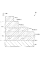
図2は、一実施形態に係る方法が適用され得る一例の被加工物の一部を拡大して示す断面図である。図2に示す被加工物Wは、第1領域R1及び第2領域R2を有している。被加工物Wは、第3領域R3を更に有していてもよい。第1領域R1は、窒化シリコンから形成されており、第2領域R2は、酸化シリコンから形成されており、第3領域R3は、シリコンから形成されている。第3領域R3は、例えば、多結晶シリコンから形成されている。図2に示す被加工物Wでは、第1領域R1、第2領域R2、及び、第3領域R3は、下地層UL上に設けられている。第1領域R1、第2領域R2、及び、第3領域R3の被加工物W中のレイアウトは、図2に示すレイアウトに限定されるものではない。 FIG. 2 is an enlarged cross-sectional view showing a part of an example work piece to which the method according to the embodiment can be applied. The workpiece W shown in FIG. 2 has a first region R1 and a second region R2. The workpiece W may further have a third region R3. The first region R1 is formed of silicon nitride, the second region R2 is formed of silicon oxide, and the third region R3 is formed of silicon. The third region R3 is formed of, for example, polycrystalline silicon. In the workpiece W shown in FIG. 2, the first region R1, the second region R2, and the third region R3 are provided on the base layer UL. The layout of the first region R1, the second region R2, and the third region R3 in the workpiece W is not limited to the layout shown in FIG.
図3は、一実施形態に係る方法が適用され得る別の一例の被加工物の一部を拡大して示す断面図である。図3に示す被加工物Wは、図2に示す被加工物Wと同様に、第1領域R1、第2領域R2、及び、第3領域R3を有する。第2領域R2は、第3領域R3の両側に設けられており、第3領域R3は、第2領域R2に対して隆起するように設けられている。第1領域R1は、第2領域R2及び第3領域R3を覆うように設けられている。なお、図3に示す被加工物Wは、Fin型電界効果トランジスタの製造途中に得られる中間生産物であり、第3領域R3は、ソース領域、ドレイン領域、及び、チャネル領域を提供するフィン領域として利用される。 FIG. 3 is an enlarged cross-sectional view showing a part of another example work piece to which the method according to the embodiment can be applied. The workpiece W shown in FIG. 3 has a first region R1, a second region R2, and a third region R3, similarly to the workpiece W shown in FIG. The second region R2 is provided on both sides of the third region R3, and the third region R3 is provided so as to bulge with respect to the second region R2. The first region R1 is provided so as to cover the second region R2 and the third region R3. The workpiece W shown in FIG. 3 is an intermediate product obtained during the manufacturing of the Fin-type field effect transistor, and the third region R3 is a fin region that provides a source region, a drain region, and a channel region. It is used as.
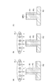
図4は、種々の実施形態に係る方法において利用可能なプラズマ処理装置を概略的に示す図である。図4に示すプラズマ処理装置10は、ICP(Inductively Coupled Plasma)型のプラズマ源を備える。プラズマ処理装置10は、チャンバ本体12を備えている。チャンバ本体12は、例えばアルミニウムといった金属から形成されている。チャンバ本体12は、例えば略円筒形状を有している。チャンバ本体12は、その内部空間をチャンバ12cとして提供している。チャンバ12cは、プラズマ処理のための空間として利用される。
FIG. 4 is a diagram schematically showing a plasma processing apparatus that can be used in the methods according to various embodiments. The
チャンバ本体12の底部には、ステージ14が設けられている。ステージ14は、その上に搭載された被加工物Wを保持するように構成されている。ステージ14は、支持部13によって支持され得る。支持部13は、チャンバ12c内において、チャンバ本体12の底部から上方に延在している。支持部13は、例えば、略円筒形状を有し得る。支持部13は、例えば石英といった絶縁材料から形成され得る。
A
ステージ14は、静電チャック16及び下部電極18を有している。下部電極18は、第1プレート18a及び第2プレート18bを含んでいる。第1プレート18a及び第2プレート18bは、例えばアルミニウムといった金属から形成されている。第1プレート18a及び第2プレート18bは、例えば略円盤形状を有し得る。第2プレート18bは、第1プレート18a上に設けられている。第2プレート18bは、第1プレート18aに電気的に接続されている。
The
静電チャック16は、第2プレート18b上に設けられている。静電チャック16は、絶縁層、及び、当該絶縁層内に内蔵された膜状の電極を有する。静電チャック16の電極には、スイッチ23を介して直流電源22が電気的に接続されている。静電チャック16は、直流電源22からの直流電圧によって生じる静電力を発生する。被加工物Wは、静電力によって静電チャック16に引き付けられ、当該静電チャック16によって保持される。
The
プラズマ処理装置10の使用時には、フォーカスリングFRが、被加工物Wのエッジ及び静電チャック16の縁部を囲むように、第2プレート18bの周縁部上に配置される。フォーカスリングFRは、プラズマ処理の均一性を向上させるために利用される。フォーカスリングFRは、例えば、石英から形成され得る。
When the
第2プレート18bには、流路24が形成されている。流路24には、ステージ14の温度調整のために熱交換媒体、例えば冷媒が、チャンバ本体12の外部に設けられた温度調節器(例えば、チラーユニット)から供給される。温度調節器は、熱交換媒体の温度を調節する装置である。流路24には、温度調節器から配管26aを介して熱交換媒体が供給される。流路24に供給された熱交換媒体は、配管26bを介して温度調節器に戻される。熱交換調節器によってその温度が調整された熱交換媒体がステージ14の流路24に供給されることにより、ステージ14の温度、ひいては被加工物Wの温度が調整される。プラズマ処理装置10では、ガス供給ライン28がステージ14を通って静電チャック16の上面まで延びている。静電チャック16の上面と被加工物Wの裏面との間には、伝熱ガス供給機構からの伝熱ガス、例えばHeガスが、ガス供給ライン28を介して供給される。これにより、ステージ14と被加工物Wの熱交換が促進される。
A
ステージ14内にはヒータHTが設けられていてもよい。ヒータHTは、加熱素子である。ヒータHTは、例えば、第2プレート18b内に、或いは、静電チャック16内に埋め込まれている。ヒータHTは、ヒータ電源HPに接続されている。ヒータ電源HPからヒータHTに電力が供給されることによって、ステージ14の温度が調整され、ひいては被加工物Wの温度が調整される。
A heater HT may be provided in the
ステージ14の下部電極18には、高周波電源30が整合器32を介して接続されている。下部電極18には、高周波電源30からの高周波が供給され得る。高周波電源30は、ステージ14上に搭載された被加工物Wにイオンを引き込むための高周波、即ち、バイアス用の高周波を発生する。バイアス用の高周波は、例えば、400[kHz]〜40.68[MHz]の範囲内の周波数、一例においては13.56[MHz]の周波数を有する。整合器32は、高周波電源30の出力インピーダンスと負荷側(下部電極18側)のインピーダンスとを整合させるための回路を有している。なお、プラズマ処理装置10では、バイアス用の高周波を下部電極18に供給することにより、プラズマ生成のために他の高周波を用いることなく、プラズマを生成することも可能である。
A high
プラズマ処理装置10では、チャンバ本体12の内壁に沿ってシールド34が着脱自在に設けられている。シールド34は、支持部13の外周にも設けられている。シールド34は、チャンバ本体12にエッチング副生物が付着することを防止するための部材である。シールド34は、アルミニウム製の母材の表面にY2O3といったセラミックスを被覆することにより構成され得る。
In the
ステージ14とチャンバ本体12の側壁との間には排気路が形成されている。この排気路は、チャンバ本体12の底部に形成された排気口12eに繋がっている。排気口12eには、配管36を介して排気装置38が接続されている。排気装置38は、圧力調整器、及び、ターボ分子ポンプといった真空ポンプを含んでいる。排気路には、即ち、ステージ14とチャンバ本体12の側壁との間には、バッフル板40が設けられている。バッフル板40は、その板厚方向に当該バッフル板40を貫通する複数の貫通孔が形成されている。バッフル板40は、例えば、アルミニウム製の母材の表面にY2O3といったセラミックスを被覆することにより構成され得る。
An exhaust path is formed between the
チャンバ本体12の天部は開口している。この開口は窓部材42によって閉じられている。窓部材42は、石英といった誘電体から形成されている。窓部材42は、例えば板状をなしている。
The top of the
チャンバ本体12の側壁には、ガス導入口12iが形成されている。ガス導入口12iには、配管46を介してガス供給部44が接続されている。ガス供給部44は、チャンバ12cに後述する第1のガス及び第2のガスを供給する。ガス供給部44は、ガスソース群44a、流量制御器群44b、及び、バルブ群44cを含んでいる。ガスソース群44aは、複数のガスソースを含んでいる。複数のガスソースは、第1のガスに含まれる一以上のガスのソース、及び、第2のガスに含まれる一以上のガスのソースを含んでいる。流量制御器群44bは、複数の流量制御器を含んでいる。複数の流量制御器の各々は、マスフローコントローラ又は圧力制御式の流量制御器である。バルブ群44cは、複数のバルブを含んでいる。ガスソース群44aの複数のガスソースは、流量制御器群44bの複数の流量制御器のうち対応の流量制御器、及び、バルブ群44cの複数のバルブのうち対応のバルブを介して、ガス導入口12iに接続されている。なお、ガス導入口12iは、チャンバ本体12の側壁ではなく、窓部材42といった他の箇所に形成されていてもよい。
A
チャンバ本体12の側壁には、開口12pが形成されている。この開口12pは、チャンバ本体12の外部からチャンバ12c内に被加工物Wが搬入されるとき、及び、チャンバ12cからチャンバ本体12の外部に被加工物Wが搬出されるときに、被加工物Wが通過する通路である。チャンバ本体12の側壁には、この開口12pの開閉のためのゲートバルブ48が取り付けられている。
An
チャンバ本体12の天部の上、及び、窓部材42の上には、アンテナ50及びシールド部材60が設けられている。アンテナ50及びシールド部材60は、チャンバ本体12の外側に設けられている。一実施形態において、アンテナ50は、内側アンテナ素子52A及び外側アンテナ素子52Bを有している。内側アンテナ素子52Aは、渦巻き状のコイルであり、窓部材42の中央部の上で延在している。外側アンテナ素子52Bは、渦巻き状のコイルであり、窓部材42上、且つ、内側アンテナ素子52Aの外側で、延在している。内側アンテナ素子52A及び外側アンテナ素子52Bの各々は、銅、アルミニウム、ステンレスといった導体から形成されている。
An
内側アンテナ素子52A及び外側アンテナ素子52Bは共に、複数の挟持体54によって挟持されており、これら複数の挟持体54によって支持されている。複数の挟持体54の各々は、棒状の形状を有している。複数の挟持体54は、内側アンテナ素子52Aの中心付近から外側アンテナ素子52Bの外側まで放射状に延在している。
Both the
シールド部材60は、アンテナ50を覆っている。シールド部材60は、内側シールド壁62A及び外側シールド壁62Bを含んでいる。内側シールド壁62Aは、筒形状を有している。内側シールド壁62Aは、内側アンテナ素子52Aを囲むように、内側アンテナ素子52Aと外側アンテナ素子52Bとの間に設けられている。外側シールド壁62Bは、筒形状を有している。外側シールド壁62Bは、外側アンテナ素子52Bを囲むように、外側アンテナ素子52Bの外側に設けられている。
The
内側アンテナ素子52Aの上には、内側シールド壁62Aの開口を塞ぐように、円盤状の内側シールド板64Aが設けられている。外側アンテナ素子52Bの上には、内側シールド壁62Aと外側シールド壁62Bとの間の開口を塞ぐように、環状板形状の外側シールド板64Bが設けられている。
A disk-shaped
なお、シールド部材60のシールド壁及びシールド板の形状は、上述した形状に限定されるものではない。シールド部材60のシールド壁の形状は、角筒形状といった他の形状であってもよい。
The shapes of the shield wall and the shield plate of the
内側アンテナ素子52A、外側アンテナ素子52Bには、高周波電源70A、高周波電源70Bがそれぞれ接続されている。内側アンテナ素子52A、外側アンテナ素子52Bには、高周波電源70A、高周波電源70Bから、同じ周波数又は異なる周波数を有する高周波がそれぞれ供給される。高周波電源70Aからの高周波が内側アンテナ素子52Aに供給されると、チャンバ12c内で誘導磁界が発生し、チャンバ12c内のガスが当該誘導磁界によって励起される。これにより、被加工物Wの中央の領域の上方でプラズマが生成される。また、高周波電源70Bからの高周波が外側アンテナ素子52Bに供給されると、チャンバ12c内で誘導磁界が発生し、チャンバ12c内のガスが当該誘導磁界によって励起される。これにより、被加工物Wの周縁領域の上方で、環状のプラズマが生成される。
A high-
なお、高周波電源70A、高周波電源70Bのそれぞれから出力される高周波に応じて、内側アンテナ素子52A、外側アンテナ素子52Bの電気的長さを調整する必要がある。このために、内側シールド板64A、外側シールド板64Bのそれぞれの高さ方向の位置は、アクチュエータ68A、アクチュエータ68Bによって個別に調整されるようになっている。
It is necessary to adjust the electrical lengths of the
プラズマ処理装置10は、制御部80を更に備え得る。制御部80は、プロセッサ、メモリといった記憶部、入力装置、表示装置等を備えるコンピュータであることができる。制御部80は、記憶部に記憶されている制御プログラム及びレシピデータに従って動作し、プラズマ処理装置10の種々の要素を制御し得る。具体的に、制御部80は、流量制御器群44bの複数の流量制御器、バルブ群44cの複数のバルブ、排気装置38、高周波電源70A、高周波電源70B、高周波電源30、整合器32、ヒータ電源HPといったプラズマ処理装置の種々の要素を制御する。なお、種々の実施形態に係る方法の実行時にも、制御部80は、制御プログラム及びレシピデータに従って、プラズマ処理装置10の種々の要素を制御することができる。
The
以下、再び図1を参照し、方法MTについて詳細に説明する。また、以下の説明では、図5の(a)、図5の(b)、図6の(a)、図6の(b)、図6の(c)、図7の(a)、図7の(b)、及び、図7の(c)を参照する。図5の(a)は一実施形態に係る方法の工程ST1を説明するための図であり、図5の(b)は一実施形態に係る方法の工程ST1の実行後の被加工物の状態を示す図である。図6の(a)は一実施形態に係る方法の工程ST2を説明するための図であり、図6の(b)は一実施形態に係る方法の工程ST2の実行後の被加工物の状態を示す図であり、図6の(c)は一実施形態に係る方法の終了時の被加工物の状態を示す図である。図7の(a)は一実施形態に係る方法の工程ST1の実行後の被加工物の状態を示す図であり、図7の(b)は一実施形態に係る方法の工程ST2の実行後の被加工物の状態を示す図であり、図7の(c)は一実施形態に係る方法の終了時の被加工物の状態を示す図である。 Hereinafter, the method MT will be described in detail with reference to FIG. 1 again. Further, in the following description, FIG. 5A, FIG. 5B, FIG. 6A, FIG. 6B, FIG. 6C, FIG. 7A, FIG. 7 (b) and FIG. 7 (c) are referred to. FIG. 5A is a diagram for explaining step ST1 of the method according to one embodiment, and FIG. 5B is a state of the workpiece after execution of step ST1 of the method according to one embodiment. It is a figure which shows. FIG. 6A is a diagram for explaining step ST2 of the method according to one embodiment, and FIG. 6B is a state of the workpiece after execution of step ST2 of the method according to one embodiment. FIG. 6 (c) is a diagram showing a state of a workpiece at the end of the method according to the embodiment. FIG. 7A is a diagram showing a state of the workpiece after the execution of the step ST1 of the method according to the embodiment, and FIG. 7B is a diagram after the execution of the step ST2 of the method according to the embodiment. It is a figure which shows the state of the workpiece, and FIG. 7C is the figure which shows the state of the workpiece at the end of the method which concerns on one Embodiment.
図1に示すように、方法MTの工程STPでは、プラズマ処理装置のチャンバ本体によって提供されるチャンバ内で、図2又は図3に示した被加工物Wが準備される。被加工物Wは、下部電極を有するステージ上に載置される。プラズマ処理装置10が用いられる場合には、被加工物Wは、ステージ14上に載置され、静電チャック16によって保持される。
As shown in FIG. 1, in the process STP of the method MT, the workpiece W shown in FIG. 2 or 3 is prepared in the chamber provided by the chamber body of the plasma processing apparatus. The workpiece W is placed on a stage having a lower electrode. When the
方法MTでは、被加工物Wがステージ14上に載置された状態で、工程ST1及び工程ST2が順に実行される。工程ST1では、チャンバ内で第1のガスのプラズマPL1が生成される。第1のガスは、水素を含有するガスを含む。水素を含有するガスは、例えばH2ガス及び/又はNH3ガスであり得る。
In the method MT, the steps ST1 and ST2 are sequentially executed with the workpiece W placed on the
工程ST1では、図5の(a)に示すように、プラズマPL1から水素の活性種、例えば水素イオンが被加工物Wの表面に照射される。図5の(a)において、文字「H」を囲む円形の図形は水素の活性種を表している。水素の活性種が被加工物Wの表面に照射されると、図5の(b)に示すように、第1領域R1の一部、即ち、その表面を含む第1領域R1の一部分が改質されて、改質領域MR1になる。なお、図3の被加工物Wの場合には、図7の(a)に示すように、改質領域MR1が形成される。改質領域MR1は、フッ素の活性種によって容易に除去可能である。一方、第2領域R2は、安定しており、水素の活性種では改質されない。 In step ST1, as shown in FIG. 5A, the surface of the workpiece W is irradiated with an active species of hydrogen, for example, hydrogen ions, from the plasma PL1. In FIG. 5A, the circular figure surrounding the letter “H” represents an active species of hydrogen. When the surface of the workpiece W is irradiated with the active species of hydrogen, as shown in FIG. 5 (b), a part of the first region R1, that is, a part of the first region R1 including the surface is modified. It is qualified and becomes the modified region MR1. In the case of the workpiece W of FIG. 3, the modified region MR1 is formed as shown in FIG. 7 (a). The modified region MR1 can be easily removed by the active species of fluorine. On the other hand, the second region R2 is stable and is not modified by active hydrogen species.
一実施形態の工程ST1では、ステージの下部電極にバイアス用の高周波が供給される。一実施形態の工程ST1では、バイアス用の高周波のみによって、プラズマが生成されてもよい。下部電極にバイアス用の高周波が供給されると、水素イオンが被加工物Wに強く引き込まれて、第1領域R1の改質が促進され、第1領域R1の膜厚方向において改質領域MR1の厚みが大きくなる。なお、工程ST1において下部電極に供給されるバイアス用の高周波のパワーは、スパッタリングによるエッチングが生じないように設定される。 In step ST1 of one embodiment, a high frequency for bias is supplied to the lower electrode of the stage. In step ST1 of one embodiment, plasma may be generated only by the high frequency for bias. When a high frequency for bias is supplied to the lower electrode, hydrogen ions are strongly attracted to the workpiece W to promote the modification of the first region R1 and the modified region MR1 in the film thickness direction of the first region R1. The thickness of is increased. The high-frequency bias power supplied to the lower electrode in step ST1 is set so that etching due to sputtering does not occur.
被加工物Wが第3領域R3を有する場合には、第1のガスは、酸素を含有するガスを更に含み得る。酸素を含有するガスは、例えば、O2ガス、COガス、CO2ガス、NOガス、NO2ガス、N2Oガス、SO2ガスのうち何れか、又は、これらのうち二以上のガスを含む混合ガスであり得る。第1のガスが酸素を含有するガスを含む場合には、図5の(a)に示すように、酸素の活性種、例えば酸素イオンが被加工物Wの表面に照射される。図5の(a)において、文字「O」を囲む円形の図形は酸素の活性種を表している。酸素の活性種が被加工物Wの表面に照射されると、図5の(b)に示すように、第3領域R3の一部、即ち、その表面を含む第3領域R3の一部分が酸化して、酸化領域MR3になる。このように第3領域R3の表面が酸化されると、後述の工程ST2において第3領域R3のエッチングが抑制される。 When the workpiece W has a third region R3, the first gas may further contain a gas containing oxygen. The oxygen-containing gas may be, for example, any one of O 2 gas, CO gas, CO 2 gas, NO gas, NO 2 gas, N 2 O gas and SO 2 gas, or two or more of these gases. It can be a mixed gas containing. When the first gas contains a gas containing oxygen, as shown in FIG. 5A, an active species of oxygen, for example, oxygen ions, is irradiated on the surface of the workpiece W. In (a) of FIG. 5, the circular figure surrounding the letter "O" represents an active species of oxygen. When the surface of the workpiece W is irradiated with an active species of oxygen, a part of the third region R3, that is, a part of the third region R3 including the surface thereof is oxidized as shown in FIG. 5 (b). Then, it becomes the oxidation region MR3. When the surface of the third region R3 is oxidized in this way, the etching of the third region R3 is suppressed in the step ST2 described later.
一実施形態では、第1のガス中の水素を含有するガスの流量に対する第1のガス中の酸素を含有するガスの流量の比率は、3/100以上、9/100以下であり得る。このように第1のガス中の水素を含有するガスの流量に対する第1のガス中の酸素を含有するガスの流量の比率が設定されることにより、後述する工程ST2において酸化領域MR3を含む第3領域R3のエッチングが更に抑制される。また、後述の工程ST2における第1領域R1のエッチングレートの低下が抑制される。 In one embodiment, the ratio of the flow rate of the oxygen-containing gas in the first gas to the flow rate of the hydrogen-containing gas in the first gas can be 3/100 or more and 9/100 or less. By setting the ratio of the flow rate of the oxygen-containing gas in the first gas to the flow rate of the hydrogen-containing gas in the first gas in this way, the second step including the oxidation region MR3 is included in the step ST2 described later. Etching of the three-region R3 is further suppressed. Further, the decrease in the etching rate of the first region R1 in the step ST2 described later is suppressed.
プラズマ処理装置10が用いられる場合には、工程ST1において、ガス供給部44から、水素を含有するガスを含む第1のガスがチャンバ12cに供給される。チャンバ12cに供給される第1のガスは、酸素を含有するガスを含んでいてもよい。第1のガスに含まれる一以上のガスの流量はそれぞれ、流量制御器群44bの対応の流量制御器によって制御される。また、排気装置38によってチャンバ12cの圧力が、指定された圧力に設定される。また、高周波電源30からのバイアス用の高周波が、下部電極18に供給されてもよい。工程ST1では、プラズマの生成のために、内側アンテナ素子52A、外側アンテナ素子52Bのそれぞれに、高周波電源70A、高周波電源70Bから高周波が供給されてもよいが、供給されなくてもよい。即ち、工程ST1では、バイアス用の高周波を下部電極18に供給することにより、他の高周波を用いることなく、プラズマが生成されてもよい。
When the
続く工程ST2では、チャンバ内で第2のガスのプラズマPL2が生成される。第2のガスは、フッ素を含有するガスを含む。フッ素を含有するガスは、フッ素を含有する任意のガスであり得る。例えば、フッ素を含有するガスは、NF3ガス、SF6ガス、フルオロカーボンガス(例えば、CF4ガス)のうち何れか、又は、これらのうち二以上のガスを含む混合ガスであり得る。第2のガスは、フッ素を含有するガスに加えて、他のガス、例えば、O2ガス、及び、Arガスといった希ガスを含んでいてもよい。 In the subsequent step ST2, a second gas plasma PL2 is generated in the chamber. The second gas contains a gas containing fluorine. The fluorine-containing gas can be any fluorine-containing gas. For example, the fluorine-containing gas may be any one of NF 3 gas, SF 6 gas, fluorocarbon gas (for example, CF 4 gas), or a mixed gas containing two or more of these gases. The second gas may contain other gases, for example, a rare gas such as O 2 gas and Ar gas, in addition to the gas containing fluorine.
工程ST2では、図6の(a)に示すように、プラズマPL2からフッ素の活性種が被加工物Wの表面に照射される。図6の(a)において、文字「F」を囲む円形の図形はフッ素の活性種を表している。フッ素の活性種が被加工物Wの表面に照射されると、図6の(b)に示すように、フッ素の活性種により改質領域MR1が選択的にエッチングされて除去される。なお、図3の被加工物Wの場合には、図7の(b)に示すように、改質領域MR1が除去される。 In step ST2, as shown in FIG. 6A, the surface of the workpiece W is irradiated with the active species of fluorine from the plasma PL2. In FIG. 6A, the circular figure surrounding the letter “F” represents an active species of fluorine. When the surface of the workpiece W is irradiated with the active species of fluorine, the modified region MR1 is selectively etched and removed by the active species of fluorine, as shown in FIG. 6 (b). In the case of the workpiece W of FIG. 3, the modified region MR1 is removed as shown in FIG. 7 (b).
一実施形態の工程ST2では、ステージの下部電極にバイアス用の高周波が供給されない。工程ST2において下部電極にバイアス用の高周波が供給されない場合には、フッ素の活性種としてフッ素イオンではなく主にフッ素ラジカルによりエッチングが行われる。即ち、イオンによるスパッタエッチングではなく、ラジカルによるエッチングが行われる。これにより、第2領域R2及び酸化領域MR3を含む第3領域R3のエッチングが抑制される。また、改質領域MR1とフッ素の活性種との化学的反応により、改質領域MR1が除去される。 In step ST2 of one embodiment, a high frequency for bias is not supplied to the lower electrode of the stage. When a high frequency for bias is not supplied to the lower electrode in step ST2, etching is performed mainly by fluorine radicals instead of fluorine ions as the active species of fluorine. That is, etching by radicals is performed instead of sputtering etching by ions. As a result, etching of the third region R3 including the second region R2 and the oxidation region MR3 is suppressed. Further, the modified region MR1 is removed by a chemical reaction between the modified region MR1 and an active species of fluorine.
一実施形態の工程ST2では、第2のガスは、水素を含んでいてもよい。第2のガスが水素を含む場合には、第2のガス中のフッ素の原子数に対する第2のガス中の水素の原子数の比率は、8/9以上である。また、第2のガスにおいて、フッ素を含有するガスがNF3ガスであり、水素を含有するガスがH2ガスである場合には、第2のガス中のNF3ガスの流量に対する第2のガス中のH2ガスの流量の比率は、3/4以上である。第2のガス中のフッ素の原子数に対する第2のガス中の水素の原子数の比率、或いは、第2のガス中のNF3ガスの流量に対する第2のガス中のH2ガスの流量の比率が上述したように設定されると、窒化シリコン、酸化シリコン、及び、シリコンは、殆どエッチングされない。しかしながら、水素によって改質された窒化シリコンは、エッチングされる。即ち、改質領域MR1はエッチングされる。したがって、第1領域R1のエッチングの選択性が更に向上される。 In step ST2 of one embodiment, the second gas may contain hydrogen. When the second gas contains hydrogen, the ratio of the number of hydrogen atoms in the second gas to the number of fluorine atoms in the second gas is 8/9 or more. Further, in the second gas, when the gas containing fluorine is the NF 3 gas and the gas containing hydrogen is the H 2 gas, the second gas is the second gas with respect to the flow rate of the NF 3 gas in the second gas. The ratio of the flow rate of H 2 gas in the gas is 3/4 or more. The ratio of the number of hydrogen atoms in the second gas to the number of fluorine atoms in the second gas, or the flow rate of H 2 gas in the second gas to the flow rate of NF 3 gas in the second gas. When the ratio is set as described above, the silicon nitride, silicon oxide, and silicon are hardly etched. However, the hydrogen-modified silicon nitride is etched. That is, the modified region MR1 is etched. Therefore, the etching selectivity of the first region R1 is further improved.
プラズマ処理装置10が用いられる場合には、工程ST2において、ガス供給部44からフッ素を含有するガスを含む第2のガスがチャンバ12cに供給される。チャンバ12cに供給される第2のガスは、水素を含有するガスを含んでいてもよい。第2のガスに含まれる一以上のガスの流量はそれぞれ、流量制御器群44bの対応の流量制御器によって制御される。また、排気装置38によってチャンバ12cの圧力が、指定された圧力に設定される。また、内側アンテナ素子52Aに高周波電源70Aからの高周波が供給され、外側アンテナ素子52Bに高周波電源70Bからの高周波が供給される。高周波電源30からのバイアス用の高周波は下部電極18に供給されないか、或いは、そのパワーは比較的小さい。
When the
図1に示すように、続く工程STJでは、停止条件が満たされるか否かが判定される。停止条件は、工程ST1及び工程ST2を含むシーケンスの実行回数が所定回数に達しているときに満たされるものと判断される。工程STJにおいて、停止条件が満たされないものと判定されると再び工程ST1が実行される。一方、停止条件が満たされるものと判定されると方法MTは終了する。方法MTの終了時には、図6の(c)に示すように、図2に示した被加工物Wから第1領域R1が除去される。或いは、図7の(c)に示すように、図3に示した被加工物Wから第1領域R1が除去される。 As shown in FIG. 1, in the subsequent step STJ, it is determined whether or not the stop condition is satisfied. It is determined that the stop condition is satisfied when the number of executions of the sequence including the steps ST1 and ST2 reaches a predetermined number of times. If it is determined in the process STJ that the stop condition is not satisfied, the process ST1 is executed again. On the other hand, when it is determined that the stop condition is satisfied, the method MT ends. At the end of the method MT, as shown in FIG. 6 (c), the first region R1 is removed from the workpiece W shown in FIG. Alternatively, as shown in FIG. 7 (c), the first region R1 is removed from the workpiece W shown in FIG.
方法MTでは、工程ST1において生成される水素の活性種により第1領域R1の一部が改質されて、フッ素の活性種により容易に除去可能な改質領域MR1となる。一方、酸化シリコンから形成された第2領域R2は、安定しているので、水素の活性種では改質されない。したがって、工程ST2では、第2領域R2に対して改質領域MR1が選択的に除去される。故に、方法MTによれば、第1領域R1が第2領域R2に対して選択的にエッチングされる。また、工程ST1及び工程ST2において生成されるプラズマ中の活性種は、ハイドロフルオロカーボンガスのプラズマ中の活性種と比較して、相当に低い堆積性を有するか、又は、実質的に堆積性を有していない。したがって、方法MTによれば、堆積物の生成が抑制される。 In the method MT, a part of the first region R1 is modified by the active species of hydrogen generated in the step ST1 to become the modified region MR1 that can be easily removed by the active species of fluorine. On the other hand, the second region R2 formed from silicon oxide is stable and is not modified by active hydrogen species. Therefore, in step ST2, the modified region MR1 is selectively removed with respect to the second region R2. Therefore, according to the method MT, the first region R1 is selectively etched with respect to the second region R2. Further, the active species in the plasma generated in the steps ST1 and ST2 have considerably lower or substantially less sedimentary properties than the active species in the plasma of the hydrofluorocarbon gas. Not done. Therefore, according to Method MT, sediment formation is suppressed.
また、被加工物Wが第3領域R3を有する場合には、上述したように、第1のガスに酸素を含有するガスが含められる。これにより、工程ST1では、酸素の活性種によって、第3領域R3の表面が酸化し、工程ST2のエッチングにおいて酸化領域MR3を含む第3領域R3のエッチングが抑制される。したがって、第2領域R2及び第3領域R3に対して第1領域R1が選択的にエッチングされる。 Further, when the workpiece W has the third region R3, as described above, the gas containing oxygen is included in the first gas. As a result, in the step ST1, the surface of the third region R3 is oxidized by the active species of oxygen, and the etching of the third region R3 including the oxidized region MR3 is suppressed in the etching of the step ST2. Therefore, the first region R1 is selectively etched with respect to the second region R2 and the third region R3.
また、上述したように、一実施形態では、第1のガス中の水素を含有するガスの流量に対する第1のガス中の酸素を含有するガスの流量の比率は、3/100以上、9/100以下に設定される。この実施形態では、工程ST2において酸化領域MR3を含む第3領域R3のエッチングが更に抑制される。また、工程ST2における第1領域R1のエッチングレートの低下が抑制される。結果的に、第3領域R3に対して第1領域R1を更に高い選択比でエッチングすることが可能となる。 Further, as described above, in one embodiment, the ratio of the flow rate of the oxygen-containing gas in the first gas to the flow rate of the hydrogen-containing gas in the first gas is 3/100 or more, 9 /. It is set to 100 or less. In this embodiment, the etching of the third region R3 including the oxidation region MR3 is further suppressed in the step ST2. Further, the decrease in the etching rate of the first region R1 in the step ST2 is suppressed. As a result, the first region R1 can be etched with a higher selectivity with respect to the third region R3.
以下、別の実施形態に係る方法について説明する。図8は、別の実施形態に係る方法を示す流れ図である。図8に示す方法MTAは、図3に示す被加工物Wのような、第1領域R1によって第2領域R2及び第3領域R3が覆われている被加工物に対して、適用され得る。 Hereinafter, a method according to another embodiment will be described. FIG. 8 is a flow chart showing a method according to another embodiment. The method MTA shown in FIG. 8 can be applied to a workpiece such as the workpiece W shown in FIG. 3, in which the second region R2 and the third region R3 are covered by the first region R1.
方法MTAは、方法MTの工程STPと同じ工程STPを含んでいる。方法MTAは、順に実行される複数のシーケンスSQを更に含んでいる。複数のシーケンスSQの各々は、方法MTの工程ST1と同様の工程ST1、及び、方法MTの工程ST2と同様の工程ST2を含んでいる。 The method MTA includes the same process STP as the process STP of the method MT. The method MTA further comprises a plurality of sequence SQs that are executed in sequence. Each of the plurality of sequence SQs includes a step ST1 similar to the step ST1 of the method MT and a step ST2 similar to the step ST2 of the method MT.
複数のシーケンスSQは、一以上の第1シーケンスSQ1、及び、一以上の第2シーケンスSQ2を含んでいる。一以上の第1シーケンスSQ1は、複数のシーケンスのうち最初に実行されるシーケンスを含む一以上のシーケンスである。一以上の第2シーケンスSQ2は、複数のシーケンスSQのうち、一以上の第1シーケンスSQ1の後に実行されるシーケンスである。一以上の第2シーケンスSQ2は、第3領域R3の表面を酸化させるための工程ST1を含むシーケンスである。 The plurality of sequence SQs include one or more first sequence SQ1s and one or more second sequence SQ2s. One or more first sequences SQ1 is one or more sequences including the sequence to be executed first among the plurality of sequences. The one or more second sequence SQ2 is a sequence executed after the one or more first sequence SQ1 among the plurality of sequence SQs. One or more second sequences SQ2 are sequences including step ST1 for oxidizing the surface of the third region R3.
方法MTAは、工程STJ1、及び、工程STJ2を含んでいる。工程STJ1では、停止条件が満たされるか否かが判定される。工程STJ1において、停止条件は、第1シーケンスSQ1の実行回数が所定回数に達しているときに満たされるものと判断される。工程STJ1において、停止条件が満たされないものと判定されると、再び第1シーケンスSQ1が実行される。一方、工程STJ1において、停止条件が満たされるものと判定されると、第2シーケンスSQ2の実行に処理が進む。 The method MTA includes step STJ1 and step STJ2. In step STJ1, it is determined whether or not the stop condition is satisfied. In step STJ1, it is determined that the stop condition is satisfied when the number of executions of the first sequence SQ1 reaches a predetermined number of times. If it is determined in step STJ1 that the stop condition is not satisfied, the first sequence SQ1 is executed again. On the other hand, if it is determined in step STJ1 that the stop condition is satisfied, the process proceeds to the execution of the second sequence SQ2.
工程STJ2では、停止条件が満たされるか否かが判定される。工程STJ2において、停止条件は、第2シーケンスSQ2の実行回数が所定回数に達しているときに満たされるものと判断される。工程STJ2において、停止条件が満たされないものと判定されると再び第2シーケンスSQ2が実行される。一方、工程STJ2において、停止条件が満たされるのと判定されると、方法MTAの実行が終了する。 In step STJ2, it is determined whether or not the stop condition is satisfied. In step STJ2, it is determined that the stop condition is satisfied when the number of executions of the second sequence SQ2 reaches a predetermined number of times. If it is determined in step STJ2 that the stop condition is not satisfied, the second sequence SQ2 is executed again. On the other hand, if it is determined in step STJ2 that the stop condition is satisfied, the execution of the method MTA ends.
図9の(a)、図9の(b)はそれぞれ、図8に示す方法の第1例における第1シーケンスの工程ST1、第2シーケンス中の工程ST1を説明するための図である。図9の(c)は第2シーケンス中の工程ST1の実行により第3領域の表面が酸化された状態を示す図である。方法MTAの第1例では、一以上の第1シーケンスSQ1は、第3領域R3が露出するまで実行される。方法MTAの第1例では、一以上の第1シーケンスSQ1の工程ST1において用いられる第1のガスは、酸素を含有するガスを含んでいない。したがって、図9の(a)に示すように、一以上の第1シーケンスSQ1の工程ST1では、酸素の活性種は被加工物Wに照射されず、水素の活性種が被加工物Wに照射される。 9 (a) and 9 (b) are diagrams for explaining the process ST1 of the first sequence and the process ST1 in the second sequence in the first example of the method shown in FIG. 8, respectively. FIG. 9C is a diagram showing a state in which the surface of the third region is oxidized by the execution of step ST1 in the second sequence. In the first example of the method MTA, one or more first sequence SQ1s are executed until the third region R3 is exposed. In the first example of the method MTA, the first gas used in step ST1 of one or more first sequences SQ1 does not contain an oxygen-containing gas. Therefore, as shown in FIG. 9A, in the step ST1 of one or more first sequence SQ1, the active species of oxygen does not irradiate the workpiece W, and the active species of hydrogen irradiates the workpiece W. Will be done.
方法MTAの第1例では、一以上の第2シーケンスSQ2は、第3領域R3が露出した直後から実行される。一以上の第2シーケンスSQ2の工程ST1では、第1のガスは、水素を含有するガスに加えて、酸素を含有するガスを含んでいる。したがって、方法MTAの第1例では、図9の(b)に示すように、第3領域R3が露出した直後に工程ST1において被加工物Wに水素の活性種と酸素の活性種が照射される。その結果、図9の(c)に示すように、第3領域R3の表面が露出した直後に、第3領域R3の表面が酸化して、酸化領域MR3が形成される。故に、工程ST2におけるフッ素の活性種のエッチングから第3領域R3が保護される。かかる方法MTAの第1例によれば、第2領域R2及び第3領域R3に対して第1領域R1が選択的にエッチングされる。 In the first example of the method MTA, one or more second sequences SQ2 are executed immediately after the third region R3 is exposed. In the step ST1 of one or more second sequences SQ2, the first gas contains an oxygen-containing gas in addition to the hydrogen-containing gas. Therefore, in the first example of the method MTA, as shown in FIG. 9B, the workpiece W is irradiated with the active species of hydrogen and the active species of oxygen in the step ST1 immediately after the third region R3 is exposed. To. As a result, as shown in FIG. 9C, immediately after the surface of the third region R3 is exposed, the surface of the third region R3 is oxidized to form the oxidized region MR3. Therefore, the third region R3 is protected from etching the active species of fluorine in step ST2. According to the first example of such a method MTA, the first region R1 is selectively etched with respect to the second region R2 and the third region R3.
図10の(a)、図10の(b)はそれぞれ、図8に示す方法の第2例における第1シーケンスの工程ST1、第2シーケンス中の工程ST1を説明するための図である。図10の(c)は第2シーケンス中の工程ST1の実行により第3領域の表面が酸化された状態を示す図である。方法MTAの第2例では、一以上の第1シーケンスSQ1は、第3領域R3が露出する直前まで実行される。即ち、第3領域R3を覆うように第1領域R1が僅かに残される状態が形成されるまで、一以上の第1シーケンスSQ1が実行される。方法MTAの第2例では、一以上の第1シーケンスSQ1の工程ST1において用いられる第1のガスは、酸素を含有するガスを含んでいない。したがって、図10の(a)に示すように、一以上の第1シーケンスSQ1の工程ST1では、酸素の活性種は被加工物Wに照射されず、水素の活性種が被加工物Wに照射される。 10 (a) and 10 (b) are diagrams for explaining the process ST1 of the first sequence and the process ST1 in the second sequence in the second example of the method shown in FIG. 8, respectively. FIG. 10 (c) is a diagram showing a state in which the surface of the third region is oxidized by the execution of step ST1 in the second sequence. In the second example of the method MTA, one or more first sequence SQ1s are executed until just before the third region R3 is exposed. That is, one or more first sequence SQ1s are executed until a state is formed in which a small amount of the first region R1 is left so as to cover the third region R3. In the second example of the method MTA, the first gas used in step ST1 of one or more first sequences SQ1 does not contain an oxygen-containing gas. Therefore, as shown in FIG. 10A, in the step ST1 of one or more first sequence SQ1, the active species of oxygen does not irradiate the workpiece W, and the active species of hydrogen irradiates the workpiece W. Will be done.
方法MTAの第2例における一以上の第2シーケンスSQ2では、第1のガスは、水素を含有するガスに加えて、酸素を含有するガスを含んでいる。したがって、方法MTAの第2例では、第3領域R3が露出する直前の時点から後に、図10の(b)に示すように、被加工物Wに酸素の活性種が照射される。したがって、図10の(c)に示すように、第3領域R3の表面が露出した直後に、当該第3領域R3の表面が酸化する。故に、第3領域R3の表面が露出した直後の時点以後、工程ST2におけるフッ素の活性種のエッチングから第3領域R3が保護される。かかる方法MTAの第2例によれば、第2領域R2及び第3領域R3に対して第1領域R1が選択的にエッチングされる。 In one or more second sequence SQ2 in the second example of the method MTA, the first gas contains an oxygen-containing gas in addition to the hydrogen-containing gas. Therefore, in the second example of the method MTA, the work piece W is irradiated with the active species of oxygen as shown in FIG. 10 (b) from the time immediately before the third region R3 is exposed. Therefore, as shown in FIG. 10 (c), the surface of the third region R3 is oxidized immediately after the surface of the third region R3 is exposed. Therefore, immediately after the surface of the third region R3 is exposed, the third region R3 is protected from etching of the active species of fluorine in the step ST2. According to the second example of such a method MTA, the first region R1 is selectively etched with respect to the second region R2 and the third region R3.
以下、更に別の実施形態に係る方法について説明する。図11は、更に別の実施形態に係る方法を示す流れ図である。図11に示す方法MTBは、方法MTAと同様に、図3に示す被加工物Wのような、第1領域R1によって第2領域R2及び第3領域R3が覆われている被加工物に対して、適用され得る。方法MTBは、工程STP、一以上の第1シーケンスSQ1、工程STJ1、一以上の第2シーケンスSQ2、及び、工程STJ2に加えて、一以上の第3シーケンスSQ3、及び、工程STJ3を更に含んでいる。 Hereinafter, a method according to still another embodiment will be described. FIG. 11 is a flow chart showing a method according to still another embodiment. Similar to the method MTA, the method MTB shown in FIG. 11 refers to a work piece such as the work piece W shown in FIG. 3 in which the second region R2 and the third region R3 are covered by the first region R1. Can be applied. The method MTB further comprises one or more third sequence SQ3 and step STJ3 in addition to step STP, one or more first sequence SQ1, process STJ1, one or more second sequence SQ2, and step STJ2. There is.
方法MTBでは、一以上の第2シーケンスSQ2は、第3領域R3の表面が酸化された後に終了される。方法MTBでは、工程STJ2において停止条件が満たされると判定される場合には、第3シーケンスSQ3の実行に処理が進む。工程STJ3では、停止条件が満たされるか否かが判定される。停止条件は、第3シーケンスSQ3の実行回数が所定回数に達しているときに満たされるものと判断される。工程STJ3において、停止条件が満たされないものと判定されると再び第3シーケンスSQ3が実行される。一方、工程STJ3において、停止条件が満たされるのと判定されると、方法MTBの実行が終了する。 In method MTB, one or more second sequence SQ2 is terminated after the surface of third region R3 has been oxidized. In the method MTB, when it is determined in the step STJ2 that the stop condition is satisfied, the process proceeds to the execution of the third sequence SQ3. In step STJ3, it is determined whether or not the stop condition is satisfied. It is determined that the stop condition is satisfied when the number of executions of the third sequence SQ3 reaches a predetermined number of times. If it is determined in step STJ3 that the stop condition is not satisfied, the third sequence SQ3 is executed again. On the other hand, in step STJ3, when it is determined that the stop condition is satisfied, the execution of the method MTB ends.
図12の(a)、図12の(b)、図12の(c)はそれぞれ、図11に示す方法における第1シーケンスの工程ST1、第2シーケンス中の工程ST1、第3シーケンス中の工程ST1を説明するための図である。方法MTBでは、一以上の第1シーケンスSQ1は、第3領域R3が露出する直前まで、又は、第3領域R3が露出するまで実行される。一以上の第1シーケンスSQ1の工程ST1においては、第1のガスは酸素を含有するガスを含んでいない。したがって、図12の(a)に示すように、一以上の第1シーケンスSQ1の工程ST1では、酸素の活性種は被加工物Wに照射されず、水素の活性種が被加工物Wに照射される。なお、一以上の第1シーケンスSQ1の工程ST1において、第1のガスは酸素を含有するガスを含んでいてもよい。 12 (a), 12 (b), and 12 (c) are the process ST1 of the first sequence, the process ST1 in the second sequence, and the process in the third sequence in the method shown in FIG. 11, respectively. It is a figure for demonstrating ST1. In the method MTB, one or more first sequence SQ1s are executed until just before the third region R3 is exposed or until the third region R3 is exposed. In the step ST1 of one or more first sequence SQ1, the first gas does not contain a gas containing oxygen. Therefore, as shown in FIG. 12A, in the step ST1 of one or more first sequence SQ1, the active species of oxygen is not irradiated to the workpiece W, and the active species of hydrogen irradiates the workpiece W. Will be done. In the step ST1 of one or more first sequence SQ1, the first gas may contain a gas containing oxygen.
方法MTBでは、一以上の第2シーケンスSQ2は、一以上の第1シーケンスSQ1の後に、第3領域R3の表面を酸化させるために実行される。一以上の第2シーケンスSQ2の工程ST1では、第1のガスは、水素を含有するガスに加えて、酸素を含有するガスを含んでいる。したがって、方法MTBの一以上の第2シーケンスSQ2によれば、図12の(b)に示すように、第3領域R3が露出した直後に被加工物Wに酸素の活性種が照射される。方法MTBでは、一以上の第2シーケンスSQ2は、第3領域R3の表面が酸化された後に終了する。 In method MTB, one or more second sequence SQ2s are performed after one or more first sequence SQ1s to oxidize the surface of the third region R3. In the step ST1 of one or more second sequences SQ2, the first gas contains an oxygen-containing gas in addition to the hydrogen-containing gas. Therefore, according to one or more second sequences SQ2 of the method MTB, as shown in FIG. 12 (b), the active species of oxygen is irradiated to the workpiece W immediately after the third region R3 is exposed. In method MTB, one or more second sequence SQ2 ends after the surface of third region R3 has been oxidized.
方法MTBでは、一以上の第2シーケンスSQ2の後に、一以上の第3シーケンスSQ3が実行される。一以上の第3シーケンスSQ3の工程ST1では、第1のガスは酸素を含有するガスを含んでいない。したがって、図12の(c)に示すように、一以上の第3シーケンスSQ3の工程ST1では、酸素の活性種は被加工物Wに照射されず、水素の活性種が被加工物Wに照射される。方法MTBでは、一以上の第2シーケンスSQ2においてその露出直後に第3領域R3の表面が酸化されるので、一以上の第3シーケンスSQ3の工程ST1において第1のガスに酸素を含有するガスが含まれていなくても、工程ST2におけるフッ素の活性種のエッチングから第3領域R3が保護される。かかる方法MTBによれば、第2領域R2及び第3領域R3に対して第1領域R1が選択的にエッチングされる。 Method In MTB, one or more second sequence SQ2 is followed by one or more third sequence SQ3. In the step ST1 of one or more third sequences SQ3, the first gas does not contain a gas containing oxygen. Therefore, as shown in FIG. 12 (c), in step ST1 of one or more third sequence SQ3, the active species of oxygen is not irradiated to the workpiece W, and the active species of hydrogen irradiates the workpiece W. Will be done. In the method MTB, since the surface of the third region R3 is oxidized immediately after the exposure in one or more second sequence SQ2, the gas containing oxygen in the first gas is added to the first gas in the step ST1 of one or more third sequence SQ3. Even if it is not contained, the third region R3 is protected from etching of the active species of fluorine in step ST2. According to such a method MTB, the first region R1 is selectively etched with respect to the second region R2 and the third region R3.
以下、種々の実験の結果について説明するが、本開示はこれらの実験によって限定されるものではない。 The results of various experiments will be described below, but the present disclosure is not limited to these experiments.
(第1の実験) (First experiment)
第1の実験は、窒化シリコンが、水素の活性種によって改質されていなければ、第2のガスのプラズマからの活性種によってエッチングされない条件を導くために行った実験である。第1の実験では、プラズマ処理装置10のチャンバ内で、窒化シリコン膜、酸化シリコン膜、及び、シリコン膜を、第2のガスのプラズマにより処理した。第1の実験において用いた第2のガスは、NF3ガス、H2ガス、O2ガス、及び、Arガスを含むガスであった。第1の実験では、第2のガス中のH2ガスの流量を種々の流量に設定した。以下、第1の実験における他のパラメータを示す。
The first experiment was conducted to derive the condition that silicon nitride is not etched by the active species from the plasma of the second gas unless it is modified by the active species of hydrogen. In the first experiment, the silicon nitride film, the silicon oxide film, and the silicon film were treated with the plasma of the second gas in the chamber of the
<第1の実験のパラメータ>
・チャンバ12cの圧力:400[mTorr](53.33[Pa])
・高周波電源70A及び70Bの高周波:27[MHz]、600[W]
・バイアス用の高周波:0[W]
・NF3ガスの流量:45[sccm]
・O2ガスの流量:300[sccm]
・Arガスの流量:100[sccm]
・処理時間:10[秒]
<Parameters of the first experiment>
-
-High
・ High frequency for bias: 0 [W]
・Flow rate of NF 3 gas: 45 [sccm]
・ O 2 gas flow rate: 300 [sccm]
-Ar gas flow rate: 100 [sccm]
-Processing time: 10 [seconds]
第1の実験では、第2のガスのプラズマを用いた処理による窒化シリコン膜、酸化シリコン膜、シリコン膜それぞれの膜厚の減少量(長さ)、即ちエッチング量を計測した。図13の(a)、図13の(b)、図13の(c)に、第1の実験の結果を表すグラフを示す。図13の(a)、図13の(b)、及び、図13の(c)それぞれのグラフにおいて、横軸は第2のガス中のH2ガスの流量を示している。図13の(a)のグラフの縦軸は、窒化シリコン膜のエッチング量を示しており、図13の(b)のグラフの縦軸は酸化シリコン膜のエッチング量を示しており、図13の(c)のグラフの縦軸はシリコン膜のエッチング量を示している。 In the first experiment, the amount of decrease (length) in the thickness of each of the silicon nitride film, the silicon oxide film, and the silicon film by the treatment using the plasma of the second gas, that is, the etching amount was measured. 13 (a), 13 (b), and 13 (c) show graphs showing the results of the first experiment. In each of the graphs of FIG. 13A, FIG. 13B, and FIG. 13C, the horizontal axis represents the flow rate of the H2 gas in the second gas. The vertical axis of the graph of FIG. 13A shows the etching amount of the silicon nitride film, and the vertical axis of the graph of FIG. 13B shows the etching amount of the silicon oxide film. The vertical axis of the graph in (c) shows the etching amount of the silicon film.
図13の(a)、図13の(b)、及び、図13の(c)から分かるように、第2のガス中のH2ガスの流量が60sccm以上である場合に、窒化シリコン膜、酸化シリコン膜、及び、シリコン膜は、第2のガスのプラズマを用いた処理では略エッチングされなかった。したがって、第2のガス中のNF3ガスの流量に対する第2のガス中のH2ガスの流量の比率が3/4以上である第2のガスのプラズマを用いた処理では、窒化シリコン、酸化シリコン、及び、シリコンはエッチングされないことが確認された。このことから、第2のガス中のフッ素の原子数に対する第2のガス中の水素の原子数の比率が8/9以上である場合に、第2のガスのプラズマを用いた処理では、窒化シリコン、酸化シリコン、及び、シリコンはエッチングされないことが確認された。 As can be seen from (a) of FIG. 13, (b) of FIG. 13, and (c) of FIG. 13, when the flow rate of the H 2 gas in the second gas is 60 sccm or more, the silicon nitride film, The silicon oxide film and the silicon film were not substantially etched by the treatment using the plasma of the second gas. Therefore, in the treatment using the plasma of the second gas in which the ratio of the flow rate of the H 2 gas in the second gas to the flow rate of the NF 3 gas in the second gas is 3/4 or more, silicon nitride and oxidation It was confirmed that silicon and silicon were not etched. From this, when the ratio of the number of atoms of hydrogen in the second gas to the number of atoms of fluorine in the second gas is 8/9 or more, the treatment using the plasma of the second gas is nitrided. It was confirmed that silicon, silicon oxide, and silicon were not etched.
(第2の実験) (Second experiment)
第2の実験では、プラズマ処理装置10を用いて、窒化シリコン膜、酸化シリコン膜、及び、シリコン膜に方法MTを適用し、第1のガス中のH2ガスの流量に対する第1のガス中のO2ガスの流量の比率と酸化シリコン膜及びシリコン膜に対する窒化シリコン膜のエッチングの選択比の関係を求めた。第2の実験において工程ST1及び工程ST2を含むシーケンスの実行回数は6回であった。第2の実験の他のパラメータを以下に示す。
In the second experiment, the method MT was applied to the silicon nitride film, the silicon oxide film, and the silicon film by using the
<第2の実験における工程ST1のパラメータ>
・チャンバ12cの圧力:30[mTorr](4[Pa])
・高周波電源70A及び70Bの高周波:0[W]
・バイアス用の高周波:13.56[MHz]、50[W]
・H2ガスの流量:100[sccm]
・処理時間:15[秒]
<第2の実験における工程ST2のパラメータ>
・チャンバ12cの圧力:400[mTorr](53.33[Pa])
・高周波電源70A及び70Bの高周波:27[MHz]、600[W]
・バイアス用の高周波:0[W]
・NF3ガスの流量:45[sccm]
・H2ガスの流量:60[sccm]
・O2ガスの流量:300[sccm]
・Arガスの流量:100[sccm]
・処理時間:10[秒]
<Parameter of step ST1 in the second experiment>
-
-High
・ High frequency for bias: 13.56 [MHz], 50 [W]
-Flow rate of H 2 gas: 100 [sccm]
-Processing time: 15 [seconds]
<Parameter of step ST2 in the second experiment>
-
-High
・ High frequency for bias: 0 [W]
・Flow rate of NF 3 gas: 45 [sccm]
・ H 2 gas flow rate: 60 [sccm]
・ O 2 gas flow rate: 300 [sccm]
-Ar gas flow rate: 100 [sccm]
-Processing time: 10 [seconds]
第2の実験では、窒化シリコン膜、酸化シリコン膜、及び、シリコン膜それぞれの膜厚の減少量(長さ)、即ちエッチング量を計測した。さらに、窒化シリコン膜のエッチング量とシリコン膜のエッチング量から、シリコン膜のエッチング量に対する窒化シリコン膜のエッチング量の比率、即ち、シリコン膜に対する窒化シリコン膜のエッチングの選択比を求めた。図14の(a)、図14の(b)、及び、図15に結果を示す。図14の(a)、図14の(b)、及び、図15のそれぞれのグラフにおいて、横軸は、H2ガスの流量に対するO2ガスの流量の割合を示している。図14の(a)のグラフにおいて、縦軸は窒化シリコン膜のエッチング量を示している。図14の(b)のグラフにおいて、縦軸は酸化シリコン膜のエッチング量及びシリコン膜のエッチング量を示している。図15のグラフにおいて、縦軸は、シリコン膜に対する窒化シリコン膜のエッチングの選択比を示している。 In the second experiment, the amount of decrease (length) in the thickness of each of the silicon nitride film, the silicon oxide film, and the silicon film, that is, the etching amount was measured. Further, the ratio of the etching amount of the silicon nitride film to the etching amount of the silicon film, that is, the selection ratio of the etching of the silicon nitride film to the silicon film was obtained from the etching amount of the silicon nitride film and the etching amount of the silicon film. The results are shown in (a) of FIG. 14, (b) of FIG. 14, and FIG. In each of the graphs of FIG. 14A, FIG. 14B, and FIG. 15, the horizontal axis shows the ratio of the flow rate of O 2 gas to the flow rate of H 2 gas. In the graph of FIG. 14A, the vertical axis shows the etching amount of the silicon nitride film. In the graph of FIG. 14B, the vertical axis shows the etching amount of the silicon oxide film and the etching amount of the silicon film. In the graph of FIG. 15, the vertical axis shows the selection ratio of etching of the silicon nitride film to the silicon film.
図14の(b)のグラフから分かるように、第1のガス中のH2ガスの流量に対する第1のガス中のO2ガスの流量の比率が3/100以上(割合では3%以上)であると、シリコン膜のエッチング量が減少すること、即ち、シリコン膜のエッチングが抑制されることが確認された。また、図14の(a)のグラフから分かるように、第1のガス中のH2ガスの流量に対する第1のガス中のO2ガスの流量の比率が9/100以下(割合では9%以下)である場合には、窒化シリコン膜のエッチング量は、第1のガス中のH2ガスの流量に対する第1のガス中のO2ガスの流量の比率が0である場合の窒化シリコン膜のエッチング量と概ね等しかった。即ち、第1のガス中のH2ガスの流量に対する第1のガス中のO2ガスの流量の比率が9/100以下である場合は、窒化シリコン膜のエッチング量は略減少しなかった。したがって、図15に示すように、第1のガス中のH2ガスの流量に対する第1のガス中のO2ガスの流量の比率が3/100以上、9/100以下であれば、シリコン膜に対する窒化シリコン膜のエッチングの選択比は高い選択比になることが確認された。 As can be seen from the graph of FIG. 14 (b), the ratio of the flow rate of the O 2 gas in the first gas to the flow rate of the H 2 gas in the first gas is 3/100 or more (the ratio is 3% or more). In this case, it was confirmed that the etching amount of the silicon film was reduced, that is, the etching of the silicon film was suppressed. Further, as can be seen from the graph of FIG. 14A, the ratio of the flow rate of the O 2 gas in the first gas to the flow rate of the H 2 gas in the first gas is 9/100 or less (9% in proportion). In the case of (below), the etching amount of the silicon nitride film is the silicon nitride film when the ratio of the flow rate of the O 2 gas in the first gas to the flow rate of the H 2 gas in the first gas is 0. It was almost the same as the etching amount of. That is, when the ratio of the flow rate of the O 2 gas in the first gas to the flow rate of the H 2 gas in the first gas was 9/100 or less, the etching amount of the silicon nitride film did not decrease substantially. Therefore, as shown in FIG. 15, if the ratio of the flow rate of the O 2 gas in the first gas to the flow rate of the H 2 gas in the first gas is 3/100 or more and 9/100 or less, the silicon film It was confirmed that the etching selectivity of the silicon nitride film with respect to the above was high.
(第3の実験) (Third experiment)
第3の実験では、プラズマ処理装置10を用いて、図3に示した被加工物Wと同様の実験サンプル1及び実験サンプル2に対して方法MTを適用した。実験サンプル1に対して適用した方法MTでは第1のガスにO2ガスを含めなかった。実験サンプル2に対して適用した方法MTでは第1のガスにO2ガスを含めた。また、図3に示した被加工物Wと同様の比較サンプルに対して、プラズマ処理装置10を用いて、ハイドロフルオロカーボンガスを含む処理ガスのプラズマ処理を行った。以下、実験サンプル1に対して適用した方法MTのパラメータ、実験サンプル2に対して適用した方法MTのパラメータ、及び、比較サンプルに対して適用したプラズマ処理のパラメータを示す。なお、実験サンプル1に対して適用した方法MT及び実験サンプル2に対して適用した方法MTにおいては、完全に第1領域R1が除去されるまで処理を行い、工程ST1及び工程ST2を含むシーケンスの実行回数は33回であった。同様に、比較サンプルに対するプラズマ処理においても、完全に第1領域R1が除去されるまで処理を行った。
In the third experiment, the method MT was applied to the
<第3の実験における実験サンプル1用の方法MTの工程ST1のパラメータ>
・チャンバ12cの圧力:30[mTorr](4[Pa])
・高周波電源70A及び70Bの高周波:0[W]
・バイアス用の高周波:13.56[MHz]、50[W]
・H2ガスの流量:100[sccm]
・O2ガスの流量:0[sccm]
・処理時間:15[秒]
<第3の実験における実験サンプル1用の方法MTの工程ST2のパラメータ>
・チャンバ12cの圧力:400[mTorr](53.33[Pa])
・高周波電源70A及び70Bの高周波:27[MHz]、600[W]
・バイアス用の高周波:0[W]
・NF3ガスの流量:45[sccm]
・H2ガスの流量:60[sccm]
・O2ガスの流量:300[sccm]
・Arガスの流量:100[sccm]
・処理時間:10[秒]
<Parameter of step ST1 of method MT for
-
-High
・ High frequency for bias: 13.56 [MHz], 50 [W]
-Flow rate of H 2 gas: 100 [sccm]
・ O 2 gas flow rate: 0 [sccm]
-Processing time: 15 [seconds]
<Parameter of step ST2 of method MT for
-
-High
・ High frequency for bias: 0 [W]
・Flow rate of NF 3 gas: 45 [sccm]
・ H 2 gas flow rate: 60 [sccm]
・ O 2 gas flow rate: 300 [sccm]
-Ar gas flow rate: 100 [sccm]
-Processing time: 10 [seconds]
<第3の実験における実験サンプル2用の方法MTの工程ST1のパラメータ>
・チャンバ12cの圧力:30[mTorr](4[Pa])
・高周波電源70A及び70Bの高周波:0[W]
・バイアス用の高周波:13.56[MHz]、50[W]
・H2ガスの流量:100[sccm]
・O2ガスの流量:9[sccm]
・処理時間:15[秒]
<第3の実験における実験サンプル2用の方法MTの工程ST2のパラメータ>
・チャンバ12cの圧力:400[mTorr](53.33[Pa])
・高周波電源70A及び70Bの高周波:27[MHz]、600[W]
・バイアス用の高周波:0[W]
・NF3ガスの流量:45[sccm]
・H2ガスの流量:60[sccm]
・O2ガスの流量:300[sccm]
・Arガスの流量:100[sccm]
・処理時間:10[秒]
<Parameter of step ST1 of method MT for
-
-High
・ High frequency for bias: 13.56 [MHz], 50 [W]
-Flow rate of H 2 gas: 100 [sccm]
・ O 2 gas flow rate: 9 [sccm]
-Processing time: 15 [seconds]
<Parameter of step ST2 of method MT for
-
-High
・ High frequency for bias: 0 [W]
・Flow rate of NF 3 gas: 45 [sccm]
・ H 2 gas flow rate: 60 [sccm]
・ O 2 gas flow rate: 300 [sccm]
-Ar gas flow rate: 100 [sccm]
-Processing time: 10 [seconds]
<比較サンプルに対して適用したプラズマ処理のパラメータ>
・チャンバ12cの圧力:50[mTorr](6.666[Pa])
・高周波電源70A及び70Bの高周波:27[MHz]、200[W]
・バイアス用の高周波:50[W]
・CH3Fガスの流量:30[sccm]
・O2ガスの流量:15[sccm]
・Heガスの流量:500[sccm]
<Plasma processing parameters applied to the comparison sample>
-
-High frequency of high
・ High frequency for bias: 50 [W]
・ CH 3 F gas flow rate: 30 [sccm]
・ O 2 gas flow rate: 15 [sccm]
-He gas flow rate: 500 [sccm]
図16の(a)は、第3の実験において各サンプルについて求めた減少量を説明するための図である。図16の(a)においては、二点鎖線で各サンプルの処理前の第2領域R2及び第3領域R3が示されており、実線で各サンプルの処理後の第2領域R2及び第3領域R3が示されている。第3の実験では、図16の(a)に示すように、各サンプルについて第2領域R2の減少量ΔL2及び第3領域R3の減少量ΔL3を求めた。その結果を図16の(b)の表に示す。図16の(b)の表に示す比較サンプルの結果から分かるように、ハイドロフルオロカーボンガスを含む処理ガスを用いたプラズマ処理では、第1領域R1がエッチングされるだけでなく、第2領域R2及び第3領域R3もエッチングされた。一方、図16の(b)の表に示す実験サンプル1の結果から分かるように、方法MTでは、水素を含有するガスを含む第1のガスのプラズマを用いた改質により、第2領域R2をエッチングすることなく、第1領域R1を選択的にエッチングすることが可能であることが確認された。但し、実験サンプル1に適用した方法MTでは、第1のガスが酸素を含有するガスを含んでいなかったので、第3領域R3はエッチングされた。酸素を含有するガスを含む第1のガスを用いた方法MTを適用した実験サンプル2の場合には、第2領域R2及び第3領域R3の双方をエッチングすることなく、第1領域R1を選択的にエッチングすることが可能であることが確認された。
FIG. 16A is a diagram for explaining the amount of reduction obtained for each sample in the third experiment. In FIG. 16A, the alternate long and short dash line shows the second region R2 and the third region R3 before processing each sample, and the solid line shows the second region R2 and the third region after processing each sample. R3 is shown. In the third experiment, as shown in FIG. 16A, the amount of decrease ΔL2 in the second region R2 and the amount of decrease ΔL3 in the third region R3 were determined for each sample. The results are shown in the table (b) of FIG. As can be seen from the results of the comparative sample shown in the table of FIG. 16 (b), in the plasma treatment using the treatment gas containing the hydrofluorocarbon gas, not only the first region R1 is etched, but also the second region R2 and the second region R2 and The third region R3 was also etched. On the other hand, as can be seen from the result of the
以下、更に別の実施形態に係る方法について説明する。図17は、更に別の実施形態に係る方法を示す流れ図である。以下の説明では、図17と共に、図18〜図25を参照する。図17に示す方法MTCでは、第1の領域を有する被加工物に第2領域が形成された後に、上述した工程ST1及び工程ST2を含むシーケンスが1回以上実行される。以下、プラズマ処理装置10を用いて実行される方法MTCについて説明するが、方法MTCは、プラズマ処理装置10以外のプラズマ処理装置を用いて実行されてもよい。
Hereinafter, a method according to still another embodiment will be described. FIG. 17 is a flow chart showing a method according to still another embodiment. In the following description, FIGS. 18 to 25 will be referred to together with FIG. In the method MTC shown in FIG. 17, after the second region is formed on the workpiece having the first region, the sequence including the above-mentioned steps ST1 and ST2 is executed one or more times. Hereinafter, the method MTC executed by using the
方法MTCの工程STPでは、プラズマ処理装置10のステージ14上に図18に示す被加工物Wが載置される。図18に示す被加工物Wは、下地層UL及び領域ELを有する。領域ELは、下地層UL上に設けられている。下地層ULの表面は、主面UL1を含んでいる。主面UL1は、方向DRに垂直な面である。方向DRは、被加工物Wがステージ14上(静電チャック16上)に載置されている状態では、鉛直方向に対応する。
In the process STP of the method MTC, the workpiece W shown in FIG. 18 is placed on the
領域ELは、複数の凸領域(例えば凸領域PJ1、凸領域PJ2等)を含んでいる。領域ELの複数の凸領域のそれぞれは、主面UL11から上方に延びている。領域ELの複数の凸領域のそれぞれは、端面を有する。凸領域PJ1は、端面TE1を有する。凸領域PJ2は、端面TE2を有する。図18に示す被加工物Wでは、領域ELの複数の凸領域のそれぞれの端面は、露出されている。凸領域PJ1の端面TE1、及び、凸領域PJ2の端面TE2は、露出されている。 The region EL includes a plurality of convex regions (for example, convex region PJ1, convex region PJ2, etc.). Each of the plurality of convex regions of the region EL extends upward from the main surface UL11. Each of the plurality of convex regions of the region EL has an end face. The convex region PJ1 has an end face TE1. The convex region PJ2 has an end face TE2. In the workpiece W shown in FIG. 18, the end faces of the plurality of convex regions of the region EL are exposed. The end face TE1 of the convex region PJ1 and the end face TE2 of the convex region PJ2 are exposed.
複数の凸領域の各々の高さは、その端面と主面UL1との間の距離である。凸領域PJ1の高さTT1は、端面TE1と主面UL1との間の距離である。凸領域PJ2の高さTT2は、端面TE2と主面UL1との間の距離である。領域ELの複数の凸領域のそれぞれの高さは、互いに異なっている。凸領域PJ1は凸領域PJ2よりも低い。即ち、凸領域PJ1の高さTT1の値は、凸領域PJ2の高さTT2の値よりも小さい。 The height of each of the plurality of convex regions is the distance between its end surface and the main surface UL1. The height TT1 of the convex region PJ1 is the distance between the end surface TE1 and the main surface UL1. The height TT2 of the convex region PJ2 is the distance between the end surface TE2 and the main surface UL1. The heights of the plurality of convex regions of the region EL are different from each other. The convex region PJ1 is lower than the convex region PJ2. That is, the value of the height TT1 of the convex region PJ1 is smaller than the value of the height TT2 of the convex region PJ2.
下地層ULは、例えばSi(シリコン)から形成されている。領域ELは、例えば窒化シリコンから形成されている。即ち、領域ELの全てが、窒化シリコンから形成された第1領域であってもよい。或いは、複数の凸領域は、互いに異なる材料から形成されていてもよい。例えば、複数の凸領域のうち一部が、他の凸領域の材料とは異なる材料から形成されていてもよい。例えば、凸領域PJ1が窒化シリコンから形成されており、他の凸領域がシリコンといった他の一以上の材料から形成されていてもよい。この場合には、凸領域PJ1が窒化シリコンから形成された第1領域である。 The base layer UL is formed of, for example, Si (silicon). The region EL is formed of, for example, silicon nitride. That is, all of the region EL may be the first region formed of silicon nitride. Alternatively, the plurality of convex regions may be formed of materials different from each other. For example, a part of the plurality of convex regions may be formed of a material different from the material of the other convex regions. For example, the convex region PJ1 may be formed of silicon nitride and the other convex region may be formed of one or more other materials such as silicon. In this case, the convex region PJ1 is the first region formed of silicon nitride.
領域ELの複数の凸領域(凸領域PJ1、凸領域PJ2等)の端部(端面TE1、端面TE2等の端面を含む部分)は、主面UL1からの距離の大きさに応じてそれらの幅が狭くなるように形成されていてもよい。即ち、領域ELの複数の凸領域の端部は、テーパ形状を有していてもよい。領域ELの複数の凸領域の端部がテーパ形状を有している場合には、複数の凸領域の端部によって画定される開口の幅が比較的に広くなるので、これら凸領域の端部における堆積物の形成が十分に抑制され得る。 The end portions (the portion including the end faces such as the end face TE1 and the end face TE2) of the plurality of convex regions (convex region PJ1, convex region PJ2, etc.) of the region EL have their widths according to the magnitude of the distance from the main surface UL1. May be formed so as to be narrow. That is, the ends of the plurality of convex regions of the region EL may have a tapered shape. When the ends of the plurality of convex regions of the region EL have a tapered shape, the width of the opening defined by the ends of the plurality of convex regions becomes relatively wide, so that the ends of these convex regions The formation of deposits in the water can be sufficiently suppressed.
図17に示すように、工程STPは、工程ST11及び工程ST12を含んでいる。工程ST11では、図18に示した被加工物Wがステージ14上に載置されている状態で、当該被加工物Wの表面上に、第1の膜SF1がコンフォーマルに形成される。第1の膜SF1は、酸化シリコンから形成される。工程ST11の成膜法は、ALD(Atomic Layer Deposition)法である。図24は、工程ST11の詳細な流れ図を示している。図24に示すように、工程ST11は、工程ST11a、工程ST11b、工程ST11b、及び、工程ST11dを含んでいる。工程ST11a、工程ST11b、工程ST11b、及び、工程ST11dは、シーケンスSQ11を構成する。工程ST11において、シーケンスSQ11は一回以上実行される。
As shown in FIG. 17, the process STP includes the process ST11 and the process ST12. In step ST11, the first film SF1 is conformally formed on the surface of the workpiece W in a state where the workpiece W shown in FIG. 18 is placed on the
工程ST11aでは、被加工物Wがその中に収容されているチャンバ12cに、ガス供給部44から、第3のガスが供給される。第3のガスは、アミノシラン系ガス、例えば有機含有のアミノシラン系ガスを含む。有機含有のアミノシラン系ガスとしては、例えばモノアミノシラン(H3−Si−R(Rは有機含有のアミノ基))が用いられる。工程ST11aでは、第3のガスのプラズマは生成されない。工程ST11aでは、被加工物Wの表面に第3のガス中の分子(例えばモノアミノシラン)が、前駆体として付着する。なお、第3のガスに含まれるアミノシラン系ガスは、モノアミノシランの他に、1〜3個のケイ素原子を有するアミノシランを含んでいてもよい。また、第3のガスに含まれるアミノシラン系ガスは、1〜3個のアミノ基を有するアミノシランを含んでいてもよい。
In the step ST11a, the third gas is supplied from the
続く工程ST11bでは、チャンバ12cのパージが実行される。即ち、工程ST11bでは、第3のガスが排気される。工程ST11bでは、パージガスとして、窒素ガス又は希ガスといった不活性ガスがチャンバ12cに供給されてもよい。工程ST11bでは、被加工物W上に過剰に付着した分子が除去され得る。工程ST11bが実行されることにより、被加工物W上の前駆体の層は、極めて薄い層(例えば単分子層)となる。
In the subsequent step ST11b, purging of the
工程ST11cでは、チャンバ12c内において第4のガスのプラズマが生成される。第4のガスは、酸素原子を含有するガスを含む。第4のガスは、例えば酸素ガスを含み得る。工程ST11cでは、ガス供給部44からチャンバ12cに第4のガスが供給される。また、排気装置38によってチャンバ12cの圧力が、指定された圧力に設定される。また、内側アンテナ素子52A、外側アンテナ素子52Bのそれぞれに、高周波電源70A、高周波電源70Bから高周波が供給される。なお、高周波電源30からのバイアス用の高周波が、下部電極18に供給されてもよい。工程ST11cでは、第4のガスが励起されて、プラズマが生成される。そして、プラズマからの酸素の活性種に前駆体の層が晒される。これにより、前駆体の層がシリコン酸化膜(第1の膜SF1又はその一部)になる。
In step ST11c, a plasma of a fourth gas is generated in the
続く工程ST11dでは、チャンバ12cのパージが実行される。即ち、工程ST11dでは、第4のガスが排気される。工程ST11dでは、パージガスとして、窒素ガス又は希ガスといった不活性ガスがチャンバ12cに供給されてもよい。
In the subsequent step ST11d, purging of the
続く工程ST11eでは、シーケンスSQ11の実行を終了するか否かが判定される。具体的には、工程ST11eにおいて、シーケンスSQ11の実行回数が予め設定された回数に達しているか否かが判定される。工程ST11eにおいて、シーケンスSQ11の実行回数が予め設定された回数に達していないと判定されると、再びシーケンスSQ11が実行される。一方、工程ST11eにおいて、シーケンスSQ11の実行回数が予め設定された回数に達しているものと判定されると、工程ST11の実行が終了する。この工程ST11の実行により、図19に示すように、被加工物Wの表面上に、第1の膜SF1がコンフォーマルに形成される。第1の膜SF1の膜厚は、シーケンスSQ11の実行回数によって規定される。即ち、第1の膜SF1の膜厚は、シーケンスSQ11の1回の実行によって形成されるシリコン酸化膜の膜厚とシーケンスSQ11の実行回数の積によって表される。シーケンスSQ11の実行回数は、第1の膜SF1の所望の膜厚に応じて設定される。 In the subsequent step ST11e, it is determined whether or not to end the execution of the sequence SQ11. Specifically, in step ST11e, it is determined whether or not the number of times the sequence SQ11 is executed has reached a preset number of times. If it is determined in step ST11e that the number of executions of the sequence SQ11 has not reached the preset number of times, the sequence SQ11 is executed again. On the other hand, in step ST11e, when it is determined that the number of executions of the sequence SQ11 has reached a preset number of times, the execution of step ST11 ends. By executing this step ST11, as shown in FIG. 19, the first film SF1 is conformally formed on the surface of the workpiece W. The film thickness of the first film SF1 is defined by the number of times the sequence SQ11 is executed. That is, the film thickness of the first film SF1 is represented by the product of the film thickness of the silicon oxide film formed by one execution of the sequence SQ11 and the number of times the sequence SQ11 is executed. The number of executions of the sequence SQ11 is set according to the desired film thickness of the first film SF1.
図17に戻り、方法MTCでは、次いで、工程ST12が実行される。工程ST12では、第1の膜SF1上に第2の膜SF2が形成される。第2の膜SF2は、酸化シリコンから形成される。工程ST12では、第2の膜SF2は、その形成位置の主面UL1からの距離が大きいほど膜厚が大きくなるように、形成される。例えば、図20に示すように、凸領域PJ1の端面TE1上の第1の膜SF1上に形成される第2の膜SF2の膜厚よりも、凸領域PJ2の端面TE2上の第1の膜SF1上に形成される第2の膜SF2の膜厚は大きい。 Returning to FIG. 17, in the method MTC, step ST12 is then executed. In step ST12, the second film SF2 is formed on the first film SF1. The second film SF2 is formed from silicon oxide. In the step ST12, the second film SF2 is formed so that the film thickness increases as the distance from the main surface UL1 of the forming position increases. For example, as shown in FIG. 20, the first film on the end face TE2 of the convex region PJ2 is larger than the film thickness of the second film SF2 formed on the first film SF1 on the end face TE1 of the convex region PJ1. The film thickness of the second film SF2 formed on SF1 is large.
工程ST12の成膜処理には、図25の(a)に示す工程ST12A、又は、図25の(b)に示す工程ST12Bを用いることができる。以下、工程ST12A及び工程ST12Bについて説明する。 For the film forming process of step ST12, step ST12A shown in FIG. 25 (a) or step ST12B shown in FIG. 25 (b) can be used. Hereinafter, the process ST12A and the process ST12B will be described.
工程ST12Aは、工程ST121及び工程ST122を含んでいる。工程ST121では、チャンバ12c内で第5のガスのプラズマが生成される。第5のガスは、シリコン原子を含み、且つ、塩素原子又は水素原子を含む。第5のガスは、SiCl4ガスまたはSiH4ガスを含む。第5のガスは、例えば、SiCl4ガス又はSiH4ガス、Arガス、及び、酸素ガスを含む混合ガスである。工程ST121では、ガス供給部44からチャンバ12cに第5のガスが供給される。また、排気装置38によってチャンバ12cの圧力が、指定された圧力に設定される。また、内側アンテナ素子52A、外側アンテナ素子52Bのそれぞれに、高周波電源70A、高周波電源70Bから高周波が供給される。なお、高周波電源30からのバイアス用の高周波が、下部電極18に供給されてもよい。工程ST121では、第5のガスが励起されて、プラズマが生成される。そして、プラズマからのシリコン及び酸素によって、第1の膜SF1上に第2の膜SF2が形成される。続く工程ST122では、チャンバ12cのパージが実行される。工程ST122のパージは、工程STST11bにおけるパージと同様である。
Step ST12A includes step ST121 and step ST122. In step ST121, a fifth gas plasma is generated in the
工程ST12Bは、工程ST125、工程ST126、工程ST127、及び、工程ST128を含んでいる。工程ST125、工程ST126、工程ST127、及び、工程ST128は、シーケンスSQ12を構成する。工程ST12Bにおいて、シーケンスSQ12は、一回以上実行される。 The process ST12B includes a process ST125, a process ST126, a process ST127, and a process ST128. The process ST125, the process ST126, the process ST127, and the process ST128 constitute the sequence SQ12. In step ST12B, sequence SQ12 is executed one or more times.
工程ST125では、第6のガスがチャンバ12cに供給される。第6のガスは、シリコン原子および塩素原子を含む。第6のガスは、例えば、SiCl4ガス及びArガスを含む混合ガスであり得る。工程ST125では、ガス供給部44からチャンバ12cに第6のガスが供給される。また、排気装置38によってチャンバ12cの圧力が、指定された圧力に設定される。工程ST125では、プラズマは生成されない。工程ST125では、第6のガス中のシリコンを含有する分子が、第1の膜SF1の表面に、前駆体として付着する。続く工程ST126では、チャンバ12cのパージが実行される。工程ST126におけるパージは、工程ST11bにおけるパージと同様である。工程ST126の実行により、第1の膜SF1に過剰に付着した分子が除去され得る。
In step ST125, a sixth gas is supplied to the
続く工程ST127では、チャンバ12c内で第7のガスのプラズマが生成される。第7のガスは、酸素原子を含有するガスを含む。第7のガスは、例えば酸素ガス及びArガスを含む混合ガスである。工程ST127では、ガス供給部44からチャンバ12cに第7のガスが供給される。また、排気装置38によってチャンバ12cの圧力が、指定された圧力に設定される。また、内側アンテナ素子52A、外側アンテナ素子52Bのそれぞれに、高周波電源70A、高周波電源70Bから高周波が供給される。なお、高周波電源30からのバイアス用の高周波が、下部電極18に供給されてもよい。工程ST127では、第7のガスが励起されて、プラズマが生成される。そして、プラズマからの酸素の活性種に前駆体の層が晒される。これにより、前駆体の層がシリコン酸化膜(第2の膜SF2又はその一部)になる。続く工程ST128では、チャンバ12cのパージが実行される。工程ST128におけるパージは、工程ST11bにおけるパージと同様である。
In the subsequent step ST127, a plasma of the seventh gas is generated in the
続く工程ST129では、シーケンスSQ12の実行を終了するか否かが判定される。具体的には、工程ST129において、シーケンスSQ12の実行回数が予め設定された回数に達しているか否かが判定される。工程ST129において、シーケンスSQ12の実行回数が予め設定された回数に達していないと判定されると、再びシーケンスSQ12が実行される。一方、工程ST129において、シーケンスSQ12の実行回数が予め設定された回数に達しているものと判定されると、工程ST12Bの実行が終了する。第2の膜SF2の膜厚は、シーケンスSQ12の実行回数によって規定される。即ち、第2の膜SF2の膜厚は、シーケンスSQ12の実行回数の増加に伴って大きくなる。シーケンスSQ12の実行回数は、第2の膜SF2の所望の膜厚に応じて設定される。 In the subsequent step ST129, it is determined whether or not to end the execution of the sequence SQ12. Specifically, in step ST129, it is determined whether or not the number of times the sequence SQ12 is executed has reached a preset number of times. If it is determined in step ST129 that the number of executions of the sequence SQ12 has not reached the preset number of times, the sequence SQ12 is executed again. On the other hand, in step ST129, when it is determined that the number of executions of the sequence SQ12 has reached a preset number, the execution of step ST12B ends. The film thickness of the second film SF2 is defined by the number of executions of the sequence SQ12. That is, the film thickness of the second film SF2 increases as the number of executions of the sequence SQ12 increases. The number of executions of the sequence SQ12 is set according to the desired film thickness of the second film SF2.
図17に戻り、方法MTCでは、次いで、工程ST13が実行される。工程ST13では、第1の膜SF1及び第2の膜SF2に対する異方性エッチングが実行される。これにより、複数の凸領域のうち1以上の凸領域上の第1の膜SF1及び第2の膜SF2が除去される。例えば、図21に示すように、凸領域PJ1の端面TE1上の第1の膜SF1及び第2の膜SF2が除去される。 Returning to FIG. 17, in the method MTC, step ST13 is then executed. In step ST13, anisotropic etching on the first film SF1 and the second film SF2 is performed. As a result, the first film SF1 and the second film SF2 on one or more convex regions among the plurality of convex regions are removed. For example, as shown in FIG. 21, the first film SF1 and the second film SF2 on the end face TE1 of the convex region PJ1 are removed.
工程ST13では、チャンバ12c内で第8のガスのプラズマが生成される。第8のガスは、フルオロカーボン系ガスを含み得る。フルオロカーボン系ガスは、フルオロカーボン(CxFy)及び/又はハイドロフルオロカーボン(CxHyFz)を含む。フルオロカーボン系ガスは、例えば、CF4、C4F8、CHF3のうち1以上を含み得る。工程ST13では、ガス供給部44からチャンバ12cに第4のガスが供給される。また、排気装置38によってチャンバ12cの圧力が、指定された圧力に設定される。また、内側アンテナ素子52A、外側アンテナ素子52Bのそれぞれに、高周波電源70A、高周波電源70Bから高周波が供給される。さらに、高周波電源30からのバイアス用の高周波が、下部電極18に供給される。これにより、プラズマからのイオンが被加工物Wに引き付けられて、第1の膜SF1及び第2の膜SF2の異方性エッチングが行われる。
In step ST13, a plasma of the eighth gas is generated in the
主面UL1からの距離が小さい位置に形成された第1の膜SF1と第2の膜SF2を含む複合膜は薄く、主面UL1からの距離が大きい位置に形成された第1の膜SF1と第2の膜SF2を含む複合膜は厚い。したがって、工程ST13では、複数の凸領域の端面のうち主面UL1からの距離が小さい一部の端面上の複合膜を除去することが可能である。例えば、図21に示すように、凸領域PJ1の端面TE1上の第1の膜SF1及び第2の膜SF2が除去される。凸領域PJ2の端面TE2上の第2の膜SF2は、その膜厚は薄くなるが、残される。残された第1の膜SF1及び第2の膜SF2は第2領域となる。 The composite film containing the first film SF1 and the second film SF2 formed at a position where the distance from the main surface UL1 is small is thin, and the first film SF1 formed at a position where the distance from the main surface UL1 is large is The composite membrane containing the second membrane SF2 is thick. Therefore, in step ST13, it is possible to remove the composite film on a part of the end faces of the plurality of convex regions having a small distance from the main surface UL1. For example, as shown in FIG. 21, the first film SF1 and the second film SF2 on the end face TE1 of the convex region PJ1 are removed. The film thickness of the second film SF2 on the end face TE2 of the convex region PJ2 becomes thin, but remains. The remaining first film SF1 and second film SF2 become the second region.
続く工程ST14では、第1の膜SF1及び第2の膜SF2、即ち第2領域に対して、第1領域、即ち、複数の凸領域のうち端面が露出された凸領域が、選択的にエッチングされる。工程ST14では、上述した工程ST1及び工程ST2を含むシーケンスが1回以上実行される。工程ST1では、複数の凸領域のうち端面が露出された凸領域の当該端面を含む一部領域が改質される。例えば、図22に示すように、端面TE1を含む凸領域PJ1の一部領域が改質されて、改質領域MXとなる。続く工程ST2では、図23に示すように、改質領域MXが選択的に除去される。 In the subsequent step ST14, the first region, that is, the convex region whose end face is exposed among the plurality of convex regions is selectively etched with respect to the first film SF1 and the second film SF2, that is, the second region. Will be done. In step ST14, the sequence including the above-mentioned steps ST1 and ST2 is executed one or more times. In step ST1, a part of the convex regions whose end faces are exposed, including the end faces, of the plurality of convex regions is modified. For example, as shown in FIG. 22, a part of the convex region PJ1 including the end face TE1 is modified to become the modified region MX. In the subsequent step ST2, as shown in FIG. 23, the modified region MX is selectively removed.
この方法MTCは、図18に示した被加工物Wの一部の凸領域のエッチングだけでなく、例えば、Fin型電界効果トランジスタの製造においても用いることができる。Fin型電界効果トランジスタの製造において、被加工物は、フィン領域及び複数のゲート領域を有する。フィン領域は、ソース領域、ドレイン領域、及び、チャネル領域を提供する。複数のゲート領域は、フィン領域上で配列されている。隣り合うゲート領域の間において、フィン領域は、シリコン窒化膜によって覆われている。Fin型電界効果トランジスタの製造においては、複数のゲート領域を保護しつつ、隣り合うゲート領域の間において、シリコン窒化膜を除去し、フィン領域(ソース領域及びドレイン領域)を露出させる処理が行われる。この処理は、フィン領域(ソース領域及びドレイン領域)に対するコンタクトの形成のために行われる。この処理のために、方法MTCが用いられ得る。 This method MTC can be used not only for etching a part of the convex region of the workpiece W shown in FIG. 18, but also for manufacturing, for example, a Fin-type field effect transistor. In the manufacture of Fin-type field effect transistors, the workpiece has a fin region and a plurality of gate regions. The fin region provides a source region, a drain region, and a channel region. The plurality of gate areas are arranged on the fin area. Between adjacent gate regions, the fin region is covered with a silicon nitride film. In the manufacture of Fin-type field effect transistors, a process is performed in which a silicon nitride film is removed between adjacent gate regions to expose fin regions (source region and drain region) while protecting a plurality of gate regions. .. This process is performed to form contacts with respect to the fin regions (source region and drain region). A method MTC can be used for this process.
以上、種々の実施形態について説明してきたが、上述した実施形態に限定されることなく種々の変形態様を構成可能である。上述したプラズマ処理装置10は、誘導結合型のプラズマ処理装置であるが、種々の実施形態及びその変形態様に係る方法の各々において使用可能なプラズマ処理装置は、ECR(Electron Cyclotron Resonance)型のプラズマ処理装置、容量結合型のプラズマ処理装置、又は、プラズマの生成においてマイクロ波といった表面波を用いるプラズマ処理装置であってもよい。
Although various embodiments have been described above, various modifications can be configured without being limited to the above-described embodiments. The above-mentioned
10…プラズマ処理装置、12…チャンバ本体、12c…チャンバ、14…ステージ、16…静電チャック、18…下部電極、30…高周波電源、44…ガス供給部、50…アンテナ、70A,70B…高周波電源、80…制御部、W…被加工物、R1…第1領域、R2…第2領域、R3…第3領域、MR1…改質領域、MR3…酸化領域。 10 ... Plasma processing device, 12 ... Chamber body, 12c ... Chamber, 14 ... Stage, 16 ... Electrostatic chuck, 18 ... Lower electrode, 30 ... High frequency power supply, 44 ... Gas supply unit, 50 ... Antenna, 70A, 70B ... High frequency Power supply, 80 ... Control unit, W ... Work piece, R1 ... 1st region, R2 ... 2nd region, R3 ... 3rd region, MR1 ... Modified region, MR3 ... Oxidation region.
Claims (17)
前記第1領域及び前記第2領域を有する被加工物をプラズマ処理装置のチャンバ本体によって提供されるチャンバ内に準備する工程と、
水素の活性種によって前記第1領域の一部を改質して改質領域を形成するよう、前記チャンバ内で水素を含有するガスを含む第1のガスのプラズマを生成する工程と、
フッ素の活性種によって前記改質領域を除去するよう、前記チャンバ内でフッ素を含有するガスを含む第2のガスのプラズマを生成する工程と、
を含み、
前記第1領域は、それらの高さが互いに異なる複数の凸領域を有し、
被加工物を準備する前記工程は、
前記複数の凸領域の表面上にコンフォーマルに、酸化シリコンから形成された第1の膜を形成する工程と、
前記第1の膜上に酸化シリコンから形成された第2の膜を形成する工程であり、該第2の膜は、その形成位置の高さ方向の位置が高いほど、厚く形成される、該工程と、
前記第1の膜及び前記第2の膜をエッチングする工程であり、前記複数の凸領域のうち一部の凸領域の上端面の上の前記第1の膜及び前記第2の膜が除去され、残された前記第1の膜及び前記第2の膜が前記第2領域を形成する、該工程と、
を含む、方法。 A method of selectively etching a first region formed of silicon nitride with respect to a second region formed of silicon oxide.
The step of preparing the workpiece having the first region and the second region in the chamber provided by the chamber body of the plasma processing apparatus, and
A step of generating a plasma of a first gas containing a gas containing hydrogen in the chamber so as to modify a part of the first region with an active species of hydrogen to form a modified region.
A step of generating a plasma of a second gas containing a fluorine-containing gas in the chamber so that the modified region is removed by an active species of fluorine.
Only including,
The first region has a plurality of convex regions having different heights from each other.
The process of preparing the work piece is
A step of formally forming a first film formed of silicon oxide on the surface of the plurality of convex regions, and
It is a step of forming a second film formed from silicon oxide on the first film, and the second film is formed thicker as the position in the height direction of the formation position is higher. Process and
In the step of etching the first film and the second film, the first film and the second film on the upper end surface of some of the convex regions among the plurality of convex regions are removed. The step of forming the second region by the remaining first film and the second film.
Including methods.
第1のガスのプラズマを生成する前記工程において、前記電極に前記高周波が供給される、
請求項1に記載の方法。 In the chamber, the work piece is mounted on a stage that includes electrodes that can be supplied with high frequencies to draw ions into the work piece.
In the step of generating the plasma of the first gas, the high frequency is supplied to the electrode.
The method according to claim 1.
第2のガスのプラズマを生成する前記工程において、前記電極に前記高周波が供給されない、
請求項1に記載の方法。 In the chamber, the work piece is mounted on a stage that includes electrodes that can be supplied with high frequencies to draw ions into the work piece.
In the step of generating the plasma of the second gas, the high frequency is not supplied to the electrode.
The method according to claim 1.
前記第2のガス中の前記フッ素の原子数に対する前記第2のガス中の前記水素の原子数の比率は、8/9以上である、請求項1〜4の何れか一項に記載の方法。 The second gas further contains hydrogen and contains
The method according to any one of claims 1 to 4, wherein the ratio of the number of atoms of the hydrogen in the second gas to the number of atoms of the fluorine in the second gas is 8/9 or more. ..
前記第1のガスは、酸素を含有するガスを更に含む、
請求項1〜9の何れか一項に記載の方法。 The workpiece further comprises a third region formed of silicon.
The first gas further contains a gas containing oxygen.
The method according to any one of claims 1 to 9.
前記第1領域及び前記第2領域を有する被加工物をプラズマ処理装置のチャンバ本体によって提供されるチャンバ内に準備する工程と、
水素の活性種によって前記第1領域の一部を改質して改質領域を形成するよう、前記チャンバ内で水素を含有するガスを含む第1のガスのプラズマを生成する工程と、
フッ素の活性種によって前記改質領域を除去するよう、前記チャンバ内でフッ素を含有するガスを含む第2のガスのプラズマを生成する工程と、
を含み、
前記被加工物は、シリコンから形成された第3領域を更に含み、
前記第1のガスは、O 2 ガスを更に含む、
方法。 A method of selectively etching a first region formed of silicon nitride with respect to a second region formed of silicon oxide.
The step of preparing the workpiece having the first region and the second region in the chamber provided by the chamber body of the plasma processing apparatus, and
A step of generating a plasma of a first gas containing a gas containing hydrogen in the chamber so as to modify a part of the first region with an active species of hydrogen to form a modified region.
A step of generating a plasma of a second gas containing a fluorine-containing gas in the chamber so that the modified region is removed by an active species of fluorine.
Including
The workpiece further comprises a third region formed of silicon.
The first gas further comprises an O 2 gas.
Method.
前記第1領域及び前記第2領域を有する被加工物をプラズマ処理装置のチャンバ本体によって提供されるチャンバ内に準備する工程と、
水素の活性種によって前記第1領域の一部を改質して改質領域を形成するよう、前記チャンバ内で水素を含有するガスを含む第1のガスのプラズマを生成する工程と、
フッ素の活性種によって前記改質領域を除去するよう、前記チャンバ内でフッ素を含有するガスを含む第2のガスのプラズマを生成する工程と、
を含み、
第1のガスのプラズマを生成する前記工程及び第2のガスのプラズマを生成する前記工程を各々が含む複数のシーケンスが順に実行され、
前記被加工物は、シリコンから形成された第3領域を更に有し、
前記複数のシーケンスの実行前に、前記第1領域は前記第2領域及び前記第3領域を覆うように設けられており、
前記複数のシーケンスは、前記第3領域が露出する直前まで、又は、前記第3領域が露出するまで実行される一以上の第1シーケンス、該一以上の第1シーケンスの後に実行される一以上の第2シーケンスであり前記第3領域の表面を酸化させるための該一以上の第2シーケンスを含み、
少なくとも一以上の第2シーケンスにおいて、前記第1のガスは、酸素を含有するガスを更に含む、
方法。 A method of selectively etching a first region formed of silicon nitride with respect to a second region formed of silicon oxide.
The step of preparing the workpiece having the first region and the second region in the chamber provided by the chamber body of the plasma processing apparatus, and
A step of generating a plasma of a first gas containing a gas containing hydrogen in the chamber so as to modify a part of the first region with an active species of hydrogen to form a modified region.
A step of generating a plasma of a second gas containing a fluorine-containing gas in the chamber so that the modified region is removed by an active species of fluorine.
Including
A plurality of sequences, each including the step of generating the plasma of the first gas and the step of generating the plasma of the second gas, are executed in sequence.
The workpiece further has a third region formed of silicon.
Prior to the execution of the plurality of sequences, the first region is provided so as to cover the second region and the third region.
The plurality of sequences are one or more first sequences executed until just before the third region is exposed or until the third region is exposed, and one or more executed after the one or more first sequences. The second sequence of the above, which comprises one or more second sequences for oxidizing the surface of the third region.
In at least one or more second sequences, the first gas further comprises a gas containing oxygen.
Method.
Priority Applications (7)
| Application Number | Priority Date | Filing Date | Title |
|---|---|---|---|
| KR1020170165222A KR102484252B1 (en) | 2016-12-13 | 2017-12-04 | Method of selectively etching first region made of silicon nitride against second region made of silicon oxide |
| US15/837,195 US10319613B2 (en) | 2016-12-13 | 2017-12-11 | Method of selectively etching first region made of silicon nitride against second region made of silicon oxide |
| CN202111453386.8A CN114156156A (en) | 2016-12-13 | 2017-12-13 | Etching apparatus |
| CN201711326482.XA CN108231579B (en) | 2016-12-13 | 2017-12-13 | Method for selectively etching silicon nitride region relative to silicon oxide region |
| US16/394,089 US10600660B2 (en) | 2016-12-13 | 2019-04-25 | Method of selectively etching first region made of silicon nitride against second region made of silicon oxide |
| US16/794,391 US11637025B2 (en) | 2016-12-13 | 2020-02-19 | Apparatus for selectively etching first region made of silicon nitride against second region made of silicon oxide |
| KR1020220184475A KR102617192B1 (en) | 2016-12-13 | 2022-12-26 | Method of selectively etching first region made of silicon nitride against second region made of silicon oxide |
Applications Claiming Priority (2)
| Application Number | Priority Date | Filing Date | Title |
|---|---|---|---|
| JP2016240871 | 2016-12-13 | ||
| JP2016240871 | 2016-12-13 |
Publications (2)
| Publication Number | Publication Date |
|---|---|
| JP2018098480A JP2018098480A (en) | 2018-06-21 |
| JP6836953B2 true JP6836953B2 (en) | 2021-03-03 |
Family
ID=62633795
Family Applications (1)
| Application Number | Title | Priority Date | Filing Date |
|---|---|---|---|
| JP2017086521A Active JP6836953B2 (en) | 2016-12-13 | 2017-04-25 | A method of selectively etching a first region formed of silicon nitride with respect to a second region formed of silicon oxide. |
Country Status (3)
| Country | Link |
|---|---|
| JP (1) | JP6836953B2 (en) |
| KR (2) | KR102484252B1 (en) |
| CN (2) | CN108231579B (en) |
Families Citing this family (4)
| Publication number | Priority date | Publication date | Assignee | Title |
|---|---|---|---|---|
| JP7174634B2 (en) | 2019-01-18 | 2022-11-17 | 東京エレクトロン株式会社 | Method for etching a film |
| JP7333752B2 (en) | 2019-12-25 | 2023-08-25 | 東京エレクトロン株式会社 | Substrate processing method and substrate processing apparatus |
| KR102594634B1 (en) * | 2020-12-09 | 2023-10-25 | 에스케이스페셜티 주식회사 | Etching Method of Silicon-containing Film and Manufacturing Method of Semiconductor Device including the Same |
| KR20220119358A (en) * | 2021-02-19 | 2022-08-29 | 주식회사 히타치하이테크 | Etching method and etching apparatus |
Family Cites Families (17)
| Publication number | Priority date | Publication date | Assignee | Title |
|---|---|---|---|---|
| US7094670B2 (en) * | 2000-08-11 | 2006-08-22 | Applied Materials, Inc. | Plasma immersion ion implantation process |
| JP4123428B2 (en) | 2001-11-30 | 2008-07-23 | 東京エレクトロン株式会社 | Etching method |
| TWI462179B (en) * | 2006-09-28 | 2014-11-21 | Tokyo Electron Ltd | Film formation method and apparatus for forming silicon oxide film |
| US7977249B1 (en) * | 2007-03-07 | 2011-07-12 | Novellus Systems, Inc. | Methods for removing silicon nitride and other materials during fabrication of contacts |
| US8252696B2 (en) * | 2007-10-22 | 2012-08-28 | Applied Materials, Inc. | Selective etching of silicon nitride |
| JP4959733B2 (en) * | 2008-02-01 | 2012-06-27 | 東京エレクトロン株式会社 | Thin film forming method, thin film forming apparatus, and program |
| KR101430093B1 (en) * | 2010-03-04 | 2014-09-22 | 도쿄엘렉트론가부시키가이샤 | Plasma etching method, method for producing semiconductor device, and plasma etching device |
| US8268184B2 (en) * | 2010-06-29 | 2012-09-18 | Tokyo Electron Limited | Etch process for reducing silicon recess |
| US8716154B2 (en) * | 2011-03-04 | 2014-05-06 | Applied Materials, Inc. | Reduced pattern loading using silicon oxide multi-layers |
| JP5712874B2 (en) * | 2011-09-05 | 2015-05-07 | 東京エレクトロン株式会社 | Film forming apparatus, film forming method, and storage medium |
| FR2993576B1 (en) * | 2012-07-20 | 2018-05-18 | Nanoplas | DEVICE FOR PROCESSING A PLASMA OBJECT |
| US8956980B1 (en) * | 2013-09-16 | 2015-02-17 | Applied Materials, Inc. | Selective etch of silicon nitride |
| US8980758B1 (en) * | 2013-09-17 | 2015-03-17 | Applied Materials, Inc. | Methods for etching an etching stop layer utilizing a cyclical etching process |
| JP6230954B2 (en) | 2014-05-09 | 2017-11-15 | 東京エレクトロン株式会社 | Etching method |
| JP6235981B2 (en) | 2014-07-01 | 2017-11-22 | 東京エレクトロン株式会社 | Method for processing an object |
| JP2016058643A (en) * | 2014-09-11 | 2016-04-21 | 株式会社Screenホールディングス | Plasma etching method |
| JP6521848B2 (en) * | 2015-01-16 | 2019-05-29 | 東京エレクトロン株式会社 | Etching method |
-
2017
- 2017-04-25 JP JP2017086521A patent/JP6836953B2/en active Active
- 2017-12-04 KR KR1020170165222A patent/KR102484252B1/en active IP Right Grant
- 2017-12-13 CN CN201711326482.XA patent/CN108231579B/en active Active
- 2017-12-13 CN CN202111453386.8A patent/CN114156156A/en active Pending
-
2022
- 2022-12-26 KR KR1020220184475A patent/KR102617192B1/en active IP Right Grant
Also Published As
| Publication number | Publication date |
|---|---|
| CN108231579A (en) | 2018-06-29 |
| CN114156156A (en) | 2022-03-08 |
| KR102484252B1 (en) | 2023-01-03 |
| KR20180068290A (en) | 2018-06-21 |
| KR20230007289A (en) | 2023-01-12 |
| KR102617192B1 (en) | 2023-12-27 |
| CN108231579B (en) | 2021-12-21 |
| JP2018098480A (en) | 2018-06-21 |
Similar Documents
| Publication | Publication Date | Title |
|---|---|---|
| US10600660B2 (en) | Method of selectively etching first region made of silicon nitride against second region made of silicon oxide | |
| JP6235981B2 (en) | Method for processing an object | |
| JP5706946B2 (en) | Plasma etching method and plasma etching apparatus | |
| KR102617192B1 (en) | Method of selectively etching first region made of silicon nitride against second region made of silicon oxide | |
| TWI627724B (en) | Apparatus and methods for spacer deposition and selective removal in an advanced patterning process | |
| TWI657499B (en) | Etching method | |
| TWI818033B (en) | In-situ high power implant to relieve stress of a thin film | |
| US11462412B2 (en) | Etching method | |
| TWI722187B (en) | Etching method | |
| US10755944B2 (en) | Etching method and plasma processing apparatus | |
| TW202002014A (en) | Method and apparatus for processing substrate | |
| US20220246440A1 (en) | Substrate processing method and substrate processing apparatus | |
| JP7296602B2 (en) | SiC substrate manufacturing method | |
| CN114188218A (en) | Etching method and substrate processing apparatus |
Legal Events
| Date | Code | Title | Description |
|---|---|---|---|
| A621 | Written request for application examination |
Free format text: JAPANESE INTERMEDIATE CODE: A621 Effective date: 20191225 |
|
| A977 | Report on retrieval |
Free format text: JAPANESE INTERMEDIATE CODE: A971007 Effective date: 20201019 |
|
| A131 | Notification of reasons for refusal |
Free format text: JAPANESE INTERMEDIATE CODE: A131 Effective date: 20201027 |
|
| A521 | Request for written amendment filed |
Free format text: JAPANESE INTERMEDIATE CODE: A523 Effective date: 20201208 |
|
| TRDD | Decision of grant or rejection written | ||
| A01 | Written decision to grant a patent or to grant a registration (utility model) |
Free format text: JAPANESE INTERMEDIATE CODE: A01 Effective date: 20210112 |
|
| A61 | First payment of annual fees (during grant procedure) |
Free format text: JAPANESE INTERMEDIATE CODE: A61 Effective date: 20210208 |
|
| R150 | Certificate of patent or registration of utility model |
Ref document number: 6836953 Country of ref document: JP Free format text: JAPANESE INTERMEDIATE CODE: R150 |
|
| R250 | Receipt of annual fees |
Free format text: JAPANESE INTERMEDIATE CODE: R250 |