JP6836694B2 - Glass substrate manufacturing method and magnetic disk manufacturing method - Google Patents
Glass substrate manufacturing method and magnetic disk manufacturing method Download PDFInfo
- Publication number
- JP6836694B2 JP6836694B2 JP2020532520A JP2020532520A JP6836694B2 JP 6836694 B2 JP6836694 B2 JP 6836694B2 JP 2020532520 A JP2020532520 A JP 2020532520A JP 2020532520 A JP2020532520 A JP 2020532520A JP 6836694 B2 JP6836694 B2 JP 6836694B2
- Authority
- JP
- Japan
- Prior art keywords
- glass substrate
- line
- manufacturing
- glass
- base plate
- Prior art date
- Legal status (The legal status is an assumption and is not a legal conclusion. Google has not performed a legal analysis and makes no representation as to the accuracy of the status listed.)
- Active
Links
- 239000011521 glass Substances 0.000 title claims description 281
- 239000000758 substrate Substances 0.000 title claims description 170
- 238000004519 manufacturing process Methods 0.000 title claims description 59
- 238000010438 heat treatment Methods 0.000 claims description 74
- 230000002093 peripheral effect Effects 0.000 claims description 60
- 238000005498 polishing Methods 0.000 claims description 53
- 238000000034 method Methods 0.000 claims description 47
- 230000008569 process Effects 0.000 claims description 8
- 230000007547 defect Effects 0.000 description 22
- 238000011282 treatment Methods 0.000 description 17
- 239000006061 abrasive grain Substances 0.000 description 11
- 230000003746 surface roughness Effects 0.000 description 11
- 230000002950 deficient Effects 0.000 description 8
- 230000001678 irradiating effect Effects 0.000 description 7
- 239000000203 mixture Substances 0.000 description 7
- 238000000926 separation method Methods 0.000 description 7
- 238000010586 diagram Methods 0.000 description 6
- 229910018068 Li 2 O Inorganic materials 0.000 description 4
- 229910004298 SiO 2 Inorganic materials 0.000 description 4
- 239000005354 aluminosilicate glass Substances 0.000 description 4
- 238000007517 polishing process Methods 0.000 description 4
- 239000011347 resin Substances 0.000 description 4
- 229920005989 resin Polymers 0.000 description 4
- 239000011734 sodium Substances 0.000 description 4
- 229910018072 Al 2 O 3 Inorganic materials 0.000 description 3
- 238000003426 chemical strengthening reaction Methods 0.000 description 3
- 239000007788 liquid Substances 0.000 description 3
- 230000003287 optical effect Effects 0.000 description 3
- 239000002245 particle Substances 0.000 description 3
- 239000002002 slurry Substances 0.000 description 3
- 229910052708 sodium Inorganic materials 0.000 description 3
- 229910021193 La 2 O 3 Inorganic materials 0.000 description 2
- MCMNRKCIXSYSNV-UHFFFAOYSA-N Zirconium dioxide Chemical compound O=[Zr]=O MCMNRKCIXSYSNV-UHFFFAOYSA-N 0.000 description 2
- 239000012467 final product Substances 0.000 description 2
- 239000010419 fine particle Substances 0.000 description 2
- 239000012530 fluid Substances 0.000 description 2
- 238000005339 levitation Methods 0.000 description 2
- FGIUAXJPYTZDNR-UHFFFAOYSA-N potassium nitrate Chemical compound [K+].[O-][N+]([O-])=O FGIUAXJPYTZDNR-UHFFFAOYSA-N 0.000 description 2
- 239000002699 waste material Substances 0.000 description 2
- VYPSYNLAJGMNEJ-UHFFFAOYSA-N Silicium dioxide Chemical compound O=[Si]=O VYPSYNLAJGMNEJ-UHFFFAOYSA-N 0.000 description 1
- PMZURENOXWZQFD-UHFFFAOYSA-L Sodium Sulfate Chemical compound [Na+].[Na+].[O-]S([O-])(=O)=O PMZURENOXWZQFD-UHFFFAOYSA-L 0.000 description 1
- 229910010413 TiO 2 Inorganic materials 0.000 description 1
- 238000002679 ablation Methods 0.000 description 1
- 229910000287 alkaline earth metal oxide Inorganic materials 0.000 description 1
- 230000004075 alteration Effects 0.000 description 1
- 230000015572 biosynthetic process Effects 0.000 description 1
- 239000005388 borosilicate glass Substances 0.000 description 1
- 229910000420 cerium oxide Inorganic materials 0.000 description 1
- 239000008119 colloidal silica Substances 0.000 description 1
- 239000002826 coolant Substances 0.000 description 1
- 229910003460 diamond Inorganic materials 0.000 description 1
- 239000010432 diamond Substances 0.000 description 1
- 238000003280 down draw process Methods 0.000 description 1
- 230000000694 effects Effects 0.000 description 1
- 239000011554 ferrofluid Substances 0.000 description 1
- 230000004907 flux Effects 0.000 description 1
- 230000009477 glass transition Effects 0.000 description 1
- 238000005342 ion exchange Methods 0.000 description 1
- 230000005389 magnetism Effects 0.000 description 1
- 239000000463 material Substances 0.000 description 1
- 230000007246 mechanism Effects 0.000 description 1
- BMMGVYCKOGBVEV-UHFFFAOYSA-N oxo(oxoceriooxy)cerium Chemical compound [Ce]=O.O=[Ce]=O BMMGVYCKOGBVEV-UHFFFAOYSA-N 0.000 description 1
- 238000007494 plate polishing Methods 0.000 description 1
- 235000010333 potassium nitrate Nutrition 0.000 description 1
- 239000004323 potassium nitrate Substances 0.000 description 1
- 238000003825 pressing Methods 0.000 description 1
- 230000000644 propagated effect Effects 0.000 description 1
- 230000005855 radiation Effects 0.000 description 1
- 239000005361 soda-lime glass Substances 0.000 description 1
- 229910052938 sodium sulfate Inorganic materials 0.000 description 1
- 235000011152 sodium sulphate Nutrition 0.000 description 1
- 239000007787 solid Substances 0.000 description 1
- 238000003860 storage Methods 0.000 description 1
Images


Classifications
-
- C—CHEMISTRY; METALLURGY
- C03—GLASS; MINERAL OR SLAG WOOL
- C03B—MANUFACTURE, SHAPING, OR SUPPLEMENTARY PROCESSES
- C03B33/00—Severing cooled glass
- C03B33/02—Cutting or splitting sheet glass or ribbons; Apparatus or machines therefor
- C03B33/04—Cutting or splitting in curves, especially for making spectacle lenses
-
- B—PERFORMING OPERATIONS; TRANSPORTING
- B23—MACHINE TOOLS; METAL-WORKING NOT OTHERWISE PROVIDED FOR
- B23K—SOLDERING OR UNSOLDERING; WELDING; CLADDING OR PLATING BY SOLDERING OR WELDING; CUTTING BY APPLYING HEAT LOCALLY, e.g. FLAME CUTTING; WORKING BY LASER BEAM
- B23K26/00—Working by laser beam, e.g. welding, cutting or boring
- B23K26/02—Positioning or observing the workpiece, e.g. with respect to the point of impact; Aligning, aiming or focusing the laser beam
- B23K26/06—Shaping the laser beam, e.g. by masks or multi-focusing
- B23K26/062—Shaping the laser beam, e.g. by masks or multi-focusing by direct control of the laser beam
- B23K26/0622—Shaping the laser beam, e.g. by masks or multi-focusing by direct control of the laser beam by shaping pulses
-
- B—PERFORMING OPERATIONS; TRANSPORTING
- B23—MACHINE TOOLS; METAL-WORKING NOT OTHERWISE PROVIDED FOR
- B23K—SOLDERING OR UNSOLDERING; WELDING; CLADDING OR PLATING BY SOLDERING OR WELDING; CUTTING BY APPLYING HEAT LOCALLY, e.g. FLAME CUTTING; WORKING BY LASER BEAM
- B23K26/00—Working by laser beam, e.g. welding, cutting or boring
- B23K26/36—Removing material
- B23K26/38—Removing material by boring or cutting
- B23K26/382—Removing material by boring or cutting by boring
-
- B—PERFORMING OPERATIONS; TRANSPORTING
- B23—MACHINE TOOLS; METAL-WORKING NOT OTHERWISE PROVIDED FOR
- B23K—SOLDERING OR UNSOLDERING; WELDING; CLADDING OR PLATING BY SOLDERING OR WELDING; CUTTING BY APPLYING HEAT LOCALLY, e.g. FLAME CUTTING; WORKING BY LASER BEAM
- B23K26/00—Working by laser beam, e.g. welding, cutting or boring
- B23K26/50—Working by transmitting the laser beam through or within the workpiece
- B23K26/53—Working by transmitting the laser beam through or within the workpiece for modifying or reforming the material inside the workpiece, e.g. for producing break initiation cracks
-
- C—CHEMISTRY; METALLURGY
- C03—GLASS; MINERAL OR SLAG WOOL
- C03B—MANUFACTURE, SHAPING, OR SUPPLEMENTARY PROCESSES
- C03B33/00—Severing cooled glass
- C03B33/02—Cutting or splitting sheet glass or ribbons; Apparatus or machines therefor
- C03B33/0222—Scoring using a focussed radiation beam, e.g. laser
-
- C—CHEMISTRY; METALLURGY
- C03—GLASS; MINERAL OR SLAG WOOL
- C03B—MANUFACTURE, SHAPING, OR SUPPLEMENTARY PROCESSES
- C03B33/00—Severing cooled glass
- C03B33/09—Severing cooled glass by thermal shock
-
- C—CHEMISTRY; METALLURGY
- C03—GLASS; MINERAL OR SLAG WOOL
- C03B—MANUFACTURE, SHAPING, OR SUPPLEMENTARY PROCESSES
- C03B33/00—Severing cooled glass
- C03B33/09—Severing cooled glass by thermal shock
- C03B33/091—Severing cooled glass by thermal shock using at least one focussed radiation beam, e.g. laser beam
-
- C—CHEMISTRY; METALLURGY
- C03—GLASS; MINERAL OR SLAG WOOL
- C03C—CHEMICAL COMPOSITION OF GLASSES, GLAZES OR VITREOUS ENAMELS; SURFACE TREATMENT OF GLASS; SURFACE TREATMENT OF FIBRES OR FILAMENTS MADE FROM GLASS, MINERALS OR SLAGS; JOINING GLASS TO GLASS OR OTHER MATERIALS
- C03C19/00—Surface treatment of glass, not in the form of fibres or filaments, by mechanical means
-
- C—CHEMISTRY; METALLURGY
- C03—GLASS; MINERAL OR SLAG WOOL
- C03C—CHEMICAL COMPOSITION OF GLASSES, GLAZES OR VITREOUS ENAMELS; SURFACE TREATMENT OF GLASS; SURFACE TREATMENT OF FIBRES OR FILAMENTS MADE FROM GLASS, MINERALS OR SLAGS; JOINING GLASS TO GLASS OR OTHER MATERIALS
- C03C21/00—Treatment of glass, not in the form of fibres or filaments, by diffusing ions or metals in the surface
-
- C—CHEMISTRY; METALLURGY
- C03—GLASS; MINERAL OR SLAG WOOL
- C03C—CHEMICAL COMPOSITION OF GLASSES, GLAZES OR VITREOUS ENAMELS; SURFACE TREATMENT OF GLASS; SURFACE TREATMENT OF FIBRES OR FILAMENTS MADE FROM GLASS, MINERALS OR SLAGS; JOINING GLASS TO GLASS OR OTHER MATERIALS
- C03C23/00—Other surface treatment of glass not in the form of fibres or filaments
- C03C23/0005—Other surface treatment of glass not in the form of fibres or filaments by irradiation
- C03C23/0025—Other surface treatment of glass not in the form of fibres or filaments by irradiation by a laser beam
-
- C—CHEMISTRY; METALLURGY
- C03—GLASS; MINERAL OR SLAG WOOL
- C03C—CHEMICAL COMPOSITION OF GLASSES, GLAZES OR VITREOUS ENAMELS; SURFACE TREATMENT OF GLASS; SURFACE TREATMENT OF FIBRES OR FILAMENTS MADE FROM GLASS, MINERALS OR SLAGS; JOINING GLASS TO GLASS OR OTHER MATERIALS
- C03C23/00—Other surface treatment of glass not in the form of fibres or filaments
- C03C23/007—Other surface treatment of glass not in the form of fibres or filaments by thermal treatment
-
- C—CHEMISTRY; METALLURGY
- C03—GLASS; MINERAL OR SLAG WOOL
- C03C—CHEMICAL COMPOSITION OF GLASSES, GLAZES OR VITREOUS ENAMELS; SURFACE TREATMENT OF GLASS; SURFACE TREATMENT OF FIBRES OR FILAMENTS MADE FROM GLASS, MINERALS OR SLAGS; JOINING GLASS TO GLASS OR OTHER MATERIALS
- C03C3/00—Glass compositions
- C03C3/04—Glass compositions containing silica
- C03C3/076—Glass compositions containing silica with 40% to 90% silica, by weight
- C03C3/083—Glass compositions containing silica with 40% to 90% silica, by weight containing aluminium oxide or an iron compound
- C03C3/085—Glass compositions containing silica with 40% to 90% silica, by weight containing aluminium oxide or an iron compound containing an oxide of a divalent metal
-
- B—PERFORMING OPERATIONS; TRANSPORTING
- B23—MACHINE TOOLS; METAL-WORKING NOT OTHERWISE PROVIDED FOR
- B23K—SOLDERING OR UNSOLDERING; WELDING; CLADDING OR PLATING BY SOLDERING OR WELDING; CUTTING BY APPLYING HEAT LOCALLY, e.g. FLAME CUTTING; WORKING BY LASER BEAM
- B23K2103/00—Materials to be soldered, welded or cut
- B23K2103/50—Inorganic material, e.g. metals, not provided for in B23K2103/02 – B23K2103/26
- B23K2103/54—Glass
Description
本発明は、レーザ光を用いて形状加工してガラス基板を製造するガラス基板の製造方法及び磁気ディスクの製造方法に関する。 The present invention relates to a method for manufacturing a glass substrate and a method for manufacturing a magnetic disk for manufacturing a glass substrate by processing the shape using laser light.
今日、パーソナルコンピュータ、ノート型パーソナルコンピュータ、あるいはDVD(Digital Versatile Disc)記録装置、あるいは、クラウドコンピューティングのデータセンター等には、データ記録のためにハードディスク装置が用いられる。ハードディスク装置では、円盤状の非磁性体の磁気ディスク用ガラス基板に磁性層が設けられた磁気ディスクが用いられる。磁気ディスクは、例えば、浮上距離が5nm程度であるDFH(Disk Flying Height)タイプの磁気ヘッドに組み込まれる。 Today, hard disk devices are used for data recording in personal computers, notebook personal computers, DVD (Digital Versailles Disc) recording devices, cloud computing data centers, and the like. In the hard disk device, a magnetic disk in which a magnetic layer is provided on a disk-shaped non-magnetic glass substrate for a magnetic disk is used. The magnetic disk is incorporated into, for example, a DFH (Disc Flying Height) type magnetic head having a levitation distance of about 5 nm.
このようなDFHタイプの磁気ヘッドでは、上記浮上距離が短いため、磁気ディスクの主表面に微小粒子等が付着することは避けなければならない。この微小粒子の付着を抑制するために、ガラス基板の主表面のみならず端面においても表面粗さが小さいことが望ましい。 In such a DFH type magnetic head, since the levitation distance is short, it is necessary to avoid adhering fine particles or the like to the main surface of the magnetic disk. In order to suppress the adhesion of these fine particles, it is desirable that the surface roughness is small not only on the main surface of the glass substrate but also on the end surface.
このような磁気ディスクの要求を満足するために、磁気ディスク用ガラス基板の内側端面の表面粗さを小さくしたガラス基板を、効率よく製造する技術が知られている(特許文献1)。
具体的には、パルスレーザ光の焦線を基板内の複数の位置に向け、複数の位置でガラス基板に吸収させて、予め定められた第1のパス上に、貫通孔の欠陥ラインをつくり、さらに、第1のパスに沿ってガラス基板を加熱してクラックを進展させてガラス基板から第1のパスに対して内側の部分を分離し、さらに、この内側の部分を加熱してガラス基板から抜き取る。In order to satisfy such a requirement of a magnetic disk, there is known a technique for efficiently manufacturing a glass substrate having a reduced surface roughness on the inner end surface of the glass substrate for a magnetic disk (Patent Document 1).
Specifically, the focused lines of the pulsed laser light are directed to a plurality of positions in the substrate and absorbed by the glass substrate at the plurality of positions to create a defect line of a through hole on a predetermined first path. Further, the glass substrate is heated along the first pass to develop cracks to separate the inner part from the glass substrate with respect to the first pass, and further, the inner part is heated to heat the glass substrate. Pull out from.
しかし、上記技術では、第1のパスに沿ってガラス基板を加熱してクラックを進展させてガラス基板から第1のパスに対して内側の部分を分離することはできても、この内側の部分を加熱してガラス基板から安定して抜き取ることが十分にできなかった。例えば、レーザを用いて欠陥を形成した後、第1のパスに沿ってガラス基板を加熱してクラックを進展させてガラス基板から第1のパスに対して内側の部分を分離するとき、クラックによる分離が熱によって再固着して確実に分離できない場合があり、この場合、内側の部分を加熱しても再固着した部分が分離できない、ことがわかった。
このため、レーザ光を用いてガラス基板の内側端面の表面粗さを小さくしたガラス基板を、効率よく製造することが難しかった。
また、近年、ガラス基板の板厚は薄くなっているため、レーザ照射及び加熱による分離を含む処理の際に割れが発生し易い。この点でも板厚の薄いガラス基板を、確実に製造することが望まれる。However, in the above technique, although it is possible to heat the glass substrate along the first pass to develop cracks and separate the inner portion from the glass substrate with respect to the first pass, this inner portion. Could not be sufficiently removed from the glass substrate by heating. For example, when a laser is used to form a defect and then the glass substrate is heated along the first pass to develop cracks and separate the inner part from the glass substrate with respect to the first pass, the cracks cause It was found that the separation may be re-fixed by heat and cannot be separated reliably. In this case, it was found that the re-fixed part cannot be separated even if the inner part is heated.
For this reason, it has been difficult to efficiently manufacture a glass substrate in which the surface roughness of the inner end surface of the glass substrate is reduced by using laser light.
Further, in recent years, since the thickness of the glass substrate has become thin, cracks are likely to occur during processing including separation by laser irradiation and heating. In this respect as well, it is desired to reliably manufacture a glass substrate having a thin plate thickness.
そこで、本発明は、ガラス基板の端面の表面粗さを小さくするために、レーザ光を用いてガラス基板の素となるガラス素板を形状加工する際に、ガラス素板から所定の形状のガラス基板を、確実に分離して抜き取ることができるガラス基板の製造方法及びこの製造方法を用いた磁気ディスクの製造方法を提供することを目的とする。 Therefore, in the present invention, in order to reduce the surface roughness of the end face of the glass substrate, when the glass base plate which is the base of the glass substrate is shaped by using a laser beam, the glass having a predetermined shape is formed from the glass base plate. It is an object of the present invention to provide a method for manufacturing a glass substrate capable of reliably separating and pulling out a substrate, and a method for manufacturing a magnetic disk using this manufacturing method.
本発明の一態様は、開孔を有するガラス基板の製造方法である。当該製造方法は、
前記ガラス基板の元となるガラス素板の面に、略同心円状に沿ってレーザ光を照射した内周円部の線と外周円部の線とを形成するステップと、
前記外周円部の線の外側部分を輻射熱により加熱することによって、前記ガラス素板の前記外周円部の線の外側部分を前記外周円部の線の内側部分に対して相対的に熱膨張させて前記外周円部の線において隙間を形成させ、前記外周円部の線の前記内側部分と前記外周円部の線の前記外側部分とを分離するステップと、
前記内周円部の線の外側部分を輻射熱により加熱することによって、前記ガラス素板の前記内周円部の線の前記外側部分を相対的に熱膨張させて前記内周円部の線において隙間を形成させ、前記内周円部の線の内側部分と前記内周円部の線の前記外側部分とを分離するステップと、
を備える。
One aspect of the present invention is a method for manufacturing a glass substrate having holes. The manufacturing method is
The surface of the glass workpiece which is the source of the glass substrate, forming a line of the line and the outer circumference portion of the inner circumferential circle portion irradiated with laser light along a substantially concentric shape,
By heating by radiant heat an outer portion of the line of the outer circumference portion, is relatively thermal expansion of the outer portion of the outer circumference portion of said line of the glass workpiece relative to the inner portion of the line of the outer circumference portion a step to form a gap, separating the outer portion of the inner portion and the outer circumference portion of the line of the line of the outer circumference portion at said line of outer circumference portion Te,
By heating by radiant heat an outer portion of the line of the inner circumference portion, in the line of the outer portion by relatively thermal expansion the inner circumference portion of the line of the inner circumference portion of the glass workpiece a step to form a gap, separating the outer portion of the line of the inner circumference portion and the inner portion of the line of the inner circumference portion,
To be equipped.
前記外周円部の線の外側部分の輻射熱による加熱又は前記内周円部の線の外側部分の輻射熱による加熱は、前記輻射熱の加熱源と前記ガラス素板とが非接触で行われる、ことが好ましい。The heating by the radiant heat of the outer portion of the line of the outer peripheral circle portion or the heating by the radiant heat of the outer portion of the wire of the inner peripheral circular portion may be performed by the heating source of the radiant heat and the glass base plate in a non-contact manner. preferable.
前記加熱源は、前記ガラス素板の主表面の両側に設けられる、ことが好ましい。It is preferable that the heating sources are provided on both sides of the main surface of the glass base plate.
前記レーザ光の照射は、前記内周円部の線及び前記外周円部の線の線上の離散的な位置に孔を断続的に形成する処理である、ことが好ましい。The irradiation of the laser beam is preferably a process of intermittently forming holes at discrete positions on the line of the inner peripheral circle portion and the line of the outer peripheral circular portion.
前記断続的に形成された前記孔のそれぞれから、隣りの孔に向かって進展したクラックが形成される、ことが好ましい。It is preferable that cracks extending toward adjacent holes are formed from each of the intermittently formed holes.
前記孔は貫通孔である、ことが好ましい。The hole is preferably a through hole.
前記ガラス素板の厚さは、0.6mm以下である、ことが好ましい。The thickness of the glass base plate is preferably 0.6 mm or less.
前記開孔を有する前記ガラス基板の主表面を研削又は研磨するステップをさらに含む、ことが好ましい。It is preferable to further include a step of grinding or polishing the main surface of the glass substrate having the holes.
前記開孔を有する前記ガラス基板は磁気ディスク用ガラス基板である、ことが好ましい。The glass substrate having the holes is preferably a glass substrate for a magnetic disk.
本発明のさらに他の一態様は、前記ガラス基板の製造方法で製造される前記磁気ディスク用ガラス基板の主表面に少なくとも磁性層を形成するステップをさらに備える、磁気ディスクの製造方法である。Yet another aspect of the present invention is a method for manufacturing a magnetic disk, further comprising a step of forming at least a magnetic layer on the main surface of the glass substrate for a magnetic disk manufactured by the method for manufacturing the glass substrate.
上述のガラス基板の製造方法及び磁気ディスクの製造方法によれば、ガラス素板から所定の形状のガラス基板を確実に分離して抜き取るができる。 According to the above-mentioned method for manufacturing a glass substrate and a method for manufacturing a magnetic disk, a glass substrate having a predetermined shape can be reliably separated and extracted from the glass base plate.
以下、ガラス基板の製造方法及び磁気ディスクの製造方法について詳細に説明する。ガラス基板の材料として、アルミノシリケートガラス、ソーダライムガラス、ボロシリケートガラスなどを用いることができる。特に、必要に応じて化学強化を施すことができ、また主表面の平坦度及び基板の強度において優れた磁気ディスク用ガラス基板を作製することができるという点で、アモルファスのアルミノシリケートガラスを好適に用いることができる。 Hereinafter, a method for manufacturing a glass substrate and a method for manufacturing a magnetic disk will be described in detail. As the material of the glass substrate, aluminosilicate glass, soda lime glass, borosilicate glass and the like can be used. In particular, amorphous aluminosilicate glass is preferable in that it can be chemically strengthened as needed, and a glass substrate for a magnetic disk having excellent surface flatness and substrate strength can be produced. Can be used.
(ガラス基板の製造法の概略説明)
一実施形態のガラス基板の製造方法は、
(A)ガラス基板の元となるガラス素板の面に、所定の環形状を成した線上にレーザ光を照射して上記線上に欠陥を形成するステップと、
(B)欠陥を形成したガラス素板の、上記線を境にして外側部分と内側部分のうち、外側部分の加熱を、内側部分に比べて高めることにより、ガラス素板の外側部分と内側部分を分離するステップと、を備える。
欠陥を形成するとは、ガラス素板に孔をあけること、あるいは、孔とこの孔から進展するクラックを形成することを含む。欠陥は、線上の全領域に形成すること、すなわち欠陥を線状に形成することの他、線上の離間した場所に、離散的に欠陥を形成することも含む。
すなわち、一実施形態のガラス基板の製造方法では、線に沿って欠陥を形成した部分に対して外側部分の加熱を、前記線に対して内側部分の加熱に比べて高めることにより、ガラス素板の外側部分と内側部分を分離する。
なお、レーザ光の照射により形成される孔は、アブレージョンによりガラス素板を(ガラス素板の厚さ方向に)貫通した孔、すなわち貫通孔であることが好ましい。貫通孔を形成することにより、ガラス素板の外側部分を加熱したときに外側部分と内側部分を容易に分離することができる。貫通孔は、ガラス素板の主表面に対して略直交する(角度が85〜95度)ように延びている。したがって、分離される外側部分及び内側部分の分離面は、ガラス素板の主表面に対して略直交する壁面であり、従来のスクライバを用いてできる割断面のような主表面に対して傾斜した壁面と異なる。(Outline explanation of manufacturing method of glass substrate)
The method for manufacturing the glass substrate of one embodiment is
(A) A step of irradiating a surface of a glass base plate, which is a base of a glass substrate, with a laser beam on a line having a predetermined ring shape to form a defect on the line.
(B) Of the outer portion and the inner portion of the defective glass base plate with the above line as a boundary, the heating of the outer portion is increased as compared with the inner portion, so that the outer portion and the inner portion of the glass base plate are heated. With a step of separating.
Forming a defect includes making a hole in a glass base plate or forming a hole and a crack extending from the hole. Defects include forming defects in the entire region on the line, that is, forming defects linearly, as well as forming defects discretely at distant locations on the line.
That is, in the method for manufacturing a glass substrate of one embodiment, the heating of the outer portion with respect to the portion where the defect is formed along the wire is increased as compared with the heating of the inner portion with respect to the wire, so that the glass base plate is heated. Separate the outer and inner parts of the glass.
The holes formed by irradiation with the laser beam are preferably holes that penetrate the glass base plate (in the thickness direction of the glass base plate) by ablation, that is, through holes. By forming the through hole, the outer portion and the inner portion can be easily separated when the outer portion of the glass base plate is heated. The through hole extends so as to be substantially orthogonal to the main surface of the glass base plate (angle is 85 to 95 degrees). Therefore, the separation surface of the outer part and the inner part to be separated is a wall surface substantially orthogonal to the main surface of the glass base plate, and is inclined with respect to the main surface such as a split cross section formed by using a conventional scriber. Different from the wall.
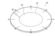
図1は、一実施形態のガラス基板の製造方法における外側部分の加熱を説明する図である。ガラス素板20は、略円形状あるいは略楕円形状を成したガラス板であって、一定の板厚を有する。このガラス素板20の面に、環形状を成した線22上にレーザ光を照射して欠陥を形成する。さらに、欠陥を形成したガラス素板20から、ガラス基板となる部分を取り出すために、ガラス素板20の加熱を行う。このとき、外側部分24の加熱を、内側部分26に比べて高くすることにより、外側部分24の熱膨張量を内側部分26の熱膨張量よりも大きくする。この結果、外側部分24は図1に示すように外側に向かって熱膨張する。このため、外側部分24と内側部分26の界面に確実に形成し隙間を形成することができる。したがって、外側部分24と内側部分26の分離を確実にすることができる。具体的には、外側部分24の加熱の程度が内側部分26に比べて高いことにより、外側部分24の内周の径(内径)が、内側部分26の外周の径(外径)に比べて相対的に大きくなるように熱膨張することで隙間が形成される。このため、形成された隙間により、外側部分24と内側部分26を確実に分離することができる。なお、外側部分24の加熱を内側部分26の加熱に比べて高くするとは、加熱の程度に差を設けて外側部分24と内側部分26の加熱を行なう場合の他に、外側部分24を選択的に加熱するが、内側部分26の意図した加熱を行なわない場合も含む。外側部分24を選択的に加熱したとしても、空間を介した熱伝導により、あるいはガラス素板20を介した熱伝導により間接的に内側部分26も加熱される。この場合、外側部分24の加熱は、内側部分26の加熱に比べて高くなっている、といえる。なお、本明細書において、説明する内側部分と外側部分の「隙間」は、内側部分と外側部分の間のいずれの位置において計測可能な空間が形成されていることの他、計測可能な空間が得られなくても内側部分と外側部分の対向する面同士が物理的又は化学的に結合状態にないことも含む。すなわち、「隙間」は、少なくとも内側部分と外側部分の境界の一部において微視的な空間が形成されていることも含む。
FIG. 1 is a diagram illustrating heating of an outer portion in the method for manufacturing a glass substrate of one embodiment. The
外側部分24ではなく内側部分26を加熱する場合、内側部分26の熱膨張量が外側部分24の熱膨張量に比べて大きくなるので、内側部分26が内側部分26と外側部分24の界面を外側に押すことにより、レーザ光の照射により形成されているクラックを進展させ、また、界面に新たなクラックを発生させる。しかし、これらのクラックは、内側部分26から外側に押されるので、内側部分26と外側部分24の界面に隙間を作り難い。このため、昇温した内側部分26の熱が界面に伝わって、形成されたクラックを再固着させて確実に分離できない場合がある。
実施形態では、外側部分24の加熱を、線22に対して内側部分26の加熱に比べて高めることで、隙間を確実に形成し、レーザを用いて形成されたクラックによる分離が熱によって再固着することを防止することができる。When the
In the embodiment, the heating of the
別の一実施形態は、開孔を有するガラス基板の製造方法である。このガラス基板の製造方法は、
(C)ガラス基板の元となるガラス素板の面に、略同心円状に沿ってレーザ光を照射した内周円部と外周円部を形成するステップと、
(D)外周円部の外側部分の加熱によって、ガラス素板の外周円部の外側部分を外周円部の内側部分に対して相対的に熱膨張させて外周円部において隙間を形成させ、外周円部の内側部分と外周円部の外側部分を分離するステップと、
(E)内周円部の外側部分の加熱によって、ガラス素板の内周円部の外側部分を相対的に熱膨張させて内周円部において隙間を形成させ、内周円部の内側部分と内周円部の外側部分を分離するステップと、を備える。Another embodiment is a method of manufacturing a glass substrate having holes. The manufacturing method of this glass substrate is
(C) A step of forming an inner and outer circular portions that are irradiated with laser light along substantially concentric circles on the surface of the glass base plate that is the base of the glass substrate.
(D) By heating the outer portion of the outer peripheral circle portion, the outer portion of the outer peripheral circular portion of the glass base plate is thermally expanded relative to the inner portion of the outer peripheral circular portion to form a gap in the outer peripheral circular portion, and the outer circumference is formed. A step to separate the inner part of the circle and the outer part of the outer circle,
(E) By heating the outer portion of the inner peripheral circle portion, the outer portion of the inner peripheral circular portion of the glass base plate is relatively thermally expanded to form a gap in the inner peripheral circular portion, and the inner portion of the inner peripheral circular portion is formed. And a step of separating the outer portion of the inner peripheral circle portion.
別の一実施形態は、開孔を有するガラス基板の製造方法である。このガラス基板の製造方法は、
(F)ガラス基板の元となるガラス素板の面に、所定の環形状を成した線上にレーザ光を照射して線上に欠陥を形成するステップと、
(G)欠陥を形成したガラス素板の、上記線を境にして外側部分と内側部分のうち、外側部分の加熱を、内側部分に比べて高めることにより、ガラス素板の外側部分と内側部分を分離するステップであって、外側部分をガラス素板の主表面の両側から同時に加熱して、外側部分の加熱を内側部分に比べて高めることにより、ガラス素板の外側部分と内側部分を分離して内側部分を開口になる部分として除去することを含むステップと、を備える。Another embodiment is a method of manufacturing a glass substrate having holes. The manufacturing method of this glass substrate is
(F) A step of irradiating a surface of a glass base plate, which is the base of a glass substrate, with a laser beam on a line having a predetermined ring shape to form a defect on the line.
(G) Of the outer portion and the inner portion of the defective glass base plate with the above line as a boundary, the heating of the outer portion is increased as compared with the inner portion, so that the outer portion and the inner portion of the glass base plate are heated. The outer part and the inner part of the glass base plate are separated by simultaneously heating the outer part from both sides of the main surface of the glass base plate and increasing the heating of the outer part as compared with the inner part. The step comprises removing the inner portion as an opening portion.
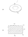
図2は、一実施形態のガラス基板の製造方法における外側部分の加熱を説明する図である。図2は、円形状のガラス素板30の面に、上記(C)に記載の内周円部を形成した後、あるいは、上記(F)に記載の所定の環形状を成した線上にレーザ光を照射して線上に欠陥を形成した後、上記(E)あるいは上記(G)に記載の加熱による分離をすることを説明している。ガラス素板30は、上記(C)に記載のガラス素板の面に、外周円部を形成し、上記(D)に記載のステップを行って外周円部の内側部分と外周円部の外側部分を分離して抜き取られた板である。
内周円部及び外周円部は、図1に示す実施形態では、線22上に形成された欠陥の部分をいう。したがって、上記(D)に記載の外周円部の形状は、図2に示すガラス素板30の外周形状に対応する。
レーザ光の照射により形成した内周円部32の外側部分34の加熱によって、ガラス素板30の内周円部32の外側部分34を相対的に熱膨張させて内周円部32において隙間を形成させ、内側部分36と外側部分34を分離する。上記(G)では分離した内側部分36を除去する。上記(G)のように、ガラス素板30の主表面の両側から同時に外側部分34を加熱することで、上記(D)に記載する加熱時の外周円部の外側部分の熱膨張量に比べて小さい内周円部32の外側部分の熱膨張量をガラス素板30の板厚方向で略均等に揃えることができ、板厚方向で均一な隙間を形成させることができる。これにより、隙間が小さくても内側部分36を外側部分34から抜き取ることができる。内周円部32は、図1に示す実施形態における線22上に沿って形成された欠陥に対応する。FIG. 2 is a diagram illustrating heating of an outer portion in the method for manufacturing a glass substrate of one embodiment. FIG. 2 shows a laser after forming the inner peripheral circular portion described in (C) above on the surface of the circular
The inner peripheral circle portion and the outer peripheral circular portion refer to the defective portion formed on the
By heating the
上記(C)〜(E)のステップを有する実施形態においても、上記(F),(G)のステップを有する実施形態においても、外側部分の加熱を行なうことで、外周円部あるいは内周円部の外側部分を、内側部分に対して熱膨張させて、外周円部及び内周円部に隙間を形成するので、レーザを用いて形成されたクラックによる界面が熱によって再固着することを防止することができる。これにより、開孔を有するガラス基板を効率よく形成することができる。
なお、上述の「略同心円」とは、外周円部の円中心位置と内周円部の円中心位置のずれ量が、20μm以下であることをいい、好ましくは、5μm以下である。In both the embodiment having the steps (C) to (E) and the embodiment having the steps (F) and (G), the outer peripheral portion or the inner peripheral circle is heated by heating the outer portion. Since the outer portion of the portion is thermally expanded with respect to the inner portion to form a gap in the outer peripheral circle portion and the inner peripheral circular portion, it is possible to prevent the interface due to the crack formed by using the laser from being re-fixed by heat. can do. As a result, a glass substrate having holes can be efficiently formed.
The above-mentioned "substantially concentric circles" means that the amount of deviation between the center position of the outer circle and the center of the inner circle is 20 μm or less, preferably 5 μm or less.
(ガラス基板の製造方法の具体的説明)
以下、一実施形態のガラス基板の製造方法及び磁気ディスクの製造方法を詳細に説明する。
図3(a)は、一実施形態で作製される磁気ディスク用ガラス基板の一例の斜視図である。図3(b)は、図3(a)に示す磁気ディスク用ガラス基板の外側端面の断面の一例を示す図である。(Specific explanation of manufacturing method of glass substrate)
Hereinafter, a method for manufacturing a glass substrate and a method for manufacturing a magnetic disk according to an embodiment will be described in detail.
FIG. 3A is a perspective view of an example of a glass substrate for a magnetic disk manufactured in one embodiment. FIG. 3B is a diagram showing an example of a cross section of the outer end surface of the glass substrate for a magnetic disk shown in FIG. 3A.
図3(a)に示すガラス基板1は、磁気ディスク用ガラス基板である。ガラス基板1は、円環状の薄板のガラス基板である。磁気ディスク用ガラス基板のサイズは問わないが、磁気ディスク用ガラス基板は、例えば、公称直径2.5インチや3.5インチの磁気ディスク用ガラス基板のサイズである。公称直径2.5インチの磁気ディスク用ガラス基板の場合、例えば、外径が65mm、中心穴の径が20mm〜25mm、板厚が0.3〜0.8mmである。公称直径3.5インチの磁気ディスク用ガラス基板の場合、例えば、外径が95mm、中心穴の径が20mm〜25mm、板厚が0.3〜0.8mmである。このガラス基板1の主表面上に磁性層が形成されて磁気ディスクが作られる。 The glass substrate 1 shown in FIG. 3A is a glass substrate for a magnetic disk. The glass substrate 1 is an annular thin glass substrate. The size of the glass substrate for a magnetic disk is not limited, but the glass substrate for a magnetic disk is, for example, the size of a glass substrate for a magnetic disk having a nominal diameter of 2.5 inches or 3.5 inches. In the case of a glass substrate for a magnetic disk having a nominal diameter of 2.5 inches, for example, the outer diameter is 65 mm, the diameter of the center hole is 20 mm to 25 mm, and the plate thickness is 0.3 to 0.8 mm. In the case of a glass substrate for a magnetic disk having a nominal diameter of 3.5 inches, for example, the outer diameter is 95 mm, the diameter of the center hole is 20 mm to 25 mm, and the plate thickness is 0.3 to 0.8 mm. A magnetic layer is formed on the main surface of the glass substrate 1 to form a magnetic disk.
ガラス基板1は、一対の主表面11p,12p、外周端面に形成された側壁面11w、側壁面11wと主表面11p,12pの間に介在する面取面11c,12c、内周端面にも、外周端面と同様に形成された、図示されない側壁面、及び、この側壁面と主表面11p,12pの間に介在する図示されない面取面とを備える。
ガラス基板1は、中心部に円孔を有する。側壁面11wは、ガラス基板1の板厚方向の中心位置を含む。面取面11c,12cの主表面11p,12pに対する傾斜角度は、特に制限されず、例えば45°である。また、側壁面11w及び面取面11c,12cの境界は、図示されるようなエッジを有する形状に限定されるものではなく、滑らかに連続する曲面状であってもよい。The glass substrate 1 also includes a pair of
The glass substrate 1 has a circular hole in the center. The
このようなガラス基板1は、図1あるいは図2に示すように、予め作製されたガラス素板20,30からレーザ光を用いて抜き取られる。図4は、一実施形態のガラス基板の製造方法におけるレーザ光の照射を説明する図である。
As shown in FIG. 1 or 2, such a glass substrate 1 is extracted from the prefabricated
図4に示すレーザ光Lが照射されるガラス素板60は、例えば、フローティング法あるいはダウンドロー法を用いて作製される一定の板厚のガラス板である。あるいは、ガラスの塊を、金型を用いてプレス成形したガラス板であってもよい。ガラス素板60の板厚は、最終製品である磁気ディスク用ガラス基板になる時の目標板厚に対して、研削及び研磨の取り代量の分だけ厚く、例えば、数μm程度厚い。
The
レーザ光源40は、レーザ光Lを出射する装置であり、例えば、YAGレーザ、あるいは、ND:YAGレーザ等の固体レーザが用いられる。したがって、一実施形態によれば、レーザ光の波長は、例えば、1030nm〜1070nmの範囲にあることが好ましい。
レーザ光Lは、パルスレーザであり、一実施形態では、レーザ光Lによるパルス幅を10−12秒以下(1ピコ秒以下)であることが、レーザ光Lの焦点位置におけるガラスの過度な変質を抑制することができる点から好ましい。
また、レーザ光Lの光エネルギは、パルス幅及びパルス幅の繰り返し周波数に応じて適宜調整することができる。パルス幅及び繰り返し周波数に対して過度な光エネルギを提供すると、ガラスが過度に変質し易くなり、焦点位置に残渣が存在し易い。The
The laser beam L is a pulsed laser, and in one embodiment, the pulse width of the laser beam L is 10 to 12 seconds or less (1 picosecond or less), which is an excessive alteration of the glass at the focal position of the laser beam L. It is preferable from the viewpoint that the above can be suppressed.
Further, the light energy of the laser beam L can be appropriately adjusted according to the pulse width and the repetition frequency of the pulse width. Providing excessive light energy for the pulse width and repetition frequency tends to cause the glass to be excessively altered and to have a residue at the focal position.
レーザ光源40は、一実施形態によれば、発振したレーザ光を2つの光束に分け、この2つの光束を、ガラス素板60の表面で、あるいはガラス素板60の内部で交差させるように、レーザ光Lをガラス素板60の主表面の法線方向に対して傾斜させてガラス素板60に照射させる。このようなレーザ光Lの照射により、ガラス素板60の線62上の一点で厚さ方向に沿って光束同士の交差が連続するように形成されるので、この点において、深さ方向に沿って線状に光エネルギが集中し、ガラス素板60の一部がプラズマ化して、孔あるいは貫通孔を形成することができる。
レーザ光Lは、一実施形態によれば、パルス状の光パルスを一定時間間隔で連続して生成する構成の光パルス群を1単位として、複数の光パルス群を断続的に発生させるバーストパルス方式でガラス素板60に照射することが好ましい。この場合、1つの光パルス群の中で、1パルスの光エネルギを可変にさせることも好ましい。
このようなレーザ光Lの照射の一例は、特許5959597号公報に開示されている。According to one embodiment, the
According to one embodiment, the laser beam L is a burst pulse that intermittently generates a plurality of optical pulse groups, with an optical pulse group having a configuration in which pulse-shaped optical pulses are continuously generated at regular time intervals as one unit. It is preferable to irradiate the
An example of such irradiation of the laser beam L is disclosed in Japanese Patent No. 5959597.
レーザ光源40によるレーザ光Lの照射では、レーザ光Lを、ガラス素板60に対して相対的に移動させながら、所定の環形状を成した線上に照射する。これにより上記線上に欠陥を形成する。例えば、ガラス素板60に、内周円部あるいは外周円部を形成することができる。レーザ光Lの照射では、ガラス素板60を移動させずにレーザ光Lを移動させてもよいし、レーザ光Lを移動させずにガラス素板60を移動させてもよい。
In the irradiation of the laser beam L by the
レーザ光Lの照射により、例えば、線62の離散的な位置に孔を断続的に形成した場合、この孔から隣りの孔に向かって進展したクラックが形成され易いので、別種のレーザ光を上記線に沿って再度照射しなくても内周円部あるいは外周円部の外側部分の加熱によって、容易に外側部分と内側部分とを分離することができる。すなわち、レーザ光Lの照射により形成された欠陥を維持したまま、ガラス素板60の外側部分の加熱によって、容易に外側部分と内側部分とを分離することができる。特に、外側部分の加熱を、ガラス素板60の主表面の両側から同時に加熱することにより、より容易に外側部分と内側部分とを分離することができる。
When holes are intermittently formed at discrete positions of the
次に、欠陥を形成したガラス素板60の、線を境にして外側部分と内側部分のうち、外側部分の加熱を、内側部分に比べて高めることにより、あるいは、外側部分を加熱することにより、ガラス素板60の外側部分と内側部分を分離する。図5は、一実施形態のガラス基板の製造方法におけるガラス素板60の加熱を具体的に説明する図である。ガラス素板60の加熱では、例えば、ガラス素板60に欠陥が形成された線62に対して外側部分64をヒータ50,52の間の加熱空間に配置し、内側部分66を加熱空間の外側に配置する。これにより、外側部分64の加熱を行うことができる。このとき、外側部分64の加熱の程度は、内側部分66に比べて高くなるので、外側部分64の熱膨張量を内側部分66の熱膨張量よりも大きくすることができる。この結果、外側部分64は図5に示すように外側に向かって熱膨張する。このため、外側部分64と内側部分66の界面に確実に形成し隙間を形成することができる。したがって、外側部分64と内側部分66の分離を確実にすることができる。
Next, by increasing the heating of the outer portion of the outer portion and the inner portion of the defective
なお、図4,5に示す例では、レーザ光Lの照射を環形状の線上に沿って行って、欠陥部分を形成した後、線の外側部分64を加熱する処理を行うが、図6に示すように、ガラス素板60へのレーザ光Lの照射を、2つの異なる略同心円の円弧線上に沿って行って、2つの欠陥部分である外周円部62a及び内周円部62bを形成した後、外周円部62aの外側部分を加熱し、内周円部62bの外側部分を加熱することもできる。図6は、一実施形態のガラス基板の製造方法におけるレーザ光の照射を説明する図である。
In the examples shown in FIGS. 4 and 5, laser light L is irradiated along the ring-shaped line to form a defective portion, and then the
このように、外側部分64と内側部分66を分離するとき、外側部分64の温度を内側温度66に比べて高くして、外側部分64を内側部分64に対して相対的に熱膨張させて、線62上に沿って隙間を形成することにより、外側部分64と内側部分66を分離するので、ガラス基板となる部分をガラス素板から確実に抜き取ることができる。
特に、内周円部62bを形成した後、内周円部62bの外側部分をガラス素板60の主表面の両側から同時に加熱することにより、ガラス素板60の板厚方向に沿って熱膨張量を均等に揃えることができるので、均一な隙間を形成することができる。特に、内周円部62bはガラス素板60の中心位置に近いので、外周円部62aの外側部分に対する加熱と同程度の加熱をしても外周円部62aに比べて熱膨張量は小さい。このため、ガラス基板となる部分をガラス素板から確実に抜き取るための隙間を精度よく形成させることが好ましい。この点から、内周円部62bの外側部分をガラス素板60の主表面の両側から同時に加熱して、厚さ方向で熱膨張量を均等に揃えることが好ましい。In this way, when the
In particular, after forming the inner peripheral
また、ガラス基板1は、開孔を有する環形状を成している。このようなガラス基板1を作製する場合、開孔を有する環形状の外縁の形状を線62(図4参照)の形状として、レーザ光Lによる照射で欠陥を形成し、この後、外側部分64(第1外側部分)の加熱を、内側部分66(第1内側部分)に比べて高くする加熱を第1加熱処理として行なうことが好ましい。レーザ光Lにより形成される、ガラス基板1の外縁を構成する外周端面の表面粗さは、従来のスクライバを用いて機械的に割断した外周端面に比べて小さく、例えば、ハードディスクドライブ装置内の磁気ディスク用ガラス基板に要求される外周断面に要求される表面粗さを満足するため、端面研磨をする必要がなく、端面研磨をするとしても研磨時間は短くて済む。このため、ガラス基板1の外縁形状を効率よく形成することができる。
この場合、ガラス素板60において、ガラス基板1の環形状に対するマージンとして、環形状の外径の0.1%〜5%の長さを残して、外側部分64(第1外側部分)と内側部分66(第1内側部分)とが分離される、ことが好ましい。マージンが大きくなると、ガラス素板60を廃棄する量が多くなり無駄が多くなる他、加熱の際の熱が熱伝導により拡散し易くなるので所定の熱膨張量を引き起こすまでの加熱時間が長くなり、生産性の点で好ましくない。Further, the glass substrate 1 has a ring shape having holes. When such a glass substrate 1 is produced, a ring-shaped outer edge having a hole is formed as a line 62 (see FIG. 4), and a defect is formed by irradiation with a laser beam L, and then an
In this case, in the
ガラス基板1の開孔(内孔)を形成する場合、開孔を有する環形状の内縁の形状を線62の形状として、レーザ光Lによる照射で欠陥を形成し、この後、外側部分64(第2外側部分)の加熱を、内側部分66(第2内側部分)に比べて高くする加熱を第2加熱処理として行なうことが好ましい。レーザ光Lにより形成される、ガラス基板1の内縁を構成する内周端面の表面粗さは、従来のスクライバを用いて機械的に割断した外周端面に比べて小さく、例えば、ハードディスクドライブ装置内の回転軸と接触する磁気ディスク用ガラス基板に要求される内周断面に要求される表面粗さを満足するため、端面研磨をする必要がなく、端面研磨をするとしても研磨時間は短くて済む。このため、ガラス基板1の開孔を効率よく形成することができる。
When forming an opening (inner hole) of the glass substrate 1, a defect is formed by irradiation with a laser beam L with the shape of the ring-shaped inner edge having the opening as the shape of the
このとき、上記第1加熱処理後、上記第2加熱処理を行うことが好ましい。第1加熱処理を行うときの内側部分66が、第2加熱処理を行うときの外側部分64になる。第1加熱処理では、内側部分66は加熱されないか、加熱されるとしても外側部分64に比べて加熱の程度は低い。しかし、内側部分66には、昇温した外側部分64からの熱伝導によって昇温する。したがって、昇温した内側部分66を、第2加熱処理で外側部分64として加熱する際、所定の熱膨張量を引き起こすまでの加熱時間を短くすることができる。このように、効率よくガラス基板1を作製することができる。
At this time, it is preferable to perform the second heat treatment after the first heat treatment. The
ガラス素板60へのレーザ光Lの照射は、パルスレーザ光により、線上の複数の離散点に、点状の貫通孔を形成した後、上記パルスレーザ光と異なるレーザ光により、線上の離散点間を繋ぐように、照射位置が線上を連続的に移動することを含んでもよい。。この場合、パルスレーザ光で形成した複数の貫通孔のうち、隣接する貫通孔の間にクラックあるいは潜在的なクラックを形成し、この後、別種のレーザ光により、クラックあるいは顕在化したクラックを貫通孔間で接続させることができるので、短時間に効率よくガラス素板の形状加工をすることができる。例えば、別種のレーザ光として、CO2レーザを用いることができる。このレーザ光によって、断続的に形成された欠陥をつなぐように線状の欠陥を形成することができる。
すなわち、線62の離散的な位置にレーザ光Lの照射によって欠陥を断続的に形成した後、別種のレーザ光として、CO2レーザを用いて、断続的に形成された欠陥をつなぐように線状の欠陥を形成して、クラックを確実に形成することもできる。これにより、後述する外側部分と内側部分との加熱による分離が確実にできる。The
That is, after defects are intermittently formed at the discrete positions of the
なお、レーザ光Lによる照射後に行うガラス素板60の加熱は、ガラス素板60の主表面の両側に設けられる加熱源からの輻射熱によりガラス素板60の両側の主表面を加熱することを含むことが好ましい。輻射による加熱では、ガラス素板60の主表面から熱伝導によって熱が伝わってガラス素板60が昇温するので、外側部分64と内側部分66との間の界面は再固着する程度の温度にならない。このため、外側部分64の熱膨張によって界面に隙間を形成することができる。
The heating of the
ガラス素板60の主表面の面積の、ガラス基板1の主表面の面積に対する面積比は、101%〜160%であり、外側部分64と内側部分66を分離するとき、1つのガラス素板60から1つのガラス基板1を抜き取ることが好ましい。大きなサイズのガラス素板60から複数のガラス基板1を抜き取ると、ガラス素板60の板厚の場所によるばらつきによってガラス基板1の板厚の固体間差が大きくなる。特に、磁気ディスク用ガラス基板では、板厚も一定に揃えることが好ましいため、ガラス基板の主表面の研削、研磨の程度をガラス基板間で調整する煩雑さがある。さらに、ガラス素板60を回転させながら精度よくレーザ光の照射ができる他、外側部分の加熱を行なって外側部分と内側部分を分離するためのガラス素板60のハンドリングが向上する。このように、一定の板厚が確保される小さなサイズのガラス素板60を用いて、1つのガラス素板60から1つの内側部分を取り出すことが、ガラス基板1の作製効率の点から好ましい。また、大きなガラス素板60から1つのガラス板を抜き出す際、大きなガラス素板60の外側部分全体が加熱により昇温するので、この昇温した部分からガラス板を抜き出す際、外側部分及び内側部分の温度は高い状態を維持しているので、所定の熱膨張量になるように外側部分を加熱して昇温させるときの温度は高くなり、好ましくない。
The area ratio of the area of the main surface of the
ガラス素板60の板厚は、一実施形態では0.6mm以下である。このような板厚のガラス素板60から作製されるガラス基板1は、磁気ディスク用ガラス基板として有効に用いることができる。磁気ディスク用ガラス基板の板厚を薄くすることにより、記憶容量の増大化のためにハードディスク装置内に搭載する磁気ディスクの枚数を増大させることができる。さらに、板厚0.6mm以下のガラス素板60は、極めて薄く、レーザ照射、加熱による外側部分と内側部分の分離の処理の際に割れが生じ易くなる。このため、ガラス素板からガラス基板を確実に分離して抜き取ることができる本実施形態の効果は薄い板厚のガラス素板において一層大きくなる。
The plate thickness of the
このように形状加工されたガラス基板は、最終製品に適した特性を有するように各種処理が行われる。 The glass substrate thus shaped is subjected to various treatments so as to have characteristics suitable for the final product.
こうしてガラス素板60から抜き取られたガラス基板の外周端面及び内周端面(上記外側部分64と内側部分66の界面である端面)と主表面とで形成される角部の面取り加工を行うための面取りが行われる。一実施形態によれば、角部を、レーザ光Lと異なる種類のレーザ光で面取りする。このレーザ光は、角部を、主表面に対して30〜60度の傾斜角度傾斜した方向から照射し、角部を加熱して軟化させて蒸発させることにより、角部を面取りすることができる。例えば、CO2レーザが好適に用いることができる。このような面取りによって、表面粗さの低い、真円度の高い面取り面を形成することができる。
こうして、内周端面あるいは外周端面と主表面とで形成される角部は、レーザ光を用いて面取り加工を行うことができる。角部を、レーザ光で面取り加工するので、砥石等により面取り加工を行う場合に比べて生産効率は高い。
ガラス素板60から所定の形状のガラス基板を抜き取る処理からガラス基板の角部の面取りまでの間、端面研磨をしないので、生産効率が向上する。For chamfering the corners formed by the outer peripheral end surface and the inner peripheral end surface (the end surface which is the interface between the
In this way, the corner portion formed by the inner peripheral end surface or the outer peripheral end surface and the main surface can be chamfered by using laser light. Since the corners are chamfered with laser light, the production efficiency is higher than when chamfering with a grindstone or the like.
Since the end face is not polished from the process of extracting the glass substrate having a predetermined shape from the
得られたガラス基板1は、主表面の研削・研磨処理が行われる。
研削・研磨処理では、ガラス基板1の研削後、研磨が行われる。
研削処理では、遊星歯車機構を備えた両面研削装置を用いて、ガラス基板1の主表面に対して研削加工を行う。具体的には、ガラス基板1の外周端面を、両面研削装置の保持部材に設けられた保持孔内に保持しながらガラス基板1の両側の主表面の研削を行う。両面研削装置は、上下一対の定盤(上定盤および下定盤)を有しており、上定盤および下定盤の間にガラス基板1が狭持される。そして、上定盤または下定盤のいずれか一方、または、双方を移動操作させ、クーラントを供給しながらガラス基板1と各定盤とを相対的に移動させることにより、ガラス基板1の両主表面を研削することができる。例えば、ダイヤモンドを樹脂で固定した固定砥粒をシート状に形成した研削部材を定盤に装着して研削処理をすることができる。The main surface of the obtained glass substrate 1 is ground and polished.
In the grinding / polishing process, polishing is performed after grinding the glass substrate 1.
In the grinding process, a double-sided grinding device equipped with a planetary gear mechanism is used to grind the main surface of the glass substrate 1. Specifically, the main surfaces on both sides of the glass substrate 1 are ground while holding the outer peripheral end surface of the glass substrate 1 in the holding holes provided in the holding member of the double-sided grinding apparatus. The double-sided grinding device has a pair of upper and lower surface plates (upper surface plate and lower surface plate), and the glass substrate 1 is sandwiched between the upper surface plate and the lower surface plate. Then, by moving one or both of the upper surface plate and the lower surface plate and relatively moving the glass substrate 1 and each surface plate while supplying coolant, both main surfaces of the glass substrate 1 are moved. Can be ground. For example, a grinding member in which fixed abrasive grains in which diamond is fixed with a resin is formed in a sheet shape can be mounted on a surface plate to perform a grinding process.
次に、研削後のガラス基板1の主表面に第1研磨が施される。具体的には、ガラス基板1の外周端面を、両面研磨装置の研磨用キャリアに設けられた保持孔内に保持しながらガラス素板の両側の主表面の研磨が行われる。第1研磨は、研削処理後の主表面に残留したキズや歪みの除去、あるいは微小な表面凹凸(マイクロウェービネス、粗さ)の調整を目的とする。 Next, the first polishing is applied to the main surface of the glass substrate 1 after grinding. Specifically, the main surfaces on both sides of the glass base plate are polished while holding the outer peripheral end surface of the glass substrate 1 in the holding holes provided in the polishing carrier of the double-sided polishing apparatus. The purpose of the first polishing is to remove scratches and strains remaining on the main surface after the grinding process, or to adjust minute surface irregularities (microwaveness, roughness).
第1研磨処理では、固定砥粒による上述の研削処理に用いる両面研削装置と同様の構成を備えた両面研磨装置を用いて、研磨スラリを与えながらガラス基板1が研磨される。第1研磨処理では、遊離砥粒を含んだ研磨スラリが用いられる。第1研磨に用いる遊離砥粒として、例えば、酸化セリウム、あるいはジルコニア等の砥粒が用いられる。両面研磨装置も、両面研削装置と同様に、上下一対の定盤の間にガラス基板1が狭持される。下定盤の上面及び上定盤の底面には、全体として円環形状の平板の研磨パッド(例えば、樹脂ポリッシャ)が取り付けられている。そして、上定盤または下定盤のいずれか一方、または、双方を移動操作させることで、ガラス基板1と各定盤とを相対的に移動させることにより、ガラス基板1の両主表面を研磨する。研磨砥粒の大きさは、平均粒径(D50)で0.5〜3μmの範囲内であることが好ましい。 In the first polishing process, the glass substrate 1 is polished while applying a polishing slurry by using a double-sided polishing device having the same configuration as the double-sided grinding device used for the above-mentioned grinding process using fixed abrasive grains. In the first polishing treatment, a polishing slurry containing free abrasive grains is used. As the free abrasive grains used for the first polishing, for example, abrasive grains such as cerium oxide or zirconia are used. In the double-sided polishing device as well, the glass substrate 1 is sandwiched between the pair of upper and lower surface plates. An annular flat plate polishing pad (for example, a resin polisher) is attached to the upper surface of the lower surface plate and the bottom surface of the upper surface plate as a whole. Then, by moving one or both of the upper surface plate and the lower surface plate, the glass substrate 1 and each surface plate are relatively moved to polish both main surfaces of the glass substrate 1. .. The size of the abrasive grains is preferably in the range of 0.5 to 3 μm in terms of average particle size (D50).
第1研磨後、ガラス基板1を化学強化してもよい。この場合、化学強化液として、例えば硝酸カリウムと硫酸ナトリウムの混合熔融液等を用い、ガラス基板1を化学強化液中に浸漬する。これにより、イオン交換によってガラス基板1の表面に圧縮応力層を形成することができる。 After the first polishing, the glass substrate 1 may be chemically strengthened. In this case, for example, a mixed melt of potassium nitrate and sodium sulfate is used as the chemical strengthening liquid, and the glass substrate 1 is immersed in the chemical strengthening liquid. As a result, a compressive stress layer can be formed on the surface of the glass substrate 1 by ion exchange.
次に、ガラス基板1に第2研磨が施される。第2研磨処理は、主表面の鏡面研磨を目的とする。第2研磨においても、第1研磨に用いる両面研磨装置と同様の構成を有する両面研磨装置が用いられる。具体的には、ガラス基板1の外周端面を、両面研磨装置の研磨用キャリアに設けられた保持孔内に保持させながら、ガラス基板1の両側の主表面の研磨が行われる。第2研磨処理では、第1研磨処理に対して、遊離砥粒の種類及び粒子サイズが異なることと、樹脂ポリッシャの硬度が異なる。樹脂ポリッシャの硬度は第1研磨処理時よりも小さいことが好ましい。例えばコロイダルシリカを遊離砥粒として含む研磨液が両面研磨装置の研磨パッドとガラス基板1の主表面との間に供給され、ガラス基板1の主表面が研磨される。第2研磨に用いる研磨砥粒の大きさは、平均粒径(d50)で5〜50nmの範囲内であることが好ましい。
化学強化処理の要否については、ガラス組成や必要性を考慮して適宜選択すればよい。第1研磨処理及び第2研磨処理の他にさらに別の研磨処理を加えてもよく、2つの主表面の研磨処理を1つの研磨処理で済ませてもよい。また、上記各処理の順番は、適宜変更してもよい。
こうして、ガラス基板1の主表面を研磨して、磁気ディスク用ガラス基板に要求される条件を満足した磁気ディスク用ガラス基板を得ることができる。
この後、主表面が研磨されて作製されたガラス基板1に、少なくとも磁性層を形成して磁気ディスクが作製される。Next, the glass substrate 1 is subjected to the second polishing. The second polishing treatment aims at mirror polishing of the main surface. Also in the second polishing, a double-sided polishing apparatus having the same configuration as the double-sided polishing apparatus used for the first polishing is used. Specifically, the main surfaces on both sides of the glass substrate 1 are polished while the outer peripheral end faces of the glass substrate 1 are held in the holding holes provided in the polishing carrier of the double-sided polishing apparatus. In the second polishing treatment, the type and particle size of the free abrasive grains are different from those in the first polishing treatment, and the hardness of the resin polisher is different. The hardness of the resin polisher is preferably smaller than that at the time of the first polishing treatment. For example, a polishing liquid containing colloidal silica as free abrasive grains is supplied between the polishing pad of the double-sided polishing apparatus and the main surface of the glass substrate 1, and the main surface of the glass substrate 1 is polished. The size of the abrasive grains used for the second polishing is preferably in the range of 5 to 50 nm in terms of average particle size (d50).
The necessity of the chemical strengthening treatment may be appropriately selected in consideration of the glass composition and necessity. In addition to the first polishing treatment and the second polishing treatment, another polishing treatment may be added, or the polishing treatment of the two main surfaces may be completed by one polishing treatment. Further, the order of each of the above processes may be changed as appropriate.
In this way, the main surface of the glass substrate 1 can be polished to obtain a glass substrate for a magnetic disk that satisfies the conditions required for the glass substrate for a magnetic disk.
After that, at least a magnetic layer is formed on the glass substrate 1 produced by polishing the main surface to produce a magnetic disk.
なお、ガラス基板1は、第1研磨を行う前に、例えば、第1研削後、第1研磨前に、あるいは、第1研削前に、ガラス基板1の端面を研磨する端面研磨処理を行ってもよい。
このような端面研磨処理を行う場合であっても、レーザ光を用いてガラス素板60から抜き出したガラス基板1の端面の算術平均粗さRaは、0.01μm未満、真円度は15μm以下であるので、端面研磨処理に要する時間は短い。
端面研磨処理は、遊離砥粒を端面に供給しながら研磨ブラシを用いて研磨する研磨ブラシ方式を用いてもよく、あるいは、磁気機能性流体を用いた研磨方式を用いてもよい。磁気機能性流体を用いた研磨方式は、例えば、磁気粘性流体に研磨砥粒を含ませたスラリを磁界によって塊にし、この塊の内部にガラス基板1の端面を突っ込んで、塊とガラス基板を相対的に回転させることにより、端面を研磨する方式である。The glass substrate 1 is subjected to an end face polishing treatment for polishing the end face of the glass substrate 1 before the first polishing, for example, after the first grinding, before the first polishing, or before the first grinding. May be good.
Even when such end face polishing treatment is performed, the arithmetic average roughness Ra of the end face of the glass substrate 1 extracted from the
For the end face polishing treatment, a polishing brush method for polishing with a polishing brush while supplying free abrasive grains to the end face may be used, or a polishing method using a magnetically functional fluid may be used. In the polishing method using a magnetically functional fluid, for example, a slurry in which abrasive grains are contained in a ferrofluid is agglomerated by a magnetic field, and the end face of the glass substrate 1 is thrust into the agglomerate to form the agglomerate and the glass substrate. This is a method of polishing the end face by rotating it relatively.
しかし、生産効率を高めるためには、端面研磨処理をしないことが好ましい。この場合、主表面の研削・研磨処理では、ガラス素板60から抜き取られたガラス基板1の真円度を維持し、さらに割断面の少なくとも一部分の表面粗さを維持しつつ、ガラス基板1の主表面を研削あるいは研磨を行う。
However, in order to increase the production efficiency, it is preferable not to perform the end face polishing treatment. In this case, in the grinding / polishing treatment of the main surface, the roundness of the glass substrate 1 extracted from the
このようなガラス基板1の組成については、限定するものではないが、以下の組成であることが好ましい。
具体的には、酸化物基準に換算し、モル%表示で、SiO2を50〜75%、Al2O3を1〜15%、Li2O、Na2O及びK2Oから選択される少なくとも1種の成分を合計で5〜35%、MgO、CaO、SrO、BaO及びZnOから選択される少なくとも1種の成分を合計で0〜20%、ならびにZrO2、TiO2、La2O3、Y2O3、Ta2O5、Nb2O5及びHfO2から選択される少なくとも1種の成分を合計で0〜10%、有する組成からなるアモルファスのアルミノシリケートガラスである。The composition of such a glass substrate 1 is not limited, but is preferably the following composition.
Specifically, it is converted into an oxide standard and is selected from 50 to 75% of SiO 2 , 1 to 15% of Al 2 O 3 and Li 2 O, Na 2 O and K 2 O in mol% display. At least one component in total 5 to 35%, at least one component selected from MgO, CaO, SrO, BaO and ZnO in total 0 to 20%, and ZrO 2 , TiO 2 , La 2 O 3 , Y 2 O 3 , Ta 2 O 5 , Nb 2 O 5 and HfO 2 , an amorphous aluminosilicate glass having a composition having a total of 0 to 10% of at least one component selected from HfO 2.
また、ガラス基板1は好ましくは、例えば、質量%表示にて、SiO2を57〜75%、Al2O3を5〜20%、(ただし、SiO2とAl2O3の合計量が74%以上)、ZrO2、HfO2、Nb2O5、Ta2O5、La2O3、Y2O3およびTiO2を合計で0%を超え、6%以下、Li2Oを1%を超え、9%以下、Na2Oを5〜28%(ただし、質量比Li2O/Na2Oが0.5以下)、K2Oを0〜6%、MgOを0〜4%、CaOを0%を超え、5%以下(ただし、MgOとCaOの合計量は5%以下であり、かつCaOの含有量はMgOの含有量よりも多い)、SrO+BaOを0〜3%、有する組成からなるアモルファスのアルミノシリケートガラスであってもよい。Further, the glass substrate 1 preferably contains 57 to 75% of SiO 2 and 5 to 20% of Al 2 O 3 in terms of mass% (however, the total amount of SiO 2 and Al 2 O 3 is 74). % Or more), ZrO 2 , HfO 2 , Nb 2 O 5 , Ta 2 O 5 , La 2 O 3 , Y 2 O 3 and TIO 2 in total exceed 0%, 6% or less, Li 2 O 1% 9% or less, Na 2 O 5 to 28% (however, mass ratio Li 2 O / Na 2 O is 0.5 or less), K 2 O 0 to 6%, Mg O 0 to 4%, Composition having CaO of more than 0% and 5% or less (however, the total amount of MgO and CaO is 5% or less, and the content of CaO is larger than the content of MgO) and SrO + BaO is 0 to 3%. It may be an amorphous aluminosilicate glass made of.
ガラス基板1の組成は、必須成分として、SiO2、Li2O、Na2O、ならびに、MgO、CaO、SrOおよびBaOからなる群から選ばれる一種以上のアルカリ土類金属酸化物を含み、MgO、CaO、SrOおよびBaOの合計含有量に対するCaOの含有量のモル比(CaO/(MgO+CaO+SrO+BaO))が0.20以下であって、ガラス転移温度が650℃以上であってもよい。このような組成のガラス基板1は、エネルギーアシスト磁気記録用磁気ディスクに使用される磁気ディスク用ガラス基板に好適である。The composition of the glass substrate 1 contains, as essential components, SiO 2 , Li 2 O, Na 2 O, and one or more alkaline earth metal oxides selected from the group consisting of MgO, CaO, SrO and BaO, and MgO. , The molar ratio of CaO content to the total content of CaO, SrO and BaO (CaO / (MgO + CaO + SrO + BaO)) may be 0.20 or less, and the glass transition temperature may be 650 ° C. or higher. The glass substrate 1 having such a composition is suitable for a glass substrate for a magnetic disk used for a magnetic disk for energy-assisted magnetic recording.
以上、本発明のガラス基板の製造方法及び磁気ディスクの製造方法について詳細に説明したが、本発明のガラス基板の製造方法及び磁気ディスクの製造方法は上記実施形態に限定されず、本発明の主旨を逸脱しない範囲において、種々の改良や変更をしてもよいのはもちろんである。 Although the glass substrate manufacturing method and the magnetic disk manufacturing method of the present invention have been described in detail above, the glass substrate manufacturing method and the magnetic disk manufacturing method of the present invention are not limited to the above embodiments, and the gist of the present invention. Of course, various improvements and changes may be made without departing from the above.
1 ガラス基板
11p,12p 主表面
11c,12c 面取面
11w 側壁面
20,30,60 ガラス素板
22,62 線
24,34,64 外側部分
26,36,66 内側部分
32,62b 内周円部
40 レーザ光源
50,52 ヒータ
62a 外周円部1
Claims (10)
前記ガラス基板の元となるガラス素板の面に、略同心円状に沿ってレーザ光を照射した内周円部の線と外周円部の線とを形成するステップと、
前記外周円部の線の外側部分を輻射熱により加熱することによって、前記ガラス素板の前記外周円部の線の外側部分を前記外周円部の線の内側部分に対して相対的に熱膨張させて前記外周円部の線において隙間を形成させ、前記外周円部の線の前記内側部分と前記外周円部の線の前記外側部分とを分離するステップと、
前記内周円部の線の外側部分を輻射熱により加熱することによって、前記ガラス素板の前記内周円部の線の前記外側部分を相対的に熱膨張させて前記内周円部の線において隙間を形成させ、前記内周円部の線の内側部分と前記内周円部の線の前記外側部分とを分離するステップと、
を備えることを特徴とするガラス基板の製造方法。 A method for manufacturing a glass substrate having holes.
The surface of the glass workpiece which is the source of the glass substrate, forming a line of the line and the outer circumference portion of the inner circumferential circle portion irradiated with laser light along a substantially concentric shape,
By heating by radiant heat an outer portion of the line of the outer circumference portion, is relatively thermal expansion of the outer portion of the outer circumference portion of said line of the glass workpiece relative to the inner portion of the line of the outer circumference portion a step to form a gap, separating the outer portion of the inner portion and the outer circumference portion of the line of the line of the outer circumference portion at said line of outer circumference portion Te,
By heating by radiant heat an outer portion of the line of the inner circumference portion, in the line of the outer portion by relatively thermal expansion the inner circumference portion of the line of the inner circumference portion of the glass workpiece a step to form a gap, separating the outer portion of the line of the inner circumference portion and the inner portion of the line of the inner circumference portion,
A method for manufacturing a glass substrate, which comprises.
Priority Applications (1)
| Application Number | Priority Date | Filing Date | Title |
|---|---|---|---|
| JP2021017765A JP7458335B2 (en) | 2018-07-27 | 2021-02-05 | Glass substrate manufacturing method and magnetic disk manufacturing method |
Applications Claiming Priority (3)
| Application Number | Priority Date | Filing Date | Title |
|---|---|---|---|
| JPPCT/JP2018/028269 | 2018-07-27 | ||
| PCT/JP2018/028269 WO2020021705A1 (en) | 2018-07-27 | 2018-07-27 | Manufacturing method for glass substrate and manufacturing method for magnetic disc |
| PCT/JP2019/029530 WO2020022510A1 (en) | 2018-07-27 | 2019-07-26 | Manufacturing method for glass substrate and manufacturing method for magnetic disc |
Related Child Applications (1)
| Application Number | Title | Priority Date | Filing Date |
|---|---|---|---|
| JP2021017765A Division JP7458335B2 (en) | 2018-07-27 | 2021-02-05 | Glass substrate manufacturing method and magnetic disk manufacturing method |
Publications (2)
| Publication Number | Publication Date |
|---|---|
| JP6836694B2 true JP6836694B2 (en) | 2021-03-03 |
| JPWO2020022510A1 JPWO2020022510A1 (en) | 2021-03-11 |
Family
ID=69181399
Family Applications (2)
| Application Number | Title | Priority Date | Filing Date |
|---|---|---|---|
| JP2020532520A Active JP6836694B2 (en) | 2018-07-27 | 2019-07-26 | Glass substrate manufacturing method and magnetic disk manufacturing method |
| JP2021017765A Active JP7458335B2 (en) | 2018-07-27 | 2021-02-05 | Glass substrate manufacturing method and magnetic disk manufacturing method |
Family Applications After (1)
| Application Number | Title | Priority Date | Filing Date |
|---|---|---|---|
| JP2021017765A Active JP7458335B2 (en) | 2018-07-27 | 2021-02-05 | Glass substrate manufacturing method and magnetic disk manufacturing method |
Country Status (5)
| Country | Link |
|---|---|
| US (1) | US20210230042A1 (en) |
| JP (2) | JP6836694B2 (en) |
| CN (1) | CN112512741B (en) |
| SG (1) | SG11202100826TA (en) |
| WO (2) | WO2020021705A1 (en) |
Families Citing this family (4)
| Publication number | Priority date | Publication date | Assignee | Title |
|---|---|---|---|---|
| JP6783401B2 (en) * | 2018-01-31 | 2020-11-11 | Hoya株式会社 | Manufacturing method of disk-shaped glass base plate and manufacturing method of glass substrate for magnetic disk |
| US11270724B1 (en) * | 2021-03-04 | 2022-03-08 | Western Digital Technologies, Inc. | Glass substrates for heat assisted magnetic recording (HAMR) and methods and apparatus for use with the glass substrates |
| WO2022211074A1 (en) * | 2021-03-31 | 2022-10-06 | Hoya株式会社 | Method for manufacturing annular glass substrate, annular glass substrate, and method for manufacturing glass substrate for magnetic disc |
| WO2023282252A1 (en) * | 2021-07-05 | 2023-01-12 | Hoya株式会社 | Manufacturing method for glass substrate and disc-shaped glass substrate |
Family Cites Families (13)
| Publication number | Priority date | Publication date | Assignee | Title |
|---|---|---|---|---|
| US6829910B1 (en) * | 2000-04-25 | 2004-12-14 | Asahi Glass Company, Ltd. | Removal of enclosed glass parts after cutting using heating and cooling techniques |
| JP4786783B2 (en) | 2000-08-18 | 2011-10-05 | 日本板硝子株式会社 | Method for cutting glass plate and glass disk for recording medium |
| JP4225375B2 (en) * | 2002-03-01 | 2009-02-18 | Hoya株式会社 | Manufacturing method of glass substrate |
| WO2013043173A1 (en) * | 2011-09-21 | 2013-03-28 | Raydiance, Inc. | Systems and processes that singulate materials |
| JP5574392B1 (en) * | 2012-09-28 | 2014-08-20 | Hoya株式会社 | Glass substrate for magnetic disk, magnetic disk |
| JP6140047B2 (en) * | 2013-09-30 | 2017-05-31 | Hoya株式会社 | Manufacturing method of glass substrate for magnetic disk |
| US11053156B2 (en) * | 2013-11-19 | 2021-07-06 | Rofin-Sinar Technologies Llc | Method of closed form release for brittle materials using burst ultrafast laser pulses |
| US10391588B2 (en) * | 2015-01-13 | 2019-08-27 | Rofin-Sinar Technologies Llc | Method and system for scribing brittle material followed by chemical etching |
| HUE055461T2 (en) * | 2015-03-24 | 2021-11-29 | Corning Inc | Laser cutting and processing of display glass compositions |
| JP6654813B2 (en) | 2015-06-02 | 2020-02-26 | 川崎重工業株式会社 | Chamfering apparatus and chamfering method |
| DE102015111490A1 (en) | 2015-07-15 | 2017-01-19 | Schott Ag | Method and device for laser-assisted separation of a section from a flat glass element |
| SG11201809797PA (en) * | 2016-05-06 | 2018-12-28 | Corning Inc | Laser cutting and removal of contoured shapes from transparent substrates |
| WO2020163995A1 (en) | 2019-02-12 | 2020-08-20 | 大族激光科技产业集团股份有限公司 | Method, device and system for processing hard and brittle product |
-
2018
- 2018-07-27 WO PCT/JP2018/028269 patent/WO2020021705A1/en active Application Filing
-
2019
- 2019-07-26 SG SG11202100826TA patent/SG11202100826TA/en unknown
- 2019-07-26 CN CN201980049738.8A patent/CN112512741B/en active Active
- 2019-07-26 WO PCT/JP2019/029530 patent/WO2020022510A1/en active Application Filing
- 2019-07-26 US US17/263,019 patent/US20210230042A1/en active Pending
- 2019-07-26 JP JP2020532520A patent/JP6836694B2/en active Active
-
2021
- 2021-02-05 JP JP2021017765A patent/JP7458335B2/en active Active
Also Published As
| Publication number | Publication date |
|---|---|
| US20210230042A1 (en) | 2021-07-29 |
| JPWO2020022510A1 (en) | 2021-03-11 |
| WO2020022510A1 (en) | 2020-01-30 |
| WO2020021705A1 (en) | 2020-01-30 |
| SG11202100826TA (en) | 2021-03-30 |
| JP2021075459A (en) | 2021-05-20 |
| CN112512741A (en) | 2021-03-16 |
| CN112512741B (en) | 2023-08-11 |
| JP7458335B2 (en) | 2024-03-29 |
Similar Documents
| Publication | Publication Date | Title |
|---|---|---|
| JP6836694B2 (en) | Glass substrate manufacturing method and magnetic disk manufacturing method | |
| JP6783401B2 (en) | Manufacturing method of disk-shaped glass base plate and manufacturing method of glass substrate for magnetic disk | |
| WO2021020587A1 (en) | Ring-shaped glass plate production method, magnetic disc glass substrate production method, magnetic disc production method, ring-shaped glass plate, magnetic disc glass substrate, and magnetic disc | |
| JP7311702B2 (en) | glass plate and magnetic disk | |
| JP7387927B2 (en) | Glass plate manufacturing method, glass plate chamfering method, and magnetic disk manufacturing method | |
| WO2021033758A1 (en) | Method for producing glass plate, method for producing glass substrate for magnetic disk, and method for producing magnetic disk | |
| JP6148345B2 (en) | Manufacturing method of non-magnetic substrate | |
| WO2019189480A1 (en) | Glass substrate manufacturing method | |
| WO2023282252A1 (en) | Manufacturing method for glass substrate and disc-shaped glass substrate | |
| WO2022114060A1 (en) | Method for manufacturing glass plate, method for manufacturing glass substrate for magnetic disk, method for manufacturing magnetic disk, and annular glass plate | |
| US20240101473A1 (en) | Method for manufacturing glass plate, method for manufacturing glass substrate for magnetic disk, method for manufacturing magnetic disk, and apparatus for processing glass plate | |
| US20230147153A1 (en) | Method for producing glass plate, and laminate |
Legal Events
| Date | Code | Title | Description |
|---|---|---|---|
| A521 | Request for written amendment filed |
Free format text: JAPANESE INTERMEDIATE CODE: A523 Effective date: 20201015 |
|
| A621 | Written request for application examination |
Free format text: JAPANESE INTERMEDIATE CODE: A621 Effective date: 20201015 |
|
| A871 | Explanation of circumstances concerning accelerated examination |
Free format text: JAPANESE INTERMEDIATE CODE: A871 Effective date: 20201015 |
|
| A975 | Report on accelerated examination |
Free format text: JAPANESE INTERMEDIATE CODE: A971005 Effective date: 20201228 |
|
| TRDD | Decision of grant or rejection written | ||
| A01 | Written decision to grant a patent or to grant a registration (utility model) |
Free format text: JAPANESE INTERMEDIATE CODE: A01 Effective date: 20210112 |
|
| A61 | First payment of annual fees (during grant procedure) |
Free format text: JAPANESE INTERMEDIATE CODE: A61 Effective date: 20210205 |
|
| R150 | Certificate of patent or registration of utility model |
Ref document number: 6836694 Country of ref document: JP Free format text: JAPANESE INTERMEDIATE CODE: R150 |
|
| R250 | Receipt of annual fees |
Free format text: JAPANESE INTERMEDIATE CODE: R250 |