JP6836152B2 - Mold for compression vulcanization of rolling bearing seals and manufacturing method of rolling bearing seals - Google Patents
Mold for compression vulcanization of rolling bearing seals and manufacturing method of rolling bearing seals Download PDFInfo
- Publication number
- JP6836152B2 JP6836152B2 JP2017012017A JP2017012017A JP6836152B2 JP 6836152 B2 JP6836152 B2 JP 6836152B2 JP 2017012017 A JP2017012017 A JP 2017012017A JP 2017012017 A JP2017012017 A JP 2017012017A JP 6836152 B2 JP6836152 B2 JP 6836152B2
- Authority
- JP
- Japan
- Prior art keywords
- seal
- mold
- rolling bearing
- diameter side
- core metal
- Prior art date
- Legal status (The legal status is an assumption and is not a legal conclusion. Google has not performed a legal analysis and makes no representation as to the accuracy of the status listed.)
- Active
Links
Images


Classifications
-
- F—MECHANICAL ENGINEERING; LIGHTING; HEATING; WEAPONS; BLASTING
- F16—ENGINEERING ELEMENTS AND UNITS; GENERAL MEASURES FOR PRODUCING AND MAINTAINING EFFECTIVE FUNCTIONING OF MACHINES OR INSTALLATIONS; THERMAL INSULATION IN GENERAL
- F16J—PISTONS; CYLINDERS; SEALINGS
- F16J15/00—Sealings
- F16J15/16—Sealings between relatively-moving surfaces
- F16J15/32—Sealings between relatively-moving surfaces with elastic sealings, e.g. O-rings
- F16J15/3204—Sealings between relatively-moving surfaces with elastic sealings, e.g. O-rings with at least one lip
-
- B—PERFORMING OPERATIONS; TRANSPORTING
- B29—WORKING OF PLASTICS; WORKING OF SUBSTANCES IN A PLASTIC STATE IN GENERAL
- B29C—SHAPING OR JOINING OF PLASTICS; SHAPING OF MATERIAL IN A PLASTIC STATE, NOT OTHERWISE PROVIDED FOR; AFTER-TREATMENT OF THE SHAPED PRODUCTS, e.g. REPAIRING
- B29C43/00—Compression moulding, i.e. applying external pressure to flow the moulding material; Apparatus therefor
- B29C43/02—Compression moulding, i.e. applying external pressure to flow the moulding material; Apparatus therefor of articles of definite length, i.e. discrete articles
- B29C43/18—Compression moulding, i.e. applying external pressure to flow the moulding material; Apparatus therefor of articles of definite length, i.e. discrete articles incorporating preformed parts or layers, e.g. compression moulding around inserts or for coating articles
-
- B—PERFORMING OPERATIONS; TRANSPORTING
- B29—WORKING OF PLASTICS; WORKING OF SUBSTANCES IN A PLASTIC STATE IN GENERAL
- B29C—SHAPING OR JOINING OF PLASTICS; SHAPING OF MATERIAL IN A PLASTIC STATE, NOT OTHERWISE PROVIDED FOR; AFTER-TREATMENT OF THE SHAPED PRODUCTS, e.g. REPAIRING
- B29C33/00—Moulds or cores; Details thereof or accessories therefor
- B29C33/02—Moulds or cores; Details thereof or accessories therefor with incorporated heating or cooling means
-
- B—PERFORMING OPERATIONS; TRANSPORTING
- B29—WORKING OF PLASTICS; WORKING OF SUBSTANCES IN A PLASTIC STATE IN GENERAL
- B29C—SHAPING OR JOINING OF PLASTICS; SHAPING OF MATERIAL IN A PLASTIC STATE, NOT OTHERWISE PROVIDED FOR; AFTER-TREATMENT OF THE SHAPED PRODUCTS, e.g. REPAIRING
- B29C33/00—Moulds or cores; Details thereof or accessories therefor
- B29C33/12—Moulds or cores; Details thereof or accessories therefor with incorporated means for positioning inserts, e.g. labels
-
- B—PERFORMING OPERATIONS; TRANSPORTING
- B29—WORKING OF PLASTICS; WORKING OF SUBSTANCES IN A PLASTIC STATE IN GENERAL
- B29C—SHAPING OR JOINING OF PLASTICS; SHAPING OF MATERIAL IN A PLASTIC STATE, NOT OTHERWISE PROVIDED FOR; AFTER-TREATMENT OF THE SHAPED PRODUCTS, e.g. REPAIRING
- B29C33/00—Moulds or cores; Details thereof or accessories therefor
- B29C33/42—Moulds or cores; Details thereof or accessories therefor characterised by the shape of the moulding surface, e.g. ribs or grooves
-
- B—PERFORMING OPERATIONS; TRANSPORTING
- B29—WORKING OF PLASTICS; WORKING OF SUBSTANCES IN A PLASTIC STATE IN GENERAL
- B29C—SHAPING OR JOINING OF PLASTICS; SHAPING OF MATERIAL IN A PLASTIC STATE, NOT OTHERWISE PROVIDED FOR; AFTER-TREATMENT OF THE SHAPED PRODUCTS, e.g. REPAIRING
- B29C35/00—Heating, cooling or curing, e.g. crosslinking or vulcanising; Apparatus therefor
- B29C35/02—Heating or curing, e.g. crosslinking or vulcanizing during moulding, e.g. in a mould
-
- B—PERFORMING OPERATIONS; TRANSPORTING
- B29—WORKING OF PLASTICS; WORKING OF SUBSTANCES IN A PLASTIC STATE IN GENERAL
- B29C—SHAPING OR JOINING OF PLASTICS; SHAPING OF MATERIAL IN A PLASTIC STATE, NOT OTHERWISE PROVIDED FOR; AFTER-TREATMENT OF THE SHAPED PRODUCTS, e.g. REPAIRING
- B29C43/00—Compression moulding, i.e. applying external pressure to flow the moulding material; Apparatus therefor
- B29C43/32—Component parts, details or accessories; Auxiliary operations
- B29C43/36—Moulds for making articles of definite length, i.e. discrete articles
- B29C43/38—Moulds for making articles of definite length, i.e. discrete articles with means to avoid flashes
-
- B—PERFORMING OPERATIONS; TRANSPORTING
- B29—WORKING OF PLASTICS; WORKING OF SUBSTANCES IN A PLASTIC STATE IN GENERAL
- B29C—SHAPING OR JOINING OF PLASTICS; SHAPING OF MATERIAL IN A PLASTIC STATE, NOT OTHERWISE PROVIDED FOR; AFTER-TREATMENT OF THE SHAPED PRODUCTS, e.g. REPAIRING
- B29C45/00—Injection moulding, i.e. forcing the required volume of moulding material through a nozzle into a closed mould; Apparatus therefor
- B29C45/17—Component parts, details or accessories; Auxiliary operations
- B29C45/38—Cutting-off equipment for sprues or ingates
-
- F—MECHANICAL ENGINEERING; LIGHTING; HEATING; WEAPONS; BLASTING
- F16—ENGINEERING ELEMENTS AND UNITS; GENERAL MEASURES FOR PRODUCING AND MAINTAINING EFFECTIVE FUNCTIONING OF MACHINES OR INSTALLATIONS; THERMAL INSULATION IN GENERAL
- F16C—SHAFTS; FLEXIBLE SHAFTS; ELEMENTS OR CRANKSHAFT MECHANISMS; ROTARY BODIES OTHER THAN GEARING ELEMENTS; BEARINGS
- F16C19/00—Bearings with rolling contact, for exclusively rotary movement
- F16C19/02—Bearings with rolling contact, for exclusively rotary movement with bearing balls essentially of the same size in one or more circular rows
- F16C19/04—Bearings with rolling contact, for exclusively rotary movement with bearing balls essentially of the same size in one or more circular rows for radial load mainly
- F16C19/06—Bearings with rolling contact, for exclusively rotary movement with bearing balls essentially of the same size in one or more circular rows for radial load mainly with a single row or balls
-
- F—MECHANICAL ENGINEERING; LIGHTING; HEATING; WEAPONS; BLASTING
- F16—ENGINEERING ELEMENTS AND UNITS; GENERAL MEASURES FOR PRODUCING AND MAINTAINING EFFECTIVE FUNCTIONING OF MACHINES OR INSTALLATIONS; THERMAL INSULATION IN GENERAL
- F16C—SHAFTS; FLEXIBLE SHAFTS; ELEMENTS OR CRANKSHAFT MECHANISMS; ROTARY BODIES OTHER THAN GEARING ELEMENTS; BEARINGS
- F16C33/00—Parts of bearings; Special methods for making bearings or parts thereof
- F16C33/72—Sealings
- F16C33/76—Sealings of ball or roller bearings
- F16C33/78—Sealings of ball or roller bearings with a diaphragm, disc, or ring, with or without resilient members
- F16C33/7816—Details of the sealing or parts thereof, e.g. geometry, material
- F16C33/7833—Special methods of manufacture
-
- B—PERFORMING OPERATIONS; TRANSPORTING
- B29—WORKING OF PLASTICS; WORKING OF SUBSTANCES IN A PLASTIC STATE IN GENERAL
- B29C—SHAPING OR JOINING OF PLASTICS; SHAPING OF MATERIAL IN A PLASTIC STATE, NOT OTHERWISE PROVIDED FOR; AFTER-TREATMENT OF THE SHAPED PRODUCTS, e.g. REPAIRING
- B29C43/00—Compression moulding, i.e. applying external pressure to flow the moulding material; Apparatus therefor
- B29C43/32—Component parts, details or accessories; Auxiliary operations
- B29C43/36—Moulds for making articles of definite length, i.e. discrete articles
- B29C2043/3602—Moulds for making articles of definite length, i.e. discrete articles with means for positioning, fastening or clamping the material to be formed or preforms inside the mould
-
- B—PERFORMING OPERATIONS; TRANSPORTING
- B29—WORKING OF PLASTICS; WORKING OF SUBSTANCES IN A PLASTIC STATE IN GENERAL
- B29K—INDEXING SCHEME ASSOCIATED WITH SUBCLASSES B29B, B29C OR B29D, RELATING TO MOULDING MATERIALS OR TO MATERIALS FOR MOULDS, REINFORCEMENTS, FILLERS OR PREFORMED PARTS, e.g. INSERTS
- B29K2105/00—Condition, form or state of moulded material or of the material to be shaped
- B29K2105/24—Condition, form or state of moulded material or of the material to be shaped crosslinked or vulcanised
- B29K2105/246—Uncured, e.g. green
-
- B—PERFORMING OPERATIONS; TRANSPORTING
- B29—WORKING OF PLASTICS; WORKING OF SUBSTANCES IN A PLASTIC STATE IN GENERAL
- B29K—INDEXING SCHEME ASSOCIATED WITH SUBCLASSES B29B, B29C OR B29D, RELATING TO MOULDING MATERIALS OR TO MATERIALS FOR MOULDS, REINFORCEMENTS, FILLERS OR PREFORMED PARTS, e.g. INSERTS
- B29K2705/00—Use of metals, their alloys or their compounds, for preformed parts, e.g. for inserts
-
- B—PERFORMING OPERATIONS; TRANSPORTING
- B29—WORKING OF PLASTICS; WORKING OF SUBSTANCES IN A PLASTIC STATE IN GENERAL
- B29L—INDEXING SCHEME ASSOCIATED WITH SUBCLASS B29C, RELATING TO PARTICULAR ARTICLES
- B29L2031/00—Other particular articles
- B29L2031/26—Sealing devices, e.g. packaging for pistons or pipe joints
Description
本発明は、転がり軸受用シールを圧縮加硫成形する際に用いる金型、及び前記シールの製造方法に関する。 The present invention relates to a mold used for compression vulcanization of a rolling bearing seal and a method for manufacturing the seal.
自動車のトランスミッション等に用いる転がり軸受として、軸受内への異物の侵入をシールにより防止するシール付き転がり軸受がある。このようなシール付き転がり軸受において、転がり軸受のシール摺動面にシールが摺動する摩擦抵抗に基づく回転トルクの上昇による燃費の悪化を抑制するために、前記回転トルクを低減するための様々な工夫がなされている(例えば、特許文献1ないし4参照)。
ここで、特許文献4のシール付き転がり軸受は、シール摺動面及びシールリップ部間に軸受内部空間及び外部間に亘って連通する油通路を生じさせるために、シールリップ部に突起を備えている。それにより、軸受の回転に伴って、油通路内の潤滑油が、シール摺動面及びシールリップ部間にくさび効果で引きずり込まれ、この間での油膜形成が促進される。このため、シールリップ部とシール摺動面とが油膜によって完全に分離されて直接接触しない状態(すなわち流体潤滑状態)になる。
よって、シール付き転がり軸受の低トルク化及び高速化を図ることができるという顕著な効果を奏する。
As a rolling bearing used for an automobile transmission or the like, there is a rolling bearing with a seal that prevents foreign matter from entering the bearing by a seal. In such a rolling bearing with a seal, various methods for reducing the rotational torque in order to suppress deterioration of fuel efficiency due to an increase in rotational torque due to frictional resistance in which the seal slides on the seal sliding surface of the rolling bearing. It has been devised (see, for example, Patent Documents 1 to 4).
Here, the rolling bearing with a seal of
Therefore, it has a remarkable effect that the torque of the rolling bearing with a seal can be reduced and the speed can be increased.
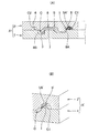
特許文献4のようなシールリップ部に複数の突起を備えた転がり軸受用シールを製造する場合、例えば、図7(A)の縦断面図及び図7(B)の要部拡大縦断面斜視図、並びに図8の斜視図に示すような圧縮加硫成形用金型A’を用いるのが一般的である。
前記転がり軸受用シールSは、環状の芯金7と、芯金7に加硫接着されたゴム8からなり、ゴム8を圧縮加硫成形する金型A’は、ゴム8を成形するための環状のキャビティCを形成する雌型1及び雄型2’を含む。
雌型1は、芯金7を位置決めするガイド部3を有するとともに、シールリップ部8Aに前記複数の突起を形成する凹凸形状4を有し、雄型2’は、キャビティCの内径側周縁部C1及び外径側周縁部C2に内径側バリ溝5’及び外径側バリ溝6を有する。
バリ溝5’,6は、加硫中にキャビティCから余分な未加硫ゴム材料を漏出させるための溝(円環状凹部)であり、図8に示すように、雌型1の凹凸形状4に対応させて、雄型2’の内径側バリ溝5’の径方向最大部5A’の形状を凹凸形状(波形形状)にし、図7(A)及び図7(B)に示す径方向隙間Iを全周に亘って略均一に形成している。
When manufacturing a rolling bearing seal having a plurality of protrusions on the seal lip portion as in
The rolling bearing seal S is composed of an
The female mold 1 has a
The burr grooves 5'and 6 are grooves (annular recesses) for leaking excess unvulcanized rubber material from the cavity C during vulcanization, and as shown in FIG. 8, the
このような圧縮加硫成形用金型A’は、雄型2’に形成する内径側バリ溝5’の径方向最大部5A’の凹凸形状(波形形状)を、マシニングセンター等による機械加工で行う必要があるので金型コストが増大する。
その上、凹凸形状(波形形状)の径方向隙間Iを全周に亘って略均一に形成するために、雌型1及び雄型2’を周方向に精度良く位置合わせ(角度合わせ)する必要があるので、生産性が低下する。
In such a compression vulcanization mold A', the uneven shape (corrugated shape) of the maximum radial portion 5A'of the inner diameter side burr groove 5'formed in the male mold 2'is formed by machining with a machining center or the like. Since it is necessary, the mold cost increases.
In addition, in order to form the radial gap I of the uneven shape (corrugated shape) substantially uniformly over the entire circumference, it is necessary to accurately align (angle) the female mold 1 and the male mold 2'in the circumferential direction. Because of this, productivity is reduced.
上述の背景に鑑み、本発明が解決しようとする課題は、シール摺動面及びシールリップ部間に軸受内部空間及び外部間に亘って連通する油通路を生じさせるために、シールリップ部に複数の突起を備えた転がり軸受用シールを圧縮加硫成形する金型の製造コストを低減すること、及び前記シールの製造における生産性を向上することである。 In view of the above background, the problem to be solved by the present invention is a plurality of problems in the seal lip portion in order to generate an oil passage communicating between the bearing internal space and the outside between the seal sliding surface and the seal lip portion. It is to reduce the manufacturing cost of the mold for compress-sulfurizing the rolling bearing seal provided with the protrusions of the above, and to improve the productivity in the manufacturing of the seal.
本発明に係る転がり軸受用シールの圧縮加硫成形用金型は、前記課題解決のために、
転がり軸受の内輪及び外輪間に形成される軸受内部空間及び外部間を区切る転がり軸受用シールの圧縮加硫成形に用いる金型であって、
前記転がり軸受用シールは、環状の芯金と、前記芯金に加硫接着されたゴムからなり、
前記ゴムは、前記芯金の内径側から径方向内方へ延びて前記内輪のシール摺動面に周方向に摺動するシールリップ部、及び前記芯金の外径側から径方向外方へ延びて前記外輪に取り付ける取付部を含み、
前記シールリップ部は、前記軸受内部空間及び外部間に亘って連通する油通路を前記シール摺動面及び当該シールリップ部間に生じさせる複数の突起を周方向全周に亘って備えるとともに、前記突起を前記シールリップ部の先端まで備えており、
前記金型は、前記ゴムを成形するための環状のキャビティを形成する雌型及び雄型を含み、
前記雌型は、前記芯金を位置決めするガイド部を有するとともに、前記シールリップ部に前記複数の突起を形成する凹凸形状を有し、
前記雄型は、前記キャビティの内径側周縁部及び外径側周縁部に内径側バリ溝及び外径側バリ溝を有するとともに、前記内径側バリ溝の径方向最大部の形状を円としてなることを特徴とする。
The mold for compression vulcanization of the seal for rolling bearings according to the present invention is used to solve the above problems.
A mold used for compression vulcanization of a rolling bearing seal that separates the inner space and outer ring of a rolling bearing formed between the inner and outer rings of a rolling bearing.
The rolling bearing seal is composed of an annular core metal and rubber vulcanized and adhered to the core metal.
The rubber extends inward in the radial direction from the inner diameter side of the core metal and slides in the circumferential direction on the seal sliding surface of the inner ring, and the outer diameter side of the core metal in the radial direction. Includes a mounting portion that extends and attaches to the outer ring
The sealing lip, the bearing inner space and the oil passage communicating over between the outer seal sliding surface and Rutotomoni comprises a plurality of projections that cause between the seal lip portion over the entire circumference, Ri you provided with the projections to the tip of the seal lip portion,
The mold comprises a female mold and a male mold that form an annular cavity for molding the rubber.
The female mold has a guide portion for positioning the core metal, and has an uneven shape that forms the plurality of protrusions on the seal lip portion.
The male mold has an inner diameter side burr groove and an outer diameter side burr groove on the inner diameter side peripheral portion and the outer diameter side peripheral portion of the cavity, and the shape of the maximum radial portion of the inner diameter side burr groove is a circle. It is characterized by.
このような構成によれば、雄型の内径側バリ溝の径方向最大部の形状が円であることから、雄型の内径側バリ溝の径方向最大部の形状を凹凸形状(波形形状)にする従来の金型と比較して、雄型の形状が簡単になるので、金型の製造コストを低減できる。
その上、発生するバリの大きさを許容範囲とすることで、複数の突起をシールリップ部の先端からシール摺動面と径方向に対面し得る範囲の全域に亘って形成することができる。
その上さらに、雄型の内径側バリ溝の径方向最大部の形状を凹凸形状(波形形状)にする従来の金型と比較して、凹凸形状(波形形状)の径方向隙間を全周に亘って略均一に形成するために、雌型及び雄型を周方向に精度良く位置合わせ(角度合わせ)する必要がないので、生産性を向上できる。
According to such a configuration, since the shape of the maximum radial portion of the inner diameter side burr groove of the male mold is a circle, the shape of the maximum radial portion of the inner diameter side burr groove of the male mold is a concave-convex shape (corrugated shape). Since the shape of the male mold is simpler than that of the conventional mold, the manufacturing cost of the mold can be reduced.
Further, by setting the size of the generated burr within the allowable range, a plurality of protrusions can be formed over the entire range from the tip of the seal lip portion to the seal sliding surface in the radial direction.
Furthermore, compared to the conventional mold in which the shape of the maximum radial portion of the inner diameter side burr groove of the male mold is a concave-convex shape (corrugated shape), the radial gap of the concave-convex shape (corrugated shape) is made all around. Productivity can be improved because it is not necessary to accurately align (angle) the female mold and the male mold in the circumferential direction in order to form them substantially uniformly.
ここで、前記内径側バリ溝の径方向最大部の形状である円の直径d(mm)を、前記複数の突起の先端に接する円の直径D(mm)に対して、(D−0.2)≦d≦Dとしてなるのが好ましい。
このような構成によれば、内径側バリ溝の径方向最大部の形状である円の直径d(mm)を、シールリップ部の複数の突起の先端に接する円の直径D(mm)に対して前記不等式の範囲内に設定していることから、0.2(mm)は、許容範囲のバリの大きさであるので、圧縮加硫成形用金型を用いた転がり軸受用シールの製造において、シールリップ部の先端に複数の突起を有するゴムの成形の信頼性が高くなる。
Here, the diameter d (mm) of the circle, which is the shape of the maximum portion in the radial direction of the inner diameter side burr groove, is (D-0.) With respect to the diameter D (mm) of the circle in contact with the tips of the plurality of protrusions. 2) It is preferable that ≦ d ≦ D.
According to such a configuration, the diameter d (mm) of the circle, which is the shape of the maximum portion in the radial direction of the inner diameter side burr groove, is set with respect to the diameter D (mm) of the circle in contact with the tips of the plurality of protrusions of the seal lip portion. Since it is set within the range of the above inequality, 0.2 (mm) is a burr size within an allowable range. Therefore, in manufacturing a seal for rolling bearings using a compression vulcanization molding die. , The reliability of molding of rubber having a plurality of protrusions at the tip of the seal lip portion is improved.
本発明に係る転がり軸受用シールの製造方法は、前記軸受用シールの圧縮加硫成形用金型を用いて転がり軸受用シールを圧縮加硫成形する転がり軸受用シールの製造方法であって、
前記金型を開いて前記雌型の前記ガイド部に前記芯金を配置する工程と、
前記雌型に未加硫ゴム材料を載置する工程と、
前記金型を閉じて加圧及び加熱して前記ゴム材料を加硫する工程と、
前記金型を開いて成形品である前記転がり軸受用シールを取り出す工程と、
を含む。
The method for manufacturing a seal for rolling bearings according to the present invention is a method for manufacturing a seal for rolling bearings in which the seal for rolling bearings is compression vulcanized using the mold for compression vulcanization of the seal for bearings.
A step of opening the mold and arranging the core metal on the guide portion of the female mold,
The step of placing the unvulcanized rubber material on the female mold and
The step of vulcanizing the rubber material by closing the mold, pressurizing and heating, and
The process of opening the mold and taking out the rolling bearing seal, which is a molded product,
including.
このような製造方法によれば、前記転がり軸受用シールの圧縮加硫成形用金型を用いるので、前記転がり軸受用シールの圧縮加硫成形用金型と同様の作用効果を奏する。 According to such a manufacturing method, since the mold for compression vulcanization of the seal for rolling bearings is used, the same operation and effect as the mold for compression vulcanization of the seal for rolling bearings can be obtained.
以上のような本発明に係る転がり軸受用シールの圧縮加硫成形用金型、及び転がり軸受用シールの製造方法によれば、主に以下に示す効果がある。
(1)雄型の内径側バリ溝の径方向最大部の形状が円であることから、雄型の形状が簡単になるので、金型の製造コストを低減できる。
(2)従来の金型のように雌型及び雄型を周方向に精度良く位置合わせする必要がないので、生産性を向上できる。
According to the above-mentioned mold for compression vulcanization molding of a rolling bearing seal and the method for manufacturing a rolling bearing seal according to the present invention, the following effects are mainly obtained.
(1) Since the shape of the maximum portion in the radial direction of the inner diameter side burr groove of the male mold is circular, the shape of the male mold is simplified, and the manufacturing cost of the mold can be reduced.
(2) Since it is not necessary to accurately align the female mold and the male mold in the circumferential direction as in the conventional mold, the productivity can be improved.
次に本発明の実施の形態を添付図面に基づき詳細に説明するが、本発明は、添付図面に示された形態に限定されず特許請求の範囲に記載の要件を満たす実施形態の全てを含むものである。
本明細書において、転がり軸受の回転軸の方向を「軸方向」といい、前記回転軸の軸芯を基準として「径方向」及び「周方向」を定義する。
Next, embodiments of the present invention will be described in detail with reference to the accompanying drawings, but the present invention is not limited to the embodiments shown in the accompanying drawings, and includes all embodiments that satisfy the requirements described in the claims. It is a waste.
In the present specification, the direction of the rotating shaft of the rolling bearing is referred to as "axial direction", and "diameter direction" and "circumferential direction" are defined with reference to the axis of the rotating shaft.
<シール付き転がり軸受>
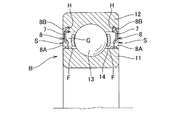
図1の要部拡大縦断面図に示すように、本発明の実施の形態にシール付き転がり軸受Bは、内輪11、外輪12、内輪11及び外輪12間を転動する、複数の転動体13,13,…、転動体13,13,…の周方向の間隔を一定に保持する保持器14、並びに、軸方向に離間した一対の転がり軸受用シールS,Sを有する。
シールS,Sは軸受内部空間Gと外部との間を区切り、軸受内部空間Gには、グリース、オイルバス等の適宜の手段により、潤滑油を供給する。
<Rolling bearing with seal>
As shown in the enlarged vertical sectional view of the main part of FIG. 1, the rolling bearing B with a seal according to the embodiment of the present invention is a plurality of rolling
The seals S and S separate the bearing internal space G from the outside, and lubricating oil is supplied to the bearing internal space G by an appropriate means such as grease or an oil bath.
シールS,Sを境界とした外部側には、例えば、ギア等の摩耗粉、微小砕石等、シール付き転がり軸受Bの組み込み先に応じた異物が存在する。このような粉状の異物は、潤滑油や雰囲気の流れによって転がり軸受B付近に到達し得る。シールS,Sは、外部から軸受内部空間Gへの前記異物の侵入を防止する。
シールSは、冷間圧延鋼板(SPCC)、電気亜鉛メッキ鋼板(SECC)又はステンレス鋼板(SUS)等の金属製である環状の芯金7と、芯金7に加硫接着されたゴム8からなる。ゴム8は、芯金7の内径側から径方向内方へ延びて内輪11のシール摺動面Fに周方向に摺動する環状のシールリップ部8A、及び芯金8の外径側から径方向外方へ延びて外輪12のシール溝Hに取り付ける取付部8Bを含む。
なお、シール付き転がり軸受Bは、内輪11が回転する内輪回転タイプ、及び外輪12が回転する外輪回転タイプがある。内径側にシールリップ8Aを有し、外径側に取付部8Bを有する転がり軸受用シールSは、前記内輪回転タイプ及び前記外輪回転タイプの両方に対して使用される。
On the outer side with the seals S and S as the boundary, for example, wear debris such as gears, fine crushed stones, and other foreign substances are present depending on the installation destination of the rolling bearing B with a seal. Such powdery foreign matter can reach the vicinity of the rolling bearing B due to the flow of lubricating oil or atmosphere. The seals S and S prevent the foreign matter from entering the bearing internal space G from the outside.
The seal S is made of an
The rolling bearing B with a seal includes an inner ring rotation type in which the
ここで、シールSのゴム8の材料としては、耐油性の良好なゴム素材として、ニトリルゴム(NBR)、水素化ニトリルゴム(HNBR)、アクリルゴム(ACM)、エチレン・アクリルゴム(AEM)、フッ素ゴム(FKM、FPM)、シリコーンゴム(VQM)等のゴムから、1種、あるいは2種以上のゴムを適当にブレンドして使用することができる。
また、ゴム材料の練り加工性、加硫成形性、芯金7との接着性を考慮した場合、他種のゴム、例えば、液状NBR、エチレンプロピレンゴム(EPDM)、天然ゴム(NR)、イソプレンゴム(IR)、スチレンブタジエンゴム(SBR)、ブタジエンゴム(BR)等とブレンドして使用することも好ましい使用態様である。
Here, as the material of the
Further, when considering the kneading processability, vulverable formability, and adhesiveness to the
<転がり軸受用シールのシールリップ部の形状>
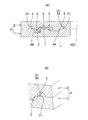
図2(A)の斜視図及び図2(B)の要部拡大縦断面斜視図、並びに図3(A)の径方向から見た要部拡大縦断面図及び図3(B)の軸方向から見た要部拡大縦断面図に示すように、本発明の実施の形態に係る転がり軸受用シールSのシールリップ部8Aには、軸受内部空間G及び外部間に亘って連通する油通路9,9,…をシール摺動面F及びシールリップ部8A間に生じさせる複数の突起10,10,…を備えている。複数の突起10,10,…は、転がり軸受用シールSのシールリップ部8Aの周方向全周に亘って形成されている。また、複数の突起10はそれぞれ、シールリップ部8Aの先端からシール摺動面Fと径方向に対面し得る範囲の全域に亘って形成されている。それにより、転がり軸受Bの回転に伴って、油通路9,9,…内の潤滑油が、シール摺動面F及びシールリップ部8A間にくさび効果で引きずり込まれるので、シール摺動面Fの全周に亘って油膜形成を均一に促進できる。このため、シールリップ部8Aとシール摺動面Fとが油膜によって完全に分離されて直接接触しない状態(すなわち流体潤滑状態)になる。
よって、シール付き転がり軸受Bの低トルク化及び高速化を図ることができる。
なお、本実施の形態に係る転がり軸受用シールSのシールリップ部8Aが備える複数の突起10,10,…は、周方向全周に亘って均一間隔であるが、本発明の対象は、複数の突起10,10,…が周方向全周に亘って均一間隔であるものに限定されない。すなわち、複数の突起10,10,…の間隔は不均一であってもよい。
<Shape of seal lip of rolling bearing seal>
The perspective view of FIG. 2 (A), the enlarged vertical sectional view of the main part of FIG. 2 (B), the enlarged vertical sectional view of the main part as seen from the radial direction of FIG. 3 (A), and the axial direction of FIG. 3 (B). As shown in the enlarged vertical cross-sectional view of the main part as seen from the above, the
Therefore, it is possible to reduce the torque and speed of the rolling bearing B with a seal.
The plurality of
次に、本発明の実施の形態に係る転がり軸受用シールSの圧縮加硫成形に用いる金型A、及び金型Aを用いた転がり軸受用シールSの製造方法について説明する。 Next, a mold A used for compression vulcanization molding of the rolling bearing seal S according to the embodiment of the present invention, and a method for manufacturing the rolling bearing seal S using the mold A will be described.
<圧縮加硫成形用金型>
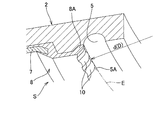
図4(A)の縦断面図及び図4(B)の要部拡大縦断面斜視図、並びに図5の斜視図に示すように、圧縮加硫成形用金型Aは、シールSのゴム8を成形するための環状のキャビティCを形成する雌型1及び雄型2を含む。
雌型(下型、ダイ)1は、シールSの芯金7を位置決めするガイド部3を有するとともに、シールリップ部8Aに複数の突起10,10,…を形成する凹凸形状4を有する。
雄型(上型、パンチ)2は、キャビティCの内径側周縁部C1及び外径側周縁部C2に内径側バリ溝5及び外径側バリ溝6を有するとともに、内径側バリ溝5の径方向最大部5Aの形状を円としてなる。
<Die for compression vulcanization molding>
As shown in the vertical sectional view of FIG. 4A, the enlarged vertical sectional perspective view of the main part of FIG. 4B, and the perspective view of FIG. 5, the compression vulcanization molding die A is the
The female mold (lower mold, die) 1 has a
The male mold (upper mold, punch) 2 has an inner diameter
図6の雌型を省略して示した要部拡大斜視図に示すように、本実施の形態では、内径側バリ溝5の径方向最大部5Aの形状である円の直径dを、シールリップ部8Aの複数の突起10,10,…の先端に接する円E(図2(B)も参照)の直径Dと等しくしている。
なお、内径側バリ溝5の径方向最大部5Aの形状である円の直径d(mm)は、複数の突起10,10,…の先端に接する円Eの直径D(mm)に対して、(D−0.2)≦d≦Dの範囲内に設定すればよく、この不等式の範囲内であれば、0.2(mm)は、許容範囲のバリの大きさであるので、圧縮加硫成形用金型Aを用いた転がり軸受用シールSの製造において、シールリップ部8Aの先端に複数の突起10,10,…を有するゴム8の成形の信頼性が高くなる。
As shown in the enlarged perspective view of the main part shown by omitting the female mold of FIG. 6, in the present embodiment, the diameter d of the circle, which is the shape of the maximum
The diameter d (mm) of the circle, which is the shape of the
<転がり軸受用シールの製造方法>
圧縮加硫成形用金型Aを用いて行う軸受用シールSの製造方法の一例について説明する。
<Manufacturing method of seals for rolling bearings>
An example of a method for manufacturing the bearing seal S performed by using the compression vulcanization mold A will be described.
(芯金配置工程)
先ず、図5のように金型Aを開いた状態で、雌型1のガイド部3に芯金7を配置する。
なお、芯金7を雌型1に配置する工程の前に、芯金7のゴム8と接する範囲に熱硬化性樹脂接着剤を塗布しておき、後工程のゴム材料加硫工程で間接加硫(架橋)接着をしてもよいし、前記接着剤を塗布しないで、後工程のゴム材料加硫工程で直接加硫(架橋)接着をしてもよい。
(Core metal placement process)
First, with the mold A open as shown in FIG. 5, the
Before the step of arranging the
(ゴム材料載置工程)
次に、雌型1に未加硫ゴム材料である、例えばゴムシートを載置する。このゴムシートの体積は、ゴム8を成形するための環状のキャビティCの容積よりも大きくする。
(Rubber material placement process)
Next, a rubber sheet, for example, which is an unvulcanized rubber material, is placed on the female mold 1. The volume of the rubber sheet is made larger than the volume of the annular cavity C for molding the
(ゴム材料加硫工程)
次に、図4(A)のように金型Aを閉じて加圧及び加熱して前記ゴムシートを加硫する。余分な未加硫ゴム材料は、雌型1及び雄型2の割り面(パーティングライン)からバリ溝5,6に漏出する。
(Rubber material vulcanization process)
Next, as shown in FIG. 4A, the mold A is closed, pressurized and heated to vulcanize the rubber sheet. The excess unvulcanized rubber material leaks from the split surfaces (parting lines) of the female mold 1 and the
(成形品取出し工程)
次に、金型Aを開いて、図2(A)及び図4(A)に示す成形品である転がり軸受用シールSを取り出す。
なお、成形品である転がり軸受用シールSを金型Aから取り出した状態では、複数の突起10,10,…は、シールリップ部8Aの先端から、シール摺動面Fと径方向に対面し得る範囲の全域に亘って形成されている。また、シールリップ部8A先端の複数の突起10,10,…において、隣り合う突起10,10の間に、薄いバリを生じる。しかしながら、このバリは、転がり軸受Bの軸方向外方へ突出するものであるとともに許容範囲のバリの大きさであり、図3(A)のようにシール摺動面Fに接触しないので、転がり軸受用シールSの機能を阻害することはなく、問題にならない。
(Molded product removal process)
Next, the mold A is opened, and the rolling bearing seal S, which is a molded product shown in FIGS. 2 (A) and 4 (A), is taken out.
When the rolling bearing seal S, which is a molded product, is taken out from the mold A, the plurality of
以上のような構成の転がり軸受用シールの圧縮加硫成形用金型A、及び転がり軸受用シールSの製造方法によれば、雄型2の内径側バリ溝5の径方向最大部5Aの形状が円であることから、雄型2’の内径側バリ溝5’の径方向最大部5A’の形状を凹凸形状(波形形状)にする従来の金型A’(図7(A)及び(B)、並びに図8)と比較して、雄型2の形状が簡単になるので、金型Aの製造コストを低減できる。
その上、上記構成の圧縮加硫成形用金型A、及び転がり軸受用シールSの製造方法によれば、発生するバリの大きさを許容範囲とすることで、複数の突起10,10,…をシールリップ部8Aの先端からシール摺動面Fと径方向に対面し得る範囲の全域に亘って形成することができる。
その上さらに、従来の金型A’と比較して、雌型1及び雄型2を周方向に精度良く位置合わせ(角度合わせ)する必要がないので、生産性を向上できる。
According to the manufacturing method of the rolling bearing seal mold A for compression vulcanization and the rolling bearing seal S having the above configuration, the shape of the maximum
Further, according to the method for manufacturing the compression vulcanization molding die A and the rolling bearing seal S having the above configuration, by setting the size of the generated burrs within the allowable range, a plurality of
Furthermore, as compared with the conventional mold A', it is not necessary to accurately align (angle) the female mold 1 and the
1 雌型(下型、ダイ)
2,2’ 雄型(上型、パンチ)
3 ガイド部
4 凹凸形状
5,5’ 内径側バリ溝
5A,5A’ 径方向最大部
6 外径側バリ溝
7 芯金
8 ゴム
8A シールリップ部
8B 取付部
9 油通路
10 突起
11 内輪
12 外輪
13 転動体
14 保持器
A,A’ 圧縮加硫成形用金型
B シール付き転がり軸受
C キャビティ
C1 内径側周縁部
C2 外径側周縁部
D シールリップ部の突起の先端に接する円の直径
d 内径側バリ溝の径方向最大部の形状である円の直径
E シールリップ部の突起の先端に接する円
F シール摺動面
G 軸受内部空間
H シール溝
I 径方向隙間
S 転がり軸受用シール
1 Female type (lower type, die)
2,2'male type (upper type, punch)
3 Guide
Claims (3)
前記転がり軸受用シールは、環状の芯金と、前記芯金に加硫接着されたゴムからなり、
前記ゴムは、前記芯金の内径側から径方向内方へ延びて前記内輪のシール摺動面に周方向に摺動するシールリップ部、及び前記芯金の外径側から径方向外方へ延びて前記外輪に取り付ける取付部を含み、
前記シールリップ部は、前記軸受内部空間及び外部間に亘って連通する油通路を前記シール摺動面及び当該シールリップ部間に生じさせる複数の突起を周方向全周に亘って備えるとともに、前記突起を前記シールリップ部の先端まで備えており、
前記金型は、前記ゴムを成形するための環状のキャビティを形成する雌型及び雄型を含み、
前記雌型は、前記芯金を位置決めするガイド部を有するとともに、前記シールリップ部に前記複数の突起を形成する凹凸形状を有し、
前記雄型は、前記キャビティの内径側周縁部及び外径側周縁部に内径側バリ溝及び外径側バリ溝を有するとともに、前記内径側バリ溝の径方向最大部の形状を円としてなることを特徴とする、
転がり軸受用シールの圧縮加硫成形用金型。
A mold used for compression vulcanization of a rolling bearing seal that separates the inner space and outer ring of a rolling bearing formed between the inner and outer rings of a rolling bearing.
The rolling bearing seal is composed of an annular core metal and rubber vulcanized and adhered to the core metal.
The rubber extends inward in the radial direction from the inner diameter side of the core metal and slides in the circumferential direction on the seal sliding surface of the inner ring, and the outer diameter side of the core metal in the radial direction. Includes a mounting portion that extends and attaches to the outer ring
The sealing lip, the bearing inner space and the oil passage communicating over between the outer seal sliding surface and Rutotomoni comprises a plurality of projections that cause between the seal lip portion over the entire circumference, Ri you provided with the projections to the tip of the seal lip portion,
The mold comprises a female mold and a male mold that form an annular cavity for molding the rubber.
The female mold has a guide portion for positioning the core metal, and has an uneven shape that forms the plurality of protrusions on the seal lip portion.
The male mold has an inner diameter side burr groove and an outer diameter side burr groove on the inner diameter side peripheral portion and the outer diameter side peripheral portion of the cavity, and the shape of the maximum radial portion of the inner diameter side burr groove is a circle. Characterized by,
Mold for compression vulcanization molding of seals for rolling bearings.
請求項1に記載の転がり軸受用シールの圧縮加硫成形用金型。 The diameter d (mm) of the circle, which is the shape of the maximum portion in the radial direction of the inner diameter side burr groove, is (D-0.2) ≦ with respect to the diameter D (mm) of the circle in contact with the tips of the plurality of protrusions. d ≦ D,
The mold for compression vulcanization molding of the seal for rolling bearings according to claim 1.
前記金型を開いて前記雌型の前記ガイド部に前記芯金を配置する工程と、
前記雌型に未加硫ゴム材料を載置する工程と、
前記金型を閉じて加圧及び加熱して前記ゴム材料を加硫する工程と、
前記金型を開いて成形品である前記転がり軸受用シールを取り出す工程と、
を含む転がり軸受用シールの製造方法。 A method for manufacturing a rolling bearing seal according to claim 1 or 2, wherein the rolling bearing seal is compression vulcanized using the compression vulcanization molding die for the rolling bearing seal.
A step of opening the mold and arranging the core metal on the guide portion of the female mold,
The step of placing the unvulcanized rubber material on the female mold and
The step of vulcanizing the rubber material by closing the mold, pressurizing and heating, and
The process of opening the mold and taking out the rolling bearing seal, which is a molded product,
A method for manufacturing a seal for rolling bearings including.
Priority Applications (5)
| Application Number | Priority Date | Filing Date | Title |
|---|---|---|---|
| JP2017012017A JP6836152B2 (en) | 2017-01-26 | 2017-01-26 | Mold for compression vulcanization of rolling bearing seals and manufacturing method of rolling bearing seals |
| EP17894047.4A EP3575640A4 (en) | 2017-01-26 | 2017-10-17 | Compression vulcanization molding mold for rolling bearing seal, and method for manufacturing rolling bearing seal |
| PCT/JP2017/037490 WO2018138981A1 (en) | 2017-01-26 | 2017-10-17 | Compression vulcanization molding mold for rolling bearing seal, and method for manufacturing rolling bearing seal |
| CN201780082936.5A CN110168261B (en) | 2017-01-26 | 2017-10-17 | Metal mold for compression vulcanization molding of seal for rolling bearing and method for manufacturing seal for rolling bearing |
| US16/479,140 US11440226B2 (en) | 2017-01-26 | 2017-10-17 | Compression vulcanization molding mold for rolling bearing seal, and method for manufacturing rolling bearing seal |
Applications Claiming Priority (1)
| Application Number | Priority Date | Filing Date | Title |
|---|---|---|---|
| JP2017012017A JP6836152B2 (en) | 2017-01-26 | 2017-01-26 | Mold for compression vulcanization of rolling bearing seals and manufacturing method of rolling bearing seals |
Publications (3)
| Publication Number | Publication Date |
|---|---|
| JP2018119624A JP2018119624A (en) | 2018-08-02 |
| JP2018119624A5 JP2018119624A5 (en) | 2019-10-31 |
| JP6836152B2 true JP6836152B2 (en) | 2021-02-24 |
Family
ID=62978247
Family Applications (1)
| Application Number | Title | Priority Date | Filing Date |
|---|---|---|---|
| JP2017012017A Active JP6836152B2 (en) | 2017-01-26 | 2017-01-26 | Mold for compression vulcanization of rolling bearing seals and manufacturing method of rolling bearing seals |
Country Status (5)
| Country | Link |
|---|---|
| US (1) | US11440226B2 (en) |
| EP (1) | EP3575640A4 (en) |
| JP (1) | JP6836152B2 (en) |
| CN (1) | CN110168261B (en) |
| WO (1) | WO2018138981A1 (en) |
Families Citing this family (1)
| Publication number | Priority date | Publication date | Assignee | Title |
|---|---|---|---|---|
| JPWO2020045072A1 (en) * | 2018-08-29 | 2021-08-10 | Nok株式会社 | Manufacturing method and molding mold of seal member |
Family Cites Families (28)
| Publication number | Priority date | Publication date | Assignee | Title |
|---|---|---|---|---|
| US3501155A (en) * | 1967-05-22 | 1970-03-17 | Gen Motors Corp | Bi-directional seal |
| US3572732A (en) * | 1969-02-26 | 1971-03-30 | Mather Co | Double load area lip seal |
| US3895814A (en) * | 1971-08-10 | 1975-07-22 | Parker Hannifin Corp | Rotary shaft seal |
| CH567927A5 (en) * | 1974-08-21 | 1975-10-15 | Schiesser Ag | |
| DE2556992C2 (en) * | 1975-12-18 | 1980-04-24 | Goetze Ag, 5093 Burscheid | Shaft seal |
| US4399998A (en) * | 1981-12-28 | 1983-08-23 | The Timken Company | Self-venting seal lip |
| US4770424A (en) * | 1985-12-19 | 1988-09-13 | The Timken Company | Compact labyrinth-type seal |
| FR2636691B1 (en) * | 1988-09-20 | 1994-12-09 | Roulements Soc Nouvelle | BEARING WITH SEAL |
| JP3242517B2 (en) * | 1993-12-29 | 2001-12-25 | 東洋シール工業株式会社 | Bearing sealing plate and method of manufacturing the same |
| US5921555A (en) * | 1997-04-10 | 1999-07-13 | Freudenberg-Nok General Partnership | Uni-directional seal for use on a shaft |
| US6409177B1 (en) * | 1999-08-23 | 2002-06-25 | Freudenberg-Nok General Partnership | Rotary shaft seal |
| JP4461518B2 (en) * | 1999-08-27 | 2010-05-12 | 住友化学株式会社 | Mold for manufacturing thermoplastic resin molded body and method for manufacturing thermoplastic resin molded body |
| JP4419641B2 (en) * | 2004-03-29 | 2010-02-24 | 日産自動車株式会社 | Mounting structure for vehicle headlamps |
| US8657299B2 (en) * | 2004-07-15 | 2014-02-25 | John E. Rode | Mounting rings for shafts |
| US7563050B2 (en) * | 2004-07-15 | 2009-07-21 | Temper Corporation | Rings for mounting structures to shafts and methods of using such rings |
| EP2093442B1 (en) * | 2006-11-14 | 2014-09-10 | NTN Corporation | Sealed rolling bearing |
| KR101260574B1 (en) * | 2008-03-13 | 2013-05-06 | 닛폰 바루카 고교 가부시키가이샤 | Seal |
| US8596872B2 (en) * | 2009-10-13 | 2013-12-03 | Amsted Rail Company, Inc. | Roller bearing seal |
| EP2725247B1 (en) * | 2011-06-27 | 2019-08-21 | NTN Corporation | Rolling bearing |
| JP2013007463A (en) | 2011-06-27 | 2013-01-10 | Ntn Corp | Bearing with seal |
| US8955849B2 (en) * | 2012-06-04 | 2015-02-17 | Federal-Mogul Corporation | Radial shaft seal and assembly therewith |
| JP6522357B2 (en) * | 2015-02-06 | 2019-05-29 | Ntn株式会社 | Rolling bearing |
| JP6523994B2 (en) | 2015-03-09 | 2019-06-05 | Ntn株式会社 | Sealed bearing |
| WO2016143786A1 (en) * | 2015-03-09 | 2016-09-15 | Ntn株式会社 | Sealed bearing |
| JP2016166655A (en) | 2015-03-10 | 2016-09-15 | Ntn株式会社 | Rolling bearing with seal |
| JP2016166654A (en) | 2015-03-10 | 2016-09-15 | Ntn株式会社 | Rolling bearing with seal |
| JP6609460B2 (en) * | 2015-11-13 | 2019-11-20 | 内山工業株式会社 | Manufacturing method of molding die and sealing device |
| JP6789739B2 (en) * | 2016-09-08 | 2020-11-25 | Ntn株式会社 | Bearing with seal |
-
2017
- 2017-01-26 JP JP2017012017A patent/JP6836152B2/en active Active
- 2017-10-17 WO PCT/JP2017/037490 patent/WO2018138981A1/en unknown
- 2017-10-17 US US16/479,140 patent/US11440226B2/en active Active
- 2017-10-17 CN CN201780082936.5A patent/CN110168261B/en active Active
- 2017-10-17 EP EP17894047.4A patent/EP3575640A4/en active Pending
Also Published As
| Publication number | Publication date |
|---|---|
| CN110168261A (en) | 2019-08-23 |
| WO2018138981A1 (en) | 2018-08-02 |
| CN110168261B (en) | 2021-05-11 |
| US11440226B2 (en) | 2022-09-13 |
| EP3575640A1 (en) | 2019-12-04 |
| US20190351590A1 (en) | 2019-11-21 |
| EP3575640A4 (en) | 2020-10-14 |
| JP2018119624A (en) | 2018-08-02 |
Similar Documents
| Publication | Publication Date | Title |
|---|---|---|
| US6660206B1 (en) | Method of manufacturing a sealing device | |
| US9714713B2 (en) | Seal ring with frictional load surface | |
| US4986553A (en) | Shaft seal | |
| US10293531B2 (en) | Method for manufacturing sealing device | |
| JPWO2009078314A1 (en) | Sealing device | |
| JP2009092223A (en) | Sealing device for universal joint | |
| JP6836152B2 (en) | Mold for compression vulcanization of rolling bearing seals and manufacturing method of rolling bearing seals | |
| JP2017087629A (en) | Metal mold and sealing device manufacturing method | |
| JP6011777B2 (en) | Sealing device | |
| JP6566384B2 (en) | Sealing device | |
| JP2006275143A (en) | Sealing device and method of manufacturing seal member | |
| WO2020009005A1 (en) | Sealing device | |
| JP3169130B2 (en) | Manufacturing method of sealing device | |
| CN107208796B (en) | The manufacturing method of lip ring | |
| CA3097674C (en) | Rotary seal and method of making same | |
| JP2005220931A (en) | Oil seal | |
| CN107816493B (en) | Universal joint comprising a seal, seal and method for mounting a seal | |
| US20200292082A1 (en) | Sealing device | |
| JP3367802B2 (en) | Sealing member manufacturing method and sealing device | |
| JP7121135B2 (en) | sealing device | |
| WO2018159809A1 (en) | Oil seal and seal attached bearing | |
| JP2011196461A (en) | Sealing device for rolling bearing | |
| JP6124052B2 (en) | Oil seal and manufacturing method thereof | |
| JP5702580B2 (en) | Oil seal mold | |
| JP2021025596A (en) | Rotation seal |
Legal Events
| Date | Code | Title | Description |
|---|---|---|---|
| A521 | Request for written amendment filed |
Free format text: JAPANESE INTERMEDIATE CODE: A523 Effective date: 20190920 |
|
| A621 | Written request for application examination |
Free format text: JAPANESE INTERMEDIATE CODE: A621 Effective date: 20190920 |
|
| A131 | Notification of reasons for refusal |
Free format text: JAPANESE INTERMEDIATE CODE: A131 Effective date: 20200804 |
|
| A521 | Request for written amendment filed |
Free format text: JAPANESE INTERMEDIATE CODE: A523 Effective date: 20200925 |
|
| TRDD | Decision of grant or rejection written | ||
| A01 | Written decision to grant a patent or to grant a registration (utility model) |
Free format text: JAPANESE INTERMEDIATE CODE: A01 Effective date: 20210106 |
|
| A61 | First payment of annual fees (during grant procedure) |
Free format text: JAPANESE INTERMEDIATE CODE: A61 Effective date: 20210119 |
|
| R150 | Certificate of patent or registration of utility model |
Ref document number: 6836152 Country of ref document: JP Free format text: JAPANESE INTERMEDIATE CODE: R150 |
|
| R250 | Receipt of annual fees |
Free format text: JAPANESE INTERMEDIATE CODE: R250 |