JP6835592B2 - Getter pump system - Google Patents
Getter pump system Download PDFInfo
- Publication number
- JP6835592B2 JP6835592B2 JP2016567349A JP2016567349A JP6835592B2 JP 6835592 B2 JP6835592 B2 JP 6835592B2 JP 2016567349 A JP2016567349 A JP 2016567349A JP 2016567349 A JP2016567349 A JP 2016567349A JP 6835592 B2 JP6835592 B2 JP 6835592B2
- Authority
- JP
- Japan
- Prior art keywords
- getter
- linear
- cartridge
- pump system
- cartridges
- Prior art date
- Legal status (The legal status is an assumption and is not a legal conclusion. Google has not performed a legal analysis and makes no representation as to the accuracy of the status listed.)
- Active
Links
- 239000000463 material Substances 0.000 claims description 16
- 238000000034 method Methods 0.000 description 7
- 229910052751 metal Inorganic materials 0.000 description 5
- 239000002184 metal Substances 0.000 description 5
- 239000007789 gas Substances 0.000 description 4
- 239000002245 particle Substances 0.000 description 4
- 238000005086 pumping Methods 0.000 description 4
- 108010083687 Ion Pumps Proteins 0.000 description 2
- RTAQQCXQSZGOHL-UHFFFAOYSA-N Titanium Chemical compound [Ti] RTAQQCXQSZGOHL-UHFFFAOYSA-N 0.000 description 2
- 239000000956 alloy Substances 0.000 description 2
- 229910045601 alloy Inorganic materials 0.000 description 2
- 238000004519 manufacturing process Methods 0.000 description 2
- 239000006187 pill Substances 0.000 description 2
- 229910052719 titanium Inorganic materials 0.000 description 2
- 239000010936 titanium Substances 0.000 description 2
- 229910000838 Al alloy Inorganic materials 0.000 description 1
- 102000006391 Ion Pumps Human genes 0.000 description 1
- 229910004688 Ti-V Inorganic materials 0.000 description 1
- 229910010968 Ti—V Inorganic materials 0.000 description 1
- QCWXUUIWCKQGHC-UHFFFAOYSA-N Zirconium Chemical compound [Zr] QCWXUUIWCKQGHC-UHFFFAOYSA-N 0.000 description 1
- 230000003213 activating effect Effects 0.000 description 1
- 230000004913 activation Effects 0.000 description 1
- 238000005054 agglomeration Methods 0.000 description 1
- 230000002776 aggregation Effects 0.000 description 1
- 238000000429 assembly Methods 0.000 description 1
- 230000000712 assembly Effects 0.000 description 1
- 239000011248 coating agent Substances 0.000 description 1
- 238000000576 coating method Methods 0.000 description 1
- 238000001514 detection method Methods 0.000 description 1
- 238000011161 development Methods 0.000 description 1
- 230000018109 developmental process Effects 0.000 description 1
- 238000001312 dry etching Methods 0.000 description 1
- 238000005516 engineering process Methods 0.000 description 1
- 230000004927 fusion Effects 0.000 description 1
- 238000010438 heat treatment Methods 0.000 description 1
- 210000003000 inclusion body Anatomy 0.000 description 1
- 238000005468 ion implantation Methods 0.000 description 1
- 230000014759 maintenance of location Effects 0.000 description 1
- 150000002739 metals Chemical class 0.000 description 1
- 239000000843 powder Substances 0.000 description 1
- 239000004065 semiconductor Substances 0.000 description 1
- 238000004544 sputter deposition Methods 0.000 description 1
- 238000000859 sublimation Methods 0.000 description 1
- 230000008022 sublimation Effects 0.000 description 1
- 239000000758 substrate Substances 0.000 description 1
- 238000000427 thin-film deposition Methods 0.000 description 1
- 230000007704 transition Effects 0.000 description 1
- 238000001771 vacuum deposition Methods 0.000 description 1
- 238000003466 welding Methods 0.000 description 1
- 229910052727 yttrium Inorganic materials 0.000 description 1
- VWQVUPCCIRVNHF-UHFFFAOYSA-N yttrium atom Chemical compound [Y] VWQVUPCCIRVNHF-UHFFFAOYSA-N 0.000 description 1
- 229910052726 zirconium Inorganic materials 0.000 description 1
Images

Classifications
-
- H—ELECTRICITY
- H01—ELECTRIC ELEMENTS
- H01J—ELECTRIC DISCHARGE TUBES OR DISCHARGE LAMPS
- H01J41/00—Discharge tubes for measuring pressure of introduced gas or for detecting presence of gas; Discharge tubes for evacuation by diffusion of ions
- H01J41/12—Discharge tubes for evacuating by diffusion of ions, e.g. ion pumps, getter ion pumps
-
- F—MECHANICAL ENGINEERING; LIGHTING; HEATING; WEAPONS; BLASTING
- F04—POSITIVE - DISPLACEMENT MACHINES FOR LIQUIDS; PUMPS FOR LIQUIDS OR ELASTIC FLUIDS
- F04B—POSITIVE-DISPLACEMENT MACHINES FOR LIQUIDS; PUMPS
- F04B37/00—Pumps having pertinent characteristics not provided for in, or of interest apart from, groups F04B25/00 - F04B35/00
- F04B37/02—Pumps having pertinent characteristics not provided for in, or of interest apart from, groups F04B25/00 - F04B35/00 for evacuating by absorption or adsorption
-
- F—MECHANICAL ENGINEERING; LIGHTING; HEATING; WEAPONS; BLASTING
- F04—POSITIVE - DISPLACEMENT MACHINES FOR LIQUIDS; PUMPS FOR LIQUIDS OR ELASTIC FLUIDS
- F04B—POSITIVE-DISPLACEMENT MACHINES FOR LIQUIDS; PUMPS
- F04B37/00—Pumps having pertinent characteristics not provided for in, or of interest apart from, groups F04B25/00 - F04B35/00
- F04B37/10—Pumps having pertinent characteristics not provided for in, or of interest apart from, groups F04B25/00 - F04B35/00 for special use
- F04B37/14—Pumps having pertinent characteristics not provided for in, or of interest apart from, groups F04B25/00 - F04B35/00 for special use to obtain high vacuum
-
- H—ELECTRICITY
- H01—ELECTRIC ELEMENTS
- H01J—ELECTRIC DISCHARGE TUBES OR DISCHARGE LAMPS
- H01J41/00—Discharge tubes for measuring pressure of introduced gas or for detecting presence of gas; Discharge tubes for evacuation by diffusion of ions
- H01J41/12—Discharge tubes for evacuating by diffusion of ions, e.g. ion pumps, getter ion pumps
- H01J41/18—Discharge tubes for evacuating by diffusion of ions, e.g. ion pumps, getter ion pumps with ionisation by means of cold cathodes
- H01J41/20—Discharge tubes for evacuating by diffusion of ions, e.g. ion pumps, getter ion pumps with ionisation by means of cold cathodes using gettering substances
Description
本発明は、特に線形加速器、又はより具体的には、スパッタリング又は真空プロセスのような薄膜堆積プロセス用の、ドライエッチング、イオン注入等の半導体製造用の、又は、真空に維持される大型の検出器用の大型のUHV/HV装置等の、空にされる大体積環境に有用な改良されたゲッターポンプシステムに関連する。他の用途は、特定の核融合システムにおける、核エネルギーシステムの特定のチャンバーにおける、例えばH2及びその同位体等の残留ガス圧の制御である。 The present invention specifically comprises linear accelerators, or more specifically, large detections for thin film deposition processes such as sputtering or vacuum processes, for semiconductor manufacturing such as dry etching, ion implantation, or maintained in vacuum. It relates to an improved getter pump system useful for large volume environments to be emptied, such as dexterous large UHV / HV devices. Other applications, in particular fusion system, in particular a chamber of nuclear energy systems, is the control of for example H 2 and residual gas pressure of the isotope and the like.
一般的に言えば、大容量環境における真空制御のゲッターベースの方法は、2つの主たるカテゴリーに分類される。 Generally speaking, getter-based methods of vacuum control in high volume environments fall into two main categories.
1つ目は、例えば、欧州特許第0964741号明細書及び欧州特許第0906635号明細書に記載され、金属チャンバーの金属表面全体を必須的に薄膜コーティングすることからなる。 The first is described in, for example, European Patent No. 0964741 and European Patent No. 0906635, which comprises essentially thin-coating the entire metal surface of the metal chamber.
広く普及している第2の方法は、その代わりに、加速器の周辺に沿って分布され、適切な開口を用いてそこに接続される複数のゲッターポンプを用いることからなる。この方法は、様々な文献に記載され、例えば、Ferrarioらによる論文(非特許文献1)が参照される。 A second method that is widespread consists of instead using multiple getter pumps that are distributed along the periphery of the accelerator and connected to it with appropriate openings. This method is described in various documents, for example, a paper by Ferrario et al. (Non-Patent Document 1) is referred to.
ゲッターポンプは、ゲッターカートリッジの使用を想定する独立したシステムであり、限られた少数のゲッターカートリッジを有する標準ポンプシステムを示す、本出願人による米国特許第6,149,392号明細書に記載されるように、それらは、独立型のシステムとして使用され得、それは、本発明とは異なって、密閉されたハウジングが真空密閉され、本発明のように、さらなる保持するケース又は含むケースなしに壁チャンバーに載置されるものではない。The getter pump is an independent system that envisions the use of getter cartridges and is described in US Pat. No. 6,149,392 by Applicant, which indicates a standard pump system with a limited number of getter cartridges. As such, they can be used as a stand-alone system, which, unlike the present invention, has a sealed housing that is vacuum sealed and, as in the present invention, a wall without additional holding cases or including cases. It is not placed in a chamber.
あるいは、ゲッターポンプは、他の真空ポンプと共同して使用され得、例えば、これらのポンプシステムにおける最近の発展に関して共に本出願人による欧州特許第2409034号明細書及び国際公開第2014/060879号が参照される。 Alternatively, getter pumps can be used in collaboration with other vacuum pumps, eg, European Patent No. 2409034 and WO 2014/060879 by the Applicant together with respect to recent developments in these pump systems. Referenced.
他の代替的な方法は、真空堆積チャンバー内の独立したゲッターポンプの使用を示す米国特許第5911560号明細書に記載されている。 Other alternative methods are described in US Pat. No. 5,911,560, which show the use of a separate getter pump in a vacuum deposition chamber.
本発明の目的は、より高い全体的な能力及び/又はポンピング速度を与えることによって、従来技術のゲッターポンプシステムの性能を改善することであり、より具体的には、本発明によるポンプシステムは、105l/sを超えるH2に対するポンピング速度、及び、CO、H2O等の残留ガスに対する105mbarリットルを超える容量を達成する。 An object of the present invention is to improve the performance of a prior art getter pump system by providing a higher overall capacity and / or pumping speed, more specifically the pump system according to the invention. pumping speed for 10 5 greater than l / s H 2, and, CO, to achieve a capacity of more than 10 5 mbar liter for residual gases such as H 2 O.
第1の側面において、本発明は、壁部、前記壁部に接続される線形支持体を有する複数のゲッターカートリッジ、及び複数の線形ヒータを備えるゲッターポンプシステムであって、前記壁部が、少なくとも0.5m2の表面積を有し、前記ゲッターカートリッジの密度が、20から2500カートリッジ/平方メートルであり、前記線形ヒータの密度が、20から5000ヒータ/平方メートルである、ゲッターポンプシステムからなる。 In a first aspect, the present invention is a getter pump system comprising a wall portion, a plurality of getter cartridges having linear supports connected to the wall portion, and a plurality of linear heaters, wherein the wall portion is at least. It comprises a getter pump system having a surface area of 0.5 m 2 and a density of the getter cartridges of 20 to 2500 cartridges / square meter and a density of the linear heaters of 20 to 5000 heaters / square meter.
ゲッターカートリッジ及びヒータの数のこの幅広いバリエーションは、各カートリッジが1つ又はそれ以上のゲッター要素を含むゲッターカートリッジの実施形態に対する様々な可能性を考慮している。このバリエーションは、典型的には1.5から15cm2の範囲である、ゲッターカートリッジの線形支持体に垂直な平面におけるゲッターカートリッジの最上部のゲッター要素の突出部として定義されるゲッターカートリッジの上部領域に加えて、ゲッター要素の形状(最も一般的な構成のディスク、正方形、及び折り畳まれた平坦なストリップ)に関連する。 This wide variation in the number of getter cartridges and heaters considers various possibilities for getter cartridge embodiments, where each cartridge contains one or more getter elements. This variation is defined as the protrusion of the getter element at the top of the getter cartridge in a plane perpendicular to the linear support of the getter cartridge, typically in the range of 1.5 to 15 cm 2. In addition, it relates to the shape of the getter element (discs, squares, and folded flat strips of the most common configurations).
次いで、このバリエーションはまた、互いに間隔が空けられた異なるカートリッジに関連する。好ましい実施形態において、平方メートルあたりのゲッターカートリッジの数に、メートルで表されるゲッター要素の上部の平均面積を乗じた値が、0.04から0.7である。This variation then also relates to different cartridges spaced apart from each other. In a preferred embodiment, the number of getter cartridges per square meter multiplied by the average area of the top of the getter element in meters is 0.04 to 0.7.
好ましくは、ゲッターカートリッジは、全て同一であり、すなわち、それらは、カートリッジあたり同一の数のゲッター要素を有し、ゲッター要素の形状及び面積が同一である。実際の製造における不可避的な変動及び許容誤差のために、平均的なゲッターカートリッジの上部面積は、好ましいゲッターカートリッジ密度に関して上記の考慮で使用される。 Preferably, the getter cartridges are all the same, i.e. they have the same number of getter elements per cartridge, and the shape and area of the getter elements are the same. Due to unavoidable variations and tolerances in actual manufacturing, the top area of the average getter cartridge is used in the above considerations with respect to the preferred getter cartridge density.
本発明は、添付の図面を参照してさらに示される。 The present invention is further shown with reference to the accompanying drawings.
前述の図面において、示された要素の寸法及び寸法比は、正確なものであるとは限らず、ある場合には、図面を読みやすくするために変更されており、さらに、電源やその接続ケーブル等の、本発明の理解に必須ではない要素は、表されていない。 In the above drawings, the dimensions and dimensional ratios of the elements shown are not always accurate and have been modified in some cases to make the drawings easier to read, as well as the power supply and its connecting cables. Elements that are not essential to the understanding of the present invention, such as, are not represented.
本発明の文脈において“ゲッターカートリッジ”という用語が、少なくとも1.5グラムのゲッター材料を含む又は保持するあらゆる細長い要素を意図するものであることに留意することが重要である。好ましくは、カートリッジあたりのゲッター材料の量は、500グラム以下である。 It is important to note that in the context of the present invention, the term "getter cartridge" is intended for any elongated element that contains or holds at least 1.5 grams of getter material. Preferably, the amount of getter material per cartridge is 500 grams or less.
ゲッターカートリッジの文脈における“細長い要素”として、本出願人は、線形支持体からのゲッター材料の最大距離と線形支持体の長さとの比が1.4未満である線形支持体上のゲッター材料の集積を考えている。特に、保持構成は、典型的には、焼結されたゲッターパウダーの間隔の空いたディスクを中心要素に取り付けることによって得られ、このような構成は、例えば、本出願人による米国特許第6,149,392号明細書に示され、その開示は、参照することによって本明細書に含まれる。 As a "slender element" in the context of getter cartridges, Applicants have found that the ratio of the maximum distance of the getter material from the linear support to the length of the linear support is less than 1.4 for the getter material on the linear support. I am thinking of agglomeration. In particular, retention configurations are typically obtained by attaching spaced discs of sintered getter powder to the central element, such configurations as, for example, US Pat. No. 6, U.S. Pat. Shown herein, 149,392, the disclosure of which is incorporated herein by reference.
本発明によるゲッターカートリッジに対する他の代替的な構成は、その目的が、ある場合には放出される粒子に加えて錠剤を保持することの両方である金属のネット構造を備える封入体に含まれるゲッター材料の錠剤(ピル)の使用を想定する。さらに、ネット構造の多孔性は、クライオポンプ又はスパッタイオンポンプ等の他のポンプと組み合わせて吸着ガスの収率を調整するように設計され得る。このように、一次的なピーク圧力は、適切な方法で管理され得る。このようなゲッターカートリッジ構造は、嵩高い構成であるとしても、例えば米国特許第5,154,582号に開示されている。 Another alternative configuration for getter cartridges according to the invention is a getter contained in an inclusion body having a metal net structure whose purpose is, in some cases, to hold the tablet in addition to the emitted particles. Suppose the use of material tablets (pills). In addition, the porosity of the net structure can be designed to adjust the yield of adsorbed gas in combination with other pumps such as cryopumps or sputter ion pumps. Thus, the primary peak pressure can be controlled in an appropriate manner. Such a getter cartridge structure, even if it has a bulky structure, is disclosed in, for example, US Pat. No. 5,154,582.
従って、それは、ゲッターディスクの場合、線形支持体からゲッター材料の最大距離を設定するディスクの直径であり、一方、ゲッター要素(錠剤)の場合、その距離は、最外の要素によって決定される。これらの2つが、2つの最も関心のある共通の構成であり、特に、一方が、中心支持体に載置されたゲッターディスクの使用を想定するが、ゲッターカートリッジにおける他の構成が可能であり、本発明に含まれる。例えば、書籍“Capture Pumping Technology”(1991)の228頁には、ゲッター材料が平坦な基板に支持される他のタイプのゲッターカートリッジが記載されており、このポンプは、市場で入手可能であり、Sorb−ACという商標名で出願人によって販売されている。この後者の場合においても、コーティングされたゲッターストリップの最外端は、上記に定義されるように線形ゲッターカートリッジにおける最大距離を決定する。 Thus, in the case of getter discs, it is the diameter of the disc that sets the maximum distance of the getter material from the linear support, while in the case of getter elements (tablets), that distance is determined by the outermost factor. These two are the two most interesting common configurations, in particular one envisions the use of getter discs mounted on a central support, but other configurations in getter cartridges are possible. Included in the present invention. For example, page 228 of the book "Capture Pumping Technology" (1991) describes other types of getter cartridges in which the getter material is supported on a flat substrate, and this pump is available on the market. Sold by the applicant under the trade name Sorb-AC. Again in this latter case, the outermost edge of the coated getter strip determines the maximum distance in the linear getter cartridge as defined above.
本発明によるゲッターポンプシステムは、ゲッターカートリッジを活性化させるためのヒータの存在を想定する。これらのヒータは、2つの主たる様式において本発明によるゲッターポンプシステムに集積され得る。第1の様式において、ヒータは、ゲッターカートリッジとは別個の離隔した線形要素であり、第2の様式において、ヒータは、それ自体ゲッターカートリッジに組み込まれている。 The getter pump system according to the present invention assumes the presence of a heater for activating the getter cartridge. These heaters can be integrated into the getter pump system according to the invention in two main modes. In the first mode, the heater is a separate linear element separate from the getter cartridge, and in the second mode, the heater is itself incorporated into the getter cartridge.
例えば、積層され、間隔が空けられたゲッターディスクで作られるカートリッジの場合、ヒータは、ゲッターディスクが載置される線形の金属支持体であり得る。 For example, in the case of cartridges made of stacked and spaced getter discs, the heater can be a linear metal support on which the getter discs are placed.
高い熱容量を有するゲッター材料で作られるゲッターカートリッジにおける組み込まれたヒータは、特に、より大きい又は拡大したシステムにおいて、妥当な時間枠で活性化及び作動状態を行うのに十分ではなく、従って、これらの場合、外部(ゲッターカートリッジに対して)の別個のヒータを使用することも想定される。 Incorporated heaters in getter cartridges made of getter material with high heat capacity are not sufficient to perform activation and operating conditions in a reasonable time frame, especially in larger or expanded systems, and therefore these In some cases, it is also envisioned to use a separate external heater (relative to the getter cartridge).
ゲッターカートリッジの幾つかが、近くにあるゲッターカートリッジに対するのと同様に、支持されたゲッター要素に対するヒータとして作用する線形支持体を有し、それによって、全てのゲッターカートリッジがヒータによって支持されるとは限らず、又は、カートリッジ内に組み込まれたものに加えて更なるヒータがある状況という、混ざり合った状況を想定することも可能である。 Some of the getter cartridges have a linear support that acts as a heater for the supported getter elements, as well as for nearby getter cartridges, so that all getter cartridges are supported by the heater. It is not limited to this, or it is possible to assume a mixed situation in which there are additional heaters in addition to those incorporated in the cartridge.
本発明が、特定のゲッター材料に限定されないが、熱処理の手段によってガスを吸着することができるあらゆる適切な材料が採用され、本発明の範囲及び目的におけるゲッター材料の定義に含まれることに留意すべきである。このような材料の認識及び特性は、当業者に利用可能であり、欧州特許第0742370号明細書等の様々な文献から容易に引き出すことができる。少なくとも30%の1つ又はそれ以上のチタン、ジルコニウム、イットリウムを含むゲッター金属又は合金が特に有利である。本出願人の名称で国際公開第2013/175340号に記載されるZr−Ti−V合金、又は、本出願人の名称で公開されていない伊国特許出願第2013−001921号明細書に記載されるZr−Ti−V−Al合金が、より好ましい材料である。 It should be noted that the present invention is not limited to any particular getter material, but any suitable material capable of adsorbing gas by means of heat treatment is employed and is included in the definition of getter material in the scope and purpose of the invention. Should be. Recognition and properties of such materials are available to those of skill in the art and can be easily derived from various documents such as European Patent No. 0742370. Getter metals or alloys containing at least 30% one or more titanium, zirconium, yttrium are particularly advantageous. Described in the Zr-Ti-V alloy described in International Publication No. 2013/175340 in the name of the applicant, or in the Japanese Patent Application No. 2013-001921 not published in the name of the applicant. Zr-Ti-V-Al alloy is a more preferred material.
本発明によるゲッターポンプシステムは、ゲッターカートリッジの数とヒータの数との間の最適な比を与え、特に、その比は、好ましくは0.66から4である。
The getter pump system according to the invention provides an optimum ratio between the number of getter cartridges and the number of heaters , in particular the ratio is preferably 0.66 to 4.
ゲッターカートリッジ又は線形ヒータである、本発明によるゲッターポンプシステムを構成する線形要素の好ましい配向は、隣接する線形要素によって形成される平均角度が好ましくは15°以下であるようなものである。The preferred orientation of the linear elements that make up the getter pump system according to the invention, which is a getter cartridge or linear heater, is such that the average angle formed by the adjacent linear elements is preferably 15 ° or less.
好ましい実施形態において、ヒータ、ゲッターカートリッジ、又は集積されたヒータを有するゲッターカートリッジである、本発明によるゲッターポンプシステムの要素は、独立して入れ替え可能である(すなわち、独立して壁に接続される)。 In a preferred embodiment, the elements of the getter pump system according to the invention, which are heaters, getter cartridges, or getter cartridges with integrated heaters, are independently replaceable (ie, independently wall-mounted). ).
好ましい接続は、ネジ、ジャンクションポケット、インターロッキングを用いて行われるが、溶接及びリベット打ち等の独立して入れ替え可能ではない接続も行われる。 Preferred connections are made using screws, junction pockets, interlocking, but also non-independent, non-replaceable connections such as welding and riveting.
代替的な好ましい実施形態において、ゲッターポンプシステムは、複数のプラットフォームアセンブリで作られ、各々は、2から10の線形カートリッジ及び1から11の線形ヒータを含む。 In an alternative preferred embodiment, the getter pump system is made up of multiple platform assemblies, each containing 2 to 10 linear cartridges and 1 to 11 linear heaters.
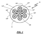
図1は、好ましい構造の1つである“ハニカム”タイプの構造を形成するように図1に示されるもののようにn個の部分で作られる、本発明によるゲッターポンプシステムの一部10の上面図を示す。この好ましい構成において、中心のゲッターカートリッジ100は、全てが壁に載置される他のゲッターカートリッジ100’、100”、・・・、100n及び線形ヒータ120、120’、・・・、120nによって囲われ、各々のゲッターカートリッジは、中心の線形要素110、110’、110”、・・・、110nに載置される複数のゲッターディスク(上面視で上部のものだけが見られる)で作られる。この構成は、ディスクで作られるゲッターカートリッジ及び別個の離隔した線形ヒータを想定するが、前述のように、この構成は、代替的には、ゲッター材料が錠剤の形態であるゲッターカートリッジ、又は、中心の線形支持要素がヒータとしても作用するゲッターカートリッジを用いて作られ得る。
FIG. 1 shows the top surface of a
図2は、複数のゲッターカートリッジ210、210’、・・・、210nが、壁部21に載置され、中心の線形支持要素がまた、ヒータとして作用する、本発明によるゲッターポンプシステム20の側面図を示す。図2から観察することができるように、ゲッターカートリッジ(及び任意の追加の外部ヒータ)が載置される壁部21は、粒子加速器等の場合等には、湾曲され得る。
FIG. 2 shows the
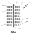
本発明によるゲッターポンプシステム30の代替的な実施形態の側面図が図3に示される。この場合、その左表面31’及び右表面31”において、中心支持要素がまたヒータとして作用する複数のゲッターカートリッジ310、310’、・・・310n及び320、320’、・・・、320nそれぞれを支持する線形垂直壁31がある。
A side view of an alternative embodiment of the
図1に示される実施形態と同様に、図2及び図3に示される実施形態の両方は、ゲッターピルを用いるタイプ等の他のタイプのゲッターカートリッジ、及びゲッターカートリッジの外部にある線形ヒータを含み得る。 Similar to the embodiment shown in FIG. 1, both embodiments shown in FIGS. 2 and 3 include other types of getter cartridges, such as those using getter pills, and linear heaters outside the getter cartridges. obtain.
また、本発明によるゲッターポンプシステムは、共に本発明によるゲッターポンプシステム含むチャンバー/体積に接続される、低温ポンプ、チタンサブリメーションポンプ及びスパッタイオンポンプ等の標準的な真空ポンプ又はゲッターポンプと共同して、又は、チャンバー/体積自体内の補助要素として使用され得る。 Further, the getter pump system according to the present invention is jointly used with a standard vacuum pump or getter pump such as a low temperature pump, a titanium sublimation pump and a sputter ion pump, both of which are connected to a chamber / volume including the getter pump system according to the present invention. Or can be used as an auxiliary element within the chamber / volume itself.
第2の側面において、本発明は、その中で、線形支持体を有する複数のゲッターカートリッジ及び複数の線形ヒータを壁に載置することによって、少なくとも10m2の公称内部表面を有するチャンバーを空にする方法であって、前記壁が、少なくとも0.5m2の表面積を有し、前記ゲッターカートリッジの密度が、20から2500カートリッジ/平方メートルであり、前記線形ヒータの密度が、20から5000ヒータ/平方メートルである、チャンバーを空にする方法からなる。 In a second aspect, the invention empties a chamber having a nominal internal surface of at least 10 m 2 by mounting a plurality of getter cartridges with linear supports and a plurality of linear heaters on the wall. The wall has a surface area of at least 0.5 m 2 , the getter cartridge has a density of 20 to 2500 cartridges / square meter, and the linear heater has a density of 20 to 5000 heaters / square meter. It consists of a method of emptying the chamber.
10、20、30 ゲッターポンプシステム
11、21、31 壁部
31’ 左表面
31” 右表面
100、100’、100”、100n ゲッターカートリッジ
110、110’、110”、110n 線形要素
120、120’、120n 線形ヒータ
210、210’、210”、210n ゲッターカートリッジ
310、310’、310n ゲッターカートリッジ
320、320’、320n ゲッターカートリッジ
10, 20, 30
Claims (6)
保持するケース又は含むケースなしにそれぞれの線形支持体の一端を介して前記壁部に接続される前記それぞれの線形支持体を有する複数のゲッターカートリッジと、
複数の線形ヒータの各々のそれぞれの一端を介して前記壁部に接続される前記複数の線形ヒータであって、前記線形ヒータが、前記線形支持体と一致し、又は、前記線形支持体から分離する、複数の線形ヒータと、
を備え、
前記線形支持体及び線形ヒータが接続される前記壁部が、少なくとも0.5m2の表面積を有し、
前記ゲッターカートリッジの密度が、20から2500カートリッジ/平方メートルであり、
前記線形ヒータの密度が、20から5000ヒータ/平方メートルであり、
前記ゲッターカートリッジが、ゲッター材料の積層されたディスクを含み、
前記平方メートルあたりのゲッターカートリッジの数に、平方メートルで表される平均のゲッターカートリッジの上部の面積を乗じた値が、0.04から0.7であり、
カートリッジあたりのゲッター材料の量が、1.5から500グラムである、ゲッターポンプシステム。 The wall inside the chamber and
A plurality of getter cartridges having the respective linear supports connected to the wall via one end of each linear support without a holding case or a case including the case.
The plurality of linear heaters connected to the wall via the respective end of each of the plurality of linear heaters, wherein the linear heater coincides with or separates from the linear support. With multiple linear heaters
With
The wall to which the linear support and linear heater are connected has a surface area of at least 0.5 m 2.
The getter cartridges have a density of 20 to 2500 cartridges / square meter.
The linear heater has a density of 20 to 5000 heaters / square meter.
Said getter cartridge, see contains stacked disks of getter material,
The value obtained by multiplying the number of getter cartridges per square meter by the area of the upper part of the average getter cartridge expressed in square meters is 0.04 to 0.7.
Getter pump system where the amount of getter material per cartridge is 1.5 to 500 grams.
Applications Claiming Priority (3)
| Application Number | Priority Date | Filing Date | Title |
|---|---|---|---|
| ITMI2014A001157 | 2014-06-26 | ||
| ITMI20141157 | 2014-06-26 | ||
| PCT/IB2015/054728 WO2015198235A1 (en) | 2014-06-26 | 2015-06-24 | Getter pumping system |
Related Child Applications (1)
| Application Number | Title | Priority Date | Filing Date |
|---|---|---|---|
| JP2019139803A Division JP2019203201A (en) | 2014-06-26 | 2019-07-30 | Getter pump system |
Publications (3)
| Publication Number | Publication Date |
|---|---|
| JP2017522481A JP2017522481A (en) | 2017-08-10 |
| JP2017522481A5 JP2017522481A5 (en) | 2018-05-24 |
| JP6835592B2 true JP6835592B2 (en) | 2021-02-24 |
Family
ID=51398734
Family Applications (2)
| Application Number | Title | Priority Date | Filing Date |
|---|---|---|---|
| JP2016567349A Active JP6835592B2 (en) | 2014-06-26 | 2015-06-24 | Getter pump system |
| JP2019139803A Ceased JP2019203201A (en) | 2014-06-26 | 2019-07-30 | Getter pump system |
Family Applications After (1)
| Application Number | Title | Priority Date | Filing Date |
|---|---|---|---|
| JP2019139803A Ceased JP2019203201A (en) | 2014-06-26 | 2019-07-30 | Getter pump system |
Country Status (7)
| Country | Link |
|---|---|
| US (1) | US9685308B2 (en) |
| EP (1) | EP3161315B1 (en) |
| JP (2) | JP6835592B2 (en) |
| KR (1) | KR102154893B1 (en) |
| CN (1) | CN107076133B (en) |
| RU (1) | RU2663813C2 (en) |
| WO (1) | WO2015198235A1 (en) |
Families Citing this family (3)
| Publication number | Priority date | Publication date | Assignee | Title |
|---|---|---|---|---|
| AU2017355652B2 (en) * | 2016-11-04 | 2022-12-15 | Tae Technologies, Inc. | Systems and methods for improved sustainment of a high performance FRC with multi-scaled capture type vacuum pumping |
| CN112012908A (en) * | 2020-09-01 | 2020-12-01 | 宁波盾科新材料有限公司 | Getter pump and use removal storage tank of this getter pump |
| WO2024028240A1 (en) | 2022-08-01 | 2024-02-08 | Saes Getters S.P.A. | Snap-on getter pump assembly and its use |
Family Cites Families (27)
| Publication number | Priority date | Publication date | Assignee | Title |
|---|---|---|---|---|
| DE2034633C3 (en) * | 1969-07-24 | 1979-10-25 | S.A.E.S. Getters S.P.A., Mailand (Italien) | Cartridge for a getter pump |
| JPS53131511A (en) * | 1977-04-22 | 1978-11-16 | Hitachi Ltd | Non-evaporation type cetter pump |
| JPH03189380A (en) * | 1989-12-20 | 1991-08-19 | Jeol Ltd | Getter pump |
| JPH0667870U (en) * | 1991-02-02 | 1994-09-22 | 株式会社日本製鋼所 | High vacuum exhaust device |
| US5154582A (en) | 1991-08-20 | 1992-10-13 | Danielson Associates, Inc. | Rough vacuum pump using bulk getter material |
| IT1255438B (en) * | 1992-07-17 | 1995-10-31 | Getters Spa | NON-EVAPORABLE GETTER PUMP |
| US5685963A (en) * | 1994-10-31 | 1997-11-11 | Saes Pure Gas, Inc. | In situ getter pump system and method |
| US5911560A (en) | 1994-10-31 | 1999-06-15 | Saes Pure Gas, Inc. | Getter pump module and system |
| US5972183A (en) * | 1994-10-31 | 1999-10-26 | Saes Getter S.P.A | Getter pump module and system |
| IT1274478B (en) * | 1995-05-11 | 1997-07-17 | Getters Spa | HEATING SET FOR GETTER PUMPS AND GAS PURIFIERS |
| IT237018Y1 (en) * | 1995-07-10 | 2000-08-31 | Getters Spa | GETTER PUMP REFINED IN PARTICULAR FOR A PORTABLE CHEMICAL ANALYSIS INSTRUMENT |
| FR2750248B1 (en) * | 1996-06-19 | 1998-08-28 | Org Europeene De Rech | NON-EVAPORABLE GETTER PUMPING DEVICE AND METHOD FOR IMPLEMENTING THE GETTER |
| FR2760089B1 (en) | 1997-02-26 | 1999-04-30 | Org Europeene De Rech | ARRANGEMENT AND METHOD FOR IMPROVING THE VACUUM IN A VERY HIGH VACUUM SYSTEM |
| IT1295340B1 (en) * | 1997-10-15 | 1999-05-12 | Getters Spa | HIGH SPEED GAS ABSORPTION GETTER PUMP |
| IT1302694B1 (en) * | 1998-10-19 | 2000-09-29 | Getters Spa | MOBILE SHIELDING DEVICE ACCORDING TO THE TEMPERATURE OF THE GETTER TRAPUMP AND TURBOMOLECULAR PUMP CONNECTED IN LINE. |
| JP2001357814A (en) * | 2000-06-15 | 2001-12-26 | Jeol Ltd | Extra-high vacuum sputter ion pump |
| JP3565153B2 (en) * | 2000-09-26 | 2004-09-15 | 日産自動車株式会社 | Getter device and sensor |
| JP3828487B2 (en) * | 2002-12-24 | 2006-10-04 | 三菱電機株式会社 | Non-evaporable getter |
| CN200958468Y (en) * | 2006-10-25 | 2007-10-10 | 北京有色金属研究总院 | Safety degasser pump with fast suction-speed |
| JP5194534B2 (en) * | 2007-04-18 | 2013-05-08 | パナソニック株式会社 | Vacuum processing equipment |
| EP2260502B1 (en) * | 2008-03-28 | 2023-05-03 | SAES GETTERS S.p.A. | Combined pumping system comprising a getter pump and an ion pump |
| ITMI20090402A1 (en) | 2009-03-17 | 2010-09-18 | Getters Spa | COMBINED PUMPING SYSTEM INCLUDING A GETTER PUMP AND A ION PUMP |
| CN201865882U (en) * | 2010-11-26 | 2011-06-15 | 中国航天科工集团第二研究院二○三所 | External heating type titanium-based getter pump for hydrogen atomic frequency standard |
| ITMI20120872A1 (en) | 2012-05-21 | 2013-11-22 | Getters Spa | NON EVAPORABLE GETTER ALLOYS PARTICULARLY SUITABLE FOR THE ABSORPTION OF HYDROGEN AND NITROGEN |
| ITMI20121732A1 (en) * | 2012-10-15 | 2014-04-16 | Getters Spa | GETTER PUMP |
| ITMI20131921A1 (en) | 2013-11-20 | 2015-05-21 | Getters Spa | NON EVAPORABLE GETTER ALLOYS PARTICULARLY SUITABLE FOR THE ABSORPTION OF HYDROGEN AND CARBON MONOXIDE |
| TWI660125B (en) * | 2014-04-03 | 2019-05-21 | 義大利商沙斯格特斯公司 | Getter pump |
-
2015
- 2015-06-24 KR KR1020167031408A patent/KR102154893B1/en active IP Right Grant
- 2015-06-24 US US15/308,057 patent/US9685308B2/en active Active
- 2015-06-24 WO PCT/IB2015/054728 patent/WO2015198235A1/en active Application Filing
- 2015-06-24 EP EP15741603.3A patent/EP3161315B1/en active Active
- 2015-06-24 CN CN201580024517.7A patent/CN107076133B/en active Active
- 2015-06-24 JP JP2016567349A patent/JP6835592B2/en active Active
- 2015-06-24 RU RU2017102266A patent/RU2663813C2/en active
-
2019
- 2019-07-30 JP JP2019139803A patent/JP2019203201A/en not_active Ceased
Also Published As
| Publication number | Publication date |
|---|---|
| KR20170026331A (en) | 2017-03-08 |
| US9685308B2 (en) | 2017-06-20 |
| RU2663813C2 (en) | 2018-08-10 |
| KR102154893B1 (en) | 2020-09-11 |
| JP2017522481A (en) | 2017-08-10 |
| RU2017102266A (en) | 2018-07-31 |
| CN107076133A (en) | 2017-08-18 |
| CN107076133B (en) | 2019-06-18 |
| US20170076925A1 (en) | 2017-03-16 |
| JP2019203201A (en) | 2019-11-28 |
| RU2017102266A3 (en) | 2018-07-31 |
| EP3161315B1 (en) | 2017-12-20 |
| WO2015198235A1 (en) | 2015-12-30 |
| EP3161315A1 (en) | 2017-05-03 |
Similar Documents
| Publication | Publication Date | Title |
|---|---|---|
| JP2019203201A (en) | Getter pump system | |
| EP0650640B1 (en) | High-capacity getter pump | |
| JP2968795B2 (en) | Getter pump with high gas sorption rate | |
| CA2128416C (en) | High capacity getter pump | |
| TWI614404B (en) | Getter pump and use of such getter pump | |
| JP6317471B2 (en) | Getter pump | |
| Raeburn et al. | A Microscope That Can Trap a Single Atom |
Legal Events
| Date | Code | Title | Description |
|---|---|---|---|
| A521 | Request for written amendment filed |
Free format text: JAPANESE INTERMEDIATE CODE: A523 Effective date: 20170111 |
|
| A521 | Request for written amendment filed |
Free format text: JAPANESE INTERMEDIATE CODE: A523 Effective date: 20180405 |
|
| A621 | Written request for application examination |
Free format text: JAPANESE INTERMEDIATE CODE: A621 Effective date: 20180405 |
|
| A871 | Explanation of circumstances concerning accelerated examination |
Free format text: JAPANESE INTERMEDIATE CODE: A871 Effective date: 20180405 |
|
| A975 | Report on accelerated examination |
Free format text: JAPANESE INTERMEDIATE CODE: A971005 Effective date: 20180627 |
|
| A131 | Notification of reasons for refusal |
Free format text: JAPANESE INTERMEDIATE CODE: A131 Effective date: 20180709 |
|
| A521 | Request for written amendment filed |
Free format text: JAPANESE INTERMEDIATE CODE: A523 Effective date: 20180907 |
|
| A131 | Notification of reasons for refusal |
Free format text: JAPANESE INTERMEDIATE CODE: A131 Effective date: 20181210 |
|
| A521 | Request for written amendment filed |
Free format text: JAPANESE INTERMEDIATE CODE: A523 Effective date: 20190311 |
|
| A02 | Decision of refusal |
Free format text: JAPANESE INTERMEDIATE CODE: A02 Effective date: 20190520 |
|
| A521 | Request for written amendment filed |
Free format text: JAPANESE INTERMEDIATE CODE: A523 Effective date: 20190730 |
|
| C60 | Trial request (containing other claim documents, opposition documents) |
Free format text: JAPANESE INTERMEDIATE CODE: C60 Effective date: 20190730 |
|
| A911 | Transfer to examiner for re-examination before appeal (zenchi) |
Free format text: JAPANESE INTERMEDIATE CODE: A911 Effective date: 20190807 |
|
| C21 | Notice of transfer of a case for reconsideration by examiners before appeal proceedings |
Free format text: JAPANESE INTERMEDIATE CODE: C21 Effective date: 20190809 |
|
| A912 | Re-examination (zenchi) completed and case transferred to appeal board |
Free format text: JAPANESE INTERMEDIATE CODE: A912 Effective date: 20191004 |
|
| C211 | Notice of termination of reconsideration by examiners before appeal proceedings |
Free format text: JAPANESE INTERMEDIATE CODE: C211 Effective date: 20191015 |
|
| C22 | Notice of designation (change) of administrative judge |
Free format text: JAPANESE INTERMEDIATE CODE: C22 Effective date: 20200309 |
|
| C22 | Notice of designation (change) of administrative judge |
Free format text: JAPANESE INTERMEDIATE CODE: C22 Effective date: 20200518 |
|
| C22 | Notice of designation (change) of administrative judge |
Free format text: JAPANESE INTERMEDIATE CODE: C22 Effective date: 20200706 |
|
| C13 | Notice of reasons for refusal |
Free format text: JAPANESE INTERMEDIATE CODE: C13 Effective date: 20200727 |
|
| A521 | Request for written amendment filed |
Free format text: JAPANESE INTERMEDIATE CODE: A523 Effective date: 20201023 |
|
| C23 | Notice of termination of proceedings |
Free format text: JAPANESE INTERMEDIATE CODE: C23 Effective date: 20201214 |
|
| C03 | Trial/appeal decision taken |
Free format text: JAPANESE INTERMEDIATE CODE: C03 Effective date: 20210112 |
|
| C30A | Notification sent |
Free format text: JAPANESE INTERMEDIATE CODE: C3012 Effective date: 20210112 |
|
| A61 | First payment of annual fees (during grant procedure) |
Free format text: JAPANESE INTERMEDIATE CODE: A61 Effective date: 20210204 |
|
| R150 | Certificate of patent or registration of utility model |
Ref document number: 6835592 Country of ref document: JP Free format text: JAPANESE INTERMEDIATE CODE: R150 |
|
| R250 | Receipt of annual fees |
Free format text: JAPANESE INTERMEDIATE CODE: R250 |