JP6832726B2 - Motor control device - Google Patents
Motor control device Download PDFInfo
- Publication number
- JP6832726B2 JP6832726B2 JP2017015921A JP2017015921A JP6832726B2 JP 6832726 B2 JP6832726 B2 JP 6832726B2 JP 2017015921 A JP2017015921 A JP 2017015921A JP 2017015921 A JP2017015921 A JP 2017015921A JP 6832726 B2 JP6832726 B2 JP 6832726B2
- Authority
- JP
- Japan
- Prior art keywords
- motor
- voltage command
- wiring
- frequency
- control device
- Prior art date
- Legal status (The legal status is an assumption and is not a legal conclusion. Google has not performed a legal analysis and makes no representation as to the accuracy of the status listed.)
- Active
Links
Images


Landscapes
- Control Of Motors That Do Not Use Commutators (AREA)
- Inverter Devices (AREA)
Description
本発明は、モータを制御するモータ制御装置に関する。 The present invention relates to a motor control device that controls a motor.
モータを高精度で制御する場合、回転子の磁極位置に合わせて回転磁束を発生させる必要がある。しかし、磁極位置の検出に位置センサを用いる場合、高コストであること、振動および熱に対する脆弱性、モータ寸法の大型化、配線の増加、配線長の制約といった様々な問題が生じる。 When controlling the motor with high accuracy, it is necessary to generate a rotating magnetic flux according to the position of the magnetic pole of the rotor. However, when a position sensor is used to detect the position of a magnetic pole, various problems such as high cost, vulnerability to vibration and heat, large size of motor, increase in wiring, and restriction of wiring length occur.
このため、従来から位置センサを用いずに磁極位置を検出する方法が開発されている。磁極位置を検出する方法としては、センサレスベクトル制御と呼ばれる方法が広く知られている。センサレスベクトル制御では、永久磁石の磁束による回転時の誘起電圧を利用して回転子の磁極位置が推定される。ただし、この方法では誘起電圧が小さい低速時においては、誘起電圧の検出または推定が困難になり、回転子の磁極位置検出精度および速度推定精度が悪化するという問題がある。 Therefore, a method of detecting the magnetic pole position without using a position sensor has been conventionally developed. As a method of detecting the magnetic pole position, a method called sensorless vector control is widely known. In sensorless vector control, the magnetic pole position of the rotor is estimated using the induced voltage during rotation due to the magnetic flux of the permanent magnet. However, this method has a problem that it becomes difficult to detect or estimate the induced voltage at a low speed when the induced voltage is small, and the accuracy of detecting the magnetic pole position of the rotor and the accuracy of estimating the speed deteriorate.
磁気突極性のあるモータに対してこの問題を解決する方法として、モータ制御装置がモータの回転を制御するために出力する基本波に、位置推定用の高周波電圧を重畳し、検出された電流により回転子の磁極位置を推定する高周波重畳方式と呼ばれる方法がある。特許文献1には、高周波重畳方式を採用して、センサレスベクトル制御における位相推定誤差を抑制する技術が開示されている。 As a method of solving this problem for a motor having magnetic salient poles, a high frequency voltage for position estimation is superimposed on the fundamental wave output by the motor controller to control the rotation of the motor, and the detected current is used. There is a method called a high-frequency superposition method that estimates the magnetic pole position of the rotor. Patent Document 1 discloses a technique of suppressing a phase estimation error in sensorless vector control by adopting a high frequency superimposition method.
特許文献1に記載の技術では、モータ制御装置が、モータへ出力する際の高周波電流の振幅を一定に保つ制御を行っている。しかしながら、モータ制御装置とモータとの間の配線長が長くなるにつれて浮遊容量の影響によりモータに流れる高周波電流の振幅が減少する。このため、モータ制御装置とモータとの間の配線長が長くなると、モータに流れる高周波電流の振幅が減少することにより、特許文献1に記載の技術では、磁極位置推定精度が低下する。 In the technique described in Patent Document 1, the motor control device controls to keep the amplitude of the high frequency current when outputting to the motor constant. However, as the wiring length between the motor control device and the motor becomes longer, the amplitude of the high frequency current flowing through the motor decreases due to the influence of stray capacitance. Therefore, when the wiring length between the motor control device and the motor becomes long, the amplitude of the high-frequency current flowing through the motor decreases, so that the magnetic pole position estimation accuracy decreases in the technique described in Patent Document 1.
上述した通り、特許文献1に記載の技術では、磁極位置推定精度が低下する。 As described above, in the technique described in Patent Document 1, the magnetic pole position estimation accuracy is lowered.
本発明は、上記に鑑みてなされたものであって、高周波重畳方式における磁極位置の推定精度を向上させることができるモータ制御装置を得ることを目的とする。 The present invention has been made in view of the above, and an object of the present invention is to obtain a motor control device capable of improving the estimation accuracy of the magnetic pole position in the high-frequency superposition method.
上述した課題を解決し、目的を達成するために、本発明にかかるモータ制御装置は、突極性を有するモータと配線で接続されることにより、モータを制御するモータ制御装置であって、モータに流れるモータ電流に基づいてモータの磁極位置を推定する推定部を備える。モータ制御装置は、さらに、モータを駆動するため第1の交流電圧指令を生成する指令演算部と、第1の交流電圧指令の周波数より高い周波数の第2の交流電圧指令を、配線の配線長または配線の浮遊容量に基づいて生成する高周波電圧指令生成部と、第1の交流電圧指令に第2の交流電圧指令を重畳することにより駆動電圧指令を生成する加算部と、を備える。 In order to solve the above-mentioned problems and achieve the object, the motor control device according to the present invention is a motor control device that controls a motor by being connected to a motor having a salient polarity by wiring, and is a motor. It is provided with an estimation unit that estimates the magnetic pole position of the motor based on the flowing motor current. The motor control apparatus may further include a calculation unit for generating a first AC voltage instruction to drive the motor, the second AC voltage instruction having a frequency higher than the frequency of the first AC voltage command, the wiring length of the wiring Alternatively, it includes a high-frequency voltage command generation unit that generates a high-frequency voltage command based on the floating capacitance of the wiring, and an addition unit that generates a drive voltage command by superimposing a second AC voltage command on the first AC voltage command.
本発明にかかるモータ制御装置によれば、高周波重畳方式による磁極位置の推定精度を向上させることができるという効果を奏する。 According to the motor control device according to the present invention, there is an effect that the estimation accuracy of the magnetic pole position by the high frequency superimposition method can be improved.
以下に、本発明の実施の形態にかかるモータ制御装置を図面に基づいて詳細に説明する。なお、この実施の形態によりこの発明が限定されるものではない。 Hereinafter, the motor control device according to the embodiment of the present invention will be described in detail with reference to the drawings. The present invention is not limited to this embodiment.
実施の形態1.
図1は、本発明の実施の形態1にかかるモータ制御装置の構成例を示す図である。実施の形態1のモータ制御装置2は、高周波重畳方式による位相推定誤差補正を行いながらセンサレスベクトル制御によりモータ1を制御する。ここで、センサレスベクトル制御とは、モータ1に位置センサを取り付けることなく、あるいはモータ1にセンサが取り付けられていても位置センサとして用いることなく、モータ1の誘起電圧からモータ1の磁極位置および回転速度を推定し、推定速度が速度指令に一致するようにモータ速度を制御する方法である。
Embodiment 1.
FIG. 1 is a diagram showing a configuration example of a motor control device according to a first embodiment of the present invention. The
モータ1は、例えば、回転子の内部に永久磁石を埋め込んだ埋込磁石型の同期モータである。図示はしていないが、モータ1の回転子は、永久磁石と永久磁石よりも透磁率の高い回転子鉄心とを有する。回転子鉄心の材質は、例えば、ケイ素鋼である。永久磁石は、フェライト磁石、ネオジム磁石が例示される。以下、モータ1の回転子の磁極が作る磁束の方向すなわち永久磁石の中心軸をd軸とし、該d軸と電気的および磁気的に直交する軸をq軸とする。d軸は磁束軸とも呼ばれ、q軸はトルク軸とも呼ばれる。d軸およびq軸による直交2軸座標系は、回転子とともに回転する座標系である。 The motor 1 is, for example, an embedded magnet type synchronous motor in which a permanent magnet is embedded inside a rotor. Although not shown, the rotor of the motor 1 has a permanent magnet and a rotor core having a higher magnetic permeability than the permanent magnet. The material of the rotor core is, for example, silicon steel. Examples of permanent magnets include ferrite magnets and neodymium magnets. Hereinafter, the direction of the magnetic flux created by the magnetic poles of the rotor of the motor 1, that is, the central axis of the permanent magnet is defined as the d-axis, and the axis electrically and magnetically orthogonal to the d-axis is defined as the q-axis. The d-axis is also called the magnetic flux axis, and the q-axis is also called the torque axis. The orthogonal two-axis coordinate system with the d-axis and the q-axis is a coordinate system that rotates with the rotor.
モータ1は、モータ1に流れる電流のd軸成分であるd軸電流idによる鎖交磁束は、回転子鉄心より透磁率の低い永久磁石が途中にあるために制限されるのに対して、モータ1に流れる電流のq軸成分であるq軸電流iqによる鎖交磁束は、磁石よりも透磁率の高い回転子鉄心を通過する。このため、q軸電流iqによる鎖交磁束は、d軸電流idによる鎖交磁束より大きくなる。したがって、モータ1は、定常運転時において、d軸の磁気抵抗がq軸の磁気抵抗よりも大きくなり、d軸のインダクタンスLdがq軸のインダクタンスLqよりも小さくなる。すなわち、d軸のインダクタンスLdに対するq軸のインダクタンスLqの比である突極比Lq/Ldが1よりも大きな値になっている。このように、モータ1は、突極性を有するモータである。 In the motor 1, the interlinkage magnetic flux due to the d-axis current id, which is the d-axis component of the current flowing through the motor 1, is limited because a permanent magnet having a magnetic permeability lower than that of the rotor core is in the middle. The interlinkage magnetic flux due to the q-axis current iq, which is the q-axis component of the current flowing through 1, passes through the rotor core having a higher magnetic permeability than the magnet. Therefore, the interlinkage magnetic flux due to the q-axis current iq is larger than the interlinkage magnetic flux due to the d-axis current id. Therefore, in the steady operation of the motor 1, the d-axis magnetic resistance becomes larger than the q-axis magnetic resistance, and the d-axis inductance Ld becomes smaller than the q-axis inductance Lq. That is, the salient pole ratio Lq / Ld, which is the ratio of the q-axis inductance Lq to the d-axis inductance Ld, is a value larger than 1. As described above, the motor 1 is a motor having a salient polarity.
実施の形態1によるモータ制御装置2は、電圧印加部3と、電流検出部4と、推定部5と、制御部6とを備えている。モータ制御装置2は、この構成によって、定常運転時におけるモータ1の突極比が1よりも大きな値であることを利用して、すなわちモータ1が有する突極性を利用して、回転子の磁極位置を示す位相を推定し、推定された磁極位置を用いてモータ1の駆動速度を制御する。回転子の磁極位置は、モータ1の回転位置に対応する。
The
電圧印加部3は、PWM(Pulse Width Modulation:パルス幅変調)方式のインバータをはじめとした電力変換器である。以下では、電圧印加部3がPWM方式のインバータである例を説明する。電圧印加部3は、制御部6の出力である駆動電圧指令Vup*、Vvp*およびVwp*に基づいて、直流電圧VdcをPWM変調した3相交流電圧へ変換し、モータ1に印加する。Vup*、Vvp*およびVwp*は、それぞれモータ1のU相、V相およびW相に対応する駆動電圧指令である。電圧印加部3における動作は、一般的なPWM方式のインバータと同様の動作であってよいため、詳細な説明は省略する。
The
電流検出部4は、本実施の形態ではモータ制御装置2に実装され、モータ1を流れるモータ電流iu,iv,iwを、それぞれ計測する。配線21,22,23はモータ1の端子と、モータ制御装置2の外部接続用端子とを接続する電力線である。すなわち、電流検出部4は、配線21,22,23を流れるモータ端とは反対側のモータ電流を検出する。モータ端とは、モータ1に近い箇所を示し、例えば、モータからの距離が一定値以下となる箇所である。配線21、配線22および配線23は、それぞれモータ1のU相、V相およびW相に対応する。配線21,22,23の長さは、同一であるとする。電流検出部4は、例えば変流器である。電流検出部4は、計測結果を制御部6へ出力する。なお、図1では3相の電流を検出する例を示しているが、任意の2相の電流を検出し、残りの相の電流はモータ電流が3相平衡であることを利用して演算によって求めてもよい。
In the present embodiment, the
制御部6は、高周波重畳方式による位相推定誤差補正を行いながらセンサレスベクトル制御を行う。制御部6は、高周波電圧発生器7と、高周波電圧補正部8と、加算部9と、座標変換器10と、フィルタ11と、駆動電圧指令演算部12と、d軸電流指令演算部13と、q軸電流指令演算部14とを備えている。駆動電圧指令演算部12は、電流制御器12aと、座標変換器12bとを備える。
The
高周波電圧発生器7は、後述の高周波電圧補正部8から入力される高周波電圧指令Vdh*,Vqh*に従って、高周波電圧指令Vuh,Vvh,Vwhを生成し、加算部9へ出力する。すなわち、高周波電圧発生器7は、高周波電圧補正部8により補正された高周波電圧指令に基づいて高周波電圧を生成する高周波電圧生成部である。高周波電圧指令Vuh,Vvh,Vwhは、第1の交流電圧指令として駆動電圧指令演算部12内の座標変換器12bが出力する駆動制御用の電圧指令Vu*,Vv*,Vw*とは周波数が異なる第2の交流電圧指令である。
The high frequency voltage generator 7 generates high frequency voltage commands Vuh, Vvh, Vwh according to the high frequency voltage commands Vdh * and Vqh * input from the high frequency voltage correction unit 8 described later, and outputs the high frequency voltage commands to the adding unit 9. That is, the high-frequency voltage generator 7 is a high-frequency voltage generator that generates a high-frequency voltage based on a high-frequency voltage command corrected by the high-frequency voltage correction unit 8. The high-frequency voltage commands Vuh, Vvh, and Vwh have frequencies different from those of the drive control voltage commands Vu *, Vv *, and Vw * output by the coordinate
すなわち、高周波電圧指令Vuh,Vvh,Vwhは、駆動電圧指令の周波数より高い周波数の高周波電圧を生成するための指令である。なお、本実施の形態では、高周波電圧指令を生成するための高周波電圧補正部8と高周波電圧発生器7をまとめて高周波電圧指令生成部と呼ぶ。高周波電圧指令Vuh,Vvh,Vwhは、駆動制御用の電圧指令Vu*,Vv*,Vw*とは異なる周波数であればどのようなものでもよいが、実施の形態1では、3相の高周波電圧指令としている。 That is, the high frequency voltage commands Vuh, Vvh, and Vwh are commands for generating a high frequency voltage having a frequency higher than the frequency of the drive voltage command. In the present embodiment, the high frequency voltage correction unit 8 and the high frequency voltage generator 7 for generating the high frequency voltage command are collectively referred to as a high frequency voltage command generation unit. The high-frequency voltage commands Vuh, Vvh, and Vwh may be any frequency different from the drive control voltage commands Vu *, Vv *, and Vw *, but in the first embodiment, the three-phase high-frequency voltage It is a directive.
高周波電圧補正部8は、外部から入力される高周波電圧指令Vdh,Vqhと配線21,22,23の長さである配線長Lとに基づき、配線長による影響を考慮した高周波電圧指令Vdh*,Vqh*を出力する。すなわち、高周波電圧補正部8は、高周波電圧指令Vdh,Vqhを、配線長に基づいて補正する補正部である。高周波電圧補正部8の処理の詳細については後述する。
The high-frequency voltage correction unit 8 is based on the high-frequency voltage commands Vdh and Vqh input from the outside and the wiring length L which is the length of the
加算部9は、高周波電圧発生器7から出力される3相の高周波電圧指令Vuh,Vvh,Vwhを、駆動電圧指令演算部12内の座標変換器12bが出力する駆動制御用の電圧指令Vu*,Vv*,Vw*に重畳して、駆動電圧指令Vup*,Vvp*,Vwp*として電圧印加部3へ出力する。すなわち、加算部9は、駆動電圧指令に前記高周波電圧を加算することにより電圧指令である駆動電圧指令Vup*,Vvp*,Vwp*を生成する。
The adder 9 outputs the three-phase high-frequency voltage commands Vuh, Vvh, and Vwh output from the high-frequency voltage generator 7 by the coordinate
電圧印加部3は、モータ1の駆動電圧指令Vup*,Vvp*,Vwp*に基づいて3相の交流電力を生成し、モータ1に印加する。すなわち、電圧印加部3は、加算部9から出力された電圧指令である駆動電圧指令Vup*,Vvp*,Vwp*に応じた電圧を生成し、生成した電圧をモータ1へ印加する。これにより、電流検出部4にて検出されるモータ電流iu,iv,iwには、高周波電圧指令Vuh,Vvh,Vwhと同じ周波数成分の高周波電流iuh,ivh,iwhが含まれることになる。モータ1は、上述したように突極性を有するので、回転子位置に応じてインダクタンスが変化する。このため、モータ電流iu,iv,iwに含まれている高周波電流iuh,ivh,iwhの振幅は、モータ1の回転子位置に応じて変化する。
The
座標変換器10は、上述したように振幅が変化する高周波電流iuh,ivh,iwhが含まれているモータ電流iu,iv,iwを、d軸とq軸とで構成される回転直交2軸座標系における制御電流idf,iqfに座標変換し、制御電流idf,iqfをフィルタ11に出力する。d軸とq軸とで構成される回転直交2軸座標系を以下dq座標系という。推定位相θ0と同期して回転する。
As described above, the coordinate
フィルタ11は、制御電流idf,iqfから、高周波電圧発生器7に外部から入力される高周波電圧指令Vdh,Vqhと同じ周波数成分の高周波電流idh、iqhを抽出する。さらに、フィルタ11は、上記の抽出した高周波電流idh、iqhを制御電流idf,iqfから取り除いて制御電流ベクトルid,iqを生成する。フィルタ11は、高周波電流idh、iqhを推定部5に出力し、制御電流ベクトルid,iqを推定部5および電流制御器12aへ出力する。また、フィルタ11は、高周波電流idh、iqhを高周波電圧補正部8へ出力することも可能である。フィルタ11は、例えばバンドパスフィルタ、ノッチフィルタなどで構成される。
The
推定部5は、フィルタ11が出力する、高周波電流idh,iqhおよび制御電流ベクトルid,iqと、電流制御器12aが出力する駆動電圧指令Vd*,Vq*とに基づいて、モータ1の推定位相θ0および推定速度ωr0を算出する。すなわち、推定部5は、モータ電流に基づいてモータの磁極位置を推定する。推定部5における推定位相θ0および推定速度ωr0の算出方法は、一般的に用いられている方法を用いることができ、どのような方法を用いてもよいため、詳細は説明を省略する。推定部5は、推定位相θ0を座標変換器10,12bへ出力し、推定速度ωr0を、d軸電流指令演算部13およびq軸電流指令演算部14へ出力する。
The
q軸電流指令演算部14は、外部から入力される速度指令ω*と推定部5から入力される推定速度ωr0とが一致するように比例積分制御により電流制御ベクトル指令iq*を算出し、電流制御ベクトル指令iq*をq軸電流指令演算部14および電流制御器12aへ出力する。なお、q軸電流指令演算部14における電流制御ベクトル指令iq*の算出方法は、比例積分制御に限定されない。
The q-axis current
d軸電流指令演算部13は、高周波重畳方式によるセンサレスベクトル制御により磁極位置の推定を実現するために電流制御ベクトル指令id*をゼロ、またはゼロ付近の一定値として電流制御器12aへ出力する。なお、モータ制御装置2は、駆動条件によって高周波重畳方式によるセンサレスベクトル制御と高周波重畳方式でないセンサレスベクトル制御との両方を実行可能であってもよい。
The d-axis current
駆動電圧指令演算部12の電流制御器12aは、制御電流ベクトル指令id*,iq*とフィルタ11から出力される制御電流ベクトルid,iqとが一致するように比例積分制御により駆動電圧指令Vd*,Vq*を算出する。なお、電流制御器12aにおける駆動電圧指令Vd*,Vq*の算出方法は、比例積分制御に限定されない。電流制御器12aは、駆動電圧指令Vd*,Vq*を座標変換器12bおよび推定部5とへ出力する。
The
駆動電圧指令演算部12の座標変換器12bは、入力された駆動電圧指令Vd*,Vq*を、推定位相θ0に基づいて、UVW3相座標系へ変換し、変換後の値である第2の駆動電圧指令Vu*,Vv*,Vw*を加算部9へ出力する。第2の駆動電圧指令Vu*,Vv*,Vw*には、加算部9において高周波電圧指令Vuh,Vvh,Vwhが重畳され駆動電圧指令Vup*,Vvp*,Vwp*となる。
The coordinate
以上のように駆動電圧指令演算部12は、推定部5により推定された磁極位置とモータ電流とに基づいてモータ1を駆動するための駆動電圧指令を生成する指令演算部である。
As described above, the drive voltage
次に、制御部6を構成する各部および推定部5のハードウェア構成について説明する。制御部6を構成する各部および推定部5は、処理回路により実現される。処理回路はアナログ回路であってもよいしデジタル回路であってもよい。制御部6を構成する各部および推定部5のうちの一部がアナログ回路であり他がデジタル回路であってもよい。また、処理回路は専用ハードウェアであってもよいし、プロセッサを備える制御回路であってもよい。制御部6を構成する各部および推定部5がプロセッサを備える制御回路により実現される場合、制御回路は例えば図2に示した制御回路である。
Next, the hardware configurations of each unit constituting the
図2は、制御回路の構成例を示す図である。制御回路100は、プロセッサ101およびメモリ102を備える。プロセッサ101は、CPU(Central Processing Unit)、マイクロプロセッサ等である。制御回路に実現される各部は、メモリ102に格納されたプログラムがプロセッサ101により実行されることにより実現される。メモリ102は、プロセッサ101によりプログラムが実行される際の記憶領域としても用いられる。メモリ102は例えば、RAM(Random Access Memory)、ROM(Read Only Memory)、フラッシュメモリー、EPROM(Erasable Programmable Read Only Memory)等の、不揮発性または揮発性の半導体メモリ等が該当する。
FIG. 2 is a diagram showing a configuration example of a control circuit. The
次に、本実施の形態のモータ制御装置2における高周波電圧の補正方法について説明する。本実施の形態のモータ制御装置2は、配線21,22,23の配線長に応じた計算式により高周波電圧の補正を実施する。このために、まず、モータ制御装置2は、配線長と高周波電流との関係を取得しておく。図3は、実施の形態1のモータ制御装置2における高周波電圧の配線長と高周波電流との関係の取得手順の一例を示すフローチャートである。モータ制御装置2は、配線長と高周波電流との関係を取得する運転モードである取得モードと、配線長と高周波電流との関係を取得した結果に基づいて補正を行う補正モードと、を有し、取得モードに設定された場合に図3に示した処理を実施する。なお、取得モードでは、モータ制御装置6の外部の電流検出器を用いて配線のモータ端側の電流を検出する。すなわち、配線浮遊容量の影響を受けて誤差が生じた高周波電流を検出する。図3に示すように、まず、モータ制御装置2は、無負荷の状態で、複数の配線長の場合のそれぞれのモータ端の高周波電流を計測する(ステップS1)。
Next, a method for correcting a high frequency voltage in the
詳細には、ステップS1では、まず、作業者により配線21,22,23の配線長が第1の配線長に設定される。第1の配線長は例えば0mである。この状態で、モータ制御装置2は、モータ1に負荷のかからない状態で運転し、このときに外部の電流検出器により検出された計測結果が座標変換器10に入力され、座標変換器10が制御電流idf,iqfをフィルタ11へ出力する。フィルタ11は、制御電流idf,iqfから高周波電流idh、iqhを抽出して、高周波電圧補正部8へ出力する。また、外部から高周波電圧補正部8へ第1の配線長が入力される。高周波電圧補正部8は、第1の配線長と高周波電流idh,iqhとを対応付けて計測結果として保持する。なお、配線が0mの時には外部の電流検出器の代わりに電流検出器4を用いてよい。
Specifically, in step S1, the operator first sets the wiring lengths of the
次に、作業者により配線21,22,23の配線長が第2の配線長に設定される。第2の配線長は第1の配線長より長く、例えば50mである。この状態で、モータ制御装置2は、モータ1に負荷のかからない状態で運転する。これにより、配線21,22,23が第1の配線長に設定された場合と同様に、フィルタ11から高周波電流idh、iqhが高周波電圧補正部8へ出力される。また、外部から高周波電圧補正部8へ第2の配線長が入力される。高周波電圧補正部8は、第2の配線長と高周波電流idh,iqhとを対応付けて計測結果として保持する。
Next, the operator sets the wiring lengths of the
なお、モータ制御装置2への第1の配線長および第2の配線長の入力は、モータ制御装置2に接続される図示しない情報処理装置を介してユーザにより行われてもよいし、モータ制御装置が入力を受け付けるキーボード、タッチパネルなどの入力手段を備え入力手段から入力されてもよい。モータ制御装置2への第1の配線長および第2の配線長の入力は、これらの例に限定されずどのような方法で行われてもよい。
The input of the first wiring length and the second wiring length to the
図3の説明に戻り、ステップS1の後、モータ制御装置2は、計測結果に基づいて、モータ端の高周波電流を配線長の一次関数で近似する(ステップS2)。詳細には、第1の配線長の場合の計測結果と第2の配線長の場合の計測結果とに基づいて、高周波電圧補正部8は、モータ端の高周波電流を配線長の関係を関数で近似する。関数の近似方法は、この例では計測点数が2点であることから、2点を結んだ直線を一次関数により表す方法を用いることができる。この場合、第1の配線長を0mとし、第2の配線長を50mとした場合、配線長のLの一次関数により近似されたモータ端の高周波電流のd軸,q軸成分をそれぞれidh(L),iqh(L)とするとき、idh(L)は、以下の式(1)で表される。なお、Idh0は、配線長を0mとした場合に外部の電流検出器により検出されたモータ端の高周波電流のd軸成分idhであり、Idh50は、配線長を50mとした場合に外部の電流検出器により検出されたモータ端の高周波電流のd軸成分idhである。
Idh(L)=(Idh50−Idh0)/50×L+Idh0 …(1)
Returning to the description of FIG. 3, after step S1, the
Idh (L) = (Idh50-Idh0) / 50 × L + Idh0… (1)
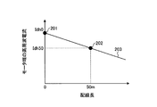
上記の例では、idh(L)を配線長Lの一次関数で近似したときの傾きが(Idh50−Idh0)/50であり、切片がIdh0である。第1の配線長および第2の配線長が上述した値以外の場合も、2点を結ぶ直線の傾きおよび切片を求めることによりidh(L)を決定することができる。図4は、図3のステップS1で得られた計測結果とIdh(L)との一例を示す図である。図4では、第1の配線長を0mとし、第2の配線長を50mとした例を示している。図4において、横軸は配線長であり、縦軸はモータ端の高周波電流のd軸成分である。図4に示すように、2つの計測点201,202を結んだ直線203が上述の式(1)で示したIdh(L)である。
In the above example, the slope when idh (L) is approximated by a linear function of the wiring length L is (Idh50-Idh0) / 50, and the intercept is Idh0. Even when the first wiring length and the second wiring length are other than the above-mentioned values, the idh (L) can be determined by obtaining the slope and intercept of the straight line connecting the two points. FIG. 4 is a diagram showing an example of the measurement result obtained in step S1 of FIG. 3 and Idh (L). FIG. 4 shows an example in which the first wiring length is 0 m and the second wiring length is 50 m. In FIG. 4, the horizontal axis is the wiring length, and the vertical axis is the d-axis component of the high-frequency current at the motor end. As shown in FIG. 4, the
図3の説明に戻り、モータ制御装置2は、近似により求めた係数を用いて高周波電圧指令を補正するための計算式を決定し(ステップS3)、取得モードの動作を終了する。詳細には、高周波電圧補正部8は、配線長による影響を考慮したd軸の高周波電圧指令Vdh*を求めるための計算式を、上述した式(1)と以下の式(2)とに決定する。Idh(0)は、配線長Lを0とした場合の上記式(1)で示したIdh(L)である。
Vdh*=Idh(0)/Idh(L)×Vdh …(2)
Returning to the description of FIG. 3, the
Vdh * = Idh (0) / Idh (L) × Vdh… (2)
高周波電圧補正部8は、q軸の高周波電圧指令Vqh*を求めるための計算式についても、d軸と同様に、以下の式(3)、式(4)のように定める。
Iqh(L)=(Iqh50−Iqh0)/50×L+Iqh0 …(3)
Vqh*=Iqh(0)/Iqh(L)×Vqh …(4)
ただし、高周波重畳方式において、d軸のみに高周波電圧を印加する方式があるが、この場合は、Vqh=0、Vqh*=0となる。
The high-frequency voltage correction unit 8 also defines the calculation formulas for obtaining the high-frequency voltage command Vqh * on the q-axis as the following formulas (3) and (4), similarly to the d-axis.
Iqh (L) = (Iqh50-Iqh0) / 50 × L + Iqh0… (3)
Vqh * = Iqh (0) / Iqh (L) × Vqh… (4)
However, in the high frequency superimposition method, there is a method in which a high frequency voltage is applied only to the d-axis, but in this case, Vqh = 0 and Vqh * = 0.
なお、ステップS3で3つ以上の配線長のそれぞれにおいてモータ端の高周波電流を計測してもよい。この場合も最小二乗法等により、一次近似式を定めることができる。 In step S3, the high frequency current at the motor end may be measured at each of the three or more wiring lengths. In this case as well, the first-order approximation formula can be determined by the least squares method or the like.
以上の動作により、高周波電圧補正部8が、高周波電圧指令を補正する際の計算式が決定される。補正モードでは、高周波電圧補正部8は、入力された配線長Lに基づいて、取得モードで決定された計算式、例えば式(1)から式(4)の計算式を用いて、高周波電圧指令を補正し、補正後の高周波電圧指令を高周波電圧発生器7へ出力する。なお、配線長Lの入力は一定周期で行われてもよいし、配線長Lが変わらない間は、同一の計算式を用いることができるため配線長が変わるときに配線長Lの入力が行われてもよい。補正モードにおいて入力される配線長Lは、モータ1の運転時における配線長である。以上のように、高周波電圧補正部8は、配線長と高周波電流との間の関係を示す情報と、モータ1の運転時における配線長とに基づいて高周波電圧指令を補正する。 By the above operation, the calculation formula when the high frequency voltage correction unit 8 corrects the high frequency voltage command is determined. In the correction mode, the high-frequency voltage correction unit 8 uses the calculation formulas determined in the acquisition mode based on the input wiring length L, for example, the calculation formulas (1) to (4) to command the high-frequency voltage. Is corrected, and the corrected high-frequency voltage command is output to the high-frequency voltage generator 7. The wiring length L may be input at regular intervals, and the same calculation formula can be used while the wiring length L does not change. Therefore, when the wiring length changes, the wiring length L is input. You may be broken. The wiring length L input in the correction mode is the wiring length during operation of the motor 1. As described above, the high-frequency voltage correction unit 8 corrects the high-frequency voltage command based on the information indicating the relationship between the wiring length and the high-frequency current and the wiring length during operation of the motor 1.
また、上述した例では、図3に示した取得モードにおける処理をモータ制御装置2が実施するようにしたが、取得モードにおける処理は、モータ制御装置2とは別の図示しない情報処理装置などによって行われてもよい。この場合、情報処理装置により決定された計算式が、高周波電圧補正部8に設定される。また、この場合、制御電流ベクトルid,iqが、情報処理装置に入力され、情報処理装置が上記の計算式を算出してもよいし、モータ端の高周波電流が情報処理装置により入力されて、情報処理装置が座標変換器10およびフィルタ11と同様の処理を行った後、上記の計算式を算出してもよい。
Further, in the above-described example, the
本実施の形態では、高周波電圧補正部8は配線長Lに基づいて補正を行ったが、その他の配線情報に基づいて補正を行っても良い。例えば、配線情報として配線の浮遊容量を用いても良い。 In the present embodiment, the high-frequency voltage correction unit 8 makes corrections based on the wiring length L, but corrections may be made based on other wiring information. For example, the stray capacitance of the wiring may be used as the wiring information.
以上のように、実施の形態1によれば、配線長とモータ端の高周波電流との関係を予め求めておき、この関係と配線長とに基づいて高周波電圧指令を補正するようにした。このため、長配線時に浮遊容量による電圧誤差が生じた場合にも磁極位置推定精度を低下させることなく、高周波重畳方式のセンサレスベクトル制御を行うことができる。また、構成の変更により配線長が変更された場合にも磁極位置推定精度を高精度に保つことができる。 As described above, according to the first embodiment, the relationship between the wiring length and the high frequency current at the motor end is obtained in advance, and the high frequency voltage command is corrected based on this relationship and the wiring length. Therefore, even when a voltage error occurs due to stray capacitance during long wiring, sensorless vector control of the high frequency superimposition method can be performed without lowering the magnetic pole position estimation accuracy. Further, even when the wiring length is changed due to the change in the configuration, the magnetic pole position estimation accuracy can be kept high.
実施の形態2.
次に、本発明の実施の形態2にかかるモータ制御装置における高周波電圧の補正方法について説明する。本実施の形態のモータ制御装置2の構成は実施の形態1と同様であるため、重複する説明を省略する。ただし、推定部5により算出された推定位相θ0は、高周波電圧補正部8にも入力され、高周波電圧補正部8には、後述する磁極位置推定精度を評価するための参照値が入力される。以下、実施の形態1と異なる点について説明する。
Next, a method for correcting a high frequency voltage in the motor control device according to the second embodiment of the present invention will be described. Since the configuration of the
本実施の形態では、取得モードにおいて、配線21,22,23が0mでない配線長である第3の配線長に設定され、モータ制御装置2はモータ1を無負荷で運転する。この状態で、高周波電圧補正部8は、所望の磁極位置推定精度が得られるように高周波電圧指令を調整する。詳細には、高周波電圧補正部8は、参照値と推定部5により算出された推定位相θ0との差を算出し、d軸、q軸のそれぞれについて、この差の絶対値が所望の磁極位置推定精度以下となるように、高周波電圧に対する調整量を決定する。すなわち、d軸の調整量をΔVdhとし、q軸の調整量をΔVqhとするとき、高周波電圧補正部8は、Vdh+ΔVdh,Vqh+ΔVqhを高周波電圧発生器7へ出力し、上記の差が所望の磁極位置推定精度以下となるように、ΔVdh,ΔVqhをそれぞれ決定する。
In the present embodiment, in the acquisition mode, the
次に、高周波電圧補正部8は、算出した調整量に基づいて、調整量を配線長Lの関数として算出するための計算式を決定する。ここでは、調整量は、配線長に正比例とするとして、計算式を決定する。例えば、第3の配線長を50mとし、参照値と推定位相θ0との差が所望の磁極位置推定精度以下となるように高周波電圧補正部8が定めたd軸の調整量をΔVdh50とする。このとき、高周波電圧補正部8は、調整量を配線長Lの関数として算出するための計算式を以下の式(5)に決定する。
ΔVdh(L)=Vdh50/50×L …(5)
Next, the high-frequency voltage correction unit 8 determines a calculation formula for calculating the adjustment amount as a function of the wiring length L based on the calculated adjustment amount. Here, the calculation formula is determined assuming that the adjustment amount is directly proportional to the wiring length. For example, the third wiring length is 50 m, and the adjustment amount of the d-axis determined by the high-frequency voltage correction unit 8 so that the difference between the reference value and the estimated phase θ0 is equal to or less than the desired magnetic pole position estimation accuracy is ΔVdh50. At this time, the high frequency voltage correction unit 8 determines the calculation formula for calculating the adjustment amount as a function of the wiring length L by the following formula (5).
ΔVdh (L) = Vdh50 / 50 × L ... (5)
さらに、高周波電圧補正部8は、配線長による影響を考慮した高周波電圧指令Vdh*を算出するための計算式を、上述した式(5)および以下の式(6)に決定する。
Vdh*=Vdh+ΔVdh(L) …(6)
Further, the high-frequency voltage correction unit 8 determines the above-mentioned formula (5) and the following formula (6) as calculation formulas for calculating the high-frequency voltage command Vdh * in consideration of the influence of the wiring length.
Vdh * = Vdh + ΔVdh (L)… (6)
高周波電圧補正部8は、q軸についても同様に、配線長による影響を考慮した高周波電圧指令Vdh*を算出するための計算式を以下の式(7)および式(8)に決定する。
ΔVqh(L)=Vqh50/50×L …(7)
Vqh*=Vqh+ΔVqh(L) …(8)
Similarly for the q-axis, the high-frequency voltage correction unit 8 determines the following formulas (7) and (8) as formulas for calculating the high-frequency voltage command Vdh * in consideration of the influence of the wiring length.
ΔVqh (L) = Vqh50 / 50 × L ... (7)
Vqh * = Vqh + ΔVqh (L)… (8)
図5は、参照値と推定位相θ0との差が所望の磁極位置推定精度以下となるように決定された調整量とΔVdh(L)との一例を示す図である。図5では、第3の配線長を50mとした例を示している。図4において、横軸は配線長であり、縦軸は高周波電圧の調整量である。図5に示すように、参照値と推定位相θ0との差が所望の磁極位置推定精度以下となるように決定された調整量301と原点とを結んだ直線302が上述の式(5)で示したΔVdh(L)である。
FIG. 5 is a diagram showing an example of an adjustment amount and ΔVdh (L) determined so that the difference between the reference value and the estimated phase θ0 is equal to or less than the desired magnetic pole position estimation accuracy. FIG. 5 shows an example in which the third wiring length is 50 m. In FIG. 4, the horizontal axis is the wiring length, and the vertical axis is the adjustment amount of the high frequency voltage. As shown in FIG. 5, a
以上の動作により、高周波電圧補正部8が、高周波電圧指令を補正する際の計算式が決定される。補正モードでは、高周波電圧補正部8は、入力された配線長Lに基づいて、取得モードで決定された計算式、例えば式(5)から式(8)の計算式を用いて、高周波電圧指令を補正し、補正後の高周波電圧指令を高周波電圧発生器7へ出力する。なお、配線長Lの入力は一定周期で行われてもよいし、配線長Lが変わらない間は、同一の計算式を用いることができるため配線長が変わるときに配線長Lの入力が行われてもよい。補正モードにおいて入力される配線長Lは、モータ1の運転時における配線長である。以上のように、実施の形態2の高周波電圧補正部8は、配線長と補正量との間の関係を示す情報すなわち取得モードで決定された計算式と、モータ1の運転時における前記配線長とに基づいて高周波電圧指令を補正する。 By the above operation, the calculation formula when the high frequency voltage correction unit 8 corrects the high frequency voltage command is determined. In the correction mode, the high-frequency voltage correction unit 8 uses the calculation formulas determined in the acquisition mode based on the input wiring length L, for example, the calculation formulas (5) to (8) to command the high-frequency voltage. Is corrected, and the corrected high-frequency voltage command is output to the high-frequency voltage generator 7. The wiring length L may be input at regular intervals, and the same calculation formula can be used while the wiring length L does not change. Therefore, when the wiring length changes, the wiring length L is input. You may be broken. The wiring length L input in the correction mode is the wiring length during operation of the motor 1. As described above, the high-frequency voltage correction unit 8 of the second embodiment includes information indicating the relationship between the wiring length and the correction amount, that is, the calculation formula determined in the acquisition mode, and the wiring length during operation of the motor 1. The high frequency voltage command is corrected based on.
以上のように、実施の形態2によれば、配線長と高周波電圧の所望の磁極位置推定精度を満たす調整量との関係を予め求めておき、この関係と配線情報とに基づいて高周波電圧指令を補正するようにした。このため、長配線時に浮遊容量による電圧誤差が生じた場合にも磁極位置推定精度を低下させることなく、高周波重畳方式のセンサレスベクトル制御を行うことができる。また、構成の変更により配線情報が変更された場合にも磁極位置推定精度を高精度に保つことができる。 As described above, according to the second embodiment, the relationship between the wiring length and the adjustment amount that satisfies the desired magnetic pole position estimation accuracy of the high frequency voltage is obtained in advance, and the high frequency voltage command is based on this relationship and the wiring information. Was corrected. Therefore, even when a voltage error occurs due to stray capacitance during long wiring, sensorless vector control of the high frequency superimposition method can be performed without lowering the magnetic pole position estimation accuracy. Further, even when the wiring information is changed due to the change in the configuration, the magnetic pole position estimation accuracy can be maintained with high accuracy.
以上の実施の形態に示した構成は、本発明の内容の一例を示すものであり、別の公知の技術と組み合わせることも可能であるし、本発明の要旨を逸脱しない範囲で、構成の一部を省略、変更することも可能である。 The configuration shown in the above-described embodiment shows an example of the content of the present invention, can be combined with another known technique, and is one of the configurations without departing from the gist of the present invention. It is also possible to omit or change the part.
1 モータ、2 モータ制御装置、3 電圧印加部、4 電流検出部、5 推定部、6 制御部、7 高周波電圧発生器、8 高周波電圧補正部、9 加算部、10 座標変換器、11 フィルタ、12 駆動電圧指令演算部、12a 電流制御器、12b 座標変換器、13 d軸電流指令演算部、14 q軸電流指令演算部。 1 motor, 2 motor controller, 3 voltage application unit, 4 current detection unit, 5 estimation unit, 6 control unit, 7 high frequency voltage generator, 8 high frequency voltage correction unit, 9 adder unit, 10 coordinate converter, 11 filter, 12 Drive voltage command calculation unit, 12a current controller, 12b coordinate converter, 13 d-axis current command calculation unit, 14 q-axis current command calculation unit.
Claims (4)
前記モータに流れるモータ電流に基づいて前記モータの磁極位置を推定する推定部と、
前記モータを駆動するための第1の交流電圧指令を生成する指令演算部と、
前記第1の交流電圧指令の周波数より高い周波数の第2の交流電圧指令を、前記配線の
配線長または前記配線の浮遊容量に基づいて生成する高周波電圧指令生成部と、
前記第1の交流電圧指令に前記第2の交流電圧指令を重畳することにより駆動電圧指令を生成する加算部と、
を備えることを特徴とするモータ制御装置。 A motor control device that controls a motor by being connected to a motor having a salient polarity by wiring.
An estimation unit that estimates the magnetic pole position of the motor based on the motor current flowing through the motor, and
A command calculation unit that generates a first AC voltage command for driving the motor, and
A second AC voltage command having a frequency higher than the frequency of the first AC voltage command is sent to the wiring .
A high-frequency voltage command generator that is generated based on the wiring length or stray capacitance of the wiring.
An adder that generates a drive voltage command by superimposing the second AC voltage command on the first AC voltage command, and
A motor control device characterized by comprising.
前記モータに流れるモータ電流に基づいて前記モータの磁極位置を推定する推定部と、An estimation unit that estimates the magnetic pole position of the motor based on the motor current flowing through the motor, and
前記モータを駆動するための第1の交流電圧指令を生成する指令演算部と、A command calculation unit that generates a first AC voltage command for driving the motor, and
前記第1の交流電圧指令の周波数より高い周波数の第2の交流電圧指令を、前記配線に関する情報である配線情報に基づいて生成する高周波電圧指令生成部と、A high-frequency voltage command generator that generates a second AC voltage command having a frequency higher than the frequency of the first AC voltage command based on the wiring information that is information about the wiring.
前記第1の交流電圧指令に前記第2の交流電圧指令を重畳することにより駆動電圧指令を生成する加算部と、An adder that generates a drive voltage command by superimposing the second AC voltage command on the first AC voltage command, and
を備え、With
前記高周波電圧指令生成部は、前記第2の交流電圧指令と同じ周波数のあらかじめ計測された高周波電流と、前記配線情報と、の関係から前記第2の交流電圧指令を生成することを特徴とするモータ制御装置。The high-frequency voltage command generation unit is characterized in that the second AC voltage command is generated from the relationship between the pre-measured high-frequency current having the same frequency as the second AC voltage command and the wiring information. Motor control device.
前記モータに流れるモータ電流に基づいて前記モータの磁極位置を推定する推定部と、An estimation unit that estimates the magnetic pole position of the motor based on the motor current flowing through the motor, and
前記モータを駆動するための第1の交流電圧指令を生成する指令演算部と、A command calculation unit that generates a first AC voltage command for driving the motor, and
前記第1の交流電圧指令の周波数より高い周波数の第2の交流電圧指令を、前記配線に関する情報である配線情報に基づいて生成する高周波電圧指令生成部と、A high-frequency voltage command generator that generates a second AC voltage command having a frequency higher than the frequency of the first AC voltage command based on the wiring information that is information about the wiring.
前記第1の交流電圧指令に前記第2の交流電圧指令を重畳することにより駆動電圧指令を生成する加算部と、An adder that generates a drive voltage command by superimposing the second AC voltage command on the first AC voltage command, and
を備え、With
前記高周波電圧指令生成部は、前記配線情報に基づいて前記第2の交流電圧指令を調整するあらかじめ計測された調整量と、前記配線情報と、の関係から前記第2の交流電圧指令を生成することを特徴とするモータ制御装置。The high-frequency voltage command generation unit generates the second AC voltage command from the relationship between the pre-measured adjustment amount for adjusting the second AC voltage command based on the wiring information and the wiring information. A motor control device characterized by the fact that.
Priority Applications (1)
| Application Number | Priority Date | Filing Date | Title |
|---|---|---|---|
| JP2017015921A JP6832726B2 (en) | 2017-01-31 | 2017-01-31 | Motor control device |
Applications Claiming Priority (1)
| Application Number | Priority Date | Filing Date | Title |
|---|---|---|---|
| JP2017015921A JP6832726B2 (en) | 2017-01-31 | 2017-01-31 | Motor control device |
Publications (3)
| Publication Number | Publication Date |
|---|---|
| JP2018125955A JP2018125955A (en) | 2018-08-09 |
| JP2018125955A5 JP2018125955A5 (en) | 2019-07-25 |
| JP6832726B2 true JP6832726B2 (en) | 2021-02-24 |
Family
ID=63111738
Family Applications (1)
| Application Number | Title | Priority Date | Filing Date |
|---|---|---|---|
| JP2017015921A Active JP6832726B2 (en) | 2017-01-31 | 2017-01-31 | Motor control device |
Country Status (1)
| Country | Link |
|---|---|
| JP (1) | JP6832726B2 (en) |
Families Citing this family (2)
| Publication number | Priority date | Publication date | Assignee | Title |
|---|---|---|---|---|
| JP7049963B2 (en) | 2018-08-21 | 2022-04-07 | 東芝シュネデール・インバータ株式会社 | Power converter |
| CN113711487B (en) * | 2019-04-23 | 2024-07-30 | 三菱电机株式会社 | Control device for AC rotary machine and control method for AC rotary machine |
-
2017
- 2017-01-31 JP JP2017015921A patent/JP6832726B2/en active Active
Also Published As
| Publication number | Publication date |
|---|---|
| JP2018125955A (en) | 2018-08-09 |
Similar Documents
| Publication | Publication Date | Title |
|---|---|---|
| JP4674525B2 (en) | Magnetic pole position estimation method and motor control apparatus | |
| JP4631672B2 (en) | Magnetic pole position estimation method, motor speed estimation method, and motor control apparatus | |
| JP6367332B2 (en) | Inverter control device and motor drive system | |
| JP4928855B2 (en) | Sensorless control device for synchronous machine | |
| JP5425173B2 (en) | Control device | |
| JP2007097263A (en) | Method of estimating magnetic pole position of synchronous motor | |
| JP2008220096A (en) | Sensorless controller of synchronous electric motor | |
| JPWO2016121237A1 (en) | Inverter control device and motor drive system | |
| JP6179389B2 (en) | Electric motor control device | |
| JP2010011543A (en) | Motor controller | |
| JP6166601B2 (en) | Motor control device and generator control device | |
| JP2009290980A (en) | Controller for permanent magnet type synchronous motor | |
| JP5473289B2 (en) | Control device and control method for permanent magnet type synchronous motor | |
| JP2008043058A (en) | Synchronous motor control unit and control method thereof | |
| JP6832726B2 (en) | Motor control device | |
| JP6135713B2 (en) | Motor control device, magnetic flux command generation device, and magnetic flux command generation method | |
| JP4781933B2 (en) | Electric motor control device | |
| JP2008206330A (en) | Device and method for estimating magnetic pole position of synchronous electric motor | |
| JP6541887B2 (en) | Control device of rotating electric machine | |
| JP2004266885A (en) | Motor controller and method of detecting deviation from controlled state | |
| JP5768255B2 (en) | Control device for permanent magnet synchronous motor | |
| JP6766398B2 (en) | Magnet temperature estimation method and magnet temperature estimation device | |
| JP2007185099A (en) | Sensorless controlling unit for synchronous generator, and controlling method | |
| JP5851662B1 (en) | AC rotating machine control device | |
| JP2008289316A (en) | Control unit of embedded permanent-magnet synchronous machine |
Legal Events
| Date | Code | Title | Description |
|---|---|---|---|
| A521 | Written amendment |
Free format text: JAPANESE INTERMEDIATE CODE: A523 Effective date: 20190624 |
|
| A621 | Written request for application examination |
Free format text: JAPANESE INTERMEDIATE CODE: A621 Effective date: 20190624 |
|
| A977 | Report on retrieval |
Free format text: JAPANESE INTERMEDIATE CODE: A971007 Effective date: 20200518 |
|
| A131 | Notification of reasons for refusal |
Free format text: JAPANESE INTERMEDIATE CODE: A131 Effective date: 20200609 |
|
| A601 | Written request for extension of time |
Free format text: JAPANESE INTERMEDIATE CODE: A601 Effective date: 20200612 |
|
| A521 | Written amendment |
Free format text: JAPANESE INTERMEDIATE CODE: A523 Effective date: 20200820 |
|
| TRDD | Decision of grant or rejection written | ||
| A01 | Written decision to grant a patent or to grant a registration (utility model) |
Free format text: JAPANESE INTERMEDIATE CODE: A01 Effective date: 20210105 |
|
| A61 | First payment of annual fees (during grant procedure) |
Free format text: JAPANESE INTERMEDIATE CODE: A61 Effective date: 20210202 |
|
| R150 | Certificate of patent or registration of utility model |
Ref document number: 6832726 Country of ref document: JP Free format text: JAPANESE INTERMEDIATE CODE: R150 |