JP6832640B2 - Bag with flexible handle - Google Patents
Bag with flexible handle Download PDFInfo
- Publication number
- JP6832640B2 JP6832640B2 JP2016114901A JP2016114901A JP6832640B2 JP 6832640 B2 JP6832640 B2 JP 6832640B2 JP 2016114901 A JP2016114901 A JP 2016114901A JP 2016114901 A JP2016114901 A JP 2016114901A JP 6832640 B2 JP6832640 B2 JP 6832640B2
- Authority
- JP
- Japan
- Prior art keywords
- handle
- bag
- columnar
- suspension
- handle portion
- Prior art date
- Legal status (The legal status is an assumption and is not a legal conclusion. Google has not performed a legal analysis and makes no representation as to the accuracy of the status listed.)
- Active
Links
- 239000000725 suspension Substances 0.000 claims description 242
- 238000005452 bending Methods 0.000 claims description 39
- 229920000092 linear low density polyethylene Polymers 0.000 claims description 7
- 239000004707 linear low-density polyethylene Substances 0.000 claims description 7
- 239000004698 Polyethylene Substances 0.000 claims description 4
- 229920005992 thermoplastic resin Polymers 0.000 claims description 3
- 238000004806 packaging method and process Methods 0.000 description 5
- 238000007789 sealing Methods 0.000 description 5
- 239000007788 liquid Substances 0.000 description 4
- 238000000034 method Methods 0.000 description 4
- 239000000843 powder Substances 0.000 description 4
- 239000005038 ethylene vinyl acetate Substances 0.000 description 3
- 238000010438 heat treatment Methods 0.000 description 3
- 229920001684 low density polyethylene Polymers 0.000 description 3
- 239000004702 low-density polyethylene Substances 0.000 description 3
- 229920001200 poly(ethylene-vinyl acetate) Polymers 0.000 description 3
- 229920000219 Ethylene vinyl alcohol Polymers 0.000 description 2
- XEEYBQQBJWHFJM-UHFFFAOYSA-N Iron Chemical compound [Fe] XEEYBQQBJWHFJM-UHFFFAOYSA-N 0.000 description 2
- 239000004952 Polyamide Substances 0.000 description 2
- 239000004743 Polypropylene Substances 0.000 description 2
- 239000004793 Polystyrene Substances 0.000 description 2
- 239000004372 Polyvinyl alcohol Substances 0.000 description 2
- 229920001328 Polyvinylidene chloride Polymers 0.000 description 2
- 239000000853 adhesive Substances 0.000 description 2
- 230000001070 adhesive effect Effects 0.000 description 2
- 238000010586 diagram Methods 0.000 description 2
- 229920005648 ethylene methacrylic acid copolymer Polymers 0.000 description 2
- 230000005484 gravity Effects 0.000 description 2
- 239000000463 material Substances 0.000 description 2
- 229920002239 polyacrylonitrile Polymers 0.000 description 2
- 229920002647 polyamide Polymers 0.000 description 2
- -1 polyethylene Polymers 0.000 description 2
- 229920002451 polyvinyl alcohol Polymers 0.000 description 2
- 239000004800 polyvinyl chloride Substances 0.000 description 2
- 229920000915 polyvinyl chloride Polymers 0.000 description 2
- 239000005033 polyvinylidene chloride Substances 0.000 description 2
- 238000003466 welding Methods 0.000 description 2
- VGGSQFUCUMXWEO-UHFFFAOYSA-N Ethene Chemical compound C=C VGGSQFUCUMXWEO-UHFFFAOYSA-N 0.000 description 1
- 229920010126 Linear Low Density Polyethylene (LLDPE) Polymers 0.000 description 1
- 230000015572 biosynthetic process Effects 0.000 description 1
- 239000003814 drug Substances 0.000 description 1
- 230000000694 effects Effects 0.000 description 1
- UFRKOOWSQGXVKV-UHFFFAOYSA-N ethene;ethenol Chemical compound C=C.OC=C UFRKOOWSQGXVKV-UHFFFAOYSA-N 0.000 description 1
- 239000004715 ethylene vinyl alcohol Substances 0.000 description 1
- 238000011156 evaluation Methods 0.000 description 1
- 239000011888 foil Substances 0.000 description 1
- 235000013305 food Nutrition 0.000 description 1
- 239000012770 industrial material Substances 0.000 description 1
- 229920000554 ionomer Polymers 0.000 description 1
- 229910052742 iron Inorganic materials 0.000 description 1
- 229920006284 nylon film Polymers 0.000 description 1
- 229920003023 plastic Polymers 0.000 description 1
- 239000004033 plastic Substances 0.000 description 1
- 239000004417 polycarbonate Substances 0.000 description 1
- 229920006289 polycarbonate film Polymers 0.000 description 1
- 229920006267 polyester film Polymers 0.000 description 1
- 229920000573 polyethylene Polymers 0.000 description 1
- 229920001155 polypropylene Polymers 0.000 description 1
- 229920002223 polystyrene Polymers 0.000 description 1
- 229920005989 resin Polymers 0.000 description 1
- 239000011347 resin Substances 0.000 description 1
- XLYOFNOQVPJJNP-UHFFFAOYSA-N water Substances O XLYOFNOQVPJJNP-UHFFFAOYSA-N 0.000 description 1
Images


Description
本発明は、可撓性取手付袋に関する。 The present invention relates to a bag with a flexible handle.
食品、医薬品、及び工業用資材等を包装するための包装袋が知られている。この包装袋の例として、ビニール袋、スタンディングパウチ、バックインボックス、及びガセット袋等を挙げることができる。 Packaging bags for packaging foods, pharmaceuticals, industrial materials, etc. are known. Examples of this packaging bag include a plastic bag, a standing pouch, a back-in box, a gusset bag and the like.
かかる包装袋は、一般的には、特定の用途に応じた種々の特性、例えば耐久性、密封性、携帯性、搬送性、伸縮性、腐食性、及び保温性等を考慮して開発され、かつ製造されている。例えば、重い内容物を持ち運び、又は搬送するために、包装袋の耐久性をより向上させるための研究も盛んに行われている。 Such packaging bags are generally developed in consideration of various properties according to a specific application, such as durability, sealing property, portability, transportability, elasticity, corrosiveness, heat retention, and the like. And it is manufactured. For example, research is being actively conducted to further improve the durability of packaging bags in order to carry or transport heavy contents.
特許文献1の平坦表面に置くための取手付可撓性容器は、袋部、並びにこの袋部に取り付けられた第一の取手部、及び注出口部を含んでいる。また、この第一の取手部は、第一の柄部、並びに第一の柄部及び袋部を連結している第一の懸垂部を有し、この第一の懸垂部が、2以上の第一の柱状懸垂部を含んでいる。さらに、第一の柄部は、この第一の柄部から袋部に向かって伸び、かつ第一の柄部を把持した際に第一の柄部と重なるようにして折り込まれるように形成されている第一の折込部を有している。
The flexible container with a handle for placing on a flat surface of
この特許文献1に記載の全ての図、すなわち、図1〜16には、取手付可撓性容器の例が示されている。これらの取手付可撓性容器の第一の取手部の第一の折込部は、2以上の第一の柱状懸垂部に隣接し、かつ第一の折込部と第一の柱状懸垂部は、それらの間にある切り込みによって互いに隔てられている。
All the figures described in
本発明は、第一の柄部及びこれに連結されている第一の柱状懸垂部にかかる荷重に対する耐久性が向上した可撓性取手付袋を提供することを目的とする。 An object of the present invention is to provide a bag with a flexible handle having improved durability against a load applied to a first handle portion and a first columnar suspension portion connected thereto.
本発明者らは、以下の手段により、上記課題を解決できることを見出した。 The present inventors have found that the above problems can be solved by the following means.
〈1〉袋部、並びに上記袋部に取り付けられた第一の取手部、及び注出口部を含む可撓性取手付袋であって、
上記第一の取手部が、第一の柄部、並びに上記第一の柄部及び上記袋部を連結している第一の懸垂部を有し、
上記第一の懸垂部が、2以上の第一の柱状懸垂部、又は2以上の第一の柱状懸垂部及び2以上の上記第一の柱状懸垂部に接続されている第一の面状懸垂部を含み、
上記第一の柄部が、上記第一の柄部から上記袋部に向かって伸び、かつ上記第一の柄部を把持した際に上記第一の柄部と重なるようにして折り込まれるように形成されている第一の折込部を有し、
上記第一の柄部及び2以上の上記第一の柱状懸垂部の間の角部の形状が、曲線状であり、
下記の(a)〜(e)の少なくとも1つを示す、可撓性取手付袋:
(a)1つの上記第一の柱状懸垂部及び他の1つの上記第一の柱状懸垂部の間の長さDが85mm以上であり、かつ上記曲線状の曲線加工rが13.0mm以上であること、
(b)1つの上記第一の柱状懸垂部及び他の1つの上記第一の柱状懸垂部の間の長さDが90mm以上であり、かつ上記曲線状の曲線加工rが10.0mm以上であること、
(c)1つの上記第一の柱状懸垂部及び他の1つの上記第一の柱状懸垂部の間の長さDが110mm以上であり、かつ上記曲線状の曲線加工rが5.0mm以上であること、
(d)1つの上記第一の柱状懸垂部及び他の1つの上記第一の柱状懸垂部の間の長さDが130mm以上であり、かつ上記曲線状の曲線加工rが2.0mm以上であること、
(e)1つの上記第一の柱状懸垂部及び他の1つの上記第一の柱状懸垂部の間の長さD(mm)と、上記曲線状の曲線加工r(mm)との間の関係が、下記の式(I)で表されること:
r≧−0.2375D+33.000 (I)
[式中、D≧85mm]。
〈2〉上記袋部に、第二の取手部が取り付けられている、上記〈1〉項に記載の可撓性取手付袋。
〈3〉上記第二の取手部が、第二の柄部、並びに上記第二の柄部及び上記袋部を連結している第二の懸垂部を有し、
上記第二の懸垂部が、2以上の第二の柱状懸垂部、又は2以上の第二の柱状懸垂部及び2以上の上記第二の柱状懸垂部に接続されている第二の面状懸垂部を含み、
上記第二の柄部が、上記第二の柄部から上記袋部に向かって伸び、かつ上記第二の柄部を把持した際に上記第二の柄部と重なるようにして折り込まれるように形成されている第二の折込部を有し、
上記第二の柄部及び2以上の上記第二の柱状懸垂部の間の角部の形状が、曲線状である、
上記〈2〉項に記載の可撓性取手付袋。
〈4〉下記の(a)〜(e)の少なくとも1つを示す、上記〈2〉又は〈3〉項に記載の可撓性取手付袋:
(a)1つの上記第二の柱状懸垂部及び他の1つの上記第二の柱状懸垂部の間の長さDが85mm以上であり、かつ上記曲線状の曲線加工rが13.0mm以上であること、
(b)1つの上記第二の柱状懸垂部及び他の1つの上記第二の柱状懸垂部の間の長さDが90mm以上であり、かつ上記曲線状の曲線加工rが10.0mm以上であること、
(c)1つの上記第二の柱状懸垂部及び他の1つの上記第二の柱状懸垂部の間の長さDが110mm以上であり、かつ上記曲線状の曲線加工rが5.0mm以上であること、
(d)1つの上記第二の柱状懸垂部及び他の1つの上記第二の柱状懸垂部の間の長さDが130mm以上であり、かつ上記曲線状の曲線加工rが2.0mm以上であること、
(e)1つの上記第二の柱状懸垂部及び他の1つの上記第二の柱状懸垂部の間の長さD(mm)と、上記曲線状の曲線加工r(mm)との間の関係が、下記の式(I)で表されること:
r≧−0.2375D+33.000 (I)
[式中、D≧85mm]。
〈5〉上記第一の取手部が、上記袋部、上記第一の柄部、及び2以上の上記第一の柱状懸垂部で四方を囲まれた把持開口部を更に有し、
上記注出口部が、上記把持開口部に形成されている、
上記〈2〉〜〈4〉項のいずれか一項に記載の可撓性取手付袋。
〈6〉上記袋部に対して上記第一の取手部の反対側に、上記第二の取手部が形成されている、上記〈2〉〜〈5〉項のいずれか一項に記載の可撓性取手付袋。
〈7〉上記第一の折込部と上記第一の柄部の間の第一の折り曲げ予定線の少なくとも一部がシールされておらず、
上記第一の折り曲げ予定線の両側が少なくとも部分的にシールされており、かつ、
上記第一の折り曲げ予定線が、上記第一の柄部を把持する際に折り曲げられる、上記第一の柄部と上記第一の折込部の間の便宜的な線でもある、
上記〈1〉〜〈6〉項のいずれか一項に記載の可撓性取手付袋。
〈8〉上記第一の折り曲げ予定線のシールされている長さの割合が、50%以下である、上記〈7〉項に記載の可撓性取手付袋。
〈9〉上記第二の折込部と上記第二の柄部の間の第二の折り曲げ予定線の少なくとも一部がシールされておらず、
上記第二の折り曲げ予定線の両側が少なくとも部分的にシールされており、かつ、
上記第二の折り曲げ予定線が、上記第二の柄部を把持する際に折り曲げられる、上記第二の柄部と上記第二の折込部の間の便宜的な線でもある、
上記〈2〉〜〈8〉項のいずれか一項に記載の可撓性取手付袋。
〈10〉袋部、並びに上記袋部に取り付けられた第一の取手部、及び注出口部を含む可撓性取手付袋であって、
上記第一の取手部が、第一の柄部、並びに上記第一の柄部及び上記袋部を連結している第一の懸垂部を有し、
上記第一の懸垂部が、2以上の第一の柱状懸垂部、又は2以上の第一の柱状懸垂部及び2以上の上記第一の柱状懸垂部に接続されている第一の面状懸垂部を含み、
上記第一の柄部が、上記第一の柄部から上記袋部に向かって伸び、かつ上記第一の柄部を把持した際に上記第一の柄部と重なるようにして折り込まれるように形成されている第一の折込部を有し、
上記第一の柄部及び2以上の上記第一の柱状懸垂部の間の角部の形状が、曲線状であり、
上記第一の折込部と上記第一の柄部の間の第一の折り曲げ予定線の少なくとも一部がシールされておらず、
上記第一の折り曲げ予定線の両側が少なくとも部分的にシールされており、かつ、
上記第一の折り曲げ予定線が、上記第一の柄部を把持する際に折り曲げられる、上記第一の柄部と上記第一の折込部の間の便宜的な線でもある、
可撓性取手付袋。
<1> A bag with a flexible handle including a bag portion, a first handle portion attached to the bag portion, and a spout port portion.
The first handle portion has a first handle portion, and a first suspension portion connecting the first handle portion and the bag portion.
A first planar suspension in which the first suspension is connected to two or more first columnar suspensions, or two or more first columnar suspensions and two or more first columnar suspensions. Including the part
The first handle extends from the first handle toward the bag, and when the first handle is gripped, the first handle is folded so as to overlap the first handle. Has a first fold that is formed,
The shape of the corner between the first handle and the two or more first columnar suspensions is curved.
A bag with a flexible handle showing at least one of (a) to (e) below:
(A) The length D between one of the first columnar suspensions and the other first columnar suspension is 85 mm or more, and the curved curve processing r is 13.0 mm or more. That there,
(B) The length D between one of the first columnar suspensions and the other first columnar suspension is 90 mm or more, and the curved curve processing r is 10.0 mm or more. That there,
(C) The length D between one of the first columnar suspensions and the other first columnar suspension is 110 mm or more, and the curved curve processing r is 5.0 mm or more. That there,
(D) The length D between one of the first columnar suspensions and the other first columnar suspension is 130 mm or more, and the curved curve processing r is 2.0 mm or more. That there,
(E) Relationship between the length D (mm) between one of the first columnar suspensions and the other first columnar suspension and the curved curve processing r (mm). Is expressed by the following formula (I):
r ≧ −0.2375D + 33.000 (I)
[D ≧ 85 mm in the formula].
<2> The bag with a flexible handle according to the above item <1>, wherein a second handle portion is attached to the bag portion.
<3> The second handle portion has a second handle portion, and a second suspension portion connecting the second handle portion and the bag portion.
A second planar suspension in which the second suspension is connected to two or more second columnar suspensions, or two or more second columnar suspensions and two or more second columnar suspensions. Including the part
The second handle extends from the second handle toward the bag, and is folded so as to overlap the second handle when the second handle is gripped. Has a second fold that is formed,
The shape of the corner between the second handle and the two or more second columnar suspensions is curved.
The bag with a flexible handle according to the above item <2>.
<4> The bag with a flexible handle according to the above item <2> or <3>, which indicates at least one of the following (a) to (e):
(A) The length D between the one second columnar suspension and the other second columnar suspension is 85 mm or more, and the curved curve processing r is 13.0 mm or more. That there,
(B) The length D between the one second columnar suspension and the other second columnar suspension is 90 mm or more, and the curved curve processing r is 10.0 mm or more. That there,
(C) The length D between the one second columnar suspension and the other second columnar suspension is 110 mm or more, and the curved curve processing r is 5.0 mm or more. That there,
(D) The length D between one of the second columnar suspensions and the other second columnar suspension is 130 mm or more, and the curved curve processing r is 2.0 mm or more. That there,
(E) Relationship between the length D (mm) between the one second columnar suspension and the other second columnar suspension and the curved curve processing r (mm). Is expressed by the following formula (I):
r ≧ −0.2375D + 33.000 (I)
[D ≧ 85 mm in the formula].
<5> The first handle portion further has a grip opening portion surrounded on all sides by the bag portion, the first handle portion, and two or more first columnar suspension portions.
The spout portion is formed in the grip opening.
The bag with a flexible handle according to any one of the above items <2> to <4>.
<6> The item can be described in any one of <2> to <5> above, wherein the second handle is formed on the opposite side of the first handle to the bag. Bag with flexible handle.
<7> At least a part of the first planned bending line between the first folding portion and the first handle portion is not sealed.
Both sides of the first planned bending line are sealed at least partially, and
The first planned bending line is also a convenient line between the first handle and the first folding portion, which is bent when gripping the first handle.
The bag with a flexible handle according to any one of the above items <1> to <6>.
<8> The bag with a flexible handle according to the above item <7>, wherein the ratio of the sealed length of the first planned bending line is 50% or less.
<9> At least a part of the second planned bending line between the second folding portion and the second handle portion is not sealed.
Both sides of the second planned bending line are sealed at least partially, and
The second planned bending line is also a convenient line between the second handle and the second folding portion, which is bent when gripping the second handle.
The bag with a flexible handle according to any one of the above items <2> to <8>.
<10> A bag with a flexible handle including a bag portion, a first handle portion attached to the bag portion, and a spout port portion.
The first handle portion has a first handle portion, and a first suspension portion connecting the first handle portion and the bag portion.
A first planar suspension in which the first suspension is connected to two or more first columnar suspensions, or two or more first columnar suspensions and two or more first columnar suspensions. Including the part
The first handle extends from the first handle toward the bag, and when the first handle is gripped, the first handle is folded so as to overlap the first handle. Has a first fold that is formed,
The shape of the corner between the first handle and the two or more first columnar suspensions is curved.
At least a part of the first planned bending line between the first folding portion and the first handle portion is not sealed.
Both sides of the first planned bending line are sealed at least partially, and
The first planned bending line is also a convenient line between the first handle and the first folding portion, which is bent when gripping the first handle.
Bag with flexible handle.
本発明によれば、第一の柄部及びこれに連結されている第一の柱状懸垂部にかかる荷重に対する耐久性が向上した可撓性取手付袋を提供することができる。 According to the present invention, it is possible to provide a bag with a flexible handle having improved durability against a load applied to a first handle portion and a first columnar suspension portion connected thereto.
以下、本発明の実施形態を詳細に説明する。なお、本発明は、以下の実施形態に限定されるものではなく、本発明の要旨の範囲内で種々に変形して実施することができる。また、図面の寸法比率は、説明の都合上変更されており、実際の比率と異なる場合がある。 Hereinafter, embodiments of the present invention will be described in detail. The present invention is not limited to the following embodiments, and can be variously modified and implemented within the scope of the gist of the present invention. In addition, the dimensional ratios in the drawings have been changed for convenience of explanation and may differ from the actual ratios.
《従来の可撓性取手付袋》
従来の可撓性取手付袋の一形態を、図16に示している。図16では、可撓性取手付袋1が、袋部2、並びに袋部2に取り付けられた第一の取手部3及び注出口部4(図16はキャップが装着された状態を示している)を有し、第一の取手部3が、第一の柄部5、並びに第一の柄部5及び袋部2を連結している第一の懸垂部6を有する。また、第一の懸垂部6が、2以上の第一の柱状懸垂部6aを含み;第一の柄部5が、第一の柄部5から袋部2に向かって伸び、かつ第一の柄部5を把持した際に第一の柄部5と重なるようにして折り込まれるように形成されている第一の折込部7を有し;第一の取手部3が、袋部2、第一の柄部5、及び2以上の第一の柱状懸垂部6aで四方を囲まれた把持開口部8を有し;注出口部4が、把持開口部8に形成されている。また、この図16では、第一の折込部7は、第一の折込部7と第一の柱状懸垂部6aの間にある切り込み9によって、第一の柱状懸垂部6aから隔てられている。
<< Conventional bag with flexible handle >>
A form of a conventional bag with a flexible handle is shown in FIG. In FIG. 16, the
この可撓性取手付袋1に所定の重量を有している液体や粉体等を収納し、第一の折込部7を折り込みつつ第一の柄部5を把持し、そして可撓性取手付袋1を持ち上げた場合には、第一の柄部5側の切り込み9の端に荷重が集中する。すなわち、第一の柱状懸垂部6aには、下方向の力(袋部の質量にかかる重力による力)が作用し、かつ第一の柄部5及び第一の折込部7には、上方向の力(袋を持ち上げようとする力、すなわち、袋部の質量にかかる重力の方向とは反対側に働く力)が作用し、これによって、第一の柄部5側の切り込み9の端に張力が集中する。このことから、本発明者らは、当該切り込み9の端から第一の柄部5が切り裂かれ、結果として、第一の取手部3、特に第一の柄部5が破損する可能性を見出した。
The
《本発明の可撓性取手付袋》
本発明の可撓性取手付袋は、袋部、並びに袋部に取り付けられた第一の取手部、及び注出口部を含み;第一の取手部が、第一の柄部、並びに第一の柄部及び袋部を連結している第一の懸垂部を有し;第一の懸垂部が、2以上の第一の柱状懸垂部、又は2以上の第一の柱状懸垂部及び2以上の第一の柱状懸垂部に接続されている第一の面状懸垂部を含み;第一の柄部が、第一の柄部から袋部に向かって伸び、かつ第一の柄部を把持した際に第一の柄部と重なるようにして折り込まれるように形成されている第一の折込部を有し;第一の柄部及び2以上の第一の柱状懸垂部の間の角部の形状が、曲線状であり;当該袋は、下記の(a)〜(e)の少なくとも1つを示す:
(a)1つの第一の柱状懸垂部及び他の1つの第一の柱状懸垂部の間の長さDが85mm以上であり、かつ上記曲線状の曲線加工rが13.0mm以上であること、
(b)1つの第一の柱状懸垂部及び他の1つの第一の柱状懸垂部の間の長さDが90mm以上であり、かつ上記曲線状の曲線加工rが10.0mm以上であること、
(c)1つの第一の柱状懸垂部及び他の1つの第一の柱状懸垂部の間の長さDが110mm以上であり、かつ上記曲線状の曲線加工rが5.0mm以上であること、
(d)1つの第一の柱状懸垂部及び他の1つの第一の柱状懸垂部の間の長さDが130mm以上であり、かつ上記曲線状の曲線加工rが2.0mm以上であること、
(e)1つの第一の柱状懸垂部及び他の1つの第一の柱状懸垂部の間の長さD(mm)と、曲線状の曲線加工r(mm)との間の関係が、下記の式(I)で表されること:
r≧−0.2375D+33.000 (I)
[式中、D≧85mm]。
<< Bag with flexible handle of the present invention >>
The bag with a flexible handle of the present invention includes a bag portion, a first handle portion attached to the bag portion, and a spout portion; the first handle portion is a first handle portion, and a first. Has a first suspension connecting the handle and bag; the first suspension is two or more first columnar suspensions, or two or more first columnar suspensions and two or more. Includes a first planar suspension that is connected to the first columnar suspension; the first handle extends from the first handle towards the bag and grips the first handle. It has a first fold that is formed to fold so that it overlaps the first stalk; the corner between the first stalk and two or more first columnar suspensions. The shape of is curved; the bag shows at least one of (a)-(e) below:
(A) The length D between one first columnar suspension and the other first columnar suspension is 85 mm or more, and the curved curve processing r is 13.0 mm or more. ,
(B) The length D between one first columnar suspension and the other first columnar suspension is 90 mm or more, and the curved curve processing r is 10.0 mm or more. ,
(C) The length D between one first columnar suspension and the other first columnar suspension is 110 mm or more, and the curved curve processing r is 5.0 mm or more. ,
(D) The length D between one first columnar suspension and the other first columnar suspension is 130 mm or more, and the curved curve processing r is 2.0 mm or more. ,
(E) The relationship between the length D (mm) between one first columnar suspension and the other first columnar suspension and the curved curve processing r (mm) is as follows. What is expressed by the formula (I) of:
r ≧ −0.2375D + 33.000 (I)
[D ≧ 85 mm in the formula].
本発明の可撓性取手付袋では、第一の柄部及び2以上の第一の柱状懸垂部の間の角部の形状が曲線状であるため、取手部を持って袋を持ち上げたときに第一の柄部にかかる上方向の力と、第一の柱状懸垂部にかかる下方向の力とを、当該曲線で分散することができる。 In the bag with a flexible handle of the present invention, since the shape of the corner portion between the first handle portion and the two or more first columnar suspension portions is curved, when the bag is lifted by holding the handle portion. The upward force applied to the first handle portion and the downward force applied to the first columnar suspension portion can be dispersed by the curve.
また、角部の曲線状の曲線加工rは、大きいことが好ましい。この場合には、何らの論理に縛られるものではないが、曲線が緩やかな形状であるため、第一の柄部にかかる上方向の力と、第一の柱状懸垂部にかかる下方向の力とを、当該曲線でより効率的に分散することができると考えられる。したがって、この曲線加工rの値は、特に限定されないが、2.0mm以上、3.0mm以上、5.0mm以上、8.0mm以上、10.0mm以上、13.0mm以上、又は15.0mm以上でよい。なお、当該rの値の上限は、特に限定されない。これは、当該rの値が大きくなるほど曲線の形状が略直線状となること、及び曲線上の角部を形成する第一の取手部の構造上の制約があることから、本発明に接した当業者であれば、適宜調節することが可能であるためである。 Further, it is preferable that the curved curve processing r of the corner portion is large. In this case, although not bound by any logic, since the curve has a gentle shape, an upward force applied to the first handle and a downward force applied to the first columnar suspension portion. It is considered that and can be dispersed more efficiently in the curve. Therefore, the value of this curve processing r is not particularly limited, but is 2.0 mm or more, 3.0 mm or more, 5.0 mm or more, 8.0 mm or more, 10.0 mm or more, 13.0 mm or more, or 15.0 mm or more. It's fine. The upper limit of the value of r is not particularly limited. This is in contact with the present invention because the shape of the curve becomes substantially linear as the value of r increases, and there are structural restrictions on the first handle portion that forms the corner portion on the curve. This is because a person skilled in the art can make appropriate adjustments.
また、本発明の可撓性取手付袋では、1つの第一の柱状懸垂部及び他の1つの第一の柱状懸垂部の間の長さが比較的長くてよい。ここで、成人男性の手の甲の幅は平均で8.3cm程度であるため、第一の柄部の中央を把持した場合には、第一の柱状懸垂部同士の間の長さが、比較的長い、例えば85mm以上であることによって、手と第一の柱状懸垂部の間に隙間が形成される。したがって、何らの論理に縛られるものではないが、本発明の可撓性取手付袋によれば、第一の柄部から袋部への方向の力の作用点位置と、袋部から第一の柄部への方向の力の作用点位置の間の距離が比較的長く、それによって、これらの力を、第一の柄部と第一の柱状懸垂部の間の角部に集中させることなく、分散させることができると考えられる。 Further, in the bag with a flexible handle of the present invention, the length between one first columnar suspension portion and the other one first columnar suspension portion may be relatively long. Here, since the width of the back of the hand of an adult male is about 8.3 cm on average, the length between the first columnar suspension parts is relatively large when the center of the first handle is gripped. By being long, for example 85 mm or more, a gap is formed between the hand and the first columnar suspension. Therefore, although not bound by any logic, according to the bag with a flexible handle of the present invention, the position of the point of action of the force in the direction from the first handle to the bag and the position from the bag to the first. The distance between the points of action of forces in the direction of the stalk is relatively long, thereby concentrating these forces on the corner between the first stalk and the first columnar suspension. It is thought that it can be dispersed.
1つの第一の柱状懸垂部及び他の1つの第一の柱状懸垂部の間の長さDは、85mm以上、90mm以上、100mm以上、110mm以上、120mm以上、又は130mm以上でよい。なお、当該長さの上限は、特に限定されない。これは、当該長さが長くなるほど第一の柄部の長さが長くなることや、この可撓性取手付袋を扱う対象を考慮することによって、本発明に接した当業者であれば、適宜調節することができるものだからである。 The length D between one first columnar suspension and the other first columnar suspension may be 85 mm or more, 90 mm or more, 100 mm or more, 110 mm or more, 120 mm or more, or 130 mm or more. The upper limit of the length is not particularly limited. This can be done by those skilled in the art who have come into contact with the present invention by considering that the length of the first handle becomes longer as the length becomes longer and the object to be handled by the bag with a flexible handle is taken into consideration. This is because it can be adjusted as appropriate.
また、上記したように、角部の曲線状の曲線加工rと、1つの第一の柱状懸垂部及び他の1つの第一の柱状懸垂部の間の長さDとの間には、相関関係が存在していてよい。具体的には、可撓性取手付袋の取手部の破損を抑制するためには、長さDが長い場合には、曲線加工rが比較的小さくともよく、かつ長さDが短い場合には、曲線加工rが比較的大きくともよい。例えば、これらの長さDと曲線加工rの間には、下記の式(I)で表される関係が存在してもよい:
r≧−0.2375D+33.000 (I)
[式中、D≧85mm]。
Further, as described above, there is a correlation between the curved curve processing r of the corner portion and the length D between one first columnar suspension portion and the other one first columnar suspension portion. Relationships may exist. Specifically, in order to suppress damage to the handle portion of the bag with a flexible handle, when the length D is long, the curve processing r may be relatively small, and when the length D is short. May have a relatively large curve processing r. For example, there may be a relationship represented by the following equation (I) between these lengths D and the curve processing r:
r ≧ −0.2375D + 33.000 (I)
[D ≧ 85 mm in the formula].
また、r切片の値は、特に限定されないが、33.000でよく、35.000でよく、38.000でよく、又は40.000でよい。 The value of the r-intercept is not particularly limited, but may be 33.000, 35.000, 38.000, or 40.000.
したがって、1つの第一の柱状懸垂部及び他の1つの第一の柱状懸垂部の間の長さDと、角部の曲線状の曲線加工rとは、それぞれ、上記の値を充足するのが好ましく、例えば、下記の(a)〜(e)の少なくとも一つを充足するのが好ましい:
(a)長さDは85mm以上であり、かつ曲線加工rは13.0mm以上であること、
(b)長さDは90mm以上であり、かつ曲線加工rは10.0mm以上であること、
(c)長さDは110mm以上であり、かつ曲線加工rは5.0mm以上であること、
(d)長さDは130mm以上であり、かつ曲線加工rは2.0mm以上であること、
(e)長さD(mm)と、曲線状の曲線加工r(mm)との間の関係が、下記の式(I)で表されること:
r≧−0.2375D+33.000 (I)
[式中、D≧85mm]。
Therefore, the length D between the one first columnar suspension and the other first columnar suspension and the curved curve processing r of the corners each satisfy the above values. Is preferable, and for example, it is preferable to satisfy at least one of the following (a) to (e):
(A) The length D is 85 mm or more, and the curve processing r is 13.0 mm or more.
(B) The length D is 90 mm or more, and the curve processing r is 10.0 mm or more.
(C) The length D is 110 mm or more, and the curve processing r is 5.0 mm or more.
(D) The length D is 130 mm or more, and the curve processing r is 2.0 mm or more.
(E) The relationship between the length D (mm) and the curved curve processing r (mm) is expressed by the following formula (I):
r ≧ −0.2375D + 33.000 (I)
[D ≧ 85 mm in the formula].
結果として、第一の柄部及びこれに連結されている第一の柱状懸垂部にかかる荷重に対する耐久性が向上した可撓性取手付袋を提供することができる。 As a result, it is possible to provide a bag with a flexible handle having improved durability against a load applied to the first handle portion and the first columnar suspension portion connected thereto.
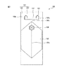
図1は、本発明の可撓性取手付袋の第一の実施形態を示す概略正面図である。図1では、可撓性取手付袋100が、袋部102、並びに袋部102に取り付けられた第一の取手部103、及び注出口部104(図1はキャップが装着された状態を示している)を含み;第一の取手部103が、第一の柄部105、並びに第一の柄部105及び袋部102を連結している第一の懸垂部106を有している。また、第一の懸垂部106が、2以上の第一の柱状懸垂部106a及びこれらに接続されている第一の面状懸垂部106bを含み;第一の柄部105が、第一の柄部105から袋部102に向かって伸び、かつ第一の柄部105を把持した際に第一の柄部105と重なるようにして折り込まれるように形成されている第一の折込部107を有している。さらに、第一の柄部105及び2以上の第一の柱状懸垂部106aの間の角部101の形状が、曲線状であり;1つの第一の柱状懸垂部106a及び他の1つの第一の柱状懸垂部106aの間の長さD(mm)と、上記曲線状の曲線加工r(mm)との間の関係が、下記の式(I)で表される:
r≧−0.2375D+33.000 (I)
[式中、D≧85mm]。
FIG. 1 is a schematic front view showing a first embodiment of the bag with a flexible handle of the present invention. FIG. 1 shows a
r ≧ −0.2375D + 33.000 (I)
[D ≧ 85 mm in the formula].
なお、用語「2以上の柱状懸垂部」は、折込部の両側にある2以上の柱状懸垂部と、存在するとすれば、これらの柱状懸垂部に重なっている他の柱状懸垂部とを含む用語である。例えば、ガセット袋等では、袋の正面側及び裏面側の取手部に、柄部を介して連結されている2つの柱状懸垂部がそれぞれ設けられ、合計で4つの柱状懸垂部が存在してよい。また、例えば、平袋等では、袋の取手部に、柄部を介して連結されている2つの柱状懸垂部が設けられ、合計で2つの柱状懸垂部が存在してよい。 The term "two or more columnar suspensions" includes two or more columnar suspensions on both sides of the folding portion and, if present, other columnar suspensions that overlap these columnar suspensions. Is. For example, in a gusset bag or the like, two columnar suspension portions connected via a handle portion are provided on the handle portions on the front side and the back surface side of the bag, respectively, and a total of four columnar suspension portions may exist. .. Further, for example, in a flat bag or the like, the handle portion of the bag may be provided with two columnar suspension portions connected via a handle portion, and a total of two columnar suspension portions may be present.
特に、角部101は、鉤形状に切り込まれており、この鉤形状の鉤部分が、弧状の曲線を構成している。なお、鉤形状の鉤部分の鉤先、及び鉤形状の柄部分の端は、袋部102に向いており、かつ鉤形状の鉤部分の弧の頂点は、第一の柄部105へと向いている。また、鉤形状の切り込みが、第一の折込部107の両側で合計で2つ存在し、かつこれらの鉤先部分が互いに向かい合うようにして、これらが配置されている。さらに、2つの鉤形状の切り込みにおいて、鉤先部分とは逆の端、すなわち鉤形状の柄部分の端が、2つ存在し、これらの端の間の中間部分が直線的に切り込まれ、これによって端と端が連結されている。このようにして、第一の折込部107の輪郭が構成されている。
In particular, the
図2及び3は、図1の可撓性取手付袋の別の形態を示す概略正面図である。図2の可撓性取手付袋の構成は、角部の鉤形状の切り込みが図1のものと異なることを除いて、図1の可撓性取手付袋の構成と同じである。したがって、当該角部の鉤形状の切り込み以外の構成の説明を省略する。 2 and 3 are schematic front views showing another form of the bag with a flexible handle of FIG. The configuration of the flexible handle bag of FIG. 2 is the same as that of the flexible handle bag of FIG. 1 except that the hook-shaped cuts at the corners are different from those of FIG. Therefore, the description of the configuration other than the notch of the hook shape of the corner portion will be omitted.
具体的には、図2の可撓性取手付袋の角部201は、図1のものの角部101の鉤形状の切り込みと略同一である。これらの違いは、鉤形状の切り込みの鉤部分である。すなわち、角部201の鉤部分は、角丸の半四角の形状である。
Specifically, the
また、図3の可撓性取手付袋の構成は、角部の鉤形状の切り込みが延長されて、第一の取手部の一部が切り抜かれていることによって、開口が形成されていることを除き、図1の可撓性取手付袋の構成と同じである。したがって、当該角部の鉤形状の切り込み以外の構成の説明を省略する。 Further, the structure of the bag with the flexible handle shown in FIG. 3 is that the hook-shaped notch at the corner is extended and a part of the first handle is cut out to form an opening. The configuration is the same as that of the bag with a flexible handle shown in FIG. Therefore, the description of the configuration other than the notch of the hook shape of the corner portion will be omitted.
具体的には、図3の可撓性取手付袋の角部301の形状は、図1のものの角部101の鉤形状と略同一である。しかしながら、角部301は、鉤形状の切り込みではなく、この部分が打ち抜かれている。具体的には、2つの鉤形状の鉤先の間の中間部分が直線的に切り込まれ、これによってこれらの鉤先が連結され;2つの鉤形状の柄の部分の端において、これらの間の中間部分が直線的に切り込まれ、これによって端と端が連結され;結果として、これら2つの鉤形状の切り込み及びこれらの2つの中間部分の直線状の切り込みによって打ち抜かれた形状の開口部が、図3の可撓性取手付袋の第一の取手部に形成されている。
Specifically, the shape of the
また、本発明の可撓性取手付袋では、袋部に、第二の取手部が取り付けられていてよい。 Further, in the bag with a flexible handle of the present invention, a second handle portion may be attached to the bag portion.
したがって、例えば、これらの取手部を両手で把持し、袋部から内容物を容易に取り出す等の使い方が可能となる。 Therefore, for example, it is possible to hold these handle portions with both hands and easily take out the contents from the bag portion.
また、本発明の可撓性取手付袋では、1つの態様において、第二の取手部が、第二の柄部、並びに第二の柄部及び袋部を連結している第二の懸垂部を有していてよく;第二の懸垂部が、2以上の第二の柱状懸垂部、又は2以上の第二の柱状懸垂部及び2以上の第二の柱状懸垂部に接続されている第二の面状懸垂部を含んでよく;第二の柄部が、第二の柄部から袋部に向かって伸び、かつ第二の柄部を把持した際に第二の柄部と重なるようにして折り込まれるように形成されている第二の折込部を有していてよく;第二の柄部及び2以上の第二の柱状懸垂部の間の角部の形状が、曲線状であってよい。 Further, in the bag with a flexible handle of the present invention, in one embodiment, the second handle portion connects the second handle portion and the second handle portion and the bag portion with the second suspension portion. The second suspension is connected to two or more second columnar suspensions, or two or more second columnar suspensions and two or more second columnar suspensions. May include a second planar suspension; the second handle extends from the second handle towards the bag and overlaps the second handle when gripping the second handle. It may have a second fold that is formed to fold in; the shape of the corner between the second handle and the two or more second columnar suspensions is curved. You can.
これによって、上記の第一の取手部と同様の効果、すなわち、第二の柄部及びこれに連結されている第二の懸垂部にかかる荷重に対する耐久性が向上した可撓性取手付袋を提供することができる。 As a result, a bag with a flexible handle having the same effect as the first handle portion described above, that is, a bag with a flexible handle having improved durability against a load applied to the second handle portion and the second suspension portion connected thereto. Can be provided.
また、本発明の可撓性取手付袋は、下記の(a)〜(e)の少なくとも1つを示してよい:
(a)1つの第二の柱状懸垂部及び他の1つの第二の柱状懸垂部の間の長さDが85mm以上であり、かつ上記曲線状の曲線加工rが13.0mm以上であること、
(b)1つの第二の柱状懸垂部及び他の1つの第二の柱状懸垂部の間の長さDが90mm以上であり、かつ上記曲線状の曲線加工rが10.0mm以上であること、
(c)1つの第二の柱状懸垂部及び他の1つの第二の柱状懸垂部の間の長さDが110mm以上であり、かつ上記曲線状の曲線加工rが5.0mm以上であること、
(d)1つの第二の柱状懸垂部及び他の1つの第二の柱状懸垂部の間の長さDが130mm以上であり、かつ上記曲線状の曲線加工rが2.0mm以上であること、
(e)1つの第二の柱状懸垂部及び他の1つの第二の柱状懸垂部の間の長さD(mm)と、曲線状の曲線加工r(mm)との間の関係が、下記の式(I)で表されること:
r≧−0.2375D+33.000 (I)
[式中、D≧85mm]。
Further, the bag with a flexible handle of the present invention may indicate at least one of the following (a) to (e):
(A) The length D between one second columnar suspension and the other second columnar suspension is 85 mm or more, and the curved curve processing r is 13.0 mm or more. ,
(B) The length D between one second columnar suspension and the other second columnar suspension is 90 mm or more, and the curved curve processing r is 10.0 mm or more. ,
(C) The length D between one second columnar suspension and the other second columnar suspension is 110 mm or more, and the curved curve processing r is 5.0 mm or more. ,
(D) The length D between one second columnar suspension and the other second columnar suspension is 130 mm or more, and the curved curve processing r is 2.0 mm or more. ,
(E) The relationship between the length D (mm) between one second columnar suspension and the other one second columnar suspension and the curved curve processing r (mm) is as follows. What is expressed by the formula (I) of:
r ≧ −0.2375D + 33.000 (I)
[D ≧ 85 mm in the formula].
したがって、第二の柄部及びこれに連結されている第二の懸垂部にかかる荷重に対する耐久性が、更に向上した可撓性取手付袋を提供することができる。 Therefore, it is possible to provide a bag with a flexible handle having further improved durability against a load applied to the second handle portion and the second suspension portion connected to the second handle portion.
図4は、本発明の可撓性取手付袋の第二の実施形態を示す概略正面図である。図4の可撓性取手付袋400の構成は、図1の可撓性取手付袋100に第二の取手部が形成されていることを除き、図1の可撓性取手付袋の構成と同じである。したがって、当該第二の取手部以外の構成の説明を省略する。
FIG. 4 is a schematic front view showing a second embodiment of the bag with a flexible handle of the present invention. The configuration of the
図4の可撓性取手付袋400の第二の取手部413は、袋部402に対して、第一の取手部403とは反対側に形成されている。図4の可撓性取手付袋400の第二の取手部413は、第二の柄部415、並びに第二の柄部415及び袋部402を連結している第二の懸垂部416を有し、第二の懸垂部416が、2以上の第二の柱状懸垂部416a及び2以上の第二の柱状懸垂部416aに接続されている第二の面状懸垂部416bを含んでいる。また、第二の柄部415が、第二の柄部415から袋部402に向かって伸び、かつ第二の柄部415を把持した際に第二の柄部415と重なるようにして折り込まれるように形成されている第二の折込部417を有しており、第二の折込部417の横側において、第二の柄部415と2以上の第二の柱状懸垂部416aの間の角部411の形状が、曲線状である。
The
特に、角部411は、弧状に切り込まれており、この弧状の弧部分が、曲線を構成している。なお、弧部分の2つの端は、袋部402に向いており、かつ弧部分の頂点、すなわち弧部分の2つの端において、一方の端から他方の端へと至る線の中間地点の出っ張りの向きは、第二の柄部415に向いている。また、この弧状の切り込みが、第二の折込部417の両側で合計で2つ存在し、かつこれらの弧状の弧部分の端であって、第二の柱状懸垂部416a側の端が2つ存在し、これらの端の間の中間部分が直線的に切り込まれ、これによって一方の端と他方の端が連結されている。このようにして、第二の折込部417の輪郭が構成されている。
In particular, the
また、本発明の可撓性取手付袋では、上記の第二の取手部に加えて、第一の取手部が、袋部、第一の柄部、及び2以上の第一の柱状懸垂部で四方を囲まれた把持開口部を更に有していてよく;注出口部が、把持開口部に形成されていてよい。 Further, in the bag with a flexible handle of the present invention, in addition to the above-mentioned second handle portion, the first handle portion is a bag portion, a first handle portion, and two or more first columnar suspension portions. It may further have a grip opening surrounded on all sides by; a spout may be formed in the grip opening.
上記のように、把持開口部に注出口部が形成されているため、例えば、第一の取手部と第二の取手部とを把持して、注出口部から、袋部に入っている内容物を取り出す等の操作が容易になる。特に、本発明の可撓性取手付袋の第一の取手部では、1つの第一の柱状懸垂部及び他の1つの第一の柱状懸垂部の間の長さが、比較的長いため、注出口部の可動域が比較的広い。したがって、注出口部から袋部に入っている内容物を取り出す際に、当該内容物の到達位置を的確に制御することが可能である。また、注出口部と第一の柱状懸垂部の間の長さが比較的長いため、適度な余裕をもって注出口部の可動を調節することが可能である。 As described above, since the spout portion is formed in the grip opening, for example, the contents of the bag portion from the spout portion by gripping the first handle portion and the second handle portion. Operations such as taking out objects become easy. In particular, in the first handle portion of the bag with the flexible handle of the present invention, the length between one first columnar suspension portion and the other one first columnar suspension portion is relatively long. The range of motion of the spout is relatively wide. Therefore, when the contents contained in the bag portion are taken out from the spout portion, it is possible to accurately control the arrival position of the contents. Further, since the length between the spout portion and the first columnar suspension portion is relatively long, it is possible to adjust the movement of the spout portion with an appropriate margin.
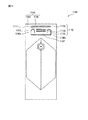
図5は、本発明の可撓性取手付袋の第三の実施形態を示す概略正面図である。図5の可撓性取手付袋500の構成は、図4のものと比較して、第一の取手部に把持開口部が形成されていること、及び注出口部の位置が違うことを除き、図4の可撓性取手付袋400の構成と同じである。したがって、当該把持開口部及び注出口部以外の構成の説明を省略する。
FIG. 5 is a schematic front view showing a third embodiment of the bag with a flexible handle of the present invention. The configuration of the
図5の把持開口部508は、袋部502、第一の柄部505、及び2以上の第一の柱状懸垂部506aで四方を囲まれた開口である。当該把持開口部508に注出口部504(図5はキャップが装着された状態を示している)が形成されているため、第一の取手部503と第二の取手部513とを把持して、注出口部504から、袋部502に入っている内容物を取り出す等の操作が容易である。特に、この可撓性取手付袋500の第一の取手部503では、1つの第一の柱状懸垂部506aから他方の1つの第一の柱状懸垂部506aの間の長さが比較的長いため、注出口部504の可動域が、比較的広い。
The
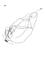
図6は、図5の可撓性取手付袋から内容物を取り出す状態を示す模式図である。この可撓性取手付袋600では、注出口部と第一の柱状懸垂部の間の長さが比較的長いため、適度な余裕をもって注出口部の可動を調節することが可能である。
FIG. 6 is a schematic view showing a state in which the contents are taken out from the bag with a flexible handle of FIG. In this bag with a
図7〜9は、図5の可撓性取手付袋の別の形態を示す概略正面図である。図7の可撓性取手付袋700の構成は、図5のものと比較して、第二の取手部の形状が異なることを除き、図5の可撓性取手付袋の構成と同じである。また、図8及び9の可撓性取手付袋の構成は、図5のものと比較して、第一の取手部の形状が異なることを除き、図5の可撓性取手付袋の構成と同じである。したがって、図7〜9の可撓性取手付袋の構成の説明に関して、図5の構成要素と同じである図7〜9の構成要素の説明は、省略する。
7 to 9 are schematic front views showing another form of the bag with a flexible handle of FIG. The configuration of the
図7の第二の取手部713の形状は、図3の第一の取手部301の形状と略同一であるため、この説明を省略する。また、図8及び9の第一の取手部の形状、特に第一の折込部の両側の角部801及び901は、それぞれ、図1及び2のものと略同等であるため、これらの説明を省略する。なお、図9及び2の角部の違いは、角部が打ち抜かれていないか、打ち抜かれているかである。
Since the shape of the
図10は、図5の可撓性取手付袋に内容物を入れた状態を示す模式図である。図10では、把持開口部508に注出口部504(図5はキャップが装着されていない状態を示している)が形成され、袋部502の正面及び裏面に、2つの第一の柱状懸垂部506aがそれぞれ設けられ、合計で4つの第一の柱状懸垂部506aが存在している。
FIG. 10 is a schematic view showing a state in which the contents are put in the bag with a flexible handle of FIG. In FIG. 10, a spout portion 504 (FIG. 5 shows a state in which the cap is not attached) is formed in the
なお、従来の可撓性取手付袋にも、第二の取手部が形成されている。例えば、図16では、可撓性取手付袋1が、第二の取手部13を有している。したがって、第一の取手部3及び第二の取手部13を把持し、袋部に収納されている内容物を取り出す操作が可能である。しかしながら、この従来の可撓性取手付袋1の第一の取手部3では、1つの第一の柱状懸垂部6a及び他の1つの第一の柱状懸垂部6aの間の長さが短いため、注出口部の可動域が、比較的狭い。したがって、注出口部から袋部に入っている内容物を取り出す際に、当該内容物の到達位置を的確に制御することが困難である可能性がある。また、注出口部と第一の柱状懸垂部の間の長さが比較的短いため、注出口部の可動を調節することが比較的困難である可能性がある。
A second handle portion is also formed in the conventional bag with a flexible handle. For example, in FIG. 16, the bag with a
図17は、図16の可撓性取手付袋から内容物を取り出す状態を示す模式図である。この従来の可撓性取手付袋では、注出口部と第一の柱状懸垂部の間の長さが比較的短いため、注出口部の可動を調節することが比較的困難である可能性がある。 FIG. 17 is a schematic view showing a state in which the contents are taken out from the bag with a flexible handle of FIG. In this conventional bag with a flexible handle, the length between the spout and the first columnar suspension is relatively short, which can make it relatively difficult to adjust the movement of the spout. is there.
また、本発明の可撓性取手付袋では、1つの態様において、第一の折込部と第一の柄部の間の第一の折り曲げ予定線の少なくとも一部がシールされていなくともよく;第一の折り曲げ予定線の両側が少なくとも部分的にシールされていてもよく;かつ、第一の折り曲げ予定線が、第一の柄部を把持する際に折り曲げられる、第一の柄部と第一の折込部の間の便宜的な線であってもよい。 Further, in the bag with a flexible handle of the present invention, in one embodiment, at least a part of the first planned bending line between the first folding portion and the first handle portion may not be sealed; Both sides of the first planned bend line may be sealed at least partially; and the first planned bend line and the first planned bend line are bent when gripping the first handle portion. It may be a convenient line between one fold.
第一の折込部と第一の柄部の間の第一の折り曲げ予定線において、シールがされていない部分があるため、第一の折込部の折り曲げを容易に行うことができる。また、第一の折り曲げ予定線の両側が少なくとも部分的にシールされているため、折り曲げる位置が明確となり、かつ折り曲げ予定線に対して直交する方向には、曲がり難くすることができる。さらに、当該可撓性取手付袋が、複数のフィルム等を重ねあわせて作成されるものである場合には、第一の折り曲げ予定線の両側が少なくとも部分的にシールされているため、複数のフィルムが、第一の柄部や第一の折込部で、個別に変形しなくともよい。 Since there is an unsealed portion on the first planned bending line between the first folding portion and the first handle portion, the first folding portion can be easily bent. Further, since both sides of the first planned bending line are sealed at least partially, the bending position is clear, and it is possible to make it difficult to bend in the direction orthogonal to the planned bending line. Further, when the bag with a flexible handle is made by superimposing a plurality of films or the like, a plurality of bags are sealed because both sides of the first planned bending line are sealed at least partially. The film does not have to be individually deformed at the first handle and the first fold.
したがって、第一の折り曲げ予定線のシールされている長さの割合は、50%以下、45%以下、40%以下、又は30%以下でよい。 Therefore, the ratio of the sealed length of the first planned bending line may be 50% or less, 45% or less, 40% or less, or 30% or less.
また、第二の折り曲げ予定線のシールされている長さの割合に関して、当該第一の折り曲げ予定線のシールされている長さの割合の記載を参照することができる。 In addition, regarding the ratio of the sealed length of the second planned bending line, the description of the ratio of the sealed length of the first planned bending line can be referred to.
図11は、本発明の可撓性取手付袋の第四の実施形態を示す概略正面図である。図11の可撓性取手付袋1100の構成は、図1のものと比較して、シール1110が施されていることを除き、図1の可撓性取手付袋100の構成と同じである。したがって、当該シール1110以外の構成の説明を省略する。
FIG. 11 is a schematic front view showing a fourth embodiment of the bag with a flexible handle of the present invention. The configuration of the
図11の可撓性取手付袋1100のシール1110は、4つの略直線状のシール1110a、b、及びcから構成され、これらのシールがこの順に並んでいる。具体的には、シール1110a及びbは、第一の折込部1107上に存在し、かつシール1110cは、第一の柄部1105上に存在している。これらのシールの長手方向は、一方の第一の柱状懸垂部1106aから他方の第一の柱状懸垂部1106aへの方向と同一である。また、第一の折り曲げ予定線1111が、シール1110b及びcの間に存在し、これによって、第一の折り曲げ予定線1111に沿うように、かつ第一の柄部1105と重なるようにして、第一の折込部1107が折り込まれる。
The
なお、第一の折り曲げ予定線1111は、折り曲げが生じてよい便宜的な線であり、厳密にこの線に沿って折り曲げが生じるとは限らない。しかしながら、折り曲げ位置を、第一の折込部と第一の柄部の間の境界、すなわち、第一の柄部の角部の位置と、シールの位置とによって略決定できることを理解されたい。すなわち、本発明に接した当業者であれば、本発明を実施できるように当該シールの位置を的確に決定することができる。
The first
図12は、図11の可撓性取手付袋の別の形態を示す概略正面図である。図12の可撓性取手付袋1200の構成は、図11のものと比較して、シールの形状が異なることを除き、図11の可撓性取手付袋1100の構成と同じである。したがって、当該シール、すなわちシール1210以外の構成の説明を省略する。
FIG. 12 is a schematic front view showing another form of the bag with a flexible handle of FIG. The configuration of the
図12の可撓性取手付袋1200のシール1210は、4つの略直線状のシール1210a、b、及びcから構成されている。シール1210aは、第一の折込部1207上に存在し、かつシール1210cは、第一の柄部1205上に存在している。これらのシール1210a及びcの長手方向は、一方の第一の柱状懸垂部1206aから他方の第一の柱状懸垂部1206aへの方向と同一である。また、シール1210bは、シール1210aの両側に、すなわちシール1210aを挟んで2つ存在し、第一の折り曲げ予定線1211と直交するように形成され、かつ第一の折込部1207及び第一の柄部1205上に形成されている。これらの2つのシール1210bの長手方向は、第一の折込部1207から第一の柄部1205への方向と同一である。
The
図12では、シール1210bが、第一の折り曲げ予定線1211に形成されている。しかしながら、シール1210bを適用した第一の折り曲げ予定線1211の領域は、一部であり、第一の折り曲げ予定線1211で折り曲げ難くなることはなくてよい。
In FIG. 12, the
図13は、図5の可撓性取手付袋に施されたシールの例を示す図である。図13の可撓性取手付袋1300の他の構成は、図5の可撓性取手付袋の構成と同一である。
FIG. 13 is a diagram showing an example of a seal applied to the bag with a flexible handle of FIG. Other configurations of the
本発明の可撓性取手付袋の構成要素を以下で説明する。 The components of the bag with a flexible handle of the present invention will be described below.
〈袋部〉
袋部は、特に限定されないが、収納物、例えば液体及び/又は粉体等を収納する部分である。袋部の形成は、特に限定されないが、例えば、複数のフィルムを重ね合わせ、注出口部を除き、袋部を形成する部分の周囲をシールすること、又は複数のフィルムを重ね合わせ、袋部を形成する部分の周囲をシールすること等によって行うことができる。
<Bag part>
The bag portion is not particularly limited, but is a portion for storing stored items such as liquid and / or powder. The formation of the bag portion is not particularly limited, but for example, a plurality of films are overlapped and the periphery of the portion forming the bag portion is sealed except for the spout portion, or a plurality of films are overlapped to form the bag portion. This can be done by sealing the circumference of the formed portion or the like.
〈取手部〉
取手部は、これを把持することによって、袋部を持ち上げる部分、又は袋部を運ぶ部分である。取手部の形状は、取手部が、柄部、並びに柄部及び袋部を連結している懸垂部を有している場合には、特に限定されない。取手部の寸法は、本発明の可撓性取手付袋を実施可能な範囲において、特に限定されない。
<Handle part>
The handle portion is a portion that lifts the bag portion or carries the bag portion by gripping the handle portion. The shape of the handle portion is not particularly limited when the handle portion has a handle portion and a suspension portion connecting the handle portion and the bag portion. The size of the handle portion is not particularly limited as long as the bag with the flexible handle of the present invention can be implemented.
(柄部)
柄部は、把持する部分でよく、かつ柄部から袋部に向かって伸び、柄部を把持した際に柄部と重なるようにして折り込まれるように形成されている折込部を有している。また、柄部及び折込部には、これらの部分を形成するフィルム同士を接合するシールが施されていてよい。
(Handle part)
The handle portion may be a gripped portion, and has a folded portion that extends from the handle portion toward the bag portion and is formed so as to overlap the handle portion when the handle portion is gripped. .. Further, the handle portion and the folded portion may be provided with a seal for joining the films forming these portions.
柄部の形状は、これを把持することが可能であれば、特に限定されない。柄部の長手方向の長さに関しては、上記の本発明の可撓性取手付袋の記載を参照されたい。 The shape of the handle is not particularly limited as long as it can be gripped. For the length of the handle in the longitudinal direction, refer to the above description of the bag with a flexible handle of the present invention.
折込部は、柄部を把持する際に折り込まれる部分でよい。折込部の使用の例としては、柄部を把持する位置を明示すること、把持する部分にかかる可撓性取手付袋の荷重を分散すること、柄部の耐久性を向上すること、及び柄部を把持した際の滑りを抑制することを挙げることができる。 The folded portion may be a portion that is folded when gripping the handle portion. Examples of the use of the folding part are to specify the position to grip the handle, to disperse the load of the bag with the flexible handle on the grip, to improve the durability of the handle, and to use the handle. It can be mentioned that slipping when gripping the portion is suppressed.
シールは、例えば、複数のフィルム同士を接合する際の接合部分でよく、折り曲げ予定の位置を略規定する部分でよく、かつ可撓性取手付袋の各所に剛性を付与する部分でよい。シール方法の例としては、特に限定されないが、例えば熱溶着(ヒートシール)、及び接着剤による接着を挙げることができる。当該熱溶着において、シールする部分を加熱する方法の例としては、アイロン等を用いた外部加熱法、及び高周波等を用いた内部加熱法を挙げることができる。 The seal may be, for example, a joint portion when joining a plurality of films to each other, a portion that substantially defines a position to be bent, and a portion that imparts rigidity to various parts of the bag with a flexible handle. Examples of the sealing method are not particularly limited, and examples thereof include heat welding (heat sealing) and adhesion with an adhesive. Examples of the method of heating the portion to be sealed in the heat welding include an external heating method using an iron or the like and an internal heating method using a high frequency or the like.
なお、柄部及び柱状懸垂部の間の角部の形状等に関しては、上記の本発明の可撓性取手付袋の記載を参照されたい。 For the shape of the corner between the handle and the columnar suspension, refer to the above description of the bag with a flexible handle of the present invention.
(懸垂部)
懸垂部は、柄部と袋部とを連結する部分であり、折込部の両側に存在している2以上の柱状懸垂部、及びこの柱状懸垂部に接続されている、任意選択的な面状懸垂部を有している。柱状懸垂部の幅は、袋部を持ち運び可能な耐久性及び取扱性を有していれば、特に限定されない。柱状懸垂部の幅は、例えばこの可撓性取手付袋を扱う対象や、当該袋に入れる内容物並びにその体積及び質量を考慮することによって、決めてもよい。
(Suspension part)
The suspension portion is a portion that connects the handle portion and the bag portion, and has two or more columnar suspension portions existing on both sides of the folding portion and an optional planar shape connected to the columnar suspension portion. It has a suspension part. The width of the columnar suspension portion is not particularly limited as long as it has durability and handleability so that the bag portion can be carried. The width of the columnar suspension portion may be determined, for example, by considering the object to handle the bag with a flexible handle, the contents to be put in the bag, and the volume and mass thereof.
〈注出口部〉
注出口部は、袋部から物体、例えば液体や粉体などを出し、かつ/又は入れるのに用いられる部分である。本発明の可撓性取手付袋を実施可能な範囲において、注出口部と袋部の間には、これらを連結する流路、例えば管等が形成されていてもよい。注出口部の形態の例としては、スパウトの形態、及び袋部の一部に注出口専用のシールを施した形態を挙げることができる。このうち、袋部の一部に注出口専用のシールを施した形態では、そのシールの横に、開封用の切れ込みを入れてもよい。
<Outlet section>
The spout portion is a portion used to eject and / or put an object such as a liquid or powder from the bag portion. To the extent that the bag with a flexible handle of the present invention can be implemented, a flow path for connecting the spout and the bag, such as a pipe, may be formed between the spout and the bag. Examples of the form of the spout portion include a spout form and a form in which a part of the bag portion is sealed for the spout portion. Of these, in the form in which a seal dedicated to the spout is provided on a part of the bag portion, a notch for opening may be made next to the seal.
〈その他〉
袋部には、上記の注出口部に加えて、別の注出口部が取り付けられていてもよい。この場合には、一方の注出口部を物体、例えば液体や粉体などを入れるのに用い、かつ他方の注出口部を当該物体を取り出すのに用いてよい。例えば、上記の袋部の一部に注出口専用のシールを施した形態の注出口部に関しては、これを、上記物体を取り出すのに用いてよい。
<Others>
In addition to the above-mentioned spout portion, another spout portion may be attached to the bag portion. In this case, one spout may be used to put an object, such as a liquid or powder, and the other spout may be used to take out the object. For example, with respect to the spout portion in which a part of the bag portion is provided with a seal dedicated to the spout, this may be used to take out the object.
また、本発明の可撓性取手付袋の構成は、当該袋に可撓性を付与可能な構成であれば、特に限定されない。本発明の可撓性取手付袋は、特に樹脂フィルム、例えば熱可塑性樹脂フィルムで形成されていてよく、フィルムの例として、直鎖状低密度ポリエチレン(LLDPE)、アイオノマーフィルム(IOフィルム)、ポリエチレンフィルム(PEフィルム)、ポリ塩化ビニルフィルム(PVCフィルム)、ポリ塩化ビニリデンフィルム(PVDCフィルム)、ポリビニルアルコールフィルム(PVAフィルム)、ポリプロピレンフィルム(PPフィルム)、ポリエステルフィルム、ポリカーボネートフィルム(PCフィルム)、ポリスチレンフィルム(PSフィルム)、ポリアクリロニトリルフィルム(PANフィルム)、エチレン酢酸ビニル共重合体フィルム(EVAフィルム)、リニアローデンシティポリエチレンフィルム(LLフィルム)、エチレン−ビニルアルコール共重合体フィルム(EVOHフィルム)、エチレン−メタクリル酸共重合体フィルム(EMAAフィルム)、ナイロンフィルム(NYフィルム)、及びポリアミド(PA)フィルムなどを挙げることができる。本発明の可撓性取手付袋の構成の例としては、特に限定されないが、PET/AL/PET/L−LDPE、OPP/PE、OPP/EVA、NY/L−LDPE、及びOPP/L−LDPE等を挙げることができる。なお、上記フィルムの厚さ等は、特に限定されないが、10μ以上、15μ以上、20μ以上、50μ以上、100μ以上、若しくは130μ以上でよく、及び/又は500μ以下、300μ以下、若しくは150μ以下でよい。 Further, the structure of the bag with a flexible handle of the present invention is not particularly limited as long as it can impart flexibility to the bag. The bag with a flexible handle of the present invention may be particularly formed of a resin film, for example, a thermoplastic resin film, and examples of the film include linear low density polyethylene (LLDPE), ionomer film (IO film), and polyethylene. Film (PE film), polyvinyl chloride film (PVC film), polyvinylidene chloride film (PVDC film), polyvinyl alcohol film (PVA film), polypropylene film (PP film), polyester film, polycarbonate film (PC film), polystyrene Film (PS film), polyacrylonitrile film (PAN film), ethylene vinyl acetate copolymer film (EVA film), linear low density polyethylene film (LL film), ethylene-vinyl alcohol copolymer film (EVOH film), ethylene − Methacrylic acid copolymer film (EMAA film), nylon film (NY film), polyamide (PA) film and the like can be mentioned. Examples of the configuration of the flexible handle bag of the present invention are not particularly limited, but are PET / AL / PET / L-LDPE, OPP / PE, OPP / EVA, NY / L-LDPE, and OPP / L-. LDPE and the like can be mentioned. The thickness of the film is not particularly limited, but may be 10 μ or more, 15 μ or more, 20 μ or more, 50 μ or more, 100 μ or more, or 130 μ or more, and / or 500 μ or less, 300 μ or less, or 150 μ or less. ..
なお、特性、例えば耐久性、密封性、携帯性、搬送性、伸縮性、腐食性、及び保温性等を考慮して、本発明の可撓性取手付袋を構成している材料、例えばフィルム、接着剤、及び/又は箔等の材料を決定してもよい。 In addition, in consideration of characteristics such as durability, hermeticity, portability, transportability, elasticity, corrosiveness, heat retention, etc., the material constituting the bag with a flexible handle of the present invention, for example, a film. , Adhesive, and / or materials such as foil may be determined.
以下に示す実施例を参照して本発明を更に詳しく説明するが、本発明の範囲はこれらの実施例によって限定されるものでないことは、言うまでもない。 The present invention will be described in more detail with reference to the examples shown below, but it goes without saying that the scope of the present invention is not limited to these examples.
《例1〜21》
袋部、並びに袋部に取り付けられた取手部を含む、600mm×250mmの可撓性取手付袋を用意した。当該袋の作成は、NY(15μ)/LLDPE(20μ)/LLDPE(130μ)の積層構造の有しているフィルムを4枚用意し、これらのフィルムをLLDPE層を最内面、すなわち内側に向け、かつヒートシールを施すことによって行った。作成された可撓性取手付袋の取手部は、柄部、並びに柄部及び袋部を連結している懸垂部を有し、当該懸垂部が4つの柱状懸垂部を含んでいる。また、柄部は、当該柄部から袋部に向かって伸び、かつこの柄部を把持した際に柄部と重なるようにして折り込まれるように形成されている折込部を有している。さらに、当該柄部及び4つの柱状懸垂部の間の角部の形状は、曲線状であり、当該角部には、具体的には、曲線加工(r)が施されている。なお、柱状懸垂部の本数は、袋部の正面の2つの柱状懸垂部と、袋部の裏面の2つの柱状懸垂部を合計した本数である。
<< Examples 1 to 21 >>
A bag with a flexible handle of 600 mm × 250 mm including a bag portion and a handle portion attached to the bag portion was prepared. To prepare the bag, four films having a laminated structure of NY (15 μ) / LLDPE (20 μ) / LLDPE (130 μ) were prepared, and the LLDPE layer was directed toward the innermost surface, that is, inward. And it was done by applying heat sealing. The handle portion of the created bag with a flexible handle has a handle portion and a suspension portion connecting the handle portion and the bag portion, and the suspension portion includes four columnar suspension portions. Further, the handle portion has a folding portion that extends from the handle portion toward the bag portion and is formed so as to be folded so as to overlap the handle portion when the handle portion is gripped. Further, the shape of the corner portion between the handle portion and the four columnar suspension portions is curved, and the corner portion is specifically subjected to curved processing (r). The number of columnar suspension portions is the total number of the two columnar suspension portions on the front surface of the bag portion and the two columnar suspension portions on the back surface of the bag portion.
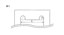
なお、図14は、例の可撓性取手付袋の取手部の一部を示す模式図である。図14では、角部の曲線加工rと、折込部の両側の2つの柱状懸垂部において1つの柱状懸垂部及び他の1つの柱状懸垂部の間の長さDとを示している。 Note that FIG. 14 is a schematic view showing a part of the handle portion of the bag with the flexible handle of the example. In FIG. 14, the curved processing r of the corner portion and the length D between one columnar suspension portion and the other columnar suspension portion in the two columnar suspension portions on both sides of the folding portion are shown.
《評価》
例1〜21の可撓性取手付袋に関して、柄部及びこれに連結されている柱状懸垂部にかかる荷重に対する耐久性の評価を行った。具体的には、可撓性取手付袋の袋部に水10Lを充填し、当該袋の取手部を把持し、かつ当該袋を上下に振動させた。上下移動を1回分の振動とし、当該袋を10回分で振動させた。角部の曲線加工rと、折込部の両側の2つの柱状懸垂部において1つの柱状懸垂部及び他の1つの柱状懸垂部の間の長さDと、柄部及び/又は柱状懸垂部の破損の有無とを、下記の表1〜4に示している。
《Evaluation》
With respect to the bag with a flexible handle of Examples 1 to 21, the durability against the load applied to the handle portion and the columnar suspension portion connected to the handle portion was evaluated. Specifically, the bag portion of the bag with a flexible handle was filled with 10 L of water, the handle portion of the bag was gripped, and the bag was vibrated up and down. The vertical movement was defined as one vibration, and the bag was vibrated 10 times. Curved corners r, length D between one columnar suspension and one other columnar suspension in the two columnar suspensions on both sides of the fold, and damage to the handle and / or columnar suspension The presence or absence of is shown in Tables 1 to 4 below.

なお、表4は、表1〜3をまとめた表である。 Table 4 is a table summarizing Tables 1 to 3.
表1からは、長さDが90mmである場合には、例1の可撓性取手付袋のみが、破損していないことが分かる。これは、何らの論理に縛られるものではないが、例1の角部の曲線加工(r)のrが、例2〜7のものより大きいため、柄部にかかる上方向の力と、柱状懸垂部にかかる下方向の力とが、当該曲線で効率的に分散されたためと考えられる。 From Table 1, it can be seen that when the length D is 90 mm, only the bag with the flexible handle of Example 1 is not damaged. This is not bound by any logic, but since the r of the curved processing (r) at the corner of Example 1 is larger than that of Examples 2 to 7, the upward force applied to the handle and the columnar shape. It is considered that the downward force applied to the suspended portion was efficiently dispersed in the curve.
表2からは、長さDが110mmである場合には、例8〜10の可撓性取手付袋の取手部が、破損していないことが分かる。また、例8の長さDは、例1のものより長い一方で、例8の角部の曲線加工rは、例1のものと同等である。したがって、上記の例1の論理と同様にして、例8の可撓性取手付袋の取手部の破損を回避できたと考えられる。 From Table 2, it can be seen that when the length D is 110 mm, the handle portion of the bag with the flexible handle of Examples 8 to 10 is not damaged. Further, the length D of Example 8 is longer than that of Example 1, while the curved processing r of the corner portion of Example 8 is equivalent to that of Example 1. Therefore, it is considered that the breakage of the handle portion of the flexible handle bag of Example 8 could be avoided in the same manner as the logic of Example 1 above.
さらに、例9及び10の可撓性取手付袋の長さDは、それぞれ例2及び3より長い一方で、例9及び10の曲線加工rは、それぞれ例2及び3のものと同等である。また、例2及び3の可撓性取手付袋は、破損している一方で、例9及び10のものは破損していない。これは、何らの論理に縛られるものではないが、例9及び10の長さDが比較的長いため、柄部にかかる上方向の力の作用点位置と、柱状懸垂部にかかる下方向の力の作用点位置との間の距離が長くなり、結果として、これらの力が柄部と柱状懸垂部の間の角部に集中しなかったためと考えられる。 Further, the length D of the flexible handle bag of Examples 9 and 10 is longer than that of Examples 2 and 3, respectively, while the curving r of Examples 9 and 10 is equivalent to that of Examples 2 and 3, respectively. .. Further, the bags with flexible handles of Examples 2 and 3 are damaged, while the bags of Examples 9 and 10 are not damaged. This is not bound by any logic, but since the length D of Examples 9 and 10 is relatively long, the position of the point of action of the upward force applied to the handle portion and the downward direction applied to the columnar suspension portion. It is probable that the distance between the force's point of action and the position became longer, and as a result, these forces were not concentrated at the corner between the handle and the columnar suspension.
表3からは、長さDが130mmである場合には、例15〜19の可撓性取手付袋の取手部が、破損していないことが分かる。すなわち、例15〜19の長さDは、例1、及び8〜10のものより長く、これによって、曲線加工rが比較的小さい場合でさえ、柄部及びこれに連結されている柱状懸垂部にかかる荷重に対する耐久性が向上していることが理解される。 From Table 3, it can be seen that when the length D is 130 mm, the handle portion of the bag with the flexible handle of Examples 15 to 19 is not damaged. That is, the length D of Examples 15-19 is longer than that of Examples 1 and 8-10, whereby the handle and the columnar suspension connected to it, even when the curving r is relatively small. It is understood that the durability against the load applied to the vehicle is improved.
取手部の破損を抑制できた境界例である例1、10、及び19、並びに取手部の破損が生じた境界例である例2、11、及び20に関して、長さD(mm)と曲線加工r(mm)の間の関係を、図15に示している。図15からは、長さDが曲線加工rと相関していることが分かる。具体的には、可撓性取手付袋の取手部の破損を抑制するためには、長さDが長い場合には、曲線加工rが比較的小さくともよく、かつ長さDが短い場合には、曲線加工rを比較的大きくすればよいことが理解される。 With respect to Examples 1, 10, and 19 which are boundary examples in which damage to the handle portion can be suppressed, and Examples 2, 11 and 20 which are boundary examples in which damage to the handle portion occurs, the length D (mm) and curve processing are performed. The relationship between r (mm) is shown in FIG. From FIG. 15, it can be seen that the length D correlates with the curve processing r. Specifically, in order to suppress damage to the handle portion of the bag with a flexible handle, when the length D is long, the curve processing r may be relatively small, and when the length D is short. It is understood that the curve processing r should be relatively large.
また、図15の例1、10、及び19の近似直線は、上記の相関関係をより明確にするものであり、下記の式(II)で表される。
r=−0.2375D+33.958 (II)
Further, the approximate straight lines of Examples 1, 10 and 19 in FIG. 15 further clarify the above correlation and are represented by the following formula (II).
r = -0.2375D + 33.958 (II)
また、取手部の破損を抑制することができた境界例である例1、10、及び19の曲線加工rと、取手部の破損が生じた境界例である例2、11、及び20の間には、少なくとも1.5mm以上の差がある。したがって、この間にも、取手部の破損を抑制することができる長さDと、曲線加工rとが存在していてよい。したがって、少なくとも、曲線加工rが、下記の式(I)で表される下記の値の範囲に存在している場合には、柄部及びこれに連結されている柱状懸垂部にかかる荷重に対する耐久性がより向上すると考えられる。
r≧−0.2375D+33.000 (I)
Further, between the curve processing r of Examples 1, 10 and 19 which are boundary examples in which the breakage of the handle portion can be suppressed and Examples 2, 11 and 20 which are boundary examples in which the breakage of the handle portion occurs. Have a difference of at least 1.5 mm or more. Therefore, even during this period, a length D capable of suppressing damage to the handle portion and a curve processing r may exist. Therefore, at least when the curve processing r exists in the range of the following values represented by the following formula (I), the durability against the load applied to the handle portion and the columnar suspension portion connected thereto It is thought that the sex will improve.
r ≧ −0.2375D + 33.000 (I)
なお、上記の式(I)は、長さDの関係式でもあることも理解されたい。 It should also be understood that the above equation (I) is also a relational equation of length D.
1,100,200,300,400,500,600,700,800,900,1000,1100,1200,1300,1700 可撓性取手付袋
2,102,402,502 袋部
2a,102a,402a,502a 袋部の折込線
3,103,403,503,803,903,1103,1203 第一の取手部
4,104,404,504 注出口部
5,105,405,505,805,905,1105,1205 第一の柄部
6,106,406,506,806,906,1106,1206 第一の懸垂部
6a,106a,506a,1106a,1206a 第一の柱状懸垂部
6b,106b 第一の面状懸垂部
7,107,507,807,907,1107,1207 第一の折込部
8,508 把持開口部
9, 切り込み
101,201,301,501,801,901,1101,1201 角部
13,413,513,713 第二の取手部
415,515,715 第二の柄部
416,516,716 第二の懸垂部
416a,516a 第二の柱状懸垂部
416b,516b 第二の面状懸垂部
417,517 第二の折込部
411,511,711 角部
1110,1210,1310 シール
1110a,1210a 直線状シール
1110b,1210b 直線状シール
1110c,1210c 直線状シール
1111,1211 第一の折り曲げ予定線
1,100,200,300,400,500,600,700,800,900,1000,1100,1200,1300,1700 Flexible handle bags 2,102,402,502
Claims (10)
前記第一の取手部が、第一の柄部、並びに前記第一の柄部及び前記袋部を連結している第一の懸垂部を有し、
前記第一の懸垂部が、2以上の第一の柱状懸垂部、又は2以上の第一の柱状懸垂部及び2以上の前記第一の柱状懸垂部に接続されている第一の面状懸垂部を含み、
前記第一の柄部が、前記第一の柄部から前記袋部に向かって伸び、かつ前記第一の柄部を把持した際に前記第一の柄部と重なるようにして折り込まれるように形成されている第一の折込部を有し、
前記第一の柄部及び2以上の前記第一の柱状懸垂部の間の角部の形状が、曲線状であり、
前記袋部に、第二の取手部が取り付けられており、
前記第二の取手部が、第二の柄部、並びに前記第二の柄部及び前記袋部を連結している第二の懸垂部を有し、
前記第二の懸垂部が、2以上の第二の柱状懸垂部、又は2以上の第二の柱状懸垂部及び2以上の前記第二の柱状懸垂部に接続されている第二の面状懸垂部を含み、
前記第二の柄部が、前記第二の柄部から前記袋部に向かって伸び、かつ前記第二の柄部を把持した際に前記第二の柄部と重なるようにして折り込まれるように形成されている第二の折込部を有し、
前記第二の柄部及び2以上の前記第二の柱状懸垂部の間の角部の形状が、曲線状であり、
前記第二の折込部と前記第二の柄部の間に第二の折り曲げ予定線を有し、
前記第二の折り曲げ予定線の少なくとも一部がシールされておらず、
前記第二の折り曲げ予定線の両側が少なくとも部分的にシールされており、
前記第二の折り曲げ予定線が、前記第二の柄部を把持する際に折り曲げられる、前記第二の柄部と前記第二の折込部の間の便宜的な線でもあり、
前記可撓性取手付袋は、厚さ10μm以上500μm以下の熱可塑性樹脂フィルムで形成されており、かつ、
下記の(a)〜(e)の少なくとも1つを示す、可撓性取手付袋:
(a)1つの前記第一の柱状懸垂部及び他の1つの前記第一の柱状懸垂部の間の長さDが85mm以上であり、かつ前記曲線状の曲線加工rが13.0mm以上であること、
(b)1つの前記第一の柱状懸垂部及び他の1つの前記第一の柱状懸垂部の間の長さDが90mm以上であり、かつ前記曲線状の曲線加工rが10.0mm以上であること、
(c)1つの前記第一の柱状懸垂部及び他の1つの前記第一の柱状懸垂部の間の長さDが110mm以上であり、かつ前記曲線状の曲線加工rが5.0mm以上であること、
(d)1つの前記第一の柱状懸垂部及び他の1つの前記第一の柱状懸垂部の間の長さDが130mm以上であり、かつ前記曲線状の曲線加工rが2.0mm以上であること、
(e)1つの前記第一の柱状懸垂部及び他の1つの前記第一の柱状懸垂部の間の長さD(mm)と、前記曲線状の曲線加工r(mm)との間の関係が、下記の式(I)で表されること:
r≧−0.2375D+33.000 (I)
[式中、D≧85mm]。 A bag with a flexible handle including a bag portion, a first handle portion attached to the bag portion, and a spout port portion.
The first handle portion has a first handle portion, and a first suspension portion connecting the first handle portion and the bag portion.
A first planar suspension in which the first suspension is connected to two or more first columnar suspensions, or two or more first columnar suspensions and two or more first columnar suspensions. Including the part
The first handle portion extends from the first handle portion toward the bag portion, and is folded so as to overlap the first handle portion when the first handle portion is gripped. Has a first fold that is formed,
The shape of the corner between the first handle and the two or more first columnar suspensions is curved.
A second handle is attached to the bag.
The second handle portion has a second handle portion, and a second suspension portion connecting the second handle portion and the bag portion.
A second planar suspension in which the second suspension is connected to two or more second columnar suspensions, or two or more second columnar suspensions and two or more of the second columnar suspensions. Including the part
The second handle portion extends from the second handle portion toward the bag portion, and is folded so as to overlap the second handle portion when the second handle portion is gripped. Has a second fold that is formed,
The shape of the corner between the second handle and the two or more second columnar suspensions is curved.
It has a second planned bending line between the second folding portion and the second handle portion.
At least a part of the second planned bending line is not sealed,
Both sides of the second planned bending line are sealed at least partially.
The second planned bending line is also a convenient line between the second handle portion and the second folding portion, which is bent when gripping the second handle portion.
The bag with a flexible handle is made of a thermoplastic resin film having a thickness of 10 μm or more and 500 μm or less, and has a thickness of 10 μm or more and 500 μm or less.
A bag with a flexible handle showing at least one of (a) to (e) below:
(A) The length D between one said first columnar suspension and the other one said first columnar suspension is 85 mm or more, and the curved curve processing r is 13.0 mm or more. That there,
(B) The length D between one said first columnar suspension and the other one said first columnar suspension is 90 mm or more, and the curved curve processing r is 10.0 mm or more. That there,
(C) The length D between one said first columnar suspension and the other one said first columnar suspension is 110 mm or more, and the curved curve processing r is 5.0 mm or more. That there,
(D) The length D between one said first columnar suspension and the other one said first columnar suspension is 130 mm or more, and the curved curve processing r is 2.0 mm or more. That there,
(E) Relationship between the length D (mm) between one said first columnar suspension and the other one said first columnar suspension and the curved curve processing r (mm). Is expressed by the following formula (I):
r ≧ −0.2375D + 33.000 (I)
[D ≧ 85 mm in the formula].
前記第一の取手部が、第一の柄部、並びに前記第一の柄部及び前記袋部を連結している第一の懸垂部を有し、 The first handle portion has a first handle portion, and a first suspension portion connecting the first handle portion and the bag portion.
前記第一の懸垂部が、2以上の第一の柱状懸垂部、又は2以上の第一の柱状懸垂部及び2以上の前記第一の柱状懸垂部に接続されている第一の面状懸垂部を含み、 A first planar suspension in which the first suspension is connected to two or more first columnar suspensions, or two or more first columnar suspensions and two or more first columnar suspensions. Including the part
前記第一の柄部が、前記第一の柄部から前記袋部に向かって伸び、かつ前記第一の柄部を把持した際に前記第一の柄部と重なるようにして折り込まれるように形成されている第一の折込部を有し、 The first handle portion extends from the first handle portion toward the bag portion, and is folded so as to overlap the first handle portion when the first handle portion is gripped. Has a first fold that is formed,
前記第一の柄部及び2以上の前記第一の柱状懸垂部の間の角部の形状が、曲線状であり、 The shape of the corner between the first handle and the two or more first columnar suspensions is curved.
前記第一の折込部と前記第一の柄部の間に第一の折り曲げ予定線を有し、 It has a first planned bending line between the first folding portion and the first handle portion.
前記第一の折り曲げ予定線の少なくとも一部がシールされておらず、 At least a part of the first planned bending line is not sealed,
前記第一の折り曲げ予定線の両側が少なくとも部分的にシールされており、かつ、 Both sides of the first planned bending line are sealed at least partially, and
前記第一の折り曲げ予定線が、前記第一の柄部を把持する際に折り曲げられる、前記第一の柄部と前記第一の折込部の間の便宜的な線でもあり、 The first planned bending line is also a convenient line between the first handle portion and the first folding portion, which is bent when gripping the first handle portion.
前記可撓性取手付袋は、厚さ10μm以上500μm以下の熱可塑性樹脂フィルムで形成されており、かつ、 The bag with a flexible handle is made of a thermoplastic resin film having a thickness of 10 μm or more and 500 μm or less, and has a thickness of 10 μm or more and 500 μm or less.
下記の(a)〜(e)の少なくとも1つを示す、可撓性取手付袋: A bag with a flexible handle showing at least one of (a) to (e) below:
(a)1つの前記第一の柱状懸垂部及び他の1つの前記第一の柱状懸垂部の間の長さDが85mm以上であり、かつ前記曲線状の曲線加工rが13.0mm以上であること、 (A) The length D between one said first columnar suspension and the other one said first columnar suspension is 85 mm or more, and the curved curve processing r is 13.0 mm or more. That there,
(b)1つの前記第一の柱状懸垂部及び他の1つの前記第一の柱状懸垂部の間の長さDが90mm以上であり、かつ前記曲線状の曲線加工rが10.0mm以上であること、 (B) The length D between one said first columnar suspension and the other one said first columnar suspension is 90 mm or more, and the curved curve processing r is 10.0 mm or more. That there,
(c)1つの前記第一の柱状懸垂部及び他の1つの前記第一の柱状懸垂部の間の長さDが110mm以上であり、かつ前記曲線状の曲線加工rが5.0mm以上であること、 (C) The length D between one said first columnar suspension and the other one said first columnar suspension is 110 mm or more, and the curved curve processing r is 5.0 mm or more. That there,
(d)1つの前記第一の柱状懸垂部及び他の1つの前記第一の柱状懸垂部の間の長さDが130mm以上であり、かつ前記曲線状の曲線加工rが2.0mm以上であること、 (D) The length D between one said first columnar suspension and the other one said first columnar suspension is 130 mm or more, and the curved curve processing r is 2.0 mm or more. That there,
(e)1つの前記第一の柱状懸垂部及び他の1つの前記第一の柱状懸垂部の間の長さD(mm)と、前記曲線状の曲線加工r(mm)との間の関係が、下記の式(I)で表されること: (E) Relationship between the length D (mm) between one said first columnar suspension and the other one said first columnar suspension and the curved curve processing r (mm). Is expressed by the following formula (I):
r≧−0.2375D+33.000 (I) r ≧ −0.2375D + 33.000 (I)
[式中、D≧85mm]。 [D ≧ 85 mm in the formula].
前記第二の懸垂部が、2以上の第二の柱状懸垂部、又は2以上の第二の柱状懸垂部及び2以上の前記第二の柱状懸垂部に接続されている第二の面状懸垂部を含み、
前記第二の柄部が、前記第二の柄部から前記袋部に向かって伸び、かつ前記第二の柄部を把持した際に前記第二の柄部と重なるようにして折り込まれるように形成されている第二の折込部を有し、
前記第二の柄部及び2以上の前記第二の柱状懸垂部の間の角部の形状が、曲線状である、
請求項1又は3に記載の可撓性取手付袋。 The second handle portion has a second handle portion, and a second suspension portion connecting the second handle portion and the bag portion.
A second planar suspension in which the second suspension is connected to two or more second columnar suspensions, or two or more second columnar suspensions and two or more of the second columnar suspensions. Including the part
The second handle portion extends from the second handle portion toward the bag portion, and is folded so as to overlap the second handle portion when the second handle portion is gripped. Has a second fold that is formed,
The shape of the corner between the second handle and the two or more second columnar suspensions is curved.
The bag with a flexible handle according to claim 1 or 3.
(a)1つの前記第二の柱状懸垂部及び他の1つの前記第二の柱状懸垂部の間の長さDが85mm以上であり、かつ前記曲線状の曲線加工rが13.0mm以上であること、
(b)1つの前記第二の柱状懸垂部及び他の1つの前記第二の柱状懸垂部の間の長さDが90mm以上であり、かつ前記曲線状の曲線加工rが10.0mm以上であること、
(c)1つの前記第二の柱状懸垂部及び他の1つの前記第二の柱状懸垂部の間の長さDが110mm以上であり、かつ前記曲線状の曲線加工rが5.0mm以上であること、
(d)1つの前記第二の柱状懸垂部及び他の1つの前記第二の柱状懸垂部の間の長さDが130mm以上であり、かつ前記曲線状の曲線加工rが2.0mm以上であること、
(e)1つの前記第二の柱状懸垂部及び他の1つの前記第二の柱状懸垂部の間の長さD(mm)と、前記曲線状の曲線加工r(mm)との間の関係が、下記の式(I)で表されること:
r≧−0.2375D+33.000 (I)
[式中、D≧85mm]。 The bag with a flexible handle according to claim 4 , which shows at least one of the following (a) to (e):
(A) The length D between one said second columnar suspension and the other one said second columnar suspension is 85 mm or more, and the curved curve processing r is 13.0 mm or more. That there,
(B) The length D between one said second columnar suspension and the other one said second columnar suspension is 90 mm or more, and the curved curve processing r is 10.0 mm or more. That there,
(C) The length D between one said second columnar suspension and the other one said second columnar suspension is 110 mm or more, and the curved curve processing r is 5.0 mm or more. That there,
(D) The length D between one said second columnar suspension and the other one said second columnar suspension is 130 mm or more, and the curved curve processing r is 2.0 mm or more. That there,
(E) Relationship between the length D (mm) between one said second columnar suspension and the other one said second columnar suspension and the curved curve processing r (mm). Is expressed by the following formula (I):
r ≧ −0.2375D + 33.000 (I)
[D ≧ 85 mm in the formula].
前記注出口部が、前記把持開口部に形成されている、
請求項1及び3〜5のいずれか一項に記載の可撓性取手付袋。 The first handle further comprises a grip opening surrounded on all sides by the bag, the first handle, and two or more of the first columnar suspensions.
The spout portion is formed in the grip opening.
The bag with a flexible handle according to any one of claims 1 and 3 to 5.
前記直線状シールの長手方向は、前記第一の柱状懸垂部のうちの1つから前記第一の柱状懸垂部のうちの他の1つへの方向と同じである、 The longitudinal direction of the linear seal is the same as the direction from one of the first columnar suspensions to the other one of the first columnar suspensions.
請求項1〜8のいずれか一項に記載の可撓性取手付袋。The bag with a flexible handle according to any one of claims 1 to 8.
Priority Applications (1)
| Application Number | Priority Date | Filing Date | Title |
|---|---|---|---|
| JP2016114901A JP6832640B2 (en) | 2016-06-08 | 2016-06-08 | Bag with flexible handle |
Applications Claiming Priority (1)
| Application Number | Priority Date | Filing Date | Title |
|---|---|---|---|
| JP2016114901A JP6832640B2 (en) | 2016-06-08 | 2016-06-08 | Bag with flexible handle |
Publications (3)
| Publication Number | Publication Date |
|---|---|
| JP2017218209A JP2017218209A (en) | 2017-12-14 |
| JP2017218209A5 JP2017218209A5 (en) | 2019-03-28 |
| JP6832640B2 true JP6832640B2 (en) | 2021-02-24 |
Family
ID=60657490
Family Applications (1)
| Application Number | Title | Priority Date | Filing Date |
|---|---|---|---|
| JP2016114901A Active JP6832640B2 (en) | 2016-06-08 | 2016-06-08 | Bag with flexible handle |
Country Status (1)
| Country | Link |
|---|---|
| JP (1) | JP6832640B2 (en) |
Families Citing this family (2)
| Publication number | Priority date | Publication date | Assignee | Title |
|---|---|---|---|---|
| JP7170465B2 (en) * | 2018-08-30 | 2022-11-14 | 株式会社細川洋行 | Gusseted bags and bag-in-box |
| EP3887281A4 (en) * | 2018-11-30 | 2022-06-29 | Dow Global Technologies LLC | Flexible container with dispensing pump |
Family Cites Families (5)
| Publication number | Priority date | Publication date | Assignee | Title |
|---|---|---|---|---|
| US4846587A (en) * | 1988-09-30 | 1989-07-11 | The Proctor & Gamble Company | Flaccid bag having improved integrally formed carrying handle |
| JP2005212884A (en) * | 2004-02-02 | 2005-08-11 | Kau Pack Kk | Gazette pouch with hole slit |
| EP2475582B1 (en) * | 2009-09-10 | 2016-09-07 | Smart Bottle, Inc | Flexible container having flexible handles |
| JP2011189965A (en) * | 2010-03-15 | 2011-09-29 | Nippon Paper Crecia Co Ltd | Packaging bag and roll product package |
| JP6473906B2 (en) * | 2014-10-06 | 2019-02-27 | Next Innovation合同会社 | Bag making container and method for producing bag making container |
-
2016
- 2016-06-08 JP JP2016114901A patent/JP6832640B2/en active Active
Also Published As
| Publication number | Publication date |
|---|---|
| JP2017218209A (en) | 2017-12-14 |
Similar Documents
| Publication | Publication Date | Title |
|---|---|---|
| JP4748064B2 (en) | Bag-like container with spout | |
| WO2014002730A1 (en) | Pouch container | |
| US20090238502A1 (en) | Perforated easy opening pouch | |
| JP6088111B1 (en) | Pouch container | |
| JP6832640B2 (en) | Bag with flexible handle | |
| JP6291893B2 (en) | Refill container | |
| US20180346218A1 (en) | Bags with tear lines | |
| US11358772B2 (en) | Spouted pouch | |
| JP5573245B2 (en) | Refill container | |
| JP2016188093A (en) | Pouch container | |
| JP2012001266A (en) | Refill container and method for manufacturing the same | |
| JP4074001B2 (en) | Self-supporting pouch | |
| JP6287239B2 (en) | Flexible packaging | |
| JP4876561B2 (en) | Bag with spout | |
| JP5663877B2 (en) | Refill container | |
| JP5323045B2 (en) | Composite container | |
| JP6659999B2 (en) | Pouch with spout | |
| WO2018083980A1 (en) | Spouted pouch | |
| US20120195534A1 (en) | Flat film bag for use in automated filling systems | |
| JP2006273338A (en) | Refilling pouch | |
| JP6942967B2 (en) | Packaging bag | |
| JP2014037259A (en) | Inner bag for drum can, inner bag unit and filling method | |
| JP6772705B2 (en) | Packaging bag | |
| JP6769197B2 (en) | Packaging bag | |
| JP7076774B2 (en) | Composite bag for filling liquids |
Legal Events
| Date | Code | Title | Description |
|---|---|---|---|
| A521 | Request for written amendment filed |
Free format text: JAPANESE INTERMEDIATE CODE: A523 Effective date: 20190214 |
|
| A621 | Written request for application examination |
Free format text: JAPANESE INTERMEDIATE CODE: A621 Effective date: 20190214 |
|
| A977 | Report on retrieval |
Free format text: JAPANESE INTERMEDIATE CODE: A971007 Effective date: 20191120 |
|
| A131 | Notification of reasons for refusal |
Free format text: JAPANESE INTERMEDIATE CODE: A131 Effective date: 20191126 |
|
| A131 | Notification of reasons for refusal |
Free format text: JAPANESE INTERMEDIATE CODE: A131 Effective date: 20200526 |
|
| A521 | Request for written amendment filed |
Free format text: JAPANESE INTERMEDIATE CODE: A523 Effective date: 20200716 |
|
| TRDD | Decision of grant or rejection written | ||
| A01 | Written decision to grant a patent or to grant a registration (utility model) |
Free format text: JAPANESE INTERMEDIATE CODE: A01 Effective date: 20210105 |
|
| A61 | First payment of annual fees (during grant procedure) |
Free format text: JAPANESE INTERMEDIATE CODE: A61 Effective date: 20210202 |
|
| R150 | Certificate of patent or registration of utility model |
Ref document number: 6832640 Country of ref document: JP Free format text: JAPANESE INTERMEDIATE CODE: R150 |
|
| R250 | Receipt of annual fees |
Free format text: JAPANESE INTERMEDIATE CODE: R250 |