JP6832487B2 - Smoke device - Google Patents
Smoke device Download PDFInfo
- Publication number
- JP6832487B2 JP6832487B2 JP2017503623A JP2017503623A JP6832487B2 JP 6832487 B2 JP6832487 B2 JP 6832487B2 JP 2017503623 A JP2017503623 A JP 2017503623A JP 2017503623 A JP2017503623 A JP 2017503623A JP 6832487 B2 JP6832487 B2 JP 6832487B2
- Authority
- JP
- Japan
- Prior art keywords
- smoke
- smoking
- chamber
- temperature
- smoked
- Prior art date
- Legal status (The legal status is an assumption and is not a legal conclusion. Google has not performed a legal analysis and makes no representation as to the accuracy of the status listed.)
- Active
Links
- 239000000779 smoke Substances 0.000 title claims description 196
- 230000000391 smoking effect Effects 0.000 claims description 191
- 241000894006 Bacteria Species 0.000 claims description 68
- 238000000855 fermentation Methods 0.000 claims description 51
- 230000004151 fermentation Effects 0.000 claims description 51
- 238000001816 cooling Methods 0.000 claims description 42
- 239000002994 raw material Substances 0.000 claims description 41
- 238000010438 heat treatment Methods 0.000 claims description 39
- 235000021107 fermented food Nutrition 0.000 claims description 28
- 235000013305 food Nutrition 0.000 claims description 21
- 239000000463 material Substances 0.000 claims description 18
- JVTAAEKCZFNVCJ-UHFFFAOYSA-N lactic acid Chemical compound CC(O)C(O)=O JVTAAEKCZFNVCJ-UHFFFAOYSA-N 0.000 description 18
- 241000209094 Oryza Species 0.000 description 11
- 235000007164 Oryza sativa Nutrition 0.000 description 11
- 235000009566 rice Nutrition 0.000 description 11
- 235000014655 lactic acid Nutrition 0.000 description 9
- 239000004310 lactic acid Substances 0.000 description 9
- 238000004519 manufacturing process Methods 0.000 description 8
- 230000001954 sterilising effect Effects 0.000 description 7
- 240000004808 Saccharomyces cerevisiae Species 0.000 description 5
- 230000007423 decrease Effects 0.000 description 5
- 239000011347 resin Substances 0.000 description 5
- 229920005989 resin Polymers 0.000 description 5
- 238000004659 sterilization and disinfection Methods 0.000 description 5
- 238000010586 diagram Methods 0.000 description 4
- 239000007788 liquid Substances 0.000 description 4
- XLYOFNOQVPJJNP-UHFFFAOYSA-N water Substances O XLYOFNOQVPJJNP-UHFFFAOYSA-N 0.000 description 4
- 235000019985 fermented beverage Nutrition 0.000 description 3
- 239000002023 wood Substances 0.000 description 3
- 229920002472 Starch Polymers 0.000 description 2
- 244000052616 bacterial pathogen Species 0.000 description 2
- 235000013351 cheese Nutrition 0.000 description 2
- 239000011248 coating agent Substances 0.000 description 2
- 238000000576 coating method Methods 0.000 description 2
- 239000002184 metal Substances 0.000 description 2
- 150000002989 phenols Chemical class 0.000 description 2
- 235000019698 starch Nutrition 0.000 description 2
- 239000008107 starch Substances 0.000 description 2
- 241000251468 Actinopterygii Species 0.000 description 1
- 244000063299 Bacillus subtilis Species 0.000 description 1
- 235000014469 Bacillus subtilis Nutrition 0.000 description 1
- 241000190021 Zelkova Species 0.000 description 1
- 150000001299 aldehydes Chemical class 0.000 description 1
- 239000011121 hardwood Substances 0.000 description 1
- 230000009545 invasion Effects 0.000 description 1
- 238000000034 method Methods 0.000 description 1
- 230000002093 peripheral effect Effects 0.000 description 1
- 238000004080 punching Methods 0.000 description 1
- 230000000630 rising effect Effects 0.000 description 1
- 235000013580 sausages Nutrition 0.000 description 1
- 239000004071 soot Substances 0.000 description 1
Images


Classifications
-
- A—HUMAN NECESSITIES
- A23—FOODS OR FOODSTUFFS; TREATMENT THEREOF, NOT COVERED BY OTHER CLASSES
- A23B—PRESERVING, e.g. BY CANNING, MEAT, FISH, EGGS, FRUIT, VEGETABLES, EDIBLE SEEDS; CHEMICAL RIPENING OF FRUIT OR VEGETABLES; THE PRESERVED, RIPENED, OR CANNED PRODUCTS
- A23B4/00—General methods for preserving meat, sausages, fish or fish products
- A23B4/044—Smoking; Smoking devices
- A23B4/052—Smoke generators ; Smoking apparatus
-
- A—HUMAN NECESSITIES
- A23—FOODS OR FOODSTUFFS; TREATMENT THEREOF, NOT COVERED BY OTHER CLASSES
- A23B—PRESERVING, e.g. BY CANNING, MEAT, FISH, EGGS, FRUIT, VEGETABLES, EDIBLE SEEDS; CHEMICAL RIPENING OF FRUIT OR VEGETABLES; THE PRESERVED, RIPENED, OR CANNED PRODUCTS
- A23B4/00—General methods for preserving meat, sausages, fish or fish products
- A23B4/044—Smoking; Smoking devices
- A23B4/052—Smoke generators ; Smoking apparatus
- A23B4/0523—Smoke generators using wood-pyrolysis or wood-friction
-
- A—HUMAN NECESSITIES
- A23—FOODS OR FOODSTUFFS; TREATMENT THEREOF, NOT COVERED BY OTHER CLASSES
- A23C—DAIRY PRODUCTS, e.g. MILK, BUTTER OR CHEESE; MILK OR CHEESE SUBSTITUTES; MAKING THEREOF
- A23C19/00—Cheese; Cheese preparations; Making thereof
- A23C19/14—Treating cheese after having reached its definite form, e.g. ripening, smoking
-
- A—HUMAN NECESSITIES
- A23—FOODS OR FOODSTUFFS; TREATMENT THEREOF, NOT COVERED BY OTHER CLASSES
- A23L—FOODS, FOODSTUFFS, OR NON-ALCOHOLIC BEVERAGES, NOT COVERED BY SUBCLASSES A21D OR A23B-A23J; THEIR PREPARATION OR TREATMENT, e.g. COOKING, MODIFICATION OF NUTRITIVE QUALITIES, PHYSICAL TREATMENT; PRESERVATION OF FOODS OR FOODSTUFFS, IN GENERAL
- A23L2/00—Non-alcoholic beverages; Dry compositions or concentrates therefor; Their preparation
- A23L2/38—Other non-alcoholic beverages
- A23L2/382—Other non-alcoholic beverages fermented
-
- A—HUMAN NECESSITIES
- A23—FOODS OR FOODSTUFFS; TREATMENT THEREOF, NOT COVERED BY OTHER CLASSES
- A23L—FOODS, FOODSTUFFS, OR NON-ALCOHOLIC BEVERAGES, NOT COVERED BY SUBCLASSES A21D OR A23B-A23J; THEIR PREPARATION OR TREATMENT, e.g. COOKING, MODIFICATION OF NUTRITIVE QUALITIES, PHYSICAL TREATMENT; PRESERVATION OF FOODS OR FOODSTUFFS, IN GENERAL
- A23L27/00—Spices; Flavouring agents or condiments; Artificial sweetening agents; Table salts; Dietetic salt substitutes; Preparation or treatment thereof
- A23L27/20—Synthetic spices, flavouring agents or condiments
- A23L27/27—Smoke flavours
-
- A—HUMAN NECESSITIES
- A23—FOODS OR FOODSTUFFS; TREATMENT THEREOF, NOT COVERED BY OTHER CLASSES
- A23L—FOODS, FOODSTUFFS, OR NON-ALCOHOLIC BEVERAGES, NOT COVERED BY SUBCLASSES A21D OR A23B-A23J; THEIR PREPARATION OR TREATMENT, e.g. COOKING, MODIFICATION OF NUTRITIVE QUALITIES, PHYSICAL TREATMENT; PRESERVATION OF FOODS OR FOODSTUFFS, IN GENERAL
- A23L5/00—Preparation or treatment of foods or foodstuffs, in general; Food or foodstuffs obtained thereby; Materials therefor
-
- A—HUMAN NECESSITIES
- A23—FOODS OR FOODSTUFFS; TREATMENT THEREOF, NOT COVERED BY OTHER CLASSES
- A23V—INDEXING SCHEME RELATING TO FOODS, FOODSTUFFS OR NON-ALCOHOLIC BEVERAGES AND LACTIC OR PROPIONIC ACID BACTERIA USED IN FOODSTUFFS OR FOOD PREPARATION
- A23V2002/00—Food compositions, function of food ingredients or processes for food or foodstuffs
Description
本開示は、燻製を作製するための燻煙装置に関する。 The present disclosure relates to a smoke device for making smoked products.
従来、木材のチップなどの燻製材を燻すことにより発生する煙に、チーズ、ハム、魚などの食品を曝して燻製を作製する燻煙装置が知られている。例えば特許文献1に記載された燻煙装置では、燻製にされる食品と燻製材と燻製材を燻すガスバーナとが燻製室内に配置される。ガスバーナにより燻製材が燻されて発生し燻製室内に充満した煙に、燻製室内の食品が曝され、燻製が作製される。 Conventionally, there is known a smoke device for producing smoke by exposing foods such as cheese, ham, and fish to smoke generated by smoking smoked wood chips and the like. For example, in the smoking device described in Patent Document 1, a smoked food, a smoked material, and a gas burner for smoking the smoked material are arranged in a smoking room. Smoked wood is smoked by a gas burner, and the smoke that fills the smoked room is exposed to the food in the smoked room to produce smoked food.
燻製の作製方法として、熱燻、温燻、および冷燻がある。それぞれ燻製温度が異なり、例えば熱燻は80〜140度、温燻は30〜80度、冷燻は0〜30度でそれぞれ行われる。 Methods for producing smoked products include hot smoking, hot smoking, and cold smoking. The smoking temperature is different, for example, hot smoking is performed at 80 to 140 degrees, hot smoking is performed at 30 to 80 degrees, and cold smoking is performed at 0 to 30 degrees.
特許文献1に記載された燻煙装置において、燻製温度が比較的低い温燻や冷燻が行われる場合、ガスバーナの火力が熱燻の場合より低く調節される。しかし、ガスバーナの火力を低くすると、燻された燻製材から発生する煙の量が不足し、温燻や冷燻の完了までに時間がかかる、または所望の燻製が作製できない場合がある。 In the smoking device described in Patent Document 1, when hot smoking or cold smoking is performed in which the smoking temperature is relatively low, the thermal power of the gas burner is adjusted to be lower than that in the case of hot smoking. However, when the thermal power of the gas burner is lowered, the amount of smoke generated from the smoked smoked material is insufficient, and it may take time to complete the hot or cold smoking, or the desired smoked product may not be produced.
そこで、本開示は、どのような燻製温度においても、十分な量の煙を用いて所望の燻製を作製することができる燻煙装置を提供することを目的とする。 Therefore, it is an object of the present disclosure to provide a smoke device capable of producing a desired smoked product using a sufficient amount of smoke at any smoked temperature.
本開示の一態様の燻煙装置は、燻製室と煙発生室と燻煙用加熱部と連通路と冷却部とを
有する。燻製室は燻製食品の原料を収容する。煙発生室は燻製室の下方に外気の通る空間が介在するように配置される。燻煙用加熱部は、煙発生室内に収容された燻製材を加熱し、煙発生室内に煙を発生させる。連通路は冷却部を通って燻製室と煙発生室とを連通する。冷却部は連通路を通過する煙を冷却する。
The smoke device of one aspect of the present disclosure includes a smoke chamber, a smoke generation chamber, a smoke heating unit, a communication passage, and a cooling unit. The smoked room houses the raw materials for smoked foods. The smoke generating chamber is arranged below the smoking chamber so that a space through which outside air passes is interposed. The smoke heating unit heats the smoked material housed in the smoke generating chamber to generate smoke in the smoke generating chamber. The communication passage communicates between the smoking room and the smoke generating room through the cooling section. The cooling unit cools the smoke passing through the communication passage.
本態様によれば、どのような燻製温度においても、十分な量の煙を用いて所望の燻製を作製することができる。 According to this aspect, a desired smoked product can be produced with a sufficient amount of smoke at any smoked temperature.
燻煙装置が、燻製室を補助的に加熱する補助加熱部をさらに有してもよい。本態様によれば、連通路を通過するときに冷却された煙を燻製室内で加熱することができる。その結果、高温の煙を用いて燻製を作製することができる。 The smoke device may further have an auxiliary heating section that auxiliary heats the smoking chamber. According to this aspect, the smoke cooled when passing through the communication passage can be heated in the smoking chamber. As a result, smoked products can be produced using high temperature smoke.
燻煙装置が、燻煙用加熱部と補助加熱部とを制御する制御部をさらに有してもよい。制御部が、燻煙用加熱部および補助加熱部の両方を用いて、燻製室の内部温度が燻製温度を越えるまで燻製室を加熱した後、補助加熱部による加熱を停止することによって燻製室の内部温度を燻製温度まで低下させ、燻製室の圧力を外気圧より低くように構成されてもよい。本態様によれば、燻製室から外部への煙の漏れを抑制することができる。 The smoke device may further have a control unit that controls a smoke heating unit and an auxiliary heating unit. The control unit uses both the smoke heating unit and the auxiliary heating unit to heat the smoking room until the internal temperature of the smoking room exceeds the smoking temperature, and then stops the heating by the auxiliary heating unit to stop the heating of the smoking room. The internal temperature may be lowered to the smoking temperature so that the pressure in the smoking chamber is lower than the outside air pressure. According to this aspect, the leakage of smoke from the smoking room to the outside can be suppressed.
本発明の一態様の燻煙装置は、燻製室内に発酵菌を投入する発酵菌投入部と、発酵菌投入部と燻煙用加熱部とを制御する制御部と、をさらに有する。制御部は、発酵菌投入部に発酵菌を燻製室内に投入させ、投入完了から所定の待機時間の経過後に、燻煙用加熱部に燻製室内に煙を発生させるように構成される。本態様によれば、発酵食品をさらに長期保存可能に作製することができる。 The smoke device according to one aspect of the present invention further includes a fermenting bacterium charging unit for charging the fermenting bacteria into the smoking chamber, and a control unit for controlling the fermenting bacterium charging unit and the smoking heating unit. The control unit is configured such that the fermenting bacteria charging unit is charged with the fermenting bacteria into the smoking chamber, and the smoke heating unit generates smoke in the smoking chamber after a predetermined waiting time has elapsed from the completion of charging. According to this aspect, the fermented food can be produced so that it can be stored for a longer period of time.
制御部が、燻製室に発酵菌を投入する前に、燻煙用加熱部によって燻製室内に発生される煙を用いて発酵食品の原料を殺菌ように構成されてもよい。本態様によれば、発酵食品をより長期保存可能に作製することができる。 The control unit may be configured to sterilize the raw material of the fermented food using the smoke generated in the smoking chamber by the smoking heating unit before the fermenting bacteria are introduced into the smoking chamber. According to this aspect, the fermented food can be produced so that it can be stored for a longer period of time.
発酵装置が、燻製室の内部温度を検出する温度センサを有してもよく、制御部が、温度センサの検出温度に基づいて、発酵菌が活性化する温度で燻製室の内部温度が維持されるように、燻煙用加熱部を制御ように構成されてもよい。本態様によれば、発酵が促進される。 The fermenter may have a temperature sensor that detects the internal temperature of the smoking chamber, and the control unit maintains the internal temperature of the smoking chamber at a temperature at which the fermenting bacteria are activated based on the temperature detected by the temperature sensor. As such, the smoke heating unit may be configured to control. According to this aspect, fermentation is promoted.
冷却部が、連通路を強制的に冷却するファンまたはペルチェ素子であってもよい。ファンまたはペルチェ素子を制御することにより、煙の温度を変更することができる。本態様によれば、様々な燻製を作製することができる。 The cooling unit may be a fan or a Peltier element that forcibly cools the communication passage. The temperature of the smoke can be changed by controlling the fan or Peltier element. According to this aspect, various smoked products can be produced.
燻煙装置が、燻製室内に回転可能に設けられ、煙が通過可能な複数の孔を備え、燻製食品の原料が載置される回転テーブルをさらに有してもよい。本態様によれば、回転テーブル上の燻製食品の原料の表面が一様に煙に曝され、良好な燻製を作製することができる。 The smoke device may be rotatably provided in the smoking chamber, provided with a plurality of holes through which smoke can pass, and further provided with a rotary table on which the raw material for the smoked food is placed. According to this aspect, the surface of the raw material of smoked food on the turntable is uniformly exposed to smoke, and good smoked food can be produced.
以下、本開示の一実施の形態について、図面を参照しながら説明する。 Hereinafter, an embodiment of the present disclosure will be described with reference to the drawings.
図1は、本開示の一実施の形態に係る燻煙装置の概略的斜視図である。図2は、燻煙装置の概略的断面図である。図3は、燻煙装置の制御系を示すブロック図である。なお、図1および図2において、X軸方向は燻煙装置の幅方向を、Y軸方向は奥行き方向を、Z軸方向は高さ方向をそれぞれ示す。 FIG. 1 is a schematic perspective view of a smoke device according to an embodiment of the present disclosure. FIG. 2 is a schematic cross-sectional view of the smoke device. FIG. 3 is a block diagram showing a control system of the smoke device. In FIGS. 1 and 2, the X-axis direction indicates the width direction of the smoke device, the Y-axis direction indicates the depth direction, and the Z-axis direction indicates the height direction.
図1に示す燻煙装置10は、詳細は後述するが、燻製食品のみならず発酵食品も作製可能な発酵機能付き燻煙装置である。言い換えれば、燻煙装置10は発酵装置でもある。作製される燻製食品は、例えば、燻製ソーセージ、燻製チーズ、燻製たまごなどである。作製される発酵食品は、甘酒、発酵飲料などである。
Although the details of the
図1および図2に示すように、燻煙装置10は、略直方体形状の本体12を有する。本体12は、その内部に燻製室14と煙発生室16とを備える。
As shown in FIGS. 1 and 2, the
燻製室14は、燻製食品または発酵食品の原料Fを収容し、燻製食品または発酵食品を作製するための空間である。言い換えれば、燻製室14内で原料Fの発酵が行われるときは、燻製室14は発酵室として機能する。
The smoked
燻煙装置10の本体12は、その正面12a側に設けられた開口と、その開口を閉じる扉18とを備える。
The
図2に示すように、燻製室14内には、燻製食品または発酵食品の原料Fが載置される回転可能な回転テーブル20が設けられる。回転テーブル20は、高さ方向(Z軸方向)に延在する回転中心線Cを中心にして回転可能であり、煙が通過可能な網状部材またはパンチングメタルによって構成される。
As shown in FIG. 2, a rotatable rotary table 20 on which the raw material F of the smoked food or the fermented food is placed is provided in the
燻製室14には、燻製室14内を補助的に加熱する、例えば電熱線で構成された補助加熱部である補助ヒータ22が設けられる。本実施の形態では、補助ヒータ22は、燻製室14の天井面に取り付けられる。この補助ヒータ22の役割については後述する。
The
燻製室14には、燻製室14内の温度を検出する温度センサ24が設けられる。本実施の形態では、温度センサ24は、燻製室14の側面に取り付けられる。この温度センサ24の役割については後述する。
The
図1および図2に示すように、煙発生室16は燻製室14の下方に配置される。煙発生室16では、燻製室14での燻製の作製に必要な煙Sが発生される。本実施の形態では、煙発生室16は、間隔をあけて燻製室14の下方に配置される。すなわち、煙発生室16は、燻製室14との間に空間が介在するように燻製室14の下方に配置される。これにより、煙発生室16と燻製室14との間の伝熱が抑制される。
As shown in FIGS. 1 and 2, the
具体的には、煙発生室16には燻製材Mが収容される。燻製材Mは、樹脂成分が少ないため原料Fに付着する煤が発生しにくいナラやケヤキなどの広葉樹から作製された木材チップが好ましい。さらに言えば、燻したときに発生する煙にフェノール類が多く含まれるものが好ましい。これに関して詳細は後述する。
Specifically, the smoked material M is housed in the
図2に示すように、燻製材Mは、煙発生室16内に配置された金属製のトレイ26上に載置される。トレイ26は、本体12の正面12a側に引き出し可能に本体12に支持される。
As shown in FIG. 2, the smoked material M is placed on a
トレイ26の下方には、トレイ26上の燻製材Mを加熱する(燻す)ための燻煙用加熱部である燻煙用ヒータ28が配置される。燻煙用ヒータ28は、例えば電熱線によって構成される。燻煙用ヒータ28が燻製材Mを燻すことにより、燻製材Mから煙が発生する。
Below the
煙発生室16内で発生した煙Sは、連通路30を介して燻製室14に供給される。本実施の形態では、図2に示すように、連通路30は、高さ方向(Z軸方向)に延在する管状の通路である。連通路30は、煙発生室16の天井面に形成された開口と燻製室14の底面に形成された開口とを接続し、これにより煙発生室16と燻製室14とを連通する。
The smoke S generated in the
煙発生室16内で発生した煙Sは、連通路30を通過して燻製室14内に供給される。煙Sは回転テーブル20を通過するため、回転中の回転テーブル20上に載置される原料Fの表面全体が煙Sに一様に曝される。これにより良好な燻製ができ上がる。
The smoke S generated in the
回転テーブル20に代わってまたは加えて、原料Fを吊り下げるためのレール(図示せず)を燻製室14の天井面に設けてもよい。
In place of or in addition to the rotary table 20, a rail (not shown) for suspending the raw material F may be provided on the ceiling surface of the
本実施の形態では、冷却ファン32が本体12内に設けられる。冷却ファン32は、連通路30に向かって冷却風Aを送ることにより、煙発生室16内で発生し連通路30を通過する煙Sを強制的に冷却する冷却部である。
In this embodiment, the cooling
冷却ファン32の回転数を調節することにより、様々な温度で十分な量の煙Sで原料Fを燻製にすることができる。これにより、燻煙用ヒータ28の出力を変更することなく、連通路30を通過する煙Sの温度を調節することができる。その結果、十分な量の煙Sを用いて、熱燻、温燻、および冷燻を実行することができる。
By adjusting the rotation speed of the cooling
例えば、高温で十分な量の煙Sを煙発生室16内に発生させるように、燻煙用ヒータ28が最大出力で燻製材Mを燻す。冷却ファン32は、煙Sが連通路30を通過するときに、煙Sを温燻に適した温度(例えば30〜80℃)または冷燻に適した温度(例えば30〜50℃)まで冷却する。これにより、温燻または冷燻に適した温度で十分な量の煙Sが燻製室14内に供給され、原料Fを短時間で所望の燻製にすることができる。
For example, the
本実施の形態によれば、連通路30に連通路30内を通過する煙Sの量を調節するための流量調節弁34が設けられる。流量調節弁34が燻製室14内に流入する煙Sの量を調節することにより、燻製条件を細かく設定することができる。
According to the present embodiment, the
上述したように、燻煙装置10は発酵食品も作製可能である。燻煙装置10は、燻製室14に発酵菌を投入するための発酵菌投入部36および発酵菌投入部38を備える。発酵菌としては、例えば乳酸菌、酵母、米麹などが用いられる。二つの発酵菌投入部が存在するのは、二種類の発酵菌を投入できるようにするためである。発酵菌投入部36、38は第1および第2の発酵菌投入部にそれぞれ対応する。
As described above, the
以下、上記のように構成された燻煙装置10における、燻製食品または発酵食品を作製するための制御について説明する。
Hereinafter, the control for producing a smoked food or a fermented food in the
図3は、燻煙装置10の制御系を示すブロック図である。
FIG. 3 is a block diagram showing a control system of the
図3に示すように、燻煙装置10の制御部44は、操作設定キー40および温度センサ24の出力信号に応じて、表示部42、回転テーブル20、燻煙用ヒータ28、補助ヒータ22、冷却ファン32、流量調節弁34、発酵菌投入部36、38を制御する。
As shown in FIG. 3, the
図1に示すように、本体12の正面12aに操作設定キー40が設けられる。使用者は、操作設定キー40を用いて、燻煙装置10の動作、例えば、燻製食品を作製する燻製モード、発酵食品を作製する発酵モード、長期保存可能な発酵食品を作製する発酵燻製モードのいずれかを選択する。
As shown in FIG. 1, an
燻製モードの場合、使用者は、原料Fの種類および重量、燻製材Mの種類、燻製温度、燻製時間などの燻製条件を、操作設定キー40を用いて設定する。発酵モードの場合、使用者は、原料Fの種類および重量、発酵菌の種類、発酵時間などの発酵条件を、操作設定キー40を用いて設定する。発酵燻製モードの場合、使用者は、原料Fの種類および重量、燻製材Mの種類、発酵菌の種類などの条件を、操作設定キー40を用いて設定する。
In the smoking mode, the user sets the smoking conditions such as the type and weight of the raw material F, the type of the smoked material M, the smoking temperature, and the smoking time by using the
制御部44は、操作設定キー40を用いて設定された項目を、図1に示す表示部42に表示するとともに、これらの設定項目に応じて、燻煙用ヒータ28、補助ヒータ22、冷却ファン32、流量調節弁34、発酵菌投入部36、38を制御する。燻製作製中または発酵中、表示部42には、その詳細や完了までの時間などが表示されてもよい。
The
以下、燻製モード、発酵モード、および発酵燻製モードの詳細について、タイミングチャートを参照しながら説明する。 The details of the smoked mode, the fermentation mode, and the fermented smoked mode will be described below with reference to the timing chart.
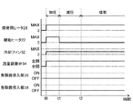
図4は、燻製モードの一例である、30〜80℃における温燻のためのタイミングチャートである。 FIG. 4 is a timing chart for hot smoking at 30 to 80 ° C., which is an example of the smoking mode.
図4に示すように、燻製食品の原料Fが燻製室14内に収容された後、タイミングt0において、操作設定キー40が操作されて燻製モードが開始すると、まず、燻製室14内が加圧される。しばらくの後、加圧された燻製室14内は減圧される。
As shown in FIG. 4, after the raw material F of the smoked food is stored in the smoked
燻製室14を一旦加圧した後に減圧するのは、燻製の作製中に、燻製室14から煙Sとともに臭いが外部に漏れるのを抑制するためである。
The reason why the
より具体的には、煙発生室16で煙Sを発生するために、本体12内に外気を取り込む必要があるため、燻製室14は、扉18を閉じても完全には密封されない。そのため、燻製の作製中、微量の煙Sが外部に漏れる。この煙Sの漏れを最小限に抑制するために、燻製室14内の圧力を大気圧P0より低下させるのである。
More specifically, in order to generate smoke S in the
図5に示すように、燻製室14を一旦加圧した後に減圧するために、燻製室14の内部温度Tが調節される。
As shown in FIG. 5, the internal temperature T of the
タイミングt0における燻製作製の開始前には、燻煙装置10が設置された部屋の室温Trと略同一であった燻製室14の内部温度Tを、燻製温度Ts(例えば50℃)より高い最大温度Tmaxまで上昇させる。最大温度Tmaxとは、温度センサ24の検出温度の上昇が止まる温度である。
Before the start of smoking production at timing t0, the internal temperature T of the
燻製室14の内部温度Tが上昇すると、燻製室14内の圧力Pが上昇する。燻製温度Tsは、設定された燻製条件に応じて、制御部44により算出される。
When the internal temperature T of the
図4に示すように、燻製室14の内部温度Tを最大温度Tmaxまで上昇させるために、制御部44は、燻煙用ヒータ28の出力を最大にして高温の煙Sを発生させるとともに、補助ヒータ22の出力を最大にする。さらに、制御部44は、冷却ファン32を、燻製温度Tsで原料Fを燻製にするときの回転数に設定する。これにより、図5に示すように、燻製室14の内部温度Tが燻製温度Tsを越え、タイミングt1において最大温度Tmaxに到達する。この温度上昇にともない、燻製室14内の圧力Pも上昇する。ただし、燻製室14が密封されていないので、その内部の圧力Pは大気圧P0よりやや上昇する程度である。
As shown in FIG. 4, in order to raise the internal temperature T of the
図4に示すように、タイミングt1において、燻製室14の内部温度Tが最大温度Tmaxになると、燻製室14には煙Sが充満し、燻製室14内の圧力Pは大気圧P0より高くなる。このとき、制御部44は補助ヒータ22を停止させる。その結果、図5に示すように、燻製室14の内部温度Tは燻製温度Tsに向かって低下する。これにともない、燻製室14内の圧力も低下する。ただし、燻製室14が密封されていないので、その内部の圧力Pは大気圧P0よりやや下降する程度である。
As shown in FIG. 4, when the internal temperature T of the
図5に示すように、燻製室14の内部温度Tが低下すると、燻製室14内の圧力Pは、大気圧P0より低くなる。その結果、燻製室14内部から外部への煙Sの漏れが抑制される。
As shown in FIG. 5, when the internal temperature T of the
タイミングt2において、内部温度Tが燻製温度Tsになるまで、燻製室14内の圧力Pは低下する。内部温度Tが燻製温度Tsになると、燻製室14内の圧力Pの低下は終了し、燻製室14内に外気が徐々に取り込まれるため、これ以降、燻製室14内の圧力Pは大気圧P0に向かって徐々に上昇する。
At the timing t2, the pressure P in the
燻製室14にその内部圧力を検出する圧力センサを設け、燻製の作製中において圧力センサが大気圧P0と略等しい圧力を検出したとき、燻製室14の内部温度Tが最大温度Tmaxになるまで補助ヒータ22による加熱を実行してもよい。これにより、燻製室14の内部圧力を大気圧P0より低い圧力に維持することができる。その結果、燻製の作製が完了するまで煙Sの漏れを抑制することができる。
A pressure sensor for detecting the internal pressure of the
燻製温度Tsでの燻製の作製において、制御部44は、燻製材Mの加熱と冷却ファン32の運転とを、設定された燻製時間が経過するまで継続する。制御部44が、設定された燻製条件に応じて燻製時間を算出し、その燻製時間が経過するまで燻製材Mの加熱と冷却ファン32の運転とを継続してもよい。
In the production of smoked food at the smoked temperature Ts, the
図4に示すように、燻製モードにおいて流量調節弁34は全開状態であり、発酵菌投入部36、38は非作動状態である。
As shown in FIG. 4, in the smoked mode, the flow
図4に示す例は温燻であるため、燻製の作製中、燻製室14内に流入する前に煙Sが冷却ファン32により強制的に冷却され、補助ヒータ22は使用されない。温燻より燻製温度が低い冷燻の場合、冷却ファン32は最大回転数で駆動される。温燻より燻製温度が高い熱燻の場合、冷却ファン32は停止し、煙Sは、連通路30を通過する際に自然冷却された後、燻製室14内で補助ヒータ22によって再度加熱される。
Since the example shown in FIG. 4 is hot smoking, the smoke S is forcibly cooled by the cooling
このように、連通路30を通過する煙Sを強制的に冷却する冷却ファン32と燻製室14内を加熱する補助ヒータ22とを制御することにより、煙Sの温度を調節することができる。燻煙用ヒータ28の出力を変更せずに、十分な量の煙Sが発生する状態を維持しつつ、煙Sの温度を調節することができる。
In this way, the temperature of the smoke S can be adjusted by controlling the cooling
したがって、様々な温度で十分な量の煙Sを用いて、様々な燻製を作製することができる。すなわち、十分な量の煙Sで温燻や冷燻を実行することができる。 Therefore, various smokes can be made using a sufficient amount of smoke S at various temperatures. That is, hot smoking and cold smoking can be performed with a sufficient amount of smoke S.
図6は、発酵モードの一例である、米麹、米、水、乳酸菌および酵母を用いて発酵飲料の作製のためのタイミングチャートである。 FIG. 6 is a timing chart for producing a fermented beverage using rice jiuqu, rice, water, lactic acid bacteria and yeast, which is an example of the fermentation mode.
図6に示すように、燻煙用ヒータ28および冷却ファン32は使用されず、流量調節弁34は全閉状態である。すなわち、燻製室14を発酵室として機能させるために、燻製室14は煙発生室16から分離される。
As shown in FIG. 6, the
図6に示す発酵モードの一例では、発酵菌投入部36に乳酸菌が、発酵菌投入部38に酵母が、使用者によってそれぞれセットされる。米麹、米、水を収容した殺菌洗浄済みの容器が、使用者によって燻製室14内に配置される。
In an example of the fermentation mode shown in FIG. 6, a lactic acid bacterium is set in the fermentation
タイミングt3において、操作設定キー40が操作されて発酵モードが開始すると、制御部44は、容器内の米麹および米を含む水を補助ヒータ22により加熱し、設定された温度(例えば55℃)に維持する。これにより、米麹による米のでんぷん成分の糖化が促進される。制御部44が、設定された発酵条件に応じた温度を算出し、容器内の米麹および米を含む水をその温度に維持するようにしてもよい。
At the timing t3, when the
タイミングt4において、タイミングt3における発酵の開始から、設定または算出された糖化時間が経過し、でんぷんの糖化が完了する。この時、制御部44は、発酵菌投入部36によって乳酸菌を燻製室14内の容器に投入する。これにより、容器内の液体は乳酸菌によって発酵し始める。これを第1の発酵と呼ぶ。第1の発酵において、燻製室14は、補助ヒータ22により、操作設定キー40を用いて設定された第1の発酵温度(例えば15度)に維持される。第1の発酵時間の間、第1の発酵が継続される。
At timing t4, the set or calculated saccharification time elapses from the start of fermentation at timing t3, and the saccharification of starch is completed. At this time, the
制御部44が、設定された発酵条件に応じて、第1の発酵温度および第1の発酵時間を算出し、算出された第1の発酵温度および第1の発酵時間で第1の発酵を行ってもよい。
The
タイミングt5において第1の発酵が完了すると、制御部44は、発酵菌投入部38を作動させ、乳酸菌発酵された容器内の液体に酵母を投入する。これにより、容器内の液体は酵母によって発酵し始める。これを第2の発酵と呼ぶ。第2の発酵において、燻製室14は、補助ヒータ22により、操作設定キー40を用いて設定された第2の発酵温度(例えば10度)に維持される。第2の発酵時間の間、第2の発酵が継続される。
When the first fermentation is completed at the timing t5, the
制御部44が、設定された発酵条件に応じて、第2の発酵温度および第2の発酵時間を算出し、算出された第2の発酵温度および第2の発酵時間で第2の発酵を行ってもよい。このようにして、燻製室14内で発酵飲料が作製される。
The
図7は、発酵燻製モードの一例である、長期保存可能な発酵食品の作製のためのタイミングチャートである。 FIG. 7 is a timing chart for producing a fermented food that can be stored for a long period of time, which is an example of the fermented smoked mode.
図7に示すように、タイミングt7において、操作設定キー40が操作されて発酵燻製モードが開始すると、制御部44は、燻製室14内に載置された発酵食品の原料Fの殺菌を行う。
As shown in FIG. 7, at the timing t7, when the
発酵食品の原料Fの殺菌時には、制御部44は、燻煙用ヒータ28および補助ヒータ22の出力を最大にし、冷却ファン32を停止する。これにより、高温の煙Sが燻製室14内に供給され、燻製室14内の発酵食品の原料Fが高温殺菌される。その結果、長期保存可能な発酵食品を作製することができる。
At the time of sterilizing the raw material F of the fermented food, the
タイミングt8において、発酵食品の原料Fの高温殺菌が完了する。この時、燻煙用ヒータ28および補助ヒータ22が停止し、流量調節弁34が全閉状態とされる。制御部44は、燻製室14の内部温度が発酵菌の死滅しない温度に低下するまで待機する。乳酸菌を用いる場合、その温度は、乳酸菌が活性化する40℃である。
At timing t8, the high temperature sterilization of the raw material F of the fermented food is completed. At this time, the
タイミングt9において、燻製室14の内部温度が発酵菌の死滅しない温度まで低下する。この時、制御部44は、発酵菌投入部36を作動させて発酵菌を燻製室14内に投入する。これにより、高温殺菌済みの発酵食品の原料Fに発酵菌が付着する。
At timing t9, the internal temperature of the
制御部44は、発酵食品の原料Fに付着した発酵菌が原料F内に進入して定着するまで待機する。この時間(待機時間W)は、操作設定キー40を用いて設定される。制御部44が、設定された発酵条件に応じて待機時間Wを算出してもよい。
The
発酵食品の原料Fへの発酵菌の定着を促進するために、補助ヒータ22で燻製室14を加熱してもよい。例えば、乳酸菌や納豆菌を用いる場合、燻製室14を約40℃に維持すると、発酵菌が活性化し発酵菌の原料Fへの定着が促進される。
In order to promote the colonization of fermented bacteria in the raw material F of the fermented food, the
タイミングt10において、制御部44は、流量調節弁34を全開状態とし、燻煙用ヒータ28を作動させて燻製材Mの加熱を開始する。これにより、燻製材Mから煙Sが発生し、その煙Sが燻製室14内に供給される。
At the timing t10, the
煙Sは、連通路30を通過中に自然冷却または強制的に冷却されることにより、発酵菌が死滅せずに活性化する温度に冷却される。これにより、高温の煙Sによる発酵菌の殺菌が抑制される。
The smoke S is cooled to a temperature at which the fermenting bacteria are activated without being killed by natural cooling or forced cooling while passing through the
燻製室14内に煙Sが供給されると、発酵食品の原料F内の発酵菌が活性化され、発酵が進む。この時、煙Sに含まれるフェノール類、アルデヒドなどが発酵食品の原料Fと反応し、その表面に樹脂膜が形成される。この樹脂膜による原料Fのコーティングにより、発酵食品内部への雑菌の侵入が抑制される。
When the smoke S is supplied into the
本実施の形態では、発酵菌を付着させる前に原料Fが殺菌されるため、コーティングされた原料Fはほぼ雑菌を含まない。本実施の形態によれば、発酵菌付着前の殺菌と発酵菌定着後の樹脂膜のコーティングとにより、長期保存可能な発酵食品を作製することができる。 In the present embodiment, since the raw material F is sterilized before the fermenting bacteria are attached, the coated raw material F contains almost no germs. According to this embodiment, a fermented food that can be stored for a long period of time can be produced by sterilizing before adhering the fermenting bacteria and coating the resin film after the fermenting bacteria are fixed.
発酵燻製モードにおいて、制御部44は、燻製室14の内部を発酵菌が活性化する温度に維持するように、燻煙用ヒータ28を制御する。これにより、発酵菌の殺菌を抑制するとともに、その発酵菌を活性化させることができる。その結果、より短時間でより確実に長期保存可能な発酵食品を作製することができる。
In the fermentation smoking mode, the
なお、煙Sを燻製室14内に供給するタイミングが、発酵菌の燻製室14への投入から待機時間Wの経過後であるのは、発酵菌の投入の直後または同時の場合、発酵が進まない可能性があるからである。
It should be noted that the timing of supplying the smoke S into the
具体的には、煙Sが、発酵菌の原料Fの表面への付着を妨害することが原因である可能性がある。原料Fの表面に付着した発酵菌が、表面上に形成された樹脂膜に取り込まれて増殖できないことが原因である可能性もある。 Specifically, it is possible that the smoke S interferes with the adhesion of the fermenting bacterium to the surface of the raw material F. It is also possible that the fermenting bacteria adhering to the surface of the raw material F are taken up by the resin film formed on the surface and cannot grow.
本実施の形態では、待機時間Wが経過して十分な量の発酵菌が原料Fの内部に進入した後に、煙Sを燻製室14内に供給する。本実施の形態によれば、どのような燻製温度においても、十分な量の煙を用いて所望の燻製を作製することができる。
In the present embodiment, the smoke S is supplied into the
以上、上述の実施の形態で本開示を説明したが、本開示は上述の実施の形態に限定されない。 Although the present disclosure has been described above in the above-described embodiment, the present disclosure is not limited to the above-described embodiment.
例えば、上述の実施の形態では、燻煙装置10が、発酵機能のために発酵菌投入部36、38を備えるが、本開示に係る燻煙装置は必ずしも発酵機能を有しなくてもよい。
For example, in the above-described embodiment, the
上述の実施の形態では、燻煙装置10が補助ヒータ22を備えるが、本開示はこれに限定されない。例えば、連通路30で自然冷却された後の煙Sの温度が熱燻の実施可能な温度であれば、補助ヒータ22を省略することができる。
In the above embodiment, the
上述の実施の形態では、連通路30が管状部材であるが、本開示はこれに限定されない。例えば、煙Sが燻製室14に到達するまでにより冷却されるように、連通路30がヘリカル状またはミアンダ状の形状を有してもよい。より長い連通路30を設ければ、煙Sをさらに冷却することができる。
In the above-described embodiment, the
連通路30は、煙発生室16で発生した煙を燻製室14に供給することができさえすれば、その形態、個数には限定がない。
The form and number of the
上述の実施の形態では、冷却部である冷却ファン32を有するが、本開示はこれに限定されない。例えば、連通路に取り付けられたペルチェ素子により、連通路を通過する煙を強制的に冷却してもよい。ペルチェ素子を用いれば、冷却ファン32と同様に煙の温度を調節することができる。
In the above-described embodiment, the cooling
冷却部は、冷却ファン32のように強制的に冷却するものに限らず、自然冷却するものであってもよい。例えば、冷却部が、管状の連通路の外周面に形成された複数のフィンであってもよい。冷却部の冷却方式は、空冷に限らず液冷であってもよい。
The cooling unit is not limited to the one that is forcibly cooled like the cooling
上述の実施の形態では、図2に示すように、発酵食品の原料が収容される燻製室14と異なる空間である煙発生室16において煙Sを発生させている。これに代わって、燻製室14内で煙を発生させてもよい。ただし、発酵菌が高温に対する耐性が低い場合、煙による発酵菌の殺菌を抑制する必要がある。すなわち、上述の実施の形態のように、燻製室14と異なる空間である煙発生室で煙を発生させ、その煙を燻製室14に供給するときに強制的にまたは自然的に冷却する必要がある。
In the above-described embodiment, as shown in FIG. 2, smoke S is generated in the
上述の実施の形態では、図7に示すように、燻製室14に発酵菌を投入する前に燻製室14内の原料Fを煙Sによって高温殺菌している。しかしながら、例えば、殺菌済みの原料を燻製室14内に収容することにより、煙による殺菌を省略することができる。
In the above-described embodiment, as shown in FIG. 7, the raw material F in the
本開示は、燻製を作製するために煙を発生させる燻煙装置に適用可能である。 The present disclosure is applicable to smoke devices that generate smoke to produce smoked products.
10 燻煙装置
12 本体
12a 正面
14 燻製室
16 煙発生室
18 扉
20 回転テーブル
22 補助ヒータ
24 温度センサ
26 トレイ
28 燻煙用ヒータ
30 連通路
32 冷却ファン
34 流量調節弁
36,38 発酵菌投入部
40 操作設定キー
42 表示部
44 制御部10
Claims (8)
前記燻製室の下方に配置された煙発生室と、
前記煙発生室内に収容された燻製材を加熱し、前記煙発生室内に煙を発生させる燻煙用
加熱部と、
前記燻製室と前記煙発生室とを連通する連通路と、
前記連通路を通過する煙を冷却する冷却部と、を有し、
前記連通路および前記冷却部は、前記燻製室と前記煙発生室との間に介在する独立した空間に配置され、前記冷却部が前記空間を水平方向に通過させる外気によって前記連通路が冷却される、燻煙装置。 A smoked room that houses the raw materials for smoked foods,
And smoke generation chamber that is placed below the smokehouse,
A smoke heating unit that heats the smoked material housed in the smoke generating chamber and generates smoke in the smoke generating chamber.
A communication passage connecting the smoking room and the smoke generating room,
It has a cooling unit that cools smoke passing through the communication passage.
The communication passage and the cooling unit are arranged in an independent space interposed between the smoking chamber and the smoke generation chamber, and the communication passage is cooled by the outside air through which the cooling unit passes through the space in the horizontal direction. that, smoking apparatus.
。 The smoke device according to claim 1, further comprising an auxiliary heating unit for auxiliary heating the smoking room.
前記制御部は、前記燻煙用加熱部および前記補助加熱部の両方を用いて、前記燻製室の
内部温度が燻製温度を越えるまで前記燻製室を加熱した後、前記補助加熱部による加熱を 停止することによって前記燻製室の内部温度を前記燻製温度まで低下させ、前記燻製室の 圧力を外気圧より低くするように構成される、請求項2に記載の燻煙装置。 Further having a control unit for controlling the smoke heating unit and the auxiliary heating unit,
The control unit uses both the smoke heating unit and the auxiliary heating unit to heat the smoke chamber until the internal temperature of the smoke chamber exceeds the smoke temperature, and then stops heating by the auxiliary heating unit. The smoke device according to claim 2, wherein the internal temperature of the smoking chamber is lowered to the smoking temperature, and the pressure of the smoking chamber is made lower than the outside pressure.
前記発酵菌投入部と前記燻煙用加熱部とを制御する制御部と、をさらに有し、
前記制御部は、前記発酵菌投入部に発酵菌を前記燻製室内に投入させ、投入完了から所
定の待機時間の経過後に、前記燻煙用加熱部に前記燻製室内に煙を発生させるように構成 される、請求項1に記載の燻煙装置。 A fermenting bacterium input section that injects fermenting bacteria into the smoking chamber,
It further has a control unit for controlling the fermentation bacterium input unit and the smoke heating unit.
The control unit causes the fermenting bacteria input unit to charge the fermenting bacteria into the smoking chamber, and after a predetermined waiting time elapses from the completion of charging, the smoke heating unit generates smoke in the smoking chamber. The smoke device according to claim 1, which is configured.
製室内に発生される煙を用いて発酵食品の原料を殺菌するように構成される、請求項4に 記載の燻煙装置。 The control unit is configured to sterilize the raw material of the fermented food using the smoke generated in the smoking chamber by the smoking heating unit before the fermenting bacteria are introduced into the smoking chamber. Item 4. The smoke device according to item 4.
前記制御部は、前記温度センサの検出温度に基づいて、発酵菌が活性化する温度で前記
燻製室の内部温度が維持されるように、前記燻煙用加熱部を制御するように構成される、 請求項4に記載の燻煙装置。 Further having a temperature sensor for detecting the internal temperature of the smoking chamber,
The control unit is configured to control the smoking heating unit so that the internal temperature of the smoking chamber is maintained at a temperature at which the fermenting bacteria are activated, based on the temperature detected by the temperature sensor. , The smoke device according to claim 4.
項1に記載の燻煙装置。 The smoke device according to claim 1, wherein the cooling unit is a fan or a Peltier element that forcibly cools the communication passage.
が載置される回転テーブルをさらに有する、請求項1に記載の燻煙装置。 The smoke device according to claim 1, further comprising a rotary table rotatably provided in the smoking chamber, provided with a plurality of holes through which smoke can pass, and on which a raw material for smoked food is placed.
Applications Claiming Priority (5)
| Application Number | Priority Date | Filing Date | Title |
|---|---|---|---|
| JP2015168076 | 2015-08-27 | ||
| JP2015168075 | 2015-08-27 | ||
| JP2015168076 | 2015-08-27 | ||
| JP2015168075 | 2015-08-27 | ||
| PCT/JP2016/003289 WO2017033388A1 (en) | 2015-08-27 | 2016-07-12 | Smoking device |
Publications (2)
| Publication Number | Publication Date |
|---|---|
| JPWO2017033388A1 JPWO2017033388A1 (en) | 2018-06-14 |
| JP6832487B2 true JP6832487B2 (en) | 2021-02-24 |
Family
ID=58099839
Family Applications (1)
| Application Number | Title | Priority Date | Filing Date |
|---|---|---|---|
| JP2017503623A Active JP6832487B2 (en) | 2015-08-27 | 2016-07-12 | Smoke device |
Country Status (4)
| Country | Link |
|---|---|
| US (1) | US10271559B2 (en) |
| EP (1) | EP3342291B1 (en) |
| JP (1) | JP6832487B2 (en) |
| WO (1) | WO2017033388A1 (en) |
Families Citing this family (10)
| Publication number | Priority date | Publication date | Assignee | Title |
|---|---|---|---|---|
| AU2017325113B2 (en) | 2016-09-09 | 2022-01-20 | Kossies Innovations Pty Ltd | Egg flavouring process |
| JP7223926B2 (en) * | 2017-04-28 | 2023-02-17 | パナソニックIpマネジメント株式会社 | smoke generator and container |
| CN108782731B (en) * | 2018-06-27 | 2021-09-07 | 桐梓县月亮河飞宏腊制品有限公司 | Preserved meat smoking machine |
| JP2020124417A (en) * | 2019-02-06 | 2020-08-20 | 株式会社ハーマン | Grill device |
| JP7365661B2 (en) * | 2019-03-19 | 2023-10-20 | 地方独立行政法人青森県産業技術センター | Method for producing smoked koji and fermented food |
| US11759051B2 (en) * | 2019-11-11 | 2023-09-19 | Turbo Trusser Llc | Smoking and basting lid |
| US20220202027A1 (en) * | 2020-12-30 | 2022-06-30 | Sharkninja Operating Llc | Smoke functionality in electric grill-type appliance |
| US20220354141A1 (en) * | 2021-05-10 | 2022-11-10 | Low and Slow Smoked Snacks, LLC | Method and system for smoking food |
| KR20230047822A (en) * | 2021-10-01 | 2023-04-10 | 삼성전자주식회사 | Cooking apparatus with smoke function |
| EP4356745A1 (en) | 2022-10-21 | 2024-04-24 | Protech Food Machinery AB | Smoker system |
Family Cites Families (20)
| Publication number | Priority date | Publication date | Assignee | Title |
|---|---|---|---|---|
| JPS5210462A (en) | 1975-07-11 | 1977-01-26 | Nikko Kk | Furnace for processing meat |
| US4355570A (en) * | 1978-03-31 | 1982-10-26 | Fred B. Bearden, Jr. | Barbecue oven |
| JPS62253333A (en) | 1986-04-25 | 1987-11-05 | Matsushita Electric Ind Co Ltd | Cooking apparatus |
| GB8824703D0 (en) | 1988-10-21 | 1988-11-30 | Jackson A | Coolers for smoking ovens |
| JPH02255039A (en) | 1989-03-28 | 1990-10-15 | Tsu Kikai Kigu Kogyo Kyodo Kumiai | Smoking system |
| US5974952A (en) * | 1991-04-12 | 1999-11-02 | Riccio; Renato | Cooking apparatus |
| JP2711377B2 (en) | 1993-04-06 | 1998-02-10 | 金光 山岡 | Method and apparatus for maintaining quality of raw tuna by ultra-low temperature smoke |
| JP4243442B2 (en) | 2001-08-06 | 2009-03-25 | 日本水産株式会社 | Method for producing fermented seafood |
| JP2004016020A (en) * | 2002-06-12 | 2004-01-22 | Kiyoshi Nakazawa | Smoking device |
| US6868777B1 (en) * | 2003-07-09 | 2005-03-22 | Mike Higgins | Cooker and smoker apparatus and method of smoke generation, recirculation, and exhaust |
| JP2005046043A (en) | 2003-07-28 | 2005-02-24 | Kawaguchi Kogyo Kk | Smoking device |
| US6810792B1 (en) * | 2003-12-17 | 2004-11-02 | David B. Knight & Associates, Inc. | Barbecue oven having improved heat circulation |
| US7451691B2 (en) * | 2004-03-16 | 2008-11-18 | Robertson Michael L | No waste cooking oven with multiple cooking functions |
| KR101009196B1 (en) * | 2008-08-04 | 2011-01-19 | 한만수 | Charcoal smoke-far infrared radiating oven |
| US8833360B2 (en) * | 2010-05-10 | 2014-09-16 | David B. Knight & Associates, Inc. | Convection oven |
| JP2011254786A (en) * | 2010-06-05 | 2011-12-22 | Keiko Nishioka | Smoking apparatus with separated fuming-smoking assembly |
| US9395092B2 (en) * | 2013-03-15 | 2016-07-19 | David B. Knight & Associates, Inc. | Front mounted air circulator for an oven |
| US20140360387A1 (en) * | 2013-06-11 | 2014-12-11 | Jon Eric Bogdon | Cool temperature smoker |
| KR200471216Y1 (en) * | 2013-12-05 | 2014-02-21 | 백랑기 | barbecue apparatus |
| AU2015255207B2 (en) * | 2014-05-14 | 2016-09-22 | Southern Pride Distributing, Llc | Smoker oven with improved air flow |
-
2016
- 2016-07-12 WO PCT/JP2016/003289 patent/WO2017033388A1/en active Application Filing
- 2016-07-12 EP EP16838740.5A patent/EP3342291B1/en not_active Not-in-force
- 2016-07-12 US US15/527,897 patent/US10271559B2/en active Active
- 2016-07-12 JP JP2017503623A patent/JP6832487B2/en active Active
Also Published As
| Publication number | Publication date |
|---|---|
| EP3342291B1 (en) | 2019-04-03 |
| EP3342291A4 (en) | 2018-07-04 |
| WO2017033388A1 (en) | 2017-03-02 |
| US20180325132A1 (en) | 2018-11-15 |
| EP3342291A1 (en) | 2018-07-04 |
| JPWO2017033388A1 (en) | 2018-06-14 |
| US10271559B2 (en) | 2019-04-30 |
Similar Documents
| Publication | Publication Date | Title |
|---|---|---|
| JP6832487B2 (en) | Smoke device | |
| EP3027050B1 (en) | Continuous low temperature food pasteurization and sous vide approach cooking system and method | |
| TWI566724B (en) | Heating the conditioner | |
| CN100486450C (en) | Cookery method | |
| CN103068286B (en) | For the preparation of through sterilizing and the apparatus and method of well-done instant rice | |
| CN108618590B (en) | Cooking appliance and control method thereof | |
| CN104688020B (en) | Pressure cooking appliance and its control method | |
| CN1973164A (en) | Cooking apparatus | |
| CN107752722B (en) | Cooking appliance and control method for cooking appliance | |
| EP1350455A3 (en) | Electrical baby feeding bottle warmer with steam, cover for an electrical baby feeding bottle warmer and method for warming baby food | |
| CA3017917A1 (en) | Method for manufacturing instant food capable of being inductively cooked, method for cooking instant food, and device for heating and cooking instant food | |
| CN105877475A (en) | Pressure cooking utensil and cooling control method thereof | |
| CN210540807U (en) | Steam heating cooking utensil with good heat preservation effect | |
| CN201481889U (en) | Water isolation adjustable frozen blood production melting apparatus | |
| CN108618564A (en) | Cooking apparatus and sterilization control method | |
| KR20170132648A (en) | Manufacturing method of instant ramen can be cooked in induction and cooking method thereof and cooking device | |
| CN101268310B (en) | Fermenter and microwave oven having the same, their controlling method | |
| CN205499842U (en) | Disposable fast hot type food container | |
| MY141979A (en) | Process for improving shelf life of refrigerated foods | |
| JP3119239U (en) | Packed rice production equipment | |
| CN108294603B (en) | Sterilization device and method for cooking appliance and cooking appliance | |
| CN1322900C (en) | Small type energy saving autoclave equipment | |
| JP3104137U (en) | Packed rice production equipment | |
| JP2007289052A (en) | Method for producing pasta food packed in container so as to be applicable to normal temperature storage | |
| US9717268B2 (en) | Method of producing cellulose encased sausages |
Legal Events
| Date | Code | Title | Description |
|---|---|---|---|
| RD01 | Notification of change of attorney |
Free format text: JAPANESE INTERMEDIATE CODE: A7421 Effective date: 20190123 |
|
| A621 | Written request for application examination |
Free format text: JAPANESE INTERMEDIATE CODE: A621 Effective date: 20190215 |
|
| A131 | Notification of reasons for refusal |
Free format text: JAPANESE INTERMEDIATE CODE: A131 Effective date: 20200225 |
|
| A601 | Written request for extension of time |
Free format text: JAPANESE INTERMEDIATE CODE: A601 Effective date: 20200424 |
|
| A521 | Request for written amendment filed |
Free format text: JAPANESE INTERMEDIATE CODE: A523 Effective date: 20200625 |
|
| A131 | Notification of reasons for refusal |
Free format text: JAPANESE INTERMEDIATE CODE: A131 Effective date: 20201006 |
|
| A521 | Request for written amendment filed |
Free format text: JAPANESE INTERMEDIATE CODE: A523 Effective date: 20201203 |
|
| TRDD | Decision of grant or rejection written | ||
| A01 | Written decision to grant a patent or to grant a registration (utility model) |
Free format text: JAPANESE INTERMEDIATE CODE: A01 Effective date: 20201215 |
|
| A61 | First payment of annual fees (during grant procedure) |
Free format text: JAPANESE INTERMEDIATE CODE: A61 Effective date: 20201228 |
|
| R151 | Written notification of patent or utility model registration |
Ref document number: 6832487 Country of ref document: JP Free format text: JAPANESE INTERMEDIATE CODE: R151 |