JP6831573B2 - Taping device and taping method - Google Patents
Taping device and taping method Download PDFInfo
- Publication number
- JP6831573B2 JP6831573B2 JP2017163014A JP2017163014A JP6831573B2 JP 6831573 B2 JP6831573 B2 JP 6831573B2 JP 2017163014 A JP2017163014 A JP 2017163014A JP 2017163014 A JP2017163014 A JP 2017163014A JP 6831573 B2 JP6831573 B2 JP 6831573B2
- Authority
- JP
- Japan
- Prior art keywords
- taping
- insulating tape
- air injection
- air
- wire rod
- Prior art date
- Legal status (The legal status is an assumption and is not a legal conclusion. Google has not performed a legal analysis and makes no representation as to the accuracy of the status listed.)
- Active
Links
- 238000000034 method Methods 0.000 title claims description 32
- 238000002347 injection Methods 0.000 claims description 97
- 239000007924 injection Substances 0.000 claims description 97
- 230000002093 peripheral effect Effects 0.000 claims description 44
- 238000003860 storage Methods 0.000 claims description 5
- 230000004308 accommodation Effects 0.000 claims description 3
- 238000004804 winding Methods 0.000 description 21
- 239000000853 adhesive Substances 0.000 description 8
- 230000001070 adhesive effect Effects 0.000 description 8
- 238000003780 insertion Methods 0.000 description 7
- 230000037431 insertion Effects 0.000 description 7
- 238000012986 modification Methods 0.000 description 6
- 230000004048 modification Effects 0.000 description 6
- 238000004519 manufacturing process Methods 0.000 description 5
- 238000001514 detection method Methods 0.000 description 4
- 238000009413 insulation Methods 0.000 description 3
- 238000006073 displacement reaction Methods 0.000 description 2
- 230000000694 effects Effects 0.000 description 2
- WABPQHHGFIMREM-UHFFFAOYSA-N lead(0) Chemical compound [Pb] WABPQHHGFIMREM-UHFFFAOYSA-N 0.000 description 2
- 238000003825 pressing Methods 0.000 description 2
- 238000012546 transfer Methods 0.000 description 2
- 238000009423 ventilation Methods 0.000 description 2
- 238000013459 approach Methods 0.000 description 1
- 230000005540 biological transmission Effects 0.000 description 1
- 230000015572 biosynthetic process Effects 0.000 description 1
- 238000007796 conventional method Methods 0.000 description 1
- 238000005520 cutting process Methods 0.000 description 1
- 238000010586 diagram Methods 0.000 description 1
- 230000012447 hatching Effects 0.000 description 1
- 239000011810 insulating material Substances 0.000 description 1
- 230000016507 interphase Effects 0.000 description 1
- 239000000463 material Substances 0.000 description 1
- 238000000465 moulding Methods 0.000 description 1
- 238000012545 processing Methods 0.000 description 1
- 238000001179 sorption measurement Methods 0.000 description 1
- 239000002699 waste material Substances 0.000 description 1
Images


Classifications
-
- B—PERFORMING OPERATIONS; TRANSPORTING
- B65—CONVEYING; PACKING; STORING; HANDLING THIN OR FILAMENTARY MATERIAL
- B65H—HANDLING THIN OR FILAMENTARY MATERIAL, e.g. SHEETS, WEBS, CABLES
- B65H81/00—Methods, apparatus, or devices for covering or wrapping cores by winding webs, tapes, or filamentary material, not otherwise provided for
- B65H81/06—Covering or wrapping elongated cores
-
- H—ELECTRICITY
- H01—ELECTRIC ELEMENTS
- H01B—CABLES; CONDUCTORS; INSULATORS; SELECTION OF MATERIALS FOR THEIR CONDUCTIVE, INSULATING OR DIELECTRIC PROPERTIES
- H01B13/00—Apparatus or processes specially adapted for manufacturing conductors or cables
- H01B13/06—Insulating conductors or cables
- H01B13/10—Insulating conductors or cables by longitudinal lapping
-
- H—ELECTRICITY
- H01—ELECTRIC ELEMENTS
- H01F—MAGNETS; INDUCTANCES; TRANSFORMERS; SELECTION OF MATERIALS FOR THEIR MAGNETIC PROPERTIES
- H01F41/00—Apparatus or processes specially adapted for manufacturing or assembling magnets, inductances or transformers; Apparatus or processes specially adapted for manufacturing materials characterised by their magnetic properties
- H01F41/02—Apparatus or processes specially adapted for manufacturing or assembling magnets, inductances or transformers; Apparatus or processes specially adapted for manufacturing materials characterised by their magnetic properties for manufacturing cores, coils, or magnets
- H01F41/04—Apparatus or processes specially adapted for manufacturing or assembling magnets, inductances or transformers; Apparatus or processes specially adapted for manufacturing materials characterised by their magnetic properties for manufacturing cores, coils, or magnets for manufacturing coils
- H01F41/12—Insulating of windings
Description
本発明は、線材に絶縁テープを貼り付けるためのテーピング装置及びテーピング方法に関し、特に、回転電機(回転電機機械)のコア巻線における渡り線の絶縁処理に好適なテーピング装置及びテーピング方法に関する。 The present invention relates to a taping device and a taping method for attaching an insulating tape to a wire rod, and more particularly to a taping device and a taping method suitable for insulating a cross wire in a core winding of a rotary electric machine (rotary electric machine).
例えばモータや発電機等の回転電機においては、同相の分割コア間を渡り線によって連結することが行われる。この渡り線が異相の分割コアを横切る場合、相間絶縁が保たれていないと短絡が起こり、回転電機の故障につながることから、渡り線を絶縁テープ等の絶縁材で保護することが、従来から行われている。 For example, in a rotary electric machine such as a motor or a generator, the divided cores having the same phase are connected by a crossover. When this crossover crosses a split core of different phases, a short circuit occurs if the interphase insulation is not maintained, which leads to a failure of the rotating electric machine. Therefore, it has been conventionally practiced to protect the crossover with an insulating material such as insulating tape. It is done.
特許文献1には、複数の分割コアに線材を連続して巻回すると共に、複数の分割コアのコイルを渡り線で連結して連結コイルを形成する連結コイル巻線装置が記載されている。この巻線装置内には、コイル間の渡り線に絶縁テープを貼り付けるテーピング機が設けられている。 Patent Document 1 describes a connecting coil winding device in which a wire rod is continuously wound around a plurality of divided cores and the coils of the plurality of divided cores are connected by a crossover to form a connecting coil. In this winding device, a taping machine for attaching an insulating tape to a crossover between coils is provided.
このテーピング機は、連結コイル巻線装置内の、コイルとなる線材を供給する線材供給機と供給された線材を分割コアに巻回するためにこの分割コアを回転させるスピンドル機との間に設けられており、コントローラからの指令に基づいて、線材の所定位置に絶縁テープを貼り付けるように構成されている。より詳しくは、テーピング機は、1つの分割コアに線材を巻回してコイルを形成した後、次に搬入される分割コアに線材を巻回する前に、これらの分割コア間を連結する渡り線となる部位に絶縁テープを貼り付けするように構成されている。 This taping machine is provided between a wire rod supply machine that supplies a wire rod to be a coil and a spindle machine that rotates the split core in order to wind the supplied wire rod around the split core in a connecting coil winding device. Insulation tape is attached to a predetermined position of the wire rod based on a command from the controller. More specifically, the taping machine winds a wire around one split core to form a coil, and then connects the wire between the split cores before winding the wire around the next split core. It is configured to attach an insulating tape to the part to be.
特許文献1に記載されたテーピング機における実際のテープ貼り付け処理は、以下のように行われる。まず、図10(a)に示すように、溝100を有するテーピング台101の上面に粘着面を上にした絶縁テープ102を負圧で吸着し(吸着工程)、この状態でテーピング台101が図にて上方へ移動することにより、図10(b)に示すように、渡り線103を絶縁テープ101と共に溝100内に嵌め込む(テープ引き込み工程)。その後、図10(c)に示すように、両側のチャック板104及び105を互いに近付くように移動させて、渡り線100の径方向両側からこれらチャック板104及び105で絶縁テープ102を挟み、その粘着面同士が重ね合わすことにより、絶縁テープの貼り付を行う(貼り付け工程)。次いで、図10(d)に示すように、テーピング台101を下降させテーピングされた渡り線103を溝100から排出させる。
The actual tape sticking process in the taping machine described in Patent Document 1 is performed as follows. First, as shown in FIG. 10A, the
しかしながら、特許文献1に記載された従来のテーピング機によると、渡り線と絶縁テープとを溝内に嵌め込んだ後に、チャック板で絶縁テープを挟んで渡り線に密着させるように構成されているため、絶縁テープと渡り線とを密着させるためには、テーピング機の溝幅を渡り線の外径に近い一定寸法としなければならなかった。即ち、チャック板は位置決めされた状態で柔軟性を有する絶縁テープの自由端部を押すだけであるので、溝幅を渡り線の外径に近い一定寸法とする必要があった。渡り線の外径に対して溝幅が大きいと、絶縁テープが渡り線の周面に密接に当接しないので、確実なテーピングを行うことができなかった。逆に、溝幅が渡り線の外径に近い寸法であると、溝幅を超えた幅を有する渡り線や曲がった渡り線には、テーピングを行うことができなかった。 However, according to the conventional taping machine described in Patent Document 1, after fitting the crossover wire and the insulating tape into the groove, the insulating tape is sandwiched between the chuck plates so as to be brought into close contact with the crossover wire. Therefore, in order for the insulating tape and the crossover wire to be brought into close contact with each other, the groove width of the taping machine must be a constant dimension close to the outer diameter of the crossover wire. That is, since the chuck plate only pushes the free end portion of the flexible insulating tape in the positioned state, it is necessary to set the groove width to a constant dimension close to the outer diameter of the crossover wire. If the groove width is large with respect to the outer diameter of the crossover wire, the insulating tape does not come into close contact with the peripheral surface of the crossover wire, so that reliable taping cannot be performed. On the contrary, when the groove width is close to the outer diameter of the crossover, taping cannot be performed on the crossover having a width exceeding the groove width or the bent crossover.
このため、従来のテーピング機を用いて線径の異なる渡り線に対してテーピングを行うには、線径に対応した溝幅を有するテーピング台への交換が必要となり、あらかじめ複数種類のテーピング台を揃えておくことが要求されていた。これは、複数のテーピング台を用意するために製造コストの増大を招くことのみならず、これら複数のテーピング台の管理も必要とした。また、テーピング台の交換作業という煩雑な工程を追加する必要もあった。さらに、特許文献1に記載された従来のテーピング機によると、図10(d)に示すように、絶縁テープ102に掴み代(挟み代)102aを設けなければならず、絶縁テープの有効活用という観点からも問題があった。
Therefore, in order to tap on crossovers with different wire diameters using a conventional taping machine, it is necessary to replace the taping table with a taping table having a groove width corresponding to the wire diameter, and multiple types of taping tables are used in advance. It was required to have them aligned. This not only led to an increase in manufacturing cost in order to prepare a plurality of taping stands, but also required management of these multiple taping stands. In addition, it was necessary to add a complicated process of replacing the taping table. Further, according to the conventional taping machine described in Patent Document 1, as shown in FIG. 10D, the
さらにまた、特許文献1に記載された従来のテーピング機は、絶縁テープをチャック板で挟んで渡り部に貼り付ける構成であるため、絶縁テープを渡り部の周面に均一にムラなく貼り付けることが困難であった。 Furthermore, since the conventional taping machine described in Patent Document 1 has a structure in which an insulating tape is sandwiched between chuck plates and attached to a crossover portion, the insulating tape is uniformly and evenly attached to the peripheral surface of the crossover portion. Was difficult.
加えて、この従来のテーピング機は、連結コイル巻線装置内に組み込まれており、巻線工程内でテーピングを行うように構成されているため、テーピングによる時間増がそのまま巻線工程全体の時間増として反映され、巻線のラインタクトを大幅に増大する一因となっていた。 In addition, since this conventional taping machine is incorporated in the connecting coil winding device and is configured to perform taping in the winding process, the time increase due to taping is the same as the time of the entire winding process. It was reflected as an increase and contributed to the significant increase in winding line tact.
本発明はこのような現状に鑑みて創案されたもので、その目的は、線径の異なる線材に対しても、複数種類のテーピング台を用意することなく、確実なテーピングを行うことができるテーピング装置及びテーピング方法の提供することにある。 The present invention was devised in view of the current situation, and an object of the present invention is taping capable of reliable taping even for wire rods having different wire diameters without preparing a plurality of types of taping tables. The purpose is to provide an apparatus and a taping method.
本発明の他の目的は、絶縁テープの有効利用が可能なテーピング装置及びテーピング方法の提供することにある。 Another object of the present invention is to provide a taping device and a taping method capable of effectively using an insulating tape.
本発明のさらに他の目的は、絶縁テープを線材の周面に均一に貼り付けることができるテーピング装置及びテーピング方法の提供することにある。 Still another object of the present invention is to provide a taping device and a taping method capable of uniformly attaching an insulating tape to the peripheral surface of a wire rod.
本発明のまたさらに他の目的は、巻線工程とは別個の独立した後工程でテーピングが可能なテーピング装置及びテーピング方法の提供することにある。 Yet another object of the present invention is to provide a taping device and a taping method capable of taping in a post-process independent of the winding process.
本発明は、絶縁テープをチャック板等のように特定の形状の部材で押圧する構成ではなく、特定の形状を有しないエアー噴射圧で絶縁テープを線材の周面に沿って密着させる構成を提供するものである。 The present invention provides a configuration in which the insulating tape is not pressed by a member having a specific shape such as a chuck plate, but the insulating tape is brought into close contact with the peripheral surface of the wire rod by an air injection pressure having no specific shape. Is what you do.
具体的には、本発明によれば、線材の周面に絶縁テープを貼り付けるためのテーピング装置は、線材の径より大きな開口間隙で一方向に開口した開口部を有しており、周面の一部に絶縁テープが被着された状態の線材を、この開口部を介して収容可能な収容凹部と、この収容凹部内に開口した複数のエアー噴射口とを備えている。複数のエアー噴射口は、絶縁テープを、エアー噴射圧で線材の周面に押圧して貼り付けするように設けられている。 Specifically, according to the present invention, the taping device for attaching the insulating tape to the peripheral surface of the wire has an opening opened in one direction with an opening gap larger than the diameter of the wire, and the peripheral surface. A wire rod in a state where an insulating tape is adhered to a part of the housing is provided with a storage recess capable of accommodating the wire rod through the opening, and a plurality of air injection ports opened in the storage recess. The plurality of air injection ports are provided so that the insulating tape is pressed against the peripheral surface of the wire rod by the air injection pressure and attached.
線材と共に絶縁テープが開口部を介して収容凹部に収容された後、複数のエアー噴射口からエアーが噴射され、絶縁テープはエアー噴射圧で線材の周面に押圧されて貼り付けられる。開口部が線材の径より大きな開口間隙で一方向に開口しており、線材が絶縁テープを周面の一部に被着した状態で開口部を介して収容できるように構成されているため、種々の線径を有する線材についても、収容凹部に収容でき、確実なテーピングを行うことができる。しかも、線径の異なる線材へのテーピングを行う場合にも、線径の異なる線材に対応可能な複数種類のテーピング台を用意する必要がないので、複数のテーピング台の用意による製造コストの増大を招かない。また、テーピング台の交換という煩雑な作業が不要であり、テーピング台自体の管理も不要である。さらにまた、絶縁テープをチャック板で挟んで渡り部に貼り付ける構成ではないため、絶縁テープに掴み代を設ける必要がなくテープの有効利用が可能となる。さらに、噴射口から噴射されたエアーは特定の経路を維持せず、絶縁テープに当たって方向を任意に変えて隈なく押圧するので、絶縁テープは線材の周面にムラ無く均一に貼り付けることができる。 After the insulating tape is accommodated in the accommodating recess through the opening together with the wire rod, air is injected from a plurality of air injection ports, and the insulating tape is pressed against the peripheral surface of the wire rod by the air injection pressure and attached. Since the opening is opened in one direction with an opening gap larger than the diameter of the wire rod, and the wire rod can be accommodated through the opening with the insulating tape adhered to a part of the peripheral surface. Wire rods having various wire diameters can also be accommodated in the accommodating recesses, and reliable taping can be performed. Moreover, even when taping wires with different wire diameters, it is not necessary to prepare multiple types of taping stands that can handle wires with different wire diameters, so the manufacturing cost can be increased by preparing multiple taping stands. Don't invite. In addition, the complicated work of replacing the taping table is not required, and the taping table itself is not required to be managed. Furthermore, since the insulating tape is not sandwiched between chuck plates and attached to the crossover portion, it is not necessary to provide a gripping allowance on the insulating tape, and the tape can be effectively used. Furthermore, the air injected from the injection port does not maintain a specific path, but hits the insulating tape and presses it all the way in any direction, so the insulating tape can be evenly and evenly attached to the peripheral surface of the wire. ..
複数のエアー噴射口が、収容凹部の開口部とは反対側の奥部において上側に向かって及び/又は下側に向かって開口するように構成されていることが好ましい。 It is preferable that the plurality of air injection ports are configured to open upward and / or downward in the inner portion opposite to the opening of the accommodating recess.
複数のエアー噴射口が収容凹部の長手方向に沿って配列されており、これら複数のエアー噴射口が互いに対向するように2列で配置されていることも好ましい。 It is also preferable that a plurality of air injection ports are arranged along the longitudinal direction of the accommodating recess, and the plurality of air injection ports are arranged in two rows so as to face each other.
複数のエアー噴射口が収容凹部の長手方向に沿って1列で配列されていることも好ましい。この場合、線材又は収容凹部を線材の周方向に回転させながら、絶縁テープを線材の周面に貼り付けるように構成されていることがより好ましい。 It is also preferable that a plurality of air injection ports are arranged in a row along the longitudinal direction of the accommodating recess. In this case, it is more preferable that the insulating tape is attached to the peripheral surface of the wire while rotating the wire or the accommodating recess in the circumferential direction of the wire.
複数のエアー噴射口が、収容凹部の長手方向に沿って互いに離隔して配列されていることも好ましい。 It is also preferable that a plurality of air injection ports are arranged so as to be separated from each other along the longitudinal direction of the accommodating recess.
収容凹部と複数のエアー噴射口とを有するエアー噴射部と、エアー噴射部の複数のエアー噴射口に連通するエアー溜まりを有するエアー導入部とをさらに備えており、このエアー噴射部はエアー溜まりと複数のエアー噴射口とをそれぞれ連通する複数の流路を有しており、エアー導入部は一端がエアー供給源に接続され他端がエアー溜まりに連通したエアー導入口を有していることも好ましい。 It further includes an air injection section having a storage recess and a plurality of air injection ports, and an air introduction section having an air reservoir communicating with the plurality of air injection ports of the air injection section. It has a plurality of flow paths that communicate with each of a plurality of air injection ports, and the air introduction part may have an air introduction port that is connected to an air supply source at one end and communicates with an air reservoir at the other end. preferable.
エアー噴射部とエアー導入部とが互いに独立した部材から構成されており、エアー噴射部の収容凹部は、独立した部材を組み合わせて一体化することにより構成されることも好ましい。 It is also preferable that the air injection part and the air introduction part are composed of independent members, and the accommodating recess of the air injection part is formed by combining and integrating independent members.
収容凹部又は線材を移動し、線材の絶縁テープを貼り付けする部分をこの収容凹部内に収容するように構成された移動手段をさらに備えていることも好ましい。このような移動手段を設けることにより、巻線工程とは別個の独立した工程でテーピング処理することが可能となるため、テーピングによって巻線のラインタクトを増大させることがない。 It is also preferable to further provide a moving means configured to move the accommodating recess or the wire rod and to accommodate the portion to which the insulating tape of the wire rod is attached in the accommodating recess. By providing such a moving means, the taping process can be performed in an independent process separate from the winding process, so that the taping does not increase the line tact of the winding.
本発明によれば、さらに、線材の周面に絶縁テープを貼り付けるテーピング方法であって、線材の径より大きな開口間隙で一方向に開口した開口部を有している収容凹部の上述の開口部を塞ぐように粘着面を外側にして絶縁テープを貼り付け、線材を貼り付けた絶縁テープを介して挿入することにより、線材及び絶縁テープを収容凹部内に収容し、収容凹部内に開口した複数のエアー噴射口からエアーを噴射することにより、絶縁テープをエアー噴射圧で線材の周面に押圧して貼り付けるテーピング方法が提供される。 According to the present invention, there is a taping method in which an insulating tape is attached to the peripheral surface of the wire rod, and the above-mentioned opening of the accommodating recess having an opening opened in one direction with an opening gap larger than the diameter of the wire rod. The wire rod and the insulating tape were accommodated in the accommodating recess and opened in the accommodating recess by attaching the insulating tape with the adhesive side to the outside so as to close the portion and inserting the insulating tape through the insulating tape to which the wire rod was attached. A taping method is provided in which an insulating tape is pressed against the peripheral surface of a wire rod by an air injection pressure to be attached by injecting air from a plurality of air injection ports.
本発明によれば、またさらに、線材の周面に絶縁テープを貼り付けるテーピング方法であって、線材の周面の一部に絶縁テープを被着しておき、線材の径より大きな開口間隙で一方向に開口した開口部を有している収容凹部のこの開口部を介して絶縁テープが被着された線材を挿入することにより、線材及び絶縁テープを収容凹部内に収容し、この収容凹部内に開口した複数のエアー噴射口からエアーを噴射することにより、絶縁テープをエアー噴射圧で線材の周面に押圧して貼り付けるテーピング方法が提供される。 According to the present invention, further, in a taping method in which an insulating tape is attached to the peripheral surface of the wire rod, the insulating tape is adhered to a part of the peripheral surface of the wire rod with an opening gap larger than the diameter of the wire rod. By inserting a wire rod coated with insulating tape through this opening of the accommodating recess having an opening opened in one direction, the wire rod and the insulating tape are accommodated in the accommodating recess, and the accommodating recess is provided. A taping method is provided in which an insulating tape is pressed and attached to a peripheral surface of a wire rod by an air injection pressure by injecting air from a plurality of air injection ports opened inside.
開口部が線材の径より大きな開口間隙で一方向に開口しており、線材が絶縁テープを周面の一部に被着した状態で開口部を介して収容できるように構成されているため、種々の線径を有する線材についても、収容凹部に収容でき、確実なテーピングを行うことができる。しかも、線径の異なる線材へのテーピングを行う場合にも、線径の異なる線材に対応可能な複数種類のテーピング台を用意する必要がないので、複数のテーピング台の用意による製造コストの増大を招かない。また、テーピング台の交換という煩雑な作業が不要であり、テーピング台自体の管理も不要である。さらにまた、絶縁テープをチャック板で挟んで渡り部に貼り付ける構成ではないため、絶縁テープに掴み代を設ける必要がなくテープの有効利用が可能となる。さらに、噴射口から噴射されたエアーは特定の経路を維持せず、絶縁テープに当たって方向を任意に変えて隈なく押圧するので、絶縁テープは線材の周面にムラ無く均一に貼り付けることができる。 Since the opening is opened in one direction with an opening gap larger than the diameter of the wire rod, and the wire rod can be accommodated through the opening with the insulating tape adhered to a part of the peripheral surface. Wire rods having various wire diameters can also be accommodated in the accommodating recesses, and reliable taping can be performed. Moreover, even when taping wires with different wire diameters, it is not necessary to prepare multiple types of taping stands that can handle wires with different wire diameters, so the manufacturing cost can be increased by preparing multiple taping stands. Don't invite. In addition, the complicated work of replacing the taping table is not required, and the taping table itself is not required to be managed. Furthermore, since the insulating tape is not sandwiched between chuck plates and attached to the crossover portion, it is not necessary to provide a gripping allowance on the insulating tape, and the tape can be effectively used. Furthermore, the air injected from the injection port does not maintain a specific path, but hits the insulating tape and presses it all the way in any direction, so the insulating tape can be evenly and evenly attached to the peripheral surface of the wire. ..
本発明によれば、種々の線径を有する線材についても、収容凹部に収容でき、確実なテーピングを行うことができる。しかも、線径の異なる線材へのテーピングを行う場合にも、線径の異なる線材に対応可能な複数種類のテーピング台を用意する必要がないので、複数のテーピング台の用意による製造コストの増大を招かない。また、テーピング台の交換という煩雑な作業が不要であり、テーピング台自体の管理も不要である。さらにまた、絶縁テープをチャック板で挟んで渡り部に貼り付ける構成ではないため、絶縁テープに掴み代を設ける必要がなくテープの有効利用が可能となる。さらに、噴射口から噴射されたエアーは特定の経路を維持せず、絶縁テープに当たって方向を任意に変えて隈なく押圧するので、絶縁テープは線材の周面にムラ無く均一に貼り付けることができる。 According to the present invention, even wire rods having various wire diameters can be accommodated in the accommodating recesses, and reliable taping can be performed. Moreover, even when taping wires with different wire diameters, it is not necessary to prepare multiple types of taping stands that can handle wires with different wire diameters, so the manufacturing cost can be increased by preparing multiple taping stands. Don't invite. In addition, the complicated work of replacing the taping table is not required, and the taping table itself is not required to be managed. Furthermore, since the insulating tape is not sandwiched between chuck plates and attached to the crossover portion, it is not necessary to provide a gripping allowance on the insulating tape, and the tape can be effectively used. Furthermore, the air injected from the injection port does not maintain a specific path, but hits the insulating tape and presses it all the way in any direction, so the insulating tape can be evenly and evenly attached to the peripheral surface of the wire. ..
以下、本発明の一実施形態について図を参照して説明する。この実施形態は、絶縁テープによってテーピングすべき線材として、回転電機の分割コアのコイル間を連結する渡り線を対象としているが、テーピングすべき線材はこれに限定されるものではなく、いかなる種類の線材であっても良い。 Hereinafter, an embodiment of the present invention will be described with reference to the drawings. This embodiment targets a crossover wire connecting the coils of the split cores of a rotary electric machine as a wire rod to be taped with insulating tape, but the wire rod to be taped is not limited to this, and any kind of wire rod should be taped. It may be a wire rod.
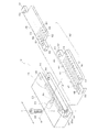
図1に示すように、本実施形態に係るテーピング装置は、エアー導入部20及びエアー噴射部22から構成されるテーピングユニット10と、このテーピングユニット10にエアーを供給する、例えばエアコンプレッサ等のエアー供給源11と、このエアー供給源11に一端が接続され他端がテーピングユニット10のエアー導入部20に接続されているエアー供給路12と、エアー供給路12の途中に配置された電磁弁13と、電磁弁13を制御してエアー供給のオン・オフ制御を行う制御手段14と、テーピングすべき線材である渡り線64が収容凹部62の底面まで挿入されたことを検知する例えばマイクロスイッチ等の線材センサ15と、エアー供給路12の一部を構成するフレキシブルなエアーホース16と、エアーホース16の先端部に連結されているプラグ17とを備えている。プラグ17は、テーピングユニット10のエアー導入部20の背面(渡り線64が挿入される側と反対側の面)に開口するエアー導入口24に挿入され連結されている。
As shown in FIG. 1, the taping device according to the present embodiment has a
上述したようにテーピングユニット10は、背面側(渡り線64が挿入される側に対して反対側)に設けられたエアー導入部20と、このエアー導入部20に一体的に固定されており、前面側(渡り線64が挿入される側)に設けられたエアー噴射部22とから構成されている。エアー噴射部22の前面側には、その長手方向に対しての垂直断面がU字形状となるように構成された収容凹部62が設けられている。収容凹部62は、テーピングすべき渡り線64の径より大きな開口間隙で前面側に開口した開口部62Aを有しており、渡り線64を、その周面の一部に絶縁テープ66が被着されている状態で開口部62Aを介して挿入可能となっている。絶縁テープ66がその周面の一部に被着された渡り線64がこの収容凹部62内に挿入され、収容凹部62の深さ方向の底面に達すると、その状態が線材センサ15によって検知され、渡り線64の径方向両側からエアーが噴射され、エアー噴射圧で絶縁テープ66が押圧され、渡り線64の周面に貼り付けられる。
As described above, the
図2に示すように、エアー導入部20は矩形のブロック形状を有しており、その背面側にはプラグ18が連結されるエアー導入口24が形成され、前面側にはエアー噴射部22が嵌合される嵌合溝(嵌合凹部)26が形成されている。エアー導入部20の内部には、嵌合溝26の深さ方向の底面26aに開口しているエアー溜まり28が形成されており、このエアー溜まり28は通気路30を介してエアー導入口24に連通している。
As shown in FIG. 2, the
エアー噴射部22は、互いに重ね合わせて一体化される上側部材38及び下側部材40からなる二分割構造となっている。下側部材40の前面側には、その長手方向に対しての垂直断面が半U字形状となるように奥部(背面側)が湾曲した凹部形成面42が形成されており、この凹部形成面42の奥部の湾曲部には、その長手方向(図2のL方向)に沿って互いに離隔して配置された小径の複数のエアー噴射口44が形成されている。これら複数のエアー噴射口44は、凹部形成面42から上側に向かって開口するように構成されている。本実施形態では、複数のエアー噴射口44は、略等間隔で1列に配列されている。これら複数のエアー噴射口44は、下側部材40の内部に形成された複数の流路46の一端(前面側端)にそれぞれ連通している。これら複数の流路46の他端(背面側端)は、このエアー噴射部22をエアー導入部20に嵌合したときにエアー溜まり28に連通するように構成されている。下側部材40の長手方向(図2のL方向)の両端部には、1対の固定部48がそれぞれ形成され、これら1対の固定部48の各々には、固定ネジ32の挿通孔50が形成されている。
The
上側部材38は、下側部材40と同様の形状を有しており、この下側部材40を上下に反転させて相互に組み合わせる構成となっている。即ち、上側部材38の前面側には、その長手方向に対しての垂直断面が半U字形状となるように奥部(背面側)が湾曲した凹部形成面52が形成されており、この凹部形成面52の奥部の湾曲部には、その長手方向(図2のL方向)に沿って互いに離隔して配置された小径の複数のエアー噴射口54が形成されている。これら複数のエアー噴射口54は、凹部形成面52から下側に向かって開口するように構成されている。本実施形態では、複数のエアー噴射口54は、略等間隔で1列に配列されている。これら複数のエアー噴射口54は、上側部材38の内部に形成された複数の流路56の一端(前面側端)にそれぞれ連通している。これら複数の流路56の他端(背面側端)は、このエアー噴射部22をエアー導入部20に嵌合したときにエアー溜まり28に連通するように構成されている。上側部材40の長手方向(図2のL方向)の両端部には、1対の固定部58がそれぞれ形成され、これら1対の固定部58の各々には、固定ネジ32の挿通孔60が形成されている。なお、図2においては、上側部材38のエアー噴射口54及び流路56の一部が省略して表示されている。
The
エアー導入部20において、嵌合溝26を下方に形成する上縁部の長手方向(図2のL方向)の両端部には、このエアー導入部20に嵌合したエアー噴射部22を固定するための固定ネジ32の1対の挿通孔34が形成されており、嵌合溝26を上方に形成する下縁部の長手方向(図2のL方向)の両端部には、嵌合したエアー噴射部22を固定するための固定ネジ32が螺合する1対のネジ孔36が形成されている。エアー噴射部22の上側部材38及び下側部材40を一体化し、エアー導入部20の嵌合溝26内に嵌合させた状態で、エアー導入部20の1対の挿通孔34、エアー噴射部22の上側部材38の1対の挿通孔60、及び下側部材42の1対の挿通孔50を介して、エアー導入部20の1対のネジ孔36に1対の固定ネジ32がそれぞれ螺合することにより、エアー導入部20とエアー噴射部22とが固定されて一体化される。
In the
エアー噴射部22の上側部材38と下側部材40とが重ね合わせられて固定されると、凹部形成面42と凹部形成面52とにより、長手方向(図2のL方向)に対しての垂直断面がU字形状の収容凹部62が形成される。図3は長手方向(図2のL方向)に対しての垂直断面(図1のハッチング表示された断面、図2のA−A線断面)であり、この収容凹部62、流路46及び56、並びにエアー噴射口44及び54の部分を拡大して示している。同図に示されているように、収容凹部62は、渡り線64の径d1よりも大きな開口間隙d2を有する開口部62Aを有している。また、その長手方向(図2のL方向)に、渡り線64の長さ方向に沿った幅W1(図1参照)を有している。これらの図から分かるように、上側部材38の複数のエアー噴射口54と、下側部材40の複数のエアー噴射口44とは、収容凹部62の奥部においてその長手方向に沿って2列で配列されており、しかも、後述するように、これら複数のエアー噴射口54及び44は、互いに対向するように開口している。
When the
収容凹部62の開口部62Aが、渡り線64の径d1よりも大きな開口間隙d2を有しているので、渡り線64が絶縁テープ66を周面の一部に被着した状態であっても、この開口部62Aを介して収容凹部62内に収容でき、渡り線64に絶縁テープ66を張り付ける作業を行うことができる。このため、種々の線径を有する渡り線64についても、収容凹部62に収容でき、確実なテーピングを行うことができる。しかも、線径の異なる渡り線64へのテーピングを行う場合にも、従来技術のように線径の異なる溝幅を有する複数種類のテーピング台を用意する必要がないから、これらテーピング台の用意による製造コストの増大を招かない。また、煩雑なテーピング台の交換作業が不要であり、テーピング台の管理も不要である。
Since the
図3に示すように、上側部材38のエアー噴射口54は、収容凹部62の奥部において下側に向かって開口しており、下側部材40のエアー噴射口44は、収容凹部62の奥部において上側に向かって開口している。従って、上側部材38のエアー噴射口54と、下側部材40のエアー噴射口44とは、互いに対向するように配置されていることとなる。より詳しくは、図3(a)に示すように、下側部材40のエアー噴射口44と上側部材38のエアー噴射口54とは、その中心位置mが、収容凹部62に収容された状態の渡り線64の中心64aよりも収容凹部62の開口部62A側へ若干ずれて配置されている。これにより、図3(b)に示すように、エアーの噴射流が渡り線64の絶縁テープ66が接着されていない部分へ向くように制御でき、その部分の押圧及び貼り付けを効果的に行うことができる。しかも、渡り線64の、収容凹部62の底面側(背面側)に位置する仮接着部分も押圧して絶縁テープ66を密着させることができる。なお、下側部材40の複数のエアー噴射口44及び流路46と、上側部材38の複数のエアー噴射口54及び流路56との長手方向の間隔は適宜設定できるが、絶縁テープ66の押圧ムラが生じないように、隣り合うエアー噴射口からの噴射流が互いに重なる間隔とすることが望ましい。
As shown in FIG. 3, the
次に、図3に基づいて、本実施形態のテーピング装置におけるテーピング動作を説明する。 Next, the taping operation in the taping device of the present embodiment will be described with reference to FIG.
図3(a)は絶縁テープ66が前面に被着された渡り線64が収容凹部62に収容されていく状態を示しており、図3(b)はエアー噴射圧によって絶縁テープ66が渡り線62の周面に貼り付けられる状態を示している。
FIG. 3A shows a state in which the
図3(a)に示すように、まず、図示しない駆動装置によって渡り線64又はテーピングユニット10が駆動されて、前面に絶縁テープ66が被着された渡り線64が矢印方向に相対的に移動する。ただし、絶縁テープ66はテーピングする長さにカットされており、その粘着面が渡り線64側に位置しているものとする。この状態で、渡り線64が矢印方向にさらに相対的に移動することにより、この渡り線64は、その一部周面に絶縁テープ66が貼り付いた状態で開口部62Aを介して収容凹部62内に挿入される。渡り線64がさらに相対的に移動することにより、絶縁テープ66が収容凹部62の側面で幅を狭められ、渡り線64の一部周面にさらに貼り付きながら収容凹部62内を矢印方向に相対的に進む。渡り線64が収容凹部62の底面に達すると、この底面に設けられたマイクロスイッチである線材センサ15(図1参照)が渡り線64の底面到着を検知し、制御手段14に検知信号が出力される。制御手段14は、検知信号を受信すると、電磁弁13を制御してテーピングユニット10へのエアー供給を開始する。なお、線材センサ15は、マイクロスイッチに代えて、上側部材38及び下側部材40間に設けられた光透過型センサであっても良い。また、エアー供給のオン・オフは手動で行うように構成しても良い。
As shown in FIG. 3A, first, the
テーピングユニット10にエアーが供給されると、図3(b)に示すように、互いに対向する上側部材38の複数のエアー噴射口54及び下側部材40の複数のエアー噴射口44から渡り線64に向かってエアーが噴射され、こられエアー噴射流は、絶縁テープ66の粘着面側とは反対側の面を、絶縁テープ66が渡り線64の周面に沿って貼り付くように押圧する。これにより、絶縁テープ66は渡り線64の周面に完全に密着して貼り付けが瞬時に完了する。絶縁テープ66が周面に貼り付いた渡り線64は、収容凹部62から、従って、テーピングユニット10から取り出される。
When air is supplied to the
このように、本実施形態のテーピング装置によれば、複数のエアー噴射口44と複数のエアー噴射口54とからの噴射流が、渡り線64の周面をなぞるように絶縁テープ66を押圧するので、押圧ムラ(貼り付けムラ)無く、均一の貼り付けを行うことができる。厳密には、渡り線64の放射方向から噴射されたエアーは、収容凹部62の底面と絶縁テープ66との隙間にも入り込むので、渡り線64の周面全体にわたって貼り付けムラは生じない。しかも、本実施形態では、従来技術のように絶縁テープをチャック板で挟むための掴み代を設ける必要がないので、絶縁テープ66に無駄が生じず、その有効利用が可能となる。絶縁テープ66の長さを渡り線64の円周長に一致させれば、より無駄が生じない。もちろん、絶縁テープ66を端部が若干重なる長さとしても良い。
As described above, according to the taping device of the present embodiment, the injection flows from the plurality of
本実施形態では、渡り線64とテーピングユニット10とを相対的に移動させるように構成されている。例えば、渡り線64を静止位置に配置してテーピングユニット10を移動させる構成としても良いし、テーピングユニット10を静止位置に配置して渡り線64を移動させる構成としても良いし、また、テーピングユニット10と渡り線64との双方を移動させるように構成しても良い。さらに、本実施形態では、収容凹部62に絶縁テープ66の一部が貼り付けられた渡り線64を収容してからエアーの噴射を開始するように構成されているが、エアーを常時噴射した状態で絶縁テープ66がその周面の一部に貼り付けられた渡り線64を収容しても、結果的に同様のテーピングがなされる。常時噴射の場合には、本実施形態の線材センサ15で検知して制御手段14で電磁弁13を制御する構成は不要である。
In the present embodiment, the
前述したように、本実施形態に係るテーピングユニット10は、収容凹部62の開口部62Aの開口間隙d2が渡り線64の径d1(図3(a)参照)より大きく設定されており、このため、図4に示すように、渡り線64が多少曲がっていても収容凹部62内に収容して絶縁テープ66を貼り付けることができる。しかも、エアー噴射圧で渡り線64の周面に沿って絶縁テープ66を押圧するので、渡り線64の径に違いがあっても、また、渡り線64が多少曲がっていてもエアー流動性によって絶縁テープ66を良好に貼り付けることができる。従って、1つのテーピングユニット10で、線径の異なる渡り線へのテーピングが可能である。また、エアー噴射圧で押圧して絶縁テープ66を貼り付けるので、従来技術のようにチャック機構で絶縁テープを重ねて貼り付ける方法に比べて絶縁テープ66を傷付ける心配もない。
As described above, in the
次に、図5に基づいて図1〜図4の実施形態のテーピング装置の一変更態様におけるテーピング動作を説明する。 Next, the taping operation in one modification of the taping device according to the embodiment of FIGS. 1 to 4 will be described with reference to FIG.
図5(a)は本変更態様において絶縁テープ66がテーピングユニットの収容凹部62に保持され、渡り線64がこの収容凹部62に対して相対的に移動する状態を示しており、図5(b)は本変更態様において絶縁テープ66が被着された渡り線64が収容凹部62に収容されていく状態を示している。
FIG. 5A shows a state in which the insulating
本変更態様においては、図5(a)に示すように、上側部材38及び下側部材40の前面側、即ち収容凹部62の開口部62A側に、凹状の段差部38a及び40aが形成されている。この段差部38a及び40aに、絶縁テープ66をその粘着面が前面側となり、収容凹部62の開口部62Aを塞ぐように載置するか、又は負圧で吸引して保持しておく。この状態で図示しない駆動装置によって渡り線64又はテーピングユニット10が駆動されて、渡り線64が矢印方向に相対的に移動し、その一部周面に絶縁テープ66が貼り付いた状態で開口部62Aを介して収容凹部62内に挿入される。図5(b)に示すように、渡り線64がさらに相対的に移動することにより、絶縁テープ66が収容凹部62の側面で幅を狭められ、渡り線64の一部周面にさらに貼り付きながら収容凹部62内を矢印方向に相対的に進む。渡り線64が収容凹部62の底面に達すると、この底面に設けられた線材センサ15(図1参照)が渡り線64の底面到着を検知し、制御手段14に検知信号が出力され、電磁弁13が制御されてテーピングユニット10へのエアー供給が開始する。以後の動作は、前述の実施形態において、図3(b)に関連して説明した通りである。本変更態様におけるその他の構成及び作用効果は、図1〜図4の実施形態の場合とほぼ同様である。
In this modified mode, as shown in FIG. 5A, concave stepped
次に、図6に基づいて図1〜図4の実施形態のテーピング装置の他の変更態様におけるテーピング動作を説明する。 Next, the taping operation in another modification of the taping device according to the embodiment of FIGS. 1 to 4 will be described with reference to FIG.
図6は本変更態様において、絶縁テープ66の一部が下面に貼り付けられた渡り線64が収容凹部62に収容されていき、エアー噴射圧によって絶縁テープ66が渡り線62の周面に貼り付けられる状態を示している。
In FIG. 6, in this modified mode, the
本変更態様においては、図6に示すように、上側部材38及び下側部材40のいずれか一方、例えば下側部材40のみに、エアー溜まり28に連通する複数の流路46と複数のエアー噴射口44とが設けられている。この状態で図示しない駆動装置によって、渡り線64又はテーピングユニットが矢印方向に相対的に移動され、その下面に絶縁テープ66が貼り付いた状態で開口部62Aを介して収容凹部62内に挿入される。渡り線64が収容凹部62の底面に達すると、この底面に設けられた線材センサ15(図1参照)が渡り線64の底面到着を検知し、制御手段14に検知信号が出力され、電磁弁13が制御されてテーピングユニット10へのエアー供給が開始する。本変更態様では、図6に示すように、エアー噴射は、図示しない駆動装置によって渡り線64を回転させながら行われ、これによって絶縁テープ66が渡り線64の周面に沿って貼り付くこととなる。絶縁テープ66が渡り線64の周面に完全に密着して貼り付けが完了すると、渡り線64は、収容凹部62から、従って、テーピングユニット10から取り出される。本変更態様におけるその他の構成及び作用効果は、図1〜図4の実施形態の場合とほぼ同様である。なお、本変更態様では渡り線64を回転させつつエアー噴射を行っているが、渡り線64を静止させ、テーピングユニット10を回転させて同様のエアー噴射を行っても良い。ただし、この場合、テーピングユニット10の回転方向は、上述の渡り線64の回転方向とは逆方向となる。
In this modified mode, as shown in FIG. 6, only one of the
次に、渡り線64をテーピングユニット10の収容凹部62内に挿入するための装置構成について説明する。この装置構成としては、(1)渡り線64(ワーク)を静止位置に配置し、テーピングユニット10を移動させて渡り線64及び絶縁テープ66を収容凹部62内に挿入する構成と、(2)テーピングユニット10を静止位置に配置し、渡り線64(ワーク)及び絶縁テープ66を移動させて収容凹部62内に挿入する構成とが存在する。
Next, a device configuration for inserting the
まず、(1)の構成の一例である図7に示す装置構成について説明する。この装置構成においては、ワークの一部を構成する4つの分割コイル70からなる1相分の4連続巻きコイル68は、その一端にリード線72が形成され、2つの分割コイル70間にテーピングすべき渡り線64が設けられている。この4連続巻きコイル68は、この例ではリニア搬送手段74によって水平方向に直線移動可能となっており、1つの渡り線64が所定位置に達するとリニア搬送手段74が停止されて静止位置に配置される。この所定位置の渡り線64の近傍(この例では上方)には、垂直多関節ロボット75の先端部に把持されたテーピングユニット10が配置されている。この垂直多関節ロボット75は、テーピングすべき渡り線64が所定位置に静止すると、絶縁テープ66を負圧で保持したテーピングユニット10が渡り線64に向って下降し、その収容凹部62内に渡り線64及び絶縁テープ66が開口部62Aを介して挿入される。
First, the device configuration shown in FIG. 7, which is an example of the configuration of (1), will be described. In this device configuration, a
垂直多関節ロボット75は、コンピュータによって数値制御されており、3次元変位が可能な複数の関節75a、75b及び75cを有している。これにより、分割コイル70の種類の変更による渡り線64の位置変化にも数値入力の変更で容易に対応することができる。また、このような垂直多関節ロボット75の自由度により、絶縁テープ66の供給場所も任意に設定することができる。
The vertical articulated
前述の実施形態の場合と同様に、収容凹部62に渡り線64が収容された状態でエアー供給がなされ、テーピングが行われる。1つの渡り線64に対するテーピングが終了すると、垂直多関節ロボット75が動作し、これによってテーピングユニット10が上方に退避し、絶縁テープ66を負圧吸引した後、渡り線64に対向する位置に待機する。その後、リニア搬送手段74が所定量送られ、次の渡り線64がテーピングユニット10に対向する位置に静止すると、上述の動作と同様のテーピング動作がなされる。
As in the case of the above-described embodiment, air is supplied and taping is performed with the
次に、(2)の構成例である図8及び図9に示す装置構成について説明する。この装置構成においては、図8に示すように、テーピングユニット10Aが例えば床面である静止位置に固定されており、テーピングすべき渡り線64を含む図7に示したごとき4連続巻きコイルのワーク80がロボットアーム76の先端部に把持されている。このロボットアーム76は、1対のチャック78によって把持したワーク80のテーピングすべき渡り線64をテーピングユニット10Aに向って上下移動可能に構成されている。テーピングユニット10Aの開口部62Aには、絶縁テープ66がその粘着面が前面側となり、収容凹部62の開口部62Aを塞ぐように載置されるか、又は負圧で吸引して保持されている。
Next, the device configurations shown in FIGS. 8 and 9 which are configuration examples of (2) will be described. In this apparatus configuration, as shown in FIG. 8, the
図8は1対のチャック78が内方に移動して、渡り線64を有するワーク80を把持した状態を示している。この状態から、図9(a)に示すように、ロボットアーム76が動作してワーク80がテーピングユニット10Aの収容凹部62に対向する位置に移動した後、下降し、渡り線64が絶縁テープ66と共にテーピングユニット10Aの収容凹部62内に開口部62Aを介して収容される。渡り線64が収容凹部62の底面に達すると、図9(b)に示すようにエアー噴射圧でテーピングが行われる。
FIG. 8 shows a state in which a pair of
ロボットアーム76は、前述の垂直多関節ロボット75と同様に、コンピュータによって数値制御されており、3次元変位が可能な複数の関節を有している。これにより、ワーク80の種類の変更による渡り線64の位置変化にも数値入力の変更で容易に対応することができる。
Similar to the above-mentioned vertical articulated
図7〜図9に述べたような装置構成によれば、巻線工程とは別個の独立した後工程でテーピング処理することが可能となる。この後工程においては、例えば、巻線後の線材の定寸カットや皮膜剥離、環状成形等が行われるが、これらの工程の作業中に並列してテーピング処理を行うことが可能となる。従って、従来技術のように、テーピング処理によって巻線工程全体のラインタクトを増大させることがなくなる。 According to the apparatus configuration as described in FIGS. 7 to 9, the taping process can be performed in a post-process separate from the winding process. In this post-process, for example, fixed-size cutting of the wire rod after winding, film peeling, annular molding, and the like are performed, and taping processing can be performed in parallel during the work of these steps. Therefore, unlike the conventional technique, the taping process does not increase the line tact of the entire winding process.
以上述べた実施形態は全て本発明を例示的に示すものであって限定的に示すものではなく、本発明は他の種々の変形態様及び変更態様で実施することができる。従って本発明の範囲は特許請求の範囲及びその均等範囲によってのみ規定されるものである。 All of the above-described embodiments are exemplary and not limited to the present invention, and the present invention can be implemented in various other modifications and modifications. Therefore, the scope of the present invention is defined only by the claims and their equivalents.
10、10A テーピングユニット
11 エアー供給源
12エアー供給路
13 電磁弁
14 制御手段
15 線材センサ
16 エアーホース
17 プラグ
20 エアー導入部
22 エアー噴射部
24 エアー導入口
26 嵌合溝
28 エアー溜まり
30 通気路
32 固定ネジ
34、50、60 挿通孔
36 ネジ孔
38 上側部材
38a、40a 段差部
40 下側部材
42、52 凹部形成面
44、54 エアー噴射口
46、56 流路
48、58 固定部
62 収容凹部
62A 開口部
64 渡り線
66 絶縁テープ
68 4連続巻きコイル
70 分割コイル
72 リード線
74 リニア搬送手段
75 垂直多関節ロボット
7a、75b、75c 関節
76 ロボットアーム
78 チャック
80 ワーク
d1 径
d2 開口間隙
W1 幅
10,
Claims (7)
前記線材の径より大きな開口間隙で一方向に開口した開口部を有しており、周面の一部に前記絶縁テープが被着された状態の前記線材を、前記開口部を介して収容可能な収容凹部と、前記収容凹部内に開口した複数のエアー噴射口とを備えており、
前記複数のエアー噴射口は、前記収容凹部の長手方向に沿って1列で配列されており、前記線材又は前記収容凹部を前記線材の周方向に回転させながら、前記絶縁テープをエアー噴射圧で前記線材の周面に押圧して貼り付けするように設けられていることを特徴とするテーピング装置。 A taping device for attaching insulating tape to the peripheral surface of a wire rod.
The wire rod has an opening opened in one direction with an opening gap larger than the diameter of the wire rod, and the wire rod in a state where the insulating tape is adhered to a part of the peripheral surface can be accommodated through the opening. It is provided with a storage recess and a plurality of air injection ports opened in the storage recess.
The plurality of air injection ports are arranged in a row along the longitudinal direction of the accommodating recess, and the insulating tape is subjected to air injection pressure while rotating the wire rod or the accommodating recess in the circumferential direction of the wire rod. A taping device characterized in that it is provided so as to be pressed and attached to the peripheral surface of the wire rod.
前記エアー噴射部は前記エアー溜まりと前記複数のエアー噴射口とをそれぞれ連通する複数の流路を有しており、前記エアー導入部は一端がエアー供給源に接続され他端が前記エアー溜まりに連通したエアー導入口を有していることを特徴とする請求項1から3のいずれか1項に記載のテーピング装置。 An air injection section having the accommodating recess and the plurality of air injection ports, and an air introduction section having an air pool communicating with the plurality of air injection ports of the air injection section are further provided.
The air injection unit has a plurality of flow paths that communicate the air pool and the plurality of air injection ports, respectively, and one end of the air introduction unit is connected to the air supply source and the other end is the air pool. The taping device according to any one of claims 1 to 3 , wherein the taping device has a communicating air inlet.
前記線材の周面の一部に前記絶縁テープを被着しておき、前記線材の径より大きな開口間隙で一方向に開口した開口部を有している収容凹部の前記開口部を介して前記絶縁テープが被着された前記線材を挿入することにより、該線材及び該絶縁テープを前記収容凹部内に収容し、該収容凹部内に開口した複数のエアー噴射口からエアーを噴射することにより、前記絶縁テープをエアー噴射圧で前記線材の周面に押圧して貼り付けることを特徴とするテーピング方法。 This is a taping method in which insulating tape is attached to the peripheral surface of the wire.
The insulating tape is adhered to a part of the peripheral surface of the wire rod, and the insulating tape is provided through the opening of the accommodating recess having an opening opening in one direction with an opening gap larger than the diameter of the wire rod. By inserting the wire rod coated with the insulating tape, the wire rod and the insulating tape are accommodated in the accommodating recess, and air is injected from a plurality of air injection ports opened in the accommodating recess. A taping method characterized in that the insulating tape is pressed against the peripheral surface of the wire rod by air injection pressure and attached.
Priority Applications (2)
| Application Number | Priority Date | Filing Date | Title |
|---|---|---|---|
| JP2017163014A JP6831573B2 (en) | 2017-08-28 | 2017-08-28 | Taping device and taping method |
| PCT/JP2018/018708 WO2019044052A1 (en) | 2017-08-28 | 2018-05-15 | Taping device and taping method |
Applications Claiming Priority (1)
| Application Number | Priority Date | Filing Date | Title |
|---|---|---|---|
| JP2017163014A JP6831573B2 (en) | 2017-08-28 | 2017-08-28 | Taping device and taping method |
Publications (3)
| Publication Number | Publication Date |
|---|---|
| JP2019038671A JP2019038671A (en) | 2019-03-14 |
| JP2019038671A5 JP2019038671A5 (en) | 2020-08-06 |
| JP6831573B2 true JP6831573B2 (en) | 2021-02-17 |
Family
ID=65527352
Family Applications (1)
| Application Number | Title | Priority Date | Filing Date |
|---|---|---|---|
| JP2017163014A Active JP6831573B2 (en) | 2017-08-28 | 2017-08-28 | Taping device and taping method |
Country Status (2)
| Country | Link |
|---|---|
| JP (1) | JP6831573B2 (en) |
| WO (1) | WO2019044052A1 (en) |
Families Citing this family (1)
| Publication number | Priority date | Publication date | Assignee | Title |
|---|---|---|---|---|
| KR102394504B1 (en) * | 2020-11-20 | 2022-05-03 | 서을용 | Apparatus for clip taping |
Family Cites Families (4)
| Publication number | Priority date | Publication date | Assignee | Title |
|---|---|---|---|---|
| JPS545102B1 (en) * | 1970-02-20 | 1979-03-13 | ||
| JPS504269B1 (en) * | 1970-07-20 | 1975-02-17 | ||
| JPS5516858A (en) * | 1978-07-22 | 1980-02-05 | Taiyo Kakoki Kk | Method of coating single-faced soft adhesive tape continuously onto outer surface of long cylindrical article |
| JP2976757B2 (en) * | 1993-08-18 | 1999-11-10 | 住友電装株式会社 | Taping wheel and tape winding device using the same |
-
2017
- 2017-08-28 JP JP2017163014A patent/JP6831573B2/en active Active
-
2018
- 2018-05-15 WO PCT/JP2018/018708 patent/WO2019044052A1/en active Application Filing
Also Published As
| Publication number | Publication date |
|---|---|
| JP2019038671A (en) | 2019-03-14 |
| WO2019044052A1 (en) | 2019-03-07 |
Similar Documents
| Publication | Publication Date | Title |
|---|---|---|
| KR101972348B1 (en) | Magnet insert apparatus of rotor core for motor and insert method | |
| CN107114009B (en) | Electronic component supply device, reeling device, tape processing unit and element containing belt compensation process | |
| JP5242300B2 (en) | Taping machine and taping method | |
| JP5877891B2 (en) | Tape automatic setting device | |
| RU2493963C2 (en) | Coiler and method of production of laminar article | |
| JP7076566B2 (en) | Laminating equipment for RFID electronic tags for tires | |
| CN108466449A (en) | The inner box former and its forming method of carton | |
| JP5294791B2 (en) | Connecting coil winding method and connecting coil winding apparatus | |
| CN207889295U (en) | A kind of automatic precision laminator | |
| JP6831573B2 (en) | Taping device and taping method | |
| WO2014097473A1 (en) | Automatic tape processing apparatus and automatic tape setting apparatus | |
| CN106712401B (en) | A kind of magnetic shoe stator automatic assembling of micro machine | |
| JP2022030877A (en) | Tape pasting system, tape pasting method, tape peeling system, and tape peeling method | |
| JP2019104092A (en) | Screwdriver tool, screwdriver device, method for conveying and fastening screw | |
| JPWO2013186848A1 (en) | Top tape loading device and tape automatic setting device | |
| JP2016046331A (en) | Coil manufacturing device and coil manufacturing method | |
| CN105436040B (en) | A kind of dispensing method of glue water tape cap protection coil | |
| CN208148601U (en) | The inner box molding equipment of carton | |
| JP2019075466A (en) | Manufacturing work machine | |
| JP2877646B2 (en) | Tape pasting machine | |
| CN115152135A (en) | Method and apparatus for manufacturing iron core product | |
| JP4960147B2 (en) | Electronic component mounting apparatus main body and electronic component mounting apparatus | |
| JP2017001769A (en) | Splicer and method of exchanging raw material film | |
| JP2005051916A (en) | Coil, winding method, and winding machine | |
| WO2023228459A1 (en) | Method for manufacturing resin-molded article |
Legal Events
| Date | Code | Title | Description |
|---|---|---|---|
| A521 | Request for written amendment filed |
Free format text: JAPANESE INTERMEDIATE CODE: A523 Effective date: 20200625 |
|
| A621 | Written request for application examination |
Free format text: JAPANESE INTERMEDIATE CODE: A621 Effective date: 20200625 |
|
| A871 | Explanation of circumstances concerning accelerated examination |
Free format text: JAPANESE INTERMEDIATE CODE: A871 Effective date: 20200625 |
|
| A975 | Report on accelerated examination |
Free format text: JAPANESE INTERMEDIATE CODE: A971005 Effective date: 20200707 |
|
| A131 | Notification of reasons for refusal |
Free format text: JAPANESE INTERMEDIATE CODE: A131 Effective date: 20200901 |
|
| A521 | Request for written amendment filed |
Free format text: JAPANESE INTERMEDIATE CODE: A523 Effective date: 20201026 |
|
| TRDD | Decision of grant or rejection written | ||
| A01 | Written decision to grant a patent or to grant a registration (utility model) |
Free format text: JAPANESE INTERMEDIATE CODE: A01 Effective date: 20210112 |
|
| A61 | First payment of annual fees (during grant procedure) |
Free format text: JAPANESE INTERMEDIATE CODE: A61 Effective date: 20210115 |
|
| R150 | Certificate of patent or registration of utility model |
Ref document number: 6831573 Country of ref document: JP Free format text: JAPANESE INTERMEDIATE CODE: R150 |
|
| R250 | Receipt of annual fees |
Free format text: JAPANESE INTERMEDIATE CODE: R250 |