JP6830787B2 - Lighting device and display device - Google Patents
Lighting device and display device Download PDFInfo
- Publication number
- JP6830787B2 JP6830787B2 JP2016203325A JP2016203325A JP6830787B2 JP 6830787 B2 JP6830787 B2 JP 6830787B2 JP 2016203325 A JP2016203325 A JP 2016203325A JP 2016203325 A JP2016203325 A JP 2016203325A JP 6830787 B2 JP6830787 B2 JP 6830787B2
- Authority
- JP
- Japan
- Prior art keywords
- light
- region
- light source
- prisms
- prism
- Prior art date
- Legal status (The legal status is an assumption and is not a legal conclusion. Google has not performed a legal analysis and makes no representation as to the accuracy of the status listed.)
- Active
Links
Images


Landscapes
- Liquid Crystal (AREA)
- Planar Illumination Modules (AREA)
Description
本発明の実施形態は、照明装置及び表示装置に関する。 Embodiments of the present invention relate to lighting devices and display devices.
例えば、液晶表示装置などの表示装置は、画素を有する表示パネルと、表示パネルを照明するバックライトなどの照明装置とを備えている。照明装置は、光を放つ光源と、この光源からの光が照射される導光板とを備えている。
光源からの光は、側面から導光板に入射し、導光板内を伝播し、導光板の一方の主面に相当する出射面から出射する。導光板の端面に複数の光源を並設することで所望の輝度の出射光を得ることもできる。
For example, a display device such as a liquid crystal display device includes a display panel having pixels and a lighting device such as a backlight that illuminates the display panel. The lighting device includes a light source that emits light and a light guide plate that is irradiated with light from this light source.
The light from the light source enters the light guide plate from the side surface, propagates in the light guide plate, and is emitted from an exit surface corresponding to one main surface of the light guide plate. By arranging a plurality of light sources side by side on the end face of the light guide plate, it is possible to obtain an emitted light having a desired brightness.
光源が放つ光の指向性が高い場合、導光板の出射面において光源に近い領域では、所望の輝度を得られない可能性がある。 When the directivity of the light emitted by the light source is high, the desired brightness may not be obtained in a region close to the light source on the exit surface of the light guide plate.
本開示の一態様における目的は、導光板の出射面から良好な輝度分布の光を照射する照明装置及び表示装置を提供することである。 An object of one aspect of the present disclosure is to provide a lighting device and a display device that irradiate light having a good luminance distribution from an exit surface of a light guide plate.
一実施形態に係る照明装置は、第1面、第1面に対向する第2面、第1面及び第2面を接続する第1側面、及び第1面及び第2面を接続し第1側面に対向する第2側面を有する導光板と、第1側面に対向する第1光源と、第2側面に対向する第2光源と、を備える。導光板は、第1方向に延在するとともに第1面又は第2面に複数の第1プリズムが配置された第1領域と、第1方向に延在するとともに第1面又は第2面に複数の第2プリズムが配置された第2領域と、を有し、第1領域及び第2領域は、第1方向と交差する第2方向に並ぶ。第1光源は、第1側面から第1領域に光を照射し、第2光源は、第2側面から第2領域に光を照射する。複数の第1プリズム及び複数の第2プリズムの形成パターンは、互いに異なる。 The lighting device according to an embodiment has a first surface, a second surface facing the first surface, a first side surface connecting the first surface and the second surface, and a first surface connecting the first surface and the second surface. A light guide plate having a second side surface facing the side surface, a first light source facing the first side surface, and a second light source facing the second side surface are provided. The light guide plate extends in the first direction and extends in the first direction and extends in the first direction and on the first surface or the second surface in the first region in which a plurality of first prisms are arranged on the first surface or the second surface. It has a second region in which a plurality of second prisms are arranged, and the first region and the second region are arranged in a second direction intersecting the first direction. The first light source irradiates the first region from the first side surface, and the second light source irradiates the second region from the second side surface. The formation patterns of the plurality of first prisms and the plurality of second prisms are different from each other.
また、一実施形態に係る表示装置は、光を選択的に透過して画像を表示する表示パネルと、上記照明装置とを備え、上記照明装置が上記表示パネルに光を照射する。 Further, the display device according to the embodiment includes a display panel that selectively transmits light to display an image and the lighting device, and the lighting device irradiates the display panel with light.
いくつかの実施形態につき、図面を参照しながら説明する。
なお、開示はあくまで一例に過ぎず、当業者において、発明の主旨を保っての適宜変更について容易に想到し得るものについては、当然に本発明の範囲に含有される。また、図面は、説明をより明確にするため、実際の態様に比べて模式的に表される場合があるが、あくまで一例であって、本発明の解釈を限定するものではない。各図において、連続して配置される同一又は類似の要素については符号を省略することがある。また、本明細書と各図において、既出の図に関して前述したものと同一又は類似した機能を発揮する構成要素には同一の参照符号を付し、重複する詳細な説明を省略することがある。
Some embodiments will be described with reference to the drawings.
It should be noted that the disclosure is merely an example, and those skilled in the art can easily conceive of appropriate changes while maintaining the gist of the invention are naturally included in the scope of the present invention. In addition, the drawings may be represented schematically as compared with actual embodiments in order to clarify the description, but the drawings are merely examples and do not limit the interpretation of the present invention. In each figure, reference numerals may be omitted for the same or similar elements arranged consecutively. Further, in the present specification and each figure, components exhibiting the same or similar functions as those described above with respect to the above-mentioned figures may be designated by the same reference numerals, and duplicate detailed description may be omitted.
各実施形態及び比較例においては、表示装置の一例として、透過型の液晶表示装置を開示する。また、照明装置の一例として、液晶表示装置のバックライトを開示する。ただし、各実施形態は、他種の表示装置や照明装置に対する、各実施形態にて開示される個々の技術的思想の適用を妨げるものではない。他種の表示装置としては、例えば、透過型の機能に加えて外光を反射してこの反射光を表示に利用する反射型の機能を備えた液晶表示装置や、MEMS(Micro Electro Mechanical System)シャッターが光学素子として機能する機械式表示パネルを有する表示装置などが想定される。他種の照明装置としては、例えば、表示装置の前面に配置されるフロントライトなどが想定される。また、照明装置は、表示装置の照明とは異なる用途で使用されるものであってもよい。 In each embodiment and comparative example, a transmissive liquid crystal display device is disclosed as an example of the display device. Further, as an example of the lighting device, the backlight of the liquid crystal display device will be disclosed. However, each embodiment does not preclude the application of the individual technical ideas disclosed in each embodiment to other types of display devices and lighting devices. Other types of display devices include, for example, a liquid crystal display device having a reflective function that reflects external light and uses the reflected light for display in addition to a transmissive function, and a MEMS (Micro Electro Mechanical System). A display device or the like having a mechanical display panel in which the shutter functions as an optical element is assumed. As another type of lighting device, for example, a front light arranged in front of the display device is assumed. Further, the lighting device may be used for a purpose different from the lighting of the display device.
(第1実施形態)
まず、第1実施形態に係る照明装置及び表示装置を図1〜図7を参照して説明する。
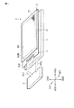
図1は、各実施形態及び比較例に係る表示装置1の概略的な構成を示す斜視図である。表示装置1は、例えば、スマートフォン、タブレット端末、携帯電話端末、パーソナルコンピュータ、テレビ受像装置、車載装置、ゲーム機器、ウェアラブル端末等の種々の装置に用いることができる。
(First Embodiment)
First, the lighting device and the display device according to the first embodiment will be described with reference to FIGS. 1 to 7.
FIG. 1 is a perspective view showing a schematic configuration of a
表示装置1は、表示パネル2と、バックライトである照明装置3と、表示パネル2を駆動する駆動ICチップ4と、表示パネル2及び照明装置3の動作を制御する制御モジュール5と、表示パネル2及び照明装置3へ制御信号を伝達するフレキシブル回路基板FPC1,FPC2とを備えている。
The
表示パネル2は、第1基板SUB1と、第1基板SUB1に対向する第2基板SUB2と、各基板SUB1,SUB2の間にある液晶層LCと、を備えている。表示パネル2は、画像を表示する表示領域DAを有している。表示パネル2は、例えば、表示領域DAにおいてマトリクス状に配列された複数の画素PXを備えている。
The
照明装置3は、第1基板SUB1と対向している。駆動ICチップ4は、例えば第1基板SUB1に実装されている。但し、駆動ICチップ4は、制御モジュール5などに実装されてもよい。フレキシブル回路基板FPC1は、第1基板SUB1と制御モジュール5とを接続している。フレキシブル回路基板FPC2は、照明装置3と制御モジュール5とを接続している。
The
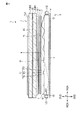
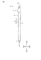
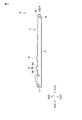
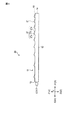
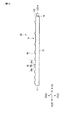
図2は、第1実施形態に係る表示装置1の概略的な断面図であり、図3は、照明装置3の概略的な構成を示す正面図である。図4は図3のF4−F4線での断面図を示し、図5は図3のF5−F5線での断面図を示す。
まず、第1実施形態に係る照明装置3に関して説明する。図2〜図5に示すように、照明装置3は、平板状の導光板10と、5個の第1光源LS1−1〜LS1−5と、4個の第2光源LS2−1〜LS2−4と、を備えている。
FIG. 2 is a schematic cross-sectional view of the
First, the
以下の説明においては、図2及び図3に示すように第1方向X、第2方向Y、及び第3方向Zを定義する。第1方向Xは、導光板10の長さ方向と平行である。第2方向Yは、導光板10の幅方向と平行である。第3方向Zは、導光板10の厚み方向と平行である。各方向X,Y,Zは、例えば互いに垂直に交わる。なお、本実施形態において、第1光源LS1からの光が照射される照射方向は、第1方向Xの一方向側である第1A方向X1である。第2光源LS2からの光が照射される照射方向は、第1方向Xの他方向側である第1B方向X2である。上記照射方向は、例えば第1光源LS1及び第2光源LS2が放つ光において、放射強度が最も高い光軸(後述の光軸AX1及びAX2)に沿う方向である。
In the following description, the first direction X, the second direction Y, and the third direction Z are defined as shown in FIGS. 2 and 3. The first direction X is parallel to the length direction of the
図2において、導光板10は、第3方向Zにおいて、第1面11と、第1面11に対向する第2面12とを有する。導光板10は、第1方向Xにおいて、第1面11及び第2面12を接続する第1側面13と、第1面11及び第2面12を接続する第2側面14とを有し、第1側面13と第2側面14とは対向している。図3において、導光板10は、第2方向Yにおいて、第3側面15と、第3側面15に対向する第4側面16とを有する。第1面11及び第2面12は、例えばXY平面と平行である。各側面13,14は、例えばYZ平面と平行である。各側面15,16は、例えばXZ平面と平行である。
In FIG. 2, the
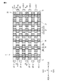
図3において、導光板10は、第1側面13から第2側面14まで第1方向Xに帯状に延在し、第3側面15から第4側面16まで第2方向Yにおいて等間隔に配置された5箇所の第1領域R1を有する。導光板10は、第1側面13から第2側面14まで第1方向Xに帯状に延在し、各第1領域R1の間に配置された4箇所の第2領域R2を有する。すなわち、第1領域R1及び第2領域R2は、第2方向Yにおいて交互に並んでいる。第1領域R1には、後述する複数の第1プリズム17が配置されている。第2領域R2には、後述する複数の第2プリズム18が配置されている。
In FIG. 3, the
5個の第1光源LS1−1〜LS1−5は、各第1領域R1の第1側面13にそれぞれ対向し、第2方向Yにおいて配列している。4個の第2光源LS2−1〜LS2−4は、各第2領域R2の第2側面14にそれぞれ対向し、第2方向Yにおいて配列している。すなわち、第1領域R1及び第1光源LS1の組と、第2領域R2及び第2光源LS2の組とは、第2方向Yにおいて交互に並んでいる。
The five first light sources LS1-1 to LS1-5 face the
各第1光源LS1及び各第2光源LS2は、例えば、赤色レーザ光源、青色レーザ光源、及び緑色レーザ光源から出射される光を混合して白色レーザ光を出射するレーザ光源である。各色のレーザ光源としては、例えば、半導体レーザを用いることができる。各第1光源LS1及び各第2光源LS2は、好ましくは偏光した光を出射する。本実施形態では、各第1光源LS1及び各第2光源LS2からの光が、進行に伴って広がる拡散光である場合を想定する。 Each of the first light source LS1 and each second light source LS2 is, for example, a laser light source that emits white laser light by mixing light emitted from a red laser light source, a blue laser light source, and a green laser light source. As the laser light source of each color, for example, a semiconductor laser can be used. Each first light source LS1 and each second light source LS2 preferably emits polarized light. In the present embodiment, it is assumed that the light from each first light source LS1 and each second light source LS2 is diffused light that spreads with progress.
次に、図3〜図5により、第1領域R1に配置された複数の第1プリズム17及び第2領域R2に配置された複数の第2プリズム18に関して説明する。
図4において、複数の第1プリズム17は、それぞれ第1領域R1の第1面11に凸部として配置されている。複数の第1プリズム17は、例えば、XZ平面に沿う断面が互いに相似の三角形状であり、それぞれ第2方向Yに延びている。複数の第1プリズム17は、例えば第1方向Xにおいて間隔を置いて配列している。複数の第1プリズム17は、第1領域R1において第1A方向X1に形成密度が高くなっている。複数の第1プリズム17は、第1A方向X1に向けてXZ平面に沿う断面積が大きくなっている。
Next, with reference to FIGS. 3 to 5, a plurality of
In FIG. 4, each of the plurality of
第1プリズム17は、第1側面13の側を向いた第1斜面17aと、第2側面14の側を向いた第2斜面17bとを有している。第1斜面17aは、XY平面に対して傾斜角θ1で傾斜する面である。第2斜面17bは、XY平面に対して傾斜角θ2で傾斜する面である。例えば、傾斜角θ1は傾斜角θ2よりも大きく、第2斜面17aは第1斜面17bよりもXY平面に対して緩やかに傾斜している。第1斜面17aと第2斜面17bとが交差する線は、第1プリズム17の頂線17cである。頂線17cは、例えば、第2方向Yに延びている。
The
図5において、複数の第2プリズム18は、それぞれ第2領域R2の第1面11に凸部として配置されている。複数の第2プリズム18は、複数の第1プリズム17と形成パターンが異なっている。複数の第2プリズム18は、例えば、第1プリズム17をYZ平面で反転させた形状を有している。複数の第1プリズム18は、第2領域R2において第1B方向X2に形成密度が高くなっている。複数の第2プリズム18は、第1B方向X2に向けてXZ平面に沿う断面積が大きくなっている。
In FIG. 5, each of the plurality of
第2プリズム18は、第2側面14の側を向いた第3斜面18aと、第1側面13の側を向いた第4斜面18bとを有している。第3斜面18aは、XY平面に対して傾斜角θ1で傾斜する面である。第4斜面18bは、XY平面に対して傾斜角θ2で傾斜する面である。例えば、傾斜角θ1は傾斜角θ2よりも大きく、第4斜面18aは第3斜面18bよりもXY平面に対して緩やかに傾斜している。第3斜面18aと第2斜面18bとが交差する線は、第2プリズム18の頂線18cである。頂線18cは、例えば、第2方向Yに延びている。
The
図3〜図5においては、複数の第1プリズム17と複数の第2プリズム18とがYZ平面で反転させた形状である例を示した。しかしながら、複数の第1プリズム17と複数の第2プリズム18とは、各斜面17a,17bと各斜面18a,18bの傾斜角が異なるなど、他の態様にて形成パターンが異なっていてもよい。
3 to 5 show an example in which the plurality of
ここで、プリズムの形成密度が高いとは、出射面の単位面積において占める光の出射に寄与する面の割合が多いことを意味する。例えば、大きな第1プリズム17が配置されている位置では、出射面での単位面積において占める光の出射に主に寄与する面である第1プリズム17の第2斜面17bの割合が増加する。そのため、大きい第1プリズム17が形成されている位置では、第1プリズム17の形成密度が高いといえる。第2プリズム18の形成密度についても同様である。なお、第2プリズム18において出射面での光の出射に主に寄与する面とは、第2プリズム18の第4斜面18bである。また、複数の第1プリズム17が第1領域R1において第1A方向X1に向けて形成密度が高くなっているとは、第1領域の全域において第1A方向X1に向けて第1プリズム17の形成密度が高くなっている必要はなく、少なくともその一部が第1方向に向けて形成密度が高くなっていればよい。複数の第2プリズム18についても同様である。
Here, a high prism formation density means that the proportion of the surface that contributes to the emission of light is large in the unit area of the emission surface. For example, at the position where the large
なお、第1プリズム17の頂線17cは、第1光源LS1側に曲率中心を有する形状に曲がっていてもよい。第2プリズム18の頂線18cは、第2光源LS2側に曲率中心を有する形状に曲がっていてもよい。
導光板10は、例えば、光透過性を有する樹脂で形成されている。第1光源LS1及び第2光源LS2が偏光する光を放つ場合、導光板10は、その内部を通過する光の偏光方向を維持する観点から、低複屈折性を有することが望ましい。このような導光板10は、例えば正の複屈折物質と負の複屈折物質との混合体または共重合体で形成されており、例えば固有複屈折率が絶対値で3×10⁻³以下の樹脂で形成されている。
The
The
図3において、各第1光源LS1−1〜LS1−5の光は、第1領域R1の第1側面13に照射され、第1側面13を介して第1領域R1に入射する。すなわち、第1側面13は導光板10の1つ目の入射面に相当する。各第2光源LS2−1〜LS2−4の光は、第2領域R2の第2側面14に照射され、第2側面14を介して第2領域R2に入射する。すなわち、第2側面14は導光板10の2つ目の入射面に相当する。導光板10の第1領域R1を伝播する光は、主に複数の第1プリズム17を透過するか、又は複数の第1プリズム17により屈曲されて第1面11から出射する。同様に、導光板10の第1領域R2を伝播する光は、主に複数の第2プリズム18を透過するか、又は複数の第2プリズム18により屈曲されて第1面11から出射する。すなわち、第1面11は、導光板10の出射面に相当する。図2に示すように、照明装置3の第1面11を表示パネル2に対向させることで画像表示に用いられる光を表示パネル2に照射することができる。
In FIG. 3, the light of each of the first light sources LS1-1 to LS1-5 is applied to the
図2に示すように、第1実施形態に係る表示装置1は、表示パネル2及び照明装置3に加え、第1偏光板PL1と、第2偏光板PL2と、反射部材6と、プリズムシート(光指向部材)7と、拡散シート(光拡散層)8とを備えている。
表示パネルの第1基板SUB1及び第2基板SUB2は、光透過性を有するガラス基板で形成されている。第1基板SUB1及び第2基板SUB2は、シール材SEによって貼り合わされている。シール材SEは、表示領域DAを囲む環状に形成されている。第1基板SUB1及び第2基板SUB2及びシール材SEによって囲まれた空間に液晶層LCが封入されている。第1偏光板PL1は、第1基板SUB1の導光板10と対向する面に設けられている。第2偏光板PL2は、第2基板SUB2の第1基板SUB1と対向する面の反対面に設けられている。
As shown in FIG. 2, the
The first substrate SUB1 and the second substrate SUB2 of the display panel are formed of a light-transmitting glass substrate. The first substrate SUB1 and the second substrate SUB2 are bonded by a sealing material SE. The sealing material SE is formed in an annular shape surrounding the display area DA. The liquid crystal layer LC is enclosed in a space surrounded by the first substrate SUB1, the second substrate SUB2, and the sealing material SE. The first polarizing plate PL1 is provided on the surface of the first substrate SUB1 facing the
反射部材6は、導光板10の第2面12に対向して配置されている。反射部材6は、例えば、導光板10と対向する面が鏡面になっており、導光板10の第2面12から漏出した光を反射して導光板10内に戻す。反射部材6は、例えば金属薄膜、又はESR(Enhanced Specular Reflector)反射シートで形成されている。
The
プリズムシート7は、導光板10の第1面11に対向して配置されている。プリズムシート7は、導光板10の第1面11から出射した光を表示パネル2に対して垂直に入射する光に指向させる。プリズムシート7は、複数の第3プリズム71を有している。複数の第3プリズム71は、例えば、XZ平面に沿う断面が三角形状であり、第2方向Yに延在し、第1方向Xに配列している。プリズムシート7は、例えば、光透過性を有する樹脂で形成されている。第1光源LS1及び第2光源LS2が偏光する光を放つ場合、導光板10はその内部を通過する光の偏光方向を維持する観点から、低複屈折性を有することが望ましい。各光源LS1,LS2からの光の偏光を維持する観点から、プリズムシート7の下面(導光板10と対向する面)に第3プリズム71が形成されていることが好ましい。
The
拡散シート8は、例えば、プリズムシート7及び第1偏光板PL1の間に配置されている。拡散シート8は、プリズムシート7を透過した光を拡散し、XY平面における輝度の均一性を向上し、表示パネル2を透過する光の視野角を向上させる。拡散シート8は、例えば、散乱粒子を含む樹脂層である。
The
以下、図2を用いて、XZ平面において、第1光源LS1から出射され導光板10の第1領域R1内を伝搬し、表示パネル2に入射する光の光路の一例を先端矢印の破線にて示し説明する。
第1光源LS1が放つ光は、例えば、第1方向Xと平行である光軸AX1において最も放射強度が強い直線偏光である。第1光源LS1が放つ光は、例えば、白色レーザ光である。第1光源LS1からの光は、第1側面13を透過して第1領域R1に照射される。第1領域R1に照射された光は、第2面12及び第1面11の第1プリズム17の配置された部分を除く領域において全反射条件を満たす場合、全反射され第1A方向X1に伝搬する。第1領域R1を伝搬する光が第1プリズム17に到達すると、この光の少なくとも一部は、第1プリズム17の第2斜面17bにおいて全反射条件を満たさず、第1面11から出射する。第1領域R1を伝搬する光は、第2面12からも出射し得るが、このような光は反射部材6で鏡面反射され、第1領域R1内に戻される。
Hereinafter, using FIG. 2, an example of an optical path of light emitted from the first light source LS1 and propagating in the first region R1 of the
The light emitted by the first light source LS1 is, for example, linearly polarized light having the strongest radiant intensity on the optical axis AX1 parallel to the first direction X. The light emitted by the first light source LS1 is, for example, white laser light. The light from the first light source LS1 passes through the
導光板10の第1面11から出射する光は、偏光方向を維持したまま第1偏光板PL1に到達する。第1偏光板PL1は、この偏光方向の光を透過する透過軸を有する。したがって、第1偏光板PL1に到達した光は吸収されずに表示パネル2に照射される。このような構成においては、光源が放つ光の利用効率を向上することができる。
The light emitted from the
なお、各光源LS1,LS2からの光が十分に偏光された状態で表示パネル2に到達する場合には、第1偏光板PL1を省略してもよい。第1偏光板PL1を省略した場合には、例えば各基板SUB1,SUB2の光透過性を高めることで、表示装置1の背景が透けて見えるいわゆる透明液晶表示装置を得ることができる。
第2光源LS2からの光に関しても、第1光源LS1からの光と同様の光路を経て表示パネル2に照射される。
When the light from the light sources LS1 and LS2 reaches the
The light from the second light source LS2 is also irradiated to the
なお、第1光源LS1からの光は、第2側面14に近い第1プリズム17ほど到達し難い。第1実施形態に係る照明装置では、第1A方向X1に第1プリズム17の形成密度を高くすることで、第1領域R1の第1方向Xにおける輝度の均一性を向上させている。同様に、第1B方向X2に第2プリズムの形成密度を高くすることで、第2領域R2の第1方向Xにおける輝度の均一性を向上させている。
It should be noted that the light from the first light source LS1 is less likely to reach the
次に、導光板10内を伝搬する光のXY平面における光路の一例につき、図3を用いて説明する。
図3に示すように、第1光源LS1が放つ光は、例えば、第1方向Xと平行である光軸AX1において最も放射強度が強く、第2方向Yにおいて広がり角θy1で広がっている。同様に、XY平面において第2光源LS2が放つ光は、例えば、第1方向Xと平行である光軸AX2において最も放射強度が強く、第2方向Yにおいて広がり角θy2で広がっている。広がり角θy1及び広がり角θy2は、例えば同一の角度である。図3では、放射強度が半値となる光の光路をそれぞれ点線で示している。
Next, an example of an optical path in the XY plane of light propagating in the
As shown in FIG. 3, the light emitted by the first light source LS1 has the strongest radiant intensity in the optical axis AX1 parallel to the first direction X, and spreads at a spread angle θy1 in the second direction Y, for example. Similarly, the light emitted by the second light source LS2 in the XY plane has the strongest radiant intensity in the optical axis AX2 parallel to the first direction X, and spreads at a spread angle θy2 in the second direction Y. The spread angle θy1 and the spread angle θy2 are, for example, the same angle. In FIG. 3, the optical paths of light whose radiation intensity is half value are shown by dotted lines.
図3において、第1光源LS1からの光は、主に第1領域R1内を第1A方向X1に伝搬し、第1プリズム17によって屈曲して第1面11から出射する。同時に、第1光源LS1が放つ光は、広がり角θy1を有するため、第1A方向X1に伝搬するに伴い隣接している第2領域R2にも伝搬する。第2領域R2に伝搬した光は、第2プリズム18によって屈曲し、第2領域R2の第1面11から出射する。
In FIG. 3, the light from the first light source LS1 mainly propagates in the first region R1 in the first A direction X1, is bent by the
同様に、第2光源LS2が放つ光は、主に第2領域R2内を第1B方向X2に伝搬し、第2プリズム18によって屈曲して第1面11から出射する。同時に、第2光源LS2からの光は、広がり角θy2を有するため、第1B方向X2に伝搬するに伴い隣接している第1領域R1にも伝搬する。第1領域R1に伝搬する光は、第1プリズム17によって屈曲し、第1領域R1の第1面11から出射する。
Similarly, the light emitted by the second light source LS2 mainly propagates in the second region R2 in the first B direction X2, is bent by the
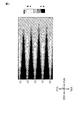
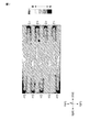
図6は、比較例に係る照明装置の導光板の出射面における輝度分布を示す図であり、図7は、第1実施形態に係る照明装置の導光板の出射面における輝度分布を示す図である。図6及び図7では、XY平面における輝度を等高線とハッチングにより示している。 FIG. 6 is a diagram showing the brightness distribution on the exit surface of the light guide plate of the lighting device according to the comparative example, and FIG. 7 is a diagram showing the brightness distribution on the exit surface of the light guide plate of the lighting device according to the first embodiment. is there. In FIGS. 6 and 7, the luminance in the XY plane is shown by contour lines and hatching.
比較例に係る照明装置は、第1実施形態と同一の第1光源LS−1〜LS−5及び、複数のプリズムが第1A方向X1に形成密度が高くなるように配置された導光板を備えている。図6に示すように、第1光源LS1が放つ光の広がり角θy1が小さく指向性が高い場合、導光板の出射面において第1光源LS1に近い領域で、所望の輝度を得られない可能性がある。 The lighting device according to the comparative example includes the same first light sources LS-1 to LS-5 as in the first embodiment, and a light guide plate in which a plurality of prisms are arranged so as to have a high formation density in the first A direction X1. ing. As shown in FIG. 6, when the spread angle θy1 of the light emitted by the first light source LS1 is small and the directivity is high, there is a possibility that the desired brightness cannot be obtained in a region close to the first light source LS1 on the emission surface of the light guide plate. There is.
第1実施形態に係る照明装置3は、図3に示すように、第1領域R1及び第1光源LS1の組と、第2領域R2及び第2光源LS2の組とは、第2方向Yにおいて交互に並んでいる。そのため、第1光源LS1からの光が出射しにくい第1光源LS1に近い領域から、第2光源LS2からの光が出射する。同様に、第2光源LS2からの光が出射しにくい第2光源LS2に近い領域から、第1光源LS1からの光が出射する。その結果、図7に示すように、第1実施形態に係る照明装置では、導光板の出射面の輝度の均一性を向上することができる。
In the
なお、第1実施形態においては、5個の第1光源及び5箇所の第1領域と、4個の第2光源及び4箇所の第2領域とを備える例を説明したが、これに限定されない。これらは、より多数であってもよいし、より少数であってもよい。また、第1光源及び第2光源は、直線偏光を放つ例を説明したが、偏光していない光を放つのでもよい。
なお、第1実施形態においては、第1領域R1及び第2領域R2が第2方向Yにおいて交互に配列している例を示したが、第1領域R1及び第2領域R2は少なくとも1組が隣接していればよい。また、第1領域及び第2領域の平面形状が矩形帯状である例を示したが、この形状は単なる例示であり、適宜変更されてよい。
In the first embodiment, an example including five first light sources, five first regions, four second light sources, and four second regions has been described, but the present invention is not limited to this. .. These may be more or less. Further, although the example in which the first light source and the second light source emit linearly polarized light has been described, unpolarized light may be emitted.
In the first embodiment, an example in which the first region R1 and the second region R2 are alternately arranged in the second direction Y is shown, but at least one set of the first region R1 and the second region R2 is used. It suffices if they are adjacent to each other. Further, an example is shown in which the planar shapes of the first region and the second region are rectangular strips, but this shape is merely an example and may be changed as appropriate.
なお、第1実施形態においては、第1プリズム及び第2プリズムが共に第1面に形成された場合を示したが、第1面又は第2面に形成されていればよく、互いに別の面に形成されていてもよい。また、第1実施形態においては、第1プリズム及び第2プリズムが凸状のプリズムとして形成された例を示したが、凹状に形成されていても同様の効果が得られる。また、図に示す第1プリズム及び第2プリズムの個数や形状は単なる例示であり、適宜変更されてよい。例えば、第1プリズム及び第2プリズムは、第2方向Yに延びる柱状のプリズムではなく、ドット状のプリズムであってもよい。なお、第1プリズム及び第2プリズムにおける出射面での光の出射に主に寄与する面とは、そのプリズムの形状や光源との配置等に随伴して変化する。 In the first embodiment, the case where both the first prism and the second prism are formed on the first surface is shown, but it suffices if they are formed on the first surface or the second surface, and the surfaces are different from each other. It may be formed in. Further, in the first embodiment, an example in which the first prism and the second prism are formed as convex prisms is shown, but the same effect can be obtained even if the first prism and the second prism are formed in a concave shape. Further, the number and shape of the first prism and the second prism shown in the figure are merely examples, and may be changed as appropriate. For example, the first prism and the second prism may be dot-shaped prisms instead of columnar prisms extending in the second direction Y. The surface of the first prism and the second prism that mainly contributes to the emission of light on the exit surface changes according to the shape of the prism, the arrangement with the light source, and the like.
また、第1実施形態において、導光板の長さ方向と、第1光源及び第2光源からの光が照射される照射方向と、第1領域及び第2領域の延在方向が平行である例を示して説明したが、これに限定されない。例えば、第1光源及び第2光源からの光の照射方向は、導光板の長さ方向に対して傾いており、第1領域及び第2領域の延在方向と平行である構成であってもよい。なお、平行とは、2直線が厳密にどこまで延長しても交わらないという関係に限定されず、1つの直線がもう一方の直線に対して僅かに傾いている、実質的な平行関係をも含む。 Further, in the first embodiment, an example in which the length direction of the light guide plate, the irradiation direction in which the light from the first light source and the second light source is irradiated, and the extending direction of the first region and the second region are parallel. However, the present invention is not limited to this. For example, the irradiation direction of the light from the first light source and the second light source is inclined with respect to the length direction of the light guide plate, and even if the configuration is parallel to the extending direction of the first region and the second region. Good. It should be noted that the term "parallel" is not limited to the relationship that two straight lines do not intersect with each other no matter how long they extend, but also includes a substantially parallel relationship in which one straight line is slightly inclined with respect to the other straight line. ..
以下に、第2〜第9実施形態に係る表示装置に関して説明する。これらの表示装置は、第1実施形態に係る表示装置と同様の効果を得ることができる。
(第2実施形態)
第2実施形態について説明する。ここでは、第1実施形態との相違点に着目し、第1実施形態と同一の構成については説明を省略する。
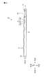
図8は、第2実施形態に係る照明装置3の概略的な構成を示す正面図である。図9は図8のF9−F9線での断面図を示し、図10は図8のF10−F10線での断面図を示す。第2実施形態は、複数の第1プリズム27及び複数の第2プリズム28の形成パターンが図3〜図5に示した照明装置3と相違している。
The display device according to the second to ninth embodiments will be described below. These display devices can obtain the same effects as the display devices according to the first embodiment.
(Second Embodiment)
The second embodiment will be described. Here, attention will be paid to the difference from the first embodiment, and the description of the same configuration as that of the first embodiment will be omitted.
FIG. 8 is a front view showing a schematic configuration of the
本実施形態に係る照明装置3は、導光板20を備えている。導光板20は、第1領域R1に設けられた複数の第1プリズム27と、第2領域R2に設けられた複数の第2プリズム28とを備えている。複数の第1プリズム27は、例えば、それぞれXZ平面に沿う断面形状が互いに同一の三角形状であり、第2方向Yに延びている。複数の第1プリズム27は、例えば第1A方向X1に向けて形成間隔が狭くなるように配置されている。
The
第1プリズム27のXZ平面に沿う断面形状は、例えば、第1実施形態の第1プリズム17と相似である。第1プリズム27は、それぞれ第1側面13の側を向いた第1斜面27a、第2側面14の側を向いた第2斜面27b、頂線27cを有している。複数の第2プリズム28は、例えば、複数の第1プリズム27をYZ平面で反転させた形状を有する。複数の第2プリズム28は、例えば第1B方向X2に向けて形成間隔が狭くなるように配置されている。第2プリズム28は、第2側面14の側を向いた第3斜面28a、第1側面13の側を向いた第4斜面28b、頂線28cを有している。
The cross-sectional shape of the
第1プリズム27の形成間隔が狭い位置では、出射面の単位面積において占める光の出射に寄与する面(第2斜面27b)の割合が増加する。そのため、第1プリズム27の形成間隔が狭い位置では、第1プリズム27の形成密度が高いといえる。第2プリズム28の形成密度についても同様である。本実施形態のように第1プリズム27及び第2プリズム28の形成密度を調整した場合であっても、第1領域R1及び第2領域R2の第1方向Xにおける輝度の均一性を向上することができる。
At a position where the formation interval of the
図8に示す例では、複数の第1及び第2プリズムの形成密度が高くなる構成の例として、同一形状を有する第1及び第2プリズムの形成間隔が狭くなっている構成を説明したが、これに限定されない。例えば、第1実施形態と組み合せて、第1A方向X1において第1プリズムを大きくしつつ、第1プリズムの形成間隔を狭くしてもよい。同様に、第1B方向X2において第2プリズムを大きくしつつ、第2プリズムの形成間隔を狭くしてもよい。 In the example shown in FIG. 8, as an example of the configuration in which the formation densities of the plurality of first and second prisms are high, the configuration in which the formation intervals of the first and second prisms having the same shape are narrow has been described. Not limited to this. For example, in combination with the first embodiment, the first prism may be enlarged in the first A direction X1 while the forming interval of the first prism may be narrowed. Similarly, the formation interval of the second prism may be narrowed while increasing the size of the second prism in the first B direction X2.
(第3実施形態)
第3実施形態について説明する。ここでは、第1実施形態との相違点に着目し、第1実施形態と同一の構成については説明を省略する。
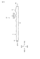
図11は、第3実施形態に係る照明装置3の概略的な構成を示す正面図である。図12は図11のF12−F12線での断面図を示し、図13は図11のF13−F13線での断面図を示す。第3実施形態は、複数の第1プリズム37及び複数の第2プリズム38の形成パターンが図3〜図5に示した照明装置3とは相違している。
(Third Embodiment)
The third embodiment will be described. Here, attention will be paid to the difference from the first embodiment, and the description of the same configuration as that of the first embodiment will be omitted.
FIG. 11 is a front view showing a schematic configuration of the
本実施形態に係る照明装置3は、導光板30を備えている。導光板30は、第1領域R1に設けられた複数の第1プリズム37と、第2領域R2に設けられた複数の第2プリズム38とを備えている。複数の第1プリズム37は、それぞれ第1領域R1の第1面11に凹部として配置されている。例えば、複数の第1プリズム37は、それぞれXZ平面に沿う断面が互いに相似の底角がθ3である二等辺三角形であり、第2方向Yに延びている。複数の第1プリズム37は、例えば第1方向Xで間隔を置いて配列している。
The
複数の第1プリズム37は、第1A方向X1に向けてXZ平面に沿う断面積が大きくなっている。第1プリズム37は、第1側面13の側を向いた第1斜面37a、第2側面14の側を向いた第2斜面37b、頂線37cを有している。複数の第2プリズム38は、例えば、複数の第1プリズム37をXZ平面で反転させ第2領域R2の第1面11に凹部として配置した形状を有している。第2プリズム38は、第2側面14の側を向いた第3斜面38a、第1側面13の側を向いた第4斜面38b、頂線38cを有している。
各第1プリズム37と各第2プリズム38とは、第2方向Yにおいて互いに隣接している。複数の第1プリズム37の頂線37c及び複数の第2プリズム38の頂線38cは、例えば第1方向Xにおいて一致し、第2方向Yにおいて直線状に並んでいる。
The plurality of
The
図14は、図11におけるF14(1)−F14(1)線、F14(2)−F14(2)線、F14(3)−F14(3)線における断面形状を比較して示す図である。頂線37c及び頂線38cは、それぞれ第2方向Yにおいて交互に配置されている。頂線37c及び頂線38cは、第2方向Yにおいて互いに連続しておらず、第2プリズム38は、第1領域R1及び第2領域R2の境界線における壁面37d及び38dを有している。当該壁面37d及び38dは、第1光源LS1及び第2光源LS2から出射された光の進行方向と平行である第1方向Xに延在している。偏光した光が、その光の進行方向と平行の壁面である壁面37d及び38dにおいて反射する場合、光の偏光方向が崩れ伝搬する光の偏光度が低下する。第1プリズム37及び第2プリズム38が隣接している場合、壁面37d及び38dの面積を縮小することができる。第3実施形態に係る照明装置においては、第1光源LS1及び第2光源LS2からの光が導光板30を伝搬する際の偏光度の低下を抑制でき、光の利用効率を向上することができる。
FIG. 14 is a diagram comparing the cross-sectional shapes of the F14 (1) -F14 (1) line, the F14 (2) -F14 (2) line, and the F14 (3) -F14 (3) line in FIG. .. The apex 37c and the apex 38c are alternately arranged in the second direction Y, respectively. The
なお、図11〜図13に示すように、第1プリズム37が凹部として形成される場合、第1光源LS1からの光の第1面11における出射には、主に第1側面13の側を向いている第1斜面37aが寄与する。同様に、第2プリズム38が凹部として形成される場合、第1光源LS1からの光の第1面11における出射には、主に第2側面14の側を向いている第3斜面38aが寄与する。
As shown in FIGS. 11 to 13, when the
(第4実施形態)
第4実施形態について説明する。ここでは、第3実施形態との相違点に着目し、第3実施形態と同一の構成については説明を省略する。
図15は、第4実施形態に係る照明装置3の概略的な構成を示す正面図である。第4実施形態は、第1プリズム47及び第2プリズム48の形状が図11〜図13に示す照明装置3とは相違している。
(Fourth Embodiment)
A fourth embodiment will be described. Here, attention will be paid to the difference from the third embodiment, and the description of the same configuration as that of the third embodiment will be omitted.
FIG. 15 is a front view showing a schematic configuration of the
本実施形態に係る照明装置3は、導光板40を備えている。導光板40は、第1領域R1に設けられた複数の第1プリズム47と、第2領域R2に設けられた複数の第2プリズム48とを備えている。複数の第1プリズム47及び複数の第2プリズム48は、第3実施形態の複数の第1プリズム37及び複数の第2プリズム38と同様に第1面11に凹部として配置されている。F12’−F12’の断面図は、図12に示す断面図と同一形状である。F13’−F13’の断面図は、図13に示す断面図と同一形状である。
The
図15に示す例では、各第1プリズム47と各第2プリズム48とは、第2方向Yにおいて互いに隣接している。複数の第1プリズムの頂線47cは、例えば複数の第2プリズムの頂線48cと第1方向Xで一致し、第2方向Yにおいて直線状に並んでいる。第1プリズム47の第1斜面47a及び第2プリズム48の第4斜面48bは、互いに第1領域R1及び第2領域R1の境界において連続する曲面として形成されている。第1プリズム47の第2斜面47b及び第2プリズム48の第3斜面48aは、互いに第1領域R1及び第2領域R2の境界において連続する曲面として形成されている。
In the example shown in FIG. 15, each
図16は、図15におけるF16(1)−F16(1)線、F16(2)−F16(2)線、F16(3)−F16(3)線における断面図を比較して示す図である。頂線47c及び頂線48cは、それぞれ第2方向Yにおいて交互に配置されている。頂線47c及び頂線48cは、第1領域R1及び第2領域R2の境界において互いに連続する曲線として形成されている。すなわち、第1プリズム47と、第2プリズム48とは、第2方向Yにおいて、連続的に形成された凹部である。この構成においては、第1プリズム47及び第2プリズム48の第1領域R1及び第2領域R2の境界線おいて、光の進行方向と平行の第1方向Xに延在する壁面が存在しない。その結果、第4実施形態に係る照明装置においては、第1光源LS1及び第2光源LS2からの光が導光板40を伝搬する際の偏光度の低下を抑制でき、光の利用効率を向上することができる。
FIG. 16 is a diagram comparing cross-sectional views taken along the lines F16 (1) -F16 (1), F16 (2) -F16 (2), and F16 (3) -F16 (3) in FIG. .. The
なお、図15に示すように、第1プリズム及び第2プリズムが、第2方向Yに連続的に形成される凹部である場合、導光板の第3側面から第4側面まで、交互に深く浅く切削することにより容易に第1プリズム及び第2プリズムを形成することができる。
同様に、第1プリズム47及び第2プリズム48が、第2方向Yに連続的に形成される凸部である場合、導光板を注型するための金型を同様に切削することにより、容易に第1プリズム及び第2プリズムに対応する金型を作製することができる。
As shown in FIG. 15, when the first prism and the second prism are recesses formed continuously in the second direction Y, the light guide plate is alternately deep and shallow from the third side surface to the fourth side surface. The first prism and the second prism can be easily formed by cutting.
Similarly, when the
(第5実施形態)
第5実施形態について説明する。ここでは、第1実施形態との相違点に着目し、第1実施形態と同一の構成については説明を省略する。
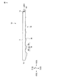
図17は、第5実施形態に係る照明装置3の概略的な構成を示す正面図である。図18は図17のF18−F18線での断面図を示し、図19は図17のF19−F19線での断面図を示す。本実施形態に係る照明装置3は、導光板50を備えている。導光板50は、第1領域R1に設けられた複数の第1プリズム57と、第2領域R2に設けられた複数の第2プリズム58とを備えている。本実施形態では、複数の第1プリズム57が第1領域R1の第1面11に配置され、複数の第2プリズム58が第2領域R2の第2面12に配置されている点で、図3〜図5に示す照明装置とは相違している。
(Fifth Embodiment)
A fifth embodiment will be described. Here, attention will be paid to the difference from the first embodiment, and the description of the same configuration as that of the first embodiment will be omitted.
FIG. 17 is a front view showing a schematic configuration of the
複数の第1プリズム57は、例えば第1実施形態の複数の第1プリズム17と同様に形成されている。第1プリズム57は、それぞれ第1側面13の側を向いた第1斜面57a、第2側面14の側を向いた第2斜面57b、頂線57cを有している。複数の第2プリズム58は、例えば第2面12に形成されていることを除いて第1実施形態の複数の第2プリズム18と同様に形成されている。第2プリズム58は、第2側面14の側を向いた第3斜面58a、第1側面13の側を向いた第4斜面58b、頂線58cを有している。第1プリズム57は、第1領域R1及び第2領域R2の境界線において壁面57dを覆って形成されている凸部57eを有している。同様に、第2プリズム58は、第1領域R1及び第2領域R2の境界線において壁面58dを覆って形成されている凸部58eを有している。第1プリズム57の当該凸部57eは、それぞれの境界線において隣接する第2領域R2上に形成されている。第2プリズム58の当該凸部58eは、それぞれの境界線において隣接する第1領域R1上に形成されている。
The plurality of
この構成においては、複数の第1プリズム57及び複数の第2プリズム58は互いに別の面に形成されている。第1プリズム57及び第2プリズム58の第1領域R1及び第2領域R2の境界線おいて、光の進行方向と平行する第1方向Xに延在する面が存在していない。その結果、第5実施形態に係る照明装置においては、第1光源LS1及び第2光源LS2からの光が導光板50を伝搬する際の偏光度の低下をより抑制でき、光の利用効率を向上することができる。
In this configuration, the plurality of
なお、図示した例では、第1領域R1の第1面11に第1プリズム57が形成され、第2領域R2の第2面12に第2プリズム58が形成されているが、逆であってもよい。すなわち、複数の第1プリズム57が第1面11及び第2面12の一方の面に配置され、複数の第2プリズム58がその他方の面に配置されていれば同様の効果が得られる。
In the illustrated example, the
(第6実施形態)
第6実施形態について説明する。ここでは、第1実施形態との相違点に着目し、第1実施形態と同一の構成については説明を省略する。
図20は、第6実施形態に係る照明装置3の概略的な構成を示す正面図である。導光板60は、第1領域R1及び第2領域R2の平面形状が、図11〜図13に示す導光板10と相違している。
(Sixth Embodiment)
The sixth embodiment will be described. Here, attention will be paid to the difference from the first embodiment, and the description of the same configuration as that of the first embodiment will be omitted.
FIG. 20 is a front view showing a schematic configuration of the
本実施形態に係る照明装置3は、導光板60を備えている。導光板60は、第1領域R1に設けられた複数の第1プリズム67と、第2領域R2に設けられた複数の第2プリズム68とを備えている。
The
第1領域R1は、平面視において、第1A方向X1に向けて第2方向Yにおける幅が大きくなる形状を有している。第2領域R2は、平面視において、第1B方向X2に向けて第2方向Yにおける幅が大きくなる形状を有している。図20に示す例では、第1領域R1は、平面視において、第1光源LS1が放つ光の広がり角θy1と対応する角度で第1B方向X2に向けて第2方向Yにおける幅が大きくなっている。また、第2領域R2は、平面視において、第2光源LS2が放つ光の広がり角θy2と対応する角度で第1A方向X1に向けて第2方向Yにおける幅が大きくなっている。 The first region R1 has a shape in which the width in the second direction Y increases toward the first A direction X1 in a plan view. The second region R2 has a shape in which the width in the second direction Y increases toward the first B direction X2 in a plan view. In the example shown in FIG. 20, the width of the first region R1 increases in the second direction Y toward the first B direction X2 at an angle corresponding to the spread angle θy1 of the light emitted by the first light source LS1 in a plan view. There is. Further, the width of the second region R2 in the second direction Y increases in the first A direction X1 at an angle corresponding to the spread angle θy2 of the light emitted by the second light source LS2 in a plan view.
第1領域R1の第1面11には、複数の第1プリズム67が配置され、第2領域R2の第1面11には、複数の第2プリズム68が配置されている。F4’−F4’の断面図は、図4に示す断面図と同一形状である。F5’−F5’の断面図は、図5に示す断面図と同一形状である。
A plurality of
このような構成によれば、第1光源LS1からの光は主に第1領域R1で出射され、第2領域R2で出射されにくい。また、第2光源LS2からの光を主に第2領域R2で出射され、第1領域R1で出射されにくい。その結果、第6実施形態によれば、導光板60の出射面の輝度を一層好適に均一化できる。
According to such a configuration, the light from the first light source LS1 is mainly emitted in the first region R1 and is less likely to be emitted in the second region R2. Further, the light from the second light source LS2 is mainly emitted in the second region R2, and is difficult to be emitted in the first region R1. As a result, according to the sixth embodiment, the brightness of the exit surface of the
なお、図示する例では、第1光源LS1が放つ光の広がり角θy1と一致する角度で第1領域R1が第1B方向X2に向けて第2方向Yにおける幅が大きくなる例を示したが、これに限定されない。第1領域R1及び第2領域R2が第1A方向X1及び第1B方向X2に向けて第2方向に広がる角度は、第1光源LS1及び第2光源LS2や導光板の出射面の輝度の均一性の向上のため適宜変更され得る。第1領域及び第2領域は、少なくとも一部が第1A方向X1及び第1B方向X2に向けて幅が大きくなる形状を有していればよい。 In the illustrated example, an example is shown in which the width of the first region R1 in the second direction Y increases toward the first B direction X2 at an angle corresponding to the spread angle θy1 of the light emitted by the first light source LS1. Not limited to this. The angle at which the first region R1 and the second region R2 spread in the second direction toward the first A direction X1 and the first B direction X2 is the uniformity of the brightness of the emission surfaces of the first light source LS1 and the second light source LS2 and the light guide plate. Can be changed as appropriate to improve. The first region and the second region may have a shape in which at least a part thereof increases in width toward the first A direction X1 and the first B direction X2.
(第7実施形態)
第7実施形態について説明する。ここでは、第1実施形態との相違点に着目し、第1実施形態と同一の構成については説明を省略する。
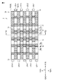
図21は、第7実施形態に係る照明装置3の概略的な構成を示す正面図である。図22は、図21のF22−F22線における断面図を示す。本実施形態に係る照明装置3は、導光板70を備えている。導光板70は、第1領域R1及び第2領域R2がそれぞれ異なる導光部材71及び72に配置されている点で、図3〜図5に示す導光板10と相違している。
(7th Embodiment)
A seventh embodiment will be described. Here, attention will be paid to the difference from the first embodiment, and the description of the same configuration as that of the first embodiment will be omitted.
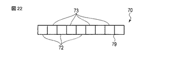
FIG. 21 is a front view showing a schematic configuration of the
導光板70は、第2方向Yにおいて交互に配置された5個の第1導光部材72及び4個の第2導光部材73によって形成されている。第1導光部材72及び第2導光部材73は、境界79において互いに光学接着剤によって接着されている。第1導光部材72及び第2導光部材73は、第1実施形態における第1領域R1及び第2領域R2にそれぞれ対応している。第1導光部材72及び第2導光部材73は、例えば上述の導光板10と同一の材料で形成されている。光学接着剤は、例えば、第1導光部材72及び第2導光部材73と同一の屈折率及び光透過性を有する透明接着剤であり、第1導光部材72及び第2導光部材73を光学的に連続になるように接着する。
The
第1導光部材72の第1面11には、複数の第1プリズム77が配置され、第2導光部材72の第1面11には、複数の第2プリズム78が配置されている。複数の第1プリズム77及び複数の第2プリズム78は、例えば、第1実施形態の複数の第1プリズム17及び複数の第2プリズム18と同一の形状を有している。
A plurality of
このような構成によれば、第1領域R1及び第2領域R2の境界において、第1プリズム及び第2プリズムが第2方向Yにおいて連続ではない形状を有する導光板70であっても容易に形成することができる。第1導光部材72と第2導光部材73は、同じ金型で製造してもよい。第7実施形態に係る照明装置3においても、第1実施形態に係る照明装置3と同様の効果を得ることができる。
According to such a configuration, even a
(第8実施形態)
第8実施形態について説明する。第1実施形態にて開示した導光板10は、第1領域R1の第1側面13の第1光源LS1と対向する部分、及び、第2領域R2の第2側面14の第2光源LS2と対向する部分に凹状又は凸状の光拡散構造を有していてもよい。他の実施形態にて開示した導光板20,30,40,50,60,70についても同様の構成を適用できる。
(8th Embodiment)
An eighth embodiment will be described. The
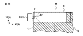
図23は、凹状の光拡散構造の一例を示す。図23の例においては、導光板10の第1側面13に第1光源LS1に対して1つずつ孔81が設けられている。各第1光源LS1からの光は、それぞれ対応する孔81に入る。孔81に入った光は、孔81の表面で屈曲(屈折)するために、第2方向Yにおける広がり角θy1が広がる。これにより、第1光源LS1の周辺における輝度がより均一化できる。
FIG. 23 shows an example of a concave light diffusion structure. In the example of FIG. 23, holes 81 are provided on the
図24は、凸状の光拡散構造の一例を示す。図24の例においては、導光板10の第1側面13に第1光源LS1に対して1つずつ突出した突起82が設けられている。各第1光源LS1からの光は、それぞれ対応する突起82に入る。突起82に入った光は、突起82の表面で屈曲(屈折)されるため、第2方向Yにおける広がり角θy1が広がる。これにより、第1光源LS1の周辺における輝度がより均一化できる。図24に示した孔81及び図24に示した突起82は、各第2光源LS2に対応して第2側面14に設けてもよい。これにより、第2光源LS2からの光の広がり角も広げることができる。
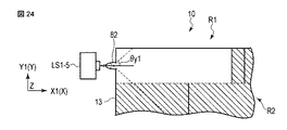
FIG. 24 shows an example of a convex light diffusion structure. In the example of FIG. 24,
なお、第8実施形態における孔81の内部は、空洞でなくてもよい。すなわち、孔81の内部を樹脂などの充填材で満たしてもよい。このような充填材は、孔により光の視野角を広げる作用を確保するために、導光板10よりも屈折率が十分に低い材料で形成することが好ましい。また、光屈折構造は、求められる視野角や放射強度分布に応じて、適宜に形状を工夫することができる。
The inside of the
図23に示した孔81及び図24に示した突起82は、各第2光源LS2に対応して第2側面14に設けてもよい。これにより、第2光源LS2からの光の広がり角も広げることができる。
The
以上の第1乃至第8実施形態にて開示した構成は、適宜に組み合わせることができる。
また、各実施形態では、第1光源LS1及び第2光源LS2がレーザ光源である場合を例示した。しかしながら、第1光源LS1及び第2光源LS2は、レーザ光よりも波長域が広い光を放つ発光ダイオードなどであってもよい。このような場合でも、導光板の出射光の輝度を均一化することができる。
また、第1光源LS1及び第2光源LS2が放つ光は、蛍光体を励起する紫外光などの励起光であってもよい。この場合には、例えば表示パネル2に蛍光層を設け、この蛍光層が励起光により励起して可視光を放つ構成を採用できる。
The configurations disclosed in the above first to eighth embodiments can be combined as appropriate.
Further, in each embodiment, the case where the first light source LS1 and the second light source LS2 are laser light sources is illustrated. However, the first light source LS1 and the second light source LS2 may be light emitting diodes or the like that emit light having a wavelength range wider than that of the laser light. Even in such a case, the brightness of the emitted light of the light guide plate can be made uniform.
Further, the light emitted by the first light source LS1 and the second light source LS2 may be excitation light such as ultraviolet light that excites the phosphor. In this case, for example, a configuration in which a fluorescent layer is provided on the
本発明の実施形態として上述した表示装置及び照明装置を基にして、当業者が適宜設計変更して実施し得る全ての表示装置及び照明装置も、本発明の要旨を包含する限り、本発明の範囲に属する。
本発明の思想の範疇において、当業者であれば、各種の変形例に想到し得るものであり、それら変形例についても本発明の範囲に属するものと解される。例えば、上述の各実施形態に対して、当業者が適宜、構成要素の追加、削除、若しくは設計変更を行ったもの、又は、工程の追加、省略若しくは条件変更を行ったものも、本発明の要旨を備えている限り、本発明の範囲に含まれる。
また、各実施形態において述べた態様によりもたらされる他の作用効果について、本明細書の記載から明らかなもの、又は当業者において適宜想到し得るものについては、当然に本発明によりもたらされるものと解される。
以下に、本願出願の当初の特許請求の範囲に記載された発明を付記する。
[1] 第1面、前記第1面に対向する第2面、前記第1面及び前記第2面を接続する第1側面、及び前記第1面及び前記第2面を接続し前記第1側面に対向する第2側面を有する導光板と、
前記第1側面に対向する第1光源と、
前記第2側面に対向する第2光源と、
を備え、
前記導光板は、第1方向に延在するとともに前記第1面又は前記第2面に複数の第1プリズムが配置された第1領域と、前記第1方向に延在するとともに前記第1面又は前記第2面に複数の第2プリズムが配置された第2領域と、を有し、
前記第1領域及び前記第2領域は、前記第1方向と交差する第2方向に並び、
前記第1光源は、前記第1側面から前記第1領域に光を照射し、
前記第2光源は、前記第2側面から前記第2領域に光を照射し、
前記複数の第1プリズム及び前記複数の第2プリズムの形成パターンは、互いに異なる、
照明装置。
[2] 前記複数の第1プリズム及び前記複数の第2プリズムは、それぞれ前記第1方向に沿って配列し、前記第2方向に沿って延在する、
[1]に記載の照明装置。
[3] 前記第1プリズムは、前記第1側面の側を向く第1斜面と、前記第2側面の側を向く第2斜面とを備え、
前記第2プリズムは、前記第2側面の側を向く第3斜面と、前記第1側面の側を向く第4斜面とを備え、
前記第1プリズム及び前記第2プリズムは、前記第2方向に隣接しており、
前記第1斜面及び前記第4斜面は連続した曲面であり、前記第2斜面及び前記第3斜面は連続した曲面である、
[2]に記載の照明装置。
[4] 前記第1光源は、前記第1方向の一方側である第1A方向に光を照射し、
前記第1光源は、前記第1方向の他方側である第1B方向に光を照射し、
前記第1プリズムは、前記第1A方向に形成密度が高くなっており、
前記第2プリズムは、前記第1B方向に形成密度が高くなっている、
[1]から[3]のいずれか1つに記載の照明装置。
[5] 前記第1光源は、前記第1方向の一方側である第1A方向に光を照射し、
前記第1光源は、前記第1方向の他方側である第1B方向に光を照射し、
前記第1領域の少なくとも一部は、平面視において、前記第1A方向に向けて前記第2方向における幅が大きくなる形状であり、
前記第2領域の少なくとも一部は、平面視において、前記第1B方向に向けて前記第2方向における幅が大きくなる形状である、
[1]から[4]のいずれか1つに記載の照明装置。
[6] 前記第1領域の少なくとも一部は、平面視において、前記第1光源が放つ光の広がり角に対応する形状であり、
前記第2領域の少なくとも一部は、平面視において、前記第2光源が放つ光の広がり角に対応する形状である、
[5]に記載の照明装置。
[7] 前記導光板は、前記第1側面の前記第1光源と対向する部分、及び、前記第2側面の前記第2光源と対向する部分に、凹状又は凸状の光拡散構造を有する、
[1]から[6]のいずれか1つに記載の照明装置。
[8] 前記導光板は、第1導光部材と、第2導光部材と、前記第1導光部材及び前記第2導光部材を接着する接着剤と、を含み、
前記第1導光部材は、前記複数の第1プリズムを有する前記第1領域であり、前記第2導光部材は前記複数の第2プリズムを有する前記第2領域である、
[1]から[7]のいずれか1つに記載の照明装置。
[9] 前記複数の第1プリズムが前記第1面及び前記第2面の一方の面に配置され、前記複数の第2プリズムがその他方の面に配置される、
[1]から[8]のいずれか1つに記載の照明装置。
[10] 前記導光板は、複数の前記第1領域及び複数の前記第2領域を備え、
前記第1領域及び前記第2領域は、前記第2方向において交互に配置され、それぞれ前記第1光源又は前記第2光源と対向している、
[1]から[9]のいずれか1つに記載の照明装置。
[11] 前記第1光源及び前記第2光源は、偏光した光を出射するレーザ光源である、
[1]から[10]のいずれか1つに記載の照明装置。
[12] 光を選択的に透過して画像を表示する表示パネルと、前記表示パネルに光を照射する[1]から[11]のいずれか1つに記載の照明装置と、備える表示装置。
All display devices and lighting devices that can be appropriately designed and implemented by those skilled in the art based on the display devices and lighting devices described above as embodiments of the present invention are also included in the present invention as long as the gist of the present invention is included. It belongs to the range.
Within the scope of the idea of the present invention, those skilled in the art can come up with various modifications, and it is understood that these modifications also belong to the scope of the present invention. For example, for each of the above-described embodiments, those skilled in the art appropriately add, delete, or change the design of components, or add, omit, or change the conditions of the process of the present invention. As long as it has a gist, it is included in the scope of the present invention.
In addition, with respect to other actions and effects brought about by the embodiments described in each embodiment, those that are clear from the description of the present specification or those that can be appropriately conceived by those skilled in the art are naturally understood to be brought about by the present invention. Will be done.
Hereinafter, the inventions described in the claims of the original application of the present application will be added.
[1] The first surface, the second surface facing the first surface, the first side surface connecting the first surface and the second surface, and the first surface connecting the first surface and the second surface. A light guide plate having a second side surface facing the side surface,
The first light source facing the first side surface and
A second light source facing the second side surface and
With
The light guide plate extends in the first direction and has a first region in which a plurality of first prisms are arranged on the first surface or the second surface, and extends in the first direction and the first surface. Alternatively, it has a second region in which a plurality of second prisms are arranged on the second surface.
The first region and the second region are arranged in a second direction intersecting the first direction.
The first light source irradiates the first region with light from the first side surface.
The second light source irradiates the second region with light from the second side surface.
The formation patterns of the plurality of first prisms and the plurality of second prisms are different from each other.
Lighting device.
[2] The plurality of first prisms and the plurality of second prisms are respectively arranged along the first direction and extend along the second direction.
The lighting device according to [1].
[3] The first prism includes a first slope facing the side of the first side surface and a second slope facing the side of the second side surface.
The second prism includes a third slope facing the side of the second side surface and a fourth slope facing the side of the first side surface.
The first prism and the second prism are adjacent to each other in the second direction.
The first slope and the fourth slope are continuous curved surfaces, and the second slope and the third slope are continuous curved surfaces.
The lighting device according to [2].
[4] The first light source irradiates light in the first A direction, which is one side of the first direction.
The first light source irradiates light in the first B direction, which is the other side of the first direction.
The first prism has a higher formation density in the first A direction.
The formation density of the second prism is higher in the first B direction.
The lighting device according to any one of [1] to [3].
[5] The first light source irradiates light in the first A direction, which is one side of the first direction.
The first light source irradiates light in the first B direction, which is the other side of the first direction.
At least a part of the first region has a shape in which the width in the second direction increases toward the first A direction in a plan view.
At least a part of the second region has a shape in which the width in the second direction increases toward the first B direction in a plan view.
The lighting device according to any one of [1] to [4].
[6] At least a part of the first region has a shape corresponding to the spread angle of the light emitted by the first light source in a plan view.
At least a part of the second region has a shape corresponding to the spread angle of the light emitted by the second light source in a plan view.
The lighting device according to [5].
[7] The light guide plate has a concave or convex light diffusion structure in a portion of the first side surface facing the first light source and a portion of the second side surface facing the second light source.
The lighting device according to any one of [1] to [6].
[8] The light guide plate includes a first light guide member, a second light guide member, and an adhesive for adhering the first light guide member and the second light guide member.
The first light guide member is the first region having the plurality of first prisms, and the second light guide member is the second region having the plurality of second prisms.
The lighting device according to any one of [1] to [7].
[9] The plurality of first prisms are arranged on one surface of the first surface and the second surface, and the plurality of second prisms are arranged on the other surface.
The lighting device according to any one of [1] to [8].
[10] The light guide plate includes a plurality of the first regions and a plurality of the second regions.
The first region and the second region are alternately arranged in the second direction and face the first light source or the second light source, respectively.
The lighting device according to any one of [1] to [9].
[11] The first light source and the second light source are laser light sources that emit polarized light.
The lighting device according to any one of [1] to [10].
[12] A display panel comprising a display panel that selectively transmits light to display an image, and a lighting device according to any one of [1] to [11] that irradiates the display panel with light.
1…表示装置、2…表示パネル、3…照明装置、4…駆動ICチップ、5…制御モジュール、SUB1…第1基板、SUB2…第2基板、LC…液晶層、DA…表示領域、PX…画素、3…照明装置、LS1…第1光源、LS2…第2光源、10,20,30,40,50,60,70…導光板、11…第1面、12…第2面、13…第1側面、14…第2側面、15…第3側面、16…第4側面、R1…第1領域、R2…第2領域、6…反射部材、7…プリズムシート(光指向部材)、8…拡散シート(光拡散層)、17,27,37,47,57,67,77…第1プリズム、18,28,38,48,58,68,78…第2プリズム、71…第3プリズム、72…第1導光部材、73…第2導光部材、81,82…光拡散構造、X…第1方向(照射方向)、Y…第2方向(幅方向)、Z…第3方向(厚み方向)。 1 ... Display device, 2 ... Display panel, 3 ... Lighting device, 4 ... Drive IC chip, 5 ... Control module, SUB1 ... 1st substrate, SUB2 ... 2nd substrate, LC ... Liquid crystal layer, DA ... Display area, PX ... Pixels, 3 ... Lighting device, LS1 ... 1st light source, LS2 ... 2nd light source, 10, 20, 30, 40, 50, 60, 70 ... Light guide plate, 11 ... 1st surface, 12 ... 2nd surface, 13 ... 1st side surface, 14 ... 2nd side surface, 15 ... 3rd side surface, 16 ... 4th side surface, R1 ... 1st region, R2 ... 2nd region, 6 ... Reflective member, 7 ... Prism sheet (light directional member), 8 ... Diffusion sheet (light diffusion layer), 17, 27, 37, 47, 57, 67, 77 ... 1st prism, 18, 28, 38, 48, 58, 68, 78 ... 2nd prism, 71 ... 3rd prism , 72 ... 1st light source member, 73 ... 2nd light source member, 81, 82 ... Light diffusion structure, X ... 1st direction (irradiation direction), Y ... 2nd direction (width direction), Z ... 3rd direction (Thickness direction).
Claims (10)
前記第1側面に対向する第1光源と、
前記第2側面に対向する第2光源と、
を備え、
前記導光板は、第1方向に延在するとともに前記第1面又は前記第2面に複数の第1プリズムが配置された第1領域と、前記第1方向に延在するとともに前記第1面又は前記第2面に複数の第2プリズムが配置された第2領域と、を有し、
前記第1領域及び前記第2領域は、前記第1方向と交差する第2方向に並び、
前記第1光源は、前記第1側面から前記第1領域に光を照射し、
前記第2光源は、前記第2側面から前記第2領域に光を照射し、
前記複数の第1プリズム及び前記複数の第2プリズムの形成パターンは、互いに異なり、
前記複数の第1プリズムが前記第1面及び前記第2面の一方の面に配置され、前記複数の第2プリズムがその他方の面に配置され、
前記第1光源から照射された光は、前記複数の第1プリズムによって屈曲されて前記第1面から出射し、
前記第2光源から照射された光は、前記複数の第2プリズムによって屈曲されて前記第1面から出射する、
照明装置。 A first surface, a second surface facing the first surface, a first side surface connecting the first surface and the second surface, and connecting the first surface and the second surface to face the first side surface. A light guide plate having a second side surface
The first light source facing the first side surface and
A second light source facing the second side surface and
With
The light guide plate extends in the first direction and has a first region in which a plurality of first prisms are arranged on the first surface or the second surface, and extends in the first direction and the first surface. Alternatively, it has a second region in which a plurality of second prisms are arranged on the second surface.
The first region and the second region are arranged in a second direction intersecting the first direction.
The first light source irradiates the first region with light from the first side surface.
The second light source irradiates the second region with light from the second side surface.
Forming a pattern of said plurality of first prism and said plurality of second prism, unlike one another,
The plurality of first prisms are arranged on one surface of the first surface and the second surface, and the plurality of second prisms are arranged on the other surface.
The light emitted from the first light source is bent by the plurality of first prisms and emitted from the first surface.
The light emitted from the second light source is bent by the plurality of second prisms and emitted from the first surface.
Lighting device.
請求項1に記載の照明装置。 The plurality of first prisms and the plurality of second prisms are respectively arranged along the first direction and extend along the second direction.
The lighting device according to claim 1.
前記第2光源は、前記第1方向の他方側である第1B方向に光を照射し、
前記第1プリズムは、前記第1A方向に形成密度が高くなっており、
前記第2プリズムは、前記第1B方向に形成密度が高くなっている、
請求項1又は2に記載の照明装置。 The first light source irradiates light in the first A direction, which is one side of the first direction.
The second light source irradiates light in the first B direction, which is the other side of the first direction.
The first prism has a higher formation density in the first A direction.
The formation density of the second prism is higher in the first B direction.
The lighting device according to claim 1 or 2 .
前記第2光源は、前記第1方向の他方側である第1B方向に光を照射し、
前記第1領域の少なくとも一部は、平面視において、前記第1A方向に向けて前記第2方向における幅が大きくなる形状であり、
前記第2領域の少なくとも一部は、平面視において、前記第1B方向に向けて前記第2方向における幅が大きくなる形状である、
請求項1から3のいずれか1項に記載の照明装置。 The first light source irradiates light in the first A direction, which is one side of the first direction.
The second light source irradiates light in the first B direction, which is the other side of the first direction.
At least a part of the first region has a shape in which the width in the second direction increases toward the first A direction in a plan view.
At least a part of the second region has a shape in which the width in the second direction increases toward the first B direction in a plan view.
The lighting device according to any one of claims 1 to 3 .
前記第2領域の少なくとも一部は、平面視において、前記第2光源が放つ光の広がり角に対応する形状である、
請求項4に記載の照明装置。 At least a part of the first region has a shape corresponding to the spread angle of the light emitted by the first light source in a plan view.
At least a part of the second region has a shape corresponding to the spread angle of the light emitted by the second light source in a plan view.
The lighting device according to claim 4 .
請求項1から5のいずれか1項に記載の照明装置。 The light guide plate has a concave or convex light diffusion structure in a portion of the first side surface facing the first light source and a portion of the second side surface facing the second light source.
The lighting device according to any one of claims 1 to 5 .
前記第1導光部材は、前記複数の第1プリズムを有する前記第1領域であり、前記第2導光部材は前記複数の第2プリズムを有する前記第2領域である、
請求項1から6のいずれか1項に記載の照明装置。 The light guide plate includes a first light guide member, a second light guide member, and an adhesive for adhering the first light guide member and the second light guide member.
The first light guide member is the first region having the plurality of first prisms, and the second light guide member is the second region having the plurality of second prisms.
The lighting device according to any one of claims 1 to 6 .
前記第1領域及び前記第2領域は、前記第2方向において交互に配置され、それぞれ前記第1光源又は前記第2光源と対向している、
請求項1から7のいずれか1項に記載の照明装置。 The light guide plate includes a plurality of the first regions and a plurality of the second regions.
The first region and the second region are alternately arranged in the second direction and face the first light source or the second light source, respectively.
The lighting device according to any one of claims 1 to 7 .
請求項1から8のいずれか1項に記載の照明装置。 The first light source and the second light source are laser light sources that emit polarized light.
The lighting device according to any one of claims 1 to 8 .
Priority Applications (1)
| Application Number | Priority Date | Filing Date | Title |
|---|---|---|---|
| JP2016203325A JP6830787B2 (en) | 2016-10-17 | 2016-10-17 | Lighting device and display device |
Applications Claiming Priority (1)
| Application Number | Priority Date | Filing Date | Title |
|---|---|---|---|
| JP2016203325A JP6830787B2 (en) | 2016-10-17 | 2016-10-17 | Lighting device and display device |
Publications (2)
| Publication Number | Publication Date |
|---|---|
| JP2018067376A JP2018067376A (en) | 2018-04-26 |
| JP6830787B2 true JP6830787B2 (en) | 2021-02-17 |
Family
ID=62087212
Family Applications (1)
| Application Number | Title | Priority Date | Filing Date |
|---|---|---|---|
| JP2016203325A Active JP6830787B2 (en) | 2016-10-17 | 2016-10-17 | Lighting device and display device |
Country Status (1)
| Country | Link |
|---|---|
| JP (1) | JP6830787B2 (en) |
Families Citing this family (4)
| Publication number | Priority date | Publication date | Assignee | Title |
|---|---|---|---|---|
| JP2022144629A (en) * | 2021-03-19 | 2022-10-03 | 株式会社ジャパンディスプレイ | Lighting device |
| JP7596249B2 (en) * | 2021-10-22 | 2024-12-09 | 株式会社ジャパンディスプレイ | Display device |
| KR20250129373A (en) * | 2024-02-22 | 2025-08-29 | 엘지디스플레이 주식회사 | Display device |
| KR20250129372A (en) * | 2024-02-22 | 2025-08-29 | 엘지디스플레이 주식회사 | Display device |
Family Cites Families (9)
| Publication number | Priority date | Publication date | Assignee | Title |
|---|---|---|---|---|
| JP2856276B2 (en) * | 1996-06-20 | 1999-02-10 | 日本電気株式会社 | Backlight device |
| JP2000171796A (en) * | 1998-12-02 | 2000-06-23 | Howa Bussan Kk | Surface light source |
| JP2003098356A (en) * | 2001-09-20 | 2003-04-03 | Pioneer Electronic Corp | Light guide plate |
| JP4440062B2 (en) * | 2004-10-08 | 2010-03-24 | シャープ株式会社 | Lighting device |
| JP2006155994A (en) * | 2004-11-26 | 2006-06-15 | Dainippon Printing Co Ltd | Light guide plate and surface light source device |
| JP5243439B2 (en) * | 2006-10-06 | 2013-07-24 | スリーエム イノベイティブ プロパティズ カンパニー | Backlight module for autostereoscopic 3D display device and scanning backlight for LCD device |
| JP4760761B2 (en) * | 2007-04-06 | 2011-08-31 | 日本ビクター株式会社 | Lighting device and display device |
| JP2008269866A (en) * | 2007-04-18 | 2008-11-06 | Seiko Epson Corp | LIGHTING DEVICE, LIQUID CRYSTAL DISPLAY DEVICE, AND ELECTRONIC DEVICE |
| JP5346053B2 (en) * | 2011-03-16 | 2013-11-20 | レノボ・シンガポール・プライベート・リミテッド | Backlight device and display device |
-
2016
- 2016-10-17 JP JP2016203325A patent/JP6830787B2/en active Active
Also Published As
| Publication number | Publication date |
|---|---|
| JP2018067376A (en) | 2018-04-26 |
Similar Documents
| Publication | Publication Date | Title |
|---|---|---|
| JP4431952B2 (en) | Surface light source device and equipment using the device | |
| KR100898100B1 (en) | Prism sheet | |
| JP5409901B2 (en) | Planar light source device and display device using the same | |
| US20190137829A1 (en) | Liquid crystal display (lcd) device | |
| JP5199830B2 (en) | Display device | |
| KR100978078B1 (en) | Prism sheet and liquid crystal display device having same | |
| JP2011014520A (en) | Lighting device and display | |
| CN107315280B (en) | Backlight module and its manufacturing method, display device | |
| CN102927524B (en) | Light mixing component, light guide plate, backlight module and display device | |
| KR102266737B1 (en) | lens,light emitting apparatus including the lens, and backlight unit including the apparatus | |
| KR102130517B1 (en) | Backlight unit and liquid crystal display device including the same | |
| CN104487887B (en) | Display device and light-emitting device | |
| CN107003558A (en) | Composite optical sheet, the Liquid crystal disply device and its preparation method using it | |
| JP6830787B2 (en) | Lighting device and display device | |
| JP2019091036A (en) | Deformed liquid crystal light emitting device | |
| CN206002812U (en) | Display device | |
| KR102090457B1 (en) | Liquid crystal display device | |
| US20190361297A1 (en) | Backlight module and display device | |
| JP2022028799A (en) | Lighting equipment | |
| WO2017159556A1 (en) | Lighting device and display device | |
| WO2017170017A1 (en) | Illumination device and display device | |
| JP5174685B2 (en) | Planar light source device and display device using the same | |
| KR20080017537A (en) | Backlight Assembly and Display Device Having Same | |
| JP2007304597A (en) | Optical plate, optical plate manufacturing method, backlight assembly, and liquid crystal display device | |
| JP7250549B2 (en) | lighting and display |
Legal Events
| Date | Code | Title | Description |
|---|---|---|---|
| A621 | Written request for application examination |
Free format text: JAPANESE INTERMEDIATE CODE: A621 Effective date: 20190912 |
|
| A977 | Report on retrieval |
Free format text: JAPANESE INTERMEDIATE CODE: A971007 Effective date: 20200619 |
|
| A131 | Notification of reasons for refusal |
Free format text: JAPANESE INTERMEDIATE CODE: A131 Effective date: 20200707 |
|
| A521 | Request for written amendment filed |
Free format text: JAPANESE INTERMEDIATE CODE: A523 Effective date: 20200819 |
|
| TRDD | Decision of grant or rejection written | ||
| A01 | Written decision to grant a patent or to grant a registration (utility model) |
Free format text: JAPANESE INTERMEDIATE CODE: A01 Effective date: 20210119 |
|
| A61 | First payment of annual fees (during grant procedure) |
Free format text: JAPANESE INTERMEDIATE CODE: A61 Effective date: 20210127 |
|
| R150 | Certificate of patent or registration of utility model |
Ref document number: 6830787 Country of ref document: JP Free format text: JAPANESE INTERMEDIATE CODE: R150 |
|
| R250 | Receipt of annual fees |
Free format text: JAPANESE INTERMEDIATE CODE: R250 |
|
| R250 | Receipt of annual fees |
Free format text: JAPANESE INTERMEDIATE CODE: R250 |
|
| R250 | Receipt of annual fees |
Free format text: JAPANESE INTERMEDIATE CODE: R250 |