JP6830673B2 - Systems and methods for AC-DC high voltage leak detection - Google Patents
Systems and methods for AC-DC high voltage leak detection Download PDFInfo
- Publication number
- JP6830673B2 JP6830673B2 JP2018559666A JP2018559666A JP6830673B2 JP 6830673 B2 JP6830673 B2 JP 6830673B2 JP 2018559666 A JP2018559666 A JP 2018559666A JP 2018559666 A JP2018559666 A JP 2018559666A JP 6830673 B2 JP6830673 B2 JP 6830673B2
- Authority
- JP
- Japan
- Prior art keywords
- high voltage
- electrode
- detection
- package
- current
- Prior art date
- Legal status (The legal status is an assumption and is not a legal conclusion. Google has not performed a legal analysis and makes no representation as to the accuracy of the status listed.)
- Active
Links
- 238000001514 detection method Methods 0.000 title claims description 197
- 238000000034 method Methods 0.000 title claims description 29
- 238000012360 testing method Methods 0.000 claims description 113
- 238000007689 inspection Methods 0.000 claims description 106
- 230000002950 deficient Effects 0.000 claims description 41
- 230000007547 defect Effects 0.000 claims description 13
- 230000008859 change Effects 0.000 claims description 7
- 230000008569 process Effects 0.000 claims description 5
- 230000007246 mechanism Effects 0.000 description 43
- 239000000047 product Substances 0.000 description 31
- CBENFWSGALASAD-UHFFFAOYSA-N Ozone Chemical compound [O-][O+]=O CBENFWSGALASAD-UHFFFAOYSA-N 0.000 description 14
- 238000005516 engineering process Methods 0.000 description 13
- 239000012263 liquid product Substances 0.000 description 10
- 239000000463 material Substances 0.000 description 9
- 238000005259 measurement Methods 0.000 description 9
- 229910052751 metal Inorganic materials 0.000 description 9
- 239000002184 metal Substances 0.000 description 9
- 239000000523 sample Substances 0.000 description 9
- 229920001940 conductive polymer Polymers 0.000 description 7
- 239000004020 conductor Substances 0.000 description 7
- 235000013305 food Nutrition 0.000 description 7
- 239000011521 glass Substances 0.000 description 7
- 230000035945 sensitivity Effects 0.000 description 7
- 239000008399 tap water Substances 0.000 description 7
- 235000020679 tap water Nutrition 0.000 description 7
- 229910000831 Steel Inorganic materials 0.000 description 6
- 239000010959 steel Substances 0.000 description 6
- 229910052782 aluminium Inorganic materials 0.000 description 5
- XAGFODPZIPBFFR-UHFFFAOYSA-N aluminium Chemical compound [Al] XAGFODPZIPBFFR-UHFFFAOYSA-N 0.000 description 5
- 239000003990 capacitor Substances 0.000 description 5
- 238000002474 experimental method Methods 0.000 description 5
- 238000006386 neutralization reaction Methods 0.000 description 5
- 238000004806 packaging method and process Methods 0.000 description 5
- 239000011800 void material Substances 0.000 description 5
- 239000003708 ampul Substances 0.000 description 4
- 239000003814 drug Substances 0.000 description 4
- 229910001092 metal group alloy Inorganic materials 0.000 description 4
- 238000012986 modification Methods 0.000 description 4
- 230000004048 modification Effects 0.000 description 4
- 239000000126 substance Substances 0.000 description 4
- 238000007599 discharging Methods 0.000 description 3
- 230000000694 effects Effects 0.000 description 3
- 239000011888 foil Substances 0.000 description 3
- 238000009413 insulation Methods 0.000 description 3
- 230000008901 benefit Effects 0.000 description 2
- 230000001066 destructive effect Effects 0.000 description 2
- 229940079593 drug Drugs 0.000 description 2
- 238000010891 electric arc Methods 0.000 description 2
- 239000012530 fluid Substances 0.000 description 2
- 238000004519 manufacturing process Methods 0.000 description 2
- 230000003472 neutralizing effect Effects 0.000 description 2
- 238000012800 visualization Methods 0.000 description 2
- XLYOFNOQVPJJNP-UHFFFAOYSA-N water Substances O XLYOFNOQVPJJNP-UHFFFAOYSA-N 0.000 description 2
- 206010057040 Temperature intolerance Diseases 0.000 description 1
- 230000002238 attenuated effect Effects 0.000 description 1
- 230000009286 beneficial effect Effects 0.000 description 1
- 238000006243 chemical reaction Methods 0.000 description 1
- 230000008543 heat sensitivity Effects 0.000 description 1
- 238000009434 installation Methods 0.000 description 1
- 239000012212 insulator Substances 0.000 description 1
- 230000003993 interaction Effects 0.000 description 1
- 230000001788 irregular Effects 0.000 description 1
- 239000007788 liquid Substances 0.000 description 1
- 239000011344 liquid material Substances 0.000 description 1
- 239000000696 magnetic material Substances 0.000 description 1
- 239000000615 nonconductor Substances 0.000 description 1
- 238000012545 processing Methods 0.000 description 1
- 230000004044 response Effects 0.000 description 1
- 230000000007 visual effect Effects 0.000 description 1
Images


Classifications
-
- G—PHYSICS
- G01—MEASURING; TESTING
- G01M—TESTING STATIC OR DYNAMIC BALANCE OF MACHINES OR STRUCTURES; TESTING OF STRUCTURES OR APPARATUS, NOT OTHERWISE PROVIDED FOR
- G01M3/00—Investigating fluid-tightness of structures
- G01M3/40—Investigating fluid-tightness of structures by using electric means, e.g. by observing electric discharges
-
- G—PHYSICS
- G01—MEASURING; TESTING
- G01M—TESTING STATIC OR DYNAMIC BALANCE OF MACHINES OR STRUCTURES; TESTING OF STRUCTURES OR APPARATUS, NOT OTHERWISE PROVIDED FOR
- G01M3/00—Investigating fluid-tightness of structures
- G01M3/02—Investigating fluid-tightness of structures by using fluid or vacuum
- G01M3/04—Investigating fluid-tightness of structures by using fluid or vacuum by detecting the presence of fluid at the leakage point
- G01M3/16—Investigating fluid-tightness of structures by using fluid or vacuum by detecting the presence of fluid at the leakage point using electric detection means
-
- G—PHYSICS
- G01—MEASURING; TESTING
- G01N—INVESTIGATING OR ANALYSING MATERIALS BY DETERMINING THEIR CHEMICAL OR PHYSICAL PROPERTIES
- G01N27/00—Investigating or analysing materials by the use of electric, electrochemical, or magnetic means
Landscapes
- Physics & Mathematics (AREA)
- General Physics & Mathematics (AREA)
- Chemical & Material Sciences (AREA)
- Chemical Kinetics & Catalysis (AREA)
- Electrochemistry (AREA)
- Health & Medical Sciences (AREA)
- Life Sciences & Earth Sciences (AREA)
- Analytical Chemistry (AREA)
- Biochemistry (AREA)
- General Health & Medical Sciences (AREA)
- Immunology (AREA)
- Pathology (AREA)
- Examining Or Testing Airtightness (AREA)
- Investigating Or Analyzing Materials By The Use Of Electric Means (AREA)
- Other Investigation Or Analysis Of Materials By Electrical Means (AREA)
Description
この発明は、リーク検出、具体的には高電圧リーク検出の技術分野に関し、これに限定されないが、腐敗しやすい生鮮食品または腐敗しない商品のためのバイアル、シリンジ、アンプル、パウチ、アルミパウチ、およびI.V.袋を含む包装容器のリーク、裂け目、破損、または他の不完全性を検出して通知するために使用される方法を実装ずる方法およびシステムに関する。 The present invention relates to, but is not limited to, the technical field of leak detection, specifically high voltage leak detection, for vials, syringes, ampoules, pouches, aluminum pouches, and non-perishable fresh foods or non-perishable commodities. I. V. It relates to methods and systems that implement the methods used to detect and notify leaks, crevices, breakage, or other imperfections in packaging containers, including bags.
リーク検出の分野では、高電圧リーク検出(HVLD)を使用するための2つの確立された技術がある。AC高電圧リーク検出は、慣用的なHVLDと呼ばれ、高電圧値で純粋なAC電流を使用する。DC高電圧リーク検出は、DC HVLDと呼ばれ、高電圧値で純粋なDC電圧を使用する。慣用的なHVLDとDC HVLDの両方ともリークを最終的に検出するために高電圧を使用するけれども、この2つの方法ではAC電圧とDC電圧の固有の差異に基づく非常に異なる技術が使用される。慣用的なHVLDおよびDC HVLDによって使用されるこれらの異なる技術のために、各方法は、そこに含まれる特定の包装容器および製品を試験する際に、それぞれ長所および短所が異なる。 In the field of leak detection, there are two established techniques for using high voltage leak detection (HVLD). AC high voltage leak detection is called conventional HVLD and uses pure AC current at high voltage values. DC high voltage leak detection is called DC HVLD and uses pure DC voltage at high voltage values. Although both conventional HVLDs and DC HVLDs use high voltage to ultimately detect leaks, the two methods use very different techniques based on the inherent differences between AC and DC voltages. .. Due to these different techniques used by conventional HVLDs and DC HVLDs, each method has different strengths and weaknesses when testing the particular packaging and products contained therein.
慣用型HVLDの場合、AC高電圧が容器に印加されて、製品および容器の抵抗を破壊する。次に、参照容器を流れる電流と試験された容器を流れる電流との差を検出することによって、リークの存在が判定される。差が十分に大きい場合、リークが存在すると判断される。 In the case of conventional HVLD, a high AC voltage is applied to the vessel, destroying the resistance of the product and the vessel. The presence of a leak is then determined by detecting the difference between the current flowing through the reference vessel and the current flowing through the tested vessel. If the difference is large enough, it is determined that a leak is present.
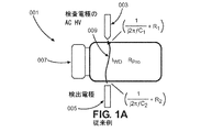
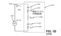
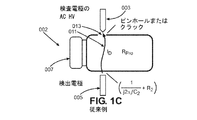
慣用型HVLDの原理を図1A〜図1Dに示す。慣用型HVLDによって検査され、液体製品で満たされ、欠陥のない参照バイアル001が図1Aに示されている。図1Bにおいて、図1Aの参照バイアルの試験は、単純化された電気等価回路で示されている。液体製品で満たされた欠陥バイアル002の試験は図1Cに示され、慣用型HVLDによって検査される。図1Dは、図1Cの欠陥バイアルの単純化された電気等価回路を表す。しかし、電気等価回路は単純化モデルに基づいており、より複雑なモデルを作成できることに注意することが重要である。
The principle of the conventional HVLD is shown in FIGS. 1A to 1D.
図1Aおよび図1Cに示すように、慣用型HVLD試験では、2つの電極003,005の間に容器007を配置し、1つの電極が検査電極003であり、もう1つの電極が検出電極005であるAC高電圧023が回路に印加される。いずれの電極とも物理的に接触することなく、試験されるべき容器が2つの電極の間に配向されるように配向される。容器は、2つの固有インピーダンスと1つの固有抵抗を有する。すなわち、検査電極から容器壁での固有インピーダンスR1+(1/jwC1)、検出電極から容器壁での固有インピーダンスR2+(1/jwC2)、および容器内の製品の固有抵抗RProである。欠陥のない容器を通って得られた電流は、IWDとして表される。
As shown in FIGS. 1A and 1C, in the conventional HVLD test, the
しかし、容器にリークがあれば、図1Cに示すように、放電電流がピンホール、亀裂、またはシールの欠陥を介して容器に流れる。容器内のリークは、図1Dに示すように、インピーダンスのうちの1つが失われる結果となる。結果として生じる、欠陥のある容器を通る電流は、固有インピーダンスの喪失のために異なる値(ID)を有する電流を生じる。次いで、製品を通る信号が検出電極によって検出される。この電流の変化を検出することにより、欠陥の存在を次のように認識することができる。

リークがあると、インピーダンスの1つが失われる。欠陥のある容器を流れる電流は次のようになる。
欠陥のある容器は、欠陥のない容器(IWD)よりも大きい電流(ID)を有する。電流の差は、容器に欠陥があるかどうかを決定し、これは、次の式で示される。
C1、R1、C2、R2、RProは可変であり、印加されるAC高電圧の振幅、材料特性(容器および液体製品の絶縁耐力など)、および液体製品の導電率に応じて変化する。印加電圧が高いほど、C1、R1、C2、R2、RProのインピーダンスは低くなる。大きすぎる電圧を印加するリスクは、高電圧を印加すると上記のインピーダンスを超えるアークまたはスパークが発生し、誤ったリークとしてあらわれることがあるということである。したがって、慣用型HVLD技術では、リーク検出のより良い感度を得るために、容器の周りでスパークさせることなく、容器自体および容器内の液体製品の絶縁を破壊することなく、可能な最高電圧に到達する必要がある。慣用型HVLDを使用して誤ってリークを検出するリスクは、低電導度の製品では特に高くなる。 C 1 , R 1 , C 2 , R 2 , R Pro are variable and depend on the amplitude of the applied AC high voltage, the material properties (such as the dielectric strength of the container and liquid product), and the conductivity of the liquid product. Change. The higher the applied voltage, the lower the impedance of C 1 , R 1 , C 2 , R 2 , and R Pro . The risk of applying a voltage that is too high is that applying a high voltage can result in arcs or sparks that exceed the impedance above, which can manifest as false leaks. Therefore, conventional HVLD technology reaches the highest possible voltage without sparking around the container and without breaking the insulation of the container itself and the liquid product inside the container for better sensitivity of leak detection. There is a need to. The risk of falsely detecting leaks using conventional HVLDs is especially high for low conductivity products.
慣用型HVLDの使用は、リーク検出に使用された場合の偽陽性の危険性を無視しても、検査された容器内に保持された製品の完全性にもリスクをもたらすものである。慣用型HVLDで使用されている純粋なAC高電圧は、高減衰なしに良好な容器の容量性インピーダンスを貫通し、容器内の製品をAC高電圧に直接暴露することになる。これにより、良好な容器内の製品に潜在的に有害で望ましくない高電圧の暴露をもたらし、これが、未知の副作用を伴う結果となる。この問題は、試験中の高電圧の暴露が医薬品を変性させたり、その他の害悪をもたらすかもしれない製薬分野にとって、とくに重要である。 The use of conventional HVLDs poses a risk to the integrity of the product held in the tested container, while ignoring the risk of false positives when used for leak detection. The pure AC high voltage used in the conventional HVLD penetrates the good container capacitive impedance without high attenuation and exposes the product in the container directly to the AC high voltage. This results in potentially harmful and undesired high voltage exposure to the product in a good container, which results in unknown side effects. This issue is of particular importance to the pharmaceutical sector, where high voltage exposure during testing may denature pharmaceuticals and cause other harm.
慣用型HVLDを使用する試験装置を作成するのに必要な構成要素は重くて扱いにくいので、慣用型HVLDは機械的な欠点にも直面する。このため、慣用型HVLDはベンチトップツールとして実用的ではない。 Conventional HVLDs also face mechanical drawbacks, as the components required to create test equipment using conventional HVLDs are heavy and cumbersome. For this reason, the conventional HVLD is not practical as a bench top tool.
慣用型HVLDの別の欠点は、AC高電圧がオゾンを効果的に生成してしまうので、検査中に過剰のオゾンを生成することである。 Another drawback of the conventional HVLD is that it produces excess ozone during the test, as the AC high voltage effectively produces ozone.
DC HVLDでは、リーク検査の対象となる容器は、そうではなくて、純粋にDC高電圧で充電される。リークの存在は、充電電流および中和電流の検出によって決定される。Takeda Chemical IndustriesのDC HVLDシステムは、米国特許第4,125,805号(以下ではTakedaという)において説明され、典型的なDC HVLDシステムの代表例である。 In DC HVLD, the container subject to leak inspection is instead charged purely at DC high voltage. The presence of leaks is determined by the detection of charging and neutralizing currents. The DC HVLD system of Takeda Chemical Industries is described in US Pat. No. 4,125,805 (hereinafter referred to as Takeda) and is a representative example of a typical DC HVLD system.
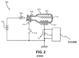
Takedaシステムは、図2に示すように、容器を充電するためにDC高電圧を使用する。容器105は、流体製品を内部に含み、アノードロッド109、補助電極ロッド111、およびカソードプレート107の間に配置される。アノードロッド109は直流高電圧源115の正側に接続されている。カソードプレート107および補助ロッド111は、図2に示すように、測定抵抗117およびスイッチ119をそれぞれ介して直流高電圧源115の負側に接続されている。
The Takeda system uses a DC high voltage to charge the container, as shown in FIG. The
スイッチ119がオフになると、補助電極111は直流高電圧源115の負側に接続されず、充電も放電も行われない。しかしながら、スイッチ119をオンにすると、補助電極111が直流高電圧源115の負側に接続され、同時に補助電極111とアノードロッド109との間で火花放電が発生し、これが、同時に、アンプル105のネック部分の電荷を放電させる。他方、弁別回路121は、抵抗117の両端に発生する電位を検出するために、抵抗117の両端で使用される。
When the
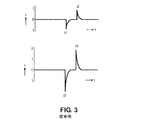
補助電極ロッド111からカソードプレート107には中和電流i1が流れ、弁別回路121で検出される。中和電流i1は、通常、補助電極111の放電開始直後に最大値に達し、上述したような状態では、アンプルが所定の量の流体を含んだ良好なサンプル(ピンホール等の欠陥がない)である場合には、図3に示すように、流れる中和電流(i1)が1単位のピーク値を得る。
Neutralization current i 1 flows in the
他方、アンプルに2ミクロン以上のピンホールなどの欠陥がある場合には、図3に示すように、中和電流i3が約2単位以上流され、ここで、i1は欠陥のない容器の中和電流であり、i3は欠陥のある容器の中和電流である。図4は、図2に示すTakedaのDC HVLDシステムの等価回路を示す。 On the other hand, when the ampoule has a defect such as a pinhole of 2 microns or more, as shown in FIG. 3, a neutralization current i 3 is passed by about 2 units or more, where i 1 is a container having no defect. a neutralizing current, i 3 is the neutralization currents container defective. FIG. 4 shows the equivalent circuit of Takeda's DC HVLD system shown in FIG.
DC HVLDの方法およびシステムの主要な欠点は、試験の連続性および一貫性の欠如である。Takedaでは、DC HVLDシステムは、離散的に生成され、サンプリングされる不連続な信号であるため、不連続テストである。試験された各パッケージは、1回の測定のために弁別回路を通して放電される前に充電されなければならない。パッケージの充放電は次々に行われる。これにより、低速で不連続な性質のため、生産ラインでのオンライン検査にDC HVLDシステムを使用することはほとんど不可能である。 A major drawback of DC HVLD methods and systems is the lack of test continuity and consistency. In Takeda, the DC HVLD system is a discontinuous test because it is a discretely generated and sampled discontinuous signal. Each package tested must be charged before being discharged through the discrimination circuit for a single measurement. The package is charged and discharged one after another. This makes it almost impossible to use the DC HVLD system for online inspection on the production line due to its slow and discontinuous nature.
DC HVLDシステムのもう一つの欠点は、充放電が必要なため、試験中に印加される信号が不連続な性質をともなうことである。TakedaのDC HVLDシステムで使用される高電圧放電は、非常に確率的である可能性がある。検出された信号は離散波形であるため、DC HVLDの信号には特定の周波数、位相、または振幅がない。その振幅は、発生する充放電の量に依存して強く変化し、電極と欠陥との間の距離に基づいて変化してしまう。 Another drawback of the DC HVLD system is that the signal applied during the test is discontinuous due to the need for charging and discharging. The high voltage discharge used in Takeda's DC HVLD system can be very stochastic. Since the detected signal is a discrete waveform, the DC HVLD signal does not have a specific frequency, phase, or amplitude. Its amplitude changes strongly depending on the amount of charge and discharge generated, and changes based on the distance between the electrode and the defect.
さらに、DC HVLD法は、アノードロッドが容器の頂部に固定される必要がある。この技術は、アンプルの検査にのみにしか使用できない。アルミニウムキャップを備えたバイアルまたは金属針付きシリンジのような容器は、金属が、ガラスまたはプラスチックと比較して導電性が高く、偽陽性の結果につながるため、DC HVLDによって検査することができない。DC HVLDは、また、カソードプレートがパッケージと接触することを必要とする。試験中のパッケージとの接触は、剛性電極を用いたオンライン試験では望ましくない。そのような接触はオンライン試験の破壊的方法であると考えられるから In addition, the DC HVLD method requires the anode rod to be secured to the top of the vessel. This technique can only be used to inspect ampoules. Containers such as vials with aluminum caps or syringes with metal needles cannot be tested by DC HVLD because the metal is more conductive than glass or plastic and leads to false positive results. DC HVLD also requires the cathode plate to be in contact with the package. Contact with the package during the test is not desirable in online tests with rigid electrodes. Because such contact is considered a destructive method of online testing
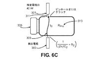
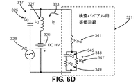
この発明は、慣用型のHVLDの高電圧、望ましくないレベルの電圧への傷つきやすい製品の露出、好ましくないレベルのオゾン生成、および誤ったリーク検出、並びに、DC HVLDの構造的柔軟性、オンライン検査限界、および変動性を、DCオフセット付きでAC電圧をリーク検出用に印加することにより解決するものであり、これは図6A〜図6Dの簡略化された電気等価回路を用いて説明でき、これらの図において、AC電流は回路内のすべての要素を通じて流れることができ、他方、DC電流はコンデンサがない経路を通じてのみ流れることができる。しかしながら、電気等価回路は単純化モデルに基づいており、より複雑なモデルを作成できることに注意することが重要である。交流−直流高電圧(ADHV)技術は、検出電極と検査電極との間に検査対象容器を配置することを含む。高電圧発生回路は、高電圧発生のために使用され、高電圧発生回路は、パルス自動変換器、高電圧整流器、および高電圧制御ボードを含む。さらに、容器は、検査電極と検出電極との間に配置される。 The present invention presents the high voltage of conventional HVLDs, exposure of vulnerable products to undesired levels of voltage, undesired levels of ozone generation, and false leak detection, as well as the structural flexibility of DC HVLDs, online inspection. Limitations and variability are solved by applying an AC voltage for leak detection with a DC offset, which can be explained using the simplified electrical equivalent circuits of FIGS. 6A-6D. In the figure, AC current can flow through all the elements in the circuit, while DC current can only flow through the path without a capacitor. However, it is important to note that the electrical equivalent circuit is based on a simplified model and can create more complex models. Alternating current-direct current high voltage (ADHV) technology involves placing a container to be inspected between a detection electrode and an inspection electrode. High voltage generators are used for high voltage generators, and high voltage generators include automatic pulse converters, high voltage rectifiers, and high voltage control boards. Further, the container is arranged between the inspection electrode and the detection electrode.
DCで電圧オフセットを伴う高電圧のAC電圧が、つぎに、高電圧発生回路を介して生成され、もって、電流が検査電極を介して容器に加えられ、容器を通る電流が検出電極によって検出され、検出ボードによって処理される。コンテナを通る電流は、電気等価回路に基づいて説明することができる。 A high voltage AC voltage with a voltage offset at DC is then generated via a high voltage generator circuit, so that current is applied to the container through the inspection electrode and the current through the container is detected by the detection electrode. , Processed by the detection board. The current through the container can be explained based on the electrical equivalent circuit.
次に、容器を通る、検出電極における電流が処理され、容器内のリークが、電流の変化に基づいて識別され、これは式ΔI=ID−IWDであり、ここで、
ADHVリーク検出のための装置の好ましい実施例は:高電圧整流器に電気的に接続された検査電極と;パルス自動変換器に電気的に接続された第1のDC電圧電源であって、上記パルス自動変換器はされに高電圧制御ボードおよび高電圧整流器に電気的に接続された、上記第1のDC電圧電源と;上記高電圧制御ボード、検出ボード、プログラマブルロジックコントローラ、およびディスプレイに電気的に接続されてこれらに電力を供給する第2の直流電圧電源と;検出ボードに電気的に接続された検出電極であって、上記検出ボードはさらに上記プログラマブルロジックコントローラに電気的に接続され、上記プログラマブルロジックコントローラはさらに上記ディスプレイに電気的に接続される、上記検出電極とを有し;上記検出電極および上記検査電極の間にパッケージがフィットするように上記検出電極および上記検査電極が配置され、DC高電圧オフセットを有するAV高電圧が上記検査電極を通じて印加される。 Preferred embodiments of the device for ADHV leak detection are: an inspection electrode electrically connected to a high voltage rectifier; a first DC voltage power source electrically connected to a pulse automatic converter, said pulse. The automatic converter is electrically connected to the high voltage control board and the high voltage rectifier, with the first DC voltage power supply; electrically to the high voltage control board, the detection board, the programmable logic controller, and the display. With a second DC voltage power supply that is connected to power them; a detection electrode that is electrically connected to the detection board, which is further electrically connected to the programmable logic controller and is programmable. The logic controller further has the detection electrode, which is electrically connected to the display; the detection electrode and the inspection electrode are arranged so that the package fits between the detection electrode and the inspection electrode, and the DC. AV high voltage with high voltage offset is applied through the inspection electrode.
ADHVリーク検出のための方法の好ましい実施例は:高電圧を発生させる高電圧発生回路を通じて接続された検出電極および検査電極の間に容器を配置するステップであって、上記高電圧発生回路は、パルス自動変換委、DC電圧電源、高電圧整流器および高電圧制御ボードを含む、上記配置するステップと;製品および上記検出電極の間、並びに上記検査電極および製品の間に容量性インピーダンスを生成するステップと;高電圧を上記高電圧発生回路を通じて生成し、もって、電流および電圧が上記検査電極を通じて上記容器に印加され、上記容器を通じて流れる電流が上記検出電極によって検出され、上記検出回路によって処理されるステップと;上記容器を通じて上記検出電極において流れる電流の変化を処理するステップと;上記電流の変化を通じて上記容器におけるリークを識別するステップとを含む。 A preferred embodiment of the method for ADHV leak detection is: a step of arranging a container between a detection electrode and an inspection electrode connected through a high voltage generating circuit that generates a high voltage. With the above-mentioned placement steps including the pulse automatic conversion committee, DC voltage power supply, high-voltage rectifier and high-voltage control board; the step of generating capacitive impedance between the product and the detection electrode, and between the inspection electrode and the product. And; a high voltage is generated through the high voltage generation circuit, so that current and voltage are applied to the container through the inspection electrode, and the current flowing through the container is detected by the detection electrode and processed by the detection circuit. It includes a step of processing a change in the current flowing through the container through the detection electrode and a step of identifying a leak in the container through the change in the current.
この開示内容の構造的、機能的、および有益な側面は、以下の詳細な説明および図面を参照することによってさらに理解できる。 The structural, functional, and beneficial aspects of this disclosure can be further understood by reference to the detailed description and drawings below.
実施例、先行技術、および実例は、図面を参照して、単なる一例として記載される。
この開示内容の様々な実施例および側面は、以下に説明する詳細を参照して説明される。以下の説明および参照された図面は、この開示内容の例示であり、この開示内容を限定するものとして解釈されるべきではない。図面は必ずしも縮尺通りではない。多数の具体的な詳細は、この開示内容の様々な実施例の完全な理解を提供するために記載される。しかしながら、ある場合には、この開示内容の実施例の簡潔な議論を提供するために、周知または従来の詳細は記載されていない。 Various examples and aspects of this disclosure will be described with reference to the details described below. The following description and referenced drawings are exemplary of this disclosure and should not be construed as limiting this disclosure. The drawings are not always on scale. A number of specific details are provided to provide a complete understanding of the various embodiments of this disclosure. However, in some cases, no well-known or conventional details are given to provide a brief discussion of the examples of this disclosure.
ここで使用されるように、用語「ADHV」は、DC高電圧オフセットを伴うAC高電圧の使用に関する交流−直流高電圧の略語である。 As used herein, the term "ADHV" is an abbreviation for AC-DC high voltage with respect to the use of AC high voltage with DC high voltage offset.
ここで使用されるように、用語「電気的に接続される」は、電気信号または電流が物体間で伝送されるように、電気回路内の1つまたは複数の物体または要素を接続する任意の既知の方法を指す。一般に、電気回路内の1つまたは複数のオブジェクトを電気的に接続するために、ワイヤ、ケーブル、ラインなどの製品が使用される。 As used herein, the term "electrically connected" is any connection of one or more objects or elements in an electrical circuit such that an electrical signal or current is transmitted between the objects. Refers to a known method. Generally, products such as wires, cables, and lines are used to electrically connect one or more objects in an electrical circuit.
パッケージングにおけるリークを検出する方法300の好ましい実施例は、回路内にDC高電圧オフセットを有するAC高電圧を生成することを含む。パッケージ305は、回路内に位置する検査電極301と検出電極303との間に配置される。検査電極301は、DC高電圧オフセット329を有するAC高電圧323をパッケージ305に印加する。その後、パッケージを流れる電流は、検出電極によって検出される。次いで、検出ボードは、リーク311がパッケージ内に存在するかどうかを判定するために、電流フローを処理する。リークが存在する場合、信号をディスプレイに送信してユーザに通知する。
A preferred embodiment of
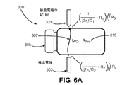
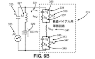
ADHVを使用してリークを検出する方法を示すために、複数の図が提供される。図6Aは、ADHV法を用いて試験される、欠陥がないパッケージ305を示す。図6Bは、図6Aの試験の等価電気回路表現319を示す。図6Cは、ADHV法を用いて試験される欠陥があるパッケージ305を示す。図6Dは、図6Cの試験の等価電気回路表現321を示す。図6A〜図6Dにおいて、C1はパッケージの第1壁の固有容量、R1はパッケージの第1の壁の固有抵抗、C2はパッケージの第2の壁の固有容量、R2はパッケージの第2の壁の固有抵抗、RProはコンテナ内の液体材料の固有高オーム抵抗を表し、fはAC高電圧の周波数を表し、L0は、AC電流を遮断するための簡略化等価回路の理想インダクタを表し、C0はDC電流を遮断するための簡略化等価回路の理想キャパシタを表し、IWDは欠陥のない容器を通る電流307を表し、IDは欠陥のある容器を通る電流309を表す。C1、R1、C2、R2、R3、R4、RProは可変であり、印加されるAC高電圧の振幅、印加されるDC高電圧オフセットのレベル、容器および液体製品の絶縁耐力のような材料特性、液体製品の導電率に依存して変化する。
Several figures are provided to show how to detect leaks using ADHV. FIG. 6A shows a defect-
回路にACおよびDCの両方の電圧を印加すると、パッケージに欠陥がある場合、パッケージ内の材料はDC高電圧にさらされる。典型的には、パッケージは、印加されたDC高電圧を強く減衰させる絶縁体からなる。 When both AC and DC voltages are applied to the circuit, the material in the package is exposed to high DC voltage if the package is defective. Typically, the package consists of an insulator that strongly attenuates the applied DC high voltage.
ADHV法は、AC電圧およびDC電圧の両方を印加するため、AC電流およびDC電流の両方が検査パッケージに流れる。図6Bの単純化された電気回路では、AC電流が回路内のすべての構成要素を通って流れることができ、一方、DC電流は、キャパシタなしの経路を通ってしか流れることができない。図6Bは、欠陥のないパッケージの試験を示し、図6Bの電流の全電流IWDは、以下の式を用いてAC電流およびDC電流の和として求めることができる。
AC電流およびDC電流の両方は不良パッケージにも流れる。図6Dの単純化された電気回路では、AC電流は回路内のすべての構成要素を通って流れることができ、DC電流はキャパシタなしの経路を通ってしか流れることができない。欠陥パッケージの試験を示す図6Dの電流の総電流IDは、以下の式を用いてAC電流およびDC電流の和として求めることができる。
パッケージにリークが存在すると、コンデンサC1が電気回路から欠落し、R1とR3の値がゼロになる。したがって、欠陥のあるパッケージを通る電流は、欠陥のないパッケージを流れる電流よりも大きい。欠陥のあるパッケージを通る電流と欠陥のないパッケージを通る電流との間の差異は、次の式を使用してリークの検出を可能にする。
DC高電圧オフセットを伴うAC高電圧は、パルス自動変換器またはパルス変換器のいずれか、高電圧制御ボード、高電圧整流器、およびDC電圧電源を使用して生成される。 AC high voltage with DC high voltage offset is generated using either an automatic pulse converter or a pulse converter, a high voltage control board, a high voltage rectifier, and a DC voltage power supply.
検査電極は、ブラシ、ロッド、スチール、または類似の形状の物体の形態で、剛性、半剛性、または可撓性であってもよい。さらに、検査電極は、金属、導電性ポリマー、または他の種類の導電性材料で作ることができる。DC高電圧オフセットを伴うAC高電圧の印加中に、検査電極がパッケージに接触するか、またはパッケージと検査電極との間に小さな空隙が存在する可能性がある。 The test electrode may be rigid, semi-rigid, or flexible in the form of a brush, rod, steel, or object of similar shape. In addition, the test electrodes can be made of metal, conductive polymers, or other types of conductive materials. During the application of AC high voltage with DC high voltage offset, the test electrode may come into contact with the package or there may be a small void between the package and the test electrode.
検出電極は、ブラシ、ロッド、スチール、または同様の形状の物体の形態の剛性、半剛性、または可撓性であってもよい。さらに、検出電極は、金属、金属合金、導電性ポリマー、または他の種類の導電性材料で作ることができる。DC高電圧オフセットを伴うAC高電圧で生成された電流の検出中に、検出電極がパッケージに接触するか、またはパッケージと検出電極との間に小さな空隙が存在する可能性がある。 The detection electrodes may be rigid, semi-rigid, or flexible in the form of brushes, rods, steel, or objects of similar shape. In addition, the detection electrodes can be made of metal, metal alloys, conductive polymers, or other types of conductive materials. During the detection of a current generated at AC high voltage with a DC high voltage offset, the detection electrode may come into contact with the package or there may be a small gap between the package and the detection electrode.
パッケージは、バイアル、シリンジ、アンプル、ポーチ、バッグ、ブローシール、および他の種類の容器の形態であっても良く、これは、プラスチック、ガラス、アルミニウムホイル、または他の適切な種類の材料で作られて良く、これは、医薬品、食品、または同様の生鮮食品または傷つきやすい製品で満たされるのに最適である。 The package may be in the form of vials, syringes, ampoules, pouches, bags, blow seals, and other types of containers, which are made of plastic, glass, aluminum foil, or other suitable type of material. It is best to be filled with medicines, foods, or similar perishables or perishable products.
パッケージングにおけるリークを検出する方法の別の実施例では、DC高電圧オフセットを有するAC高電圧が回路内に生成される。パッケージは、回路内に位置する検査電極と検出電極との間に配置される。パッケージは、検査電極と検出電極との間で単一の軸に沿って回転される。さらに、検査電極および検出電極は、パッケージが回転するにつれてパッケージの長さに沿って移動する。検査電極は、パッケージにDC高電圧オフセットを加えたAC高電圧を印加する。パッケージを流れる電流は、検出電極によって検出される。次いで、検出ボードは、電流フローを処理して、好ましい実施例と同じ式を使用してパッケージ内にリークが存在するかどうかを判定する。リークが存在する場合、ユーザが視覚化するための信号がディスプレイに送られる。 In another embodiment of the method of detecting leaks in packaging, an AC high voltage with a DC high voltage offset is generated in the circuit. The package is placed between the inspection electrode and the detection electrode located in the circuit. The package is rotated along a single axis between the test electrode and the detection electrode. In addition, the test and detection electrodes move along the length of the package as the package rotates. The inspection electrode applies an AC high voltage with a DC high voltage offset added to the package. The current flowing through the package is detected by the detection electrodes. The detection board then processes the current flow to determine if there is a leak in the package using the same formula as in the preferred embodiment. If a leak is present, a signal is sent to the display for user visualization.
DC高電圧オフセットを伴うAC高電圧は、パルス自動変換器またはパルス変換器のいずれか、高電圧制御ボード、および高電圧整流器を使用して生成される。 AC high voltage with DC high voltage offset is generated using either an automatic pulse converter or a pulse converter, a high voltage control board, and a high voltage rectifier.
検査電極は、ブラシ、ロッド、スチール、または類似の形状の物体の形態で、剛性、半剛性、または可撓性であってもよい。さらに、検査電極は、金属、導電性ポリマー、または他の種類の導電性材料で作ることができる。DC高電圧オフセットを伴うAC高電圧の印加中に、検査電極がパッケージに接触するか、またはパッケージと検査電極との間に小さな空隙が存在する可能性がある。 The test electrode may be rigid, semi-rigid, or flexible in the form of a brush, rod, steel, or object of similar shape. In addition, the test electrodes can be made of metal, conductive polymers, or other types of conductive materials. During the application of AC high voltage with DC high voltage offset, the test electrode may come into contact with the package or there may be a small void between the package and the test electrode.
検出電極は、ブラシ、ロッド、スチール、または同様の形状の物体の形態の剛性、半剛性、または可撓性であってもよい。さらに、検出電極は、金属、金属合金、導電性ポリマー、または他の種類の導電性材料で作ることができる。DC高電圧オフセットを伴うAC高電圧で生成された電流の検出中に、検出電極がパッケージに接触するか、またはパッケージと検出電極との間に小さな空隙が存在する可能性がある。 The detection electrodes may be rigid, semi-rigid, or flexible in the form of brushes, rods, steel, or objects of similar shape. In addition, the detection electrodes can be made of metal, metal alloys, conductive polymers, or other types of conductive materials. During the detection of a current generated at AC high voltage with a DC high voltage offset, the detection electrode may come into contact with the package or there may be a small gap between the package and the detection electrode.
パッケージは、バイアル、シリンジ、アンプル、パウチ、および、任意の他の種類の容器の形態であって良く、これはプラスチック、ガラス、アルミニウム箔、または任意の他の種類の材料で製造されて良く、これに、薬品、食品、または他の類似の製品で満たされて好適である。 The package may be in the form of vials, syringes, ampoules, pouches, and any other type of container, which may be made of plastic, glass, aluminum foil, or any other type of material. It is suitable to be filled with chemicals, foods, or other similar products.
この方法のさらなる実施例は、回路内にDC高電圧オフセットを有するAC高電圧を生成することを含む。パッケージがコンベア上に置かれる。コンベアは、回路内に位置する検査電極と検出電極との間でパッケージを移動させる。検査電極は、パッケージにDC高電圧オフセットを加えたAC高電圧を印加する。パッケージを流れる電流は、検出電極によって検出される。次いで、検出ボードは、電流フローを処理して、好ましい実施例と同じ式を使用してパッケージ内にリークが存在するかどうかを判定する。リークが存在する場合、ユーザが視覚化するための信号がディスプレイに送られる。 Further embodiments of this method include generating an AC high voltage with a DC high voltage offset in the circuit. The package is placed on the conveyor. The conveyor moves the package between the inspection and detection electrodes located in the circuit. The inspection electrode applies an AC high voltage with a DC high voltage offset added to the package. The current flowing through the package is detected by the detection electrodes. The detection board then processes the current flow to determine if there is a leak in the package using the same formula as in the preferred embodiment. If a leak is present, a signal is sent to the display for user visualization.
DC高電圧オフセットを伴うAC高電圧は、パルス自動変換器またはパルス変換器のいずれか、高電圧整流器およびDC電圧電源を使用して生成される。 AC high voltage with DC high voltage offset is generated using either an automatic pulse converter or a pulse converter, a high voltage rectifier and a DC voltage power supply.
検査電極は、ブラシ、ロッド、スチール、または類似の形状の物体の形態で、剛性、半剛性、または可撓性であってもよい。さらに、検査電極は、金属、導電性ポリマー、または他の種類の導電性材料で作ることができる。DC高電圧オフセットを伴うAC高電圧の印加中に、検査電極がパッケージに接触するか、またはパッケージと検査電極との間に小さな空隙が存在する可能性がある。 The test electrode may be rigid, semi-rigid, or flexible in the form of a brush, rod, steel, or object of similar shape. In addition, the test electrodes can be made of metal, conductive polymers, or other types of conductive materials. During the application of AC high voltage with DC high voltage offset, the test electrode may come into contact with the package or there may be a small void between the package and the test electrode.
検出電極は、ブラシ、ロッド、スチール、または同様の形状の物体の形態の剛性、半剛性、または可撓性であってもよい。さらに、検出電極は、金属、金属合金、導電性ポリマー、または他の種類の導電性材料で作ることができる。DC高電圧オフセットを伴うAC高電圧で生成された電流の検出中に、検出電極がパッケージに接触するか、またはパッケージと検出電極との間に小さな空隙が存在する可能性がある。 The detection electrodes may be rigid, semi-rigid, or flexible in the form of brushes, rods, steel, or objects of similar shape. In addition, the detection electrodes can be made of metal, metal alloys, conductive polymers, or other types of conductive materials. During the detection of a current generated at AC high voltage with a DC high voltage offset, the detection electrode may come into contact with the package or there may be a small gap between the package and the detection electrode.
パッケージは、バイアル、シリンジ、アンプル、ポーチ、バッグ、ブローシール、および他の任意の容器であって良く、これはプラスチック、ガラス、アルミニウムホイル、または他の適切な種類の材料で作られて良く、医薬品、食品、または同様の生鮮食品または傷つきやすい製品で満たされていて良い。 The package may be a vial, syringe, ampoule, pouch, bag, blow seal, and any other container, which may be made of plastic, glass, aluminum foil, or any other suitable type of material. It may be filled with medicines, foods, or similar fresh foods or perishable products.
ADHV検査方法を適用するための装置の多くの実施例が存在する。そのような実施例は、検査されるパッケージのタイプや、パッケージが一度に1つずつテストされるかどうか(オフラインテストとしても知られる)、または複数のパッケージがユーザ操作なしで連続的にテストされるか(ラインテストとしても知られている)に応じて変化する。 There are many examples of devices for applying ADHV testing methods. Such examples include the type of package being inspected, whether the packages are tested one at a time (also known as offline testing), or multiple packages are tested continuously without user interaction. It changes depending on whether it is (also known as a line test).
図5に示すように、リーク検出回路200の好ましい実施例は、高電圧ケーブル203によって高電圧整流器205に接続された検査電極201を含み、この高電圧整流器205はパルス自動変換器208にさらに電気的に接続され、第1のDC電圧電源209がパルス自動変換器208に電気的に接続され、パルス自動変換器208は高電圧制御ボード211に電気的に接続され、高電圧制御ボード211はプログラマブルロジックコントローラ217に電気的に接続され、検出電極227はシールドケーブル225を介して検出ボード219に電気的に接続され、検出ボード219はプログラマブルコントローラに電気的に接続され、ディスプレイ215はプログラマブルロジックコントローラに電気的に接続され、第2のDC電源213は高電圧制御ボード211、検出ボード219、プログラマブルロジックコントローラ217、およびディスプレイ215に電気的に接続され、ここで、検査電極201および検査電極201は、パッケージがこれら検査電極201および検査電極201の間にフィットするように配置され、一旦、このパッケージが検査電極201および検出電極の間に配置されると、DC高電圧オフセットを伴うAC高電圧がこのパッケージに印加される。DC高電圧オフセットを伴うAC高電圧は、DC電圧電源213、高電圧整流器205、および高電圧制御器を伴うパルス自動変換器208以外の当技術分野で知られている手段によって生成されて良く、これに限定されないが、DC電圧電源213、高電圧整流器205、および高電圧制御器を伴うパルス自動変換器208によって生成されて良い。そのような場合、検査電極201は、高電圧整流器205に電気的に接続され、この高電圧整流器205はパルス変換器208に電気的に接続される。
As shown in FIG. 5, a preferred embodiment of the
DC電源209、高電圧制御ボード211、および、高電圧パルス自動変換器208の組み合わせ、または、DC電源209、高電圧制御ボード211、パルス変換器208の組み合わせのいずれかがAC高電圧を発生する。
Either the combination of the
高電圧制御ボード211は、これに限定されるものではないが、マイクロプロセッサとMOSFETまたはIGBTとの組み合わせであって良い。マイクロプロセッサは、所定のデュレーションおよびデューティサイクルのパルスを生成することによりMOSFETまたはIGBTをオンおよびオフにし、これは、高電圧パルス自動変換器208または高電圧パルス変換器208を通じてDC電源209から流れる電流の流れをオンおよびオフする。高電圧パルス自動変換器208または高電圧パルス変換器208を通る電流がオンおよびオフに切り替えられるので、AC高電圧が、高電圧パルス自動変換器208または高電圧パルス変換器208の出力端に形成される。高電圧制御ボード211は、生成されたAC高電圧の振幅を、パルスのデュレーションおよびデューティサイクルを変更することによって調整する。
The high
高電圧整流器205は、AC高電圧を整流し、AC高電圧にDCオフセットを付与する。DCオフセットを伴うAC高電圧は、高電圧ケーブル203および検査電極201を介してパッケージに印加される。
The
DC高電圧オフセットを伴うAC高電圧が検査電極201を介してパッケージ202に、一旦、印加されると、検出電極227は結果としてパッケージ202を流れる電流を受け取る。電流は電流検出ボード219に進み、電流が処理されてリークが存在するか否かを決定される。
Once an AC high voltage with a DC high voltage offset is applied to the
検出ボード219はプログラマブルロジックコントローラ217に電気的に接続されている。検出ボード219は受信信号を処理し、処理された信号をプログラマブルロジックコントローラ217に送り、ディスプレイはリークがあるかどうかを示す。プログラマブルロジックコントローラ217は、電流検出ボード219に電気的に接続されており、もって、プログラマブルロジックコントローラ217は、所望の方法で検出ボード219と相互作用するようにプログラムすることができる。プログラマブルロジックコントローラ217は、高電圧制御ボード211に電気的に接続されており、もってプログラマブルロジックコントローラ217は、所望の方法で高電圧制御ボード211と相互作用するようにプログラムすることができる。ディスプレイ215は、プログラマブルロジックコントローラ217に電気的に接続され、オーディオおよびビジュアル情報を含むプログラマブルロジックコントローラに格納された情報をユーザに提供する。第2の直流電圧電源は、高電圧制御ボード211、検出ボード219、プログラマブルロジックコントローラ217、ディスプレイ215に接続され、これらに電力を供給するようになっている。
The
DC高電圧オフセットを伴うAC高電圧は、DC電圧電源209、高電圧制御ボード211、および高電圧整流器205を伴うパルス自動変換器207以外の当技術分野で知られている手段によって生成されてもよく、例えば、これに限定されないが、DC電圧電源209、高電圧制御ボード211、高電圧整流器205を伴うパルス変換器208によって生成されて良い。そのような場合、検査電極201は、高電圧整流器205に電気的に接続され、これは、パルス自動変換器207またはパルス変換器208に電気的に接続されている。
AC high voltage with DC high voltage offset may be generated by means known in the art other than DC
パッケージ202は、バイアル、シリンジ、アンプル、または他の類似のポーチ、ボトル、容器、または密閉されたホルダであって良い。さらに、パッケージ202は、プラスチック、ガラス、または、容量性および抵抗性の特性を示す別の材料で作ることができる。パッケージは、典型的には製品で満たされ、これは、制約的ではないが、食品、医薬品、生物学的製剤、または他の同様の製品を含む。試験中にパッケージ202を固定するためにホルダを使用することができる。ホルダは、これに限定されないが、トレイ、固定機構を備えたロッド、ベルト、または他の同様の装置を含んで良い。さらに、ホルダは、ホルダおよびパッケージを検査電極および検出電極の間で回転させる回転機構に取り付けて良い。
検査電極201および検出電極227の両方は、その用途に応じて異なる形状にすることができ、異なる材料で作ることができる。検査電極201および検出電極227は、金属、金属合金、導電性ポリマー、磁性材料、または他の種類の導電性材料で作ることができる。検査電極201および検出電極227は、剛性、半剛性、または可撓性であってもよく、ブラシ、ロッド、くしまたは類似の形状の物体の形態であってもよい。DC高電圧オフセットを伴うAC高電圧で生成された電流の印加および検出中に、検査電極201および検出電極227の両方がパッケージ202に接触することができる。逆に、パッケージ202と検査電極201と検出電極227との間に小さな空隙204を設けることができる。小さい空隙204は、検査電極201とパッケージとの間、及び検出電極227とパッケージ202との間にあってもよい。検査電極201と検出電極227は、検査中に互いに接触すべきではなく、アーク放電を防止するのに十分離れて配置されるべきである。
Both the
検査電極201および検出電極227は、パッケージに対して移動可能であっても良い。検査電極および検出電極の一方または双方にスライド機構を取り付けることができる。スライド機構は、パッケージの長さに沿って、パッケージの方に、またはパッケージから離れる方向に移動することができる。この動きは、検査電極と検出電極との間のパッケージの設置および取り外し中に電極を離れるように動かすことを可能にする。スライド機構によってもたらされる動きにより、検査電極および検出電極は、試験中に傾斜、曲線または不規則な形状を有するパッケージとの接触を維持するか、またはパッケージからの距離を均一に維持することができる。
The
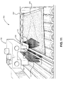
オンライン検査のためにリーク検出回路200と共にコンベアを使用することもできる。検査電極201と検出電極227との間でパッケージを移動させるコンベア上に1つ以上のパッケージが配置される。検査されるパッケージのタイプに応じて、検査電極201および検出電極227は、試験中、パッケージ202と接触するように構成されて良く、あるいは、電極201および227と227とパッケージ202との間に空隙を設けるように間隔を空けて配置するように構成されて良い。コンベアは、検査電極201を、DC高電圧オフセットを伴うAC高電圧をパッケージ202の一方の表面に印加するような態様で位置付けるのを可能にし、検出電極227を、パッケージ202の反対側の表面に得られる電流を受け取るように位置付けることを可能にするように構成される。図11は、コンベアと連結されたリーク検出回路200の1つの実現可能な実施例の例を提供する。図11において、コンベアは、一連のローラであり、検出電極が2つのローラの間に配置され、検査電極がコンベアの上にぶら下がっている。もう1つの実現可能な構成は、2つのベルトを備えたコンベアシステムである。電極201および227は、2つのコンベアベルトの間に互いに所定の距離をおいて配置され、電極間の直接的なスパークを防止する。リーク検出システム200を備えたコンベアの使用は、検討した好ましい実施例の要素の構造的多様性を限定するものではない。
A conveyor can also be used with the
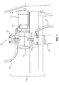
図7は、具体的に試験インターフェース402において、リーク検出システム400の別の実施例を示し、ここで、パッケージ409は、検査電極401と検出電極403との間に固定される。ホルダ411は、この実施例では倍あるとして示される、パッケージ409を、試験中に水平に固定する。回転機構413は、試験中にホルダ411およびパッケージ409を同軸に回転させる。この実施例では、検査電極401および検出電極403は、検査中にパッケージ409の傷またはマーキングを防止するために、パッケージ409に接触しない。
FIG. 7 specifically shows another embodiment of the
検査用スライド機構417は検査電極401に取り付けられている。検査用スライド機構417は検査中に検査電極401をパッケージ409の長さに沿って前後に水平に移動させる。検出用スライド機構415は、検出電極403に取り付けられている。検出用スライド機構415は、検査中に検出電極403をパッケージ409の長さに沿って前後に水平移動させる。
The
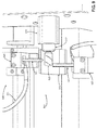
図8は、リーク検出システム400の同一の実施例を示す。ただし、図8は、検査電極401および検出電極403が検査用スライド機構417および検出用スライド機構415にそれぞれ取り付けられたときに実現可能な、検査電極401および検出電極403の位置付けの実例を説明する。図7は、検査電極401および検出電極403が中央に位置付けられているのを示し、図8は、電極401および403のズレを示し、こえは、スライド機構415および417によって電極401および403を、試験中、パッケージ409の長さ方向に沿って前後にスライドさせることができることを示す。
FIG. 8 shows the same embodiment of the
高電圧ケーブル405は、図7に示される実施例の検査電極401をリーク検出回路200の残りの要素に接続し、これは好ましい実施例で説明され、図5において示される。同様に、シールドケーブル407は、リーク検出回路200の残りの要素に接続され、これ好ましい実施例で説明され、図5において示される。
The
図9は、リーク検出システム500の別の実施例を示し、具体的には、試験インターフェース502において、これを示し、ここで、パッケージ505が検査電極501および検出電極503の間に固定されている。ホルダ517は、この実施例では、パッケージ505、この実施例ではバイアルを、試験中に水平に固定する。回転機構519は、試験中にホルダ517およびパッケージ505を同軸に回転させる。トレイ515は、パッケージ505の下に配置される。この実施例でも、検査電極501および検出電極503は、検査中にパッケージ505の傷またはマーキングを防止するために、パッケージ505に接触しない。
FIG. 9 shows another embodiment of the
検査用スライド機構509は検査電極501に取り付けられている。検査用スライド機構509は検査中に検査電極501をパッケージ505の長さに沿って前後に水平移動させる。検出用スライド機構507は、検出電極503に取り付けられている。検出用スライド機構507は、試験中に検出電極503をパッケージ505の長さに沿って前後に水平に移動させる。電極501および503は、図9において、ズレており、これは、スライド機構507および509が、試験中に、パッケージ501の長さに沿って電極501および503を前後にスライドさせることができることを示す。残りの要素、それらの変形、および構造上の連携は、好ましい実施例で説明されるとおりである。
The
高電圧ケーブル511は、図9に示される実施例の検査電極501を、リーク検出回路200の残りの要素に接続し、これは、好ましい実施例において説明され、図5に示される。同様に、シールドケーブル513は、検出電極503を、リーク検出回路200の残りの要素に接続し、これは、好ましい実施例において説明され、図5に示される。残りの要素、それらの変形形態、および構造上の連携は、好ましい実施例で説明されるとおりである。
The
図10は、リーク検出システム600のさらに別の実施例を示し、特に、検査インターフェース602において、これを示し、ここで、検査電極601および検出電極603の間にパッケージ613が固定されている。ホルダ609は、パッケージ613を、試験中、水平に固定し、この実施例ではシリンジとして示す。回転機構611は、試験中にホルダ609およびパッケージ613を同軸に回転させる。トレイ615は、パッケージ613の下に配置される。検査電極601および検出電極603は、この実施例では、パッケージ613に接触しないので、検査中のパッケージ613の傷またはマーキングを防止する。
FIG. 10 shows yet another embodiment of the
検査用スライド機構605は検査電極601に取り付けられている。検査用スライド機構605は試験中に検査電極601をパッケージ613の長さに沿って前後に水平移動させる。検出用スライド機構607は、検出電極603に取り付けられている。検出用スライド機構607は、試験中に検出電極603をパッケージ613の長さに沿って前後に水平に移動させる。電極601および603は、図10と同様の相対位置にあるが、前の実施例で説明したようにパッケージ613の長さに沿って独立してスライドすることができる。
The
図10に示す実施例の検査電極601は、リーク検出回路200に関連する残りの要素に接続され、これは、好ましい実施例で説明され、図5に示される。同様に、検出電極603は、リーク検出回路200に関連する、残りの構成要素に接続され、これは、好ましい実施例で説明され、図5に示される。残りの要素、それらの変形形態、および構造上の連携は、好ましい実施例で説明するとおりである。
The
図11は、リーク検出システム700のコンベアの実施例を示し、特にこれを試験インターフェース702において示し、ここで、パッケージ709は1または複数の検査電極701と検出電極703との間で搬送される。コンベア707は、先行する実施例においてパッケージ709を固定するホルダと同一の機能を実現し、これは、この実施例において非堅固なIVバッグとして示され、これは検査電極701および検出電極703の間にある。好ましい実施例と同様に、図11に示すコンベアの実施例は、他の形状、寸法、材料、およびデザインのパッケージを試験するのに使用されて良く、これは、バイアル、アンプル、シリンジ、パウチ、および類似の容器を含むが、これに限定されない。さらに、好ましい実施例と同様に、検査電極701および検出電極703は、ブラシのみに限定される必要はなく、好ましい実施例で提供される変形を含んで良い。
FIG. 11 shows an example of a conveyor for the
この実施例では、検査電極701および検出電極703は、先の実施例に示すような、ロッドの代わりにブラシを用いる。検査電極701および検出電極703は、コンベア707がパッケージ709を2つの電極701と703との間を通過する際に、パッケージ709の対向する面でパッケージ709に接触する。電極701と703は、試験中、十分に離間されており、もって、アーク放電を防止する。
In this embodiment, the
電極用スライド機構705が検査電極701に取り付けられている。電極用スライド機構705は試験中に検査電極701をコンベア707の幅方向に往復移動させる。図11には示されていないが、同様の電極用スライド機構を検出電極703に取り付けることにより、試験中に検出電極をコンベア707の幅に沿って前後にスライドさせることができる。
An
図11に示す実施例の検査電極701は、リーク検出回路200に関連する残りの要素に接続され、これは好ましい実施例において説明され、図5において示される。同様に、検出電極703は、リーク検出回路200に関連する残りの要素に接続され、これは好ましい実施例において説明され、図5において示される。残りの要素、これらの変形、および構造上の連携は好ましい実施例において説明されるとおりである。
The
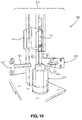
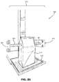
図20は、さらに別の実施例のリーク検出システム800を示し、とくに、これを検査インターフェース802において示し、ここで、パッケージ813が検査電極801および検出電極803の間に固定されている。トレイ815は、試験中、パッケージ813の下に配置され、パッケージを固定する。この実施形例でも、検査電極801および検出電極803は、試験中にパッケージ813に接触せず、パッケージ813の傷またはマーキングを防止する。
FIG. 20 shows a
検査用スライド機構805は検査電極801に取り付けられている。検査用スライド機構805は試験中に検査電極801をパッケージ813の長さに沿って前後に水平移動させる。検出用スライド機構807は、検出電極803に取り付けられている。検出用スライド機構807は、試験中に検出電極803をパッケージ813の長さに沿って前後に水平に移動させる。電極801および803は、図20と同様の相対位置にあるが、先行する実施例で説明したようにパッケージ813の長さに沿って独立してスライドすることができる。
The
この実施例800では、主に試験されるパッケージ813は、ガセットポーチ、または3重シールポイントを有するパッケージである。検査電極805は、パウチのガセットの下に配置され、その点は、パッケージの三重シール点にガセット側から接触する。
In this Example 800, the
図20に示す実施例の検査電極801は、リーク検出回路200に関連する残りの要素に接続され、これは、好ましい実施例において説明され図5に示されている。同様に、検出電極803は、リーク検出回路200に関連する残りの要素に接続され、これは、好ましい実施例において説明され図5に示されている。残りの要素、それらの変形例、および構造上の連携は、好ましい実施例において説明されるとおりである。パッケージは、薬品、食品、または他の製品で満たされ、トレイ815内に、直立状態になるように載置される。
[例]
[例1]
[慣用型HVLD露出]
The
[Example]
[Example 1]
[Conventional HVLD exposure]
どのようなHVLD技術においても、容器の周りでスパークを発生させることなく、容器内の液体および製品の絶縁を破壊することなく、欠陥に対して高い信号応答を生成するために可能な限り高い電圧に到達する必要があり、同時に、リーク検出の感度を高めるために容器を導電性にするひつようがある。 In any HVLD technology, the highest possible voltage to produce a high signal response to defects without causing sparks around the vessel and without breaking the insulation of the liquid and product in the vessel. At the same time, there is a need to make the container conductive to increase the sensitivity of leak detection.
慣用型のHVLD技術がリーク検出に使用される場合、印加された純粋なAC高電圧は、良好な容器の容量性インピーダンスを高い減衰なしに通り抜け、容器内の製品をAC高電圧に直接暴露することになる。この結果、良好な容器内の製品が高電圧に露出され、これは潜在的に有害であり好ましくなく、負の副作用をもたらす。 When conventional HVLD technology is used for leak detection, the applied pure AC high voltage passes through the capacitive impedance of a good vessel without high attenuation and exposes the product in the vessel directly to the AC high voltage. It will be. As a result, the product in a good container is exposed to high voltage, which is potentially harmful, undesirable and has negative side effects.
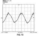
慣用型のHVLD試験中に容器内の製品がどれだけの電圧の露出を受けるかを決定するために、18.5kVPkのAC高電圧下に15mLのバイアルを入れ、容器内の電圧を測定した。バイアルには欠陥がなく、水道水で満たされていた。この測定には、1:1000の比のTektronix P6015A高電圧プローブとTektronix TDS2024オシロスコープを使用した。水道水の導電率は87.5μSであった。電圧測定プローブを、尖った検査電極の近くのバイアルの内壁に配置した。図15は、慣用型のHVLDシステムによる試験中のバイアル内部の水の測定電圧を示す。図14は、慣用型のHVLD(18.5kVPk)による試験中にバイアルの外壁に印加された測定電圧を示す。この測定には、1:1000の比のTektronix P6015A高電圧プローブとTektronix TDS2024オシロスコープを使用した。 To determine how much voltage the product in the container would be exposed to during the conventional HVLD test, a 15 mL vial was placed under AC high voltage of 18.5 kVPk and the voltage in the container was measured. The vial was flawless and filled with tap water. A 1: 1000 ratio Tektronix P6015A high voltage probe and a Tektronix TDS2024 oscilloscope were used for this measurement. The conductivity of tap water was 87.5 μS. A voltage measuring probe was placed on the inner wall of the vial near the pointed test electrode. FIG. 15 shows the measured voltage of water inside the vial under test with a conventional HVLD system. FIG. 14 shows the measured voltage applied to the outer wall of the vial during the test with the conventional HVLD (18.5 kVPk). A 1: 1000 ratio Tektronix P6015A high voltage probe and a Tektronix TDS2024 oscilloscope were used for this measurement.
図15に示すように、バイアル内部の水道水の測定電圧は約7kVPkであった。この実験結果は、慣用型のHVLDシステムで試験した場合、バイアル内部の高感度の薬品が直接高電圧に曝されていることを示す。バイアル内の製品に対するこの高電圧の影響は、熱感受性または他の要因によって変化する。
[例2]
[ADHV露出]
As shown in FIG. 15, the measured voltage of tap water inside the vial was about 7 kVPk. The results of this experiment show that the sensitive chemicals inside the vial are directly exposed to high voltage when tested in a conventional HVLD system. The effect of this high voltage on the product in the vial depends on heat sensitivity or other factors.
[Example 2]
[ADHV exposure]
慣用型のHVLD技術に対するADHV試験の主な利点の1つは、容器内の製品が高電圧に直接さらされないことである。シリンジ、バイアル、および他の容器は、ガラスまたはプラスチック製である。ガラスおよびプラスチックは電気絶縁体であり、これは、性質上容量性であり、本質的に、同じ大きさのAC高電圧よりもDC高電圧を完全に遮断または減衰する。容器内の製品は、DC高電圧オフセットから完全に絶縁されているか、比較的低いDC電圧にのみさらされている。製品は、容器のリークの存在の下、DC高電圧に晒されるだけである。 One of the main advantages of ADHV testing over conventional HVLD technology is that the product in the container is not directly exposed to high voltage. Syringes, vials, and other containers are made of glass or plastic. Glass and plastic are electrical insulators, which are capacitive in nature and essentially completely block or attenuate DC high voltages than AC high voltages of the same magnitude. The product in the container is either completely isolated from the DC high voltage offset or exposed only to a relatively low DC voltage. The product is only exposed to DC high voltage in the presence of container leaks.
ADHVによる試験中に容器内の製品が高電圧にさらされないことを証明するために、慣用型のHVLDシステム(水道水で満たされた15mLのバイアル)で例1で使用したのと同じサンプルを試験した。水道水の導電率は87.5μSであった。ADHVシステムに印加された電圧のピーク振幅は−18.5kVPkであった。 To prove that the product in the container is not exposed to high voltage during the test with ADHV, the same sample used in Example 1 was tested in a conventional HVLD system (15 mL vial filled with tap water). did. The conductivity of tap water was 87.5 μS. The peak amplitude of the voltage applied to the ADHV system was -18.5 kVPk.
実験用バイアルには欠陥がなかった。この測定には、1:1000の比のTektronix P6015A高電圧プローブとTektronix TDS2024オシロスコープを使用した。 The experimental vial was flawless. A 1: 1000 ratio Tektronix P6015A high voltage probe and a Tektronix TDS2024 oscilloscope were used for this measurement.
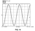
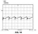
ADHVをバイアルの外壁に印加したときに測定されたADHV電圧を図18に示す。この図から、AC成分の振幅は約5kVPPであり、DC高電圧オフセットは約16kVであることがわかる。この測定には、1:1000の比のTektronix P6015A高電圧プローブとTektronix TDS2024オシロスコープを使用した。 The ADHV voltage measured when ADHV was applied to the outer wall of the vial is shown in FIG. From this figure, it can be seen that the amplitude of the AC component is about 5 kVPP and the DC high voltage offset is about 16 kV. A 1: 1000 ratio Tektronix P6015A high voltage probe and a Tektronix TDS2024 oscilloscope were used for this measurement.
図16に示すように、ADHVに基づくHVLD技術による試験中のバイアル内部の製品の測定電圧は約−300VPkであった。電圧測定プローブは、検査電極の近くのバイアルの内壁に配置した。この測定には、1:1000の比のTektronix P6015A電圧プローブとTektronix TDS2024オシロスコープを使用した。 As shown in FIG. 16, the measured voltage of the product inside the vial under test by the ADHV-based HVLD technique was about −300 VPk. The voltage measuring probe was placed on the inner wall of the vial near the test electrode. A 1: 1000 ratio Tektronix P6015A voltage probe and a Tektronix TDS2024 oscilloscope were used for this measurement.
試験結果は、欠陥が存在しない場合、製品(この場合は水道水)がADHV技術による試験中に高電圧にさらされないことを示している。高いDC電圧は、容器の容量性インピーダンスによって強く減衰した。この結果と比較して、慣用型のHVLDシステムにおけるバイアル内部の測定電圧は7kVPkであった。要約すると、ADHVに基づくHVLD技術は、医薬品およびバイオテクノロジー産業で使用される唯一のHVLD法であり、真に非破壊的である。
[例3]
[オゾン生成]
The test results show that in the absence of defects, the product (tap water in this case) is not exposed to high voltages during testing with ADHV technology. The high DC voltage was strongly attenuated by the capacitive impedance of the vessel. Compared with this result, the measured voltage inside the vial in the conventional HVLD system was 7 kVPk. In summary, ADHV-based HVLD technology is the only HVLD method used in the pharmaceutical and biotechnology industries and is truly non-destructive.
[Example 3]
[Ozone generation]
ADHVに基づくHVLD技術のもう1つの重要な利点は、慣用型のHVLD技術よりもずっと少ないオゾンしか生成しないことである。ADHV法によって生成されるオゾンの量は、慣用型のHVLD法によって生成されるオゾンの量に比べて無視できる程度である。ADHVに基づくHVLD技術と比較して、試験中に、慣用型のHVLDシステムがどれだけのオゾンを生成するかを決定する実験が行われた。0.001ppm分解能の校正済みAeroqual 200シリーズオゾン検出器を両方のシステムの試験室内に設置した。両方のシステムは密閉されていた。
Another important advantage of ADHV-based HVLD technology is that it produces much less ozone than conventional HVLD technology. The amount of ozone produced by the ADHV method is negligible compared to the amount of ozone produced by the conventional HVLD method. During the test, experiments were conducted to determine how much ozone the conventional HVLD system produced, compared to ADHV-based HVLD technology. A calibrated
慣用型のHVLDシステムにおける交流高電圧振幅は、18.5kVPkに設定された。交流高電圧を5分間ターンオンした。オゾン検出器は、試験終了時にチャンバ内で0.150ppmのオゾンを検出した。ADHVシステムでの高電圧振幅を−18.5kVPkに設定し、5分間ターンオンした。チャンバ内のオゾンは、試験終了時に0.004ppmであった。 The AC high voltage amplitude in the conventional HVLD system was set to 18.5 kV Pk . The AC high voltage was turned on for 5 minutes. The ozone detector detected 0.150 ppm ozone in the chamber at the end of the test. The high voltage amplitude in the ADHV system was set to -18.5 kV Pk and turned on for 5 minutes. Ozone in the chamber was 0.004 ppm at the end of the test.
この実験は、ADHVシステムが、慣用型のHVLDシステムと比較して、動作中のオゾン生成の点でより安全な検査ツールであることを示している。これは、コンベアベルト上でHVLDシステムをオンラインで連続稼働させる場合に特に重要である。HLVDは、このような設定で作業員の周りにオゾンを常に生成する。
[例4]
[感度]
This experiment shows that the ADHV system is a safer inspection tool in terms of ozone production during operation compared to the conventional HVLD system. This is especially important when running the HVLD system online continuously on a conveyor belt. HLVD constantly produces ozone around the worker in such a setting.
[Example 4]
[sensitivity]
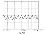
ADHVは、低導電性の水性生成物で満たされた容器内のリークを検出する際、慣用型のHVLDシステムより高い感度を有する。図12は、水道水で満たされた欠陥のないシリンジの試験中に検出電極で検出されたADHV電圧のグラフ表示を示す。水の伝導率は87.5μSであった。図13は、容器に印加されるADHV電流のグラフ表示を示す。 ADHV has higher sensitivity than conventional HVLD systems in detecting leaks in containers filled with low conductive aqueous products. FIG. 12 shows a graphical representation of the ADHV voltage detected by the detection electrodes during the test of a defect-free syringe filled with tap water. The conductivity of water was 87.5 μS. FIG. 13 shows a graph display of the ADHV current applied to the container.
同一の試料を用いて2つの系の感度を決定し、比較することによって実験を行った。欠陥のある1mLシリンジと欠陥のない1mLシリンジを試験した。欠陥のあるシリンジには、Lenox Laserによって製造され、認定された2ミクロンのレーザー穴あきピンホールがあった。
Experiments were performed by determining the sensitivities of the two systems using the same sample and comparing them. Defective 1 mL syringe and
慣用型のHVLDシステムの試験では、高電圧は12kVPkに設定された。慣用型のHVLDシステムの結果を図18に示す。実線は不良シリンジの信号を示し、破線は不良のないシリンジの信号を示す。電圧は12kVPkであった。シリンジを320rpmで回転させた。検出されたシグナルは、欠陥のないシリンジについては約3.6Vであり、欠陥のあるシリンジについては約5.4Vであった。欠損の有無によるシリンジの信号レベルの比は、5.4V/3.6V=1.5であった。 In the tests of the conventional HVLD system, the high voltage was set to 12 kVPk. The results of the conventional HVLD system are shown in FIG. The solid line shows the signal of a defective syringe, and the broken line shows the signal of a non-defective syringe. The voltage was 12 kVPk. The syringe was rotated at 320 rpm. The signal detected was about 3.6V for a defective syringe and about 5.4V for a defective syringe. The ratio of the signal level of the syringe with and without the defect was 5.4V / 3.6V = 1.5.
ADHVシステムの試験のために、電圧は12kVPkに設定された。欠損あり、および欠損なしの、1mLシリンジをADHVシステムで試験した。図19に示すように、実線は不良のシリンジを表している。破線は、シリンジの欠陥のない信号を示す。慣用型のHVLDシステムと異なり、ADHVシステムの実線は、信号の最大振幅の位置であるリークの位置を通知する。高電圧は12kVPkに設定した。試験した両方のシリンジを320rpmで回転させた。欠陥のないシリンジについて検出された信号は、不良なシリンジについて2.2Vおよび7.7Vであった。不具合のないシリンジに対する欠陥のあるシリンジの信号レベルの比は、7.7V/2.2V=3.5であった。 For testing the ADHV system, the voltage was set to 12 kVPk. 1 mL syringes with and without defects were tested on the ADHV system. As shown in FIG. 19, the solid line represents a defective syringe. The dashed line indicates a syringe-free signal. Unlike conventional HVLD systems, the solid line in the ADHV system signals the location of the leak, which is the location of the maximum amplitude of the signal. The high voltage was set to 12 kVPk. Both syringes tested were rotated at 320 rpm. The signals detected for defective syringes were 2.2V and 7.7V for defective syringes. The ratio of the signal level of the defective syringe to the defective syringe was 7.7V / 2.2V = 3.5.
この実験は、ADHV技術が慣用型のHVLD技術の2倍以上の感度を示し、慣用型のHVLD技術では漏とさらないものも正確に突き止めることを示す。 This experiment shows that the ADHV technology is more than twice as sensitive as the conventional HVLD technology, and that the conventional HVLD technology can accurately identify what is not leaked.
001 参照バイアル
002 欠陥バイアル
003 検査電極
005 検出電極
007 容器
023 AC高電圧
105 容器
107 カソードプレート
109 アノードロッド
111 補助電極ロッド
115 直流高電圧源
117 測定抵抗
119 スイッチ
121 弁別回路
200 リーク検出回路
201 検査電極
202 パッケージ
203 高電圧ケーブル
204 空隙
205 高電圧整流器
208 高電圧パルス自動変換器(高電圧パルス変換器)
209 第1のDC電圧電源
211 高電圧制御ボード
213 第2のDC電圧電源
215 ディスプレイ
217 プログラマブルロジックコントローラ
219 電流検出ボード
225 シールドケーブル
227 検出電極
301 検査電極
303 検出電極
305 パッケージ
323 AC高電圧
329 DC高電圧オフセット
400 リーク検出システム
401 検査電極
402 試験インターフェース
403 検出電極
405 高電圧ケーブル
407 シールドケーブル
409 パッケージ
411 ホルダ
413 回転機構
415 検出用スライド機構
417 検査用スライド機構
500 リーク検出システム
501 検査電極
501 パッケージ
502 試験インターフェース
503 検出電極
505 パッケージ
507 検出用スライド機構
509 検査用スライド機構
511 高電圧ケーブル
513 シールドケーブル
515 トレイ
517 ホルダ
519 回転機構
600 リーク検出システム
601 検査電極
602 検査インターフェース
603 検出電極
605 検査用スライド機構
607 検出用スライド機構
609 ホルダ
611 回転機構
613 パッケージ
615 トレイ
700 リーク検出システム
701 検査電極
702 試験インターフェース
703 検出電極
705 電極用スライド機構
707 コンベア
709 パッケージ
800 リーク検出システム
801 検査電極
802 検査インターフェース
803 検出電極
805 検査用スライド機構
807 検出用スライド機構
813 パッケージ
815 トレイ
001
209 First DC
Claims (9)
高電圧整流器に電気的に接続された検査電極であって、上記高電圧整流器は、高電圧パルス自動変換器、または、DC高電圧オフセットを伴うAC電圧を生成する他の手段に電気的に接続される、上記検査電極と、
上記高電圧パルス自動変換器に電気的に接続された第1のDC電圧電源であって、上記高電圧パルス自動変換器はさらに高電圧制御ボードに電気的に接続された、上記第1のDC電圧電源と、
上記高電圧制御ボード、検出ボード、プログラマブルロジックコントローラ、およびディスプレイに電気的に接続されてこれらに電力を供給する第2のDC電圧電源と、
上記検出ボードに電気的に接続された検出電極であって、上記検出ボードはさらに上記プログラマブルロジックコントローラに電気的に接続され、上記プログラマブルロジックコントローラはさらに上記ディスプレイに電気的に接続される、上記検出電極とを有し、
上記検出電極および上記検査電極の間にパッケージがフィットするように上記検出電極および上記検査電極が配置され、DC高電圧オフセットを有するAC高電圧が上記検査電極を通じて印加されることを特徴とするリーク検出装置。 In a leak detector that uses an AC voltage with a DC high voltage offset
An inspection electrode electrically connected to a high voltage rectifier, the high voltage rectifier being electrically connected to a high voltage pulse automatic converter or other means of generating an AC voltage with a DC high voltage offset. The above inspection electrode and
The first DC voltage power supply electrically connected to the high voltage pulse automatic converter, and the high voltage pulse automatic converter is further electrically connected to the high voltage control board, the first DC. With voltage power supply
A second DC voltage power supply that is electrically connected to and powers the high voltage control board, detection board, programmable logic controller, and display.
A detection electrode that is electrically connected to the detection board, the detection board is further electrically connected to the programmable logic controller, and the programmable logic controller is further electrically connected to the display. With electrodes
The detection electrode and the inspection electrode are arranged so that the package fits between the detection electrode and the inspection electrode, and an AC high voltage having a DC high voltage offset is applied through the inspection electrode. Detection device.
上記マイクロプロセッサは、所定のデュレーションおよびデューティサイクルのパルスを発生することにより、上記MOSFETまたはIGBTをオン・オフに切り替え、上記MOSFETまたはIGBTが上記第1のDC電源から上記高電圧パルス自動変換器を通じて流れる電流のオン・オフを切り替え、
上記高電圧パルス自動変換器を通じた電流のオン・オフの切り替えが、上記高電圧パルス自動変換器の出力端にAC高電圧を生成し、
上記高電圧制御ボードは、上記マイクロプロセッサにより生成される上記パルスの上記デュレーションおよび上記デューティサイクルを変更することにより、上記生成されたAC高電圧の振幅を調整する、請求項1に記載の装置。 The high voltage control board is a combination of a microprocessor and MOSFET or IGBT,
The microprocessor switches the MOSFET or IGBT on and off by generating pulses of a predetermined duration and duty cycle, and the MOSFET or IGBT is transferred from the first DC power source through the high voltage pulse automatic converter. Switch the flowing current on and off,
Switching the current on and off through the high voltage pulse automatic converter produces an AC high voltage at the output end of the high voltage pulse automatic converter.
It is the high voltage control board, by changing the duration and the duty cycle of the pulse generated by the microprocessor, to adjust the amplitude of the generated AC high voltage apparatus according to claim 1.
上記検出ボードは上記電流を処理し、上記処理された信号を上記プログラマブルロジックコントローラに送り、
上記プログラマブルロジックコントローラは、測定された電流と非欠陥の電流との間の変化を処理し、
上記プログラマブルロジックコントローラは、電流における上記変化によって容器内のリークを識別し、
試験の結果を上記ディスプレイに表示する、請求項1に記載の装置。 The detection electrode detects a current and transmits the current to the detection board .
The detection board processes the current and sends the processed signal to the programmable logic controller.
The programmable logic controller handles the change between the measured current and the non-defective current and
The programmable logic controller identifies leaks in the vessel by the changes in current.
The device according to claim 1 , wherein the test results are displayed on the display.
上記ホルダは、試験中に検査電極と検出電極との間に上記パッケージを固定する、請求項1に記載の装置。 Has more holders
It said holder, securing the packages between the test electrode and the detection electrode in the test apparatus of claim 1.
上記ホルダは、試験中に上記パッケージを軸に沿って回転させる、請求項1に記載の装置。 Has more holders
The device according to claim 1 , wherein the holder rotates the package along an axis during a test.
Applications Claiming Priority (5)
| Application Number | Priority Date | Filing Date | Title |
|---|---|---|---|
| US201662289579P | 2016-02-01 | 2016-02-01 | |
| US62/289,579 | 2016-02-01 | ||
| US201662317873P | 2016-04-04 | 2016-04-04 | |
| US62/317,873 | 2016-04-04 | ||
| PCT/US2016/056976 WO2017136007A1 (en) | 2016-02-01 | 2016-10-14 | System and method for alternating-direct high voltage leak detection |
Related Child Applications (1)
| Application Number | Title | Priority Date | Filing Date |
|---|---|---|---|
| JP2021003176A Division JP7056998B2 (en) | 2016-02-01 | 2021-01-13 | Systems and methods for AC-DC high voltage leak detection |
Publications (3)
| Publication Number | Publication Date |
|---|---|
| JP2019505006A JP2019505006A (en) | 2019-02-21 |
| JP2019505006A5 JP2019505006A5 (en) | 2019-11-14 |
| JP6830673B2 true JP6830673B2 (en) | 2021-02-17 |
Family
ID=59500492
Family Applications (2)
| Application Number | Title | Priority Date | Filing Date |
|---|---|---|---|
| JP2018559666A Active JP6830673B2 (en) | 2016-02-01 | 2016-10-14 | Systems and methods for AC-DC high voltage leak detection |
| JP2021003176A Active JP7056998B2 (en) | 2016-02-01 | 2021-01-13 | Systems and methods for AC-DC high voltage leak detection |
Family Applications After (1)
| Application Number | Title | Priority Date | Filing Date |
|---|---|---|---|
| JP2021003176A Active JP7056998B2 (en) | 2016-02-01 | 2021-01-13 | Systems and methods for AC-DC high voltage leak detection |
Country Status (5)
| Country | Link |
|---|---|
| US (2) | US10859464B2 (en) |
| EP (2) | EP4411364A2 (en) |
| JP (2) | JP6830673B2 (en) |
| KR (2) | KR102417975B1 (en) |
| WO (1) | WO2017136007A1 (en) |
Families Citing this family (9)
| Publication number | Priority date | Publication date | Assignee | Title |
|---|---|---|---|---|
| KR102417975B1 (en) | 2016-02-01 | 2022-07-05 | 팩키징 테크놀로지스 앤드 인스펙션, 엘엘시 | Systems and methods for detecting AC-DC high voltage leaks |
| PL3749275T3 (en) * | 2018-02-06 | 2024-08-12 | Packaging Technologies & Inspection, LLC | Device and method for testing and inspecting the integrity of an autoinjector |
| SG10201803574YA (en) * | 2018-04-27 | 2019-11-28 | Nat Univ Singapore | Method and system for integrity testing of sachets |
| IT201800007905A1 (en) * | 2018-08-06 | 2020-02-06 | Convel Srl | EQUIPMENT FOR THE INSPECTION OF CONTAINERS AND PROCEDURE FOR THE CONSTRUCTION OF A TRACK FOR THE SAID EQUIPMENT |
| US11067473B2 (en) | 2019-06-07 | 2021-07-20 | Packaging Technologies & Inspection, LLC | System and method for high voltage leak detection |
| US11397126B2 (en) * | 2020-02-20 | 2022-07-26 | Packaging Technologies and Inspection, LLC | System and method for grounded high voltage leak detection |
| US20240163741A1 (en) | 2021-03-31 | 2024-05-16 | Nec Corporation | Ran node, ue, and method |
| CN114062437A (en) * | 2021-10-28 | 2022-02-18 | 山东科技大学 | Detection method and detection equipment for eggshell cracks |
| DE102021133158A1 (en) * | 2021-12-15 | 2023-06-15 | Körber Pharma Inspection Gmbh | Apparatus and system for leak testing a container and method therefor |
Family Cites Families (27)
| Publication number | Priority date | Publication date | Assignee | Title |
|---|---|---|---|---|
| JPS5386294A (en) * | 1976-12-18 | 1978-07-29 | Takeda Chemical Industries Ltd | Inspecting method and apparatus for defect in insulation vessels |
| DE2715399A1 (en) * | 1976-07-15 | 1978-01-19 | Takeda Chemical Industries Ltd | METHOD AND DEVICE FOR CHECKING CLOSED CONTAINERS FOR DEFECTS |
| JPS5476284A (en) | 1977-11-30 | 1979-06-18 | Otsuka Pharma Co Ltd | Method of checking whether or not there is pinhole in enclosed package |
| JPS58613B2 (en) * | 1978-02-28 | 1983-01-07 | 武田薬品工業株式会社 | Insulating container defect inspection method and device |
| DE3204762C2 (en) * | 1982-02-11 | 1986-02-06 | REHAU AG + Co, 8673 Rehau | Technical accessories for medical equipment |
| JPS59125035A (en) * | 1982-12-31 | 1984-07-19 | Terumo Corp | Inferiority inspecting device |
| JPS59195140A (en) * | 1983-04-20 | 1984-11-06 | Sanpo:Kk | Method and device for measuring airtightness of vessel |
| JPS6270725A (en) * | 1985-09-25 | 1987-04-01 | Nikka Densoku Kk | Apparatus for detecting pinhole or the like in hermetically sealed food |
| US5010761A (en) * | 1990-03-01 | 1991-04-30 | Superior Industries International, Inc. | Automated leak detection apparatus and method therefor |
| JP3154588B2 (en) * | 1993-05-19 | 2001-04-09 | 松下電器産業株式会社 | Evaluation method of defect generation of anodic oxide film |
| US6110148A (en) | 1994-07-22 | 2000-08-29 | Health Hero Network, Inc. | Capacitance-based dose measurements in syringes |
| US5628309A (en) | 1996-01-25 | 1997-05-13 | Raya Systems, Inc. | Meter for electrically measuring and recording injection syringe doses |
| US6288554B1 (en) | 1996-02-16 | 2001-09-11 | Joven Denki Kabushiki Kaisha | Method for inspecting hermetically sealed package |
| JP2000088788A (en) | 1998-07-10 | 2000-03-31 | Jiyooben Denki Kk | Inspection method for airtight package |
| JP3818831B2 (en) * | 2000-06-15 | 2006-09-06 | シャープ株式会社 | Grid-connected inverter device |
| US6636031B1 (en) * | 2000-10-05 | 2003-10-21 | Sanko Electronic Laboratory Co., Ltd. | Method and device for detecting pinholes in organic film on concrete surface |
| JP2003194663A (en) * | 2001-12-28 | 2003-07-09 | Nihon Tetra Pak Kk | Sealing state inspection device |
| US7148659B2 (en) * | 2003-06-20 | 2006-12-12 | Comarco Wireless Technologies, Inc. | Programmable AC/DC power supply |
| DE102004040441A1 (en) | 2004-08-20 | 2006-06-14 | Disetronic Licensing Ag | Apparatus and method for determining the level of an ampoule |
| US7560872B2 (en) * | 2005-01-31 | 2009-07-14 | Intersil Americas Inc. | DC-AC converter having phase-modulated, double-ended, half-bridge topology for powering high voltage load such as cold cathode fluorescent lamp |
| JP2006300541A (en) * | 2005-04-15 | 2006-11-02 | Jiyooben Denki Kk | Inspection method of hermetically sealed package and its inspection device |
| US7636151B2 (en) * | 2006-01-06 | 2009-12-22 | Qualcomm Mems Technologies, Inc. | System and method for providing residual stress test structures |
| US8879218B2 (en) * | 2007-12-14 | 2014-11-04 | True-Safe Technologies, Inc. | Arc fault circuit interrupter, systems, apparatus and methods of detecting and interrupting electrical faults |
| US8698504B2 (en) * | 2010-10-09 | 2014-04-15 | Rockwell Automation Technologies, Inc. | System for detection of a ground fault in a high resistance ground network |
| GB201107692D0 (en) * | 2011-05-09 | 2011-06-22 | Snowball Malcolm R | Sterilisation of packed articles |
| GB201218913D0 (en) | 2012-10-22 | 2012-12-05 | Ucb Pharma Sa | Auto-injector and drive unit therefor |
| KR102417975B1 (en) | 2016-02-01 | 2022-07-05 | 팩키징 테크놀로지스 앤드 인스펙션, 엘엘시 | Systems and methods for detecting AC-DC high voltage leaks |
-
2016
- 2016-10-14 KR KR1020187024864A patent/KR102417975B1/en active IP Right Grant
- 2016-10-14 EP EP24175842.4A patent/EP4411364A2/en active Pending
- 2016-10-14 KR KR1020227014399A patent/KR102554891B1/en active IP Right Grant
- 2016-10-14 WO PCT/US2016/056976 patent/WO2017136007A1/en active Application Filing
- 2016-10-14 JP JP2018559666A patent/JP6830673B2/en active Active
- 2016-10-14 EP EP16889637.1A patent/EP3411685B1/en active Active
- 2016-10-14 US US16/074,146 patent/US10859464B2/en active Active
-
2020
- 2020-10-08 US US17/065,607 patent/US11300476B2/en active Active
-
2021
- 2021-01-13 JP JP2021003176A patent/JP7056998B2/en active Active
Also Published As
| Publication number | Publication date |
|---|---|
| US20190376873A1 (en) | 2019-12-12 |
| JP7056998B2 (en) | 2022-04-19 |
| KR102554891B1 (en) | 2023-07-11 |
| KR20180132617A (en) | 2018-12-12 |
| EP3411685A1 (en) | 2018-12-12 |
| US20210072112A1 (en) | 2021-03-11 |
| EP3411685A4 (en) | 2019-09-25 |
| KR20220057666A (en) | 2022-05-09 |
| WO2017136007A1 (en) | 2017-08-10 |
| KR102417975B1 (en) | 2022-07-05 |
| JP2021060425A (en) | 2021-04-15 |
| US10859464B2 (en) | 2020-12-08 |
| US11300476B2 (en) | 2022-04-12 |
| EP3411685B1 (en) | 2024-05-15 |
| JP2019505006A (en) | 2019-02-21 |
| EP4411364A2 (en) | 2024-08-07 |
Similar Documents
| Publication | Publication Date | Title |
|---|---|---|
| JP7056998B2 (en) | Systems and methods for AC-DC high voltage leak detection | |
| JP2019505006A5 (en) | ||
| EP3749275B1 (en) | Device and method for testing and inspecting the integrity of an autoinjector | |
| JP4008173B2 (en) | Capacitor insulation resistance measuring method and insulation resistance measuring device | |
| JP2003307509A (en) | Pinhole inspection method for insulating covering material | |
| JP2002372509A (en) | Method and device for inspecting leakage of sealed vessel | |
| JPH03150440A (en) | Inspection method for hermetically sealed container | |
| CN101292136A (en) | Device and method for detecting the filling level of a container, and device for filling a container | |
| JP2011028931A (en) | Battery insulation testing device | |
| JPS59125035A (en) | Inferiority inspecting device | |
| RU2613571C1 (en) | Method for controlling dielectric coating continuity on elements of radio-electronic equipment | |
| JP2004184079A (en) | Pin hole inspection device and pin hole inspection method | |
| JPH03150439A (en) | Inspection method for hermetically sealed container | |
| JP3728483B2 (en) | Pinhole inspection apparatus and pinhole detection method thereof | |
| US9638664B2 (en) | Method of analyzing a material | |
| JP2000214123A (en) | Method for inspecting sealed packaged object | |
| JP2004020474A (en) | Apparatus and method for inspecting defect in coating | |
| Jolic et al. | A non-destructive technique for detecting pinholes in hermetically sealed flexible packaging1 | |
| WO1982001418A1 (en) | Method of electrically testing sealed package | |
| Chubb et al. | Measurements for the assessment of ignition risks from static electricity | |
| JPH01227033A (en) | Detecting method of degree of vacuum inside sealed bottle | |
| JP2008164363A (en) | Sealed package inspection device and pinhole inspection method |
Legal Events
| Date | Code | Title | Description |
|---|---|---|---|
| A521 | Request for written amendment filed |
Free format text: JAPANESE INTERMEDIATE CODE: A523 Effective date: 20190926 |
|
| A621 | Written request for application examination |
Free format text: JAPANESE INTERMEDIATE CODE: A621 Effective date: 20190926 |
|
| A521 | Request for written amendment filed |
Free format text: JAPANESE INTERMEDIATE CODE: A523 Effective date: 20190927 |
|
| A977 | Report on retrieval |
Free format text: JAPANESE INTERMEDIATE CODE: A971007 Effective date: 20200819 |
|
| A131 | Notification of reasons for refusal |
Free format text: JAPANESE INTERMEDIATE CODE: A131 Effective date: 20200915 |
|
| A521 | Request for written amendment filed |
Free format text: JAPANESE INTERMEDIATE CODE: A523 Effective date: 20201208 |
|
| TRDD | Decision of grant or rejection written | ||
| A01 | Written decision to grant a patent or to grant a registration (utility model) |
Free format text: JAPANESE INTERMEDIATE CODE: A01 Effective date: 20210105 |
|
| A61 | First payment of annual fees (during grant procedure) |
Free format text: JAPANESE INTERMEDIATE CODE: A61 Effective date: 20210113 |
|
| R150 | Certificate of patent or registration of utility model |
Ref document number: 6830673 Country of ref document: JP Free format text: JAPANESE INTERMEDIATE CODE: R150 |
|
| R250 | Receipt of annual fees |
Free format text: JAPANESE INTERMEDIATE CODE: R250 |