JP6830644B2 - Packaging equipment - Google Patents

Packaging equipment Download PDF

Info

Publication number
JP6830644B2
JP6830644B2 JP2016181471A JP2016181471A JP6830644B2 JP 6830644 B2 JP6830644 B2 JP 6830644B2 JP 2016181471 A JP2016181471 A JP 2016181471A JP 2016181471 A JP2016181471 A JP 2016181471A JP 6830644 B2 JP6830644 B2 JP 6830644B2
Authority
JP
Japan
Prior art keywords
packaging material
unit
packaging
state
arm
Prior art date
Legal status (The legal status is an assumption and is not a legal conclusion. Google has not performed a legal analysis and makes no representation as to the accuracy of the status listed.)
Active
Application number
JP2016181471A
Other languages
Japanese (ja)
Other versions
JP2018043785A (en
Inventor
尚史 山林
尚史 山林
Current Assignee (The listed assignees may be inaccurate. Google has not performed a legal analysis and makes no representation or warranty as to the accuracy of the list.)
Takazono Corp
Original Assignee
Takazono Corp
Priority date (The priority date is an assumption and is not a legal conclusion. Google has not performed a legal analysis and makes no representation as to the accuracy of the date listed.)
Filing date
Publication date
Application filed by Takazono Corp filed Critical Takazono Corp
Priority to JP2016181471A priority Critical patent/JP6830644B2/en
Publication of JP2018043785A publication Critical patent/JP2018043785A/en
Application granted granted Critical
Publication of JP6830644B2 publication Critical patent/JP6830644B2/en
Active legal-status Critical Current
Anticipated expiration legal-status Critical

Links

Images

Description

本発明は、包装対象物を包材内に包装する包装装置に関する。 The present invention relates to a packaging device for packaging an object to be packaged in a packaging material.

従来の包装装置は、巻回体から巻き出された包材で、包装対象物を順に包装する。巻回体は、長尺シート状の包材が巻回されて構成されたものである。実開昭59−32606号公報(特許文献1)には、駆動モータが巻回体を回転させることで巻回体から包材を適宜巻き出す構成が開示されている。 In the conventional packaging device, the packaging material unwound from the wound body wraps the objects to be packaged in order. The wound body is formed by winding a long sheet-shaped packaging material. Japanese Patent Application Laid-Open No. 59-32606 (Patent Document 1) discloses a configuration in which a drive motor rotates a winding body to appropriately unwind a packaging material from the winding body.

実開昭59−32606号公報Jikkai Sho 59-32606

巻回体を交換した際などに、巻回体から包材を手作業で巻き出して包装部に巻き掛ける作業が必要となる。 When the winding body is replaced, it is necessary to manually unwind the packaging material from the winding body and wind it around the packaging part.

本発明の目的は、包材の巻き掛け作業を容易にすることができる包装装置を提供することである。 An object of the present invention is to provide a packaging device capable of facilitating the winding work of a packaging material.

本発明者は、巻回体から包材を巻き出すための回転駆動力を発生する駆動部を備える包装装置において、作業者が巻回体から包材を巻き出す作業に、駆動部が負荷となるために比較的大きな力が必要になるとの知見を得た。本発明者は、この問題を解決すべくさらに検討を進め、本発明を完成させるに至った。 In the packaging device provided with a drive unit that generates a rotational driving force for unwinding the packaging material from the winding body, the present inventor puts a load on the driving unit for the work of the operator unwinding the packaging material from the winding body. It was found that a relatively large amount of force is required to achieve this. The present inventor has further studied to solve this problem and has completed the present invention.

すなわち、本発明に係る包装装置は、長尺シート状の包材が巻回された巻回体が装着される被装着部と、被装着部を回転させて巻回体から包材を巻き出すための駆動力を発生する駆動部と、巻回体から巻き出された包材を用いて包装対象物を順次包装する包装部と、動力伝達部とを備えている。動力伝達部は、駆動部の発生する駆動力を被装着部に伝達する伝達状態と伝達しない非伝達状態とに切り換え可能である。 That is, in the packaging device according to the present invention, the mounting portion on which the winding body around which the long sheet-shaped packaging material is wound is mounted, and the mounting portion is rotated to unwind the packaging material from the winding body. It is provided with a driving unit that generates a driving force for the purpose, a packaging unit that sequentially wraps the object to be packaged using the packaging material unwound from the winding body, and a power transmission unit. The power transmission unit can switch between a transmission state in which the driving force generated by the drive unit is transmitted to the mounted portion and a non-transmission state in which the driving force is not transmitted.

上記の包装装置は、張力付与部をさらに備えている。張力付与部は、巻回体から巻き出された包材に張力を付与する付与状態と付与しない非付与状態とに切り換え可能である。張力付与部が付与状態から非付与状態に切り換わるのに応じて、動力伝達部が伝達状態から非伝達状態に切り換わるように、包装装置は構成されている。 The above-mentioned packaging device further includes a tension applying portion. The tension applying portion can be switched between an applied state in which tension is applied to the packaging material unwound from the wound body and a non-applied state in which tension is not applied. The packaging device is configured so that the power transmission unit switches from the transmission state to the non-transmission state as the tension applying unit switches from the applied state to the non-applied state.

上記の包装装置は、包装装置の外郭を構成する筐体をさらに備えている。被装着部は、筐体の内部空間と外部空間との間で移動可能に構成されている。被装着部が筐体の内部空間から外部空間へ移動するのに応じて、張力付与部が付与状態から非付与状態に切り換わるように、包装装置は構成されている。 The above-mentioned packaging device further includes a housing constituting the outer shell of the packaging device. The mounted portion is configured to be movable between the internal space and the external space of the housing. The packaging device is configured so that the tension-applied portion switches from the applied state to the non-applied state as the mounted portion moves from the internal space of the housing to the external space.

上記の包装装置は、被装着部が筐体の内部空間から外部空間へ移動するのに応じて、動力伝達部が伝達状態から非伝達状態に切り換わるように構成されている。 The packaging device is configured such that the power transmission unit switches from the transmission state to the non-transmission state as the mounted portion moves from the internal space of the housing to the external space.

上記の包装装置において、動力伝達部は、複数のギヤを含んでいる。複数のギヤの噛み合いを経て、駆動力が駆動部から被装着部に伝達される。動力伝達部は、複数のギヤのうちの2つのギヤの噛み合いが解除されることにより、非伝達状態に切り換えられる。 In the above packaging device, the power transmission unit includes a plurality of gears. The driving force is transmitted from the driving portion to the mounted portion through the meshing of a plurality of gears. The power transmission unit is switched to the non-transmission state by disengaging two of the plurality of gears.

上記の包装装置は、2つのギヤのうちの1つのギヤを往復移動させる移動部をさらに備えている。 The packaging device further includes a moving unit that reciprocates one of the two gears.

上記の包装装置は、動力伝達部を非伝達状態にロックするロック部をさらに備えている。 The packaging device further includes a lock portion that locks the power transmission portion to a non-transmission state.

本発明の包装装置によると、包材の巻き掛け作業を容易にすることができる。 According to the packaging device of the present invention, the wrapping work of the packaging material can be facilitated.

薬剤供給装置の外観を示す斜視図である。It is a perspective view which shows the appearance of the drug supply device. 実施形態に係る包装装置の概略構成図である。It is a schematic block diagram of the packaging apparatus which concerns on embodiment. 包装装置の概略斜視図である。It is a schematic perspective view of the packaging device. 包材供給部の正面図である。It is a front view of the packaging material supply part. 包材供給部の背面を見た斜視図である。It is a perspective view which looked at the back of the packaging material supply part. 包材供給部の背面図である。It is a rear view of the packaging material supply part. ダンサーローラが定位置にあるときの包材供給部の正面図である。It is a front view of the packaging material supply part when a dancer roller is in a fixed position. ダンサーローラが定位置にあるときの包材供給部の背面を見た斜視図である。It is a perspective view which looked at the back of the packaging material supply part when a dancer roller is in a fixed position. ダンサーローラが搬送時移動位置にあるときの包材供給部の正面図である。It is a front view of the packaging material supply part when a dancer roller is in a moving position at the time of transport. ダンサーローラが搬送時移動位置にあるときの包材供給部の背面を見た斜視図である。It is a perspective view which looked at the back of the packaging material supply part when a dancer roller is in a moving position at the time of transport. ダンサーローラが退避位置にあるときの包材供給部の正面図である。It is a front view of the packaging material supply part when a dancer roller is in a retracted position. ダンサーローラが退避位置にあるときの包材供給部の背面を見た斜視図である。It is a perspective view which looked at the back of the packaging material supply part when a dancer roller is in a retracted position. 伝達状態にある動力伝達部を示す模式図である。It is a schematic diagram which shows the power transmission part in the transmission state. 非伝達状態へ切り換わる途中の動力伝達部を示す模式図である。It is a schematic diagram which shows the power transmission part in the process of switching to a non-transmission state. 非伝達状態にある動力伝達部を示す模式図である。It is a schematic diagram which shows the power transmission part in the non-transmission state. ロック部がメインアームをロックする直前の状態を示す模式図である。It is a schematic diagram which shows the state just before the lock part locks the main arm. ロック部がメインアームをロックする途中の状態を示す模式図である。It is a schematic diagram which shows the state in which the lock part is in the process of locking the main arm. ロック部がメインアームをロックした状態を示す模式図である。It is a schematic diagram which shows the state which the lock part locked the main arm. 包装装置が前方へ引き出される第1の状態を示す模式図である。It is a schematic diagram which shows the 1st state which the packaging apparatus is pulled out forward. 包装装置が前方へ引き出される第2の状態を示す模式図である。It is a schematic diagram which shows the 2nd state which the packaging apparatus is pulled out forward. 包装装置が前方へ引き出される第3の状態を示す模式図である。It is a schematic diagram which shows the 3rd state which the packaging apparatus is pulled out forward. 包装装置が前方へ引き出される第4の状態を示す模式図である。It is a schematic diagram which shows the 4th state which the packaging apparatus is pulled out forward.

以下、図面に基づいて本発明の実施の形態を説明する。なお、以下の図面において、同一または相当する部分には同一の参照番号を付し、その説明は繰り返さない。 Hereinafter, embodiments of the present invention will be described with reference to the drawings. In the following drawings, the same or corresponding parts are given the same reference numbers, and the description thereof will not be repeated.

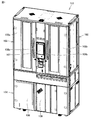
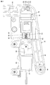
図1は、薬剤供給装置101の外観を示す斜視図である。図1に示すように、薬剤供給装置101は、薬剤供給装置101の外郭を構成する筐体102を備えている。筐体102は、上部筐体103と、下部筐体104とを有している。上部筐体103には、複数の薬剤容器からそれぞれの薬剤を排出する薬剤収納払出装置が収納されている。下部筐体104には、薬剤を包材内に包装する包装装置が収納されている。 FIG. 1 is a perspective view showing the appearance of the drug supply device 101. As shown in FIG. 1, the drug supply device 101 includes a housing 102 that constitutes an outer shell of the drug supply device 101. The housing 102 has an upper housing 103 and a lower housing 104. The upper housing 103 houses a drug storage / dispensing device that discharges each drug from a plurality of drug containers. The lower housing 104 houses a packaging device for packaging the drug in the packaging material.

上部筐体103の前面には、扉105a,105bが取り付けられている。扉105aは取っ手106aを有し、扉105bは取っ手106bを有している。薬剤供給装置101を使用するユーザは、取っ手106aを持って扉105aを開閉することができ、取っ手106bを持って扉105bを開閉することができる。上部筐体103の前面には、操作部107が設けられている。操作部107は、タッチパネル機能を有するディスプレイを備えるものであってもよく、操作盤に物理的なボタンを備えるものであってもよい。 Doors 105a and 105b are attached to the front surface of the upper housing 103. The door 105a has a handle 106a, and the door 105b has a handle 106b. The user who uses the drug supply device 101 can open and close the door 105a by holding the handle 106a, and can open and close the door 105b by holding the handle 106b. An operation unit 107 is provided on the front surface of the upper housing 103. The operation unit 107 may be provided with a display having a touch panel function, or may be provided with physical buttons on the operation panel.

下部筐体104の前面には、扉108,109が設けられている。扉108,109は開閉可能に構成されている。薬剤供給装置101を使用するユーザは、扉108,109を開けて、薬剤が内部に収容された包装物を、下部筐体104の内部から取り出すことができる。扉108,109には、開口が形成されてもよく、この開口から、薬剤が内部に収容された包装物を取り出すことができるように構成してもよい。 Doors 108 and 109 are provided on the front surface of the lower housing 104. The doors 108 and 109 are configured to be openable and closable. The user who uses the drug supply device 101 can open the doors 108 and 109 to take out the package containing the drug from the inside of the lower housing 104. An opening may be formed in the doors 108 and 109, and the doors 108 and 109 may be configured so that the package containing the drug can be taken out from the opening.

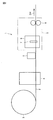
図2は、実施形態に係る包装装置1の概略構成図である。包装装置1は、包装対象物を包装するために用いられる。包装対象物は、薬剤であり、具体的には固形の薬剤である。固形の薬剤としては、錠剤、丸剤およびカプセル剤などが挙げられる。固形の薬剤としては、散剤および顆粒剤であってもよい。包装対象物は、固形の薬剤に限られない。包装対象物は、半固形の薬剤であってもよく、または、液状の薬剤であってもよい。 FIG. 2 is a schematic configuration diagram of the packaging device 1 according to the embodiment. The packaging device 1 is used for packaging an object to be packaged. The object to be packaged is a drug, specifically a solid drug. Examples of solid agents include tablets, pills and capsules. The solid drug may be a powder or a granule. The object to be packaged is not limited to solid drugs. The object to be packaged may be a semi-solid drug or a liquid drug.

包装装置1は、処方箋に基づいて薬剤を包装するための薬剤包装装置である。処方箋は、医師が患者に交付するものである。処方箋には、患者情報および薬剤情報が記載されている。患者情報は、患者の氏名および年齢を含む。薬剤情報は、薬名、分量、用法および用量を含む。このような処方箋に基づいて薬剤を1回の服用分ずつ包装するために、包装装置1が用いられる。 The packaging device 1 is a drug packaging device for packaging a drug based on a prescription. The prescription is given by the doctor to the patient. The prescription contains patient information and drug information. Patient information includes the patient's name and age. Drug information includes drug name, dosage, dosage and administration. The packaging device 1 is used to package the drug for each dose based on such a prescription.

包装装置1は、包材搬送部8を備えている。包材搬送部8は、包材2に駆動力を作用し、包材2を搬送する。包材2は、長尺シート状である。包材2は、この包材2の長手方向に搬送される。包材2は、巻回体3から巻き出される。巻回体3は、包材2がロール状に巻回されたものである。図2中の矢印は、包材2の搬送方向DRを示す。以下、包材2の搬送方向DRを単に「搬送方向DR」という。 The packaging device 1 includes a packaging material transport unit 8. The packaging material transport unit 8 acts a driving force on the packaging material 2 to transport the packaging material 2. The packaging material 2 is in the form of a long sheet. The packaging material 2 is conveyed in the longitudinal direction of the packaging material 2. The packaging material 2 is unwound from the winding body 3. The winding body 3 is formed by winding the packaging material 2 in a roll shape. The arrows in FIG. 2 indicate the transport direction DR of the packaging material 2. Hereinafter, the transport direction DR of the packaging material 2 is simply referred to as “transport direction DR”.

包装装置1は、印刷部4と、供給部5と、収容部形成部6と、をさらに備えている。搬送方向DRの上流(巻回体3に近い側)から下流(巻回体3から離れる側)に向けて、印刷部4、供給部5、収容部形成部6の順に並んでいる。印刷部4は、包材搬送部8によって搬送される包材2に、所定の情報を印刷する。所定の情報は、薬剤に関連する情報である。供給部5は、包材搬送部8によって搬送される包材2に、薬剤を供給する。薬剤は、処方箋に基づいて1回の服用分ずつ供給される。収容部形成部6は、包材搬送部8によって搬送される包材2を用いて、収容部を形成する。収容部には、薬剤が収容される。収容部形成部6は、供給部5から薬剤が供給された後に、包材2を熱融着して、薬剤が内部に収容された包装物を形成する。 The packaging device 1 further includes a printing unit 4, a supply unit 5, and an accommodating unit forming unit 6. The printing section 4, the supply section 5, and the accommodating section forming section 6 are arranged in this order from the upstream side (the side closer to the winding body 3) to the downstream side (the side away from the winding body 3) of the transport direction DR. The printing unit 4 prints predetermined information on the packaging material 2 conveyed by the packaging material conveying unit 8. The predetermined information is information related to the drug. The supply unit 5 supplies the drug to the packaging material 2 transported by the packaging material transport unit 8. The drug is supplied in single doses based on the prescription. The accommodating portion forming portion 6 forms an accommodating portion by using the packaging material 2 conveyed by the packaging material conveying portion 8. The drug is stored in the storage section. After the drug is supplied from the supply section 5, the storage section forming section 6 heat-seals the packaging material 2 to form a package in which the drug is housed.

包装装置1は、ミシン目形成部7をさらに備えている。ミシン目形成部7は、収容部形成部6に設けられている。ミシン目形成部7は、包材搬送部8によって搬送される包材2に、搬送方向DRに直交する方向に延びるミシン目を形成する。ミシン目は、複数の細孔が包材2の短手方向に連続して並んだものである。 The packaging device 1 further includes a perforation forming portion 7. The perforation forming portion 7 is provided in the accommodating portion forming portion 6. The perforation forming portion 7 forms a perforation extending in a direction orthogonal to the conveying direction DR in the packaging material 2 conveyed by the packaging material conveying portion 8. The perforations are those in which a plurality of pores are continuously arranged in the lateral direction of the packaging material 2.

このような包装装置1では、収容部形成部6とミシン目形成部7と包材搬送部8とによって、包装部9が構成されている。包装部9において、巻回体3から巻き出された包材2を用いて、包装対象物である薬剤が順次包装される。 In such a packaging device 1, the packaging portion 9 is composed of the accommodating portion forming portion 6, the perforation forming portion 7, and the packaging material transporting portion 8. In the packaging section 9, the chemicals to be packaged are sequentially packaged using the packaging material 2 unwound from the winding body 3.

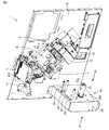
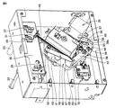
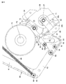
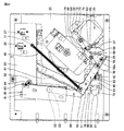
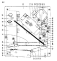
図3は、包装装置1の概略斜視図である。包装装置1は、包材供給部10と、方向転換バー11と、切断部12と、排出部13と、フレーム15とをさらに備えている。上述した供給部5、収容部形成部6および包材搬送部8を含む、包装装置1を構成する各機器類は、フレーム15に取り付けられている。包装装置1は、フレーム15の厚み方向に、筐体102(図1)に対して往復移動可能に構成されている。包装装置1は、下部筐体104(図1)に対して前後方向に移動可能であり、下部筐体104内に収納されている収納位置から前方へ引き出され得るように構成されている。 FIG. 3 is a schematic perspective view of the packaging device 1. The packaging device 1 further includes a packaging material supply unit 10, a direction changing bar 11, a cutting unit 12, a discharge unit 13, and a frame 15. Each device constituting the packaging device 1, including the supply section 5, the accommodating section forming section 6, and the packaging material transport section 8 described above, is attached to the frame 15. The packaging device 1 is configured to be reciprocally movable with respect to the housing 102 (FIG. 1) in the thickness direction of the frame 15. The packaging device 1 is movable in the front-rear direction with respect to the lower housing 104 (FIG. 1), and is configured to be able to be pulled out forward from the storage position housed in the lower housing 104.

包材供給部10は、略箱状のケーシング20と、図2に示す巻回体3が装着される被装着部21とを有している。被装着部21は、巻回体3を支持する。巻回体3は、被装着部21に対して相対回転不能に、被装着部21に取り付けられる。ケーシング20は、平面状の外表面20aを有している。外表面20aは、箱状のケーシング20の一部表面を構成している。被装着部21は、ケーシング20の外表面20aから突出し、外表面20aに対して略垂直に延びている。 The packaging material supply unit 10 has a substantially box-shaped casing 20 and a mounted portion 21 on which the winding body 3 shown in FIG. 2 is mounted. The mounted portion 21 supports the winding body 3. The winding body 3 is attached to the attached portion 21 so as not to rotate relative to the attached portion 21. The casing 20 has a flat outer surface 20a. The outer surface 20a constitutes a partial surface of the box-shaped casing 20. The mounted portion 21 projects from the outer surface 20a of the casing 20 and extends substantially perpendicular to the outer surface 20a.

ケーシング20の外表面20aには、案内孔22が形成されている。案内孔22は、緩やかに湾曲して延びている。案内孔22の延びる方向に沿って移動可能に、ダンサーローラ23が設けられている。外表面20aには、固定ローラ24,25が取り付けられている。ダンサーローラ23と固定ローラ24,25とは、ケーシング20の外表面20aから突出し、外表面20aに対して略垂直に延びている。ダンサーローラ23と固定ローラ24,25とは、互いに平行に延びている。包材供給部10のその他の構成については後述する。 A guide hole 22 is formed on the outer surface 20a of the casing 20. The guide hole 22 is gently curved and extends. A dancer roller 23 is provided so as to be movable along the extending direction of the guide hole 22. Fixed rollers 24 and 25 are attached to the outer surface 20a. The dancer rollers 23 and the fixed rollers 24 and 25 project from the outer surface 20a of the casing 20 and extend substantially perpendicular to the outer surface 20a. The dancer roller 23 and the fixed rollers 24 and 25 extend in parallel with each other. Other configurations of the packaging material supply unit 10 will be described later.

巻回体3から巻き出される包材2は、固定ローラ24、ダンサーローラ23、および固定ローラ25に、この順に巻き掛けられる。包材2はさらに、方向転換バー11に巻き掛けられる。方向転換バー11は、包材2の搬送方向を変更して、包材2を供給部5へ向く方向へ移動させる。包材2はさらに、供給部5を経由して、包装部9(図2)に巻き掛けられる。 The packaging material 2 unwound from the winding body 3 is wound around the fixed roller 24, the dancer roller 23, and the fixed roller 25 in this order. The packaging material 2 is further wrapped around the direction change bar 11. The direction change bar 11 changes the transport direction of the packaging material 2 to move the packaging material 2 in the direction toward the supply unit 5. The packaging material 2 is further wound around the packaging unit 9 (FIG. 2) via the supply unit 5.

供給部5が薬剤を包材2に供給する薬剤供給位置では、包材2が、この包材2の短手方向の中心線に沿って二つ折りされている。供給部5は、ホッパ151を有している。ホッパ151は、上部筐体103(図1)内に収納された薬剤収納払出装置から払い出された薬剤を、包材2に導く。ホッパ151の先端は、二つ折りされた包材2の内側に入り込むように配置されている。薬剤は、ホッパ151によって導かれることで、二つ折りされた包材2の内側に入る。 At the drug supply position where the supply unit 5 supplies the drug to the packaging material 2, the packaging material 2 is folded in half along the center line in the lateral direction of the packaging material 2. The supply unit 5 has a hopper 151. The hopper 151 guides the drug discharged from the drug storage / dispensing device stored in the upper housing 103 (FIG. 1) to the packaging material 2. The tip of the hopper 151 is arranged so as to enter the inside of the packaging material 2 folded in half. The drug enters the inside of the folded packaging material 2 by being guided by the hopper 151.

切断部12は、包装部9を構成している収容部形成部6および包材搬送部8よりも搬送方向DRの下流に、設けられている。切断部12は、薬剤が内部に収容された包材2を切断する。排出部13は、切断部12よりも搬送方向DRの下流に、設けられている。排出部13は、切断部12によって切断された包材2を搬送するための駆動力を発生して、包材2を外部に排出する。以下、巻回体3から巻き出されて排出部13にまで搬送される包材2が通る経路を、「搬送経路」という。 The cutting portion 12 is provided downstream of the housing portion forming portion 6 and the packaging material transporting portion 8 constituting the packaging portion 9 in the transport direction DR. The cutting portion 12 cuts the packaging material 2 in which the drug is contained. The discharge portion 13 is provided downstream of the cutting portion 12 in the transport direction DR. The discharge unit 13 generates a driving force for transporting the packaging material 2 cut by the cutting unit 12, and discharges the packaging material 2 to the outside. Hereinafter, the path through which the packaging material 2 that is unwound from the winding body 3 and transported to the discharge unit 13 passes is referred to as a “transport path”.

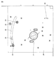
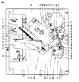
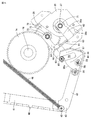
図4は、包材供給部10の正面図である。図4には、図3に示す矢印IV方向から見た包材供給部10が図示されている。ダンサーローラ23は、ケーシング20に形成された案内孔22に沿って、ケーシング20に対して相対移動する。ダンサーローラ23は、包材2の搬送経路に交差する方向に変位可能に構成されている。 FIG. 4 is a front view of the packaging material supply unit 10. FIG. 4 shows the packaging material supply unit 10 as viewed from the direction of arrow IV shown in FIG. The dancer roller 23 moves relative to the casing 20 along the guide hole 22 formed in the casing 20. The dancer roller 23 is configured to be displaceable in a direction intersecting the transport path of the packaging material 2.

包材供給部10は、ダンサーローラ23の位置を検出する位置検出部を含んでいる。この位置検出部は、定位置センサ28を有している。定位置センサ28は、磁気センサである。ダンサーローラ23が取り付けられている後述するメインアームに、磁石が取り付けられている。図4の紙面垂直方向においてダンサーローラ23が定位置センサ28と重なる位置を、定位置と称する。定位置は、搬送経路上にある。定位置センサ28は、ダンサーローラ23が定位置にあるとき、磁力を検出してオン状態になる。ダンサーローラ23が定位置から離れると、定位置センサ28はオンからオフに切り換わる。これにより定位置センサ28は、ダンサーローラ23が定位置にあるか否かを検出する。 The packaging material supply unit 10 includes a position detection unit that detects the position of the dancer roller 23. This position detection unit has a fixed position sensor 28. The fixed position sensor 28 is a magnetic sensor. A magnet is attached to the main arm, which will be described later, to which the dancer roller 23 is attached. The position where the dancer roller 23 overlaps the fixed position sensor 28 in the vertical direction of the paper surface of FIG. 4 is referred to as a fixed position. The home position is on the transport path. When the dancer roller 23 is in the fixed position, the fixed position sensor 28 detects the magnetic force and turns on. When the dancer roller 23 leaves the home position, the home position sensor 28 switches from on to off. As a result, the fixed position sensor 28 detects whether or not the dancer roller 23 is in the fixed position.

包材供給部10は、ロック解除部26を有している。上記のメインアームは、後述するロック部によってロックされる。ロック解除部26を手動で操作することにより、ロック部によるメインアームのロックが解除される。 The packaging material supply unit 10 has an unlocking unit 26. The main arm is locked by a lock portion described later. By manually operating the unlocking unit 26, the lock of the main arm by the locking unit is released.

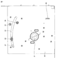
図5は、包材供給部10の背面を見た斜視図である。図6は、包材供給部10の背面図である。図6には、図3に示す矢印VI方向から見た包材供給部10が図示されている。ダンサーローラ23の位置を検出する位置検出部は、上述した定位置センサ28の他に、限界位置センサ27と、退避位置センサ29とを有している。限界位置センサ27、定位置センサ28および退避位置センサ29は、センサ支持部30によって支持されている。センサ支持部30は、ケーシング20の天井部に固定されている。 FIG. 5 is a perspective view of the back surface of the packaging material supply unit 10. FIG. 6 is a rear view of the packaging material supply unit 10. FIG. 6 shows the packaging material supply unit 10 as viewed from the direction of the arrow VI shown in FIG. The position detection unit that detects the position of the dancer roller 23 has a limit position sensor 27 and a retracted position sensor 29 in addition to the above-mentioned fixed position sensor 28. The limit position sensor 27, the fixed position sensor 28, and the retracted position sensor 29 are supported by the sensor support portion 30. The sensor support portion 30 is fixed to the ceiling portion of the casing 20.

図4においてダンサーローラ23が配置されている位置を、限界位置と称する。限界位置は、案内孔22の一方端にある。案内孔22の他方端の位置を、退避位置と称する。限界位置センサ27および退避位置センサ29は、磁気センサである。限界位置および退避位置は、搬送経路から外れている。限界位置は、定位置よりも搬送経路から離れている。 The position where the dancer roller 23 is arranged in FIG. 4 is referred to as a limit position. The limit position is at one end of the guide hole 22. The position of the other end of the guide hole 22 is referred to as a retracted position. The limit position sensor 27 and the retracted position sensor 29 are magnetic sensors. The limit position and the retract position are out of the transport path. The limit position is farther from the transport path than the fixed position.

限界位置センサ27は、ダンサーローラ23が限界位置にあるとき、磁力を検出してオン状態になる。ダンサーローラ23が限界位置から離れると、限界位置センサ27はオンからオフに切り換わる。これにより限界位置センサ27は、ダンサーローラ23が限界位置にあるか否かを検出する。退避位置センサ29は、ダンサーローラ23が退避位置にあるとき、磁力を検出してオン状態になる。ダンサーローラ23が退避位置から離れると、退避位置センサ29はオンからオフに切り換わる。これにより退避位置センサ29は、ダンサーローラ23が退避位置にあるか否かを検出する。 The limit position sensor 27 detects the magnetic force when the dancer roller 23 is in the limit position and turns on. When the dancer roller 23 moves away from the limit position, the limit position sensor 27 switches from on to off. As a result, the limit position sensor 27 detects whether or not the dancer roller 23 is in the limit position. When the dancer roller 23 is in the retracted position, the retracted position sensor 29 detects the magnetic force and turns on. When the dancer roller 23 leaves the retracted position, the retracted position sensor 29 switches from on to off. As a result, the retracted position sensor 29 detects whether or not the dancer roller 23 is in the retracted position.

包材供給部10は、巻出巻取モータ35を有している。本実施の形態の巻出巻取モータ35は、ステッピングモータである。巻出巻取モータ35は、ケーシング20に支持されている。巻出巻取モータ35は、被装着部21を回転させて、巻回体3から包材2を巻き出す、または包材2を巻回体3へ巻き取るための、回転駆動力を発生する。巻出巻取モータ35の発生する駆動力は、中間ギヤ72、中間ピニオンギヤ73、ローラギヤ74を経由して、被装着部21に伝達される。中間ギヤ72と中間ピニオンギヤ73とは、一体として回転可能に固定されている。 The packaging material supply unit 10 has a take-up / take-up motor 35. The unwinding and winding motor 35 of the present embodiment is a stepping motor. The unwinding and winding motor 35 is supported by the casing 20. The unwinding and winding motor 35 rotates the mounted portion 21 to generate a rotational driving force for unwinding the packaging material 2 from the winding body 3 or winding the packaging material 2 around the winding body 3. .. The driving force generated by the unwinding and winding motor 35 is transmitted to the mounted portion 21 via the intermediate gear 72, the intermediate pinion gear 73, and the roller gear 74. The intermediate gear 72 and the intermediate pinion gear 73 are integrally rotatably fixed.

包材供給部10は、メインアーム40と、サブアーム50と、ギヤ位置決めプレート55とを有している。メインアーム40は、第一腕部41、第二腕部42および屈曲部43を有している。図6に示す第一腕部41および第二腕部42は、それぞれ略直線状の形状を有している。第一腕部41、第二腕部42および屈曲部43は、一体として回転可能に、互いに固定されている。メインアーム40は、屈曲部43において屈曲された、略L字状の形状を有している。 The packaging material supply unit 10 has a main arm 40, a sub arm 50, and a gear positioning plate 55. The main arm 40 has a first arm portion 41, a second arm portion 42, and a bending portion 43. The first arm portion 41 and the second arm portion 42 shown in FIG. 6 each have a substantially linear shape. The first arm portion 41, the second arm portion 42, and the bent portion 43 are rotatably and fixed to each other as a unit. The main arm 40 has a substantially L-shaped shape that is bent at the bent portion 43.

第一腕部41は、先端と基端とを有している。第一腕部41の先端に、上述したダンサーローラ23が固定されている。第一腕部41は、その基端において、屈曲部43とつながっている。第二腕部42は、先端と基端とを有している。第二腕部42の基端に、ギヤ位置決めプレート55が固定されている。第二腕部42は、その先端において、屈曲部43とつながっている。屈曲部43には、ロックピン47が固定されている。メインアーム40は、アーム回転軸44を回転中心として、回転可能に構成されている。メインアーム40は、アーム回転軸44を介して、ケーシング20に支持されている。 The first arm portion 41 has a tip end and a base end. The dancer roller 23 described above is fixed to the tip of the first arm portion 41. The first arm portion 41 is connected to the bent portion 43 at its base end. The second arm portion 42 has a tip end and a base end. A gear positioning plate 55 is fixed to the base end of the second arm portion 42. The second arm portion 42 is connected to the bent portion 43 at its tip. A lock pin 47 is fixed to the bent portion 43. The main arm 40 is configured to be rotatable around the arm rotation shaft 44 as a rotation center. The main arm 40 is supported by the casing 20 via the arm rotation shaft 44.

サブアーム50は、基端部51と、先端部52とを有している。基端部51は、メインアーム40の屈曲部43から第二腕部42に亘ってメインアーム40の表面に面接触し、ボルトなどの固定部材を複数用いてメインアーム40に固定されている。これによりサブアーム50は、メインアーム40と一体に回転可能に構成されている。サブアーム50の先端部52には、円筒部53が取り付けられている。円筒部53は、スプリングヒンジ90の第2ヒンジプレート92に対して摺動し、これによりサブアーム50およびメインアーム40をアーム回転軸44回りに回動させるように構成されているが、その詳細は後述する。 The sub arm 50 has a base end portion 51 and a tip end portion 52. The base end portion 51 is in surface contact with the surface of the main arm 40 from the bent portion 43 of the main arm 40 to the second arm portion 42, and is fixed to the main arm 40 by using a plurality of fixing members such as bolts. As a result, the sub arm 50 is configured to be rotatable integrally with the main arm 40. A cylindrical portion 53 is attached to the tip portion 52 of the sub arm 50. The cylindrical portion 53 is configured to slide with respect to the second hinge plate 92 of the spring hinge 90, thereby rotating the sub-arm 50 and the main arm 40 around the arm rotation shaft 44. It will be described later.

サブアーム50をメインアーム40に固定する複数の固定部材のうちの一つは、ばね掛け部45を構成している。センサ支持部30にも、ばね掛け部31が設けられている。センサ支持部30に取り付けられたボルトにより、ばね掛け部31が構成されている。ばね掛け部31に、復帰ばね46の一端が係合し、ばね掛け部45に、復帰ばね46の他端が係合している。復帰ばね46は、たとえばコイルばねである。 One of the plurality of fixing members for fixing the sub arm 50 to the main arm 40 constitutes a spring hooking portion 45. The sensor support portion 30 is also provided with a spring hook portion 31. The spring hook portion 31 is composed of bolts attached to the sensor support portion 30. One end of the return spring 46 is engaged with the spring hook portion 31, and the other end of the return spring 46 is engaged with the spring hook portion 45. The return spring 46 is, for example, a coil spring.

ギヤ位置決めプレート55は、メインアーム40の第二腕部42の基端に、ボルトなどの固定部材56を複数用いて、固定されている。ギヤ位置決めプレート55には、切欠き59が形成されている。ギヤ位置決めプレート55は、第一部分57と第二部分58とを有している。第一部分57と第二部分58とは、切欠き59によって隔てられている。第二部分58の縁部の一部は、円弧縁58aを形成している。円弧縁58aは、アーム回転軸44を中心とする円弧の形状を有している。 The gear positioning plate 55 is fixed to the base end of the second arm portion 42 of the main arm 40 by using a plurality of fixing members 56 such as bolts. A notch 59 is formed in the gear positioning plate 55. The gear positioning plate 55 has a first portion 57 and a second portion 58. The first part 57 and the second part 58 are separated by a notch 59. A part of the edge portion of the second portion 58 forms an arc edge 58a. The arc edge 58a has an arc shape centered on the arm rotation axis 44.

円弧縁58aに当接して、円筒部65が設けられている。円筒部65の外周面は、円弧縁58aに対して摺動可能である。円筒部65はまた、切欠き59内に移動可能である。円筒部65の外周面が円弧縁58aに当接することにより中間ギヤ72および中間ピニオンギヤ73が位置決めされ、また円筒部65が切欠き59内へ移動することにより中間ギヤ72および中間ピニオンギヤ73がその位置を変化するように構成されているが、その詳細は後述する。 A cylindrical portion 65 is provided in contact with the arc edge 58a. The outer peripheral surface of the cylindrical portion 65 is slidable with respect to the arc edge 58a. The cylindrical portion 65 is also movable within the notch 59. The intermediate gear 72 and the intermediate pinion gear 73 are positioned when the outer peripheral surface of the cylindrical portion 65 abuts on the arc edge 58a, and the intermediate gear 72 and the intermediate pinion gear 73 are positioned when the cylindrical portion 65 moves into the notch 59. It is configured to change, but the details will be described later.

包材供給部10は、ロック部78をさらに備えている。ロック部78は、メインアーム40に取り付けられたロックピン47と係合することにより、メインアーム40をロックするように構成されているが、その詳細もまた後述する。 The packaging material supply unit 10 further includes a lock unit 78. The lock portion 78 is configured to lock the main arm 40 by engaging with a lock pin 47 attached to the main arm 40, the details of which will also be described later.

図7は、ダンサーローラ23が定位置にあるときの包材供給部10の正面図である。図7に示すダンサーローラ23は、図4と比較して、案内孔22に沿って図中の右方向へ移動している。図7に示すダンサーローラ23は、限界位置から離れて、定位置に位置している。ダンサーローラ23が、図4に示す限界位置から離れているため、図7では限界位置センサ27が図示されている。一方、図7では、ダンサーローラ23が定位置にあるため、定位置センサ28にダンサーローラ23が重なっており、定位置センサ28は図示されていない。 FIG. 7 is a front view of the packaging material supply unit 10 when the dancer roller 23 is in a fixed position. The dancer roller 23 shown in FIG. 7 is moving to the right in the figure along the guide hole 22 as compared with FIG. The dancer roller 23 shown in FIG. 7 is located at a fixed position away from the limit position. Since the dancer roller 23 is separated from the limit position shown in FIG. 4, the limit position sensor 27 is shown in FIG. 7. On the other hand, in FIG. 7, since the dancer roller 23 is in a fixed position, the dancer roller 23 overlaps the fixed position sensor 28, and the fixed position sensor 28 is not shown.

図7には図示しない巻回体3から巻き出される包材2は、上述した通り、固定ローラ24、ダンサーローラ23、および固定ローラ25に、この順に巻き掛けられる。ダンサーローラ23が定位置にあるとき、包材2には、予め定められた張力が付与されている。包材2に張力を付与することにより、包材2の弛みの発生が抑制されている。これにより、包材搬送部8(図2,3)が包材2を搬送するときの、包材2のずれおよび皺寄りなどが、抑制されている。 As described above, the packaging material 2 unwound from the winding body 3 (not shown in FIG. 7) is wound around the fixed roller 24, the dancer roller 23, and the fixed roller 25 in this order. When the dancer roller 23 is in place, the packaging material 2 is subjected to a predetermined tension. By applying tension to the packaging material 2, the occurrence of slack in the packaging material 2 is suppressed. As a result, when the packaging material transporting unit 8 (FIGS. 2 and 3) transports the packaging material 2, deviation and wrinkling of the packaging material 2 are suppressed.

図8は、ダンサーローラ23が定位置にあるときの包材供給部10の背面を見た斜視図である。図8に示すメインアーム40およびサブアーム50は、図5と比較して、アーム回転軸44を中心として、反時計回り方向に回転している。ギヤ位置決めプレート55がメインアーム40とともに回転し、円筒部65がギヤ位置決めプレート55の円弧縁58aに沿って相対移動することにより、図8に示す円筒部65は、図5と比較して切欠き59に近い位置にある。図8に示すロックピン47は、図5と比較して、ロック部78に近づく方向に移動している。図8に示す復帰ばね46は、図5と比較して、その長さが増大している。 FIG. 8 is a perspective view of the back surface of the packaging material supply unit 10 when the dancer roller 23 is in a fixed position. The main arm 40 and the sub arm 50 shown in FIG. 8 are rotated counterclockwise with respect to the arm rotation axis 44 as compared with FIG. The gear positioning plate 55 rotates together with the main arm 40, and the cylindrical portion 65 moves relative to the arc edge 58a of the gear positioning plate 55, so that the cylindrical portion 65 shown in FIG. 8 is notched as compared with FIG. It is located close to 59. The lock pin 47 shown in FIG. 8 is moving in a direction closer to the lock portion 78 as compared with FIG. The length of the return spring 46 shown in FIG. 8 is increased as compared with that of FIG.

図9は、ダンサーローラ23が搬送時移動位置にあるときの包材供給部10の正面図である。図9に示すダンサーローラ23は、図7と比較して、案内孔22に沿って図中の右方向に移動している。図9に示すダンサーローラ23は、定位置から離れており、そのため図9では限界位置センサ27と定位置センサ28との両方が図示されている。図7においてダンサーローラ23が配置されている位置を、搬送時移動位置と称する。搬送時移動位置は、搬送経路上にある。 FIG. 9 is a front view of the packaging material supply unit 10 when the dancer roller 23 is in the moving position during transportation. The dancer roller 23 shown in FIG. 9 is moving to the right in the drawing along the guide hole 22 as compared with FIG. 7. The dancer roller 23 shown in FIG. 9 is separated from the fixed position, and therefore both the limit position sensor 27 and the fixed position sensor 28 are shown in FIG. The position where the dancer roller 23 is arranged in FIG. 7 is referred to as a moving position during transportation. The moving position during transportation is on the transportation path.

図9には、薬剤が内部に収容された包装物の一包分の長さだけ包材2が包材搬送部8によって搬送され、包材2の搬送に伴って定位置から移動した後のダンサーローラ23が、図示されている。包材搬送部8による包材2の搬送が実行されている間、巻出巻取モータ35は停止している。そのため、包材2が巻回体3から巻き出されることはない。 In FIG. 9, the packaging material 2 is transported by the packaging material transport unit 8 by the length of one package of the package in which the drug is contained, and is moved from a fixed position along with the transportation of the packaging material 2. The dancer roller 23 is illustrated. The unwinding and winding motor 35 is stopped while the packaging material 2 is being transported by the packaging material transport unit 8. Therefore, the packaging material 2 is not unwound from the winding body 3.

一方、包材搬送部8が包材2を包装物の一包分搬送することにより、巻回体3から包材搬送部8へ至るまでの搬送方向における包材2の長さが、一包分短くなる。この包材2の長さの変化を、ダンサーローラ23を移動させて、ダンサーローラ23と固定ローラ24との距離、およびダンサーローラ23と固定ローラ25との距離を短くすることにより、調節している。 On the other hand, when the packaging material transport unit 8 transports the packaging material 2 for one package of the package, the length of the packaging material 2 in the transport direction from the winding body 3 to the packaging material transport unit 8 becomes one package. It will be shorter by a minute. The change in the length of the packaging material 2 is adjusted by moving the dancer roller 23 to shorten the distance between the dancer roller 23 and the fixed roller 24 and the distance between the dancer roller 23 and the fixed roller 25. There is.

つまり、図7に示す定位置にあるダンサーローラ23と固定ローラ24,25との間に巻き掛けられる包材2と、図9に示す位置にあるダンサーローラ23と固定ローラ24,25との間に巻き掛けられる包材2との長さを比較すると、図9の方が包材2の長さが短くなる。ダンサーローラ23と固定ローラ24,25との間に巻き掛けられる包材2の長さの変化を、包装物の一包分の長さに対応させることにより、包材2に予め定められた張力が付与された状態を一定に維持しつつ、包材2を搬送することができる。 That is, between the packaging material 2 wound between the dancer roller 23 at the fixed position shown in FIG. 7 and the fixed rollers 24 and 25, and between the dancer roller 23 and the fixed rollers 24 and 25 at the position shown in FIG. Comparing the length with the packaging material 2 wrapped around, the length of the packaging material 2 is shorter in FIG. By making the change in the length of the packaging material 2 wound between the dancer roller 23 and the fixed rollers 24 and 25 correspond to the length of one package of the package, a predetermined tension is applied to the packaging material 2. The packaging material 2 can be transported while maintaining a constant state in which is given.

搬送方向における包装物の一包分の長さは、常に一定とは限らず、包装物内に収容される薬剤の量に従って変化させてもよい。包装物の寸法に応じて、包材搬送部8による包材2の搬送量も変更可能であり、搬送時移動位置も変動する。搬送方向における包装物の一包分の長さが大きいと、搬送時移動位置は相対的に定位置から離れた位置に設定される。搬送方向における包装物の一包分の長さが小さいと、搬送時移動位置は相対的に定位置に近い位置に設定される。 The length of one package of the package in the transport direction is not always constant and may be changed according to the amount of the drug contained in the package. The amount of the packaging material 2 transported by the packaging material transport unit 8 can be changed according to the dimensions of the package, and the moving position during transport also changes. If the length of one package in the transport direction is large, the moving position during transport is set to a position relatively far from the fixed position. If the length of one package of the package in the transport direction is small, the moving position during transport is set to a position relatively close to the fixed position.

包材2は、間欠的に搬送される。包材2の搬送を実行した後、包材2の搬送を停止している間に、巻出巻取モータ35が駆動される。被装着部21に巻出巻取モータ35の駆動力が伝達されて巻回体3が回転することにより、包材2が巻回体3から巻き出される。このとき包材搬送部8による包材2の搬送は停止しているので、巻回体3から巻き出された包材2は、ダンサーローラ23と固定ローラ24,25との間に巻き掛けられる包材2の長さを元に戻すために用いられる。つまり、包材2が巻回体3から巻き出されると、ダンサーローラ23は、図9に示す搬送時移動位置から、図7に示す定位置へ向けて移動する。定位置にまでダンサーローラ23が移動して、定位置センサ28がダンサーローラ23を検出すると、巻出巻取モータ35が停止される。 The packaging material 2 is intermittently transported. After the transportation of the packaging material 2 is executed, the unwinding and winding motor 35 is driven while the transportation of the packaging material 2 is stopped. The packaging material 2 is unwound from the winding body 3 by transmitting the driving force of the unwinding winding motor 35 to the mounted portion 21 and rotating the winding body 3. At this time, since the transportation of the packaging material 2 by the packaging material transporting unit 8 is stopped, the packaging material 2 unwound from the winding body 3 is wound between the dancer roller 23 and the fixed rollers 24 and 25. It is used to restore the length of the packaging material 2. That is, when the packaging material 2 is unwound from the winding body 3, the dancer roller 23 moves from the moving position during transportation shown in FIG. 9 to the fixed position shown in FIG. 7. When the dancer roller 23 moves to the fixed position and the fixed position sensor 28 detects the dancer roller 23, the unwinding / winding motor 35 is stopped.

このように、包材搬送部8による包材2の搬送と、巻回体3からの包材2の巻き出しとを交互に繰り返すことにより、包材2に予め定められた張力が付与された状態を維持したまま、包材2を適切に搬送することができる。 In this way, by alternately repeating the transportation of the packaging material 2 by the packaging material transporting unit 8 and the unwinding of the packaging material 2 from the winding body 3, a predetermined tension is applied to the packaging material 2. The packaging material 2 can be appropriately transported while maintaining the state.

図10は、ダンサーローラ23が搬送時移動位置にあるときの包材供給部10の背面を見た斜視図である。図10に示すメインアーム40およびサブアーム50は、図8と比較して、アーム回転軸44を中心として、反時計回り方向に回転している。ギヤ位置決めプレート55がメインアーム40とともに回転し、円筒部65がギヤ位置決めプレート55の円弧縁58aに沿って相対移動することにより、図10に示す円筒部65は、図8と比較して切欠き59に近い位置にある。図10に示すロックピン47は、図8と比較して、ロック部78に近づく方向に移動している。図10に示す復帰ばね46は、図8と比較して、その長さが増大している。 FIG. 10 is a perspective view of the back surface of the packaging material supply unit 10 when the dancer roller 23 is in the moving position during transportation. Compared with FIG. 8, the main arm 40 and the sub arm 50 shown in FIG. 10 are rotated in the counterclockwise direction about the arm rotation axis 44. The gear positioning plate 55 rotates together with the main arm 40, and the cylindrical portion 65 moves relative to the arc edge 58a of the gear positioning plate 55, so that the cylindrical portion 65 shown in FIG. 10 is notched as compared with FIG. It is located close to 59. The lock pin 47 shown in FIG. 10 is moving in a direction closer to the lock portion 78 as compared with FIG. The length of the return spring 46 shown in FIG. 10 is increased as compared with that in FIG.

上述した通り、包材搬送部8による包材2を搬送しているとき、包材2に張力が付与された状態が維持され、このときダンサーローラ23が定位置と搬送時移動位置との間を往復移動する。巻回体3から全ての包材2が巻き出されると、包材2の搬送方向DRの上流側の端部が巻回体3によって支持されなくなるため、包材2に張力が付与されなくなる。張力が付与された状態の包材2によってダンサーローラ23が支持されなくなるため、復帰ばね46の弾性力によってメインアーム40が回転し、これに伴ってダンサーローラ23は限界位置へ移動する。 As described above, when the packaging material 2 is being conveyed by the packaging material conveying unit 8, the state in which tension is applied to the packaging material 2 is maintained, and at this time, the dancer roller 23 is between the fixed position and the moving position during transportation. Move back and forth. When all the packaging materials 2 are unwound from the winding body 3, the end portion of the packaging material 2 on the upstream side of the transport direction DR is not supported by the winding body 3, so that tension is not applied to the packaging material 2. Since the dancer roller 23 is not supported by the packaging material 2 in the tensioned state, the main arm 40 is rotated by the elastic force of the return spring 46, and the dancer roller 23 moves to the limit position accordingly.

図11は、ダンサーローラ23が退避位置にあるときの包材供給部10の正面図である。図11に示すダンサーローラ23は、図9と比較して、案内孔22に沿って図中の右方向に移動している。図11に示すダンサーローラ23は、案内孔22の他方端の退避位置に位置している。 FIG. 11 is a front view of the packaging material supply unit 10 when the dancer roller 23 is in the retracted position. The dancer roller 23 shown in FIG. 11 is moving to the right in the drawing along the guide hole 22 as compared with FIG. 9. The dancer roller 23 shown in FIG. 11 is located at a retracted position at the other end of the guide hole 22.

図7,9において、ダンサーローラ23は、固定ローラ24,25に対して、図中の左側に位置している。そのため、固定ローラ24、ダンサーローラ23および固定ローラ25にこの順に巻き掛けられた包材2は、ダンサーローラ23によって押圧され、これにより包材2に張力が付与されている。これに対し、図11では、ダンサーローラ23は、固定ローラ24,25に対して、図中の右側に位置している。巻回体3から巻き出される包材2は、図11中の左右方向におけるダンサーローラ23と固定ローラ24との間の隙間を通り、またダンサーローラ23と固定ローラ25との間の隙間を通ることが可能になっている。このとき、包材2には、張力が付与されない。 In FIGS. 7 and 9, the dancer roller 23 is located on the left side in the drawing with respect to the fixed rollers 24 and 25. Therefore, the packaging material 2 wound around the fixed roller 24, the dancer roller 23, and the fixed roller 25 in this order is pressed by the dancer roller 23, whereby tension is applied to the packaging material 2. On the other hand, in FIG. 11, the dancer roller 23 is located on the right side in the drawing with respect to the fixed rollers 24 and 25. The packaging material 2 unwound from the winding body 3 passes through the gap between the dancer roller 23 and the fixed roller 24 in the left-right direction in FIG. 11, and also passes through the gap between the dancer roller 23 and the fixed roller 25. It is possible. At this time, no tension is applied to the packaging material 2.

図11中の左右方向におけるダンサーローラ23と固定ローラ24,25との間の隙間に包材2を通し、その状態でダンサーローラ23を定位置へ移動させることにより、包材2に張力が付与される。 Tension is applied to the packaging material 2 by passing the packaging material 2 through the gap between the dancer roller 23 and the fixed rollers 24 and 25 in the left-right direction in FIG. 11 and moving the dancer roller 23 to a fixed position in that state. Will be done.

ダンサーローラ23および固定ローラ24,25は、巻回体3から巻き出された包材2に張力を付与する、張力付与部を構成している。張力付与部は、ダンサーローラ23が包材2を押圧することで、包材2に張力を付与する。ダンサーローラ23は、包材2の搬送経路に交差する方向に変位可能な、変位部材を構成している。張力付与部は、ダンサーローラ23を移動させることにより、包材2に張力を付与する付与状態と、包材2に張力を付与しない非付与状態とに、切換可能である。 The dancer rollers 23 and the fixed rollers 24 and 25 form a tension applying portion that applies tension to the packaging material 2 unwound from the winding body 3. In the tension applying portion, the dancer roller 23 presses the packaging material 2 to apply tension to the packaging material 2. The dancer roller 23 constitutes a displacement member that can be displaced in a direction intersecting the transport path of the packaging material 2. By moving the dancer roller 23, the tension applying portion can be switched between an applied state in which tension is applied to the packaging material 2 and a non-applied state in which tension is not applied to the packaging material 2.

図12は、ダンサーローラ23が退避位置にあるときの包材供給部10の背面を見た斜視図である。図12に示すメインアーム40およびサブアーム50は、図10と比較して、アーム回転軸44を中心として、反時計回り方向に回転している。図12に示す円筒部65は、ギヤ位置決めプレート55の円弧縁58aから離れて、切欠き59内にある。図12に示すロックピン47は、図12には図示しないロック部78と係合しており、これによりメインアーム40はロックされている。図12に示す復帰ばね46は、図10と比較して、その長さが増大しており、最大の長さをとっている。 FIG. 12 is a perspective view of the back surface of the packaging material supply unit 10 when the dancer roller 23 is in the retracted position. The main arm 40 and the sub-arm 50 shown in FIG. 12 are rotated in the counterclockwise direction about the arm rotation axis 44 as compared with FIG. The cylindrical portion 65 shown in FIG. 12 is located in the notch 59 apart from the arc edge 58a of the gear positioning plate 55. The lock pin 47 shown in FIG. 12 is engaged with a lock portion 78 (not shown in FIG. 12), whereby the main arm 40 is locked. The return spring 46 shown in FIG. 12 has an increased length as compared with FIG. 10, and has the maximum length.

次に、メインアーム40のアーム回転軸44まわりの回転に伴う、巻出巻取モータ35から被装着部21への駆動力の伝達の切り換えについて、詳細に説明する。 Next, switching of transmission of the driving force from the unwinding take-up motor 35 to the mounted portion 21 accompanying the rotation of the main arm 40 around the arm rotation shaft 44 will be described in detail.

図13は、伝達状態にある動力伝達部を示す模式図である。巻出巻取モータ35は、図示しないモータ本体を有しており、モータ本体はモータ支持部36により支持されている。巻出巻取モータ35の発生する回転駆動力は、モータ出力軸37に出力される。モータ出力軸37には、モータギヤ71が固定されている。モータギヤ71は、モータ出力軸37と一体に回転する。 FIG. 13 is a schematic view showing a power transmission unit in a transmission state. The unwinding and winding motor 35 has a motor body (not shown), and the motor body is supported by a motor support portion 36. The rotational driving force generated by the unwinding and winding motor 35 is output to the motor output shaft 37. A motor gear 71 is fixed to the motor output shaft 37. The motor gear 71 rotates integrally with the motor output shaft 37.

モータギヤ71は、中間ギヤ72と噛み合っている。中間ギヤ72は、中間ピニオンギヤ73と、一体に回転可能に構成されている。中間ギヤ72と中間ピニオンギヤ73とは、中間ギヤ軸75を中心に、一体に回転可能である。 The motor gear 71 meshes with the intermediate gear 72. The intermediate gear 72 is configured to be rotatable integrally with the intermediate pinion gear 73. The intermediate gear 72 and the intermediate pinion gear 73 can rotate integrally around the intermediate gear shaft 75.

中間ピニオンギヤ73は、ローラギヤ74と噛み合っている。ローラギヤ74は、ローラ軸76を中心に回転可能である。被装着部21は、ローラ軸76に固定されている。 The intermediate pinion gear 73 meshes with the roller gear 74. The roller gear 74 can rotate about the roller shaft 76. The mounted portion 21 is fixed to the roller shaft 76.

巻出巻取モータ35の発生する駆動力は、モータギヤ71、中間ギヤ72、中間ピニオンギヤ73およびローラギヤ74を順に経由して、被装着部21に伝達される。駆動力が伝達されて被装着部21が回転することにより、被装着部21に装着された巻回体3も回転し、巻回体3から包材2が巻き出される。巻出巻取モータ35は、被装着部21を回転させて巻回体3から包材2を巻き出すための駆動力を発生する、駆動部を構成している。モータギヤ71、中間ギヤ72、中間ピニオンギヤ73およびローラギヤ74は、巻出巻取モータ35の発生する駆動力を被装着部に伝達する、動力伝達部を構成している。 The driving force generated by the unwinding and winding motor 35 is transmitted to the mounted portion 21 via the motor gear 71, the intermediate gear 72, the intermediate pinion gear 73, and the roller gear 74 in this order. When the driving force is transmitted and the mounted portion 21 rotates, the winding body 3 mounted on the mounted portion 21 also rotates, and the packaging material 2 is unwound from the winding body 3. The unwinding and winding motor 35 constitutes a driving unit that rotates the mounted portion 21 to generate a driving force for unwinding the packaging material 2 from the winding body 3. The motor gear 71, the intermediate gear 72, the intermediate pinion gear 73, and the roller gear 74 form a power transmission unit that transmits the driving force generated by the unwinding and winding motor 35 to the mounted portion.

図13に示すように、包材供給部10は、ギヤアーム60を有している。ギヤアーム60は、アーム回転軸44とモータ出力軸37との間に配置されるベース部61を有している。ギヤアーム60はまた、第1部材62、第2部材63および第3部材64を有している。第1部材62と第3部材64とは、ベース部61に対してモータ出力軸37側に突出している。第2部材63は、ベース部61に対してアーム回転軸44側に突出している。 As shown in FIG. 13, the packaging material supply unit 10 has a gear arm 60. The gear arm 60 has a base portion 61 arranged between the arm rotation shaft 44 and the motor output shaft 37. The gear arm 60 also has a first member 62, a second member 63 and a third member 64. The first member 62 and the third member 64 project toward the motor output shaft 37 with respect to the base portion 61. The second member 63 projects toward the arm rotation shaft 44 with respect to the base portion 61.

第1部材62の基端部は、ベース部61に固定されている。第1部材62の先端部は、モータ出力軸37と、ベアリングを介して係合している。第1部材62は、モータ出力軸37により支持されている。第1部材62は、モータ出力軸37に対して回転可能に構成されている。図13に示す第1部材62は、モータ支持部36の一部表面である当接面36aに、当接している。 The base end portion of the first member 62 is fixed to the base portion 61. The tip of the first member 62 is engaged with the motor output shaft 37 via a bearing. The first member 62 is supported by the motor output shaft 37. The first member 62 is configured to be rotatable with respect to the motor output shaft 37. The first member 62 shown in FIG. 13 is in contact with the contact surface 36a, which is a partial surface of the motor support portion 36.

第2部材63の基端部は、ベース部61に固定されている。第2部材63の先端部に、円筒部65が取り付けられている。図13に示す配置において、円筒部65の外周面は、ギヤ位置決めプレート55の円弧縁58aに接触している。円筒部65の下方の表面がギヤ位置決めプレート55に接触することにより、第2部材63は、ギヤ位置決めプレート55によって支持されている。 The base end portion of the second member 63 is fixed to the base portion 61. A cylindrical portion 65 is attached to the tip end portion of the second member 63. In the arrangement shown in FIG. 13, the outer peripheral surface of the cylindrical portion 65 is in contact with the arc edge 58a of the gear positioning plate 55. The second member 63 is supported by the gear positioning plate 55 by contacting the lower surface of the cylindrical portion 65 with the gear positioning plate 55.

第3部材64の基端部は、ベース部61に固定されている。第3部材64の先端部は、中間ギヤ軸75と、ベアリングを介して係合している。中間ギヤ軸75は、第3部材64に対して回転可能に構成されている。第3部材64は、互いに噛み合う2つのギヤ(中間ピニオンギヤ73およびローラギヤ74)のうちの1つのギヤ(中間ピニオンギヤ73)の回転軸である中間ギヤ軸75に、連結されている。 The base end portion of the third member 64 is fixed to the base portion 61. The tip of the third member 64 is engaged with the intermediate gear shaft 75 via a bearing. The intermediate gear shaft 75 is configured to be rotatable with respect to the third member 64. The third member 64 is connected to an intermediate gear shaft 75, which is a rotation shaft of one of two gears (intermediate pinion gear 73 and roller gear 74) that mesh with each other (intermediate pinion gear 73).

第1部材62、第2部材63、および第3部材64は、各々、ベース部61と一体に形成されていてもよく、または、ボルトなどの固定部材を用いてベース部61に固定されていてもよい。 The first member 62, the second member 63, and the third member 64 may be integrally formed with the base portion 61, or may be fixed to the base portion 61 by using a fixing member such as a bolt. May be good.

モータ支持部36には、ばね掛け部38が形成されている。第3部材64には、ばね掛け部66が形成されている。図示しない復帰ばねの一端がばね掛け部38に係合し、他端がばね掛け部66に係合している。 A spring hooking portion 38 is formed on the motor supporting portion 36. A spring hooking portion 66 is formed on the third member 64. One end of a return spring (not shown) is engaged with the spring hook portion 38, and the other end is engaged with the spring hook portion 66.

図13に示す状態では、モータギヤ71と中間ギヤ72とが噛み合い、中間ピニオンギヤ73とローラギヤ74とが噛み合っているため、巻出巻取モータ35の発生する駆動力を、動力伝達部を経由して被装着部21に伝達可能である。動力伝達部は、巻出巻取モータ35の発生する駆動力を被装着部21に伝達可能な、伝達状態にある。 In the state shown in FIG. 13, since the motor gear 71 and the intermediate gear 72 are meshed with each other and the intermediate pinion gear 73 and the roller gear 74 are meshed with each other, the driving force generated by the unwinding and winding motor 35 is transmitted via the power transmission unit. It can be transmitted to the mounted portion 21. The power transmission unit is in a transmission state capable of transmitting the driving force generated by the unwinding / winding motor 35 to the mounted unit 21.

上述した通り、包材2の搬送と巻き出しとが繰り返されるとき、ダンサーローラ23は定位置と搬送時移動位置との間を往復移動する。このときメインアーム40は、アーム回転軸44を中心とする時計回り方向の回転移動と反時計回り方向の回転移動とを繰り返す。これにより、ギヤ位置決めプレート55と円筒部65との相対位置が変化するものの、円筒部65の外周面がギヤ位置決めプレート55の円弧縁58aに当接する配置は維持される。円筒部65の外周面が円弧縁58aに対して摺動している間は、ギヤアーム60の位置は不変である。したがって、ギヤ同士の噛み合いが維持され、動力伝達部は伝達状態に維持される。 As described above, when the transportation and unwinding of the packaging material 2 are repeated, the dancer roller 23 reciprocates between the fixed position and the moving position during transportation. At this time, the main arm 40 repeats the rotational movement in the clockwise direction and the rotational movement in the counterclockwise direction about the arm rotation shaft 44. As a result, although the relative positions of the gear positioning plate 55 and the cylindrical portion 65 change, the arrangement in which the outer peripheral surface of the cylindrical portion 65 abuts on the arc edge 58a of the gear positioning plate 55 is maintained. The position of the gear arm 60 does not change while the outer peripheral surface of the cylindrical portion 65 slides with respect to the arc edge 58a. Therefore, the meshing of the gears is maintained, and the power transmission unit is maintained in the transmission state.

図14は、非伝達状態へ切り換わる途中の動力伝達部を示す模式図である。図14に示すメインアーム40は、図13と比較して、アーム回転軸44を中心として、反時計回り方向に回転している。ギヤ位置決めプレート55は、メインアーム40と一体に、反時計回り方向に回転している。 FIG. 14 is a schematic view showing a power transmission unit in the middle of switching to the non-transmission state. Compared with FIG. 13, the main arm 40 shown in FIG. 14 is rotated in the counterclockwise direction about the arm rotation axis 44. The gear positioning plate 55 is integrally rotated with the main arm 40 in the counterclockwise direction.

このとき円筒部65は、ギヤ位置決めプレート55の円弧縁58aから離れている。図14では、円筒部65の外周面は、ギヤ位置決めプレート55の第一部分57の縁に接触している。図14に示すギヤアーム60は、図13に示す配置から移動していない。図14に示す中間ギヤ72および中間ピニオンギヤ73は、図13に示す配置から移動していない。そのため図14では、動力伝達部は、依然として伝達状態にある。 At this time, the cylindrical portion 65 is separated from the arc edge 58a of the gear positioning plate 55. In FIG. 14, the outer peripheral surface of the cylindrical portion 65 is in contact with the edge of the first portion 57 of the gear positioning plate 55. The gear arm 60 shown in FIG. 14 has not moved from the arrangement shown in FIG. The intermediate gear 72 and the intermediate pinion gear 73 shown in FIG. 14 have not moved from the arrangement shown in FIG. Therefore, in FIG. 14, the power transmission unit is still in the transmission state.

図15は、非伝達状態にある動力伝達部を示す模式図である。図15に示すメインアーム40は、図14と比較して、アーム回転軸44を中心として、反時計回り方向に回転している。メインアーム40とともにギヤ位置決めプレート55がアーム回転軸44を中心として回転する結果、円筒部65は、ギヤ位置決めプレート55の第一部分57によって押圧され、第一部分57に対して摺動して切欠き59内へ移動する。円筒部65は、切欠き59内に嵌合する。このとき、ギヤアーム60の全体が、モータ出力軸37を中心として、図中の反時計回り方向に回転している。図15に示す第1部材62は、当接面36aから離れて、モータ支持部36の他の一部表面である当接面36bに、当接している。一対の当接面36a,36bは、ギヤアーム60の移動範囲を規定している。 FIG. 15 is a schematic view showing a power transmission unit in a non-transmission state. The main arm 40 shown in FIG. 15 is rotated in the counterclockwise direction about the arm rotation shaft 44 as compared with FIG. As a result of the gear positioning plate 55 rotating about the arm rotation shaft 44 together with the main arm 40, the cylindrical portion 65 is pressed by the first portion 57 of the gear positioning plate 55 and slides with respect to the first portion 57 to form a notch 59. Move in. The cylindrical portion 65 fits into the notch 59. At this time, the entire gear arm 60 rotates in the counterclockwise direction in the drawing about the motor output shaft 37. The first member 62 shown in FIG. 15 is in contact with the contact surface 36b, which is another partial surface of the motor support portion 36, apart from the contact surface 36a. The pair of contact surfaces 36a and 36b define the moving range of the gear arm 60.

ギヤアーム60の全体が引き下げられる結果、中間ギヤ軸75は、ギヤアーム60の第3部材64と共に、モータ出力軸37を中心に反時計回り方向に回転移動する。これにより、中間ギヤ72および中間ピニオンギヤ73もまた、モータ出力軸37を中心に反時計回り方向に回転移動する。このとき、モータギヤ71と中間ギヤ72との噛み合いは維持されているが、中間ピニオンギヤ73とローラギヤ74との噛み合いが外れる。その結果として、巻出巻取モータ35の発生する駆動力が、動力伝達部を経由して被装着部21に伝達されなくなる。図15に示す動力伝達部は、巻出巻取モータ35の発生する駆動力を被装着部21に伝達しない非伝達状態に、切り換えられている。 As a result of the entire gear arm 60 being pulled down, the intermediate gear shaft 75 rotates in the counterclockwise direction around the motor output shaft 37 together with the third member 64 of the gear arm 60. As a result, the intermediate gear 72 and the intermediate pinion gear 73 also rotate and move in the counterclockwise direction about the motor output shaft 37. At this time, the meshing between the motor gear 71 and the intermediate gear 72 is maintained, but the meshing between the intermediate pinion gear 73 and the roller gear 74 is disengaged. As a result, the driving force generated by the unwinding / winding motor 35 is not transmitted to the mounted portion 21 via the power transmission portion. The power transmission unit shown in FIG. 15 is switched to a non-transmission state in which the driving force generated by the unwinding / winding motor 35 is not transmitted to the mounted unit 21.

図15に示す配置から、メインアーム40をアーム回転軸44を中心として時計回り方向に移動させると、図示しない復帰ばねの付勢力、およびギヤ位置決めプレート55の第二部分58により円筒部65が押圧される作用によって、ギヤアーム60の全体が図13に示す配置に戻る。このとき、中間ピニオンギヤ73とローラギヤ74とは、再び噛み合うようになる。これにより、動力伝達部は、巻出巻取モータ35の発生する駆動力を被装着部21に伝達する伝達状態に切り換えられる。ギヤアーム60の第3部材64と、中間ギヤ72および中間ピニオンギヤ73とが、モータ出力軸37を中心とする円弧状の軌跡に沿って往復移動することにより、動力伝達部が伝達状態と非伝達状態とに切り換えられる。 From the arrangement shown in FIG. 15, when the main arm 40 is moved clockwise around the arm rotation shaft 44, the cylindrical portion 65 is pressed by the urging force of the return spring (not shown) and the second portion 58 of the gear positioning plate 55. Due to the action, the entire gear arm 60 returns to the arrangement shown in FIG. At this time, the intermediate pinion gear 73 and the roller gear 74 are engaged again. As a result, the power transmission unit is switched to a transmission state in which the driving force generated by the unwinding / winding motor 35 is transmitted to the mounted unit 21. The third member 64 of the gear arm 60, the intermediate gear 72, and the intermediate pinion gear 73 reciprocate along an arc-shaped locus centered on the motor output shaft 37, so that the power transmission unit is in a transmission state and a non-transmission state. Can be switched to.

包装装置1は、中間ピニオンギヤ73をモータ出力軸37を中心に回転移動させる移動部を含んでいる。移動部は、メインアーム40と、ギヤ位置決めプレート55と、ギヤアーム60とを、少なくとも含んで構成されている。 The packaging device 1 includes a moving portion that rotationally moves the intermediate pinion gear 73 around the motor output shaft 37. The moving portion includes at least a main arm 40, a gear positioning plate 55, and a gear arm 60.

次に、ロック部78の構成、およびロック部78がメインアーム40をロックする動作について、詳細に説明する。 Next, the configuration of the lock portion 78 and the operation of the lock portion 78 to lock the main arm 40 will be described in detail.

図16は、ロック部78がメインアーム40をロックする直前の状態を示す模式図である。図16および後述する図17,18では、ケーシング20内に収納されているメインアーム40とロック部78とを正面から見た図が示されている。上述した通り、メインアーム40の屈曲部43には、ロックピン47が取り付けられている。ロックピン47は、中実丸棒の外周面の一部が面取りされた形状を有している。この面取りされた部分は、平面状の係合面48を構成している。 FIG. 16 is a schematic view showing a state immediately before the lock portion 78 locks the main arm 40. In FIGS. 16 and 17 and 18, which will be described later, a front view of the main arm 40 and the lock portion 78 housed in the casing 20 is shown. As described above, the lock pin 47 is attached to the bent portion 43 of the main arm 40. The lock pin 47 has a shape in which a part of the outer peripheral surface of the solid round bar is chamfered. This chamfered portion constitutes a flat engaging surface 48.

ロック部78は、ロック部材79を有している。ロック部材79は、一方側(図16中の右側)の端部に、傾斜部80と、係合部81とを有している。ロック部材79は、他方側(図16中の左側)の端部に、連結片83を有している。ロック部材79はまた、突起部82を有している。 The lock portion 78 has a lock member 79. The lock member 79 has an inclined portion 80 and an engaging portion 81 at an end portion on one side (right side in FIG. 16). The lock member 79 has a connecting piece 83 at the end on the other side (left side in FIG. 16). The lock member 79 also has a protrusion 82.

ロック部材79は、保持部材84によって保持されている。保持部材84は、ケーシング20に固定されている。保持部材84は、ロック部材79を、その延在方向(図16中の左右方向)にスライド移動可能に保持している。保持部材84は、突起部85を有している。ロック部材79の突起部82と、保持部材84の突起部85とは、その先端部が互いに向き合うように配置されている。突起部82と突起部85とに亘って、スプリング86が設けられている。突起部82は、スプリング86の一方端(図16中に示すスプリング86の右端)を支持している。突起部85は、スプリング86の他方端(図16中に示すスプリング86の左端)を支持している。 The lock member 79 is held by the holding member 84. The holding member 84 is fixed to the casing 20. The holding member 84 holds the lock member 79 so as to be slidable in the extending direction (left-right direction in FIG. 16). The holding member 84 has a protrusion 85. The protrusion 82 of the lock member 79 and the protrusion 85 of the holding member 84 are arranged so that their tip portions face each other. A spring 86 is provided over the protrusion 82 and the protrusion 85. The protrusion 82 supports one end of the spring 86 (the right end of the spring 86 shown in FIG. 16). The protrusion 85 supports the other end of the spring 86 (the left end of the spring 86 shown in FIG. 16).

ロック部78はまた、リニアソレノイドアクチュエータ87を有している。リニアソレノイドアクチュエータ87は、保持部材89によって保持されている。保持部材89は、ケーシング20に固定されている。リニアソレノイドアクチュエータ87は、本体部と、本体部から突出するステム88とを有している。ステム88は、ロック部材79の連結片83に連結されている。 The lock portion 78 also has a linear solenoid actuator 87. The linear solenoid actuator 87 is held by the holding member 89. The holding member 89 is fixed to the casing 20. The linear solenoid actuator 87 has a main body portion and a stem 88 projecting from the main body portion. The stem 88 is connected to the connecting piece 83 of the lock member 79.

図16に示すロックピン47は、ロック部材79に接触しておらず、ロックピン47からロック部材79へ押圧力は作用していない。図9,10を併せて参照して、メインアーム40が図16に示す位置にあるとき、ダンサーローラ23は、図9に示す搬送時移動位置と図11に示す退避位置との間の、退避位置寄りの位置に配置されている。 The lock pin 47 shown in FIG. 16 is not in contact with the lock member 79, and no pressing force is applied from the lock pin 47 to the lock member 79. With reference to FIGS. 9 and 10, when the main arm 40 is in the position shown in FIG. 16, the dancer roller 23 retracts between the transport moving position shown in FIG. 9 and the retracted position shown in FIG. It is located closer to the position.

図17は、ロック部がメインアーム40をロックする途中の状態を示す模式図である。図17に示すメインアーム40は、図16と比較して、アーム回転軸44を中心として、図17中の時計回り方向に回転している。ロックピン47は、図中の下方向へ移動して、ロック部材79に接触している。具体的には、ロックピン47の外周面のうち係合面48を構成しない円筒面が、ロック部材79の傾斜部80に接触している。 FIG. 17 is a schematic view showing a state in which the lock portion is in the process of locking the main arm 40. Compared with FIG. 16, the main arm 40 shown in FIG. 17 is rotated in the clockwise direction in FIG. 17 with the arm rotation shaft 44 as the center. The lock pin 47 moves downward in the drawing and is in contact with the lock member 79. Specifically, of the outer peripheral surfaces of the lock pin 47, a cylindrical surface that does not form an engaging surface 48 is in contact with the inclined portion 80 of the lock member 79.

ロックピン47が傾斜部80に当接した状態で押し下げられることにより、ロック部材79には、図中の左方向へ向く力が作用する。これによりロック部材79は、リニアソレノイドアクチュエータ87に近づく方向へ移動している。ロック部材79の突起部82と、保持部材84の突起部85とは、互いに接近している。スプリング86は圧縮されており、これによりスプリング86に弾性エネルギーが蓄積されている。 When the lock pin 47 is pushed down in a state of being in contact with the inclined portion 80, a force acting to the left in the drawing acts on the lock member 79. As a result, the lock member 79 moves in the direction approaching the linear solenoid actuator 87. The protrusion 82 of the lock member 79 and the protrusion 85 of the holding member 84 are close to each other. The spring 86 is compressed, which stores elastic energy in the spring 86.

図18は、ロック部78がメインアーム40をロックした状態を示す模式図である。図18に示すメインアーム40は、図17と比較して、アーム回転軸44を中心として、図18中の時計回り方向に回転している。ロックピン47は、図中の下方向へさらに移動して、ロック部材79の傾斜部80から離れている。ロックピン47の外周面の一部を構成する係合面48が、ロック部材79の係合部81に接触している。 FIG. 18 is a schematic view showing a state in which the lock portion 78 locks the main arm 40. Compared with FIG. 17, the main arm 40 shown in FIG. 18 is rotated in the clockwise direction in FIG. 18 with the arm rotation shaft 44 as the center. The lock pin 47 further moves downward in the drawing and is separated from the inclined portion 80 of the lock member 79. The engaging surface 48 forming a part of the outer peripheral surface of the lock pin 47 is in contact with the engaging portion 81 of the lock member 79.

このとき、ロックピン47は傾斜部80を押圧しておらず、ロックピン47からロック部材79に図中の左右方向の力は作用していない。スプリング86は伸長して元の形状に戻っている。スプリング86は、ロック部材79に対し、図中の右方向へ向く力を作用する。これによりロック部材79は、図17に示す位置からリニアソレノイドアクチュエータ87から離れる方向へ移動して、図16に示す元の位置へ戻っている。 At this time, the lock pin 47 does not press the inclined portion 80, and the force in the left-right direction in the drawing does not act from the lock pin 47 to the lock member 79. The spring 86 extends and returns to its original shape. The spring 86 acts on the lock member 79 with a force directed to the right in the drawing. As a result, the lock member 79 moves away from the linear solenoid actuator 87 from the position shown in FIG. 17 and returns to the original position shown in FIG.

ロックピン47の係合面48がロック部材79の係合部81に係合することにより、ロックピン47は図中の上方向へ移動不能となっている。ロック部材79は、メインアーム40の、図中反時計回り方向の回転を妨げている。メインアーム40は、アーム回転軸44回りに最大限回動した位置で、ロックされている。図11,12を併せて参照して、メインアーム40が図18に示す位置にあるとき、ダンサーローラ23は、図11に示す退避位置にある。このとき動力伝達部は、図15を参照して上述した通り、巻出巻取モータ35の発生する駆動力を被装着部21に伝達しない非伝達状態にある。ロック部78は、動力伝達部を非伝達状態にロック可能に構成されている。 The engaging surface 48 of the lock pin 47 engages with the engaging portion 81 of the lock member 79, so that the lock pin 47 cannot move upward in the drawing. The lock member 79 hinders the rotation of the main arm 40 in the counterclockwise direction in the drawing. The main arm 40 is locked at a position where it is rotated to the maximum around the arm rotation shaft 44. With reference to FIGS. 11 and 12, the dancer roller 23 is in the retracted position shown in FIG. 11 when the main arm 40 is in the position shown in FIG. At this time, as described above with reference to FIG. 15, the power transmission unit is in a non-transmission state in which the driving force generated by the unwinding / winding motor 35 is not transmitted to the mounted unit 21. The lock portion 78 is configured so that the power transmission portion can be locked in a non-transmission state.

メインアーム40のロックは、ロック部材79とロックピン47との係合を外すことにより、解除することができる。上述したロック解除部26(図4)を手動で操作して、ロック部材79をロックピン47から離れる方向に平行移動することにより、ロック部材79とロックピン47との係合を外してロックを解除することができる。または、リニアソレノイドアクチュエータ87の、ソレノイドに電流を流すことで磁性体をコイル内に引き込む動作を利用して、リニアソレノイドアクチュエータ87の本体部からステム88が突出する長さを小さくするようにステム88を移動させることにより、ロック部材79を平行移動させて、ロック部材79とロックピン47との係合を外してロックを解除することができる。 The lock of the main arm 40 can be released by disengaging the lock member 79 and the lock pin 47. By manually operating the unlocking portion 26 (FIG. 4) described above to translate the lock member 79 in the direction away from the lock pin 47, the lock member 79 and the lock pin 47 are disengaged and the lock is released. It can be released. Alternatively, the stem 88 so as to reduce the length of the stem 88 protruding from the main body of the linear solenoid actuator 87 by utilizing the operation of pulling the magnetic material into the coil by passing an electric current through the solenoid of the linear solenoid actuator 87. By moving the lock member 79, the lock member 79 can be moved in parallel, the lock member 79 and the lock pin 47 can be disengaged, and the lock can be released.

図12に示すように、メインアーム40が最大回動位置でロックされているとき、復帰ばね46が伸長する長さが最大となり、復帰ばね46に弾性エネルギーが蓄積されている。メインアーム40のロックが解除されると、復帰ばね46は、その伸長長さを小さくするように変形する。復帰ばね46の弾性力の作用により、メインアーム40はアーム回転軸44回りに逆方向に回転する。このときダンサーローラ23は、案内孔22に沿って、退避位置(図11)から限界位置(図4)へ向かって移動する。 As shown in FIG. 12, when the main arm 40 is locked at the maximum rotation position, the length of extension of the return spring 46 is maximized, and elastic energy is stored in the return spring 46. When the lock of the main arm 40 is released, the return spring 46 is deformed so as to reduce its extension length. Due to the action of the elastic force of the return spring 46, the main arm 40 rotates in the opposite direction around the arm rotation shaft 44. At this time, the dancer roller 23 moves from the retracted position (FIG. 11) to the limit position (FIG. 4) along the guide hole 22.

次に、包装装置1全体を下部筐体104から引き出す動作に伴う、巻出巻取モータ35から被装着部21への駆動力の伝達の切り換えについて、詳細に説明する。 Next, switching of transmission of the driving force from the unwinding take-up motor 35 to the mounted portion 21 accompanying the operation of pulling out the entire packaging device 1 from the lower housing 104 will be described in detail.

図6を参照して、包装装置1は、スプリングヒンジ90を有している。スプリングヒンジ90は、第1ヒンジプレート91と、第2ヒンジプレート92と、ヒンジ軸93と、トーションスプリング94とを有している。第1ヒンジプレート91と第2ヒンジプレート92とは、ヒンジ軸93を介して連結されている。 With reference to FIG. 6, the packaging device 1 has a spring hinge 90. The spring hinge 90 has a first hinge plate 91, a second hinge plate 92, a hinge shaft 93, and a torsion spring 94. The first hinge plate 91 and the second hinge plate 92 are connected via a hinge shaft 93.

第1ヒンジプレート91は、下部筐体104に固定されており、移動不能である。第2ヒンジプレート92は、ヒンジ軸93を回転中心として、第1ヒンジプレート91に対して相対移動可能である。第2ヒンジプレート92は、その上端が相対的に前方(図中の右方向)にありその下端が相対的に後方(図中の左方向)にあるように、上下方向に対して傾斜して配置されている。 The first hinge plate 91 is fixed to the lower housing 104 and is immovable. The second hinge plate 92 can move relative to the first hinge plate 91 with the hinge shaft 93 as the center of rotation. The second hinge plate 92 is inclined in the vertical direction so that the upper end thereof is relatively forward (to the right in the figure) and the lower end thereof is relatively rearward (to the left in the figure). Have been placed.

トーションスプリング94は、ヒンジ軸93の周りに巻回されたコイル部と、コイル部から突き出る一対のアーム部とを有している。一対のアーム部のうちの一方は、第1ヒンジプレート91に当接している。一対のアーム部のうちの他方は、第2ヒンジプレート92に当接している。 The torsion spring 94 has a coil portion wound around the hinge shaft 93 and a pair of arm portions protruding from the coil portion. One of the pair of arm portions is in contact with the first hinge plate 91. The other of the pair of arm portions is in contact with the second hinge plate 92.

トーションスプリング94は、第1ヒンジプレート91と第2ヒンジプレート92との間に弾性反発力を作用させ、ヒンジ軸93を回転中心として第2ヒンジプレート92が第1ヒンジプレート91から離れる方向に、第2ヒンジプレート92を付勢している。トーションスプリング94の付勢力および重力以外の外力がスプリングヒンジ90に作用しない状態で、第1ヒンジプレート91と第2ヒンジプレート92とは、略直交して延びている。ヒンジ軸93の軸方向に見て、第1ヒンジプレート91と第2ヒンジプレート92とは、L字状の形状に配置されている。 The torsion spring 94 exerts an elastic repulsive force between the first hinge plate 91 and the second hinge plate 92 so that the second hinge plate 92 separates from the first hinge plate 91 with the hinge shaft 93 as the center of rotation. The second hinge plate 92 is urged. The first hinge plate 91 and the second hinge plate 92 extend substantially orthogonally to each other in a state where the urging force of the torsion spring 94 and the external force other than gravity do not act on the spring hinge 90. The first hinge plate 91 and the second hinge plate 92 are arranged in an L-shape when viewed in the axial direction of the hinge shaft 93.

包材供給部10は、スプリングヒンジ90に対して、筐体102の前後方向(図6中の左右方向)に相対移動可能である。図6に示す配置では、サブアーム50の円筒部53は、第2ヒンジプレート92から離れており、円筒部53と第2ヒンジプレート92とは非接触の状態である。 The packaging material supply unit 10 can move relative to the spring hinge 90 in the front-rear direction (left-right direction in FIG. 6) of the housing 102. In the arrangement shown in FIG. 6, the cylindrical portion 53 of the sub arm 50 is separated from the second hinge plate 92, and the cylindrical portion 53 and the second hinge plate 92 are in a non-contact state.

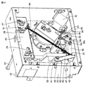
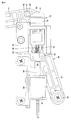
図19は、包装装置1が前方へ引き出される第1の状態を示す模式図である。図6には、包装装置1が下部筐体104内の収納位置にあるときの包材供給部10とスプリングヒンジ90とが図示されている。これに対し、図19には、包装装置1が収納位置から前方へ引き出され始めたときの包材供給部10とスプリングヒンジ90とが図示されている。 FIG. 19 is a schematic view showing a first state in which the packaging device 1 is pulled forward. FIG. 6 shows the packaging material supply unit 10 and the spring hinge 90 when the packaging device 1 is in the storage position in the lower housing 104. On the other hand, FIG. 19 shows a packaging material supply unit 10 and a spring hinge 90 when the packaging device 1 starts to be pulled forward from the storage position.

図19に示す包材供給部10は、図6と比較して、前方(図中の右方向)に移動している。被装着部21、アーム回転軸44およびその他の包材供給部10の各構成は、前方へ平行移動している。このとき、サブアーム50の円筒部53は、第2ヒンジプレート92に当接している。 The packaging material supply unit 10 shown in FIG. 19 has moved forward (to the right in the figure) as compared with FIG. Each configuration of the mounted portion 21, the arm rotating shaft 44, and the other packaging material supply portion 10 is translated forward. At this time, the cylindrical portion 53 of the sub arm 50 is in contact with the second hinge plate 92.

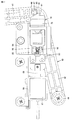
図20は、包装装置1が前方へ引き出される第2の状態を示す模式図である。図20に示す包材供給部10は、図19と比較して、さらに前方に移動している。サブアーム50の円筒部53は、第2ヒンジプレート92に対して摺動し、第2ヒンジプレート92に沿って下方へ移動している。サブアーム50とメインアーム40とは一体に固定されているため、サブアーム50の先端部52が下方へ移動するに従って、メインアーム40とサブアーム50とは、アーム回転軸44回りに図中の反時計回り方向に回転している。これにより、メインアーム40の先端に固定されたダンサーローラ23は、案内孔22に沿って移動している。 FIG. 20 is a schematic view showing a second state in which the packaging device 1 is pulled forward. The packaging material supply unit 10 shown in FIG. 20 has moved further forward as compared with FIG. 19. The cylindrical portion 53 of the sub-arm 50 slides with respect to the second hinge plate 92 and moves downward along the second hinge plate 92. Since the sub-arm 50 and the main arm 40 are integrally fixed, as the tip 52 of the sub-arm 50 moves downward, the main arm 40 and the sub-arm 50 rotate counterclockwise in the drawing around the arm rotation axis 44. It is rotating in the direction. As a result, the dancer roller 23 fixed to the tip of the main arm 40 is moving along the guide hole 22.

図21は、包装装置1が前方へ引き出される第3の状態を示す模式図である。図21に示す包材供給部10は、図20と比較して、さらに前方に移動している。サブアーム50の円筒部53は、第2ヒンジプレート92の下端の位置まで移動しており、円筒部53は第2ヒンジプレート92の下端に対して摺動している。メインアーム40とサブアーム50とは、図20と比較してアーム回転軸44回りに図中の反時計回り方向に回転しており、ロック部78によってロックされている。ダンサーローラ23は、案内孔22に沿って退避位置まで移動している。ギヤアーム60の円筒部65は、ギヤ位置決めプレート55の切欠き59内へ移動している。中間ピニオンギヤ73とローラギヤ74との噛み合いが外れている。 FIG. 21 is a schematic view showing a third state in which the packaging device 1 is pulled forward. The packaging material supply unit 10 shown in FIG. 21 has moved further forward as compared with FIG. 20. The cylindrical portion 53 of the sub-arm 50 has moved to the position of the lower end of the second hinge plate 92, and the cylindrical portion 53 slides with respect to the lower end of the second hinge plate 92. The main arm 40 and the sub arm 50 are rotated counterclockwise in the drawing around the arm rotation axis 44 as compared with FIG. 20, and are locked by the lock portion 78. The dancer roller 23 has moved to the retracted position along the guide hole 22. The cylindrical portion 65 of the gear arm 60 has moved into the notch 59 of the gear positioning plate 55. The intermediate pinion gear 73 and the roller gear 74 are out of mesh.

図22は、包装装置1が前方へ引き出される第4の状態を示す模式図である。図22に示す包材供給部10は、図21と比較して、さらに前方に移動している。図22に示す配置において、巻回体3が装着される被装着部21は、下部筐体104の外部へ引き出されている。メインアーム40はロックされた状態であり、メインアーム40およびその他の包材供給部10を構成する装置の、ケーシング20に対する相対位置は、図21と同じである。 FIG. 22 is a schematic view showing a fourth state in which the packaging device 1 is pulled forward. The packaging material supply unit 10 shown in FIG. 22 has moved further forward as compared with FIG. 21. In the arrangement shown in FIG. 22, the mounted portion 21 on which the winding body 3 is mounted is pulled out to the outside of the lower housing 104. The main arm 40 is in a locked state, and the relative positions of the main arm 40 and other devices constituting the packaging material supply unit 10 with respect to the casing 20 are the same as those in FIG.

図22では、円筒部53と第2ヒンジプレート92との係合が外れている。図22に示す配置では、円筒部53は、第2ヒンジプレート92から離れており、円筒部53と第2ヒンジプレート92とは非接触の状態である。 In FIG. 22, the cylindrical portion 53 and the second hinge plate 92 are disengaged. In the arrangement shown in FIG. 22, the cylindrical portion 53 is separated from the second hinge plate 92, and the cylindrical portion 53 and the second hinge plate 92 are in a non-contact state.

被装着部21を含む包材供給部10が、下部筐体104の内部空間から外部空間へ移動するのに応じて、中間ピニオンギヤ73とローラギヤ74との噛み合いが外れ、動力伝達部が非伝達状態に切り換えられている。これにより被装着部21は、両方向への自在な回転が可能になっている。 As the packaging material supply unit 10 including the mounted unit 21 moves from the internal space of the lower housing 104 to the external space, the intermediate pinion gear 73 and the roller gear 74 are disengaged, and the power transmission unit is in a non-transmission state. It has been switched to. As a result, the mounted portion 21 can freely rotate in both directions.

巻回体3を交換するとき、包装装置1は、作業性の向上のために、前方へ移動される。巻回体3が装着される被装着部21が少なくとも下部筐体104の外部空間へ移動するように、包装装置1は下部筐体104から前方へ引き出される。この移動に応じて、動力伝達部は、伝達状態から非伝達状態へ切り換えられている。 When replacing the winding body 3, the packaging device 1 is moved forward in order to improve workability. The packaging device 1 is pulled forward from the lower housing 104 so that the mounted portion 21 on which the winding body 3 is mounted moves at least to the external space of the lower housing 104. In response to this movement, the power transmission unit is switched from the transmission state to the non-transmission state.

被装着部21に取り付けられた交換後の巻回体3の包材2を包装部9へ巻き掛ける巻き掛け作業時に、巻回体3から包材2を巻き出すために、被装着部21は回転する。巻き掛け作業の開始時に、動力伝達部を非伝達状態とし、被装着部21を自在に回転可能にすることにより、巻出巻取モータ35が被装着部21の回転に対する負荷となることが防止されている。これによって、作業者が小さな力で巻回体3から包材2を巻き出すことができるので、包材2の巻き掛け作業を容易にすることができる。 In order to unwind the packaging material 2 from the winding body 3 during the winding operation of winding the packaging material 2 of the replacement winding body 3 attached to the mounting unit 21 around the packaging unit 9, the mounted portion 21 Rotate. At the start of the winding work, the power transmission unit is set to the non-transmission state and the mounted portion 21 can be freely rotated, thereby preventing the unwinding and winding motor 35 from becoming a load on the rotation of the mounted portion 21. Has been done. As a result, the operator can unwind the packaging material 2 from the winding body 3 with a small force, so that the winding work of the packaging material 2 can be facilitated.

被装着部21の移動に応じて、ダンサーローラ23は、退避位置へ移動している。これにより、図11を参照して説明した通り、張力付与部は、包材2に張力を付与しない非付与状態へ切り換えられている。包材2を巻回体3から巻き出して包装部9へ巻き掛ける巻き掛け作業時に、包材2に張力が付与されていない状態で作業を行なうことができる。加えて、退避位置にあるダンサーローラ23と固定ローラ24,25との間に、巻回体3から巻き出した包材2を、まっすぐにして通すことができる。したがって、包材2の巻き掛け作業を容易にすることができる。 The dancer roller 23 moves to the retracted position in response to the movement of the mounted portion 21. As a result, as described with reference to FIG. 11, the tension applying portion is switched to a non-applying state in which tension is not applied to the packaging material 2. At the time of winding work in which the packaging material 2 is unwound from the winding body 3 and wound around the packaging portion 9, the work can be performed in a state where tension is not applied to the packaging material 2. In addition, the packaging material 2 unwound from the winding body 3 can be passed straight between the dancer roller 23 and the fixed rollers 24 and 25 in the retracted position. Therefore, the winding work of the packaging material 2 can be facilitated.

張力付与部が非付与状態に切り換わるのに応じて、動力伝達部が非伝達状態に切り換わるように構成されているため、作業者は、張力付与部と動力伝達部との各々を個別に操作する必要がない。したがって、操作に要する手間を削減することができる。 Since the power transmission unit is configured to switch to the non-transmission state in response to the tension application unit switching to the non-application state, the operator can individually switch each of the tension application unit and the power transmission unit. No need to operate. Therefore, the time and effort required for the operation can be reduced.

動力伝達部の伝達状態から非伝達状態への切り換え、および、張力付与部の付与状態から非付与状態への切り換えが、下部筐体104の外部空間への被装着部21の移動に応じて行なわれる。動力伝達部の非伝達状態への切り換え、および張力付与部の非付与状態への切り換えのために、特別な操作を必要としないため、操作に要する手間を削減することができる。 Switching from the transmission state of the power transmission unit to the non-transmission state and switching from the tension application unit to the non-application state are performed according to the movement of the mounted portion 21 to the external space of the lower housing 104. Is done. Since no special operation is required for switching the power transmission unit to the non-transmission state and the tension applying unit to the non-application state, the labor required for the operation can be reduced.

包材2の巻き掛け作業を終えると、ロック解除部26の操作、またはリニアソレノイドアクチュエータ87の動作により、ロックが解除される。これによりメインアーム40は逆方向に回転して、ダンサーローラ23は退避位置から限界位置へ移動する。サブアーム50は、上下方向においてスプリングヒンジ90と重なり合う位置に移動する。この状態で、包装装置1は下部筐体104内へ収納される。 When the winding work of the packaging material 2 is completed, the lock is released by the operation of the lock release unit 26 or the operation of the linear solenoid actuator 87. As a result, the main arm 40 rotates in the opposite direction, and the dancer roller 23 moves from the retracted position to the limit position. The sub arm 50 moves in the vertical direction to a position where it overlaps with the spring hinge 90. In this state, the packaging device 1 is housed in the lower housing 104.

包装装置1を下部筐体104内の収納位置へ移動するとき、サブアーム50がスプリングヒンジ90と干渉する。サブアーム50が第2ヒンジプレート92に接触して第2ヒンジプレート92を押圧すると、第2ヒンジプレート92はヒンジ軸93回りに回転して、第1ヒンジプレート91に近づく方向へ移動する。スプリングヒンジ90が、L字形状を閉じるように変形することにより、スプリングヒンジ90がサブアーム50の移動を妨げることはなく、包装装置1を円滑に移動させることができる。 When the packaging device 1 is moved to the storage position in the lower housing 104, the sub arm 50 interferes with the spring hinge 90. When the sub-arm 50 comes into contact with the second hinge plate 92 and presses the second hinge plate 92, the second hinge plate 92 rotates around the hinge shaft 93 and moves in a direction approaching the first hinge plate 91. By deforming the spring hinge 90 so as to close the L-shape, the spring hinge 90 does not hinder the movement of the sub-arm 50, and the packaging device 1 can be smoothly moved.

サブアーム50がスプリングヒンジ90の位置を通過すると、トーションスプリング94の弾性力により、第2ヒンジプレート92が元の位置へ移動して、スプリングヒンジ90は再びL字状の形状になる。これにより、次回の包装装置1の移動の際にも、移動に応じてメインアーム40を回転させて、動力伝達部を非伝達状態に切り換えるとともに張力付与部を非付与状態に切り換えることが可能になる。 When the sub-arm 50 passes the position of the spring hinge 90, the elastic force of the torsion spring 94 causes the second hinge plate 92 to move to the original position, and the spring hinge 90 becomes L-shaped again. As a result, when the packaging device 1 is moved next time, the main arm 40 can be rotated according to the movement to switch the power transmission unit to the non-transmission state and the tension applying unit to the non-application state. Become.

これまでの説明においては、包装装置1の下部筐体104に対する相対移動に応じて動力伝達部が非伝達状態に切り換わり、張力付与部が非付与状態に切り換わる例について説明した。この例に限られず、作業者が手動で、または自動で、ダンサーローラ23を退避位置へ移動させ、これに応じて張力付与部を非付与状態に切り換えるとともに動力伝達部を非伝達状態に切り換えることが可能である。 In the description so far, an example has been described in which the power transmission unit is switched to the non-transmission state and the tension application unit is switched to the non-application state according to the relative movement of the packaging device 1 with respect to the lower housing 104. Not limited to this example, the operator manually or automatically moves the dancer roller 23 to the retracted position, and accordingly, the tension applying unit is switched to the non-applied state and the power transmission unit is switched to the non-transmission state. Is possible.

またこれまでの説明においては、モータ出力軸37を中心とする円弧状の軌跡に沿って中間ピニオンギヤ73を往復移動させることにより、動力伝達部の伝達状態と非伝達状態とを切り換える例について説明した。この例に限られず、中間ピニオンギヤ73を平行移動させることにより、動力伝達部の伝達状態と非伝達状態とを切り換える構成としてもよい。中間ピニオンギヤ73は、そのピッチ円の径方向に平行移動してもよく、または中間ギヤ軸75の軸方向に平行移動してもよい。 Further, in the above description, an example of switching between the transmission state and the non-transmission state of the power transmission unit by reciprocating the intermediate pinion gear 73 along the arc-shaped locus centered on the motor output shaft 37 has been described. .. Not limited to this example, the intermediate pinion gear 73 may be moved in parallel to switch between the transmission state and the non-transmission state of the power transmission unit. The intermediate pinion gear 73 may be translated in the radial direction of its pitch circle, or may be translated in the axial direction of the intermediate gear shaft 75.

以上のように本発明の実施の形態について説明を行なったが、今回開示された実施の形態はすべての点で例示であって、制限的なものではないと考えられるべきである。この発明の範囲は上記した説明ではなくて特許請求の範囲によって示され、特許請求の範囲と均等の意味、および範囲内でのすべての変更が含まれることが意図される。 Although the embodiments of the present invention have been described above, it should be considered that the embodiments disclosed this time are examples in all respects and are not restrictive. The scope of the present invention is shown by the scope of claims rather than the above description, and is intended to include the meaning equivalent to the scope of claims and all modifications within the scope.

1 包装装置、2 包材、3 巻回体、5 供給部、8 包材搬送部、9 包装部、10 包材供給部、11 方向転換バー、15 フレーム、20 ケーシング、20a 外表面、21 被装着部、22 案内孔、23 ダンサーローラ、24,25 固定ローラ、26 ロック解除部、27 限界位置センサ、28 定位置センサ、29 退避位置センサ、30 センサ支持部、31,38,45,66 ばね掛け部、35 モータ、36 モータ支持部、36a,36b 当接面、37 モータ出力軸、40 メインアーム、41 第一腕部、42 第二腕部、43 屈曲部、44 アーム回転軸、46 復帰ばね、47 ロックピン、48 係合面、50 サブアーム、51 基端部、52 先端部、53,65 円筒部、55 ギヤ位置決めプレート、56 固定部材、57 第一部分、58 第二部分、58a 円弧縁、59 実開昭、60 ギヤアーム、61 ベース部、62 第1部材、63 第2部材、64 第3部材、71 モータギヤ、72 中間ギヤ、73 中間ピニオンギヤ、74 ローラギヤ、75 中間ギヤ軸、76 ローラ軸、78 ロック部、79 ロック部材、80 傾斜部、81 係合部、82,85 突起部、83 連結片、84,89 保持部材、86 スプリング、87 リニアソレノイドアクチュエータ、88 ステム、90 スプリングヒンジ、91 第1ヒンジプレート、92 第2ヒンジプレート、93 ヒンジ軸、94 トーションスプリング、101 薬剤供給装置、102 筐体、104 下部筐体、108,109 扉、DR 搬送方向。 1 Packaging device, 2 packaging material, 3 winding body, 5 supply unit, 8 packaging material transport unit, 9 packaging unit, 10 packaging material supply unit, 11 direction change bar, 15 frame, 20 casing, 20a outer surface, 21 covering Mounting part, 22 guide hole, 23 dancer roller, 24, 25 fixed roller, 26 unlocking part, 27 limit position sensor, 28 fixed position sensor, 29 retracted position sensor, 30 sensor support part, 31, 38, 45, 66 spring Hanging part, 35 motor, 36 motor support part, 36a, 36b contact surface, 37 motor output shaft, 40 main arm, 41 first arm part, 42 second arm part, 43 bending part, 44 arm rotation shaft, 46 return Spring, 47 lock pin, 48 engaging surface, 50 sub-arm, 51 base end, 52 tip, 53,65 cylindrical part, 55 gear positioning plate, 56 fixing member, 57 first part, 58 second part, 58a arc edge , 59 Mikiaki, 60 Gear arm, 61 Base part, 62 1st member, 63 2nd member, 64 3rd member, 71 Motor gear, 72 Intermediate gear, 73 Intermediate pinion gear, 74 Roller gear, 75 Intermediate gear shaft, 76 Roller shaft , 78 lock part, 79 lock member, 80 inclined part, 81 engaging part, 82,85 protrusion, 83 connecting piece, 84,89 holding member, 86 spring, 87 linear solenoid actuator, 88 stem, 90 spring hinge, 91 1st hinge plate, 92 2nd hinge plate, 93 hinge shaft, 94 torsion spring, 101 drug supply device, 102 housing, 104 lower housing, 108, 109 doors, DR transport direction.

Claims (6)

長尺シート状の包材が巻回された巻回体が装着される被装着部と、
前記被装着部を回転させて前記巻回体から前記包材を巻き出すための駆動力を発生する駆動部と、
前記巻回体から巻き出された前記包材を用いて包装対象物を順次包装する包装部と、
前記駆動部の発生する駆動力を前記被装着部に伝達する伝達状態と伝達しない非伝達状態とに切り換え可能である動力伝達部と、
前記巻回体から巻き出された前記包材に張力を付与する付与状態と付与しない非付与状態とに切り換え可能である張力付与部とを備え、
前記張力付与部が前記付与状態から前記非付与状態に切り換わるのに応じて、前記動力伝達部が前記伝達状態から前記非伝達状態に切り換わるように構成される、包装装置。
The mounted part to which the winding body around which the long sheet-shaped packaging material is wound is mounted,
A driving unit that rotates the mounted portion to generate a driving force for unwinding the packaging material from the winding body, and a driving unit.
A packaging unit that sequentially wraps the object to be packaged using the packaging material unwound from the winding body,
A power transmission unit capable of switching between a transmission state in which the driving force generated by the drive unit is transmitted to the mounted portion and a non-transmission state in which the driving force is not transmitted,
E Bei a tensioning unit can be switched to a non-applied state without imparting a applied state that applies tension to the packaging material unwound from the wound body,
A packaging device configured such that the power transmission unit switches from the transmission state to the non-transmission state in response to the tension application unit switching from the application state to the non-application state .
前記包装装置の外郭を構成する筐体をさらに備え、
前記被装着部は、前記筐体の内部空間と外部空間との間で移動可能に構成されており、
前記被装着部が前記筐体の内部空間から外部空間へ移動するのに応じて、前記張力付与部が前記付与状態から前記非付与状態に切り換わるように構成される、請求項に記載の包装装置。
Further provided with a housing constituting the outer shell of the packaging device,
The mounted portion is configured to be movable between the internal space and the external space of the housing.
Wherein in response to the mounting portion moves from the inner space of the housing to the external space, configured such that the tension applying portion is switched to the non-applied state from the applied state, according to claim 1 Packaging equipment.
長尺シート状の包材が巻回された巻回体が装着される被装着部と、
前記被装着部を回転させて前記巻回体から前記包材を巻き出すための駆動力を発生する駆動部と、
前記巻回体から巻き出された前記包材を用いて包装対象物を順次包装する包装部と、
前記駆動部の発生する駆動力を前記被装着部に伝達する伝達状態と伝達しない非伝達状態とに切り換え可能である動力伝達部と、
装装置の外郭を構成する筐体とを備え、
前記被装着部は、前記筐体の内部空間と外部空間との間で移動可能に構成されており、
前記被装着部が前記筐体の内部空間から外部空間へ移動するのに応じて、前記動力伝達部が前記伝達状態から前記非伝達状態に切り換わるように構成される、包装装置。
The mounted part to which the winding body around which the long sheet-shaped packaging material is wound is mounted,
A driving unit that rotates the mounted portion to generate a driving force for unwinding the packaging material from the winding body, and a driving unit.
A packaging unit that sequentially wraps the object to be packaged using the packaging material unwound from the winding body,
A power transmission unit capable of switching between a transmission state in which the driving force generated by the drive unit is transmitted to the mounted portion and a non-transmission state in which the driving force is not transmitted,
E Bei a housing constituting an outer shell of the packaging device,
The mounted portion is configured to be movable between the internal space and the external space of the housing.
Wherein in response to the mounting portion moves from the inner space of the housing to the external space, the power transmission unit is configured to switch the on non-transmission state from the transmitting state, packaging device.
前記動力伝達部は、複数のギヤを含み、前記複数のギヤの噛み合いを経て前記駆動力が前記駆動部から前記被装着部に伝達され、
前記動力伝達部は、前記複数のギヤのうちの2つのギヤの噛み合いが解除されることにより、前記非伝達状態に切り換えられる、請求項1〜のいずれか1項に記載の包装装置。
The power transmission unit includes a plurality of gears, and the driving force is transmitted from the driving unit to the mounted portion through meshing of the plurality of gears.
The packaging device according to any one of claims 1 to 3 , wherein the power transmission unit is switched to the non-transmission state by disengaging two gears among the plurality of gears.
前記2つのギヤのうちの1つのギヤを往復移動させる移動部をさらに備える、請求項に記載の包装装置。 The packaging device according to claim 4 , further comprising a moving portion for reciprocating one of the two gears. 前記動力伝達部を前記非伝達状態にロックするロック部をさらに備える、請求項1〜のいずれか1項に記載の包装装置。 The packaging device according to any one of claims 1 to 5 , further comprising a lock portion that locks the power transmission portion to the non-transmission state.
JP2016181471A 2016-09-16 2016-09-16 Packaging equipment Active JP6830644B2 (en)

Priority Applications (1)

Application Number Priority Date Filing Date Title
JP2016181471A JP6830644B2 (en) 2016-09-16 2016-09-16 Packaging equipment

Applications Claiming Priority (1)

Application Number Priority Date Filing Date Title
JP2016181471A JP6830644B2 (en) 2016-09-16 2016-09-16 Packaging equipment

Publications (2)

Publication Number Publication Date
JP2018043785A JP2018043785A (en) 2018-03-22
JP6830644B2 true JP6830644B2 (en) 2021-02-17

Family

ID=61692780

Family Applications (1)

Application Number Title Priority Date Filing Date
JP2016181471A Active JP6830644B2 (en) 2016-09-16 2016-09-16 Packaging equipment

Country Status (1)

Country Link
JP (1) JP6830644B2 (en)

Family Cites Families (7)

* Cited by examiner, † Cited by third party
Publication number Priority date Publication date Assignee Title
US4501109A (en) * 1982-05-03 1985-02-26 Rexham Corporation Packaging machine with improved web feeding system
JPS60218250A (en) * 1984-04-16 1985-10-31 Fuji Kikai Seisakusho Kk Web tension applying method
JP3423760B2 (en) * 1994-02-28 2003-07-07 株式会社モリヤマ Apparatus for forming viscous substances into sheets
JP4003819B2 (en) * 1997-03-03 2007-11-07 株式会社イシダ Film termination system
JP4404454B2 (en) * 2000-07-05 2010-01-27 高園産業株式会社 Heat sealing device and medicine packaging device
JP2003052794A (en) * 2001-08-08 2003-02-25 Takazono Sangyo Co Ltd Packaging paper unit and medicine packaging device
JP4174219B2 (en) * 2002-02-13 2008-10-29 高園産業株式会社 Heat sealing device and medicine packaging device

Also Published As

Publication number Publication date
JP2018043785A (en) 2018-03-22

Similar Documents

Publication Publication Date Title
JP6219283B2 (en) Spindle mechanism for protective packaging devices
EP4306438A2 (en) Strapping apparatus
US6755321B2 (en) Dispenser for adhesive-backed articles
JPH11227707A (en) Packaging apparatus
JP6954585B2 (en) Packaging equipment
CA3095612A1 (en) Sheet material transfer system/assembly for a dispenser
JP6830644B2 (en) Packaging equipment
JP6839830B2 (en) Packaging equipment
JP7039073B2 (en) Packaging equipment
KR20030086420A (en) Medicine packing apparatus
JP2018043875A (en) Packaging device
JP2010254336A (en) Medicine packaging apparatus
WO2020184132A1 (en) Packaging device, wound body, core tube, manufacturing method of wound body, and wound material
JP5084660B2 (en) Drug packaging device
JP2003104603A5 (en)
JP2020142931A (en) Combination of wound body and agent packaging device, wound body, core tube, and recording medium
ITMI960632A1 (en) DEVICE FOR THE MANUALLY OPERATED CONTROLLED DISPENSING OF PAPER PORTIONS FROM A CONTINUOUS ROLL, FOR USE AS A DRYER
JP2020142861A (en) Combination of wound body and packaging device
EP1565376B1 (en) Assembly and method for automatically unrolling and cutting stretch film
JP2001279563A (en) Method for folding and receiving knitted fabric in knitted machine and mechanism therefor
JP5247576B2 (en) Drug packaging device
JP5974530B2 (en) Packaging equipment
JP3379424B2 (en) Stretch wrapping machine
JP2001031003A (en) Medicine packaging apparatus
JP3488448B2 (en) Roll paper winding and cutting machine

Legal Events

Date Code Title Description
A711 Notification of change in applicant

Free format text: JAPANESE INTERMEDIATE CODE: A711

Effective date: 20190227

RD02 Notification of acceptance of power of attorney

Free format text: JAPANESE INTERMEDIATE CODE: A7422

Effective date: 20190731

A621 Written request for application examination

Free format text: JAPANESE INTERMEDIATE CODE: A621

Effective date: 20190820

A977 Report on retrieval

Free format text: JAPANESE INTERMEDIATE CODE: A971007

Effective date: 20200707

A131 Notification of reasons for refusal

Free format text: JAPANESE INTERMEDIATE CODE: A131

Effective date: 20200721

A521 Request for written amendment filed

Free format text: JAPANESE INTERMEDIATE CODE: A523

Effective date: 20200824

TRDD Decision of grant or rejection written
A01 Written decision to grant a patent or to grant a registration (utility model)

Free format text: JAPANESE INTERMEDIATE CODE: A01

Effective date: 20210105

A61 First payment of annual fees (during grant procedure)

Free format text: JAPANESE INTERMEDIATE CODE: A61

Effective date: 20210113

R150 Certificate of patent or registration of utility model

Ref document number: 6830644

Country of ref document: JP

Free format text: JAPANESE INTERMEDIATE CODE: R150

R250 Receipt of annual fees

Free format text: JAPANESE INTERMEDIATE CODE: R250