JP6825317B2 - Tapered roller bearings and power transmission - Google Patents
Tapered roller bearings and power transmission Download PDFInfo
- Publication number
- JP6825317B2 JP6825317B2 JP2016219768A JP2016219768A JP6825317B2 JP 6825317 B2 JP6825317 B2 JP 6825317B2 JP 2016219768 A JP2016219768 A JP 2016219768A JP 2016219768 A JP2016219768 A JP 2016219768A JP 6825317 B2 JP6825317 B2 JP 6825317B2
- Authority
- JP
- Japan
- Prior art keywords
- tapered roller
- contact
- large end
- end surface
- power transmission
- Prior art date
- Legal status (The legal status is an assumption and is not a legal conclusion. Google has not performed a legal analysis and makes no representation as to the accuracy of the status listed.)
- Expired - Fee Related
Links
Images

Classifications
-
- F—MECHANICAL ENGINEERING; LIGHTING; HEATING; WEAPONS; BLASTING
- F16—ENGINEERING ELEMENTS AND UNITS; GENERAL MEASURES FOR PRODUCING AND MAINTAINING EFFECTIVE FUNCTIONING OF MACHINES OR INSTALLATIONS; THERMAL INSULATION IN GENERAL
- F16C—SHAFTS; FLEXIBLE SHAFTS; ELEMENTS OR CRANKSHAFT MECHANISMS; ROTARY BODIES OTHER THAN GEARING ELEMENTS; BEARINGS
- F16C33/00—Parts of bearings; Special methods for making bearings or parts thereof
- F16C33/30—Parts of ball or roller bearings
- F16C33/58—Raceways; Race rings
- F16C33/583—Details of specific parts of races
- F16C33/585—Details of specific parts of races of raceways, e.g. ribs to guide the rollers
-
- F—MECHANICAL ENGINEERING; LIGHTING; HEATING; WEAPONS; BLASTING
- F16—ENGINEERING ELEMENTS AND UNITS; GENERAL MEASURES FOR PRODUCING AND MAINTAINING EFFECTIVE FUNCTIONING OF MACHINES OR INSTALLATIONS; THERMAL INSULATION IN GENERAL
- F16C—SHAFTS; FLEXIBLE SHAFTS; ELEMENTS OR CRANKSHAFT MECHANISMS; ROTARY BODIES OTHER THAN GEARING ELEMENTS; BEARINGS
- F16C19/00—Bearings with rolling contact, for exclusively rotary movement
- F16C19/22—Bearings with rolling contact, for exclusively rotary movement with bearing rollers essentially of the same size in one or more circular rows, e.g. needle bearings
- F16C19/225—Details of the ribs supporting the end of the rollers
-
- F—MECHANICAL ENGINEERING; LIGHTING; HEATING; WEAPONS; BLASTING
- F16—ENGINEERING ELEMENTS AND UNITS; GENERAL MEASURES FOR PRODUCING AND MAINTAINING EFFECTIVE FUNCTIONING OF MACHINES OR INSTALLATIONS; THERMAL INSULATION IN GENERAL
- F16C—SHAFTS; FLEXIBLE SHAFTS; ELEMENTS OR CRANKSHAFT MECHANISMS; ROTARY BODIES OTHER THAN GEARING ELEMENTS; BEARINGS
- F16C19/00—Bearings with rolling contact, for exclusively rotary movement
- F16C19/22—Bearings with rolling contact, for exclusively rotary movement with bearing rollers essentially of the same size in one or more circular rows, e.g. needle bearings
- F16C19/34—Bearings with rolling contact, for exclusively rotary movement with bearing rollers essentially of the same size in one or more circular rows, e.g. needle bearings for both radial and axial load
- F16C19/36—Bearings with rolling contact, for exclusively rotary movement with bearing rollers essentially of the same size in one or more circular rows, e.g. needle bearings for both radial and axial load with a single row of rollers
- F16C19/364—Bearings with rolling contact, for exclusively rotary movement with bearing rollers essentially of the same size in one or more circular rows, e.g. needle bearings for both radial and axial load with a single row of rollers with tapered rollers, i.e. rollers having essentially the shape of a truncated cone
-
- F—MECHANICAL ENGINEERING; LIGHTING; HEATING; WEAPONS; BLASTING
- F16—ENGINEERING ELEMENTS AND UNITS; GENERAL MEASURES FOR PRODUCING AND MAINTAINING EFFECTIVE FUNCTIONING OF MACHINES OR INSTALLATIONS; THERMAL INSULATION IN GENERAL
- F16C—SHAFTS; FLEXIBLE SHAFTS; ELEMENTS OR CRANKSHAFT MECHANISMS; ROTARY BODIES OTHER THAN GEARING ELEMENTS; BEARINGS
- F16C33/00—Parts of bearings; Special methods for making bearings or parts thereof
- F16C33/30—Parts of ball or roller bearings
- F16C33/34—Rollers; Needles
- F16C33/36—Rollers; Needles with bearing-surfaces other than cylindrical, e.g. tapered; with grooves in the bearing surfaces
- F16C33/366—Tapered rollers, i.e. rollers generally shaped as truncated cones
-
- F—MECHANICAL ENGINEERING; LIGHTING; HEATING; WEAPONS; BLASTING
- F16—ENGINEERING ELEMENTS AND UNITS; GENERAL MEASURES FOR PRODUCING AND MAINTAINING EFFECTIVE FUNCTIONING OF MACHINES OR INSTALLATIONS; THERMAL INSULATION IN GENERAL
- F16H—GEARING
- F16H57/00—General details of gearing
- F16H57/04—Features relating to lubrication or cooling or heating
- F16H57/042—Guidance of lubricant
- F16H57/0421—Guidance of lubricant on or within the casing, e.g. shields or baffles for collecting lubricant, tubes, pipes, grooves, channels or the like
- F16H57/0424—Lubricant guiding means in the wall of or integrated with the casing, e.g. grooves, channels, holes
-
- F—MECHANICAL ENGINEERING; LIGHTING; HEATING; WEAPONS; BLASTING
- F16—ENGINEERING ELEMENTS AND UNITS; GENERAL MEASURES FOR PRODUCING AND MAINTAINING EFFECTIVE FUNCTIONING OF MACHINES OR INSTALLATIONS; THERMAL INSULATION IN GENERAL
- F16H—GEARING
- F16H57/00—General details of gearing
- F16H57/04—Features relating to lubrication or cooling or heating
- F16H57/0467—Elements of gearings to be lubricated, cooled or heated
- F16H57/0469—Bearings or seals
- F16H57/0471—Bearing
-
- F—MECHANICAL ENGINEERING; LIGHTING; HEATING; WEAPONS; BLASTING
- F16—ENGINEERING ELEMENTS AND UNITS; GENERAL MEASURES FOR PRODUCING AND MAINTAINING EFFECTIVE FUNCTIONING OF MACHINES OR INSTALLATIONS; THERMAL INSULATION IN GENERAL
- F16H—GEARING
- F16H57/00—General details of gearing
- F16H57/04—Features relating to lubrication or cooling or heating
- F16H57/048—Type of gearings to be lubricated, cooled or heated
- F16H57/0493—Gearings with spur or bevel gears
-
- F—MECHANICAL ENGINEERING; LIGHTING; HEATING; WEAPONS; BLASTING
- F16—ENGINEERING ELEMENTS AND UNITS; GENERAL MEASURES FOR PRODUCING AND MAINTAINING EFFECTIVE FUNCTIONING OF MACHINES OR INSTALLATIONS; THERMAL INSULATION IN GENERAL
- F16C—SHAFTS; FLEXIBLE SHAFTS; ELEMENTS OR CRANKSHAFT MECHANISMS; ROTARY BODIES OTHER THAN GEARING ELEMENTS; BEARINGS
- F16C19/00—Bearings with rolling contact, for exclusively rotary movement
- F16C19/54—Systems consisting of a plurality of bearings with rolling friction
- F16C19/546—Systems with spaced apart rolling bearings including at least one angular contact bearing
- F16C19/547—Systems with spaced apart rolling bearings including at least one angular contact bearing with two angular contact rolling bearings
- F16C19/548—Systems with spaced apart rolling bearings including at least one angular contact bearing with two angular contact rolling bearings in O-arrangement
-
- F—MECHANICAL ENGINEERING; LIGHTING; HEATING; WEAPONS; BLASTING
- F16—ENGINEERING ELEMENTS AND UNITS; GENERAL MEASURES FOR PRODUCING AND MAINTAINING EFFECTIVE FUNCTIONING OF MACHINES OR INSTALLATIONS; THERMAL INSULATION IN GENERAL
- F16C—SHAFTS; FLEXIBLE SHAFTS; ELEMENTS OR CRANKSHAFT MECHANISMS; ROTARY BODIES OTHER THAN GEARING ELEMENTS; BEARINGS
- F16C2240/00—Specified values or numerical ranges of parameters; Relations between them
- F16C2240/40—Linear dimensions, e.g. length, radius, thickness, gap
- F16C2240/70—Diameters; Radii
-
- F—MECHANICAL ENGINEERING; LIGHTING; HEATING; WEAPONS; BLASTING
- F16—ENGINEERING ELEMENTS AND UNITS; GENERAL MEASURES FOR PRODUCING AND MAINTAINING EFFECTIVE FUNCTIONING OF MACHINES OR INSTALLATIONS; THERMAL INSULATION IN GENERAL
- F16C—SHAFTS; FLEXIBLE SHAFTS; ELEMENTS OR CRANKSHAFT MECHANISMS; ROTARY BODIES OTHER THAN GEARING ELEMENTS; BEARINGS
- F16C2326/00—Articles relating to transporting
- F16C2326/01—Parts of vehicles in general
- F16C2326/06—Drive shafts
-
- F—MECHANICAL ENGINEERING; LIGHTING; HEATING; WEAPONS; BLASTING
- F16—ENGINEERING ELEMENTS AND UNITS; GENERAL MEASURES FOR PRODUCING AND MAINTAINING EFFECTIVE FUNCTIONING OF MACHINES OR INSTALLATIONS; THERMAL INSULATION IN GENERAL
- F16C—SHAFTS; FLEXIBLE SHAFTS; ELEMENTS OR CRANKSHAFT MECHANISMS; ROTARY BODIES OTHER THAN GEARING ELEMENTS; BEARINGS
- F16C2361/00—Apparatus or articles in engineering in general
- F16C2361/61—Toothed gear systems, e.g. support of pinion shafts
Landscapes
- Engineering & Computer Science (AREA)
- General Engineering & Computer Science (AREA)
- Mechanical Engineering (AREA)
- Rolling Contact Bearings (AREA)
- General Details Of Gearings (AREA)
Description
本発明は、円すいころ軸受及び動力伝達装置に関する。 The present invention relates to tapered roller bearings and power transmission devices.
円すいころ軸受は、同サイズの他の転がり軸受と比較して負荷容量が大きく、剛性が高いという特徴を有するため、幅広く用いられており、その一例として、自動車のトランスミッション装置やデファレンシャル装置等の駆動伝達装置に使用されている。 Tapered roller bearings are widely used because they have a larger load capacity and higher rigidity than other rolling bearings of the same size. As an example, they drive automobile transmission devices and differential devices. Used in transmission devices.
図5は、従来の円すいころ軸受の断面図である。この円すいころ軸受は、内輪101と、外輪102と、これらの間に設けられている複数の円すいころ103と、複数の円すいころ103を保持している環状の保持器104とを備えている。円すいころ軸受では、軸受回転の際、円すいころ103の大端面105が、内輪101の大鍔部109に滑り接触する。そこで、大端面105を凸曲面状とし、大鍔部109の鍔面(側面)108を凹曲面状とすることで、これら大端面105と鍔面108との間の滑り摩擦抵抗を低減しようとしている(例えば、特許文献1参照)。
FIG. 5 is a cross-sectional view of a conventional tapered roller bearing. This tapered roller bearing includes an
しかし、円すいころ103の大端面105及び大鍔部109の鍔面108の各曲率半径をどの程度の値に設定すべきかについて具体的な指針が明確になっていない。このため、曲率半径の大きさによっては滑り摩擦抵抗を充分に低減できない場合があるかもしれない。
However, a specific guideline has not been clarified as to what value each radius of curvature of the
また、前記滑り摩擦抵抗は、大端面105と鍔面108との間に生じる接触面圧の他、これらの間に形成される油膜厚さの影響を大きく受ける。つまり、接触面圧が小さく油膜が厚いほど滑り摩擦抵抗は低減される。
そこで、本発明は、円すいころ軸受において、内輪の大鍔部と円すいころとの間に生じる接触面圧の低下と、これらの間に形成される油膜厚さの増大とを両立させることを目的とする。
Further, the sliding frictional resistance is greatly affected by the contact surface pressure generated between the
Therefore, an object of the present invention is to achieve both a decrease in contact surface pressure generated between a large flange portion of an inner ring and a tapered roller and an increase in the oil film thickness formed between them in a tapered roller bearing. And.
本発明の円すいころ軸受は、外周側に内軌道面を有していると共に当該内軌道面の軸方向一方側に径方向外側へ突出している大鍔部を有する内輪と、内周側に外軌道面を有している外輪と、前記内軌道面及び前記外軌道面に転がり接触する複数の円すいころと、複数の前記円すいころを保持する環状の保持器と、を備え、前記円すいころは、軸方向一方側に凸曲面状の大端面を有し、前記大鍔部は、前記大端面と接触する凹曲面状の鍔面を有し、前記大端面と前記鍔面との接触位置から前記円すいころのコーンセンタまでの距離をR、前記大端面の曲率半径をRr(ただし、Rr<R)、前記鍔面の曲率半径をRi(ただし、Ri>R)とすると、2≦(Ri−R)/(R−Rr)≦10の関係を満たしている。 The tapered roller bearing of the present invention has an inner ring having an inner raceway surface on the outer peripheral side and a large flange portion protruding outward in the radial direction on one side in the axial direction of the inner raceway surface, and an outer ring on the inner peripheral side. The tapered rollers are provided with an outer ring having a raceway surface, a plurality of tapered rollers that roll and contact the inner raceway surface and the outer raceway surface, and an annular cage that holds the plurality of tapered rollers. The large end surface has a convex curved surface on one side in the axial direction, and the large flange portion has a concave curved surface that contacts the large end surface, from the contact position between the large end surface and the flange surface. If the distance of the tapered roller to the cone center is R, the radius of curvature of the large end surface is Rr (where Rr <R), and the radius of curvature of the flange surface is Ri (where Ri> R), then 2 ≦ (Ri). The relationship of −R) / (R−Rr) ≦ 10 is satisfied.
この円すいころ軸受によれば、内輪の大鍔部と円すいころとの間に生じる接触面圧の低下と、これらの間に形成される油膜厚さの増大とを両立することができる。 According to this tapered roller bearing, it is possible to achieve both a decrease in contact surface pressure generated between the large flange portion of the inner ring and the tapered rollers and an increase in the oil film thickness formed between them.
また、前記大端面と前記鍔面とが接触することで生じる接触楕円は、当該鍔面の径方向外側端縁よりも径方向内側に位置しているのが好ましい。
この場合、円すいころの大端面において、エッジロードにより接触面圧が局所的に大きくなるのを防ぐことができる。
Further, it is preferable that the contact ellipse formed by the contact between the large end surface and the collar surface is located radially inside the radial outer edge of the collar surface.
In this case, it is possible to prevent the contact surface pressure from being locally increased due to the edge load on the large end surface of the tapered roller.
また、本発明の動力伝達装置は、ハウジングと、当該ハウジング内に設けられている動力伝達軸と、当該動力伝達軸を回転自在に支持する軸受とを備え、前記軸受が前記円すいころ軸受である。
この動力伝達装置によれば、動力伝達軸を支持する軸受は前記円すいころ軸受と同じ作用効果を奏することから、動力伝達軸の回転性能を高めることが可能となる。
Further, the power transmission device of the present invention includes a housing, a power transmission shaft provided in the housing, and a bearing that rotatably supports the power transmission shaft, and the bearing is the tapered roller bearing. ..
According to this power transmission device, since the bearing that supports the power transmission shaft has the same effect as that of the tapered roller bearing, it is possible to improve the rotational performance of the power transmission shaft.
本発明によれば、内輪の大鍔部と円すいころとの間に生じる接触面圧の低下と、これらの間に形成される油膜厚さの増大とを両立することができる。この結果、軸受回転時における大鍔部と円すいころとの間の滑り摩擦抵抗を低減することが可能となる。 According to the present invention, it is possible to achieve both a decrease in the contact surface pressure generated between the large flange portion of the inner ring and the tapered rollers and an increase in the oil film thickness formed between them. As a result, it is possible to reduce the sliding frictional resistance between the large flange portion and the tapered rollers when the bearing rotates.
以下、本発明の実施の形態を図面に基づいて説明する。
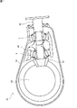
図1は、本発明の円すいころを備えているデファレンシャル装置の断面図である。このデファレンシャル装置51は、自動車のエンジンの出力を伝達する動力伝達経路に配置されており、エンジンの出力をデファレンシャル装置51の両側(図1の紙面貫通方向の両側)それぞれ配置された駆動軸(図示せず)に伝達する。
Hereinafter, embodiments of the present invention will be described with reference to the drawings.
FIG. 1 is a cross-sectional view of a differential device including the tapered rollers of the present invention. The differential device 51 is arranged in a power transmission path for transmitting the output of the engine of an automobile, and drive shafts (both sides in the paper penetrating direction in FIG. 1) arranged on both sides of the differential device 51 (FIG. 1) Not shown).
デファレンシャル装置51は、エンジンの出力を伝達するためのプロペラシャフト(図示せず)と一体回転するピニオン軸(動力伝達軸)52と、このピニオン軸52の端部に設けられているピニオンギヤ53と、このピニオンギヤ53の回転に伴い動作する差動ギヤ機構54と、これらを収容するハウジング55とを備えている。ピニオン軸52は、ハウジング55内で一対の円すいころ軸受1によって回転自在に支持されている。また、ハウジング55には、潤滑油供給路56が形成されており、この潤滑油供給路56は、図中の矢印で示すように潤滑油を誘導し一対の円すいころ軸受1に与える。円すいころ軸受1は、この潤滑油によって潤滑される。
The differential device 51 includes a pinion shaft (power transmission shaft) 52 that rotates integrally with a propeller shaft (not shown) for transmitting the output of the engine, a
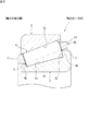
図2は、円すいころ軸受1の断面図である。円すいころ軸受1は、内輪2と、外輪3と、これら内輪2と外輪3との間に設けられた複数の円すいころ4と、これら円すいころ4を周方向に沿って所定間隔毎に保持している保持器10とを備えている。
FIG. 2 is a cross-sectional view of the tapered
内輪2は、軸受鋼や機械構造用鋼等を用いて形成された環状の部材であり、その外周側に内軌道面2aを有している。内軌道面2aは、軸方向一方側(図2では右側)から軸方向他方側(図2では左側)に向けて縮径する円すい形状を有している。外輪3は、内輪2と同様、軸受鋼や機械構造用鋼等を用いて形成された環状の部材であり、その内周側に外軌道面3aを有している。外軌道面3aは、内軌道面2aに対向しており、軸方向一方側から軸方向他方側に向けて縮径する円すい形状を有している。
The
円すいころ4は、軸受鋼等を用いて形成された部材であり、内輪2と外輪3との間に介在し、内軌道面2a及び外軌道面3aに転がり接触する。円すいころ4は、円すい台形状を有し、軸方向一方側に大端面4bを有し、軸方向他方側に直径が大端面4bよりも小さい小端面4aを有している。
The tapered
保持器10は、全体として環状であり、円すいころ4の軸方向一方側に位置する大環状部12と、円すいころ4の軸方向他方側に位置する小環状部11と、これら大環状部12と小環状部11とを連結している複数の柱部13とを有している。大環状部12と小環状部11との間であって、周方向で隣り合う柱部13の間が、円すいころ4を収容するポケットとなる。
The
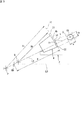
内輪2は、更に、内軌道面2aの軸方向一方側に、径方向外側へ突出している大鍔部7を有している。また、内輪2は、内軌道面2aの軸方向他方側に、径方向外側へ突出している小鍔部5を有している。大鍔部7は、その軸方向他方側に、円すいころ4の大端面4bが接触する鍔面7bを有している。この鍔面7bは凹曲面状に形成されている。この形状を具体的に説明すると、図3に示すように、鍔面7bは、所定の点Pを中心とする仮想球面71に沿った凹曲面形状を有している。図3は、内輪2及び円すいころ4の形状を説明するためのイメージ図である。なお、図3では、説明のために鍔面7bと円すいころ4の大端面4bとを離しているが、実際は接触した状態にある。図3において、前記仮想球面71の曲率半径(半径)、つまり、鍔面7bの曲率半径(半径)をRiとしている。前記点Pは、鍔面7bの中心点となる。
The
図2において、円すいころ4の大端面4bは凸曲面状に形成されており、内輪2が有する大鍔部7の鍔面7bに接触する。軸受(本実施形態では内輪2)が回転すると、大端面4bは鍔面7bに滑り接触する。大端面4bの形状を具体的に説明すると、図3に示すように、大端面4bは、所定の点Qを中心とする仮想球面72に沿った凸曲面形状を有している。図3において、前記仮想球面72の曲率半径(半径)、つまり、大端面4bの曲率半径(半径)をRrとしている。前記点Qは、大端面4bの中心点となる。
In FIG. 2, the
前記のとおり、円すいころ4の大端面4bは凸曲面形状を有しており、内輪2の鍔面7bは凹曲面形状を有していることから、両者が接触すると、これら大端面4bと鍔面7bとの間には楕円形の接触面が生じる。以下、この楕円形の接触面を接触楕円と呼ぶ。図3では、この接触楕円Sをイメージとして付記しているが、実際ではこの接触楕円Sは、大端面4bと鍔面7bとの間に発生する。接触楕円Sの全ては鍔面7bの範囲内に形成される。つまり、図3において、鍔面7bの径方向外側端縁31と径方向内側端縁32との間の範囲に接触楕円Sが生じる。
As described above, the
図3において、接触楕円Sの中心をC1としている。また、接触楕円Sの寸法に関して、鍔面7bの内周側から外周側に向かう方向(径方向)の寸法を「b」とし、その直交方向(周方向)を「a」としている。この接触楕円Sの楕円率は「b/a」となる。
In FIG. 3, the center of the contact ellipse S is C1. Further, regarding the dimension of the contact ellipse S, the dimension in the direction (diameter direction) from the inner peripheral side to the outer peripheral side of the
鍔面7bの曲率半径Riと大端面4bの曲率半径Rrとの関係について説明する。
ここで、鍔面7bと大端面4bとの接触位置から円すいころ4のコーンセンタC0までの距離を「R」とする。なお、コーンセンタC0は、円すいころ4の円すい形状(外周面形状)の頂点を意味する。また、鍔面7bと大端面4bとの接触位置は、接触楕円Sの中心C1を意味する。そして、大端面4bの曲率半径Rrは前記距離Rよりも小さく(Rr<R)、鍔面7bの曲率半径Riは前記距離Rよりも大きい(Ri>R)。
The relationship between the radius of curvature Ri of the
Here, the distance from the contact position between the
そして、本実施形態の円すいころ軸受1では、曲率半径Rr、曲率半径Ri、及び距離Rは、次の式(1)を満たす関係にある。
2≦(Ri−R)/(R−Rr)≦10 ・・・ (1)
In the tapered
2 ≦ (Ri-R) / (R-Rr) ≦ 10 ・ ・ ・ (1)
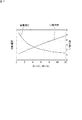
図4は、横軸を前記式(1)中の「(Ri−R)/(R−Rr)」とし、縦軸を「接触面圧」及び「1/楕円率」とした場合の計算結果を示すグラフである。「接触面圧」は、鍔面7bと大端面4bとの間で生じる接触面圧であり、「1/楕円率」は、前記接触楕円Sによる値である。
接触面圧及び楕円率を算出するための接触楕円Sの寸法a,bは、ヘルツの式を用いた接触理論により求められる。なお、この際に用いられる変数として、円すいころ4と内輪2の縦弾性係数を207.9GPa、ポアソン比を0.3、荷重を基本動定格荷重の40%になるアキシャル荷重としている。また、図4では、接触楕円Sの寸法bを一定とし、寸法aを変数とした場合のグラフである。
In FIG. 4, the calculation result when the horizontal axis is "(Ri-R) / (R-Rr)" in the above formula (1) and the vertical axis is "contact surface pressure" and "1 / ellipticity". It is a graph which shows. The "contact surface pressure" is the contact surface pressure generated between the
The dimensions a and b of the contact ellipse S for calculating the contact surface pressure and the ellipticity are obtained by the contact theory using the Hertz equation. As the variables used at this time, the Young's modulus of the tapered
接触楕円Sの形状が変化すると、鍔面7bと大端面4bとの間に生じる接触面圧及び楕円率は変化する。この接触面圧及び楕円率は、円すいころ軸受1の性能に影響する。すなわち、接触面圧を低下させることで、鍔面7bと大端面4bとの間の摩耗を防止し、軸受寿命を延ばすことができ、また、楕円率(b/a)が大きくなると、鍔面7bと大端面4bとの間における油膜の厚さが増加する。なお、図3に示す形態の接触楕円Sの楕円率(b/a)が大きくなると油膜が厚くなることは一般的に知られているが、これに関する論文として「R.J.Chittenden, D.Dowson, J.F.Dunn, C.M.Taylor: Proc.R.Soc.Lond, A397(1985)271」が知られている。
When the shape of the contact ellipse S changes, the contact surface pressure and ellipticity generated between the
図4では、楕円率の逆数(1/楕円率)を指標としている。前記のとおり楕円率(b/a)を大きくする油膜が厚くなり好ましい。楕円率の逆数の場合、その値が小さくなると油膜が厚くなる。 In FIG. 4, the reciprocal of the ellipticity (1 / ellipticity) is used as an index. As described above, the oil film that increases the ellipticity (b / a) becomes thicker, which is preferable. In the case of the reciprocal of the ellipticity, the smaller the value, the thicker the oil film.
図4に示すように、前記式(1)中の寸法比「(Ri−R)/(R−Rr)」を2以上とすることで、鍔面7bと大端面4bとの接触面圧を低減することができ、また、前記寸法比「(Ri−R)/(R−Rr)」を10以下とすることで、楕円率の逆数(a/b)が小さくなり(つまり、楕円率(b/a)が大きくなり)、鍔面7bと大端面4bとの間に形成される油膜を厚くすることができる。つまり、前記式(1)の条件を満たすことで、図2において、内輪2の大鍔部7(鍔面7b)と円すいころ4(大端面4b)との間に生じる接触面圧の低下と、これらの間に形成される油膜厚さの増大とを両立することができる。これにより、内輪2の大鍔部7と円すいころ4との間において好ましい接触形態が得られ、軸受回転時における大鍔部7と円すいころ4との間の滑り摩擦抵抗を低減することが可能となる。また、この滑り摩擦抵抗を低減することで、円すいころ軸受1の回転抵抗が低減され、また、大鍔部7と円すいころ4との間の発熱を抑制したり、摩耗を防止したりすることが可能となる。
As shown in FIG. 4, by setting the dimensional ratio "(Ri-R) / (R-Rr)" in the above formula (1) to 2 or more, the contact surface pressure between the
なお、前記寸法比「(Ri−R)/(R−Rr)」の下限値を「2」とする以外に、「3」としてもよく、更には下限値を「4」とするのが好ましい。また、前記寸法比「(Ri−R)/(R−Rr)」の上限値を「10」とする以外に、「9」としてもよく、更には「8」とするのが好ましい。
内輪2の大鍔部7と円すいころ4との間における接触形態を良好にするためには、これらの間に形成される油膜厚さがより重要であり、この点に着目すると、前記寸法比「(Ri−R)/(R−Rr)」の上限値を「6」又は「5」とするのが好ましく、この場合、寸法比(Ri−R)/(R−Rr)は、2以上であり、6(又は5)以下となる。この場合、油膜厚さを大きくすることができるため、面圧が多少大きくなっても軸受の昇温を抑えることができる。
In addition to setting the lower limit value of the dimensional ratio "(Ri-R) / (R-Rr)" to "2", it may be set to "3", and further, it is preferable to set the lower limit value to "4". .. Further, in addition to setting the upper limit value of the dimension ratio "(Ri-R) / (R-Rr)" to "10", it may be set to "9", and more preferably set to "8".
In order to improve the contact form between the
また、本実施形態では、図3により説明したように、円すいころ4の大端面4bと内輪2の鍔面7bとが接触することで生じる接触楕円Sは、この鍔面7bの径方向外側端縁31よりも径方向内側に位置している。このため、円すいころ4の大端面4bにおいて、エッジロードにより接触面圧が局所的に大きくなるのを防ぐことができる。また、図4において一定値と設定している接触楕円Sの寸法bについては、鍔面7bの径方向の寸法(つまり、径方向外側端縁31と径方向内側端縁32との間の寸法)よりも僅かに小さい値とするのが好ましい。
なお、鍔面7bにおける接触楕円Sの位置(中心C1の位置)を設定する手段としては、点P、点Q、コーンセンタC0の位置を調整すればよい。本実施形態では、図3に示すように円すいころ軸受1の中心線L0を含む断面において、点P、点Q及びコーンセンタC0は、共通する直線L1上に位置しているが、これら点P、点Q、コーンセンタC0は、共通する直線L1上に位置していなくてもよい。
Further, in the present embodiment, as described with reference to FIG. 3, the contact ellipse S generated by the contact between the
As a means for setting the position of the contact ellipse S (the position of the center C1) on the
そして、図1は、前記構成を有する円すいころ軸受1を備えたデファレンシャル装置51を示している。このデファレンシャル装置51は、ハウジング55と、このハウジング55内に設けられているピニオン軸(動力伝達軸)52と、このピニオン軸52を回転自在に支持する軸受とを備えており、この軸受が前記円すいころ軸受1である。このデファレンシャルによれば、ピニオン軸52を支持する円すいころ軸受1において、前記のとおり(図2参照)、内輪2の大鍔部7(鍔面7b)と円すいころ4(大端面4b)との間に生じる接触面圧の低下と、これらの間に形成される油膜厚さの増大とを両立することができるので、ピニオン軸52の回転抵抗を低減する等の回転性能を高めることが可能となる。
Then, FIG. 1 shows a differential device 51 including a tapered
以上のとおり開示した実施形態はすべての点で例示であって制限的なものではない。つまり、本発明の円すいころ軸受は、図示する形態に限らず本発明の範囲内において他の形態のものであってもよい。例えば、保持器10は図示した形態以外のものであってもよい。また、前記実施形態では、円すいころ軸受1をデファレンシャル装置に適用する場合について例示したが、トランスミッション装置等の他の動力伝達装置に適用することもできる。または、円すいころ軸受1を動力伝達装置以外の回転機器に適用することができる。
The embodiments disclosed as described above are exemplary in all respects and are not restrictive. That is, the tapered roller bearing of the present invention is not limited to the illustrated form, and may have other forms within the scope of the present invention. For example, the
1:円すいころ軸受 2:内輪 2a:内軌道面
3:外輪 3a:外軌道面 4:円すいころ
4b:大端面 7:大鍔部 7b:鍔面
10:保持器 31:径方向外側端縁 32:径方向内側端縁
51:デファレンシャル装置(動力伝達装置) 52:ピニオン軸(動力伝達軸)
55:ハウジング C0:コーンセンタ
C1:中心(接触位置) R:距離
Rr:大端面の曲率半径 Ri:鍔面の曲率半径
S:接触楕円
1: Tapered roller bearing 2:
55: Housing C0: Cone center C1: Center (contact position) R: Distance Rr: Radius of curvature of large end face Ri: Radius of curvature of brim surface S: Contact ellipse
Claims (3)
前記円すいころは、軸方向一方側に凸曲面状の大端面を有し、
前記大鍔部は、前記大端面と接触する凹曲面状の鍔面を有し、
前記大端面と前記鍔面との接触位置から前記円すいころのコーンセンタまでの距離をR、前記大端面の曲率半径をRr(ただし、Rr<R)、前記鍔面の曲率半径をRi(ただし、Ri>R)とすると、
2≦(Ri−R)/(R−Rr)≦10
の関係を満たしている、円すいころ軸受。 An inner ring having an inner raceway surface on the outer peripheral side and a large collar portion protruding outward in the radial direction on one side in the axial direction of the inner raceway surface, and an outer ring having an outer raceway surface on the inner peripheral side. And a plurality of cones that roll and come into contact with the inner raceway surface and the outer raceway surface.
The tapered roller has a large end face having a convex curved surface on one side in the axial direction.
The large flange portion has a concave curved flange surface that comes into contact with the large end surface.
The distance from the contact position between the large end surface and the collar surface to the cone center of the cone is R, the radius of curvature of the large end surface is Rr (where Rr <R), and the radius of curvature of the collar surface is Ri (however). , Ri> R)
2 ≦ (Ri-R) / (R-Rr) ≦ 10
Tapered roller bearings that meet the above relationships.
Priority Applications (4)
| Application Number | Priority Date | Filing Date | Title |
|---|---|---|---|
| JP2016219768A JP6825317B2 (en) | 2016-11-10 | 2016-11-10 | Tapered roller bearings and power transmission |
| US15/803,095 US10060477B2 (en) | 2016-11-10 | 2017-11-03 | Tapered roller bearing and power transmission device |
| DE102017126097.8A DE102017126097A1 (en) | 2016-11-10 | 2017-11-08 | TAPER ROLLER BEARING AND POWER TRANSMISSION DEVICE |
| CN201711108431.XA CN108071683B (en) | 2016-11-10 | 2017-11-09 | Tapered roller bearing and power transmission device |
Applications Claiming Priority (1)
| Application Number | Priority Date | Filing Date | Title |
|---|---|---|---|
| JP2016219768A JP6825317B2 (en) | 2016-11-10 | 2016-11-10 | Tapered roller bearings and power transmission |
Publications (2)
| Publication Number | Publication Date |
|---|---|
| JP2018076927A JP2018076927A (en) | 2018-05-17 |
| JP6825317B2 true JP6825317B2 (en) | 2021-02-03 |
Family
ID=62026236
Family Applications (1)
| Application Number | Title | Priority Date | Filing Date |
|---|---|---|---|
| JP2016219768A Expired - Fee Related JP6825317B2 (en) | 2016-11-10 | 2016-11-10 | Tapered roller bearings and power transmission |
Country Status (4)
| Country | Link |
|---|---|
| US (1) | US10060477B2 (en) |
| JP (1) | JP6825317B2 (en) |
| CN (1) | CN108071683B (en) |
| DE (1) | DE102017126097A1 (en) |
Families Citing this family (2)
| Publication number | Priority date | Publication date | Assignee | Title |
|---|---|---|---|---|
| JP6825317B2 (en) * | 2016-11-10 | 2021-02-03 | 株式会社ジェイテクト | Tapered roller bearings and power transmission |
| DE102019007309A1 (en) | 2018-11-23 | 2020-05-28 | Sew-Eurodrive Gmbh & Co Kg | Bearing system with one bearing and gearbox with one bearing system |
Family Cites Families (14)
| Publication number | Priority date | Publication date | Assignee | Title |
|---|---|---|---|---|
| JP2951036B2 (en) * | 1991-04-30 | 1999-09-20 | エヌティエヌ株式会社 | Tapered roller bearing |
| JPH0575520U (en) | 1992-03-19 | 1993-10-15 | 光洋精工株式会社 | Tapered roller bearing |
| JP2000065066A (en) * | 1998-08-19 | 2000-03-03 | Nippon Seiko Kk | Cylindrical roller bearing |
| JP3637866B2 (en) * | 2000-11-14 | 2005-04-13 | 日産自動車株式会社 | Toroidal continuously variable transmission |
| US6502996B2 (en) * | 2001-05-11 | 2003-01-07 | The Timken Company | Bearing with low wear and low power loss characteristics |
| JP2005076675A (en) * | 2003-08-28 | 2005-03-24 | Ntn Corp | Tapered roller bearing for transmission of automobile |
| JP2007051703A (en) * | 2005-08-18 | 2007-03-01 | Jtekt Corp | Tapered roller bearing and transmission bearing device using the same |
| JP2007051702A (en) * | 2005-08-18 | 2007-03-01 | Jtekt Corp | Tapered roller bearing and vehicle pinion shaft support device using the same |
| DE102010034618A1 (en) * | 2010-08-18 | 2012-02-23 | Schaeffler Technologies Gmbh & Co. Kg | Rolling bearing i.e. taper roller bearing, for driving system of motor car, has rolling members arranged in cage, where outer contour is formed at part of members in cage such that members form point contact with surfaces of rings |
| JP2015113972A (en) | 2013-12-16 | 2015-06-22 | 株式会社ジェイテクト | Tapered roller bearing and power transmission device |
| JP6256023B2 (en) * | 2014-01-16 | 2018-01-10 | 株式会社ジェイテクト | Tapered roller bearing and power transmission device |
| JP6350099B2 (en) * | 2014-08-11 | 2018-07-04 | 株式会社ジェイテクト | Tapered roller bearing |
| JP6492646B2 (en) * | 2014-12-26 | 2019-04-03 | 株式会社ジェイテクト | Tapered roller bearing |
| JP6825317B2 (en) * | 2016-11-10 | 2021-02-03 | 株式会社ジェイテクト | Tapered roller bearings and power transmission |
-
2016
- 2016-11-10 JP JP2016219768A patent/JP6825317B2/en not_active Expired - Fee Related
-
2017
- 2017-11-03 US US15/803,095 patent/US10060477B2/en active Active
- 2017-11-08 DE DE102017126097.8A patent/DE102017126097A1/en not_active Withdrawn
- 2017-11-09 CN CN201711108431.XA patent/CN108071683B/en not_active Expired - Fee Related
Also Published As
| Publication number | Publication date |
|---|---|
| JP2018076927A (en) | 2018-05-17 |
| US10060477B2 (en) | 2018-08-28 |
| CN108071683B (en) | 2020-12-29 |
| CN108071683A (en) | 2018-05-25 |
| DE102017126097A1 (en) | 2018-05-17 |
| US20180128316A1 (en) | 2018-05-10 |
Similar Documents
| Publication | Publication Date | Title |
|---|---|---|
| JP6492646B2 (en) | Tapered roller bearing | |
| JPWO2009020087A1 (en) | Double row roller bearing | |
| WO2012099120A1 (en) | Roller bearing | |
| JP6256023B2 (en) | Tapered roller bearing and power transmission device | |
| JPWO2015076271A1 (en) | Cylindrical roller bearing and transmission bearing device | |
| JP6874455B2 (en) | Rolling bearing | |
| JP6825317B2 (en) | Tapered roller bearings and power transmission | |
| JP6028377B2 (en) | Tapered roller bearing | |
| JPH0712135A (en) | Rolling bearing | |
| JP2017125572A (en) | Tapered roller bearing | |
| JP6991823B2 (en) | Track wheels for thrust roller bearings and thrust roller bearings | |
| JP2012202453A (en) | Self-aligning roller bearing | |
| JP2017053420A (en) | Rolling bearing | |
| CN107588094B (en) | Tapered Roller Bearings | |
| CN106050904A (en) | Spherical roller bearing arrangement | |
| JP2014105809A (en) | Retainer for rolling bearing | |
| US20170122368A1 (en) | Tapered Roller Bearing | |
| JP5668877B2 (en) | Bi-splitting rolling bearing and bearing device having the same | |
| JP2016102525A (en) | Self-aligning roller bearing | |
| JP4453804B2 (en) | Rolling bearing | |
| JP6350099B2 (en) | Tapered roller bearing | |
| JP5625474B2 (en) | Bi-splitting rolling bearing and bearing device having the same | |
| KR101885140B1 (en) | A low torque taper roller bearing | |
| JP2015222089A (en) | Needle bearing | |
| JP2015132320A (en) | Self-aligning roller bearing |
Legal Events
| Date | Code | Title | Description |
|---|---|---|---|
| A621 | Written request for application examination |
Free format text: JAPANESE INTERMEDIATE CODE: A621 Effective date: 20191014 |
|
| A977 | Report on retrieval |
Free format text: JAPANESE INTERMEDIATE CODE: A971007 Effective date: 20200813 |
|
| A131 | Notification of reasons for refusal |
Free format text: JAPANESE INTERMEDIATE CODE: A131 Effective date: 20200901 |
|
| TRDD | Decision of grant or rejection written | ||
| A01 | Written decision to grant a patent or to grant a registration (utility model) |
Free format text: JAPANESE INTERMEDIATE CODE: A01 Effective date: 20201215 |
|
| A61 | First payment of annual fees (during grant procedure) |
Free format text: JAPANESE INTERMEDIATE CODE: A61 Effective date: 20201228 |
|
| R150 | Certificate of patent or registration of utility model |
Ref document number: 6825317 Country of ref document: JP Free format text: JAPANESE INTERMEDIATE CODE: R150 |
|
| LAPS | Cancellation because of no payment of annual fees |