以下、図面を参照して、本発明の実施の形態について説明する。なお、以下の図面において同一または相当する部分には同一の参照番号を付し、その説明は繰返さない。
Hereinafter, embodiments of the present invention will be described with reference to the drawings. In the following drawings, the same or corresponding parts will be given the same reference number, and the explanation will not be repeated.
(実施の形態1)
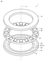
図1から図6を参照して、実施の形態1に係るスラストころ軸受1及びスラストころ軸受用軌道輪(第1のスラストころ軸受用軌道輪10、第2のスラストころ軸受用軌道輪20)を説明する。スラストころ軸受1は、第1のスラストころ軸受用軌道輪10と、第2のスラストころ軸受用軌道輪20と、複数の第1のころ30とを主に備える。スラストころ軸受1は、第1のころ30を保持する保持器40をさらに備えてもよい。第1のスラストころ軸受用軌道輪10は、第1のころ30を介して、回転軸8を中心に、第2のスラストころ軸受用軌道輪20に対して回転する。本明細書において、内側は、回転軸8に近い側として定義され、外側は、回転軸8から遠い側として定義される。本明細書において、径方向は、回転軸8に直交する方向として定義される。
(Embodiment 1)
With reference to FIGS. 1 to 6, the thrust roller bearing 1 and the raceway ring for the thrust roller bearing according to the first embodiment (the raceway ring 10 for the first thrust roller bearing and the raceway ring 20 for the second thrust roller bearing). To explain. The thrust roller bearing 1 mainly includes a raceway ring 10 for a first thrust roller bearing, a raceway ring 20 for a second thrust roller bearing, and a plurality of first rollers 30. The thrust roller bearing 1 may further include a cage 40 for holding the first roller 30. The first thrust roller bearing raceway ring 10 rotates about the rotation shaft 8 with respect to the second thrust roller bearing raceway ring 20 via the first roller 30. In the present specification, the inner side is defined as the side closer to the rotating shaft 8, and the outer side is defined as the side farther from the rotating shaft 8. In the present specification, the radial direction is defined as a direction orthogonal to the rotation axis 8.
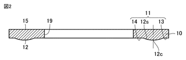
第1のスラストころ軸受用軌道輪10は、環状の板部材である。第1のスラストころ軸受用軌道輪10は、第1のころ30が転動する軌道面11と、軌道面11とは反対側の第1の主面15とを有する。
The first thrust roller bearing raceway ring 10 is an annular plate member. The raceway ring 10 for a first thrust roller bearing has a raceway surface 11 on which the first roller 30 rolls, and a first main surface 15 on the side opposite to the raceway surface 11.
第1のスラストころ軸受用軌道輪10の軌道面11は、第1のスラストころ軸受用軌道輪10の第1のフルクラウニング部12の第1の表面12sを含む。第1のスラストころ軸受用軌道輪10の軌道面11は、第1の外側平坦部13と、第1の内側平坦部14とをさらに含んでもよい。第1のフルクラウニング部12に対して外側に、第1の外側平坦部13が設けられてもよい。第1のフルクラウニング部12に対して内側に、第1の内側平坦部14が設けられてもよい。
The raceway surface 11 of the raceway ring 10 for the first thrust roller bearing includes the first surface 12s of the first full crowning portion 12 of the raceway ring 10 for the first thrust roller bearing. The raceway surface 11 of the raceway ring 10 for the first thrust roller bearing may further include a first outer flat portion 13 and a first inner flat portion 14. A first outer flat portion 13 may be provided on the outer side of the first full crowning portion 12. A first inner flat portion 14 may be provided inside the first full crowning portion 12.
第1の主面15は、平らであってもよい。平らな第1の主面15は、第1のスラストころ軸受用軌道輪10がハウジング(図示せず)に隙間なく取り付けられることを可能にする。そのため、スラスト荷重がスラストころ軸受1に負荷されるとき、スラストころ軸受1は、スラスト荷重を適切に受けることができる。
The first main surface 15 may be flat. The flat first main surface 15 allows the first thrust roller bearing raceway ring 10 to be tightly attached to the housing (not shown). Therefore, when the thrust load is applied to the thrust roller bearing 1, the thrust roller bearing 1 can appropriately receive the thrust load.
第2のスラストころ軸受用軌道輪20は、環状の板部材である。第2のスラストころ軸受用軌道輪20は、第1のころ30が転動する軌道面21と、軌道面21とは反対側の第2の主面25とを有する。
The second thrust roller bearing raceway ring 20 is an annular plate member. The raceway ring 20 for a second thrust roller bearing has a raceway surface 21 on which the first roller 30 rolls, and a second main surface 25 on the side opposite to the raceway surface 21.
第2のスラストころ軸受用軌道輪20の軌道面21は、第2のスラストころ軸受用軌道輪20の第1のフルクラウニング部22の第1の表面22sを含む。第2のスラストころ軸受用軌道輪20の軌道面21は、第2の外側平坦部23と、第2の内側平坦部24とをさらに含んでもよい。第1のフルクラウニング部22に対して外側に、第2の外側平坦部23が設けられてもよい。第1のフルクラウニング部22に対して内側に、第2の内側平坦部24が設けられてもよい。
The raceway surface 21 of the second thrust roller bearing raceway ring 20 includes the first surface 22s of the first full crowning portion 22 of the second thrust roller bearing raceway ring 20. The raceway surface 21 of the raceway ring 20 for the second thrust roller bearing may further include a second outer flat portion 23 and a second inner flat portion 24. A second outer flat portion 23 may be provided on the outer side of the first full crowning portion 22. A second inner flat portion 24 may be provided inside the first full crowning portion 22.
第2の主面25は、平らであってもよい。平らな第2の主面25は、第2のスラストころ軸受用軌道輪20がハウジング(図示せず)に隙間なく取り付けられることを可能にする。そのため、スラスト荷重がスラストころ軸受1に負荷されるとき、スラストころ軸受1は、スラスト荷重を適切に受けることができる。
The second main surface 25 may be flat. The flat second main surface 25 allows the raceway ring 20 for the second thrust roller bearing to be tightly attached to the housing (not shown). Therefore, when the thrust load is applied to the thrust roller bearing 1, the thrust roller bearing 1 can appropriately receive the thrust load.
本実施の形態では、第1のスラストころ軸受用軌道輪10の軌道面11及び第2のスラストころ軸受用軌道輪20の軌道面21は、各々、第1のフルクラウニング部22を有している。第1のスラストころ軸受用軌道輪10の軌道面11及び第2のスラストころ軸受用軌道輪20の軌道面21の少なくとも1つが、第1のころ30に接触する第1のフルクラウニング部22を有してもよい。第1のスラストころ軸受用軌道輪10の軌道面11及び第2のスラストころ軸受用軌道輪20の軌道面21の一方のみに第1のフルクラウニング部が設けられており、第1のスラストころ軸受用軌道輪10の軌道面11及び第2のスラストころ軸受用軌道輪20の軌道面21の他方には第1のフルクラウニング部が設けられていなくてもよい。本明細書において、クラウニング部は、軌道面11,21に形成された膨らみを意味する。本明細書において、フルクラウニング部は、ころ(第1のころ30)の面取り部(面取り部32)を除くころ(第1のころ30)の転動面(第1転動面31)の全てに対向するクラウニング部を意味する。
In the present embodiment, the raceway surface 11 of the first thrust roller bearing raceway ring 10 and the raceway surface 21 of the second thrust roller bearing raceway ring 20 each have a first full crowning portion 22. There is. At least one of the raceway surface 11 of the raceway ring 10 for the first thrust roller bearing and the raceway surface 21 of the raceway ring 20 for the second thrust roller bearing 20 comes into contact with the first roller 30 to form a first full crowning portion 22. May have. A first full crowning portion is provided only on one of the raceway surface 11 of the raceway ring 10 for the first thrust roller bearing and the raceway surface 21 of the racetrack ring 20 for the second thrust roller bearing, and the first thrust roller is provided. The first full crowning portion may not be provided on the other side of the raceway surface 11 of the bearing raceway ring 10 and the raceway surface 21 of the second thrust roller bearing raceway ring 20. In the present specification, the crowning portion means a bulge formed on the raceway surfaces 11 and 21. In the present specification, the full crowning portion refers to all of the rolling surfaces (first rolling surface 31) of the rollers (first roller 30) except for the chamfered portion (chamfered portion 32) of the rollers (first roller 30). It means a crowning part facing to.
第1のスラストころ軸受用軌道輪10の第1のフルクラウニング部12は、第1のスラストころ軸受用軌道輪10の周方向に環状に延在している。第1のスラストころ軸受用軌道輪10の第1のフルクラウニング部12は、スラストころ軸受1の径方向における、第1のスラストころ軸受用軌道輪10の軌道面11の中央部に設けられてもよい。第1のスラストころ軸受用軌道輪10の第1のフルクラウニング部12は、第1の外側平坦部13及び第1の内側平坦部14から第1のころ30の第1転動面31に向けて膨出してもよい。第1のスラストころ軸受用軌道輪10の第1のフルクラウニング部12は、第1の外側平坦部13および第2の内側平坦部24に滑らかに連なるように形成されてもよい。
The first full crowning portion 12 of the raceway ring 10 for the first thrust roller bearing extends in an annular direction in the circumferential direction of the raceway ring 10 for the first thrust roller bearing. The first full crowning portion 12 of the raceway ring 10 for the first thrust roller bearing is provided at the center of the raceway surface 11 of the raceway ring 10 for the first thrust roller bearing in the radial direction of the thrust roller bearing 1. May be good. The first full crowning portion 12 of the raceway ring 10 for the first thrust roller bearing is directed from the first outer flat portion 13 and the first inner flat portion 14 toward the first rolling surface 31 of the first roller 30. May swell. The first full crowning portion 12 of the raceway ring 10 for the first thrust roller bearing may be formed so as to be smoothly connected to the first outer flat portion 13 and the second inner flat portion 24.
第2のスラストころ軸受用軌道輪20の第1のフルクラウニング部22は、第2のスラストころ軸受用軌道輪20の周方向に環状に延在している。第2のスラストころ軸受用軌道輪20の第1のフルクラウニング部22は、スラストころ軸受1の径方向における、第2のスラストころ軸受用軌道輪20の軌道面21の中央部に設けられてもよい。第2のスラストころ軸受用軌道輪20の第1のフルクラウニング部22は、第2の外側平坦部23及び第2の内側平坦部24から第1のころ30の第1転動面31に向けて膨出してもよい。第2のスラストころ軸受用軌道輪20の第1のフルクラウニング部22は、第1の外側平坦部13および第2の内側平坦部24に滑らかに連なるように形成されてもよい。
The first full crowning portion 22 of the second thrust roller bearing raceway ring 20 extends in an annular direction in the circumferential direction of the second thrust roller bearing raceway ring 20. The first full crowning portion 22 of the second thrust roller bearing raceway ring 20 is provided at the center of the raceway surface 21 of the second thrust roller bearing raceway ring 20 in the radial direction of the thrust roller bearing 1. May be good. The first full crowning portion 22 of the raceway ring 20 for the second thrust roller bearing is directed from the second outer flat portion 23 and the second inner flat portion 24 toward the first rolling surface 31 of the first roller 30. May swell. The first full crowning portion 22 of the raceway ring 20 for the second thrust roller bearing may be formed so as to be smoothly connected to the first outer flat portion 13 and the second inner flat portion 24.
図5及び図6を参照して、スラストころ軸受1の径方向の断面(第1のスラストころ軸受用軌道輪10の径方向の断面、第2のスラストころ軸受用軌道輪20の径方向の断面)における、第1のフルクラウニング部12,22の第1の表面12s,22sの形状は、第1の単一円弧である。第1のスラストころ軸受用軌道輪10の第1のフルクラウニング部12は、点O1を中心とする単一の曲率半径r1を有する円の一部の形状を有する。第2のスラストころ軸受用軌道輪20の第1のフルクラウニング部22は、点O2を中心とする単一の曲率半径r2を有する円の一部の形状を有する。
With reference to FIGS. 5 and 6, a radial cross section of the thrust roller bearing 1 (a radial cross section of the first thrust roller bearing raceway ring 10 and a radial cross section of the second thrust roller bearing raceway ring 20). The shape of the first surfaces 12s and 22s of the first full crowning portions 12 and 22 in the cross section) is a first single arc. The first full crowning portion 12 of the raceway ring 10 for the first thrust roller bearing has the shape of a part of a circle having a single radius of curvature r1 centered on the point O1. The first full crowning portion 22 of the raceway ring 20 for the second thrust roller bearing has the shape of a part of a circle having a single radius of curvature r 2 centered on the point O 2 .
本実施の形態では、第2のスラストころ軸受用軌道輪20の第1のフルクラウニング部22の曲率半径r2は、第1のスラストころ軸受用軌道輪10の第1のフルクラウニング部12の曲率半径r1に等しい。第2のスラストころ軸受用軌道輪20の第1のフルクラウニング部22の曲率半径r2は、第1のスラストころ軸受用軌道輪10の第1のフルクラウニング部12の曲率半径r1と異なってもよい。
In the present embodiment, the radius of curvature r 2 of the first full crowning portion 22 of the raceway ring 20 for the second thrust roller bearing is the first full crowning portion 12 of the raceway ring 10 for the first thrust roller bearing. Equal to radius of curvature r 1 . The radius of curvature r 2 of the first full crowning portion 22 of the raceway ring 20 for the second thrust roller bearing is different from the radius of curvature r 1 of the first full crowning portion 12 of the raceway ring 10 for the first thrust roller bearing. May be.
図6を参照して、第1のころ30の第1ころ回転軸30rが延在する方向(スラストころ軸受1の径方向)における第1のころ30の第1転動面31の中心31cは、スラストころ軸受1の径方向における第1のスラストころ軸受用軌道輪10の第1のフルクラウニング部12の中心12cに接触してもよい。第1のころ30の第1ころ回転軸30rが延在する方向(スラストころ軸受1の径方向)における第1のころ30の第1転動面31の中心31cは、スラストころ軸受1の径方向における第2のスラストころ軸受用軌道輪20の第1のフルクラウニング部22の中心22cに接触してもよい。
With reference to FIG. 6, the center 31c of the first rolling surface 31 of the first roller 30 in the direction in which the first roller rotation shaft 30r of the first roller 30 extends (the radial direction of the thrust roller bearing 1) is , The center 12c of the first full crowning portion 12 of the raceway ring 10 for the first thrust roller bearing in the radial direction of the thrust roller bearing 1 may be contacted. The center 31c of the first rolling surface 31 of the first roller 30 in the direction in which the first roller rotation shaft 30r of the first roller 30 extends (the radial direction of the thrust roller bearing 1) is the diameter of the thrust roller bearing 1. It may come into contact with the center 22c of the first full crowning portion 22 of the raceway ring 20 for the second thrust roller bearing in the direction.
第1のフルクラウニング部12を含む第1のスラストころ軸受用軌道輪10及び第1のフルクラウニング部22を含む第2のスラストころ軸受用軌道輪20の製造方法の一例は、以下の工程を備えてもよい。略一定の厚さを有する環状の板部材が準備される。第1のフルクラウニング部12,22が残るように環状の板部材の部分を削ることによって、第1のフルクラウニング部12,22が形成される。
An example of a method for manufacturing a first thrust roller bearing raceway ring 10 including the first full crowning portion 12 and a second thrust roller bearing raceway ring 20 including the first full crowning portion 22 is described in the following steps. You may prepare. An annular plate member having a substantially constant thickness is prepared. The first full crowning portions 12, 22 are formed by scraping the portion of the annular plate member so that the first full crowning portions 12, 22 remain.
第1のフルクラウニング部12を含む第1のスラストころ軸受用軌道輪10及び第1のフルクラウニング部22を含む第2のスラストころ軸受用軌道輪20の製造方法の別の例は、以下の工程を備えてもよい。略一定の厚さを有する環状の板部材が準備される。環状の板部材の一部を肉盛りすることによって、第1のフルクラウニング部12,22が形成される。
Another example of a method for manufacturing a first thrust roller bearing raceway ring 10 including the first full crowning portion 12 and a second thrust roller bearing raceway ring 20 including the first full crowning portion 22 is as follows. A process may be provided. An annular plate member having a substantially constant thickness is prepared. By overlaying a part of the annular plate member, the first full crowning portions 12, 22 are formed.
第1のころ30は、第1のスラストころ軸受用軌道輪10と第2のスラストころ軸受用軌道輪20との間に、第1のスラストころ軸受用軌道輪10及び第2のスラストころ軸受用軌道輪20の周方向に沿って配置されている。第1のころ30は、円筒ころまたは針状ころであってもよい。第1のころ30は、各々、第1のスラストころ軸受用軌道輪10及び第2のスラストころ軸受用軌道輪20の軌道面11,21、特に、第1のフルクラウニング部12,22に接触する第1転動面31を有する。第1のころ30はクラウニング部を有していない。そのため、スラストころ軸受1のコストが低減され得る。
The first roller 30 is a raceway ring 10 for a first thrust roller bearing and a second thrust roller bearing between a raceway ring 10 for a first thrust roller bearing and a raceway ring 20 for a second thrust roller bearing. The bearing wheels 20 are arranged along the circumferential direction. The first roller 30 may be a cylindrical roller or a needle-shaped roller. The first rollers 30 are in contact with the raceway surfaces 11 and 21 of the first thrust roller bearing raceway ring 10 and the second thrust roller bearing raceway ring 20, in particular, the first full crowning portions 12 and 22, respectively. It has a first rolling surface 31 to be bearing. The first time 30 does not have a crowning portion. Therefore, the cost of the thrust roller bearing 1 can be reduced.
図4を参照して、第1のころ30は、スラストころ軸受1の径方向に沿う第1ころ回転軸30rを中心に回転しながら、スラストころ軸受用軌道輪(第1のスラストころ軸受用軌道輪10及び第2のスラストころ軸受用軌道輪20)の軌道面11,21上を転動する。第1のころ30は、第1のころ長さL1を有する。第1のころ長さL1は、第1ころ回転軸30rにおける、第1のころ30の第1外側端面33と第1のころ30の第1内側端面34との間の距離として定義される。第1のころ30の第1転動面31の第1外側端部36は、第1外側端面33側の第1転動面31の端部である。第1のころ30の第1転動面31の第1内側端部37は、第1内側端面34側の第1転動面31の端部である。第1のころ30は、第1のころ30の第1外側端面33と第1転動面31との間並びに第1のころ30の第1外側端面33と第1転動面31との間に、面取り部32を含んでもよい。
With reference to FIG. 4, the first roller 30 rotates about the first roller rotation shaft 30r along the radial direction of the thrust roller bearing 1 and is a raceway ring for the thrust roller bearing (for the first thrust roller bearing). It rolls on the raceway surfaces 11 and 21 of the raceway ring 10 and the raceway ring 20) for the second thrust roller bearing. The first roller 30 has a first roller length L 1 . The first roller length L 1 is defined as the distance between the first outer end surface 33 of the first roller 30 and the first inner end surface 34 of the first roller 30 on the first roller rotation shaft 30r. .. The first outer end portion 36 of the first rolling surface 31 of the first roller 30 is the end portion of the first rolling surface 31 on the side of the first outer end surface 33. The first inner end portion 37 of the first rolling surface 31 of the first roller 30 is the end portion of the first rolling surface 31 on the side of the first inner end surface 34. The first roller 30 is between the first outer end surface 33 and the first rolling surface 31 of the first roller 30 and between the first outer end surface 33 and the first rolling surface 31 of the first roller 30. May include a chamfered portion 32.
保持器40は、周方向に間隔をあけて配置される複数のポケット45を有する。第1のころ30は、それぞれ、ポケット45に収容される。保持器40は、第1のころ30が互いに接触しないように、第1のころ30を保持する。
The cage 40 has a plurality of pockets 45 that are spaced apart in the circumferential direction. Each of the first rolls 30 is housed in a pocket 45. The cage 40 holds the first rollers 30 so that the first rollers 30 do not come into contact with each other.
本実施の形態のスラストころ軸受1の動作状態を説明する。スラストころ軸受1の動作状態において、保持器40のポケット45に収容された第1のころ30は、スラストころ軸受用軌道輪(第1のスラストころ軸受用軌道輪10及び第2のスラストころ軸受用軌道輪20)の軌道面11,21上を転動する。具体的には、第1のころ30は、第1のスラストころ軸受用軌道輪10に設けられた第1のフルクラウニング部12上と、第2のスラストころ軸受用軌道輪20に設けられた第1のフルクラウニング部22上とを転動する。第1のスラストころ軸受用軌道輪10は、第1のころ30を介して、回転軸8を中心に、第2のスラストころ軸受用軌道輪20に対して回転する。
The operating state of the thrust roller bearing 1 of the present embodiment will be described. In the operating state of the thrust roller bearing 1, the first roller 30 housed in the pocket 45 of the cage 40 is a raceway ring for a thrust roller bearing (a raceway ring 10 for a first thrust roller bearing and a second thrust roller bearing). Rolls on the raceway surfaces 11 and 21 of the bearing ring 20). Specifically, the first roller 30 is provided on the first full crowning portion 12 provided on the first thrust roller bearing raceway ring 10 and on the second thrust roller bearing raceway ring 20. Roll on the first full crowning section 22. The first thrust roller bearing raceway ring 10 rotates about the rotation shaft 8 with respect to the second thrust roller bearing raceway ring 20 via the first roller 30.
本実施形態の実施例を説明する。
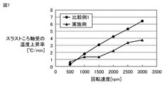
図7に、第2のスラストころ軸受用軌道輪20に対する第1のスラストころ軸受用軌道輪10の回転速度と、本実施例のスラストころ軸受1の温度上昇率と、比較例1のスラストころ軸受の温度上昇率との関係を示す。第2のスラストころ軸受用軌道輪20に対する第1のスラストころ軸受用軌道輪10の回転速度は、1分間当たりの、第2のスラストころ軸受用軌道輪20に対する第1のスラストころ軸受用軌道輪10の回転数として定義される。
An embodiment of the present embodiment will be described.
FIG. 7 shows the rotation speed of the first thrust roller bearing raceway ring 10 with respect to the second thrust roller bearing raceway ring 20, the temperature rise rate of the thrust roller bearing 1 of the present embodiment, and the thrust roller of Comparative Example 1. The relationship with the temperature rise rate of the bearing is shown. The rotation speed of the first thrust roller bearing raceway ring 10 with respect to the second thrust roller bearing raceway ring 20 is the rotation speed of the first thrust roller bearing with respect to the second thrust roller bearing raceway ring 20 per minute. It is defined as the number of revolutions of the ring 10.
本実施例のスラストころ軸受1では、第1のスラストころ軸受用軌道輪10の第1のフルクラウニング部12は、520mmの曲率半径r1を有し、かつ、第2のスラストころ軸受用軌道輪20の第1のフルクラウニング部22は、520mmの曲率半径r2を有している。比較例1のスラストころ軸受では、本実施形態のスラストころ軸受1から、第1のフルクラウニング部12,22が省略されている。
In the thrust roller bearing 1 of the present embodiment, the first full crowning portion 12 of the raceway ring 10 for the first thrust roller bearing has a radius of curvature r1 of 520 mm, and the raceway for the second thrust roller bearing. The first full-crowning portion 22 of the ring 20 has a radius of curvature r 2 of 520 mm. In the thrust roller bearing of Comparative Example 1, the first full crowning portions 12 and 22 are omitted from the thrust roller bearing 1 of the present embodiment.
本実施例のスラストころ軸受1及び比較例1のスラストころ軸受では、第1のころ30は、第1のころ30の第1ころ回転軸30rに沿って5.4mmの第1のころ長さを有する。本実施例のスラストころ軸受1及び比較例1のスラストころ軸受には、3kNのスラスト荷重が印加されている。本実施例のスラストころ軸受1及び比較例1のスラストころ軸受では、ISO VG32の粘度を有する潤滑油が使用されている。本実施例のスラストころ軸受1及び比較例1のスラストころ軸受の温度上昇率は、第1の主面15及び第2の主面25の温度上昇率である。
In the thrust roller bearing 1 of this embodiment and the thrust roller bearing of Comparative Example 1, the first roller 30 has a first roller length of 5.4 mm along the first roller rotation shaft 30r of the first roller 30. Have. A thrust load of 3 kN is applied to the thrust roller bearing 1 of this embodiment and the thrust roller bearing of Comparative Example 1. In the thrust roller bearing 1 of this embodiment and the thrust roller bearing of Comparative Example 1, a lubricating oil having a viscosity of ISO VG32 is used. The temperature rise rate of the thrust roller bearing 1 of this embodiment and the thrust roller bearing of Comparative Example 1 is the temperature rise rate of the first main surface 15 and the second main surface 25.
図7に示されるように、本実施例のスラストころ軸受1の温度上昇率及び比較例1のスラストころ軸受の温度上昇率は、いずれも、第2のスラストころ軸受用軌道輪20に対する第1のスラストころ軸受用軌道輪10の回転速度が増加するにつれて、増加する。しかし、本実施例のスラストころ軸受1は、比較例1のスラストころ軸受よりも低いスラストころ軸受1の温度上昇率を有している。表1に示されるように、本実施例のスラストころ軸受1の発熱量は、比較例1のスラストころ軸受の発熱量よりも少ない。
As shown in FIG. 7, the temperature rise rate of the thrust roller bearing 1 of this embodiment and the temperature rise rate of the thrust roller bearing of Comparative Example 1 are both the first with respect to the raceway ring 20 for the second thrust roller bearing. It increases as the rotational speed of the raceway ring 10 for thrust roller bearings increases. However, the thrust roller bearing 1 of the present embodiment has a lower temperature rise rate of the thrust roller bearing 1 than the thrust roller bearing of the comparative example 1. As shown in Table 1, the calorific value of the thrust roller bearing 1 of this embodiment is smaller than the calorific value of the thrust roller bearing of Comparative Example 1.
比較例1のスラストころ軸受に比べて、本実施例のスラストころ軸受1が、スラストころ軸受1の発熱量を減少させ、かつ、スラストころ軸受1の温度上昇率を低減することができる理由を、以下説明する。
The reason why the thrust roller bearing 1 of the present embodiment can reduce the calorific value of the thrust roller bearing 1 and reduce the temperature rise rate of the thrust roller bearing 1 as compared with the thrust roller bearing of the comparative example 1. , Will be described below.
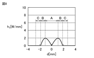
図8は、本実施例における、スラストころ軸受1の径方向における第1のころ30の第1転動面31上の位置dと、位置dでの単位長さ当たりの発熱量h1との関係を示す。本明細書において、位置dでの単位長さ当たりの発熱量は、第1転動面31と軌道面11,21とが線接触する長さで規格化された、位置dにおける第1転動面31と軌道面11,21との間で発生する熱量として定義される。図9は、本実施例における、スラストころ軸受1の径方向における第1のころ30の第1転動面31上の位置dと、位置dでの、第1のころ30の第1転動面31と軌道面11,21との間の接触面圧P1との関係を示す。図6を参照して、スラストころ軸受1の径方向における第1のころ30の第1転動面31上の中心31cの位置は、d=0として定義される。第1のころ30の中心31cに対して外側にある第1のころ30の第1転動面31上の位置dは、正の位置(d>0)と定義される。第1のころ30の中心31cに対して内側にある第1のころ30の第1転動面31上の位置dは、負の位置(d<0)と定義される。
FIG. 8 shows the position d on the first rolling surface 31 of the first roller 30 in the radial direction of the thrust roller bearing 1 in the present embodiment and the calorific value h 1 per unit length at the position d. Show the relationship. In the present specification, the calorific value per unit length at the position d is standardized by the length at which the first rolling surface 31 and the raceway surfaces 11 and 21 are in line contact with each other, and the first rolling at the position d. It is defined as the amount of heat generated between the surface 31 and the raceway surfaces 11 and 21. FIG. 9 shows the position d on the first rolling surface 31 of the first roller 30 in the radial direction of the thrust roller bearing 1 in the present embodiment and the first rolling of the first roller 30 at the position d. The relationship between the contact surface pressure P1 between the surface 31 and the raceway surfaces 11 and 21 is shown. With reference to FIG. 6, the position of the center 31c on the first rolling surface 31 of the first roller 30 in the radial direction of the thrust roller bearing 1 is defined as d = 0. The position d on the first rolling surface 31 of the first roller 30, which is outside the center 31c of the first roller 30, is defined as a positive position (d> 0). The position d on the first rolling surface 31 of the first roller 30 inside the center 31c of the first roller 30 is defined as a negative position (d <0).
第1のころ30の中心31cにおいて、第1のころ30の第1転動面31は、スラストころ軸受用軌道輪(第1のスラストころ軸受用軌道輪10、第2のスラストころ軸受用軌道輪20)の軌道面11,21に線接触している。第1のころ30の中心31cでは、第2のスラストころ軸受用軌道輪20の軌道面21に対する第1のスラストころ軸受用軌道輪10の軌道面11の周速度は、第1のころ30の第1転動面31の周速度に等しい。第1のころ30の中心31cでは、第1のころ30の第1転動面31は、軌道面11,21に対して滑らない。そのため、第1のころ30の中心31cでは、第1のころ30の第1転動面31と軌道面11,21との間の差動滑りに起因する熱は発生しない。第1のころ30の中心31cにおける単位長さ当たりの発熱量h1は、0[W/mm]である。
At the center 31c of the first roller 30, the first rolling surface 31 of the first roller 30 is a raceway ring for a thrust roller bearing (a raceway ring 10 for a first thrust roller bearing, a raceway for a second thrust roller bearing). The wheels 20) are in line contact with the raceway surfaces 11 and 21. At the center 31c of the first roller 30, the peripheral speed of the raceway surface 11 of the first thrust roller bearing raceway ring 10 with respect to the raceway surface 21 of the second thrust roller bearing raceway ring 20 is the first roller 30. It is equal to the peripheral speed of the first rolling surface 31. At the center 31c of the first roller 30, the first rolling surface 31 of the first roller 30 does not slide with respect to the raceway surfaces 11 and 21. Therefore, at the center 31c of the first roller 30, heat due to differential slip between the first rolling surface 31 of the first roller 30 and the raceway surfaces 11 and 21 is not generated. The calorific value h 1 per unit length at the center 31c of the first roller 30 is 0 [W / mm].
これに対して、第1のころ30の位置dが第1のころ30の中心31cから離れるにつれて、第1のころ30の第1転動面31は、軌道面11,21に対してより多く滑る。具体的には、第1のころ30の第1転動面31の周速度は、第1のころ30の第1転動面31上の位置dによらず、一定である。これに対し、第2のスラストころ軸受用軌道輪20の軌道面21に対する第1のスラストころ軸受用軌道輪10の軌道面11の周速度は、スラストころ軸受1の回転軸8からスラストころ軸受1の外側に向かうにつれて増加する。第1のころ30の位置dが第1のころ30の中心31cから離れるにつれて、第1のスラストころ軸受用軌道輪10の軌道面11の周速度と第1のころ30の第1転動面31の周速度との間の差が大きくなる。そのため、第1のころ30の位置dが第1のころ30の中心31cから離れるにつれて、第1のころ30の第1転動面31と軌道面11,21との間の差動滑りは大きくなる。この差動滑りが大きくなるにつれて、第1のころ30の第1転動面31と軌道面11,21との間で発生する熱が増加する。以下、この熱は、周速度差の増加に起因する熱と定義される。
On the other hand, as the position d of the first roller 30 moves away from the center 31c of the first roller 30, the first rolling surface 31 of the first roller 30 becomes larger with respect to the orbital planes 11 and 21. slide. Specifically, the peripheral speed of the first rolling surface 31 of the first roller 30 is constant regardless of the position d on the first rolling surface 31 of the first roller 30. On the other hand, the peripheral speed of the raceway surface 11 of the raceway ring 10 for the first thrust roller bearing with respect to the raceway surface 21 of the raceway ring 20 for the second thrust roller bearing is from the rotary shaft 8 of the thrust roller bearing 1 to the thrust roller bearing. It increases toward the outside of 1. As the position d of the first roller 30 moves away from the center 31c of the first roller 30, the peripheral speed of the raceway surface 11 of the raceway ring 10 for the first thrust roller bearing and the first rolling surface of the first roller 30 The difference between the peripheral speed of 31 and the peripheral speed becomes large. Therefore, as the position d of the first roller 30 moves away from the center 31c of the first roller 30, the differential slip between the first rolling surface 31 of the first roller 30 and the raceway surfaces 11 and 21 increases. Become. As this differential slip increases, the heat generated between the first rolling surface 31 of the first roller 30 and the raceway surfaces 11 and 21 increases. Hereinafter, this heat is defined as heat caused by an increase in the peripheral speed difference.
第1のころ30の第1転動面31と軌道面11,21との間の接触面圧P1が増加(減少)するにつれて、この差動滑りによって第1のころ30の第1転動面31との軌道面11,21との間で発生する熱が増加(減少)する。以下、この増加(減少)された熱は、接触面圧に起因する熱と定義される。
As the contact surface pressure P1 between the first rolling surface 31 of the first roller 30 and the raceway surfaces 11 and 21 increases (decreases), this differential slip causes the first rolling of the first roller 30. The heat generated between the surface 31 and the raceway surfaces 11 and 21 increases (decreases). Hereinafter, this increased (decreased) heat is defined as heat caused by the contact surface pressure.
本実施例では、スラストころ軸受用軌道輪(第1のスラストころ軸受用軌道輪10、第2のスラストころ軸受用軌道輪20)の軌道面11,21は、第1のころ30に接触する第1のフルクラウニング部12,22を有する。スラストころ軸受1の径方向の断面(スラストころ軸受用軌道輪(第1のスラストころ軸受用軌道輪10、第2のスラストころ軸受用軌道輪20)の径方向の断面)における第1のフルクラウニング部12,22の第1の表面12s,22sの形状は第1の単一円弧である。第1のフルクラウニング部12,22の第1の表面12s,22sの形状は第1の単一円弧であるため、第1のころ30の位置dが第1のころ30の中心31cから離れるにつれて、第1のフルクラウニング部12,22の第1の表面12s,22sは、第1のころ30の第1転動面31から離れる形状を有している。そのため、図9に示されるように、第1のころ30の位置dが第1のころ30の中心31cから離れるにつれて、第1のころ30の第1転動面31と軌道面11,21との間の接触面圧P1が減少し、接触面圧P1に起因する熱は減少する。
In this embodiment, the raceway surfaces 11 and 21 of the raceway rings for thrust roller bearings (the raceway ring 10 for the first thrust roller bearing and the raceway ring 20 for the second thrust roller bearing) come into contact with the first roller 30. It has first full crowning portions 12, 22. The first full in the radial cross section of the thrust roller bearing 1 (the radial cross section of the raceway ring for the thrust roller bearing (the raceway ring 10 for the first thrust roller bearing, the raceway ring 20 for the second thrust roller bearing)). The shapes of the first surfaces 12s and 22s of the crowning portions 12 and 22 are the first single arc. Since the shapes of the first surfaces 12s and 22s of the first full crowning portions 12 and 22 are the first single arc, as the position d of the first roller 30 moves away from the center 31c of the first roller 30. The first surfaces 12s and 22s of the first full crowning portions 12 and 22 have a shape away from the first rolling surface 31 of the first roller 30. Therefore, as shown in FIG. 9, as the position d of the first roller 30 moves away from the center 31c of the first roller 30, the first rolling surface 31 and the raceway surface 11 and 21 of the first roller 30 become The contact surface pressure P 1 during is reduced, and the heat caused by the contact surface pressure P 1 is reduced.
スラスト荷重がスラストころ軸受1に印加されて、第1のスラストころ軸受用軌道輪10、第2のスラストころ軸受用軌道輪20及び第1のころ30が弾性変形する。そのため、図8及び図9に示される領域Aでは、第1のころ30の第1転動面31は、スラストころ軸受用軌道輪(第1のスラストころ軸受用軌道輪10、第2のスラストころ軸受用軌道輪20)の軌道面11,21に線接触している。領域Aでは、接触面圧の減少に起因する熱の減少の影響よりも、周速度差の増加に起因する熱の増加の影響が大きい。したがって、領域Aでは、第1のころ30の位置dが第1のころ30の中心31cから離れるにつれて、第1のころ30の位置dにおける単位長さ当たりの発熱量h1は増加する。
A thrust load is applied to the thrust roller bearing 1, and the first roller bearing raceway ring 10, the second thrust roller bearing raceway ring 20, and the first roller 30 are elastically deformed. Therefore, in the region A shown in FIGS. 8 and 9, the first rolling surface 31 of the first roller 30 is a raceway ring for a thrust roller bearing (a raceway ring 10 for a first thrust roller bearing, a second thrust). The raceway rings 20) for roller bearings are in line contact with the raceway surfaces 11 and 21. In the region A, the effect of the increase in heat due to the increase in the peripheral speed difference is larger than the effect of the decrease in heat due to the decrease in the contact surface pressure. Therefore, in the region A, as the position d of the first roller 30 moves away from the center 31c of the first roller 30, the calorific value h 1 per unit length at the position d of the first roller 30 increases.
図8及び図9に示される領域Bにおいても、領域Aと同様に、第1のころ30の第1転動面31は、軌道面11,21に線接触している。しかし、第1のフルクラウニング部12,22の第1の表面12s,22sの形状は第1の単一円弧であるため、領域Bでは、領域Aよりもさらに、第1のころ30の第1転動面31と軌道面11,21との間の接触面圧P1が減少する。領域Bでは、周速度差の増加に起因する熱の増加の影響よりも、接触面圧の減少に起因する熱の減少の影響が大きくなる。したがって、領域Bでは、第1のころ30の位置dが第1のころ30の中心31cから離れるにつれて、第1のころ30の位置dにおける単位長さ当たりの発熱量h1は減少する。
In the region B shown in FIGS. 8 and 9, the first rolling surface 31 of the first roller 30 is in line contact with the raceway planes 11 and 21 as in the region A. However, since the shapes of the first surfaces 12s and 22s of the first full crowning portions 12 and 22 are the first single arcs, in the region B, the first of the first rollers 30 is further than the region A. The contact surface pressure P1 between the rolling surface 31 and the raceway surfaces 11 and 21 decreases. In region B, the effect of the decrease in heat due to the decrease in contact surface pressure is greater than the effect of the increase in heat due to the increase in peripheral velocity difference. Therefore, in the region B, as the position d of the first roller 30 moves away from the center 31c of the first roller 30, the calorific value h 1 per unit length at the position d of the first roller 30 decreases.
第1のフルクラウニング部12,22の第1の表面12s,22sの形状は第1の単一円弧である。第1のフルクラウニング部12,22の第1の表面12s,22sは、第1のころ30の位置dが第1のころ30の中心31cから離れるにつれて、第1のころ30の第1転動面31から離れる形状を有している。そのため、図8及び図9に示される領域Cでは、第1のスラストころ軸受用軌道輪10、第2のスラストころ軸受用軌道輪20及び第1のころ30が弾性変形しても、第1のころ30の第1転動面31は、軌道面11,21に線接触しない。
The shapes of the first surfaces 12s and 22s of the first full crowning portions 12 and 22 are the first single arc. The first surfaces 12s and 22s of the first full crowning portions 12, 22 are the first rolling of the first roller 30 as the position d of the first roller 30 moves away from the center 31c of the first roller 30. It has a shape away from the surface 31. Therefore, in the region C shown in FIGS. 8 and 9, even if the first roller bearing raceway ring 10, the second thrust roller bearing raceway ring 20, and the first roller 30 are elastically deformed, the first roller is first. The first rolling surface 31 of the roller 30 does not make line contact with the raceway surfaces 11 and 21.
領域Cでは、第1のころ30の第1転動面31とスラストころ軸受用軌道輪(第1のスラストころ軸受用軌道輪10、第2のスラストころ軸受用軌道輪20)の軌道面11,21との間の差動滑りは発生しない。領域Cでは、第1のころ30の第1転動面31とスラストころ軸受用軌道輪(第1のスラストころ軸受用軌道輪10、第2のスラストころ軸受用軌道輪20)の軌道面11,21との間の接触面圧P1はゼロとなる。領域Cでは、第1のころ30の位置dにおける単位長さ当たりの発熱量h1はゼロとなる。本実施例の第1のフルクラウニング部12,22は、後述する比較例1におけるエッジロードが発生することを防ぐことができる。
In the region C, the first rolling surface 31 of the first roller 30 and the raceway surface 11 of the raceway ring for the thrust roller bearing (the raceway ring 10 for the first thrust roller bearing and the raceway ring 20 for the second thrust roller bearing). No differential slip occurs between the bearings and 21. In the region C, the first rolling surface 31 of the first roller 30 and the raceway surface 11 of the raceway ring for the thrust roller bearing (the raceway ring 10 for the first thrust roller bearing and the raceway ring 20 for the second thrust roller bearing). The contact surface pressure P 1 between and 21 becomes zero. In the region C, the calorific value h 1 per unit length at the position d of the first roller 30 becomes zero. The first full crowning portions 12 and 22 of this embodiment can prevent the edge load in Comparative Example 1 described later from occurring.
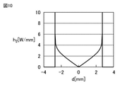
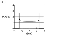
図10は、比較例1における、スラストころ軸受1の径方向における第1のころ30の第1転動面31上の位置dと、位置dでの単位長さ当たりの発熱量h2との関係を示す。図11は、比較例1における、スラストころ軸受1の径方向における第1のころ30の第1転動面31上の位置dと、位置dでの、第1のころ30の転動面とスラストころ軸受用軌道輪の軌道面との間の接触面圧P2との関係を示す。
FIG. 10 shows the position d on the first rolling surface 31 of the first roller 30 in the radial direction of the thrust roller bearing 1 in Comparative Example 1 and the calorific value h 2 per unit length at the position d. Show the relationship. FIG. 11 shows the position d on the first rolling surface 31 of the first roller 30 in the radial direction of the thrust roller bearing 1 in Comparative Example 1 and the rolling surface of the first roller 30 at the position d. The relationship between the contact surface pressure P 2 and the raceway surface of the raceway ring for thrust roller bearings is shown.
比較例1では、スラストころ軸受用軌道輪の軌道面は平坦であって、第1のフルクラウニング部12,22を有さない。スラスト荷重がスラストころ軸受用軌道輪に印加されて、スラストころ軸受用軌道輪及び第1のころ30は弾性変形する。そのため、第1のころ30の第1転動面31は、スラストころ軸受用軌道輪の軌道面に線接触している。
In Comparative Example 1, the raceway surface of the raceway ring for the thrust roller bearing is flat and does not have the first full crowning portions 12 and 22. A thrust load is applied to the bearing ring for the thrust roller bearing, and the bearing ring for the thrust roller bearing and the first roller 30 are elastically deformed. Therefore, the first rolling surface 31 of the first roller 30 is in line contact with the raceway surface of the raceway ring for the thrust roller bearing.
図11に示されるように、第1のころ30の位置dが第1のころ30の中心31cから離れるにつれて、第1のころ30の第1転動面31とスラストころ軸受用軌道輪の軌道面との間の接触面圧P2が増加する。特に、比較例1では、第1のころ30の第1転動面31の端部(第1外側端部36、第1内側端部37)において、第1のころ30の第1転動面31とスラストころ軸受用軌道輪の軌道面との間の接触面圧P2が急激に増加する。比較例1では、第1のころ30の第1転動面31の端部(第1外側端部36、第1内側端部37)とスラストころ軸受用軌道輪の軌道面との間に、大きなエッジロードが発生する。
As shown in FIG. 11, as the position d of the first roller 30 moves away from the center 31c of the first roller 30, the raceway of the first rolling surface 31 of the first roller 30 and the raceway ring for the thrust roller bearing. The contact surface pressure P 2 between the surfaces increases. In particular, in Comparative Example 1, at the end portion (first outer end portion 36, first inner end portion 37) of the first rolling surface 31 of the first roller 30, the first rolling surface of the first roller 30 The contact surface pressure P 2 between 31 and the raceway surface of the raceway ring for thrust roller bearings increases sharply. In Comparative Example 1, between the end portion of the first rolling surface 31 of the first roller 30 (first outer end portion 36, first inner end portion 37) and the raceway surface of the raceway ring for the thrust roller bearing, Large edge load occurs.
そのため、比較例1では、第1のころ30の位置dが第1のころ30の中心31cから離れるにつれて、周速度差に起因する熱が増加するとともに、接触面圧P2に起因する熱も増加する。図10に示されるように、比較例1では、第1のころ30の位置dが第1のころ30の中心31cから離れるにつれて、第1のころ30の第1転動面31とスラストころ軸受用軌道輪の軌道面との間に発生する熱が急激に増加する。
Therefore, in Comparative Example 1, as the position d of the first roller 30 moves away from the center 31c of the first roller 30, the heat caused by the difference in peripheral speed increases, and the heat caused by the contact surface pressure P 2 also increases. To increase. As shown in FIG. 10, in Comparative Example 1, as the position d of the first roller 30 moves away from the center 31c of the first roller 30, the first rolling surface 31 of the first roller 30 and the thrust roller bearing are used. The heat generated between the bearing and the raceway surface of the bearing ring increases sharply.
このようにして、本実施例のスラストころ軸受1は、比較例1のスラストころ軸受1に比べて、第1のころ30の第1転動面31とスラストころ軸受用軌道輪(第1のスラストころ軸受用軌道輪10、第2のスラストころ軸受用軌道輪20)の軌道面11,21との間で発生する熱を減少させることができる。本実施例のスラストころ軸受1は、比較例1のスラストころ軸受に比べて、スラストころ軸受1の温度上昇を抑制することができる。
In this way, the thrust roller bearing 1 of the present embodiment has a first rolling surface 31 of the first roller 30 and a raceway ring for the thrust roller bearing (first) as compared with the thrust roller bearing 1 of the comparative example 1. It is possible to reduce the heat generated between the raceway rings 10 for thrust roller bearings and the raceway surfaces 11 and 21 of the raceway rings 20) for second thrust roller bearings. The thrust roller bearing 1 of the present embodiment can suppress the temperature rise of the thrust roller bearing 1 as compared with the thrust roller bearing of the comparative example 1.
表2に示されるように、本実施例のスラストころ軸受1は、比較例2及び比較例3のスラストころ軸受よりも、第1のころ30の第1転動面31がスラストころ軸受用軌道輪(第1のスラストころ軸受用軌道輪10、第2のスラストころ軸受用軌道輪20)の軌道面11,21に対して滑ることによって発生する熱を低減することができる。
As shown in Table 2, in the thrust roller bearing 1 of this embodiment, the first rolling surface 31 of the first roller 30 is a track for the thrust roller bearing as compared with the thrust roller bearings of Comparative Example 2 and Comparative Example 3. It is possible to reduce the heat generated by sliding on the raceway surfaces 11 and 21 of the wheels (the raceway ring 10 for the first thrust roller bearing and the raceway ring 20 for the second thrust roller bearing).
比較例2のスラストころ軸受では、スラストころ軸受用軌道輪の軌道面は、本実施例のスラストころ軸受1の第1のフルクラウニング部12,22に代えて、対数フルクラウニング部を有している。スラストころ軸受の径方向の断面(スラストころ軸受用軌道輪の径方向の断面)における対数フルクラウニング部の表面の形状は、対数曲線である。比較例3のスラストころ軸受では、スラストころ軸受用軌道輪の軌道面は、本実施例のスラストころ軸受1の第1のフルクラウニング部12,22に代えて、部分クラウニング部を有している。部分クラウニング部は、ころ(第1のころ30)の転動面(第1転動面31)の一部のみに対向するクラウニング部を意味する。
In the thrust roller bearing of Comparative Example 2, the raceway surface of the raceway ring for the thrust roller bearing has a logarithmic full crowning portion instead of the first full crowning portions 12 and 22 of the thrust roller bearing 1 of the present embodiment. There is. The shape of the surface of the logarithmic full crowning portion in the radial cross section of the thrust roller bearing (the radial cross section of the raceway ring for the thrust roller bearing) is a logarithmic curve. In the thrust roller bearing of Comparative Example 3, the raceway surface of the raceway ring for the thrust roller bearing has a partial crowning portion instead of the first full crowning portions 12 and 22 of the thrust roller bearing 1 of the present embodiment. .. The partial crowning portion means a crowning portion facing only a part of the rolling surface (first rolling surface 31) of the roller (first roller 30).
スラスト荷重がスラストころ軸受1に印加されて、第1のスラストころ軸受用軌道輪10、第2のスラストころ軸受用軌道輪20及び第1のころ30が弾性変形する。第1のころ30の第1転動面31は、軌道面11,21に線接触する。第1のフルクラウニング部12,22の第1の表面12s,22sの形状は第1の単一円弧であるため、本実施例は、比較例2及び比較例3よりも、第1のころ30の第1転動面31が軌道面11,21に線接触する長さを減少させることができる。そのため、本実施例のスラストころ軸受1は、第1のころ30の第1転動面31がスラストころ軸受用軌道輪(第1のスラストころ軸受用軌道輪10、第2のスラストころ軸受用軌道輪20)の軌道面11,21に対して滑ることによって発生する熱を低減することができる。
A thrust load is applied to the thrust roller bearing 1, and the first roller bearing raceway ring 10, the second thrust roller bearing raceway ring 20, and the first roller 30 are elastically deformed. The first rolling surface 31 of the first roller 30 makes line contact with the raceway surfaces 11 and 21. Since the shapes of the first surfaces 12s and 22s of the first full crowning portions 12 and 22 are the first single arcs, this embodiment is more than the comparative example 2 and the comparative example 3 in the first roller 30. The length of the first rolling surface 31 in line contact with the raceway surfaces 11 and 21 can be reduced. Therefore, in the thrust roller bearing 1 of the present embodiment, the first rolling surface 31 of the first roller 30 is a raceway ring for a thrust roller bearing (a raceway ring 10 for a first thrust roller bearing and a second thrust roller bearing). It is possible to reduce the heat generated by sliding on the raceway surfaces 11 and 21 of the raceway ring 20).
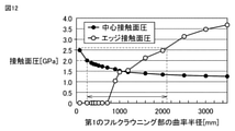
図12は、本実施の形態における、第1のフルクラウニング部12,22の曲率半径r1,r2と、中心接触面圧と、エッジ接触面圧との関係を表す。エッジ接触面圧は、第1のころ30の第1転動面31の端部(第1外側端部36、第1内側端部37)における、第1のころ30の第1転動面31と本実施の形態のスラストころ軸受用軌道輪(第1のスラストころ軸受用軌道輪10、第2のスラストころ軸受用軌道輪20)の軌道面11,21との間の接触面圧として定義される。中心接触面圧は、第1のころ30の中心31cにおける、第1のころ30の第1転動面31と本実施の形態のスラストころ軸受用軌道輪(第1のスラストころ軸受用軌道輪10、第2のスラストころ軸受用軌道輪20)の軌道面11,21との間の接触面圧として定義される。
FIG. 12 shows the relationship between the radii of curvature r1 and r2 of the first full crowning portions 12 and 22, the center contact surface pressure, and the edge contact surface pressure in the present embodiment. The edge contact surface pressure is the first rolling surface 31 of the first roller 30 at the end portion (first outer end portion 36, first inner end portion 37) of the first rolling surface 31 of the first roller 30. Is defined as the contact surface pressure between the raceway surface 11 and 21 of the raceway ring for thrust roller bearings (the raceway ring 10 for the first thrust roller bearing and the raceway ring 20 for the second thrust roller bearing) of the present embodiment. Will be done. The center contact surface pressure is the first rolling surface 31 of the first roller 30 and the bearing ring for the thrust roller bearing of the present embodiment (the bearing ring for the first thrust roller bearing) at the center 31c of the first roller 30. 10. It is defined as the contact surface pressure between the raceway surfaces 11 and 21 of the second thrust roller bearing raceway ring 20).
エッジ接触面圧が大きくなると、第1のころ30の第1転動面31の端部(第1外側端部36、第1内側端部37)と軌道面11,21との接触部において、スラストころ軸受用軌道輪(第1のスラストころ軸受用軌道輪10、第2のスラストころ軸受用軌道輪20)が破損してしまう。このようなスラストころ軸受用軌道輪(第1のスラストころ軸受用軌道輪10、第2のスラストころ軸受用軌道輪20)の破損を防止するために、エッジ接触面圧は、2.6GPa以下であってもよく、2.49GPa以下であってもよく、2.15GPa以下であってもよく、1.6GPa以下であってもよい。このようなスラストころ軸受用軌道輪(第1のスラストころ軸受用軌道輪10、第2のスラストころ軸受用軌道輪20)の破損を防止するために、本実施の形態の第1のフルクラウニング部12,22の曲率半径r1,r2は、2100mm以下であってもよく、2000nm以下であってもよく、1600mm以下であってもよく、1200mm以下であってもよい。
When the edge contact surface pressure becomes large, at the contact portion between the end portion (first outer end portion 36, first inner end portion 37) of the first rolling surface 31 of the first roller 30 and the raceway surfaces 11 and 21. The raceway wheels for thrust roller bearings (the raceway ring 10 for the first thrust roller bearing and the raceway ring 20 for the second thrust roller bearing) are damaged. In order to prevent such damage to the bearing wheels for thrust roller bearings (the bearing ring 10 for the first thrust roller bearing and the bearing ring 20 for the second thrust roller bearing), the edge contact surface pressure is 2.6 GPa or less. It may be 2.49 GPa or less, 2.15 GPa or less, or 1.6 GPa or less. In order to prevent such damage to the raceway wheels for thrust roller bearings (the raceway ring 10 for the first thrust roller bearing and the raceway ring 20 for the second thrust roller bearing), the first full crowning of the present embodiment is performed. The radii of curvature r 1 and r 2 of the portions 12 and 22 may be 2100 mm or less, 2000 nm or less, 1600 mm or less, or 1200 mm or less.
本実施の形態のスラストころ軸受用軌道輪(第1のスラストころ軸受用軌道輪10、第2のスラストころ軸受用軌道輪20)の軌道面11,21は、第1のフルクラウニング部12,22を有している。そのため、図9及び図11に示されるように、本実施の形態の中心接触面圧(P1(d=0))は、比較例1の中心接触面圧(P2(d=0))よりも大きい。
The raceway surfaces 11 and 21 of the raceway wheels for thrust roller bearings (the raceway ring 10 for the first thrust roller bearing and the raceway ring 20 for the second thrust roller bearing) of the present embodiment are the first full crowning portions 12, Has 22. Therefore, as shown in FIGS. 9 and 11, the central contact surface pressure (P 1 (d = 0)) of the present embodiment is the central contact surface pressure (P 2 (d = 0)) of Comparative Example 1 . Greater than.
本実施の形態の中心接触面圧が大きくなると、第1のころ30の中心31cと本実施の形態のスラストころ軸受用軌道輪(第1のスラストころ軸受用軌道輪10、第2のスラストころ軸受用軌道輪20)の軌道面11,21との接触部において、本実施の形態のスラストころ軸受用軌道輪(第1のスラストころ軸受用軌道輪10、第2のスラストころ軸受用軌道輪20)が破損してしまう。このようなスラストころ軸受用軌道輪(第1のスラストころ軸受用軌道輪10、第2のスラストころ軸受用軌道輪20)の破損を防止するために、本実施の形態の中心接触面圧は、2.0GPa以下であってもよく、1.8GPa以下であってもよく、1.7GPa以下であってもよく、1.67GPa以下であってもよい。このようなスラストころ軸受用軌道輪(第1のスラストころ軸受用軌道輪10、第2のスラストころ軸受用軌道輪20)の破損を防止するために、本実施の形態の第1のフルクラウニング部12,22の曲率半径r1,r2は、250mm以上であってもよく、445mm以上であってもよく、600mm以上であってもよく、720mm以上であってもよい。
When the center contact surface pressure of the present embodiment becomes large, the center 31c of the first roller 30 and the raceway ring for the thrust roller bearing of the present embodiment (the raceway ring 10 for the first thrust roller bearing, the second thrust roller) At the contact portion of the bearing raceway ring 20) with the raceway surfaces 11 and 21, the thrust roller bearing raceway ring of the present embodiment (first thrust roller bearing raceway ring 10, second thrust roller bearing raceway ring 10) 20) will be damaged. In order to prevent such damage to the bearing wheels for thrust roller bearings (the bearing ring 10 for the first thrust roller bearing and the bearing ring 20 for the second thrust roller bearing), the central contact surface pressure of the present embodiment is set. , 2.0 GPa or less, 1.8 GPa or less, 1.7 GPa or less, or 1.67 GPa or less. In order to prevent such damage to the raceway wheels for thrust roller bearings (the raceway ring 10 for the first thrust roller bearing and the raceway ring 20 for the second thrust roller bearing), the first full crowning of the present embodiment is performed. The radii of curvature r 1 and r 2 of the portions 12 and 22 may be 250 mm or more, 445 mm or more, 600 mm or more, or 720 mm or more.
本実施の形態のスラストころ軸受1及びスラストころ軸受用軌道輪(第1のスラストころ軸受用軌道輪10、第2のスラストころ軸受用軌道輪20)の効果を説明する。
The effects of the thrust roller bearing 1 and the raceway ring for the thrust roller bearing (the raceway ring 10 for the first thrust roller bearing and the raceway ring 20 for the second thrust roller bearing) of the present embodiment will be described.
本実施の形態のスラストころ軸受1は、第1のスラストころ軸受用軌道輪10と、第2のスラストころ軸受用軌道輪20と、第1のスラストころ軸受用軌道輪10と第2のスラストころ軸受用軌道輪20との間に、第1のスラストころ軸受用軌道輪10及び第2のスラストころ軸受用軌道輪20の周方向に沿って配置された複数の第1のころ30とを備える。第1のスラストころ軸受用軌道輪10及び第2のスラストころ軸受用軌道輪20は、各々、第1のころ30が転動する軌道面11,21を含む。第1のスラストころ軸受用軌道輪10の軌道面11及び第2のスラストころ軸受用軌道輪20の軌道面21の少なくとも1つは、第1のころ30に接触する第1のフルクラウニング部12,22を有する。スラストころ軸受1の径方向の断面における第1のフルクラウニング部12,22の第1の表面12s,22sの形状は、第1の単一円弧である。
The thrust roller bearing 1 of the present embodiment includes a first thrust roller bearing raceway ring 10, a second thrust roller bearing raceway ring 20, a first thrust roller bearing raceway ring 10, and a second thrust. A plurality of first rollers 30 arranged along the circumferential direction of the first thrust roller bearing raceway ring 10 and the second thrust roller bearing raceway ring 20 are placed between the roller bearing raceway ring 20. Be prepared. The first thrust roller bearing raceway ring 10 and the second thrust roller bearing raceway ring 20 each include raceway surfaces 11 and 21 on which the first roller 30 rolls. At least one of the raceway surface 11 of the raceway ring 10 for the first thrust roller bearing and the raceway surface 21 of the raceway ring 20 for the second thrust roller bearing 20 is a first full crowning portion 12 in contact with the first roller 30. , 22. The shape of the first surfaces 12s and 22s of the first full crowning portions 12 and 22 in the radial cross section of the thrust roller bearing 1 is a first single arc.
第1の表面12s,22sの形状が第1の単一円弧である第1のフルクラウニング部12,22は、周速度差に起因する熱及び接触面圧に起因する熱を減少させることができる。本実施の形態のスラストころ軸受1は、第1のころ30の第1転動面31がスラストころ軸受用軌道輪(第1のスラストころ軸受用軌道輪10、第2のスラストころ軸受用軌道輪20)の軌道面11,21に対して滑ることによって発生する熱を低減することができる。本実施の形態のスラストころ軸受1は、この熱に起因してスラストころ軸受用軌道輪(第1のスラストころ軸受用軌道輪10、第2のスラストころ軸受用軌道輪20)の軌道面11,21に表面起点剥離が発生することを防止することができる。
The first full crowning portions 12 and 22 having the shape of the first surfaces 12s and 22s as the first single arc can reduce the heat caused by the peripheral speed difference and the heat caused by the contact surface pressure. .. In the thrust roller bearing 1 of the present embodiment, the first rolling surface 31 of the first roller 30 is a raceway ring for a thrust roller bearing (a raceway ring 10 for a first thrust roller bearing, a raceway for a second thrust roller bearing). It is possible to reduce the heat generated by sliding on the raceway surfaces 11 and 21 of the ring 20). The thrust roller bearing 1 of the present embodiment is a raceway surface 11 of a raceway ring for a thrust roller bearing (a raceway ring 10 for a first thrust roller bearing and a raceway ring 20 for a second thrust roller bearing) due to this heat. , 21 can be prevented from causing surface origin peeling.
第1の表面12s,22sの形状が第1の単一円弧である第1のフルクラウニング部12,22は、第1のころ30の端部(第1外側端部36、第1内側端部37)とスラストころ軸受用軌道輪(第1のスラストころ軸受用軌道輪10、第2のスラストころ軸受用軌道輪20)の軌道面11,21との間に発生するエッジロードを減少させることができる。本実施の形態のスラストころ軸受1は、このエッジロードに起因してスラストころ軸受用軌道輪(第1のスラストころ軸受用軌道輪10、第2のスラストころ軸受用軌道輪20)が損傷を受けることを防止することができる。
The first full crowning portions 12 and 22 having the shape of the first surfaces 12s and 22s as the first single arc are the ends of the first rollers 30 (first outer end portion 36 and first inner end portion). 37) To reduce the edge load generated between the raceway surfaces 11 and 21 of the raceway wheels for thrust roller bearings (the raceway ring 10 for the first thrust roller bearing and the raceway ring 20 for the second thrust roller bearing). Can be done. In the thrust roller bearing 1 of the present embodiment, the raceway rings for thrust roller bearings (the raceway ring 10 for the first thrust roller bearing and the raceway ring 20 for the second thrust roller bearing) are damaged due to this edge load. It is possible to prevent receiving.
本実施の形態のスラストころ軸受1では、第1の単一円弧は、250mm以上2100mm以下の曲率半径r1,r2を有する。そのため、スラストころ軸受用軌道輪(第1のスラストころ軸受用軌道輪10、第2のスラストころ軸受用軌道輪20)が破損することが防がれ得る。
In the thrust roller bearing 1 of the present embodiment, the first single arc has radii of curvature r 1 and r 2 of 250 mm or more and 2100 mm or less. Therefore, it is possible to prevent the raceway rings for thrust roller bearings (the raceway ring 10 for the first thrust roller bearing and the raceway ring 20 for the second thrust roller bearing) from being damaged.
本実施の形態のスラストころ軸受用軌道輪(第1のスラストころ軸受用軌道輪10、第2のスラストころ軸受用軌道輪20)は、複数の第1のころ30が転動する軌道面11,21を備える。軌道面11,21は、第1のころ30に接触する第1のフルクラウニング部12,22を有する。スラストころ軸受用軌道輪(第1のスラストころ軸受用軌道輪10、第2のスラストころ軸受用軌道輪20)の径方向の断面における第1のフルクラウニング部12,22の第1の表面12s,22sの形状は、第1の単一円弧である。
In the raceway ring for thrust roller bearings (the raceway ring 10 for the first thrust roller bearing and the raceway ring 20 for the second thrust roller bearing) of the present embodiment, the raceway surface 11 on which the plurality of first rollers 30 roll. , 21 is provided. The raceway surfaces 11 and 21 have first full crowning portions 12 and 22 that come into contact with the first rollers 30. The first surface 12s of the first full crowning portions 12, 22 in the radial cross section of the raceway wheels for thrust roller bearings (the raceway ring 10 for the first thrust roller bearing, the raceway ring 20 for the second thrust roller bearing). , 22s is the first single arc.
第1の表面12s,22sの形状が第1の単一円弧である第1のフルクラウニング部12,22は、周速度差に起因する熱及び接触面圧に起因する熱を減少させることができる。本実施の形態のスラストころ軸受用軌道輪(第1のスラストころ軸受用軌道輪10、第2のスラストころ軸受用軌道輪20)は、第1のころ30がスラストころ軸受用軌道輪(第1のスラストころ軸受用軌道輪10、第2のスラストころ軸受用軌道輪20)の軌道面11,21に対して滑ることによって発生する熱を低減することができる。本実施の形態のスラストころ軸受用軌道輪(第1のスラストころ軸受用軌道輪10、第2のスラストころ軸受用軌道輪20)は、この熱に起因してスラストころ軸受用軌道輪(第1のスラストころ軸受用軌道輪10、第2のスラストころ軸受用軌道輪20)の軌道面11,21に表面起点剥離が発生することを防止することができる。
The first full crowning portions 12 and 22 having the shape of the first surfaces 12s and 22s as the first single arc can reduce the heat caused by the peripheral speed difference and the heat caused by the contact surface pressure. .. In the raceway ring for thrust roller bearings (the raceway ring 10 for the first thrust roller bearing, the raceway ring 20 for the second thrust roller bearing) of the present embodiment, the first roller 30 is the raceway ring for the thrust roller bearing (the first). It is possible to reduce the heat generated by sliding on the raceway surfaces 11 and 21 of the first thrust roller bearing raceway ring 10 and the second thrust roller bearing raceway ring 20). The raceway ring for thrust roller bearings (the raceway ring 10 for the first thrust roller bearing, the raceway ring 20 for the second thrust roller bearing) of the present embodiment is caused by this heat, and the raceway ring for the thrust roller bearing (the first). It is possible to prevent surface origin peeling from occurring on the raceway surfaces 11 and 21 of the first thrust roller bearing raceway ring 10 and the second thrust roller bearing raceway ring 20).
第1の表面12s,22sの形状が第1の単一円弧である第1のフルクラウニング部12,22は、第1のころ30の端部(第1外側端部36、第1内側端部37)とスラストころ軸受用軌道輪(第1のスラストころ軸受用軌道輪10、第2のスラストころ軸受用軌道輪20)の軌道面11,21との間に発生するエッジロードを減少させることができる。本実施の形態のスラストころ軸受用軌道輪(第1のスラストころ軸受用軌道輪10、第2のスラストころ軸受用軌道輪20)は、このエッジロードに起因してスラストころ軸受用軌道輪(第1のスラストころ軸受用軌道輪10、第2のスラストころ軸受用軌道輪20)が損傷を受けることを防止することができる。
The first full crowning portions 12 and 22 having the shape of the first surfaces 12s and 22s as the first single arc are the ends of the first rollers 30 (first outer end portion 36 and first inner end portion). 37) To reduce the edge load generated between the raceway surfaces 11 and 21 of the raceway wheels for thrust roller bearings (the raceway ring 10 for the first thrust roller bearing and the raceway ring 20 for the second thrust roller bearing). Can be done. The raceway ring for thrust roller bearings (the raceway ring 10 for the first thrust roller bearing, the raceway ring 20 for the second thrust roller bearing) of the present embodiment is a raceway ring for thrust roller bearings due to this edge load (1st thrust roller bearing raceway ring 10). It is possible to prevent the first thrust roller bearing raceway ring 10 and the second thrust roller bearing raceway ring 20) from being damaged.
本実施の形態のスラストころ軸受用軌道輪(第1のスラストころ軸受用軌道輪10、第2のスラストころ軸受用軌道輪20)では、第1の単一円弧は、250mm以上2100mm以下の曲率半径r1,r2を有する。そのため、スラストころ軸受用軌道輪(第1のスラストころ軸受用軌道輪10、第2のスラストころ軸受用軌道輪20)が破損することが防がれ得る。
In the raceway ring for thrust roller bearings (first raceway ring 10 for thrust roller bearings, raceway ring 20 for second thrust roller bearings) of the present embodiment, the first single arc has a curvature of 250 mm or more and 2100 mm or less. It has radii r 1 and r 2 . Therefore, it is possible to prevent the raceway rings for thrust roller bearings (the raceway ring 10 for the first thrust roller bearing and the raceway ring 20 for the second thrust roller bearing) from being damaged.
(実施の形態2)
図13を参照して、実施の形態2に係るスラストころ軸受1a及びスラストころ軸受用軌道輪(第1のスラストころ軸受用軌道輪10a、第2のスラストころ軸受用軌道輪20a)を説明する。本実施の形態のスラストころ軸受1a及びスラストころ軸受用軌道輪(第1のスラストころ軸受用軌道輪10a、第2のスラストころ軸受用軌道輪20a)は、実施の形態1のスラストころ軸受1及びスラストころ軸受用軌道輪(第1のスラストころ軸受用軌道輪10、第2のスラストころ軸受用軌道輪20)と同様の構成を備えるが、主に以下の点で異なる。
(Embodiment 2)
The thrust roller bearing 1a and the raceway ring for the thrust roller bearing (the raceway ring 10a for the first thrust roller bearing and the raceway ring 20a for the second thrust roller bearing) according to the second embodiment will be described with reference to FIG. .. The thrust roller bearing 1a and the raceway ring for the thrust roller bearing (the raceway ring 10a for the first thrust roller bearing and the raceway ring 20a for the second thrust roller bearing) of the present embodiment are the thrust roller bearing 1 of the first embodiment. And, it has the same configuration as the raceway ring for thrust roller bearings (the raceway ring 10 for the first thrust roller bearing, the raceway ring 20 for the second thrust roller bearing), but is mainly different in the following points.
本実施の形態のスラストころ軸受1aでは、第1のころ30aは、円錐ころである。円錐ころである第1のころ30aは、第1内側端部37から第1外側端部36に向かうにつれて、次第に大きくなる直径を有する。
In the thrust roller bearing 1a of the present embodiment, the first roller 30a is a conical roller. The first roller 30a, which is a conical roller, has a diameter that gradually increases from the first inner end 37 to the first outer end 36.
本実施の形態のスラストころ軸受1aでは、第1のスラストころ軸受用軌道輪10aの軌道面11a,21aは、図2及び図5に示される第1の外側平坦部13及び第1の内側平坦部14を含んでいない。第1のスラストころ軸受用軌道輪10aは、軌道面11aに対して外側に位置する第1の外側鍔部51と、軌道面11aに対して内側に位置する第1の内側鍔部52とを含んでいる。第1の外側鍔部51及び第1の内側鍔部52は、スラストころ軸受1aの径方向における第1のころ30aの位置を規制する。第1の外側鍔部51及び第1の内側鍔部52の少なくとも1つは第1のころ30aに接触して、第1のころ30aをガイドしてもよい。
In the thrust roller bearing 1a of the present embodiment, the raceway surfaces 11a and 21a of the raceway ring 10a for the first thrust roller bearing are the first outer flat portion 13 and the first inner flat portion shown in FIGS. 2 and 5. Does not include part 14. The raceway ring 10a for the first thrust roller bearing has a first outer flange portion 51 located outside the raceway surface 11a and a first inner flange portion 52 located inside the raceway surface 11a. Includes. The first outer flange portion 51 and the first inner flange portion 52 regulate the position of the first roller 30a in the radial direction of the thrust roller bearing 1a. At least one of the first outer flange portion 51 and the first inner flange portion 52 may come into contact with the first roller 30a to guide the first roller 30a.
本実施の形態のスラストころ軸受1aでは、第2のスラストころ軸受用軌道輪20aの軌道面11a,21aは、図3及び図5に示される第2の外側平坦部23及び第2の内側平坦部24を含んでいない。第2のスラストころ軸受用軌道輪20aは、軌道面21aに対して外側に位置する第2の外側鍔部56と、軌道面21aに対して内側に位置する第2の内側鍔部57とを含んでいる。第2の外側鍔部56及び第2の内側鍔部57は、スラストころ軸受1aの径方向における第1のころ30aの位置を規制する。第2の外側鍔部56及び第2の内側鍔部57の少なくとも1つは第1のころ30aに接触して、第1のころ30aをガイドしてもよい。
In the thrust roller bearing 1a of the present embodiment, the raceway surfaces 11a and 21a of the raceway ring 20a for the second thrust roller bearing are the second outer flat portion 23 and the second inner flat portion shown in FIGS. 3 and 5. Does not include part 24. The raceway ring 20a for the second thrust roller bearing has a second outer flange portion 56 located outside the raceway surface 21a and a second inner flange portion 57 located inside the raceway surface 21a. Includes. The second outer flange portion 56 and the second inner flange portion 57 regulate the position of the first roller 30a in the radial direction of the thrust roller bearing 1a. At least one of the second outer flange portion 56 and the second inner flange portion 57 may come into contact with the first roller 30a to guide the first roller 30a.
図14を参照して、本実施の形態の変形例に係るスラストころ軸受1b及びスラストころ軸受用軌道輪(第1のスラストころ軸受用軌道輪10a、第2のスラストころ軸受用軌道輪20)を説明する。本実施の形態の変形例のスラストころ軸受1b及びスラストころ軸受用軌道輪(第1のスラストころ軸受用軌道輪10a、第2のスラストころ軸受用軌道輪20)は、本実施の形態のスラストころ軸受1a及びスラストころ軸受用軌道輪(第1のスラストころ軸受用軌道輪10a、第2のスラストころ軸受用軌道輪20a)と同様の構成を備えるが、主に以下の点で異なる。
With reference to FIG. 14, the thrust roller bearing 1b and the raceway ring for the thrust roller bearing (the raceway ring 10a for the first thrust roller bearing and the raceway ring 20 for the second thrust roller bearing) according to the modified example of the present embodiment. To explain. The thrust roller bearing 1b and the raceway ring for the thrust roller bearing (the raceway ring 10a for the first thrust roller bearing and the raceway ring 20 for the second thrust roller bearing) of the modification of the present embodiment are the thrust of the present embodiment. It has the same configuration as the roller bearing 1a and the raceway ring for the thrust roller bearing (the raceway ring 10a for the first thrust roller bearing and the raceway ring 20a for the second thrust roller bearing), but is mainly different in the following points.
本実施の形態の変形例の第2のスラストころ軸受用軌道輪20は、実施の形態1の第2のスラストころ軸受用軌道輪20と同様の構成を有している。本実施の形態の変形例の第2のスラストころ軸受用軌道輪20の軌道面21は、第2の外側平坦部23及び第2の内側平坦部24を含んでいる。本実施の形態の変形例の第2のスラストころ軸受用軌道輪20は、図13に示される第2の外側鍔部56及び第2の内側鍔部57を含んでいない。
The second thrust roller bearing raceway ring 20 of the modification of the present embodiment has the same configuration as the second thrust roller bearing raceway ring 20 of the first embodiment. The raceway surface 21 of the raceway ring 20 for the second thrust roller bearing of the modification of the present embodiment includes the second outer flat portion 23 and the second inner flat portion 24. The second thrust roller bearing raceway ring 20 of the modification of the present embodiment does not include the second outer flange portion 56 and the second inner flange portion 57 shown in FIG.
本実施の形態の変形例の保持器40bは、スラストころ軸受1bの内側から外側に向かうにつれて第2のスラストころ軸受用軌道輪20の軌道面21から離れるように傾斜する傾斜部43を含んでいる。第1のころ30aを収容するポケット45は、傾斜部43に配置されている。
The cage 40b of the modification of the present embodiment includes an inclined portion 43 that is inclined so as to be separated from the raceway surface 21 of the raceway ring 20 for the second thrust roller bearing from the inside to the outside of the thrust roller bearing 1b. There is. The pocket 45 for accommodating the first roller 30a is arranged on the inclined portion 43.
本実施の形態及びその変形例のスラストころ軸受1a,1bの効果は、実施の形態1のスラストころ軸受1の効果に加えて、以下の効果を奏する。
The effects of the thrust roller bearings 1a and 1b of the present embodiment and its modifications have the following effects in addition to the effects of the thrust roller bearings 1 of the first embodiment.
円錐ころである第1のころ30aは、第1内側端部37から第1外側端部36に向かうにつれて、次第に大きくなる直径を有する。第1内側端部37から第1外側端部36に向かうにつれて、第1のころ30aの第1転動面31の周速度は増加する。円錐ころである第1のころ30aは、スラストころ軸受1a,1bの径方向(第1のころ30aの第1ころ回転軸が延在する方向)において、第1のころ30aの第1転動面31の周速度と、第1のスラストころ軸受用軌道輪10aの軌道面11aの周速度との間の差を減少させることができる。
The first roller 30a, which is a conical roller, has a diameter that gradually increases from the first inner end 37 to the first outer end 36. The peripheral speed of the first rolling surface 31 of the first roller 30a increases from the first inner end portion 37 toward the first outer end portion 36. The first roller 30a, which is a conical roller, is the first rolling of the first roller 30a in the radial direction of the thrust roller bearings 1a and 1b (the direction in which the first roller rotation axis of the first roller 30a extends). The difference between the peripheral speed of the surface 31 and the peripheral speed of the raceway surface 11a of the raceway ring 10a for the first thrust roller bearing can be reduced.
そのため、本実施の形態及びその変形例のスラストころ軸受1a,1bは、スラストころ軸受用軌道輪(第1のスラストころ軸受用軌道輪10a、第2のスラストころ軸受用軌道輪20,20a)の軌道面11a,21,21aに対する第1のころ30aの滑りを減少させて、この滑りによって発生する熱を低減することができる。本実施の形態のスラストころ軸受1a,1bは、この熱に起因してスラストころ軸受用軌道輪(第1のスラストころ軸受用軌道輪10a、第2のスラストころ軸受用軌道輪20,20a)の軌道面11a,21,21aに表面起点剥離が発生することを防止することができる。
Therefore, the thrust roller bearings 1a and 1b of the present embodiment and its modifications are the raceway wheels for thrust roller bearings (the raceway rings 10a for the first thrust roller bearings and the raceway rings 20 and 20a for the second thrust roller bearings). The slip of the first roller 30a with respect to the raceway surfaces 11a, 21 and 21a can be reduced, and the heat generated by this slip can be reduced. The thrust roller bearings 1a and 1b of the present embodiment are the raceway rings for thrust roller bearings (the raceway rings 10a for the first thrust roller bearings and the raceway rings 20 and 20a for the second thrust roller bearings) due to this heat. It is possible to prevent the surface origin peeling from occurring on the raceway surfaces 11a, 21 and 21a of the above.
(実施の形態3)
図15から図17を参照して、実施の形態3に係るスラストころ軸受1c及びスラストころ軸受用軌道輪(第1のスラストころ軸受用軌道輪10c、第2のスラストころ軸受用軌道輪20c)を説明する。本実施の形態のスラストころ軸受1c及びスラストころ軸受用軌道輪(第1のスラストころ軸受用軌道輪10c、第2のスラストころ軸受用軌道輪20c)は、実施の形態1のスラストころ軸受1及びスラストころ軸受用軌道輪(第1のスラストころ軸受用軌道輪10、第2のスラストころ軸受用軌道輪20)と同様の構成を備えるが、主に以下の点で異なる。
(Embodiment 3)
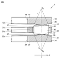
With reference to FIGS. 15 to 17, the thrust roller bearing 1c and the raceway ring for the thrust roller bearing according to the third embodiment (the raceway ring 10c for the first thrust roller bearing and the raceway ring 20c for the second thrust roller bearing). To explain. The thrust roller bearing 1c and the raceway ring for the thrust roller bearing (the raceway ring 10c for the first thrust roller bearing and the raceway ring 20c for the second thrust roller bearing) of the present embodiment are the thrust roller bearing 1 of the first embodiment. And, it has the same configuration as the raceway ring for thrust roller bearings (the raceway ring 10 for the first thrust roller bearing, the raceway ring 20 for the second thrust roller bearing), but is mainly different in the following points.
図15に示されるように、本実施の形態のスラストころ軸受1cは、複列のころ(第1のころ30c、第2のころ60)を備える。具体的には、本実施の形態のスラストころ軸受1cは、第1のスラストころ軸受用軌道輪10cと第2のスラストころ軸受用軌道輪20cとの間に、複数の第2のころ60をさらに備える。第2のころ60は、第1のスラストころ軸受用軌道輪10c及び第2のスラストころ軸受用軌道輪20cの周方向に沿って配置される。第2のころ60は、第1のころ30cに対して内側に配置される。第2のころ60は、スラストころ軸受用軌道輪(第1のスラストころ軸受用軌道輪10c、第2のスラストころ軸受用軌道輪20c)の軌道面11c,21c上を転動する。
As shown in FIG. 15, the thrust roller bearing 1c of the present embodiment includes double row rollers (first roller 30c, second roller 60). Specifically, the thrust roller bearing 1c of the present embodiment has a plurality of second rollers 60 between the raceway ring 10c for the first thrust roller bearing and the raceway ring 20c for the second thrust roller bearing. Further prepare. The second roller 60 is arranged along the circumferential direction of the first thrust roller bearing raceway ring 10c and the second thrust roller bearing raceway ring 20c. The second roller 60 is arranged inside the first roller 30c. The second roller 60 rolls on the raceway surfaces 11c and 21c of the raceway ring for the thrust roller bearing (the raceway ring 10c for the first thrust roller bearing and the raceway ring 20c for the second thrust roller bearing).
本実施の形態では、第1のスラストころ軸受用軌道輪10cの軌道面11cは、第2のころ60に接触する第2のフルクラウニング部16を有し、かつ、第2のスラストころ軸受用軌道輪20cの軌道面21cは、第2のころ60に接触する第2のフルクラウニング部26を有する。第1のスラストころ軸受用軌道輪10cの軌道面11c及び第2のスラストころ軸受用軌道輪20cの軌道面21cの少なくとも1つが、第2のころ60に接触する第2のフルクラウニング部16,26を有してもよい。第2のフルクラウニング部16は第1のフルクラウニング部12に対して内側に位置し、かつ、第2のフルクラウニング部26は第1のフルクラウニング部22に対して内側に位置する。
In the present embodiment, the raceway surface 11c of the raceway ring 10c for the first thrust roller bearing has a second full crowning portion 16 in contact with the second roller 60, and is for the second thrust roller bearing. The raceway surface 21c of the raceway ring 20c has a second full crowning portion 26 in contact with the second roller 60. A second full crowning portion 16, in which at least one of the raceway surface 11c of the racetrack ring 10c for the first thrust roller bearing and the raceway surface 21c of the racetrack ring 20c for the second thrust roller bearing contacts the second roller 60, You may have 26. The second full-crowning portion 16 is located inside the first full-crowning portion 12, and the second full-crowning portion 26 is located inside the first full-crowning portion 22.
第1のスラストころ軸受用軌道輪10cは、第2のフルクラウニング部16に対して外側に、第1の内側平坦部14を有してもよい。第1のスラストころ軸受用軌道輪10cは、第2のフルクラウニング部16に対して内側に、第3の平坦部17を有してもよい。第2のフルクラウニング部16は、第1の内側平坦部14及び第3の平坦部17から第1のころ30の第1転動面31に向けて膨出してもよい。第2のフルクラウニング部16は、第1の内側平坦部14及び第3の平坦部17に滑らかに連なるように形成されてもよい。
The raceway ring 10c for a first thrust roller bearing may have a first inner flat portion 14 on the outer side of the second full crowning portion 16. The raceway ring 10c for the first thrust roller bearing may have a third flat portion 17 inside the second full crowning portion 16. The second full crowning portion 16 may bulge from the first inner flat portion 14 and the third flat portion 17 toward the first rolling surface 31 of the first roller 30. The second full crowning portion 16 may be formed so as to be smoothly connected to the first inner flat portion 14 and the third flat portion 17.
第2のスラストころ軸受用軌道輪20cは、第2のフルクラウニング部26に対して外側に、第2の内側平坦部24を有してもよい。第2のスラストころ軸受用軌道輪20cは、第2のフルクラウニング部26に対して内側に、第4の平坦部27を有してもよい。第2のフルクラウニング部26は、第2の内側平坦部24及び第4の平坦部27から第1のころ30の第1転動面31に向けて膨出してもよい。第2のフルクラウニング部26は、第2の内側平坦部24及び第4の平坦部27に滑らかに連なるように形成されてもよい。
The second thrust roller bearing raceway ring 20c may have a second inner flat portion 24 on the outer side of the second full crowning portion 26. The raceway ring 20c for the second thrust roller bearing may have a fourth flat portion 27 inside the second full crowning portion 26. The second full crowning portion 26 may bulge from the second inner flat portion 24 and the fourth flat portion 27 toward the first rolling surface 31 of the first roller 30. The second full crowning portion 26 may be formed so as to be smoothly connected to the second inner flat portion 24 and the fourth flat portion 27.
軌道面11cは、第1のフルクラウニング部12の第1の表面12sと、第2のフルクラウニング部16の第2の表面16sとを含む。軌道面11cは、第1のフルクラウニング部12に対して外側に、第1の外側平坦部13をさらに含んでもよい。軌道面21cは、第1のフルクラウニング部22の第1の表面22sと、第2のフルクラウニング部26の第2の表面26sとを含む。軌道面21cは、第1のフルクラウニング部22に対して外側に、第2の外側平坦部23をさらに含んでもよい。
The raceway surface 11c includes a first surface 12s of the first full crowning portion 12 and a second surface 16s of the second full crowning portion 16. The raceway surface 11c may further include a first outer flat portion 13 on the outer side of the first full crowning portion 12. The raceway surface 21c includes a first surface 22s of the first full crowning portion 22 and a second surface 26s of the second full crowning portion 26. The raceway surface 21c may further include a second outer flat portion 23 on the outer side of the first full crowning portion 22.
スラストころ軸受1cの径方向の断面(第1のスラストころ軸受用軌道輪10cの径方向の断面、第2のスラストころ軸受用軌道輪20cの径方向の断面)における第2のフルクラウニング部16,26の第2の表面16s,26sの形状は、第2の単一円弧である。第2のフルクラウニング部16,26の曲率半径は、第1のフルクラウニング部12,22の曲率半径に等しくてもよい。第2のフルクラウニング部16,26の曲率半径は、第1のフルクラウニング部12,22の曲率半径と異なってもよい。
The second full crowning portion 16 in the radial cross section of the thrust roller bearing 1c (the radial cross section of the raceway ring 10c for the first thrust roller bearing, the radial cross section of the raceway ring 20c for the second thrust roller bearing). , 26 The shape of the second surface 16s, 26s is a second single arc. The radius of curvature of the second full crowning portions 16, 26 may be equal to the radius of curvature of the first full crowning portions 12, 22. The radius of curvature of the second full crowning portions 16, 26 may be different from the radius of curvature of the first full crowning portions 12, 22.
第2のころ60の端部(第2外側端部66、第2内側端部67)とスラストころ軸受用軌道輪(第1のスラストころ軸受用軌道輪10c、第2のスラストころ軸受用軌道輪20c)の軌道面11c,21cとの接触部においてスラストころ軸受用軌道輪(第1のスラストころ軸受用軌道輪10c、第2のスラストころ軸受用軌道輪20c)が破損することを防ぐために、本実施の形態の第2のフルクラウニング部16,26の曲率半径は、2100mm以下であってもよく、2000nm以下であってもよく、1600mm以下であってもよく、1200mm以下であってもよい。本実施の形態のスラストころ軸受用軌道輪(第1のスラストころ軸受用軌道輪10c、第2のスラストころ軸受用軌道輪20c)のこのような破損を防ぐために、本実施の形態の第2のフルクラウニング部16,26の曲率半径は、250mm以上であってもよく、445mm以上であってもよく、600mm以上であってもよく、720mm以上であってもよい。
The end of the second roller 60 (second outer end 66, second inner end 67) and the raceway ring for the thrust roller bearing (the raceway ring 10c for the first thrust roller bearing, the raceway for the second thrust roller bearing). In order to prevent the raceway rings for thrust roller bearings (the raceway rings 10c for the first thrust roller bearings and the raceway rings 20c for the second thrust roller bearings) from being damaged at the contact portions of the wheels 20c) with the raceway surfaces 11c and 21c. The radius of curvature of the second full bearing portions 16 and 26 of the present embodiment may be 2100 mm or less, 2000 nm or less, 1600 mm or less, or 1200 mm or less. good. In order to prevent such damage to the raceway wheels for thrust roller bearings (the raceway ring 10c for the first thrust roller bearing and the raceway ring 20c for the second thrust roller bearing) of the present embodiment, the second embodiment of the present embodiment is used. The radius of curvature of the full crowning portions 16 and 26 may be 250 mm or more, 445 mm or more, 600 mm or more, or 720 mm or more.
本実施の形態の第1のころ30cは、実施の形態1の第1のころ30と同様の構成を有するが、以下の点で異なる。本実施の形態の第1のころ30cの第1のころ長さL1c(図16参照)は、実施の形態1の第1のころ30の第1のころ長さL1(図4参照)よりも短い。
The first roller 30c of the present embodiment has the same configuration as the first roller 30 of the first embodiment, but differs in the following points. The first roller length L 1c of the first roller 30c of the present embodiment (see FIG. 16) is the first roller length L 1 of the first roller 30 of the first embodiment (see FIG. 4). Shorter than.
図17を参照して、第2のころ60は、第2のころ長さL2を有する。第2のころ長さL2は、第2ころ回転軸60rにおける、第2のころ60の第2外側端面63と第2のころ60の第2内側端面64との間の距離として定義される。第2のころ60は、スラストころ軸受1cの径方向に沿う第2ころ回転軸60rを中心に回転しながら、スラストころ軸受用軌道輪(第1のスラストころ軸受用軌道輪10c、第2のスラストころ軸受用軌道輪20c)の軌道面11c,21c上を転動する。第2のころ60の第2転動面61の第2外側端部66は、第2外側端面63側の第2転動面61の端部である。第2のころ60の第2転動面61の第2内側端部67は、第2内側端面64側の第2転動面61の端部である。第2のころ60は、第2のころ60の第2外側端面63と第2転動面61との間並びに第2のころ60の第2内側端面64と第2転動面61との間に、面取り部62を含んでもよい。
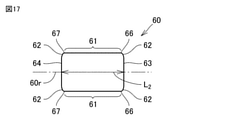
With reference to FIG. 17, the second roller 60 has a second roller length L 2 . The second roller length L 2 is defined as the distance between the second outer end surface 63 of the second roller 60 and the second inner end surface 64 of the second roller 60 on the second roller rotation shaft 60r. .. The second roller 60 rotates around the second roller rotation shaft 60r along the radial direction of the thrust roller bearing 1c, and the raceway ring for the thrust roller bearing (the raceway ring 10c for the first thrust roller bearing, the second roller 60). It rolls on the raceway surfaces 11c and 21c of the raceway ring 20c) for thrust roller bearings. The second outer end portion 66 of the second rolling surface 61 of the second roller 60 is the end portion of the second rolling surface 61 on the second outer end surface 63 side. The second inner end portion 67 of the second rolling surface 61 of the second roller 60 is the end portion of the second rolling surface 61 on the second inner end surface 64 side. The second roller 60 is between the second outer end surface 63 of the second roller 60 and the second rolling surface 61, and between the second inner end surface 64 of the second roller 60 and the second rolling surface 61. May include a chamfered portion 62.
本実施の形態の第2のころ60は、実施の形態1の第1のころ30と同様の構成を有するが、以下の点で異なる。本実施の形態の第2のころ60の第2のころ長さL2(図17参照)は、実施の形態1の第1のころ30の第1のころ長さL1(図4参照)よりも短い。本実施の形態の第1のころ30cの第1のころ長さL1cと第2のころ60の第2のころ長さL2との和は、実施の形態1の第1のころ長さL1よりも短くてもよい。第2のころ60は、第1のころ30cと同じ構成を有してもよい。
The second roller 60 of the present embodiment has the same configuration as the first roller 30 of the first embodiment, but differs in the following points. The second roller length L 2 of the second roller 60 of the present embodiment (see FIG. 17) is the first roller length L 1 of the first roller 30 of the first embodiment (see FIG. 4). Shorter than. The sum of the first roller length L 1c of the first roller 30c and the second roller length L 2 of the second roller 60 of the present embodiment is the first roller length of the first embodiment. It may be shorter than L 1 . The second roller 60 may have the same configuration as the first roller 30c.
本実施の形態のスラストころ軸受1c及びスラストころ軸受用軌道輪(第1のスラストころ軸受用軌道輪10c、第2のスラストころ軸受用軌道輪20c)の効果は、実施の形態1のスラストころ軸受1及びスラストころ軸受用軌道輪(第1のスラストころ軸受用軌道輪10、第2のスラストころ軸受用軌道輪20)の効果に加えて、以下の効果を奏する。
The effects of the thrust roller bearing 1c and the raceway ring for the thrust roller bearing (the raceway ring 10c for the first thrust roller bearing and the raceway ring 20c for the second thrust roller bearing) of the present embodiment are the thrust rollers of the first embodiment. In addition to the effects of the bearing 1 and the bearing ring for the thrust roller bearing (the raceway ring 10 for the first thrust roller bearing and the raceway ring 20 for the second thrust roller bearing), the following effects are exhibited.
本実施の形態のスラストころ軸受1cは、第1のスラストころ軸受用軌道輪10cと第2のスラストころ軸受用軌道輪20cとの間に、第1のスラストころ軸受用軌道輪10c及び第2のスラストころ軸受用軌道輪20cの周方向に沿って配置された複数の第2のころ60をさらに備える。第2のころ60は、第1のスラストころ軸受用軌道輪10cの軌道面11c及び第2のスラストころ軸受用軌道輪20cの軌道面21c上を転動する。第1のスラストころ軸受用軌道輪10cの軌道面11c及び第2のスラストころ軸受用軌道輪20cの軌道面21cの少なくとも1つは、第2のころ60に接触する第2のフルクラウニング部16,26を有する。第2のフルクラウニング部16,26は第1のフルクラウニング部12,22に対して内側に位置する。スラストころ軸受1cの径方向の断面における第2のフルクラウニング部16,26の第2の表面16s,26sの形状は、第2の単一円弧である。
In the thrust roller bearing 1c of the present embodiment, the first thrust roller bearing raceway ring 10c and the second thrust roller bearing raceway ring 10c and the second thrust roller bearing raceway ring 10c are provided between the first thrust roller bearing raceway ring 10c and the second thrust roller bearing raceway ring 20c. Further includes a plurality of second rollers 60 arranged along the circumferential direction of the raceway ring 20c for thrust roller bearings. The second roller 60 rolls on the raceway surface 11c of the first thrust roller bearing raceway ring 10c and on the raceway surface 21c of the second thrust roller bearing raceway ring 20c. At least one of the raceway surface 11c of the racetrack ring 10c for the first thrust roller bearing and the raceway surface 21c of the raceway ring 20c for the second thrust roller bearing is a second full crowning portion 16 in contact with the second roller 60. , 26. The second full crowning portions 16 and 26 are located inside the first full crowning portions 12 and 22. The shape of the second surfaces 16s and 26s of the second full crowning portions 16 and 26 in the radial cross section of the thrust roller bearing 1c is a second single arc.
本実施の形態のスラストころ軸受1cは、第1のスラストころ軸受用軌道輪10cと第2のスラストころ軸受用軌道輪20cとの間に、第1のころ30cと第2のころ60とを含んでいる。第2のフルクラウニング部16,26に接触する第2のころ60は、第1のフルクラウニング部12,22に接触する第1のころ30cに対して内側に配置される。第2のころ60の第2転動面61の周速度は、第1のころ30cの第2転動面61の周速度よりも低くなり得る。
In the thrust roller bearing 1c of the present embodiment, the first roller 30c and the second roller 60 are placed between the first thrust roller bearing raceway ring 10c and the second thrust roller bearing raceway ring 20c. Includes. The second roller 60 in contact with the second full crowning portions 16 and 26 is arranged inside the first roller 30c in contact with the first full crowning portions 12 and 22. The peripheral speed of the second rolling surface 61 of the second roller 60 may be lower than the peripheral speed of the second rolling surface 61 of the first roller 30c.
本実施の形態における第1のスラストころ軸受用軌道輪10cの軌道面11cの周速度と第1のころ30cの第1転動面31の周速度との間の第2の差は、実施の形態1における第1のスラストころ軸受用軌道輪10の軌道面11の周速度と第1のころ30の第1転動面31の周速度との間の第1の差よりも減少する。本実施の形態における第1のスラストころ軸受用軌道輪10cの軌道面11cの周速度と第2のころ60の第2転動面61の周速度との間の第3の差は、実施の形態1における第1のスラストころ軸受用軌道輪10の軌道面11の周速度と第1のころ30の第1転動面31の周速度との間の第1の差よりも減少する。
The second difference between the peripheral speed of the raceway surface 11c of the raceway ring 10c for the first thrust roller bearing and the peripheral speed of the first rolling surface 31 of the first roller 30c in the present embodiment is the implementation. It is less than the first difference between the peripheral speed of the raceway surface 11 of the raceway ring 10 for the first thrust roller bearing in the first mode and the peripheral speed of the first rolling surface 31 of the first roller 30. The third difference between the peripheral speed of the raceway surface 11c of the raceway ring 10c for the first thrust roller bearing and the peripheral speed of the second rolling surface 61 of the second roller 60 in the present embodiment is the implementation. It is less than the first difference between the peripheral speed of the raceway surface 11 of the raceway ring 10 for the first thrust roller bearing in the first mode and the peripheral speed of the first rolling surface 31 of the first roller 30.
そのため、実施の形態1の第1のころ30の第1転動面31に比べて、本実施の形態の第1のころ30cの第1転動面31及び第2のころ60の第2転動面61は、軌道面11c,21cに対してより少なく滑る。本実施の形態のスラストころ軸受1cは、第1のころ30cの第1転動面31及び第2のころ60の第2転動面61が軌道面11c,21cに対して滑ることによって発生する熱を低減することができる。本実施の形態のスラストころ軸受1cは、この熱に起因してスラストころ軸受用軌道輪(第1のスラストころ軸受用軌道輪10c、第2のスラストころ軸受用軌道輪20c)の軌道面11c,21cに表面起点剥離が発生することを防止することができる。
Therefore, as compared with the first rolling surface 31 of the first roller 30 of the first embodiment, the first rolling surface 31 of the first roller 30c and the second rolling surface of the second roller 60 of the present embodiment The moving surface 61 slides less with respect to the raceway surfaces 11c and 21c. The thrust roller bearing 1c of the present embodiment is generated when the first rolling surface 31 of the first roller 30c and the second rolling surface 61 of the second roller 60 slide with respect to the raceway surfaces 11c and 21c. The heat can be reduced. The thrust roller bearing 1c of the present embodiment is a raceway surface 11c of a raceway ring for a thrust roller bearing (a raceway ring 10c for a first thrust roller bearing and a raceway ring 20c for a second thrust roller bearing) due to this heat. , 21c can be prevented from causing surface origin peeling.
第2の表面16s,26sの形状が第2の単一円弧である第2のフルクラウニング部16,26は、第2のころ60の端部(第2外側端部66、第2内側端部67)における、第2のころ60の第2転動面61とスラストころ軸受用軌道輪(第1のスラストころ軸受用軌道輪10c、第2のスラストころ軸受用軌道輪20c)の軌道面11c,21cとの間の接触面圧を減少させることができる。第2の表面16s,26sの形状が第2の単一円弧である第2のフルクラウニング部16,26は、第2のころ60の端部(第2外側端部66、第2内側端部67)とスラストころ軸受用軌道輪(第1のスラストころ軸受用軌道輪10c、第2のスラストころ軸受用軌道輪20c)の軌道面11c,21cとの間に発生するエッジロードを減少させることができる。本実施の形態のスラストころ軸受1cは、このエッジロードに起因してスラストころ軸受用軌道輪(第1のスラストころ軸受用軌道輪10c、第2のスラストころ軸受用軌道輪20c)が損傷を受けることを防止することができる。
The second full crowning portions 16 and 26 having the shape of the second surfaces 16s and 26s as the second single arc are the ends of the second rollers 60 (second outer end portion 66 and second inner end portion). 67), the second rolling surface 61 of the second roller 60 and the raceway surface 11c of the raceway ring for the thrust roller bearing (the raceway ring 10c for the first thrust roller bearing, the raceway ring 20c for the second thrust roller bearing). , 21c can reduce the contact surface pressure. The second full crowning portions 16 and 26 having the shape of the second surfaces 16s and 26s as the second single arc are the ends of the second rollers 60 (second outer end portion 66 and second inner end portion). 67) To reduce the edge load generated between the raceway surfaces 11c and 21c of the raceway wheels for thrust roller bearings (the raceway ring 10c for the first thrust roller bearing and the raceway ring 20c for the second thrust roller bearing). Can be done. In the thrust roller bearing 1c of the present embodiment, the raceway wheels for thrust roller bearings (the raceway ring 10c for the first thrust roller bearing and the raceway ring 20c for the second thrust roller bearing) are damaged due to this edge load. It is possible to prevent receiving.
本実施の形態のスラストころ軸受1cでは、第1のころ30cだけでなく第2のころ60も、スラスト荷重を受ける。そのため、本実施の形態のスラストころ軸受1cは、より大きなスラスト荷重に耐えることができる。
In the thrust roller bearing 1c of the present embodiment, not only the first roller 30c but also the second roller 60 receives the thrust load. Therefore, the thrust roller bearing 1c of the present embodiment can withstand a larger thrust load.
本実施の形態のスラストころ軸受1cでは、第2の単一円弧は、250mm以上2100mm以下の曲率半径を有してもよい。そのため、スラストころ軸受用軌道輪(第1のスラストころ軸受用軌道輪10c、第2のスラストころ軸受用軌道輪20c)が破損することが防がれ得る。
In the thrust roller bearing 1c of the present embodiment, the second single arc may have a radius of curvature of 250 mm or more and 2100 mm or less. Therefore, it is possible to prevent the raceway rings for thrust roller bearings (the raceway ring 10c for the first thrust roller bearing and the raceway ring 20c for the second thrust roller bearing) from being damaged.
本実施の形態のスラストころ軸受用軌道輪(第1のスラストころ軸受用軌道輪10c、第2のスラストころ軸受用軌道輪20c)は、軌道面11c,21cを転動する複数の第2のころ60に接触する第2のフルクラウニング部16,26をさらに有する。第2のフルクラウニング部16,26は第1のフルクラウニング部12,22に対して内側に位置する。スラストころ軸受用軌道輪(第1のスラストころ軸受用軌道輪10c、第2のスラストころ軸受用軌道輪20c)の径方向の断面における第2のフルクラウニング部16,26の第2の表面16s,26sの形状は第2の単一円弧である。
The raceway ring for thrust roller bearings (the raceway ring 10c for the first thrust roller bearing and the raceway ring 20c for the second thrust roller bearing) of the present embodiment is a plurality of second wheels that roll on the raceway surfaces 11c and 21c. It further has second full crowning portions 16, 26 that come into contact with the rollers 60. The second full crowning portions 16 and 26 are located inside the first full crowning portions 12 and 22. The second surface 16s of the second full crowning portions 16 and 26 in the radial cross section of the raceway ring for the thrust roller bearing (the raceway ring 10c for the first thrust roller bearing and the racer ring 20c for the second thrust roller bearing). The shape of, 26s is a second single arc.
本実施の形態のスラストころ軸受用軌道輪(第1のスラストころ軸受用軌道輪10c、第2のスラストころ軸受用軌道輪20c)は、第1のフルクラウニング部12,22と、第1のフルクラウニング部12,22に対して内側に位置する第2のフルクラウニング部16,26とを含んでいる。第2のフルクラウニング部16,26に接触する第2のころ60は、第1のころ30cに対して内側に配置され得る。そのため、第2のころ60の第2転動面61の周速度は、第1のころ30aの第1転動面31の周速度よりも低くなり得る。
The raceway rings for thrust roller bearings (first raceway ring 10c for thrust roller bearings, raceway ring 20c for second thrust roller bearings) of the present embodiment are the first full crowning portions 12, 22 and the first. It includes the second full crowning portions 16 and 26 located inside the full crowning portions 12 and 22. The second roller 60, which comes into contact with the second full crowning portions 16, 26, may be arranged inside the first roller 30c. Therefore, the peripheral speed of the second rolling surface 61 of the second roller 60 may be lower than the peripheral speed of the first rolling surface 31 of the first roller 30a.
本実施の形態における第1のスラストころ軸受用軌道輪10cの軌道面11cの周速度と第1のころ30cの第1転動面31の周速度との間の第2の差は、実施の形態1における第1のスラストころ軸受用軌道輪10の軌道面11の周速度と第1のころ30の第1転動面31の周速度との間の第1の差よりも減少する。本実施の形態における第1のスラストころ軸受用軌道輪10cの軌道面11cの周速度と第2のころ60の第2転動面61の周速度との間の第3の差は、実施の形態1における第1のスラストころ軸受用軌道輪10の軌道面11の周速度と第1のころ30の第1転動面31の周速度との間の第1の差よりも減少する。
The second difference between the peripheral speed of the raceway surface 11c of the raceway ring 10c for the first thrust roller bearing and the peripheral speed of the first rolling surface 31 of the first roller 30c in the present embodiment is the implementation. It is less than the first difference between the peripheral speed of the raceway surface 11 of the raceway ring 10 for the first thrust roller bearing in the first mode and the peripheral speed of the first rolling surface 31 of the first roller 30. The third difference between the peripheral speed of the raceway surface 11c of the raceway ring 10c for the first thrust roller bearing and the peripheral speed of the second rolling surface 61 of the second roller 60 in the present embodiment is the implementation. It is less than the first difference between the peripheral speed of the raceway surface 11 of the raceway ring 10 for the first thrust roller bearing in the first mode and the peripheral speed of the first rolling surface 31 of the first roller 30.
そのため、実施の形態1の第1のころ30の第1転動面31に比べて、本実施の形態の第1のころ30cの第1転動面31及び第2のころ60の第2転動面61は、軌道面11c,21cに対してより少なく滑る。本実施の形態のスラストころ軸受用軌道輪(第1のスラストころ軸受用軌道輪10c、第2のスラストころ軸受用軌道輪20c)は、第1のころ30cの第1転動面31及び第2のころ60の第2転動面61がスラストころ軸受用軌道輪(第1のスラストころ軸受用軌道輪10c、第2のスラストころ軸受用軌道輪20c)の軌道面11c,21cに対して滑ることによって発生する熱を低減することができる。本実施の形態のスラストころ軸受用軌道輪(第1のスラストころ軸受用軌道輪10c、第2のスラストころ軸受用軌道輪20c)は、この熱に起因してスラストころ軸受用軌道輪(第1のスラストころ軸受用軌道輪10c、第2のスラストころ軸受用軌道輪20c)の軌道面11c,21cに表面起点剥離が発生することを防止することができる。
Therefore, as compared with the first rolling surface 31 of the first roller 30 of the first embodiment, the first rolling surface 31 of the first roller 30c and the second rolling surface of the second roller 60 of the present embodiment The moving surface 61 slides less with respect to the raceway surfaces 11c and 21c. The raceway ring for thrust roller bearings (the raceway ring 10c for the first thrust roller bearing and the raceway ring 20c for the second thrust roller bearing) of the present embodiment has the first rolling surface 31 and the first rolling surface 31 of the first roller 30c. The second rolling surface 61 of the roller 60 is relative to the raceway surfaces 11c and 21c of the raceway ring for the thrust roller bearing (the raceway ring 10c for the first thrust roller bearing and the raceway ring 20c for the second thrust roller bearing). The heat generated by slipping can be reduced. The raceway ring for thrust roller bearings (first raceway ring for thrust roller bearing 10c, raceway ring 20c for second thrust roller bearing) of the present embodiment is caused by this heat, and the raceway ring for thrust roller bearing (first). It is possible to prevent surface origin peeling from occurring on the raceway surfaces 11c and 21c of the first thrust roller bearing raceway ring 10c and the second thrust roller bearing raceway ring 20c).
第2の表面16s,26sの形状が第2の単一円弧である第2のフルクラウニング部16,26は、第2のころ60の端部(第2外側端部66、第2内側端部67)における、第2のころ60の第2転動面61と軌道面11c,21cとの間の接触面圧を減少させることができる。第2の表面16s,26sの形状が第2の単一円弧である第2のフルクラウニング部16,26は、第2のころ60の端部(第2外側端部66、第2内側端部67)と軌道面11c,21cとの間に発生するエッジロードを減少させることができる。本実施の形態のスラストころ軸受用軌道輪(第1のスラストころ軸受用軌道輪10c、第2のスラストころ軸受用軌道輪20c)は、このエッジロードに起因してスラストころ軸受用軌道輪(第1のスラストころ軸受用軌道輪10c、第2のスラストころ軸受用軌道輪20c)が損傷を受けることを防止することができる。
The second full crowning portions 16 and 26 having the shape of the second surfaces 16s and 26s as the second single arc are the ends of the second rollers 60 (second outer end portion 66 and second inner end portion). In 67), the contact surface pressure between the second rolling surface 61 of the second roller 60 and the raceway surfaces 11c and 21c can be reduced. The second full crowning portions 16 and 26 having the shape of the second surfaces 16s and 26s as the second single arc are the ends of the second rollers 60 (second outer end portion 66 and second inner end portion). It is possible to reduce the edge load generated between 67) and the raceway surfaces 11c and 21c. The raceway ring for thrust roller bearings (first raceway ring for thrust roller bearing 10c, raceway ring for second thrust roller bearing 20c) of the present embodiment is a raceway ring for thrust roller bearing due to this edge load (1st thrust roller bearing raceway ring 10c, second thrust roller bearing raceway ring 20c). It is possible to prevent the first thrust roller bearing raceway ring 10c and the second thrust roller bearing raceway ring 20c) from being damaged.
本実施の形態のスラストころ軸受用軌道輪(第1のスラストころ軸受用軌道輪10c、第2のスラストころ軸受用軌道輪20c)では、第2の単一円弧は、250mm以上2100mm以下の曲率半径を有してもよい。そのため、スラストころ軸受用軌道輪(第1のスラストころ軸受用軌道輪10c、第2のスラストころ軸受用軌道輪20c)が破損することが防がれ得る。
In the raceway ring for thrust roller bearings (first raceway ring for thrust roller bearing 10c, raceway ring for second thrust roller bearing 20c) of the present embodiment, the second single arc has a curvature of 250 mm or more and 2100 mm or less. It may have a radius. Therefore, it is possible to prevent the raceway rings for thrust roller bearings (the raceway ring 10c for the first thrust roller bearing and the raceway ring 20c for the second thrust roller bearing) from being damaged.
今回開示された実施の形態はすべての点で例示であって制限的なものではないと考えられるべきである。例えば、実施の形態2及びその変形例の第1の外側鍔部51、第1の内側鍔部52、第2の外側鍔部56及び第2の内側鍔部57の少なくとも1つが、実施の形態1及び実施の形態3のスラストころ軸受1cに設けられてもよい。本発明の範囲は上記した説明ではなくて特許請求の範囲によって示され、特許請求の範囲と均等の意味および範囲内でのすべての変更が含まれることが意図される。
It should be considered that the embodiments disclosed this time are exemplary in all respects and not restrictive. For example, at least one of the first outer flange portion 51, the first inner flange portion 52, the second outer flange portion 56, and the second inner flange portion 57 of the second embodiment and its modifications is the embodiment. It may be provided in the thrust roller bearing 1c of 1 and the third embodiment. The scope of the present invention is shown by the scope of claims rather than the above description, and is intended to include all modifications within the meaning and scope equivalent to the scope of claims.