JP6823274B2 - Condition correction unit - Google Patents
Condition correction unit Download PDFInfo
- Publication number
- JP6823274B2 JP6823274B2 JP2019149120A JP2019149120A JP6823274B2 JP 6823274 B2 JP6823274 B2 JP 6823274B2 JP 2019149120 A JP2019149120 A JP 2019149120A JP 2019149120 A JP2019149120 A JP 2019149120A JP 6823274 B2 JP6823274 B2 JP 6823274B2
- Authority
- JP
- Japan
- Prior art keywords
- correction
- unit
- posture
- seated person
- seat
- Prior art date
- Legal status (The legal status is an assumption and is not a legal conclusion. Google has not performed a legal analysis and makes no representation as to the accuracy of the status listed.)
- Active
Links
- 238000012937 correction Methods 0.000 title claims description 327
- 230000008961 swelling Effects 0.000 claims description 44
- 238000000034 method Methods 0.000 claims description 41
- 238000012545 processing Methods 0.000 claims description 28
- 230000008569 process Effects 0.000 claims description 23
- 230000000694 effects Effects 0.000 claims description 10
- 238000011156 evaluation Methods 0.000 claims description 2
- 230000036544 posture Effects 0.000 description 185
- 238000005259 measurement Methods 0.000 description 40
- 230000008859 change Effects 0.000 description 20
- 238000012546 transfer Methods 0.000 description 11
- 210000003205 muscle Anatomy 0.000 description 10
- 230000029058 respiratory gaseous exchange Effects 0.000 description 10
- 238000003825 pressing Methods 0.000 description 7
- 230000006872 improvement Effects 0.000 description 6
- 210000004197 pelvis Anatomy 0.000 description 6
- 238000005452 bending Methods 0.000 description 5
- 241000282326 Felis catus Species 0.000 description 4
- 206010049816 Muscle tightness Diseases 0.000 description 4
- 238000013461 design Methods 0.000 description 4
- 230000006870 function Effects 0.000 description 4
- 230000037007 arousal Effects 0.000 description 3
- 238000001514 detection method Methods 0.000 description 3
- 238000010586 diagram Methods 0.000 description 3
- 210000001624 hip Anatomy 0.000 description 3
- 230000000241 respiratory effect Effects 0.000 description 3
- 238000004891 communication Methods 0.000 description 2
- 230000001186 cumulative effect Effects 0.000 description 2
- 230000036541 health Effects 0.000 description 2
- 238000010438 heat treatment Methods 0.000 description 2
- 210000004705 lumbosacral region Anatomy 0.000 description 2
- 230000004043 responsiveness Effects 0.000 description 2
- 210000000577 adipose tissue Anatomy 0.000 description 1
- 230000037182 bone density Effects 0.000 description 1
- 210000001217 buttock Anatomy 0.000 description 1
- 230000003247 decreasing effect Effects 0.000 description 1
- 239000012530 fluid Substances 0.000 description 1
- 238000009434 installation Methods 0.000 description 1
- 239000007788 liquid Substances 0.000 description 1
- 238000000691 measurement method Methods 0.000 description 1
- 230000007246 mechanism Effects 0.000 description 1
- 230000000399 orthopedic effect Effects 0.000 description 1
- 210000000062 pectoralis major Anatomy 0.000 description 1
- 230000000737 periodic effect Effects 0.000 description 1
- 230000000087 stabilizing effect Effects 0.000 description 1
- 238000005728 strengthening Methods 0.000 description 1
- 230000001960 triggered effect Effects 0.000 description 1
- 238000010792 warming Methods 0.000 description 1
- 230000037303 wrinkles Effects 0.000 description 1
Images


Landscapes
- Seats For Vehicles (AREA)
- Measurement Of The Respiration, Hearing Ability, Form, And Blood Characteristics Of Living Organisms (AREA)
- Chair Legs, Seat Parts, And Backrests (AREA)
Description
本発明は、シート着座者の身体状態を矯正する状態矯正ユニットに係り、特に、シート着座者の個性に適した矯正内容にて矯正することが可能な状態矯正ユニットに関する。 The present invention relates to a condition correction unit that corrects the physical condition of a seat occupant, and more particularly to a condition correction unit that can correct a condition with correction contents suitable for the individuality of the seat occupant.
シート着座者の姿勢等を検知し、その検知結果に応じてシート各部を動かすことでシート着座者の姿勢等を矯正する技術は、既に知られている(例えば、特許文献1参照)。具体的に説明すると、特許文献1に記載の技術は、車両用シートの着座者の姿勢を検知し、その検知結果に応じてシートバックの背凭れ部に配置された空気袋の膨出圧を調整することで着座者の姿勢を適切な姿勢に矯正するものである。
A technique for detecting the posture of a seated person and correcting the posture of the seated person by moving each part of the seat according to the detection result is already known (see, for example, Patent Document 1). Specifically, the technique described in
特に、特許文献1に記載の技術は、着座者固有の着座姿勢がもたらす情報を、空気袋の膨出圧(換言すると、シート形状)を定める際の判断要素としている。これにより、姿勢矯正時に着座者に負担が掛かりにくいシート形状が定められるようになる。
In particular, the technique described in
一方、負担の掛かり方については個人差があり、異なる着座者がそれぞれ同じような姿勢でシートに着座したとしても、矯正時に掛かる負担については、個人間で異なってくる可能性がある。したがって、着座姿勢等のシート着座者の身体状態を矯正する際には、着座者の個性(年齢や性別等)を事前に把握しておき、把握した個性に応じた内容にて身体状態を矯正することが重要となる。 On the other hand, there are individual differences in how the burden is applied, and even if different seated persons sit on the seat in the same posture, the burden applied at the time of correction may differ among individuals. Therefore, when correcting the physical condition of the seated person such as the sitting posture, the individuality (age, gender, etc.) of the seated person should be grasped in advance, and the physical condition should be corrected according to the grasped individuality. It is important to do.
また、シート着座者の身体状態を矯正する際には、通常、着座姿勢等の現在値を測定し、その測定値に応じた内容にて身体状態を矯正することになる。このため、身体状態に関する測定については、より適切な矯正内容を設定する観点から考えて、より適切に行われるのが好ましい。 Further, when correcting the physical condition of the seated person, the current value such as the sitting posture is usually measured, and the physical condition is corrected according to the measured value. Therefore, it is preferable that the measurement related to the physical condition is performed more appropriately from the viewpoint of setting a more appropriate correction content.
さらに、異なる日時に矯正を複数回に亘って繰り返し実行する場合には、矯正が施される者(すなわち、シート着座者)にとって、毎回の矯正効果(矯正による身体状態の改善具合)を管理することが重要となる。このため、毎回の矯正効果を適切にシート着座者に知らせるための技術(機器)が必要となる。 Further, when the correction is repeatedly performed a plurality of times at different dates and times, the correction effect (the degree of improvement of the physical condition by the correction) is managed for the person to be corrected (that is, the seated person). Is important. For this reason, a technique (equipment) for appropriately informing the seat seater of the correction effect each time is required.
そこで、本発明は、上記の問題に鑑みてなされたものであり、その目的は、シート着座者の個性に適した矯正内容にて当該シート着座者の身体状態を矯正することが可能な状態矯正ユニットを提供することにある。
また、本発明の他の目的は、身体状態を矯正するにあたり当該身体状態に関する測定を適切に行うことである。
また、本発明の他の目的は、シート着座者に対して矯正効果を適切に知らせることである。
Therefore, the present invention has been made in view of the above problems, and an object of the present invention is to correct a condition capable of correcting the physical condition of the seated person with a correction content suitable for the individuality of the seated person. To provide the unit.
In addition, another object of the present invention is to appropriately measure the physical condition in correcting the physical condition.
Another object of the present invention is to appropriately inform the seated person of the corrective effect.
前記課題は、本発明の状態矯正ユニットによれば、乗物用シートに着座している着座者の着座姿勢を矯正するために動作する動作部と、前記着座姿勢を特定するための指標の現在値を測定する測定部と、該測定部が測定した前記現在値から前記着座者の着座姿勢を判定する判定部と、前記着座姿勢に応じた矯正内容を示す矯正プランを記憶しているプラン記憶部と、前記判定部が判定した前記着座者の前記着座姿勢に応じた前記矯正プランを、前記プラン記憶部から読み出して前記着座者に対して提示する提示部と、情報を画面に表示する情報表示部と、前記測定部が過去に測定した前記着座姿勢を特定するための指標の測定値を記憶する記憶部と、今回測定した前記現在値と過去に測定した前記測定値とを比較する比較部と、を備え、前記情報表示部は、前記提示部が提示する前記矯正プランと、前記比較部が前記現在値と前記測定値とを比較したことによる姿勢矯正の効果の情報と、を前記画面に表示することにより解決される。 According to the state correction unit of the present invention, the subject is a moving unit that operates to correct the sitting posture of a seated person sitting on a vehicle seat, and a current value of an index for specifying the sitting posture. A measurement unit that measures, a determination unit that determines the seating posture of the seated person from the current value measured by the measuring unit, and a plan storage unit that stores a correction plan indicating the correction content according to the sitting posture. When the said determination unit corresponding to the seated posture of the seated person which determines correction plan, a presentation section for presenting to the seated person is read from the plan memory unit, an information display for displaying information on a screen A unit, a storage unit that stores the measured values of the index for identifying the sitting posture measured in the past by the measuring unit, and a comparison unit that compares the current value measured this time with the measured value measured in the past. The screen of the information display unit displays the correction plan presented by the presentation unit and information on the effect of posture correction caused by the comparison unit comparing the current value with the measured value. It is solved by displaying in.
本発明の状態矯正ユニットによれば、シート着座者の個性に適した矯正内容にてシート着座者の身体状態を適切に矯正することが可能となる。 According to the condition correction unit of the present invention, it is possible to appropriately correct the physical condition of the seat occupant with the correction content suitable for the individuality of the seat occupant.
また、上記の状態矯正ユニットにおいて、前記情報表示部は、前記乗物用シートと前記判定部が判定した前記着座者の着座姿勢とを示す画像情報を前記画面に表示すると、より好適である。 Further, in the above state correction unit, the previous SL information display unit, when displaying the image information indicating the seated posture of the seated person that the evaluation unit and the vehicle seat is determined on the screen, is more preferable.
また、上記の状態矯正ユニットにおいて、前記動作部に前記着座者の着座姿勢を矯正させることを指示するための補正開始用ボタンが、前記矯正プランの情報と共に前記画面に表示されていると、さらに好適である。 Further, in the above state correction unit, correcting the start button for instructing to be correct seated posture of the seated person before Symbol operation unit, when together with the information of the correction plan is displayed on the screen, More suitable.
また、上記の状態矯正ユニットにおいて、現在の着座姿勢のままで安定させるよう前記動作部を動作させる安楽補正モードと、現在の着座姿勢を理想姿勢になるように矯正するよう前記動作部を動作させる理想補正モードと、が設定されていて、前記情報表示部は、前記動作部を安楽補正モードで動作させるか、又は、理想補正モードで動作させるかを選択可能なボタンを前記画面に表示するとよい。 Further, in the above-mentioned state correction unit, the comfort correction mode in which the moving unit is operated so as to stabilize the current sitting posture and the moving unit are operated so as to correct the current sitting posture to the ideal posture. When the ideal correction mode is set, and the information display unit displays a button on the screen capable of selecting whether to operate the operation unit in the comfort correction mode or the ideal correction mode. Good .
また、上記の状態矯正ユニットにおいて、前記情報表示部は、理想姿勢と前記着座姿勢の矯正内容とを示す情報を前記画面に表示すると、好適である。 Further, in the above-mentioned state correction unit, it is preferable that the information display unit displays information indicating the ideal posture and the correction contents of the sitting posture on the screen.
また、上記の状態矯正ユニットにおいて、前記動作部は、前記着座者の前記着座姿勢を矯正するために膨出して前記着座者を押圧する複数の空気袋からなり、前記状態矯正ユニットは、前記動作部を制御して前記着座姿勢を矯正する処理を実行する処理実行部と、前記複数の空気袋の各々の膨出圧を測定する膨出圧センサと、前記複数の空気袋の各々の前面に設置され、前記乗物用シートに掛る圧力を測定する圧力センサと、を有し、前記複数の空気袋の各々は、前記乗物用シートに前記着座者が着座する前段階において、予め設定された膨出圧となるまで膨出し、前記測定部は、前記膨出圧センサにより、前記乗物用シートに前記着座者が着座することで変化する前記膨出圧を前記指標として前記膨出圧の前記現在値を測定し、前記測定部は、前記圧力センサにより、前記乗物用シートに前記着座者が着座することで変化する前記圧力を前記指標として前記圧力の前記現在値を測定し、前記判定部は、前記複数の前記空気袋の各々における前記膨出圧の前記現在値と、前記乗物用シートに掛る前記圧力の前記現在値とから前記着座姿勢を判定し、前記提示部は、前記現在値に応じた前記矯正プランを前記プラン記憶部から読み出して前記着座者に対して提示し、前記処理実行部は、読み出した前記矯正プランが示す前記矯正内容に従って、前記着座姿勢を矯正する前記処理を実行すると、より一層好適である。
上記の構成では、空気袋を用いてシート着座者の着座姿勢を矯正する。また、上記の構成では、シート着座者の着座姿勢に関する測定として、着座により変化する空気袋の膨出圧の現在値を測定する。すなわち、上記の構成では、空気袋が矯正用に用いられると共に着座姿勢の測定用にも用いられており、これにより、空気袋をより有効に活用することが可能となる。
Further, in the above-mentioned condition correction unit, the operating portion comprises a plurality of air bags that bulge to correct the seating posture of the seated person and press the seated person, and the state-correcting unit comprises the above-mentioned operation. A processing execution unit that controls the unit to execute a process of correcting the sitting posture , an swelling pressure sensor that measures the swelling pressure of each of the plurality of air bags, and a front surface of each of the plurality of air bags. Each of the plurality of air bags has a pressure sensor which is installed and measures the pressure applied to the vehicle seat, and each of the plurality of air bags is set in advance before the seater is seated on the vehicle seat. It swells until it reaches the swelling pressure, and the measuring unit uses the swelling pressure, which changes when the seated person sits on the vehicle seat by the swelling pressure sensor, as the index, and the present of the swelling pressure. The value is measured, and the measuring unit measures the current value of the pressure by using the pressure sensor, using the pressure that changes when the seated person sits on the vehicle seat as the index. , said current value of the bulging pressure in each of the plurality of said air bag, said sitting posture is determined from said current value of said pressure exerted on the seat for the vehicle, the front Symbol presentation unit, the current value The correction plan corresponding to the above is read from the plan storage unit and presented to the seated person, and the processing execution unit performs the processing for correcting the sitting posture according to the correction content indicated by the read correction plan. When implemented, it is even more preferred.
In the above configuration, an air bag is used to correct the seating posture of the seated person. Further, in the above configuration, the current value of the swelling pressure of the air bag, which changes depending on the seating , is measured as the measurement regarding the sitting posture of the seated person. That is, in the above configuration, the air bag is used for correction and also for measuring the sitting posture , which makes it possible to utilize the air bag more effectively.
本発明によれば、シート着座者の個性に適した矯正内容にてシート着座者の身体状態を適切に矯正することが可能となる。
また、本発明によれば、矯正時に適用する矯正プランについて、身体状態の矯正具合(改善具合)に応じて必要により適宜見直すことが可能となる。
また、本発明によれば、乗物用シートへの通算着座時間に連動させて矯正時の負荷を適切に調整することが可能となる。
また、本発明によれば、同じシート着座者に対する身体状態の測定を複数の測定日に亘って測定し、測定値同士を比較することで矯正効果を評価することが可能となる。
また、本発明によれば、矯正を実施するにあたりシート着座者の身体を温めておき、当該シート着座者の身体状態をより矯正し易い状態へ移行させることが可能となる。
また、本発明によれば、矯正を実施するにあたりシート着座者の所定部位に対して振動を付与して当該部位の緊張(筋肉の張り)を弛めたり、当該部位の筋力を増強したりすることが可能となる。
また、本発明によれば、シート着座者が身体状態の現状や、それに応じた矯正プラン、さらには矯正後の身体状態を、画面を通じて確認することが可能となる。
また、本発明によれば、シート着座者が保持する携帯端末と通信することにより比較的容易にシート着座者の識別情報を取得することが可能となる。
また、本発明によれば、シート着座者の脊椎の曲がり状態を判定し、当該曲がり状態をシート着座者の個性に適した姿勢内容にて適切に矯正することが可能となる。
また、本発明によれば、空気袋を矯正用に用いると共に身体状態の測定用にも用いることで、空気袋をより有効に活用することが可能となる。
According to the present invention, it is possible to appropriately correct the physical condition of the seat occupant with the correction content suitable for the individuality of the seat occupant.
Further, according to the present invention, the correction plan applied at the time of correction can be appropriately reviewed as necessary according to the correction condition (improvement condition) of the physical condition.
Further, according to the present invention, it is possible to appropriately adjust the load at the time of correction in conjunction with the total sitting time on the vehicle seat.
Further, according to the present invention, it is possible to evaluate the correction effect by measuring the physical condition of the same seated person over a plurality of measurement days and comparing the measured values with each other.
Further, according to the present invention, it is possible to warm the body of the seat occupant when performing the correction, and to shift the physical condition of the seat occupant to a state in which it is easier to correct.
Further, according to the present invention, when performing correction, vibration is applied to a predetermined portion of the seated person to relax the tension (muscle tension) of the portion or strengthen the muscle strength of the portion. It becomes possible.
Further, according to the present invention, the seated person can confirm the current state of the physical condition, the correction plan according to the current state, and the physical condition after the correction through the screen.
Further, according to the present invention, it is possible to relatively easily acquire the identification information of the seated person by communicating with the mobile terminal held by the seated person.
Further, according to the present invention, it is possible to determine the bent state of the spine of the seated person and appropriately correct the bent state with the posture content suitable for the individuality of the seated person.
Further, according to the present invention, the air bag can be used more effectively by using the air bag for correction and for measuring the physical condition.
以下、本発明の一実施形態(本実施形態)について、その構成例及び動作例を説明する。なお、以下では、乗物用シートの一例として車両用シートを例に挙げ、車両用シートに着座している着座者(以下、シート着座者)の身体状態を矯正する状態矯正ユニットについて説明することとする。ただし、本発明の状態矯正ユニットは、車両用シート以外の乗物用シートにも適用可能であり、具体的には、車両以外の乗物(例えば、航空機や船舶)に搭載されたシートにも適用可能である。 Hereinafter, a configuration example and an operation example thereof will be described with respect to one embodiment of the present invention (the present embodiment). In the following, a vehicle seat will be taken as an example of a vehicle seat, and a condition correction unit for correcting the physical condition of a seated person (hereinafter referred to as a seated person) seated on the vehicle seat will be described. To do. However, the condition correction unit of the present invention can be applied to a vehicle seat other than a vehicle seat, and specifically, can be applied to a seat mounted on a vehicle other than a vehicle (for example, an aircraft or a ship). Is.
また、以下の説明中、本発明の状態矯正ユニットによる矯正対象である「身体状態」とは、人体に関する状態のうち、整形外科学上の状態を意味し、具体的には、骨格、関節、筋肉等に関する状態である。その一例としては、脊椎の曲がり状態(換言すると、姿勢)や筋肉の緊張具合、骨格の歪み等が挙げられる。なお、以下では、脊椎の曲がり状態(姿勢)を「身体状態」として矯正する構成について説明することとする。ただし、本発明の状態矯正ユニットによる矯正対象は、脊椎の曲がり状態(姿勢)に限定されず、他の「身体状態」、例えば筋肉の緊張具合や骨格の歪み等を矯正するものであってもよい。 Further, in the following description, the "physical condition" to be corrected by the condition correction unit of the present invention means an orthopedic condition among the states related to the human body, specifically, the skeleton, joints, and the like. It is a condition related to muscles and the like. Examples thereof include the bending state of the spine (in other words, posture), the degree of muscle tension, and the distortion of the skeleton. In the following, a configuration for correcting the bending state (posture) of the spine as a "physical state" will be described. However, the correction target by the state correction unit of the present invention is not limited to the bending state (posture) of the spine, and may correct other "physical conditions" such as muscle tension and skeletal distortion. Good.
<<本実施形態に係る状態矯正ユニットの概要>>
先ず、本実施形態に係る状態矯正ユニット(以下、単に状態矯正ユニット1)について、その概要を説明する。状態矯正ユニット1は、車両内に搭載され、車両用シートSの着座者の健康状態を段階的に改善する目的で利用されるものである。より詳しく説明すると、状態矯正ユニット1は、シート着座者の姿勢、すなわち、脊椎の曲がり状態を当該シート着座者が車両用シートSに着座している間に矯正するものである。本実施形態において、状態矯正ユニット1による姿勢矯正は、単発的ではなく継続的に実施されることになっており、予め設定されたプラン(矯正プラン)に則って進められる。
<< Outline of the condition correction unit according to this embodiment >>
First, the outline of the condition correction unit (hereinafter, simply condition correction unit 1) according to the present embodiment will be described. The
具体的に説明すると、矯正プランについては複数の候補が用意されており、その中から一つの矯正プランが選定される。状態矯正ユニット1は、選定された矯正プランが示す矯正内容に従って姿勢矯正を実施する。ここで、「矯正内容」とは、姿勢矯正に関する具体的な内容であり、例えば、シート着座者の身体において姿勢矯正時に負荷を掛ける部位、複数の部位に負荷を掛ける際の部位間の負荷バランス、矯正実施期間、最終目標とする姿勢(具体的には、後述の理想姿勢)及び矯正時の負荷の標準的な大きさ等が挙げられる。
Specifically, a plurality of candidates are prepared for the correction plan, and one correction plan is selected from among them. The
そして、本実施形態では、矯正プランの選択においてシート着座者の個性が反映されることになっている。これにより、本実施形態では、シート着座者の個性に適した姿勢矯正が実施されるようになる。かかる点が本実施形態の特徴であり、当該特徴については後に詳しく説明することとする。 Then, in the present embodiment, the individuality of the seated person is to be reflected in the selection of the correction plan. As a result, in the present embodiment, the posture correction suitable for the individuality of the seated person is carried out. This point is a feature of the present embodiment, and the feature will be described in detail later.
なお、本実施形態において、状態矯正ユニット1は、車両用シートSのうち、運転席に相当するシートに搭載されることになっている。すなわち、状態矯正ユニット1は、ドライバの姿勢を矯正するために用いられるものである。ただし、これに限定されるものではなく、状態矯正ユニット1は、運転席以外のシート(例えば、補助席用のシート若しくは後部座席用のシート)に搭載されてもよい。
In the present embodiment, the
<<状態矯正ユニットの構成例>>
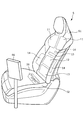
先ず、状態矯正ユニット1の構成例について説明するにあたり、状態矯正ユニット1が搭載される車両用シートSの構成について説明する。車両用シートSは、図1に示すように、着座者の背を後方から支えるシートバックS1と、着座者の臀部を下方から支えるシートクッションS2と、着座者の頭部を後方から支えるヘッドレストS3と、を有する。これらシート各部の基本構成については、公知の構成であるため、説明を省略する。
<< Configuration example of condition correction unit >>
First, in explaining the configuration example of the
次に、状態矯正ユニット1の構成例について説明する。状態矯正ユニット1は、上記の車両用シートSの内部若しくは周辺に配置された機器により構成されている。より具体的に説明すると、状態矯正ユニット1は、車両用シートS内に設置されておりシート着座者の姿勢を矯正するために動作する機器(動作部に相当)を有する。
Next, a configuration example of the
動作部について詳しく説明すると、車両用シートSのシートバックS1には、動作部を備えた複数のサポート部が存在する。具体的に説明すると、図1に示すように、シートバックS1には、ショルダーサポート部11と、ランバーサポート部12と、ペルビスサポート13部と、サイドサポート部14と、が設けられている。
Explaining the moving portion in detail, the seat back S1 of the vehicle seat S has a plurality of supporting portions provided with the moving portion. More specifically, as shown in FIG. 1, the seat back S1 is provided with a
ショルダーサポート部11は、シートバックS1中、車両用シートSに着座している状態にあるシート着座者(厳密には標準体型のシート着座者であり、以下、本段落において同じ。)の肩部を支持する部分であり、図1に示すように左右一対設けられている。ランバーサポート部12は、シートバックS1中、シート着座者の腰部を支持する部分であり、図1に示すようにシートバックS1の下側部分に設けられている。ペルビスサポート部13は、シートバックS1中、シート着座者の身体において骨盤が位置する部位を支持する部分であり、図1に示すようにランバーサポート部12の下方に設けられている。サイドサポート部14は、シート着座者の身体に側方から宛がわれる部分であり、図1に示すようにシートバックS1中、幅方向両端部が盛り上がって形成された部分(土手部)の内側に設けられている。
The
そして、上述した4つのサポート部は、それぞれ空気袋を有する。具体的に説明すると、図2に示すように、ショルダーサポート部11に肩部用空気袋11aが設けられ、ランバーサポート部12に腰部用空気袋12aが設けられ、ペルビスサポート部13に骨盤用空気袋13aが設けられている。なお、図2には不図示であるが、サイドサポート部14にも空気袋が設けられている。
Each of the four support units described above has an air bag. More specifically, as shown in FIG. 2, the
各空気袋は、シートバックS1の内部若しくはシートバックS1の前面に配置されている。そして、各空気袋は、空気が封入されることにより膨出する。このような各空気袋の膨出によってシート着座者の姿勢が矯正されるようになる。より詳しく説明すると、各空気袋は、車両用シートSにシート着座者が着座している間に膨出すると当該シート着座者を背側から押圧するようになる。かかる押圧力により、シート着座者の姿勢が矯正されるようになる。ちなみに、空気袋の膨出によって生じる押圧力は、姿勢矯正時に着座者に作用する負荷(矯正負荷)に相当する。 Each air bag is arranged inside the seat back S1 or in front of the seat back S1. Then, each air bag swells when air is sealed. Such swelling of each air bag corrects the posture of the seat seater. More specifically, when each air bag swells while the seat occupant is seated on the vehicle seat S, the air bag presses the seat occupant from the back side. The pressing force corrects the posture of the seated person. Incidentally, the pressing force generated by the swelling of the air bag corresponds to the load acting on the seated person at the time of posture correction (correction load).
また、各空気袋への空気の供給は、図2に図示のアクチュエータ18によって行われる。このアクチュエータ18から供給される空気は、送気路を形成する不図示のチューブ内を通って各空気袋に封入される。さらに、各空気袋の手前位置には、空気袋への空気の封入量を調整するための電磁弁Vが空気袋別に設置されている。以上のアクチュエータ18及び電磁弁Vが空気袋と共に、本発明の「動作部」を構成している。
Further, the air is supplied to each air bag by the
なお、本実施形態では、膨出してシート着座者を押圧する押圧手段として、空気が封入されることにより膨出する空気袋を用いているが、空気以外の流体、例えば液体が封入することにより膨出する袋体を用いてもよい。また、空気袋や袋体のようにシート着座者を押圧するにあたって膨出するものに限定されず、ローラ状体やボール状体若しくはブロック状体のような定型状の部材を押し当てることでシート着座者を押圧してもよい。 In the present embodiment, an air bag that swells and swells when air is sealed is used as a pressing means that swells and presses the seated person. However, when a fluid other than air, for example, a liquid is sealed, the bag is used. A bulging bag may be used. Further, the seat is not limited to the one that bulges when the seat seater is pressed, such as an air bag or a bag body, and the seat is pressed by pressing a standard member such as a roller-shaped body, a ball-shaped body, or a block-shaped body. The seated person may be pressed.
さらに、本実施形態では、図1に示すように、空気袋による姿勢矯正を効果的に行うための補助機構として、ヒータ15及び振動付与デバイス16が設けられている。ヒータ15は、加温部に相当し、車両用シートSに着座しているシート着座者の身体の所定部位を加温するものである。このヒータ15が設けられていることにより、姿勢矯正に際してシート着座者の身体を背側から温めておくことが可能となる。このようにシート着座者の身体を背側から温めることで、シート着座者の身体について空気袋の押圧力(負荷)に対する応答性(押圧され易さ)が改善され、その結果、姿勢矯正がより容易に行われるようになる。
Further, in the present embodiment, as shown in FIG. 1, a
振動付与デバイス16は、振動付与部に相当し、車両用シートSに着座しているシート着座者の身体(厳密には背部)の所定部位に対して振動を付与するものである。この振動付与デバイス16が設けられていることにより、姿勢矯正に際してシート着座者の背部に振動を付与して当該背部の緊張(筋肉の張り)を弛めることが可能となる。これにより、シート着座者の身体について空気袋の押圧力(負荷)に対する応答性(押圧され易さ)が改善され、その結果、姿勢矯正がより容易に行われるようになる。
The
なお、本実施形態では、振動付与デバイス16をシート着座者の緊張を弛めるために用いることとしたが、振動付与デバイス16の用途については、上記の内容に限定されるものではない。例えば、シート着座者の背部の筋力を増強する目的で振動付与デバイス16を用いてもよい。また、シート着座者の覚醒度が低下しているとき(例えば、居眠り状態にあるとき)に覚醒度を上昇させる用途としても振動付与デバイス16を利用することが可能である。
In the present embodiment, the
一方、図2に示すように、状態矯正ユニット1は、上述の動作部(厳密にはアクチュエータ18や電磁弁V)を制御する制御装置を備えている。この制御装置は、車両内に搭載されたECU(Electric Control Unit)41からなる。このECU41には姿勢矯正用の制御回路が組み込まれている。そして、ECU41が姿勢矯正用の制御回路を通じてアクチュエータ18のオンオフや電磁弁Vの開度を制御すると、各空気袋の膨出圧が調整される。この結果、シート着座者の背部に対して各空気圧の膨出圧に応じた押圧力(負荷)が掛かって、シート着座者の姿勢が矯正されるようになる。
On the other hand, as shown in FIG. 2, the
また、ECU41は、車両内に設置された各種センサと車内ネットワークを通じて通信することで、当該各種センサの測定値を取得する。換言すると、ECU41は、車両内の各種センサと協働することで様々な管理項目の現在値を測定することが可能である。そして、ECU41が測定する管理項目(すなわち、測定対象)の中には、シート着座者の着座状態に関する項目が含まれている。
Further, the
より詳しく説明すると、シート着座者の着座状態を測定するためのセンサには、呼吸センサ31、膨出圧センサ32、圧力センサ33及び重量センサ34が含まれている。これらのセンサは、車両用シートSに取り付けられた状態で利用されている。
More specifically, the sensors for measuring the seated state of the seated person include a
各センサについて説明すると、膨出圧センサ32及び圧力センサ33は、いずれもシート着座者の身体状態、具体的には着座姿勢を特定するために設置されたセンサである。膨出圧センサ32は、空気袋の膨出圧の現在値を測定するために空気袋別に設置されている。圧力センサ33は、膨出圧センサ32と同様、空気袋別に設置されており、具体的には図2に示すように各空気袋の前面に取り付けられている。そして、ECU41は、シート着座者が車両用シートSに着座している間に各膨出圧センサ32及び各圧力センサ33を通じて、シート着座者の着座姿勢を特定するための指標の現在値を測定する。
Explaining each sensor, the bulging
より詳しく説明すると、本実施形態では、車両用シートSにシート着座者が着座する前段階において、複数の空気袋の各々(具体的には、肩部用空気袋11a、腰部用空気袋12a及び骨盤用空気袋13a)が予め設定された膨出圧となるまで膨出することになっている。かかる状態で車両用シートSにシート着座者が着座すると、各空気袋の膨出圧が変化する。ECU41は、変化後の膨出圧を膨出圧センサ32を通じて空気袋別に測定する。ここで、各空気袋の膨出圧(換言すると、空気袋間の膨出圧のバランス)は、シート着座者の着座姿勢に応じた値となる。つまり、ECU41は、シート着座者の着座姿勢を特定するための指標として、シート着座者が車両用シートSに着座することで変化する各空気袋の膨出圧の現在値を測定することになっている。
More specifically, in the present embodiment, in the stage before the seat seater is seated on the vehicle seat S, each of the plurality of air bags (specifically, the
以上のように本実施形態では、空気袋が姿勢矯正用に用いられると共にシート着座者の着座状態の測定用にも用いられており、空気袋がより有効に活用されている。 As described above, in the present embodiment, the air bag is used for posture correction and also for measuring the seated state of the seated person, and the air bag is used more effectively.
また、ECU41は、車両用シートSにシート着座者が着座した際、空気袋別に設けられた圧力センサ33を通じて、シートバックS1に掛かる圧力の現在値を測定する。具体的に説明すると、シート着座者が車両用シートSに着座してシートバックS1に凭れ掛かった際、空気袋の前面にシート着座者の背から圧力が掛かると、圧力センサ33が当該圧力を検知し、ECU41が検知された圧力の大きさを圧力センサ33により測定する。ここで、空気袋別に測定される圧力は、空気袋の設置箇所に応じて変化する。また、空気袋間の圧力のバランスは、シート着座者の着座姿勢に応じた値となる。つまり、ECU41は、シート着座者の着座姿勢を特定するための指標として、シート着座者が車両用シートSに着座しているときの圧力の現在値を測定することになっている。
Further, when the seated person is seated on the vehicle seat S, the
以上のように本実施形態では、シート着座者の着座姿勢を特定する上で2つの指標(具体的には、空気袋の膨出圧及びシートバックS1に掛かる圧力)を測定することになっている。これにより、上記2つの指標のうちのいずれか一方のみを測定する場合に比べて、着座姿勢をより適切に特定することが可能となる。より詳しく説明すると、空気袋の膨出圧のみを測定して着座姿勢を特定しようとする場合には、シート着座者が車両用シートSに着座することで変化した膨出圧を測定することになる。ただし、膨出圧が変化したとしても、それがシート着座によるものであるのか、若しくはそれ以外の理由(例えば、空気袋への空気封入)によるものなのかが判明し難いケースがある。他方、圧力センサ33にてシートバックS1に掛かる圧力のみを測定して着座姿勢を特定しようとする場合、シート着座者の背がシートバックS1中、空気袋がある部分に適切に当たっていないと、圧力センサ33による測定が正確になされなくなってしまう。
As described above, in the present embodiment, two indexes (specifically, the bulging pressure of the air bag and the pressure applied to the seat back S1) are measured in specifying the seating posture of the seated person. There is. This makes it possible to more appropriately specify the sitting posture as compared with the case where only one of the above two indexes is measured. More specifically, when trying to specify the sitting posture by measuring only the bulging pressure of the air bag, it is decided to measure the bulging pressure changed by the seat seater sitting on the vehicle seat S. Become. However, even if the swelling pressure changes, it may be difficult to determine whether it is due to seat seating or for some other reason (for example, air filling in an air bag). On the other hand, when the
これに対して、本実施形態では、シート着座者の着座姿勢を特定する上で2つの指標を測定するため、上述した一方の指標のみを測定するケースに比して、より適切にシート着座者の着座姿勢を特定することが可能となる。ただし、これに限定されるものではなく、2つの指標のうちのいずれか一方のみを測定することとしてもよい。 On the other hand, in the present embodiment, since two indexes are measured for specifying the seating posture of the seat seated person, the seat seated person is more appropriately compared with the case where only one of the above indexes is measured. It is possible to specify the sitting posture of. However, the present invention is not limited to this, and only one of the two indicators may be measured.
また、ECU41は、呼吸センサ31や重量センサ34を用いて、着座姿勢以外の着座状態を測定する。具体的に説明すると、ECU41は、シートクッションS2の後端部に設置された感圧抵抗型のセンサからなる呼吸センサ31を用いて、シート着座者の覚醒状態を特定する。より厳密に説明すると、ECU41は、シート着座の呼吸に連動する周期的な座圧変動(呼吸波形)を呼吸センサ31にて測定し、その測定値からシート着座者の覚醒状態を特定する。また、ECU41は、重量センサ34を用いて車両用シートSに作用する荷重を測定し、その測定値からシート着座者の有無を特定する。
Further, the
さらに、ECU41は、車内ネットワークを通じて、上述したセンサ以外の車内センサと通信することで当該車内センサの測定値を取得し、例えば、車速センサ42と通信することで走行速度(車速)の現在値を取得する。
Further, the
さらにまた、ECU41は、車内ネットワークを通じて車内に在る上記以外の通信機器と通信することで、当該通信機器から情報を取得することが可能である。具体的に説明すると、ECU41は、シート着座者が所持している携帯端末としてのスマートフォン44と通信することで、シート着座者に関する情報(厳密には、後述の識別情報)を取得する。また、ECU41は、カーナビゲーション装置43と通信することで、その日に車両が走行する予定の距離や予定経路に関する情報を取得する。
Furthermore, the
さらにまた、ECU41は、車両がETC(Electronic
Toll Collection)47の前を通過する際にETC47と通信することで、車両の走行場所を特定するための情報(厳密には、車両が高速道路を走行しているかどうかを示す情報)を取得する。
Furthermore, in the
By communicating with the
さらにまた、ECU41は、USBメモリやSDカード(登録商標)のような携帯自在な記録媒体であるポータブルメモリ45と接続可能であり、当該ポータブルメモリ45との間でデータの受け渡しを行うことが可能である。つまり、ECU41は、自身が記憶している情報をポータブルメモリ45に書き込む一方で、ポータブルメモリ45が記憶している情報を読み取ることが可能である。
Furthermore, the
さらにまた、ECU41は、車内に設けられたタブレット端末(以下、車内タブレット端末46)と通信し、車内タブレット端末46のモニタ画面(画面に相当)に情報を表示させることが可能である。より具体的に説明すると、車内タブレット端末46は、車両用シートSの周囲(厳密には、シート着座者にとって操作し易い位置)に配置されており、図1に示すように、車体フロアから立設しているスタンションの上部にセットされている。
Furthermore, the
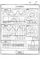
そして、ECU41は、画像情報や文字列情報を表示するためのデータ(情報表示データ)を生成し、当該情報表示データを車内タブレット端末46に向けて送信する。車内タブレット端末46は、車内ネットワークを通じて情報表示データを受信すると、これを展開して同データが示す情報をモニタ画面に表示する。これにより、シート着座者は、ECU41から発信されてくる各種情報をモニタ画面にて確認することが可能となり、例えば、図4に示すように、ECU41が測定した着座状態を確認することが可能となる。
Then, the
ちなみに、図4が示す画面例は、あくまでもモニタ画面の一例であり、そのデザインや画面レイアウトについては図4に図示のものに限定されるものではなく、任意に設定することが可能である。また、図4では、呼吸状態に関する情報(厳密には、呼吸波形や覚醒度判定グラフ)、骨盤角度に関する情報(厳密には、骨盤角度の変化曲線及び疲労レベル判定グラフ)、及び、車体の傾き(図中、車体Gと表記)が着座状態として表示されているが、モニタ画面に表示される情報については上記の内容に限定されるものではない。 Incidentally, the screen example shown in FIG. 4 is merely an example of a monitor screen, and its design and screen layout are not limited to those shown in FIG. 4, and can be set arbitrarily. Further, in FIG. 4, information on the respiratory state (strictly speaking, the respiratory waveform and the arousal degree determination graph), information on the pelvic angle (strictly speaking, the change curve of the pelvic angle and the fatigue level determination graph), and the inclination of the vehicle body. (Indicated as vehicle body G in the figure) is displayed as a seated state, but the information displayed on the monitor screen is not limited to the above contents.
なお、車内タブレット端末46のモニタ画面は、タッチパネル46aからなり、情報表示データが示す情報を表示すると共に、シート着座者が行う画面操作(タッチ操作)を入力操作として受け付ける。
The monitor screen of the in-
<<制御装置の機能について>>
次に、図4を参照しながら、制御装置としてのECU41の機能について説明する。ECU41は、姿勢矯正に関する各種の機能を実装している。具体的に説明すると、ECU41は、図4に示すように、識別情報取得部51、測定部52、プラン記憶部53、提示部54、処理実行部55、通算着座時間管理部56、態様設定部57、比較部58、情報表示部59、判定部60、情報転送部61、情報読取部62及びプラン変更部63を有する。これらの機能部は、それぞれ、ECU41を構成するハードウェア機器(具体的には、MPU及びメモリ)がソフトウェア機器(姿勢制御用の制御回路)と協働することにより実現されるものである。
<< About the function of the control device >>
Next, the function of the
以下、上記の機能部のそれぞれについて説明する。なお、以降における各機能部の説明の順序は、上述した機能部の掲載順序と異なっている。 Hereinafter, each of the above functional units will be described. It should be noted that the order of description of each functional unit in the following is different from the posting order of the functional units described above.
(識別情報取得部51)
識別情報取得部51は、シート着座者の識別情報を取得するものである。ここで、識別情報とは、シート着座者を特定(個人認証)するための情報であり、例えば、シート着座者のID情報、シート着座者の顔画像や指紋画像を示す画像情報、シート着座者の声紋情報等が該当する。
(Identification information acquisition unit 51)
The identification
ちなみに、本実施形態において、識別情報取得部51は、シート着座者が所持しているスマートフォン44と通信することで当該スマートフォン44から識別情報を取得する。かかる構成により、スマートフォン44を所持している者が車両用シートSに着座すると、ECU41が上記のスマートフォン44と通信することでシート着座者の識別情報を自動的に取得するようになる。この結果、本実施形態では、比較的容易にシート着座者の識別情報を取得することが可能となる。
By the way, in the present embodiment, the identification
なお、識別情報の取得方法については上記の方法に限定されるものではなく、シート着座者が車内タブレット端末46や所定の入力装置を通じて識別情報を入力し、その入力操作を受け付けた機器からECU41が識別情報(入力操作の内容)に関するデータを受信することで識別情報を取得する形でもよい。あるいは、車内に設置されたカメラによりシート着座者の顔画像を撮影したり、車内に設置されたマイクによりシート着座者の音声を録音したりすることで識別情報を取得してもよい。または、シート着座者を識別するためのセンサを車内(例えば、ハンドル付近)に設置し、かかるセンサからECU41が識別情報(センサの検知結果)を取得してもよい。
The method of acquiring the identification information is not limited to the above method, and the seated person inputs the identification information through the in-
(測定部52)
測定部52は、車内に設けられた着座状態測定用のセンサ群を用いて、車両用シートSに着座しているときのシート着座者の身体状態、すなわち着座状態を測定するものである。具体的に説明すると、測定部52は、空気袋別に設けられた膨出圧センサ32により、シート着座者が車両用シートSに着座することで変化する各空気袋の膨出圧の現在値を測定する。また、測定部52は、各空気袋の前面に取り付けられた圧力センサ33により、シート着座者が車両用シートSに着座している際にシートバックS1各部に掛かる圧力の現在値を測定する。また、測定部52は、呼吸センサ31により、シート着座者の呼吸波形を測定する。また、測定部52は、重量センサ34により、車両用シートSに作用する荷重を測定する。
(Measuring unit 52)
The measuring
なお、測定部52による測定対象や測定方法については、シート着座者の身体状態を特定するための指標を好適な方法にて測定すればよく、上記の内容に限定されるものではない。例えば、シート着座者の骨格形状を公知の形状センサによって測定してもよい。あるいは、シート着座者を車内のカメラにて撮影し、その撮影画像を解析することでシート着座者の脊椎の曲がり具合や骨格の歪み等を測定してもよい。
The measurement target and the measurement method by the
以上のように測定部52は、シート着座者の着座状態(具体的には、各空気袋の膨出圧やシートバックS1に掛かる圧力の現在値)を測定するが、本実施形態では同じシート着座者(すなわち、識別情報が同一である着座者)に対して複数の測定日に亘って測定することになっている。より具体的に説明すると、ある者が異なる日に車両を利用する場合、測定部52は、その者の着座状態を日別に測定する。
As described above, the measuring
なお、測定部52による日別の測定値は、測定履歴として記憶されることになっている。この測定履歴は、シート着座者の識別情報と関連付けられており、シート着座者毎に管理されている。
The daily measured value by the measuring
(判定部60)
判定部60は、測定部52が測定した着座状態に関する現在値のうち、着座姿勢を特定するための指標(具体的には、膨出圧センサ32にて測定される膨出圧、及び圧力センサ33にて測定される圧力)の現在値から着座姿勢(脊椎の曲がり状態)を判定する。より詳しく説明すると、判定部60は、「猫背」、「やや猫背」、「理想姿勢」、「やや反り背」及び「反り背」の5つの姿勢の中から該当するものを選び、その選択結果をシート着座者の現在の着座姿勢とする。
(Judgment unit 60)
The
なお、測定部52が測定した指標の現在値(すなわち、測定値)がどの範囲にあるときに上記5つの着座姿勢のうちのいずれに該当するのかについては、任意に設定することが可能である。また、着座姿勢の候補についても上記5つの姿勢に限定されるものではなく、任意に決めることが可能である。
In addition, it is possible to arbitrarily set which of the above five sitting postures corresponds to when the current value (that is, the measured value) of the index measured by the measuring
(プラン記憶部53)
プラン記憶部53は、姿勢矯正時に適用される矯正プランを記憶するものである。なお、本実施形態において、矯正プランは、予め複数用意されており、プラン記憶部53は、図5に示すようにn個(nは2以上の自然数)の矯正プランを記憶している。
(Plan memory 53)
The
また、プラン記憶部53は、矯正プランと共に、図5に図示のプラン管理テーブルTを記憶している。このプラン管理テーブルTは、シート着座者に対して設定された矯正プランを管理するためのデータである。より具体的に説明すると、プラン管理テーブルTは、識別情報取得部51が取得したシート着座者の識別情報と、当該識別情報によって特定されるシート着座者に対して姿勢矯正を実施する際に適用される矯正プランと、の対応関係を規定している。一例を挙げて説明すると、識別情報「aaaa」のシート着座者に対して姿勢矯正を行う際には矯正プラン(1)が適用されることになっている。
Further, the
(提示部54)
提示部54は、判定部60が判定した着座姿勢に応じた矯正プランをプラン記憶部53から読み出してシート着座者に対して提示するものである。ここで、判定部60が着座姿勢を判定する際には、前述したように、測定部52が測定した着座状態に関する現在値に基づいて判定することになっている。かかる意味で、提示部54は、測定部52が測定した着座状態に関する現在値に応じた矯正プランを提示すると言える。
(Presentation unit 54)
The
提示部54による矯正プランの提示について詳しく説明すると、提示部54は、着座姿勢と矯正プランとの対応関係を規定したテーブル(以下、対応テーブル)を参照し、判定部60が判定したシート着座者の着座姿勢と対応する矯正プランを一つ選び、当該矯正プランを提示する。なお、対応テーブルには、各着座姿勢に適した矯正プランが着座姿勢別に規定されており、着座姿勢が決まると、対応テーブルに基づいて対応する矯正プランが一つ選定されるようになる。
Explaining in detail the presentation of the correction plan by the
そして、シート着座者に提示された矯正プランは、当該シート着座者の識別情報と関連付けてプラン記憶部53に記憶されることになっている。つまり、プラン記憶部53は、提示部54が提示した矯正プランを、提示部54が矯正プランを提示した際に車両用シートに着座していたシート着座者の識別情報と関連付けて記憶することになっている。より具体的に説明すると、提示部54が矯正プランを提示した際、プラン記憶部53が記憶しているプラン管理テーブルTに新たなレコードが追加される。かかるレコードは、提示部54が今回提示した矯正プランと、プラン提示時のシート着座者の識別情報と、を関連付けるデータとなっている。
Then, the correction plan presented to the seat seater is to be stored in the
(処理実行部55)
処理実行部55は、着座姿勢を矯正する処理(以下、矯正処理)を実行するものである。処理実行部55は、矯正処理においてアクチュエータ18及び電磁弁Vを制御することで各空気袋の膨出圧を調整する。これにより、シート着座者の背が空気袋によって押圧される結果、シート着座者の着座姿勢が矯正されるようになる。
(Processing Execution Unit 55)
The
また、本実施形態において、処理実行部55は、姿勢矯正に際して、その時点で車両用シートSに着座しているシート着座者の識別情報を特定し、特定した識別情報に関連付けられた矯正プランをプラン記憶部53から読み出す。そして、処理実行部55は、読み出した矯正プランが示す矯正内容に従って矯正処理を実行するようになる。このように本実施形態では、シート着座者の着座姿勢を矯正する際に、当該シート着座者に提示された矯正プランが示す内容にて矯正が行われることになっている。この結果、シート着座者の着座姿勢に適した矯正内容にて当該シート着座者の着座姿勢が適切に矯正されることになる。
Further, in the present embodiment, the
具体的に説明すると、処理実行部55は、矯正処理において肩部用空気袋11a、腰部用空気袋12a及び骨盤用空気袋13aの各々の膨出圧をシート着座者の着座姿勢(すなわち、判定部60による判定結果)に応じて調整する。一例を挙げて説明すると、着座姿勢が猫背であるときには、図6Aに示すように、肩部用空気袋11a、腰部用空気袋12a及び骨盤用空気袋13aの順に膨出圧を大きくし、骨盤用空気袋13aの膨出圧(図中、P3にて示す)を最も大きくする。なお、図6A及び後述の図6B、6Cには、各着座姿勢での脊椎と各空気袋との位置関係を示す図と、空気袋間の膨出圧の大小関係を示す模式図と、が図示されている。
Specifically, the
反対に、着座姿勢が反り背であるときには、図6Cに示すように、肩部用空気袋11aの膨出圧(図中、P1にて示す)を最も大きくし、腰部用空気袋12aの膨出圧(図中、P2にて示す)を最も小さくする。一方、着座姿勢が理想姿勢であるときには、図6Bに示すように、肩部用空気袋11aの膨出圧よりも腰部用空気袋12aの膨出圧を大きくし、骨盤用空気袋13aの膨出圧を腰部用空気袋12aの膨出圧よりも若干大きくする。なお、図6A〜6Cに図示の矯正内容(具体的には、空気袋間の膨出圧のバランス)は、あくまでも一例に過ぎず、これらの図に示した内容に限定されるものではない。
On the contrary, when the sitting posture is a warped back, as shown in FIG. 6C, the bulging pressure of the
ところで、本実施形態において、処理実行部55は、矯正処理の実行時、後述の態様設定部57が設定した矯正態様にてシート着座者の着座姿勢を矯正することになっている。ここで、「矯正態様」とは、姿勢矯正の具体的な進め方(矯正手順)や矯正モードのことであり、例えば、姿勢矯正時においてシート着座者の身体に負荷を掛ける際の度合い(厳密には、負荷の変動速度、負荷付与スケジュール、各時間帯における負荷の大きさ等)が該当する。なお、本実施形態において、矯正態様は、その日のシート着座者の状態やスケジュールや、車両及びその周囲の状況、その他矯正態様を設定する上で考慮すべき事項に応じて矯正処理を実行する都度、設定されることになっている。
By the way, in the present embodiment, when the
さらにまた、処理実行部55は、矯正処理の実行に際してヒータ15を制御してシート着座者の背(具体的には、背においてヒータ15の直前位置にある部位)を温める。また、処理実行部55は、矯正処理の実行に際して振動付与デバイス26を制御してシート着座者の背に振動を付与する。以上により、シート着座者の筋肉(特に肩、背、腰の筋肉)が和らげられ、その後の姿勢矯正が効率良く行われるようになる。
Furthermore, the
(通算着座時間管理部56)
通算着座時間管理部56は、シート着座者別に通算着座時間を管理するものである。ここで、「通算着座時間」とは、識別情報が同一であるシート着座者が車両用シートSに着座した時間の累計値を意味する。なお、本実施形態において、通算着座時間は、シート着座者が初めて姿勢矯正を受けた際の当該姿勢矯正の開始時を基準(始点)として管理することになっている。すなわち、本実施形態において、通算着座時間とは、シート着座者が姿勢矯正を受けてきた累計時間と同義である。
(Total seating time management department 56)
The total seating
また、通算着座時間管理部56は、シート着座者の通算着座時間を当該シート着座者の識別情報と関連付けて記憶しており、具体的には、通算着座時間と識別情報との対応関係を規定した管理テーブル(以下、通算着座時間管理テーブル)を記憶している。
Further, the total seating
通算着座時間の管理について具体的に説明すると、シート着座者が車両用シートSに着座した際に、通算着座時間管理部56が、その時点で識別情報取得部51が取得した識別情報と上記の通算着座時間管理テーブルとに基づいて、当該シート着座者の前回までの通算着座時間を特定する。一方、通算着座時間管理部56は、シート着座者が車両用シートSに着座した時点から着座時間をカウントし、特定した前回までの通算着座時間とカウント中の新たな着座時間とを合算することで、今回の通算着座時間を求める。そして、通算着座時間管理部56は、通算着座時間管理テーブル中、車両用シートSに着座しているシート着座者の識別情報と関連付けられた通算着座時間を、今回求めた通算着座時間に更新する。
To specifically explain the management of the total seating time, when the seated person is seated on the vehicle seat S, the total seating
(態様設定部57)
態様設定部57は、処理実行部55が矯正処理を実行する際に適用される矯正態様を設定する。また、本実施形態において、態様設定部57は、前述したように、矯正処理が実行される度に矯正態様を設定することになっている。また、本実施形態において、態様設定部57は、様々な状況を踏まえて矯正態様を設定する。具体的には、下記の事項(r1)、(r2)、(r3)、(r4)、(r5)及び(r6)に応じた矯正態様を設定することになっている。
(r1)通算着座時間管理部56が管理している通算着座時間のうち、車両用シートSに着座しているシート着座者の識別情報と関連付けられている通算着座時間
(r2)車両用シートSに着座しているシート着座者の年齢
(r3)その日に車両が走行する予定の走行経路
(r4)その日の曜日及び現在の時刻
(r5)車両の走行場所(高速道路を走行しているかどうか)
(r6)車両の走行速度
(Aspect setting unit 57)
The
(R1) Total seating time Of the total seating time managed by the
(R6) Traveling speed of the vehicle
以上のように、本実施形態では、上記6つの事項を考慮して矯正態様を設定するため、姿勢矯正の進展具合(つまり、姿勢矯正を受けてきた時間)やシート着座者の予定等を加味した上で適切な態様にて姿勢矯正が行われるようになる。具体的に説明すると、あるシート着座者は、それまでの通算着座時間に応じた矯正態様にて姿勢矯正を受けることになる。これにより、通算着座時間に応じて矯正時の負荷が適切に調整されるようになり、例えば、矯正初期(すなわち、通算着座時間が比較的小さいとき)には負荷を小さく抑え、通算着座時間の増加と共に徐々に負荷を大きくすることが可能となる。 As described above, in the present embodiment, in order to set the correction mode in consideration of the above six items, the progress of posture correction (that is, the time during which the posture correction has been received), the schedule of the seated person, etc. are taken into consideration. After that, posture correction will be performed in an appropriate manner. Specifically, a seated person will receive posture correction in a correction mode according to the total sitting time up to that point. As a result, the load at the time of correction is appropriately adjusted according to the total sitting time. For example, the load is kept small at the initial stage of correction (that is, when the total sitting time is relatively small), and the total sitting time is reduced. It becomes possible to gradually increase the load as the number increases.
また、車両が比較的長距離を走行する場合には、シート着座者が車両用シートSに長時間着座することになるため、姿勢矯正の継続時間が通常の時間よりも長くなるように矯正態様を設定することが可能となる。また、特定の曜日(例えば、祝日)や特定の時間(例えば、早朝)に車両を運転する場合には、その曜日や時間帯に応じた矯正態様にて姿勢矯正を行うことも可能となる。また、車両が高速道路を走行している期間中には、シート着座者の着座姿勢が安定するため、シート着座者に対してより高い頻度にて負荷を掛けるように矯正態様を設定することも可能となる。 Further, when the vehicle travels a relatively long distance, the seat seater will be seated on the vehicle seat S for a long time, so that the posture correction duration is longer than the normal time. Can be set. Further, when driving a vehicle on a specific day of the week (for example, a holiday) or a specific time (for example, early morning), it is possible to perform posture correction in a correction mode according to the day of the week or time zone. In addition, since the seating posture of the seated person is stable while the vehicle is traveling on the highway, it is possible to set the correction mode so that the load is applied to the seated person more frequently. It will be possible.
なお、上記6つの事項のうち、(r1)、(r4)、(r5)及び(r6)は、車両が走行している期間中、動的に変化するものである。態様設定部57は、車両走行期間中、これら4つの事項を定期的に特定すると共に、その特定結果に応じて矯正態様を適宜更新する。したがって、本実施形態では、矯正処理の実行中、矯正態様が定期的に更新されることになっており、矯正態様が変わった場合には、変更後の矯正態様にて処理実行部55が矯正処理を実行するようになる。
Of the above six items, (r1), (r4), (r5) and (r6) dynamically change during the period in which the vehicle is traveling. The
ちなみに、本実施形態において、上記6つの事項のうち、(r2)に関する情報については、シート着座者が車内タブレット端末46や所定の入力装置を通じて入力することで取得される。ただし、これに限定されるものではなく、シート着座者の年齢については、車内に設置されたカメラが撮像したシート着座者の顔画像を解析したり、シート着座者の生体情報のうち、年齢に応じて変化する情報(例えば、皺数、骨密度、体脂肪率等)を所定のセンサにて測定したりすることで取得することも可能である。なお、年齢については、実際の年齢(実年齢)であってもよく、体力や健康状態に応じて決まる年齢(いわゆる体力年齢)であってもよい。
By the way, in the present embodiment, the information regarding (r2) among the above six items is acquired by the seated person inputting the information through the in-
また、本実施形態において、(r3)に関する情報については、ECU41がカーナビゲーション装置43と通信することにより取得される。ただし、これに限定されるものではなく、車両の予定走行経路については、シート着座者が車内タブレット端末46や所定の入力装置を通じて入力することで取得することも可能である。
Further, in the present embodiment, the information regarding (r3) is acquired by the
また、本実施形態において、(r4)に関する情報については、ECU41内のカレンダや内部時計から取得される。ただし、これに限定されるものではなく、その日の曜日や現在時刻については、ECU41が外部の機器やシート着座者のスマートフォン44と通信することで取得することも可能である。
Further, in the present embodiment, the information regarding (r4) is acquired from the calendar or the internal clock in the
また、本実施形態において、(r5)に関する情報、具体的には、車両が現在高速道路を走行しているか否かの情報については、車両がETC47の前を通過する際にECU41がETC47からの出力信号を受信することにより取得される。ただし、これに限定されるものではなく、車両が現在高速道路を走行しているか否かについては、車両やスマートフォン44若しくは車内タブレット端末46に搭載されたGPS機能により取得することも可能である。若しくは、シート着座者が車内タブレット端末46や所定の入力装置を通じて入力することで取得することも可能である。
Further, in the present embodiment, regarding the information regarding (r5), specifically, the information on whether or not the vehicle is currently traveling on the highway, the
また、本実施形態において、(r6)に関する情報については、ECU41が車速センサ42からの出力信号を受信することにより取得される。ただし、これに限定されるものではなく、車両の走行速度については、シート着座者が車内タブレット端末46や所定の入力装置を通じて入力することで取得することも可能である。
Further, in the present embodiment, the information regarding (r6) is acquired by the
なお、本実施形態では、上記6つの事項(r1)〜(r6)に応じて矯正態様を設定することとしたが、矯正態様を設定する際に考慮すべき事項については、上記6つの事項に限定されるものではなく、上記6つの事項のいずれかのみであってもよい。あるいは、上記6つの事項以外の事項(例えば、シート着座者の体調や車両が走行している路面の状態等)をさらに考慮して矯正態様を設定してもよい。 In the present embodiment, the correction mode is set according to the above six items (r1) to (r6), but the items to be considered when setting the correction mode are described in the above six items. It is not limited, and may be only one of the above six items. Alternatively, the correction mode may be set in consideration of items other than the above six items (for example, the physical condition of the seated person, the condition of the road surface on which the vehicle is traveling, etc.).
(情報表示部59)
情報表示部59は、情報を車内タブレット端末46のタッチパネル46aに表示する。より具体的に説明すると、情報表示部59は、情報を表示するためのデータ(情報表示データ)を生成して車内タブレット端末46に向けて送信する。車内タブレット端末46は、車内ネットワークを通じて情報表示データを受信すると、これを展開して同データが示す情報をモニタ画面に表示する。
(Information display unit 59)
The
情報表示部59が送信する情報表示データについて説明すると、判定部60による判定結果を表示するためのデータが情報表示データとして送信される。すなわち、本実施形態において、情報表示部59は、判定部60の判定結果を示す情報、具体的にはシート着座者の現在の着座姿勢を表示する。ここで、判定部60が着座姿勢を判定する際には、前述したように、測定部52が測定した着座状態に関する現在値に基づいて判定することになっている。かかる意味で、情報表示部59は、測定部52が測定した着座状態に関する現在値に応じた情報を表示すると言える。
Explaining the information display data transmitted by the
なお、図7に、判定部60による判定結果を表示している画面例を示す。ただし、図7に図示の画面は、判定部60による判定結果を表示している画面の一例であり、画面デザインや画面レイアウト、並びに表示する情報については図7に図示の内容に限定されるものではない。
Note that FIG. 7 shows an example of a screen displaying the determination result by the
また、情報表示部59が送信する情報表示データの中には、提示部54が提示した矯正プランを表示するためのデータが含まれている。すなわち、本実施形態において、提示部54は、情報表示部59に矯正プランを車内タブレット端末46の画面に表示させることで矯正プランを提示する。
Further, the information display data transmitted by the
なお、図8に、提示部54が提示した矯正プランを表示している画面例を示す。ここで、画面中、矯正プランは、現在の着座姿勢に関する将来的なリスクや要因、理想姿勢及び矯正内容(図中、「背筋・大胸筋を・・・・保つことができます。」と表記された部分)によって構成されている。ただし、画面に矯正プランを表示する際の表示内容については、図8に図示した内容に限定されるものではない。また、提示部54が提示した矯正プランを表示する画面のデザインや画面レイアウトについても、図8に図示の内容に限定されるものではない。
Note that FIG. 8 shows an example of a screen displaying the correction plan presented by the
また、本実施形態において、情報表示部59は、車内タブレット端末46のタッチパネル46aに情報を表示することとしたが、これに限定されるものではない。例えば、シート着座者が保持するスマートフォン44や車内に搭載された他の画面(例えば、カーナビゲーション装置43のディスプレイ)に情報を表示してもよい。
Further, in the present embodiment, the
(比較部58)
比較部58は、同一のシート着座者を対象にして測定部52が直前の測定日に測定した着座状態(具体的には、各空気袋の膨出圧やシートバックS1に掛かる圧力の現在値)と、直前の測定日よりも前の測定日に測定した着座状態と、を比較する。具体的に説明すると、あるシート着座者が車両用シートSに着座した際、測定部52による着座状態の測定(すなわち、今回の測定)が行われる。その一方で、比較部58が上記のシート着座者の測定履歴を参照し、初回の測定における着座状態の測定値(初回の測定値)を読み出す。
(Comparison part 58)
The
そして、比較部58は、今回の測定値と初回の測定値とを比較する。このような比較を行うことで、前回までに行ってきた姿勢矯正の効果(すなわち、矯正による姿勢改善具合)を把握することが可能となる。
Then, the
また、本実施形態では、図9に示すように、比較対象である今回の測定値及び初回の測定値のそれぞれについて、当該測定値に応じた情報(厳密には、測定値に応じた脊椎の曲がり状態を示す画像)が情報表示部59によって車内タブレット端末46に表示されることになっている。これにより、シート着座者は、車内タブレット端末46を通じて、前回までに行ってきた姿勢矯正の効果(すなわち、矯正による姿勢改善効果)を確認することが可能となる。
Further, in the present embodiment, as shown in FIG. 9, for each of the current measurement value and the first measurement value, which are the comparison targets, the information corresponding to the measurement value (strictly speaking, the spine according to the measurement value). An image showing the bent state) is to be displayed on the in-
なお、図9に図示の画面は、比較部58によって比較される2つの対象を示す画面の一例に過ぎず、当該画面のデザインやレイアウト、及び表示される情報については、図9に図示の内容に限定されるものではない。
The screen illustrated in FIG. 9 is merely an example of a screen showing two objects to be compared by the
(プラン変更部63)
プラン変更部63は、提示部54がシート着座者に対して提示した矯正プランを必要に応じて変更するものである。厳密に説明すると、プラン変更部63は、所定の変更条件が成立したとき、提示部54が矯正プランを提示した際に車両用シートSに着座していたシート着座者の識別情報と関連付けられている矯正プランを、プラン記憶部53に記憶された一の矯正プランから他の矯正プランに変更する。
(Plan change part 63)
The
より詳しく説明すると、本実施形態では、姿勢矯正が複数日に亘って繰り返し実施されることになっている。換言すると、シート着座者が車両用シートSに着座する日付が変わる度に、同じシート着座者に対して矯正処理を繰り返し実行することになっている。また、測定部52による着座状態の測定についても、日付が変わる度に実施されることになっている。つまり、測定部52は、初回の矯正処理が開始された日後に着座状態(具体的には、各空気袋の膨出圧及びシートバックS1に掛かる圧力の現在値)を測定し直す。
More specifically, in the present embodiment, the posture correction is to be repeatedly performed over a plurality of days. In other words, every time the date on which the seat occupant sits on the vehicle seat S changes, the correction process is repeatedly executed for the same seat occupant. Further, the measurement of the seated state by the measuring
一方、プラン変更部63は、初回の矯正処理が開始された日以降、シート着座者が車両用シートSに着座する日付が変わる度に、測定部52が測定し直した着座状態(すなわち、今回の測定値)に基づいてプラン変更の要否を判定する。より具体的に説明すると、比較部58が今回の測定値と初回の測定値とを比較すると、その比較結果(例えば、測定値の差分)がプラン変更部63に通知されることになっている。プラン変更部63は、通知された比較結果が所定の条件を満たすかどうかを判定する。そして、プラン変更部63は、上記の条件が成立している場合に矯正プランを変更する。具体的には、対象となるシート着座者(厳密には、初回の矯正処理で適用された矯正プランが提示部54によって提示した時点のシート着座者)の識別情報と関連付けられている矯正プランが変更するようにプラン管理テーブルTを更新する。
On the other hand, the
以上のように、本実施形態では、矯正処理において適用する矯正プランを決めた日後に、必要に応じて当該矯正プランの見直しを行う。これにより、一度設定した矯正プランであっても、着座姿勢の矯正具合(改善具合)に応じて必要により適宜見直すことが可能となる。これにより、効果的に着座姿勢を矯正することが可能となる。 As described above, in the present embodiment, after the day when the correction plan to be applied in the correction process is determined, the correction plan is reviewed as necessary. As a result, even if the correction plan is set once, it can be appropriately reviewed as necessary according to the correction condition (improvement condition) of the sitting posture. This makes it possible to effectively correct the sitting posture.
なお、矯正プランの変更に関して、プラン記憶部53に記憶された矯正プランのうち、どのプランを変更後の矯正プランとして採用するかについては、特に限定されるものではないが、比較部58が今回の測定値と初回の測定値とを比較した際の比較結果を考慮して、最適なプランが選ばれるのが望ましい。
Regarding the change of the correction plan, which of the correction plans stored in the
(情報転送部61及び情報読取部62)
情報転送部61は、ECU41が記憶している各種情報を、ECU41に接続されているポータブルメモリ45に転送する。情報読取部62は、ECU41に接続されているポータブルメモリ45から情報を読み取る。すなわち、本実施形態では、ポータブルメモリ45を利用することでECU41に記憶されている情報を移送することが可能である。
(
The
ここで、ポータブルメモリ45に転送したりポータブルメモリ45から読み取ったりする情報の中には、測定部52が着座状態を測定した際の測定値(厳密には、過去の測定値を収録した測定履歴)、識別情報取得部51が取得したシート着座者の識別情報、提示部54が提示した矯正プランの対応関係(具体的にはプラン管理テーブルT)、通算着座時間管理部56が管理している通算着座時間、及び、プラン変更部63によって矯正プランが見直されたときの変更後の矯正プランが含まれている。
Here, among the information transferred to the
本実施形態では、上記の情報転送部61及び情報読取部62が設けられていることで、互いに異なる車両に搭載されたECU41の各々が姿勢矯正に関する一連の機能(すなわち、上述した機能部)を具備するものであれば、ECU41間で情報の移送(引き継ぎ)を行うことが可能となる。これにより、例えば、利用する車両を交換した場合、それまで利用していた車両内に搭載されたECU41が記憶していた姿勢矯正に関する情報を、新たに利用する車両内のECU41に引き継ぐことが可能となる。この結果、車両利用者(つまり、シート着座者)は、それまで利用していた車両内で受けていた姿勢矯正と同じ矯正内容の姿勢矯正(つまり、同じ矯正プランにて行われる姿勢矯正)を、新たな車両内で引き続き受けることが可能となる。
In the present embodiment, since the
なお、本実施形態では、情報転送部61が情報を転送し、情報読取部62が情報を読み取る対象として、USBメモリ等からなるポータブルメモリ45を用いることとしたが、これに限定されるものではない。すなわち、ポータブルメモリ45の代用品として、シート着座者が保持するスマートフォン44を用いてもよく、あるいは、車内タブレット端末46が持ち運び自在の構成となっていれば当該車内タブレット端末46を用いてもよい。
In the present embodiment, the
<<状態矯正ユニットの動作例>>
次に、状態矯正ユニット1の動作例として、状態矯正ユニット1による姿勢矯正の流れ(姿勢矯正フロー)について説明する。
姿勢矯正フローは、主に、シート着座者が初めて姿勢矯正を受けるときのフロー(以下、初回時フロー)と、初回以降のフロー(以下、通常時フロー)と、に分かれる。以下では、先ず、初回時フローについて説明し、その後に、通常時フローを説明することとする。
<< Operation example of condition correction unit >>
Next, as an operation example of the
The posture correction flow is mainly divided into a flow when the seated person receives the posture correction for the first time (hereinafter, the flow at the first time) and a flow after the first time (hereinafter, the flow at the normal time). In the following, the initial flow will be described first, and then the normal flow will be described.
(初回時フロー)
初回時フローは、図10及び11に示す流れに従って進行する。具体的に説明すると、シート着座者が本実施形態に係る車両用シートSに初めて着座した際に、初回時フローが自動的に開始される(S001)。より詳しく説明すると、車両用シートSにシート着座者が着座すると、これに伴って変化するシート重量の大きさに応じた信号を重量センサ34が出力する。ECU41は、重量センサ34からの出力信号を受信すると、これをトリガーとして初回時フローの主工程(ステップS002以降の工程)を自動的に開始する。なお、本実施形態では、車両用シートSにシート着座者が着座した時点で自動的に初回時フローが開始されることとしたが、これに限定されるものではなく、シート着座者がシート着座後に所定の操作/動作を行い、かかる操作/動作を契機に初回時フローが開始されてもよい。
(First time flow)
The initial flow proceeds according to the flow shown in FIGS. 10 and 11. Specifically, when the seated person first sits on the vehicle seat S according to the present embodiment, the initial flow is automatically started (S001). More specifically, when the seated person is seated on the vehicle seat S, the
初回時フローが開始されると、ECU41(具体的には、測定部52)は、シート着座者の着座状態に関する測定をはじめ、各種測定を実施する(S002)。具体的には、各空気袋の膨出圧を膨出圧センサ32により測定し、シートバックS1の各部に掛かる圧力を圧力センサ33により測定し、呼吸に伴って変化する着座圧を呼吸センサ31にて測定する。なお、各空気袋の膨出圧を測定するにあたり、ECU41は、車両用シートSにシート着座者が着座する前段階でアクチュエータ18及び電磁弁Vを制御し、各空気袋を所定の膨出圧になるまで膨出させる。
When the flow at the first time is started, the ECU 41 (specifically, the measuring unit 52) performs various measurements including the measurement regarding the seated state of the seated person (S002). Specifically, the swelling pressure of each air bag is measured by the swelling
その後、ECU41(具体的には、識別情報取得部51)は、シート着座者が所持しているスマートフォン44と通信することで当該スマートフォン44からシート着座者の識別情報を取得する(S003)。また、ECU41(具体的には、判定部60)は、ステップS002にて測定した着座状態からシート着座者の着座姿勢を判定する(S004)。より具体的に説明すると、ECU41は、空気袋の膨出圧の現在値、及びシートバックS1の各部に掛かる圧力の現在値に基づいて、シート着座者の現在の着座姿勢が「猫背」、「やや猫背」、「理想姿勢」、「やや反り背」、「反り背」のうちのいずれであるかを判定する。
After that, the ECU 41 (specifically, the identification information acquisition unit 51) acquires the identification information of the seat occupant from the
そして、ECU41(具体的には、情報表示部59)は、判定した着座姿勢を表示するための情報表示データを生成して車内タブレット端末46に向けて送信する。これにより、車内タブレット端末46のタッチパネル46aに、着座姿勢の判定結果が表示されるようになる(S005)。
Then, the ECU 41 (specifically, the information display unit 59) generates information display data for displaying the determined sitting posture and transmits it to the in-
その後、ECU41は、着座姿勢の判定結果に応じて以降の工程を実施する。具体的に説明すると、判定された着座姿勢が理想姿勢である場合(S006でYes)、ECU41は、初回時フローを終了する。一方、判定された着座姿勢が理想姿勢以外の姿勢である場合(S006でNo)、ECU41は、シート着座者のモード指定操作を契機として以降の工程を実施する。
After that, the
ここで、シート着座者によるモード指定操作について説明すると、モード指定操作は、ECU41の制御モードについて用意された複数の候補の中から一つを指定するために行われる操作であり、本実施形態では、車内タブレット端末46のタッチパネル46aを通じて行われる。なお、ECU41による制御モードとして2つの候補が用意されており、具体的には、『安楽補正』のモードと『理想補正』のモードが設定されている。『理想補正』のモードは、姿勢矯正を行うモードであり、具体的には、現在の着座姿勢を理想姿勢になるように矯正するようにアクチュエータ18や電磁弁V等を制御するモードである。
Here, the mode designation operation by the seated person will be described. The mode designation operation is an operation performed to specify one of a plurality of candidates prepared for the control mode of the
『安楽補正』のモードは、現在の着座姿勢のままで安定させるためのモードであり、シート着座者にとって現在の着座姿勢を保持し易くなるようにアクチュエータ18や電磁弁V等を制御するモードである。
The "comfort correction" mode is a mode for stabilizing the current sitting posture, and is a mode for controlling the
シート着座者は、以上2つの制御モードの中からいずれか一方を指定するために、タッチパネル46aにおいて着座姿勢の判定結果と共に表示される2つの指定ボタン(図7中、「安楽補正」、「理想補正」という文字が付されたボタン)のうちの一方を押す。かかるボタン操作がモード指定操作であり、ECU41は、車内タブレット端末46を介して当該操作を受け付ける。
The seat seater has two designation buttons (“comfort correction” and “ideal” in FIG. 7) displayed together with the seating posture determination result on the
そして、『安楽補正』のモードが指定された場合(S007で「安楽補正」)、ECU41は、上述した安楽補正を実施する(S008)。
Then, when the mode of "comfort correction" is specified ("comfort correction" in S007), the
一方、『理想補正』のモードが指定された場合(S007で「理想補正」)、ECU41は、上述した理想補正を実施する。理想補正を実施するにあたり、ECU41(具体的には、提示部54)は、プラン記憶部53にアクセスし、プラン記憶部53に記憶されている矯正プランの中から、前ステップS004で判定したシート着座者の現在の着座姿勢に応じた矯正プランを読み出す。そして、ECU41は、読み出した矯正プランをシート着座者に提示する(S009)。より具体的に説明すると、ECU41(具体的には、情報表示部59)が、読み出した矯正プランを表示するための情報表示データを生成して車内タブレット端末46に向けて送信する。これにより、図8に示すように、車内タブレット端末46のタッチパネル46aにECU41が読み出した矯正プラン、すなわち、シート着座者の現在の着座姿勢に応じた矯正プランが表示されるようになる。
On the other hand, when the "ideal correction" mode is specified ("ideal correction" in S007), the
また、ECU41は、前ステップS003で取得したシート着座者の識別情報と、提示した矯正プランとを関連付けてプラン記憶部53に記憶する(S010)。具体的には、識別情報と矯正プランとを互いに関連付けたレコードがプラン管理テーブルT中に追加されるように、プラン管理テーブルTを更新する。
Further, the
その後、シート着座者が車内タブレット端末46にて理想補正の実施指令を行うと(具体的には、図8中、「補正開始」の文字が付されたボタンを押すと)、これをトリガーとしてECU41が理想補正を実施する(S011)。理想補正は、ECU41が図12に示す各工程を実施することで進行する。
After that, when the seated person issues a command to execute the ideal correction on the in-vehicle tablet terminal 46 (specifically, when the button with the characters "correction start" is pressed in FIG. 8), this is used as a trigger. The
具体的に説明すると、理想補正において、ECU41(具体的には、処理実行部55)は、車両用シートSに着座しているシート着座者の識別情報に関連付けられた矯正プランをプラン記憶部53から読み出す(S021)。
Specifically, in the ideal correction, the ECU 41 (specifically, the processing execution unit 55) provides a correction plan associated with the identification information of the seat seater seated on the vehicle seat S in the
次に、ECU41(具体的には、処理実行部55)は、ヒータ15を制御してシート着座者の背の所定部位を加温するとともに(S022)、振動付与デバイス16を制御してシート着座者の背に対して振動を付与する(S023)。これにより、シート着座者の筋肉(特に肩、背、腰の筋肉)が和らげられ、その後の姿勢矯正が効率良く行われるようになる。
Next, the ECU 41 (specifically, the processing execution unit 55) controls the
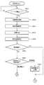
その後、ECU41(具体的には、態様設定部57)は、矯正処理時に適用する矯正態様を設定する(S024)。矯正態様を設定する手順について説明すると、図13に示すように、ECU41(具体的には、通算着座時間管理部56)が、その時点で車両用シートSに着座しているシート着座者の通算着座時間を特定する(S031)。なお、初回時フローの開始直後の段階では、通算着座時間が0となっている。 After that, the ECU 41 (specifically, the mode setting unit 57) sets the straightening mode to be applied at the time of the straightening process (S024). Explaining the procedure for setting the correction mode, as shown in FIG. 13, the total number of seated persons who are seated on the vehicle seat S at that time by the ECU 41 (specifically, the total seating time management unit 56) The seating time is specified (S031). At the stage immediately after the start of the flow at the first time, the total seating time is 0.
その後、ECU41(具体的には、態様設定部57)は、その日の曜日及び現在の時間帯を特定する(S032)。また、ECU41(具体的には、態様設定部57)は、カーナビゲーション装置43と通信することで、その日の車両の走行予定距離を特定する(S033)。また、ECU41(具体的には、態様設定部57)は、ETC47から受信した信号等に基づいて車両の現在の走行場所、より具体的には車両が高速道路を走行しているかどうかを特定する(S034)。さらに、ECU41(具体的には、態様設定部57)は、シート着座者が車内タブレット端末46を通じて入力したシート着座者の年齢を特定する(S035)。これら一連の特定工程が完了した後、ECU41(具体的には、態様設定部57)は、それまでの各ステップS031〜S035での特定結果に応じた矯正態様を設定する(S036)。
After that, the ECU 41 (specifically, the mode setting unit 57) specifies the day of the week and the current time zone of the day (S032). Further, the ECU 41 (specifically, the mode setting unit 57) identifies the planned travel distance of the vehicle on that day by communicating with the car navigation device 43 (S033). Further, the ECU 41 (specifically, the mode setting unit 57) specifies the current traveling location of the vehicle, more specifically, whether or not the vehicle is traveling on the highway, based on the signal received from the
矯正態様設定後、ECU41(具体的には、処理実行部55)は、前ステップS021にて読み出した矯正プランが示す矯正内容に従って、前ステップS036にて設定した矯正態様にて矯正処理を実行する(S025)。 After setting the correction mode, the ECU 41 (specifically, the processing execution unit 55) executes the correction processing in the correction mode set in the previous step S036 according to the correction content indicated by the correction plan read in the previous step S021. (S025).
そして、ECU41(具体的には、処理実行部55)は、図12に示すように、矯正終了条件が成立するまで(S026)、矯正態様を設定するステップと、矯正処理を実行するステップと、を定期的に繰り返す。なお、矯正終了条件とは、理想補正のうち、その日の実施分(一日分)を終了するタイミングを規定したものであり、例えば、予め指定された矯正時間が経過すること、車両が目的地に到着すること、若しくは、シート着座者が矯正終了を指示するための操作を行うことが挙げられる。 Then, as shown in FIG. 12, the ECU 41 (specifically, the process execution unit 55) has a step of setting the correction mode, a step of executing the correction process, and a step of executing the correction process until the correction end condition is satisfied (S026). Is repeated regularly. The correction end condition defines the timing for ending the execution portion (one day's worth) of the ideal correction. For example, the correction time specified in advance has elapsed, and the vehicle is the destination. It is possible to arrive at the or to perform an operation for the seated person to instruct the end of the correction.
そして、矯正終了条件が成立した時点で、初回分の姿勢矯正が完了し、初回時フローが終了することとなる。 Then, when the correction end condition is satisfied, the posture correction for the first time is completed, and the flow at the first time is finished.
(通常時フロー)
通常時フローは、初回時フローが行われた日後に行われることになっており、図14に示す流れに従って進行する。具体的に説明すると、通常時フローについても、初回時フローと同様、シート着座者が車両用シートSに着座した時点で自動的に開始される(S041)。その後、ECU41が、初回時フローと同様の手順にて、シート着座者の着座状態等に関する各種の測定(S042)、シート着座者の識別情報の取得(S043)、及び着座姿勢の判定(S044)を行う。
(Normal flow)
The normal flow is to be performed after the day when the initial flow is performed, and proceeds according to the flow shown in FIG. More specifically, the normal flow is automatically started when the seated person is seated on the vehicle seat S (S041), as in the initial flow. After that, the
以上のように、本実施形態において、ECU41は、初回時フロー及び通常時フローの共通ルーティンとして、着座状態の測定、識別情報の取得及び着座姿勢の判定を行うことになっている。そして、取得した識別情報が以前に取得済みの識別情報と一致している場合、ECU41は、以降、図14に示す手順にて通常時フローを行うことになる。なお、通常時フローが行われるということは、識別情報が同一であるシート着座者に対して、着座状態の測定及び着座姿勢の判定が複数日に亘って行われることを意味している。換言すると、通常時フローでは、初回時フローが行われた日後にシート着座者の着座姿勢を測定し直すことになる。
As described above, in the present embodiment, the
通常時フローにおいて着座姿勢の判定が行われた後、ECU41(具体的には比較部58)は、姿勢比較を実施する(S045)。具体的に説明すると、姿勢比較では、初回時フローにおける着座状態の測定値(初回の測定値)と、通常時フローにおいて今回測定した着座状態の測定値(今回の測定値)と、を比較する。 After the seating posture is determined in the normal flow, the ECU 41 (specifically, the comparison unit 58) performs a posture comparison (S045). Specifically, in the posture comparison, the measured value of the seated state in the initial flow (first measured value) and the measured value of the seated state measured this time in the normal flow (current measured value) are compared. ..
その後、ECU41(具体的には情報表示部59)は、姿勢比較の結果を表示するための情報表示データを生成して車内タブレット端末46に向けて送信する。これにより、図9に示すように、車内タブレット端末46のタッチパネル46aに着座姿勢の比較結果、具体的には今回の測定値及び初回の測定値のそれぞれに応じた画像情報が表示されるようになる(S046)。これにより、シート着座者は、上記のタッチパネル46aを通じて、前回までに行ってきた姿勢矯正の効果(姿勢改善具合)を把握するようになる。
After that, the ECU 41 (specifically, the information display unit 59) generates information display data for displaying the result of the posture comparison and transmits it to the in-
一方、ECU41(具体的にはプラン変更部63)は、シート着座者(厳密には、その時点で車両用シートSに着座しているシート着座者)の姿勢を矯正する際に適用する矯正プランを変更するか否かを、前ステップS046での比較結果に応じて判定する。具体的に説明すると、比較結果からシート着座者の着座姿勢についての矯正具合を特定し、当該矯正具合が一定以上であるならば(S047でYes)、プラン変更は行われないことになっている。かかる場合、ECU41は、識別情報が同一であるシート着座者に対して理想補正(すなわち、姿勢矯正)を実施する場面において、それまで当該識別情報と関連付けられていた矯正プランを引き続き適用して理想補正を実施することになる(S048)。
On the other hand, the ECU 41 (specifically, the plan change unit 63) is a correction plan applied when correcting the posture of the seat seater (strictly speaking, the seat seater who is seated on the vehicle seat S at that time). Whether or not to change is determined according to the comparison result in the previous step S046. Specifically, the correction condition for the sitting posture of the seat seater is specified from the comparison result, and if the correction condition is above a certain level (Yes in S047), the plan is not changed. .. In such a case, the
これに対して、矯正具合が一定未満であるとき(S047でNo)、ECU41(具体的には、提示部54)は、プラン記憶部53に記憶されている矯正プランの中から、その時点での矯正具合に応じた矯正プランを読み出し、当該矯正プランを新たな矯正プランとしてシート着座者に提示する(S049)。そして、ECU41(具体的にはプラン変更部63)は、新たな矯正プランが提示されたシート着座者の識別情報と関連付けられている矯正プランを変更する(S050)。具体的には、上記のプラン変更が反映されるようにプラン管理テーブルTを更新する。その上で、ECU41(具体的には、処理実行部55)は、変更後の矯正プランにて理想補正(すなわち、姿勢矯正)を実施する(S051)。
On the other hand, when the correction condition is less than a certain level (No in S047), the ECU 41 (specifically, the presentation unit 54) is selected from the correction plans stored in the
なお、通常時フローにおいて、理想補正は、初回時フローと同様の手順(すなわち、図12に示す手順)にて進行する。また、通常時フローにおいても、矯正終了条件が成立するまで、矯正態様を設定するステップと、矯正処理を実行するステップと、を定期的に繰り返される。そして、矯正終了条件が成立した時点で、その日の分の姿勢矯正が完了し、通常時フローが終了することとなる。 In the normal flow, the ideal correction proceeds in the same procedure as the initial flow (that is, the procedure shown in FIG. 12). Further, even in the normal flow, the step of setting the correction mode and the step of executing the correction process are periodically repeated until the correction end condition is satisfied. Then, when the correction end condition is satisfied, the posture correction for that day is completed, and the normal flow ends.
<<その他の実施形態>>
上記の実施形態には、主として本発明の状態矯正ユニットについて説明したが、上記の実施形態は、本発明の理解を容易にするためのものであり、本発明を限定するものではない。すなわち、本発明は、その趣旨を逸脱することなく、変更、改良され得ると共に、本発明にはその等価物が含まれることは勿論である。
<< Other Embodiments >>
Although the state correction unit of the present invention has been mainly described in the above-described embodiment, the above-described embodiment is for facilitating the understanding of the present invention and does not limit the present invention. That is, the present invention can be modified and improved without deviating from the gist thereof, and it goes without saying that the present invention includes an equivalent thereof.
また、上記の実施形態では、シート着座者が車両用シートSに着座する前段階で既に複矯正プランが複数用意されていて、予めプラン記憶部53に記憶されていることとした。ただし、これに限定されるものではなく、シート着座者が車両用シートSに着座した後、例えばシート着座者の着座状態を測定した後に当該測定値を反映して矯正プランを新たに作成してもよい。
Further, in the above embodiment, it is determined that a plurality of double correction plans have already been prepared before the seat seater sits on the vehicle seat S and are stored in the
また、上記の実施形態では、同一のシート着座者に対して姿勢矯正を複数の日に亘って繰り返し実施するケースを例に挙げて説明したが、これに限定されるものではない。本発明は、シート着座者に対して姿勢矯正を単発的に行うケースに対しても適用可能である。 Further, in the above embodiment, the case where the posture correction is repeatedly performed for the same seat seated person over a plurality of days has been described as an example, but the present invention is not limited to this. The present invention is also applicable to a case where posture correction is performed on a seated person in a single shot.
また、上記の実施形態では、主にシート着座者の着座姿勢を矯正する目的で本発明の状態矯正ユニット1を用いることとした。ただし、状態矯正ユニット1の用途については特に限定されるものではなく、着座姿勢以外の身体状態、例えば、筋力、柔軟性、骨格の歪み等を矯正する目的で用いてもよい。
Further, in the above embodiment, the
1 状態矯正ユニット
11 ショルダーサポート部
11a 肩部用空気袋(動作部、空気袋)
12 ランバーサポート部
12a 腰部用空気袋(動作部、空気袋)
13 ペルビスサポート部
13a 骨盤用空気袋(動作部、空気袋)
14 サイドサポート部
15 ヒータ(加温部)
16 振動付与デバイス(振動付与部)
18 アクチュエータ(動作部)
31 呼吸センサ
32 膨出圧センサ
33 圧力センサ
34 重量センサ
41 ECU
42 車速センサ
43 カーナビゲーション装置
44 スマートフォン(携帯端末)
45 ポータブルメモリ
46 車内タブレット端末
46a タッチパネル
47 ETC
51 識別情報取得部
52 測定部
53 プラン記憶部
54 提示部
55 処理実行部
56 通算着座時間管理部
57 態様設定部
58 比較部
59 情報表示部
60 判定部
61 情報転送部
62 情報読取部
63 プラン変更部
S 車両用シート
S1 シートバック
S2 シートクッション
S3 ヘッドレスト
T プラン管理テーブル
V 電磁弁
1
12
13
14
16 Vibration applying device (vibration applying part)
18 Actuator (moving part)
31
42 Vehicle speed sensor 43
45
51 Identification
Claims (6)
前記着座姿勢を特定するための指標の現在値を測定する測定部と、
該測定部が測定した前記現在値から前記着座者の前記着座姿勢を判定する判定部と、
前記着座姿勢に応じた矯正内容を示す矯正プランを記憶しているプラン記憶部と、
前記判定部が判定した前記着座者の前記着座姿勢に応じた前記矯正プランを、前記プラン記憶部から読み出して前記着座者に対して提示する提示部と、
情報を画面に表示する情報表示部と、
前記測定部が過去に測定した前記着座姿勢を特定するための指標の測定値を記憶する記憶部と、
今回測定した前記現在値と過去に測定した前記測定値とを比較する比較部と、
を備え、
前記情報表示部は、前記提示部が提示する前記矯正プランと、前記比較部が前記現在値と前記測定値とを比較したことによる姿勢矯正の効果の情報と、を前記画面に表示することを特徴とする状態矯正ユニット。 A moving part that operates to correct the sitting posture of the seated person sitting on the vehicle seat, and
A measuring unit that measures the current value of the index for specifying the sitting posture , and
A determination unit that determines the seating posture of the seated person from the current value measured by the measuring unit, and a determination unit.
A plan storage unit that stores a correction plan indicating the correction content according to the sitting posture, and
A presentation unit for the determination unit to the corrective plan in accordance with the seated posture of the seated person that determines, presented to the seated person is read from the plan memory unit,
An information display unit that displays information on the screen,
A storage unit that stores the measured values of the index for identifying the sitting posture measured in the past by the measuring unit, and a storage unit.
A comparison unit that compares the current value measured this time with the measured value measured in the past,
With
The information display unit displays on the screen the correction plan presented by the presentation unit and the information on the effect of posture correction by the comparison unit comparing the current value with the measured value. A characteristic condition correction unit.
前記情報表示部は、前記動作部を安楽補正モードで動作させるか、又は、理想補正モードで動作させるかを選択可能なボタンを前記画面に表示することを特徴とする請求項1乃至3のいずれか一項に記載の状態矯正ユニット。 An comfort correction mode in which the moving part is operated so as to stabilize the current sitting posture and an ideal correction mode in which the moving part is operated so as to correct the current sitting posture to the ideal posture are set. hand,
The information display unit is any of claims 1 to 3 , wherein the information display unit displays a button on the screen capable of selecting whether to operate the operation unit in the comfort correction mode or the ideal correction mode. The condition correction unit described in item 1.
前記状態矯正ユニットは、
前記動作部を制御して前記着座姿勢を矯正する処理を実行する処理実行部と、
前記複数の空気袋の各々の膨出圧を測定する膨出圧センサと、
前記複数の空気袋の各々の前面に設置され、前記乗物用シートに掛る圧力を測定する圧力センサと、を有し、
前記複数の空気袋の各々は、前記乗物用シートに前記着座者が着座する前段階において、予め設定された膨出圧となるまで膨出し、
前記測定部は、前記膨出圧センサにより、前記乗物用シートに前記着座者が着座することで変化する前記膨出圧を前記指標として前記膨出圧の前記現在値を測定し、
前記測定部は、前記圧力センサにより、前記乗物用シートに前記着座者が着座することで変化する前記圧力を前記指標として前記圧力の前記現在値を測定し、
前記判定部は、前記複数の前記空気袋の各々における前記膨出圧の前記現在値と、前記乗物用シートに掛る前記圧力の前記現在値とから前記着座姿勢を判定し、
前記処理実行部は、読み出した前記矯正プランが示す前記矯正内容に従って、前記着座姿勢を矯正する前記処理を実行することを特徴とする請求項1乃至5のいずれか一項に記載の状態矯正ユニット。 The moving portion comprises a plurality of air bags that bulge and press the seated person in order to correct the seating posture of the seated person.
The condition correction unit is
A processing execution unit for executing a process of correcting the sitting posture by controlling the pre-SL operation unit,
An swelling pressure sensor that measures the swelling pressure of each of the plurality of air bags,
It has a pressure sensor, which is installed in front of each of the plurality of air bags and measures the pressure applied to the vehicle seat.
Each of the plurality of air bags swells to a preset swelling pressure in the stage before the seated person sits on the vehicle seat.
The measuring unit measures the current value of the swelling pressure using the swelling pressure sensor, which changes when the seated person sits on the vehicle seat, as an index.
The measuring unit measures the current value of the pressure by using the pressure sensor, using the pressure that changes when the seated person sits on the vehicle seat as the index.
The determination unit determines the sitting posture from the current value of the bulging pressure in each of the plurality of air bags and the current value of the pressure applied to the vehicle seat .
Pre Symbol processing execution unit in accordance with the correction content indicated by the read the correction plan, the state correction according to any one of claims 1 to 5, characterized in that executing the processing of correcting the seating posture unit.
Priority Applications (1)
| Application Number | Priority Date | Filing Date | Title |
|---|---|---|---|
| JP2019149120A JP6823274B2 (en) | 2019-08-15 | 2019-08-15 | Condition correction unit |
Applications Claiming Priority (1)
| Application Number | Priority Date | Filing Date | Title |
|---|---|---|---|
| JP2019149120A JP6823274B2 (en) | 2019-08-15 | 2019-08-15 | Condition correction unit |
Related Parent Applications (1)
| Application Number | Title | Priority Date | Filing Date |
|---|---|---|---|
| JP2015208274A Division JP6572727B2 (en) | 2015-10-22 | 2015-10-22 | Condition correction unit |
Related Child Applications (1)
| Application Number | Title | Priority Date | Filing Date |
|---|---|---|---|
| JP2021001417A Division JP7116343B2 (en) | 2021-01-07 | 2021-01-07 | condition correction unit |
Publications (3)
| Publication Number | Publication Date |
|---|---|
| JP2020001695A JP2020001695A (en) | 2020-01-09 |
| JP2020001695A5 JP2020001695A5 (en) | 2020-02-20 |
| JP6823274B2 true JP6823274B2 (en) | 2021-02-03 |
Family
ID=69098521
Family Applications (1)
| Application Number | Title | Priority Date | Filing Date |
|---|---|---|---|
| JP2019149120A Active JP6823274B2 (en) | 2019-08-15 | 2019-08-15 | Condition correction unit |
Country Status (1)
| Country | Link |
|---|---|
| JP (1) | JP6823274B2 (en) |
Families Citing this family (3)
| Publication number | Priority date | Publication date | Assignee | Title |
|---|---|---|---|---|
| JP7298519B2 (en) * | 2020-03-09 | 2023-06-27 | 株式会社豊田中央研究所 | warming expansion device |
| JP7116343B2 (en) * | 2021-01-07 | 2022-08-10 | テイ・エス テック株式会社 | condition correction unit |
| WO2022158546A1 (en) * | 2021-01-21 | 2022-07-28 | テイ・エス テック株式会社 | Vehicle seat |
Family Cites Families (3)
| Publication number | Priority date | Publication date | Assignee | Title |
|---|---|---|---|---|
| JP3772642B2 (en) * | 2000-05-31 | 2006-05-10 | 日産自動車株式会社 | Sheet |
| JP2007283932A (en) * | 2006-04-18 | 2007-11-01 | Toyota Motor Corp | Occupant warming device for vehicle |
| JP5962485B2 (en) * | 2012-12-17 | 2016-08-03 | トヨタ紡織株式会社 | Vehicle seat |
-
2019
- 2019-08-15 JP JP2019149120A patent/JP6823274B2/en active Active
Also Published As
| Publication number | Publication date |
|---|---|
| JP2020001695A (en) | 2020-01-09 |
Similar Documents
| Publication | Publication Date | Title |
|---|---|---|
| JP6572727B2 (en) | Condition correction unit | |
| JP6823274B2 (en) | Condition correction unit | |
| JP6572336B2 (en) | Vehicle seat occupant posture adjustment device | |
| US20190337412A1 (en) | Adjustable seat assembly and input from a health care provider | |
| CN106166964B (en) | Adjustable chair component | |
| JP2024057057A (en) | Posture correction unit | |
| JP6076712B2 (en) | Correction device | |
| JP5962485B2 (en) | Vehicle seat | |
| CN108244865A (en) | Adjustable seat component | |
| CN106166965A (en) | Adjustable chair assembly | |
| CN108349386A (en) | Device and method for controlling the display equipment in motor vehicle | |
| JP2022162083A5 (en) | ||
| CN107521380A (en) | Adjustable seat component and vehicles component | |
| WO2019208764A1 (en) | Ecu device, vehicle seat, system for estimating lower limb length of seated person, and attachment structure for sitting height detection sensor | |
| JP6507702B2 (en) | Sitting posture mannequin and method of controlling posture of sitting posture mannequin | |
| US20200189500A1 (en) | Movement-based comfort adjustment | |
| JP2020066404A (en) | Posture determination device | |
| CN106923567A (en) | A kind of intelligent health chair appearance method of data capture | |
| US20240083315A1 (en) | Vehicle seat and vehicle provided with vehicle seat | |
| CN106920371A (en) | A kind of ultrasonic wave sitting posture seat detection system and its detection method | |
| JP2024024107A5 (en) | ||
| JP6003454B2 (en) | Seat seating mannequin | |
| JP2022136274A5 (en) | ||
| JP7164812B2 (en) | ECU device, vehicle seat and seated person's leg length estimation system | |
| JP2021073129A5 (en) |
Legal Events
| Date | Code | Title | Description |
|---|---|---|---|
| A621 | Written request for application examination |
Free format text: JAPANESE INTERMEDIATE CODE: A621 Effective date: 20190913 |
|
| A521 | Request for written amendment filed |
Free format text: JAPANESE INTERMEDIATE CODE: A523 Effective date: 20191226 |
|
| A131 | Notification of reasons for refusal |
Free format text: JAPANESE INTERMEDIATE CODE: A131 Effective date: 20200519 |
|
| A521 | Request for written amendment filed |
Free format text: JAPANESE INTERMEDIATE CODE: A523 Effective date: 20200716 |
|
| TRDD | Decision of grant or rejection written | ||
| A01 | Written decision to grant a patent or to grant a registration (utility model) |
Free format text: JAPANESE INTERMEDIATE CODE: A01 Effective date: 20201208 |
|
| A61 | First payment of annual fees (during grant procedure) |
Free format text: JAPANESE INTERMEDIATE CODE: A61 Effective date: 20201221 |
|
| R150 | Certificate of patent or registration of utility model |
Ref document number: 6823274 Country of ref document: JP Free format text: JAPANESE INTERMEDIATE CODE: R150 |
|
| R250 | Receipt of annual fees |
Free format text: JAPANESE INTERMEDIATE CODE: R250 |