JP3772642B2 - Sheet - Google Patents
Sheet Download PDFInfo
- Publication number
- JP3772642B2 JP3772642B2 JP2000162575A JP2000162575A JP3772642B2 JP 3772642 B2 JP3772642 B2 JP 3772642B2 JP 2000162575 A JP2000162575 A JP 2000162575A JP 2000162575 A JP2000162575 A JP 2000162575A JP 3772642 B2 JP3772642 B2 JP 3772642B2
- Authority
- JP
- Japan
- Prior art keywords
- support
- lumbar
- standard value
- seat
- vertebra
- Prior art date
- Legal status (The legal status is an assumption and is not a legal conclusion. Google has not performed a legal analysis and makes no representation as to the accuracy of the status listed.)
- Expired - Fee Related
Links
Images


Landscapes
- Chair Legs, Seat Parts, And Backrests (AREA)
Description
【0001】
【発明の属する技術分野】
本発明は、自動車、航空機、船舶などに使用されるシートに関する。
【0002】
【従来の技術】
従来のシートとしては、例えば特開平7−75608号公報、特開平6−72199号公報、特許第2689620号公報にそれぞれ記載されたものがある。
【0003】
特開平7−75608号公報に記載されたシートは、シートバックの上部と下部とにショルダーサポートとランバーサポートとが設置され、いずれか一方をシートバックに対し前方又は後方へ調整し、他方を連動して逆方向へ駆動し、自然な着座姿勢が保持されるようにしたものである。
【0004】
前記特開平6−72199号公報に記載されたものは、シートクッションの前後移動に連動するソーラックス調節機構を設け、シートバックのクッション体の下側を前方に変位させて、運転者の臀の後方の隙間を埋めることにより着座時の耐圧分布を分散させ、快適な着座感を得るようにしたものである。
【0005】
前記特許第2689620号公報に記載されたものは、座面形状を変更駆動する駆動手段と、駆動手段を制御する制御手段及び乗員の体格を検出する検出手段とが設けられ、検出された体格に基づいて制御手段の制御タイミングを設定するようにし、体格に応じた疲労軽減を図ることができるようにしている。
【0006】
【発明が解決しようとする課題】
しかしながら従来のシートでは、全ての着座者に対して同じ状態を提供するものであるか、着座者の体格に応じて決定される制御を経時的に行うものであり、着座者個々人が持つ固有の身体形状特徴に対応していないので長時間着座による疲労を軽減することができないという問題があった。
【0007】
本発明は、着座者個々人が持つ固有の身体形状特徴に応じた適切な支持状態を得ることのできるシートの提供を課題とする。
【0008】
【課題を解決するための手段】
請求項1の発明は、シートバック及びシートクッションから成るシートにおいて、着座者の胸椎部の支持状態を可変にする胸椎支持可変手段及び腰椎部の支持状態を可変にする腰椎支持可変手段と、着座者の背面形状をS字型、直線型、猫背型の少なくとも3通りに分類する背面形状分類手段とを備え、前記背面形状の分類に応じて前記胸椎支持可変手段及び腰椎支持可変手段を駆動し、前記背面形状がS字型に分類されるとき前記胸椎部の支持を予め定められた標準値よりも弱く、且つ前記腰椎部の支持を前記標準値よりも強くするように駆動し、前記背面形状が直線型に分類されるとき前記腰椎部の支持を前記標準値よりも強く、且つ前記腰椎部の支持を前記標準値よりも弱くするように駆動し、前記背面形状が猫背型に分類されるとき前記胸椎部の支持を前記標準値よりも弱く、且つ前記腰椎部の支持を前記標準値よりも弱くするように駆動し、前記腰椎部の支持を、着座者の背面全体の荷重合計に対する第3腰椎及びその周辺の荷重合計の割合で行い、前記胸椎部の支持を、着座者の背面全体の荷重合計に対する第10胸椎から第12胸椎及びその周辺の荷重合計の割合で行うことを特徴とする。
【0011】
請求項2の発明は、シートバック及びシートクッションから成るシートにおいて、着座者の胸椎部の支持状態を可変にする胸椎支持可変手段及び腰椎部の支持状態を可変にする腰椎支持可変手段と、着座者の背面形状をS字型、直線型、猫背型の少なくとも3通りに分類する背面形状分類手段と、着座者の着座支持状態の目標状態を前記背面形状の分類に応じて設定する目標状態設定手段と、着座者の着座支持状態を検出する着座状態検出手段と、前記背面形状の分類に応じて前記検出した着座支持状態が前記設定した目標状態となるように前記胸椎支持可変手段及び腰椎支持可変手段を駆動する駆動手段とを備え、前記目標状態設定手段は、着座者の胸椎部及び腰椎部の支持状態の標準値を予め設定し、前記背面形状がS字型に分類されるとき前記腰椎部の支持を前記標準値よりも弱く、且つ前記腰椎部の支持を標準値よりも強く設定し、前記背面形状が直線型に分類されるとき前記胸椎部の支持を前記標準値よりも強く、且つ前記腰椎部の支持を標準値よりも弱く設定し、前記背面形状が猫背型に分類されるとき前記胸椎部の支持を前記標準値よりも弱く、且つ前記腰椎部の支持を標準値よりも弱く設定することを特徴とする。
【0013】
請求項3の発明は、請求項2に記載のシートであって、前記目標状態設定手段は、前記腰椎部の支持を、着座者の背面全体の荷重合計に対する第3腰椎及びその周辺の荷重合計の割合で設定し、前記胸椎部の支持を、着座者の背面全体の荷重合計に対する第10胸椎から第12胸椎及びその周辺の荷重合計の割合で設定することを特徴とする。
【0014】
請求項4の発明は、請求項2又は3に記載のシートであって、前記胸椎部支持可変手段は、前記シートバックを上下中間部で折れ変形させる中折れ機構であり、前記腰椎部支持可変手段は、前記シートバックの下部側に設けたランバーサポートであり、前記駆動手段は、前記胸椎部の支持を前記標準値よりも強くするときは前記中折れ機構によりシートバック上部を同下部に対し前傾方向へ駆動すると共に、前記胸椎部の支持を前記標準値よりも弱くするときは前記中折れ機構によりシートバック上部を同下部に対し後傾方向へ駆動し、且つ前記腰椎部の支持を前記標準値よりも強くするときは前記ランバーサポートをシートバックに対し突出方向へ駆動すると共に、前記腰椎部の支持を前記標準値よりも弱くするときは前記ランバーサポートをシートバックに対し反突出方向へ駆動することを特徴とする。
【0015】
請求項5の発明は、請求項2又は3に記載のシートであって、前記胸椎部支持可変手段は、前記シートバックの上部側に設けたチェストサポートであり、前記腰椎部支持可変手段は、前記シートバックの下部側に設けたランバーサポートであり、前記駆動手段は、前記胸椎部の支持を前記標準値よりも強くするときは前記チェストサポートをシートバックに対し突出方向へ駆動すると共に、前記胸椎部の支持を前記標準値よりも弱くするときは前記チェストサポートをシートバックに対し反突出方向へ駆動し、且つ前記腰椎部の支持を前記標準値よりも強くするときは前記ランバーサポートをシートバックに対し突出方向へ駆動すると共に、前記腰椎部の支持を前記標準値よりも弱くするときは前記ランバーサポートをシートバックに対し反突出方向へ駆動することを特徴とする。
【0016】
請求項6の発明は、請求項2又は3に記載のシートであって、前記胸椎部支持可変手段は、前記シートバックの上部側に設けた空気袋であり、前記腰椎部支持可変手段は、前記シートバックの下部側に設けた空気袋であり、前記駆動手段は、前記胸椎部の支持を前記標準値よりも強くするときは前記上部側の空気袋の内圧を増加するように駆動すると共に、前記胸椎部の支持を前記標準値よりも弱くするときは前記上部側の空気袋の内圧を減少するように駆動し、且つ前記腰椎部の支持を前記標準値よりも強くするときは前記下部側の空気袋の内圧を増加するように駆動すると共に、前記腰椎部の支持を前記標準値よりも弱くするときは前記下部側の空気袋の内圧を減少するように駆動することを特徴とする。
【0017】
請求項7の発明は、請求項2又は3に記載のシートであって、前記背面形状分類手段は、前記シートクッションに設けた着座センサ及び前記シートバックへの接触を検出可能な接触センサを備え、前記着座センサにより着座者のシートクッションに対する臀部最後端位置を検出すると共に、前記シートクッションを平坦角度且つ前記シートバックを直立角度に設定した状態で、前記胸椎部支持可変手段及び腰椎部支持可変手段を駆動し前記接触センサの接触検出時の該胸椎支持可変手段及び腰椎部支持可変手段の駆動量を検出し、前記臀部最後端位置と胸椎部支持可変手段及び腰椎部支持可変手段の駆動量とから前記背面形状を分類することを特徴とする。
【0018】
請求項8の発明は、請求項4又は5に記載のシートであって、前記着座状態検出手段は、前記シートバックに内蔵された圧力感応型の着座センサの検出値により前記胸椎部及び腰椎部の着座支持状態を検出することを特徴とする。
【0019】
請求項9の発明は、請求項4又は5に記載のシートであって、前記着座状態検出手段は、前記ランバーサポート及び中折れ機構又はランバーサポート及びチェストサポートの駆動力の検出値により前記胸椎部及び腰椎部の着座支持状態を検出することを特徴とする。
【0020】
請求項10の発明は、請求項6に記載のシートであって、前記着座状態検出手段は、前記シートバックに内蔵された空気袋の内圧により着座支持状態を検出することを特徴とする。
【0021】
請求項11の発明は、請求項2〜10の何れかに記載のシートであって、前記着座検出手段の検出した着座支持状態を表示する表示手段を設けたことを特徴とする。
【0022】
【発明の効果】
請求項1の発明によれば、背面形状分類手段によって着座者の背面形状をS字型、直線型、猫背型の少なくとも3通りに分類することができ、背面形状の分類に応じて胸椎支持可変手段及び腰椎支持可変手段を駆動することができる。従って、着座者個々人が持つ固有の身体形状特徴に応じた適切な支持状態を得ることができ、長時間着座による疲労を大幅に軽減することができる。
【0023】
請求項1の発明では、背面形状がS字型に分類されるとき、胸椎部の支持を予め定められた標準値よりも弱く、且つ腰椎部の支持を標準値よりも強くするように駆動することができ、背面形状が直線型に分類されるとき、胸椎部の支持を標準値よりも強く腰椎部の支持を標準値よりも弱くするように駆動することができ、背面形状が猫背型に分類されるときは胸椎部の支持を標準値よりも弱く、腰椎部の支持を標準値よりも弱くするように駆動することができる。従って、着座者個々人が持つ固有の身体形状特徴に対し、より適切に対応した支持状態を得ることができ、長時間着座による疲労をより確実に軽減することができる。
【0024】
請求項1の発明では、腰椎部の支持を着座者の背面全体の荷重合計に対する第3腰椎及びその周辺の荷重合計の割合で行い、胸椎部の支持を着座者の背面全体の荷重合計に対する第10胸椎から第12胸椎及びその周辺の荷重合計の割合で行うことができる。従って、胸椎部、腰椎部ごとに、より適切な支持状態を得ることができ、長時間着座による疲労をより確実に軽減することができる。
【0025】
請求項2の発明では、背面形状分類手段によって、着座者の背面形状をS字型、直線型、猫背型の少なくとも3通りに分類することができる。目標状態設定手段によって着座者の着座支持状態の目標状態を背面形状の分類に応じて設定することができる。着座状態検出手段では、着座者の着座支持状態を検出することができる。そして駆動手段により背面形状の分類に応じて検出した着座支持状態が設定した目標状態となるように胸椎支持可変手段及び腰椎支持可変手段を駆動することができる。従って、着座者個々人が持つ固有の身体形状特徴に応じた適切な支持状態を自動的に得ることができ、長時間着座による疲労を確実に軽減することができる。
【0026】
請求項2の発明では、目標状態設定手段は着座者の胸椎部及び腰椎部の支持状態の標準値を予め設定し、背面形状がS字型に分類されるとき胸椎部の支持を標準値よりも弱く、腰椎部の支持を標準値よりも強く設定し、背面形状が直線型に分類されるとき胸椎部の支持を標準値よりも強く、腰椎部の支持を標準値よりも弱く設定し、背面形状が猫背型に分類されるとき胸椎部の支持を標準値よりも弱く、腰椎部の支持を標準値よりも弱く設定することができる。従って、着座者個々人が持つ固有の身体形状特徴に、より適切に応じた支持状態を得ることができ、長時間着座による疲労をより確実に軽減することができる。
【0027】
請求項3の発明では、請求項2の発明の効果に加え、目標状態設定手段は腰椎部の支持を着座者の背面全体の荷重合計に対する第3腰椎及びその周辺の荷重合計の割合で設定し、胸椎部の支持を着座者の背面全体の荷重合計に対する第10胸椎から第12胸椎及びその周辺の荷重合計の割合で設定することができる。従って、胸椎部、腰椎部の各部位ごとに適切な支持状態を得ることができ、長時間着座による疲労をより確実に軽減することができる。
【0028】
請求項4の発明では、請求項2又は3の発明の効果に加え、胸椎部支持可変手段はシートバックを上下中間部で折れ変形させる中折れ機構であり、腰椎部支持可変手段はシートバックの下部側に設けたランバーサポートであり、駆動手段は胸椎部の支持を標準値よりも強くするとき中折れ機構によりシートバック上部を同下部に対し前傾方向へ駆動すると共に、胸椎部の支持を標準値よりも弱くするときは中折れ機構によりシートバック上部を同下部に対して後傾方向へ駆動し、腰椎部の支持を標準値よりも強くするときはランバーサポートをシートバックに対し突出方向へ駆動すると共に、腰椎部の支持を標準値よりも弱くするときはランバーサポートをシートバックに対し反突出方向へ駆動することができる。従って、中折れ機構とランバーサポートとの2種の簡便な機構により、適切な支持状態を容易に得ることができ、長時間着座による疲労を確実に軽減することができる。
【0029】
請求項5の発明では、請求項2又は3の発明の効果に加え、胸椎部支持可変手段はシートバックの上部側に設けたチェストサポートであり、腰椎部支持可変手段はシートバックの下部側に設けたランバーサポートであり、駆動手段は胸椎部の支持を標準値よりも強くするときは上部側のチェストサポートをシートバックに対し突出方向へ駆動すると共に、胸椎部の支持を標準値よりも弱くするときは上部側のチェストサポートをシートバックに対し反突出方向へ駆動し、腰椎部の支持を標準値よりも強くするときは下部側のランバーサポートをシートバックに対し突出方向へ駆動すると共に、腰椎部の支持を標準値よりも弱くするときは下部側のランバーサポートをシートバックに対して反突出方向へ駆動することができる。従って、チェストサポート、ランバーサポートの簡便な機構により、適切な支持状態を容易に得ることができ、長時間着座による疲労をより確実に軽減することができる。
【0030】
請求項6の発明では、請求項2又は3の発明の効果に加え、胸椎部支持可変手段はシートバックの上部側に設けた空気袋であり、腰椎部支持可変手段はシートバックの下部側に設けた空気袋であり、駆動手段は胸椎部の支持を標準値よりも強くするときは上部側の空気袋の内圧を増加するように駆動すると共に、胸椎部の支持を標準値よりも弱くするときは上部側の空気袋の内圧を減少するように駆動し、腰椎部の支持を標準値よりも強くするときは下部側の空気袋の内圧を増加するように駆動すると共に、腰椎部の支持を標準値よりも強くするときは下部側の空気袋の内圧を減少するように駆動することができる。従って、2個の空気袋の内圧調整によって、適切な支持状態を容易に得ることができ、長時間着座による疲労を確実に軽減することができる。
【0031】
請求項7の発明では、請求項2又は3の発明の効果に加え、背面形状分類手段はシートクッションに設けた着座センサ及びシートバックへの接触を検出可能な接触センサを備え、着座センサにより着座者のシートクッションに対する臀部最後端位置を検出すると共に、シートクッションを平坦角度、且つシートバックを直立角度に設定した状態で、胸椎部支持可変手段及び腰椎部支持可変手段を駆動し、接触センサの接触検出時の胸椎部支持可変手段及び腰椎部支持可変手段の駆動量を検出し、臀部最後端位置及び胸椎部支持可変手段及び腰椎部支持可変手段の駆動量から背面形状を分類することができる。従って、着座者は自己の背面形状分類を気にすることなく、各着座者の背面形状を確実且つ容易に分類することができ、適切な支持状態を容易に得ることができ、長時間着座による疲労を確実に軽減することができる。
【0032】
請求項8の発明では、請求項4又は5の発明の効果に加え、着座状態検出手段は、シートバックに内蔵された圧力感応型の着座センサの検出値により、着座支持状態を検出することができる。従って、シートに大きな改変をすることなく、着座支持状態を確実に検出することができ、適切な支持状態を容易に得ることができ、長時間着座による疲労を確実に軽減することができる。
【0033】
請求項9の発明では、請求項4又は5の発明の効果に加え、着座状態検出手段は、前記シートバックに設けられたランバーサポート、中折れ機構、チェストサポートの駆動力の検出値により着座支持状態を検出することができる。従って、直流モータで駆動する場合には、入力電圧を変化させたときの起動トルクから着座支持状態を検出することができ、新たな検出機構の追加をすることなく、適切な支持状態を容易に検出することができ、長時間着座による疲労を確実に軽減することができる。
【0034】
請求項10の発明では、請求項6の発明の効果に加え、着座状態検出手段はシートバックに内蔵された空気袋の内圧により着座支持状態を検出することができる。従って、新たな検出部材を追加することなく、着座支持状態を検出することができ、適切な支持状態を容易に得ることができ、長時間着座による疲労を確実に軽減することができる。
【0035】
請求項11の発明では、請求項2〜10の何れかの発明の効果に加え、着座検出手段の検出した着座状態を表示手段によって表示することができ、該表示によって姿勢の修正、若しくは自動調節の駆動を促す警告を与えることができ、着座者は容易に調整の必要性を知ることができ、適切な調節により長時間着座による疲労を確実に軽減することができる。
【0036】
【発明の実施の形態】
(第1実施形態)
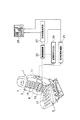
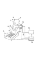
図1は本発明の第1実施形態にかかるシートの概略構成図である。まず、シート1は本実施形態において車両用シートとして適用するが、船舶、航空機、その他のシートとしても適用することができる。
【0037】
前記シート1は、シートバック3及びシートクッション5からなっている。前記シートバック3には、着座者の胸椎部に相当するシートバック上部7が着座者の腰椎部に相当するシートバック3の下部9に対し前後方向へ傾動できるように構成されている。すなわちシートバック3の上部7は、下部9に対し中折れ機構11で連結されている。中折れ機構11は、例えばリクライニングデバイスのような機構で構成されており、モータの駆動によってシートバック3の上部7が下部9に対し前後方向へ傾動できるようになっている。
【0038】
又、シートバック3の下部9にはランバーサポート13が設置されている。ランバーサポート13は、例えば乗員の腰椎部に相当する部分に板状の部材が配置され、この板状の部材がシートバック下部9のフレームに対し前後方向へ移動可能にする機構によって支持され、その移動を例えばモータ駆動によって行っている。そして、前記中折れ機構11の駆動によって、シートバック3の上部7がシートバック3の下部9に対し前後方向へ傾動し、着座者の胸椎部の支持状態を可変として胸椎支持可変手段を構成し、前記ランバーサポート13は着座者の腰椎部の支持状態を可変として腰椎支持可変手段を構成している。
【0039】
前記シートバック7内には、乗員の着座荷重を検出可能な背面着座センサアレイ15が内蔵され、シートクッション5には乗員の着座荷重を検出可能な座面着座センサアレイ17が内蔵されている。各センサアレイ15,17は、シートバック5、シートクッション7の表皮内に配置され、着座した乗員にはセンサアレイ15,17の存在が感じないように配置されている。
【0040】
前記各センサアレイ15,17の出力は、背面形状判定部19へ入力され、この背面形状判定部19によって各センサアレイ15,17からの荷重出力に基づき着座者の背面形状をS字型、直線型、猫背型の少なくとも3通りに分類する。従って、各センサアレイ15,17及び背面形状判定部19は本実施形態において背面形状分類手段を構成している。
【0041】
又、各センサアレイ15,17の出力は、支持状態判断部21へも入力されるようになっている。支持状態判断部21では、各センサアレイ15,17の荷重出力に基づいて着座者の着座支持状態を検出するものである。従って、各センサアレイ15,17及び支持状態判断部21は、本実施形態において着座状態検出手段を構成している。
【0042】
支持状態判断部21の判断結果は、駆動制御部23と、表示手段25とに入力されるようになっている。又、駆動制御部23には、支持状態設定部27からの信号も入力されるようになってる。支持状態設定部27は、着座者の着座支持状態の目標状態を前記背面形状の分類に応じて設定し、駆動制御部23に入力するものであり、本実施形態において目標状態設定手段を構成している。又、支持状態設定部27の信号は、前記表示手段25にも入力されるようになっている。
【0043】
前記駆動制御部23は、例えばマイクロコンピュータなどによって構成され、前記背面形状の分類に応じて検出した着座支持状態が、設定された目標状態となるように前記中折れ機構11及びランバーサポート13のモータを駆動するものである。従って、中折れ機構11及びランバーサポート13のモータと駆動制御部23とは本実施形態において、胸椎支持可変手段及び腰椎支持可変手段を駆動する駆動手段を構成している。
【0044】
前記表示手段25は、例えば車両インストルメントなどに備えられたモニターで構成され、前記支持状態判断部21によって検出した着座支持状態及び支持状態設定部27によって設定した目標状態などが表示されるようになっている。
【0045】
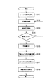
次に、本実施形態において、着座者の背面形状を判定し、シートの長時間着座による疲労を軽減する適切な支持状態を提供する流れを図2のフローチャートを用いて説明する。
【0046】
着座者がシート1に着座すると、まずステップS1において、着座者の背面形状の分類を判定し、ステップS2において背面形状分類に応じた目標支持状態を設定しステップS3へ移行する。ステップS3においてセンサアレイ15,17により現在の荷重分布を取得し、ステップS4において胸椎部および腰椎部の荷重のシートバック全体荷重に対する割合を計算し、ステップS5へ移行する。ステップS5においてモニター画面17に表示し、ステップS6において、ステップS2で設定した目標支持状態と現在の支持状態とを比較し、目標状態を満たしていない場合は、ステップS7にて駆動方向を判定し、ステップS8にて駆動を行う。本発明は、このループを目標状態に至るまで繰り返すことで、背面形状に応じた疲労を軽減する適切な支持状態を提供するものである。
【0047】
図2のステップS1の背面形状判定の処理の流れを、図3のフローチャートおよび図4の駆動概要図、図5〜7の背面形状の分類判定状態を用いて説明する。背面形状の判定は、着座者が着座した状態で、ステップS11においてシート角度初期設定の処理が実行され、図4のようにシート1の上部7および下部9を直立角度に設定し、かつシートクッション3を平坦角度にした状態に設定しステップS12へ移行する。シート1の上部7および下部9の直立角度は、例えば、中折れ機構11が折れ角零の状態で、シートバック3のシートバックフレームが垂直になる角度とする。また、シートクッション3の平坦角度とは、例えば、シートクッション5のクッションフレームが水平になる角度とする。
【0048】
ステップS12においては、可動装置駆動の処理が実行され、中折れ機構11を前方へ傾動し、同時にランバーサポート13を前方へ突出するよう駆動する。ステップS13では、接触荷重検出の処理が実行され、シートバック3の上部7および下部9に内蔵されたセンサアレイ15により、随時荷重が検出されステップ14へ移行する。ステップ14にて、接触したか否かの判断が実行され、前記ステップS13で検出された荷重が、予め設定されているシートバック3の上部7表面に身体Bが接触したことを判定するにたる微少な所定量の荷重に一致したか否かが判断され、接触したと判断されるまで、ステップS12,S13が繰り返され、接触したと判断されたらステップS15へ移行する。従って、本実施形態においてシートバック上部のセンサアレイ15は、接触センサを構成している。
【0049】
ステップS15では、可動量記憶の処理が実行され、駆動が停止した時のモータの駆動量を記憶し、ステップS16の可動量より相対位置計算の処理により、センサアレイ15の中から検出荷重が予め設定された荷重に一致するセンサを抽出し、該センサのシートバック3の上部7での位置を胸椎部接触位置29、シートバック3の下部9での位置を腰椎部接触位置31とし、ステップS15で記憶した駆動量から相対的な位置関係を計算し、ステップS17へ移行する。
【0050】
ステップS17では、臀部最後端位置検出の処理が実行され、シートクッション5に内蔵されたセンサアレイ17において、臀部最後端位置33を検出し、ステップS18へ移行する。
【0051】
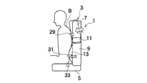
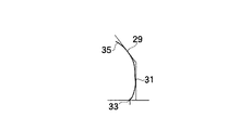
ステップS18では、背面形状分類判定の処理が実行され、人体背面形状35を、胸椎部接触位置29、腰椎部接触位置31および臀部最後端位置33の3点の相対関係から、図5、図6,図7に示すように分類する。
【0052】
図5では、臀部最後端位置33が浅く、かつ中折れ機構11が上部7を前方へ傾動させ、かつランバーサポート13が突出している状態であり、この場合をS字型に分類する。図6では、臀部最後端位置33が深く、かつ背面中折れ機構11の傾動が小さく、かつランバーサポート13の突出も小さい状態であり、この場合を直線型に分類する。図7では、臀部最後端位置33が深く、かつ中折れ機構11が前方へ傾動し、かつランバーサポート13の突出量が小さい状態であり、この場合を猫背型に分類する。
【0053】
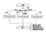
次に、図2のステップS2の目標状態設定の処理について、図8に示すフローチャートを用いて説明する。まず、ステップS21において、図2のステップS1において分類された着座者の背面形状により処理を分岐する。背面形状の分類がS字型である場合はステップS22へ移行し、直線型である場合はステップS23へ移行し、猫背型である場合はステップS24へ移行する。
【0054】
前記ステップS22では、背面形状の分類がS字型である場合、疲労を軽減する適切な支持状態として、着座時の胸椎部支持割合P1が、あらかじめ実験により求めた胸椎部支持割合の標準値N1に対して、小さくなるように目標状態を設定する。同時に、着座時の腰椎部支持割合P2が、あらかじめ実験により求めた腰椎部支持割合の標準値N2に対して、大きくなるように目標状態を設定する。
【0055】
前記ステップS23では、背面形状の分類が直線型である場合、疲労を軽減する適切な支持状態として、着座時の胸椎部支持割合P1が、あらかじめ実験により求めた胸椎部支持割合の標準値N1に対して、大きくなるように目標状態を設定する。同時に、着座時の腰椎部支持割合P2が、あらかじめ実験により求めた腰椎部支持割合の標準値N2に対して、小さくなるように目標状態を設定する。
【0056】
前記ステップS24では、背面形状の分類が猫背型である場合、疲労を軽減する適切な支持状態として、着座時の胸椎部支持割合P1が、あらかじめ実験により求めた胸椎部支持割合の標準値N1に対して、小さくなるように目標状態を設定する。同時に、着座時の腰椎部支持割合P2が、あらかじめ実験により求めた腰椎部支持割合の標準値N2に対して、小さくなるように目標状態を設定する。
【0057】
図2のステップS4の荷重割合計算の処理では、シートバック3全体の着座センサ出力合計に対する第10胸椎から第12胸椎及びその周辺の範囲の荷重合計を胸椎部支持割合とし、またシートバック3全体の着座センサ出力合計に対する第3腰椎及びその周辺の範囲の荷重合計を腰椎部支持割合としている。
【0058】
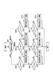
図2のステップS6の目標状態か否かの判断処理を図9を用いて説明する。まず、ステップS61において、背面形状分類が何れかかを判断する。ここでは図2のステップS1において分類された着座者の背面形状により処理を分岐する。それぞれの背面形状分類における目標支持状態は、図2のステップS2において、設定されているため、図2のステップS4において求められた現在の胸椎部支持割合P1および腰椎部支持割合P2と標準値の支持割合N1,N2とをステップS62〜S67において比較し、目標状態に至っていない場合は、駆動方向を判定する。
【0059】
駆動方向の判定S7は、胸椎部支持状態においては、ステップS71〜S73にて行われ、目標状態に比べ、支持が不足している場合は胸部が前傾する方向へ中折れ機構11を駆動し、支持が強すぎる場合は胸部が後傾する方向へ中折れ機構11を駆動する。
【0060】
一方、腰椎部支持状態においては、ステップS74〜S76にて行われ、目標状態に比べ、支持が不足している場合は腰部を突出する方向へランバーサポート13を駆動し、支持が強すぎる場合は奥部が引き込む方向へランバーサポート13を駆動する。
【0061】
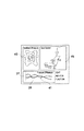
図2のステップS5の画面表示処理では、例えば図10に示すように、目標状態37に対する胸椎部および腰椎部の現在の状態39,41を画面表示し、かつ現在の荷重分布43や現在の可動機構の状態45も同時に画面表示することで、着座者への座り方に対するフィードバックを行い、着座者が任意に調整する場合は着座者による適正状態への回復を促進することができる。また調整を自動的に行う場合でも現在の調整状態を一目で確認することができ、調整の可、不可を確認することができる。
【0062】
このようにして、着座者の背面形状をS字型、直線型、猫背型の少なくとも3通りに分類し、背面形状の分類に応じて胸椎支持及び腰椎支持を変更して、着座者個々人が持つ固有の身体形状特徴に応じた適切な支持状態を得ることができ、長時間着座による疲労を大幅に軽減することができる。
【0063】
また、背面形状がS字型に分類されるとき、胸椎部の支持である胸椎部支持割合P1を予め定められた標準値N1に対して小さくすることにより弱く、且つ腰椎部の支持である腰椎部支持割合P2を標準値N2に対して大きくすることにより強くするように駆動することができ、背面形状が直線型に分類されるとき、胸椎部の支持P1を標準値N1よりも強く腰椎部の支持P2を標準値N2よりも弱くするように駆動することができ、背面形状が猫背型に分類されるときは胸椎部の支持P1を標準値N1よりも弱く、腰椎部の支持P2を標準値N2よりも弱くするように駆動することができる。従って、着座者個々人が持つ固有の身体形状特徴に対し、P1,P2を適切に設定し、より適切に対応した支持状態を得ることができ、長時間着座による疲労をより確実に軽減することができる。
【0064】
さらに、腰椎部の支持P2を着座者の背面全体の荷重合計に対する第3腰椎及びその周辺の荷重合計の割合で行い、胸椎部の支持P1を着座者の背面全体の荷重合計に対する第10胸椎から第12胸椎及びその周辺の荷重合計の割合で行うので、胸椎部、腰椎部ごとに、より適切な支持状態を得ることができ、長時間着座による疲労をより確実に軽減することができる。
【0065】
また、胸椎部支持可変手段はシートバック3を上下中間部で折れ変形させる中折れ機構11であり、腰椎部支持可変手段はシートバック3の下部9側に設けたランバーサポート13であり、胸椎部の支持P1を標準値N1よりも強くするとき中折れ機構11によりシートバック上部7を同下部9に対し前傾方向へ駆動すると共に、胸椎部の支持P1を標準値N1よりも弱くするときは中折れ機構11によりシートバック上部7を同下部9に対して後傾方向へ駆動し、腰椎部の支持P2を標準値N2よりも強くするときはランバーサポート13をシートバック3に対し突出方向へ駆動すると共に、腰椎部の支持P2を標準値N2よりも弱くするときはランバーサポート13をシートバック3に対し反突出方向へ駆動する。従って、中折れ機構11とランバーサポート13との2種の簡便な機構により、適切な支持状態を容易に得ることができ、長時間着座による疲労を確実に軽減することができる。
【0066】
また、センサアレイ17により着座者のシートクッション5に対する臀部最後端位置を検出すると共に、シートクッション5を平坦角度、且つシートバック3を直立角度に設定した状態で、シートバック3の上部7、ランバーサポート13を駆動し、接触検出時の中折れ機構11及びランバーサポート13の駆動量を検出し、臀部最後端位置と中折れ機構11及びランバーサポート13の駆動量とから背面形状を分類することができる。従って、着座者は自己の背面形状分類を気にすることなく、各着座者の背面形状を確実且つ容易に分類することができ、適切な支持状態を容易に得ることができ、長時間着座による疲労を確実に軽減することができる。
【0067】
また、シートバック3に内蔵された圧力感応型のセンサアレイ15の検出値により、着座支持状態を検出することができる。従って、シート1に大きな改変をすることなく、着座支持状態を確実に検出することができ、適切な支持状態を容易に得ることができ、長時間着座による疲労を確実に軽減することができる。
【0068】
本実施形態において、疲労を軽減する適正支持状態の提供は、図2に示す流れを適正支持状態復帰として行うものであり、適正状態提供は、図2に示す流れを常にループとして行うことにより、経時的な着座の場合にくずれた姿勢に対する復帰を行わせることができ、経時的に適正な支持状態を得るシートとすることができる。なお、適正状態提供を一時的なものとし、表示手段25を確認しながら着座者の自主的な操作により行うようにすることも可能である。
【0069】
また、本実施形態において胸椎部の支持状態を変化させる可動機構として、中折れ機構13を採用したが、図11のように腰椎部と同様にランバーサポート13と同様の可動機構のチェストサポート47をシートバック上部7に内蔵することによっても、同様の効果を得ることが可能である。
【0070】
すなわち、胸椎部の支持P1を標準値N1よりも強くするときは上部7側のチェストサポート47をシートバック3に対し突出方向へ駆動すると共に、胸椎部の支持P1を標準値N1よりも弱くするときは上部7側のチェストサポート47をシートバック3に対し反突出方向へ駆動し、腰椎部の支持P2を標準値N2よりも強くするときは下部9側のランバーサポート13をシートバック3に対し突出方向へ駆動すると共に、腰椎部の支持P2を標準値N2よりも弱くするときは下部9側のランバーサポート13をシートバック3に対して反突出方向へ駆動することができる。従って、図11の実施形態では駆動制御部23及びランバーサポート13の駆動モータ、チェストサポート47の駆動モータが駆動手段を構成している。
【0071】
そして、チェストサポート47、ランバーサポート13の簡便な機構により、適切な支持状態を容易に得ることができ、長時間着座による疲労をより確実に軽減することができる。
【0072】
(第2実施形態)
図12は本発明の第2実施形態に係るシートの概略構成図を示している。尚、基本的な構成は第1実施形態と略同様であるため、対応する構成部分には同符号を付して説明する。
【0073】
一方、本実施形態においては、シートバック3の背面着座センサアレイを取り除いた構成となっている。本実施形態においては、前記中折れ機構11の駆動モータ及びランバーサポート13の駆動モータの入力電圧が背面形状判定部19及び支持状態判定部21に入力されている。一般に直流モータ特性において、トルクと回転数との間には反比例の関係があり、この関係は入力電圧に応じて変化するため、ある負荷に対しモータが起動するトルクを電圧により計測することが可能である。従って、入力電圧を変化させることにより、中折れ機構11及びランバーサポート13のモータが微少に回転したときの入力電圧をシートバック上部7及びシートバック下部9に掛かる荷重に変換することができる。すなわち、本実施形態においては、背面形状の分類をするときに、直立角度に設定したシートバック3のシートバック上部7を中折れ機構11で前方へ変位させ、シートバック上部7が乗員の身体に接触したときのモータの入力電圧の変化を検出することにより接触を検出することができ、本実施形態において、中折れ機構11のモータは接触センサを構成している。
【0074】
従って、本実施形態においては、第1実施形態と略同様な作用効果を奏することができる他、シートバック3に設けられたランバーサポート13、中折れ機構11の駆動力の検出値により着座支持状態を検出することができる。直流モータで駆動する場合には、入力電圧を変化させたときの起動トルクから着座支持状態を検出することができ、新たな検出機構の追加をすることなく、適切な支持状態を容易に検出することができ、長時間着座による疲労を確実に軽減することができる。シートバック3から着座センサアレイ15を省略することができ、簡単な構造で背面形状の分類及び着座支持状態の検出を行うことができる。
【0075】
(第3実施形態)
図13は第3実施形態に係るシート1の概略構成図を示している。尚、第1実施形態と対応する構成部分には同符号を付して説明する。
【0076】
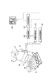
一方、本実施形態においては、胸椎部可変支持手段をシートバック3の上部7側に設けた空気袋51で構成し、腰椎部支持可変手段をシートバック3の下部9側に設けた空気袋49で構成している。各空気袋49,51は、ポンプ53の吐出口に接続された配管55を分岐して接続されている。配管55には、空気袋49,51用のバルブ57,59が介設されている。バルブ57,59は、駆動制御部23によって駆動制御されるようになっている。従って、本実施形態においては、駆動制御部23及びバルブ57,59が駆動手段を構成している。
【0077】
そして、胸椎部の支持P1を標準値N1よりも強くするときは、上部7側の空気袋51の内圧を増加するように駆動すると共に、胸椎部の支持P1を標準値N1よりも弱くするときは上部7側の空気袋51の内圧を減少するように駆動し、腰椎部の支持P2を標準値N2よりも強くするときは下部9側の空気袋49の内圧を増加するように駆動すると共に、腰椎部の支持P2を標準値N2よりも弱くするときは下部9側の空気袋49の内圧を減少するように駆動する。
【0078】
又、本実施形態においても、シートバック3の着座センサアレイは取り除かれており、空気袋49,51の内圧により胸椎部及び腰椎部の着座支持状態を検出することができる。
【0079】
従って、本実施形態においても第1実施形態と略同様な作用効果を奏することができる他、2個の空気袋49,51の内圧調整によって、適切な支持状態を容易に得ることができ、長時間着座による疲労を確実に軽減することができる。また、シートバック3から着座センサアレイを省略することができ、構造をさらに簡単にすることができる。
【図面の簡単な説明】
【図1】本発明の第1実施形態に係るシートの概略構成図である。
【図2】第1実施形態に係り、システム全体のフローチャートである。
【図3】第1実施形態に係り、背面形状分類のフローチャートである。
【図4】第1実施形態に係り、背面形状分類でのシートの駆動状態を示す概略図である。
【図5】第1実施形態に係り、背面形状をS字型に分類するときの概略を示す説明図である。
【図6】第1実施形態に係り、背面形状を直線型に分類するときの状態を示す概略説明図である。
【図7】第1実施形態に係り、背面形状を猫背型に分類するときの状態を示す概略説明図である。
【図8】第1実施形態に係り、背面形状の分類に応じた目標状態設定のフローチャートである。
【図9】第1実施形態に係り、背面形状の分類に応じた駆動のフローチャートである。
【図10】第1実施形態に係り、画面表示の説明図である。
【図11】第1実施形態の変形例に係るシートの概略構成図である。
【図12】本発明の第2実施形態に係るシートの概略構成図である。
【図13】本発明の第3実施形態に係るシートの概略構成図である。
【符号の説明】
1 シート
3 シートバック
5 シートクッション
7 上部(胸椎部可変手段)
9 下部
11 中折れ機構(胸椎部可変手段)
13 ランバーサポート(腰椎部可変手段)
15 背面着座センサアレイ(着座センサ、接触センサ、背面形状分類手段)
17 座面着座センサアレイ(着座センサ、背面形状分類手段)
19 背面形状判定部(背面形状分類手段)
21 支持状態判断部(着座状態検出手段)
23 駆動制御部(駆動手段)
25 表示手段
27 支持状態設定部(目標状態設定手段)
47 チェストサポート
49,51 空気袋
53 ポンプ(駆動手段)
57,59 バルブ(駆動手段)[0001]
BACKGROUND OF THE INVENTION
The present invention relates to a seat used for automobiles, aircraft, ships and the like.
[0002]
[Prior art]
Examples of conventional sheets include those described in Japanese Patent Application Laid-Open Nos. 7-75608, 6-72199, and 2,689,620, respectively.
[0003]
The seat described in Japanese Patent Application Laid-Open No. 7-75608 is provided with shoulder support and lumbar support at the upper and lower portions of the seat back, one of which is adjusted forward or backward with respect to the seat back and the other is interlocked Then, it is driven in the opposite direction so that a natural sitting posture is maintained.
[0004]
Japanese Patent Laid-Open No. 6-72199 discloses a Solux adjustment mechanism that interlocks with the forward and backward movement of the seat cushion, displaces the lower side of the cushion body of the seat back forward, The pressure-resistant distribution at the time of sitting is dispersed by filling the rear gap, so that a comfortable seating feeling is obtained.
[0005]
The one described in the above-mentioned Japanese Patent No. 2689620 is provided with a driving means for changing and driving the seat surface shape, a control means for controlling the driving means, and a detecting means for detecting the physique of the occupant. Based on this, the control timing of the control means is set so that fatigue can be reduced according to the physique.
[0006]
[Problems to be solved by the invention]
However, in the conventional seat, the same state is provided for all seated persons, or the control determined according to the seated person's physique is performed over time. There is a problem that fatigue due to sitting for a long time cannot be reduced because it does not correspond to body shape characteristics.
[0007]
It is an object of the present invention to provide a seat that can obtain an appropriate support state according to the unique body shape characteristics of each individual occupant.
[0008]
[Means for Solving the Problems]
According to the first aspect of the present invention, there is provided a seat comprising a seat back and a seat cushion. And a back shape classification means for classifying the back shape of the person into at least three types of S-shape, linear shape, and stoop shape, and driving the thoracic vertebra support variable means and lumbar support variable means according to the classification of the back shape And when the back shape is classified as S-shaped, the support of the thoracic vertebra is driven to be weaker than a predetermined standard value and the support of the lumbar vertebra is stronger than the standard value, When the back shape is classified as a linear type, the support of the lumbar portion is driven to be stronger than the standard value and the support of the lumbar portion is weaker than the standard value, and the back shape is classified as a dorsal shape The thoracic spine support is driven to be weaker than the standard value and the lumbar spine support is weaker than the standard value. The thoracic vertebra is supported at a ratio of the total load of the 10th to 12th thoracic vertebrae and the surrounding area to the total load of the entire back surface of the seated person. It is characterized by that.
[0011]
Claim 2 According to the present invention, in a seat comprising a seat back and a seat cushion, a thoracic vertebra support variable means for changing the support state of the thoracic vertebra of the seated person, a lumbar support variable means for changing the support state of the lumbar vertebra, and a back surface of the seat A back surface shape classifying means for classifying the shape into at least three types of S-shape, straight line shape, and back shape; a target state setting means for setting a target state of a seated person's sitting support state according to the classification of the back surface shape; Seating state detecting means for detecting a seating support state of a seated person, and the thoracic vertebra support variable means and the lumbar support variable means so that the detected seating support state becomes the set target state according to the classification of the back surface shape. Drive means to drive The target state setting means presets standard values of the support state of the thoracic vertebrae and lumbar vertebrae of the seated person, and supports the lumbar part from the standard value when the back surface shape is classified as S-shaped. And the support of the lumbar part is set stronger than the standard value, and the support of the thoracic vertebra part is stronger than the standard value and the support of the lumbar part is standard when the back surface shape is classified as a linear type. When the back shape is classified as a stoop, the support of the thoracic vertebra is set weaker than the standard value, and the support of the lumbar spine is set weaker than the standard value. It is characterized by that.
[0013]
[0014]
[0015]
[0016]
[0017]
[0018]
The invention of
[0019]
[0020]
[0021]
[0022]
【The invention's effect】
According to the first aspect of the present invention, the back shape classification means can classify the back shape of the seated person into at least three types of S-shape, straight line type, and stoop type, and the thoracic vertebra support is variable according to the classification of the back shape. The means and the lumbar support variable means can be driven. Accordingly, it is possible to obtain an appropriate support state according to the unique body shape characteristics of each individual occupant, and to greatly reduce fatigue caused by sitting for a long time.
[0023]
[0024]
[0025]
Claim 2 In the present invention, the back surface shape classification means can classify the back surface shape of the seated person into at least three types of S-shape, straight line shape, and stoop shape. The target state of the seating support state of the seated person can be set according to the classification of the back surface shape by the target state setting means. The seating state detection means can detect the seating support state of the seated person. Then, the thoracic vertebra support variable means and the lumbar vertebra support variable means can be driven so that the seating support state detected according to the classification of the back surface shape by the drive means becomes the set target state. Therefore, it is possible to automatically obtain an appropriate support state according to the unique body shape characteristics of each individual occupant, and to reliably reduce fatigue caused by sitting for a long time.
[0026]
Claim 2 The invention of The eyes The standard state setting means presets the standard value of the support state of the seated person's thoracic vertebra and lumbar vertebrae, and when the back shape is classified as S-shaped, the support of the thoracic vertebra is weaker than the standard value, and the lumbar support Is set stronger than the standard value, and when the back shape is classified as a straight type, the support of the thoracic vertebra is set stronger than the standard value, the support of the lumbar spine is set weaker than the standard value, and the back shape is classified as the dorsal shape When done, the support of the thoracic vertebra can be set weaker than the standard value and the support of the lumbar spine can be set weaker than the standard value. Therefore, it is possible to obtain a support state that more appropriately corresponds to the unique body shape characteristics of each individual occupant, and to more reliably reduce fatigue caused by sitting for a long time.
[0027]
[0028]
[0029]
[0030]
[0031]
[0032]
[0033]
[0034]
[0035]
[0036]
DETAILED DESCRIPTION OF THE INVENTION
(First embodiment)
FIG. 1 is a schematic configuration diagram of a sheet according to the first embodiment of the present invention. First, the
[0037]
The
[0038]
A
[0039]
The seat back 7 incorporates a back
[0040]
The outputs of the
[0041]
The outputs of the
[0042]
The determination result of the support
[0043]
The
[0044]
The display means 25 is composed of, for example, a monitor provided in a vehicle instrument or the like so that the seating support state detected by the support
[0045]
Next, in the present embodiment, the flow of determining the back shape of the seated person and providing an appropriate support state for reducing fatigue due to long-time seating of the seat will be described with reference to the flowchart of FIG.
[0046]
When the seated person sits on the
[0047]
The flow of the back surface shape determination process in step S1 of FIG. 2 will be described using the flowchart of FIG. 3, the drive outline diagram of FIG. 4, and the back surface shape classification determination state of FIGS. In the determination of the rear surface shape, the seat angle initial setting process is executed in step S11 in a state where the seated person is seated, the
[0048]
In step S12, the process of driving the movable device is executed, and the
[0049]
In step S15, a process for storing the movable amount is executed, the drive amount of the motor when the drive is stopped is stored, and the detected load is preliminarily detected from the
[0050]
In step S17, a heel end position detection process is executed, and the
[0051]
In step S18, the back surface shape classification determination process is executed, and the human body back
[0052]
FIG. 5 shows a state in which the collar
[0053]
Next, the target state setting process in step S2 of FIG. 2 will be described using the flowchart shown in FIG. First, in step S21, the process branches according to the back shape of the seated person classified in step S1 of FIG. If the back shape classification is S-shaped, the process proceeds to step S22. If it is linear, the process proceeds to step S23.
[0054]
In step S22, when the back shape classification is S-shaped, the thoracic vertebra support ratio P1 at the time of sitting is a standard value N1 of the thoracic vertebra support ratio obtained in advance by experiments as an appropriate support state to reduce fatigue. In contrast, the target state is set so as to be smaller. At the same time, the target state is set so that the lumbar support ratio P2 at the time of sitting is larger than the standard value N2 of the lumbar support ratio obtained in advance by experiments.
[0055]
In step S23, when the back shape classification is linear, as a suitable support state to reduce fatigue, the thoracic vertebra support ratio P1 at the time of sitting is set to the standard value N1 of the thoracic vertebra support ratio obtained in advance by experiments. On the other hand, the target state is set so as to increase. At the same time, the target state is set so that the lumbar support ratio P2 at the time of sitting is smaller than the standard value N2 of the lumbar support ratio obtained in advance by experiments.
[0056]
In step S24, when the back shape classification is stooped, the thoracic vertebra support ratio P1 at the time of sitting is set to the standard value N1 of the thoracic vertebra support ratio obtained in advance by experiment as an appropriate support state to reduce fatigue. On the other hand, the target state is set to be small. At the same time, the target state is set so that the lumbar support ratio P2 at the time of sitting is smaller than the standard value N2 of the lumbar support ratio obtained in advance by experiments.
[0057]
In the processing of load ratio calculation in step S4 of FIG. 2, the total load of the 10th to 12th thoracic vertebra and its surroundings relative to the total seating sensor output total of the seat back 3 is used as the thoracic vertebra support ratio, and the entire seat back 3 The total load of the third lumbar vertebra and its surrounding area with respect to the total seating sensor output is the lumbar portion support ratio.
[0058]
The determination process of whether or not the target state is Step S6 in FIG. 2 will be described with reference to FIG. First, in step S61, it is determined whether the back surface shape classification is any. Here, the process branches depending on the back shape of the seated person classified in step S1 of FIG. Since the target support state in each back surface shape classification is set in step S2 of FIG. 2, the current thoracic vertebra support ratio P1 and lumbar support ratio P2 obtained in step S4 of FIG. The support ratios N1 and N2 are compared in steps S62 to S67, and if the target state has not been reached, the drive direction is determined.
[0059]
The driving direction determination S7 is performed in steps S71 to S73 in the thoracic vertebra support state, and when the support is insufficient as compared with the target state, the
[0060]
On the other hand, in the lumbar support state, the
[0061]
In the screen display process in step S5 of FIG. 2, for example, as shown in FIG. 10, the
[0062]
In this way, the back shape of the seated person is classified into at least three types, S-shaped, straight, and stooped, and the thoracic support and lumbar support are changed according to the back shape classification, and each seated person has it. An appropriate support state according to the unique body shape characteristics can be obtained, and fatigue due to sitting for a long time can be greatly reduced.
[0063]
Further, when the back surface shape is classified as S-shaped, the lumbar vertebrae is weak by reducing the thoracic vertebra support rate P1 that is the support of the thoracic vertebrae with respect to a predetermined standard value N1, and is the lumbar support that supports the lumbar part When the back support shape is classified as a linear type, the thoracic support P1 is stronger than the standard value N1 and can be driven to be stronger by increasing the part support ratio P2 relative to the standard value N2. Support P2 can be driven to be weaker than the standard value N2, and when the dorsal shape is classified as a stoop, the thoracic support P1 is weaker than the standard value N1, and the lumbar support P2 is standard. It can be driven to be weaker than the value N2. Therefore, P1 and P2 can be appropriately set for the unique body shape characteristics of each individual occupant to obtain a more appropriate support state, and fatigue due to long-term sitting can be more reliably reduced. it can.
[0064]
further, Waist Vertebral support P 2 The ratio of the total load on the third lumbar vertebra and its surroundings to the total load on the back of the seated person, breast
[0065]
The thoracic vertebra support variable means is a
[0066]
In addition, the rear end position of the buttocks with respect to the
[0067]
Further, the seating support state can be detected from the detection value of the pressure
[0068]
In the present embodiment, the provision of the proper support state for reducing fatigue is performed by returning the flow shown in FIG. 2 as the proper support state return, and the proper state provision is performed by always performing the flow shown in FIG. 2 as a loop. In the case of seating over time, the seat can be returned to the out of posture, and the seat can obtain an appropriate support state over time. It is also possible to provide the appropriate state temporarily and to perform it by the seated person's independent operation while confirming the display means 25.
[0069]
Further, in the present embodiment, as the movable mechanism for changing the support state of the thoracic vertebra part, the
[0070]
That is, when the support P1 of the thoracic vertebra is made stronger than the standard value N1, the
[0071]
The simple support of the
[0072]
(Second Embodiment)
FIG. 12 shows a schematic configuration diagram of a seat according to the second embodiment of the present invention. Since the basic configuration is substantially the same as that of the first embodiment, the corresponding components will be described with the same reference numerals.
[0073]
On the other hand, in the present embodiment, the back seating sensor array of the seat back 3 is removed. In the present embodiment, input voltages of the drive motor of the
[0074]
Therefore, in the present embodiment, substantially the same operational effects as those of the first embodiment can be obtained, and the seating support state is determined by the detected values of the driving force of the
[0075]
(Third embodiment)
FIG. 13 is a schematic configuration diagram of the
[0076]
On the other hand, in the present embodiment, the thoracic vertebra part variable support means is constituted by the
[0077]
When the support P1 of the thoracic vertebra is made stronger than the standard value N1, the internal pressure of the
[0078]
Also in the present embodiment, the seating sensor array of the seat back 3 is removed, and the seating support state of the thoracic vertebra and lumbar vertebra can be detected by the internal pressure of the
[0079]
Therefore, the present embodiment can provide substantially the same operational effects as the first embodiment, and an appropriate support state can be easily obtained by adjusting the internal pressures of the two
[Brief description of the drawings]
FIG. 1 is a schematic configuration diagram of a seat according to a first embodiment of the present invention.
FIG. 2 is a flowchart of the entire system according to the first embodiment.
FIG. 3 is a flowchart of rear surface shape classification according to the first embodiment.
FIG. 4 is a schematic diagram illustrating a driving state of a sheet in a rear surface shape classification according to the first embodiment.
FIG. 5 is an explanatory diagram illustrating an outline when the back surface shape is classified into an S shape according to the first embodiment;
FIG. 6 is a schematic explanatory diagram illustrating a state when the back surface shape is classified into a linear shape according to the first embodiment.
FIG. 7 is a schematic explanatory diagram illustrating a state when the back surface shape is classified into a dorsal shape according to the first embodiment.
FIG. 8 is a flowchart of target state setting according to the classification of the back surface shape according to the first embodiment.
FIG. 9 is a flowchart of driving according to the classification of the back surface shape according to the first embodiment.
FIG. 10 is an explanatory diagram of screen display according to the first embodiment.
FIG. 11 is a schematic configuration diagram of a sheet according to a modification of the first embodiment.
FIG. 12 is a schematic configuration diagram of a sheet according to a second embodiment of the present invention.
FIG. 13 is a schematic configuration diagram of a seat according to a third embodiment of the present invention.
[Explanation of symbols]
1 sheet
3 Seat back
5 Seat cushion
7 Upper part (Thoracic vertebrae variable means)
9 Bottom
11 Folding mechanism (Thoracic vertebrae variable means)
13 Lumber support (Lumbar spine variable means)
15 Back seating sensor array (sitting sensor, contact sensor, back shape classification means)
17 Seating surface seating sensor array (seating sensor, back surface shape classification means)
19 Back surface shape determination unit (back surface shape classification means)
21 Support state determination unit (sitting state detection means)
23 Drive control unit (drive means)
25 Display means
27 Support state setting unit (target state setting means)
47 Chest support
49,51 Air bag
53 Pump (drive means)
57, 59 Valve (drive means)
Claims (11)
着座者の胸椎部の支持状態を可変にする胸椎支持可変手段及び腰椎部の支持状態を可変にする腰椎支持可変手段と、
着座者の背面形状をS字型、直線型、猫背型の少なくとも3通りに分類する背面形状分類手段とを備え、
前記背面形状の分類に応じて前記胸椎支持可変手段及び腰椎支持可変手段を駆動し、
前記背面形状がS字型に分類されるとき前記胸椎部の支持を予め定められた標準値よりも弱く、且つ前記腰椎部の支持を前記標準値よりも強くするように駆動し、
前記背面形状が直線型に分類されるとき前記胸椎部の支持を前記標準値よりも強く、且つ前記腰椎部の支持を前記標準値よりも弱くするように駆動し、
前記背面形状が猫背型に分類されるとき前記胸椎部の支持を前記標準値よりも弱く、且つ前記腰椎部の支持を前記標準値よりも弱くするように駆動し、
前記腰椎部の支持を、着座者の背面全体の荷重合計に対する第3腰椎及びその周辺の荷重合計の割合で行い、前記胸椎部の支持を、着座者の背面全体の荷重合計に対する第10胸椎から第12胸椎及びその周辺の荷重合計の割合で行うことを特徴とするシート。In a seat consisting of a seat back and a seat cushion,
A thoracic vertebra support variable means for changing the support state of the thoracic vertebra of the seated person and a lumbar support variable means for changing the support state of the lumbar vertebra;
A back shape classification means for classifying the back shape of the seated person into at least three types of S-shape, linear shape, and stoop shape,
Driving the thoracic vertebra support variable means and the lumbar spine support variable means according to the classification of the back surface shape ,
When the back shape is classified as S-shaped, the support of the thoracic vertebra is driven to be weaker than a predetermined standard value and the support of the lumbar vertebra is stronger than the standard value,
Driving the thoracic vertebrae to support the thoracic vertebrae more strongly than the standard value and weaken the lumbar vertebrae support less than the standard value when the back surface shape is classified as a linear type;
Driving the thoracic vertebrae support to be weaker than the standard value and the lumbar spine support to be weaker than the standard value when the dorsal shape is classified as a stoop;
The lumbar portion is supported at a ratio of the total load on the third lumbar vertebra and its surroundings to the total load on the back of the seated person, and the thoracic portion is supported from the tenth thoracic vertebra on the total load on the back of the seated person. A sheet characterized in that it is performed at a ratio of the total load on the twelfth thoracic vertebra and its surroundings .
着座者の胸椎部の支持状態を可変にする胸椎支持可変手段及び腰椎部の支持状態を可変にする腰椎支持可変手段と、
着座者の背面形状をS字型、直線型、猫背型の少なくとも3通りに分類する背面形状分類手段と、
着座者の着座支持状態の目標状態を前記背面形状の分類に応じて設定する目標状態設定手段と、
着座者の着座支持状態を検出する着座状態検出手段と、
前記背面形状の分類に応じて前記検出した着座支持状態が前記設定した目標状態となるように前記胸椎支持可変手段及び腰椎支持可変手段を駆動する駆動手段とを備え、
前記目標状態設定手段は、着座者の胸椎部及び腰椎部の支持状態の標準値を予め設定し、
前記背面形状がS字型に分類されるとき前記胸椎部の支持を前記標準値よりも弱く、且つ前記腰椎部の支持を標準値よりも強く設定し、
前記背面形状が直線型に分類されるとき前記胸椎部の支持を前記標準値よりも強く、且つ前記腰椎部の支持を標準値よりも弱く設定し、
前記背面形状が猫背型に分類されるとき前記胸椎部の支持を前記標準値よりも弱く、且つ前記腰椎部の支持を標準値よりも弱く設定することを特徴とするシート。In a seat consisting of a seat back and a seat cushion,
A thoracic vertebra support variable means for changing the support state of the thoracic vertebra of the seated person and a lumbar support variable means for changing the support state of the lumbar vertebra;
A back surface shape classifying means for classifying the back surface shape of the seated person into at least three types of S-shape, straight line shape, and back shape;
A target state setting means for setting a target state of the seating support state of the seated person according to the classification of the back surface shape;
A seating state detection means for detecting a seating support state of the seated person;
E Bei and driving means for driving said thoracic support changing means and lumbar support adjustment means so that the detection and seating support state as a target state of said set according to the classification of the rear shape,
The target state setting means pre-set a standard value of the support state of the thoracic vertebrae and lumbar vertebrae of the seated person,
When the back shape is classified as S-shaped, the support of the thoracic vertebra is set weaker than the standard value and the support of the lumbar vertebra is set stronger than the standard value,
When the back shape is classified as a straight type, the support of the thoracic vertebra is set stronger than the standard value and the support of the lumbar vertebra is set weaker than the standard value,
The seat is characterized in that when the back shape is classified as a dorsum type, the support of the thoracic vertebra is set weaker than the standard value and the support of the lumbar vertebra is set weaker than the standard value .
前記目標状態設定手段は、前記腰椎部の支持を、着座者の背面全体の荷重合計に対する第3腰椎及びその周辺の荷重合計の割合で設定し、前記胸椎部の支持を、着座者の背面全体の荷重合計に対する第10胸椎から第12胸椎及びその周辺の荷重合計の割合で設定することを特徴とするシート。The sheet according to claim 2 ,
Said target state setting means, the support of the lumbar vertebral unit sets a ratio of the load sum of the third lumbar and its periphery against the load overall total back of the seated person, the support of the chest vertebral portions, of the seated person A seat characterized by being set at a ratio of a total load of the 10th to 12th thoracic vertebra and its surroundings with respect to a total load of the entire back surface.
前記胸椎部支持可変手段は、前記シートバックを上下中間部で折れ変形させる中折れ機構であり、
前記腰椎部支持可変手段は、前記シートバックの下部側に設けたランバーサポートであり、
前記駆動手段は、前記胸椎部の支持を前記標準値よりも強くするときは前記中折れ機構によりシートバック上部を同下部に対し前傾方向へ駆動すると共に、前記胸椎部の支持を前記標準値よりも弱くするときは前記中折れ機構によりシートバック上部を同下部に対し後傾方向へ駆動し、且つ前記腰椎部の支持を前記標準値よりも強くするときは前記ランバーサポートをシートバックに対し突出方向へ駆動すると共に、前記腰椎部の支持を前記標準値よりも弱くするときは前記ランバーサポートをシートバックに対し反突出方向へ駆動することを特徴とするシート。The sheet according to claim 2 or 3 ,
The thoracic vertebra support variable means is a middle folding mechanism that folds and deforms the seat back at an upper and lower middle part,
The lumbar part support variable means is a lumbar support provided on the lower side of the seat back,
When the support of the thoracic vertebra is stronger than the standard value, the drive means drives the upper part of the seat back in a forward tilting direction with respect to the lower part by the center folding mechanism, and supports the thoracic vertebra by the standard value. If the lower back is weakened, the upper part of the seat back is driven backwardly with respect to the lower part by the middle folding mechanism, and if the support of the lumbar part is stronger than the standard value, the lumbar support is attached to the seat back. The seat is driven in the protruding direction, and when the support of the lumbar portion is weaker than the standard value, the lumbar support is driven in a direction opposite to the seat back.
前記胸椎部支持可変手段は、前記シートバックの上部側に設けたチェストサポートであり、
前記腰椎部支持可変手段は、前記シートバックの下部側に設けたランバーサポートであり、
前記駆動手段は、前記胸椎部の支持を前記標準値よりも強くするときは前記チェストサポートをシートバックに対し突出方向へ駆動すると共に、前記胸椎部の支持を前記標準値よりも弱くするときは前記チェストサポートをシートバックに対し反突出方向へ駆動し、且つ前記腰椎部の支持を前記標準値よりも強くするときは前記ランバーサポートをシートバックに対し突出方向へ駆動すると共に、前記腰椎部の支持を前記標準値よりも弱くするときは前記ランバーサポートをシートバックに対し反突出方向へ駆動することを特徴とするシート。The sheet according to claim 2 or 3 ,
The thoracic vertebra support variable means is a chest support provided on the upper side of the seat back,
The lumbar part support variable means is a lumbar support provided on the lower side of the seat back,
The drive means drives the chest support in the protruding direction with respect to the seat back when the support of the thoracic vertebra is stronger than the standard value, and when the support of the thoracic vertebra is weaker than the standard value. When the chest support is driven in the anti-projection direction with respect to the seat back and the support of the lumbar portion is made stronger than the standard value, the lumbar support is driven in the protrusion direction with respect to the seat back, and The seat is characterized in that when the support is weaker than the standard value, the lumbar support is driven in a direction opposite to the seat back.
前記胸椎部支持可変手段は、前記シートバックの上部側に設けた空気袋であり、
前記腰椎部支持可変手段は、前記シートバックの下部側に設けた空気袋であり、
前記駆動手段は、前記胸椎部の支持を前記標準値よりも強くするときは前記上部側の空気袋の内圧を増加するように駆動すると共に、前記胸椎部の支持を前記標準値よりも弱くするときは前記上部側の空気袋の内圧を減少するように駆動し、且つ前記腰椎部の支持を前記標準値よりも強くするときは前記下部側の空気袋の内圧を増加するように駆動すると共に、前記腰椎部の支持を前記標準値よりも弱くするときは前記下部側の空気袋の内圧を減少するように駆動することを特徴とするシート。The sheet according to claim 2 or 3 ,
The thoracic vertebra support variable means is an air bag provided on the upper side of the seat back,
The lumbar support variable means is an air bag provided on the lower side of the seat back,
The drive means drives to increase the internal pressure of the upper air bladder when the support of the thoracic vertebra part is stronger than the standard value, and makes the support of the thoracic vertebra part weaker than the standard value. When it is driven to decrease the internal pressure of the upper air bag, and when the support of the lumbar portion is made stronger than the standard value, it is driven to increase the internal pressure of the lower air bag. The seat is driven so as to reduce the internal pressure of the lower air bag when the support of the lumbar portion is weaker than the standard value.
前記背面形状分類手段は、前記シートクッションに設けた着座センサ及び前記シートバックへの接触を検出可能な接触センサを備え、
前記着座センサにより着座者のシートクッションに対する臀部最後端位置を検出すると共に、前記シートクッションを平坦角度且つ前記シートバックを直立角度に設定した状態で、前記胸椎部支持可変手段及び腰椎部支持可変手段を駆動し前記接触センサの接触検出時の該胸椎支持可変手段及び腰椎部支持可変手段の駆動量を検出し、
前記臀部最後端位置と胸椎部支持可変手段及び腰椎部支持可変手段の駆動量とから前記背面形状を分類することを特徴とするシート。The sheet according to claim 2 or 3 ,
The back surface shape classification means includes a seating sensor provided on the seat cushion and a contact sensor capable of detecting contact with the seat back,
The thoracic vertebra support variable means and the lumbar vertebra support variable means in a state where the seating sensor detects the rear end position of the buttocks relative to the seat cushion of the seated person and the seat cushion is set to a flat angle and the seat back is set to an upright angle. Detecting the drive amount of the thoracic vertebra support variable means and the lumbar support variable means at the time of contact detection of the contact sensor,
The seat is characterized in that the back surface shape is classified from the rear end position of the buttocks and the drive amounts of the thoracic vertebra support variable means and the lumbar support variable means.
前記着座状態検出手段は、前記シートバックに内蔵された圧力感応型の着座センサの検出値により前記胸椎部及び腰椎部の着座支持状態を検出することを特徴とするシート。The sheet according to claim 4 or 5 ,
The seat according to claim 1, wherein the seating state detecting means detects the seating support state of the thoracic vertebra and lumbar vertebra by a detection value of a pressure-sensitive seating sensor built in the seat back.
前記着座状態検出手段は、前記ランバーサポート及び中折れ機構又はランバーサポート及びチェストサポートの駆動力の検出値により前記胸椎部及び腰椎部の着座支持状態を検出することを特徴とするシート。The sheet according to claim 4 or 5 ,
The seat is characterized in that the seating state detecting means detects the seating support state of the thoracic vertebra and lumbar vertebra by detecting the driving force of the lumbar support and folding mechanism or the lumbar support and chest support.
前記着座状態検出手段は、前記シートバックに内蔵された空気袋の内圧により着座支持状態を検出することを特徴とするシート。The sheet according to claim 6 ,
The seating state detecting means detects a seating support state based on an internal pressure of an air bag built in the seat back.
前記着座検出手段の検出した着座支持状態を表示する表示手段を設けたことを特徴とするシート。The sheet according to any one of claims 2 to 10 ,
A seat provided with display means for displaying a seating support state detected by the seating detection means.
Priority Applications (1)
| Application Number | Priority Date | Filing Date | Title |
|---|---|---|---|
| JP2000162575A JP3772642B2 (en) | 2000-05-31 | 2000-05-31 | Sheet |
Applications Claiming Priority (1)
| Application Number | Priority Date | Filing Date | Title |
|---|---|---|---|
| JP2000162575A JP3772642B2 (en) | 2000-05-31 | 2000-05-31 | Sheet |
Publications (2)
| Publication Number | Publication Date |
|---|---|
| JP2001340163A JP2001340163A (en) | 2001-12-11 |
| JP3772642B2 true JP3772642B2 (en) | 2006-05-10 |
Family
ID=18666457
Family Applications (1)
| Application Number | Title | Priority Date | Filing Date |
|---|---|---|---|
| JP2000162575A Expired - Fee Related JP3772642B2 (en) | 2000-05-31 | 2000-05-31 | Sheet |
Country Status (1)
| Country | Link |
|---|---|
| JP (1) | JP3772642B2 (en) |
Families Citing this family (11)
| Publication number | Priority date | Publication date | Assignee | Title |
|---|---|---|---|---|
| JP3885642B2 (en) * | 2001-08-06 | 2007-02-21 | 松下電工株式会社 | Human body detection sensor and seat equipped with the human body detection sensor |
| WO2003072953A2 (en) * | 2002-02-27 | 2003-09-04 | Myoung-Ho Cho | Posture sensing apparatus |
| JP4143963B2 (en) * | 2002-11-21 | 2008-09-03 | マツダ株式会社 | Vehicle seat device |
| JP2005160495A (en) * | 2003-11-28 | 2005-06-23 | Nissan Motor Co Ltd | Vehicle seat device |
| JP5363783B2 (en) * | 2008-10-29 | 2013-12-11 | 株式会社岡村製作所 | Chair operating device |
| JP6572727B2 (en) * | 2015-10-22 | 2019-09-11 | テイ・エス テック株式会社 | Condition correction unit |
| JP7416371B2 (en) * | 2018-03-29 | 2024-01-17 | 国立大学法人 奈良先端科学技術大学院大学 | Sitting posture determination device, chair, sitting posture determination method, and program |
| US12213788B2 (en) | 2019-02-14 | 2025-02-04 | Ts Tech Co., Ltd. | Seat system and program |
| JP2020130269A (en) * | 2019-02-14 | 2020-08-31 | テイ・エス テック株式会社 | Training sheet |
| JP6823274B2 (en) * | 2019-08-15 | 2021-02-03 | テイ・エス テック株式会社 | Condition correction unit |
| JP7116343B2 (en) * | 2021-01-07 | 2022-08-10 | テイ・エス テック株式会社 | condition correction unit |
-
2000
- 2000-05-31 JP JP2000162575A patent/JP3772642B2/en not_active Expired - Fee Related
Also Published As
| Publication number | Publication date |
|---|---|
| JP2001340163A (en) | 2001-12-11 |
Similar Documents
| Publication | Publication Date | Title |
|---|---|---|
| US10647235B2 (en) | Adjustable seat assembly with driving modes | |
| CN105799566B (en) | Flexible vehicle seat | |
| JP6572336B2 (en) | Vehicle seat occupant posture adjustment device | |
| KR102791546B1 (en) | System for controlling seat of vehicle | |
| CN106166965B (en) | Adjustable chair component | |
| JP3772642B2 (en) | Sheet | |
| CN110936961B (en) | System for correcting passenger posture in an autonomous vehicle | |
| CN107521380A (en) | Adjustable seat components and vehicle components | |
| JP6565712B2 (en) | Vehicle seat device | |
| CN106166964A (en) | Adjustable chair assembly | |
| JP2009119181A (en) | Seat for automobile with fatigue mitigation function | |
| JP4143963B2 (en) | Vehicle seat device | |
| JP2004168224A (en) | Vehicle seat device | |
| KR102054900B1 (en) | System for controlling posture of vehicle seats | |
| JP2002315657A (en) | Seat seat | |
| JP4534624B2 (en) | Vehicle seat device and vehicle seat adjustment method | |
| JPS60174334A (en) | Rear seat | |
| JP7165096B2 (en) | seat seat | |
| JP3389736B2 (en) | Vehicle seat device | |
| JP2664602B2 (en) | Seat equipment | |
| JP3376773B2 (en) | Occupant posture adjustment device | |
| JPH0910067A (en) | Vehicle seat device | |
| JP2633777B2 (en) | Seat equipment | |
| JP3163775B2 (en) | Seat equipment | |
| JP2021123159A (en) | Seat |
Legal Events
| Date | Code | Title | Description |
|---|---|---|---|
| A977 | Report on retrieval |
Free format text: JAPANESE INTERMEDIATE CODE: A971007 Effective date: 20050729 |
|
| A131 | Notification of reasons for refusal |
Free format text: JAPANESE INTERMEDIATE CODE: A131 Effective date: 20050809 |
|
| A521 | Written amendment |
Free format text: JAPANESE INTERMEDIATE CODE: A523 Effective date: 20050922 |
|
| TRDD | Decision of grant or rejection written | ||
| A01 | Written decision to grant a patent or to grant a registration (utility model) |
Free format text: JAPANESE INTERMEDIATE CODE: A01 Effective date: 20060124 |
|
| A61 | First payment of annual fees (during grant procedure) |
Free format text: JAPANESE INTERMEDIATE CODE: A61 Effective date: 20060206 |
|
| R150 | Certificate of patent or registration of utility model |
Free format text: JAPANESE INTERMEDIATE CODE: R150 |
|
| FPAY | Renewal fee payment (event date is renewal date of database) |
Free format text: PAYMENT UNTIL: 20090224 Year of fee payment: 3 |
|
| FPAY | Renewal fee payment (event date is renewal date of database) |
Free format text: PAYMENT UNTIL: 20100224 Year of fee payment: 4 |
|
| LAPS | Cancellation because of no payment of annual fees |