JP6822955B2 - Automatic tracking and alignment of ultrasonic probes using optical shape detection without tip fixation - Google Patents
Automatic tracking and alignment of ultrasonic probes using optical shape detection without tip fixation Download PDFInfo
- Publication number
- JP6822955B2 JP6822955B2 JP2017529353A JP2017529353A JP6822955B2 JP 6822955 B2 JP6822955 B2 JP 6822955B2 JP 2017529353 A JP2017529353 A JP 2017529353A JP 2017529353 A JP2017529353 A JP 2017529353A JP 6822955 B2 JP6822955 B2 JP 6822955B2
- Authority
- JP
- Japan
- Prior art keywords
- path
- probe
- optical shape
- imaging
- fiber
- Prior art date
- Legal status (The legal status is an assumption and is not a legal conclusion. Google has not performed a legal analysis and makes no representation as to the accuracy of the status listed.)
- Active
Links
- 239000000523 sample Substances 0.000 title claims description 132
- 230000003287 optical effect Effects 0.000 title claims description 53
- 238000001514 detection method Methods 0.000 title claims description 35
- 238000003384 imaging method Methods 0.000 claims description 50
- 238000000034 method Methods 0.000 claims description 21
- 230000001681 protective effect Effects 0.000 claims description 5
- 230000037361 pathway Effects 0.000 claims description 4
- 230000009466 transformation Effects 0.000 claims description 4
- 239000000835 fiber Substances 0.000 description 110
- 238000002604 ultrasonography Methods 0.000 description 34
- 238000013175 transesophageal echocardiography Methods 0.000 description 30
- 230000010354 integration Effects 0.000 description 12
- 238000012285 ultrasound imaging Methods 0.000 description 7
- 230000008859 change Effects 0.000 description 6
- 230000033001 locomotion Effects 0.000 description 6
- 238000010586 diagram Methods 0.000 description 5
- 230000006870 function Effects 0.000 description 5
- 239000013307 optical fiber Substances 0.000 description 5
- 230000002441 reversible effect Effects 0.000 description 4
- 230000008901 benefit Effects 0.000 description 3
- 230000000747 cardiac effect Effects 0.000 description 3
- 238000006243 chemical reaction Methods 0.000 description 3
- 238000002591 computed tomography Methods 0.000 description 3
- 238000007667 floating Methods 0.000 description 3
- 238000005259 measurement Methods 0.000 description 3
- 230000002792 vascular Effects 0.000 description 3
- 238000005452 bending Methods 0.000 description 2
- 238000013461 design Methods 0.000 description 2
- 210000003238 esophagus Anatomy 0.000 description 2
- 238000003780 insertion Methods 0.000 description 2
- 230000037431 insertion Effects 0.000 description 2
- 239000011159 matrix material Substances 0.000 description 2
- 230000007246 mechanism Effects 0.000 description 2
- 230000004048 modification Effects 0.000 description 2
- 238000012986 modification Methods 0.000 description 2
- 230000008569 process Effects 0.000 description 2
- 239000004065 semiconductor Substances 0.000 description 2
- 238000001356 surgical procedure Methods 0.000 description 2
- 230000009471 action Effects 0.000 description 1
- 238000013459 approach Methods 0.000 description 1
- 230000009286 beneficial effect Effects 0.000 description 1
- 230000005540 biological transmission Effects 0.000 description 1
- 230000015572 biosynthetic process Effects 0.000 description 1
- 210000004204 blood vessel Anatomy 0.000 description 1
- 238000004891 communication Methods 0.000 description 1
- 238000004590 computer program Methods 0.000 description 1
- 230000000694 effects Effects 0.000 description 1
- 210000004177 elastic tissue Anatomy 0.000 description 1
- 238000005516 engineering process Methods 0.000 description 1
- 210000001035 gastrointestinal tract Anatomy 0.000 description 1
- 210000002216 heart Anatomy 0.000 description 1
- 230000003993 interaction Effects 0.000 description 1
- 238000010859 live-cell imaging Methods 0.000 description 1
- 230000004807 localization Effects 0.000 description 1
- 210000004072 lung Anatomy 0.000 description 1
- HLXZNVUGXRDIFK-UHFFFAOYSA-N nickel titanium Chemical compound [Ti].[Ti].[Ti].[Ti].[Ti].[Ti].[Ti].[Ti].[Ti].[Ti].[Ti].[Ni].[Ni].[Ni].[Ni].[Ni].[Ni].[Ni].[Ni].[Ni].[Ni].[Ni].[Ni].[Ni].[Ni] HLXZNVUGXRDIFK-UHFFFAOYSA-N 0.000 description 1
- 229910001000 nickel titanium Inorganic materials 0.000 description 1
- 210000000056 organ Anatomy 0.000 description 1
- 230000000737 periodic effect Effects 0.000 description 1
- 230000002093 peripheral effect Effects 0.000 description 1
- 238000009877 rendering Methods 0.000 description 1
- 230000004044 response Effects 0.000 description 1
- 239000007787 solid Substances 0.000 description 1
- 238000011477 surgical intervention Methods 0.000 description 1
- 238000003786 synthesis reaction Methods 0.000 description 1
- 238000002113 ultrasound elastography Methods 0.000 description 1
- 238000012800 visualization Methods 0.000 description 1
Images


Classifications
-
- A—HUMAN NECESSITIES
- A61—MEDICAL OR VETERINARY SCIENCE; HYGIENE
- A61B—DIAGNOSIS; SURGERY; IDENTIFICATION
- A61B8/00—Diagnosis using ultrasonic, sonic or infrasonic waves
- A61B8/42—Details of probe positioning or probe attachment to the patient
- A61B8/4245—Details of probe positioning or probe attachment to the patient involving determining the position of the probe, e.g. with respect to an external reference frame or to the patient
- A61B8/4254—Details of probe positioning or probe attachment to the patient involving determining the position of the probe, e.g. with respect to an external reference frame or to the patient using sensors mounted on the probe
-
- A—HUMAN NECESSITIES
- A61—MEDICAL OR VETERINARY SCIENCE; HYGIENE
- A61B—DIAGNOSIS; SURGERY; IDENTIFICATION
- A61B34/00—Computer-aided surgery; Manipulators or robots specially adapted for use in surgery
- A61B34/20—Surgical navigation systems; Devices for tracking or guiding surgical instruments, e.g. for frameless stereotaxis
-
- A—HUMAN NECESSITIES
- A61—MEDICAL OR VETERINARY SCIENCE; HYGIENE
- A61B—DIAGNOSIS; SURGERY; IDENTIFICATION
- A61B5/00—Measuring for diagnostic purposes; Identification of persons
- A61B5/06—Devices, other than using radiation, for detecting or locating foreign bodies ; determining position of probes within or on the body of the patient
- A61B5/065—Determining position of the probe employing exclusively positioning means located on or in the probe, e.g. using position sensors arranged on the probe
-
- A—HUMAN NECESSITIES
- A61—MEDICAL OR VETERINARY SCIENCE; HYGIENE
- A61M—DEVICES FOR INTRODUCING MEDIA INTO, OR ONTO, THE BODY; DEVICES FOR TRANSDUCING BODY MEDIA OR FOR TAKING MEDIA FROM THE BODY; DEVICES FOR PRODUCING OR ENDING SLEEP OR STUPOR
- A61M25/00—Catheters; Hollow probes
- A61M25/01—Introducing, guiding, advancing, emplacing or holding catheters
- A61M25/0105—Steering means as part of the catheter or advancing means; Markers for positioning
- A61M25/0133—Tip steering devices
- A61M25/0147—Tip steering devices with movable mechanical means, e.g. pull wires
-
- G—PHYSICS
- G01—MEASURING; TESTING
- G01B—MEASURING LENGTH, THICKNESS OR SIMILAR LINEAR DIMENSIONS; MEASURING ANGLES; MEASURING AREAS; MEASURING IRREGULARITIES OF SURFACES OR CONTOURS
- G01B11/00—Measuring arrangements characterised by the use of optical techniques
- G01B11/24—Measuring arrangements characterised by the use of optical techniques for measuring contours or curvatures
-
- G—PHYSICS
- G01—MEASURING; TESTING
- G01L—MEASURING FORCE, STRESS, TORQUE, WORK, MECHANICAL POWER, MECHANICAL EFFICIENCY, OR FLUID PRESSURE
- G01L1/00—Measuring force or stress, in general
- G01L1/24—Measuring force or stress, in general by measuring variations of optical properties of material when it is stressed, e.g. by photoelastic stress analysis using infrared, visible light, ultraviolet
- G01L1/242—Measuring force or stress, in general by measuring variations of optical properties of material when it is stressed, e.g. by photoelastic stress analysis using infrared, visible light, ultraviolet the material being an optical fibre
-
- A—HUMAN NECESSITIES
- A61—MEDICAL OR VETERINARY SCIENCE; HYGIENE
- A61B—DIAGNOSIS; SURGERY; IDENTIFICATION
- A61B34/00—Computer-aided surgery; Manipulators or robots specially adapted for use in surgery
- A61B34/20—Surgical navigation systems; Devices for tracking or guiding surgical instruments, e.g. for frameless stereotaxis
- A61B2034/2046—Tracking techniques
- A61B2034/2061—Tracking techniques using shape-sensors, e.g. fiber shape sensors with Bragg gratings
-
- A—HUMAN NECESSITIES
- A61—MEDICAL OR VETERINARY SCIENCE; HYGIENE
- A61B—DIAGNOSIS; SURGERY; IDENTIFICATION
- A61B5/00—Measuring for diagnostic purposes; Identification of persons
- A61B5/68—Arrangements of detecting, measuring or recording means, e.g. sensors, in relation to patient
- A61B5/6846—Arrangements of detecting, measuring or recording means, e.g. sensors, in relation to patient specially adapted to be brought in contact with an internal body part, i.e. invasive
- A61B5/6847—Arrangements of detecting, measuring or recording means, e.g. sensors, in relation to patient specially adapted to be brought in contact with an internal body part, i.e. invasive mounted on an invasive device
- A61B5/6848—Needles
-
- A—HUMAN NECESSITIES
- A61—MEDICAL OR VETERINARY SCIENCE; HYGIENE
- A61B—DIAGNOSIS; SURGERY; IDENTIFICATION
- A61B5/00—Measuring for diagnostic purposes; Identification of persons
- A61B5/68—Arrangements of detecting, measuring or recording means, e.g. sensors, in relation to patient
- A61B5/6846—Arrangements of detecting, measuring or recording means, e.g. sensors, in relation to patient specially adapted to be brought in contact with an internal body part, i.e. invasive
- A61B5/6847—Arrangements of detecting, measuring or recording means, e.g. sensors, in relation to patient specially adapted to be brought in contact with an internal body part, i.e. invasive mounted on an invasive device
- A61B5/6852—Catheters
-
- A—HUMAN NECESSITIES
- A61—MEDICAL OR VETERINARY SCIENCE; HYGIENE
- A61B—DIAGNOSIS; SURGERY; IDENTIFICATION
- A61B8/00—Diagnosis using ultrasonic, sonic or infrasonic waves
- A61B8/12—Diagnosis using ultrasonic, sonic or infrasonic waves in body cavities or body tracts, e.g. by using catheters
Landscapes
- Health & Medical Sciences (AREA)
- Life Sciences & Earth Sciences (AREA)
- Engineering & Computer Science (AREA)
- Surgery (AREA)
- General Health & Medical Sciences (AREA)
- Biomedical Technology (AREA)
- Heart & Thoracic Surgery (AREA)
- Animal Behavior & Ethology (AREA)
- Public Health (AREA)
- Veterinary Medicine (AREA)
- Physics & Mathematics (AREA)
- Medical Informatics (AREA)
- Molecular Biology (AREA)
- Biophysics (AREA)
- Pathology (AREA)
- Nuclear Medicine, Radiotherapy & Molecular Imaging (AREA)
- Radiology & Medical Imaging (AREA)
- Human Computer Interaction (AREA)
- General Physics & Mathematics (AREA)
- Robotics (AREA)
- Mechanical Engineering (AREA)
- Pulmonology (AREA)
- Anesthesiology (AREA)
- Hematology (AREA)
- Ultra Sonic Daignosis Equipment (AREA)
- Endoscopes (AREA)
Description
この開示は、医療機器、特に超音波プローブに一体化される無拘束光学形状検出ファイバを備えるシステム、装置及び方法に関する。 The disclosure relates to medical devices, in particular systems, devices and methods comprising an unconstrained optical shape detection fiber integrated into an ultrasonic probe.
光学形状検出(OSS)は、外科的介入の間、装置ローカライゼーション及びナビゲーションのためにマルチコア光ファイバに沿って光を使う。 関係する1つの原理は、特性レイリー後方散乱又は制御グレーティングパターンを使う光ファイバにおける、分布ストレイン測定を利用する。 光ファイバに沿った形状はローンチ点(又はz=0)として知られている、センサに沿う特定点から始まり、後続する形状位置及び方向はその点に関連する。 有意義な臨床使用のために、形状検出装置は、(術前コンピュータ断層撮影(CT)画像又はライブ蛍光透視画像のような)レファレンスのイメージングフレームに位置合わせされる必要がある。Optical Shape Detection (OSS) uses light along a multi-core fiber optic for device localization and navigation during surgical intervention. One principle involved utilizes distribution strain measurements in fiber optics that use characteristic Rayleigh backscatter or control grating patterns. The shape along the fiber optic starts at a particular point along the sensor, known as the launch point (or z = 0), and subsequent shape positions and orientations are related to that point. For meaningful clinical use, the shape detector needs to be aligned with the imaging frame of the reference (such as preoperative computed tomography (CT) images or live fluoroscopic images).
複数の装置が光学形状検出で使用可能にされるマルチテザー形状検出において、これらの装置の各々はレファレンスのイメージングフレームに位置合わせされる必要がある。 代わりに、一つの装置がイメージングフレームに位置合わせされる場合、後続する装置は単にその最初の装置に位置合わせされることができる。 装置の間の位置合わせは、"シェイプツーシェイプ"位置合わせとして知られている。In multitether shape detection, where multiple devices are enabled for optical shape detection, each of these devices needs to be aligned with the reference imaging frame. Alternatively, if one device is aligned with the imaging frame, subsequent devices can simply be aligned with its first device. Alignment between devices is known as "shape-to-shape" alignment .
位置合わせされる間、術前CTは介入プロシージャのために豊富で有用な情報を提供するが、この情報はライブでなくて、プロシージャの間、状況に応じて更新されない。 ライブ超音波イメージングはこの術前データを増やして、介入プロシージャの間、臨床医に有用な洞察を提供する。 しかしながら、このライブイメージングの価値を最大にするために、情報は患者空間及びツール空間に位置合わせされる必要がある。 While aligned , preoperative CT provides a wealth of useful information for the intervention procedure, but this information is not live and is not contextually updated during the procedure. Live ultrasound imaging augments this preoperative data to provide clinicians with useful insights during intervention procedures. However, in order to maximize the value of this live imaging, the information needs to be aligned in the patient space and tool space.
本原理に従って、位置合わせ装置は、イメージングプローブに適合すると共に結合されるように構成されるアタッチメントピースを含む。アタッチメントピース内又は上に形成される経路は、光学形状検出装置が、経路内において縦方向のねじれを可能にするために自由にフロートすることができるように、光学形状検出装置を受けるように構成される。経路は、特徴的な幾何形状が、イメージング座標系及び光学形状検出座標系の間で位置合 わせを可能にするためにイメージングプローブを使って集められる画像内においてテンプレートパターンを提供するように、光学形状検出装置を形成するための特徴的な幾何形状を含む。According to this principle, the alignment device includes an attachment piece that is configured to fit and be coupled to the imaging probe. The path formed in or on the attachment piece is configured to receive the optical shape detector so that the optical shape detector can freely float in the path to allow longitudinal twisting. Will be done. Path, as the characteristic geometry, provides a template pattern in the image is collected with the imaging probe to allow Align between imaging coordinate system and the optical shape detection coordinate system, optical Includes characteristic geometries for forming shape detectors.
他の位置合わせは、イメージングシステムのためのイメージングプローブに適合すると共に結合されるように構成されるアタッチメントピースを含む。アタッチメントピース内又は上に形成される経路は、光学形状検出装置が、経路内において縦方向のねじれを可能にするために自由にフロートすることができるように、光学形状検出装置を受けるように構成される。経路は、特徴的な幾何形状が、イメージングプローブを使って集められる画像内においてテンプレートパターンを提供するように、光学形状検出装置を形成するための特徴的な幾何形状を含む。位置合わせモジュールは、イメージング座標系及び光学形状検出座標系の間の位置合わせを可能にするために、テンプレートパターンに一致する、メモリに記憶される形状テンプレートをテンプレートパターンを含む画像と比較するように構成される。Other alignments include attachment pieces that are configured to fit and be coupled to imaging probes for imaging systems. The path formed in or on the attachment piece is configured to receive the optical shape detector so that the optical shape detector can freely float in the path to allow longitudinal twisting. Will be done. The path includes a characteristic geometry for forming an optical shape detector such that the characteristic geometry provides a template pattern in the image collected using the imaging probe. The alignment module now compares the memory-stored shape template that matches the template pattern with the image containing the template pattern to allow alignment between the imaging coordinate system and the optical shape detection coordinate system. It is composed.
位置合わせのための方法は、アタッチメントピースをイメージングプローブに接続するステップであって、アタッチメントピースはイメージングシステムのためのイメージングプローブに適合すると共に結合されるように構成される、ステップと、アタッチメントピース内又は上に形成される経路において光学形状検出装置を位置させるステップであって、前記経路は、光学形状検出装置が経路内における縦方向のねじれを可能にするために自由にフロートすることを可能にし、前記経路は、特徴的な幾何形状が、イメージングプローブを使って集められる画像内においてテンプレートパターンを提供するように、光学形状検出装置を形成するための特徴的な幾何形状を含む、ステップと、イメージング座標系及び光学形状検出座標系の間で位置合わせするために、テンプレートパターンに一致する、メモリに記憶される形状テンプレートを、テンプレートパターンを含む画像に位置合わ せするステップとを含む。The method for alignment is the step of connecting the attachment piece to the imaging probe, the step and within the attachment piece, the attachment piece being configured to fit and be coupled to the imaging probe for the imaging system. Alternatively, it is a step of positioning the optical shape detector in the path formed above, which allows the optical shape detector to float freely to allow longitudinal twisting in the path. The path comprises a characteristic geometry for forming an optical shape detector such that the characteristic geometry provides a template pattern in an image collected using an imaging probe. to align between the imaging coordinate system and the optical shape detection coordinate system matches the template pattern, and a step of a shape template stored in the memory, to match the position in the image including the template pattern.
本開示のこれらの及び他の目的、特徴及び利点は、添付の図面と関連して読まれるその実施形態例の以下の詳細な記載から明らかとなるだろう。 These and other objectives, features and advantages of the present disclosure will become apparent from the following detailed description of examples thereof, which are read in connection with the accompanying drawings.
本開示は以下の図面を参照して好適な実施形態の以下の記載を詳細に提示する。 The present disclosure presents in detail the following description of preferred embodiments with reference to the following drawings.
本原理によれば、光学形状検出(OSS)空間に関して、超音波空間の位置をトラッキングする、システム、装置及び方法が提供される。超音波イメージング、特に、経食道心エコー(TEE)イメージング、しばしば介入心臓プロシージャ及び脈管プロシージャのために使われる。 しかしながら、TEE画像空間にOSS空間を位置合わせするように光ファイバをTEEプローブに付けることは、重大な機械的な課題を提示する。 本実施例は、これらの課題を克服して、様々な超音波トランスデューサに適用できるメカニズムを提供する。 ある例において、特定のパターン又はテンプレートは、マトリックス超音波プローブにクリップされるアタッチメントピースとして提供される。 これは、OSSが固定される必要がなく、ファイバの何れの部分でもプローブを通過することができることを確実にする。 マッチングパターンのためのOSS再構成に沿ってサーチすることによって、OSSに関する超音波画像/ボリューム及びOSSに関する超音波プローブの位置は計算される。 超音波トランスデューサが動かされると、OSSはプローブ及びボリュームの位置をリアルタイムに更新する。According to this principle, there are provided systems, devices and methods for tracking the position of an ultrasonic space with respect to an optical shape detection (OSS) space. It is used for ultrasound imaging, especially transesophageal echocardiography (TEE) imaging, often for interventional cardiac and vascular procedures. However, attaching an optical fiber to the TEE probe to align the OSS space with the TEE image space presents a significant mechanical challenge. This embodiment overcomes these challenges and provides a mechanism that can be applied to various ultrasonic transducers. In certain examples, a particular pattern or template is provided as an attachment piece that is clipped to a matrix ultrasound probe. This ensures that the OSS does not need to be fixed and that any part of the fiber can pass through the probe. By searching along the OSS reconstruction for the matching pattern, the position of the ultrasound image / volume for OSS and the ultrasound probe for OSS is calculated. When the ultrasonic transducer is moved, the OSS updates the position of the probe and volume in real time.
商用超音波プローブでOSSファイバの一体化を実現するために、外部の装置タイプ一体化は使用され、又は内部一体化装置は使用される。 いずれにせよ、ファイバはレトロフィットであるか、超音波プローブに製造される。 超音波プローブとの内部の一体化は、商用プローブ構造を修正する追加費用及び労力を伴う。 可逆的外部装置を備えるOSS強調超音波は、これらの課題の一部について説明するために提供される。 External device type integration is used, or internal integration devices are used to achieve OSS fiber integration in commercial ultrasonic probes. In any case, the fiber is either retrofitted or manufactured into an ultrasonic probe. Internal integration with the ultrasonic probe entails the additional cost and effort of modifying the commercial probe structure. OSS-enhanced ultrasound with reversible external devices is provided to illustrate some of these challenges.
本原理が内部又は外部プローブの何れかのために使用されることは理解されるべきである。特に有用な実施例において、心臓プロシージャ用に広範囲に使われる経食道心エコー(TEE)プローブ、又は脈管及び産科学イメージングのためにしばしば使われる使用される外部マトリックスアレイプローブ(例えば、X6-1プローブ)は、OSSとともに使用され、例としてここに使用される。特に本原理は、可逆的外部一体化のために、プローブとのOSS一体化に直面する課題について説明する。 It should be understood that this principle is used for either internal or external probes. In a particularly useful example, a widely used transesophageal echocardiography (TEE) probe for cardiac procedures, or an external matrix array probe often used for vascular and obstetric imaging (eg, X6-1). The probe) is used with OSS and is used here as an example. In particular, this principle describes the challenges facing OSS integration with probes for reversible external integration.
たとえば、プローブ画像空間はOSS空間に位置合わせされることができるように、OSSファイバをTEEプローブに付けることは多くの課題に直面する。 たとえば、いくつかの課題は、トランスデューサへの繰り返し可能な6つの自由度位置合わせが提供されることができるように、ファイバをプローブに固定すること、食道挿入に適した十分小さなプロファイルとのリバーシブルなアタッチメントを作ること、TEEプローブの本体及びヘッドの動きに適応するファイバのためのサポートルーメンをつくること、正確に、リアルタイムに超音波画像空間にファイバ空間を位置合わせすること、OSSファイバの先端を固定するために超音波ハードウェアに対する恒久変化をもたらすことに関連した高いコストに対処すること等を含む。For example, attaching an OSS fiber to a TEE probe faces many challenges so that the probe image space can be aligned with the OSS space. For example, some challenges are fixing the fiber to the probe, reversible with a sufficiently small profile suitable for esophageal insertion, so that repeatable 6-degree-of-freedom alignment to the transducer can be provided. Making attachments, making support lumens for fibers that adapt to the movement of the body and head of the TEE probe, accurately aligning the fiber space to the ultrasound image space in real time, fixing the tip of the OSS fiber Including dealing with the high costs associated with bringing about permanent changes to ultrasonic hardware, etc.
これらの限界は、ファイバを固定することに代わるものを見つけ、リバーシブルな低コストレトロフィットアタッチメントを作ることによって解消されることができる。プローブヘッドが6つのDOFでトラッキングされる必要があるため、ファイバチップはトラックロールに堅く取り付けられる必要がある。 これは、ファイバ信頼性及び従来システムにおけるパフォーマンスに対する深刻な損失である。 本原理によるテンプレートを使用することによって、ファイバは先端固定なしでフロートすることができる。 これは、ファイバの信頼性、パフォーマンス及び寿命を改善する。 These limitations can be overcome by finding an alternative to fixing the fiber and creating a reversible, low-cost retrofit attachment. Since the probe head needs to be tracked by 6 DOFs, the fiber chip needs to be tightly mounted on the track roll. This is a serious loss to fiber reliability and performance in traditional systems. By using a template according to this principle, the fiber can be floated without tip fixing. This improves fiber reliability, performance and life.
本原理による実施例は、OSSファイバを超音波イメージングプローブに付けるハードウェア一体化を含み、OSSファイバを物理的一体化に位置合わせするための方法を提供する。1つの実施例において、物理的一体化は、プローブヘッドに位置合わせされる。 いくつかの実施例がプローブをトラッキングするためにOSSファイバを超音波プローブに一体化する外部方法にフォーカスするため、ファイバはアタッチメントハードウェアに繰り返し 位置合わせされることができ、今度は超音波空間に位置合わせされる。 ハードウェア一体化は、フリーフローティングOSSファイバとの超音波プローブの一体化を含む。 Examples of this principle include hardware integration to attach the OSS fiber to the ultrasound imaging probe to physically integrate the OSS fiber.AlignmentProvide a way to do it. In one embodiment, the physical integration is on the probe head.AlignmentWill be done. The fiber repeats on the attachment hardware as some examples focus on an external method of integrating the OSS fiber into the ultrasonic probe to track the probe. AlignmentCan be done, this time in ultrasonic spaceAlignmentWill be done. Hardware integration includes integration of the ultrasonic probe with free floating OSS fiber.
超音波は、介入のためのリアルタイム画像ガイダンスを提供するために、針及びカテーテルに基づく介入の多くの形態で用いられるイメージングモダリティである。 光学形状検出は、それが一体化されるルーメンの三次元(3D)形状を再構成することによって、これらのプロシージャに対する洞察を提供することができる。 2つの技術の組合せは、リアルタイム放射線フリー介入(例えば、ゼロX線)を可能にすることができる。 イメージング空間及びOSS情報は互いに位置合わせされる必要がある。本原理によれば、OSSファイバはフリーフローティングになり(固定されず)、特定の形状テンプレートを使用することができる。超音波プローブは自由に動かされることができ、OSSはリアルタイム位置合わ せを可能にする特定の形状テンプレートを使用してプローブをトラッキングすることができる。Ultrasound is an imaging modality used in many forms of needle and catheter-based interventions to provide real-time imaging guidance for interventions. Optical shape detection can provide insights into these procedures by reconstructing the three-dimensional (3D) shape of the lumen into which it is integrated. The combination of the two techniques can enable real-time radiation-free intervention (eg, zero X-rays). The imaging space and OSS information need to be aligned with each other. According to this principle, the OSS fiber is free-floating (not fixed) and a specific shape template can be used. Ultrasonic probe can be freely moved, OSS can track the probe with a specific shape template that allows to match the real-time position.
シェイプツーシェイプ位置合わせとは異なり、本原理は(湾曲のような)形状特徴をリアルタイムに既知のテンプレートにマッチングし、動き補償されたリアルタイムトラッキング及び一つ又はそれより多くの超音波画像/ボリューム及びOSSの位置合わせを可能にする。本原理は、超音波ハードウェア(プローブへの変化)又はソフトウェアの何れの修正も必要とすることなく、レトロフィットソリューションを使う超音波によるOSSの使用を可能にする。これは、例えば、心臓又は脈管空間において、特にこの技術の簡単なローンチをOSSに提供することに役立つ。 装置(すなわち、カテーテル又は針)及び超音波トランスデューサの両方をトラッキングすることによって、介入装置は、たとえ第二のイメージングモダリティ又はトラッキング方法なしで超音波画像空間の原点が静止していなくても、超音波画像空間において位置合わせされることができる。これは、OSS可能なナビゲーション装置のため、及び自動画像スライス選択(例えば、装置の平面のトラッキング、仮想心臓内心エコー(ICE)のような画像情報の仮想表現、仮想静脈超音波(IVUS)、又は小型ディスポーザブル超音波プローブがカテーテル又は他の装置に置かれる他の方法)、高度な情報(例えば、装置位置、治療履歴、及び進捗など)の画像重ね合わせ、超音波画像の合成(例えば、より大きなボリュームへの3次元超音波ボリュームのスティッチ、画像の分解能を改善して、動きのぼけを減らすための画像重ね合わせ、強調超音波エラストグラフィの実行等)、位置合わせ装置(例えば、iXRフレームワーク(iXRはX線空間でプローブを自動的に位置合わせする方法である。これがX線画像空間で超音波情報を重ね合わせるためにTEEプロシージャでしばしば使われる)におけるTEEプローブのための既存の位置合わせの使用)、及び患者空間及びOSS空間に超音波を位置合わせするために使用される解剖学的インテリジェント超音波等を含む超音波イメージングの解釈のための高度な機能を可能にする。Unlike shape-to-shape alignment , this principle matches shape features (such as curvature) to known templates in real time, motion-compensated real-time tracking and one or more ultrasound images / volumes and Allows OSS alignment . This principle allows the use of ultrasonic OSS with a retrofit solution without the need for any modification of ultrasonic hardware (changes to probes) or software. This helps to provide OSS with a simple launch of this technology, especially in the cardiac or vascular space, for example. By tracking both the device (ie, the catheter or needle) and the ultrasound transducer, the intervention device can superimpose the ultrasound image space even if the origin is not stationary without a second imaging modality or tracking method. It can be aligned in the ultrasound image space. This is for OSS capable navigation devices and for automatic image slice selection (eg, device plane tracking, virtual representation of image information such as virtual intracardiac echo (ICE), virtual venous ultrasound (IVUS), or Image superimposition of small disposable ultrasound probes (other ways in which a small disposable ultrasound probe is placed on a catheter or other device), advanced information (eg, device position, treatment history, and progress, etc.), synthesis of ultrasound images (eg, larger) Stitching 3D ultrasound volume to volume, overlaying images to improve image resolution and reduce motion blur, performing enhanced ultrasound elastography, etc., alignment devices (eg iXR framework (eg iXR framework) iXR is a method of automatically aligning the probe in X-ray space, which is often used in TEE procedures to superimpose ultrasound information in X-ray image space) of existing alignment for TEE probes. Use), and enable advanced features for the interpretation of ultrasound imaging, including anatomical intelligent ultrasound used to align ultrasound in patient space and OSS space.
本発明は医療機器に関して記載されるが、本発明の教示はより広範であり、いかなる光ファイバ器具にも適用可能であることが理解されるべきである。一部の実施形態において、本発明の原理は複雑な生物学的若しくは機械的システムのトラッキング若しくは解析に利用される。特に、本発明の原理は生物学的システムの内部トラッキングプロシージャ、肺、胃腸管、排泄器官、血管、心臓などといった、体の全領域における手術に適用可能である。図中に描かれる要素はハードウェア及びソフトウェアの様々な組み合わせで実現され、単一要素若しくは複数要素に組み合わされ得る機能を提供し得る。 Although the present invention is described with respect to medical devices, it should be understood that the teachings of the present invention are broader and applicable to any fiber optic device. In some embodiments, the principles of the invention are utilized for tracking or analyzing complex biological or mechanical systems. In particular, the principles of the present invention are applicable to surgery in all areas of the body, including internal tracking procedures for biological systems, lungs, gastrointestinal tract, excretory organs, blood vessels, heart and the like. The elements depicted in the figure can be realized by various combinations of hardware and software, and can provide functions that can be combined into a single element or multiple elements.
図に示す様々な要素の機能は、専用ハードウェアだけでなく、適切なソフトウェアと関連してソフトウェアを実行することができるハードウェアの使用を通じて提供され得る。プロセッサによって提供されるとき、機能は単一専用プロセッサによって、単一共有プロセッサによって、又はその一部が共有され得る複数の個別プロセッサによって提供され得る。さらに、"プロセッサ"又は"コントローラ"という語の明示的使用はソフトウェアを実行可能なハードウェアを排他的にあらわすものと解釈されるべきではなく、デジタル信号プロセッサ("DSP")ハードウェア、ソフトウェアをメモリするためのリードオンリーメモリ("ROM")、ランダムアクセスメモリ("RAM")、不揮発性メモリ装置などを非明示的に含み得るが、これらに限定されない。 The functionality of the various elements shown in the figure may be provided through the use of dedicated hardware as well as hardware that can run the software in association with the appropriate software. When provided by a processor, functionality may be provided by a single dedicated processor, by a single shared processor, or by multiple individual processors that may be partially shared. Furthermore, the explicit use of the word "processor" or "controller" should not be construed as an exclusive representation of the hardware in which the software can run, but rather the digital signal processor ("DSP") hardware, software. Read-only memory ("ROM") for memory, random access memory ("RAM"), non-volatile memory devices, and the like can be implicitly included, but are not limited thereto.
さらに、本発明の原理、態様、及び実施形態、並びにそれらの特定の実施例を列挙する本明細書の全記述は、その構造的及び機能的均等物の両方を包含することが意図される。付加的に、かかる均等物は現在既知の均等物だけでなく将来開発される均等物(すなわち構造にかかわらず同じ機能を実行する、開発される任意の要素)の両方を含むことが意図される。従って、例えば、本明細書に提示されるブロック図は本発明の原理を実施例する例示的なシステムコンポーネント及び/又は回路の概念図をあらわすことが当業者によって理解される。同様に、任意のフローチャート、フロー図などは、実質的にコンピュータ可読メモリ媒体にあらわされ、コンピュータ若しくはプロセッサによってそのように実行され得る様々なプロセスを、かかるコンピュータ若しくはプロセッサが明示的に示されるかどうかにかかわらず、あらわすことが理解される。 Moreover, the entire description of the present specification enumerating the principles, aspects, and embodiments of the invention, as well as their particular examples, is intended to include both structural and functional equivalents thereof. Additionally, such equivalents are intended to include both currently known equivalents as well as future developed equivalents (ie, any element developed that performs the same function regardless of structure). .. Thus, for example, it will be understood by those skilled in the art that the block diagrams presented herein represent conceptual diagrams of exemplary system components and / or circuits that illustrate the principles of the invention. Similarly, any flowchart, flow diagram, etc. is effectively represented on a computer-readable memory medium, whether such computer or processor explicitly indicates the various processes that can be performed by the computer or processor. Regardless, it is understood to represent.
さらに、本発明の実施形態はコンピュータ若しくは任意の命令実行システムによる又はそれらに関連した使用のためのプログラムコードを提供するコンピュータ使用可能若しくはコンピュータ可読メモリ媒体からアクセス可能なコンピュータプログラム製品の形をとり得る。この記載の目的における、コンピュータ使用可能若しくはコンピュータ可読メモリ媒体とは、命令実行システム、装置若しくはデバイスによる又はそれらに関連した使用のためのプログラムを、包含、メモリ、通信、伝搬、若しくは輸送し得る任意の装置であり得る。媒体は電子、磁気、光学、電磁、赤外線、又は半導体システム(若しくは装置若しくはデバイス)又は伝搬媒体であり得る。コンピュータ可読媒体の実施例は半導体若しくはソリッドステートメモリ、磁気テープ、リムーバブルコンピュータディスケット、ランダムアクセスメモリ(RAM)、リードオンリーメモリ(ROM)、剛性磁気ディスク及び光ディスクを含む。光ディスクの本実施例はコンパクトディスク‐リードオンリーメモリ(CD‐ROM)、コンパクトディスク‐リード/ライト(CD‐R/W)、Blu‐Ray(位置合わせ商標)及びDVDを含む。Further, embodiments of the present invention may take the form of computer program products accessible from computer-enabled or computer-readable memory media that provide program code for use by or in connection with a computer or any instruction execution system. .. A computer-enabled or computer-readable memory medium for the purposes of this description is any that may include, memory, communicate, propagate, or transport programs for use by or in connection with an instruction execution system, device or device. It can be a device of. The medium can be electronic, magnetic, optical, electromagnetic, infrared, or a semiconductor system (or device or device) or propagation medium. Examples of computer-readable media include semiconductor or solid state memory, magnetic tape, removable computer diskettes, random access memory (RAM), read-only memory (ROM), rigid magnetic disks and optical disks. This embodiment of the optical disc is a compact disc - including read / write (CD-R / W), Blu-Ray ( positioning TM) and DVD - Read Only Memory (CD-ROM), compact disk.
図面において同様の数字は同一若しくは同様の要素をあらわし、最初に図1を参照すると、形状検出可能装置を用いて画像をトラッキング及び位置合わせするためのシステム100が実施形態例による例示される。システム100はワークステーション若しくはコンソール112を含み、ここから手術が監視及び/又は管理される。ワークステーション112は好適にはプログラムとアプリケーションをメモリするためのメモリ116と一つ又はそれより多くのプロセッサ114を含む。メモリ116は形状検出装置若しくはシステム104からの光学フィードバック信号を解釈するように構成される光学検出モジュール115をメモリし得る。光学検出モジュール115は光学信号フィードバック(及び任意の他のフィードバック、例えば電磁(EM)トラッキング、超音波など)を使用して、医療機器若しくは器具102及び/又はその周辺領域に関する変形、偏向、及び他の変化を再構成するように構成される。医療装置102はカテーテル、ガイドワイヤ、プローブ、内視鏡、ロボット、電極、フィルタ装置、バルーン装置、若しくは他の医療用部品などを含み得る。In the drawings, similar numbers represent the same or similar elements, and with reference to FIG. 1 first, a
特定の有用な実施例において、医療装置102は、経路又はテンプレート105内又はそれを通じるプローブ102上又はそれに渡ってフィットする特徴的な幾何形状を備える経路105又はファイバ運搬テンプレートを含むアタッチメントピース106を備える超音波プローブを含む。アタッチメントピース106は、ハウジング、壁、又は医療装置102の容器特徴を含む。 アタッチメントピース106は、取り外し可能なピース(例えば、スプリットハーフ、スナップオンアタッチメントなど)を含むか、又は医療装置102のパーマネントピースを含む。In certain useful embodiments, the
形状検出システム104は、プローブ102上又はそれにおいてアタッチメントピース106のテンプレート又は経路105に移るか、さもなければ結合され、一つ又は複数のセットパターンでシステム104に結合される一つ又はそれより多くの光ファイバ126を含む。光ファイバ126は、ワークステーション112につながる。 形状検出システム104は、カテーテル、ガイドワイヤー又は他の医療部品等を含み、又はそれらに含まれる。 The
光ファイバを伴う形状検出システム104は光ファイバブラッググレーティングセンサに基づき得る。光ファイバブラッググレーティング(FBG)は特定波長の光を反射しその他は全て透過する光ファイバの短セグメントである。これはファイバコアに屈折率の周期的変動を加えることによって実現され、これは波長特異的誘電体鏡を生成する。ファイバブラッググレーティングは従って特定波長をブロックするインライン光学フィルタとして、又は波長特異的反射体として使用され得る。 The
ファイバブラッググレーティングの動作の背景にある基本的原理は、屈折率が変化する界面の各々におけるフレネル反射である。一部の波長において、様々な周期の反射光が同相であるため、反射について強め合う介入が存在し、その結果、透過について弱め合う介入が存在する。ブラッグ波長はひずみ及び温度に敏感である。これはブラッググレーティングが光ファイバセンサにおいて検出素子として使用されることができることを意味する。FBGセンサにおいて、測定量(例えばひずみ)はブラッグ波長においてシフトを生じる。 The basic principle behind the operation of fiber Bragg gratings is Fresnel reflection at each interface where the index of refraction changes. At some wavelengths, the reflected light of different cycles is homeomorphic, so there are interventions that strengthen each other's reflections and, as a result, weaken each other's transmission. Bragg wavelengths are sensitive to strain and temperature. This means that Bragg gratings can be used as detection elements in fiber optic sensors. In the FBG sensor, the measured quantity (eg, strain) causes a shift at the Bragg wavelength.
この技術の一つの利点は、様々なセンサ素子がファイバの長さにわたって分布され得ることである。構造の中に埋め込まれるファイバの長さに沿って様々なセンサ(ゲージ)を持つ三つ以上のコアを組み込むことは、かかる構造の三次元形状が正確に、典型的には1mm以上の精度で決定されることを可能にする。ファイバの長さに沿って、様々な位置において、多数のFBGセンサが位置付けられ得る(例えば3以上のファイバ検出コア)。各FBGのひずみ測定から、その位置において構造の曲率が推測されることができる。多数の測定位置から、全体の三次元形状が決定される。 One advantage of this technique is that various sensor elements can be distributed over the length of the fiber. Incorporating three or more cores with various sensors (gauges) along the length of the fiber embedded in the structure allows the three-dimensional shape of such structure to be accurate, typically with an accuracy of 1 mm or more. Allows you to be determined. A large number of FBG sensors can be positioned at various positions along the length of the fiber (eg, 3 or more fiber detection cores). From the strain measurement of each FBG, the curvature of the structure can be estimated at that position. The entire three-dimensional shape is determined from a large number of measurement positions.
光ファイバブラッググレーティングの代替案として、従来の光ファイバにおける固有後方散乱が利用され得る。かかるアプローチの一つは標準単一モード通信ファイバにおいてレイリー散乱を使用することである。レイリー散乱はファイバコア内の屈折率のランダム変動の結果として生じる。これらのランダム変動はグレーティング長に沿って振幅と位相のランダム変動を伴うブラッググレーティングとしてモデル化され得る。単一長のマルチコアファイバ内を走る三つ以上のコアにおいてこの効果を用いることによって、関心面の3D形状とダイナミクスがトラッキングされ得る。 As an alternative to fiber optic Bragg gratings, intrinsic backscatter in conventional fiber optics can be utilized. One such approach is to use Rayleigh scattering in standard single-mode communication fibers. Rayleigh scattering occurs as a result of random fluctuations in the index of refraction within the fiber core. These random variations can be modeled as Bragg gratings with random amplitude and phase variations along the grating length. By using this effect on three or more cores running in a single length multi-core fiber, the 3D shape and dynamics of the surface of interest can be tracked.
1つの実施例において、テンプレート105はそれを通じてサインファイバ幾何形状又はテンプレートパターン107を含む。 テンプレートパターン107は、その中の形状検出システム104を受ける一つ又はそれより多くのカーブを含む。 テンプレートパターン107は好ましくは、ファイバ126が(先端固定でない)経路105内においてフロートすることを可能にする。 このように、縦又は軸方向のストレインは、ファイバにおいて蓄積されない。In one embodiment,
空間又はボリューム131内の形状検出システム104の画像134は、表示装置118に表示されることができる。 画像134は何れかのイメージングモダリティ又はシステム142を使用して、好ましくはプローブ102を使用してとらえられる。 特に有用な実施例において、イメージングモダリティ又はシステム142は、超音波(US)を含む。 ワークステーション112は、被験体(患者)又はボリューム131の内部の画像を見るためのディスプレイ118を含み、オーバレイ又は他のレンダリングとして形状検出システム104に位置合わせされる画像134を含む。ディスプレイ118は、ユーザーがワークステーション112(タッチスクリーンインターフェースを含む)、その構成要素及び機能又はシステム100内の他の要素と対話することも可能にする。これは、キーボード、マウス、ジョイスティック、触覚装置を含みうるインタフェース120、又はワークステーション112との対話及びユーザフィードバックを可能にする他の周辺機器又は制御装置により更に容易化される。The
OSS空間に関して超音波空間の位置をトラッキングする1つの目標をサポートするために、OSSファイバ126又はシステム104を超音波イメージングプローブ102に付けることに関していくつかの考慮すべき点がある。 位置合わせモジュール130は、物理的一体化(テンプレート105及び/又はアタッチメントピース106)にOSSファイバ126又はシステム104を位 置合わせするように構成される。 位置合わせモジュール130は、装置102(例えば、プローブヘッド)に、物理的一体化106及び/又はテンプレート105を位置合わせする。 ファイバ126又はシステム104はアタッチメントハードウェア又はテンプレート105に繰り返し 位置合わせされることができ、今度は超音波空間に位置合わせされる。OSS空間が超音波空間に実効的に位置合わせされるために、ファイバ126はプローブ102に堅く搭載されることができるか、又はファイバ及びプローブ102の間の関係における何れかの変化はトラッキングされ、更新される。しかしながら、物理的アタッチメントハードウェア106、OSSシステム104又はルーメン/経路105が、ファイバ126及びイメージング空間の間の位置合わせを再較正する必要なしに、プローブ102に繰り返し取り付け可能である場合、有利になる(つまり、例えば、物理的アタッチメントハードウェア、ファイバ、ルーメン又は経路は、付けられ、取り外され、必要に応じて再び付けられることができる)。このため、テンプレート105、ルーメン等は、毎回正確に同じ方法(例えば、鍵又は適切な接続)でプローブ102に付けられる。更に、テンプレート105は、定期的な使用下において、テンプレート105に位置合わせされるOSSファイバ空間が超音波画像空間に関してシフトしないように、十分にリジッドである必要がある。 There are several considerations regarding attaching the
物理的アタッチメントハードウェア106/テンプレート105への、OSSファイバ126又はシステム104の最適な位置合わせのために、ファイバ126は、単一の変換だけがOSS空間及び超音波空間の間で使われることができるような方法でプローブ102に対してトラッキングされる必要がある。これは、方向及び位置情報を含むファイバ126のいくつかの特定可能な部分が超音波プローブに関して整合していることを確実にすることによって静的又はダイナミックに実現されることができる。言い換えると、アタッチメントハードウェア又はテンプレート105は、経路内にあるファイバの部分が簡単に特定されることができるように、形成されるファイバ経路を提供する。更に、この経路の形状特性は経路内にあるファイバの部分の形状情報が経路の位置及び方向を特定するために用いられることができるようでなければならず、今度は超音波イメージング空間にリジッドに位置合わせされることができる。For optimal alignment of the
超音波空間へのファイバ点位置の位置合わせのためにファイバ126に沿った単一の点を使うため、その点は、プローブ102、物理的アタッチメントハードウェア106又はテンプレート105に堅く固定される必要がある。 その点は、OSSシステム104の位置又はローンチ点に関する位置及びロール方向情報を含む。 その点を固定することは、位置及び方向の両方が、ワンタイムマニュアル又はオートマチックセットアップの後にトラッキングされることができることを確実にする。 しかしながら、ファイバの2点(ローンチ及び位置合 わせ点)を固定することは理想的ではなく、ファイバはその軸のねじれを緩めることができず、ファイバが見る経路長は整合されるままである必要がある。Since a single point along the
形状認識位置合わせのために、特徴的な形状は、ファイバ126からの位置及び方向情報の両方を得るために使用されることができる。 ファイバ126がプローブ102のまわりで所定の不変経路をとる場合、その経路の湾曲及び形状情報は特有な超音波画像からファイバ への変換を特定するために用いられることができる。 ファイバ126がプローブ102のまわりにとる経路にマッチングする形状テンプレート121が、つくられ、メモリ116において記憶されることができ、原点位置及び方向を規定する軸はこの形状テンプレート121に対して規定されることができる。 形状テンプレート121は、シェイプツーシェイプ位置合わせを使って静的又はダイナミックにファイバ126に位置合わせされることができる。 形状テンプレート121からの湾曲情報は、所定の形態であるファイバ126の位置を見つけるために用いられることができる。For shape recognition alignment , characteristic shapes can be used to obtain both position and orientation information from the
ワンタイム位置合わせ初期化プロセスにおいて、変換144は、超音波画像と形状テンプレート121によって規定される軸との間で検出される。 これは位置合わせファントムを使って実現されることができ、位置合わせされたファイバは超音波画像において鮮明に見られる。 それから、超音波画像は、マニュアル又は自動的に、位置合わせされるファイバの視覚化にマッチングされることができる。 代わりに、超音波画像原点の位置及び方向がプローブ102の点に関して知られている場合、位置合わせ初期化変換は計算されることができる。ファイバ126への形状テンプレート121のライブ位置合わせと結合される形状テンプレート121への超音波画像のワンタイム位置合わせは、ファイバ位置合わせに対するライブ超音波画像をもたらす。In one-time registration initialization process,
形状に基づく位置合わせの利点のいくつかは、以下の通りに記述される。 テンプレート位置合わせが軸のねじれから独立するため、形状再構成性能の範囲内において、ファイバ126に沿うねじれはプローブ102に関して制約される必要はない。 形状(x、y、z位置)自体は、何れの必要な方向情報も提供する。フローティング先端構成は、ねじれ、ストレイン緩和及びファイバ寿命に関してファイバ126のために有益である。Some of the advantages of shape-based alignment are described as follows. The twist along the
ファイバ126がプローブ102のまわりでとる所定の経路へのテンプレート位置合わせは、ファイバ126に沿う位置から独立する。 これは、その装置におけるファイバ126がプローブ102に関してスライドすることができ、オペレーターのための更なる柔軟性に対する可能性は与えられることを意味する。形状検出装置(カテーテルのようなシステム104)は、それらがアタッチメント内の形状テンプレート経路に適合するのに十分柔軟な限り、超音波プローブ102の使用のためにカスタムメードされる必要はない。複数のプローブは、ファイバ126又はシステム104に沿って使用される。 形状に基づく位置合わせを使う柔軟性は、複数のプローブが一つの装置で簡単にトラッキングされることを可能にする。The template alignment taken by the
図2A乃至2Cを参照すると、1つの実施例によるTEEプローブのためのTEE一体化キャップ200が示される。 TEEプローブは、内部超音波プローブの例である。 元来、TEEプローブのヘッドは、人間の食道の内側に適合するように設計される。 この機能を維持するために、何れかのアタッチメントは、食道への挿入にも適したスリムプロファイルを有する必要がある。更に、ヘッドへのファイバの付加は、ファイバ空間及び超音波空間の間の変換をつくるのに適する必要がある。 このために、超抵プロファイルヘッドのキャップ200が提供される。 ヘッドのキャップ200は、キャップ200をTEEプローブ(図示略)に繰り返し位置させるためにモールドマッチングされる内面214を使って製造されるハーフ210によるスプリットハーフ構成で作られる。輪郭に基づくクランプ機構212は、非常に低いプロファイル設計及び単一のアタッチメントスクリュー204を可能にする。 ルーメン又はチャンネル206は、OSSファイバ(図示略)をルーティングするためにキャップ200内又はその上に提供される。キャップ200が使用されるとき、トランスデューサウインドウ216はウインドウを音響エネルギーに提供する。Referring to FIGS. 2A-2C, a TEE
図2A、2B及び2Cへの継続的な参照を伴う図3を参照すると、TEEプローブ300は、長い柔軟な本体又はシース318の端部に位置決めされるトランスデューサ302を含み、遠位端において、トランスデューサヘッド200は経路長を変化させる曲げにおける2つの自由度を有する。 図3は、各々の方向における全経路長変化を示すTEE遠位端の自由度を示す。 TEEプローブヘッド304の動きをトラッキングするため、従って超音波イメージング空間の動きをトラッキングするため、ファイバルーメン206は、ねじれを避けるためにTEEプローブのヘッドの動きをトラッキングする必要がある。 ルーメン206は矢印A及びBによって示されるこの曲げの中心軸から常にオフセットされるため、ファイバの経路に関連する経路長変化が存在する。 ファイバをねじれから保護するために、この経路長変化は管理される必要がある。 With reference to FIG. 3 with continuous references to FIGS. 2A, 2B and 2C, the
この問題は、ルーメンクリップ等を通じてプローブヘッド304に付けられる(プローブシース318の内側又は外側にある)弾性ファイバルーメン206、312(図4)(例えば、ニチノール)の使用を通じて対処される。 ファイバルーメン206(312、図4)は、ヘッドキャップ200に、又はそれを通じてファイバをもたらすために保護ルーメンを提供すること、ファイバが常に可能な限り最小限の湾曲を経験することを確実にするためにファイバルーメン206、312(図4)の曲げに抵抗すること、及びプローブ300の遠位ネックにおける経路長変化に応じてルーメン体を押して、引くためのコラム強度を提供することを含むいくつかの目的にかなう。 This problem is addressed through the use of
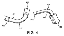
図4を参照すると、実施例は、図3に関して記述される目的に対処するように開発されたクリップサポートシステム及びルーメンを示す。TEEプローブ300の遠位端部の自由度は、プロトタイプヘッドキャップ400に対して示される。 アーマードファイバルーメン312を支持するルーメンガイドクリップ402が示される。アーマードファイバルーメン312は、OSSファイバを受けて、フルレンジの動きをプローブ404に提供する間、プローブ404から保護されて、オフセットされ続ける。 With reference to FIG. 4, examples show clip support systems and lumens developed to address the objectives described with respect to FIG. The degrees of freedom at the distal end of the
図5を参照すると、Philips(R)から商用入手可能なX6-1のプローブのような外部プローブ500が、エルゴノミクス(人間工学的)形状を提供するように設計される。これは外部プローブであり、体内でフィットする必要はないので、 このシステム制約にもかかわらず、この種のプローブは、TEEプローブ又は他の内部プローブより大きな空間的自由を提供する。図5は、その場にアタッチメントピース又はキャップ600なしで、その経路に沿うファイバ502を示す。アタッチメントピース又はキャップ600は、図6に示される。 With reference to Figure 5, an
図6を参照すると、プローブ500に関して固定される経路を通じて、シース(又は他の構造)によって保護される、ファイバ502をガイドするために特有なルーメン602を提供する専用設計プローブアタッチメントピース又はキャップ600は表される。ファイバは自由にレンダリングされ、回転されるが、テンプレート形状経路は超音波プローブ又はトランスデューサ500、したがって超音波画像空間に関して変化しない。 ルーメン602の断面は、ファイバシースにおける多様性を考慮するようにサイジングされることができる。 たとえば、アタッチメントピース600は、カテーテル、ガイドワイヤー又は針等で達せられるシースと互換性を持つことができる。 ルーメン602は、ファイバ502がルーメン602を通じてプッシュされるように、又は堅い端部ピース(例えば、針など)を可能にするためにスプリットルーメンに配置されるように構成される。 Referring to FIG. 6, a specially designed probe attachment piece or cap 600 that provides a
図7を参照すると、1つの実施例において、アタッチメントピース700は、スプリットルーメン702及び閉ルーメン704で構成されることができる。 カバーピース(図示略)は、完全なルーメンをつくるためにスプリットルーメン702上にクランプされる。 アタッチメントピースは、完全スプリット若しくは完全閉ルーメン又はその組合せを含むように設計されることができる。 アタッチメントピース700は、ピース700の部分をともに保持するか、ピース700の中心部にアクセスするためにそれらを開けるために、ヒンジ706を含む。 Referring to FIG. 7, in one embodiment, the
図8を参照すると、他の実施例は、外部のX6-1のプローブ500に関するレトロフィットアタッチメントピース800ソリューションを示す。 ピース800は、中に配置されるOSSファイバシステム806に対する特徴的なカーブサインをつくるために、一つ又はそれより多くの円周湾曲部分802及び一つ又はそれより多くの縦方向湾曲部分804を含む。規定される特徴は、プローブ500のリアルタイムトラッキング及び位置合わせを可能にする。 外部プローブアタッチメントピースがX6-1プローブのために例示されるが、本原理は何れの超音波プローブにも適用できることが理解されるべきである。With reference to FIG. 8, another example shows a
本原理は、他の外部又は内部プローブに同様に適用されることができる。 プローブは本原理によるルーメンで製造されることができ、又は外部アタッチメントの設計は臨床医に最良のアピールに変えられることができる。 本原理に従うすべてのアタッチメントピースのために、ファイバ経路は、特徴的な形状に基づくファイバから超音波ボリュームへ の位置合わせを可能にするため、非対称的で非模倣の、自然に誘導される湾曲パターンになるべきである。This principle can be applied to other external or internal probes as well. The probe can be manufactured with lumens according to this principle, or the design of the external attachment can be changed to the best appeal to the clinician. For all attachment piece according to the principles curved fiber path, to the fibers based on feature shape allows the alignment of the ultrasound volume, asymmetric non-mimetic, derived naturally Should be a pattern.
図9を参照すると、中を通過する形状検出可能カテーテル906を有する超音波ファントム904を表す画像900が示される。カテーテル906は、テンプレートパターン902でアタッチメントピースのまわりで巻かれる。 テンプレートパターン902の既知の幾何形状は、テンプレートパターン902から続くカテーテル906のOSSファイバのためのファントム904に現れる。OSSカテーテル906がテンプレートパターン902にマッチングする位置に基づいて、ファントム904のボリュームは変形され、配置され、リアルタイム位置合わせが確実にされる。Referring to FIG. 9,
本原理は、TEE及び外部プローブ構成のために実例として提示されるが、本原理は、体又は機械的システム若しくは装置におけるナビゲーションのために光学形状検出の、医療装置への何れの一体化にも適用される。 これらの原理は、互いに関して既知の幾何形状を有する2つの装置が使用され、シェイプツーシェイプ位置合わせが考慮される、特にマルチテザーアプリケーションに関連する。アプリケーションはガイドワイヤー及びカテーテル(マニュアル及びロボット)の使用を含むが、内視鏡、気管支鏡及び他のこのようなアプリケーションに応用されることができる。 OSSファイバは、異なる物理パラメータ、例えば、レイリー散乱(強調及び通常)、ファイバブラッグ実現、他の散乱タイプ等を使用する。Although this principle is presented as an example for TEE and external probe configurations, it can be used to integrate optical shape detection into any medical device for navigation in a body or mechanical system or device. Applies. These principles are particularly relevant for multitether applications where two devices with known geometries with respect to each other are used and shape-to-shape alignment is considered. Applications include the use of guide wires and catheters (manuals and robots), but can be applied to endoscopes, bronchoscopes and other such applications. OSS fibers use different physical parameters such as Rayleigh scattering (emphasis and normal), fiber Bragg realization, other scattering types, and the like.
図10を参照すると、位置合わせのための方法が、実施例による実例として示される。 ブロック1002において、アタッチメントピースは、イメージングプローブに接続される。
アタッチメントピースは、イメージングシステムのためのイメージングプローブに適合して、それに付かれるように構成される。 アタッチメントピースはスプリットハーフになるか、プローブ上に渡ってスライドするか、プローブにつながるか、ハウジング又は他の特徴に一体化されるか、又は本原理による何れかの他の構成を含む。 イメージングプローブは、TEEプローブ、外部超音波プローブ又は他のプローブ若しくは装置を含む。With reference to FIG. 10, the method for alignment is shown as an example by way of example. At
The attachment piece is configured to fit and attach to an imaging probe for an imaging system. The attachment piece may be split-half, slide over the probe, be connected to the probe, integrated into the housing or other features, or include any other configuration according to this principle. Imaging probes include TEE probes, external ultrasound probes or other probes or devices.
ブロック1004において、光学形状検出装置は、アタッチメントピース又はハウジング内又は上に形成される経路に置かれる。 経路は、光学形状検出装置が、経路内の縦方向のねじれを可能にするように自由にフロートすることを可能にする。このように、装置の先端は固定されない。経路は、イメージングプローブを使って集められる画像内に特徴的な 幾何形状がテンプレートパターンを提供するように、光学形状検出装置を形成するための特徴的な幾何形状を含む。 At
経路は、光学形状検出装置がルーメンを通る場合、その中の光学形状検出装置を受けるためのルーメンを含む。経路は、その遠位端部に結合される器具を有する光学形状検出装置を受けるために開けられるように構成されるスプリットルーメンを代わりに含む。1つの実施例において、経路はプローブのケーブルに沿って縦方向に延在し、保護ルーメンを含む経路はケーブルの外部に結合される。 これは、イメージングプローブがTEEプローブを含む場合、特に有用である。 The path includes lumens for receiving the optical shape detector in the lumen if the optical shape detector passes through the lumen. The pathway instead comprises a split lumen configured to be opened to receive an optical shape detector with an instrument coupled to its distal end. In one embodiment, the path extends longitudinally along the cable of the probe and the path containing the protective lumen is coupled to the outside of the cable. This is especially useful if the imaging probe contains a TEE probe.
1つの実施例において、複数のアタッチメントピースは、複数のプローブ及び単一のOSSファイバとともに使用される。 他の実施例において、OSSファイバは、カテーテル、ガイドワイヤー又は他の器具に含まれる。 In one embodiment, multiple attachment pieces are used with multiple probes and a single OSS fiber. In other embodiments, the OSS fiber is included in a catheter, guidewire or other device.
ブロック1006において、メモリに記憶される形状テンプレートは、テンプレートパターンを含む画像に位置合わせされる。 テンプレートパターンはアタッチメントピース上に提供されて、記憶される形状テンプレートと一致する。 形状テンプレート及びテンプレートパターンは、イメージング座標系及び光学形状検出座標系の間で位置合わせするためにマッチングされる。In
ブロック1008において、イメージング座標系及び光学形状検出座標系の間の位置合わせは、形状テンプレート及びテンプレートパターン間の変換を計算することを含む。In
添付の請求項を解釈するに当たり、以下のことが理解されるべきである: In interpreting the attached claims, the following should be understood:
a)"有する"という語は所与の請求項に列挙されるもの以外の要素若しくは動作の存在を除外しない。 a) The word "have" does not exclude the existence of elements or actions other than those listed in a given claim.
b)ある要素に先行する"a"若しくは"an"という語はかかる要素の複数の存在を除外しない。 b) The word "a" or "an" preceding an element does not exclude the existence of more than one such element.
c)請求項における任意の参照符号はその範囲を限定しない。 c) Any reference code in the claims does not limit its range.
d)複数の"手段"は、同じ項目又はハードウェア若しくはソフトウェア実施構造若しくは機能によってあらわされ得る。 d) Multiple "means" may be represented by the same item or hardware or software implementation structure or function.
e)特に指定されない限り特定の動作順序が要求されることを意図しない。 e) It is not intended that a particular sequence of operations is required unless otherwise specified.
先端固定なしに光学形状検出を用いる超音波プローブの自動トラッキング及び位置合わ せについて好適な実施形状態を記載したが(これらは例示であって限定ではないことが意図される)、上記教示に照らして修正及び変更が当業者によってなされ得ることが留意される。従って添付の請求項によって概説される通り本明細書に開示の実施形状態の範囲内にある変更が開示の実施形状態の特定の実施形状態においてなされ得ることが理解されるものとする。特許法によって要求される特徴と詳細をこのように記載したが、特許証による保護を望まれる特許請求の範囲は添付の請求項に規定される。Having described preferred embodiments type states for Align automatic tracking and the position of the ultrasonic probe using optical shape detection without tip fixed (which are intended to not be limited to be illustrative), in light of the above teachings It should be noted that modifications and changes may be made by one of ordinary skill in the art. It is therefore understood that changes within the embodiment of the disclosure herein can be made in the particular embodiment of the disclosed embodiment, as outlined by the appended claims. Although the features and details required by the Patent Law are described in this way, the scope of claims for which protection by a patent certificate is desired is specified in the attached claims.
Claims (15)
前記アタッチメントピース内又は上に形成され、光学形状検出装置を受けるように構成される経路であって、前記光学形状検出装置が、前記経路内において縦方向のねじれを可能にするために自由にフロートすることができ、前記経路は、イメージング座標系及び光学形状検出座標系の間で位置合わせを可能にするためにテンプレートパターンを含む、経路と
を有する、位置合わせ装置。 With an attachment piece that is configured to fit and bond to the imaging probe,
Wherein formed on the attachment piece in or on, a path configured to receive the optical shape detection device, wherein the optical shape detection device, freely float to permit longitudinal twist in the path is Ki de to said path, including a template pattern to allow alignment between the Imaging coordinate system and the optical shape detection coordinate system, and a path, the alignment device.
前記アタッチメントピース内又は上に形成され、光学形状検出装置を受けるように構成される経路であって、前記光学形状検出装置が、前記経路内において縦方向のねじれを可能にするために自由にフロートすることができ、前記経路は、イメージング座標系及び光学形状検出座標系の間で位置合わせを可能にするためにテンプレートパターンを含む、経路と、
前記テンプレートパターンに一致する、メモリに記憶される形状テンプレートを使用して前記テンプレートパターンを有する前記光学形状検出装置の位置を見つけるように構成される、位置合わせモジュールと
を有する、位置合わせシステム。 With attachment pieces configured to fit and bond with imaging probes for imaging systems,
Wherein formed on the attachment piece in or on, a path configured to receive the optical shape detection device, wherein the optical shape detection device, freely float to permit longitudinal twist in the path it can be said path, and including, the route a template pattern to allow alignment between the imaging coordinate system and the optical shape detection coordinate system,
Match before Symbol template pattern have using a shape template stored in the memory configured to find the position of the optical shape detection device having the template pattern, and a registration module, the alignment system.
前記アタッチメントピース内又は上に形成される経路において光学形状検出装置を位置させるステップであって、前記経路は、前記光学形状検出装置が前記経路内における縦方向のねじれを可能にするように自由にフロートすることを可能にし、前記経路は、イメージング座標系及び光学形状検出座標系の間で位置合わせを可能にするためにテンプレートパターンを含む、ステップと、
前記テンプレートパターンに一致する、メモリに記憶される形状テンプレートを使用して前記テンプレートパターンを有する前記光学形状検出装置の位置を見つけるステップと
を含む、位置合わせのための方法。 A step of connecting an attachment piece to an imaging probe, wherein the attachment piece is configured to fit and be coupled to the imaging probe for an imaging system.
A step of positioning an optical shape detector in or on a path formed in or on the attachment piece, the path being free to allow the optical shape detector to twist in the longitudinal direction within the path. it possible to float, the path including a template pattern to allow alignment between the imaging coordinate system and the optical shape detection coordinate system, comprising the steps,
Match before Symbol template pattern, and a step of using a shape template stored in the memory to locate the optical shape detection device having the template pattern, a method for alignment.
Applications Claiming Priority (3)
| Application Number | Priority Date | Filing Date | Title |
|---|---|---|---|
| US201462086248P | 2014-12-02 | 2014-12-02 | |
| US62/086,248 | 2014-12-02 | ||
| PCT/IB2015/059248 WO2016088037A1 (en) | 2014-12-02 | 2015-12-01 | Automatic tracking and registration of ultrasound probe using optical shape sensing without tip fixation |
Publications (3)
| Publication Number | Publication Date |
|---|---|
| JP2017537698A JP2017537698A (en) | 2017-12-21 |
| JP2017537698A5 JP2017537698A5 (en) | 2020-11-26 |
| JP6822955B2 true JP6822955B2 (en) | 2021-01-27 |
Family
ID=54937324
Family Applications (1)
| Application Number | Title | Priority Date | Filing Date |
|---|---|---|---|
| JP2017529353A Active JP6822955B2 (en) | 2014-12-02 | 2015-12-01 | Automatic tracking and alignment of ultrasonic probes using optical shape detection without tip fixation |
Country Status (5)
| Country | Link |
|---|---|
| US (1) | US10639007B2 (en) |
| EP (1) | EP3226772B1 (en) |
| JP (1) | JP6822955B2 (en) |
| CN (1) | CN106999153B (en) |
| WO (1) | WO2016088037A1 (en) |
Families Citing this family (18)
| Publication number | Priority date | Publication date | Assignee | Title |
|---|---|---|---|---|
| US11690975B2 (en) * | 2015-10-02 | 2023-07-04 | Koninklijke Philips N.V. | Hub for device navigation with optical shape sensed guidewire |
| US20180317554A1 (en) | 2015-10-30 | 2018-11-08 | British American Tobacco (Investments) Limited | Article for use with apparatus for heating smokable material |
| US20170119051A1 (en) | 2015-10-30 | 2017-05-04 | British American Tobacco (Investments) Limited | Article for Use with Apparatus for Heating Smokable Material |
| CN108697412A (en) * | 2016-02-25 | 2018-10-23 | 波士顿科学国际有限公司 | System and method for improved tissue sampling |
| EP3420914A1 (en) | 2017-06-30 | 2019-01-02 | Koninklijke Philips N.V. | Ultrasound system and method |
| JP7048727B2 (en) | 2017-09-15 | 2022-04-05 | ニコベンチャーズ トレーディング リミテッド | A device for heating smoking material |
| US11887236B2 (en) | 2018-01-02 | 2024-01-30 | Koninklijke Philips N.V. | Animated position display of an OSS interventional device |
| CN111789630B (en) * | 2019-04-08 | 2023-06-20 | 中慧医学成像有限公司 | Ultrasonic probe three-dimensional space information measuring device |
| WO2020251806A1 (en) * | 2019-06-12 | 2020-12-17 | Bard Access Systems, Inc. | Microintroducer system |
| WO2021122264A1 (en) * | 2019-12-17 | 2021-06-24 | Koninklijke Philips N.V. | Ultrasound probe housing with sinusoidal interface and associated ultrasound imaging system |
| EP4120919B1 (en) * | 2020-03-17 | 2024-05-08 | Koninklijke Philips N.V. | Self expanding stent system with imaging |
| CN216675721U (en) | 2020-08-03 | 2022-06-07 | 巴德阿克塞斯系统股份有限公司 | Bragg grating optical fiber fluctuation sensing and monitoring system |
| WO2022067101A1 (en) | 2020-09-25 | 2022-03-31 | Bard Access Systems, Inc. | Minimum catheter length tool |
| US12064569B2 (en) | 2020-09-25 | 2024-08-20 | Bard Access Systems, Inc. | Fiber optics oximetry system for detection and confirmation |
| CN116648208A (en) * | 2020-09-30 | 2023-08-25 | 皇家飞利浦有限公司 | Interventional medical device tracking |
| EP3995076A1 (en) * | 2020-11-06 | 2022-05-11 | Koninklijke Philips N.V. | Method of re-connecting optical fibers and system |
| US20220211442A1 (en) * | 2021-01-06 | 2022-07-07 | Bard Access Systems, Inc. | Needle Guidance Using Fiber Optic Shape Sensing |
| CN115969409A (en) * | 2021-10-14 | 2023-04-18 | 巴德阿克塞斯系统股份有限公司 | Optical fiber ultrasonic probe |
Family Cites Families (15)
| Publication number | Priority date | Publication date | Assignee | Title |
|---|---|---|---|---|
| US6612992B1 (en) | 2000-03-02 | 2003-09-02 | Acuson Corp | Medical diagnostic ultrasound catheter and method for position determination |
| US20110125022A1 (en) * | 2009-11-25 | 2011-05-26 | Siemens Medical Solutions Usa, Inc. | Synchronization for multi-directional ultrasound scanning |
| US9285246B2 (en) * | 2010-02-12 | 2016-03-15 | Intuitive Surgical Operations, Inc. | Method and system for absolute three-dimensional measurements using a twist-insensitive shape sensor |
| JP6195795B2 (en) * | 2011-01-27 | 2017-09-13 | コーニンクレッカ フィリップス エヌ ヴェKoninklijke Philips N.V. | Storage and retrieval of information unique to shape detection devices |
| CN103347461B (en) | 2011-01-28 | 2016-03-09 | 皇家飞利浦有限公司 | For the tip of medical instrument and the optic shape sensing optical fiber of shape facility |
| EP2675354B1 (en) * | 2011-02-17 | 2015-01-07 | Koninklijke Philips N.V. | System for providing an electrical activity map using optical shape sensing |
| US20140100452A1 (en) | 2011-06-27 | 2014-04-10 | Koninklijke Philips Electronics N.V. | Ultrasound-image-guide system and volume-motion-base calibration method |
| US9138166B2 (en) | 2011-07-29 | 2015-09-22 | Hansen Medical, Inc. | Apparatus and methods for fiber integration and registration |
| RU2014110007A (en) * | 2011-08-16 | 2015-09-27 | Конинклейке Филипс Н.В. | CURVED MULTI-PLAN RECONSTRUCTION USING FORM OF FIBER FORM FORM DATA |
| EP2968857B1 (en) | 2013-03-15 | 2022-05-04 | Intuitive Surgical Operations, Inc. | Shape sensor systems for tracking interventional instruments |
| CN105120789B (en) | 2013-03-26 | 2019-12-31 | 皇家飞利浦有限公司 | System and method for minimizing distortion for optical shape sensing enabled instruments |
| EP2978378B1 (en) | 2013-03-29 | 2017-03-08 | Koninklijke Philips N.V. | Systems for measuring force and torque on ultrasound probe during imaging through strain measurement |
| EP3054889B1 (en) | 2013-09-30 | 2020-06-24 | Koninklijke Philips N.V. | Multipurpose lumen design for optical shape sensing |
| US20160213432A1 (en) | 2013-10-02 | 2016-07-28 | Koninklijke Philips N.V. | Hub design and methods for optical shape sensing registration |
| CN107072719A (en) | 2014-09-08 | 2017-08-18 | 皇家飞利浦有限公司 | Optic shape sensing for the instrument tracking in orthopaedy |
-
2015
- 2015-12-01 JP JP2017529353A patent/JP6822955B2/en active Active
- 2015-12-01 WO PCT/IB2015/059248 patent/WO2016088037A1/en active Application Filing
- 2015-12-01 US US15/529,100 patent/US10639007B2/en active Active
- 2015-12-01 EP EP15813570.7A patent/EP3226772B1/en active Active
- 2015-12-01 CN CN201580065620.6A patent/CN106999153B/en active Active
Also Published As
| Publication number | Publication date |
|---|---|
| CN106999153B (en) | 2020-08-28 |
| US20170290563A1 (en) | 2017-10-12 |
| EP3226772A1 (en) | 2017-10-11 |
| US10639007B2 (en) | 2020-05-05 |
| WO2016088037A1 (en) | 2016-06-09 |
| CN106999153A (en) | 2017-08-01 |
| EP3226772B1 (en) | 2022-10-19 |
| JP2017537698A (en) | 2017-12-21 |
Similar Documents
| Publication | Publication Date | Title |
|---|---|---|
| JP6822955B2 (en) | Automatic tracking and alignment of ultrasonic probes using optical shape detection without tip fixation | |
| JP2017537698A5 (en) | ||
| JP7050733B6 (en) | Virtual image with viewpoint of optical shape detector | |
| JP6568084B2 (en) | Robot control to image devices using optical shape detection | |
| US11547489B2 (en) | Shape sensing of multiple over-the-wire devices | |
| JP6902533B2 (en) | Hub for device placement with shape detection system | |
| EP2677937B1 (en) | Non-rigid-body morphing of vessel image using intravascular device shape | |
| US20160213432A1 (en) | Hub design and methods for optical shape sensing registration | |
| JP2018529449A (en) | Hub for device navigation with optical shape-sensing guidewire | |
| JP6706576B2 (en) | Shape-Sensitive Robotic Ultrasound for Minimally Invasive Interventions | |
| JP2014526927A (en) | Curved multiplanar reconstruction using optical fiber shape data | |
| US11406278B2 (en) | Non-rigid-body morphing of vessel image using intravascular device shape | |
| EP2879586B1 (en) | Quantifying probe deflection for improved catheter identification |
Legal Events
| Date | Code | Title | Description |
|---|---|---|---|
| A521 | Request for written amendment filed |
Free format text: JAPANESE INTERMEDIATE CODE: A523 Effective date: 20181129 |
|
| A621 | Written request for application examination |
Free format text: JAPANESE INTERMEDIATE CODE: A621 Effective date: 20181129 |
|
| A977 | Report on retrieval |
Free format text: JAPANESE INTERMEDIATE CODE: A971007 Effective date: 20190809 |
|
| A131 | Notification of reasons for refusal |
Free format text: JAPANESE INTERMEDIATE CODE: A131 Effective date: 20190820 |
|
| A521 | Request for written amendment filed |
Free format text: JAPANESE INTERMEDIATE CODE: A523 Effective date: 20191105 |
|
| A131 | Notification of reasons for refusal |
Free format text: JAPANESE INTERMEDIATE CODE: A131 Effective date: 20200107 |
|
| A601 | Written request for extension of time |
Free format text: JAPANESE INTERMEDIATE CODE: A601 Effective date: 20200407 |
|
| A524 | Written submission of copy of amendment under article 19 pct |
Free format text: JAPANESE INTERMEDIATE CODE: A524 Effective date: 20200706 |
|
| A521 | Request for written amendment filed |
Free format text: JAPANESE INTERMEDIATE CODE: A523 Effective date: 20200907 |
|
| A521 | Request for written amendment filed |
Free format text: JAPANESE INTERMEDIATE CODE: A523 Effective date: 20200907 |
|
| TRDD | Decision of grant or rejection written | ||
| A01 | Written decision to grant a patent or to grant a registration (utility model) |
Free format text: JAPANESE INTERMEDIATE CODE: A01 Effective date: 20201215 |
|
| A61 | First payment of annual fees (during grant procedure) |
Free format text: JAPANESE INTERMEDIATE CODE: A61 Effective date: 20210107 |
|
| R150 | Certificate of patent or registration of utility model |
Ref document number: 6822955 Country of ref document: JP Free format text: JAPANESE INTERMEDIATE CODE: R150 |
|
| R250 | Receipt of annual fees |
Free format text: JAPANESE INTERMEDIATE CODE: R250 |