EP2879586B1 - Quantifying probe deflection for improved catheter identification - Google Patents
Quantifying probe deflection for improved catheter identification Download PDFInfo
- Publication number
- EP2879586B1 EP2879586B1 EP13774237.5A EP13774237A EP2879586B1 EP 2879586 B1 EP2879586 B1 EP 2879586B1 EP 13774237 A EP13774237 A EP 13774237A EP 2879586 B1 EP2879586 B1 EP 2879586B1
- Authority
- EP
- European Patent Office
- Prior art keywords
- shape sensing
- imaging devices
- optical fiber
- recited
- enabled device
- Prior art date
- Legal status (The legal status is an assumption and is not a legal conclusion. Google has not performed a legal analysis and makes no representation as to the accuracy of the status listed.)
- Active
Links
Images


Classifications
-
- A—HUMAN NECESSITIES
- A61—MEDICAL OR VETERINARY SCIENCE; HYGIENE
- A61B—DIAGNOSIS; SURGERY; IDENTIFICATION
- A61B8/00—Diagnosis using ultrasonic, sonic or infrasonic waves
- A61B8/08—Detecting organic movements or changes, e.g. tumours, cysts, swellings
- A61B8/0833—Detecting organic movements or changes, e.g. tumours, cysts, swellings involving detecting or locating foreign bodies or organic structures
- A61B8/0841—Detecting organic movements or changes, e.g. tumours, cysts, swellings involving detecting or locating foreign bodies or organic structures for locating instruments
-
- A—HUMAN NECESSITIES
- A61—MEDICAL OR VETERINARY SCIENCE; HYGIENE
- A61B—DIAGNOSIS; SURGERY; IDENTIFICATION
- A61B1/00—Instruments for performing medical examinations of the interior of cavities or tubes of the body by visual or photographical inspection, e.g. endoscopes; Illuminating arrangements therefor
- A61B1/00002—Operational features of endoscopes
- A61B1/00004—Operational features of endoscopes characterised by electronic signal processing
- A61B1/00009—Operational features of endoscopes characterised by electronic signal processing of image signals during a use of endoscope
-
- A—HUMAN NECESSITIES
- A61—MEDICAL OR VETERINARY SCIENCE; HYGIENE
- A61B—DIAGNOSIS; SURGERY; IDENTIFICATION
- A61B1/00—Instruments for performing medical examinations of the interior of cavities or tubes of the body by visual or photographical inspection, e.g. endoscopes; Illuminating arrangements therefor
- A61B1/00163—Optical arrangements
- A61B1/00165—Optical arrangements with light-conductive means, e.g. fibre optics
- A61B1/00167—Details of optical fibre bundles, e.g. shape or fibre distribution
-
- A—HUMAN NECESSITIES
- A61—MEDICAL OR VETERINARY SCIENCE; HYGIENE
- A61B—DIAGNOSIS; SURGERY; IDENTIFICATION
- A61B5/00—Measuring for diagnostic purposes; Identification of persons
- A61B5/0059—Measuring for diagnostic purposes; Identification of persons using light, e.g. diagnosis by transillumination, diascopy, fluorescence
- A61B5/0082—Measuring for diagnostic purposes; Identification of persons using light, e.g. diagnosis by transillumination, diascopy, fluorescence adapted for particular medical purposes
- A61B5/0084—Measuring for diagnostic purposes; Identification of persons using light, e.g. diagnosis by transillumination, diascopy, fluorescence adapted for particular medical purposes for introduction into the body, e.g. by catheters
-
- A—HUMAN NECESSITIES
- A61—MEDICAL OR VETERINARY SCIENCE; HYGIENE
- A61B—DIAGNOSIS; SURGERY; IDENTIFICATION
- A61B5/00—Measuring for diagnostic purposes; Identification of persons
- A61B5/06—Devices, other than using radiation, for detecting or locating foreign bodies ; determining position of probes within or on the body of the patient
- A61B5/065—Determining position of the probe employing exclusively positioning means located on or in the probe, e.g. using position sensors arranged on the probe
- A61B5/066—Superposing sensor position on an image of the patient, e.g. obtained by ultrasound or x-ray imaging
-
- A—HUMAN NECESSITIES
- A61—MEDICAL OR VETERINARY SCIENCE; HYGIENE
- A61B—DIAGNOSIS; SURGERY; IDENTIFICATION
- A61B8/00—Diagnosis using ultrasonic, sonic or infrasonic waves
- A61B8/12—Diagnosis using ultrasonic, sonic or infrasonic waves in body cavities or body tracts, e.g. by using catheters
-
- A—HUMAN NECESSITIES
- A61—MEDICAL OR VETERINARY SCIENCE; HYGIENE
- A61B—DIAGNOSIS; SURGERY; IDENTIFICATION
- A61B8/00—Diagnosis using ultrasonic, sonic or infrasonic waves
- A61B8/42—Details of probe positioning or probe attachment to the patient
- A61B8/4245—Details of probe positioning or probe attachment to the patient involving determining the position of the probe, e.g. with respect to an external reference frame or to the patient
- A61B8/4254—Details of probe positioning or probe attachment to the patient involving determining the position of the probe, e.g. with respect to an external reference frame or to the patient using sensors mounted on the probe
-
- A—HUMAN NECESSITIES
- A61—MEDICAL OR VETERINARY SCIENCE; HYGIENE
- A61B—DIAGNOSIS; SURGERY; IDENTIFICATION
- A61B8/00—Diagnosis using ultrasonic, sonic or infrasonic waves
- A61B8/44—Constructional features of the ultrasonic, sonic or infrasonic diagnostic device
- A61B8/4444—Constructional features of the ultrasonic, sonic or infrasonic diagnostic device related to the probe
- A61B8/4461—Features of the scanning mechanism, e.g. for moving the transducer within the housing of the probe
- A61B8/4466—Features of the scanning mechanism, e.g. for moving the transducer within the housing of the probe involving deflection of the probe
-
- A—HUMAN NECESSITIES
- A61—MEDICAL OR VETERINARY SCIENCE; HYGIENE
- A61B—DIAGNOSIS; SURGERY; IDENTIFICATION
- A61B8/00—Diagnosis using ultrasonic, sonic or infrasonic waves
- A61B8/58—Testing, adjusting or calibrating the diagnostic device
-
- A—HUMAN NECESSITIES
- A61—MEDICAL OR VETERINARY SCIENCE; HYGIENE
- A61N—ELECTROTHERAPY; MAGNETOTHERAPY; RADIATION THERAPY; ULTRASOUND THERAPY
- A61N5/00—Radiation therapy
- A61N5/10—X-ray therapy; Gamma-ray therapy; Particle-irradiation therapy
- A61N5/1001—X-ray therapy; Gamma-ray therapy; Particle-irradiation therapy using radiation sources introduced into or applied onto the body; brachytherapy
- A61N5/1027—Interstitial radiation therapy
-
- A—HUMAN NECESSITIES
- A61—MEDICAL OR VETERINARY SCIENCE; HYGIENE
- A61N—ELECTROTHERAPY; MAGNETOTHERAPY; RADIATION THERAPY; ULTRASOUND THERAPY
- A61N5/00—Radiation therapy
- A61N5/10—X-ray therapy; Gamma-ray therapy; Particle-irradiation therapy
- A61N5/1048—Monitoring, verifying, controlling systems and methods
- A61N5/1049—Monitoring, verifying, controlling systems and methods for verifying the position of the patient with respect to the radiation beam
-
- A—HUMAN NECESSITIES
- A61—MEDICAL OR VETERINARY SCIENCE; HYGIENE
- A61N—ELECTROTHERAPY; MAGNETOTHERAPY; RADIATION THERAPY; ULTRASOUND THERAPY
- A61N5/00—Radiation therapy
- A61N5/10—X-ray therapy; Gamma-ray therapy; Particle-irradiation therapy
- A61N5/1048—Monitoring, verifying, controlling systems and methods
- A61N5/1064—Monitoring, verifying, controlling systems and methods for adjusting radiation treatment in response to monitoring
- A61N5/1065—Beam adjustment
- A61N5/1067—Beam adjustment in real time, i.e. during treatment
-
- A—HUMAN NECESSITIES
- A61—MEDICAL OR VETERINARY SCIENCE; HYGIENE
- A61B—DIAGNOSIS; SURGERY; IDENTIFICATION
- A61B34/00—Computer-aided surgery; Manipulators or robots specially adapted for use in surgery
- A61B34/20—Surgical navigation systems; Devices for tracking or guiding surgical instruments, e.g. for frameless stereotaxis
- A61B2034/2046—Tracking techniques
- A61B2034/2061—Tracking techniques using shape-sensors, e.g. fiber shape sensors with Bragg gratings
-
- A—HUMAN NECESSITIES
- A61—MEDICAL OR VETERINARY SCIENCE; HYGIENE
- A61N—ELECTROTHERAPY; MAGNETOTHERAPY; RADIATION THERAPY; ULTRASOUND THERAPY
- A61N5/00—Radiation therapy
- A61N5/10—X-ray therapy; Gamma-ray therapy; Particle-irradiation therapy
- A61N5/1048—Monitoring, verifying, controlling systems and methods
- A61N5/1049—Monitoring, verifying, controlling systems and methods for verifying the position of the patient with respect to the radiation beam
- A61N2005/1058—Monitoring, verifying, controlling systems and methods for verifying the position of the patient with respect to the radiation beam using ultrasound imaging
Description
- This disclosure relates to medical instruments and more particularly to shape sensing optical fibers in medical applications for improved identification of medical instruments.
- High dose rate (HDR) brachytherapy procedures involve the transperineal placement of catheters under transrectal ultrasound (TRUS) guidance. Subsequently, catheter identification using TRUS images is performed manually. However, this leads to a high probability of error, since the ultrasonic speckle combined with the variable echogenicity of the catheters makes it difficult for the catheters to be accurately and consistently identified, resulting in inaccuracies in the treatment planning process. Automated methods of catheter mapping include electromagnetic (EM) tracking of sensors or guidewires placed in the catheter. This method requires a consistently stable relationship between the EM and TRUS frames of reference. However, in clinical situations, the process of positioning the TRUS probe within the patient induces a bending/deflection of the probe, which may cause inconsistencies in the registration of the EM and TRUS frames of reference.
- International Patent Application
WO2011098926A1 describes a system for determining a position of an optical fiber. The system includes a transducer device configured to receive signals from a console and generate images based upon reflected waves. A flexible cable is coupled to the transducer device to provide excitation energy to the transducer device from the console. An optical fiber has a shape and position corresponding to a shape and position of the cable during operation. - In accordance with the present principles, a system includes a shape sensing enabled device including one or more imaging devices, the shape sensing enabled device coupled to at least one optical fiber. A shape sensing module is configured to receive optical signals from the at least one optical fiber within a structure and interpret the optical signals to determine a shape of the shape sensing enabled device. A device positioning module is configured to determine position information of the one or more imaging devices based upon one or more relationships between the at least one optical fiber and the one or more imaging devices. A mapping module is configured to register frames of reference of the at least one optical fiber, the shape sensing enabled device, and a mapping system of a target device to provide an adjusted position of the target device based on the position information.
- A system includes a shape sensing enabled medical device including one or more imaging devices, the shape sensing enabled medical device coupled to at least one optical fiber. A shape sensing module is configured to receive optical signals from the at least one optical fiber within a structure and interpret the optical signals to determine a shape of the shape sensing enabled medical device. A device positioning module is configured to determine position information of the one or more imaging devices based upon one or more relationships between each of the at least one optical fiber and one or more points each representing the one or more imaging devices. The one or more relationships is determined prior to placing the one or more imaging devices within the structure. A mapping module is configured to register frames of reference of the at least one optical fiber, the shape sensing enabled medical device, and a mapping system of a target device to provide an adjusted position of the target device based on the position information.
- A method includes collecting shape sensing data from a shape sensing enabled device disposed within a structure, the shape sensing enabled device coupled to at least one optical fiber and including one or more imaging devices. Position information of the one or more imaging devices is determined based upon one or more relationships between the at least one optical fiber and the one or more imaging devices. Frames of reference of the at least one optical fiber, the shape sensing enable device, and a mapping system of a target device are registered to provide an adjusted position of the target device based on the position information.
- These and other objects, features and advantages of the present disclosure will become apparent from the following detailed description of illustrative embodiments thereof, which is to be read in connection with the accompanying drawings.
- This disclosure will present in detail the following description of preferred embodiments with reference to the following figures wherein:
-
FIG. 1 is a block/flow diagram showing a shape sensing system to identify a position of a device in accordance with one embodiment; -
FIG. 2 illustratively depicts a cross-sectional view of a probe including an exemplary arrangement of optical fibers in accordance with one embodiment; -
FIG. 3 illustratively depicts the effect of probe deflection/bending when positioned within a subject; and -
FIG. 4 is a block/flow diagram showing a method for identifying a position of a device in accordance with one embodiment. - In accordance with the present principles, systems and methods for identifying a catheter during an HDR brachytherapy procedure are provided. Typically, HDR brachytherapy is performed under the guidance of transrectal ultrasound (TRUS). However, the insertion of the TRUS probe into a subject induces a deflection/bend in the probe. Fiber optic shape sensing may be applied to quantify the deflection/bend in the probe to thereby provide positional information of the probe. Based on spatial relationships between optical fibers coupled to the probe and the TRUS imaging arrays, positional information of the TRUS imaging arrays may be computed.
- Catheters may be mapped using, e.g., optical fibers or electromagnetic (EM) sensors. The frames of references of the TRUS imaging arrays, optical fibers and mapping system of the catheters may be registered. The mapped position of the catheters may be adjusted based on the positional information of the TRUS imaging arrays, representing the true catheter positions with TRUS probe deflection/bending taken into account.
- Advantageously, the present principles provide accurate, real-time updates of catheter and afterloader positions (and hence, radioactive source positions). The ability to provide real-time source position updates may reduce the disconnect between treatment planning and delivery, which may exist due to inconsistent spatial relationships between the treatment sources and tissue. Real-time catheter tracking during treatment delivery may also allow for treatment adaptation.
- It also should be understood that the present invention will be described in terms of medical instruments; however, the teachings of the present invention are much broader and are applicable to any fiber optic or imaging instruments. In some embodiments, the present principles are employed in tracking or analyzing complex biological or mechanical systems. In particular, the present principles are applicable to internal tracking procedures of biological systems, procedures in all areas of the body such as the lungs, gastro-intestinal tract, excretory organs, blood vessels, etc. The elements depicted in the FIGS. may be implemented in various combinations of hardware and software and provide functions which may be combined in a single element or multiple elements.
- The functions of the various elements shown in the FIGS. can be provided through the use of dedicated hardware as well as hardware capable of executing software in association with appropriate software. When provided by a processor, the functions can be provided by a single dedicated processor, by a single shared processor, or by a plurality of individual processors, some of which can be shared. Moreover, explicit use of the term "processor" or "controller" should not be construed to refer exclusively to hardware capable of executing software, and can implicitly include, without limitation, digital signal processor ("DSP") hardware, read-only memory ("ROM") for storing software, random access memory ("RAM"), non-volatile storage, etc.
- It will be appreciated by those skilled in the art that the block diagrams presented herein represent conceptual views of illustrative system components and/or circuitry embodying the principles of the invention. Similarly, it will be appreciated that any flow charts, flow diagrams and the like represent various processes which may be substantially represented in computer readable storage media and so executed by a computer or processor, whether or not such computer or processor is explicitly shown.
- Furthermore, embodiments of the present invention can take the form of a computer program product accessible from a computer-usable or computer-readable storage medium providing program code for use by or in connection with a computer or any instruction execution system. For the purposes of this description, a computer-usable or computer readable storage medium can be any apparatus that may include, store, communicate, propagate, or transport the program for use by or in connection with the instruction execution system, apparatus, or device. The medium can be an electronic, magnetic, optical, electromagnetic, infrared, or semiconductor system (or apparatus or device) or a propagation medium. Examples of a computer-readable medium include a semiconductor or solid state memory, magnetic tape, a removable computer diskette, a random access memory (RAM), a read-only memory (ROM), a rigid magnetic disk and an optical disk. Current examples of optical disks include compact disk - read only memory (CD-ROM), compact disk - read/write (CD-R/W), Blu-Ray™ and DVD.
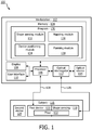
- Referring now to the drawings in which like numerals represent the same or similar elements and initially to
FIG. 1 , asystem 100 for determining positioning information of a catheter is illustratively depicted in accordance with one embodiment. Thesystem 100 may include a workstation orconsole 102 from which procedures (e.g., HDR brachytherapy) are supervised and managed.Workstation 102 preferably includes one ormore processors 106 andmemory 104 for storing programs and applications. It should be understood that the functions and components ofsystem 100 may be integrated into one or more workstations or systems. -
Workstation 102 may include one ormore displays 108 for viewing. Thedisplay 108 may also permit a user to interact with theworkstation 102 and its components and functions. This is further facilitated by auser interface 110, which may include a keyboard, mouse, joystick, or any other peripheral or control to permit user interaction with theworkstation 102. - While the present principles will be described with respect to an HDR brachytherapy procedure, one of ordinary skill in the art would recognize that the present principles are much broader and may be applicable to any workflow utilizing an imaging system that communicates between multiple tracking systems. For example, the present principles may be applied to create flexible ultrasound arrays or other imaging devices that conventionally need to be rigid in order to have a known imaging geometry. Tracking with optical shape sensing provides real-time knowledge of the specific geometry of a flexible imaging device, which enables access to areas or structures that are difficult to image with conventional, rigid devices. In another example, the present principles may be applied in plumbing where pipes may be imaged using both an ultrasound system and an endoscope. Other applications are also contemplated.
-
Memory 104 may store a computer implementedprogram 130 including ashape sensing module 132 configured to interpret optical feedback signals from a shape sensing device orsystem 118.Shape sensing module 132 is configured to use the optical signal feedback (and any other feedback, e.g., electromagnetic (EM) tracking) to reconstruct deformations, deflections and other changes associated with a first medical device orinstrument 120. Thefirst device 120 preferably includes a (e.g., transrectal ultrasound (TRUS)) probe, but may include one or more of an endoscope, or other imaging components, etc. Theprobe 120 may be coupled to theworkstation 102 throughcabling 128. Thecabling 128 may include electrical connections, optical fiber connections, instrumentation, etc., as needed. Theprobe 120 may be used to evaluate a structure or subject 116 (e.g., patient). - A shape sensing system includes
module 132 andshape sensing device 118 mounted on or integrated into theprobe 120. The shape sensing system includes anoptical interrogator 112 that provides selected signals and receives optical responses. Anoptical source 114 may be provided as part of theinterrogator 112 or as a separate unit for providing light signals to theshape sensing device 118.Shape sensing device 118 includes one or moreoptical fibers 122 which may be coupled to thedevice 120 in a set pattern or patterns. Thefibers 122 may be coupled to theworkstation 102 throughcabling 126. The cabling may include fiber optics, electrical connections, other instrumentation, etc. as needed. - In one embodiment, the
fibers 122 are integrated within the casing of theprobe 120. Ifmultiple fibers 122 are utilized, eachfiber 122 may be arranged in a specific pattern around the circumference or perimeter of theprobe 120, with eachfiber 122 running along the length of theprobe 120. - Referring for a moment to
FIG. 2 , with continued reference toFIG. 1 , a cross-sectional view of aTRUS probe 200 including an exemplary arrangement of optical fibers is illustratively depicted in accordance with one embodiment. Since deflection of theprobe 120 may be non-linear, it may be advantageous to have a greater concentration offibers 122 placed in close proximity to the one ormore imaging arrays 202 of theprobe 120, with a sparser distribution offibers 122 away from theimaging arrays 202. Other patterns offibers 122 within theprobe 120 are also contemplated. For example, a distribution offibers 122 throughout the cross-section of theprobe 120 may offer several advantages: the capability to measure relative positions ofmultiple fibers 122 with respect to each other; and providing measurement redundancy in the event that communication with one or more of thefibers 122 fails. However, if the positions offibers 122 change, the spatial relationship between thefibers 122 andimaging arrays 202 may not be valid either. - Referring back to
FIG. 1 , in another embodiment, thefibers 122 may be externally coupled to theprobe 120 using, e.g., a clip-on attachment. Thefibers 122 are rigidly registered to theprobe 120. While this embodiment may limit the proximity of thefibers 122 to the imaging arrays of theprobe 120, it affords some flexibility to the operator with regards to the placement of thefibers 122. Other arrangements of thefibers 122 coupled on or in theprobe 120 are also contemplated. -
Shape sensing 118 withfibers 122 may be implemented using any mechanism of optical fiber transmission/reflection. For example, shape sensing 118 withfibers 122 may be implemented using one or more of: wavelength-division multiplexed distributed sensing, time-wavelength-division multiplexed distributed sensing, interferometric detection, amplitude-based inherent scattering, etc. Preferably, shape sensing 118 withfibers 122 is based on the fiber optic Bragg grating (FBG) principle; however, other approaches are also contemplated, such as, e.g., Rayleigh scattering, Raman scattering or Brillouin scattering. FBG is a short segment of optical fiber that reflects particular wavelengths of light and transmits all others. This is achieved by adding a periodic variation of the refractive index in the fiber core, which generates a wavelength-specific dielectric mirror. A fiber Bragg grating can therefore be used as an inline optical filter to block certain wavelengths, or as a wavelength-specific reflector. - The shape of the
fibers 122 at any spatial location along its length is dependent on the internal strain developed in the fiber. The Bragg wavelength is sensitive to this strain.Shape sensing module 132 may use the strain in three or more FBGs (one in eachfiber 122, in a group of three fibers 122) to calculate the local bend in the fiber group. Thus, the shape of the fiber is accumulated. A priori knowledge of the FBG positions along the fiber can be utilized to provide shape and position estimates of the fiber in the desired frame of reference. - Computer implemented
program 130 may include adevice positioning module 134 configured to determine the origins of the imaging array of theprobe 120 upon insertion into the subject 116. Initially, prior to positioning theprobe 120 within the subject 116,device positioning module 134 may compute a transformation between thefibers 122 and the imaging arrays of theprobe 120. The transformation represents spatial relationships between thefibers 122 and the imaging arrays of theprobe 120 for an unbent configuration of theprobe 120. In one embodiment, spatial relationships are defined between eachfiber 122 and one or more points (e.g., center) each representing the one or more imaging arrays of theprobe 120. In another embodiment,fibers 122 are divided into multiple sections and spatial relationships are defined between each section of eachfiber 122 and the center of each of the imaging arrays ofprobe 120. Other embodiments are also contemplated. The spatial relationships are constant throughout the procedure. If not, recalibration may be performed. - Preferably, spatial relationships are determined in a pre-procedural calibration step, prior to the
probe 120 insertion intosubject 116. For example, the pre-procedural calibration may be a one-time calibration performed intermittently (e.g., weekly, monthly, etc.). This calibration step allows the origins of the imaging arrays of theprobe 120 to be defined relative to the coordinate system of thefibers 122. In another embodiment, a prior pre-procedural calibration may be adjusted intra-procedurally. - Once the
probe 120 has been positioned and stabilized within the subject 116, the shape and pose of each of thefibers 122 is recorded usingshape sensing module 126. Based upon the determined spatial relationship betweenfibers 122 and the imaging arrays of theprobe 120,device positioning module 134 may compute the origins of the imaging arrays of theprobe 120. The origins of the imaging arrays are preferably stored inmemory 104 in a common frame of reference (e.g., the probe's 120 frame of reference). - Referring for a moment to
FIG. 3 , aprobe 300 is positioned within a subject. Prior to positioning theprobe 120 within a subject 116, for anunbent configuration 304 of the probe, atarget area 302 of a subject 116 is imaged 306 with no probe deflection/bending. However, the process of positioning theprobe 120 in the subject 116 induces a bending/deflection 312. Thebent probe 308images 310 thetarget area 302. Using spatial relationships betweenfibers 122 coupled to theprobe 120 and theimaging arrays 202 of theprobe 120, thedevice positioning module 134 may account for the bending/deflection 312 to compute the origins of the imaging arrays. - Referring back to
FIG. 1 , the computer implementedprogram 130 may include amapping module 136 configured to map the position of one or more second medical devices orinstruments 124 within the subject 116 prior to treatment planning. Thesecond device 124 preferably includes a catheter, but may include one or more of a probe, a guidewire, an endoscope, a robot, an electrode, a filter device, a balloon device, or other components, etc. Thecatheters 124 may be positioned within the subject 116 for, e.g., HDR brachytherapy. - In one embodiment, the
mapping module 136 is configured to perform EM-based path mapping to identify thecatheter 124 positions within the subject 116. In an embodiment, EM-based path mapping may be performed using an EM-tracked guidewire that can be inserted into and retracted fromcatheters 124. The spatial information of the tracker may be recorded during this process. Other embodiments of EM-based path mapping are also contemplated. The frames of reference of the EM system,fibers 118 and imaging arrays of theprobe 120 are registered. In another embodiment, themapping module 136 may be configured to perform optical shape sensing to identify thecatheter 124 positions within the subject 116. The frames of reference of the fibers 122 (used in both thecatheters 124 and the probe 120) and the imaging arrays of theprobe 120 are registered. Other embodiments of mapping thecatheter 124 within the subject 116 are also contemplated. - The
mapping module 136 may adjust the position information of thecatheter 124 based on the origins of the imaging arrays of theprobe 120, determined bydevice positioning module 134. The adjustedcatheter 124 positions represent thetrue catheter 124 positions determined with deflection/bending of theprobe 120 taken into account. - The
mapping module 136 may be further configured to perform real-time catheter 124 tracking during a procedure, such as treatment delivery. If thecatheter 124 shape and pose are tracked usingfibers 122, then real-time changes in the shape of thecatheters 124 can be determined and adjusted based on the calculated deflection/bending of theprobe 120 at that time instant. Each incremental position of the afterloader device within thecatheters 124 can also be recorded to provide a real-time estimate of the positions of the radioactive sources. Advantageously, by knowing the planned locations of the radioactive sources, real-time adaptions can be made to the treatment plan. - The computer implemented
program 130 may also include aplanning module 138. The planning module may involve one ormore displays 108 and/oruser interfaces 110. In one embodiment, theplanning module 138 may be configured to provide pre-planning mapping ofcatheters 124, such as in an, e.g., HDR brachytherapy procedure. Knowledge of the position of the imaging arrays of theprobe 120 allows for improved accuracy in the estimates of catheter positions, which are used to formulate an initial treatment plan to specify appropriate dose levels for target areas and/or surrounding organs at risk (OARs). - In another embodiment, the
planning module 138 may provide for adaptive treatment planning using real-time updates ofcatheter 124 and afterloader positions. In the event ofcatheter 124 motion (relative to the target area of the subject 116), the initial treatment plan may be modified to account for the motion. For example, if the estimated dose received by the target is less than the planned dose in the, e.g., posterior region of the target, then the dwell positions and dwell times of sources in the catheters closes to the posterior region of the target can be adjusted accordingly to compensate for the reduced dosage in that region. Other modifications to the treatment plan are also contemplated. - Referring now to
FIG. 4 , a block diagram showing a method for determining positioning information of a catheter is illustratively depicted in accordance with one embodiment. Inblock 402, shape sensing data is collected from a shape sensing enabled device. The shape sensing enabled device is preferably includes an ultrasound probe, but may also include an endoscope, or other imaging components, etc. The shape sensing enabled device may be disposed within a structure, such as, e.g., a vascular structure, a mechanical structure, etc. - One or more optical fibers are preferably coupled to the shape sensing enabled device in a set pattern or patterns. In one embodiment, in
block 404, the optical fibers may be integrated or embedded within the shape sensing enabled device. For example, the optical fibers may be arranged such that a greater concentration of optical fibers is positioned in close proximity to one or more imaging devices (e.g., imaging arrays) of the shape sensing enabled device, with a sparser distribution of optical fibers away from the imaging devices. In another example, optical fibers may be distributions throughout the cross-section of the shape sensing enabled device. In still another embodiment, inblock 406, the optical fibers may be externally coupled to the shape sensing enabled device using, e.g., a clip on attachment. Other patterns of positioning optical fibers in or around the shape sensing enabled device are also contemplated. - In
block 408, position information of the imaging devices of the shape sensing enabled device is determined based on spatial relationships between the fibers and the one or more imaging devices. Initially, prior to the disposition of the shape sensing enabled device within the structure, a transformation between the fibers and imaging devices of the shape sensing enabled device is determined. The transformation represents spatial relationships between the fibers and the imaging devices. In one embodiment, inblock 410, spatial relationships are defined between each fiber and one or more points (e.g., center) each representing the one or more imaging devices of the shape sensing enabled device. In another embodiment, inblock 412, fibers are divided into multiple sections and spatial relationships are defined between each section of each fiber and one or more points each representing the one or more imaging devices of the shape sensing enabled device. Other embodiments are also contemplated. The spatial relationships are constant throughout the procedure. If not constant, recalibration may be performed. - Preferably, spatial relationships are determined in a pre-procedural calibration step, prior to the disposition of the shape sensing enabled device within the structure. For example, the pre-procedural calibration may be a one-time calibration performed intermittently (e.g., weekly, monthly, etc.). This calibration step allows the origins of the imaging devices of the shape sensing enabled device to be defined relative to the coordinate system of the fibers.
- Once the shape sensing enabled device has been positioned within the structure, the shape and pose of the fibers are recorded. Based on the spatial relationship between the fibers and the one or more imaging devices, position information of the one or more imaging devices of the shape sensing enabled device may be determined.
- In
block 414, frames of reference of the optical fibers, imaging devices, and a mapping system of a target device are registered to provide an adjusted position of the target device based on the position information of the imaging devices. The target device preferably includes a catheter, but may also include a probe, endoscope, guidewire, etc. The target device is mapped using the mapping system. In one embodiment, the mapping system includes an EM-based mapping system. EM-based mapping may be performed using an EM-tracked guidewire. Other methods of EM-based mapping are also contemplated. In another embodiment, the mapping system includes an optical shape sensing system. Other implementations of the mapping system are also contemplated. - The mapped position of the target device (using the mapping system) is adjusted using the position of the imaging devices. The adjusted position of the target device represents the true position determined by taking into account deflection/bending of the shape sensing enabled device.
- In
block 416, a treatment plan is created or modified. If the target device is tracked using optical fibers, real-time changes in the shape of the target device can be determined and a treatment plan can be adjusted. In one embodiment, a position of an afterloader within a shape sensing enabled device may be recorded to provide a real-time estimate of the positions of (e.g., radioactive) sources positioned in the shape sensing enabled device. Knowing the planned locations of the radioactive sources, real-time adaptations can be made to a treatment plan. For example, if the estimated dose received by the target is less than the planned dose in the, e.g., posterior region of the target, then the dwell positions and dwell times of sources in the target device closest to the posterior region of the target can be adjusted accordingly to compensate for the reduced dosage in that region. Other modifications to the treatment plan are also contemplated. - Additionally, a treatment plan may be developed. Knowledge of the position of imaging devices of the shape sensing enabled device results in improved accuracy of the estimates of the position of the target device. Accurate positioning of the target device may be important in the creation of the initial treatment plan.
Claims (15)
- A system, comprising:a shape sensing enabled device (120) including one or more imaging devices (202), the shape sensing enabled device coupled to at least one optical fiber (122);a shape sensing module (132) configured to receive optical signals from the at least one optical fiber within a structure and interpret the optical signals to determine a shape of the shape sensing enabled device;a device positioning module (134) configured to determine position information of the one or more imaging devices based upon one or more spatial relationships between the at least one optical fiber and the one or more imaging devices; anda mapping module (136) configured to register frames of reference of the at least one optical fiber, the shape sensing enabled device, and a mapping system of a target device (124) to provide an adjusted position of the target device based on the position information.
- The system as recited in claim 1, wherein the shape sensing enabled device (120) is coupled to the at least one optical fiber by at least one of embedding the at least one optical fiber in the shape sensing enabled device and externally attaching the at least one optical fiber to the shape sensing enabled device.
- The system as recited in claim 1, wherein the at least one optical fiber (122) is distributed throughout a cross-section of the shape sensing enabled device.
- The system as recited in claim 1, wherein the at least one optical fiber (122) is arranged around a perimeter of the shape sensing enabled device.
- The system as recited in claim 1, wherein the device positioning module (134) is further configured to determine the one or more spatial relationships between each of the at least one optical fiber and one or more points each representing the one or more imaging devices prior to placing the one or more imaging devices within the structure.
- The system as recited in claim 1, wherein the device positioning module (134) is further configured to determine the one or more relationships between each section of each of the at least one optical fibers and one or more points each representing the one or more imaging devices prior to placing the one or more imaging devices within the structure.
- The system as recited in claim 1, further comprising a planning module (138) configured to adapt or create a treatment plan according to the adjusted position of the target device.
- The system as recited in claim 1, wherein the mapping system includes at least one of an electromagnetic tracking system and a shape sensing system.
- The system as recited in claim 1, wherein the shape sensing enabled device (120) includes one or more of a probe and an endoscope.
- The system as recited in claim 1, wherein the target device (124) includes one or more of a probe, a catheter, a guidewire, and an endoscope.
- The system as recited in claim 1, wherein the structure is a body cavity.
- The system as recited in claim 1, wherein the system is used to create one or more flexible imaging arrays.
- The system as recited in claim 1, wherein the device positioning module (134) is further configured to determine position information of the one or more imaging devices based upon one or more spatial relationships between each of the at least one optical fiber and one or more points each representing the one or more imaging devices, the one or more spatial relationships determined prior to placing the one or more imaging devices within the structure.
- A method, comprising:collecting (402) shape sensing data from a shape sensing enabled device disposed within a structure, the shape sensing enabled device coupled to at least one optical fiber and including one or more imaging devices;determining (408) position information of the one or more imaging devices based upon one or more spatial relationships between the at least one optical fiber and the one or more imaging devices; andregistering (414) frames of reference of the at least one optical fiber, the shape sensing enable device, and a mapping system of a target device to provide an adjusted position of the target device based on the position information.
- The method as recited in claim 14, wherein determining (408) further includes determining (410) the one or more spatial relationships between each of the at least one optical fiber and one or more points each representing the one or more imaging devices prior to placing the one or more imaging devices within the structure.
Applications Claiming Priority (2)
| Application Number | Priority Date | Filing Date | Title |
|---|---|---|---|
| US201261679696P | 2012-08-04 | 2012-08-04 | |
| PCT/IB2013/056000 WO2014024069A1 (en) | 2012-08-04 | 2013-07-22 | Quantifying probe deflection for improved catheter identification |
Publications (2)
| Publication Number | Publication Date |
|---|---|
| EP2879586A1 EP2879586A1 (en) | 2015-06-10 |
| EP2879586B1 true EP2879586B1 (en) | 2019-11-06 |
Family
ID=49322659
Family Applications (1)
| Application Number | Title | Priority Date | Filing Date |
|---|---|---|---|
| EP13774237.5A Active EP2879586B1 (en) | 2012-08-04 | 2013-07-22 | Quantifying probe deflection for improved catheter identification |
Country Status (7)
| Country | Link |
|---|---|
| US (1) | US11109776B2 (en) |
| EP (1) | EP2879586B1 (en) |
| JP (1) | JP6574378B2 (en) |
| CN (1) | CN104519803B (en) |
| BR (1) | BR112015002133A2 (en) |
| RU (1) | RU2015107381A (en) |
| WO (1) | WO2014024069A1 (en) |
Families Citing this family (5)
| Publication number | Priority date | Publication date | Assignee | Title |
|---|---|---|---|---|
| RU2014110007A (en) * | 2011-08-16 | 2015-09-27 | Конинклейке Филипс Н.В. | CURVED MULTI-PLAN RECONSTRUCTION USING FORM OF FIBER FORM FORM DATA |
| WO2015128179A1 (en) | 2014-02-27 | 2015-09-03 | Koninklijke Philips N.V. | Medical instrument for high dose rate brachytherapy |
| JP6894839B2 (en) | 2014-10-17 | 2021-06-30 | コーニンクレッカ フィリップス エヌ ヴェKoninklijke Philips N.V. | A system for real-time organ segmentation and instrument navigation during instrument insertion within interventional treatment, and how it operates |
| EP3420914A1 (en) * | 2017-06-30 | 2019-01-02 | Koninklijke Philips N.V. | Ultrasound system and method |
| WO2021106140A1 (en) * | 2019-11-28 | 2021-06-03 | オリンパス株式会社 | Endoscope image processing device, endoscope system, and method for operating endoscope image processing device |
Family Cites Families (17)
| Publication number | Priority date | Publication date | Assignee | Title |
|---|---|---|---|---|
| EP1079730B1 (en) | 1997-11-24 | 2007-01-03 | Computerized Medical Systems, Inc. | Real time brachytherapy spatial registration and visualization system |
| US6494835B1 (en) * | 2000-02-16 | 2002-12-17 | Jomed Inc. | Method and apparatus for intravascular brachytherapy treatment planning |
| CN100515332C (en) * | 2004-02-18 | 2009-07-22 | 皇家飞利浦电子股份有限公司 | Device and method for the determination of the position of a catheter in a vascular system |
| DE102005056080B4 (en) * | 2005-11-24 | 2010-04-08 | Siemens Ag | Device for X-ray brachytherapy with a probe insertable into the interior of a body for X-ray brachytherapy |
| CN102599875B (en) * | 2006-03-22 | 2015-03-11 | 皇家飞利浦电子股份有限公司 | Medical instrument system |
| US8622935B1 (en) * | 2007-05-25 | 2014-01-07 | Endosense Sa | Elongated surgical manipulator with body position and distal force sensing |
| TWI345067B (en) | 2007-11-23 | 2011-07-11 | Ind Tech Res Inst | Devices and methods for led life test |
| CN102014779B (en) * | 2008-05-09 | 2014-10-22 | 赫莱拉公司 | Systems, assemblies, and methods for treating a bronchial tree |
| CN102076378B (en) * | 2008-06-25 | 2014-10-08 | 皇家飞利浦电子股份有限公司 | Method and system for brachytherapy |
| US20100030063A1 (en) * | 2008-07-31 | 2010-02-04 | Medtronic, Inc. | System and method for tracking an instrument |
| US10004387B2 (en) * | 2009-03-26 | 2018-06-26 | Intuitive Surgical Operations, Inc. | Method and system for assisting an operator in endoscopic navigation |
| US10610085B2 (en) * | 2009-10-23 | 2020-04-07 | Koninklijke Philips N.V. | Optical sensing-enabled interventional instruments for rapid distributed measurements of biophysical parameters |
| EP2519320B1 (en) * | 2009-12-28 | 2015-04-22 | Koninklijke Philips N.V. | Apparatus for brachytherapy featuring tracking via shape-sensing |
| BR112012019616A2 (en) | 2010-02-09 | 2020-05-26 | Koninklijke Philips Electronics N.V. | APPARATUS FOR DETERMINING A POSITION, ORIENTATION AND \ OR FORM AND SYSTEM FOR TRACKING A PORTION OF AN IMAGE GENERATION DEVICE OR THERAPY |
| US10850126B2 (en) | 2010-06-30 | 2020-12-01 | Koninklijke Philips N.V. | System and method for guided adaptive brachytherapy |
| RU2573443C2 (en) | 2010-11-18 | 2016-01-20 | Конинклейке Филипс Электроникс Н.В. | Medical device with ultrasonic transducers integrated into flexible film |
| CN103347460B (en) * | 2011-01-27 | 2017-04-19 | 皇家飞利浦电子股份有限公司 | Integration of fiber optic shape sensing within interventional environment |
-
2013
- 2013-07-22 EP EP13774237.5A patent/EP2879586B1/en active Active
- 2013-07-22 BR BR112015002133A patent/BR112015002133A2/en not_active IP Right Cessation
- 2013-07-22 JP JP2015524875A patent/JP6574378B2/en not_active Expired - Fee Related
- 2013-07-22 US US14/415,825 patent/US11109776B2/en active Active
- 2013-07-22 WO PCT/IB2013/056000 patent/WO2014024069A1/en active Application Filing
- 2013-07-22 CN CN201380041499.4A patent/CN104519803B/en not_active Expired - Fee Related
- 2013-07-22 RU RU2015107381A patent/RU2015107381A/en unknown
Non-Patent Citations (1)
| Title |
|---|
| None * |
Also Published As
| Publication number | Publication date |
|---|---|
| JP6574378B2 (en) | 2019-09-11 |
| WO2014024069A1 (en) | 2014-02-13 |
| RU2015107381A (en) | 2016-09-27 |
| CN104519803B (en) | 2018-10-09 |
| CN104519803A (en) | 2015-04-15 |
| BR112015002133A2 (en) | 2017-07-04 |
| JP2015529494A (en) | 2015-10-08 |
| EP2879586A1 (en) | 2015-06-10 |
| US11109776B2 (en) | 2021-09-07 |
| US20150182144A1 (en) | 2015-07-02 |
Similar Documents
| Publication | Publication Date | Title |
|---|---|---|
| CN105792768B (en) | It is tracked using the equipment longitudinally encoded | |
| EP2677937B1 (en) | Non-rigid-body morphing of vessel image using intravascular device shape | |
| US10925567B2 (en) | Adaptive imaging and frame rate optimizing based on real-time shape sensing of medical instruments | |
| US11547489B2 (en) | Shape sensing of multiple over-the-wire devices | |
| JP6188685B2 (en) | Fiber optic sensing determines real-time changes in applicator placement for interventional therapy | |
| JP6822955B2 (en) | Automatic tracking and alignment of ultrasonic probes using optical shape detection without tip fixation | |
| US20180264227A1 (en) | Hub for device placement with optical shape sensed guidewire | |
| US9607381B2 (en) | Accurate and rapid mapping of points from ultrasound images to tracking systems | |
| US20160242854A1 (en) | Artifact removal using shape sensing | |
| EP2879586B1 (en) | Quantifying probe deflection for improved catheter identification | |
| JP2017537698A5 (en) | ||
| US11576729B2 (en) | Cranial surgery using optical shape sensing | |
| US11406278B2 (en) | Non-rigid-body morphing of vessel image using intravascular device shape | |
| WO2014053934A1 (en) | System and method for registering shape sensing with imaging using an optimal plane | |
| US9895556B2 (en) | Motion-compensated dose received by tissue in high dose rate brachytherapy procedures | |
| WO2015092590A1 (en) | System and method for determining the entry point to the body using optical shape sensing |
Legal Events
| Date | Code | Title | Description |
|---|---|---|---|
| PUAI | Public reference made under article 153(3) epc to a published international application that has entered the european phase |
Free format text: ORIGINAL CODE: 0009012 |
|
| 17P | Request for examination filed |
Effective date: 20150304 |
|
| AK | Designated contracting states |
Kind code of ref document: A1 Designated state(s): AL AT BE BG CH CY CZ DE DK EE ES FI FR GB GR HR HU IE IS IT LI LT LU LV MC MK MT NL NO PL PT RO RS SE SI SK SM TR |
|
| AX | Request for extension of the european patent |
Extension state: BA ME |
|
| DAX | Request for extension of the european patent (deleted) | ||
| GRAP | Despatch of communication of intention to grant a patent |
Free format text: ORIGINAL CODE: EPIDOSNIGR1 |
|
| STAA | Information on the status of an ep patent application or granted ep patent |
Free format text: STATUS: GRANT OF PATENT IS INTENDED |
|
| INTG | Intention to grant announced |
Effective date: 20190528 |
|
| GRAS | Grant fee paid |
Free format text: ORIGINAL CODE: EPIDOSNIGR3 |
|
| GRAA | (expected) grant |
Free format text: ORIGINAL CODE: 0009210 |
|
| STAA | Information on the status of an ep patent application or granted ep patent |
Free format text: STATUS: THE PATENT HAS BEEN GRANTED |
|
| AK | Designated contracting states |
Kind code of ref document: B1 Designated state(s): AL AT BE BG CH CY CZ DE DK EE ES FI FR GB GR HR HU IE IS IT LI LT LU LV MC MK MT NL NO PL PT RO RS SE SI SK SM TR |
|
| REG | Reference to a national code |
Ref country code: GB Ref legal event code: FG4D |
|
| REG | Reference to a national code |
Ref country code: CH Ref legal event code: EP Ref country code: AT Ref legal event code: REF Ref document number: 1197684 Country of ref document: AT Kind code of ref document: T Effective date: 20191115 |
|
| REG | Reference to a national code |
Ref country code: IE Ref legal event code: FG4D |
|
| REG | Reference to a national code |
Ref country code: DE Ref legal event code: R096 Ref document number: 602013062577 Country of ref document: DE |
|
| REG | Reference to a national code |
Ref country code: NL Ref legal event code: MP Effective date: 20191106 |
|
| RAP2 | Party data changed (patent owner data changed or rights of a patent transferred) |
Owner name: KONINKLIJKE PHILIPS N.V. |
|
| REG | Reference to a national code |
Ref country code: LT Ref legal event code: MG4D |
|
| PG25 | Lapsed in a contracting state [announced via postgrant information from national office to epo] |
Ref country code: FI Free format text: LAPSE BECAUSE OF FAILURE TO SUBMIT A TRANSLATION OF THE DESCRIPTION OR TO PAY THE FEE WITHIN THE PRESCRIBED TIME-LIMIT Effective date: 20191106 Ref country code: PL Free format text: LAPSE BECAUSE OF FAILURE TO SUBMIT A TRANSLATION OF THE DESCRIPTION OR TO PAY THE FEE WITHIN THE PRESCRIBED TIME-LIMIT Effective date: 20191106 Ref country code: SE Free format text: LAPSE BECAUSE OF FAILURE TO SUBMIT A TRANSLATION OF THE DESCRIPTION OR TO PAY THE FEE WITHIN THE PRESCRIBED TIME-LIMIT Effective date: 20191106 Ref country code: LT Free format text: LAPSE BECAUSE OF FAILURE TO SUBMIT A TRANSLATION OF THE DESCRIPTION OR TO PAY THE FEE WITHIN THE PRESCRIBED TIME-LIMIT Effective date: 20191106 Ref country code: BG Free format text: LAPSE BECAUSE OF FAILURE TO SUBMIT A TRANSLATION OF THE DESCRIPTION OR TO PAY THE FEE WITHIN THE PRESCRIBED TIME-LIMIT Effective date: 20200206 Ref country code: NL Free format text: LAPSE BECAUSE OF FAILURE TO SUBMIT A TRANSLATION OF THE DESCRIPTION OR TO PAY THE FEE WITHIN THE PRESCRIBED TIME-LIMIT Effective date: 20191106 Ref country code: ES Free format text: LAPSE BECAUSE OF FAILURE TO SUBMIT A TRANSLATION OF THE DESCRIPTION OR TO PAY THE FEE WITHIN THE PRESCRIBED TIME-LIMIT Effective date: 20191106 Ref country code: LV Free format text: LAPSE BECAUSE OF FAILURE TO SUBMIT A TRANSLATION OF THE DESCRIPTION OR TO PAY THE FEE WITHIN THE PRESCRIBED TIME-LIMIT Effective date: 20191106 Ref country code: PT Free format text: LAPSE BECAUSE OF FAILURE TO SUBMIT A TRANSLATION OF THE DESCRIPTION OR TO PAY THE FEE WITHIN THE PRESCRIBED TIME-LIMIT Effective date: 20200306 Ref country code: GR Free format text: LAPSE BECAUSE OF FAILURE TO SUBMIT A TRANSLATION OF THE DESCRIPTION OR TO PAY THE FEE WITHIN THE PRESCRIBED TIME-LIMIT Effective date: 20200207 Ref country code: NO Free format text: LAPSE BECAUSE OF FAILURE TO SUBMIT A TRANSLATION OF THE DESCRIPTION OR TO PAY THE FEE WITHIN THE PRESCRIBED TIME-LIMIT Effective date: 20200206 |
|
| PG25 | Lapsed in a contracting state [announced via postgrant information from national office to epo] |
Ref country code: IS Free format text: LAPSE BECAUSE OF FAILURE TO SUBMIT A TRANSLATION OF THE DESCRIPTION OR TO PAY THE FEE WITHIN THE PRESCRIBED TIME-LIMIT Effective date: 20200306 Ref country code: HR Free format text: LAPSE BECAUSE OF FAILURE TO SUBMIT A TRANSLATION OF THE DESCRIPTION OR TO PAY THE FEE WITHIN THE PRESCRIBED TIME-LIMIT Effective date: 20191106 Ref country code: RS Free format text: LAPSE BECAUSE OF FAILURE TO SUBMIT A TRANSLATION OF THE DESCRIPTION OR TO PAY THE FEE WITHIN THE PRESCRIBED TIME-LIMIT Effective date: 20191106 |
|
| PG25 | Lapsed in a contracting state [announced via postgrant information from national office to epo] |
Ref country code: AL Free format text: LAPSE BECAUSE OF FAILURE TO SUBMIT A TRANSLATION OF THE DESCRIPTION OR TO PAY THE FEE WITHIN THE PRESCRIBED TIME-LIMIT Effective date: 20191106 |
|
| PG25 | Lapsed in a contracting state [announced via postgrant information from national office to epo] |
Ref country code: EE Free format text: LAPSE BECAUSE OF FAILURE TO SUBMIT A TRANSLATION OF THE DESCRIPTION OR TO PAY THE FEE WITHIN THE PRESCRIBED TIME-LIMIT Effective date: 20191106 Ref country code: CZ Free format text: LAPSE BECAUSE OF FAILURE TO SUBMIT A TRANSLATION OF THE DESCRIPTION OR TO PAY THE FEE WITHIN THE PRESCRIBED TIME-LIMIT Effective date: 20191106 Ref country code: RO Free format text: LAPSE BECAUSE OF FAILURE TO SUBMIT A TRANSLATION OF THE DESCRIPTION OR TO PAY THE FEE WITHIN THE PRESCRIBED TIME-LIMIT Effective date: 20191106 Ref country code: DK Free format text: LAPSE BECAUSE OF FAILURE TO SUBMIT A TRANSLATION OF THE DESCRIPTION OR TO PAY THE FEE WITHIN THE PRESCRIBED TIME-LIMIT Effective date: 20191106 |
|
| REG | Reference to a national code |
Ref country code: DE Ref legal event code: R097 Ref document number: 602013062577 Country of ref document: DE |
|
| REG | Reference to a national code |
Ref country code: AT Ref legal event code: MK05 Ref document number: 1197684 Country of ref document: AT Kind code of ref document: T Effective date: 20191106 |
|
| PG25 | Lapsed in a contracting state [announced via postgrant information from national office to epo] |
Ref country code: SK Free format text: LAPSE BECAUSE OF FAILURE TO SUBMIT A TRANSLATION OF THE DESCRIPTION OR TO PAY THE FEE WITHIN THE PRESCRIBED TIME-LIMIT Effective date: 20191106 Ref country code: SM Free format text: LAPSE BECAUSE OF FAILURE TO SUBMIT A TRANSLATION OF THE DESCRIPTION OR TO PAY THE FEE WITHIN THE PRESCRIBED TIME-LIMIT Effective date: 20191106 |
|
| PLBE | No opposition filed within time limit |
Free format text: ORIGINAL CODE: 0009261 |
|
| STAA | Information on the status of an ep patent application or granted ep patent |
Free format text: STATUS: NO OPPOSITION FILED WITHIN TIME LIMIT |
|
| 26N | No opposition filed |
Effective date: 20200807 |
|
| PG25 | Lapsed in a contracting state [announced via postgrant information from national office to epo] |
Ref country code: SI Free format text: LAPSE BECAUSE OF FAILURE TO SUBMIT A TRANSLATION OF THE DESCRIPTION OR TO PAY THE FEE WITHIN THE PRESCRIBED TIME-LIMIT Effective date: 20191106 Ref country code: AT Free format text: LAPSE BECAUSE OF FAILURE TO SUBMIT A TRANSLATION OF THE DESCRIPTION OR TO PAY THE FEE WITHIN THE PRESCRIBED TIME-LIMIT Effective date: 20191106 |
|
| PG25 | Lapsed in a contracting state [announced via postgrant information from national office to epo] |
Ref country code: IT Free format text: LAPSE BECAUSE OF FAILURE TO SUBMIT A TRANSLATION OF THE DESCRIPTION OR TO PAY THE FEE WITHIN THE PRESCRIBED TIME-LIMIT Effective date: 20191106 |
|
| PG25 | Lapsed in a contracting state [announced via postgrant information from national office to epo] |
Ref country code: MC Free format text: LAPSE BECAUSE OF FAILURE TO SUBMIT A TRANSLATION OF THE DESCRIPTION OR TO PAY THE FEE WITHIN THE PRESCRIBED TIME-LIMIT Effective date: 20191106 |
|
| REG | Reference to a national code |
Ref country code: CH Ref legal event code: PL |
|
| REG | Reference to a national code |
Ref country code: BE Ref legal event code: MM Effective date: 20200731 |
|
| PG25 | Lapsed in a contracting state [announced via postgrant information from national office to epo] |
Ref country code: LI Free format text: LAPSE BECAUSE OF NON-PAYMENT OF DUE FEES Effective date: 20200731 Ref country code: CH Free format text: LAPSE BECAUSE OF NON-PAYMENT OF DUE FEES Effective date: 20200731 Ref country code: LU Free format text: LAPSE BECAUSE OF NON-PAYMENT OF DUE FEES Effective date: 20200722 |
|
| PG25 | Lapsed in a contracting state [announced via postgrant information from national office to epo] |
Ref country code: BE Free format text: LAPSE BECAUSE OF NON-PAYMENT OF DUE FEES Effective date: 20200731 |
|
| PG25 | Lapsed in a contracting state [announced via postgrant information from national office to epo] |
Ref country code: IE Free format text: LAPSE BECAUSE OF NON-PAYMENT OF DUE FEES Effective date: 20200722 |
|
| PGFP | Annual fee paid to national office [announced via postgrant information from national office to epo] |
Ref country code: FR Payment date: 20210726 Year of fee payment: 9 |
|
| PGFP | Annual fee paid to national office [announced via postgrant information from national office to epo] |
Ref country code: GB Payment date: 20210726 Year of fee payment: 9 Ref country code: DE Payment date: 20210729 Year of fee payment: 9 |
|
| PG25 | Lapsed in a contracting state [announced via postgrant information from national office to epo] |
Ref country code: TR Free format text: LAPSE BECAUSE OF FAILURE TO SUBMIT A TRANSLATION OF THE DESCRIPTION OR TO PAY THE FEE WITHIN THE PRESCRIBED TIME-LIMIT Effective date: 20191106 Ref country code: MT Free format text: LAPSE BECAUSE OF FAILURE TO SUBMIT A TRANSLATION OF THE DESCRIPTION OR TO PAY THE FEE WITHIN THE PRESCRIBED TIME-LIMIT Effective date: 20191106 Ref country code: CY Free format text: LAPSE BECAUSE OF FAILURE TO SUBMIT A TRANSLATION OF THE DESCRIPTION OR TO PAY THE FEE WITHIN THE PRESCRIBED TIME-LIMIT Effective date: 20191106 |
|
| PG25 | Lapsed in a contracting state [announced via postgrant information from national office to epo] |
Ref country code: MK Free format text: LAPSE BECAUSE OF FAILURE TO SUBMIT A TRANSLATION OF THE DESCRIPTION OR TO PAY THE FEE WITHIN THE PRESCRIBED TIME-LIMIT Effective date: 20191106 |
|
| REG | Reference to a national code |
Ref country code: DE Ref legal event code: R119 Ref document number: 602013062577 Country of ref document: DE |
|
| GBPC | Gb: european patent ceased through non-payment of renewal fee |
Effective date: 20220722 |
|
| PG25 | Lapsed in a contracting state [announced via postgrant information from national office to epo] |
Ref country code: FR Free format text: LAPSE BECAUSE OF NON-PAYMENT OF DUE FEES Effective date: 20220731 |
|
| PG25 | Lapsed in a contracting state [announced via postgrant information from national office to epo] |
Ref country code: GB Free format text: LAPSE BECAUSE OF NON-PAYMENT OF DUE FEES Effective date: 20220722 Ref country code: DE Free format text: LAPSE BECAUSE OF NON-PAYMENT OF DUE FEES Effective date: 20230201 |