JP6822782B2 - Two-layer woven fabric for non-woven fabric - Google Patents
Two-layer woven fabric for non-woven fabric Download PDFInfo
- Publication number
- JP6822782B2 JP6822782B2 JP2016090923A JP2016090923A JP6822782B2 JP 6822782 B2 JP6822782 B2 JP 6822782B2 JP 2016090923 A JP2016090923 A JP 2016090923A JP 2016090923 A JP2016090923 A JP 2016090923A JP 6822782 B2 JP6822782 B2 JP 6822782B2
- Authority
- JP
- Japan
- Prior art keywords
- woven fabric
- warp
- surface side
- weft
- yarn
- Prior art date
- Legal status (The legal status is an assumption and is not a legal conclusion. Google has not performed a legal analysis and makes no representation as to the accuracy of the status listed.)
- Active
Links
- 239000002759 woven fabric Substances 0.000 title claims description 109
- 239000004745 nonwoven fabric Substances 0.000 title claims description 67
- 239000010410 layer Substances 0.000 claims description 41
- 239000002344 surface layer Substances 0.000 claims description 6
- OKTJSMMVPCPJKN-UHFFFAOYSA-N Carbon Chemical compound [C] OKTJSMMVPCPJKN-UHFFFAOYSA-N 0.000 claims description 5
- 229910052799 carbon Inorganic materials 0.000 claims description 5
- 238000005304 joining Methods 0.000 claims description 5
- 239000004744 fabric Substances 0.000 claims description 2
- 239000000835 fiber Substances 0.000 description 14
- 230000035699 permeability Effects 0.000 description 14
- 230000000694 effects Effects 0.000 description 7
- 238000004519 manufacturing process Methods 0.000 description 7
- 230000018044 dehydration Effects 0.000 description 5
- 238000006297 dehydration reaction Methods 0.000 description 5
- 238000003780 insertion Methods 0.000 description 4
- 230000037431 insertion Effects 0.000 description 4
- -1 polyethylene naphthalate Polymers 0.000 description 4
- 238000009941 weaving Methods 0.000 description 4
- 229920000728 polyester Polymers 0.000 description 3
- 239000002033 PVDF binder Substances 0.000 description 2
- 239000004696 Poly ether ether ketone Substances 0.000 description 2
- 239000004952 Polyamide Substances 0.000 description 2
- 239000004734 Polyphenylene sulfide Substances 0.000 description 2
- 239000004760 aramid Substances 0.000 description 2
- 229920003235 aromatic polyamide Polymers 0.000 description 2
- 230000005611 electricity Effects 0.000 description 2
- 239000000463 material Substances 0.000 description 2
- 229920003207 poly(ethylene-2,6-naphthalate) Polymers 0.000 description 2
- 229920002647 polyamide Polymers 0.000 description 2
- 229920002530 polyetherether ketone Polymers 0.000 description 2
- 239000011112 polyethylene naphthalate Substances 0.000 description 2
- 229920000069 polyphenylene sulfide Polymers 0.000 description 2
- 229920001155 polypropylene Polymers 0.000 description 2
- 229920001343 polytetrafluoroethylene Polymers 0.000 description 2
- 239000004810 polytetrafluoroethylene Substances 0.000 description 2
- 229920002981 polyvinylidene fluoride Polymers 0.000 description 2
- 230000002040 relaxant effect Effects 0.000 description 2
- 230000003068 static effect Effects 0.000 description 2
- 229920000742 Cotton Polymers 0.000 description 1
- 238000005299 abrasion Methods 0.000 description 1
- 238000005452 bending Methods 0.000 description 1
- 230000000295 complement effect Effects 0.000 description 1
- 239000000470 constituent Substances 0.000 description 1
- 229920001577 copolymer Polymers 0.000 description 1
- 238000002788 crimping Methods 0.000 description 1
- 230000007423 decrease Effects 0.000 description 1
- 238000010586 diagram Methods 0.000 description 1
- 239000012467 final product Substances 0.000 description 1
- 239000002184 metal Substances 0.000 description 1
- 238000000034 method Methods 0.000 description 1
- 239000000126 substance Substances 0.000 description 1
- 210000002268 wool Anatomy 0.000 description 1
Images
Classifications
-
- D—TEXTILES; PAPER
- D03—WEAVING
- D03D—WOVEN FABRICS; METHODS OF WEAVING; LOOMS
- D03D15/00—Woven fabrics characterised by the material, structure or properties of the fibres, filaments, yarns, threads or other warp or weft elements used
- D03D15/20—Woven fabrics characterised by the material, structure or properties of the fibres, filaments, yarns, threads or other warp or weft elements used characterised by the material of the fibres or filaments constituting the yarns or threads
- D03D15/242—Woven fabrics characterised by the material, structure or properties of the fibres, filaments, yarns, threads or other warp or weft elements used characterised by the material of the fibres or filaments constituting the yarns or threads inorganic, e.g. basalt
- D03D15/275—Carbon fibres
-
- B—PERFORMING OPERATIONS; TRANSPORTING
- B01—PHYSICAL OR CHEMICAL PROCESSES OR APPARATUS IN GENERAL
- B01D—SEPARATION
- B01D39/00—Filtering material for liquid or gaseous fluids
- B01D39/08—Filter cloth, i.e. woven, knitted or interlaced material
- B01D39/083—Filter cloth, i.e. woven, knitted or interlaced material of organic material
-
- B—PERFORMING OPERATIONS; TRANSPORTING
- B32—LAYERED PRODUCTS
- B32B—LAYERED PRODUCTS, i.e. PRODUCTS BUILT-UP OF STRATA OF FLAT OR NON-FLAT, e.g. CELLULAR OR HONEYCOMB, FORM
- B32B5/00—Layered products characterised by the non- homogeneity or physical structure, i.e. comprising a fibrous, filamentary, particulate or foam layer; Layered products characterised by having a layer differing constitutionally or physically in different parts
- B32B5/02—Layered products characterised by the non- homogeneity or physical structure, i.e. comprising a fibrous, filamentary, particulate or foam layer; Layered products characterised by having a layer differing constitutionally or physically in different parts characterised by structural features of a fibrous or filamentary layer
- B32B5/024—Woven fabric
-
- D—TEXTILES; PAPER
- D03—WEAVING
- D03D—WOVEN FABRICS; METHODS OF WEAVING; LOOMS
- D03D1/00—Woven fabrics designed to make specified articles
- D03D1/0094—Belts
-
- D—TEXTILES; PAPER
- D03—WEAVING
- D03D—WOVEN FABRICS; METHODS OF WEAVING; LOOMS
- D03D11/00—Double or multi-ply fabrics not otherwise provided for
-
- D—TEXTILES; PAPER
- D03—WEAVING
- D03D—WOVEN FABRICS; METHODS OF WEAVING; LOOMS
- D03D15/00—Woven fabrics characterised by the material, structure or properties of the fibres, filaments, yarns, threads or other warp or weft elements used
- D03D15/20—Woven fabrics characterised by the material, structure or properties of the fibres, filaments, yarns, threads or other warp or weft elements used characterised by the material of the fibres or filaments constituting the yarns or threads
- D03D15/283—Woven fabrics characterised by the material, structure or properties of the fibres, filaments, yarns, threads or other warp or weft elements used characterised by the material of the fibres or filaments constituting the yarns or threads synthetic polymer-based, e.g. polyamide or polyester fibres
-
- D—TEXTILES; PAPER
- D03—WEAVING
- D03D—WOVEN FABRICS; METHODS OF WEAVING; LOOMS
- D03D3/00—Woven fabrics characterised by their shape
- D03D3/04—Endless fabrics
-
- B—PERFORMING OPERATIONS; TRANSPORTING
- B01—PHYSICAL OR CHEMICAL PROCESSES OR APPARATUS IN GENERAL
- B01D—SEPARATION
- B01D2239/00—Aspects relating to filtering material for liquid or gaseous fluids
- B01D2239/04—Additives and treatments of the filtering material
- B01D2239/0435—Electret
-
- B—PERFORMING OPERATIONS; TRANSPORTING
- B01—PHYSICAL OR CHEMICAL PROCESSES OR APPARATUS IN GENERAL
- B01D—SEPARATION
- B01D2239/00—Aspects relating to filtering material for liquid or gaseous fluids
- B01D2239/06—Filter cloth, e.g. knitted, woven non-woven; self-supported material
- B01D2239/065—More than one layer present in the filtering material
-
- B—PERFORMING OPERATIONS; TRANSPORTING
- B01—PHYSICAL OR CHEMICAL PROCESSES OR APPARATUS IN GENERAL
- B01D—SEPARATION
- B01D2239/00—Aspects relating to filtering material for liquid or gaseous fluids
- B01D2239/12—Special parameters characterising the filtering material
- B01D2239/1233—Fibre diameter
-
- D—TEXTILES; PAPER
- D10—INDEXING SCHEME ASSOCIATED WITH SUBLASSES OF SECTION D, RELATING TO TEXTILES
- D10B—INDEXING SCHEME ASSOCIATED WITH SUBLASSES OF SECTION D, RELATING TO TEXTILES
- D10B2321/00—Fibres made from polymers obtained by reactions only involving carbon-to-carbon unsaturated bonds
- D10B2321/02—Fibres made from polymers obtained by reactions only involving carbon-to-carbon unsaturated bonds polyolefins
- D10B2321/021—Fibres made from polymers obtained by reactions only involving carbon-to-carbon unsaturated bonds polyolefins polyethylene
-
- D—TEXTILES; PAPER
- D10—INDEXING SCHEME ASSOCIATED WITH SUBLASSES OF SECTION D, RELATING TO TEXTILES
- D10B—INDEXING SCHEME ASSOCIATED WITH SUBLASSES OF SECTION D, RELATING TO TEXTILES
- D10B2321/00—Fibres made from polymers obtained by reactions only involving carbon-to-carbon unsaturated bonds
- D10B2321/04—Fibres made from polymers obtained by reactions only involving carbon-to-carbon unsaturated bonds polymers of halogenated hydrocarbons
- D10B2321/042—Fibres made from polymers obtained by reactions only involving carbon-to-carbon unsaturated bonds polymers of halogenated hydrocarbons polymers of fluorinated hydrocarbons, e.g. polytetrafluoroethene [PTFE]
-
- D—TEXTILES; PAPER
- D10—INDEXING SCHEME ASSOCIATED WITH SUBLASSES OF SECTION D, RELATING TO TEXTILES
- D10B—INDEXING SCHEME ASSOCIATED WITH SUBLASSES OF SECTION D, RELATING TO TEXTILES
- D10B2401/00—Physical properties
- D10B2401/16—Physical properties antistatic; conductive
-
- D—TEXTILES; PAPER
- D10—INDEXING SCHEME ASSOCIATED WITH SUBLASSES OF SECTION D, RELATING TO TEXTILES
- D10B—INDEXING SCHEME ASSOCIATED WITH SUBLASSES OF SECTION D, RELATING TO TEXTILES
- D10B2505/00—Industrial
- D10B2505/04—Filters
Description
本発明は、不織布を支持する織物の表面密度を一定に保持しつつ、同時に織物の内部における脱水性及び通気度を従来の織物よりも向上させた不織布用二層織物に関する。本発明は、また不織布を製造する際における繊維の刺さり込みを改善するとともに、不織布用二層織物に、優れたヨコ剛性、ナナメ剛性、シートサポート性という要求特性を付加することができる。 The present invention relates to a two-layer woven fabric for non-woven fabric in which the surface density of the woven fabric supporting the non-woven fabric is kept constant, and at the same time, the dehydration property and the air permeability inside the woven fabric are improved as compared with the conventional woven fabric. The present invention can also improve the insertion of fibers in the production of a non-woven fabric, and can add the required characteristics of excellent horizontal rigidity, naname rigidity, and sheet support to a two-layer woven fabric for non-woven fabric.
現在、不織布を製造する複数の方法が知られている。例えば、スパンボンド製法では使用する不織布用織物にヨコ剛性、通気度、シートサポート性等の特性が要求される。不織布の製造機械においては、不織布用織物が走行中横方向に移動するため、パームを当てることによって動きを修正する必要がある。そのため、使用する不織布用織物のヨコ剛性が低いと、パームによる干渉によって不織布用織物自体が折れてしまうという問題が生じていた。
又、不織布用織物に要求される通気度は、製織する織物により適宜設定する必要がある。織物における通気度が高すぎると繊維が抜け落ちてしまい、低すぎるとバキュームの効果が低下してしまうという問題が生じる。更に、シートサポート性が低いと不織布を輸送する際に、形成される不織布が織物上で動く事で折れ込みが入ってしまうという問題が生じていた。
Currently, a plurality of methods for producing a non-woven fabric are known. For example, in the spunbond manufacturing method, the non-woven fabric used is required to have characteristics such as horizontal rigidity, air permeability, and seat support. In a non-woven fabric manufacturing machine, since the non-woven fabric for non-woven fabric moves in the lateral direction during traveling, it is necessary to correct the movement by hitting a palm. Therefore, if the horizontal rigidity of the non-woven fabric used is low, there is a problem that the non-woven fabric itself is broken due to interference by the palm.
Further, the air permeability required for the woven fabric for non-woven fabric needs to be appropriately set depending on the woven fabric to be woven. If the air permeability of the woven fabric is too high, the fibers will fall out, and if it is too low, the vacuum effect will be reduced. Further, if the sheet supportability is low, there is a problem that when the non-woven fabric is transported, the formed non-woven fabric moves on the woven fabric and is folded.
具体的には、従来の織物として特許文献1における図19に示すものが用いられていた。かかる従来の織物は、初期状態における通気度等は非常に良好であるが、不織布の製造工程に繰返し使用することによって、経時的に被抄物に含まれる繊維が織物へ刺さり込んでしまうという問題が生じていた。ここで、繊維の刺さり込みとは、ワイヤーのナックル交点間に繊維が入り込んでしまう現象である。繊維の刺さり込みが生じると、ワイヤーが不織布を噛み込んでしまったり、織物の通気度が低下してしまう等の問題が発生する。
また、一般に一本の糸に掛かるナックルは交点支持力が強く、複数の糸に掛かるロングナックルは交点支持力が低くなる傾向にある。そのため、交点支持力が最も高くなる組織は平織組織となることが知られている。平織組織では、全てのナックルが1本の糸に掛かるナックルを構成する為、ナックル密度が最も高くなるため、交点支持力も高くなるのである。
しかし、一般的な不織布用織物では、横糸を太径にすると表面密度が低下してしまう為、ヨコ剛性と表面密度が相反してしまうため、平織組織を製造するのが困難であった。
そのような問題点を解決するために、通気度、ヨコ剛性、繊維刺さり込む、表面密度、ナナメ剛性、シートサポート性に優れた不織布用多層織物が発明された(特許文献2)。
Specifically, the conventional woven fabric shown in FIG. 19 in
Further, in general, a knuckle hung on one thread tends to have a strong intersection bearing capacity, and a long knuckle hung on a plurality of threads tends to have a low intersection bearing capacity. Therefore, it is known that the structure having the highest intersection bearing capacity is a plain weave structure. In the plain weave structure, since all the knuckles form a knuckle that hangs on one thread, the knuckle density is the highest, and the intersection bearing capacity is also high.
However, in a general non-woven fabric, it is difficult to produce a plain weave structure because the surface density decreases when the weft has a large diameter, and the weft rigidity and the surface density conflict with each other.
In order to solve such problems, a multilayer woven fabric for non-woven fabrics having excellent air permeability, horizontal rigidity, fiber piercing, surface density, name rigidity, and sheet supportability has been invented (Patent Document 2).
他方、織物は縦糸と横糸とを織り合せることにより形成されている。織り合わされた夫々の糸は、様々な角度に折れ曲がることにより形状変化が生じている。また、織物に熱処理を施す際に、縦糸に張力がかかることから、織り合わされた糸は、横糸方向に大きく変形する傾向がある。すなわち、織物は巾方向にカールすることが良く知られている。
また織物を構成する糸としては、様々なものが知られている。例えば、ポリエステル、ポリアミド、ポリフェニレンサルファイド、ポリフッ化ビニリデン、ポリプロ、アラミド、ポリエーテルエーテルケトン、ポリエチレンナフタレート、ポリテトラフルオロエチレンが、織物を構成する糸として使用できる。
しかし、上記糸を織物に使用した場合、織物に熱処理を施すことにより、糸が収縮することから、織物の巾方向のカールがより発生しやすくなる。加えて二層織物では、表面側織物と裏面側織物における糸の線径が相違したり、表面側織物と裏面側織物を構成する糸の本数が相違していることも少なくない。
このような要因が複合的に作用し、表面側織物と裏面側織物における収縮力が異なることによって、織物の巾方向のカールが、より一層発生しやすくなっていた。
このような織物がカールするという問題は、特許文献2に開示された不織布用多層織物においても見受けられ、現在までこの問題を解決する有効な手段は見つかっていなかった。
On the other hand, the woven fabric is formed by weaving warp threads and weft threads. Each woven thread changes its shape by bending at various angles. Further, when the woven fabric is heat-treated, tension is applied to the warp yarns, so that the woven yarns tend to be significantly deformed in the weft yarn direction. That is, it is well known that the woven fabric curls in the width direction.
In addition, various threads are known to form a woven fabric. For example, polyester, polyamide, polyphenylene sulfide, polyvinylidene fluoride, polypro, aramid, polyetheretherketone, polyethylene naphthalate, and polytetrafluoroethylene can be used as the yarns constituting the woven fabric.
However, when the above-mentioned yarn is used for a woven fabric, the yarn shrinks when the woven fabric is heat-treated, so that curling in the width direction of the woven fabric is more likely to occur. In addition, in the two-layer woven fabric, the wire diameters of the threads on the front side woven fabric and the back side woven fabric are often different, and the number of threads constituting the front side woven fabric and the back side woven fabric is often different.
Due to the combined action of such factors and the difference in shrinkage force between the front side woven fabric and the back side woven fabric, curling in the width direction of the woven fabric is more likely to occur.
The problem of curling of such a woven fabric is also found in the multilayer woven fabric for non-woven fabric disclosed in Patent Document 2, and an effective means for solving this problem has not been found so far.
本発明は、不織布を支持する織物における表面密度を均一に保持しつつ、同時に織物の内部における脱水性及び通気度を従来の織物よりも向上させることを目的とする。 また本発明は、不織布を製造する際に発生していた繊維の刺さり込みを改善するとともに、不織布用二層織物に、優れたヨコ剛性、ナナメ剛性、シートサポート性といった要求特性を付加することを目的とする。 An object of the present invention is to maintain uniform surface density in a woven fabric that supports a non-woven fabric, and at the same time, to improve dehydration and air permeability inside the woven fabric as compared with a conventional woven fabric. In addition, the present invention improves the fiber sticking that occurs when manufacturing a non-woven fabric, and adds the required characteristics such as excellent horizontal rigidity, naname rigidity, and sheet support to a two-layer woven fabric for non-woven fabric. The purpose.
本発明に係る不織布用二層織物は、繊維刺さり込み問題を改善し、通気度、ヨコ剛性に優れ、表面密度、ナナメ剛性、シートサポート性、ヨコ剛性を向上させるものである。本発明は、上記従来技術の課題を解決するために、以下の構成を採用している。
(1)表面側縦糸と表面側横糸からなる表面層と裏面側縦糸と裏面側横糸からなる裏面層からなる不織布用二層織物において、接結糸として機能する表面側接結縦糸と接結糸として機能する裏面側接結縦糸とが略垂直方向に配置された第一の縦糸対と、表面側縦糸と裏面側縦糸とが垂直方向に重ねて配置された第二の縦糸対と、2本の表面側縦糸を隣接して並置した第三の縦糸対と、からなることを特徴とする不織布用二層織物である。
(2)前記不織布用二層織物の完全組織が16本の縦糸を有し、当該16本の縦糸が、2組の第一の縦糸対と、4組の第二の縦糸対と、2組の第三の縦結対と、から構成されていることを特徴とする上記(1)に記載された不織布用二層織物である。
The two-layer woven fabric for non-woven fabric according to the present invention improves the problem of fiber piercing, is excellent in air permeability and horizontal rigidity, and improves surface density, naname rigidity, sheet supportability, and horizontal rigidity. The present invention employs the following configurations in order to solve the above problems of the prior art.
(1) In a two-layer woven fabric for non-woven fabric consisting of a front surface layer consisting of a front surface side warp yarn and a front surface side weft yarn, a back surface side warp yarn, and a back surface layer consisting of a back surface side weft yarn, a front side knotting warp and a knotting yarn functioning as a binding yarn A first pair of warp threads in which the back side woven warp threads are arranged substantially vertically, and a second warp thread pair in which the front surface side warp threads and the back surface side warp threads are vertically overlapped, and two threads. This is a two-layer woven fabric for non-woven fabric, which comprises a third warp yarn pair in which the surface side warp yarns of the above are arranged side by side.
(2) The complete structure of the two-layer woven fabric for non-woven fabric has 16 warp threads, and the 16 warp threads are two sets of the first warp thread pair, four sets of the second warp thread pair, and two sets. The two-layer woven fabric for non-woven fabric according to the above (1), which is composed of the third vertical knot pair of the above.
(3)前記第一乃至第三の縦糸対を構成する縦糸の線径がφ0.30〜φ0.50mmであり、表面側横糸の線径がφ0.30〜φ0.70mmであり、裏面側横糸の線径がφ0.30〜φ0.70であることを特徴とする上記(1)又は(2)に記載された不織布用二層織物である。
本発明における縦糸の線径はφ0.30〜φ0.50mmが好ましい。縦糸の線径がφ0.30未満であると、表面密度やシートサポート性や剛性等の点から優れた効果を得ることができない可能性がある。一方、縦糸の線径がφ0.50mmを超えると、通気度や脱水性等の観点から優れた効果を得ることができない可能性がある。
(4)前記不織布用二層織物において、縦糸の相対する端部同士がループ接合によって結合されることにより無端状に形成されていることを特徴とする上記(1)乃至(3)のいずれか一に記載された不織布用二層織物である。
(5)少なくとも前記第二の縦糸対の一部又は全部をカーボン線で形成したことを特徴とする上記(1)乃至(4)のいずれか一に記載された不織布用二層織物である。
(6)前記不織布用二層織物において、表面側織物及び裏面側織物の織組織が平織であることを特徴とする上記(1)乃至(5)のいずれか一に記載された不織布用二層織物である。
(3) The wire diameters of the warp yarns constituting the first to third warp yarn pairs are φ0.30 to φ0.50 mm, the wire diameters of the front surface side weft yarns are φ0.30 to φ0.70 mm, and the back surface side weft yarns. The two-layer woven fabric for non-woven fabric according to (1) or (2) above, wherein the wire diameter of the above is φ0.30 to φ0.70.
The wire diameter of the warp in the present invention is preferably φ0.30 to φ0.50 mm. If the wire diameter of the warp is less than φ0.30, it may not be possible to obtain an excellent effect in terms of surface density, sheet support, rigidity, and the like. On the other hand, if the wire diameter of the warp exceeds φ0.50 mm, it may not be possible to obtain an excellent effect from the viewpoint of air permeability, dehydration and the like.
(4) Any of the above (1) to (3), characterized in that, in the two-layer woven fabric for non-woven fabric, the opposing ends of the warp threads are joined by loop joining to form an endless shape. The two-layer woven fabric for non-woven fabrics described in 1.
(5) The two-layer woven fabric for non-woven fabric according to any one of (1) to (4) above, wherein at least a part or all of the second warp yarn pair is formed of carbon wire.
(6) The two-layered non-woven fabric according to any one of (1) to (5) above, wherein the woven fabric of the front-side woven fabric and the back-side woven fabric is a plain weave. It is a woven fabric.
本発明に係る不織布用二層織物は、不織布を支持する織物における表面密度を均一に保持しつつ、同時に織物の内部における脱水性及び通気度を従来の織物よりも向上させるという効果を奏する。
また本発明に係る不織布用二層織物は、不織布を製造する際に発生していた繊維の刺さり込みを抑止するとともに、ヨコ剛性、ナナメ剛性、シートサポート性といった優れた要求特性を充足する効果を奏する。
The two-layer woven fabric for non-woven fabric according to the present invention has the effect of uniformly maintaining the surface density of the woven fabric supporting the non-woven fabric, and at the same time improving the dehydration property and air permeability inside the woven fabric as compared with the conventional woven fabric.
Further, the two-layer woven fabric for non-woven fabric according to the present invention has the effect of suppressing the sticking of fibers generated during the production of the non-woven fabric and satisfying the excellent required characteristics such as horizontal rigidity, naname rigidity and seat support. Play.
以下、本発明に係る不織布用二層織物の構造と作用効果を説明する。その後、図面を参照して本発明に係る不織布用二層織物の実施形態を詳述する。
本発明に係る不織布用二層織物は、表面側縦糸と表面側横糸からなる表面側織物と、裏面側縦糸と裏面側横糸からなる裏面側織物とを、接結糸として機能する表面側接結糸と接結糸として機能する裏面側接結糸によって接結することによって形成されている。
本発明に係る不織布用二層織物は、接結糸として機能する表面側接結糸と接結糸として機能する裏面側接結糸とが略垂直方向に配置された第一の縦糸対と、表面側縦糸と裏面側縦糸とが垂直方向に配置された第二の縦糸対と、2本の表面側縦糸を隣接して配置した第三の縦糸対と、から構成されている。
ここで、接結糸として機能する表面側接結糸とは、不織布用二層織物の完全組織における縦糸の構成配置上、本来ならば表面側縦糸となるべき縦糸が、裏面側横糸を裏面側から織り込むことで接結糸として機能する糸のことであり、接結糸として機能する裏面側接結糸とは、不織布用二層織物の完全組織における縦糸の構成配置上、本来ならば裏面側縦糸となるべき縦糸が、表面側横糸を表面側から織り込むことで接結糸として機能する糸のことである。
そして第一の縦糸対は、一の表面側接結糸が表面側横糸の上を通った後、平織り織物の構造上、次の表面側横糸の上を通る箇所で裏面側横糸の下を通って織られている。前記表面側横糸の上を通る箇所においては、他の裏面側接結糸が表面側横糸の上を通って織り込まれている。すなわち、2本の接結糸が交互に表面側のナックルを補完し合うことによって、表面の平織りを形成する点に特徴を有している。
Hereinafter, the structure and action / effect of the two-layer woven fabric for non-woven fabric according to the present invention will be described. After that, the embodiment of the two-layer woven fabric for non-woven fabric according to the present invention will be described in detail with reference to the drawings.
In the two-layer woven fabric for non-woven fabric according to the present invention, the front side woven fabric composed of the front surface side warp yarn and the front surface side weft yarn and the back surface side woven fabric composed of the back surface side warp yarn and the back surface side weft yarn are bonded to the front surface side which functions as a binding yarn. It is formed by binding with a backside side tie yarn that functions as a tie yarn with the yarn.
In the two-layer woven fabric for non-woven fabric according to the present invention, a first warp yarn pair in which a front side tie yarn functioning as a tie yarn and a back side tie yarn functioning as a tie yarn are arranged in substantially vertical directions, and It is composed of a second warp yarn pair in which the front surface side warp yarn and the back surface side warp yarn are arranged in the vertical direction, and a third warp yarn pair in which two front surface side warp yarns are arranged adjacent to each other.
Here, the front-side tie-knot that functions as a tie-knot is a warp that should normally be a front-side warp due to the configuration arrangement of the warp in the complete structure of the two-layer woven fabric for non-woven fabric, and the back-side weft is the back-side. It is a yarn that functions as a knotting yarn by weaving from, and the backside side knotting yarn that functions as a knotting yarn is originally the back side due to the composition arrangement of the warp yarn in the complete structure of the two-layered non-woven fabric. The warp yarn that should be the warp yarn is a yarn that functions as a knotting yarn by weaving the surface side weft yarn from the surface side.
Then, the first warp yarn pair passes under the back surface side weft at the place where one front surface side tie yarn passes over the front surface side weft and then passes over the next front surface side weft due to the structure of the plain weave fabric. Is woven. At the portion passing over the front surface side weft, another back surface side tie yarn is woven by passing over the front surface side weft. That is, it is characterized in that the two knotted yarns alternately complement the knuckles on the surface side to form a plain weave on the surface.
また、第二の縦糸対は、表面側縦糸と裏面側縦糸とが垂直方向に配置されて対を形成している。このように表面層と裏面層を縦方向に織り合せることにより、不織布用二層織物にヨコ剛性、ナナメ剛性といった織物の要求特性を高水準で充足させることができる。また接結構造を有しないため、縦糸の張力が第一の縦糸対に比較して弱い事から、繊維の刺さり込みを緩和する作用を有している。
さらに本発明においては、第三の縦糸対を構成する対となる2本の表面側縦糸のうち1本の表面側縦糸は、織物の組織上、本来的には裏面側縦糸を構成する糸が表面側横糸と織り合わされて表面側の織物を形成している点に特徴を有する。
このように本発明に係る不織布用二層織物は、第三の縦糸対を必須の構成として有することによって、織物の表面側縦糸の本数が裏面側縦糸の本数より増加し、表面密度が上がるため、交点支持力を大幅に緩和する作用も奏することになる。また、裏面側縦糸の本数が少ないため、通気度及び脱水性に優れることになる。
そして本発明において、第二の縦糸対における表面側に表れる縦糸と、第三の縦糸対によって、従来技術の問題点の一つであった繊維の刺さり込みを改善することができる。
Further, in the second warp yarn pair, the front surface side warp yarn and the back surface side warp yarn are arranged in the vertical direction to form a pair. By weaving the front surface layer and the back surface layer in the vertical direction in this way, the two-layer woven fabric for non-woven fabric can satisfy the required characteristics of the woven fabric such as horizontal rigidity and naname rigidity at a high level. Further, since it does not have a binding structure, the tension of the warp threads is weaker than that of the first warp thread pair, so that it has an action of alleviating the insertion of fibers.
Further, in the present invention, one of the two front surface side warp yarns that form the third warp yarn pair is the front side warp yarn that originally constitutes the back surface side warp yarn due to the structure of the woven fabric. It is characterized in that it is woven with the weft threads on the surface side to form a woven fabric on the surface side.
As described above, the two-layer woven fabric for non-woven fabric according to the present invention has a third warp yarn pair as an essential configuration, so that the number of warp yarns on the front surface side of the woven fabric is larger than the number of warp yarns on the back surface side, and the surface density is increased. , It also has the effect of significantly relaxing the intersection bearing capacity. In addition, since the number of warp threads on the back surface side is small, the air permeability and dehydration are excellent.
Then, in the present invention, the warp threads appearing on the surface side of the second warp thread pair and the third warp thread pair can improve the insertion of fibers, which is one of the problems of the prior art.
また、本発明に係る不織布用二層織物は、表面側織物及び裏面側織物の完全組織を平織で形成するのが好ましい。
本発明において、完全組織とは織物組織を形成する最小の繰り返し単位であり、これが前後左右に繰り返されて織物が形成される。
Further, in the two-layer woven fabric for non-woven fabric according to the present invention, it is preferable that the complete structure of the front side woven fabric and the back side woven fabric is formed by plain weave.
In the present invention, the complete structure is the smallest repeating unit for forming a woven fabric structure, and this is repeated back and forth and left and right to form a woven fabric.
本発明は、表面平織組織でありながら、太径又は細径の横糸を用いることが可能である。従来採用されていた不織布用二層織物の構造において、平織組織として太径の横糸を用いれば表面密度は低くなる。しかし、本発明では縦糸を第1の縦糸対、第2の縦糸対及び第3の縦糸対のいずれにも有するため、裏面側横糸に太径の横糸を、表面側にそれよりも径の細い横糸を用いて太径の横糸を使用しながら表面密度を高めることもできる。また、表面側横糸に太い横糸を用い、裏面側横糸に細い横糸を使用することによって、通気性を向上させることもできる。
具体的には、前記表面側横糸に対する前記裏面側横糸の線径差が、表面側横糸の線径における±20%以内で形成しても良い。表面側横糸の線径が裏面側横糸の線径より、線径差が20%を超えると、網のバランスに不具合が生じたり、ループの形成が困難となる問題が生じる。本発明に係る不織布用二層織物は、表面側横糸と裏面側横糸を±20%以内の範囲で調整し得ることにより、通気度や表面平滑性を調整することができる。
In the present invention, it is possible to use a weft with a large diameter or a small diameter while having a surface plain weave structure. In the conventionally adopted structure of a two-layer woven fabric for non-woven fabric, if a large-diameter weft yarn is used as the plain weave structure, the surface density becomes low. However, in the present invention, since the warp threads are provided in each of the first warp thread pair, the second warp thread pair, and the third warp thread pair, the back surface side weft thread has a large diameter weft thread, and the front surface side has a smaller diameter. It is also possible to increase the surface density while using a large diameter weft by using a weft. Further, by using a thick weft for the front weft and a thin weft for the back weft, the air permeability can be improved.
Specifically, the wire diameter difference of the back surface side weft with respect to the front surface side weft may be formed within ± 20% of the wire diameter of the front surface side weft. If the wire diameter of the weft on the front surface side exceeds the wire diameter of the weft on the back surface side by more than 20%, there arises a problem that the balance of the net becomes poor or it becomes difficult to form a loop. In the two-layer woven fabric for non-woven fabric according to the present invention, the air permeability and surface smoothness can be adjusted by adjusting the front surface side weft and the back surface side weft within a range of ± 20%.
本発明に使用される糸は用途によって選択すればよいが、例えば、モノフィラメントの他、マルチフィラメント、スパンヤーン、捲縮加工や嵩高加工等を施した一般的にテクスチャードヤーン、バルキーヤーン、ストレッチヤーンと称される加工糸、あるいはこれらをより合わせるなどして組み合わせた糸が使用できる。また、糸の断面形状も円形だけでなく四角形状や星型等の短形状の糸や楕円形状、中空等の糸が使用できる。また、糸の材質としても、自由に選択でき、ポリエステル、ポリアミド、ポリフェニレンサルファイド、ポリフッ化ビニリデン、ポリプロ、アラミド、ポリエーテルエーテルケトン、ポリエチレンナフタレート、ポリテトラフルオロエチレン、綿、ウール、金属等が使用できる。もちろん、共重合体やこれらの材質に目的に応じてさまざまな物質をブレンドしたり含有させた糸を使用しても良い。一般的に不織布用織物を構成する糸には剛性があり、寸法安定性に優れるポリエステルモノフィラメントを用いるのが好ましい。 The yarn used in the present invention may be selected depending on the intended use. For example, in addition to monofilament, multifilament, spun yarn, generally textured yarn, bulky yarn, stretch yarn, etc. that have been subjected to crimping or bulk processing, etc. It is possible to use the so-called processed yarns or yarns that are combined by twisting them together. Further, the cross-sectional shape of the thread is not limited to a circular shape, but a short shape such as a quadrangular shape or a star shape, an elliptical shape, or a hollow shape can be used. In addition, the material of the thread can be freely selected, and polyester, polyamide, polyphenylene sulfide, polyvinylidene fluoride, polypro, aramid, polyetheretherketone, polyethylene naphthalate, polytetrafluoroethylene, cotton, wool, metal, etc. are used. it can. Of course, a copolymer or a yarn in which various substances are blended or contained in these materials may be used depending on the purpose. In general, it is preferable to use a polyester monofilament which has rigidity and is excellent in dimensional stability as the yarn constituting the woven fabric for non-woven fabric.
更に本発明においては、第二の縦糸対の一部又は全部にカーボン線を使用することができる。不織布を製造する際、静電気によりワイヤーが帯電する事がある。その場合帯電したワイヤーと不織布の繊維が反発し、ワイヤー上に不織布が形成出来なくなる。そこで第二の縦糸の一部又は全部にカーボン線を用いることで、ワイヤーから静電気を除電する事が可能になるのである。なお、カーボン線を第二の縦糸以外(例えば、表面又は裏面側横糸)に用いた場合を、本発明の範囲から除外するものではない。
織物構成糸の線径については特に限定はないが、緻密で平滑な織物表面とするためには表面側層を構成する表面側縦糸、表面側横糸は比較的線径の小さいものであることが好ましい。また、マシンやロールの接触面となる裏面側表面は剛性や耐摩耗性が必要とされるため、裏面側横糸、裏面側縦糸は比較的線径の大きい糸である方が好ましい。これらは用途や使用環境、上下横糸本数の配置比率等を考慮して選択すればよい。
Further, in the present invention, carbon wire can be used for a part or all of the second warp thread pair. When manufacturing a non-woven fabric, the wire may be charged by static electricity. In that case, the charged wire and the fiber of the non-woven fabric repel each other, and the non-woven fabric cannot be formed on the wire. Therefore, by using carbon wire for a part or all of the second warp, it is possible to remove static electricity from the wire. It should be noted that the case where the carbon wire is used for other than the second warp (for example, the front or back side weft) is not excluded from the scope of the present invention.
The wire diameter of the woven fabric constituent yarns is not particularly limited, but in order to obtain a dense and smooth woven fabric surface, the surface side warp yarns and the surface side weft yarns constituting the surface side layer must have relatively small wire diameters. preferable. Further, since the back surface side surface which is the contact surface of the machine or the roll is required to have rigidity and abrasion resistance, it is preferable that the back surface side weft threads and the back surface side warp threads are threads having a relatively large wire diameter. These may be selected in consideration of the application, the usage environment, the arrangement ratio of the number of upper and lower weft threads, and the like.
さらに本発明に係る不織布用二層織物は、縦方向端部をループ接合によって無端状とするのが好ましい。
ここでループ接合は、織物の端部における横糸を少なくとも1本残し、ループ形成部を形成することができる。そして、前記ループ形成部において、織物の片側端部又は両側端部の縦糸の全部又は一部を折り返してループとし、適宜横糸と織り合わせて接合用ループを形成する。複数の前記ループを噛み合わせることにより横糸の下方に芯線を挿入するための共通孔を形成してもよい。
Further, in the two-layer woven fabric for non-woven fabric according to the present invention, it is preferable that the vertical end portion is endless by loop joining.
Here, the loop joint can form a loop forming portion by leaving at least one weft at the end of the woven fabric. Then, in the loop forming portion, all or a part of the warp yarns at one side end portion or both side end portions of the woven fabric is folded back to form a loop, which is appropriately woven with the weft yarn to form a joining loop. A common hole for inserting the core wire may be formed below the weft by engaging the plurality of loops.
以下、本発明に係る実施形態について図面を参照して説明する。ここで、意匠図とは織物組織の最小の繰り返し単位であって織物の完全組織に相当する。本発明に係る特許請求の範囲に記載されている織物はこの完全組織に相当する。かかる完全組織が上下左右に任意に結合することによって最終的な製品として完成する。
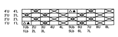
各意匠図において、縦糸はアラビア数字、例えば1、2、3・・・で示す。
横糸は、ダッシュを付したアラビア数字、例えば1'、2'、3'・・・で示す。表面側糸はUを付した数字、裏面側糸はLを付した数字、例えば1'U、2'L等で示す。又、表面側織物と裏面側織物とを接結する接結糸はbを付した数字で示した。
意匠図において、▲印は、第一の縦糸対における本来的には裏面側縦糸を構成する糸が表面側横糸の上に配置されていることを示し、×印は、第一の縦糸対における接結糸として機能する表面側接結糸、第二の縦糸対又は第三の縦糸対における表面側縦糸が表面側横糸の上に配置されていることを示し、△印は、第一の縦糸対における接結糸として機能する表面側接結糸が裏面側横糸の下に配置されていることを示し、○印は、第一の縦糸対における接結糸として機能する裏面側接結糸、第二の縦糸対又は第三の縦糸対における裏面側縦糸が裏面側横糸の下に配置されていることを示している。
下記本実施形態の説明中における、ナックルとは縦糸が1本または複数本の横糸の上、または下を通って表面に突出した部分をいい、クリンプとは横糸が複数本の縦糸の上または下を通って表面に形成した長い浮きをいう。
Hereinafter, embodiments according to the present invention will be described with reference to the drawings. Here, the design drawing is the smallest repeating unit of the woven fabric structure and corresponds to the complete structure of the woven fabric. The woven fabric described in the claims according to the present invention corresponds to this complete structure. The final product is completed by arbitrarily joining the complete structure vertically and horizontally.
In each design drawing, the warp threads are indicated by Arabic numerals, for example 1, 2, 3 ...
The weft is indicated by an Arabic numeral with a dash, for example, 1', 2', 3'... The front side yarn is indicated by a number with U, and the back side yarn is indicated by a number with L, for example, 1'U, 2'L and the like. Further, the knotting yarn for connecting the front side woven fabric and the back side woven fabric is indicated by a number with b.
In the design drawing, the ▲ mark indicates that the threads that originally constitute the back surface side warp threads in the first warp thread pair are arranged on the front surface side weft threads, and the × mark indicates that in the first warp thread pair. A surface-side knot, a second warp pair or a third warp pair, which functions as a knot, indicates that the surface-side warp is arranged on the surface-side weft, and a Δ mark indicates the first warp. The front side tie that functions as the tie in the pair indicates that the front side tie is placed under the back side weft, and the circles indicate the back side tie that functions as the tie in the first warp pair. It indicates that the back surface side warp threads in the second warp thread pair or the third warp thread pair are arranged below the back surface side weft threads.
In the following description of the present embodiment, the knuckle is a portion where one or more warp threads are above or below the weft threads and protrudes to the surface, and the crimp is above or below the warp threads having a plurality of weft threads. A long float formed on the surface through the surface.
実施形態1
図1は、本発明に係る実施形態1の不織布用二層織物の完全組織を示す意匠図である。また図2は図1に示す意匠図における縦糸に沿った断面図を示している。また図1において、第三の縦糸対(4Uと4L及び8Uと8L)は、表面側縦糸が並置されているため、便宜上2列に分けて記載してある。
図1に示す実施形態1に係る不織布用二層織物は、左側から1つの第一の縦糸対(1Ubと1Lb)、2つの第二の縦糸対(2Uと2L及び3Uと3L)、1つの第三の縦糸対(4Uと3L)、1つの第一の縦糸対(5Ubと5Lb)、2つの第二の縦糸対(6Uと6L及び7Uと7L)、1つの第三の縦糸対(8Uと8L)、及び表面側横糸1’U,2’U,3’U,4’Uと、裏面側横糸1’L,2’L,3’L,4’Lによって構成された表面平織組織による二層織物である。
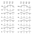
FIG. 1 is a design diagram showing the complete structure of the two-layer woven fabric for non-woven fabric according to the first embodiment of the present invention. Further, FIG. 2 shows a cross-sectional view taken along the warp in the design drawing shown in FIG. Further, in FIG. 1, the third warp yarn pair (4U and 4L and 8U and 8L) is described in two rows for convenience because the surface side warp yarns are juxtaposed.
The two-layer woven fabric for non-woven fabric according to the first embodiment shown in FIG. 1 has one first warp pair (1Ub and 1Lb), two second warp pairs (2U and 2L and 3U and 3L) from the left side. Third warp pair (4U and 3L), one first warp pair (5Ub and 5Lb), two second warp pairs (6U and 6L and 7U and 7L), one third warp pair (8U) And 8L), and a surface plain weave structure composed of front surface side weft threads 1'U, 2'U, 3'U, 4'U and back surface side weft threads 1'L, 2'L, 3'L, 4'L. It is a two-layer woven fabric by.
図2に示す如く、第一の縦糸対を構成する接結糸として機能する表面側縦糸1Ubは、裏面側横糸1’Lの下側を通って裏面側ナックルを形成し、次いで表面側横糸2’Uと裏面側横糸2’Lとの間を通った後、表面側横糸3’Uの上側を通って表面側ナックルを形成した後、表面側横糸4’Uと裏面側横糸4’Lとの間を通って織り合わされている。また、第一の縦糸対を構成する接結糸として機能する裏面側縦糸1Lbは、表面側横糸1’Uの上側を通って表面側ナックルを形成し、次いで表面側横糸2’Uと裏面側横糸2’Lとの間を通った後、裏面側横糸3’Lの下側を通って裏面側ナックルを形成した後、表面側横糸4’Uと裏面側横糸4’Lとの間を通って織り合わされている。
また、第二の縦糸対を構成する表面側縦糸2Uは、表面側横糸1’Uの下側を通った後、表面側横糸2’Uの上側を通って表面側ナックルを形成し、次いで表面側横糸3’Uの下側を通った後、表面側横糸4’Uの上側を通って再び表面側ナックルを形成するように織り合わされている。また、第二の縦糸対を構成する裏面側縦糸2Lは、裏面側横糸1’Lの上側を通った後、表面側横糸2’Lの下側を通って裏面側ナックルを形成し、次いで裏面側横糸3’Lの上側を通った後、裏面側横糸4’Lの下側を通って再び裏面側ナックルを形成するように織り合わされている。
また、第二の縦糸対を構成する表面側縦糸3Uは、表面側横糸1’Uの上側を通って表面側ナックルを形成し、次いで表面側横糸2’Uの下側を通った後、表面側横糸3’Uの上側を通って再び表面側ナックルを形成した後、表面側横糸4’Uの下を通って織り合わされている。また、第二の縦糸対を構成する裏面側縦糸3Lは、裏面側横糸1’Lの下側を通って裏面側ナックルを形成し、次いで裏面側横糸2’Lの上側を通った後、裏面側横糸3’Lの下側を通って再び裏面側ナックルを形成した後、裏面側横糸4’Lの上を通って織り合わされている。
As shown in FIG. 2, the front surface side warp yarn 1Ub that functions as a knotting yarn constituting the first warp yarn pair passes under the back surface side weft yarn 1'L to form a back surface side knuckle, and then the front surface side weft yarn 2 After passing between the'U and the back side weft 2'L, and then passing above the front side weft 3'U to form a front side knuckle, the front side weft 4'U and the back side weft 4'L It is woven through the space. Further, the back surface side warp yarn 1Lb which functions as a knotting yarn constituting the first warp yarn pair passes above the front surface side weft yarn 1'U to form a front surface side knuckle, and then the front surface side weft yarn 2'U and the back surface side. After passing between the weft 2'L and the back side weft 3'L to form a back side knuckle, it passes between the front side weft 4'U and the back side weft 4'L. Is woven together.
Further, the
Further, the
また、第三の縦糸対を構成する表面側縦糸4Uは、表面側横糸1’Uの下側を通った後、表面側横糸2’Uの上側を通って表面側ナックルを形成し、次いで表面側横糸3’Uの下側を通った後、表面側横糸4’Uの上側を通って再び表面側ナックルを形成するように織り合わされている。また、第三の縦糸対を構成する表面側縦糸4Uは、表面側横糸1’Uの上側を通って表面側ナックルを形成した後、表面側横糸2’Uの下側を通って、次いで表面側横糸3’Uの上側を通って表面側ナックルを形成した後、表面側横糸4’Uの下側を通って織り合わされている。
また、第一の縦糸対を構成する接結糸として機能する表面側縦糸5Ubは、表面側横糸1’Uと裏面側横糸1’Lとの間を通った後、表面側横糸2’Uの上側を通って表面側ナックルを形成し、次いで表面側横糸3’Uと裏面側横糸3’Lとの間を通った後、裏面側横糸4’Lの下側を通って裏面側ナックルを形成している。また、第一の縦糸対を構成する接結糸として機能する裏面側縦糸5Lbは、表面側横糸1’Uと裏面側横糸1’Lとの間を通った後、裏面側横糸2’Lの下側を通って裏面側ナックルを形成し、次いで表面側横糸3’Uと裏面側横糸3’Lとの間を通った後、表面側横糸4’Uの上側を通って表面側ナックルを形成している。
Further, the
Further, the front surface side warp yarn 5Ub that functions as the knotting yarn that constitutes the first warp yarn pair passes between the front surface side weft yarn 1'U and the back surface side weft yarn 1'L, and then the front surface side weft yarn 2'U. The front side knuckle is formed through the upper side, then the front side weft 3'U and the back side weft 3'L are passed, and then the back side knuckle is formed through the lower side of the back side weft 4'L. doing. Further, the back surface side warp yarn 5Lb that functions as the knotting yarn that constitutes the first warp yarn pair passes between the front surface side weft yarn 1'U and the back surface side weft yarn 1'L, and then the back surface side weft yarn 2'L. The back side knuckle is formed through the lower side, then the front side weft 3'U and the back side weft 3'L are passed, and then the front side knuckle is formed through the upper side of the front side weft 4'U. doing.
また、第二の縦糸対を構成する表面側縦糸6Uは、表面側横糸1’Uの上側を通って表面側ナックルを形成し、次いで表面側横糸2’Uの下側を通った後、表面側横糸3’Uの上側を通って再び表面側ナックルを形成した後、表面側横糸4’Uの下を通って織り合わされている。また、第二の縦糸対を構成する表面側縦糸6Lは、裏面側横糸1’Lの下側を通って裏面側ナックルを形成した後、裏面側横糸2’Lの上側を通った後、次いで裏面側横糸3’Lの下側を通って再び裏面側ナックルを形成し、次いで裏面側横糸4’Lの上側を通って織り合わされている。
また、第二の縦糸対を構成する表面側縦糸7Uは、表面側横糸1’Uの下側を通った後、ついで表面側横糸2’Uの上側を通って表面側ナックルを形成し、次いで表面側横糸3’Uの下側を通った後、表面側横糸4’Uの上側を通って再び表面側ナックルを形成している。また、第二の縦糸対を構成する表面側縦糸7Lは、裏面側横糸1’Lの上側を通った後、次いで裏面側横糸2’Lの下側を通って裏面側ナックルを形成した後、裏面側横糸3’Lの上側を通った後、次いで裏面側横糸4’Lの下側を通って再び裏面側ナックルを形成している。
さらに、第三の縦糸対を構成する表面側縦糸8Uは、表面側横糸1’Uの上側を通って表面側ナックルを形成した後、表面側横糸2’Uの下側を通って、次いで表面側横糸3’Uの上側を通って再び表面側ナックルを形成した後、表面側横糸4’Uの下側を通って織り合わされている。さらに、第三の縦糸対を構成する表面側縦糸8Uは、表面側横糸1’Uの下側を通った後、表面側横糸2’Uの上側を通って表面側ナックルを形成した後、次いで表面側横糸3’Uの下側を通った後、表面側横糸4’Uの上側を通って再び表面側ナックルを形成している。
Further, the
Further, the
Further, the surface-
上述の構成を有することによって、本実施形態1に係る不織布用二層織物は、表面に平織組織を形成している。表面に規則正しく平織組織を形成することによって、不織布を支持する織物における表面密度を均一に保持し、シートサポート性を向上させている。
また、第二の縦糸対及び第三の縦糸対を、完全組織中に存在する2つの第一の縦糸対の間に3つ配置することによって、接結糸の表面側ナックルに生じる交点支持力を織物全体で緩和することによって、繊維の刺さり込みを抑止することができる。
さらに、第二の縦糸対を2つ並べて配置することによって、織物の剛性を強化することができる。そのため、織物の内部に補助横糸等を配置することなく、織物のヨコ剛性及びナナメ剛性を向上させることができる。
By having the above-mentioned structure, the two-layer woven fabric for non-woven fabric according to the first embodiment forms a plain weave structure on the surface. By regularly forming a plain weave structure on the surface, the surface density of the woven fabric supporting the non-woven fabric is uniformly maintained, and the sheet supportability is improved.
Further, by arranging three pairs of the second warp and the third pair of warp between the two pairs of the first warp existing in the complete structure, the intersection bearing force generated on the surface side knuckle of the knotted yarn is generated. By relaxing the entire woven fabric, it is possible to prevent fiber sticking.
Further, by arranging two pairs of second warp threads side by side, the rigidity of the woven fabric can be enhanced. Therefore, the weft rigidity and the naname rigidity of the woven fabric can be improved without arranging the auxiliary weft threads or the like inside the woven fabric.
1U,3U,4U,5U,7U,8U,9U,10U 表面側縦糸
3L,4L,57L,8L,9L,10L 裏面側縦糸
2Ub,6Ub 表面側接結糸
2Lb,6Lb 裏面側接結糸
1LU,5LU 織物の配置上、本来的には裏面側縦糸を構成する第二の縦糸対を構成する表面側縦糸
2’U,4’U,6’U,8’U 表面側横糸
2’L,4’L,6’L,8’L 裏面側横糸
1’S,3’S,5’S,7’S 補助横糸
1U, 3U, 4U, 5U, 7U, 8U, 9U, 10U
Claims (5)
Priority Applications (6)
| Application Number | Priority Date | Filing Date | Title |
|---|---|---|---|
| JP2016090923A JP6822782B2 (en) | 2016-04-28 | 2016-04-28 | Two-layer woven fabric for non-woven fabric |
| PCT/JP2017/004322 WO2017187705A1 (en) | 2016-04-28 | 2017-02-07 | Two-layer textile for nonwoven fabric |
| CA3016404A CA3016404A1 (en) | 2016-04-28 | 2017-02-07 | Two-layer fabric for unwoven fabric |
| EP17788994.6A EP3450599B1 (en) | 2016-04-28 | 2017-02-07 | Two-layer textile for nonwoven fabric |
| KR1020187032375A KR102600840B1 (en) | 2016-04-28 | 2017-02-07 | Two-ply fabric for nonwovens |
| US16/096,555 US20190136422A1 (en) | 2016-04-28 | 2017-02-07 | Two-layer fabric for unwoven fabric |
Applications Claiming Priority (1)
| Application Number | Priority Date | Filing Date | Title |
|---|---|---|---|
| JP2016090923A JP6822782B2 (en) | 2016-04-28 | 2016-04-28 | Two-layer woven fabric for non-woven fabric |
Publications (2)
| Publication Number | Publication Date |
|---|---|
| JP2017197883A JP2017197883A (en) | 2017-11-02 |
| JP6822782B2 true JP6822782B2 (en) | 2021-01-27 |
Family
ID=60161398
Family Applications (1)
| Application Number | Title | Priority Date | Filing Date |
|---|---|---|---|
| JP2016090923A Active JP6822782B2 (en) | 2016-04-28 | 2016-04-28 | Two-layer woven fabric for non-woven fabric |
Country Status (6)
| Country | Link |
|---|---|
| US (1) | US20190136422A1 (en) |
| EP (1) | EP3450599B1 (en) |
| JP (1) | JP6822782B2 (en) |
| KR (1) | KR102600840B1 (en) |
| CA (1) | CA3016404A1 (en) |
| WO (1) | WO2017187705A1 (en) |
Families Citing this family (1)
| Publication number | Priority date | Publication date | Assignee | Title |
|---|---|---|---|---|
| KR20230005342A (en) | 2020-10-23 | 2023-01-09 | 닛폰 휘루콘 가부시키가이샤 | Fabrics and conveyor belts for non-woven fabrics |
Family Cites Families (11)
| Publication number | Priority date | Publication date | Assignee | Title |
|---|---|---|---|---|
| GB1028142A (en) * | 1962-03-02 | 1966-05-04 | Lister & Company Ltd | Textile insulating material having spaced ground fabrics |
| JP2558154B2 (en) | 1988-08-31 | 1996-11-27 | 日本フイルコン株式会社 | Single woven fabric for papermaking with auxiliary wefts placed in the recesses on the papermaking surface |
| CA2155223C (en) * | 1990-06-29 | 1997-11-11 | Paul Dennis Trokhan | Papermaking fabric |
| CA2304075A1 (en) * | 1997-09-18 | 1999-03-25 | Larry Leroy Huston | Multiple layer foraminous belts with fugitive tie yarns |
| US7861747B2 (en) * | 2008-02-19 | 2011-01-04 | Voith Patent Gmbh | Forming fabric having exchanging and/or binding warp yarns |
| JP5711946B2 (en) * | 2010-11-30 | 2015-05-07 | 日本フイルコン株式会社 | Industrial two-layer fabric |
| JP5749795B2 (en) | 2011-04-11 | 2015-07-15 | 日本フイルコン株式会社 | Multilayer fabric for nonwoven fabric |
| JP5749796B2 (en) * | 2011-04-11 | 2015-07-15 | 日本フイルコン株式会社 | Double-layer fabric for nonwoven fabric |
| WO2014104065A1 (en) | 2012-12-27 | 2014-07-03 | 日本フイルコン株式会社 | Industrial double-layered fabric |
| TW201519300A (en) * | 2013-11-08 | 2015-05-16 | Advanced Semiconductor Eng | Semiconductor process |
| CA2920999C (en) * | 2014-03-04 | 2020-04-28 | Nippon Filcon Co., Ltd | Industrial two-layered fabric |
-
2016
- 2016-04-28 JP JP2016090923A patent/JP6822782B2/en active Active
-
2017
- 2017-02-07 CA CA3016404A patent/CA3016404A1/en active Pending
- 2017-02-07 EP EP17788994.6A patent/EP3450599B1/en active Active
- 2017-02-07 US US16/096,555 patent/US20190136422A1/en active Pending
- 2017-02-07 WO PCT/JP2017/004322 patent/WO2017187705A1/en active Application Filing
- 2017-02-07 KR KR1020187032375A patent/KR102600840B1/en active IP Right Grant
Also Published As
| Publication number | Publication date |
|---|---|
| WO2017187705A1 (en) | 2017-11-02 |
| EP3450599A1 (en) | 2019-03-06 |
| EP3450599C0 (en) | 2023-07-05 |
| EP3450599A4 (en) | 2019-11-13 |
| CA3016404A1 (en) | 2017-11-02 |
| JP2017197883A (en) | 2017-11-02 |
| EP3450599B1 (en) | 2023-07-05 |
| KR102600840B1 (en) | 2023-11-09 |
| KR20190002517A (en) | 2019-01-08 |
| US20190136422A1 (en) | 2019-05-09 |
Similar Documents
| Publication | Publication Date | Title |
|---|---|---|
| JP4819477B2 (en) | Industrial two-layer fabric | |
| JP2003013382A (en) | Industrial multilayered woven fabric | |
| JP2006348403A (en) | Double layer woven fabric for industrial use | |
| JP5749795B2 (en) | Multilayer fabric for nonwoven fabric | |
| JP6822782B2 (en) | Two-layer woven fabric for non-woven fabric | |
| JP5280160B2 (en) | Industrial multilayer fabric with drawn wefts | |
| JP5777826B2 (en) | Industrial two-layer fabric | |
| JP6145565B2 (en) | Industrial two-layer fabric | |
| JP2006322108A (en) | Industrial two-layered woven fabric | |
| JP2008138309A (en) | Industrial double layered woven fabric in which vertical grooves are formed | |
| JP2013501153A (en) | Forming fabric for manufacturing fibrous web materials | |
| JP2003155680A (en) | Industrial multilayered woven fabric | |
| WO2023276311A1 (en) | Industrial fabric | |
| JP6475063B2 (en) | Seam felt for papermaking | |
| JP2022015983A (en) | Industrial fabric | |
| JP4588535B2 (en) | Industrial single-layer fabric that forms uneven surfaces | |
| JP2019014993A (en) | Seam felt base fabric for paper making | |
| JP2018035472A (en) | Seam felt for paper making, and method of manufacturing the same |
Legal Events
| Date | Code | Title | Description |
|---|---|---|---|
| A521 | Request for written amendment filed |
Free format text: JAPANESE INTERMEDIATE CODE: A523 Effective date: 20160609 |
|
| A621 | Written request for application examination |
Free format text: JAPANESE INTERMEDIATE CODE: A621 Effective date: 20190404 |
|
| A131 | Notification of reasons for refusal |
Free format text: JAPANESE INTERMEDIATE CODE: A131 Effective date: 20200526 |
|
| A521 | Request for written amendment filed |
Free format text: JAPANESE INTERMEDIATE CODE: A523 Effective date: 20200727 |
|
| RD02 | Notification of acceptance of power of attorney |
Free format text: JAPANESE INTERMEDIATE CODE: A7422 Effective date: 20200924 |
|
| RD04 | Notification of resignation of power of attorney |
Free format text: JAPANESE INTERMEDIATE CODE: A7424 Effective date: 20201006 |
|
| TRDD | Decision of grant or rejection written | ||
| A01 | Written decision to grant a patent or to grant a registration (utility model) |
Free format text: JAPANESE INTERMEDIATE CODE: A01 Effective date: 20210105 |
|
| A61 | First payment of annual fees (during grant procedure) |
Free format text: JAPANESE INTERMEDIATE CODE: A61 Effective date: 20210107 |
|
| R150 | Certificate of patent or registration of utility model |
Ref document number: 6822782 Country of ref document: JP Free format text: JAPANESE INTERMEDIATE CODE: R150 |
|
| R250 | Receipt of annual fees |
Free format text: JAPANESE INTERMEDIATE CODE: R250 |