JP6819078B2 - Encoder, robot, and encoder-integrated motor - Google Patents
Encoder, robot, and encoder-integrated motor Download PDFInfo
- Publication number
- JP6819078B2 JP6819078B2 JP2016107163A JP2016107163A JP6819078B2 JP 6819078 B2 JP6819078 B2 JP 6819078B2 JP 2016107163 A JP2016107163 A JP 2016107163A JP 2016107163 A JP2016107163 A JP 2016107163A JP 6819078 B2 JP6819078 B2 JP 6819078B2
- Authority
- JP
- Japan
- Prior art keywords
- encoder
- shaft
- gear
- housing
- magnet
- Prior art date
- Legal status (The legal status is an assumption and is not a legal conclusion. Google has not performed a legal analysis and makes no representation as to the accuracy of the status listed.)
- Active
Links
Images


Description
この発明は、エンコーダー、ロボット、及びエンコーダー一体型モーターに関する。
The present invention, encoders, robot, and to encoder integrated motor.
光学式エンコーダー装置と磁気式エンコーダー装置とを備えたアブソリュートエンコーダーの研究や開発が行われている。 Research and development of absolute encoders equipped with an optical encoder device and a magnetic encoder device are being carried out.
これに関し、歯車機構を備えた位置検出装置と、光学式エンコーダー装置とがハウジング内に収納されているエンコーダーであって、ハウジングが歯車機構と光学式エンコーダー装置とを隔離するように構成されているエンコーダーが知られている(特許文献1参照)。具体的には、当該エンコーダーでは、ハウジング内において歯車機構の歯車の上方に配置されたベアリングによって歯車機構と光学式エンコーダー装置との間が隔離される。これにより、当該エンコーダーは、歯車機構から光学式エンコーダー装置へのグリースや摩耗粉等の侵入を遮蔽することができる。 In this regard, a position detector equipped with a gear mechanism and an optical encoder device are encoders housed in a housing, and the housing is configured to separate the gear mechanism from the optical encoder device. Encoders are known (see Patent Document 1). Specifically, in the encoder, a bearing arranged above the gear of the gear mechanism in the housing separates the gear mechanism from the optical encoder device. As a result, the encoder can block the intrusion of grease, abrasion powder, etc. from the gear mechanism into the optical encoder device.
しかしながら、このようなエンコーダーは、ベアリングを備えていない場合と比較して、ベアリングの分だけ大きさが大きくなってしまい、小型化することが困難な場合があった。 However, such an encoder may be difficult to miniaturize because the size of the encoder is increased by the amount of the bearing as compared with the case where the encoder is not provided with the bearing.
上記課題の少なくとも一つを解決するために本発明の一態様は、歯車を有する第1位置検出器と、光学検出器を有する第2位置検出器と、前記歯車と前記光学検出器との間を、シール部を介して隔離する第1筐体と、を備えるエンコーダーである。
この構成により、エンコーダーは、シール部を介して歯車と光学検出器との間を隔離する。これにより、エンコーダーは、シール部を介して歯車と光学検出器との間を隔離しつつ小型化することができる。
In order to solve at least one of the above problems, one aspect of the present invention is between a first position detector having a gear, a second position detector having an optical detector, and the gear and the optical detector. Is an encoder including a first housing that separates the above with a seal portion.
With this configuration, the encoder isolates between the gear and the optical detector via a seal. As a result, the encoder can be miniaturized while separating the gear and the optical detector via the seal portion.
また、本発明の他の態様は、エンコーダーにおいて、前記シール部は、オイルシールである、構成が用いられてもよい。
この構成により、エンコーダーでは、シール部は、オイルシールである。これにより、エンコーダーは、オイルシールを介して歯車と光学検出器との間を隔離しつつ小型化することができる。
Further, in another aspect of the present invention, in the encoder, the seal portion may be an oil seal.
With this configuration, in the encoder, the seal portion is an oil seal. As a result, the encoder can be miniaturized while separating the gear and the optical detector via the oil seal.
また、本発明の他の態様は、エンコーダーにおいて、前記光学検出器は、光学素子が設けられ、第1貫通孔を有する光学基板と、第2貫通孔を有する光学ディスクとを有し、前記第1貫通孔と前記第2貫通孔を用いて、前記光学基板と前記光学ディスクとが位置決め可能である、構成が用いられてもよい。
この構成により、エンコーダーでは、第1貫通孔と第2貫通孔を用いて、光学基板と光学ディスクとが位置決め可能である。これにより、エンコーダーは、組み立て時において光学基板と光学ディスクとの相対的な位置がずれてしまうことによる誤差を抑制することができる。
In another aspect of the present invention, in the encoder, the optical detector has an optical substrate provided with an optical element and having a first through hole, and an optical disk having a second through hole. A configuration may be used in which the optical substrate and the optical disk can be positioned by using the first through hole and the second through hole.
With this configuration, in the encoder, the optical substrate and the optical disk can be positioned by using the first through hole and the second through hole. As a result, the encoder can suppress an error due to the relative position of the optical substrate and the optical disc being displaced during assembly.
また、本発明の他の態様は、エンコーダーにおいて、前記第1位置検出器は、第1歯車と、前記第1歯車に設けられた第1シャフトと、を有し、前記シール部は、前記第1シャフトと前記第1筐体との間に位置する、構成が用いられてもよい。
この構成により、エンコーダーでは、シール部は、第1シャフトと第1筐体との間に位置する。これにより、エンコーダーは、第1シャフトと第1筐体との間に位置するシール部によって歯車と光学検出器との間を隔離しつつ小型化することができる。
Further, in another aspect of the present invention, in the encoder, the first position detector has a first gear and a first shaft provided on the first gear, and the seal portion is the first gear. A configuration may be used that is located between the shaft and the first housing.
With this configuration, in the encoder, the seal portion is located between the first shaft and the first housing. As a result, the encoder can be miniaturized while separating the gear and the optical detector by a seal portion located between the first shaft and the first housing.
また、本発明の他の態様は、エンコーダーにおいて、前記第1位置検出器は、前記第1シャフトに設けられた第1磁石と、前記第1磁石から出る磁束を検出する第1磁束検出素子と、を有する、構成が用いられてもよい。
この構成により、エンコーダーでは、第1位置検出器は、第1シャフトに設けられた第1磁石と、第1磁石から出る磁束を検出する第1磁束検出素子と、を有する。これにより、エンコーダーは、第1位置検出器によって第1シャフトの角度位置を検出することができる。
Further, in another aspect of the present invention, in the encoder, the first position detector includes a first magnet provided on the first shaft and a first magnetic flux detecting element for detecting the magnetic flux emitted from the first magnet. , A configuration having, may be used.
With this configuration, in the encoder, the first position detector has a first magnet provided on the first shaft and a first magnetic flux detecting element for detecting the magnetic flux emitted from the first magnet. As a result, the encoder can detect the angular position of the first shaft by the first position detector.
また、本発明の他の態様は、エンコーダーにおいて、前記第1位置検出器は、前記第1歯車と噛み合う第2歯車と、前記第2歯車に設けられた第2磁石と、を有し、前記第2磁石と前記シール部は同一平面上に位置する、構成が用いられてもよい。
この構成により、エンコーダーでは、第1位置検出器は、第1歯車と噛み合う第2歯車と、第2歯車に設けられた第2磁石と、を有し、第2磁石とシール部は同一平面上に位置する。これにより、エンコーダーは、第2磁石と同一平面上に位置するシール部によって歯車と光学検出器との間を隔離しつつ小型化することができる。
Another aspect of the present invention is that in the encoder, the first position detector has a second gear that meshes with the first gear and a second magnet provided on the second gear. A configuration may be used in which the second magnet and the seal portion are located on the same plane.
With this configuration, in the encoder, the first position detector has a second gear that meshes with the first gear and a second magnet provided on the second gear, and the second magnet and the seal portion are on the same plane. Located in. As a result, the encoder can be miniaturized while separating the gear and the optical detector by a seal portion located on the same plane as the second magnet.
また、本発明の他の態様は、エンコーダーにおいて、前記第1位置検出器は、前記第2磁石から出る磁束を検出する第2磁束検出素子を有し、前記第1筐体は、前記第2磁石と前記第2磁束検出素子との間に位置する第1部分を有する、構成が用いられてもよい。
この構成により、エンコーダーでは、第1位置検出器は、第2磁石から出る磁束を検出する第2磁束検出素子を有し、第1筐体は、第2磁石と第2磁束検出素子との間に位置する第1部分を有する。これにより、エンコーダーは、第2磁石と第2磁束検出素子との相対的な距離が変化してしまうことを抑制することができる。
In another aspect of the present invention, in the encoder, the first position detector has a second magnetic flux detecting element for detecting the magnetic flux emitted from the second magnet, and the first housing has the second. A configuration may be used that has a first portion located between the magnet and the second magnetic flux detecting element.
With this configuration, in the encoder, the first position detector has a second magnetic flux detecting element that detects the magnetic flux emitted from the second magnet, and the first housing is between the second magnet and the second magnetic flux detecting element. It has a first portion located in. As a result, the encoder can suppress the relative distance between the second magnet and the second magnetic flux detecting element from changing.
また、本発明の他の態様は、エンコーダーにおいて、前記第1位置検出器は、前記第2磁束検出素子が設けられた磁気基板を有し、前記第1筐体に設けられた挿入部材又は前記第1筐体に形成された突起部により、前記第1筐体と前記磁気基板とが位置決め可能である、構成が用いられてもよい。
この構成により、エンコーダーでは、第1位置検出器は、第2磁束検出素子が設けられた磁気基板を有し、第1筐体に設けられた挿入部材又は第1筐体に形成された突起部により、第1筐体と磁気基板とが位置決め可能である。これにより、エンコーダーは、第1筐体と磁気基板との相対的な位置がずれてしまうことを抑制することができる。
In another aspect of the present invention, in the encoder, the first position detector has a magnetic substrate provided with the second magnetic flux detecting element, and is an insertion member provided in the first housing or the said. A configuration may be used in which the first housing and the magnetic substrate can be positioned by the protrusions formed on the first housing.
With this configuration, in the encoder, the first position detector has a magnetic substrate provided with a second magnetic flux detecting element, and is an insertion member provided in the first housing or a protrusion formed in the first housing. Therefore, the first housing and the magnetic substrate can be positioned. As a result, the encoder can prevent the relative positions of the first housing and the magnetic substrate from shifting.
また、本発明の他の態様は、エンコーダーにおいて、前記第1位置検出器は、前記第2歯車に挿通された第2シャフトを有し、前記第2シャフトは、モーターの筐体に形成された凹部に挿通されている、構成が用いられてもよい。
この構成により、エンコーダーでは、第2シャフトは、モーターの筐体に形成された凹部に挿通されている。これにより、エンコーダーは、第2シャフトを挿通するための他の部材を必要としないため、第2シャフトの軸方向におけるエンコーダーの大きさを小さくすることができる。
Further, in another aspect of the present invention, in the encoder, the first position detector has a second shaft inserted through the second gear, and the second shaft is formed in the housing of the motor. A configuration that is inserted through the recess may be used.
With this configuration, in the encoder, the second shaft is inserted into a recess formed in the housing of the motor. As a result, since the encoder does not require another member for inserting the second shaft, the size of the encoder in the axial direction of the second shaft can be reduced.
また、本発明の他の態様は、エンコーダーにおいて、前記第1シャフトの端部に凹部が形成され、前記第1シャフトの軸方向において、前記凹部を用いて、前記第2位置検出器が有する光学ディスクと前記第1シャフトとの位置決め可能である、構成が用いられてもよい。
この構成により、エンコーダーでは、第1シャフトの軸方向において、第1シャフトの凹部を用いて、第2位置検出器が有する光学ディスクと第1シャフトとの位置決め可能である。これにより、エンコーダーは、第1シャフトと光学ディスクとの相対的な位置がずれてしまうことを抑制することができる。
Further, in another aspect of the present invention, in the encoder, a recess is formed at the end of the first shaft, and the recess is used in the axial direction of the first shaft to have an optical function of the second position detector. A configuration may be used in which the disc and the first shaft can be positioned.
With this configuration, the encoder can position the optical disc of the second position detector and the first shaft in the axial direction of the first shaft by using the recess of the first shaft. As a result, the encoder can prevent the relative positions of the first shaft and the optical disc from shifting.
また、本発明の他の態様は、エンコーダーにおいて、前記第1筐体は、樹脂を含む、構成が用いられてもよい。
この構成により、エンコーダーでは、第1筐体は、樹脂を含む。これにより、エンコーダーは、エンコーダー3に熱を伝える物体からの光学検出器への伝熱を抑制し、光学検出器の熱膨張を抑制することができる。
Further, in another aspect of the present invention, in the encoder, the first housing may include a resin.
With this configuration, in the encoder, the first housing contains resin. As a result, the encoder can suppress heat transfer from an object that transfers heat to the
また、本発明の他の態様は、上記に記載のエンコーダーを備える、モーターである。
この構成により、モーターは、エンコーダーにおいて、シール部を介して歯車と光学検出器との間を隔離する。これにより、モーターは、エンコーダーを含む全体の大きさを小型化することができる。
Another aspect of the present invention is a motor comprising the encoder described above.
With this configuration, the motor isolates between the gear and the optical detector in the encoder via a seal. As a result, the motor can be reduced in overall size including the encoder.
また、本発明の他の態様は、上記に記載のモーターを備える、ロボットである。
この構成により、ロボットは、モーターが備えるエンコーダーにおいて、シール部を介して歯車と光学検出器との間を隔離する。これにより、ロボットは、エンコーダーを備えるモーターを含む全体の大きさを小型化することができる。
Another aspect of the present invention is a robot comprising the motor described above.
With this configuration, the robot isolates the gear from the optical detector via a seal in the encoder included in the motor. This allows the robot to reduce its overall size, including the motor with the encoder.
以上により、エンコーダーは、シール部を介して歯車と光学検出器との間を隔離する。これにより、エンコーダーは、シール部を介して歯車と光学検出器との間を隔離しつつ小型化することができる。
また、モーターは、エンコーダーにおいて、シール部を介して歯車と光学検出器との間を隔離する。これにより、モーターは、エンコーダーを含む全体の大きさを小型化することができる。
また、ロボットは、モーターが備えるエンコーダーにおいて、シール部を介して歯車と光学検出器との間を隔離する。これにより、ロボットは、エンコーダーを備えるモーターを含む全体の大きさを小型化することができる。
As described above, the encoder isolates the gear from the optical detector via the seal portion. As a result, the encoder can be miniaturized while separating the gear and the optical detector via the seal portion.
In addition, the motor isolates the gear from the optical detector via a seal in the encoder. As a result, the motor can be reduced in overall size including the encoder.
In addition, the robot isolates the gear from the optical detector via a seal portion in the encoder provided in the motor. This allows the robot to reduce its overall size, including the motor with the encoder.
<実施形態>
以下、本発明の実施形態について、図面を参照して説明する。
<Embodiment>
Hereinafter, embodiments of the present invention will be described with reference to the drawings.
<ロボットの構成>
まず、ロボット1の構成について説明する。
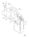
図1は、実施形態に係るロボット1の構成の一例を示す図である。ロボット1は、床面や壁面等の設置面に設置される支持台Bと、支持台Bにより第1軸AX1周りに回動可能に支持された第1アームA1と、第1アームA1により第2軸AX2周りに回動可能に支持された第2アームA2と、第2アームA2により第3軸AX3周りに回動可能且つ第3軸AX3の軸方向に並進可能に支持されたシャフトSを備えるスカラロボットである。
<Robot configuration>
First, the configuration of the
FIG. 1 is a diagram showing an example of the configuration of the
なお、ロボット1は、スカラロボットに代えて、垂直多関節ロボットや直角座標ロボット等の他のロボットであってもよい。なお、垂直多関節ロボットは、1つの腕を備える単腕ロボットであってもよく、2つの腕を備える双腕ロボット(2つの腕を備える複腕ロボット)であってもよく、3以上の腕を備える複腕ロボットであってもよい。また、直角座標ロボットは、例えば、ガントリロボットである。
The
シャフトSは、円柱形状の軸体である。シャフトSの周表面には、図示しないボールねじ溝とスプライン溝とがそれぞれ形成されている。シャフトSは、この一例において、第2アームA2の端部のうちの第1アームA1と反対側の端部を、支持台Bが設置された設置面に対して垂直な方向である第1方向に貫通し、設けられる。また、シャフトSの端部のうちの当該設置面側の端部は、エンドエフェクターを取り付け可能である。当該エンドエフェクターは、物体を把持可能なエンドエフェクターであってもよく、空気や磁気等によって物体を吸着可能なエンドエフェクターであってもよく、他のエンドエフェクターであってもよい。 The shaft S is a cylindrical shaft body. A ball screw groove and a spline groove (not shown) are formed on the peripheral surface of the shaft S, respectively. In this example, the shaft S has the end portion of the end portion of the second arm A2 opposite to the first arm A1 in the first direction which is the direction perpendicular to the installation surface on which the support base B is installed. It is provided by penetrating into. Further, an end effector can be attached to the end portion of the shaft S on the installation surface side. The end effector may be an end effector capable of gripping an object, an end effector capable of adsorbing an object by air, magnetism, or the like, or another end effector.
第1アームA1は、この一例において、第1軸AX1周りに回動するので、第2方向に移動する。第2方向は、前述の第1方向に直交する方向である。第2方向は、例えば、ワールド座標系やロボット座標系RCにおけるXY平面に沿った方向である。第1アームA1は、支持台Bが備えるモーター21によって第1軸AX1周りに回動させられる。すなわち、第1軸AX1は、モーター21の回動軸である。 In this example, the first arm A1 rotates around the first axis AX1 and thus moves in the second direction. The second direction is a direction orthogonal to the above-mentioned first direction. The second direction is, for example, a direction along the XY plane in the world coordinate system or the robot coordinate system RC. The first arm A1 is rotated around the first axis AX1 by the motor 21 included in the support base B. That is, the first shaft AX1 is a rotation shaft of the motor 21.
第2アームA2は、この一例において、第2軸AX2周りに回動するので、第2方向に移動する。第2アームA2は、第2アームA2が備えるモーター22によって第2軸AX2周りに回動させられる。すなわち、第2軸AX2は、モーター22の回動軸である。また、第2アームA2は、図示しないモーター23及び図示しないモーター24を備え、シャフトSを支持する。モーター23は、シャフトSのボールねじ溝の外周部に設けられたボールねじナットをタイミングベルト等で回動させることにより、シャフトSを第1方向に移動(昇降)させる。モーター24は、シャフトSのスプライン溝の外周部に設けられたボールスプラインナットをタイミングベルト等で回動させることにより、シャフトSを第3軸AX3周りに回動させる。
In this example, the second arm A2 rotates around the second axis AX2, so that it moves in the second direction. The second arm A2 is rotated around the second axis AX2 by the
以下では、一例として、モーター21〜モーター24のそれぞれが、すべて同じ構成を有している場合について説明する。なお、モーター21〜モーター24のうちの一部又は全部は、互いに異なる構成を有するモーターであってもよい。以下では、モーター21〜モーター24のそれぞれを区別する必要がない限り、これらをまとめてモーター2と称して説明する。
In the following, as an example, a case where each of the motors 21 to 24 has the same configuration will be described. Note that some or all of the motors 21 to 24 may be motors having different configurations from each other. In the following, unless it is necessary to distinguish between the motors 21 to 24, these will be collectively referred to as the
モーター2は、回動軸の回動角をロボット制御装置や他の装置に出力するエンコーダー3を備える。当該ロボット制御装置は、ロボット1を制御する装置である。なお、当該ロボット制御装置は、ロボット1に内蔵される構成であってもよく、ロボット1と別体の外付けである構成であってもよい。ロボット1と別体の外付けである場合、当該ロボット制御装置は、ロボット1と有線又は無線によって通信可能に接続される。
The
ここで、エンコーダー3の概要について説明する。エンコーダー3は、歯車を有する第1位置検出器11と、光学検出器13を有する第2位置検出器12と、当該歯車と光学検出器13との間を、シール部SDを介して隔離する第1筐体41と、を備える。これにより、エンコーダー3は、シール部SDを介して当該歯車と光学検出器13との間を隔離しつつ小型化することができる。エンコーダー3を小型化した場合、エンコーダー3を備えるモーター21〜モーター24のそれぞれも小型化可能である。また、モーター21〜モーター24のそれぞれが小型化された場合、ロボット1も小型化可能である。以下では、このようにロボット1の小型化を可能にするエンコーダー3について詳しく説明する。
Here, the outline of the
<エンコーダーの構成>
以下、図2〜図6を参照し、エンコーダー3の構成について説明する。
図2は、エンコーダー3の構成の一例を示す分解斜視図である。また、図3は、図2に示したエンコーダー3を他の角度から見た場合の分解斜視図である。また、図4は、図2に示したエンコーダー3の分解側面図である。また、図5は、図4に示したエンコーダー3を他の側面から見た場合の分解側面図である。また、図6は、図4に示したエンコーダー3を組み立てた場合の断面図である。なお、図2〜図6には、エンコーダー3を構成する主要な部品のみを図示してあり、一部の部品については、図示を省略している。
<Encoder configuration>
Hereinafter, the configuration of the
FIG. 2 is an exploded perspective view showing an example of the configuration of the
図2〜6に示したように、エンコーダー3は、ハウジングHG内に第1位置検出器11と、第2位置検出器12とが収納された構造を有している。第1位置検出器11は、歯車を有する磁気式エンコーダー装置である。第2位置検出器12は、光学検出器13を有する光学式エンコーダー装置である。ハウジングHGは、2つの収納部である第1収納部31と、第2収納部32とから構成される。ハウジングHGは、第1収納部31の内部に歯車部Gが収納され、第2収納部32の内部に磁気基板CB1と、光学ディスクDが設けられた台座Hと、光学基板CB2とが収納された構造を有している。
As shown in FIGS. 2 to 6, the
第1収納部31は、第1収納部31において隔壁部を構成するモータートップケースMTCと、モータートップケースMTCに固定された第1筐体41とから構成される。また、第1筐体41は、絶縁樹脂により一体成型された成形体からなり、ボルトBTによってモータートップケースMTCに固定されている。これにより、エンコーダー3は、エンコーダー3に熱を伝える物体(この一例において、モーター2)からの光学検出器への伝熱を抑制し、光学検出器の熱膨張を抑制することができる。この一例において、第1筐体41の材質は、POM(ポリアセタール)であるが、これに代えて、他の樹脂であってもよい。
The
モータートップケースMTCは、第1シャフトS1の軸方向に沿ったモーター2の端部のうちのエンコーダー3側の端部を構成する部材である。第1シャフトS1は、モーター2の回動軸としてモーター2が有する軸体である。なお、図2〜図6には、モーター2を構成する部品について、モータートップケースMTCと、第1シャフトS1との2つのみを図示してあり、他の部品については、図示を省略している。以下では、説明の便宜上、第1シャフトS1の軸方向のうちのエンコーダー3からモーター2に向かう方向を下方向と称し、モーター2からエンコーダー3に向かう方向を上方向と称して説明する。
The motor top case MTC is a member that constitutes an end portion on the
第2収納部32は、第2収納部32において隔壁部を構成する第1筐体41の上端部と、当該上端部に固定された第2筐体42と、蓋部材ECとから構成される。第2筐体42は、導電性を有する金属により一体成型された成形体からなり、ボルトBTによって当該上端部に固定されている。また、蓋部材ECは、ボルトBTによって第2筐体42に固定されている。
The
ここで、ハウジングHGの構造について簡単にまとめると、ハウジングHGは、上から下に向かって蓋部材EC、第2筐体42、第1筐体41、モータートップケースMTCの順に組み付けられ、蓋部材EC、第2筐体42、第1筐体41、モータートップケースMTCの順に上から下に向かって挿通されたボルトBT(この一例において、4本のボルトBT)によって固定されている。また、第2収納部32の内部では、光学基板CB2、台座H、磁気基板CB1のそれぞれが、上から下に向かって、光学基板CB2、台座H、磁気基板CB1の順に収納されている。
Here, to briefly summarize the structure of the housing HG, the housing HG is assembled from top to bottom in the order of the lid member EC, the
第1位置検出器11が有する複数の部材の一部は、第1収納部31に収納されており、当該一部と異なる他の部材は、第2収納部32に収納されている。具体的には、第1位置検出器11は、歯車部Gと、第1シャフトS1と、第1磁石M1と、第1磁束検出素子MD1と、第2シャフトS2と、第2磁石M2と、第2磁束検出素子MD2と、第3シャフトS3と、第3磁石M3と、第3磁束検出素子MD3と、磁気基板CB1と、光学基板CB2を有する。
A part of the plurality of members included in the first position detector 11 is housed in the
歯車部Gは、互いに歯数や直径が異なる3つの歯車である第1歯車G1と、第2歯車G2と、第3歯車G3を有する。第1歯車G1は、第1シャフトS1に連結(固定)されて第1シャフトS1とともに回動する歯車である。すなわち、この一例において、第1歯車G1の回動軸となる軸体は、第1シャフトS1である。これにより、エンコーダー3は、第1シャフトS1と別体の軸体であって第1歯車G1の回動軸となる軸体を第1シャフトS1に設ける必要がないため、振動等によって第1シャフトS1と当該軸体との組み付けがずれてしまうことを抑制することができる。第2歯車G2と第3歯車G3はそれぞれ、第1歯車G1と噛み合う歯車である。また、第2歯車G2は、第3歯車G3と噛み合っていない。また、この一例において、エンコーダー3を上下方向と直交する方向から見た場合において、第1歯車G1と、第2歯車G2と、第3歯車G3とのそれぞれの回動軸は、第2歯車G2、第1歯車G1、第3歯車G3の順に一列に並んでいる。なお、第1歯車G1と、第2歯車G2と、第3歯車G3とのそれぞれの回動軸は、当該場合、第2歯車G2と第3歯車G3とが第1歯車G1と噛み合い、第2歯車G2と第3歯車G3とが互いに噛み合わなければ、一列に並んでいなくてもよい。
The gear portion G includes a first gear G1, a second gear G2, and a third gear G3, which are three gears having different numbers of teeth and diameters. The first gear G1 is a gear that is connected (fixed) to the first shaft S1 and rotates together with the first shaft S1. That is, in this example, the shaft body serving as the rotation shaft of the first gear G1 is the first shaft S1. As a result, the
第1磁石M1は、第1シャフトS1に設けられた磁石である。第1磁石M1は、他の部材を介さずに第1シャフトS1に設けられる構成であってもよく、他の部材を介して第1シャフトS1に設けられる構成であってもよい。図2〜図6に示した例では、第1磁石M1は、当該他の部材として台座Hを介して第1シャフトS1の上端部に設けられている。第1磁石M1は、永久磁石であり、例えば、サマリウムコバルト磁石である。なお、第1磁石M1は、これに代えて、ネオジム磁石等の他の磁石であってもよい。第1磁束検出素子MD1は、第1磁石M1から出る磁束を検出し、検出した磁束を示す信号を出力するホール素子によって構成された磁束検出素子である。 The first magnet M1 is a magnet provided on the first shaft S1. The first magnet M1 may be provided on the first shaft S1 without interposing another member, or may be provided on the first shaft S1 via another member. In the example shown in FIGS. 2 to 6, the first magnet M1 is provided at the upper end portion of the first shaft S1 via the pedestal H as the other member. The first magnet M1 is a permanent magnet, for example, a samarium-cobalt magnet. The first magnet M1 may be replaced with another magnet such as a neodymium magnet. The first magnetic flux detecting element MD1 is a magnetic flux detecting element composed of a Hall element that detects the magnetic flux emitted from the first magnet M1 and outputs a signal indicating the detected magnetic flux.
第2シャフトS2は、図6に示したように、滑り軸受けとして加工された凹部DC2を有する第2歯車G2の凹部DC2に挿通された軸体である。このため、第2歯車G2は、第2シャフトS2を回動軸として第2シャフトS2周りをほぼ無負荷で回動する。また、第2シャフトS2は、モータートップケースMTC、すなわちモーター2の筐体に形成された凹部DM2に挿通されている。これにより、エンコーダー3は、第2シャフトS2を挿通するための他の部材を必要としないため、第2シャフトS2の軸方向におけるエンコーダー3の大きさを小さくすることができる。また、第2シャフトS2は、第2歯車G2を貫通せずに第2歯車G2に挿通している。第2磁石M2は、第2歯車G2の上端部に設けられた磁石である。第2磁石M2は、永久磁石であり、例えば、サマリウムコバルト磁石である。なお、第2磁石M2は、これに代えて、ネオジム磁石等の他の磁石であってもよい。第2磁束検出素子MD2は、第2磁石M2から出る磁束を検出し、検出した磁束を示す信号を出力するホール素子によって構成された磁束検出素子である。
As shown in FIG. 6, the second shaft S2 is a shaft body inserted into the recess DC2 of the second gear G2 having the recess DC2 processed as a sliding bearing. Therefore, the second gear G2 rotates around the second shaft S2 with almost no load around the second shaft S2 as a rotation shaft. Further, the second shaft S2 is inserted into the motor top case MTC, that is, the recess DM2 formed in the housing of the
第3シャフトS3は、図6に示したように、滑り軸受けとして加工された凹部DC3を有する第3歯車G3の凹部DC3に挿通された軸体である。このため、第3歯車G3は、第3シャフトS3を回動軸として第3シャフトS3周りをほぼ無負荷で回動する。また、第3シャフトS3は、モータートップケースMTC、すなわちモーター2の筐体に形成された凹部DM3に挿通されている。これにより、エンコーダー3は、第3シャフトS3を挿通するための他の部材を必要としないため、第3シャフトS3の軸方向におけるエンコーダー3の大きさを小さくすることができる。また、第3シャフトS3は、第3歯車G3を貫通せずに第3歯車G3に挿通している。第3磁石M3は、第3歯車G3の上端部に設けられた磁石である。第3磁石M3は、永久磁石であり、例えば、サマリウムコバルト磁石である。なお、第3磁石M3は、これに代えて、ネオジム磁石等の他の磁石であってもよい。第3磁束検出素子MD3は、第3磁石M3から出る磁束を検出し、検出した磁束を示す信号を出力するホール素子によって構成された磁束検出素子である。
As shown in FIG. 6, the third shaft S3 is a shaft body inserted into the recess DC3 of the third gear G3 having the recess DC3 processed as a sliding bearing. Therefore, the third gear G3 rotates around the third shaft S3 with almost no load with the third shaft S3 as the rotation axis. Further, the third shaft S3 is inserted into the motor top case MTC, that is, the recess DM3 formed in the housing of the
磁気基板CB1は、第2磁束検出素子MD2及び第3磁束検出素子MD3が設けられた基板である。なお、磁気基板CB1は、2以上に分割された基板を組み合わせた基板であってもよい。
光学基板CB2は、第1磁束検出素子MD1が設けられた基板である。なお、光学基板CB2は、2以上に分割された基板を組み合わせた基板であってもよい。
The magnetic substrate CB1 is a substrate provided with the second magnetic flux detecting element MD2 and the third magnetic flux detecting element MD3. The magnetic substrate CB1 may be a substrate in which a substrate divided into two or more is combined.
The optical substrate CB2 is a substrate provided with the first magnetic flux detecting element MD1. The optical substrate CB2 may be a substrate in which a substrate divided into two or more is combined.
第1位置検出器11は、第1磁束検出素子MD1によって検出された第1磁石M1から出る磁束に基づいて、第1シャフトS1(又は第1シャフトS1とともに回動する第1歯車G1)の角度位置を検出する。また、第1位置検出器11は、第2磁束検出素子MD2によって検出された第2磁石M2から出る磁束に基づいて、第2歯車G2の角度位置を検出する。また、第1位置検出器11は、第3磁束検出素子MD3によって検出された第3磁石M3から出る磁束に基づいて、第3歯車G3の角度位置を検出する。 The first position detector 11 determines the angle of the first shaft S1 (or the first gear G1 that rotates together with the first shaft S1) based on the magnetic flux emitted from the first magnet M1 detected by the first magnetic flux detecting element MD1. Detect the position. Further, the first position detector 11 detects the angular position of the second gear G2 based on the magnetic flux emitted from the second magnet M2 detected by the second magnetic flux detecting element MD2. Further, the first position detector 11 detects the angular position of the third gear G3 based on the magnetic flux emitted from the third magnet M3 detected by the third magnetic flux detecting element MD3.
ここで、第1位置検出器11では、第1筐体41は、第2磁石M2と第2磁束検出素子MD2との間に位置する第1部分P1を有する。具体的には、図6に示したように、第2磁石M2は、第1筐体41の上端部の一部(すなわち、第1部分P1)を挟んで第2磁束検出素子MD2と対向している。これにより、エンコーダー3は、第2磁石M2と第2磁束検出素子MD2との相対的な距離であって上下方向の距離が変化してしまうことを抑制することができる。その結果、エンコーダー3は、このような距離の変化に基づく第2歯車G2の角度位置の検出誤差を抑制することができる。
Here, in the first position detector 11, the
また、第1位置検出器11では、第1筐体41は、第3磁石M3と第3磁束検出素子MD3との間に位置する第2部分P2を有する。具体的には、図6に示したように、第3磁石M3は、第1筐体41の上端部の一部(すなわち、第2部分P2)を挟んで第3磁束検出素子MD3と対向している。これにより、エンコーダー3は、第3磁石M3と第3磁束検出素子MD3との相対的な距離であって上下方向の距離が変化してしまうことを抑制することができる。その結果、エンコーダー3は、このような距離の変化に基づく第3歯車G3の角度位置の検出誤差を抑制することができる。
Further, in the first position detector 11, the
第2位置検出器12は、光学検出器13を有し、光を利用して第1シャフトS1の角度位置を検出する。光学検出器13は、第1シャフトS1に固定された台座Hと、台座Hの上面に設けられた(固定された)光学ディスクDと、光学基板CB2に設けられた(固定された)光学素子LDと、図示しない発光素子を有する。
The second position detector 12 has an
光学ディスクDには、周方向に並ぶ複数のスリットからなる複数のスリット列が形成されている。ここで、第2位置検出器12の構成は、公知であるため、説明を省略する。なお、光学ディスクDのスリットは、透過型であってもよく、反射型であってもよい。前述した通り、この一例では、光学ディスクDは、磁気基板CB1と光学基板CB2との間に配置されている。なお、磁気基板CB1と光学基板CB2とは、図示しない電気的接続部材によって電気的に接続されている。 The optical disc D is formed with a plurality of slit rows composed of a plurality of slits arranged in the circumferential direction. Here, since the configuration of the second position detector 12 is known, the description thereof will be omitted. The slit of the optical disc D may be a transmissive type or a reflective type. As described above, in this example, the optical disk D is arranged between the magnetic substrate CB1 and the optical substrate CB2. The magnetic substrate CB1 and the optical substrate CB2 are electrically connected by an electrical connection member (not shown).
また、第1シャフトS1は、図6に示したように、モータートップケースMTCの下から上に向かってモータートップケースMTCの上端部、第1歯車G1、第1筐体41の上端部、磁気基板CB1の順にそれぞれを貫通している。すなわち、モータートップケースMTCの上端部と、第1歯車G1と、第1筐体41の上端部と、磁気基板CB1とのそれぞれには、第1シャフトS1が下から上に貫通する貫通孔が形成されている。
Further, as shown in FIG. 6, the first shaft S1 includes the upper end portion of the motor top case MTC, the first gear G1, the upper end portion of the
このようなエンコーダー3における第1筐体41は、前述した通り、歯車部Gが有する歯車である第1歯車G1〜第3歯車G3のそれぞれと光学検出器13との間を、シール部SDを介して隔離する。これは、第1収納部31に収納された当該歯車に塗布されたグリースや、当該歯車のうちの第1歯車G1と第2歯車G2及び第3歯車G3のそれぞれとの摩耗粉等のダストが、第2収納部32の内側に含まれる物体に付着してしまうことを抑制するためである。シール部SDは、例えば、オイルシールである。なお、シール部SDは、オイルシールに代えて、ガスケット、パッキン、防水シール等の他のシール材であってもよい。シール部SDを有するエンコーダー3は、シール部SDの代わりにベアリングを有するエンコーダーと比較して、シール部SDの大きさを小さくすることができるため、シール部SDを介して当該歯車と光学検出器13との間を隔離しつつ小型化することができる。
As described above, the
図6に示した例では、シール部SDは、第1シャフトS1と第1筐体41との間に位置している。具体的には、シール部SDは、第1筐体41を第1シャフトS1が貫通する貫通孔と、第1シャフトS1との間に配置される。これにより、エンコーダー3は、第1シャフトS1と第1筐体41との間に位置するシール部SDによって歯車部Gが有する歯車と光学検出器13との間を隔離することができる。また、当該例では、シール部SDは、第2磁石M2と第3磁石M3とのそれぞれと同一平面上に位置している。当該平面は、上下方向と直交する平面である。換言すると、上下方向と直交する方向であって第2磁石M2から第3磁石M3に向かう方向からエンコーダー3を見た場合において、シール部SDは、第2磁石M2及び第3磁石M3の両方と重なる部分を有する。これにより、エンコーダー3は、第2磁石M2及び第3磁石M3と同一平面上に位置するシール部SDによって歯車部Gが有する歯車と光学検出器13との間を隔離することができる。なお、シール部SDは、第2磁石M2と第3磁石M3とのうちいずれか一方のみと同一平面上に位置している構成であってもよい。この場合、エンコーダー3は、第2磁石M2と第3磁石M3のうちいずれか一方のみと同一平面上に位置するシール部SDによって歯車部Gが有する歯車と光学検出器13との間を隔離することができる。
In the example shown in FIG. 6, the seal portion SD is located between the first shaft S1 and the
また、シール部SDは、図7に示した断面構造を有している。図7は、シール部SDの断面構造の一例を示す図である。具体的には、図7は、シール部SDの断面のうち図6に示した枠WDによって囲まれた断面の一例を示す図である。図7に示したように、シール部SDは、第1部材SDMが第2部材SDGによって覆われていることによって構成されている。 Further, the seal portion SD has the cross-sectional structure shown in FIG. FIG. 7 is a diagram showing an example of the cross-sectional structure of the seal portion SD. Specifically, FIG. 7 is a diagram showing an example of a cross section of the seal portion SD surrounded by the frame WD shown in FIG. As shown in FIG. 7, the seal portion SD is configured by covering the first member SDM with the second member SDG.
第1部材SDMは、材質が金属の部材であり、リング形状の部材である。図7に示した第1部材SDMの断面の形状は、L字型であるが、これに限られるわけではない。第1部材SDMは、第2部材SDGが変形し、シール部SDと第1筐体41との間に間隙ができてしまうことを抑制する。図7に示したように、第1部材SDMは、第2部材SDGに覆われている。
The first member SDM is a member whose material is metal and is a ring-shaped member. The cross-sectional shape of the first member SDM shown in FIG. 7 is L-shaped, but the shape is not limited to this. The first member SDM suppresses the deformation of the second member SDG and the formation of a gap between the seal portion SD and the
第2部材SDGは、材質がゴムの部材であり、第1筐体41を第1シャフトS1が貫通する貫通孔と、第1シャフトS1との間の間隙を塞ぐ部材である。当該ゴムには、例えば、ニトリルゴム、フッ素ゴム、シリコーンゴム等が用いられるが、他の素材のゴムであってもよい。
The second member SDG is a member made of rubber, and is a member that closes the gap between the through hole through which the first shaft S1 penetrates the
ここで、エンコーダー3では、第1位置検出器11が第1歯車G1〜第3歯車G3それぞれの角度位置(多回転データ)を検出し、第2位置検出器12が第1シャフトS1(又は第1歯車G1)の1回転の角度位置を検出する。このため、エンコーダー3は、検出したこれらの角度位置に基づいて、第1シャフトS1の絶対位置を検出することができる。
Here, in the
また、エンコーダー3の第1位置検出器11では、第1歯車G1〜第3歯車G3それぞれの歯数及び直径が異なるため、第1歯車G1〜第3歯車G3それぞれの回転比率が異なる。これにより、第1位置検出器11は、第1歯車G1〜第3歯車G3それぞれの角度位置を検出し、検出した角度位置に基づく多回転データを算出することができる。また、第1位置検出器11は、多回転データを記憶(保持)するためのバッテリーを必要としない。すなわち、エンコーダー3は、シール部SDを介して歯車部Gが有する歯車と光学検出器13との間を隔離しつつ小型化することができることに加えて、更にバッテリーの体積分の大きさを小さくすることができる。このような構成は、エンコーダー3を備えるモーター2、及びモーター2を備えるロボット1それぞれをより小型化するために有効である。
Further, in the first position detector 11 of the
<エンコーダーの組み立て時における第1シャフトへの光学ディスクの組み付け>
以下、再び図6を参照し、エンコーダー3の組み立て時における第1シャフトS1への光学ディスクDの組み付けについて説明する。
<Assembling the optical disc to the first shaft when assembling the encoder>
Hereinafter, with reference to FIG. 6 again, the assembly of the optical disc D to the first shaft S1 at the time of assembling the
図6に示したように、第1シャフトS1の端部には、凹部DC1が形成されている。凹部DC1の内側には、ねじ溝が設けられている。また、台座Hに設けられた光学ディスクDと、台座Hにはそれぞれ、光学ディスクD及び台座Hを上から見た場合における中心部分に、ねじが貫通する貫通孔が設けられている。また、台座Hには、第1シャフトS1の上端部が挿通される凹部DH1が形成されている。凹部DH1は、台座Hを下から見た場合における中心部分に形成されており、台座Hに設けられた貫通孔よりも直径が大きい。また、凹部DH1は、台座Hを貫通していない。 As shown in FIG. 6, a recess DC1 is formed at the end of the first shaft S1. A screw groove is provided inside the recess DC1. Further, the optical disc D provided on the pedestal H and the pedestal H are each provided with a through hole through which a screw penetrates in a central portion when the optical disc D and the pedestal H are viewed from above. Further, the pedestal H is formed with a recess DH1 through which the upper end portion of the first shaft S1 is inserted. The concave portion DH1 is formed in the central portion when the pedestal H is viewed from below, and has a diameter larger than that of the through hole provided in the pedestal H. Further, the recess DH1 does not penetrate the pedestal H.
ここで、エンコーダー3は、凹部DH1を用いて、光学ディスクDと第1シャフトS1との位置決め可能である。具体的には、組み立て時においてエンコーダー3では、光学ディスクDが設けられた台座Hが第1シャフトS1に固定される際、光学ディスクDに設けられた貫通孔、台座Hに設けられた貫通孔の順に、光学ディスクDの上からこれらの貫通孔にねじが挿入される。そして、エンコーダー3では、挿入されたねじが締め付けられることにより、第1シャフトS1が凹部DH1の最深部まで挿通させられる。これにより、エンコーダー3では、台座Hと第1シャフトS1との相対的な位置がずれないように固定される。その結果、エンコーダー3は、第1シャフトS1と光学ディスクDとの相対的な位置がずれてしまうことを抑制することができる。
Here, the
なお、第1シャフトS1への光学ディスクDの組み付けが終わった後、エンコーダー3では、凹部DC1に締め付けられたねじが取り外され、台座Hに形成された貫通孔を上から第1磁石M1によって塞ぐように第1磁石M1が台座Hの上端部に配置(固定)される。第1磁石M1は、例えば、台座Hに接着剤等によって固定される。なお、第1磁石M1は、接着剤に代えて、他の方法によって台座Hに固定される構成であってもよい。
After the assembly of the optical disc D to the first shaft S1 is completed, the screw tightened in the recess DC1 is removed from the
<エンコーダーの組み立て時における磁気基板と第1筐体との位置合わせ>
以下、図8及び図9を参照し、エンコーダー3の組み立て時における磁気基板CB1と、第1筐体41との位置合わせについて説明する。
<Alignment of the magnetic board and the first housing when assembling the encoder>
Hereinafter, the alignment of the magnetic substrate CB1 and the
図8は、図6に示したエンコーダー3を他の方向から切断した場合の断面図である。図8に示したように、エンコーダー3では、第1筐体41の上端部には、上に向かって2以上の挿入部材LGが設けられている(又は形成されている)。以下では、一例として、当該上端部に2つの挿入部材LGが設けられている場合について説明する。
FIG. 8 is a cross-sectional view of the
ここで、エンコーダー3は、挿入部材LGにより、第1筐体41と磁気基板CB1とが位置決め可能である。具体的には、エンコーダー3では、磁気基板CB1には、下から上に各挿入部材LGに対応する貫通孔が形成されている。当該貫通孔は、挿入部材LGが貫通する貫通孔である。これらの貫通孔は、挿入部材LGのそれぞれが、それぞれの挿入部材LGに対応する貫通孔に貫通された場合、第2磁石M2と第2磁束検出素子MD2とが前述の第1部分P1を挟んで対向し、第3磁石M3と第3磁束検出素子MD3とが前述の第2部分P2を挟んで対向するように磁気基板CB1に形成されている。
Here, in the
すなわち、組み立て時におけるエンコーダー3では、第1筐体41に磁気基板CB1が配置(固定)される際、挿入部材LGのそれぞれが、それぞれの挿入部材LGに対応する貫通孔に貫通させられながら第1筐体41に磁気基板CB1が配置される。これにより、エンコーダー3は、第1筐体41と磁気基板CB1との相対的な位置がずれてしまうことを抑制することができる。
That is, in the
なお、第1筐体41の上端部は、上に向かって2以上の挿入部材LGが設けられた構成に代えて、図9に示したように、2以上の突起部LHが形成されている構成であってもよい。図9は、図6に示したエンコーダー3を更に他の方向から切断した場合の断面図である。突起部LHは、当該上端部において上に向かって形成されており、凹部LH1を有する。以下では、一例として、当該上端部に2つの突起部LHが形成されている場合について説明する。
In addition, as shown in FIG. 9, two or more protrusions LH are formed on the upper end portion of the
この場合、磁気基板CB1には、凹部LH1のそれぞれに対応する貫通孔が形成されている。ある凹部LH1に対応する貫通孔の輪郭は、第2磁石M2と第2磁束検出素子MD2とが第1部分P1を挟んで対向し、第3磁石M3と第3磁束検出素子MD3とが第2部分P2を挟んで対向する場合、磁気基板CB1を上から下に向かって見ると、当該凹部LH1の輪郭と重なる。 In this case, the magnetic substrate CB1 is formed with through holes corresponding to each of the recesses LH1. The contour of the through hole corresponding to a certain recess LH1 is such that the second magnet M2 and the second magnetic flux detecting element MD2 face each other with the first portion P1 interposed therebetween, and the third magnet M3 and the third magnetic flux detecting element MD3 are second. When facing each other with the portion P2 in between, when the magnetic substrate CB1 is viewed from top to bottom, it overlaps with the contour of the recess LH1.
すなわち、エンコーダー3では、第1筐体41に磁気基板CB1が配置(固定)される際、凹部LH1のそれぞれと、それぞれの凹部LH1に対応する貫通孔とにピン等の挿入部材が挿入されることによって、第1筐体41と磁気基板CB1との相対的な位置が位置決めされ、第1筐体41に磁気基板CB1が固定される。その結果、エンコーダー3は、第1筐体41と磁気基板CB1との相対的な位置がずれてしまうことを抑制することができる。なお、当該挿入部材は、凹部LH1及び凹部LH1に対応する貫通孔を上から下に向かって見た場合の形状に応じた形状であれば如何なる形状であってもよい。
That is, in the
<エンコーダーの組み立て時における光学基板と光学ディスクとの位置合わせ>
以下、図10を参照し、エンコーダー3の組み立て時における光学基板CB2と、光学ディスクDとの位置合わせについて説明する。
<Alignment of optical board and optical disc when assembling encoder>
Hereinafter, the alignment of the optical substrate CB2 and the optical disc D at the time of assembling the
図10は、図6に示したエンコーダー3を更に他の方向から切断した場合の断面図である。図10に示したように、エンコーダー3では、光学基板CB2は、2以上の第1貫通孔HH1を有し、光学ディスクDは、2以上の第2貫通孔HH2を有する。以下では、一例として、光学基板CB2が2つの第1貫通孔HH1を有し、光学ディスクDが第1貫通孔HH1のそれぞれに対応する2つの第2貫通孔HH2を有している場合について説明する。なお、光学ディスクDが設けられた台座Hには、第2貫通孔HH2の真下に、第2貫通孔HH2の直径とほぼ同じ直径の凹部が設けられている。当該凹部は、台座Hを貫通していない。
FIG. 10 is a cross-sectional view of the
ここで、エンコーダー3は、第1貫通孔HH1と第2貫通孔HH2とを用いて、光学基板CB2と光学ディスクDとが位置決め可能である。具体的には、第1貫通孔HH1は、第1貫通孔HH1のそれぞれと、それぞれの第1貫通孔HH1に対応する第2貫通孔HH2とにピン等の挿入部材を挿入した場合、第1磁石M1と第1磁束検出素子MD1とが対向し、光学ディスクDに対する光学素子LDの相対的な位置が所定位置となるように光学基板CB2に形成されている。所定位置は、光学ディスクDによって反射された光を光学素子LDが検出可能な位置である。また、第1貫通孔HH1に対応する第2貫通孔HH2は、当該場合、第1磁石M1と第1磁束検出素子MD1とが対向し、光学ディスクDに対する光学素子LDの相対的な位置が所定位置となるように光学ディスクDに形成されている。
Here, in the
すなわち、エンコーダー3では、第2収納部32の内部に光学基板CB2と光学ディスクDが設けられた台座Hとが配置(固定)される際、第1貫通孔HH1のそれぞれと、それぞれの第1貫通孔HH1に対応する第2貫通孔HH2とにピン等の挿入部材が挿入されながら光学基板CB2と光学ディスクDとが当該内部に配置(固定)される。これにより、エンコーダー3は、組み立て時において光学基板CB2と光学ディスクDとの相対的な位置がずれてしまうことによる誤差を抑制することができる。なお、当該挿入部材は、第1貫通孔HH1及び第2貫通孔HH2を上から下に向かって見た場合の形状に応じた形状であれば如何なる形状であってもよい。
That is, in the
なお、上記の実施形態において、エンコーダー3では、歯車部Gが3つの歯車である第1歯車G1〜第3歯車G3を有していたが、これに代えて、2つの歯車を有する構成であってもよく、4つ以上の歯車を有する構成であってもよい。この場合、エンコーダー3が4つ以上の歯車を有する構成の場合、エンコーダー3の角度分解能は、向上する。
また、第1位置検出器11は、歯車部Gを有する磁気式エンコーダー装置であったが、これに代えて、歯車部Gを有するレゾルバや光学式エンコーダー装置等の歯車部Gを有する他のエンコーダー装置であってもよい。
In the above embodiment, in the
Further, the first position detector 11 was a magnetic encoder device having a gear portion G, but instead of this, another encoder having a gear portion G such as a resolver having a gear portion G or an optical encoder device. It may be a device.
以上のように、エンコーダー3は、シール部(この一例において、シール部SD)を介して歯車(この一例において、歯車部Gが有する歯車)と光学検出器(この一例において、光学検出器13)との間を隔離する。これにより、エンコーダー3は、シール部を介して歯車と光学検出器との間を隔離しつつ小型化することができる。
As described above, the
また、エンコーダー3では、シール部は、オイルシールである。これにより、エンコーダー3は、オイルシールを介して歯車と光学検出器との間を隔離しつつ小型化することができる。
Further, in the
また、エンコーダー3では、第1貫通孔(この一例において、第1貫通孔HH1)と第2貫通孔(この一例において、第2貫通孔HH2)を用いて、光学基板(この一例において、光学基板CB2)と光学ディスク(この一例において、光学ディスクD)とが位置決め可能である。これにより、エンコーダー3は、組み立て時において光学基板と光学ディスクとの相対的な位置がずれてしまうことによる誤差を抑制することができる。
Further, in the
また、エンコーダー3では、シール部は、第1シャフト(この一例において、第1シャフトS1)と第1筐体(この一例において、第1筐体41)との間に位置する。これにより、エンコーダー3は、第1シャフトと第1筐体との間に位置するシール部によって歯車と光学検出器との間を隔離しつつ小型化することができる。
Further, in the
また、エンコーダー3では、第1位置検出器(この一例において、第1位置検出器11)は、第1シャフトに設けられた第1磁石(この一例において、第1磁石M1)と、第1磁石から出る磁束を検出する第1磁束検出素子(この一例において、第1磁束検出素子MD1)と、を有する。これにより、エンコーダー3は、第1シャフトに第1磁石を設けるための他の部材を必要としないため、振動等によって第1シャフトと当該部材との組み付けがずれてしまうことを抑制することができ、その結果、第1磁石と第1磁束検出素子との相対的な位置がずれてしまうことを抑制することができる。
Further, in the
また、エンコーダー3では、第1位置検出器は、第1歯車(この一例において、第1歯車G1)と噛み合う第2歯車(この一例において、第2歯車G2)と、第2歯車に設けられた第2磁石(この一例において、第2磁石M2)と、を有し、第2磁石とシール部は同一平面上に位置する。これにより、エンコーダー3は、第2磁石と同一平面上に位置するシール部によって歯車と光学検出器との間を隔離しつつ小型化することができる。
Further, in the
また、エンコーダー3では、第1位置検出器は、第2磁石から出る磁束を検出する第2磁束検出素子(この一例において、第2磁束検出素子MD2)を有し、第1筐体は、第2磁石と第2磁束検出素子との間に位置する第1部分(この一例において、第1部分P1)を有する。これにより、エンコーダー3は、第2磁石と第2磁束検出素子との相対的な距離が変化してしまうことを抑制することができる。
Further, in the
また、エンコーダー3では、第1位置検出器は、第2磁束検出素子が設けられた磁気基板(この一例において、磁気基板CB1)を有し、第1筐体に設けられた挿入部材(この一例において、挿入部材LG)又は第1筐体に形成された突起部(この一例において、突起部LH)により、第1筐体と磁気基板とが位置決め可能である。これにより、エンコーダー3は、第1筐体と磁気基板との相対的な位置がずれてしまうことを抑制することができる。
Further, in the
また、エンコーダー3では、第2シャフト(この一例において、第2シャフトS2)は、モーター(この一例において、モーター2)の筐体(この一例において、モータートップケースMTC)に形成された凹部(この一例において、凹部DM2)に挿通されている。これにより、エンコーダー3は、第2シャフトを挿通するための他の部材を必要としないため、第2シャフトの軸方向におけるエンコーダー3の大きさを小さくすることができる。
Further, in the
また、エンコーダー3では、第1シャフトの軸方向において、第1シャフトの凹部(この一例において、凹部DC1)を用いて、第2位置検出器(この一例において、第2位置検出器12)が有する光学ディスクと第1シャフトとの位置決め可能である。これにより、エンコーダー3は、第1シャフトと光学ディスクとの相対的な位置がずれてしまうことを抑制することができる。
Further, in the
また、エンコーダー3では、第1筐体は、樹脂を含む。これにより、エンコーダー3は、エンコーダー3に熱を伝える物体(この一例において、モーター2)からの光学検出器への伝熱を抑制し、光学検出器の熱膨張を抑制することができる。
Further, in the
また、エンコーダー3を備えるモーター2は、シール部を介してエンコーダー3において歯車と光学検出器との間を隔離する。これにより、モーター2は、エンコーダー3を含む全体の大きさを小型化することができる。
Further, the
また、モーター2を備えるロボット1は、モーター2が備えるエンコーダー3において、シール部を介して歯車と光学検出器との間を隔離する。これにより、ロボット1は、エンコーダー3を備えるモーター2を含む全体の大きさを小型化することができる。
Further, the
以上、この発明の実施形態を、図面を参照して詳述してきたが、具体的な構成はこの実施形態に限られるものではなく、この発明の要旨を逸脱しない限り、変更、置換、削除等されてもよい。 Although the embodiments of the present invention have been described in detail with reference to the drawings, the specific configuration is not limited to this embodiment, and changes, substitutions, deletions, etc., are not limited to the present embodiments. May be done.
1…ロボット、2、21〜24…モーター、3…エンコーダー、11…第1位置検出器、12…第2位置検出器、13…光学検出器、31…第1収納部、32…第2収納部、41…第1筐体、42…第2筐体、A1…第1アーム、A2…第2アーム、AX1…第1軸、AX2…第2軸、AX3…第3軸、B…支持台、BT…ボルト、CB1…磁気基板、CB2…光学基板、D…光学ディスク、DC1〜DC3、DH1、DM1〜DM3、LH1…凹部、EC…蓋部材、G…歯車部、G1…第1歯車、G2…第2歯車、G3…第3歯車、H…台座、LD…光学素子、HG…ハウジング、HH1…第1貫通孔、HH2…第2貫通孔、LG…挿入部材、LH…突起部、M1…第1磁石、M2…第2磁石、M3…第3磁石、MD1…第1磁束検出素子、MD2…第2磁束検出素子、MD3…第3磁束検出素子、MTC…モータートップケース、S…シャフト、S1…第1シャフト、S2…第2シャフト、S3…第3シャフト、SD…シール部 1 ... Robot, 2, 21-24 ... Motor, 3 ... Encoder, 11 ... 1st position detector, 12 ... 2nd position detector, 13 ... Optical detector, 31 ... 1st storage unit, 32 ... 2nd storage Part, 41 ... 1st housing, 42 ... 2nd housing, A1 ... 1st arm, A2 ... 2nd arm, AX1 ... 1st axis, AX2 ... 2nd axis, AX3 ... 3rd axis, B ... Support base , BT ... Bolt, CB1 ... Magnetic substrate, CB2 ... Optical substrate, D ... Optical disk, DC1 to DC3, DH1, DM1 to DM3, LH1 ... Recess, EC ... Lid member, G ... Gear part, G1 ... First gear, G2 ... 2nd gear, G3 ... 3rd gear, H ... pedestal, LD ... optical element, HG ... housing, HH1 ... 1st through hole, HH2 ... 2nd through hole, LG ... insertion member, LH ... protrusion, M1 ... 1st magnet, M2 ... 2nd magnet, M3 ... 3rd magnet, MD1 ... 1st magnetic flux detection element, MD2 ... 2nd magnetic flux detection element, MD3 ... 3rd magnetic flux detection element, MTC ... motor top case, S ... shaft , S1 ... 1st shaft, S2 ... 2nd shaft, S3 ... 3rd shaft, SD ... Seal
Claims (12)
前記第1空間に設けられた歯車を有する、第1位置検出器と、
前記第2空間に設けられた光学検出器を有する、第2位置検出器と、
を備え、
前記歯車と前記光学検出器との間は、前記シール部を介して隔離されており、
前記シール部は、オイルシール、ガスケット、パッキン、防水シールのうちのいずれかである、エンコーダー。 A first housing having a first space inside and a seal portion located between the first space and a second space different from the first space.
Having a gear provided in said first space, between a first position detector,
Has an optical detector provided in the second space, and a second position detector,
With
Between the optical detector and the gear is isolated through the seal portion,
The seal portion is an encoder which is one of an oil seal, a gasket, a packing, and a waterproof seal.
前記第1貫通孔と前記第2貫通孔を用いて、前記光学基板と前記光学ディスクとが位置決めされる、
請求項1に記載のエンコーダー。 The optical detector has an optical substrate provided with an optical element and having a first through hole, and an optical disk having a second through hole.
The optical substrate and the optical disk are positioned by using the first through hole and the second through hole.
The encoder according to claim 1 .
請求項1又は2に記載のエンコーダー。 The first housing contains a resin.
The encoder according to claim 1 or 2 .
前記第1空間に設けられた歯車を有する、第1位置検出器と、A first position detector having a gear provided in the first space,
前記第2空間に設けられた光学検出器を有する、第2位置検出器と、A second position detector having an optical detector provided in the second space,
を有するエンコーダーと、With an encoder that has
前記歯車が設けられた第1シャフトを有する 、ロボットアーム駆動用のモーターと、A motor for driving a robot arm having a first shaft provided with the gears,
を、備え、To prepare
前記隔壁部には、前記第1シャフトが貫通する貫通孔が設けられており、The partition wall is provided with a through hole through which the first shaft penetrates.
前記貫通孔における前記第1シャフトと前記隔壁部との間には、前記シール部が配置されており、The seal portion is arranged between the first shaft and the partition wall portion in the through hole.
前記第1空間と前記第2空間とは、前記第1シャフトの回転軸方向において、前記シール部を挟んで並んでおり、 The first space and the second space are arranged side by side with the seal portion in the direction of the rotation axis of the first shaft.
前記シール部は、オイルシール、ガスケット、パッキン、防水シールのうちのいずれかである、ロボット。The seal portion is one of an oil seal, a gasket, a packing, and a waterproof seal, a robot.
請求項4に記載のロボット。 The first position detector includes a first magnet provided on the first shaft and a first magnetic flux detecting element for detecting the magnetic flux emitted from the first magnet.
The robot according to claim 4.
請求項4又は5に記載のロボット。 The first position detector has a second gear that meshes with the first gear and a second magnet provided on the second gear, and the second magnet and the seal portion are located on the same plane. To do
The robot according to claim 4 or 5.
前記第1筐体は、前記第2磁石と前記第2磁束検出素子との間に位置する第1部分を有する、
請求項6に記載のロボット。 The first position detector has a second magnetic flux detecting element that detects the magnetic flux emitted from the second magnet.
The first housing has a first portion located between the second magnet and the second magnetic flux detecting element.
The robot according to claim 6.
前記第1筐体に設けられた挿入部材又は前記第1筐体に形成された突起部により、前記第1筐体と前記磁気基板とが位置決めされる、
請求項7に記載のロボット。 The first position detector has a magnetic substrate provided with the second magnetic flux detecting element.
The first housing and the magnetic substrate are positioned by an insertion member provided in the first housing or a protrusion formed in the first housing.
The robot according to claim 7.
前記第2シャフトは、モーターの筐体に形成された凹部に挿通されている、
請求項6から8のうちいずれか一項に記載のロボット。 The first position detector has a second shaft inserted through the second gear.
The second shaft is inserted into a recess formed in the housing of the motor.
The robot according to any one of claims 6 to 8.
請求項4から9のうちいずれか一項に記載のロボット。 A recess is formed at the end of the first shaft, and the optical disk of the second position detector and the first shaft are positioned using the recess in the axial direction of the first shaft.
The robot according to any one of claims 4 to 9.
請求項4から10のうちいずれか一項に記載のロボット。 The first housing contains a resin.
The robot according to any one of claims 4 to 10.
前記第1空間に設けられた歯車を有する、第1位置検出器と、A first position detector having a gear provided in the first space,
前記第2空間に設けられた光学検出器を有する、第2位置検出器と、A second position detector having an optical detector provided in the second space,
を有するエンコーダーと、With an encoder that has
前記歯車が設けられた第1シャフトと、The first shaft provided with the gear and
を備えるロボットアーム駆動用のモーターであって、It is a motor for driving a robot arm equipped with
前記隔壁部には、前記第1シャフトが貫通する貫通孔が設けられており、The partition wall is provided with a through hole through which the first shaft penetrates.
前記貫通孔における前記第1シャフトと前記隔壁部との間には、前記シール部が配置されており、The seal portion is arranged between the first shaft and the partition wall portion in the through hole.
前記第1空間と前記第2空間とは、前記第1シャフトの回転軸方向において、前記シール部を挟んで並んでおり、 The first space and the second space are arranged side by side with the seal portion in the direction of the rotation axis of the first shaft.
前記シール部は、オイルシール、ガスケット、パッキン、防水シールのうちのいずれかである、エンコーダー一体型モーター。The seal portion is an encoder-integrated motor that is one of an oil seal, a gasket, a packing, and a waterproof seal.
Priority Applications (1)
| Application Number | Priority Date | Filing Date | Title |
|---|---|---|---|
| JP2016107163A JP6819078B2 (en) | 2016-05-30 | 2016-05-30 | Encoder, robot, and encoder-integrated motor |
Applications Claiming Priority (1)
| Application Number | Priority Date | Filing Date | Title |
|---|---|---|---|
| JP2016107163A JP6819078B2 (en) | 2016-05-30 | 2016-05-30 | Encoder, robot, and encoder-integrated motor |
Publications (3)
| Publication Number | Publication Date |
|---|---|
| JP2017215148A JP2017215148A (en) | 2017-12-07 |
| JP2017215148A5 JP2017215148A5 (en) | 2019-05-30 |
| JP6819078B2 true JP6819078B2 (en) | 2021-01-27 |
Family
ID=60576740
Family Applications (1)
| Application Number | Title | Priority Date | Filing Date |
|---|---|---|---|
| JP2016107163A Active JP6819078B2 (en) | 2016-05-30 | 2016-05-30 | Encoder, robot, and encoder-integrated motor |
Country Status (1)
| Country | Link |
|---|---|
| JP (1) | JP6819078B2 (en) |
Families Citing this family (4)
| Publication number | Priority date | Publication date | Assignee | Title |
|---|---|---|---|---|
| JP7234577B2 (en) | 2018-10-31 | 2023-03-08 | セイコーエプソン株式会社 | ROBOT SYSTEM, ROBOT CONTROL METHOD, AND ENCODER |
| JP7234580B2 (en) | 2018-10-31 | 2023-03-08 | セイコーエプソン株式会社 | ROBOT SYSTEM, ROBOT CONTROL METHOD, AND ENCODER |
| JP7274294B2 (en) * | 2019-01-25 | 2023-05-16 | ニデックインスツルメンツ株式会社 | Encoder manufacturing methods, encoders and motors with encoders |
| JP7272075B2 (en) * | 2019-04-08 | 2023-05-12 | セイコーエプソン株式会社 | Encoders, motors and robots |
Family Cites Families (5)
| Publication number | Priority date | Publication date | Assignee | Title |
|---|---|---|---|---|
| JPS548777Y2 (en) * | 1973-03-06 | 1979-04-21 | ||
| JPS5826665U (en) * | 1981-07-16 | 1983-02-21 | 株式会社デンソー | rotation speed sensor |
| JP3671521B2 (en) * | 1996-06-20 | 2005-07-13 | 多摩川精機株式会社 | Inclination detection method |
| CN202420512U (en) * | 2011-12-09 | 2012-09-05 | 合肥信朗动力科技有限公司 | Signal sensor device for spark ignition engine of non-road vehicle |
| JP2014083613A (en) * | 2012-10-22 | 2014-05-12 | Seiko Epson Corp | Robot |
-
2016
- 2016-05-30 JP JP2016107163A patent/JP6819078B2/en active Active
Also Published As
| Publication number | Publication date |
|---|---|
| JP2017215148A (en) | 2017-12-07 |
Similar Documents
| Publication | Publication Date | Title |
|---|---|---|
| JP6819078B2 (en) | Encoder, robot, and encoder-integrated motor | |
| JP6578642B2 (en) | motor | |
| JP5734065B2 (en) | Joystick device | |
| US10591031B2 (en) | Electric actuator | |
| US11002355B2 (en) | Actuator with sensor on output flange | |
| US20180115224A1 (en) | Motor | |
| KR20180132064A (en) | Rotary actuators and robots | |
| JP2007321879A (en) | Reduction gear unit with rotational position sensor | |
| US10483823B2 (en) | Electric actuator | |
| US10794465B2 (en) | Electric actuator | |
| CN108883531B (en) | Robot | |
| JP6939185B2 (en) | Electric actuator | |
| US11408485B2 (en) | Electric actuator | |
| US20180215036A1 (en) | Robot | |
| WO2014112361A1 (en) | Rotary connector having sensor mounted therein | |
| WO2020110901A1 (en) | Absolute encoder | |
| JP7102842B2 (en) | Drive | |
| CN111795709A (en) | Encoder, motor and robot | |
| US20180219461A1 (en) | Robot | |
| KR20160025381A (en) | Motor and power transmission apparatus including the same | |
| US20220221310A1 (en) | Absolute encoder | |
| JP7441099B2 (en) | absolute encoder | |
| JP5579282B2 (en) | Sensor built-in rotation connector | |
| JP2019105529A (en) | Rotary encoder | |
| JP2014142270A (en) | Opening degree detection device |
Legal Events
| Date | Code | Title | Description |
|---|---|---|---|
| RD03 | Notification of appointment of power of attorney |
Free format text: JAPANESE INTERMEDIATE CODE: A7423 Effective date: 20181026 |
|
| A521 | Written amendment |
Free format text: JAPANESE INTERMEDIATE CODE: A523 Effective date: 20190418 |
|
| A621 | Written request for application examination |
Free format text: JAPANESE INTERMEDIATE CODE: A621 Effective date: 20190418 |
|
| A977 | Report on retrieval |
Free format text: JAPANESE INTERMEDIATE CODE: A971007 Effective date: 20200325 |
|
| A131 | Notification of reasons for refusal |
Free format text: JAPANESE INTERMEDIATE CODE: A131 Effective date: 20200512 |
|
| A521 | Written amendment |
Free format text: JAPANESE INTERMEDIATE CODE: A523 Effective date: 20200710 |
|
| TRDD | Decision of grant or rejection written | ||
| A01 | Written decision to grant a patent or to grant a registration (utility model) |
Free format text: JAPANESE INTERMEDIATE CODE: A01 Effective date: 20201201 |
|
| A61 | First payment of annual fees (during grant procedure) |
Free format text: JAPANESE INTERMEDIATE CODE: A61 Effective date: 20201214 |
|
| R150 | Certificate of patent or registration of utility model |
Ref document number: 6819078 Country of ref document: JP Free format text: JAPANESE INTERMEDIATE CODE: R150 |